ACT Geotechnical Engineers Pty Ltd - Yass Valley Council
10
ACT Geotechnical Engineers Pty Ltd 5/9 Beaconsfield St, Fyshwick, ACT, 2600 ACN 063 673 530 PO Box 9225, Deakin, ACT, 2609 Ph: (02) 6285 1547 1 24 September 2020 Our ref: KA/C11049 Tracey Ewens Via email: [email protected] [email protected] Attention: Tracey Ewens PROPOSED RESIDENCE 11 KINSMAN DRIVE, MURRUMBATEMAN, NSW EFFLUENT DISPOSAL REPORT – SITE AND SOIL EVALUATION 1 Introduction At the request of Tracey Ewens, ACT Geotechnical Engineers Pty. Ltd carried out an effluent disposal assessment to AS1547 “On-Site domestic wastewater management”, for a proposed residence at 11 Kinsman Drive, in Murrumbateman, NSW. It is understood that the new dwelling will have two potential bedrooms, in addition to the one bedroom existing residence. The lot is legally described as Lot 24 of DP258364. The lot is currently vacant and will be the site for a new residence. The rectangular shaped lot is approximately 8230 m 2 in area. The lot is relatively flat and slopes very gently to the south-west, towards the road. This Site and Soil Evaluation was conducted in general accordance with AS 1547:2012 - “On-site domestic wastewater management”, “Designing and Installing On-Site Wastewater Systems: A WaterNSW Current Recommended Practice: 2019”, and “The Environment & Protection Guidelines 1998 – On-Site Sewage Management for Single Households” (Silver Book). The site details and assumptions made to assess the requirements of the effluent disposal system are outlined in Table 1 below. The details of the site and proposed works are summarized in Table 1 below. TABLE 1 – SITE DETAILS Area of Lot ~8230 m 2 Number of Potential Bedrooms 3 Design Flowrate 600L/day (as per “Designing and Installing On-site Wastewater Systems – WaterNSW”) Rainfall Station 070344 – Murrumbateman (McIntosh Circuit) Evaporation Station 070351 – Canberra Airport 2 Effluent Disposal Site Assessment The proposed site for the effluent disposal system was assessed and the site limitation assessment is addressed below. The 1:100,000 Gunning Geology Map documents the area to be underlain by Silurian age Hawkins Volcanics, comprising residual eluvial saprolite deposits overlying blue-grey biotite and rhyolitic to dacitic ignimbrite.
Transcript of ACT Geotechnical Engineers Pty Ltd - Yass Valley Council

ACT Geotechnical Engineers Pty Ltd 5/9 Beaconsfield St, Fyshwick, ACT, 2600
ACN 063 673 530 PO Box 9225, Deakin, ACT, 2609Ph: (02) 6285 1547
1
24 September 2020Our ref: KA/C11049
Tracey EwensVia email: [email protected]
Attention: Tracey Ewens
PROPOSED RESIDENCE11 KINSMAN DRIVE, MURRUMBATEMAN, NSW
EFFLUENT DISPOSAL REPORT – SITE AND SOIL EVALUATION
1 Introduction
At the request of Tracey Ewens, ACT Geotechnical Engineers Pty. Ltd carried out an effluent disposalassessment to AS1547 “On-Site domestic wastewater management”, for a proposed residence at 11 KinsmanDrive, in Murrumbateman, NSW.
It is understood that the new dwelling will have two potential bedrooms, in addition to the one bedroomexisting residence. The lot is legally described as Lot 24 of DP258364. The lot is currently vacant and will be thesite for a new residence. The rectangular shaped lot is approximately 8230 m2 in area. The lot is relatively flatand slopes very gently to the south-west, towards the road.
This Site and Soil Evaluation was conducted in general accordance with AS 1547:2012 - “On-site domesticwastewater management”, “Designing and Installing On-Site Wastewater Systems: A WaterNSW CurrentRecommended Practice: 2019”, and “The Environment & Protection Guidelines 1998 – On-Site SewageManagement for Single Households” (Silver Book).
The site details and assumptions made to assess the requirements of the effluent disposal system are outlined inTable 1 below.
The details of the site and proposed works are summarized in Table 1 below.
TABLE 1 – SITE DETAILS
Area of Lot ~8230 m2
Number of Potential Bedrooms 3
Design Flowrate 600L/day (as per “Designing and Installing On-siteWastewater Systems – WaterNSW”)
Rainfall Station 070344 – Murrumbateman (McIntosh Circuit)
Evaporation Station 070351 – Canberra Airport
2 Effluent Disposal Site Assessment
The proposed site for the effluent disposal system was assessed and the site limitation assessment is addressed
below.
The 1:100,000 Gunning Geology Map documents the area to be underlain by Silurian age Hawkins Volcanics,
comprising residual eluvial saprolite deposits overlying blue-grey biotite and rhyolitic to dacitic ignimbrite.

2
2.1 Site Limitation Assessment
Table 2 below is a site assessment of the proposed effluent disposal system, and has been assessed using Table
1 from “On-site Sewage Management for Single Households”. The table used for this assessment is attached to
this report.
TABLE 2 – SITE ASSESSMENT
Site Limitation Assessment
Climate Average rainfall for the Murrumbateman
area is ~726mm per year. The average
monthly rainfall for summer is ~56mm and
~64mm for winter. Average monthly
evapotranspiration for summer is ~175mm
and ~42mm for winter.
The climate in the area is suitable for
disposal of effluent using surface irrigation.
Flood Potential Above 1:20 year flood;
Above 1:100 year flood.
Flood potential is not a limitation.
Slope of Land Slopes <5% southwest <10% (surface and sub-surface irrigation) –
minor constraint
Exposure -
Vegetation (grass,
trees, etc.)
No shelter from topographical features or
existing vegetation.
Site is suitable
Landform Linear planar slope - the disposal site is
downslope from the residence.
Minor Constraint – Site is suitable
Run-on & upslope
seepage
The disposal site is down-gradient from
the proposed residence.
Minor Constraint- Site is suitable
Erosion Potential No signs of erosion potential present Minor Constraint – Site is suitable
Site Drainage No visible signs of surface dampness Minor Constraint – Site is suitable
Soil Disturbance
(Fill)
No fill was present in the area of the site Minor Constraint – site is suitable
Buffer Distance Section 2.3 addresses buffer distances
Land Area Area is available with required buffer
distances (assuming council approval was
given for the current system)
Site is suitable
Rocky Outcrops No rocky outcrops in the area Site is suitable
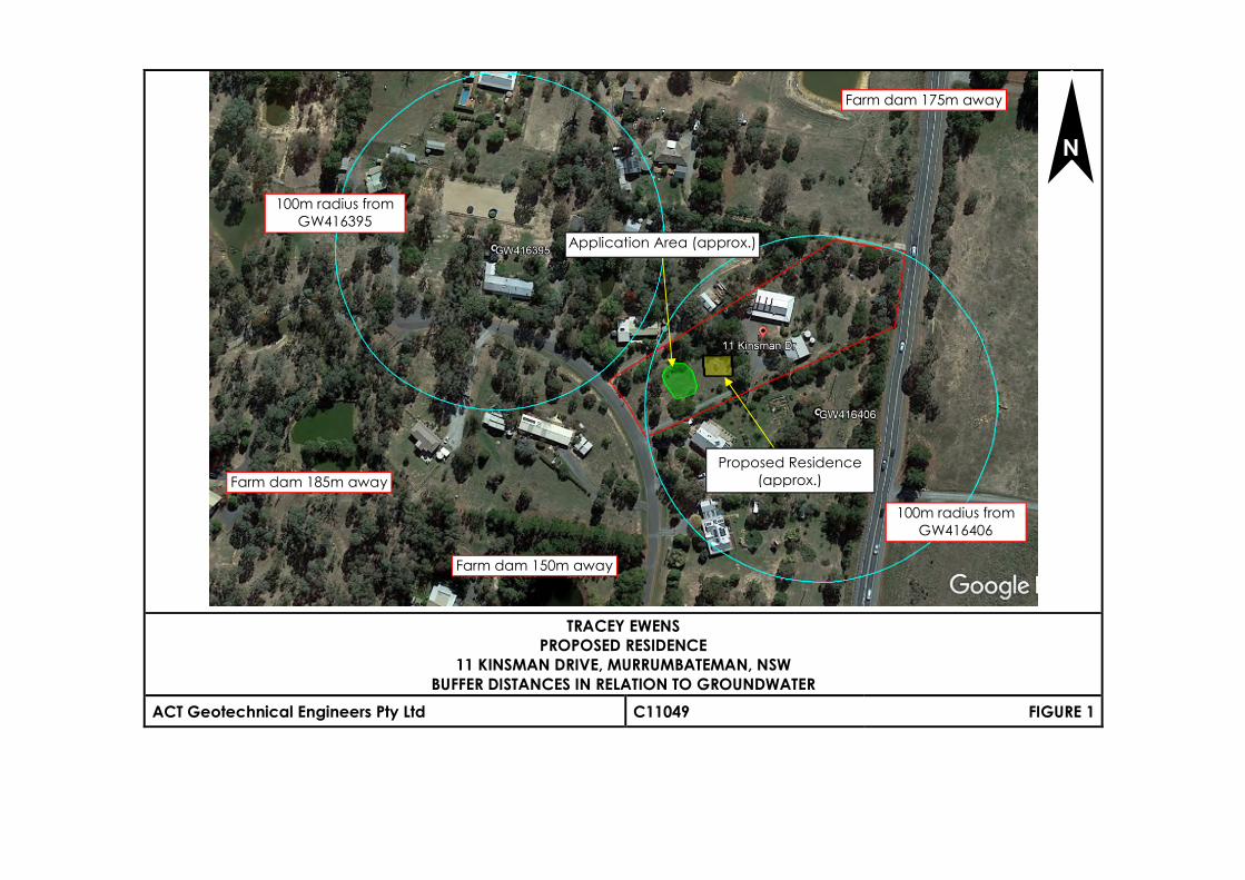
Groundwater and
Surface Waters
Two groundwater wells within 150m of the
proposed application area:
GW416406 – 75m away
GW416395 – 125m away
Site is suitable – assuming council
approval was given for the current system

3ACT Geotechnical Engineers Pty Ltd
2.2 Subsurface Conditions
To establish the subsurface conditions, one test hole (BH2) was drilled near the proposed land applicationarea. Figure 1 shows the site locality, while Figure 2 is a site plan showing the location of the investigationborehole. The subsurface profile was logged in terms of the Unified Soil Classification System (USCS).
Geological Profile Typical DepthInterval
Description
TOPSOIL 0.0m to 0.15m Silty SAND; fine to medium grained sand, low plasticity silt, darkbrown, dry, with grass rootlets, loose.
ALLUVIUM 0.2m to 0.6m Clayey SAND, Sandy CLAY; fine to coarse sand, low to mediumplasticity clay, brown, orange-brown, dry to moist, loose tomedium dense, stiff.
RESIDUAL 0.6m to 0.8m Clayey SAND and Sandy CLAY; medium plasticity clay, fine tocoarse sand, orange-brown, some grey-brown, trace ferruginousnodules up to 5mm, dry to moist.
EXTREMELYWEATHERED ROCK
0.8m to >1.0m Extremely Weathered (EW) Sandstone; excavates as ClayeySAND; fine to coarse sand, low plasticity clay, some fine gravel,orange-brown, dry, very dense.
Based on the soil encountered and in accordance with AS1547:2012 – “Disposal Systems for Effluent From
Domestic Premises” (Reference 2), the properties of the most limiting material are summarised in Table 2
below.
TABLE 3 – SITE SOIL PROPERTIES
Soil Category 4 – Clay Loams Minor limitation
Depth of Soil Layer 0.8m Moderate Limitation
Depth to high episodic/seasonal
watertable
>1m Minor limitation, groundwater
is not expected within >1m
Soil Structure Weakly Structured Minor Limitation, moderate
permeability
Bulk Density 1.5g/cm3 <1.8g/cm3 Minor Limitation
Phosphorous Sorption Capacity 7,200kg/ha Minor Limitation – more than
6000kg/ha
Indicative Permeability 0.12 – 0.5m/day -
Design Irrigation Rate (DIR) 3.5mm/day -
Design Loading Rate (DLR) - -
Coarse Fragments <20% Minor Limitation
pH 7.23 – Topsoil
7.10 – Residual
Minor limitation
Electrical Conductivity ECe dS/m 0.311 – Topsoil
0.111 – Residual
Minor limitation
Modified Emerson Aggregate Test Class 2 Moderate Limitation
Given the moderate expected permeability of the weakly structured clay loams present at the irrigation area,
a Design Irrigation Rate (DIR) of 3.5mm/day has been adopted.
2.3 Siting of Disposal Areas
Different minimum buffer distances are required for different features on the site, as per AS1547:2012 ‘On-site
Domestic Wastewater Management’. These have been assessed on site and are summarized in Table 4 below.
Figure 3 shows the buffer distances for the effluent disposal system.

4ACT Geotechnical Engineers Pty Ltd
TABLE 4 – BUFFER DISTANCES
Site Constraint Minimum Required
Buffer Distance
Priority Proposed System Buffer
Distance
Permanent Surface Waters (river, creek, lake,
etc.)
100m Low >100m
Domestic groundwater well or bore. 100m High >75m (suitable –
assuming council
approval was given for
previous system)
Other waters (farm dam, intermittent creeks,
drainage channels, etc.)
40m Low >100m
Property Boundaries 12m (uphill)
6m (downhill)
Low >12m
Dwellings, swimming pools & driveways 6m (uphill)
3m (downhill)
Low >3m
2.4 Effluent Disposal System Selection
The current surface irrigation system is still suitable but the application area will need to be moved and
expanded to make way for the new residence.
3 Effluent Disposal System Design
The calculations in determining the size for the application area are outlined below. Using Table H1 in
AS1547:2012 – “Disposal Systems for Effluent From Domestic Premises”, the daily flow was calculated using the
assumptions outlined in Table 1.
Water Balance: A = Q (L/day)/DIR (mm/day);
Where Q = 600L/day
DIR = 3.5mm/day
A = 600/3.5 = 172m2
Nitrogen Balance: A = Q(L/day) x TN (mg/L)/ Ln (critical loading of TN, mg/m2/day)Where Q = 600L/dayTN = 25mg/L
Assume 20% loss by denitrification; 25mg/L – (25 x 0.2) = 20mg/LLn – 15,000mg/m2/year (150kg/ha/year, for imported species)A = 600 x 20 x 365/15,000 = 292m2
Phosphorous Balance: A = P gen/(P uptake + P sorb) [P sorption capacity in upper 50cm & 50 year design period]P sorption capacity in upper 50cmP sorb = 7,200kg/ha = 0.72kg/m2
P uptake for design period of 50 years
P uptake = 4mg/m2/day x 365 x 50 = 0.073kg/m2
P generated over 50 year design period
P gen = 8mg/l x 600 x 365 x 50 = 87.6kg
A = P gen/(P uptake + P sorb) = 131.4/(0.073 + 0.72) = 110m2
The sizing of the irrigation area should be designed to take into account the nitrogen and phosphorousbalance and an area of 292m2 should be allowed for.

5ACT Geotechnical Engineers Pty Ltd
3.1 Treatment System
For surface/spray irrigation, the effluent must be secondary treated effluent, which can be treated in a NSWHealth accredited AWTS system (like the current Super Treat system) and should be installed as per thePlumber’s installation manual. The system shall have adequate capacity to treat the design flow rate(600L/day) for the combined three bedroom lot. The tank should be installed to comply with the local councilrequirements and the standard AS3500.2:2003 – “Plumbing and Drainage Part 2 Sanitary Plumbing andDrainage”, and the manufacturer’s recommendations.
The tanks should be installed so that the lid of the tank is exposed at least 100mm off the ground surface levelto ensure that no stormwater enters the tank.
3.2 Designated Area
A spray irrigation system for the site requires a minimum application area of 292m2. The spray irrigation system
shall be constructed in accordance with the requirements of AS1547:2012 Appendix M.
The area will need to be covered with at least 100mm of fertile topsoil to act as an immediate storage media
for effluent applied to it, and to support the rapid growth of suitable vegetation to maximize evapo-
transpiration. A list of suitable plants is provided in “The Easy Septic Guide” produced by the NSW Department
of Local Government. Multiple irrigation areas may need to be constructed, to allow spray cycling between
the areas.
The slope of the block is a minor constraint for surface spray irrigation systems. The soils have moderate
permeability and spray irrigation is suitable for the site provided it is sited on land with a slope of less than 20%
and outside the required buffer distances.
In the case of system failure, a reserve area is required of the same size of 292m2. This is highlighted in Figure 2
attached.
A fence should be placed around the effluent disposal area if there is a risk of children, animals or vehiclescoming into the area. Signage, complying with AS1319 shall be placed in at least two places at the boundaryof the application area, clearly visible to property uses, with wording such as “Recycled Water – AvoidContact – DO NOT DRINK”.
The treated effluent is not suitable for vegetable gardens or areas where people can come in contact withthe effluent.
The area should not be used for any purposes that compromise the effectiveness of the system or access forfuture maintenance purposes.
Should you require any further information regarding this report, please do not hesitate to contact our office.
Yours faithfullyACT Geotechnical Engineers Pty. Ltd.
Jeremy MurrayDirectorSenior Geotechnical EngineerAttachments: - Figures 1 and 2, Borehole Log
TRACEY EWENSPROPOSED RESIDENCE
11 KINSMAN DRIVE, MURRUMBATEMAN, NSWBUFFER DISTANCES IN RELATION TO GROUNDWATER
ACT Geotechnical Engineers Pty Ltd C11049 FIGURE 1
Farm dam 185m away
Application Area (approx.)
N
Proposed Residence(approx.)
Farm dam 150m away
Farm dam 175m away
100m radius fromGW416395
100m radius fromGW416406

TRACEY EWENSPROPOSED RESIDENCE
11 KINSMAN DRIVE, MURRUMBATEMAN, NSWSITE PLAN
ACT Geotechnical Engineers Pty Ltd C11049 FIGURE 2
N
LEGEND
- - Location of Test Hole
BH1
NOTE: appropriate warning signagecomplying with AS1547:2012
Appendix M and AS1319 must beplaced in at least two places around
the Application Area
Reserve Area(292m2)
Application Area(292m2)

TRACEY EWENSPROPOSED RESIDENCE
11 KINSMAN DRIVE, MURRUMBATEMAN, NSWEXAMPLE LAYOUT OF SPRAY IRRIGATION SYSTEM
ACT Geotechnical Engineers Pty Ltd C11049 FIGURE 3

Silty SAND; fine to medium grained sand, low plasticity silt, dark brown, dry, withgrass rootlets.
Clayey SAND; fine to coarse sand, low plasticity clay, brown, orange-brown, dryto moist.
Sandy CLAY; medium plasticity clay, fine to coarse sand, red-brown,orange-brown, moist (less than plastic limit).
Clayey SAND and Sandy CLAY; medium plasticity clay, fine to coarse sand,orange-brown, some grey-brown, trace ferruginous nodules up to 5mm, dry tomoist.
Extremely Weathered (EW) Sandstone; excavates as Clayey SAND; fine tocoarse sand, low plasticity clay, some fine gravel, orange-brown, dry.
BOREHOLE TERMINATED AT 1mrefusal
LOOSE
LOOSETOMEDIUMDENSE
STIFF
STIFF TOVERYSTIFF
VERYDENSE
SM
SC
CH
SC
SC
TOPSOIL
ALLUVIUM
RESIDUAL
EXTREMELYWEATHEREDROCK
0.15
0.35
0.6
0.8
1
Soil Type: Plasticity or Particle Characteristics,Colour, Secondary and Minor Components,Moisture, Structure
1.2
BH1
FieldTest
Results
Borehole No.
Sheet
Con
sist
ency
orR
elat
ive
Den
sity
Collar Level : Not KnownAngle From Vertical : 0°Bearing : N.A.
Cas
ing
U.S
.C.S
.
GeologicalProfile
1 of 1
Gra
phic
Log
Dep
th
1.0
Dep
th
1.0
Sam
ples
Borehole Log
Equipment Type : PUSH TUBE DRILLHole Diameter : 50mm
Metres
Material Description, Structure
C11049Job No.
CLIENT: TRACEY EWENS
Logged By : KA
Location : SEE REPORT
Date : 16/9/20 Checked By : JM Date : 16/9/20
PROPOSED RESIDENCE11 KINSMAN DRIVE, MURRUMBATEMAN, NSW
ACT Geotechnical Engineers
PROJECT
BO
RE
HO
LE/E
XC
AV
AT
ION
LO
G C
1104
9.G
PJ
AC
T G
EO
.GD
T 2
1/9/
20

ACT Geotechnical Engineers Pty Lt 5/9 Beaconsfield Street, Fyshwick ACT 2609
ACN 063 673 530 PO Box 9225, Deakin ACT 2600
Ph: (02) 6285 1547
ACT Geotechnical Engineers Pty Ltd
Limitations in the Use and Interpretation
of this Geotechnical Report
Our Professional services were performed, our findings obtained, and our recommendations
prepared in accordance with generally accepted engineering principles and practices. This
warranty is in lieu of all other warranties, either expressed or implied.
The geotechnical report was prepared for the use of the Owner in the design of the subject
development and should be made available to potential contractors and/or the Contractor for
information on factual data only. This report should not be used for contractual purposes as a
warranty of interpreted subsurface conditions such as those indicated by the interpretive
borehole and test pit logs, cross- sections, or discussion of subsurface conditions contained herein.
The analyses, conclusions and recommendations contained in the report are based on site
conditions as they presently exist and assume that the exploratory bore holes, test pits, and/or
probes are representative of the subsurface conditions of the site. If, during construction,
subsurface conditions are found which are significantly different from those observed in the
exploratory bore holes and test pits, or assumed to exist in the excavations, we should be advised
at once so that we can review these conditions and reconsider our recommendations where
necessary. If there is a substantial lapse of time between conducting this investigation and the
start of work at the site, or if conditions have changed due to natural causes or construction
operations at or adjacent to the site, this report should be reviewed to determine the applicability
of the conclusions and the recommendations considering the changed conditions and time
lapse.
The summary bore hole and test pit logs are our opinion of the subsurface conditions revealed by
periodic sampling of the ground as the test holes progressed. The soil descriptions and interfaces
between strata are interpretive and actual changes may be gradual.
The bore hole and test pit logs and related information depict subsurface conditions only at the
specific locations and at the particular time designated on the logs. Soil conditions at the other
locations may differ from conditions occurring at these bore hole and test pit locations. Also, the
passage of time may result in a change in the soil conditions at these test locations.
Groundwater levels often vary seasonally. Groundwater levels reported on the boring logs or in
the body of the report are factual data only for the dates shown.
Unanticipated soil conditions are commonly encountered on construction sites and cannot be
fully anticipated by merely taking soil samples, bore holes or test pits. Such unexpected conditions
frequently require that additional expenditures be made to attain a properly constructed project.
It is recommended that the Owner consider providing a contingency fund to accommodate
such potential extra costs.
This firm cannot be responsible for any deviation from the intent of this report including, but not
restricted to, any changes to the scheduled time of construction, the nature of the project or the
specific construction methods or means indicated in this report: nor can our company be
responsible for any construction activity on sites other than the specific site referred to in this
report.