ACS800 PM kits - ABB MyLearning€¦ · · 2010-12-27drives see parameter 145.14 FAN LIFETIME LIM...
23
© Copyright 12/27/2010 ABB. All rights reserved. Help Preventive maintenance kits ABB industrial drives ACS800 Welcome to the ABB industrial drives, ACS800 Preventive maintenance kits training module. If you need help navigating this module, please click the Help button in the top right corner. To view the presenter notes as text, please click the Notes button in the bottom right corner.
Transcript of ACS800 PM kits - ABB MyLearning€¦ · · 2010-12-27drives see parameter 145.14 FAN LIFETIME LIM...

©C
opyr
ight
12/
27/2
010
AB
B.
All
right
s re
serv
ed.
Help
Preventive maintenance kits
ABB industrial drives ACS800
Welcome to the ABB industrial drives, ACS800 Preventive maintenance kits training module.
If you need help navigating this module, please click the Help button in the top right corner. To view the presenter notes as text, please click the Notes button in the bottom right corner.

©C
opyr
ight
12/
27/2
010
AB
B.
All
right
s re
serv
ed. -
2-
Help
Objectives
Define the aging components of the ACS800
Recall the preventive maintenance kits for the ACS800
List the actions of preventive maintenance kit replacement operations
State the actions of preventive maintenance measurements and checkings
After completing this module, you will be able to
After completing this module, you will be able to
• define the aging components of the ACS800,
• recall the preventive maintenance kits for the ACS800,
• list the actions of preventive maintenance kit replacement operations, and
• state the actions of preventive maintenance measurements and checkings.

©C
opyr
ight
12/
27/2
010
AB
B.
All
right
s re
serv
ed. -
3-
Help
Lifespan of ACS800 componentsLifespan of ACS800 components
The following pages list the aging components and the common aging phenomena of the ACS800 drives.

©C
opyr
ight
12/
27/2
010
AB
B.
All
right
s re
serv
ed. -
4-
Help
Cooling fansLifespan of ACS800 components
FAN ON-TIME– New fan Reset counter
Change intervals– 6 years:
Main cooling fan(s)
diode (DSU), IGBT (ISU) supply modules cooling fans
– 3 years: ACS800-01, ACS800-11 and ACS800-104 IP21 and IP55
internal cooling fan
ACS800-02 enclosure extension cooling fan
Thyristor (TSU) supply modules main cooling fans
Cooling fan capacitor
In the ACS800 the cooling fans operate for a short time when the drive is powered up and when the run-command for the drive is active. The cooling fan operating hour counter, the signal named FAN ON-TIME, should be checked and compared with the actual age of the drive.Resetting of the counter is recommended when the fan gets replaced. This can be done by using the DriveWindow2 software (for resetting single drives see parameter 145.14 FAN LIFETIME LIM / In system software see parameter 16.09 RESET COUNTER).
The main cooling fan for the heat sinks needs to be replaced every six years.
The Change interval for internal or additional cooling fans are three years.
Note that in the case of separate cooling fan starting capacitors, they should also be replaced when changing the fan.

©C
opyr
ight
12/
27/2
010
AB
B.
All
right
s re
serv
ed. -
5-
Help
Electrolytic capacitors
DC-link– 9 years
AINT + flatcables– 9 years
Lifespan of ACS800 components
The typical aging phenomena of electrolytic capacitors are the decrease of capacitance and the increase of ESR. Note that some ACS800 drives have film type capacitors in dc-link. They don’t have similar aging phenomena to electrolytic capacitors.
In the case of dc-link capacitors the aging causes higher ripples on dc-link voltage and poorer response for rapid load torque changes.
The change interval for the dc-link capacitors is nine years.
In AINT boards the aging of electrolytic capacitors causes ripple on signals.
The change interval for AINT board and its flatcables is nine years.

©C
opyr
ight
12/
27/2
010
AB
B.
All
right
s re
serv
ed. -
6-
Help
ESR
Equivalent Serial Resistance (m)
contacts polarization leakage currents
ESR
Aging components on ACS800 | Electrolytic capacitors
Equivalent serial resistance is the ohmic part of the equivalent series circuit of an electrolytic capacitor. It represents the losses associated with a capacitor due to metallic contacts, polarization, leakage currents, and so on; It is expressed in milliohms (mΩ).

©C
opyr
ight
12/
27/2
010
AB
B.
All
right
s re
serv
ed. -
7-
Help
Cooling air filters
Door filters
Module filters
Annually (at least)– replace (IP54)
– check (IP21...IP42)
Aging components on ACS800
The drive may have cooling air filters attached on the cabinet door and some modules, for instance the R8i, may be equipped with an internal cooling air filter.
Cooling air filters are recommended to be changed annually in the case of IP54 or higher IP classes. In the case of IP21 to IP42 mechanics, the filters must be checked at least annually.

©C
opyr
ight
12/
27/2
010
AB
B.
All
right
s re
serv
ed. -
8-
Help
ACS800 Preventive maintenance kitsACS800 Preventive maintenance kits
12 months warranty
Reasonably priced
reduces risk of incompatible spare parts
ABB verified components
Preventive maintenance kits are genuine service parts according exactly to the maintenance schedule, with a 12 months warranty.Kits are reasonably priced as a set compared to the price of individual spare parts. Using the preventive maintenance kits reduces the risk of incompatible spare parts. Delivery time for the kits is four weeks. Return old boards to the ABB Logistic Center. They will be used as exchange spare parts after repair or update and testing.
Components on the open market may have similarities with those used on preventive maintenance kits and original drives. Replacing original components with components that are not verified by ABB has a high risk of damaging the drive. The Reason is that open market components have looser tolerances than those delivered by ABB.
The exact contents of the Preventive maintenance kit can be found in the “Kit Includes” view in Parts OnLine.

©C
opyr
ight
12/
27/2
010
AB
B.
All
right
s re
serv
ed. -
9-
Help
Assembly
SAFETY!
ESD requirements
Mark connections
Handle fiber optics carefully
ACS800 Preventive maintenance kits
All hardware maintenance actions must be done without any voltage. Before starting the component changing, the safe level of voltages must be ensured by measuring. Check the safety instructions from the hardware and the user’s manual.
Use ESD protection and handle the new and old components according to ESD requirements.
If the wiring connection markings are not clear, mark them to ensure the correct connections when re-installing the components.
Handle fibre optics carefully. When disconnecting, pull from the connector, do not disconnect it (fibre optics) from the fibre itself.
©C
opyr
ight
12/
27/2
010
AB
B.
All
right
s re
serv
ed. -
10-
Help
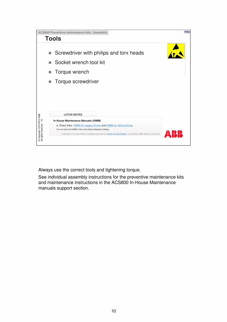
Tools
Screwdriver with philips and torx heads
Socket wrench tool kit
Torque wrench
Torque screwdriver
ACS800 Preventive maintenance kits | Assembly
LOTUS NOTES
In-House Maintenance Manuals (IHMM)
Direct links: IHMM for Legacy Drives and IHMM for Active DrivesYou can also find IHMM in the Lotus Notes Database Catalog.
Links open in a new window. Possible requirements: Adobe Acrobat Reader, Lotus Notes, ABB network connection.
Always use the correct tools and tightening torque.
See individual assembly instructions for the preventive maintenance kits and maintenance instructions in the ACS800 In-House Maintenance manuals support section.
©C
opyr
ight
12/
27/2
010
AB
B.
All
right
s re
serv
ed. -
11-
Help
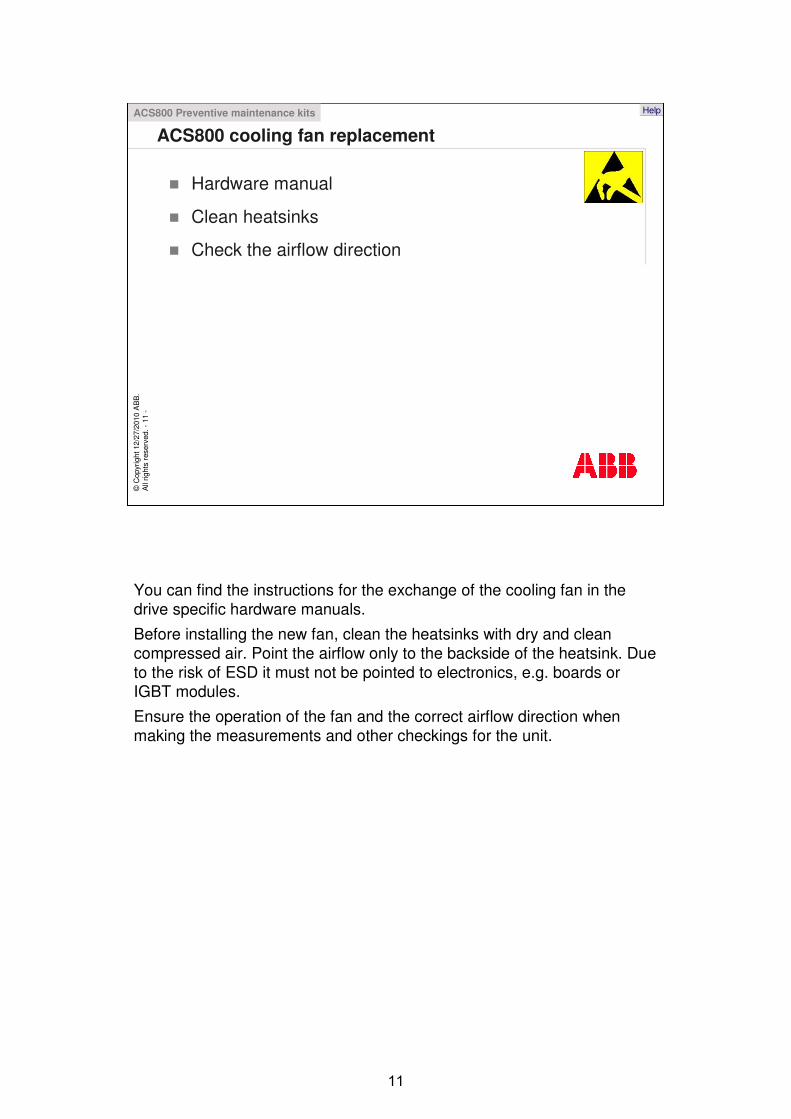
ACS800 cooling fan replacementACS800 Preventive maintenance kits
Hardware manual
Clean heatsinks
Check the airflow direction
You can find the instructions for the exchange of the cooling fan in the drive specific hardware manuals.
Before installing the new fan, clean the heatsinks with dry and clean compressed air. Point the airflow only to the backside of the heatsink. Due to the risk of ESD it must not be pointed to electronics, e.g. boards or IGBT modules.
Ensure the operation of the fan and the correct airflow direction when making the measurements and other checkings for the unit.
©C
opyr
ight
12/
27/2
010
AB
B.
All
right
s re
serv
ed. -
12-
Help
ACS800 other components replacementACS800 Preventive maintenance kits
Cooling air filters: hardware manual
You can find instructions for the exchange of cooling air filters in the drive specific hardware manuals.

©C
opyr
ight
12/
27/2
010
AB
B.
All
right
s re
serv
ed. -
13-
Help
ACS800 Preventive maintenance measurementsACS800 Preventive maintenance measurements
Each drive type has its own reporting tool in the Legacy drives section of the In-House Maintenance manual.
All preventive maintenance measurements and checkings are listed on each report form.
Instructions for the reporting tool can be found in the training module: Preventive maintenance reporting tool.

©C
opyr
ight
12/
27/2
010
AB
B.
All
right
s re
serv
ed. -
14-
Help
Drives and inverter modules reportACS800 Preventive maintenance measurements
Preventive maintenance report forms for single drives and inverter modules have three main sections.

©C
opyr
ight
12/
27/2
010
AB
B.
All
right
s re
serv
ed. -
15-
Help
0. EnvironmentACS800 Preventive maintenance measurements | Drives and inverter modules report
Check the ambient conditions and that they fit the specifications listed on the hardware manuals. Pay attention to ambient temperature, humidity and other conditions. Note that the air conditioning may be switched off during the scheduled stop. Mark any abnormal items in the report, and if needed you can attach a digital photo.
Check the corrosion level of the drive visually by using a magnifying glass and a flashlight.
Check the fault logger contents, save the logger to a separate file with DriveWindow2 or mark them in the report.
Check the availability of the documentation, manuals, application drawings, etc.
Check the spare parts availability, compatibility and storage conditions. Note that annual re-freshing is recommended for individual electrolytic capacitors for dc-link and spare modules. Annual re-freshing ensures the spare units usability without re-freshing when repairing the drive. See the ACS800 Capacitor Reforming Guide in the ACS800 In-House Maintenance manual (section General manuals part Application & Installation & User’s guides).

©C
opyr
ight
12/
27/2
010
AB
B.
All
right
s re
serv
ed. -
16-
Help
1. Maintenance with no voltage appliedACS800 Preventive maintenance measurements | Drives and inverter modules report
In the case of light dust, clean the units with an ESD vacuum cleaner. Use an ESD approved brush to remove the dust and wear personal ESD protection. Note that in case of very dusty units or if the dust contains conductive particles, oil or any other particles that stick to the surfaces, the cleaning should be done in a certified repair center. In that case, the drive can be cleaned thoroughly and tested reliably before delivered back to the customer.
Check the condition of electrical connections on the drive. Make a pull test for the wire connections and check the busbar connections with a torque wrench. Search for any loose connections on the busbars, terminals, and so on.
Check the mechanical assembly of fuses and their compatibility.
When visually checking the fibre optics, dc-link capacitors, printed circuit boards and IGBT-modules, pay attention to any marks of mechanical damage or other abnormalities.
Check that the cooling air filters, if not changed, are clean.
Check the mechanical conditions of application related to optional relays, contactors, and so on.
Measure the insulation resistance of the motor cable and the motor. Disconnect the motor cable from the inverter output before the measurement.

!""#$%&''$

©C
opyr
ight
12/
27/2
010
AB
B.
All
right
s re
serv
ed. -
17-
Help
2. Maintenance with voltage appliedACS800 Preventive maintenance measurements | Drives and inverter modules report
Check the cooling fans operation.
Make a backup copy of the drive software.
Make an I/O test. Note that for safety reasons drives signals to other systems must be eliminated and motor output disconnected.
If the drive is equipped with current transducers they can be checked by following the instructions that are in ACS800 In-House Maintenance manuals Support section.
Mark down the reading of the Service hour meter, i.e. operation hour counter.
Check the dc link. Compare the actual dc link voltage to the voltage in drives signals. Pay attention to safety! Voltage slicing is measured only when the maintenance is made in a certified repair center.
Check the pulse encoder, if there is one. Check the mechanical conditions of the tacho, cabling and the coupling. Check the pulses with an oscilloscope when running the drive in scalar mode. The pulses should be square wave.
When making a test run, check the motors direction of rotation, test that the drive follows upper level commands. If possible, run the drive on maximum speed and load.
Check the emergency stop function. See earlier safety presentations for emergency stop function details. Note that in the case of smaller ACS800 single drives the emergency stop function is normally done by switching off the supplying voltage of the drive and that the drive has no individual relays for emergency stop.

&()&*(!) +
&$ &$,(! &$,(! !""#$%&''$

©C
opyr
ight
12/
27/2
010
AB
B.
All
right
s re
serv
ed. -
18-
Help
Supply modulesACS800 Preventive maintenance measurementsACS800 Preventive maintenance measurements
The operations mentioned on the diode and thyristor supply modules report form have similar actions to those mentioned earlier on the drives and inverter modules report description.

©C
opyr
ight
12/
27/2
010
AB
B.
All
right
s re
serv
ed. -
19-
Help
Additional information (1/2)
Links to ACS800 hardware manuals in ABB Library:ACS800-01/U1 Hardware Manual
ACS800-02/U2 Hardware Manual
ACS800-04/04M/U4 Hardware Manual
ACS800-04 Drive Modules Hardware Manual, (0.55 to 132 kW)
ACS800-11/U11 Hardware Manual (5.5 to 110 kW)
ACS800-07 (45 to 560 kW) Hardware Manual
ACS800-07 (500 to 2800 kW) Hardware Manual
ACS800-17 Drives (75 to 1120 kW), Hardware manual
ACS800-17 Drives (55 to 2500 kW / 75 to 2800 HP), Hardware Manual
ACS800-31/U31 Hardware Manual
ACS800-37 Drives (55 to 2700 kW / 75 to 3000 HP), Hardware manual
ACS800-104 Inverter Modules, Hardware Manual
ACS800-107 (1.5 to 5340 kW) Cabinet-built Inverter Units Hardware Manual
ACS800-607 Brake Units Hardware Manual
ACS800-67 Wind Turbine Drives for Asynchronous Slip Ring Generators Hardware Manual
ACS800-07LC Drives Hardware Manual
Here are some links to related information.
Some of the links are not available in the ABB Library, those documents can be found in the ACS800 In-House Maintenance manual.
Check for the latest revision by using the document number search.

©C
opyr
ight
12/
27/2
010
AB
B.
All
right
s re
serv
ed. -
20-
Help
Additional information (2/2)
Links to ACS800 hardware manuals in ABB Library:ACS800-204 IGBT Supply Modules Hardware Manual
ACS800-207 Cabinet-installed IGBT Supply Unit Hardware Manual
ACS800-404 Thyristor Supply Modules User's Manual
User's Manual: ACS800-407 and ACS800-807 Cabinet-installed Thyristor Supply Units (TSU) (639 to 5991 kW)
ACS800-307 and ACS800-507 Cabinet-installed Diode Supply Unit User's manual
Diode Supply Modules ACS800-304 and ACS800-704 User's manual
ACA 635 IGBT Supply Sections, ACS 800-17 Line-Side Converter User's manual
Here are some links to related information.
Some of the links are not available in the ABB Library, those documents can be found in the ACS800 In-House Maintenance manual.
Check for the latest revision by using the document number search.

Thank you for your attention. You may now go ahead and move on to the next unit.