ACS550-01/U1 Drive User’s Manual · User's Manual for control connections to the drive. Typical...
34
User’s Manual ACH550-CC/CD Packaged Drive with Classic Bypass Supplement for ACH550-UH HVAC User’s Manual
Transcript of ACS550-01/U1 Drive User’s Manual · User's Manual for control connections to the drive. Typical...

User’s Manual
ACH550-CC/CD Packaged Drive with Classic Bypass Supplement for ACH550-UH HVAC User’s Manual

ii ACH550-CC/CD Packaged Drive with Classic Bypass
ACH550 Drive Manuals GENERAL MANUALS
ACH550-UH HVAC Drives User's Manual (1…550 HP)• Safety • Installation• Start-Up• Embedded Fieldbus• Fieldbus Adapter• Diagnostics• Maintenance• Technical DataACH550-PC/PD Drive with Disconnect Supplement to ACH550-UH HVAC User’s Manual• Safety• Installation• Start-Up• Technical DataE-Bypass Configurations (BC, BD, VC or VD) for ACH550 Drives (1…400 HP) • Safety• Installation• Start-Up• Technical DataACH550-CC/CD Packaged Drive with Classic BypassSupplement for ACH550-UH HVAC User’s Manual • Safety• Installation• Start-Up• Technical Data
© 2007 ABB Inc. All Rights Reserved.

ACH550-CC/CD Packaged Drive with Classic Bypass 1
Safety
WARNING! The ACH550 adjustable speed AC drive with Classic Bypass should ONLY be installed by a qualified electrician.WARNING! Even when the motor is stopped, dangerous voltage is present at the Power Circuit terminals U1, V1, W1 and U2, V2, W2 and, depending on the frame size, UDC+ and UDC-, or BRK+ and BRK-WARNING! Dangerous voltage is present when input power is connected. After disconnecting the supply, wait at least 5 minutes (to let the intermediate circuit capacitors discharge) before removing the cover. WARNING! Even when power is removed from the input terminals of the ACH550, there may be dangerous voltage (from external sources) on the terminals of the relay outputs.WARNING! When the control terminals of two or more drive units are connected in parallel, the auxiliary voltage for these control connections must be taken from a single source which can either be one of the units or an external supply.WARNING! The ACH550 will start up automatically after an input voltage interruption if the external run command is on.WARNING! When the ACH550 with Classic Bypass is connected to the line power, the Motor Terminals T1, T2, and T3 are live even if the motor is not running. Do not make any connections when the ACH550 with Classic Bypass is connected to the line. Disconnect and lock out power to the drive before servicing the drive. Failure to disconnect power may cause serious injury or death.
Note! For more technical information, contact the factory or your local ABB sales representative.
Safety

2 ACH550-CC/CD Packaged Drive with Classic Bypass
Use of Warnings and NotesThere are two types of safety instructions throughout this manual:• Notes draw attention to a particular condition or fact, or give information on a
subject.
• Warnings caution you about conditions which can result in serious injury or death and/or damage to the equipment. They also tell you how to avoid the danger. The warning symbols are used as follows:
Dangerous voltage warning warns of high voltage which can cause physical injury and/or damage to the equipment. General warning warns about conditions, other than those caused by electricity, which can result in physical injury and/or damage to the equipment.
Safety
ACH550-CC/CD Packaged Drive with Classic Bypass 3
Table of Contents
Table of Contents
SafetyUse of Warnings and Notes . . . . . . . . . . . . . . . . . . . . . . . . . . . . . . . . . . . . . . . . 2
Table of Contents
InstallationApplication . . . . . . . . . . . . . . . . . . . . . . . . . . . . . . . . . . . . . . . . . . . . . . . . . . . . . 4Classic Bypass Features and Functions . . . . . . . . . . . . . . . . . . . . . . . . . . . . . . 4Installation Flow Chart . . . . . . . . . . . . . . . . . . . . . . . . . . . . . . . . . . . . . . . . . . . . 6Preparing for Installation (Supplement to ACH550-UH User’s Manual) . . . . . . . 7Installing the Wiring (Supplement to ACH550-UH User’s Manual) . . . . . . . . . . 8
MaintenanceMaintenance Interval . . . . . . . . . . . . . . . . . . . . . . . . . . . . . . . . . . . . . . . . . . . . 15
Technical DataInput Power Connections (Supplement to ACH550-UH User’s Manual) . . . . . 16Motor Connections (Supplement to ACH550-UH User’s Manual) . . . . . . . . . . 22Dimensions and Weights (Supplement to ACH550-UH User’s Manual) . . . . . 23Applicable Standards . . . . . . . . . . . . . . . . . . . . . . . . . . . . . . . . . . . . . . . . . . . . 28
Index

4 ACH550-CC/CD Packaged Drive with Classic Bypass
Installation
Study these installation instructions carefully before proceeding. Failure to observe the warnings and instructions may cause a malfunction or personal hazard.
WARNING! Before you begin read "Safety" on page 1.
WARNING! When the ACH550 with Classic Bypass is connected to the line power, the Motor Terminals T1, T2, and T3 are live even if the motor is not running. Do not make any connections when the ACH550 with Classic Bypass is connected to the line. Disconnect and lock out power to the drive before servicing the drive. Failure to disconnect power may cause serious injury or death.
ApplicationThis manual is a supplement to the ACH550-UH User’s Manual and documents Classic Bypass configurations.
Classic Bypass Features and FunctionsThe ACH550 with Classic Bypass is an ACH550 AC adjustable frequency drive in an integrated UL Type 1, UL Type 12, or UL Type 3R package with a bypass function configured entirely of standard industrial control components. The ACH550 with Classic Bypass provides:
• Disconnect switch or circuit breaker with door mounted control lever. The lever can be padlocked in the OFF position (padlock not supplied).
• Electrically interlocked Bypass and drive output contactors
• Class 20 motor overload protection.
• ACH-CP-B drive control panel
– Cover mounted - UL Type 1 and 12 enclosures– Drive mounted - UL Type 3R enclosures
• Bypass cover mounted control
– Drive-Off-Bypass selector switch– Bypass pilot light– External Fault/MOL pilot light
• Provisions for external control connections.
• Optional drive service switch (drive input disconnect), the functional equivalent of a three-contactor bypass arrangement.
Installation
ACH550-CC/CD Packaged Drive with Classic Bypass 5
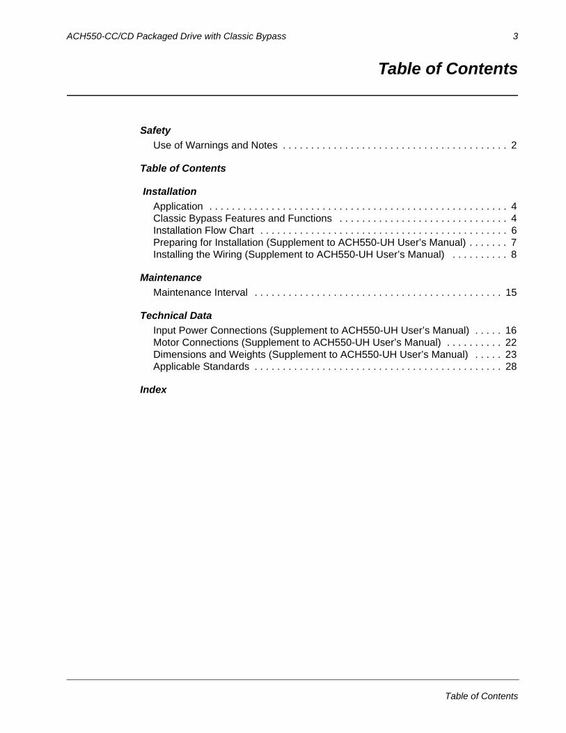
The following shows the front view of a typical ACH550 Classic Bypass wall mount configuration, and identifies the major components.
The following shows the front view of a typical ACH550 Classic Bypass floor mount configuration, and identifies the major components.
l
ACH-CP-BControl Panel
Operating handle for DisconnectSwitch or Circuit Breaker
Cover Control
ACH-CP-BControl Panel
Operating handle for DisconnectSwitch or Circuit Breaker
Cover Control
Installation

6 ACH550-CC/CD Packaged Drive with Classic Bypass
The following is a typical power diagram.
Installation Flow ChartThe installation of Classic Bypass Configurations for ACH550 drives follows the outline below. The steps must be carried out in the order shown. At the right of each step are references to the detailed information needed for the correct installation of the unit.
TaskReference in ACH550-UH
User’s Manual “Installation” section
Reference in this Manual
PREPARE for installation
“Preparing for Installation” "Drive Identification" on page 7."Suitable Mounting Location (Supplement to ACH550-UH User’s Manual)" on page 8
PREPARE the Mounting Location
“Prepare the Mounting Location”
--
REMOVE the front cover “Remove Front Cover” --
MOUNT the drive “Mount the Drive” --
INSTALL wiring “Wiring Overview” and “Install the Wiring”
"Installing the Wiring (Supplement to ACH550-UH User’s Manual)" starting on page 8.
SET overload relay -- “Motor Overload Relay (Supplement to ACH550-UH User’s Manual)” on page 14 .
CHECK installation “Check Installation” --
RE-INSTALL the cover “Re-install Cover” --
APPLY power “Apply Power” --
START-UP “Start-Up” --
ACH550
Drive with Classic Bypass
Motor3 PhaseDrive
Disconnect Switchor Circuit Breaker
Service Switch(Optional)
Input Power
BypassContactor
Drive OutputContactor
Installation
ACH550-CC/CD Packaged Drive with Classic Bypass 7
Preparing for Installation
Drive IdentificationDrive Label
To identify the type of device you are installing, refer to the type code number on the device identification label.
• Wall mounting base drives – label attached on the side surface of the heat sink.
• Packaged drive with screw cover – label attached to outside surface on the left side of enclosure.
• Enclosure with hinged cover/door – label on inside surface of the cover/door.
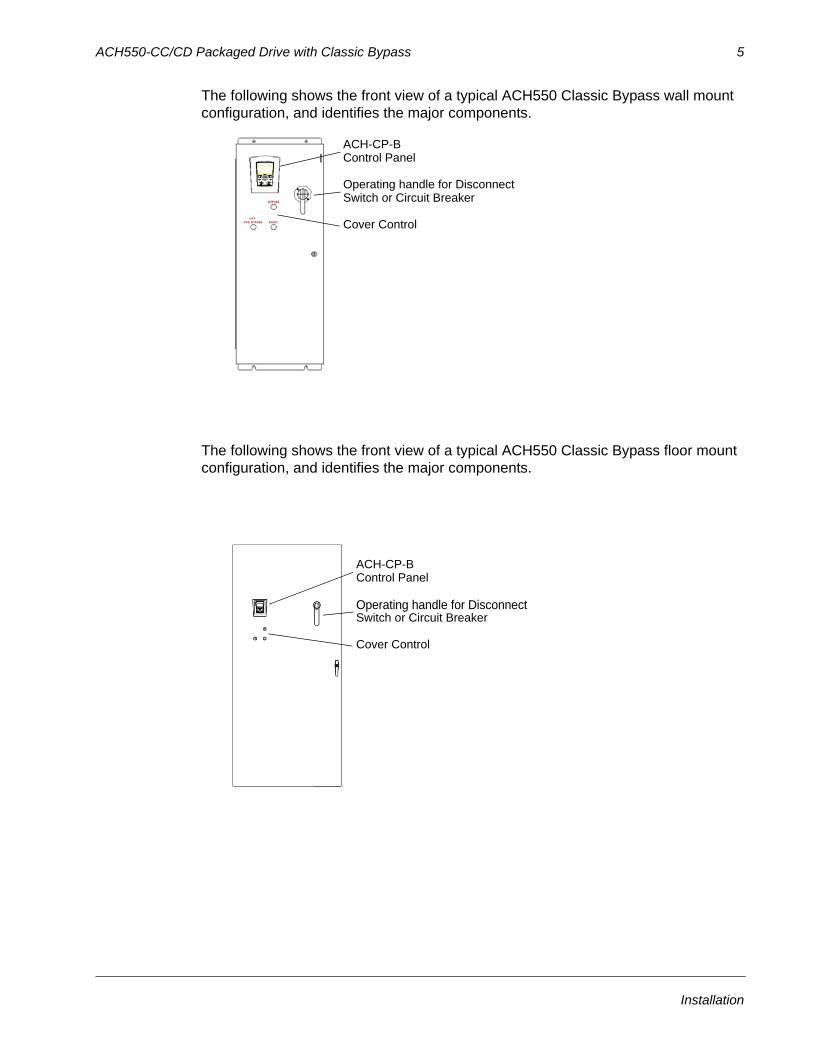
Type CodeUse the following to interpret the type code found on the identification label.
ACH550-UH-015A-4 +…+…AC, HVAC Drive = 550 Product SeriesConstruction UH = Base Drive BC = E-Bypass with circuit breaker BD = E-Bypass with disconnect switch CC = Classic Bypass with circuit breaker CD = Classic Bypass with disconnect switch PC = Drive with circuit breaker PD = Drive with disconnect switch VC = Vertical bypass with circuit breaker VD = Vertical bypass with disconnect switchOutput current rating (See ratings chart for details)Voltage rating 2 = 208…240 VAC 4 = 380…480 VAC 6 = 500…600 VACEnclosure protection class No specification = UL type/NEMA 1 +B055 = UL type/NEMA 12 +B058 = UL type/NEMA 3RPower options +E213 = Line reactor +F267 = Service switchInput/Output option modules +L511 = Relay output extension +L512 = 115/230 V digital input interfaceImbedded fieldbus protocol +K465 = BACnet protocolFieldbus adaptors +K451 – DeviceNet Adaptor +K452 = LonWorks Adaptor +K454 = Profibus Adaptor +K462 = ControlNet Adaptor +K466 = Ethernet AdaptorMiscellaneous options +G349 = Bypass damper control
Installation

8 ACH550-CC/CD Packaged Drive with Classic Bypass
Suitable Mounting Location )In selecting a suitable mounting location for Classic Bypass configurations, refer to the Technical Data in this manual for the appropriate information on:
• Branch circuit protection
• Dimensions and weights
Installing the Wiring
WARNING!• Do not connect or disconnect input or output power wiring, or control
wires, when power is applied.• Never connect line voltage to drive output Terminals T1, T2, and T3.• Do not make any voltage tolerance tests (Hi Pot or Megger) on any part of
the unit. Disconnect motor wires before taking any measurements in the motor or motor wires.
• Make sure that power factor correction capacitors are not connected between the drive and the motor.
Wiring Requirements
Refer to the “Wiring Requirements” Section in the ACH550 User’s Manual. The requirements apply to all ACH550 drives. In particular:
• Use separate, metal conduit runs to keep these three classes of wiring apart:
– Input power wiring.– Motor wiring.– Control/communications wiring.
• Properly and individually ground the drive, the motor and cable shields.
Installation
ACH550-CC/CD Packaged Drive with Classic Bypass 9
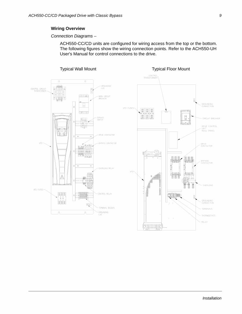
Wiring OverviewConnection Diagrams –
ACH550-CC/CD units are configured for wiring access from the top or the bottom. The following figures show the wiring connection points. Refer to the ACH550-UH User's Manual for control connections to the drive.
Typical Wall Mount Typical Floor Mount
Installation

10 ACH550-CC/CD Packaged Drive with Classic Bypass
Install the Line Input WiringLine Input Connections – Classic Bypass Configurations
Connect input power to the terminals of the disconnect switch or circuit breaker. Connect the equipment grounding conductor to the ground lug at the top of the enclosure. The figures below show the connection points for typical configurations. Units are configured for wiring access from the top or the bottom.
Typical Wall mount Typical Floor mount
WARNING! Check the motor and motor wiring insulation before connecting the ACH550 to line power. Follow the procedure in the ACH550-UH User’s Manual. Before proceeding with the insulation resistance measurements, check that the ACH550 is disconnected from incoming line power. Failure to disconnect line power could result in death or serious injury.
Installation

ACH550-CC/CD Packaged Drive with Classic Bypass 11
Install the Motor Wiring Motor Connections – Classic Bypass Configurations
Connect the motor cables to the motor overload relay output terminals; see the figures below. The motor grounding conductor can be connected to the ground lug near the motor overload relay.
Typical Wall mount Typical Floor mount
Install the Control WiringConnect control wiring to the terminal block 1TB located on the back panel toward the bottom of the enclosure.
Control Wiring
The control wiring includes connections to an analog speed command signal and start/stop relay contact for controlling the drive in the AUTO mode. There may also be connections to external run enable interlock contacts and a connection from the Motor Run contact to an external status indicating circuit.
Wiring Practices
The external control wiring to 1TB must not be run in the same conduit or raceway with any high power wiring. The external speed reference signal must be wired using a shielded, twisted pair cable. The shield connection must be terminated at the ground terminal provided (1TB:3). The other end of the shield should be cut and taped back at the signal source.
Installation

12 ACH550-CC/CD Packaged Drive with Classic Bypass
Terminal Block 1TB
Connection Points
All of the basic control connections are made to 1TB, which is a din-rail terminal block on the back panel at the bottom of the enclosure. 1TB includes screw clamp terminals rated for #22-10 AWG stranded or solid wire. Recommended tightening torque is 4.4 - 7.1 in-lbs.
The following figure shows connections 1TB1:1 through 1TB1:15. These connections are described in the following paragraphs.
Terminals 1TB:1 and 1TB:2 are low voltage speed reference signal input terminals (24 VDC maximum). Terminal 1TB:3 is a ground terminal for terminating the shielded cable. Terminals 1TB:4 to 1TB:8 are 120 VAC control circuit terminals connected to 120 VAC control power supplied by the control circuit transformer provided. Terminals 1TB:9 and 1TB:10 are powered at 24VDC to accept an external contact closure to start the drive. Terminals 1TB:11 to 1TB:15 are connected to un-powered relay contacts provided for use with externally powered customer control circuits.
Additional Connections
Analog outputs, additional relay outputs, and additional digital input connections are available on Terminal Block X1 inside the ACH550. Note that the Classic Bypass control circuitry uses inputs and outputs DI1,DI4 and R02. These inputs are not available for any other purpose and must not be reconfigured. Input AI1 and output RO2 are wired to the terminal block, 1TB. AI1, AI2, DI3, DI5, DI6, RO1, and R03 are available for use. Refer to the ACH550-UH HVAC Drives User’s Manual for information about control connections on Terminal Block X1. When making connections to Terminal Block X1, be careful not to disturb the factory installed wiring between X1 and the Classic Bypass control circuitry.
Analog Input
The external “Auto” speed reference is connected to Terminals 1TB:1 and 1TB:2. The Auto speed reference is factory wired from 1TB to ACH550 analog input AI1.
The analog input can accept a voltage signal (0 – 10 VDC) or a current signal (0 – 20 mA). Jumper J1, located on the Control Board in the ACH550, determines the signal type. J1 can be set in either the voltage or current position according to the type of external signal that will be connected. Refer to the ACH550 User’s Manual.
REMOTE RUN
Installation

ACH550-CC/CD Packaged Drive with Classic Bypass 13
Run Enable Interlocks
Run Enable interlocks, such as Freeze, Fire and Smoke protection are normally closed un-powered contacts connected in series between 1TB:7 and 1TB:8. When any of these contacts opens, the motor will stop, whether in DRIVE or BYPASS. The unit is shipped with a jumper installed from 1TB:7 to 1TB:8. This jumper must be removed before connecting external contacts.
Auto Start Contact
To start the ACH550 by means of an external un-powered contact (maintained), connect the contact to 1TB:9 and 1TB:10. Closing this contact will start the motor when the drive is in the AUTO mode.
Relay Contact Output
A “Motor Running” relay contact output is provided at terminals 1TB:13 and 1TB:14 for external indication of the motor status. The output consists of a normally open auxiliary contact on the bypass contactor and a normally open “Drive Running” contact from the ACH550. The two contacts are connected in parallel so that a contact closure is provided whenever the motor is running.
Refer to “Control Connections” in the ACH550-UH HVAC Drives User’s Manual Technical Data where relay contacts are used to control inductive loads.
Installation
14 ACH550-CC/CD Packaged Drive with Classic Bypass
Motor Overload RelayThe ACH550 with Classic Bypass includes a motor overload relay to provide thermal motor protection. It is connected in both drive and bypass modes of operation. For motor full load currents up to 80 amperes, the Motor Overload Relay is an adjustable trip, bimetallic overload relay with a class 20 trip characteristic. Above 80 amperes, the Motor Overload Relay is an adjustable trip, electronic overload relay with selectable class 10, 20 or 30 trip characteristic.
Suggested Settings
Current
Set the current adjustment to the value of the full load current shown on the motor nameplate.
Auto/Man
It is recommended the overload relay be set to the Manual Reset mode of operation. In the Auto Reset mode, the Overload Relay contacts re-close automatically when the bi-metals of bi-metallic versions cool or when the timer function within the electronic versions times out. If power is applied and the switches and contacts in the control circuit are commanding the motor to run, the motor will start as soon as the overload relay resets.
Class
The class 20 setting on the electronic overload relays would be the appropriate choice for the majority of the motors used in North America.
Resetting the Overload Relay
In the event an overload relay set in the Manual Reset mode trips, it is necessary to open the door of the enclosure and push the Reset button on the front of the overload relay to reset it.
WARNING: If power is applied and the switches and contacts in the control circuit are commanding the motor to run, the motor will start as soon as the overload relay resets. Use caution when manually resetting the overload relay to make sure it is safe to start the motor.
Installation

ACH550-CC/CD Packaged Drive with Classic Bypass 15
Maintenance
Maintenance
Maintenance IntervalIf installed in an appropriate environment, the drive requires very little maintenance. The table lists the routine maintenance intervals recommended by ABB. The information shown below is supplemental and in addition to that shown in the ACH550-UH HVAC User’s Manual.
Maintenance Application Interval
Check/replace enclosure inlet air filter
UL Type 12 and 3R enclosures Check every 3 months. Replace as needed
Check/replace enclosure exhaust air filter
UL Type 12 and 3R enclosures Check every 6 months. Replace as needed.
Replace enclosure vent fan(s). UL Type 12 and 3R enclosures Every three years
Replace enclosure air circulation fan Frames R4 through R6 in UL Type 1 enclosures
Every three years
16 ACH550-CC/CD Packaged Drive with Classic Bypass
Technical Data
Input Power Connections
Branch Circuit ProtectionInput power is connected to the ACH550 with Classic Bypass through either a non-fusible disconnect switch or a circuit breaker.
The circuit providing power to an ACH550 with Classic Bypass having a non-fusible switch disconnect must include an appropriate branch circuit protective device to provide short circuit and ground fault protection for the motor when operating in the bypass mode.
In the ACH550 with Classic Bypass having a circuit breaker disconnecting means, the circuit breaker provides the branch circuit short circuit and ground fault protection for the motor operating in the bypass mode.
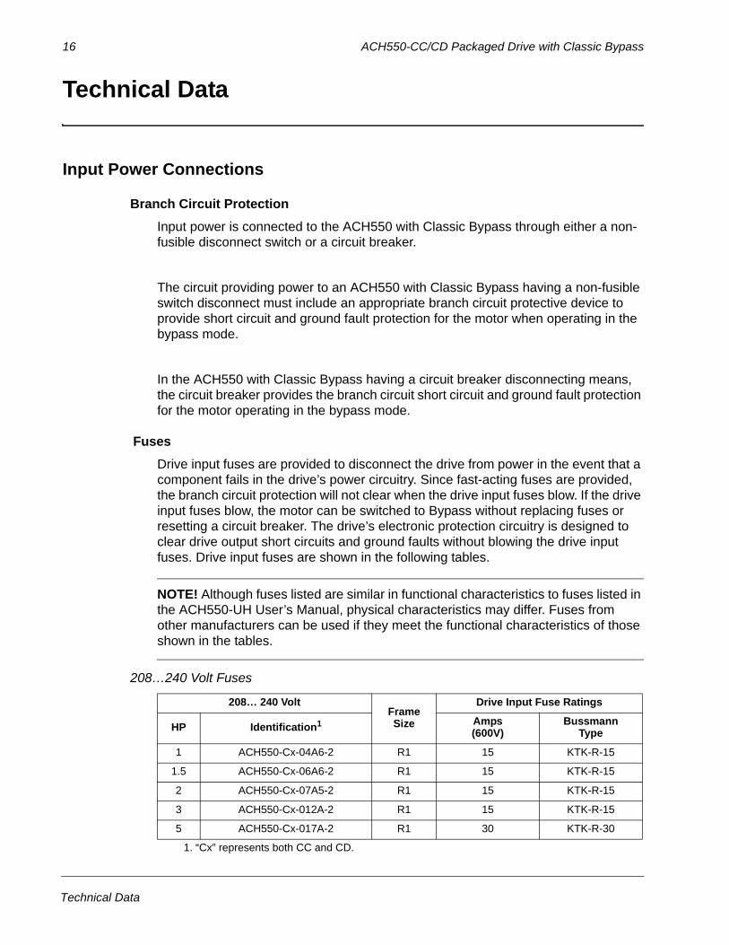
FusesDrive input fuses are provided to disconnect the drive from power in the event that a component fails in the drive’s power circuitry. Since fast-acting fuses are provided, the branch circuit protection will not clear when the drive input fuses blow. If the drive input fuses blow, the motor can be switched to Bypass without replacing fuses or resetting a circuit breaker. The drive’s electronic protection circuitry is designed to clear drive output short circuits and ground faults without blowing the drive input fuses. Drive input fuses are shown in the following tables.
NOTE! Although fuses listed are similar in functional characteristics to fuses listed in the ACH550-UH User’s Manual, physical characteristics may differ. Fuses from other manufacturers can be used if they meet the functional characteristics of those shown in the tables.
208…240 Volt Fuses
208… 240 VoltFrame Size
Drive Input Fuse Ratings
HP Identification1 Amps(600V)
BussmannType
1 ACH550-Cx-04A6-2 R1 15 KTK-R-15
1.5 ACH550-Cx-06A6-2 R1 15 KTK-R-15
2 ACH550-Cx-07A5-2 R1 15 KTK-R-15
3 ACH550-Cx-012A-2 R1 15 KTK-R-15
5 ACH550-Cx-017A-2 R1 30 KTK-R-30
1. “Cx” represents both CC and CD.
Technical Data

ACH550-CC/CD Packaged Drive with Classic Bypass 17
380…480 Volt Fuses
7.5 ACH550-Cx-024A-2 R2 30 KTK-R-30
10 ACH550-Cx-031A-2 R2 50 JJS-50
15 ACH550-Cx-046A-2 R3 80 JJS-80
20 ACH550-Cx-059A-2 R3 80 JJS-80
25 ACH550-Cx-075A-2 R4 100 JJS-100
30 ACH550-Cx-088A-2 R4 110 JJS-110
40 ACH550-Cx-114A-2 R4 150 JJS-150
50 ACH550-Cx-143A-2 R6 200 JJS-200
60 ACH550-Cx-178A-2 R6 250 JJS-250
75 ACH550-Cx-221A-2 R6 300 JJS-300
100 ACH550-Cx-248A-2 R6 350 JJS-350
380… 480 VoltFrameSize
Drive Input Fuse Ratings
HP Identification1 Amps(600V)
BussmannType
1/1.5 ACH550-Cx-03A3-4 R1 15 KTK-R-15
2 ACH550-Cx-04A1-4 R1 15 KTK-R-15
3 ACH550-Cx-06A9-4 R1 15 KTK-R-15
5 ACH550-Cx-08A8-4 R1 15 KTK-R-15
7.5 ACH550-Cx-012A-4 R1 15 KTK-R-15
10 ACH550-Cx-015A-4 R2 30 KTK-R-30
15 ACH550-Cx-023A-4 R2 30 KTK-R-30
20 ACH550-Cx-031A-4 R3 50 JJS-50
25 ACH550-Cx-038A-4 R3 50 JJS-50
30 ACH550-Cx-045A-4 R3 100 JJS-100
30 ACH550-Cx-044A-4 R4 100 JJS-100
40 ACH550-Cx-059A-4 R4 100 JJS-100
50 ACH550-Cx-072A-4 R4 100 JJS-100
60 ACH550-Cx-078A-4 R4 100 JJS-100
75 ACH550-Cx-097A-4 R4 125 JJS-125
75 ACH550-Cx-096A-4 R5 125 JJS-125
100 ACH550-Cx-125A-4 R5 175 JJS-175
100 ACH550-Cx-124A-4 R6 175 JJS-175
125 ACH550-Cx-157A-4 R6 200 JJS-200
150 ACH550-Cx-180A-4 R6 250 JJS-250
200 ACH550-Cx-245A-4 R7 400 JJS-400
208… 240 VoltFrame Size
Drive Input Fuse Ratings
HP Identification1 Amps(600V)
BussmannType
1. “Cx” represents both CC and CD.
Technical Data

18 ACH550-CC/CD Packaged Drive with Classic Bypass
Fuses, 500…600 Volt, Fuses
Line ReactorThe ACH550 Classic Bypass may contain an optional input line reactor to provide additional input impedance on the VAC line. This impedance is in addition to the approximate 5% input impedance provided by internal reactors that are standard in the drive.
250 ACH550-Cx-316A-4 R8 400 JJS-400
300 ACH550-Cx-368A-4 R8 400 JJS-400
350 ACH550-Cx-414A-4 R8 600 JJS-600
400 ACH550-Cx-486A-4 R8 600 JJS-600
500…600 VoltFrame Size
Drive Input Fuse Ratings
HP Identification1 Amps(600V)
BussmannType
2 ACH550-Cx-02A7-6 R2 15 KTK-R-15
3 ACH550-Cx-03A9-6 R2 15 KTK-R-15
5 ACH550-Cx-06A1-6 R2 15 KTK-R-15
7.5 ACH550-Cx-09A0-6 R2 15 KTK-R-15
10 ACH550-Cx-011A-6 R2 30 KTK-R-30
15 ACH550-Cx-017A-6 R2 30 KTK-R-30
20 ACH550-Cx-022A-6 R3 50 JJS-50
25 ACH550-Cx-027A-6 R3 50 JJS-50
30 ACH550-Cx-032A-6 R4 100 JJS-100
40 ACH550-Cx-041A-6 R4 100 JJS-100
50 ACH550-Cx-052A-6 R4 100 JJS-100
60 ACH550-Cx-062A-6 R4 100 JJS-100
75 ACH550-Cx-077A-6 R6 100 JJS-100
100 ACH550-Cx-099A-6 R6 150 JJS-150
125 ACH550-Cx-125A-6 R6 175 JJS-175
150 ACH550-Cx-144A-6 R6 200 JJS-200
380… 480 VoltFrameSize
Drive Input Fuse Ratings
HP Identification1 Amps(600V)
BussmannType
1. “Cx” represents both CC and CD.
Technical Data

ACH550-CC/CD Packaged Drive with Classic Bypass 19
Power Connection TerminalsThe following tables show maximum wire size and required tightening torque for incoming power, motor terminals, and grounding terminal lug information.
208…240 Volt, Terminals
1. “Cx” represents both CC and CD.2. Tightening Torque - 50 in-lbs for #3 to #1/0, 45 in-lbs for #6 to #4, 40 in-lbs for #8, 35 in-lbs for #14 to #10.
208…240 Volt, Power Connection Terminal Data
208…240 Volt DriveFrameSize
Power Wiring Data
HP Type Code1 Circuit Breaker
Disconnect Switch
Overload Relay
Ground Lugs
1 ACH550-Cx-04A6-2 R1
#102 #107 in-lbs #10
13 in-lbs
#215 in-lbs
(#14 - #12)40 in-lbs
(#10 - #6)50 in-lbs(#4 - #2)
1.5 ACH550-Cx-06A6-2 R1
2 ACH550-Cx-07A5-2 R1
3 ACH550-Cx-012A-2 R1
5 ACH550-Cx-017A-2 R1
7.5 ACH550-Cx-024A-2 R2#62
#87 in-lbs
10 ACH550-Cx-031A-2 R2#6
18 in-lbs#8
21 in-lbs
15 ACH550-Cx-046A-2 R3#32 #3
18 in-lbs#3
36 in-lbs20 ACH550-Cx-059A-2 R3
25 ACH550-Cx-075A-2 R4 #1/02 #1/055 in-lbs
#236 in-lbs
30 ACH550-Cx-088A-2 R4#2/0
274 in-lbs
#1/070 in-lbs #2/0
300 in-lbs40 ACH550-Cx-114A-2 R4
#2/0200 in-lbs
50 ACH550-Cx-143A-2 R6
300 MCM274 in-lbs
300 MCM200 in-lbs
250 MCM300 in-lbs
#2/0275 in-lbs(#6 - #2)
375 in-lbs(#1 - #2/0)
60 ACH550-Cx-178A-2 R6
75 ACH550-Cx-221A-2 R6 2 x 250 MCM275 in-lbs
2 x 250 MCM275 in-lbs
2 x 250 MCM375 in-lbs
350 MCM100 in-lbs100 ACH550-Cx-248A-2 R6
Technical Data

20 ACH550-CC/CD Packaged Drive with Classic Bypass
380…480 Volt, Terminals
1. “Cx” represents both CC and CD.2. Tightening Torque - 50 in-lbs for #3 to #1/0, 45 in-lbs for #6 to #4, 40 in-lbs for #8, 35 in-lbs for #14 to #10.
380…480 Volt, Power Connection Terminal Data
380…480 Volt DriveFrameSize
Power Wiring Data
HP Type Code1 Circuit Breaker
Disconnect Switch
Overload Relay Ground Lugs
1/1.5 ACH550-Cx-03A3-4 R1
#102 #107 in-lbs #10
13 in-lbs
#215 in-lbs
(#14 - #12)40 in-lbs
(#10 - #6)50 in-lbs(#4 - #2)
2 ACH550-Cx-04A1-4 R1
3 ACH550-Cx-06A9-4 R1
5 ACH550-Cx-08A8-4 R1
7.5 ACH550-Cx-012A-4 R1
10 ACH550-Cx-015A-4 R2#62 #8
7 in-lbs15 ACH550-Cx-023A-4 R2
20 ACH550-Cx-031A-4 R3
#32#3
18 in-lbs
#821 in-lbs
25 ACH550-Cx-038A-4 R3 #336 in-lbs30 ACH550-Cx-045A-4 R3
30 ACH550-Cx-044A-4 R4
#1/02
#118 in-lbs #2
36 in-lbs40 ACH550-Cx-059A-4 R4
50 ACH550-Cx-072A-4 R4 #1/055 in-lbs60 ACH550-Cx-078A-4 R4
75 ACH550-Cx-097A-4 R4
300 MCM274 in-lbs
#1/070 in-lbs
250 MCM300 in-lbs
75 ACH550-Cx-096A-4 R5
100 ACH550-Cx-125A-4 R5
300 MCM200 in-lbs
100 ACH550-Cx-124A-4 R6
125 ACH550-Cx-157A-4 R6 #2/0275 in-lbs(#6 - #2)
375 in-lbs(#1 - #2/0)
150 ACH550-Cx-180A-4 R6
200 ACH550-Cx-245A-4 R7 2 x 250 MCM275 in-lbs
2 x 250 MCM275 in-lbs
2 x 250 MCM375 in-lbs
350 MCM 100 in-lbs
250 ACH550-Cx-316A-4 R8
300 ACH550-Cx-368A-4 R82 x 500 MCM
275 in-lbs2 x 500 MCM
275 in-lbs
2 x 500 MCM375 in-lbs350 ACH550-Cx-414A-4 R8
400 ACH550-Cx-486A-4 R8
Technical Data

ACH550-CC/CD Packaged Drive with Classic Bypass 21
500…600 Volt, Terminals
1. “Cx” represents both CC and CD.
500…600 Volt, Power Connection Terminal Data
500…600 Volt DriveFrameSize
Power Wiring Data
HP Type Code1 Circuit Breaker
Disconnect Switch
Overload Relay
Ground Lugs
2 ACH550-Cx-02A7-6 R2
#662 in-lbs
#87 in-lbs #10
13 in-lbs#2
15 in-lbs(#14 - #12)40 in-lbs
(#10 - #6)50 in-lbs(#4 - #2)
3 ACH550-Cx-03A9-6 R2
5 ACH550-Cx-06A1-6 R2
7.5 ACH550-Cx-09A0-6 R2
10 ACH550-Cx-011A-6 R2
15 ACH550-Cx-017A-6 R2
20 ACH550-Cx-022A-6 R3 #362 in-lbs
#318 in-lbs25 ACH550-Cx-027A-6 R3 #8
21 in-lbs30 ACH550-Cx-032A-6 R4
#1/062 in-lbs
#118 in-lbs
40 ACH550-Cx-041A-6 R4
#236 in-lbs
50 ACH550-Cx-052A-6 R4 #1/055 in-lbs60 ACH550-Cx-062A-6 R4
75 ACH550-Cx-077A-6 R6
300 MCM200 in-lbs
#1/070 in-lbs100 ACH550-Cx-099A-6 R6
250 MCM300 in-lbs
125 ACH550-Cx-125A-6 R6
300 MCM200 in-lbs
#2/0275 in-lbs(#6 - #2)
375 in-lbs(#1 - #2/0)
150 ACH550-Cx-144A-6 R6
Technical Data

22 ACH550-CC/CD Packaged Drive with Classic Bypass
Motor Connections
Motor TerminalsSee preceding “Power Connection Terminal Data” tables.
Bypass ContactorsThe bypass circuit in the ACH550 Classic Bypass includes two contactors. One contactor is the bypass contactor (2M) that can be used to connect the motor directly to the incoming power line in the event that the ACH550 is out of service. The other contactor is the ACH550 output contactor (1M) that disconnects the ACH550 from the motor when the motor is operating in the Bypass mode. The drive output contactor and the bypass contactor are electrically interlocked to prevent “back feeding,” applying line voltage to the ACH550 output terminals.
Motor Overload ProtectionThe ACH550 with Classic Bypass includes a motor overload relay to provide thermal motor protection. It is connected in both drive and bypass modes of operation. For motor full load currents through 80 amperes, the Motor Overload Relay is an adjustable trip, bimetallic overload relay with a class 20 trip characteristic. Above 80 amperes, the Motor Overload Relay is an adjustable trip, electronic overload relay with selectable class 10, 20 or 30 trip characteristic. The class 20 setting on the electronic overload relays is the appropriate choice for the majority of the motors used in North America.
WARNING: If power is applied and the switches and contacts in the control circuit are commanding the motor to run, the motor will start as soon as the overload relay is reset. Use caution when resetting the relay protection to make sure it is safe to start the motor.
Technical Data

ACH550-CC/CD Packaged Drive with Classic Bypass 23
Dimensions and Weights
Dimensional ReferencesThe following tables contain dimensional references that will be needed to identify the dimensional information applying to a given device type code.
208/230V Classic Bypass Packages
HP Type Code Amp Frame
UL Type(NEMA) 1
Dim. Ref. Page 25
UL Type(NEMA) 12
Dim. Ref. Page 26
UL Type(NEMA) 3R
Dim. Ref. Page 27
1 ACH550-Cx-04A6-2 4.6 R1 CX1-1 CX12-1 CX3R-11.5 ACH550-Cx-06A6-2 6.6 R1 CX1-1 CX12-1 CX3R-12 ACH550-Cx-07A5-2 7.5 R1 CX1-1 CX12-1 CX3R-13 ACH550-Cx-012A-2 12 R1 CX1-1 CX12-1 CX3R-15 ACH550-Cx-017A-2 17 R1 CX1-1 CX12-1 CX3R-1
7.5 ACH550-Cx-024A-2 24 R2 CX1-3 CX12-3 CX3R-310 ACH550-Cx-031A-2 31 R2 CX1-3 Cx12-3 CX3R-315 ACH550-Cx-046A-2 46 R3 CX1-4 CX12-5 CX3R-520 ACH550-Cx-059A-2 59 R3 CX1-4 CX12-5 CX3R-525 ACH550-Cx-075A-2 75 R4 CX1-6 CX12-6 CX3R-630 ACH550-Cx-088A-2 88 R4 CX1-9 CX12-6 CX3R-640 ACH550-Cx-114A-2 114 R4 CX1-9 CX12-7 CX3R-750 ACH550-Cx-143A-2 143 R6 CX1-10 CX12-10 CX3R-1060 ACH550-Cx-178A-2 178 R6 CX1-10 CX12-10 CX3R-1075 ACH550-Cx-221A-2 221 R6 CX1-10 CX12-11 CX3R-11
100 ACH550-Cx-248A-2 248 R6 CX1-10 CX12-11 CX3R-11
Technical Data

24 ACH550-CC/CD Packaged Drive with Classic Bypass
480V Classic Bypass Packages
600V Classic Bypass Packages
HP Type Coxe Amp Frame
UL Type(NEMA) 1
Dim. Ref. Page 25
UL Type(NEMA) 12
Dim. Ref. Page 26
UL Type(NEMA) 3R
Dim. Ref. Page 27
1 ACH550-Cx-03A3-4 3.3 R1 CX1-1 CX12-1 CX3R-11.5 ACH550-Cx-03A3-4 3.3 R1 CX1-1 CX12-1 CX3R-12 ACH550-Cx-04A1-4 4.1 R1 CX1-1 CX12-1 CX3R-13 ACH550-Cx-06A9-4 6.9 R1 CX1-1 CX12-1 CX3R-15 ACH550-Cx-08A8-4 8.8 R1 CX1-1 CX12-1 CX3R-1
7.5 ACH550-Cx-012A-4 12 R1 CX1-1 CX12-1 CX3R-110 ACH550-Cx-015A-4 15 R2 CX1-2 CX12-2 CX3R-215 ACH550-Cx-023A-4 23 R2 CX1-2 CX12-2 CX3R-220 ACH550-Cx-031A-4 31 R3 CX1-4 CX12-4 CX3R-425 ACH550-Cx-038A-4 38 R3 CX1-4 CX12-4 CX3R-430 ACH550-Cx-044A-4 44 R4 CX1-5 CX12-6 CX3R-640 ACH550-Cx-059A-4 59 R4 CX1-5 CX12-6 CX3R-650 ACH550-Cx-072A-4 72 R4 CX1-5 CX12-6 CX3R-660 ACH550-Cx-078A-4 78 R4 CX1-5 CX12-6 CX3R-675 ACH550-Cx-096A-4 96 R5 CX1-7 CX12-8 CX3R-8
100 ACH550-Cx-124A-4 124 R6 CX1-8 CX12-9 CX3R-9125 ACH550-Cx-157A-4 157 R6 CX1-10 CX12-9 CX3R-9150 ACH550-Cx-180A-4 180 R6 CX1-10 CX12-9 CX3R-9200 ACH550-Cx-245A-4 245 R7 CX1-11 CX12-12250 ACH550-Cx-316A-4 316 R8 CX1-12 CX12-13300 ACH550-Cx-368A-4 368 R8 CX1-13 CX12-14350 ACH550-Cx-414A-4 414 R8 CX1-13 CX12-14400 ACH550-Cx-486A-4 486 R8 CX1-13 CX12-14
Consult Factory
HP Type Code Amp Frame
UL Type(NEMA) 1
Dim. Ref. Page 25
UL Type(NEMA) 12
Dim. Ref. Page 26
UL Type(NEMA) 3R
Dim. Ref. Page 27
2 ACH550-Cx-02A7-6 2.7 R2 CX1-2 CX12-2 CX3R-23 ACH550-Cx-03A9-6 3.9 R2 CX1-2 CX12-2 CX3R-25 ACH550-Cx-06A1-6 6.1 R2 CX1-2 CX12-2 CX3R-2
7.5 ACH550-Cx-09A0-6 9 R2 CX1-2 CX12-2 CX3R-210 ACH550-Cx-011A-6 11 R2 CX1-2 CX12-2 CX3R-215 ACH550-Cx-017A-6 17 R2 CX1-2 CX12-2 CX3R-220 ACH550-Cx-022A-6 22 R3 CX1-4 CX12-4 CX3R-425 ACH550-Cx-027A-6 27 R3 CX1-4 CX12-4 CX3R-430 ACH550-Cx-032A-6 32 R4 CX1-5 CX12-6 CX3R-640 ACH550-Cx-041A-6 41 R4 CX1-5 CX12-6 CX3R-650 ACH550-Cx-052A-6 52 R4 CX1-5 CX12-6 CX3R-660 ACH550-Cx-062A-6 62 R4 CX1-5 CX12-6 CX3R-675 ACH550-Cx-077A-6 77 R6 CX1-8 CX12-9 CX3R-9100 ACH550-Cx-099A-6 99 R6 CX1-8 CX12-9 CX3R-9125 ACH550-Cx-125A-6 125 R6 CX1-10 CX12-9 CX3R-9150 ACH550-Cx-144A-6 144 R6 CX1-10 CX12-9 CX3R-9
Technical Data

ACH550-CC/CD Packaged Drive with Classic Bypass 25
Dimensions: ACH550-CX UL Type 1/NEMA 1 R1 through R8 Frame Size
CX1-9 to CX1-13 Free StandingCX1-1 to CX1-8 Wall Mounted
D
H
W
H1
W1
H1 W1 Height (H) Width (W) Depth (D) Weight
CX1-1 920 208 948 348 349 35
[36.2] [8.2] [37.3] [13.7] [13.7] [76]
CX1-2 920 208 948 348 349 37
[36.2] [8.2] [37.3] [13.7] [13.7] [82]
CX1-3 1352 254 1380 414 371 49
[53.2] [10] [54.3] [16.3] [14.6] [107]
CX1-4 1352 254 1380 414 371 61
[53.2] [10] [54.3] [16.3] [14.6] [135]
CX1-5 1352 254 1380 414 371 76
[53.2] [10] [54.3] [16.3] [14.6] [168]
CX1-6 1568 330 1596 491 489 90
[61.7] [13] [62.8] [19.3] [19.2] [198]
CX1-7 1568 330 1596 491 489 119
[61.7] [13] [62.8] [19.3] [19.2] [262]
CX1-8 1568 330 1596 491 489 154
[61.7] [13] [62.8] [19.3] [19.2] [339]
CX1-9 Free Free 1883 889 527 126
Standing Standing [74.1] [35] [20.7] [277]
CX1-10 Free Free 1883 889 527 190
Standing Standing [74.1] [35] [20.7] [418]
CX1-11 Free Free 2134 914 847 443
Standing Standing [84] [36] [33.4] [975]
CX1-12 Free Free 2134 914 847 579
Standing Standing [84] [36] [33.4] [1273]
CX1-13 Free Free 2134 1524 847 662
Standing Standing [84] [60] [33.4] [1456]
Allow 4-6 inches between enclosures for venting.
Technical Data

26 ACH550-CC/CD Packaged Drive with Classic Bypass
Dimensions: ACH550-CX UL Type 12 / NEMA 12 R1 through R8 Frame Size
Allow 4-6 inches between enclosures for venting.
CX12-1 to CX12-10 Wall Mounted CX12-11 to CX12-14 Free Standing
D W
H
W1W1
H1H1
H1 W1 Height (H) Width (W) Depth (D) Weight
CX12-1 648 419 686 457 369 36
[25.5] [16.5] [27] [18] [14.5] [78]
CX12-2 648 419 686 457 369 38
[25.5] [16.5] [27] [18] [14.5] [84]
CX12-3 800 572 838 610 369 51
[31.5] [22.5] [33] [24] [14.3] [113]
CX12-4 800 572 838 610 369 64
[31.5] [22.5] [33] [24] [14.3] [141]
CX12-5 953 724 991 762 369 78
[37.5] [28.5] [39] [30] [14.3] [172]
CX12-6 953 724 991 762 369 93
[37.5] [28.5] [39] [30] [14.3] [205]
CX12-7 1257 724 1304 914 572 118
[49.5] [28.5] [51.4] [36] [22.5] [259]
CX12-8 1257 724 1304 914 572 147
[49.5] [28.5] [51.4] [36] [22.5] [323]
CX12-9 1257 724 1304 914 572 182
[49.5] [28.5] [51.4] [36] [22.5] [400]
CX12-10 1562 876 1600 914 594 212
[61.5] [34.5] [63] [36] [23.4] [467]
CX12-11 Free Free 2134 914 847 356
Standing Standing [84] [36] [33.4] [782]
CX12-12 Free Free 2134 914 847 443
Standing Standing [84] [36] [33.4] [975]
CX12-13 Free Free 2134 914 847 579
Standing Standing [84] [36] [33.4] [1273]
CX12-14 Free Free 2134 1524 847 662
Standing Standing [84] [60] [33.4] [1456]
Technical Data

ACH550-CC/CD Packaged Drive with Classic Bypass 27
Dimensions: ACH550-CX UL Type 3R /NEMA 3R R1 through R6 Frame
CX3R-1 to CX3R-10 Wall Mounted CX3R-11 Free Standing
H1 W1
Height
(H)
Width
(W)
Width
(W2)
Width
(W3)
Depth
(D) Weight
CX3R-1 572 419 610 457 89 N/A 359 37
[22.5] [16.5] [24] [18] [3.5] N/A [14.1] [82]
CX3R-2 572 419 610 457 89 N/A 359 40
[22.5] [16.5] [24] [18] [3.5] N/A [14.1] [88]
CX3R-3 724 572 762 610 89 N/A 359 53
[28.5] [22.5] [30] [24] [3.5] N/A [14.1] [117]
CX3R-4 724 572 762 610 89 N/A 359 66
[28.5] [22.5] [30] [24] [3.5] N/A [14.1] [145]
CX3R-5 876 725 914 762 89 89 359 82
[34.5] [28.5] [36] [30] [3.5] [3.5] [14.1] [180]
CX3R-6 876 725 914 762 89 89 359 97
[34.5] [28.5] [36] [30] [3.5] [3.5] [14.1] [213]
CX3R-7 1181 876 1219 914 89 89 562 121
[46.5] [34.5] [48] [36] [3.5] [3.5] [22.1] [267]
CX3R-8 1181 876 1219 914 89 89 562 151
[46.5] [34.5] [48] [36] [3.5] [3.5] [22.1] [331]
CX3R-9 1181 876 1219 914 89 89 562 186
[46.5] [34.5] [48] [36] [3.5] [3.5] [22.1] [408]
CX3R-10 1486 877 1524 914 89 89 533 217
[58.5] [34.5] [60] [36] [3.5] [3.5] [23.6] [477]
CX3R-11 Free Free 2134 914 89 89 884 360
Standing Standing [84] [36] [3.5] [3.5] [34.8] [792]
Technical Data
28 ACH550-CC/CD Packaged Drive with Classic Bypass
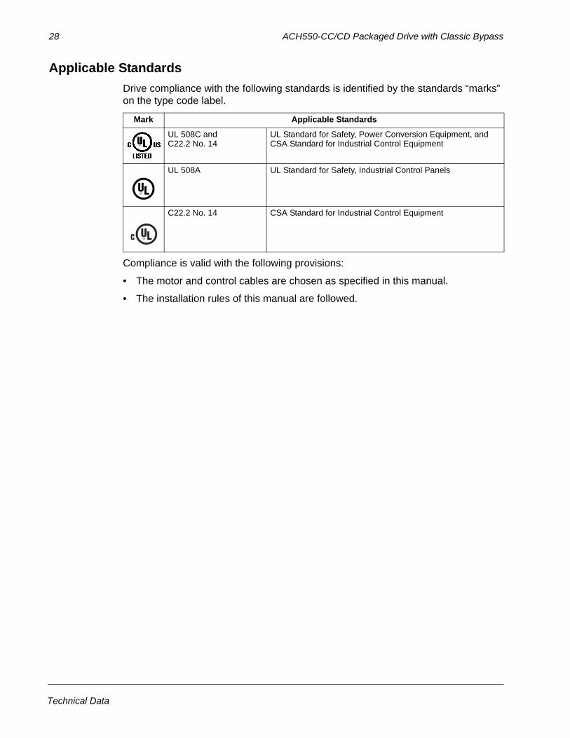
Applicable StandardsDrive compliance with the following standards is identified by the standards “marks” on the type code label.
Compliance is valid with the following provisions:
• The motor and control cables are chosen as specified in this manual.
• The installation rules of this manual are followed.
Mark Applicable Standards
UL 508C and C22.2 No. 14
UL Standard for Safety, Power Conversion Equipment, and CSA Standard for Industrial Control Equipment
UL 508A UL Standard for Safety, Industrial Control Panels
C22.2 No. 14 CSA Standard for Industrial Control Equipment
Technical Data

ACH550-CC/CD Packaged Drive with Classic Bypass 29
Index
Numerics208/230V classic bypass packages. . . . . . . . . . . 23480V classic bypass packages . . . . . . . . . . . . . . 24600V classic bypass packages . . . . . . . . . . . . . . 24
AAnalog input. . . . . . . . . . . . . . . . . . . . . . . . . . . . . 12Auto start contact. . . . . . . . . . . . . . . . . . . . . . . . . 13Automatic start-up warning . . . . . . . . . . . . . . . . . . 1Auto/Man setting, overload relay . . . . . . . . . . . . . 14
BBranch circuit protection . . . . . . . . . . . . . . . . . . . 16Bypass
contactors, description . . . . . . . . . . . . . . . . . 22diagram . . . . . . . . . . . . . . . . . . . . . . . . . . . . . . 6features and functions. . . . . . . . . . . . . . . . . . . 4
CClass setting, overload relay . . . . . . . . . . . . . . . . 14Connection points . . . . . . . . . . . . . . . . . . . . . . . . 12Construction code . . . . . . . . . . . . . . . . . . . . . . . . . 7Contactor bypass, description . . . . . . . . . . . . . . . 22Control wiring. . . . . . . . . . . . . . . . . . . . . . . . . . . . 11Current rating code . . . . . . . . . . . . . . . . . . . . . . . . 7
DDimensional references. . . . . . . . . . . . . . . . . 23–24
208/230V classic bypass packages . . . . . . . 23480V classic bypass packages . . . . . . . . . . . 24600V classic bypass packages . . . . . . . . . . . 24
Dimensions . . . . . . . . . . . . . . . . . . . . . . . . . . . . . 23UL Type (NEMA) 1 R1-R8 frame size. . . . . . 23UL Type (NEMA) 12 R1-R8 frame size. . . . . 23UL Type (NEMA) 3R R1-R6 frame size . . . . 23
Driveidentification . . . . . . . . . . . . . . . . . . . . . . . . . . 7standards, compliance to . . . . . . . . . . . . . . . 28
EEnclosure protection class code . . . . . . . . . . . . . . 7
FFloor mount
installing the line input wiring . . . . . . . . . . . . 10installing the motor wiring . . . . . . . . . . . . . . . 11typical configuration . . . . . . . . . . . . . . . . . . . . 9wiring overview . . . . . . . . . . . . . . . . . . . . . . . . 9
Fuses, drive208 to 240 volt drives . . . . . . . . . . . . . . . . . . 16380 to 480 volt drives . . . . . . . . . . . . . . . . . . 17500-600 volt drives . . . . . . . . . . . . . . . . . . . . 18
GGrounding requirements . . . . . . . . . . . . . . . . . . . . . 8
IInput power
branch circuit protection . . . . . . . . . . . . . . . . . 16fuses. . . . . . . . . . . . . . . . . . . . . . . . . . . . . . . . 16
Installationflow chart . . . . . . . . . . . . . . . . . . . . . . . . . . . . . 6preparation . . . . . . . . . . . . . . . . . . . . . . . . . . . . 7
Installer warning . . . . . . . . . . . . . . . . . . . . . . . . . . . 1
LLine connection warning . . . . . . . . . . . . . . . . . . . . . 1Line reactor . . . . . . . . . . . . . . . . . . . . . . . . . . . . . . 18Location
mounting. . . . . . . . . . . . . . . . . . . . . . . . . . . . . . 8overload relay. . . . . . . . . . . . . . . . . . . . . . . . . 14
MMaintenance schedule . . . . . . . . . . . . . . . . . . . . . 15Manuals for the ACH550 drive . . . . . . . . . . . . . . . . iiMetal conduit runs. . . . . . . . . . . . . . . . . . . . . . . . . . 8Motor. . . . . . . . . . . . . . . . . . . . . . . . . . . . . . . . . . . 14
protection, overload relay . . . . . . . . . . . . . . . . 22wiring . . . . . . . . . . . . . . . . . . . . . . . . . . . . . . . 11
OOverload relay
motor protection . . . . . . . . . . . . . . . . . . . . . . . 22resetting . . . . . . . . . . . . . . . . . . . . . . . . . . . . . 14
PParallel control connections warning . . . . . . . . . . . 1Power connection terminals . . . . . . . . . . . . . . . . . 19Protection
branch circuit . . . . . . . . . . . . . . . . . . . . . . . . . 16motor overload . . . . . . . . . . . . . . . . . . . . . . . . 22
QQualified installer requirement . . . . . . . . . . . . . . . . 1
RRelay
motor overload . . . . . . . . . . . . . . . . . . . . . . . . 14motor running contact output . . . . . . . . . . . . . 13
Requirementsgrounding . . . . . . . . . . . . . . . . . . . . . . . . . . . . . 8input power. . . . . . . . . . . . . . . . . . . . . . . . . . . 16metal conduit runs . . . . . . . . . . . . . . . . . . . . . . 8qualified installer. . . . . . . . . . . . . . . . . . . . . . . . 1wiring . . . . . . . . . . . . . . . . . . . . . . . . . . . . . . . . 8
Index
30 ACH550-CC/CD Packaged Drive with Classic Bypass
SSafety warnings. . . . . . . . . . . . . . . . . . . . . . . . . . . 1Specifications
380 to 480 volt power connection . . . . . . . . . 20500 to 600 volt power connection . . . . . . . . . 21input power connections . . . . . . . . . . . . . . . . 16motor connections . . . . . . . . . . . . . . . . . . . . 22power connection terminals . . . . . . . . . . . . . 19
StandardsC22.2 No. 14. . . . . . . . . . . . . . . . . . . . . . . . . 28UL 508C . . . . . . . . . . . . . . . . . . . . . . . . . . . . 28
TTerminal block 1TB . . . . . . . . . . . . . . . . . . . . . . . 14Terminals, power, wire sizes . . . . . . . . . . . . . . . . 19
UUL Type (NEMA) 1
code . . . . . . . . . . . . . . . . . . . . . . . . . . . . . . . . 7R1-R8 frame size dimensions. . . . . . . . . . . . 23
UL Type (NEMA) 12code . . . . . . . . . . . . . . . . . . . . . . . . . . . . . . . . 7R1-R8 frame size dimensions. . . . . . . . . . . . 23
UL Type (NEMA) 3Rcode . . . . . . . . . . . . . . . . . . . . . . . . . . . . . . . . 7R1-R6 frame size dimensions. . . . . . . . . . . . 23
VVoltage rating code . . . . . . . . . . . . . . . . . . . . . . . . 7
WWall mount
installing the line input wiring . . . . . . . . . . . . 10installing the motor wiring . . . . . . . . . . . . . . . 11typical configuration . . . . . . . . . . . . . . . . . . . . 9wiring overview . . . . . . . . . . . . . . . . . . . . . . . . 9
Warningautomatic start-up . . . . . . . . . . . . . . . . . . . . . . 1line connection . . . . . . . . . . . . . . . . . . . . . . . . 1parallel control connections . . . . . . . . . . . . . . 1qualified installer . . . . . . . . . . . . . . . . . . . . . . . 1
Wiringconduits . . . . . . . . . . . . . . . . . . . . . . . . . . . . 11control . . . . . . . . . . . . . . . . . . . . . . . . . . . . . . 11line input . . . . . . . . . . . . . . . . . . . . . . . . . . . . 10motor. . . . . . . . . . . . . . . . . . . . . . . . . . . . . . . 11practices . . . . . . . . . . . . . . . . . . . . . . . . . . . . 11requirements. . . . . . . . . . . . . . . . . . . . . . . . . . 8shielded cable . . . . . . . . . . . . . . . . . . . . . . . . 11wall and floor mount overviews. . . . . . . . . . . . 9
Index

ACH550-CC/CD Packaged Drive with Classic Bypass 31
Index

ABB Inc. Automation ProductsLow Voltage Drives16250 West Glendale DriveNew Berlin, WI 53151Telephone 262 785-3200Fax 262 780-5135Internet www.abb.us/drives
www.abb-drives.com
AC
H55
0-P
NM
U01
U-E
N R
EV
A3A
UA
0000
0147
57 R
EV
A /
EN
EFF
EC
TIV
E: M
arch
1, 2
007


![BackTrack Hard Drive Installation Hard Drive... · · 2016-07-07BackTrack Hard Drive Installation BackTrack Development Team jabra [at] remote-exploit ... Mount the Devices ...](https://static.fdocuments.us/doc/165x107/5ae57f027f8b9a6d4f8b5d64/backtrack-hard-drive-installation-hard-drive2016-07-07backtrack-hard-drive-installation.jpg)