ACRP Report 45: De/Anti-Icing Optimization Fact Sheets
73
ACRP FACT SHEETS AIRPORT COOPERATIVE RESEARCH PROGRAM Sponsored by the Federal Aviation Administration De/Anti-Icing Optimization
Transcript of ACRP Report 45: De/Anti-Icing Optimization Fact Sheets
ACRPFACT SHEETS
AIRPORTCOOPERATIVE RESEARCH PROGRAM
Sponsored by the Federal Aviation Administration
De/Anti-Icing Optimization
FACT SHEETSDe/Anti-Icing Optimization #42–57; 112
ACRP Report 45Optimizing the Use of Aircraft Deicing and Anti-Icing Fluids
AIRPORT COOPERATIVE RESEARCH PROGRAM 2016 (Revised)
Fact Sheets for De/Anti-IcingOptimization
IntroductionDuring Phase I of ACRP Project 10-01, an extensive review of the literature onground de/anti-icing of aircraft was conducted. This included:
• Specific industry technical reports;
• Manufacturer reports;
• Regulatory, government, and industry reports;
• Guidance materials and standards; and
• Technology patents and procedures.
The review produced a list of 34 potential de/anti-icing optimization technolo-gies and procedures. Many of the potential technologies and procedures weredeemed to possess technical or operational deficiencies, or to not offer an ade-quate environmental or operational enhancement, and were thus eliminated during the review process. The promising technologies and procedures were developed singly or in combination into 16 Fact Sheets that were given genericdescriptive titles to eliminate commercial or competitive issues.
In 2016, as part of the ACRP Project 02-61 research, the 16 Fact Sheets were reviewed to assess if they reflected current technologies and practices in the industry. That review resulted in updates to Fact Sheets 45, 55, and 56, and thecreation of a new Fact Sheet 112.
Documentation of Fact SheetsThis section includes Fact Sheets for the following 17 de/anti-icing fluid opti-mization technologies and procedures:
Fact Sheet 42: Physical Removal
Fact Sheet 43: Deicing-Only Fluid Buffer Reduction
Fact Sheet 44: First-Step Deicing Fluid Buffer Reduction
Fact Sheet 45: Blending to Temperature
Fact Sheet 46: Proactive Anti-Icing
Fact Sheet 47: Forced Air/Hybrid Deicing
Fact Sheet 48: Holdover Time Determination System
iii
Fact Sheet 49: Point Detection Sensors to Indicate Fluid Condition andContamination on Aircraft Surfaces
Fact Sheet 50: Remote Ice Detection Sensors to Scan Aircraft CriticalSurfaces Before Departure Runway
Fact Sheet 51: Spot Deicing for Frost Removal
Fact Sheet 52: Tempered Steam Technology
Fact sheet 53: Threshold Deicing
Fact Sheet 54: Use of SAE Fluid Dilutions (Type I, II, III, IV)
Fact Sheet 55: Type III Fluids
Fact Sheet 56: Infrared Deicing Technology
Fact Sheet 57: Enhanced Weather Forecasting
Fact Sheet 112: Low Flow Nozzles
The Fact Sheets follow a format similar to that used in ACRP Project 02-02,“Managing Runoff from Aircraft and Airfield Deicing and Anti-IcingOperations,” and presented in ACRP Report 14: Deicing Planning Guidelinesand Practices for Stormwater Management Systems. This formatting enabledthese Fact Sheets to be included within the overall compendium of ACRP FactSheets for optimizing the use of de/anti-icing fluids.
Each Fact Sheet includes (1) a description of the technology or procedure, (2) implementation considerations, and (3) cost information. The information included in each of the three sections is described below.
1) The Description section includes:
• Purpose;
• Technology; and
• Documented performance.
2) The Implementation Considerations section includes:
• Applicability assessment;
• Regulatory considerations;
• Planning and design considerations;
• Integration with other Fact Sheets; and
• Operation and maintenance considerations.
3) The Costs section includes cost information that in some cases is separatedinto:
• Capital costs; and
• Operation and maintenance costs.
iv FACT SHEETS FOR DE/ANTI-ICING OPTIMIZATION
FACT SHEET 42
Physical Removal
1. DescriptionPurposeThis Fact Sheet provides the opportunity to reduce the volume of conventionalaircraft deicing equipment used in wintertime operations by physically(mechanically) removing snow or ice from aircraft. This is in lieu of using,and/or reducing the amount of deicing fluids needed. Manual methods of snowremoval are useful in certain circumstances and can be used as long as safety isnot compromised.
Physical removal techniques are the responsibility of the aircraft operator or itscontracted service provider.
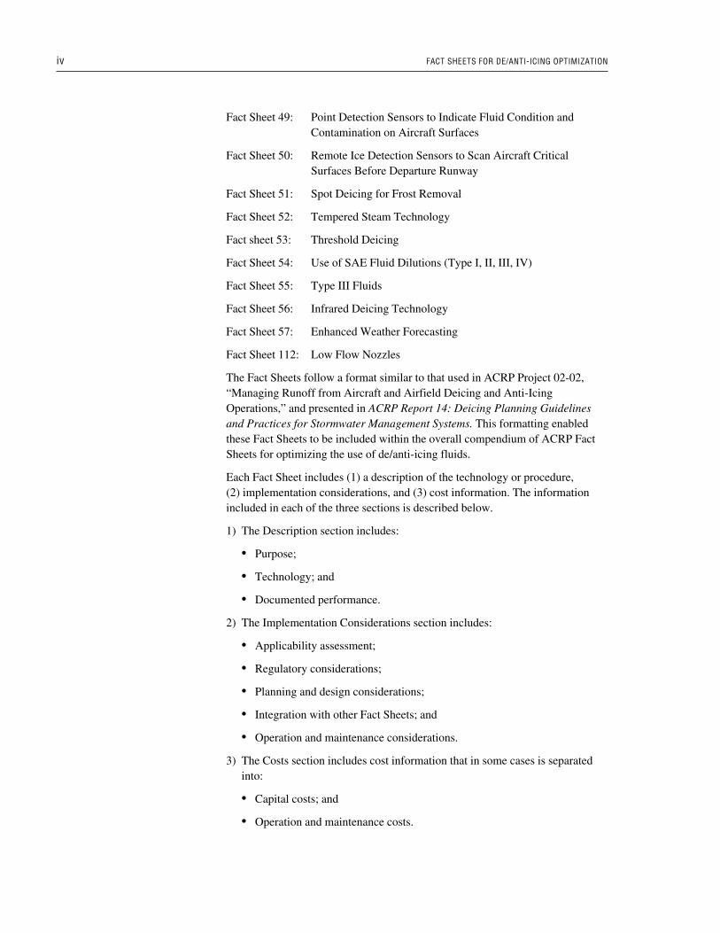
TechnologyPhysical removal of snow or ice involves manual labor and brooms, ropes, and/orbrushes to remove accumulated snow from an aircraft. Hot-air-blast deicing sys-tems may also be used. This requires that care be taken to avoid damage to theaircraft during the process of physically removing snow and ice.
Typically, after snow or ice has been physically removed, a deicing or anti-icingfluid will need to be applied to an aircraft to completely remove any remainingfrozen contamination. The application of this fluid will also provide adequateholdover time prior to takeoff.
A Transport Canada (TC) Publication, “Guidelines for Aircraft Ground Deicing”(TP 14052), provides an excellent description of the safe use of brooms, ropes,and scrapers. It also discusses the use of portable forced-air heaters in theremoval of frost. TP 14052 can be found on the following website:(http://www.tc.gc.ca/CivilAviation/publications/TP14052).
In addition to the devices described in TP 14052, some operators have employedportable leaf-blowers to remove dry contamination. This approach is particularlyapplicable and useful in the condition of cold dry snow that is not adhered to theaircraft surface. Fluid deicing can potentially be avoided entirely by blowingaway the dry snow. The blown air must be cold to avoid melting of the snowonto the wing, with subsequent refreezing.
Brooms are very useful in cleaning windows and other sensitive areas. They canbe used on radomes, static ports, pitot tubes, and other sensitive instrumentswhere the application of hot liquid is best avoided or prohibited.
There is a separate set of technologies that serve to physically remove frozenprecipitation during flight. “Boot” deicing systems are often used on smaller propeller aircraft. This technology employs an inflatable pneumatic or hydraulic
ACRP Report 45 April 20111
Some of the more common typesof physical contaminationremoval include:
• Brooms;• Brushes;• Ropes; and• Scrapers.
Deicing employs an inflatable bootinstalled on the leading edge of awing to dislodge hardened ice.
boot, installed on the leading edge of aircraft wings, to crack and dislodge icefrom the aircraft. Other mechanical means that have been evaluated on an exper-imental basis include electrical resistive heating on small aircraft (heating matsapplied to the surface of the aircraft). These technologies have no impact on theuse of deicing fluids.
Documented PerformanceThe performance of physical removal techniques is very site-specific, dependingon factors such as the type of precipitation and the aircraft fleet mix.
There is a lack of documented performance of this practice. Anecdotal reportsindicate that manual approaches to removing contamination are effective inparticular circumstances. One such circumstance is the pre-deicing removal oflarge amounts of snow during early morning hours and removing small accu-mulations of dry cold non-adhered snow. This eliminates the need for fluiddeicing.
2. Implementation ConsiderationsApplicability AssessmentPhysical removal is most successful with loose precipitation (e.g., dry powderysnow) and smaller aircraft with horizontal surfaces that can easily be accessed by ramp personnel. Larger aircraft, those with high wings, present access andsafety issues that make physical removal impractical or unsafe. Protruding sen-sors or antennae on the surface of an aircraft may also make physically removingcontamination impractical.
Items that should be evaluated prior to considering physical removal techniquesinclude the size and configuration of the aircraft, the timeliness required prior todepartures, traffic volumes, availability of suitable personnel, and the frequencyof dry powdery snow.
Physical removal is more likely to be applicable at general aviation airports dueto the smaller size of the aircraft involved. Aircraft operators may consider thisprocess in conjunction with anti-icing protection to reduce the use of aircraft-deicing fluid.
Personnel performing mechanical deicing require training to ensure that theyuse proper equipment and methods to maintain safety and not damage the aircraft.
Regulatory ConsiderationsThe primary regulatory consideration for the implementation of the physical/mechanical removal techniques is incorporation into the aircraft operator’sapproved snow and ice control plans. Safety guidelines related to labor (i.e.,exposure to the elements, working under slippery conditions, etc.) should also beconsidered.
2 FACT SHEET 42
April 2011 ACRP Report 45
Physical removal should carefullyconsider that safety is maintainedand the technique used will notdamage the aircraft in any way.
Planning and Design ConsiderationsThe following factors should be considered in planning for physical removal:
• Frequency of snowfall that is subject to efficient physical removal;
• Size and configuration of aircraft;
• Staffing and labor requirements;
• Time requirements associated with physically removing snow or ice;
• Number of aircraft requiring the service at peak departure times;
• Equipment to provide personnel with safe access to aircraft surfaces is essen-tial. This may take the form of the open bucket of a deicer or other high-liftvehicle, or a wing inspection ladder; and
• Personnel must be properly trained and should be provided with suitableequipment to avoid damage to highly sensitive and often fragile sensors andnavigation antennae. Other such instruments vulnerable to damage are: pitottubes, static ports, angle of attack sensors, and vortex generators.
Integration with Other Fact SheetsPhysical removal techniques may be employed prior to the application of aircraftde/anti-icing fluids in order to reduce the total amount of fluid required. In thesecases, applicable practices (containment/collection, conveyance/storage, andtreatment/disposal practices) can be implemented to further reduce the dischargeof deicing agents into the stormwater system.
Operation and Maintenance ConsiderationsThe primary operational considerations are worker safety and ensuring that nodamage is incurred to the aircraft during the physical removal process.
Because manual methods of snow removal may be very time consuming, theirapplication must be compatible with flight departure schedules.
3. CostsEquipment costs for manually removing snow from aircraft are relatively smalland generally would be covered under operating costs. Equipment acquisitiongenerally would be limited to brooms, ropes, brushes, and access ladders.
Labor costs are the primary component of operation and maintenance costs.Personnel must be provided with suitable equipment for safe access to aircraftsurfaces and be properly trained to avoid damage to aircraft components.
The equipment used is generally not sophisticated and does not introduce new orotherwise significant equipment maintenance requirements.
FACT SHEET 42 3
ACRP Report 45 April 2011
FACT SHEET 43
Deicing-Only Fluid Buffer Reduction
1. DescriptionPurposeThis Fact Sheet involves the procedure of using a reduced fluid freeze point(FFP) buffer in deicing-only conditions. The procedure is not currently approvedby regulatory authorities at this time.
This procedure involves using a deicing fluid with a lower concentration of gly-col for cleaning contamination from aircraft surfaces. It addresses the deicingcondition when the only requirement is to clean contamination from the aircraftwithout the need for anti-icing protection. A typical example would be morningstart-up following an overnight snowfall. A heated SAE Type I deicing fluidwould typically be used for this cleaning operation.
Because this condition is not specifically addressed in SAE AerospaceRecommendation Practice (ARP) 4737, field operators currently follow theguidelines that provide protection against ongoing precipitation. These guide-lines require a one-step Type I deicing fluid to have a freeze point of not lessthan 10°C below ambient temperature. As a result, a higher-than-necessary concentration of glycol is employed in deicing-only conditions.
Application of a reduced fluid buffer for deicing-only conditions (i.e., no needfor anti-icing protection) would provide cost savings and reduce environmentalimpact.
TechnologySome field operators are changing to deicing equipment with on-board fluid con-centration blending systems. These deicers provide the best means of applyingthis procedure.
Alternatively, for deicers not equipped with fluid mixers, the deicing fluid wouldneed to be pre-mixed to the required concentration. Guidelines for mixing fluidsto specific freeze points are provided by fluid manufacturers.
Documented PerformanceResearch conducted to examine the results of applying fluid mixes having freezepoints above outside air temperature (OAT) was reported in a TC publicationentitled “Aircraft Deicing Fluid Freeze Point Buffer Requirements: DeicingOnly and First Step of Two-Step Deicing” (TP 13315). Tests were conducted atvarious ambient temperatures and wind speeds. The research established experi-mental data to support development of a deicing-only table to serve as an indus-try guideline.
ACRP Report 45 April 20111
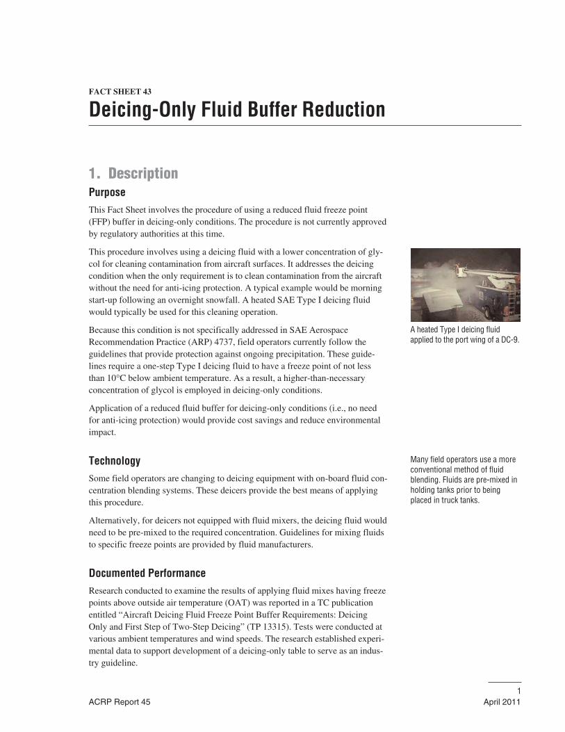
A heated Type I deicing fluidapplied to the port wing of a DC-9.
Many field operators use a moreconventional method of fluidblending. Fluids are pre-mixed inholding tanks prior to beingplaced in truck tanks.
Initial test data indicated that for diluted Type I fluids (both ethylene and propy-lene glycol-based), fluid strength increased because of water evaporation follow-ing application of the heated fluid. As well, the test surfaces did not experiencefreezing when the applied fluid was mixed to a freeze point equal to the outsideair temperature, regardless of wind speed.
A further detailed examination was reported in another TC publication, “AircraftDeicing Fluid Freeze Point Buffer Requirements for Deicing-Only Condition” (TP13478). This research examined how other variables affected fluid enrichment.
Specific recommendations were:
• The deicing-only concept should not be applied during active frost conditions;
• The deicing-only concept should not be applied for cold-soaked wing condi-tions in conjunction with a level of humidity that could cause active frost deposition on the cold surface;
• Type II propylene glycol-based fluids are unsuitable for the deicing-only procedure; and
• Procedures for the deicing-only concept should encourage the use of gener-ous quantities of fluid, and the protection of heated fluid temperatures bylocating the spray nozzle as near as possible to the wing surface.
2. Implementation ConsiderationsApplicability AssessmentSome larger operators are moving to deicing vehicles equipped with fluidstrength blending systems. Such equipment provides the most satisfactory means of taking advantage of the potential of this procedure.
Operational concerns relate mainly to the spray equipment commonly in use,which are not equipped with on-board fluid blenders. To satisfy this procedure,fluid for these deicers would have to be pre-mixed to a specific concentrationbased on temperatures expected to occur during the operation. When a more dilutefluid is boarded in the truck tanks, there is a greater danger that falling tempera-tures could lead to freezing in the truck fluid system. Closer attention to forecastconditions is needed to prevent this. In the same vein, protection of fluid systemswhen the truck is taken out of use following the operation must be managed.
Many operators currently employ Type I fluid only at its delivered strength(50/50). Although current guidelines allow application of this fluid at lower con-centrations both for deicing and anti-icing, these operators have yet to developthe local expertise needed to manage fluid mixes with fluid freeze points closerto ambient temperature.
Regulatory ConsiderationsThis procedure does not have regulatory approval. Guidelines for its use havenot been developed or published.
2 FACT SHEET 43
April 2011 ACRP Report 45
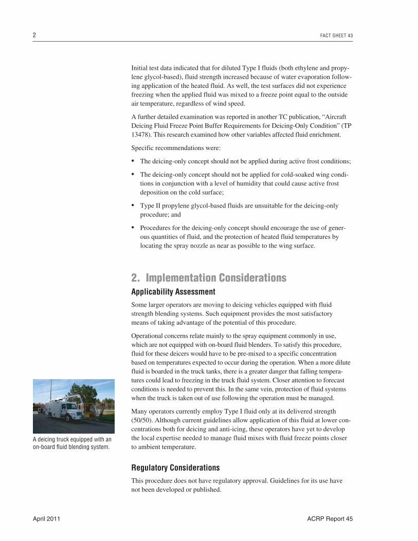
A deicing truck equipped with anon-board fluid blending system.
Guidelines for this procedure would need to be developed and must be approvedprior to application in the field.
Planning and Design ConsiderationsFor locations equipped with deicers having on-board fluid blending systems, thenecessary fluid management systems and expertise would already be in place.
At other locations, local procedures, training, and fluid management controlswould need to be developed.
Integration with Other Fact SheetsThis procedure integrates well with the Fact Sheet entitled Blending toTemperature. Three different Type I buffers can be considered:
1. First-step deicing fluid buffer of 3°C above ambient temperature (approved in current guidelines);
2. Anti-icing fluid buffer of 10°C below ambient temperature (approved in current guidelines); and
3. Deicing-only fluid buffer (no current guidelines and not approved).
Operation and Maintenance ConsiderationsExtra care must be taken to prevent freezing of the weaker fluid in truck plumb-ing systems.
3. CostsCapital CostsIt is not expected that operators would modify their deicer fleet to on-board fluidblending solely to take advantage of this concept. Thus, additional capital costsare not expected. However, if this procedure was to be approved, it would assistin justifying the capital costs of moving to on-board fluid blending.
Operation and Maintenance CostsThis procedure provides the potential for lower deicing fluid costs as a result oflower concentrations of glycol.
FACT SHEET 43 3
ACRP Report 45 April 2011
FACT SHEET 44
First-Step Deicing Fluid Buffer Reduction
1. DescriptionPurposeIn a two-step deicing operation, a first-step heated deicing fluid is applied toclean the surface, and a second-step anti-icing fluid is over-sprayed to provideongoing protection (holdover time).
This Fact Sheet relates to the limit on freeze point temperature for the first-stepfluids. Current SAE ARP 4737 guidelines require that the second-step anti-icingfluid be applied before the first-step fluid freezes, typically within three minutes,and that the freeze point of the first-step deicing fluid be not more than 3°Cabove outside air temperature. This freeze point constraint may be more severethan necessary. It is possible that a different limit based on scientific researchcould provide the same levels of safety, while reducing the environmentalimpact and lowering the cost of the applied fluid.
In the past, some operators had deiced successfully using heated water at ambi-ent temperatures as low as −7°C, applying a first-step fluid having a freeze pointtemperature 7°C above outside air temperature. At that time, the second-stepfluid consisted of a heated application of Type I fluid. The heat from the second-step fluid may have corrected any early freezing. Currently, the second-step fluidis frequently a cold Type II or IV fluid, which would not offer the same inherentearly-freezing correction. This past practice ended by industry adoption of SAEARP 4737 in 1992, which introduced the 3°C limit. The value of the 3°C limitwas obtained by consensus and was not based on scientific data.
A procedure using a first-step deicing fluid with a freeze point more than 3°C aboveoutside air temperature would provide a potential means of lowering glycol usage.
Regulatory authorities do not approve such a procedure at this time.
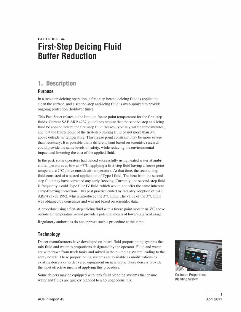
TechnologyDeicer manufacturers have developed on-board fluid proportioning systems thatmix fluid and water to proportions designated by the operator. Fluid and waterare withdrawn from truck tanks and mixed in the plumbing system leading to thespray nozzle. These proportioning systems are available as modifications toexisting deicers or as delivered equipment on new units. These deicers providethe most effective means of applying this procedure.
Some deicers may be equipped with tank fluid blending systems that ensurewater and fluids are quickly blended to a homogeneous mix.
ACRP Report 45 April 20111
On-board Proportional Blending System
Alternatively, for deicers not equipped with fluid proportioning systems or in-tank mixers, the deicing fluid may be pre-mixed to the required concentration,either in storage tanks or in the deicer tanks. Care must be taken, especially whenmixing in the deicer tanks, to ensure that the fluid and water proportions arecompletely blended. Guidelines for mixing fluid and water to specific freezepoints are provided by fluid manufacturers.
Documented PerformanceResearch on this subject was reported in the TC Publication entitled “AircraftDeicing Fluid Freeze Point Buffer Requirements: Deicing only and First Step ofTwo-Step Deicing” (TP 13315E). This research examined freeze point tempera-ture limits (buffers) for fluids used as the first-step of a two-step deicing opera-tion. Various fluid strengths were tested in different precipitation and windconditions.
Conclusions drawn from the research were:
• In calm wind conditions, all fluids tested delivered an interval of at leastthree minutes prior to initiation of freezing, at the lowest test temperatureof −14°C;
• Wind exerts a major influence on the time interval available prior to freezingby causing more rapid cooling of the protected surface;
• Dilution of applied fluids occurs very rapidly. At the upper range of lightfreezing rain (25 g/dm2/h), the applied fluid film is quickly replaced by rainwater:
– Type I ethylene-based fluid mixed to −7°C freeze point: 4 to 5 minutes;and
– Type I ethylene-based fluid at delivered strength (−43°C freeze point): 7 to 8 minutes.
• At the lower precipitation rate of 13 g/dm2/h, (the boundary demarcatingfreezing drizzle from light freezing rain), Type I ethylene-based fluid dilutesfrom a −43°C freeze point to a −10°C freeze point in about 3 minutes; and
• In precipitation conditions, the major contributor to the period of protectionfrom the first-step fluid is the temperature of the aircraft surface, which hasbeen heated above ambient by the applied heated fluid.
Several years ago, a European airline reported an incident where ice was foundon a wing following takeoff. The aircraft had been deiced and anti-iced usingthis procedure, which led the operator to question the 3 minute assumption andthe adequacy of the fluid freeze point buffer.
In response to the reported incident, APS reviewed data it had previously col-lected and undertook a research project in the winter of 2005–06 to determinethe effect the FFP buffer of first-step deicing fluids has on protection time. Thisis reported in the TC draft report TP 14714E, “Evaluation of Fluid Freeze Pointsin First-Step Application of Deicing Fluids.”
2 FACT SHEET 44
April 2011 ACRP Report 45
The status quo −3°C FFP buffer fluid generally provided protection for at leastthree minutes, but showed weakness in cold temperatures and under high precip-itation rates. In conditions where it provided less than three minutes protectiontime, fluids with higher FFP buffers provided only minimal improvements. Thissupported the premise that an increased FFP buffer gives longer protection in con-ditions when it is not needed, but little increase in protection when it is needed.
It was recommended that the current application procedure (−3°C FFP bufferfluid) remain in place and that operators wishing to follow a more conservativeapproach may choose to increase the FFP buffer of first-step fluids.
2. Implementation ConsiderationsApplicability AssessmentSome larger operators are moving to deicing vehicles equipped with fluidstrength blending systems. Such equipment provide the most satisfactory meansof taking advantage of the potential of this procedure.
Operational concerns are mainly related to much of the spray equipment com-monly in use, which are not equipped with on-board fluid blenders. To satisfythis procedure, fluid for these deicers would have to be pre-mixed to a specificconcentration based on temperatures expected to occur during the operation.
When a more dilute fluid is boarded in the truck tanks, there is a greater dangerthat falling temperatures could lead to freezing in the truck fluid system. Closerattention to forecast conditions is needed to prevent this. In the same vein, protection of fluid systems when the truck is taken out of use following the operation must be managed.
Many operators currently employ Type I fluid only at its delivered strength(50/50). Although current guidelines allow application of this fluid at lower con-centrations both for deicing and anti-icing, these operators have not developedthe local expertise needed to manage fluid mixes with fluid freeze points closerto ambient temperature.
Regulatory ConsiderationsThis procedure does not have regulatory approval, and guidelines for its use havenot been developed or published.
Guidelines for this procedure would need to be developed and approved prior toapplication in the field.
Planning and Design ConsiderationsFor locations equipped with deicers having on-board fluid blending systems, thenecessary fluid management systems and expertise would already be in place.
At other locations, local procedures, training, and fluid management controlswould need to be developed.
FACT SHEET 44 3
ACRP Report 45 April 2011
Integration with Other Fact SheetsThis procedure integrates well with the Fact Sheet entitled Blending toTemperature. Three different Type I buffers could be considered:
1. First-step deicing fluid buffer of 3°C above ambient temperature (approved in current guidelines);
2. Anti-icing fluid buffer of 10°C below ambient temperature (approved in current guidelines); and
3. Deicing-only fluid buffer (no current guidelines and not approved).
Operation and Maintenance ConsiderationsExtra care must be taken to prevent freezing of the weaker fluid in truck plumbing systems.
3. CostsCapital CostsIt is not expected that operators would modify their deicer fleet to on-board fluidblending solely to take advantage of this concept. Thus, additional capital costsare not expected. However, if this procedure were to be approved, it would assistin justifying the capital costs of moving to on-board fluid blending.
Operation and Maintenance CostsThis procedure provides the potential for lower fluid costs with the use of lowerconcentrations of glycol.
4 FACT SHEET 44
April 2011 ACRP Report 45
FACT SHEET 45
Blending to Temperature
1. DescriptionPurposeBlending to temperature is a source reduction practice that reduces the volume ofconcentrated (or neat) Type I Aircraft Deicing Fluid (ADF) needed for deicing byoptimizing the deicer concentration relative to the outside air temperature (OAT).As the OAT rises, a more diluted ADF may be applied without affecting aircraftoperations safety. The result is a reduction in glycol use and potential discharge tothe environment. This Fact Sheet is not directly applicable to Type II or Type IVaircraft anti-icing fluids because they are not typically diluted prior to use.
Aircraft operators or contracted service providers are normally responsible forthe implementation of blending to temperature. Implementation of this practicethroughout a facility can be facilitated through airport involvement and coordi-nation of efforts.
ACRP Report 45 September 20161
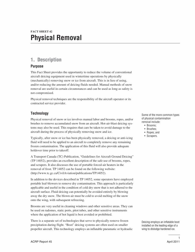
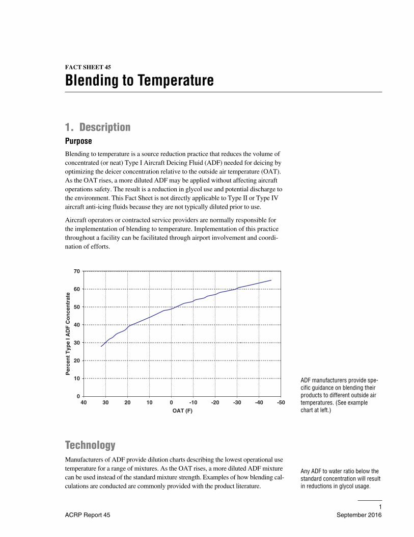
ADF manufacturers provide spe-cific guidance on blending theirproducts to different outside airtemperatures. (See example chart at left.)
0
10
20
30
40
50
60
70
-50-40-30-20-10010203040
OAT (F)
Per
cen
t T
ype
I AD
F C
on
cen
trat
e
Any ADF to water ratio below thestandard concentration will resultin reductions in glycol usage.
TechnologyManufacturers of ADF provide dilution charts describing the lowest operational usetemperature for a range of mixtures. As the OAT rises, a more diluted ADF mixturecan be used instead of the standard mixture strength. Examples of how blending cal-culations are conducted are commonly provided with the product literature.
Many aircraft operators adopt a standard ADF-water mixture, typically between45/55 and 60/40, to ensure consistent compliance with regulatory criteria andprescribed safety factors under the full range of anticipated OATs. Any use ofmixtures that can be accomplished below the standard concentration will resultin reduced glycol use.
Blending can be accomplished in a variety of ways. The simplest involves manualmixing of ADF and water in a deicing truck’s tank to the desired concentration.
Blending stations automate the mixing process at a central location and trucksare filled with a mixture strength that is determined to be appropriate for the current and anticipated OAT. The most advanced blending station technologyenables deicing trucks to return unused blended deicing fluid to a mixing station.There, additional ADF or water can be added to adjust the ADF concentration asthe temperature changes. “Blending on the fly” technology provides the abilityto vary the mixture of concentrated ADF and water fed to the deicing applicationnozzle depending on OAT. These recent developments in equipment technologyhave made blending to temperature more practicable and reliable.
Documented PerformanceThe success of this practice varies widely depending on climate and temperaturevariations. The greatest potential for benefits exists at airports where deicing isconducted mostly at higher OATs.
Because blending to temperature is typically combined with other practices,specific documented performance data is not available. Various individual air-port studies, as well as manufacturers’ literature estimate reductions in ADFconcentrate (and therefore glycol) usage of between 29 and 50% per season.The potential reduction is greatly influenced by facility specific factors, suchas typical winter weather, aircraft mix, time of day, and when aircraft deicingis conducted.
2. Implementation ConsiderationsApplicability AssessmentThis is an aircraft operator Fact Sheet, so the first consideration will be the feasi-bility and acceptability of blending to temperature by the aircraft operators, orcontracted service provider, at the airport. The availability of blending technol-ogy greatly improves the feasibility of blending to temperature.
Airports may encourage this practice through environmental awareness programsand may go as far as providing central ADF storage and dispensing stations withautomated blending equipment. Blending may be implemented in conjunctionwith centralized deicing systems; however, consideration must be made forinfrastructure, such as a water supply, to support blending mixtures at the deicing facility.
2 FACT SHEET 45
September 2016 ACRP Report 45
Implementation may be constrained by the requirements of various air carriers.For example, fixed base operators (FBOs) or contracted service providers mayelect to use a standard conservative blend on all aircraft because individual contracts with different carriers specify unique ADF blends.
Regulatory ConsiderationsThere are no specific environmental regulations that apply to this practice,although reduction of deicing agents in stormwater will generally be viewedfavorably by environmental regulatory agencies.
The use of blending to temperature requires adherence to the SAE ARP 4737specification that residual Type I ADF on aircraft surfaces following deicingmust have a freezing point at least 10ºC (18ºF) below the OAT or aircraft skintemperature, whichever is lower. This is commonly referred to as the freezingpoint buffer. In addition, the practice must be adequately described in an aircraftoperator’s approved snow and ice control plan.
Planning and Design ConsiderationsThe following factors should be considered in planning implementation ofblending to temperature:
• Standard mixtures currently being used by aircraft operators;
• Coordination with airlines and or contracted service provider to defineacceptable practices moving forward;
• Distribution of air temperatures during periods of aircraft deicing;
• Suitability to aircraft fleet mix and operations;
• Availability of specialized blending equipment and land/space requirements,if any;
• Availability of water for blending accessible on site;
• Plans for glycol recycling, consideration should be given to efficiency, as itmay be affected by the lower glycol concentration; and
• Effective training and quality assurance program.
Integration with Other Fact SheetsBlending to temperature may be used in conjunction with most other Fact Sheetsin the source reduction, containment/collection, conveyance/storage, and treat-ment disposal categories.
This BMP will reduce the concentrations of ADF in deicing stormwater, withreductions being proportional to the relative amount of aircraft deicing activityconducted at warmer temperatures and the level of implementation at an airport.Glycol recovery operations may be negatively impacted if the volumes of high-concentration runoff are reduced below the level that is critical to the economicviability of recycling.
FACT SHEET 45 3
ACRP Report 45 September 2016
Operation and Maintenance ConsiderationsThe most significant operational consideration is efficient implementation with-out affecting aircraft safety. For example, it is important to manage trucks withvarious concentrations to ensure that the proper concentration is applied to theaircraft. Each facility and situation will present a unique set of opportunities andconstraints in this regard.
Where blending is incorporated into a hydrant ADF delivery system, the opera-tion and maintenance of separate service lines for the deicing fluids and watermust be considered, along with other equipment and facilities that may berequired.
When blending is done at a central station, the rate at which outside temperaturechanges will be an important consideration. Blending at a station inherentlyintroduces a delay between when the fluid is mixed and when it is applied. Thisdelay can make adjusting the mixture to rapidly changing weather conditionschallenging. However, this can largely be avoided by using a larger temperaturebuffer than the regulatory freezing point buffer of at least 10ºC (18ºF) below theOAT or aircraft skin temperature.
The added complexity involved in blending stations and blend-on-the-fly truck-mounted equipment will increase maintenance requirements.
3. CostsCapital CostsIt is difficult to assess the capital costs of blending-to-temperature practicesbecause most industry information contains total system or facility wide costsrather than those of individual components of the system. The cost of a singlefixed blending station can vary but has been reported by users at $300,000 forthe entire unit including the glycol measuring equipment, pumps, etc. In thisexample the entire system including the concrete pad and electrical utilities costapproximately $480,000.
Operation and Maintenance CostsSupporting evidence of substantial operations and maintenance savings doesexist. The primary savings is through the reduction of glycol use. For example, anairline-sponsored study at a large hub airport concluded that savings of up to $2.5 million per year could be realized if blending-to-temperature mixtures wereused. Other studies have suggested potential reductions of up to 30% in ADF use,under relatively optimal climatological conditions (deicing conducted primarily attemperatures above −2ºC). Finally, although it may be difficult to quantify, thereis the potential for environmental improvements associated with lower levels ofglycol use that may bring cost savings.
4 FACT SHEET 45
September 2016 ACRP Report 45
FACT SHEET 46
Proactive Anti-Icing
1. DescriptionPurposeThis Fact Sheet involves the application of aircraft anti-icing agents as a preven-tative measure, potentially resulting in a reduction in the volume of deicingagents required to ensure that aircraft are free of snow and ice contaminationprior to takeoff.
Implementation of this practice would be the responsibility of aircraft operators.
TechnologyProactive anti-icing involves the application of anti-icing agents in advance of an anticipated frozen-precipitation event, therefore reducing the adherence offrozen precipitation on the aircraft and facilitating its removal. Aircraft anti-icingfluids (AAFs) are applied in significantly smaller volumes than deicing fluids,potentially resulting in cost savings to the aircraft operators, as well as reducedenvironmental impact due to glycol runoff.
Documented PerformanceAccording to testing performed by the U.S. Air Force, proactive anti-icing canreduce the overall volume of glycol-based deicing fluid applied to an aircraftwhen properly performed prior to the advent of icing conditions. Proactive anti-icing has been found to be most effective under freezing precipitation; it is lesseffective for heavy snow.
Several aircraft operators have experimented with the preventative application ofanti-icing agents to aircraft immediately after their landing. The purpose of thispractice is to prevent the buildup of frozen precipitation while aircraft are at thegate and to reduce the deicing effort needed prior to their departure. Aircraft withshort turnaround times generally require less deicing fluid application prior todeparture, depending on weather conditions.
The key to proper implementation of this practice is access to accurate weatherforecasts. When used with inaccurate weather forecasts, this practice can resultin the application of otherwise unnecessary and excessive amounts of anti-icingfluid and deicing fluids needed to remove the AAF.
A drawback of preventative anti-icing is that the application of AAF alone hasbeen found to pose a safety risk to aircraft under certain conditions. If a dryperiod occurs in place of a predicted frozen-precipitation event, the AAF maydry into a residue, only to be rehydrated and refrozen during subsequent stormevents. Several aircraft operators have expressed concerns that this refrozen
ACRP Report 45 April 20111
Many airlines have experimentedwith post-landing application ofanti-icing fluid.
Proactive deicing requires anaccurate assessment of weatherforecasts.
residue can degrade aircraft parts and limit flight controls. Out of concern for air-craft safety, aircraft that have been anti-iced are often deiced with Type I prior to takeoff in an effort to remove the Type IV residue, even in situations wheredeicing may not have been otherwise required.
2. Implementation ConsiderationsApplicability AssessmentThis Fact Sheet would be most applicable for aircraft operators or fixed-baseoperations (FBOs) at airports that typically experience weather conditions duringwhich proactive anti-icing would be an effective alternative or supplement todeicing (freezing rain, for example). Airports that frequently experience heavysnow conditions during the deicing season may not benefit as much from aproactive anti-icing program owing to the reduced effectiveness of anti-icingagents in those weather conditions. Deicing personnel should also considerwhether the coordination of proactive anti-icing and deicing activities for arriving and departing flights would cause significant interference with airportoperations and/or flight delays.
Regulatory ConsiderationsThe FAA requires that an aircraft be clean prior to take-off in order to meet air-craft safety requirements. If proactive anti-icing is implemented, it must be per-formed with considerations for aircraft safety and regulations. In many cases, anaircraft will be deiced again prior to takeoff to ensure that all frozen precipitationhas been removed and to prevent any buildup of anti-icer residue on the surfaceof the aircraft. Conservative deicing procedures required to ensure safety havethe potential to reduce the documented performance levels of this practice.
Planning and Design ConsiderationsAircraft operators and FBOs that are interested in proactive anti-icing shouldconsider the following in their planning and implementation:
• Identify services or equipment for improving weather-forecasting abilitiesand thereby the accuracy of proactive anti-icing;
• Develop protocols for identifying conditions that are appropriate for proactive anti-icing;
• Develop standard operating procedures for proactive anti-icing, includingweather forecasting, anti-icing equipment coordination, anti-icing agentapplication, and scheduling; and
• Integration with other practices.
The success of proactive anti-icing activities can be increased by using special-ized weather-forecasting systems and procedures to identify opportunities forproactive anti-icing. Accurate weather forecasts can help aircraft operators and
2 FACT SHEET 46
April 2011 ACRP Report 45
Application of Type IV anti-icermay result in the formation of aresidue that poses a potential air-craft safety risk. The applicationof hot water or heated Type I fluidin the first step of a two-stepprocess for subsequent deicingoperations will minimize the formation of residues.
FBOs identify weather conditions during which proactive anti-icing is expectedto be more efficient than deicing alone and conditions that will not result in theformation of a harmful residue.
Integration with Other Fact SheetsProactive anti-icing has the potential to be integrated with most practices. Thecombination of proactive anti-icing and enhanced weather forecasting tools maybe extremely useful to airports and aircraft operators.
Operation and Maintenance ConsiderationsOperational requirements associated with this practice include the regular monitoring of weather forecasts to identify weather conditions that would beappropriate for proactive anti-icing.
Maintenance requirements for this BMP may include removing residue thatcould form on aircraft from dried anti-icing materials.
3. CostsOverall costs include the costs for anti-icing materials and equipment, as well asweather-forecasting or monitoring systems to accurately identify conditions thatare beneficial for proactive anti-icing. Potential savings may be achieved wherethe net cost of all deicers and anti-icers used is reduced.
Capital CostsThe primary capital cost would be for the installation of a specialized weatherforecasting system, if applicable. In some instances, additional deicing equipmentmay be required to meet air traffic demands.
Operation and Maintenance CostsOperational costs may include additional aircraft anti-icing fluids used; costsassociated with subscribing to a specialized weather-forecasting service, andspecialized training. Other costs may include the labor and material costs toremove anti-icing material residue from aircraft. Potential cost savings may be achieved through any reduced use of aircraft deicing fluids.
FACT SHEET 46 3
ACRP Report 45 April 2011
FACT SHEET 47
Forced Air/Hybrid Deicing
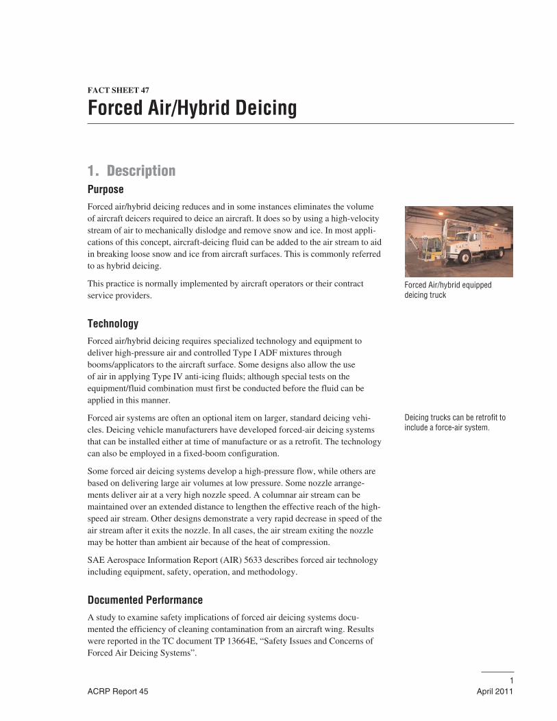
1. DescriptionPurposeForced air/hybrid deicing reduces and in some instances eliminates the volumeof aircraft deicers required to deice an aircraft. It does so by using a high-velocitystream of air to mechanically dislodge and remove snow and ice. In most appli-cations of this concept, aircraft-deicing fluid can be added to the air stream to aidin breaking loose snow and ice from aircraft surfaces. This is commonly referredto as hybrid deicing.
This practice is normally implemented by aircraft operators or their contractservice providers.
TechnologyForced air/hybrid deicing requires specialized technology and equipment todeliver high-pressure air and controlled Type I ADF mixtures throughbooms/applicators to the aircraft surface. Some designs also allow the use of air in applying Type IV anti-icing fluids; although special tests on the equipment/fluid combination must first be conducted before the fluid can beapplied in this manner.
Forced air systems are often an optional item on larger, standard deicing vehi-cles. Deicing vehicle manufacturers have developed forced-air deicing systemsthat can be installed either at time of manufacture or as a retrofit. The technologycan also be employed in a fixed-boom configuration.
Some forced air deicing systems develop a high-pressure flow, while others arebased on delivering large air volumes at low pressure. Some nozzle arrange-ments deliver air at a very high nozzle speed. A columnar air stream can bemaintained over an extended distance to lengthen the effective reach of the high-speed air stream. Other designs demonstrate a very rapid decrease in speed of theair stream after it exits the nozzle. In all cases, the air stream exiting the nozzlemay be hotter than ambient air because of the heat of compression.
SAE Aerospace Information Report (AIR) 5633 describes forced air technologyincluding equipment, safety, operation, and methodology.
Documented PerformanceA study to examine safety implications of forced air deicing systems docu-mented the efficiency of cleaning contamination from an aircraft wing. Resultswere reported in the TC document TP 13664E, “Safety Issues and Concerns ofForced Air Deicing Systems”.
ACRP Report 45 April 20111
Forced Air/hybrid equipped deicing truck
Deicing trucks can be retrofit toinclude a force-air system.
The study found that the increase in wing skin temperatures resulting fromforced air deicing (and, to a lesser degree, from fluid injected air) was consider-ably less than that resulting from the standard nozzle application of heated fluid,and led to a reduced time interval until refreezing occurred.
In tests to remove ice, the use of forced air alone was unable to free the icefrom a test-wing surface. The heat within the air stream was insufficient tomelt through the ice. The air/fluid combination did melt through the ice butrequired over 7 minutes to clean the wing, using 174 L of fluid and giving atime-to-refreeze of just under 4 minutes. The standard fluid nozzle cleanedthe wing in just over 3 minutes using 250 L of fluid, and time-to-refreeze was 8 minutes.
In tests to remove dry snow the air/fluid combination and the standard fluid noz-zle cleaned the test-wing in about the same time. The air/fluid combination used44 L of fluid and protected the wing from refreezing for less than one minuteafter deicing, while the standard fluid nozzle used 214 L and refreezing occurredat just under 3 minutes.
The short time-to-refreeze following forced air deicing prevents its use as a one-step deicing process, and raises a serious concern about its suitability as the first-step in a two-step deicing process.
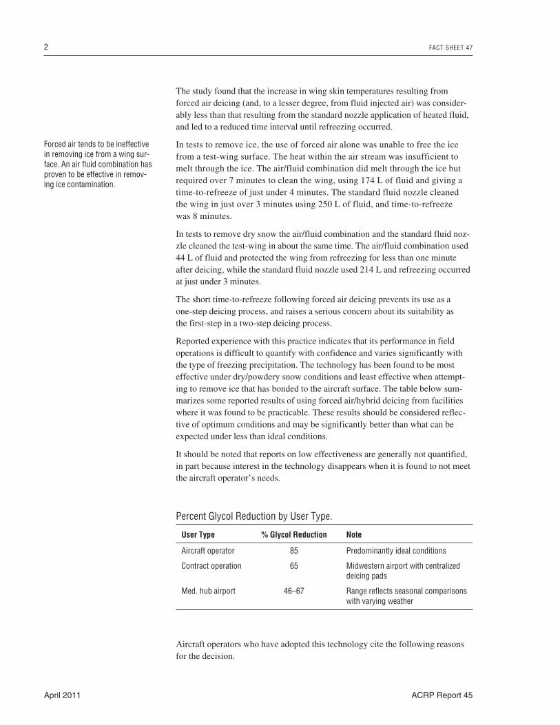
Reported experience with this practice indicates that its performance in fieldoperations is difficult to quantify with confidence and varies significantly withthe type of freezing precipitation. The technology has been found to be mosteffective under dry/powdery snow conditions and least effective when attempt-ing to remove ice that has bonded to the aircraft surface. The table below sum-marizes some reported results of using forced air/hybrid deicing from facilitieswhere it was found to be practicable. These results should be considered reflec-tive of optimum conditions and may be significantly better than what can beexpected under less than ideal conditions.
It should be noted that reports on low effectiveness are generally not quantified,in part because interest in the technology disappears when it is found to not meetthe aircraft operator’s needs.
2 FACT SHEET 47
April 2011 ACRP Report 45
Forced air tends to be ineffectivein removing ice from a wing sur-face. An air fluid combination hasproven to be effective in remov-ing ice contamination.
Percent Glycol Reduction by User Type.
User Type % Glycol Reduction Note
Aircraft operator 85 Predominantly ideal conditions
Contract operation 65 Midwestern airport with centralizeddeicing pads
Med. hub airport 46–67 Range reflects seasonal comparisonswith varying weather
Aircraft operators who have adopted this technology cite the following reasonsfor the decision.
The time required to clean an aircraft of snow can be reduced under certainconditions:
• A significant reduction in ADF usage over conventional trucks is possibleunder certain types of weather conditions, such as dry snow and frost;
• There are times, such as during dry snow conditions, when very little ADF isrequired; and
• The potential source reduction benefits of the technology can assist facilitiesand airports with maintaining compliance with stormwater regulations.
It should be noted that there may be additional operational efficiencies due to thedecreased frequency in refilling deicing fluid tanks.
2. Implementation ConsiderationsApplicability AssessmentForced air systems are not approved for use as a one-step deicing process, as thisapplication has not been demonstrated to produce endurance times that satisfyHOT guidelines.
Forced air systems are not approved for the first step of a two-step deicingprocess unless the use of the system has been tested and shown to be satisfactory.The SAE G12E Equipment Subcommittee has documented a test procedure forthis purpose.
Forced air systems can be used very effectively to clean contamination from aircraft surfaces as a pre-step prior to standard fluid deicing. This can be doneeither with or without Type I fluid injection.
Using forced air to remove most of the snow in a pre-step deicing applicationprior to the actual deicing operation can speed up the deicing process andmarkedly reduce the amount of fluid needed to produce a clean aircraft.
Conditions are sometimes encountered where cold dry snow falling onto a coldwing can be seen to be swirled and moved by the wind across the wing surface.It is evident that the snow is not adhering to the wing surface. The application of fluid would result in the snow adhering to the wing, thus it may be counter-productive to spray fluids. However, if snow has accumulated at any location onthe wing surface it must be removed prior to take-off. The removal of this snowwith a stream of cold forced air may avoid the need to deice the aircraft with fluid,and may speed up the flight departure. A caution is necessary as the airflow fromforced air systems typically retains some heat from the compression stage. Theair stream temperature diminishes with distance, so it is important to determinehow far from the wing the nozzle must be positioned in order to avoid meltingof the snow onto the wing surface. This process does not provide a HOT. Thesurfaces must be checked after cleaning to ensure that no snow has melted andrefrozen, adhering to the wing. If ice has adhered to the wing, the standard deicingprocess using heated deicing fluid must then be applied, followed by an anti-icingprocedure producing a HOT.
FACT SHEET 47 3
ACRP Report 45 April 2011
The key consideration in evaluating potential applicability of this technology is thetype of winter precipitation commonly encountered and the effectiveness of thetechnology in removing it. Dry, powdery snow provides the greatest opportunityin this regard, whereas the technology is least effective where icy conditions andheavy wet snow predominate.
A practical consideration is the age of existing deicing equipment. Newly pur-chased equipment may not be scheduled for replacement for several years, thusreducing the feasibility of changing to forced air/hybrid application technology.
Regulatory ConsiderationsThere are no specific environmental regulations that apply to this practice,although increased air emissions may be an issue at some airports.
Forced air systems are not approved for use as a one-step deicing process.
Forced air systems are not approved for the first step of a two-step deicingprocess unless the use of the system has been tested and shown to be satisfactory.
The adoption of forced air/hybrid deicing requires that it be described in an aircraft operator’s approved snow and ice control plan.
Planning and Design ConsiderationsThe following items need to be considered prior to planning, designing, andimplementing a forced air/hybrid deicing system:
• Climate suited to the technology’s strengths;
• Extensive operator-training program, which is key to success;
• Maintenance staff training; and
• Phased procurement as part of regular deicing-truck replacement schedule.
Useful references on the use of forced air for deicing include Transport CanadaTP 14052, SAE AIR 5633, and SAE ARP4737.
Integration with Other Fact SheetsForced air/hybrid deicing can be integrated with virtually all of the other sourcereduction Fact Sheets, with the exception of Hangared Parking (#8). This prac-tice is compatible with all of the containment/collection, conveyance/storage,and treatment/recycling practices. Significant reduction in the use of deicingfluids may undermine the economic viability of recycling programs.
Operation and Maintenance ConsiderationsStandard operations and maintenance associated with deicing vehicles or deicingbooms apply. The added complexity of the air blowers and delivery system willincrease maintenance and repair requirements.
Specialized operator training and skill development are critical to maximizingthe effectiveness of this practice. Specific operational concerns with this technol-
4 FACT SHEET 47
April 2011 ACRP Report 45
ogy cited by aircraft operators include the possible degradation of the fluids dueto shear forces through the application process and excessive foaming, whichobstructs the view of the aircraft skin. The techniques are significantly differentfrom conventional deicing trucks, and require more training and practice time todevelop and maintain proficiency. Where local weather conditions result ininfrequent use of the technology, operators may be challenged to maintain ahigh level of skill.
Noise due to the high air stream velocity may necessitate hearing protection foroperators and for nearby ground service personnel.
Care must be taken to:
• Ensure that ground service personnel are clear of the area before using forced air;
• Ensure that loose debris is not blown into engines or other intakes;
• Avoid blowing ice snow or slush into control surface hinge areas and othercavities. Apply the forced air stream from the wing leading edge to the trailing edge; and
• Ensure that ice removal does not result in impact damage to other surfaces orcomponents.
If used to remove non-adhered cold dry snow, it is important to ensure that the airstream is cold enough to avoid melting of the snow. The surfaces must be checkedafter cleaning to ensure that no snow has melted and refrozen, adhering to the wing.
Operational efficiencies may result due to increased time intervals between deic-ing fluid resupply, in particular for deicing vehicles/equipment with deicer fluidtanks. Similarly, operational efficiencies can be realized by using forced air sys-tems to remove accumulated snow versus physical/mechanical removal methods,and the opportunity for damage to the aircraft is minimized.
3. CostsCapital CostsThe initial capital investment for forced air/hybrid deicing is dependent on thecosts associated with the specialized equipment purchase. Anecdotal informationfrom air carriers who use this technology indicates that the incremental costassociated with the addition of a forced air option on a deicing truck is in theneighborhood of $100,000, including a recommended enclosed cab feature.
Operation and Maintenance CostsAdditional maintenance costs may be expected because of the increased com-plexity of the machinery. Increased fuel consumption is required to operate theair blowers. However, aircraft operators have reported that overall the incremen-tal cost of this technology above conventional equipment may be recovered insavings from reduced deicer usage within several seasons. Costs associated withdelayed departures including aircraft operating costs, crew costs, and costs forinconvenienced passengers, may be reduced.
FACT SHEET 47 5
ACRP Report 45 April 2011
FACT SHEET 48
Holdover Time Determination System
1. DescriptionPurposeThe industry has long sought tools to assist flight crews in holdover time deci-sion making in winter operating conditions.
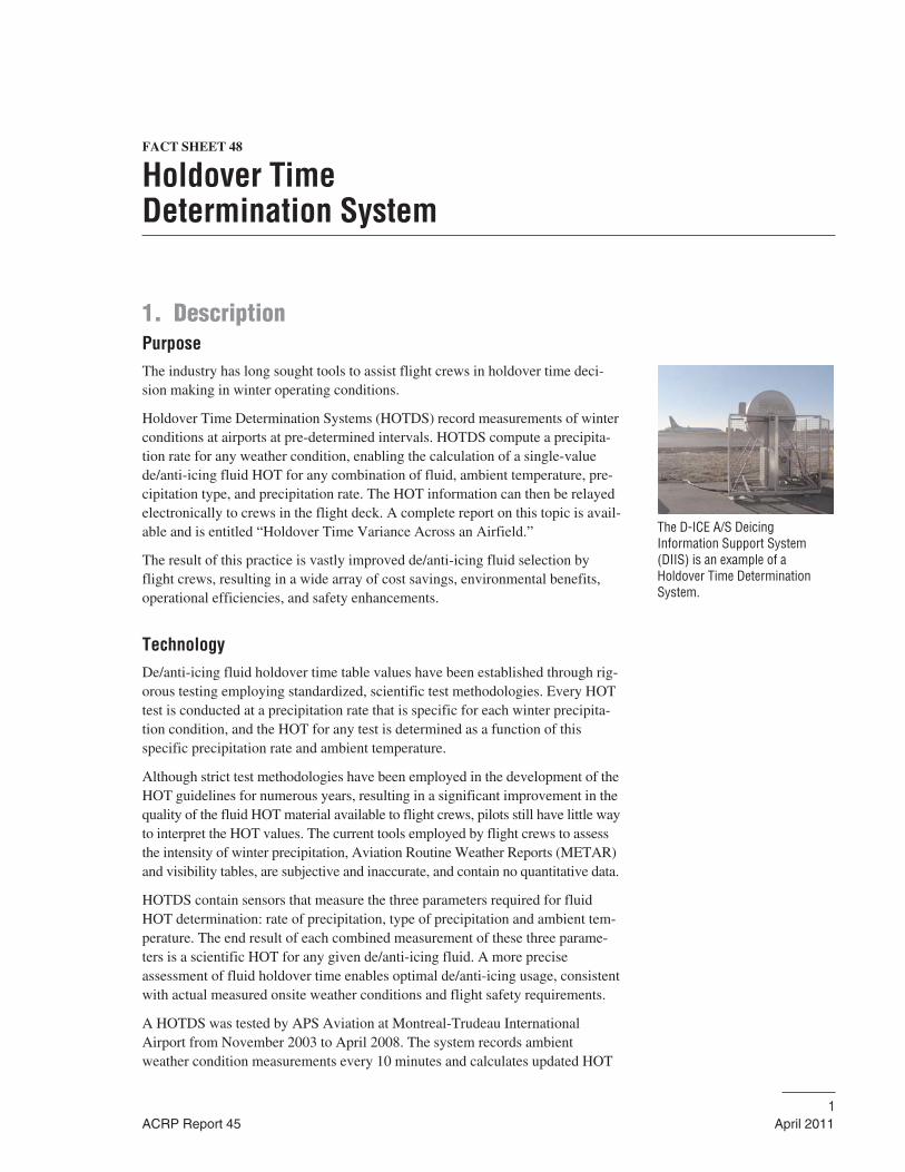
Holdover Time Determination Systems (HOTDS) record measurements of winterconditions at airports at pre-determined intervals. HOTDS compute a precipita-tion rate for any weather condition, enabling the calculation of a single-valuede/anti-icing fluid HOT for any combination of fluid, ambient temperature, pre-cipitation type, and precipitation rate. The HOT information can then be relayedelectronically to crews in the flight deck. A complete report on this topic is avail-able and is entitled “Holdover Time Variance Across an Airfield.”
The result of this practice is vastly improved de/anti-icing fluid selection byflight crews, resulting in a wide array of cost savings, environmental benefits,operational efficiencies, and safety enhancements.
TechnologyDe/anti-icing fluid holdover time table values have been established through rig-orous testing employing standardized, scientific test methodologies. Every HOTtest is conducted at a precipitation rate that is specific for each winter precipita-tion condition, and the HOT for any test is determined as a function of this specific precipitation rate and ambient temperature.
Although strict test methodologies have been employed in the development of theHOT guidelines for numerous years, resulting in a significant improvement in thequality of the fluid HOT material available to flight crews, pilots still have little wayto interpret the HOT values. The current tools employed by flight crews to assessthe intensity of winter precipitation, Aviation Routine Weather Reports (METAR)and visibility tables, are subjective and inaccurate, and contain no quantitative data.
HOTDS contain sensors that measure the three parameters required for fluidHOT determination: rate of precipitation, type of precipitation and ambient tem-perature. The end result of each combined measurement of these three parame-ters is a scientific HOT for any given de/anti-icing fluid. A more preciseassessment of fluid holdover time enables optimal de/anti-icing usage, consistentwith actual measured onsite weather conditions and flight safety requirements.
A HOTDS was tested by APS Aviation at Montreal-Trudeau InternationalAirport from November 2003 to April 2008. The system records ambientweather condition measurements every 10 minutes and calculates updated HOT
ACRP Report 45 April 20111
The D-ICE A/S DeicingInformation Support System(DIIS) is an example of aHoldover Time DeterminationSystem.
information based on quantitative data collected. The system includes weathersensors for precipitation type, precipitation intensity, ambient temperature, andwind speed. Weather measurements are analyzed by the dedicated PC-basedsoftware, which calculates HOTs based on the measured weather and ADFholdover time databases. The HOT databases are fluid-specific and represent the same information used to prepare conventional holdover timetables.
Calculated holdover times are displayed on the PC and can then be transmitted tothe flight deck and ground crews. Holdover times are updated every 10 minuteswith real-time weather data, and can be updated more frequently if multipleHOTDS units are used.
Other HOTDS products, including a liquid water equivalent system developedby the National Center for Atmospheric Research (NCAR), are currently in thedevelopment phase. The data collection intervals, sensor arrays, and specifics ofthe programming associated with these products may differ from the ones pre-sented herein, but the system outputs are similar and serve the same objectives.
Documented PerformanceA HOTDS was tested at Montreal-Trudeau International Airport over five winterseasons. Over 2,500 data points were collected with the system during this periodin nearly 100 natural precipitation events, spanning the full range of ambienttemperatures and precipitation types. Data from the HOTDS were compared todata collected using historical rate measurement procedures and human weatherobservations, and the correlation was excellent. In summer 2008, the HOTDSdemonstrated compliance with the Minimum Performance Specifications andQuality Assurance Requirements established by TC for use of HOTDS outputsin Canadian air operations (see later section on Regulatory Considerations).
An operational assessment of the HOTDS was also performed at Montreal-TrudeauInternational Airport from 2004–06. The objective of this work was to compareactual flight crew decisions in winter operating conditions to optimal de/anti-icingfluid decisions that could be made if HOTDS were available. The operational datacollection indicated that in 27% of all departures at the airport, flight crew selectedto employ thickened Type IV fluids in conditions that did not warrant their use. Anadditional 4% of all departures took off with exceeded de/anti-icing fluid holdovertimes. The operational data collection, which was based on a sample of nearly1,600 departures in a wide range of conditions, indicates the costs savings andsafety enhancements that could be achieved through use of HOTDS outputs.
Additional HOTDS equipment is currently under development by other manu-facturers, and testing of the systems is underway.
2. Implementation ConsiderationsApplicability AssessmentThe potential cost savings, environmental benefits, operational efficiencies andsafety enhancements associated with this practice render it applicable to all
2 FACT SHEET 48
April 2011 ACRP Report 45
An HOTDS can provide real-timeupdates directly to the flight deckvia Aircraft Communication andReporting Systems (ACARS).
airports and aircraft operators subjected to winter precipitation conditions andthe use of fluid holdover time tables.
The benefits associated with the implementation of this practice will vary largelyby the size of the operation and, therefore, the capital and operating costs of thispractice may limit its widespread applicability to medium- and large-size airportsand operations characterized by severe winter weather.
Regulatory ConsiderationsTC and the FAA develop and publish the de/anti-icing fluid holdover time tableson an annual basis, and both organizations regulate the usage of the informationby air carriers in their respective countries. The shift to automated provision ofde/anti-icing fluid holdover time data will therefore require regulatory oversight.
In December 2007, TC issued a regulatory approval process for use of HOTDSin Canadian air operations. The regulatory approval process was based on an aircarrier exemption from Canadian Aviation Regulation (CAR) 622.11, which per-tains to the use of fluid holdover time tables in winter planning. As part of theregulatory approval process, TC developed Minimum Performance Specificationsand Minimum Quality Assurance Requirements for HOTDS. The manufacturerof the HOTDS must demonstrate adherence to the minimum requirements established by TC prior to being approved by the regulator.
The manufacturer of the HOTDS tested in Canada has demonstrated compliancewith the minimum requirements established by TC, and operational use of thesystem began in the winter of 2008–09.
The FAA is currently examining the development and adoption of a regulatoryapproval process for HOTDS, but it is believed that the process may still be afew years away.
Planning and Design ConsiderationsNumerous planning and design considerations need to be examined when imple-menting this practice:
• Airport siting issues with HOTDS: where to install the equipment on an airportsite so that the system will provide outputs that are representative of conditionsexperienced by aircraft on the airfield;
• Determination of the desired data provision cycle time, which may impact thenumber of HOTDS systems that are ultimately installed at the airport;
• Space requirements for the physical installation of the system hardware; and
• Development of data communication pathways for system information(datalink, radio frequencies, wireless modems, etc.).
Integration with Other Fact SheetsHOTDS technology has the potential to be integrated with most Fact Sheets,including all fluid-related Fact Sheets. The combination of real-time weather
FACT SHEET 48 3
ACRP Report 45 April 2011
An HOTDS can provide significantcost savings, environmental ben-efits, and safety enhancements toall airports and aircraft operators.
measurement from the HOTDS and enhanced weather forecasting tools may beextremely useful to airports and aircraft operators.
Operation and Maintenance ConsiderationsOperational and maintenance requirements associated with this practice are notyet available because it has not been implemented at an operational level ortested over the long term.
Some operational considerations, such as how the holdover time informationfrom the system will be employed by flight crews, will need to be examined indetail. The development of training programs for flight crews to ensure the tran-sition from paper tables to electronic information is essential, as well as the need for calibration, maintenance, and verification programs for the HOTDShardware, to ensure the validity of the system outputs.
3. CostsOverall costs are not yet fully defined, as the technology has yet to be fullyimplemented in an operational environment.
Capital CostsCapital costs are not fully defined, but are likely to consist primarily of costs ofthe installation, the location, as well as the hardware and software. Alternatively,capital costs of the installation may be incurred by a service provider who willsell the service to the airport/aircraft carrier community.
Operation and Maintenance CostsOperational costs will be uncertain until the technology has been fully commer-cialized but are likely to include costs for personnel to oversee system operationand monitor results as well as costs for maintaining and testing the weather-monitoring equipment.
4 FACT SHEET 48
April 2011 ACRP Report 45
FACT SHEET 49
Point Detection Sensors to IndicateFluid Condition and Contaminationon Aircraft Surfaces
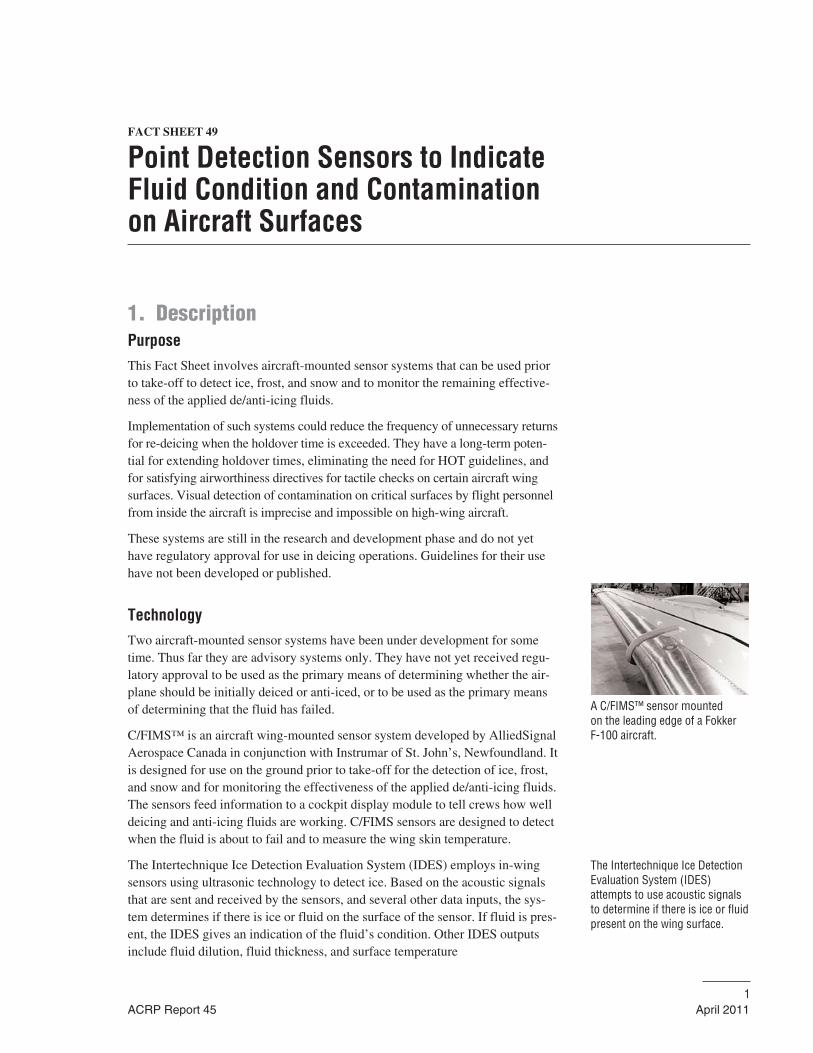
1. DescriptionPurposeThis Fact Sheet involves aircraft-mounted sensor systems that can be used priorto take-off to detect ice, frost, and snow and to monitor the remaining effective-ness of the applied de/anti-icing fluids.
Implementation of such systems could reduce the frequency of unnecessary returnsfor re-deicing when the holdover time is exceeded. They have a long-term poten-tial for extending holdover times, eliminating the need for HOT guidelines, andfor satisfying airworthiness directives for tactile checks on certain aircraft wingsurfaces. Visual detection of contamination on critical surfaces by flight personnelfrom inside the aircraft is imprecise and impossible on high-wing aircraft.
These systems are still in the research and development phase and do not yethave regulatory approval for use in deicing operations. Guidelines for their usehave not been developed or published.
TechnologyTwo aircraft-mounted sensor systems have been under development for sometime. Thus far they are advisory systems only. They have not yet received regu-latory approval to be used as the primary means of determining whether the air-plane should be initially deiced or anti-iced, or to be used as the primary meansof determining that the fluid has failed.
C/FIMS™ is an aircraft wing-mounted sensor system developed by AlliedSignalAerospace Canada in conjunction with Instrumar of St. John’s, Newfoundland. Itis designed for use on the ground prior to take-off for the detection of ice, frost,and snow and for monitoring the effectiveness of the applied de/anti-icing fluids.The sensors feed information to a cockpit display module to tell crews how welldeicing and anti-icing fluids are working. C/FIMS sensors are designed to detectwhen the fluid is about to fail and to measure the wing skin temperature.
The Intertechnique Ice Detection Evaluation System (IDES) employs in-wingsensors using ultrasonic technology to detect ice. Based on the acoustic signalsthat are sent and received by the sensors, and several other data inputs, the sys-tem determines if there is ice or fluid on the surface of the sensor. If fluid is pres-ent, the IDES gives an indication of the fluid’s condition. Other IDES outputsinclude fluid dilution, fluid thickness, and surface temperature
ACRP Report 45 April 20111
A C/FIMS™ sensor mounted on the leading edge of a Fokker F-100 aircraft.
The Intertechnique Ice DetectionEvaluation System (IDES)attempts to use acoustic signalsto determine if there is ice or fluidpresent on the wing surface.
Documented Performancea) C/FIMS™ System
An operational evaluation of a two-sensor C/FIMS™ system installation wasreported in a TC publication (TP 2979E), “Final Report Operational Evaluationfor the Two Sensor Contaminant/Fluid Integrity Measuring System (C/FIMS)Midway Airlines F-100 Aircraft.”
The system was installed for evaluation on a Midway Airlines F-100 aircraft.Data was obtained from 82 take-off events. This included 8 events in whichde/anti-icing fluids were used and 15 events in which the weather conditionswere such that the FAA Airworthiness Directives (AD) called for a tactilecheck. Data collected by Midway pilots was obtained from two take-offevents.
The results demonstrated that the two-sensor C/FIMS™ would enhance safetyand provide operational benefits not available using existing manual inspectionprocedures. A further finding was that wing skin temperatures on average were5.6°C (10°F) warmer than OAT.
The following year a four-sensor C/FIMS™ installation design was developedfor the F-100, with the participation of Fokker Aviation Services. The evaluationwas reported in the TC publication (TP 13254E), “Operational Evaluation for theFour Sensor Contaminant/Fluid Integrity Measuring System (C/FIMS) MidwayAirlines F-100 Aircraft.”
Data was collected from 63 take-off events on the Midway F-100 aircraft four-sensor system, from January to April 1997. This included four events in whichde/anti-icing fluids were used and 11 events when the aircraft was within theweather conditions covered by the FAA AD applicable to F-100 aircraft.
From the collected data and analysis performed, it was concluded that a four-sensor production configuration of C/FIMS™ will provide airline operators ofthe F-100 with the benefits of enhanced safety and improved operations in icingconditions.
b) Intertechnique Ice Detection Evaluation System (IDES)
The ability of an IDES fluid failure sensor to replicate visual fluid failure callswas reported in the TC publication (TP 14382E), “A Sensor for Detecting Anti-Icing Fluid Failure: Phase I.” If successful, the variability associated with humanvisual determination of failure during fluid endurance time tests could be elimi-nated by use of the sensor. It was concluded that the IDES was currently not ableto duplicate the visual determination of failure. This may have been partially aresult of the IDES system inability to match a human observation, rather than itsinability to detect ice.
An improved IDES system (named WIDS) was tested in 2004–05 and resultswere reported in the TC publication (TP 4446E), “A Sensor for DetectingAnti-Icing Fluid Failure: Phase II.” A limited number of tests were con-ducted with four fluids in natural snow, freezing drizzle, freezing rain, andfreezing fog.
2 FACT SHEET 49
April 2011 ACRP Report 45
C/FIMS™ will provide airlineoperators of the F-100 with thebenefits of enhanced safety andimproved operations in icing conditions.
It was concluded that:
1. The Intertechnique IDES may be capable of being further refined to replicatevisual endurance times in snow with Type II and Type IV fluids; and
2. Significant resources would be required to improve the technology to accu-rately replicate visual endurance times with Type I fluids or with all fluidtypes in simulated precipitation conditions.
2. Implementation ConsiderationsApplicability AssessmentWhen such systems are approved, they would be applicable to all aircraft types.
It is expected that installation of these systems at time of aircraft manufacturewould be less costly than retrofitting aircraft already in operation.
Successful systems could be integrated into the fluid holdover time test processto enhance the accuracy of fluid failure calls.
Regulatory ConsiderationsSome principal considerations in developing regulations on the use of this equip-ment are:
• System accuracy in identifying contamination in all weather and precipitationconditions and for all types of fluid applications;
• Ability to identify adhered contamination;
• Ability of point sensors to adequately represent condition of entire critical surface;
• Proven system reliability;
• Identification of numbers of point sensors and installation locations for bestperformance, by aircraft type;
• System indications versus published holdover time guidelines—which takespriority; and
• Once implemented, is the system included in the aircraft minimum equipment list.
These systems do not yet have regulatory approval for use in deicing operationsand guidelines for their use have not been developed or published.
Planning and Design ConsiderationsIt is expected that installation of such systems at time of aircraft manufacturewould be the more efficient approach.
However, limiting implementation to new aircraft would dramatically extendthe timeframe of implementation, given that many operators’ fleets include relatively new aircraft that will be in service for some time.
FACT SHEET 49 3
ACRP Report 45 April 2011
IDEAS require more refinement to accurately replicate visualendurance times.
When the systems receive regulatory approval for use in operations, interestedoperators will need to determine the most cost-effective approach to installingthem, in conjunction with existing maintenance routines.
Flight operations procedures on the use and application of such systems andassociated training would be required.
Integration with Other Fact SheetsThese systems complement other practices that address the reduction of glycolusage.
Operation and Maintenance ConsiderationsOperations considerations include integrating use of the sensor system intoapproved deicing programs and in flight operations manuals. The process ofdecision making based on sensor system information must be clearly definedand in accordance with regulatory guidance.
Potential inclusion of the implemented system in the minimum equipment listfor commercial aircraft operation must be considered.
3. CostsCosts include both capital and operating costs.
Capital CostsCapital costs include purchase and installation of the system.
Operation and Maintenance CostsAdditional aircraft systems maintenance costs can be expected.
Implementation of the system may avoid some returns for re-deicing with theirassociated delayed operations costs as well as the additional deicing costs.
4 FACT SHEET 49
April 2011 ACRP Report 45
FACT SHEET 50
Remote Ice Detection Sensors toScan Aircraft Critical SurfacesBefore Departure Runway
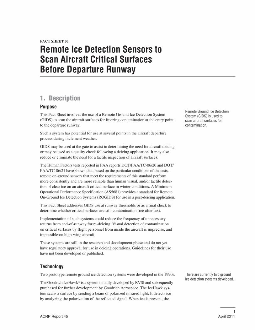
1. DescriptionPurposeThis Fact Sheet involves the use of a Remote Ground Ice Detection System(GIDS) to scan the aircraft surfaces for freezing contamination at the entry pointto the departure runway.
Such a system has potential for use at several points in the aircraft departureprocess during inclement weather.
GIDS may be used at the gate to assist in determining the need for aircraft deicingor may be used as a quality check following a deicing application. It may alsoreduce or eliminate the need for a tactile inspection of aircraft surfaces.
The Human Factors tests reported in FAA reports DOT/FAA/TC-06/20 and DOT/FAA/TC-06/21 have shown that, based on the particular conditions of the tests,remote on-ground sensors that meet the requirements of this standard performmore consistently and are more reliable than human visual, and/or tactile detec-tion of clear ice on an aircraft critical surface in winter conditions. A MinimumOperational Performance Specification (AS5681) provides a standard for RemoteOn-Ground Ice Detection Systems (ROGIDS) for use in a post-deicing application.
This Fact Sheet addresses GIDS use at runway thresholds or as a final check todetermine whether critical surfaces are still contamination free after taxi.
Implementation of such systems could reduce the frequency of unnecessaryreturns from end-of-runway for re-deicing. Visual detection of contamination on critical surfaces by flight personnel from inside the aircraft is imprecise, andimpossible on high-wing aircraft.
These systems are still in the research and development phase and do not yethave regulatory approval for use in deicing operations. Guidelines for their usehave not been developed or published.
TechnologyTwo prototype remote ground ice detection systems were developed in the 1990s.
The Goodrich IceHawk® is a system initially developed by RVSI and subsequentlypurchased for further development by Goodrich Aerospace. The IceHawk sys-tem scans a surface by sending a beam of polarized infrared light. It detects iceby analyzing the polarization of the reflected signal. When ice is present, the
ACRP Report 45 April 20111
Remote Ground Ice DetectionSystem (GIDS) is used to scan aircraft surfaces for contamination.
There are currently two groundice detection systems developed.
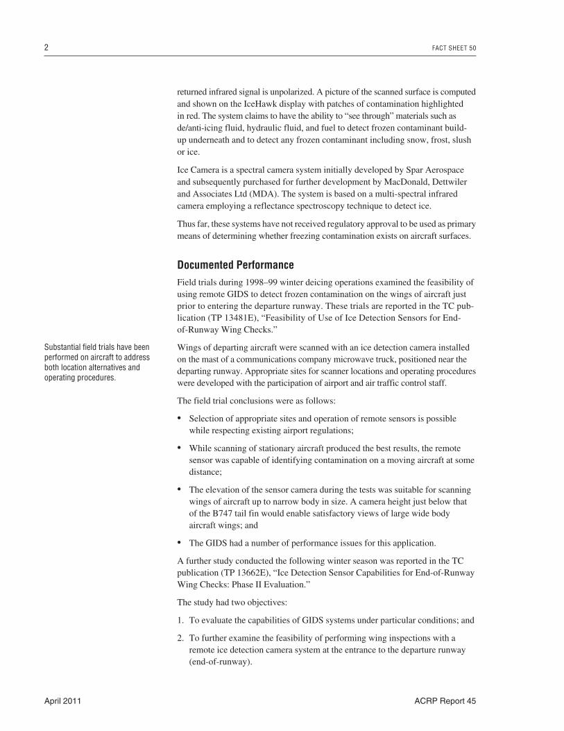
returned infrared signal is unpolarized. A picture of the scanned surface is computedand shown on the IceHawk display with patches of contamination highlighted in red. The system claims to have the ability to “see through” materials such asde/anti-icing fluid, hydraulic fluid, and fuel to detect frozen contaminant build-up underneath and to detect any frozen contaminant including snow, frost, slushor ice.
Ice Camera is a spectral camera system initially developed by Spar Aerospaceand subsequently purchased for further development by MacDonald, Dettwilerand Associates Ltd (MDA). The system is based on a multi-spectral infraredcamera employing a reflectance spectroscopy technique to detect ice.
Thus far, these systems have not received regulatory approval to be used as primarymeans of determining whether freezing contamination exists on aircraft surfaces.
Documented PerformanceField trials during 1998–99 winter deicing operations examined the feasibility ofusing remote GIDS to detect frozen contamination on the wings of aircraft justprior to entering the departure runway. These trials are reported in the TC pub-lication (TP 13481E), “Feasibility of Use of Ice Detection Sensors for End-of-Runway Wing Checks.”
Wings of departing aircraft were scanned with an ice detection camera installedon the mast of a communications company microwave truck, positioned near thedeparting runway. Appropriate sites for scanner locations and operating procedureswere developed with the participation of airport and air traffic control staff.
The field trial conclusions were as follows:
• Selection of appropriate sites and operation of remote sensors is possiblewhile respecting existing airport regulations;
• While scanning of stationary aircraft produced the best results, the remotesensor was capable of identifying contamination on a moving aircraft at somedistance;
• The elevation of the sensor camera during the tests was suitable for scanningwings of aircraft up to narrow body in size. A camera height just below thatof the B747 tail fin would enable satisfactory views of large wide body aircraft wings; and
• The GIDS had a number of performance issues for this application.
A further study conducted the following winter season was reported in the TCpublication (TP 13662E), “Ice Detection Sensor Capabilities for End-of-RunwayWing Checks: Phase II Evaluation.”
The study had two objectives:
1. To evaluate the capabilities of GIDS systems under particular conditions; and
2. To further examine the feasibility of performing wing inspections with aremote ice detection camera system at the entrance to the departure runway(end-of-runway).
2 FACT SHEET 50
April 2011 ACRP Report 45
Substantial field trials have beenperformed on aircraft to addressboth location alternatives andoperating procedures.
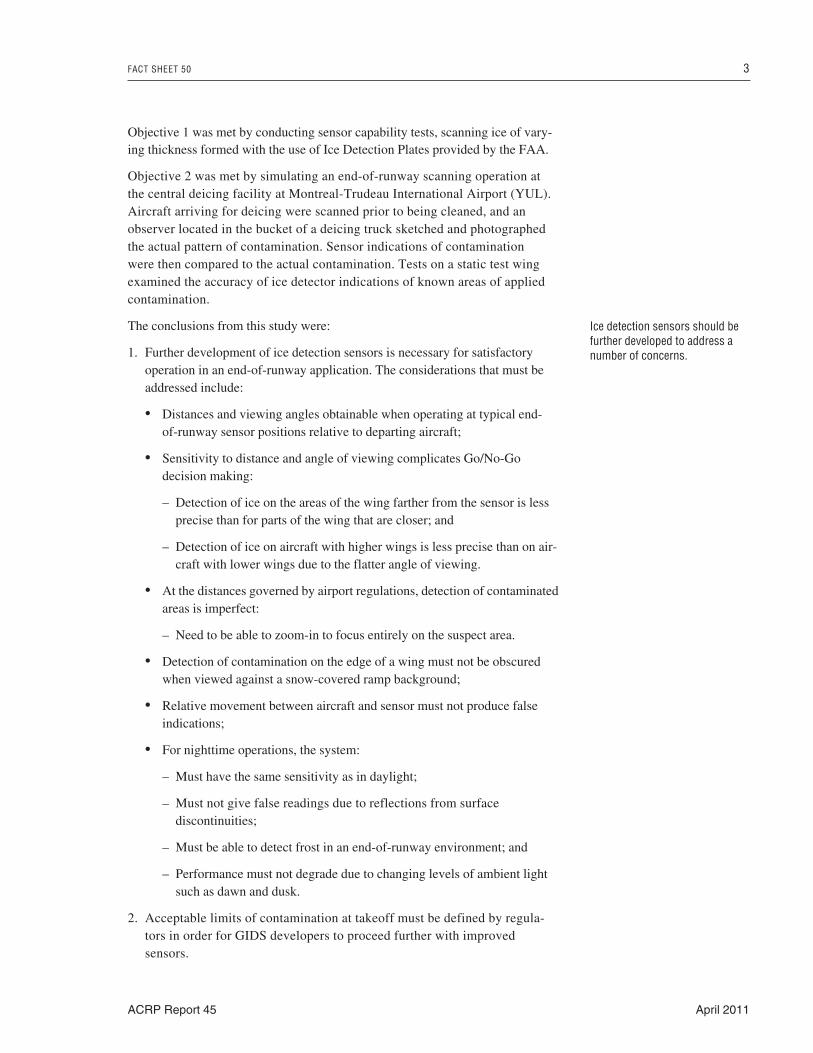
Objective 1 was met by conducting sensor capability tests, scanning ice of vary-ing thickness formed with the use of Ice Detection Plates provided by the FAA.
Objective 2 was met by simulating an end-of-runway scanning operation atthe central deicing facility at Montreal-Trudeau International Airport (YUL).Aircraft arriving for deicing were scanned prior to being cleaned, and anobserver located in the bucket of a deicing truck sketched and photographedthe actual pattern of contamination. Sensor indications of contamination were then compared to the actual contamination. Tests on a static test wingexamined the accuracy of ice detector indications of known areas of appliedcontamination.
The conclusions from this study were:
1. Further development of ice detection sensors is necessary for satisfactoryoperation in an end-of-runway application. The considerations that must beaddressed include:
• Distances and viewing angles obtainable when operating at typical end-of-runway sensor positions relative to departing aircraft;
• Sensitivity to distance and angle of viewing complicates Go/No-Go decision making:
– Detection of ice on the areas of the wing farther from the sensor is lessprecise than for parts of the wing that are closer; and
– Detection of ice on aircraft with higher wings is less precise than on air-craft with lower wings due to the flatter angle of viewing.
• At the distances governed by airport regulations, detection of contaminatedareas is imperfect:
– Need to be able to zoom-in to focus entirely on the suspect area.
• Detection of contamination on the edge of a wing must not be obscuredwhen viewed against a snow-covered ramp background;
• Relative movement between aircraft and sensor must not produce falseindications;
• For nighttime operations, the system:
– Must have the same sensitivity as in daylight;
– Must not give false readings due to reflections from surface discontinuities;
– Must be able to detect frost in an end-of-runway environment; and
– Performance must not degrade due to changing levels of ambient lightsuch as dawn and dusk.
2. Acceptable limits of contamination at takeoff must be defined by regula-tors in order for GIDS developers to proceed further with improved sensors.
FACT SHEET 50 3
ACRP Report 45 April 2011
Ice detection sensors should befurther developed to address anumber of concerns.
2. Implementation ConsiderationsApplicability AssessmentWhen such systems are approved, they would be applicable to all aircraft types.They would provide improved information to the pilot regarding contaminationon wings, leading to better decisions on the need to return for re-deicing, andenhanced aircraft safety.
Regulatory ConsiderationsSome principal considerations in developing regulations on this application follow:
Camera location:
• Selected in compliance with aerodrome regulations regarding the ObstacleLimitation surfaces (OLS).
GIDS system:
• System accuracy in identifying contamination in all weather and precipita-tion conditions and for all types of fluid applications;
• Proven system reliability;
• System accuracy in identifying contamination for all aircraft types at thedistance and angles of viewing governed by the installations; and
• System indications versus published holdover time guidelines—whichtakes priority?
These systems do not yet have regulatory approval for use in deicing operationsand guidelines for their use have not been developed or published.
Planning and Design Considerationsa) Selecting Scanner Locations
Considerations include aerodrome standards designed to minimize the dangerspresented by obstacles to aircraft, local airport runway, taxiway, and deicingfacility layout; how runways and taxiways are assigned during deicing condi-tions; and remote GIDS system limitations.
b) Aerodrome Standards
The height limitation of the sensor camera installation is controlled by the OLS.Fixed objects are not permitted above the surface except for frangible mountedobjects. Mobile objects are not permitted above the surface when the runway isused for landing.
The location of aircraft taxi-holding positions also is controlled by the surface.Both the tail height and nose height are considered in establishing minimum dis-tances from the runway centerline. This is of interest because scanning of staticaircraft, as opposed to taxiing aircraft, produces superior results.
4 FACT SHEET 50
April 2011 ACRP Report 45
c) Airport Layout
The layout or geography of each airport influences the sensor positioning deci-sion. Specific runways may be favored for departures during weather conditionsrequiring deicing and should be given prime consideration when designing GIDSinstallations. If these runways are also used for landing, the height of the sensorinstallation is then limited.
An escape route is necessary to allow the aircraft to return to the deicing facilityfollowing scanning of the wing for frozen contamination.
Departure-clearance holding-bays with more than one centerline to allow side-by-side aircraft positioning may interfere with the scanning of both wings. Baysthat require immediate turning of the aircraft when departing may result in anunacceptably strong jet blast in the area where a GIDS camera might be located.
d) GIDS System Limitations
The sensor operating characteristics and limitations must be considered. As withany optical instrument, the field of view is a function of the square of the dis-tance between instrument and subject. Similarly, the degree of detail within thescanned area is diminished with increased distance.
The angle of view on the scanned surface is important. Below certain viewingangles, the GIDS system cannot identify contamination regardless of its magni-tude. The normal wing dihedral exaggerates the problem for a sensor locatedoutboard from a wingtip. Scanning with acute viewing angles reduces the abilityto identify small areas of contamination.
Increased sensor height and minimum separation distances produces enhancedresults and better detection of contamination.
Scanning stationary aircraft awaiting clearance for departure produces betterresults than scanning moving aircraft.
e) Operating procedures
The nature of GIDS output dictates the need for an on-ground operator and con-troller, as opposed to direct communication from GIDS to pilot.
Procedures for such an application would involve a number of groups, includingflight operations, airport and air traffic control, airline ground operations, andcentral deicing facilities operators.
Communications procedures must be developed and documented.
Integration with Other Fact SheetsThese systems do not conflict with implementation of other Fact Sheets.
Operation and Maintenance ConsiderationsOperations considerations include integrating use of the sensor system in currentdeicing programs. Responsibility for decision making based on GIDS systeminformation must be clearly defined and in accordance with regulatory guidance.
FACT SHEET 50 5
ACRP Report 45 April 2011
3. CostsCosts include both capital and operating costs.
Capital CostsCapital costs include purchasing and installing a GIDS system and its ancillarysystems (power supply, communications of GIDS output).
Operations and Maintenance CostsOperation and maintenance costs include:
• Maintenance of the GIDS system and its installation;
• Manpower to monitor and communicate GIDS information; and
• Implementation of the system may avoid some returns for re-deicing with theirassociated delayed operations costs as well as the additional deicing costs.
6 FACT SHEET 50
April 2011 ACRP Report 45
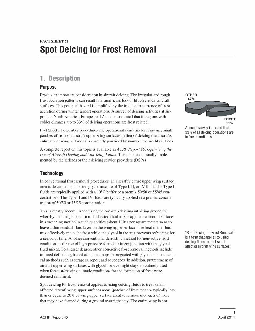
FACT SHEET 51
Spot Deicing for Frost Removal
1. DescriptionPurposeFrost is an important consideration in aircraft deicing. The irregular and roughfrost accretion patterns can result in a significant loss of lift on critical aircraftsurfaces. This potential hazard is amplified by the frequent occurrence of frostaccretion during winter airport operations. A survey of deicing activities at air-ports in North America, Europe, and Asia demonstrated that in regions withcolder climates, up to 33% of deicing operations are frost related.
Fact Sheet 51 describes procedures and operational concerns for removing smallpatches of frost on aircraft upper wing surfaces in lieu of deicing the aircraftsentire upper wing surface as is currently practiced by many of the worlds airlines.
A complete report on this topic is available in ACRP Report 45: Optimizing theUse of Aircraft Deicing and Anti-Icing Fluids. This practice is usually imple-mented by the airlines or their deicing service providers (DSPs).
TechnologyIn conventional frost removal procedures, an aircraft’s entire upper wing surfacearea is deiced using a heated glycol mixture of Type I, II, or IV fluid. The Type Ifluids are typically applied with a 10°C buffer or a premix 50/50 or 55/45 con-centrations. The Type II and IV fluids are typically applied in a premix concen-tration of 50/50 or 75/25 concentration.
This is mostly accomplished using the one-step deicing/anti-icing procedurewhereby, in a single operation, the heated fluid mix is applied to aircraft surfacesin a sweeping motion in such quantities (about 1 liter per square meter) so as toleave a thin residual fluid layer on the wing upper surface. The heat in the fluidmix effectively melts the frost while the glycol in the mix prevents refreezing fora period of time. Another conventional defrosting method for non-active frostconditions is the use of high-pressure forced air in conjunction with the glycolfluid mixes. To a lesser degree, other non-active frost removal methods includeinfrared defrosting, forced air alone, mops impregnated with glycol, and mechani-cal methods such as scrapers, ropes, and squeegees. In addition, pretreatment ofaircraft upper wing surfaces with glycol for overnight stays is routinely usedwhen forecast/existing climatic conditions for the formation of frost weredeemed imminent.
Spot deicing for frost removal applies to using deicing fluids to treat small,affected aircraft wing upper surfaces areas (patches of frost that are typically lessthan or equal to 20% of wing upper surface area) to remove (non-active) frostthat may have formed during a ground overnight stay. The entire wing is not
ACRP Report 45 April 20111
A recent survey indicated that33% of all deicing operations arein frost conditions.
“Spot Deicing for Frost Removal”is a term that applies to usingdeicing fluids to treat smallaffected aircraft wing surfaces.
FROST33%
OTHER67%
treated; however both wings are treated symmetrically, whether both wingsneed to be defrosted or not. If any frost is observed on the leading edge of thewing(s), it must be removed. In non-active frost conditions, the wing does notrequire anti-icing and holdover times do not apply. The main thrust of usingspot deicing is to reduce the amount of glycol used to achieve aerodynami-cally clean aircraft wings prior to takeoff, in comparison to amounts of glycoluse in treating an entire upper wing surface. In addition, defrosting time maybe reduced, depending upon the aircraft size, the extent of the frost, and theambient conditions.
In performing spot deicing for frost removal, standard deicing fluid applica-tion procedures are typically employed, in which a fan spray nozzle setting isused. Also, Type I fluids are typically applied at a 60°C temperature (at thenozzle). Of the air carriers that have adopted spot deicing for frost removalprocedures, it was indicated that this practice is performed on most currentcommercial aircraft, thus precluding the need for additional guidance fromaircraft manufacturers.
Documented PerformanceIn a recently conducted survey (summer 2008) of airlines and DSPs relative toaircraft deicing for frost removal it was revealed that:
• Although a reasonable number of operators are currently using spot deicing,there are still many operators who are not familiar with this methodology forfrost removal;
• Spot deicing is seen to be a cheap and effective methodology for frostremoval. Cost, fluid, and time savings are notable benefits of spot deicingcompared to conventional deicing. Fluid savings are estimated to bebetween 30 and 60%;
• Spot deicing for frost removal is currently being employed using Type I fluidmixed to a 10°C buffer heated to 60°C and applied using a regular deicingvehicle;
• Training, lack of qualified individuals to make assessments about its usage,and asymmetrical application resulting in risks to safety, were identified asthe key obstacles in employing spot deicing for frost removal; and
• The methodology was seen to be more suitable for operations at warmer temperatures.
2. Implementation ConsiderationsApplicability AssessmentThis procedure is readily available for use by all airlines and DSPs. Frostremoval prior to takeoff is a requisite safety requirement for all aircraft andconventional deicing procedures and equipments are in place to meet thisrequirement. Since the same equipment used for conventional defrosting is
2 FACT SHEET 51
April 2011 ACRP Report 45
Many service providers are stillusing standard fluid applicationsfor spot deicing. This can lead tosignificant glycol waste.
Recent Surveys have demonstra-ted 30–60% in monetary savingswhen using spot deicing for frostprocedures.
available for spot deicing for frost removal, its applicability is straight forward.Implementation changes would entail:
• Additional training for deicing personnel in performing the spot deicing procedure;
• Additional checking following the application of the procedure; and
• Providing specific guidance material by industry professional groups and regulatory authorities.
Regulatory ConsiderationsThere are no specific SAE guidelines in SAE ARP 4737, “Aircraft Deicing/Anti-icing Methods” document that addressed procedures for spot deicing for frost removal. The general guideline for removal of frost and light ice (i.e., paragraph 6.1.2.2) simply states,
A nozzle setting giving a fan spray is recommended. NOTE: Providing that thehot fluid is applied close to the aircraft skin, a minimal amount of fluid will berequired to melt the deposit.
Also, there were no specific SAE activities geared toward establishing guidelinesfor the use of spot deicing for the removal of frost. However there is a specificAEA recommended procedure to this effect in paragraph 3.9.1.3.2 of the AEA,“Recommendations for Deicing/Anti-icing of Aircraft on the Ground.”
It states:
AEA Paragraph 3.9.1.3.2 Local wing frost removal:
For frost limited to a small patch on the upper wing surface only, andwhen no precipitation is falling or expected, ‘local area’ deicing maybe carried out.
Spray the affected area with a heated fluid/water mix suitable for aOne-Step Procedure, and then spray the same area on the other wing.Both wings must be treated identically (same areas, same amount andtype of fluid, same mixture strength), even if the frost is only presenton one wing.
The trained and qualified person releasing the aircraft must check thatthe treatment was done symmetrically and that all frozen depositshave been removed, and then report the details of the treatment to theCommander.
CAUTION: Holdover times do not apply.
However, changes to SAE ARP 4737 were proposed and accepted at the May 2009meeting of the SAE G-12 Aircraft Ground Deicing Methods Subcommittee. Thesechanges were adopted for the winter 2009–10 operating season, and will provideadequate guidance for operators wishing to implement this procedure.
In the aforementioned survey, the majority of the airlines and the DSPs (57%)indicated that they already use this procedure. These included major U.S.,
FACT SHEET 51 3
ACRP Report 45 April 2011
Canadian, AEA, and Russian air carriers. Most North American air carriersindicated that they already used this procedure. Several of the survey respon-dents that have not adopted spot deicing for frost removal procedures cite theneed for further guidance from the SAE ARP 4737 document and FAA approvalof their deicing program when this procedure is incorporated therein.
In turn, the FAA indicates, “Currently spot deicing is not prohibited by the FAA,however it is not specifically encouraged.”
Planning and Design ConsiderationsThere is no specific planning or design consideration for the adoption of thisspot deicing for frost removal procedure. Current locations, deicing pads, andequipment and personnel used in conventional defrosting of aircraft are deemedadequate to effect the intent of this practice.
Integration with Other Fact SheetsIntegration with conventional frost removal procedures will help improve glycolusage and significantly reduce the amount of spent glycol that eventually findsit way into the environment. In addition, significant savings in overall aircraftdeicing operation expenses have been reported.
Operation and Maintenance ConsiderationsThese spot deicing for frost removal procedures would be incorporated into anair carriers deicing program for approval by appropriated authorities. Onceapproved, DSPs would then be able to offer/perform this procedure for theircustomer (the airlines).
There are no additional or new equipment required for this practice. Therefore,it does not introduce new or otherwise significant equipment maintenancerequirements.
3. CostsThe additional equipment costs to accomplish spot deicing for frost removal is deemed to be zero since the same deicing equipment used for conventionalremoval of frost would be used for spot deicing for frost removal. Additionaltraining of deicing personnel and checking/inspection personnel on the spotdeicing for frost removal procedures would be required.
However, this would add little material cost to the training syllabus or time tothe annual deicing training requirement. In addition, flight crews would requiresome supplemental training on conducting post deicing checks following spotdeicing for frost removal. Again, this supplemental training would be minimaland accomplished at the same time that training for pre-takeoff contaminationchecking is accomplished.
4 FACT SHEET 51
April 2011 ACRP Report 45
Spot Deicing for Frost does notrequire significant capital invest-ment because the same deicingequipment employed in conven-tional deicing is also employedfor spot removal.
Labor costs would be the same or slightly less than that required for conventionaldeicing for frost removal.
In the future, new methodologies for spot deicing for frost removal may beadopted in which small transport aircraft could be spot deiced using a heatedglycol mix carried in a bucket and applied by mops. In this case, a small costassociated with the procurement of mops and buckets would be appropriate.
Should the latter procedure of using mops and buckets for spot removal of frostbe adopted, personnel must be provided with suitable equipment for safe accessto aircraft surfaces and be properly trained to avoid damage to aircraft components.
FACT SHEET 51 5
ACRP Report 45 April 2011
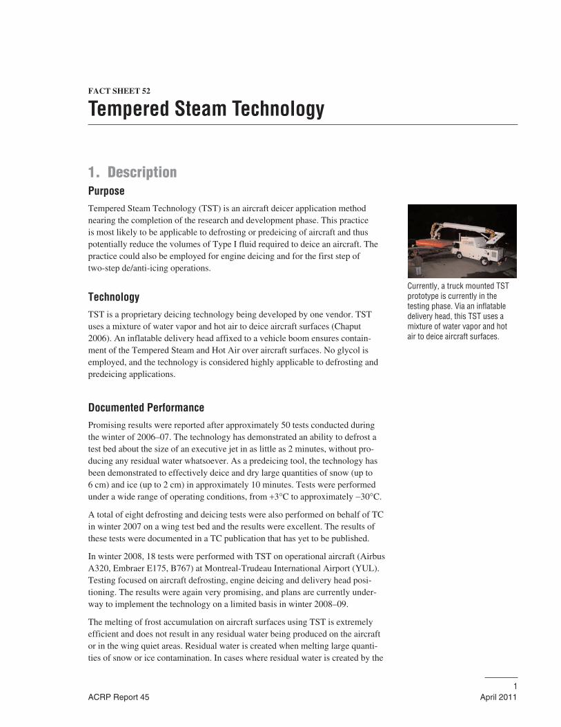
FACT SHEET 52
Tempered Steam Technology
1. DescriptionPurposeTempered Steam Technology (TST) is an aircraft deicer application methodnearing the completion of the research and development phase. This practice is most likely to be applicable to defrosting or predeicing of aircraft and thuspotentially reduce the volumes of Type I fluid required to deice an aircraft. Thepractice could also be employed for engine deicing and for the first step of two-step de/anti-icing operations.
TechnologyTST is a proprietary deicing technology being developed by one vendor. TSTuses a mixture of water vapor and hot air to deice aircraft surfaces (Chaput2006). An inflatable delivery head affixed to a vehicle boom ensures contain-ment of the Tempered Steam and Hot Air over aircraft surfaces. No glycol isemployed, and the technology is considered highly applicable to defrosting andpredeicing applications.
Documented PerformancePromising results were reported after approximately 50 tests conducted duringthe winter of 2006–07. The technology has demonstrated an ability to defrost atest bed about the size of an executive jet in as little as 2 minutes, without pro-ducing any residual water whatsoever. As a predeicing tool, the technology hasbeen demonstrated to effectively deice and dry large quantities of snow (up to 6 cm) and ice (up to 2 cm) in approximately 10 minutes. Tests were performedunder a wide range of operating conditions, from +3°C to approximately −30°C.
A total of eight defrosting and deicing tests were also performed on behalf of TCin winter 2007 on a wing test bed and the results were excellent. The results ofthese tests were documented in a TC publication that has yet to be published.
In winter 2008, 18 tests were performed with TST on operational aircraft (AirbusA320, Embraer E175, B767) at Montreal-Trudeau International Airport (YUL).Testing focused on aircraft defrosting, engine deicing and delivery head posi-tioning. The results were again very promising, and plans are currently under-way to implement the technology on a limited basis in winter 2008–09.
The melting of frost accumulation on aircraft surfaces using TST is extremelyefficient and does not result in any residual water being produced on the aircraftor in the wing quiet areas. Residual water is created when melting large quanti-ties of snow or ice contamination. In cases where residual water is created by the
ACRP Report 45 April 20111
Currently, a truck mounted TSTprototype is currently in the testing phase. Via an inflatabledelivery head, this TST uses amixture of water vapor and hotair to deice aircraft surfaces.
melting process, a simple application of Type I fluid could be applied subsequentto the deicing operation with TST to ensure the meltwater does not re-freeze. Noother performance limitations have been documented to date, although use ofthis technology in active precipitation conditions would require anti-icing usingconventional methods. Based on testing to date, the technology has no knownlimitations over conventional deicing methods.
2. Implementation ConsiderationsApplicability AssessmentThis practice would be most applicable to frost and predeicing applications in allclimates, but could also be employed for engine deicing and for all deicing oper-ations as a first step in two–step de/anti-icing. Anti-icing operations would requirethe use of glycol-based fluids. Airports that have limitations on glycol use at gatepositions or airports that have a large number of frost deicing events may be mostsuitable for TST, although the technology has been proven to be effective acrossthe entire spectrum of operation conditions. As TST is vehicle-based and can beemployed at gate positions for defrosting, the use of this technology may enableaircraft to push back from the gate and taxi to the departure runway withouthaving to undergo a glycol spray and the delays associated with it.
Regulatory ConsiderationsThe primary regulatory consideration associated with TST would be its accept-ance by regulators as an approvable component of an aircraft operator’s snowand ice control plan.
Planning and Design ConsiderationsAlthough TST is not yet commercially available, it is likely to be implementedon a limited basis in winter 2010–11. As the technology is vehicle mounted, theplanning and design considerations applicable to this practice are marginal.
Integration with Other Fact SheetsOne of the biggest benefits of TST is its potential ability to be combined withvirtually all other Fact Sheets to streamline the cost and efficiency of de/anti-icing operations. The system is vehicle mounted, allowing it to be employed atthe gate, remote pads, or in centralized deicing operations.
Operation and Maintenance ConsiderationsBecause the technology is still under development and has yet to be fully imple-mented into airport operations, the operating and maintenance requirements ofthe BMP are not fully known at this point.
2 FACT SHEET 52
April 2011 ACRP Report 45
TST has many applicationsincluding:
• Deicing in Frost Conditions• Pre-deicing in all precipitation
types• First step of a two-step
deicing application (alterna-tive to Type I fluid)
• Engine Deicing

3. CostsThe practice is not yet commercially available at this time, and so definitivecosts have not yet been established. It is believed that the technology costs willbe considerably less than those associated with conventional deicing, especiallywhen the cost benefits (glycol savings, operational efficiencies, aircraft fuelsavings, environmental savings) associated with the technology are considered.
FACT SHEET 52 3
ACRP Report 45 April 2011
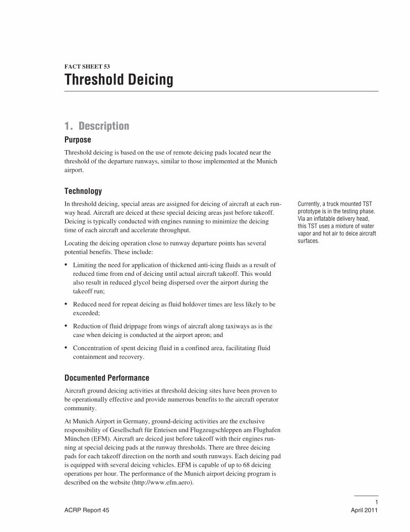
FACT SHEET 53
Threshold Deicing
1. DescriptionPurposeThreshold deicing is based on the use of remote deicing pads located near thethreshold of the departure runways, similar to those implemented at the Munichairport.
TechnologyIn threshold deicing, special areas are assigned for deicing of aircraft at each run-way head. Aircraft are deiced at these special deicing areas just before takeoff.Deicing is typically conducted with engines running to minimize the deicingtime of each aircraft and accelerate throughput.
Locating the deicing operation close to runway departure points has severalpotential benefits. These include:
• Limiting the need for application of thickened anti-icing fluids as a result ofreduced time from end of deicing until actual aircraft takeoff. This wouldalso result in reduced glycol being dispersed over the airport during thetakeoff run;
• Reduced need for repeat deicing as fluid holdover times are less likely to beexceeded;
• Reduction of fluid drippage from wings of aircraft along taxiways as is thecase when deicing is conducted at the airport apron; and
• Concentration of spent deicing fluid in a confined area, facilitating fluidcontainment and recovery.
Documented PerformanceAircraft ground deicing activities at threshold deicing sites have been proven tobe operationally effective and provide numerous benefits to the aircraft operatorcommunity.
At Munich Airport in Germany, ground-deicing activities are the exclusiveresponsibility of Gesellschaft für Enteisen und Flugzeugschleppen am FlughafenMünchen (EFM). Aircraft are deiced just before takeoff with their engines run-ning at special deicing pads at the runway thresholds. There are three deicingpads for each takeoff direction on the north and south runways. Each deicing padis equipped with several deicing vehicles. EFM is capable of up to 68 deicingoperations per hour. The performance of the Munich airport deicing program isdescribed on the website (http://www.efm.aero).
ACRP Report 45 April 20111
Currently, a truck mounted TSTprototype is in the testing phase.Via an inflatable delivery head,this TST uses a mixture of watervapor and hot air to deice aircraftsurfaces.
As much of the sprayed deicing fluid as possible is collected at the remote thresh-old areas in Munich. It is treated at the airport’s recycling facility to produce newdeicing fluid. Because of the proximity of the remote areas to the runway, aircraftcan take off within the shortest possible time after being deiced. This minimizesthe possibility that the holdover time for the deicing fluid will be exceeded, whichnecessitates a repeat deicing operation. Remote deicing ensures safety, savestime, reduces costs, limits the quantity of deicing fluid used, and protects theenvironment.
2. Implementation ConsiderationsApplicability AssessmentA number of principal factors apply when considering this approach:
• The availability of the large land areas at locations near runway thresholds,suitable for such operations;
• The large upfront infrastructure costs for such facilities; and
• The commitment of local commercial operators to use the facility, and tosubmit deicing operations to a single deicing operator.
Regulatory ConsiderationsSafe and efficient aircraft operations are of primary importance in the develop-ment of any aircraft deicing facility. FAA Advisory Circular (AC) No: 150.5300-14B Design of Aircraft Deicing Facilities discusses sizing, siting, environmentalrunoff mitigation, and operational needs of a deicing facility and how to maxi-mize deicing capacity while maintaining maximum safety and efficiency.
TC publication (TP 14052), “Guidelines for Aircraft Ground-Icing Operations,”contains information applicable to the Commercial Operation of Aircraft inCanada under Ground Icing Conditions. The information provided is derivedfrom many sources and comes from operational experience, from scientific fact,from testing and evaluation, and from regulation.
All runoff from deicing operations must be contained, collected, and disposed ofin accordance with regulations and guidelines of applicable governmental andmunicipal authorities. It is the responsibility of the user to assure that disposal is appropriate and is in compliance with legal requirements.
The operator’s approved deicing program must provide a detailed description ofthe procedures related to the remote deicing site.
Planning and Design ConsiderationsThe SAE Aerospace Division publication ARP 4902, Design and Operation ofAircraft Deicing Facilities, provides a list of operational issues that SAE recom-mends addressing. Each remote facility must be capable of handling the depar-
2 FACT SHEET 53
April 2011 ACRP Report 45
ture traffic expected for the associated runway without causing major delays todepartures.
Each facility must have the capability of handling the locally operated aircraftwith the most demanding characteristics, such as wingspan, tail height, etc.
The site location must be such that there is no interference with air traffic controlor runway obstacle clearance requirements.
Remote sites will require electrical power, water, and potentially another energysupply.
Systems for spent fluid containment, collection, and disposal will be needed ateach site.
Integration with Other Fact SheetsConcentration of deicing operations at a few sites will offer the possibility ofcollecting a greater quantity of spent fluid as compared with deicing at the apron.
Minimizing taxi times to final takeoff will potentially enable greater use of onlyType I fluids, reducing the need for thickened anti-icing fluids. Practices relatedto applying the lowest authorized fluid strength for Type I fluid could furtherreduce costs and environmental impact. The implementation of Holdover TimeDetermination Systems at threshold deicing sites may enable increased usage ofType I fluids.
Operation and Maintenance ConsiderationsTypically, such an operation would be controlled and managed by a singleservice provider.
Procedures for use of the facilities, especially standardized communicationspackages, will need to be developed in concert with aircraft operators, airportmanagement, and air traffic control.
The standardized communications package is a vital key to safe and efficient useof the remote site.
• An efficient and reliable method of communication allows pilots to commu-nicate their intentions to the service provider at the earliest possible time;
• Communication between the pilot and the service provider, as soon as pos-sible in advance of the aircraft arriving at the deicing location, ensures thatthe deicing operation will be accomplished in the safest and most efficientmanner, for both the flight crew and the ground crew;
• Once an aircraft has received permission to proceed to the deicing locationand has begun taxiing, it is important that flight crews be able to receiveprompt notification of any changes to the deicing operation or of problemsthat arise;
• The procedures used by the service provider for entry of aircraft into, and exitfrom the deicing pad must be made clear to the flight crews;
FACT SHEET 53 3
ACRP Report 45 April 2011
• Once an aircraft has reached the entry point to the facility, control must betransferred from Air Traffic Services to Pad Control. A communication linkbetween the Pilot-in-Command and Pad Control must be established prior tothe aircraft entering a deicing bay;
• Prior to commencement of the deicing/anti-icing operation, certain vitalinformation will need to be shared and acknowledged to ensure that the aircraft is treated correctly, in a safe manner, and with a safe result;
• Following deicing, the pilot must be provided with standard informationabout the deicing anti-icing process used, prior to dispatch from the pad; and
• Emergency procedures must be clearly defined.
3. CostsSignificant capital, maintenance, and operating costs would be expected for suchinstallations. The magnitude of these costs will be specific to each installationand location.
4 FACT SHEET 53
April 2011 ACRP Report 45
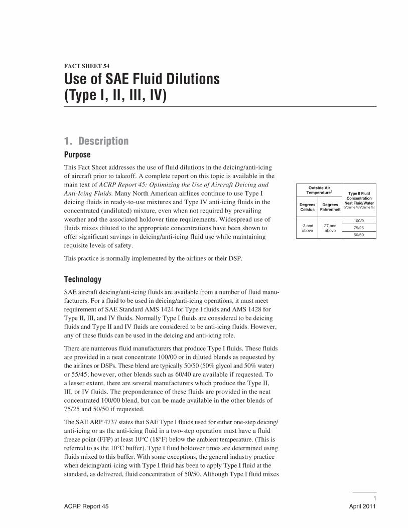
FACT SHEET 54
Use of SAE Fluid Dilutions (Type I, II, III, IV)
1. DescriptionPurposeThis Fact Sheet addresses the use of fluid dilutions in the deicing/anti-icing of aircraft prior to takeoff. A complete report on this topic is available in themain text of ACRP Report 45: Optimizing the Use of Aircraft Deicing andAnti-Icing Fluids. Many North American airlines continue to use Type I deicing fluids in ready-to-use mixtures and Type IV anti-icing fluids in theconcentrated (undiluted) mixture, even when not required by prevailingweather and the associated holdover time requirements. Widespread use offluids mixes diluted to the appropriate concentrations have been shown tooffer significant savings in deicing/anti-icing fluid use while maintaining requisite levels of safety.
This practice is normally implemented by the airlines or their DSP.
TechnologySAE aircraft deicing/anti-icing fluids are available from a number of fluid manu-facturers. For a fluid to be used in deicing/anti-icing operations, it must meetrequirement of SAE Standard AMS 1424 for Type I fluids and AMS 1428 forType II, III, and IV fluids. Normally Type I fluids are considered to be deicingfluids and Type II and IV fluids are considered to be anti-icing fluids. However,any of these fluids can be used in the deicing and anti-icing role.
There are numerous fluid manufacturers that produce Type I fluids. These fluidsare provided in a neat concentrate 100/00 or in diluted blends as requested bythe airlines or DSPs. These blend are typically 50/50 (50% glycol and 50% water)or 55/45; however, other blends such as 60/40 are available if requested. To a lesser extent, there are several manufacturers which produce the Type II, III, or IV fluids. The preponderance of these fluids are provided in the neatconcentrated 100/00 blend, but can be made available in the other blends of75/25 and 50/50 if requested.
The SAE ARP 4737 states that SAE Type I fluids used for either one-step deicing/anti-icing or as the anti-icing fluid in a two-step operation must have a fluidfreeze point (FFP) at least 10°C (18°F) below the ambient temperature. (This isreferred to as the 10°C buffer). Type I fluid holdover times are determined usingfluids mixed to this buffer. With some exceptions, the general industry practicewhen deicing/anti-icing with Type I fluid has been to apply Type I fluid at thestandard, as delivered, fluid concentration of 50/50. Although Type I fluid mixes
ACRP Report 45 April 20111
Outside AirTemperature2
DegreesCelsius
DegreesFahrenheit
-3 andabove
27 andabove
Type II FluidConcentration
Neat Fluid/Water[Volume %/Volume %]
100/0
75/25
50/50
are required to have only a 10°C buffer, the Type I fluid 50/50 mixes typicallyhave FFP ranging from −20°C to −35°C depending upon the type of glycol used.These FFPs provide greater buffers than the 10°C buffer required for most pre-vailing temperatures during aircraft deicing operations. Thus, this practiceresults in dispensing much more glycol content than is necessary, and leads to unnecessary operational costs and increased stress on the environment.
Similarly SAE Types II, III, and IV anti-icing fluids are available at fluiddilutions/concentrations of 100/0, 75/25, and 50/50. Fluid endurance times are measured for several temperature bands using fluids mixed to these con-centrations and the corresponding holdover time guidelines are published.Some 75/25 anti-icing thickened fluid concentrations have holdover timessimilar to 100/0 fluids, and many 50/50 thickened fluid concentrations haveholdover times well in excess of SAE Type I fluid, where applicable. Despitethe opportunity to employ lower fluid concentrations, anti-icing operations inNorth America have been based almost exclusively on 100/0 Type IV fluidconcentrations. As a result, there is a considerable opportunity to reduce theamount of glycol dispensed by applying fluid at lower, already approved, concentrations.
A proportioning/blending unit consists of a pumping system (including a pump,valves, piping, and a controller) that pumps ADF from one tank and water fromanother tank into a blend tank at a selected concentration. The blend tank is nor-mally fitted with a refractometer to measure the FFP of the mixture. The blendtank may be fitted with heaters, to allow application of the blend mix at requiredtemperatures. For Type II, and Type IV fluids, special pumps such as diaphragmpumps may be required. This technology is well established.
Several manufacturers of deicing equipment produce units with proportionalblending capabilities that can readily blend glycol and water to produce therequired Type I fluid 10°C buffer mix. In addition some units have blendingcapabilities that dilute the 100/0 Type II, III, and IV fluid concentrations toblends of 75/25 and 50/50 concentrations. The sizes of these units vary from lessthan 1,000 gallon capacity to over 3,000 gallon capacity. Although newer unitswith proportional blending are available, many airlines opt to continue to use theolder conventional units which do not have proportional blending capabilities. Inthis case, ready-to-use mixes of Type I in the 50/50 or 55/45 concentration andType IV fluids in the 100/0 concentration are usually used.
Documented PerformanceSeveral equipment manufacturers have cited case studies in which proportionalblending of Type I fluids to the required 10°C buffer have resulted in savings of30 to 70% over that of conventional deicing/anti-icing operations using a manu-facturers supplied ready-to-use mix of 55/45 concentrations. In many of thesecases, the temperature and prevailing weather conditions were such that only a20/80 mixture was required to achieve the required 10°C buffer. This was com-mon at the warmer temperatures where the aircraft were defrosted early in themorning at the start of the day’s operations.
2 FACT SHEET 54
April 2011 ACRP Report 45
2. Implementation ConsiderationsApplicability AssessmentTwo significant factors apply when considering the use of fluid dilutions fordeicing and anti-icing. They are:
• Costs associated with the procurement of deicing equipment with a propor-tional blending capability or cost required to add this capability to existingdeicing equipment; and
• The willingness of deicing operators to not use ready-to-use Type I fluid mix-tures with 50/50 or 55/45 concentrations, or Type IV fluid neat concentra-tions (100/0) when prevailing climatic conditions and Holdover-timerequirements can be met by Type I fluids with appropriate 10°C buffers orType IV 50/50 or 75/25 fluid dilutions.
Regulatory ConsiderationsCurrent industry and regulatory guidelines are in place, which allow the efficientuse of fluid dilutions to effect deicing and anti-icing of aircraft surfaces. Thereare specific SAE Guidelines in SAE ARP 4737 that addressed procedures for theapplication of Type I, II, III, and IV fluids and their dilutions in both the one-stepand the two-step deicing/anti-icing procedures.
Similar tables are contained in the guidance documents published yearly by theFAA, TC, and the AEA. In a recent survey on this topic, both the airlines andDSPs indicated that these guidelines were adequate to effect safe and timely useof fluid dilutions in the deicing and anti-icing operations.
Planning and Design ConsiderationsThe following items need to be considered when planning, and implementing adeicing/anti-icing system that uses proportional blending to effect the required10°C buffer for Type I fluids or are used to dilute Type II, III, or IV 100/0 anti-icing fluids to 75/25 or 50/50 concentrations:
• Climate suited to the technology’s strengths;
• Additions to the operators training program to address operational character-istics, limitations, and safety concerns associated with the use of dilutions;
• Maintenance staff training; and
• Upgrade of existing conventional deicing units vs. phased replacement ofentire deicing units on a scheduled basis.
Integration with Other Fact SheetsUse of dilutions of SAE Type I, II, III, and IV fluids can readily be integratedwith other source reduction BMP where fluids are used. This practice is compati-ble with all of the containment/collection/conveyance/storage, and treatment/
FACT SHEET 54 3
ACRP Report 45 April 2011
recycling practices. This practice may not be compatible with those airport-recycling programs where captured spent deicing fluids must contain a minimalamount of glycol to prove economically viable.
Operation and Maintenance ConsiderationsOperational requirements associated with this BMP include proportioning/blending equipment that will allow fluid blending and the associated training for deicing personnel to use the equipment safely.
The added complexity of the technology may increase maintenance requirements.
3. CostsModerate capital, maintenance, and operating costs would be expected for thesituations in which conventional deicing equipment without proportional blend-ing capabilities are replaced or upgraded with the installation of blending systems.These costs would be governed by the sophistication of the upgrade to the deicingequipment and could vary between $30,000 to $60,000 depending upon the capa-bilities, condition, and age of the equipment being upgraded. A new deicing unit/equipment (a single deicing vehicle) with proportional blending capability couldvary from $230,000–400,000 for moderate sized (1,800 gallon units) to wellover $600,000 for larger capacity (3000 + gallon) high reach units.
There would be similar cost increases ($30,000 to $60,000) associated with theaddition of proportioning blending to dilute Type IV fluids from the 100/0 concen-trations to 50/50 or 75/25 dilutions as appropriate. Studies have shown potentialsaving in the long run whenever adequate and not excessive dilutions are used.
4 FACT SHEET 54
April 2011 ACRP Report 45
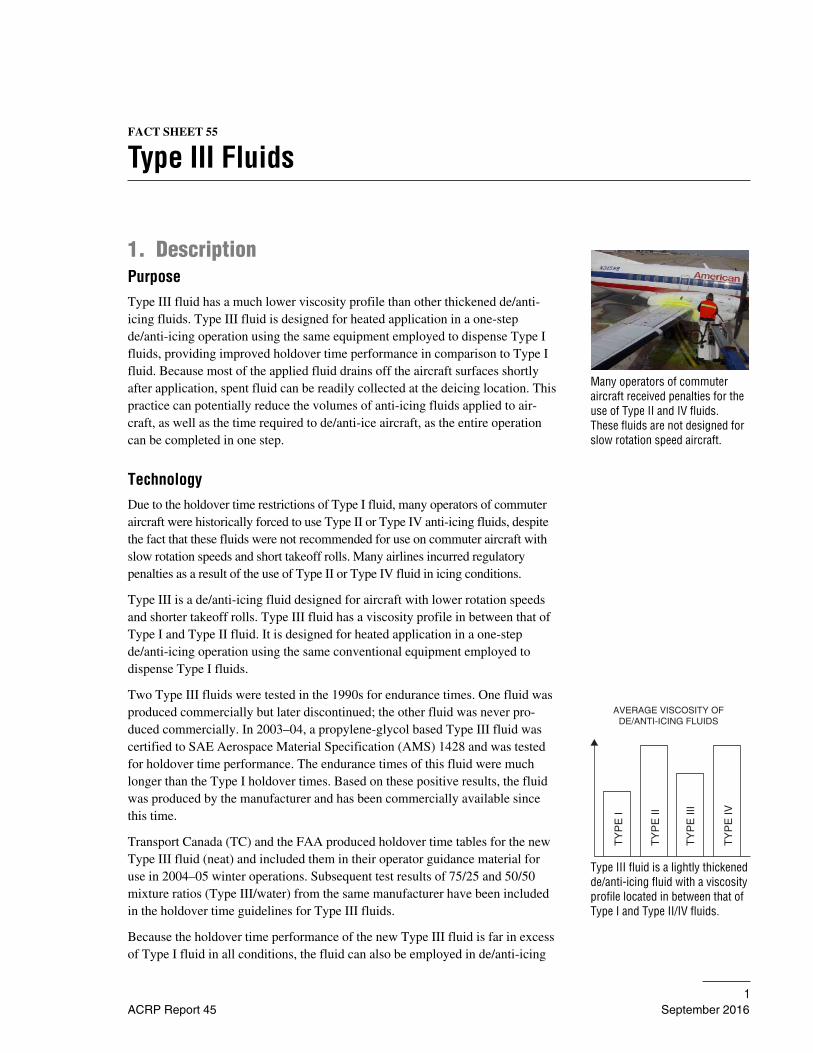
FACT SHEET 55
Type III Fluids
1. DescriptionPurposeType III fluid has a much lower viscosity profile than other thickened de/anti-icing fluids. Type III fluid is designed for heated application in a one-stepde/anti-icing operation using the same equipment employed to dispense Type Ifluids, providing improved holdover time performance in comparison to Type Ifluid. Because most of the applied fluid drains off the aircraft surfaces shortlyafter application, spent fluid can be readily collected at the deicing location. Thispractice can potentially reduce the volumes of anti-icing fluids applied to air-craft, as well as the time required to de/anti-ice aircraft, as the entire operationcan be completed in one step.
TechnologyDue to the holdover time restrictions of Type I fluid, many operators of commuteraircraft were historically forced to use Type II or Type IV anti-icing fluids, despitethe fact that these fluids were not recommended for use on commuter aircraft withslow rotation speeds and short takeoff rolls. Many airlines incurred regulatorypenalties as a result of the use of Type II or Type IV fluid in icing conditions.
Type III is a de/anti-icing fluid designed for aircraft with lower rotation speedsand shorter takeoff rolls. Type III fluid has a viscosity profile in between that ofType I and Type II fluid. It is designed for heated application in a one-stepde/anti-icing operation using the same conventional equipment employed to dispense Type I fluids.
Two Type III fluids were tested in the 1990s for endurance times. One fluid wasproduced commercially but later discontinued; the other fluid was never pro-duced commercially. In 2003–04, a propylene-glycol based Type III fluid wascertified to SAE Aerospace Material Specification (AMS) 1428 and was testedfor holdover time performance. The endurance times of this fluid were muchlonger than the Type I holdover times. Based on these positive results, the fluidwas produced by the manufacturer and has been commercially available sincethis time.
Transport Canada (TC) and the FAA produced holdover time tables for the newType III fluid (neat) and included them in their operator guidance material foruse in 2004–05 winter operations. Subsequent test results of 75/25 and 50/50mixture ratios (Type III/water) from the same manufacturer have been includedin the holdover time guidelines for Type III fluids.
Because the holdover time performance of the new Type III fluid is far in excessof Type I fluid in all conditions, the fluid can also be employed in de/anti-icing
ACRP Report 45 September 20161
Many operators of commuter aircraft received penalties for theuse of Type II and IV fluids.These fluids are not designed forslow rotation speed aircraft.
Type III fluid is a lightly thickenedde/anti-icing fluid with a viscosityprofile located in between that ofType I and Type II/IV fluids.
AVERAGE VISCOSITY OFDE/ANTI-ICING FLUIDS
TY
PE
I
TY
PE
II
TY
PE
III
TY
PE
IV
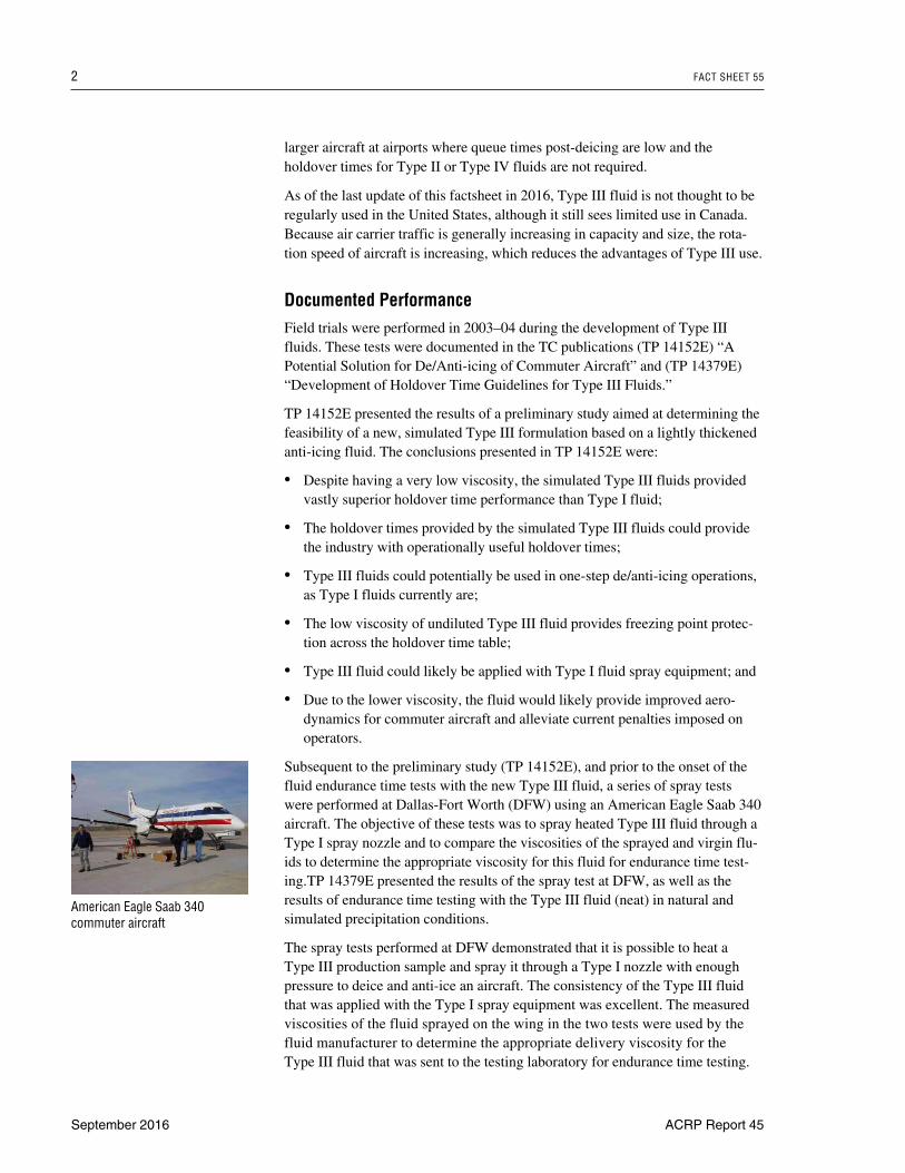
larger aircraft at airports where queue times post-deicing are low and theholdover times for Type II or Type IV fluids are not required.
As of the last update of this factsheet in 2016, Type III fluid is not thought to beregularly used in the United States, although it still sees limited use in Canada.Because air carrier traffic is generally increasing in capacity and size, the rota-tion speed of aircraft is increasing, which reduces the advantages of Type III use.
Documented PerformanceField trials were performed in 2003–04 during the development of Type III fluids. These tests were documented in the TC publications (TP 14152E) “APotential Solution for De/Anti-icing of Commuter Aircraft” and (TP 14379E)“Development of Holdover Time Guidelines for Type III Fluids.”
TP 14152E presented the results of a preliminary study aimed at determining thefeasibility of a new, simulated Type III formulation based on a lightly thickenedanti-icing fluid. The conclusions presented in TP 14152E were:
• Despite having a very low viscosity, the simulated Type III fluids providedvastly superior holdover time performance than Type I fluid;
• The holdover times provided by the simulated Type III fluids could providethe industry with operationally useful holdover times;
• Type III fluids could potentially be used in one-step de/anti-icing operations,as Type I fluids currently are;
• The low viscosity of undiluted Type III fluid provides freezing point protec-tion across the holdover time table;
• Type III fluid could likely be applied with Type I fluid spray equipment; and
• Due to the lower viscosity, the fluid would likely provide improved aero-dynamics for commuter aircraft and alleviate current penalties imposed on operators.
Subsequent to the preliminary study (TP 14152E), and prior to the onset of thefluid endurance time tests with the new Type III fluid, a series of spray testswere performed at Dallas-Fort Worth (DFW) using an American Eagle Saab 340aircraft. The objective of these tests was to spray heated Type III fluid through aType I spray nozzle and to compare the viscosities of the sprayed and virgin flu-ids to determine the appropriate viscosity for this fluid for endurance time test-ing.TP 14379E presented the results of the spray test at DFW, as well as theresults of endurance time testing with the Type III fluid (neat) in natural and simulated precipitation conditions.
The spray tests performed at DFW demonstrated that it is possible to heat a Type III production sample and spray it through a Type I nozzle with enoughpressure to deice and anti-ice an aircraft. The consistency of the Type III fluidthat was applied with the Type I spray equipment was excellent. The measuredviscosities of the fluid sprayed on the wing in the two tests were used by thefluid manufacturer to determine the appropriate delivery viscosity for the Type III fluid that was sent to the testing laboratory for endurance time testing.
2 FACT SHEET 55
September 2016 ACRP Report 45
American Eagle Saab 340 commuter aircraft
The endurance time tests performed with new Type III fluid provided very goodresults. The endurance times were all much longer than the Type I holdovertimes. TC and the FAA produced similar Type III holdover time tables for inclu-sion within their operator guidance material for use in 2004–05 winter opera-tions. Subsequent incarnations of the Type III holdover time guidelines from TCand FAA have included values for 75/25 and 50/50 Type III fluids.
The Type III fluid has been endorsed by most airframe manufacturers, andBombardier and Embraer have performed takeoff tests on operational aircraftwith the Type III fluid. Aerodynamic testing with the Type III fluid limited itsuse to −16.5°C (2°F) with slow rotation speed aircraft and −29°C (−20°F) withhigh rotation speed aircraft.
In the early 2000s, air operators in the United States and Canada began employ-ing Type III fluid in winter operations, but its use has not been widespread. Thefluid was reported to have performed well in all operations, and no deficiencieshave been noted to date.
The fluid, as designed, may be used heated in a one-step operation. Use ofheated, thickened anti-icing fluids for deicing has resulted in cases of fluidresidue re-hydration in the past. As the viscosity profile of the fluid is greatlyreduced in comparison to other thickened fluids, it is believed that fluid residueswill be greatly reduced with Type III fluid. A verification program may need tobe implemented if Type III use is initiated.
2. Implementation ConsiderationsApplicability AssessmentThis practice would be primarily applicable to aircraft operators or FBOs atairports with commuter aircraft traffic or with short queue times followingde/anti-icing. This practice would be readily applicable for spray-and-go deicingoperations. As the fluids provide holdover times well in excess of Type I fluids,this practice would enable improved operational flexibility at many airports andimproved safety. In addition, the use of Type III fluid could sizably reduce vol-umes of fluids applied at airports that have mild winter operating conditions.
Regulatory ConsiderationsThe fluid currently resides on the TC and FAA lists of approved de/anti-icing fluids,and holdover time guidelines for the products are provided by the regulators. Thereare no other regulatory considerations that hinder the use of Type III fluid.
Planning and Design ConsiderationsThe following factors should be considered in planning implementation of Type III fluids:
• Aerodynamic performance and freeze point limitations of the Type III fluidversus the operating environment at the airport;
FACT SHEET 55 3
ACRP Report 45 September 2016
• Holdover times required for operations at the airport in all winter operatingconditions;
• Queue times of aircraft post-deicing;
• On-site fluid storage facilities;
• The logistics of product substitution, which will include consuming or dis-posing of existing stockpiles of old fluids and cleaning tanks and refillingthem with the new product;
• Modifying and distributing deicing plans to reflect the new product and training employees on the new plan and product;
• The environmental characteristics of the Type III product; and
• Effective training and quality assurance program.
Integration with Other Fact SheetsType III fluid could be employed with many other practices.
Operation and Maintenance ConsiderationsFor this practice to be effective, operators should plan on revising deicing plans toreflect new product and providing product-specific training to deicing personnel.
With the exception of changes required to the deicing plans, equipment operationand maintenance requirements should not change significantly.
A maintenance program may need to be initiated to verify that gel residueissues are not created by the use of Type III fluids in a heated one-step deicingoperation.
3. CostsThe initial costs for implementing Type III ADF would be for the purchase of the fluid and any additional storage capacity that may be required.
The cost of Type III fluid is similar to that of Types I and IV. However, Type IIIfluid is applied at higher concentrations than Type I, which makes it more expen-sive per gallon applied for deicing. Additionally, Type III fluid offers shorter hold-over time protection than Type IV fluids. Therefore, cost savings are generallyrealized only when Type III fluid can be used in a one-step deicing/anti-icingprocess that replaces both Type I and Type IV fluids. Because business jets aresmaller than commercial airliners and often operate from smaller airports wherelong holdover protection is not necessary, they are the most likely to benefit fromType III fluid application. A reduction in environmental costs would also occur.
Costs may also be incurred development and monitoring of a maintenance pro-gram to verify that gel residue is not an issue with the use of Type III fluids in aheated one-step deicing operation.
4 FACT SHEET 55
September 2016 ACRP Report 45
FACT SHEET 56
Infrared Deicing Technology
This Fact Sheet is structured in two parts: Part I describes the use of fixed facilitiesfor infrared deicing and Part II describes the use of mobile infrared deicing systems.
Part I Fixed Infrared Deicing Facilities
1. DescriptionPurposeThis practice utilizes infrared (IR) energy to melt frost, snow, and ice from thesurface of an aircraft, greatly reducing the need for deicing fluids.
Responsibility for implementation and operation is by a specialized service contractor in coordination with an airport.
TechnologyThe technology for infrared deicing utilizes natural gas- or propane-fired emittersthat are tuned to optimize the melting of frost, ice, and snow. The IR energyfrom the emitters does not heat the air nor is it lost in the air before it contacts the aircraft. The IR energy does not pass through the aircraft surface and has a negligible effect on aircraft cabin temperature.
Some deicer or anti-icer application may be required after snow and ice havebeen removed by the IR to provide holdover time during periods of active freez-ing or frozen precipitation. Depending on the weather conditions and location of the system, some deicing of the aircraft using aircraft deicing fluid may benecessary before it can be moved to the IR deicing location.
One manufacturer has developed an IR deicing system that consists of a drive-through structure with emitters mounted from the ceiling that aircraft pass throughto be deiced. Four facilities were constructed in the United States between 1997and 2006 at Buffalo Niagara, Rhinelander–Oneida County, Newark International,and JFK International airports. However, as of 2016, none of these facilities arecurrently in regular use. Another facility was opened in Oslo, Norway in 2006 andwas used as a testing facility for two deicing seasons before it was shut down.
Documented PerformancePerformance data on IR deicing are limited by the number and scale of facilitiesin commercial operation to date. When they were operating, all of the existing
ACRP Report 45 September 20161
Some deicer or anti-icer applica-tion may be required after IRdeicing to provide holdover timeduring periods of active freezingor frozen precipitation.
installations served a small fraction of the total aircraft traffic at the airportswhere they are located. For that reason, there are no data available on airportwide glycol use reductions.
Data is available for two facilities in the New York metropolitan area:
• An 80–90% reduction in per aircraft glycol use was reported using the systeminstalled at the Newark airport;
• The JFK Airport IR facility was operated during the 2006–2007 deicing season.With the exception of two ice storms, this was a relatively mild deicing sea-son. Glycol reductions of approximately 90% per aircraft were reported undersnow and ice conditions. Defrosting operations were reported as having usedno glycol.
2. Implementation ConsiderationsApplicability AssessmentThe following factors should be considered in evaluating the potential applica-bility of this technology to a particular airport:
• All of the existing IR deicing facilities were implemented by a single manu-facturer. Since that time, this manufacturer is no longer actively offering thisproduct and service. While there are other companies that offer IR heatingequipment and may have the capability to install IR deicing hangars, none are actively pursuing IR deicing at the time of this factsheet;
• The IR system provides aircraft deicing, but does not provide any holdovertime. Supplemental application of aircraft deicers or anti-icers is likely to berequired for safe flight operations;
• With the current drive-through designs, land requirements and siting of an IRfacility are key determinants regarding basic feasibility. See RegulatoryConsiderations and Planning and Design Considerations;
• Substantial upfront infrastructure costs are associated with construction of an IRfacility. In most cases, some level of commitment by aircraft operators to use thefacility would be required to prove the business case for a new installation; and
• It may be possible to find productive uses (e.g., vehicle storage and mainte-nance) for the IR structures during the non-deicing season.
Regulatory ConsiderationsThe FAA has produced several guidance documents related to the use of IRenergy for deicing and encourages the development and use of this technology.IR facilities need to meet the criteria of FAA AC 120-89, “Ground DeicingUsing Infrared Energy.” Use of IR energy for deicing can be approved as part ofany Part 121, 125, or 135 certificate holder’s deicing/anti-icing program or plan.FAA publication AC 150/5300-14C, “Design of Aircraft Deicing Facilities,”Chapter 5 covers the design of infrared deicing facilities.
2 FACT SHEET 56
September 2016 ACRP Report 45
Although the technology is stillavailable, IR deicing facilities arenot in active production.
Air emissions issues and applicable regulations should be considered with thispractice. Aircraft movement to the deicing facility may increase air emissions. In addition, the power generation and gas used by the infrared emitters may have emissions ramifications.
These issues need to be examined at the airport level before a decision is made toemploy this practice.
Planning and Design ConsiderationsThe location and design of the IR system structure is critical to its acceptanceand success. IR facility placement must take into consideration the aircraftlaunch area and allow for adequate approach and egress. These facilities can be land intensive. The structure itself must conform to FAA Part 77 and beapproved for tower sightlines and runway object-free areas. Part 77 includesimaginary surfaces that define navigable airspace with specific height and construction restrictions. Basic electrical, water, and gas utilities are required.
The size and type of aircraft operating at the facility must be considered todetermine if they can be accommodated by the IR system. In most cases, it willbe advisable to consider a “composite” aircraft when designing an IR deicingfacility. That is, consider the most constraining features of all of the variousaircraft that are envisioned using the facility. One facility in the United Statesceased operations because the air carrier it typically served increased the sizeof its aircraft.
A screening-level traffic analysis will provide an estimate of the number of facilities that would be required to serve a given portion or subset of an airport’sdeicing needs. If the airport operates with significant “pushes” each day where a large number of aircraft are departing during a relatively short period, the IRfacility must be sized with enough throughput capacity to prevent bottlenecksduring severe weather conditions. Under these circumstances, conventional deicing of aircraft may be required to ensure adequate throughput.
FAA publication AC 150/5300-14C, “Design of Aircraft Deicing Facilities,”provides standards and recommendations for the design and construction of IRaircraft-deicing facilities. In 2005, the FAA issued AC 120-89, “Ground DeicingUsing Infrared Energy” to offer guidance to airlines on how to integrate IR deicing operations into their operating plans.
Integration with Other Fact SheetsAs discussed earlier, some level of deicing or anti-icing will still need to be performed on aircraft under many conditions. Additional collection and contain-ment of the resulting glycol-laden runoff may be required at the IR deicing facility.This localized collection and containment would be a likely opportunity for collec-tion of relatively small volumes of high concentration of glycol.
Because this is a source control BMP, its use will likely reduce the volume ofdeicing stormwater requiring collection and treatment, with reductions beingproportional to the level of implementation at an airport. Glycol recovery operations
FACT SHEET 56 3
ACRP Report 45 September 2016
may be negatively impacted if the volumes of high-concentration runoff arereduced below the level critical to economic feasibility.
Operation and Maintenance ConsiderationsOperation and maintenance of the IR facility are typically provided by a servicecontractor with specialized skills and training.
Ground traffic coordination may impose new operational requirements.
3. CostsAs with performance data, cost data are limited on the IR deicing facilitiesbecause of the few installations to date. The most recent implementations havebeen installed under cooperative agreements between the airport and the technology provider.
Capital CostsThe range of costs for construction of a single-bay deicing facility was reportedas $1 million to $4 million in 1997 ($1.5 million to $6.0 million in 2016 dollars).The 68,644 ft2 facility at JFK is reported to have cost $9.5 million ($12.1 millionin 2016 dollars). Final costs are dependent upon airport location and size, num-ber of bays, proximity to required utilities, and local geotechnical conditions.
Operation and Maintenance CostsOperating costs for infrared deicing have been cited as being significantly lowerthan conventional deicing with fluids.
Part II Mobile Infrared Deicing Systems
1. DescriptionPurposeA mobile IR deicing system has the potential to be an alternative to standard glycol deicing, with the flexibility to operate at the gate or other locations whereenvironmental restrictions could prohibit the use of glycol.
This practice is not yet a proven technology, but has been examined as a poten-tial alternative technology in the research and development phase. As of 2016,Trimac Industries is still capable of producing the truck as described belowalthough they are not actively pursuing its production.
4 FACT SHEET 56
September 2016 ACRP Report 45
TechnologyTrimac Industries, LLC of North Kansas City, Missouri, developed a mobile aircraft deicing system designed around flameless IR heat emitters. The systemis known as the Infra-Red Technologies Ice Cat™ system.
The Ice Cat aircraft deicing system is designed around IR heat emitters usingnatural gas, propane or butane fuel. The IR heat is created through a catalyticprocess that doesn’t emit nitrous oxides or carbon monoxide associated withcombustion processes.
A microprocessor based temperature control system manages the IR energytransmitted to the aircraft surfaces. The control system allows the operator topre-set the desired maximum aircraft skin temperature by continuously adjusting the amount of propane fuel being fed to the heaters.
The Ice Cat’s emitters are installed on mobile vehicles equipped with articulatingboom extensions, which lift and position the panels over the aircraft surfaces.
Documented PerformanceA study conducted to examine the effectiveness of a mobile system in removingdifferent types of frozen contamination from a wing surface in terms of time andquality and to assess the potential for future use was reported in the TransportCanada document (TP 13489E), “Deicing with a Mobile Infrared System.”
The research team evaluated the effectiveness of the Ice Cat IR deicing systemon Fokker F28 and Boeing 737 aircraft. The time required to clear an entire wingof wet snow or frozen precipitation for the prototype system was found to beunacceptably long. The researchers concluded that deicing times would need tobe reduced for the unit to be operationally viable.
Although the system’s effectiveness in natural frost conditions was not examined,it is expected that the deicing time should be much shorter than that experiencedwith natural snow and may be operationally acceptable.
2. Implementation ConsiderationsAs of 2016, this technology is not commercially available. Nonetheless, the fol-lowing general guidance on implementation considerations is provided if the sta-tus should change in the future.
Applicability AssessmentAs a mobile unit, the system could be used in two possible modes:
• At the gate, to remove overnight frost, ice, or snow contamination followingtermination of precipitation; and
• Off-gate deicing or in conjunction with off-gate deicing, to deice the aircraftprior to application of anti-icing fluid.
FACT SHEET 56 5
ACRP Report 45 September 2016
The time required to deice an entire wing of wet snow or frozen precipitation forthe prototype unit, as demonstrated, was found to be unacceptably long. Deicingtimes would need to be reduced for the unit to be operationally viable.
Although the system’s effectiveness in natural frost conditions was not examined,the deicing time should be much shorter than that experienced with natural snow,and may be operationally acceptable.
There may be an opportunity to develop the system as a solution for frostremoval. Incorporation of blowing fans could be considered to assist in removingmelt water from the surface to prevent it from running into wing cavities.Defrosting constitutes a relatively large part of winter deicing operations. Whenviewed on the basis of the amount of contamination being removed, fluiddefrosting is a relatively high-cost operation.
Regulatory ConsiderationsThe system must produce results that comply with ARP 4737.
Approval by regulatory authorities is required prior to implementation in field operations.
FAA AC 120-89, “Ground Deicing using Infrared Energy” offers more information on the subject.
Planning and Design ConsiderationsSome prime objectives that must be considered for successful application are:
• The mobile equipment must be adaptable to use on aircraft parked at passen-ger terminals;
• The deicing/defrosting process must be sufficiently rapid to avoid delays toaircraft departures; and
• Wing surface temperatures must conform to aircraft manufacturer’s limitations.
Integration with Other Fact SheetsThis practice is viewed as being an alternative technology to the use of glycoldeicing fluids, but could also be employed to eliminate a portion of the contami-nation on the aircraft prior to the use of glycol-based fluids. Therefore, it couldbe integrated with other practices.
Operation and Maintenance ConsiderationsSpecialized operator training would be required for the safe use of such equipment, particularly if employed in the congested passenger terminal parking areas.
Maintenance support and training would be required for the mobile IR system.
6 FACT SHEET 56
September 2016 ACRP Report 45
3. CostsCapital CostsA significant capital cost would be associated with purchasing such systems,which include the mobile vehicles and articulating booms for mounting the IR panels.
Operation and Maintenance CostsMaintenance costs would be associated with the mobile vehicles and IR systems.Operational costs for the vehicle operation and the IR panel fuel must be considered. Savings could accrue from reduced use of glycol fluids.
FACT SHEET 56 7
ACRP Report 45 September 2016
FACT SHEET 57
Enhanced Weather Forecasting
1. DescriptionPurposeThis Fact Sheet involves the use of advanced weather forecasting systems toimprove the accuracy of deicing and anti-icing material application, as well asfor the preparation and operation of deicing practices.
Airports, aircraft operators or deicing service providers may be responsible forimplementing this practice.
TechnologyThis practice utilizes real-time weather forecasting to improve the efficiency ofdeicing and anti-icing practices by giving pilots and airport operators relevantqualitative and quantitative information on the potential for wintertime precipita-tion. This real-time forecasting may assist in improving the efficiency of deicingand anti-icing practices.
Several technologies have been developed and implemented at several airports toachieve improve weather forecasting.
One popular technology uses regional area Doppler radars, surface weather stations,and snow gauges situated in terminal areas to measure weather characteristics. TheNational Center for Atmospheric Research (NCAR) developed an integrated dis-play system that uses this information to depict accurate, real-time nowcasts ofsnowfall rate plus current temperature, humidity, and wind speed and direction.
A second technology provides forecast services ranging from terminal forecasts towritten or oral system route briefings. Terminal forecasts are short-term, 18-hourforecasts of ceilings, visibilities, winds, and weather in or near airports, all ofwhich dictate weather restrictions on arriving aircraft. If airport conditions improveearlier than originally forecasted, an amendment is issued as soon as possible.Route system briefing forecasts provide weather conditions over longer periodsand over larger areas than the terminal forecasts. Briefings consist of a writtensummary of weather features and events that are likely to impact aviation opera-tions. Generally, they include a discussion of the pertinent weather features fore-casted to affect the route system during the next 8 to 24 or 48 hours. Potentialweather trouble spots including timeframes and impacts are identified as specifi-cally as possible. These reports are intended for use by systems operation con-trollers and others who work with the various components of flight operations.
Documented PerformanceThe performance has not been directly measured. If used successfully, this prac-tice can optimize the selection of deicing or anti-icing materials and methods for
ACRP Report 45 April 20111
a particular deicing event. When used in conjunction with other deicing prac-tices, enhanced weather forecasting may also improve the accuracy of practiceselection, coordination, and operation, thereby potentially reducing concentra-tions or discharge volumes of deicer- or anti-icer-impacted stormwater.
A limitation associated with this practice is that forecasts are often inaccurate,even with advanced weather systems and equipment. Deicing personnel aretasked with making real-time deicing decisions that are conservative with respectto aircraft safety. As such, deicer application rates may not be significantlydecreased because of enhanced weather forecasts.
2. Implementation ConsiderationsApplicability AssessmentEnhanced weather forecasting would be applicable to any airport or aircraftoperator that performs aircraft or pavement deicing because it can improve theaccuracy of deicer or anti-icer application rates and methods. The practice couldbe especially beneficial at airports with deicer management systems and deicerapplication practices that could be optimized by more accurate weather forecasts.
Accurate weather forecasts can help to identify weather conditions that are opti-mal for alternative deicing methods such as forced air deicing, tempered steam,hot water deicing, proactive anti-icing, and deicer blending to temperature.Weather forecasts can also improve the preparation and coordination of deicercontainment and collection equipment, including deicer collection vehicles andcatch basin inserts. Airports with fewer operations may not realize significantbenefits when compared to the costs for installation and operation. Medium andlarge airports in northern climates are more likely to achieve the most benefitsfrom this practice.
Regulatory ConsiderationsThe primary regulatory consideration for this practice is complete compliancewith all FAA requirements for effective deicing and safe flight operations.
Planning and Design ConsiderationsAirports, aircraft operators and deicing service providers interested in enhancedweather forecasting as a practice should consider the following in their planningand implementation:
• Identify the service or equipment that can provide enhanced weather forecast-ing services that best meet the needs of the airport and aircraft operators;
• Consider the following:
– Capital and operational cost for each service or equipment; and
– Types and accuracy of forecasts provided through each system and theirapplicability to existing airport deicing procedures and practices.
2 FACT SHEET 57
April 2011 ACRP Report 45
• Determine how enhanced weather forecasts will be incorporated into standardoperating procedures for deicing/anti-icing and deicer management;
• Develop protocol for identifying weather conditions that are appropriate forexisting deicer or anti-icer application methods and deicer managementpractices; and
• Develop a training program for employees that will be using the weather-forecasting system.
Integration with Other Fact SheetsThe success of many deicer application and deicer management practices may beenhanced by more-accurate and relevant weather forecasts. Enhanced weatherforecasts may enable an airport or aircraft operator to identify opportunities forusing alternative deicing practices, including alternative deicing materials andapplication equipment. Accurate weather forecasts can help to identify weatherconditions that are optimal for alternative deicing methods such as forced airdeicing, tempered steam, hot-water deicing, proactive anti-icing, and deicerblending to temperature. Weather forecasts can also improve the preparation andcoordination of deicer containment and collection equipment, including deicercollection vehicles and catch basin inserts.
Operation and Maintenance ConsiderationsOperational requirements depend on the technology employed. If a serviceprovider is used, the primary operational issues will be incorporating the infor-mation into standard operating procedures and training of personnel. If the tech-nology is to be operated by the airport or aircraft operator, regular maintenanceof equipment associated with sensors and forecasting technologies will berequired, as prescribed by the manufacturer.
3. CostsCosts consist of the costs of the weather-forecasting service or system as well asthe time for the airport/airline staff to interpret the data.
Capital CostsCapital costs include installation of specialized weather-forecasting equipmentonsite. Costs may be significant if the airport or aircraft operator chooses to ownand operate the instrumentation. Using a forecasting service will entail no capitalcosts if dedicated instrumentation is not required.
Operation and Maintenance CostsOperational costs may include costs associated with subscribing to or accessinga specialized weather-forecasting service, or costs for maintenance of onsiteenhanced weather-forecasting sensors and equipment.
FACT SHEET 57 3
ACRP Report 45 April 2011
Even with enhanced weather systems, forecasts are some-times inaccurate.
Consequently, deicing decisionsthat are conservative with respectto aircraft safety must be made.
FACT SHEET 112
Low Flow Nozzles
1. DescriptionPurposeThis Fact Sheet discusses the use of low flow Aircraft Deicing Fluid (ADF)application nozzle technology that uses a reduced amount of ADF as comparedto standard nozzles. Low flow nozzles may be used on most existing deicingtrucks as an immediate low cost method of improving the efficiency of ADFapplication to aircraft, and reducing ADF usage.
TechnologyAlthough specific models will vary, a typical low flow nozzle has flow ratesthat can be varied between 11 and 40 gallons per minute (gpm), compared toconventional fixed flow nozzles which typically are between 50–60 gpm.Some variants of the low flow nozzles maintain a constant pressure over arange of flow settings. Low flow nozzles that change the pressure to regulatethe flow can result in higher pressures that are not applicable for all aspects of deicing.
Documented PerformanceLow flow nozzles, particularly constant pressure variable flow nozzles, havebeen shown to deice aircraft in the same amount of time and as effectively asconventional nozzles. Constant pressure low flow nozzles are able to maintain a useable stream while flow is being adjusted. An additional benefit is that itmoderates fluctuations in flow due to truck systems.
Nozzles that decrease flow by increasing pressure (similar to placing your thumbover the end of a garden hose) have been shown to be useful to penetrate moreresilient snow and ice, such as refrozen snow.
Some nozzles deliver flows as low as 11 gpm, which are applicable to aircraftdefrosting operations. This has been reported to result in a considerable reductionof ADF compared to conventional nozzles.
Specific glycol savings are difficult to estimate because it varies for eachuser depending on flow rates used and fleet make up. However, since lowflow nozzles are generally capable of deicing an aircraft in the same amountof time as higher flow nozzles, operators should be able to estimate theirglycol savings by estimating glycol use as a function of flow and time takento deice an aircraft.
ACRP Report 45 September 20161
Low flow nozzles range from 11 gpm to 40 gpm, often with the ability to vary flow settings.
2. Implementation ConsiderationsApplicability AssessmentThis technology is directly applicable to operators who have the responsibilityfor selecting and using ADF application technology that meets all requirementsfor maintaining aircraft safety.
Older generation trucks with original nozzles may have flow rates as high as50–60 gpm. Some trucks also have the capability of using multiple nozzles andswitching between them. Using low flow nozzles as either the sole nozzle or asan option on a multi-nozzle truck allows for a reduction in applied gpm andhence a reduction in applied volume. This option is often cited as low hangingfruit when considering options for reducing glycol consumption. This technol-ogy is particularly applicable to improving the efficiency of older generationtrucks.
Regulatory ConsiderationsThere are no regulatory considerations that directly affect this practice. However,aircraft must be free from contamination before takeoff, and the exclusive use oflow flow deicing nozzles may make it difficult to meet these requirements in atimely manner under severe winter conditions.
Planning and Design ConsiderationsThe following factors should be considered in planning for low flow nozzles:
• Existing deicing equipment that can accommodate low flow nozzles;
• Size and configuration of aircraft;
• Time requirements associated with reduced flow nozzles (particularly duringsevere weather conditions); and
• Additional training for personnel.
Integration with Other Fact SheetsLow flow nozzles may be employed in association with technologies describedin other Fact Sheets involving the use of ADF blending or dilution. Low flownozzles can be integrated with forced air or blending to temperature to furtherreduce ADF use.
Operation and Maintenance ConsiderationsLow flow nozzles are compatible with the majority of existing trucks and theirinstallation is generally uncomplicated. Trucks with the capacity to measureADF use in real time should ensure compatibility with low flow nozzles beforeswitching/supplementing low flow nozzles to ensure accuracy. Pumping systemsfor trucks may have to be adjusted to meet flow and pressure ratings for specificnozzles.
2 FACT SHEET 112
September 2016 ACRP Report 45
Low flow nozzles are often citedas low hanging fruit when consid-ering glycol use reduction options.
Low flow nozzles are often easilyinstalled on existing trucks.
Higher pressure low flow nozzles may be impractical for use in anti-icing operations because the higher pressure results in uneven fluid application.
Care should be taken when using low flow nozzles in conjunction with blending totemperature or hybrid air technologies to ensure that temperature buffers are met.Holdover time is a function of volume of fluid on the aircraft and the temperatureof the fluid. Therefore, if the volume of the fluid is reduced (and subsequently theinherent total heat), holdover time will also be reduced. This problem may beamplified when deicing aircraft where the skin of the aircraft is colder than normal,for example from having flown long distances.
3. CostsCapital CostsThe primary cost associated with this technology is the initial purchase of thenozzles, which is on the order of $200 each. While installation is moderatelysimple, it varies with the make and model of the trucks and selected nozzles.Total initial costs will depend on fleet size. Truck pump modifications may benecessary depending on the specific truck and nozzle pairing. Additional systemadjustments may add to the initial cost.
Operation and Maintenance CostsBeyond initial cost to purchase and install this technology, there are not consideredto be any significant additional costs. This procedure provides the potential forsavings through reduction in deicing fluid usage.
FACT SHEET 112 3
ACRP Report 45 September 2016