'ACR-700 Human Factors Engineering Program Plan,' 108 ...
34
AECL EKL Plant Performance Specification ACR -700 HUMAN FACTORS ENGINEERING PROGRAM PLAN ACR 108-03800-PPS-001 Revision 1 Prepared by RBdig6 par Leger Robert P. Reviewed by VBrifi6 par Malcolm Scott Approved by Approuk par Crane Dick (RH) 2003/06/23 2003/06/23 Controlled Contr616 Licensing Licensing @Atomic Energy of Canada Limited Ohergie Atomique du Canada Limitke 2251 Speakman Drive Mississauga, Ontario Canada L5K lB2 2251 rue Speakman Mississauga (Ontario) Canada L5K 1 B2
Transcript of 'ACR-700 Human Factors Engineering Program Plan,' 108 ...

AECL EKL Plant Performance Specification ACR -700 HUMAN FACTORS ENGINEERING PROGRAM PLAN ACR 108-03800-PPS-001
Revision 1
Prepared by RBdig6 par
Leger Robert P.
Reviewed by VBrifi6 par
Malcolm Scott
Approved by Approuk par
Crane Dick (RH)
2003/06/23 2003/06/23 Controlled Contr616 Licensing Licensing
@Atomic Energy of Canada Limited
Ohergie Atomique du Canada Limitke
2251 Speakman Drive Mississauga, Ontario Canada L5K lB2
2251 rue Speakman Mississauga (Ontario) Canada L5K 1 B2
SIGNATUREPAGE
DO NOT DELETE THIS!!!

108-03800-PPS-001 2003/06/23
Human Factors Engineering Program Plan
ACR-700 Human Factors Engineering Program Plan
ACR
108-03800-PPS-001 Revision 1
2003 June
CONTROLLED - Licensing This document and the information contained in it is made available for licensing review. All rights reserved by Atomic Energy of Canada Limited. No part of this document may be reproduced or transmitted in any form or by any means, including photocopying and recording, without the written permission of the copyright holder, application for which should be addressed to Atomic Energy of Canada Limited. Such written permission must also be obtained before any part of this document is stored in a retrieval system of any nature.
Juin 2003
CONTRÔLÉ - Permis Le présent document et l’information qu’il contient sont disponibles pour examen en vue de l’obtention des permis. Tous droits réservés par Énergie atomique du Canada limitée. Il est interdit de reproduire ou de transmettre, par quelque procédé que ce soit, y compris de photocopier ou d’enregistrer, toute partie du présent document, sans une autorisation écrite du propriétaire du copyright obtenue auprès d’Énergie atomique du Canada limitée. De plus, on doit obtenir une telle autorisation avant qu’une partie du présent document ne soit intégrée dans un système de recherche documentaire de quelque nature que ce soit.
� Atomic Energy of Canada Limited
© Énergie atomique du Canada limitée
2251 Speakman Drive Mississauga, Ontario Canada L5K 1B2
2251, rue Speakman Mississauga (Ontario) Canada L5K 1B2

Release and Liste des documents Revision History et des révisions 0939B Rev. 13
Document Details / Détails sur le document
Title Titre
Total no. of pages Nbre total de pages
ACR-700 Human Factors Engineering Program Plan
CONTROLLED – Licensing - CONTRÔLÉ - Permis
Release and Revision History / Liste des documents et des révisions
Release Document
Revision Révision
Purpose of Release; Details of Rev./Amendement Objet du document; détails des rév. ou des modif.
Prepared by Rédigé par
Reviewed by Examiné par
Approved by Approuvé par
No./No Date No./No Date
DCS/RMS Input / Données SCD ou SGD
Rel. Proj. Proj. conn.
Project Projet
SI
Section
Serial Série
Sheet Feuille No. N
o
Of De
Unit No.(s) Tranche no
108 03800 PPS 001 1 1 dsfpdfsp 108-03800-PPS-001 2003/06/23
1 D1 2002/06/14 Issued for Review and Comment.
K. Holford J.S. Malcolm A. Josefowicz
2 0 2002/07/22 Issued as “Approved for Use”.
K. Holford J.S. Malcolm A. Josefowicz
3 1 2003/06/23 Issued as “Approved for Use”. Document security designation changed to Controlled Licensing.
R. Leger J. S. Malcolm D. Crane

CONTROLLED - Licensing 108-03800-PPS-001 Page i Rev. 1
TABLE OF CONTENTS
SECTION PAGE
108-03800-PPS-001 2003/06/23
1. SCOPE/PURPOSE...............................................................................................1-1
2. PROGRAM SOURCE DOCUMENTS ...............................................................2-1
2.1 Governing Documents..........................................................................................2-1 2.2 Guidance Documents ...........................................................................................2-1 2.3 Reference Documents ..........................................................................................2-1
3. HUMAN FACTORS ORGANIZATIONAL STRUCTURE AND RESPONSIBILITY..............................................................................................3-1
3.1 Purchasing/Operating Utility Responsibilities .....................................................3-2
4. HUMAN FACTORS ENGINEERING LEVEL OF EFFORT............................4-1
5. HUMAN FACTORS ENGINEERING ACTIVITIES.........................................5-1
5.1 Level A HFE Design Changes .............................................................................5-3 5.2 Level B Design Changes ......................................................................................5-6 5.3 Design Tracking ...................................................................................................5-6 5.4 Configuration Control ..........................................................................................5-6
6. HUMAN FACTORS MILESTONES AND DOCUMENTATION ....................6-1
6.1 Milestones ............................................................................................................6-1 6.2 Documentation .....................................................................................................6-1 6.2.1 Design Guides ................................................................................................6-4 6.2.2 Design Requirements .....................................................................................6-4 6.2.3 Plant Performance Specifications...................................................................6-4 6.2.4 System Performance Specifications ...............................................................6-5 6.2.5 Design Assessments/Analysis Reports ..........................................................6-5 6.2.6 Design Descriptions .......................................................................................6-5
7. REFERENCES.....................................................................................................7-1
FIGURES
Figure 5-1 Human Factors Engineering Program Review Model .........................................5-2 Figure 6-1 Control Centre Design Documentation Hierarchy...............................................6-2 Figure 6-2 HSI Design Model for Documentation Usage .....................................................6-3
Figure A-1 ACR-700 Model (Swain and Weston) of the Tasks in Human Decision Making ................................................................................................................A-3

CONTROLLED - Licensing 108-03800-PPS-001 Page ii Rev. 1
TABLE OF CONTENTS
SECTION PAGE
108-03800-PPS-001 2003/06/23
Figure B-1 ACR-700 Human Factors Issue Form................................................................. B-4
APPENDICES
Appendix A Model of Human Decision Making.....................................................................A-1 Appendix B ACR-700 Human Factors Engineering Issue Form ............................................ B-1 Appendix C Glossary of Abbreviations................................................................................... C-1

CONTROLLED - Licensing 108-03800-PPS-001 Page 1-1 Rev. 1
108-03800-PPS-001 2003/06/23
1. SCOPE/PURPOSE
The Advanced CANDU Reactor�* (ACR-700�) Human Factors Engineering Program Plan (HFEPP) identifies the Human Factors Engineering (HFE) principles, standards, requirements and processes necessary to integrate HFE throughout the design of the entire plant and satisfies the requirement for such a document as outlined in the Basic Engineering Program Plan [Reference 1]. The ACR-700 HFEPP is based on the experience derived from the application of HFE to CANDU design projects throughout the evolution of CANDU technology. This HFEPP covers all HF tasks associated with the design of the ACR-700 plant. Currently, this project includes plant design only. Therefore, this HFEPP applies to construction and commissioning issues only in that they will be considered where foreseeable as an input to design. This plan specifies HFE activities and design processes which will result in effective ACR-700 human-system interface (HSI) designs, which, in turn, can be safely operated and maintained in the operational environment, and which are compatible with human information requirements, capabilities and limitations. The HFE activities as outlined in this plan, will enhance the human component contribution towards the achievement of overall system safety and performance goals. The integration of HFE activities throughout all steps of the design process will facilitate the achievement of these goals under all postulated plant regions and system states.
* Advanced CANDU Reactor� (ACR-700�) is a trademark of Atomic Energy of Canada Limited (AECL).

CONTROLLED - Licensing 108-03800-PPS-001 Page 2-1 Rev. 1
108-03800-PPS-001 2003/06/23
2. PROGRAM SOURCE DOCUMENTS
2.1 Governing Documents
The following documents govern the format, content and structure of the HFE program: 1) COG-92-444, A Guide to the Development of Project Specific Human Factors Engineering
Program Plans [Reference 2]. 2) IEEE Std. 1023-1988, IEEE Guide for the Application of Human Factors Engineering to
Systems, Equipment and Facilities of Nuclear Power Generating Stations [Reference 3]. 3) NUREG-0711, Human Factors Engineering Program Review Model [Reference 4]. 4) P-00119, Policy on Human Factors, Canadian Nuclear Safety Commission [Reference 5].
2.2 Guidance Documents
The following HF guidance documents will be used as primary sources of HFE design criteria for incorporation into ACR-700 documentation and design guidance. 1) NUREG-0700, Guidelines for Control Room Design Reviews, Rev. 01 [Reference 6]. 2) EPRI NP-4350, Human Engineering Design Guidelines for Maintainability [Reference 7]. 3) NUREG-0896, Functional Criteria for Emergency Response Facilities [Reference 8]. 4) MIL-STD-1472D, Human Engineering Design Criteria for Military Systems, Equipment, and
Facilities. US Department of Defense [Reference 9]. The ACR-700 project will also develop a series of design guides based on the documents listed above. The CANDU HFE DGs shall be developed primarily for system designers (mainly of Level B design areas, see Section 6.2.1), but shall also be developed for control centre and HF designers for reasons of consistency and thoroughness. A preliminary list of HFE DGs which aid human factors design tasks through all stages of the design process is provided in this program plan (Section 6.2.1). This list will be modified as required during the course of design.
2.3 Reference Documents
Where guidance found in the above documents is limited, or for some reason inappropriate, ACR-700 has chosen the following as reference documents: 1) Woodson, Tillman and Tillman, Human Factors Design Handbook, Second Edition, (general
reference) [Reference 10]. 2) Fregly and Blatteis, Handbook of Physiology: Environmental Physiology, (human
physiology reference) [Reference 11]. 3) Gilmore, Gertman and Blackman, User Computer Interface in Process Control: A Human
Factors Engineering Handbook, (computer interface reference) [Reference 12]. Further reference books may be located as needed in COG-92-444 [Reference 2], which contains several reference and guidance documents specific to many of the ten elements. In addition to the documentation, the Swain and Weston decision-making model, documented in Appendix A, will be used as an input to design decisions.

CONTROLLED - Licensing 108-03800-PPS-001 Page 3-1 Rev. 1
108-03800-PPS-001 2003/06/23
3. HUMAN FACTORS ORGANIZATIONAL STRUCTURE AND RESPONSIBILITY
The overall responsibility for ensuring that HFE is integrated in the ACR-700 design resides with the ACR-700 Project Director. The ACR-700 HFE design specialists report directly to the ACR-700 Instrumentation, Control and Electrical Manager. The HF design team support to other ACR-700 disciplines shall be provided in accordance with the level of design effort (see Section 4.0). The HF design team size and content will fluctuate in accordance with the workload and expertise requirements for the design, and will be more fully defined in future revisions of this document. HF team members will be drawn from specialists at AECL Sheridan Park, and from consultants and contract staff when required. Responsibilities for activities specified in this plan have been divided between 3 groups: 1) HF Team 2) Management Team 3) Branch Champions and Designers These are summarized below. 1. The HF design team responsibilities shall include (but not be limited to): • Identification and development of HFE plans, processes, procedures and design guides. • Ensuring compliance of activities to approved HFE plans and project procedures. This
includes ensuring successful integration of activities through all stages of the design process. • HFE review, where applicable, the design engineering change proposals for identification of
human performance issues. • Performance assessment of HFE design, development, test and evaluation activities. • Initiation, recommendation and provision of solutions for problems encountered in the
implementation of HFE activities, as well as tracking of issues. • Verification of implementation of human factors design team engineering recommendations
which have been accepted by project management. • Identification and notification of HFE design concerns and issues to an appropriate level of
project management. • Planning HFE design team activities and milestones. • On-going HFE training for ACR-700 Branch Champions and System Designers in support of
designated HFE design tasks and activities. • On-going HFE support to Branch Champions and System Designers as required/requested. • Assisting in and performing operational experience reviews as required. • Ensuring significant human performance issues are tracked and appropriately documented. 2. The project management, including project technical and branch managers shall have the following HFE responsibilities, in addition to their assigned management responsibilities:

CONTROLLED - Licensing 108-03800-PPS-001 Page 3-2 Rev. 1
108-03800-PPS-001 2003/06/23
• The support of HFE design related activities identified for their design teams by project procedure, and their support of the HFEPP.
• The selection, designation and functional support of one of their branch design engineers as a Human Factors (HF) champion.
• The supervisory support of HFE within their branch, to ensure HFE issues are being identified and resolved according to procedure.
3. The Branch HF champions shall have the following HFE responsibilities, in addition to their assigned system design responsibilities:
• Providing HFE procedure and DG interpretations to branch designers, and assistance in performing HFE design related activities (e.g., HFE issue identification in relation to human operational and maintenance requirements) in concert with the HF design team.
• The reporting of significant HFE issues per Section 5.3 (e.g., with respect to HFE procedures or DGs) and unresolved or inadequate assessment of HFE issues to their branch manager, and to the project quality assurance manager.
• The assessment of the HF needs and requirements of branch designers, and the manner in which these needs will be supported (e.g., via HF design team direct support).
• Liaison with the HF design team and branch managers, as appropriate. If required, further responsibilities relating to HF will be added to this document once further information is available regarding the functional and organizational structure of the ACR-700 project team.
3.1 Purchasing/Operating Utility Responsibilities
This plan identifies the relevant design information and inputs necessary to aid the development of station specific design and the subsequent operational practices (e.g., station specific training and operating procedures) by the purchasing/operating utility. The purchasing/operating utility should be responsible for the development of the finalized plant operational practices, due to the station specific nature of the final design. The utility should also ensure that the development of these practices is consistent with the initial definitions (e.g., staff roles and responsibilities, emergency operating procedures, etc.) used or developed as part of the ACR-700 plant design. Apart from the AECL ACR-700 HFEPP, the purchasing/operating utility should document the development methodology of the following:
• General plant operations/personnel organization, • Station staffing, • Assigned staff responsibility, • Maintenance methodology and procedures, • Operating and testing procedures, and • Training programs for station staff.

CONTROLLED - Licensing 108-03800-PPS-001 Page 4-1 Rev. 1
108-03800-PPS-001 2003/06/23
4. HUMAN FACTORS ENGINEERING LEVEL OF EFFORT
In order to effectively utilize HFE design resources in a manner that achieves maximum safety, production and maintenance design benefit from HFE considerations, a multi-level of effort approach has been chosen. This level of effort approach serves to provide an initial focus for the HF design team and ensures direct HF design support is provided to areas more dependent on high levels of human-system performance towards the achievement of overall safety and production goals. However, the allocation decision is flexible in that assignment of a design area to a level is not rigid. As the plant/system design progresses, more information about the system becomes available, allowing the design level designation to be reassessed. Based on extensive CANDU 9 background review and feedback, the following systems, equipment and layouts (‘design areas’) have been assigned to one of the two HFE application design levels, in accordance with the criteria defined below.
Level A Level A design areas are designated systems, subsystems, equipment and layouts in receipt of direct and detailed HF design team support. Level A design areas typically represent areas where human involvement is known to be intense and important to the achievement of plant safety and production goals. Systems meeting any of the following criteria shall be designated as Level A. • Human-System Interfaces (HSI) designated to be within the Control Centre Areas (i.e., MCA
and SCA). • Identified Operational Experience Review information indicating significant human
performance issues with the reference design or known occupational health and safety issues/concerns.
• Changes in level of plant system control automation (i.e., function allocation changes). • Systems/Areas aiding the supervision and/or control of operational and maintenance
activities which could infer significant safety or production consequences upon functional performance degradation.
• Significant HF design team concerns, highlighted during HF design team assessments, system design change proposal reviews (per project change control procedure) and, design reviews.
The design areas for Level A HFE application presently include: • Main Control Area (MCA) – This includes the Main Control Room (MCR), Work Control
Area (WCA), Shift Supervisors Office (SSO), Control Equipment Rooms (CERs). Direct HF design team support shall be given to the associated room layouts, panel/console design, and to control, display, and annunciation interface designs.
• Secondary Control Area (SCA) – Direct HF design team support shall be given to room layouts, panel/console design, and to control, display, and annunciation HSI designs.
• Remote field panels and control areas • Process and Control Systems HSIs designated for the Control Centre Area

CONTROLLED - Licensing 108-03800-PPS-001 Page 4-2 Rev. 1
108-03800-PPS-001 2003/06/23
• Control Centre Communications to field and generic implications to plant-wide communication systems.
The design tasks involved with the above areas are under the direct responsibility of the Control Centres design team (which encompasses the HF design team), and process control designers.
Level B Level B design areas encompass all ACR-700 design areas that have not been allocated as a Level A design area. Generally, Level B design areas are not viewed as requiring direct HF design support as they exhibit a proven/acceptable performance record (per OER review) combined with a relatively low level of human interaction. The designation of ACR-700 design areas for Level B HFE application is not rigid. If during the design, Level B design areas are seen to warrant Level A HFE attention, these design areas shall be re-allocated to the Level A HFE application level. Level B design areas will receive HF design support via system designer adherence to project procedures, HFE design guides, and HF design team review recommendations, as applicable. System designers working on Level B design areas will also have support from their designated HF Branch Champion. Level B design areas presently include, for example:
• Remote panels or interfaces for controls and displays which warrant little human interaction, located outside of the Control Centres.
• Civil structures and systems and equipment located outside of the Control Centres areas The HFE design tasks involved with the above areas are under the direct responsibility of various ACR-700 design branches and sections. The HFE tasks involved, generally relate to the design and layout of systems and equipment with regard to human operations (including testing and inspection), maintenance and commissioning requirements. In support of Level B design area HFE activities, the HF design team will provide the ACR-700 system designers with appropriate: • HF consultative support as required or requested, • HF revisions to project procedures, • HFE design guides, and • HFE training (basic) for facilitation of designer identification and resolution of HFE design
issues. The HF design team shall also perform spot-check audits on approximately 15% of Level B system designs to ensure that HFE procedures and principles are appropriately applied. The HF design team shall also take part in Level B system design documentation DR and DD reviews (note: approximately 15% of Level B documentation will be reviewed).

CONTROLLED - Licensing 108-03800-PPS-001 Page 5-1 Rev. 1
108-03800-PPS-001 2003/06/23
5. HUMAN FACTORS ENGINEERING ACTIVITIES
The HFE activities performed as part of ACR-700 design work will be summarized in a Human Factors Engineering Summary Report (HFESR), the scope of which is to be determined as the design timeline and scope of activity are more clearly defined. Details will be documented in project records, and filed as per ACR-700 procedures (to be written). The human factors activities for Level A and B activities will reflect the ten elements of HFE design and implementation, as outlined in NUREG-0711 [Reference 4] (See Figure 5-1).

CONTROLLED - Licensing 108-03800-PPS-001 Page 5-2 Rev. 1
108-03800-PPS-001 2003/06/23
HFE Design & ImplementationProcess Stages
Planning Analysis Design V&V
Element 1HFE ProgramManagement
Element 2Operating Experience
Review
Element 3 Functional Requirements
Analysis & FunctionAllocation
Element 4Task Analysis
Element 5Staffing
Element 6Human Reliability
Analysis
Element 7Interface Design
Element 8Procedure
Development
Element 9Training
Development
Element 10Verification
and Validation
Figure 5-1 Human Factors Engineering Program Review Model
(From NUREG-0711, p. 1-8)

CONTROLLED - Licensing 108-03800-PPS-001 Page 5-3 Rev. 1
108-03800-PPS-001 2003/06/23
5.1 Level A HFE Design Changes
For the purpose of this plan, Level A HFE design areas are equivalent to Control Centre design areas, however, this may change as the HFE processes are implemented and some Level B HFE design areas are elevated to Level A HFE design areas. The HF activities for Level A systems will be performed as outlined below.
Element 1 – HFE Program Management HFE Program Management for the ACR-700 Project is defined and addressed by this document.
Element 2 – Operating Experience Review The operating experience review (OER) identifies the HFE related issues. The intent is to review documentation from the reference plant(s) and, where possible, to survey personnel to obtain operating experience relating to human system interface issues. Further sources of information that may be employed as a means of gaining OER information include: reference plant site visits/document review; design or peer review meetings; and OER information from the Feedback for Design process. The ACR-700 Control Centres Operations Experience Review 108-66000-ASD-001 [Reference 13] contains a preliminary review of available OER information. Issues outlined in this document, and additional issues identified through the Feedback for Design process will be examined. Each issue that is determined to be appropriate for incorporation into the design will be documented in the HFE issues database and tracked.
Element 3 – Functional Requirements Analysis and Function Allocation Functional requirements analyses provide the framework for the human system interface and for completion of the detailed task analysis. Functional allocation is the analysis of the requirements for plant control and the assignment of control functions to personnel (manual control), system elements (automatic control) or to a combination thereof. The CANDU 9 functional basis document [Reference 14] shall be used as the initial basis for establishing information and control functions required by the control centre staff for monitoring and controlling the ACR-700 plant.
Element 4 – Task Analysis Task analyses identify the performance demands on plant personnel and the task requirements for accomplishing functions allocated to them. Where ‘task analysis’ is applied to operation, ‘maintenance analysis’ is a task analysis conducted to determine the performance expectations of maintenance personnel. Task analyses form the basis for: • Evaluating function allocations (i.e., examining the capability of plant personnel to
accomplish tasks assigned to them) • Providing a basis for staffing and job design • Providing detailed task requirements to support detailed procedure development • Identifying training requirements • Defining task support verifications requirements for verification • Validation review

CONTROLLED - Licensing 108-03800-PPS-001 Page 5-4 Rev. 1
108-03800-PPS-001 2003/06/23
Task analyses will be iterative throughout the design cycle. As a minimum, task analyses will be completed for Start up [Reference 15] and Shutdown [Reference 16] control room tasks. This work will be based on task descriptions completed for the CANDU 9 reference plant.
Element 5 – Staffing An analysis of staffing examines the organization and distribution of job responsibilities among operations staff. The ACR-700 Operational Basis outlines the current staffing plan, however the plan may be modified based on the analyses described here (e.g., task analysis, validation etc.).
Element 6 – Human Reliability Analysis (Safety Analysis and Risk Assessment) Human reliability analysis will be performed as part of the ACR-700 Probabilistic Safety Assessment. The approach to the analysis will be based on the guidelines of 108-03660-AB-001, Probabilistic Safety Assessment Methodology.
Element 7 – Interface Design (HSI) The results of HFE analysis (Elements 2 through 6) will be applied in the detailed design stage. As well as interface design (e.g., panels, computer driven displays (including wall panel displays in the MCR) etc.), this stage will include the design of floor plans, selection of annunciation media, and several other tasks which are part of overall HF design work, but not normally considered interfaces. The ACR-700 design guides, which will be written to reflect the best current practices in the HF field, will be followed whenever possible. However, where there is no guidance available in the design guides, or where guidance conflicts with other requirements, HFE specialists will perform the design work using the referenced design guidance (Section 2), and input from team members with appropriate expertise.
Element 8 and 9 – Procedure and Training Program Development The development and issue of operating procedures and training programs will normally be the responsibility of the purchasing/operating utility, and as such, beyond the scope of this HFEPP. Design work completed in accordance with this plan will be provided to the purchasing/operating utility as an input to the development of operating procedures and training program development.
Element 10a – Design Verification Verification is a confirmation that the design meets the requirements. Design verification methods are currently to be determined, and will be outlined in the ACR-700 Human Factors Engineering Verification and Validation Plan, to be released separately once sufficient information is available to determine the appropriate scope and activities. The two types of verification are HSI Task Support Verification and HFE Design Verification. Task support verification is a check to ensure that HSI components are provided to address all identified personnel tasks. Design verification is a check to determine whether the design of each HSI component reflects HFE principles, standards, and guidelines. Verification will take place through the company wide Design Verification [Reference 17], Design Review [Reference 18] and Document Review and Comment [Reference 19] processes.

CONTROLLED - Licensing 108-03800-PPS-001 Page 5-5 Rev. 1
108-03800-PPS-001 2003/06/23
Element 10b – Design Validation Design validation is a confirmation that individual designs and the design as an integrated whole meets the overall performance objectives of the system and the plant. HFE validation will be performed using a variety of methods as appropriate to the HF issues associated with a given design. The scope of design elements to be validated, and the most appropriate methods of validation are currently to be determined. A detailed outline of the validation plan will be provided in the ACR-700 Human Factors Engineering Verification and Validation Plan, to be released. As a minimum, the main control room design will be mocked up with both static and dynamic features. This mock up will serve as both an ongoing design tool and a platform for formal HFE validation.

CONTROLLED - Licensing 108-03800-PPS-001 Page 5-6 Rev. 1
108-03800-PPS-001 2003/06/23
5.2 Level B Design Changes
Designs categorized as Level B will have all of the operational and maintenance design issues handled by the discipline designer using the HFE design guides developed to ensure appropriate consideration of HF issues in ACR-700 design work. The ACR-700 HFE team will be included in preliminary review of design work to ensure the appropriateness of the Level B classification. As previously outlined, spot-check audits will be performed on approximately 15% of Level B system designs to ensure that HFE procedures and principles are appropriately applied. HF branch champions will also support system designers in the conduct of HFE tasks and activities as required. It should be noted that the detailed design work for many Level B systems, pertaining to the ‘Balance of Plant’, is contract dependent although AECL will strongly recommend HFEPP compliance. The purchasing utility will be supplied with the relevant design guides to ensure adequate design for operation and maintenance is considered in a thorough and consistent manner. The human factors design team will provide HFE assistance to the purchasing utility, on a contractual basis, as requested. Level B system and equipment designers shall review operations experience for, in part, human performance issues associated with related design operation and maintenance aspects. This information, along with HFE design guides, shall be used in the development of design requirements for the relevant systems. HFE designers may review the design requirements for the relevant systems as part of their performance assessment and verification of system designers’ identification, assessment, and disposition of human factors issues. Designers are required to document any deviation or exception from the guidance supplied in the design guides. All deviations and exceptions must be reviewed by an HFE specialist from the ACR-700 HF team.
5.3 Design Tracking
The ACR-700 Human Factors Team will maintain an up-to date spreadsheet of systems and milestone documents, in order to ensure that appropriate levels of effort are applied to each portion of the design, and to assist in estimating completed and outstanding work. Due to design trade offs and constraints, some HFE design criteria will not be fully realized by the ACR-700 design. Design processes exist within AECL to assess such trade offs for all disciplines, ranging from discussions between individual designers to formal trade off studies. The HF team shall also assess any HFE trade offs to determine if the trade off warrants higher recognition. If this is the case, an HFE issue form shall be completed (see Appendix B) by a member of the HFE team, in conjunction with the responsible system designer. The forms will outline the nature of the issue, the associated rationale and the issue disposition. HFE issue forms will be filed in the engineering record, and will be tracked by HFE as required.
5.4 Configuration Control
To facilitate effective project change control and promote communication and integration between disciplines, a formal configuration change control process shall be used. This process includes a Change Control Board, and shall be used in accordance with the AECL Change

CONTROLLED - Licensing 108-03800-PPS-001 Page 5-7 Rev. 1
108-03800-PPS-001 2003/06/23
Control Procedure (00-681.1) [Reference 20]. If an ACR-700 specific procedure is written, HF change control will integrate with that process. HFE design issues may initiate design or work process changes. These issues may originate from several sources, and will be assessed for scope, cost and impact on interfacing disciplines in accordance with the ACR project change control process.

CONTROLLED - Licensing 108-03800-PPS-001 Page 6-1 Rev. 1
108-03800-PPS-001 2003/06/23
6. HUMAN FACTORS MILESTONES AND DOCUMENTATION
6.1 Milestones
The HFE design activities and tasks are to be scheduled as a subset of the master schedule. Change Request forms will be processed through the configuration control process and will be actioned as approved or rejected with the goal of resolving any HFE issues before design drawings and details are released. Up to date project schedules for design activities and milestones, including human factors, will be maintained by the central planning/scheduling authority. The following is a list of the ACR-700 human factors design team activities that shall be included in the schedule when it is created. a) Issue and update of the ACR-700 HFEPP as required b) Issue and update of the ACR-700 project procedures (e.g., DD, DR procedures) for
integration of HFE issues into the design process, as required. c) Issues and update of ACR-700 HFE design guide documentation d) ACR-700 HFE design support
1) Operational Experience Review (OER) 2) Plant Functional Basis Document issues and revisions 3) Plant Operational Basis Document issues and revisions 4) Control Centre design documentation (e.g., DD, DR) 5) Development of ACR-700 HFE Verification and Validation Plan, performance of
mock-up exercises, and issue of the V&V report. e) Issue and update of the Maintenance Basis Document f) HFE consultation to minor effort system designers, as required. g) HFE training to all ACR-700 designers (Basic HF training and training on any HF changes to
project procedures) h) Issue and update of the HFESR
6.2 Documentation
The fundamental basis documents (HFEPP, V&V Plan, etc) shall take precedence over all other documents where conflicts exist. The Control Centre Design Documentation Hierarchy can be found in Figure 6-2. The HSI Design Model for Documentation Usage (see Figure 6-3) illustrates how the human factors design guidance will contribute to system design documentation. Certain design guides will be very useful as input into design description documents and others will be more useful as support material for detailed design work (e.g., those in the lower right section of the figure, labelled “HFE Standards”). For current, up-to-date information regarding the documentation hierarchy, see the official project schedules. The following sections list HFE design and compliance documentation currently planned for the ACR-700 project.

CONTROLLED - Licensing 108-03800-PPS-001 Page 6-2 Rev. 1
108-03800-PPS-001 2003/06/23
Design Requirements
Support Rules (Design Guides)
Fundamental Basis, Analysis Methods,
Tools and Plans
Human Factors Engineering Program
Plan
PDS and FHD Quality
Project Plan
SSM Quality Project
Plan
CC HFE Design Validation Plan
Fundamental Methods, tools, research and
process plans provide tracability and a
foundation for various aspects of the design
Design Guides are distilled from Fundamental Methods, tools, research and
development and process plans
System Summary Display
Location of Hardwired Human-System
Interfaces (HSIs)
Computer Hardware (HSI)
Function Analysis
Human Factors of Maintenance,
Inspection, and Testing
Annunciation
Panel Device Selection and Layout
Computer Display & Navigation
Symbology
Labeling and Text
Colour Usage
Abbreviations & Acronymns
Control Display
Support Information
Reference Plant Operational Basis
69-03800-SPS-002
CCs Reference Plant OER
Categorization of SSM Software
Reference Plant Functional Basis
69-03800-SPS-003
ACR-700 Functional Basis
ACR-700 Operational Basis
Operator Response Guidelines (ORGs)
Safety Design Guides (SDGs)
Categorization of PDS and FHD Software
Licensing Bases Document (LBD)
Support and rationale information is produced based on Design Guides and Rules. Support
information about the system and its operation is used to direct, support, or provide guidance for the design basis, requirements, and decisions.
PAM DR
CC DR
PDS DR
SSM DR
FDS DR
Annunciation DR
Central Overview Display DR
DCS DR
FCS DR
Design Descriptions
PDS DD
PAM DD
CC DD
FDS DD
SSM DD
Annunciation DD
DCS DD
FCS DD
Figure 6-1 Control Centre Design Documentation Hierarchy

CONTROLLED - Licensing 108-03800-PPS-001 Page 6-3 Rev. 1
108-03800-PPS-001 2003/06/23
HFE- Control Centres
- MCR and SCA HSI-Field Panel HSI
DesignDescription
Control AnnunciationDisplay
H.F. ofMaint. Test,
Inspect.
SystemSummary
Control Display
Panel DeviceSelection &
Layout
Annunciation
FunctionAnalysis
Location ofHardwired HSI
VDU DisplaySuites AnnunciationField Panel
HSIMCR & SCA
HSI
HFE Standards
ComputerHardware
Computer Display& Navigation
Task Analysis
Abbreviations
Colour Coding
Symbololgy
Labelling
Information from System Design
HSI Design Model for Documentation Usage
Minor
Major
Figure 6-2 HSI Design Model for Documentation Usage

CONTROLLED - Licensing 108-03800-PPS-001 Page 6-4 Rev. 1
108-03800-PPS-001 2003/06/23
6.2.1 Design Guides
Human Factors design guides shall be utilized by systems designers for system design requirements and design description document development. Compliance with design guides, where practicable, shall ensure design thoroughness and consistency. The DGs will be produced in accordance with the Formal Documents Design Manual (00-03000-MAN-001 Appendix H) [Reference 21]. The following guides are planned:
• Human Factors of Maintenance, Inspection and Testing Design Guide (108-03800-DG-001 [Reference 22])
• Control Display Design Guide • Hardwired Human-System Interfaces Design Guide • System Summary Design Guide • Annunciation Design Guide • Panels Layout and Device Selection Design Guide • Function Analysis Design Guide • Computer Hardware Design Guide • Computer Display and Navigation Design Guide • Task Analysis Design Guide • Abbreviations and Acronyms Design Guide • Colour Usage Design Guide • Labelling and Text Design Guide • Symbology Design Guide
6.2.2 Design Requirements
Wherever practicable, human factors design requirements shall be incorporated into ACR-700 Design Requirements. For some major tasks, the Human Factors team may produce the Design Requirements. The DRs will be produced in accordance with the Formal Documents Design Manual (00-03000-MAN-001 Appendix J) [Reference 21]. The following documents are currently planned:
• Control Centres (MCA and SCA) DR • Central Overview Display DR • Annunciation DR • Plant Display System DR • Safety System Monitoring DR • Fuel Handling Display System (FDS) DR
6.2.3 Plant Performance Specifications
The human factors plant performance specifications shall be used to specify the overall human factors objectives and considerations that are plant wide. ACR-700 design plans, which describe

CONTROLLED - Licensing 108-03800-PPS-001 Page 6-5 Rev. 1
108-03800-PPS-001 2003/06/23
the methodology and degree to which human factors will be integrated into the plant design will also be considered to be plant performance specifications. The human factors design team will be responsible for verifying the performance of human factors activities and processes as outlined in the plans and procedures. These documents will be produced in accordance with the Formal Documents Design Manual (00-03000-MAN-001 Appendix R) [Reference 21]. The following HFE plant performance specifications are planned: • The Human Factors Engineering Program Plan (108-03800-PPS-001) • ACR-700 HFE Verification and Validation Plan
6.2.4 System Performance Specifications
Human factors system performance specifications shall be used to specify the ACR-700 design basis, which is fundamental to the derivation of requirements for related systems. It is currently anticipated that these documents will be produced in accordance with procedure 74-432.10. The following HFE system performance specifications are currently planned: • ACR-700 Plant Operational Basis (108-03800-SPS-001) • ACR-700 Plant Functional Basis • ACR-700 Maintenance Basis
6.2.5 Design Assessments/Analysis Reports
Human factors design assessment reports shall be written to document specific HFE design considerations and concerns. Human factors design analysis reports will document plant or system behaviour and performance and will be written at various steps in the design process. The human factors team will not always be solely responsible for preparing all assessments and analysis reports that document HFE design attributes. For the majority of these documents, the human factors component accounts for only part of the overall content and purpose of the document. For these documents, the human factors team shall provide input as appropriate. The governing procedure for this work is the Formal Documents Design Manual (00-03000-MAN-001 Appendices B and C) [Reference 21]. The following design assessment and analysis documents, either authored by or with significant input from HF, are anticipated:
• Control Centres/Plant Operations Experience Review (OER) Report • Categorization of PDS and FHD Software • Categorization of SSM Software • Control Centres Design Validation Assessment Report
6.2.6 Design Descriptions
Design Description documents will indicate the level of compliance to the design requirements related to all disciplines, including HF. Compliance to operability and maintainability requirements shall be documented in system designer DDs to the extent practicable. It is

CONTROLLED - Licensing 108-03800-PPS-001 Page 6-6 Rev. 1
108-03800-PPS-001 2003/06/23
currently anticipated that these documents will be produced in accordance with the Formal Documents Design Manual (00-03000-MAN-001 Appendix G) [Reference 21]. The following design area DDs, either authored by or with significant input from HF, are currently planned: • Control Centres (MCA & SCA) DD • Plant Display System DD • Annunciation System DD • Safety System Monitoring DD • Post Accident Monitoring (PAM) DD • Fuel Handling Display System (FDS) DD

CONTROLLED - Licensing 108-03800-PPS-001 Page 7-1 Rev. 1
108-03800-PPS-001 2003/06/23
7. REFERENCES
[1] 108-00300-062-001 R0 ACR-700 Basic Engineering Program Plan. [2] COG 92-444, A Guide for the Development of Project Specific Human Factors
Engineering Program Plans, CANDU Owners Group, October 1993. [3] EEE Std. 1023-1988, IEEE Guide for the Application of Human Factors Engineering to
Systems, Equipment, and Facilities of Nuclear Power Generating Stations, The Institute of Electrical and Electronics Engineers, Inc., 1988.
[4] NUREG-0711, Human Factors Engineering Program Review Model, U.S. Nuclear Regulatory Commission, July 1994.
[5] REP/CNSC-P-119/2000, Policy on Human Factors, Canadian Nuclear Safety Commission.
[6] NUREG-0700, Rev. 1, Human-System Interface Design Review Guideline, United States Nuclear Regulatory Commission, Washington (DC), 1996.
[7] EPRI NP-4350, Human Engineering Guidelines for Maintainability, Electrical Standards Research Institute, Palo Alto, CA, 1985.
[8] NUREG –0896, Functional Criteria for Emergency Response Facilities, US Nuclear Regulatory Commission, 1981.
[9] MIL-STD-1472D (1989), Human Engineering Design Criteria for Military Systems, Equipment, and Facilities, US Department of Defense.
[10] Woodson, Tillman and Tillman, Human Factors Design Handbook, Second Edition, McGraw-Hill, 1992.
[11] Fregley and Blatteis, Handbook of Human Physiology: Environmental Physiology, New York, Oxford Press, 1996.
[12] Gilmore, W.E., Gertman, D.I., and Blackman, H.S., User Computer Interface In Process Control: A Human Factors Engineering Handbook, Toronto, Academic Press, 1989.
[13] 108-03800-ASD-001 ACR Control Centres Operations Experience Review. [14] 69-03800-SPS-003 Plant Functional Basis. [15] 69-03800-AR-004 Reference Plant Task Analysis: Start-Up to Power from GSS Rev. 0. [16] 69-03800-AR-003 Reference Plant Task Analysis: Controlled Shutdown from Power to
GSS Rev. 0. [17] 00-531.1, Design Verification Procedure, AECL Procedural Document. [18] 00-531.2, Design Review Procedure, AECL Procedural Document. [19] 00-531.4, Document Review and Comment Procedure, AECL Procedural Document. [20] 00-681.1, AECL Change Control Procedure, AECL Procedural Document. [21] 00-03000-MAN-001, Formal Documents Design Manual, AECL Procedural Document. [22] 108-03800-DG-001, Human Factors of Maintenance, Inspection and Testing Design
Guide.

CONTROLLED - Licensing 108-03800-PPS-001 Page A-1 Rev. 1
108-03800-PPS-001 2003/06/23
Appendix A
Model of Human Decision Making
As stated in Section 2, the Swain and Weston decision making model has been selected for ACR-700 work, and will be utilized during task analysis activities as a framework for guiding, capturing and organizing the information needs of the operators and maintainers in support of their operation and maintenance detection, anticipatory action, decision making and control strategies. The Swain and Weston decision-making model has been chosen for its simplicity and applicability to the engineering system design process. The model is consistent with the other well known decision making models (e.g., Rasmussen). Information gathered from the application of the model shall provide input to the detailed HSI design (e.g., the model will be applied for determination of CRT plant display attributes). The Swain and Weston decision making model is depicted in Figure A-1. Each part of the model is briefly described below.
Perception To perceive is to become aware of some change in the environment. All information must be processed by the human at this level if it is to be considered at all. At this point, the human can proceed directly to the action execution phase, or pass the information on to the discriminate phase. The role of all displayed information in the human machine interface is to make the operator aware of some change in the environment. That being said, the role of the interface at the perception phase of decision making, is to ensure that a given piece of information is actually received by the operator.
Discrimination To discriminate is to distinguish one signal or set of signals from another. At this point the human can proceed directly to the action execution phase or pass the information on to the interpret phase.
Interpretation To interpret is to assign meaning to a pattern of signals. At this point the human operator can proceed directly to action execution or pass the information on to the diagnosis phase.
Diagnosis To diagnose is to attribute (through postulation and confirmation) most likely cause(s) of an event to the level required to take action. At this point the operator can proceed to the action execution phase or pass the information on to the decision making phase. In the case of the senior power plant operator, the term diagnose can be equally applied to diagnosis of the nature of a de-stabilization to identify the compensation required, or diagnosis of the root cause of an upset to fix the problem. As part of the diagnosis effort, the operator uses pieces of precompiled knowledge to aid in the determination of hypotheses and actions. Precompiled knowledge might be thought of as the

CONTROLLED - Licensing 108-03800-PPS-001 Page A-2 Rev. 1
108-03800-PPS-001 2003/06/23
gathering of plant parameter information including reactor power level, electric generation output, boiler status and other relevant parameters to determine the current operating state of the plant. This precompiled knowledge is then used to support diagnosis and decision making when needed.
Decision Making Decision making is to a) Choose between alternative diagnoses and b) Choose actions to take after the diagnosis is made. The first part is the choice of a diagnosis consistent with current goals and plant state and the second part is to select specific actions consistent with the diagnosis selected. At this point the operator would proceed directly to the action execution phase.
Action The action phase is where, with any necessary approvals, the operator performs one or more activities identified as necessary by operating rules, written procedures or training.

CONTROLLED - Licensing 108-03800-PPS-001 Page A-3 Rev. 1
108-03800-PPS-001 2003/06/23
Figure A-1 ACR-700 Model (Swain and Weston) of the Tasks in Human Decision Making

CONTROLLED - Licensing 108-03800-PPS-001 Page B-1 Rev. 1
108-03800-PPS-001 2003/06/23
Appendix B
ACR-700 Human Factors Engineering Issue Form
B.1 Introduction
A human factors issue form shall be created when design adherence to HFE criteria (as outlined in the HFEPP, DR documents, project procedures and design guides) is not possible (refer to Section 5.3) and the HF design team determined the design criteria tradeoffs warrant higher recognition. The following outlines the definition, use, purpose and tracking of HF issue forms.
B.1.1 Human Factors Issue
By definition, a human factors design issue represents a significant system design deviation from HFE criteria. Such design criteria is contained in sources such as the HFEPP, project procedures and design guides.
B.1.2 Use/Purpose
A human factors issue design form shall be completed when document design features do not satisfy significant HFE design criteria. The significance of the design feature exception to the HFE design criteria will be assessed by the HF design team, and will include such criteria as HFE design practice, standards and guidelines, OER information, and with the associate operational and maintenance activities which may be impacted. It is the responsibility of the ACR-700 system designers to advise the HF design team upon discovery that the HFE design criteria will not be met. Early recognition of the HF issue assists in issue review, development of alternative design proposals, and helps to avoid inappropriate design decisions due to schedule constraints.
B.1.3 HFE Issue Tracking
The HF issue forms shall be kept on permanent record and shall be tracked by the ACR-700 HF team. The file shall serve as a record of system deviation from significant HFE design criteria and of appropriate compensatory actions and resolutions as applicable. The file shall also serve as a reference to ensure similar HFE issues are handled in a consistent manner.
B.2 HFE Issue Form Description
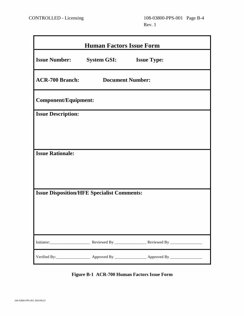
An HFE issue form may be initiated by any member of the HF design team. The initiator shall identify the issue number, system GSI, issue type, branch, document number, and affected component/equipment as applicable. The initiator shall also document the issue description and rationale/justification for not adhering to the applicable HFE design criteria. Exact reference to the HFE design criteria should be provided where possible. It is the responsibility of the initiator to ensure HF issue forms are appropriately prepared, reviewed, signed and filed in the HFE issues tracking file. The HFE design team shall be responsible for reviewing, verifying and providing applicable design input. In the event of disagreement with system designers, the final authority as to

CONTROLLED - Licensing 108-03800-PPS-001 Page B-2 Rev. 1
108-03800-PPS-001 2003/06/23
whether an HF issue form is necessary is to be decided once project organization is more fully determined. The following describes the information to be provided in each section of the HFE issue form:
Issue Number The initiator shall assign an issue number that consists of four digits. The first digit shall identify the HF issue category, based on the impact of the HF issue on the following design areas: a) Main Control Area (MCA) b) Secondary Control Area (SCA) c) Remote field panel or control area d) Human System Interface within the MCA/SCA e) Communications from/to the Control Centres (MCA/SCA) f) Plant Display System g) Annunciation h) Safety System Monitoring Computer i) Other design area The remaining three digits shall be assigned sequentially. The initiator shall verify and reserve the Issue number with the database maintainer (TBD) upon initiation of the HF issue form.
System GSI The initiator shall assign GSI numbers, as applicable, that are associated with the HF issue.
Issue Type The initiator shall identify the HF issue type which shall consist of a two character designation. The first character shall be a digit which defines the HF issue concern and follows: a) Occupational Health and Safety b) Supervisory Function c) Corrective Action and Control Function d) Maintenance Function e) Testing Function f) Inspection Function The second character shall be a letter which defines what level (A=minor, B=medium, C=large) system design area the issue is related to.
ACR-700 Branch The initiator shall note which design branch is affected by the HF design issue. The branches include: Civil; Safety and Licensing; Process; Control Engineering; Instrumentation, Control and Electrical (ICE); and Reactor and Fuel Handling (RFH).
Document Number The initiator shall identify documents related to the HF issue, as required.

CONTROLLED - Licensing 108-03800-PPS-001 Page B-3 Rev. 1
108-03800-PPS-001 2003/06/23
Component/Equipment The initiator shall identify specific system components or equipment affected by the HF issue.
Issue Description The initiator shall identify and describe the significant HF design criteria which will not be fully realized by the design. The description shall identify from which HF design criteria the design deviates (i.e., HFEPP, project procedure, accepted Branch design practice, HFE design guides or accepted general HFE practice).
Issue Rationale The initiator shall clearly state the rationale for the design deviation from the HFE design Criteria. This includes the identification of design consequences as a result of the design deviation (i.e., impact on operational and maintenance activities). The selected design alternative shall also be stated, as applicable. Additional requirements which may be imposed on other systems or station staff to alleviate the impact of the design deviation shall be stated, as applicable.
Issue Disposition/HF Specialist Comments The initiator/applicable HF design team member shall identify any resolutions and actions resulting from the HF issue review and design assessment. Any design recommendations that have been made to alleviate the impact of the design deviation shall be stated in this section.
CONTROLLED - Licensing 108-03800-PPS-001 Page B-4 Rev. 1
108-03800-PPS-001 2003/06/23
Human Factors Issue Form
Issue Number: System GSI: Issue Type: ACR-700 Branch: Document Number: Component/Equipment: Issue Description: Issue Rationale: Issue Disposition/HFE Specialist Comments: Initiator:____________________ Reviewed By ________________ Reviewed By ________________ Verified By:_________________ Approved By ________________ Approved By ________________
Figure B-1 ACR-700 Human Factors Issue Form

CONTROLLED - Licensing 108-03800-PPS-001 Page C-1 Rev. 1
108-03800-PPS-001 2003/06/23
Appendix C
Glossary of Abbreviations
The following is a summary of the abbreviations used throughout this document:
• AR – Analysis Report • ASD – Assessment Document • ATP – Authorization to Proceed • CANNET – CANDU Network • CC – Control Centres • CCB – Change Control Board • COG – CANDU Owner’s Group • CR – Change Request • DD – Design Description • DG – Design Guide • DNGS – Darlington Nuclear Generating Station • DR – Design Requirement • DVP – Design Verification Plan • HFE – Human Factors Engineering • HF – Human Factors • HFEPP – Human Factors Engineering Program Plan • HRA – Human Reliability Analysis • HSI – Human System Interface • MCA – Main Control Area • OER – Operating Experience Review • ORG – Operators Response Guideline • PLGS – Point Lepreau Generating Station • PPS – Plant Performance Specification • PSA – Probabilistic Safety Assessment • PWR – Pressurized Water Reactor • RMS – Records Management System • R&R – Review and Recommendation • S&L – Safety and Licensing • SCA – Secondary Control Area • SER – Significant Event Report • SME – Subject Matter Expert

CONTROLLED - Licensing 108-03800-PPS-001 Page C-2 Rev. 1
108-03800-PPS-001 2003/06/23
• SPS – System Performance Specification • V&V – Verification and Validation