
Acquiring 2D Seismic Data in a Logistically Difficult …2 Acquiring 2D Seismic Data in a...
11
NEF Project, Oil India Limited, Duliajan, India, E Mail: [email protected] P-121 Acquiring 2D Seismic Data in a Logistically Difficult and Highly Complex Area: A Case Study in Mizoram G. K. Ghosh *, A. K. Khanna and Dr. R.Dasgupta, Oil India Ltd. Summary The proven hydrocarbon discoveries in the periphery of Mizoram state in the north eastern part of India impelled Oil India Limited (OIL), Duliajan to start the hydrocarbon exploration in the area. The area is extremely difficult with hilly terrain, drastic elevation variations having geological setting with thrusted and folded beds. The seismic data acquisition is a great challenge in such kind of highly undulating terrain with complex subsurface. OIL has acquired more than 1300 Ground Line Kilometers (GLKM) 2D quality seismic data. The paper explains about the details of challenges faced, mythology & strategies adopted by OIL for acquisition of the quality seismic data and its correlation and integration withall other geoscientific data like geological, geochemical, gravity and magnetic for understanding the subsurface model for successful hydrocarbon exploration. Keywords: Gravity, Magnetic, Seismic, Basement, Tibetan Plate, Burman Plates Introduction OIL has been awarded a block with more than 3000 SQKM area in Mizoram state for carrying out the hydrocarbon exploration. The area is totally unexplored, however, the hydrocarbon discoveries in and around the periphery of this area in the recent past has made the area promising for the hydrocarbon discoveries. During the span of last four years OIL has acquired more than 1300 GLKM of 2D seismic data. Initially, straight line 2D seismic data acquisition has been taken up, however, later on after analyzing the seismic response Crooked lines acquisition geometry was opted due to terrain constraints and relatively better seismic response with respect to straight lines 2D Seismic. The more difficult part of the survey area is movement of equipments and drilling rigs due to poor communication of road and navigation system. The surface elevation in the study area varies from 100 m to 1800 m with rugged hilly terrain and undulating topography. Shot hole drilling is a great problem due to scarcity of water, transportation of drilling crew, material & technical accessories. Shifting material for camp construction, managing necessary living facilities as potable drinking/ usable water, frequent presence of insects like snacks, mosquito and poor medical services, understanding of local language etc are another few difficulties faced by the crew due to remoteness of the area. Another most important constraint is non availability of skilled and unskilled labor for carrying out initial field survey, shifting & laying cable/ geophones for data acquisition and for tough drilling work in the area etc. In the presence of all these surface complexities and extreme hilly terrain conditions, seismic data acquisition work has been done successfully within prescribed time period. The location of area of study and surface topography are shown in Figure-1 and Figure-2 respectively. Petroleum Provinces The area of study is located in the Mizoram fold and thrust belt between Bangladesh and Myanmar and located to the south and east of established petroleum provinces, 70 km from the nearest producing hydrocarbon field. The closest well is Rengte-2 situated 54 km to the north therefore the petroleum potential of this block relies heavily on regional data ( Ganguly 1983). The development of the fold belt began in the Late Cretaceous on the north-eastern margin of the Indian craton. It was here, in a passive margin setting, that the first sediments were deposited. Open marine conditions prevailed across the shelf as the Indian continent
Transcript of Acquiring 2D Seismic Data in a Logistically Difficult …2 Acquiring 2D Seismic Data in a...
NEF Project, Oil India Limited, Duliajan, India,
E Mail: [email protected]
P-121
Acquiring 2D Seismic Data in a Logistically Difficult and Highly Complex
Area: A Case Study in Mizoram
G. K. Ghosh *, A. K. Khanna and Dr. R.Dasgupta, Oil India Ltd.
Summary
The proven hydrocarbon discoveries in the periphery of Mizoram state in the north eastern part of India impelled Oil India
Limited (OIL), Duliajan to start the hydrocarbon exploration in the area. The area is extremely difficult with hilly terrain,
drastic elevation variations having geological setting with thrusted and folded beds. The seismic data acquisition is a great
challenge in such kind of highly undulating terrain with complex subsurface. OIL has acquired more than 1300 Ground Line
Kilometers (GLKM) 2D quality seismic data. The paper explains about the details of challenges faced, mythology &
strategies adopted by OIL for acquisition of the quality seismic data and its correlation and integration withall other
geoscientific data like geological, geochemical, gravity and magnetic for understanding the subsurface model for successful
hydrocarbon exploration.
Keywords: Gravity, Magnetic, Seismic, Basement, Tibetan Plate, Burman Plates
Introduction
OIL has been awarded a block with more than 3000 SQKM
area in Mizoram state for carrying out the hydrocarbon
exploration. The area is totally unexplored, however, the
hydrocarbon discoveries in and around the periphery of this
area in the recent past has made the area promising for the
hydrocarbon discoveries. During the span of last four years
OIL has acquired more than 1300 GLKM of 2D seismic
data. Initially, straight line 2D seismic data acquisition has
been taken up, however, later on after analyzing the seismic
response Crooked lines acquisition geometry was opted due
to terrain constraints and relatively better seismic response
with respect to straight lines 2D Seismic.
The more difficult part of the survey area is movement of
equipments and drilling rigs due to poor communication of
road and navigation system. The surface elevation in the
study area varies from 100 m to 1800 m with rugged hilly
terrain and undulating topography. Shot hole drilling is a
great problem due to scarcity of water, transportation of
drilling crew, material & technical accessories. Shifting
material for camp construction, managing necessary living
facilities as potable drinking/ usable water, frequent
presence of insects like snacks, mosquito and poor medical
services, understanding of local language etc are another
few difficulties faced by the crew due to remoteness of the
area. Another most important constraint is non availability
of skilled and unskilled labor for carrying out initial field
survey, shifting & laying cable/ geophones for data
acquisition and for tough drilling work in the area etc.
In the presence of all these surface complexities and
extreme hilly terrain conditions, seismic data acquisition
work has been done successfully within prescribed time
period. The location of area of study and surface
topography are shown in Figure-1 and Figure-2
respectively.
Petroleum Provinces
The area of study is located in the Mizoram fold and thrust
belt between Bangladesh and Myanmar and located to the
south and east of established petroleum provinces, 70 km
from the nearest producing hydrocarbon field. The closest
well is Rengte-2 situated 54 km to the north therefore the
petroleum potential of this block relies heavily on regional
data ( Ganguly 1983). The development of the fold belt
began in the Late Cretaceous on the north-eastern margin of
the Indian craton. It was here, in a passive margin setting,
that the first sediments were deposited. Open marine
conditions prevailed across the shelf as the Indian continent

2
Acquiring 2D Seismic Data in a Logistically Difficult and Highly
Complex Area: A Case Study in Mizoram in North Eastern India
drifted northward. In the north, oceanic crust of the Neo-
Tethys was subducting beneath the Tibetan Plate. Some of
these early sediments were metamorphosed in the collision
of the two continents which began in the Late Cretaceous to
Early Tertiary times. Collision of the Indian, Tibetan and
West Burman Plates led to a hiatus in sedimentation and the
development of an unconformity in the study area.
Sedimentation resumed in the Eocene with the arrival of
sediment from the north. A large fluvio-deltaic system
developed across the whole Bengal-Assam area fed from
the developing orogens to the north and east. In the Late
Eocene to Oligocene the Burmese Plate closed over the
Assam Shelf, giving its approximate modern day shape.
Figure. 2: Elevation profiles of one seismic 2D Crooked lines in study
area where the elevation varies from 100-900 m.
Deltaic facies continued in the study area well into the
Miocene, where the stratigraphic record stops. Upper
Miocene and younger sediments are missing from this area,
eroded during the final and most recent phase of continental
collision. Continued crustal shortening occurred as the
Burmese Plate tightened against northeast India. A fold and
thrust belt developed in the Mizoram and Tripura areas,
detaching at depth, possibly on Upper Cretaceous shales. It
is in this late phase of tectonic development that structures
suitable for trapping hydrocarbons developed (Murty 1983).
The Mizoram fold belt consists of a series of tight elongate
folds that trend roughly in north south direction. They are
arcuate, concave to the east and doubly plunging arranged
in an en echelon fashion moving
west into the Tripura fold belt, away
from the epicenter of deformation;
the folds (particularly the synclines)
become more open and gentle. The
uplift and erosion in this area are
alsoless severe as younger strata are
preserved and outcrop at surface.
Miocene sediments are the youngest
to outcrop within the block.
Figure 1: (a) Location map of the study area, (b) Crooked line survey Base Mapof the study area (c) Elevation profile.
3
Acquiring 2D Seismic Data in a Logistically Difficult and Highly
Complex Area: A Case Study in Mizoram in North Eastern India
Stratigraphy of the Area
The oldest fossiliferous sediments in the study area belong
to the Upper Cretaceous Disang Group which exceeds
300m in thickness, but has not been differentiated in this
area. Exposures can be found in central Manipur and
northern Mizoram. The Disang Group was deposited in
relatively deep marine waters on the northeast margin of the
Indian Plate, which was passive at the time. The formation
is dominated by shales but does contain some arenaceous
intervals. The Upper Eocene to Oligocene Barail Group lies
unconformably above the Disang. It represents a thick
deltaic sequence of approximately 3500m.
Exposures are known from south and east Manipur, where
the group has been further subdivided into 3 intervals, the
Laisong (1500m), Jenam (1200m) and Renji (800m)
Formations. The sequence as a whole coarsens upwards and
is dominated by sand, but also contains mudstone and coal
horizons. At this time, the Indian Plate was docking against
the West Burma and Asian Plates and sediment was sourced
from the northeast. The Miocene Surma Group is the next
stratigraphic interval in the study area, though much of the
top of this interval has been eroded. It is spit into the
Bhuban and Bokabil Formations (Dasgupta and Biswas
2000). The Bhuban Formation is further split into Lower,
Middle and Upper intervals. As a whole, the group
comprises alternations of sandstone and shale that were
deposited in a deltaic environment. Outcrops of the Bhuban
and Bokabil Formations can be found across the block,
though the Upper Bhuban and Bokabil intervals are only
present as thin intervals in the cores of synclines. The
Middle Bhuban is the oldest drilled interval in the study
area, penetrated by Rengte-2, which was drilled to 3001m.
The Surma Group is expected to exceed 4000m in this area.
Continued collision and uplift of the Himalayas provided
sediment from the north.
Communication through Survey Work
As such in the initial stage of the survey work,
communication with the local people was a big problem.
The most common local language is Mizo, which was not
understandable to most of OIL employees. Sufficient
number of skilled, unskilled labors and drivers were not
available for carrying the project work. OIL regularly
arranged training for skilled and unskilled labor, however, a
large number of labors did not usually return for work after
getting the training. During the operational period many
jobs were offered to the unemployed educated and
uneducated persons. Company established the necessary
facilities like drinking water in the remote places. The
Honorable Chief Minister and other officials of Mizoram
provided full administrative support & cooperation
throughout the field operations and visited the camp as well
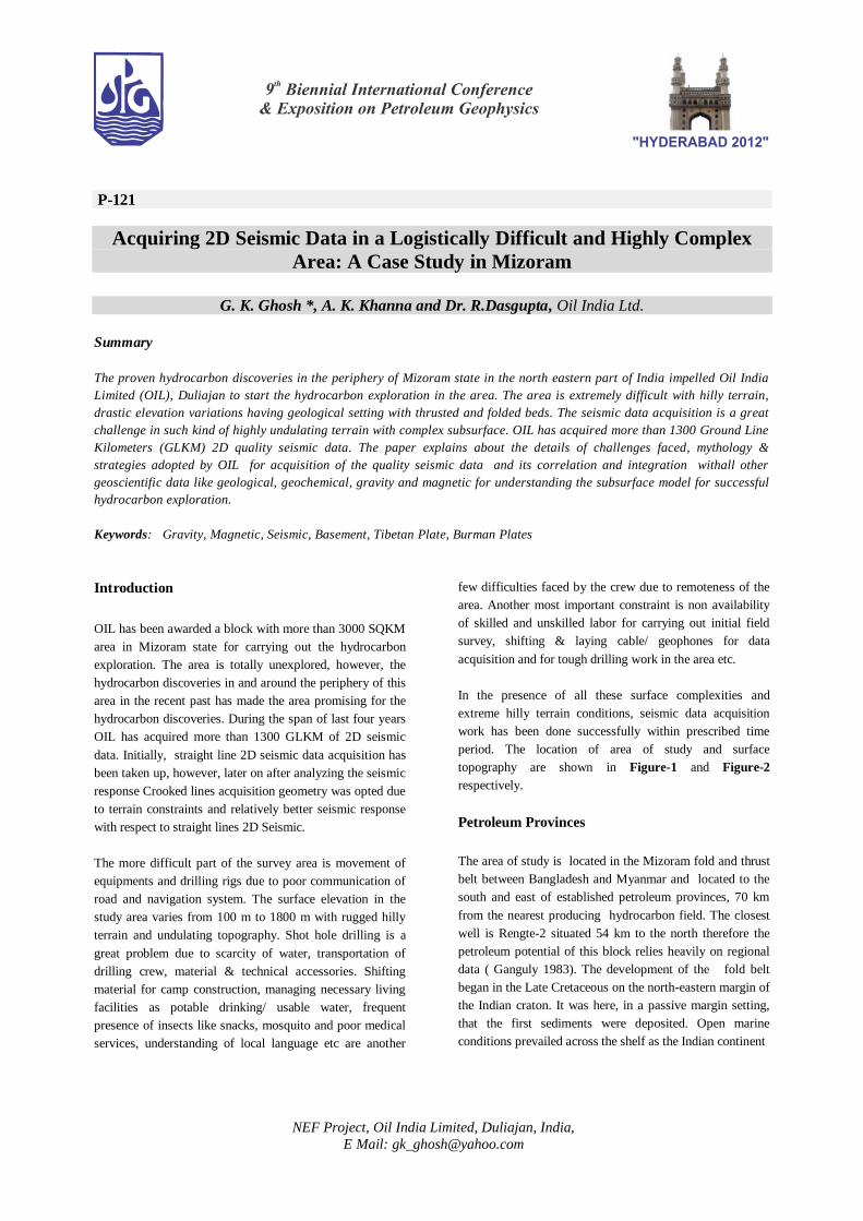
as field site. The Figure 3 shows the Honorable Chief
Minister Sri Lal Thanhawla (left side sitting) and foreign
experts (standing) for quality control of seismic data. Later
on it has been a very pleasant experience to work with the
Mizo people, who over the period acquired the sufficient
knowledge to get associated all aspects of field work like
Topographic Survey, Shothole Drilling, Cable layout,
Geophone plantation and Seismic acquisition.
Figure 3. The Honorable Chief Minister of Mizoram (left side
seated) visited the OIL seismic survey Camp Site. The
Foreign Technical experts are also standing in the picture.
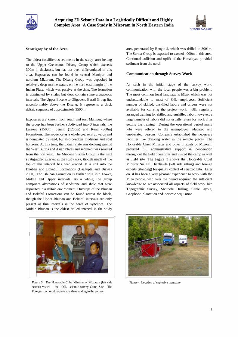
Figure 4: Location of explosive magazine
4
Acquiring 2D Seismic Data in a Logistically Difficult and Highly
Complex Area: A Case Study in Mizoram in North Eastern India
Management of Logistics
(I) Campestablishment
The block / operational area remotely located south of
Aizwal and north of Lunglai town. There is only one
National Highway NH-54 passing through the block from
Aizawl to Lunglei. The location of camp and its
establishment for carryout out day to day field activities is
itself a great challenge. Initially two Base camps are
established very near to NH-54, one in Thenzawl (around
130 Km from Aizawl) and another in Chhiahtlang (around
100 Km from Aizwal) area, however a number of Fly
camps were established as and when required near the
profile for carrying out shot hole drilling, laying cable,
geophone and other ground electronics in the line/ profile.
Lot of men power required for building & upkeep of camps,
providing necessary facilities and constant supply of
provisions and material in each camp of more than 80
persons. Carrying out maintenance of geophysical
equipment & accessories was a question mark in such a
remote area. The lines are situated in so remote places that
traveling takes more than 4-5 hours from the nearest camp
site, killing the working time window. The operational area
is lacking in basic facilities viz, drinking water,
communication, medical, transportation, language and
working labours. Frequent heavy rains, storms causing
landslides, narrower and poor quality connecting roads
further decreases the working time window. The explosives
magazine has been established at Thenzawl. The location
and magazine site has shown in Figure 4. The explosive
vehicles are kept empty and park within the safe distance in
the magazine site. Regular maintaining of explosives in
Magazine and transportation from the Magazine to the
operational area was taking very long time. Most of the
necessary material related to technical and human
requirements were arranged from the Silchar (around 180
Km from Aizawl) via road careers. The seismic data
Quality Control (QC) facilities, Electronic workshop for
maintenance of equipments, cables, geophones etc on daily
basis, HF (High frequency) control room was established
in Thenzawl and Chhiahtlang base camps.
(II) Approach for Topographic Survey
Most of the operation areas have no motorable road to reach
the proposed lines for initial Topographic survey. The Line
survey crews faced extreme difficulties for carrying
equipments along the lines due to deep gorges, frequent
folds with low & high elevations and highly undulating
surface. As most of the area was covered with thick forest
and cutting of bushes for making approach path was itself a
challenging task. Zoom cultivation was another challenge
for survey work. The villagers put fires in the jungle and
remains of cultivation which made survey approach
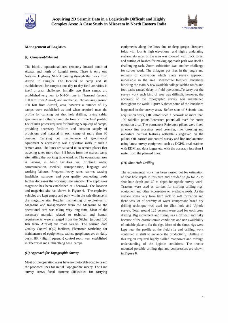
impossible in the area. Meanwhile frequent landslides
blocking the main & few available village kachha roads and
foot paths caused delay in field operations.To carry out the
survey work such kind of area was difficult; however, the
accuracy of the topographic survey was maintained
throughout the work. Figure 5 shows some of the landslides
happened in the survey area. Before start of Seismic data
acquisition work, OIL established a network of more than
100 Satellite points/Reference points all over the entire
operation area. The permanent Reference pillars were fixed
at every line crossings, road crossing, river crossing and
important cultural features withdetails engraved on the
pillars. OIL carried out control survey and line implantation
using latest survey equipment such as DGPS, total stations
with EDM and data logger etc. with the accuracy less than 1
meter from the planned lines.
(III) Shot Hole Drilling
The experimental work has been carried out for estimation
of shot hole depth in this area and decided to go for 25 m
shot hole depth and 60 m depth for uphole survey work.
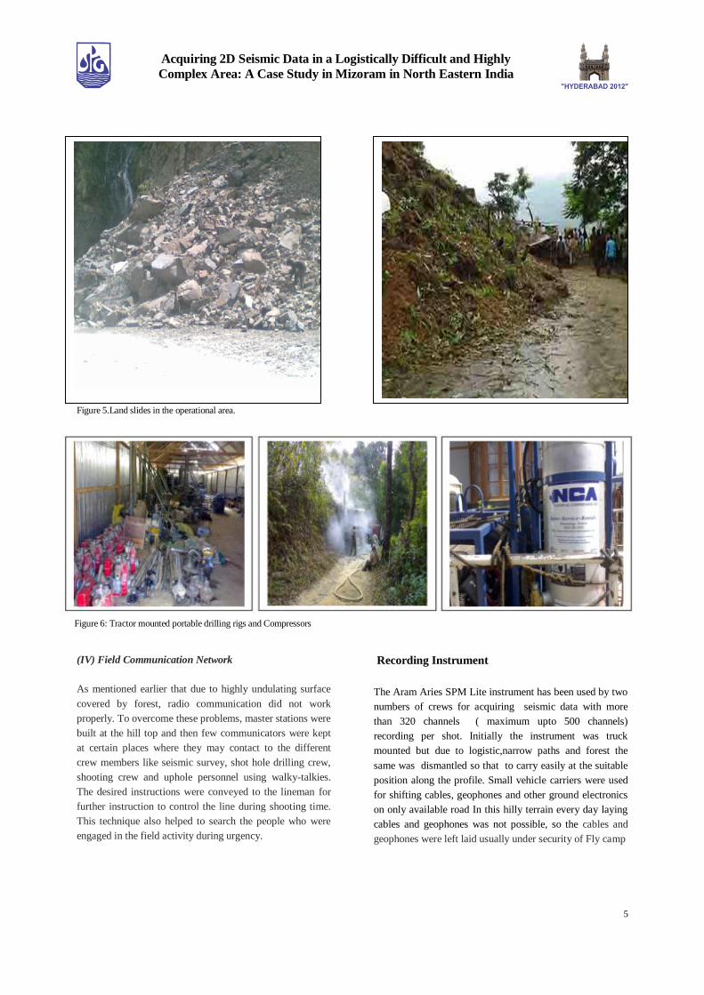
Tractors were used as carriers for shifting drilling rigs,
equipment and other accessories on available roads. As the
surface strata vary from hard rock to soft formation and
there was lot of scarcity of water compressor based dry
drilling technique was used for Shot hole and Uphole
survey. Total around 125 persons were used for each crew
drilling. Rig movement and fixing was a difficult and risky
because of the drastic terrain conditions and non availability
of suitable place to fix the rigs. Most of the times rigs were
kept near the profile at the field site and drilling work
continued in shift to enhance the productivity. Drilling in
this region required highly skilled manpower and through
understanding of the logistic conditions. The tractor
mounted portable drilling rigs and compressors are shown
in Figure 6.
5
Acquiring 2D Seismic Data in a Logistically Difficult and Highly
Complex Area: A Case Study in Mizoram in North Eastern India
Figure 5.Land slides in the operational area.
(IV) Field Communication Network
As mentioned earlier that due to highly undulating surface
covered by forest, radio communication did not work
properly. To overcome these problems, master stations were
built at the hill top and then few communicators were kept
at certain places where they may contact to the different
crew members like seismic survey, shot hole drilling crew,
shooting crew and uphole personnel using walky-talkies.
The desired instructions were conveyed to the lineman for
further instruction to control the line during shooting time.
This technique also helped to search the people who were
engaged in the field activity during urgency.
Recording Instrument
The Aram Aries SPM Lite instrument has been used by two
numbers of crews for acquiring seismic data with more
than 320 channels ( maximum upto 500 channels)
recording per shot. Initially the instrument was truck
mounted but due to logistic,narrow paths and forest the
same was dismantled so that to carry easily at the suitable
position along the profile. Small vehicle carriers were used
for shifting cables, geophones and other ground electronics
on only available road In this hilly terrain every day laying
cables and geophones was not possible, so the cables and
geophones were left laid usually under security of Fly camp
Figure 6: Tractor mounted portable drilling rigs and Compressors

6
Acquiring 2D Seismic Data in a Logistically Difficult and Highly
Complex Area: A Case Study in Mizoram in North Eastern India
workers. There was tremendous risk of burning cables,
geophones and other ground electronics laid for data
acquisition due to frequent jungle fire by villagers as fire
use to spread very fast in the area. The receiver and shot
position were marked at every 12.5 m and 50 m of interval.
Each crew had around 150 cables with length 220m each
(with 4 takeout at every 55m) and around 600 geophones
strings (with 12 geophones each string). The shooting
pattern adopted was End on. More than 100 persons were
engaged by each crew for laying cables, geophones,
handling other ground electronics in the field. Figures 7
show the Aram Aries recording equipment, Blaster, Cable
layout, and forest fire with burnt cables at the field site.
Acqusition of Meaningful Seismic Data
Prior to start of data acquisition faulty channels like dead
channels, leaky, noisy traces, reverse polarity, background
noise, cultural noise have been checked and
minimized/removed as applicable. This could be done by
proper coupling of geophones, proper connection of
takeout, changing batteries fully, removing faulty cables
and geophones. Faulty cables and geophones used to be
sent to workshop on regular basis for repairs, where Cable
Tester of M/s Aram Aries for analyzing the cables and SMT
200 /300 analyzers for geophones unit were used for testing
Field Parameter Selection
To meet the geoscientific requirement keeping in view of
complex geology, faulted, trusted beds with extremely
subsurface complexities, good reflection from the survey
area was a major challenging task among the geoscientist.
So proper geometry study was critical. Experimental survey
work was carried out and initially was decided to go for
Split spread data acquisition with 25 m shot hole depth and
25 m of Receiver spacing and 50 m Shot spacing. Few
profiles with Straight line geometry were shot, however,
later on further through experimental survey was done for
acquisition of more meaningful data over complex geology
and tackling terrain condition. It was observed that the
Crooked line geometry has given better subsurface image in
place of Conventional straight line geometry. Few Crooked
lines were acquired and it has been further analysed and
observed that End-On geometry recorded profiles with
group interval 12.5 m are further better quality with
reasonably good S/N ratio rather than group interval of
25.m. Bad shots were re-shot and skipped shots were
managed with proper offset shots prior to moving the next
location.
Based on the observation made from the field records and
on site generated Brute-Stacks, it was inferred that End-On
using group interval of 12.5 mts, shot interval 50 mts with
320 or more receiver groups gave far better subsurface
image. It was also observed that since straight line shooting
is not feasible due to steep elevation, multiple hill ranges
and poor quality of data, hence Crooked line geometry shall
be adopted through available roads, rivers, nallas and
valleys and foot paths / traces in the area.
End-On shooting has been carried out with the following
seismic parameters as mentioned in Table-1.
Figures 7 :Recording equipment (Aram Aries, the Blaster, Cable layout, and forest fire with burnt cables at the field site.

7
Acquiring 2D Seismic Data in a Logistically Difficult and Highly
Complex Area: A Case Study in Mizoram in North Eastern India
Pattern of shooting Symmetrical split spread End on Shooting
Group interval 25 m 25 m (initially)/12.5 m (finally)
Shot interval 50 m 50 m
Shot hole depth 25 m 25 m
No of channels >320 nos. >320 nos.
Table-1 : Seismic acquisition parameters
Figure 8 : Seismic data recorded on a Test line using Spit spread shooting (a) End on shooting pattern (b)
Figure 9 : Comparison of Stacks of a Test Line with (a) Receiver interval at 25m (b) Receiver interval of 12.5m.
Figure 10: Comparison of (a) DMO Stack of Straight line X (b) DMO Stack of Crooked line X’ very close to X Straight line X.
Straight Line X Crooked Line X’
8
Acquiring 2D Seismic Data in a Logistically Difficult and Highly
Complex Area: A Case Study in Mizoram in North Eastern India
The near surface velocity models were generated and shot
hole depth was optimized accordingly to ensure proper
energy penetration to the earth’s interior. The shot hole
depth is suggested 25 m with optimum 7.5 kg explosives.
Uphole data has also been acquired in 60 m shot hole depths
at all line crossings. The amount can be exceeds upto 10 kg
in the case of extremely hilly terrain.
Processing of Crooked Profiles –Solution For
Complex Geology
Seismic data has been processed at OIL’s Processing Center
at Duliajan, Assam using ProMAX software of CGG-
Halliburton and paralleley outsourced to International
processing company as the area is very challenging with
typical thrust belt complex geology. Following two
sequences were followed to obtain outputs for analysis and
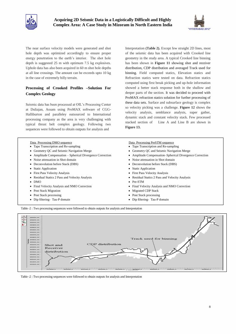
Interpretation (Table 2). Except few straight 2D lines, most
of the seismic data has been acquired with Crooked line
geometry in the study area. A typical Crooked line binning
has been shown in Figure 11 showing shot and receiver
distribution, CDP distribution and averaged Track used for
binning. Field computed statics, Elevation statics and
Refraction statics were tested on data. Refraction statics
computed using first break picking and up-hole information
showed a better stack response both in the shallow and
deeper parts of the section. It was decided to proceed with
ProMAX refraction statics solution for further processing of
these data sets. Surface and subsurface geology is complex
so velocity picking was a challenge. Figure 12 shows the
velocity analysis, semblance analysis, super gather,
dynamic stack and constant velocity stack. Few processed
stacked section of Line A and Line B are shown in
Figure 13.
Data Processing DMO sequence Data Processing PreSTM sequence
Tape Transcription and Re-sampling
Geometry QC and Seismic Navigation Merge
Amplitude Compensation – Spherical Divergence Correction
Noise attenuation in Shot domain
Deconvolution before Stack (DBS)
Static Application
First Pass Velocity Analysis
Residual Statics 2 Pass and Velocity Analysis
DMO
Final Velocity Analysis and NMO Correction
Post Stack Migration
Post Stack processing
Dip filtering- Tau-P domain
Tape Transcription and Re-sampling
Geometry QC and Seismic Navigation Merge
Amplitude Compensation–Spherical Divergence Correction
Noise attenuation in Shot domain
Deconvolution before Stack (DBS)
Static Application
First Pass Velocity Analysis
Residual Statics 2 Pass and Velocity Analysis
Pre-STM
Final Velocity Analysis and NMO Correction
Migrated CDP Stack
Post Stack processing
Dip filtering- Tau-P domain
Table -2 : Two processing sequences were followed to obtain outputs for analysis and Interpretation
Table -2 : Two processing sequences were followed to obtain outputs for analysis and Interpretation

9
Acquiring 2D Seismic Data in a Logistically Difficult and Highly
Complex Area: A Case Study in Mizoram in North Eastern India
Figure.12: Interactive velocity Analysis (a) Semblance display, (b) Super gather (c) Dynamic stack (d) Constant velocity stack panel
Line-X’ Line-X
Figure 13: Processed Seismic stacked sections Crooked Line X’ (a) and Straight Line X (b) from Mizoram study area
Figure 14 : (a) Bouguer anomaly map, (b) Magnetic anomaly map, (c) Geochemical leads marked in blue color identified by Oil India Limited and red color by an
International company.
10
Acquiring 2D Seismic Data in a Logistically Difficult and Highly
Complex Area: A Case Study in Mizoram in North Eastern India
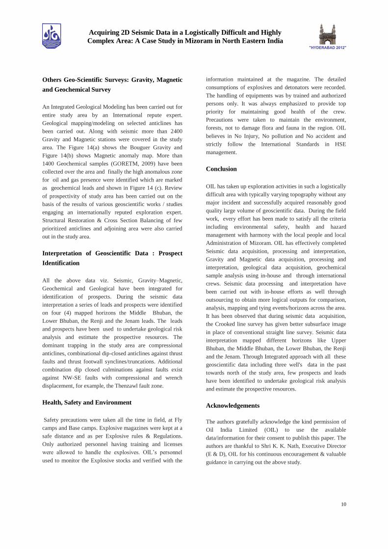
Others Geo-Scientific Surveys: Gravity, Magnetic
and Geochemical Survey
An Integrated Geological Modeling has been carried out for
entire study area by an International repute expert.
Geological mapping/modeling on selected anticlines has
been carried out. Along with seismic more than 2400
Gravity and Magnetic stations were covered in the study
area. The Figure 14(a) shows the Bouguer Gravity and
Figure 14(b) shows Magnetic anomaly map. More than
1400 Geochemical samples (GORETM, 2009) have been
collected over the area and finally the high anomalous zone
for oil and gas presence were identified which are marked
as geochemical leads and shown in Figure 14 (c). Review
of prospectivity of study area has been carried out on the
basis of the results of various geoscientific works / studies
engaging an internationally reputed exploration expert.
Structural Restoration & Cross Section Balancing of few
prioritized anticlines and adjoining area were also carried
out in the study area.
Interpretation of Geoscientific Data : Prospect
Identification
All the above data viz. Seismic, Gravity–Magnetic,
Geochemical and Geological have been integrated for
identification of prospects. During the seismic data
interpretation a series of leads and prospects were identified
on four (4) mapped horizons the Middle Bhuban, the
Lower Bhuban, the Renji and the Jenam leads. The leads
and prospects have been used to undertake geological risk
analysis and estimate the prospective resources. The
dominant trapping in the study area are compressional
anticlines, combinational dip-closed anticlines against thrust
faults and thrust footwall synclines/truncations. Additional
combination dip closed culminations against faults exist
against NW-SE faults with compressional and wrench
displacement, for example, the Thenzawl fault zone.
Health, Safety and Environment
Safety precautions were taken all the time in field, at Fly
camps and Base camps. Explosive magazines were kept at a
safe distance and as per Explosive rules & Regulations.
Only authorized personnel having training and licenses
were allowed to handle the explosives. OIL’s personnel
used to monitor the Explosive stocks and verified with the
information maintained at the magazine. The detailed
consumptions of explosives and detonators were recorded.
The handling of equipments was by trained and authorized
persons only. It was always emphasized to provide top
priority for maintaining good health of the crew.
Precautions were taken to maintain the environment,
forests, not to damage flora and fauna in the region. OIL
believes in No Injury, No pollution and No accident and
strictly follow the International Standards in HSE
management.
Conclusion
OIL has taken up exploration activities in such a logistically
difficult area with typically varying topography without any
major incident and successfully acquired reasonably good
quality large volume of geoscientific data. During the field
work, every effort has been made to satisfy all the criteria
including environmental safety, health and hazard
management with harmony with the local people and local
Administration of Mizoram. OIL has effectively completed
Seismic data acquisition, processing and interpretation,
Gravity and Magnetic data acquisition, processing and
interpretation, geological data acquisition, geochemical
sample analysis using in-house and through international
crews. Seismic data processing and interpretation have
been carried out with in-house efforts as well through
outsourcing to obtain more logical outputs for comparison,
analysis, mapping and tying events/horizons across the area.
It has been observed that during seismic data acquisition,
the Crooked line survey has given better subsurface image
in place of conventional straight line survey. Seismic data
interpretation mapped different horizons like Upper
Bhuban, the Middle Bhuban, the Lower Bhuban, the Renji
and the Jenam. Through Integrated approach with all these
geoscientific data including three well's data in the past
towards north of the study area, few prospects and leads
have been identified to undertake geological risk analysis
and estimate the prospective resources.
Acknowledgements
The authors gratefully acknowledge the kind permission of
Oil India Limited (OIL) to use the available
data/information for their consent to publish this paper. The
authors are thankful to Shri K. K. Nath, Executive Director
(E & D), OIL for his continuous encouragement & valuable
guidance in carrying out the above study.

11
Acquiring 2D Seismic Data in a Logistically Difficult and Highly
Complex Area: A Case Study in Mizoram in North Eastern India
References
DASGUPTA, A.B. and BISWAS, A.K., 2000. Geology of
Assam.Geol. Soc., India, Bangalore.
GANGULY, S., 1983. Geology and hydrocarbon prospects
of Tripura - Cahar - Mizoram region. Petroleum Asia J.l, v.
6 (4), p. 105-109.
GORETM, 2009. Survey for Exploration Amplified
Geochemical Imaging Technique. Geochemical Survey I
Mizoram Block (Unpublished report).
MURTY, K.N., 1983. Geology and hydrocarbon prospects
of Assam Shelf - Recent advances and present status.
Petroleum Asia J., v. 6, no. 4, p. 1-14.