ACOUSTIC EMISSION DETECTION OF DAMAGE INITIATION · PDF fileACOUSTIC EMISSION DETECTION OF...
10
32 nd EWGAE 393 Czech Society for Nondestructive Testing 32 nd European Conference on Acoustic Emission Testing Prague, Czech Republic, September 07-09, 2016 ACOUSTIC EMISSION DETECTION OF DAMAGE INITIATION IN 1D CFRP NCF COMPOSITES SUBJECTED TO BENDING Maciej PANEK 1 , Marek NOWAK 2 , Ireneusz BARAN 2 , Krzysztof J. KONSZTOWICZ 3 1 Wroclaw University of Technology, KMMT, 50-372 Wroclaw, Poland 2 Cracow University of Technology, Institute of Production Eng., Krakow, Poland 3 University of Bielsko-Biała, IB WIMBiS, ul.Willowa2, Bielsko-Biala, Poland phone +48 33 827 9114, e-mail: [email protected] Abstract Acoustic Emission was applied to detect microcrack initiation in unidirectional (1D) carbon fiber reinforced composites (CFRP) subjected to 4-point bending. Materials were prepared from polyester (PES) bonded 1D carbon fiber fabric and epoxy resin using the RTM technology. Fiber volume content of composites varied from small (35%) through medium (51%) to high (68%). Samples were cut from 1D composite plates to the size of 120x20x2mm in two orthogonal directions - along fibers [0] and across fibers [90]. Selected samples had part of their tensile surface (in bending) pre-polished to enable microscopic (SEM) observations. Samples were subjected to monotonic and step- loading tests in 4-point bending while Acoustic Emission (AE) sensors attached to samples’ surfaces monitored the damage initiation. The AE Historic Index proved to be the most reliable AE parameter indicating damage initiation, which allowed to interrupt loading sequence before failure. Details of microcracks were observed under the SEM on polished composite tensile surfaces loaded in bending. Fiber debonding and breakage occurred simultaneously and were the first defects to initiate damage in the examined materials. Keywords: acoustic-emission, 4-point bending, step-load, SEM, debonding 1. Introduction An important number of damage studies were carried out on unidirectional (UD or 1D) fiber composites over the past half-century, mostly on glass fiber reinforced plastics (GFRP) and carbon fiber reinforced plastics (CFRP) materials [1]. Multitude of direct or indirect NDE methods have been applied in these studies with different degree of success [2, 3]. The majority of NDE techniques are capable of detecting larger defects at the stage of propagation, closer to catastrophic failure, however the initiating flaws are usually too small to be detected by available conventional NDE techniques [4, 5]. As pointed out by Lomov et al.[6], one of fundamental issues in composite damage studies is the definition what “damage initiation” means. Singular fiber breaks may not constitute substantial danger to integrity of material, as composites containing broken fibers are known to sustain long-term fatigue tests [7, 8]. The fiber-matrix debonds also may not be lethal to material as long as they do not coalesce into larger flows [9], whereas the details of the nature of matrix cracks and their relation to matrix cross-linking process are still not quite well recognized [10]. Another difficult issue of damage initiation studies is the accuracy of applied experimental techniques with regard to localization and time of occurrence of initiating defects. In earlier works [11, 12] significant progress was already achieved using visual examination to describe flaws of millimiter order of magnitude. Recently, the high resolution scanning electron microscopy (SEM) and computer tomography (CT) techniques enable flaw detection of micrometer sizes [3] and yet the details of damage initiation are still not fully recognized. Due to specific application requirements, many works related to 1D composites were carried out on multilayer, complex architecture materials and often attempts were made to describe the flaws of very different nature (i.e. matrix cracks, debonding, fiber breakage, fiber pull-out,
-
Upload
doankhuong -
Category
Documents
-
view
216 -
download
0
Transcript of ACOUSTIC EMISSION DETECTION OF DAMAGE INITIATION · PDF fileACOUSTIC EMISSION DETECTION OF...
32nd EWGAE 393
Czech Society for Nondestructive Testing32nd European Conference on Acoustic Emission TestingPrague, Czech Republic, September 07-09, 2016
ACOUSTIC EMISSION DETECTION OF DAMAGE INITIATION IN 1D CFRP NCF COMPOSITES SUBJECTED TO BENDING
Maciej PANEK1, Marek NOWAK2, Ireneusz BARAN2, Krzysztof J. KONSZTOWICZ3
1 Wroclaw University of Technology, KMMT, 50-372 Wroclaw, Poland 2 Cracow University of Technology, Institute of Production Eng., Krakow, Poland
3 University of Bielsko-Biała, IB WIMBiS, ul.Willowa2, Bielsko-Biala, Poland phone +48 33 827 9114, e-mail: [email protected]
Abstract Acoustic Emission was applied to detect microcrack initiation in unidirectional (1D) carbon fiber reinforced composites (CFRP) subjected to 4-point bending. Materials were prepared from polyester (PES) bonded 1D carbon fiber fabric and epoxy resin using the RTM technology. Fiber volume content of composites varied from small (35%) through medium (51%) to high (68%). Samples were cut from 1D composite plates to the size of 120x20x2mm in two orthogonal directions - along fibers [0] and across fibers [90]. Selected samples had part of their tensile surface (in bending) pre-polished to enable microscopic (SEM) observations. Samples were subjected to monotonic and step-loading tests in 4-point bending while Acoustic Emission (AE) sensors attached to samples’ surfaces monitored the damage initiation. The AE Historic Index proved to be the most reliable AE parameter indicating damage initiation, which allowed to interrupt loading sequence before failure. Details of microcracks were observed under the SEM on polished composite tensile surfaces loaded in bending. Fiber debonding and breakage occurred simultaneously and were the first defects to initiate damage in the examined materials. Keywords: acoustic-emission, 4-point bending, step-load, SEM, debonding
1. Introduction An important number of damage studies were carried out on unidirectional (UD or 1D) fiber composites over the past half-century, mostly on glass fiber reinforced plastics (GFRP) and carbon fiber reinforced plastics (CFRP) materials [1]. Multitude of direct or indirect NDE methods have been applied in these studies with different degree of success [2, 3]. The majority of NDE techniques are capable of detecting larger defects at the stage of propagation, closer to catastrophic failure, however the initiating flaws are usually too small to be detected by available conventional NDE techniques [4, 5]. As pointed out by Lomov et al.[6], one of fundamental issues in composite damage studies is the definition what “damage initiation” means. Singular fiber breaks may not constitute substantial danger to integrity of material, as composites containing broken fibers are known to sustain long-term fatigue tests [7, 8]. The fiber-matrix debonds also may not be lethal to material as long as they do not coalesce into larger flows [9], whereas the details of the nature of matrix cracks and their relation to matrix cross-linking process are still not quite well recognized [10]. Another difficult issue of damage initiation studies is the accuracy of applied experimental techniques with regard to localization and time of occurrence of initiating defects. In earlier works [11, 12] significant progress was already achieved using visual examination to describe flaws of millimiter order of magnitude. Recently, the high resolution scanning electron microscopy (SEM) and computer tomography (CT) techniques enable flaw detection of micrometer sizes [3] and yet the details of damage initiation are still not fully recognized. Due to specific application requirements, many works related to 1D composites were carried out on multilayer, complex architecture materials and often attempts were made to describe the flaws of very different nature (i.e. matrix cracks, debonding, fiber breakage, fiber pull-out,
394 32nd EWGAE
delamination) – all in one study [13]. On the other pole, many excellent results were achieved in examining single fiber composites (sfc), single bundle or a layer [14-16]. However, owing to complexity of stress distribution in composite structures, such singular results are hardly transferable to real materials. There still seems to exist the need for systematic studies of damage initiation studies in composite materials of simple fiber architecture, concentrating on particular type of flaw. The aim of this work is to describe the microcrack initiation process in 1D non-crimp fabric (NCF) CFRP composites subjected to 4-point bending tests, based on continuous monitoring of damage initiation in function of time of test with use of Acoustic Emission. To this end, the sensitivity of AE Historic Index to the onset of damage is exploited. Important deformation of fiber reinforced plastic (FRP) composites in bending [17] is turned into advantage, enhancing the possibility of defect localization in the area of highest risk of damage. In the 4-point bending tests it is the area near the center of outer surface, and this was observed under the SEM. This simple methodology was already proven successful in compression studies of CFRP composites [18].
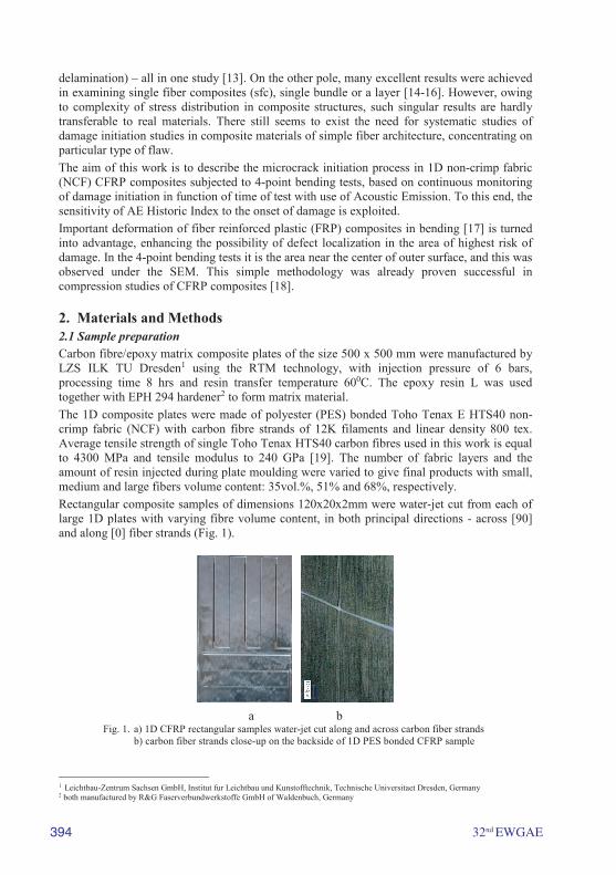
2. Materials and Methods2.1 Sample preparation Carbon fibre/epoxy matrix composite plates of the size 500 x 500 mm were manufactured by LZS ILK TU Dresden1 using the RTM technology, with injection pressure of 6 bars, processing time 8 hrs and resin transfer temperature 600C. The epoxy resin L was used together with EPH 294 hardener2 to form matrix material. The 1D composite plates were made of polyester (PES) bonded Toho Tenax E HTS40 non-crimp fabric (NCF) with carbon fibre strands of 12K filaments and linear density 800 tex. Average tensile strength of single Toho Tenax HTS40 carbon fibres used in this work is equal to 4300 MPa and tensile modulus to 240 GPa [19]. The number of fabric layers and the amount of resin injected during plate moulding were varied to give final products with small, medium and large fibers volume content: 35vol.%, 51% and 68%, respectively. Rectangular composite samples of dimensions 120x20x2mm were water-jet cut from each of large 1D plates with varying fibre volume content, in both principal directions - across [90] and along [0] fiber strands (Fig. 1).
a b Fig. 1. a) 1D CFRP rectangular samples water-jet cut along and across carbon fiber strands
b) carbon fiber strands close-up on the backside of 1D PES bonded CFRP sample
1 Leichtbau-Zentrum Sachsen GmbH, Institut fur Leichtbau und Kunstofftechnik, Technische Universitaet Dresden, Germany 2 both manufactured by R&G Faserverbundwerkstoffe GmbH of Waldenbuch, Germany
32nd EWGAE 395
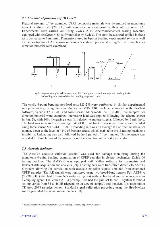
2.2 Mechanical properties of 1D CFRP Flexural strength of the examined CFRP composite materials was determined in monotonic 4 point bending tests [20, 21], with simultaneous monitoring of their AE response [22]. Experiments were carried out using Zwick Z100 electro-mechanical testing machine, equipped with testXpert v.3.1 software (also by Zwick). The cross-head speed applied in these tests was equal to 2 mm/min. Dimensions used in 4-point bending experimental set-up as well as the positioning of AE sensors on sample’s ends are presented in Fig.2a. Five samples per direction/material were examined.
a b
Fig.2. a) positioning of AE sensors on CFRP sample in monotonic 4-point bending tests b) loading schedule of 4-point bending step-load tests
The cyclic 4-point bending step-load tests [23-28] were performed in similar experimental set-up geometry, using the servo-hydraulic MTS 810 machine, equipped with FlexTest software, version 3.5B 1787 and force sensor MTS model 661 19F-01. Five samples per direction/material were examined. Increasing load was applied following the scheme shown in Fig. 2b, with 10% increasing steps (in relation to rupture stress), followed by 5 min hold. The load was increased with average rate of 0,01 of fracture stress per minute and recorded using force sensor MTS 661 19F-01. Unloading rate was on average 0,1 of fracture stress per minute, down to the level of ~1% of fracture stress, which enabled to avoid testing machine’s instability. Unloading was also followed by hold period of five minutes. This sequence was repeated till final failure of the sample or until interruption of the test by operator.
2.3 Acoustic Emission The AMSY6 acoustic emission system3 was used for damage monitoring during the monotonic 4-point bending examination of CFRP samples in electro-mechanical Zwick100 testing machine. The AMSY-6 was equipped with Vallen software for parametric and transient data acquisition and analysis [29]. Loading data were transferred directly to AMSY-6 system allowing for correlation with acoustic emission signals obtained from examined CFRP samples. The AE signals were registered using two broad-band sensors Fuji AE144A (50-700 kHz) attached to sample’s surface (Fig. 2a) with rubber band and vacuum grease as a coupling agent. The Vallen AEP4 preamplifiers had the gain set to 34dB. System threshold setting varied from 34 to 46 dB (depending on type of sample), and transient files registration TR used 2048 samples per set. Standard signal calibration procedure using the Hsu-Nielsen source preceded the actual measurements [30].
3 manufactured by Vallen Systeme GmbH, 82057 Icking, Germany. http://www.vallen.de/
396 32nd EWGAE
Damage monitoring during the step-load tests in servo-hydraulic MTS 810 machine was performed using AMS-3 acoustic emission system (also by Vallen Systeme GmbH), equipped with Vallen software for parametric and transient data acquisition and analysis. Signals were collected by Vallen resonant sensors V150-M followed by Vallen AEP3 preamplifiers, with gain set to 34dB. System threshold in most cases was set to 40,7 dB, with 2048 samples per TR set. Standard signal calibration procedure was applied prior to measurements [30].
2.4 Microscopic observations Two of each set of 5 samples per material/direction had central part of their outer surface (between inner supports, Fig.2a) pre-polished for microscopic studies. The SEM observations of damage initiation in these surfaces were performed using high resolution scanning electron microscope Nova NanoSEM 2004. Uncoated samples were observed in secondary electron mode (SE) in low vacuum conditions (60 Pa) and at relatively low voltage (5kV).
3. Results and Discussion3.1 The 4-point bending of 1D CFRP The mechanical response of neat epoxy resin obtained in 4-point bending on same size samples as the examined 1D CFRP composites is presented in Fig. 3a. It is not quite certain that the departure from linearity at higher loads may be related only to viscoelasticity of epoxy resin. It may be also due to described recently microcrack formation similar in nature to that found in crystalline solids [10].
The samples of 1D NCF CFRP composites cut longitudinally [0] and transversely to fibers [90] practically do not show the non-linearity of force-displacement plots (Fig.3b). The longitudinal strength of 1D NCF CFRP increases with fiber volume, while transversal strength does not change with fiber volume (Fig. 3c), as it depends mostly on fiber-matrix interphase [1, 9].
30 35 40 45 50 55 60 65 70
Fiber Volume [%]
σm
[M
Pa]
0
50
100
600
650
700
750
800
850
900
XY
a b c
Fig.3. Force-displacement plots and strength obtained in monotonic 4-point bending: a) neat epoxy resin; b) 1D NCF CFRP of average fib. vol.- 51%, measured in [0] and [90] direction; c) strength of examined 1D NCF CFRP in function of fiber volume (X - dir.[90], Y - dir.[0])
4 FEI Company, Europe NanoPort, Achtseweg Noord 5, 5651 GG Eindhoven, The Netherlands

32nd EWGAE 397
3.2 Acoustic Emission in 4-point bending of 1D CFRP The AE basic parameters registered during monotonic 4-pont bending tests of 1D NCF CFRP composites did not reveal any specific pattern, which would be of interest from the point of view of damage initiation description in these materials. Of all the obtained data, only the AE Frequency results may be more interesting, as they seem to be indicative of the type of damage occurring during loading, similarly to results observed in other published works [31-36].
The histograms of AE Frequency vs # Hits (Fig. 4 a-c) obtained for longitudinally cut 1D NCF CFRP samples point at fiber debonding (~200 kHz) as the dominant damage mechanism. Interestingly, decreasing number of hits related to fibre breaks (300-350 kHz) can be also noticed from these results, following the increase of fiber volume content. This observation may indicate reduced singular fiber damage when more fibers are capable of transferring the load.
Figs. 4 (d-f) present the histograms of AE Frequency vs # Hits obtained for transversely cut samples of 1D NCF CFRP composites. It is interesting to note here the increasing role (relative) of debonding and matrix defects following the increase of fiber volume content (~100kHz and ~200kHz). A few signals ~300 kHz in these histograms may come from incidentally misaligned fibers.
a)38v/o of fib. b) 51v/o c) 68v/o
d) 38v/o e) 51v/o f) 68v/o
Fig.4. The histograms of AE Frequency vs # Hits obtained during monotonic 4-point bending tests of CFRP samples with varying fibre volume content, cut in longitudinal [0] direction (a,b,c), and in transversal [90] direction to fibers (d,e,f).
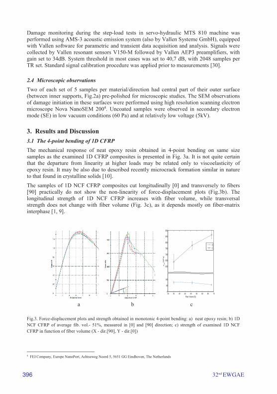
3.2 Determination of damage initiation using the AE Historic Index The most consistent AE parameter indicating clearly the initiation of micro-damage during both monotonic and step-loading of the examined CFRP composites was the AE Historic Index [23, 37, 38]. Fig.5 shows the variations of Historic Index with time of test in monotonic 4-point bending loading. This parameter is sensitive to settings and Fig.5a proves that its important indications may sometime pass unnoticed in standard AE tests. Fig.5b is the same plot after re-scaling of vertical axis and it gives the evidence of initial damage appearing already in the mid-time of bending test (HI ~2).
398 32nd EWGAE
At the time of these experiments no significant changes of Historic Index were observed in samples cut transversely to fibers, i.e. in direction [90]. However, the appearance of measuring points at HI values ~1,0 in some of these [90] plots (Fig. 5c) prompted the setting adjustments, which enabled to find significant HI variations even in neat epoxy resin [10].
a b c
Fig.5. The AE Historic Index indications during monotonic 4-point bending for UD NCF CFRP. a) sample cut in longitudinal [0] direction, b) rescaled HI plot for this sample, c) The HI indication in transversal [90] sample.
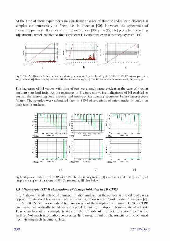
The increases of HI values with time of test were much more evident in the case of 4-point bending step-load tests. As the examples in Fig.6a-c show, the indications of HI enabled to control the increasing-load process and interrupt the loading sequence before macroscopic failure. The samples were submitted then to SEM observations of microcracks initiation on their tensile surfaces.
a) b) c)
Fig.6. Step-load tests of UD CFRP with 51% fib. vol. in longitudinal [0] direction: a) full test b) interrupted sample; c) sample cut transversely [90]. Corresponding HI plots below.
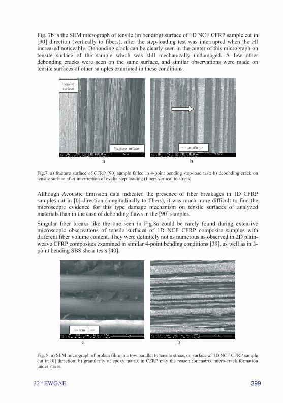
3.3 Microscopic (SEM) observations of damage initiation in 1D CFRP Fig. 7. shows the advantage of damage initiation analysis on the surface subjected to stress as opposed to standard fracture surface observation, often named “post mortem” analysis [6]. Fig.7a is the SEM micrograph of fracture surface of the sample of examined 1D NCF CFRP composite cut vertically to fibers and cycled to failure in 4-point bending step-load test. Tensile surface of this sample is seen on the left side of the picture, vertical to fracture surface. Not much information concerning the damage initiation phenomena can be obtained from viewing such fracture surface.
32nd EWGAE 399
Fig. 7b is the SEM micrograph of tensile (in bending) surface of 1D NCF CFRP sample cut in [90] direction (vertically to fibers), after the step-loading test was interrupted when the HI increased noticeably. Debonding crack can be clearly seen in the center of this micrograph on tensile surface of the sample which was still mechanically undamaged. A few other debonding cracks were seen on the same surface, and similar observations were made on tensile surfaces of other samples examined in these conditions.
a b
Fig.7. a) fracture surface of CFRP [90] sample failed in 4-point bending step-load test; b) debonding crack on tensile surface after interruption of cyclic step-loading (fibers vertical to stress)
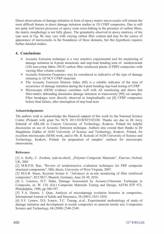
Although Acoustic Emission data indicated the presence of fiber breakages in 1D CFRP samples cut in [0] direction (longitudinally to fibers), it was much more difficult to find the microscopic evidence for this type damage mechanism on tensile surfaces of analyzed materials than in the case of debonding flaws in the [90] samples.
Singular fiber breaks like the one seen in Fig.8a could be rarely found during extensive microscopic observations of tensile surfaces of 1D NCF CFRP composite samples with different fiber volume content. They were definitely not as numerous as observed in 2D plain-weave CFRP composites examined in similar 4-point bending conditions [39], as well as in 3-point bending SBS shear tests [40].
a b
Fig. 8. a) SEM micrograph of broken fibre in a tow parallel to tensile stress, on surface of 1D NCF CFRP sample cut in [0] direction; b) granularity of epoxy matrix in CFRP may the reason for matrix micro-crack formation under stress.
Fracture surface
Tensile surface
<= tensile =>
<= tensile =>
400 32nd EWGAE
Direct observations of damage initiation in form of epoxy matrix micro-cracks will remain the most difficult feature in direct damage initiation studies in 1D CFRP composites. Due to still not quite well known processes of epoxy resin cross-linking in the presence of carbon fibers, the matrix morphology is not fully glassy. The granularity observed in epoxy matrices, of the type seen in Fig. 8b, may vary with varying carbon fiber content and may be the source of appearance of microcracks in the boundaries of these domains, but this hypothesis requires further detailed studies.
4. Conclusions Acoustic Emission technique is a very sensitive experimental tool for monitoring of
damage initiation in 4-point monotonic and step-load bending tests of unidirectional(1D) non-crimp fabric (NCF) carbon fiber reinforced plastic (CFRP) composites withvarying fiber volume content
Acoustic Emission Frequency may be considered as indicative of the type of damageinitiating in 1D NCF CFRP materials
The Acoustic Emission Historic Index (HI) is a reliable indicator of the time ofoccurrence of damage initiation during the 4-pont bending step-load testing of CFRP
Microscopic (SEM) evidence correlates well with AE monitoring and shows thatfiber-matrix debonding dominates damage initiation in transversely [90] cut samples.Fiber breakages were directly observed in longitudinally cut [0] CFRP compositesbefore final failure, after interruption of step-load tests
Acknowledgements The authors wish to acknowledge the financial support of this work by the National Science Centre (Poland) with grant No NCN 2011/03/B/ST5/03180. Thanks are due to Dr Jerzy Schmidt of ARLAB in Cracow University of Technology, Krakow, Poland for helpful discussions on use of Acoustic Emission technique. Authors also extend their thanks to Dr Magdalena Ziąbka of AGH University of Science and Technology, Krakow, Poland, for excellent microscopic (SEM) work, and to Mr. B. Kotecki of AGH University of Science and Technology, Krakow, Poland, for preparation of samples’ surfaces for microscopic observations.
Reference [1] A. Kelly, C. Zweben, (eds-in-chief), „Polymer Composite Materials”, Elsevier, Oxford, UK, 2001 [2] M.R.P.D. Rao, “Review of nondestructive evaluation techniques for FRP composite structural components”, MSc thesis, University of West Virginia, 2007. [3] M.G.R. Sause, Keynote lecture 6: “Advances in in-situ monitoring of fiber reinforced composites”, ECCM17, Munich, Germany, June 26-30, 2016. [4] L. Lorenzo, H.T. Hahn, Damage Assessment by Acousto-Ultrasonic Technique in Composite, in: W. J.D. (Ed.) Composite Materials Testing and Design, ASTM STP 972, Philadelphia, 1988, pp 380-397. [5] Y.A. Dzenis, J. Qian, Analysis of microdamage evolution histories in composites, International Journal of Solids and Structures, 38 (2001) 1831-1854. [6] S.V. Lomov, D.S. Ivanov, T.C. Truong, et.al., Experimental methodology of study of damage initiation and development in textile composites in uniaxial tensile test, Composites Science and Technology, 68 (2008) 2340-2349.
32nd EWGAE 401
[7] B. Harris (ed.), Fatigue in Composites, CRC Press, Woodhead Publishing Ltd, Cambridge, UK, 2003. [8] A.P. Vassilopoulos, T. Keller, Fatigue of Fiber-reinforced Composites, Springer, 2011. [9] S.L. Gao, E. Mader, S.F. Zhandarov, Carbon fibers and composites with epoxy resins: Topography, fractography and interphases, Carbon, 42 (2004) 515-529. [10] K. Konsztowicz, M. Nowak, I. Baran, M. Ziąbka, C. J., “Detection of micro-crack initiation in epoxy matrix material with use of acoustic emission”, Proceedings of ECCM17, Munich, Germany, June 2016. [11] R.S. Williams, K.L. Reifsnider, Investigation of acoustic-emission during fatigue loading of composite specimens, Journal of Composite Materials, 8 (1974) 340-355. [12] A.L. Highsmith, K.L. Reifsnider, Stiffness-Reduction Mechanisms in Composite Laminates, Damage in Composite Materials, ASTM STP 775, K. L. Reifsnider, Ed., ASTM, Philadelphia, 1982, pp. 103-117. [13] P.F. Liu, J.K. Chu, Y.L. Liu, J.Y. Zheng, A study on the failure mechanisms of carbon fiber/epoxy composite laminates using acoustic emission, Materials & Design, 37 (2012) 228-235. [14] J. Bohse, Acoustic emission characteristics of micro-failure processes in polymer blends and composites, Composites Science and Technology, 60 (2000) 1213-1226. [15] R.P. Reed, J.C. Berg, Measuring effective interfacial shear strength in carbon fiber bundle polymeric composites, Journal of Adhesion Science and Technology, 20 (2006) 1929-1936. [16] Q.Q. Ni, E. Jinen, Fracture behavior and acoustic emission in bending tests on single-fiber composites, Engineering Fracture Mechanics, 56 (1997) 779-796. [17] I. De Baere, W. Van Paepegem, J. Degrieck, Comparison of different setups for fatigue testing of thin composite laminates in bending, International Journal of Fatigue, 31 (2009) 1095-1101. [18] N.V. De Carvalho, S.T. Pinho, P. Robinson, An experimental study of failure initiation and propagation in 2D woven composites under compression, Composites Science and Technology, 71 (2011) 1316-1325. [19] Toho product specification, http://www.tohotenax.com/products/tenax%c2%ae-carbon-fiber/. [20] ASTM D6272-10, Standard Test Method for Flexural Properties of Unreinforced and Reinforced Plastics and Electrical Insulating Materials by Four-Point Bending, ASTM International, West Conshohocken, PA, 2010, www.astm.org. [21] EN ISO 14125: Fibre-reinforced plastic composites -- Determination of flexural properties, 1998. [22] C.J. Hellier, „Handbook of Nondestructive Evaluation”, Chap.10: "Acoustic Emission Testing", McGrow-Hill Co., 2003. [23] ASTM E2478-11, Standard Practice for Determining Damage-Based Design Stress for Glass Fiber Reinforced Plastic (GFRP) Materials Using Acoustic Emission, ASTM International, West Conshohocken, PA, 2011, www.astm.org. [24] J. Gassan, T. Dietz, Load-increasing fatigue test to characterize the interface of composites under fatigue loadings, Journal of Materials Science, 38 (2003) 2755-2760. [25] P. Alander, L.V.J. Lassila, A. Tezvergil, P.K. Vallittu, Acoustic emission analysis of fiber-reinforced composite in flexural testing, Dental Materials, 20 (2004) 305-312. [26] A.R.A. Abraham, K.L. Johnson, C.T. Nichols, R.L. Saulsberry, J.M. Waller, “Use of statistical analysis of acoustic emission data on carbon-epoxy COPV materials-of-construction for enhanced felicity ratio onset determination”, NASA report JSC-CN-26080, pp. 1-15, 2012.
402 32nd EWGAE
[27] J.M. Waller, C.T. Nichols, D.J. Wentzel, R.L. Saulsberry, Use of modal acoustic emission to monitor damage progression in carbon fiber/epoxy composites, in: 37th Annual Review of Progress in Quantitative Nondestructive Evaluation (QNDE), San Diego, CA, 2010, pp. 919-926. [28] N.B. Mabry, C.Toutanji, H.Seif, M., Acoustic Emission Felicity Ratio Measurements in Carbon Composites Laminates using Fiber Bragg Grating Sensors, in: W. Ecke, K.J. Peters, T.E. Matikas (Eds.) Smart Sensor Phenomena, Technology, Networks, and Systems, 2011, Proceedings of SPIE, 2011. [29] H. Vallen, "AE testing fundamentals, Equipment, Applications", The e-Journal of Non-destructive Testing, www.ndt.net, Vol.7, No9, Sept. 2002. [30] N.N. Hsu, F.R. Breckenridge, Characterization and calibration of acoustic-emission sensors, Materials Evaluation, 39 (1981) 60-68. [31] P.J. deGroot, P.A.M. Wijnen, R.B.F. Janssen, Real-time frequency determination of acoustic emission for different fracture mechanisms in carbon epoxy composites, Composites Science and Technology, 55 (1995) 405-412. [32] J. Bohse, Acoustic emission examination of polymer–matrix composites, in, J. Acoust. Emission, vol. 22, 2004, pp. 208–23. [33] C.R. Ramirez-Jimenez, N. Papadakis, N. Reynolds, T.H. Gan, P. Purnell, M. Pharaoh, Identification of failure modes in glass/polypropylene composites by means of the primary frequency content of the acoustic emission event, Composites Science and Technology, 64 (2004) 1819-1827. [34] R. Gutkin, C.J. Green, S. Vangrattanachai, S.T. Pinho, P. Robinson, P.T. Curtis, On acoustic emission for failure investigation in CFRP: Pattern recognition and peak frequency analyses, Mechanical Systems and Signal Processing, 25 (2011) 1393-1407. [35] L. Li, S.V. Lomov, X. Yan, V. Carvelli, Cluster analysis of acoustic emission signals for 2D and 3D woven glass/epoxy composites, Composite Structures, 116 (2014) 286-299. [36] K. Ono, A. Gallego, “Research and Applications of AE on Advanced Composites”, in, 30th European Conference on Acoustic Emission Testing & 7th International Conference on Acoustic Emission, University of Granada, 12-15 September 2012. [37] N. Ativitavas, “Acoustic emission signature analysis of failure mechanisms in fibre reinforced plastic structures”, in, PhD thesis, University of Texas at Austin, 2002. [38] P.H. Ziehl, T.J. Fowler, Fiber reinforced polymer vessel design with a damage criterion approach, Composite Structures, 61 (2003) 395-411. [39] M. Nowak, M. Panek, I. Baran, K. Konsztowicz, "Acoustic emission detection of damage initiation in plain-weave CFRP loaded in bending", Proceedings of ECCM17, Munich, Germany, June 2016. [40] I.J. Baran, M.B. Nowak, J.P. Chłopek, K.J. Konsztowicz, Acoustic emission detection of microcrack initiation in CFRP under shear stress, 10th Internat’l. Conf. on Comp. Sci. and Technol. ICCST/10, Lisboa, Sept. 2015, paper 23.