ACL 9000 Service Manual - medteh.info 9000 Service Manual Instrumentation Laboratory V 7.16 Software...
391
Instrumentation Laboratory S.P.A Viale Monza 338 – 20128 Milano (Italia) ACL 9000 Service Manual P/N 00079990-00 Revision 0 October 2000
Transcript of ACL 9000 Service Manual - medteh.info 9000 Service Manual Instrumentation Laboratory V 7.16 Software...
Instrumentation Laboratory S.P.A Viale Monza 338 – 20128 Milano (Italia)
ACL 9000 Service Manual
P/N 00079990-00 Revision 0 October 2000
ACL 9000 Service Manual
Instrumentation Laboratory
Foreword
This Service Manual contains the information necessary to service, maintain andtroubleshoot the Instrumentation Laboratory ACL 9000 system.
This Service Manual is strictly intended for IL field engineers, or service engineersfrom organisations duly recognised and authorised by Instrumentation Laboratory,who have been previously trained on how to use, maintain and troubleshoot the ILACL 9000 model.The Service Engineer should be kept handy this Manual for reference when perform aservice action in field.For detailed information on Operator’s interface and other user related topics,reference to specific ACL 9000 Operator’s Manual.
The ACL 9000 system is compatible with the diverse requirements for supply voltageand frequency encountered throughout the world.The ACL 9000 system is conforms to the directives and standards of the CommunityEuropean 89/336/EEC + 92/31EEC + 93/68EEC and certified by CE marking. Thissystem is approved to CE standards EN55011:1991 (CISPR 11), Group 1, Class A;EN50082-1:1997 and EN61010-1993 + A2:1995 (IEC 1010-1).The ACL 9000 system is also conforms to the directives and standards of the CSA andcertified by CSA marking. This system is approved to CSA standards with licencenumber LR24215 and produced under CSA certification number 161648/1121145.All instruments bear the CE and CSA monograms.
The mechanical components (screws, nuts, washer, etc.) are metric.
The reproduction or copying of this manual without the explicit written authorisationof Instrumentation Laboratory is prohibited.
ACL 9000 Service Manual
Instrumentation Laboratory I
Table of Contents
Foreword
Table of Contents
1 General Information 1.1
1.1 Product Use 1.21.2 Measured Parameters 1.21.3 Presentation of Results 1.31.4 Instrument Description and Operation 1.41.4.1 Main Hardware Components 1.51.4.2 Sample Tray 1.61.4.3 Reagent Area 1.81.4.4 Rinse/Waste Area 1.101.4.5 Rotor Loading and Analysis Area 1.101.4.6 Liquid Crystal Display (LCD) 1.161.4.7 Keyboard 1.171.4.8 Interface Connectors 1.181.4.9 Internal Cooling System 1.191.4.10 On-board Barcode Reader 1.191.4.11 External Barcode Scanner 1.201.4.12 External printer 1.211.4.13 Floppy Disk Drive 1.211.5 Additional Features 1.221.5.1 Standby Status 1.221.5.2 End of the Cycle 1.221.5.3 Power Loss 1.221.5.4 Setup and Utility Programs 1.221.5.5 Fault Detection 1.221.6 Procedural Limitations 1.23
2 Operator Interface Description 2.1
2.1 Screen Areas and Main Commands Description 2.12.2 Available Input Devices 2.82.3 Instrument Status 2.102.4 Password 2.122.5 Analysis and Service Programs Menu’ Description 2.12
Table of Contents
II Instrumentation Laboratory
3 General Description 3.1
3.1 Main Fluidic System Description 3.23.2 Main Optic System Description 3.53.2.1 Coagulimetric Optic Channel 3.63.2.2 Chromogenic Optic Channel 3.83.3 Electronic Description 3.103.3.1 Interconnection Schematic 3.103.3.2 Quick Reference Board Function Table 3.113.3.3 Quick Reference Board Function Diagram 3.133.3.4 CPU Master Board #1 & PC104 Board 3.143.3.5 Slave Board #2 3.183.3.6 Acquisition & Sensors Board #3 3.223.3.7 Rotor Exchange Module Board #4 3.283.3.8 Motors Board #5 3.333.3.9 Photometric & Temperatures Control Board #6 3.373.3.10 Switching Power Supply Board 3.413.3.11 Instrument Ground Circuit 3.433.4 Main Hardware Components Description 3.443.5 Software Description 3.453.6 Heating and Cooling Systems Description 3.46
4 Parts Replacement 4.1
4.1 Parts Replacement 4.14.1.1 Autosampler Assy Replacement 4.24.1.2 Peltier 1 Assy Replacement 4.44.1.3 Sample Arm Assy Replacement 4.54.1.4 Rotor Holder Movement Assy Replacement 4.94.1.5 Rotor Exchange Module Replacement 4.114.1.6 Rotor Holder Cover Assy Replacement 4.204.1.7 Halogen Lamp Assy Replacement 4.244.1.8 Dilutors Replacement 4.264.1.9 Display Replacement 4.274.1.10 Hard Disk Drive Replacement 4.284.2 Instrument Covers Removing 4.304.3 Instrument Boards Replacement 4.31
ACL 9000 Service Manual
Instrumentation Laboratory III
5 Installation & Maintenance 5.1
5.1 Installation 5.25.1.1 Site Requirements 5.25.1.2 Unpacking and Inspection 5.55.1.3 Mounting Instrument Parts 5.75.1.4 First Turn On Cycle 5.115.1.5 Instrument Set-up 5.145.1.6 Performance Tests 5.145.1.7 ACL 9000 Functionality Check List 5.155.2 Maintenance 5.165.2.1 Daily Maintenance 5.175.2.2 Weekly Maintenance 5.185.2.3 Bi-Weekly Maintenance 5.195.2.4 Monthly Maintenance 5.205.2.5 Yearly Maintenance 5.215.2.6 As needed Maintenance 5.215.2.7 Maintenance schedule 5.245.3 Shut down & Shipment Precautions 5.255.3.1 Long Term Shut Down 5.255.3.2 Shipment 5.25
6 Troubleshooting 6.1
6.1 Error Messages & Troubleshooting 6.16.1.1 System Errors 6.26.1.2 Temperature Errors 6.66.1.3 Mechanical Errors 6.106.1.4 R.E.M. Errors 6.146.1.5 Optic Errors 6.166.1.6 Acquisition Errors 6.176.1.7 Liquid Sensors Errors 6.196.1.8 Operative Errors 6.226.1.9 Database Errors 6.236.1.10 Sample Identification Errors 6.246.1.11 DMS Errors 6.246.1.12 Analytical Errors 6.266.2 Service Tools 6.416.3 Standard Tools 6.53
Table of Contents
IV Instrumentation Laboratory
7 Check Out & Adjustment 7.1
7.1 Quick Reference Guide to Electronic Adjustment 7.27.2 Coagulimetric Channel 7.47.3 Chromogenic Channel 7.147.4 Liquid Sensor 7.237.4.1 Needles Sensors Test 7.237.4.2 Wash-Reference Emulsion Volume Test 7.247.5 Optic Sensor 7.277.5.1 Rotor Stack 7.287.5.2 Rotor Waste Container 7.317.5.3 Autosampler Housing 7.327.6 Motors Adjust 7.387.6.1 Rotor Motor 7.417.6.2 Rotor Holder Cover Motor 7.427.6.3 Sample Arm Horizontal Motor 7.447.6.4 Sample Arm Vertical Motor 7.457.6.5 Autosampler Motor 7.467.6.6 Sample / Reagent Dilutor Motors 7.487.6.7 Transport Motor 7.497.6.8 Rotor Arm Horizontal Motor 7.507.6.9 Rotor Arm Vertical Motor 7.517.7 Modules Positioning 7.527.7.1 Sample Arm Assy 7.537.7.2 Autosampler Assy 7.557.7.3 Rotor Holder Assy 7.577.7.4 Needles Block Assy 7.587.7.5 Rotor Transport Assy 7.617.7.6 Rotor Arm Assy 7.617.7.7 R.E.M. Centring 7.637.7.8 Rotor Arm Tilt Adjustment 7.657.7.9 R.E.M. Selftest 7.667.8 Dilutors Module 7.677.8.1 Dilutors Test 7.677.8.2 Volume Test 7.707.9 Magnetic Sensor 7.737.9.1 Rotor Cover Sensor 7.737.9.2 Rotor Stack Cover Sensor 7.747.10 Rotor Waste Presence Switch 7.757.11 Switching Power Supply Check Out & Adjustment 7.767.12 Touch Screen Calibration 7.777.13 Interface Test 7.787.14 Temperature Control 7.847.15 Floppy Disk Drive Test 7.85
ACL 9000 Service Manual
Instrumentation Laboratory V
7.16 Software Checking & Loading 7.877.16.1 Software Identification 7.877.16.2 Software Upload & Upgrade 7.887.16.3 Databases Check 7.917.16.4 Backup / Restore of the System Configuration 7.927.16.5 Upgrade IL Library 7.93
8 System Interfacing 8.1
8.1 Keyboard 8.28.2 External Parallel Printer 8.38.3 Network 8.48.4 Modem 8.48.5 Mouse 8.48.6 Host Computer 8.48.7 External Bar Code Reader 8.6
9 Parts List 9.1
9.1 Start Up Kit 9.29.2 Expendable 9.49.3 Service Parts List 9.5
10 Drawings 10.1
11 Service Notes 11.1
12 Appendix 12.1
A Host Communication Protocol 12.1 AB Barcodes Label specifications 12.1 B
ACL 9000 Service Manual
Instrumentation Laboratory 1.1
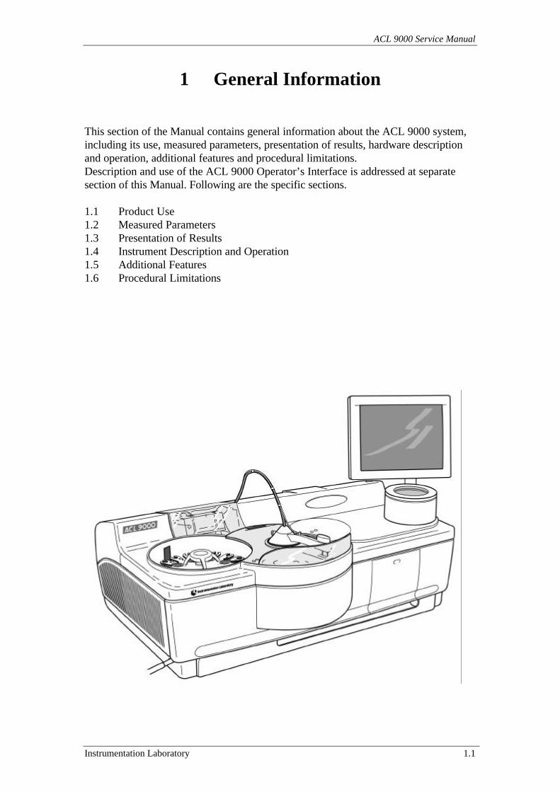
1 General Information
This section of the Manual contains general information about the ACL 9000 system,including its use, measured parameters, presentation of results, hardware descriptionand operation, additional features and procedural limitations.Description and use of the ACL 9000 Operator’s Interface is addressed at separatesection of this Manual. Following are the specific sections.
1.1 Product Use1.2 Measured Parameters1.3 Presentation of Results1.4 Instrument Description and Operation1.5 Additional Features1.6 Procedural Limitations
General Information
1.2 Instrumentation Laboratory
1.1 Product Use
The IL ACL 9000 system is a fully automated, high productivity analyser designedspecifically for clinical use in the hemostasis laboratory, for coagulation and/orfibrinolysis testing.The system provides results for both direct hemostasis measurements and calculatedparameters.
1.2 Measured Parameters
The ACL 9000 system is used to perform the following tests:
Coagulometric Tests
• PT-FIB (Prothrombin Time and PT-Based Fibrinogen concentration)• APTT (Activated Partial Thromboplastin Time)• TT (Thrombin Time)• Single Factors (VII, X, V, II, XII, XI, IX, VIII)
Absorbance Tests
• Antithrombin• Heparin Xa• Protein C• Plasmin Inhibitor (alpha-2-antiplasmin)• Plasminogen• Fibrinogen-C (Clauss method)
Immunological Tests
• D-Dimer• von Willebrand Factor (*)
Special Tests
• ProClot (clotting Protein C)• Protein S• APCR-V• Pro-IL-Complex **• Hepatocomplex **
Note: An (*) indicates that the test is not currently available for the ACL 9000.An (**) indicates that the test is not available in the United States.
ACL 9000 Service Manual
Instrumentation Laboratory 1.3
Profiles
The user may program Profiles on patient samples to be performed on a random accessbasis. Refer to the Operator’s Manual for additional information on this subject.
Tests Groups
Some tests can be run together as a group, thus saving time when the number ofsamples to be analysed is relatively small. Following are some examples:
PT-FIB/APTTPT-FIB/APTT/TT
Double Tests
The ACL 9000 offers the user the capability to set up double tests. Refer to theOperator’s Manual for additional information on this subject.
1.3 Presentation of Results
The ACL 9000 offers the following choices to display and print results of testing:
• s (seconds)• R (Ratio)• NR (Normalised Ratio)• INR (International Normalised Ratio)• % (Percent activity)• U/mL (units/mL)• mg/dL (for example for Fibrinogen)• g/L (for example for Fibrinogen)• ng/mL (for example for D-Dimer)• microg/L (for example for D-Dimer)• micromol/L• IU/mL (International Unit)• User configurable unit
General Information
1.4 Instrumentation Laboratory
1.4 Instrument Description and Operation
The ACL is a family of fully automated computer-controlled, microcentrifugalanalysers.
The ACL 9000 system incorporates a Liquid Crystal Display (LCD) unit that displaysthe status of the instrument, permits the user to select desired procedures and, throughthe use of menus and options, guides the operator through these procedures.
Information and instructions are entered into the system either via a Touch Screendevice or through a standard PC keyboard or through a mouse.
When sample testing is initiated, the samples and reagents are sequentially pipetted intoa 20-cuvette polystyrene rotor (loading process). Sample and reagents are then mixedby centrifugation process. The mixing is carried out by a combination of rapidacceleration and braking actions that are effective in thoroughly mixing the liquids.Reaction measurements (data acquisition) via the photometer are made while the rotoris spinning.
The ACL measures the parameters at 37 oC ± 1 oC (98.6 oF ± 1.8 oF), at an ambienttemperature from 15 oC to 32 oC (59 oF to 89 oF). However, if the ACL is in atemperature controlled environment where the ambient temperature is held constant,the measurements are made within a narrower temperature range: 37 oC ± 0.25 oC.The results are displayed on the VDU and optionally printed by the external printer,and/or sent to a host computer. The ACL performs automatic calibration, offers aseries of utility programs for the operator and manages a complete quality controlprogram.
ACL 9000 Service Manual
Instrumentation Laboratory 1.5
1.4.1 Main hardware components
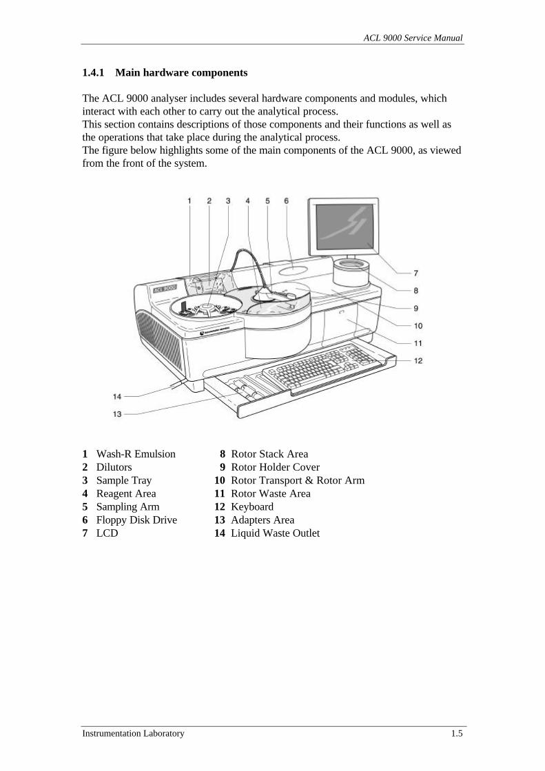
The ACL 9000 analyser includes several hardware components and modules, whichinteract with each other to carry out the analytical process.This section contains descriptions of those components and their functions as well asthe operations that take place during the analytical process.The figure below highlights some of the main components of the ACL 9000, as viewedfrom the front of the system.
1 Wash-R Emulsion 8 Rotor Stack Area2 Dilutors 9 Rotor Holder Cover3 Sample Tray 10 Rotor Transport & Rotor Arm4 Reagent Area 11 Rotor Waste Area5 Sampling Arm 12 Keyboard6 Floppy Disk Drive 13 Adapters Area7 LCD 14 Liquid Waste Outlet
General Information
1.6 Instrumentation Laboratory
More information about the other system present on the instrument is given in thesection “3 General Description”.Following are the specific sub-section with the item descriptions.
1.4.2 Sample Tray1.4.3 Reagent Area1.4.4 Rinse/Waste Area1.4.5 Rotor loading and Analysis Area1.4.6 Liquid Crystal Display (LCD)1.4.7 Keyboard1.4.8 Interface Connectors1.4.9 Internal Cooling System1.4.10 On-board Barcode Reader1.4.11 External Barcode Scanner1.4.12 External printer1.4.13 Floppy disk drive
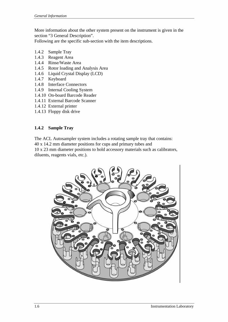
1.4.2 Sample Tray
The ACL Autosampler system includes a rotating sample tray that contains:40 x 14.2 mm diameter positions for cups and primary tubes and10 x 23 mm diameter positions to hold accessory materials such as calibrators,diluents, reagents vials, etc.).
ACL 9000 Service Manual
Instrumentation Laboratory 1.7
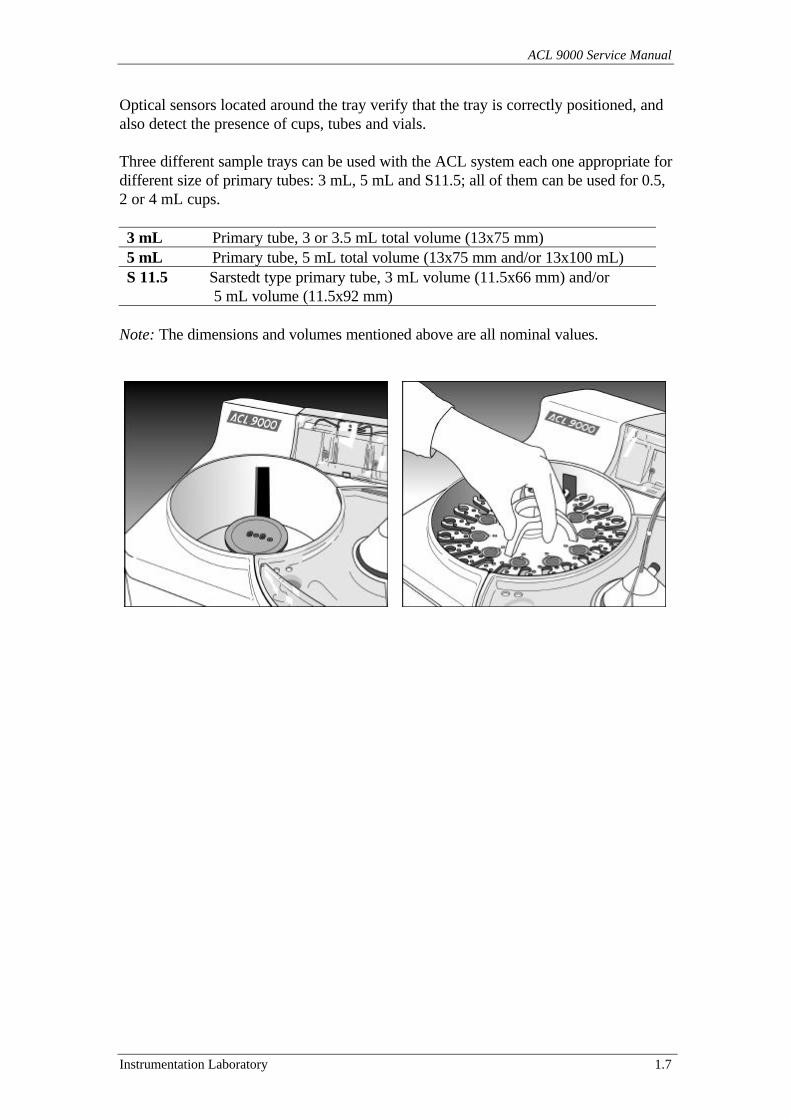
Optical sensors located around the tray verify that the tray is correctly positioned, andalso detect the presence of cups, tubes and vials.
Three different sample trays can be used with the ACL system each one appropriate fordifferent size of primary tubes: 3 mL, 5 mL and S11.5; all of them can be used for 0.5,2 or 4 mL cups.
3 mL Primary tube, 3 or 3.5 mL total volume (13x75 mm)5 mL Primary tube, 5 mL total volume (13x75 mm and/or 13x100 mL)S 11.5 Sarstedt type primary tube, 3 mL volume (11.5x66 mm) and/or 5 mL volume (11.5x92 mm)
Note: The dimensions and volumes mentioned above are all nominal values.
General Information
1.8 Instrumentation Laboratory
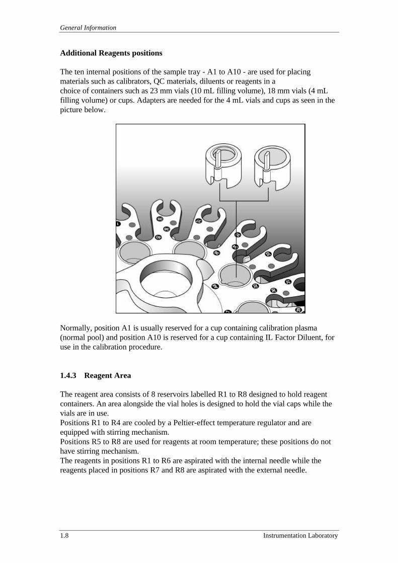
Additional Reagents positions
The ten internal positions of the sample tray - A1 to A10 - are used for placingmaterials such as calibrators, QC materials, diluents or reagents in achoice of containers such as 23 mm vials (10 mL filling volume), 18 mm vials (4 mLfilling volume) or cups. Adapters are needed for the 4 mL vials and cups as seen in thepicture below.
Normally, position A1 is usually reserved for a cup containing calibration plasma(normal pool) and position A10 is reserved for a cup containing IL Factor Diluent, foruse in the calibration procedure.
1.4.3 Reagent Area
The reagent area consists of 8 reservoirs labelled R1 to R8 designed to hold reagentcontainers. An area alongside the vial holes is designed to hold the vial caps while thevials are in use.Positions R1 to R4 are cooled by a Peltier-effect temperature regulator and areequipped with stirring mechanism.Positions R5 to R8 are used for reagents at room temperature; these positions do nothave stirring mechanism.The reagents in positions R1 to R6 are aspirated with the internal needle while thereagents placed in positions R7 and R8 are aspirated with the external needle.
ACL 9000 Service Manual
Instrumentation Laboratory 1.9
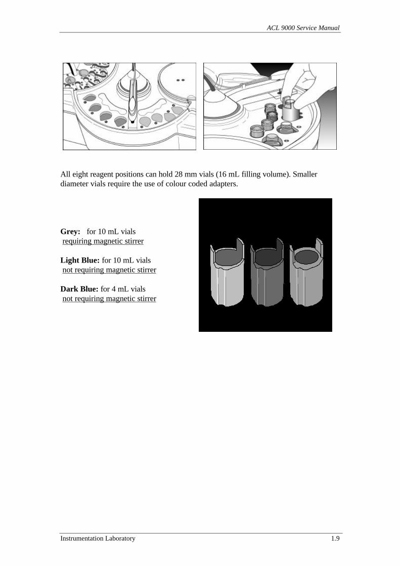
All eight reagent positions can hold 28 mm vials (16 mL filling volume). Smallerdiameter vials require the use of colour coded adapters.
Grey: for 10 mL vials requiring magnetic stirrer
Light Blue: for 10 mL vials not requiring magnetic stirrer
Dark Blue: for 4 mL vials not requiring magnetic stirrer
General Information
1.10 Instrumentation Laboratory
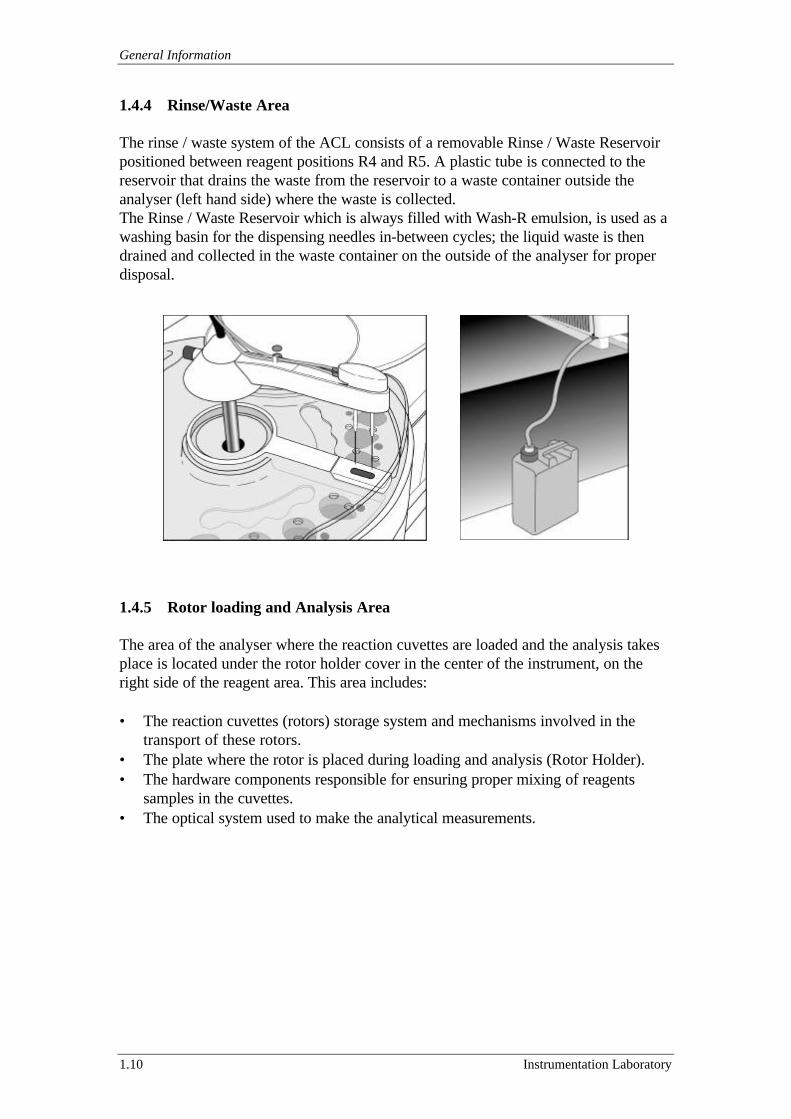
1.4.4 Rinse/Waste Area
The rinse / waste system of the ACL consists of a removable Rinse / Waste Reservoirpositioned between reagent positions R4 and R5. A plastic tube is connected to thereservoir that drains the waste from the reservoir to a waste container outside theanalyser (left hand side) where the waste is collected.The Rinse / Waste Reservoir which is always filled with Wash-R emulsion, is used as awashing basin for the dispensing needles in-between cycles; the liquid waste is thendrained and collected in the waste container on the outside of the analyser for properdisposal.
1.4.5 Rotor loading and Analysis Area
The area of the analyser where the reaction cuvettes are loaded and the analysis takesplace is located under the rotor holder cover in the center of the instrument, on theright side of the reagent area. This area includes:
• The reaction cuvettes (rotors) storage system and mechanisms involved in thetransport of these rotors.
• The plate where the rotor is placed during loading and analysis (Rotor Holder).• The hardware components responsible for ensuring proper mixing of reagents
samples in the cuvettes.• The optical system used to make the analytical measurements.
ACL 9000 Service Manual
Instrumentation Laboratory 1.11
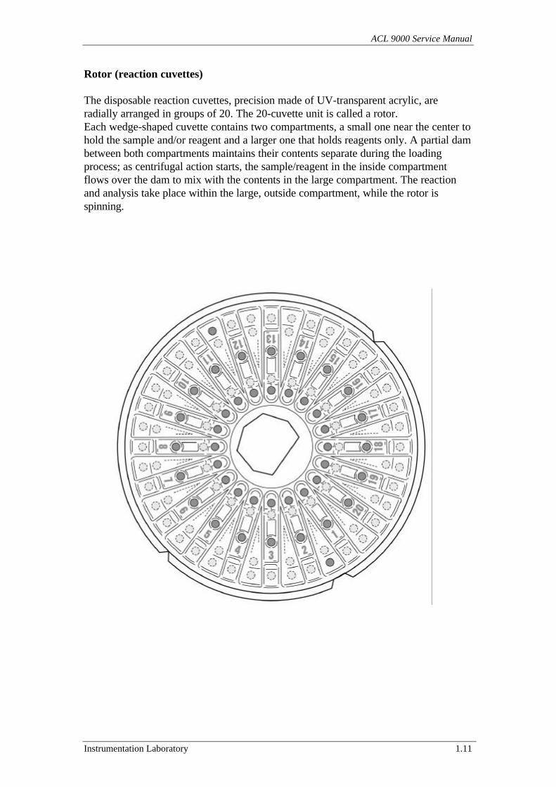
Rotor (reaction cuvettes)
The disposable reaction cuvettes, precision made of UV-transparent acrylic, areradially arranged in groups of 20. The 20-cuvette unit is called a rotor.Each wedge-shaped cuvette contains two compartments, a small one near the center tohold the sample and/or reagent and a larger one that holds reagents only. A partial dambetween both compartments maintains their contents separate during the loadingprocess; as centrifugal action starts, the sample/reagent in the inside compartmentflows over the dam to mix with the contents in the large compartment. The reactionand analysis take place within the large, outside compartment, while the rotor isspinning.
General Information
1.12 Instrumentation Laboratory
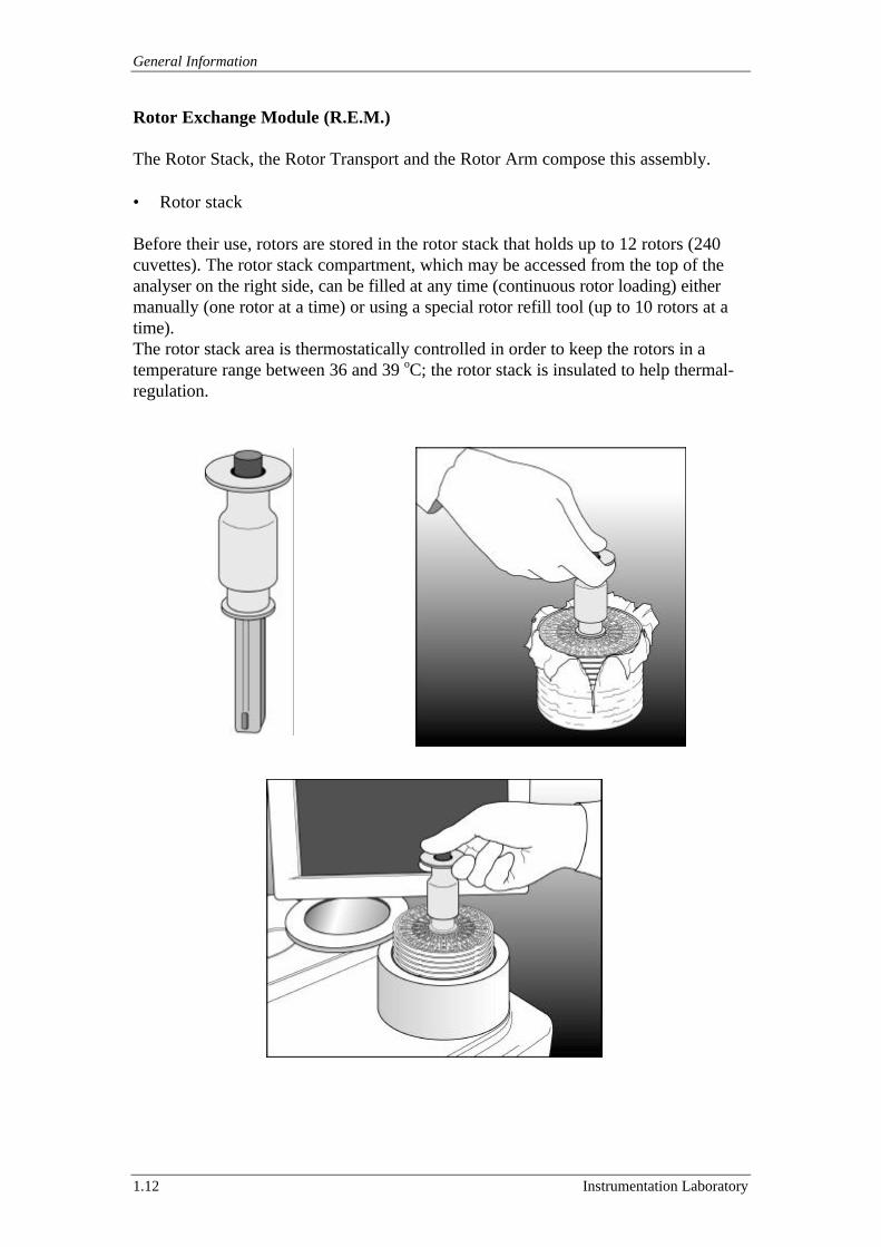
Rotor Exchange Module (R.E.M.)
The Rotor Stack, the Rotor Transport and the Rotor Arm compose this assembly.
• Rotor stack
Before their use, rotors are stored in the rotor stack that holds up to 12 rotors (240cuvettes). The rotor stack compartment, which may be accessed from the top of theanalyser on the right side, can be filled at any time (continuous rotor loading) eithermanually (one rotor at a time) or using a special rotor refill tool (up to 10 rotors at atime).The rotor stack area is thermostatically controlled in order to keep the rotors in atemperature range between 36 and 39 oC; the rotor stack is insulated to help thermal-regulation.
ACL 9000 Service Manual
Instrumentation Laboratory 1.13
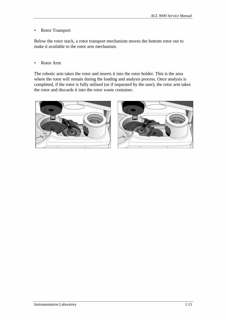
• Rotor Transport
Below the rotor stack, a rotor transport mechanism moves the bottom rotor out tomake it available to the rotor arm mechanism.
• Rotor Arm
The robotic arm takes the rotor and inserts it into the rotor holder. This is the areawhere the rotor will remain during the loading and analysis process. Once analysis iscompleted, if the rotor is fully utilised (or if requested by the user), the rotor arm takesthe rotor and discards it into the rotor waste container.
General Information
1.14 Instrumentation Laboratory
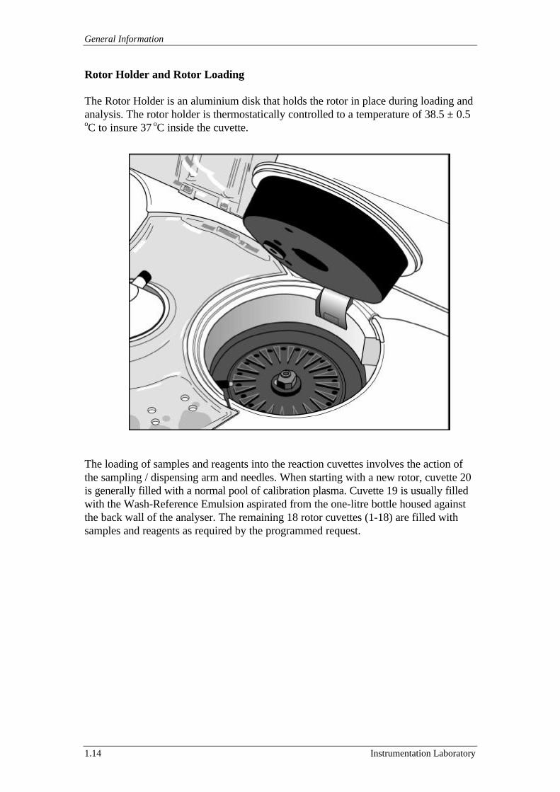
Rotor Holder and Rotor Loading
The Rotor Holder is an aluminium disk that holds the rotor in place during loading andanalysis. The rotor holder is thermostatically controlled to a temperature of 38.5 ± 0.5oC to insure 37 oC inside the cuvette.
The loading of samples and reagents into the reaction cuvettes involves the action ofthe sampling / dispensing arm and needles. When starting with a new rotor, cuvette 20is generally filled with a normal pool of calibration plasma. Cuvette 19 is usually filledwith the Wash-Reference Emulsion aspirated from the one-litre bottle housed againstthe back wall of the analyser. The remaining 18 rotor cuvettes (1-18) are filled withsamples and reagents as required by the programmed request.
ACL 9000 Service Manual
Instrumentation Laboratory 1.15
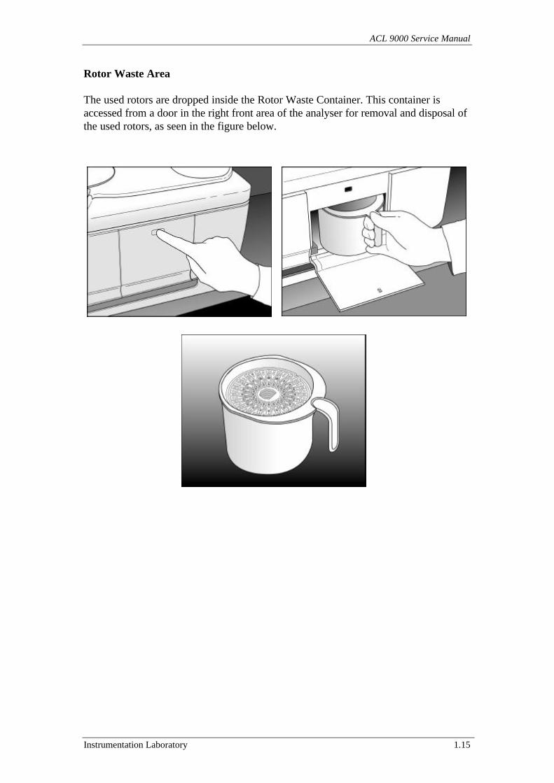
Rotor Waste Area
The used rotors are dropped inside the Rotor Waste Container. This container isaccessed from a door in the right front area of the analyser for removal and disposal ofthe used rotors, as seen in the figure below.
General Information
1.16 Instrumentation Laboratory
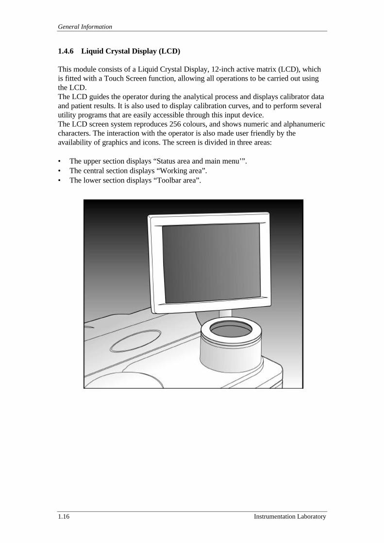
1.4.6 Liquid Crystal Display (LCD)
This module consists of a Liquid Crystal Display, 12-inch active matrix (LCD), whichis fitted with a Touch Screen function, allowing all operations to be carried out usingthe LCD.The LCD guides the operator during the analytical process and displays calibrator dataand patient results. It is also used to display calibration curves, and to perform severalutility programs that are easily accessible through this input device.The LCD screen system reproduces 256 colours, and shows numeric and alphanumericcharacters. The interaction with the operator is also made user friendly by theavailability of graphics and icons. The screen is divided in three areas:
• The upper section displays “Status area and main menu’”.• The central section displays “Working area”.• The lower section displays “Toolbar area”.
ACL 9000 Service Manual
Instrumentation Laboratory 1.17
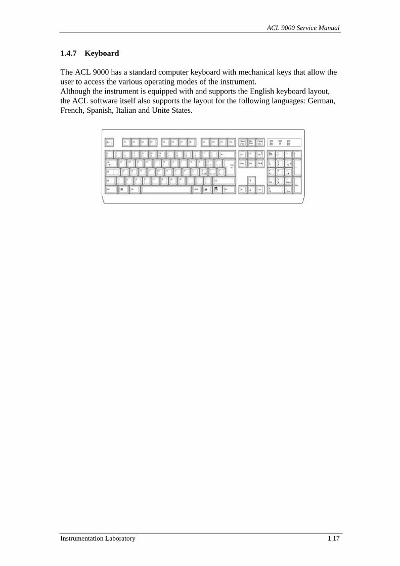
1.4.7 Keyboard
The ACL 9000 has a standard computer keyboard with mechanical keys that allow theuser to access the various operating modes of the instrument.Although the instrument is equipped with and supports the English keyboard layout,the ACL software itself also supports the layout for the following languages: German,French, Spanish, Italian and Unite States.
General Information
1.18 Instrumentation Laboratory
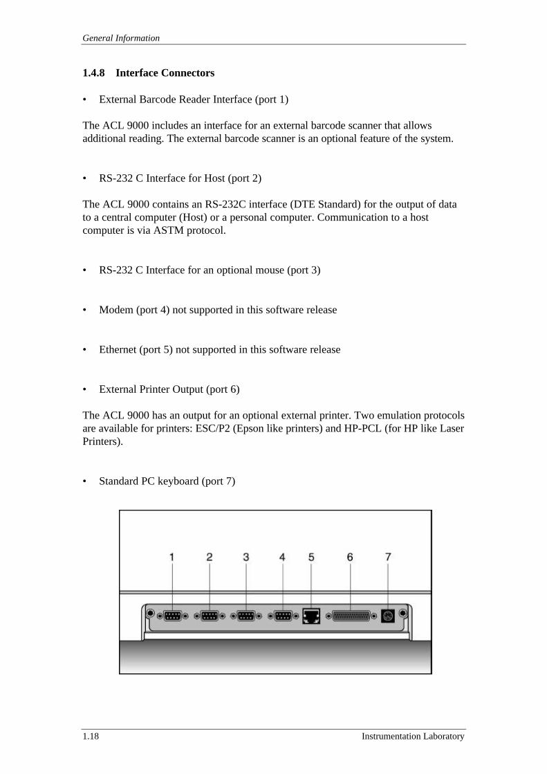
1.4.8 Interface Connectors
• External Barcode Reader Interface (port 1)
The ACL 9000 includes an interface for an external barcode scanner that allowsadditional reading. The external barcode scanner is an optional feature of the system.
• RS-232 C Interface for Host (port 2)
The ACL 9000 contains an RS-232C interface (DTE Standard) for the output of datato a central computer (Host) or a personal computer. Communication to a hostcomputer is via ASTM protocol.
• RS-232 C Interface for an optional mouse (port 3)
• Modem (port 4) not supported in this software release
• Ethernet (port 5) not supported in this software release
• External Printer Output (port 6)
The ACL 9000 has an output for an optional external printer. Two emulation protocolsare available for printers: ESC/P2 (Epson like printers) and HP-PCL (for HP like LaserPrinters).
• Standard PC keyboard (port 7)
ACL 9000 Service Manual
Instrumentation Laboratory 1.19
1.4.9 Internal Cooling System
The cooling of the system is insured by the presence of fans mounted on the internalsright and left sides of the analyser. An air filter prevents dust from entering the system.A two-level alarm warns the user when the internal temperature of the instrument risesabove damaging levels. The first level alerts the operator of the temperature rise anddisplays a warning. The second level switches off the instrument.
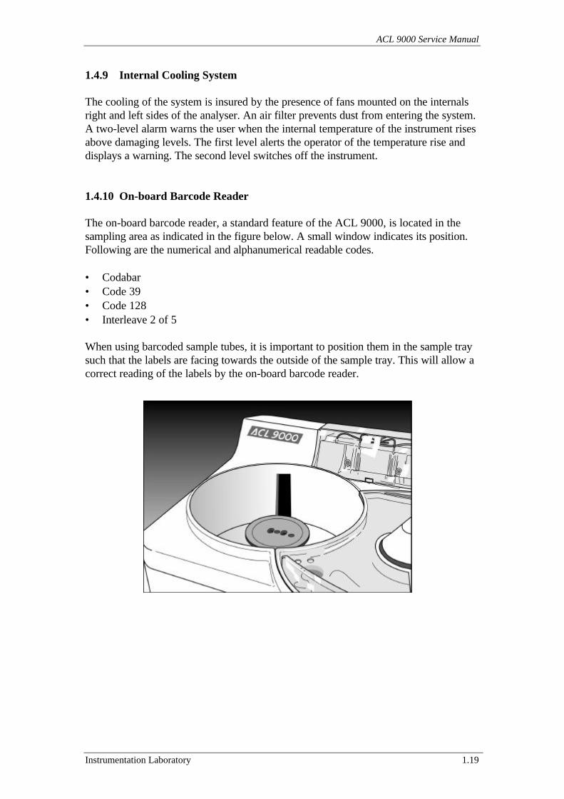
1.4.10 On-board Barcode Reader
The on-board barcode reader, a standard feature of the ACL 9000, is located in thesampling area as indicated in the figure below. A small window indicates its position.Following are the numerical and alphanumerical readable codes.
• Codabar• Code 39• Code 128• Interleave 2 of 5
When using barcoded sample tubes, it is important to position them in the sample traysuch that the labels are facing towards the outside of the sample tray. This will allow acorrect reading of the labels by the on-board barcode reader.
General Information
1.20 Instrumentation Laboratory
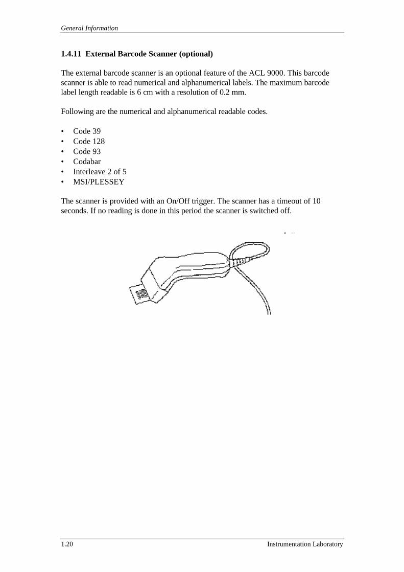
1.4.11 External Barcode Scanner (optional)
The external barcode scanner is an optional feature of the ACL 9000. This barcodescanner is able to read numerical and alphanumerical labels. The maximum barcodelabel length readable is 6 cm with a resolution of 0.2 mm.
Following are the numerical and alphanumerical readable codes.
• Code 39• Code 128• Code 93• Codabar• Interleave 2 of 5• MSI/PLESSEY
The scanner is provided with an On/Off trigger. The scanner has a timeout of 10seconds. If no reading is done in this period the scanner is switched off.
ACL 9000 Service Manual
Instrumentation Laboratory 1.21
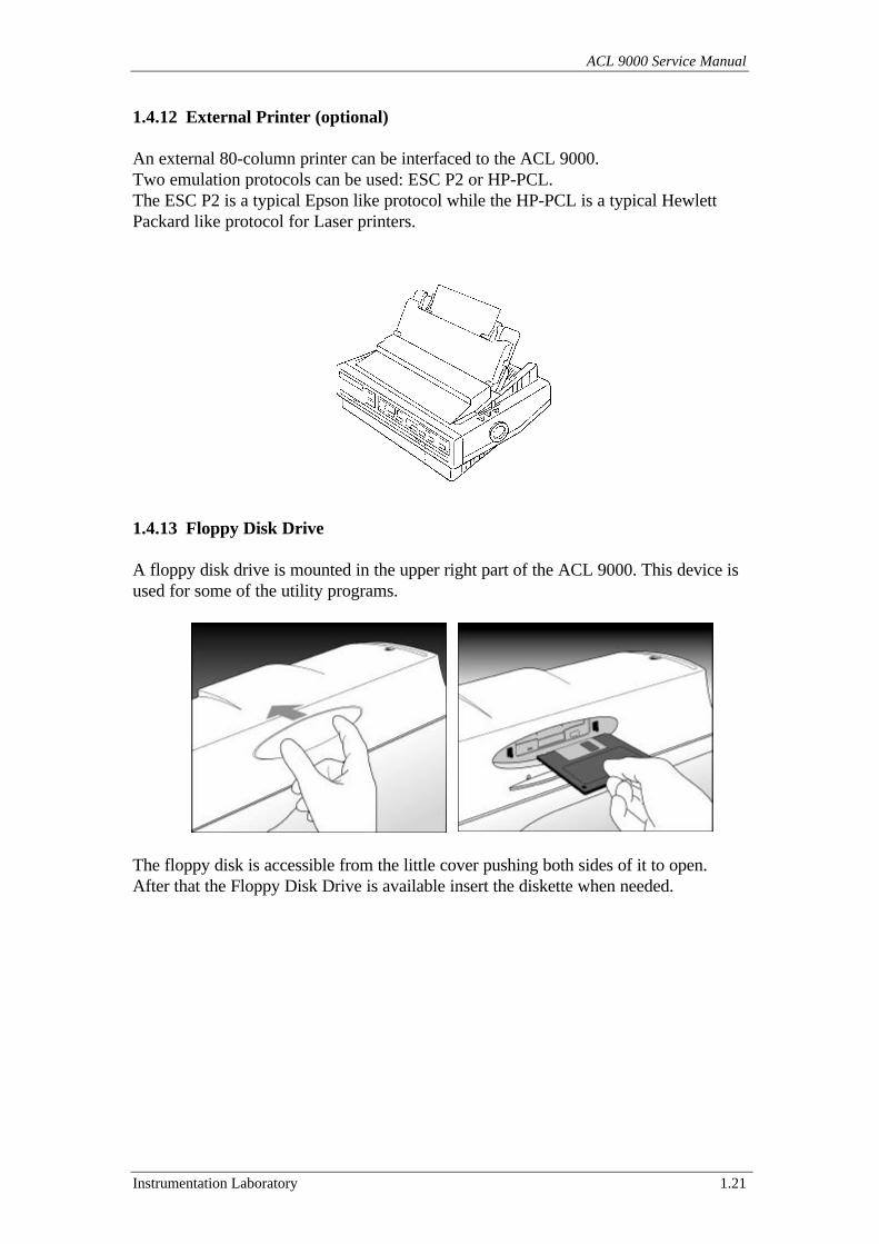
1.4.12 External Printer (optional)
An external 80-column printer can be interfaced to the ACL 9000.Two emulation protocols can be used: ESC P2 or HP-PCL.The ESC P2 is a typical Epson like protocol while the HP-PCL is a typical HewlettPackard like protocol for Laser printers.
1.4.13 Floppy Disk Drive
A floppy disk drive is mounted in the upper right part of the ACL 9000. This device isused for some of the utility programs.
The floppy disk is accessible from the little cover pushing both sides of it to open.After that the Floppy Disk Drive is available insert the diskette when needed.
General Information
1.22 Instrumentation Laboratory
1.5 Additional Features
This section provides information on any additional features improved in the ACL9000.
1.5.1 Standby Status
If the ACL 9000 is left ON for a period longer than 30 minutes without any operatoraction, the system moves into the Standby status. The LCD screen displays “StandbyStatus”. Pressing the Touch Screen reactivates the display and allows the system toresume normal operation.When the system enters the Standby status, all motors are deactivated to reduce powerconsumption and the LED source is switched off. While the instrument is in theStandby status, an automatic priming cycle is performed every 30 minutes.
1.5.2 End of the Cycle
At the end of each analytical cycle, a beep signal notifies the operator that the cycle hasbeen completed.
1.5.3 Power loss
The ACL contains a Hard Disk Drive to store the database in the event of a powerinterruption. The instrument performs an automatic save of the database to retain thedata every entry in standby or when exiting from the main program for the power off.The instrument has an internal clock that keeps track of the date and time.
1.5.4 Setup and Utility Programs
The instrument incorporates several utility programs that allow certain functions to bechanged or set according to the user’s needs. These programs also help introubleshooting.For additional information, refer to section 2 “Operator Interface description“ of thisManual.
1.5.5 Fault Detection
The system automatically monitors faults to ensure accuracy of sample data and propersystem performance. Fault monitoring includes display of alarms and warnings.For additional information, refer to the section “6 Troubleshooting” of this Manual.
ACL 9000 Service Manual
Instrumentation Laboratory 1.23
1.6 Procedural Limitations
The operating range of the ACL 9000 is 15 to 32 oC ( 59 to 89 oF) and at up to 85%Relative Humidity (not condensing).No safety hazards occur in the temperature range 5 - 40 oC (41 to 104 oF) andfunctional performance characteristics are resumed when the instrument re-enters therange of 15 to 32 oC ( 59 to 89 oF).
ACL 9000 Service Manual
Instrumentation Laboratory 2.1
2 Operator Interface Description
This section is designed to familiarise the service engineer with the Operator Interface(OI) items used during the process of requesting and performing analytical and serviceoperations, such as the data input devices, elements within menus, buttons and icons.Following are the specific sections.
2.1 Screen areas and main commands description.2.2 Available input devices.2.3 Instrument status.2.4 Passwords.2.5 Analysis and Service program menu description.
2.1 Screen areas and main commands description.
In this section are provided information about the Operator Interface displayed onscreen.The basic interaction with the ACL is done through menus which allow access to setsof related functions (analysis, calibration, QC, set-up, diagnostics, etc.) and throughthe use of windows, dialogue or message boxes to input or retrieve information.The screen is divided in the following 3 main areas.
2.1.1 Status area and main menu’.2.1.2 Working area.2.1.3 Toolbar area.
Note: On the screen, any disabled object (menu, check-box, and button) is displayeddimmed and it cannot be selected.
2.1.1 Status area and main menu’
This is the upper part of the screen that contains the following items.
• IL Logo• Indication of current instrument status (see section 2.3)• Date and Time• Windows like Menu bar (see section 2.5)
Operator Interface Description
2.2 Instrumentation Laboratory
2.1.2 Working area
This is the central area of the screen, which display windows containing data,commands or messages.Within the ACL 9000 screens these item are grouped or contained in three differenttypes of defined windows that are following.
• Standard window
In the analysis menu’ usually this is a larger area that contains sets of related data,which can be edited by the user by means of command buttons.In the service menu’ or in any common menu’ usually this is an area that containsconfiguration and setting options with command buttons.
• Dialogue box
This is a small area used to prompt the user to choose one of several options (OK,Abort, Retry, Ignore, Cancel, Yes, No)
• Message box
This is an area used only to provide information
Command buttons allow the user to select options, cause actions and get from one partof the software to another.The buttons are positioned in different areas depending on the screen.Some are identified with text that is self-explanatory of the action.
ACL 9000 Service Manual
Instrumentation Laboratory 2.3
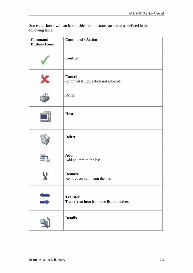
Some are shown with an icon inside that illustrates an action as defined in thefollowing table.
CommandButtons Icons
Command / Action
Confirm
Cancel(Dimmed if Edit action not allowed)
Host
Delete
AddAdd an item to the list.
RemoveRemove an item from the list.
TransferTransfer an item from one list to another.
Details
Operator Interface Description
2.4 Instrumentation Laboratory
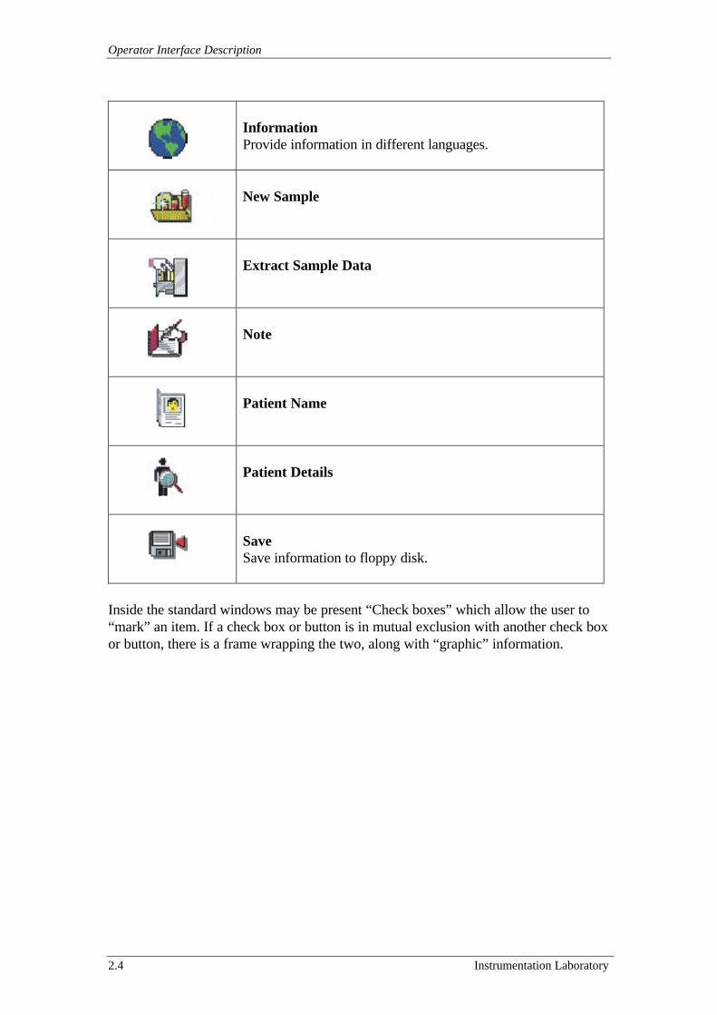
InformationProvide information in different languages.
New Sample
Extract Sample Data
Note
Patient Name
Patient Details
SaveSave information to floppy disk.
Inside the standard windows may be present “Check boxes” which allow the user to“mark” an item. If a check box or button is in mutual exclusion with another check boxor button, there is a frame wrapping the two, along with “graphic” information.
ACL 9000 Service Manual
Instrumentation Laboratory 2.5
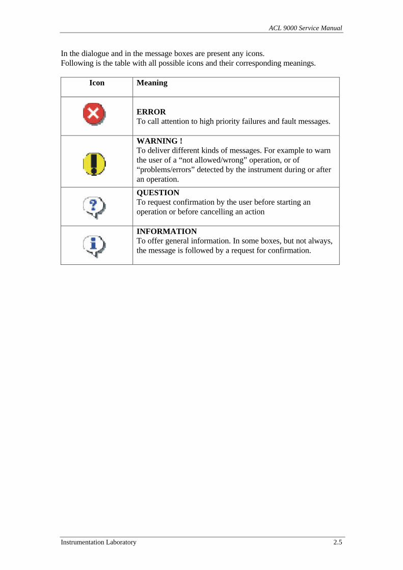
In the dialogue and in the message boxes are present any icons.Following is the table with all possible icons and their corresponding meanings.
Icon Meaning
ERRORTo call attention to high priority failures and fault messages.
WARNING !To deliver different kinds of messages. For example to warnthe user of a “not allowed/wrong” operation, or of“problems/errors” detected by the instrument during or afteran operation.
QUESTIONTo request confirmation by the user before starting anoperation or before cancelling an action
INFORMATIONTo offer general information. In some boxes, but not always,the message is followed by a request for confirmation.
Operator Interface Description
2.6 Instrumentation Laboratory
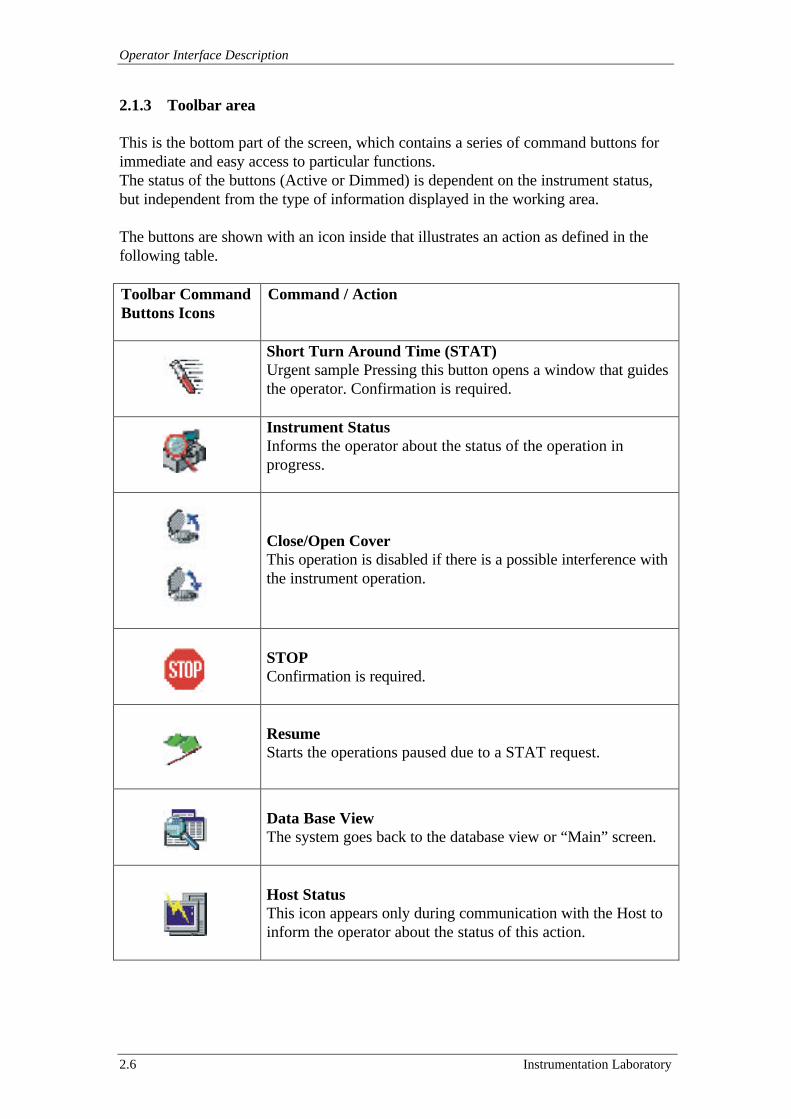
2.1.3 Toolbar area
This is the bottom part of the screen, which contains a series of command buttons forimmediate and easy access to particular functions.The status of the buttons (Active or Dimmed) is dependent on the instrument status,but independent from the type of information displayed in the working area.
The buttons are shown with an icon inside that illustrates an action as defined in thefollowing table.
Toolbar CommandButtons Icons
Command / Action
Short Turn Around Time (STAT)Urgent sample Pressing this button opens a window that guidesthe operator. Confirmation is required.
Instrument StatusInforms the operator about the status of the operation inprogress.
Close/Open CoverThis operation is disabled if there is a possible interference withthe instrument operation.
STOPConfirmation is required.
ResumeStarts the operations paused due to a STAT request.
Data Base ViewThe system goes back to the database view or “Main” screen.
Host StatusThis icon appears only during communication with the Host toinform the operator about the status of this action.
ACL 9000 Service Manual
Instrumentation Laboratory 2.7
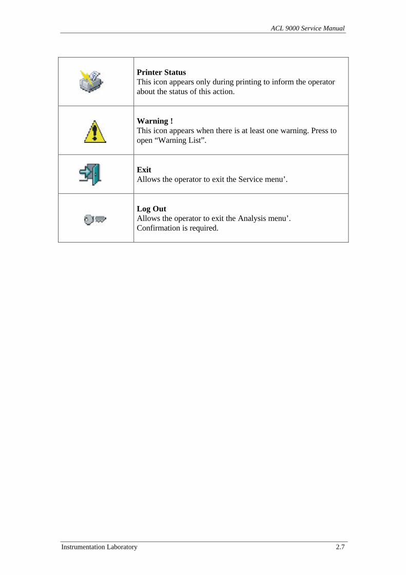
Printer StatusThis icon appears only during printing to inform the operatorabout the status of this action.
Warning !This icon appears when there is at least one warning. Press toopen “Warning List”.
ExitAllows the operator to exit the Service menu’.
Log OutAllows the operator to exit the Analysis menu’.Confirmation is required.
Operator Interface Description
2.8 Instrumentation Laboratory
2.2 Available input devices
This section provides information about the available input devices and them use indifferent screens.Following are the specific sub-section for each device.
2.2.1 Touch Screen2.2.2 Standard PC Keyboard2.2.3 Mouse2.2.4 External Bar Code Reader
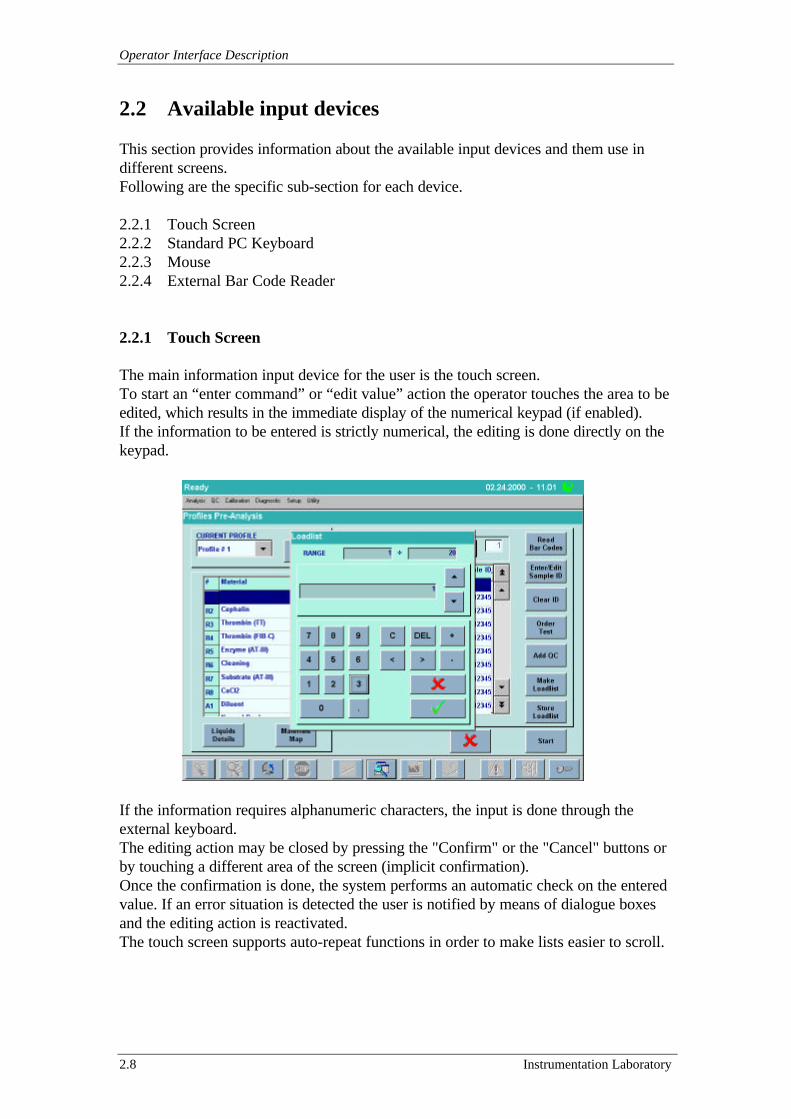
2.2.1 Touch Screen
The main information input device for the user is the touch screen.To start an “enter command” or “edit value” action the operator touches the area to beedited, which results in the immediate display of the numerical keypad (if enabled).If the information to be entered is strictly numerical, the editing is done directly on thekeypad.
If the information requires alphanumeric characters, the input is done through theexternal keyboard.The editing action may be closed by pressing the "Confirm" or the "Cancel" buttons orby touching a different area of the screen (implicit confirmation).Once the confirmation is done, the system performs an automatic check on the enteredvalue. If an error situation is detected the user is notified by means of dialogue boxesand the editing action is reactivated.The touch screen supports auto-repeat functions in order to make lists easier to scroll.
ACL 9000 Service Manual
Instrumentation Laboratory 2.9
2.2.2 Standard PC Keyboard
The main function of the PC keyboard is to enter and edit data in the alphanumericfields.To start the editing action selects the field to be edited. Moving the cursor from thecurrent object (it may be the default object if the window was just opened) does this tothe chosen object by pressing [TAB] or [Shift] [TAB].To close the editing action press [Enter] or select another active object or move thecursor by pressing the [TAB] or [Shift] [TAB] keys. In all cases, closing the editingaction causes the system to activate checks on the entered data and the user is notifiedof any error conditions by means of a dialogue box. If the editing action has beenimplicitly closed (touching a different area of the screen) the fault condition of theentered value will be changed to the pre-existing one.Pressing the [ESC] key without activating any control may also close the editingaction; in this case the value returns to the pre-existing one.Main and secondary menus may be selected using the keyboard. Pressing [ALT]+Character opens the menus; selections within the secondary menus are done usingthe Character key.The keyboard may also be used to activate the Toolbar functions ( [F 1] to [F 11] ).Pressing [ALT]-[TAB] allows shifting from an activated window to another visiblewindow.
2.2.3 Mouse
The mouse is an optional device that may be used as a selecting device in place oftouching the screen. If at the instrument turn on the mouse is connected to the properports of the Interface Board then the Mouse arrow pointer is displayed.
2.2.4 External Barcode Reader
The external barcode reader is an optional device used to “read” the informationencoded in sample barcode labels. The characters read are handled exactly as themanual editing from the keyboard and are valid for every editable field.
Operator Interface Description
2.10 Instrumentation Laboratory
2.3 Instrument Status
Located in the upper part of the screen, within the “Status area”, this item identifies thecurrent state of the instrument as one of the following.
• SYSTEM INIT (BOOT/START-UP)
This indicates that the instrument after the turn on is performing start-up operations(Initialising).
• LOG-IN
This indicates that the instrument is inoperative and is waiting for the inputting of theUser Identification and the Password of the operator (see section 2.4).
• READY
This indicates that there have been no blocking errors detected, there are no analyticaloperations in progress and the instrument is ready to start.
• OPERATING
This indicates that either an analytical function is in progress (Calibration or SampleAnalysis) or a diagnostic function is being performed.
• HOLD
This identifies a system "pause" reached during an analytical session (STAT request,no rotors, etc.). In order to continue the current session select “Resume” (green flagicon in the Toolbar).
• FAILURE
This indicates that the system has detected a blocking malfunction for a softwareproblem or into internal mechanisms (devices, temperature control, etc.).
ACL 9000 Service Manual
Instrumentation Laboratory 2.11
• STAND-BY
This is the status into which the instrument moves automatically after 30 minutes ofinactivity. The LCD lamp in the video module is turned off and its status led becomesgreen. Both coagulimetric LED and Halogen Lamp are off and the system performs aDatabase check then becomes inoperative.To exit from the stand by status enter any command (Touch the screen, press any keyetc.).
• SERVICE
This is the status assumed when the instrument is in the Service program or in itsmenus.To gain access at the Service program is necessary to insert the proper identificationpassword at the LOG-IN (User: Service, Password: ACL fix) and then select on thewindows like menu’ bar “Diagnostic” and then “Service”.In the Service program are contained all the software tools and utilities to allows at theService Engineer a complete check out and adjustment of the whole Instrument.In the Service program the coagulimetric LED and Halogen Lamp are turned on fordefault.To exit from the Service program selects the “Exit” button on the Toolbar.
Note: Every time that on the Tool Bar the “Exit” button is touched, the systemperforms an initialisation of the Instrument.During this initialisation puts all the motors in the home position and try to recover allthe error presents before access to the Analysis program.
Operator Interface Description
2.12 Instrumentation Laboratory
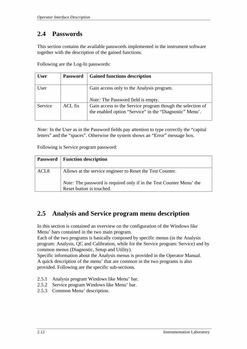
2.4 Passwords
This section contains the available passwords implemented in the instrument softwaretogether with the description of the gained functions.
Following are the Log-In passwords:
User Password Gained functions description
User Gain access only to the Analysis program.
Note: The Password field is empty.Service ACL fix Gain access to the Service program though the selection of
the enabled option “Service” in the “Diagnostic” Menu’.
Note: In the User as in the Password fields pay attention to type correctly the “capitalletters” and the “spaces”. Otherwise the system shows an “Error” message box.
Following is Service program password:
Password Function description
ACL8 Allows at the service engineer to Reset the Test Counter.
Note: The password is required only if in the Test Counter Menu’ theReset button is touched.
2.5 Analysis and Service program menu description
In this section is contained an overview on the configuration of the Windows likeMenu’ bars contained in the two main program.Each of the two programs is basically composed by specific menus (in the Analysisprogram: Analysis, QC and Calibration, while for the Service program: Service) and bycommon menus (Diagnostic, Setup and Utility).Specific information about the Analysis menus is provided in the Operator Manual.A quick description of the menu’ that are common in the two programs is alsoprovided. Following are the specific sub-sections.
2.5.1 Analysis program Windows like Menu’ bar.2.5.2 Service program Windows like Menu’ bar.2.5.3 Common Menu’ description.
ACL 9000 Service Manual
Instrumentation Laboratory 2.13
2.5.1 Analysis program Windows like Menu’ bar
This sub-section is designed to provides information about the location of the menu’ inthe Analysis program.A menu may be opened by selecting the appropriate area of the screen (touch or clickwith the mouse) or using the keyboard: [ALT] + Character.The selection of menus to be opened may be done in all directions: up and down orright and left.The displayed items, which have a secondary menu, are identified with a marker (ØØ).Selecting a menu item, touching an external area, or pressing [ESC] from the standardkeyboard closes a menu.
The “Analysis Windows Like Menu’ Expanded Diagrams” is available in the figure2.5.1 Drawing 1 of the section “10 Drawings”.
2.5.2 Service program Windows like Menu’ bar
This sub-section is designed to provides information about the location of the menu’ inthe Service program.A menu may be opened by selecting the appropriate area of the screen (touch or clickwith the mouse) or using the keyboard: [ALT] + Character.The selection of menus to be opened may be done in all directions: up and down orright and left.The displayed items, which have a secondary menu, are identified with a marker (ØØ).Selecting a menu item, touching an external area, or pressing [ESC] from the standardkeyboard closes a menu.
The “Service Windows Like Menu’ Expanded Diagrams” is available in the figure2.5.2 Drawing 1 of the section “10 Drawings”.
2.5.3 Common Menu’ description
This sub-section is designed to provide information on the menu’ that are common andpresent in both the Analysis and the Service program. More information about these 3menus is provided in the Operator’s Manual.Following are the specific sub-section for these 3 menus.
2.5.3.a Diagnostic2.5.3.b Setup2.5.5.c Utility

Operator Interface Description
2.14 Instrumentation Laboratory
2.5.3.a Diagnostic
Following is the table with the description of the functionality of each option in the“Diagnostic” menu’.
Option Description
Priming This performs a priming cycle of the fluidic system withWash-Reference Emulsion by means of the Dilutors.
Cleaning This performs a configurable cleaning cycle of the NeedlesBlock with Cleaning Solution by means of the Dilutors.
Maintenance This is a schedule that allows at the operator to rememberdates and notes about the instrument maintenance actions.
Temperature Control This screen allows to monitoring the temperatures of theheating and cooling systems.
Needles Position This is a test that allows at the operator to verify/adjust theNeedles Block position.
Session Error History It’s a table where are traced by the system the errorsoccurred during the last session.
Logbook It’s a table where are traced by the system the last 100actions of the operators on the system configuration.
Service This option allows at the Service Engineer to access at theService program (without the proper password is dimmed).
2.5.3.b Setup
Following is the table with the description of the functionality of each option in the“Setup” menu’.
Option Description
Tests This is a second level menu’ with any options that allow tothe operator to whole configure the analytical tests.
Profiles This is a second level menu’ with any options that allow tothe operator to whole configure the analytical profile tests.
Liquids This is an option that allows to the operator to wholeconfigure the liquids used by the instrument.
Interfaces This is a second level menu’ with any options that allow tothe operator to whole configure the interface with theinternal / external device.
System Configuration This is an option that allows to the operator to wholeconfigure the system.
Date / Time This is an option that allows to the operator to set the dateand the internal clock time.
Units This is an option that allows at the operator to select themeasuring units for the data.
ACL 9000 Service Manual
Instrumentation Laboratory 2.15
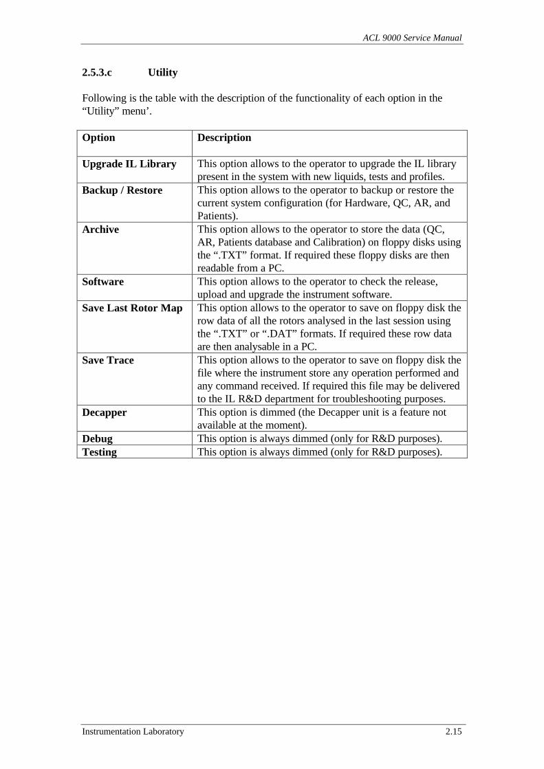
2.5.3.c Utility
Following is the table with the description of the functionality of each option in the“Utility” menu’.
Option Description
Upgrade IL Library This option allows to the operator to upgrade the IL librarypresent in the system with new liquids, tests and profiles.
Backup / Restore This option allows to the operator to backup or restore thecurrent system configuration (for Hardware, QC, AR, andPatients).
Archive This option allows to the operator to store the data (QC,AR, Patients database and Calibration) on floppy disks usingthe “.TXT” format. If required these floppy disks are thenreadable from a PC.
Software This option allows to the operator to check the release,upload and upgrade the instrument software.
Save Last Rotor Map This option allows to the operator to save on floppy disk therow data of all the rotors analysed in the last session usingthe “.TXT” or “.DAT” formats. If required these row dataare then analysable in a PC.
Save Trace This option allows to the operator to save on floppy disk thefile where the instrument store any operation performed andany command received. If required this file may be deliveredto the IL R&D department for troubleshooting purposes.
Decapper This option is dimmed (the Decapper unit is a feature notavailable at the moment).
Debug This option is always dimmed (only for R&D purposes).Testing This option is always dimmed (only for R&D purposes).
ACL 9000 Service Manual
Instrumentation Laboratory 3.1
3 General Description
This section of the Manual contains general description about the ACL 9000 system,including them use and functionality. Following are the specific sections.
3.1 Main Fluidic System Description3.2 Main Optic System Description3.3 Electronic Description3.4 Main Hardware Components Description3.5 Software Description3.6 Heating and Cooling System Description
General Description
3.2 Instrumentation Laboratory
3.1 Main Fluidic System Description
This section provides information about the fluidic system functionality during theanalysis and on its components.
The fluidic functions are sampling, dispensing and flushing the system.The ACL 9000 fluidic system includes the components described in the followingsub-sections.
3.1.1 Wash-Reference Emulsion bottle.3.1.2 Dilutors Chamber and Electro-Valves.3.1.3 Sample Arm Assembly.
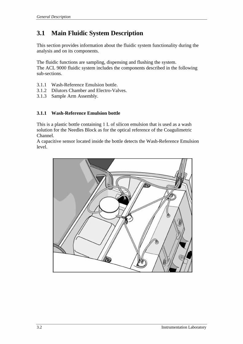
3.1.1 Wash-Reference Emulsion bottle
This is a plastic bottle containing 1 L of silicon emulsion that is used as a washsolution for the Needles Block as for the optical reference of the CoagulimetricChannel.A capacitive sensor located inside the bottle detects the Wash-Reference Emulsionlevel.
ACL 9000 Service Manual
Instrumentation Laboratory 3.3
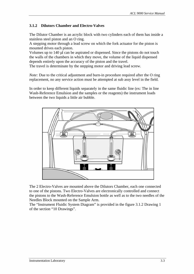
3.1.2 Dilutors Chamber and Electro-Valves
The Dilutor Chamber is an acrylic block with two cylinders each of them has inside astainless steel piston and an O ring.A stepping motor through a lead screw on which the fork actuator for the piston ismounted drives each piston.Volumes up to 140 µl can be aspirated or dispensed. Since the pistons do not touchthe walls of the chambers in which they move, the volume of the liquid dispenseddepends entirely upon the accuracy of the piston and the travel.The travel is determinate by the stepping motor and driving lead screw.
Note: Due to the critical adjustment and burn-in procedure required after the O ringreplacement, no any service action must be attempted at sub assy level in the field.
In order to keep different liquids separately in the same fluidic line (ex: The in lineWash-Reference Emulsion and the samples or the reagents) the instrument loadsbetween the two liquids a little air bubble.
The 2 Electro-Valves are mounted above the Dilutors Chamber, each one connectedto one of the pistons. Two Electro-Valves are electronically controlled and connectthe pistons to the Wash-Reference Emulsion bottle as well as to the two needles of theNeedles Block mounted on the Sample Arm.The “Instrument Fluidic System Diagram” is provided in the figure 3.1.2 Drawing 1of the section “10 Drawings”.
General Description
3.4 Instrumentation Laboratory
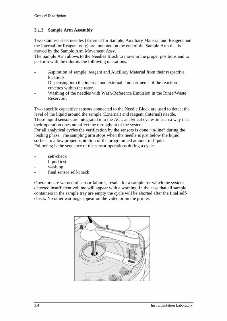
3.1.3 Sample Arm Assembly
Two stainless steel needles (External for Sample, Auxiliary Material and Reagent andthe Internal for Reagent only) are mounted on the end of the Sample Arm that ismoved by the Sample Arm Movement Assy.The Sample Arm allows to the Needles Block to move in the proper positions and toperform with the dilutors the following operations.
- Aspiration of sample, reagent and Auxiliary Material from their respectivelocations.
- Dispensing into the internal and external compartments of the reactioncuvettes within the rotor.
- Washing of the needles with Wash-Reference Emulsion in the Rinse/WasteReservoir.
Two specific capacitive sensors connected to the Needle Block are used to detect thelevel of the liquid around the sample (External) and reagent (Internal) needle.These liquid sensors are integrated into the ACL analytical cycles in such a way thattheir operation does not affect the throughput of the system.For all analytical cycles the verification by the sensors is done “in-line” during theloading phase. The sampling arm stops when the needle is just below the liquidsurface to allow proper aspiration of the programmed amount of liquid.Following is the sequence of the sensor operations during a cycle.
- self-check- liquid test- washing- final sensor self-check
Operators are warned of sensor failures, results for a sample for which the systemdetected insufficient volume will appear with a warning. In the case that all samplecontainers in the sample tray are empty the cycle will be aborted after the final self-check. No other warnings appear on the video or on the printer.
ACL 9000 Service Manual
Instrumentation Laboratory 3.5
3.2 Main optic system description
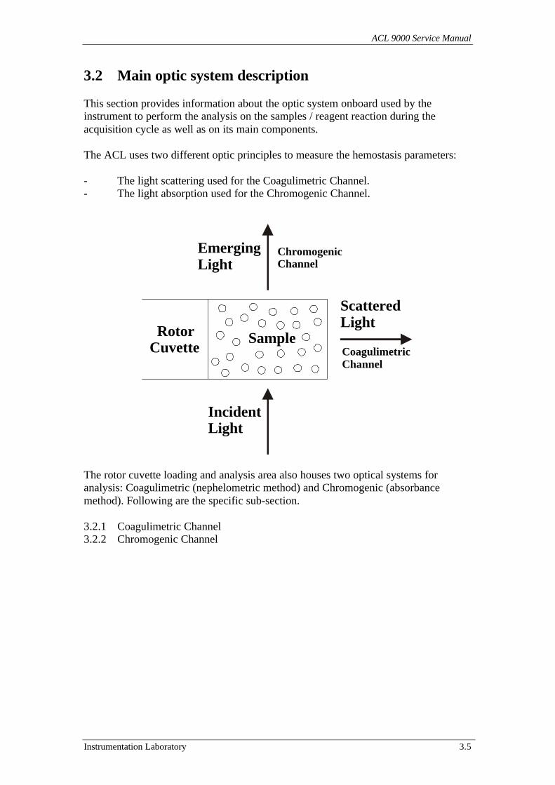
This section provides information about the optic system onboard used by theinstrument to perform the analysis on the samples / reagent reaction during theacquisition cycle as well as on its main components.
The ACL uses two different optic principles to measure the hemostasis parameters:
- The light scattering used for the Coagulimetric Channel.- The light absorption used for the Chromogenic Channel.
The rotor cuvette loading and analysis area also houses two optical systems foranalysis: Coagulimetric (nephelometric method) and Chromogenic (absorbancemethod). Following are the specific sub-section.
3.2.1 Coagulimetric Channel3.2.2 Chromogenic Channel
Sample RotorCuvette
IncidentLight
ScatteredLight
EmergingLight
CoagulimetricChannel
ChromogenicChannel
General Description
3.6 Instrumentation Laboratory
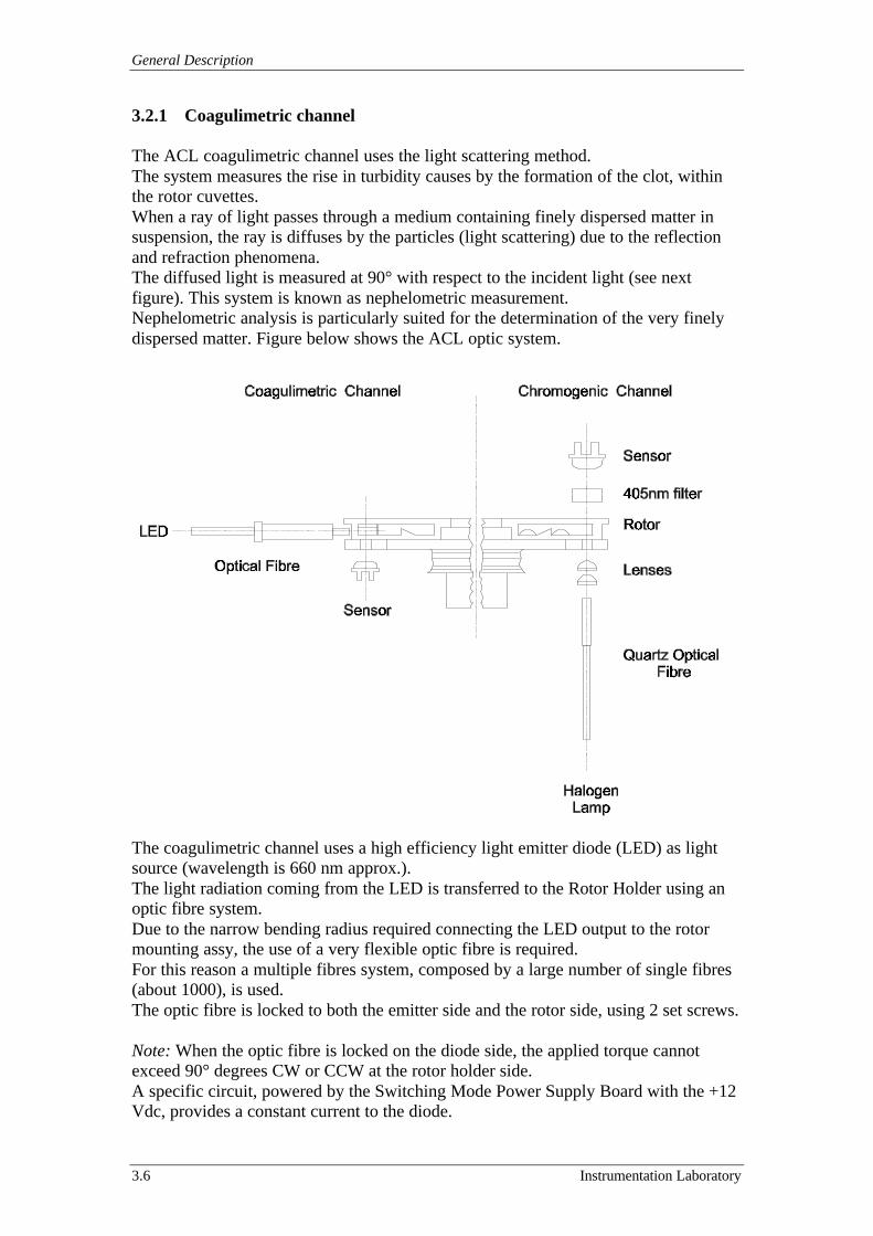
3.2.1 Coagulimetric channel
The ACL coagulimetric channel uses the light scattering method.The system measures the rise in turbidity causes by the formation of the clot, withinthe rotor cuvettes.When a ray of light passes through a medium containing finely dispersed matter insuspension, the ray is diffuses by the particles (light scattering) due to the reflectionand refraction phenomena.The diffused light is measured at 90° with respect to the incident light (see nextfigure). This system is known as nephelometric measurement.Nephelometric analysis is particularly suited for the determination of the very finelydispersed matter. Figure below shows the ACL optic system.
The coagulimetric channel uses a high efficiency light emitter diode (LED) as lightsource (wavelength is 660 nm approx.).The light radiation coming from the LED is transferred to the Rotor Holder using anoptic fibre system.Due to the narrow bending radius required connecting the LED output to the rotormounting assy, the use of a very flexible optic fibre is required.For this reason a multiple fibres system, composed by a large number of single fibres(about 1000), is used.The optic fibre is locked to both the emitter side and the rotor side, using 2 set screws.
Note: When the optic fibre is locked on the diode side, the applied torque cannotexceed 90° degrees CW or CCW at the rotor holder side.A specific circuit, powered by the Switching Mode Power Supply Board with the +12Vdc, provides a constant current to the diode.
ACL 9000 Service Manual
Instrumentation Laboratory 3.7
The light emitter is also equipped with a “LED OFF” line, coming from the MotorBoard (Board #5), which de-activates the LED when the instrument enters the Stand-by status.The light generated by the light emitter diode and transmitted through the optic fibreis scattered by the reaction mixture present in the rotor cuvette. This scattered light isread by using a solid state optical detector, which is installed below the Rotor Holderand is directly connected to the Acquisition & Sensors Board (Board #3) through acoaxial cable.

General Description
3.8 Instrumentation Laboratory
3.2.2 Chromogenic channel
The Chromogenic Channel is based on the light absorption principle.A polychromatic source of light hits the cuvette content.The radiation passes through the solution contained in the cuvette and the unabsorbedportion of light reaches the photocell that transforms the light energy of the raystriking it into an electrical signal. Figure below shows the ACL optic system.
The Chromogenic Channel uses a Halogen lamp with an effective life of 1000 hours.The main characteristics of the lamp are the following:
• Voltage: 6 V• Wattage: 10 W
The lamp is installed on to an appropriate socket that allows an easy installation intothe Source lamp assy. The Halogen Lamp Socket can be replaced by accessing thearea through a removable cover inside the rotor waste area, in the center of theinstrument. In case of replacement of the halogen lamp, attention must be paid toavoid that fingerprints are left on the lamp bulb.
The Chromogenic Lamp is powered at a regulated voltage, generated by a particularelectronic circuit located onto the Switch Mode Power Supply. The circuit is providedof protections against open circuit and short circuit.The lamp is activated only during the chromogenic cycles, and when the instrument isin the Service programs.The lamp beam passes through an optical filter that “cuts” the infrared radiation(named antiheat filter) in order to avoid damages to the fibre, caused by the high
ACL 9000 Service Manual
Instrumentation Laboratory 3.9
temperature presents nearby the lamp. The filter is mounted in the Halogen LampAssy. The beam passes through a quartz optic fibre, and then is fed to the rotorthrough a focusing system, composed by an optic condenser (the two lenses).The assembly composed by the focusing system plus the optic fibre is called OpticalCollimator Assy.
One end of the optic fibre is secured to the source lamp assy by means of a setscrew,while the other end, is secured below the rotor mounting assy.The quantity of radiation unabsorbed by the cuvette contents, passes through a 405nm interferential filter and than is detected by an optical sensor (solid statephotodiode).Both the optical detector and the filter are mounted in the Rotor Holder Cover.The photodetector is directly connected to the Acquisition & Sensor Board #3 througha coaxial cable.
Note: The optical path width for the Chromogenic Channel is 0,5 cm (cuvette height).The absorbance values provided by the analyser are normalised to 1 cm. These valuesare generally double the ones obtained on other ACL models, for which theabsorbance values are strictly the ones obtained for the 0,5 cm cuvette path.
General Description
3.10 Instrumentation Laboratory
3.3 Electronic Description
This section is designed to completely describe whole the electronic system of theinstrument.Electronic drawings and explanation of the logical functionality are also included.Following are the specific sub-sections.
3.3.1 Interconnection schematic3.3.2 Quick reference board function table3.3.3 Quick reference board function diagram3.3.4 CPU Master Board #13.3.5 Slave Board #23.3.6 Acquisition & Sensors Board #33.3.7 Rotor Exchange Module Board #43.3.8 Motors Board #53.3.9 Photometric & Temperatures Control Board #63.3.10 Switching Power Supply Board3.3.11 Instrument Ground Circuit
3.3.1 Interconnection Schematic
The purpose of this drawing is to clarify the starting point and the route of each signalpresent in whole the Instrument.
The major modules are logically grouped. An exception is made for the big ModuleInterconnection Board that is split for better identifies each single module driven.
The “Mother Board and Interconnections General Block Diagrams” is available in thefigure 3.3.1 Drawing 1 of the section “10 Drawings”.
ACL 9000 Service Manual
Instrumentation Laboratory 3.11
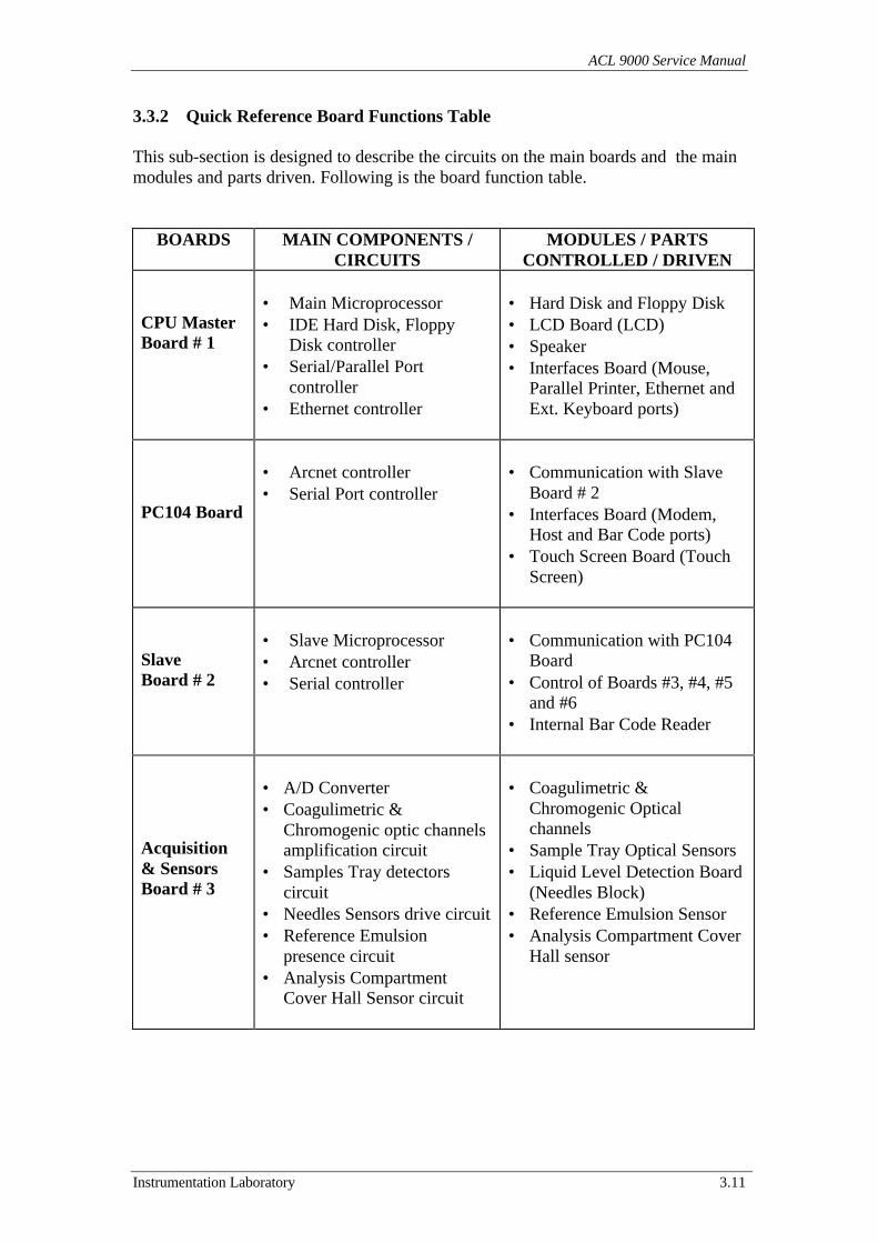
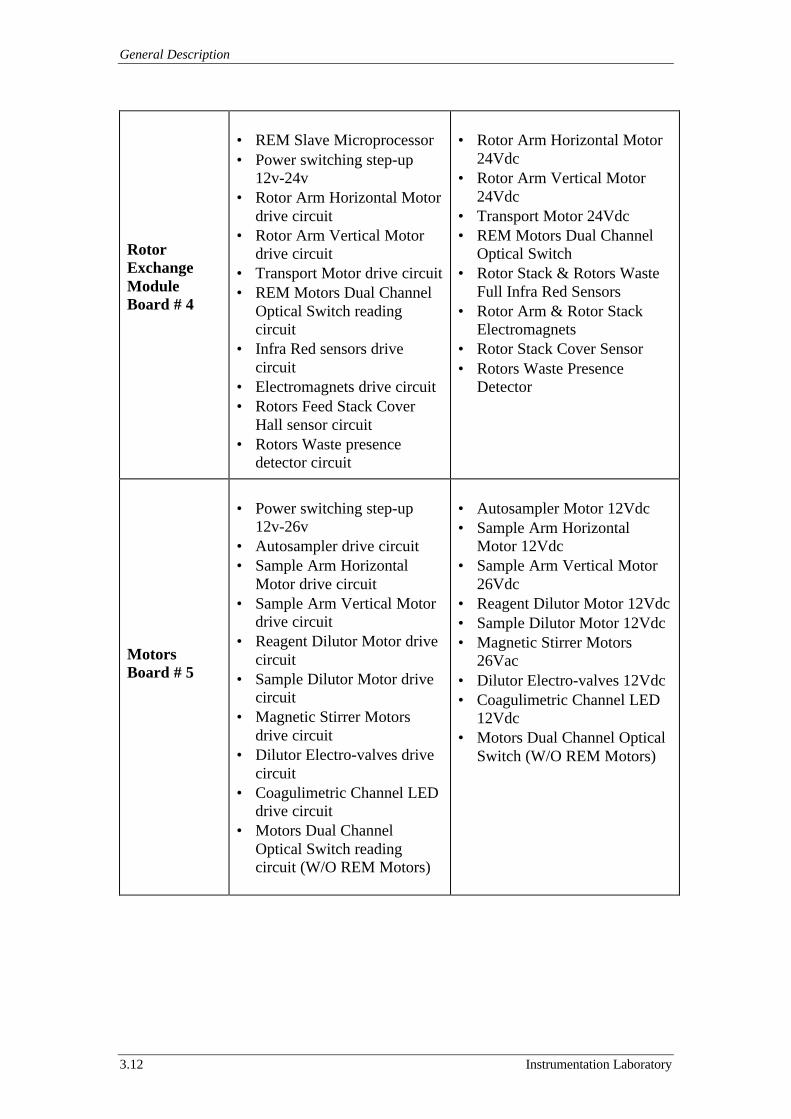
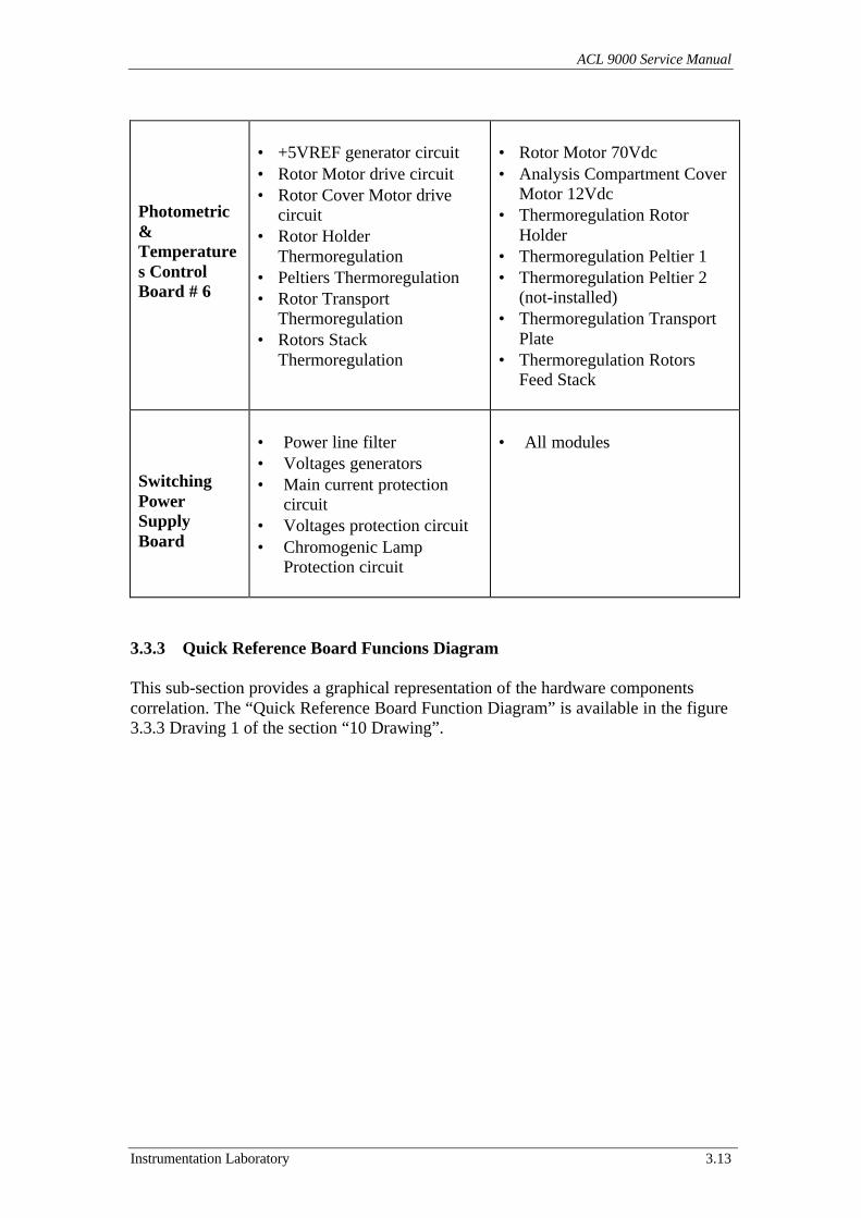
3.3.2 Quick Reference Board Functions Table
This sub-section is designed to describe the circuits on the main boards and the mainmodules and parts driven. Following is the board function table.
BOARDS MAIN COMPONENTS /CIRCUITS
MODULES / PARTSCONTROLLED / DRIVEN
CPU MasterBoard # 1
• Main Microprocessor• IDE Hard Disk, Floppy
Disk controller• Serial/Parallel Port
controller• Ethernet controller
• Hard Disk and Floppy Disk• LCD Board (LCD)• Speaker• Interfaces Board (Mouse,
Parallel Printer, Ethernet andExt. Keyboard ports)
PC104 Board
• Arcnet controller• Serial Port controller
• Communication with SlaveBoard # 2
• Interfaces Board (Modem,Host and Bar Code ports)
• Touch Screen Board (TouchScreen)
SlaveBoard # 2
• Slave Microprocessor• Arcnet controller• Serial controller
• Communication with PC104Board
• Control of Boards #3, #4, #5and #6
• Internal Bar Code Reader
Acquisition& SensorsBoard # 3
• A/D Converter• Coagulimetric &
Chromogenic optic channelsamplification circuit
• Samples Tray detectorscircuit
• Needles Sensors drive circuit• Reference Emulsion
presence circuit• Analysis Compartment
Cover Hall Sensor circuit
• Coagulimetric &Chromogenic Opticalchannels
• Sample Tray Optical Sensors• Liquid Level Detection Board
(Needles Block)• Reference Emulsion Sensor• Analysis Compartment Cover
Hall sensor
General Description
3.12 Instrumentation Laboratory
RotorExchangeModuleBoard # 4
• REM Slave Microprocessor• Power switching step-up
12v-24v• Rotor Arm Horizontal Motor
drive circuit• Rotor Arm Vertical Motor
drive circuit• Transport Motor drive circuit• REM Motors Dual Channel
Optical Switch readingcircuit
• Infra Red sensors drivecircuit
• Electromagnets drive circuit• Rotors Feed Stack Cover
Hall sensor circuit• Rotors Waste presence
detector circuit
• Rotor Arm Horizontal Motor24Vdc
• Rotor Arm Vertical Motor24Vdc
• Transport Motor 24Vdc• REM Motors Dual Channel
Optical Switch• Rotor Stack & Rotors Waste
Full Infra Red Sensors• Rotor Arm & Rotor Stack
Electromagnets• Rotor Stack Cover Sensor• Rotors Waste Presence
Detector
MotorsBoard # 5
• Power switching step-up12v-26v
• Autosampler drive circuit• Sample Arm Horizontal
Motor drive circuit• Sample Arm Vertical Motor
drive circuit• Reagent Dilutor Motor drive
circuit• Sample Dilutor Motor drive
circuit• Magnetic Stirrer Motors
drive circuit• Dilutor Electro-valves drive
circuit• Coagulimetric Channel LED
drive circuit• Motors Dual Channel
Optical Switch readingcircuit (W/O REM Motors)
• Autosampler Motor 12Vdc• Sample Arm Horizontal
Motor 12Vdc• Sample Arm Vertical Motor
26Vdc• Reagent Dilutor Motor 12Vdc• Sample Dilutor Motor 12Vdc• Magnetic Stirrer Motors
26Vac• Dilutor Electro-valves 12Vdc• Coagulimetric Channel LED
12Vdc• Motors Dual Channel Optical
Switch (W/O REM Motors)
ACL 9000 Service Manual
Instrumentation Laboratory 3.13
Photometric&Temperatures ControlBoard # 6
• +5VREF generator circuit• Rotor Motor drive circuit• Rotor Cover Motor drive
circuit• Rotor Holder
Thermoregulation• Peltiers Thermoregulation• Rotor Transport
Thermoregulation• Rotors Stack
Thermoregulation
• Rotor Motor 70Vdc• Analysis Compartment Cover
Motor 12Vdc• Thermoregulation Rotor
Holder• Thermoregulation Peltier 1• Thermoregulation Peltier 2
(not-installed)• Thermoregulation Transport
Plate• Thermoregulation Rotors
Feed Stack
SwitchingPowerSupplyBoard
• Power line filter• Voltages generators• Main current protection
circuit• Voltages protection circuit• Chromogenic Lamp
Protection circuit
• All modules
3.3.3 Quick Reference Board Funcions Diagram
This sub-section provides a graphical representation of the hardware componentscorrelation. The “Quick Reference Board Function Diagram” is available in the figure3.3.3 Draving 1 of the section “10 Drawing”.
General Description
3.14 Instrumentation Laboratory
3.3.4 CPU Master Board (Board # 1) & PC104 Board
The CPU Master Board and the PC104 Board, located between the system CardHousing and the Dilutor Assy, are powered through the Switching Power Supply,which provides a +5Vdc (DGT) and +12Vdc (DGT).The CPU Master Board (Board #1) has a Personal Computer architecture design.
The “CPU Master Board General Block Diagram” is available in figure 3.3.4 Drawing1, while the “PC104 Board General Block Diagram” is available in figure 3.3.4Drawing 2 of the section “10 Drawings”.The main functions reported in the brief below are further expanded and presented onspecific paragraphs.
CPU Master Board General Block Diagram (see paragraph 3.3.4.a)
• Software runtime.
• Internal devices control.• External devices control.
• Communication with PC104 Board.
PC104 Board General Block Diagram (see paragraph 3.3.4.b)
• Communication with the Slave Board (Board # 2).
• External devices control.• Touch Screen control.
ACL 9000 Service Manual
Instrumentation Laboratory 3.15
3.3.4.a CPU Master Board General Block Diagram (See figure 3.3.4 Drawing 1)
• Software runtime.
At the instrument power on the CPU Master downloads from the Hard Disk Driveboth the Operating System and the Application software. A local MEMORY BANKis used during the software runtime. After downloading, the Board #1 starts systeminitialisation testing the instrument hardware through the Slave Board (Board # 2).The control of the MEMORY BANK is achieved through the SYSTEM & DRAMCONTROLLER and the MEMORY CONTROLLER. The Hard Disk Drive control isperformed through the SYSTEM & DRAM CONTROLLER and the PERIPHERALSSTANDARD CONTROLLER.In addition to the Operating System and Application software the Hard Disk Drivealso allows Patient and Analytical Database storage.The CPU Master Board reads the internal device configuration, through the SYSTEM& DRAM CONTROLLER from the BIOS MEMORY.
• Internal device control.
The internal devices of the instrument controlled from the Board # 1 are:
The active matrix LCD (Liquid Crystal Display) controlled by the VGACONTROLLER and the VIDEO MEMORY (through the LCD ACTIVEMATRIX CONNECTOR CN6). The VGA CONTROLLER can also supportstandard PC monitor (through PC MONITOR CONNECTOR P1), and/orpassive matrix LCD (through the LCD PASSIVE MATRIX CONNECTORCN2 – CN3).
The Floppy Disk Drive controlled by the PERIPHERAL STANDARDCONTROLLER (through the FLOPPY DISK DRIVE CONNECTOR CN16).
The Hard Disk Drive (located under the CPU Master Board) controlled by thePERIPHERAL STANDARD CONTROLLER (through the HARD DISKDRIVE CONNECTOR CN17).
The SPEAKER (located on the rear of the system Card Housing) controlled by theSYSTEM & DRAM CONTROLLER (through the UTILITY CONNECTORCN7).
• External devices control.
The external devices controlled by Board # 1 (through the Interface Board) are:
The standard PC Keyboard controlled from the SYSTEM & DRAM CONTROLLER(through the UTILITY CONNECTOR CN7).
An external Ethernet interface controlled from the ETHERNET CONTROLLER(through the ETHERNET CONNECTOR CN11).
An external Parallel Printer controlled from the PERIPHERAL STANDARDCONTROLLER (through the PARALLEL PORT CONNECTOR CN18).
General Description
3.16 Instrumentation Laboratory
A PC serial Mouse controlled from the PERIPHERAL STANDARD CONTROLLER(through the MOUSE SERIAL PORT CONNECTOR CN20).
Three other serial lines are controlled from the PERIPHERAL STANDARDCONTROLLER (through the SERIAL PORT CONNECTOR CN19 – CN21 –CN22, actually Not Used).
• Communication with PC104 Board.
The CPU Master Board communicates with the PC104 Board through the SYSTEM& DRAM CONTROLLER and the PC104 CONNECTOR CN8 – CN9 – CN25.The CPU Master Board receives the signal RESET from the Mother Board throughthe UTILITY CONNECTOR CN7. This signal is generated from the Slave Board(Board # 2) and is sent also to the PC104 Board.The Board # 1 provides to the PC104 Board also a +5Vdc (DGT).
ACL 9000 Service Manual
Instrumentation Laboratory 3.17
3.3.4.b PC104 Board General Block Diagram (See figure 3.3.4 Drawing 2)
• Communication with the Slave Board (Board # 2).
The CPU Master Board communicates to the PC104 Board through the connectorCN1 – CN2.The PC104 Board interfaces with the Slave Board (Board # 2) through the ARCNETCONTROLLER, which is connected with the ARCNET CONNECTOR CN5 (CN4could also be used as it replicates CN5 pinout, being parallel connected).The controller is electrically de-coupled by means of the INSULATING &TRANSCEIVER CIRCUIT.
• External device control.
The CPU Master Board communicates to the PC104 Board through the connectorCN1 – CN2.The PC104 Board, through the SERIAL CONTROLLER, controls the MODEM –HOST – BAR CODE SERIAL PORT CONNECTOR CN7 – CN8 – CN9. Theseserial ports though the Interface Board allow to the Instrument to communicate withthe external devices. The MOUSE SERIAL PORT is configured to support anexternal Bar Code Reader.
• Touch Screen control.
The CPU Master Board communicates to the PC104 Board through the connectorCN1 – CN2.The PC104 Board through the TOUCH SCREEN CONTROL BOARD SERIALLINE CN6 and the TOUCH SCREEN CONTROL BORD POWER CN3, controls theTouch Screen Board located inside the Display assembly.

General Description
3.18 Instrumentation Laboratory
3.3.5 Slave Board (Board # 2)
The Slave board (Board #2) is located on the system card housing and poweredthrough the Switching Power Supply, which provides a +5Vdc (DGT).The Slave Board is equipped with a microprocessor (MCU U1), a resident memorybank and a circuitry handling various interrupt signals that are sent to the board.
Multiple data and address busses are employed: (D0 - D15 and A0 - A23) are used toconnect the MCU U1 to the internal bus (DB0 - DB15 and AB0 - AB23). The internalbusses are then buffered to external data and address bus (SLD0 - SLD15 and SLA0 -SLA23) through which the Slave board communicates with the Boards # 3, # 5 and# 6.
The “Slave Board General Block Diagram” is available in figure 3.3.5 Drawing 1 ofthe section “10 Drawings”.The main functions reported in the brief below are further expanded and presented onspecific paragraphs.
Slave Board General Block Diagram (see paragraph 3.3.5.a)
• Main Reset circuits.• Power supply presence circuit.
• Communication Section (see paragraph 3.3.5.b).• Memory Section (see paragraph 3.3.5.c) .
• Glue Logic Section (see paragraph 3.3.5.d).
Communication Section (see paragraph 3.3.5.b)
• Receives commands forwarded from the CPU Master Board (Board # 1).
• Controls the REM Board (Board #4) and the internal Bar Code Reader.
Memory Section (see paragraph 3.3.5.c)
• Programs run time and data storage.
Main Logic Section (see paragraph 3.3.5.d)
• Interfaces the Slave board with the external data and address bus
• Interrupt controller
ACL 9000 Service Manual
Instrumentation Laboratory 3.19
3.3.5.a Slave Board General Block Diagram (See figure 3.3.5 Drawing 1)
• Main reset circuit
The RESET CIRCUIT U3 generates the signal RESET used to initialise the wholesystem. The RESET CIRCUIT can be triggered by any of the followingdevices/signals:
- The MAIN LOGIC EPLD U12 (Main Logic Section)- The signal INIT generated on the Switching Power Supply.- The local microswitch RESET SWITCH SW1 (used only for manufacturing
testing purposes).
The LED LD1 is aimed only when the signal RESET is present.
• Power supply presence circuit
The LED LD4 is aimed always while the Board # 2 is powered with +5Vdc (DGT).
3.3.5.b Communication Section (See figure 3.3.5 Drawing 2)
• Receives commands forwarded from the CPU Master Board (Board # 1).
The Slave board communicates with the CPU Master Board by means of an Arcnetconnection, using a dedicated cable and connector P6 (P7 could also be used as itreplicates P6 pinout, being parallel connected). The data transmission is handled bythe ARCNET CONTROLLER CIRCUIT U27.
The controller is electrically de-coupled by means of the INSULATING CIRCUITISO1 – ISO2. A DC/DC CONVERTER REG1, connected to the LED LD2, providesa dedicated power supply to the TRANCEIVER CIRCUIT U29. A further circuitcontrolled by the CANBUS CONTROLLER U28 is present but not used on the Slaveboard.
• Controls the REM Board (Board #4) and the internal Bar Code Reader.
A serial communication is achieved by the SERIAL CONTROLLER CIRCUIT U31– U32. The serial controller is electrically de-coupled by means of the INSULATINGCIRCUIT ISO3 – ISO10. A DC/DC CONVERTER REG2, connected to the LEDLD3, provides a dedicated power supply to the DRIVER CIRCUIT U33 – U34 – U35.The serial communication line TX0 – RX0 coming from MCU U1, is also linked tothe DRIVER CIRCUIT U33 – U34 – U35, which handles the serial communicationline TXD4 – RXD4 to the REM board (board # 4).Signals TRIGBARC, TX1 – RX1 are respectively utilised for both enabling(TRIGBARC) and communicate (TX1 - RX1) with the internal Bar Code reader.
General Description
3.20 Instrumentation Laboratory
The serial ports P8 - P9 - P10 are not used during the normal operations. Use of theseports is limited to the manufacturing process when the board is connected to externaldevices, which program the resident logic.
3.3.5.d Memory Section (See figure 3.3.5 Drawing 3)
• Programs run time and data storage.
A few memory devices are employed to support the MCU U1 on the Slave Board,these are:
The SERIAL EEPROM U2 is directly linked to a serial port of the MCU U1.The RAM STATIC MEMORY BANK U22-25 linked to MCU U1 through the databus DB0 - DB15 and the address bus AB0 - AB19.The FLASH EPROM MEMORY U14 - U21 linked to MCU U1 through the data busDB0 - DB15 and the address bus AB0 - AB19.
The MCU U1 is also connected to the BOOT LOADER EPROM U26 from, whichdownloads the boot program by sending the command CSBOOT while initialising.
3.3.5.d Main Logic Section (See figure 3.3.5 Drawing 4)
• Interfaces the Slave board with the external data and address bus.
The MCU U1 is connected through the data bus D0 - D15 to the INTERNAL DATABUS TRANSCEIVER U4, which outputs DB0 - DB15 as local data bus connecting toother devices resident on the Slave board.
The local data bus BD0 - DB15, is then linked to the EXTERNAL DATA BUSTRANSCEIVER U7 – U36. These devices output SLD0 - SLD15 «slave data bus»,which allows MCU U1 to communicate with the Board # 3, # 5 and # 6, located onthe system card housing.
The address bus A0 - A23 links MCU U1 to the INTERNAL ADDRESS BUSBUFFER U5 – U6 which outputs AB0 - AB23 as local address bus connecting toother devices resident on the Slave board.
The local address bus AD0 - AD23, is then linked to the EXTERNAL ADDRESSBUS BUFFER U8 – U9. These devices output SLA0 - SLA23 «slave address bus»,which allows MCU U1 to communicate with the Board # 3, # 5 and # 6, located onthe system card housing.
The control signal R/W is fed to the INTERNAL ADDRESS BUS BUFFER U5 –U6which outputs a signal BR/W connected to the MAIN LOGIC EPLD U12. The EPLDgenerates the individual control signals RD and WR which are routed to theINTERNAL ADDRESS BUS BUFFER U5 –U6 where they get converted into BRDand BWR. The EXTERNAL INTERRUPT BUS BUFFER U10 – U11 buffer the
ACL 9000 Service Manual
Instrumentation Laboratory 3.21
commands and output the commands SLRD and SLWR which become control signalsof the external data and address bus.
The MAIN LOGIC EPLD U12 also handles the chip select signals for the localdevices as well as the board select commands. The board select commands (BS0 -BS3) are fed to the EXTERNAL INTERRUPT BUS BUFFER U10 – U11 whichprovide outputs SLBS0 - SLBS3 to the Board # 3, # 5 e # 6 located on the systemCard Housing.
• Interrupt controller.
Possible interrupts generated outside the Slave board are input via the EXTERNALINTERRUPT BUS BUFFER U10 – U11 and then routed to the INTERRUPTCONTROLLER EPLD U13. The EPDL U13 handles the interrupts following ascheme of priority and sends signals IRQ1 - IRQ7 to the MCU U1.The interrupts, which can be, generate and logged into the slave board are as follows:
- INIT (Initial Reset)This signal is raised from the Switching Power Supply and has the purpose to keepthe system reset for a pre-defined period of time thus allowing the power supplyvoltages to reach stability.
- POWERFAILThis signal is raises from the Switching Power Supply, which can detect a lack ofsupply voltage, and may lead to a decrease of the dc voltages thus impairing properfunctioning of the logic.
- STSThis can be raise by the Acquisition & Sensor Board (Board # 3) when the A/Dconversion has been accomplished and the data is available on the bus.
- ELETFAILThis can be raise by the Rotor Exchange Module Board (Board # 4) in case ofmalfunction of an electromagnet thus impairing proper rotor displacement.
- ROTCUV and ROTCUVZThese can be raised by the Motor Board (Board # 5) and are utilised to highlight apossible malfunction either of the rotor motor or associated device, such as the DualChannel Optical Switch.
- ROTFAILThis can be raised by the Photometric & Temperature Control Board (Board # 6) incase of a malfunction of the Rotor Motor.
General Description
3.22 Instrumentation Laboratory
3.3.6 Acquisition & Sensors Board (Board # 3)
The Acquisition & Sensor Board, is located in the system Card Housing, and poweredthrough the Switching Power Supply, which provides the +5Vdc (DGT), +15Vdc(ANA), -15Vdc (ANA) and +12Vdc (PW).The Acquisition & Sensors Board communicates with the Slave Board (Board # 2)through the signals SLD0 - SLD15 “slave data bus”, and the signals SLA0 - SLA7“slave address bus”. This communication is supported by the control signals SLRD,SLWR, RESET as well as the Board enabling signal SLBS0.
The “Acquisition & Sensors Board General Block Diagram” is available in figure3.3.6 Drawing 1 of the section “10 Drawings”.The main functions reported in the brief below are further expanded and presented onspecific paragraphs.
Acquisition & Sensors Board General Block Diagram (see paragraph 3.3.6.a)
• Reading Warning signals from Switching Power Supply.
• Control signals for Switching Power Supply.• Multiplexer & Acquisition Section (see paragraph 3.3.6.b).
• Channel Amplifier Section (see paragraph 3.3.6.c).• Sample Tray Detectors Emitter & Receiver Sections (see paragraph 3.3.6.d).
• Needles Sensor Section (see paragraph 3.3.6.e).• Reference Emulsion Presence Section (see paragraph 3.3.6.f).
• Analysis Compartment Cover Sensor Section (see paragraph 3.3.6.g).
Multiplexer & Acquisition Section (see paragraph 3.3.6.b)
• A/D Conversion for most important signals.
• Sends the interrupt signal STS to the Slave Board (Board # 2).• Frequency generation for Magnetic Stirrer Motors.
Channel Amplifier Section (see paragraph 3.3.6.c)
• Optical channel amplification.
Sample Tray Detectors Emitter & Receiver Sections (see paragraph 3.3.6.d)
• Container on Sample Tray detection.
ACL 9000 Service Manual
Instrumentation Laboratory 3.23
Needles Sensor Section (see paragraph 3.3.6.e)
• Liquid presence detection during the analysis loading cycle.
Reference Emulsion Presence Section (see paragraph 3.3.6.f)
• Reference Emulsion presence level in the bottle.
Analysis Compartment Cover Hall Sensor Section (see paragraph 3.3.6.g)
• Analysis Compartment Cover position detection.
3.3.6.a Acquisition & Sensors Board General Block Diagram (See figure 3.3.6Drawing 1)
• Reading Warning signals from Switching Power Supply.
The Switching Power Supply, in case of malfunction, sends two warning signals tothe Acquisition & Sensor Board (Board # 3). The signal THERFAIL is raised by theSwitching Power Supply in case the temperature of the environment reaches a level(about 60 C°), which way become dangerous for the Switching Power Supply. Ifovereating is detected (about 75 C°) the Switching Power Supply enters the ProtectionMode putting down the power of the instrument.The second signal MISSLAMP is raised by the Switching Power Supply when thecurrent for the Halogen Lamp gets too low.Both signals enter in the PARALLEL I/O U5 where are read by the Slave Board.
• Control signals for Switching Power Supply.
The Slave Board (Board # 2) sends to the PARALLEL I/O U5 two control signals forthe Switching Power Supply. The first is the signal LAMPWR that controls theHalogen Lamp status.The second is the signal PWROFF that controls the +9Vdc, +12Vdc and +70Vdcpower voltage status.
General Description
3.24 Instrumentation Laboratory
3.3.6.b Multiplexer & Acquisition Section (See figure 3.3.6 Drawing 2)
• A/D Conversion for most important signals.
Following are the most important signals converted:
COAG – CHROM for the Analysis Compartment Optical Channels readingTPELT1 for the Peltier temperature detectionTPELT2 for the second Peltier temperature detection (not used)TROT for the Rotor Holder temperature detectionTFSLITTA for the Transport Plate temperature detectionTFSILOS for the Rotors Feed Stack temperature detection+5VREF for the 5V Reference voltage detectionSCUVINT for the Sample Tray internal ring container detectionSCUVEXT for the Sample Tray middle and external rings container detectionSLIQ for the liquid presence detectionSFLUSH for the Reference Emulsion level detectionSHALL for the Analysis Compartment Cover closed detection.
The Board # 3 uses the multiplexer MPLX CIRCUIT U1 to select that signal willconvert the A/D CONVERTER CIRCUIT U11. This selection is driven by thePARALLEL I/O U5 that sends the control signals MUX0 - MUX3 to the multiplexer.The EPLD U6 controls with the start signal ADRC and the end signal ADSTAT theconversion process of the A/D CONVERTER CIRCUIT U11. The EPLD U6 controlsthe timer programmable TIMER PROG. U9 that allows the EPLD of work with theRotor Motor ‘s speed during acquisition at 600 or 1200 Rpm, and introduces a delayin the acquisition time pre-selected in the Curve Adjustment Service menu (seesection 7.2 for Coag. and section 7.3 for Chrom.). The EPLD U6 receives from thePARALLEL I/O U5 the control signals AACQ to select the static or the dynamicacquisition and the signals SCALF to select the delay for Coag. Ch. or Chrom. Ch.The EPLD U6 receives the signals ROTCUV – ROTCUVZ from the Motors Board(Board # 5) and they are very important signals to synchronise the data acquisition.
• Sends the interrupt signal STS to the Slave Board (Board # 2).
When the new data is ready the EPLD U6 receives the signal ADSTAT from the A/DCONVERTER CIRCUIT U11, then enables the BUFFER 3-STATE U12 – U13 withthe signal RDADC and sends the interrupt signal STS to the Slave Board (Board # 2).
• Frequency generation for Magnetic Stirrer Motors.
The timer programmable TIMER PROG. U10 is used to produce the frequencyFREQST for the work of the Magnetic Stirrer Motors drivers on the Motors Board(Board # 5).
ACL 9000 Service Manual
Instrumentation Laboratory 3.25
3.3.6.c Channels Amplifier Section (See figure 3.3.6 Drawing 3)
• Optical channel amplification.
The Optical sensor of the Coagulimetric Channel is located under the Rotor Holder.This sensor is connected to the Acquisition & Sensors Board through a coaxial cablethat enters in the specific amplifier ‘s box. The sensor ‘s signal enter in theAMPLIFIER CIRCUIT U17 – U21, the output COAG is one of the most importantsignals converted in the Multiplexer & Acquisition Section. This circuit is composedalso by the trimmers RV1 used to adjust the Offset and RV2 used to adjust the Gainduring the instrument testing (see section 7.2).The Optical sensor of the Chromogenic Channel is located under the AnalysisCompartment Cover. This sensor is connected to the Acquisition & Sensors Boardthrough a coaxial cable that enters in the specific amplifier ‘s box. The sensor ‘ssignal enter in the AMPLIFIER CIRCUIT U20 – U22, the output CHROM is one ofthe most important signals converted in the Multiplexer & Acquisition Section. Thiscircuit is composed also by the trimmers RV4 used to adjust the Offset and RV3 usedto adjust the Gain during the instrument testing (see section 7.3).
3.3.6.e Samples Tray Detectors Emitter & Receiver Sections(See figures 3.6.6 Drawing 4 and Drawing 5)
• Container on Sample Tray detection.
The Autosampler is designed to accept patient samples, as well as calibrants on thesame tray (Sample Tray).Forty positions are available to load patient samples. Two rings (outermost andmiddle ring) can accept twenty cup/tubes each. A third ring (innermost) is availableon the Sample Tray either up to ten positions can be loaded with calibrants, controlsand/or reagents.
Two optical sensors are located in the Autosampler housing with the purpose ofdetecting the presence of the containers in the Sample Tray. The internal sensor isplaced in the internal wall while the external sensor is placed in the external wall ofthe Autosampler housing. Both the sensors detect the presence of the containers usingthe refraction principle.
The power section for the infra red light emitter of the sensors is controlled by thePARALLEL I/O U5 that sends the enabling signals ESCUV – ESCUVINT –ESCUVEXT to the EPLD U6.The Sample cup/tubes can be placed in the Sample Tray on two different rings. As thesample cup/tubes can be placed on both the outermost and the middle ring, twodifferent levels of current are needed to drive the external sensor which shall detectthe presence of sample container located either close (outermost ring) or far (middlering).To select the most appropriate current level, the EPLD U6 sends the AUTOC signalto the SWITCH CIRCUIT U26 which through the signals SCUVL1 – SCUVL2 setthe current level output at the CURRENT GENERATOR U43A – U46A.
General Description
3.26 Instrumentation Laboratory
The trimmer RV6 allow the adjustment of the current in the emitter during theinstrument testing (see sub-section 7.5.3). The outputs of the power circuit for theexternal sensor are ANLED1 – KD1.The auxiliary materials containers are placed in the innermost ring of the Sample Trayand are detected by the internal sensor. The trimmer RV7 allows the adjustment of thecurrent in the emitter during the instrument testing (see sub-section 7.5.3).The outputs of the power circuit for the internal sensor are ANLED2 – KD2.
The external sensor receives the refracted light and sends to the receiver circuit thesignal ET1 witch is filtered and amplifier to produce the signal SCUVEXT. Thissignal is then converted in the Multiplexer & Acquisition Section.To select the right work’s level, the EPLD U6 sends the controls signal AUTOC tothe SWITCH CIRCUIT U26 that can linking the trimmer RV10 to control the gain ofthe AMPLIFIER CIRCUIT U27A.The trimmer RV10 allows, for the outermost ring, the adjustment of the amplifier gainfor the receiver signal during the instrument testing (see sub-section 7.5.3).Another controls signal is BLIVSCUV which is sent to the COMPARATORCIRCUIT U48A to select the right work level and produce the logical signalPCUVEXT, then this signal is read from the PARALLEL I/O U5. The DRIVERCIRCUIT U28 controls the LED DL1 that is lighted when the sample containers aredetected during the Autosampler / BCR Test (see sub-section 7.5.3).The internal sensor receive the refracted light and sends to the receiver circuit thesignal ET2 witch is filtered and amplifier to produce the signal SCUVINT, one of themost important signals converted in the Multiplexer & Acquisition Section.The circuit produces also the logical signal PCUVINT witch is read from thePARALLEL I/O U5. The DRIVER CIRCUIT U28 controls the LED DL2 that islighted when the auxiliary materials containers are detected during the AutosamplerTest (see sub-section 7.5.3).
3.3.6.e Needles Sensor Section (See figure 3.3.6 Drawing 6)
• Liquid presence detection during the analysis loading cycle.
The Liquid Level Detector Board, connected to the needles probe assy, sends thesignals AGOSS for the sample needle and AGOSR for the reagent needle to theAcquisition & Sensors Board. The EPLD U36 selects with the enabling signalsEAGOS - EAGOR the sample/reagent needle sensor signal. The EPLD U36 alsocontrols with the signals EAUTOZEROS – RAUTOZEROS the reading or the resetof the auto-zero circuit. The selected signals enter in the specific circuit and producethe output signal SLIQ, which is then converted in the Multiplexer & AcquisitionSection. The EPLD U36 sends the controls signals GXL1 – GXL2 to the SWITCHCIRCUIT U51 which, according with the cycle in progress, sets the gain of theAMPLIFIER CIRCUIT U39B by connecting either the trimmer RV11 (for theReagent) or RV12 (for the Sample) as appropriate.

ACL 9000 Service Manual
Instrumentation Laboratory 3.27
The trimmer RV11 and RV12 allow the adjustments of the amplifier gain for theoutput SLIQ during the instrument testing (see cap. 6.3.1). The signal SLIQ is alsocompared with one of the three threshold signals SG1 – SG2 – SG3, this selection iscontrolled by EPLD U36 to produce the logical signal PSAGO, then this signal is readfrom the PARALLEL I/O U5. The DRIVER CIRCUIT U28 controls the LED DL4that is lighted when the liquids are detected during the Needles Sensor Test (see sub-section 7.4.1). The PARALLEL I/O U5 sends to the EPLD U36 the signal EAGHITIPaimed at enabling the entire liquid detectors circuit and the signal LGT2 to enables thetimer programmable TIMER PROG. U9.
3.3.6.f Reference Emulsion Presence Section (See figure 3.3.6 Drawing 7)
• Reference Emulsion presence level in the bottle.
The sensor located inside the cap of Reference Emulsion bottle detects the volume ofthe liquid in the bottle. The PARALLEL I/O U5 enables with the signal ECLKLIQthe timer programmable TIMER PROG. U10, which outputs the clock signalCLKSENSE, amplified and used with the name of CLKSINE as a reference. Thissignal CLKSINE is sends to the sensor and return to the board attenuated with thename of BFLUSH. The signal ‘s attenuation is proportional to the missing volume ofReference Emulsion, so the signal MFLUSH is the amplified reads of the sensor. TheEPLD U6 – U36 controls through the signal SFLH the SWITCH CIRCUIT U26. Thiscircuit then selects between the inputs MFLUSH and CLKSINE the output signalMSENSE. The signal MSENSE is then amplified and output as SFLUH from theAMPLIFIER CIRCUIT U24. The signal SFLUSH is then converted in theMultiplexer & Acquisition Section.The trimmer RV9 allows the adjustments of the amplifier gain for the output signalSFLUSH during the instrument testing (see sub-section 7.4.2). The trimmer RV8allows the factory adjustment of the amplifier gain for the reference signal CLKSINE.
3.3.6.g Analysis Compartment Cover Sensor Section (See figure 3.3.6 Drawing 8)
• Analysis Compartment Cover position detection.
The magnetic sensor, located under the Fluidic Plate on the left side of the AnalysisCompartment, detect the presence of the magnet placed in the Analysis CompartmentCover and outputs the signals COVDET1 – COVDET2 for the Acquisition & SensorBoard. The circuit output the signal SHALL, one of the most important signalsconverted in the Multiplexer & Acquisition Section. The trimmer RV5 allow theadjustments of the amplifier for the output signal SHALL during the instrumenttesting (see sub-section 7.9.1). The signal SHALL is also used to generate the signalPHALL which enter in the DRIVER CIRCUIT U28 to controls the LED DL3 whichis lighted when the cover is closed.

General Description
3.28 Instrumentation Laboratory
3.3.7 Rotor Exchange Module Board (Board # 4)
The Rotor Exchange Module Board, is located in the system Card Housing, andpowered through the Switching Power Supply, which provides the +5Vdc (DGT),+15Vdc (ANA), -15Vdc (ANA) and +12Vdc (PW).The R.E.M. Board is equipped with a microprocessor (CPU U1) and a residentmemory bank. The R.E.M. Board communicates with the Slave Board (Board # 2)through the serial communications line TXD4 – RXD4.
The “Rotor Exchange Module Board General Block Diagram” is available in figure3.3.7 Drawing 1 of the section “10 Drawing”.The main functions reported in the brief below are further expanded and presented onspecific paragraphs.
Rotor Exchange Module General Block Diagram (see paragraph 3.3.7.a)
• Reading of the Motor Dual Channel Optical Switch.• Rotors Waste container presence detection.
• Rotors Feed Stack cover position detection.• CPU ready condition circuit.
• Transport Motors Section (see paragraph 3.3.7.b).• Rotor Arm Motors Section (see paragraph 3.3.7.c).
• Memory & Communication Section (see paragraph 3.3.7.d).• Infra Red Sensors Section (see paragraph 3.3.7.e).
• Electro Magnets Control Section (see paragraph 3.3.7.f).
Transport Motor Section (see paragraph 3.3.7.b)
• Transport Motor drives circuit.
Rotor Arm Motors Section (see paragraph 3.3.7.c)
• Rotor Arm Horizontal Motor drives circuit.
• Rotor Arm Vertical Motor drives circuit.
Memory & Communication Section (see paragraph 3.3.7.d)
• Resident Memory Bank and communication with the Slave Board (Board # 2).
ACL 9000 Service Manual
Instrumentation Laboratory 3.29
Infra Red Sensors Section (see paragraph 3.3.7.e)
• New and used Rotors presence detection.
Electro Magnets Control Section (see paragraph 3.3.7.f)
• Rotors loading from Caliper and Rotors Feed Stack.• Sends the interrupt signal ELETFAIL to the Slave Board (Board # 2).
3.3.7.a Rotor Exchange Module General Block Diagram (See figure 3.3.7Drawing 1)
• Reading of the Motor Dual Channel Optical Switch.
Three Dual Channel Optical Switches are mounted on the Transport and on the RotorArm assembly to detect the positions of the motors. The motor position is coded byEncoder disk or flag located on the movement assy. The Dual Channel Optical Switchsends to the Board # 4 the signals reading on the Encoders. These signals enter in theBUFFER CIRCUIT U27 – U28 – U29, which output the signals: SLOT_CAS –EDGE_CAS for the Transport Motor, SLOT_ROT – EDGE_ROT for the Rotor ArmHorizontal Motor and SLOT_HIG – EDGE_HIG for the Rotor Arm Vertical Motor.These signals are routed directly or through the multiplexer MPLX CIRCUIT U6 intothe CPU U1.The motor rotation, sensed by the Dual Channel Optical Switch, allows the CPU U1to detect possible “motor failures”.
• Rotors Waste container presence detection.
The status of the mechanical switch, located inside the Rotors Waste containercompartment, is read through the BUFFER CIRCUIT U27, which outputs the signalDOOR_WST to the CPU U1.
• Rotors Feed Stack cover position detection.
The magnetic sensor, located over the Rotors Feed Stack, is activated by a magnetembedded inside the Feed Stack cover. The magnet sensor status is read through theBUFFER CIRCUIT U30, which outputs the signal COP_SILOS to the CPU U1.
• CPU ready condition circuit.
The CPU U1 through the EPLD U2 controls the LED DL1, which is lighted when theCPU U1 is ready.
General Description
3.30 Instrumentation Laboratory
3.3.7.b Transport Motor Section (See figure 3.3.7 Drawing 2)
• Transport Motor drive circuit.
The Slave Board sends to the CPU U1 the command relative to the Transport Motormovement. The CPU U1 controls the TRANSPORT MOTOR DRIVER U14 – DX1,whose output signals are the motor phases M1A – M1BB. The CPU U1 uses thedemultiplexer DEMPL U29 to send the enable signal M1_PWR_ENA to the drivercircuit, and the multiplexer MPLX U6 to check the presence of the signal MO_CASgenerated by the driver only if there is a malfunction. The TRANSPORT MOTORDRIVER U14 – DX1 is powered by the LOCAL GENERATOR +24VPW U10.The jumpers in M1 are factory pre-set to obtain full or half steps as required.
3.3.7.c Rotor Arm Motors Section (See figure 3.3.7 Drawing 3)
• Rotor Arm Horizontal Motor drives circuit.
The Slave Board sends to the CPU U1 the command relative to the Rotor ArmHorizontal Motor movement. The CPU U1 controls the ROTOR ARMHORIZONTAL MOTOR DRIVER U16 – DX2, whose output signals are the motorphases M2A – M2BB. The CPU U1 uses the demultiplexer DEMPL U29 to send theenable signal M2_PWR_ENA to the driver circuit, and the multiplexer MPLX U6 tocheck the presence of the signal MO_ROT generated by the driver only if there is amalfunction. The ROTOR ARM HORIZONTAL MOTOR DRIVER U16 – DX2 ispowered by the LOCAL GENERATOR +24VPW U10. The jumpers in M2 arefactory pre-set to obtain full or half steps as required.
• Rotor Arm Vertical Motor drives circuit.
The Slave Board sends to the CPU U1 the command relative to the Rotor ArmVertical Motor movement. The CPU U1 controls the ROTOR ARM VERTICALMOTOR DRIVER U18 – DX3, whose output signals are the motor phases M3A –M3BB. The CPU U1 uses the demultiplexer DEMPL U29 to send the enable signalM3_PWR_ENA to the driver circuit, and the multiplexer MPLX U6 to check thepresence of the signal MO_HIG generated by the driver only if there is a malfunction.The ROTOR ARM VERTICAL MOTOR DRIVER U18 – DX3 is powered by theLOCAL GENERATOR +24VPW U10. The jumpers in M3 are factory pre-set toobtain the full or half steps as required.
ACL 9000 Service Manual
Instrumentation Laboratory 3.31
3.3.7.d Memory & Communication Section (See figure 3.3.7 Drawing 4)
• Resident Memory Bank and communication with the Slave Board (Board # 2).
The CPU U1 controls through the data bus D0 – D7, the address bus A8 – A15, andthe BUFFER 3-STATE CIRCUIT U3, the RAM MEMORY U4 and the ROMFLASH MEMORY U5, used for the program ’s run-time and data storage.The CPU U1 through the EPLD U2 sends the enables signals to the memories.
The serial communication line of the CPU U1 is linked with the SERIAL I/OCIRCUIT U8, which handles the serial communication line TXD4 – RXD4 to theSlave Board (Board # 2).
3.3.7.e Infra Red Sensors Section (See figure 3.3.7 Drawing 5)
• New and used Rotors presence detection.
Three optical sensors are located on the Rotor Exchange Module assy, with thepurpose of detecting the presence of the rotors along the route. This route begins inthe Rotors Feed Stack and ends in the Rotors Waste container. Two optical sensor arelocated in the Rotors Feed Stack and one above the Rotors Waste container.These three sensors detect the presence of the rotors using the refraction principle.
The upper sensor located inside the Rotors Feed Stack allows the system to detect forpresence of new rotors in the store of the Rotor Stack (over the mechanicalmovements).This sensor is powered by the POWER CIRCUIT Q7, which provides the signalsAFCS and CFC.The sensor receives the refracted light and sends to the receiver circuit the signalsFCS, which is handled by the circuit to produce the signal FC_STR. This signal isreads by the CPU U1 through the multiplexer MPLX CIRCUIT U7. This circuit iscomposed also by the trimmer PT1 used to adjust the signal during the instrumenttesting (see sub-section 7.5.1).
The lower sensor located inside the Rotors Feed Stack allows the system to detect forpresence of a new rotor on the Rotor Transport plate.This sensor is powered by the POWER CIRCUIT Q7, which provides the signalsAFCC and CFC.The sensor receives the refracted light and sends to the receiver circuit the signalsFCC, which is handled by the circuit to produce the signal FC_CAS. This signal isreads by the CPU U1 through the multiplexer MPLX CIRCUIT U7. This circuit iscomposed also by the trimmer PT2 used to adjust the signal during the instrumenttesting (see sub-section 7.5.1).
General Description
3.32 Instrumentation Laboratory
The sensor located above the Rotors Waste container allows the system to detect theconditions of “Waste container full”.This sensor is powered by the POWER CIRCUIT Q7, which provides the signalsAFCW and CFC.The sensor receives the refracted light and sends to the receiver circuit the signalsFCW, which is handled by the circuit to produce the signal FC_WST. This signal isreads by the CPU U1 through the multiplexer MPLX CIRCUIT U7. This circuit iscomposed also by the trimmers PT3 used to adjust the reading of the signal during theinstrument testing (see sub-section 7.5.2).
The CPU U1 through the EPLD U2 sends the signal CK_LED, which is used toenable the circuit.
3.3.7.f Electro Magnets Control Section (See figure 3.3.7 Drawing 6)
• Rotor loading from Caliper and Rotors Feed Stack.
Three similar mechanisms achieve the rotors loading on the Rotor Exchange Moduleassy. One of them is the Caliper, located over the Rotor Arm, used to load and unloadthe Analysis Compartment and to waste the used rotors. Two of them are locatedinside the Rotors Feed Stack to allow the correct rotors loading. These mechanismsuse three identical electromagnets. The CPU U1 through the EPLD U2 controls thePOWER CIRCUIT Q1 – Q2 – Q3 – D7 – D8, which outputs the signals used topower the electromagnets.These signals are EMCL for the Caliper, EMS1 for the upper movement inside theRotors Feed Stack and EMS2 for the lower one. The signal EM_SUPPLY is used ascommon to recover the high current produced during the electromagnet opening.
• Sends the interrupt signal ELETFAIL to the Slave Board (Board # 2).
The RESISTIVE CIRCUIT controls the signals for the electromagnets and sends thewarning TEM_CLM for the Caliper, TEM_ST1 for the upper movement, TEM_ST2for the lower movement, and the signal 24V_MOT for the LOCAL GENERATOR+24VPW. These signals are reads by the CPU U1 through the multiplexer MPLXCIRCUIT U7. If a warning signal is active the CPU U1 commands the EPLD U2 todisable the electromagnet with the failure and sends the interrupt signal ELETFAIL tothe Slave Board (Board # 2).
ACL 9000 Service Manual
Instrumentation Laboratory 3.33
3.3.8 Motors Board (Board # 5)
The Motors Board, is located in the system Card Housing, and powered through theSwitching Power Supply, which provides the +5Vdc (DGT), and +12Vdc (PW).The Motors Board communicates with the Slave Board (Board # 2) through thesignals SLD0 - SLD7 “slave data bus”, and the signals SLA0 - SLA7 “slave addressbus”. This communication is supported by the control signals SLRD, SLWR, RESETas well as the Board enabling signal SLBS2.
The “Motors Board General Block Diagram” is available in figure 3.3.8 Drawing 1 ofthe section “10 Drawings”.The main functions reported in the brief below are further expanded and presented onspecific paragraphs.
Motors Board General Block Diagram (see paragraph 3.3.8.a)
• Reading of the signals originated by the Dual Channel Optical Switch mounted onthe Autosampler Motor, the Sample Arm Motors, the Dilutors Motors, the RotorMotor and the Analisis Compartment Cover Motor.
• Sends the interrupt signals ROTCUV – ROTCUVZ to the Slave Board (Board #2) and to the Acquisition & Sensor Board (Board #3).
• Dilutor Electro Valves control.
• Coagulimetric Channel LED status control.• Autosampler Motor Section (see paragraph 3.3.8.b).
• Sample Arm Motors Section (see paragraph 3.3.8.c).• Dilutors Motors Section (see paragraph 3.3.8.d).
• Magnetic Stirrer Motors Section (see paragraph 3.3.8.e).
Autosampler Motor Section (see paragraph 3.3.8.b)
• Autosampler Motor drives circuit.
Sample Arm Motors Section (see paragraph 3.3.8.c)
• Sample Arm Horizontal Motor drives circuit.
• Sample Arm Vertical Motor drives circuit.
Dilutors Motors Section (see paragraph 3.3.8.d)
• Reagent Dilutor Motor drives circuit.
• Sample Dilutor Motor drives circuit.
General Description
3.34 Instrumentation Laboratory
Magnetic Stirrer Motors Section (see paragraph 3.3.8.e)
• Magnetic Stirrer Motors drives circuit.
3.3.8.a Motors Board General Block Diagram (See figure 3.3.8 Drawing 1)
• Reading of the signals originated by the Dual Channel Optical Switch mounted onthe Autosampler Motor, the Sample Arm Motors, the Dilutors Motors, the RotorMotor and the Analisis Compartment Cover Motor.
The positions of the motors are coded by Encoders disk or flag located on themovement assy. The Dual Channel Optical Switch sends to the Board # 5 the signalsreading on the Encoders associated. These signals are:SMALOW – SMAHIGH for the Autosampler MotorSMOLOW – SMOHIGH for the Sample Arm Horizontal MotorSMVLOW – SMVHIGH for the Sample Arm Vertical MotorSMDREAG for the Reagent Dilutor Motor (use a Single Channel Optical Switch)SMDSAMP for the Sample Dilutor Motor (use a Single Channel Optical Switch)SMRTLOW – SMRTHIG for the Analisis Compartment Cover MotorSMRLOW – SMRHIGH for the Rotor Motor.
These signals enter in the BUFFER CIRCUIT U7 – U8 then in the PARALLEL I/OU1, which is controlled through the “slave data and address bus” from the SlaveBoard (board # 2).The motor rotation, sensed by the Dual Channel Optical Switch, allows the SlaveBoard to detect possible “motor failures”.
• Sends the interrupt signals ROTCUV – ROTCUVZ to the Slave Board (Board #2) and to the Acquisition & Sensor Board (Board #3).
The Dual Channel Optical Switch mounted on the Rotor Motor is very important toachieve a proper reading during the Analysis Acquisition. Its signals SMRLOW –SMRHIGH through the BUFFER CIRCUIT U7 – U8 enter the EPLD U41, whichsends the signals ROTCUV – ROTCUVZ to the Acquisition & Sensor Board (Board# 3) and to the Slave Board (Board # 2).
• Dilutor Electro Valves control.
The Slave Board controls through the “slave data and address bus” the PARALLELI/O U1, which communicates the request status for the Electro Valves to the DRIVERCIRCUIT U5. This driver energise/de-energise the Electro Valves through the powersignals EV1 – EV2.
• Coagulimetric Channel LED status control.
ACL 9000 Service Manual
Instrumentation Laboratory 3.35
The Slave Board controls through the “slave data and address bus” the PARALLELI/O U1, which output enables the power circuit Q1 to send the signal LEDOFF to theCoagulimetric Channel LED.
3.3.8.b Autosampler Motor Section (See figure 3.3.8 Drawing 2)
• Autosampler Motor drives circuit.
The Slave Board sends to the EPLD U43 the command relative to the AutosamplerMotor movement. The EPLD U43 through the demultiplexer DEMPLX CIRCUITU24 controls the AUTOSAMPLER MOTOR DRIVER U21 – U22, which outputsignals are the motor phases MFA1 – MFA4.The Autosampler Motor drives circuit is powered from the LOCAL GENERATOR+5VPW U40, factory adjusted by means of the trimmer RV6.The trimmer RV3 is factory adjusted to sets the reference voltage to the demultiplexerDEMPLX CIRCUIT U24.
3.3.8.c Sample Arm Motors Section (See figure 3.3.8 Drawing 3)
• Sample Arm Horizontal Motor drives circuit.
The Slave Board sends to the EPLD U42 the command relative to the Sample ArmHorizontal Motor movement. The EPLD U42 through the demultiplexer DEMPLXCIRCUIT U34 controls the SAMPLE ARM HORIZONTAL MOTOR DRIVER U31– U32, which output signals are the motor phases MFO1 – MFO4.The Sample Arm Horizontal Motor drive circuit is powered from the LOCALGENERATOR +5VPW U40.The trimmer RV4 is factory adjusted to sets the reference voltage to the demultiplexerDEMPLX CIRCUIT U34.
• Sample Arm Vertical Motor drives circuit.
The Slave Board sends to the EPLD U43 the command relative to the Sample ArmVertical Motor movement. The EPLD U43 through the demultiplexer DEMPLXCIRCUIT U38 controls the SAMPLE ARM VERTICAL MOTOR DRIVER U35 –U36, which output signals are the motor phases MFV1 – MFV4.The Sample Arm Vertical Motor drive circuit is powered from the LOCALSWITCHING POWER SUPPLY +26VPW U7. This circuit is also powered from theLOCAL GENERATOR +5VPW U40. The trimmer RV5 is factory adjusted to setsthe reference voltage to the demultiplexer DEMPLX CIRCUIT U38.
General Description
3.36 Instrumentation Laboratory
3.3.8.d Dilutors Motors Section (See figure 3.3.8 Drawing 4)
• Reagent Dilutor Motor drives circuit.
The Slave Board sends to the EPLD U42 the command relative to the Reagent DilutorMotor movement. The EPLD U42 through the demultiplexer DEMPLX CIRCUITU16 controls the REAGENT DILUTOR MOTOR DRIVER U13 – U14, which outputsignals are the motor phases MFR1 – MFR4.The Reagent Dilutor Motor drives circuit is powered from the LOCALGENERATOR +5VPW U40. The trimmer RV1 is factory adjusted to sets thereference voltage to the demultiplexer DEMPLX CIRCUIT U16.
• Sample Dilutor Motor drives circuit.
The Slave Board sends to the EPLD U42 the command relative to the Sample DilutorMotor movement. The EPLD U42 through the demultiplexer DEMPLX CIRCUITU20 controls the SAMPLE DILUTOR MOTOR DRIVER U17 – U18, which outputsignals are the motor phases MFS1 – MFS4.The Sample Dilutor Motor drives circuit is powered from the LOCAL GENERATOR+5VPW U40. The trimmer RV2 is factory adjusted to sets the reference voltage to thedemultiplexer DEMPLX CIRCUIT U20.
3.3.8.e Magnetic Stirrer Motors Section (See figure 3.3.8 Drawing 5)
• Magnetic Stirrer Motors drives stage.
The Slave Board sends to the EPLD U43 the command relative to the MagneticStirrer Motors movement. The EPLD U43 controls the MAGNETIC STIRRERMOTOR DRIVER U25 – U26 – U27 – U28, which outputs signals are the motorphases AGTR1A – AGTR4B. The driver circuit is powered from the LOCALSWITCHING POWER SUPPLY +26VPW U7. These driver circuits work with ACmotors, so they need the frequency signal STFREQ (50 Hz) from the Acquisition &Sensors Board.The REFERENCE VOLTAGE GENERATOR U39 and the THRESHOLD CIRCUITU11 allow to the COMPARATOR CIRCUIT U6 – U12 to detect a possiblemalfunction of the magnetic stirrers. In case of malfunction is detected theCOMPARATOR CIRCUIT U6 – U12 and outputs the warning signals ALAGTR1 -ALAGTR4. These warning signals are read through the PARALLEL I/O U1 by theSlave Board, and by the EPLD U43 that turns off the magnetic stirrer motor raising afail warning.
ACL 9000 Service Manual
Instrumentation Laboratory 3.37
3.3.9 Photometric & Temperatures Control (Board # 6)
The Photometric & Temperatures Control Board, is located in the system CardHousing, and powered through the Switching Power Supply, which provides the+5Vdc (DGT), +15Vdc (ANA), -15Vdc (ANA), +9Vdc (PW), +12Vdc (PW) and+70Vdc (PW).The Motors Board communicates with the Slave Board (Board # 2) through thesignals SLD0 - SLD7 “slave data bus”, and the signals SLA0 - SLA7 “slave addressbus”. This communication is supported by the control signals SLRD, SLWR, RESETas well as the Board enabling signal SLBS3.
The “Photometric & Temperatures Control Board General Block Diagram” isavailable in figure 3.3.9 Drawing 1 of the section “10 Drawings”. The main functionsreported in the brief below are further expanded and presented on specific paragraphs.
Photometric & Temperatures Control General Block Diagram
• Rotor Motor Section (see paragraph 3.3.9.a).
• Analysis Compartment Cover Motor Section (see paragraph 3.3.9.b).• Rotor Thermoregulation Section (see paragraph 3.3.9.c).
• Peltiers Thermoregulation Section (see paragraph 3.3.9.d).• Transport & Rotors Feed Stack Section (see paragraph 3.3.9.e).
Rotor Motor Section (see paragraph 3.3.9.a)
• Rotor Motor drives circuit.• Sends the interrupt signal ROTFAIL to the Slave Board (Board # 2).
Analysis Compartment Cover Motor Section (see paragraph 3.3.9.b)
• Analysis Compartment Cover Motor drives circuit.
Rotor Thermoregulation Section (see paragraph 3.3.9.c)
• Rotor Holder temperature detection and control.
Peltier Thermoregulation Section (see paragraph 3.3.9.d)
• Peltier temperature detection and control.
• +5VREF generator circuit.
General Description
3.38 Instrumentation Laboratory
Transport & Rotors Feed Stack Section (see paragraph 3.3.9.e)
• Transport plate temperature detection and control.
• Rotors Feed Stack temperature detection and control.
3.3.9.a Rotor Motor Section (See figure 3.3.9 Drawing 2)
• Rotor Motor drives circuit.
The Slave Board through the PARALLEL I/O U4 sends to the EPLD U5 thecommand relative to the Rotor Motor movement. The EPLD U5 controls the ROTORMOTOR DRIVER U7 – U8 – U10 – U14, which output signals are the motor phasesRF1 – RF4.The Rotor Motor drives circuits is powered from the LOCAL GENERATOR +5VPWU13.
• Sends the interrupt signal ROTFAIL to the Slave Board (Board # 2).
The circuits ROTOR MOTOR DRIVER U7 – U8 – U10 – U14 send the signalsVSENSE1 – VSENSE2 to the COMPARATOR CIRCUIT U12, which is aimed todetect possible motor fail. If the fail is present this circuit outputs the signal IRFAIL,which enters the BUFFER CIRCUIT U2. The buffer sends the interrupt signalROTFAIL to the Slave Board (Board # 2).The Slave Board disables the interrupt ROTFAIL through the PARALLEL I/O U4,which sends the signal ROTCLR to the EPLD U5. The EPLD U5 controls with thesignal NROTCLR the SWITCH CIRCUIT U18, which sends the signal CLFAIL toreset the COMPARATOR CIRCUIT U12.If there is a warning for high current, the driver circuits output the signals AACHOP –BBCHOP, which are used to disable the EPLD U5
3.3.9.b Analysis Compartment Cover Motor Section (See figure 3.3.9 Drawing 3)
• Analysis Compartment Cover Motor drives circuit.
The Slave Board through the PARALLEL I/O U4 sends to the EPLD U5 thecommand relative to the Analysis Compartment Cover Motor movement. The EPLDU5 through the demultiplexer DEMPLX CIRCUIT U37 controls the COVERMOTOR DRIVER U15 – U16, which outputs signals are the motor phases MFT1 –MFT4.The Analysis Compartment Cover Motor drives circuit is powered from the LOCALGENERATOR +5VPW U13.The trimmer RV6 is factory adjusted to sets the reference voltage to the demultiplexerDEMPLX CIRCUIT U37.
ACL 9000 Service Manual
Instrumentation Laboratory 3.39
3.3.9.c Rotor Thermoregulation Section (See figure 3.3.9 Drawing 4)
• Rotor Holder temperature detection and control.
The thermistor located inside the Rotor Holder sends the signal SROT1 – SROT2 tothe Photometric & Temperatures Control Board.This signal is connected to the jumper JR1, the reference resistance R59 and to thetrimmer RV1. When the jumper JR1 is on the check position the trimmer RV1 allowsthe factory adjustment of the circuit. When the jumper JR1 is in the reading positionthe signal SROT1 – SROT2 is amplified and outputs as TROT, which is sent to theAcquisition & Sensor Board (Board # 3).The Slave Board through the Acquisition & Sensors Board acquires the temperatureof the Rotor Holder, and controls the PARALLEL I/O U4 that sends the enable signalINCOIL to the EPLD U6. The EPLD U6 controls the thermoregulation circuit, whichprovides the signal Z1 – FOTGND to the heating coil of the Rotor Holder. The circuitthat provides the power is also composed of:The PACKET DELAY CIRCUIT U26A – U21 output signal TASTD, which controlsthe timing of the sinusoidal wave signals packet.The PHASE DISPLACEMENT CIRCUIT U22 output the signal COMROT that, withthe SWITCH CIRCUIT U19, controls the phase of the sinusoidal wave signalgenerated by the OSCILLATOR CIRCUIT U23.The IMPULSE GENERATOR U24 generate the signal that triggers the POWERCIRCUIT Q11 that activates the LC oscillator circuit providing heating to the rotorholder. The trimmer RV2 is factory set to obtain the most suitable time shift to thepower signal and avoid overcurrent which may damage the POWER CIRCUIT Q11.
3.3.9.d Peltiers Thermoregulation Section (See figure 3.3.9 Drawing 5)
• Peltier temperature detection and control.
The thermistor located inside the Peltier sends the signal SPELT1 to the Photometric& Temperatures Control Board.This signal is connected to the jumper JR2, with the reference resistance R86 and tothe trimmer RV3. When the jumper JR2 is on the check position the trimmer RV3allows the factory adjustment of the circuit. When the jumper JR2 is in the readingposition the signals SPELT1 is amplified and outputs as TPELT1, which is sent to theAcquisition & Sensor Board (Board # 3).The Slave Board through the Acquisition & Sensors Board acquires the temperatureof the Peltier, and controls the PARALLEL I/O U4 that sends the enable signalINPELT1 to the SWITCH CIRCUIT U19. This circuit outputs the signal ONPELT1to active the CURRENT GENERATOR CIUCUIT U32A, which provide the currentsignal +VP1 to the Peltier cell used to cool the Peltier assembly.Another identical circuit, as reported in fig. 3.3.9 Drawing 5, is present on the Board #6 but not used in the ACL 9000.
General Description
3.40 Instrumentation Laboratory
• +5VREF generator circuit.
The Board # 6 has a dedicated voltage generator circuit, called REFERENCEVOLTAGE GENERATOR +5VREF U29, which provides the signal +5VREF.This reference signal is used in the temperature control sections and is also sent forthe conversion to the Acquisition & Sensor Board (Board # 3).The reference value is factory pre-set through the trimmer RV4.
3.3.9.e Transport & Rotors Feed Stack Section (See figure 3.3.9 Drawing 6)
• Transport Plate temperature detection and control.
The thermistor located inside the Transport Plate sends the signal SSLITTA to thePhotometric & Temperatures Control Board.This signal is amplified and outputs as TFSLITTA to the Acquisition & Sensor Board(Board # 3).The Slave Board through the Acquisition & Sensors Board acquires the temperatureof the Transport Plate, and controls the PARALLEL I/O U4 that sends the enablesignal INPREH to the SWITCH CIRCUIT U18. This circuit outputs the signalONSLITTA to active the POWER CIRCUIT Q10, which provide the current signalPSLITTA to the heating pad used to heat the transport plate.
• Rotors Feed Stack temperature detection and control.
The thermistor located inside the Rotors Feed Stack sends the signal SSILOS to thePhotometric & Temperatures Control Board.This signal is amplified and outputs as TFSILOS to the Acquisition & Sensor Board(Board # 3).The Slave Board through the Acquisition & Sensors Board acquires the temperatureof the Feed Stack, and controls the PARALLEL I/O U4 that sends the enable signalINPREH to the SWITCH CIRCUIT U19. This circuit outputs the signal ONSILOS toactive the POWER CIRCUIT Q14, which provide the current signal PSILOS to theheating pad used to heat the Rotors Feed Stack.
ACL 9000 Service Manual
Instrumentation Laboratory 3.41
3.3.10 Switching Power Supply Board
The Switching Power Supply Board, located under the dilutor assembly, provides tothe whole the instrument +5VDGT, +12VDGT, +15VANA, -15VANA, +9VPW,+12VPW, +70VPW and +6VLAMP.The Power Entry provides the signal LINE-IN that allows the operation of theSwitching Power Supply. This signal must be in the range from 100-120Vac to 220-240Vac (50-60 Hz).
The “Switching Power Supply Board General Block Diagram” is available in figure3.3.10 Drawing 1 of the section “10 Drawings”. The main functions reported in thebrief below are further expanded and presented on specific paragraphs.
Switching Power Supply Board General Block Diagram (see paragraph 3.3.10.a)
• Line filter.
• Automatic identification of the line voltage.• Control & Protection stage for all the generators.
• Sends the ready signal to the system.• Control the turn off of the power voltages.
• Chromogenic Lamp drives circuit.• Communicate warning status to the system.
3.3.10.a Switching Power Supply Board General Block Diagram (See figure3.3.10 Drawing 1)
• Line filter.
The Switching Power Supply Board has a LINE FILTER integrated on board.
• Automatic identification of the line voltage.
The Board through the POWER FACTOR CORRECTION BOARD PCB1 identifiesthe line voltage connected to the instrument, and sets the Switching Power SupplyBoard as appropriate. The line voltage acceptable for the Switching Power SupplyBoard are100-120Vac to 220-240Vac (50-60 Hz).
General Description
3.42 Instrumentation Laboratory
• Control & Protection stage for all the generators.
The POWER CONTROL BOARD PCB2 controls all the voltage generators, andprotects them from Short Circuit or high voltage. If one of these problems is presenton the voltage GENERATOR +5VDGT, +15VANA and -15VANA, the POWERCONTROL BOARD PCB2 sets to “Protection Mode”, turn off all the dc voltage andlights the LED DL1. To recover proper working conditions it is necessary to switchthe system OFF for at least 20 seconds prior switching it beck ON.The TRIMMER RV2 – RV3 – RV4 – RV5 – RV6 are used to adjust the digital andanalogical voltage outputs. The Test Points TP1 – TP9 are used for factory testing ofthe Switching Power Supply Board.
• Sends the ready signal to the system.
At the instrument turn on, the POWER CONTROL BOARD PCB2 controls all the dcvoltage outputs, when all of them are stabilised, sends the signal INIT to the SlaveBoard (Board # 2).
• Control the turn off of the power voltages.
When the POWER CONTROL BOARD PCB2 receives the signal POWEROFF fromthe Acquisition & Sensors Board (Board # 3), it disables the power voltagesGENERATOR +9VPW, +12VPW and +70VPW.
• Chromogenic Lamp drives circuit.
When the POWER CONTROL BOARD PCB2 receive the signal LAMPWR from theAcquisition & Sensors Board (Board # 3), enables the GENERATOR +6VLAMP thatturns on the Chromogenic Lamp.
• Communicate warning status to the system.
The POWER CONTROL BOARD PCB2 sends three warning signals to the system incase of malfunction, which are detected as follows:
The signal POWERFAIL is sent to the Slave Board (Board # 2) if the output voltagesare lower than the 80% of the normal value, or in any case before that the SwitchingPower Supply is turned off.The signal THERFAIL is sent to the Acquisition & Sensors Board (Board # 3) if theenvironment temperature is over 60 C°. If this temperature rises up to readies 75 C°,the Board sets to “Protection Mode” and turning off the whole the instrument.The signal MISSLAMP is sent to the Acquisition & Sensors Board (Board # 3) if aShort Circuit or a no load is detected on the GENERATOR +6VLAMP.
ACL 9000 Service Manual
Instrumentation Laboratory 3.43
3.3.11 Instrument Ground Circuit
This sub-section provides information about the Instrument Ground System, in orderto help the service engineer in the assembling of the circuit placed in whole theInstrument.The diagram of the “Instrument Ground Circuit” is available in figure 3.3.11 Drawing1 of the section “10 Drawings”.
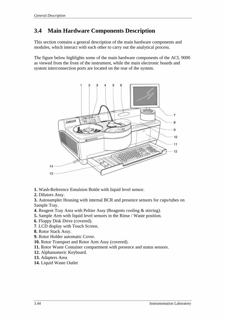
General Description
3.44 Instrumentation Laboratory
3.4 Main Hardware Components Description
This section contains a general description of the main hardware components andmodules, which interact with each other to carry out the analytical process.
The figure below highlights some of the main hardware components of the ACL 9000as viewed from the front of the instrument, while the main electronic boards andsystem interconnection ports are located on the rear of the system.
1. Wash-Reference Emulsion Bottle with liquid level sensor.2. Dilutors Assy.3. Autosampler Housing with internal BCR and presence sensors for cups/tubes onSample Tray.4. Reagent Tray Area with Peltier Assy (Reagents cooling & stirring).5. Sample Arm with liquid level sensors in the Rinse / Waste position.6. Floppy Disk Drive (covered).7. LCD display with Touch Screen.8. Rotor Stack Assy.9. Rotor Holder automatic Cover.10. Rotor Transport and Rotor Arm Assy (covered).11. Rotor Waste Container compartment with presence and status sensors.12. Alphanumeric Keyboard.13. Adapters Area14. Liquid Waste Outlet
ACL 9000 Service Manual
Instrumentation Laboratory 3.45
3.5 Software Description
This section contains a general description of the main software and its physicallocation in the system.
At the turn on the instrument shows the CPU Master Board (Board #1) BIOS bootscreen with the CPU Master initialization.Then the system loading the operative system and the application program from theHard Disk Drive and perform the initialisation of both the electronic boards and themodules.
In the Hard Disk Drive is stored all the software of the instrument, both theapplication program (Analytical and Service programs) and backup files of thesoftware working on the Slave Board (Board #2) and R.E.M. Board (Board #4).
These two specific softwares are stored in the memories located onboard the SlaveBoard and the R.E.M. Board where are located two slave microprocessors.The two microproprocessors loading the software directly from the memories (FlashEprom) at the instrument turn on.
In order to load a new software revison in the instrument or download the softwarefrom the Hard Disk Drive to the boards memories, the software upgrade procedurehave to be performed as described in the sub-section 7.16.2.

General Description
3.46 Instrumentation Laboratory
3.6 Heating and Cooling System Description
This section contains a general description of the assemblies that insure propertemperatures during the pre-analysis and the analysis phases. These temperatures(reagent cooling and plastic rotors heating) are very important for the analysiscarrying out. Following are these assemblies.
• Rotor Holder Assy.• Peltier Assy.• Rotor Transport Assy.• Rotor Stack Assy.
• Rotor Holder Assy
The Rotor Holder Assy is provided with a Heating Coil and a high precisionthermistor, that are powered and driven by a specific electronic circuit.Through this system the instrument insure the 38.5 °C (the accepted range is 38.0 °Cto 39.0 °C) on the Rotor Holder iron and so the 37.0 °C (the accepted range is 36.0 °Cto 38.0 °C) on the liquids inside the cuvettes of the plastic rotor.
• Peltier Assy
The Peltier Assy is provided with 3 “Peltier effect” cells and a high precisionthermistor, that are powered and driven by a specific electronic circuit.Through this system the instrument insure that the reagent vials temperature on theassembly is maintained in the accepted range from 10.0 °C to 16.0 °C.
• Rotor Transport Assy
The Rotor Transport Assy is provided with 2 Heating Pad resistance and a highprecision thermistor, that is powered and driven by a specific electronic circuit.Through this system the instrument insure that the plastic rotor temperature on theassembly is maintained in the accepted range from 34.0 °C to 40.0 °C.
• Rotor Stack Assy
The Rotor Stack Assy is provided with 2 Heating Pad resistance and a high precisionthermistor, that is powered and driven by a specific electronic circuit.Through this system the instrument insure that the plastic rotors temperature in theassembly is maintained in the accepted range from 34.0 °C to 40.0 °C.
ACL 9000 Service Manual
Instrumentation Laboratory 4.1
4 Parts Replacement
This section of the Manual contains general description about the operation required inorder to replace the main assemblies as well as the electronic boards and the coverspresent on the ACL 9000 system.Following are the specific sections.
4.1 Parts Replacement.4.2 Instrument Covers Removing.4.3 Instrument Boards Replacement.
4.1 Parts Replacement
This section is designed to drive step by step the Service Engineer during theReplacement of the major assembly on board of the Instrument.Following are the specific sub-sections for each module.
4.1.1 Autosampler Assy Replacement.4.1.2 Peltier 1 Assy Replacement.4.1.3 Sample Arm Assy Replacement.4.1.4 Rotor Holder Assy Replacement.4.1.5 Rotor Holder Cover Assy Replacement.4.1.6 Dilutors Replacement.4.1.7 Display Replacement.4.1.8 Rotor Exchange Module Replacement.4.1.9 Hard Disk Drive Replacement.
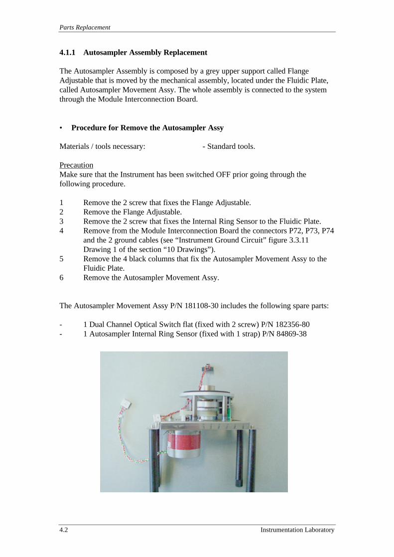
Parts Replacement
4.2 Instrumentation Laboratory
4.1.1 Autosampler Assembly Replacement
The Autosampler Assembly is composed by a grey upper support called FlangeAdjustable that is moved by the mechanical assembly, located under the Fluidic Plate,called Autosampler Movement Assy. The whole assembly is connected to the systemthrough the Module Interconnection Board.
• Procedure for Remove the Autosampler Assy
Materials / tools necessary: - Standard tools.
PrecautionMake sure that the Instrument has been switched OFF prior going through thefollowing procedure.
1 Remove the 2 screw that fixes the Flange Adjustable.2 Remove the Flange Adjustable.3 Remove the 2 screw that fixes the Internal Ring Sensor to the Fluidic Plate.4 Remove from the Module Interconnection Board the connectors P72, P73, P74
and the 2 ground cables (see “Instrument Ground Circuit” figure 3.3.11Drawing 1 of the section “10 Drawings”).
5 Remove the 4 black columns that fix the Autosampler Movement Assy to theFluidic Plate.
6 Remove the Autosampler Movement Assy.
The Autosampler Movement Assy P/N 181108-30 includes the following spare parts:
- 1 Dual Channel Optical Switch flat (fixed with 2 screw) P/N 182356-80- 1 Autosampler Internal Ring Sensor (fixed with 1 strap) P/N 84869-38
ACL 9000 Service Manual
Instrumentation Laboratory 4.3
• Procedure for Replace the Autosampler Assy
Materials / tools necessary: - Standard tools.
PrecautionMake sure that the Instrument has been switched OFF prior going through thefollowing procedure.
1 Follow in the opposite direction the “Procedure for Remove the AutosamplerAssy” paying attention to the position of the Internal Ring Sensor cable respectto the encoder disk.
2 Perform the Motor Adjustment test for the Autosampler Motor as described inthe sub-section 7.6.5.
3 Follow the procedure for the Autosampler Assy module centring as describedin the sub-section 7.7.1.
4 Perform the check out & adjustment for the Internal/External Rings Sensors asdescribed in the sub-section 7.5.3.
5 Perform the verification/adjustment of the Needles Sensors as described in thesub-section 7.4.1.
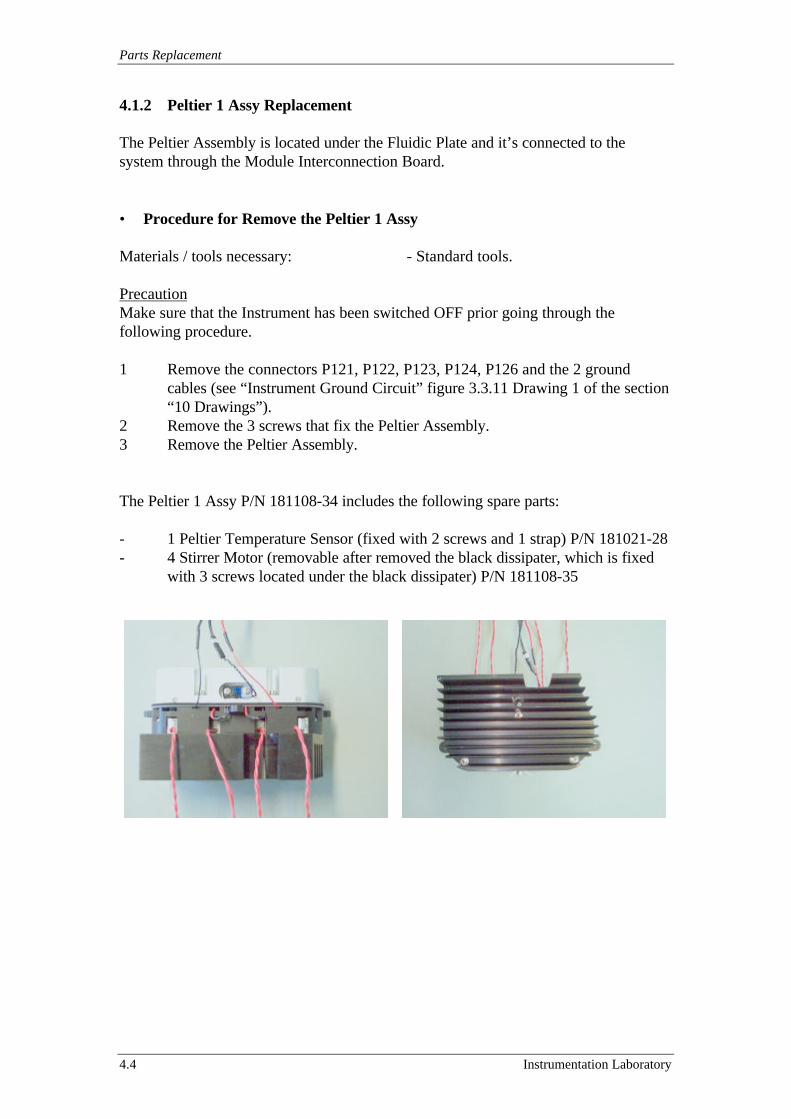
Parts Replacement
4.4 Instrumentation Laboratory
4.1.2 Peltier 1 Assy Replacement
The Peltier Assembly is located under the Fluidic Plate and it’s connected to thesystem through the Module Interconnection Board.
• Procedure for Remove the Peltier 1 Assy
Materials / tools necessary: - Standard tools.
PrecautionMake sure that the Instrument has been switched OFF prior going through thefollowing procedure.
1 Remove the connectors P121, P122, P123, P124, P126 and the 2 groundcables (see “Instrument Ground Circuit” figure 3.3.11 Drawing 1 of the section“10 Drawings”).
2 Remove the 3 screws that fix the Peltier Assembly.3 Remove the Peltier Assembly.
The Peltier 1 Assy P/N 181108-34 includes the following spare parts:
- 1 Peltier Temperature Sensor (fixed with 2 screws and 1 strap) P/N 181021-28- 4 Stirrer Motor (removable after removed the black dissipater, which is fixed
with 3 screws located under the black dissipater) P/N 181108-35
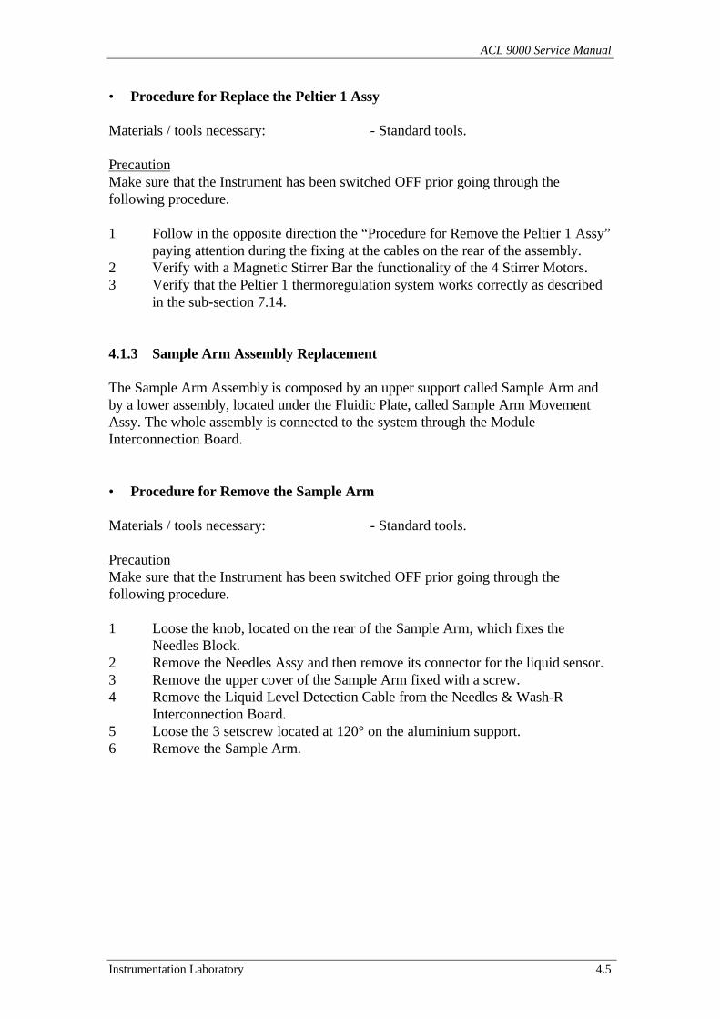
ACL 9000 Service Manual
Instrumentation Laboratory 4.5
• Procedure for Replace the Peltier 1 Assy
Materials / tools necessary: - Standard tools.
PrecautionMake sure that the Instrument has been switched OFF prior going through thefollowing procedure.
1 Follow in the opposite direction the “Procedure for Remove the Peltier 1 Assy”paying attention during the fixing at the cables on the rear of the assembly.
2 Verify with a Magnetic Stirrer Bar the functionality of the 4 Stirrer Motors.3 Verify that the Peltier 1 thermoregulation system works correctly as described
in the sub-section 7.14.
4.1.3 Sample Arm Assembly Replacement
The Sample Arm Assembly is composed by an upper support called Sample Arm andby a lower assembly, located under the Fluidic Plate, called Sample Arm MovementAssy. The whole assembly is connected to the system through the ModuleInterconnection Board.
• Procedure for Remove the Sample Arm
Materials / tools necessary: - Standard tools.
PrecautionMake sure that the Instrument has been switched OFF prior going through thefollowing procedure.
1 Loose the knob, located on the rear of the Sample Arm, which fixes theNeedles Block.
2 Remove the Needles Assy and then remove its connector for the liquid sensor.3 Remove the upper cover of the Sample Arm fixed with a screw.4 Remove the Liquid Level Detection Cable from the Needles & Wash-R
Interconnection Board.5 Loose the 3 setscrew located at 120° on the aluminium support.6 Remove the Sample Arm.
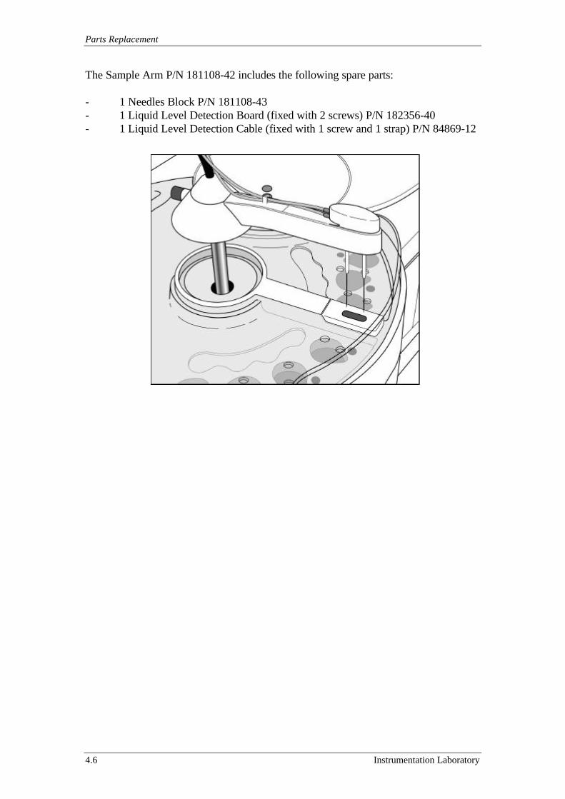
Parts Replacement
4.6 Instrumentation Laboratory
The Sample Arm P/N 181108-42 includes the following spare parts:
- 1 Needles Block P/N 181108-43- 1 Liquid Level Detection Board (fixed with 2 screws) P/N 182356-40- 1 Liquid Level Detection Cable (fixed with 1 screw and 1 strap) P/N 84869-12
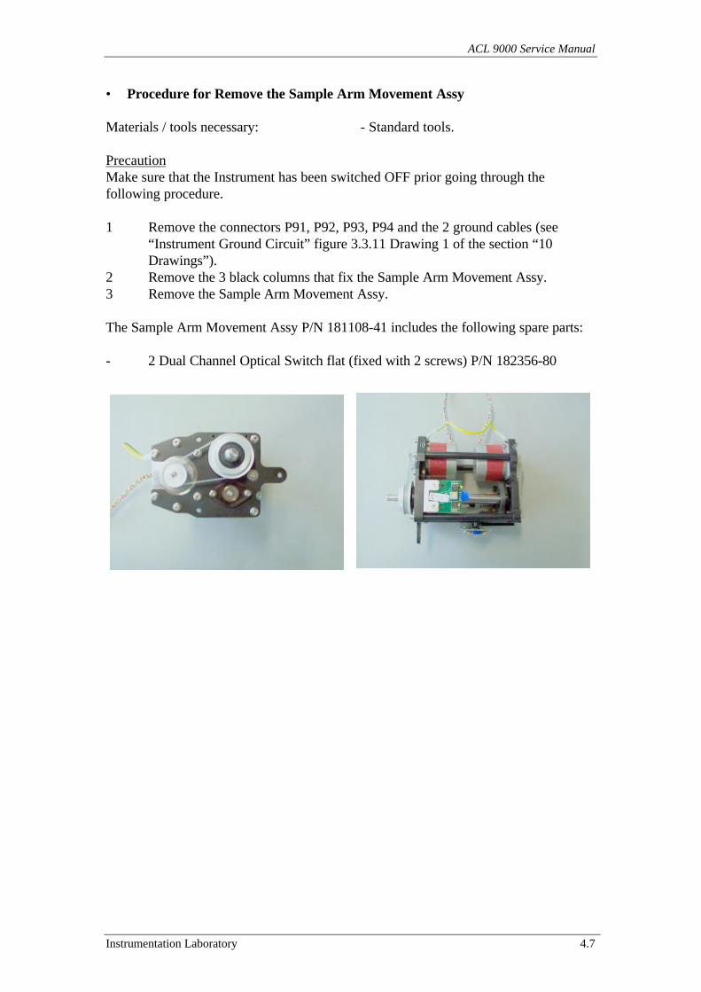
ACL 9000 Service Manual
Instrumentation Laboratory 4.7
• Procedure for Remove the Sample Arm Movement Assy
Materials / tools necessary: - Standard tools.
PrecautionMake sure that the Instrument has been switched OFF prior going through thefollowing procedure.
1 Remove the connectors P91, P92, P93, P94 and the 2 ground cables (see“Instrument Ground Circuit” figure 3.3.11 Drawing 1 of the section “10Drawings”).
2 Remove the 3 black columns that fix the Sample Arm Movement Assy.3 Remove the Sample Arm Movement Assy.
The Sample Arm Movement Assy P/N 181108-41 includes the following spare parts:
- 2 Dual Channel Optical Switch flat (fixed with 2 screws) P/N 182356-80

Parts Replacement
4.8 Instrumentation Laboratory
• Procedure for Replace the Sample Arm Movement Assy
Materials / tools necessary: - Standard tools.- Sample Arm Centring Tool P/N 190513-00
PrecautionMake sure that the Instrument has been switched OFF prior going through thefollowing procedure.
1 Follow in the opposite direction the “Procedure for Remove the Sample ArmMovement Assy”.
2 Perform the Motor Adjustment tests for the Sample Arm Horizontal andVertical Motor as described in the sub-section 7.6.3 and 7.6.4.
3 Centre shaft of the assembly in the hole of the Fluidic Plate using the SampleArm Centring Tool P/N 190513-00.
• Procedure for Replace the Sample Arm
Materials / tools necessary: - Standard tools.
PrecautionMake sure that the Instrument has been switched OFF prior going through thefollowing procedure.
1 Follow in the opposite direction the “Procedure for Remove the Sample Arm”.2 Follow the procedure for the module centring of this assembly as described in
the sub-section 7.7.1. and also the procedure to fine adjust the Needles BlockAssy position as described in the sub-section 7.7.4.
3 Perform the Liquid Level Sensor test as described in the sub-section 7.4.1.
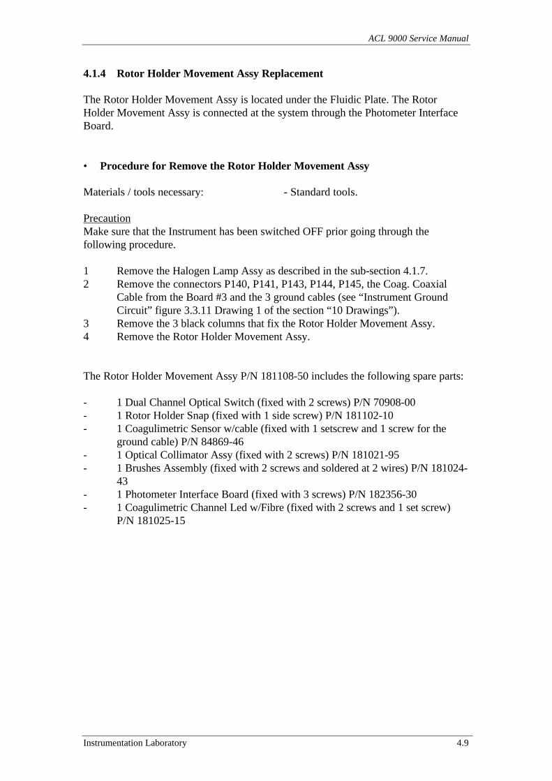
ACL 9000 Service Manual
Instrumentation Laboratory 4.9
4.1.4 Rotor Holder Movement Assy Replacement
The Rotor Holder Movement Assy is located under the Fluidic Plate. The RotorHolder Movement Assy is connected at the system through the Photometer InterfaceBoard.
• Procedure for Remove the Rotor Holder Movement Assy
Materials / tools necessary: - Standard tools.
PrecautionMake sure that the Instrument has been switched OFF prior going through thefollowing procedure.
1 Remove the Halogen Lamp Assy as described in the sub-section 4.1.7.2 Remove the connectors P140, P141, P143, P144, P145, the Coag. Coaxial
Cable from the Board #3 and the 3 ground cables (see “Instrument GroundCircuit” figure 3.3.11 Drawing 1 of the section “10 Drawings”).
3 Remove the 3 black columns that fix the Rotor Holder Movement Assy.4 Remove the Rotor Holder Movement Assy.
The Rotor Holder Movement Assy P/N 181108-50 includes the following spare parts:
- 1 Dual Channel Optical Switch (fixed with 2 screws) P/N 70908-00- 1 Rotor Holder Snap (fixed with 1 side screw) P/N 181102-10- 1 Coagulimetric Sensor w/cable (fixed with 1 setscrew and 1 screw for the
ground cable) P/N 84869-46- 1 Optical Collimator Assy (fixed with 2 screws) P/N 181021-95- 1 Brushes Assembly (fixed with 2 screws and soldered at 2 wires) P/N 181024-
43- 1 Photometer Interface Board (fixed with 3 screws) P/N 182356-30- 1 Coagulimetric Channel Led w/Fibre (fixed with 2 screws and 1 set screw)
P/N 181025-15
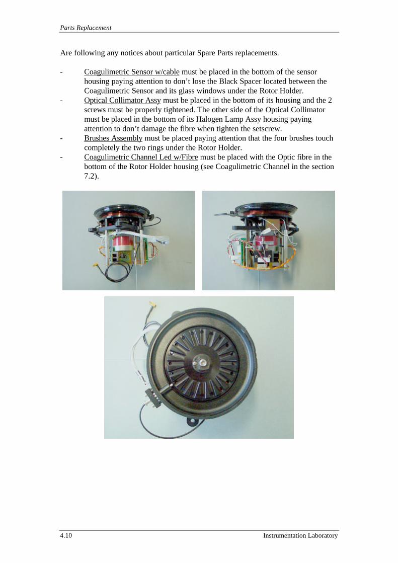
Parts Replacement
4.10 Instrumentation Laboratory
Are following any notices about particular Spare Parts replacements.
- Coagulimetric Sensor w/cable must be placed in the bottom of the sensorhousing paying attention to don’t lose the Black Spacer located between theCoagulimetric Sensor and its glass windows under the Rotor Holder.
- Optical Collimator Assy must be placed in the bottom of its housing and the 2screws must be properly tightened. The other side of the Optical Collimatormust be placed in the bottom of its Halogen Lamp Assy housing payingattention to don’t damage the fibre when tighten the setscrew.
- Brushes Assembly must be placed paying attention that the four brushes touchcompletely the two rings under the Rotor Holder.
- Coagulimetric Channel Led w/Fibre must be placed with the Optic fibre in thebottom of the Rotor Holder housing (see Coagulimetric Channel in the section7.2).
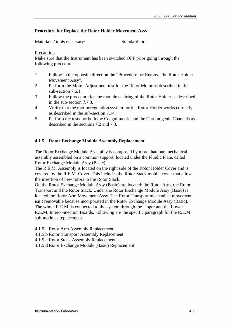
ACL 9000 Service Manual
Instrumentation Laboratory 4.11
Procedure for Replace the Rotor Holder Movement Assy
Materials / tools necessary: - Standard tools.
PrecautionMake sure that the Instrument has been switched OFF prior going through thefollowing procedure.
1 Follow in the opposite direction the “Procedure for Remove the Rotor HolderMovement Assy”.
2 Perform the Motor Adjustment test for the Rotor Motor as described in thesub-section 7.6.1.
3 Follow the procedure for the module centring of the Rotor Holder as describedin the sub-section 7.7.3.
4 Verify that the thermoregulation system for the Rotor Holder works correctlyas described in the sub-section 7.14.
5 Perform the tests for both the Coagulimetric and the Chromogenic Channels asdescribed in the sections 7.2 and 7.3.
4.1.5 Rotor Exchange Module Assembly Replacement
The Rotor Exchange Module Assembly is composed by more than one mechanicalassembly assembled on a common support, located under the Fluidic Plate, calledRotor Exchange Module Assy (Basic).The R.E.M. Assembly is located on the right side of the Rotor Holder Cover and iscovered by the R.E.M. Cover. This includes the Rotor Stack mobile cover that allowsthe insertion of new rotors in the Rotor Stack.On the Rotor Exchange Module Assy (Basic) are located: the Rotor Arm, the RotorTransport and the Rotor Stack. Under the Rotor Exchange Module Assy (Basic) islocated the Rotor Arm Movement Assy. The Rotor Transport mechanical movementisn’t removable because incorporated in the Rotor Exchange Module Assy (Basic).The whole R.E.M. is connected to the system through the Upper and the LowerR.E.M. Interconnection Boards. Following are the specific paragraph for the R.E.M.sub-modules replacement.
4.1.5.a Rotor Arm Assembly Replacement4.1.5.b Rotor Transport Assembly Replacement4.1.5.c Rotor Stack Assembly Replacement4.1.5.d Rotor Exchange Module (Basic) Replacement
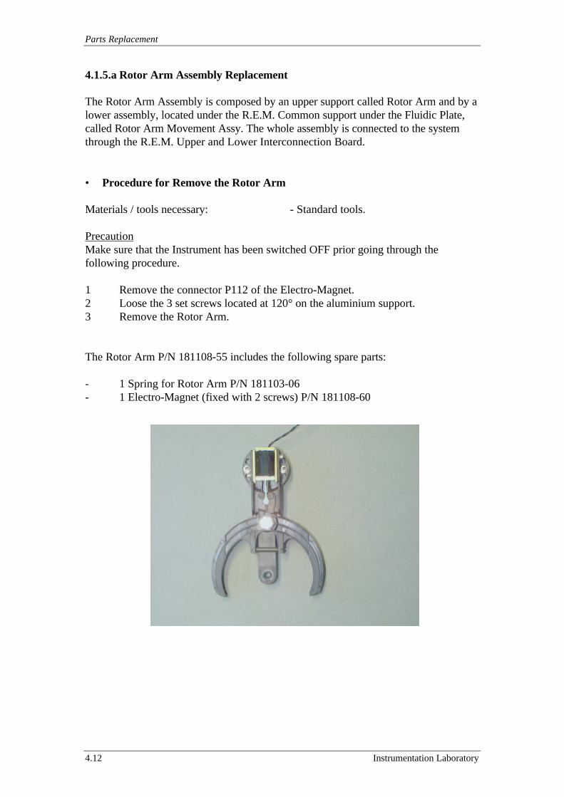
Parts Replacement
4.12 Instrumentation Laboratory
4.1.5.a Rotor Arm Assembly Replacement
The Rotor Arm Assembly is composed by an upper support called Rotor Arm and by alower assembly, located under the R.E.M. Common support under the Fluidic Plate,called Rotor Arm Movement Assy. The whole assembly is connected to the systemthrough the R.E.M. Upper and Lower Interconnection Board.
• Procedure for Remove the Rotor Arm
Materials / tools necessary: - Standard tools.
PrecautionMake sure that the Instrument has been switched OFF prior going through thefollowing procedure.
1 Remove the connector P112 of the Electro-Magnet.2 Loose the 3 set screws located at 120° on the aluminium support.3 Remove the Rotor Arm.
The Rotor Arm P/N 181108-55 includes the following spare parts:
- 1 Spring for Rotor Arm P/N 181103-06- 1 Electro-Magnet (fixed with 2 screws) P/N 181108-60
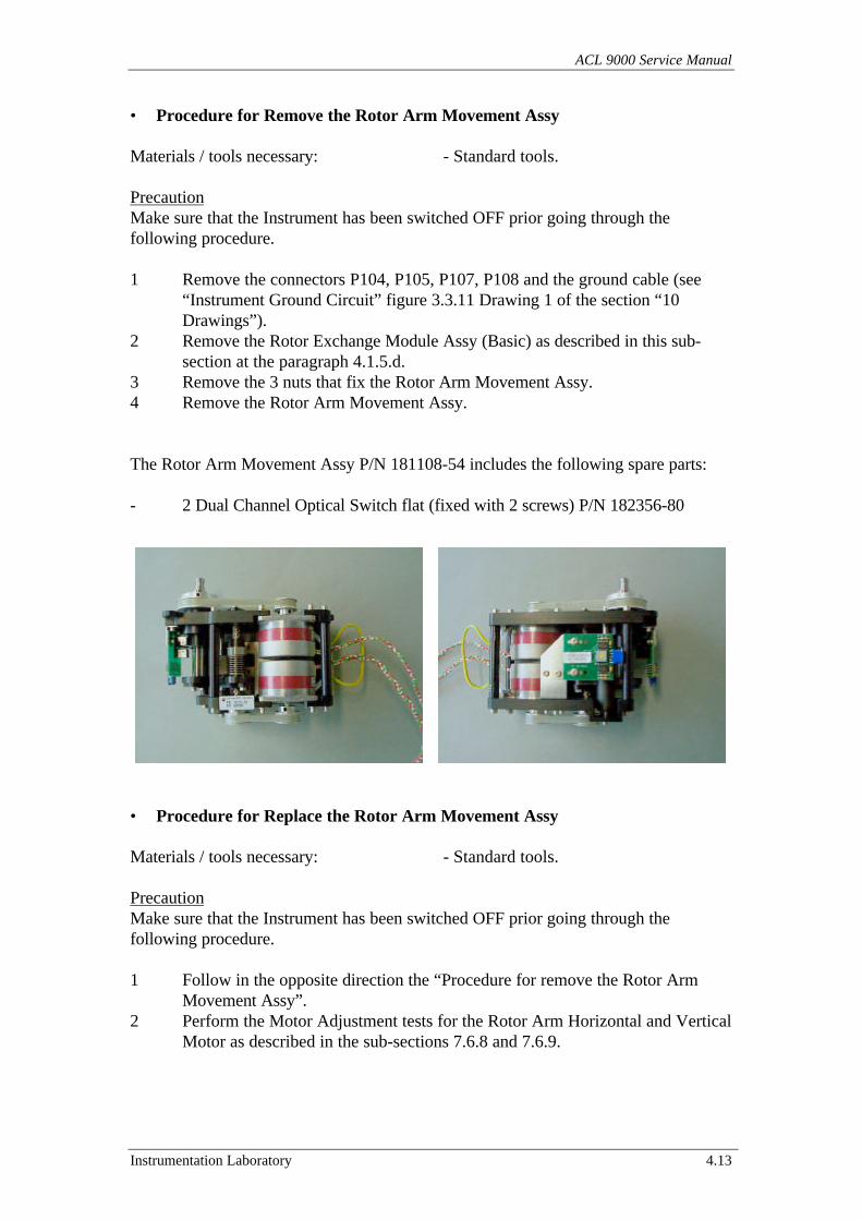
ACL 9000 Service Manual
Instrumentation Laboratory 4.13
• Procedure for Remove the Rotor Arm Movement Assy
Materials / tools necessary: - Standard tools.
PrecautionMake sure that the Instrument has been switched OFF prior going through thefollowing procedure.
1 Remove the connectors P104, P105, P107, P108 and the ground cable (see“Instrument Ground Circuit” figure 3.3.11 Drawing 1 of the section “10Drawings”).
2 Remove the Rotor Exchange Module Assy (Basic) as described in this sub-section at the paragraph 4.1.5.d.
3 Remove the 3 nuts that fix the Rotor Arm Movement Assy.4 Remove the Rotor Arm Movement Assy.
The Rotor Arm Movement Assy P/N 181108-54 includes the following spare parts:
- 2 Dual Channel Optical Switch flat (fixed with 2 screws) P/N 182356-80
• Procedure for Replace the Rotor Arm Movement Assy
Materials / tools necessary: - Standard tools.
PrecautionMake sure that the Instrument has been switched OFF prior going through thefollowing procedure.
1 Follow in the opposite direction the “Procedure for remove the Rotor ArmMovement Assy”.
2 Perform the Motor Adjustment tests for the Rotor Arm Horizontal and VerticalMotor as described in the sub-sections 7.6.8 and 7.6.9.
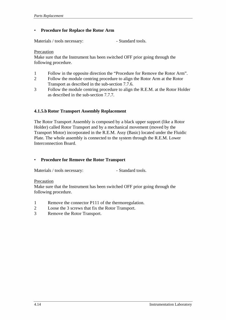
Parts Replacement
4.14 Instrumentation Laboratory
• Procedure for Replace the Rotor Arm
Materials / tools necessary: - Standard tools.
PrecautionMake sure that the Instrument has been switched OFF prior going through thefollowing procedure.
1 Follow in the opposite direction the “Procedure for Remove the Rotor Arm”.2 Follow the module centring procedure to align the Rotor Arm at the Rotor
Transport as described in the sub-section 7.7.6.3 Follow the module centring procedure to align the R.E.M. at the Rotor Holder
as described in the sub-section 7.7.7.
4.1.5.b Rotor Transport Assembly Replacement
The Rotor Transport Assembly is composed by a black upper support (like a RotorHolder) called Rotor Transport and by a mechanical movement (moved by theTransport Motor) incorporated in the R.E.M. Assy (Basic) located under the FluidicPlate. The whole assembly is connected to the system through the R.E.M. LowerInterconnection Board.
• Procedure for Remove the Rotor Transport
Materials / tools necessary: - Standard tools.
PrecautionMake sure that the Instrument has been switched OFF prior going through thefollowing procedure.
1 Remove the connector P111 of the thermoregulation.2 Loose the 3 screws that fix the Rotor Transport.3 Remove the Rotor Transport.
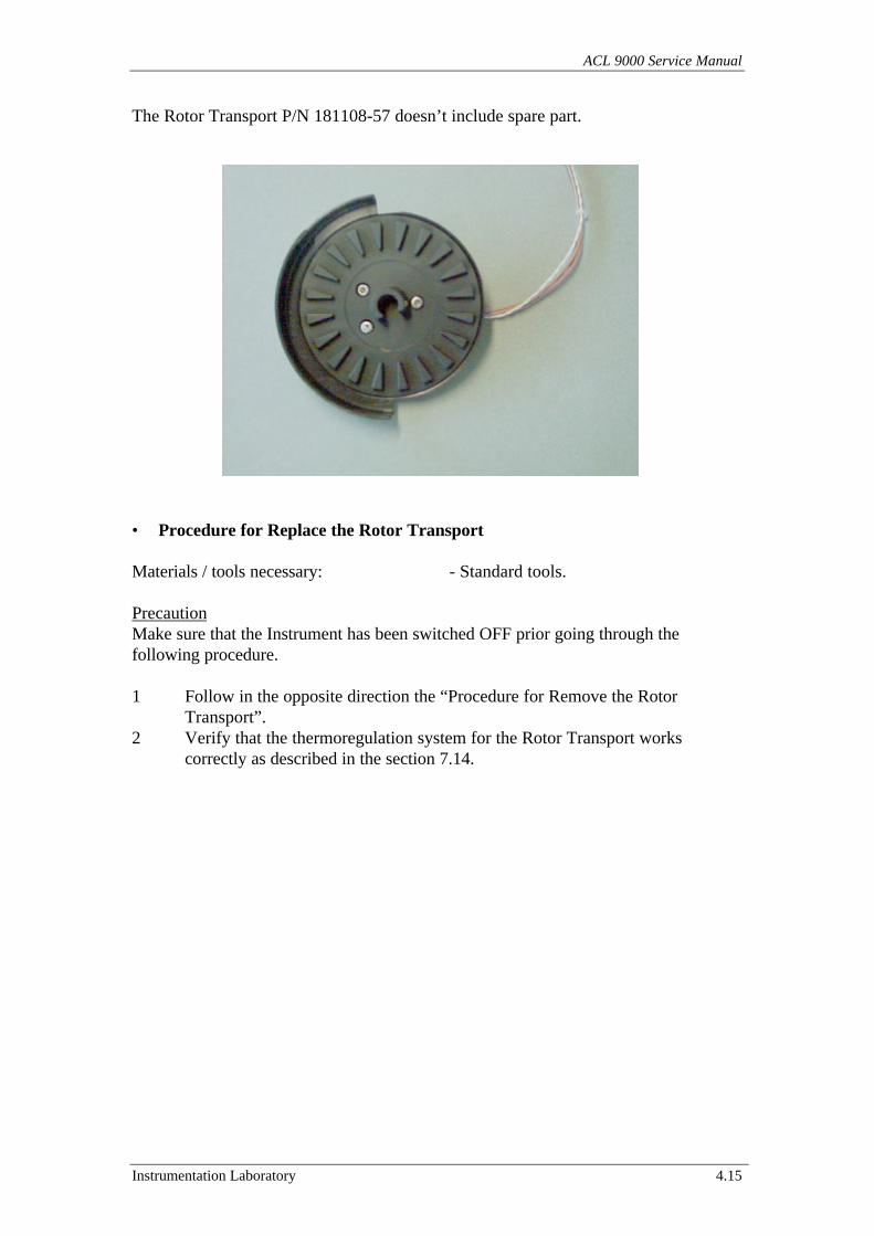
ACL 9000 Service Manual
Instrumentation Laboratory 4.15
The Rotor Transport P/N 181108-57 doesn’t include spare part.
• Procedure for Replace the Rotor Transport
Materials / tools necessary: - Standard tools.
PrecautionMake sure that the Instrument has been switched OFF prior going through thefollowing procedure.
1 Follow in the opposite direction the “Procedure for Remove the RotorTransport”.
2 Verify that the thermoregulation system for the Rotor Transport workscorrectly as described in the section 7.14.
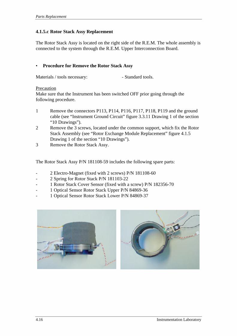
Parts Replacement
4.16 Instrumentation Laboratory
4.1.5.c Rotor Stack Assy Replacement
The Rotor Stack Assy is located on the right side of the R.E.M. The whole assembly isconnected to the system through the R.E.M. Upper Interconnection Board.
• Procedure for Remove the Rotor Stack Assy
Materials / tools necessary: - Standard tools.
PrecautionMake sure that the Instrument has been switched OFF prior going through thefollowing procedure.
1 Remove the connectors P113, P114, P116, P117, P118, P119 and the groundcable (see “Instrument Ground Circuit” figure 3.3.11 Drawing 1 of the section“10 Drawings”).
2 Remove the 3 screws, located under the common support, which fix the RotorStack Assembly (see “Rotor Exchange Module Replacement” figure 4.1.5Drawing 1 of the section “10 Drawings”).
3 Remove the Rotor Stack Assy.
The Rotor Stack Assy P/N 181108-59 includes the following spare parts:
- 2 Electro-Magnet (fixed with 2 screws) P/N 181108-60- 2 Spring for Rotor Stack P/N 181103-22- 1 Rotor Stack Cover Sensor (fixed with a screw) P/N 182356-70- 1 Optical Sensor Rotor Stack Upper P/N 84869-36- 1 Optical Sensor Rotor Stack Lower P/N 84869-37
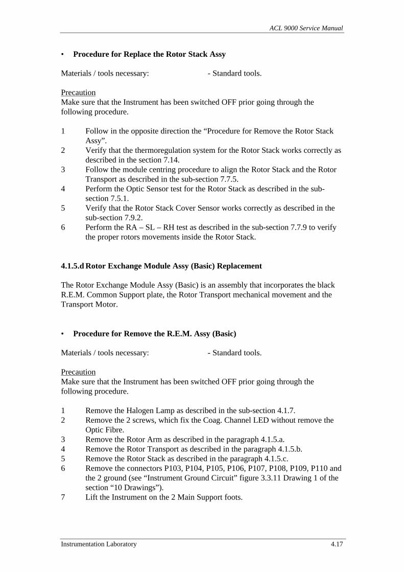
ACL 9000 Service Manual
Instrumentation Laboratory 4.17
• Procedure for Replace the Rotor Stack Assy
Materials / tools necessary: - Standard tools.
PrecautionMake sure that the Instrument has been switched OFF prior going through thefollowing procedure.
1 Follow in the opposite direction the “Procedure for Remove the Rotor StackAssy”.
2 Verify that the thermoregulation system for the Rotor Stack works correctly asdescribed in the section 7.14.
3 Follow the module centring procedure to align the Rotor Stack and the RotorTransport as described in the sub-section 7.7.5.
4 Perform the Optic Sensor test for the Rotor Stack as described in the sub-section 7.5.1.
5 Verify that the Rotor Stack Cover Sensor works correctly as described in thesub-section 7.9.2.
6 Perform the RA – SL – RH test as described in the sub-section 7.7.9 to verifythe proper rotors movements inside the Rotor Stack.
4.1.5.d Rotor Exchange Module Assy (Basic) Replacement
The Rotor Exchange Module Assy (Basic) is an assembly that incorporates the blackR.E.M. Common Support plate, the Rotor Transport mechanical movement and theTransport Motor.
• Procedure for Remove the R.E.M. Assy (Basic)
Materials / tools necessary: - Standard tools.
PrecautionMake sure that the Instrument has been switched OFF prior going through thefollowing procedure.
1 Remove the Halogen Lamp as described in the sub-section 4.1.7.2 Remove the 2 screws, which fix the Coag. Channel LED without remove the
Optic Fibre.3 Remove the Rotor Arm as described in the paragraph 4.1.5.a.4 Remove the Rotor Transport as described in the paragraph 4.1.5.b.5 Remove the Rotor Stack as described in the paragraph 4.1.5.c.6 Remove the connectors P103, P104, P105, P106, P107, P108, P109, P110 and
the 2 ground (see “Instrument Ground Circuit” figure 3.3.11 Drawing 1 of thesection “10 Drawings”).
7 Lift the Instrument on the 2 Main Support foots.
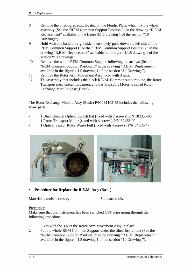
Parts Replacement
4.18 Instrumentation Laboratory
8 Remove the 5 fixing screws, located on the Fluidic Plate, which fix the wholeassembly (See the “REM Common Support Position 3” in the drawing “R.E.M.Replacement” available in the figure 4.1.5 drawing 1 of the section “10Drawings”).
9 Hold with one hand the right side, then slowly push down the left side of theREM Common Support (See the “REM Common Support Position 2” in thedrawing “R.E.M. Replacement” available in the figure 4.1.5 drawing 1 of thesection “10 Drawings”).
10 Remove the whole REM Common Support following the arrows (See the“REM Common Support Position 1” in the drawing “R.E.M. Replacement”available in the figure 4.1.5 drawing 1 of the section “10 Drawings”).
11 Remove the Rotor Arm Movement Assy fixed with 3 nuts.12 The assembly that includes the black R.E.M. Common support plate, the Rotor
Transport mechanical movement and the Transport Motor is called RotorExchange Module Assy (Basic).
The Rotor Exchange Module Assy (Basic) P/N 181108-53 includes the followingspare parts:
- 1 Dual Channel Optical Switch flat (fixed with 2 screws) P/N 182356-80- 1 Rotor Transport Motor (fixed with 4 screws) P/N 82433-00- 1 Optical Sensor Rotor Waste Full (fixed with 4 screws) P/N 84869-47
• Procedure for Replace the R.E.M. Assy (Basic)
Materials / tools necessary: - Standard tools.
PrecautionMake sure that the Instrument has been switched OFF prior going through thefollowing procedure.
1 Fixes with the 3 nuts the Rotor Arm Movement Assy in place.2 Put the whole REM Common Support under the tilted Instrument (See the
“REM Common Support Position 1” in the drawing “R.E.M. Replacement”available in the figure 4.1.5 drawing 1 of the section “10 Drawings”).
ACL 9000 Service Manual
Instrumentation Laboratory 4.19
3 Following the arrows lift the right side of the REM Common Support, payingattention to center the 3 Rotor Stack fixing points holes in the Fluidic Plate(See the “REM Common Support Position 2” in the drawing “R.E.M.Replacement” available in the figure 4.1.5 drawing 1 of the section “10Drawings”).
4 Hold with one hand the right side, then slowly lift the left side of the REMCommon Support (See the “REM Common Support Position 3” in the drawing“R.E.M. Replacement” available in the figure 4.1.5 drawing 1 of the section“10 Drawings”).
5 Fix the 5 screws, located on the Fluidic Plate, which fix the whole assembly(See the “5 REM fixing points”).
6 Now follow in the opposite direction from the point 7 to the point 1 theprocedure for remove the R.E.M. Assy (Basic).
7 Perform the Motor Adjustment tests for the Transport Motor as described inthe sub-section 7.6.7.
Note: It’s requited to perform also the relevant check out for all the other assemblythat was been removed.
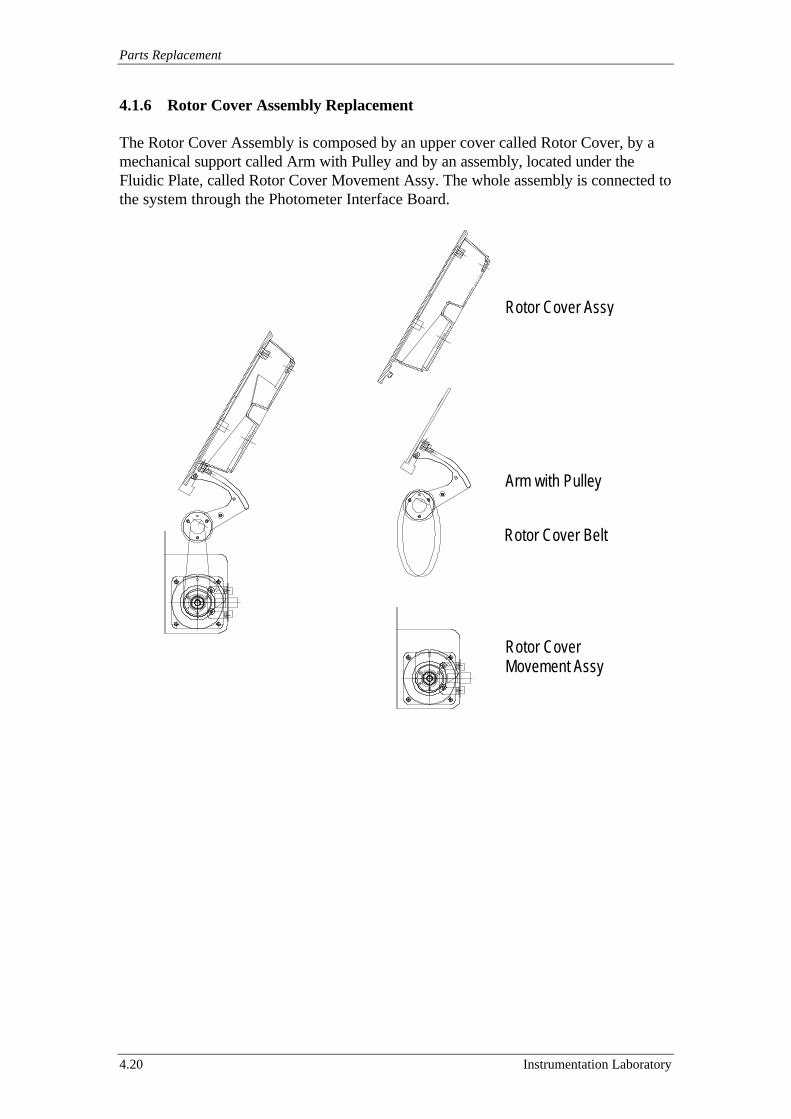
Parts Replacement
4.20 Instrumentation Laboratory
4.1.6 Rotor Cover Assembly Replacement
The Rotor Cover Assembly is composed by an upper cover called Rotor Cover, by amechanical support called Arm with Pulley and by an assembly, located under theFluidic Plate, called Rotor Cover Movement Assy. The whole assembly is connected tothe system through the Photometer Interface Board.
Rotor Cover Assy
Rotor CoverMovement Assy
Arm with Pulley
Rotor Cover Belt
ACL 9000 Service Manual
Instrumentation Laboratory 4.21
• Procedure for Remove the Rotor Cover Assy
Materials / tools necessary: - Standard tools.
PrecautionMake sure that the Instrument has been switched OFF prior going through thefollowing procedure.
1 Remove the 3 screws, located on the lower black side, which fix the upperwhite support.
2 Remove the 2 screws, located on the metallic mechanical arm, which fix theblack lower support.
3 Remove the Chromogenic Coaxial Cable.
The Rotor Cover P/N 181108-46 include the following spare parts:
- 1 Chromogenic Coaxial Cable (connected to the Board #3) P/N 84869-44.- 1 Filter Optical 405 nm (located in the black “Filter & Sensor Housing”, fixed
with 5 screws, and hold in the bottom with a white spacer) P/N 89721-00.- 1 Chromogenic Sensor Board (located in the Filter & Sensor Housing colour
black and fixed with 6 screws) P/N 82627-00.
• Procedure for Replace the Rotor Cover Assy
Materials / tools necessary: - Standard tools.
PrecautionMake sure that the Instrument has been switched OFF prior going through thefollowing procedure.
1 Follow in the opposite direction the “Procedure for Remove the Rotor Cover”paying attention at the cleaning of the optic parts.
2 Perform the tests for the Chromogenic Channel as described in the sub section7.3.
Parts Replacement
4.22 Instrumentation Laboratory
• Procedure for Remove the Arm with Pulley
Materials / tools necessary: - Standard tools.
PrecautionMake sure that the Instrument has been switched OFF prior going through thefollowing procedure.
1 Remove the Rotor Holder as described in the sub-sections 4.1.4.2 Remove the Rotor Cover and the Rotor Cover Movement Assy as described in
this sub-section 4.1.6.3 Remove the Chromogenic Coaxial Cable.4 Remove the Arm with Pulley (fixed with 4 screws).
The Arm with Pulley includes the following spare part.
- 1 Rotor Cover Belt P/N 66675-60
• Procedure for Replace the Arm with Pulley
Materials / tools necessary: - Standard tools.
PrecautionMake sure that the Instrument has been switched OFF prior going through thefollowing procedure.
1 Follow in the opposite direction the “Procedure for Removes the Arm withPulley”, paying attention to secure the Chromogenic Coaxial Cable in a properposition to save it during the Arm with Pulley movement.
• Procedure for Remove the Rotor Cover Movement Assy
Materials / tools necessary: - Standard tools.
PrecautionMake sure that the Instrument has been switched OFF prior going through thefollowing procedure.
1 Remove the Halogen Lamp as described in the sub-section 4.1.7.2 Remove the connectors P143, P144 and the ground cable (see “Instrument
Ground Circuit” figure 3.3.11 Drawing 1 of the section “10 Drawings”).3 Remove Rotor Holder Movement Assy as described in the sub-section 4.1.4.4 Remove all the 5 Boards in the Card Housing.5 Remove the bulkhead and the 2 fixing knobs located inside the Card Housing.6 Loose the 3 screws that fix the Cover Movement Assy.
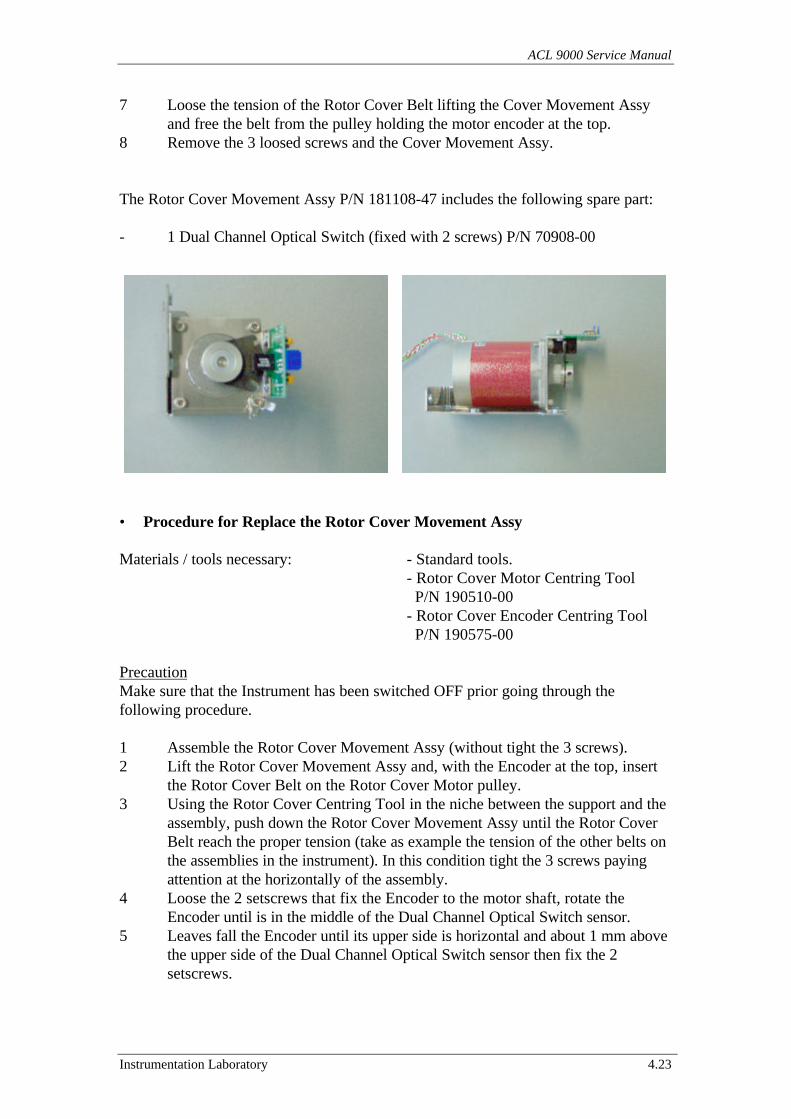
ACL 9000 Service Manual
Instrumentation Laboratory 4.23
7 Loose the tension of the Rotor Cover Belt lifting the Cover Movement Assyand free the belt from the pulley holding the motor encoder at the top.
8 Remove the 3 loosed screws and the Cover Movement Assy.
The Rotor Cover Movement Assy P/N 181108-47 includes the following spare part:
- 1 Dual Channel Optical Switch (fixed with 2 screws) P/N 70908-00
• Procedure for Replace the Rotor Cover Movement Assy
Materials / tools necessary: - Standard tools.- Rotor Cover Motor Centring Tool P/N 190510-00- Rotor Cover Encoder Centring Tool P/N 190575-00
PrecautionMake sure that the Instrument has been switched OFF prior going through thefollowing procedure.
1 Assemble the Rotor Cover Movement Assy (without tight the 3 screws).2 Lift the Rotor Cover Movement Assy and, with the Encoder at the top, insert
the Rotor Cover Belt on the Rotor Cover Motor pulley.3 Using the Rotor Cover Centring Tool in the niche between the support and the
assembly, push down the Rotor Cover Movement Assy until the Rotor CoverBelt reach the proper tension (take as example the tension of the other belts onthe assemblies in the instrument). In this condition tight the 3 screws payingattention at the horizontally of the assembly.
4 Loose the 2 setscrews that fix the Encoder to the motor shaft, rotate theEncoder until is in the middle of the Dual Channel Optical Switch sensor.
5 Leaves fall the Encoder until its upper side is horizontal and about 1 mm abovethe upper side of the Dual Channel Optical Switch sensor then fix the 2setscrews.
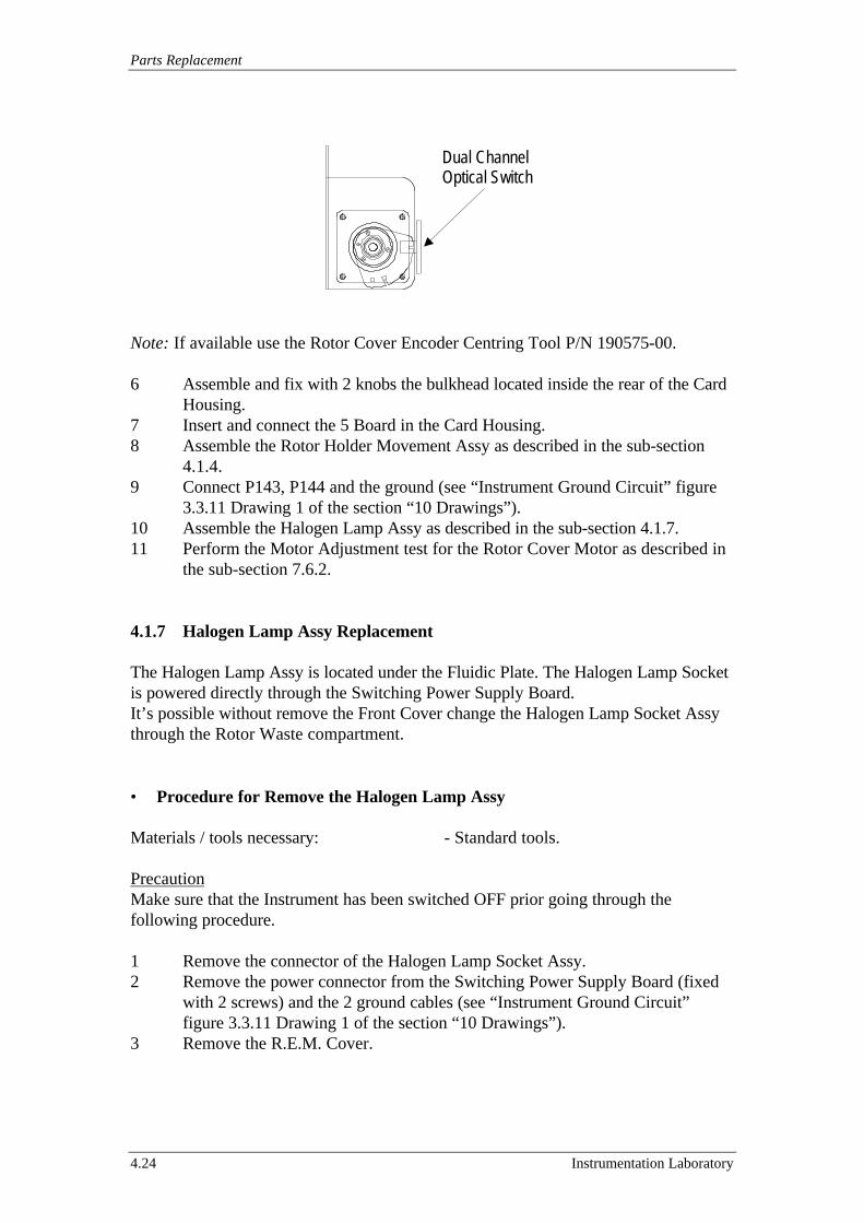
Parts Replacement
4.24 Instrumentation Laboratory
Note: If available use the Rotor Cover Encoder Centring Tool P/N 190575-00.
6 Assemble and fix with 2 knobs the bulkhead located inside the rear of the CardHousing.
7 Insert and connect the 5 Board in the Card Housing.8 Assemble the Rotor Holder Movement Assy as described in the sub-section
4.1.4.9 Connect P143, P144 and the ground (see “Instrument Ground Circuit” figure
3.3.11 Drawing 1 of the section “10 Drawings”).10 Assemble the Halogen Lamp Assy as described in the sub-section 4.1.7.11 Perform the Motor Adjustment test for the Rotor Cover Motor as described in
the sub-section 7.6.2.
4.1.7 Halogen Lamp Assy Replacement
The Halogen Lamp Assy is located under the Fluidic Plate. The Halogen Lamp Socketis powered directly through the Switching Power Supply Board.It’s possible without remove the Front Cover change the Halogen Lamp Socket Assythrough the Rotor Waste compartment.
• Procedure for Remove the Halogen Lamp Assy
Materials / tools necessary: - Standard tools.
PrecautionMake sure that the Instrument has been switched OFF prior going through thefollowing procedure.
1 Remove the connector of the Halogen Lamp Socket Assy.2 Remove the power connector from the Switching Power Supply Board (fixed
with 2 screws) and the 2 ground cables (see “Instrument Ground Circuit”figure 3.3.11 Drawing 1 of the section “10 Drawings”).
3 Remove the R.E.M. Cover.
Dual ChannelOptical Switch
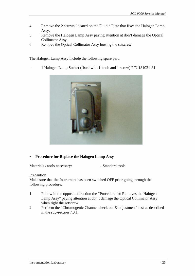
ACL 9000 Service Manual
Instrumentation Laboratory 4.25
4 Remove the 2 screws, located on the Fluidic Plate that fixes the Halogen LampAssy.
5 Remove the Halogen Lamp Assy paying attention at don’t damage the OpticalCollimator Assy.
6 Remove the Optical Collimator Assy loosing the setscrew.
The Halogen Lamp Assy include the following spare part:
- 1 Halogen Lamp Socket (fixed with 1 knob and 1 screw) P/N 181021-81
• Procedure for Replace the Halogen Lamp Assy
Materials / tools necessary: - Standard tools.
PrecautionMake sure that the Instrument has been switched OFF prior going through thefollowing procedure.
1 Follow in the opposite direction the “Procedure for Removes the HalogenLamp Assy” paying attention at don’t damage the Optical Collimator Assywhen tight the setscrew.
2 Perform the “Chromogenic Channel check out & adjustment” test as describedin the sub-section 7.3.1.
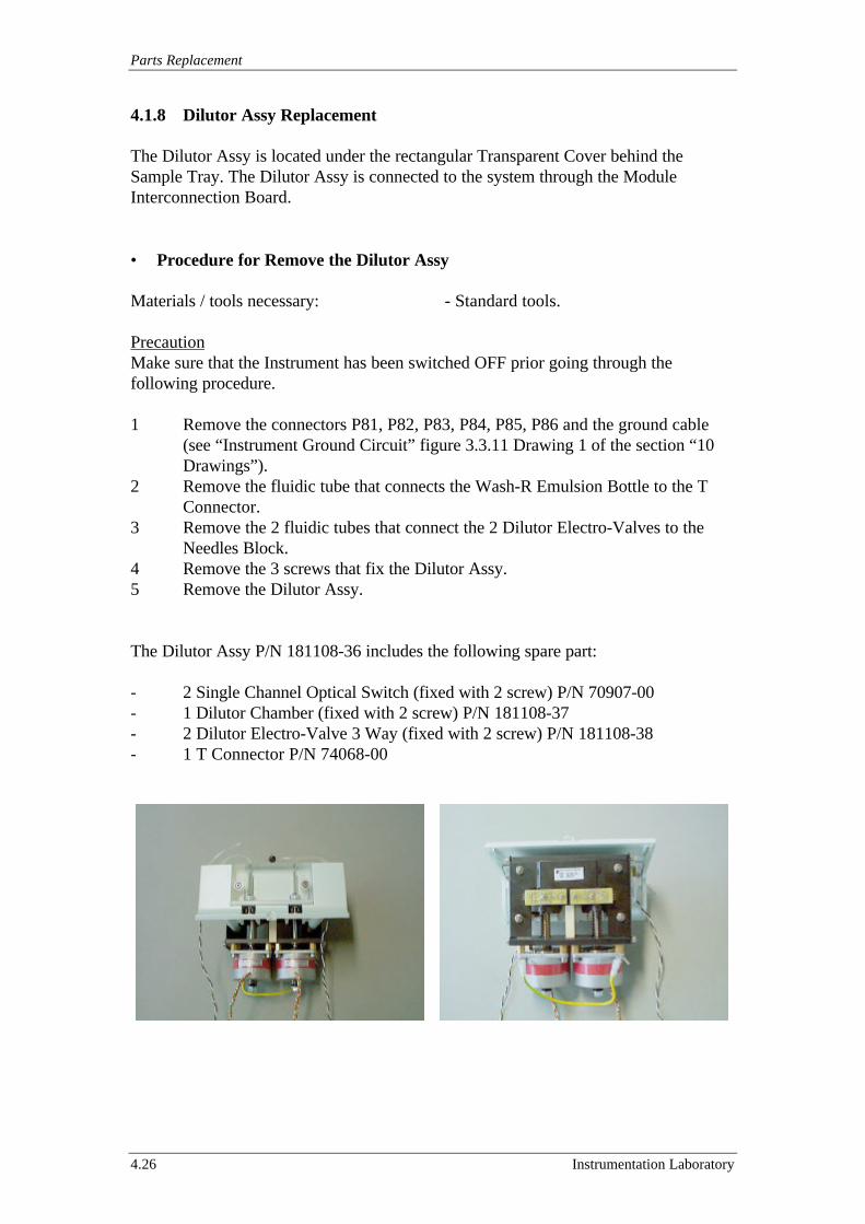
Parts Replacement
4.26 Instrumentation Laboratory
4.1.8 Dilutor Assy Replacement
The Dilutor Assy is located under the rectangular Transparent Cover behind theSample Tray. The Dilutor Assy is connected to the system through the ModuleInterconnection Board.
• Procedure for Remove the Dilutor Assy
Materials / tools necessary: - Standard tools.
PrecautionMake sure that the Instrument has been switched OFF prior going through thefollowing procedure.
1 Remove the connectors P81, P82, P83, P84, P85, P86 and the ground cable(see “Instrument Ground Circuit” figure 3.3.11 Drawing 1 of the section “10Drawings”).
2 Remove the fluidic tube that connects the Wash-R Emulsion Bottle to the TConnector.
3 Remove the 2 fluidic tubes that connect the 2 Dilutor Electro-Valves to theNeedles Block.
4 Remove the 3 screws that fix the Dilutor Assy.5 Remove the Dilutor Assy.
The Dilutor Assy P/N 181108-36 includes the following spare part:
- 2 Single Channel Optical Switch (fixed with 2 screw) P/N 70907-00- 1 Dilutor Chamber (fixed with 2 screw) P/N 181108-37- 2 Dilutor Electro-Valve 3 Way (fixed with 2 screw) P/N 181108-38- 1 T Connector P/N 74068-00
ACL 9000 Service Manual
Instrumentation Laboratory 4.27
• Procedure for Replace the Dilutor Assy
Materials / tools necessary: - Standard tools.
PrecautionMake sure that the Instrument has been switched OFF prior going through thefollowing procedure.
1 Follow in the opposite direction the “Procedure for Remove the Dilutor Assy”.2 Perform the Motor Adjustment tests for the Sample/Reagent Motors as
described in the sub-section 7.6.6.3 Perform the Volume Check and the Dilutor Test as described in “Dilutor
Module” test in the section 7.8.
4.1.9 Display Assembly Replacement
The Display Assembly is located on a flag support over the right side of theInstrument. The Display Assembly is connected to the CPU Master Board and to thePC104 Board through the Display Cable.
• Procedure for Remove the Display Assembly
Materials / tools necessary: - Standard tools.
PrecautionMake sure that the Instrument has been switched OFF prior going through thefollowing procedure.
1 Remove the Cover on the rear of the Display Assembly.2 Remove the Display Cable that is fixed with 2 screws.3 Remove the Display Connector.4 Remove the 8 screws that fix the Display Assembly to the flag paying attention
to hold the Assembly.5 Remove the Display Assembly.
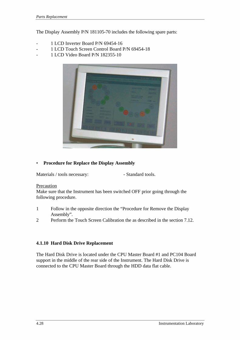
Parts Replacement
4.28 Instrumentation Laboratory
The Display Assembly P/N 181105-70 includes the following spare parts:
- 1 LCD Inverter Board P/N 69454-16- 1 LCD Touch Screen Control Board P/N 69454-18- 1 LCD Video Board P/N 182355-10
• Procedure for Replace the Display Assembly
Materials / tools necessary: - Standard tools.
PrecautionMake sure that the Instrument has been switched OFF prior going through thefollowing procedure.
1 Follow in the opposite direction the “Procedure for Remove the DisplayAssembly”.
2 Perform the Touch Screen Calibration the as described in the section 7.12.
4.1.10 Hard Disk Drive Replacement
The Hard Disk Drive is located under the CPU Master Board #1 and PC104 Boardsupport in the middle of the rear side of the Instrument. The Hard Disk Drive isconnected to the CPU Master Board through the HDD data flat cable.
ACL 9000 Service Manual
Instrumentation Laboratory 4.29
• Procedure for Remove the Hard Disk Drive
Materials / tools necessary: - Standard tools.
PrecautionMake sure that the Instrument has been switched OFF prior going through thefollowing procedure.
1 Remove all the cables connected to the CPU Master Board #1 and PC104Board.
2 Remove the Needles & Wash-R Sensor Interconnection Board support that isfixed with 2 screws.
3 Remove the HDD with the CPU Master Board and the PC104 Board removingthe 2 external screw and loosing the internal 1 screw.
4 Remove the HDD power and data cables connectors.5 Remove the HDD that is fixed with 4 screw.
The Hard Disk Drive P/N 065033-00 doesn’t includes spare parts.
• Procedure for Replace the Hard Disk Drive
Materials / tools necessary: - Standard tools.
PrecautionMake sure that the Instrument has been switched OFF prior going through thefollowing procedure.
1 Follow in the opposite direction the “Procedure for Remove the Hard DiskDrive”.
2 Perform the procedures described in the section 7.16 “Software Checking andLoading”.
Note: In order to completely restore the system status on the new Hard Disk Drive asbefore the replacement of the damaged one, is needed perform the followingoperations.
- Perform the Upload & Upgrade procedures of the Master Software asdescrebed in the sub-section 7.16.2.
- Perform the Upload procedure of the Slave and the R.E.M. Software asdescrebed in the sub-section 7.16.2.
- Perform the Restore procedure of the last Backup of the system configurationavailable descrebed in the sub-section 7.16.4.
- Perform the Upgrade procedure for the IL Library descrebed in the sub-section7.16.5.
Parts Replacement
4.30 Instrumentation Laboratory
4.2 Instrument Covers removing
This section is designed to clarify the Instrument Covers names and positions as well asthem removing / assembling sequence and fixing points.
Following is the Covers lists with the relevant fixing points.
Cover Name Fixing point Note1 Left Side Cover 3 Screws2 Right Side Cover 3 Screws3 Upper Cover 4 Screws
(2 for each side)Remove before the Left &Right Side Covers.
4 Rear Cover 2 Screws(1 for each side + 2 hookshape on the bottom)
Remove before the Left &the Right Side Covers.
5 Front Cover 6 Screws(2 for each side + 2 underthe Front Lower Plate)
Remove before the Left &Right Side Covers.
6 Front Lower Plate 2 Knob Remove before the Left &Right Side Covers and theFront Cover.
7 R.E.M. Cover No screws. Remove with caution the 3fixing points at pressure.
8 ReagentTransparent Cover
3 screws.
9 DilutorsTransparent Cover
No screws. Press with cautions the 2fixing points at pressure.
10 Keyboard Support 4 Screws(2 for each sledge)
The table is according with the drawing “Instrument Covers” reported in the figure 4.2Drawing 1 of the section “10 Drawings”.
ACL 9000 Service Manual
Instrumentation Laboratory 4.31
4.3 Instrument Boards Replacement
This section provides information on the electronic boards located in several placesinside the instrument that compose the electronic system.Following is the board’s list with the proper Check Out & Adjustment required afterboard’s replacement for troubleshooting purposes.
Board Name P/N Check Out & Adjustment Section
CPU Master Board #1 182352-10 Test for functionality.No Adjustment Required.
3.3.4
Slave Board #2 182355-30 Check Software revision.Upgrade SW if requiredTest for functionality.No Adjustment Required.
7.16.17.16.23.3.5
Acquisition & SensorsBoard #3
182355-40 Test for functionality.Coagulimetric Channel CheckOutChromogenic Channel Check OutLiquid Sensors Check OutAutosampler Optic SensorsCheck OutRotor Cover Sensor Check Out
3.3.6
7.2
7.37.4
7.5.37.9.1
Rotor Exchange ModuleBoard #4
182356-00 Check Software revision.Upgrade SW if requiredTest for functionality.REM Optic Sensors Check Out
7.16.17.16.23.3.77.5
Motors Board #5 182355-50 Test for functionality.No Adjustment Required.
3.3.8
Photometric &Temperature ControlBoard #6
182355-60 Test for functionality.Temperatures Check Out.No Adjustment Required.
3.3.97.14
PC104 Board 182355-20 Test for functionality.No Adjustment Required.
3.3.4
Switching Power SupplyBoard
182356-60 Test for functionality.No Adjustment Required.
3.3.10
Interface Board 182355-00 Test for functionality.No Adjustment Required.
7.13
Fan control Board 182356-90 Test for functionality.No Adjustment Required.
7.14
LCD Touch ScreenControl Board
069454-18 Test for functionality.Calibrate Touch Screen ifrequired 7.12
Liquid Level DetectionBoard
182356-40 Test for functionality.No Adjustment Required.
7.4.1
ACL 9000 Service Manual
Instrumentation Laboratory 5.1
5 Installation & Maintenance
This section provides information related to the Instrument installation, asrecommendation for the unpacking and the various set-up procedures necessary to putthe system in working condition, as well as Operator maintenance procedures.Sub-section detailing on Instrument cleaning and decontamination procedures, plusshut down and shipment precautions complete this section.
Following are the specific section with the relevant procedures.
5.1 Installation5.2 Maintenance5.3 Shut down & Shipment precautions
WARNING !
BIOLOGICAL HAZARDS EXIST. Avoid touching, with bare hands, any partsof the system which may have come in contact with potentially infectious fluids.ALWAYS wear gloves when performing any type of Maintenance/Service actionon this area.
As a reminder for the technical personnel, the above warning is also directly shown inthose sub-sections describing the maintenance / cleaning actions on the fluidic lines ofthe Instrument.
Installation & Maintenance
5.2 Instrumentation Laboratory
5.1 Installation
This section contains all the information necessary for install, set-up and put inworking conditions the ACL 9000 system.Before attempting the installation of the ACL 9000 system in the laboratory, inspectthe site with laboratory personnel to identify the desired location for the system and toinsure that the environment meets all the requirements for its successful installation.In addition ensure that the Coagulimetric Optic Test Kit P/N 97580-50 and theChromogenic Optic Test Kit P/N 97579-50 together with the Temperature Probe P/N70954-00 are available.Following are the specific sub-sections.
5.1.1 Site requirements5.1.2 Unpacking and inspection5.1.3 Mounting Instrument parts5.1.4 First turn on cycle5.1.5 Instrument set-up5.1.6 Performance tests5.1.7 ACL 9000 Functionality Check List
Note: The ACL 9000 system must only be installed either by IL personnel or ILauthorised personnel.
5.1.1 Site requirement
Following are the specific paragraph with the required condition to install the ACL9000 system.
5.1.1.a Ambient condition5.1.1.b Space requirements5.1.1.c Electrical requirements
5.1.1.a Ambient Condition
The instrument will function correctly in an ambient temperature of 15-32 °C (59 °F to89 °F) with a relative humidity of up to 85% (non-condensing).In accordance with the IEC regulations no instrument failures will occur in presence ofshort-term ambient temperature as low as 5 °C or as high as 40 °C.The instrument should be positioned in an area free from dust, fumes, vibrations andexcessive variations of temperature.

ACL 9000 Service Manual
Instrumentation Laboratory 5.3
5.1.1.b Space requirements
Following are the external dimensions and the weight of the ACL 9000 analyser.
Height at display level 60 cm 23.6inchesHeight of analysis surface 27 cm 10.6 inchesWidth (including LCD) 100 cm39.4 inchesDepth 60 cm 23.6 inchesWeight 63 Kg 139 lbs.
The heat generated by the instrument during normal operation is exhausted from thebottom, in the front-right and left side of the unit.Sufficient space must be allowed around the instrument to permit circulation of air forcooling.The instrument must be positioned so that a waste tube can be easily connected on itsleft side.If the operator wishes to work from a sitting position in front of the system, leg-spaceshould be provided under the front of the instrument.
5.1.1.c Electrical requirements
• Voltage
The instrument has been designed to operate correctly with variations of ± 10% on thenominal line voltage and with line frequencies between 50-60 Hz.The instrument has a power supply that can operate from 100 to 240 V and itautomatically switches to the line voltage required.
Warning:Check that the nominal line voltage in the laboratory is compatible with the label on therear of the instrument as shown in the table below.
Value as shown on the label Values of line voltage forNormal function
100 – 240 V 100, 110, 115, 120, 125 Vac ±10%220, 230, 240 Vac ±10%
• Power Consumption
Check that the line is capable of supplying 350 VA.
Note: The average power consumption is about 350 VA, but peak loads or currentsurges may exceed this value when turning the instrument on and during thetemperature warm-up.
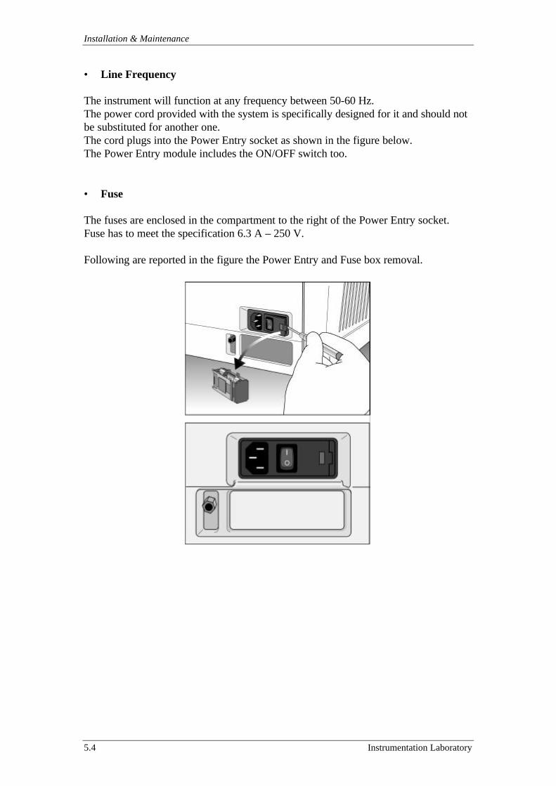
Installation & Maintenance
5.4 Instrumentation Laboratory
• Line Frequency
The instrument will function at any frequency between 50-60 Hz.The power cord provided with the system is specifically designed for it and should notbe substituted for another one.The cord plugs into the Power Entry socket as shown in the figure below.The Power Entry module includes the ON/OFF switch too.
• Fuse
The fuses are enclosed in the compartment to the right of the Power Entry socket.Fuse has to meet the specification 6.3 A – 250 V.
Following are reported in the figure the Power Entry and Fuse box removal.
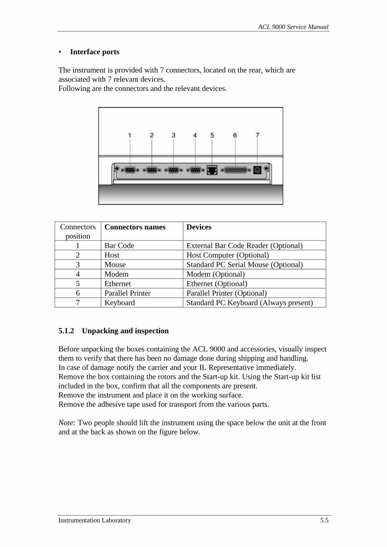
ACL 9000 Service Manual
Instrumentation Laboratory 5.5
• Interface ports
The instrument is provided with 7 connectors, located on the rear, which areassociated with 7 relevant devices.Following are the connectors and the relevant devices.
Connectorsposition
Connectors names Devices
1 Bar Code External Bar Code Reader (Optional)2 Host Host Computer (Optional)3 Mouse Standard PC Serial Mouse (Optional)4 Modem Modem (Optional)5 Ethernet Ethernet (Optional)6 Parallel Printer Parallel Printer (Optional)7 Keyboard Standard PC Keyboard (Always present)
5.1.2 Unpacking and inspection
Before unpacking the boxes containing the ACL 9000 and accessories, visually inspectthem to verify that there has been no damage done during shipping and handling.In case of damage notify the carrier and your IL Representative immediately.Remove the box containing the rotors and the Start-up kit. Using the Start-up kit listincluded in the box, confirm that all the components are present.Remove the instrument and place it on the working surface.Remove the adhesive tape used for transport from the various parts.
Note: Two people should lift the instrument using the space below the unit at the frontand at the back as shown on the figure below.
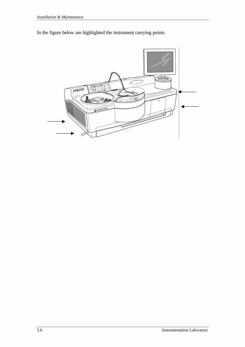
Installation & Maintenance
5.6 Instrumentation Laboratory
In the figure below are highlighted the instrument carrying points
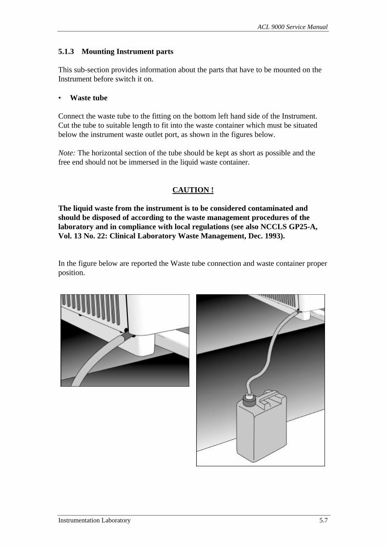
ACL 9000 Service Manual
Instrumentation Laboratory 5.7
5.1.3 Mounting Instrument parts
This sub-section provides information about the parts that have to be mounted on theInstrument before switch it on.
• Waste tube
Connect the waste tube to the fitting on the bottom left hand side of the Instrument.Cut the tube to suitable length to fit into the waste container which must be situatedbelow the instrument waste outlet port, as shown in the figures below.
Note: The horizontal section of the tube should be kept as short as possible and thefree end should not be immersed in the liquid waste container.
CAUTION !
The liquid waste from the instrument is to be considered contaminated andshould be disposed of according to the waste management procedures of thelaboratory and in compliance with local regulations (see also NCCLS GP25-A,Vol. 13 No. 22: Clinical Laboratory Waste Management, Dec. 1993).
In the figure below are reported the Waste tube connection and waste container properposition.
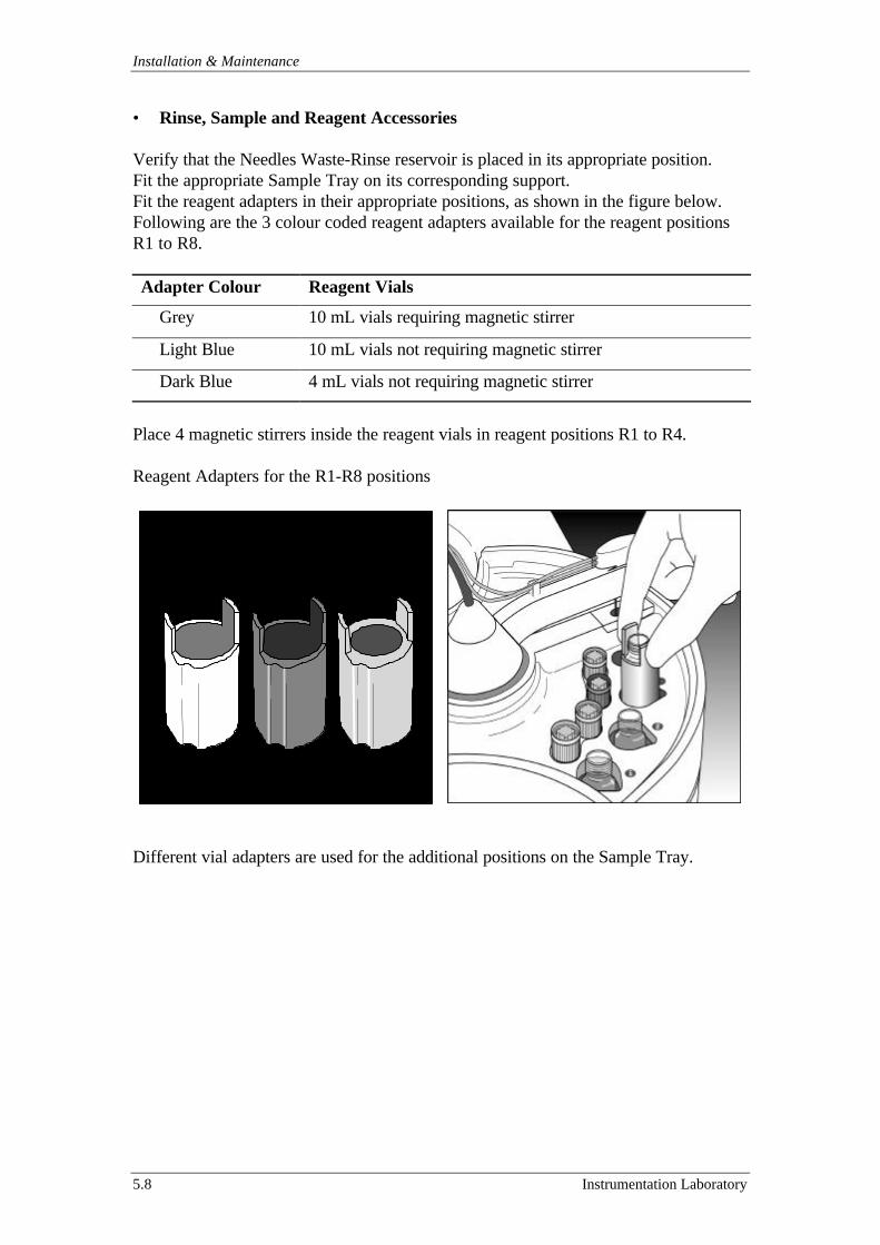
Installation & Maintenance
5.8 Instrumentation Laboratory
• Rinse, Sample and Reagent Accessories
Verify that the Needles Waste-Rinse reservoir is placed in its appropriate position.Fit the appropriate Sample Tray on its corresponding support.Fit the reagent adapters in their appropriate positions, as shown in the figure below.Following are the 3 colour coded reagent adapters available for the reagent positionsR1 to R8.
Adapter Colour Reagent Vials
Grey 10 mL vials requiring magnetic stirrer
Light Blue 10 mL vials not requiring magnetic stirrer
Dark Blue 4 mL vials not requiring magnetic stirrer
Place 4 magnetic stirrers inside the reagent vials in reagent positions R1 to R4.
Reagent Adapters for the R1-R8 positions
Different vial adapters are used for the additional positions on the Sample Tray.
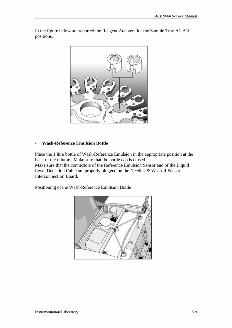
ACL 9000 Service Manual
Instrumentation Laboratory 5.9
In the figure below are reported the Reagent Adapters for the Sample Tray A1-A10positions.
• Wash-Reference Emulsion Bottle
Place the 1 litre bottle of Wash-Reference Emulsion in the appropriate position at theback of the dilutors. Make sure that the bottle cap is closed.Make sure that the connectors of the Reference Emulsion Sensor and of the LiquidLevel Detection Cable are properly plugged on the Needles & Wash-R SensorInterconnection Board.
Positioning of the Wash-Reference Emulsion Bottle
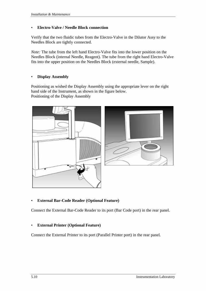
Installation & Maintenance
5.10 Instrumentation Laboratory
• Electro-Valve / Needle Block connection
Verify that the two fluidic tubes from the Electro-Valve in the Dilutor Assy to theNeedles Block are tightly connected.
Note: The tube from the left hand Electro-Valve fits into the lower position on theNeedles Block (internal Needle, Reagent). The tube from the right hand Electro-Valvefits into the upper position on the Needles Block (external needle, Sample).
• Display Assembly
Positioning as wished the Display Assembly using the appropriate lever on the righthand side of the Instrument, as shown in the figure below.Positioning of the Display Assembly
• External Bar-Code Reader (Optional Feature)
Connect the External Bar-Code Reader to its port (Bar Code port) in the rear panel.
• External Printer (Optional Feature)
Connect the External Printer to its port (Parallel Printer port) in the rear panel.
ACL 9000 Service Manual
Instrumentation Laboratory 5.11
5.1.4 First turn on cycle
Before turning the Instrument on, check that the line voltage setting of the laboratoryis in accordance with the Instrument label.Switch the Instrument on using the Power Switch on the Power Entry.The system initialises the Instrument with a series of electronics and mechanics self-checks. During this initialisation check that the Sample Arm, the Rotor Arm and theRotor Cover may be free to move without obstruction.Following are some of messages showed during the System Init phase.
ACL Starting. Please wait…
Checking Database……Check Ok. Continuing Init.
The Init System phase continue with a progress bar in a window where is wrote
Init System in Progress. Please Wait.
When the progress bar is full and all the sequence of self-checks is ended, then theLogin window appears.
- Touching the USER window it goes in reverse mode.- Press “Del” (Delete Key) on the main Keyboard, the window becomes empty.- Type the word “Service” (with capital S).- Touching the PASSWORD window it goes in reverse mode.- Type the word “ACL fix” (with capital ACL) then confirm touching “V”.
The system shows the main Analytical Menu’.
Touch Utility on the Main Menu’ Bar then the Software and the SoftwareIdentification option. Checks that in the SW Identification screen all the softwarehave been the last revision. The last software revision is also present in the InstrumentStart Up Kit.
Check for Magnetic Stirrer bar rotation in the R1 – R4 reagents positions.
Note: Any temperature and liquid level sensors warning may be present. In this casethe yellow Warning button on the Tool Bar is active.
Touch Setup on the Main Menu Bar then the Date/Time option. Choose the dateformat and set the current date and time. Press “V” to accept.
Mounting (if needed) the Needles Block and then perform/verify the Needle Positionprocedure as described in the sub-section 7.7.4.
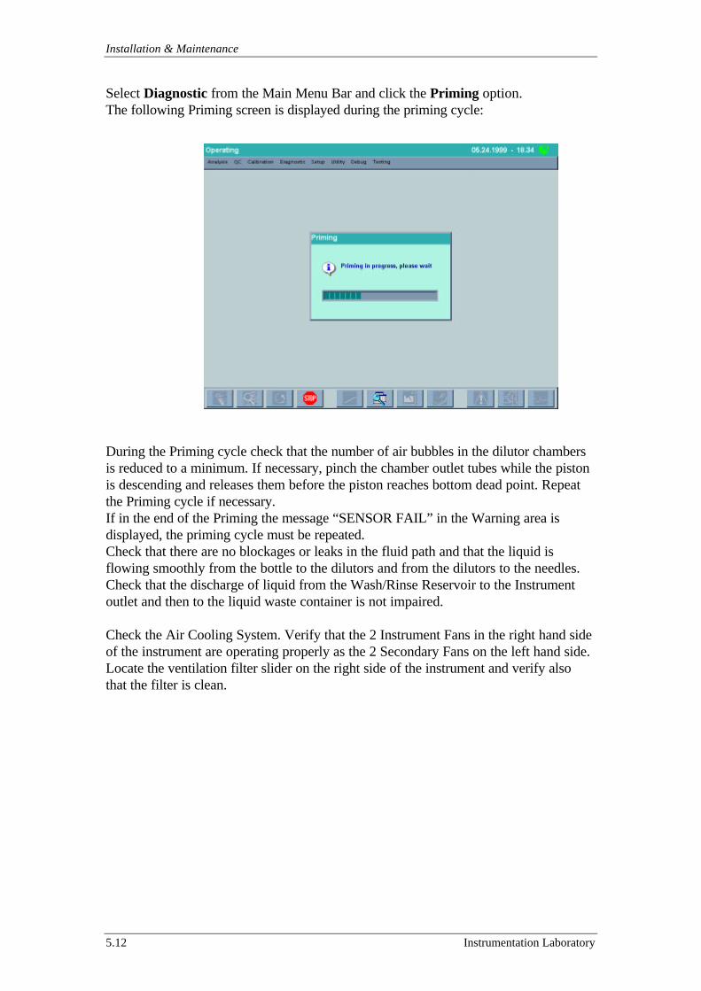
Installation & Maintenance
5.12 Instrumentation Laboratory
Select Diagnostic from the Main Menu Bar and click the Priming option.The following Priming screen is displayed during the priming cycle:
During the Priming cycle check that the number of air bubbles in the dilutor chambersis reduced to a minimum. If necessary, pinch the chamber outlet tubes while the pistonis descending and releases them before the piston reaches bottom dead point. Repeatthe Priming cycle if necessary.If in the end of the Priming the message “SENSOR FAIL” in the Warning area isdisplayed, the priming cycle must be repeated.Check that there are no blockages or leaks in the fluid path and that the liquid isflowing smoothly from the bottle to the dilutors and from the dilutors to the needles.Check that the discharge of liquid from the Wash/Rinse Reservoir to the Instrumentoutlet and then to the liquid waste container is not impaired.
Check the Air Cooling System. Verify that the 2 Instrument Fans in the right hand sideof the instrument are operating properly as the 2 Secondary Fans on the left hand side.Locate the ventilation filter slider on the right side of the instrument and verify alsothat the filter is clean.
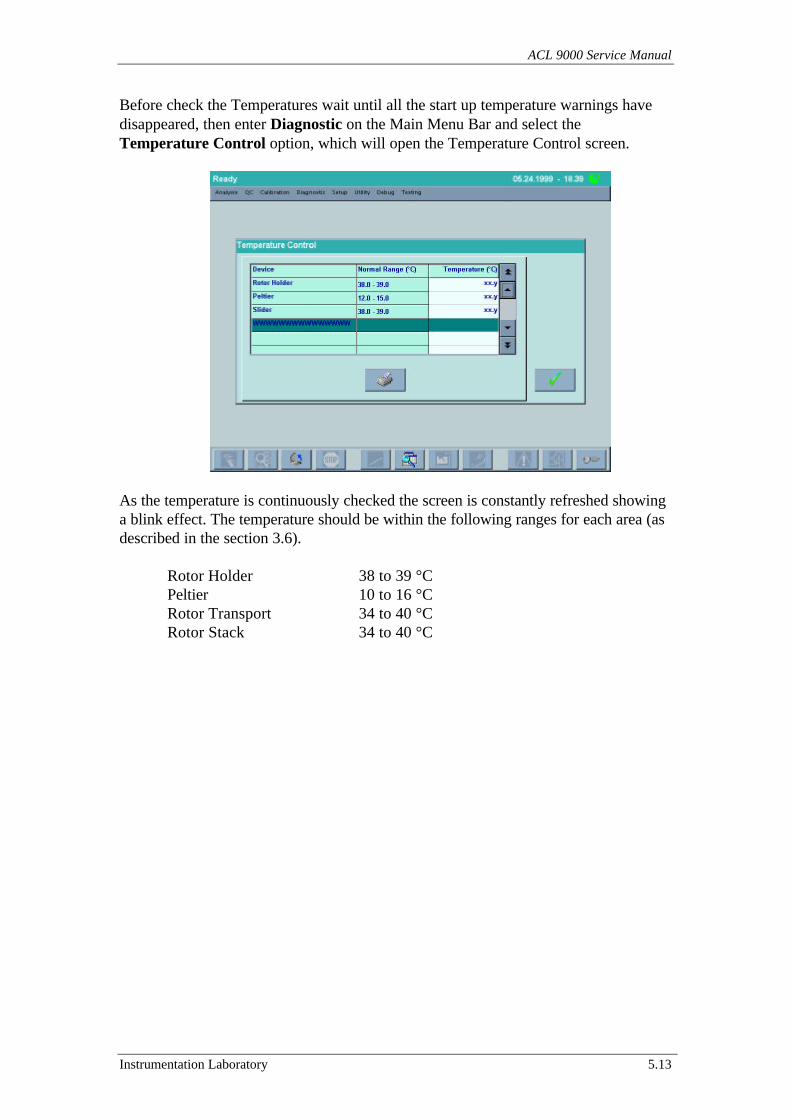
ACL 9000 Service Manual
Instrumentation Laboratory 5.13
Before check the Temperatures wait until all the start up temperature warnings havedisappeared, then enter Diagnostic on the Main Menu Bar and select theTemperature Control option, which will open the Temperature Control screen.
As the temperature is continuously checked the screen is constantly refreshed showinga blink effect. The temperature should be within the following ranges for each area (asdescribed in the section 3.6).
Rotor Holder 38 to 39 °CPeltier 10 to 16 °CRotor Transport 34 to 40 °CRotor Stack 34 to 40 °C
Installation & Maintenance
5.14 Instrumentation Laboratory
5.1.5 Instrument Setup
The purpose of this sub-section is to verify that all the main Setup option has beenalready set or otherwise to help the customer to make his owner setup.
Select Setup from the Main Menu Bar then set the following options.
System ConfigurationPatient Database listingQC Database listingReflex StatusCurrent languageSample Tray typeSensor EnableHW enable
Date / TimeUnit
5.1.6 Performance tests
The following test, which we recommend be carried out at the installation, check theprecision and the linearity of the two Optic Channel as well as the precision and theaccuracy of the dilutors.
Perform a Priming cycle then check the Optic Channel precision and accuracy asdescribed in the sub-sections 7.2.2 (for Coagulimetric) and 7.3.2 (for Chromogenic).
Perform a Priming cycle then check the Dilutors precision as described in the sub-section 7.8.1 (for Coagulimetric and Chromogenic Channel).
Perform a Priming cycle then carry out the PT-FIB calibration cycle as described in theOperator’s Manual.
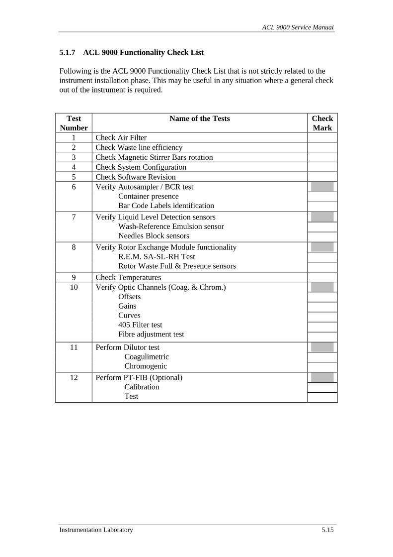
ACL 9000 Service Manual
Instrumentation Laboratory 5.15
5.1.7 ACL 9000 Functionality Check List
Following is the ACL 9000 Functionality Check List that is not strictly related to theinstrument installation phase. This may be useful in any situation where a general checkout of the instrument is required.
TestNumber
Name of the Tests CheckMark
1 Check Air Filter2 Check Waste line efficiency3 Check Magnetic Stirrer Bars rotation4 Check System Configuration5 Check Software Revision6 Verify Autosampler / BCR test
Container presence Bar Code Labels identification
7 Verify Liquid Level Detection sensors Wash-Reference Emulsion sensor Needles Block sensors
8 Verify Rotor Exchange Module functionality R.E.M. SA-SL-RH Test Rotor Waste Full & Presence sensors
9 Check Temperatures10 Verify Optic Channels (Coag. & Chrom.)
Offsets Gains Curves 405 Filter test Fibre adjustment test
11 Perform Dilutor test Coagulimetric Chromogenic
12 Perform PT-FIB (Optional) Calibration Test
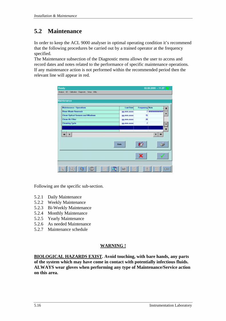
Installation & Maintenance
5.16 Instrumentation Laboratory
5.2 Maintenance
In order to keep the ACL 9000 analyser in optimal operating condition it’s recommendthat the following procedures be carried out by a trained operator at the frequencyspecified.The Maintenance subsection of the Diagnostic menu allows the user to access andrecord dates and notes related to the performance of specific maintenance operations.If any maintenance action is not performed within the recommended period then therelevant line will appear in red.
Following are the specific sub-section.
5.2.1 Daily Maintenance5.2.2 Weekly Maintenance5.2.3 Bi-Weekly Maintenance5.2.4 Monthly Maintenance5.2.5 Yearly Maintenance5.2.6 As needed Maintenance5.2.7 Maintenance schedule
WARNING !
BIOLOGICAL HAZARDS EXIST. Avoid touching, with bare hands, any partsof the system which may have come in contact with potentially infectious fluids.ALWAYS wear gloves when performing any type of Maintenance/Service actionon this area.
ACL 9000 Service Manual
Instrumentation Laboratory 5.17
5.2.1 Daily Maintenance
At the beginning and at the end of each working day perform a Priming cycle to ensurethe complete removal of all sample or reagent residual along the fluidic paths.While the priming cycle is in progress, the operator should visually inspect three items:
• That number of bubbles in the Dilutor Chamber reduces to minimum. If bubbles arestill present, pinch the chamber outlet tubes while the piston is descending andreleases them before the piston reaches the bottom dead center. Repeat the primingcycle as needed until all bubbles are gone.
• That there are no blockages or leaks in the liquid flow path and the liquid isflowing smoothly from reservoir to dilutors and from dilutors to needles.
• That there is free flow of the liquid waste from the washing chamber to theinstrument outlet tube and then to the waste container (check the liquid level in thewaste container).
Note: The Instrument is provided of sensors to detect the availability of WashReference Emulsion as well as new and used rotors. In order to start the working daywith the maximum of Instrument autonomy it’s advisable to empty the Rotor WasteContainer from used rotors, fill the Rotor Stack with brand new rotors and check thelevel of the Wash Reference Emulsion in the bottle.
Installation & Maintenance
5.18 Instrumentation Laboratory
5.2.2 Weekly Maintenance
The weekly preventive maintenance for the ACL consists in cleaning all the keyinstrument areas which normally come in contact with sample and reagents andtherefore accumulate residues that will, if allowed to build up, impair the instrumentfunctionality and affect the tests results. The parts / areas to be cleaned are:
• Instrument exposed surfaces.
• The Needle Block.
• The Rinse / Waste reservoir.
WARNING !
BIOLOGICAL HAZARDS EXIST. Avoid touching, with bare hands, any partsof the system which may have come in contact with potentially infectious fluids.ALWAYS wear gloves when performing any type of Maintenance/Service actionon this area.
• Instrument exposed surfaces
Wipe down all exposed surfaces of the analyser body, the inside of the Autosamplercompartment and the Rotor compartment (excluding the rotor holder) using a clothsoaked in a 0.1 N Hydrochloric Acid (HCl) solution (IL Cleaning Solution P/N 98317-00). Rinse using a cloth soaked in distilled water. Wipe dry.
• The Needle Block
Place 2 glass vials with 4 mL of 0.1 N HCl solution in reagent positions R6 and R7Click the Diagnostic button on the Main menu bar and select the Cleaning option ofthe Diagnostic submenu to display the Cleaning screen.In this screen the operator defines the configuration of the cleaning operation,according to the needs of the instrument.Clicking the Start button starts the cleaning cycle and opens a window displaying a barthat moves to show the elapsed time of the procedure.
• The Rinse / Waste reservoir
Remove the Rinse / Waste reservoir, wash it thoroughly with 0.1N HCl solution (ILCleaning Solution P/N 98317-00) and rinse it with distilled water.
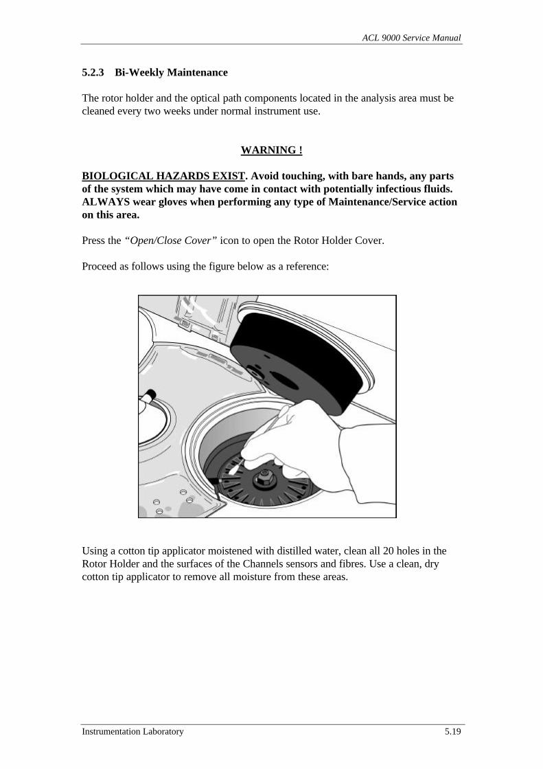
ACL 9000 Service Manual
Instrumentation Laboratory 5.19
5.2.3 Bi-Weekly Maintenance
The rotor holder and the optical path components located in the analysis area must becleaned every two weeks under normal instrument use.
WARNING !
BIOLOGICAL HAZARDS EXIST. Avoid touching, with bare hands, any partsof the system which may have come in contact with potentially infectious fluids.ALWAYS wear gloves when performing any type of Maintenance/Service actionon this area.
Press the “Open/Close Cover” icon to open the Rotor Holder Cover.
Proceed as follows using the figure below as a reference:
Using a cotton tip applicator moistened with distilled water, clean all 20 holes in theRotor Holder and the surfaces of the Channels sensors and fibres. Use a clean, drycotton tip applicator to remove all moisture from these areas.
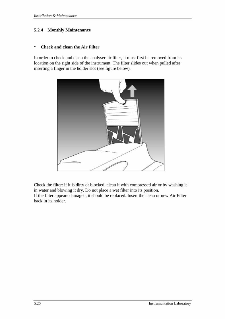
Installation & Maintenance
5.20 Instrumentation Laboratory
5.2.4 Monthly Maintenance
• Check and clean the Air Filter
In order to check and clean the analyser air filter, it must first be removed from itslocation on the right side of the instrument. The filter slides out when pulled afterinserting a finger in the holder slot (see figure below).
Check the filter: if it is dirty or blocked, clean it with compressed air or by washing itin water and blowing it dry. Do not place a wet filter into its position.If the filter appears damaged, it should be replaced. Insert the clean or new Air Filterback in its holder.

ACL 9000 Service Manual
Instrumentation Laboratory 5.21
5.2.5 Yearly Maintenance
The yearly preventive maintenance for the ACL consists in replacing the wearexpandable parts.
• Replace the Air Filter
• Replace the sample and reagent tubes
• Replace the Needle Block (see sub-section 5.2.6)
• Replace the waste tube
• Replace the Rinse/Waste Reservoir
WARNING !
BIOLOGICAL HAZARDS EXIST. Avoid touching, with bare hands, any partsof the system which may have come in contact with potentially infectious fluids.ALWAYS wear gloves when performing any type of Maintenance/Service actionon this area.
5.2.6 As needed Maintenance
WARNING !
BIOLOGICAL HAZARDS EXIST. Avoid touching, with bare hands, any partsof the system which may have come in contact with potentially infectious fluids.ALWAYS wear gloves when performing any type of Maintenance/Service actionon this area.
• Waste Line Cleaning Procedure
The waste line cleaning procedure is performed to prevent formation of clots or toclean any possible blockages (due to clotting) in the waste line. The frequency withwhich this procedure should be done depends on the daily workload.
Materials / Tools needed: - 20 mL plastic syringe- 20 cm of PVC tube, 4 mm ID, 6 mm OD.- 20 mL of distilled water.
1 Remove the needle from the plastic syringe (if necessary), and fit the PVC tubeon the end on the syringe (the tube’s dimensions must be such that it will fitonto the syringe on one end and into the waste line at the other end).
2 Fill the syringe with distilled water.3 Remove the Rinse / Waste Reservoir and clean it if necessary (refer to Section
5.2.2).
Installation & Maintenance
5.22 Instrumentation Laboratory
4 Insert the free end of the PVC tube into the waste line, carefully inject thedistilled water into the waste line and check that the liquid flows out from theexternal waste line of the instrument to the waste container.
5 Repeat the procedure several times to ensure removal of any potential blockagethen replace the Rinse / Waste reservoir.
• Cleaning of Sample Spillage
In case of sample / reagent spillage wipe using a clean cloth or cotton tip applicatorsoaked in a 0.1N HCl solution (IL Cleaning Solution P/N 98317-00). Follow withdistilled water and dry with a clean cloth or cotton tip applicator.In case of sample / reagent spillage in the Autosampler or in the Rotor Holdercompartment, it may be required to clean also the 2 sensors in the Autosampler and thetwo optical paths in the analysis area (see sub-section 5.2.3).
• Needles Block replacing and positioning
Press the “Open/Close Cover” icon to open the Rotor Cover.Click “Diagnostic” on the Main menu bar and select “Needles Position”. The SampleArm moves over the Rotor Holder.Loosen the white knob on the back of the Sample Arm, disconnect the tubing and theLiquid Sensor Cable and remove the Needle Block.Insert the new Needle Block, connect the sensor cable and the two tubing and positionthe block higher than the arm’s top surface.
Follow the Needles Block Assy positioning procedure as described in the sub-section7.7.4.
ACL 9000 Service Manual
Instrumentation Laboratory 5.23
• Needles Block decontamination procedure
This sub-section describes the procedure to decontaminate the ACL Needles Block.It’s recommended after using the system to test a highly infectious sample and as ageneral precaution to prevent and eliminate potential bacterial contamination.
The use of the ACL system for the analysis of known or suspected highly infectioussamples, should be followed by careful disinfecting of the instrument surfaces and partswhich have been in contact with the samples. The disinfecting agent used to performthe procedure indicated below is a 1:8 dilution of IL Cleaning Agent P/N 98327-00,which is a solution of sodium hypochlorite with a concentration of less than 0.625% ofavailable chlorine. The 1:8 diluted solution is prepared by mixing 1 part CleaningAgent with 7 parts of distilled water.
WARNING !
Use only IL Cleaning Agent (P/N 98327-00) diluted 1:8 with distilled water.The use of undiluted IL Cleaning Agent may cause corrosion of metal parts.
Materials / Tools needed: - 2 glass 10 mL vials- IL Cleaning Agent P/N 98327-00- Distilled water
Prepare approximately 16 mL of diluted Cleaning Agent solution (mix 2 part of ILCleaning Agent and 14 parts distilled water).Load the ACL reagent position R6 and R7 with the 2 glass vials filled with 8 mL of theprepared diluted Cleaning Agent solutionPress “Diagnostic” on the Main menu bar, select “Cleaning” and then press “Start”.At the end of the cleaning cycle remove the vials in position R6 and R7 and perform aPriming cycle.Replace the external waste tube and the waste container.
CAUTION !
The discarded items must be placed in an appropriate container for furtherincineration, according to proper local regulations.In the case of suspected severe contamination, replace the tubing and discard theold one in an appropriate container for further incineration, according to properlocal regulations
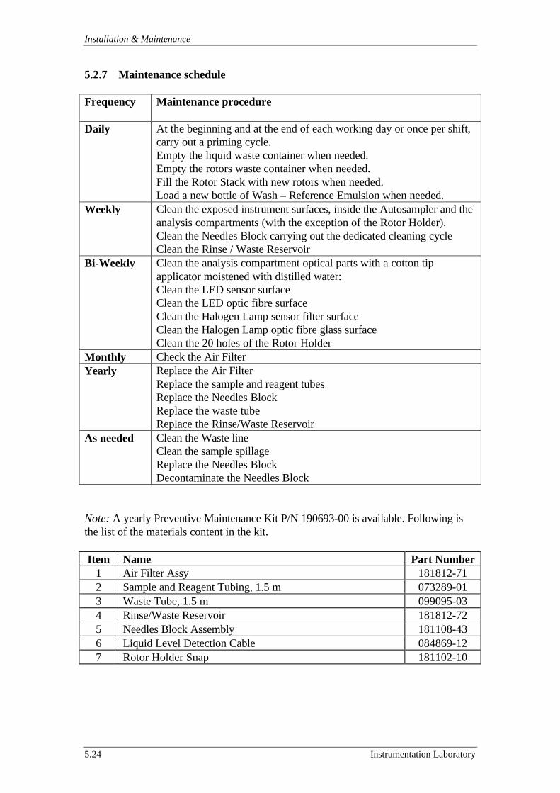
Installation & Maintenance
5.24 Instrumentation Laboratory
5.2.7 Maintenance schedule
Frequency Maintenance procedure
Daily At the beginning and at the end of each working day or once per shift,carry out a priming cycle.Empty the liquid waste container when needed.Empty the rotors waste container when needed.Fill the Rotor Stack with new rotors when needed.Load a new bottle of Wash – Reference Emulsion when needed.
Weekly Clean the exposed instrument surfaces, inside the Autosampler and theanalysis compartments (with the exception of the Rotor Holder).Clean the Needles Block carrying out the dedicated cleaning cycleClean the Rinse / Waste Reservoir
Bi-Weekly Clean the analysis compartment optical parts with a cotton tipapplicator moistened with distilled water:Clean the LED sensor surfaceClean the LED optic fibre surfaceClean the Halogen Lamp sensor filter surfaceClean the Halogen Lamp optic fibre glass surfaceClean the 20 holes of the Rotor Holder
Monthly Check the Air FilterYearly Replace the Air Filter
Replace the sample and reagent tubesReplace the Needles BlockReplace the waste tubeReplace the Rinse/Waste Reservoir
As needed Clean the Waste lineClean the sample spillageReplace the Needles BlockDecontaminate the Needles Block
Note: A yearly Preventive Maintenance Kit P/N 190693-00 is available. Following isthe list of the materials content in the kit.
Item Name Part Number1 Air Filter Assy 181812-712 Sample and Reagent Tubing, 1.5 m 073289-013 Waste Tube, 1.5 m 099095-034 Rinse/Waste Reservoir 181812-725 Needles Block Assembly 181108-436 Liquid Level Detection Cable 084869-127 Rotor Holder Snap 181102-10
ACL 9000 Service Manual
Instrumentation Laboratory 5.25
5.3 Shut down & Shipment precautions
This section give some suggestions in case of long term shut down or shipment of theinstrument.The following procedures describe how to prepare the ACL before a shut down or ashipment.
5.3.1 Long term shut down5.3.2 Shipment
5.3.1 Long term shut down
For long period of inactivity, more than one week, the following actions should becarried out.
1 Perform a Priming cycle by selecting “Priming” in the “Diagnostic” menu’.2 Remove any container on board the instrument.3 Empty the Rotor Waste Container.4 Remove and close the Wash – Reference Emulsion bottle.5 Empty the fluidic tubes by performing another Priming cycle.6 Close the Wash – Reference Emulsion aspiration tube with adhesive tape.7 Log-out and switch the instrument Off.8 Empty and remove the waste tube and the waste container.9 Disconnect the ACL system electrically from the main power, removing the
Power Cord from the rear of the instrument and from the main line.10 Cover the instrument with a dust cover.
5.3.2 Shipment
In case of shipment, carry out the following actions.
1 Perform the actions suggested in the sub-section 5.3.1.2 Remove the Needles Block, wash it with IL Cleaning Solution P/N 98317-00
and rinse with distilled water. Pack it separately.3 Remove and pack separately also all the other accessories (Sample Tray,
Adapters, Keyboard etc…).4 Fix with adhesive tape all the parts that could be moving during the transport
(Sample Arm, Rotor Cover, Rotor Stack Cover, Rotor Waste CompartmentPanel etc…).
5 Close with adhesive tape the waste outlet tube on the left side of theinstrument.
6 If the original packing is not available is recommended that a suitable box toisolate the instrument from any external impact to be used (paying particularattention to the Display Assembly). In this case pack all the accessories inanother box, separately.
ACL 9000 Service Manual
Instrumentation Laboratory 6.1
6 Troubleshooting
This section is designed to provide at Service Engineer information about the errormessages displayed by the instrument as well as suggestions and tools to fix theproblem during the Instrument Troubleshooting.
Following are the specific sections.
6.1 Error Messages & Troubleshooting6.2 Service Tools6.3 Standard Tools
6.1 Error Messages and Troubleshooting
This section provides information about instrument error conditions and specific errorsdisplayed by the instrument.
Following are the specific sub-section for each category of problem.
6.1.1 System errors6.1.2 Temperature errors6.1.3 Mechanical errors6.1.4 R.E.M. error6.1.5 Optic errors6.1.6 Acquisition errors6.1.7 Liquid sensors errors6.1.8 Operative error6.1.9 Database errors6.1.10 Sample identification errors6.1.11 DMS errors6.1.12 Analytical errors
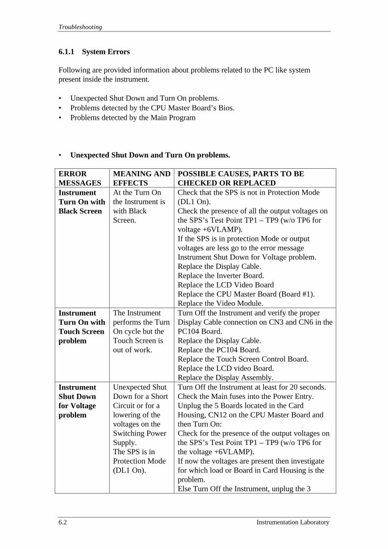
Troubleshooting
6.2 Instrumentation Laboratory
6.1.1 System Errors
Following are provided information about problems related to the PC like systempresent inside the instrument.
• Unexpected Shut Down and Turn On problems.• Problems detected by the CPU Master Board’s Bios.• Problems detected by the Main Program
• Unexpected Shut Down and Turn On problems.
ERRORMESSAGES
MEANING ANDEFFECTS
POSSIBLE CAUSES, PARTS TO BECHECKED OR REPLACED
InstrumentTurn On withBlack Screen
At the Turn Onthe Instrument iswith BlackScreen.
Check that the SPS is not in Protection Mode(DL1 On).Check the presence of all the output voltages onthe SPS’s Test Point TP1 – TP9 (w/o TP6 forvoltage +6VLAMP).If the SPS is in protection Mode or outputvoltages are less go to the error messageInstrument Shut Down for Voltage problem.Replace the Display Cable.Replace the Inverter Board.Replace the LCD Video BoardReplace the CPU Master Board (Board #1).Replace the Video Module.
InstrumentTurn On withTouch Screenproblem
The Instrumentperforms the TurnOn cycle but theTouch Screen isout of work.
Turn Off the Instrument and verify the properDisplay Cable connection on CN3 and CN6 in thePC104 Board.Replace the Display Cable.Replace the PC104 Board.Replace the Touch Screen Control Board.Replace the LCD video Board.Replace the Display Assembly.
InstrumentShut Downfor Voltageproblem
Unexpected ShutDown for a ShortCircuit or for alowering of thevoltages on theSwitching PowerSupply.The SPS is inProtection Mode(DL1 On).
Turn Off the Instrument at least for 20 seconds.Check the Main fuses into the Power Entry.Unplug the 5 Boards located in the CardHousing, CN12 on the CPU Master Board andthen Turn On:Check for the presence of the output voltages onthe SPS’s Test Point TP1 – TP9 (w/o TP6 forthe voltage +6VLAMP).If now the voltages are present then investigatefor which load or Board in Card Housing is theproblem.Else Turn Off the Instrument, unplug the 3
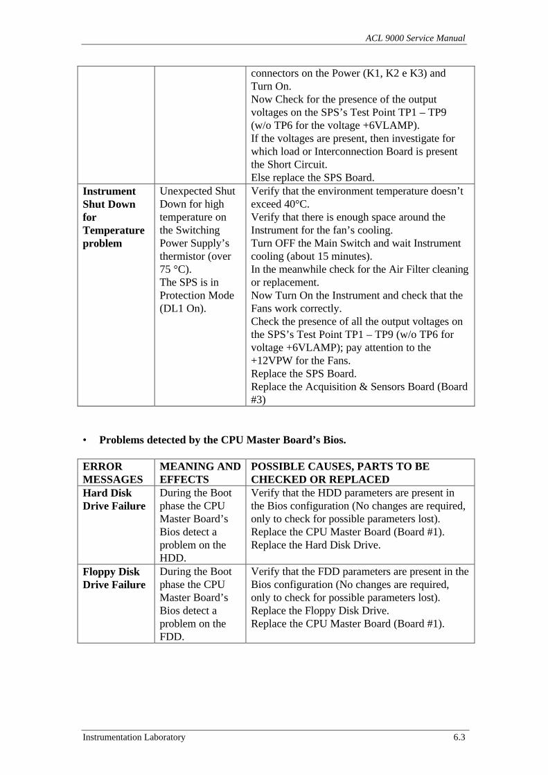
ACL 9000 Service Manual
Instrumentation Laboratory 6.3
connectors on the Power (K1, K2 e K3) andTurn On.Now Check for the presence of the outputvoltages on the SPS’s Test Point TP1 – TP9(w/o TP6 for the voltage +6VLAMP).If the voltages are present, then investigate forwhich load or Interconnection Board is presentthe Short Circuit.Else replace the SPS Board.
InstrumentShut DownforTemperatureproblem
Unexpected ShutDown for hightemperature onthe SwitchingPower Supply’sthermistor (over75 °C).The SPS is inProtection Mode(DL1 On).
Verify that the environment temperature doesn’texceed 40°C.Verify that there is enough space around theInstrument for the fan’s cooling.Turn OFF the Main Switch and wait Instrumentcooling (about 15 minutes).In the meanwhile check for the Air Filter cleaningor replacement.Now Turn On the Instrument and check that theFans work correctly.Check the presence of all the output voltages onthe SPS’s Test Point TP1 – TP9 (w/o TP6 forvoltage +6VLAMP); pay attention to the+12VPW for the Fans.Replace the SPS Board.Replace the Acquisition & Sensors Board (Board#3)
• Problems detected by the CPU Master Board’s Bios.
ERRORMESSAGES
MEANING ANDEFFECTS
POSSIBLE CAUSES, PARTS TO BECHECKED OR REPLACED
Hard DiskDrive Failure
During the Bootphase the CPUMaster Board’sBios detect aproblem on theHDD.
Verify that the HDD parameters are present inthe Bios configuration (No changes are required,only to check for possible parameters lost).Replace the CPU Master Board (Board #1).Replace the Hard Disk Drive.
Floppy DiskDrive Failure
During the Bootphase the CPUMaster Board’sBios detect aproblem on theFDD.
Verify that the FDD parameters are present in theBios configuration (No changes are required,only to check for possible parameters lost).Replace the Floppy Disk Drive.Replace the CPU Master Board (Board #1).
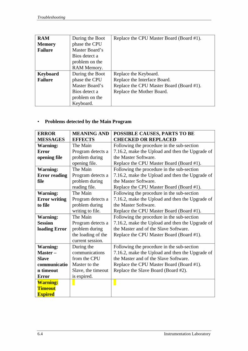
Troubleshooting
6.4 Instrumentation Laboratory
RAMMemoryFailure
During the Bootphase the CPUMaster Board’sBios detect aproblem on theRAM Memory.
Replace the CPU Master Board (Board #1).
KeyboardFailure
During the Bootphase the CPUMaster Board’sBios detect aproblem on theKeyboard.
Replace the Keyboard.Replace the Interface Board.Replace the CPU Master Board (Board #1).Replace the Mother Board.
• Problems detected by the Main Program
ERRORMESSAGES
MEANING ANDEFFECTS
POSSIBLE CAUSES, PARTS TO BECHECKED OR REPLACED
Warning:Erroropening file
The MainProgram detects aproblem duringopening file.
Following the procedure in the sub-section7.16.2, make the Upload and then the Upgrade ofthe Master Software.Replace the CPU Master Board (Board #1).
Warning:Error readingfile
The MainProgram detects aproblem duringreading file.
Following the procedure in the sub-section7.16.2, make the Upload and then the Upgrade ofthe Master Software.Replace the CPU Master Board (Board #1).
Warning:Error writingto file
The MainProgram detects aproblem duringwriting to file.
Following the procedure in the sub-section7.16.2, make the Upload and then the Upgrade ofthe Master Software.Replace the CPU Master Board (Board #1).
Warning:Sessionloading Error
The MainProgram detects aproblem duringthe loading of thecurrent session.
Following the procedure in the sub-section7.16.2, make the Upload and then the Upgrade ofthe Master and of the Slave Software.Replace the CPU Master Board (Board #1).
Warning:Master –Slavecommunication timeoutError
During thecommunicationsfrom the CPUMaster to theSlave, the timeoutis expired.
Following the procedure in the sub-section7.16.2, make the Upload and then the Upgrade ofthe Master and of the Slave Software.Replace the CPU Master Board (Board #1).Replace the Slave Board (Board #2).
Warning:TimeoutExpired
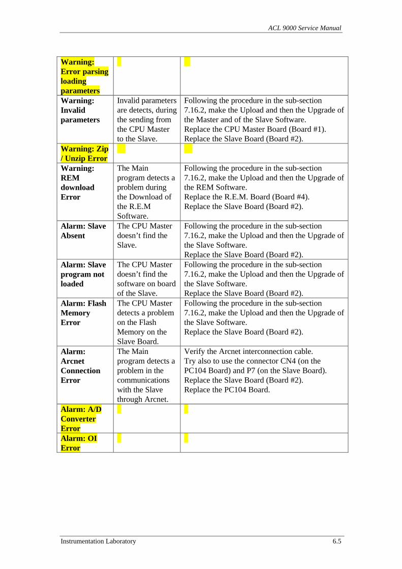
ACL 9000 Service Manual
Instrumentation Laboratory 6.5
Warning:Error parsingloadingparametersWarning:Invalidparameters
Invalid parametersare detects, duringthe sending fromthe CPU Masterto the Slave.
Following the procedure in the sub-section7.16.2, make the Upload and then the Upgrade ofthe Master and of the Slave Software.Replace the CPU Master Board (Board #1).Replace the Slave Board (Board #2).
Warning: Zip/ Unzip ErrorWarning:REMdownloadError
The Mainprogram detects aproblem duringthe Download ofthe R.E.MSoftware.
Following the procedure in the sub-section7.16.2, make the Upload and then the Upgrade ofthe REM Software.Replace the R.E.M. Board (Board #4).Replace the Slave Board (Board #2).
Alarm: SlaveAbsent
The CPU Masterdoesn’t find theSlave.
Following the procedure in the sub-section7.16.2, make the Upload and then the Upgrade ofthe Slave Software.Replace the Slave Board (Board #2).
Alarm: Slaveprogram notloaded
The CPU Masterdoesn’t find thesoftware on boardof the Slave.
Following the procedure in the sub-section7.16.2, make the Upload and then the Upgrade ofthe Slave Software.Replace the Slave Board (Board #2).
Alarm: FlashMemoryError
The CPU Masterdetects a problemon the FlashMemory on theSlave Board.
Following the procedure in the sub-section7.16.2, make the Upload and then the Upgrade ofthe Slave Software.Replace the Slave Board (Board #2).
Alarm:ArcnetConnectionError
The Mainprogram detects aproblem in thecommunicationswith the Slavethrough Arcnet.
Verify the Arcnet interconnection cable.Try also to use the connector CN4 (on thePC104 Board) and P7 (on the Slave Board).Replace the Slave Board (Board #2).Replace the PC104 Board.
Alarm: A/DConverterErrorAlarm: OIError
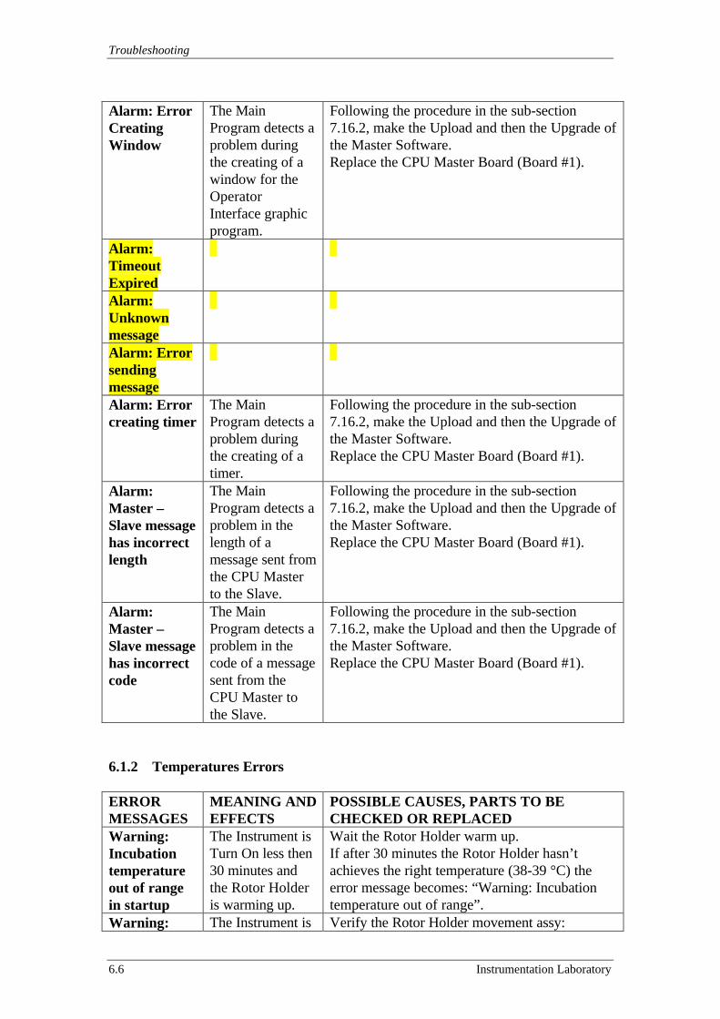
Troubleshooting
6.6 Instrumentation Laboratory
Alarm: ErrorCreatingWindow
The MainProgram detects aproblem duringthe creating of awindow for theOperatorInterface graphicprogram.
Following the procedure in the sub-section7.16.2, make the Upload and then the Upgrade ofthe Master Software.Replace the CPU Master Board (Board #1).
Alarm:TimeoutExpiredAlarm:UnknownmessageAlarm: ErrorsendingmessageAlarm: Errorcreating timer
The MainProgram detects aproblem duringthe creating of atimer.
Following the procedure in the sub-section7.16.2, make the Upload and then the Upgrade ofthe Master Software.Replace the CPU Master Board (Board #1).
Alarm:Master –Slave messagehas incorrectlength
The MainProgram detects aproblem in thelength of amessage sent fromthe CPU Masterto the Slave.
Following the procedure in the sub-section7.16.2, make the Upload and then the Upgrade ofthe Master Software.Replace the CPU Master Board (Board #1).
Alarm:Master –Slave messagehas incorrectcode
The MainProgram detects aproblem in thecode of a messagesent from theCPU Master tothe Slave.
Following the procedure in the sub-section7.16.2, make the Upload and then the Upgrade ofthe Master Software.Replace the CPU Master Board (Board #1).
6.1.2 Temperatures Errors
ERRORMESSAGES
MEANING ANDEFFECTS
POSSIBLE CAUSES, PARTS TO BECHECKED OR REPLACED
Warning:Incubationtemperatureout of rangein startup
The Instrument isTurn On less then30 minutes andthe Rotor Holderis warming up.
Wait the Rotor Holder warm up.If after 30 minutes the Rotor Holder hasn’tachieves the right temperature (38-39 °C) theerror message becomes: “Warning: Incubationtemperature out of range”.
Warning: The Instrument is Verify the Rotor Holder movement assy:
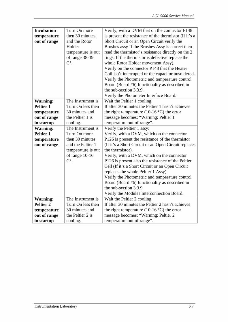
ACL 9000 Service Manual
Instrumentation Laboratory 6.7
Incubationtemperatureout of range
Turn On morethen 30 minutesand the RotorHoldertemperature is outof range 38-39C°.
Verify, with a DVM that on the connector P148is present the resistance of the thermistor (If it’s aShort Circuit or an Open Circuit verify theBrushes assy If the Brushes Assy is correct thenread the thermistor’s resistance directly on the 2rings. If the thermistor is defective replace thewhole Rotor Holder movement Assy).Verify on the connector P148 that the HeaterCoil isn’t interrupted or the capacitor unsoldered.Verify the Photometric and temperature controlBoard (Board #6) functionality as described inthe sub-section 3.3.9.Verify the Photometer Interface Board.
Warning:Peltier 1temperatureout of rangein startup
The Instrument isTurn On less then30 minutes andthe Peltier 1 iscooling.
Wait the Peltier 1 cooling.If after 30 minutes the Peltier 1 hasn’t achievesthe right temperature (10-16 °C) the errormessage becomes: “Warning: Peltier 1temperature out of range”.
Warning:Peltier 1temperatureout of range
The Instrument isTurn On morethen 30 minutesand the Peltier 1temperature is outof range 10-16C°.
Verify the Peltier 1 assy:Verify, with a DVM, which on the connectorP126 is present the resistance of the thermistor(If it’s a Short Circuit or an Open Circuit replacesthe thermistor).Verify, with a DVM, which on the connectorP126 is present also the resistance of the PeltierCell (If it’s a Short Circuit or an Open Circuitreplaces the whole Peltier 1 Assy).Verify the Photometric and temperature controlBoard (Board #6) functionality as described inthe sub-section 3.3.9.Verify the Modules Interconnection Board.
Warning:Peltier 2temperatureout of rangein startup
The Instrument isTurn On less then30 minutes andthe Peltier 2 iscooling.
Wait the Peltier 2 cooling.If after 30 minutes the Peltier 2 hasn’t achievesthe right temperature (10-16 °C) the errormessage becomes: “Warning: Peltier 2temperature out of range”.
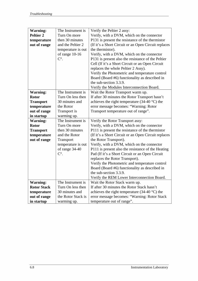
Troubleshooting
6.8 Instrumentation Laboratory
Warning:Peltier 2temperatureout of range
The Instrument isTurn On morethen 30 minutesand the Peltier 2temperature is outof range 10-16C°.
Verify the Peltier 2 assy:Verify, with a DVM, which on the connectorP131 is present the resistance of the thermistor(If it’s a Short Circuit or an Open Circuit replacesthe thermistor).Verify, with a DVM, which on the connectorP131 is present also the resistance of the PeltierCell (If it’s a Short Circuit or an Open Circuitreplaces the whole Peltier 2 Assy).Verify the Photometric and temperature controlBoard (Board #6) functionality as described inthe sub-section 3.3.9.Verify the Modules Interconnection Board.
Warning:RotorTransporttemperatureout of rangein startup
The Instrument isTurn On less then30 minutes andthe RotorTransport iswarming up.
Wait the Rotor Transport warm up.If after 30 minutes the Rotor Transport hasn’tachieves the right temperature (34-40 °C) theerror message becomes: “Warning: RotorTransport temperature out of range”.
Warning:RotorTransporttemperatureout of range
The Instrument isTurn On morethen 30 minutesand the RotorTransporttemperature is outof range 34-40C°.
Verify the Rotor Transport assy:Verify, with a DVM, which on the connectorP111 is present the resistance of the thermistor(If it’s a Short Circuit or an Open Circuit replacesthe Rotor Transport).Verify, with a DVM, which on the connectorP111 is present also the resistance of the HeatingPad (If it’s a Short Circuit or an Open Circuitreplaces the Rotor Transport).Verify the Photometric and temperature controlBoard (Board #6) functionality as described inthe sub-section 3.3.9.Verify the REM Lower Interconnection Board.
Warning:Rotor Stacktemperatureout of rangein startup
The Instrument isTurn On less then30 minutes andthe Rotor Stack iswarming up.
Wait the Rotor Stack warm up.If after 30 minutes the Rotor Stack hasn’tachieves the right temperature (34-40 °C) theerror message becomes: “Warning: Rotor Stacktemperature out of range”.
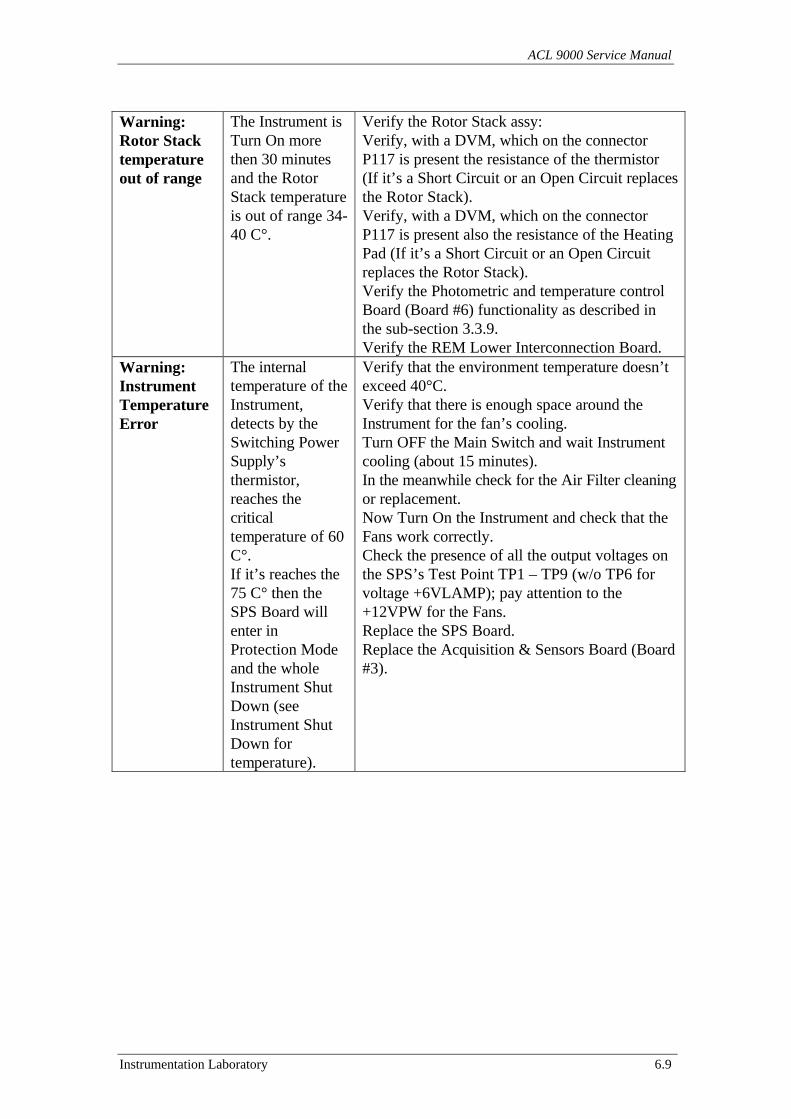
ACL 9000 Service Manual
Instrumentation Laboratory 6.9
Warning:Rotor Stacktemperatureout of range
The Instrument isTurn On morethen 30 minutesand the RotorStack temperatureis out of range 34-40 C°.
Verify the Rotor Stack assy:Verify, with a DVM, which on the connectorP117 is present the resistance of the thermistor(If it’s a Short Circuit or an Open Circuit replacesthe Rotor Stack).Verify, with a DVM, which on the connectorP117 is present also the resistance of the HeatingPad (If it’s a Short Circuit or an Open Circuitreplaces the Rotor Stack).Verify the Photometric and temperature controlBoard (Board #6) functionality as described inthe sub-section 3.3.9.Verify the REM Lower Interconnection Board.
Warning:InstrumentTemperatureError
The internaltemperature of theInstrument,detects by theSwitching PowerSupply’sthermistor,reaches thecriticaltemperature of 60C°.If it’s reaches the75 C° then theSPS Board willenter inProtection Modeand the wholeInstrument ShutDown (seeInstrument ShutDown fortemperature).
Verify that the environment temperature doesn’texceed 40°C.Verify that there is enough space around theInstrument for the fan’s cooling.Turn OFF the Main Switch and wait Instrumentcooling (about 15 minutes).In the meanwhile check for the Air Filter cleaningor replacement.Now Turn On the Instrument and check that theFans work correctly.Check the presence of all the output voltages onthe SPS’s Test Point TP1 – TP9 (w/o TP6 forvoltage +6VLAMP); pay attention to the+12VPW for the Fans.Replace the SPS Board.Replace the Acquisition & Sensors Board (Board#3).
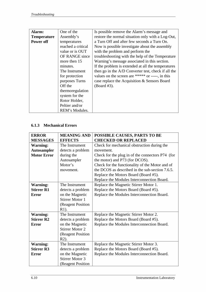
Troubleshooting
6.10 Instrumentation Laboratory
Alarm:TemperaturePower off
One of theAssembly’stemperaturesreached a criticalvalue or is OUTOF RANGE sincemore then 15minutes.The Instrumentfor protectionpurposes TurnsOff thethermoregulationsystem for theRotor Holder,Peltier and/orREM’s Modules.
Is possible remove the Alarm’s message andrestore the normal situation only with a Log-Out,a Turn Off and after few seconds a Turn On.Now is possible investigate about the assemblywith the problem and perform thetroubleshooting with the help of the TemperatureWarning’s message associated in this section.If the problem is extended at all the temperaturesthen go in the A/D Converter test, check if all thevalues on the screen are ***** or -----, in thiscase replace the Acquisition & Sensors Board(Board #3).
6.1.3 Mechanical Errors
ERRORMESSAGES
MEANING ANDEFFECTS
POSSIBLE CAUSES, PARTS TO BECHECKED OR REPLACED
Warning:AutosamplerMotor Error
The Instrumentdetects a problemduring theAutosamplerMotor’smovement.
Check for mechanical obstruction during themovement.Check for the plug in of the connectors P74 (forthe motor) and P73 (for DCOS).Check for the functionality of the Motor and ofthe DCOS as described in the sub-section 7.6.5.Replace the Motors Board (Board #5).Replace the Modules Interconnection Board.
Warning:Stirrer R1Error
The Instrumentdetects a problemon the MagneticStirrer Motor 1(Reagent PositionR1).
Replace the Magnetic Stirrer Motor 1.Replace the Motors Board (Board #5).Replace the Modules Interconnection Board.
Warning:Stirrer R2Error
The Instrumentdetects a problemon the MagneticStirrer Motor 2(Reagent PositionR2).
Replace the Magnetic Stirrer Motor 2.Replace the Motors Board (Board #5).Replace the Modules Interconnection Board.
Warning:Stirrer R3Error
The Instrumentdetects a problemon the MagneticStirrer Motor 3(Reagent Position
Replace the Magnetic Stirrer Motor 3.Replace the Motors Board (Board #5).Replace the Modules Interconnection Board.
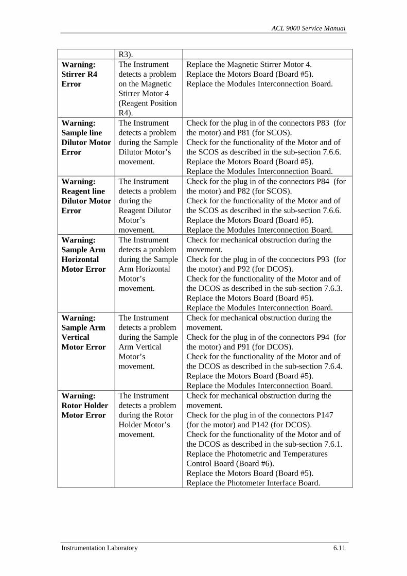
ACL 9000 Service Manual
Instrumentation Laboratory 6.11
R3).Warning:Stirrer R4Error
The Instrumentdetects a problemon the MagneticStirrer Motor 4(Reagent PositionR4).
Replace the Magnetic Stirrer Motor 4.Replace the Motors Board (Board #5).Replace the Modules Interconnection Board.
Warning:Sample lineDilutor MotorError
The Instrumentdetects a problemduring the SampleDilutor Motor’smovement.
Check for the plug in of the connectors P83 (forthe motor) and P81 (for SCOS).Check for the functionality of the Motor and ofthe SCOS as described in the sub-section 7.6.6.Replace the Motors Board (Board #5).Replace the Modules Interconnection Board.
Warning:Reagent lineDilutor MotorError
The Instrumentdetects a problemduring theReagent DilutorMotor’smovement.
Check for the plug in of the connectors P84 (forthe motor) and P82 (for SCOS).Check for the functionality of the Motor and ofthe SCOS as described in the sub-section 7.6.6.Replace the Motors Board (Board #5).Replace the Modules Interconnection Board.
Warning:Sample ArmHorizontalMotor Error
The Instrumentdetects a problemduring the SampleArm HorizontalMotor’smovement.
Check for mechanical obstruction during themovement.Check for the plug in of the connectors P93 (forthe motor) and P92 (for DCOS).Check for the functionality of the Motor and ofthe DCOS as described in the sub-section 7.6.3.Replace the Motors Board (Board #5).Replace the Modules Interconnection Board.
Warning:Sample ArmVerticalMotor Error
The Instrumentdetects a problemduring the SampleArm VerticalMotor’smovement.
Check for mechanical obstruction during themovement.Check for the plug in of the connectors P94 (forthe motor) and P91 (for DCOS).Check for the functionality of the Motor and ofthe DCOS as described in the sub-section 7.6.4.Replace the Motors Board (Board #5).Replace the Modules Interconnection Board.
Warning:Rotor HolderMotor Error
The Instrumentdetects a problemduring the RotorHolder Motor’smovement.
Check for mechanical obstruction during themovement.Check for the plug in of the connectors P147(for the motor) and P142 (for DCOS).Check for the functionality of the Motor and ofthe DCOS as described in the sub-section 7.6.1.Replace the Photometric and TemperaturesControl Board (Board #6).Replace the Motors Board (Board #5).Replace the Photometer Interface Board.
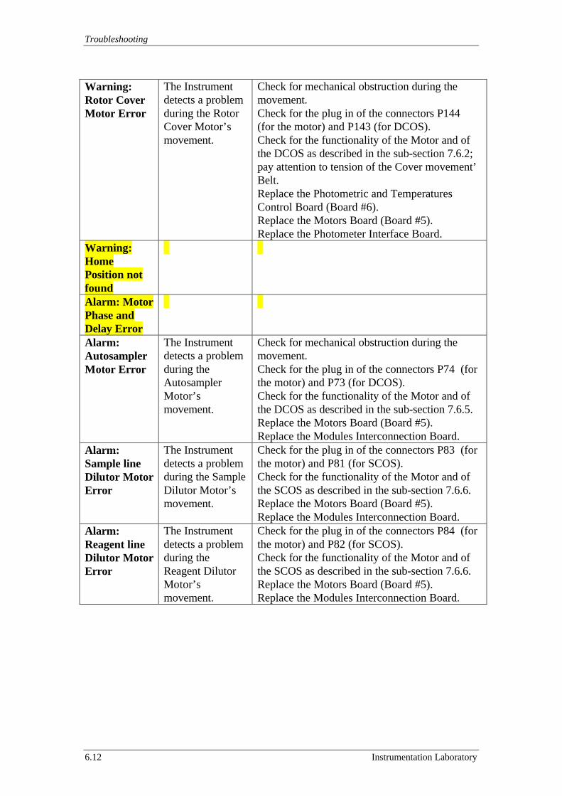
Troubleshooting
6.12 Instrumentation Laboratory
Warning:Rotor CoverMotor Error
The Instrumentdetects a problemduring the RotorCover Motor’smovement.
Check for mechanical obstruction during themovement.Check for the plug in of the connectors P144(for the motor) and P143 (for DCOS).Check for the functionality of the Motor and ofthe DCOS as described in the sub-section 7.6.2;pay attention to tension of the Cover movement’Belt.Replace the Photometric and TemperaturesControl Board (Board #6).Replace the Motors Board (Board #5).Replace the Photometer Interface Board.
Warning:HomePosition notfoundAlarm: MotorPhase andDelay ErrorAlarm:AutosamplerMotor Error
The Instrumentdetects a problemduring theAutosamplerMotor’smovement.
Check for mechanical obstruction during themovement.Check for the plug in of the connectors P74 (forthe motor) and P73 (for DCOS).Check for the functionality of the Motor and ofthe DCOS as described in the sub-section 7.6.5.Replace the Motors Board (Board #5).Replace the Modules Interconnection Board.
Alarm:Sample lineDilutor MotorError
The Instrumentdetects a problemduring the SampleDilutor Motor’smovement.
Check for the plug in of the connectors P83 (forthe motor) and P81 (for SCOS).Check for the functionality of the Motor and ofthe SCOS as described in the sub-section 7.6.6.Replace the Motors Board (Board #5).Replace the Modules Interconnection Board.
Alarm:Reagent lineDilutor MotorError
The Instrumentdetects a problemduring theReagent DilutorMotor’smovement.
Check for the plug in of the connectors P84 (forthe motor) and P82 (for SCOS).Check for the functionality of the Motor and ofthe SCOS as described in the sub-section 7.6.6.Replace the Motors Board (Board #5).Replace the Modules Interconnection Board.
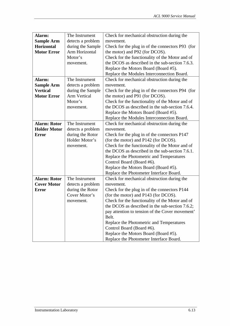
ACL 9000 Service Manual
Instrumentation Laboratory 6.13
Alarm:Sample ArmHorizontalMotor Error
The Instrumentdetects a problemduring the SampleArm HorizontalMotor’smovement.
Check for mechanical obstruction during themovement.Check for the plug in of the connectors P93 (forthe motor) and P92 (for DCOS).Check for the functionality of the Motor and ofthe DCOS as described in the sub-section 7.6.3.Replace the Motors Board (Board #5).Replace the Modules Interconnection Board.
Alarm:Sample ArmVerticalMotor Error
The Instrumentdetects a problemduring the SampleArm VerticalMotor’smovement.
Check for mechanical obstruction during themovement.Check for the plug in of the connectors P94 (forthe motor) and P91 (for DCOS).Check for the functionality of the Motor and ofthe DCOS as described in the sub-section 7.6.4.Replace the Motors Board (Board #5).Replace the Modules Interconnection Board.
Alarm: RotorHolder MotorError
The Instrumentdetects a problemduring the RotorHolder Motor’smovement.
Check for mechanical obstruction during themovement.Check for the plug in of the connectors P147(for the motor) and P142 (for DCOS).Check for the functionality of the Motor and ofthe DCOS as described in the sub-section 7.6.1.Replace the Photometric and TemperaturesControl Board (Board #6).Replace the Motors Board (Board #5).Replace the Photometer Interface Board.
Alarm: RotorCover MotorError
The Instrumentdetects a problemduring the RotorCover Motor’smovement.
Check for mechanical obstruction during themovement.Check for the plug in of the connectors P144(for the motor) and P143 (for DCOS).Check for the functionality of the Motor and ofthe DCOS as described in the sub-section 7.6.2;pay attention to tension of the Cover movement’Belt.Replace the Photometric and TemperaturesControl Board (Board #6).Replace the Motors Board (Board #5).Replace the Photometer Interface Board.
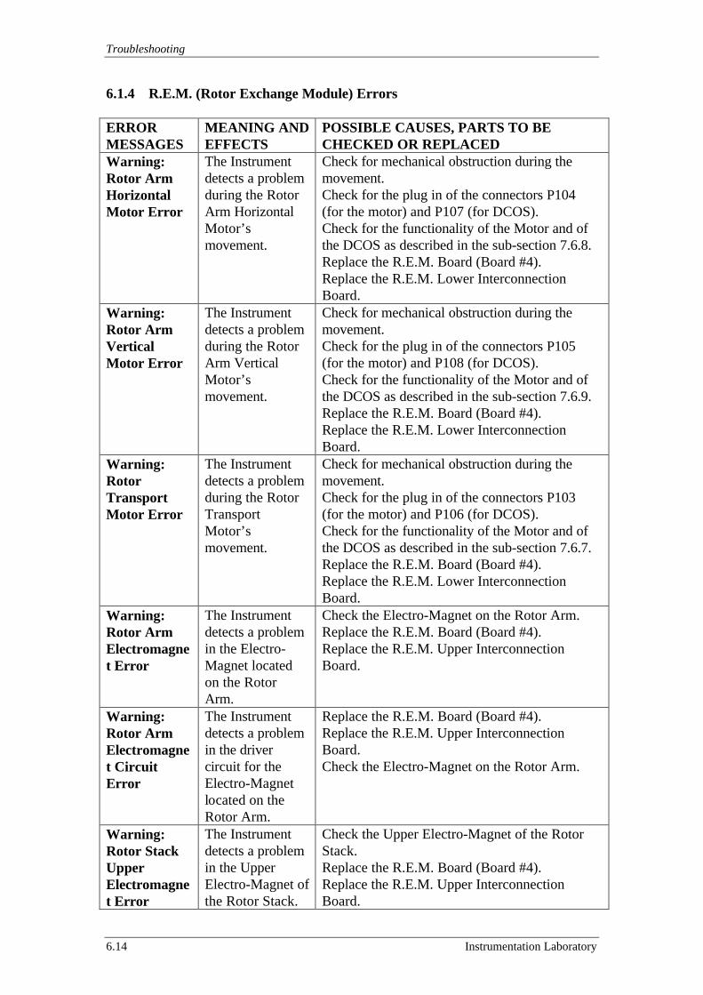
Troubleshooting
6.14 Instrumentation Laboratory
6.1.4 R.E.M. (Rotor Exchange Module) Errors
ERRORMESSAGES
MEANING ANDEFFECTS
POSSIBLE CAUSES, PARTS TO BECHECKED OR REPLACED
Warning:Rotor ArmHorizontalMotor Error
The Instrumentdetects a problemduring the RotorArm HorizontalMotor’smovement.
Check for mechanical obstruction during themovement.Check for the plug in of the connectors P104(for the motor) and P107 (for DCOS).Check for the functionality of the Motor and ofthe DCOS as described in the sub-section 7.6.8.Replace the R.E.M. Board (Board #4).Replace the R.E.M. Lower InterconnectionBoard.
Warning:Rotor ArmVerticalMotor Error
The Instrumentdetects a problemduring the RotorArm VerticalMotor’smovement.
Check for mechanical obstruction during themovement.Check for the plug in of the connectors P105(for the motor) and P108 (for DCOS).Check for the functionality of the Motor and ofthe DCOS as described in the sub-section 7.6.9.Replace the R.E.M. Board (Board #4).Replace the R.E.M. Lower InterconnectionBoard.
Warning:RotorTransportMotor Error
The Instrumentdetects a problemduring the RotorTransportMotor’smovement.
Check for mechanical obstruction during themovement.Check for the plug in of the connectors P103(for the motor) and P106 (for DCOS).Check for the functionality of the Motor and ofthe DCOS as described in the sub-section 7.6.7.Replace the R.E.M. Board (Board #4).Replace the R.E.M. Lower InterconnectionBoard.
Warning:Rotor ArmElectromagnet Error
The Instrumentdetects a problemin the Electro-Magnet locatedon the RotorArm.
Check the Electro-Magnet on the Rotor Arm.Replace the R.E.M. Board (Board #4).Replace the R.E.M. Upper InterconnectionBoard.
Warning:Rotor ArmElectromagnet CircuitError
The Instrumentdetects a problemin the drivercircuit for theElectro-Magnetlocated on theRotor Arm.
Replace the R.E.M. Board (Board #4).Replace the R.E.M. Upper InterconnectionBoard.Check the Electro-Magnet on the Rotor Arm.
Warning:Rotor StackUpperElectromagnet Error
The Instrumentdetects a problemin the UpperElectro-Magnet ofthe Rotor Stack.
Check the Upper Electro-Magnet of the RotorStack.Replace the R.E.M. Board (Board #4).Replace the R.E.M. Upper InterconnectionBoard.
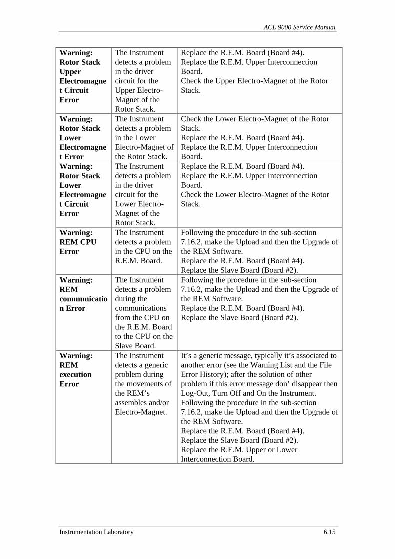
ACL 9000 Service Manual
Instrumentation Laboratory 6.15
Warning:Rotor StackUpperElectromagnet CircuitError
The Instrumentdetects a problemin the drivercircuit for theUpper Electro-Magnet of theRotor Stack.
Replace the R.E.M. Board (Board #4).Replace the R.E.M. Upper InterconnectionBoard.Check the Upper Electro-Magnet of the RotorStack.
Warning:Rotor StackLowerElectromagnet Error
The Instrumentdetects a problemin the LowerElectro-Magnet ofthe Rotor Stack.
Check the Lower Electro-Magnet of the RotorStack.Replace the R.E.M. Board (Board #4).Replace the R.E.M. Upper InterconnectionBoard.
Warning:Rotor StackLowerElectromagnet CircuitError
The Instrumentdetects a problemin the drivercircuit for theLower Electro-Magnet of theRotor Stack.
Replace the R.E.M. Board (Board #4).Replace the R.E.M. Upper InterconnectionBoard.Check the Lower Electro-Magnet of the RotorStack.
Warning:REM CPUError
The Instrumentdetects a problemin the CPU on theR.E.M. Board.
Following the procedure in the sub-section7.16.2, make the Upload and then the Upgrade ofthe REM Software.Replace the R.E.M. Board (Board #4).Replace the Slave Board (Board #2).
Warning:REMcommunication Error
The Instrumentdetects a problemduring thecommunicationsfrom the CPU onthe R.E.M. Boardto the CPU on theSlave Board.
Following the procedure in the sub-section7.16.2, make the Upload and then the Upgrade ofthe REM Software.Replace the R.E.M. Board (Board #4).Replace the Slave Board (Board #2).
Warning:REMexecutionError
The Instrumentdetects a genericproblem duringthe movements ofthe REM’sassembles and/orElectro-Magnet.
It’s a generic message, typically it’s associated toanother error (see the Warning List and the FileError History); after the solution of otherproblem if this error message don’ disappear thenLog-Out, Turn Off and On the Instrument.Following the procedure in the sub-section7.16.2, make the Upload and then the Upgrade ofthe REM Software.Replace the R.E.M. Board (Board #4).Replace the Slave Board (Board #2).Replace the R.E.M. Upper or LowerInterconnection Board.
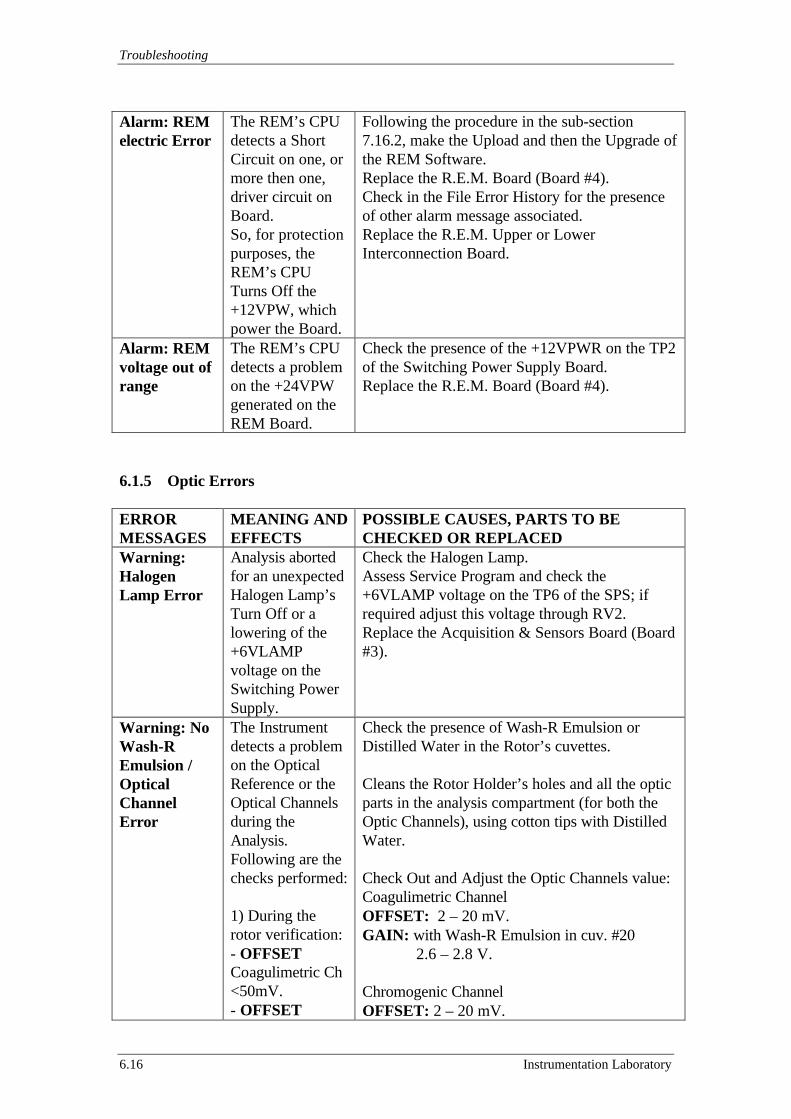
Troubleshooting
6.16 Instrumentation Laboratory
Alarm: REMelectric Error
The REM’s CPUdetects a ShortCircuit on one, ormore then one,driver circuit onBoard.So, for protectionpurposes, theREM’s CPUTurns Off the+12VPW, whichpower the Board.
Following the procedure in the sub-section7.16.2, make the Upload and then the Upgrade ofthe REM Software.Replace the R.E.M. Board (Board #4).Check in the File Error History for the presenceof other alarm message associated.Replace the R.E.M. Upper or LowerInterconnection Board.
Alarm: REMvoltage out ofrange
The REM’s CPUdetects a problemon the +24VPWgenerated on theREM Board.
Check the presence of the +12VPWR on the TP2of the Switching Power Supply Board.Replace the R.E.M. Board (Board #4).
6.1.5 Optic Errors
ERRORMESSAGES
MEANING ANDEFFECTS
POSSIBLE CAUSES, PARTS TO BECHECKED OR REPLACED
Warning:HalogenLamp Error
Analysis abortedfor an unexpectedHalogen Lamp’sTurn Off or alowering of the+6VLAMPvoltage on theSwitching PowerSupply.
Check the Halogen Lamp.Assess Service Program and check the+6VLAMP voltage on the TP6 of the SPS; ifrequired adjust this voltage through RV2.Replace the Acquisition & Sensors Board (Board#3).
Warning: NoWash-REmulsion /OpticalChannelError
The Instrumentdetects a problemon the OpticalReference or theOptical Channelsduring theAnalysis.Following are thechecks performed:
1) During therotor verification:- OFFSETCoagulimetric Ch<50mV.- OFFSET
Check the presence of Wash-R Emulsion orDistilled Water in the Rotor’s cuvettes.
Cleans the Rotor Holder’s holes and all the opticparts in the analysis compartment (for both theOptic Channels), using cotton tips with DistilledWater.
Check Out and Adjust the Optic Channels value:Coagulimetric ChannelOFFSET: 2 – 20 mV.GAIN: with Wash-R Emulsion in cuv. #20 2.6 – 2.8 V.
Chromogenic ChannelOFFSET: 2 – 20 mV.
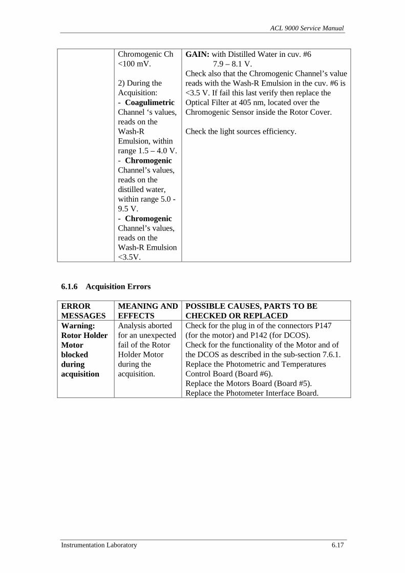
ACL 9000 Service Manual
Instrumentation Laboratory 6.17
Chromogenic Ch<100 mV.
2) During theAcquisition:- CoagulimetricChannel ‘s values,reads on theWash-REmulsion, withinrange 1.5 – 4.0 V.- ChromogenicChannel’s values,reads on thedistilled water,within range 5.0 -9.5 V.- ChromogenicChannel’s values,reads on theWash-R Emulsion<3.5V.
GAIN: with Distilled Water in cuv. #6 7.9 – 8.1 V.Check also that the Chromogenic Channel’s valuereads with the Wash-R Emulsion in the cuv. #6 is<3.5 V. If fail this last verify then replace theOptical Filter at 405 nm, located over theChromogenic Sensor inside the Rotor Cover.
Check the light sources efficiency.
6.1.6 Acquisition Errors
ERRORMESSAGES
MEANING ANDEFFECTS
POSSIBLE CAUSES, PARTS TO BECHECKED OR REPLACED
Warning:Rotor HolderMotorblockedduringacquisition
Analysis abortedfor an unexpectedfail of the RotorHolder Motorduring theacquisition.
Check for the plug in of the connectors P147(for the motor) and P142 (for DCOS).Check for the functionality of the Motor and ofthe DCOS as described in the sub-section 7.6.1.Replace the Photometric and TemperaturesControl Board (Board #6).Replace the Motors Board (Board #5).Replace the Photometer Interface Board.
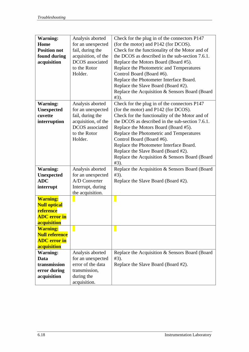
Troubleshooting
6.18 Instrumentation Laboratory
Warning:HomePosition notfound duringacquisition
Analysis abortedfor an unexpectedfail, during theacquisition, of theDCOS associatedto the RotorHolder.
Check for the plug in of the connectors P147(for the motor) and P142 (for DCOS).Check for the functionality of the Motor and ofthe DCOS as described in the sub-section 7.6.1.Replace the Motors Board (Board #5).Replace the Photometric and TemperaturesControl Board (Board #6).Replace the Photometer Interface Board.Replace the Slave Board (Board #2).Replace the Acquisition & Sensors Board (Board#3).
Warning:Unexpectedcuvetteinterruption
Analysis abortedfor an unexpectedfail, during theacquisition, of theDCOS associatedto the RotorHolder.
Check for the plug in of the connectors P147(for the motor) and P142 (for DCOS).Check for the functionality of the Motor and ofthe DCOS as described in the sub-section 7.6.1.Replace the Motors Board (Board #5).Replace the Photometric and TemperaturesControl Board (Board #6).Replace the Photometer Interface Board.Replace the Slave Board (Board #2).Replace the Acquisition & Sensors Board (Board#3).
Warning:UnexpectedADCinterrupt
Analysis abortedfor an unexpectedA/D ConverterInterrupt, duringthe acquisition.
Replace the Acquisition & Sensors Board (Board#3).Replace the Slave Board (Board #2).
Warning:Null opticalreferenceADC error inacquisitionWarning:Null referenceADC error inacquisitionWarning:Datatransmissionerror duringacquisition
Analysis abortedfor an unexpectederror of the datatransmission,during theacquisition.
Replace the Acquisition & Sensors Board (Board#3).Replace the Slave Board (Board #2).
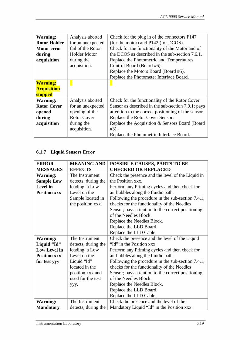
ACL 9000 Service Manual
Instrumentation Laboratory 6.19
Warning:Rotor HolderMotor errorduringacquisition
Analysis abortedfor an unexpectedfail of the RotorHolder Motorduring theacquisition.
Check for the plug in of the connectors P147(for the motor) and P142 (for DCOS).Check for the functionality of the Motor and ofthe DCOS as described in the sub-section 7.6.1.Replace the Photometric and TemperaturesControl Board (Board #6).Replace the Motors Board (Board #5).Replace the Photometer Interface Board.
Warning:AcquisitionstoppedWarning:Rotor Coveropenedduringacquisition
Analysis abortedfor an unexpectedopening of theRotor Coverduring theacquisition.
Check for the functionality of the Rotor CoverSensor as described in the sub-section 7.9.1; paysattention to the correct positioning of the sensor.Replace the Rotor Cover Sensor.Replace the Acquisition & Sensors Board (Board#3).Replace the Photometric Interface Board.
6.1.7 Liquid Sensors Error
ERRORMESSAGES
MEANING ANDEFFECTS
POSSIBLE CAUSES, PARTS TO BECHECKED OR REPLACED
Warning:Sample LowLevel inPosition xxx
The Instrumentdetects, during theloading, a LowLevel on theSample located inthe position xxx.
Check the presence and the level of the Liquid inthe Position xxx.Perform any Priming cycles and then check forair bubbles along the fluidic path.Following the procedure in the sub-section 7.4.1,checks for the functionality of the NeedlesSensor; pays attention to the correct positioningof the Needles Block.Replace the Needles Block.Replace the LLD Board.Replace the LLD Cable.
Warning:Liquid “Id”Low Level inPosition xxxfor test yyy
The Instrumentdetects, during theloading, a LowLevel on theLiquid “Id”located in theposition xxx andused for the testyyy.
Check the presence and the level of the Liquid“Id” in the Position xxx.Perform any Priming cycles and then check forair bubbles along the fluidic path.Following the procedure in the sub-section 7.4.1,checks for the functionality of the NeedlesSensor; pays attention to the correct positioningof the Needles Block.Replace the Needles Block.Replace the LLD Board.Replace the LLD Cable.
Warning:Mandatory
The Instrumentdetects, during the
Check the presence and the level of theMandatory Liquid “Id” in the Position xxx.
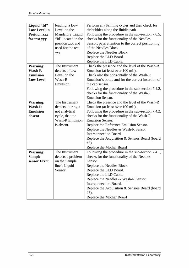
Troubleshooting
6.20 Instrumentation Laboratory
Liquid “Id”Low Level inPosition xxxfor test yyy
loading, a LowLevel on theMandatory Liquid“Id” located in theposition xxx andused for the testyyy.
Perform any Priming cycles and then check forair bubbles along the fluidic path.Following the procedure in the sub-section 7.6.5,checks for the functionality of the NeedlesSensor; pays attention to the correct positioningof the Needles Block.Replace the Needles Block.Replace the LLD Board.Replace the LLD Cable.
Warning:Wash-REmulsionLow Level
The Instrumentdetects a LowLevel on theWash-REmulsion.
Check the presence and the level of the Wash-REmulsion (at least over 100 mL).Check also the horizontally of the Wash-REmulsion’s bottle and for the correct insertion ofthe cap sensor.Following the procedure in the sub-section 7.4.2,checks for the functionality of the Wash-REmulsion Sensor.
Warning:Wash-REmulsionabsent
The Instrumentdetects, during anot analyticalcycle, that theWash-R Emulsionis absent.
Check the presence and the level of the Wash-REmulsion (at least over 100 mL).Following the procedure in the sub-section 7.4.2,checks for the functionality of the Wash-REmulsion Sensor.Replace the Reference Emulsion Sensor.Replace the Needles & Wash-R SensorInterconnection Board.Replace the Acquisition & Sensors Board (board#3).Replace the Mother Board
Warning:Samplesensor Error
The Instrumentdetects a problemon the Sampleline’s LiquidSensor.
Following the procedure in the sub-section 7.4.1,checks for the functionality of the NeedlesSensor.Replace the Needles Block.Replace the LLD Board.Replace the LLD Cable.Replace the Needles & Wash-R SensorInterconnection Board.Replace the Acquisition & Sensors Board (board#3).Replace the Mother Board
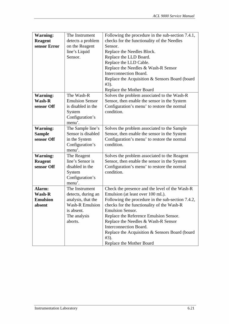
ACL 9000 Service Manual
Instrumentation Laboratory 6.21
Warning:Reagentsensor Error
The Instrumentdetects a problemon the Reagentline’s LiquidSensor.
Following the procedure in the sub-section 7.4.1,checks for the functionality of the NeedlesSensor.Replace the Needles Block.Replace the LLD Board.Replace the LLD Cable.Replace the Needles & Wash-R SensorInterconnection Board.Replace the Acquisition & Sensors Board (board#3).Replace the Mother Board
Warning:Wash-Rsensor Off
The Wash-REmulsion Sensoris disabled in theSystemConfiguration’smenu’.
Solves the problem associated to the Wash-RSensor, then enable the sensor in the SystemConfiguration’s menu’ to restore the normalcondition.
Warning:Samplesensor Off
The Sample line’sSensor is disabledin the SystemConfiguration’smenu’.
Solves the problem associated to the SampleSensor, then enable the sensor in the SystemConfiguration’s menu’ to restore the normalcondition.
Warning:Reagentsensor Off
The Reagentline’s Sensor isdisabled in theSystemConfiguration’smenu’.
Solves the problem associated to the ReagentSensor, then enable the sensor in the SystemConfiguration’s menu’ to restore the normalcondition.
Alarm:Wash-REmulsionabsent
The Instrumentdetects, during ananalysis, that theWash-R Emulsionis absent.The analysisaborts.
Check the presence and the level of the Wash-REmulsion (at least over 100 mL).Following the procedure in the sub-section 7.4.2,checks for the functionality of the Wash-REmulsion Sensor.Replace the Reference Emulsion Sensor.Replace the Needles & Wash-R SensorInterconnection Board.Replace the Acquisition & Sensors Board (board#3).Replace the Mother Board
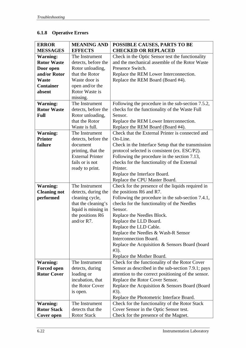
Troubleshooting
6.22 Instrumentation Laboratory
6.1.8 Operative Errors
ERRORMESSAGES
MEANING ANDEFFECTS
POSSIBLE CAUSES, PARTS TO BECHECKED OR REPLACED
Warning:Rotor WasteDoor openand/or RotorWasteContainerabsent
The Instrumentdetects, before theRotor unloading,that the RotorWaste door isopen and/or theRotor Waste ismissing.
Check in the Optic Sensor test the functionalityand the mechanical assemble of the Rotor WastePresence Switch.Replace the REM Lower Interconnection.Replace the REM Board (Board #4).
Warning:Rotor WasteFull
The Instrumentdetects, before theRotor unloading,that the RotorWaste is full.
Following the procedure in the sub-section 7.5.2,checks for the functionality of the Waste FullSensor.Replace the REM Lower Interconnection.Replace the REM Board (Board #4).
Warning:Printerfailure
The Instrumentdetects, before thedocumentprinting, that theExternal Printerfails or is notready to print.
Check that the External Printer is connected andOn-Line.Check in the Interface Setup that the transmissionprotocol selected is consistent (ex. ESC/P2).Following the procedure in the section 7.13,checks for the functionality of the ExternalPrinter.Replace the Interface Board.Replace the CPU Master Board.
Warning:Cleaning notperformed
The Instrumentdetects, during thecleaning cycle,that the cleaning’sliquid is missing inthe positions R6and/or R7.
Check for the presence of the liquids required inthe positions R6 and R7.Following the procedure in the sub-section 7.4.1,checks for the functionality of the NeedlesSensor.Replace the Needles Block.Replace the LLD Board.Replace the LLD Cable.Replace the Needles & Wash-R SensorInterconnection Board.Replace the Acquisition & Sensors Board (board#3).Replace the Mother Board.
Warning:Forced openRotor Cover
The Instrumentdetects, duringloading orincubation, thatthe Rotor Coveris open.
Check for the functionality of the Rotor CoverSensor as described in the sub-section 7.9.1; paysattention to the correct positioning of the sensor.Replace the Rotor Cover Sensor.Replace the Acquisition & Sensors Board (Board#3).Replace the Photometric Interface Board.
Warning:Rotor StackCover open
The Instrumentdetects that theRotor Stack
Check for the functionality of the Rotor StackCover Sensor in the Optic Sensor test.Check for the presence of the Magnet.
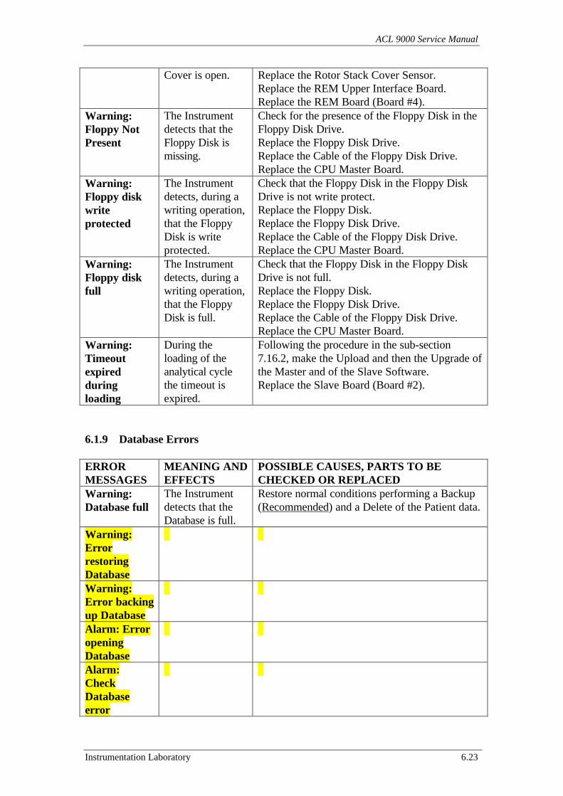
ACL 9000 Service Manual
Instrumentation Laboratory 6.23
Cover is open. Replace the Rotor Stack Cover Sensor.Replace the REM Upper Interface Board.Replace the REM Board (Board #4).
Warning:Floppy NotPresent
The Instrumentdetects that theFloppy Disk ismissing.
Check for the presence of the Floppy Disk in theFloppy Disk Drive.Replace the Floppy Disk Drive.Replace the Cable of the Floppy Disk Drive.Replace the CPU Master Board.
Warning:Floppy diskwriteprotected
The Instrumentdetects, during awriting operation,that the FloppyDisk is writeprotected.
Check that the Floppy Disk in the Floppy DiskDrive is not write protect.Replace the Floppy Disk.Replace the Floppy Disk Drive.Replace the Cable of the Floppy Disk Drive.Replace the CPU Master Board.
Warning:Floppy diskfull
The Instrumentdetects, during awriting operation,that the FloppyDisk is full.
Check that the Floppy Disk in the Floppy DiskDrive is not full.Replace the Floppy Disk.Replace the Floppy Disk Drive.Replace the Cable of the Floppy Disk Drive.Replace the CPU Master Board.
Warning:Timeoutexpiredduringloading
During theloading of theanalytical cyclethe timeout isexpired.
Following the procedure in the sub-section7.16.2, make the Upload and then the Upgrade ofthe Master and of the Slave Software.Replace the Slave Board (Board #2).
6.1.9 Database Errors
ERRORMESSAGES
MEANING ANDEFFECTS
POSSIBLE CAUSES, PARTS TO BECHECKED OR REPLACED
Warning:Database full
The Instrumentdetects that theDatabase is full.
Restore normal conditions performing a Backup(Recommended) and a Delete of the Patient data.
Warning:ErrorrestoringDatabaseWarning:Error backingup DatabaseAlarm: ErroropeningDatabaseAlarm:CheckDatabaseerror
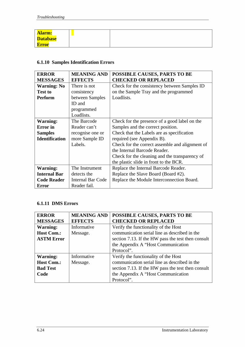
Troubleshooting
6.24 Instrumentation Laboratory
Alarm:DatabaseError
6.1.10 Samples Identification Errors
ERRORMESSAGES
MEANING ANDEFFECTS
POSSIBLE CAUSES, PARTS TO BECHECKED OR REPLACED
Warning: NoTest toPerform
There is notconsistencybetween SamplesID andprogrammedLoadlists.
Check for the consistency between Samples IDon the Sample Tray and the programmedLoadlists.
Warning:Error inSamplesIdentification
The BarcodeReader can’trecognise one ormore Sample IDLabels.
Check for the presence of a good label on theSamples and the correct position.Check that the Labels are as specificationrequired (see Appendix B).Check for the correct assemble and alignment ofthe Internal Barcode Reader.Check for the cleaning and the transparency ofthe plastic slide in front to the BCR.
Warning:Internal BarCode ReaderError
The Instrumentdetects theInternal Bar CodeReader fail.
Replace the Internal Barcode Reader.Replace the Slave Board (Board #2).Replace the Module Interconnection Board.
6.1.11 DMS Errors
ERRORMESSAGES
MEANING ANDEFFECTS
POSSIBLE CAUSES, PARTS TO BECHECKED OR REPLACED
Warning:Host Com.:ASTM Error
InformativeMessage.
Verify the functionality of the Hostcommunication serial line as described in thesection 7.13. If the HW pass the test then consultthe Appendix A “Host CommunicationProtocol”.
Warning:Host Com.:Bad TestCode
InformativeMessage.
Verify the functionality of the Hostcommunication serial line as described in thesection 7.13. If the HW pass the test then consultthe Appendix A “Host CommunicationProtocol”.
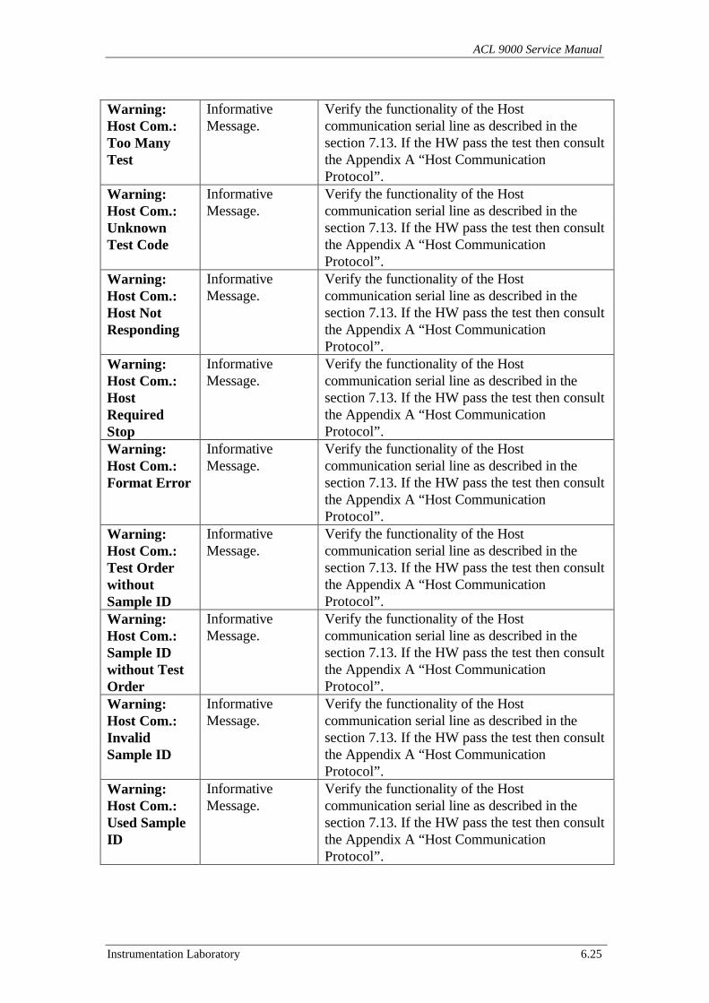
ACL 9000 Service Manual
Instrumentation Laboratory 6.25
Warning:Host Com.:Too ManyTest
InformativeMessage.
Verify the functionality of the Hostcommunication serial line as described in thesection 7.13. If the HW pass the test then consultthe Appendix A “Host CommunicationProtocol”.
Warning:Host Com.:UnknownTest Code
InformativeMessage.
Verify the functionality of the Hostcommunication serial line as described in thesection 7.13. If the HW pass the test then consultthe Appendix A “Host CommunicationProtocol”.
Warning:Host Com.:Host NotResponding
InformativeMessage.
Verify the functionality of the Hostcommunication serial line as described in thesection 7.13. If the HW pass the test then consultthe Appendix A “Host CommunicationProtocol”.
Warning:Host Com.:HostRequiredStop
InformativeMessage.
Verify the functionality of the Hostcommunication serial line as described in thesection 7.13. If the HW pass the test then consultthe Appendix A “Host CommunicationProtocol”.
Warning:Host Com.:Format Error
InformativeMessage.
Verify the functionality of the Hostcommunication serial line as described in thesection 7.13. If the HW pass the test then consultthe Appendix A “Host CommunicationProtocol”.
Warning:Host Com.:Test OrderwithoutSample ID
InformativeMessage.
Verify the functionality of the Hostcommunication serial line as described in thesection 7.13. If the HW pass the test then consultthe Appendix A “Host CommunicationProtocol”.
Warning:Host Com.:Sample IDwithout TestOrder
InformativeMessage.
Verify the functionality of the Hostcommunication serial line as described in thesection 7.13. If the HW pass the test then consultthe Appendix A “Host CommunicationProtocol”.
Warning:Host Com.:InvalidSample ID
InformativeMessage.
Verify the functionality of the Hostcommunication serial line as described in thesection 7.13. If the HW pass the test then consultthe Appendix A “Host CommunicationProtocol”.
Warning:Host Com.:Used SampleID
InformativeMessage.
Verify the functionality of the Hostcommunication serial line as described in thesection 7.13. If the HW pass the test then consultthe Appendix A “Host CommunicationProtocol”.
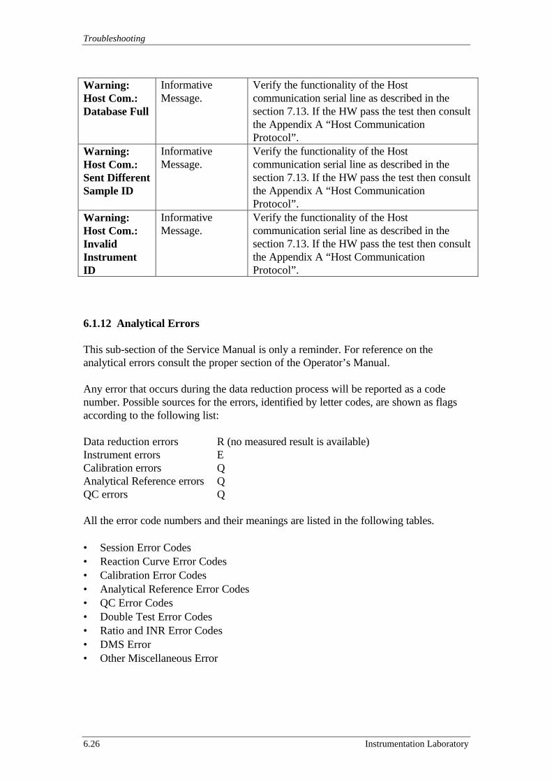
Troubleshooting
6.26 Instrumentation Laboratory
Warning:Host Com.:Database Full
InformativeMessage.
Verify the functionality of the Hostcommunication serial line as described in thesection 7.13. If the HW pass the test then consultthe Appendix A “Host CommunicationProtocol”.
Warning:Host Com.:Sent DifferentSample ID
InformativeMessage.
Verify the functionality of the Hostcommunication serial line as described in thesection 7.13. If the HW pass the test then consultthe Appendix A “Host CommunicationProtocol”.
Warning:Host Com.:InvalidInstrumentID
InformativeMessage.
Verify the functionality of the Hostcommunication serial line as described in thesection 7.13. If the HW pass the test then consultthe Appendix A “Host CommunicationProtocol”.
6.1.12 Analytical Errors
This sub-section of the Service Manual is only a reminder. For reference on theanalytical errors consult the proper section of the Operator’s Manual.
Any error that occurs during the data reduction process will be reported as a codenumber. Possible sources for the errors, identified by letter codes, are shown as flagsaccording to the following list:
Data reduction errors R (no measured result is available)Instrument errors ECalibration errors QAnalytical Reference errors QQC errors Q
All the error code numbers and their meanings are listed in the following tables.
• Session Error Codes• Reaction Curve Error Codes• Calibration Error Codes• Analytical Reference Error Codes• QC Error Codes• Double Test Error Codes• Ratio and INR Error Codes• DMS Error• Other Miscellaneous Error
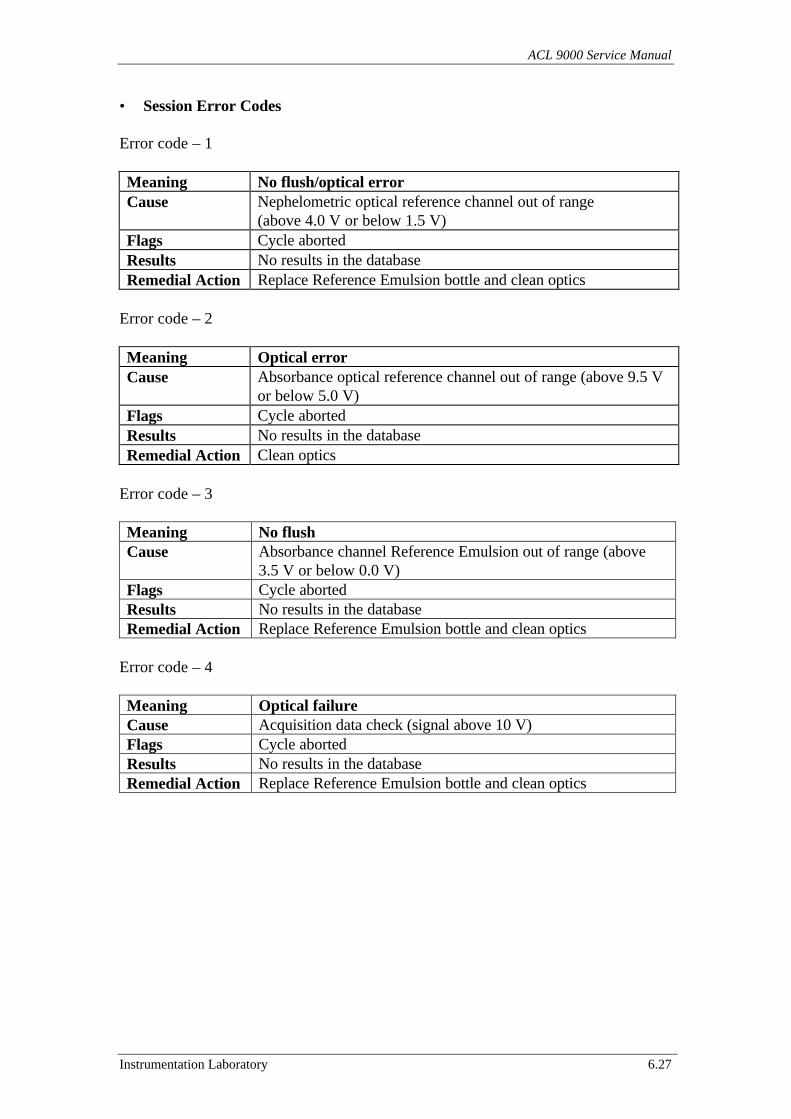
ACL 9000 Service Manual
Instrumentation Laboratory 6.27
• Session Error Codes
Error code – 1
Meaning No flush/optical errorCause Nephelometric optical reference channel out of range
(above 4.0 V or below 1.5 V)Flags Cycle abortedResults No results in the databaseRemedial Action Replace Reference Emulsion bottle and clean optics
Error code – 2
Meaning Optical errorCause Absorbance optical reference channel out of range (above 9.5 V
or below 5.0 V)Flags Cycle abortedResults No results in the databaseRemedial Action Clean optics
Error code – 3
Meaning No flushCause Absorbance channel Reference Emulsion out of range (above
3.5 V or below 0.0 V)Flags Cycle abortedResults No results in the databaseRemedial Action Replace Reference Emulsion bottle and clean optics
Error code – 4
Meaning Optical failureCause Acquisition data check (signal above 10 V)Flags Cycle abortedResults No results in the databaseRemedial Action Replace Reference Emulsion bottle and clean optics
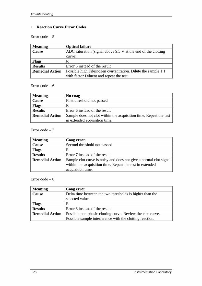
Troubleshooting
6.28 Instrumentation Laboratory
• Reaction Curve Error Codes
Error code – 5
Meaning Optical failureCause ADC saturation (signal above 9.5 V at the end of the clotting
curve)Flags RResults Error 5 instead of the resultRemedial Action Possible high Fibrinogen concentration. Dilute the sample 1:1
with factor Diluent and repeat the test.
Error code – 6
Meaning No coagCause First threshold not passedFlags RResults Error 6 instead of the resultRemedial Action Sample does not clot within the acquisition time. Repeat the test
in extended acquisition time.
Error code – 7
Meaning Coag errorCause Second threshold not passedFlags RResults Error 7 instead of the resultRemedial Action Sample clot curve is noisy and does not give a normal clot signal
within the acquisition time. Repeat the test in extendedacquisition time.
Error code – 8
Meaning Coag errorCause Delta time between the two thresholds is higher than the
selected valueFlags RResults Error 8 instead of the resultRemedial Action Possible non-phasic clotting curve. Review the clot curve.
Possible sample interference with the clotting reaction.
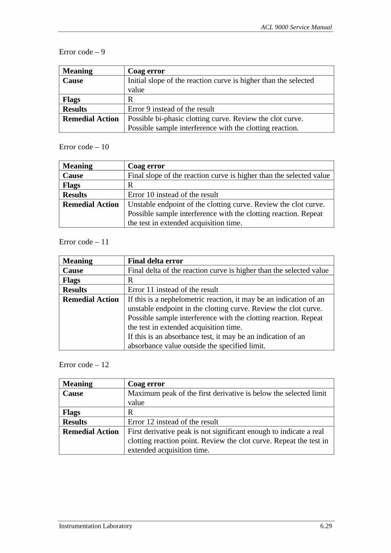
ACL 9000 Service Manual
Instrumentation Laboratory 6.29
Error code – 9
Meaning Coag errorCause Initial slope of the reaction curve is higher than the selected
valueFlags RResults Error 9 instead of the resultRemedial Action Possible bi-phasic clotting curve. Review the clot curve.
Possible sample interference with the clotting reaction.
Error code – 10
Meaning Coag errorCause Final slope of the reaction curve is higher than the selected valueFlags RResults Error 10 instead of the resultRemedial Action Unstable endpoint of the clotting curve. Review the clot curve.
Possible sample interference with the clotting reaction. Repeatthe test in extended acquisition time.
Error code – 11
Meaning Final delta errorCause Final delta of the reaction curve is higher than the selected valueFlags RResults Error 11 instead of the resultRemedial Action If this is a nephelometric reaction, it may be an indication of an
unstable endpoint in the clotting curve. Review the clot curve.Possible sample interference with the clotting reaction. Repeatthe test in extended acquisition time.If this is an absorbance test, it may be an indication of anabsorbance value outside the specified limit.
Error code – 12
Meaning Coag errorCause Maximum peak of the first derivative is below the selected limit
valueFlags RResults Error 12 instead of the resultRemedial Action First derivative peak is not significant enough to indicate a real
clotting reaction point. Review the clot curve. Repeat the test inextended acquisition time.
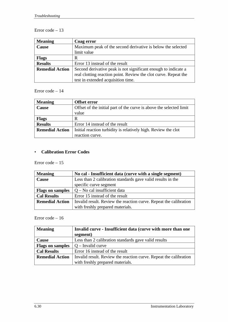
Troubleshooting
6.30 Instrumentation Laboratory
Error code – 13
Meaning Coag errorCause Maximum peak of the second derivative is below the selected
limit valueFlags RResults Error 13 instead of the resultRemedial Action Second derivative peak is not significant enough to indicate a
real clotting reaction point. Review the clot curve. Repeat thetest in extended acquisition time.
Error code – 14
Meaning Offset errorCause Offset of the initial part of the curve is above the selected limit
valueFlags RResults Error 14 instead of the resultRemedial Action Initial reaction turbidity is relatively high. Review the clot
reaction curve.
• Calibration Error Codes
Error code – 15
Meaning No cal - Insufficient data (curve with a single segment)Cause Less than 2 calibration standards gave valid results in the
specific curve segmentFlags on samples Q – No cal insufficient dataCal Results Error 15 instead of the resultRemedial Action Invalid result. Review the reaction curve. Repeat the calibration
with freshly prepared materials.
Error code – 16
Meaning Invalid curve - Insufficient data (curve with more than onesegment)
Cause Less than 2 calibration standards gave valid resultsFlags on samples Q – Invalid curveCal Results Error 16 instead of the resultRemedial Action Invalid result. Review the reaction curve. Repeat the calibration
with freshly prepared materials.
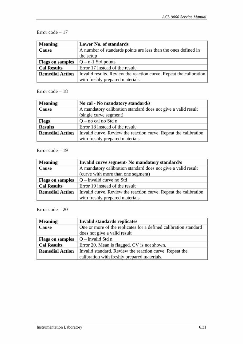
ACL 9000 Service Manual
Instrumentation Laboratory 6.31
Error code – 17
Meaning Lower No. of standardsCause A number of standards points are less than the ones defined in
the setupFlags on samples Q – n-1 Std pointsCal Results Error 17 instead of the resultRemedial Action Invalid results. Review the reaction curve. Repeat the calibration
with freshly prepared materials.
Error code – 18
Meaning No cal - No mandatory standard/sCause A mandatory calibration standard does not give a valid result
(single curve segment)Flags Q – no cal no Std nResults Error 18 instead of the resultRemedial Action Invalid curve. Review the reaction curve. Repeat the calibration
with freshly prepared materials.
Error code – 19
Meaning Invalid curve segment- No mandatory standard/sCause A mandatory calibration standard does not give a valid result
(curve with more than one segment)Flags on samples Q – invalid curve no StdCal Results Error 19 instead of the resultRemedial Action Invalid curve. Review the reaction curve. Repeat the calibration
with freshly prepared materials.
Error code – 20
Meaning Invalid standards replicatesCause One or more of the replicates for a defined calibration standard
does not give a valid resultFlags on samples Q – invalid Std nCal Results Error 20. Mean is flagged. CV is not shown.Remedial Action Invalid standard. Review the reaction curve. Repeat the
calibration with freshly prepared materials.
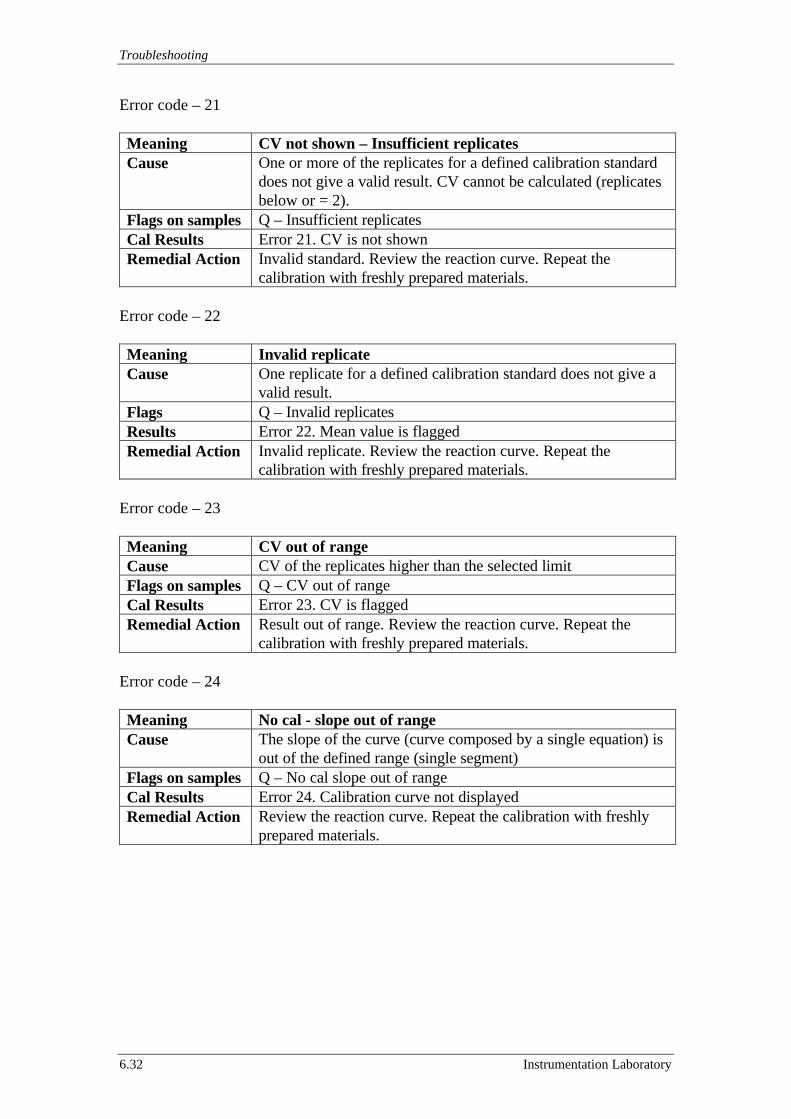
Troubleshooting
6.32 Instrumentation Laboratory
Error code – 21
Meaning CV not shown – Insufficient replicatesCause One or more of the replicates for a defined calibration standard
does not give a valid result. CV cannot be calculated (replicatesbelow or = 2).
Flags on samples Q – Insufficient replicatesCal Results Error 21. CV is not shownRemedial Action Invalid standard. Review the reaction curve. Repeat the
calibration with freshly prepared materials.
Error code – 22
Meaning Invalid replicateCause One replicate for a defined calibration standard does not give a
valid result.Flags Q – Invalid replicatesResults Error 22. Mean value is flaggedRemedial Action Invalid replicate. Review the reaction curve. Repeat the
calibration with freshly prepared materials.
Error code – 23
Meaning CV out of rangeCause CV of the replicates higher than the selected limitFlags on samples Q – CV out of rangeCal Results Error 23. CV is flaggedRemedial Action Result out of range. Review the reaction curve. Repeat the
calibration with freshly prepared materials.
Error code – 24
Meaning No cal - slope out of rangeCause The slope of the curve (curve composed by a single equation) is
out of the defined range (single segment)Flags on samples Q – No cal slope out of rangeCal Results Error 24. Calibration curve not displayedRemedial Action Review the reaction curve. Repeat the calibration with freshly
prepared materials.
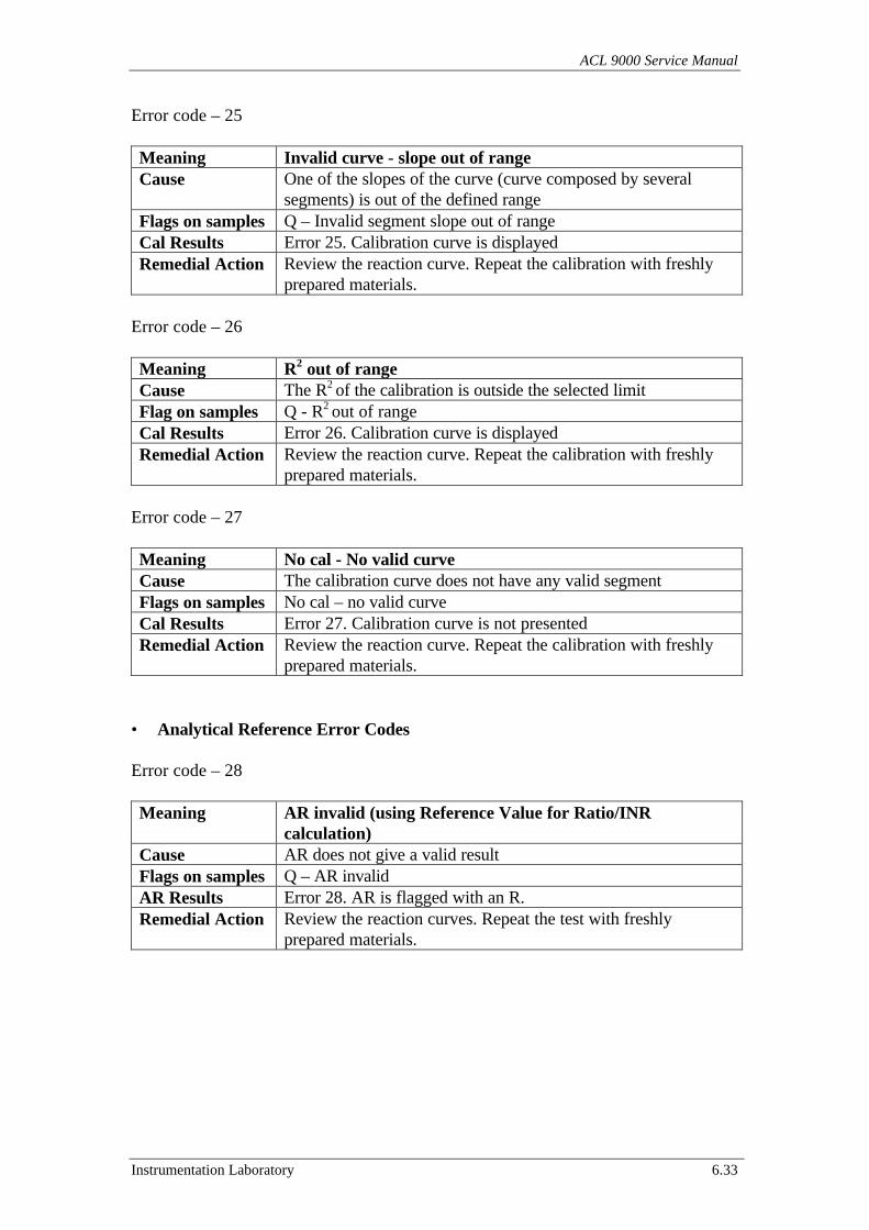
ACL 9000 Service Manual
Instrumentation Laboratory 6.33
Error code – 25
Meaning Invalid curve - slope out of rangeCause One of the slopes of the curve (curve composed by several
segments) is out of the defined rangeFlags on samples Q – Invalid segment slope out of rangeCal Results Error 25. Calibration curve is displayedRemedial Action Review the reaction curve. Repeat the calibration with freshly
prepared materials.
Error code – 26
Meaning R2 out of rangeCause The R2 of the calibration is outside the selected limitFlag on samples Q - R2 out of rangeCal Results Error 26. Calibration curve is displayedRemedial Action Review the reaction curve. Repeat the calibration with freshly
prepared materials.
Error code – 27
Meaning No cal - No valid curveCause The calibration curve does not have any valid segmentFlags on samples No cal – no valid curveCal Results Error 27. Calibration curve is not presentedRemedial Action Review the reaction curve. Repeat the calibration with freshly
prepared materials.
• Analytical Reference Error Codes
Error code – 28
Meaning AR invalid (using Reference Value for Ratio/INRcalculation)
Cause AR does not give a valid resultFlags on samples Q – AR invalidAR Results Error 28. AR is flagged with an R.Remedial Action Review the reaction curves. Repeat the test with freshly
prepared materials.

Troubleshooting
6.34 Instrumentation Laboratory
Error code – 29
Meaning AR out of range (using Reference Value for Ratio/INRcalculation)
Cause AR gives a result out of rangeFlags on samples Q – AR out of rangeAR Results AR is flaggedRemedial Action Review the reaction curves. Repeat the test with freshly
prepared materials.
Error code – 30
Meaning AR invalid (AR used as reference for Ratio/INR calculation)Cause AR does not give a valid calculated resultFlags on samples Q – AR invalid. Ratio/INR on samples is not presentedAR Results Error 30. AR is flagged.Remedial Action Review the reaction curves. Repeat the test with freshly
prepared materials.
Error code – 31
Meaning AR out of range (AR used as reference for Ratio/INRcalculation)
Cause AR gives a result out of rangeFlags on samples Q – AR out of range. Ratio/INR on samples is not presentedAR Results AR is flaggedRemedial Action Review the reaction curves. Repeat the test with freshly
prepared materials.
Error code – 32
Meaning AR out of range (compared to a Cal standard)Cause AR does not have a valid Ratio resultFlags on samples Q – AR out of range, Ratio/INR on samples is not presentedAR Results AR has no ratio calculatedRemedial Action Review the reaction curves. Repeat the test with freshly
prepared materials.
Error code – 33
Meaning AR not checked (compared to a Cal standard not defined)Cause AR gives a result out of rangeFlags on samples Q – AR not checked. Ratio/INR is given on samplesAR Results AR is flaggedRemedial Action Review the reaction curves. Repeat the test with freshly
prepared materials.
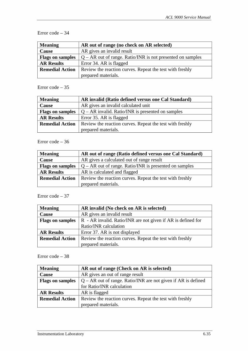
ACL 9000 Service Manual
Instrumentation Laboratory 6.35
Error code – 34
Meaning AR out of range (no check on AR selected)Cause AR gives an invalid resultFlags on samples Q – AR out of range. Ratio/INR is not presented on samplesAR Results Error 34. AR is flaggedRemedial Action Review the reaction curves. Repeat the test with freshly
prepared materials.
Error code – 35
Meaning AR invalid (Ratio defined versus one Cal Standard)Cause AR gives an invalid calculated unitFlags on samples Q – AR invalid. Ratio/INR is presented on samplesAR Results Error 35. AR is flaggedRemedial Action Review the reaction curves. Repeat the test with freshly
prepared materials.
Error code – 36
Meaning AR out of range (Ratio defined versus one Cal Standard)Cause AR gives a calculated out of range resultFlags on samples Q – AR out of range. Ratio/INR is presented on samplesAR Results AR is calculated and flaggedRemedial Action Review the reaction curves. Repeat the test with freshly
prepared materials.
Error code – 37
Meaning AR invalid (No check on AR is selected)Cause AR gives an invalid resultFlags on samples R - AR invalid. Ratio/INR are not given if AR is defined for
Ratio/INR calculationAR Results Error 37. AR is not displayedRemedial Action Review the reaction curves. Repeat the test with freshly
prepared materials.
Error code – 38
Meaning AR out of range (Check on AR is selected)Cause AR gives an out of range resultFlags on samples Q – AR out of range. Ratio/INR are not given if AR is defined
for Ratio/INR calculationAR Results AR is flaggedRemedial Action Review the reaction curves. Repeat the test with freshly
prepared materials.
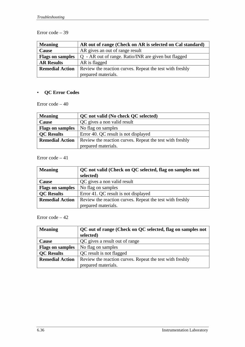
Troubleshooting
6.36 Instrumentation Laboratory
Error code – 39
Meaning AR out of range (Check on AR is selected on Cal standard)Cause AR gives an out of range resultFlags on samples Q - AR out of range. Ratio/INR are given but flaggedAR Results AR is flaggedRemedial Action Review the reaction curves. Repeat the test with freshly
prepared materials.
• QC Error Codes
Error code – 40
Meaning QC not valid (No check QC selected)Cause QC gives a non valid resultFlags on samples No flag on samplesQC Results Error 40. QC result is not displayedRemedial Action Review the reaction curves. Repeat the test with freshly
prepared materials.
Error code – 41
Meaning QC not valid (Check on QC selected, flag on samples notselected)
Cause QC gives a non valid resultFlags on samples No flag on samplesQC Results Error 41. QC result is not displayedRemedial Action Review the reaction curves. Repeat the test with freshly
prepared materials.
Error code – 42
Meaning QC out of range (Check on QC selected, flag on samples notselected)
Cause QC gives a result out of rangeFlags on samples No flag on samplesQC Results QC result is not flaggedRemedial Action Review the reaction curves. Repeat the test with freshly
prepared materials.
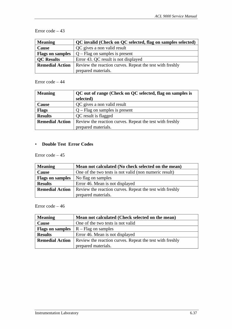
ACL 9000 Service Manual
Instrumentation Laboratory 6.37
Error code – 43
Meaning QC invalid (Check on QC selected, flag on samples selected)Cause QC gives a non valid resultFlags on samples Q – Flag on samples is presentQC Results Error 43. QC result is not displayedRemedial Action Review the reaction curves. Repeat the test with freshly
prepared materials.
Error code – 44
Meaning QC out of range (Check on QC selected, flag on samples isselected)
Cause QC gives a non valid resultFlags Q – Flag on samples is presentResults QC result is flaggedRemedial Action Review the reaction curves. Repeat the test with freshly
prepared materials.
• Double Test Error Codes
Error code – 45
Meaning Mean not calculated (No check selected on the mean)Cause One of the two tests is not valid (non numeric result)Flags on samples No flag on samplesResults Error 46. Mean is not displayedRemedial Action Review the reaction curves. Repeat the test with freshly
prepared materials.
Error code – 46
Meaning Mean not calculated (Check selected on the mean)Cause One of the two tests is not validFlags on samples R – Flag on samplesResults Error 46. Mean is not displayedRemedial Action Review the reaction curves. Repeat the test with freshly
prepared materials.
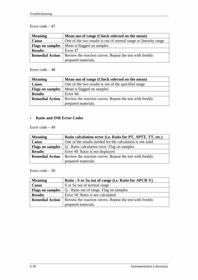
Troubleshooting
6.38 Instrumentation Laboratory
Error code – 47
Meaning Mean out of range (Check selected on the mean)Cause One of the two results is out of normal range or linearity rangeFlags on samples Mean is flagged on samplesResults Error 47Remedial Action Review the reaction curves. Repeat the test with freshly
prepared materials.
Error code – 48
Meaning Mean out of range (Check selected on the mean)Cause One of the two results is out of the specified rangeFlags on samples Mean is flagged on samplesResults Error 48.Remedial Action Review the reaction curves. Repeat the test with freshly
prepared materials.
• Ratio and INR Error Codes
Error code – 49
Meaning Ratio calculation error (i.e. Ratio for PT, APTT, TT, etc.)Cause One of the results needed for the calculation is not validFlags on samples Q - Ratio calculation error. Flag on samplesResults Error 49. Ratio is not displayedRemedial Action Review the reaction curves. Repeat the test with freshly
prepared materials.
Error code – 50
Meaning Ratio : S or Sa out of range (i.e. Ratio for APCR-V)Cause S or Sa out of normal rangeFlags on samples Q - Ratio out of range. Flag on samplesResults Error 50. Ratio is not calculatedRemedial Action Review the reaction curves. Repeat the test with freshly
prepared materials.
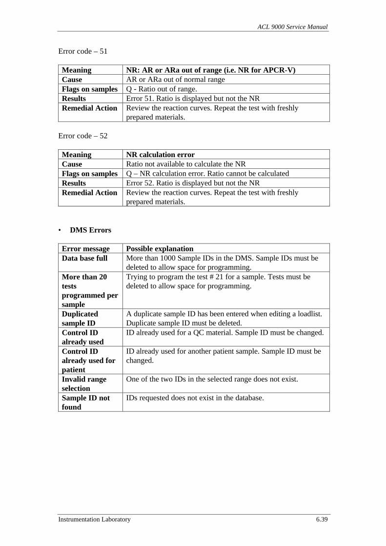
ACL 9000 Service Manual
Instrumentation Laboratory 6.39
Error code – 51
Meaning NR: AR or ARa out of range (i.e. NR for APCR-V)Cause AR or ARa out of normal rangeFlags on samples Q - Ratio out of range.Results Error 51. Ratio is displayed but not the NRRemedial Action Review the reaction curves. Repeat the test with freshly
prepared materials.
Error code – 52
Meaning NR calculation errorCause Ratio not available to calculate the NRFlags on samples Q – NR calculation error. Ratio cannot be calculatedResults Error 52. Ratio is displayed but not the NRRemedial Action Review the reaction curves. Repeat the test with freshly
prepared materials.
• DMS Errors
Error message Possible explanationData base full More than 1000 Sample IDs in the DMS. Sample IDs must be
deleted to allow space for programming.More than 20testsprogrammed persample
Trying to program the test # 21 for a sample. Tests must bedeleted to allow space for programming.
Duplicatedsample ID
A duplicate sample ID has been entered when editing a loadlist.Duplicate sample ID must be deleted.
Control IDalready used
ID already used for a QC material. Sample ID must be changed.
Control IDalready used forpatient
ID already used for another patient sample. Sample ID must bechanged.
Invalid rangeselection
One of the two IDs in the selected range does not exist.
Sample ID notfound
IDs requested does not exist in the database.
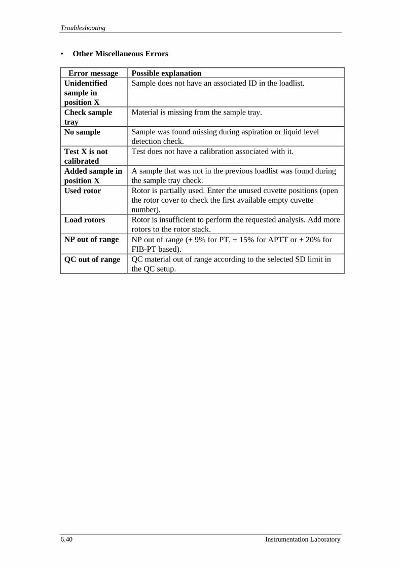
Troubleshooting
6.40 Instrumentation Laboratory
• Other Miscellaneous Errors
Error message Possible explanationUnidentifiedsample inposition X
Sample does not have an associated ID in the loadlist.
Check sampletray
Material is missing from the sample tray.
No sample Sample was found missing during aspiration or liquid leveldetection check.
Test X is notcalibrated
Test does not have a calibration associated with it.
Added sample inposition X
A sample that was not in the previous loadlist was found duringthe sample tray check.
Used rotor Rotor is partially used. Enter the unused cuvette positions (openthe rotor cover to check the first available empty cuvettenumber).
Load rotors Rotor is insufficient to perform the requested analysis. Add morerotors to the rotor stack.
NP out of range NP out of range (± 9% for PT, ± 15% for APTT or ± 20% forFIB-PT based).
QC out of range QC material out of range according to the selected SD limit inthe QC setup.

ACL 9000 Service Manual
Instrumentation Laboratory 6.41
6.2 Service Tools
In this section are described the entire Service Tool that have been designed to aid theservice of the ACL 9000.All tools listed below are included in the “Service Tools Kit for ACL 9000” P/N190653-00.
Following is the table with the main information about the Service Tools.
Name PartNumber
Used for Already used inACL family
Temperature Probe 70954-00 Rotor Holder temperature test YESCoagulimetric OpticTest Kit
97580-50 Coagulimetric Channelperformance checks
YES
Chromogenic OpticTest Kit
97579-50 Chromogenic Channelperformance checks
YES
Graduated CapillaryKit
82589-00 Sample / Reagent Dilutor linedispensation test
YES
RS 232 C InterfaceCheck Connector
99211-01 Serial lines test (Require theAdapter below to work)
YES
RS 232 C InterfaceCheck ConnectorAdapter
71467-70 Serial lines test (Require theCheck connector above towork)
NO
Needles Position Tool 181039-41 Needles Position test YESSample ArmCentring Tool
190513-00 Sample Arm Movement Assypositioning
NO
Rotor Arm CentringTool
190503-00 Rotor Arm positioning NO
Needles WasteCentring Tool
190515-00 Sample Arm positioning NO
Peltier Centring Tool 190507-00 Peltier positioning NOTouch ScreenCalibration Tool
190574-00 Touch Screen Calibration test NO
Rotor Cover MotorCentring Tool
190510-00 Rotor Cover Movement Assypositioning
NO
Rotor CoverEncoder CentringTool
190575-00 Rotor Cover Movement AssyEncoder positioning
NO
Rotor StackCentring Tool
190501-01 Rotor Stack positioning NO
Sample TrayCentring Tool
190520-00 Sample Tray Positioning NO
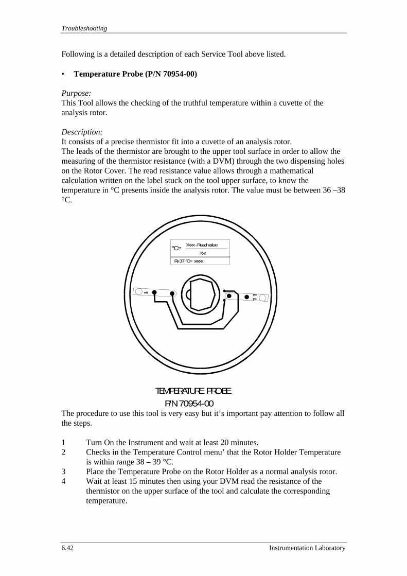
Troubleshooting
6.42 Instrumentation Laboratory
Following is a detailed description of each Service Tool above listed.
• Temperature Probe (P/N 70954-00)
Purpose:This Tool allows the checking of the truthful temperature within a cuvette of theanalysis rotor.
Description:It consists of a precise thermistor fit into a cuvette of an analysis rotor.The leads of the thermistor are brought to the upper tool surface in order to allow themeasuring of the thermistor resistance (with a DVM) through the two dispensing holeson the Rotor Cover. The read resistance value allows through a mathematicalcalculation written on the label stuck on the tool upper surface, to know thetemperature in °C presents inside the analysis rotor. The value must be between 36 –38°C.
The procedure to use this tool is very easy but it’s important pay attention to follow allthe steps.
1 Turn On the Instrument and wait at least 20 minutes.2 Checks in the Temperature Control menu’ that the Rotor Holder Temperature
is within range 38 – 39 °C.3 Place the Temperature Probe on the Rotor Holder as a normal analysis rotor.4 Wait at least 15 minutes then using your DVM read the resistance of the
thermistor on the upper surface of the tool and calculate the correspondingtemperature.
°C=Xxxx - Read value
Xxx
Rv 37 °C= xxxxx
TEMPERATURE PROBE P/N 70954-00
ACL 9000 Service Manual
Instrumentation Laboratory 6.43
• Coagulimetric Optic Test Kit (P/N 97580-50)
Purpose:This kit allows the checking of the performance of the Coagulimetric Channel (see sub-section 7.2.2).
Description:The kit contain four different concentration levels of Wash-Reference Emulsion for atotal of 50 ampoules distributed as follows:
13 ampoules of 219 ampoules of 112 ampoules of 0.56 ampoules of 0.25
• Chromogenic Optic Test Kit (P/N 97579-50)
Purpose:This kit allows the checking of the performance of the Chromogenic Channel (see sub-section 7.3.2).
Description:The kit contain four different concentration levels of a yellow solution(ParaNitroAniline, PNA) for a total of 50 ampoules distributed as follows:
13 ampoules of 16019 ampoules of 8012 ampoules of 406 ampoules of 20
• Graduated Capillary Kit (P/N 82589-00)
Purpose:This tool allows the checking of the Sample and Reagent Dilutor lines aspiration anddispensation (see sub-section 7.8.2).
Description:The kit contains 3 capillaries.
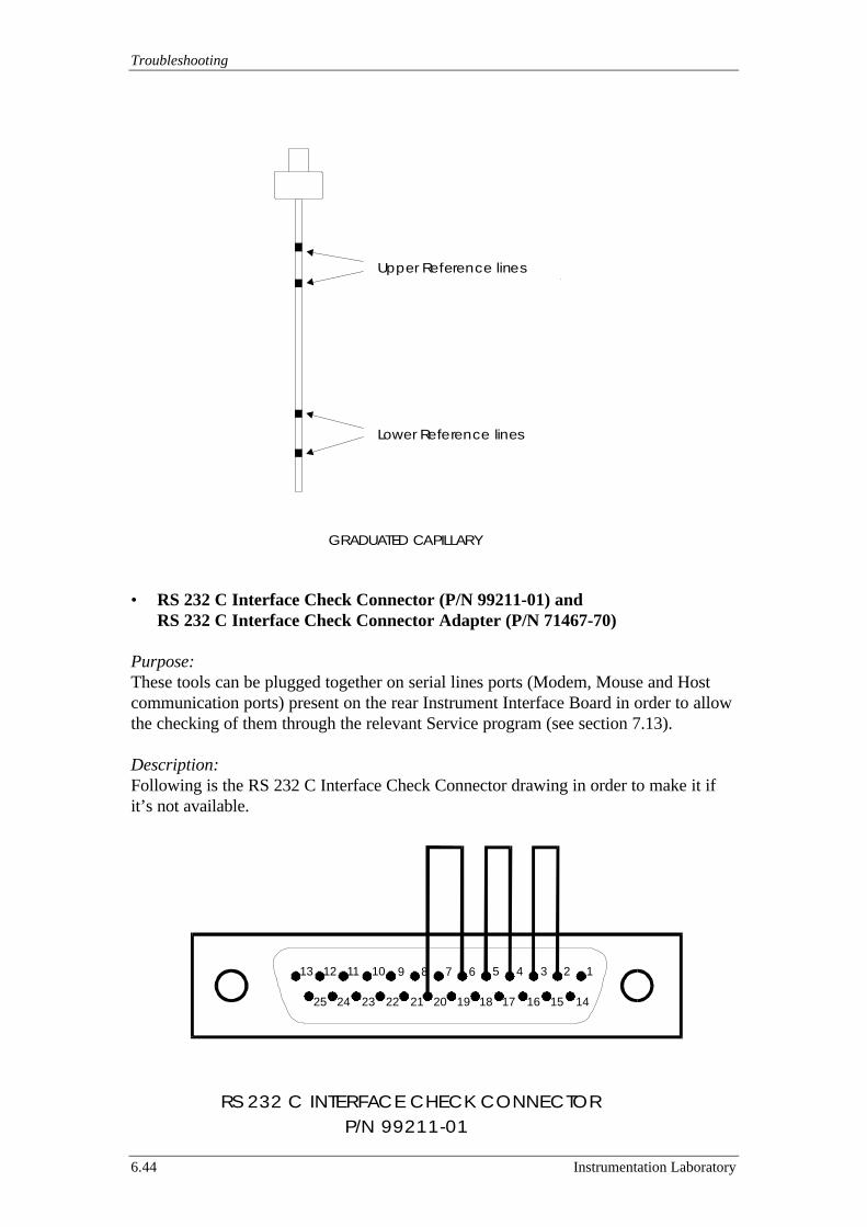
Troubleshooting
6.44 Instrumentation Laboratory
• RS 232 C Interface Check Connector (P/N 99211-01) andRS 232 C Interface Check Connector Adapter (P/N 71467-70)
Purpose:These tools can be plugged together on serial lines ports (Modem, Mouse and Hostcommunication ports) present on the rear Instrument Interface Board in order to allowthe checking of them through the relevant Service program (see section 7.13).
Description:Following is the RS 232 C Interface Check Connector drawing in order to make it ifit’s not available.
Upper Reference lines
Lower Reference lines
GRADUATED CAPILLARY
56789
18192021
1234
14151617
10111213
22232425
RS 232 C INTERFACE CHECK CONNECTOR P/N 99211-01

ACL 9000 Service Manual
Instrumentation Laboratory 6.45
The RS 232 C Interface Check Connector Adapter is a standard PC adapter 25/9 PinFemale/Female.
Following is the drawing of a serial customised 9 Pin Check Connector Male (for theBar Code Port) or Female (for Host, Mouse and Modem Port) in order to make it ifthe RS 232 C Interface Check Connector and its Adapter are not available.
12345
6789
RXTX
DSRDTR
RTSCTS
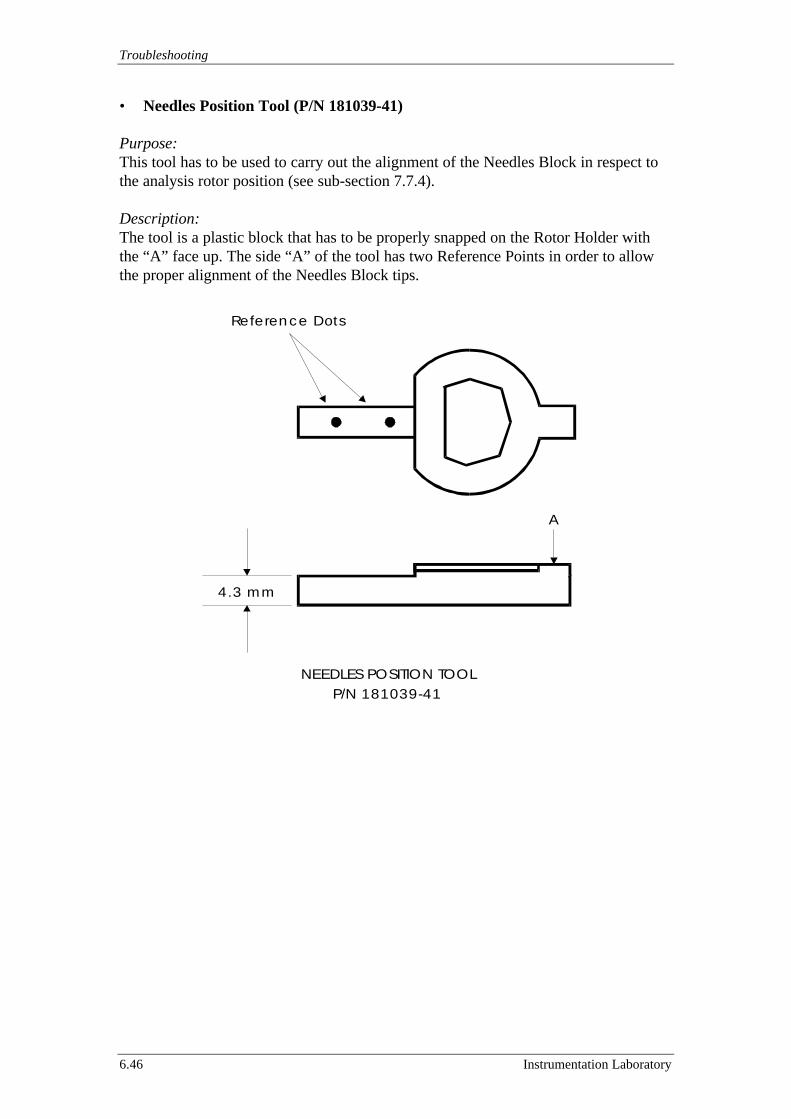
Troubleshooting
6.46 Instrumentation Laboratory
• Needles Position Tool (P/N 181039-41)
Purpose:This tool has to be used to carry out the alignment of the Needles Block in respect tothe analysis rotor position (see sub-section 7.7.4).
Description:The tool is a plastic block that has to be properly snapped on the Rotor Holder withthe “A” face up. The side “A” of the tool has two Reference Points in order to allowthe proper alignment of the Needles Block tips.
NEEDLES POSITION TOOL P/N 181039-41
4.3 mm
A
Reference Dots
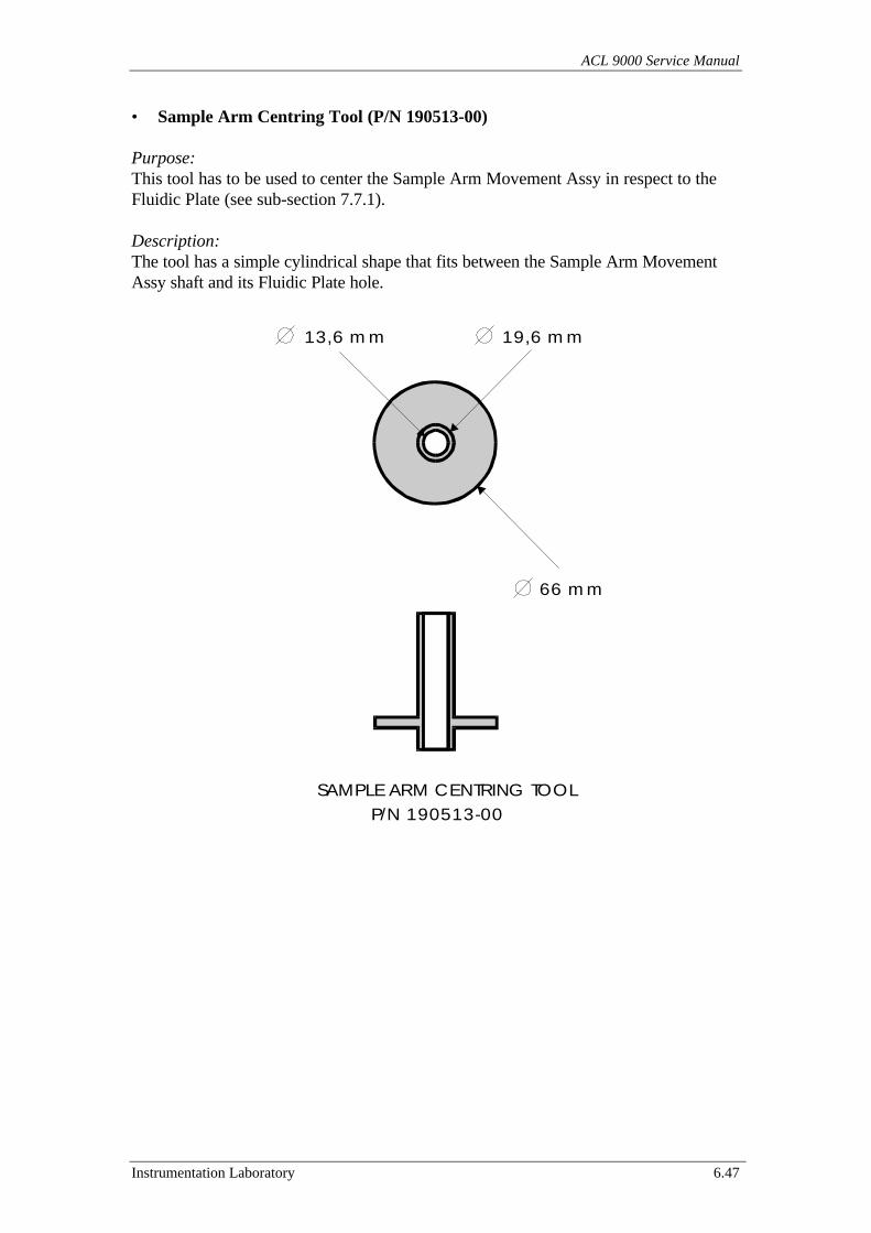
ACL 9000 Service Manual
Instrumentation Laboratory 6.47
• Sample Arm Centring Tool (P/N 190513-00)
Purpose:This tool has to be used to center the Sample Arm Movement Assy in respect to theFluidic Plate (see sub-section 7.7.1).
Description:The tool has a simple cylindrical shape that fits between the Sample Arm MovementAssy shaft and its Fluidic Plate hole.
66 mm
19,6 mm13,6 mm
SAMPLE ARM CENTRING TOOL P/N 190513-00
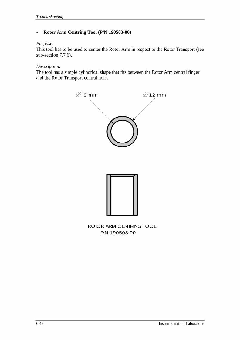
Troubleshooting
6.48 Instrumentation Laboratory
• Rotor Arm Centring Tool (P/N 190503-00)
Purpose:This tool has to be used to center the Rotor Arm in respect to the Rotor Transport (seesub-section 7.7.6).
Description:The tool has a simple cylindrical shape that fits between the Rotor Arm central fingerand the Rotor Transport central hole.
12 mm9 mm
ROTOR ARM CENTRING TOOL P/N 190503-00
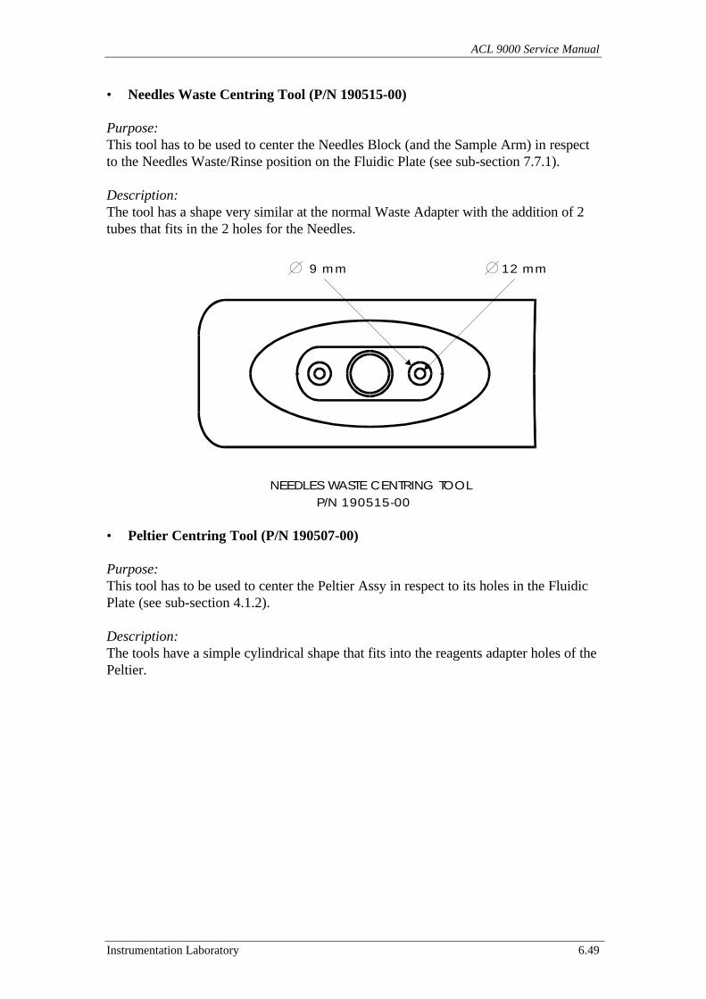
ACL 9000 Service Manual
Instrumentation Laboratory 6.49
• Needles Waste Centring Tool (P/N 190515-00)
Purpose:This tool has to be used to center the Needles Block (and the Sample Arm) in respectto the Needles Waste/Rinse position on the Fluidic Plate (see sub-section 7.7.1).
Description:The tool has a shape very similar at the normal Waste Adapter with the addition of 2tubes that fits in the 2 holes for the Needles.
• Peltier Centring Tool (P/N 190507-00)
Purpose:This tool has to be used to center the Peltier Assy in respect to its holes in the FluidicPlate (see sub-section 4.1.2).
Description:The tools have a simple cylindrical shape that fits into the reagents adapter holes of thePeltier.
12 mm9 mm
NEEDLES WASTE CENTRING TOOL P/N 190515-00
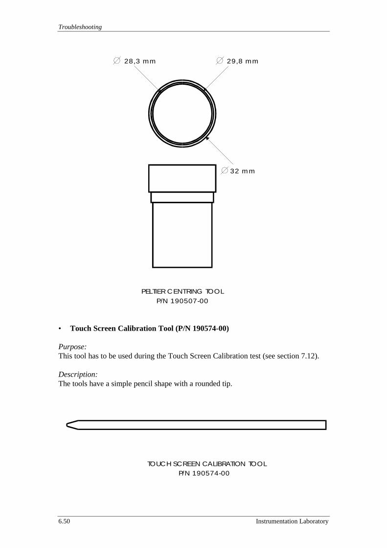
Troubleshooting
6.50 Instrumentation Laboratory
• Touch Screen Calibration Tool (P/N 190574-00)
Purpose:This tool has to be used during the Touch Screen Calibration test (see section 7.12).
Description:The tools have a simple pencil shape with a rounded tip.
TOUCH SCREEN CALIBRATION TOOL P/N 190574-00
29,8 mm28,3 mm
32 mm
PELTIER C ENTRING TOOL P/N 190507-00

ACL 9000 Service Manual
Instrumentation Laboratory 6.51
• Rotor Cover Motor Centring Tool (P/N 190510-00)
Purpose:This tool has to be used when is needed to put in tension the Belt of the Rotor CoverMovement Assy before the final fixing with the 3 screws (see sub-section 7.6.2).
Description:The tool has a simple flat shape that fits into the niche between the Rotor CoverMovement Assy and the support. This tool assures the horizontally of the Rotor CoverMovement Assy.
• Rotor Cover Encoder Centring Tool (P/N 190575-00)
Purpose:This tool has to be used for centre the Encoder Disk position when the Rotor CoverMovement Assy is replaced (see sub-section 7.6.2).
Description:The tool has a simple pencil shape with a thread (M3) at the tip that fits into thesetscrew hole.
ROTOR COVER MOTOR CENTRING TOOL P/N 190510-00
ROTOR COVER ENCODER CENTRING TOOL P/N 190575-00
M3

Troubleshooting
6.52 Instrumentation Laboratory
• Rotor Stack Centring Tool (P/N 190501-01)
Purpose:This tool has to be used for centre the Rotor Stack in respect to the Rotor Transport(see sub-section 7.7.5).
Description:The tools have a simple shape that fits into the Rotor Stack and at the bottom fits intothe Rotor Transport central hole.
• Sample Tray Centring Tool (P/N 190520-00)
Purpose:This tool has to be used to adjust the Sample Tray position in respect to the NeedlesBlock on the Sample Arm (see sub-section 7.7.2).
Description:The tool has a simple cylindrical shape with a central hole that fits on Sample Tray.
ACL 9000 Service Manual
Instrumentation Laboratory 6.53
6.3 Standard Tools
This section provides suggestions about the standard tools equipment of the ServiceEngineer required to perform a replacement or an adjustment on the ACL 9000.
Following is the list of the standard tools.
• Set of metric Hexagonal Allen Screw DriverIn particular: 1.5 mm
2 mm2.5 mm *3 mm *5 mm
• Set of metric Monkey Wrench and/or Socket Wrench DriverIn particular: 5 mm
5.5 mm6 mm7 mm
• Flat Screw Driver• Phillips Screw Driver
* Note: A special flexible version of these two screw driver are both available inthe kit “2.5/3 mm Flex Allen Screw Driver” P/N 99208-10
ACL 9000 Service Manual
Instrumentation Laboratory 7.1
7 Checkout & Adjustment
This section is designed to allow at the Service Engineer to perform a thorough checkout of the whole Instrument.The Service software incorporates proper utilities for the entire checkout andadjustment needed.Following are the specific sections with the check out procedures.
7.1 Quick Reference Guide to Electronic Adjustment7.2 Coagulimetric Channel7.3 Chromogenic Channel7.4 Liquid Sensor7.5 Optic Sensor7.6 Motors Adjust7.7 Modules Positioning7.8 Dilutors Module7.9 Magnetic Sensor7.10 Rotor Waste Presence Switch7.11 Switching Power Supply check out & Adjustment7.12 Touch Screen Calibration7.13 Interface Test7.14 Temperature Control7.15 Floppy Disk Drive Test7.16 Software checking & loading
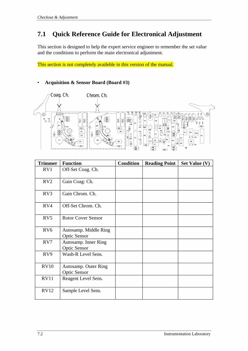
Checkout & Adjustment
7.2 Instrumentation Laboratory
7.1 Quick Reference Guide for Electronical Adjustment
This section is designed to help the expert service engineer to remember the set valueand the conditions to perform the main electronical adjustment.
This section is not completely availeble in this version of the manual.
• Acquisition & Sensor Board (Board #3)
Trimmer Function Condition Reading Point Set Value (V)RV1 Off-Set Coag. Ch.
RV2 Gain Coag: Ch.
RV3 Gain Chrom. Ch.
RV4 Off-Set Chrom. Ch.
RV5 Rotor Cover Sensor
RV6 Autosamp. Middle RingOptic Sensor
RV7 Autosamp. Inner RingOptic Sensor
RV9 Wash-R Level Sens.
RV10 Autosamp. Outer RingOptic Sensor
RV11 Reagent Level Sens.
RV12 Sample Level Sens.
Coag. Ch. Chrom. Ch.
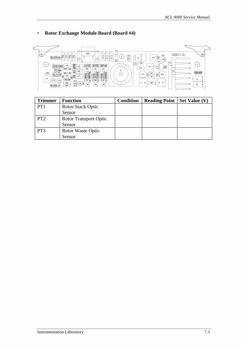
ACL 9000 Service Manual
Instrumentation Laboratory 7.3
• Rotor Exchange Module Board (Board #4)
Trimmer Function Condition Reading Point Set Value (V)PT1 Rotor Stack Optic
SensorPT2 Rotor Transport Optic
SensorPT3 Rotor Waste Optic
Sensor
Checkout & Adjustment
7.4 Instrumentation Laboratory
7.2 Coagulimetric channel
Several tests are available to troubleshoot or verify the Coagulimetric Channel.These tests allow verification of electronic circuits (PCB) and optical components(light source and optic fibre). The tests used to verify the Coagulimetric OpticalChannel are:
Test Name Purpose See sectionCoagulimetric Channelcheck out and adjustment
Sets the reading value and the peak ofthe bell shaped signal of data acquisition.
7.2.1
Performance check out Verifies that precision and linearity arewithin specs.
7.2.2
Light source (LED)verification
Performs match of electronic signals toactual performance of the light source.
7.2.3
Optic fibre check out andadjustment procedure
Optimises optic performance. 7.2.4
7.2.1 Coagulimetric Channel check out and adjustment
Materials / tools necessary for the test: - Brand new rotors.- Wash-Reference Emulsion.- 200µl micropipette.
PrecautionMake sure that the instrument has been switched ON for at least 20 minutes (warm-upof light source and thermoregulation) prior going through the following procedure.
1 Enter the service program menu.2 Thoroughly clean the twenty optical path (holes) of the Rotor Holder with distilled
water and a cotton swab. Clean also the optical sensor window and the optic fibreof the Coagulimetric Channel. Do not use metal forceps with gauze as this mayscratch the rotor holder generating possible stray light affecting the proper systemperformance.
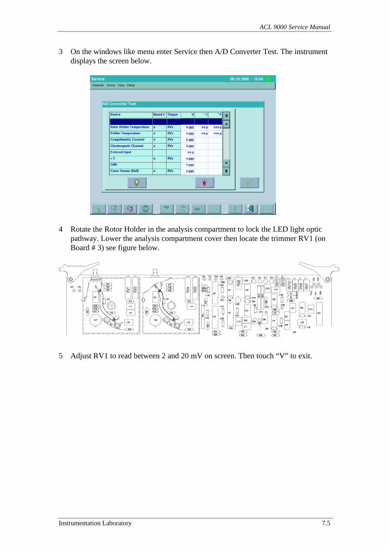
ACL 9000 Service Manual
Instrumentation Laboratory 7.5
3 On the windows like menu enter Service then A/D Converter Test. The instrumentdisplays the screen below.
4 Rotate the Rotor Holder in the analysis compartment to lock the LED light optic
pathway. Lower the analysis compartment cover then locate the trimmer RV1 (onBoard # 3) see figure below.
5 Adjust RV1 to read between 2 and 20 mV on screen. Then touch “V” to exit.

Checkout & Adjustment
7.6 Instrumentation Laboratory
6 On the windows like menu enter Service then Optical Module Test and CurveAdjustment. The instrument shows the screen below:
7 Load 200µl of Wash-Reference Emulsion in cuvette number 20 of a new rotor.8 Place the prepared rotor on the Rotor Holder.9 Select Coagulimetric Channel, set rotational speed to 1200 rpm and touch Start.
The instrument performs an acquisition cycle. Upon completion of the acquisitioncycle, scroll the table of values and delays still you find the delay corresponding tovalue of 1000.
10 Update, if necessary the current delay, keying in the new value on the window“Select Delay”.
11 Change now the rotational speed from 1200 to 600 rpm, and touch Start. Theinstrument performs an acquisition cycle. Upon completion of the acquisition cyclescroll the table of values and delays still you find the delay corresponding to valueof 1000.
12 Update the delay by keying it on the window “Select Delay” only if necessary.Touch now “V” to exit, so the new settings will be saved.
13 On the windows like menu enter Service then Optical Module and AcquisitionAdjustment.
14 Leave the rotor previously loaded in place and touch Start (if the rotor loaded is inplace than more of 3 minutes loading a new one).
15 Adjust RV2 (on board # 3, see figure on previous page) until to read 2.7 Vdc onthe Coagulimetric Channel line (accept any value from 2.6 to 2.8Vdc). Onceadjusted touch Stop, then “V” to exit.
16 On the windows like menu enter Service then Optical Module and FibreAdjustment. Wait for the motor initialisation, then remove the rotor from theanalysis compartment. Touch Start and verify that (without a rotor in place) no“cuvette” reads higher than 80 mV. Should this test fail, perform the fibreadjustment as described in sub-section 7.2.4. If the test pass then touch Stop andinsert a new rotor into the analysis compartment. Touch Start and verify thatcuvette readings are above 140 mV and do not exceed 1500 mV. Touch Stop andthen “X” to exit.
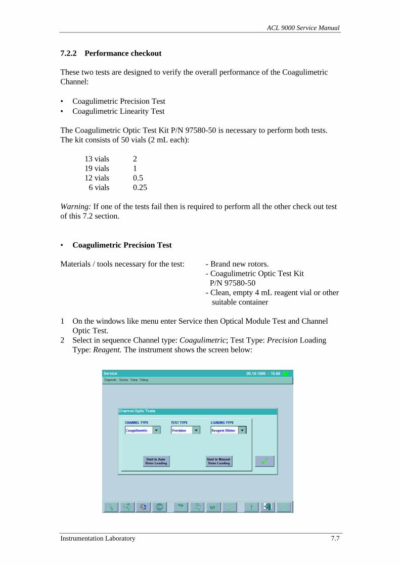
ACL 9000 Service Manual
Instrumentation Laboratory 7.7
7.2.2 Performance checkout
These two tests are designed to verify the overall performance of the CoagulimetricChannel:
• Coagulimetric Precision Test• Coagulimetric Linearity Test
The Coagulimetric Optic Test Kit P/N 97580-50 is necessary to perform both tests.The kit consists of 50 vials (2 mL each):
13 vials 219 vials 112 vials 0.5 6 vials 0.25
Warning: If one of the tests fail then is required to perform all the other check out testof this 7.2 section.
• Coagulimetric Precision Test
Materials / tools necessary for the test: - Brand new rotors.- Coagulimetric Optic Test Kit P/N 97580-50- Clean, empty 4 mL reagent vial or other suitable container
1 On the windows like menu enter Service then Optical Module Test and ChannelOptic Test.
2 Select in sequence Channel type: Coagulimetric; Test Type: Precision LoadingType: Reagent. The instrument shows the screen below:
Checkout & Adjustment
7.8 Instrumentation Laboratory
3 Put the content of two vials (4ml) labelled 1 (taken from the kit P/N 97580-50)into a clean, empty 4 mL reagent vial with it’s Dark Blue adapter.
Note: For this test is possible use the Wash-Reference Emulsion in substitution of theSilicon Emulsion labelled 1.
4 Position the 4 mL reagent vial with the adapter onto the reagent position R1.5 Load 200µl of Wash-Reference Emulsion in cuvette number 20 of a new rotor
before place the rotor onto the Rotor Holder in the analysis compartment.6 Touch “Start in Manual Rotor Loading”. The instrument will load the rotor
cuvettes picking the Silicon Emulsion from the reagent vial using the reagentprobe.
7 Wait for the acquisition cycle then verify the following parameters :
CV% (cuvette # 1 to # 18) : < = 5CV% (Reference) : < = 3Mean Reference : 2.2 V to 3.0 V
Note: Acquisition cycle only can be repeated selecting Skip Loading from the “LoadingType” window.
8 Touch “V” twice to exit.
• Coagulimetric Linearity Test
Materials / tools necessary for the test: - Brand new rotors.- Coagulimetric Optic Test Kit P/N 97580-50.- Clean, empty reagent vial or other suitable container.
1 On the windows like menu enter Service then Optical Module Test and ChannelOptic Test.
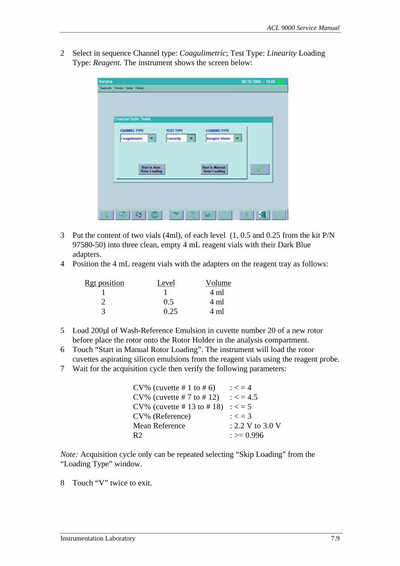
ACL 9000 Service Manual
Instrumentation Laboratory 7.9
2 Select in sequence Channel type: Coagulimetric; Test Type: Linearity LoadingType: Reagent. The instrument shows the screen below:
3 Put the content of two vials (4ml), of each level (1, 0.5 and 0.25 from the kit P/N97580-50) into three clean, empty 4 mL reagent vials with their Dark Blueadapters.
4 Position the 4 mL reagent vials with the adapters on the reagent tray as follows:
Rgt position Level Volume 1 1 4 ml 2 0.5 4 ml
3 0.25 4 ml
5 Load 200µl of Wash-Reference Emulsion in cuvette number 20 of a new rotorbefore place the rotor onto the Rotor Holder in the analysis compartment.
6 Touch “Start in Manual Rotor Loading”. The instrument will load the rotorcuvettes aspirating silicon emulsions from the reagent vials using the reagent probe.
7 Wait for the acquisition cycle then verify the following parameters:
CV% (cuvette # 1 to # 6) : < = 4CV% (cuvette # 7 to # 12) : < = 4.5CV% (cuvette # 13 to # 18) : < = 5CV% (Reference) : < = 3Mean Reference : 2.2 V to 3.0 VR2 : >= 0.996
Note: Acquisition cycle only can be repeated selecting “Skip Loading” from the“Loading Type” window.
8 Touch “V” twice to exit.
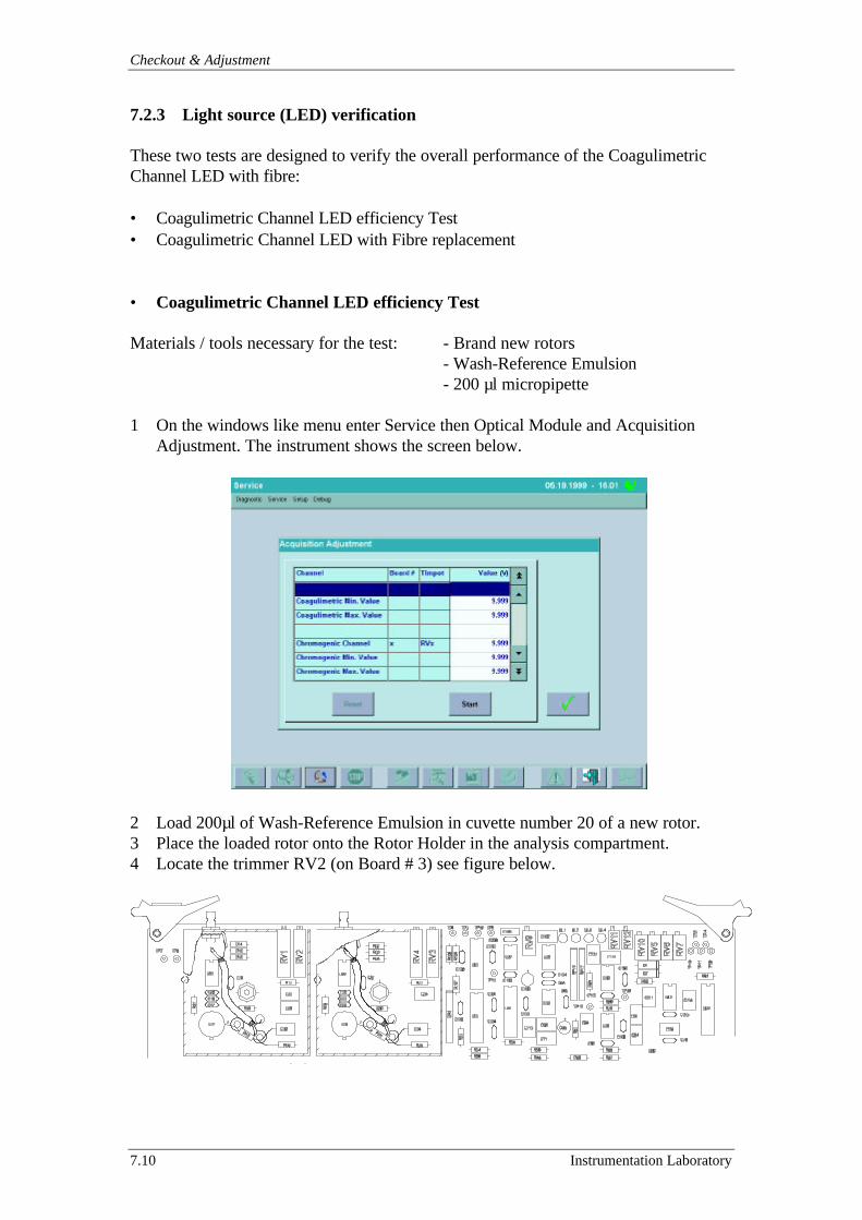
Checkout & Adjustment
7.10 Instrumentation Laboratory
7.2.3 Light source (LED) verification
These two tests are designed to verify the overall performance of the CoagulimetricChannel LED with fibre:
• Coagulimetric Channel LED efficiency Test• Coagulimetric Channel LED with Fibre replacement
• Coagulimetric Channel LED efficiency Test
Materials / tools necessary for the test: - Brand new rotors- Wash-Reference Emulsion- 200 µl micropipette
1 On the windows like menu enter Service then Optical Module and AcquisitionAdjustment. The instrument shows the screen below.
2 Load 200µl of Wash-Reference Emulsion in cuvette number 20 of a new rotor.3 Place the loaded rotor onto the Rotor Holder in the analysis compartment.4 Locate the trimmer RV2 (on Board # 3) see figure below.
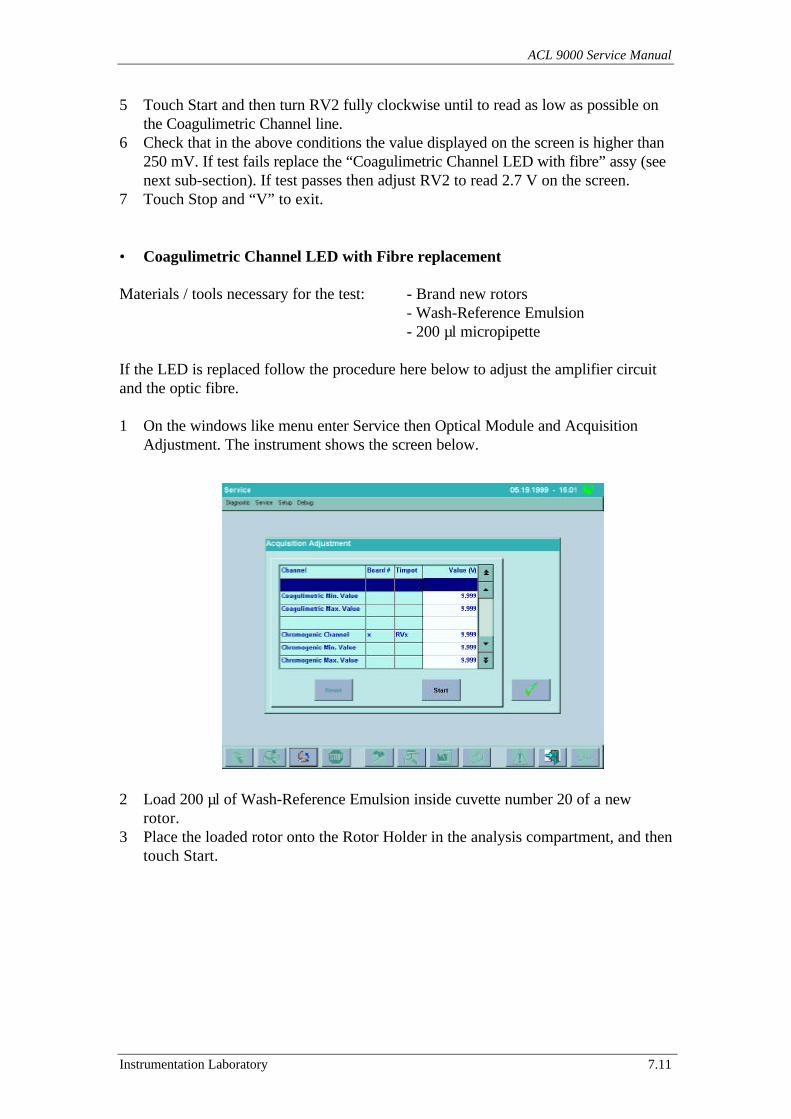
ACL 9000 Service Manual
Instrumentation Laboratory 7.11
5 Touch Start and then turn RV2 fully clockwise until to read as low as possible onthe Coagulimetric Channel line.
6 Check that in the above conditions the value displayed on the screen is higher than250 mV. If test fails replace the “Coagulimetric Channel LED with fibre” assy (seenext sub-section). If test passes then adjust RV2 to read 2.7 V on the screen.
7 Touch Stop and “V” to exit.
• Coagulimetric Channel LED with Fibre replacement
Materials / tools necessary for the test: - Brand new rotors- Wash-Reference Emulsion- 200 µl micropipette
If the LED is replaced follow the procedure here below to adjust the amplifier circuitand the optic fibre.
1 On the windows like menu enter Service then Optical Module and AcquisitionAdjustment. The instrument shows the screen below.
2 Load 200 µl of Wash-Reference Emulsion inside cuvette number 20 of a newrotor.
3 Place the loaded rotor onto the Rotor Holder in the analysis compartment, and thentouch Start.
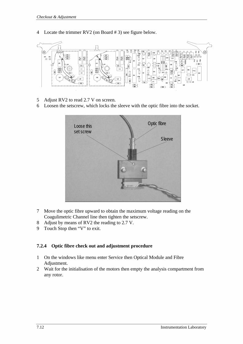
Checkout & Adjustment
7.12 Instrumentation Laboratory
4 Locate the trimmer RV2 (on Board # 3) see figure below.
5 Adjust RV2 to read 2.7 V on screen.6 Loosen the setscrew, which locks the sleeve with the optic fibre into the socket.
7 Move the optic fibre upward to obtain the maximum voltage reading on theCoagulimetric Channel line then tighten the setscrew.
8 Adjust by means of RV2 the reading to 2.7 V.9 Touch Stop then “V” to exit.
7.2.4 Optic fibre check out and adjustment procedure
1 On the windows like menu enter Service then Optical Module and FibreAdjustment.
2 Wait for the initialisation of the motors then empty the analysis compartment fromany rotor.
Loose thisset screw
Sleeve
Optic fibre

ACL 9000 Service Manual
Instrumentation Laboratory 7.13
3 Touch Start and verify that (without any rotor in place) no “cuvette” reads a valuehigher than 80 mV. See screen below:
Warning: If this test fails then follow these few points:
• Loose the setscrew that holds the Optic Fibre in place on the Rotor Holder side.• Rotate the Optic Fibre CW or CCW (max. 90°) until a reading lower than 80 mV is
obtained.• Tighten the setscrew to lock the Optic Fibre back in place (the Optic Fibre must be
placed in the bottom).
4 Touch “Set envelope mode”.5 Wait for about 30 seconds and verify that for no cuvette the MIN-MAX reading
value is higher than 50 mV. If not then perform the test in the sub-section 7.2.3paying attention to the reading oscillations on Coagulimetric Channel (higher then50 mV). Then perform the procedure in the sub-section 7.2.1.
6 If OK touches “Stop”. Raise the Rotor Holder Cover and load a new rotor on theRotor Holder.
7 Touch Start and check that all cuvettes values reads are higher than 140 mV anddon’t exceed 1500 mV. If exceed 1500 mV then check for rotor integrity.
8 Touch Stop and then “X” to exit.
Checkout & Adjustment
7.14 Instrumentation Laboratory
7.3 Chromogenic channel
Several tests are available either to troubleshoot or verify the Chromogenic Channel.These tests allow verification of electronic circuits (PCB) as well as opticalcomponents (light source and optic fibre).
The tests that achieve verification of the Chromogenic Optical Channel are:
Test Name Purpose See sectionChromogenic Channelcheck out and adjustment
Sets the read value and the peak of the bellshaped signal of data acquisition.
7.3.1
Channel performancecheck out
Verifies that precision and linearity arewithin specs
7.3.2
Light Source (HalogenLamp) verification
Performs match of electronic signals toactual performance of light source
7.3.3
7.3.1 Chromogenic Channel check out and adjustment
Materials / tools necessary for the test: - Brand new rotors- Wash-Reference Emulsion- 200 µl micropipette
PrecautionMake sure that the instrument has been switched on for at least 20 minutes (warm-upof light source and thermoregulation) prior going through the following procedure:
1 Enter to the service program menu.2 Thoroughly clean the twenty optical path (holes) of the Rotor Holder with distilled
water and a cotton swab. Clean also the optical sensor and the Optic Fibrewindows of the Chromogenic Channel. Do not use metal forceps with gauze as thismay scratch the rotor holder generating possible stray light affecting the propersystem performance.
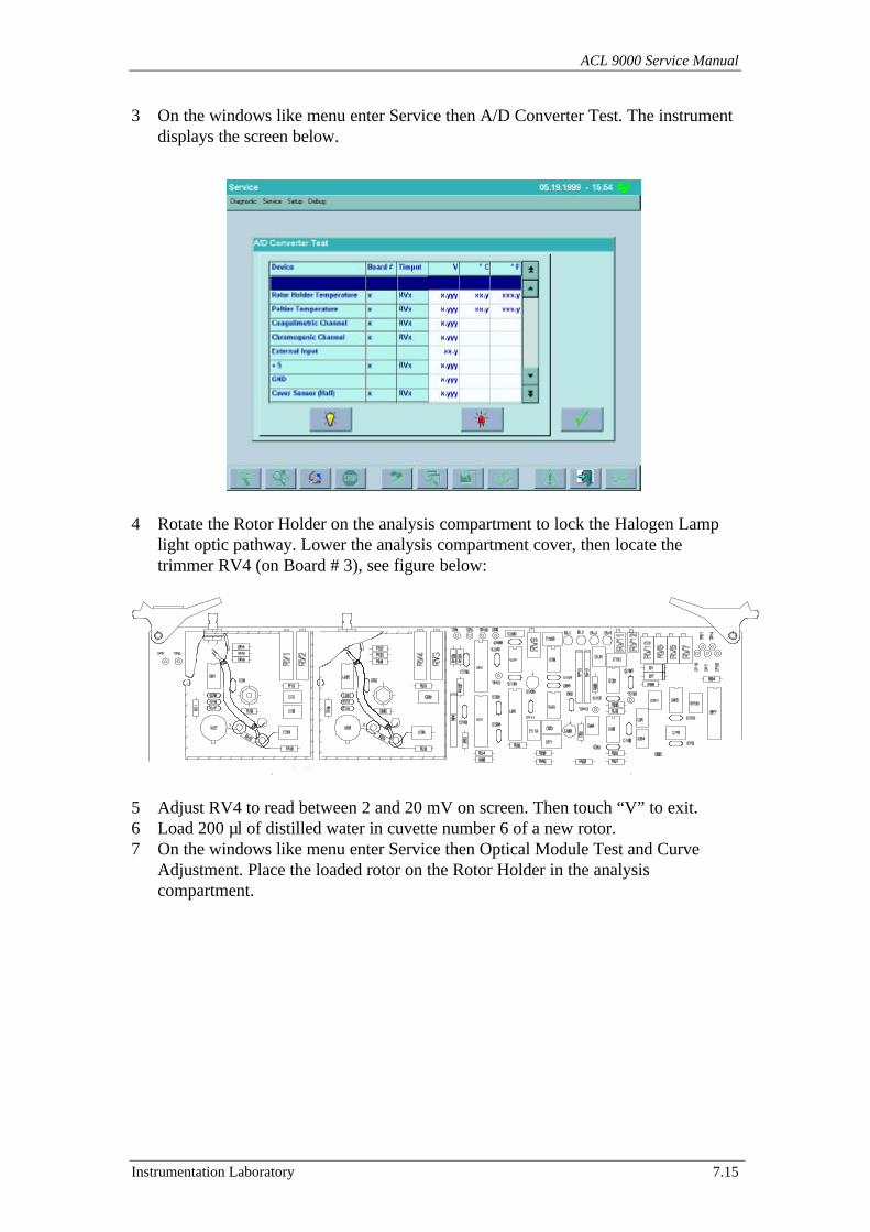
ACL 9000 Service Manual
Instrumentation Laboratory 7.15
3 On the windows like menu enter Service then A/D Converter Test. The instrumentdisplays the screen below.
4 Rotate the Rotor Holder on the analysis compartment to lock the Halogen Lamplight optic pathway. Lower the analysis compartment cover, then locate thetrimmer RV4 (on Board # 3), see figure below:
5 Adjust RV4 to read between 2 and 20 mV on screen. Then touch “V” to exit.6 Load 200 µl of distilled water in cuvette number 6 of a new rotor.7 On the windows like menu enter Service then Optical Module Test and Curve
Adjustment. Place the loaded rotor on the Rotor Holder in the analysiscompartment.

Checkout & Adjustment
7.16 Instrumentation Laboratory
8 Select Chromogenic Channels, set rotational speed at 1200 rpm and touch “Start”.The instrument performs an acquisition cycle. Upon completion of the acquisitioncycle scroll the table of values and delays still you find the delay corresponding tothe value of 1000 (see example below).
9 Check that the delay does not to far than 100 µsec. from the “current” delaydisplayed on the window “Select Delay”.
10 Change now the rotational speed from 1200 to 600 rpm and touch “Start”. Theinstrument performs an acquisition cycle. Upon completion of the acquisition cyclescroll the table of values and delays still you find the delay corresponding to thevalue of 1000.
11 Check that the delay is not too far than 100 µsec. from the “current” delaydisplayed on the window “Select Delay”
12 On the windows like menu enter Service then Optical Module Test and AcquisitionAdjustment. Touch Start, then adjust RV3 (on board # 3, see figure on previouspage) until to read 8.0 Vdc on the Chromogenic Channel line (accept any valuefrom 7.9 to 8.1Vdc). Once adjusted touch “Stop”.
13 Load a new rotor with 200 µl of Wash-Reference Emulsion on cuvette # 6. Placethe loaded rotor in the analysis compartment.
14 Touch “Start” and verify that the reading on Chromogenic Channel line does notexceed 3.5 Vdc. Otherwise replace the 405 nm Optical Filter and repeat the test.
15 Touch “V” to exit
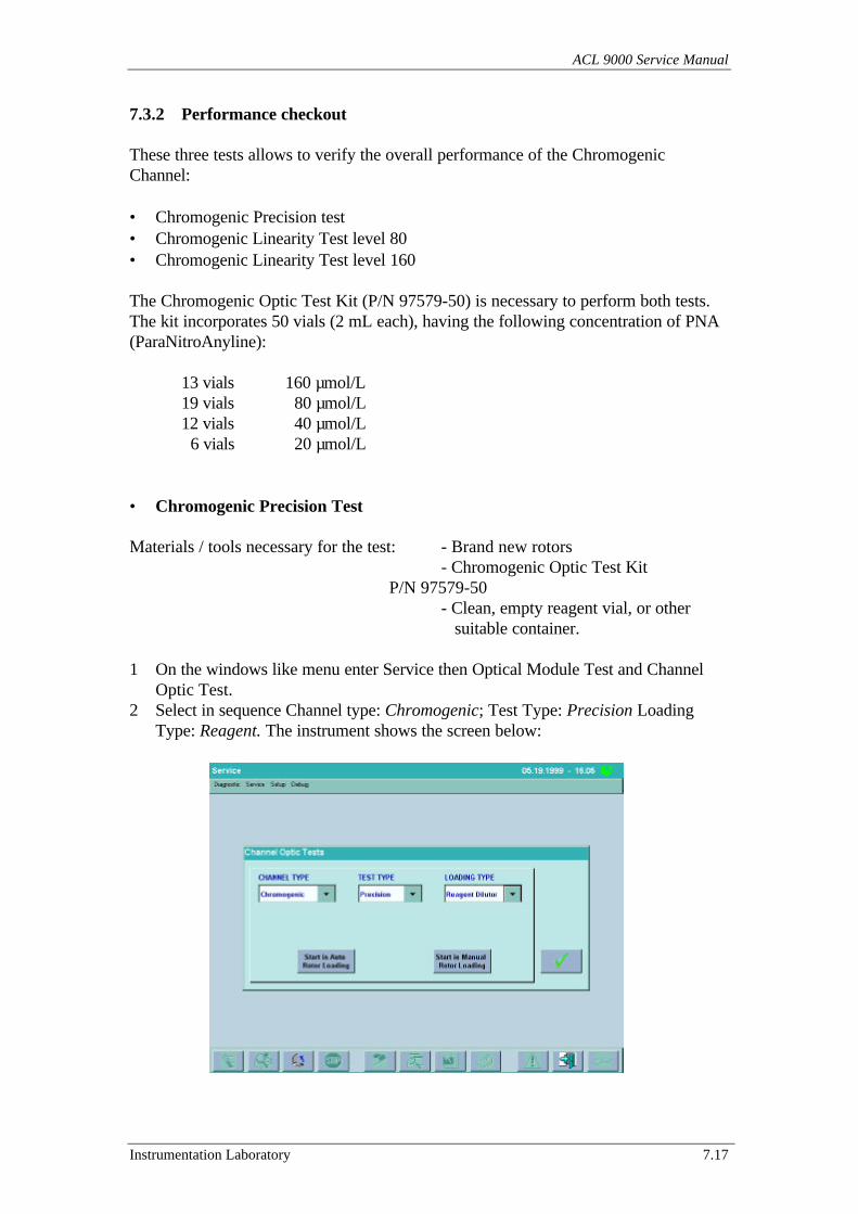
ACL 9000 Service Manual
Instrumentation Laboratory 7.17
7.3.2 Performance checkout
These three tests allows to verify the overall performance of the ChromogenicChannel:
• Chromogenic Precision test• Chromogenic Linearity Test level 80• Chromogenic Linearity Test level 160
The Chromogenic Optic Test Kit (P/N 97579-50) is necessary to perform both tests.The kit incorporates 50 vials (2 mL each), having the following concentration of PNA(ParaNitroAnyline):
13 vials 160 µmol/L19 vials 80 µmol/L12 vials 40 µmol/L 6 vials 20 µmol/L
• Chromogenic Precision Test
Materials / tools necessary for the test: - Brand new rotors- Chromogenic Optic Test Kit
P/N 97579-50- Clean, empty reagent vial, or other suitable container.
1 On the windows like menu enter Service then Optical Module Test and ChannelOptic Test.
2 Select in sequence Channel type: Chromogenic; Test Type: Precision LoadingType: Reagent. The instrument shows the screen below:
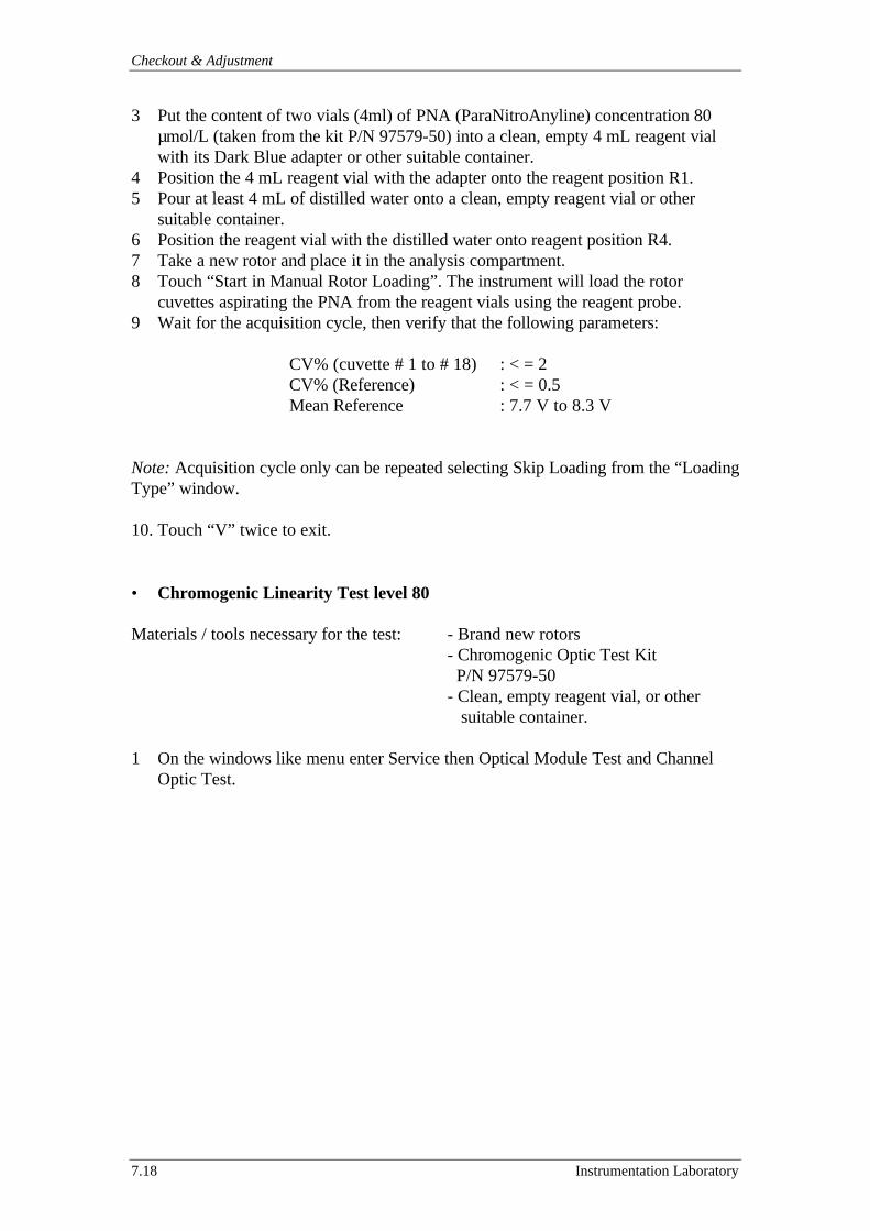
Checkout & Adjustment
7.18 Instrumentation Laboratory
3 Put the content of two vials (4ml) of PNA (ParaNitroAnyline) concentration 80µmol/L (taken from the kit P/N 97579-50) into a clean, empty 4 mL reagent vialwith its Dark Blue adapter or other suitable container.
4 Position the 4 mL reagent vial with the adapter onto the reagent position R1.5 Pour at least 4 mL of distilled water onto a clean, empty reagent vial or other
suitable container.6 Position the reagent vial with the distilled water onto reagent position R4.7 Take a new rotor and place it in the analysis compartment.8 Touch “Start in Manual Rotor Loading”. The instrument will load the rotor
cuvettes aspirating the PNA from the reagent vials using the reagent probe.9 Wait for the acquisition cycle, then verify that the following parameters:
CV% (cuvette # 1 to # 18) : < = 2CV% (Reference) : < = 0.5Mean Reference : 7.7 V to 8.3 V
Note: Acquisition cycle only can be repeated selecting Skip Loading from the “LoadingType” window.
10. Touch “V” twice to exit.
• Chromogenic Linearity Test level 80
Materials / tools necessary for the test: - Brand new rotors- Chromogenic Optic Test Kit P/N 97579-50- Clean, empty reagent vial, or other
suitable container.
1 On the windows like menu enter Service then Optical Module Test and ChannelOptic Test.
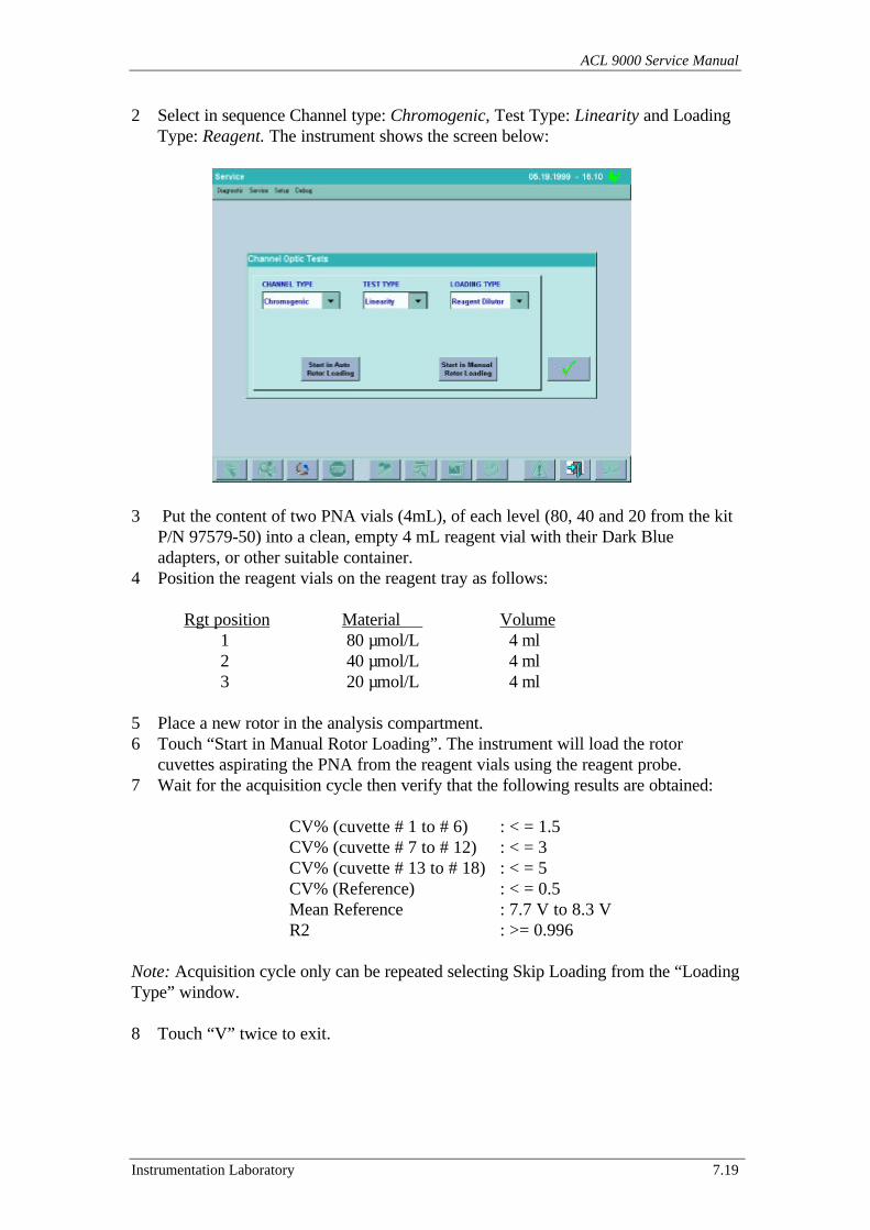
ACL 9000 Service Manual
Instrumentation Laboratory 7.19
2 Select in sequence Channel type: Chromogenic, Test Type: Linearity and LoadingType: Reagent. The instrument shows the screen below:
3 Put the content of two PNA vials (4mL), of each level (80, 40 and 20 from the kit
P/N 97579-50) into a clean, empty 4 mL reagent vial with their Dark Blueadapters, or other suitable container.
4 Position the reagent vials on the reagent tray as follows:
Rgt position Material Volume 1 80 µmol/L 4 ml 2 40 µmol/L 4 ml
3 20 µmol/L 4 ml
5 Place a new rotor in the analysis compartment.6 Touch “Start in Manual Rotor Loading”. The instrument will load the rotor
cuvettes aspirating the PNA from the reagent vials using the reagent probe.7 Wait for the acquisition cycle then verify that the following results are obtained:
CV% (cuvette # 1 to # 6) : < = 1.5CV% (cuvette # 7 to # 12) : < = 3CV% (cuvette # 13 to # 18) : < = 5CV% (Reference) : < = 0.5Mean Reference : 7.7 V to 8.3 VR2 : >= 0.996
Note: Acquisition cycle only can be repeated selecting Skip Loading from the “LoadingType” window.
8 Touch “V” twice to exit.
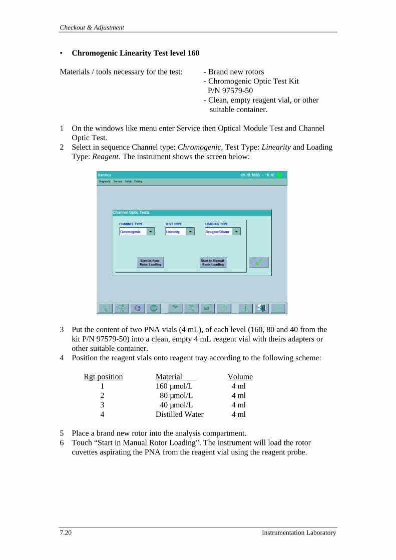
Checkout & Adjustment
7.20 Instrumentation Laboratory
• Chromogenic Linearity Test level 160
Materials / tools necessary for the test: - Brand new rotors- Chromogenic Optic Test Kit P/N 97579-50- Clean, empty reagent vial, or other
suitable container.
1 On the windows like menu enter Service then Optical Module Test and ChannelOptic Test.
2 Select in sequence Channel type: Chromogenic, Test Type: Linearity and LoadingType: Reagent. The instrument shows the screen below:
3 Put the content of two PNA vials (4 mL), of each level (160, 80 and 40 from thekit P/N 97579-50) into a clean, empty 4 mL reagent vial with theirs adapters orother suitable container.
4 Position the reagent vials onto reagent tray according to the following scheme:
Rgt position Material Volume 1 160 µmol/L 4 ml 2 80 µmol/L 4 ml
3 40 µmol/L 4 ml 4 Distilled Water 4 ml
5 Place a brand new rotor into the analysis compartment.6 Touch “Start in Manual Rotor Loading”. The instrument will load the rotor
cuvettes aspirating the PNA from the reagent vial using the reagent probe.

ACL 9000 Service Manual
Instrumentation Laboratory 7.21
7 Wait for the acquisition cycle, then verify that the following results are obtained:
CV% (cuvette # 1 to # 6) : < = 1.5CV% (cuvette # 7 to # 12) : < = 3CV% (cuvette # 13 to # 18) : < = 5CV% (Reference) : < = 0.5Mean Reference : 7.7 V to 8.3 VR2 : >= 0.996
Note: Acquisition cycle only can be repeated selecting Skip Loading from the “LoadingType” window.
8 Touch “V” twice to exit.
7.3.3 Light source (Halogen Lamp) verification
Materials / tools necessary for the test: - Distilled Water- Brand new rotors
1 On the windows like menu enter Service then Optical Module and AcquisitionAdjustment. Wait for motors initialisation then the instrument shows the screenbelow.
2 Load 200 µl of distilled water inside cuvette number 6 of a new rotor.3 Place the loaded rotor onto the Rotor Holder in the analysis compartment.
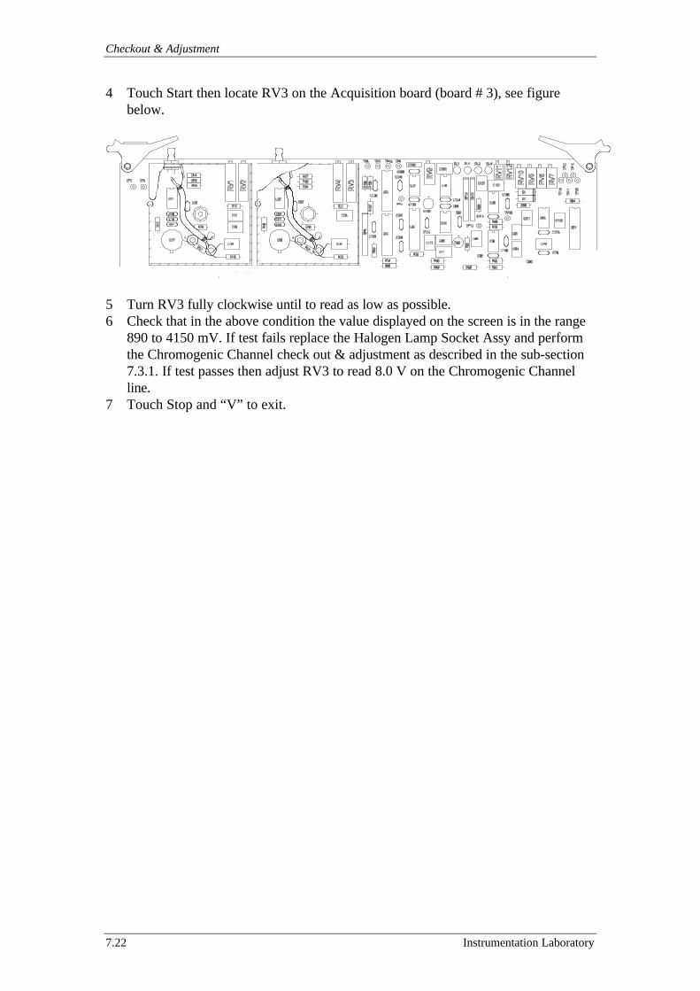
Checkout & Adjustment
7.22 Instrumentation Laboratory
4 Touch Start then locate RV3 on the Acquisition board (board # 3), see figurebelow.
5 Turn RV3 fully clockwise until to read as low as possible.6 Check that in the above condition the value displayed on the screen is in the range
890 to 4150 mV. If test fails replace the Halogen Lamp Socket Assy and performthe Chromogenic Channel check out & adjustment as described in the sub-section7.3.1. If test passes then adjust RV3 to read 8.0 V on the Chromogenic Channelline.
7 Touch Stop and “V” to exit.
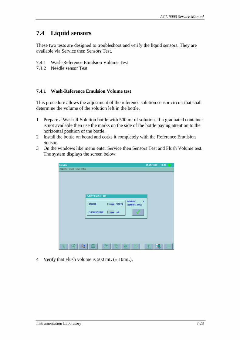
ACL 9000 Service Manual
Instrumentation Laboratory 7.23
7.4 Liquid sensors
These two tests are designed to troubleshoot and verify the liquid sensors. They areavailable via Service then Sensors Test.
7.4.1 Wash-Reference Emulsion Volume Test7.4.2 Needle sensor Test
7.4.1 Wash-Reference Emulsion Volume test
This procedure allows the adjustment of the reference solution sensor circuit that shalldetermine the volume of the solution left in the bottle.
1 Prepare a Wash-R Solution bottle with 500 ml of solution. If a graduated containeris not available then use the marks on the side of the bottle paying attention to thehorizontal position of the bottle.
2 Install the bottle on board and corks it completely with the Reference EmulsionSensor.
3 On the windows like menu enter Service then Sensors Test and Flush Volume test.The system displays the screen below:
4 Verify that Flush volume is 500 mL (± 10mL).
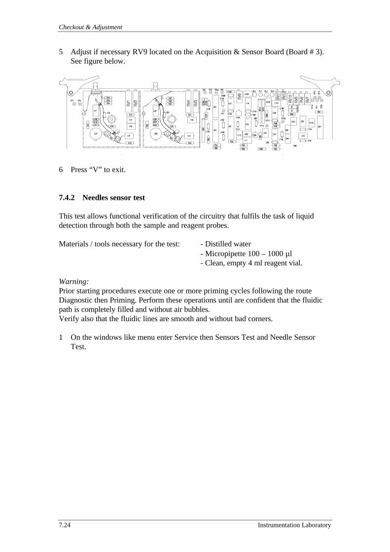
Checkout & Adjustment
7.24 Instrumentation Laboratory
5 Adjust if necessary RV9 located on the Acquisition & Sensor Board (Board # 3).See figure below.
6 Press “V” to exit.
7.4.2 Needles sensor test
This test allows functional verification of the circuitry that fulfils the task of liquiddetection through both the sample and reagent probes.
Materials / tools necessary for the test: - Distilled water- Micropipette 100 – 1000 µl- Clean, empty 4 ml reagent vial.
Warning:Prior starting procedures execute one or more priming cycles following the routeDiagnostic then Priming. Perform these operations until are confident that the fluidicpath is completely filled and without air bubbles.Verify also that the fluidic lines are smooth and without bad corners.
1 On the windows like menu enter Service then Sensors Test and Needle SensorTest.
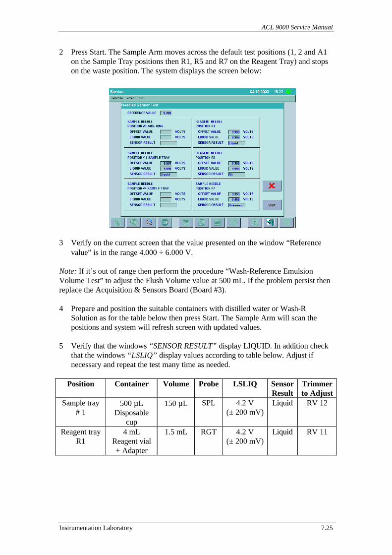
ACL 9000 Service Manual
Instrumentation Laboratory 7.25
2 Press Start. The Sample Arm moves across the default test positions (1, 2 and A1on the Sample Tray positions then R1, R5 and R7 on the Reagent Tray) and stopson the waste position. The system displays the screen below:
3 Verify on the current screen that the value presented on the window “Referencevalue” is in the range 4.000 ÷ 6.000 V.
Note: If it’s out of range then perform the procedure “Wash-Reference EmulsionVolume Test” to adjust the Flush Volume value at 500 mL. If the problem persist thenreplace the Acquisition & Sensors Board (Board #3).
4 Prepare and position the suitable containers with distilled water or Wash-RSolution as for the table below then press Start. The Sample Arm will scan thepositions and system will refresh screen with updated values.
5 Verify that the windows “SENSOR RESULT” display LIQUID. In addition checkthat the windows “LSLIQ” display values according to table below. Adjust ifnecessary and repeat the test many time as needed.
Position Container Volume Probe LSLIQ SensorResult
Trimmerto Adjust
Sample tray# 1
500 µLDisposable
cup
150 µL SPL 4.2 V(± 200 mV)
Liquid RV 12
Reagent trayR1
4 mLReagent vial+ Adapter
1.5 mL RGT 4.2 V(± 200 mV)
Liquid RV 11
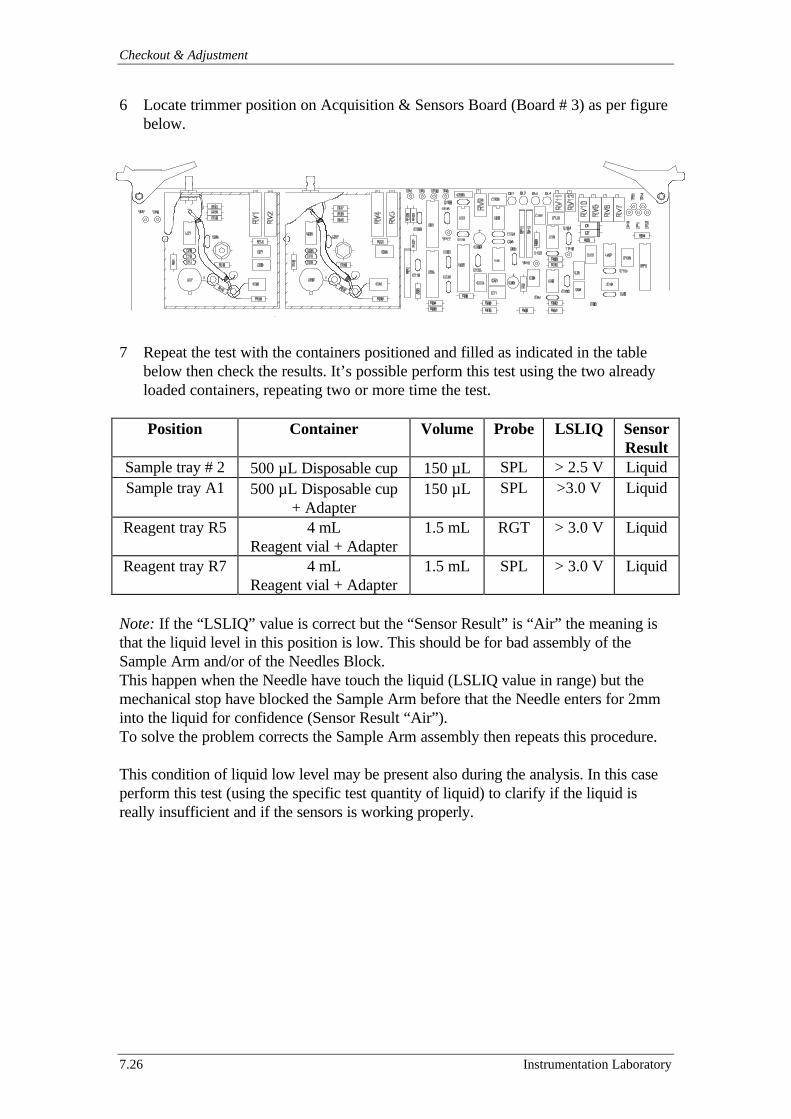
Checkout & Adjustment
7.26 Instrumentation Laboratory
6 Locate trimmer position on Acquisition & Sensors Board (Board # 3) as per figurebelow.
7 Repeat the test with the containers positioned and filled as indicated in the tablebelow then check the results. It’s possible perform this test using the two alreadyloaded containers, repeating two or more time the test.
Position Container Volume Probe LSLIQ SensorResult
Sample tray # 2 500 µL Disposable cup 150 µL SPL > 2.5 V LiquidSample tray A1 500 µL Disposable cup
+ Adapter150 µL SPL >3.0 V Liquid
Reagent tray R5 4 mLReagent vial + Adapter
1.5 mL RGT > 3.0 V Liquid
Reagent tray R7 4 mLReagent vial + Adapter
1.5 mL SPL > 3.0 V Liquid
Note: If the “LSLIQ” value is correct but the “Sensor Result” is “Air” the meaning isthat the liquid level in this position is low. This should be for bad assembly of theSample Arm and/or of the Needles Block.This happen when the Needle have touch the liquid (LSLIQ value in range) but themechanical stop have blocked the Sample Arm before that the Needle enters for 2mminto the liquid for confidence (Sensor Result “Air”).To solve the problem corrects the Sample Arm assembly then repeats this procedure.
This condition of liquid low level may be present also during the analysis. In this caseperform this test (using the specific test quantity of liquid) to clarify if the liquid isreally insufficient and if the sensors is working properly.
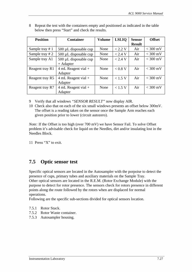
ACL 9000 Service Manual
Instrumentation Laboratory 7.27
8 Repeat the test with the containers empty and positioned as indicated in the tablebelow then press “Start” and check the results.
Position Container Volume LSLIQ SensorResult
Offset
Sample tray # 1 500 µL disposable cup None < 2.2 V Air < 300 mVSample tray # 2 500 µL disposable cup None < 2.4 V Air < 300 mVSample tray A1 500 µL disposable cup
+ AdapterNone < 2.4 V Air < 300 mV
Reagent tray R1 4 mL Reagent vial +Adapter
None < 0.8 V Air < 300 mV
Reagent tray R5 4 mL Reagent vial +Adapter
None < 1.5 V Air < 300 mV
Reagent tray R7 4 mL Reagent vial +Adapter
None < 1.5 V Air < 300 mV
9 Verify that all windows “SENSOR RESULT” now display AIR.10 Check also that on each of the six small windows presents an offset below 300mV.
The offset is a reading taken on the sensor once the Sample Arm reaches eachgiven position prior to lower (circuit autozero).
Note: If the Offset is too high (over 700 mV) we have Sensor Fail. To solve Offsetproblem it’s advisable check for liquid on the Needles, dirt and/or insulating lost in theNeedles Block.
11 Press “X” to exit.
7.5 Optic sensor test
Specific optical sensors are located in the Autosampler with the porpoise to detect thepresence of cups, primary tubes and auxiliary materials on the Sample Tray.Other optical sensors are located in the R.E.M. (Rotor Exchange Module) with thepurpose to detect for rotor presence. The sensors check for rotors presence in differentpoints along the route followed by the rotors when are displaced for normaloperations.Following are the specific sub-sections divided for optical sensors location.
7.5.1 Rotor Stack.7.5.2 Rotor Waste container.7.5.3 Autosampler housing.
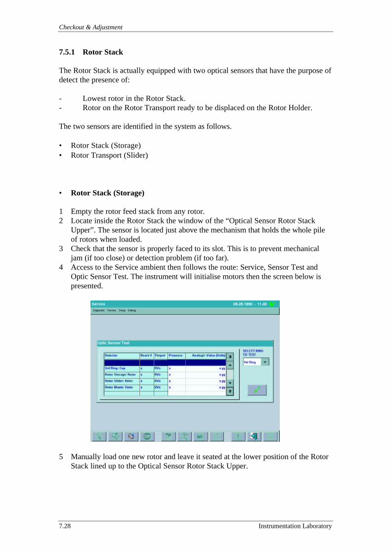
Checkout & Adjustment
7.28 Instrumentation Laboratory
7.5.1 Rotor Stack
The Rotor Stack is actually equipped with two optical sensors that have the purpose ofdetect the presence of:
- Lowest rotor in the Rotor Stack.- Rotor on the Rotor Transport ready to be displaced on the Rotor Holder.
The two sensors are identified in the system as follows.
• Rotor Stack (Storage)• Rotor Transport (Slider)
• Rotor Stack (Storage)
1 Empty the rotor feed stack from any rotor.2 Locate inside the Rotor Stack the window of the “Optical Sensor Rotor Stack
Upper”. The sensor is located just above the mechanism that holds the whole pileof rotors when loaded.
3 Check that the sensor is properly faced to its slot. This is to prevent mechanicaljam (if too close) or detection problem (if too far).
4 Access to the Service ambient then follows the route: Service, Sensor Test andOptic Sensor Test. The instrument will initialise motors then the screen below ispresented.
5 Manually load one new rotor and leave it seated at the lower position of the RotorStack lined up to the Optical Sensor Rotor Stack Upper.
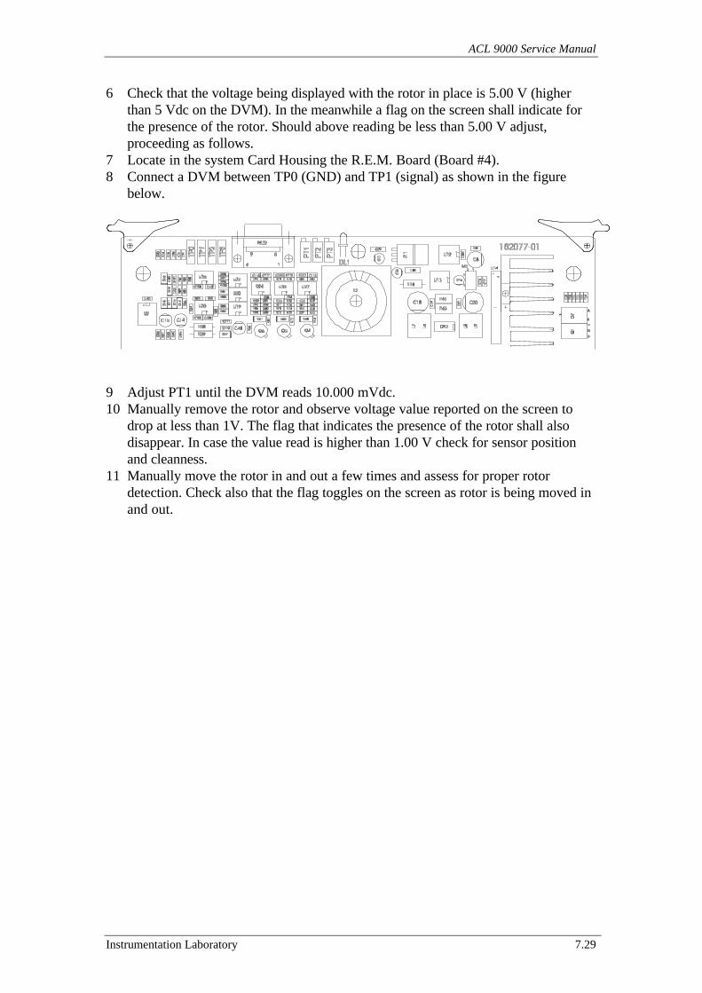
ACL 9000 Service Manual
Instrumentation Laboratory 7.29
6 Check that the voltage being displayed with the rotor in place is 5.00 V (higherthan 5 Vdc on the DVM). In the meanwhile a flag on the screen shall indicate forthe presence of the rotor. Should above reading be less than 5.00 V adjust,proceeding as follows.
7 Locate in the system Card Housing the R.E.M. Board (Board #4).8 Connect a DVM between TP0 (GND) and TP1 (signal) as shown in the figure
below.
9 Adjust PT1 until the DVM reads 10.000 mVdc.10 Manually remove the rotor and observe voltage value reported on the screen to
drop at less than 1V. The flag that indicates the presence of the rotor shall alsodisappear. In case the value read is higher than 1.00 V check for sensor positionand cleanness.
11 Manually move the rotor in and out a few times and assess for proper rotordetection. Check also that the flag toggles on the screen as rotor is being moved inand out.
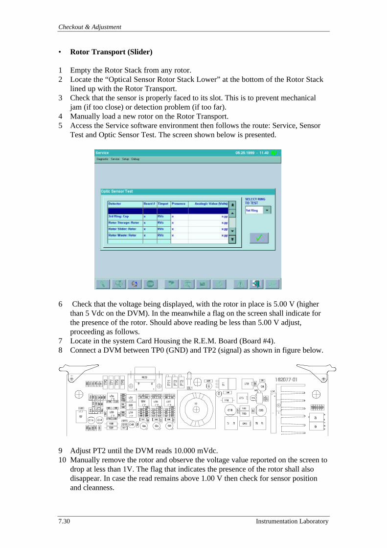
Checkout & Adjustment
7.30 Instrumentation Laboratory
• Rotor Transport (Slider)
1 Empty the Rotor Stack from any rotor.2 Locate the “Optical Sensor Rotor Stack Lower” at the bottom of the Rotor Stack
lined up with the Rotor Transport.3 Check that the sensor is properly faced to its slot. This is to prevent mechanical
jam (if too close) or detection problem (if too far).4 Manually load a new rotor on the Rotor Transport.5 Access the Service software environment then follows the route: Service, Sensor
Test and Optic Sensor Test. The screen shown below is presented.
6 Check that the voltage being displayed, with the rotor in place is 5.00 V (higherthan 5 Vdc on the DVM). In the meanwhile a flag on the screen shall indicate forthe presence of the rotor. Should above reading be less than 5.00 V adjust,proceeding as follows.
7 Locate in the system Card Housing the R.E.M. Board (Board #4).8 Connect a DVM between TP0 (GND) and TP2 (signal) as shown in figure below.
9 Adjust PT2 until the DVM reads 10.000 mVdc.10 Manually remove the rotor and observe the voltage value reported on the screen to
drop at less than 1V. The flag that indicates the presence of the rotor shall alsodisappear. In case the read remains above 1.00 V then check for sensor positionand cleanness.
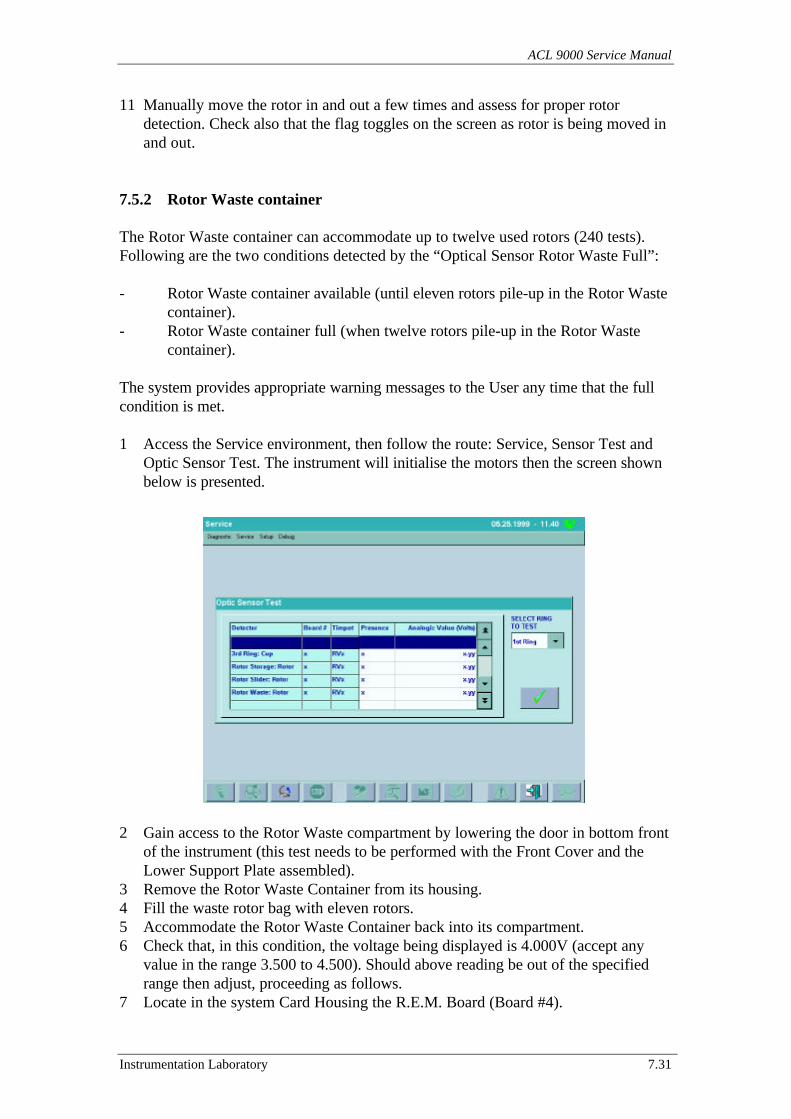
ACL 9000 Service Manual
Instrumentation Laboratory 7.31
11 Manually move the rotor in and out a few times and assess for proper rotordetection. Check also that the flag toggles on the screen as rotor is being moved inand out.
7.5.2 Rotor Waste container
The Rotor Waste container can accommodate up to twelve used rotors (240 tests).Following are the two conditions detected by the “Optical Sensor Rotor Waste Full”:
- Rotor Waste container available (until eleven rotors pile-up in the Rotor Wastecontainer).
- Rotor Waste container full (when twelve rotors pile-up in the Rotor Wastecontainer).
The system provides appropriate warning messages to the User any time that the fullcondition is met.
1 Access the Service environment, then follow the route: Service, Sensor Test andOptic Sensor Test. The instrument will initialise the motors then the screen shownbelow is presented.
2 Gain access to the Rotor Waste compartment by lowering the door in bottom frontof the instrument (this test needs to be performed with the Front Cover and theLower Support Plate assembled).
3 Remove the Rotor Waste Container from its housing.4 Fill the waste rotor bag with eleven rotors.5 Accommodate the Rotor Waste Container back into its compartment.6 Check that, in this condition, the voltage being displayed is 4.000V (accept any
value in the range 3.500 to 4.500). Should above reading be out of the specifiedrange then adjust, proceeding as follows.
7 Locate in the system Card Housing the R.E.M. Board (Board #4).
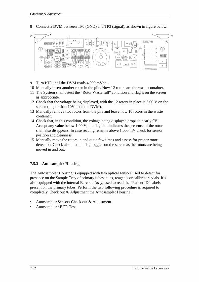
Checkout & Adjustment
7.32 Instrumentation Laboratory
8 Connect a DVM between TP0 (GND) and TP3 (signal), as shown in figure below.
9 Turn PT3 until the DVM reads 4.000 mVdc.10 Manually insert another rotor in the pile. Now 12 rotors are the waste container.11 The System shall detect the “Rotor Waste full” condition and flag it on the screen
as appropriate.12 Check that the voltage being displayed, with the 12 rotors in place is 5.00 V on the
screen (higher than 10Vdc on the DVM).13 Manually remove two rotors from the pile and leave now 10 rotors in the waste
container.14 Check that, in this condition, the voltage being displayed drops to nearly 0V.
Accept any value below 1.00 V, the flag that indicates the presence of the rotorshall also disappears. In case reading remains above 1.000 mV check for sensorposition and cleanness.
15 Manually move the rotors in and out a few times and assess for proper rotordetection. Check also that the flag toggles on the screen as the rotors are beingmoved in and out.
7.5.3 Autosampler Housing
The Autosampler Housing is equipped with two optical sensors used to detect forpresence on the Sample Tray of primary tubes, cups, reagents or calibrators vials. It’salso equipped with the internal Barcode Assy, used to read the “Patient ID” labelspresent on the primary tubes. Perform the two following procedure is required tocompletely Check out & Adjustment the Autosampler Housing.
• Autosampler Sensors Check out & Adjustment.• Autosampler / BCR Test.
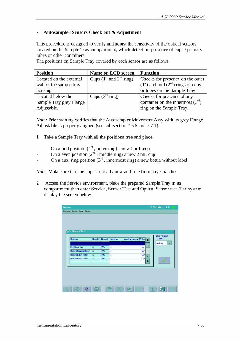
ACL 9000 Service Manual
Instrumentation Laboratory 7.33
• Autosampler Sensors Check out & Adjustment
This procedure is designed to verify and adjust the sensitivity of the optical sensorslocated on the Sample Tray compartment, which detect for presence of cups / primarytubes or other containers.The positions on Sample Tray covered by each sensor are as follows.
Position Name on LCD screen FunctionLocated on the externalwall of the sample trayhousing
Cups (1st and 2nd ring) Checks for presence on the outer(1st) and mid (2nd) rings of cupsor tubes on the Sample Tray.
Located below theSample Tray grey FlangeAdjustable.
Cups (3rd ring) Checks for presence of anycontainer on the innermost (3rd)ring on the Sample Tray.
Note: Prior starting verifies that the Autosampler Movement Assy with its grey FlangeAdjustable is properly aligned (see sub-section 7.6.5 and 7.7.1).
1 Take a Sample Tray with all the positions free and place:
- On a odd position (1st , outer ring) a new 2 mL cup- On a even position (2nd , middle ring) a new 2 mL cup- On a aux. ring position (3rd , innermost ring) a new bottle without label
Note: Make sure that the cups are really new and free from any scratches.
2 Access the Service environment, place the prepared Sample Tray in itscompartment then enter Service, Sensor Test and Optical Sensor test. The systemdisplay the screen below:
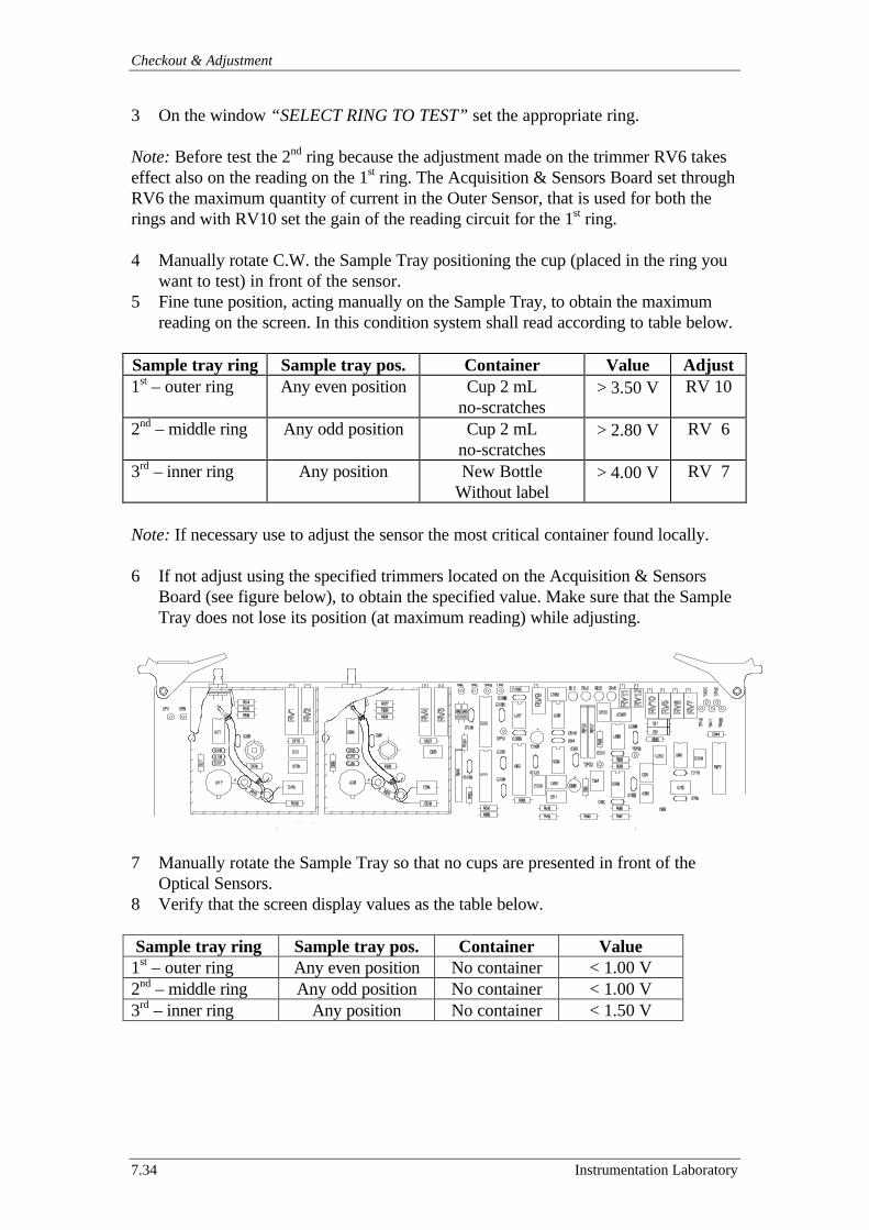
Checkout & Adjustment
7.34 Instrumentation Laboratory
3 On the window “SELECT RING TO TEST” set the appropriate ring.
Note: Before test the 2nd ring because the adjustment made on the trimmer RV6 takeseffect also on the reading on the 1st ring. The Acquisition & Sensors Board set throughRV6 the maximum quantity of current in the Outer Sensor, that is used for both therings and with RV10 set the gain of the reading circuit for the 1st ring.
4 Manually rotate C.W. the Sample Tray positioning the cup (placed in the ring youwant to test) in front of the sensor.
5 Fine tune position, acting manually on the Sample Tray, to obtain the maximumreading on the screen. In this condition system shall read according to table below.
Sample tray ring Sample tray pos. Container Value Adjust1st – outer ring Any even position Cup 2 mL
no-scratches> 3.50 V RV 10
2nd – middle ring Any odd position Cup 2 mLno-scratches
> 2.80 V RV 6
3rd – inner ring Any position New BottleWithout label
> 4.00 V RV 7
Note: If necessary use to adjust the sensor the most critical container found locally.
6 If not adjust using the specified trimmers located on the Acquisition & SensorsBoard (see figure below), to obtain the specified value. Make sure that the SampleTray does not lose its position (at maximum reading) while adjusting.
7 Manually rotate the Sample Tray so that no cups are presented in front of theOptical Sensors.
8 Verify that the screen display values as the table below.
Sample tray ring Sample tray pos. Container Value1st – outer ring Any even position No container < 1.00 V2nd – middle ring Any odd position No container < 1.00 V3rd – inner ring Any position No container < 1.50 V
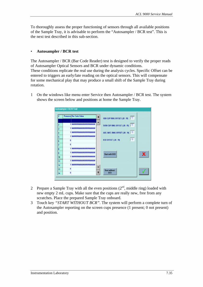
ACL 9000 Service Manual
Instrumentation Laboratory 7.35
To thoroughly assess the proper functioning of sensors through all available positionsof the Sample Tray, it is advisable to perform the “Autosampler / BCR test”. This isthe next test described in this sub-section.
• Autosampler / BCR test
The Autosampler / BCR (Bar Code Reader) test is designed to verify the proper readsof Autosampler Optical Sensors and BCR under dynamic conditions.These conditions replicate the real use during the analysis cycles. Specific Offset can beentered to triggers an early/late reading on the optical sensors. This will compensatefor some mechanical play that may produce a small shift of the Sample Tray duringrotation.
1 On the windows like menu enter Service then Autosampler / BCR test. The systemshows the screen below and positions at home the Sample Tray.
2 Prepare a Sample Tray with all the even positions (2nd, middle ring) loaded withnew empty 2 mL cups. Make sure that the cups are really new, free from anyscratches. Place the prepared Sample Tray onboard.
3 Touch key “START WITHOUT BCR”. The system will perform a complete turn ofthe Autosampler reporting on the screen cups presence (1 present; 0 not present)and position.
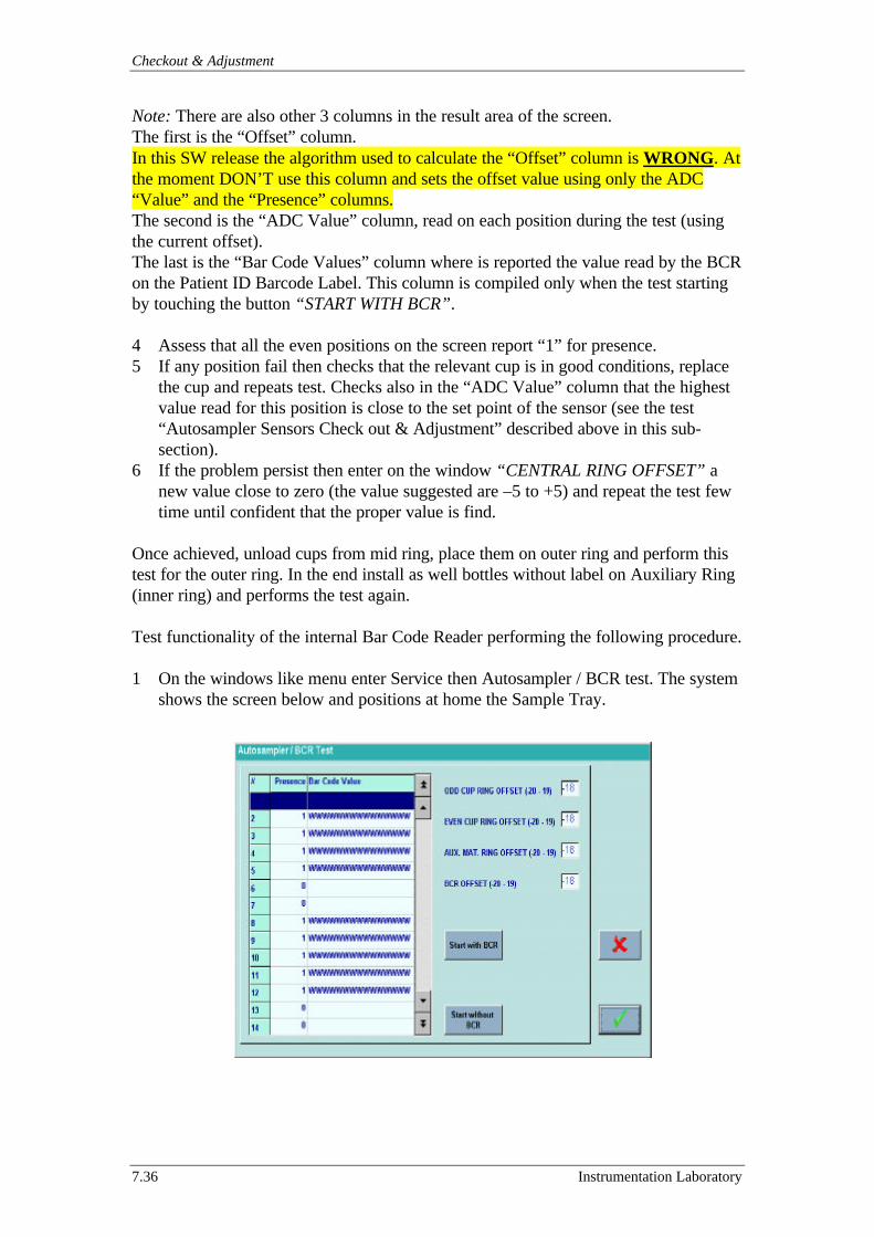
Checkout & Adjustment
7.36 Instrumentation Laboratory
Note: There are also other 3 columns in the result area of the screen.The first is the “Offset” column.In this SW release the algorithm used to calculate the “Offset” column is WRONG. Atthe moment DON’T use this column and sets the offset value using only the ADC“Value” and the “Presence” columns.The second is the “ADC Value” column, read on each position during the test (usingthe current offset).The last is the “Bar Code Values” column where is reported the value read by the BCRon the Patient ID Barcode Label. This column is compiled only when the test startingby touching the button “START WITH BCR”.
4 Assess that all the even positions on the screen report “1” for presence.5 If any position fail then checks that the relevant cup is in good conditions, replace
the cup and repeats test. Checks also in the “ADC Value” column that the highestvalue read for this position is close to the set point of the sensor (see the test“Autosampler Sensors Check out & Adjustment” described above in this sub-section).
6 If the problem persist then enter on the window “CENTRAL RING OFFSET” anew value close to zero (the value suggested are –5 to +5) and repeat the test fewtime until confident that the proper value is find.
Once achieved, unload cups from mid ring, place them on outer ring and perform thistest for the outer ring. In the end install as well bottles without label on Auxiliary Ring(inner ring) and performs the test again.
Test functionality of the internal Bar Code Reader performing the following procedure.
1 On the windows like menu enter Service then Autosampler / BCR test. The systemshows the screen below and positions at home the Sample Tray.
ACL 9000 Service Manual
Instrumentation Laboratory 7.37
2 Prepare a Sample Tray with all the even positions (2nd, middle ring) loaded withprimary tubes equipped with Bar Code Label. Make sure that the labels are valid,in good conditions (see also Appendix B Bar Code Label specification) andpositioned toward the Bar Code Reader.
3 Place the prepared Sample Tray onboard.4 Touch key “START WITH BCR”. The system will perform a complete turn of the
Autosampler reporting on the “Bar Code Values” column the value read by theBCR on the Patient ID Barcode Label.
5 Assess that all the even positions on the screen report “1” for presence.6 If any position fail then checks that the relevant primary tube label is in good
conditions, replace the primary tube and repeats test.7 If the problem persist then enter on the window “BCR OFFSET” a new value and
repeat the test (move the Offset value + or – 1 at any repetition). Perform anyattempts until is confident that the BCR reads correctly all primary tubes labels.
Once achieved, unload primary tubes from mid ring, place them on outer ring andperform this test again.Never perform the test on the two rings together or may be that a wrong offset inducesthe system to assign the value of the label in position #1 to the position #2 or #40.
Note: The value reported in the “Offset” column is WRONG and relative to thepresence Optic Sensors and NOT to the BCR reading (see note and explanationabove).
Checkout & Adjustment
7.38 Instrumentation Laboratory
7.6 Motor adjust
This service program sub-menu includes the utilities designed to allow stepping motorsphase adjustments and/or check out of the Optical Sensors (Dual/Single ChannelOptical Switch) functionality.Following are the stepper motors check out procedures:
7.6.1 Rotor Motor7.6.2 Rotor Holder Cover Motor7.6.3 Sample Arm Motors: - Horiz. Sample Arm Motor7.6.4 - Vert. Sample Arm Motor7.6.5 Autosampler Motor7.6.6 Dilutors Motors: - Sample / Reagent Dilutor Motor7.6.7 Slider Motor7.6.8 Rotor Arm Motors: - Horiz. Rotor Arm Motor7.6.9 - Vert. Rotor Arm Motor
Operator interface for each motor adjustment screens is very similar. Some exceptionsexist for the Rotor Holder Cover Motor. The functionality of the commands availableand of the most common dynamic labels is described in the following sub- section.
Most common commandsThe following section provides a description of the commands whose functionality isreplicated in each of the motor adjust screens.
Rotation C.W. Arrow/Rotation C.C.W. ArrowAllows the clockwise/counter clockwise stepping of the motor. The number of stepexecuted for each command is in accord with the current STEP INCREMENT valuepresent in the windows.
Next C.W. Position / Next C.C.W. PositionSteps the motor to the next “meaningful positions” in the clockwise/counter clockwisedirection that can be reached from the current motor position. At each touch thesystem will update values on the following labels on the screen:
PRESENT PHASECOVER SENSORHOME SENSORPOSITION SENSORSTEP DONE
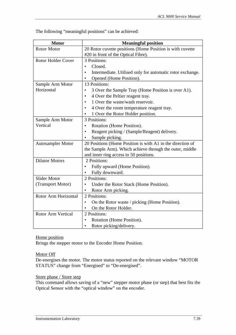
ACL 9000 Service Manual
Instrumentation Laboratory 7.39
The following “meaningful positions” can be achieved:
Motor Meaningful positionRotor Motor 20 Rotor cuvette positions (Home Position is with cuvette
#20 in front of the Optical Fibre).Rotor Holder Cover 3 Positions:
• Closed.• Intermediate. Utilised only for automatic rotor exchange.• Opened (Home Position).
Sample Arm MotorHorizontal
13 Positions:• 3 Over the Sample Tray (Home Position is over A1).• 4 Over the Peltier reagent tray.• 1 Over the waste/wash reservoir.• 4 Over the room temperature reagent tray.• 1 Over the Rotor Holder position.
Sample Arm MotorVertical
3 Positions:• Rotation (Home Position).• Reagent picking / (Sample/Reagent) delivery.• Sample picking.
Autosampler Motor 20 Positions (Home Position is with A1 in the direction ofthe Sample Arm). Which achieve through the outer, middleand inner ring access to 50 positions.
Dilutor Motors 2 Positions:• Fully upward (Home Position).• Fully downward.
Slider Motor(Transport Motor)
2 Positions:• Under the Rotor Stack (Home Position).• Rotor Arm picking.
Rotor Arm Horizontal 2 Positions:• On the Rotor waste / picking (Home Position).• On the Rotor Holder.
Rotor Arm Vertical 2 Positions:• Rotation (Home Position).• Rotor picking/delivery.
Home positionBrings the stepper motor to the Encoder Home Position.
Motor OffDe-energises the motor. The motor status reported on the relevant window “MOTORSTATUS” change from “Energised” to “De-energised”.
Store phase / Store stepThis command allows saving of a “new” stepper motor phase (or step) that best fits theOptical Sensor with the “optical window” on the encoder.
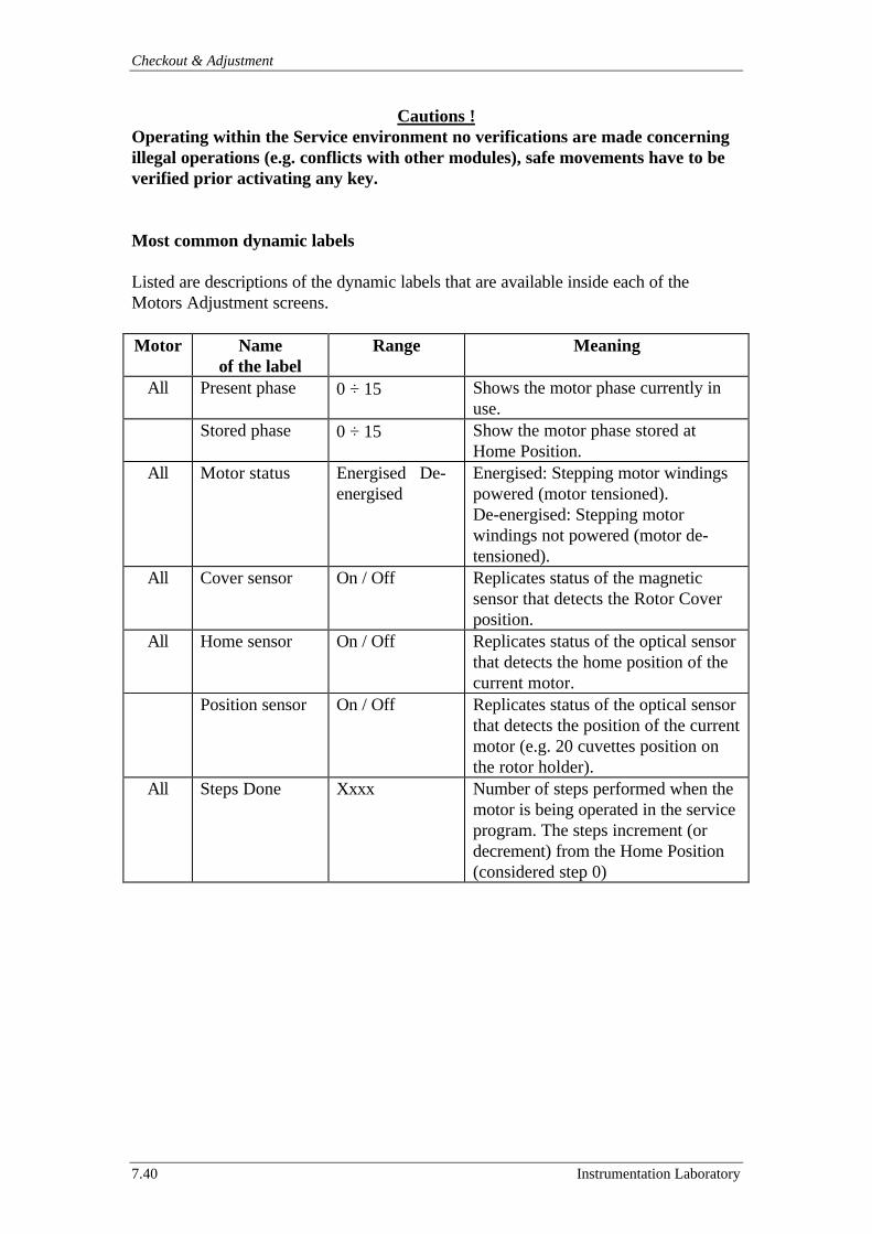
Checkout & Adjustment
7.40 Instrumentation Laboratory
Cautions !Operating within the Service environment no verifications are made concerningillegal operations (e.g. conflicts with other modules), safe movements have to beverified prior activating any key.
Most common dynamic labels
Listed are descriptions of the dynamic labels that are available inside each of theMotors Adjustment screens.
Motor Nameof the label
Range Meaning
All Present phase 0 ÷ 15 Shows the motor phase currently inuse.
Stored phase 0 ÷ 15 Show the motor phase stored atHome Position.
All Motor status Energised De-energised
Energised: Stepping motor windingspowered (motor tensioned).De-energised: Stepping motorwindings not powered (motor de-tensioned).
All Cover sensor On / Off Replicates status of the magneticsensor that detects the Rotor Coverposition.
All Home sensor On / Off Replicates status of the optical sensorthat detects the home position of thecurrent motor.
Position sensor On / Off Replicates status of the optical sensorthat detects the position of the currentmotor (e.g. 20 cuvettes position onthe rotor holder).
All Steps Done Xxxx Number of steps performed when themotor is being operated in the serviceprogram. The steps increment (ordecrement) from the Home Position(considered step 0)
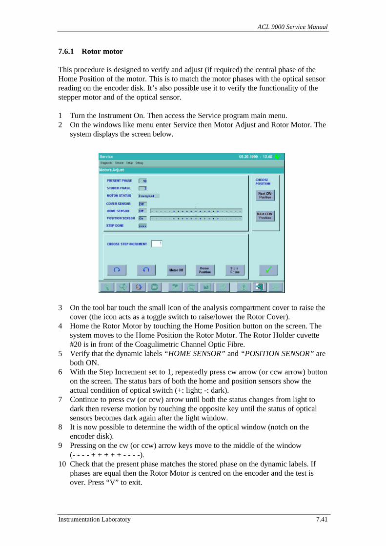
ACL 9000 Service Manual
Instrumentation Laboratory 7.41
7.6.1 Rotor motor
This procedure is designed to verify and adjust (if required) the central phase of theHome Position of the motor. This is to match the motor phases with the optical sensorreading on the encoder disk. It’s also possible use it to verify the functionality of thestepper motor and of the optical sensor.
1 Turn the Instrument On. Then access the Service program main menu.2 On the windows like menu enter Service then Motor Adjust and Rotor Motor. The
system displays the screen below.
3 On the tool bar touch the small icon of the analysis compartment cover to raise thecover (the icon acts as a toggle switch to raise/lower the Rotor Cover).
4 Home the Rotor Motor by touching the Home Position button on the screen. Thesystem moves to the Home Position the Rotor Motor. The Rotor Holder cuvette#20 is in front of the Coagulimetric Channel Optic Fibre.
5 Verify that the dynamic labels “HOME SENSOR” and “POSITION SENSOR” areboth ON.
6 With the Step Increment set to 1, repeatedly press cw arrow (or ccw arrow) buttonon the screen. The status bars of both the home and position sensors show theactual condition of optical switch (+: light; -: dark).
7 Continue to press cw (or ccw) arrow until both the status changes from light todark then reverse motion by touching the opposite key until the status of opticalsensors becomes dark again after the light window.
8 It is now possible to determine the width of the optical window (notch on theencoder disk).
9 Pressing on the cw (or ccw) arrow keys move to the middle of the window(- - - - + + + + + - - - -).
10 Check that the present phase matches the stored phase on the dynamic labels. Ifphases are equal then the Rotor Motor is centred on the encoder and the test isover. Press “V” to exit.
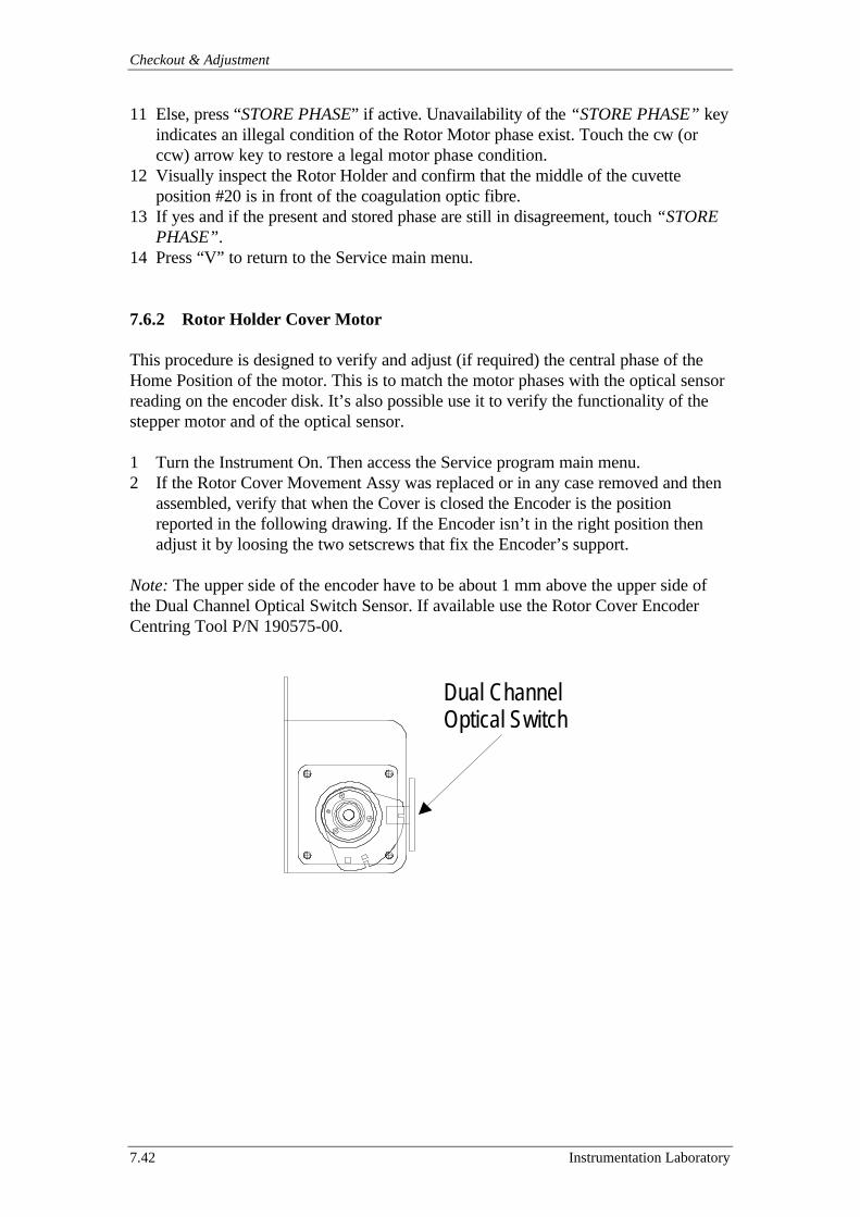
Checkout & Adjustment
7.42 Instrumentation Laboratory
11 Else, press “STORE PHASE” if active. Unavailability of the “STORE PHASE” keyindicates an illegal condition of the Rotor Motor phase exist. Touch the cw (orccw) arrow key to restore a legal motor phase condition.
12 Visually inspect the Rotor Holder and confirm that the middle of the cuvetteposition #20 is in front of the coagulation optic fibre.
13 If yes and if the present and stored phase are still in disagreement, touch “STOREPHASE”.
14 Press “V” to return to the Service main menu.
7.6.2 Rotor Holder Cover Motor
This procedure is designed to verify and adjust (if required) the central phase of theHome Position of the motor. This is to match the motor phases with the optical sensorreading on the encoder disk. It’s also possible use it to verify the functionality of thestepper motor and of the optical sensor.
1 Turn the Instrument On. Then access the Service program main menu.2 If the Rotor Cover Movement Assy was replaced or in any case removed and then
assembled, verify that when the Cover is closed the Encoder is the positionreported in the following drawing. If the Encoder isn’t in the right position thenadjust it by loosing the two setscrews that fix the Encoder’s support.
Note: The upper side of the encoder have to be about 1 mm above the upper side ofthe Dual Channel Optical Switch Sensor. If available use the Rotor Cover EncoderCentring Tool P/N 190575-00.
Dual ChannelOptical Switch
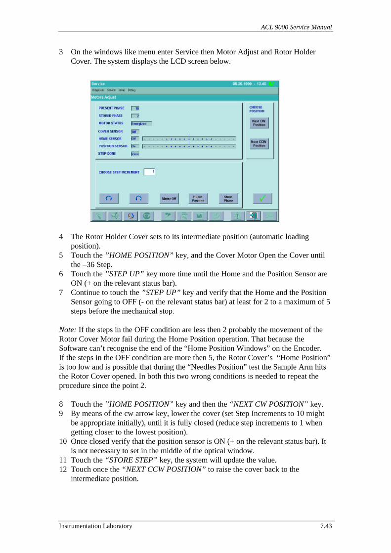
ACL 9000 Service Manual
Instrumentation Laboratory 7.43
3 On the windows like menu enter Service then Motor Adjust and Rotor HolderCover. The system displays the LCD screen below.
4 The Rotor Holder Cover sets to its intermediate position (automatic loadingposition).
5 Touch the ”HOME POSITION” key, and the Cover Motor Open the Cover untilthe –36 Step.
6 Touch the ”STEP UP” key more time until the Home and the Position Sensor areON (+ on the relevant status bar).
7 Continue to touch the ”STEP UP” key and verify that the Home and the PositionSensor going to OFF (- on the relevant status bar) at least for 2 to a maximum of 5steps before the mechanical stop.
Note: If the steps in the OFF condition are less then 2 probably the movement of theRotor Cover Motor fail during the Home Position operation. That because theSoftware can’t recognise the end of the “Home Position Windows” on the Encoder.If the steps in the OFF condition are more then 5, the Rotor Cover’s “Home Position”is too low and is possible that during the “Needles Position” test the Sample Arm hitsthe Rotor Cover opened. In both this two wrong conditions is needed to repeat theprocedure since the point 2.
8 Touch the ”HOME POSITION” key and then the “NEXT CW POSITION” key.9 By means of the cw arrow key, lower the cover (set Step Increments to 10 might
be appropriate initially), until it is fully closed (reduce step increments to 1 whengetting closer to the lowest position).
10 Once closed verify that the position sensor is ON (+ on the relevant status bar). Itis not necessary to set in the middle of the optical window.
11 Touch the “STORE STEP” key, the system will update the value.12 Touch once the “NEXT CCW POSITION” to raise the cover back to the
intermediate position.

Checkout & Adjustment
7.44 Instrumentation Laboratory
13 Once the intermediate position is reached verify that the dynamic label “STEPDONE” sets to value of 0. The dynamic labels of cover, home and position sensorshould be set as specified (see table below).
Cover Position Cover SensorStatus
Home SensorStatus
Position SensorStatus
Step Done
Fully Open OFF ON ON -36Intermediate OFF ON OFF 0Closed ON OFF ON Steps Stored
14 Touch any time the “NEXT CCW POSITION” and the “NEXT CW POSITION”until confidant that the adjustment is acceptable.
15 Touch “V” to return at the Service main menu screen.
7.6.3 Sample Arm horizontal motor
This procedure is designed to verify and adjust (if required) the central phase of theHome Position of the motor. This is to match the motor phases with the optical sensorreading on the encoder disk. It’s also possible use it to verify the functionality of thestepper motor and of the optical sensor.
1 Turn the Instrument On. Then access the Service program main menu.2 On the windows like menu enter Service then Motor Adjust then Sample Arm
Motors and Horiz. Sample Arm Motor. The system displays the screen below.
3 Manually Raise the Sample Arm to the rotation height.4 Touch the Home Position button on the screen. The system moves the Sample Arm
Horizontal Motor until to place the Sample Arm (if assembled) over theAutosampler housing (position A1 on the Sample Tray).
5 Verify that both the “HOME SENSOR” and “POSITION SENSOR” are ON.
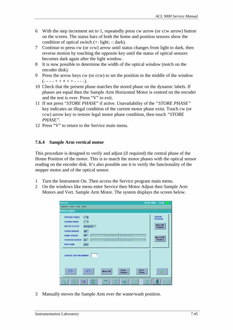
ACL 9000 Service Manual
Instrumentation Laboratory 7.45
6 With the step increment set to 1, repeatedly press cw arrow (or ccw arrow) buttonon the screen. The status bars of both the home and position sensors show thecondition of optical switch (+: light; -: dark).
7 Continue to press cw (or ccw) arrow until status changes from light to dark, thenreverse motion by touching the opposite key until the status of optical sensorsbecomes dark again after the light window.
8 It is now possible to determine the width of the optical window (notch on theencoder disk).
9 Press the arrow keys cw (or ccw) to set the position in the middle of the window(- - - - + + + + + - - - -).
10 Check that the present phase matches the stored phase on the dynamic labels. Ifphases are equal then the Sample Arm Horizontal Motor is centred on the encoderand the test is over. Press “V” to exit.
11 If not press “STORE PHASE” if active. Unavailability of the “STORE PHASE”key indicates an illegal condition of the current motor phase exist. Touch cw (orccw) arrow key to restore legal motor phase condition, then touch “STOREPHASE”.
12 Press “V” to return to the Service main menu.
7.6.4 Sample Arm vertical motor
This procedure is designed to verify and adjust (if required) the central phase of theHome Position of the motor. This is to match the motor phases with the optical sensorreading on the encoder disk. It’s also possible use it to verify the functionality of thestepper motor and of the optical sensor.
1 Turn the Instrument On. Then access the Service program main menu.2 On the windows like menu enter Service then Motor Adjust then Sample Arm
Motors and Vert. Sample Arm Motor. The system displays the screen below.
3 Manually moves the Sample Arm over the waste/wash position.
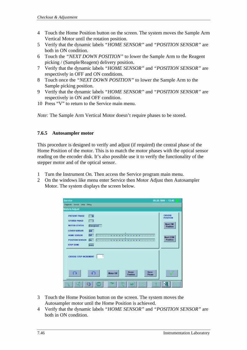
Checkout & Adjustment
7.46 Instrumentation Laboratory
4 Touch the Home Position button on the screen. The system moves the Sample ArmVertical Motor until the rotation position.
5 Verify that the dynamic labels “HOME SENSOR” and “POSITION SENSOR” areboth in ON condition.
6 Touch the “NEXT DOWN POSITION” to lower the Sample Arm to the Reagentpicking / (Sample/Reagent) delivery position.
7 Verify that the dynamic labels “HOME SENSOR” and “POSITION SENSOR” arerespectively in OFF and ON conditions.
8 Touch once the “NEXT DOWN POSITION” to lower the Sample Arm to theSample picking position.
9 Verify that the dynamic labels “HOME SENSOR” and “POSITION SENSOR” arerespectively in ON and OFF condition.
10 Press “V” to return to the Service main menu.
Note: The Sample Arm Vertical Motor doesn’t require phases to be stored.
7.6.5 Autosampler motor
This procedure is designed to verify and adjust (if required) the central phase of theHome Position of the motor. This is to match the motor phases with the optical sensorreading on the encoder disk. It’s also possible use it to verify the functionality of thestepper motor and of the optical sensor.
1 Turn the Instrument On. Then access the Service program main menu.2 On the windows like menu enter Service then Motor Adjust then Autosampler
Motor. The system displays the screen below.
3 Touch the Home Position button on the screen. The system moves theAutosampler motor until the Home Position is achieved.
4 Verify that the dynamic labels “HOME SENSOR” and “POSITION SENSOR” areboth in ON condition.
ACL 9000 Service Manual
Instrumentation Laboratory 7.47
5 With the step increment set to 1, repeatedly press cw (or ccw) arrow button on thescreen. The status bars of both the home and position sensors show the actualcondition of optical switch (+: light; -: dark).
6 Continue to press cw (or ccw) until status changes from light to dark, then reversemotion by touching the opposite key until the status of the optical sensors becomesdark again after the light window.
7 It is now possible to determine the width of the optical window (notch on theencoder disk).
8 Press the arrow keys cw (or ccw) to set the middle of the optical window(- - - - + + + + + - - - -).
9 Check that the present phase matches the stored phase on the dynamic labels. Ifphases are equal then the Autosampler Motor is centred on the encoder and thetest is over. Press “V” to exit.
10 If not press “STORE PHASE” if active. Unavailability of the “STORE PHASE”key indicates an illegal condition of the current motor phase exist. Touch once cw(or ccw) arrow key to restore legal motor phase condition and then touch “STOREPHASE”.
11 Press “V” to return to the Service main menu.
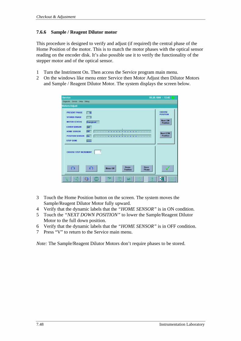
Checkout & Adjustment
7.48 Instrumentation Laboratory
7.6.6 Sample / Reagent Dilutor motor
This procedure is designed to verify and adjust (if required) the central phase of theHome Position of the motor. This is to match the motor phases with the optical sensorreading on the encoder disk. It’s also possible use it to verify the functionality of thestepper motor and of the optical sensor.
1 Turn the Instriment On. Then access the Service program main menu.2 On the windows like menu enter Service then Motor Adjust then Dilutor Motors
and Sample / Reagent Dilutor Motor. The system displays the screen below.
3 Touch the Home Position button on the screen. The system moves theSample/Reagent Dilutor Motor fully upward.
4 Verify that the dynamic labels that the “HOME SENSOR” is in ON condition.5 Touch the “NEXT DOWN POSITION” to lower the Sample/Reagent Dilutor
Motor to the full down position.6 Verify that the dynamic labels that the “HOME SENSOR” is in OFF condition.7 Press “V” to return to the Service main menu.
Note: The Sample/Reagent Dilutor Motors don’t require phases to be stored.
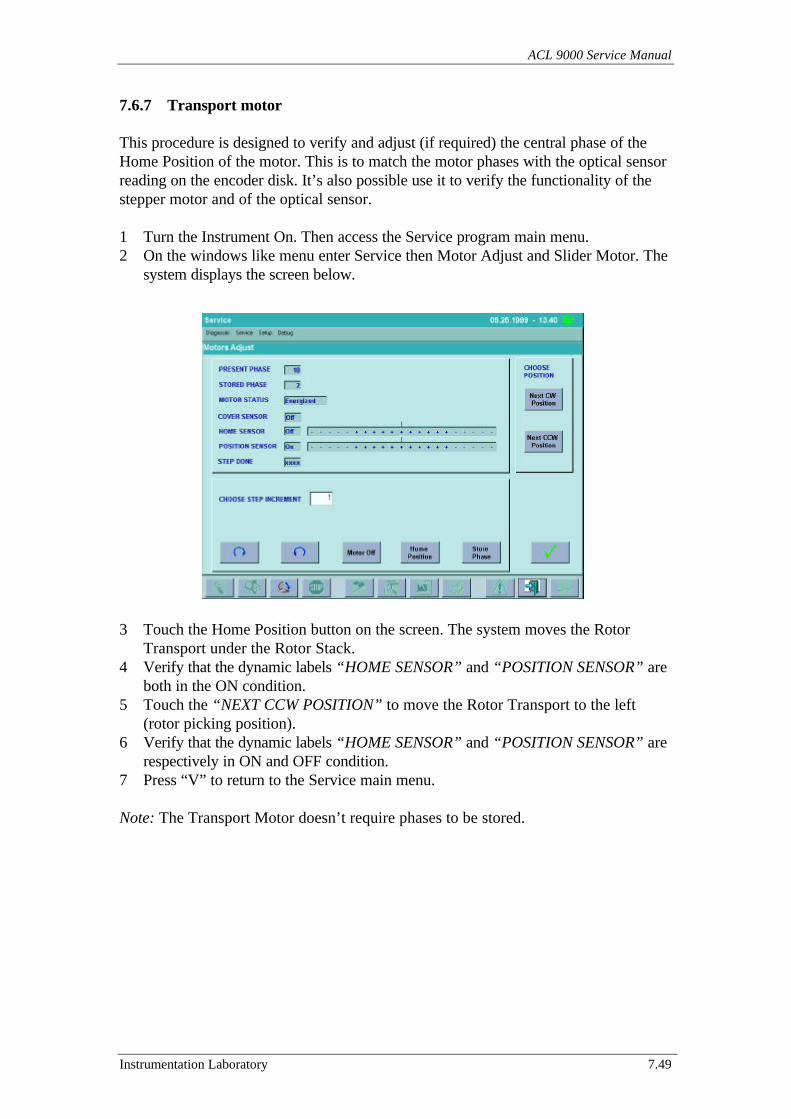
ACL 9000 Service Manual
Instrumentation Laboratory 7.49
7.6.7 Transport motor
This procedure is designed to verify and adjust (if required) the central phase of theHome Position of the motor. This is to match the motor phases with the optical sensorreading on the encoder disk. It’s also possible use it to verify the functionality of thestepper motor and of the optical sensor.
1 Turn the Instrument On. Then access the Service program main menu.2 On the windows like menu enter Service then Motor Adjust and Slider Motor. The
system displays the screen below.
3 Touch the Home Position button on the screen. The system moves the RotorTransport under the Rotor Stack.
4 Verify that the dynamic labels “HOME SENSOR” and “POSITION SENSOR” areboth in the ON condition.
5 Touch the “NEXT CCW POSITION” to move the Rotor Transport to the left(rotor picking position).
6 Verify that the dynamic labels “HOME SENSOR” and “POSITION SENSOR” arerespectively in ON and OFF condition.
7 Press “V” to return to the Service main menu.
Note: The Transport Motor doesn’t require phases to be stored.
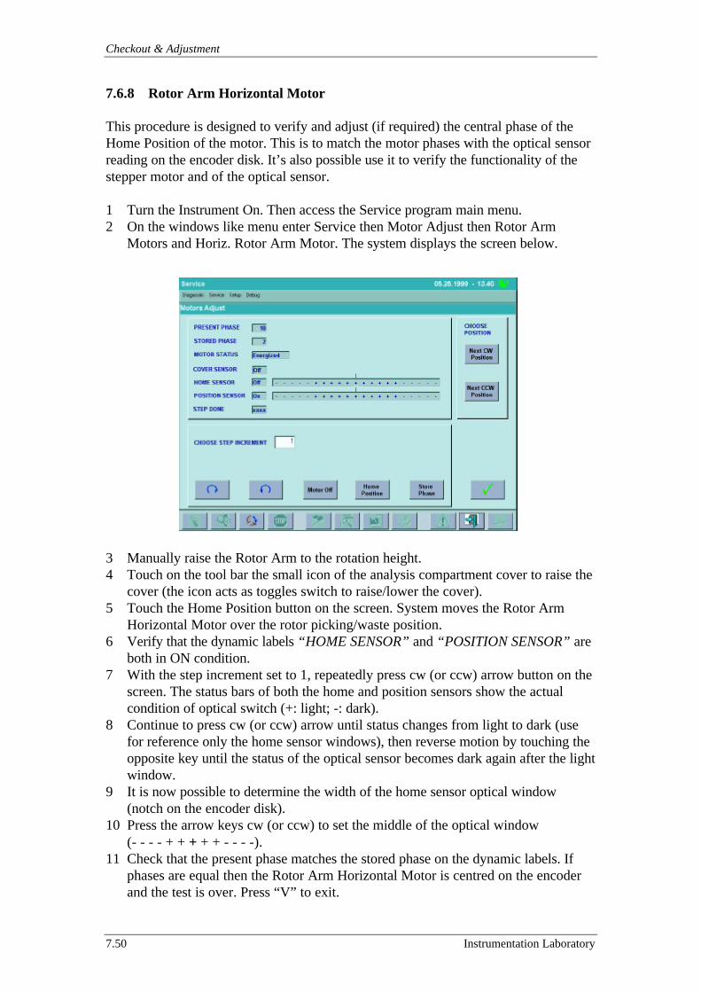
Checkout & Adjustment
7.50 Instrumentation Laboratory
7.6.8 Rotor Arm Horizontal Motor
This procedure is designed to verify and adjust (if required) the central phase of theHome Position of the motor. This is to match the motor phases with the optical sensorreading on the encoder disk. It’s also possible use it to verify the functionality of thestepper motor and of the optical sensor.
1 Turn the Instrument On. Then access the Service program main menu.2 On the windows like menu enter Service then Motor Adjust then Rotor Arm
Motors and Horiz. Rotor Arm Motor. The system displays the screen below.
3 Manually raise the Rotor Arm to the rotation height.4 Touch on the tool bar the small icon of the analysis compartment cover to raise the
cover (the icon acts as toggles switch to raise/lower the cover).5 Touch the Home Position button on the screen. System moves the Rotor Arm
Horizontal Motor over the rotor picking/waste position.6 Verify that the dynamic labels “HOME SENSOR” and “POSITION SENSOR” are
both in ON condition.7 With the step increment set to 1, repeatedly press cw (or ccw) arrow button on the
screen. The status bars of both the home and position sensors show the actualcondition of optical switch (+: light; -: dark).
8 Continue to press cw (or ccw) arrow until status changes from light to dark (usefor reference only the home sensor windows), then reverse motion by touching theopposite key until the status of the optical sensor becomes dark again after the lightwindow.
9 It is now possible to determine the width of the home sensor optical window(notch on the encoder disk).
10 Press the arrow keys cw (or ccw) to set the middle of the optical window(- - - - + + + + + - - - -).
11 Check that the present phase matches the stored phase on the dynamic labels. Ifphases are equal then the Rotor Arm Horizontal Motor is centred on the encoderand the test is over. Press “V” to exit.
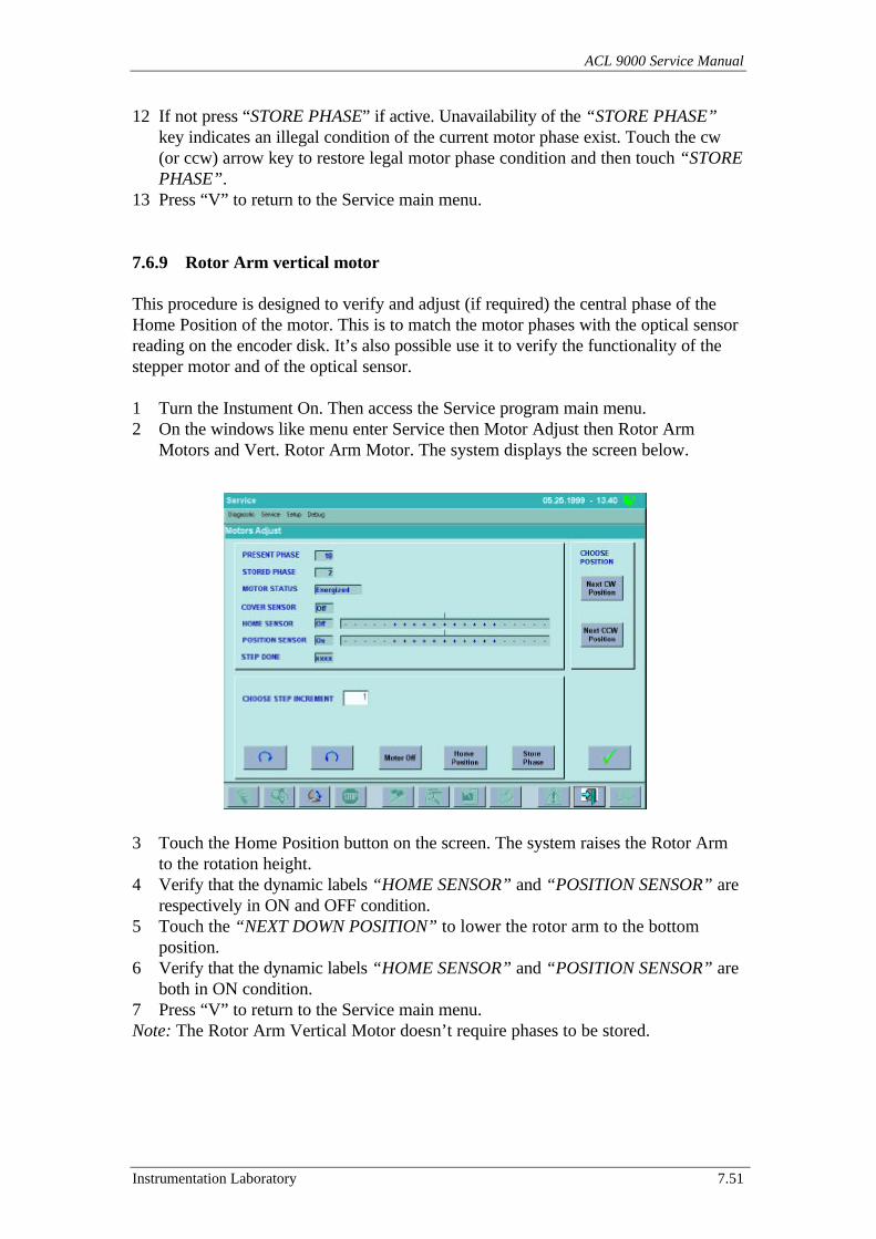
ACL 9000 Service Manual
Instrumentation Laboratory 7.51
12 If not press “STORE PHASE” if active. Unavailability of the “STORE PHASE”key indicates an illegal condition of the current motor phase exist. Touch the cw(or ccw) arrow key to restore legal motor phase condition and then touch “STOREPHASE”.
13 Press “V” to return to the Service main menu.
7.6.9 Rotor Arm vertical motor
This procedure is designed to verify and adjust (if required) the central phase of theHome Position of the motor. This is to match the motor phases with the optical sensorreading on the encoder disk. It’s also possible use it to verify the functionality of thestepper motor and of the optical sensor.
1 Turn the Instument On. Then access the Service program main menu.2 On the windows like menu enter Service then Motor Adjust then Rotor Arm
Motors and Vert. Rotor Arm Motor. The system displays the screen below.
3 Touch the Home Position button on the screen. The system raises the Rotor Armto the rotation height.
4 Verify that the dynamic labels “HOME SENSOR” and “POSITION SENSOR” arerespectively in ON and OFF condition.
5 Touch the “NEXT DOWN POSITION” to lower the rotor arm to the bottomposition.
6 Verify that the dynamic labels “HOME SENSOR” and “POSITION SENSOR” areboth in ON condition.
7 Press “V” to return to the Service main menu.Note: The Rotor Arm Vertical Motor doesn’t require phases to be stored.
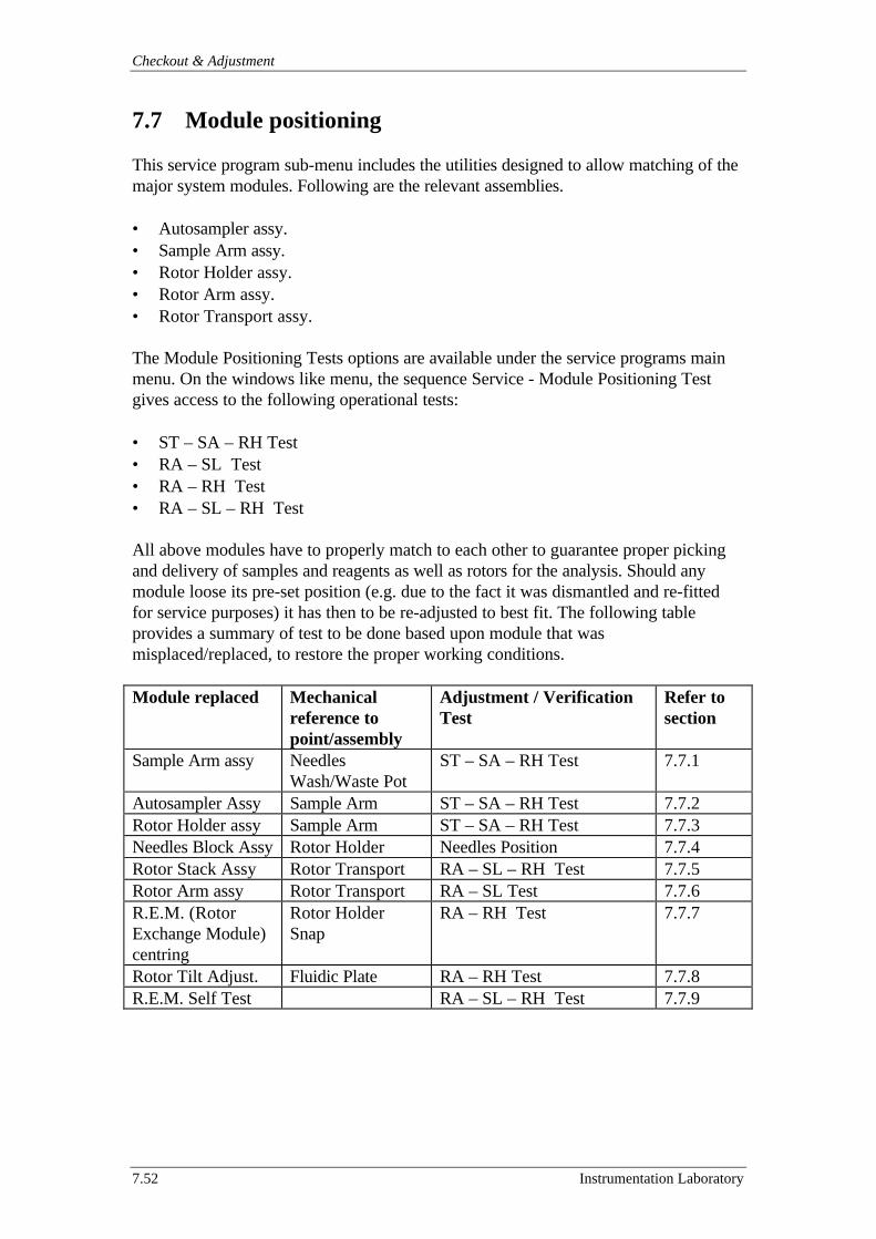
Checkout & Adjustment
7.52 Instrumentation Laboratory
7.7 Module positioning
This service program sub-menu includes the utilities designed to allow matching of themajor system modules. Following are the relevant assemblies.
• Autosampler assy.• Sample Arm assy.• Rotor Holder assy.• Rotor Arm assy.• Rotor Transport assy.
The Module Positioning Tests options are available under the service programs mainmenu. On the windows like menu, the sequence Service - Module Positioning Testgives access to the following operational tests:
• ST – SA – RH Test• RA – SL Test• RA – RH Test• RA – SL – RH Test
All above modules have to properly match to each other to guarantee proper pickingand delivery of samples and reagents as well as rotors for the analysis. Should anymodule loose its pre-set position (e.g. due to the fact it was dismantled and re-fittedfor service purposes) it has then to be re-adjusted to best fit. The following tableprovides a summary of test to be done based upon module that wasmisplaced/replaced, to restore the proper working conditions.
Module replaced Mechanicalreference topoint/assembly
Adjustment / VerificationTest
Refer tosection
Sample Arm assy NeedlesWash/Waste Pot
ST – SA – RH Test 7.7.1
Autosampler Assy Sample Arm ST – SA – RH Test 7.7.2Rotor Holder assy Sample Arm ST – SA – RH Test 7.7.3Needles Block Assy Rotor Holder Needles Position 7.7.4Rotor Stack Assy Rotor Transport RA – SL – RH Test 7.7.5Rotor Arm assy Rotor Transport RA – SL Test 7.7.6R.E.M. (RotorExchange Module)centring
Rotor HolderSnap
RA – RH Test 7.7.7
Rotor Tilt Adjust. Fluidic Plate RA – RH Test 7.7.8R.E.M. Self Test RA – SL – RH Test 7.7.9
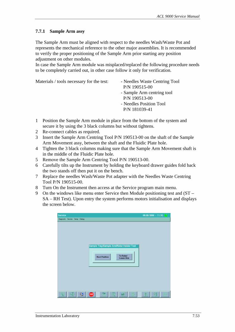
ACL 9000 Service Manual
Instrumentation Laboratory 7.53
7.7.1 Sample Arm assy
The Sample Arm must be aligned with respect to the needles Wash/Waste Pot andrepresents the mechanical reference to the other major assemblies. It is recommendedto verify the proper positioning of the Sample Arm prior starting any positionadjustment on other modules.In case the Sample Arm module was misplaced/replaced the following procedure needsto be completely carried out, in other case follow it only for verification.
Materials / tools necessary for the test: - Needles Waste Centring Tool P/N 190515-00- Sample Arm centring tool P/N 190513-00- Needles Position Tool P/N 181039-41
1 Position the Sample Arm module in place from the bottom of the system andsecure it by using the 3 black columns but without tightens.
2 Re-connect cables as required.3 Insert the Sample Arm Centring Tool P/N 190513-00 on the shaft of the Sample
Arm Movement assy, between the shaft and the Fluidic Plate hole.4 Tighten the 3 black columns making sure that the Sample Arm Movement shaft is
in the middle of the Fluidic Plate hole.5 Remove the Sample Arm Centring Tool P/N 190513-00.6 Carefully tilts up the Instrument by holding the keyboard drawer guides fold back
the two stands off then put it on the bench.7 Replace the needles Wash/Waste Pot adapter with the Needles Waste Centring
Tool P/N 190515-00.8 Turn On the Instrument then access at the Service program main menu.9 On the windows like menu enter Service then Module positioning test and (ST –
SA – RH Test). Upon entry the system performs motors initialisation and displaysthe screen below.
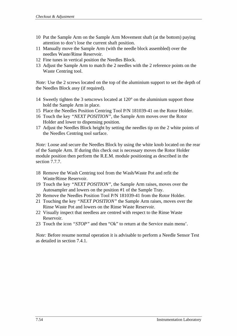
Checkout & Adjustment
7.54 Instrumentation Laboratory
10 Put the Sample Arm on the Sample Arm Movement shaft (at the bottom) payingattention to don’t lose the current shaft position.
11 Manually move the Sample Arm (with the needle block assembled) over theneedles Waste/Rinse Reservoir.
12 Fine tunes in vertical position the Needles Block.13 Adjust the Sample Arm to match the 2 needles with the 2 reference points on the
Waste Centring tool.
Note: Use the 2 screws located on the top of the aluminium support to set the depth ofthe Needles Block assy (if required).
14 Sweetly tighten the 3 setscrews located at 120° on the aluminium support thosehold the Sample Arm in place.
15 Place the Needles Position Centring Tool P/N 181039-41 on the Rotor Holder.16 Touch the key “NEXT POSITION”, the Sample Arm moves over the Rotor
Holder and lower to dispensing position.17 Adjust the Needles Block height by setting the needles tip on the 2 white points of
the Needles Centring tool surface.
Note: Loose and secure the Needles Block by using the white knob located on the rearof the Sample Arm. If during this check out is necessary moves the Rotor Holdermodule position then perform the R.E.M. module positioning as described in thesection 7.7.7.
18 Remove the Wash Centring tool from the Wash/Waste Pot and refit theWaste/Rinse Reservoir.
19 Touch the key “NEXT POSITION”, the Sample Arm raises, moves over theAutosampler and lowers on the position #1 of the Sample Tray.
20 Remove the Needles Position Tool P/N 181039-41 from the Rotor Holder.21 Touching the key “NEXT POSITION” the Sample Arm raises, moves over the
Rinse Waste Pot and lowers on the Rinse Waste Reservoir.22 Visually inspect that needless are centred with respect to the Rinse Waste
Reservoir.23 Touch the icon “STOP” and then “Ok” to return at the Service main menu’.
Note: Before resume normal operation it is advisable to perform a Needle Sensor Testas detailed in section 7.4.1.
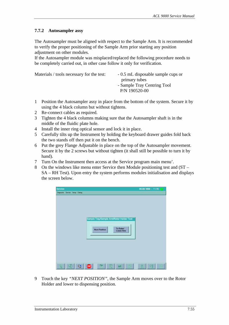
ACL 9000 Service Manual
Instrumentation Laboratory 7.55
7.7.2 Autosampler assy
The Autosampler must be aligned with respect to the Sample Arm. It is recommendedto verify the proper positioning of the Sample Arm prior starting any positionadjustment on other modules.If the Autosampler module was misplaced/replaced the following procedure needs tobe completely carried out, in other case follow it only for verification.
Materials / tools necessary for the test: - 0.5 mL disposable sample cups or primary tubes- Sample Tray Centring Tool P/N 190520-00
1 Position the Autosampler assy in place from the bottom of the system. Secure it byusing the 4 black column but without tightens.
2 Re-connect cables as required.3 Tighten the 4 black columns making sure that the Autosampler shaft is in the
middle of the fluidic plate hole.4 Install the inner ring optical sensor and lock it in place.5 Carefully tilts up the Instrument by holding the keyboard drawer guides fold back
the two stands off then put it on the bench.6 Put the grey Flange Adjustable in place on the top of the Autosampler movement.
Secure it by the 2 screws but without tighten (it shall still be possible to turn it byhand).
7 Turn On the Instrument then access at the Service program main menu’.8 On the windows like menu enter Service then Module positioning test and (ST –
SA – RH Test). Upon entry the system performs modules initialisation and displaysthe screen below.
9 Touch the key “NEXT POSITION”, the Sample Arm moves over to the RotorHolder and lower to dispensing position.
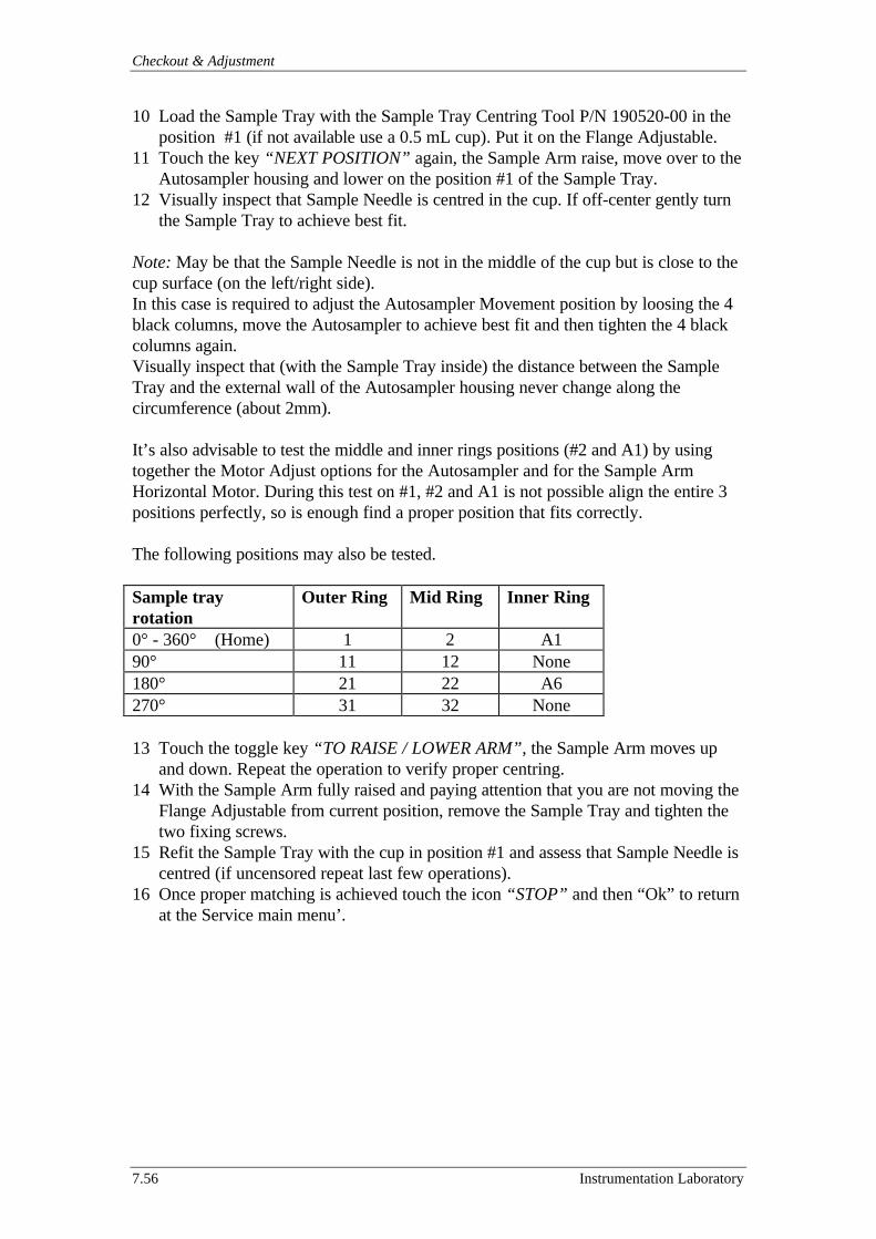
Checkout & Adjustment
7.56 Instrumentation Laboratory
10 Load the Sample Tray with the Sample Tray Centring Tool P/N 190520-00 in theposition #1 (if not available use a 0.5 mL cup). Put it on the Flange Adjustable.
11 Touch the key “NEXT POSITION” again, the Sample Arm raise, move over to theAutosampler housing and lower on the position #1 of the Sample Tray.
12 Visually inspect that Sample Needle is centred in the cup. If off-center gently turnthe Sample Tray to achieve best fit.
Note: May be that the Sample Needle is not in the middle of the cup but is close to thecup surface (on the left/right side).In this case is required to adjust the Autosampler Movement position by loosing the 4black columns, move the Autosampler to achieve best fit and then tighten the 4 blackcolumns again.Visually inspect that (with the Sample Tray inside) the distance between the SampleTray and the external wall of the Autosampler housing never change along thecircumference (about 2mm).
It’s also advisable to test the middle and inner rings positions (#2 and A1) by usingtogether the Motor Adjust options for the Autosampler and for the Sample ArmHorizontal Motor. During this test on #1, #2 and A1 is not possible align the entire 3positions perfectly, so is enough find a proper position that fits correctly.
The following positions may also be tested.
Sample trayrotation
Outer Ring Mid Ring Inner Ring
0° - 360° (Home) 1 2 A190° 11 12 None180° 21 22 A6270° 31 32 None
13 Touch the toggle key “TO RAISE / LOWER ARM”, the Sample Arm moves upand down. Repeat the operation to verify proper centring.
14 With the Sample Arm fully raised and paying attention that you are not moving theFlange Adjustable from current position, remove the Sample Tray and tighten thetwo fixing screws.
15 Refit the Sample Tray with the cup in position #1 and assess that Sample Needle iscentred (if uncensored repeat last few operations).
16 Once proper matching is achieved touch the icon “STOP” and then “Ok” to returnat the Service main menu’.
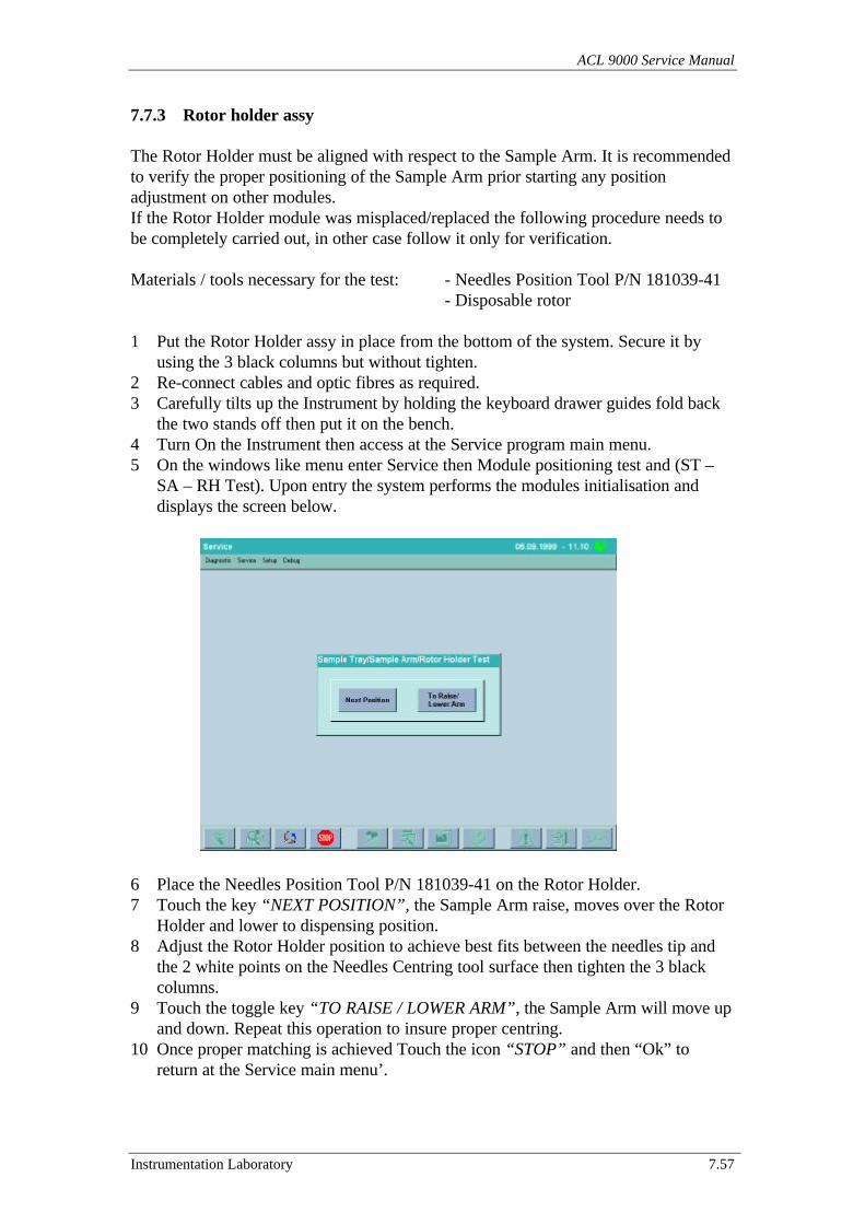
ACL 9000 Service Manual
Instrumentation Laboratory 7.57
7.7.3 Rotor holder assy
The Rotor Holder must be aligned with respect to the Sample Arm. It is recommendedto verify the proper positioning of the Sample Arm prior starting any positionadjustment on other modules.If the Rotor Holder module was misplaced/replaced the following procedure needs tobe completely carried out, in other case follow it only for verification.
Materials / tools necessary for the test: - Needles Position Tool P/N 181039-41- Disposable rotor
1 Put the Rotor Holder assy in place from the bottom of the system. Secure it byusing the 3 black columns but without tighten.
2 Re-connect cables and optic fibres as required.3 Carefully tilts up the Instrument by holding the keyboard drawer guides fold back
the two stands off then put it on the bench.4 Turn On the Instrument then access at the Service program main menu.5 On the windows like menu enter Service then Module positioning test and (ST –
SA – RH Test). Upon entry the system performs the modules initialisation anddisplays the screen below.
6 Place the Needles Position Tool P/N 181039-41 on the Rotor Holder.7 Touch the key “NEXT POSITION”, the Sample Arm raise, moves over the Rotor
Holder and lower to dispensing position.8 Adjust the Rotor Holder position to achieve best fits between the needles tip and
the 2 white points on the Needles Centring tool surface then tighten the 3 blackcolumns.
9 Touch the toggle key “TO RAISE / LOWER ARM”, the Sample Arm will move upand down. Repeat this operation to insure proper centring.
10 Once proper matching is achieved Touch the icon “STOP” and then “Ok” toreturn at the Service main menu’.
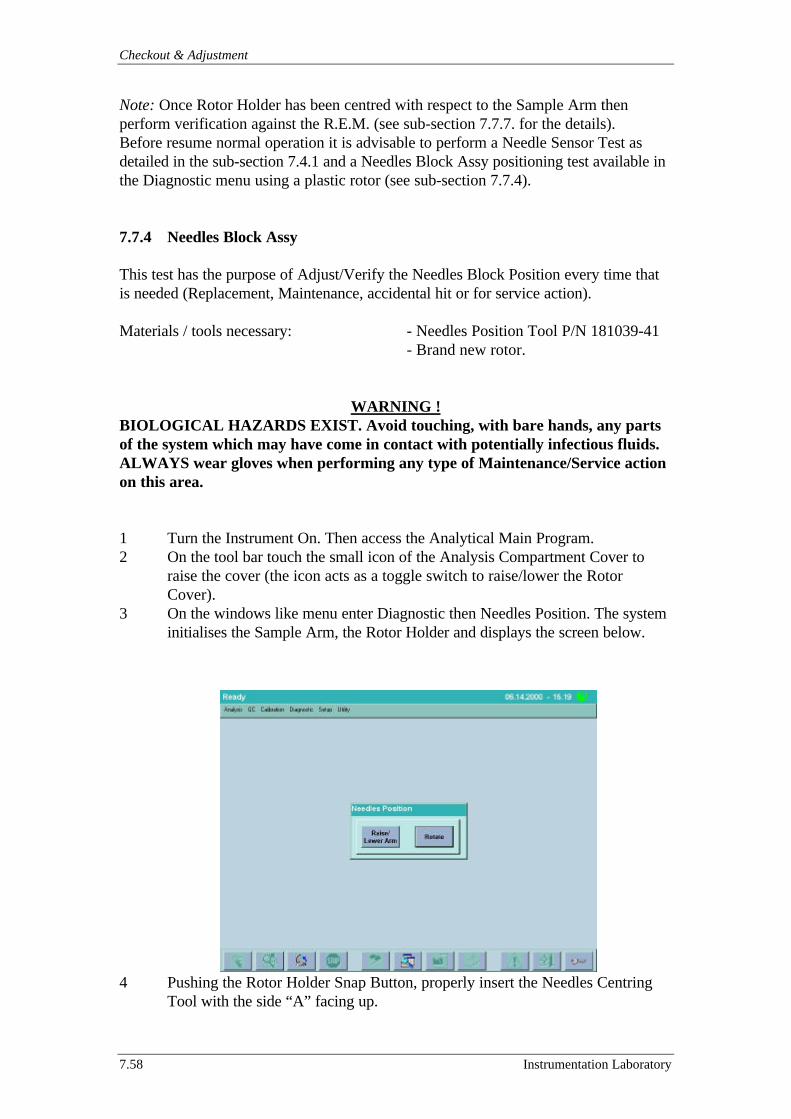
Checkout & Adjustment
7.58 Instrumentation Laboratory
Note: Once Rotor Holder has been centred with respect to the Sample Arm thenperform verification against the R.E.M. (see sub-section 7.7.7. for the details).Before resume normal operation it is advisable to perform a Needle Sensor Test asdetailed in the sub-section 7.4.1 and a Needles Block Assy positioning test available inthe Diagnostic menu using a plastic rotor (see sub-section 7.7.4).
7.7.4 Needles Block Assy
This test has the purpose of Adjust/Verify the Needles Block Position every time thatis needed (Replacement, Maintenance, accidental hit or for service action).
Materials / tools necessary: - Needles Position Tool P/N 181039-41- Brand new rotor.
WARNING !BIOLOGICAL HAZARDS EXIST. Avoid touching, with bare hands, any partsof the system which may have come in contact with potentially infectious fluids.ALWAYS wear gloves when performing any type of Maintenance/Service actionon this area.
1 Turn the Instrument On. Then access the Analytical Main Program.2 On the tool bar touch the small icon of the Analysis Compartment Cover to
raise the cover (the icon acts as a toggle switch to raise/lower the RotorCover).
3 On the windows like menu enter Diagnostic then Needles Position. The systeminitialises the Sample Arm, the Rotor Holder and displays the screen below.
4 Pushing the Rotor Holder Snap Button, properly insert the Needles CentringTool with the side “A” facing up.

ACL 9000 Service Manual
Instrumentation Laboratory 7.59
5 Press Raise/Lower Arm. The Sample Arm is lowered over the Rotor Holder.6 Using the knob located on the rear of the Sample Arm adjust the height of the
Needles Block so that the needles tip come in touch with the upper surface ofthe Needles Position Tool. During this operation pay attention to put them invertically position.
7 Secures the Needles Block by tightening the relevant knob without lose thecurrent position.
8 Make sure that the needles tip match with the 2 reference dots of the tool. Ifthe needles tip don’t match then verify the Sample Arm and the Rotor Holderpositioning as described in the section 7.7.
9 Once the Needles Block adjustment with the tool is achieved, press theRaise/Lower Arm button. The arm is raised and so it’s possible remove theNeedles Centring Tool.
10 Pushing the Rotor Holder Snap Button, properly insert a brand new plasticrotor.
11 Press Raise/Lower Arm. The Sample Arm is lowered over the plastic rotor onthe Rotor Holder.
12 Visually inspect for the proper position of the needles in the centre of the 2holes of the cuvette.
13 Press Raise/Lower Arm. The Sample Arm is raised so that by touching theRotate button (now active) the plastic rotor on the Rotor Holder is rotated (90°for each touch).
14 It’s advisable repeat the 3 last steps to be sure that in the 4 main test position(cuvette 1,6,11 and 16) the Needles Block adjustment is acceptable.
Note: The needles alignment may not be identical in the 4 rotor cuvettes. If whilecarrying out the previously steps the needles not enter a port of the rotor or if SampleNeedle was found to the right of the centre in any one cuvette (see example C in figurebelow), it must be readjusted.
A
Reference Dots
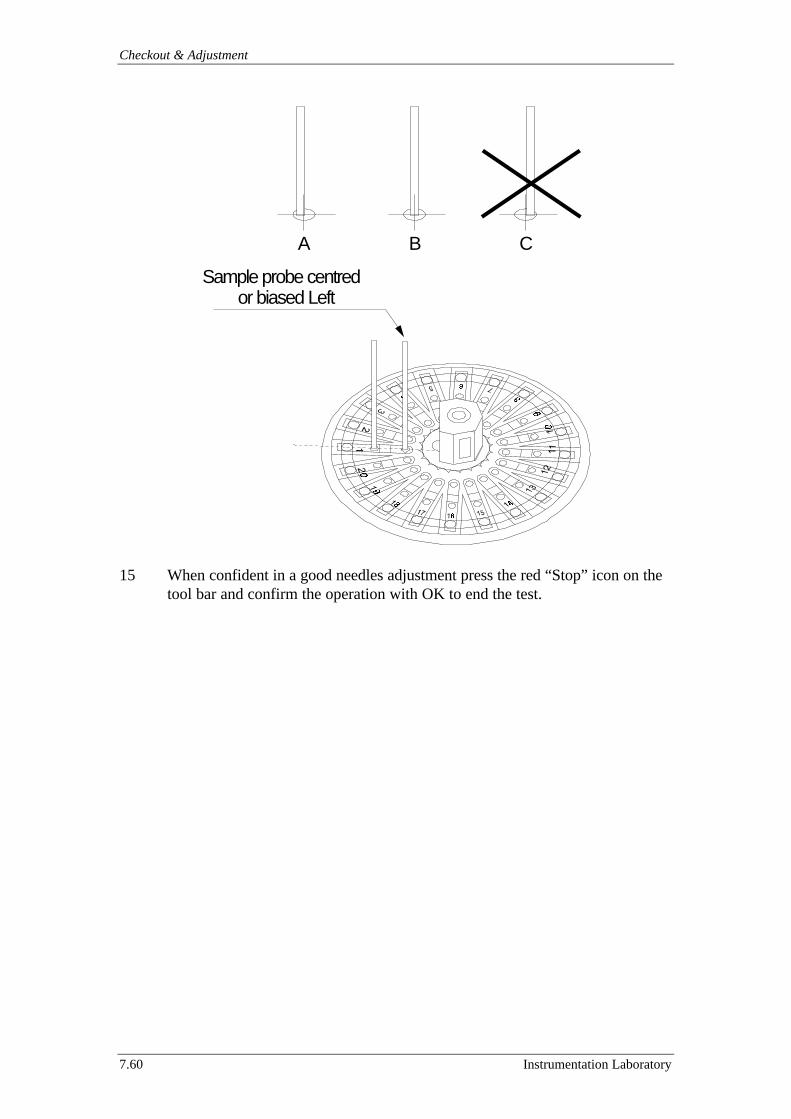
Checkout & Adjustment
7.60 Instrumentation Laboratory
15 When confident in a good needles adjustment press the red “Stop” icon on thetool bar and confirm the operation with OK to end the test.
Sample probe centredor biased Left
A B C
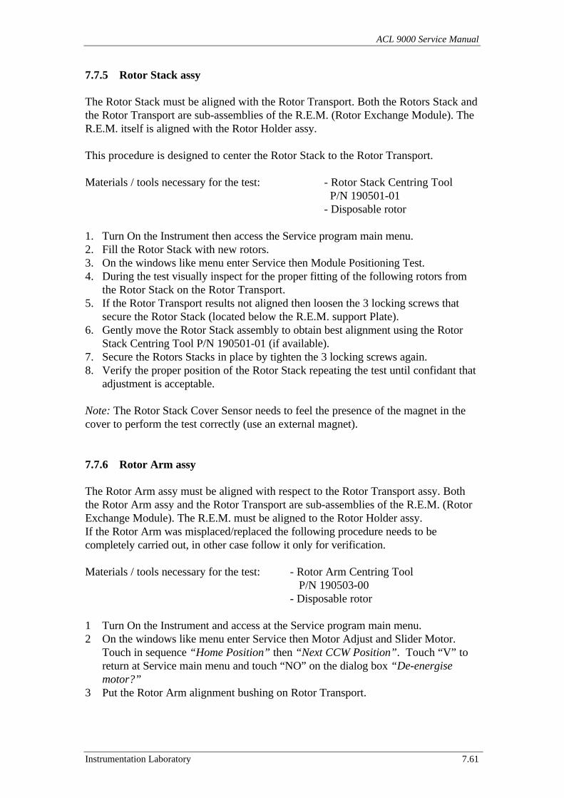
ACL 9000 Service Manual
Instrumentation Laboratory 7.61
7.7.5 Rotor Stack assy
The Rotor Stack must be aligned with the Rotor Transport. Both the Rotors Stack andthe Rotor Transport are sub-assemblies of the R.E.M. (Rotor Exchange Module). TheR.E.M. itself is aligned with the Rotor Holder assy.
This procedure is designed to center the Rotor Stack to the Rotor Transport.
Materials / tools necessary for the test: - Rotor Stack Centring Tool P/N 190501-01- Disposable rotor
1. Turn On the Instrument then access the Service program main menu.2. Fill the Rotor Stack with new rotors.3. On the windows like menu enter Service then Module Positioning Test.4. During the test visually inspect for the proper fitting of the following rotors from
the Rotor Stack on the Rotor Transport.5. If the Rotor Transport results not aligned then loosen the 3 locking screws that
secure the Rotor Stack (located below the R.E.M. support Plate).6. Gently move the Rotor Stack assembly to obtain best alignment using the Rotor
Stack Centring Tool P/N 190501-01 (if available).7. Secure the Rotors Stacks in place by tighten the 3 locking screws again.8. Verify the proper position of the Rotor Stack repeating the test until confidant that
adjustment is acceptable.
Note: The Rotor Stack Cover Sensor needs to feel the presence of the magnet in thecover to perform the test correctly (use an external magnet).
7.7.6 Rotor Arm assy
The Rotor Arm assy must be aligned with respect to the Rotor Transport assy. Boththe Rotor Arm assy and the Rotor Transport are sub-assemblies of the R.E.M. (RotorExchange Module). The R.E.M. must be aligned to the Rotor Holder assy.If the Rotor Arm was misplaced/replaced the following procedure needs to becompletely carried out, in other case follow it only for verification.
Materials / tools necessary for the test: - Rotor Arm Centring Tool P/N 190503-00- Disposable rotor
1 Turn On the Instrument and access at the Service program main menu.2 On the windows like menu enter Service then Motor Adjust and Slider Motor.
Touch in sequence “Home Position” then “Next CCW Position”. Touch “V” toreturn at Service main menu and touch “NO” on the dialog box “De-energisemotor?”
3 Put the Rotor Arm alignment bushing on Rotor Transport.
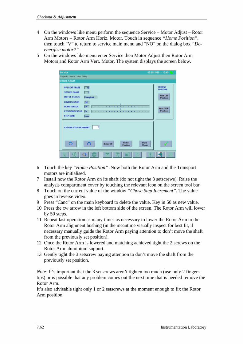
Checkout & Adjustment
7.62 Instrumentation Laboratory
4 On the windows like menu perform the sequence Service – Motor Adjust – RotorArm Motors – Rotor Arm Horiz. Motor. Touch in sequence “Home Position”,then touch “V” to return to service main menu and “NO” on the dialog box “De-energise motor?”.
5 On the windows like menu enter Service then Motor Adjust then Rotor ArmMotors and Rotor Arm Vert. Motor. The system displays the screen below.
6 Touch the key “Home Position” .Now both the Rotor Arm and the Transportmotors are initialised.
7 Install now the Rotor Arm on its shaft (do not tight the 3 setscrews). Raise theanalysis compartment cover by touching the relevant icon on the screen tool bar.
8 Touch on the current value of the window “Chose Step Increment”. The valuegoes in reverse video.
9 Press “Canc” on the main keyboard to delete the value. Key in 50 as new value.10 Press the cw arrow in the left bottom side of the screen. The Rotor Arm will lower
by 50 steps.11 Repeat last operation as many times as necessary to lower the Rotor Arm to the
Rotor Arm alignment bushing (in the meantime visually inspect for best fit, ifnecessary manually guide the Rotor Arm paying attention to don’t move the shaftfrom the previously set position).
12 Once the Rotor Arm is lowered and matching achieved tight the 2 screws on theRotor Arm aluminium support.
13 Gently tight the 3 setscrew paying attention to don’t move the shaft from thepreviously set position.
Note: It’s important that the 3 setscrews aren’t tighten too much (use only 2 fingerstips) or is possible that any problem comes out the next time that is needed remove theRotor Arm.It’s also advisable tight only 1 or 2 setscrews at the moment enough to fix the RotorArm position.

ACL 9000 Service Manual
Instrumentation Laboratory 7.63
14 The adjustment is now complete, press “V” to return to service main menu. Touch“YES” on the dialog box “De-energise motor?”
15 Remove the alignment bushing and place a new rotor on the Rotor Transport.16 On the windows like menu enter Service then Module Positioning Test and RA –
SL Test.17 The instrument exercises the Rotor Arm and Rotor Transport in sequence. Let the
system operate for a suitable number of cycles and verify for proper matching,touch “Abort” once confident that adjustment is acceptable.
7.7.7 R.E.M. (Rotor Exchange Module) centring
The Rotor Exchange Module is a major assembly that incorporates Rotor Stack, RotorTransport and Rotor Arm assy. The R.E.M. must be aligned with respect to the RotorHolder.
This procedure is designed to center the R.E.M. to the Rotor Holder.
Materials / tools necessary for the test: - Disposable rotor
1 Turn On the Instrument then access at the Service program main menu.2 On the windows like menu enter Service then Motor Adjust then Rotor Arm
Motors and Rotor Arm Vert. Motor. Touch “Home Position”, and then touch “V”to return to service main menu. Touch “NO” on the dialog box “De-energisemotor?”
3 Raise the Rotor Cover by touching the relevant icon on the screen tool bar.4 On the windows like menu enter Service then Motor Adjust then Rotor Motor.
Touch “Home Position”, and then touch “V” to return to service main menu.Touch “NO” on the dialog box “De-energise motor?”
5 On the windows like menu enter Service then Motor Adjust then Rotor ArmMotors and Rotor Arm Horiz. Motor. Touch in sequence “Home Position”, “NextCCW Position”. Touch “V” to return to service main menu. Touch “NO” on thedialog box “De-energise motor?”
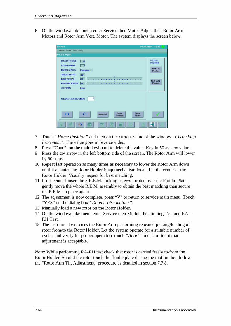
Checkout & Adjustment
7.64 Instrumentation Laboratory
6 On the windows like menu enter Service then Motor Adjust then Rotor ArmMotors and Rotor Arm Vert. Motor. The system displays the screen below.
7 Touch “Home Position” and then on the current value of the window “Chose StepIncrement”. The value goes in reverse video.
8 Press “Canc”. on the main keyboard to delete the value. Key in 50 as new value.9 Press the cw arrow in the left bottom side of the screen. The Rotor Arm will lower
by 50 steps.10 Repeat last operation as many times as necessary to lower the Rotor Arm down
until it actuates the Rotor Holder Snap mechanism located in the center of theRotor Holder. Visually inspect for best matching.
11 If off center loosen the 5 R.E.M. locking screws located over the Fluidic Plate,gently move the whole R.E.M. assembly to obtain the best matching then securethe R.E.M. in place again.
12 The adjustment is now complete, press “V” to return to service main menu. Touch“YES” on the dialog box “De-energise motor?”.
13 Manually load a new rotor on the Rotor Holder.14 On the windows like menu enter Service then Module Positioning Test and RA –
RH Test.15 The instrument exercises the Rotor Arm performing repeated picking/loading of
rotor from/to the Rotor Holder. Let the system operate for a suitable number ofcycles and verify for proper operation, touch “Abort” once confident thatadjustment is acceptable.
Note: While performing RA-RH test check that rotor is carried freely to/from theRotor Holder. Should the rotor touch the fluidic plate during the motion then followthe “Rotor Arm Tilt Adjustment” procedure as detailed in section 7.7.8.
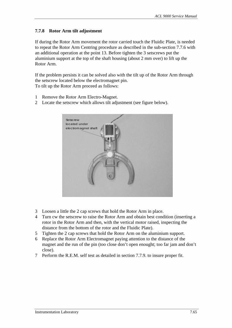
ACL 9000 Service Manual
Instrumentation Laboratory 7.65
7.7.8 Rotor Arm tilt adjustment
If during the Rotor Arm movement the rotor carried touch the Fluidic Plate, is neededto repeat the Rotor Arm Centring procedure as described in the sub-section 7.7.6 withan additional operation at the point 13. Before tighten the 3 setscrews put thealuminium support at the top of the shaft housing (about 2 mm over) to lift up theRotor Arm.
If the problem persists it can be solved also with the tilt up of the Rotor Arm throughthe setscrew located below the electromagnet pin.To tilt up the Rotor Arm proceed as follows:
1 Remove the Rotor Arm Electro-Magnet.2 Locate the setscrew which allows tilt adjustment (see figure below).
3 Loosen a little the 2 cap screws that hold the Rotor Arm in place.4 Turn cw the setscrew to raise the Rotor Arm and obtain best condition (inserting a
rotor in the Rotor Arm and then, with the vertical motor raised, inspecting thedistance from the bottom of the rotor and the Fluidic Plate).
5 Tighten the 2 cap screws that hold the Rotor Arm on the aluminium support.6 Replace the Rotor Arm Electromagnet paying attention to the distance of the
magnet and the run of the pin (too close don’t open enought; too far jam and don’tclose).
7 Perform the R.E.M. self test as detailed in section 7.7.9. to insure proper fit.
Setscrewlocated under
electromagnet shaft
Checkout & Adjustment
7.66 Instrumentation Laboratory
7.7.9 R.E.M. (Rotor Exchange Module) self test
The Rotor Exchange Module is a major assembly that incorporates the Rotor Stack,Rotor Transport and Rotor Arm. The R.E.M. must be aligned to the Rotor Holder.The procedure is detailed in section 7.7.7.
This test is designed to verify the proper alignment of the major sub-assembles of theRotor Exchange Module and the Rotor Holder.
Materials / tools necessary for the test: - Disposable rotors
1 Turn On the Instrument then access at the Service program main menu.2 Load a stack of 10 new rotors in the Rotor Stack.3 Empty the Rotor Waste container and place it back onto its housing.4 On the windows like menu enter Service then Module positioning test and RA –
SL – RH test.5 The instrument initialises the motors of the R.E.M., the Rotor Holder and the
Rotor Cover.6 Once initialisation is completed the system starts loading / unloading rotors until
the stack of rotors is exhausted.
Note: If the R.E.M. cover is open or is out of place then the Rotor Stack Cover Sensordetects this conditions and the system, for safety purposes, don’t allows opening at theRotor Stack Upper Electro-Magnet. To obviate at this situation and achieve a goodvisual inspection without the R.E.M. Cover, put a little magnet on the magnetic sensor(try both the 2 sides of the magnet to find the proper polarisation).
7 Visually inspect for proper movement of rotors. If any problem is present thenperform the relevant check out and adjustment procedure.
ACL 9000 Service Manual
Instrumentation Laboratory 7.67
7.8 System Dilutors Test
This service program sub-menu includes two different options, these are available viaService then Dilutors Test:
7.8.1 Dilutor Test7.8.2 Volume Check
7.8.1 Dilutor Test
This test is designed to verify the overall system precision. The test is automaticallyperformed by the instrument by performs three series of six replicates each solution atthree different concentrations (undiluted, diluted 1/2 and diluted 1/4).
CV % are then calculated for each series, and reported on the screen. The test can beconfigured for one Channel (Coagulimetric / Chromogenic) and one dilutor (sample /reagent) at a time. Any imprecision of the system could be generated either by thefluidics system (Fluidic parts obstruction, Electro-Valves, air bubbles and/or dilutorscompensation value) or by the optical system (light sources and/or detectors).
Note: Should this test fail, it would be advisable to perform the “Optical channelcheck out and adjustment procedure” to verify the system optics. If the system opticspass the tests then troubleshoot the fluidic system.
Following are described the procedures to test the Reagent Dilutor with both theCoagulimetric and Chromogenic Channels.
• Reagent Dilutor Test with Coagulimetric Channel.• Reagent Dilutor Test with Chromogenic Channel.
Note: To test the Sample Dilutor with both Channels, sets the Loading Type with“Sample Dilutor”. The only additional operation required is to exchanges temporary(only for the duration of the test with the Sample Dilutor) the two fluidic tubes that areconnected to the Needles Block.
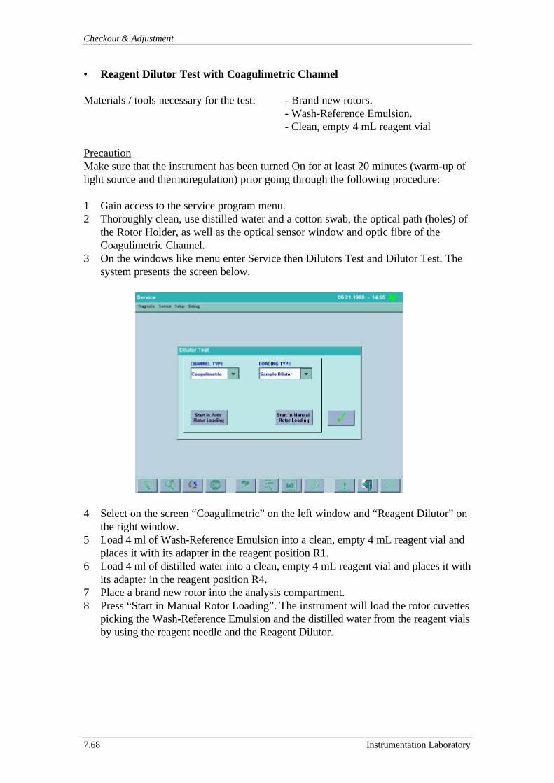
Checkout & Adjustment
7.68 Instrumentation Laboratory
• Reagent Dilutor Test with Coagulimetric Channel
Materials / tools necessary for the test: - Brand new rotors.- Wash-Reference Emulsion.- Clean, empty 4 mL reagent vial
PrecautionMake sure that the instrument has been turned On for at least 20 minutes (warm-up oflight source and thermoregulation) prior going through the following procedure:
1 Gain access to the service program menu.2 Thoroughly clean, use distilled water and a cotton swab, the optical path (holes) of
the Rotor Holder, as well as the optical sensor window and optic fibre of theCoagulimetric Channel.
3 On the windows like menu enter Service then Dilutors Test and Dilutor Test. Thesystem presents the screen below.
4 Select on the screen “Coagulimetric” on the left window and “Reagent Dilutor” onthe right window.
5 Load 4 ml of Wash-Reference Emulsion into a clean, empty 4 mL reagent vial andplaces it with its adapter in the reagent position R1.
6 Load 4 ml of distilled water into a clean, empty 4 mL reagent vial and places it withits adapter in the reagent position R4.
7 Place a brand new rotor into the analysis compartment.8 Press “Start in Manual Rotor Loading”. The instrument will load the rotor cuvettes
picking the Wash-Reference Emulsion and the distilled water from the reagent vialsby using the reagent needle and the Reagent Dilutor.
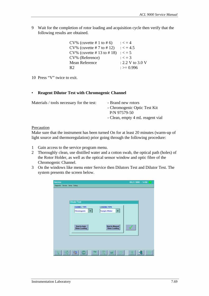
ACL 9000 Service Manual
Instrumentation Laboratory 7.69
9 Wait for the completion of rotor loading and acquisition cycle then verify that thefollowing results are obtained.
CV% (cuvette # 1 to # 6) : < = 4CV% (cuvette # 7 to # 12) : < = 4.5CV% (cuvette # 13 to # 18) : < = 5CV% (Reference) : < = 3Mean Reference : 2.2 V to 3.0 VR2 : >= 0.996
10 Press “V” twice to exit.
• Reagent Dilutor Test with Chromogenic Channel
Materials / tools necessary for the test: - Brand new rotors- Chromogenic Optic Test Kit P/N 97579-50- Clean, empty 4 mL reagent vial
PrecautionMake sure that the instrument has been turned On for at least 20 minutes (warm-up oflight source and thermoregulation) prior going through the following procedure:
1 Gain access to the service program menu.2 Thoroughly clean, use distilled water and a cotton swab, the optical path (holes) of
the Rotor Holder, as well as the optical sensor window and optic fibre of theChromogenic Channel.
3 On the windows like menu enter Service then Dilutors Test and Dilutor Test. Thesystem presents the screen below.
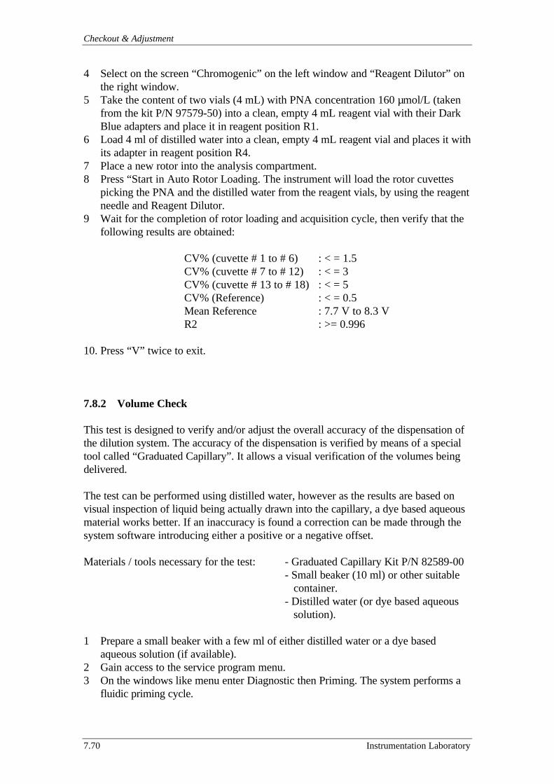
Checkout & Adjustment
7.70 Instrumentation Laboratory
4 Select on the screen “Chromogenic” on the left window and “Reagent Dilutor” onthe right window.
5 Take the content of two vials (4 mL) with PNA concentration 160 µmol/L (takenfrom the kit P/N 97579-50) into a clean, empty 4 mL reagent vial with their DarkBlue adapters and place it in reagent position R1.
6 Load 4 ml of distilled water into a clean, empty 4 mL reagent vial and places it withits adapter in reagent position R4.
7 Place a new rotor into the analysis compartment.8 Press “Start in Auto Rotor Loading. The instrument will load the rotor cuvettes
picking the PNA and the distilled water from the reagent vials, by using the reagentneedle and Reagent Dilutor.
9 Wait for the completion of rotor loading and acquisition cycle, then verify that thefollowing results are obtained:
CV% (cuvette # 1 to # 6) : < = 1.5CV% (cuvette # 7 to # 12) : < = 3CV% (cuvette # 13 to # 18) : < = 5CV% (Reference) : < = 0.5Mean Reference : 7.7 V to 8.3 VR2 : >= 0.996
10. Press “V” twice to exit.
7.8.2 Volume Check
This test is designed to verify and/or adjust the overall accuracy of the dispensation ofthe dilution system. The accuracy of the dispensation is verified by means of a specialtool called “Graduated Capillary”. It allows a visual verification of the volumes beingdelivered.
The test can be performed using distilled water, however as the results are based onvisual inspection of liquid being actually drawn into the capillary, a dye based aqueousmaterial works better. If an inaccuracy is found a correction can be made through thesystem software introducing either a positive or a negative offset.
Materials / tools necessary for the test: - Graduated Capillary Kit P/N 82589-00- Small beaker (10 ml) or other suitable container.- Distilled water (or dye based aqueous solution).
1 Prepare a small beaker with a few ml of either distilled water or a dye basedaqueous solution (if available).
2 Gain access to the service program menu.3 On the windows like menu enter Diagnostic then Priming. The system performs a
fluidic priming cycle.
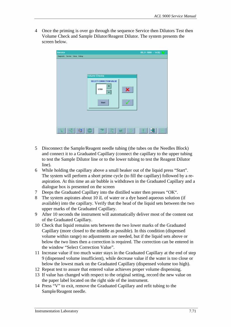
ACL 9000 Service Manual
Instrumentation Laboratory 7.71
4 Once the priming is over go through the sequence Service then Dilutors Test thenVolume Check and Sample Dilutor/Reagent Dilutor. The system presents thescreen below.
5 Disconnect the Sample/Reagent needle tubing (the tubes on the Needles Block)and connect it to a Graduated Capillary (connect the capillary to the upper tubingto test the Sample Dilutor line or to the lower tubing to test the Reagent Dilutorline).
6 While holding the capillary above a small beaker out of the liquid press “Start”.The system will perform a short prime cycle (to fill the capillary) followed by a re-aspiration. At this time an air bubble is withdrawn in the Graduated Capillary and adialogue box is presented on the screen
7 Deeps the Graduated Capillary into the distilled water then presses “OK“.8 The system aspirates about 10 ìL of water or a dye based aqueous solution (if
available) into the capillary. Verify that the head of the liquid sets between the twoupper marks of the Graduated Capillary.
9 After 10 seconds the instrument will automatically deliver most of the content outof the Graduated Capillary.
10 Check that liquid remains sets between the two lower marks of the GraduatedCapillary (more closed to the middle as possible). In this condition (dispensedvolume within range) no adjustments are needed, but if the liquid sets above orbelow the two lines then a correction is required. The correction can be entered inthe window “Select Correction Value”.
11 Increase value if too much water stays in the Graduated Capillary at the end of step9 (dispensed volume insufficient), while decrease value if the water is too close orbelow the lowest mark on the Graduated Capillary (dispensed volume too high).
12 Repeat test to assure that entered value achieves proper volume dispensing.13 If value has changed with respect to the original setting, record the new value on
the paper label located on the right side of the instrument.14 Press “V” to exit, remove the Graduated Capillary and refit tubing to the
Sample/Reagent needle.
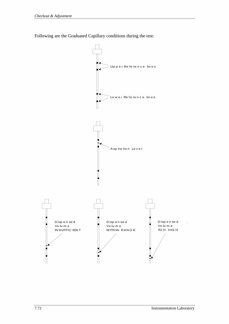
Checkout & Adjustment
7.72 Instrumentation Laboratory
Following are the Graduated Capillary conditions during the test:
Up p e r Re fe re n c e lin e s
Lo w e r Re fe re n c e lin e s
A sp ira tio n Le v e l
D isp e n se dVo lu m eINSUFFIC IEN T
D isp e n se dVo lu m eW ITHIN RANG E
D isp e n se dVo lu m eTO O HIG H
.
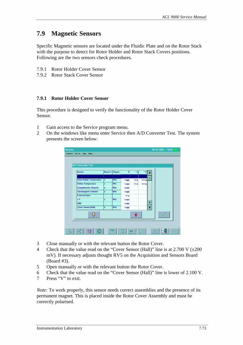
ACL 9000 Service Manual
Instrumentation Laboratory 7.73
7.9 Magnetic Sensors
Specific Magnetic sensors are located under the Fluidic Plate and on the Rotor Stackwith the purpose to detect for Rotor Holder and Rotor Stack Covers positions.Following are the two sensors check procedures.
7.9.1 Rotor Holder Cover Sensor7.9.2 Rotor Stack Cover Sensor
7.9.1 Rotor Holder Cover Sensor
This procedure is designed to verify the functionality of the Rotor Holder CoverSensor.
1 Gain access to the Service program menu.2 On the windows like menu enter Service then A/D Converter Test. The system
presents the screen below:
3 Close manually or with the relevant button the Rotor Cover.4 Check that the value read on the “Cover Sensor (Hall)” line is at 2.700 V (±200
mV). If necessary adjusts thought RV5 on the Acquisition and Sensors Board(Board #3).
5 Open manually or with the relevant button the Rotor Cover.6 Check that the value read on the “Cover Sensor (Hall)” line is lower of 2.100 V.7 Press “V” to exit.
Note: To work properly, this sensor needs correct assemblies and the presence of itspermanent magnet. This is placed inside the Rotor Cover Assembly and must becorrectly polarised.

Checkout & Adjustment
7.74 Instrumentation Laboratory
7.9.2 Rotor Stack Cover Sensor
This procedure is designed to verify the functionality of the Rotor Stack Cover Sensor.
1 Gain access to the Service program menu.2 On the windows like menu enter Service then Sensor Tests and Optic Sensor Test.
The system presents the screen below:
3 Open the Rotor Stack Cover.4 Check that on the “Rotor Storage Sensor Open” line there is displayed a “V”.5 Close the Rotor Stack Cover.6 Check that on the “Rotor Storage Sensor Open” line is disappeared the “V”.7 Press “V” to exit.
Note: To work properly, this sensor needs the presence of a permanent magnet. It’splaced inside the Rotor Stack Cover and must be correctly polarised.This sensor doesn’t need adjustments because works with a digital output signal (Onor Off).

ACL 9000 Service Manual
Instrumentation Laboratory 7.75
7.10 Rotor Waste Presence Switch
This procedure is designed to verify the functionality of the Rotor Waste PresenceSwitch.
1 Gain access to the Service program menu.2 On the windows like menu enter Service then Sensor Tests and Optic Sensor Test.
The system presents the screen below.
3 Open the Rotor Waste compartment door and verify the presence of the RotorWaste Container (if absent put it in place) then close the door.
4 Check that on the “Rotor Waste Presence Switch” line there is displayed a “V”.5 Open the Rotor Waste compartment door and remove the Rotor Waste Container
then close the door.6 Check that on the “Rotor Waste Presence Switch” line is disappeared the “V”.7 Press “V” to exit.
Note: This sensor doesn’t need electronic adjustments because works with a digitaloutput signal (On or Off).
In the first software revision this option is not available and the check is made directlyon the “WASTE” status displayed in the “Material Map” screen during the analysis.“WASTE Open” meaning that the Rotor Waste Container is not present, “WASTEFull or not Full” meaning that the Container is present and its status full/available).
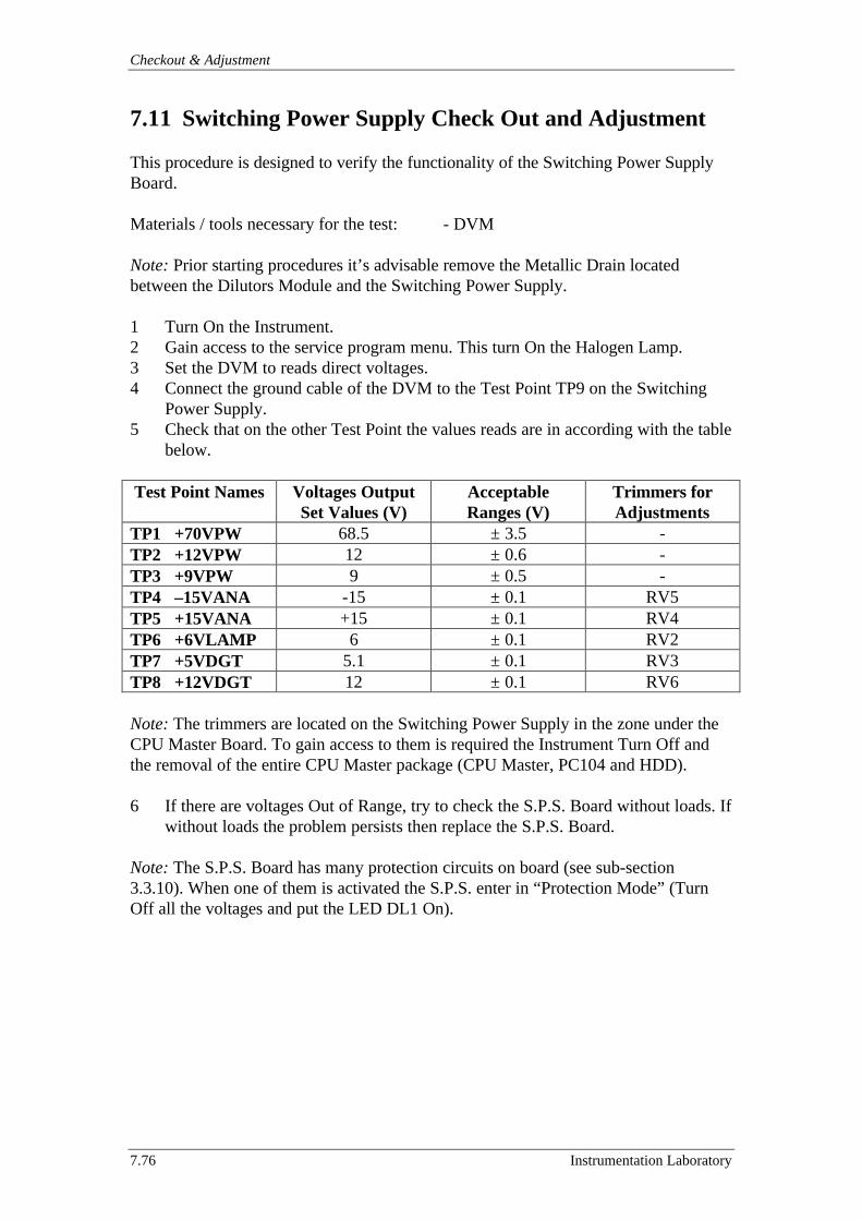
Checkout & Adjustment
7.76 Instrumentation Laboratory
7.11 Switching Power Supply Check Out and Adjustment
This procedure is designed to verify the functionality of the Switching Power SupplyBoard.
Materials / tools necessary for the test: - DVM
Note: Prior starting procedures it’s advisable remove the Metallic Drain locatedbetween the Dilutors Module and the Switching Power Supply.
1 Turn On the Instrument.2 Gain access to the service program menu. This turn On the Halogen Lamp.3 Set the DVM to reads direct voltages.4 Connect the ground cable of the DVM to the Test Point TP9 on the Switching
Power Supply.5 Check that on the other Test Point the values reads are in according with the table
below.
Test Point Names Voltages OutputSet Values (V)
AcceptableRanges (V)
Trimmers forAdjustments
TP1 +70VPW 68.5 ± 3.5 -TP2 +12VPW 12 ± 0.6 -TP3 +9VPW 9 ± 0.5 -TP4 –15VANA -15 ± 0.1 RV5TP5 +15VANA +15 ± 0.1 RV4TP6 +6VLAMP 6 ± 0.1 RV2TP7 +5VDGT 5.1 ± 0.1 RV3TP8 +12VDGT 12 ± 0.1 RV6
Note: The trimmers are located on the Switching Power Supply in the zone under theCPU Master Board. To gain access to them is required the Instrument Turn Off andthe removal of the entire CPU Master package (CPU Master, PC104 and HDD).
6 If there are voltages Out of Range, try to check the S.P.S. Board without loads. Ifwithout loads the problem persists then replace the S.P.S. Board.
Note: The S.P.S. Board has many protection circuits on board (see sub-section3.3.10). When one of them is activated the S.P.S. enter in “Protection Mode” (TurnOff all the voltages and put the LED DL1 On).
ACL 9000 Service Manual
Instrumentation Laboratory 7.77
7.12 Touch Screen Calibration
This procedure is designed to calibrate the parameters in the Touch Screen ControlBoard in respect to the physical dimension of the Touch Screen surface.
Materials / tools necessary for the test: - Touch Screen Calibration Tool P/N190574-00
Note: If the Touch Screen Calibration Tool is not available then it’s advisable use anobject with the tip rounded. Don’t use any object that can damage the Touch Screensurface.
1 Gain access to the Service program menu.2 On the windows like menu enter Service then Touch Calibration.3 A window appears with inside the information that “The current Touch Screen
calibration will be lost. The operation cannot be reverted. It’s OK to proceed?”4 Press “OK”.5 A window appears with inside the instruction “Please touch into red rectangle 1”.6 In the upper left corner of the screen a red rectangle has appeared. Touch it with
care using the Touch Screen Calibration Tool.7 Repeat the same operation with the red rectangle 2 located on the lower right of
the screen.8 In order to verify the calibration repeat the operation also the check red rectangle
3.9 A window appears with inside the information that “Touch Screen successfully
calibrated. Save the calibration?”10 Press “OK” to save the calibration and exit.
Note: During the calibration procedure any error may occur or the time out to touchthe proper red rectangle on the screen has expired (15 seconds). In this case a windowsappears with inside the information that the touch screen calibration is aborted. In thiscondition the Touch Screen is “out of order” and is needed to use the TAB key (or themouse if available) to select the Retry button and then press the Enter key. Repeat theentire procedure until the Touch Screen is successfully calibrated.
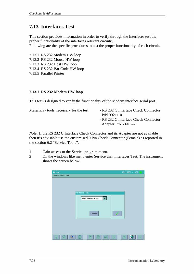
Checkout & Adjustment
7.78 Instrumentation Laboratory
7.13 Interfaces Test
This section provides information in order to verify through the Interfaces test theproper functionality of the interfaces relevant circuitry.Following are the specific procedures to test the proper functionality of each circuit.
7.13.1 RS 232 Modem HW loop7.13.2 RS 232 Mouse HW loop7.13.3 RS 232 Host HW loop7.13.4 RS 232 Bar Code HW loop7.13.5 Parallel Printer
7.13.1 RS 232 Modem HW loop
This test is designed to verify the functionality of the Modem interface serial port.
Materials / tools necessary for the test: - RS 232 C Interface Check Connector P/N 99211-01- RS 232 C Interface Check Connector Adapter P/N 71467-70
Note: If the RS 232 C Interface Check Connector and its Adapter are not availablethen it’s advisable use the customised 9 Pin Check Connector (Female) as reported inthe section 6.2 “Service Tools”.
1 Gain access to the Service program menu.2 On the windows like menu enter Service then Interfaces Test. The instrument
shows the screen below.
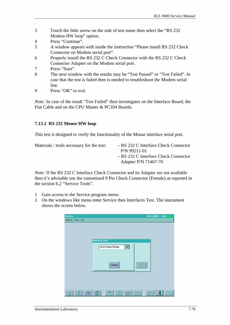
ACL 9000 Service Manual
Instrumentation Laboratory 7.79
3 Touch the little arrow on the side of test name then select the “RS 232Modem HW loop” option.
4 Press “Continue”.5 A window appears with inside the instruction “Please install RS 232 Check
Connector on Modem serial port”.6 Properly install the RS 232 C Check Connector with the RS 232 C Check
Connector Adapter on the Modem serial port.7 Press “Start”.8 The next window with the results may be “Test Passed” or “Test Failed”. In
case that the test is failed then is needed to troubleshoot the Modem serialline.
9 Press “OK” to exit.
Note: In case of the result “Test Failed” then investigates on the Interface Board, theFlat Cable and on the CPU Master & PC104 Boards.
7.13.2 RS 232 Mouse HW loop
This test is designed to verify the functionality of the Mouse interface serial port.
Materials / tools necessary for the test: - RS 232 C Interface Check Connector P/N 99211-01- RS 232 C Interface Check Connector Adapter P/N 71467-70
Note: If the RS 232 C Interface Check Connector and its Adapter are not availablethen it’s advisable use the customised 9 Pin Check Connector (Female) as reported inthe section 6.2 “Service Tools”.
1 Gain access to the Service program menu.2 On the windows like menu enter Service then Interfaces Test. The instrument
shows the screen below.
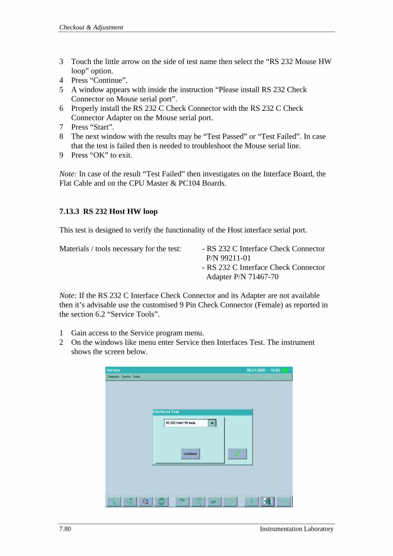
Checkout & Adjustment
7.80 Instrumentation Laboratory
3 Touch the little arrow on the side of test name then select the “RS 232 Mouse HWloop” option.
4 Press “Continue”.5 A window appears with inside the instruction “Please install RS 232 Check
Connector on Mouse serial port”.6 Properly install the RS 232 C Check Connector with the RS 232 C Check
Connector Adapter on the Mouse serial port.7 Press “Start”.8 The next window with the results may be “Test Passed” or “Test Failed”. In case
that the test is failed then is needed to troubleshoot the Mouse serial line.9 Press “OK” to exit.
Note: In case of the result “Test Failed” then investigates on the Interface Board, theFlat Cable and on the CPU Master & PC104 Boards.
7.13.3 RS 232 Host HW loop
This test is designed to verify the functionality of the Host interface serial port.
Materials / tools necessary for the test: - RS 232 C Interface Check Connector P/N 99211-01- RS 232 C Interface Check Connector Adapter P/N 71467-70
Note: If the RS 232 C Interface Check Connector and its Adapter are not availablethen it’s advisable use the customised 9 Pin Check Connector (Female) as reported inthe section 6.2 “Service Tools”.
1 Gain access to the Service program menu.2 On the windows like menu enter Service then Interfaces Test. The instrument
shows the screen below.
ACL 9000 Service Manual
Instrumentation Laboratory 7.81
3 Touch the little arrow on the side of test name then select the “RS 232 Host HWloop” option.
4 Press “Continue”.5 A window appears with inside the instruction “Please install RS 232 Check
Connector on Host serial port”.6 Properly install the RS 232 C Check Connector with the RS 232 C Check
Connector Adapter on the Host serial port.7 Press “Start”.8 The next window with the results may be “Test Passed” or “Test Failed”. In case
that the test is failed then is needed to troubleshoot the Host serial line.9 Press “OK” to exit.
Note: In case of the result “Test Failed” then investigates on the Interface Board, theFlat Cable and on the CPU Master & PC104 Boards.
7.13.4 RS 232 Bar Code HW loop
This test is designed to verify the functionality of the Bar Code interface serial port.
Materials / tools necessary for the test: - Tested External Bar Code Reader
Note:The External Bar-Code Reader is NOT AVAILABLE in this SW release.
Connect the External Bar Code reader to the relevant port on the rear of theinstrument then use it to compile a new Loadlist.
If a Tested External Bar Code Reader is not available then it’s advisable use thecustomised 9 Pin Check Connector (Male) reported in the section 6.2 “Service Tools”and follow the procedure below.
1 Gain access to the Service program menu.
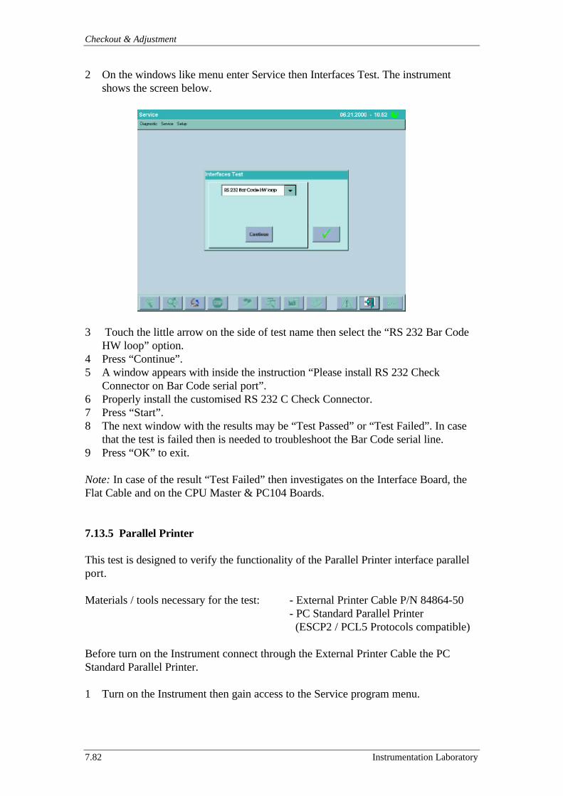
Checkout & Adjustment
7.82 Instrumentation Laboratory
2 On the windows like menu enter Service then Interfaces Test. The instrumentshows the screen below.
3 Touch the little arrow on the side of test name then select the “RS 232 Bar CodeHW loop” option.
4 Press “Continue”.5 A window appears with inside the instruction “Please install RS 232 Check
Connector on Bar Code serial port”.6 Properly install the customised RS 232 C Check Connector.7 Press “Start”.8 The next window with the results may be “Test Passed” or “Test Failed”. In case
that the test is failed then is needed to troubleshoot the Bar Code serial line.9 Press “OK” to exit.
Note: In case of the result “Test Failed” then investigates on the Interface Board, theFlat Cable and on the CPU Master & PC104 Boards.
7.13.5 Parallel Printer
This test is designed to verify the functionality of the Parallel Printer interface parallelport.
Materials / tools necessary for the test: - External Printer Cable P/N 84864-50- PC Standard Parallel Printer (ESCP2 / PCL5 Protocols compatible)
Before turn on the Instrument connect through the External Printer Cable the PCStandard Parallel Printer.
1 Turn on the Instrument then gain access to the Service program menu.
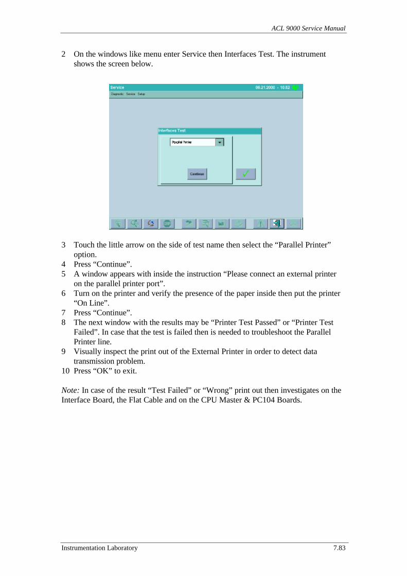
ACL 9000 Service Manual
Instrumentation Laboratory 7.83
2 On the windows like menu enter Service then Interfaces Test. The instrumentshows the screen below.
3 Touch the little arrow on the side of test name then select the “Parallel Printer”option.
4 Press “Continue”.5 A window appears with inside the instruction “Please connect an external printer
on the parallel printer port”.6 Turn on the printer and verify the presence of the paper inside then put the printer
“On Line”.7 Press “Continue”.8 The next window with the results may be “Printer Test Passed” or “Printer Test
Failed”. In case that the test is failed then is needed to troubleshoot the ParallelPrinter line.
9 Visually inspect the print out of the External Printer in order to detect datatransmission problem.
10 Press “OK” to exit.
Note: In case of the result “Test Failed” or “Wrong” print out then investigates on theInterface Board, the Flat Cable and on the CPU Master & PC104 Boards.
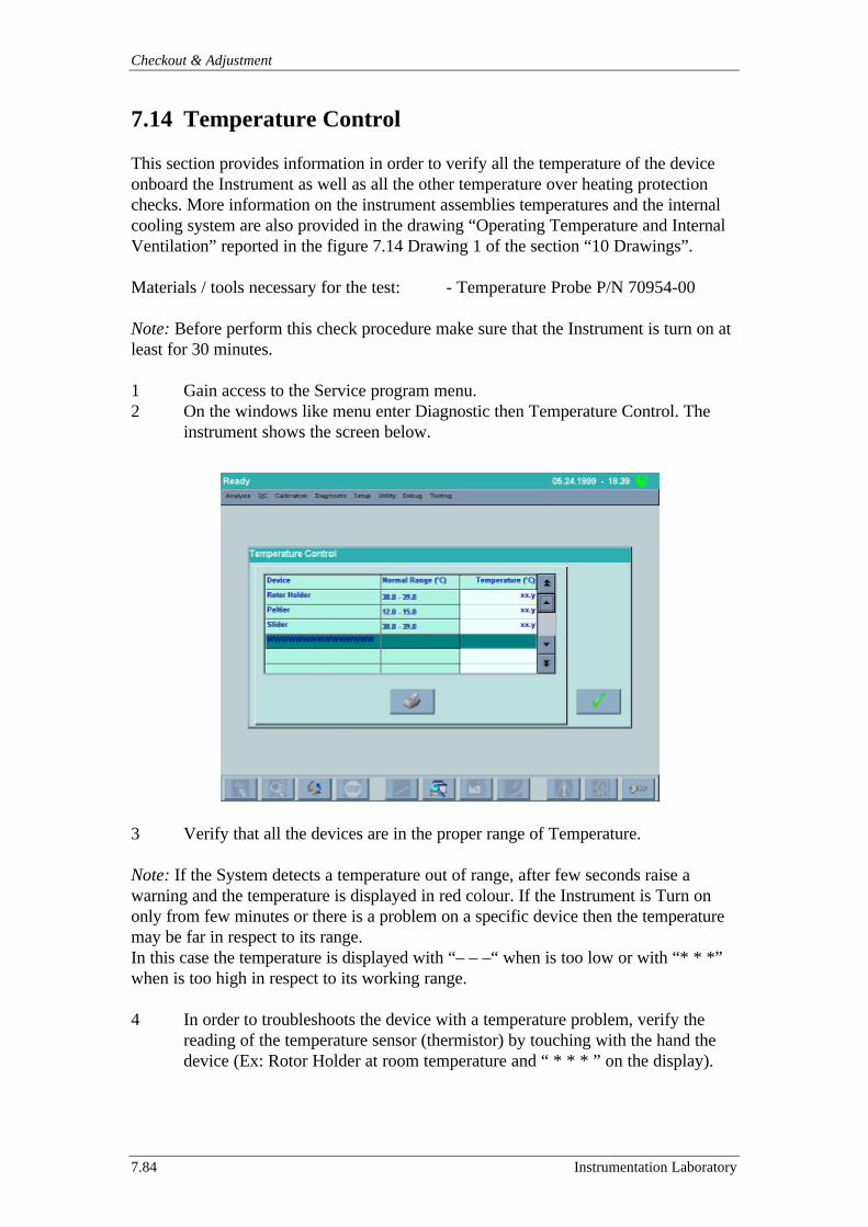
Checkout & Adjustment
7.84 Instrumentation Laboratory
7.14 Temperature Control
This section provides information in order to verify all the temperature of the deviceonboard the Instrument as well as all the other temperature over heating protectionchecks. More information on the instrument assemblies temperatures and the internalcooling system are also provided in the drawing “Operating Temperature and InternalVentilation” reported in the figure 7.14 Drawing 1 of the section “10 Drawings”.
Materials / tools necessary for the test: - Temperature Probe P/N 70954-00
Note: Before perform this check procedure make sure that the Instrument is turn on atleast for 30 minutes.
1 Gain access to the Service program menu.2 On the windows like menu enter Diagnostic then Temperature Control. The
instrument shows the screen below.
3 Verify that all the devices are in the proper range of Temperature.
Note: If the System detects a temperature out of range, after few seconds raise awarning and the temperature is displayed in red colour. If the Instrument is Turn ononly from few minutes or there is a problem on a specific device then the temperaturemay be far in respect to its range.In this case the temperature is displayed with “– – –“ when is too low or with “* * *”when is too high in respect to its working range.
4 In order to troubleshoots the device with a temperature problem, verify thereading of the temperature sensor (thermistor) by touching with the hand thedevice (Ex: Rotor Holder at room temperature and “ * * * ” on the display).
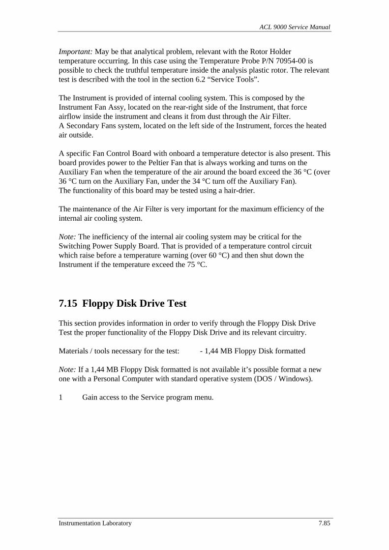
ACL 9000 Service Manual
Instrumentation Laboratory 7.85
Important: May be that analytical problem, relevant with the Rotor Holdertemperature occurring. In this case using the Temperature Probe P/N 70954-00 ispossible to check the truthful temperature inside the analysis plastic rotor. The relevanttest is described with the tool in the section 6.2 “Service Tools”.
The Instrument is provided of internal cooling system. This is composed by theInstrument Fan Assy, located on the rear-right side of the Instrument, that forceairflow inside the instrument and cleans it from dust through the Air Filter.A Secondary Fans system, located on the left side of the Instrument, forces the heatedair outside.
A specific Fan Control Board with onboard a temperature detector is also present. Thisboard provides power to the Peltier Fan that is always working and turns on theAuxiliary Fan when the temperature of the air around the board exceed the 36 °C (over36 °C turn on the Auxiliary Fan, under the 34 °C turn off the Auxiliary Fan).The functionality of this board may be tested using a hair-drier.
The maintenance of the Air Filter is very important for the maximum efficiency of theinternal air cooling system.
Note: The inefficiency of the internal air cooling system may be critical for theSwitching Power Supply Board. That is provided of a temperature control circuitwhich raise before a temperature warning (over 60 °C) and then shut down theInstrument if the temperature exceed the 75 °C.
7.15 Floppy Disk Drive Test
This section provides information in order to verify through the Floppy Disk DriveTest the proper functionality of the Floppy Disk Drive and its relevant circuitry.
Materials / tools necessary for the test: - 1,44 MB Floppy Disk formatted
Note: If a 1,44 MB Floppy Disk formatted is not available it’s possible format a newone with a Personal Computer with standard operative system (DOS / Windows).
1 Gain access to the Service program menu.
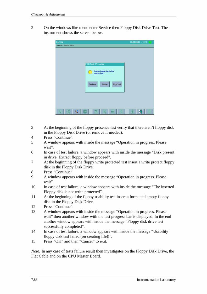
Checkout & Adjustment
7.86 Instrumentation Laboratory
2 On the windows like menu enter Service then Floppy Disk Drive Test. Theinstrument shows the screen below.
3 At the beginning of the floppy presence test verify that there aren’t floppy diskin the Floppy Disk Drive (or remove if needed).
4 Press “Continue”.5 A window appears with inside the message “Operation in progress. Please
wait”.6 In case of test failure, a window appears with inside the message “Disk present
in drive. Extract floppy before proceed”.7 At the beginning of the floppy write protected test insert a write protect floppy
disk in the Floppy Disk Drive.8 Press “Continue”.9 A window appears with inside the message “Operation in progress. Please
wait”.10 In case of test failure, a window appears with inside the message “The inserted
Floppy disk is not write protected”.11 At the beginning of the floppy usability test insert a formatted empty floppy
disk in the Floppy Disk Drive.12 Press “Continue”.13 A window appears with inside the message “Operation in progress. Please
wait” then another window with the test progress bar is displayed. In the endanother window appears with inside the message “Floppy disk drive testsuccessfully completed”.
14 In case of test failure, a window appears with inside the message “Usabilityfloppy disk test failed (on creating file)!”.
15 Press “OK” and then “Cancel” to exit.
Note: In any case of tests failure result then investigates on the Floppy Disk Drive, theFlat Cable and on the CPU Master Board.
ACL 9000 Service Manual
Instrumentation Laboratory 7.87
7.16 Software checking & loading
This section provide information in order to complete explain the upgrade procedureof the software in the system. The software is stored in the Hard Disk Drive and in theFlash Memory Chips on the boards.Following are the specific procedures.
7.16.1 Software Identification7.16.2 Software Upload & Upgrade7.16.3 Databases Check7.16.4 Backup / Restore of the system configuration7.16.5 Upgrade IL Library
7.16.1 1 Software Identification
1 Gain accesses to the Service program menu.2 On the windows like menu enter Utility then Software and Software Identification.
The instrument shows the screen below.
3 Verify that all the Software releases are in the last versions available.4 Press “V” to exit.
Note: The Master and the IL Library software release displayed are the current storedin the HDD, while the Slave and the REM software release displayed are relevant tothe software stored in the boards memories (Boards #2 and #4).If for troubleshooting purposes the current Slave Board #2 or REM Board #4 arereplaced it’s required to perform the Upgrade procedure. That’s in order to programthe new board memories with the last software revision that is Uploaded in the HardDisk Drive. Only after the Upgrade procedure then the last software revision willworking in the boards.
Checkout & Adjustment
7.88 Instrumentation Laboratory
If a new software revision is available then follow the Upload and the Upgradeprocedure in order to replace (before in the HDD with the Upload and then on theBoard with the Upgrade) the old software present in the instrument with the brand newone in the Upgrade Kits. That’s for the 3 main software (Master, Slave and REM)while to upgrade the IL Library software follows the upgrade procedure described inthe sub-section 7.16.5.
7.16.2 Software Upload & Upgrade
This sub-section clarifies the sequence of operation required to perform the Uploadand Upgrade for the Master, Slave and REM software.
The system is provided with a Hard Disk Drive where during the Upload is stored thesoftware loaded from the floppy disks.Then during the Upgrade procedure the loaded software replaces the old one andbecome operative at the next turn on.
Note: It’s very important that each procedure is individually performed. Perform all the3 Uploads and then select all the 3 Upgrades may generate confusion in the sequencewith the results that any software will not upgraded.
Following are the specific software upgrade procedure.
• Software Master• Software Slave• Software REM
• Software Master
This procedure is designed to install a new Master software release for the Instrument.
Materials / tools necessary for the test: - Software System Disk Kit P/N 181812-75
1 Gain access to the Service program menu.2 On the windows like menu enter Utility then Software, SW Upgrade, SW
Master and Upload.3 The instrument shows a window with inside wrote “Upload Master code
selected. Do you confirm?”. Press “Yes” to continue.4 As required “Insert the first floppy disk.” in the floppy drive then press “OK”.5 The instrument shows a window with inside wrote “Upload in progress…” and
an operation in progress bar.6 When the progress bar is full the instrument shows a window where the system
require to “Insert another disk.”. Insert the next disk and press “OK”.7 Repeat last few steps until all the Master floppy disks are uploaded.
ACL 9000 Service Manual
Instrumentation Laboratory 7.89
8 The Upload procedure is ended and the instrument shows a window with insidewrote, “Upload code completed. To continue the Upgrade software, pleaseselect the Upgrade option.”. Press “OK” to continue.
9 On the windows like menu enter Utility then Software, SW Upgrade, SWMaster and Upgrade.
10 The instrument shows a window with inside wrote, “Upgrade Master codeselected. Do you confirm?”. Press “Yes” to continue.
11 The instrument shows a window with inside wrote “Upgrade in progress…”and an operation in progress bar.
12 When the progress bar is full the instrument shows a window where with insidewrote, “Upgrade code completed. To continue switch the system Off, wait fewseconds and switch it back On.”. Now, the software is freeze and the onlypossible operation is to switch Off and then On the Instrument.
13 After the turn On, verify the new software release follows the softwareidentification procedure.
• Software Slave
This procedure is designed to install a new Slave software release for the Instrument.
Materials / tools necessary for the test: - Software System Disk Kit P/N 181812-75
1 Gain access to the Service program menu.2 On the windows like menu enter Utility then Software, SW Upgrade, SW Slave
and Upload.3 The instrument shows a window with inside wrote, “Upload code selected. Do you
confirm?”. Press “Yes” to continue.4 As required “Insert disk.” in the floppy drive then press “OK”.5 The instrument shows a window with inside wrote “Upload in progress…” and an
operation in progress bar.6 When the progress bar is full the Upload procedure is ended and the instrument
shows a window with inside wrote, “Upload code completed. To continue theUpgrade software, please select the Upgrade option.”. Press “OK” to continue.
7 On the windows like menu enter Utility then Software, SW Upgrade, SW Slaveand Upgrade.
8 The instrument shows a window with inside wrote, “Upgrade code selected. Doyou confirm?”. Press “Yes” to continue.
9 The instrument shows for few seconds a window with inside wrote, “Upgrade inprogress…”.
10 After the instrument shows a window with inside wrote, “The device is ready toreceive the code, please Logout. Switch the system Off, wait few seconds andswitch it back On, to continue the Upgrade.”. Logout, Switch Off and then On theInstrument to continue.
11 When during the Init System the system shows a window with inside wrote “InitSystem in progress… Please wait!” and an operation in progress bar, then the

Checkout & Adjustment
7.90 Instrumentation Laboratory
system test the Slave software with the result that it is invalidate. So the systemproceed to replace it with the new one uploaded in three steps.
12 The first step to upgrade the software on the Slave Board #2 is show in thewindow “Erase Flash Memory in progress… Please wait!” with the relevantoperation in progress bar.
13 The second step show in the window “Upgrade Slave code in progress… Pleasewait!” with the relevant operation in progress bar.
14 The third and last step shows in the window “Init Slave code in progress… Pleasewait!”. After that the Init System continue normally without other interruption.
15 After the Log-In verifies the new software release follows the softwareidentification procedure.
• Software REM
This procedure is designed to install a new REM software release for the Instrument.
Materials / tools necessary for the test: - Software System Disk Kit P/N 181812-75
1 Gain access to the Service program menu.2 On the windows like menu enter Utility then Software, SW Upgrade, SW REM
and Upload.3 The instrument shows a window with inside wrote, “Upload code selected. Do you
confirm?”. Press “Yes” to continue.4 As required “Insert disk.” in the floppy drive then press “OK”.5 The instrument shows a window with inside wrote “Upload in progress…” and an
operation in progress bar.6 When the progress bar is full the Upload procedure is ended and the instrument
shows a window with inside wrote, “Upload code completed. To continue theUpgrade software, please select the Upgrade option.”. Press “OK” to continue.
7 On the windows like menu enter Utility then Software, SW Upgrade, SW REMand Upgrade.
8 The instrument shows a window with inside wrote, “Upgrade code selected. Doyou confirm?”. Press “Yes” to continue.
9 The instrument shows for a second a window with inside wrote, “Upgrade inprogress…”.
10 After the instrument shows a window with inside wrote, “The device is ready toreceive the code, please Logout. Switch the system Off, wait few seconds andswitch it back On, to continue the Upgrade.”. Logout, Switch Off and then On theInstrument to continue.
11 When during the Init System the system shows a window with inside wrote “InitSystem in progress… Please wait!” and an operation in progress bar, then thesystem test the REM software with the result that it is invalidate. So the systemproceed to replace it with the new one uploaded.
12 To upgrade the software on the REM Board #2 the system shows in a window“REM code Upgrade in progress… Please wait!” with the relevant operation inprogress bar. After that the progress bar is full then the Init System continuenormally without other interruption.
ACL 9000 Service Manual
Instrumentation Laboratory 7.91
13 After the Log-In verifies the new software release follows the softwareidentification procedure.
7.16.3 DataBases Check
This sub-section is designed to clarify the action that is possible do in case that ispresent an issue on databases as well as to perform Databases checks.
If the Checking Database during the Init System phase (at Turn On) detects a problemthen the system shows the following menu’.
Database check reported some errors. Please select one of these options.
1 – Restore last saved Database (on “Date” and “time”)
If this option is selected then the system proceeds with the restore of the last validdatabase saved.Caution! That means that all the data and modification stored from the last self-backup(on “date” and “time”) to now will be lost!
2 – Power off and call service
If this option is selected then the system proceeds showing the message “Systemhalted. You can safely turn off ACL.”
3 – Ignore error and proceed with Init
If this option is selected then the system proceeds with the Init System.
Caution! Is possible that after the Init System the instrument is halted with a databasefailure message. This depends from a big problem in the instrument database and theaccess to the Operator Main Program is denied. In this case the only chance is turn offand then on again the instrument, and chose 1 (Restore last saved database) in themenu’.
Caution! If, after the Init System, is possible gain access to the Service Program thenit’s advisable try to perform an “Archive” of all the data not saved yet (QC, AR,Calibrations and Patient data) and also a Backup of the system configuration (if another one is not available) as described in the sub-section 7.16.4.
Checkout & Adjustment
7.92 Instrumentation Laboratory
After this, on the windows like menu enter Service then DataBases Check.The system shows a window where is possible select one of the four following option.
- Restore whole Database- Restore Setup and Calibration Database deleting other data- Restore Setup Database deleting other data- Ignore error
If also through this menu’ it’s impossible recover Data and/or Setup configuration thenLog-Out, switch off and then On the Instrument and in the menu’ select the option “1– Restore last saved Database”.
7.16.4 Backup / Restore of the system configuration
This sub-section is designed to provide information about the Backup / Restore of thesystem configuration.The following procedure allows to the service engineer to save on a floppy disk thecurrent configuration of the instrument with the purpose to create a backup copy thatmay be restored in the future on the same but also on other instruments.
The databases that will be saved contain information about the setup of:• Liquids• Tests• Profile• QC• AR• Interface configuration• System configuration
Materials / tools necessary for the test: - Available Floppy Disk 1,44 MB formatted.
1 Gain access to the Analysis / Service program menu.2 On the windows like menu enter Utility then Backup / Restore.3 The instrument shows a window with inside 3 choice buttons.4 Touch “Backup”. The system takes few minutes to prepare the data for the backup
displaying the message “Backup of database in progress, please wait”.5 When required insert the floppies disk in the Floppy Drive and press “OK”.6 The system writes the data on the disk displaying a progress bar.7 Finished the operation extracts the floppy disk and put on an identification label.
ACL 9000 Service Manual
Instrumentation Laboratory 7.93
Following is the procedure is to restore the backup data file on the instrument.
1 Gain access to the Analysis / Service program menu.2 On the windows like menu enter Utility then Backup / Restore.3 The instrument shows a window with inside 3 choice buttons.4 Touch “Restore”. The system displays a choice box with the message “Restoring
the saved instrument configuration some results in the databases could be erased”then presses “Yes”.
5 When required inserts the proper floppies disk in the Floppy Drive and press “OK”.6 The system reads the data on the disk displaying a progress bar and then takes few
minutes to restore the data.7 Finished the operation confirms and extracts the floppy disk.
Touching the button “View Backup Date” is also possible check the date of theBackup file on the disk without proceed with the Restore.
7.16.5 Upgrade IL Library
This sub-section is designed to provide information about the Upgrade of the ILLibrary.The following procedure allows to the service engineer to perform the IL LibraryUpgrade.
The databases that will be updated contain information about:• New Liquids• New Profiles• New Interference Table• New Tests
For all the tests updated in the databases with a new revision the calibration, AR, QCand patients data will be lost. In the end of the operation the system provide to theservice engineer / customer the list of all the data erased.
Materials / tools necessary for the test: - IL Library Upgrade Disk
1 Gain access to the Analysis / Service program menu.2 On the windows like menu enter Utility then Upgrade IL Library.3 The instrument shows a window with the message “Load DB file from floppy disk”
then touch “continue.4 Insert the first disk as required and touch “OK”.5 The system takes few minutes to read the data and Upgrade the libraries.6 When finished extract the floppy disk in the Floppy Drive and press “OK”.
ACL 9000 Service Manual
Instrumentation Laboratory 8.1
8 System Interfacing
This section provides the main information related to the configuration of theinstrument interface for the communication with external devices.The devices that are possible connecting to the instrument are following.
8.1 Keyboard8.2 External Parallel Printer8.3 Network8.4 Modem8.5 Mouse8.6 Host Computer8.7 External Bar Code Reader

System Interfacing
8.2 Instrumentation Laboratory
8.1 Keyboard
On the windows like menu’ select “Setup” then “Interfaces” and “Keyboard”. Thesystem displays the screen below.
The window in this screen allows configuring the ACL 9000 PC standard keyboard forthe language and layout used. Also the enabling of the on-screen keypad isconfigurable by selecting:
KEYBOARD TYPE: EnglishFrenchGermanSpanishItalianUnited States
NUMERICAL KEYPAD: DisabledAll numerical fieldsAll numerical fields and Sample ID
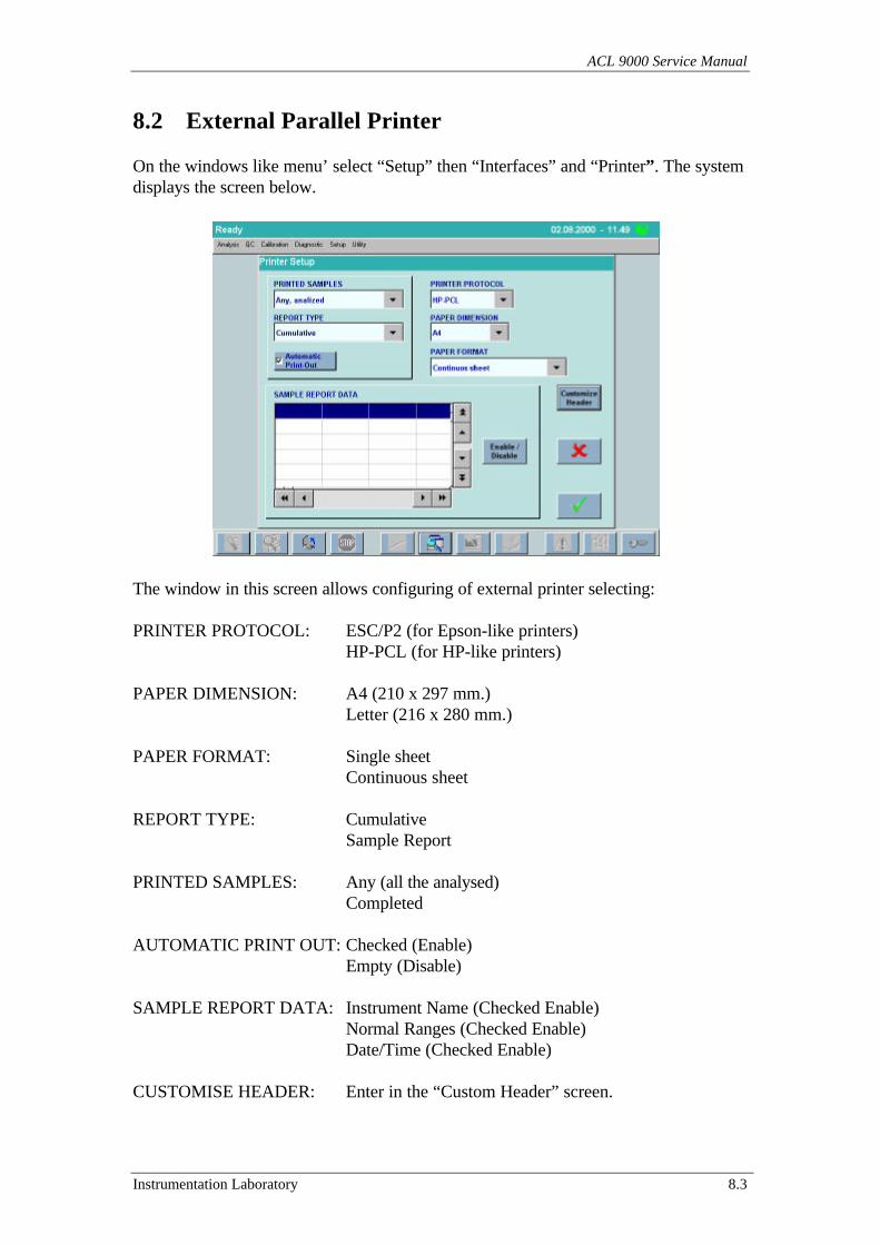
ACL 9000 Service Manual
Instrumentation Laboratory 8.3
8.2 External Parallel Printer
On the windows like menu’ select “Setup” then “Interfaces” and “Printer”. The systemdisplays the screen below.
The window in this screen allows configuring of external printer selecting:
PRINTER PROTOCOL: ESC/P2 (for Epson-like printers)HP-PCL (for HP-like printers)
PAPER DIMENSION: A4 (210 x 297 mm.)Letter (216 x 280 mm.)
PAPER FORMAT: Single sheetContinuous sheet
REPORT TYPE: CumulativeSample Report
PRINTED SAMPLES: Any (all the analysed)Completed
AUTOMATIC PRINT OUT: Checked (Enable)Empty (Disable)
SAMPLE REPORT DATA: Instrument Name (Checked Enable)Normal Ranges (Checked Enable)Date/Time (Checked Enable)
CUSTOMISE HEADER: Enter in the “Custom Header” screen.
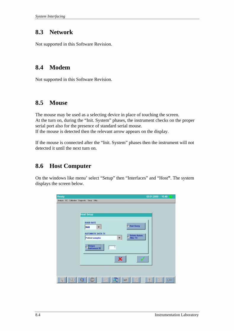
System Interfacing
8.4 Instrumentation Laboratory
8.3 Network
Not supported in this Software Revision.
8.4 Modem
Not supported in this Software Revision.
8.5 Mouse
The mouse may be used as a selecting device in place of touching the screen.At the turn on, during the “Init. System” phases, the instrument checks on the properserial port also for the presence of standard serial mouse.If the mouse is detected then the relevant arrow appears on the display.
If the mouse is connected after the “Init. System” phases then the instrument will notdetected it until the next turn on.
8.6 Host Computer
On the windows like menu’ select “Setup” then “Interfaces” and “Host”. The systemdisplays the screen below.
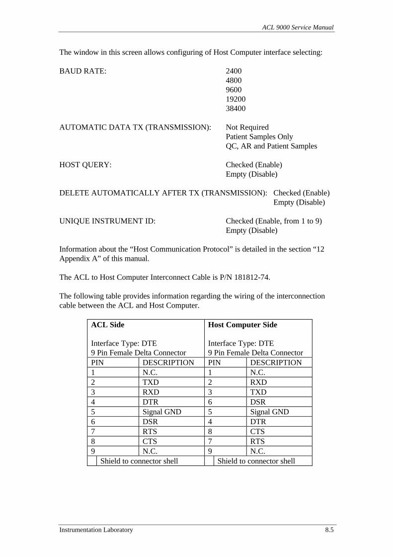
ACL 9000 Service Manual
Instrumentation Laboratory 8.5
The window in this screen allows configuring of Host Computer interface selecting:
BAUD RATE: 2400480096001920038400
AUTOMATIC DATA TX (TRANSMISSION): Not RequiredPatient Samples OnlyQC, AR and Patient Samples
HOST QUERY: Checked (Enable)Empty (Disable)
DELETE AUTOMATICALLY AFTER TX (TRANSMISSION): Checked (Enable)Empty (Disable)
UNIQUE INSTRUMENT ID: Checked (Enable, from 1 to 9)Empty (Disable)
Information about the “Host Communication Protocol” is detailed in the section “12Appendix A” of this manual.
The ACL to Host Computer Interconnect Cable is P/N 181812-74.
The following table provides information regarding the wiring of the interconnectioncable between the ACL and Host Computer.
ACL Side
Interface Type: DTE9 Pin Female Delta Connector
Host Computer Side
Interface Type: DTE9 Pin Female Delta Connector
PIN DESCRIPTION PIN DESCRIPTION1 N.C. 1 N.C.2 TXD 2 RXD3 RXD 3 TXD4 DTR 6 DSR5 Signal GND 5 Signal GND6 DSR 4 DTR7 RTS 8 CTS8 CTS 7 RTS9 N.C. 9 N.C.
Shield to connector shell Shield to connector shell

System Interfacing
8.6 Instrumentation Laboratory
8.7 External Bar Code Reader
On the windows like menu’ select “Setup” then “Interfaces” and “Barcode”. Thesystem displays the screen below.
The first step is enable (Checked) the Internal and/or External Barcode Reader.
The four fields visible on the screen correspond to the four families of barcodes thatmay be activated on the ACL, along with their corresponding subtypes of barcodes.Choose for each field one of the options below according to the laboratory’s needs.
CODABAR: DisabledNo ChecksumAIM Mod 16NW7 Mod 11NW7 Mod 16
CODE 39: DisabledNo ChecksumMod 43
INTERLEAVED 2 OF 5: DisabledNo ChecksumUSS Mod 10OPCC Mod 10
CODE 128: DisabledNo Checksum
Note: The External Bar Code Reader is not supported in this Software Revision.
ACL 9000 Service Manual
Instrumentation Laboratory 9.1
9 Part List
This section contains information about the service parts as well as the expendablematerials that are available for use with the ACL 9000 System. A large number of theexpendable materials are shipped in the “Startup Kit” included with the ACL 9000system. These items may be ordered using their Part Numbers as shown in the tables.Following are the specific sections.
9.1 Startup Kit9.2 Expendable Materials9.3 Service Parts List
Part List
9.2 Instrumentation Laboratory
9.1 Startup Kit
The following expendable materials are contained in the Startup Kit that is shippedwith the ACL 9000 System.
• Sample Trays
Three types of sample trays are available as shown below. The startup kit includes twoof them, chosen by the user according to the desired system configuration.
Tray type Used for3 mL Primary tube, 3 or 3.5 mL total volume (13x75 mm)5 mL Primary tube, 5 mL total volume (13x75 or 13x100 mm)S 11.5 Sarstedt type tube, 3 mL (11.5x66 mm) or 5 mL (11.5x92 mm)
• Sample Tray Adapters for plastic cups - 4 piecesfor 4 mL glass vials - 6 pieces
• Reagent Vial Adapters for 10 mL vials, reagents requiring magneticstirring (grey) - 4 piecesfor 10 mL vials, reagents not requiring magneticstirring (light blue) - 6 piecesfor 4 mL vials, reagents not requiring magneticstirring (dark blue) - 4 pieces
• Magnetic Stirrers for reagent stirring - one package containing 6pieces
• Small Sample Cups 0.5 mL sample cups - one package containing1000 pieces
• Large Sample Cups 2.0 mL sample cups - one package containing1000 pieces
• Diluent/Buffer/Reagent Cups 4.0 mL cups, with labels - one packagecontaining 100 pieces
• Diluent/Buffer/Reagent Glass Vials 10 mL glass vials - one packagecontaining 10 pieces
• Needles Block Assy an assembly consisting of an acrylic block withthe sample and reagent needles and theirassociated liquid sensors
• Sample and Reagent Tubing 1.5 meter piece of tubing to be cut and used asneeded
ACL 9000 Service Manual
Instrumentation Laboratory 9.3
• Insertion Tool for Tubing a tool to be used when replacing sample andreagent tubing
• Wash/Reference Emulsiona 1-liter bottle of Emulsion
• Rinse/Waste Reservoir a reservoir for needles rinse and liquid waste
• Waste Bottle a 5-liter bottle to collect ACL waste
• Waste Tubing a 1.5 meter piece of tubing to be used forcollection of liquid waste
• Adjustment Tool for Needles a tool to be used for adjusting the position of theneedles in the arm
• Rotors 20-Cuvette Rotors - package containing 100pieces
• Rotor Insertion Tool a tool used for inserting rotors into the system
• Rotor Waste Container a removable container used inside the system tohold the used rotors
• Moulded Air Filter One air filter for the analyser body
• Fuses 6.3 AT 2 fuses for the system
• Power Cord a power cord for the system: the cord included isconsistent with the voltage with which thesystem will be used
• External Printer Cable a cable to connect the optional external printer
• Host Computer Cable a cable to connect the optional host computer
• Software System Disk Kit kit containing the main system software
• Test Library Disk Kit kit containing the test library software
• Operator’s Manual the Operator’s Manual for use of the ACL 9000system
• Compliance Certificate a specific system compliance certificate
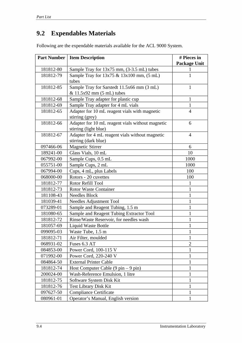
Part List
9.4 Instrumentation Laboratory
9.2 Expendables Materials
Following are the expendable materials available for the ACL 9000 System.
Part Number Item Description # Pieces inPackage Unit
181812-80 Sample Tray for 13x75 mm, (3-3.5 mL) tubes 1181812-79 Sample Tray for 13x75 & 13x100 mm, (5 mL)
tubes1
181812-85 Sample Tray for Sarstedt 11.5x66 mm (3 mL)& 11.5x92 mm (5 mL) tubes
1
181812-68 Sample Tray adapter for plastic cup 1181812-69 Sample Tray adapter for 4 mL vials 1181812-65 Adapter for 10 mL reagent vials with magnetic
stirring (grey)4
181812-66 Adapter for 10 mL reagent vials without magneticstirring (light blue)
6
181812-67 Adapter for 4 mL reagent vials without magneticstirring (dark blue)
4
097466-06 Magnetic Stirrer 6189241-00 Glass Vials, 10 mL 10067992-00 Sample Cups, 0.5 mL 1000055751-00 Sample Cups, 2 mL 1000067994-00 Cups, 4 mL, plus Labels 100068000-00 Rotors - 20 cuvettes 100181812-77 Rotor Refill Tool 1181812-73 Rotor Waste Container 1181108-43 Needles Block 1181039-41 Needles Adjustment Tool 1073289-01 Sample and Reagent Tubing, 1.5 m 1181080-65 Sample and Reagent Tubing Extractor Tool 1181812-72 Rinse/Waste Reservoir, for needles wash 1181057-69 Liquid Waste Bottle 1099095-03 Waste Tube, 1.5 m 1181812-71 Air Filter, moulded 1068931-02 Fuses 6.3 AT 2084853-00 Power Cord, 100-115 V 1071992-00 Power Cord, 220-240 V 1084864-50 External Printer Cable 1181812-74 Host Computer Cable (9 pin – 9 pin) 1200024-00 Wash-Reference Emulsion, 1 litre 1181812-75 Software System Disk Kit 1181812-76 Test Library Disk Kit 1097627-50 Compliance Certificate 1080961-01 Operator’s Manual, English version 1
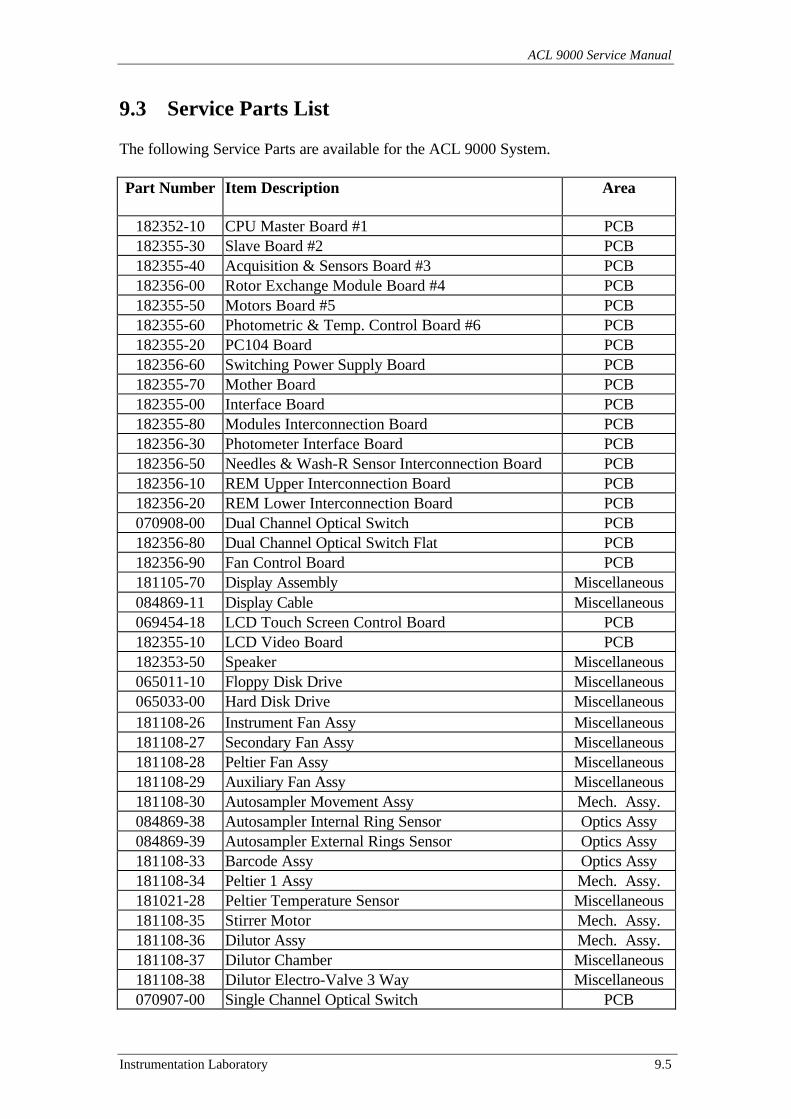
ACL 9000 Service Manual
Instrumentation Laboratory 9.5
9.3 Service Parts List
The following Service Parts are available for the ACL 9000 System.
Part Number Item Description Area
182352-10 CPU Master Board #1 PCB182355-30 Slave Board #2 PCB182355-40 Acquisition & Sensors Board #3 PCB182356-00 Rotor Exchange Module Board #4 PCB182355-50 Motors Board #5 PCB182355-60 Photometric & Temp. Control Board #6 PCB182355-20 PC104 Board PCB182356-60 Switching Power Supply Board PCB182355-70 Mother Board PCB182355-00 Interface Board PCB182355-80 Modules Interconnection Board PCB182356-30 Photometer Interface Board PCB182356-50 Needles & Wash-R Sensor Interconnection Board PCB182356-10 REM Upper Interconnection Board PCB182356-20 REM Lower Interconnection Board PCB070908-00 Dual Channel Optical Switch PCB182356-80 Dual Channel Optical Switch Flat PCB182356-90 Fan Control Board PCB181105-70 Display Assembly Miscellaneous084869-11 Display Cable Miscellaneous069454-18 LCD Touch Screen Control Board PCB182355-10 LCD Video Board PCB182353-50 Speaker Miscellaneous065011-10 Floppy Disk Drive Miscellaneous065033-00 Hard Disk Drive Miscellaneous181108-26 Instrument Fan Assy Miscellaneous181108-27 Secondary Fan Assy Miscellaneous181108-28 Peltier Fan Assy Miscellaneous181108-29 Auxiliary Fan Assy Miscellaneous181108-30 Autosampler Movement Assy Mech. Assy.084869-38 Autosampler Internal Ring Sensor Optics Assy084869-39 Autosampler External Rings Sensor Optics Assy181108-33 Barcode Assy Optics Assy181108-34 Peltier 1 Assy Mech. Assy.181021-28 Peltier Temperature Sensor Miscellaneous181108-35 Stirrer Motor Mech. Assy.181108-36 Dilutor Assy Mech. Assy.181108-37 Dilutor Chamber Miscellaneous181108-38 Dilutor Electro-Valve 3 Way Miscellaneous070907-00 Single Channel Optical Switch PCB
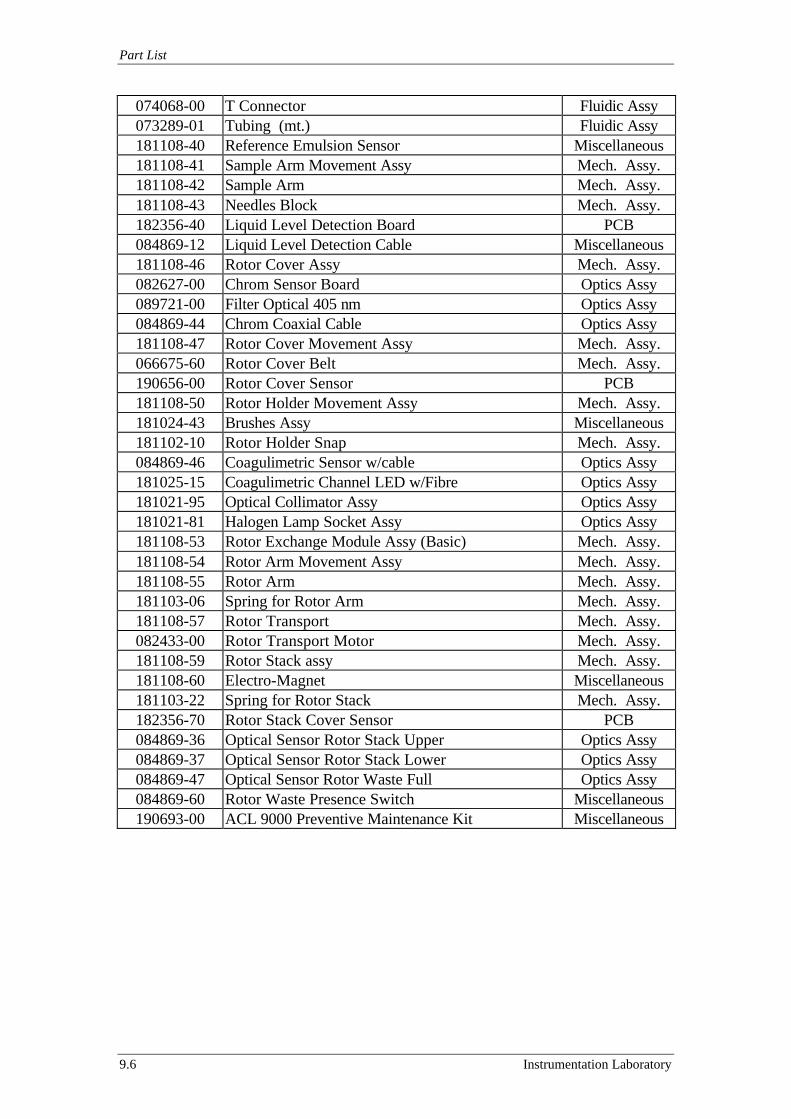
Part List
9.6 Instrumentation Laboratory
074068-00 T Connector Fluidic Assy073289-01 Tubing (mt.) Fluidic Assy181108-40 Reference Emulsion Sensor Miscellaneous181108-41 Sample Arm Movement Assy Mech. Assy.181108-42 Sample Arm Mech. Assy.181108-43 Needles Block Mech. Assy.182356-40 Liquid Level Detection Board PCB084869-12 Liquid Level Detection Cable Miscellaneous181108-46 Rotor Cover Assy Mech. Assy.082627-00 Chrom Sensor Board Optics Assy089721-00 Filter Optical 405 nm Optics Assy084869-44 Chrom Coaxial Cable Optics Assy181108-47 Rotor Cover Movement Assy Mech. Assy.066675-60 Rotor Cover Belt Mech. Assy.190656-00 Rotor Cover Sensor PCB181108-50 Rotor Holder Movement Assy Mech. Assy.181024-43 Brushes Assy Miscellaneous181102-10 Rotor Holder Snap Mech. Assy.084869-46 Coagulimetric Sensor w/cable Optics Assy181025-15 Coagulimetric Channel LED w/Fibre Optics Assy181021-95 Optical Collimator Assy Optics Assy181021-81 Halogen Lamp Socket Assy Optics Assy181108-53 Rotor Exchange Module Assy (Basic) Mech. Assy.181108-54 Rotor Arm Movement Assy Mech. Assy.181108-55 Rotor Arm Mech. Assy.181103-06 Spring for Rotor Arm Mech. Assy.181108-57 Rotor Transport Mech. Assy.082433-00 Rotor Transport Motor Mech. Assy.181108-59 Rotor Stack assy Mech. Assy.181108-60 Electro-Magnet Miscellaneous181103-22 Spring for Rotor Stack Mech. Assy.182356-70 Rotor Stack Cover Sensor PCB084869-36 Optical Sensor Rotor Stack Upper Optics Assy084869-37 Optical Sensor Rotor Stack Lower Optics Assy084869-47 Optical Sensor Rotor Waste Full Optics Assy084869-60 Rotor Waste Presence Switch Miscellaneous190693-00 ACL 9000 Preventive Maintenance Kit Miscellaneous
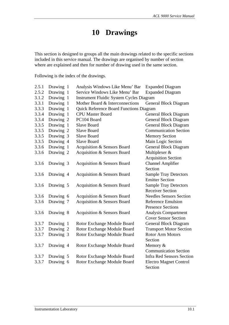
ACL 9000 Service Manual
Instrumentation Laboratory 10.1
10 Drawings
This section is designed to groups all the main drawings related to the specific sectionsincluded in this service manual. The drawings are organised by number of sectionwhere are explained and then for number of drawing used in the same section.
Following is the index of the drawings.
2.5.1 Drawing 1 Analysis Windows Like Menu’ Bar Expanded Diagram2.5.2 Drawing 1 Service Windows Like Menu’ Bar Expanded Diagram3.1.2 Drawing 1 Instrument Fluidic System Cycles Diagram3.3.1 Drawing 1 Mother Board & Interconnections General Block Diagram3.3.3 Drawing 1 Quick Reference Board Functions Diagram3.3.4 Drawing 1 CPU Master Board General Block Diagram3.3.4 Drawing 2 PC104 Board General Block Diagram3.3.5 Drawing 1 Slave Board General Block Diagram3.3.5 Drawing 2 Slave Board Communication Section3.3.5 Drawing 3 Slave Board Memory Section3.3.5 Drawing 4 Slave Board Main Logic Section3.3.6 Drawing 1 Acquisition & Sensors Board General Block Diagram3.3.6 Drawing 2 Acquisition & Sensors Board Multiplexer &
Acquisition Section3.3.6 Drawing 3 Acquisition & Sensors Board Channel Amplifier
Section3.3.6 Drawing 4 Acquisition & Sensors Board Sample Tray Detectors
Emitter Section3.3.6 Drawing 5 Acquisition & Sensors Board Sample Tray Detectors
Receiver Section3.3.6 Drawing 6 Acquisition & Sensors Board Needles Sensors Section3.3.6 Drawing 7 Acquisition & Sensors Board Reference Emulsion
Presence Sections3.3.6 Drawing 8 Acquisition & Sensors Board Analysis Compartment
Cover Sensor Section3.3.7 Drawing 1 Rotor Exchange Module Board General Block Diagram3.3.7 Drawing 2 Rotor Exchange Module Board Transport Motor Section3.3.7 Drawing 3 Rotor Exchange Module Board Rotor Arm Motors
Section3.3.7 Drawing 4 Rotor Exchange Module Board Memory &
Communication Section3.3.7 Drawing 5 Rotor Exchange Module Board Infra Red Sensors Section3.3.7 Drawing 6 Rotor Exchange Module Board Electro Magnet Control
Section
Drawings
10.2 Instrumentation Laboratory
3.3.8 Drawing 1 Motors Board General Block Diagram3.3.8 Drawing 2 Motors Board Autosampler Motor
Section3.3.8 Drawing 3 Motors Board Sample Arm Motors
Section3.3.8 Drawing 4 Motors Board Dilutors Motors Section3.3.8 Drawing 5 Motors Board Magnetic Stirrer Motors
Section3.3.9 Drawing 1 Photom & Temp Control Board General Block Diagram3.3.9 Drawing 2 Photom & Temp Control Board Rotor Motor Section3.3.9 Drawing 3 Photom & Temp Control Board Analysis Compartment
Cover Motor Section3.3.9 Drawing 4 Photom & Temp Control Board Rotor Thermoregulation
Section3.3.9 Drawing 5 Photom & Temp Control Board Peltiers Thermoregulation
Section3.3.9 Drawing 6 Photom & Temp Control Board Rotors Transport & Feed
Stack Section3.3.10 Drawing 1 Switching Power Supply Board General Block Diagram3.3.11 Drawing 1 Instrument Ground Circuit4.1.5 Drawing 1 Rotor Exchange Module Replacement4.2 Drawing 1 Instrument Covers7.14 Drawing 1 Operating Temperatures & Internal Ventilation
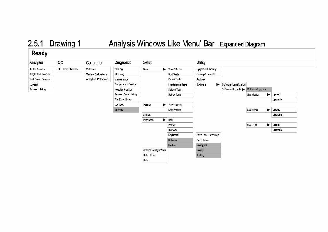
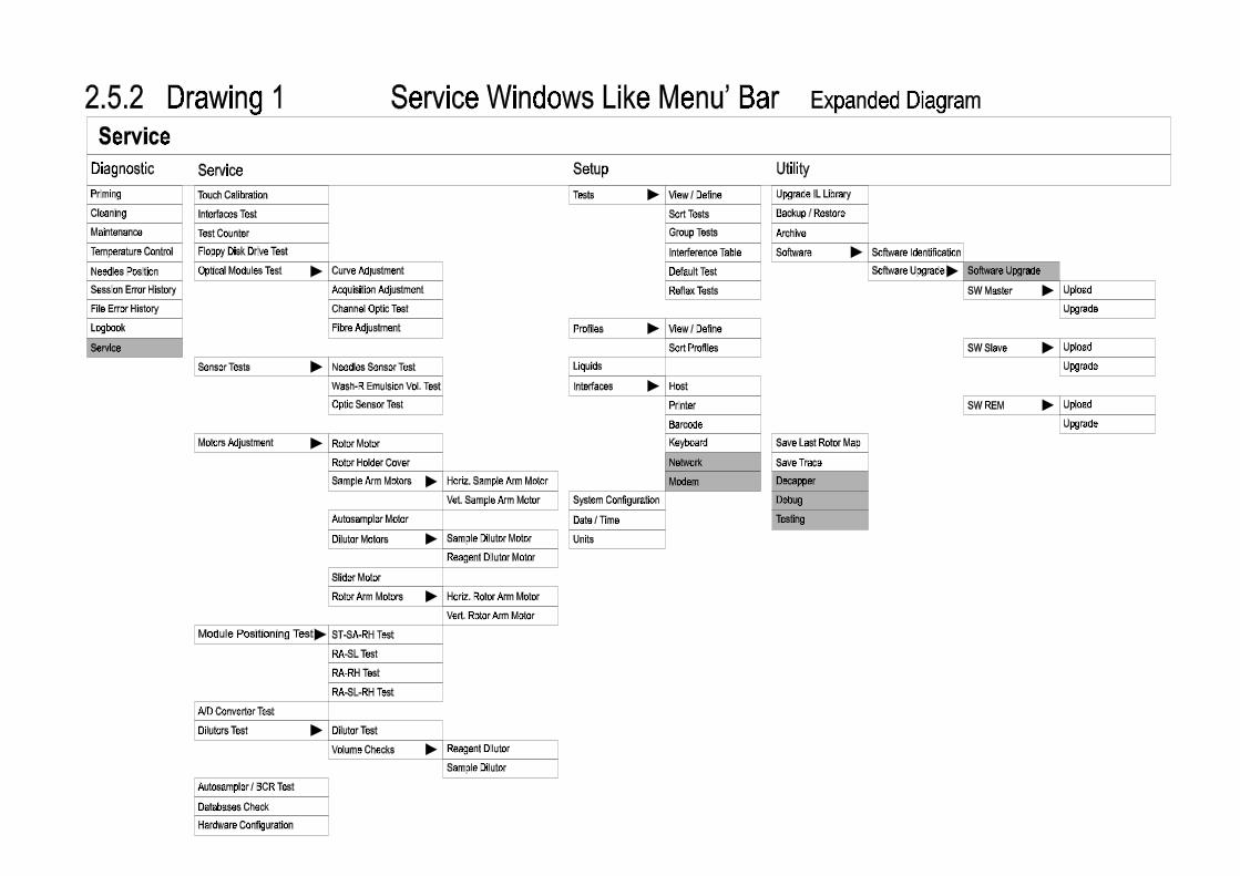
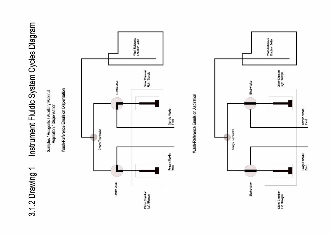
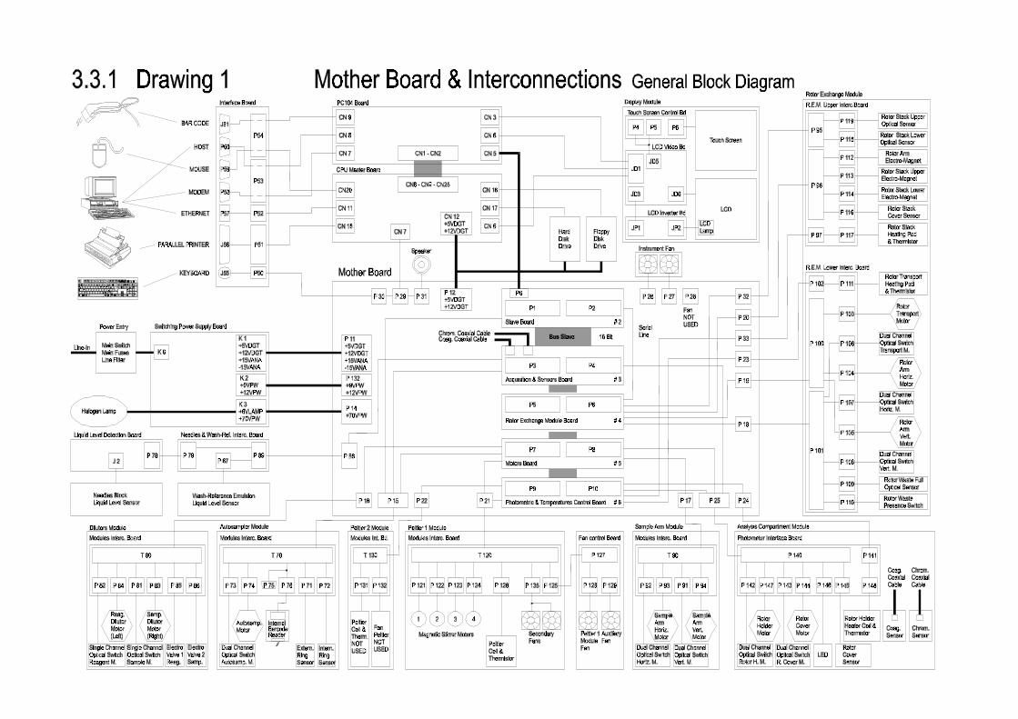
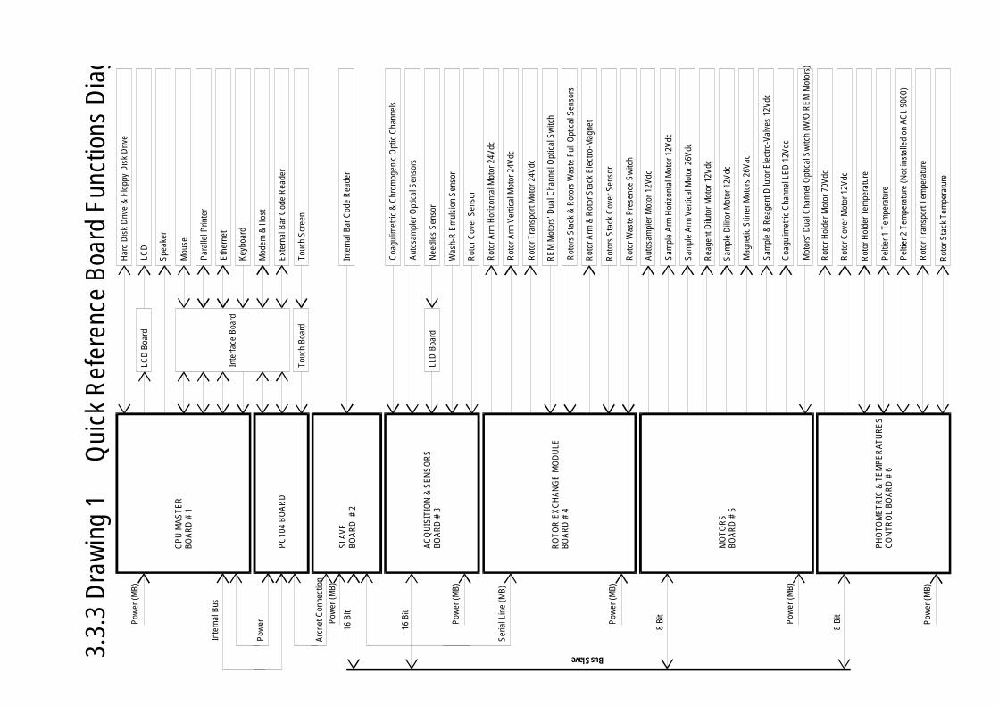
3.3.
3 D
raw
ing
1
Qui
ck R
efer
ence
Boa
rd F
unct
ions
Dia
gram
Rot
or S
tack
Tem
pera
ture
Rot
or T
rans
port
Tem
pera
ture
Pel
tier 2
Tem
pera
ture
(Not
inst
alle
d on
AC
L 90
00)
Pel
tier 1
Tem
pera
ture
Rot
or H
olde
r Tem
pera
ture
Rot
or C
over
Mot
or 1
2Vdc
Rot
or H
olde
r Mot
or 7
0Vdc
Mot
ors’
Dua
l Cha
nnel
Opt
ical
Sw
itch
(W/O
RE
M M
otor
s)
Coa
gulim
etric
Cha
nnel
LE
D 1
2Vdc
Sam
ple
& R
eage
nt D
iluto
r Ele
ctro
-Val
ves
12V
dc
Mag
netic
Stir
rer M
otor
s 26
Vac
Sam
ple
Dili
tor M
otor
12V
dc
Rea
gent
Dilu
tor M
otor
12V
dc
Sam
ple
Arm
Ver
tical
Mot
or 2
6Vdc
Sam
ple
Arm
Hor
izon
tal M
otor
12V
dc
Aut
osam
pler
Mot
or 1
2Vdc
Rot
or W
aste
Pre
senc
e S
witc
h
Rot
ors
Sta
ck C
over
Sen
sor
Rot
or A
rm &
Rot
or S
tack
Ele
ctro
-Mag
net
Rot
ors
Sta
ck &
Rot
ors
Was
te F
ull O
ptic
al S
enso
rs
RE
M M
otor
s’ D
ual C
hann
el O
ptic
al S
witc
h
Rot
or T
rans
port
Mot
or 2
4Vdc
Rot
or A
rm V
ertic
al M
otor
24V
dc
Rot
or A
rm H
oriz
onta
l Mot
or 2
4Vdc
Rot
or C
over
Sen
sor
Was
h-R
Em
ulsi
on S
enso
r
Nee
dles
Sen
sor
Aut
osam
pler
Opt
ical
Sen
sors
Coa
gulim
etric
& C
hrom
ogen
ic O
ptic
Cha
nnel
s
Inte
rnal
Bar
Cod
e R
eade
r
Touc
h S
cree
n
Ext
erna
l Bar
Cod
e R
eade
r
Mod
em &
Hos
t
Key
boar
d
Eth
erne
t
Par
alle
l Prin
ter
Mou
se
Spe
aker
LCD
Har
d D
isk
Driv
e &
Flo
ppy
Dis
k D
rive
LLD
Boa
rd
Touc
h B
oard
LCD
Boa
rd
Inte
rface
Boa
rd
CP
U M
AS
TER
BO
AR
D #
1
PC
104
BO
AR
D
SLA
VE
BO
AR
D #
2
AC
QU
ISIT
ION
& S
EN
SO
RS
BO
AR
D #
3
RO
TOR
EX
CH
AN
GE
MO
DU
LEB
OA
RD
# 4
MO
TOR
SB
OA
RD
# 5
PH
OTO
ME
TRIC
& T
EM
PE
RA
TUR
ES
CO
NTR
OL
BO
AR
D #
6
Pow
er (M
B)
Pow
er (M
B)
Pow
er (M
B)
Pow
er (M
B)
Pow
er (M
B)
Pow
er (M
B)
Pow
er
Inte
rnal
Bus
Arc
net C
onne
ctio
n
Ser
ial L
ine
(MB
)
16 B
it
16 B
it
8 B
it
8 B
it
Bus Slave
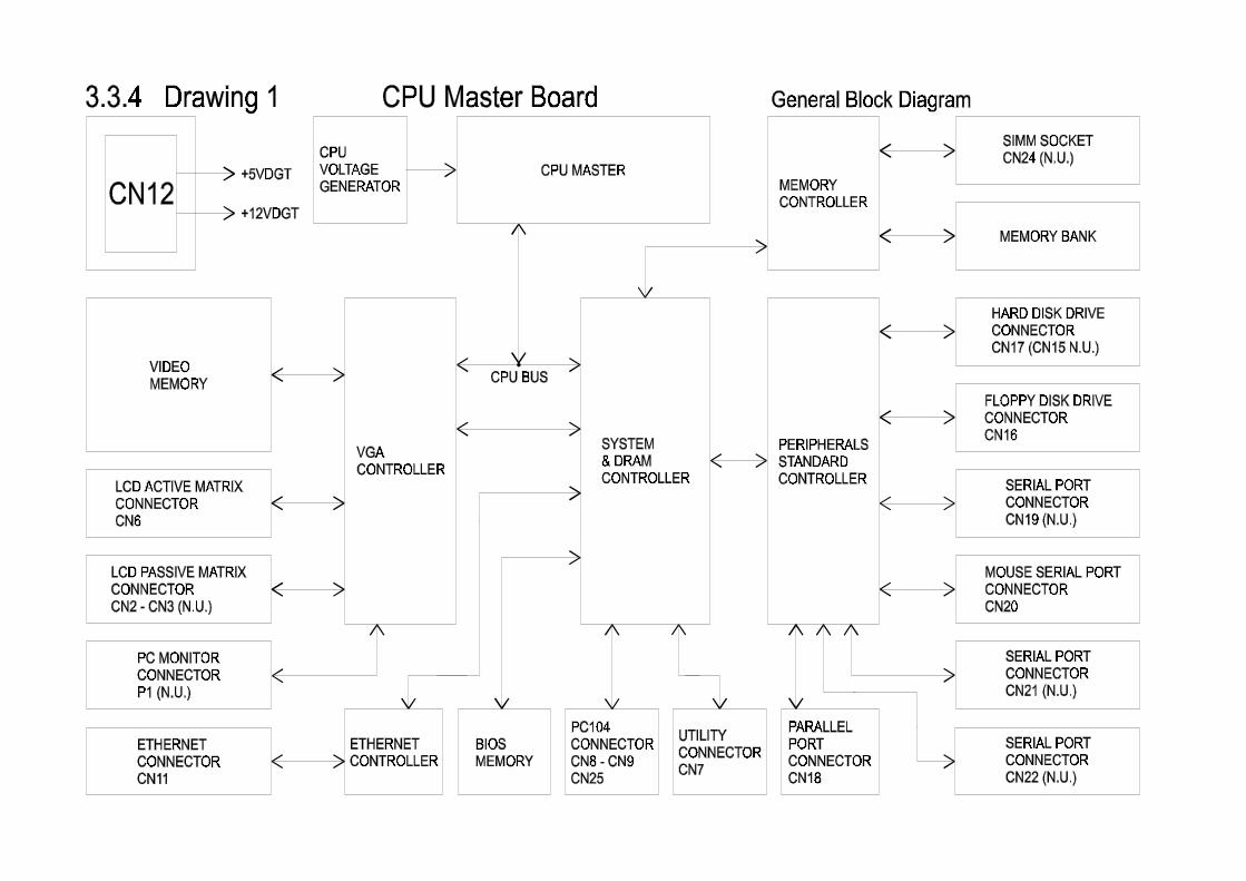
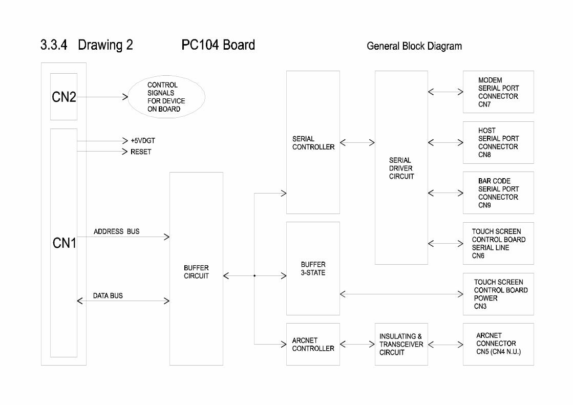

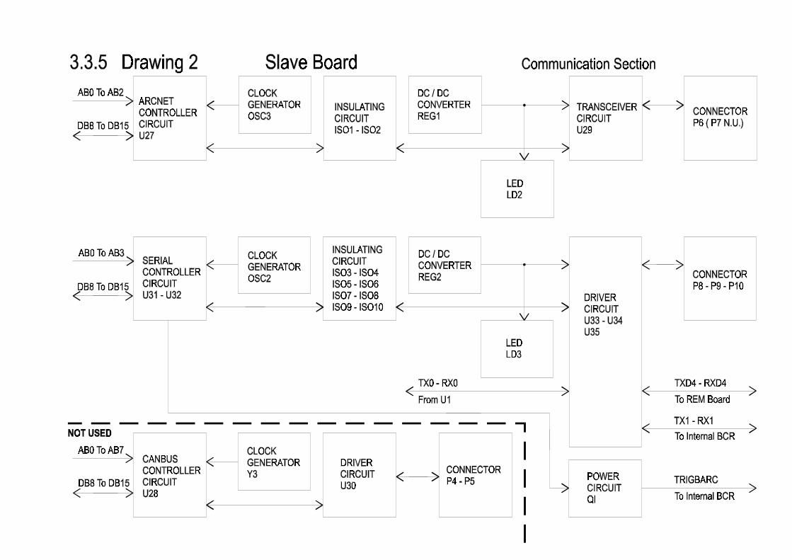
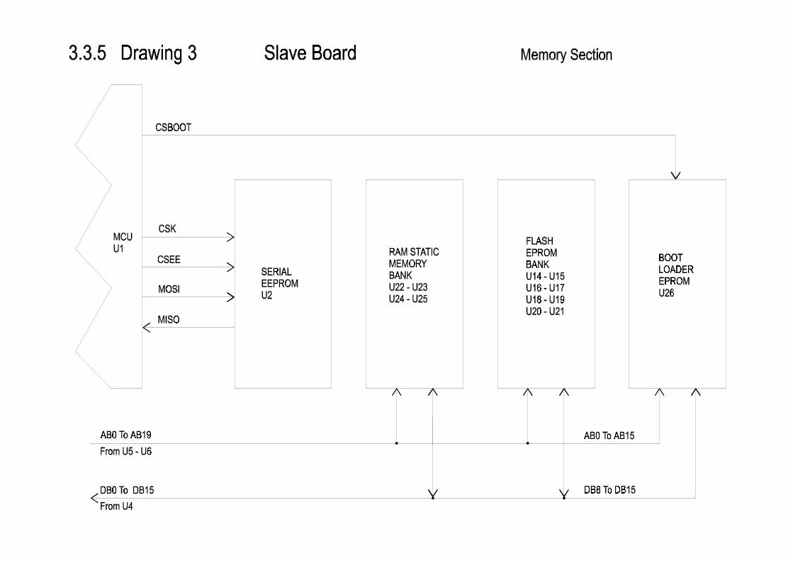
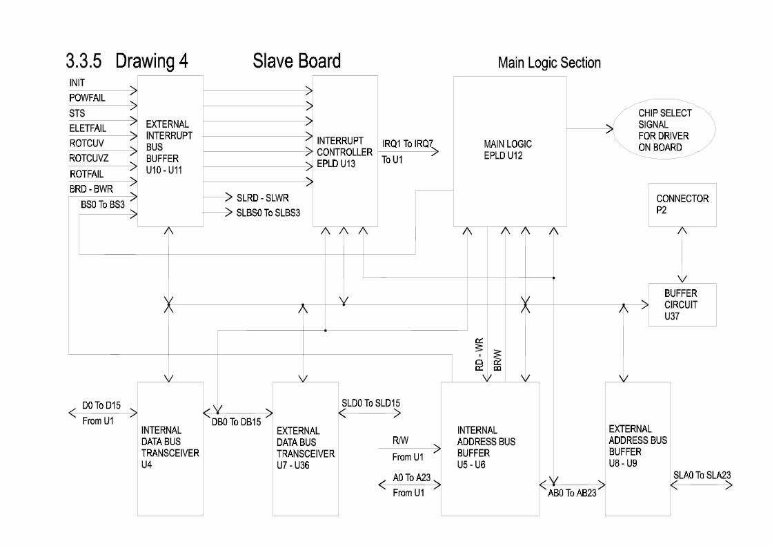
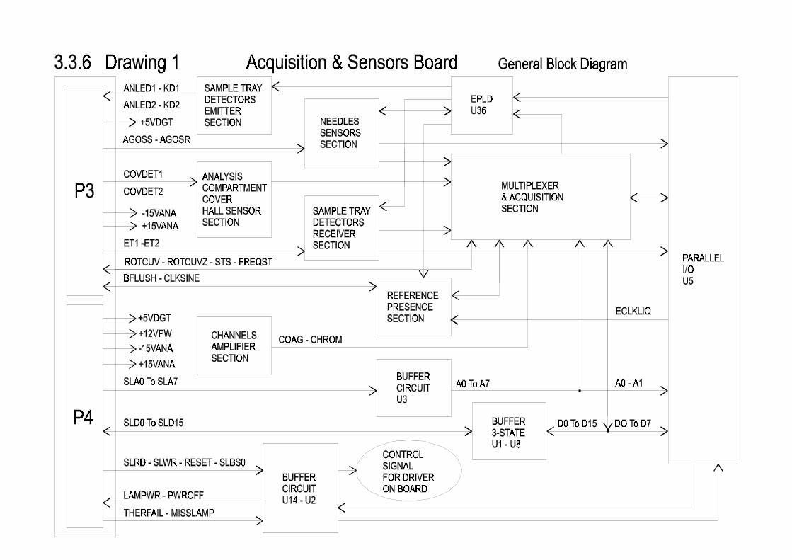
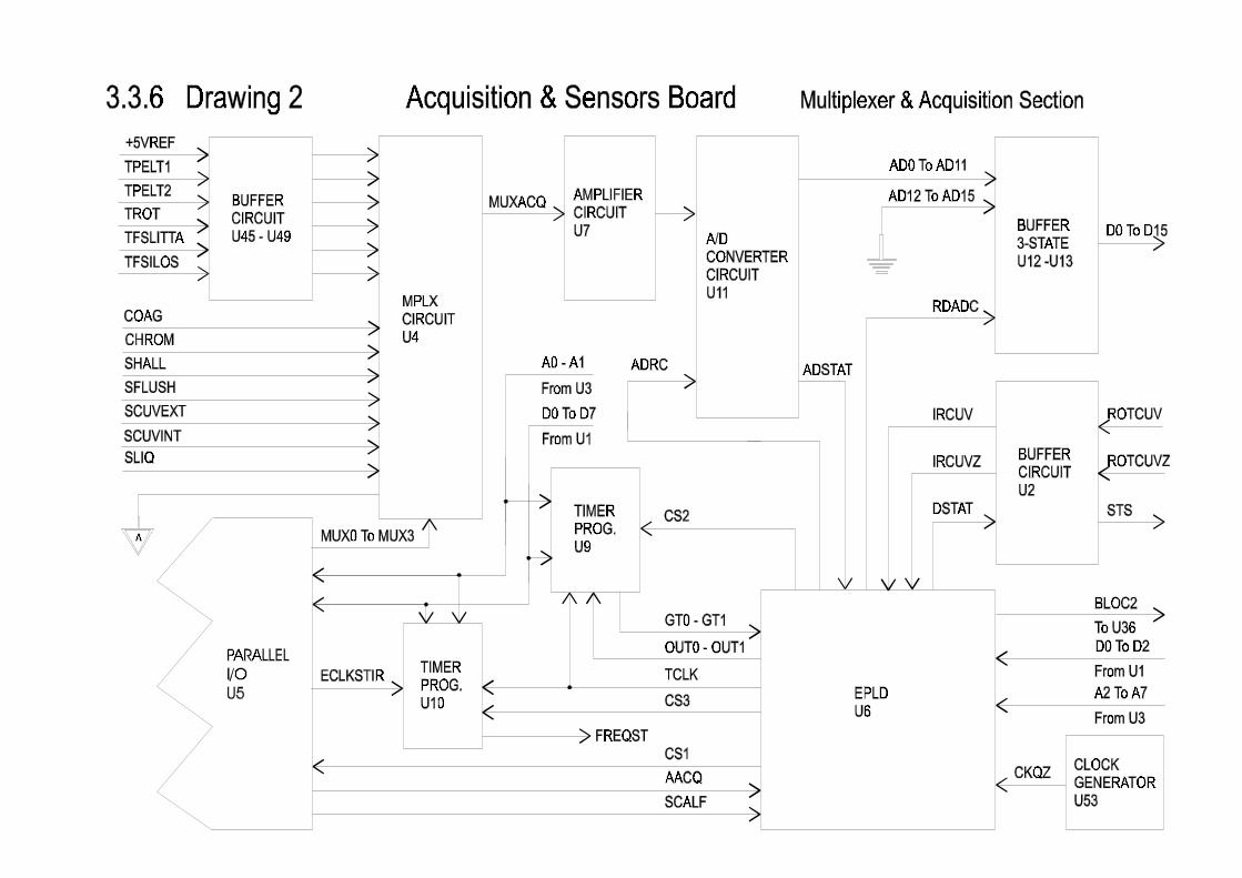
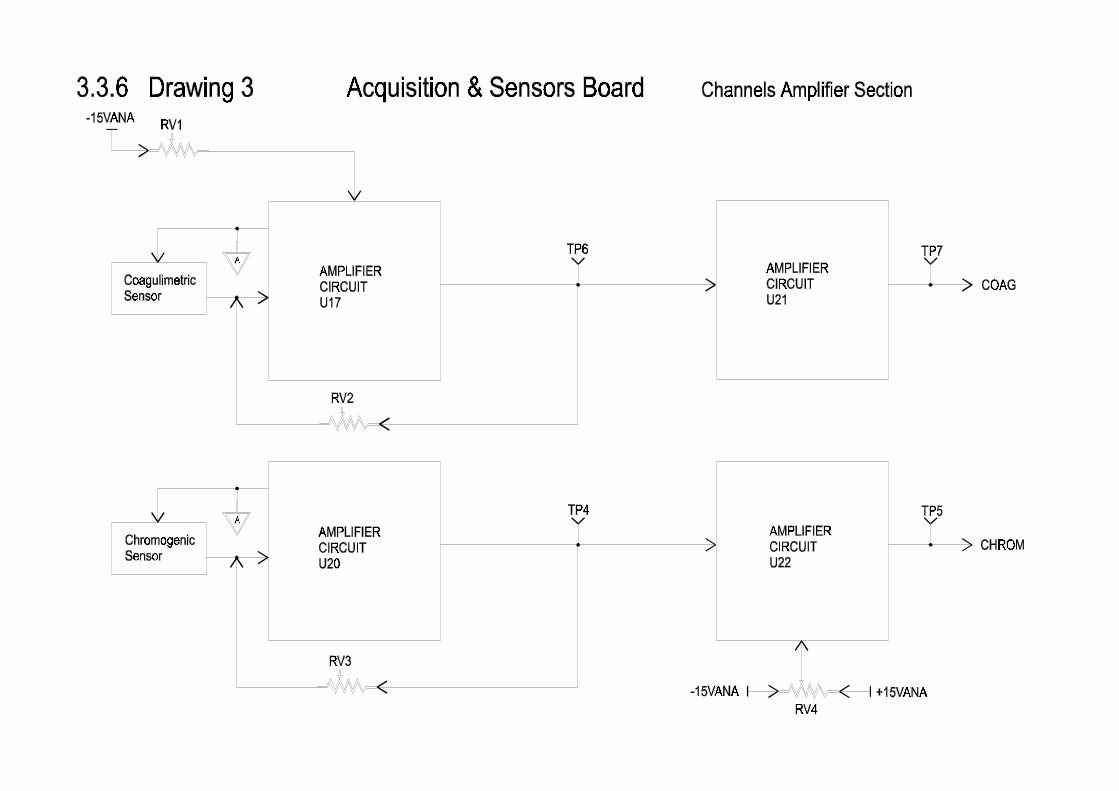
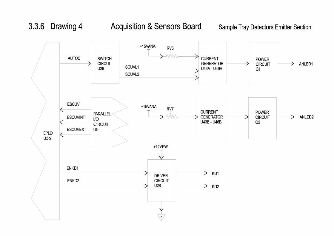
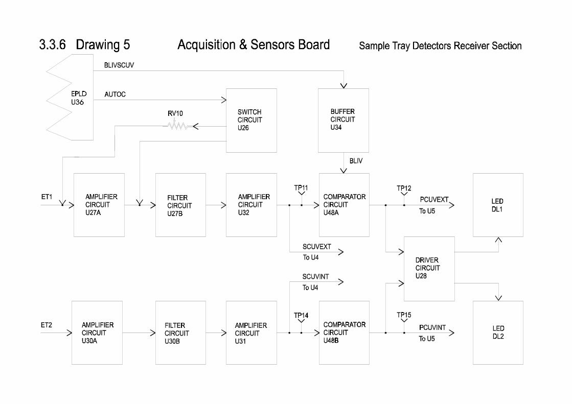
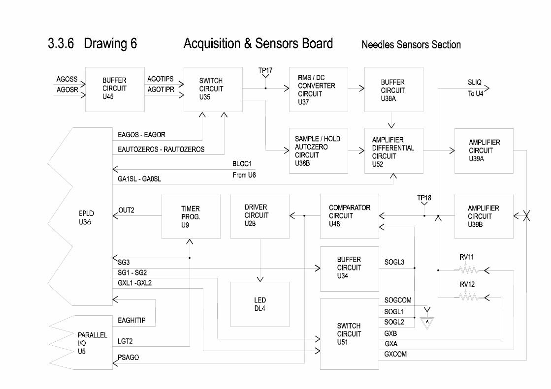
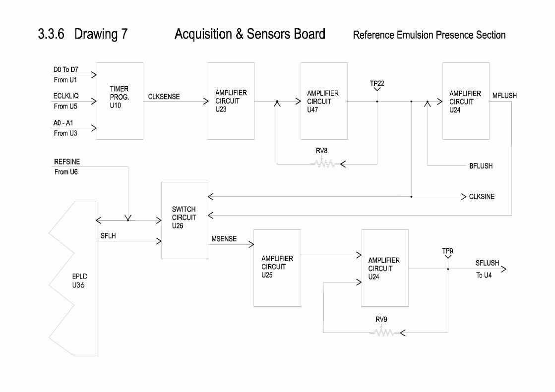
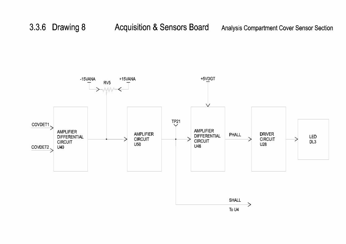
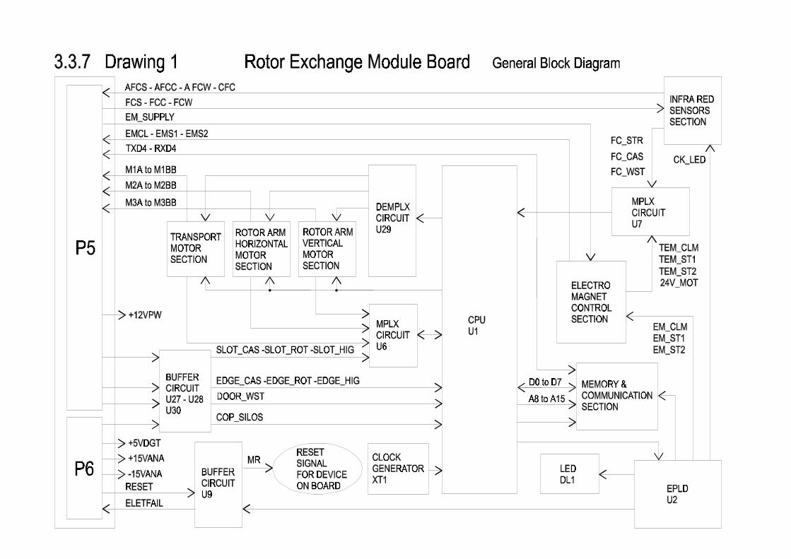

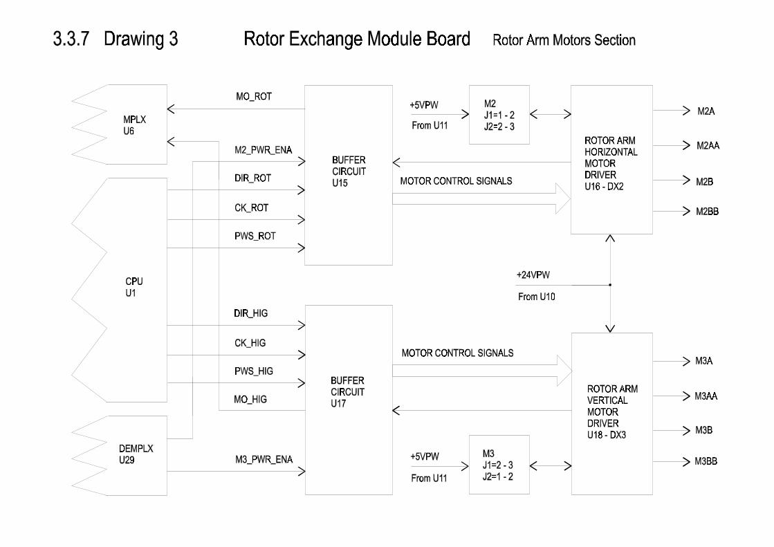
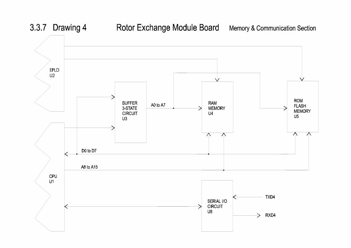

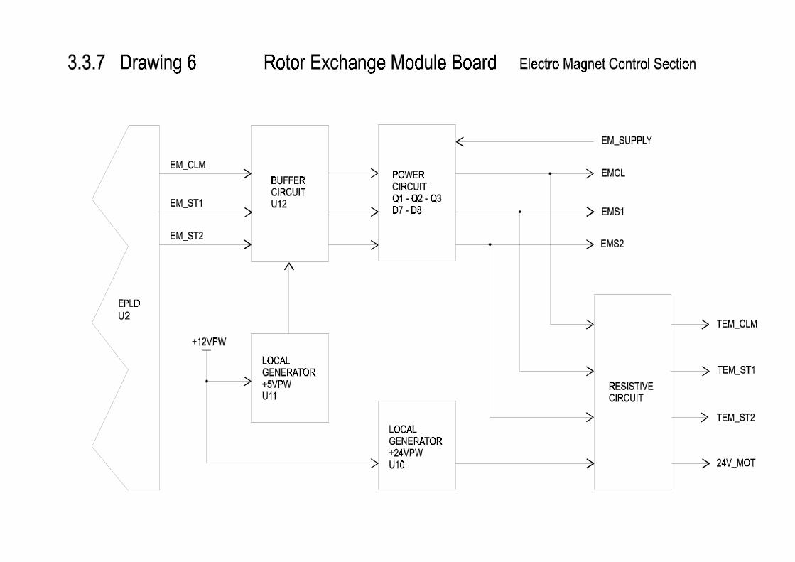
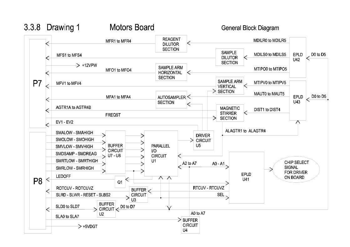
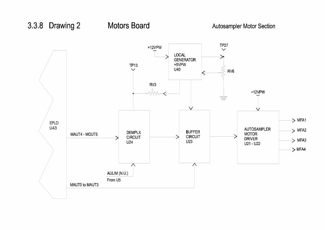
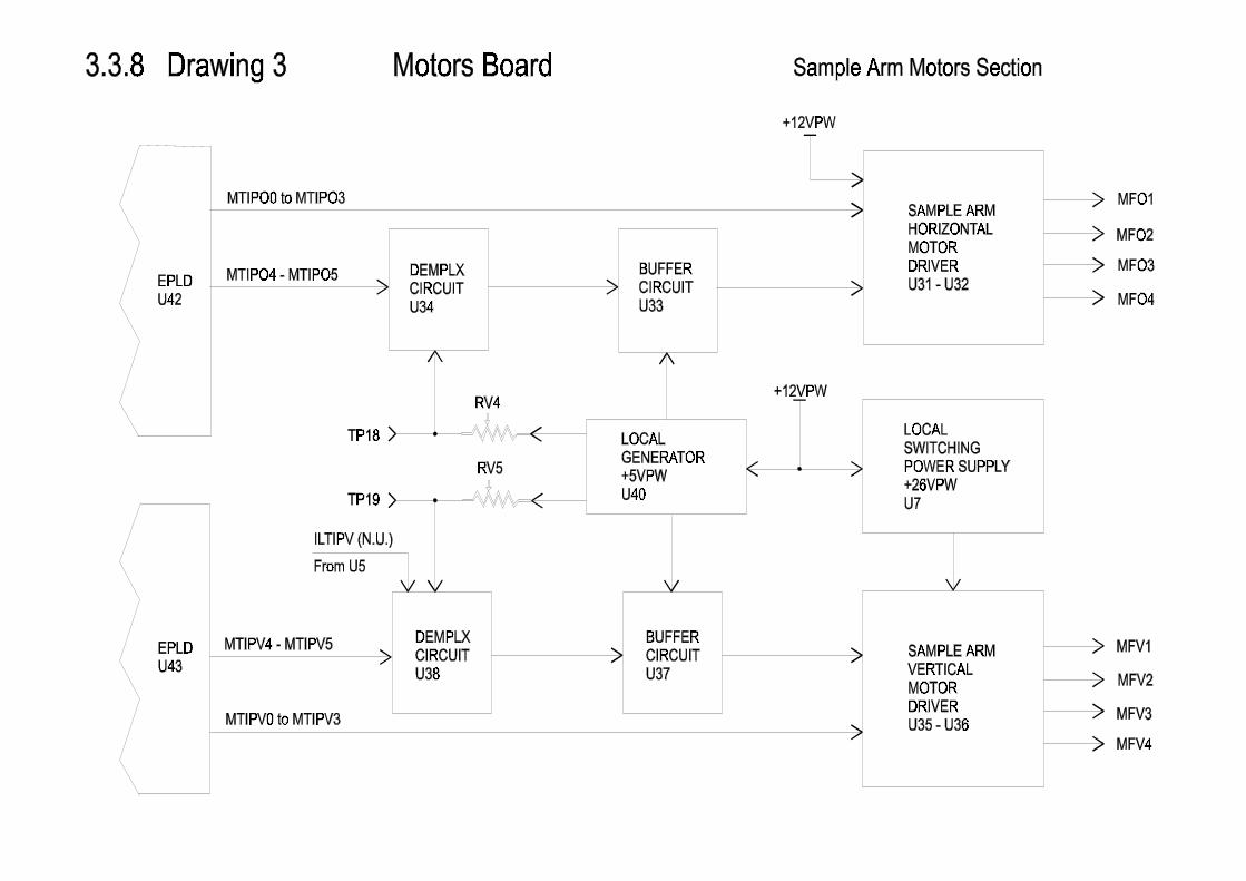
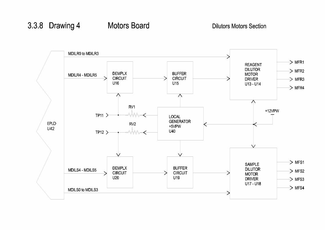

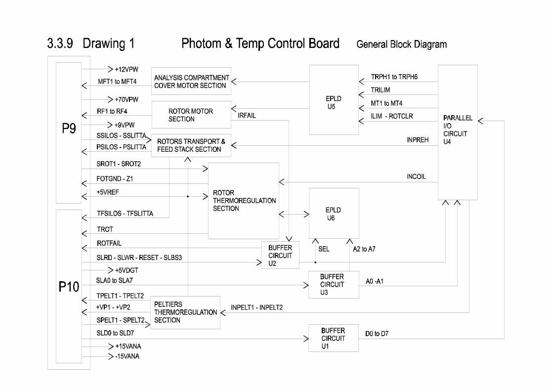
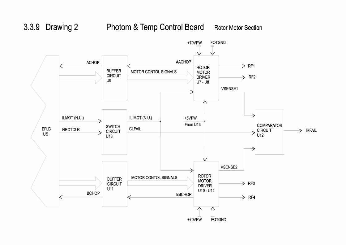
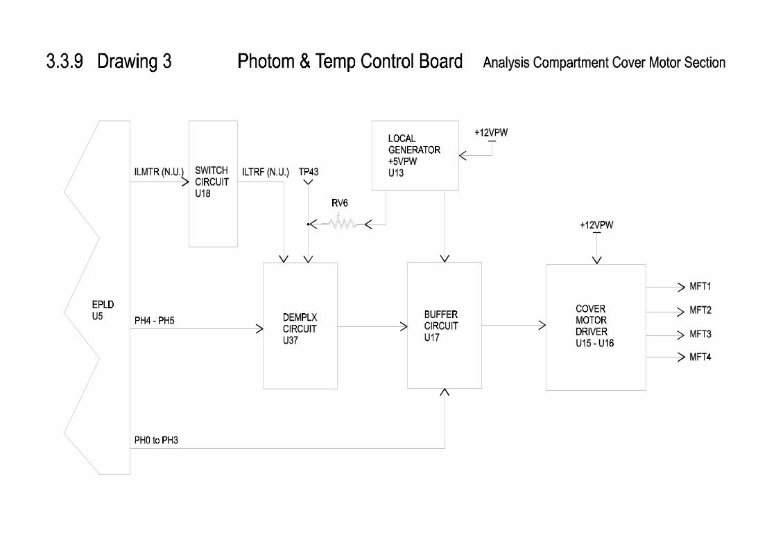
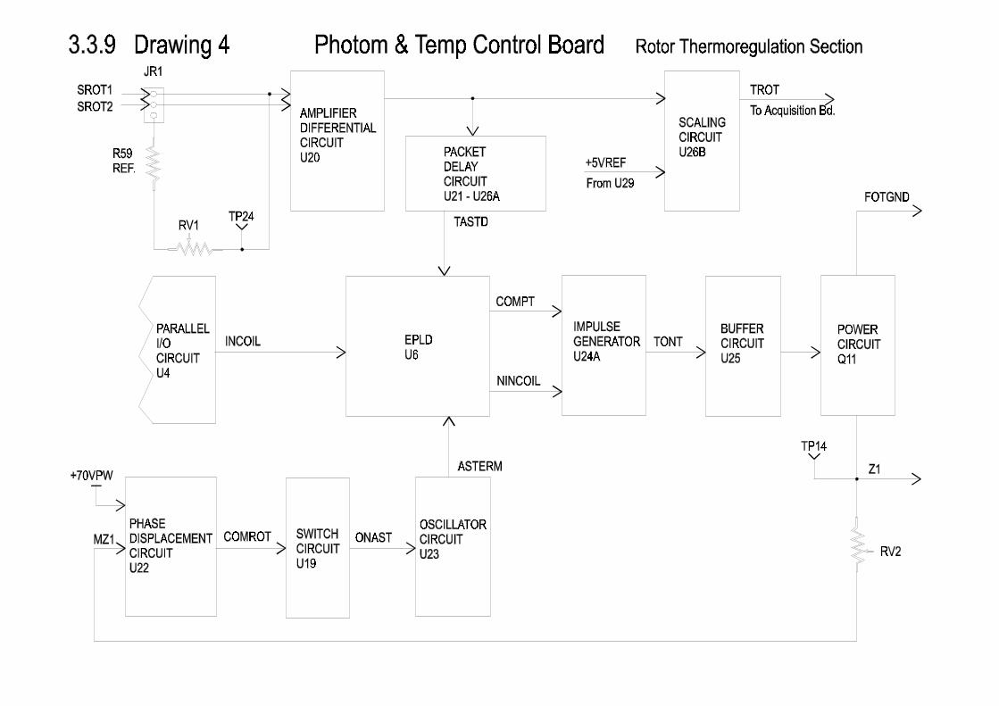
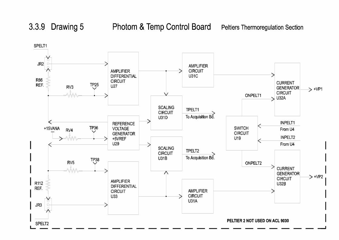
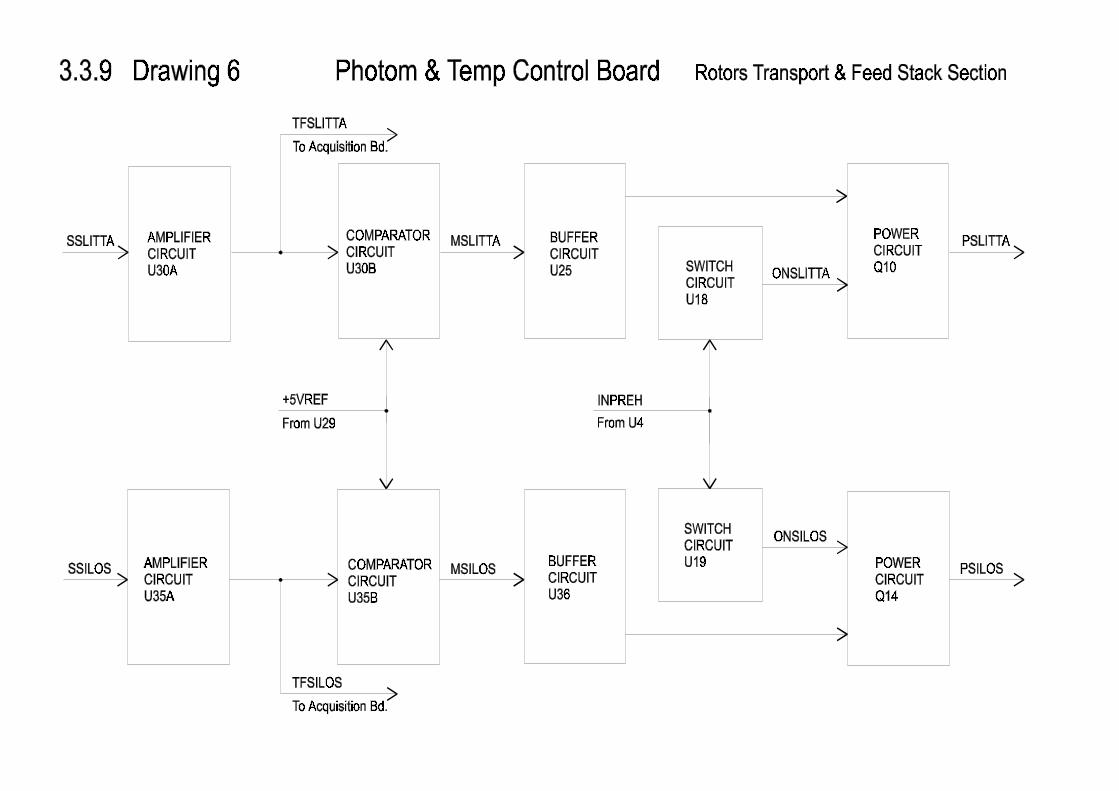
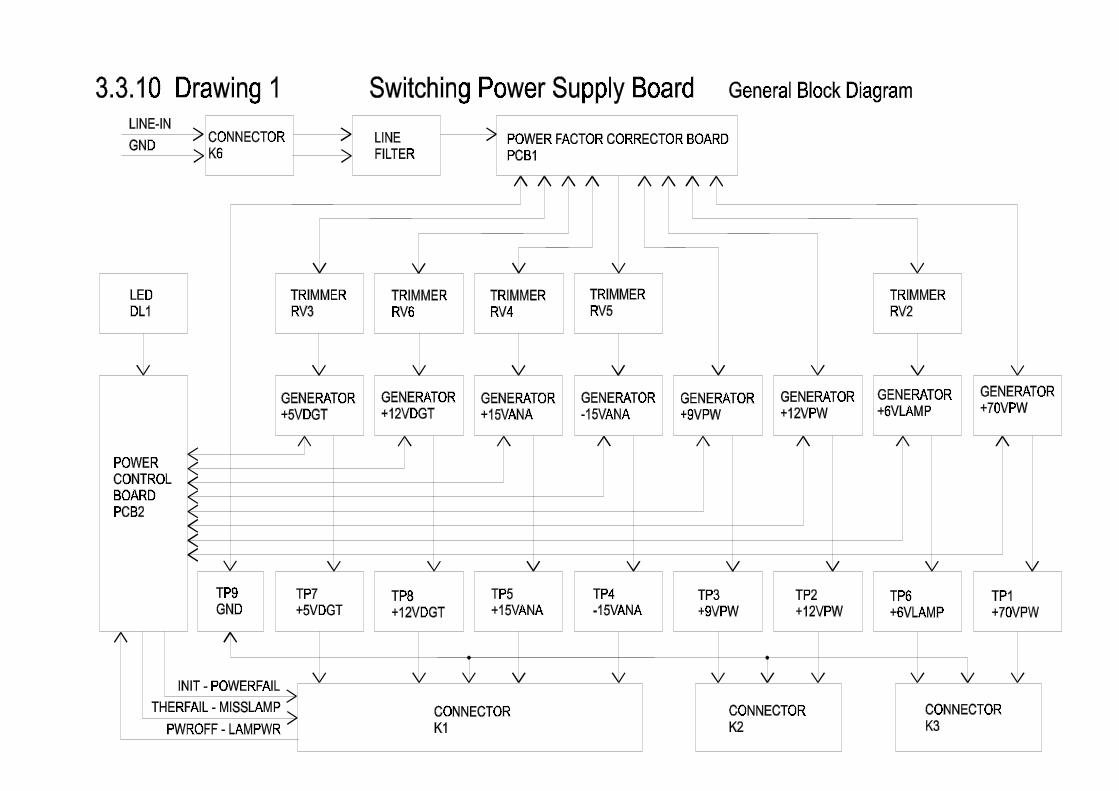
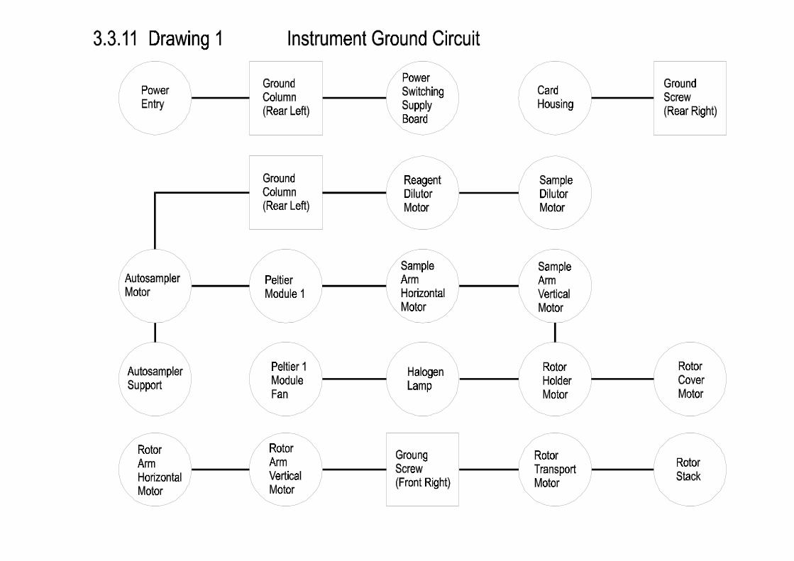
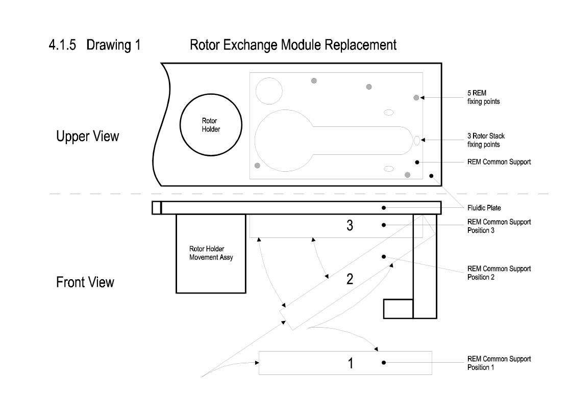

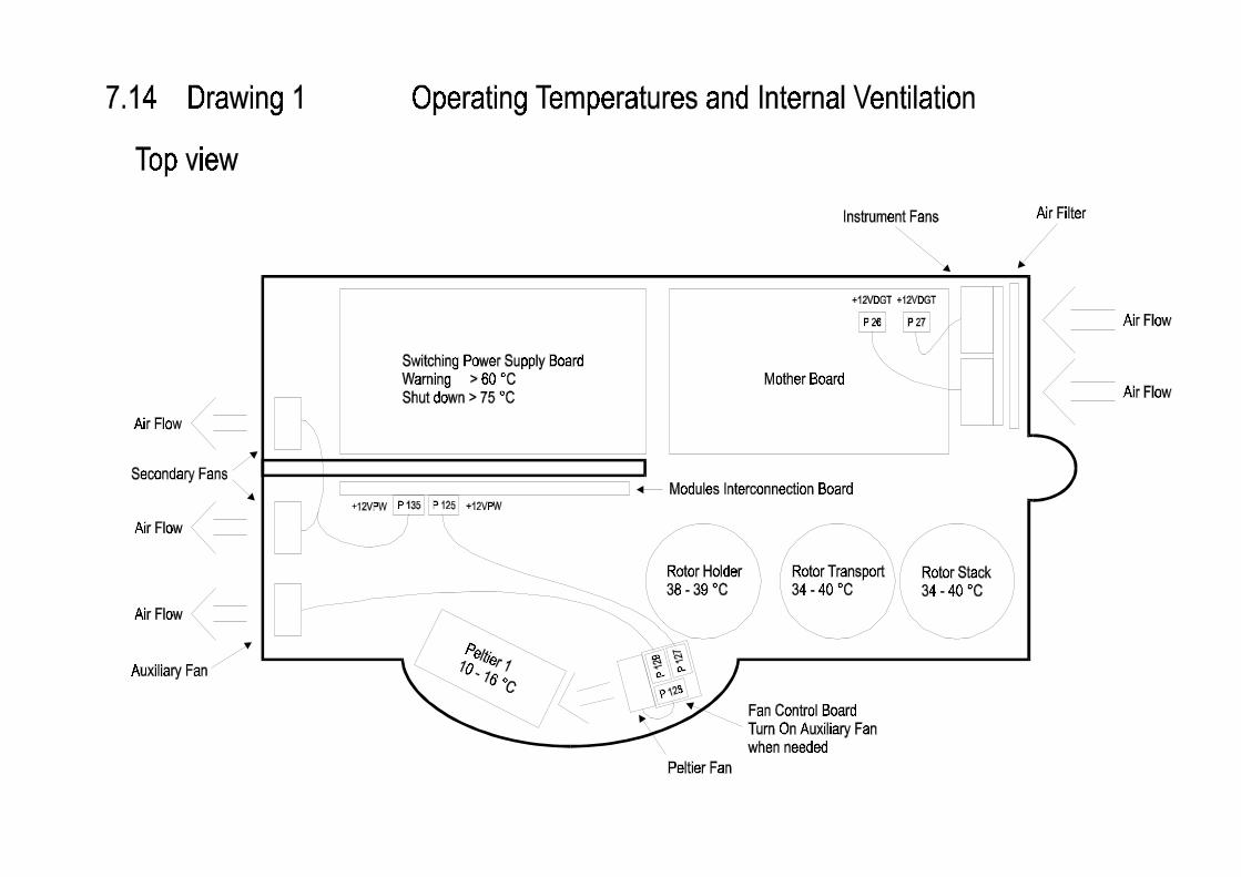

ACL 9000 Service Manual
Instrumentation Laboratory 12.1 A
12 Appendix A
ACL 9000
Host Communication Protocol
(Revision 0.2)
Appendix A
12.2 A Instrumentation Laboratory
1.0 Index
1.0 Index2.0 Revision History3.0 Introduction3.1 Purpose4.0 General Description4.1 Product Perspective5.0 Specific Requirements5.1 Protocol Specification5.2 Low Level Interface5.3 Data Link and Logical Layer5.4 Sessions5.4.1 Message Header and Message Terminator Records5.5 Test Order Downloading5.5.1 Receive Session from DMS5.5.1.1 Test Request Message5.5.1.2 Test Order Message5.5.1.2.1 Patient Information Record5.5.1.2.2 Test Order Record5.5.2 Host Query5.5.3 Test Request Message5.5.4 Test Order Message5.6 Rejected Test Order5.7 Downloading Session Volumes6.0 Test Results Uploading6.1 Test Result Message6.1.1 Patient Information Record6.1.2 Test Order Record6.1.3 Result Record6.1.4 Comment Record6.1.5 Error Codes6.2 Uploading Session Volumes7.0 Not Supported Records8.0 Transmission Abort9.0 Appendix - ACL 9000 Test Codes10.0 Appendix - ACL 9000 Supported Characters10.1 Supported Characters for Sample ID10.2 Supported Characters for Patient name and Department10.3 Supported Characters for delimiters11.0 Appendix - ACL 9000 Supported Units
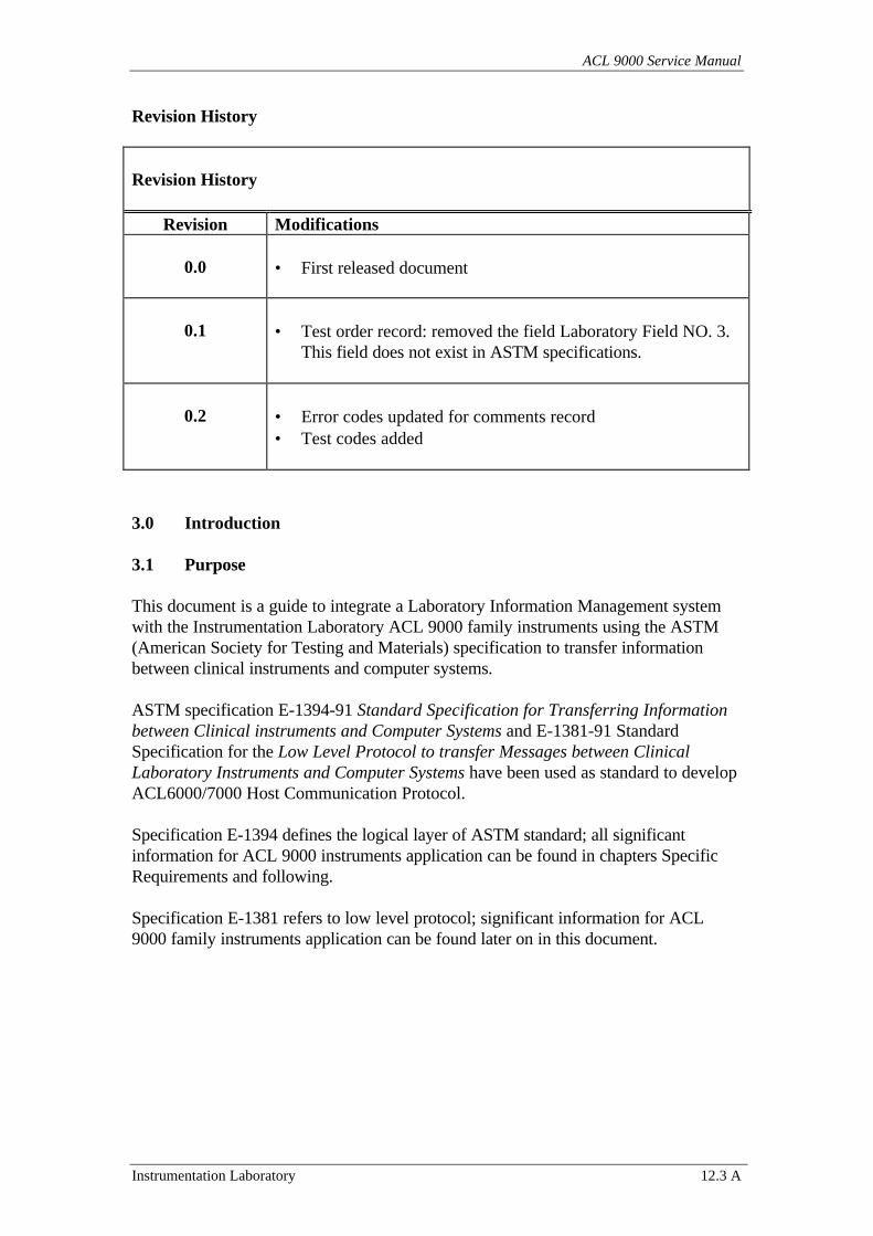
ACL 9000 Service Manual
Instrumentation Laboratory 12.3 A
Revision History
Revision History
Revision Modifications
0.0 • First released document
0.1 • Test order record: removed the field Laboratory Field NO. 3.This field does not exist in ASTM specifications.
0.2 • Error codes updated for comments record• Test codes added
3.0 Introduction
3.1 Purpose
This document is a guide to integrate a Laboratory Information Management systemwith the Instrumentation Laboratory ACL 9000 family instruments using the ASTM(American Society for Testing and Materials) specification to transfer informationbetween clinical instruments and computer systems.
ASTM specification E-1394-91 Standard Specification for Transferring Informationbetween Clinical instruments and Computer Systems and E-1381-91 StandardSpecification for the Low Level Protocol to transfer Messages between ClinicalLaboratory Instruments and Computer Systems have been used as standard to developACL6000/7000 Host Communication Protocol.
Specification E-1394 defines the logical layer of ASTM standard; all significantinformation for ACL 9000 instruments application can be found in chapters SpecificRequirements and following.
Specification E-1381 refers to low level protocol; significant information for ACL9000 family instruments application can be found later on in this document.
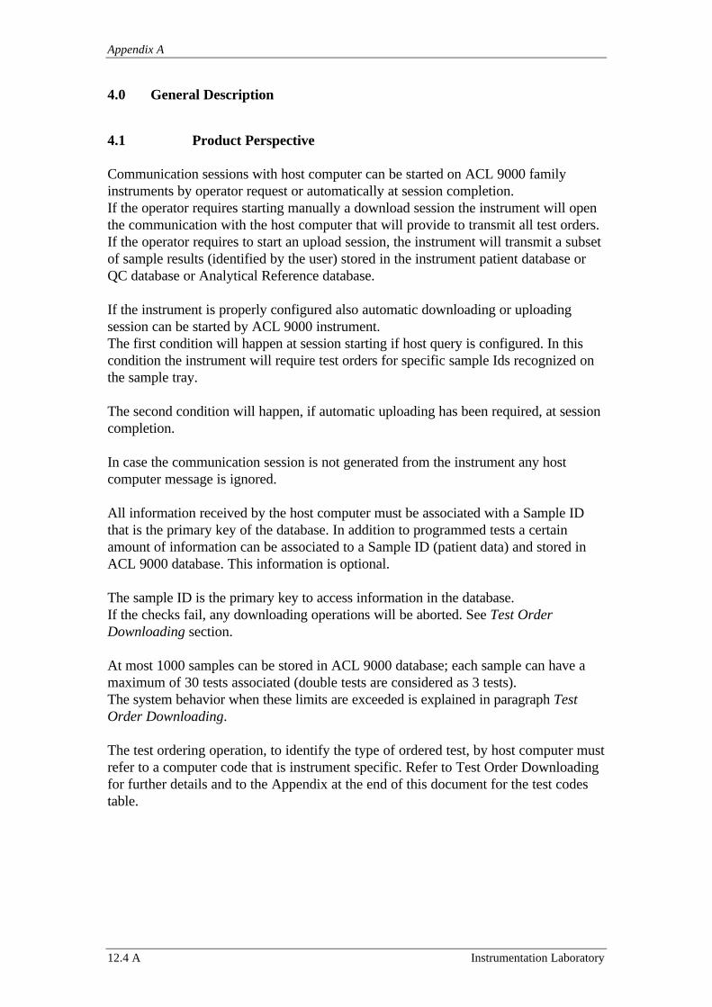
Appendix A
12.4 A Instrumentation Laboratory
4.0 General Description
4.1 Product Perspective
Communication sessions with host computer can be started on ACL 9000 familyinstruments by operator request or automatically at session completion.If the operator requires starting manually a download session the instrument will openthe communication with the host computer that will provide to transmit all test orders.If the operator requires to start an upload session, the instrument will transmit a subsetof sample results (identified by the user) stored in the instrument patient database orQC database or Analytical Reference database.
If the instrument is properly configured also automatic downloading or uploadingsession can be started by ACL 9000 instrument.The first condition will happen at session starting if host query is configured. In thiscondition the instrument will require test orders for specific sample Ids recognized onthe sample tray.
The second condition will happen, if automatic uploading has been required, at sessioncompletion.
In case the communication session is not generated from the instrument any hostcomputer message is ignored.
All information received by the host computer must be associated with a Sample IDthat is the primary key of the database. In addition to programmed tests a certainamount of information can be associated to a Sample ID (patient data) and stored inACL 9000 database. This information is optional.
The sample ID is the primary key to access information in the database.If the checks fail, any downloading operations will be aborted. See Test OrderDownloading section.
At most 1000 samples can be stored in ACL 9000 database; each sample can have amaximum of 30 tests associated (double tests are considered as 3 tests).The system behavior when these limits are exceeded is explained in paragraph TestOrder Downloading.
The test ordering operation, to identify the type of ordered test, by host computer mustrefer to a computer code that is instrument specific. Refer to Test Order Downloadingfor further details and to the Appendix at the end of this document for the test codestable.
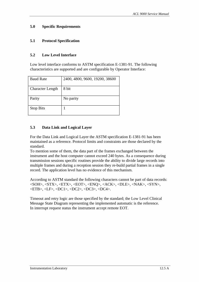
ACL 9000 Service Manual
Instrumentation Laboratory 12.5 A
5.0 Specific Requirements
5.1 Protocol Specification
5.2 Low Level Interface
Low level interface conforms to ASTM specification E-1381-91. The followingcharacteristics are supported and are configurable by Operator Interface:
Baud Rate 2400, 4800, 9600, 19200, 38600
Character Length 8 bit
Parity No parity
Stop Bits 1
5.3 Data Link and Logical Layer
For the Data Link and Logical Layer the ASTM specification E-1381-91 has beenmaintained as a reference. Protocol limits and constraints are those declared by thestandard.To mention some of them, the data part of the frames exchanged between theinstrument and the host computer cannot exceed 240 bytes. As a consequence duringtransmission sessions specific routines provide the ability to divide large records intomultiple frames and during a reception session they re-build partial frames in a singlerecord. The application level has no evidence of this mechanism.
According to ASTM standard the following characters cannot be part of data records:<SOH>, <STX>, <ETX>, <EOT>, <ENQ>, <ACK>, <DLE>, <NAK>, <SYN>,<ETB>, <LF>, <DC1>, <DC2>, <DC3>, <DC4>.
Timeout and retry logic are those specified by the standard; the Low Level ClinicalMessage State Diagram representing the implemented automatic is the reference.In interrupt request status the instrument accept remote EOT.
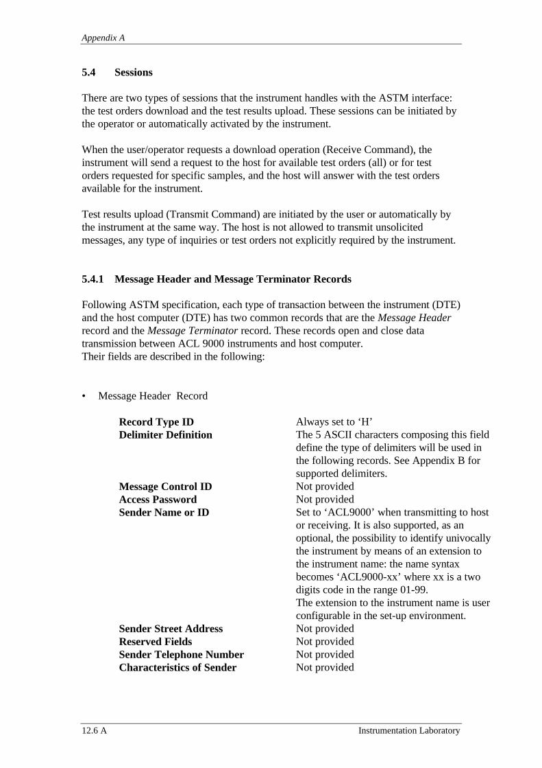
Appendix A
12.6 A Instrumentation Laboratory
5.4 Sessions
There are two types of sessions that the instrument handles with the ASTM interface:the test orders download and the test results upload. These sessions can be initiated bythe operator or automatically activated by the instrument.
When the user/operator requests a download operation (Receive Command), theinstrument will send a request to the host for available test orders (all) or for testorders requested for specific samples, and the host will answer with the test ordersavailable for the instrument.
Test results upload (Transmit Command) are initiated by the user or automatically bythe instrument at the same way. The host is not allowed to transmit unsolicitedmessages, any type of inquiries or test orders not explicitly required by the instrument.
5.4.1 Message Header and Message Terminator Records
Following ASTM specification, each type of transaction between the instrument (DTE)and the host computer (DTE) has two common records that are the Message Headerrecord and the Message Terminator record. These records open and close datatransmission between ACL 9000 instruments and host computer.Their fields are described in the following:
• Message Header Record
Record Type ID Always set to ‘H’Delimiter Definition The 5 ASCII characters composing this field
define the type of delimiters will be used inthe following records. See Appendix B forsupported delimiters.
Message Control ID Not providedAccess Password Not providedSender Name or ID Set to ‘ACL9000’ when transmitting to host
or receiving. It is also supported, as anoptional, the possibility to identify univocallythe instrument by means of an extension tothe instrument name: the name syntaxbecomes ‘ACL9000-xx’ where xx is a twodigits code in the range 01-99.The extension to the instrument name is userconfigurable in the set-up environment.
Sender Street Address Not providedReserved Fields Not providedSender Telephone Number Not providedCharacteristics of Sender Not provided
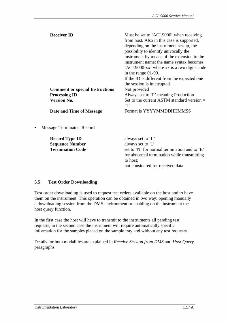
ACL 9000 Service Manual
Instrumentation Laboratory 12.7 A
Receiver ID Must be set to ‘ACL9000’ when receivingfrom host. Also in this case is supported,depending on the instrument set-up, thepossibility to identify univocally theinstrument by means of the extension to theinstrument name: the name syntax becomes‘ACL9000-xx’ where xx is a two digits codein the range 01-99.If the ID is different from the expected onethe session is interrupted.
Comment or special Instructions Not providedProcessing ID Always set to ‘P’ meaning ProductionVersion No. Set to the current ASTM standard version =
‘1’Date and Time of Message Format is YYYYMMDDHHMMSS
• Message Terminator Record
Record Type ID always set to ‘L’Sequence Number always set to ‘1’Termination Code set to ‘N’ for normal termination and to ‘E’
for abnormal termination while transmittingto host;not considered for received data
5.5 Test Order Downloading
Test order downloading is used to request test orders available on the host and to havethem on the instrument. This operation can be obtained in two way: opening manuallya downloading session from the DMS environment or enabling on the instrument thehost query function.
In the first case the host will have to transmit to the instruments all pending testrequests, in the second case the instrument will require automatically specificinformation for the samples placed on the sample tray and without any test requests.
Details for both modalities are explained in Receive Session from DMS and Host Queryparagraphs.
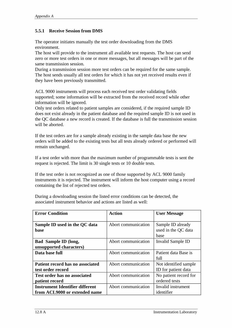
Appendix A
12.8 A Instrumentation Laboratory
5.5.1 Receive Session from DMS
The operator initiates manually the test order downloading from the DMSenvironment.The host will provide to the instrument all available test requests. The host can sendzero or more test orders in one or more messages, but all messages will be part of thesame transmission session.During a transmission session more test orders can be required for the same sample.The host sends usually all test orders for which it has not yet received results even ifthey have been previously transmitted.
ACL 9000 instruments will process each received test order validating fieldssupported; some information will be extracted from the received record while otherinformation will be ignored.Only test orders related to patient samples are considered, if the required sample IDdoes not exist already in the patient database and the required sample ID is not used inthe QC database a new record is created. If the database is full the transmission sessionwill be aborted.
If the test orders are for a sample already existing in the sample data base the neworders will be added to the existing tests but all tests already ordered or performed willremain unchanged.
If a test order with more than the maximum number of programmable tests is sent therequest is rejected. The limit is 30 single tests or 10 double tests.
If the test order is not recognized as one of those supported by ACL 9000 familyinstruments it is rejected. The instrument will inform the host computer using a recordcontaining the list of rejected test orders.
During a downloading session the listed error conditions can be detected, theassociated instrument behavior and actions are listed as well:
Error Condition Action User Message
Sample ID used in the QC database
Abort communication Sample ID alreadyused in the QC database
Bad Sample ID (long,unsupported characters)
Abort communication Invalid Sample ID
Data base full Abort communication Patient data Base isfull
Patient record has no associatedtest order record
Abort communication Not identified sampleID for patient data
Test order has no associatedpatient record
Abort communication No patient record forordered tests
Instrument Identifier differentfrom ACL9000 or extended name
Abort communication Invalid instrumentidentifier
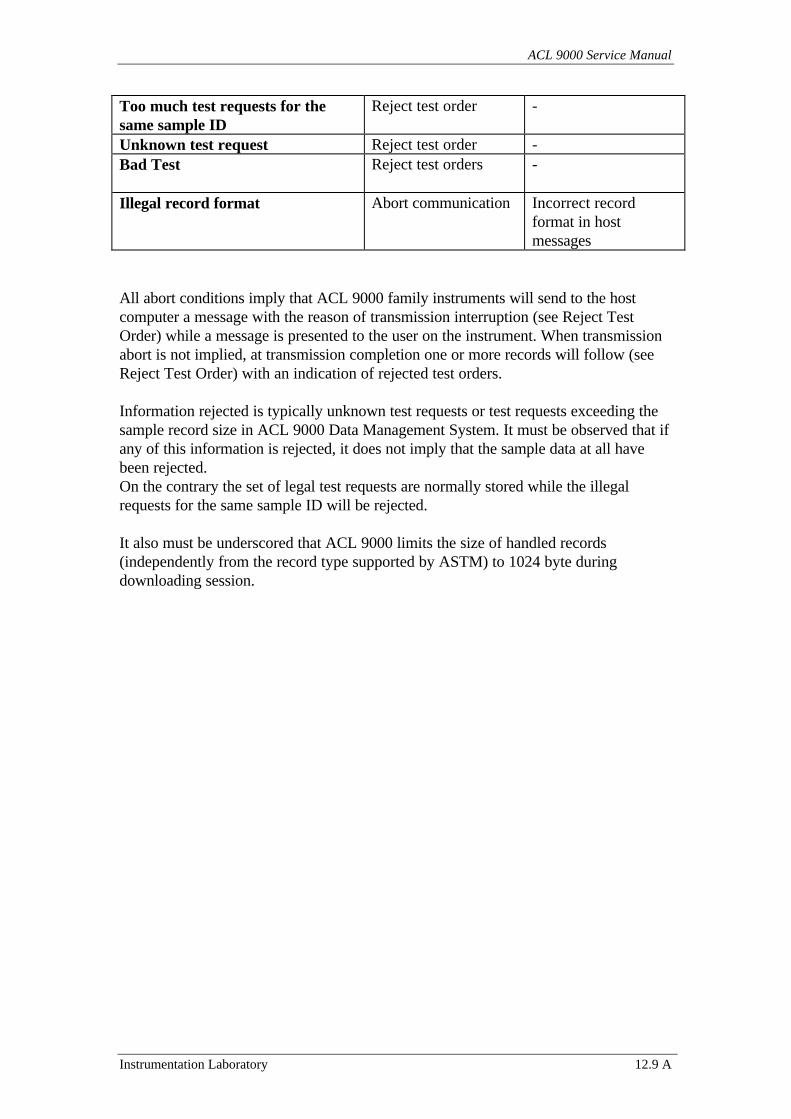
ACL 9000 Service Manual
Instrumentation Laboratory 12.9 A
Too much test requests for thesame sample ID
Reject test order -
Unknown test request Reject test order -Bad Test Reject test orders -
Illegal record format Abort communication Incorrect recordformat in hostmessages
All abort conditions imply that ACL 9000 family instruments will send to the hostcomputer a message with the reason of transmission interruption (see Reject TestOrder) while a message is presented to the user on the instrument. When transmissionabort is not implied, at transmission completion one or more records will follow (seeReject Test Order) with an indication of rejected test orders.
Information rejected is typically unknown test requests or test requests exceeding thesample record size in ACL 9000 Data Management System. It must be observed that ifany of this information is rejected, it does not imply that the sample data at all havebeen rejected.On the contrary the set of legal test requests are normally stored while the illegalrequests for the same sample ID will be rejected.
It also must be underscored that ACL 9000 limits the size of handled records(independently from the record type supported by ASTM) to 1024 byte duringdownloading session.
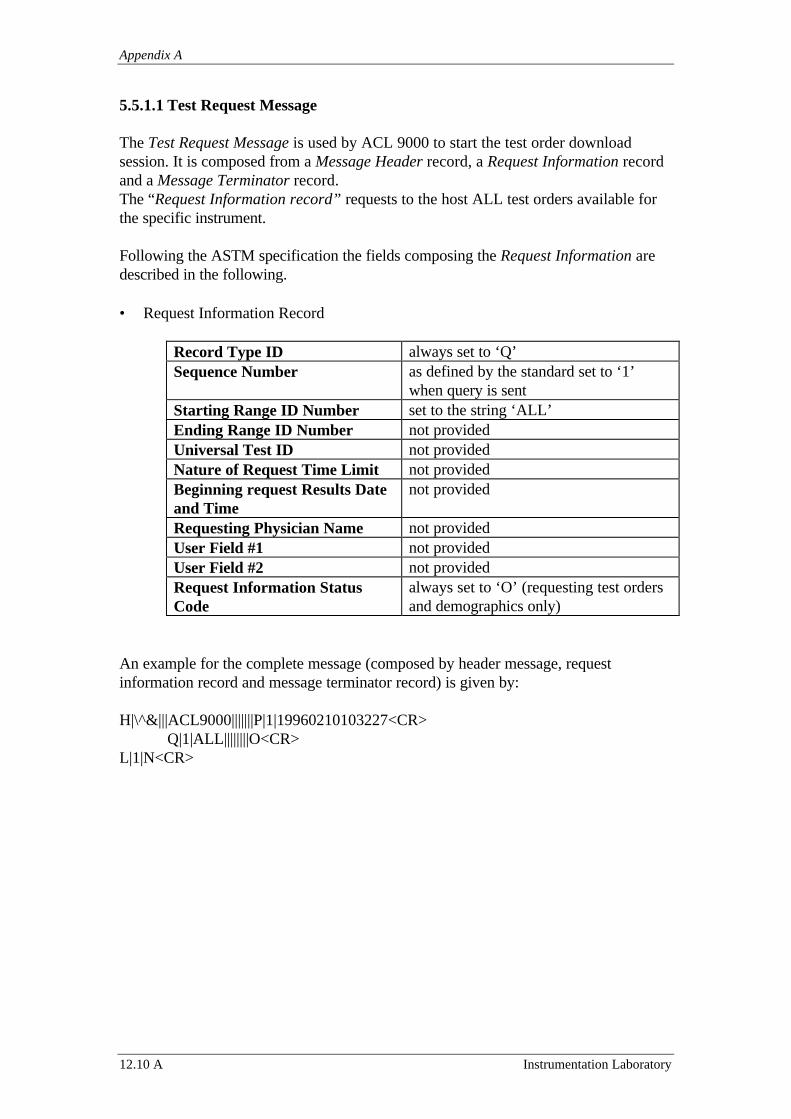
Appendix A
12.10 A Instrumentation Laboratory
5.5.1.1 Test Request Message
The Test Request Message is used by ACL 9000 to start the test order downloadsession. It is composed from a Message Header record, a Request Information recordand a Message Terminator record.The “Request Information record” requests to the host ALL test orders available forthe specific instrument.
Following the ASTM specification the fields composing the Request Information aredescribed in the following.
• Request Information Record
Record Type ID always set to ‘Q’Sequence Number as defined by the standard set to ‘1’
when query is sentStarting Range ID Number set to the string ‘ALL’Ending Range ID Number not providedUniversal Test ID not providedNature of Request Time Limit not providedBeginning request Results Dateand Time
not provided
Requesting Physician Name not providedUser Field #1 not providedUser Field #2 not providedRequest Information StatusCode
always set to ‘O’ (requesting test ordersand demographics only)
An example for the complete message (composed by header message, requestinformation record and message terminator record) is given by:
H|\^&|||ACL9000|||||||P|1|19960210103227<CR>Q|1|ALL||||||||O<CR>
L|1|N<CR>
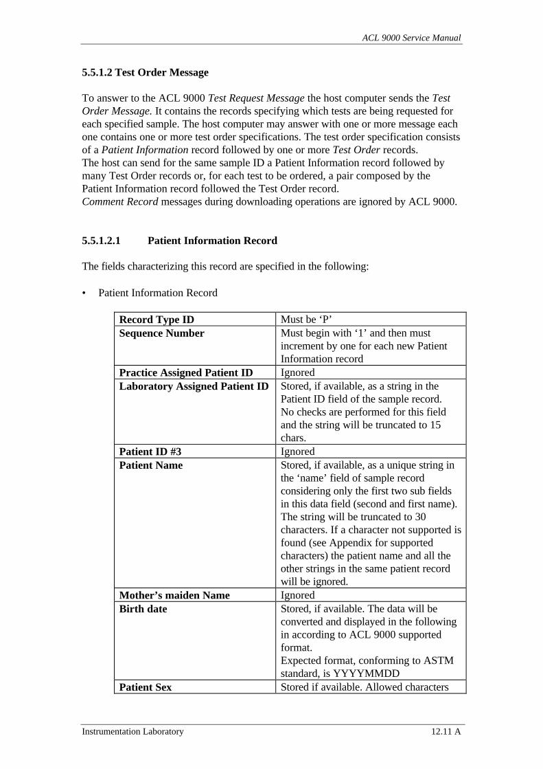
ACL 9000 Service Manual
Instrumentation Laboratory 12.11 A
5.5.1.2 Test Order Message
To answer to the ACL 9000 Test Request Message the host computer sends the TestOrder Message. It contains the records specifying which tests are being requested foreach specified sample. The host computer may answer with one or more message eachone contains one or more test order specifications. The test order specification consistsof a Patient Information record followed by one or more Test Order records.The host can send for the same sample ID a Patient Information record followed bymany Test Order records or, for each test to be ordered, a pair composed by thePatient Information record followed the Test Order record.Comment Record messages during downloading operations are ignored by ACL 9000.
5.5.1.2.1 Patient Information Record
The fields characterizing this record are specified in the following:
• Patient Information Record
Record Type ID Must be ‘P’Sequence Number Must begin with ‘1’ and then must
increment by one for each new PatientInformation record
Practice Assigned Patient ID IgnoredLaboratory Assigned Patient ID Stored, if available, as a string in the
Patient ID field of the sample record.No checks are performed for this fieldand the string will be truncated to 15chars.
Patient ID #3 IgnoredPatient Name Stored, if available, as a unique string in
the ‘name’ field of sample recordconsidering only the first two sub fieldsin this data field (second and first name).The string will be truncated to 30characters. If a character not supported isfound (see Appendix for supportedcharacters) the patient name and all theother strings in the same patient recordwill be ignored.
Mother’s maiden Name IgnoredBirth date Stored, if available. The data will be
converted and displayed in the followingin according to ACL 9000 supportedformat.Expected format, conforming to ASTMstandard, is YYYYMMDD
Patient Sex Stored if available. Allowed characters
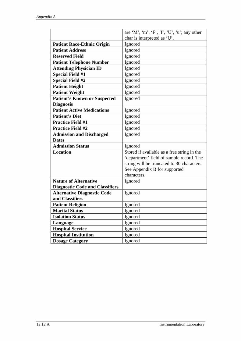
Appendix A
12.12 A Instrumentation Laboratory
are ‘M’, ‘m’, ‘F’, ‘f’, ‘U’, ‘u’; any otherchar is interpreted as ‘U’.
Patient Race-Ethnic Origin IgnoredPatient Address IgnoredReserved Field IgnoredPatient Telephone Number IgnoredAttending Physician ID IgnoredSpecial Field #1 IgnoredSpecial Field #2 IgnoredPatient Height IgnoredPatient Weight IgnoredPatient’s Known or SuspectedDiagnosis
Ignored
Patient Active Medications IgnoredPatient’s Diet IgnoredPractice Field #1 IgnoredPractice Field #2 IgnoredAdmission and DischargedDates
Ignored
Admission Status IgnoredLocation Stored if available as a free string in the
‘department’ field of sample record. Thestring will be truncated to 30 characters.See Appendix B for supportedcharacters.
Nature of AlternativeDiagnostic Code and Classifiers
Ignored
Alternative Diagnostic Codeand Classifiers
Ignored
Patient Religion IgnoredMarital Status IgnoredIsolation Status IgnoredLanguage IgnoredHospital Service IgnoredHospital Institution IgnoredDosage Category Ignored
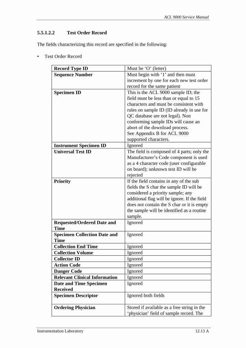
ACL 9000 Service Manual
Instrumentation Laboratory 12.13 A
5.5.1.2.2 Test Order Record
The fields characterizing this record are specified in the following:
• Test Order Record
Record Type ID Must be ‘O’ (letter)Sequence Number Must begin with ‘1’ and then must
increment by one for each new test orderrecord for the same patient
Specimen ID This is the ACL 9000 sample ID; thefield must be less than or equal to 15characters and must be consistent withrules on sample ID (ID already in use forQC database are not legal). Nonconforming sample IDs will cause anabort of the download process.See Appendix B for ACL 9000supported characters.
Instrument Specimen ID IgnoredUniversal Test ID The field is composed of 4 parts; only the
Manufacturer’s Code component is usedas a 4 character code (user configurableon board); unknown test ID will berejected
Priority If the field contains in any of the subfields the S char the sample ID will beconsidered a priority sample; anyadditional flag will be ignore. If the fielddoes not contain the S char or it is emptythe sample will be identified as a routinesample.
Requested/Ordered Date andTime
Ignored
Specimen Collection Date andTime
Ignored
Collection End Time IgnoredCollection Volume IgnoredCollector ID IgnoredAction Code IgnoredDanger Code IgnoredRelevant Clinical Information IgnoredDate and Time SpecimenReceived
Ignored
Specimen Descriptor Ignored both fields
Ordering Physician Stored if available as a free string in the‘physician’ field of sample record. The
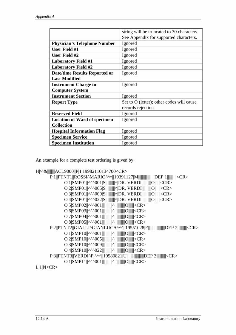
Appendix A
12.14 A Instrumentation Laboratory
string will be truncated to 30 characters.See Appendix for supported characters.
Physician’s Telephone Number IgnoredUser Field #1 IgnoredUser Field #2 IgnoredLaboratory Field #1 IgnoredLaboratory Field #2 IgnoredDate/time Results Reported orLast Modified
Ignored
Instrument Charge toComputer System
Ignored
Instrument Section IgnoredReport Type Set to O (letter); other codes will cause
records rejectionReserved Field IgnoredLocation of Ward of specimenCollection
Ignored
Hospital Information Flag IgnoredSpecimen Service IgnoredSpecimen Institution Ignored
An example for a complete test ordering is given by:
H|\^&||||||||ACL9000||P|1|19982110134700<CR>P|1||PTNT1||ROSSI^MARIO^^^||19391127|M|||||||||||||||||DEP 1||||||||||<CR>
O|1|SMP01||^^^001|S||||||||||^|DR. VERDI||||||||||O||||||<CR>O|2|SMP01||^^^005|S||||||||||^|DR. VERDI||||||||||O||||||<CR>O|3|SMP01||^^^009|S||||||||||^|DR. VERDI||||||||||O||||||<CR>O|4|SMP01||^^^022|S||||||||||^|DR. VERDI||||||||||O||||||<CR>O|5|SMP02||^^^001|||||||||||^|||||||||||O||||||<CR>O|6|SMP03||^^^001|||||||||||^|||||||||||O||||||<CR>O|7|SMP04||^^^001|||||||||||^|||||||||||O||||||<CR>O|8|SMP05||^^^001|||||||||||^|||||||||||O||||||<CR>
P|2||PTNT2||GIALLI^GIANLUCA^^^||19551028|F||||||||||||||||||DEP 2||||||||||<CR>O|1|SMP10||^^^001|||||||||||^|||||||||||O||||||<CR>O|2|SMP10||^^^005|||||||||||^|||||||||||O||||||<CR>O|3|SMP10||^^^009|||||||||||^|||||||||||O||||||<CR>O|4|SMP10||^^^022|||||||||||^|||||||||||O||||||<CR>
P|3||PTNT3||VERDI^P.^^^||19580821|U||||||||||||||||||DEP 3||||||||||<CR>O|1|SMP11||^^^001|||||||||||^|||||||||||O||||||<CR>
L|1|N<CR>
ACL 9000 Service Manual
Instrumentation Laboratory 12.15 A
5.5.2 Host Query
The host query is automatically activated by the instrument each time the system isproperly configured and starting the pre-analysis phase of a single test or profile or testgroup one or more samples have not any type of test requests associated.
The instrument will send, using the requested information record, the sample IDsrequiring test programming and will accept only test orders for those sample Ids. It hasto be underlined that the instrument will accept for the queried samples any test ordersindependently by the type of test will be executed in the starting session.
The mechanism supported by ASTM requires sending to the host a RequestInformation record for each sample Id or send to the host a range of queried sampleIDs. The mechanism supported by ACL 9000 is the first one so to be independent bythe sorting system used by instrument or host computer on the samples.
As a consequence the instrument will send a query for the first sample, will wait for thehost information and will send later a new query for the next samples (if any). All thehost query session will be organized in the described way.
Because the instrument is asking information for a specific sample Id it will reject anytype of information associated to different sample IDs.
The host will provide to the instrument all available test requests. The host can sendzero or more test orders in one or more messages, but all messages will be part of thesame transmission session.During a transmission session more test orders can be required for the same sample.
ACL 9000 will process each received test order validating the fields that ACL 9000supports; some information will be extracted from the received record while otherinformation will be ignored.
If the test order is not recognized as one of those supported by ACL 9000 it will berejected. The instrument will inform the host computer using a record containing thelist of rejected test orders.
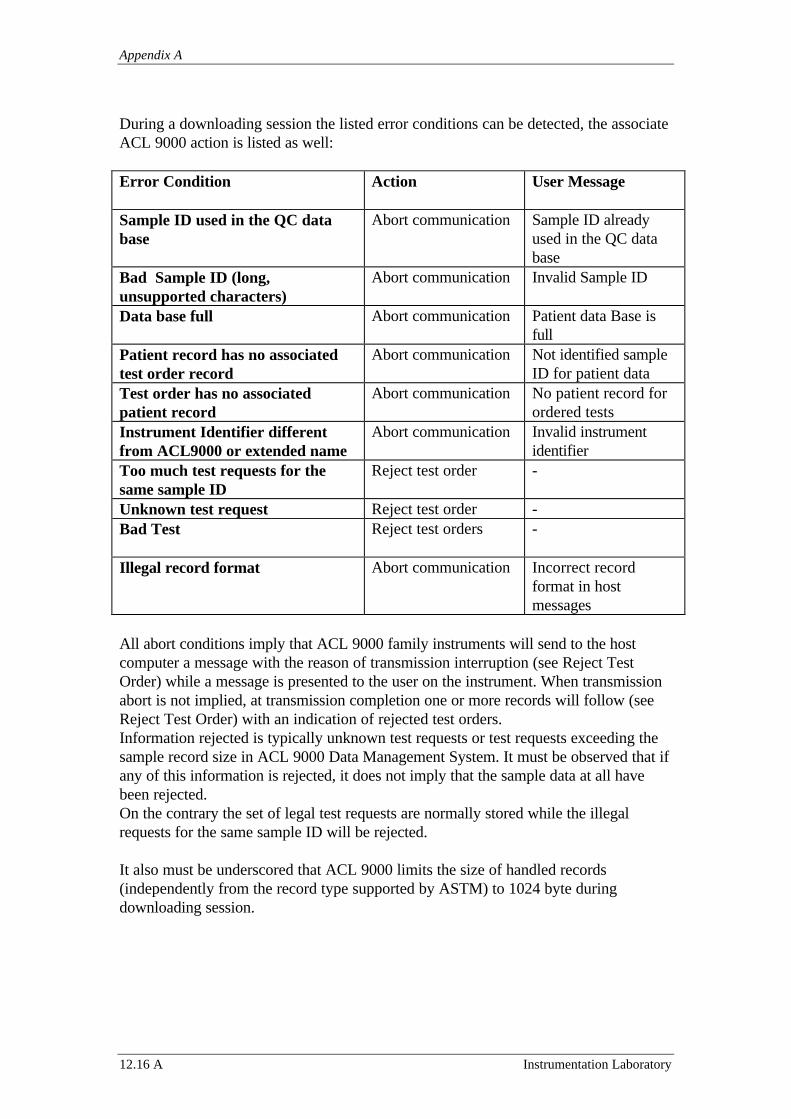
Appendix A
12.16 A Instrumentation Laboratory
During a downloading session the listed error conditions can be detected, the associateACL 9000 action is listed as well:
Error Condition Action User Message
Sample ID used in the QC database
Abort communication Sample ID alreadyused in the QC database
Bad Sample ID (long,unsupported characters)
Abort communication Invalid Sample ID
Data base full Abort communication Patient data Base isfull
Patient record has no associatedtest order record
Abort communication Not identified sampleID for patient data
Test order has no associatedpatient record
Abort communication No patient record forordered tests
Instrument Identifier differentfrom ACL9000 or extended name
Abort communication Invalid instrumentidentifier
Too much test requests for thesame sample ID
Reject test order -
Unknown test request Reject test order -Bad Test Reject test orders -
Illegal record format Abort communication Incorrect recordformat in hostmessages
All abort conditions imply that ACL 9000 family instruments will send to the hostcomputer a message with the reason of transmission interruption (see Reject TestOrder) while a message is presented to the user on the instrument. When transmissionabort is not implied, at transmission completion one or more records will follow (seeReject Test Order) with an indication of rejected test orders.Information rejected is typically unknown test requests or test requests exceeding thesample record size in ACL 9000 Data Management System. It must be observed that ifany of this information is rejected, it does not imply that the sample data at all havebeen rejected.On the contrary the set of legal test requests are normally stored while the illegalrequests for the same sample ID will be rejected.
It also must be underscored that ACL 9000 limits the size of handled records(independently from the record type supported by ASTM) to 1024 byte duringdownloading session.
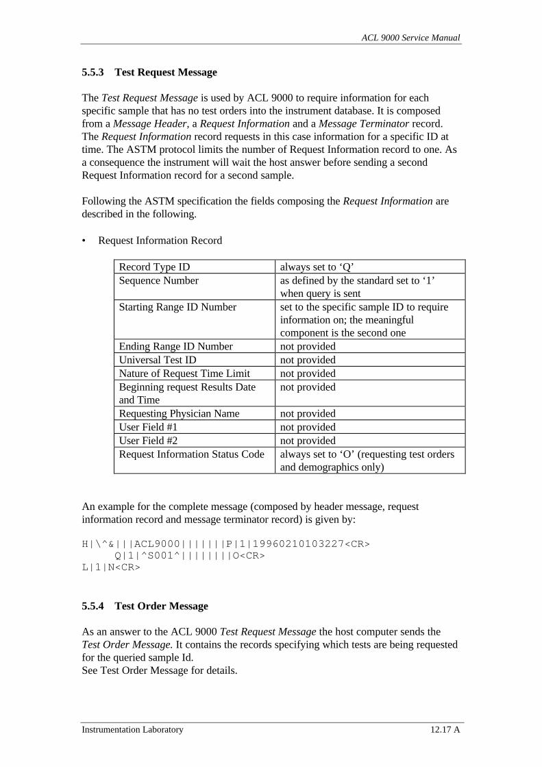
ACL 9000 Service Manual
Instrumentation Laboratory 12.17 A
5.5.3 Test Request Message
The Test Request Message is used by ACL 9000 to require information for eachspecific sample that has no test orders into the instrument database. It is composedfrom a Message Header, a Request Information and a Message Terminator record.The Request Information record requests in this case information for a specific ID attime. The ASTM protocol limits the number of Request Information record to one. Asa consequence the instrument will wait the host answer before sending a secondRequest Information record for a second sample.
Following the ASTM specification the fields composing the Request Information aredescribed in the following.
• Request Information Record
Record Type ID always set to ‘Q’Sequence Number as defined by the standard set to ‘1’
when query is sentStarting Range ID Number set to the specific sample ID to require
information on; the meaningfulcomponent is the second one
Ending Range ID Number not providedUniversal Test ID not providedNature of Request Time Limit not providedBeginning request Results Dateand Time
not provided
Requesting Physician Name not providedUser Field #1 not providedUser Field #2 not providedRequest Information Status Code always set to ‘O’ (requesting test orders
and demographics only)
An example for the complete message (composed by header message, requestinformation record and message terminator record) is given by:
H|\^&|||ACL9000|||||||P|1|19960210103227<CR>Q|1|^S001^||||||||O<CR>
L|1|N<CR>
5.5.4 Test Order Message
As an answer to the ACL 9000 Test Request Message the host computer sends theTest Order Message. It contains the records specifying which tests are being requestedfor the queried sample Id.See Test Order Message for details.
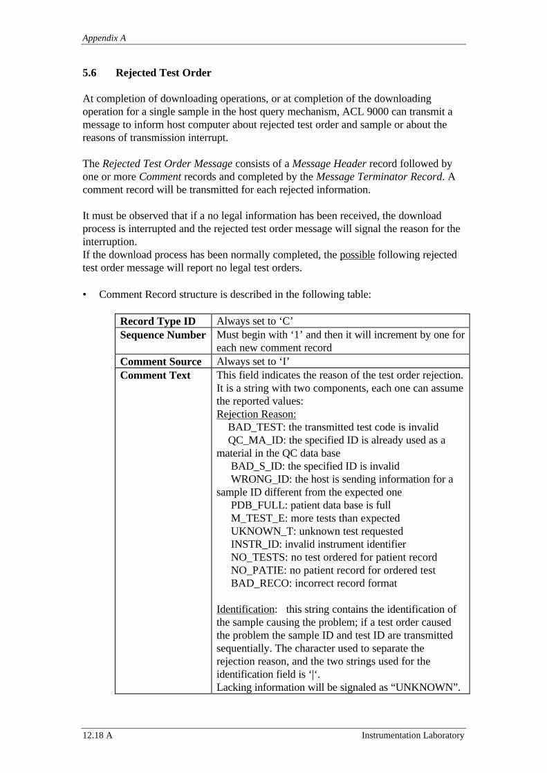
Appendix A
12.18 A Instrumentation Laboratory
5.6 Rejected Test Order
At completion of downloading operations, or at completion of the downloadingoperation for a single sample in the host query mechanism, ACL 9000 can transmit amessage to inform host computer about rejected test order and sample or about thereasons of transmission interrupt.
The Rejected Test Order Message consists of a Message Header record followed byone or more Comment records and completed by the Message Terminator Record. Acomment record will be transmitted for each rejected information.
It must be observed that if a no legal information has been received, the downloadprocess is interrupted and the rejected test order message will signal the reason for theinterruption.If the download process has been normally completed, the possible following rejectedtest order message will report no legal test orders.
• Comment Record structure is described in the following table:
Record Type ID Always set to ‘C’Sequence Number Must begin with ‘1’ and then it will increment by one for
each new comment recordComment Source Always set to ‘I’Comment Text This field indicates the reason of the test order rejection.
It is a string with two components, each one can assumethe reported values:Rejection Reason: BAD_TEST: the transmitted test code is invalid QC_MA_ID: the specified ID is already used as amaterial in the QC data base BAD_S_ID: the specified ID is invalid WRONG_ID: the host is sending information for asample ID different from the expected one PDB_FULL: patient data base is full M_TEST_E: more tests than expected UKNOWN_T: unknown test requested INSTR_ID: invalid instrument identifier NO_TESTS: no test ordered for patient record NO_PATIE: no patient record for ordered test BAD_RECO: incorrect record format
Identification: this string contains the identification ofthe sample causing the problem; if a test order causedthe problem the sample ID and test ID are transmittedsequentially. The character used to separate therejection reason, and the two strings used for theidentification field is ‘|‘.Lacking information will be signaled as “UNKNOWN”.
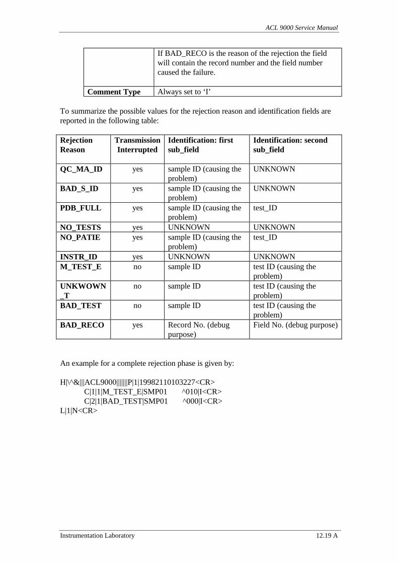
ACL 9000 Service Manual
Instrumentation Laboratory 12.19 A
If BAD_RECO is the reason of the rejection the fieldwill contain the record number and the field numbercaused the failure.
Comment Type Always set to ‘I’
To summarize the possible values for the rejection reason and identification fields arereported in the following table:
RejectionReason
TransmissionInterrupted
Identification: firstsub_field
Identification: secondsub_field
QC_MA_ID yes sample ID (causing theproblem)
UNKNOWN
BAD_S_ID yes sample ID (causing theproblem)
UNKNOWN
PDB_FULL yes sample ID (causing theproblem)
test_ID
NO_TESTS yes UNKNOWN UNKNOWNNO_PATIE yes sample ID (causing the
problem)test_ID
INSTR_ID yes UNKNOWN UNKNOWNM_TEST_E no sample ID test ID (causing the
problem)UNKWOWN_T
no sample ID test ID (causing theproblem)
BAD_TEST no sample ID test ID (causing theproblem)
BAD_RECO yes Record No. (debugpurpose)
Field No. (debug purpose)
An example for a complete rejection phase is given by:
H|\^&|||ACL9000|||||||P|1|19982110103227<CR>C|1|1|M_TEST_E|SMP01 ^010|I<CR>C|2|1|BAD_TEST|SMP01 ^000|I<CR>
L|1|N<CR>
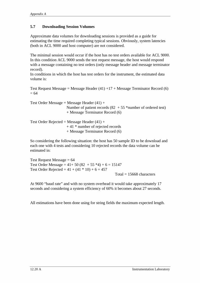
Appendix A
12.20 A Instrumentation Laboratory
5.7 Downloading Session Volumes
Approximate data volumes for downloading sessions is provided as a guide forestimating the time required completing typical sessions. Obviously, system latencies(both in ACL 9000 and host computer) are not considered.
The minimal session would occur if the host has no test orders available for ACL 9000.In this condition ACL 9000 sends the test request message, the host would respondwith a message containing no test orders (only message header and message terminatorrecord).In conditions in which the host has test orders for the instrument, the estimated datavolume is:
Test Request Message = Message Header (41) +17 + Message Terminator Record (6)= 64
Test Order Message = Message Header (41) +Number of patient records (82 + 55 *number of ordered test)+ Message Terminator Record (6)
Test Order Rejected = Message Header (41) ++ 41 * number of rejected records+ Message Terminator Record (6)
So considering the following situation: the host has 50 sample ID to be download andeach one with 4 tests and considering 10 rejected records the data volume can beestimated in:
Test Request Message = 64Test Order Message = 41+ 50 (82 + 55 *4) + 6 = 15147Test Order Rejected = 41 + (41 * 10) + 6 = 457
Total = 15668 characters
At 9600 “baud rate” and with no system overhead it would take approximately 17seconds and considering a system efficiency of 60% it becomes about 27 seconds.
All estimations have been done using for string fields the maximum expected length.
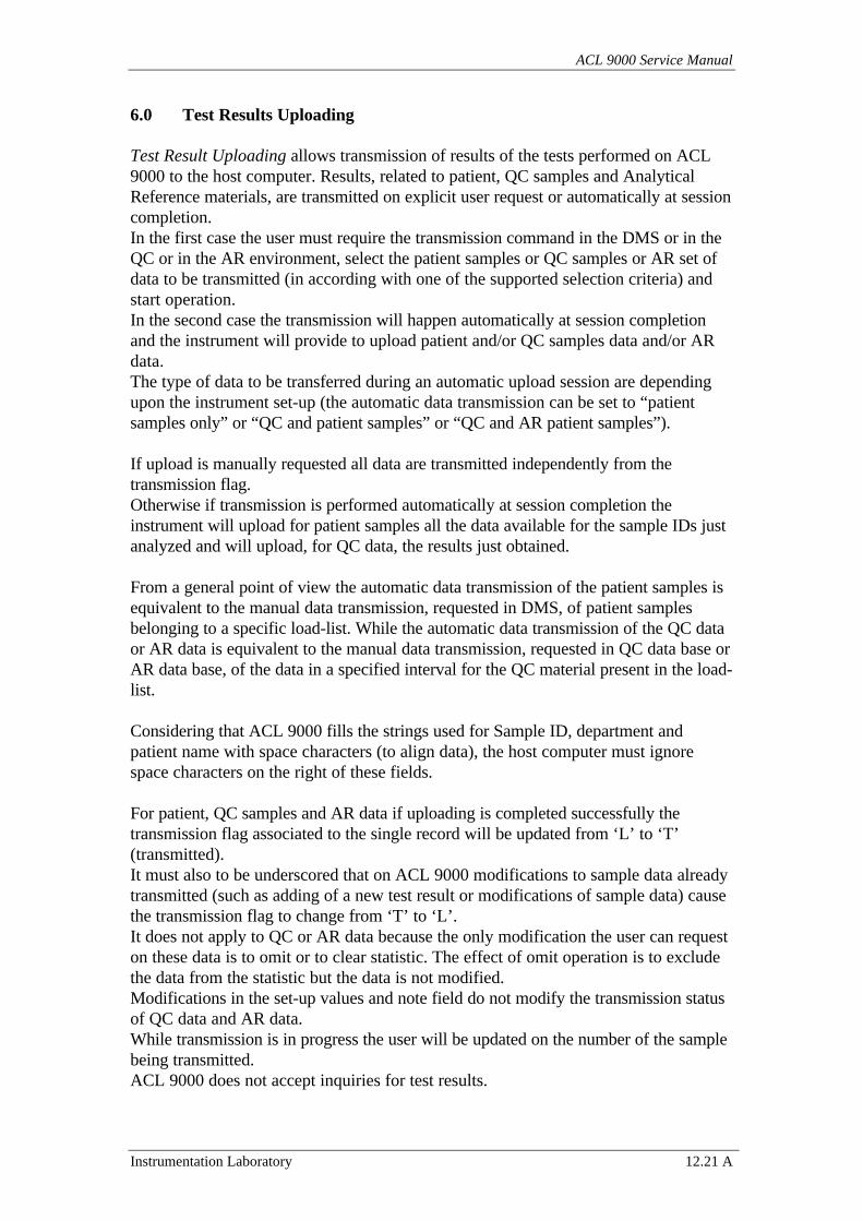
ACL 9000 Service Manual
Instrumentation Laboratory 12.21 A
6.0 Test Results Uploading
Test Result Uploading allows transmission of results of the tests performed on ACL9000 to the host computer. Results, related to patient, QC samples and AnalyticalReference materials, are transmitted on explicit user request or automatically at sessioncompletion.In the first case the user must require the transmission command in the DMS or in theQC or in the AR environment, select the patient samples or QC samples or AR set ofdata to be transmitted (in according with one of the supported selection criteria) andstart operation.In the second case the transmission will happen automatically at session completionand the instrument will provide to upload patient and/or QC samples data and/or ARdata.The type of data to be transferred during an automatic upload session are dependingupon the instrument set-up (the automatic data transmission can be set to “patientsamples only” or “QC and patient samples” or “QC and AR patient samples”).
If upload is manually requested all data are transmitted independently from thetransmission flag.Otherwise if transmission is performed automatically at session completion theinstrument will upload for patient samples all the data available for the sample IDs justanalyzed and will upload, for QC data, the results just obtained.
From a general point of view the automatic data transmission of the patient samples isequivalent to the manual data transmission, requested in DMS, of patient samplesbelonging to a specific load-list. While the automatic data transmission of the QC dataor AR data is equivalent to the manual data transmission, requested in QC data base orAR data base, of the data in a specified interval for the QC material present in the load-list.
Considering that ACL 9000 fills the strings used for Sample ID, department andpatient name with space characters (to align data), the host computer must ignorespace characters on the right of these fields.
For patient, QC samples and AR data if uploading is completed successfully thetransmission flag associated to the single record will be updated from ‘L’ to ‘T’(transmitted).It must also to be underscored that on ACL 9000 modifications to sample data alreadytransmitted (such as adding of a new test result or modifications of sample data) causethe transmission flag to change from ‘T’ to ‘L’.It does not apply to QC or AR data because the only modification the user can requeston these data is to omit or to clear statistic. The effect of omit operation is to excludethe data from the statistic but the data is not modified.Modifications in the set-up values and note field do not modify the transmission statusof QC data and AR data.While transmission is in progress the user will be updated on the number of the samplebeing transmitted.ACL 9000 does not accept inquiries for test results.
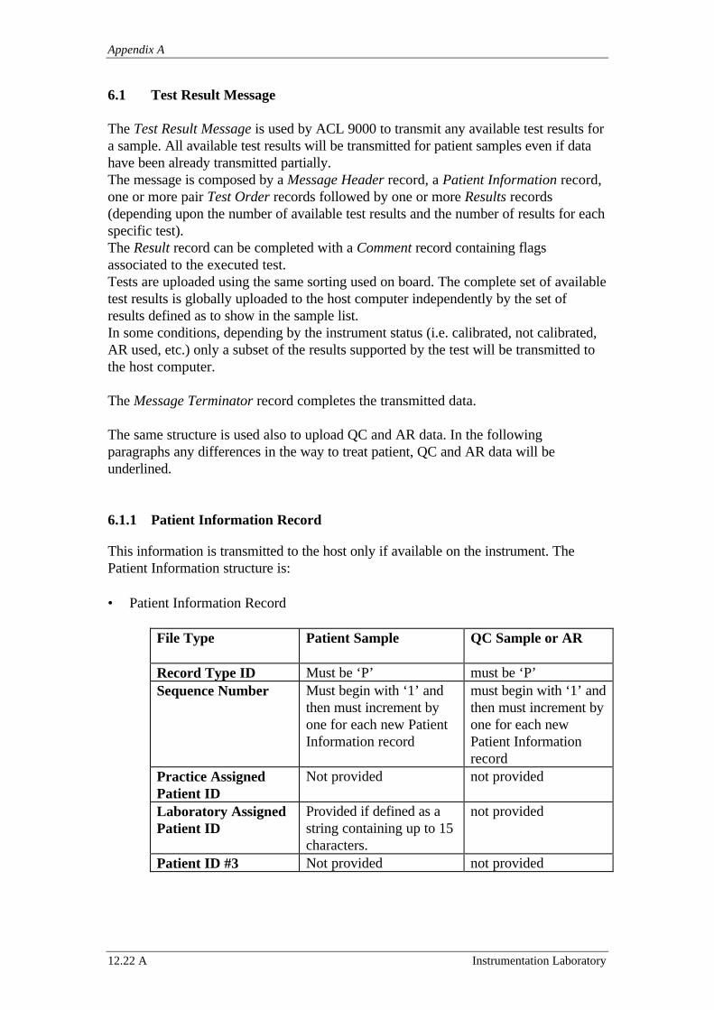
Appendix A
12.22 A Instrumentation Laboratory
6.1 Test Result Message
The Test Result Message is used by ACL 9000 to transmit any available test results fora sample. All available test results will be transmitted for patient samples even if datahave been already transmitted partially.The message is composed by a Message Header record, a Patient Information record,one or more pair Test Order records followed by one or more Results records(depending upon the number of available test results and the number of results for eachspecific test).The Result record can be completed with a Comment record containing flagsassociated to the executed test.Tests are uploaded using the same sorting used on board. The complete set of availabletest results is globally uploaded to the host computer independently by the set ofresults defined as to show in the sample list.In some conditions, depending by the instrument status (i.e. calibrated, not calibrated,AR used, etc.) only a subset of the results supported by the test will be transmitted tothe host computer.
The Message Terminator record completes the transmitted data.
The same structure is used also to upload QC and AR data. In the followingparagraphs any differences in the way to treat patient, QC and AR data will beunderlined.
6.1.1 Patient Information Record
This information is transmitted to the host only if available on the instrument. ThePatient Information structure is:
• Patient Information Record
File Type Patient Sample QC Sample or AR
Record Type ID Must be ‘P’ must be ‘P’Sequence Number Must begin with ‘1’ and
then must increment byone for each new PatientInformation record
must begin with ‘1’ andthen must increment byone for each newPatient Informationrecord
Practice AssignedPatient ID
Not provided not provided
Laboratory AssignedPatient ID
Provided if defined as astring containing up to 15characters.
not provided
Patient ID #3 Not provided not provided
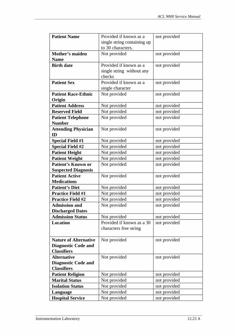
ACL 9000 Service Manual
Instrumentation Laboratory 12.23 A
Patient Name Provided if known as asingle string containing upto 30 characters.
not provided
Mother’s maidenName
Not provided not provided
Birth date Provided if known as asingle string without anychecks
not provided
Patient Sex Provided if known as asingle character
not provided
Patient Race-EthnicOrigin
Not provided not provided
Patient Address Not provided not providedReserved Field Not provided not providedPatient TelephoneNumber
Not provided not provided
Attending PhysicianID
Not provided not provided
Special Field #1 Not provided not providedSpecial Field #2 Not provided not providedPatient Height Not provided not providedPatient Weight Not provided not providedPatient’s Known orSuspected Diagnosis
Not provided not provided
Patient ActiveMedications
Not provided not provided
Patient’s Diet Not provided not providedPractice Field #1 Not provided not providedPractice Field #2 Not provided not providedAdmission andDischarged Dates
Not provided not provided
Admission Status Not provided not providedLocation Provided if known as a 30
characters free stringnot provided
Nature of AlternativeDiagnostic Code andClassifiers
Not provided not provided
AlternativeDiagnostic Code andClassifiers
Not provided not provided
Patient Religion Not provided not providedMarital Status Not provided not providedIsolation Status Not provided not providedLanguage Not provided not providedHospital Service Not provided not provided
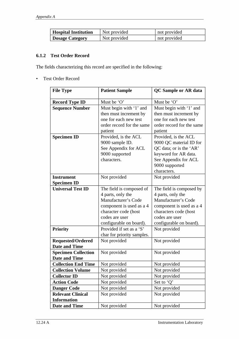
Appendix A
12.24 A Instrumentation Laboratory
Hospital Institution Not provided not providedDosage Category Not provided not provided
6.1.2 Test Order Record
The fields characterizing this record are specified in the following:
• Test Order Record
File Type Patient Sample QC Sample or AR data
Record Type ID Must be ‘O’ Must be ‘O’Sequence Number Must begin with ‘1’ and
then must increment byone for each new testorder record for the samepatient
Must begin with ‘1’ andthen must increment byone for each new testorder record for the samepatient
Specimen ID Provided, is the ACL9000 sample ID.See Appendix for ACL9000 supportedcharacters.
Provided, is the ACL9000 QC material ID forQC data; or is the ‘AR’keyword for AR data.See Appendix for ACL9000 supportedcharacters.
InstrumentSpecimen ID
Not provided Not provided
Universal Test ID The field is composed of4 parts, only theManufacturer’s Codecomponent is used as a 4character code (hostcodes are userconfigurable on board).
The field is composed by4 parts, only theManufacturer’s Codecomponent is used as a 4characters code (hostcodes are userconfigurable on board).
Priority Provided if set as a ‘S’char for priority samples.
Not provided
Requested/OrderedDate and Time
Not provided Not provided
Specimen CollectionDate and Time
Not provided Not provided
Collection End Time Not provided Not providedCollection Volume Not provided Not providedCollector ID Not provided Not providedAction Code Not provided Set to ‘Q’Danger Code Not provided Not providedRelevant ClinicalInformation
Not provided Not provided
Date and Time Not provided Not provided
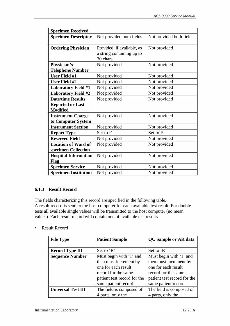
ACL 9000 Service Manual
Instrumentation Laboratory 12.25 A
Specimen ReceivedSpecimen Descriptor Not provided both fields Not provided both fields
Ordering Physician Provided, if available, asa string containing up to30 chars
Not provided
Physician’sTelephone Number
Not provided Not provided
User Field #1 Not provided Not providedUser Field #2 Not provided Not providedLaboratory Field #1 Not provided Not providedLaboratory Field #2 Not provided Not providedDate/time ResultsReported or LastModified
Not provided Not provided
Instrument Chargeto Computer System
Not provided Not provided
Instrument Section Not provided Not providedReport Type Set to F Set to FReserved Field Not provided Not providedLocation of Ward ofspecimen Collection
Not provided Not provided
Hospital InformationFlag
Not provided Not provided
Specimen Service Not provided Not providedSpecimen Institution Not provided Not provided
6.1.3 Result Record
The fields characterizing this record are specified in the following table.A result record is send to the host computer for each available test result. For doubletests all available single values will be transmitted to the host computer (no meanvalues). Each result record will contain one of available test results.
• Result Record
File Type Patient Sample QC Sample or AR data
Record Type ID Set to ‘R’ Set to ‘R’Sequence Number Must begin with ‘1’ and
then must increment byone for each resultrecord for the samepatient test record for thesame patient record
Must begin with ‘1’ andthen must increment byone for each resultrecord for the samepatient test record for thesame patient record
Universal Test ID The field is composed of4 parts, only the
The field is composed of4 parts, only the
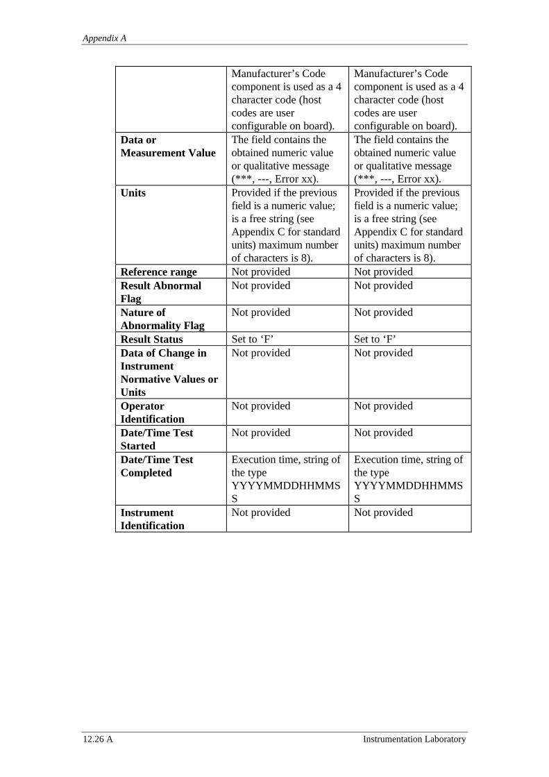
Appendix A
12.26 A Instrumentation Laboratory
Manufacturer’s Codecomponent is used as a 4character code (hostcodes are userconfigurable on board).
Manufacturer’s Codecomponent is used as a 4character code (hostcodes are userconfigurable on board).
Data orMeasurement Value
The field contains theobtained numeric valueor qualitative message(***, ---, Error xx).
The field contains theobtained numeric valueor qualitative message(***, ---, Error xx).
Units Provided if the previousfield is a numeric value;is a free string (seeAppendix C for standardunits) maximum numberof characters is 8).
Provided if the previousfield is a numeric value;is a free string (seeAppendix C for standardunits) maximum numberof characters is 8).
Reference range Not provided Not providedResult AbnormalFlag
Not provided Not provided
Nature ofAbnormality Flag
Not provided Not provided
Result Status Set to ‘F’ Set to ‘F’Data of Change inInstrumentNormative Values orUnits
Not provided Not provided
OperatorIdentification
Not provided Not provided
Date/Time TestStarted
Not provided Not provided
Date/Time TestCompleted
Execution time, string ofthe typeYYYYMMDDHHMMSS
Execution time, string ofthe typeYYYYMMDDHHMMSS
InstrumentIdentification
Not provided Not provided

ACL 9000 Service Manual
Instrumentation Laboratory 12.27 A
6.1.4 Comment Record
The Comment record allows integration of the transmitted test results with possibleerror messages.One or more comment records can follow the result records. Fields characterizing thisrecord are specified in the following.
• Comment Record
Record Type ID set to ‘C’Sequence Number must begin with ‘1’ and then must increment by one for
each comment recordComment Source set to ‘I’Comment Text this field specifies the instrument errors (see table) as a
numeric code (2 characters) plus the associated messageComment Type set to ‘I’
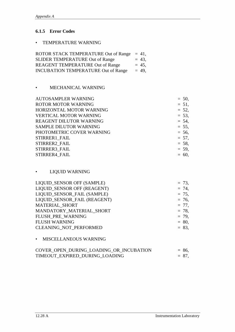
Appendix A
12.28 A Instrumentation Laboratory
6.1.5 Error Codes
• TEMPERATURE WARNING
ROTOR STACK TEMPERATURE Out of Range = 41,SLIDER TEMPERATURE Out of Range = 43,REAGENT TEMPERATURE Out of Range = 45,INCUBATION TEMPERATURE Out of Range = 49,
• MECHANICAL WARNING
AUTOSAMPLER WARNING = 50,ROTOR MOTOR WARNING = 51,HORIZONTAL MOTOR WARNING = 52,VERTICAL MOTOR WARNING = 53,REAGENT DILUTOR WARNING = 54,SAMPLE DILUTOR WARNING = 55,PHOTOMETRIC COVER WARNING = 56,STIRRER1_FAIL = 57,STIRRER2_FAIL = 58,STIRRER3_FAIL = 59,STIRRER4_FAIL = 60,
• LIQUID WARNING
LIQUID_SENSOR OFF (SAMPLE) = 73,LIQUID_SENSOR OFF (REAGENT) = 74,LIQUID_SENSOR_FAIL (SAMPLE) = 75,LIQUID_SENSOR_FAIL (REAGENT) = 76,MATERIAL_SHORT = 77,MANDATORY_MATERIAL_SHORT = 78,FLUSH_PRE_WARNING = 79,FLUSH WARNING = 80,CLEANING_NOT_PERFORMED = 83,
• MISCELLANEOUS WARNING
COVER_OPEN_DURING_LOADING_OR_INCUBATION = 86,TIMEOUT_EXPIRED_DURING_LOADING = 87,
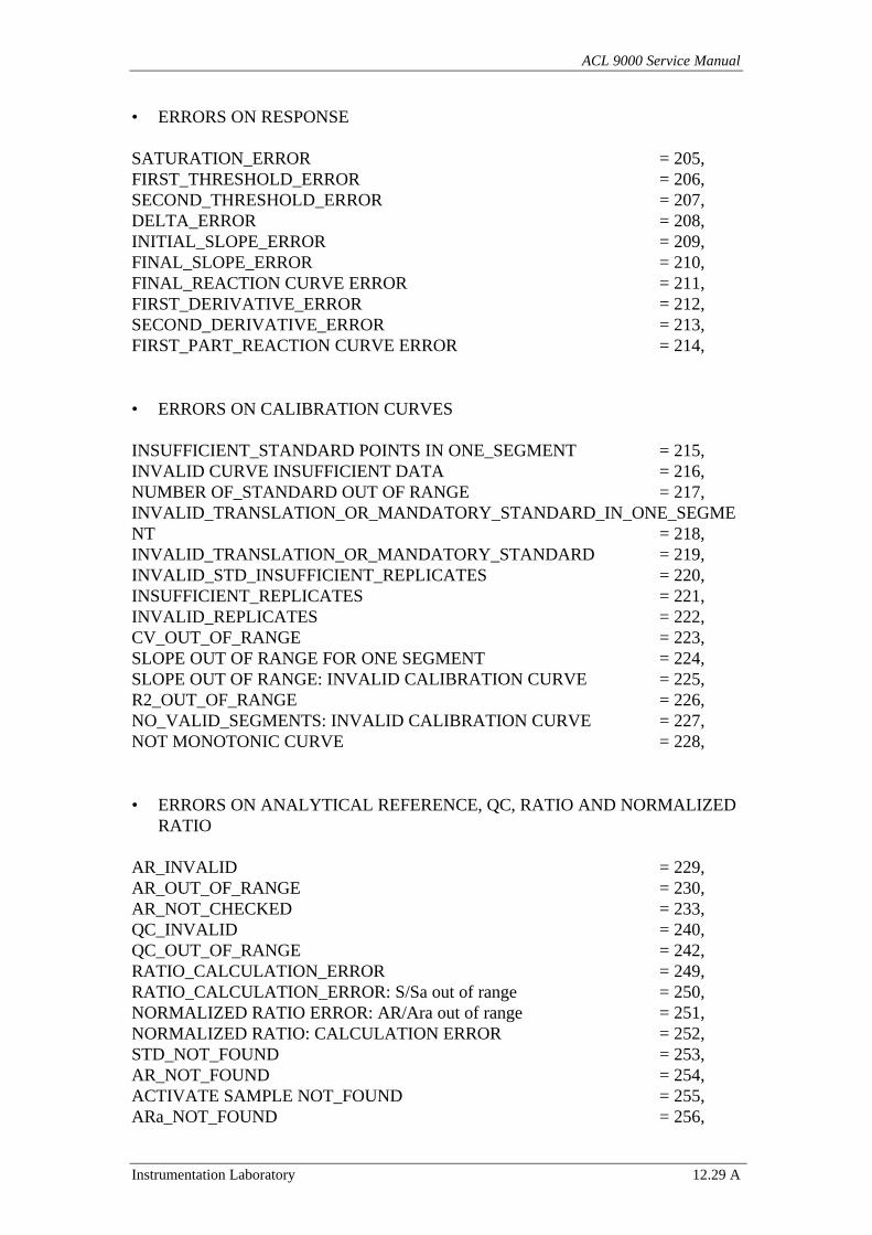
ACL 9000 Service Manual
Instrumentation Laboratory 12.29 A
• ERRORS ON RESPONSE
SATURATION_ERROR = 205,FIRST_THRESHOLD_ERROR = 206,SECOND_THRESHOLD_ERROR = 207,DELTA_ERROR = 208,INITIAL_SLOPE_ERROR = 209,FINAL_SLOPE_ERROR = 210,FINAL_REACTION CURVE ERROR = 211,FIRST_DERIVATIVE_ERROR = 212,SECOND_DERIVATIVE_ERROR = 213,FIRST_PART_REACTION CURVE ERROR = 214,
• ERRORS ON CALIBRATION CURVES
INSUFFICIENT_STANDARD POINTS IN ONE_SEGMENT = 215,INVALID CURVE INSUFFICIENT DATA = 216,NUMBER OF_STANDARD OUT OF RANGE = 217,INVALID_TRANSLATION_OR_MANDATORY_STANDARD_IN_ONE_SEGMENT = 218,INVALID_TRANSLATION_OR_MANDATORY_STANDARD = 219,INVALID_STD_INSUFFICIENT_REPLICATES = 220,INSUFFICIENT_REPLICATES = 221,INVALID_REPLICATES = 222,CV_OUT_OF_RANGE = 223,SLOPE OUT OF RANGE FOR ONE SEGMENT = 224,SLOPE OUT OF RANGE: INVALID CALIBRATION CURVE = 225,R2_OUT_OF_RANGE = 226,NO_VALID_SEGMENTS: INVALID CALIBRATION CURVE = 227,NOT MONOTONIC CURVE = 228,
• ERRORS ON ANALYTICAL REFERENCE, QC, RATIO AND NORMALIZEDRATIO
AR_INVALID = 229,AR_OUT_OF_RANGE = 230,AR_NOT_CHECKED = 233,QC_INVALID = 240,QC_OUT_OF_RANGE = 242,RATIO_CALCULATION_ERROR = 249,RATIO_CALCULATION_ERROR: S/Sa out of range = 250,NORMALIZED RATIO ERROR: AR/Ara out of range = 251,NORMALIZED RATIO: CALCULATION ERROR = 252,STD_NOT_FOUND = 253,AR_NOT_FOUND = 254,ACTIVATE SAMPLE NOT_FOUND = 255,ARa_NOT_FOUND = 256,

Appendix A
12.30 A Instrumentation Laboratory
RATIO_NOT_FOUND = 257,AR_OUT_OF_RANGE = 258,AR_NULL = 259,STD_NULL = 260,SAMPLE_NULL = 262,REF_NULL = 263,AR_RATIO_ NULL_ = 264,ACTIVATED_AR NULL_ = 265,NULL_DIFFERENCE = 266,
N.B. Out of range indications referring to normal or test ranges are not transmitted tothe host computer.
An example for a complete test uploading sequence is given by:
H|\^&||||||||ACL9000||P|1|19982110134700<CR>P|1||PTNT1||BLU^^^^||19391127|M|||||||||||||||||DEP 1||||||||||<CR>
O|1|SMP01||^^^001|S||||||||||^|DR. VERDI||||||||||O||||||<CR>R|1|^^^001|12.8|||||F||||19960119114215|<CR>
C|1|I|31^ Invalid for QC |I<CR>P|2||PTNT1||Gialli^^^^||19391127|M|||||||||||||||||DEP 1||||||||||<CR>
O|1|SMP10||^^^001|S||||||||||^|DR. VERDI||||||||||O||||||<CR>R|1|^^^001|14.5|s||||F||||19960119114215|<CR>
C|1|I|31^ Invalid for QC |I<CR>L|1|N<CR>
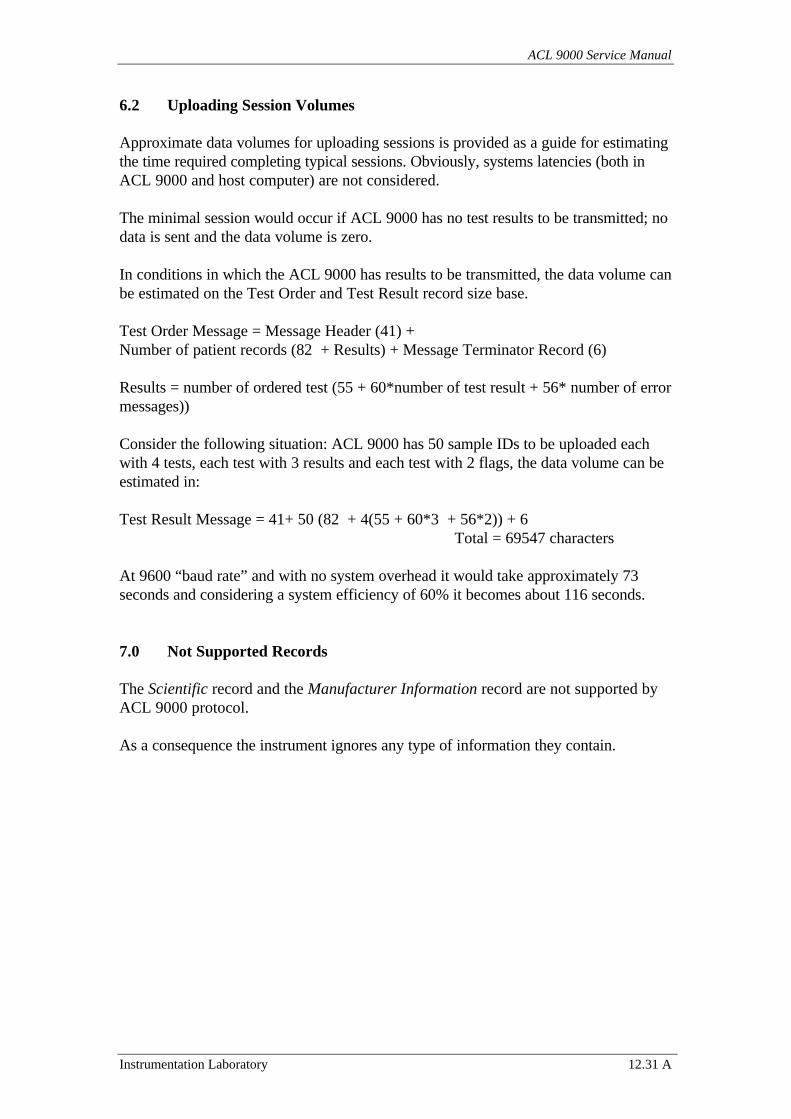
ACL 9000 Service Manual
Instrumentation Laboratory 12.31 A
6.2 Uploading Session Volumes
Approximate data volumes for uploading sessions is provided as a guide for estimatingthe time required completing typical sessions. Obviously, systems latencies (both inACL 9000 and host computer) are not considered.
The minimal session would occur if ACL 9000 has no test results to be transmitted; nodata is sent and the data volume is zero.
In conditions in which the ACL 9000 has results to be transmitted, the data volume canbe estimated on the Test Order and Test Result record size base.
Test Order Message = Message Header (41) +Number of patient records (82 + Results) + Message Terminator Record (6)
Results = number of ordered test (55 + 60*number of test result + 56* number of errormessages))
Consider the following situation: ACL 9000 has 50 sample IDs to be uploaded eachwith 4 tests, each test with 3 results and each test with 2 flags, the data volume can beestimated in:
Test Result Message = 41+ 50 (82 + 4(55 + 60*3 + 56*2)) + 6Total = 69547 characters
At 9600 “baud rate” and with no system overhead it would take approximately 73seconds and considering a system efficiency of 60% it becomes about 116 seconds.
7.0 Not Supported Records
The Scientific record and the Manufacturer Information record are not supported byACL 9000 protocol.
As a consequence the instrument ignores any type of information they contain.
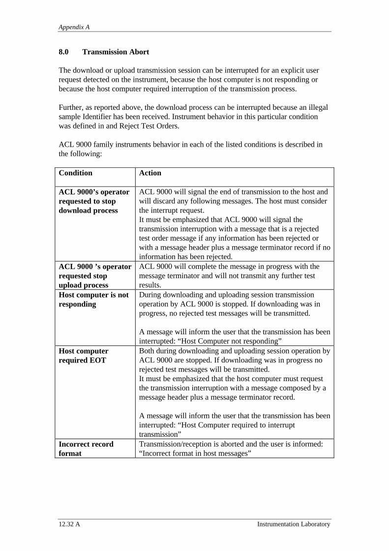
Appendix A
12.32 A Instrumentation Laboratory
8.0 Transmission Abort
The download or upload transmission session can be interrupted for an explicit userrequest detected on the instrument, because the host computer is not responding orbecause the host computer required interruption of the transmission process.
Further, as reported above, the download process can be interrupted because an illegalsample Identifier has been received. Instrument behavior in this particular conditionwas defined in and Reject Test Orders.
ACL 9000 family instruments behavior in each of the listed conditions is described inthe following:
Condition Action
ACL 9000’s operatorrequested to stopdownload process
ACL 9000 will signal the end of transmission to the host andwill discard any following messages. The host must considerthe interrupt request.It must be emphasized that ACL 9000 will signal thetransmission interruption with a message that is a rejectedtest order message if any information has been rejected orwith a message header plus a message terminator record if noinformation has been rejected.
ACL 9000 ’s operatorrequested stopupload process
ACL 9000 will complete the message in progress with themessage terminator and will not transmit any further testresults.
Host computer is notresponding
During downloading and uploading session transmissionoperation by ACL 9000 is stopped. If downloading was inprogress, no rejected test messages will be transmitted.
A message will inform the user that the transmission has beeninterrupted: “Host Computer not responding”
Host computerrequired EOT
Both during downloading and uploading session operation byACL 9000 are stopped. If downloading was in progress norejected test messages will be transmitted.It must be emphasized that the host computer must requestthe transmission interruption with a message composed by amessage header plus a message terminator record.
A message will inform the user that the transmission has beeninterrupted: “Host Computer required to interrupttransmission”
Incorrect recordformat
Transmission/reception is aborted and the user is informed:“Incorrect format in host messages”
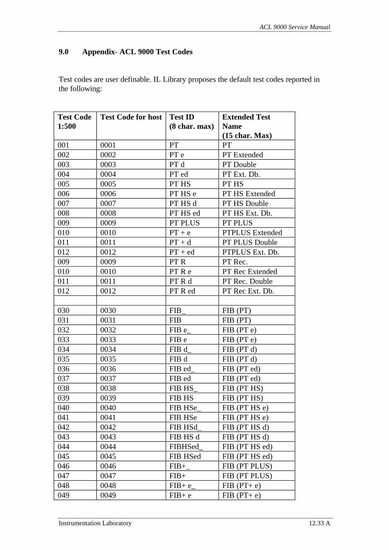
ACL 9000 Service Manual
Instrumentation Laboratory 12.33 A
9.0 Appendix- ACL 9000 Test Codes
Test codes are user definable. IL Library proposes the default test codes reported inthe following:
Test Code1:500
Test Code for host Test ID(8 char. max)
Extended TestName(15 char. Max)
001 0001 PT PT002 0002 PT e PT Extended003 0003 PT d PT Double004 0004 PT ed PT Ext. Db.005 0005 PT HS PT HS006 0006 PT HS e PT HS Extended007 0007 PT HS d PT HS Double008 0008 PT HS ed PT HS Ext. Db.009 0009 PT PLUS PT PLUS010 0010 PT + e PTPLUS Extended011 0011 PT + d PT PLUS Double012 0012 PT + ed PTPLUS Ext. Db.009 0009 PT R PT Rec.010 0010 PT R e PT Rec Extended011 0011 PT R d PT Rec. Double012 0012 PT R ed PT Rec Ext. Db.
030 0030 FIB_ FIB (PT)031 0031 FIB FIB (PT)032 0032 FIB e_ FIB (PT e)033 0033 FIB e FIB (PT e)034 0034 FIB d_ FIB (PT d)035 0035 FIB d FIB (PT d)036 0036 FIB ed_ FIB (PT ed)037 0037 FIB ed FIB (PT ed)038 0038 FIB HS_ FIB (PT HS)039 0039 FIB HS FIB (PT HS)040 0040 FIB HSe_ FIB (PT HS e)041 0041 FIB HSe FIB (PT HS e)042 0042 FIB HSd_ FIB (PT HS d)043 0043 FIB HS d FIB (PT HS d)044 0044 FIBHSed_ FIB (PT HS ed)045 0045 FIB HSed FIB (PT HS ed)046 0046 FIB+_ FIB (PT PLUS)047 0047 FIB+ FIB (PT PLUS)048 0048 FIB+ e_ FIB (PT+ e)049 0049 FIB+ e FIB (PT+ e)
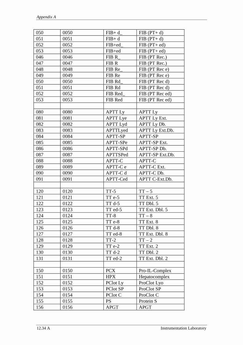
Appendix A
12.34 A Instrumentation Laboratory
050 0050 FIB+ d_ FIB (PT+ d)051 0051 FIB+ d FIB (PT+ d)052 0052 FIB+ed_ FIB (PT+ ed)053 0053 FIB+ed FIB (PT+ ed)046 0046 FIB R_ FIB (PT Rec.)047 0047 FIB R FIB (PT Rec.)048 0048 FIB Re_ FIB (PT Rec e)049 0049 FIB Re FIB (PT Rec e)050 0050 FIB Rd_ FIB (PT Rec d)051 0051 FIB Rd FIB (PT Rec d)052 0052 FIB Red_ FIB (PT Rec ed)053 0053 FIB Red FIB (PT Rec ed)
080 0080 APTT Ly APTT Ly081 0081 APTT Lye APTT Ly Ext.082 0082 APTT Lyd APTT Ly Db.083 0083 APTTLyed APTT Ly Ext.Db.084 0084 APTT-SP APTT-SP085 0085 APTT-SPe APTT-SP Ext.086 0086 APTT-SPd APTT-SP Db.087 0087 APTTSPed APTT-SP Ext.Db.088 0088 APTT-C APTT-C089 0089 APTT-C e APTT-C Ext.090 0090 APTT-C d APTT-C Db.091 0091 APTT-Ced APTT C-Ext.Db.
120 0120 TT-5 TT – 5121 0121 TT e-5 TT Ext. 5122 0122 TT d-5 TT Dbl. 5123 0123 TT ed-5 TT Ext. Dbl. 5124 0124 TT-8 TT – 8125 0125 TT e-8 TT Ext. 8126 0126 TT d-8 TT Dbl. 8127 0127 TT ed-8 TT Ext. Dbl. 8128 0128 TT-2 TT – 2129 0129 TT e-2 TT Ext. 2130 0130 TT d-2 TT Dbl. 2131 0131 TT ed-2 TT Ext. Dbl. 2
150 0150 PCX Pro-IL-Complex151 0151 HPX Hepatocomplex152 0152 PClot Ly ProClot Lyo153 0153 PClot SP ProClot SP154 0154 PClot C ProClot C155 0155 PS Protein S156 0156 APGT APGT
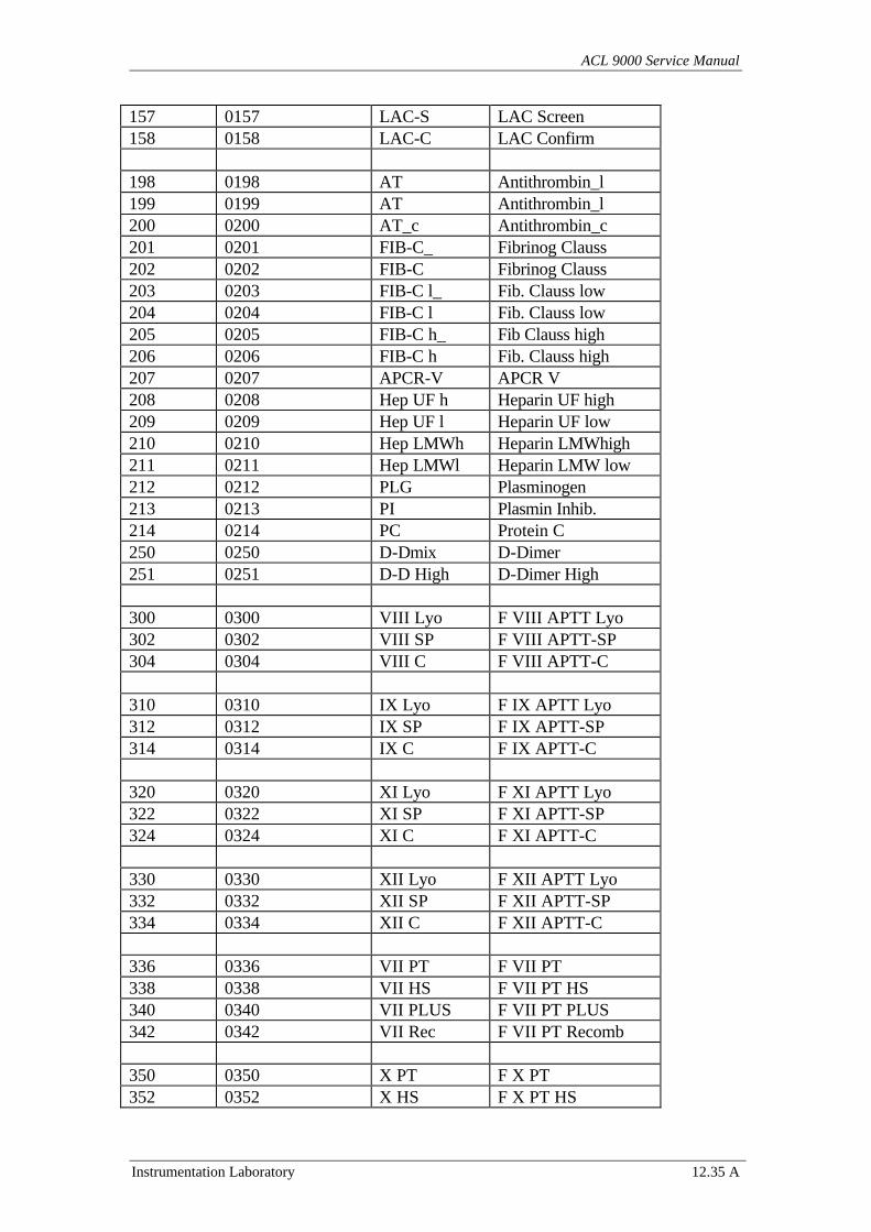
ACL 9000 Service Manual
Instrumentation Laboratory 12.35 A
157 0157 LAC-S LAC Screen158 0158 LAC-C LAC Confirm
198 0198 AT Antithrombin_l199 0199 AT Antithrombin_l200 0200 AT_c Antithrombin_c201 0201 FIB-C_ Fibrinog Clauss202 0202 FIB-C Fibrinog Clauss203 0203 FIB-C l_ Fib. Clauss low204 0204 FIB-C l Fib. Clauss low205 0205 FIB-C h_ Fib Clauss high206 0206 FIB-C h Fib. Clauss high207 0207 APCR-V APCR V208 0208 Hep UF h Heparin UF high209 0209 Hep UF l Heparin UF low210 0210 Hep LMWh Heparin LMWhigh211 0211 Hep LMWl Heparin LMW low212 0212 PLG Plasminogen213 0213 PI Plasmin Inhib.214 0214 PC Protein C250 0250 D-Dmix D-Dimer251 0251 D-D High D-Dimer High
300 0300 VIII Lyo F VIII APTT Lyo302 0302 VIII SP F VIII APTT-SP304 0304 VIII C F VIII APTT-C
310 0310 IX Lyo F IX APTT Lyo312 0312 IX SP F IX APTT-SP314 0314 IX C F IX APTT-C
320 0320 XI Lyo F XI APTT Lyo322 0322 XI SP F XI APTT-SP324 0324 XI C F XI APTT-C
330 0330 XII Lyo F XII APTT Lyo332 0332 XII SP F XII APTT-SP334 0334 XII C F XII APTT-C
336 0336 VII PT F VII PT338 0338 VII HS F VII PT HS340 0340 VII PLUS F VII PT PLUS342 0342 VII Rec F VII PT Recomb
350 0350 X PT F X PT352 0352 X HS F X PT HS
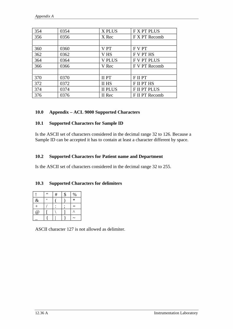
Appendix A
12.36 A Instrumentation Laboratory
354 0354 X PLUS F X PT PLUS356 0356 X Rec F X PT Recomb
360 0360 V PT F V PT362 0362 V HS F V PT HS364 0364 V PLUS F V PT PLUS366 0366 V Rec F V PT Recomb
370 0370 II PT F II PT372 0372 II HS F II PT HS374 0374 II PLUS F II PT PLUS376 0376 II Rec F II PT Recomb
10.0 Appendix – ACL 9000 Supported Characters
10.1 Supported Characters for Sample ID
Is the ASCII set of characters considered in the decimal range 32 to 126. Because aSample ID can be accepted it has to contain at least a character different by space.
10.2 Supported Characters for Patient name and Department
Is the ASCII set of characters considered in the decimal range 32 to 255.
10.3 Supported Characters for delimiters
! “ # $ %& ‘ ( ) *+ / : ; =@ [ \ ] ^_ { | } ~
ASCII character 127 is not allowed as delimiter.
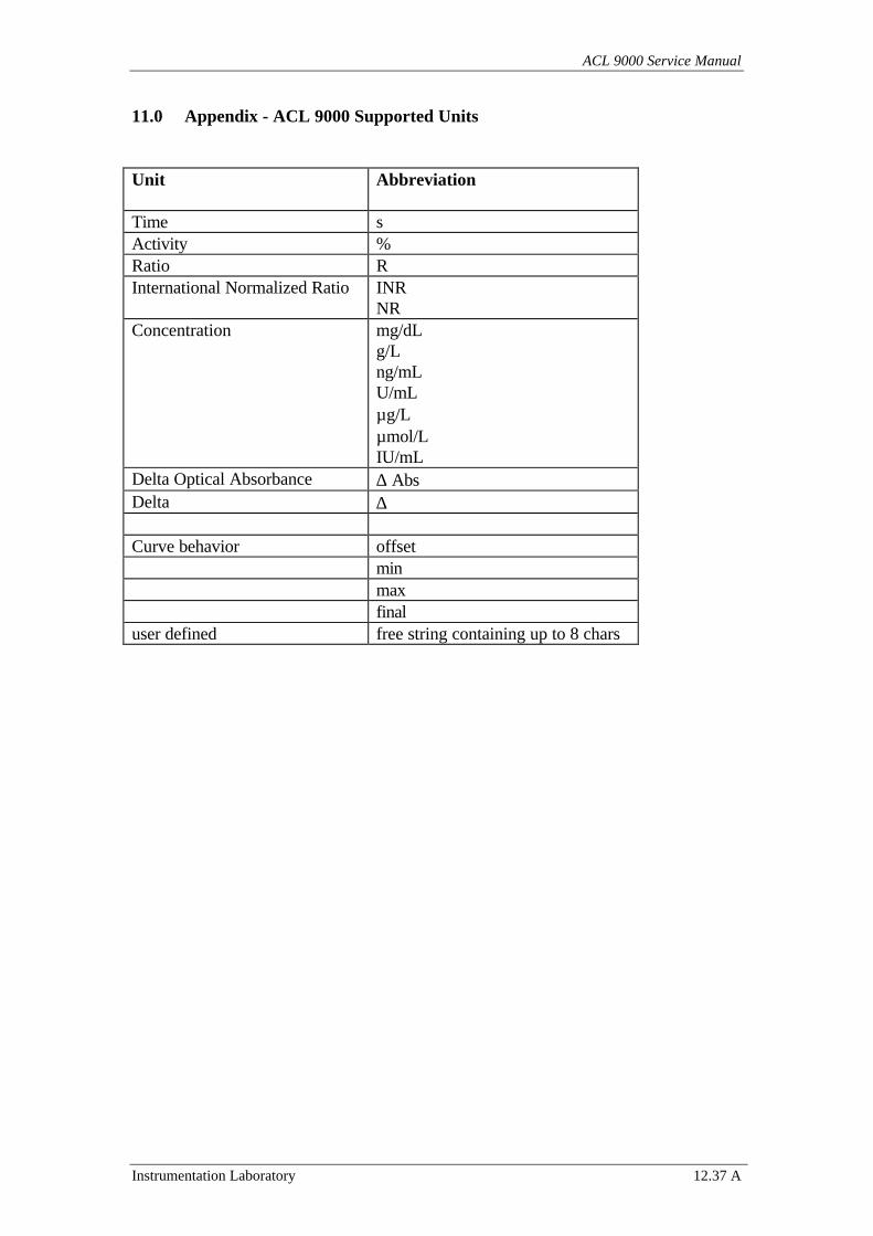
ACL 9000 Service Manual
Instrumentation Laboratory 12.37 A
11.0 Appendix - ACL 9000 Supported Units
Unit Abbreviation
Time sActivity %Ratio RInternational Normalized Ratio INR
NRConcentration mg/dL
g/Lng/mLU/mLµg/Lµmol/LIU/mL
Delta Optical Absorbance ∆ AbsDelta ∆
Curve behavior offsetminmaxfinal
user defined free string containing up to 8 chars
ACL 9000 Service Manual
Instrumentation Laboratory 12.1 B
12 Appendix B
ACL 9000
Bar Code Label Specification
(REV 0.0)
Appendix B
12.2 B Instrumentation Laboratory
Index
1.0 Introduction1.1 Purpose1.2 Definitions, Acronyms and Abbreviations1.3 References2.0 General Description2.1 Supported Codes and Checksum type2.2 Bar Code Symbol Specifications2.3 Barcode Parameters2.4 Barcode Label Positioning2.5 Barcode Label Dimensions
1.0 Introduction
In the following sections the characteristics of the bar code labels that can be read withthe Welch Allyn SCANTEAM 3700 scanner installed on ACL 9000 family instrumentsare described.
1.1 Purpose
Purpose of this document is to give indication of the scanner characteristics in terms ofreadable codes, identify the requirements the barcode labels have to satisfy and defineconstraints in terms of label positioning within ACL 9000 instrument.
1.2 Definitions, Acronyms and Abbreviations
WA Walch Allyn SCANTEAM 3700
Near Distance is the nearest distance that a scanner can accurately digitize agiven bar code.
Far Distance is the farthtest distance that a scanner can accurately digitize agiven bar code.
Scan Width is the length of the widest bar code that can be successfully interpreted by the scanner.
Quiet Zone is the blank area located just before and just after the bar space pattern.
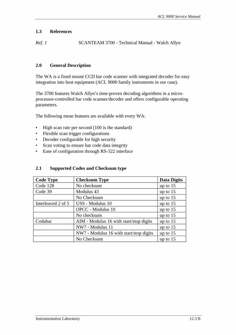
ACL 9000 Service Manual
Instrumentation Laboratory 12.3 B
1.3 References
Ref. 1 SCANTEAM 3700 - Technical Manual - Walch Allyn
2.0 General Description
The WA is a fixed mount CCD bar code scanner with integrated decoder for easyintegration into host equipment (ACL 9000 family instruments in our case).
The 3700 features Walch Allyn’s time-proven decoding algorithms in a micro-processor-controlled bar code scanner/decoder and offers configurable operatingparameters.
The following mean features are available with every WA:
• High scan rate per second (100 is the standard)• Flexible scan trigger configurations• Decoder configurable for high security• Scan voting to ensure bar code data integrity• Ease of configuration through RS-322 interface
2.1 Supported Codes and Checksum type
Code Type Checksum Type Data DigitsCode 128 No checksum up to 15Code 39 Modulus 43 up to 15
No Checksum up to 15Interleaved 2 of 5 USS - Modulus 10 up to 15
OPCC - Modulus 10 up to 15No checksum up to 15
Codabar AIM - Modulus 16 with start/stop digits up to 15NW7 - Modulus 11 up to 15NW7 - Modulus 16 with start/stop digits up to 15No Checksum up to 15
Appendix B
12.4 B Instrumentation Laboratory
2.2 Bar Code Symbol Specifications
All bar code symbols have to satisfy the appropriate AIM Uniform SymbologySpecification. In particular the following characteristics have to considered:
• Background substrate
The barcode symbol should be printed on a material type that is reflective and has amatte (not glossy) finish. A background diffuse reflectance of at least 70% to 80% issuggested for optimum contrast.
• Ink colour and type
The ink type has to be compatible with 660 nm LEDs used in the scanner. The barcodesymbols inked bars should not exceed 10% reflectance at 660 nm that is being used forreading, whether printed with black ink or coloured ink.
• Voids and Specks
The code has to be printed clearly, free of voids, specks, blemishes and lines whichcould “fool” the scanner.
• Definition
The bars in the barcode symbols should be well defined. Their edges should not berough or fuzzy, so that bar and spaces have the proper widths intended for the usedbarcode symbology used. Definition should be sharp and consistent.
• Tolerance
The ratio of the widths and spaces in a barcode symbol must conform to theappropriate AIM barcode specifications and can cause problems if not correctthroughout the barcode. Problems can occur if bar edges are smeared or rough, orwhen they exhibit voids.
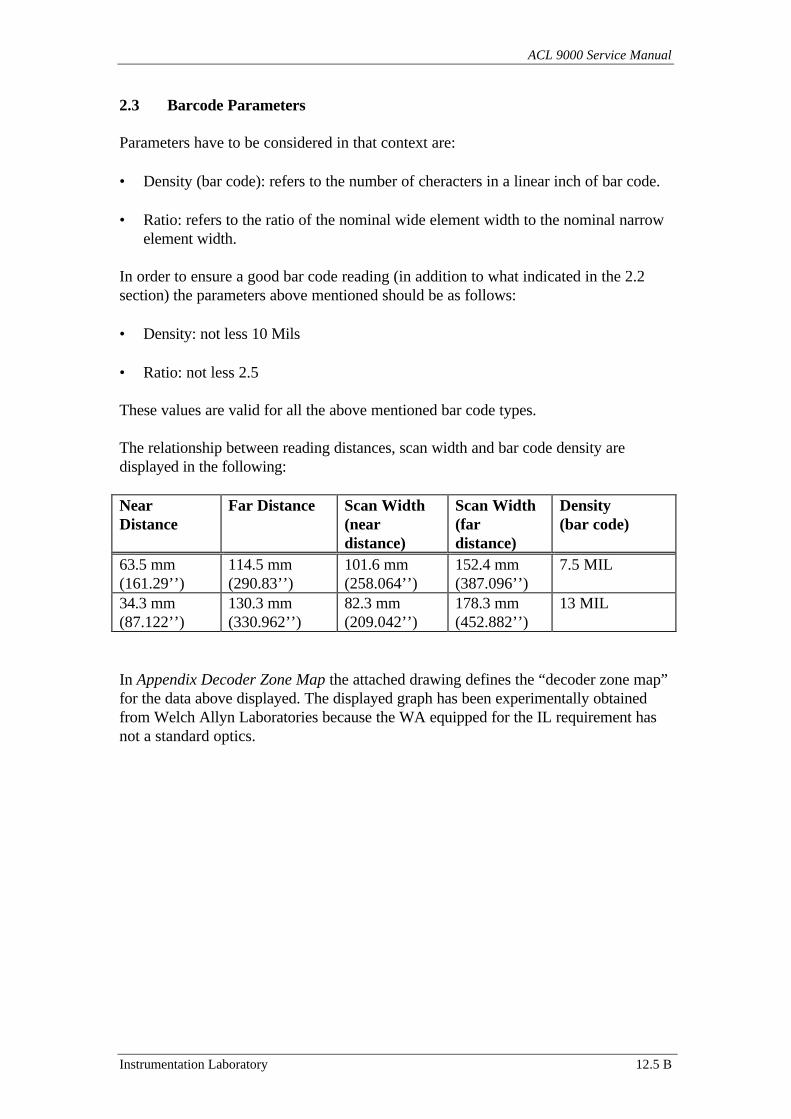
ACL 9000 Service Manual
Instrumentation Laboratory 12.5 B
2.3 Barcode Parameters
Parameters have to be considered in that context are:
• Density (bar code): refers to the number of cheracters in a linear inch of bar code.
• Ratio: refers to the ratio of the nominal wide element width to the nominal narrowelement width.
In order to ensure a good bar code reading (in addition to what indicated in the 2.2section) the parameters above mentioned should be as follows:
• Density: not less 10 Mils
• Ratio: not less 2.5
These values are valid for all the above mentioned bar code types.
The relationship between reading distances, scan width and bar code density aredisplayed in the following:
NearDistance
Far Distance Scan Width(neardistance)
Scan Width(fardistance)
Density(bar code)
63.5 mm(161.29’’)
114.5 mm(290.83’’)
101.6 mm(258.064’’)
152.4 mm(387.096’’)
7.5 MIL
34.3 mm(87.122’’)
130.3 mm(330.962’’)
82.3 mm(209.042’’)
178.3 mm(452.882’’)
13 MIL
In Appendix Decoder Zone Map the attached drawing defines the “decoder zone map”for the data above displayed. The displayed graph has been experimentally obtainedfrom Welch Allyn Laboratories because the WA equipped for the IL requirement hasnot a standard optics.
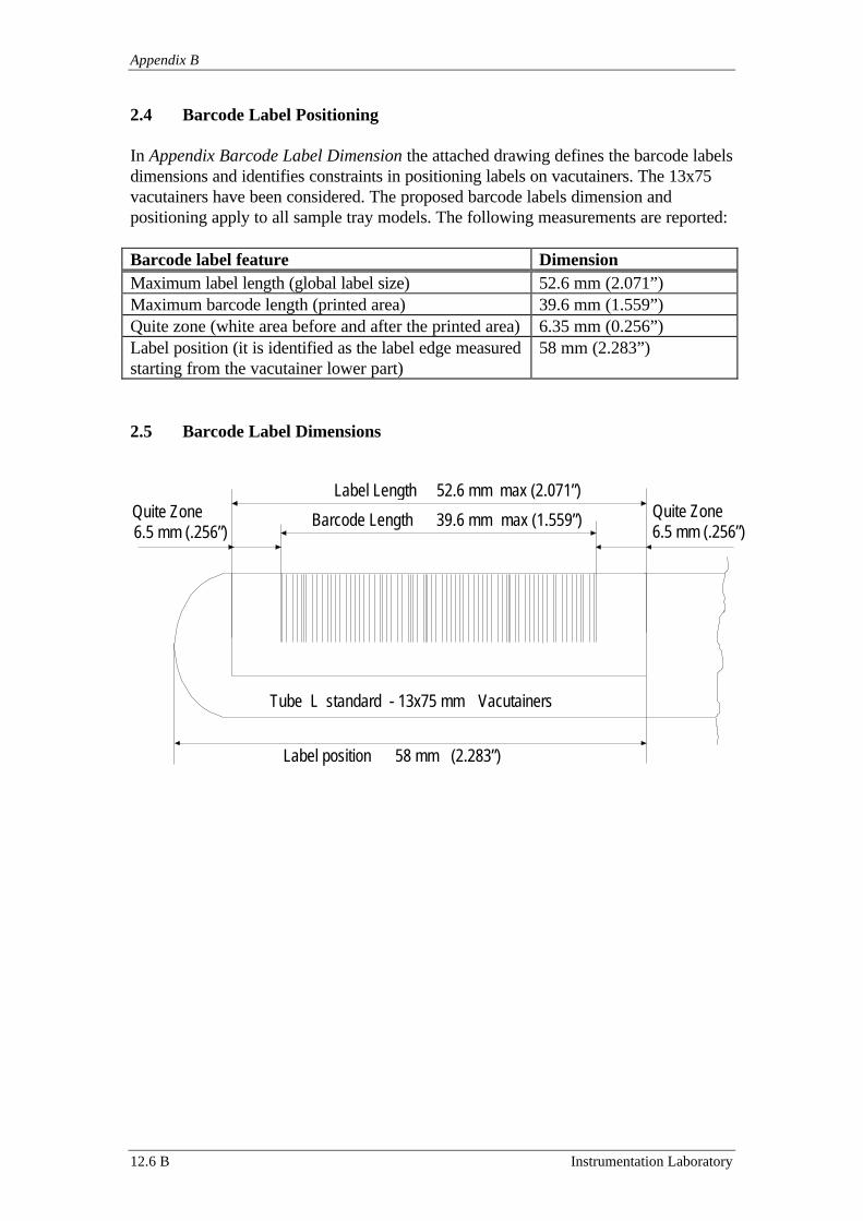
Appendix B
12.6 B Instrumentation Laboratory
2.4 Barcode Label Positioning
In Appendix Barcode Label Dimension the attached drawing defines the barcode labelsdimensions and identifies constraints in positioning labels on vacutainers. The 13x75vacutainers have been considered. The proposed barcode labels dimension andpositioning apply to all sample tray models. The following measurements are reported:
Barcode label feature DimensionMaximum label length (global label size) 52.6 mm (2.071”)Maximum barcode length (printed area) 39.6 mm (1.559”)Quite zone (white area before and after the printed area) 6.35 mm (0.256”)Label position (it is identified as the label edge measuredstarting from the vacutainer lower part)
58 mm (2.283”)
2.5 Barcode Label Dimensions
Quite Zone6.5 mm (.256”)
Tube L standard - 13x75 mm Vacutainers
Barcode Length 39.6 mm max (1.559”)
Label position 58 mm (2.283”)
Label Length 52.6 mm max (2.071”)Quite Zone6.5 mm (.256”)