ACIS Software Test Tools T 80230 36-55001 3.1
162
MASSACHUSETTS INSTITUTE OF TECHNOLOGY CENTER FOR SPACE RESEARCH NAME DATE Checked: Approved: Released: Scale: Sheet of Size Code Identification No. Drawing No. Rev. REVISIONS Rev ECO No. Description Checked Approved Date 1.0 N/A Initial Release PGF RFG 06/26/96 2.0 N/A Update for Flight S/W Beta release PGF RFG 01/07/97 3.0 N/A Update for Flight S/W Release 1.0 PGF RFG 02/07/97 3.1 N/A Update for Flight S/W Release 1.5 PGF RFG 06/20/97 01/13/97 ACIS Software Test Tools T 80230 36-55001 3.1 NONE i 147 Drawn: P. Ford
-
Upload
softwarecentral -
Category
Documents
-
view
766 -
download
2
Transcript of ACIS Software Test Tools T 80230 36-55001 3.1

M
ASSACHUSETTS
I
NSTITUTE
OF
T
ECHNOLOGY
C
ENTER
FOR
S
PACE
R
ESEARCH
N
AME
D
ATE
Checked:
Approved:
Released:
Scale: Sheet of
Size Code Identification No. Drawing No. Rev.
R
EVISIONS
Rev ECO No. Description Checked Approved Date
1.0 N/A Initial Release PGF RFG 06/26/96
2.0 N/A Update for Flight S/W Beta release PGF RFG 01/07/97
3.0 N/A Update for Flight S/W Release 1.0 PGF RFG 02/07/97
3.1 N/A Update for Flight S/W Release 1.5 PGF RFG 06/20/97
01/13/97
ACIS Software Test Tools
T 80230 36-55001 3.1
NONE i 147
Drawn:
P. Ford

t
M
ASSACHUSETTS
I
NSTITUTE
OF
T
ECHNOLOGY
C
ENTER
FOR
S
PACE
R
ESEARCH
C
AMBRIDGE
, M
ASSACHUSETTS
02139ACIS
MIT CSR
Dra
fACIS Test Tools
MIT 36-55001 Rev. 3.1
June 20, 1997

Revision Log
MASSACHUSETTS INSTITUTE OF TECHNOLOGYCENTER FOR SPACE RESEARCHCAMBRIDGE, MASSACHUSETTS 02139
REVISIONLOG
TITLE:ACIS Test Tools
DOC. NO.36-55001 Rev. 3.1
Revision Datemm/dd/yy
ECONo.
Section(s)Affected Reason Approval
pre-release0.6
03/13/96 — All Initial Release —
pre-release0.7
05/23/96 —
§2.2 Rename pseudo-packets
—
Tables3 & 4
Rename fields and add lengths and offsets
Table 5 Rename packet classes
§3.1Add description of processScience & Table 6
Table 7 Add dump, reset, and stop commands
§3.3Update buildCmds examples to reflect IP&CL changes
§4.3 Reword parts of genPixelImages description
§7.6 Update frame-buffer function description
1.0 06/26/96 — CoverUpdate cover sheet to show part number and revision level
RFG06/29/96
2.0 10/03/96 —
Cover Added revision log and TBD list
RFG
§2.1Added to the description of filterServer, fil-terClient, and shim
§2.6 Added description of hardware commands
§3.1Reorganized buildCmds description; reworded Tables 7 and 8. Added Table 9.
§3.2 Added lcmd description
§3.3 Moved ltlm description from §5.
§3.4Reworded processScience description and updated Table 10
§3.6 Added runacis description
§5 Removed ltlm and tlmsim descriptions
§6 Rewritten from ECO 567
§9 Rewritten from the contents of ~acis/tools
Appendix A Updated
ii of iii • ACIS Test Tools June 20, 1997 12:43 pm

3.0 11/22/96 —
Table 5 Changed engineering pseudopacket format
RFG
Table 6 Added to describe irig-b format
§3.4 Replaced processScience with psci
§5 New section describing psci
§10 Added numerous new manual entries.
3.1 06/20/97 — §5 Describe the -B, -T, and -s options.
Revision Datemm/dd/yy
ECONo.
Section(s)Affected Reason Approval

Items to be Determined
Definition of CTUE no-op channel values .............................................................5Location of next-in-line data within minor frames .................................................7IP&CL mnemonic for select eeprom command ...................................................11GUI for monitorEngineering .................................................................................17Format of processEngineeringData output ...........................................................17Location of next-in-line data within minor frames .............................................116Definition of CTUE no-op channel values .........................................................139
ACIS Test Tools Rev. 3.1 • viJune 20, 1997 12:43 pm

Items to be Determined
vii • ACIS Test Tools Rev. 3.1 June 20, 1997 12:43 pm

Table of Contents
Table of Contents
1.0 Introduction 1
2.0 GSE Transport Tools 32.1 sendCmds 32.2 cclient 32.3 cserver 32.4 shim 32.5 getPackets 42.6 filterServer 42.7 filterClient 52.8 Transport Tool Interfaces 5
2.8.1 Stdin to sendCmds 52.8.2 Stdout from filterClient 62.8.3 filterClient arguments 8
3.0 GSE Test Tools 93.1 buildCmds 9
3.1.1 buildCmds Examples 133.2 lcmd 153.3 ltlm 153.4 psci 163.5 analyzeData 173.6 runacis 173.7 monitorDeaHousekeeping 173.8 monitorEngineeringData 173.9 monitorScience 173.10 processEngineeringData 17
4.0 Image Tools 184.1 getImages 184.2 putImages 184.3 genPixelImages 184.4 loadFitsImage 184.5 genObjectImage 184.6 generateExpectedData 194.7 Image Tool Interfaces 19
4.7.1 stdin to putImages 194.7.2 Output from getImages 19
5.0 The psci Command 215.1 Packet Field Verification 21
ACIS Test Tools Rev. 3.1 • viiiJune 20, 1997 12:43 pm

Table of Contents
5.2 Packet Logging 235.3 Monitor Output 245.4 Science Event Modes 245.5 Event Frame Timestamp Files 275.6 Histogram Files 285.7 Raw Mode 285.8 Bias Files 295.9 Memory Readout 295.10 Huffman Tables 305.11 Pseudopackets 315.12 Architecture 315.13 Tests applied to packet fields 35
6.0 Simulated ACIS Telemetry 426.1 fepCtlTest—simulate the ACIS front-end processor 426.2 dumpring—display ring-buffer records 446.3 tlmsim—create simulated telemetry packets 46
6.3.1 Bias Map 466.3.2 Timing 466.3.3 Miscellaneous 47
6.4 Examples 48
7.0 ACIS Timing Algorithms 507.1 The Timeline of Single Exposure Time Modes 507.2 The Timeline of Alternating Exposure Time Modes 52
8.0 Frame Buffer Specification 538.1 Significant Changes in this Version 538.2 Terms 538.3 Initial Requirements/Specifications 538.4 Basic Design Concept 548.5 Operating Modes 54
8.5.1 Ramp Mode 548.5.2 Normal Mode 55
8.6 Directive Functions 558.6.1 “EXXX” Last Pixel Flag (LPF) 558.6.2 “Annn” Repeat Segment “nnn” times (RS)
“Xnnn” Segment Length argument (SL) 558.6.3 “7nnn” Repeat Frame “nnn” times (RF) 558.6.4 “6000” Go (TBR) 55
8.7 Current Status 568.8 Proposed Additional Features 56
8.8.1 Front Panel Status LEDs 568.8.2 Error LED(s) 56
9.0 ACIS Data Analysis and Database 57
ix • ACIS Test Tools Rev. 3.1 June 20, 1997 12:43 pm

Table of Contents
9.1 Data Format 579.2 Raw Image Format 57
9.2.1 FSF Format 619.2.2 ARV Format 629.2.3 IDL Format 62
9.3 Analysis Procedure 629.3.1 ACISANAL1 639.3.2 ACISANAL2 649.3.3 Data Products 65
9.4 Utility Software 689.5 Database 68
10.0 UNIX Commands 7010.1 ACISshell 7010.2 acisBepUnix 7110.3 acisFepUnix 7210.4 acispkts 7310.5 bcmd 7510.6 buildCmds 7910.7 cclient 9410.8 cserver 9510.9 diff6 9610.10 dumpring 9810.11 fepCtlTest 9910.12 fepImage2 10110.13 filterClient 10210.14 filterServer 10310.15 genObjectImage 10410.16 genPixelImages 11010.17 getPackets 11510.18 lcmd 11810.19 lerv 12010.20 lhuff 12110.21 loadFitsImage 12210.22 logGet 12410.23 ltlm 12510.24 monitorScience 12710.25 processDEAhkp 12910.26 psci 13010.27 runacis 13510.28 sciglue 13810.29 sendCmds 13910.30 shim 141
ACIS Test Tools Rev. 3.1 • xJune 20, 1997 12:43 pm

Table of Contents
10.31 tlmsim 14310.32 writeCCB 146
Appendix A Test Tool Status 148
xi • ACIS Test Tools Rev. 3.1 June 20, 1997 12:43 pm

List of Figures
June 20, 1997 12:43 pm ACIS Test Tools • xii
List of Figures
FIGURE 1. Test Tool Overview . . . . . . . . . . . . . . . . . . . . . . . . . . . . . . . . . . . . . . . . . . 1
FIGURE 2. ACIS Test Tools . . . . . . . . . . . . . . . . . . . . . . . . . . . . . . . . . . . . . . . . . . . . . 2
FIGURE 3.
psci
build architecture . . . . . . . . . . . . . . . . . . . . . . . . . . . . . . . . . . . . . . . . 31
FIGURE 4. Relative coordinate system of a subframe arraywith respect to the full frame array. . . . . . . . . . . . . . . . . . . . . . . . . . . . . . 58
FIGURE 5. Sequence of pixel values from 3x3 pixel islandstored in the event record of an FSF. . . . . . . . . . . . . . . . . . . . . . . . . . . . . 61
FIGURE 6. Sequence of pixel values from 3x3 pixel islandstored in ARV format.. . . . . . . . . . . . . . . . . . . . . . . . . . . . . . . . . . . . . . . . 62
FIGURE 7. A sample light curve . . . . . . . . . . . . . . . . . . . . . . . . . . . . . . . . . . . . . . . . . 66
FIGURE 8. A sample PH histogram/spectrum. . . . . . . . . . . . . . . . . . . . . . . . . . . . . . . 66
FIGURE 9. A sample primary calibration file . . . . . . . . . . . . . . . . . . . . . . . . . . . . . . . 67
FIGURE 10. A sample readout noise file. . . . . . . . . . . . . . . . . . . . . . . . . . . . . . . . . . . . 67

List of Tables
List of Tables
TABLE 1. Command Type and Channel Definition . . . . . . . . . . . . . . . . . . . . . . . . . 5
TABLE 2. sendCmds Command Formats . . . . . . . . . . . . . . . . . . . . . . . . . . . . . . . . . 5
TABLE 3. Header Format and Content . . . . . . . . . . . . . . . . . . . . . . . . . . . . . . . . . . . 6
TABLE 4. Science Frame Pseudo-Packet Format and Content . . . . . . . . . . . . . . . . 7
TABLE 5. Engineering Pseudo-Packet Format and Content. . . . . . . . . . . . . . . . . . . 7
TABLE 6. IRIG-B Field Format and Contents . . . . . . . . . . . . . . . . . . . . . . . . . . . . . 8
TABLE 7. filterClient packet classes. . . . . . . . . . . . . . . . . . . . . . . . . . . . . . . . . . . . . 8
TABLE 8. Serial Commands to BEP Software . . . . . . . . . . . . . . . . . . . . . . . . . . . . . 9
TABLE 9. Serial commands to BEP Hardware. . . . . . . . . . . . . . . . . . . . . . . . . . . . 11
TABLE 10. Pulse Commands to PSMC Hardware . . . . . . . . . . . . . . . . . . . . . . . . . . 11
TABLE 11. Output files and streams generated by psci . . . . . . . . . . . . . . . . . . . . . . 22
TABLE 12. Example of formatted packet logs . . . . . . . . . . . . . . . . . . . . . . . . . . . . . 23
TABLE 13. Packet monitor stream written to stdout . . . . . . . . . . . . . . . . . . . . . . . . 25
TABLE 14. Extended Vanderspek (ERV) record format. . . . . . . . . . . . . . . . . . . . . . 26
TABLE 15. A sample ERV event file in ASCII format . . . . . . . . . . . . . . . . . . . . . . . 26
TABLE 16. Contents of an event frame timestamp file. . . . . . . . . . . . . . . . . . . . . . . 27
TABLE 17. Contents of an ASCII histogram file . . . . . . . . . . . . . . . . . . . . . . . . . . . 28
TABLE 18. Examples of FITS file headers. . . . . . . . . . . . . . . . . . . . . . . . . . . . . . . . 29
TABLE 19. ASCII dump of a Huffman block containing multiple tables . . . . . . . . 30
TABLE 20. Sample enum.aux file . . . . . . . . . . . . . . . . . . . . . . . . . . . . . . . . . . . . . . . 32
TABLE 21. An example of tlm.aux. . . . . . . . . . . . . . . . . . . . . . . . . . . . . . . . . . . . . . 33
TABLE 22. An example of cmd.aux . . . . . . . . . . . . . . . . . . . . . . . . . . . . . . . . . . . . . 34
TABLE 23. Tests applied to individual ACIS packet fields. . . . . . . . . . . . . . . . . . . . 36
TABLE 24. fepCtlTest Command Syntax . . . . . . . . . . . . . . . . . . . . . . . . . . . . . . . . . 43
TABLE 25. Summary of products from ACISANAL2 . . . . . . . . . . . . . . . . . . . . . . . 65
TABLE 26. Header Format and Content . . . . . . . . . . . . . . . . . . . . . . . . . . . . . . . . . 115
TABLE 27. Science Frame Pseudo-Packet Format and Content . . . . . . . . . . . . . . 116
TABLE 28. Engineering Pseudo-Packet Format and Content. . . . . . . . . . . . . . . . . 116
TABLE 29. IRIG-B Field Format and Contents . . . . . . . . . . . . . . . . . . . . . . . . . . . 117
TABLE 30. Command Type and Channel Definition . . . . . . . . . . . . . . . . . . . . . . . 139
TABLE 31. sendCmds Command Formats . . . . . . . . . . . . . . . . . . . . . . . . . . . . . . . 139
xiii • ACIS Test Tools Rev. 3.1 June 20, 1997 12:43 pm
List of Tables
TABLE 32. CTUE command . . . . . . . . . . . . . . . . . . . . . . . . . . . . . . . . . . . . . . . . . 146
TABLE 33. CTUE command block . . . . . . . . . . . . . . . . . . . . . . . . . . . . . . . . . . . . 146
ACIS Test Tools Rev. 3.1 • xivJune 20, 1997 12:43 pm

List of Tables
xv • ACIS Test Tools Rev. 3.1 June 20, 1997 12:43 pm

Introduction
1.0 Introduction
This is a description of the software tools being developed to test ACIS flight software, to supportACIS EGSE, and to perform end-to-end tests of the instrument. It is a joint effort of the ACISflight software and GSE teams, and includes a detailed description of the command and imagedefinition languages and bit-level descriptions of the several interfaces between sub-components.
The tools are divided into three categories: “GSE Transport Tools” are responsible for sendingcommands to the instrument and receiving telemetry in reply; “GSE Test Tools” generate thecommands from human-readable scripts, interpret the telemetry packets, and analyze theircontents; and “Image Tools” are responsible both for reading images from the analog units(DEAs) and for creating and writing images to the digital units (FEPs). The general relationshipbetween these three tool groups is represented in Figure 1; the details are in Figure 2.
FIGURE 1. Test Tool Overview
The interface between the Image Tools and ACIS, the “Image Loader”, is described in Section 8.0on page 53, and science data formats of use in analyzing the “GSE Test Tools” output aredescribed in Section 9.0. Some alternative image tools are described in Section 10.0. The currentstatus of tool development is shown in Appendix A.
GSE Transport GSE Test Tools
Image Toolshigh speed tap
image loader pixels
commands
data
commands
packets
commands
data files
image generation commands
FITS files
ToolsAC
SI
ACIS Test Tools Rev. 3.1 • 1 of 148June 20, 1997 12:43 pm

June 20, 1997 12:43 pm2 of 148 • ACIS Test Tools Rev. 3.1
send
Cm
ds
RC
TU
CT
UE
S H I M
getP
acke
tsA
XA
F
bina
ry c
omm
and
stre
am
filte
rSer
ver
scie
nce
pack
ets
data request
packets
build
Cm
ds
mon
itor
-
Hou
seke
epin
gD
EA
-
mon
itor
-
Scie
nce
anal
yze-
Dat
a
mon
itor
-
Eng
inee
ring
-
Dat
a
data
file
ssc
ienc
e pa
cket
s
DE
A H
/K p
acke
ts
proc
ess-
Eng
inee
ring
-
Dat
a
filte
rClie
ntge
tIm
ages
putI
mag
es
genP
ixel
Imag
es
gene
rate
-
FEP
DEA pixel output
FIT
S16 b
itim
age
pixe
ls
TC
P ne
twor
k la
yer
data request
packets
tele
met
ry‘
fram
es
FIG
UR
E 2
.
AC
IS T
est T
ools
LR
CT
U
inpu
t
form
atim
age
files
imag
ede
finiti
ons
IRIG
-B
hous
ekee
ping
pac
kets
scie
nce
fram
eps
eudo
-pac
kets
hous
ekee
ping
pac
kets
scie
nce
fram
eps
eudo
-pac
kets
engi
neer
ing
pseu
do-p
acke
ts
engi
neer
ing
pseu
do-p
acke
ts
filte
rClie
nt
seri
alin
terf
ace
CT
UE
ethe
rnet
Exp
ecte
dDat
a
Tra
nspo
rt T
ools
Tes
t Too
lsIm
age
Too
ls
Leg
end
psci
cser
ver
cclie
nt
com
man
dsc
ript
s
time
ofda
y
com
man
dsne
twor
kla
yer
A C SI

GSE Transport Tools
2.0 GSE Transport Tools
These components occupy the top third of Figure 2, except that
buildCmds
is a “GSE Test Tool”.The ACIS instrument is represented by the box at the top left. It may communicate through asmany as 3 simultaneous interfaces, the
RCTU/CTUE
, representing the interface that will be usedat XRCF and closely parallels the AXAF spacecraft interface itself; the
LRCTU
which is asimplified replacement for the
RCTU/CTUE
developed at MIT; the “High Speed Tap” whichsamples the digital image pixels being output from one of the ACIS analog boards; and the“Image Loader”, an MIT-developed hardware interface that mimics the analog boards and permitstest images to be sent directly to one or more FEP boards.
The software consists of the server-client pairs, their input and output interface, and theirprotocols. There are five GSE Transport programs:
shim
,
sendCmds
,
getPackets
,
filterServer
and
filterClient
. All are being developed by ACIS EGSE personnel, with assistance from the ACISFlight Software Team. The major external interfaces are between
buildCmds
and
sendCmds
, andbetween
getPackets
and its various clients (via the
filterServer
/
filterClient
combination). Bothinterfaces may be described as a single stream of binary bytes, with no timing constraints.
2.1 sendCmds
sendCmds
receives a binary command stream from
buildCmds
, containing
type
,
channel, datatriplets. It constructs 23-bit, formatted command strings, packages them into 24-bit strings tosimplify the output interface, and sends them to shim. This command is described in detail inSection 10.29.
2.2 cclient
cclient makes a TCP connection to a socket previously created by the cserver program. Once theconnection has been established, cclient copies its standard input to the socket. When itencounters an end-of-file condition on stdin, it closes the socket and exits. Its function is thereforeto isolate the commands generated by sendCmds and buildCmds from shim and ACIS itself—aseries of commands can be issued from separate UNIX processes, even from different hostcomputers, and cserver will merge them into a single unbroken command stream. This commandis described in detail in Section 10.7.
2.3 cserver
cserver creates a socket and listens for connections from cclient processes. When one is made, itcopies the contents of the socket to its standard output, stdout. On an end-of-socket or errorcondition, cserver closes the connection and waits for another one. This command is described indetail in Section 10.8.
2.4 shim
shim provides a consistent interface between ACIS and all user applications that generatecommands or receive telemetry. It can communicate with ACIS either through the LRCTU
ACIS Test Tools Rev. 3.1 • 3 of 148June 20, 1997 12:43 pm

GSE Transport Tools
(RCTU/CTUE emulator) or through the RCTU/CTUE itself. This command is described in detailin Section 10.30
When sending commands to an LRCTU, shim drops all High Level Pulse commands because theLRCTU does not support them. It passes all other Serial Digital Hardware and Softwarecommands to the LRCTU via a serial interface in the 24 bit format generated by sendCmds. Whenreceiving telemetry from an LRCTU via the same serial interface, shim formats the packets intoAXAF-I telemetry major frames, adding science frame headers and ACIS and IRIG-B timestampsas appropriate.
When shim sends commands to an RCTU/CTUE, it includes High Level Pulse commands as wellas Serial Digital Hardware and Software commands. It extracts the 23-bit input command wordsfrom the 24 bit sendCmds format and packs them into 48-bit Ground Command Format strings. Itthen assembles these strings into command blocks, which it sends to the RCTU/CTUE via a TCP/IP interface. It receives telemetry via the same interface and passes them to its client (getPackets)unmodified.
2.5 getPackets
getPackets receives AXAF-I telemetry frames from shim. It extracts ACIS-related informationand passes it to its filterServer client. It must first identify the current telemetry format—either 1or 2. In the former, ACIS science data is being generated at 512 bits/sec; in the latter at 24 Kbits/sec. In both cases, getPackets assembles the serial telemetry from ACIS, locates the individualpackets by their synch words and lengths, and writes them to filterServer as separate logicalrecords.
getPackets also sends filterServer two types of “pseudo-packet”, i.e. records whose formatmimics genuine ACIS telemetry packets but whose “type” codes are distinguished from thoseused by the instrument itself. One type of pseudo-packet contains data from science frame headersand from ACIS timestamps. The other contains ACIS and other AXAF engineering data that wasfound in the non-science areas of the telemetry frames. This command is described in detail inSection 10.17.
2.6 filterServer
filterServer receives the stream of telemetry packets from stdin and listens on an INET socket fornetwork clients to request TCP connections. When this occurs, filterServer determines the datatypes requested by the client, and then forks a copy of itself to write those packets to the client.Clients connecting to filterServer send it a short message that indicates which of the 4 types oftelemetry they wish to receive. filterServer writes all telemetry packets of the requested types tothe output socket.
If filterServer doesn’t understand the data request, it closes the INET socket and writes an error message to stderr. Once a connection is made, the packet type cannot be changed. When a client no longer wants packets, it closes the socket—the spawned server process should exit after log-ging the event to stderr. This command is described in detail in Section 10.14.
4 of 148 • ACIS Test Tools Rev. 3.1 June 20, 1997 12:43 pm
GSE Transport Tools
2.7 filterClientfilterClient inspects its argument list to determine the location (host and port number) of a fil-terServer process, and which types of packet it is to request. It establishes a TCP connection to the server, sends a request for data, and copies the resulting stream to stdout. This command is described in detail in Section 10.13.
2.8 Transport Tool Interfaces
2.8.1 Stdin to sendCmds
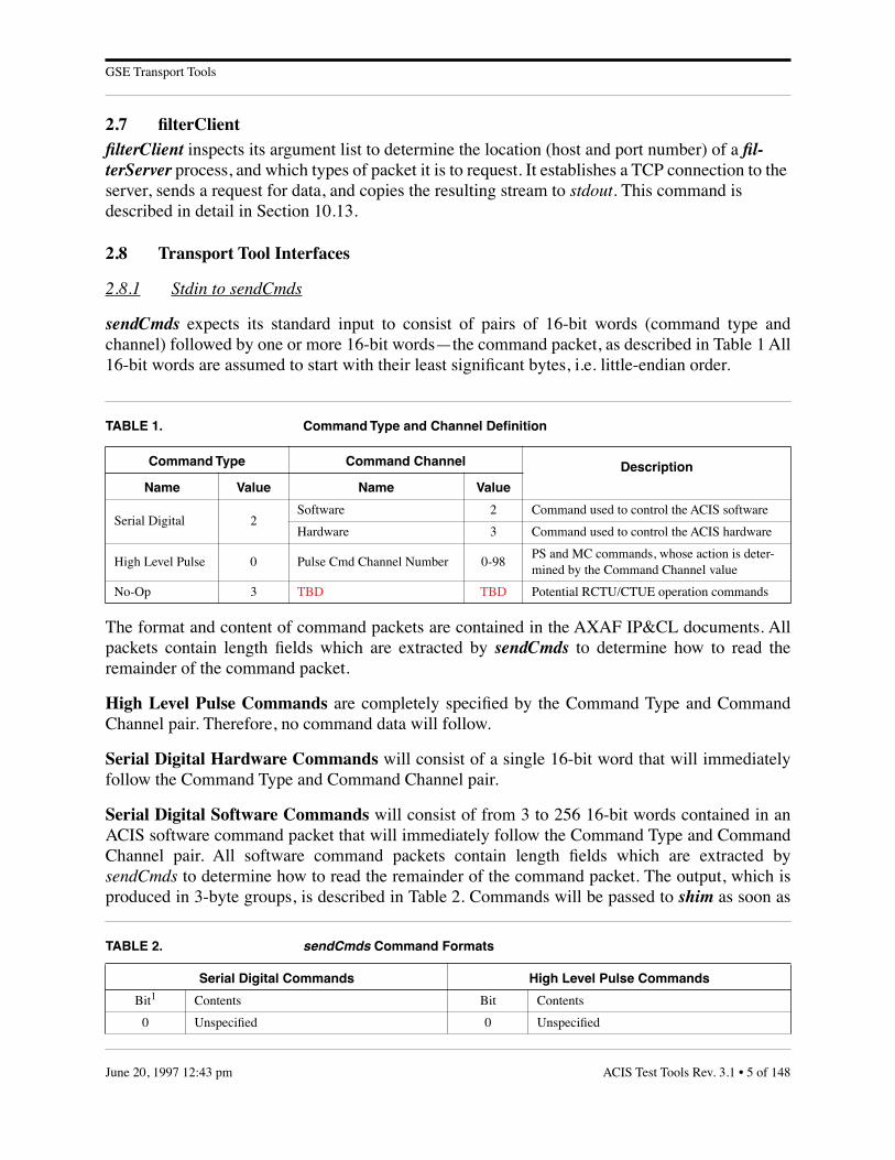
sendCmds expects its standard input to consist of pairs of 16-bit words (command type andchannel) followed by one or more 16-bit words—the command packet, as described in Table 1 All16-bit words are assumed to start with their least significant bytes, i.e. little-endian order.
The format and content of command packets are contained in the AXAF IP&CL documents. Allpackets contain length fields which are extracted by sendCmds to determine how to read theremainder of the command packet.
High Level Pulse Commands are completely specified by the Command Type and CommandChannel pair. Therefore, no command data will follow.
Serial Digital Hardware Commands will consist of a single 16-bit word that will immediatelyfollow the Command Type and Command Channel pair.
Serial Digital Software Commands will consist of from 3 to 256 16-bit words contained in anACIS software command packet that will immediately follow the Command Type and CommandChannel pair. All software command packets contain length fields which are extracted bysendCmds to determine how to read the remainder of the command packet. The output, which isproduced in 3-byte groups, is described in Table 2. Commands will be passed to shim as soon as
TABLE 1. Command Type and Channel Definition
Command Type Command Channel Description
Name Value Name Value
Serial Digital 2Software 2 Command used to control the ACIS software
Hardware 3 Command used to control the ACIS hardware
High Level Pulse 0 Pulse Cmd Channel Number 0-98PS and MC commands, whose action is deter-mined by the Command Channel value
No-Op 3 TBD TBD Potential RCTU/CTUE operation commands
TABLE 2. sendCmds Command Formats
Serial Digital Commands High Level Pulse Commands
Bit1 Contents Bit Contents
0 Unspecified 0 Unspecified
ACIS Test Tools Rev. 3.1 • 5 of 148June 20, 1997 12:43 pm

GSE Transport Tools
each 16-bit Command Data word is read from stdin. Since this is buffered via the stdio.h library, itis the responsibility of a program piping commands to sendCmds to flush the pipe, e.g. with a callto fflush(), before any planned inter-command delay. Otherwise, the time delay will beunpredictable.
When sendCmds reads an illegal packet from stdin, it writes an error message to stderr.Depending on arguments supplied on its command line, sendCmds may then decide to continueprocessing the next command from stdin, or abort the run entirely.
2.8.2 Stdout from filterClient
getPackets writes a stream of telemetry packets and pseudo-packets to stdout, These are passedthrough filterServer to each filterClient, which writes a user-selected sub-set to its stdout. Thefour packet types that may be selected are: “ACIS Science Packets”, “ACIS DEA and SoftwareHousekeeping Packets”, “Science-Frame Pseudo-Packets”, and “Engineering Pseudo-Packets”.Each packet consists of a telemetry header followed by application data, as defined in IP&CL.The header formats and contents are defined in Table 3.
All fields are written in “little-endian” format, e.g. the packet synch word, 0x736f4166, iswritten as 4 bytes, 0x66, 0x41, 0x6f, and finally 0x73. The contents of all packets originatingwithin ACIS are defined in IP&CL. The data portion of the Science Frame pseudo-packet isdescribed in Table 4 and that of the Engineering pseudo-packet in Table 5.
Each packet will be written to the getPackets standard output stream as soon as the last data bytethat contributes to it is read from shim. A Science Frame Pseudo-Packet will be written after
1-2 Command Type 1-2 Command Type
3-18 Command Data 3-14 Unspecified
19-23 Command Channel 15-23 Command Channel
1. bit 0 is the most significant bit and is transmitted/received first
TABLE 3. Header Format and Content
Packet HeaderFields
Field Length(bits)
Science or Housekeeping Packet
Science FramePseudo-Packet
EngineeringPseudo-Packet
Synch 32 0x736f4166 0x736f4166 0x736f4166
Length 10 Varying1
1. The packet length (number of 32 bit words) varies with the contents.
7 Varying1
Format Tag 6 Varying 62 61
Sequence Number 16incremented by 1 for each packet in the telemetry stream
02
2. The sequence number of a pseudo-packet is always zero.
02
TABLE 2. sendCmds Command Formats
Serial Digital Commands High Level Pulse Commands
6 of 148 • ACIS Test Tools Rev. 3.1 June 20, 1997 12:43 pm

GSE Transport Tools
reading the last byte of each complete minor frame containing a science frame header. AnEngineering Pseudo-Packet will be written after the last byte of each complete major frame isread.
The 6-byte IRIG-B timestamp in the AXAF-I minor frame is the result of packing 4 separate bitfields into a 48-bit string. However, getPackets treats the 6 bytes of the IRIG-B timestamp as 3unsigned 16-bit integers. It copies them into the Engineering Pseudo-Packet and converts them tolittle-endian format, which is the ACIS standard. Table 4 describes how to decipher theEngineering Pseudo-Packet’s irigb field.
TABLE 4. Science Frame Pseudo-Packet Format and Content
FieldName
Source filterClientOutput Format
DescriptionLocation Start Length
format Virtual Channel ID bit 10 3 bits unsigned intFrame format identifier, either 1 (signifying 512 bps) or 2 (24 kbps), i.e. the AXAF tlm code + 1.
majorFrameId CCSDS Header bit 16 17 bits unsigned int Virtual Channel Data Unit Major Frame Count (0 to 131071)
minorFrameId CCSDS Header bit 33 7 bits unsigned shortVirtual Channel Data Unit Major Frame Count (0 to 127)
irigb Science Header byte 32 6 bytes unsigned short [3]Time (msec) from the IRIG-B inter-face
bepSciTimeScience Data byte 56
4 bytes unsigned intLatched version of the BEP science pulse 1 MHz timestampNext-in-line Data TBD
TABLE 5. Engineering Pseudo-Packet Format and Content
FieldName
Source filterClientOutputFormat
DescriptionLocation Start Length
format Virtual Channel ID bit 10 3 bits unsigned intFrame format identifier, either 1 (sig-nifying 512 bps) or 2 (24 kbps), i.e. the AXAF tlm code + 1.
majorFrameId CCSDS Header bit 16 17 bits unsigned int Major Frame Counter (0 to 131071)
followed by an array of one or more elements, each consisting of the following fields
dataVariable location within major frame
var 8 bits unsigned char Engineering data
minorFrameId CCSDS Header bit 33 7 bits unsigned charVirtual Channel Data Unit Frame Counter (0 to 127)
minorFrameByte unsigned shortByte number in the minor frame (0 to 1024)
ACIS Test Tools Rev. 3.1 • 7 of 148June 20, 1997 12:43 pm
GSE Transport Tools
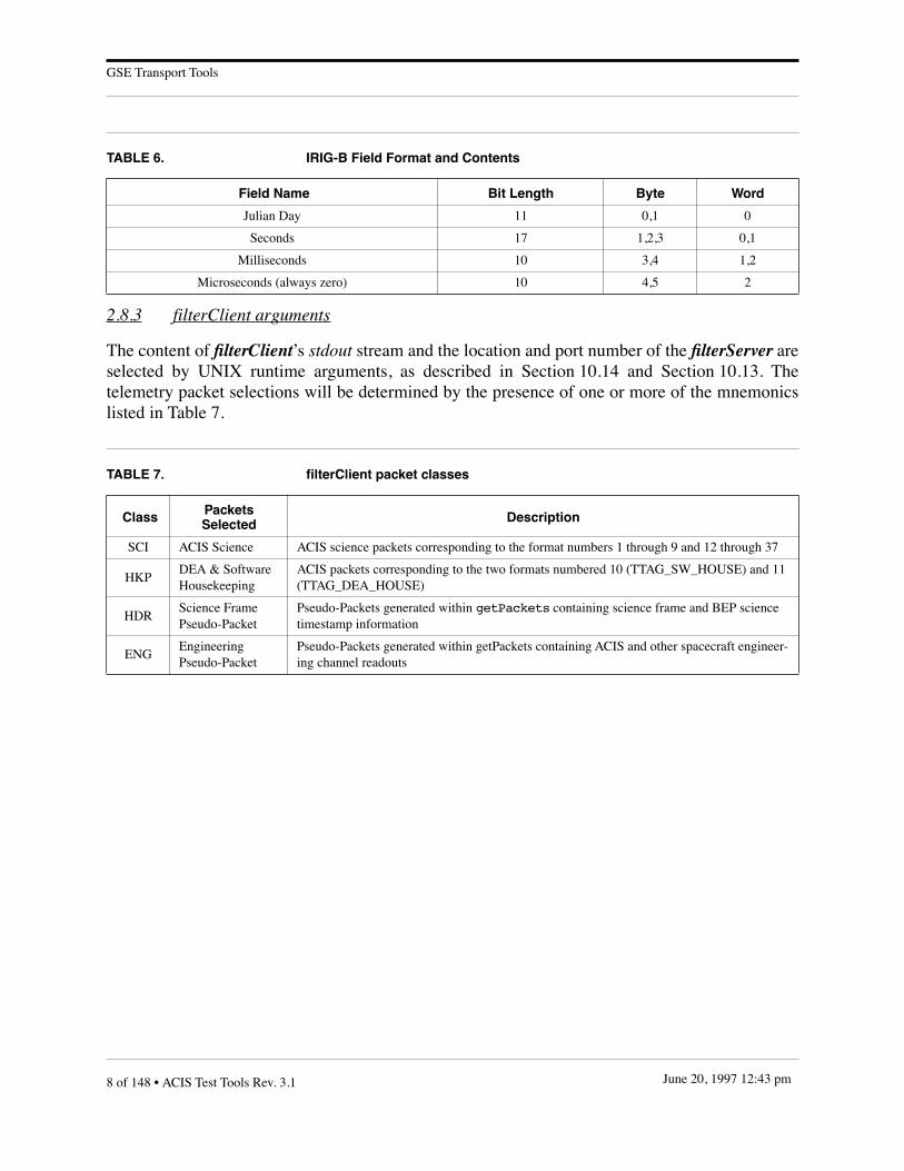
2.8.3 filterClient arguments
The content of filterClient’s stdout stream and the location and port number of the filterServer areselected by UNIX runtime arguments, as described in Section 10.14 and Section 10.13. Thetelemetry packet selections will be determined by the presence of one or more of the mnemonicslisted in Table 7.
TABLE 6. IRIG-B Field Format and Contents
Field Name Bit Length Byte Word
Julian Day 11 0,1 0
Seconds 17 1,2,3 0,1
Milliseconds 10 3,4 1,2
Microseconds (always zero) 10 4,5 2
TABLE 7. filterClient packet classes
Class Packets Selected Description
SCI ACIS Science ACIS science packets corresponding to the format numbers 1 through 9 and 12 through 37
HKPDEA & SoftwareHousekeeping
ACIS packets corresponding to the two formats numbered 10 (TTAG_SW_HOUSE) and 11 (TTAG_DEA_HOUSE)
HDRScience FramePseudo-Packet
Pseudo-Packets generated within getPackets containing science frame and BEP science timestamp information
ENGEngineering Pseudo-Packet
Pseudo-Packets generated within getPackets containing ACIS and other spacecraft engineer-ing channel readouts
8 of 148 • ACIS Test Tools Rev. 3.1 June 20, 1997 12:43 pm
GSE Test Tools
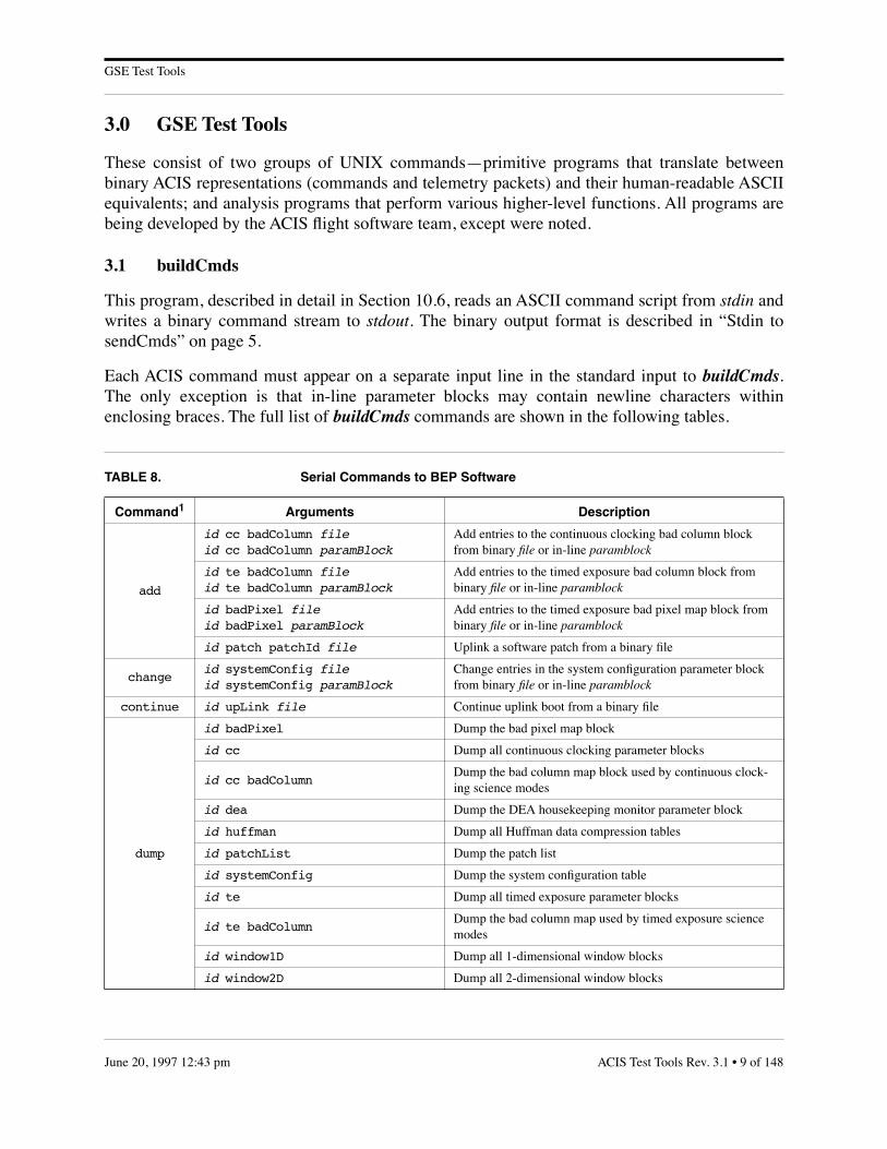
3.0 GSE Test Tools
These consist of two groups of UNIX commands—primitive programs that translate betweenbinary ACIS representations (commands and telemetry packets) and their human-readable ASCIIequivalents; and analysis programs that perform various higher-level functions. All programs arebeing developed by the ACIS flight software team, except were noted.
3.1 buildCmds
This program, described in detail in Section 10.6, reads an ASCII command script from stdin andwrites a binary command stream to stdout. The binary output format is described in “Stdin tosendCmds” on page 5.
Each ACIS command must appear on a separate input line in the standard input to buildCmds.The only exception is that in-line parameter blocks may contain newline characters withinenclosing braces. The full list of buildCmds commands are shown in the following tables.
TABLE 8. Serial Commands to BEP Software
Command1 Arguments Description
add
id cc badColumn fileid cc badColumn paramBlock
Add entries to the continuous clocking bad column block from binary file or in-line paramblock
id te badColumn fileid te badColumn paramBlock
Add entries to the timed exposure bad column block from binary file or in-line paramblock
id badPixel fileid badPixel paramBlock
Add entries to the timed exposure bad pixel map block from binary file or in-line paramblock
id patch patchId file Uplink a software patch from a binary file
changeid systemConfig fileid systemConfig paramBlock
Change entries in the system configuration parameter block from binary file or in-line paramblock
continue id upLink file Continue uplink boot from a binary file
dump
id badPixel Dump the bad pixel map block
id cc Dump all continuous clocking parameter blocks
id cc badColumnDump the bad column map block used by continuous clock-ing science modes
id dea Dump the DEA housekeeping monitor parameter block
id huffman Dump all Huffman data compression tables
id patchList Dump the patch list
id systemConfig Dump the system configuration table
id te Dump all timed exposure parameter blocks
id te badColumnDump the bad column map used by timed exposure science modes
id window1D Dump all 1-dimensional window blocks
id window2D Dump all 2-dimensional window blocks
ACIS Test Tools Rev. 3.1 • 9 of 148June 20, 1997 12:43 pm

GSE Test Tools
exec
id address [args]Execute the function located in the BEP memory at the speci-fied address (a multiple of 4), with optional 32-bit arguments
id fep fepId address [args]Execute the function located at the specified address (a multi-ple of 4) of FEP number fepId, with optional 32-bit argu-ments
load
id cc slotId fileid cc slotId paramBlock
Load a continuous clocking parameter block at the specified slotId from binary file or in-line paramblock
id dea slotId file id dea slotId paramBlock
Load a DEA housekeeping parameter block at the specified slotId from binary file or in-line paramblock
id te slotId fileid te slotId paramBlock
Load a timed exposure parameter block at the specified slotId from binary file or in-line paramblock
id window1D slotId fileid window1D slotId paramBlock
Load a one-dimensional window parameter block at the spec-ified slotId from binary file or in-line paramblock
id window2D slotId file id window2D slotId paramBlock
Load a two-dimensional window parameter block at the spec-ified slotId from binary file or in-line paramblock
read
id address lengthRead length 32–bit words of BEP memory starting at the specified address
id fep fepId address lengthRead length 32–bit words of memory from FEP number fepId, starting at the specified address
id pram ccdId address lengthRead length 16–bit words of PRAM memory from DEA number ccdId, starting at the specified 16-bit word address
id sram ccdId address lengthRead length 16–bit words of SRAM memory from DEA number ccdId, starting at the specified 16-bit word address
remove id patch patchId Remove patchId from the software patch list
reset
id badPixel Remove all entries from the bad pixel map
id cc badColumnRemove all entries from the continuous clocking bad column map
id te badColumn Remove all entries from the timed exposure bad column map
start
id cc slotIdStart a continuous clocking science run with parameters from slotId
id cc bias slotIdStart a continuous clocking bias calculation with parameters from slotId
id dea slotIdStart the DEA housekeeping monitor with parameters from slotId
id te slotIdStart a timed exposure science run with parameters from slotId
id te bias slotIdStart a timed exposure bias calculation with parameters from slotId
id upLink file Start an uplink boot from binary data in file
stopid dea Stop the currently executing DEA housekeeping monitor
id science Stop the currently executing science run
wait id seconds Suspend command output an integral number of seconds
TABLE 8. Serial Commands to BEP Software (Continued)
Command1 Arguments Description
10 of 148 • ACIS Test Tools Rev. 3.1 June 20, 1997 12:43 pm
GSE Test Tools
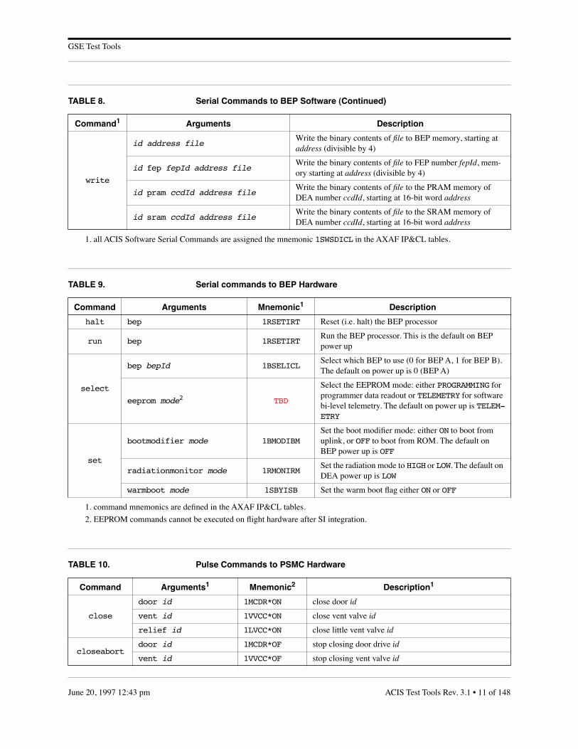
write
id address fileWrite the binary contents of file to BEP memory, starting at address (divisible by 4)
id fep fepId address fileWrite the binary contents of file to FEP number fepId, mem-ory starting at address (divisible by 4)
id pram ccdId address fileWrite the binary contents of file to the PRAM memory of DEA number ccdId, starting at 16-bit word address
id sram ccdId address fileWrite the binary contents of file to the SRAM memory of DEA number ccdId, starting at 16-bit word address
1. all ACIS Software Serial Commands are assigned the mnemonic 1SWSDICL in the AXAF IP&CL tables.
TABLE 9. Serial commands to BEP Hardware
Command Arguments Mnemonic1 Description
halt bep 1RSETIRT Reset (i.e. halt) the BEP processor
run bep 1RSETIRTRun the BEP processor. This is the default on BEP power up
select
bep bepId 1BSELICLSelect which BEP to use (0 for BEP A, 1 for BEP B). The default on power up is 0 (BEP A)
eeprom mode2 TBD
Select the EEPROM mode: either PROGRAMMING for programmer data readout or TELEMETRY for software bi-level telemetry. The default on power up is TELEM-ETRY
set
bootmodifier mode 1BMODIBMSet the boot modifier mode: either ON to boot from uplink, or OFF to boot from ROM. The default on BEP power up is OFF
radiationmonitor mode 1RMONIRMSet the radiation mode to HIGH or LOW. The default on DEA power up is LOW
warmboot mode 1SBYISB Set the warm boot flag either ON or OFF
1. command mnemonics are defined in the AXAF IP&CL tables.
2. EEPROM commands cannot be executed on flight hardware after SI integration.
TABLE 10. Pulse Commands to PSMC Hardware
Command Arguments1 Mnemonic2 Description1
close
door id 1MCDR*ON close door id
vent id 1VVCC*ON close vent valve id
relief id 1LVCC*ON close little vent valve id
closeabortdoor id 1MCDR*OF stop closing door drive id
vent id 1VVCC*OF stop closing vent valve id
TABLE 8. Serial Commands to BEP Software (Continued)
Command1 Arguments Description
ACIS Test Tools Rev. 3.1 • 11 of 148June 20, 1997 12:43 pm

GSE Test Tools
disable
daBake id 1HBO*DS disable commands to bakeout heater id
daHeater id 1HHTR*DS disable commands to housing heater id
dea id 1DEPS*DS disable commands to DEA power supply id
door id 1MCMD*DS disable commands to door mechanism drive id
dpa id 1DPPS*DS disable commands to DPA power supply id
pressure id 1PRES*DS disable pressure sensor id
relief id 1LVC*DS disable commands to little vent valve id
vent id 1VVC*DS disable commands to side vent valve id
enable
daBake id 1HBO*EN enable commands to bakeout heater id
daHeater id 1HHTR*EN enable commands to housing heater id
dea id 1DEPS*EN enable commands to DEA power supply id
door id 1MCMD*EN enable commands to door mechanism drive id
dpa id 1DPPS*EN enable commands to DPA power supply id
pressure id 1PRES*EN enable pressure sensor id
relief id 1LVC*EN enable commands to little vent valve id
vent id 1VVC*EN enable commands to side vent valve id
open
door id 1MODR*ON open door id
vent id 1VVCO*ON open vent valve id
relief id 1LVCO*ON open little vent valve id
openabortdoor id 1MODR*OF stop opening door drive id
vent id 1VVCO*OF stop opening vent valve id
poweroff
daBake id 1HBO*OF power off bakeout heater id
daHeater id 1HHTR*OF power off housing heater id
dea id 1DEPS*OF power off DEA power supply id
dpa id 1DPPS*OF power off DPA power supply id
poweron
daBake id 1HBO*ON power on bakeout heater id
daHeater id 1HHTR*ON power on housing heater id
dea id 1DEPS*ON power on DEA power supply id
dpa id 1DPPS*ON power on DPA power supply id
TABLE 10. Pulse Commands to PSMC Hardware (Continued)
Command Arguments1 Mnemonic2 Description1
12 of 148 • ACIS Test Tools Rev. 3.1 June 20, 1997 12:43 pm

GSE Test Tools
3.1.1 buildCmds Examples
• The following UNIX pipe commands the ACIS instrument to start executing storedtimed exposure parameter block 1:
echo ‘start 22 te 1’ | buildCmds | sendCmds
• Dump 600 words from FEP number 2, starting at word offset 45678:
echo ‘read 4 fep 2 45678 600’ | buildCmds | sendCmds
turnoff
daBake
1HBOAOF1HBOBOF1HBOADS1HBOBDS
power off and disable both bakeout heaters
daBake id1HBO*OF1HBO*DS
power off and disable bakeout heater id
daHeater
1HHTRAOF1HHTRBOF1HHTRADS1HHTRBDS
power off and disable both housing heaters
daHeater id1HHTR*OF1HHTR*DS
power off and disable housing heater id
dea
1DEPSAOF1DEPSBOF1DEPSADS1DEPSBDS
power off and disable both DEAs
dea id1DEPS*OF1DEPS*DS
power off and disable DEA id
dpa
1DPPSAOF1DPPSBOF1DPPSADS1DPPSBDS
power off and disable both DPAs
dpa id1DPPS*OF1DPPS*DS
power off and disable DPA id
turnon
daBake id1HBO*EN1HBO*ON
enable and power on bakeout header id
daHeater id1HHTR*EN1HHTR*ON
enable and power on housing heater id
dea id1DEPS*EN1DEPS*ON
enable and power on DEA id
dpa id1DPPS*EN1DPPS*ON
enable and power on DPA id
1. the id field represents the hardware redundancy, either 0 for the A-side or 1 for the B-side.
2. command mnemonics are defined by AXAF IP&CL tables. ‘*’ represents the hardware redundancy, either ‘A’ or ‘B’.
TABLE 10. Pulse Commands to PSMC Hardware (Continued)
Command Arguments1 Mnemonic2 Description1
ACIS Test Tools Rev. 3.1 • 13 of 148June 20, 1997 12:43 pm

GSE Test Tools
• Start a timed exposure using the parameter block in slot #2. Give this command theidentifier ‘11’.
echo start 11 te 2 | buildCmds | sendCmds
• Stop a science run—give this command the identifier ‘5’.
stop 5 science | buildCmds | sendCmds
• Load a 1-dimensional window block. The order of keywords within each windowstructure is significant—if a keyword is omitted, the most recent value will be used(zero if it has not yet been used within the block).
load 33 window1D 4 { parameterBlockName = window1D windowBlockId = 45 arrayDim = 3 ⇐ number of structures to follow ccdId = 1 ⇐ first window structure ccdColumn = 2 width = 4 sampleCycle = 6 lowerEventAmplitude = 7 eventAmplitudeRange = 8 ccdId = 2 ⇐ second window structure ccdColumn = 3 width = 6 sampleCycle = 8 lowerEventAmplitude = 10 eventAmplitudeRange = 20 ccdId = 3 ⇐ third window structure ccdColumn = 20 width = 40 sampleCycle = 2 lowerEventAmplitude = 70 eventAmplitudeRange = 80}
• Load a Continuous Clocking parameter block. The parameter block is to be storedin slot #3 and the command is given the identifier ‘22’. The keywords must appearin the order shown. If omitted, a zero value will be assumed.
load 22 cc 3 { paramBlockName = ccBlock parameterBlockId = 2030 fepCcdSelect = 0 1 2 3 4 5 fepMode = 1 bepPackingMode = 1 ignoreBadColumnMap = 0 recomputeBias = 1 trickleBias = 1 rowSum = 4 columnSum = 5 overclockPairsPerNode = 8 outputRegisterMode = 2 CcdVideoResponse = 1 1 1 1 1 1 fep0EventThreshold = 100 100 100 100 fep1EventThreshold = 100 100 100 100 fep2EventThreshold = 100 100 100 100 fep3EventThreshold = 100 100 100 100 fep4EventThreshold = 100 100 100 100
14 of 148 • ACIS Test Tools Rev. 3.1 June 20, 1997 12:43 pm
GSE Test Tools
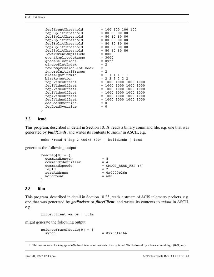
fep5EventThreshold = 100 100 100 100 fep0SplitThreshold = 80 80 80 80 fep1SplitThreshold = 80 80 80 80 fep2SplitThreshold = 80 80 80 80 fep3SplitThreshold = 80 80 80 80 fep4SplitThreshold = 80 80 80 80 fep5SplitThreshold = 80 80 80 80 lowerEventAmplitude = 800 eventAmplitudeRange = 3000 gradeSelections = 0xf1
windowSlotIndex = 2 rawCompressionSlotIndex = 1 ignoreInitialFrames = 2 biasAlgorithmId = 1 1 1 1 1 1 biasRejection = 2 2 2 2 2 2 fep0VideoOffset = 1000 1000 1000 1000 fep1VideoOffset = 1000 1000 1000 1000 fep2VideoOffset = 1000 1000 1000 1000 fep3VideoOffset = 1000 1000 1000 1000 fep4VideoOffset = 1000 1000 1000 1000 fep5VideoOffset = 1000 1000 1000 1000 deaLoadOverride = 0 fepLoadOverride = 0}
3.2 lcmd
This program, described in detail in Section 10.18, reads a binary command file, e.g. one that wasgenerated by buildCmds, and writes its contents to stdout in ASCII, e.g.
echo ‘read 4 fep 2 45678 600’ | buildCmds | lcmd
generates the following output:
readFep[0] = { commandLength = 8 commandIdentifier = 4 commandOpcode = CMDOP_READ_FEP (4) fepId = 2 readAddress = 0x0000b26e wordCount = 600}
3.3 ltlm
This program, described in detail in Section 10.23, reads a stream of ACIS telemetry packets, e.g.one that was generated by getPackets or filterClient, and writes its contents to stdout in ASCII,e.g.
filterclient -m ps | ltlm
might generate the following output:
scienceFramePseudo[0] = { synch = 0x736f4166
1. The continuous clocking gradeSelection value consists of an optional ‘0x’ followed by a hexadecimal digit (0–9, a–f).
ACIS Test Tools Rev. 3.1 • 15 of 148June 20, 1997 12:43 pm

GSE Test Tools
telemetryLength = 7 formatTag = TTAG_PSEUDO_SCIENCE (62) sequenceNumber = 0 format = 2 majorFrameId = 0 minorFrameId = 0 irigBdays = 935 irigBsecs = 72260 irigBmsecs = 0 irigBusecs = 0 bepSciTime = 0xa5997aff}bepStartupMessage[0] = { synch = 0x736f4166 telemetryLength = 7 formatTag = TTAG_STARTUP (8) sequenceNumber = 0 bepTickCounter = 0x00000237 version = 2147483647 lastFatalCode = 0 lastFatalValue = 0 watchdogFlag = 0 patchValidFlag = 1 configFlag = 1 parametersFlag = 1}
3.4 psci
This program, described in detail in Section 5.0, reads telemetry packets from stdin (e.g. theoutput of filterClient), outputs a continuous packet summary to stdout, and writes selected sciencedata to disk files or UNIX pipes. The summaries always include the following information fromall packets to verify the ACIS execution sequence:
• packet name
• sequence number
They also include detailed information that depends on the telemetry packet type for the purposeof verifying some detail of ACIS command execution. The information is written to stdout inASCII characters, one item per line.
In addition to its monitoring function, psci may also be commanded to extract specific data fieldsfrom telemetry packets and write them to disk files or pipes. psci generates several sets of logfiles, each one corresponds to a group of telemetry packets. The file content is identified by itsname, examples of which are shown in Table 11.
16 of 148 • ACIS Test Tools Rev. 3.1 June 20, 1997 12:43 pm

GSE Test Tools
3.5 analyzeData
This is a suite of programs to perform various data analysis functions, including those describedin “Analysis Procedure” on page 62.
3.6 runacis
This is a UNIX Bourne shell script that executes the BEP software simulator, acisBepUnix,described in Section 10.2, and a single copy of the FEP software simulator, acisFepUnix,described in Section 10.3, on a remote host. Its standard input stream, stdin, should consist of abinary ACIS command stream, e.g. as output by buildCmds. Its standard output stream, stdout,will consist of a stream of ACIS packets such as those generated by getPackets and filterClient.The user may specify as command line option the name of a shell script that generates a pixelstream to be read by acisFepUnix. runacis is described in detail in Section 10.27.
3.7 monitorDeaHousekeeping
This program reads ASCII-format DEA housekeeping summaries from stdin and displays theircontents on a graphical interface. This program is being developed by ACIS EGSE personnel
3.8 monitorEngineeringData
This program reads ASCII-format engineering summaries from stdin and displays their contentson a TBD graphical interface. This program is being developed by ACIS EGSE personnel
3.9 monitorScience
This program reads ASCII-format packet summaries from stdin and displays their contents in aTcl/Tk interface. It is described in detail in Section 10.24.
3.10 processEngineeringData
This program reads packets from stdin, inspects all engineering telemetry packets (ignoring theremainder), and writes to stdout a summary of these packets in a TBD format. This program isbeing developed by ACIS EGSE personnel.
ACIS Test Tools Rev. 3.1 • 17 of 148June 20, 1997 12:43 pm

Image Tools
4.0 Image Tools
Image operations fall into two categories: (a) simulating DEA output and feeding it into one ormore Front End Processors (FEPs), and (b) intercepting real DEA output for off-line examination.The first task is accomplished by means of a “Frame Buffer”, a dedicated hardware interface thatdown-loads pixels to the FEPs at a measured rate, and the latter by a “High-Speed Tap”,essentially the same process in reverse.
4.1 getImages
The getImages command instructs an attached ARIEL signal processor to capture the output of aDEA controller via its high speed tap and to write it to a series of disk files. The format isdescribed in Section 9.2 on page 57.
4.2 putImages
putImages reads a stream of 16-bit pixels from stdin and writes them to an attached Frame Bufferfor transmittal to one or more FEPs. The process is described in detail in Section 8.0.
4.3 genPixelImages
genPixelImages reads input commands from stdin and writes images to stdout in a formatsuitable for loading into the “Frame Buffer” described in Section 8.0. This format consists of 16bit-words containing frame-buffer directives, FEP synchronization codes, and pixel and overclockvalues. Each image begins with four VSYNC codes and may contain from 1 to 1024 “rows”, eachbeginning with four HSYNC codes. Each row may contain between 4 and 1024 “columns”,divided into “nodes” (four in “ABCD” mode, two in either “AC” or “BD” mode), and followed by0 to 15 pairs of overclocks per node. Note that the fourth, diagnostic, clocking mode generates nopixel values. It is therefore simulated by “ABCD” mode and no separate genPixelImages optionis required. This command is described in detail in Section 10.16
4.4 loadFitsImage
This is an alternative to genPixelImages for creating binary pixel streams for the Frame Buffer(Section 8.0 on page 53) from an existing 2-D FITS image such those created by putImages. Thiscommand is fully described in Section 10.21.
4.5 genObjectImage
This is an alternative to genPixelImages and loadFitsImage. Instead of defining the pixels row-by-row, its command language (read from stdin) defines the characteristics of the output image, ofeach of its output nodes, and of various objects (“events” and “blobs”), which are then located atvarious row and column addresses in the image. This command is fully described inSection 10.15.
18 of 148 • ACIS Test Tools Rev. 3.1 June 20, 1997 12:43 pm
Image Tools
4.6 generateExpectedData
This is a library of UNIX programs that duplicate the steps used by ACIS flight software inprocessing DEA pixel streams into raw pixel images, histograms, and photon event lists. Eachstep is implemented as a filter, permitting multiple to be applied in sequence to the same inputdata. The purpose of these programs is to repeat in a UNIX environment the operations executedby ACIS flight software in order to verify their correctness.
4.7 Image Tool Interfaces
The major external interfaces are between genPixelImages and putImages, and betweengetImages and various image display programs. Both interfaces may be described as a singlestream of binary bytes, with no timing constraints.
4.7.1 stdin to putImages
The data stream sent from genPixelImages to putImages consists of 16-bit words, containingnumeric data in their 12 least significant bits and codes in their 4 most significant bits. Somewords are interpreted as local “directive functions” within the Frame Buffer (see Section 8.0 onpage 53). All other words are passed along to the FEPs, where their codes determine whether their12-bit values are to be interpreted as CCD pixel data or overclocks, or whether the word is a no-opor FEP control code (HSYNC or VSYNC).
4.7.2 Output from getImages
The output from getImages consists of one or more files on magnetic disk. The files are written inFITS image format. Each set of VSYNC codes starts a new file. Within each image, each set ofHSYNC codes begins a new row. The 4 most significant bits in each 16-bit data or overclock pixelare filled with zeroes. All other pixel types are ignored, i.e. they are not included in the output.The FITS headers are described in Section 9.2 on page 57. The files are created with a user-specified base name, followed by a sequentially increasing frame number, followed by a fileextension of “.fits”.
ACIS Test Tools Rev. 3.1 • 19 of 148June 20, 1997 12:43 pm

Image Tools
20 of 148 • ACIS Test Tools Rev. 3.1 June 20, 1997 12:43 pm
The psci Command
5.0 The psci Command
This program reads a stream of ACIS packets, verifies their format and internal consistency, andoptionally, sorts, reformats, and writes them to a series of data streams and disk files, as detailedin Table 11. The UNIX command syntax is as follows:
psci [-BDTVacmpqsuv] [-h name] [-l name] [file]
Packets are read from the input file named on the psci command line, or, if omitted, from thestandard input stream, stdin. They are subjected to a variety of tests, as detailed below. If the –loption is specified, their headers are translated into ASCII and written to log files. If –m isspecified, a one-line description is written to stdout, suitable for display by monitorScience (q.v.)Most packets are then discarded, and psci reads the next one, but some are retained, as follows:
• the most recent exposure header packet from each FEP,
• all event data packets, until a corresponding exposure header packet is encountered,
• multi-packet memory read-out packets originating from a single BEP command
• the most recent dumped*Block and dumpedHuffman packets.
5.1 Packet Field Verification
psci has been compiled with tables derived directly from the IP&CL Structures database. Packetswith unrecognized TTAG codes (as defined in the “acis_h/interface.h” file) cause warningmessages to be written to stderr, and are ignored. All fields in recognized packets andpseudopackets1 are then checked against their IP&CL limits—bit fields are expanded to“unsigned long int” values unless their minimum permissible values (column 15 in theIP&CL structure tables) are negative, in which case, psci treats them as twos-complement signedintegers and expands them to “long int”. If a field is discovered to be out of range, psci writes amessage to stderr, e.g.
file: packet[ntotal,ncount].field[index] above maximum (val > maxval)file: packet[ntotal,ncount].field[index] below minimum (val < minval)
This example illustrates several features of psci. All stderr messages begin with a file:argument; for errors and warnings, this is the name of the input file (or “stdin”); for informatorymessages, it is usually the name of an output file. Packets are designated by their IP&CL names2,e.g., exposureTeRaw, followed by ntotal, the sequence number of the packet within theinput stream, and ncount, the sequence number among packets of this particular type. Bothcounts start at zero, so the first packet is [0,0]. Multi-dimensional fields within packets arefollowed by an array index, which also starts at 0. The value of the field is displayed as adecimal integer.
1. Since the format of pseudopackets is not governed by IP&CL, their fields are described to psci at compile time in a file named pseudo.map, in an identical format to the intermediate cmd.map and tlm.map”files used to construct C structures from IP&CL tables, as described in §5.12, below.
2. Many field names in the IP&CL tables contain spaces. psci treats them consistently as single words by (a) capitalizing all words but the first, and (b) removing the spaces. Thus, “Command Opcode” becomes commandOpcode, not CommandOpcode or commandOpCode.
ACIS Test Tools Rev. 3.1 • 21 of 148June 20, 1997 12:43 pm

The psci Command
TABLE 11. Output files and streams generated by psci
File or Stream Contents Remarks
stdout
One line per input packet, contain-ing the packet name followed by one or more keyword=value fields.
For use by monitorScience. Only generated when the –m option is specified on the psci command line. For an example, see Table 13.
stderrError, warning, and informatory messages.
Warning messages will be suppressed by includ-ing –q on the psci command line; informatory messages are only generated if –v is specified.
Files containing formatted listings of packet headers
name.s.bias.log Bias packets from science run s.
name.command.log CommandEcho packets.Details all commands received and echoed by the ACIS BEP.
name.deahk.log DeaHousekeeping packets.
name.s.science.log Science packets from run s.Includes the contents of all load*Block com-mands within dumped*Block packets.
name.packet.log Miscellaneous packets.Describes all packets not logged in one of the other files.
name.pseudo.log Pseudopackets.Only generated if the –p flag is specified on the psci command line.
name.swhk.log SwHousekeeping packets.Details all messages received from the BEP soft-ware housekeeper.
Files containing data in various other formats
name.s.n.erv.txtEvents in “extended RV” format from FEP number n from science run s. *.txt if ASCII; *.dat if binary.
If the –a flag is specified on the psci command line, the file will be written in ASCII (see Table 15); else it will contain 36-byte binary records (Table 14).name.s.n.erv.dat
name.s.n.i-j.hist.txtHistograms from exposures i through j of FEP number n from science run s. *.txt if ASCII; *.fits if binary.
If the –a flag is specified, contains columns of ASCII values (see Table 17), one per CCD output node; otherwise writes FITS files containing 4096 samples of 32-bit binary integers per output node.name.s.n.i-j.hist.fits
name.s.packet.n.txtThe contents of the n’th instance of a memory read-back packet—multiple packets generated by the same ACIS command will be con-catenated.
If –a is specified on the psci command line, the data are written in groups of hexadecimal ASCII words to *.txt (except Huffman blocks which are formatted as shown in Table 19.) Without –a, they are written in binary to *.dat.
name.s.packet.n.dat
name.s.n.bias.fitsA bias map from FEP number n from science run s, in FITS format.
Continuously clocked bias maps are replicated to 512 rows by 1024 columns. Timed exposure maps contain 1024 rows of 1024 columns (see Table 18).
name.s.n.m.raw.fitsRaw pixels from exposure m of FEP number n from science run s, in FITS format.
Overclock values are appended to each image line. Frame-average overclocks are written to the FITS header (see Table 18).
name.s.time.txt Exposure time tag files. See §5.5.
name.s.n.TMP.fitsA temporary file name used for raw data.
psci will rename the file as soon as it determines the exposure number.
22 of 148 • ACIS Test Tools Rev. 3.1 June 20, 1997 12:43 pm

The psci Command
Since out-of-limits field-values are not considered to be sufficient reason for halting the program,psci writes these messages and continues processing. The messages themselves can be suppressedby invoking psci with the “–q” option.
5.2 Packet Logging
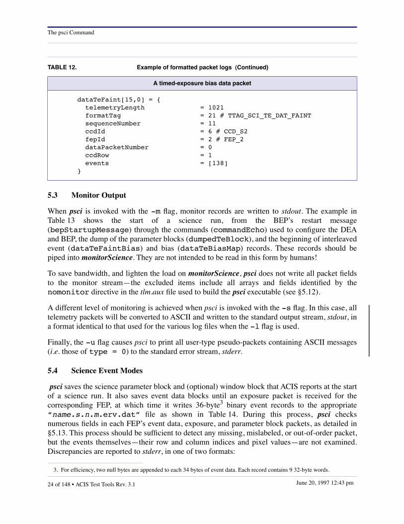
When the -l option is used, psci writes packet-header information to the log files listed inTable 11. The format of these files is derived from that of data structures in the C language, e.g.Table 12, which identifies itself as the first dataTeFaintBias packet, the 16th packet in thestream. Note that fields whose values are enumerated in acis_h/interface.h will be followed by“#” and the enumeration. Unsigned values larger than 32767 are shown in hexadecimal base,preceded by “0x”. The values of arrays of fields with dimension > 9 are not shown—merely theirdimension. When a packet contains one or more command blocks, e.g. dumpedTeBlock, whichcontains a science parameter block (either loadTeBlock or loadCcBlock) and an optionalwindow block (either load1dBlock or load2dBlock), the individual sub-fields are logged,shifted to the right by 2 columns.
As shown in Table 11, the “name” supplied with the -l option of psci is used as a commonprefix to the names of all output files. When a dumpedCcBlock or dumpedTeBlock packet isreceived, a comment is written into all open log files, and the science run number is incremented.Any opened science and bias data files are automatically closed, and a warning message is writtento stderr since they should have been closed: science files by the receipt of a previousscienceReport packet, and bias files when complete.
TABLE 12. Example of formatted packet logs
A timed-exposure faint-mode event packet
dataTeBiasMap[12,4] = { telemetryLength = 779 formatTag = 14 # TTAG_SCI_TE_BIAS sequenceNumber = 9 biasStartTime = 0x9e73a7e5 biasParameterId = 4011 ccdId = 6 # CCD_S2 fepId = 2 # FEP_2 dataPacketNumber = 4 initialOverclocks = 180 184 181 184 pixelsPerRow = 1023 rowsPerBias = 1023 ccdRow = 1015 ccdRowCount = 1 compressionTableSlotIndex = 255 compressionTableIdentifier = 0xffffffff pixelCount = 2048 data = [768]}
ACIS Test Tools Rev. 3.1 • 23 of 148June 20, 1997 12:43 pm
The psci Command
5.3 Monitor Output
When psci is invoked with the -m flag, monitor records are written to stdout. The example inTable 13 shows the start of a science run, from the BEP’s restart message(bepStartupMessage) through the commands (commandEcho) used to configure the DEAand BEP, the dump of the parameter blocks (dumpedTeBlock), and the beginning of interleavedevent (dataTeFaintBias) and bias (dataTeBiasMap) records. These records should bepiped into monitorScience. They are not intended to be read in this form by humans!
To save bandwidth, and lighten the load on monitorScience, psci does not write all packet fieldsto the monitor stream—the excluded items include all arrays and fields identified by thenomonitor directive in the tlm.aux file used to build the psci executable (see §5.12).
A different level of monitoring is achieved when psci is invoked with the -s flag. In this case, alltelemetry packets will be converted to ASCII and written to the standard output stream, stdout, ina format identical to that used for the various log files when the -l flag is used.
Finally, the -u flag causes psci to print all user-type pseudo-packets containing ASCII messages(i.e. those of type = 0) to the standard error stream, stderr.
5.4 Science Event Modes
psci saves the science parameter block and (optional) window block that ACIS reports at the startof a science run. It also saves event data blocks until an exposure packet is received for thecorresponding FEP, at which time it writes 36-byte3 binary event records to the appropriate“name.s.n.m.erv.dat” file as shown in Table 14. During this process, psci checksnumerous fields in each FEP’s event data, exposure, and parameter block packets, as detailed in§5.13. This process should be sufficient to detect any missing, mislabeled, or out-of-order packet,but the events themselves—their row and column indices and pixel values—are not examined.Discrepancies are reported to stderr, in one of two formats:
A timed-exposure bias data packet
dataTeFaint[15,0] = { telemetryLength = 1021 formatTag = 21 # TTAG_SCI_TE_DAT_FAINT sequenceNumber = 11 ccdId = 6 # CCD_S2 fepId = 2 # FEP_2 dataPacketNumber = 0 ccdRow = 1 events = [138]}
3. For efficiency, two null bytes are appended to each 34 bytes of event data. Each record contains 9 32-byte words.
TABLE 12. Example of formatted packet logs (Continued)
24 of 148 • ACIS Test Tools Rev. 3.1 June 20, 1997 12:43 pm

The psci Command
file: packet1[tot1,cnt1].field1=val1 != val2file: packet1[tot1,cnt1].field1=val1 != packet2[tot2,cnt2].field2=val2
where val1 is a (possibly signed) decimal integer, and val2 is an integer or an enumerationfrom acis_h/interface.h. As with the out-of-range messages described in §5.1, these are merelywarnings, and may be suppressed by the -q flag. psci also examines the irigB and
TABLE 13. Packet monitor stream written to stdout
bepStartupMessage sequenceNumber=0 bepTickCounter=567 version=0xffffffff lastFatalCode=0 lastFatalValue=0 watchdogFlag=0 patchValidFlag=1 configFlag=1 parametersFlag=1
commandEcho sequenceNumber=1 arrival=0xa5997d1e result=1 commandIdentifier=0 commandOpcode=9
commandEcho sequenceNumber=2 arrival=0xa5997de8 result=1 commandIdentifier=0 commandOpcode=11
commandEcho sequenceNumber=3 arrival=0xa5997e2c result=1 commandIdentifier=0 commandOpcode=14
dumpedTeBlock sequenceNumber=4
dataTeBiasMap sequenceNumber=5 ccdId=6 fepId=2 dataPacketNumber=0 pixelsPerRow=1023 rowsPerBias=1023 ccdRow=1023 ccdRowCount=1 pixelCount=2048
dataTeBiasMap sequenceNumber=6 ccdId=6 fepId=2 dataPacketNumber=1 pixelsPerRow=1023 rowsPerBias=1023 ccdRow=1021 ccdRowCount=1 pixelCount=2048
dataTeBiasMap sequenceNumber=7 ccdId=6 fepId=2 dataPacketNumber=2 pixelsPerRow=1023 rowsPerBias=1023 ccdRow=1019 ccdRowCount=1 pixelCount=2048
dataTeBiasMap sequenceNumber=8 ccdId=6 fepId=2 dataPacketNumber=3 pixelsPerRow=1023 rowsPerBias=1023 ccdRow=1017 ccdRowCount=1 pixelCount=2048
dataTeBiasMap sequenceNumber=9 ccdId=6 fepId=2 dataPacketNumber=4 pixelsPerRow=1023 rowsPerBias=1023 ccdRow=1015 ccdRowCount=1 pixelCount=2048
dataTeBiasMap sequenceNumber=10 ccdId=6 fepId=2 dataPacketNumber=5 pixelsPerRow=1023 rowsPerBias=1023 ccdRow=1013 ccdRowCount=1 pixelCount=2048
dataTeFaintBias sequenceNumber=11 ccdId=6 fepId=2 dataPacketNumber=0 ccdRow=1
dataTeBiasMap sequenceNumber=12 ccdId=6 fepId=2 dataPacketNumber=6 pixelsPerRow=1023 rowsPerBias=1023 ccdRow=1011 ccdRowCount=1 pixelCount=2048
ACIS Test Tools Rev. 3.1 • 25 of 148June 20, 1997 12:43 pm

The psci Command
bepSciTime fields of all scienceFramePseudo packets. If these are accurate, it willcalculate approximate irigtime fields for the ERV records, but the algorithm makes threeassumptions—(a) that the BEP timer runs at precisely 100 kHz, (b) that all exposures in timedexposure mode have the same duration, and (c) that until psci has received a pair offepTimestamp fields, it will approximate the exposure repetition interval by theprimaryExposure field of loadTeBlock
All event-finding modes generate ERV files in the same format, but the use of the 9 fields in thedata array differs according to mode. In CC and TE graded modes, the event amplitude isrecorded in data[0] and the grade code in data[1]; in graded TE mode, data[2] containsthe mean of the 4 corner pixel amplitudes; the remaining graded-mode data fields containzeroes. In faint modes, the central pixel value is reported in data[4], with the neighboringpixels from the same CCD row in data[3] and data[5]. In 1x3 faint mode, the remaining 6fields contain zeroes; in 3x3 faint modes, data[0] through data[2] contain the pixel valuesfrom the previous row, and data[6] through data[8] those from the following row. CCDcolumn and row numbers are defined from the lower left corner of the CCD.
TABLE 14. Extended Vanderspek (ERV) record format
typedef struct { unsigned short expnum; /* exposure number */ unsigned short exposure; /* exposure time (msec) */ unsigned long irigtime; /* IRIG timestamp */ unsigned short nodenum; /* output node index */ unsigned short col; /* column index */ unsigned short row; /* row index */ unsigned short data[9]; /* event data values */ short doclk; /* delta overclock */} RvRec;
TABLE 15. A sample ERV event file in ASCII format
n msec irig nq col row ———————————— pixels ———————————— ∆oclk
0 2800 80856262 2 566 1 191 1057 178 217 1406 168 174 180 176 00 2800 80856262 0 192 2 197 181 201 175 1300 661 188 760 385 00 2800 80856262 1 352 2 187 213 217 161 1453 1143 178 170 177 00 2800 80856262 2 549 2 182 387 164 173 2094 177 169 155 165 00 2800 80856262 2 650 2 175 176 174 177 1599 891 181 177 181 00 2800 80856262 2 743 2 172 177 185 177 1292 185 160 1179 217 00 2800 80856262 3 1017 2 227 602 619 211 1014 936 213 211 209 00 2800 80856262 0 102 3 183 196 185 179 2549 184 180 180 184 00 2800 80856262 0 224 3 185 175 175 167 2517 192 181 173 187 00 2800 80856262 3 949 3 215 223 205 204 2431 205 205 217 214 0...
26 of 148 • ACIS Test Tools Rev. 3.1 June 20, 1997 12:43 pm

The psci Command
In most event modes, psci will report the raw pixel values, but in Faint-with-Bias mode, thecorresponding bias values are available. Even then, the subtraction will be made only if the -Bflag is specified on the psci command line, in which case the appropriate “biasValues+deltaOverclocks” is subtracted from each valid pixel value. Invalid pixels, i.e. those withbias values exceeding 4093, will be assigned a value of -32768.
If the -a flag is specified, psci writes ERV files in ASCII format to “name.s.n.m.erv.txt”,as shown in Table 15. A tally is kept of all exposures, events, and bias parity errors for checkingagainst the contents of the scienceReport packet that should terminate the science run.Additional informatory messages will be written to stderr if psci is invoked with the -v flag, e.g.
# psci -a -l test1 -v dat.1dat.1: start TE EV3x3 FAINTBIAS bep 0x52ccbf71 irig 935:72262 exptime 3.207test1.2.fits: bias file written, 2100032 bytestest1.2.erv: written 13 exposures 25127 eventsdat.1: scienceReport[909,0] irig 935:72301 exp 13 fep ok ccd ok dea 0 bep 0test1.packet.log: 456 bytes writtentest1.command.log: 1570 bytes writtentest1.science.log: 80351 bytes writtentest1.bias.log: 371820 bytes writtenpsci: 930 packets read from dat.1
5.5 Event Frame Timestamp Files
When the -T flag is specified on the psci command line, the times of each event-mode exposureframe present in the input stream are written to the ASCII file “name.s.time.txt”. This con-sists of the quantities shown in Table 17. The timestamp file is only generated during event-modescience runs, i.e. not during raw or histogram mode. The BepTime value should be constantwithin a given file. Frames will only be listed if at least one FEP processed that exposureNum-ber. Since the external (IRIG) time will drift relative to the ~100 kHz pixel clock reported inBepTime and FepTime, the drift can be estimated by comparing BEP and IRIG timestampswithin science header pseudopackets. This drift is reported in the dIrig0 field.
TABLE 16. Contents of an event frame timestamp file
Field Name Description
Exp ACIS event-mode exposure frame number
BepTime BEP start-of-run timestamp
FepTime FEP timestamp for this frame
dFEP FEP timestamp increment since the last frame
dFrame Length of a frame in pixel clock units
irigTime IRIG time (UTC) of this exposure
dIrig Frame-to-frame time in seconds
dIrig0 Drift between IRIG and ACIS clock in seconds
ACIS Test Tools Rev. 3.1 • 27 of 148June 20, 1997 12:43 pm

The psci Command
5.6 Histogram Files
Although ACIS writes histograms for each CCD output node at a time, psci saves the data packetsuntil all expected nodes have been received, and writes a binary file in FITS format (see the lefthand column of Table 18) named “name.s.n.i-j.hist.fits” for each contributing FEP. Ifthe -a flag is specified, this will be an ASCII file named “name.s.n.i-j.hist.txt”,consisting of 6 header lines followed by 4096 lines of 5 columns each containing, respectively, thepixel value and one pixel count for each output node A through D (see Table 17). If the CCDs arerun with restricted output nodes (i.e. QUAD_AC or QUAD_BD), the unused columns are filled withzeroes.
5.7 Raw Mode
The contents of raw data packets are written to disk files in FITS format as soon as they arereceived. Since the data packets always precede the exposure packet that describes them, theoutput file is first named “name.s.n.TMP.fits”, and renamed “name.s.n.m.raw.fits”as soon as the exposure number “m” is known. For greater efficiency, psci uses memory mapping(the mmap(2) system call) to write raw-mode and bias files. As a consequence, the “ls -l”command will indicate that these files contain at least 2 Mbytes (1 Mbyte in continuous clockingmode), but the actual disk allocation, e.g. from the “du -a” command, will gradually increase asthe data packets are received. Care must be taken to allow for this extra disk space when psci isreceiving raw data and bias maps.
The headers of raw-mode FITS files will contain the fields shown in the center column ofTable 18. Overclocks are appended to each line of the image array. The data area is always1024×1024 pixels in timed-exposure mode and 1024×512 pixels in continuous clocking mode.psci will examine the dumpedTeBlock or dumpedCcBlock packet to see whether the CCDwas run in a pixel-summing mode, or in sub-array readout mode, and will replicate and shiftpixels accordingly to recreate a FITS file that reconstructs the original CCD geometry.
TABLE 17. Contents of an ASCII histogram file
! histogram of fep n for n exposures n to n!! minimumOverclock valA valB valC valD! maximumOverclock valA valB valC valD! meanOverclock valA valB valC valD! varianceOverclockLow valA valB valC valD! varianceOverclockHigh valA valB valC valD!000000 histA histB histC HistD000001 histA histB histC HistD...
28 of 148 • ACIS Test Tools Rev. 3.1 June 20, 1997 12:43 pm

The psci Command
5.8 Bias Files
These are created in the same manner as raw pixel images, i.e. they are memory-mapped into pre-allocated files of fixed length. The FITS file header format is shown in the right-hand column ofTable 18. Timed exposure bias files always contain 2100032 bytes (2880 header bytes followed by1024×1024 2-byte image pixels). As in raw mode, psci replicates and shifts the pixels to fill theentire 1024×1024 pixel array. Continuously clocked bias maps contain 1051456 bytes—the singlerow reported by the BEP is replicated 512 times.
5.9 Memory Readout
When the -l flag is specified, psci copies the contents of all memory readout packets to disk filesnamed “name.pkt.n.dat”, where “name” is the prefix specified on the command line, “pkt”is the type of memory readout, and “n” is an index that increments whenever a packet, or group4
of packets of this type is encountered. They are written in the native byte order of the host
TABLE 18. Examples of FITS file headers
Binary Histograms Raw Mode with Overclocks Bias Images
SIMPLE = TBITPIX = 32NAXIS = 2NAXIS1 = 4096NAXIS2 = 4NFEP = 3NCCD = 5CCDROW1 = 1CCDNROWS= 1024CCDNODES= 4QUADMODE= 'QUAD_FULL'DEAGAIN = 125SUM2X2 = 'NO'EXPOTIM1= 30EXPOTIM2= 0DUTYCYCL= 0FIRSTEXP= 71LASTEXP = 75NEXP = 5FILENAME= '...'DATETIME= ‘...’OCLKMINA= 181OCLKMAXA= 186OCLKMEAA= 184OCLKVARA= 8OCLKVAHA= 0...END
SIMPLE = TBITPIX = 16NAXIS = 2NAXIS1 = 1088NAXIS2 = 1024NFEP = 2NCCD = 5CCDROW1 = 1CCDNROWS= 1024CCDNCOLS= 1024CCDOCLKS= 64CCDNODES= 4QUADMODE= 'QUAD_FULL'DEAGAIN = 123SUM2X2 = 'NO'EXPOTIM1= 28EXPOTIM2= 0DUTYCYCL= 0EXPOSURE= 21FILENAME= '...'DATETIME= ‘...’END
SIMPLE = TBITPIX = 1NAXIS = 2NAXIS1 = 1024NAXIS2 = 1024NFEP = 2NCCD = 5CCDROW1 = 1CCDNROWS= 1CCDNODES= 4QUADMODE= 'QUAD_FULL'ACISMODE= ‘TE’SUM2X2 = 'NO'DEAGAIN = 75BIASALGO= 1BIASARG0= 0BIASARG1= 10BIASARG2= 0BIASARG3= 100BIASARG4= 70FILENAME= ‘...’DATETIME= ‘...’INITOCLA= 180INITOCLB= 184INITOCLC= 181INITOCLD= 184END
ACIS Test Tools Rev. 3.1 • 29 of 148June 20, 1997 12:43 pm

The psci Command
machine. When the –a flag is also present, the files are written in hexadecimal notation similar tothe output of the “od -X” command (or “od -x” for the 16-bit SRAM and PRAM dumps), andthy will be named “name.pkt.n.dat”.
5.10 Huffman Tables
The compression tables used by the BEP to compress the contents of raw science and bias datapackets are treated by psci as special cases of memory readout. Since the Huffman table block istoo long to dump in a single packet, psci assembles it from several dumpedHuffman packetsand, when it is complete, saves it to decompress any subsequent raw or bias packets. If the “–l”option is used, the Huffman block will also be written to a disk file. Since Huffman blocks will notalways be part of the packet stream, psci can be told, via the “–h” option, to pre-load a previously
4. A series of packets generated from a single memory readout command when the requested length exceeded the maximum permitted telemetry packet size. Such packet groups share the same commandId field value.
TABLE 19. ASCII dump of a Huffman block containing multiple tables
huffmanTable[0] = { tabid = 0xffffffff lowlim = 3837 tabsize = 512 trunc = 07 3e0000 1111100 badbias = 21 184df8 111111011001000011000 badpix = 21 004df8 111111011001000000000 -256 = 16 43bf00 1111110111000010 -255 = 17 87ef80 11111011111100001 -254 = 18 8897c0 111110100100010001 -253 = 19 d737e0 1111110110011101011... 252 = 19 0937e0 1111110110010010000 253 = 18 f6efc0 111111011101101111 254 = 20 a89bf0 11111101100100010101 255 = 19 e937e0 1111110110010010111}huffmanTable[1] = { tabid = 0xfffffffe lowlim = 3837 tabsize = 512 trunc = 06 280000 010100 badbias = 21 497af8 111110101111010010010 badpix = 18 c557c0 111110101010100011 -256 = 20 eaf5f0 11111010111101010111 -255 = 19 bc77a0 1011110111000111101 -254 = 19 9c77a0 1011110111000111001 -253 = 21 c17af8 111110101111010000011...}
30 of 148 • ACIS Test Tools Rev. 3.1 June 20, 1997 12:43 pm

The psci Command
saved binary Huffman block, but this will always be supplanted by a complete Huffman block inthe packet stream.
When the “–a” flag is used, Huffman blocks will be written to disk in ASCII format. Thesecannot be loaded by the “–h” option, but they are more readable, e.g. the example in Table 19.
5.11 Pseudopackets
If the “–p” flag is specified, these are written to “name.pseudo.log”. BEP & IRIG timefields are saved from scienceFramePseudo packets, as outlined in §5.4. above. Also, whenpsci is invoked with the “-u” flag, userPseudo packets with “type” field values of zero areinterpreted as diagnostic messages from the flight software and the remainder of the packets,assumed to contain null-terminated character strings, are written to stderr. Otherwise,pseudopackets are ignored.
5.12 Architecture
With the exception of the external Huffman tables discussed in §5.10, psci is self-contained—allpacket and field names and formats are compiled into the executable module. The code isgenerated in three stages In the first, a Perl script named genmap reads the IP&CL structures fileand creates intermediate cmd.map and tlm.map files which define the field formats and minimumand maximum values. genmap also extracts the enumeration values from acis_h/interface.h andwrites them to enum.c as character string arrays.Then gentab, a second Perl script, convertscmd.map and tlm.map into C structures in cmdtab.c and cmdtab.h. Finally, gcc compiles thestructures with the remaining source code. While the process is automatic, it can be guided by
Inputs To gcc
cmdtab.h
tlmtab.c
tlmtab.h
enum.c, enum.h
cmd.map
tlm.map
pseudo.map
cmd.aux, tlm.aux
IP&CL structures
acis_h/interface.h
enum.aux
genm
ap
gent
ab
cmdtab.c
Intermediates
FIGURE 3. psci build architecture
ACIS Test Tools Rev. 3.1 • 31 of 148June 20, 1997 12:43 pm

The psci Command
directives in the three files enum.aux, cmd.aux, and tlm.aux. An example of enum.aux is shown inTable 20.—lines of the form “command id name” assign “name” to command packets withthat “id”, and “packet id name” performs the same function for telemetry packets. Thiscauses psci to use the new names within messages and in log and monitor files, as well as givingsymbolic names to pseudopackets, since these were never described by the IP&CL.
Examples of the cmd.aux and tlm.aux files are shown in Table 21 and Table 22. They share acommon syntax. The “enumerate” command assigns a character string array in enum.c to aparticular command or telemetry packet field. psci will display the enumerated value in its logfiles and error messages. The “nolog” directive prevents psci from logging a particular type ofcommand, or packet, or field. The “nomonitor” command, which is only used in tlm.aux,performs the same function—of eliminating fields from monitor packets. The more restrictive“nomonitornull” command prevents fields from being written to the monitor stream if theyhave zero value.
TABLE 20. Sample enum.aux file
## resolve duplicated command packet names#command CMDOP_START_TE startTecommand CMDOP_BIAS_TE startTeBiascommand CMDOP_START_CC startCccommand CMDOP_BIAS_CC startCcBiascommand CMDOP_ADD_BAD_TE_COL addBadTeColumncommand CMDOP_RESET_BAD_TE_COL resetBadTeColumnMapcommand CMDOP_ADD_BAD_CC_COL addBadCcColumncommand CMDOP_RESET_BAD_CC_COL resetBadCcColumnMapcommand CMDOP_DUMP_TE_SLOTS dumpTeSlotscommand CMDOP_DUMP_CC_SLOTS dumpCcSlotscommand CMDOP_DUMP_2D_SLOTS dump2dSlotscommand CMDOP_DUMP_1D_SLOTS dump1dSlotscommand CMDOP_DUMP_DEA_SLOTS dumpDeaSlots#
32 of 148 • ACIS Test Tools Rev. 3.1 June 20, 1997 12:43 pm

The psci Command
# resolve duplicated telemetry packet names#packet TTAG_DUMP_SYS_CONFIG dumpedSysConfigpacket TTAG_DUMP_BAD_PIXEL dumpedBadPixpacket TTAG_DUMP_BAD_TE_COL dumpedBadTeColpacket TTAG_DUMP_BAD_CC_COL dumpedBadCcColpacket TTAG_DUMP_PATCHES dumpedPatchespacket TTAG_DUMP_HUFFMAN dumpedHuffmanpacket TTAG_DUMP_TE_SLOTS dumpedTeSlotspacket TTAG_DUMP_CC_SLOTS dumpedCcSlotspacket TTAG_DUMP_2D_SLOTS dumped2dSlotspacket TTAG_DUMP_1D_SLOTS dumped1dSlotspacket TTAG_DUMP_DEA_SLOTS dumpedDeaSlotspacket TTAG_SCI_CC_REC_FAINT exposureCcFaintpacket TTAG_SCI_CC_REC_GRADED exposureCcGradedpacket TTAG_SCI_TE_REC_FAINT exposureTeFaintpacket TTAG_SCI_TE_REC_GRADED exposureTeGraded## name the pseudopackets#packet 61 engineeringPseudopacket 62 scienceFramePseudopacket 63 userPseudo
TABLE 21. An example of tlm.aux
## Use the following enumerations in log files#enumerate formatTag TlmFormatTagStrenumerate ccdId CcdIdStrenumerate fepId FepIdStrenumerate lastFatalCode FatalCodeStrenumerate commandOpcode CmdOpcodeStrenumerate result CmdResultStrenumerate fepErrorCodes FepIoErrorsStrenumerate query DeaQueryCntlIdStrenumerate queryId DeaQueryCcdIdStrenumerate fatalCode FatalCodeStr## Omit the following fields from log records#nolog commandEcho.commandBodynolog scienceReport.ccdErrornolog dumpedTeBlock.parameterBlockData
TABLE 20. Sample enum.aux file (Continued)
ACIS Test Tools Rev. 3.1 • 33 of 148June 20, 1997 12:43 pm

The psci Command
## Omit the following fields from monitor records#nomonitor userPseudonomonitor engineeringPseudonomonitor scienceFramePseudonomonitor telemetryLengthnomonitor formatTagnomonitor dataTeBiasMap.compressionTableSlotIndexnomonitor dataTeBiasMap.compressionTableIdentifiernomonitor dataTeBiasMap.biasStartTimenomonitor dataTeBiasMap.biasParameterIdnomonitor commandEcho.commandLength## Omit the following when null#nomonitornull biasParityErrors
TABLE 22. An example of cmd.aux
## Use the following enumerations in log files#enumerate commandOpcode CmdOpcodeStrenumerate ccdId CcdIdStrenumerate itemId SystemSettingsStrenumerate fepId FepIdStrenumerate fepCcdSelect CcdIdStrenumerate queryId DeaQueryCcdIdStrenumerate outputRegisterMode QuadModeStr## Enumerations specific to particular command blocks#enumerate loadCcBlock.fepMode CcFepModeStrenumerate loadTeBlock.fepMode TeFepModeStrenumerate loadCcBlock.bepPackingMode CcBepModeStrenumerate loadTeBlock.bepPackingMode TeBepModeStr## Remove redundant fields from log output#nolog loadTeBlock.gradeSelectValuenolog loadTeBlock.videoResponsenolog loadCcBlock.gradeSelectValuenolog loadCcBlock.videoResponse
TABLE 21. An example of tlm.aux (Continued)
34 of 148 • ACIS Test Tools Rev. 3.1 June 20, 1997 12:43 pm
The psci Command
5.13 Tests applied to packet fields
Table 23 details the tests applied within the particular packet-handling modules. These are inaddition to the range tests described in §5.1, which themselves verify the following fields:
• In all command blocks: commandLength, commandOpcode
• In all telemetry packets: synch, telemetryLength, formatTag
A number of other consistency checks are made in the process of creating the output data files,and may cause warning messages to appear on stderr. For instance, the ccdRow andccdRowCount fields in dataTeBiasMap packets are verified against the sub-array fields inloadTeBlock. The warnings are usually self-explanatory; the user should consult the sourcecode for further details.
Considerate la vostra semenza:fatti non foste a viver come bruti,
ma per seguir virtute e canoscenza.
ACIS Test Tools Rev. 3.1 • 35 of 148June 20, 1997 12:43 pm

The psci Command
TABLE 23. Tests applied to individual ACIS packet fields
Packet Field Checked against Module
bepReadReplydumped*Slots
commandId
last packet of same type within multi-packet group
memory.creadAddress
requestedAddress
requestedWordCount
dataCcBiasMap
biasParameterId loadCcBlock.parameterBlockId
bias.cccdIdloadCcBlock.fepCcdSelect
fepId
dataCcFaintdataCcGraded
ccdIdexposureCcFaint.ccdId
event.cloadCcBlock.fepCcdSelect
dataPacketNumber running packet count
fepId exposureCcFaint.fepId
dataCcRaw
ccdIdlast packet of same type from this FEP
raw.c
loadCcBlock.fepCcdSelect
compressionTableIdentifier last packet of same type from this FEP
compressionTableSlotIndex
loadCcBlockk.rawCompression-SlotIndex
last packet of same type from this FEP
dataPacketNumber running packet count
fepId last packet of same type from this FEP
pixelCount loadCcBlock fields and pixel count
dataTeBiasMap
biasParameterIdlast packet of same type from this FEP
bias.c
loadTeBlock.parameterBlockId
biasStartTime last packet of same type from this FEP
ccdIdloadTeBlock.fepCcdSelect
last packet of same type from this FEP
ccdRow compatibility with loadTeBlock fieldsccdRowCount
compressionTableIdentifier last packet of same type from this FEP
compressionTableSlotIndex
loadTeBlock.rawCompression-SlotIndex
last packet of same type from this FEP
dataPacketNumber running packet count
fepIdlast packet of same type from this FEP
loadTeBlock.fepCcdSelect
pixelsPerRowpixel count
loadTeBlock.onChip2x2Summing
dataTeBiasMap (contd.) rowsPerBias loadTeBlock.subarrayRowCount bias.c
36 of 148 • ACIS Test Tools Rev. 3.1 June 20, 1997 12:43 pm

The psci Command
dataTeFaintdataTeGraded
ccdId exposureTeFaint.ccdId
event.cdataPacketNumber packet count
fepId exposureTeFaint.fepId
dataTeFaintBias
ccdIdexposureTeFaintBias.ccdId
event.cloadTeBlock.fepCcdSelect
dataPacketNumber packet count
fepId exposureTeFaintBias.fepId
dataTeHist
ccdIdexposureTeHistogram.ccdId
hist.c
loadTeBlock.fepCcdSelect
dataPacketNumber packet count
fepId exposureTeHistogram.fepId
outputNodeIdexposureTeHistogram.output-NodeId
startingBin packet count
dataTeRaw
ccdIdlast packet of same type from this FEP
raw.c
loadTeBlock.fepCcdSelect
compressionTableIdentifier last packet of same type from this FEP
compressionTableSlotIndex
loadTeBlock.rawCompression-SlotIndex
last packet of same type from this FEP
dataPacketNumber packet count
fepId last packet of same type from this FEP
exposureCcFaint
-
loadCcBlock.bepPackingMode
event.c
loadCcBlock.commandOpcode
loadCcBlock.fepMode
biasParameterId last packet of same type from this FEP
biasStartTimelast packet of same type from this FEP
scienceReport.runStartTime
ccdId
last packet of same type from this FEP
dataCcFaint.ccdId
dataCcGraded.ccdId
loadCcBlock.fepCcdSelect
eventsSent event count
exposureNumber> last packet of same type from this FEP
fepIdlast packet of same type from this FEP
dataCcFaint.fepId
TABLE 23. Tests applied to individual ACIS packet fields (Continued)
Packet Field Checked against Module
ACIS Test Tools Rev. 3.1 • 37 of 148June 20, 1997 12:43 pm

The psci Command
exposureCcFaint (contd.)
parameterBlockIdlast packet of same type from this FEP
event.c
loadCcBlock.parameterBlockId
runStartTimelast packet of same type from this FEP
scienceReport.runStartTime
windowBlockIdlast packet of same type from this FEP
load1dBlock.windowBlockId
exposureCcRaw
-loadCcBlock.commandOpcode
raw.c
loadCcBlock.fepMode
ccdIdlast packet of same type from this FEP
loadCcBlock.fepCcdSelect
exposureNumber> last packet of same type from this FEP
fepId last packet of same type from this FEP
parameterBlockId
last packet of same type from this FEP
scienceReport.parameter-BlockId
runStartTimelast packet of same type from this FEP
scienceReport.runStartTime
windowBlockIdlast packet of same type from this FEP
scienceReport.windowBlockId
exposureTeFaintexposureTeFaintBias
-
loadTeBlock.bepPackingMode
event.c
loadTeBlock.commandOpcode
loadTeBlock.fepMode
scienceReport.exposuresSent
biasParameterId last packet of same type from this FEP
biasStartTimelast packet of same type from this FEP
scienceReport.biasStartTime
ccdId
last packet of same type from this FEP
dataTeFaint.ccdId
dataTeGraded.ccdId
loadTeBlock.fepCcdSelect
eventsSent event count
exposureNumber> last packet of same type from this FEP
TABLE 23. Tests applied to individual ACIS packet fields (Continued)
Packet Field Checked against Module
38 of 148 • ACIS Test Tools Rev. 3.1 June 20, 1997 12:43 pm

The psci Command
exposureTeFaintexposureTeFaintBias(contd.)
fepId
last packet of same type from this FEP
event.c
dataTeFaint.fepId
dataTeGraded.fepId
parameterBlockId
last packet of same type from this FEP
loadTeBlock.parameterBlockId
scienceReport.parameter-BlockId
runStartTimelast packet of same type from this FEP
scienceReport.runStartTime
windowBlockId
last packet of same type from this FEP
load2dBlock.windowBlockId
scienceReport.windowBlockId
exposureTeHistogram
-loadTeBlock.commandOpcode
hist.c
loadTeBlock.fepMode
ccdId
last packet of same type from this FEP
dataTeHist.ccdId
loadTeBlock.fepCcdSelect
endExposureNumber last packet of same type from this FEP
exposureCount scienceReport.exposuresSent
fepIdlast packet of same type from this FEP
dataTeHist.fepId
outputNodeId dataTeHist.outputNodeId
parameterBlockId
last packet of same type from this FEP
loadTeBlock.parameterBlockId
scienceReport.parameter-BlockId
runStartTimelast packet of same type from this FEP
scienceReport.runStartTime
startExposureNumber
last packet of same type from this FEP
> last packet of same type from this FEP
TABLE 23. Tests applied to individual ACIS packet fields (Continued)
Packet Field Checked against Module
ACIS Test Tools Rev. 3.1 • 39 of 148June 20, 1997 12:43 pm

The psci Command
exposureTeRaw
-
loadTeBlock.commandOpcode
raw.c
loadTeBlock.fepMode
scienceReport.exposuresSent
ccdIdlast packet of same type from this FEP
loadTeBlock.fepCcdSelect
exposureNumber> last packet of same type from this FEP
fepId last packet of same type from this FEP
parameterBlockId
last packet of same type from this FEP
scienceReport.parameter-BlockId
runStartTimelast packet of same type from this FEP
scienceReport.runStartTime
windowBlockIdlast packet of same type from this FEP
scienceReport.windowBlockId
fepReadReply
commandId
last packet of same type within multi-packet group from this FEP
memory.cfepId
requestedAddress
requestedWordCount
load1dBlock
commandOpcode CMDOP_LOAD_1D
bias.cevent.craw.cwindow.c
windowBlockId
exposureCcFaint.window-BlockId
event.c
exposureCcRaw.windowBlockId raw.c
load2dBlock
commandOpcode CMDOP_LOAD_2D
bias.cevent.craw.cwindow.c
windowBlockId
exposureTeFaint.window-BlockId
event.cexposureTeFaintBias.window-BlockId
exposureTeRaw.windowBlockId raw.c
loadCcBlock bepPackingModeBEP_CC_MODE_FAINT
event.cBEP_CC_MODE_GRADED
TABLE 23. Tests applied to individual ACIS packet fields (Continued)
Packet Field Checked against Module
40 of 148 • ACIS Test Tools Rev. 3.1 June 20, 1997 12:43 pm

The psci Command
loadCcBlock (contd.)
commandOpcode CMDOP_LOAD_CCbias.cevent.craw.c
fepModeFEP_CC_MODE_EV1x3 event.c
FEP_CC_MODE_RAW raw.c
parameterBlockId
dataCcBiasMap.biasParame-terId
bias.c
exposureCcFaint.parameter-BlockId
event.c
loadTeBlock
bepPackingMode
BEP_TE_MODE_FAINT
event.cBEP_TE_MODE_FAINTBIAS
BEP_TE_MODE_GRADED
commandOpcode CMDOP_LOAD_TE
bias.cevent.chist.craw.c
fepMode
FEP_TE_MODE_EV3x3 event.c
FEP_TE_MODE_HIST hist.c
FEP_TE_MODE_RAW raw.c
parameterBlockId
dataTeBiasMap.biasParame-terId
bias.c
exposureTeFaint.parameter-BlockId
event.cexposureTeFaintBias.parame-terBlockId
exposureTeHistogram.parame-terBlockId
hist.c
subarrayRowCount dataTeBiasMap.rowsPerBias bias.c
pramReadReplysramReadReply
ccdId
last packet of same type within multi-packet group from this DEA
memory.ccommandId
requestedIndex
requestedWordCount
scienceReport
biasErrorCount bias error count
science.c
biasParameterIdvalue in previous exposure record(s)
biasStartTime
exposuresProducedexposure counters
exposuresSent
parameterBlockId
value in previous exposure record(s)runStartTime
windowBlockId
TABLE 23. Tests applied to individual ACIS packet fields (Continued)
Packet Field Checked against Module
ACIS Test Tools Rev. 3.1 • 41 of 148June 20, 1997 12:43 pm

Simulated ACIS Telemetry
6.0 Simulated ACIS Telemetry
This chapter describes how to generate a simulated ACIS timed-exposure telemetry stream.It proceeds in two steps. First, the FEP simulator reads commands and input data in the formof 16-bit FITS images, creating one or more “ring-buffer” files and bias maps. In the secondstep, these files are used to produce the telemetry stream.
6.1 fepCtlTest—simulate the ACIS front-end processor
The simulator can read a command script from its standard input stream, stdin, or behavelike a command shell, as in the following example of a timed-exposure science run. The firstgroup of “set” commands specifies the location of the input FITS image files, and thelocation of pixels and overclocks within those images. The second group uses “param”commands to define FEP-to-BEP run-time parameters, followed by an “exec” commandto store them in the FEP, another to compute the bias map, and a “dumpbias” command tocopy the bias map to a disk file. The third group uses the “output” command to directsubsequent output to a disk file, and then executes the simulated timed-exposure run.
#! /acis/h3/tools/bin/fepCtlTest
# Test images use CCD image frames with fe55 and co60
set input = /cdrom/ccid17-38-3/fe55co60/fe55+Co60_nowin_120.%04d.fitsset rows = 2,1025set pixels = 4,259,344,599,684,939,1024,1279set overclocks = 260,336,600,676,940,1016,1280,1356
# fepTimedBias() full-frame bias, 4 nodes
param type = FEP_TIMED_PARM_3x3param nrows = 1024param ncols = 256param quadcode = FEP_QUAD_ABCDparam noclk = 16param nhist = 0param btype = FEP_BIAS_1param thresh[0] = 100param thresh[1] = 100param thresh[2] = 100param thresh[3] = 100param bparm[0] = 5param bparm[1] = 10param bparm[2] = 0param bparm[3] = 100param bparm[4] = 70param nskip = 0param initskip = 2
exec BEP_FEP_CMD_PARAMexec BEP_FEP_CMD_BIAS
42 of 148 • ACIS Test Tools Rev. 3.1 June 20, 1997 12:43 pm

Simulated ACIS Telemetry
dumpbias feco.bias.te.fframe
# fepSciTimed() in 3x3 event modeset output = feco.ring.te.3x3exec BEP_FEP_CMD_TIMED
This script causes two files to be written—“feco.bias.te.fframe” to contain the biasmap and “feco.ring.te.3x3” to contain the events. The former can be viewed by anyFITS image reader, the latter by the dumpring command (see Section 6.2).
TABLE 24. fepCtlTest Command Syntax
Command Description
dumpbias file write an already-computed bias map to file in FITS format
exec cmd
execute a BEP-to-FEP command—one of the followingFEP_BEP_CMD_BIAS start bias calibrationBEP_BEP_FEP_CMD_TIMED start timed exposureBEP_FEP_CMD_CCLK start continuous clockingBEP_FEP_CMD_STOP stop the runBEP_FEP_CMD_PARAM read parametersBEP_FEP_CMD_SUSPEND temporarily haltBEP_FEP_CMD_RESUME resume after suspensionBEP_FEP_CMD_STATUS return FEP statusBEP_FEP_CMD_FIDPIX define fiducial pixels1
fidpix = row col... define one or more fiducial pixels1
param name = val
set a BEP-to-FEP parameter—one of the following2
type type of parameter block:FEP_NO_PARMFEP_TIMED_PARM_RAWFEP_TIMED_PARM_HISTFEP_TIMED_PARM_3x3FEP_TIMED_PARM_5x5FEP_CCLK_PARM_RAWFEP_CCLK_PARM_1x3
nrows number of rows in a CCD framencols number of pixels per row per nodequadcode node clocking code:
FEP_QUAD_ABCDFEP_QUAD_ACFEP_QUAD_BD
noclk number of overclocks per row per nodenhist number of frames per histogrambtype type of bias calibration to perform
FEP_NO_BIASFEP_BIAS_1FEP_BIAS_2
thresh[4] event detection thresholds for each nodebparm[5] bias calibration parametersnskip timed exposure skip factor
ACIS Test Tools Rev. 3.1 • 43 of 148June 20, 1997 12:43 pm

Simulated ACIS Telemetry
fepCtlTest assumes that the input FITS files contain 16-bit pixels in big-endian format(most-significant byte first). Only the least significant 12 bits of each pixel will be used. Thebias maps will also be written in 16-bit FITS format, but in little-endian format (least-significant byte first), irrespective of whether fepCtlTest is compiled for little- or big-endianmachines. This is not the case with the ring-buffer output files—their byte ordering willdepend on the architecture of the machine running fepCtlTest.
6.2 dumpring—display ring-buffer records
This is a perl script that converts the contents of a binary ring-buffer file to ASCII text. Itrecognizes only a single command-line argument, the name of the input file. If omitted, it
reset ctrreset an internal simulator counter. Currently, the only counter recognized is “wakeup”.
set buf[row,col] = valset an element of the 2-dimensional buf array. buf is either “bias” or “biasparity”
set input = file
subsequent bias calibrations or science runs will read pixel data from file, a set of FITS images whose name should contain a numeric “printf” format string, e.g. “%04d” which will be replaced by the integers 1,2,3,... when the FEP simulator opens successive input FITS files.
set output = filesubsequent “ring buffer” output will be written to file. See Section 6.2 for details of ring-buffer formats
set overclocks = p1,p2,p3,p4...specify the ranges of overclock pixels in each raster of the input file. Node A’s overclocks will span columns p1 through p2 (indexing from 0), Node B’s will span p3 through p4, etc.
set pixels = p1,p2,p3,p4,...specify the ranges of data pixels in each raster of the input file. Node A’s pixels will span columns p1 through p2 (indexing from 0), Node B’s will span p3 through p4, etc.
set rows = r1,r2
specify the range of input image rows, indexed from 0. If omit-ted, the range will begin with the first row and will continue for the number of rows specified by the “param nrows” com-mand.
stuff param name = valused in unit and coverage testing to force a BEP parameter to a particular value, bypassing the normal range checking applied to a BEP_FEP_CMD_PARAM command.
xor buf[row,col] = valperform an exclusive OR of val with an element of the 2-dimensional buf array, storing the result back into the array. buf is either “bias” or “biasparity”
1. this feature is not currently supported in the ACIS BEP detailed design, but has been included in the FEP software.
2. see Table 47 and Table 48 of the ACIS Flight Software Detailed Design Specification (36-53200 Rev. 01++) for more details of bias parameters
TABLE 24. fepCtlTest Command Syntax (Continued)
Command Description
44 of 148 • ACIS Test Tools Rev. 3.1 June 20, 1997 12:43 pm

Simulated ACIS Telemetry
reads from stdin. The formats of the various ring-buffer records are defined in Section 4.10of the ACIS Flight Software Detailed Design Specification (36-53200 Rev. 01++).dumpring inspects the first few records to determine the byte-order, little- or big-endian. Itwrites a formatted ASCII listing on stdout, as in the following example:
FEPexpRec[1] = {expnum = 1timestamp = 0x05234672bias0 = 180 184 181 184dOclk = 0 0 0 0
}FEPeventRec3x3[1,1] = {
row = 2col = 1017p,b = { 227 602 619 } { 210 210 210 }
= { 211 1014 936 } { 210 210 204 }= { 213 211 209 } { 209 209 203 }
}FEPeventRec3x3[1,2] = {
row = 4col = 448p,b = { 180 166 174 } { 166 164 164 }
= { 190 1981 166 } { 166 722 160 }= { 171 658 168 } { 165 168 168 }
}..FEPexpEndRec[1] = {
expnum = 1thresholds = 3765parityerrs = 0
}FEPexpRec[2] = {
expnum = 2timestamp = 0x0540f48bbias0 = 180 184 181 184dOclk = 0 0 0 0
}..
dumpring numbers the records consecutively, beginning with 11. Thus, in the aboveexample, the start-of-exposure record FEPexpRec[1] is matched by the end-of-exposurerecord FEPexpEndRec[1]. In between, the event records are FEPeventRec3x3[1,n], wherethe event index n also starts at 1.
1. note that the BEP numbers its exposures beginning with 0, i.e. it subtracts 1 from the exposure numbers reported by the FEPs, which use exposure number 0 to indicate their state before the first exposure has been received.
ACIS Test Tools Rev. 3.1 • 45 of 148June 20, 1997 12:43 pm

Simulated ACIS Telemetry
6.3 tlmsim—create simulated telemetry packets
This command combines a pair of files created by fepCtlTest, a ring-buffer and a bias map,into a stream of ACIS test packets. In addition to these files, tlmsim must be provided withsuitable parameter and window blocks to include in its output. It is described in detail inSection 10.31.
The output stream contains two sorts of packets—ACIS science packets and science framepseudo-packets (SFPP). They share a common format, as described in Table 3 on page 6, butserve different functions. Remember that all ACIS telemetry fields, including those inpseudo-packets, are recorded in little-endian order, with less significant bytes precedingmore significant.
The science packets simulate the ACIS serial telemetry stream that would be written to the“science data” portion of each Format-2 AXAF telemetry frame, or into the next-in-line fieldin Format 1. Their format is given by Table 3 on page 6, and their contents are described inthe ACIS IP&CL documents and in “http://acis.mit.edu/acis/ipcl”. Inter-packet padding has been removed. However, the real ACIS instrument also inserts 4-bytetime tags into its serial telemetry whenever it receives a science frame pulse. Since thesetags could appear at any offset within a packet, it is inappropriate to include them intlmsim’s science packets. If users wishes to simulate them, they must specify the –p option,causing tlmsim to write them as pseudo-packets.
6.3.1 Bias Map
The size of the bias map is taken from the FITS header variables NAXIS1 and NAXIS2. It isusually 1024 rows and 1024 columns. tlmsim formats it into dataTeBiasMap packets,two rows per packet. This version of tlmsim is unable to compress the 12-bit data, so itreports the compressionTableSlotIndex as 255 (no compression).
The initialOverClocks fields in the dataTeBiasMap packets are copied from thering-buffer file, so it is important that the ring-buffer and bias map files should have beengenerated from the same fepCtlTest input data
6.3.2 Timing
The order of the science packets is as follows:
1 bepStartupMessage simulating an ACIS commanded reset
1 commandEcho executing a loadTeBlock command
1 commandEcho executing a startScience command
1 dumpedTeBlock reporting the current teBlock and window2d block
many dataTeFaintBias
bias map packets interleaved with event and exposure packetsmany exposureTeFaintBias
many dataTeBiasMap
1 commandEcho executing a stopScience command
46 of 148 • ACIS Test Tools Rev. 3.1 June 20, 1997 12:43 pm

Simulated ACIS Telemetry
If the –p option is specified, a SFPP will be written inserted once per science frame, i.e.every 2.05 seconds of “real” instrument time, determined by counting the length of thescience packets and assuming that they are filling the available telemetry bandwidth (512bps in Format-1 and 24 kbps in Format-2). tlmsim normally simulates Format-2. Use the –fflag to create (48 times as many!) Format-1 pseudo-packets.
An AXAF/ACIS telemetry stream contains 5 types of timing information, each of which issimulated independently
1. fepTimestamp—the 25-bit value of the FEP’s megahertz counter which would be latched whenever the start of a new frame were received (VSYNC from PRAM). The simulated value is taken from the ring-buffer records created by fepCtlTest, which currently uses the value of the UNIX microsecond timer for this field.
2. bepTimestamp—the 32-bit value of the BEP’s megahertz counter which would be latched (a) whenever a S/C science pulse is received or (b) whenever the BEP sends a “start processors” command to the DEA(s). The former would be inserted synchro-nously into the telemetry, and is simulated by tlmsim as the bepSciTime field in the SFPP; the latter would be reported as biasStartTime and runStartTime in science packets. They are simulated as the instantaneous value of the UNIX microsecond timer, except that the biasStartTime is then arbitrarily decreased by 120 seconds.
3. bepTickCounter—the BEP also contains a 10 Hz counter whose value would be reported as the bepTickCounter field in the bepStartupMessage packet and the arrival field of commandEcho packets. tlmsim assigns an initial value of 500 to this counter, and increments it within subsequent packets according to the time elapsed as read from the UNIX microsecond timer.
4. majorFrameId and minorFrameId—these SFPP fields contain the VCDU fields that would occur at the start of each AXAF telemetry minor frame. They are simulated by keeping count of the telemetry mode (the –f flag) and of the data vol-ume being written. minorFrameId is incremented for every 750 bytes of ACIS data (8 bytes in Format-1), and majorFrameId is incremented every 128 minor frames. Both are initialized to zero at the start of the simulation.
5. IRIG-B—the day and second count in the SFPPs are initialized from the UNIX sys-tem clock, and the milli- and micro-second timers are initialized to zero. They are incremented by 0.25625 seconds for each minor frame (750 bytes of ACIS data in Format-2, 8 bytes in Format-1).
6.3.3 Miscellaneous
The tlmsim output always assigns correct lengths to telemetry packets and to encapsulatedcommands and parameter blocks. It numbers the science packets sequentially from zero (inthe sequenceNumber fields), and computes correct checksums. All commands are
1 scienceReport reporting the statistics of the run
- dataTeBiasMap remaining bias packets until the entire map is reported
ACIS Test Tools Rev. 3.1 • 47 of 148June 20, 1997 12:43 pm

Simulated ACIS Telemetry
executed successfully (CMDRESULT_OK in the result field of commandEcho packets), andall events in the ring-buffer file are copied to telemetry packets—none is removed by(simulated) BEP filters. The only errors that are simulated are instances of bias mapcorruption within the FEP. They are created by including “xor parity” or “xorparityplane” commands within the fepCtlTest script, and they result in errors beingwritten to the ring-buffer file and thence to dataBiasErr packets in the tlmsim outputstream.
6.4 Examples
In the simplest case, the output from tlmsim may be piped directly into ltlm, e.g.
tlmsim -c te.1 -p -w win.1 ring.1 bias.1 | ltlm | more
If you only want to inspect packets of a particular type, e.g. exposureTeFaintBiaswhose formatTag value is 22, invoke ltlm with the -p 22 option. If you also want to seedataTeFaintBias packets (formatTag 23), use -p22 -p23 together. If you forget aformatTag value, invoke ltlm -lt with no other arguments to list them all.
ltlm -v -p22 -p2 tlm.out11 | moredataTeFaintBias[0] = { synch = 0x736f4166 telemetryLength = 1021 formatTag = TTAG_SCI_TE_DAT_FAINTB (23) sequenceNumber = 11 ccdId = 6 fepId = 2 dataPacketNumber = 0 events = [138]}...dataTeFaintBias[36] = { synch = 0x736f4166 telemetryLength = 675 formatTag = TTAG_SCI_TE_DAT_FAINTB (23) sequenceNumber = 237 ccdId = 6 fepId = 2 dataPacketNumber = 10 events = [91]}exposureTeFaintBias[2] = { synch = 0x736f4166 telemetryLength = 20 formatTag = TTAG_SCI_TE_REC_FAINTB (22) sequenceNumber = 238 runStartTime = 0x619a9cf4 parameterBlockId = 0x00000fab windowBlockId = 0x00000baf
48 of 148 • ACIS Test Tools Rev. 3.1 June 20, 1997 12:43 pm
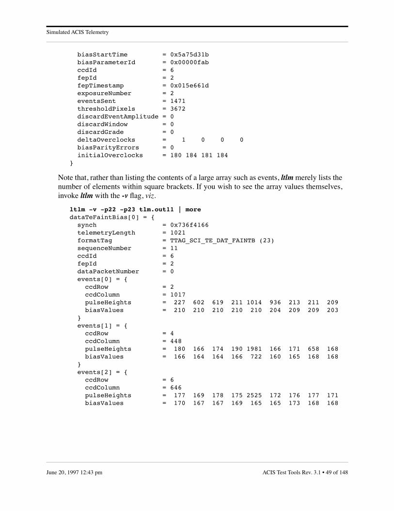
Simulated ACIS Telemetry
biasStartTime = 0x5a75d31b biasParameterId = 0x00000fab ccdId = 6 fepId = 2 fepTimestamp = 0x015e661d exposureNumber = 2 eventsSent = 1471 thresholdPixels = 3672 discardEventAmplitude = 0 discardWindow = 0 discardGrade = 0 deltaOverclocks = 1 0 0 0 biasParityErrors = 0 initialOverclocks = 180 184 181 184 }
Note that, rather than listing the contents of a large array such as events, ltlm merely lists thenumber of elements within square brackets. If you wish to see the array values themselves,invoke ltlm with the -v flag, viz.
ltlm -v -p22 -p23 tlm.out11 | moredataTeFaintBias[0] = { synch = 0x736f4166 telemetryLength = 1021 formatTag = TTAG_SCI_TE_DAT_FAINTB (23) sequenceNumber = 11 ccdId = 6 fepId = 2 dataPacketNumber = 0 events[0] = { ccdRow = 2 ccdColumn = 1017 pulseHeights = 227 602 619 211 1014 936 213 211 209 biasValues = 210 210 210 210 210 204 209 209 203 } events[1] = { ccdRow = 4 ccdColumn = 448 pulseHeights = 180 166 174 190 1981 166 171 658 168 biasValues = 166 164 164 166 722 160 165 168 168 } events[2] = { ccdRow = 6 ccdColumn = 646 pulseHeights = 177 169 178 175 2525 172 176 177 171 biasValues = 170 167 167 169 165 165 173 168 168
ACIS Test Tools Rev. 3.1 • 49 of 148June 20, 1997 12:43 pm

ACIS Timing Algorithms
7.0 ACIS Timing Algorithms
This section provides a guide for producing algorithms which map science run times toobservatory time and hence to UTC and TDB. The BEP and FEP counters are driven by the BEP’sinternal clock which will drift relative to Spacecraft Event Time (SCET), i.e., any counter that isdriven by the spacecraft’s ultra-stable 1024000 Hz oscillator, and this drift must be modeled inorder to assign accurate SCETs to events within ACIS. In this section, ACIS telemetry packetfields will appear in monotype.
When ACIS receives a Science Frame Pulse from the spacecraft, it preserves the 32-bit value of itsinternal 100 kHz timer and immediately writes it to the serial telemetry stream, inserting it intoany telemetry packet that it might be writing at the time. The first 4 bytes of ACIS sciencetelemetry following a Science Frame Pulse will always contain this timestamp, called refTime inthis section. Since Science Frame Pulses occur every 2.05 seconds, and can be related to UTC viathe VCDU counters in the telemetry minor frame headers, it is possible to relate refTime itself,and hence any arbitrary value of the BEP 100 kHz clock, to UTC.
Section 7.1 describes how to determine the UTC timeline when ACIS is operating either inContinuous Clocking mode (i.e. via a CMDOP_START_CC command) or in Timed Exposure Mode(CMDOP_START_TE) with a single exposure time (dutyCycle=0 in the current teBlock). WhendutyCycle is non-zero, a single exposure of length primaryExposureTime will be followed bydutyCycle exposures lasting secondaryExposureTime. This situation is covered in Section 7.2.
7.1 The Timeline of Single Exposure Time Modes
Since it takes a finite time to move the image out of each CCD, the X-Ray integration time of atimed exposure is less than the time from one exposure to the next. The following describes theoverall steps in determining the start time of a timed exposure (or of a particular image frame incontinuous-clocking mode.) The method first computes the time in units of the BEP clock, andthen relates that to observatory time through the synchronous science header timestamps.
1. Determine runStartTime, the starting time of the science run in BEP timer units. It is reported in the scienceReport packet that terminates the run, as well as in each individual exposure packet.
2. Add the DEA startup time, startupTicks.
This is the initial delay, in BEP clock units, between the commanded start-of-run time and the start of the first CCD exposure period. It is a function based on the clocking parameters and method. This function will be provided as part of the AS-BUILT ACIS Software Detailed Design Specification, MIT 36-53200.
3. Inspect any pair of consecutive fepTimestamp values in exposure packets.
If fepTimestampi-1 is less than fepTimestampi, exposure n starts at
exposureStartTimen = runStartTime + startupTicks +
n * (fepTimestampi - fepTimestampi-1)
50 of 148 • ACIS Test Tools Rev. 3.1 June 20, 1997 12:43 pm
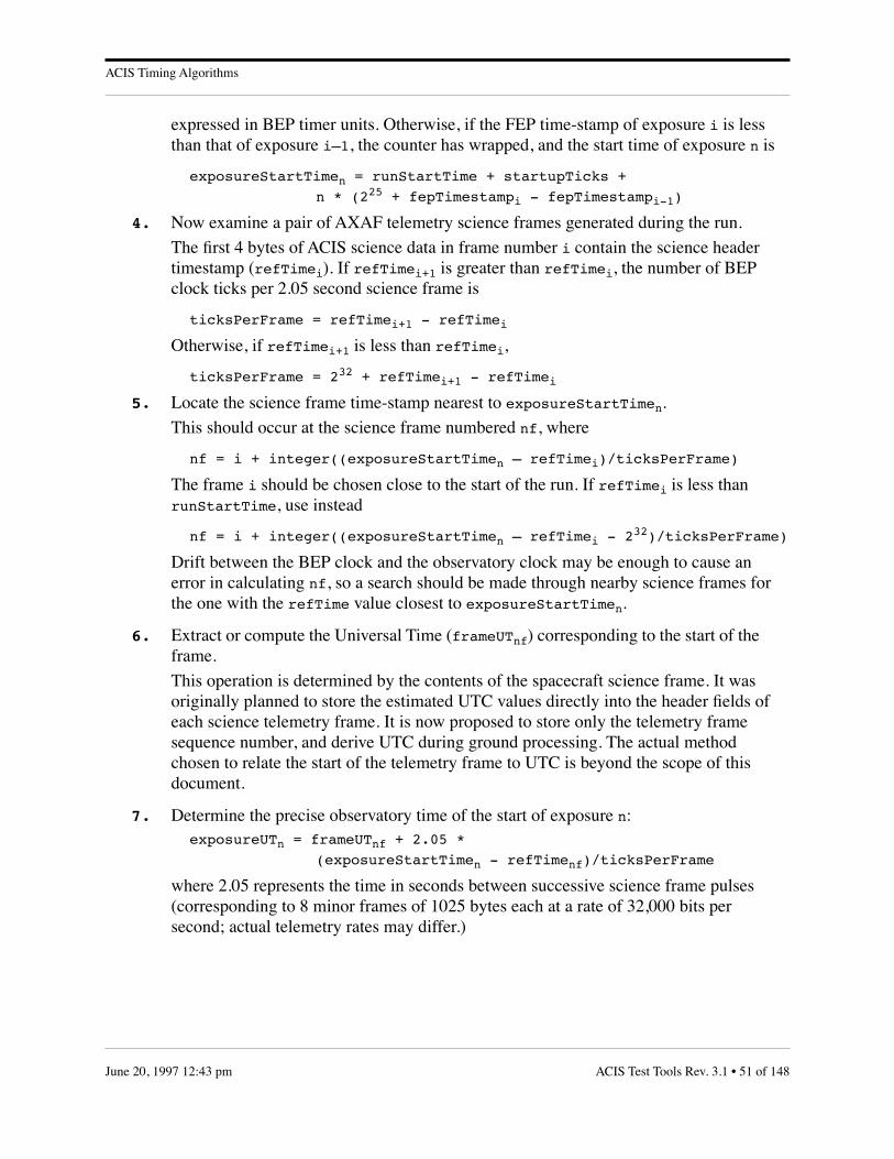
ACIS Timing Algorithms
expressed in BEP timer units. Otherwise, if the FEP time-stamp of exposure i is less than that of exposure i–1, the counter has wrapped, and the start time of exposure n is
exposureStartTimen = runStartTime + startupTicks +
n * (225 + fepTimestampi - fepTimestampi-1)
4. Now examine a pair of AXAF telemetry science frames generated during the run.
The first 4 bytes of ACIS science data in frame number i contain the science header timestamp (refTimei). If refTimei+1 is greater than refTimei, the number of BEP clock ticks per 2.05 second science frame is
ticksPerFrame = refTimei+1 - refTimei
Otherwise, if refTimei+1 is less than refTimei,
ticksPerFrame = 232 + refTimei+1 - refTimei
5. Locate the science frame time-stamp nearest to exposureStartTimen.
This should occur at the science frame numbered nf, where
nf = i + integer((exposureStartTimen – refTimei)/ticksPerFrame)
The frame i should be chosen close to the start of the run. If refTimei is less than runStartTime, use instead
nf = i + integer((exposureStartTimen – refTimei - 232)/ticksPerFrame)
Drift between the BEP clock and the observatory clock may be enough to cause an error in calculating nf, so a search should be made through nearby science frames for the one with the refTime value closest to exposureStartTimen.
6. Extract or compute the Universal Time (frameUTnf) corresponding to the start of the frame.
This operation is determined by the contents of the spacecraft science frame. It was originally planned to store the estimated UTC values directly into the header fields of each science telemetry frame. It is now proposed to store only the telemetry frame sequence number, and derive UTC during ground processing. The actual method chosen to relate the start of the telemetry frame to UTC is beyond the scope of this document.
7. Determine the precise observatory time of the start of exposure n:exposureUTn = frameUTnf + 2.05 *
(exposureStartTimen - refTimenf)/ticksPerFrame
where 2.05 represents the time in seconds between successive science frame pulses (corresponding to 8 minor frames of 1025 bytes each at a rate of 32,000 bits per second; actual telemetry rates may differ.)
ACIS Test Tools Rev. 3.1 • 51 of 148June 20, 1997 12:43 pm

ACIS Timing Algorithms
7.2 The Timeline of Alternating Exposure Time Modes
The following describes the overall steps in determining the start time of a particular exposure inTimed-Exposure Mode when two exposure times are used:
1. Compute runStartTime + startupTicks, as above.
2. Inspect several consecutive exposure records and compute three repetition intervals.int1 = fepTimestampi - fepTimestampi-1
int2 = fepTimestampi+1 - fepTimestampi
int3 = fepTimestampi+2 - fepTimestampi+1
where exposure number i is evenly divisible by (dutyCycle+1). If any of these rates is negative, increment it by 225.
3. Compute the total number of primary exposures and exposure cycles.primaryCount = integer((dutyCycle + n) / (dutyCycle + 1))
cycleCount = integer(n / (dutyCycle + 1))
4. Compute the exposure starting time in BEP timer units.exposureStartTimen = runStartTime + startupTicks +
(n - primaryCount - cycleCount) * int1 +
primaryCount * int2 + cycleCount * int3 +
(cycleCount - primaryCount) * (E2 - E1)
where E1 and E2 are, respectively, the commanded primaryExposureTime and secondaryExposureTime from the timed exposure parameter block, converted to BEP clock units.
5. Follow steps Section 4.–Section 7. of the preceding section to translate exposure-StartTimen to UTC.
52 of 148 • ACIS Test Tools Rev. 3.1 June 20, 1997 12:43 pm

ACIS Data Analysis and Database
8.0 Frame Buffer Specification
M. Doucette
27 October 1995
Revised 7 December 1995
8.1 Significant Changes in this Version• The terms frame and image no longer refer to the same thing. The term file has been
added.
• The “Repeat Pixel” function will not be implemented unless it is deemed necessary and iftime permits. Repeat telemetering a single pixel can be done by repeat telemetering a seg-ment of length one.
• The “parameter file frame changing” function will not be implemented.
• 6 DEA-to-FEP outputs will be implemented.
• The repeat frame directive must appear as the first word in the downloaded frame.
• Multiple images within a frame is valid as long as there is only one “Last Pixel Flag”.
8.2 Terms• Buffer
The term Buffer will refer to the Frame Buffer, an in-house designed and fabricated box usedto supply test images to a Front End Processor (FEP).
• Image
The term image will mean a set of pixels as defined in a DPA/DEA Interface ControlDocument”.
• Directive
A special pixel having a Pixel Code (unused by the FEP) used exclusively by the FrameBuffer for function control.
• File
The term file will refer to that set of data words downloaded from the DECstation to theBuffer box.
• Frame
The term frame will refer to the set of data stored in the Buffer's memory. Frames includeboth image and directive pixels.
8.3 Initial Requirements/Specifications
The following requirements/specifications for a “Frame Buffer” box were proposed:
• Autonomously generate and output a repeating ramp image.
ACIS Test Tools Rev. 3.1 • 53 of 148June 20, 1997 12:43 pm

ACIS Data Analysis and Database
• Receive a single downloaded file from a DECstation via a Direct Memory Access (DMA)interface.
• Accept full or partial frames.
• Output the downloaded frame once, a specified number of times, or repeat the frame con-tinuously.
• Inject a deterministic delay between telemetered frames.
• Telemeter a segment of pixel(s) “n” times.
• Generate a base frame which repeats and in which pixel data increments according todownloaded parameters. (Refer to the Status section.)
• Provide 6 DEA-to-FEP output circuits having indentical data and signal timing.
8.4 Basic Design Concept
The Buffer is designed around a Motorola 56001 Digital Signal Processor (DSP). All code willbe in ROM. A DMA interface is incorporated for receiving downloaded files from theDECstation (and possibly DMA equipped SPARCstations). An internal memory stores a full 16Mbit frame plus up to 128K miscellaneous pixels (e.g., Over Clocks, Ignores, directives, etc.).The memory is organized in 9 131,072 x 16-bit pages. Electrical and data format of signalsinterfacing to flight hardware will be reproduced as defined in the “DPA/DEA Interface ControlDocument”. Integrated circuits interfacing to flight hardware will be commercial versions offlight components. Signal timing will be done with hardware circuitry versus software control.The Pixel Clock frequency is derived from an “RC Coupled CMOS Gate Mulitvibrator” circuitrunning at approximately 6.4 MHz. Since the frequency is determined by a resistor andcapacitor, its stability will not be very good.
The Frame Buffer will not supply FEP power. Buffer internal power will be over-voltageprotected.
Buffer requirements such as telemetering a segment of pixels “n” times, or a frame “n” times,are accomplished by using special “directive” pixels inserted in the appropriate locations in thedownloaded file. These directives use five (TBR) Pixel Codes not used by the FEP. In somecases the 12 data bits in the directive or the 12 data bits in a second pixel are an argument to thedirective. Directive pixels must be inserted by the user in the file to be downloaded.
8.5 Operating Modes
There are two modes of operation selected by a front panel switch: Ramp and Normal Mode.
8.5.1 Ramp Mode
In Ramp Mode the Buffer continuously telemeters pixels which are generated in realtime—this is not a stored file. The ramp image begins with 4 Ignore pixels followed by 4Vertical Syncs followed by 1024 rows of 1024 columns of Valid pixels. Column 0 of eachrow contains the row number (0 thru 3FF hex). Columns 1 thru 1023 contain the column
54 of 148 • ACIS Test Tools Rev. 3.1 June 20, 1997 12:43 pm

ACIS Data Analysis and Database
number (1 thru 3FF hex). Each row ends with 32 Over Clocks having an incrementing datafield (0 thru 1F hex) followed by 4 Horizontal Syncs.
8.5.2 Normal Mode
When the Buffer is in Normal Mode and is powered on, a file must be downloaded to theBuffer memory. Once downloaded, the Buffer will telemeter the image to the FEP inaccordance with directives within the frame data. A reset will cause the Buffer to monitorthe DMA interface in preparation for receiving data from the DECstation. A reset will notcause the loss of a currently stored frame, and telemetering may be initiated by theDECstation issuing a “Go” command. All pixels in the downloaded file are stored inmemory. The Pixel Code of each pixel is decoded as it is received, and transfers will beterminated only upon receiving a “Last Pixel Flag” directive (see below). After thedownload is complete, the Buffer will then telemeter the image to the FEP. Directives arenot telemetered to the FEP.
8.6 Directive Functions
In the following paragraphs, unused bits in hexadecimal fields are marked with the letter ‘X’.
8.6.1 “EXXX” Last Pixel Flag (LPF)
The LPF marks the last pixel in the downloaded file. The data bits in this pixel are ignored.Attempting to download pixels after a LPF will have an indeterminate effect on the Bufferoperation. A frame may contain multiple images but only one LPF directive.
8.6.2 “Annn” Repeat Segment “nnn” times (RS)“Xnnn” Segment Length argument (SL)
This function requires two arguments. The first argument is the 12 data bits in the directivewhich defines the number of times (up to FFF hex) the segment is to be written to the FEP.The second argument is in the following pixel and defines the number of pixels (up to FFFhex) in the segment. The pixel following the second argument is the first pixel of thesegment.
8.6.3 “7nnn” Repeat Frame “nnn” times (RF)
Repeat this frame “nnn” times. If the downloaded file does not begin with this directive, orif its argument “nnn” is “000 hex”, the frame will repeat continuously. This directive mustappear as the first word in the downloaded file—it is only tested once, and will be ignoredif it occurs later in the file.
8.6.4 “6000” Go (TBR)
This single directive (or, more appropriately, command) downloaded from the DECstationcauses the Buffer to begin telemetering a currently stored frame. This directive is ignoredunless a frame has been stored in the buffer.
ACIS Test Tools Rev. 3.1 • 55 of 148June 20, 1997 12:43 pm

ACIS Data Analysis and Database
8.7 Current Status
Two circuit boards have been wired and a third is in progress. (Hardware revision levels beloware for initial use only.)
• S/N 01 hardware is at Rev. 01. The DSP code installed in this unit is configured to gener-ate ramp images only—image data files cannot be downloaded to this unit at this time.
• S/N 02 hardware is at Rev. 04. This unit has been used to develop DSP code to receivedownloaded files, decode directives, and output image data in accordance with thosedirectives. Code to generate a ramp image is not installed in this unit as yet.
The current version of the DSP code processes directives correctly. Timing has been a concernbecause, within the 2.5 µsec pixel period, each pixel is read, decoded and processed before it istelemetered to the FEP. “Repeat Segments” within the frame are processed in about 1.5 µsec.Continuous frames are also not a problem, taking about 0.75 µsec to process. The additionalcode required to process a “Repeat Frame” proved to be a problem. Periodically it has takenmore than 2.5 µsec to set up for the next frame. As a result, the last pixel of the previous framewould be re-telemetered before the first pixel of the coming frame could be latched into theoutput circuits. To avoid this problem, I have the DSP running with minimum wait states. Togain some margin, the current 24 MHz DSPs will be replaced with 33 MHz devices. Thedownload time for short (1k word) files has been measured at approximately 3.2 µsec/word. Therequirement in which the Buffer would generate a “base” frame which would continuouslytelemeter pixels which change data from one image to the next according to downloadedparameters will not be implemented.
8.8 Proposed Additional Features
8.8.1 Front Panel Status LEDs
• Power On LED — Self explanatory.
• DMA Request LED — Indicates that the DECstation is waiting to download a file. It remains lit during the download and is cleared by the Buffer receiving a LPF or a RESET.
• Telemetry In Progress — Lit while the Buffer is telemetering Pixels to the FEP.
8.8.2 Error LED(s)
• Pixel Re-write LED — Lit when a timing error occurs and the Buffer re-teleme-ters a Pixel. This LED would be cleared by a RESET.
56 of 148 • ACIS Test Tools Rev. 3.1 June 20, 1997 12:43 pm

ACIS Data Analysis and Database
9.0 ACIS Data Analysis and Database
To: ACIS Team
From: Jonathan W. Woo
Subject: ACIS Data Analysis and Database
Date: 4 May 1995
This memo describes the following subjects related to the MIT ACIS lab calibrations: dataformats, standard preliminary analysis procedures, utility software, and the database structure ofevents collected from flight devices.
9.1 Data Format
At present, there are four different data formats used in the initial data reduction processes. (1)Raw data read from ACIS CCDs are first recorded in the FITS files of full frame images. (2,3)From the raw image FITS files, events are then collected and stored in one of two event listformats—Ftool science file (FSF) format and ACIS RV (ARV) format, or in both. (4) Someevent lists are also stored in IDL table files.
9.2 Raw Image Format
The raw data read out from ACIS CCDs by current test electronics are initially recorded in 2DFITS image files. Each value of readout pixels is registered as a 16 bits short integer record. Inthe beginning of each raw FITS file, extended FITS Header keywords can be found.
The following first group of keywords are there to conform to the FITS standard:
SIMPLE = T / file does conform to FITS standardBITPIX = 16 / number of bits per data pixelNAXIS = 2 / number of data axesNAXIS1 = 1120 / length of data axis 1NAXIS2 = 256 / length of data axis 2 EXTEND = T / FITS dataset may contain extensions
These keywords specify that this FITS file contains a 2D short integer (16 bits) image array(1120x256).
The next six keywords are used to map a subframe array captured/saved from the full framearray (when the entire CCD is read out). The full frame array includes all active image pixelsand “expected” overclock pixels (OCs) that should be consistent with OCs in the subframearray.
RASTER1 = 1120 / Original column dimension of entire CCDRASTER2 = 1030 / Original row dimension of entire CCDCRPIX1 = 1 / starting column number of sub image arrayCRPIX2 = 1 / starting row number of sub image arrayCRVAL1 = 1 / starting column number of remapping array
ACIS Test Tools Rev. 3.1 • 57 of 148June 20, 1997 12:43 pm

ACIS Data Analysis and Database
CRVAL2 = 200 / starting row number of remapping array
Thus RASTER1 and RASTER2 define the “expected” dimension of the full frame array. Thesekeywords are useful when a subframe array of a given device is compared with a different (inlocationwise) subframe array of the same device. The values of CRPIX1 and CRPX2 is usually1. CRVAL1 and CRVAL2 should be the coordinate values of the first pixel from the subframearray relative to the full frame array (see Figure 4).
The following keywords are there for record keeping purposes:
MISSION = 'AXAF ' / Mission nameTELESCOP= 'MIT_CCD ' / Telescope (facility) nameINSTRUME= 'ACIS ' / Instrument nameOBS_MODE= 'GROUND ' / Observation modeOBS_ID = 'PTB Whitelight' / Observation purposeDATAMODE= 'SPECIAL ' / data modeCREATOR = '/usr/acis/s56dsp/hostvid' / creator of data
/ acquisition and control softwareDETNAM = 'w34c3 ' / CCD IDAEID = 'acis3 ' / Electronics IDORIGIN = 'MIT ' / SAO/MITSRC_ID = 'BESSY ' / Name of X-ray source deviceOBJECT = 'PTB ' / Name of X-ray source anodeOBSERVER= 'sek' / User ID of calibration operatorHOSTID = '0xeffff284' / host machine CPU IDHOSTNAME= 'otto' / Host machine nameDATE = '27/04/95' / FITS file creation date (dd/mm/yy)
These keywords are self-explanatory.
The next set of keywords specify the locations of the active readout image pixels in the readoutarray:
IAMINCOL= 5 / Minimum column number of Output Node A
FIGURE 4. Relative coordinate system of a subframe arraywith respect to the full frame array.
Captured
RASTER1
RA
STE
R2
NA
XIS
2
NAXIS1(CRVAL1, CRVAL2) :in RASTER Coord.
Entire CCD(Active Pixels + Exp. OC)
58 of 148 • ACIS Test Tools Rev. 3.1 June 20, 1997 12:43 pm

ACIS Data Analysis and Database
IAMAXCOL= 260 / Maximum column number of Output Node AIAMINROW= 1 / Minimum row number of Output Node AIAMAXROW= 256 / Maximum row number of Output Node AIBMINCOL= 285 / Minimum column number of Output Node BIBMAXCOL= 540 / Maximum column number of Output Node BIBMINROW= 1 / Minimum row number of Output Node BIBMAXROW= 256 / Maximum row number of Output Node BICMINCOL= 565 / Minimum column number of Output Node CICMAXCOL= 820 / Maximum column number of Output Node CICMINROW= 1 / Minimum row number of Output Node CICMAXROW= 256 / Maximum row number of Output Node CIDMINCOL= 845 / Minimum column number of Output Node DIDMAXCOL= 1100 / Maximum column number of Output Node DIDMINROW= 1 / Minimum row number of Output Node DIDMAXROW= 256 / Maximum row number of Output Node D
These are the row and column boundaries of the four read out nodes which contains activeimage pixels which exclude overclock pixels, underclock pixels, and undefined parallel transferclock pixels from the readout array.
The frame acquisition time (actually for the previous frame) and a rough exposure time(difference between two UNIX time calls at the two consecutive data synchronization marks)are recorded in the following keywords:
DATE-OBS= '27/04/95' / Date(dd/mm/yy) of exposure start (EDT)TIME-OBS= '05:08:39' / Time(hh:mm:ss) of exposure start (EDT)ONTIME = 1.528E+00 / Exposure time (sec between two sync)
The following keywords are initially set by data acquisition programs:
FILENAME= 'i24ey001.1170.fits'FILEPATH= '/otto/d3/w34c3/27Apr0357/'OVERFILL= 24704 / over fillVERBOSE = 1 / verbose (0=off;1=on)TRIGGER = F0F0 /TRCOUNT = 16 /
Voltage, current, and temperature readings of various clocks and corresponding ADU values arerecorded in the following keywords:
V_IA_H = +4.490 / Voltage of CCD Image Clock High (V)A_IA_H = 44262 / ADU of CCD Image Clock High (ADU)V_IA_L = -5.033 / Voltage of CCD Image Clock Low (V)A_IA_L = 19884 / ADU of CCD Image Clock Low (ADU)V_FS_H = +6.956 / Voltage of CCD Frame Storage Clock High (V)A_FS_H = 50576 / ADU of CCD Frame Storage Clock High (ADU)V_FS_L = -1.888 / Voltage of CCD Frame Storage Clock Low (V)A_FS_L = 27935 / ADU of CCD Frame Storage Clock Low (ADU)V_OR_H = 0.0 / Voltage of CCD Output Register Clock High (V)A_OR_H = 0 / ADU of CCD Output Register Clock High (ADU)
ACIS Test Tools Rev. 3.1 • 59 of 148June 20, 1997 12:43 pm

ACIS Data Analysis and Database
V_OR_L = 0.0 / Voltage of CCD Output Register Clock Low (V)A_OR_L = 0 / ADU of CCD Output Register Clock Low (ADU)V_RG_H = +7.522 / Voltage of CCD Reset Clock High (V)A_RG_H = 52025 / ADU of CCD Reset Clock High (ADU)V_RG_LP = +4.018 / Voltage of CCD Reset Clock Low+ (V)A_RG_LP = 43054 / ADU of CCD Reset Clock Low+ (ADU)V_SCP = +7.027 / Voltage of CCD Scupper (V)A_SCP = 50758 / ADU of CCD Scupper (ADU)V_OG_P = +1.020 / Voltage of CCD Output Gate+ (V)A_OG_P = 35378 / ADU of CCD Output Gate+ (ADU)V_RDA = +7.021 / Voltage of CCD Reset Drain (V)A_RDA = 50742 / ADU of CCD Reset Drain (ADU)V_HTR_C = +0.014 / Amp of Heater CurrentA_HTR_C = 32803 / ADU of Heater CurrentV_HTR_V = +0.014 / Heater Voltage (V)A_HTR_V = 32804 / ADU of Heater VoltageV_RG_LM = 0.0 / Voltage of CCD Reset Clock Low - (V)A_RG_LM = 0 / ADU of CCD Reset Clock Low - (ADU)V_VDD_A = +19.170 / Voltage of CCD Vdd_A (V)A_VDD_A = 49126 / ADU of CCD Vdd_A (ADU)V_VDD_B = +19.173 / Voltage of CCD Vdd_B (V)A_VDD_B = 49129 / ADU of CCD Vdd_B (ADU)V_VDD_C = +19.105 / Voltage of CCD Vdd_C (V)A_VDD_C = 49071 / ADU of CCD Vdd_C (ADU)V_VDD_D = +19.218 / Voltage of CCD Vdd_D (V)A_VDD_D = 49167 / ADU of CCD Vdd_D (ADU)V_BJ = 0.0 / Voltage of CCD Back Junction (V)A_BJ = 0 / ADU of CCD Back Junction (ADU)V_EB_A = +5800.000 / Voltage of node A Electronics Bias (V)A_EB_A = 5800 / ADU of node A Electronics Bias (ADU)V_EB_B = +5500.000 / Voltage of node B Electronics Bias (V)A_EB_B = 5500 / ADU of node B Electronics Bias (ADU)V_EB_C = +5700.000 / Voltage of node C Electronics Bias (V)A_EB_C = 5700 / ADU of node C Electronics Bias (ADU)V_EB_D = +5900.000 / Voltage of node D Electronics Bias (V)A_EB_D = 5900 / ADU of node D Electronics Bias (ADU)CAM_TEMP= +0.013 / Camera Temperature (C)CCD_TEMP= -242.00 / CCD Temperature (C)
The DE binary bit settings for the “gse” data acquisition program are recorded in the followingkeywords:
DE_MODE0= 0 / CHKCR: MODE0 bit (0=off;1=on)DE_MODE1= 0 / CHKCR: MODE1 bit (0=off;1=on)DE_HSEQ = 1 / CHKCR: HSEQ bit(0=off;1=on) the hard sequencerDE_TSAP = 0 / CHKCR/TESTAP asyn loopback test (global hk pipe)DE_BOARD= 1 / CHKCR: BOARD bit (0=off;1=on)DE_RASTR= 1 / CHKCR: RASTER bit (0=off;1=on)
60 of 148 • ACIS Test Tools Rev. 3.1 June 20, 1997 12:43 pm

ACIS Data Analysis and Database
DE_RIGHT= 0 / VHKCR: RIGHT bit (0=off;1=on)DE_SHFT0= 0 / VHKCR: SHIFT0 bit (0=off;1=on)DE_SHFT1= 0 / VHKCR: SHIFT1 bit (0=off;1=on)DE_SHFT2= 0 / VHKCR: SHIFT2 bit (0=off;1=on)DE_EN12 = 0 / VCRX: EN12 bit (0=off;1=on)DE_TSDVP= 0 / VCRX: TESTDVP bit (0=off;1=on)DE_HEATR= 0 / DHKCR: Turns the heater (0=off;1=on)DE_SWAP = 0 / DHKCR: Swaps output shift reg phs 2 with 3
9.2.1 FSF Format
In the standard ACIS analysis procedure, an event (3x3 pixel island whose center pixel value isthe local maximum above event threshold) detected by the event finding algorithm (adoptedfrom rv_findevents) is stored in the FSF event files. The FSF event files are in a binary FITStable extension format similar to the ASCA science event file format. Each FSF file has at leastthe following three components: a dummy primary image extension with zero dimension, abinary table extension containing events, and a binary table extension of good time intervals(GTIs). Since most of the FITS Header keywords in FSF are adopted from ASCA convention, adetailed description of the keywords is not presented in this memo.
In the binary table extension, each event is defined by 10 fields:
TIME, READX, READY, CHIPX, CHIPY, LABX, LABY, FRAME, PHAS, CCDNODE.
The TIME field is the absolute time (seconds after 1994.0 in UNIX time) of the frame exposurewhen the event was detected. The center pixel position of a detected event (above a specifiedevent threshold) is recorded in readout, physical CCD, and lab reference coordinate systems,respectively as READX & READY, CHIPX & CHIPY, and LABX & LABY columns. TheFRAME field contains the integer numbers of the frames where the detected events extracted.The frame numbers are counted from the TSTART time when the first data frame is exposed.
Therefore, the frame number has only a relative meaning for a single FSF data set. In amathematical expression, nframe = (t-TSTART)/exposure. The PHAS field contains 9 shortinteger pulse height values of a 3x3 pixel island (see Figure 5). Finally, the CCDNODE fieldspecifies the read-out node.
FIGURE 5. Sequence of pixel values from 3x3 pixel islandstored in the event record of an FSF.
1
2 3 4
5 6
7 8 9
READX
RE
AD
Y
ACIS Test Tools Rev. 3.1 • 61 of 148June 20, 1997 12:43 pm
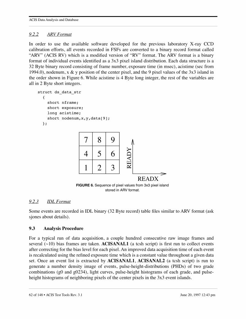
ACIS Data Analysis and Database
9.2.2 ARV Format
In order to use the available software developed for the previous laboratory X-ray CCDcalibration efforts, all events recorded in FSFs are converted to a binary record format called“ARV” (ACIS RV) which is a modified version of “RV” format. The ARV format is a binaryformat of individual events identified as a 3x3 pixel island distribution. Each data structure is a32 Byte binary record consisting of frame number, exposure time (in msec), acistime (sec from1994.0), nodenum, x & y position of the center pixel, and the 9 pixel values of the 3x3 island inthe order shown in Figure 6. While acistime is 4 Byte long integer, the rest of the variables areall in 2 Byte short integers.
struct ds_data_str { short nframe; short exposure; long acistime; short nodenum,x,y,data[9]; };
9.2.3 IDL Format
Some events are recorded in IDL binary (32 Byte record) table files similar to ARV format (asksjones about details).
9.3 Analysis Procedure
For a typical run of data acquisition, a couple hundred consecutive raw image frames andseveral (~10) bias frames are taken. ACISANAL1 (a tcsh script) is first run to collect eventsafter correcting for the bias level for each pixel. An improved data acquisition time of each eventis recalculated using the refined exposure time which is a constant value throughout a given dataset. Once an event list is extracted by ACISANAL1, ACISANAL2 (a tcsh script) is run togenerate a number density image of events, pulse-height-distributions (PHDs) of two gradecombinations (g0 and g0234), light curves, pulse-height histograms of each grade, and pulse-height histograms of neighboring pixels of the center pixels in the 3x3 event islands.
FIGURE 6. Sequence of pixel values from 3x3 pixel islandstored in ARV format.
6
7 8 9
READX
RE
AD
Y
54
321
62 of 148 • ACIS Test Tools Rev. 3.1 June 20, 1997 12:43 pm

ACIS Data Analysis and Database
9.3.1 ACISANAL1
This script first produces a mean clip bias frame from all the available bias frames in a data set,by executing the meanbiasclip program:
ls ${bias_heading}.????.fits | meanbiasclip ${bias}
The mean bias frame prepared in this step will be used in the acis_mit_findevents routine toestimate the bias level for each pixel.
After a FITS file containing the mean bias frame is created, the script then prepares to run themain routine, acis_mit_findevents to extract events. As a first step for the preparation, the scriptexecutes the following line to collect all data file names into a temporary file:
ls ${data_heading}.????.fits > tmp_data.list
And then, the script calculates the exposure time of the data set (which is a constant value for asingle data set). It uses the first 20 files to estimate a rough exposure time by executing theget_exp program which makes a simple average of values stored in the FITS header keywordONTIME from the first 20 raw image frames. The script calls get_exp again to make a fineadjustment of the exposure time by averaging all ONTIME values which are close to the initialrough exposure time within 50% level. With these two iterations, the calculated exposure timeshould be good to 1/1000 s.
The following two lines in the ACISANAL1 script are executed to calculate the exposure time:
set init_exp = `get_exp -1.0 20 < tmp_data.list | lines 1-1`set exp = `get_exp ${init_exp} 0 < tmp_data.list | lines 1-1`
Once an accurate exposure time and an average bias frame are obtained, the ACISANAL1script runs the acis_mit_findevents program to extract events. acis_mit_findevents first readsin the mean bias frame and subtracts it off from each data image frame before extracting events.For each quadrant, it adds back the mean value of the bias frame subtracted image over-clockregion to each image pixel for a fine temporal bias level adjustment. Then, the program goesthrough each pixel of the bias subtracted image array to find events where each event's centralpixel value is above the low event threshold and is also the local maximum in the 3x3 island.Events are then recorded in a FSF event binary table FITS file. Each event record is identifiedwith the UNIX time (absolute time is good to within a sec and relative time among events in asingle data set is good to within ~1 ms), the position (readout and device coordinates) of thecenter pixel, quadrant id, and the 9 pixel values of the 3x3 island. This step is executed by:
acis_mit_findevents -el ${low_ev_th} -i stdin -bs ${bias} -o${acis_evts_fits} -h ${acis_hk_fits} -exp ${exp} < tmp_data.list
To do further analysis using available RV tools, the FSF event list is converted into ARV formatby running the acis_fits_to_rv program.
acis_fits_to_rv ${acis_evts_fits} stdout > ${acis_evts}
ACIS Test Tools Rev. 3.1 • 63 of 148June 20, 1997 12:43 pm

ACIS Data Analysis and Database
Since it is convenient to calculate readout noise at this stage, the acis_readoutnoise tcsh scriptis called to calculate readout noise values for 4 image and overclock regions using the first twobias files.
acis_readoutnoise ${bias_heading}.0001.fits ${bias_heading}.0002.fits
9.3.2 ACISANAL2
ACISANAL2 is a tcsh script which creates secondary products from an ARV event file: pulse-height distributions (histograms and XSPEC input file—PHA), event number density map, lightcurves, and event corner pixel pulse-height distributions. A number density map is created as a2D FITS image file, PHA files are in the XSPEC binary format, and the rest of the products arein QDP file formats.
The ACISANAL2 script first creates a number density map of detected events whose pixelgrade distributions are either singles or splits (i.e., grades 0, 2, 3, or 4).
rv_gflt ${ev_th} ${sp_th} -p 0 4095 -g 0 2 3 4 < ${acis_evts} | rv_ef${x_img} ${y_img} > ${heading}_sp${sp_th}_g0234_img.fits
For each of the four read-out nodes, two pulse-height histograms (g0 & g0234) are created. Inthe script, the following two lines in the foreach loop are executed:
rv_streamfilt -c ${ro_node} < ${acis_evts} | rv_gflt ${ev_th}${sp_th} -p 0 4095 -g 0 | grad_ph ${sp_th} | awk '{print $4}' | histo1 0.5 4095.5 4096 > ${heading}_c${ro_node}_sp${sp_th}_g0.qdprv_streamfilt -c ${ro_node} < ${acis_evts} | rv_gflt ${ev_th}${sp_th} -p 0 4095 -g 0 2 3 4 | grad_ph ${sp_th} | awk '{print $4}' |histo 1 0.5 4095.5 4096 > ${heading}_c${ro_node}_sp${sp_th}_g0234.qdp
Next, the script calculates the variation in count rate (counts/frame) for each read-out node as afunction of frame number counted from the first raw image frame of a given set (~200 frames).
rv_streamfilt -c ${ro_node} < ${acis_evts} | rv_gflt ${ev_th}${sp_th} -p 0 4095 -g 0 2 3 4 | grad_ph ${sp_th} | awk '{print $7}' |lightcv > ${heading}_c${ro_node}_sp${sp_th}_g0234_lightcv.qdp
And, pulse-height histograms of each grade (0 to 7) are produced in QDP by the following tcshcommand:
rv_streamfilt -c ${ro_node} < ${acis_evts} | rv_gflt ${ev_th}${sp_th} -p 0 4095 | rv_ev2pcf ${ev_th} ${sp_th} /dev/null >${heading}_c${ro_node}_pcf.qdp
Neighbor histograms (corner pixel distributions and top, bottom, left, and right pixeldistributions of detected events) are produced by the following command:
rv_streamfilt -c ${ro_node} < ${acis_evts} | neighborhist >${heading}_neighborhist_c${ro_node}.qdp
64 of 148 • ACIS Test Tools Rev. 3.1 June 20, 1997 12:43 pm

ACIS Data Analysis and Database
In QDP files, as a product of this step, “readout fraction” (total pixel values divided by the totalnumber of pixels for each bin) is plotted against ADU.
To use XSPEC for the spectral analysis (with convolution of response matrix), two PHA filesare produced (g0 & g0234):
rv_streamfilt -c ${ro_node} < ${acis_evts} | rv_gflt ${ev_th}${sp_th} -p 0 4095 -g 0 2 3 4 | rv_ev2pha ${ev_th} ${sp_th} 1 >${heading}_c${ro_node}g0234.pharv_streamfilt -c ${ro_node} < ${acis_evts} | rv_gflt ${ev_th}${sp_th} -p 0 4095 -g 0 | rv_ev2pha ${ev_th} ${sp_th} 1 >${heading}_c${ro_node}g0.pha
9.3.3 Data Products
A summary table and sample plots of products generated by ACISANAL2 are presented in thissection. A sample plot of light curve is shown in Figure 7, a sample plot of PH-histogram is inFigure 8, a sample plot of primary calibration file is in Figure 9, and a sample plot of read-outnoise distribution is in Figure 10.
TABLE 25. Summary of products from ACISANAL2
Type Sample_filename Format Purpose
Evts Num Density test_sp20_g0234_img.fits FITS Event Flux
PH histogram test_c0_sp20_g0.qdp QDP Spectral Resolution
PH histogram test_c0_sp20_g0234.qdp QDP Spectral Resolution
PH spectrum test_c0_sp20_g0.pha XSPEC Spectral response/QE meas.
PH spectrum test_c0_sp20_g0234.pha XSPEC Spectral response/QE meas.
Primary Cal File test_c0_pcf.qdp QDP Grade branching ratio meas.
Light Curve test_c0_sp20_g0234_lightcv.qdp QDP Check source/detector stability
Noise Summary File readoutnoise.out ASCII Read-out Noise σ (ADU)
Noise Model readoutnoise00im.model ASCII 1 Gaussian fit
Noise spectrum readoutnoise00im.qdp QDP Read-out Noise meas.
ACIS Test Tools Rev. 3.1 • 65 of 148June 20, 1997 12:43 pm

ACIS Data Analysis and Database
FIGURE 7. A sample light curve
FIGURE 8. A sample PH histogram/spectrum.
66 of 148 • ACIS Test Tools Rev. 3.1 June 20, 1997 12:43 pm

ACIS Data Analysis and Database
FIGURE 9. A sample primary calibration file
FIGURE 10. A sample readout noise file
ACIS Test Tools Rev. 3.1 • 67 of 148June 20, 1997 12:43 pm

ACIS Data Analysis and Database
9.4 Utility Software
There are a few utility modules in the “/usr/acis/bin” directory. ana2gau calculates the FWHMvalue of 2–Gaussian model determined by a fit to the PH histogram. The ARV event list can bedisplayed in ascii format with acisrvtoascii.
9.5 Database
The ACIS flight device calibration database will be constructed as subdirectory trees. On the toplevel, there will be one directory for each device and the directory name will be named after thedevice id (e.g., c17–103–1). For a given device directory, there will be subdirectories to identifylab experiment setups (e.g., IFM, HIREFS, HE–A, HE–B, SES, BESSY). As a next lower levelsubtree, the date of a particular data acquisition will be used (e.g., 01may95). A FSF event FITSfile, a house keeping FITS file, an ARV file, two bias FITS files, and the averaged bias FITS filewill be stored in the next lower level which specifies the source energy range (e.g., carbon_k,oxygen_k). Any ASCII note regarding to the particular data set will be placed at the samedirectory.
As an example,
p4 jww@ohno> pard/ohno/d1/c17-103-1/bessy/09mar95/t1957_i05ey495p4 jww@ohno> lsc17-103-1_bessy_09mar95_1957_i05ey495.evtsc17-103-1_bessy_09mar95_1957_i05ey495_bias.0001.fitsc17-103-1_bessy_09mar95_1957_i05ey495_bias.0002.fitsc17-103-1_bessy_09mar95_1957_i05ey495_bias_avg.fitsc17-103-1_bessy_09mar95_1957_i05ey495_evts.fitsc17-103-1_bessy_09mar95_1957_i05ey495_hk.fitsproducts/temperature.dat
The secondary products from ACISANAL2 will be also stored in a subdirectory call“products”:
p4 jww@ohno> pwd/ohno/d1/c17-103-1/bessy/09mar95/t1957_i05ey495/productsp4 jww@ohno> lsi05ey495_c0_pcf.qdp i05ey495_neighborhist_c0.qdpi05ey495_c0_sp20_g0.qdp i05ey495_neighborhist_c1.qdpi05ey495_c0_sp20_g0234.qdp i05ey495_neighborhist_c2.qdpi05ey495_c0_sp20_g0234_lightcv.qdp i05ey495_neighborhist_c3.qdpi05ey495_c0_sp20_g0.pha i05ey495_sp20_g0234_img.fitsi05ey495_c0_sp20_g0234.pha readoutnoise.mesgi05ey495_c1_pcf.qdp readoutnoise.outi05ey495_c1_sp20_g0.qdp readoutnoise00im.modeli05ey495_c1_sp20_g0234.qdp readoutnoise00im.qdpi05ey495_c1_sp20_g0234_lightcv.qdp readoutnoise00oc.model
68 of 148 • ACIS Test Tools Rev. 3.1 June 20, 1997 12:43 pm

ACIS Data Analysis and Database
i05ey495_c1_sp20_g0.pha readoutnoise00oc.qdpi05ey495_c1_sp20_g0234.pha readoutnoise01im.modeli05ey495_c2_pcf.qdp readoutnoise01im.qdpi05ey495_c2_sp20_g0.qdp readoutnoise01oc.modeli05ey495_c2_sp20_g0234.qdp readoutnoise01oc.qdpi05ey495_c2_sp20_g0234_lightcv.qdp readoutnoise02im.modeli05ey495_c2_sp20_g0.pha readoutnoise02im.qdpi05ey495_c2_sp20_g0234.pha readoutnoise02oc.modeli05ey495_c3_pcf.qdp readoutnoise02oc.qdpi05ey495_c3_sp20_g0.qdp readoutnoise03im.modeli05ey495_c3_sp20_g0234.qdp readoutnoise03im.qdpi05ey495_c3_sp20_g0234_lightcv.qdp readoutnoise03oc.modeli05ey495_c3_sp20_g0.pha readoutnoise03oc.qdpi05ey495_c3_sp20_g0234.pha
A log summary file of these directory trees, called “data.log” can be found in the “/usr/acis/database/” directory. This file can be used as a guide to locate events and products. The contentof this file should be:
CDID EXP DATE(HH:MM) SRCID DIR USER MOD-DATEc17-103-1 BESSY 09mar95(19:57) i05ey495 * jww 05/02/95
* = /ohno/d1/c17-103-1/bessy/09mar95/t1957_i05ey495
ACIS Test Tools Rev. 3.1 • 69 of 148June 20, 1997 12:43 pm
UNIX Commands - ACISshell
10.0 UNIX Commands
10.1 ACISshell
NAME
ACISshell – run a shell from which the CTUE can get ACIS commands
SYNOPSIS
ACISshell
DESCRIPTION
ACISshell creates a TCP/IP socket at the port that the CTUE will connect to when accepting commands fromthe ACIS EGSE. Once the connection is established, the program executes a standard Bourne shell, which itindicates by displaying the ACISshell% command prompt.
This shell and all of the programs that it launches inherit the open socket descriptor that connects to theCTUE. (This socket descriptor is available in environment variable CTUE_CMD_SD.) To send commandsto the CTUE use:
ACISshell% buildCmds < ACIS command script file | sendCmds | writeCCB
or:
ACISshell% cat < CTUE command block file > &$CTUE_CMD_SD
ACISshell tries to open port 541 for CTUE commands. This port number is in the range that only root canopen. If ACISshell is not running with root priviledges, it will try to open port 7541 for CTUE commands.The appropriate port number must be entered in the CTUE’s c:\windows\ethernet.cfg file. The IPaddress of the host where ACISshell will run must also be entered in this file. The CTUE will connect onlyto the IP address and port indicated.
To connect to the CTUE, the user should first execute ACISshell and then use the CTUE’s GUI to selectACIS commands from the Ethernet control section. ACISshell, like the CTUE, handles only a singleconnection. When that connection terminates, so does the program and so does the connection to the CTUE.However, commands can be sent repeatedly while the ACISshell% prompt is displayed.
AUTHOR
Demitrios Athens, MIT CSR
Ann M. Davis, MIT CSR for the network code.
SEE ALSO
writeCCB(1)
CTUE User’s Manual
70 of 148 • ACIS Test Tools Rev. 3.1 June 20, 1997 12:43 pm

UNIX Commands - acisBepUnix
10.2 acisBepUnix
NAME
acisBepUnix – Simulate the ACIS Back End Processor
SYNOPSIS
acisBepUnix
DESCRIPTION
This program simulates the Back End Processor software on an Ultrix workstation. The program launches acommand server program, cserver, to acquire command packets, and writes its binary telemetry to stdout.The cserver program is launched to establish a command socket on the local host machine. The used socketnumber is 7000.
Command packets may be built and sent to the running simulation using buildCmds and cclient. Telemetrycan be examined using psci or ltlm. (Note: Typically, a telemetry server, such as filterServer is setup to readstdout of the program and then distribute the telemetry to one or more clients. The clients then decode thereceived telemetry packets).
FEP hardware and software can be simulated using acisFepUnix. Each instance of a simulated FEP is adistinct invocation of acisFepUnix. The BEP simulator communicates with the simulated FEPs throughshared memory segments.
OPTIONS
None
RESTRICTIONS
cserver must be in the user’s search path.
This program is currently only supported for the DECstations running Ultrix.
FILES
None
SEE ALSO
cserver(1), cclient(1), acisFepUnix(1), buildCmds(1), psci(1), ipcs(1), ipcrm(1)
DIAGNOSTICS
Fatal Messages:
None
Warning Messages:
None
Informatory Messages:
Discrete Software Telemetry codes (LED codes) appear on stderr as they are written to the "hardware"by the flight software.
The message "WarmFuzzy" is written to stderr once about every 5 seconds.
Commands to the DEA are decoded and written to stderr.
ACIS Test Tools Rev. 3.1 • 71 of 148June 20, 1997 12:43 pm
UNIX Commands - acisFepUnix
10.3 acisFepUnix
NAME
acisFepUnix – Simulate the ACIS Front End Processor
SYNOPSIS
acisFepUnix fepId
DESCRIPTION
This program simulates a single Front End Processor software on an Ultrix workstation. The FEP is indicatedby fepId. The FEP simulation program communicates with the BEP simulation program, acisBepUnix, usingshared memory segments and signals. Images are loaded into the FEP simulation using fepImage2, which alsouses shared memory and signals to communicate with the FEP process. The BEP program simulates a resetto the FEP simulation using the SIGUSR2 (31) signal. The FEP image loader program simulates FEPinterrupts using the SIGUSR1 (30) signal.
OPTIONS
None
RESTRICTIONS
Only one acisFepUnix program with a given fepId may be active on a single machine at a time.
This program is currently only supported for the DECstations running Ultrix.
FILES
None
SEE ALSO
acisBepUnix(1), fepImage2(1), ipcs(1), ipcrm(1)
DIAGNOSTICS
Fatal Messages:
If the program fails to obtain shared memory segments, it will issue an error message to stderr and exitwith a -1.
Warning Messages:
None
Informatory Messages:
During initialization, the program prints information about its shared memory segments to stderr.
When the FEP program is "reset" it prints a "Calling fepCtl()" message to stdout.
72 of 148 • ACIS Test Tools Rev. 3.1 June 20, 1997 12:43 pm

UNIX Commands - acispkts
10.4 acispkts
NAME
acispkts – extract ACIS packets and pseudopackets from LRCTU output
SYNTAX
acispkts [–ep] [–np] [–nt]
DESCRIPTION
acispkts reads the stdout stream from the LRCTU handler, rctu2b, identifies individual ACIS telemetrypackets, and writes them to the standard output stream, stdout.
Unless the –np option is specified, acispkts will generate one science frame pseudopacket and oneengineering pseudopacket for every simulated LRCTU science pulse, at 2.05 second intervals. The scienceframe pseudopacket will contain the 32-bit BEP science pulse timestamp and a time-of-day clock value inIRIG-B format derived from the gettimeofday() system call. The origin of the IRIG day number is 0h, January0 of the current year. CCSD major and minor frame counts start at zero. Engineering pseudopackets containthe 8 LED hardware status bits, recorded in two 16-bit data fields, one bit per nibble, e.g. status bits of‘00110110’ will be reported as 0x0011, followed by 0x0110.
OPTIONS
–ep generate a user pseudoppacket (a formatId of TTAG_USER) whenever LRCTU or ACIS packetsynchronization is lost. If this option is omitted, the information will be written to stderr, (seeDiagnostics, below).
–np suppress the writing of Science Header and Engineering pseudo-packets to stdout. The default behavioris to generate one of each for every equivalent science frame simulated by the LRCTU.
–nt suppresses the printing of ACIS timestamp and LED information to stderr.
AUTHOR
Ann Davis <[email protected]> and Peter Ford, <[email protected]>, MIT CSR
SEE ALSO
rctu2b(1), filterServer(1)
DIAGNOSTICS
• Acis Time: xxxxxxxx Bilevels: bbbbbbbb this message is generated at 2.05 second intervals unless the –nt option is specified. xxxxxxxx is the BEPtimestamp at the most recent science pulse time, and bbbbbbbb are the current LED values.
• Fill error: got ’string’ the character received from the LRCTU doesn’t match the ACIS synchronization string, "fAos". If the –ep option is selected, this message will be written to stdout in a user pseudopacket (TTAG_USER).Otherwise, it will be written to stderr.
• Invalid ACIS packet length the length of the current packet is less than 2 32-bit words or greater than 1024. If the –ep option isselected, this message will be written to stdout in a user pseudopacket (TTAG_USER). Otherwise, it willbe written to stderr.
• Lost LRCTU frame synch, n bytes to recover the expected LRCTU synch code (0x55aa) was not received. n bytes were skipped until the next synch was
ACIS Test Tools Rev. 3.1 • 73 of 148June 20, 1997 12:43 pm

UNIX Commands - acispkts
found. If the –ep option is selected, this message will be written to stdout in a user pseudopacket(TTAG_USER). Otherwise, it will be written to stderr.
• Questionable frame length n the LRCTU frame length is neither 768 nor 744. If the –ep option is selected, this message will be writtento stdout in a user pseudopacket (TTAG_USER). Otherwise, it will be written to stderr.
74 of 148 • ACIS Test Tools Rev. 3.1 June 20, 1997 12:43 pm

UNIX Commands - bcmd
10.5 bcmd
NAME
bcmd – translate ACIS command script to binary
SYNOPSIS
bcmd [–V] [–r] [file]
DESCRIPTION
This Perl script reads a script of ACIS commands, checks syntax and field values, and writes the binary outputto stdout, prefixing each command with a 4-byte header specifying the command type and RCTU channelcode.
OPTIONS
–V (show Version) write to stderr the RCS revision number of this command and of the IP&CL used togenerate it.
–r (raw mode) omit the 4-byte prefix to each command, which are all assumed to be software serialcommand. The presence of any hardware serial or pulse command will be considered illegal and bcmdwill terminate abnormally.
SYNTAX
The bcmd command scripts obey the following rules: a "#" sign begins a comment and causes the remainderof the line to be ignored. Blank lines will also be ignored. Each command must appear on a single line, unlessit ends with a "{" sign, in which case it continues on as many lines as necessary to define the block, eachcontaining a single "keyword = value" statement, and terminating with a line containing a single "}". Thekeyword names are identical to those in the IP&CL structures tables.
In the following command lists, the construction "< x | y >" means "necessarily, either x or y".
Software Serial Commands
add n cc badcolumn <{file>add n te badcolumn <{file>add n badpixel < {file>add n patch d d <{file>change n systemconfig <{file>continue n uplink <{file>dump n badpixeldump n ccdump n cc badcolumndump n deadump n huffmandump n patchlistdump n systemconfigdump n tedump n te badcolumndump n window1ddump n window2dexec n nexec n d <{file>exec n fep d nexec n fep d d <{file>
ACIS Test Tools Rev. 3.1 • 75 of 148June 20, 1997 12:43 pm

UNIX Commands - bcmd
load n cc d <{file>load n dea d <{file>load n te d <{file>load n window1d d <{file>load n window2d d <{file>read n d nread n fep d d nread n pram d d nread n sram d d nremove n patch <{file>reset n badpixelreset n cc badcolumnreset n te badcolumnstart n cc nstart n cc bias nstart n dea nstart n te nstart n te bias nstart n uplink d d d <{file>stop n deastop n sciencewait nwrite n d <{file>write n fep d d <{file>write n pram d d <{file>write n sram d d <{file>
Hardware Serial Commands
halt bepprogram eeprom n nrun bepselect bep <ab>select eeprom <programmingtelemetry>set <warmbootbootmodifier> <offon>set radiationmonitor <highlow>verify eeprom n
Hardware Pulse Commands
<openclose> <doorventrelief> <ab><openabortcloseabort> <doorvent> <ab><enabledisable> <dabakedaheaterdeadoordpapressurereliefvent>
<ab><poweronpoweroff> <dabakedaheaterdeadpa> <ab>
Italicized arguments represent user-supplied values; those in normal type must appear unaltered, except thatupper and lower case letters may be freely interchanged, except in file names. All numeric arguments may beentered as signed decimal integers or, if preceded by "0x", as unsigned hexadecimal integers. If preceded by"0" alone, they will be interpreted as unsigned octal integers.
Within parameter blocks, i.e. between the "{" and "}" characters, the following fields are determined fromthe command line and from other keywords, so they do not need to be specified:
ccBlockSlotIndexchecksum
76 of 148 • ACIS Test Tools Rev. 3.1 June 20, 1997 12:43 pm

UNIX Commands - bcmd
commandLengthcommandIdentifiercommandOpcodedeaBlockSlotIndexteBlockSlotIndexwindowSlotIndex (in window1d and window2d blocks, only)
When a block contains fixed-length arrays, e.g. fepCcdSelect in teBlock, the values, 6 in this case, must appearon the same line, i.e.
fepCcdSelect = 0 1 2 3 10 10
When a block contains varying-length arrays of structures, e.g. windows in window2d, the structures must bedefined in the following manner:
load 2 window2d 1 { windowBlockId = 0x00000abc windows = { ccdId = 0 ccdRow = 50 ccdColumn = 150 width = 99 height = 99 sampleCycle = 1 lowerEventAmplitude = 0 eventAmplitudeRange = 65535 } windows = { ccdId = 0 ccdRow = 250 ccdColumn = 350 width = 99 height = 99 sampleCycle = 1 lowerEventAmplitude = 0 eventAmplitudeRange = 65535 }}
AUTHOR
Peter G. Ford, MIT CSR
SEE ALSO
buildCmds(1), lcmd(1)
DIAGNOSTICS
• command: bad wait time the waiting time (in seconds) must be a positive integer.
• command: command not implemented some hardware serial commands, e.g. "set EEPROM", are unimplemented in this version of bcmd.
• command: command packet too long: n bytes no commands can contain more than 256 words (512 bytes). Longer packets, e.g. large patches, bad pixelor column table loads, must be split up into smaller data sets and resubmitted.
ACIS Test Tools Rev. 3.1 • 77 of 148June 20, 1997 12:43 pm

UNIX Commands - bcmd
• command: illegal in raw mode hardware serial and pulse commands are illegal when the –r flag is used.
• command: unknown command bcmd does not recognize the command, either because of its leading command word or because it isfollowed by incorrect keywords.
• command: unrecognized keyword: word the named word is not legal for this particular command.
• name: bad field offset: bits the starting offset of a table or data array must be an exact multiple of 16 bits. This error should not occurin a fully debugged version of bcmd.
• name: field missing from block definition the input script contained no value for the name field.
• name: illegal field value: n the value n supplied for field name was outside the limits defined for this field in the IP&CL structurestable.
• name: missing data array no array or data file was specified for a command that expects one.
• name: wrong number of field values: n, not m the number of fields supplied for name did not match that in the IP&CL structures table.
78 of 148 • ACIS Test Tools Rev. 3.1 June 20, 1997 12:43 pm

UNIX Commands - buildCmds
10.6 buildCmds
NAME
buildCmds – generate an ACIS binary command stream
SYNTAX
buildCmds [–a] [–i] [–l item] [–m] [–p] [–?]
DESCRIPTION
buildCmds creates a binary ACIS command stream from a script read from stdin.
OPTIONS
–a output command packets in hexadecimal to stdout. default: output binary to stdout.
–i print the release number of the IP&CL used to generate commands.
–l itemif item is "blockList", print a list of valid parameter block keywords. otherwise, print a list of validparameter keywords used to define the parameter block named item.
–m format a single parameter block. Default: buildCmds accepts a series of commands, some of which maycontain parameter blocks
–p omit the 4–byte command type and channel headers. Default: prefix each command block with typeand channel identifiers.
–? print a description of buildCmds options.
COMMAND SCRIPTS
The input script consists of one or more lines of ASCII text. Blank lines, and all text following the firstinstance of a ‘#’ character within a line, will be treated as comments and ignored. All other lines must containone or more tokens, separated by whitespace (blanks or tabs). The first token must be a recognized commandas listed below. The second token must be a numeric cmdId. All tokens are case insensitive, file names mustbe strings in small letters. The underlined tokens indicate values introduced by user, the not underline tokensare keywords.
The full syntax is as follows:
command cmdId [ arg_1 ... arg_n ]
command the action to be executed by the ACIS instrument or by its EGSE.
cmdId a decimal integer in the range 0-65535, identifying the specific command. It is used to identify thecommand reply in the telemetry packets.
The remaining arguments arg_1 ... arg_n depend on the particular command. They are of the following types:
address a decimal or hexadecimal (‘0x’ prefix) number identifying a memory location.
length a decimal or hexadecimal (‘0x’ prefix) number specifying the length of a memory segment.
memory a mnemonic identifying the memory segment to which the action is applied, e.g: bep, fep, pram, orsram.
ACIS Test Tools Rev. 3.1 • 79 of 148June 20, 1997 12:43 pm

UNIX Commands - buildCmds
memoryId a mnemonic identifying a subsection of memory by name, e.g: slotid.
param_block the contents of an ACIS parameter block. Parameter blocks are represented by brace-enclosedcommand line lists of the form
{ parameterBlockName = nameId keyword1 = value 1 keyword2 = value 2 . keywordN = value N}
The value of the parameterBlockName keyword identifies the type of parameter block. Valid valuesare:
• arguments• badcolumn• badpixel • ccblock • configsetting • deablock • patches• teblock • window1d• window2d
The parameterBlockName keyword is required, and must be the first keyword in the blockdefinition. Keyword values are expressed as decimal or hexadecimal (‘0x’ prefix) integers. Anynumber of newlines may appear within the enclosing braces. Some parameter blocks, namelywindow1D, window2D, and, deaBlock, contain keywords followed by arrays of structures, eachcontaining several keywords. In these cases, the special keyword arrayDim must be addedimmediately before the array to indicate its dimension.
Within the parameter block, and within each enclosed sub-structure, the order of keywords must followthe order in the IP&CL tables, i.e. ascending bit offset from the start of the block. Omitted keywordswill be assigned default values—their most recently specified value, or zero if they have not yet beenused in the block.
Each ACIS command must therefore appear on a separate input line. The only exception is that in-lineparam_blocks may contain newline characters within the enclosing braces.
SERIAL SOFTWARE COMMANDS
The following commands will be prefixed by a 4-byte header that sends them to the software serial commandport of the DPA.
ADD
This command reads data to add in BEP memory and outputs a binary stream to the standard output, stdout,which contains the commands in the format requested by the ACIS software.
add cmdId badPixel paramBlock add set of pixels to Timed Exposure Bad Pixel Map
add cmdId cc badColumn paramBlock add set of columns to Continuous Clocking Bad Column Pixel Map.
80 of 148 • ACIS Test Tools Rev. 3.1 June 20, 1997 12:43 pm
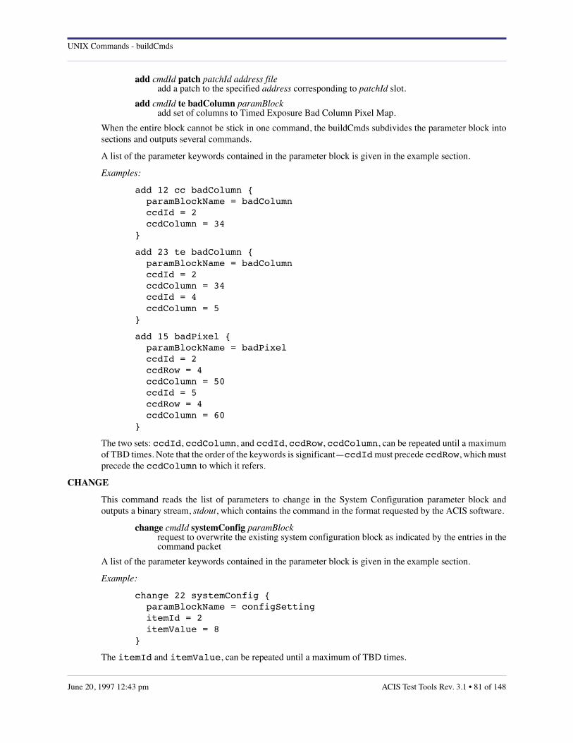
UNIX Commands - buildCmds
add cmdId patch patchId address file add a patch to the specified address corresponding to patchId slot.
add cmdId te badColumn paramBlock add set of columns to Timed Exposure Bad Column Pixel Map.
When the entire block cannot be stick in one command, the buildCmds subdivides the parameter block intosections and outputs several commands.
A list of the parameter keywords contained in the parameter block is given in the example section.
Examples:
add 12 cc badColumn { paramBlockName = badColumn ccdId = 2 ccdColumn = 34}
add 23 te badColumn { paramBlockName = badColumn ccdId = 2 ccdColumn = 34 ccdId = 4 ccdColumn = 5}
add 15 badPixel { paramBlockName = badPixel ccdId = 2 ccdRow = 4 ccdColumn = 50 ccdId = 5 ccdRow = 4 ccdColumn = 60}
The two sets: ccdId, ccdColumn, and ccdId, ccdRow, ccdColumn, can be repeated until a maximumof TBD times. Note that the order of the keywords is significant—ccdId must precede ccdRow, which mustprecede the ccdColumn to which it refers.
CHANGE
This command reads the list of parameters to change in the System Configuration parameter block andoutputs a binary stream, stdout, which contains the command in the format requested by the ACIS software.
change cmdId systemConfig paramBlock request to overwrite the existing system configuration block as indicated by the entries in thecommand packet
A list of the parameter keywords contained in the parameter block is given in the example section.
Example:
change 22 systemConfig { paramBlockName = configSetting itemId = 2 itemValue = 8}
The itemId and itemValue, can be repeated until a maximum of TBD times.
ACIS Test Tools Rev. 3.1 • 81 of 148June 20, 1997 12:43 pm

UNIX Commands - buildCmds
CONTINUE
This command reads a binary file containing the data to uplink and outputs a binary stream to the standardoutput, stdout, which contains the command and the data to uplink in the format requested by the ACISsoftware. The maximum size of the binary file is 249 16-bit words corresponding to one command packet.
continue cmdId uplink file request to continue the uplink boot using the data contained in the packet
file is the name of a binary file containing the data to uplink.
Example:
continue 35 uplink file
DUMP
This command reads the identification of the memory section to dump and outputs a binary stream to thestandard output, stdout, which contains the command in the format requested by the ACIS software.
dump cmdId badPixel request to dump the Bad Pixel Map
dump cmdId cc request to dump every Continuous Clocking parameter block stored in memory
dump cmdId cc badColumn request to dump the Continuous Clocking Bad Column Pixel Map
dump cmdId dea request to dump every DEA parameter block stored in memory
dump cmdId huffman request to dump huffman tables
dump cmdId patchList request to dump the patchList
dump cmdId systemConfig request to dump the System Configuration parameter block
dump cmdId te request to dump every Timed Exposure parameter block stored in memory
dump cmdId te badColumn request to dump the Timed Exposure Bad Column Pixel Map
dump cmdId window1D request to dump every window 1D blocks stored in memory
dump cmdId window2D request to dump every window 2D blocks stored in memory
Example:
dump 35 badPixeldump 36 cc badColumndump 37 te
EXEC
This command reads memory bank, address, and optional arguments of the function to execute and outputs abinary stream to the standard output, stdout, which contains the command in the format requested by theACIS software.
exec cmdId address request to execute the function located in bep memory at the indicated address
82 of 148 • ACIS Test Tools Rev. 3.1 June 20, 1997 12:43 pm

UNIX Commands - buildCmds
exec cmdId address argumentBlock request to execute the function located in bep memory at the indicated address with thespecified arguments
exec cmdId fep fepId address request to execute the function located in fep memory at the indicated address
exec cmdId fep fepId address argumentBlock request to execute the function located in fep memory at the indicated address with thespecified arguments
fepId specifies the FEP memory where the function is located. The value is a decimal integer in the range 0-5. If the fep and fepId keywords are missing, the default memory is BEP.
argumentBlock contains the list of arguments used by the function.
Example:
exec 2 0x1111111 execute the function located in the BEP at address 0x11111111
exec 56 fep 5 0x12345678 execute the function located in the FEP 5 at address 0x12345678
exec 44 0x22222222 { paramBlockName = arguments functionArguments = 1111 functionArguments = 3}
execute the function located in the BEP at the address 0x22222222 with two arguments, 1111 and 3.
exec 24 fep 3 0x1234 { paramBlockName = arguments functionArguments = 2222 functionArguments = 5}
execute the function located in the FEP 3 at the address 0x1234 with two arguments, 2222 and 5.
LOAD
The command reads the parameter block information and outputs a binary stream to the standard output,stdout, which contains the command in the format requested by the ACIS software.
load cmdId cc slotId paramBlock request to load the Continuous Clocking parameter block in the specified slot
load cmdId dea slotId paramBlock request to load the dea parameter block in the specified slot
load cmdId te slotId paramBlock request to load the Timed Exposure parameter block in the specified slot
load cmdId window1D slotId paramBlock request to load the window 1-D parameter block in the specified slot
load cmdId window2D slotId paramBlock request to load the window 2-D parameter block in the specified slot
cc, te, dea, window1D, and window2D are keywords identifying the parameter block to which the action isapplied. In particular, cc specifies the Continuous Clocking parameter block, te the Timed Exposureparameter block, dea the DEA housekeeping parameter block, window1D and window2D respectively theWindow 1-D and Window 2-D parameter block.
ACIS Test Tools Rev. 3.1 • 83 of 148June 20, 1997 12:43 pm

UNIX Commands - buildCmds
The parameterBlocks "window1D" and "window2D" contain an additional parameter name "arrayDim"which indicate the number of windows contained in the paramBlock. A list of the parameter keywordscontained in the parameter block is given in the example section. As explained above, keyword order issignificant.
Examples:
load 2 cc 3 { paramBlockName = ccBlock parameterBlockId = 2030 fepCcdSelect = 0 1 2 3 4 5 fepMode = 1 bepPackingMode = 2 ignoreBadColumnMap = 1 recomputeBias = 1 trickleBias = 0 rowSum = 8 columnSum = 6 overclockPairsPerNode = 8 outputRegisterMode = 2 ccdVideoResponse = 1 1 0 1 1 0 fep0EventThreshold = 100 100 100 100 fep1EventThreshold = 100 100 100 100 fep2EventThreshold = 100 100 100 100 fep3EventThreshold = 100 100 100 100 fep4EventThreshold = 100 100 100 100 fep5EventThreshold = 100 100 100 100 fep0SplitThreshold = 0 0 0 0 fep1SplitThreshold = 0 0 0 0 fep2SplitThreshold = 0 0 0 0 fep3SplitThreshold = 0 0 0 0 fep4SplitThreshold = 0 0 0 0 fep5SplitThreshold = 0 0 0 0 lowerEventAmplitude = 0 eventAmplitudeRange = 40 gradeSelections = 0 windowSlotIndex = 1 rawCompressionSlotIndex = 255 ignoreInitialFrames = 2 biasAlgorithmId = 2 2 2 2 2 2 biasRejection = 1 2 4 6 5 6 fep0VideoOffset = 1000 1000 1000 1000 fep1VideoOffset = 1000 1000 1000 1000 fep2VideoOffset = 1000 1000 1000 1000 fep3VideoOffset = 1000 1000 1000 1000 fep4VideoOffset = 1000 1000 1000 1000 fep5VideoOffset = 1000 1000 1000 1000 deaLoadOverride = 0 fepLoadOverride = 0}
load 3 te 2 { parameterBlockName = teBlock parameterBlockId = 0x2345
84 of 148 • ACIS Test Tools Rev. 3.1 June 20, 1997 12:43 pm

UNIX Commands - buildCmds
fepCcdSelect = 0 1 2 3 4 5 fepMode = 2 bepPackingMode = 1 onChip2x2Summing = 0 ignoreBadPixelMap = 0 ignoreBadColumnMap = 0 recomputeBias = 1 trickleBias = 1 subarrayStartRow = 0 subarrayRowCount = 1023 overclockPairsPerNode = 16 outputRegisterMode = 0 ccdVideoResponse = 0 0 0 0 0 0 primaryExposure = 1 secondaryExposure = 10 dutyCycle = 0 fep0EventThreshold = 100 100 100 100 fep1EventThreshold = 100 100 100 100 fep2EventThreshold = 100 100 100 100 fep3EventThreshold = 100 100 100 100 fep4EventThreshold = 100 100 100 100 fep5EventThreshold = 100 100 100 100 fep0SplitThreshold = 0 0 0 0 fep1SplitThreshold = 0 0 0 0 fep2SplitThreshold = 0 0 0 0 fep3SplitThreshold = 0 0 0 0 fep4SplitThreshold = 0 0 0 0 fep5SplitThreshold = 0 0 0 0 lowerEventAmplitude = 0 eventAmplitudeRange = 65535 gradeSelections = 0 windowSlotIndex = 0 histogramCount = 0 biasCompressionSlotIndex = 255 255 255 255 255 255 rawCompressionSlotIndex = 0 ignoreInitialFrames = 2 biasAlgorithmId = 2 2 2 2 2 2 biasArg0 = 10 10 10 10 10 10 biasArg1 = 0 0 0 0 0 0 biasArg2 = 1 1 1 1 1 1 biasArg3 = 0 0 0 0 0 0 biasArg4 = 0 0 0 0 0 0 fep0VideoOffset = 1000 1000 1000 1000 fep1VideoOffset = 1000 1000 1000 1000 fep2VideoOffset = 1000 1000 1000 1000 fep3VideoOffset = 1000 1000 1000 1000 fep4VideoOffset = 1000 1000 1000 1000 fep5VideoOffset = 1000 1000 1000 1000 deaLoadOverride = 0 fepLoadOverride = 0}
ACIS Test Tools Rev. 3.1 • 85 of 148June 20, 1997 12:43 pm

UNIX Commands - buildCmds
load 4 dea 4 { paramBlockName = deaBlock deaBlockId = 123456 sampleRate = 4 arrayDim = 2 ccdId = 5 queryId = 2 ccdId = 5 queryId = 2}
load 4 window1D 4 { parameterBlockName = window1D windowBlockId = 45 arrayDim = 3
ccdId = 1 ccdColumn = 2 width = 4 sampleCycle = 6 lowerEventAmplitude = 7 eventAmplitudeRange = 8
ccdId = 1 ccdColumn = 2 width = 4 sampleCycle = 6 lowerEventAmplitude = 7 eventAmplitudeRange = 8
ccdId = 1 ccdColumn = 2 width = 4 sampleCycle = 6 lowerEventAmplitude = 7 eventAmplitudeRange = 8}
load 2 window2D 3 { paramBlockName = window2D windowBlockId = 50 arrayDim = 3
ccdId = 0 ccdRow = 490 ccdColumn = 490 width = 20 height = 20 sampleCycle = 0 lowerEventAmplitude = 0 eventAmplitudeRange = 64535
ccdId = 0 ccdRow = 500 ccdColumn = 500 width = 100
86 of 148 • ACIS Test Tools Rev. 3.1 June 20, 1997 12:43 pm

UNIX Commands - buildCmds
height = 100 sampleCycle = 1 lowerEventAmplitude = 0 eventAmplitudeRange = 64535
ccdId = 0 ccdRow = 0 ccdColumn = 0 width = 1023 height = 1023 sampleCycle = 0 lowerEventAmplitude = 0 eventAmplitudeRange = 0}
READ
The command reads memory bank, address, and number of words to read and outputs a binary stream to thestandard output, stdout, which contains the command in the format requested by the ACIS software.
read cmdId address length request to read a chunk of bep memory of the indicated length at the specified address
read cmdId fep fepId address length request to read a chunk of fep memory of the indicated length at the specified address
read cmdId pram ccdId address length request to read a chunk of pram memory of the indicated length at the specified address
read cmdId sram ccdId address length request to read a chunk of sram memory of the indicated length at the specified address
The memory bank is identified by the keywords: fep fepId, sram ccdId, and pram ccdId. A missing memoryindicates the bep memory.
address is an hexadecimal or decimal integer indicating the memory address where to start the reading. Thisvalue is in the range 0-0xffffffff for fep and bep memory reading, and in the range 0-0xffff for sram and pramreading.
length is an hexadecimal or decimal integer indicating the number of words to read. This value is in the range0-0xffffffff for fep and bep memory reading, in the range 0-0xffff for pram and sram reading.
Example:
read 4 0x103d87a0 40 request to read 40 32-bit words in the bep starting from address 0x103d87a0
read 1 fep 2 0x10003400 2 request to read 2 32-bit words in the fep 2 starting from address 0x10003400
read 2 pram 2 0x2340 5 request to read 5 16-bit words in the pram 2 starting from address 0x2340
read 2 sram 4 0x1fff 5 request to read 5 16-bit words in the sram 4 starting from address 0x1fff
REMOVE
This command reads the identifiers of the patches to remove and outputs a binary stream to the standardoutput, stdout, which contains the command in the format requested by the ACIS software.
remove cmdId patch patchBlock request to remove the patch list contained in the patchBlock
Example
ACIS Test Tools Rev. 3.1 • 87 of 148June 20, 1997 12:43 pm
UNIX Commands - buildCmds
remove 1 patch { paramName = patches patchId = 1 patchId = 2 patchId = 8}
remove three patches: 1,2,and 8 from the patch list
RESET
This command reads the name of the memory block to reset and outputs a binary stream to the standardoutput, stdout, which contains the command in the format requested by the ACIS software.
reset cmdId badPixel request to reset the bad pixel map
reset cmdId cc badColumn request to reset the Continuous Clocking bad column map
reset cmdId te badColumn request to reset the Timed Exposure bad column map
cc, te, badPixel, and badColumn are keywords identifying the memory to reset. In particular, cc badColumnspecifies the Continuous Clocking badColumn map, te badColumn the Timed Exposure parameterbadColumn map.
Examples:
reset 4 badPixel reset the badPixel Map
reset 6 te badColumn reset the Timed Exposure badColumn map
reset 10 cc badColumn reset the Continous Clocking badColumn map
START
This command reads the slotId containing the parameter of the science run to start and outputs a binary streamto the standard output, stdout, which contains the command in the format requested by the ACIS software.This command is also used to start DEA housekeeping monitor and uplink boot.
start cmdId cc slotId request to start the Continuous Clocking science run whose parameters are stored in thespecified slotId
start cmdId cc bias slotId request to start the Continuous Clocking bias calculation whose parameters are stored in thespecified slotId
start cmdId dea slotId request to start the DEA Housekeeping monitor whose parameters are stored in the specifiedslotId
start cmdId te slotId request to start the Timed Exposure science run whose parameters are stored in the specifiedslotId
start cmdId te bias slotId request to start the Timed Exposure bias calculation whose parameters are stored in thespecified slotId
start cmdId uplink file request to start the uplink boot using the data stored in the indicated file
88 of 148 • ACIS Test Tools Rev. 3.1 June 20, 1997 12:43 pm

UNIX Commands - buildCmds
cc, te, dea, and bias are keywords identifying the parameter block to which the action is applied. In particular,cc specifies the Continuous Clocking parameter block, te the Timed Exposure parameter block, dea the DEAhousekeeping parameter block.
uplink is a keyword identifying the boot mode.
Examples:
start 22 te 4 start Timed Exposure science run with the parameters stored in slotId 4
start 33 cc 3 start Continous Clocking science run with the parameters stored in slotId 3
start 44 cc bias 0 start Timed Exposure bias calculation with the parameters stored in slotId 0
start 55 te bias 1 start Continous Clocking bias calculation with the parameters stored in slotId 1
start 66 dea 2 start Dea Housekeeping monitor with the parameters stored in slotId 2
start 77 uplink fileName start the uplink boot with the data contained in the fle fileName
STOP
This command stops science run or DEA Housekeeping monitor. It outputs a binary stream to the standardoutput, stdout, which contains the command in the format requested by the ACIS software.
stop cmdId dea request to stop the currently running DEA Housekeeping monitor
stop cmdId science request to stop the currently running science exposure
science, and dea are keywords identifying the task to stop.
Examples:
stop 22 science
stop 33 dea
WRITE
This command read a binary file, identifies the memory bank where to write the file content, and outputs abinary stream to the standard output, stdout, stdout , which contains the command in the format requested bythe ACIS software.
write cmdId address file request to write the binary file content in the bep memory at the specified address
write cmdId fep fepId address file request to write the binary file content in the fep memory at the specified address
write cmdId pram ccdId address file request to write the binary file content in the pram memory at the specified address
write cmdId sram ccdId address file request to write the binary file content in the sram memory at the specified address
The memory bank to write is identified by the keywords fep fepId, pram ccdId, and sram ccdId. A missingmemory indicates the bep memory.
ACIS Test Tools Rev. 3.1 • 89 of 148June 20, 1997 12:43 pm

UNIX Commands - buildCmds
address is an hexadecimal or decimal integer indicating the memory address where to start the reading. Thisvalue is in the range 0-0xffffffff for fep and bep memory reading, and in the range 0-0xffff for sram and pramreading.
file is the name of the file containing the data to write in memory. The file size is limited by the memory bankwhere the data should be stored. If the data contained in the file cannot be loaded in one command, theircontent will be divided into sections and loaded by multiple commands.
Examples:
write 4 0x00002345 asm write the content of the "asm" file in the bep at the address 0x00002345
write 5 fep 4 0x00000056 bsm write the content of the "bsm" file in the fep 4 at the address 0x00000056
write 6 pram 4 0x0024 csm write the content of the "csm" file in the pram 4 at the address 0x0024
write 7 sram 5 0x0034 dsm write the content of the "dsm" file in the sram 5 at the address 0x0034
SERIAL HARDWARE COMMANDS
The following commands will be prefixed by a 4-byte header that sends them to the hardware serial commandport of the DPA.
HALT
This hardware serial command outputs a binary stream to the standard output stdout, containing thecommand in the format requested by the ACIS hardware.
halt bep request to reset the BEP processor.
RUN
This hardware serial command outputs a binary stream to the standard output stdout, containing thecommand in the format requested by the ACIS hardware.
run bep request to run the BEP processor.
SELECT
This hardware serial command outputs a binary stream to the standard output stdout, containing thecommand in the format requested by the ACIS hardware.
select EEPROM programming request to select EEPROM programmer readout
select EEPROM telemetry request to select software bi-level telemetry.
select bep bepId request to select one of the two BEP processor (0 select BEP A, 1 select BEP B).
SET
This hardware serial command outputs a binary stream to the standard output stdout, containing thecommand in the format requested by the ACIS hardware.
set bootModifier off request to clear the bootModifier flag
set bootModifier on request to set the bootModifier flag
90 of 148 • ACIS Test Tools Rev. 3.1 June 20, 1997 12:43 pm

UNIX Commands - buildCmds
set radiationMonitor high request to set the radiation flag
set radiationMonitor low request to clear the radiation flag
set warmBoot off request to clear the warm boot flag
set warmBoot on request to set the warm boot flag
HARDWARE PULSE COMMANDS
The following commands will be sent to the command port of the Power Supply Mechanism Control (PSMC),as specified in the "CTUE Command Format". Each pulse command has two versions, depending on whetherit is to be sent to the A-side or B-side of the redundant PSMC hardware. These are identified by the idparameter in the following table, where id must be either "0" for the A-side, or "1" for the B-side.
CLOSE
close door id close instrument door id
close vent id close vent subsystem valve id
close relief id close vent subsystem small valve id
CLOSEABORT
closeabort door id abort the closing of instrument door id
closeabort vent id abort the closing of vent subsystem valve id
DISABLE
disable daBake id disable commands to bakeout heater id
disable daHeater id disable commands to housing heater id
disable dea id disable commands to DEA power supply id
disable door id disable commands to door mechanism id
disable dpa id disable commands to DPA power supply id
disable pressure id disable commands to pressure sensor id
disable relief id disable commands to vent subsystem small valve id
disable vent id disable commands to vent subsystem valve id
ENABLE
enable daBake id enable commands to bakeout heater id
ACIS Test Tools Rev. 3.1 • 91 of 148June 20, 1997 12:43 pm
UNIX Commands - buildCmds
enable daHeater id enable commands to housing heater id
enable dea id enable commands to DEA power supply id
enable door id enable commands to door mechanism id
enable dpa id enable commands to DPA power supply id
enable pressure id enable commands to pressure sensor id
enable relief id enable commands to vent subsystem small valve id
enable vent id enable commands to vent subsystem valve id
OPEN
open door id open instrument door id
open vent id open vent subsystem valve id
open relief id open vent subsystem small valve id
OPENABORT
openabort door id abort the opening of instrument door id
openabort vent id abort the opening of vent subsystem valve id
POWEROFF
poweroff dabake id power off bakeout heater id
poweroff daheater id power off housing heater id
poweroff dea id power off DEA power supply id
poweroff dpa id power off DPA power supply id
POWERON
poweron dabake id power on bakeout heater id
poweron daheater id power on housing heater id
poweron dea id power on DEA power supply id
poweron dpa id power on DPA power supply id
TURNOFF
turnoff dabake power off and disable both bakeout heaters
92 of 148 • ACIS Test Tools Rev. 3.1 June 20, 1997 12:43 pm

UNIX Commands - buildCmds
turnoff dabake id power off and disable bakeout heater id
turnoff daheater power off and disable both housing heaters
turnoff daheater id power off and disable housing heater id
turnoff dea power off and disable both DEAs
turnoff dea id power off and disable DEA id
turnoff dpa power off and disable both DPAs
turnoff dpa id power off and disable DPA id
TURNON
turnon dabake id enable and power on bakeout heater id
turnon daheater id enable and power on housing heater id
turnon dea id enable and power on DEA id
turnon dpa id enable and power on DPA id
AUTHOR
Rita Somigliana, MIT CSR <[email protected]>
ACIS Test Tools Rev. 3.1 • 93 of 148June 20, 1997 12:43 pm

UNIX Commands - cclient
10.7 cclient
NAME
cclient – send commands to a command server process on a remote host
SYNOPSIS
cclient hostname socket_number
DESCRIPTION
cclient sends commands to a command server process, typically cserver, on a remote host.
EXAMPLES
The following UNIX pipe uses cclient as part of commanding ACIS:
buildCmds < myCmdScript | sendCmds | writeCCB | cclient poplar 8000
AUTHOR
Ann M. Davis, MIT CSR
STATUS
The current version is working according to specification.
94 of 148 • ACIS Test Tools Rev. 3.1 June 20, 1997 12:43 pm
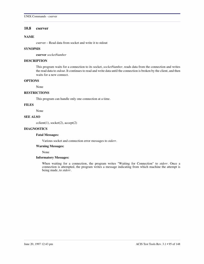
UNIX Commands - cserver
10.8 cserver
NAME
cserver – Read data from socket and write it to stdout
SYNOPSIS
cserver socketNumber
DESCRIPTION
This program waits for a connection to its socket, socketNumber, reads data from the connection and writesthe read data to stdout. It continues to read and write data until the connection is broken by the client, and thenwaits for a new connect.
OPTIONS
None
RESTRICTIONS
This program can handle only one connection at a time.
FILES
None
SEE ALSO
cclient(1), socket(2), accept(2)
DIAGNOSTICS
Fatal Messages:
Various socket and connection error messages to stderr.
Warning Messages:
None
Informatory Messages:
When waiting for a connection, the program writes "Waiting for Connection" to stderr. Once aconnection is attempted, the program writes a message indicating from which machine the attempt isbeing made, to stderr.
ACIS Test Tools Rev. 3.1 • 95 of 148June 20, 1997 12:43 pm

UNIX Commands - diff6
10.9 diff6
NAME
diff6 – compare multiple ACIS binary event files against each other
SYNOPSIS
diff6 [–v] file1 file2 [file3...file6]
DESCRIPTION
This program reads the binary ERV event files generated by psci, and compares them record-by-record. If itfinds a mis-match, it attempts to re-synchronize.
OPTIONS
–v run diff6 in verbose mode, writing informatory messages to stderr. If omitted, only one single errormessage will be written at the conclusion of the program.
EXAMPLE
The following pipe uses filterClient to read ACIS telemetry packets from emily, runs them through psci todecommutate them, generating both data files (the –l flag) and monitor records (the –m flag). The latter arepassed through sciglue to scramble them, and on into monitorScience to display (hopefully) useful statisticson an X-window display.
filterClient -h emily | psci -v -l run123 -m | sciglue | monitorScience
While monitorScience is displaying fancy stuff on the screen, psci is doing the hard work of unpacking thebias maps and event files. The latter will be written to a series of disk files with names"run123.nrun.nfep.erv.dat", where run123 is a prefix inherited from the –l option of psci, nrun is a "sciencerun index" that is incremented at the start of each science run, and nfep is the index of the particular FEP thatgenerated the events. After psci has generated an end-of-run message, e.g.
stdin: scienceReport[54321,0] run 1 irig 12345:678 exp 2 fep ok ccd ok dea 0 bep 1
indicating that the event files have been written successfully, they may be compared by
diff6 -v run123.1.*.erv.dat
AUTHOR
Peter G. Ford, MIT CSR
SEE ALSO
psci(1)
DIAGNOSTICS
• count mis-matches reported diff6 has found this number of mis-matches during the
• count records processed from each of count files. No problemo! The message we hope for, but don’t always get.
• file[rec,exp,row,col] != file[rec,exp,row,col] a mis-match has occurred: the message includes the file names, the record numbers (starting at 0), and theexposure number, row, and column recorded in each.
96 of 148 • ACIS Test Tools Rev. 3.1 June 20, 1997 12:43 pm

UNIX Commands - diff6
• file: no data the input file was empty.
• file: premature EOF One (or more) of the input files ended before at least one of the others.
• too many input files 6 is the limit.
ACIS Test Tools Rev. 3.1 • 97 of 148June 20, 1997 12:43 pm

UNIX Commands - dumpring
10.10 dumpring
NAME
dumpring – translate ACIS FEP ring buffer records to ASCII
SYNOPSIS
dumpring [file]
DESCRIPTION
This Perl script reads a FEP ring buffer file and lists its contents in ASCII on the standard output stream,stdout. If file is omitted, the input is taken from the standard input stream, stdin. Records are indexed by theirexposure number and by the count of records of the same type generated by that exposure. All indices,including exposure numbers, start at 1. The record and field names are taken from fepBep.h.
AUTHOR
Peter G. Ford, MIT CSR
SEE ALSO
fepBep.h
DIAGNOSTICS
unknown code id for record nexp,nrec the type code in record nrec of exposure number nexp is invalid.
BUGS
• the contents of raw image rows and histograms are not reported.
98 of 148 • ACIS Test Tools Rev. 3.1 June 20, 1997 12:43 pm

UNIX Commands - fepCtlTest
10.11 fepCtlTest
NAME
fepCtlTest – simulate ACIS front end processor
SYNOPSIS
fepCtlTest [file]
DESCRIPTION
This command subjects the high-level ACIS front end processor software to a series of tests, directed by ascript read from file, or, if omitted, from the standard input stream , stdin. All input lines are echoed to stderr,with the following additional output, detailing the interaction between the FEP and the (simulated) BEP:
BEP COMMAND name [ parm ... ] a command has been received from the simulated BEP mailbox
FEP REPLY TYPE=type CODE=retc the FEP is replying to a BEP type command with a return code retc.
FEP REPLY TYPE=type MODE=mode BIAS=flag PARITY=addr OCLK=(n,n,n,n) the FEP is replying to a BEP_FEP_CMD_STATUS command.
file: usec user ssec sys an image frame has been processed, using usec seconds of user CPU time and ssec seconds of systemCPU time.
file: bias0 = { n, n, n, n } A bias map has been calculated. The initial overclock averages are shown.
EOF on stdin The input script has been processed.
COMMAND LANGUAGE
dumpbias file write a bias map to file in FITS format.
exec cmd execute a BEP command. The names are as defined in the IP&CL nodes, e.g.BEP_FEP_CMD_STATUS, BEP_FEP_CMD_PARAM, etc.
fidpix = row col ... define one or more fiducial pixels.
fidpix = bad issue a null-length fiducial-pixel command.
param name = val set an internal parameter field. name is a member of the FEPparmBlock structure as defined infepBep.h, i.e. type, nrows, etc.
reset ctr reset an internal counter. Currently, only wakeup is implemented.
set buf[row,col] = val set the row and col element of buf (either "bias" or "biasparity") to val.
set input = file read data from the FITS image. file should contain "%d" to be replaced with the exposure number.
ACIS Test Tools Rev. 3.1 • 99 of 148June 20, 1997 12:43 pm
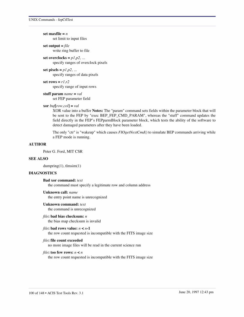
UNIX Commands - fepCtlTest
set maxfile = n set limit to input files
set output = file write ring buffer to file
set overclocks = p1,p2, ... specify ranges of overclock pixels
set pixels = p1,p2, ... specify ranges of data pixels
set rows = r1,r2 specify range of input rows
stuff param name = val set FEP parameter field
xor buf[row,col] = val XOR value into a buffer Notes: The "param" command sets fields within the parameter block that willbe sent to the FEP by "exec BEP_FEP_CMD_PARAM", whereas the "stuff" command updates thefield directly in the FEP’s FEPparmBlock parameter block, which tests the ability of the software todetect damaged parameters after they have been loaded.
The only "ctr" is "wakeup" which causes FIOgetNextCmd() to simulate BEP commands arriving whilea FEP mode is running.
AUTHOR
Peter G. Ford, MIT CSR
SEE ALSO
dumpring(1), tlmsim(1)
DIAGNOSTICS
Bad xor command: text the command must specify a legitimate row and column address
Unknown call: name the entry point name is unrecognized
Unknown command: text the command is unrecognized
file: bad bias checksum: n the bias map checksum is invalid
file: bad rows value: n < n-1 the row count requested is incompatible with the FITS image size
file: file count exceeded no more image files will be read in the current science run
file: too few rows: n < n the row count requested is incompatible with the FITS image size
100 of 148 • ACIS Test Tools Rev. 3.1 June 20, 1997 12:43 pm
UNIX Commands - fepImage2
10.12 fepImage2
NAME
fepImage2 – Load an image into a Unix FEP Simulation
SYNOPSIS
fepImage2 fepId sequencer
DESCRIPTION
This program reads a DEA to FEP pixel stream from stdin and feeds the image to a running Unix FEPsimulation process, which is simulating the FEP indicated by fepId. A Unix FEP simulation process (seeacisFepUnix(1) ) must be running with the same fepId prior to using this program. The input for this programcan be produced using several programs, including genObjectImage and loadFitsImage.
OPTIONS
None
RESTRICTIONS
This program is currently only supported for the DECstations running Ultrix.
FILES
None
SEE ALSO
acisFepUnix(1), genObjectImage(1), loadFitsImage(1), ipcs(1), ipcrm(1)
DIAGNOSTICS
Fatal Messages:
If the system attempts to write a pixel beyond the end the image memory (due to some internal error, orto a badly formed input image), the program write print the contents of some key FEP register values(from shared memory) to stderr and exit with a -1 exit code.
Warning Messages:
None
Informatory Messages:
If the program would be blocked by the FEP when trying to write an image, rather than discard the image,the program prints a "Dummy Image VSYNC - Sleep 3" message to stderr and then sleeps for 3 seconds.It will then re-attempt to load the image. This will continue indefinitely until either the FEP accepts theimage, or until the program is aborted (usually via a Ctrl-C).
As the program loads the image into the FEP, it prints the current image start row, CCD start row andRow Count values used for the load to stdout.
ACIS Test Tools Rev. 3.1 • 101 of 148June 20, 1997 12:43 pm

UNIX Commands - filterClient
10.13 filterClient
NAME
filterClient – receive ACIS telemetry from filterServer socket
SYNOPSIS
filterClient [–D] [–h host] [–m mode] [–p port]
DESCRIPTION
This Perl script makes a TCP connection to the specified filterServer port, and copies packets of type modeto the standard output stream, stdout.
OPTIONS
–D run filterClient in debug mode.
–h host specifies the name of the host running filterServer. If omitted, this is assumed to be the local machine
–m mode selects the type of telemetry packets to be extracted from filterServer. mode is a string of between oneand four letters, as follows:
s science telemetrye engineering pseudo-packetsp science frame pseudo-packetsh DEA housekeeping packets
If omitted, the default is seph, i.e. extract all types of packet.
–p port specifies the port number on the filterServer host. If omitted, the default is 7002.
AUTHOR
Peter G. Ford, MIT CSR
SEE ALSO
processScience(1)
102 of 148 • ACIS Test Tools Rev. 3.1 June 20, 1997 12:43 pm

UNIX Commands - filterServer
10.14 filterServer
NAME
filterServer – Distribute ACIS telemetry to TCP clients
SYNOPSIS
filterServer [–D] [–S] [–b size] [–l file] [–n num] [–p port] [–v]
DESCRIPTION
This Perl script reads ACIS telemetry from its standard input and accepts connections from filterClientprocesses. It writes the buffered telemetry to each connected client, until that client disconnects. If an end-of-file occurs on its standard input, it disconnects all clients immediately.
OPTIONS
–D run filterServer in debug mode, writing all I/O activity to the log file (if –l was specified), or to stderrif it wasn’t. –D implies –v.
–S sleep for 0.1 second after reading each input packet. This is intended to aid in debugging the filterClientprocess.
–b size specifies the maximum size of each client’s telemetry buffer. If a client’s buffer grows larger than thisamount, the socket to the client will be broken. The default is 1 MByte.
–l filewrite a list of socket activity (opens and closes) to the log file (if –l was specified), or to stderr if itwasn’t. –l implies –v.
–n num specify the maximum number of concurrent connections. The default is 8.
–p port specify the number of the TCP port on which filterServer listens for connections. The default is 7002.
–v write a list of socket activity (opens and closes) to stderr.
AUTHOR
Peter G. Ford, MIT CSR
SEE ALSO
filterClient(1)
ACIS Test Tools Rev. 3.1 • 103 of 148June 20, 1997 12:43 pm

UNIX Commands - genObjectImage
10.15 genObjectImage
NAME
genObjectImage – generate an ACIS pixel image from an ASCII script
SYNOPSIS
genObjectImage [–D] [–c cols] [–e] [–m mode] [–n count] [–o oclks][–r rows] [–s iseed] [–u] [–v] [infile [outfile]]
DESCRIPTION
genObjectImage reads commands from infile (or, if omitted, from stdin), and generates a stream of pixels tooutfile (or, if omitted, to stdout), in a format suitable for passing to the ACIS Image Loader.
OPTIONS
–D for debugging purposes, writes the output in the form of a FITS image file, in the native byte orderingof the CPU, with the rows running top to bottom and the nodes, columns and overclocks from left toright, beginning with the columns and ending with the overclocks. For example, for 4 nodes (mode =ABCD), the four columns will be followed by the 4 sets of overclocks. Each set will be separated by anull pixel; two rows of null pixels will separate the columns from the overclocks. Pixel ordering withineach column follows the CCD mapping order, i.e. nodes B and D are not reversed. Pixel OP codes (bits0–3) are set to zero and VSYNC, HSYNC, and NOOP pixels are suppressed.
–c cols specifies the number of columns per output node, overriding any "columns =" statement in the inputscript. If omitted entirely, the number depends on the "mode", 256 for ABCD, 512 otherwise.
–e instructs genObjectImage to write a Last Pixel Flag (LPF) code at the end of the output stream, tellingthe frame buffer to start loading its data into the instrument. This flag must always be specified on thelast, or only invocation of genObjectImage to load the frame buffer.
–m mode selects the CCD quadrant readout mode that is to be simulated, overriding any "mode =" statement inthe input script. mode must be either "ABCD", "AC", or "BD" (or their lower case equivalents). Ifomitted entirely, the default is "ABCD".
–n count commands the frame buffer to write the following data to the instrument a total of count times. Ifomitted, the frame buffer loops continuously until reset. This option can only be specified on the firstof a series of invocations of genObjectImage when loading the frame buffer.
–o noclks specifies the number of overclocks to be used per quadrant, overriding any "overclocks =" statement inthe input script. If omitted entirely, the default is 4.
–r rows specifies the number of rows in the output image, overriding any "rows =" statement in the input script.If omitted entirely, the default is 1024.
–s seed specifies a seed integer to be used to start the random number generator, overriding any "seed ="statement in the input script. If omitted entirely, the default is the value returned by a call to the time()function.
–u omits the special image-loader codes. No compression is possible; stdout contains only valid FEP pixelcodes.
104 of 148 • ACIS Test Tools Rev. 3.1 June 20, 1997 12:43 pm

UNIX Commands - genObjectImage
–v runs genObjectImage in verbose mode, writing a description of each node and display object to stderr,and summarizing the number of pixels in the output image.
INPUT SCRIPTS
A script consists of a series of ASCII statements of the form
keyword = value . . .
followed by zero or more object "call-outs" of the form
object row column
which will be described below. The script statements are case-insensitive—upper and lower case charactersmay be freely mixed. Each statement must appear on a separate line, but may be surrounded by any numberof blanks and tabs. Any number of spaces or tabs may separate statement arguments.
Null lines, lines containing only whitespace, and lines whose first non-whitespace character is ’#’, areinterpreted as comments, and ignored.
The statements are grouped logically into five classes:
• Global Parameter Assignments These statements affect the entire output image. All except wedge and noop may be overridden byoptions on the genObjectImage command line, as described above.
columns = ival The number of pixels to write for each output node. This may be overridden by the –c option.The default value is determined by the mode: 256 if ABCD, otherwise 512.
mode = string The CCD output shift register mode to be simulated. Possible string values are ABCD, AC,and BD. This may be overridden by the –m option. The default value is ABCD.
noop = ival where what The number of NOOP pixels to write between various parts of the output pixel stream. wheremay be either before or after. what may be either vsync, hsync, or oclks. That number ofNOOPs will be written (for each of the 4 output nodes) before or after VSYNC or HSYNC OPcodes, or before or after writing each row’s overclock section.
overclocks = ival The number of overclock pixels to write for each output node. This may be overridden by the–o option. The default value is 4.
rows = ival The number of rows of pixels to write. This may be overridden by the –r option. The defaultvalue is 1024.
seed = ival An integer to initialize the random number generator used when dbias or doverclock is non-zero.
wedge = drow dcol drowcol Adjust all pixels in this image by adding
drow * irow + dcol * icol + drowcol * irow * icol
where the row index, irow, varies from 0 for the first row to rows–1 for the last, and the columnindex, icol, varies from 0 for the first pixel of node A to (nodes * columns – 1) for the firstpixel of node D. This statement allows genObjectImage output to mimic various CCDbehaviors, e.g., light leaks.
• Node Blocks A node block, a group of statements delimited by "begin node" and "end node" statements, should bespecified for each CCD output node that is to be simulated. It is good practice to define all 4, A, B, C,and D, even when the mode is AC or BD, since you may want to override it on the command line. The
ACIS Test Tools Rev. 3.1 • 105 of 148June 20, 1997 12:43 pm

UNIX Commands - genObjectImage
contents of the node block generates the background pixel and overclock values, on which the otherdisplay object are superimposed.
begin node = char
bias = ival Initialize all data pixels (but not overclocks) in this node to the integer value, ival. This servesas a base on which to apply various adjustments.
dbias = fval Adjust all pixels in this node by adding a zero-mean Gaussian random variable of variancefval. This mimics the real variability of CCD pixel values.
overclock = ival Initialize all overclocks in this node to the integer value, ival. This serves as a base on whichto apply various adjustments.
doverclock = fval Adjust all overclocks in this node by adding a zero-mean Gaussian random variable ofvariance fval.
end node = char
• Event Blocks Each event block, a group of statements delimited by "begin event" and "end event" statements, definesan array of integers to be added to the CCD pixel array. Each block is named, and these names are usedlater in the script (see "Object Call-outs", below) to perform this task, perhaps many times at differentimage locations.
begin event = name
columns = ival The width of the values array.
rows = ival The height of the values array.
values = ival ival...ival A series of columns × rows integer values to be added to the CCD pixel image. The values aresupplied in row-major order, i.e. the first row values are followed by the second row, and soon. Within a row, the values are in ascending column order.
end event = name
• Blob Blocks A blob block, a group of statements delimited by "begin blob" and "end blob" statements, specifies anelliptical artifact to add to the CCD image. It is defined by its width, height, orientation angle, andmaximum (additional) pixel value. The blob is modeled as a double Gaussian in width and height. Eachblock is named, and these names are used later in the script (see "Object Call-outs", below) to performthis task, perhaps many times at different image locations.
begin blob = name
angle = fval The rotation angle of the blob, in degrees counter-clockwise.
height = fval The Gaussian width of the blob in the column direction, before rotating through angle.
value = fval The additional pixel value of the center of the blob.
width = fval The Gaussian width of the blob in the row direction, before rotating through angle.
end blob = name
106 of 148 • ACIS Test Tools Rev. 3.1 June 20, 1997 12:43 pm
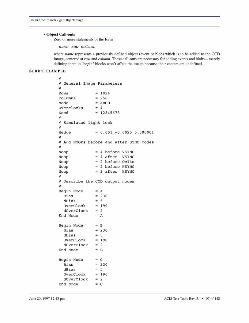
UNIX Commands - genObjectImage
• Object Call-outs Zero or more statements of the form
name row column
where name represents a previously defined object (event or blob) which is to be added to the CCDimage, centered at row and column. These call-outs are necessary for adding events and blobs—merelydefining them in "begin" blocks won’t affect the image because their centers are undefined.
SCRIPT EXAMPLE
## General Image Parameters#Rows = 1024Columns = 256Mode = ABCDOverclocks = 4Seed = 12345678## Simulated light leak#Wedge = 0.001 -0.0025 0.000001## Add NOOPs before and after SYNC codes#Noop = 4 before VSYNCNoop = 4 after VSYNCNoop = 2 before OclksNoop = 2 before HSYNCNoop = 2 after HSYNC## Describe the CCD output nodes#Begin Node = A Bias = 230 dBias = 5 OverClock = 190 dOverClock = 2End Node = A
Begin Node = B Bias = 230 dBias = 5 OverClock = 190 dOverClock = 2End Node = B
Begin Node = C Bias = 230 dBias = 5 OverClock = 190 dOverClock = 2End Node = C
ACIS Test Tools Rev. 3.1 • 107 of 148June 20, 1997 12:43 pm

UNIX Commands - genObjectImage
Begin Node = D Bias = 230 dBias = 5 OverClock = 190 dOverClock = 2 End Node = D## Define an X-ray event#Begin Event = event_1 Rows = 3 Columns = 3 Value = 0 0 0 0 1500 0 0 0 0End Event = event_1## Define a split X-ray event#Begin Event = event_2 Rows = 3 Columns = 3 Value = 0 0 0 0 1000 500 0 0 0End Event = event_2## Define a "bloom" event#Begin Blob = bloom Width = 8 Height = 16 Angle = 30 Value = 1000End Blob = bloom## Insert some events into the image#event_1 100200event_1 475891bloom 25129event_2 100131# end of script
AUTHOR
Peter G. Ford, MIT CSR
SEE ALSO
Frame Buffer Specification, ACIS Memo, M. Doucette, MIT, October 27, 1995.
The Coordinate System of ACIS FITS Files, ACIS Memo, J. W. Woo and S. E. Kissel, MIT, December 7,1994.
DIAGNOSTICS
• bad blob statement: statement unrecognized statement within a "blob" block.
108 of 148 • ACIS Test Tools Rev. 3.1 June 20, 1997 12:43 pm

UNIX Commands - genObjectImage
• bad blob name: name the name in an "end blob" statement must match that in the preceding "begin blob" statement. "begin"blocks may not be nested.
• bad event statement: statement unrecognized statement within an "event" block.
• bad event name: name the name in an "end event" statement must match that in the preceding "begin event" statement. "begin"blocks may not be nested.
• bad keyword: name the "noop" value must be followed by "before" or "after", which must be followed in turn by either"hsync", "vsync", or "oclks".
• bad node statement: statement this statement is illegal within "begin node" and "end node" statements.
• bad node: char the node designator must be a single character in the range ’A’ through ’D’ (or equivalently ’a’ through’d’). The node name in an "end node" statement must match that in the preceding "begin node". "begin"blocks may not be nested.
• bad value[n]: value the n’th item in the "values =" list of an "event" block is invalid.
• duplicate blob: statement object names (events and blobs) must be unique.
• duplicate event: statement object names (events and blobs) must be unique.
• misplaced statement: statement "begin" blocks may not be nested.
• missing columns the "event" block must contain a "columns =" statement.
• missing height the "blob" block must contain a "height =" statement.
• missing rows the "event" block must contain a "rows =" statement.
• missing value the "blob" block must contain a "value =" statement.
• missing values the "event" block must contain a "values =" statement.
• missing width the "blob" block must contain a "width =" statement.
• negative value: statement variances (dbias and dover) must be non-negative.
• unknown statement: statement the statement is unrecognized.
• unknown mode: statement the mode is unrecognized. Valid values are "ABCD", "AC", "BD", and their lowercase equivalents.
ACIS Test Tools Rev. 3.1 • 109 of 148June 20, 1997 12:43 pm
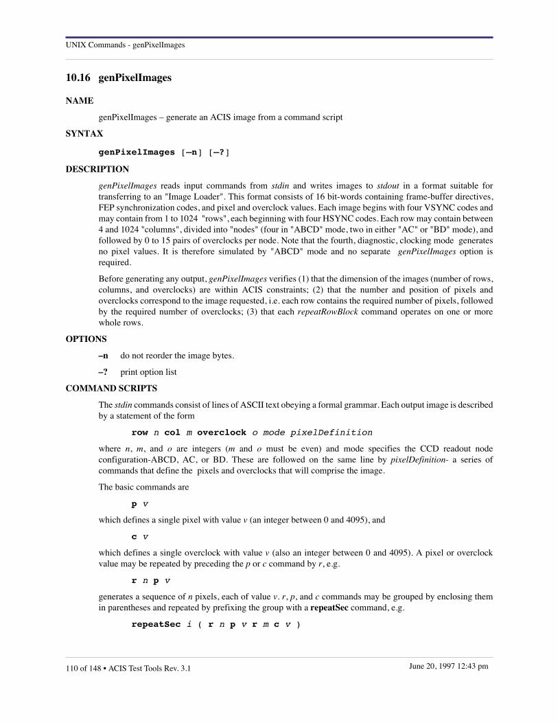
UNIX Commands - genPixelImages
10.16 genPixelImages
NAME
genPixelImages – generate an ACIS image from a command script
SYNTAX
genPixelImages [–n] [–?]
DESCRIPTION
genPixelImages reads input commands from stdin and writes images to stdout in a format suitable fortransferring to an "Image Loader". This format consists of 16 bit-words containing frame-buffer directives,FEP synchronization codes, and pixel and overclock values. Each image begins with four VSYNC codes andmay contain from 1 to 1024 "rows", each beginning with four HSYNC codes. Each row may contain between4 and 1024 "columns", divided into "nodes" (four in "ABCD" mode, two in either "AC" or "BD" mode), andfollowed by 0 to 15 pairs of overclocks per node. Note that the fourth, diagnostic, clocking mode generatesno pixel values. It is therefore simulated by "ABCD" mode and no separate genPixelImages option isrequired.
Before generating any output, genPixelImages verifies (1) that the dimension of the images (number of rows,columns, and overclocks) are within ACIS constraints; (2) that the number and position of pixels andoverclocks correspond to the image requested, i.e. each row contains the required number of pixels, followedby the required number of overclocks; (3) that each repeatRowBlock command operates on one or morewhole rows.
OPTIONS
–n do not reorder the image bytes.
–? print option list
COMMAND SCRIPTS
The stdin commands consist of lines of ASCII text obeying a formal grammar. Each output image is describedby a statement of the form
row n col m overclock o mode pixelDefinition
where n, m, and o are integers (m and o must be even) and mode specifies the CCD readout nodeconfiguration-ABCD, AC, or BD. These are followed on the same line by pixelDefinition- a series ofcommands that define the pixels and overclocks that will comprise the image.
The basic commands are
p v
which defines a single pixel with value v (an integer between 0 and 4095), and
c v
which defines a single overclock with value v (also an integer between 0 and 4095). A pixel or overclockvalue may be repeated by preceding the p or c command by r, e.g.
r n p v
generates a sequence of n pixels, each of value v. r, p, and c commands may be grouped by enclosing themin parentheses and repeated by prefixing the group with a repeatSec command, e.g.
repeatSec i ( r n p v r m c v )
110 of 148 • ACIS Test Tools Rev. 3.1 June 20, 1997 12:43 pm
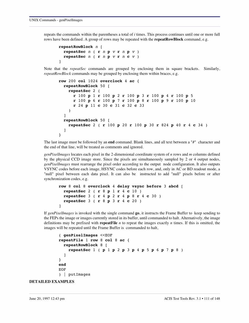
UNIX Commands - genPixelImages
repeats the commands within the parentheses a total of i times. This process continues until one or more fullrows have been defined. A group of rows may be repeated with the repeatRowBlock command, e.g.
repeatRowBlock n [ repeatSec n ( r n p v r n p v ) repeatSec n ( r n p v r n c v )]
Note that the repeatSec commands are grouped by enclosing them in square brackets. Similarly,repeatRowBlock commands may be grouped by enclosing them within braces, e.g.
row 200 col 1024 overclock 4 ac { repeatRowBlock 50 [ repeatSec 2 ( r 100 p 1 r 100 p 2 r 100 p 3 r 100 p 4 r 100 p 5 r 100 p 6 r 100 p 7 r 100 p 8 r 100 p 9 r 100 p 10 r 24 p 11 c 30 c 31 c 32 c 33 ) ] repeatRowBlock 50 [ repeatSec 2 ( r 100 p 20 r 100 p 30 r 824 p 40 r 4 c 34 ) ]}
The last image must be followed by an end command. Blank lines, and all text between a "#" character andthe end of that line, will be treated as comments and ignored.
genPixelImages locates each pixel in the 2-dimensional coordinate system of n rows and m columns definedby the physical CCD image store. Since the pixels are simultaneously sampled by 2 or 4 output nodes,genPixelImages must rearrange the pixel order according to the output node configuration. It also outputsVSYNC codes before each image, HSYNC codes before each row, and, only in AC or BD readout mode, a"null" pixel between each data pixel. It can also be instructed to add "null" pixels before or aftersynchronization codes, e.g.
row 8 col 8 overclock 4 delay vsync before 3 abcd [ repeatSec 2 ( r 8 p 1 r 4 c 10 ) repeatSec 3 ( r 4 p 2 r 4 p 8 r 4 c 30 ) repeatSec 3 ( r 8 p 3 r 4 c 20 )]
If genPixelImages is invoked with the single command go, it instructs the Frame Buffer to keep sending tothe FEPs the image or images currently stored in its buffer, until commanded to halt. Alternatively, the imagedefinitions may be prefixed with repeatFile n to repeat the images exactly n times. If this is omitted, theimages will be repeated until the Frame Buffer is commanded to halt,
( genPixelImages <<EOFrepeatFile 1 row 8 col 8 ac { repeatRowBlock 8 [ repeatSec 1 ( p 1 p 2 p 3 p 4 p 5 p 6 p 7 p 8 ) ]}endEOF) | putImages
DETAILED EXAMPLES
ACIS Test Tools Rev. 3.1 • 111 of 148June 20, 1997 12:43 pm
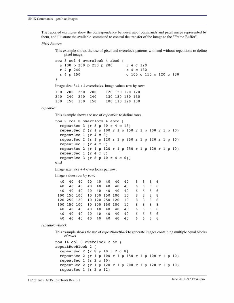
UNIX Commands - genPixelImages
The reported examples show the correspondence between input commands and pixel image represented bythem, and illustrate the available command to control the transfer of the image to the "Frame Buffer".
Pixel Pattern
This example shows the use of pixel and overclock patterns with and without repetitions to definepixel image.
row 3 col 4 overclock 4 abcd ( p 100 p 200 p 250 p 200 r 4 c 120 r 4 p 240 r 4 c 130 r 4 p 150 c 100 c 110 c 120 c 130)
Image size: 3x4 + 4 overclocks. Image values row by row:
100 200 250 200 120 120 120 120240 240 240 240 130 130 130 130150 150 150 150 100 110 120 130
repeatSec
This example shows the use of repeatSec to define rows.
row 9 col 8 overclock 4 abcd [ repeatSec 3 (r 8 p 40 r 4 c 15) repeatSec 2 (r 1 p 100 r 1 p 150 r 1 p 100 r 1 p 10) repeatSec 1 (r 4 c 8) repeatSec 2 (r 1 p 120 r 1 p 250 r 1 p 120 r 1 p 10) repeatSec 1 (r 4 c 8) repeatSec 2 (r 1 p 120 r 1 p 250 r 1 p 120 r 1 p 10) repeatSec 1 (r 4 c 8) repeatSec 3 (r 8 p 40 r 4 c 6)]end
Image size: 9x8 + 4 overclocks per row.
Image values row by row:
40 40 40 40 40 40 40 40 6 6 6 6 40 40 40 40 40 40 40 40 6 6 6 6 40 40 40 40 40 40 40 40 6 6 6 6 100 150 100 10 100 150 100 10 8 8 8 8 120 250 120 10 120 250 120 10 8 8 8 8 100 150 100 10 100 150 100 10 8 8 8 8 40 40 40 40 40 40 40 40 6 6 6 6 40 40 40 40 40 40 40 40 6 6 6 6 40 40 40 40 40 40 40 40 6 6 6 6
repeatRowBlock
This example shows the use of repeatRowBlock to generate images containing multiple equal blocksof rows
row 14 col 8 overclock 2 ac {repeatRowBlock 2 [ repeatSec 2 (r 8 p 10 r 2 c 8) repeatSec 2 (r 1 p 100 r 1 p 150 r 1 p 100 r 1 p 10) repeatSec 1 (r 2 c 10) repeatSec 2 (r 1 p 120 r 1 p 200 r 1 p 120 r 1 p 10) repeatSec 1 (r 2 c 12)
112 of 148 • ACIS Test Tools Rev. 3.1 June 20, 1997 12:43 pm

UNIX Commands - genPixelImages
repeatSec 2 (r 1 p 100 r 1 p 150 r 1 p 100 r 1 p 10) repeatSec 1 (r 2 c 10) repeatSec 2 (r 8 p 10 r 2 c 8) ]repeatRowBlock 2 [ repeatSec 1 (r 8 p 10 r 2 c 8) repeatSec 2 (r 1 p 100 r 1 p 150 r 1 p 100 r 1 p 10) repeatSec 1 (r 2 c 10) repeatSec 2 (r 1 p 120 r 1 p 200 r 1 p 120 r 1 p 10) repeatSec 1 (r 2 c 10) repeatSec 2 (r 1 p 100 r 1 p 150 r 1 p 100 r 1 p 10) repeatSec 1 (r 2 c 10) repeatSec 2 (r 8 p 10 r 2 c 8) ]}end
The image size: 10x8 + 2 overclocks
The image values row by row:
8 8 8 8 8 8 8 8 8 8 8 8 8 8 8 8 8 8 8 8100 150 100 10 100 150 100 10 10 10120 200 120 10 120 200 120 10 10 12100 150 100 10 100 150 100 10 12 10 8 8 8 8 8 8 8 8 8 8 8 8 8 8 8 8 8 8 8 8 8 8 8 8 8 8 8 8 8 8 8 8 8 8 8 8 8 8 8 8100 150 100 10 100 150 100 10 10 10120 200 120 10 120 200 120 10 10 12100 150 100 10 100 150 100 10 12 10 8 8 8 8 8 8 8 8 8 8 8 8 8 8 8 8 8 8 8 8
Delay
This example show the use of delay to introduce time delays before beginning to image transfer.
row 8 col 8 overclock 4 delay vsync before 3 after 2 abcd [ repeatSec 2 (r 8 p 100 r 4 c 10) repeatSec 3 (r 4 p 200 r 4 p 100 r 4 c 15) repeatSec 3 (r 8 p 150 r 4 c 120) ]end
The image loading is delayed by the insertion of three NULL pixels before and two after the VSYNCcode. No delay is introduced between rows.
repeatFile
This example shows the use of repeatFile to send the same file multiple times to the "Frame Buffer".
repeatFile 2 row 22 col 8 overclock 4 abcd {repeatRowBlock 2 [ repeatSec 2 (r 8 p 1 r 4 c 10) repeatSec 3 (r 4 p 2 r 4 p 3 r 4 c 30) repeatSec 3 (r 8 p 4 r 4 c 20) ]repeatRowBlock 3 [ repeatSec 2 (r 8 p 5 r 4 c 33)]
ACIS Test Tools Rev. 3.1 • 113 of 148June 20, 1997 12:43 pm

UNIX Commands - genPixelImages
}end
The output image is preceded by a keyword requesting the "Frame Buffer" to repeat the loading ofthe same image twice.
AUTHOR
Rita Somigliana, MIT CSR <[email protected]>
SEE ALSO
genObjectImage(1), loadFitsImage(1), putImages(1)
114 of 148 • ACIS Test Tools Rev. 3.1 June 20, 1997 12:43 pm
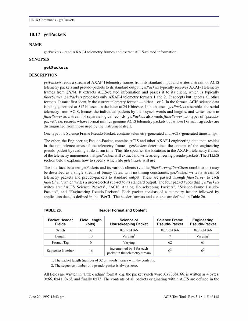
UNIX Commands - getPackets
10.17 getPackets
NAME
getPackets - read AXAF-I telemetry frames and extract ACIS-related information
SYNOPSIS
getPackets
DESCRIPTION
getPackets reads a stream of AXAF-I telemetry frames from its standard input and writes a stream of ACIStelemetry packets and pseudo-packets to its standard output. getPackets typically receives AXAF-I telemetryframes from SHIM. It extracts ACIS-related information and passes it to its client, which is typicallyfilterServer. getPackets processes only AXAF-I telemetry formats 1 and 2. It accepts but ignores all otherformats. It must first identify the current telemetry format –– either 1 or 2. In the former, ACIS science datais being generated at 512 bits/sec; in the latter at 24 Kbits/sec. In both cases, getPackets assembles the serialtelemetry from ACIS, locates the individual packets by their synch words and lengths, and writes them tofilterServer as a stream of separate logical records. getPackets also sends filterServer two types of "pseudo-packet", i.e. records whose format mimics genuine ACIS telemetry packets but whose Format Tag codes aredistinguished from those used by the instrument itself.
One type, the Science Frame Pseudo-Packet, contains telemetry-generated and ACIS-generated timestamps.
The other, the Engineering Pseudo-Packet, contains ACIS and other AXAF-I engineering data that residesin the non-science areas of the telemetry frames. getPackets determines the content of the engineeringpseudo-packet by reading a file at run time. This file specifies the locations in the AXAF-I telemetry framesof the telemetry mnemonics that getPackets will extract and write as engineering pseudo-packets. The FILESsection below explains how to specify which file getPackets will use.
The interface between getPackets and its various clients (via the filterServer/filterClient combination) maybe described as a single stream of binary bytes, with no timing constraints. getPackets writes a stream oftelemetry packets and pseudo-packets to standard output. These are passed through filterServer to eachfilterClient, which writes a user-selected sub-set to its standard output. The four packet types that getPacketswrites are: "ACIS Science Packets", "ACIS Analog Housekeeping Packets", "Science-Frame Pseudo-Packets", and "Engineering Pseudo-Packets". Each packet consists of a telemetry header followed byapplication data, as defined in the IP&CL. The header formats and contents are defined in Table 26.
All fields are written in "little-endian" format, e.g. the packet synch word, 0x736f4166, is written as 4 bytes,0x66, 0x41, 0x6f, and finally 0x73. The contents of all packets originating within ACIS are defined in the
TABLE 26. Header Format and Content
Packet HeaderFields
Field Length(bits)
Science or Housekeeping Packet
Science FramePseudo-Packet
EngineeringPseudo-Packet
Synch 32 0x736f4166 0x736f4166 0x736f4166
Length 10 Varying1
1. The packet length (number of 32 bit words) varies with the contents.
7 Varying1
Format Tag 6 Varying 62 61
Sequence Number 16incremented by 1 for each
packet in the telemetry stream02
2. The sequence number of a pseudo-packet is always zero.
02
ACIS Test Tools Rev. 3.1 • 115 of 148June 20, 1997 12:43 pm
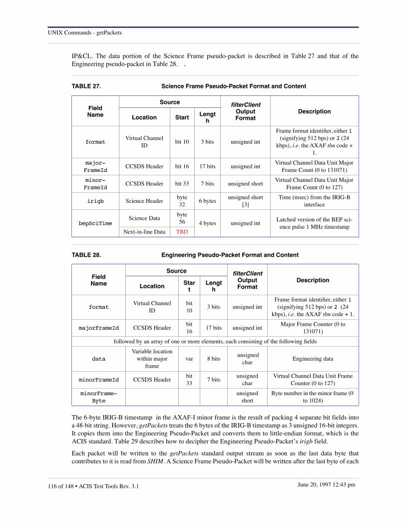
UNIX Commands - getPackets
IP&CL. The data portion of the Science Frame pseudo-packet is described in Table 27 and that of theEngineering pseudo-packet in Table 28. .
The 6-byte IRIG-B timestamp in the AXAF-I minor frame is the result of packing 4 separate bit fields intoa 48-bit string. However, getPackets treats the 6 bytes of the IRIG-B timestamp as 3 unsigned 16-bit integers.It copies them into the Engineering Pseudo-Packet and converts them to little-endian format, which is theACIS standard. Table 29 describes how to decipher the Engineering Pseudo-Packet’s irigb field.
Each packet will be written to the getPackets standard output stream as soon as the last data byte thatcontributes to it is read from SHIM. A Science Frame Pseudo-Packet will be written after the last byte of each
TABLE 27. Science Frame Pseudo-Packet Format and Content
FieldName
Source filterClientOutput Format
DescriptionLocation Start Lengt
h
formatVirtual Channel
IDbit 10 3 bits unsigned int
Frame format identifier, either 1 (signifying 512 bps) or 2 (24
kbps), i.e. the AXAF tlm code + 1.
major-FrameId
CCSDS Header bit 16 17 bits unsigned int Virtual Channel Data Unit Major
Frame Count (0 to 131071)
minor-FrameId
CCSDS Header bit 33 7 bits unsigned shortVirtual Channel Data Unit Major
Frame Count (0 to 127)
irigb Science Headerbyte 32
6 bytesunsigned short
[3]Time (msec) from the IRIG-B
interface
bepSciTimeScience Data
byte 56 4 bytes unsigned int
Latched version of the BEP sci-ence pulse 1 MHz timestamp
Next-in-line Data TBD
TABLE 28. Engineering Pseudo-Packet Format and Content
FieldName
Source filterClientOutputFormat
DescriptionLocation Star
tLengt
h
formatVirtual Channel
IDbit 10
3 bits unsigned intFrame format identifier, either 1 (signifying 512 bps) or 2 (24
kbps), i.e. the AXAF tlm code + 1.
majorFrameId CCSDS Headerbit 16
17 bits unsigned intMajor Frame Counter (0 to
131071)
followed by an array of one or more elements, each consisting of the following fields
dataVariable location
within major frame
var 8 bits unsigned
charEngineering data
minorFrameId CCSDS Headerbit 33
7 bitsunsigned
charVirtual Channel Data Unit Frame
Counter (0 to 127)
minorFrame-Byte
unsigned short
Byte number in the minor frame (0 to 1024)
116 of 148 • ACIS Test Tools Rev. 3.1 June 20, 1997 12:43 pm

UNIX Commands - getPackets
complete minor frame that contains a science data area header has been read. An Engineering Pseudo-Packetwill be written after the last byte of each complete major frame is read.
EXAMPLES
The following UNIX pipe uses getPackets as part of commanding the ACIS instrument:
... | buildCmds | sendCmds | shim lrctu | getPackets | filterServer ...
FILES
$ACISTOOLSDIR The path name of the ACIS Test Tools directory. If this variable does not exist in theuser’s environment, getPackets will exit.
$ACISTTMFILE The name of the file that specifies the locations in the AXAF-I telemetry frames of thetelemetry mnemonics that getPackets will extract and write as engineering pseudo-packets. If this variableexists in the user’s environment, getPackets will attempt to open $ACISTOOLSDIR/lib/$ACISTTMFILE. If it doesn’t, getPackets will attempt to open $ACISTOOLSDIR/lib/acisEng.ttminstead.
AUTHOR
Demitrios Athens, MIT CSR
STATUS
The current version should work with either the CTUE or the LRCTU (if its telemetry output is passedthrough ltp2mnf).
The current version is only capable of processing Format 2 telemetry. Its behavior if fed any other format isunknown but is liable to be objectionable.
The current version is implemented by having getPackets fork into 2 processes. One process, the original oneas it turns out, reads AXAF-I telemetry and produces pseudo-packets. It also pipes the ACIS telemetry packetstream to the other process, which assembles and writes the ACIS packets. Both processes change theirargv[0] environment value to either "axafFrames" or "acisPackets" as appropriate. This fools ps(1) intoreporting the new name of each process. However, top(1) reports both as "getPackets."
TABLE 29. IRIG-B Field Format and Contents
Field Name Bit Length Byte Word
Julian Day 11 0,1 0
Seconds 17 1,2,3 0,1
Milliseconds 10 3,4 1,2
Microseconds (always zero) 10 4,5 2
ACIS Test Tools Rev. 3.1 • 117 of 148June 20, 1997 12:43 pm

UNIX Commands - lcmd
10.18 lcmd
NAME
lcmd – list contents of ACIS command stream
SYNOPSIS
lcmd [–Bindent] [–V] [–lc] [–lh] [–lp] [–r] [–v] [–w cols] [file ...]
DESCRIPTION
This Perl script reads one or more ACIS command files and writes a formatted listing to the standard outputstream, stdout. If no input file is specified, lcmd reads the standard input stream, stdin.
The output consists of a series of "keyword = value" lines, in which the keywords are derived from the IP&CLfield names, translating to uppercase all characters that immediately follow an embedded blank, and thenremoving the blank, e.g. "command length" is written as "commandLength". The "value" fields are renderedin decimal, with the following exceptions • 32-bit addresses and block IDs are in hexadecimal, prefixed with"0x"; • command tags are displayed as enumerated names, e.g. "CMDOP_LOAD_1D", followed by theirdecimal value in parentheses; • the timed-exposure "gradeSelection" value is written as a series of 8-characterhexadecimal fields.
Each command begins with a header line of the form "name[n] = {", and ends with a matching right brace.Command blocks are separately numbered, starting at zero.
OPTIONS
–B n inserts n blank characters at the start of each output line—used by ltlm when invoking lcmd internally.The default is to insert no blanks.
–V write two lines to stderr reporting the RCS update level of this command and of the IP&CL structuredescription to which it refers.
–lc does no processing; merely lists the names of ACIS software serial command blocks, their"commandIdentifier" codes, and decimal equivalents.
–lh does no processing; merely lists the names of ACIS hardware serial commands, their IP&CLmnemonics, and hexadecimal equivalents.
–lp does no processing; merely lists the names of ACIS high-level pulse commands, their IP&CLmnemonics, and their decimal and hexadecimal RCTU channel values.
–r raw mode—the commands are not assumed to be prefixed by 4-byte headers, two 16-bit binary integerscontaining the command type and channel number, respectively.
–v becomes very verbose, listing the values of all large arrays. Otherwise lcmd will only list the numberof elements in each array.
–w cols sets the column width—array values that exceed this width will be continued on the next output line.The default value is 73.
AUTHOR
Peter G. Ford, MIT CSR
SEE ALSO
The Web page "http://acis.mit.edu/ipcl", which tabulates ACIS command and telemetry packet formats.
DIAGNOSTICS
118 of 148 • ACIS Test Tools Rev. 3.1 June 20, 1997 12:43 pm

UNIX Commands - lcmd
bad commandOpcode: code in packet n the "commandOpcode" in command n is illegal. lcmd lists only the command header.
ACIS Test Tools Rev. 3.1 • 119 of 148June 20, 1997 12:43 pm

UNIX Commands - lerv
10.19 lerv
NAME
lerv – display contents of binary ERV event data files
SYNOPSIS
lerv [–N] [–V] [file]
DESCRIPTION
This Perl script reads an ERV event file, e.g. one generated by psci, and writes the contents of each record inASCII to stdout. The ERV record data fields are as follows:
typedef struct {unsigned short expnum; /* exposure number [5] */unsigned short exposure; /* exposure time (msec) [5] */unsigned long irigtime; /* IRIG timestamp [8] */unsigned short nodenum; /* output node index [1] */unsigned short col; /* column index [4] */unsigned short row; /* row index [4] */unsigned short data[9]; /* event data values [4] */short doclk; /* delta overclock [2] */
} RvRec;
They are written out as decimal numbers, right-justified with blank fill and separated by single blanks. Thenumbers in square brackets in the above definitions represent the minimum field widths. If the ASCII valueof a particular field exceeds this, the remaining fields will be shifted right in the output line to accommodateit. Thus, although most output lines will contain 80 characters followed by a newline, some could be longer.
OPTIONS
–N interpret the input field as big-endian (MSB first) integers. Use this flag to read a MSB event file, e.g.one created on a Sun, on a LSB machine, e.g. a DecStation.
–V interpret the input field as little-endian (LSB first) integers. Use this flag to read a LSB event file, e.g.one created on a DecStation, on a MSB machine, e.g. a Sun.
AUTHOR
Peter G. Ford, MIT CSR
SEE ALSO
psci(1)
120 of 148 • ACIS Test Tools Rev. 3.1 June 20, 1997 12:43 pm

UNIX Commands - lhuff
10.20 lhuff
NAME
lhuff – display contents of binary Huffman table block
SYNOPSIS
lhuff [–N] [–V] [file]
DESCRIPTION
This Perl script reads a binary Huffman table block, e.g. as created by psci, and writes the contents in ASCIIto stdout.
OPTIONS
–N interpret the input field as big-endian (MSB first) integers. Use this flag to read a MSB Huffman file,e.g. one created on a Sun, on a LSB machine, e.g. a DecStation.
–V interpret the input field as little-endian (LSB first) integers. Use this flag to read a LSB Huffman file,e.g. one created on a DecStation, on a MSB machine, e.g. a Sun.
AUTHOR
Peter G. Ford, MIT CSR
SEE ALSO
psci(1)
DIAGNOSTICS
• file: bad table header one of the 4-byte offsets at the beginning of file points beyond the end of the file.
• file: bad table length: n the length of a single table exceeds that of the remainder of the file.
ACIS Test Tools Rev. 3.1 • 121 of 148June 20, 1997 12:43 pm

UNIX Commands - loadFitsImage
10.21 loadFitsImage
NAME
loadFitsImage – convert FITS file to FEP image load format
SYNOPSIS
loadFitsImage [–a] [–m mode] [–n noclks] [–o col1,...,col8] [–p col1,...,col8] [–r nrows] [–s row1] [–v] [file ...]
DESCRIPTION
This command loads one or more FITS images and reformats them for an ACIS Image Loader, rearrangingthe pixels and overclocks according to the simulated CCD readout mode specified by the –m option. If thelist of files is omitted, a single FITS image will be read from the standard input stream, stdin.
OPTIONS
–a determine the image dimensions and the location of the valid pixels and overclocks from the FITSheader keywords alone. When the –v flag is specified, the values of the –n, –o, –p, –r, and –s optionsare copied to stderr.
–m mode selects the CCD quardant readout mode that is to be simulated. mode must be either abcd, or ac, or bd.
–n noclks specifies the number of overclocks to be used per quadrant. At least this number must be available ineach of the input FITS files.
–o col1,col2,col3,col4,col5,col6,col7,col8 selects the column limits of overclocked pixels in the 4 quadrants of the input FITS files. The pixelsfrom quadrant A are located in columns col1 through col2 of each line, those of quadrant B in columnscol3 through col4, etc. It is assumed that the input pixel order is as in the ACIS Memo cited below.
–p col1,col2,col3,col4,col5,col6,col7,col8 selects the column limits of good pixels in the 4 quadrants of the input FITS files. The first column isindexed 0. The pixels from quadrant A are located in columns col1 through col2 of each line, those ofquadrant B in columns col3 through col4, etc. It is assumed that the input pixel order is as in the ACISMemo cited below.
–r nrows specifies the number of output rows to write, each of which will be followed by a HSYNC code.
–s row1 specifies the index of the first row in the input image (counting from 0) to write to the output.
–v puts loadFitsImage into verbose mode, writing statistics to stderr, detailing the number of rows andcolumns of each output image.
AUTHOR
Peter G. Ford, MIT CSR
SEE ALSO
The Coordinate System of ACIS FITS Files, ACIS Memo, J. W. Woo and S. E. Kissel, December 7, 1994.
DIAGNOSTICS
EOF while reading FITS header the input probably isn’t in FITS format.
122 of 148 • ACIS Test Tools Rev. 3.1 June 20, 1997 12:43 pm

UNIX Commands - loadFitsImage
IcMAXCOL: header keyword missing the –a option has been specified, but the FITS header doesn’t contain sufficient information to specify thepixel locations.
IcMINCOL: header keyword missing the –a option has been specified, but the FITS header doesn’t contain sufficient information to specify thepixel locations.
bad pixel range in quadrant val the number of pixels in each quadrant is not the same.
bad BITPIX value: val the value of the FITS header keyword BITPIX must be 16.
bad NAXIS1 value: val the value of the FITS header keyword NAXIS1 must be not less than 1024+4×noclks, where noclks is asspecified in the –n option.
bad NAXIS2 value: val the value of the FITS header keyword NAXIS2 must be not less than nrows+row1, where nrows is asspecified by the –r option, and row1 by the –s option.
bad overclock offsets: list the overclock column list must contain exactly 8 unsigned integers, separated by commas, without anyother whitespace or punctuation.
bad pixel offsets: list the pixel column list must contain exactly 8 unsigned integers, separated by commas, without any otherwhitespace or punctuation.
unable to allocate input buffer the value of the FITS header keyword NAXIS1 is too large and loadFitsImage is unable to allocate a bufferto hold the input record.
unexpected EOF in record val an end-of-file was encountered while reading record val of the input file, indicating that the file istruncated, or that one or more FITS header keywords are incorrect.
name: n lines, each n pixels + n oclks generated by the –v verbose flag, this indicates that the FITS file name generated a number of output lines,each containing the specified number of pixels and overclocks.
BUGS
On-chip summation is not currently implemented. It is assumed that all output nodes generate either 256pixels (ABCD mode) or 512 pixels (AC or BD mode).
ACIS Test Tools Rev. 3.1 • 123 of 148June 20, 1997 12:43 pm
UNIX Commands - logGet
10.22 logGet
NAME
logGet – get CTUE command abort log messages
SYNOPSIS
logGet
DESCRIPTION
logGet listens on the TCP/IP port number that the CTUE will try to connect to for sending command abortlog messages. It prints any messages it receives on its standard output.
If logGet is run with root priviledges, it will listen on port 542 for a connection from the CTUE. If it is runwith regular user priviledges, logGet will listen on port 7542. The appropriate port number must be enteredin the CTUE’s c:\windows\ethernet.cfg file. logGet adds its own time stamp to each message.
EXAMPLES
The following UNIX command uses logGet as part of commanding ACIS:
acisEgseHost% logGet
AUTHOR
Ann M. Davis, MIT CSR
Demitrios Athens, MIT CSR
STATUS
The current version is working according to specification.
124 of 148 • ACIS Test Tools Rev. 3.1 June 20, 1997 12:43 pm

UNIX Commands - ltlm
10.23 ltlm
NAME
ltlm – list contents of ACIS telemetry stream
SYNOPSIS
ltlm [–E] [–V] [–e type] [–f from] [–lc] [–lt] [–p type] [–s] [–t to][–v] [–w cols] [file ...]
DESCRIPTION
This Perl script reads one or more ACIS telemetry files and writes a formatted listing to the standard outputstream, stdout. If no input file is specified, ltlm reads the standard input stream, stdin.
The output consists of a series of "keyword = value" lines, in which the keywords are derived from the IP&CLfield names, translating to uppercase all characters that immediately follow an embedded blank, and thenremoving the blank, e.g. "command length" is written as "commandLength". The "value" fields are renderedin decimal, with the following exceptions • synch codes, 32-bit addresses, timestamps and block IDs are inhexadecimal, prefixed with "0x"; • command and packet tags are displayed as enumerated names, e.g."TTAG_CMD_ECHO", followed by their decimal value in parentheses; • the timed-exposure"gradeSelection" value is written as a series of 8-character hexadecimal fields.
Each telemetry packet and embedded command block begins with a header line of the form "name[n] = {",and ends with a matching right brace. Each type of command block and telemetry packet is separatelynumbered, starting at zero. Embedded arrays of data structures are also numbered from zero, but the index isreset at the start of each array instance.
OPTIONS
–E write two lines to perform extended error checking on ACIS packets. Currently, the only test is to verifythat the packet sequence numbers are in ascending order. Missing or out-of-sequence packets are notedby messages to stderr.
–V write two lines to stderr reporting the RCS update level of this command and of the IP&CL structuredescription to which it refers.
–e type excludes output of those packets whose decimal "formatTag" value is type. Allowed values aretabulated by invoking ltlm with the –lt flag. Multiple –e options may be specified to exclude more thanone type of packet.
–f from don’t list packets with "sequenceNumber" values less than from.
–lc does no processing; merely list the names of ACIS command blocks, their "commandIdentifier" codes,and decimal equivalents.
–lt does no processing; merely list the names of ACIS telemetry packets, their "formatTag" codes, anddecimal equivalents.
–p type restricts output to those packets whose decimal "formatTag" value is type. Allowed values are tabulatedby invoking ltlm with the –lt flag. Multiple –p options may be specified to list more than one type ofpacket.
–s print only a tally of packet statistics: the number of packets, the packet type, and its TTAG format code.
–t to don’t list packets with "sequenceNumber" values greater than to.
ACIS Test Tools Rev. 3.1 • 125 of 148June 20, 1997 12:43 pm

UNIX Commands - ltlm
–v becomes very verbose, listing the values of all large arrays within the telemetry packets. Otherwise ltlmwill only list the number of elements in each array.
–w cols sets the column width—array values that exceed this width will be continued on the next output line.The default value is 73.
AUTHOR
Peter G. Ford, MIT CSR
SEE ALSO
The Web page "http://acis.mit.edu/ipcl", which tabulates ACIS command and telemetry packet formats.
DIAGNOSTICS
bad commandOpcode: code in packet n the "commandOpcode" in packet n is illegal. ltlm lists only the command header.
bad formatTag: tag in packet n the format tag in the header of packet n is illegal. ltlm ignores this packet and reads the next.
decompression unimplemented in packet n this version of ltlm cannot list the values of compressed pixels in "dataCcRaw", "dataTeBiasMap", or"dataTeRaw" packets.
126 of 148 • ACIS Test Tools Rev. 3.1 June 20, 1997 12:43 pm

UNIX Commands - monitorScience
10.24 monitorScience
NAME
monitorScience – display ACIS run-time information on an X11 server
SYNTAX
monitorScience
DESCRIPTION
monitorScience creates a multi-window display, reads the stdout stream from processScience, and writes itinto one of the windows.
monitorScience uses colors to signal various conditions: fatal anomalies are shown in red, warnings in blue.The initiation and termination of science or monitor requests are displayed in green. Colors are also used todistinguish decimal numbers (black) from hexadecimal numbers (brown).
Black and brown colors are also used to facilitate the reading of parameter names. In science data windows,they distinguish telemetry packet names (black) from parameter names (brown). In the Dea Housekeepingwindow, packet header fields are colored brown, and data fields black (see below). In Sw Housekeeping,packet header fields are brown, data fields are black, red, or blue, depending on the type of informationdisplayed.
Normally, window backgrounds are colored "linen", but background of the most recently updated window iscolored "white".
WINDOW LIST
Echo Command Packets This window displays the command name, arrival time, execution time, and command ID of allcommands echoed from the ACIS instrument. The list shows what commands were sent to the BEP,and the order in which they were executed.
Science General Parameters This window displays information about any BepStartupMessage","Dump Parameter", and "ScienceReport" telemetry packets. It identifies the most recent science parameter block, and the result of themost recent science run.
Science Data This window displays information about the most recent science and bias telemetry packets receivedfrom ACIS. The window is divided vertically into three regions -- two for science data and one for biasdata -- and horizontally into six columns, one for each FEP. The first science data packet is displayedin the top window, the next in the middle window, the third in the top window again, and so on.
Fatal Messages This window displays the time at which a fatal error was detected by the BEP and the correspondingerror code and value.
Read and Write This window displays information about the execution of write-to-memory commands, i.e. "Read BadColumns" (TE and CC), "Read Bad Pixels", "Read System Configuration", "Read Patches", "ReadHuffman Tables", and "Read Parameter Slots" (TE, CC, 2D window, 1D window, and DEA).
Sw Housekeeping This window displays information about "Software Housekeeping" telemetry packets in the form of atable containing rows of two types. One contains the start and end times of the housekeeping collectionperiod, the other contains the name, repetition times, and value of each monitored parameter.
ACIS Test Tools Rev. 3.1 • 127 of 148June 20, 1997 12:43 pm

UNIX Commands - monitorScience
Dea Housekeeping This window displays information about "Dea Housekeeping" telemetry packets in the form of a tablecontaining rows of two types. One contains the "Dea Block id" and "Command Id" of the most recent"Start Dea Housekeeping" command and the BEP time corresponding to the most recent housekeepingpacket. The other contains monitor information:; the "Board Id", "Query Id" name and value.
ENVIRONMENT VARIABLES
ACISTOOLSDIR must point to the top-level test directory within which the monitorScience modules are located, e.g."~acis/toolstest".
TCL_LIBRARY must point to the TCL run-time library, e.g. "$ACISTOOLSDIR/src/Other/tcl7.4/lib/tcl7.4".
TK_LIBRARY must point to the TK run-time library, e.g. "$ACISTOOLSDIR/src/Other/tk4.0/lib/tk4.0".
AUTHOR
Rita Somigliana, MIT CSR <[email protected]>
128 of 148 • ACIS Test Tools Rev. 3.1 June 20, 1997 12:43 pm

UNIX Commands - processDEAhkp
10.25 processDEAhkp
NAME
processDEAhkp – extract DEA query response data from a DEA housekeeping ACIS telemetry packet
SYNOPSIS
processDEAhkp -f outFileName [ filename... ]
DESCRIPTION
processDEAhkp reads DEA housekeeping ACIS telemetry packets either from the standard input or from oneor more files specified as command line arguments. It rewrites the outFileName whenever it reads a DEAhousekeeping ACIS telemetry packet from its input.
For each query response that the DEA housekeeping packet contains, processDEAhkp writes to theoutFileName the ccdId, queryId, and value. The output is in ASCII and is the decimal value of the item inthe packet. A blank delimits the end of each of the first two items and a newline delimits the end of the lastitem. processDEAhkp expects its input to consist of DEA housekeeping ACIS telemetry packets. It silentlyignores any other packets in its input. It also silently ignores the other elements of the DEA housekeepingACIS telemetry packet: deaBlockId, commandId, and bepTickCounter. processDEAhkp always removes anyexisting contents of outFileName when starting.
EXAMPLES
The following UNIX pipe uses processDEAhkp as part of monitoring DEA housekeeping information:
filterClient -h | processDEAhkp -f DEAhkp | monitorDEAhkp -f DEAhkp ...
AUTHOR
Demitrios Athens, MIT CSR <[email protected]>
STATUS
The current version has been been tested but not used extensively.
The current version does not ensure that its first argument is "-f" but simply assumes that its second argument,if present, is the outFileName. If the "-f" option is missing and processDEAhkp is to read its input from a file,then the contents of the first input file will be lost.
ACIS Test Tools Rev. 3.1 • 129 of 148June 20, 1997 12:43 pm

UNIX Commands - psci
10.26 psci
NAME
psci – parse an ACIS serial telemetry stream
SYNOPSIS
psci [–DVacmpqsuv] [–h file] [–l prefix] [file]
DESCRIPTION
This program reads a stream of ACIS packets, verifies their format and internal consistency, and optionally,sorts, reformats, and writes them to a series of data streams and disk files. Packets are read from the input file,or, if omitted, from the standard input stream, stdin. They are subjected to a variety of tests. If the –l optionis specified, their headers are translated into ASCII and written to log files. If –m is specified, a one-linedescription is written to stdout, suitable for display by monitorScience(1). Most packets are then discarded,and psci goes on to read the next one, but some are retained, as follows:
• the most recent exposure header packet from each FEP,
• all event data packets, until a corresponding exposure header packet is encountered,
• multi-packet memory read-out packets originating from a single BEP command,
• the most recent dumped*Block and dumpedHuffman packets.
psci has been compiled with tables derived directly from the IP&CL Structures database. Packets withunrecognized TTAG codes (as defined in the "acis_h/interface.h" file) cause warning messages to be writtento stderr, and are ignored. All fields in recognized packets and pseudopackets are then checked against theirIP&CL limits—bit fields are expanded to "unsigned long int" values unless their minimum permissible values(column 15 in the IP&CL structure tables) are negative, in which case, psci treats them as twos-complementsigned integers and expands them to "long int". If a field is discovered to be out of range, psci writes amessage to stderr:
file: packet[ntotal,ncount].field[index] above maximum (val > maxval) file: packet[ntotal,ncount].field[index] below minimum (val < maxval)
All stderr messages begin with a "file:" argument; for errors and warnings, this is the name of the input file(or stdin); for informatory messages, it is usually the name of an output file. Packets are designated by theirIP&CL names, e.g., exposureTeRaw, followed by ntotal, the sequence number of the packet within the inputstream, and ncount, its sequence number among packets of its particular type. Both counts start at zero, so thefirst packet is [0,0]. Multi-dimensional fields within packets are followed by an array index, which also startsat [0]. The value of the field is displayed as a decimal integer. Since out-of-limits field-values are notconsidered to be sufficient reason for halting the program, psci writes these messages and continuesprocessing. The messages themselves can be suppressed by invoking psci with the –q option.
When the –l option is used, psci writes packet-header information to log files. The format of these files isderived from that of data structures in the C language. Fields whose values are enumerated in "acis_h/interface.h" will be followed by "#" and the enumeration. Unsigned values larger than 32767 are shown inhexadecimal base, preceded by "0x". The values of arrays of fields with dimension > 9 are not shown—merely their dimension. When a packet contains one or more command blocks, e.g. dumpedTeBlock, whichcontains a science parameter block (either loadTeBlock or loadCcBlock) and an optional window block(either load1dBlock or load2dBlock), the individual fields are also logged, shifted to the right by 2 columns.
When a dumpedCcBlock or dumpedTeBlock packet is received, a comment is written into all open log files,and the science run number is incremented. Any opened science and bias data files are automatically closed,and a warning message is written to stderr since they should have been closed: science files by the receipt ofa previous scienceReport packet, and bias files when complete.
130 of 148 • ACIS Test Tools Rev. 3.1 June 20, 1997 12:43 pm

UNIX Commands - psci
When psci is invoked with the –m flag, monitor records are written to stdout.
OPTIONS
–D run psci in debug mode, appending the source file name and line number to all error and warningmessages. If the program terminates abnormally, the failing packet header will also be logged to stderr.
–V print the RCS revision ID of the psci program and of the IP&CL structure tables used in its compilation.
–a write log and data files in ASCII mode. If omitted, these files will consist of 32-bit binary fields in thehost machine’s byte order.
–c concatenate log files, i.e. append to any existing files of the same name. If omitted, existing log fileswill be overwritten.
–h file initialize the Huffman compression tables from file, which must consist of a binary Huffman block. Theformat is that of a binary Huffman file written by a previous invocation of psci.
–l prefix generate log and data file, prefixing their names with the prefix string. If omitted, no files will bewritten.
–m write monitor information to stdout, one line per input packet, in the format accepted bymonitorScience.
–p write the contents of pseudo-packets to "prefix.pseudo.log", where prefix is specified by the –l option.If omitted, pseudopackets will be ignored, except for those requested by the –u flag.
–q execute psci in quiet mode, suppressing all warning messages.
–s write all log files to stdout, rather than to disk files. This and the –m flag are mutually exclusive.
–u write text messages in user pseudo-packets to stderr. If omitted, user pseudopackets will be ignored.These messages are null terminated strings beginning at word 4 of those packets whose 3rd word iszero.
–v execute psci in verbose mode, writing informatory messages to stderr, detailing the names and contentsof log and data files, the status of scienceReport packets, etc.
FILES
Files used to build psci
acis_h/interface.h enumerations cmd.aux command definition overrides enum.aux more enumerations ipcl-struct*.tsv IP&CL structures pseudo.map pseudopacket definitions tlm.aux telemetry definition overrides
Files generated by psci (ASCII listings of packet contents)
prefix.s.bias.log bias packet headers prefix.command.log BEP commands prefix.deahk.log analog housekeeping prefix.s.science.log science mode packets prefix.packet.log miscellaneous packets prefix.pseudo.log pseudopackets (–p only) prefix.swhk.log S/W housekeeping packets
Memory Dumps (ASCII if –a specified, otherwise binary)
ACIS Test Tools Rev. 3.1 • 131 of 148June 20, 1997 12:43 pm

UNIX Commands - psci
prefix.bepReadReply.n.dat BEP memory readout (binary) prefix.bepReadReply.n.txt BEP memory readout (ASCII) prefix.dumpedSysConfig.n.dat Configuration tables (binary) prefix.dumpedSysConfig.n.txt Configuration tables (ASCII) prefix.dumpedBadPix.n.dat Bad pixel lists (binary) prefix.dumpedBadPix.n.txt Bad pixel lists (ASCII) prefix.dumpedBadTeCol.n.dat Bad Te column lists (binary) prefix.dumpedBadTeCol.n.txt Bad Te column lists (ASCII) prefix.dumpedBadCcCol.n.dat Bad Cc column lists (binary) prefix.dumpedBadCcCol.n.txt Bad Cc column lists (ASCII) prefix.dumpedPatches.n.dat Patch list (binary) prefix.dumpedPatches.n.txt Patch list (ASCII) prefix.dumpedHuffman.n.dat Huffman tables (binary) prefix.dumpedHuffman.n.txt Huffman tables (ASCII) prefix.dumpedTeSlots.n.dat Te parameter blocks (binary) prefix.dumpedTeSlots.n.txt Te parameter blocks (ASCII) prefix.dumpedCcSlots.n.dat Cc parameter blocks (binary) prefix.dumpedCcSlots.n.txt Cc parameter blocks (ASCII) prefix.dumped2dSlots.n.dat 2D window blocks (binary) prefix.dumped2dSlots.n.txt 2D window blocks (ASCII) prefix.dumped1dSlots.n.dat 1D window blocks (binary) prefix.dumped1dSlots.n.txt 1D window blocks (ASCII) prefix.dumpedDeaSlots.n.dat DEA H/K list (binary) prefix.dumpedDeaSlots.n.txt DEA H/K list (ASCII) prefix.fepReadReply.n.dat FEP memory readout (binary) prefix.fepReadReply.n.txt FEP memory readout (ASCII) prefix.pramReadReply.n.dat PRAM memory readout (binary) prefix.pramReadReply.n.txt PRAM memory readout (ASCII) prefix.sramReadReply.n.dat SRAM memory readout (binary) prefix.sramReadReply.n.txt SRAM memory readout (ASCII)
Data Files (produced by FEP n from science run s.)
prefix.s.n.erv.dat event data (binary ERV format) prefix.s.n.erv.txt event data (ASCII ERV format) prefix.s.n.i–j.hist.fits pixel histograms (FITS format) prefix.s.n.i–j.hist.txt pixel histograms (ASCII) prefix.s.n.bias.fits bias FITS files prefix.s.n.m.raw.fits raw pixel FITS files prefix.s.n.TMP.fits temporary raw pixel files
AUTHOR
Peter G. Ford, MIT CSR
SEE ALSO
"IP&CL Structure Definitions", MIT CSR
DIAGNOSTICS
Fatal Messages:
The following messages will always be written to stderr, after which psci will exit with non-zero systemreturn code. If –D is specified, the header of the last packet will be logged to stderr before exiting.
132 of 148 • ACIS Test Tools Rev. 3.1 June 20, 1997 12:43 pm

UNIX Commands - psci
• packet[ntot,npkt] Huffman table slot n is empty A raw-mode or bias packet referenced a non-existent Huffman table slot.
• packet[ntot,npkt] illegal Huffman table slot: n A Huffman table slot header is damaged.
• packet[ntot,npkt] truncated Huffman table slot n A Huffman table header contains a length field that is too large for the Huffman block.
• –l and –s are mutually exclusive The –l option directs logging output to disk files; –s sends it to stdout.
• –m and –s are mutually exclusive The –m option writes monitor information to stdout; the –s option uses stdout for logging.
• no more memory Insufficient memory was available to initialize psci symbol tables.
• unable to allocate memory for packet n psci ran out of memory for storing packets.
Warning Messages:
These are written to stderr unless the –q flag appears on the psci command line.
• packet[ntot,npkt] ‘file’ partially filled • last data packet was packet[ntot,npkt]
a science run was terminated while incomplete raw-mode data files were being written.
• packet[ntot,npkt] ‘file’ partially filled • packet[ntot,npkt].ccdRow=n in last bias packet
a science run was terminated while incomplete bias files were being written.
• packet[ntot,npkt] missing parameter block A science packet cannot be processed because no science-mode parameter block has beenreceived.
• packet[ntot,npkt] no Huffman table specified An initial table can be pre-allocated by using the –h option.
• packet[ntot,npkt] no histogram data packets received An exposureTeHistogram packet was received with no preceding dataTeHist packets.
• packet[ntot,npkt] no parameter block was found A scienceReport packet was received without any prior dumpedCcBlock or dumpedTeBlockpackets.
• packet[ntot,npkt].readAddress != packet[ntot,npkt.requestedAddress + 4*n The readAddress is inconsistent with the position of this packet within a group of memory-readout packets.
• packet[ntot,npkt].readIndex != packet[ntot,npkt].requestedIndex + 2*n The readIndex is inconsistent with the position of this packet within a group of DEA memory-readout packets.
• packet[ntot,npkt] unpacking failure in=m/n out=p/p This packet has failed Huffman decompression. n 32-bit words (out of m) remain to beunpacked; p 12-bit values (out of an anticipated q) have resulted.
• packet[ntot,npkt] unpacking length inconsistency The unpacked length of this packet does not conform to that expected from its header fields.
• packet[ntot,npkt] warning: no data packets A raw-mode exposure packet was not preceded by any raw-mode data packets.
• packet[ntot,npkt].startExposureNumber=n <= packet[ntot,npkt].endExposureNumber=n The startExposureNumber of this histogram exposure packet is not greater than theendExposureNumber of the previous exposure packet.
ACIS Test Tools Rev. 3.1 • 133 of 148June 20, 1997 12:43 pm

UNIX Commands - psci
• packet[ntot,npkt].ccdRow=n > packet[ntot,npkt].(subarrayStartRow+subarrayRowCount)=n The ccdRow field of the current packet is inconsistent with the subarrayStartRow andsubarrayRowCount fields in the science-mode parameter block.
• packet[ntot,npkt].field[n] above maximum (val > maxval) The named field is larger than the limit defined in the IP&CL Structures table.
• packet[ntot,npkt].field[n] below minimum (val < minval) The named field is smaller than the limit defined in the IP&CL Structures table.
• packet[ntot,npkt].(ccdRow-ccdRowCount)=n < packet[ntot,npkt].subarrayStartRow=n The ccdRow and ccdRowCount fields of this packet are inconsistent with thesubarrayStartRow field in the science-mode parameter block.
• packet[ntot,npkt].sequenceNumber=n != n The packet sequence number is not one larger than that of the preceding (non-pseudo-) packet.
• packet n ignored: unknown type n The packet’s formatTag is not defined in the IP&CL Structures table.
• unrecognized commandOpcode n in packet[ntot,npkt] The commandOpcode is not defined in the IP&CL Structures table.
• warning: non-zero dutyCycle, ERV timetags may be inaccurate psci does not attempt to generate "reasonable" acistime fields for timed-exposure mode withnon-zero dutyCycle.
Informatory Messages:
These are only written to stderr if the –v flag appears on the psci command line.
• written n bytes to log file ‘file’ a log file has been successfully closed.
• packet[ntot,npkt] written to ‘file’ a memory-read packet, or groups of packets, has been written to a disk file.
• packet[ntot,npkt] run n irig n:n exp n fep n ccd n dea n bep n A science run has terminated with the specified number of exposures and FEP, DEA, and BEPcompletion codes.
• Executing packet[ntot,npkt] run n A science run has begun.
• written n bytes to bias file ‘file’ A bias file has been successfully closed.
• start packet run n fepmode bepmode bep timestamp irig days:secs exptime secs A science run has started and psci has figured out the approximate IRIG start time and inter-exposure interval.
• written n exposures n events to ‘file’ An event file has been successfully closed.
• written histogram to ‘file’ A histogram file has been successfully closed.
• written n bytes to raw image file ‘file’ A raw-mode FITS file has been successfully closed.
134 of 148 • ACIS Test Tools Rev. 3.1 June 20, 1997 12:43 pm

UNIX Commands - runacis
10.27 runacis
NAME
runacis – Execute ACIS FEP and BEP software simulators
SYNOPSIS
runacis [–B file] [–D dir] [–F file] [–b file] [–c] [–h host] [–nc ccd] [–nf fep] [–x file]
DESCRIPTION
runacis starts a simulated ACIS back-end processor (BEP) on a remote DecStation host and copies itstelemetry stream to the standard output stream, stdout. It reads its standard input stream, stdin, copying thecontents to the software serial port of the simulated BEP. This input stream may be constructed from thestandard output of buildCmds, invoked with the –p flag to suppress channel code prefixes.
The –b and –x options are used to specify programs that will supply CCD pixel values to a simulated ACISfront-end processor (FEP) that will be started on the same remote host as was the BEP simulator. The –b fileis intended for bias pixels, and –x for subsequent science-mode pixels. If both –b and –x are omitted, no FEPsimulator will be started.
All error messages from the simulator(s) will be written to files named host.type.log in the current directory,where host is the name of the remote DecStation that is running the simulator(s), and type is bep for outputfrom acisBepUnix, fep for output from acisFepUnix, img for output from the fepImage2 loader, cmd foroutput from the cclient command sender, and tlm for output from filterClient, the telemetry receiver. Thestandard error stream, stderr, from runacis itself will only contain short informatory messages, e.g."acisBepUnix: starting", etc., along with the stderr of commands specified in the –b and –x options.
OPTIONS
–B file specifies the name of the BEP software simulator. The default is acisBepUnix.
–D dir specifies the name of the directory tree within which the various executables (acisBepUnix,acisFepUnix, fepImage2, etc. ) are to be found. If dir is a relative pathname, it is assumed to be locatedwithin ~acis.
–F file specifies the name of the FEP software simulator. The default is acisFepUnix. It will only be started ifthe –x option is used.
–b file starts the executable file, passing its standard output to a copy of fepImage2 running on the remote host.This standard output should therefore consist of a stream of DEA pixel values with legal control codes.For instance, rows should be ended with HSYNC codes and frames with VSYNC codes. Unless eitherthis option or –x (q.v.) is specified, no FEP simulator will be started on the remote host.
–c clean up the software simulator processes running on the remote host and release any shared memorythat remains allocated.
–h host the name of the remote DecStation host that is to run the simulators.
–nc ccd the number of the CCD/DEA to simulate. The default is CCD 0. runacis will only start a singlesimulated CCD, and then only if the –x option is used.
ACIS Test Tools Rev. 3.1 • 135 of 148June 20, 1997 12:43 pm

UNIX Commands - runacis
–nf fep the number of the FEP to simulate. The default is FEP 0. runacis will only start a single simulated FEP,and then only if the –x option is used.
–x file waits until acisBepUnix writes the string ":invokeDataProcess" to its stderr stream, and then starts theexecutable file, passing its standard output to a copy of fepImage2 running on the remote host. Thecontents are as described for the –b option described above.
EXAMPLE
In the following, only the first telemetry packet, a cmdEcho, and a scienceReport packet, are shown.
$ buildCmds –p < te.1 | runacis –h quasar –b genbias –x genfep | ltlm –v –e11acisBepUnix: startingacisFepUnix: startingfilterClient: startingquasar: configuringcommandEcho[0] = { synch = 0x736f4166 telemetryLength = 8 formatTag = 7 (TTAG_CMD_ECHO) sequenceNumber = 1 arrival = 0x00000097 result = 1 (CMDRESULT_OK) changeConfigSetting[1] = { commandLength = 7 commandIdentifier = 0 commandOpcode = 32 (CMDOP_CHANGE_SYS_ENTRY) entries[0] = { itemId = 0 (SETTING_DEA_POWER) itemValue = 1 } entries[1] = { itemId = 1 (SETTING_FEP_POWER) itemValue = 1 } }}cclient: startingfepImage2: starting FEP 0 sequencer for biasgenbias: bias 1 writtengenbias: bias 2 writtengenbias: bias 3 writtenfepImage2: starting FEP 0 sequencer for science rungenfep: image 1 writtengenfep: image 2 writtengenfep: image 3 writtenscienceReport[0] = { synch = 0x736f4166 telemetryLength = 12 formatTag = 15 (TTAG_SCI_REPORT) sequenceNumber = 13
136 of 148 • ACIS Test Tools Rev. 3.1 June 20, 1997 12:43 pm

UNIX Commands - runacis
runStartTime = 0x09af8da0 parameterBlockId = 0x12345678 windowBlockId = 0xffffffff biasStartTime = 0x04460e20 biasParameterId = 0x12345678 exposuresProduced = 2 exposuresSent = 2 biasErrorCount = 0 fepErrorCodes = 0 0 0 0 0 0 ccdErrorFlags = 0 1 1 1 1 1 deaInterfaceErrorFlag = 0 terminationCode = 1 (SMTERM_STOPCMD)}acisBepUnix: stopping science run
The user must now type CTRL–C to stop the run. runacis will respond "Cleaning up", and will continue torun until the processes are killed on the remote host and the shared memory released.
FILES
host.bep.log stderr from acisBepUnix running on host. host.cmd.log stderr from cclient sending commands to host. host.fep.log stderr from acisFepUnix running on host. host.img.log stderr from fepImage2 running on host. host.tlm.log stderr from filterClient receiving telemetry from host.
AUTHOR
Peter G. Ford, MIT CSR
SEE ALSO
acisBepUnix(1), acisFepUnix(1), buildCmds(1), cclient(1), fepImage2(1), filterClient(1), filterServer(1),ltlm(1), processScience(1)
DIAGNOSTICS
Bad –nc value the CCD value must lie in the range 0 through 9.
Bad –nf value the FEP value must lie in the range 0 through 5.
BUGS
runacis makes various assumptions about the time required for the various processes to start up. If thenetwork connection to the remote host is particularly slow, it will fail.
If acisFepUnix isn’t correctly cleaned up on the remote host, a subsequent runacis job may fail because theshared memory segments are still in use. The remedy is to invoke runacis with the –c flag to repeat the clean-up and then run it a second time in its usual manner.
ACIS Test Tools Rev. 3.1 • 137 of 148June 20, 1997 12:43 pm

UNIX Commands - sciglue
10.28 sciglue
NAME
sciglue – convert psci monitor output for monitorScience
SYNOPSIS
sciglue [file]
DESCRIPTION
This Perl script reads the standard output of psci, invoked with the –m flag, and converts it into a formatsuitable for input to monitorScience.
AUTHOR
Peter G. Ford, MIT CSR
SEE ALSO
monitorScience(1), psci(1)
138 of 148 • ACIS Test Tools Rev. 3.1 June 20, 1997 12:43 pm
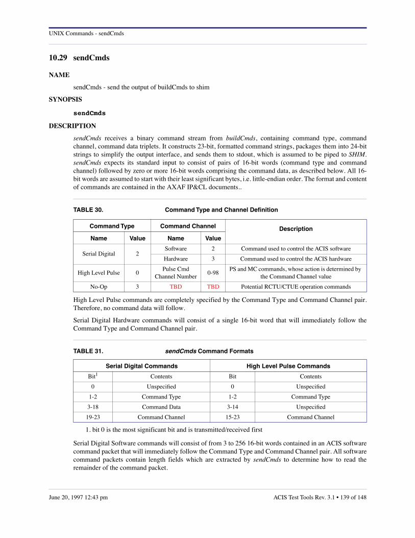
UNIX Commands - sendCmds
10.29 sendCmds
NAME
sendCmds - send the output of buildCmds to shim
SYNOPSIS
sendCmds
DESCRIPTION
sendCmds receives a binary command stream from buildCmds, containing command type, commandchannel, command data triplets. It constructs 23-bit, formatted command strings, packages them into 24-bitstrings to simplify the output interface, and sends them to stdout, which is assumed to be piped to SHIM.sendCmds expects its standard input to consist of pairs of 16-bit words (command type and commandchannel) followed by zero or more 16-bit words comprising the command data, as described below. All 16-bit words are assumed to start with their least significant bytes, i.e. little-endian order. The format and contentof commands are contained in the AXAF IP&CL documents..
High Level Pulse commands are completely specified by the Command Type and Command Channel pair.Therefore, no command data will follow.
Serial Digital Hardware commands will consist of a single 16-bit word that will immediately follow theCommand Type and Command Channel pair.
Serial Digital Software commands will consist of from 3 to 256 16-bit words contained in an ACIS softwarecommand packet that will immediately follow the Command Type and Command Channel pair. All softwarecommand packets contain length fields which are extracted by sendCmds to determine how to read theremainder of the command packet.
TABLE 30. Command Type and Channel Definition
Command Type Command Channel Description
Name Value Name Value
Serial Digital 2Software 2 Command used to control the ACIS software
Hardware 3 Command used to control the ACIS hardware
High Level Pulse 0Pulse Cmd
Channel Number0-98
PS and MC commands, whose action is determined by the Command Channel value
No-Op 3 TBD TBD Potential RCTU/CTUE operation commands
TABLE 31. sendCmds Command Formats
Serial Digital Commands High Level Pulse Commands
Bit1
1. bit 0 is the most significant bit and is transmitted/received first
Contents Bit Contents
0 Unspecified 0 Unspecified
1-2 Command Type 1-2 Command Type
3-18 Command Data 3-14 Unspecified
19-23 Command Channel 15-23 Command Channel
ACIS Test Tools Rev. 3.1 • 139 of 148June 20, 1997 12:43 pm
UNIX Commands - sendCmds
When sendCmds reads an illegal command type or command channel from stdin, it writes an error messageto stderr and terminates processing. When sendCmds reads an illegal software command packet from stdin,it writes an error message to stderr, but it processes the command anyway. No warning is given if anunknown opcode is encountered. These shortcomings will be fixed in a later version.
EXAMPLES
The following UNIX pipe uses sendCmds as part of commanding the ACIS instrument to start executingstored timed exposure parameter block 1:
echo ‘start 22 te 1’ | buildCmds | sendCmds | shim ...
AUTHOR
Demitrios Athens, MIT CSR
STATUS
The current version does not check for and remove critical commands.
The current version has been used with the LRCTU and the CTUE.
The current version produces its output in the bit order shown above, which is as defined in the CTUE andthe Command and Data Management equipment specifications. However, to make the software worksuccessfully with the LRCTU, the current version REVERSES THE BYTE ORDER OF ALL SERIALDIGITAL COMMAND DATA that it receives. This seems to work when talking to the CTUE.
The current version has successfully handled both software and hardware Serial Digital commands and HighLevel Pulse commands.
The values currently used for software and hardware command channels are updated to the current IP&CLvalues as expressed in the beta version of the "interface.h" file.
The curent version will may be modified to emit No-Op commands that will be used to convey a commandcount for use in assembling CTUE command blocks.
Software commands with unrecognized opcodes are passed through. This responds to a request from theflight software folks to provide flexibility during testing.
Hardware command data is not checked for validity.
140 of 148 • ACIS Test Tools Rev. 3.1 June 20, 1997 12:43 pm

UNIX Commands - shim
10.30 shim
NAME
shim - common interface for both CTUE and LRCTU
SYNOPSIS
shim ctue|lrctu
DESCRIPTION
shim provides a consistent interface between ACIS and all user applications that either generate ACIScommands or receive ACIS telemetry. It can communicate with ACIS using either the CTUE/RCTUcombination or the Jim Littlefield RCTU emulator, the LRCTU. It always expects its command input to bein the 24-bit sendCmds format. It always produces its telemetry output in the AXAF-I minor frame format.
OPTIONS
ctue communicate with ACIS using the CTUE/RCTU combination. shim extracts the 23-bit input commandwords from the 24-bit sendCmds format and packs them into 48-bit Ground Command format strings.It then assembles these strings into command blocks, which it sends to the CTUE/RCTU via a TCP/IPinterface. shim receives telemetry via the same interface and passes it to its client, which is typicallygetPackets, without modification.
lrctu communicate with ACIS using the Jim Littlefield RCTU emulator, the LRCTU
When sending commands to an LRCTU, shim reads the 24-bit output of sendCmds and passes it to theLRCTU via a serial interface. Note that High Level Pulse commands will not be executed because theLRCTU does not support them.
When receiving telemetry from an LRCTU via the same serial interface, shim reformats the LRCTUtelemetry packets into AXAF-I, Format 2, telemetry minor frames, adding frame synchs and CCSDSheaders as appropriate. shim always resets the LRCTU hardware (by sending an ASCII character withmany zero bits to the LRCTU’s reset port) and then copies the LRCTU’s operating code to the device’smemory.
EXAMPLE
... buildCmds | sendCmds | shim lrctu | getPackets ...
ENVIRONMENT
ACISTOOLSDIR The name of the top-level ACIS Test Tools directory. shim will use this directory as its starting point whenlooking for executables. See the FILES section immediately below.
FILES
${ACISTOOLSDIR}/bin/sun4/lrctu.unix Jim Littlefield’s code that runs on UNIX and communicates with the LRCTU through the fast tty device.
${ACISTOOLSDIR}/bin/mips/lrctu.mongoose.srec Jim Littlefield’s code that runs on the Mongoose processor on the LRCTU and communicates with UNIXthrough the fast tty device.
/dev/ttyC?0 LRCTU command and telemetry fast tty device (? is typically 4)
ACIS Test Tools Rev. 3.1 • 141 of 148June 20, 1997 12:43 pm

UNIX Commands - shim
/dev/ttyC?1 LRCTU hardware reset fast tty device (? is typically 4)
/dev/ct.o fast tty device driver
/etc/rc/sts fast tty device system boot file
/etc/sts/bin/cdmknods fast tty device system boot file
AUTHOR
Demitrios Athens, MIT CSR
STATUS
The current version only works with the Jim Littlefield RCTU Emulator.
The current version creates AXAF-I telemetry major frames from LRCTU telemetry by piping LRCTUtelemetry to ltp2mnf.
The current version does not put bilevels (LED’s) reported in the LRCTU telemetry packets into the AXAF-I minor frames. Expect this to change soon.
The current version of the LRCTU does not produce real-time or even near-real-time timestamps when itissues science header pulses to the BEP. It merely copies the BEP timestamp, which is the latched value of afree running counter, and uses this information in its telemetry packet headers. The ability to obtain near-real-time timestamp information from the LRCTU has been proposed but has neither been made a requirementnor been implemented. ltp2mnf creates pseudo IRIG-B timestamps and puts them into the AXAF-I formatminor frames that it creates. Times come from the host system clock, not from an actual IRIG-B interface,and are not adjusted to account for processing or transmission delays.
The ability to command BEP and FEP hardware resets through the LRCTU has been proposed but has neitherbeen made a requirement nor been implemented.
142 of 148 • ACIS Test Tools Rev. 3.1 June 20, 1997 12:43 pm

UNIX Commands - tlmsim
10.31 tlmsim
NAME
tlmsim – simulate ACIS telemetry packet stream
SYNOPSIS
tlmsim [–c file] [–f] [–p] [–t] [–w file] ringfile biasfile
DESCRIPTION
This command generates a stream of ACIS telemetry packets from a timed-exposure ring-buffer file (ringfile)and a bias map in FITS format (biasfile). These files are generated by the output and dumpbias directives infepCtlTest scripts.
OPTIONS
–c file Load a timed-exposure parameter block from file, which must contain a series of "keyword = value"lines, as exemplified in the following section. If this option is omitted, tlmsim will use a default block.
–f Simulate Format 1 output, i.e. with ACIS out of the focal plane and restricted to 512 baud downlink.This will affect the ratio of telemetry packets to science-frame pseudo-packets.
–p Generate science-frame pseudo-packets in the format described in the ACIS Test Tools document. Ifthis option is used in conjunction with the –f flag, a huge number of pseudo-packets will be generated.
–t Use the current UNIX system clock as a basis for BEP timestamps. If omitted, these fields will bezeroed out, making it easier to compare tlmsim output files.
–w file Load a 2-dimensional window block from file, which must contain a series of "keyword = value" lines,as exemplified in the following section. If this option is omitted, tlmsim uses no windows.
PARAMETER BLOCK EXAMPLE
Keywords may be expressed in upper, lower, or mixed case characters. In this example, a simple 3x3 faint-with-bias science run is defined, using CCD number 6 and FEP number 2, as specified by the fep*CcdSelectkeywords. All keyword values are unsigned integers, or arrays of unsigned integers, with the followingexceptions: • parameterBlockId, deaLoadOverride, and fepLoadOverride are hexadecimal integers with "0x"prefixes; • gradeSelection is an array of 8 hexadecimal integers, without any "0x" prefix. With theseexceptions, tlmsim does not check the values in any way. Blank lines, and all characters between "#" andnewline, are ignored.
teBlockSlotIndex = 1parameterBlockId = 0x00000fabfepCcdSelect = 10 10 6 10 10 10fepMode = 2bepPackingMode = 1onChip2x2Summing = 0ignoreBadPixelMap = 0ignoreBadColumnMap = 0recomputeBias = 1trickleBias = 1subarrayStartRow = 0subarrayRowCount = 0overclockPairsPerNode = 15outputRegisterMode = 0
ACIS Test Tools Rev. 3.1 • 143 of 148June 20, 1997 12:43 pm

UNIX Commands - tlmsim
ccdVideoResponse = 0 0 0 0 0 0primaryExposure = 28secondaryExposure = 0dutyCycle = 0fep0EventThreshold = 0 0 0 0 fep1EventThreshold = 0 0 0 0 fep2EventThreshold = 100 100 100 100 fep3EventThreshold = 0 0 0 0 fep4EventThreshold = 0 0 0 0 fep5EventThreshold = 0 0 0 0 fep0SplitThreshold = 0 0 0 0 fep1SplitThreshold = 0 0 0 0 fep2SplitThreshold = 0 0 0 0 fep3SplitThreshold = 0 0 0 0 fep4SplitThreshold = 0 0 0 0 fep5SplitThreshold = 0 0 0 0 lowerEventAmplitude = 0eventAmplitudeRange = 65535gradeSelection = ffff0000 0 0 0 0 0 0 0 windowSlotIndex = 65535histogramCount = 0biasCompressionSlotIndex = 255 255 255 255 255 255 rawCompressionSlotIndex = 255ignoreInitialFrames = 20biasAlgorithmId = 0 0 1 0 0 0 biasArg0 = 0 0 0 0 0 0 biasArg1 = 0 0 10 0 0 0 biasArg2 = 0 0 0 0 0 0 biasArg3 = 0 0 100 0 0 0 biasArg4 = 0 0 70 0 0 0 fep0VideoOffset = 0 0 0 0fep1VideoOffset = 0 0 0 0fep2VideoOffset = 127 128 129 130fep3VideoOffset = 0 0 0 0fep4VideoOffset = 0 0 0 0fep5VideoOffset = 0 0 0 0deaLoadOverride = 0x00000000fepLoadOverride = 0x00000000
WINDOW BLOCK EXAMPLE
Keywords may be expressed in upper, lower, or mixed case characters. In this example, two windows aredefined, one for CCD 5 and the other for CCD 6. All keyword values are unsigned integers, except forwindowBlockId, which must be a hexadecimal integer with leading "0x". Otherwise, tlmsim does not checkthe values in any way. Blank lines, and all characters between "#" and newline, are ignored.
windowSlotIndex = 1windowBlockId = 0x00000baf
ccdId = 5ccdRow = 1ccdColumn = 1width = 1022height = 1022
144 of 148 • ACIS Test Tools Rev. 3.1 June 20, 1997 12:43 pm

UNIX Commands - tlmsim
sampleCycle = 0lowerEventAmplitude = 0eventAmplitudeRange = 65535
ccdId = 6ccdRow = 1ccdColumn = 1width = 1022height = 1022sampleCycle = 0lowerEventAmplitude = 0eventAmplitudeRange = 65535
AUTHOR
Peter G. Ford, MIT CSR
SEE ALSO
dumpring(1), fepCtlTest(1), ltlm(1) ACIS Test Tools, ACIS Document, Version 1.0, July, 1996 ACIS IP&CL Structures, Version 1.17, July, 1996
DIAGNOSTICS
bad argument: arg(s) tlmsim too many arguments have been specified on the command line.
does not scan: line the statement in a parameter or window block is invalid, either because the keyword is unrecognized, orthe value(s) is(are) illegal, or because there is no equals sign between them.
missing file name(s) takes exactly two non-optional command line arguments, the name of the ring-buffer file, followed by thename of the FITS bias file.
multiple CCDs selected the parameter block can contain only one fep*ccdSelect field whose value is less than 10, i.e. tlmsim canonly simulate a single CCD at a time.
no CCD selected the parameter block must contain at least one fep*ccdSelect whose value differs from 10.
no window specified the window block contains no window-specific keywords.
out of order: line one or more header keywords comes after the first window-specific keyword in a window block.
unknown flag: flag the flag is unrecognized. There must be whitespace between the flag and the file name in the –c and –woptions.
unsupported biasCompressionSelect[n] value: val this version of tlmsim requires that all biasCompressionSelect fields have the value 255, i.e. nocompression at all.
unsupported rawCompressionSelect value: val this version of tlmsim requires that the rawCompressionSelect field has the value 255, i.e. no compressionat all.
ACIS Test Tools Rev. 3.1 • 145 of 148June 20, 1997 12:43 pm
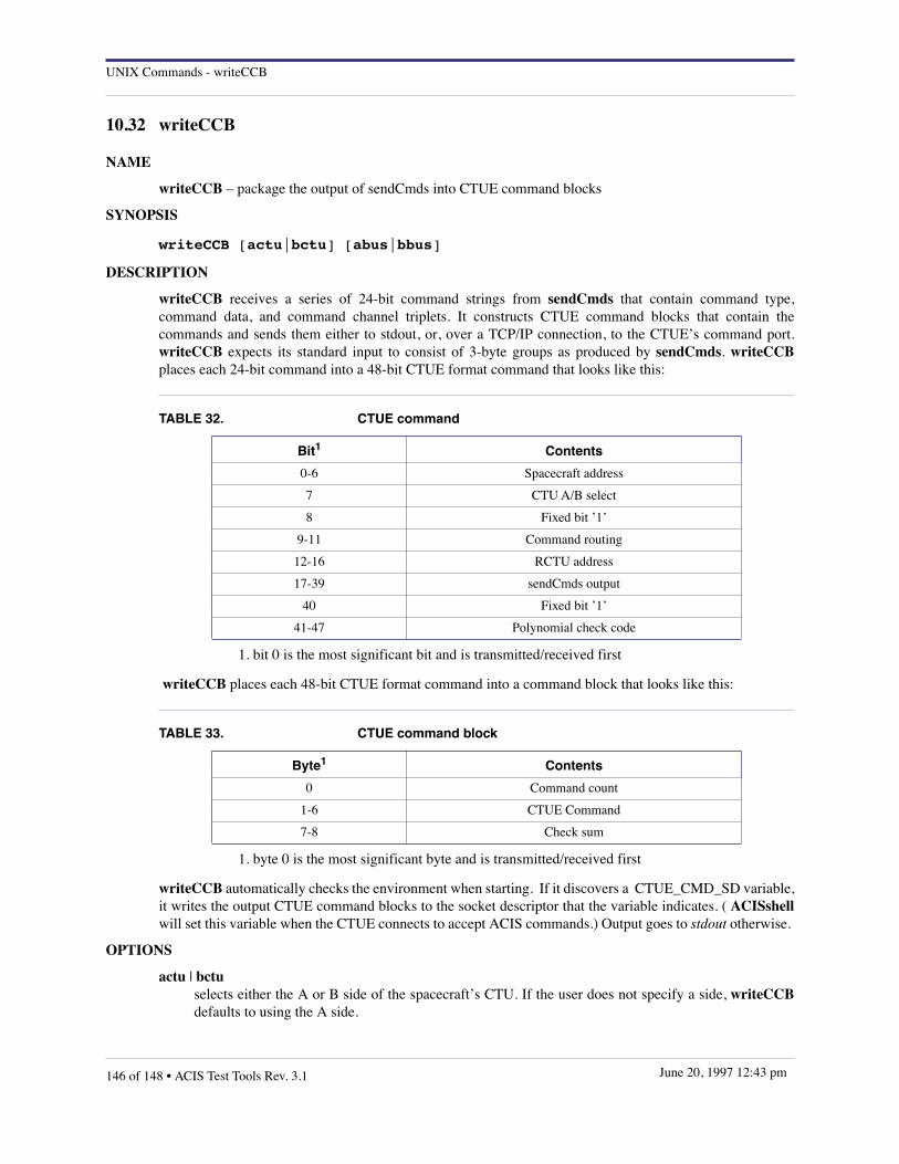
UNIX Commands - writeCCB
10.32 writeCCB
NAME
writeCCB – package the output of sendCmds into CTUE command blocks
SYNOPSIS
writeCCB [actu|bctu] [abus|bbus]
DESCRIPTION
writeCCB receives a series of 24-bit command strings from sendCmds that contain command type,command data, and command channel triplets. It constructs CTUE command blocks that contain thecommands and sends them either to stdout, or, over a TCP/IP connection, to the CTUE’s command port.writeCCB expects its standard input to consist of 3-byte groups as produced by sendCmds. writeCCBplaces each 24-bit command into a 48-bit CTUE format command that looks like this:
writeCCB places each 48-bit CTUE format command into a command block that looks like this:
writeCCB automatically checks the environment when starting. If it discovers a CTUE_CMD_SD variable,it writes the output CTUE command blocks to the socket descriptor that the variable indicates. ( ACISshellwill set this variable when the CTUE connects to accept ACIS commands.) Output goes to stdout otherwise.
OPTIONS
actu | bctu selects either the A or B side of the spacecraft’s CTU. If the user does not specify a side, writeCCBdefaults to using the A side.
TABLE 32. CTUE command
Bit1
1. bit 0 is the most significant bit and is transmitted/received first
Contents
0-6 Spacecraft address
7 CTU A/B select
8 Fixed bit ’1’
9-11 Command routing
12-16 RCTU address
17-39 sendCmds output
40 Fixed bit ’1’
41-47 Polynomial check code
TABLE 33. CTUE command block
Byte1
1. byte 0 is the most significant byte and is transmitted/received first
Contents
0 Command count
1-6 CTUE Command
7-8 Check sum
146 of 148 • ACIS Test Tools Rev. 3.1 June 20, 1997 12:43 pm

UNIX Commands - writeCCB
abus | bbus selects either Bus A or Bus B command routing from either the CTUE or the spacecraft CTU to theRCTU. If the user does not specify a bus, writeCCB defaults to using the A bus.
EXAMPLES
The following UNIX pipe uses writeCCB as part of commanding the ACIS instrument to start executingstored timed exposure parameter block 1. The command prompt indicates that ACISshell has been executedand that the CTUE has established a connection. ACISshell% echo ‘start 22 te 1’ | buildCmds | sendCmds |writeCCB
AUTHOR
Demitrios Athens, MIT CSR
SEE ALSO
sendCmds(1) ACISshell(1)
STATUS
The current version has been used with the CTUE only.
The actu|bctu option is probably meaningless and best left alone when using a CTUE, which has only an Aside. (The B side was so good that it’s being saved for the album.)
The interaction of the abus|bbus option and the CTUE’s own GUI, which allows the operator to select acommand bus, is a complete mystery. It’s probably best not to specify the option unless you’re looking foradventure.
ACIS Test Tools Rev. 3.1 • 147 of 148June 20, 1997 12:43 pm

ACIS Data Analysis and Database
148 of 148 • ACIS Test Tools Rev. 3.1 June 20, 1997 12:43 pm
Appendix A Test Tool Status
TABLE A–1. Test Tools and their Current Status
Program Name Author Status Comments
GSE Transport Software
ACISshell Athena Implemented
acispkts Davis/Ford Implemented Replaced by shim | getPackets
filterClient Ford Implemented
filterServer Ford Implemented
sendCmds Athens Implemented
getPacktes Athens Implemented
shim Athens Implemented
writeCCB Athens Implemented
GSE Test Tool Software
analyzeData Woo Implemented Function provided by existing programs
bcnd Ford Implemented Alternative to buildCmds
buildCmds Somigliana Implemented
diff6 Ford Implemented Untested
lcmd Ford Implemented
lerv Ford Implemented
lhuff Ford Implemented
ltlm Ford Implemented
monitorDEAHousekeeping Shaff Implemented May require modifications
monitorEngineeringData Athens In progress
monitorScience Somigliana Implemented Filter input through sciglue first
psci Ford Implemented Replacement for processScience
processDEAhkp Athens Implemented No documentation
processEngrData Athens In progress No documentation
runacis Ford Implemented
DEA Image Operations
getImages Shaff Implemented
genPixelImages Somigliana Partially Implemented Lacks image compression
genObjectImage Ford Implemented
generatedExpectedData - Abandoned
loadFitsImage Ford Implemented
putImages Athens Implemented