Acer projector P5260 service manual.pdf
50
P1165E&P5260E Acer P1165E & P5260E Service Manual 100% Recycled Paper Date: 2007/10/05 FORWORD For your convenience, all service parts, identified in this manual are available through Acer’s normal distribution channels. In addition to service part number, the generic description has been given, where possible, to allow your service technicians to substitute equivalent components which might be available from other sources. All orders for service parts will be honored. However, on instance where generic components are considered to be available from several common sources, as would be the case with an industry standard fuse, resistor, or semiconductor, it may be more economical and expeditious to purchase the part locally.
description
Repair manual
Transcript of Acer projector P5260 service manual.pdf
P1165E&P5260E
Acer P1165E & P5260E
Service Manual
100% Recycled Paper Date: 2007/10/05
FORWORD For your convenience, all service parts, identified in this manual are available through Acer’s normal distribution
channels.
In addition to service part number, the generic description has been given, where possible, to allow your service
technicians to substitute equivalent components which might be available from other sources.
All orders for service parts will be honored. However, on instance where generic components are considered to be
available from several common sources, as would be the case with an industry standard fuse, resistor, or
semiconductor, it may be more economical and expeditious to purchase the part locally.

P1165E&P5260E i
Update History 2007/10/05 First edition completed
P1165E&P5260E ii
P1165E&P5260E iii
Conventions The following conventions are used in this manual
Screen Messages Denote actual messages that appear on screen.
Note Give bits and pieces of additional information related to the current topic.
Warning Alert you any damage that might result form doing or not doing specific actions.
Caution Give precautionary measures to avoid possible hardware or software problems.
Important Remind you doing specific actions relevant to the accomplishment of procedures.
Table of Contents 1 System Introduction .............................................................................................................. 1
1.1 Technical Specification ......................................................................................................1 1.2 Lamp Specification. ............................................................................................................2 1.2.1 Lamp for P1165E.................................................................................................................2 1.2.2 Lamp for P2560E ................................................................................................................3 1.3 P1165E/P5260E System Block Diagram ........................................................................5
2 Firmware Upgraded Flow...................................................................................................... 6 2.1 Setup Tool/Equipment ........................................................................................................7 2.2 Upgrading Procedure .........................................................................................................7
3 Machine Disassembly and Replacement ............................................................................ 11 3.1 Tools ....................................................................................................................................11 3.2 Disassembly Procedure ...................................................................................................12 3.3 Disassembly Lamp Module .............................................................................................17 3.4 Disassembly the main board and DMD board..............................................................20
4 Troubleshooting and Verifying the Repair ........................................................................... 22 4.1 Troubleshooting .................................................................................................................22 4.2 Verifying the Repair ..........................................................................................................28
5 Connector Information ........................................................................................................ 34 5.1 Main Board .........................................................................................................................34 5.2 Ballast Board......................................................................................................................35 5.3 Power board.......................................................................................................................37 5.4 I/O board.............................................................................................................................38
6 FRU (Field Replaceable Unit) List....................................................................................... 39 6.1 Mechanical Drawing .........................................................................................................40 6.2 Accessory ...........................................................................................................................43 6.3 Board/Module ....................................................................................................................43 6.4 Case/Cover/Bracket Assembly .......................................................................................43 6.5 Optical Device....................................................................................................................44 6.6 Fans ....................................................................................................................................43 6.7 Miscellaneous ....................................................................................................................44 6.8 Wire .....................................................................................................................................44 6.9 Screws ................................................................................................................................44
Appendix : Service mode……………..………………………………………………………………45
P1165E&P5260E iv
P1165E&P5260E 1
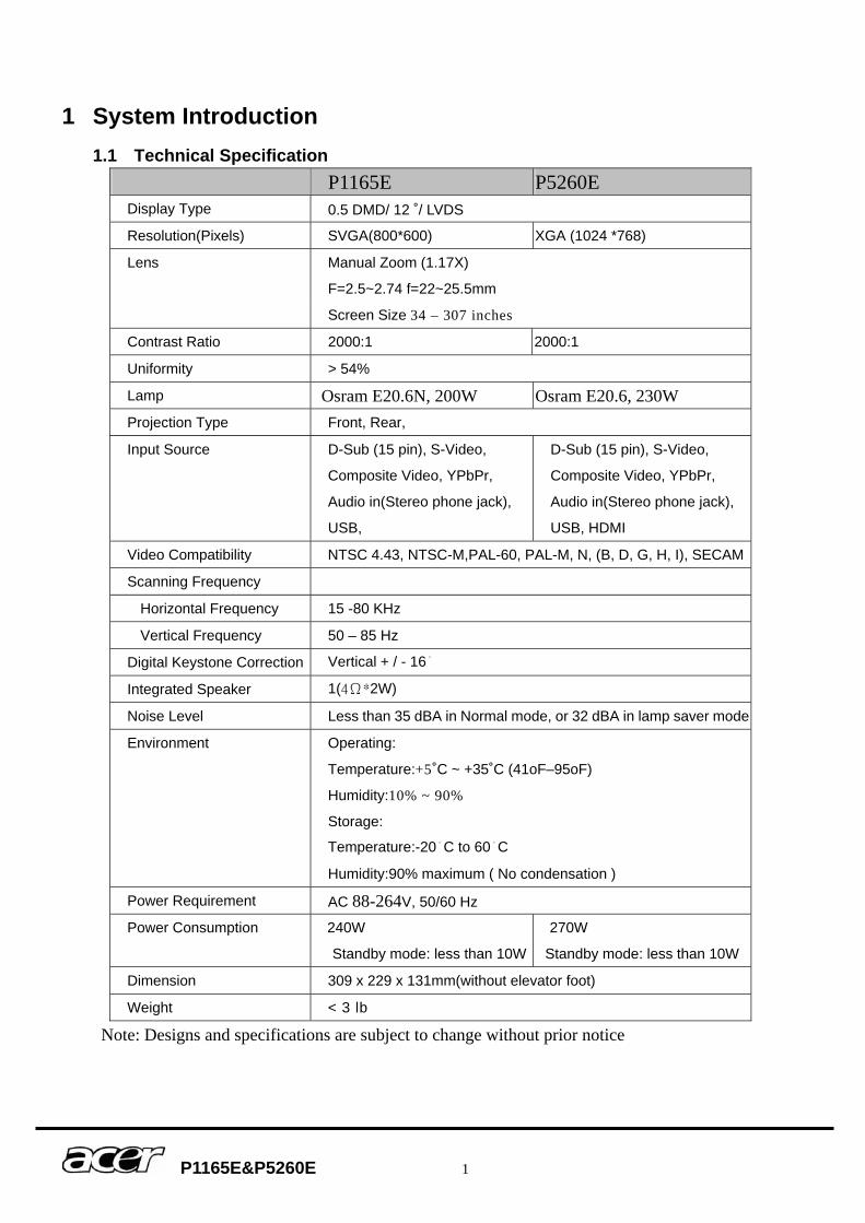
1 System Introduction 1.1 Technical Specification
P1165E P5260E Display Type 0.5 DMD/ 12 ˚/ LVDS Resolution(Pixels) SVGA(800*600) XGA (1024 *768)
Lens Manual Zoom (1.17X)
F=2.5~2.74 f=22~25.5mm
Screen Size 34 – 307 inches
Contrast Ratio 2000:1 2000:1
Uniformity > 54%
Lamp Osram E20.6N, 200W Osram E20.6, 230W Projection Type Front, Rear,
Input Source D-Sub (15 pin), S-Video,
Composite Video, YPbPr,
Audio in(Stereo phone jack),
USB,
D-Sub (15 pin), S-Video,
Composite Video, YPbPr,
Audio in(Stereo phone jack),
USB, HDMI
Video Compatibility NTSC 4.43, NTSC-M,PAL-60, PAL-M, N, (B, D, G, H, I), SECAM
Scanning Frequency
Horizontal Frequency 15 -80 KHz
Vertical Frequency 50 – 85 Hz
Digital Keystone Correction Vertical + / - 16。
Integrated Speaker 1(4Ω*2W)
Noise Level Less than 35 dBA in Normal mode, or 32 dBA in lamp saver mode
Environment Operating:
Temperature:+5˚C ~ +35˚C (41oF–95oF)
Humidity:10% ~ 90%
Storage:
Temperature:-20。C to 60。C
Humidity:90% maximum ( No condensation )
Power Requirement AC 88-264V, 50/60 Hz
Power Consumption 240W
Standby mode: less than 10W
270W
Standby mode: less than 10W
Dimension 309 x 229 x 131mm(without elevator foot)
Weight < 3 lb
Note: Designs and specifications are subject to change without prior notice
P1165E&P5260E 2
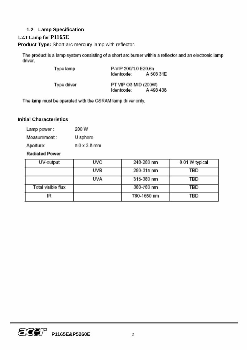
1.2 Lamp Specification 1.2.1 Lamp for P1165E Product Type: Short arc mercury lamp with reflector.
Initial Characteristics
P1165E&P5260E 3
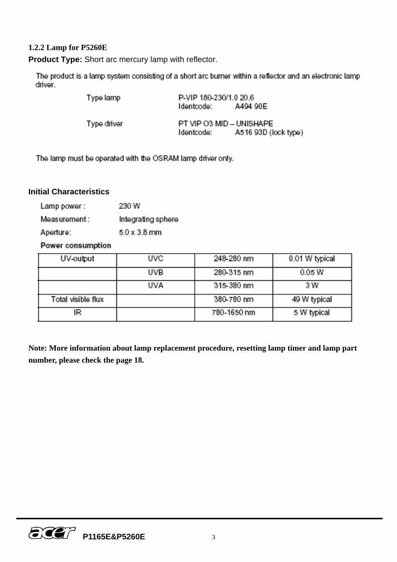
1.2.2 Lamp for P5260E Product Type: Short arc mercury lamp with reflector.
Initial Characteristics
Note: More information about lamp replacement procedure, resetting lamp timer and lamp part number, please check the page 18.
P1165E&P5260E 4
Attention for handling ♦ Do not touch the lamp until it has cooled completely, because the lamp is very hot
during operation and immediately after turned off. ♦ The lamp has to be fixed firmly to the base or socket. ♦ Turn off the power supply during maintenance. ♦ Do not hold the lamp except outer surface of the reflector. ♦ Wear protective gloves and eyeglasses when handling the lamp. ♦ Any unusual shock or vibration to the lamp should be avoided. ♦ The lamp contains the mercury. Its breakage might cause mercury to flow out of the
reflector. Please manage provision at the customer’s product. ♦ Do not pull the lead wire and plug by more than 24.5N. ♦ Please be careful of handling the lamp because it is made of glass. ♦ Please notice for keeping or handling the lamp, because there is a projection of this
lamp with reflector ahead. ♦ Do not touch the bulb and the mirror area of the reflector.
Attention for use ♦ Do not close or cover the lamp with any flammable stuff. ♦ During operation, the lamp is under extremely high pressure. Please manage
provision at the customer’s product to prevent fragments of bulb and mercury from flowing out of it. If the lamp bursts in case of an emergency, the sound will be occurred.
♦ Lamp operation should be with the specified lamp driver and the system ONLY. ♦ Do not look at the lamp directly during operations. ♦ Do not expose your skin directly. We recommend to you to put on something for
protection for your skin. For example, long sleeve shirt, gloves, glassed and so on. ♦ Do not modify the lamp and never use a lamp that has been modified. ♦ Any unusual shock or vibration to the lamp should be avoided during operation. ♦ Do not use any broken lamps. ♦ Dispose of used lamps according to your local instruction. ♦ Do not turn on the lamp while the system is opened. ♦ The lamp contains mercury. If the lamp bursts during operation ventilate the area
sufficiently to avoid inhaling harmful mercury fumes. ♦ Use the lead below 200。C to prevent a deterioration of cladding clad of the
fluorocarbon resin. ♦ The lead wire insulation clad shouldn’t touch the reflector. ♦ Exchange the lamp that has already passed the life time immediately.
P1165E&P5260E 5
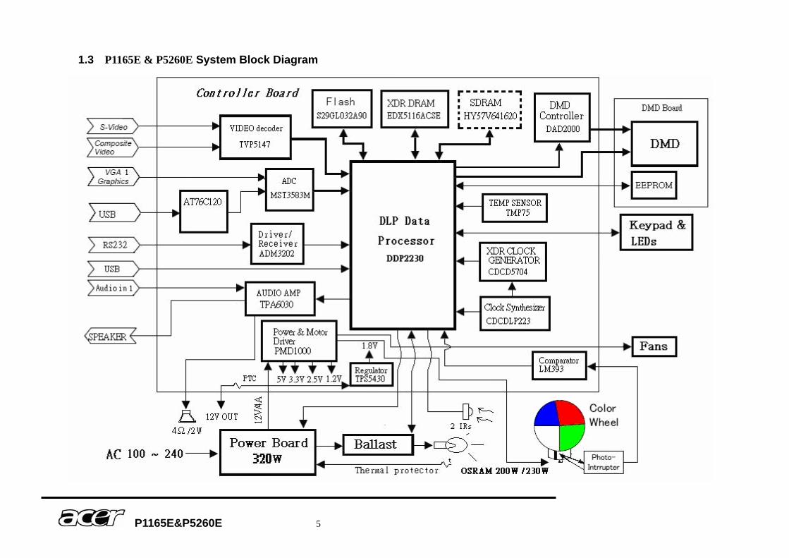
1.3 P1165E & P5260E System Block Diagram
P1165E&P5260E 6
2 Firmware Upgraded Flow This chapter provides the information regarding relevant equipments and upgrading
procedure for firmware upgrade.
Note:
Please check the firmware and composer version before any firmware upgrade procedures. During firmware download period, please do not shut down PC or projector, this will cause flash memory’s damage. And need to return the unit to manufacturer for flash memory recovery.
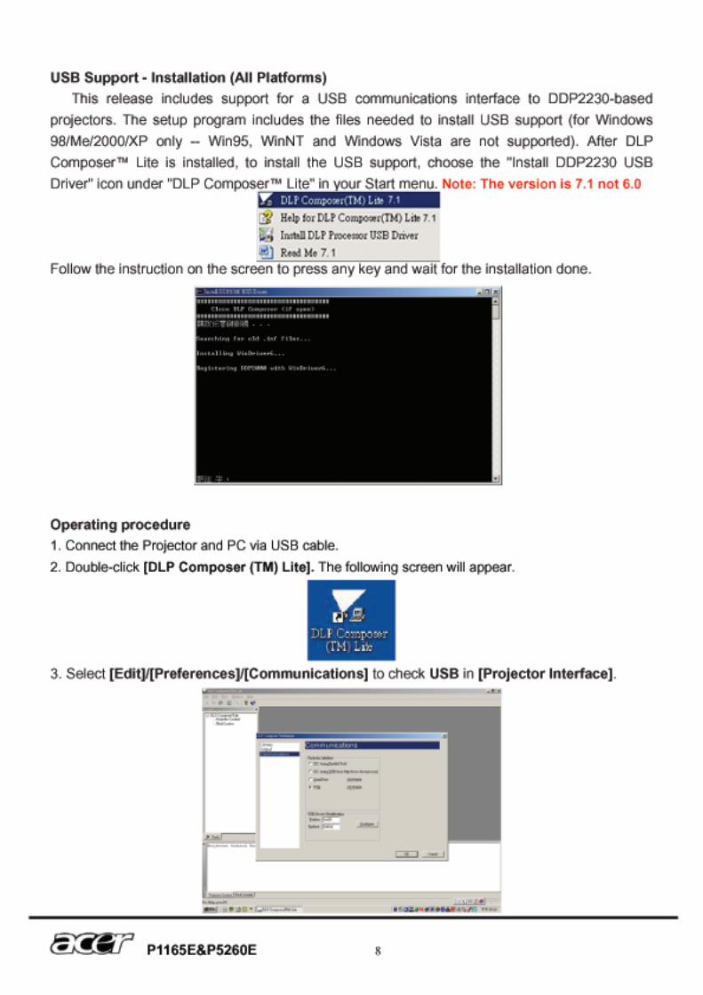
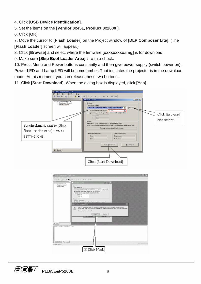
P1165E&P5260E 9
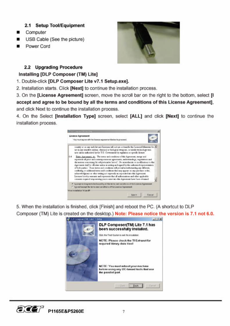
4. Click [USB Device Identification]. 5. Set the items on the [Vendor 0x451, Product 0x2000 ]. 6. Click [OK] 7. Move the cursor to [Flash Loader] on the Project window of [DLP Composer Lite]. (The [Flash Loader] screen will appear.) 8. Click [Browse] and select where the firmware [xxxxxxxxx.img] is for download. 9. Make sure [Skip Boot Loader Area] is with a check. 10. Press Menu and Power buttons constantly and then give power supply (switch power on). Power LED and Lamp LED will become amber. That indicates the projector is in the download mode. At this moment, you can release these two buttons. 11. Click [Start Download]. When the dialog box is displayed, click [Yes].
P1165E&P5260E 10
12. Wait for the Completion of Burning and then remove Power Cord and Burning Cord Note: In case, the device manager can’t recognize the DDP2230 as blow, please disable this device. This will not affect upgrade procedure.
P1165E&P5260E 11
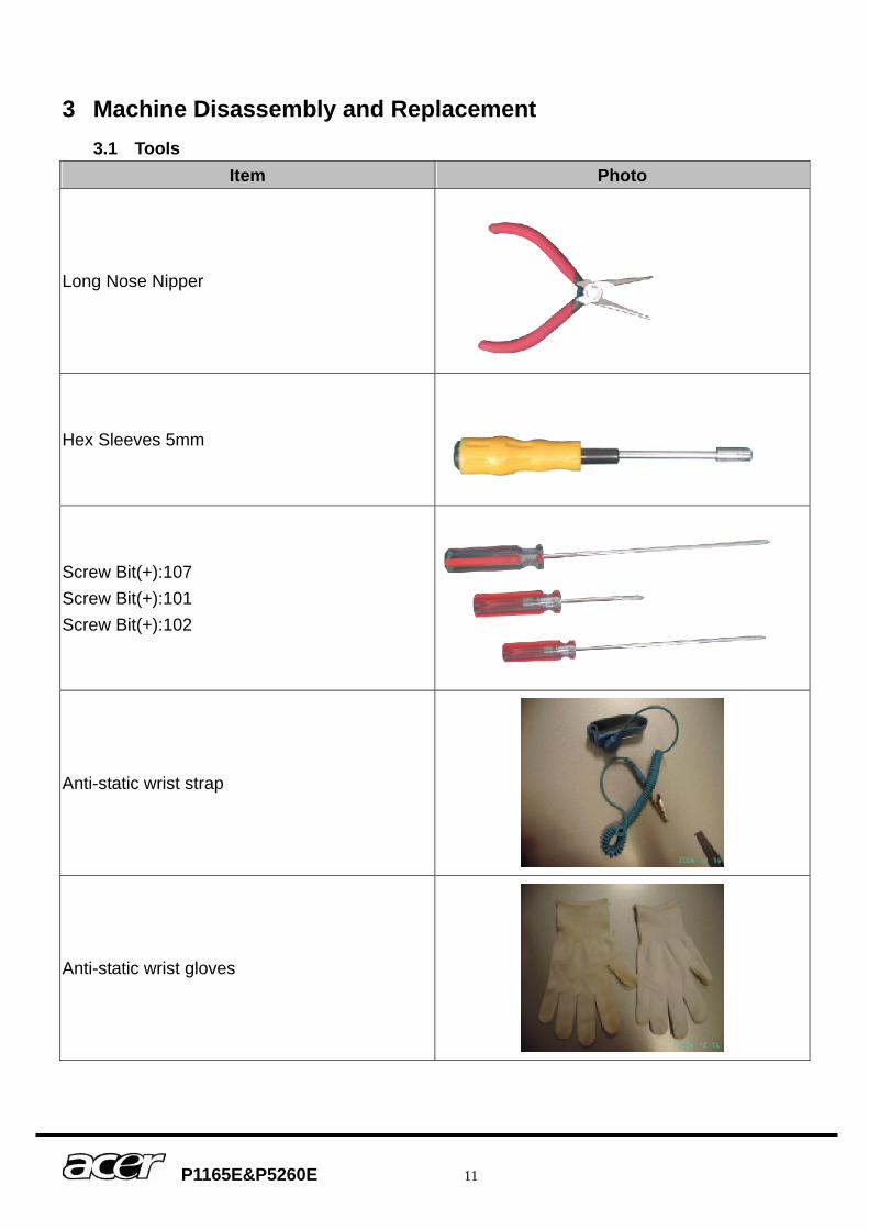
3 Machine Disassembly and Replacement 3.1 Tools
Item Photo
Long Nose Nipper
Hex Sleeves 5mm
Screw Bit(+):107 Screw Bit(+):101 Screw Bit(+):102
Anti-static wrist strap
Anti-static wrist gloves
P1165E&P5260E 12
3.2 Disassembly Procedure Warning ♦ Put on the Static Electricity Ring when starting for repair. ♦ Repair Environment suggest in Clean-room class 10000. Do not remove Optical
Engine or DMD panel outside the clean room. Please return the optical engine to supplier if your repair condition can not meet the requirement.
♦ While screwing or unscrewing screws, please keep the screwdriver straight. Keeping screwdriver inclined will damage the screw holes.
♦ Please turn off the power before replacing any parts. ♦ Please wait for the projector lamp cooling down and turn off the power before changing
it. Never touch or hit the lamp module when replacing the lamp. ♦ When you replace the projector lamp, never touch the new lamp with your bare hands.
The invisible residue left by the oil on your hands may shorten the lamp life. Use lint-free gloves or finger cots are recommended.
P1165E&P5260E 13
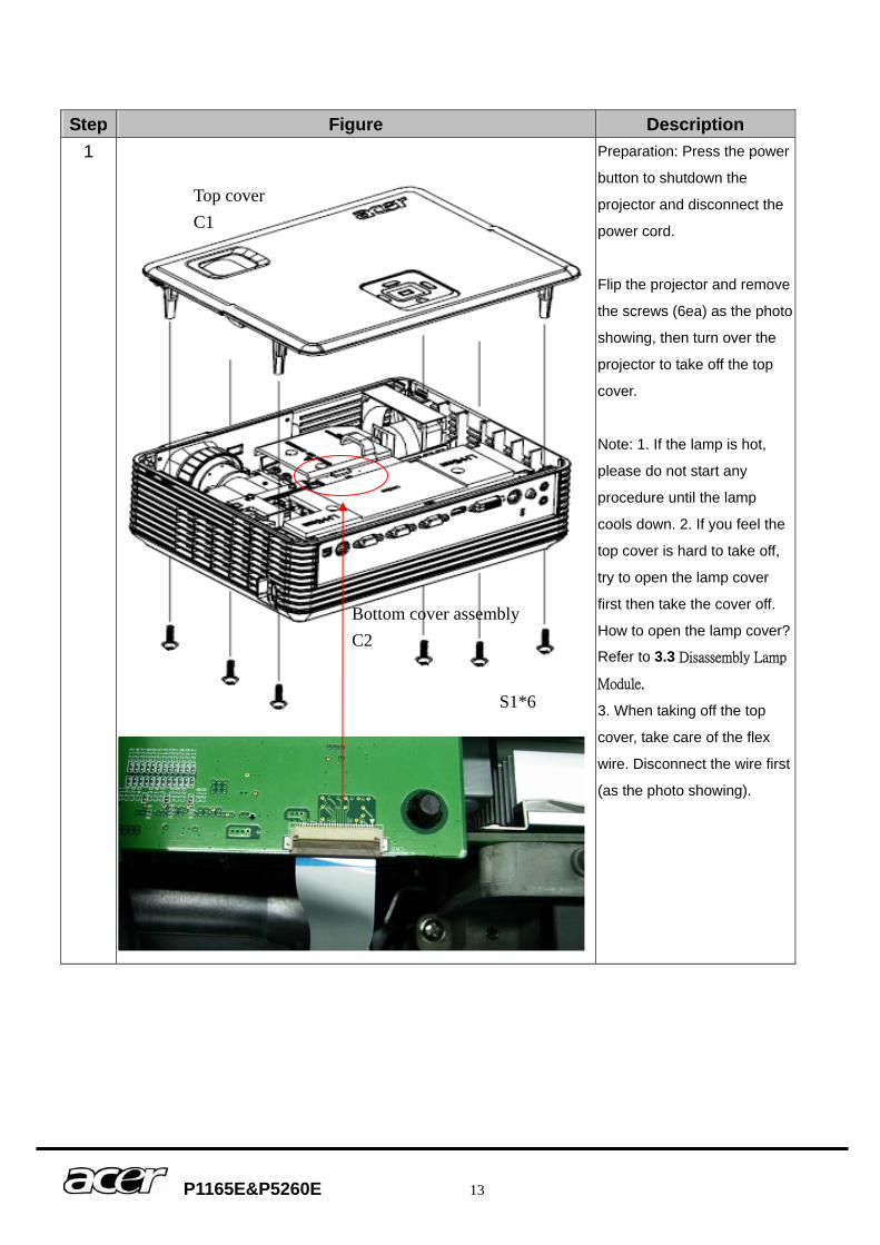
Step Figure Description
1 Preparation: Press the power
button to shutdown the
projector and disconnect the
power cord.
Flip the projector and remove
the screws (6ea) as the photo
showing, then turn over the
projector to take off the top
cover.
Note: 1. If the lamp is hot,
please do not start any
procedure until the lamp
cools down. 2. If you feel the
top cover is hard to take off,
try to open the lamp cover
first then take the cover off.
How to open the lamp cover?
Refer to 3.3 Disassembly Lamp
Module.
3. When taking off the top
cover, take care of the flex
wire. Disconnect the wire first
(as the photo showing).
S1*6
Top cover C1
Bottom cover assembly C2
P1165E&P5260E 14
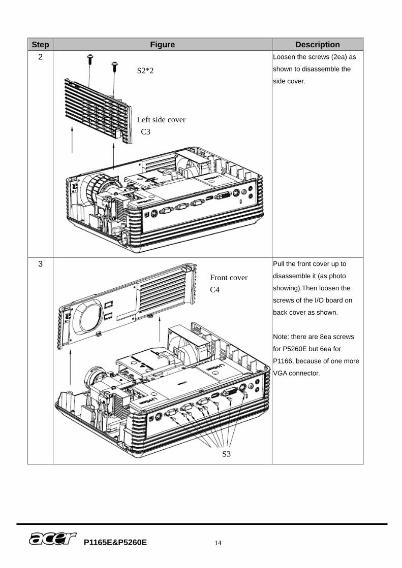
Step Figure Description 2 Loosen the screws (2ea) as
shown to disassemble the
side cover.
3 Pull the front cover up to
disassemble it (as photo
showing).Then loosen the
screws of the I/O board on
back cover as shown.
Note: there are 8ea screws
for P5260E but 6ea for
P1166, because of one more
VGA connector.
S2*2
S3
Left side cover C3
Front cover C4
P1165E&P5260E 15
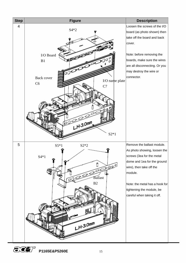
Step Figure Description 4
Loosen the screws of the I/O
board (as photo shown) then
take off the board and back
cover.
Note: before removing the
boards, make sure the wires
are all disconnecting. Or you
may destroy the wire or
connector.
5
Remove the ballast module.
As photo showing, loosen the
screws (3ea for the metal
dome and 1ea for the ground
wire), then take off the
module.
Note: the metal has a hook for
tightening the module, be
careful when taking it off.
S4*2
S2*2 S5*1
S4*1
I/O BoardB1
S2*1
Back cover C6
Ballast B2
I/O name plate C7
P1165E&P5260E 16
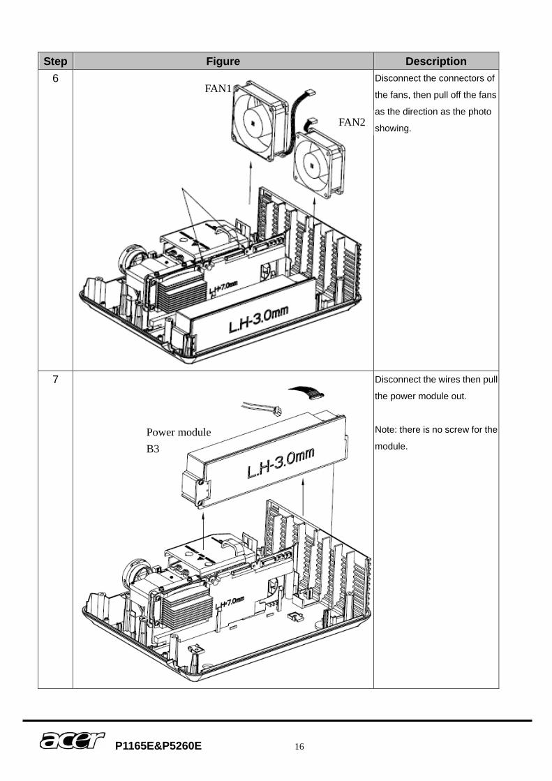
Step Figure Description 6 Disconnect the connectors of
the fans, then pull off the fans
as the direction as the photo
showing.
7 Disconnect the wires then pull
the power module out.
Note: there is no screw for the
module.
FAN1
FAN2
Power module B3
P1165E&P5260E 17
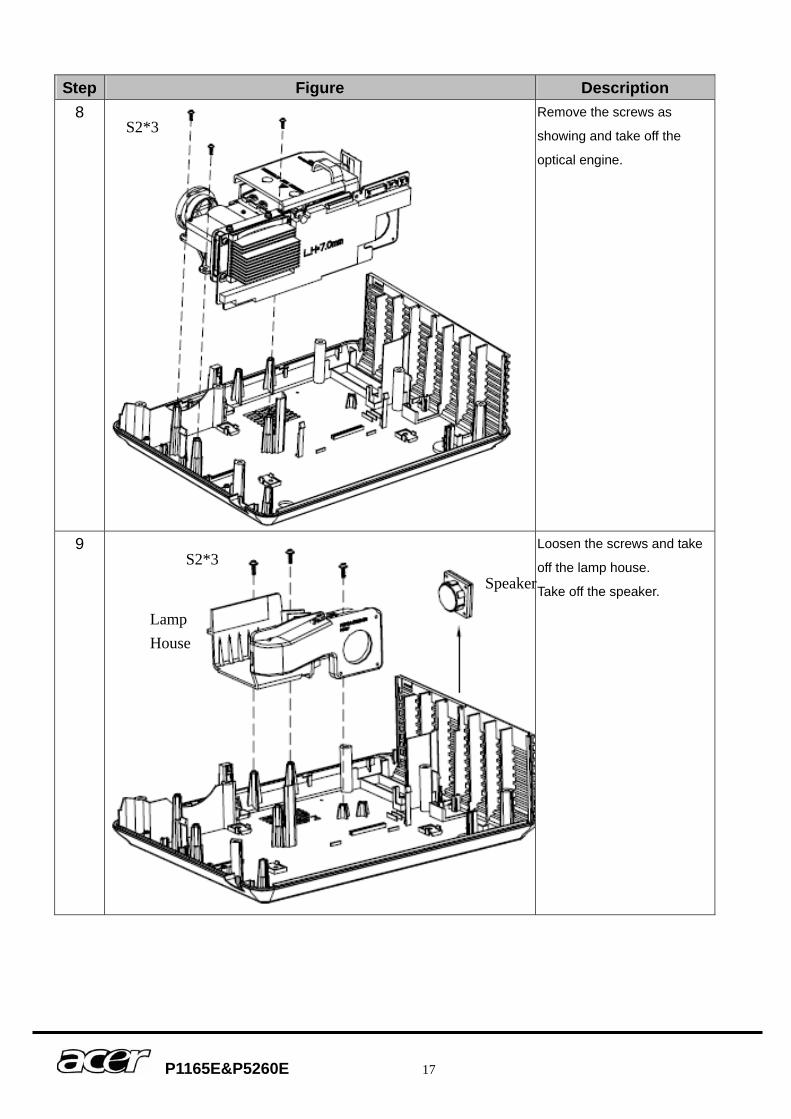
Step Figure Description 8
Remove the screws as
showing and take off the
optical engine.
9 Loosen the screws and take
off the lamp house.
Take off the speaker.
S2*3
Speaker S2*3
Lamp House
P1165E&P5260E 18
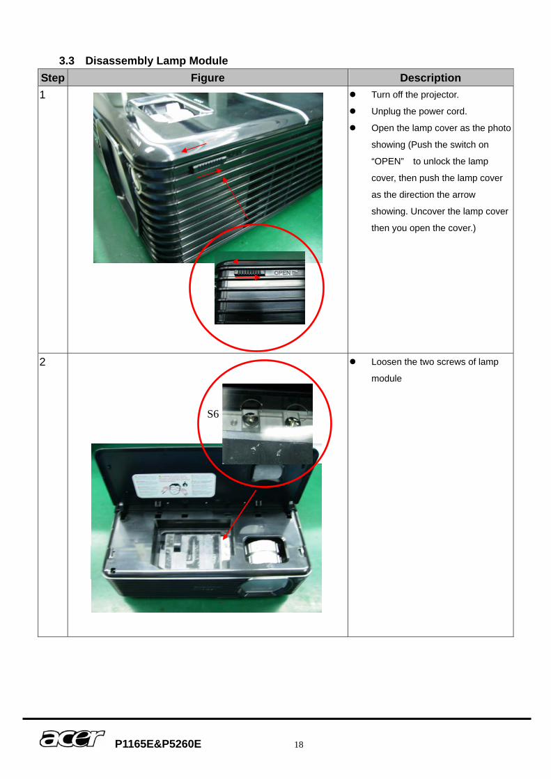
3.3 Disassembly Lamp Module Step Figure Description 1
Turn off the projector.
Unplug the power cord.
Open the lamp cover as the photo
showing (Push the switch on
“OPEN” to unlock the lamp
cover, then push the lamp cover
as the direction the arrow
showing. Uncover the lamp cover
then you open the cover.)
2
Loosen the two screws of lamp
module
S6
P1165E&P5260E 19
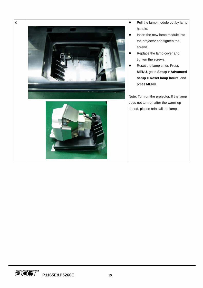
3
Pull the lamp module out by lamp
handle.
Insert the new lamp module into
the projector and tighten the
screws.
Replace the lamp cover and
tighten the screws.
Reset the lamp timer. Press
MENU, go to Setup > Advanced
setup > Reset lamp hours, and
press MENU.
Note: Turn on the projector. If the lamp
does not turn on after the warm-up
period, please reinstall the lamp.
P1165E&P5260E 20
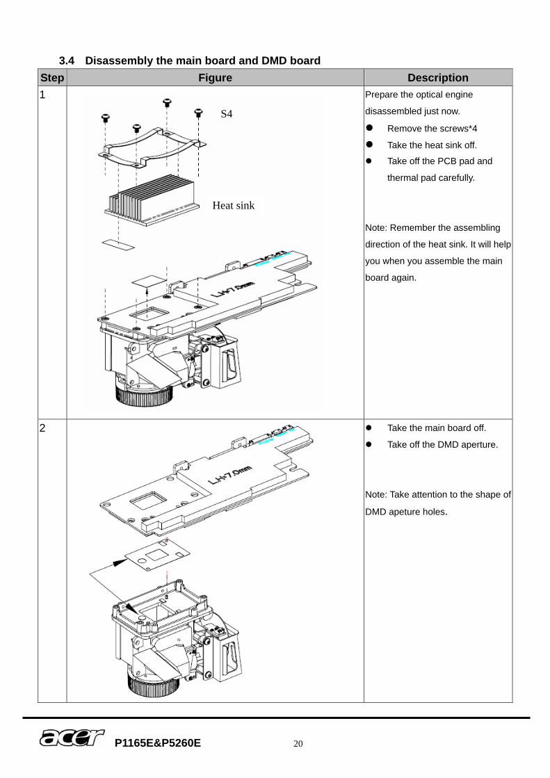
3.4 Disassembly the main board and DMD board Step Figure Description 1
Prepare the optical engine
disassembled just now. Remove the screws*4 Take the heat sink off. Take off the PCB pad and
thermal pad carefully.
Note: Remember the assembling
direction of the heat sink. It will help
you when you assemble the main
board again.
2
Take the main board off.
Take off the DMD aperture.
Note: Take attention to the shape of
DMD apeture holes.
S4
Heat sink
P1165E&P5260E 21
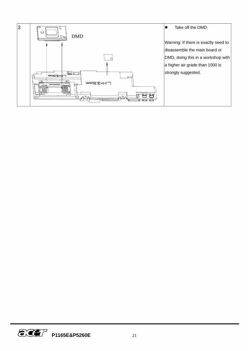
3
Take off the DMD.
Warning: If there is exactly need to
disassemble the main board or
DMD, doing this in a workshop with
a higher air grade than 1000 is
strongly suggested.
DMD
P1165E&P5260E 22
4 Troubleshooting and Verifying the Repair This chapter provides technicians with electronic background how to maintain the product. Moreover, you can get the appropriate operation to solve some complicated problems of component repairing and professional problems.
4.1 Troubleshooting Warning
Do not directly look into the lens to avoid eyesight damages. The projector is equipped with ventilation holes (intake) and ventilation holes (exhaust). Do
not block or place anything near these slots, or internal heat build-up may occur, causing picture degradation or damage to the projector.
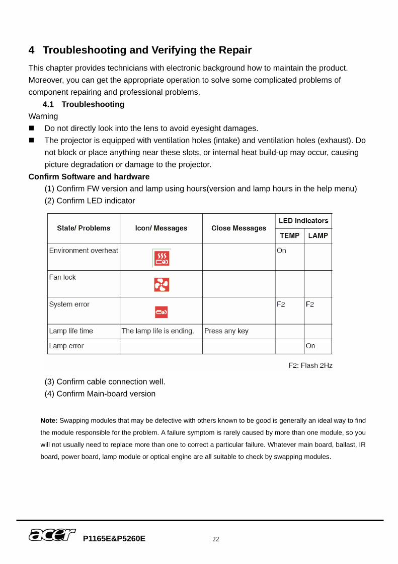
Confirm Software and hardware (1) Confirm FW version and lamp using hours(version and lamp hours in the help menu) (2) Confirm LED indicator
(3) Confirm cable connection well. (4) Confirm Main-board version
Note: Swapping modules that may be defective with others known to be good is generally an ideal way to find
the module responsible for the problem. A failure symptom is rarely caused by more than one module, so you
will not usually need to replace more than one to correct a particular failure. Whatever main board, ballast, IR
board, power board, lamp module or optical engine are all suitable to check by swapping modules.
P1165E&P5260E 23
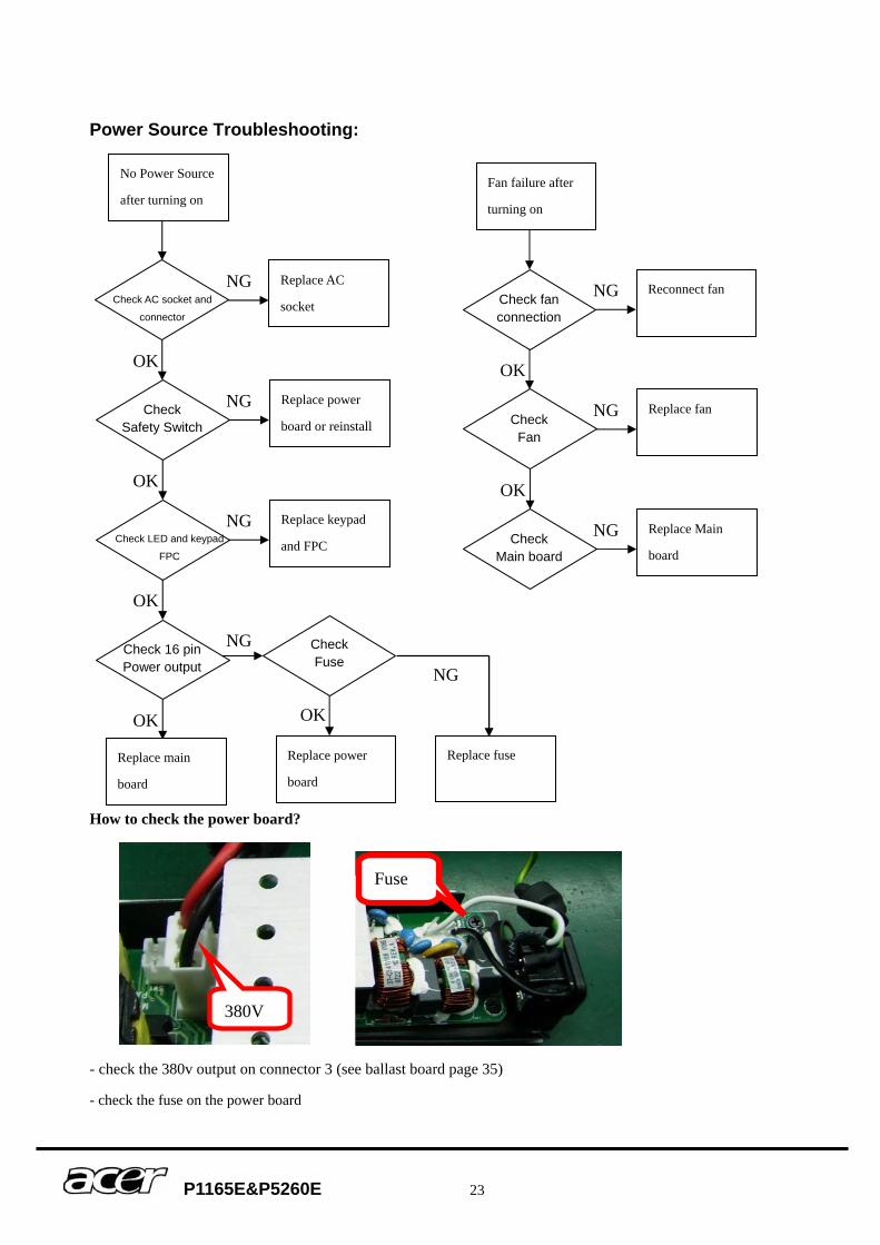
Power Source Troubleshooting:
How to check the power board?
- check the 380v output on connector 3 (see ballast board page 35)
- check the fuse on the power board
No Power Source
after turning on
Replace AC
socket
Replace power
board or reinstall
Replace keypad
and FPC
Replace power
board
Replace main
board
OK
OK
OK
OK
NG
NG
NG
NG Check 16 pin Power output
Check Safety Switch
Check AC socket and
connector
Check LED and keypad
FPC
Fan failure after
turning on
Reconnect fan
Replace fan
Replace Main
board
NG
NG
NG
OK
OK
Check Main board
Check Fan
Check fan connection
Check Fuse
OK
Replace fuse
NG
Fuse
380V
P1165E&P5260E 24
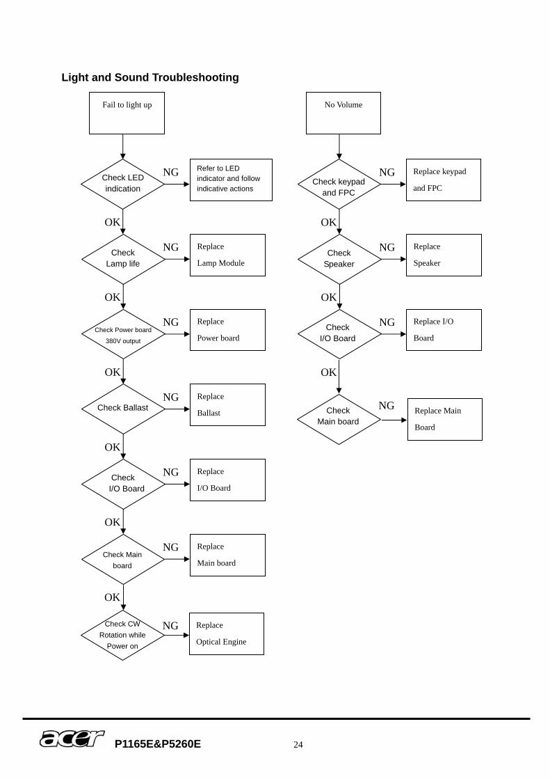
Light and Sound Troubleshooting
Fail to light up
Refer to LED indicator and follow indicative actions
Replace
Lamp Module
Replace
Power board
Replace
Ballast
Replace
I/O Board
OK
OK
OK
OK
OK
NG
NG
NG
NG
NG Check I/O Board
Check Ballast
Check Lamp life
Check LED indication
Check Power board
380V output
Replace
Main board
NG Check Main
board
No Volume
Replace keypad
and FPC
Replace
Speaker
Replace I/O
Board
NG
NG
NG
OK
OK
Check I/O Board
Check Speaker
Check keypad and FPC
Check Main board
OK
NG Replace Main
Board
Check CW Rotation while
Power on
Replace
Optical Engine
OK
NG
P1165E&P5260E 25
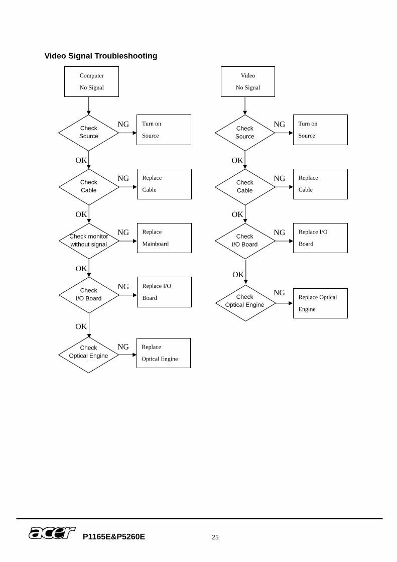
Video Signal Troubleshooting
Computer
No Signal
Turn on
Source
Replace
Cable
Replace
Mainboard
Replace I/O
Board
OK
OK
OK
NG
NG
NG
NG Check I/O Board
Check Cable
Check Source
Check monitor without signal
Video
No Signal
Turn on
Source
Replace
Cable
Replace I/O
Board
NG
NG
NG
OK
OK
Check Cable
Check Source
Check I/O Board
Replace
Optical Engine
Check Optical Engine
OK
NG
Replace Optical
Engine
Check Optical Engine
OK
NG
P1165E&P5260E 26
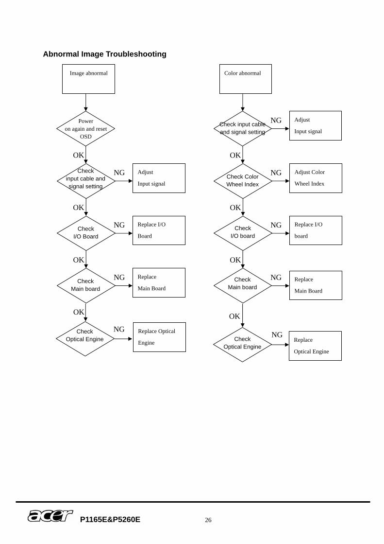
Abnormal Image Troubleshooting
Image abnormal
Adjust
Input signal
Replace I/O
Board
Replace
Main Board
OK
OK
OK
NG
NG
NG
Check Optical Engine
Check input cable and signal setting
Power on again and reset
OSD
Check I/O Board
Color abnormal
Adjust
Input signal
Adjust Color
Wheel Index
Replace I/O
board
NG
NG
NG
OK
OK
Check Color Wheel Index
Check input cable and signal setting
Replace
Main Board
OK
NG
Check I/O board
Check Main board
Replace Optical
Engine
NG
OK
Check Optical Engine
Replace
Optical Engine
Check Main board
OK
NG
P1165E&P5260E 27
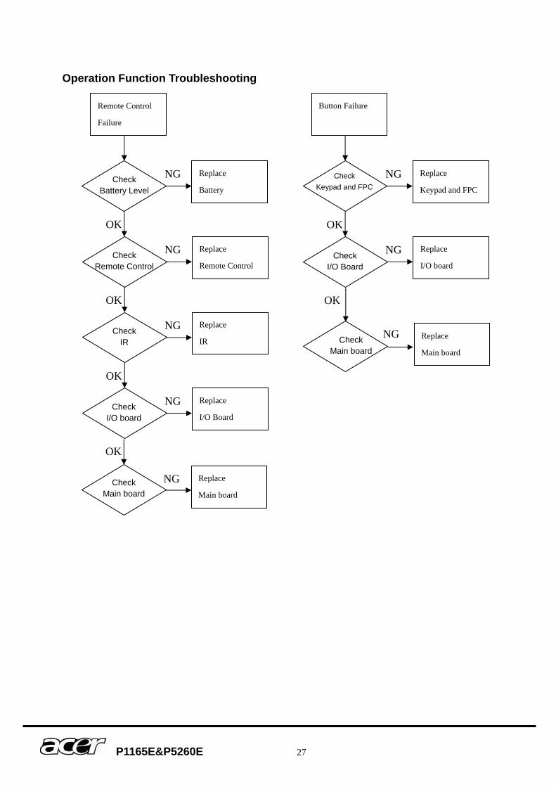
Operation Function Troubleshooting
Remote Control
Failure
Replace
Battery
Replace
Remote Control
Replace
IR
Replace
I/O Board
OK
OK
OK
NG
NG
NG
NG Check I/O board
Check Remote Control
Check Battery Level
Check IR
Button Failure
Replace
Keypad and FPC
Replace
I/O board
NG
NG
OK
Check I/O Board
Check Keypad and FPC
Replace
Main board Check
Main board
OK
NG
Replace
Main board Check
Main board
OK
NG
P1165E&P5260E 28
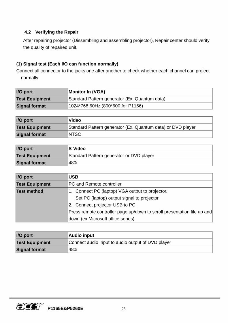
4.2 Verifying the Repair
After repairing projector (Dissembling and assembling projector), Repair center should verify the quality of repaired unit.
(1) Signal test (Each I/O can function normally) Connect all connector to the jacks one after another to check whether each channel can project
normally
I/O port Monitor In (VGA) Test Equipment Standard Pattern generator (Ex. Quantum data) Signal format 1024*768 60Hz (800*600 for P1166) I/O port Video Test Equipment Standard Pattern generator (Ex. Quantum data) or DVD player Signal format NTSC I/O port S-Video Test Equipment Standard Pattern generator or DVD player Signal format 480i I/O port USB Test Equipment PC and Remote controller Test method 1. Connect PC (laptop) VGA output to projector.
Set PC (laptop) output signal to projector 2. Connect projector USB to PC. Press remote controller page up/down to scroll presentation file up and down (ex Microsoft office series)
I/O port Audio input Test Equipment Connect audio input to audio output of DVD player Signal format 480i
P1165E&P5260E 29
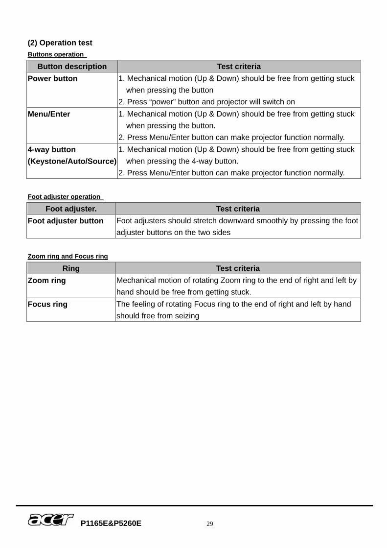
(2) Operation test Buttons operation
Button description Test criteria Power button 1. Mechanical motion (Up & Down) should be free from getting stuck
when pressing the button 2. Press “power” button and projector will switch on
Menu/Enter 1. Mechanical motion (Up & Down) should be free from getting stuck when pressing the button.
2. Press Menu/Enter button can make projector function normally. 4-way button (Keystone/Auto/Source)
1. Mechanical motion (Up & Down) should be free from getting stuck when pressing the 4-way button.
2. Press Menu/Enter button can make projector function normally. Foot adjuster operation
Foot adjuster. Test criteria Foot adjuster button Foot adjusters should stretch downward smoothly by pressing the foot
adjuster buttons on the two sides Zoom ring and Focus ring
Ring Test criteria Zoom ring Mechanical motion of rotating Zoom ring to the end of right and left by
hand should be free from getting stuck. Focus ring The feeling of rotating Focus ring to the end of right and left by hand
should free from seizing
P1165E&P5260E 30
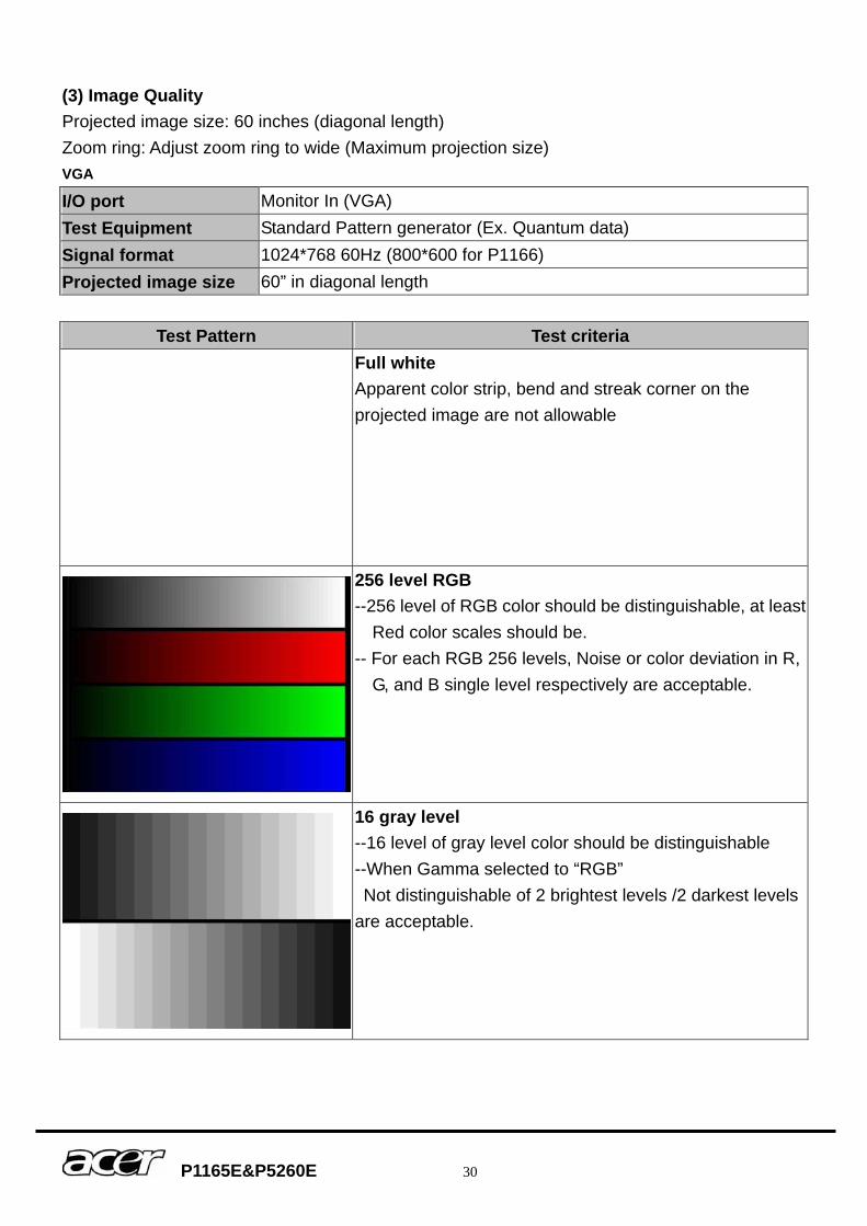
(3) Image Quality Projected image size: 60 inches (diagonal length) Zoom ring: Adjust zoom ring to wide (Maximum projection size) VGA
I/O port Monitor In (VGA) Test Equipment Standard Pattern generator (Ex. Quantum data) Signal format 1024*768 60Hz (800*600 for P1166) Projected image size 60” in diagonal length
Test Pattern Test criteria Full white
Apparent color strip, bend and streak corner on the projected image are not allowable
256 level RGB --256 level of RGB color should be distinguishable, at least
Red color scales should be. -- For each RGB 256 levels, Noise or color deviation in R,
G, and B single level respectively are acceptable.
16 gray level --16 level of gray level color should be distinguishable --When Gamma selected to “RGB” Not distinguishable of 2 brightest levels /2 darkest levels are acceptable.
P1165E&P5260E 31
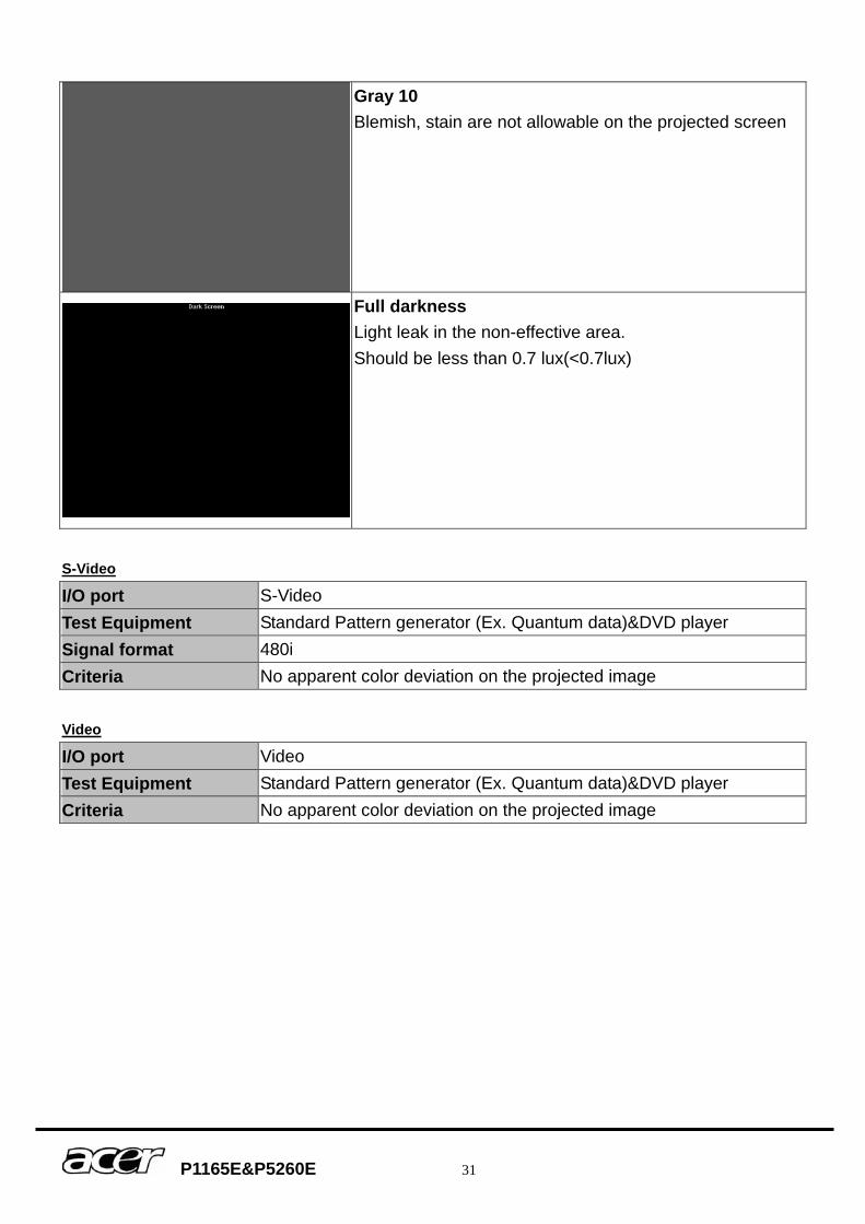
Gray 10 Blemish, stain are not allowable on the projected screen
Full darkness Light leak in the non-effective area. Should be less than 0.7 lux(<0.7lux)
S-Video
I/O port S-Video Test Equipment Standard Pattern generator (Ex. Quantum data)&DVD player Signal format 480i Criteria No apparent color deviation on the projected image Video
I/O port Video Test Equipment Standard Pattern generator (Ex. Quantum data)&DVD player Criteria No apparent color deviation on the projected image
P1165E&P5260E 32
(4) Resolution I/O port VGA Test Equipment PC Test Method
1. Rotate Zoom ring to wide mode (Maximum projected image) 2. Fix projector to set diagonal length of projected image to 60”. 3. Adjust focus ring to make resolution of 4 corners and center
are balanced. 4. Check he characters should be recognized easily. 5. Rotate Zoom ring to tele mode (Minimum projected image) 6. Adjust focus ring to make resolution of 4 corners and center
are balanced. 7. Check the characters should be recognized easily.
(5) Front and Rear infrared sensor Device Front and Rear infrared Test Equipment Remote controller Test method 1. Cover front sensor and operate remote controller to test rear
sensor 2. Cover rear sensor and operate remote controller to test front sensor
(6) Brightness measurements Test items Brightness measurements Test Equipment Chroma automatic system (The alternative is CL-200) Test method Measure 9 points Criteria Marketing spec 20% off
P1165E&P5260E 33
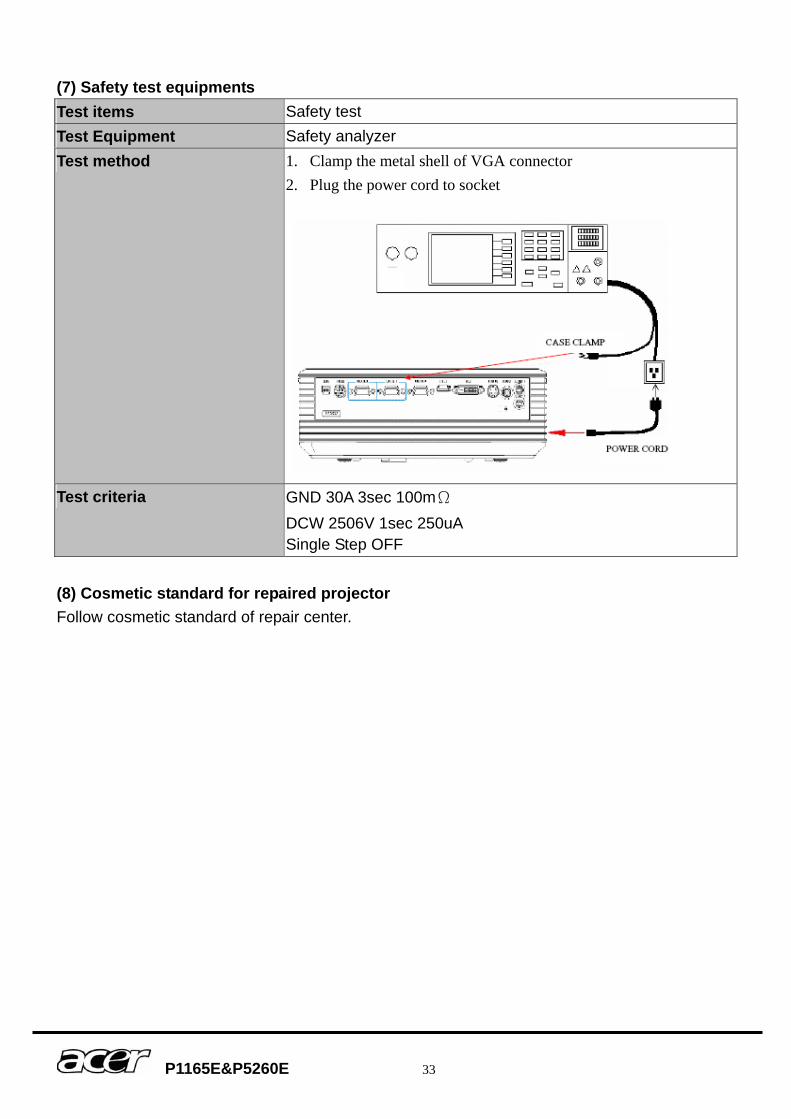
(7) Safety test equipments Test items Safety test Test Equipment Safety analyzer Test method 1. Clamp the metal shell of VGA connector
2. Plug the power cord to socket
Test criteria GND 30A 3sec 100mΩ DCW 2506V 1sec 250uA Single Step OFF
(8) Cosmetic standard for repaired projector Follow cosmetic standard of repair center.
P1165E&P5260E 34
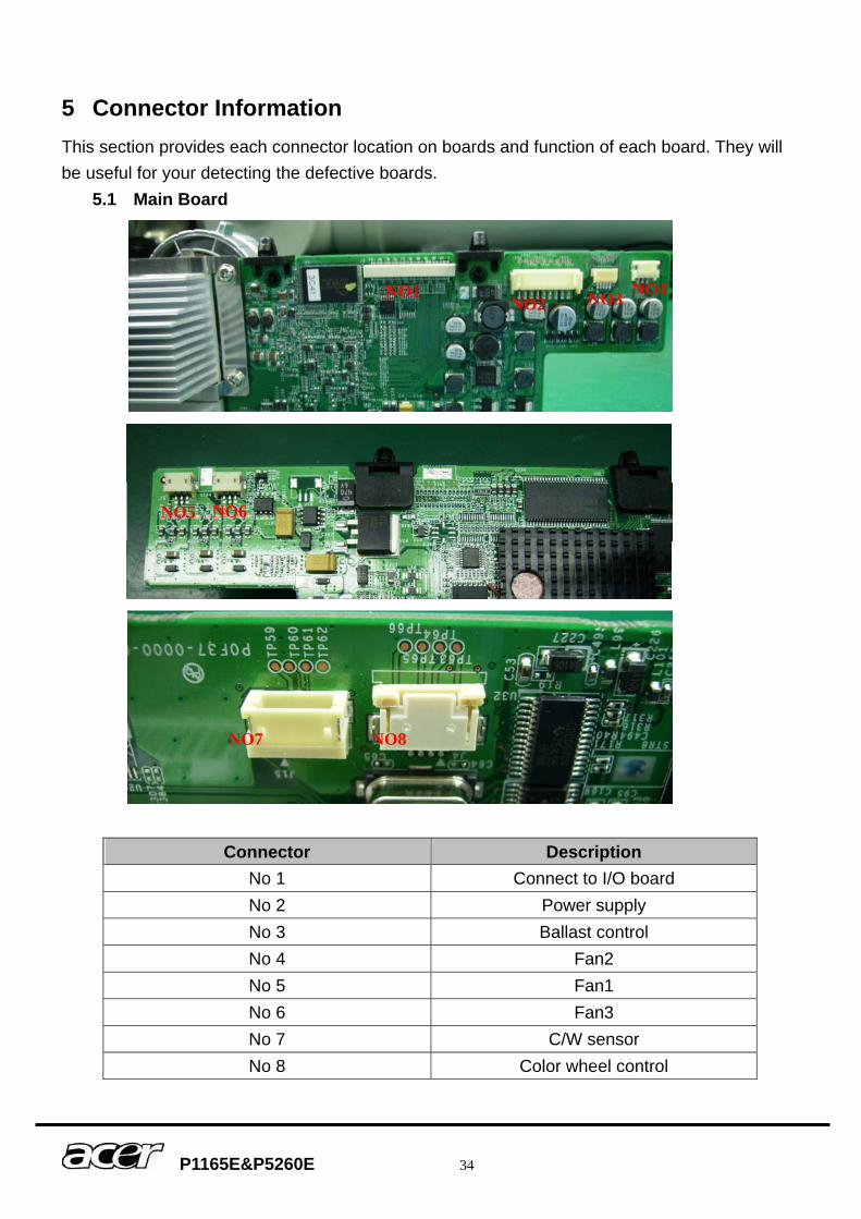
5 Connector Information This section provides each connector location on boards and function of each board. They will be useful for your detecting the defective boards.
5.1 Main Board
Connector Description No 1 Connect to I/O board No 2 Power supply No 3 Ballast control No 4 Fan2 No 5 Fan1 No 6 Fan3 No 7 C/W sensor No 8 Color wheel control
NO1 NO2 NO3 NO4
NO5 NO6
NO7 NO8
P1165E&P5260E 35
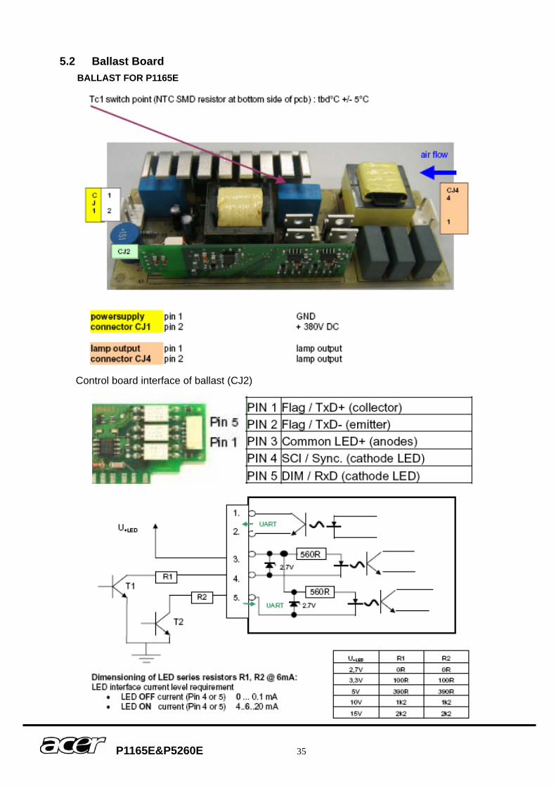
5.2 Ballast Board BALLAST FOR P1165E
Control board interface of ballast (CJ2)
P1165E&P5260E 36
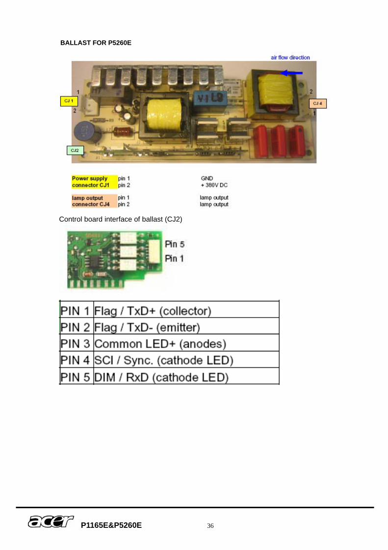
BALLAST FOR P5260E
Control board interface of ballast (CJ2)
P1165E&P5260E 37
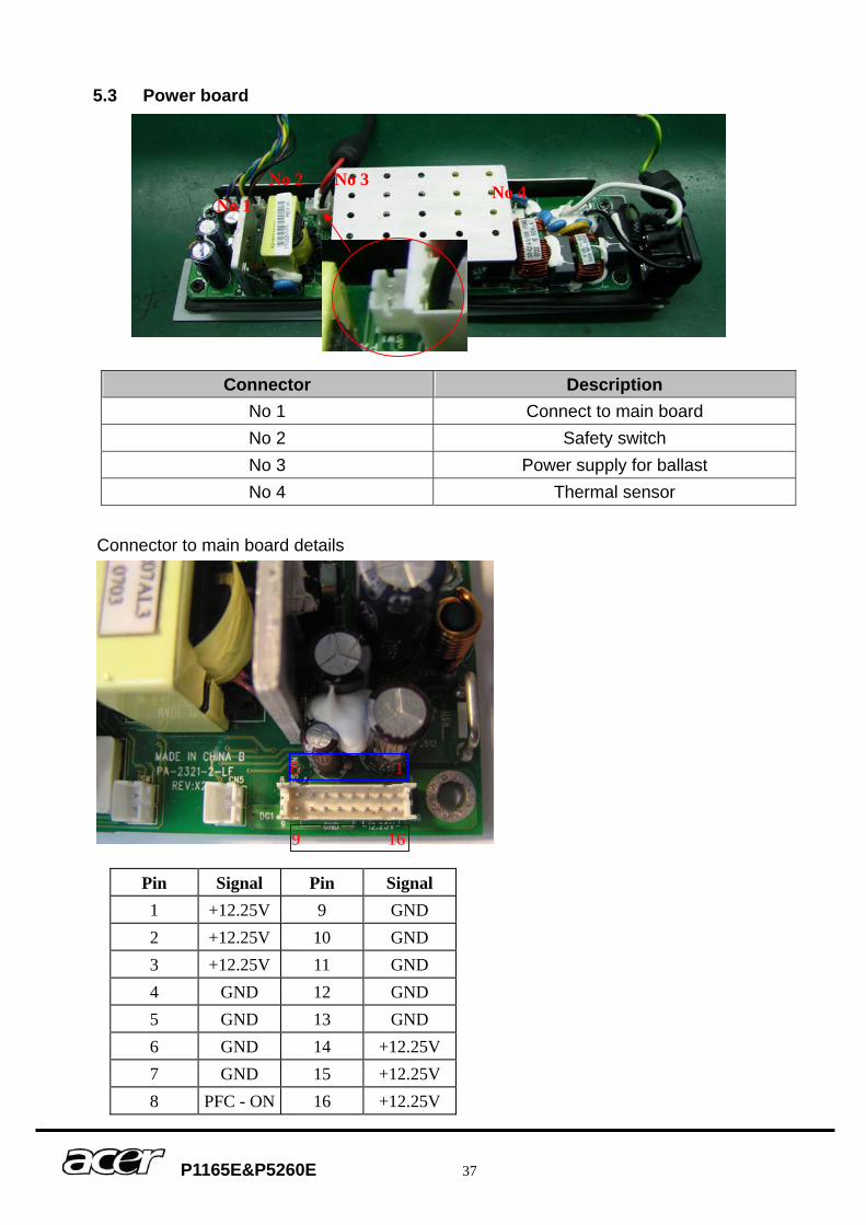
5.3 Power board
Connector to main board details
Connector Description No 1 Connect to main board No 2 Safety switch No 3 Power supply for ballast No 4 Thermal sensor
Pin Signal Pin Signal 1 +12.25V 9 GND 2 +12.25V 10 GND 3 +12.25V 11 GND 4 GND 12 GND 5 GND 13 GND 6 GND 14 +12.25V 7 GND 15 +12.25V 8 PFC - ON 16 +12.25V
No 1 No 4
No 3 No 2
8 1
9 16
P1165E&P5260E 38
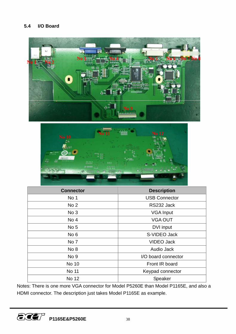
5.4 I/O Board
Connector Description
No 1 USB Connector No 2 RS232 Jack No 3 VGA Input No 4 VGA OUT No 5 DVI input No 6 S-VIDEO Jack No 7 VIDEO Jack No 8 Audio Jack No 9 I/O board connector No 10 Front IR board No 11 Keypad connector No 12 Speaker
Notes: There is one more VGA connector for Model P5260E than Model P1165E, and also a HDMI connector. The description just takes Model P1165E as example.
No 1 No 2 No 3 No 4 No 5 No 6 No 7 No 8
No 9
No 10No 11 No 12
P1165E&P5260E 39
6 FRU (Field Replaceable Unit) List Introduction This section is a list of all the FRU removal. Following the FRU table of contents is an enlarged view of the entire projector, which shows the primary FRUs in the projector. When working on the projector, use appropriate anti-static precautions such as anti-static mats, wrist straps and grounded work surfaces. Failure to do this can destroy static-sensitive components and make the product inoperable.
P1165E&P5260E 40
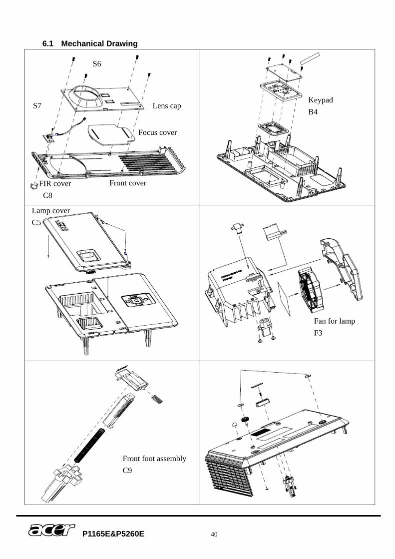
6.1 Mechanical Drawing
S6
S7 Lens cap
Focus cover
Front cover
Keypad B4
Fan for lamp F3
Lamp cover C5
FIR cover C8
Front foot assembly C9

P1165E&P5260E 41
Lamp module assembly
P1165E&P5260E 42
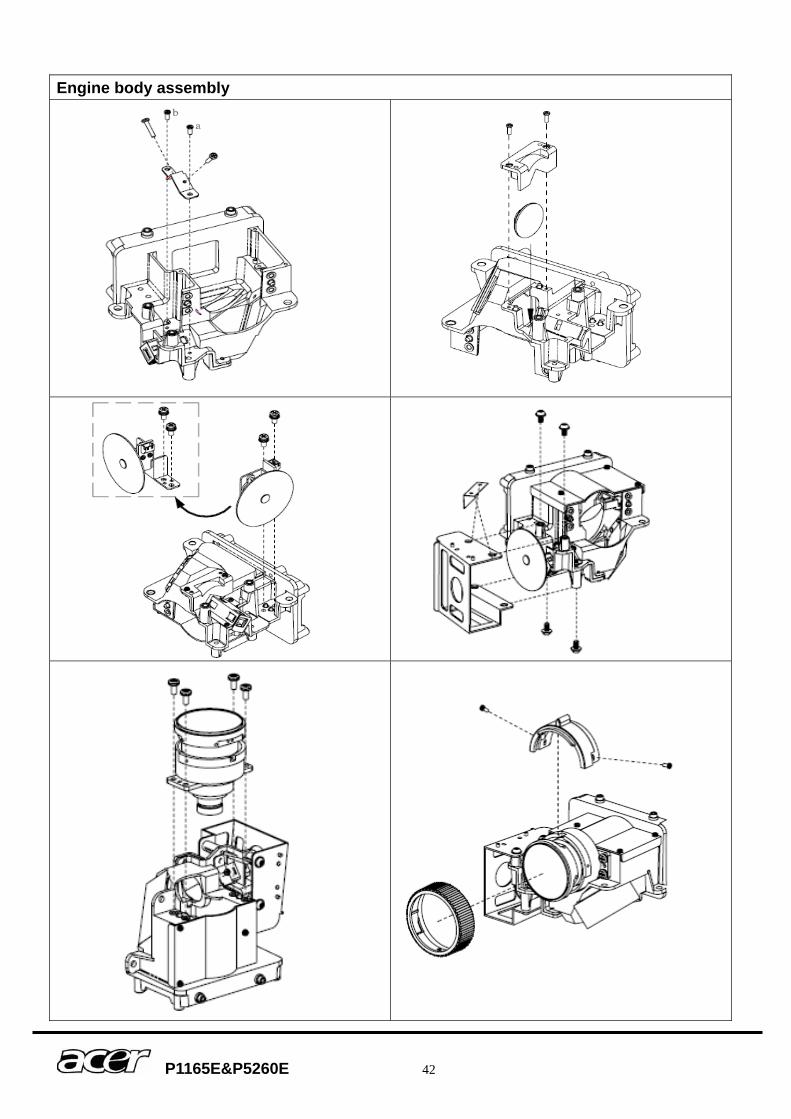
Engine body assembly

P1165E&P5260E 43
6.2 Accessory Key No. P/N Description P1165E P5260E
RC P0K00-RC01 ACER_REMOTE CONTROL_APD-X510_W/B_AAA2PCS V V 6.3 Board/Module
Key No. P/N Description P1165E P5260E
P0L47-6100 IO_DIP_PCB_ASY_APD-S520_ROHS V B1
P0K47-6100 IO_DIP_PCB_ASY_APD-X510_ROHS V P0L43-1013 BALLAST-ASM_APD-S520_ROHS V
B2 P0K43-1013 BALLAST-ASM_APD-X510_ROHS V
B3 P0K43-1018 LITEON-POWER-ASM_APD-X510_ROHS V V
B4 P0K43-1017 KEY-PAD-ASY_APD-X510_ROHS V V
B5 P0K47-5100 FIR SENSOR_DIP_PCB_ASY_APD-X510_ROHS V V
B6 P0F47-5000 CW SENSOR_SMT_PCB_ASY_PD-S550_ROHS V V
6.4 Case/Cover/Bracket Assembly
Key No. P/N Description P1165E P5260E P0L43-1011 TOP COVER ASY_APD-S520_ROHS V
C1 P0K43-1011 TOP COVER ASY_APD-X510_ROHS V
P0L43-1015 BOTTOM-COVER_ASY_APD-S520_ROHS V C2
P0K43-1015 BOTTOM-COVER_ASY_APD-X510_ROHS V
C3 P0K34-4550-00 LEFT-COVER_APD-X510_00_NO PAINTING_ROHS V V
C4 P0K43-1012 FRONT-COVER_ASY_APD-X510_ROHS V V
P0L43-1010 LAMP COVER ASY_APD-S520_ROHS V C5
P0K43-1010 LAMP COVER ASY_APD-X510_ROHS V
P0L43-1014 BACK COVER ASY_APD-S520_ROHS V C6
P0K43-1014 BACK COVER ASY_APD-X510_ROHS V
P0L38-1560-00 IO-NAME-PLATE_APD-S520_ROHS V C7
P0K38-1560-00 IO-NAME-PLATE_APD-X510_ROHS V
C8 P0P34-4610-00 FRONT IR COVER V V
C9 P0P43-1050 FRONT FOOT ASSY V V
6.5 Fans
Key No. P/N Description P1165E P5260E
F1 J2394-0074-00 FAN._3110KL-04W-B39-S00(L=100MM)_NMB_ROHS V V
F2 J2394-0069-00 FAN._AUB0712M-R00(L=80)_DELTA_ROHS V V
J2394-0087-00 FAN_BUB0512VHD-7T72(L=140MM)_DELTA_ROHS V F3
J2394-0070-00 FAN._BUB0512LD(L=60MM)_DELTA_ROHS V
P1165E&P5260E 44
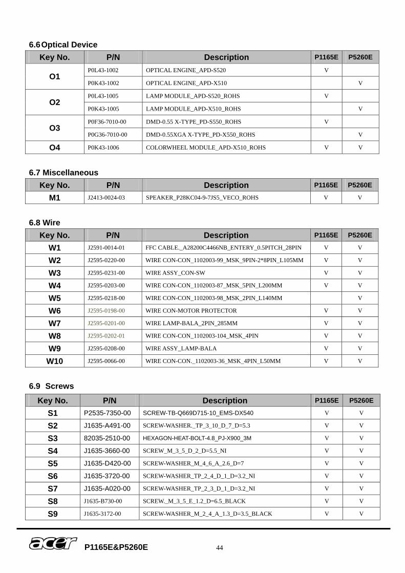
6.6 Optical Device Key No. P/N Description P1165E P5260E
P0L43-1002 OPTICAL ENGINE_APD-S520 V O1
P0K43-1002 OPTICAL ENGINE_APD-X510 V
P0L43-1005 LAMP MODULE_APD-S520_ROHS V O2
P0K43-1005 LAMP MODULE_APD-X510_ROHS V
P0F36-7010-00 DMD-0.55 X-TYPE_PD-S550_ROHS V O3
P0G36-7010-00 DMD-0.55XGA X-TYPE_PD-X550_ROHS V
O4 P0K43-1006 COLORWHEEL MODULE_APD-X510_ROHS V V
6.7 Miscellaneous
Key No. P/N Description P1165E P5260E
M1 J2413-0024-03 SPEAKER_P28KC04-9-7JS5_VECO_ROHS V V
6.8 Wire
Key No. P/N Description P1165E P5260E
W1 J2591-0014-01 FFC CABLE._A28200C4466NB_ENTERY_0.5PITCH_28PIN V V
W2 J2595-0220-00 WIRE CON-CON_1102003-99_MSK_9PIN-2*8PIN_L105MM V V
W3 J2595-0231-00 WIRE ASSY_CON-SW V V
W4 J2595-0203-00 WIRE CON-CON_1102003-87_MSK_5PIN_L200MM V V
W5 J2595-0218-00 WIRE CON-CON_1102003-98_MSK_2PIN_L140MM V
W6 J2595-0198-00 WIRE CON-MOTOR PROTECTOR V V
W7 J2595-0201-00 WIRE LAMP-BALA_2PIN_285MM V V
W8 J2595-0202-01 WIRE CON-CON_1102003-104_MSK_4PIN V V
W9 J2595-0208-00 WIRE ASSY_LAMP-BALA V V
W10 J2595-0066-00 WIRE CON-CON._1102003-36_MSK_4PIN_L50MM V V
6.9 Screws
Key No. P/N Description P1165E P5260E S1 P2535-7350-00 SCREW-TB-Q669D715-10_EMS-DX540 V V
S2 J1635-A491-00 SCREW-WASHER._TP_3_10_D_7_D=5.3 V V
S3 82035-2510-00 HEXAGON-HEAT-BOLT-4.8_PJ-X900_3M V V
S4 J1635-3660-00 SCREW_M_3_5_D_2_D=5.5_NI V V
S5 J1635-D420-00 SCREW-WASHER_M_4_6_A_2.6_D=7 V V
S6 J1635-3720-00 SCREW-WASHER_TP_2_4_D_1_D=3.2_NI V V
S7 J1635-A020-00 SCREW-WASHER_TP_2_3_D_1_D=3.2_NI V V
S8 J1635-B730-00 SCREW._M_3_5_E_1.2_D=6.5_BLACK V V
S9 J1635-3172-00 SCREW-WASHER_M_2_4_A_1.3_D=3.5_BLACK V V
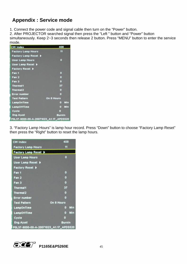
Appendix : Service mode 1. Connect the power code and signal cable then turn on the ”Power” button. 2. After PROJECTOR searched signal then press the “Left ” button and “Power” button simultaneously. Keep 2~3 seconds then release 2 button. Press “MENU” button to enter the service mode.
3. “Factory Lamp Hours” is lamp hour record. Press “Down” button to choose “Factory Lamp Reset” then press the “Right” button to reset the lamp hours.
P1165E&P5260E 45