ACE VALVE COMPANY LIMITED - Strainerasia-pacifics.com/pdf_products/09_ace/Company Profile (ACE...
20
ACE VALVE COMPANY LIMITED ISO 9001 ISO 14001 Http://www.ace-valve.co.kr
Transcript of ACE VALVE COMPANY LIMITED - Strainerasia-pacifics.com/pdf_products/09_ace/Company Profile (ACE...

ACE VALVE COMPANY LIMITEDISO 9001ISO 14001
Http://www.ace-valve.co.kr
ACE VALVE PRODUCT GUIDEBOOK C-2
Technological Knowhow of
ACE VALVE
ACE VALVE has provided the best quality products by using accumulated technological knowhow and the mostadvanced machinery.
Now we challenge the whole world market of butterfly valve.
A Top-ranking company in the 21st century by challenging the potential

Specification of “C” Series
The valve shall be capable of bi-directional flow with bubble tightshut-off at full rating pressure.
TYPE NUMBERING SYSTEMAV-CWR Concentric WAFER type Rubber lined Butterfly ValvesAV-CSR Concentric SEMI-LUG type Rubber lined Butterfly ValvesAV-CLR Concentric LUG type Rubber lined Butterfly ValvesAV-CFR Concentric FLANGE type Rubber lined Butterfly Valves
STANDARD COMPLIANCEACE Concentric Butterfly valves conform to ISO 5752, KSV 7490, JIS F 7480,JIS B 2032, JIS B 2064, API 609, BS5155, in general.
PRODUCTION RANGESIZE : 50A (2inch) ~ 2000A (80inch)RATING PRESSURE : Up to 16barRATING TEMPERATURE : -20 ~ +200
APPLICABLE FLANGEKS/JIS 5K, 10K, 16KANSI B 16.1 Class 125LBANSI B 16.5 Class 150LBBS 4504 PN 6, PN10DIN 2501 PN 6, PN10ISO 2084 PN 6, PN10
ACE VALVE PRODUCT GUIDEBOOK C-3

AV-C Series Concentric Butterfly valves
The Concentric DesignCENTER OF SHAFT’ in the ‘Center of Pipe’ / ‘Center of the Valve Seat’Applicable for BUTTERFLY VALVE WITH ELASTOMER LINING.
Classification by Connection type
Symmetric disc design ensures favorable flow characteristics and lowpressure dropConcentric shaft ensures low operating torqueLining gives a good protection to valve body, and acts as flange gasket- Shaft penetrates the valve seat- Limited choice of seating materials(Elastomer, only)
Suitable for installation in Low Pressure SystemNot suitable where FIRE-SAFE or FIRE-PROOF requirement apply to thevalve or valve installation method
TypeAppearance General Characteristics
AV-C SeriesAV-CWR(WAFER)
General Applications- Shipbuilding, water works, heating and ventilation, power plants, oil
refinery Chemical plants etc.Valve to be installed with long bolts between the flanges at adjacent pipewithout flange on the valve.Easy handling and light weight.Easy installation, less bolt quantity and low cost.Inconvenient maintenance of adjacent pipe.
AV-C SeriesAV-CSR
(SEMI-LUG)
General Applications- Shipbuilding, water works, heating and ventilation, power plants, oil
refinery Chemical plants etc.Similar as wafer type except a pair of the jack bolt hole in way of upper andlower sides for easy maintenance of adjacent pipe.Easy handling and light weight.Less quantity of bolt and easy installation.Keep liquid remained during repairing adjacent pipe.
AV-C SeriesAV-CLR
(FULL-LUG)
General Applications : general piping system pump outlets, tank drains, ship sides etc.Ring shape bolt hole for bolting with flange.Keep pressure inside during repairing adjacent one side pipe.Different flange shape.Possible damage on full face gasket.Hard repairing of corroded bolt.More man-hour for installation.Heavy weight.
AV-C SeriesAV-CFR
(FLANGE)
General Applications- Shipside valves, ballast valves, water works, power plants, etc all piping system. Both ends with complete flange.Suitable to general pipe flange.Suitable for shipside valve in the ship.Heavy weight.Same installation as ordinary valve.
ACE VALVE PRODUCT GUIDEBOOK C-4

AV-C Series Concentric Butterfly valves
Schema of concentric typeThe valve shall be a 90 turn clockwise to close, non-jamming, resilientseated valve for zero leakage service.The valve shall be torque seated and designed in such a manner thatthe disc can be rotated the seat with out the actuator.Also this valve enables the fluid perfect shut-off regardless of the flowdirection.
OperationsThe following operation of the valve is possible depend on the valvelocation, the type of work and service of the valve to be provided.
Manual lever OperationManual worm gear OperationSingle or double acting pneumatic OperationHydraulic actuator OperationElectric motor Operation
MATERIAL
CAST IRON / DUCTILE IRONSTAINLESS STEEL / CARBON STEELALUMINUM BRONZE
STAINLESS STEEL / ALLOY STEELALUMINUM BRONZE
NBR / EPDM / SILICON / VITON
STAINLESS STEEL(SS304, 316, 410,420, 17-4PH)
STAINLESS STEEL
RUBBER SAME AS SEAT MATERIAL
BRONZE
STAINLESS STEEL
PTFE + pb
RUBBER SAME AS SEAT MATERIAL
CARBON STEEL / STAINLESS STEEL /AL-BRONZE / MILD STEEL
STEEL / STAINLESS STEEL
CARBON STEEL, if necessary
PART NAMEP.NO.
1
2
3
4
5
6
7
8
9
10
11
12
13
BODY
DISC
SEAT
STEM
DISC PIN
O-RING
PACKING GLAND
GLAND BOLT
BEARING
O-RING
BOTTOM COVER
BOLT & WASHER
KEY
ACE VALVE PRODUCT GUIDEBOOK C-5
813
7
1
3
2
9
11
6
9
4
5
1012

unit : mm
mminch
SIZE
L H H1 H2 H3SQ TYPE N M N- Z
WEIGHT(APPROX.)
(kg)
STEM TOP FLANGE
AV-CWR Wafer Concentric Dimensions
ACE VALVE PRODUCT GUIDEBOOK C-6
VALVE DIMENSIONS

ACE VALVE PRODUCT GUIDEBOOK C-7
AV-CSR Semi-Lug Concentric Dimensions
unit : mm
KEYSIZE
DH4H2H1HL
mminch
SIZE
TYPE
WEIGHT(APPROX.)
(kg)N M N- ZSQUARE
STEM TOP FLANGE
SQ H3
VALVE DIMENSIONS

ACE VALVE PRODUCT GUIDEBOOK C-8
AV-CLR Lug Concentric Dimensions
unit : mm
KEYSIZE
DH4H2H1HL
mminch
SIZE
TYPE
WEIGHT(APPROX.)
(kg)N M N- ZSQUARE
STEM TOP FLANGE
SQ H3
VALVE DIMENSIONS

ACE VALVE PRODUCT GUIDEBOOK C-9
AV-CFR Flange Concentric Dimensions
unit : mm
KEYSIZE
DH4H2H1HL
mminch
SIZE
TYPE
WEIGHT(APPROX.)
(kg)N M N- ZSQUARE
STEM TOP FLANGE
SQ H3
VALVE DIMENSIONS

Range of ApplicationsButterfly valves provide a bubble tight seal. They are used to shut-off, throttle and regulate highly corrosive gases,liquids, slurries and powders. Butterfly valves are designed to handle a variety of applications to the semi conductor,chemical, petrochemical, pulp and paper, mining, food and beverage, sugar refining, sewage, air pollution control, oiland gas, and chemical carrier, shipbuilding industries etc.
Butterfly Valve with Teflon Lining
P.NO. PART NAME
BODY1
9
2
3
4
5
6
7
8
DISC
SEAT
STEM
PACKING
GLAND
BUSH
GLAND BOLT
DISC PIN
MATERIAL
Ductile iron
Stainless Steel
Carbon Steel
Stainless Steel
PTFE
Stainless Steel
PTFE
Stainless Steel
Stainless Steel
Stainless Steel
Stainless Steel
AV-TLW(WAFER) AV-TLL(LUG) AV-TLF(FLANGE)VALVE TYPE
Valve Nominal Sizes
Applicable Flange
Working temperatu rerange
Face to Face
Allowable temperaturein continuous use
Actuators
50A~500A(2 ~20 ) 50A~600A(2 ~24 ) 50A~600A(2 ~24 )
JIS / KS 5K, 10K,
ANSI B 16.5 CLASS 150LB
LEVER, WORM GEAR, PNEUMATIC CYLINDER
ELECTRIC MOTOR, HYDRAULIC ACTUATOR
.-20 ~ +250
-10 ~ +230
KS V 7490, JIS F 7480, ISO 5752(Table 6)
ACE VALVE PRODUCT GUIDEBOOK C-10
1
8654
75 3
92

ACE VALVE PRODUCT GUIDEBOOK C-11
SIZE
AV-TLW Teflon lined Butterfly Valve Dimensions
WEIGHT(APPROX.)
(kg)TYPE N M N- ZSQH3H2H1HL
STEM
mm
TOP FLANGE
VALVE DIMENSIONS unit : mm
inch

ACE VALVE PRODUCT GUIDEBOOK C-12
Basic Formulas for obtaining Cv-Value
Flow coefficient for ACE Butterfly Valves
Rated flow coefficient (Cv) is a number which represents a valve’s ability to pass flow.The bigger Cv, the more flow can pass the valve with a given pressure drop. Rate Cv means the volume of water in unitedstates gallons per minute that will pass through a given valve opening with a pressure drop of 1 pound square inch.(Waterat temp=60DEG.F) A Cv of 1900 means a valve will pass 1900gpm of 60 F water with a dp of 1PSI.
The relation between Cv and Kv, expressed in the above mentioned unit of measure are as followsCv=1.16kv
Formula 1FLOW RATE LBS/HR(Stem or Water)
Where :dp = pressure drop in PSIF = flow rate in lbs./hr.
= square root of specific volume in ft. /lb.(downstream of valve)
63.5CvFdp = ( ) or Cv =
v
dp
V
63.5F V
Formula 2FLOW RATE GPM(Water or Other Liquids)
Where :dp = pressure drop in PSISg = specific gravityQ = Flow rate in GPM
CvQ
dp = ( ) or Cv =
v
dpSg
Cv
20 30VALVE SIZE
40 50 60 70 80 90
inch mm
DISC OPENING
Cv Cv Cv Cv Cv Cv Cv

ACE VALVE PRODUCT GUIDEBOOK C-13
The torques listed are applicable to water, sea water, lubricating type of hydro carbons and most media at temperature 0~80 (32~180 F).The operating speed of the actuator must be considered in order to avoid water hammer when the valve is closed in junction with Liquid.
Ta=Tb+Ts+Th=1.2Tb Td
Ts=CsD2
Tb=4.17D2 dfp
Td=CtD3P
Th=3.06D4
V=Cf P = Q/0.785D2
Ta: The required actuator torque (lb-ft)Ts: Seat or unseating torque (lb-ft)Td: Dynamic torque (lb-ft)Q: Flow (cubic for per second)V: Velocity (feet per second)D: Diameter of valve (feet)d: Diameter of shaft (inch)P: Pressure drop across valve (psi)Cs: Coefficient of seating or unseating torqueCt: Coefficient of dynamic torqueCf: Coefficient of flowf: Bearing friction coefficient
Actuator torques can be calculated with the following formulas.
Torques Required to Operate Valve
-m -mNm Nm
CONCENTRIC TYPE
3bar 5barmm
SIZE
inch
TORQUE TABLE unit : kg-m/Nm
-m Nm -m Nm -m Nm
10bar 13bar 16bar

ACE VALVE PRODUCT GUIDEBOOK C-14
The following chart should be used as a general guide.Application suggested derives from recommendation given by elastomer manufacturer.The resistance can be affected by type of fluid, concentration, temperature, pressure, flow rate or evaporation of themedium.The final choice is to be taken by the customer, based on characteristics and specific application.
MATERIAL
Fresh WaterSea WaterBrineEstersAlkalisOzoneAlcoholsBrake FluidTreated Water With Caustic Soda
Fresh WaterSea WaterTreated Water With Caustic Soda
HydrocabonsNatural GasOil and FatAirGasoline
Acids and Alkalis
Acids, OilsHydrocarbon
SolventsCorrosive ProductsKetones
Acid, Ozone, OilsFatsGreasesSolvents
FoodBeverage
GENERAL APPLICATION SERVICE TEMPERATURE NOT RECOMMENDED FOR
Elastomer General Chart
HydrocarbonsOilsFatsGreases
EPDM
NBR
SBR
VITON
SILICONE
TEFLON
NEOPRENE
-15 to + 120(for intermittent opration)
0 ~ 100(Allowable temperature
in continuous use)
-10 to + 80(Allowable temperature
in continuous use)0 ~ 70
(L-NBR -50 to 70 )
-20 to + 80
-10 to + 230
-20 to + 140
-50 to +230
(PTFE -196 to + 230 )
-18 to + 90
SolventsBenzeneXylol
Steam, EsterFreon22, AlkalisSolvents, Ketones
SteamSolventsHydrocarbons
Fluid Containing PowdersAlkalineGaseous Fluorine
Ketones, ThinnersConcentrated Acids

ACE VALVE PRODUCT GUIDEBOOK C-15
”
Bolting Dimensions (Wafer & Semi-Lug Type)
SEMI-LUG TYPESIZE
inch mmFACE TO
FACE Q’TY
JIS 5K
BOLT Q’TY
JIS 10K
BOLT Q’TY
ANSI 150LB
BOLT
FLANGE(T) 5K FLANGE(T) 10K JIS 5K JIS 10KNUT(T)
5KNUT(T)
10K CASTIRON
CASTSTEEL
SIZEFACE TO
FACE
WAFER TYPE
CASTIRON
CASTSTEEL
Q’TYBOLTSIZE
Q’TYBOLTSIZE
ACE VALVE PRODUCT GUIDEBOOK C-16
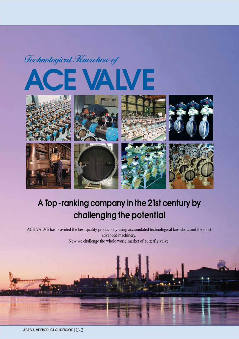
G1 G3
T1 T3
L1 L3
OPERATOR POSITION
Bolting Dimensions (Lug Type)
JIS 10K
GEARTYPE
LEVERTYPE
JIS 5K
SIZEFace to
Face5K 10K JIS 5K 5K 10K Bolt Size
Connect Flange “t” SIZE Connect Flange “t” SIZE
CASTIRON
CASTIRON
CASTSTEEL
CASTSTEEL
CASTIRON
CASTIRON
CASTSTEEL
CASTSTEEL
Q’TY Q’TYSIZE SIZE
SIZEFace to
Face

ACE VALVE PRODUCT GUIDEBOOK C-17
Bolting Dimensions (Flanged Type)
JIS 5K-Casting body
FC
Valveflange thickness Bolt size
SC
Holes &Taps
Quantitymminch
Face toFace
length
“B”Type boltMachine bolt+Nut
“A”Type boltMachine bolt
VALV SIZE
JIS 10K-Casting body
FC
Valveflange thickness Bolt size
SC
Holes &Taps
Quantitymminch
Face toFace
length
VALV SIZE

ACE VALVE PRODUCT GUIDEBOOK C-18
Method for Carrying & Keeping
How to Install Butterfly Valve
Centering & Flanging of Valve
RIGHTBolts spanned, disc edge with inbody face-to-face.No disc edge damage,propersealing allowed
Be careful not to scratch Disc and Seat ring.The flange must be protected by plywood or other things when carrying valve.
Valve must not be shocked and shaken too much.(It may cause the breaking neck, lever, handle, and body)
Valve is recommended to be kept and carried under the condition of opening.
The suitable temperature is over -10 and humidity is 60% while keeping valve.
In keeping Valve, must check the operation once per three months.
Aligning of Flange bolts
WRONGPiping misaligned:Result-DiscO.D. touches pipe I.D. causing discedge damage. Increased torque &leakage.Seat face, seals improperly withoutengagement
RIGHTPiping aligned properly when boltstightened, disc in full open position:Result-disc clears adjacent pipeI.D., seat face seals properly, noexcessive initial torque.
WRONG CORRECT
WRONGDisc in closed position:gasketsused:Results-Seat distorted andover compressed causing highinitial unseating torque problems

ACE VALVE PRODUCT GUIDEBOOK C-19
CERTIFICATE

2008.08. ACE
VAL
VE CAT
ALOG
ACE VALVE COMPANY LIMITEDHttp://www.ace-valve.co.kr
278-4, MANG DEOK LI, JUCHON MYON, GIM-HAE CITYGYUNG NAM, KOREA.TEL_ 82-55-329-0651~6 FAX_ 82-55-329-0657E-mail_ [email protected]


![Untitled-2 [] · ACE ADD 951 ACE ASD 115](https://static.fdocuments.us/doc/165x107/5fb6ce9650e9f0666a6110e5/untitled-2-ace-add-951-ace-asd-115.jpg)