ACDC TOPSwitchHX 032514; INPUT INFO … 0 Cmils Output Winding Bare Conductor minimum ... it is the...
10
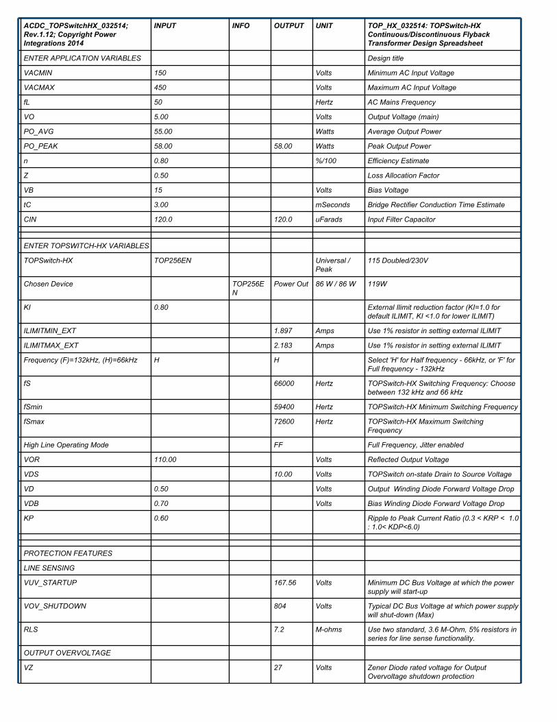
ACDC_TOPSwitchHX_032514; Rev.1.12; Copyright Power Integrations 2014 INPUT INFO OUTPUT UNIT TOP_HX_032514: TOPSwitch-HX Continuous/Discontinuous Flyback Transformer Design Spreadsheet ENTER APPLICATION VARIABLES Design title VACMIN 150 Volts Minimum AC Input Voltage VACMAX 450 Volts Maximum AC Input Voltage fL 50 Hertz AC Mains Frequency VO 5.00 Volts Output Voltage (main) PO_AVG 55.00 Watts Average Output Power PO_PEAK 58.00 58.00 Watts Peak Output Power n 0.80 %/100 Efficiency Estimate Z 0.50 Loss Allocation Factor VB 15 Volts Bias Voltage tC 3.00 mSeconds Bridge Rectifier Conduction Time Estimate CIN 120.0 120.0 uFarads Input Filter Capacitor ENTER TOPSWITCH-HX VARIABLES TOPSwitch-HX TOP256EN Universal / Peak 115 Doubled/230V Chosen Device TOP256E N Power Out 86 W / 86 W 119W KI 0.80 External Ilimit reduction factor (KI=1.0 for default ILIMIT, KI <1.0 for lower ILIMIT) ILIMITMIN_EXT 1.897 Amps Use 1% resistor in setting external ILIMIT ILIMITMAX_EXT 2.183 Amps Use 1% resistor in setting external ILIMIT Frequency (F)=132kHz, (H)=66kHz H H Select 'H' for Half frequency - 66kHz, or 'F' for Full frequency - 132kHz fS 66000 Hertz TOPSwitch-HX Switching Frequency: Choose between 132 kHz and 66 kHz fSmin 59400 Hertz TOPSwitch-HX Minimum Switching Frequency fSmax 72600 Hertz TOPSwitch-HX Maximum Switching Frequency High Line Operating Mode FF Full Frequency, Jitter enabled VOR 110.00 Volts Reflected Output Voltage VDS 10.00 Volts TOPSwitch on-state Drain to Source Voltage VD 0.50 Volts Output Winding Diode Forward Voltage Drop VDB 0.70 Volts Bias Winding Diode Forward Voltage Drop KP 0.60 Ripple to Peak Current Ratio (0.3 < KRP < 1.0 : 1.0< KDP<6.0) PROTECTION FEATURES LINE SENSING VUV_STARTUP 167.56 Volts Minimum DC Bus Voltage at which the power supply will start-up VOV_SHUTDOWN 804 Volts Typical DC Bus Voltage at which power supply will shut-down (Max) RLS 7.2 M-ohms Use two standard, 3.6 M-Ohm, 5% resistors in series for line sense functionality. OUTPUT OVERVOLTAGE VZ 27 Volts Zener Diode rated voltage for Output Overvoltage shutdown protection
Transcript of ACDC TOPSwitchHX 032514; INPUT INFO … 0 Cmils Output Winding Bare Conductor minimum ... it is the...
ACDC_TOPSwitchHX_032514;Rev.1.12; Copyright PowerIntegrations 2014
INPUT INFO OUTPUT UNIT TOP_HX_032514: TOPSwitch-HXContinuous/Discontinuous FlybackTransformer Design Spreadsheet
ENTER APPLICATION VARIABLES Design title
VACMIN 150 Volts Minimum AC Input Voltage
VACMAX 450 Volts Maximum AC Input Voltage
fL 50 Hertz AC Mains Frequency
VO 5.00 Volts Output Voltage (main)
PO_AVG 55.00 Watts Average Output Power
PO_PEAK 58.00 58.00 Watts Peak Output Power
n 0.80 %/100 Efficiency Estimate
Z 0.50 Loss Allocation Factor
VB 15 Volts Bias Voltage
tC 3.00 mSeconds Bridge Rectifier Conduction Time Estimate
CIN 120.0 120.0 uFarads Input Filter Capacitor
ENTER TOPSWITCH-HX VARIABLES
TOPSwitch-HX TOP256EN Universal /Peak
115 Doubled/230V
Chosen Device TOP256EN
Power Out 86 W / 86 W 119W
KI 0.80 External Ilimit reduction factor (KI=1.0 fordefault ILIMIT, KI <1.0 for lower ILIMIT)
ILIMITMIN_EXT 1.897 Amps Use 1% resistor in setting external ILIMIT
ILIMITMAX_EXT 2.183 Amps Use 1% resistor in setting external ILIMIT
Frequency (F)=132kHz, (H)=66kHz H H Select 'H' for Half frequency - 66kHz, or 'F' forFull frequency - 132kHz
fS 66000 Hertz TOPSwitch-HX Switching Frequency: Choosebetween 132 kHz and 66 kHz
fSmin 59400 Hertz TOPSwitch-HX Minimum Switching Frequency
fSmax 72600 Hertz TOPSwitch-HX Maximum SwitchingFrequency
High Line Operating Mode FF Full Frequency, Jitter enabled
VOR 110.00 Volts Reflected Output Voltage
VDS 10.00 Volts TOPSwitch on-state Drain to Source Voltage
VD 0.50 Volts Output Winding Diode Forward Voltage Drop
VDB 0.70 Volts Bias Winding Diode Forward Voltage Drop
KP 0.60 Ripple to Peak Current Ratio (0.3 < KRP < 1.0: 1.0< KDP<6.0)
PROTECTION FEATURES
LINE SENSING
VUV_STARTUP 167.56 Volts Minimum DC Bus Voltage at which the powersupply will start-up
VOV_SHUTDOWN 804 Volts Typical DC Bus Voltage at which power supplywill shut-down (Max)
RLS 7.2 M-ohms Use two standard, 3.6 M-Ohm, 5% resistors inseries for line sense functionality.
OUTPUT OVERVOLTAGE
VZ 27 Volts Zener Diode rated voltage for OutputOvervoltage shutdown protection

RZ 5.1 k-ohms Output OVP resistor. For latching shutdownuse 20 ohm resistor instead
OVERLOAD POWER LIMITING
Overload Current Ratio at VMAX 1.20 Enter the desired margin to current limit atVMAX. A value of 1.2 indicates that the currentlimit should be 20% higher than peak primarycurrent at VMAX
Overload Current Ratio at VMIN 1.26 Margin to current limit at low line.
ILIMIT_EXT_VMIN 1.43 A Peak primary Current at VMIN
ILIMIT_EXT_VMAX 1.27 A Peak Primary Current at VMAX
RIL 7.80 k-ohms Current limit/Power Limiting resistor.
RPL N/A M-ohms Resistor not required. Use RIL resistor only
ENTER TRANSFORMERCORE/CONSTRUCTION VARIABLES
Core Type Auto EER28 Core Type
Custom Core Part Number (Optional) If custom core used - Enter part number here
Bobbin EER28_BOBBIN
P/N: BEER-28-1112CPH
AE 0.8210 cm^2 Core Effective Cross Sectional Area
LE 6.4000 cm Core Effective Path Length
AL 2870.0 nH/T^2 Ungapped Core Effective Inductance
BW 16.7 mm Bobbin Physical Winding Width
M 0.00 mm Safety Margin Width (Half the Primary toSecondary Creepage Distance)
L 3.00 Number of Primary Layers
NS 5 Number of Secondary Turns
DC INPUT VOLTAGE PARAMETERS
VMIN 191 Volts Minimum DC Input Voltage
VMAX 636 Volts Maximum DC Input Voltage
CURRENT WAVEFORM SHAPEPARAMETERS
DMAX 0.38 Maximum Duty Cycle (calculated atPO_PEAK)
IAVG 0.36 Amps Average Primary Current (calculated ataverage output power)
IP 1.43 Amps Peak Primary Current (calculated at Peakoutput power)
IR 0.82 Amps Primary Ripple Current (calculated at averageoutput power)
IRMS 0.60 Amps Primary RMS Current (calculated at averageoutput power)
TRANSFORMER PRIMARY DESIGNPARAMETERS
LP 1222 uHenries Primary Inductance
LP Tolerance 10 Tolerance of Primary Inductance
NP 100 Primary Winding Number of Turns
NB 14 Bias Winding Number of Turns
ALG 122 nH/T^2 Gapped Core Effective Inductance

BM 2134 Gauss Maximum Flux Density at PO, VMIN(BM<3000)
BP 3573 Gauss Peak Flux Density (BP<4200) at ILIMITMAXand LP_MAX. Note: Recommended values foradapters and external power supplies <=3600Gauss
BAC 640 Gauss AC Flux Density for Core Loss Curves (0.5 XPeak to Peak)
ur 1780 Relative Permeability of Ungapped Core
LG 0.81 mm Gap Length (Lg > 0.1 mm)
BWE 50.1 mm Effective Bobbin Width
OD 0.50 mm Maximum Primary Wire Diameter includinginsulation
INS 0.07 mm Estimated Total Insulation Thickness (= 2 * filmthickness)
DIA 0.44 mm Bare conductor diameter
AWG 26 AWG Primary Wire Gauge (Rounded to next smallerstandard AWG value)
CM 256 Cmils Bare conductor effective area in circular mils
CMA 425 Cmils/Amp Primary Winding Current Capacity (200 < CMA< 500)
Primary Current Density (J) 4.70 Amps/mm^2 Primary Winding Current density (3.8 < J <9.75)
TRANSFORMER SECONDARYDESIGN PARAMETERS (SINGLEOUTPUT EQUIVALENT)
Lumped parameters
ISP 28.68 Amps Peak Secondary Current
ISRMS 15.47 Amps Secondary RMS Current
IO_PEAK 11.60 Amps Secondary Peak Output Current
IO 11.00 Amps Average Power Supply Output Current
IRIPPLE 10.88 Amps Output Capacitor RMS Ripple Current
CMS 3094 Cmils Secondary Bare Conductor minimum circularmils
AWGS 15 AWG Secondary Wire Gauge (Rounded up to nextlarger standard AWG value)
DIAS 1.45 mm Secondary Minimum Bare Conductor Diameter
ODS 3.34 mm Secondary Maximum Outside Diameter forTriple Insulated Wire
INSS 0.94 mm Maximum Secondary Insulation WallThickness
VOLTAGE STRESS PARAMETERS
VDRAIN Warning 854 Volts !!! REDUCE DRAIN VOLTAGE Vdrain<680,reduce VACMAX, reduce VOR
PIVS 37 Volts Output Rectifier Maximum Peak InverseVoltage
PIVB 106 Volts Bias Rectifier Maximum Peak Inverse Voltage
TRANSFORMER SECONDARYDESIGN PARAMETERS (MULTIPLEOUTPUTS)
1st output
VO1 5.00 5.00 Volts Output Voltage

IO1_AVG 10.00 10.00 Amps Average DC Output Current
PO1_AVG 50 Watts Average Output Power
VD1 0.50 Volts Output Diode Forward Voltage Drop
NS1 5.00 Output Winding Number of Turns
ISRMS1 14.064 Amps Output Winding RMS Current
IRIPPLE1 9.89 Amps Output Capacitor RMS Ripple Current
PIVS1 37 Volts Output Rectifier Maximum Peak InverseVoltage
CMS1 2813 Cmils Output Winding Bare Conductor minimumcircular mils
AWGS1 15 AWG Wire Gauge (Rounded up to next largerstandard AWG value)
DIAS1 1.45 mm Minimum Bare Conductor Diameter
ODS1 3.34 mm Maximum Outside Diameter for TripleInsulated Wire
2nd output
VO2 6.00 Volts Output Voltage
IO2_AVG 1.00 Amps Average DC Output Current
PO2_AVG 6 Watts Average Output Power
VD2 0.70 Volts Output Diode Forward Voltage Drop
NS2 6.09 Output Winding Number of Turns
ISRMS2 1.406 Amps Output Winding RMS Current
IRIPPLE2 0.99 Amps Output Capacitor RMS Ripple Current
PIVS2 45 Volts Output Rectifier Maximum Peak InverseVoltage
CMS2 281 Cmils Output Winding Bare Conductor minimumcircular mils
AWGS2 25 AWG Wire Gauge (Rounded up to next largerstandard AWG value)
DIAS2 0.46 mm Minimum Bare Conductor Diameter
ODS2 2.74 mm Maximum Outside Diameter for TripleInsulated Wire
3rd output
VO3 Volts Output Voltage
IO3_AVG Amps Average DC Output Current
PO3_AVG 0 Watts Average Output Power
VD3 0.70 Volts Output Diode Forward Voltage Drop
NS3 0.64 Output Winding Number of Turns
ISRMS3 0 Amps Output Winding RMS Current
IRIPPLE3 0.00 Amps Output Capacitor RMS Ripple Current
PIVS3 4 Volts Output Rectifier Maximum Peak InverseVoltage
CMS3 0 Cmils Output Winding Bare Conductor minimumcircular mils
AWGS3 N/A AWG Wire Gauge (Rounded up to next largerstandard AWG value)
DIAS3 N/A mm Minimum Bare Conductor Diameter
ODS3 N/A mm Maximum Outside Diameter for TripleInsulated Wire

Total Continuous Output Power 56 Watts Total Continuous Output Power
Negative Output N/A N/A If negative output exists enter Output number;e.g.: If VO2 is negative output, enter 2

Electrical Diagram
Mechanical Diagram
Winding InstructionPrimary Winding (Section 1)
Start on pin(s) 3 and wind 50 turns (x 1 filar) of item [5]. in 2 layer(s) from left to right. Winding direction is clockwise. At the end of 1st layer, continue towind the next layer from right to left. On the final layer, spread the winding evenly across entire bobbin. Finish this winding on pin(s) 2.
Add 1 layer of tape, item [3], for insulation.
Bias Winding

Start on pin(s) 5 and wind 15 turns (x 2 filar) of item [6]. Winding direction is clockwise. Spread the winding evenly across entire bobbin. Finish this windingon pin(s) 4.
Add 3 layers of tape, item [3], for insulation.
Secondary Winding
Use 3 mm margin (item [8]) on the left side and 3 mm margin on the right side (to meet safety). Start on pin(s) 6 and wind 5 turns of item [7]. Windingdirection is clockwise. Finish this winding on pin(s) 7.
Add 1 layer of tape, item [3], for insulation.
Start on pin(s) 8 and wind 1 turns (x 1 filar) of item [9]. Spread the winding evenly across entire bobbin. Winding direction is clockwise. Finish this windingon pin(s) 9.
Add 3 layers of tape, item [3], for insulation.
Primary Winding (Section 2)
Start on pin(s) 2 and wind 50 turns (x 1 filar) of item [5]. in 2 layer(s) from left to right. Winding direction is clockwise. At the end of 1st layer, continue towind the next layer from right to left. On the final layer, spread the winding evenly across entire bobbin. Finish this winding on pin(s) 1.
Add 3 layers of tape, item [3], for insulation.
Core Assembly
Assemble and secure core halves. Item [1].
Varnish
Dip varnish uniformly in item [4]. Do not vacuum impregnate.
Comments1. Use of a grounded flux-band around the core may improve the EMI performance.
2. For non margin wound transformers use triple insulated wire for all secondary windings.
MaterialsItem Description
[1] Core: EER28, PC95, gapped for ALG of 122 nH/T²
[2] Bobbin: Generic, 5 pri. + 4 sec.
[3] Barrier Tape: Polyester film [1 mil (25 µm) base thickness], 16.70 mm wide
[4] Varnish
[5] Magnet Wire: 24 AWG, Solderable Double Coated
[6] Magnet Wire: 27 AWG, Solderable Double Coated
[7] Copper Foil: 10 mil thick, 10.70 mm wide, covered with 1 layer of lapped tape. Terminations to foil: 2 x 23 AWG magnetwire with sleeving
[8] Tape: Polyester web 3 mm wide
[9] Triple Insulated Wire: 25 AWG
Electrical Test SpecificationsParameter Condition Spec
Electrical Strength, VAC 60 Hz 1 second, from pins 1,2,3,4,5 to pins 6,7,8,9. 3000
Nominal Primary Inductance, µH Measured at 1 V pk-pk, typical switching frequency, between pin 1 to pin3, with all other Windings open.
1222
Tolerance, ±% Tolerance of Primary Inductance 10.0
Maximum Primary Leakage, µH Measured between Pin 1 to Pin 3, with all other Windings shorted. 30.54
Although the design of the software considered safety guidelines, it is the user's responsibility to ensure that the user's power supply design meets allapplicable safety requirements of user's product.

Transformer Construction ParametersVar Value Units Description
Core Type EER28 Core Type
Core Material PC95 Core Material
Bobbin Reference Generic, 5 pri. + 4 sec. Bobbin Reference
Bobbin Orientation Horizontal Bobbin type
Primary Pins 5 Number of Primary pins used
Secondary Pins 4 Number of Secondary pins used (Manual Overwrite)
LP 1222 µH Nominal Primary Inductance
ML 0.00 mm Safety Margin on Left Width
MR 0.00 mm Safety Margin on Right Width
LG 0.809 mm Estimated Gap Length
Bias VariablesVar Value Units Description
NB 15 Bias Winding Number of Turns
Wire Size 27 AWG Wire size of Bias windings
Winding Type Bifilar (x2) Wire type of Bias windings
Layers 0.73 Bias Winding Layers
Start Pin(s) 5 Starting pin(s) for Bias winding
Termination Pin(s) 4 Termination pin(s) for Bias winding
Primary Winding Section 1Var Value Units Description
NP1 50 Number of Primary Winding Turns in the First Section ofPrimary
Wire Size 24 AWG Primary Winding - Wire Size
Winding Type Single (x1) Primary Winding - Number of Parallel Wire Strands
L 1.70 Primary Winding - Number of Layers
Start Pin(s) 3 Starting pin(s) for first section of primary winding
Termination Pin(s) 2 Termination pin(s) for first section of primary winding
Primary Winding Section 2Var Value Units Description
NP2 50 Rounded (Integer) Number of Primary winding turns in thesecond section of primary
Wire Size 24 AWG Primary Winding - Wire Size
Winding Type Single (x1) Primary Winding - Number of Parallel Wire Strands
L2 1.70 Primary Number of Layers in 2nd split winding
Start Pin(s) 2 Starting pin(s) for the second section of primary winding
Termination Pin(s) 1 Termination pin(s) for the second section of primarywinding
Output 1Var Value Units Description
VO 5.00 V Typical Output Voltage
IO 10.00 A Output Current
VOUT_ACTUAL 5.00 V Actual Output Voltage
NS 5 Secondary Number of Turns
Foil Thickness 10 mil Wire size of secondary winding

Winding Type Foil Output winding number of parallel strands
L_S_OUT 5.00 Secondary Output Winding Layers
Start Pin(s) 6 Starting pin(s) for Output winding
Termination Pin(s) 7 Termination pin(s) for Output winding
Output 2Var Value Units Description
VO 6.00 V Typical Output Voltage
IO 1.00 A Output Current
VOUT_ACTUAL 5.90 V Actual Output Voltage
NS 1 Secondary Number of Turns
Wire Size 25 AWG Wire size of secondary winding
Winding Type Single (x1) Output winding number of parallel strands
L_S_OUT 0.04 Secondary Output Winding Layers
Start Pin(s) 8 Starting pin(s) for Output winding (Manual Overwrite)
Termination Pin(s) 9 Termination pin(s) for Output winding (Manual Overwrite)

0 Errors, Warnings, Information