AccuMap & UltraMap Owner's Manual this type of failure nor its consequences are cov-ered by the...
92
INSTALLATION AND OPERATION INSTRUCTIONS AccuMap and UltraMap TM TM
Transcript of AccuMap & UltraMap Owner's Manual this type of failure nor its consequences are cov-ered by the...
INSTALLATION ANDOPERATION INSTRUCTIONS
AccuMapand
UltraMapTM
TM

Copyright © 1998 Eagle Electronics. All rights reserved.
UltraMap™ and AccuMap™ are trademarks of Eagle Electronics..
WARNING!USE THIS UNIT ONLY AS AN AID TO NAVIGATION. A CAREFUL NAVI-GATOR NEVER RELIES ON ONLY ONE METHOD TO OBTAIN POSI-TION INFORMATION.
Never use this product while operating a vehicle.
CAUTIONWhen showing navigation data to a position (waypoint), this unit will showthe shortest, most direct path to the waypoint. It provides navigation datato the waypoint regardless of obstructions. Therefore, the prudent naviga-tor will not only take advantage of all available navigation tools when trav-elling to a waypoint, but will also visually check to make certain a clear,safe path to the waypoint is always available.
The operating and storage temperature for your unit is from -4 degrees to+167 degrees Fahrenheit (-20 to +75 degrees Celsius). Extended storagetemperatures higher or lower than specified will cause the liquid crystaldisplay to fail. Neither this type of failure nor its consequences are cov-ered by the warranty. For more information, consult the factory customerservice department.
All features and specifications subject to change without notice.
Eagle Electronics may find it necessary to change or end our policies,regulations, and special offers at any time. We reserve the right to do sowithout notice.
All screens in this manual are simulated.

This device complies with Part 15 of the FCC Rules. Operation is subjectto the following two conditions: (1) this device may not cause harmfulinterference, and (2) this device must accept any interference received,including interference that may cause undesired operation.
Note:This equipment has been tested and found to comply with the limits for aClass B digital device, pursuant to Part 15 of the FCC Rules. These limitsare designed to provide reasonable protection against harmful interfer-ence in a residential installation. This equipment generates, uses and canradiate radio frequency energy and, if not installed and used in accor-dance with the instructions, may cause harmful interference to radio com-munications. However, there is no guarantee that interference will not oc-cur in a particular installation. If this equipment does cause harmful inter-ference to radio or television reception, which can be determined by turn-ing the equipment off and on, the user is encouraged to try to correct theinterference by one or more of the following measures:
• Reorient or relocate the receiving antenna.• Increase the separation between the equipment and receiver.• Connect the equipment into an outlet on a circuit different from that to
which the receiver is connected.• Consult the factory customer service department for help.

Edit Position .................................. 40Edit Name ..................................... 40Edit Icon ........................................ 40
Delete a Waypoint ............................. 40Delete All Waypoints ......................... 41Move a Waypoint .............................. 41Waypoint Options ............................. 41
WAYPOINT NAVIGATION ........................... 42Navigate to a cursor location .................. 42Navigate to a Waypoint using the Map ... 43
CANCEL NAVIGATION ............................... 43ROUTES ..................................................... 43
Create a Route ....................................... 43Add From Waypoint List .................... 44Add From Map .................................. 44
Delete a Waypoint .................................. 45Waypoint Statistics ................................. 45Following a Route .................................. 45
Waypoint Information ........................ 47Delete a Route ....................................... 47
SYSTEM SETUP ......................................... 48Sound .................................................... 48Contrast ................................................. 48Backlight ................................................ 48Set Local Time ....................................... 48Units of Measure .................................... 49NMEA / DGPS ....................................... 49Configure NMEA Output ........................ 50DGPS ..................................................... 50Serial Communication Setup .................. 51Reset Groups ......................................... 51Reset Options ........................................ 51System Info ............................................ 52
GPS SETUP ................................................ 52Position Format ...................................... 52DATUM ................................................... 53PCF (Position Correction Factor) ............ 54POSITION PINNING .............................. 55
GPS ALARMS ............................................. 56DGPS MESSAGES ..................................... 57SUN/MOON CALCULATOR ........................ 57SIMULATOR ................................................ 58
INSTALLATION ................................................. 1Mounting ........................................................ 1Power Connections ........................................ 2Cable Connections ........................................ 3
AccuMap .................................................. 3UltraMap .................................................. 4
Antenna ........................................................ 5Transducer ..................................................... 6
INTRODUCTION TO GPS ............................... 10OPERATION ................................................... 12
Satellite Status Screen ................................ 13Finding Your Position ................................... 14
Auto Search ........................................... 14Manual Initialization ................................ 14Position Acquisition ................................ 15
Modes ...................................................... 15Navigation Screens ................................ 15
Course Deviation Indicator (CDI) ...... 18Map ...................................................... 18
Cursor ............................................... 19Map Setup ........................................ 20Change Maps ................................... 20
Map Options ........................................... 21Map Orientation ................................ 21Range Rings/Grid Lines ................... 22Autozoom ......................................... 22
Map Details ............................................ 23Earth Map On/Off ............................. 23Text Labels ....................................... 23Map Detail ........................................ 23Gray Fill ............................................ 24Map Boundaries ............................... 24Map Symbols .................................... 24Locations .......................................... 25Contour Lines ................................... 25
Plot Trail Options .................................... 25Clear Trail ......................................... 25Flash Trail ......................................... 25Show Trail ......................................... 25Save Trail .......................................... 25Update Trail ....................................... 26
ICONS ................................................... 26MAP DOWNLOADING ........................... 28WINDOWS ............................................. 29
Reprogram Boxes ............................. 34RESET GROUPS .................................. 35WAYPOINTS .......................................... 35
Waypoint Menu ................................. 35Saving Your Present Position as aWaypoint (Quick Save Method) ........ 35Saving The Cursor Position as aWaypoint ........................................... 36Saving Your Present Position as aWaypoint (Select Number Method) ... 36Saving a New Position ...................... 37Waypoint Averaging .......................... 37Project a Waypoint ............................ 38Selecting a Waypoint ........................ 39
From List ....................................... 39By Name ....................................... 39
Editing a Waypoint ............................ 40
Table of Contents

SONAR OPERATION ...................................... 59Sonar Modes ............................................... 59
Full Chart ............................................... 59Split Chart .............................................. 59Digital/Chart ........................................... 59
Automatic ..................................................... 60Sonar Options .............................................. 60
Sensitivity ............................................... 60Grayline .................................................. 61Adjust Surface Clarity (SCC) .................. 61ASP (Advanced Signal Processing) ....... 62Range - Automatic ................................. 62
Manual .............................................. 63Chart Options ......................................... 63
Chart Speed ..................................... 63Chart Stop ........................................ 63
Zoom ...................................................... 64Fish ID ................................................... 65FISHTRACK™ ....................................... 65Chart Display ......................................... 66
Zoom Bar .......................................... 66Zone Bar ........................................... 67
Chart Cursor .......................................... 67Digital Sonar .......................................... 67Alarms .................................................... 68
Depth Alarms .................................... 68Zone Alarm ....................................... 69Fish Alarm ........................................ 69
Keel Offset ............................................. 69Calibrate Speed ..................................... 70
SONAR TROUBLESHOOTING ....................... 71UPS Return Service ........................................ 74Warranty ...................................................... 76Datum List ...................................................... 77
Table of Contents

Notes:
1
Thank you for purchasing an Eagle product! You won't find another com-bination GPS and sonar unit with these features and power for the money!Each of our products is designed and manufactured to precision toler-ances for long life under extreme conditions. We hope that you'll enjoy thisproduct for years.
This manual covers both the Eagle UltraMap™ and AccuMap™. Bothare 12-channel GPS receivers, however the UltraMap™ also has a sonarbuilt into the unit. The installation of these two products vary, otherwisethe GPS operation of the two units is nearly identical.
No matter which unit you own, please read the installation section care-fully, especially the transducer section. Many times future trouble can beavoided by carefully locating and wiring the equipment.
If you do have problems, please read the troubleshooting section in theback of this manual. You may find the solution to your problem there. TheEagle customer service department also has representatives available toanswer your questions on our toll-free telephone lines. See the back pageof this manual for more information.
We want your experience with our equipment to be a happy one. Goodluck, and good fishing.
INSTALLATION
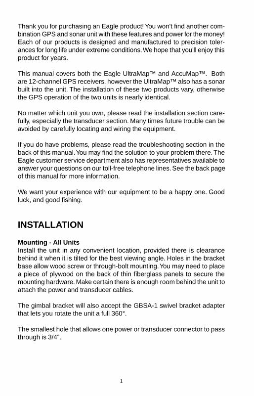
Mounting - All UnitsInstall the unit in any convenient location, provided there is clearancebehind it when it is tilted for the best viewing angle. Holes in the bracketbase allow wood screw or through-bolt mounting. You may need to placea piece of plywood on the back of thin fiberglass panels to secure themounting hardware. Make certain there is enough room behind the unit toattach the power and transducer cables.
The gimbal bracket will also accept the GBSA-1 swivel bracket adapterthat lets you rotate the unit a full 360°.
The smallest hole that allows one power or transducer connector to passthrough is 3/4".
2
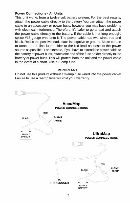
Power Connections - All UnitsThis unit works from a twelve-volt battery system. For the best results,attach the power cable directly to the battery. You can attach the powercable to an accessory or power buss, however you may have problemswith electrical interference. Therefore, it’s safer to go ahead and attachthe power cable directly to the battery. If the cable is not long enough,splice #18 gauge wire onto it. The power cable has two wires, red andblack. Red is the positive lead, black is negative or ground. Make certainto attach the in-line fuse holder to the red lead as close to the powersource as possible. For example, if you have to extend the power cable tothe battery or power buss, attach one end of the fuse holder directly to thebattery or power buss. This will protect both the unit and the power cablein the event of a short. Use a 3-amp fuse.
IMPORTANT!Do not use this product without a 3-amp fuse wired into the power cable!Failure to use a 3-amp fuse will void your warranty.
3-AMPFUSE
12-VOLTBATTERY
3-AMPFUSE
12-VOLTBATTERY
TOTRANSDUCER
RED
BLACK
RED
BLACK
UltraMapPOWER CONNCECTIONS
AccuMapPOWER CONNCECTIONS

3
If possible, route the unit’s power cable and transducer cable away fromother wiring. VHF radio antenna cables radiate noise when transmitting,so be certain to keep the sonar’s wires away from it. You may need toroute the sonar unit’s power cable directly to the battery to isolate it fromother wiring on the boat.
CABLE CONNECTIONS - AccuMap Only
RED(+12VDC)
BLACK(GROUND)
GREEN(NMEA
RECEIVE)
ANTENNA
WHITE(NMEA
TRANSMIT)
EAGLE

4
CABLE CONNECTIONS - ULTRAMAP Only
RED
BLACK
GREEN(NMEA
RECEIVE)
ANTENNATO
TRANSDUCER
TOSPEED/TEMP
SENSOR(OPTIONAL)
WHITE(NMEA
TRANSMIT)
EAGLE
BLACK(GROUND)
TO+12 VDC
See Note 1
Notes1. If the NMEA wires are not used, then the NMEA adapter cable is not required. Thespeed/temperature sensor's cable can be attached directly to the UltraMap.
NMEAADAPTER
CABLE
POWER/TRANSDUCER
CABLE
5
GPS Antenna Installation - All UnitsThe antenna can be mounted on any flat surface, provided you have ac-cess behind the surface for the mounting screws. A magnet is also sup-plied that can be epoxied to the bottom of the antenna. A pole mountadapter lets you mount the antenna on a pole or swivel mount that usesstandard 1" - 14 threads. The antenna has 25 feet of cable. Do not cut orsplice this cable.
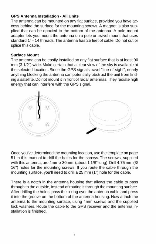
Surface MountThe antenna can be easily installed on any flat surface that is at least 90mm (3 1/2") wide. Make certain that a clear view of the sky is available atthe selected location. Since the GPS signals travel “line-of-sight”, nearlyanything blocking the antenna can potentially obstruct the unit from find-ing a satellite. Do not mount it in front of radar antennas. They radiate highenergy that can interfere with the GPS signal.
Once you’ve determined the mounting location, use the template on page51 in this manual to drill the holes for the screws. The screws, suppliedwith this antenna, are 4mm x 30mm. (about 1 1/8" long). Drill 4.75 mm (3/16") holes for the mounting screws. If you route the cable through themounting surface, you’ll need to drill a 25 mm (1") hole for the cable.
There is a notch in the antenna housing that allows the cable to passthrough to the outside, instead of routing it through the mounting surface.After drilling the holes, pass the o-ring over the antenna cable and pressit into the groove on the bottom of the antenna housing. Now attach theantenna to the mounting surface, using 4mm screws and the suppliedlock washers. Route the cable to the GPS receiver and the antenna in-stallation is finished.

6
Magnet MountA magnet lets you temporarily mount the an-tenna on any ferrous metal surface. (such as acar) To use the magnet, simply epoxy it to thebottom of the antenna, using the epoxy sup-plied with your antenna. Carefully follow the in-structions on the epoxy package and apply itto the magnet. Then carefully press the mag-net to the bottom of the antenna housing. Afterthe epoxy cures (in about 30 minutes), the an-tenna is ready for use.
Pole MountThe antenna attaches to the pole mount adapterwith the supplied 4 mm screws. You can routethe antenna cable through the slot in the side ofthe antenna, or pass it down through the polemount adapter. A slot next to the threads in thepole mount adapter places the cable next to thepole where it can be easily routed down the poleto the GPS receiver. The threads on the polemount adapter accept a standard marine antennamount.
MAGNET
SPEED/TEMPERATURE SENSOR (UltraMap Only)If you’re installing a temperature or speed/temperature sensor, read thesensor’s mounting instructions before making the installation. Route thesensor’s cable directly to the UltraMap and plug it into the connector onthe NMEA/DGPS cable.
TRANSDUCER INSTALLATION (UltraMap Only)The HS-WSBK supplied with this unit is a transom mount transducer. Itcan be installed on any outboard or stern-drive (inboard\outboard) pow-ered boat. It can also be permanently installed inside the boat to “shoot-through” the hull on some fiberglass boats.
The “kick-up” mounting bracket helps prevent damage if the transducerstrikes an object while the boat is moving. If the transducer does “kick-up”, the bracket can easily be pushed back in place without tools.
POLE MOUNT

7
Read this section carefully before attempting the installation. Determinewhich of the mounting positions is right for your boat. Remember, thetransducer location is the most critical part of a sonar installation.
Location - General1. The transducer must be placed in a location that has a smooth flow of
water at all times. If the transducer is not placed in a smooth flow ofwater, interference will show on the sonar’s display in the form of ran-dom lines or dots whenever the boat is moving.
2. The transducer should be installed with it’s face pointing straight down,if possible.
3. Make certain the transducer’s location doesn’t interfere with the traileror hauling of the boat. Also, don’t mount it closer than approximatelyone foot from the engine’s lower unit. This will prevent cavitation inter-ference with the propeller. Typically, the transducer should be mountedas deep in the water as possible. This increases the chance that it willbe in the water in high speed and reduces the possiblity of air bubbleinterference.
POOR ANGLEPOOR ANGLEPOOR ANGLEPOOR ANGLEPOOR ANGLEGOOD LOCATIONGOOD LOCATIONGOOD LOCATIONGOOD LOCATIONGOOD LOCATION
POOR LOCATIONPOOR LOCATIONPOOR LOCATIONPOOR LOCATIONPOOR LOCATION
4. If possible, route the transducer cable away from other wiring on theboat. Electrical interference from VHF radio, engine wiring, bilge pumps,and areators can be displayed on the sonar’s screen. Use caution whenrouting the transducer cable around these wires.
CAUTION!CAUTION!CAUTION!CAUTION!CAUTION!CLAMP THE TRANSDUCER CABLE TOCLAMP THE TRANSDUCER CABLE TOCLAMP THE TRANSDUCER CABLE TOCLAMP THE TRANSDUCER CABLE TOCLAMP THE TRANSDUCER CABLE TO
TRANSOM NEAR THE TRANSDUCER. THISTRANSOM NEAR THE TRANSDUCER. THISTRANSOM NEAR THE TRANSDUCER. THISTRANSOM NEAR THE TRANSDUCER. THISTRANSOM NEAR THE TRANSDUCER. THISWILL HELP PREVENT THE TRANSDUCERWILL HELP PREVENT THE TRANSDUCERWILL HELP PREVENT THE TRANSDUCERWILL HELP PREVENT THE TRANSDUCERWILL HELP PREVENT THE TRANSDUCER
FROM ENTERING THE BOAT IF IT ISFROM ENTERING THE BOAT IF IT ISFROM ENTERING THE BOAT IF IT ISFROM ENTERING THE BOAT IF IT ISFROM ENTERING THE BOAT IF IT ISKNOCKED OFF AT HIGH SPEED.KNOCKED OFF AT HIGH SPEED.KNOCKED OFF AT HIGH SPEED.KNOCKED OFF AT HIGH SPEED.KNOCKED OFF AT HIGH SPEED.
GOOD LOCATIONGOOD LOCATIONGOOD LOCATIONGOOD LOCATIONGOOD LOCATION

8
Transducer Assembly and MountingThe best way to install this transducer is to loosely assemble all of theparts first, then place the transducer’s bracket against the transom andsee if you can move the transducer so that it’s parallel with the ground.
1. Press the two small plastic ratchets into the sides of the metal bracketas shown below. Notice there are letters molded into each ratchet. Placeeach ratchet into the bracket with the letter “A” aligned with the dotstamped into the metal bracket. This position sets the transducer’scoarse angle adjustment for a fourteen (14) degree transom. Most out-board and stern-drive transoms have a fourteen degree angle.
DOT
2. Slide the transducer between the two ratchets. Temporally slide the boltthough the transducer assembly and hold it against the transom. Look-ing at the transducer from the side, check to see if it will adjust so thatits face is parallel to the ground. If it does, then the “A” position is cor-rect for your hull. If the transducer’s face isn’t parallel with the ground,remove the transducer and ratchets from the bracket. Place the ratch-ets into the holes in the bracket with the letter “B” aligned with the dotstamped in the bracket. Reassemble the transducer and bracket andplace them against the transom. Again, check to see if you can movethe transducer so it’s parallel with the ground. If it does, then go to step3. If it doesn’t, repeat step 2, but use a different letter until you canplace the transducer on the transom correctly.
RATCHETS

9
3. Once you determine the correct position for the ratchets, assemble thetransducer as shown below. Don’t tighten the lock nut at this time.
4. Hold the transducer and bracket assembly against the transom. Thetransducer should be roughly parallel to the ground. The bottom of thetransducer bracket should be in line with the bottom of the hull. Don’t letthe bracket extend below the hull! Mark the center of the slots for themounting holes. Drill two 5/32" holes in the marked locations for the#10 screws supplied with the transducer.
NUTMETAL
WASHER
RUBBERWASHERS
METALWASHER
BOLT
TRANSOM
SIDE VIEW
5. Attach the transducer to the transom. Slide the transducer up or downuntil it’s aligned properly on the transom as shown above. Tighten thebracket’s mounting screws. Adjust the transducer so that it’s parallel tothe ground and tighten the lock nut until it touches the flat washer, thenadd 1/4 turn. Don’t over tighten the lock nut! If you do, the transducerwon’t “kick-up” if it strikes an object in the water.

10
6. Route the transducer cable to the sonar unit. If possible, route the trans-ducer cable away from other wiring on the boat. Electrical noise fromthe engine’s wiring, bilge pumps, VHF radio wires and cables, and aera-tors can be picked up by the sonar. Use caution when routing the trans-ducer cable around these wires.
IMPORTANT!Clamp the transducer cable to the transom close to the transducer. Thiscan prevent the transducer from entering the boat if it is knocked off athigh speed.
7. Make a test run to determine the results. If the bottom is lost at highspeed, or if noise appears on the display, try sliding the transducerbracket down. This puts the transducer deeper into the water, hopefullybelow the turbulence causing the noise. Don’t allow the transducerbracket to go below the bottom of the hull!
Periodically wash the transducer’s face with soap and water to removeany oil film that may collect. Oil and dirt on the face will reduce the sensi-tivity or may even prevent operation.
INTRODUCTION TO GPSThe Global Positioning System (GPS) was developed by the United StatesDepartment of Defense as a 24-hour a day, 365 days a year global navi-gation system for the military. Civilian availability was added (but with lessaccuracy) using the same satellites. Twenty-four satellites orbit the Earth.Three of these satellites are spares, unused until needed. The rest virtu-ally guarantee that at least four satellites are in view nearly anywhere onEarth at all times.
The system requires three satellites in order to determine a position. Thisis called a 2D fix. It takes four satellites to determine both position andelevation, (your height above sea level - also called altitude.) called a 3Dfix.
Remember, the unit must have a clear view of the satellites in order toreceive their signals. Unlike radio or television, GPS works at very highfrequencies. The signals can be blocked easily by trees, buildings, evenyour body.
Never use this GPS receiver while operating a vehicle!
Like most GPS receivers, this unit doesn’t have a compass or any othernavigation aid built inside. It relies solely on the signals from the satellites

11
to calculate a position. Speed, direction of travel, and distance are allcalculated from position information. Therefore, in order for it to determinedirection of travel, you must be moving and the faster, the better. This isnot to say that it won’t work at trolling speeds - it will. There will simply bemore “wandering” of the data shown on the display.
Another factor that greatly influences the receiver’s ability to determineposition is SA. The United States government intentionally degrades thesatellite’s signal for civilian users. They introduce small errors into thesignals that makes the GPS receiver less accurate. These errors are calledselective availability, or SA. How bad is it? They guarantee that the posi-tion reported by a GPS receiver that meets their specifications is within100 meters horizontally and 150 meters vertically 95% of the time. (Theposition can be worse than that the other 5% of the time.) In other words,the position shown on your receiver is within 100 meters of your actualposition, 95% of the time. That’s over 300 feet! Not exactly pinpoint accu-racy, but then few people need positioning accuracy greater than this.However, if you do want better performance, (and who doesn’t?) manymanufacturers (including Eagle) sell a DGPS receiver that attaches toyour GPS receiver. The DGPS system transmits correction signals thatnullify the effects of SA. The DGPS receiver takes signals from theseland-based transmitters and gives them to the GPS receiver which thenuses them to show a more accurate position. The ironic part is the federalgovernment implemented SA and is also operating many DGPS transmit-ters. (You can use the signals from all of the Coast Guard DGPS stationsfor free, by the way.) The downside to this is it requires another piece ofelectronic gear (the DGPS receiver) . And you have to be close enough toa station to receive the DGPS signals.
Generally, you find that using your GPS receiver without DGPS is botheasy and amazingly accurate. It’s easily the most accurate method ofelectronic navigation available to the general public today. Remember,however, that this receiver is only a tool. Always have another method ofnavigation available, such as a chart or map and a compass.
Also remember that this unit will always show navigation information inthe shortest line from your present position to a waypoint, regardless ofterrain! It only calculates position, it can’t know what’s between you andyour camp, for example. It’s up to you to safely navigate around obstacles,no matter how you’re using this product.

12
GPS OPERATIONThere are 12 keys on the keyboard. You can navigate through the menus,adjust the chart’s cursor, and enter data using the arrow keys. The fivemajor modes of operation are accessed using the PAGES key. Press theMENU key to select or adjust a feature from a list. The Z-IN and Z-OUTkeys zoom-in or zoom-out the view on the plotter screen. The ENT andEXIT keys are used to enter or clear data or screens. Save and editwaypoints using the WPT key. The PWR key turns the unit on and off.Pressing it once while the unit is operating turns on the screen’s back-light. To prevent an accidental shutdown, you must hold the PWR keydown for a few seconds to turn the unit off.
PWRENT
MENU EXIT
PAGES WPT
ZOUT ZIN
Most of the unit’s features are found on “menus’. You can view the menusby pressing the MENU key. This product has “Intelligent Menus”. Thereare many menus that pertain to only the sonar, for example. When youpress the MENU key and the sonar is showing, menu items for the sonarshow in addition to the normal menus. For example, if the sonar is show-ing, and you press the MENU key, GPS map items won’t show on the list.This helps you find the needed item without scrolling through unneces-sary menus.

13
To turn the unit on, simply press the PWR key. AGPS logo screen appears, then the screen simi-lar to the one at right appears. Read the mes-sage on the screen, then press the EXIT key toerase it or wait a few seconds and it automati-cally clears. The screen shown below appearsnext.
This screen appears each time you turn the uniton. It shows a graphical view of the satellites thatare in view. Each satellite is shown on the circu-lar chart relative to your position. The point in thecenter of the chart is directly overhead. The smallinner ring represents 45° above the horizon andthe large ring represents the horizon. North is atthe top of the screen. You can use this to seewhich satellites are obstructed by obstacles inyour immediate area if you hold the unit facingnorth.
The GPS receiver is tracking satellites that are surrounded by a blackbox. The receiver hasn't locked onto a satellite if it's number isn't sur-rounded by a box, therefore it isn’t being used to solve the position.
Beneath the circular graph are the bar graphs, one for each satellite inview. Since the unit has twelve channels, it can dedicate one channel pervisible satellite. Therefore, if only six satellites are visible, only six barcharts show at the bottom of the screen. The wider the bar on the graph,the better the unit is receiving the signals from the satellite.
The number in the upper left corner is the “expected horizontal positionerror” or expected error from a benchmark location. In other words, if theexpected error shows 50 feet, then the position shown by the unit is esti-mated to be within 50 feet of the actual location. However, this number isonly valid if you’re using DGPS or if S/A is turned off. Due to S/A, theaccuracy can only be less than 100 meters, 95% of the time, per U.S.government specifications. Although the expected error is not accurateunless you have a DGPS receiver, it does give you an indicator of the fixquality the unit currently has. The smaller the expected error number, thebetter (and more accurate) the fix is. If the expected error flashes, thenthe unit hasn't locked onto the satellites, and the number shown isn't valid.
A light bulb indicator at the top right corner of the screen appears whenthe backlights are on.

14
FINDING YOUR POSITIONAuto SearchTo lock onto the satellites, the GPS receiver needs to know it’s currentposition, UTC time, and date. (Elevation (altitude) is also used in the equa-tion, but it’s rarely required to determine a position.) It needs this data sothat it can calculate which satellites should be in view. It then searches foronly those satellites. When your GPS receiver is turned on for the firsttime, it doesn’t know what your position or elevation (altitude) is. It doesknow the current UTC time and date since these were programmed into itat the factory and an internal clock keeps the time while the unit is turnedoff. It begins searching for the satellites using the above data that it ac-quired the last time it was turned on. This probably was at the factory.Since it’s almost certain that you’re not at our factory, it’s probably lookingfor the wrong satellites. If it doesn’t find the satellites it’s looking for afterfive minutes, it switches to Auto Search. The receiver looks for any satel-lite in the sky. Due to advanced technology, the auto search time hasshrunk to about five minutes, so the longest time you should ever have towait is ten minutes from the time you turn the unit on until it locks onto thesatellites and shows a position. Once the unit locks onto the satellites, itshould take less than a minute to find your position the next time it’s turnedon, provided you haven’t moved more than approximately 100 miles fromthe last location it was used.
Manual InitializationIf you don’t want to wait for the Auto Search, then you may be able tospeed up the initialization process by using the manual initialization fea-ture. Using this feature tells the unit it’s approximate position. Once it knowsit’s location, it determines exactly which satellites should be in view andstarts looking only for those satellites.
To manually initialize the unit, press the MENUkey. Now press the down arrow key until the “GPSSETUP” label is highlighted. Press the right ar-row key. The “INITIALIZE GPS” label is high-lighted. Press the right arrow key again. A screensimilar to the one at right appears. Use the arrowkeys to move the crosshairs to your approximatelocation on the map. You can use the ZIN andZOUT keys to enlarge the map which makes iteasier and faster to find your location. The box at the top of the screenshows the latitude and longitude of the cursor position, along with thedistance and bearing from the last known position. Once you have thecrosshairs on your location, press the ENT key. The unit returns to thesatellite status screen.

15
Using the manual initialization method loads a position that’s close toyours into the GPS receiver. It should now have position, time, and date,thereby giving it the data it needs to determine which satellites are inview. Once the satellites are known, the receiver searches for only thosesatellites, making a lock faster than an auto search method.
All position and navigation data flashes until the unit acquires a position.Do not rely on any data that is flashing! When the numbers are flashing,they represent the last known values when the unit lost it’s lock on thesatellites.
Position AquisitionWhen the receiver locks onto the satellites and calculates a position, itshows the message “Position Acquired” on the screen. Once the unit hasacquired the satellites and the position acquired message appears, it’sready for use.
(Note: The altitude data may still flash even if the unit shows a “PositionAcquired” message and all other data is not flashing. The unit must belocked onto at least four satellites to determine altitude. It only takes threesatellites to determine position. You can navigate with this unit if the alti-tude is flashing, simply ignore the altitude display until it quits flashing.)
REMEMBER, DO NOT NAVIGATE WITH THIS UNIT UNTIL THE NUM-BERS STOP FLASHING!
MODESThe UltraMap has five modes: status, navigation, sonar, map, and win-dow groups. The AccuMap has four - no sonar mode. Use the PAGES andarrow keys to switch between the different screens. The four GPS screensthat show by default are shown at the top of the next page. (UltraMapowners, see the sonar section in this manual for sonar operation.)
To change modes, simply press the PAGES key.A screen similar to the one at right appears. Usethe up or down arrow keys to change modes. (Thewindows mode is shown as “groups”. Group “A”is the first windows group.)
Press the right arrow key while the above menuis showing to switch between different versionsof each mode. When the desired screen appears,press the EXIT key to erase the menu.

16
STATUS NAVIGATION SONAR(UltraMap Only)
MAPPING WINDOW GROUPS
NavigationThere are two different navigation screens. Nav screen number one showsa graphical view of your trip, Nav screen number 2 shows all navigationdetails in large digital numbers. You can also customize both navigationscreens to show data other than the default. See the “Programming Boxes”section for more information.
Nav-1This screen has a compass rose that shows notonly your direction of travel, but also the direc-tion to a recalled waypoint. The navigation screenlooks like the one at right when you’re not navi-gating to a waypoint. Your position is shown byan arrow in the center of the screen. Your trailhistory, or path you’ve taken is depicted by theline extending from the arrow. The arrow pointingdown at the top of the compass rose indicatesthe current track (direction of travel) you are taking. This is also shown inthe “TRK” (track) box in the upper right corner of the screen. On the ex-ample shown at right, the track is 240°. The current ground speed (GS)shows in the box in the lower center of this screen.
When navigating to a waypoint, Nav screen number one looks like theone at the top of the next page. Bearing to the destination waypoint is inthe box in the upper left corner. Bearing is also shown by the large arrow

17
pointing up towards the compass, above thepresent position arrow. Distance from the presentposition to the waypoint (DIS) shows beneath thecompass on the lower left side of the screen. Nextto the distance box is estimated time enroute(ETE). This is the estimated time that it will takeyou to arrive at the destination, based upon cur-rent track and ground speed. In the lower rightcorner is the course (CRS) box showing the di-rection from your starting position to the waypoint. Remember, a courseis a proposed path from the starting position to the destination. Track isyour actual direction of travel.
Lines on either side of the present position show the current cross trackerror range. Cross track error is the distance you are off-course to theside of the desired course line. The course line is an imaginary line drawnfrom your position when you started navigating to the destination way-point. It’s shown on the screen as a vertical dotted line. The default for thecross track error range is 0.20 mile. For example,if the present position symbol touches the rightcross track error line, then you are .25 mile to theright of the desired course. You need to steer leftto return to the desired course. You can use theZIN or ZOUT keys to change the cross track er-ror range. A circle depicting your destination (way-point) appears on the screen as you approachthe waypoint as shown on the screen at right.
Nav-2This navigation screen shows all navigation in-formation in large digital numbers. To view thisscreen, press the PAGES key, then press the uparrow key until the “NAV 1” label is highlighted.While it’s highlighted, press the right arrow key.The screen shown at right appears. Press theEXIT key to erase the menu.
This screen is composed of eight digital boxes.Track (TRK) and ground speed (GS) data are the only ones that showdata if you’re not navigating to a waypoint. If you are navigating to a way-point, then bearing (BRG), distance to waypoint (DIS), estimated time enroute (ETE), cross track error (XTK), estimated time of arrival (ETA), andthe CDI also operate.

18
Course Deviation Indicator (CDI)Once navigation to a waypoint is established, the CDI shows your dis-tance to the left or right of the desired course. The vertical line in the boxshows both the direction you must steer toget back on course and the distance to thecourse line. For example, if you’re travel-ling straight towards the destination, fromthe start, then the line stays in the center.If you drift off course to the right, the linemoves to the left. This signifies that youneed to steer to the left to get back on course. This is called “chasing theneedle”. If you steer towards the line (needle), you’ll always be heading inthe correct direction to get back on course.
The CDI’s range shows beneath the CDI label. On the above screen, theCDI range is .20 mile, which is the default. You can adjust the range byselecting “ALARMS” on the main menu, then “GPS ALARMS”. Highlightthe “CDI DIS” label, then use the left or right arrow key to adjust it. TheCDI range is also shown by the dotted lines at the far left and right side ofthe CDI indicator. If the solid line is on either of the dotted lines, then youare 0.20 mile off course. Remember, if the line moves to the left, then youare too far to the right of the desired course line and vice-versa.
Using the CDI with a mapping screen helps you visualize your position inrelation to the course. The screen on the right shows that we are off courseto the right. The vertical bar has moved to the left side of the CDI, showingthe direction to the desired course line. The CDI gives you a quick, easy toread visual indicator of your relationship between your direction of traveland the desired direction.
MapThis unit has a ground map of the world built inside. This map has themajority of its detail in far southern Canada, the continental United Statesand Hawaiian islands, northern Mexico, the Bahamas, and Bermuda. Themap screens show your course and track from a “birds-eye” view. If you’renavigating to a waypoint, the map shows yourstarting location, present position, course line,and destination. You don’t have to navigate to awaypoint, however, to use the map.
Using the map is as simple as pressing thePAGES key, then highlighting “MAP 1”. A screensimilar to the one at right appears. The arrowflashing in the center of the screen is your present

19
position. It points in the direction you’re travelling. The solid line extendingfrom the arrow is your plot trail, or path you’ve taken. The plotter’s rangeshows in the lower left corner of the screen. In this example, the plotter’srange is four miles from the left edge of the map to the right.
MAP-1 MAP-2 MAP-3
There are three different mapping screens. To view the other map screens,press the PAGES key, highlight the MAP label, and press the right arrowkey until the desired map screen appears. Press the EXIT key to erasethe menu. Map-2 has navigation data added at the right side. The dataincludes bearing to waypoint (BRG), track (TRK), distance to waypoint(DIS), ground speed (GS), a steering arrow (shows the direction to thedestination when the top of the screen is pointing in your direction oftravel), and a CDI.
Map-3 is similar to Map-2, except it shows sonardata on the right side. When the MENU key ispressed while Map-3 is showing, the screenshown at right appears. The "ACTIVE MODE"menu at the top of this screen lets you switch thearrow and zoom keys between the GPS side andthe sonar side of Map-3.
The Z-IN and Z-OUT keys zoom-in and out allmaps to enlarge or reduce their coverage area. The available ranges are:0.1, 0.15, 0.2, 0.3, 0.4, 0.6, 0.8, 1, 1.5, 2, 3, 4, 5, 6, 8, 10, 15, 20, 30, 40,60, 80, 100, 150, 200, 300, 400, 600, 800, 1000, 1500, 2000, 3000, and4000 miles.
CursorPressing an arrow key turns on two dotted lines that intersect at the presentposition symbol. These lines are called a “cursor” and have a variety ofuses.
To turn the cursor on, simply press the arrow key in the direction you wantthe cursor to move. This lets you view areas on the plotter that are away

20
from your present position. The zoom-in andzoom-out keys work from the cursor’s positionwhen it’s active - not the present position. Youcan zoom in on any detail, anywhere. The cursorcan also place icons and waypoints.
When the cursor is used with map-1, it’s posi-tion, bearing, and distance from your presentposition show at the top of the screen.
Cursor DistanceYou can use the cursor to find the distance be-tween two points. While the cursor is showing,press the MENU key, then select "FIND DIS-TANCE". The unit returns to the mapping screen.Now move the cursor to the first location that youwant to measure the distance from and press theENT key. Now move the cursor to the positionthat you want to measure the distance to. A lineis drawn from the point when the ENT key waspressed to the cursor's present location. The distance covered by the lineshows at the top of the screen. To measure another two points, simplymove the cursor and press the ENT key.
Press the EXIT key to erase the cursor. The unit centers your presentposition on the screen after erasing the cursor.
MAP SETUPThe map has many customization options. Tochange them, first press the MENU key while amap is showing on the screen. The map setuplabel is highlighted. Press the right arrow key. Ascreen similar to the one at right appears.
Change MapsChanges made to the map using the options inthe Map Setup is normally made to all mapscreens. The change can be limited to the map screen currently in use,however, by switching the “All Maps” to “This Map” in the “Change” menu.To do this, simply highlight the “Change” label, then press the right arrowkey. To switch back, repeat the above.

21
Map OptionsThe following map options are listed under the “Map Options” menu: MapOrientation, Auto Zoom, Range Rings, and Latitude/Longitude Grids.
Map OrientationBy default, this receiver shows the map with north always at the top of thescreen. This is the way most maps and charts are printed on paper. Thisis fine if you’re always travelling due north. What you see to your left cor-responds to the left side of the map, to your right is shown on the rightside of the map, and so on. However, if you travel any other direction, themap doesn’t line up with your view of the world.
To correct this problem, a track-up mode rotates the map as you turn.Thus, what you see on the left side of the screen should always be to yourleft, and so on. A course-up mode keeps the map at the same orientationas the initial bearing to the waypoint.
NORTH-UP TRACK-UP COURSE-UP
In the north-up view shown at left, we’re travelling east. In this view, thepresent position indicator appears to move towards the right side of thescreen.
In the track-up view, the present position moves straight towards the topof the display. A “N” shows to help you see which direction is north whenthe track-up mode is on. Remember, in the track-up mode, the screenrotates as you change direction. It always keeps your direction of travel(track) heading towards the top of the screen.
In the course-up mode, the screen is locked into your original bearing tothe recalled waypoint, regardless of your track.
To select the desired mode, first press the MENU key, select “MAP 1SETUP”, then select “MAP OPTIONS”. Finally, select “ORIENTATION”and press the right or left arrow key until the desired mode appears. Pressthe EXIT key to erase this menu.

22
Range Rings/Grid LinesThe map screen can be customized with ringsthat are 1/4 of the range and/or grids that dividethe plotter into equal segments of latitude andlongitude. To do this, press the MENU key, select“Map 1 Setup”, then “Map Options”. Highlight thedesired option, then press the right arrow key toturn it on. Press the EXIT key repeatedly to erasethe menus. The screen at right shows grids.
AUTOZOOMThis receiver has an autozoom feature that eliminates much of the buttonpushing that competitive units force you to make. It works in conjunctionwith the navigation features. First, recall a waypoint. (See the waypointsection for more information on navigating to a waypoint.) Then, with theautozoom mode on, the unit zooms out until the entire course shows,from the present position to the destination waypoint (recalled waypoint).As you travel towards the destination, the unit automatically begins zoom-ing in, one zoom range at a time, keeping the destination on the screen.
The screens below show a slice of the progression of a trip near a lake.Screen number one is the start and is on the 3 mile range. Intermediatestages progressively zoom in as it gets closer to the destination.
1 2 3
4 5

23
MAP DETAILSThis unit lets you change many of the built-inbackground map’s features. To change the op-tions, first press the MENU key, then select theMap Details label. Press the right arrow key. Thescreen shown at right appears.
Earth Map On/OffThe map can be turned on or off using the “AllMap Details” label. Simply highlight the menu, then press the left arrowkey to turn it off.
EARTH MAP ON EARTH MAP OFF
Text LabelsSelect “Map Text” to turn all names on the map (such as Lake Tahoe orMississippi River) off or on. The default is “on”. Press the left arrow key toturn them off.
Map DetailThe detail shown on the background map diminishes as the screen iszoomed out. This prevents cluttering of the display, or overlapping of textand graphics which can make it unreadable. There are two detail levels:normal and high. The difference between the two shows below. The screenon the left is normal detail, on the right is high detail. Both screens are onthe 10 mile range.
NORMAL DETAIL HIGH DETAIL
To change the map’s detail setting, select “Map Detail Level” from themap details menu, then press the right arrow key.

24
Gray FillWhen this unit is first turned on, all water (lakes, oceans, rivers) is filledwith gray to distinguish it from land, which is clear. (See below) To makethe land fill with gray and water remain clear, select the “Fill with Gray”label from the Map Detail menu, then press the left arrow key. Press theEXIT key repeatedly to return to the mapping screen.
WATER FILLEDWITH GRAY
LAND FILLEDWITH GRAY
Map BoundariesBy default, this unit draws a line around areas of the map that have moredetail than the background map. This line depicts the detailled map bound-aries. To turn this off, select “Map Bounds” from the map details menu,then press the left arrow key.
Map SymbolsWhen the nav aid data is downloaded to this unit, buoys and other naviga-tional aids can be turned off or on by using “Map Symbols” on the “MapDetails” menu. To find this menu, press the down arrow key while on the“Map Details” menu until “Map Symbols” appears. Press the left arrow keyto turn them off.
LIGHTED BUOY
UNLIGHTED BUOY
LIGHT
SQUARE DAYBEACON
TRIANGLE DAYBEACON
RADIO BEACON
PLATFORM
INTERSTATE HIGHWAY
U.S. ROUTE HIGHWAYU.S. ALTERNATE ROUTE HWY.
STATE HIGHWAY
COUNTY ROUTE
TRANS-CANADA HIGHWAY
CANADIAN (QUEBEC)AUTOROUTE
MEXICAN FEDERAL HWY.

25
LocationsNormally, text disappears as you zoom out. This declutters the screen,making it easier to see significant map detail. Turning “LOCATION DOTS”on from the Map Details menu places a dot on the screen where a textlabel should be when the screen is zoomed out.
Contour LinesSome nav aid data shows depth contour lines in navigable waters. To turnthese lines off, select “Contour Lines” from the “Map Detail” menu. Pressthe left arrow key to turn them off. Press the EXIT key to erase the menu.
PLOT TRAILThe line extending from the present position sym-bol is called a plot trail. You can customize theplot trail and save trails using the trail optionsmenu. To use it, press the MENU key, select “MAPSETUP”, then “TRAIL OPTIONS”. The screen atright appears.
Clear TrailTo erase the current plot trail from the screen,select Clear Trail from the Trail Options menu. A message appears, ask-ing if you really want to erase the plot trail. Follow the instructions on thescreen. When the trail is erased, the unit returns to the map screen.
Flash TrailBy default, the plot trail flashes once per second. This typically makes iteasier to see the plot trail against the background map. To turn the flash-ing off, select “FLASH TRAIL” from the trail options menu. Press the leftarrow key to turn it off.
Trails ShownThe current plot trail shows on the map by de-fault. To place a previously saved trail onto theplotter, choose “TRAILS SHOWN” from the TrailOptions menu. The screen shown at right ap-pears. Highlight the desired trail on this screen,then press the right arrow key to select it. Pressthe EXIT key to erase this menu. The selectedplot trail shows on the plotter.
Save a TrailThis unit automatically saves the current plot trail in memory when youturn it off. You can save two other trails in memory. To save your current
26
plot trail in a specific memory location, choose “SAVE TRAIL” from the“TRAIL OPTIONS” menu. A new screen appears. Highlight the desirednumber that you wish to save the current trail under, (i.e. “Trail 1 or Trail 2)and press the right arrow key. Your current trail is saved. Press the EXITkey to erase this menu.
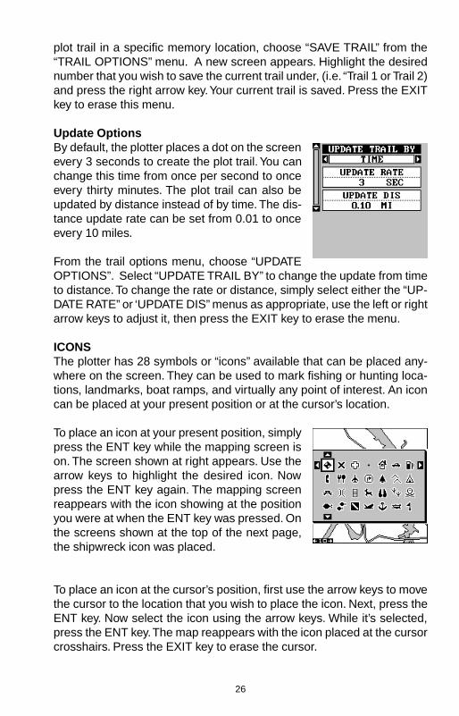
Update OptionsBy default, the plotter places a dot on the screenevery 3 seconds to create the plot trail. You canchange this time from once per second to onceevery thirty minutes. The plot trail can also beupdated by distance instead of by time. The dis-tance update rate can be set from 0.01 to onceevery 10 miles.
From the trail options menu, choose “UPDATEOPTIONS”. Select “UPDATE TRAIL BY” to change the update from timeto distance. To change the rate or distance, simply select either the “UP-DATE RATE” or ‘UPDATE DIS” menus as appropriate, use the left or rightarrow keys to adjust it, then press the EXIT key to erase the menu.
ICONSThe plotter has 28 symbols or “icons” available that can be placed any-where on the screen. They can be used to mark fishing or hunting loca-tions, landmarks, boat ramps, and virtually any point of interest. An iconcan be placed at your present position or at the cursor’s location.
To place an icon at your present position, simplypress the ENT key while the mapping screen ison. The screen shown at right appears. Use thearrow keys to highlight the desired icon. Nowpress the ENT key again. The mapping screenreappears with the icon showing at the positionyou were at when the ENT key was pressed. Onthe screens shown at the top of the next page,the shipwreck icon was placed.
To place an icon at the cursor’s position, first use the arrow keys to movethe cursor to the location that you wish to place the icon. Next, press theENT key. Now select the icon using the arrow keys. While it’s selected,press the ENT key. The map reappears with the icon placed at the cursorcrosshairs. Press the EXIT key to erase the cursor.

27
Icons can be erased from the plotter individually,all of a specific type, or all at once. They can alsosimply be turned off without erasing them. Tomake changes to the icons, press the MENU key,then select MAP SETUP, and finally select IconOptions. The screen shown at right appears.
The first menu (ICONS OFF/ON) simply turns allicon symbols off or on. This doesn’t erase theicons, it simply “hides” the icons from the map. You can use this feature totemporarily de-clutter the display.
The DELETE ALL ICONS selection does erase all of the icons frommemory, Use this only if you want to erase all icons that have been placedon all map screens.
To erase only a certain type of icon, select the DELETE ICON TYPEmenu. The icon menu appears. Highlight the icon style that you want toerase from memory, then press the ENT key. The unit returns to the mapscreen with only the selected icons erased.
You can delete individual icons by selecting "DE-LETE FROM MAP". Once this menu is selected,the unit returns to the mapping screen with thecursor activated as shown at right. Use the ar-row keys to move the cursor to the icon that youwant to erase. Once the crosshairs are on top ofthe icon, press the ENT key. The icon is immedi-ately erased. Press the EXIT key to erase thecursor.
MAP SCREENPRESS ENT KEY
SELECT ICONPRESS ENT KEY
ICON PLACED ATPOSITION

28
MAP DOWNLOADINGThis unit has a background map of the world permanently installed inside.You can send an enhanced map from the enclosed CD-ROM to the unitusing a personal computer.
Currently, the MapSelect CD has the following databases:
IMS SmartMap™ data covers the 48 contiguous states and are brokendown into 64 different mapping regions. Contained in this database arethe names and locations of over 140,000 cities; 30,000 national, stateand county parks; 120,000 inland bodies of water plus coastal waters outto 25 miles; as well as nearly all state and federal highways, interstatesand routes.
IMS WorldMap™ data covers 35 specific regions around the globe in-cluding Canada, Europe, Indonesia and Australia. Contained in this data-base are the names and locations of cities, towns, provinces and states,plus major roadways including two- and four-lane highways, inland water-ways and coastal hydrography.
Coastal nav aid data covers coastal regions of the 49 U.S. States (exclud-ing Hawaii), the District of Columbia, the Great Lakes and many largecoastal rivers and other large inland lakes. Contained are approximately60,000 marine navigation aids. Each navigation aid is displayed as a smallsymbol, with information useful to the navigator (including light type (flash-ing or continuous), light color, and other aid markings) below the symbol.
To use one of these, install the software from the CD-ROM onto your PCcompatible computer according to the insturctions supplied with the CD.Next, plug the AC adapter into a wall socket, and attach its cable to theunit. Connect the cable supplied with this unit from a serial port on thecomputer to the GPS receiver. Now turn the unit on and adjust the com-munication port baud rate to its highest level (Press MENU/SYSTEMSETUP/COM PORT SETUP). Set the parity to “none” and data bits to “8”.
Start the GDM 16 program on the computer. Click on the “GPS” label,then click on “Options”. Select the com port that the GPS cable is con-nected to and click “OK”. Now click on the “GPS” label, then “Initialize”.This starts the communication between the GPS unit and the computer. Ifthe communications fail, try switching the baud rate on the GPS unit to alower setting. Once the communications are established, click on the “MapSelect” tab. Choose a memory partition to download a map into, thenchoose a map. If you have problems, click on “Help”. There is extensivehelp available on the GDM-16 program.
29
TRANSFERRING MAP DATAUsing either GDM or MapCreate software, you may transfer maps of yourchoice to your GPS Unit. The following instructions are for the GDM soft-ware.
1. Click on the MapSelect Tab.2. Select a map by clicking on the desired database button (IMS Smart-
Map, IMS WorldMap, or Coastal Navaids). A map appears on the screen.Click the desired area that you want to download to the GPS unit.
3. Select a memory partition by clicking on Memory Partition 1 or 2.(Note: Any data already present in a selected memory partition will beoverwritten. When transferring map data larger than 1 megabyte, bothmemory partitions are automatically selected.)
4. Click the Transfer Map Data Button.
A status bar appears on both the PC and the GPS unit’s screen. Whenthe bar disappears, the transfer is complete. You’ll be able to see the dif-ference when the unit is zoomed in to ranges of ten miles or less.
WINDOWSThe UltraMap has 13 different data screens chosen for their broad rangeof navigation information and ease of use. The AccuMap has 10.
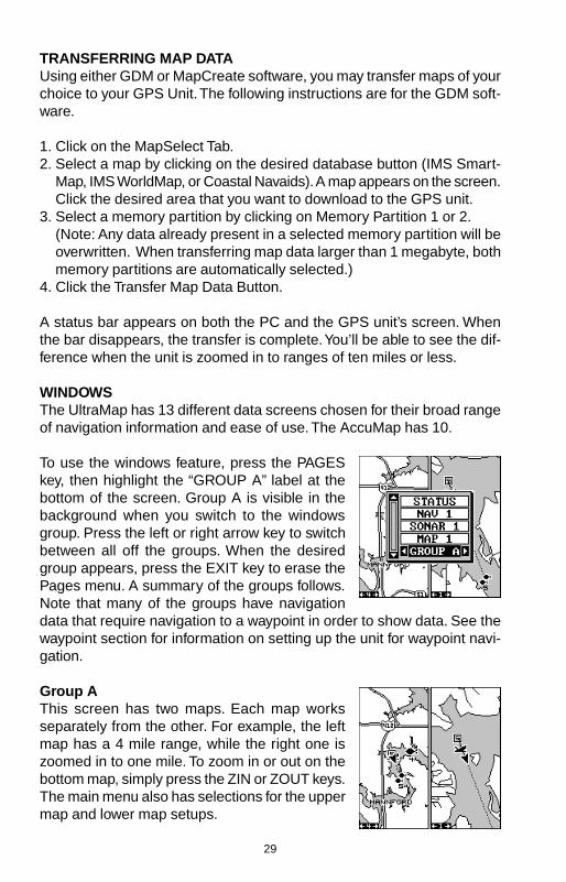
To use the windows feature, press the PAGESkey, then highlight the “GROUP A” label at thebottom of the screen. Group A is visible in thebackground when you switch to the windowsgroup. Press the left or right arrow key to switchbetween all off the groups. When the desiredgroup appears, press the EXIT key to erase thePages menu. A summary of the groups follows.Note that many of the groups have navigationdata that require navigation to a waypoint in order to show data. See thewaypoint section for information on setting up the unit for waypoint navi-gation.
Group AThis screen has two maps. Each map worksseparately from the other. For example, the leftmap has a 4 mile range, while the right one iszoomed in to one mile. To zoom in or out on thebottom map, simply press the ZIN or ZOUT keys.The main menu also has selections for the uppermap and lower map setups.

30
Group BThis screen has a map on the top half with bear-ing (BRG), distance to go (DIS), track (TRK) andthe CDI on the lower half.
Group CA half screen map is on the left side of the screen.A quarter-size map is in the upper right corner.in the middle of the screen. Track (TRK) and theCDI shows distance to go (DIS) show in the lowerright quarter.
Group DThis group has a half-screen map on the left sideof the screen. CDI, bearing (BRG), estimated timeen-route (ETE), and ground speed (GS) are onthe right side.
Group EDigital displays make up this group. It has bear-ing (BRG), distance to go (DIS), track (TRK),ground speed (GS), CDI, estimated time en-route(ETE), velocity made good (VMG), and altitude(ALT).

31
Group F - UltraMap OnlyThis group shows your present position (POSI-TION) in latitude/longitude at the top of thescreen, and in UTM at the bottom. You can changethe type of position display on both the top andbottom of this (and all) screens by pressing theMENU key, then selecting "GPS SETUP". Nowselect "POSITION FORMAT" to change the topposition display, or "ALTERNATE FORMAT" tochange the bottom display.
Group GThe group G screen shows DGPS information.There must be a DGPS receiver connected tothe unit in order to use this screen.
The DGPS status, station’s ID number, frequency,bit rate, signal strength, bit rate, signal to noiseratio (SNR), and time since the GPS receiver re-ceived the satellite corrections (AGE) all show inthe top half of this screen.
The DGPS corrections at the bottom of the screen shows a list of thesatellites in view. The satellite’s number is follow by an identifier showingits status. They are as follows:
OK DGPS corrections are in use by GPS receiver and correctionsare available.
OLD Unit hasn’t received corrections in last 60seconds.
NA No correction available.
Group HThis is a time screen. An analog clock shows in the top left corner, fol-lowed by a digital clock showing your local timeon the right. The clock’s alarm setting shows inthis window, also. UTC time shows at the bottomright corner of this screen. (UTC is the time atthe prime meridian. It used to be called GMT.)Battery voltage and estimated time of arrival(ETA) complete this group.
To set the clock alarm, first press the MENU key,

32
then select “CLOCK ALARM” and press the rightarrow key. Now select "SET CLOCK ALARM".The screen at right appears. Using the arrow keys,enter the alarm’s time. Press the ENT key. Theunit returns to the clock alarm menu. Highlightthe “CLOCK ALM OFF ON” label and press theright arrow key to turn it on. Press the EXIT keyto erase the menus. The unit returns to group Hwith the new alarm time in the clock’s window.
Group IThis group has a trip timer (TRP TIMER), esti-mated time enroute (ETE), a digital clock, andestimated time of arrival (ETA). The trip timermeasures the total time you have been travel-ling. It starts counting when you exceed a presetspeed. The default is 5 miles per hour. You canadjust this time from zero to 200 m.p.h.. To dothis, press the MENU key, then select “TRIPTIMER SETUP” menu. Highlight the “TRIPSTART GS” label, then press the left or right arrow keys until the desiredspeed appears. Press the EXIT key to erase this screen.
Group JThere are three timers on this screen and anodometer (TRIP DIS). The trip timer is describedin group I.
Trip distance measures the distance you’ve trav-elled since it was last reset. To reset the trip meter,press the MENU key, then select “TRIP METERRESET” and press the right arrow key. The unitreturns to Group J with the trip meter reset tozero.
The up timer starts at zero and counts up. The up timer also has an alarm.The down timer starts from a user setting and counts down to zero.
To start a timer, first press the MENU key, then highlight the desired timersetup menu. In this example, we’re using the count up timer, so the UPTIMER SETUP was selected. Now press the right arrow key. A screensimilar to the one at the top of the next page appears. To start the timer,simply highlight the “UP TIMER” menu, then press the right arrow key. To
33
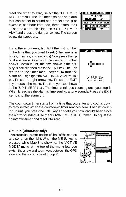
reset the timer to zero, select the “UP TIMERRESET” menu. The up timer also has an alarmthat can be set to sound at a preset time. (Forexample, one hour from now, three hours, etc.)To set the alarm, highlight the “SET UP TIMERALM” and press the right arrow key. The screenbelow right appears.
Using the arrow keys, highlight the first numberin the time that you want to set. (The time is inhours, minutes, and seconds) Now press the upor down arrow keys until the desired numbershows. Continue until the time shown in the dis-play is correct, then press the ENT key. The unitreturns to the timer menu screen. To turn thealarm on, highlight the “UP TIMER ALARM” la-bel. Press the right arrow key. Press the EXITkey to erase the menu. The time you set showsin the “UP TIMER” box . The timer continues counting until you stop it.When it reaches the alarm’s time setting, a tone sounds. Press the EXITkey to shut the alarm off.
The countdown timer starts from a time that you enter and counts downto zero. (Note: When the countdown timer reaches zero, it begins count-ing up until you press the EXIT key. This tells you how long it’s been sincethe alarm sounded.) Use the “DOWN TIMER SETUP” menu to adjust thecountdown timer and reset it to zero.
Group K (UltraMap Only)This group has a map on the left half of the screenand sonar on the right. When the MENU key ispressed while Map-3 is showing, the "ACTIVEMODE" menu at the top of the menu lets youswitch the arrow and zoom keys between the GPSside and the sonar side of group K.

34
Group L (UltraMap Only)This group has a digital depth display along withthe sonar alarms setting in the upper left cornerof the screen. (See the sonar section for moreinformation on the sonar alarms.) A quarter-sizesonar screen shows in the upper right corner.Surface water temperature shows in the lowerleft corner of the screen, both digital and a tem-perature graph. Water speed and a second tem-perature show in the bottom right corner of the screen. (Note: Speed andwater temperature on this screen comes from an optional speed/tem-perature sensor. The TEMP 2 display requires an optional TS-2BK tem-perature sensor.
Reprogram BoxesThe digital boxes on MAP 2 and both NAV screens can be reprogrammed,changing the informations shown by the boxes.
To customize a screen, first switch to the screenthat you want to customize. Map-2 (shown at right)is used in this example. Next, press the MENUkey, then select the “Reprogram Boxes” menu.The screen shown below appears.
This is the MAP-2 edit screen. The “BRG” boxnear the left corner flashes, which means it’sready for change. If you don’t want to change thisbox, simply press the up or down arrow key to move to the box that you dowant to change. In this example, we will change the bearing (BRG) box toground speed (GS). To do this, simply press the left or right arrow keywhile the box is flashing. The box changes each time the arrow key ispressed. When the desired box appears, then you can change another
Group M (UltraMap Only)This screen has digital depth, half-screen sonar,water speed, and surface water temperature dis-plays.

35
box or save your changes by pressing the ENTkey. If you want to leave this screen without sav-ing the changes, simply press the EXIT key. Usethis same method to change the NAV screens.
Reset GroupsTo restore all boxes on the navigation and plotter screens to their factorysettings, first press the MENU key, then highlight the “System Setup” la-bel and press the right arrow key. Now highlight the “Reset Groups” labelon this menu. Press the right arrow key. A message appears, asking if youreally want to do this. Press the right arrow key to continue, or the leftarrow key to exit without resetting the groups.
WAYPOINTSThis GPS receiver gives you the ability to create your own database oflocations, called “waypoints’. You can save your present position, cursorposition, or enter a coordinate and save it as a waypoint. For example,you may wish to store the location of your parked car as a waypoint be-fore starting on a hike. When you want to return to the car, all you have todo is recall the waypoint and the unit will show distance and bearing fromyour present position to the car. This unit stores up to 750 waypoints.
Waypoint MenuWith few exceptions, in order to save, modify, orrecall a waypoint, you’ll use the waypoint menu,shown at right. To see this menu, simply pressthe WPT key. The current waypoint number showsat the top of the screen. Its name appears be-neath the “GO TO WAYPOINT” label. Thewaypoint’s position, distance and bearing fromyour present position to the waypoint, and thedate and time the waypoint was saved show atthe bottom of the screen. It’s icon shows just to the right of the date andtime. In short, all of the detail about the waypoint shows on this screen.
Saving Your Present Position as a Waypoint(Quick Save Method)To save your present position, simply press the WPT key twice. Your cur-rent position is placed into the first available waypoint number on the list.A message appears on the display telling you the waypoint number it justused. This also momentarily places you in the waypoint menu. Anytime
36
this menu is showing, simply press the WPT key once and the unit willstore your present position on the waypoint list.
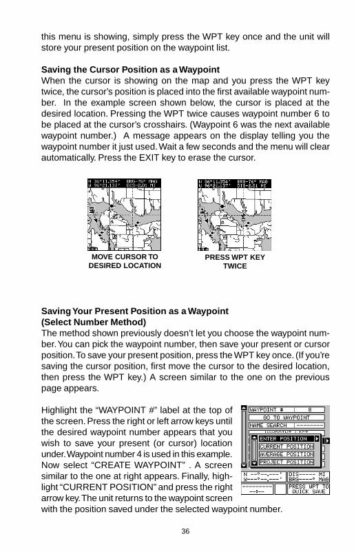
Saving the Cursor Position as a WaypointWhen the cursor is showing on the map and you press the WPT keytwice, the cursor’s position is placed into the first available waypoint num-ber. In the example screen shown below, the cursor is placed at thedesired location. Pressing the WPT twice causes waypoint number 6 tobe placed at the cursor’s crosshairs. (Waypoint 6 was the next availablewaypoint number.) A message appears on the display telling you thewaypoint number it just used. Wait a few seconds and the menu will clearautomatically. Press the EXIT key to erase the cursor.
MOVE CURSOR TODESIRED LOCATION
PRESS WPT KEYTWICE
Saving Your Present Position as a Waypoint(Select Number Method)The method shown previously doesn’t let you choose the waypoint num-ber. You can pick the waypoint number, then save your present or cursorposition. To save your present position, press the WPT key once. (If you’resaving the cursor position, first move the cursor to the desired location,then press the WPT key.) A screen similar to the one on the previouspage appears.
Highlight the “WAYPOINT #” label at the top ofthe screen. Press the right or left arrow keys untilthe desired waypoint number appears that youwish to save your present (or cursor) locationunder. Waypoint number 4 is used in this example.Now select “CREATE WAYPOINT” . A screensimilar to the one at right appears. Finally, high-light “CURRENT POSITION” and press the rightarrow key. The unit returns to the waypoint screenwith the position saved under the selected waypoint number.

37
Saving a New PositionTo save a position other than the cursor’s or thepresent position as a waypoint, first select thewaypoint number as described on the previouspage. Next, select “CREATE WAYPOINT”. Thescreen shown at the bottom of the previous pageappears. Select “ENTER POSITIION”. The screenshown at right appears. Using the arrow keys,enter the latitude and longitude of the positionthat you want to save. (Note: latitude and longi-tude is the default, however if UTM or other position format is in use, thisscreen will let you enter the position in the format that’s currently in use.)
Waypoint AveragingAlthough electronic position finding devices such as this one show theposition in precise digital numbers, there is some ambiguity in the dis-played position. With position pinning turned off, you can see this by watch-ing the position displayed on the unit move while you’re standing still. Thisis due to many factors; SA, atmospheric conditions, the number of satel-lites being tracked and their location relative to your position, and so on.
However, even with SA turned on, this GPS receiver can show surpris-ingly accurate position information. If you wish to increase the accuracyof a saved position, use the waypoint averaging method. This methodrequires the unit to remain untouched at the location that you want tosave, preferably for at least one hour. Longer times will result in a betterposition. The unit averages all of the positions reported by its GPS re-ceiver, resulting in typically higher position accuracy.
To use this feature, first press the WPT key andselect a waypoint number, then select “CREATEWAYPOINT”. The screen in the middle of the pre-vious page appears. Now select “AVERAGEPOSITION”. The screen shown at right appears.Your present position shows at the top of thescreen. A box with a plotter graphically showsthe movement of your average position. The num-ber of positions or points taken appears next tothe plotter. The position is updated once per second. Now place the unitwhere it has an unobstructed view of the sky. At the end of the positiongathering time, press the ENT key to save the averaged position.

38
Project PositionYou can save a waypoint even if you don’t know it’s position or location onthe map. This unit lets you project the location of a waypoint from a knownwaypoint using only bearing and distance from the known waypoint. Thisis useful if you don’t know the latitude/longitude of a location, but you doknow the distance and bearing from a savedwaypoint or your own position.
(Note: To project a waypoint from your presentposition, you must first save your present posi-tion as a waypoint.)
To use this feature, press the WPT key, then se-lect a waypoint number that you want to save theprojected waypoint under. Waypoint 7 is used inthis example. Now select “CREATE WAYPOINT”,then “PROJECT POSITION”. The screen shownat the top of this page appears.
The unit needs a location (reference waypoint)to project the new waypoint from. The default ref-erence is waypoint number one. Highlight the“REFERENCE WPT” label on the Project WPTmenu and press the right arrow key. The screenbelow right appears. Select a waypoint using ei-ther the waypoint number or waypoint list. In thisexample, waypoint 4 was chosen. When you’vechosen the waypoint, highlight the “SET REFER-ENCE” label and press the right arrow key. Theunit returns to the Project WPT screen shownabove. The starting waypoint you chose showsin the middle of this screen. Now set the distancefrom the starting waypoint to the projected way-point by highlighting the “SET DISTANCE” labeland pressing the right arrow key. Use the arrowkeys to set the distance, then press the ENT keywhen you’re finished. The unit returns to theProject Position screen. Now enter the bearingfrom the starting waypoint to the projected way-point by selecting “SET BEARING” from theProject Position screen.
Once you’ve entered the bearing, the unit returnsto the Project Position screen with the distance

39
and bearing from your present position showing at the bottom of the screen,as shown at right. In this example, the new waypoint is 3.53 miles on abearing of 68° from our position. Now press the ENT key. The unit savesthe projected location under the waypoint number that you picked at thebeginning.
SELECTING A WAYPOINTIn order to edit or navigate to a waypoint, youmust first select it. There are three ways to dothis: by waypoint number, waypoint list, or searchby name. All selection methods are on the mainwaypoint menu shown at right.
To select a waypoint by its number, simply high-light the “WAYPOINT #” label at the top of thewaypoint menu, then press the left or right arrowkeys until the desired waypoint number appears.
Select from ListThe waypoint number selection method forcesyou to scroll through all waypoint numbers,whether there’s a location saved in them or not.The waypoint list is composed only of saved way-points. To use the list, select “WAYPOINT LIST”from the waypoint menu. The screen shown atright appears. The names of all waypoints storedin memory show on this list. Simply highlight thedesired waypoint and press the right arrow keyto select it. The waypoint menu reappears.
(Note: When created, a waypoint is given a default name designated byan asterisk (*). Default names are not shown on the map. The waypointnumber is shown until it’s renamed.)
Select by NameTo find a waypoint by it's name, select "NAMESEARCH" from the waypont menu. The screenat right appears. Using the arrow keys, type thewaypoint's name on the screen. When the de-sired waypoint name appears, press the ENT key.The unit returns to the waypoint screen with theselected waypoint showing.

40
EDIT A WAYPOINTYou can customize a waypoint by giving it a name or change it’s positionor icon. To do this, first press the WPT key. The waypoint screen appears.Follow the instructions below for each item.
PositionAny latitude/longitude can be assigned to anywaypoint by manually entering it using the key-board. First select the waypoint number that youwant to save a position under from the waypointmenu. Next, select “EDIT WAYPOINT”, then se-lect “EDIT POSITION”. The screen shown at rightappears. Using the left and right arrow keys, high-light each number in the position and change itusing the up and down arrow keys. When you’reready to save this position and return to the waypoint screen, press theENT key. Note: You can only use this method to change the position of anexisting waypoint.
NameYou can assign a name to each waypoint. Thename can have up to eight characters. To do this,first select the waypoint that you wish to name,then choose “EDIT NAME” from the Edit Way-point menu. A screen similar to the one at rightappears.
Press the up or down arrow keys to select thefirst letter in the name. Press the right arrow keyto highlight the next position in the name. Repeat this sequence until you’veentered all of the letters in the waypoint name. Press the ENT key toaccept this name, the WPT key to erase all characters in the name, or theEXIT key to leave this screen without saving any changes.
Icon (Symbol)To change the icon assigned to a waypoint, first select the waypoint, thenchoose “EDIT SYMBOL” from the Edit Waypoint menu. The icon selectionscreen appears. Use the arrow keys to select the icon that you want toassign to the waypoint, then press the ENT key. The waypoint now hasthe new icon.
Delete a WaypointTo erase all of the information in a waypoint, first press the WPT key, thenselect the waypoint you want to erase. Now highlight the “DELETE WAY-

41
POINT” label and press the right arrow key. A message appears, asking ifyou really want to delete this waypoint. Press the right arrow key to deleteit, the left to exit without deleting the waypoint.
Delete All WaypointsYou can remove all of the waypoints from the unit’s memory. To do this,press the MENU key, then highlight the “SYSTEM SETUP” menu andpress the right arrow key. Now highlight the “DELETE ALL WPTS” labeland press the right arrow key. The unit removes all waypoints from memory.Note: This also removes all routes from memory.
Move a WaypointYou can move all information from one waypointnumber to another to help organize the waypoints.In this example, we’ll move all of the informationin waypoint number 1 to waypoint number 9. Todo this, highlight the “MOVE WAYPOINT” on thewaypoint screen and press the right arrow key.The screen shown at right appears. The “From”label is highlighted at the top of the screen. Pressthe right arrow key until the waypoint number thatyou want to move appears. In this example, we selected waypoint number1. Now press the down arrow key once to highlight the “To” label. Pressthe left or right arrow key until the number that you want to move thewaypoint to appears. Again, in this example, we chose to move waypointnumber 1 to waypoint number 9, so we pressed the right arrow key until“9” appeared. As you can see on the screen above, waypoint number 1 isshowing in the “From” box. Now press the ENT key. The “From” box is nowempty and the “To” box has waypoint number 9. Press the EXIT key toerase this menu.
Waypoint OptionsYou can customize the method used to show awaypoint on the map screens. To do this, firstpress the MENU key, then select “MAP SETUP”,finally select “WAYPOINT OPTIONS”. The screenshown at right appears. You can turn all of thewaypoints, their symbols, names, or numbers onor off. Simply select the desired label, then pressthe appropriate arrow key. Press the EXIT key toerase this menu.

42
WAYPOINT NAVIGATIONThis unit makes it easy to navigate to any way-point. All you have to do is select the waypoint,then highlight the “GO TO WAYPOINT” label onthe waypoint screen and press the right arrowkey. The unit immediately shows navigation in-formation to the waypoint on all navigation, map,and windows screens.
MOVE CURSOR TODESIRED LOCATION
PRESS MENU KEY,THEN SELECT
"GOTO CURSOR"
NAVIGATING TOCURSOR POSITION
In this example, the waypoint named "BIG FISH"(# 5) was recalled. Switching to the MAP-1 screen(shown at right) shows the starting location “S”,the recalled waypoint “4”, the plot trail from thestarting location to the present position, and thepresent position. The present position arrow alsoshows the direction of travel (track).
Navigating to a Cursor PositionThis unit lets you navigate to a location without storing it in the waypointdatabase by using the map and cursor. To do this, first switch to a map.Now move the cursor to the location that you want to navigate to. Next,press the MENU key. A new, highlighted menu appears on the list: “Go ToCursor”. Press the right arrow key. It now shows navigation data to thecursor location (shown as “D” on the map).

43
Navigating to a Waypoint using the MapThe unique “birds-eye” view used by the mapgives you an easy way to navigate to a waypoint.On the map screen shown at right, the arrow isyour present position. The box with the “S” in itwas your starting location when the waypoint wasrecalled. The dotted line is called a course lineand is the shortest path from the starting loca-tion to the destination. The “D” is the cursor des-tination, when the cursor position is used as adestination. If you follow the course line, you’ll reach the destination, cov-ering the shortest distance in the least time.
CAUTION!This product does NOT take land features or any other feature into ac-count when it projects the course line on the screen. Use caution whennavigating to a location. Make certain there are no obstructions in yourpath.
CANCEL NAVIGATIONThis unit continues to navigate to a recalled waypoint, the last waypoint ina route, or the cursor position until you stop it.
To stop the navigation function, press the MENU key, then press the up ordown arrow keys until the “Cancel Nav” label is highlighted. Press theright arrow key. The unit stops showing navigation information.
ROUTESYou can connect several user waypoints together to form a route. Whenyou recall the route, the unit shows navigation information to the first way-point in the route, then when you reach that waypoint, it switches to thenext waypoint, and so on until you reach the last waypoint in the route.
To create a route, first press the MENU key, highlight the “ROUTE PLAN-NING” label, and press the right arrow key. Thescreen shown at right appears.
This unit can store up to 99 routes. Route num-ber one shows on this page. If you wish to createa route using a different number, simply pressthe left or right arrow keys until the desired routenumber appears. In this example, however, we’lluse route number one.

44
If you wish to name the route, highlight the “EDIT ROUTE NAME” labeland press the right arrow key. Use the arrow keys to name the route, (youcan use up to eight characters in the name) then press the ENT key whenyou’re finished.
The gray boxes in the lower portion of the screencomprise the list of waypoints that form the route.To add waypoints to the route, highlight the firstgray box and press the right arrow key. The screenshown at right appears. To add a waypoint to theroute from the waypoint table, select the “ADDWPT” label. To select a waypoint from the map,choose “ADD FROM MAP”.
Add From Waypoint ListThis screen is virtually identical to the waypointscreen Select a waypoint either by using the way-point number, waypoint name, or from the way-point list. After selecting the waypoint, highlightthe “ADD TO ROUTE” label and press the rightarrow key. The unit returns to the route screenwith the first waypoint at the top of the list. High-light the next waypoint location beneath the firstwaypoint and press the right arrow key. Now re-peat the previous steps to select the second way-point for your route. After selecting the secondwaypoint, the unit returns to the waypoint listscreen. The second waypoint shows beneath thefirst one, with bearing and distance from the firstwaypoint in the route to the second showing un-der the second waypoint’s name.
Add From MapYou can add waypoints from the map, even create new ones. To do this,select “ADD FROM MAP” from the menu as shown on the previous page.A screen similar to the one at right appears. Using the arrow keys, movethe cursor to the desired waypoint or location. Now press the ENT key toadd it to the route. If it’s an existing waypoint, it will be added to the route.If you mark a location with the cursor that isn’t a waypoint, the unit will

45
create a waypoint and add it to the route. To addanother location or waypoint to the route, movethe cursor to that location and press the ENT key.When you’re finished, press the EXIT key. Thescreen below right appears.
The total route distance shows at the bottom ofthe screen. Continue selecting waypoints until allof the waypoints in the route are on the list. Pressthe EXIT key to return to the Route menu. Yourroute is now saved in memory. Press the EXITkey to erase the menus.
Delete a Waypoint from the RouteTo remove a waypoint from a route, first select the route, then select thewaypoint that you want to delete and press the right arrow key. Highlightthe “Delete” label on this menu and press the right arrow key. The unitreturns to the route list with the waypoint removed from the list. (Note:This doesn’t delete the waypoint from the database, it simply removes itfrom the route.)
Waypoint StatisticsBy default, this unit shows the distance and bearing from each waypointin the route to the next. It will also show estimated time en route (ETE),estimated time of arrival (ETA), or the waypoint names (NAMES). To viewthe different statistics, highlight the “SHOW INFO-DIS/BRG” label, thenpress the left or right arrow key until the desired statistic appears.
Follow a Route - Direct To MethodBefore starting the route, you’ll need to decide if you want to start at thefirst waypoint and travel forward to the last waypoint or start at the lastwaypoint in the route and travel backwards (reverse) to the first waypoint.The default is forward. You can also start at the closest waypoint to yourposition, then travel forward or reverse through the route using the “AUTOSTART” feature.
To follow a route, first select the route number that you wish to follow byhighlighting the “Route #” label, and pressing the left or right arrow keys

46
until the desired route number appears. In this example we’re using routenumber one. To run the route from the last waypoint to the first, highlightthe “RUN ROUTE” label and press the right arrow key to change it fromforward to reverse.
Now highlight the first waypoint in the route thatyou wish to start with and press the right arrowkey. (The first waypoint in the route is used inthis example.) The screen shown above rightappears. Now select “DIRECT TO” and press theright arrow key.
The unit returns to the last used navigation, map-ping, or windows screen. In this example, mapscreen 1 was in use. A box with the “S” insiderepresents your location when you started theroute. A dotted line shows from your starting po-sition to the waypoint. A dashed line extends fromthis waypoint to each of the other waypoints inthe route. Follow these lines to get to each of thewaypoints. When you enter the radius set by thearrival alarm, the unit automatically switches tothe next waypoint on the list, showing navigationdata to that waypoint, and so on until the last way-point on the route list has been reached. (Note: The arrival alarm does nothave to be turned on.) The unit continues to show navigation data to thelast waypoint in the route until you end the navigation. (See Cancel Navi-gation)
Following a Route - Auto Start MethodYou don’t have to choose the starting waypoint ina route. Selecting “AUTO START” on the routeplanning menu, starts navigation along the leg ofthe route that is closest to your present position.The screen shown at the top of the next pageshows the result of the auto start feature. Whenthe route was started, the first leg of the route(from waypoint #3 to waypoint #4) was the clos-est to the present position. Therefore, the unitshows navigation information to waypoint number 4. The first leg of theroute, from #3 to #4 is shown on the screen by a dotted line. Once youarrive at waypoint number 4, the unit switches to the next waypoint in theroute, and so on. The rest of the route navigation is used normally.

47
Waypoint InformationTo see details about the highlighted waypoint,select the waypoint from the list of waypoints onthe route screen, then press the right arrow key.Now select “WAYPOINT INFO”. The screen atright appears.
The selected waypoint number appears at thetop of this screen. Information about the waypointshows at the bottom of the screen. When you’re finished with this screen,press the EXIT key to erase it.
Delete a RouteTo erase a route, highlight the “ROUTE #” labelon the route planning menu, then select the routeyou want to erase. Next, highlight the “DELETEROUTE” label and press the right arrow key. Amessage appears, asking if you really want toerase the route. If you press the right arrow key,the route will be erased. If you select “Yes” (bypressing the right arrow key) the unit then asks ifyou want to erase the waypoints used in the routefrom memory also. Press the right arrow key again to erase them, or theleft arrow key to leave the waypoints in memory. The unit returns to theroutes menu. Press the EXIT key to erase the menu.
Note:If you are navigating with this unit, either to a waypoint or in a route andshut it off, it will preserve the current waypoint number that it is navigatingto. It also saves the current route (if it is in use) and the route’s forward orreverse order. When you turn the unit on, it will show navigation data tothe waypoint as soon as it locks onto the satellites as if it had never beenturned off.

48
SYSTEM SETUPMany features are listed under the “SystemSetup” label on the main menu. These commandsaffect the basic operation of the unit. To use them,press the MENU key, then “System Setup”. Thescreen at right appears.
Audio/ScreenThis unit gives you three audio options. 1.The unitwill sound a tone whenever an alarm sounds and when you press a key. 2.The unit sounds the alarm only. 3. No sound. To change the audio mode,highlight the “SOUND” label as shown below, then press the right or leftarrow keys. Note: If the speaker is turned completely off the alarm mes-sages will still flash on the screen.
ContrastTo adjust the display’s contrast, highlight the “Con-trast” label. Press the right or left arrow keys untilthe screen’s contrast is best for the lighting con-ditions.
BacklightThe display has lights that can be turned on fornight use. To turn the lights on, simply press the PWR key. To turn themoff, press the PWR key again. A light bulb indicator on the satellite statusscreen shows when the lights are on.
The default light level is maximum. To reduce the level, select “BACK-LIGHT LEVEL”, then press the left arrow key until the lights are at thedesired level. To increase the light level, press the right arrow key.
Set Local TimeWhen this unit is first initialized, it may not showthe correct time for your location due to daylightsavings time, time zone variances, and so on. Ifthe time shown on the clock displays is incorrect,select “SET LOCAL TIME” from the system setupmenu and press the right arrow key. The screenshown at right appears.
Use the left or right arrow keys to select the num-ber in the current time that you want to change. Use the up or down arrowkeys to change the number. Press the ENT key to save the change, theEXIT key to erase the menu without changing it.

49
Change UnitsYou can view data in three different formats: statute, nautical, and metric.The default is statute. The chart below shows the settings for each.
Statute Nautical MetricDistance ..... miles .....................nautical miles ....... kilometersSpeed ......... miles per hour ....... knots .................... kilometers per hourAltitude ....... feet ........................ feet ....................... meters
The unit will also show bearing in degrees trueor magnetic, and the clock in 12 hour (a.m./p.m.)or 24 hour formats. The UltraMap can also showwater depth in feet, fathoms, or meters, tempera-ture in degrees Fahrenheit or Celsius, (tempera-ture requires an optional temp sensor) .To changea unit of measure, first select “Change Units” fromthe System Setup menu. Highlight the desiredselection, then press the left or right arrow key.You can change any or all of the settings on this page. When you’re fin-ished, press the EXIT key.
NMEA/DGPSThis product transmits data through the power/data port in the back of theunit using NMEA 0183 format, version 1.5 or 2.0. The data is used byother electronic devices such as marine autopilots for position and steer-ing information.
DGPS on the other hand, is a data input. DGPS is an acronym for Differ-ential Global Positioning System. Currently, it relies on a system of ground-based transmitters that send correction signals to small DGPS receivers.DGPS gives you more accurate positions than is otherwise possible.
See the installation section for cable connections. See the sample wiringdiagram below for general wiring procedures. Read your other product’sowner’s manual for more wiring information.
TO GPSUNIT
TO BEACONRECEIVER
WHITE (TRANSMIT)
GREEN (RECEIVE)
BLACK (GROUND)
RECEIVE
TRANSMIT
GROUND
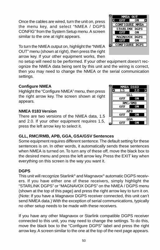
50
Once the cables are wired, turn the unit on, pressthe menu key, and select “NMEA / DGPSCONFIG” from the System Setup menu. A screensimilar to the one at right appears.
To turn the NMEA output on, highlight the “NMEAOUT” menu (shown at right), then press the rightarrow key. If your other equipment works, thenno setup will need to be performed. If your other equipment doesn’t rec-ognize the NMEA data being sent by this unit and the wiring is correct,then you may need to change the NMEA or the serial communicationsettings.
Configure NMEAHighlight the “Configure NMEA” menu, then pressthe right arrow key. The screen shown at rightappears.
NMEA 0183 VersionThere are two versions of the NMEA data, 1.5and 2.0. If your other equipment requires 1.5,press the left arrow key to select it.
GLL, RMC/RMB, APB, GGA, GSA/GSV SentencesSome equipment requires different sentence. The default setting for thesesentences is on. In other words, it automatically sends these sentenceswhen NMEA is turned on. To turn any of these off, move the black box tothe desired menu and press the left arrow key. Press the EXIT key wheneverything on this screen is the way you want it.
DGPSThis unit will recognize Starlink® and Magnavox® automatic DGPS receiv-ers. If you have either one of these receivers, simply highlight the“STARLINK DGPS” or “MAGNAVOX DGPS” on the NMEA / DGPS menu(shown at the top of this page) and press the right arrow key to turn it on.(Note: If you have a Magnavox DGPS receiver connected, this unit can’tsend NMEA data.) With the exception of serial communications, typicallyno other setup needs to be made with these receivers.
If you have any other Magnavox or Starlink compatible DGPS receiverconnected to this unit, you may need to change the settings. To do this,move the black box to the “Configure DGPS” label and press the rightarrow key. A screen similar to the one at the top of the next page appears.

51
These menus select the beacon receiver’s fre-quency and bit rate (in bits per second). To changeone of these settings, simply highlight the menuitem you wish to change, then press the right orleft arrow key until the desired number appears.
The “STARLINK AUTO” menu works with theStarlink or compatible receivers that automaticallydetermine the frequency and bit rate. If you have one of these receivers,leave this set to “ON”, otherwise turn it off.
Press the EXIT key when you’re finished.
Com Port SetupIf you’re connecting a computer or other serialdevice to this unit, (including DGPS receivers)you’ll probably need to change the communica-tions settings. To do this, select “Com Port Setup”on the System Setup menu. Press the right ar-row key. The screen shown at right appears.
Check your computer or DGPS receiver’s manualfor the proper data settings. Highlight the menu item you need to change.Press the left or right arrow keys to change them. The serial port defaultsare 4800 baud, no parity, and 8 data bits. Press the EXIT key to erase thismenu.
Reset GroupsTo return all window groups and boxes on the navigation and mappingscreens to their factory defaults, select Reset Groups on the SystemSetup menu. Finally, press the right arrow key. All window groups anddigital boxes are reset to their factory settings.
Reset OptionsTo return the unit to the original factory settings, highlight the “Reset Op-tions” menu on the System Setup screen. Now press the right arrow key.A message appears, asking if you want to restore the original options.Press the right arrow key if you do, the left arrow key to quit.
If you restore the unit to the factory settings, all options such as contrast,alarms, and other system choices are returned to their default values.However, no waypoints, routes, or icons are erased.

52
System InformationThe system information screen shows the release date and the software’sversion number. To view this screen, highlight the System Info label on theSystem Setup menu. Now press the right arrow key. Press the EXIT keywhen you’re finished reading this screen.
GPS SETUPItems found under the GPS Setup menu includeinitialization, (covered at the beginning of thismanual), position format, datums, and more. Touse any of these features, first press the MENUkey, highlight GPS Setup and press the right ar-row key. The screen shown at right appears.
Position Format/Alternate FormatThis unit can show the position in degrees, min-utes, and thousandths of a minute (36° 28.700') or degrees, minutes,seconds, and tenths of a second (36° 28' 40.9"). It can also show positionin UTM (Universal Transverse Mercator) projection, German, Taiwan, Brit-ish, Irish, Swedish, Swiss, Finnish, New Zealand, and Military Grid.
UTM’s are marked on USGS topographic charts. This system divides theEarth into 60 zones, each 6 degrees wide in longitude.
German, Taiwan, British, Irish, Swedish, Swiss, New Zealand, and Finn-ish grid systems are the national coordinate system used only in theirrespective countries. In order to use these grid systems, you must be inthe respective country. This unit will pick the matching datum for you whenyou select the grid. See the Datums section for more information.
The military grid reference system (MGRS) uses two grid letteringschemes, which are referred to as standard and alternate MGRS on thisunit. Your position and datum in use determines which one to use. If youuse standard, and your position is off significantly, then try the alternate.
Note: When the position format is changed, it affects the way all positionsare shown on all screens. This includes waypoints.
Windows Group “F” has two position displays, standard (shown at the topof the screen), which is also shown on all other position displays, andalternate. The alternate position (shown at the bottom of the screen) canbe programmed to show your present position in a different format thanthe upper position. For example, you can show latitude/longitude at thetop of the screen and UTM’s at the bottom.

53
To change the position format, highlight either the“Position Format” or the “Alternate Format” labelon the “GPS Setup” menu, then press the rightarrow key. A screen similar to the one at rightappears. Press the up or down arrow keys toselect the desired format. Press the EXIT key toerase the position format menu.
DatumMaps and charts are based on a survey of the area that’s covered by themap or chart. These surveys are called “Datums”. Maps that are createdusing different datums will show the same latitude/longitude in slightlydifferent locations.
All datums are named. The GPS system is based on the WGS-84 datum,which covers the entire world. Other datums may also cover the entireworld, or just a small portion. By default, your position shows using theWGS-84 datum. However, it can show your position using one of 191different datums.
To change the datum, first press the MENU key,then highlight the “GPS Setup” label and pressthe right arrow key. Now highlight the “Select Da-tum” label. Finally, press the right arrow key again.A screen similar to the one at right appears.
The WGS-84 label is highlighted. To change it,simply press the up or down arrow keys to high-light the desired datum, then press the ENT key.This selects the datum and erases the select datum menu.
A list of the datums used by this unit is in the back of this manual.
Map FixMap Fix is used with charts or maps. This system asks for a referenceposition in latitude/longitude, which you take from a marked location onthe map. It then shows the present position as distance on the map fromthat reference point. For example, if it shows a distance of UP 4.00” andLEFT 0.50”, you then measure up four inches and to the left a half-inchfrom the reference point on the map to find your location.
To use this format, you need to follow these steps in order. First, take yourmap of the area and determine a reference latitude/longitude. (Note: inorder for this system to work, the latitude/longitude lines must be parallel

54
with the edge of the map. USGS maps are parallel, others may not be.Also, this works better with smaller scale maps.) The reference positioncan be anywhere on the map, but the closer it is to your location, thesmaller the numbers will be that you’ll have to deal with.
Once you’ve decided on a reference position, you’ll need to save it as awaypoint. See the waypoint section for information on saving a waypointusing the EDIT Position method. Save the reference position as a way-point. Exit from the waypoint screens.
Press the MENU key, then select GPS Setup. Highlight "MAP FIX SETUP"and press the right arrow key. The screen at right appears. "REFERENCEPOINT" is highlighted. Press the right arrow key. Select the waypoint num-ber that you saved the reference point under. Highlight the "SET REFER-ENCE" label and press the right arrow key. The unit returns to the Map FixSetup menu. Now highlight the Map Scale label and press the right arrowkey. Enter the map’s scale. This is generally at the bottom of the papermap. It’s shown as a ratio, for example 1:24000.In this example, we entered 24000 as a mapscale. (Ignore the 1:) The unit returns to the MapFix Setup screen.
Finally, press the EXIT key to erase this menu.Now select "POSITION FORMAT". Select MapFix from the list and press the EXIT key. All posi-tion information now shows as a distance fromthe reference point you entered and saved as awaypoint earlier.
Set PCF OffsetAnother method used to make your display match a chart or map is called“PCF” or Position Correction Factor. This unit gives you the capability tomove or offset the position shown on the display to match one on thechart. The unit will add this offset to all position and navigation displays atall times.
Remember, the position error on any radio navigation system is very dy-namic and the PCF offset should never be used in an attempt to cancelthe error.
In general terms, PCF should only be used if your map indicates what thepossible error is. PCF should always be reset to zero when you’re finishedwith the chart.

55
For example, suppose you are stopped at a location that is accuratelymarked on a chart. Your unit shows a longitude position that is .244 min-utes east of the one on the chart and .047 minutes north latitude. Usingthe PCF feature, you can make this unit match the chart you’re using. Ifyou move, the unit will continuously add the change to all position, navi-gation, and mapping displays. This makes it more closely match the da-tum used by the chart. For this reason, you should be careful when enter-ing the PCF offset. It’s saved in memory and doesn’t change when theunit is turned off. However, resetting the unit does erase the PCF offset.
To change the PCF offset, first press the MENUkey, then highlight the “GPS Setup” label andpress the right arrow key. Now highlight the “SetPCF Offset” label. Finally, press the right arrowkey again.
A screen similar to the one at right appears.
Now enter the correction for your location. Re-member, this is the difference between the location shown on the presentposition display and the position shown on the chart. In this example, weentered 0 degrees, 0.047 minutes north latitude and 0 degrees, 0.244minutes east longitude. That is the difference between the present posi-tion shown by this unit and the one on our chart.
After you’ve entered the latitude/longitude correction, press the ENT keyto accept it. The PCF entry screen is erased and the unit returns to thenavigation or mapping screens with the correction factor applied.
Position PinningWhen using a GPS receiver at extremely low speeds, it can have troubledetermining your course over ground, or direction you’re travelling. This isdue in large part to SA, or selective availability. SA is small inaccuraciespurposefully put into the GPS satellite’s signal by the government. Thiscause wide variations in the track display and other navigation displayswhen using the unit at slow speeds.
If you’re using this receiver without DGPS and stop, the position pinningfeature locks the present position indicator on the plotter until you’ve moveda short distance or exceed a very slow speed. This prevents the “wander-ing” plot trail seen when you’re stopped with position pinning turned off.This also affects the navigational displays.
The easiest way to see the effects of S/A is to stand still with the GPS

56
receiver turned on and watch your plot trail with position pinning turnedoff. You’ll see the present position change, speed increase and decrease,and a random plot trail on the plotter’s screen.
If you wish to turn the position pinning feature off, press the MENU key,then highlight the “GPS Setup” label and press the right arrow key. Nowhighlight the “POSITION PINNING” label. Finally, press the left arrow key.
ALARMSThis unit has several GPS alarms. (Sonar alarms for the UltraMap arecovered in the sonar section of this manual.) You can set an arrival alarmto flash a warning message and sound a tone when you cross a presetdistance from a waypoint. For example, if you have the arrival alarm set to.1 mile, then the alarm will flash a message when you come within .1 mileof the recalled waypoint. The course deviation indicator alarm (CDI) canwarns when your track drifts too far to the right or left of the course line tothe waypoint. For example, if the alarm is set to .1 mile, then the alarmflashes a message if you drift .1 of a mile or more to the right or left of theline to the waypoint. The anchor alarm is triggered when you drift outsideof a preset radius. Again, using the .1 mile as an example, if you’re an-chored and your boat moves more than .1 of a mile, the alarm will flash amessage and sound a tone.
To use any of these alarms, first press the MENUkey, then select the “ALARMS” menu. Next, se-lect “GPS ALARMS”. A screen similar to the oneshown at right appears. Press the up or downarrow key to select the desired alarm, then pressthe right arrow key to turn it on.
To adjust an alarm’s distance, move the blackbox to the alarm’s “DIS” menu item, then pressthe right or left arrow keys to increase or decrease the alarm’s distance.
When you’re finished, press the EXIT key to erase this menu.
Important Alarm Notes:Anchor Alarm - Since civilian users don’t receive the accuracy given tomilitary users, the anchor alarm may be triggered even when you’re sit-ting still. This typically happens when using small (less than .05 mile)anchor alarm ranges. If you have a DGPS beacon receiver connected tothis unit, smaller ranges may be usable.
Arrival Alarm - If you set the arrival alarm’s distance to a small number,

57
and you run a route (see the routes section), this unit may not show navi-gation data to the next waypoint, once you arrive at the first one, sinceyou may not be able to come close enough to the first waypoint to trip thearrival alarm.
DGPS MessagesThe DGPS message selections are found on the Alarms/CDI menu shownabove. Pressing the EXIT key erases these messages.
The DGPS message appears whenever the unit begins or stops usingDGPS data to help determine your position.
The default setting for these messages is “on”. To turn the message off,select the “Setup Alarms” menu from the main menu, then highlight “DGPSMESSAGES” and press the left arrow key.
Sun/Moon CalculatorThis unit has a sunrise/sunset and moonrise/moonset calculator that shows this informationanywhere or anytime in the world. To use it, pressthe MENU key, then highlight “SUN/MOONCALC” and press the right arrow key. The screenshown at right appears. (Both calculators workidentically. The sunrise/sunset calculator is usedfor this example.) The sun and moon data fortoday’s date appear in the center of the screen.A moon symbol shows in the moonrise/moonset box, showing the ap-proximate phase of the moon. The arrow next to the symbol shows if it ismoving towards a full moon (up) or a new moon (down).
Today’s date shows at the top of the screen. If you want to know thesunrise/sunset for a different date, press the ENT key, then enter the newdate with the arrow keys. The unit returns to the above screen with thesun and moon data shown for the date you entered.
The sun and moon data show for your present position. If you move theplotter’s cursor to a different position before using this calculator, it willshow the sunrise/sunset for the cursor’s location.
Press the EXIT key to erase this screen.

58
SIMULATORA simulator is built into this unit that moves the GPS position and pro-duces a simulated sonar chart (UltraMap only). You can use nearly all ofthe unit’s features - even save and recall waypoints. This is useful for tripplanning.
To use the simulator, press the MENU key, thenpress the up or down arrow keys until the “Simu-lator Setup” menu is surrounded by the black box.Now press the right arrow key. The screen shownat right appears.
If you simply press the right arrow key, turningthe simulator on, this unit will start from yourpresent position and follow a track of 355° at 100 miles per hour.
To change either the track or speed, highlight the one you want to change,then press the right or left arrow key. When the numbers are correct,press the EXIT key.
Starting PositionNormally, the starting position for the simulator is your present position. Ifyou want to change the starting position, highlight the “SET START WPT”label on the Simulator Setup menu, then press the right arrow key.
You can select any waypoint as the simulator’s starting point. Select thestarting point by pressing the right arrow key on the “WPT#” label until thedesired starting waypoint number appears. Now highlight the “SET SIMSTART” label and press the right arrow key. The unit returns to the Simu-lator Setup menu using the specified waypoint as the starting waypoint.
Steer SimulatorThis option lets you change both the course and speed on the screen asthe simulator is running. To do this, highlight the “STEER SIMULATOR”label on the Simulator Setup screen, then press the right arrow key. Thescreen shown at right appears. Use the up anddown arrow keys to increase or decrease thespeed. Use the right and left arrow keys to changethe track. When you’re finished changing the trackand speed, press the EXIT key to erase themenus.

59
SONAR OPERATION - UltraMap Only
SONAR MODESThis unit has three different sonar modes: fullchart (sonar 1), split-chart (sonar 2), and sonarwith digital information (sonar 3). To select amode, first press the PAGES key. Press the upor down arrow key to select sonar modes, thenpress the left or right arrow key to select the de-sired mode. Press the EXIT key to erase themodes menu.
Full ChartThis is the default mode used when the unit is first turned on (shownabove). The bottom signal scrolls across the screen from right to left. Depthscales on the right side of the screen makes it easy to determine thedepth of fish, structure, and other objects. The line at the top of the screenrepresents the surface. The bottom depth shows at the top left corner ofthe screen. The word “AUTO” at the screen’s top center shows that it’s inthe automatic mode, freeing you from sensitivity, range, and noise rejec-tion adjustments.
Split ChartA split chart shows the underwater world fromthe surface to the bottom on the right side of thescreen. The left side shows an enlarged versionof the right side. The zoom range shows at thebottom of the screen. In this example, the zoomrange is 2X, or two times the right side’s view.
Digital/ChartThe digital/chart shows the chart on the left sideof the screen. The right side has six digital boxescontaining the water depth at the top of thescreen, boat speed, surface water temperature,temperature #2, waypoint number with directionarrow, and CDI. (Note: Boat speed, distance, andtemperature require an optional speed/tempera-ture sensor. Temperature #2 requires an addi-tional temperature sensor.)

60
AUTOMATICWhen this unit is first turned on, the automatic feature is enabled. This isindicated by the word “AUTO” at the top of the screen. The automaticfeature adjusts the sensitivity and range so the bottom signal is displayedin the lower half of the screen at all times.
To turn automatic off, first press the MENU key,then select “SONAR SETUP”. Now select “SO-NAR AUTO MODE”. Press the left arrow key toswitch to the manual mode. Press the EXIT keyto return to the sonar screen. To turn Automaticon, repeat the above steps to get the auto menu,then press the right arrow key.
SONAR OPTIONSSensitivityThe sensitivity controls the ability of the unit to pick up echoes. A lowsensitivity level excludes much of the bottom information, fish signals,and other target information. High sensitivity levels enables you to seethis detail, but it can also clutter the screen with many undesired signals.Typically, the best sensitivity level shows a good solid bottom signal withGrayline and some surface clutter.
The sensitivity is adjusted to keep a solid bottom signal displayed, plus alittle more when the unit is in the automatic mode. This gives it the capa-bility to show fish and other detail.
However, situations occur where it becomes necessary to increase ordecrease the sensitivity. This typically happens when you wish to seemore detail, so an increase in sensitivity is indicated. The procedure toadjust it is the same whether the unit is in the automatic or manual mode.
To adjust the sensitivity, press the MENU key,then select “SONAR OPTIONS”. The screen atright appears. There are four options on thismenu, with two showing. They are: sensitivity,grayline, surface clarity, and ASP. Use the up ordown arrow keys to switch between options. Thesensitivity menu has left and right arrows, plus ahorizontal bar graph. The graph gives a visualindication of the sensitivity level. The number tothe right of the bar graph shows the percentage of sensitivity in use.
To increase the sensitivity level, press the right arrow key. As you press

61
the key, the menu’s bar graph will grow wider and the percentage willincrease in value. You can also see the difference on the chart record asit scrolls. When the sensitivity is at the desired level, release the key.
To decrease the sensitivity level, press the left arrow key. The bar graphand percentage will decrease. When the sensitivity is at the desired level,release the key. When you reach either the maximum or minimum limit, atone sounds.
To erase the menu, press the EXIT key.
GRAYLINE ®
GRAYLINE lets you distinguish between strong and weak echoes. It “paints”gray on targets that are stronger than a preset value. This allows you totell the difference between a hard and soft bottom. For example, a soft,muddy or weedy bottom returns a weaker signal which is shown with anarrow or no gray line. A hard bottom returns a strong signal which causesa wide gray line.
If you have two signals of equal size, one with gray and the other without,then the target with gray is the stronger signal. This helps distinguish weedsfrom trees on the bottom, or fish from structure.
GRAYLINE is adjustable. Since GRAYLINE shows the difference betweenstrong and weak signals, adjusting the sensitivity may require a differentGRAYLINE level, also. The level chosen by the unit at power on is usuallyadequate for most conditions. Experiment with your unit to find theGRAYLINE setting that’s best for you.
To adjust the GRAYLINE level, press the MENU key, then select “SONAROPTIONS”. The screen at the bottom of the previous page appears. Usethe up or down arrow keys to select the GRAYLINE menu. Press the leftarrow key to decrease the gray level or the right arrow key to increase it.The percentage of GRAYLINE in use changes as the arrow keys arepressed. The bar chart also gives a graphical indication of the GRAYLINElevel. You can see the change on the screen (both on the menu and on thechart record) as you press the keys. After you’ve finished, press the EXITkey to erase the menu.
ADJUST CHART SURFACE CLARITYThe markings extending downward from the zero line on the chart arecalled “surface clutter.” These markings are caused by wave action, boatwakes, temperature inversion, and other natural causes.

62
The Surface Clarity Control (SCC) reduces or eliminates surface cluttersignals from the display. SCC varies the sensitivity of the receiver, de-creasing it near the surface and gradually increasing it as the depth in-creases.
There are three levels of SCC available on thisunit: low, medium, and high. When it’s turned onfor the first time, the SCC level is low. To changeit, press the MENU key, then select “SONAROPTIONS”. The screen at righ appears. Use theup or down arrow keys to select the SURFACECLARITY menu. Now use the left or right arrowkeys to change it. When you’re finished, pressthe EXIT key to erase the menus.
ASP (Advanced Signal Processing)The ASP feature is a noise rejection system that constantly evaluates theeffects of boat speed, water conditions, and interference. This automaticfeature gives you the best display possible under most conditions.
The ASP feature is an effective tool in combating noise. In sonar terms,noise is any undesired signal. It is caused by electrical and mechanicalsources such as bilge pumps, engine ignition systems and wiring, airbubbles passing over the face of the transducer, even vibration from theengine. In all cases, noise can produce unwanted marks on the display.
The ASP feature has two levels - Normal and High. If you have high noiselevels, try using the “High” ASP setting. However, if you are having troublewith noise, we suggest that you take steps to find the interference sourceand fix it, rather than continually using the unit with the high ASP setting.However, there are times when you may want to turn the ASP feature off.This lets you view all incoming echoes before they are processed by theASP feature.
To change the ASP level, press the MENU key. select "SONAR SETUP",then “SONAR OPTIONS”, and finally press the up or down arrow keysuntil the “ASP” menu appears, as shown at the top of this page. Now usethe left or right arrow keys to change it. When you’re finished, press theEXIT key to erase the menu.
RANGE - AutomaticWhen turned on for the first time, the bottom signal is automatically placedin the lower half of the screen. This is called Auto Ranging and is part ofthe automatic function. Typically, the range cannot be changed manually

63
while the unit is in automatic, as shown at right.However, depending upon the bottom depth andthe current range, you can change the range to adifferent depth. In the example screen shown atright, the bottom depth has descended to a pointwhere you can change the range to XX feet. Todo this, select “CHART RANGE” from the “SO-NAR OPTIONS” menu. Simply press the right orleft arrow keys to select a different range. Whenyou’re finished , press the EXIT key to erase the menu.
RANGE - ManualYou have complete control over the range when the unit is in the manualmode.
To change the range, first make certain the unitis in the manual mode. Next, select “CHARTRANGE” from the "SONAR OPTIONS" menu.Simply press the right or left arrow keys to selecta different range. Press the left or right arrow keysto decrease or increase the range. The availableranges are 0-10, 20, 30, 40, 60, 100, 150, 200,300, 500, 800, and 1000 feet. After selecting therange, press the EXIT key to erase the rangemenu.
NOTE: The sonar’s depth capability depends on the transducer installa-tion, water and bottom conditions, and other factors.
CHART OPTIONSChart SpeedThe rate echoes scroll across the screen is calledthe chart speed. It’s adjustable by selecting“CHART SPEED” from the "CHART OPTIONS"menu. Increase the chart speed by pressing theright arrow key or decrease it by pressing the leftarrow key. The percentage of chart speed in usechanges as the arrow keys are pressed. The barchart also gives a graphical indication of the chartspeed. After you’ve made the adjustment, pressthe EXIT key to erase the menu.
Chart StopTo stop the chart, select “CHART” from the chart options menu. Press the

64
left arrow key to stop the chart. To start the chart again, press the rightarrow key.
Upper and Lower LimitsYou can enter virtually any combination of ranges when the unit is in themanual mode. The unit lets you enter any upper and lower limit, providedthere is at least ten feet separating them. (On the screen below left, theupper limit is 0 and the lower limit is 100.) Using the upper and lower limitrange option, we changed the range from 0 to 100 feet to 30 to 55 feet.This “zoomed” the display to a 35 foot range.
0 - 100 FOOT RANGE 30 - 55 FOOT RANGE
As you can see, the fish arches near the bottom are much larger andeasier to see. Not only does this make it easier to see targets, but you canmore accurately determine their depth, due to the expanded depth range.
To change the upper and lower limits, first pressthe MENU key, then select “CHART OPTIONS”from the "SONAR SETUP" menu. The screen atthe bottom of the previous page appears. Tochange the lower limit, select “SET LOWERLIMIT” from the menu. The screen at right ap-pears. Using the arrow keys, enter the desireddepth. Press the ENT key to save the range, EXITto erase this screen without changing the range.
Change the upper limit the same way, except choose “SET UPPER LIMIT”from the CHART OPTIONS menu.
ZOOM“Zooming” the picture is a common method used to enlarge small detailand fish signals. To zoom the screen, simply press the ZIN (zoom-in) key.This enlarges all echoes on the screen to twice their normal size. To re-turn the screen to 2X or normal, simply press the ZOUT (zoom-out) keyuntil the desired zoom appears. When the unit is in zoom, “2X” appears inthe lower right corner of the screen, showing the current zoom mode.
ZOOM“Zooming” the picture is a common method used to enlarge small detailand fish signals. To zoom the screen, simply press the ZIN (zoom-in) key.This enlarges all echoes on the screen to twice their normal size. To re-turn the screen to 2X or normal, simply press the ZOUT (zoom-out) keyuntil the desired zoom appears. When the unit is in zoom, “2X” appears inthe lower right corner of the screen, showing the current zoom mode.

65
FISH IDThe Fish ID feature identifies targets that meetcertain conditions as fish. The microcomputeranalyses all echoes and eliminates surface clut-ter, thermoclines, and other signals that are un-desirable. In most instances, remaining targetsare fish. The Fish ID feature displays symbolson the screen in place of the actual fish echoes.There are four fish symbol sizes: tiny, small,medium, and large. These are used to designatethe relative size between targets. In other words, it displays a small fishsymbol when it thinks a target is a small fish, a medium fish symbol on a larger target,etc.
The microcomputer is sophisticated, but it can be fooled. It can’t distin-guish between fish and other suspended objects such as trotlines, turtles,submerged floats, air bubbles, etc. Individual tree limbs extending out-wards from a group of limbs is the hardest object for the Fish ID feature todistinguish from fish.
You may see Fish ID symbols on the screen when actually, there are nofish. Practice with the unit in both the Fish ID mode and without to be-come more familiar with the Fish ID feature.
To turn the Fish ID feature off, press the MENUkey, then select “SONAR SETUP”. Now choose“FISH ID” from this menu. Press the left arrowkey to turn the fish ID feature off. To turn the FishID feature on again, repeat the above steps, butpress the right arrow key until the “ON” is high-lighted. Any targets the microcomputer deter-mines are fish will be displayed as fish symbols.
Remember, the Fish ID feature can’t be used when the unit is in the manualmode. If you turn the Fish ID feature on when the unit is in the manualmode, the microcomputer will turn the automatic feature on. If you turnautomatic off when the Fish ID feature is on, the Fish ID feature will beturned off also.
FISHTRACK™The FishTrack feature shows the depth of a fish symbol when it appearson the display. This lets you accurately gauge the depth of targets. Thisfeature is available only when the Fish ID feature is on.
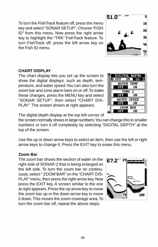
66
To turn the FishTrack feature off, press the menukey and select “SONAR SETUP”. Choose “FISHID” from this menu. Now press the right arrowkey to highlight the “TRK” FishTrack feature. Toturn FishTrack off, press the left arrow key onthe Fish ID menu.
CHART DISPLAYThe chart display lets you set up the screen toshow the digital displays, such as depth, tem-perature, and water speed. You can also turn thezoom bar and zone alarm bars on or off. To makethese changes, press the MENU key and select“SONAR SETUP”, then select “CHART DIS-PLAY”. The screen shown at right appears.
The digital depth display at the top left corner ofthe screen normally shows in large numbers. You can change this to smallernumbers or turn it off completely by selecting “DIGITAL DEPTH” at thetop of the screen.
Use the up or down arrow keys to select an item, then use the left or rightarrow keys to change it. Press the EXIT key to erase this menu.
Zoom BarThe zoom bar shows the section of water on theright side of SONAR-2 that is being enlarged onthe left side. To turn the zoom bar on continu-ously, select “ ZOOM BAR” on the “CHART DIS-PLAY” menu, then press the right arrow key. Nowpress the EXIT key. A screen similar to the oneat right appears. Press the up arrow key to movethe zoom bar up or the down arrow key to moveit down. This moves the zoom coverage area. Toturn the zoom bar off, repeat the above steps.
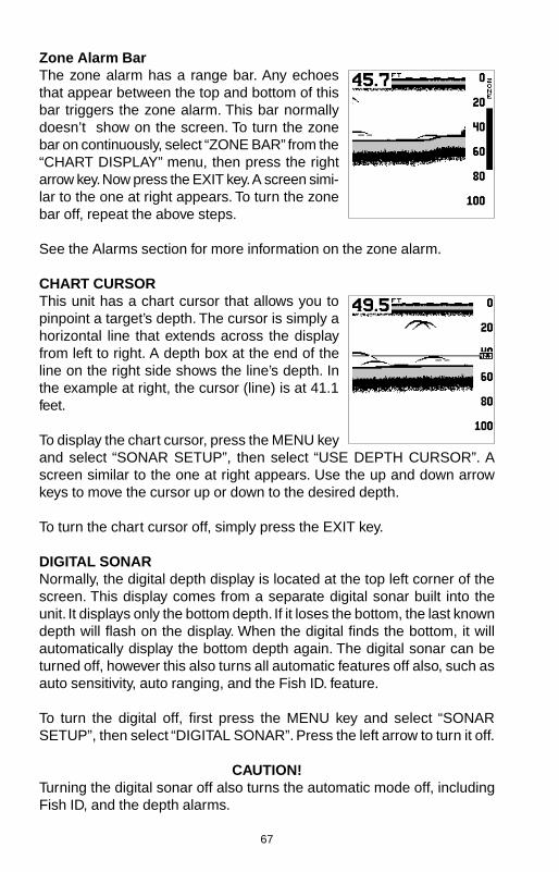
67
Zone Alarm BarThe zone alarm has a range bar. Any echoesthat appear between the top and bottom of thisbar triggers the zone alarm. This bar normallydoesn’t show on the screen. To turn the zonebar on continuously, select “ZONE BAR” from the“CHART DISPLAY” menu, then press the rightarrow key. Now press the EXIT key. A screen simi-lar to the one at right appears. To turn the zonebar off, repeat the above steps.
See the Alarms section for more information on the zone alarm.
CHART CURSORThis unit has a chart cursor that allows you topinpoint a target’s depth. The cursor is simply ahorizontal line that extends across the displayfrom left to right. A depth box at the end of theline on the right side shows the line’s depth. Inthe example at right, the cursor (line) is at 41.1feet.
To display the chart cursor, press the MENU keyand select “SONAR SETUP”, then select “USE DEPTH CURSOR”. Ascreen similar to the one at right appears. Use the up and down arrowkeys to move the cursor up or down to the desired depth.
To turn the chart cursor off, simply press the EXIT key.
DIGITAL SONARNormally, the digital depth display is located at the top left corner of thescreen. This display comes from a separate digital sonar built into theunit. It displays only the bottom depth. If it loses the bottom, the last knowndepth will flash on the display. When the digital finds the bottom, it willautomatically display the bottom depth again. The digital sonar can beturned off, however this also turns all automatic features off also, such asauto sensitivity, auto ranging, and the Fish ID. feature.
To turn the digital off, first press the MENU key and select “SONARSETUP”, then select “DIGITAL SONAR”. Press the left arrow to turn it off.
CAUTION!Turning the digital sonar off also turns the automatic mode off, includingFish ID, and the depth alarms.

68
ALARMSThis unit has three different types of sonar alarms. The first is the FishAlarm. It sounds when the Fish I.D. feature determines an echo or groupof echoes is a fish. Another alarm is the Zone Alarm which consists of abar. Any echo that appears inside this bar triggers this alarm. The lastalarm is called the Depth Alarm. Only the bottom signal will trigger thisalarm. This is useful as an anchor watch, a shal-low water alert, or for navigation.
To adjust an alarm, first press the MENU key,then select “ALARMS”. Now select “SONARALARMS”. The screen shown at right appears.Follow the instructions below for setting eachalarm.
DEPTH ALARMSThe depth alarms sound a tone when the bottom signal goes shallowerthan the shallow alarm’s setting or deeper than the deep alarm’s setting.For example, if you set the shallow alarm to ten feet, the alarm will sounda tone if the bottom signal is less than ten feet. It will continue to sounduntil the bottom goes deeper than 10 feet. The deep alarm works just theopposite. It sounds a warning tone if the bottom depth goes deeper thanthe alarm’s setting. Both depth alarms work only off the digital bottomdepth signals. No other targets will trip these alarms. If you turn the digitalsonar off, the depth alarms will be inoperative. These alarms can be usedat the same time or individually.
To adjust the shallow alarm, highlight the “Shal-low Depth” label. To adjust the deep alarm, high-light the “Deep Depth” label. Both alarms adjustidentically. We’ll use the shallow alarm as an ex-ample. Highlight the “Shallow Depth” label, thenpress the right arrow key. The screen shown atright appears.
Use the up or down arrow keys to select the number, the right and leftkeys to move from number to number in the depth. For example, to set theshallow alarm depth to 10 feet, press the right arrow key once, then pressthe up arrow key once. The changes the second “0” to a “1”. Next, pressthe right arrow key again and press the down arrow key once. This changesthe “1” at the end of the number to a “0”. The depth now shows 10 feet.
Press the ENT key to accept this setting. The unit returns to the alarmsmenu, showing a shallow depth of 10 feet. Now you can activate the alarm
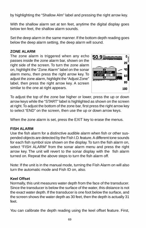
69
by highlighting the “Shallow Alm” label and pressing the right arrow key.
With the shallow alarm set at ten feet, anytime the digital display goesbelow ten feet, the shallow alarm sounds.
Set the deep alarm in the same manner. If the bottom depth reading goesbelow the deep alarm setting, the deep alarm will sound.
ZONE ALARMThe zone alarm is triggered when any echopasses inside the zone alarm bar, shown on theright side of the screen. To turn the zone alarmon, highlight the “Zone Alarm” label on the sonaralarm menu, then press the right arrow key. Toadjust the zone alarm, highlight the “Adjust Zone”label, then press the right arrow key. A screensimilar to the one at right appears.
To adjust the top of the zone bar higher or lower, press the up or downarrow keys while the “START” label is highlighted as shown on the screenat right. To adjust the bottom of the zone bar, first press the right arrow keyto select “END” on the screen, then use the up or down arrow keys.
When the zone alarm is set, press the EXIT key to erase the menus.
FISH ALARMUse the fish alarm for a distinctive audible alarm when fish or other sus-pended objects are detected by the Fish I.D. feature. A different tone soundsfor each fish symbol size shown on the display. To turn the fish alarm on,select “FISH ALARM” from the sonar alarm menu and press the rightarrow key. The unit will revert to the sonar display with the fish alarmturned on. Repeat the above steps to turn the fish alarm off.
Note: If the unit is in the manual mode, turning the Fish Alarm on will alsoturn the automatic mode and Fish ID on, also.
Keel OffsetNormally, this unit measures water depth from the face of the transducer.Since the transducer is below the surface of the water, this distance is notthe exact water depth. If the transducer is one foot below the surface, andthe screen shows the water depth as 30 feet, then the depth is actually 31feet.
You can calibrate the depth reading using the keel offset feature. First,

70
highlight the “SET KEEL OFFSET” label on the“System Setup” menu, then press the right arrowkey. The screen shown at right appears. The cur-rent bottom depth shows in the upper left cornerof the screen. The keel offset shows beneath it.In this example, we need to change the keel off-set so that the unit will add one foot to the depth,since the transducer is one foot below the sur-face. Press the right arrow key, then the up ordown arrow keys until +1.0 appears in the box, as shown at right, thenpress the ENT key. This immediately changes the digital depth display atthe top of the screen by one foot. Press the EXIT key to erase this menu.
Note: Another way to use the keel offset feature is if you want to know thedepth of the water below the lowest part of the boat, instead of the sur-face. To do this, measure the lowest part of the boat below the transducer.In this example, we’ll use 3 feet. Now, using the keel offset feature, adjustthe offset for a negative 3 feet.
Please note that adjusting the keel offset only affects the digital depthdisplay and all features that use the digital depth, such as the depth alarmsand FishTrack. This doesn’t affect the chart at all.
Calibrate SpeedYou can calibrate the speed display if an optionalspeed sensor is attached. To do this, highlightthe “Calibrate Speed” label on the “System Setup”menu, then press the right arrow key. A screensimilar to the one at right appears.
If the digital speed display is slower than youractual speed, add a positive percentage to makeit read faster. If the digital speed display is faster,use a negative percentage to make it read slower. Use the arrow keys tochange the speed, then press the ENT key. Press the EXIT key to erasethis menu.

71
SONAR TROUBLESHOOTINGIf your unit is not working, or if you need technical help, please use thefollowing troubleshooting section before contacting the factory customerservice department. It may save you the trouble of returning your unit.
Unit won’t turn on:1. Check the power cable’s connection at the unit. Also check the wiring.
2. Make certain the power cable is wired properly. The red wire connectsto the positive battery terminal, black to negative or ground.
3. Check the fuse.
4. Measure the battery voltage at the unit’s power connector. It should beat least 11 volts. If it isn’t, the wiring to the unit is defective, the batteryterminals or wiring on the terminals are corroded, or the battery needscharging.
Unit freezes, locks up, or operates erratically:1. Electrical noise from the boat’s motor, trolling motor, or an accessory
may be interfering with the sonar unit. Rerouting the power and trans-ducer cables away from other electrical wiring on the boat may help.Route the sonar unit’s power cable directly to the battery instead ofthrough a fuse block or ignition switch
2. Inspect the transducer cable for breaks, cuts, or pinched wires.
3. Check both the transducer and power connectors. Make certain bothare securely plugged in to the unit.
Weak bottom echo, digital readings erratic, or no fish signals:1. Make certain transducer is pointing straight down. Clean the face of the
transducer. Oil, dirt, and fuel can cause a film to form on the trans-ducer, reducing its effectiveness. If the transducer is mounted insidethe hull, be sure it is shooting through only one layer of fiberglass andthat it is securely bonded to the hull. Do NOT use RTV silicone rubberadhesive or Marinetex
2. Electrical noise from the boat’s motor can interfere with the sonar. Thiscauses the sonar to automatically increase its Discrimination or noiserejection feature. This can cause the unit to eliminate weaker signalssuch as fish or even structure from the display.

72
3. The water may be deeper than the sonar’s ability to find the bottom. Ifthe sonar can’t find the bottom signal while it’s in the automatic mode,the digital will flash continuously. It may change the range to limits fargreater than the water you are in. If this happens, place the unit in themanual mode, then change the range to a realistic one, (for example,0-100 feet) and increase the sensitivity. As you move into shallowerwater, a bottom signal should appear.
4. Check the battery voltage. If the voltage drops, the unit’s transmitterpower also drops, reducing its ability to find the bottom or targets.
Bottom echo disappears at high speeds or erratic digital reading orweak bottom echo while boat is moving1. The transducer may be in turbulent water. It must be mounted in a
smooth flow of water in order for the sonar to work at all boat speeds.Air bubbles in the water disrupt the sonar signals, interfering with itsability to find the bottom or other targets. The technical term for this isCavitation.
2. Electrical noise from the boat’s motor can interfere with the sonar. Thiscauses the sonar to automatically increase its Discrimination or noiserejection feature. This can cause the unit to eliminate weaker signalssuch as fish or even structure from the display. Try using resistor sparkplugs or routing the sonar unit’s power and transducer cables awayfrom other electrical wiring on the boat.
No fish arches when the Fish ID feature is off:1. Make certain transducer is pointing straight down. This is the most
common problem if a partial arch is displayed.
2. The sensitivity may not be high enough. In order for the unit to display afish arch, it has to be able to receive the fish’s echo from the time itenters the cone until it leaves. If the sensitivity is not high enough, theunit shows the fish only when it is in the center of the cone.
3. Use the Zoom feature. It is much easier to display fish arches whenzoomed in on a small range of water than a large one. For example,you will have much better luck seeing fish arches with a 30 to 60 footrange than a 0 to 60 foot range. This enlarges the targets, allowing thedisplay to show much more detail.
4. The boat must be moving at a slow trolling speed to see fish arches. Ifthe boat is motionless, fish stay in the cone, showing on the screen asstraight horizontal lines.

73
NOISEA major cause of sonar problems is electrical noise. This usually appearson the sonar’s display as random patterns of dots or lines. In severe cases,it can completely cover the screen with black dots, or cause the unit oper-ate erratically, or not at all.
To eliminate or minimize the effects of electrical noise, first try to deter-mine the cause. With the boat at rest in the water, the first thing you shoulddo is turn all electrical equipment on the boat off. Make certain the engineis off, also. Turn the sonar unit on, then turn off ASP (Advanced SignalProcessing). There should be a steady bottom signal on the display. Nowturn on each piece of electrical equipment on the boat and view the effecton the sonar’s display. For example, turn on the bilge pump and view thesonar display for noise. If no noise is present, turn the pump off, then turnon the VHF radio and transmit. Keep doing this until all electrical equip-ment has been turned on, their effect on the sonar display noted, thenturned off.
If you find noise interference from an electrical instrument, trolling motor,pump, or radio, try to isolate the problem. You can usually reroute thesonar unit’s power cable and transducer cable away from the wiring thatis causing the interference. VHF radio antenna cables radiate noise whentransmitting, so be certain to keep the sonar’s wires away from it. You mayneed to route the sonar unit’s power cable directly to the battery to isolateit from other wiring on the boat.
If no noise displays on the sonar unit from electrical equipment, then makecertain everything except the sonar unit is turned off, then start the en-gine. Increase the RPM with the gearshift in neutral. If noise appears onthe display, the problem could be one of three things; spark plugs, alter-nator, or tachometer wiring. Try using resistor spark plugs, alternator fil-ters, or routing the sonar unit’s power cable away from engine wiring.Again, routing the power cable directly to the battery helps eliminate noiseproblems. Make certain to use the in-line fuse supplied with the unit whenwiring the power cable to the battery.
When no noise appears on the sonar unit after all of the above tests, thenthe noise source is probably cavitation. Many novices or persons withlimited experience make hasty sonar installations which function perfectlyin shallow water, or when the boat is at rest. In nearly all cases, the causeof the malfunction will be the location and/or angle of the transducer. Theface of the transducer must be placed in a location that has a smooth flowof water at all boat speeds. Read the transducer instructions for the bestmounting position.
74
UPS Return ServiceEagle Electronics and United Parcel Service (UPS) are proud to offer allof our customers free shipping for all units sent to us for repair or service.If you have to send this unit to the factory, and you are in the continentalUnited States, use the enclosed UPS shipping label for easy, free ship-ping to our factory customer service department. There are six easy steps:
1.Call Eagle at the toll-free number on the front of this flyer for a ReturnAuthorization (RA) number and instructions about what accessories toreturn. Do not return a product to the factory without a Return Au-thorization (RA) Number!
2.Pack your unit and any accessories in the original shipping container, ifpossible. Be sure to include proof of purchase for warranty verifi-cation!
3. Write a brief note detailing the problem you’re having with the unit.Please include your name, address, and daytime telephone number.
4. Please include payment for non-warranty repairs. Check, money order,Visa, or MasterCard may be used.
5.Fill in your name, address, zip code, date, and RA number in the blanksprovided on the UPS form included with your unit.
6.Attach the label to the shipping box, tear off the tab for your receipt andgive the package to any UPS driver or take the package to any UPSCustomer Center. You will not be charged for this shipment.
That’s it! Your unit will be shipped to Eagle’s customer service depart-ment at no charge to you. Units under warranty will be returned to youat no charge.
NOTE!Eagle will pay UPS surface shipping charges both to and from the factoryfor this unit in the event it needs repair. Your unit is insured against loss orshipping damage when you use the enclosed UPS label.
75
KEEP THIS LABEL!YOU WILL NEED IT IF YOU EVER NEED TO RETURN YOUR UNIT TO THE
FACTORY FOR REPAIR.
Accessory Ordering InformationTo order accessories such as power cables or transducers, please con-tact:
1) Your local marine dealer. Most quality dealers that handle marine elec-tronic equipment should be able to assist you with these items. Consultyour local telephone directory for listings.
2) LEI Extras, Inc. P.O. Box 129 Catoosa, OK 74015-0129or call
800-324-0045(USA orders only.)
76
EAGLE ELECTRONICSFULL ONE-YEAR WARRANTY
“We”, “our”, or “us” refers to EAGLE ELECTRONICS, a division of LEI, the manufacturer ofthis product. “You” or “your” refers to the first person who purchases this product as aconsumer item for personal, family, or household use.
We warrant this product against defects or malfunctions in materials and workmanship,and against failure to conform to this product’s written specifications, all for one year (1)from the date of original purchase by you. WE MAKE NO OTHER EXPRESS WARRANTYOR REPRESENTATION OF ANY KIND WHATSOEVER CONCERNING THIS PRODUCT.Your remedies under this warranty will be available so long as you can show in a reason-able manner that any defect or malfunction in materials or workmanship, or any non-conformity with the product’s written specifications, occurred within one year from the dateof your original purchase, which must be substantiated by a dated sales receipt or salesslip. Any such defect, malfunction, or non-conformity which occurs within one year fromyour original purchase date will either be repaired without charge or be replaced with anew product identical or reasonably equivalent to this product, at our option, within a rea-sonable time after our receipt of the product. If such defect, malfunction, or non-conformityremains after a reasonable number of attempts to repair by us, you may elect to obtainwithout charge a replacement of the product or a refund for the product. THIS REPAIR,REPLACEMENT, OR REFUND (AS JUST DESCRIBED) IS THE EXCLUSIVE REMEDYAVAILABLE TO YOU AGAINST US FOR ANY DEFECT, MALFUNCTION, OR NON-CON-FORMITY CONCERNING THE PRODUCT OR FOR ANY LOSS OR DAMAGE RESULT-ING FROM ANY OTHER CAUSE WHATSOEVER. WE WILL NOT UNDER ANY CIRCUM-STANCES BE LIABLE TO ANYONE FOR ANY SPECIAL, CONSEQUENTIAL, INCIDEN-TAL, OR OTHER INDIRECT DAMAGE OF ANY KIND.
Some states do not allow the exclusion or limitation of incidental or consequential dam-ages, so the above limitations or exclusions may not apply to you.
This warranty does NOT apply in the following circumstances: (1) when the product hasbeen serviced or repaired by anyone other than us, (2) when the product has been con-nected, installed, combined, altered, adjusted, or handled in a manner other than accord-ing to the instructions furnished with the product, (3) when any serial number has beeneffaced, altered, or removed, or (4) when any defect, problem, loss, or damage has re-sulted from any accident, misuse, negligence, or carelessness, or from any failure to pro-vide reasonable and necessary maintenance in accordance with the instructions of theowner’s manual for the product.
We reserve the right to make changes or improvements in our products from time to timewithout incurring the obligation to install such improvements or changes on equipment oritems previously manufactured.
This warranty gives you specific legal rights and you may also have other rights which mayvary from state to state.
REMINDER: You must retain the sales slip or sales receipt proving the date of youroriginal purchase in case warranty service is ever required.
EAGLE ELECTRONICSPO BOX 669
CATOOSA, OK 74015800-324-1354

77
WGS 84 .................DEFAULT
ADINDAN ...............MEAN
ADINDAN ...............BURKINAFASO
ADINDAN ...............CAMEROON
ADINDAN ...............ETHIOPIA
ADINDAN ...............MALI
ADINDAN ...............SENEGAL
ADINDAN ...............SUDAN
AFGOOYE .............SOMALIA
AIN EL ABD ...........1970BAHRAIN
AIN EL ABD ...........1970 SAUDIARABIA
ANNA 1 ASTRO ....1965 COCOSISLANDS
ANTIGUA ...............ISLANDASTRO 1943
ARC 1950 ..............MEAN
ARC 1950 ..............BOTSWANA
ARC 1950 ..............BURUNDI
ARC 1950 ..............LESOTHO
ARC 1950 ..............MALAWI
ARC 1950 ..............SWAZILAND
ARC 1950 ..............ZAIRE
ARC 1950 ..............ZAMBIA
ARC 1950 ..............ZIMBABWE
WGS 1984Default
AdindanMean for Ethiopia, Sudan
AdindanBurkina Faso
AdindanCameroon
AdindanEthiopia
AdindanMali
AdindanSenegal
AdindanSudan
AfgooyeSomalia
Ain el Abd 1970Bahrain
Ain el Abd 1970Saudi Arabia
Anna 1 Astro 1965Cocos Islands
Antigua Island Astro 1943Antigua (Leeward Islands)
Arc 1950Mean for Botswana, Lesotho,Malawi, Swaziland, Zaire, Zambia,Zimbabwe
Arc 1950 - Botswana
Arc 1950 - Burundi
Arc 1950 - Lesotho
Arc 1950 - Malawi
Arc 1950 - Swaziland
Arc 1950 - Zaire
Arc 1950 - Zambia
Arc 1950 - Zimbabwe
ARC 1960 ..............MEAN
ASCENSION ..........ISLAND1958
ASTRO BEACON ..E 1945IWO JIMA
ASTRO DOS 714 ..ST HELENAISLAND
ASTRO TERN ........ISLAND1961
ASTRONOMICAL ..STATION ‘52MARCUS ISLE
AUSTRALIAN ........GEODETIC1966
AUSTRALIAN ........GEODETIC1984
AYABELLE .............LIGHTHOUSEDJIBOUTI
BELLEVUE ............(IGN) EFATEERRAOMANGO
BERMUDA .............1957
BISSAU ..................GUINEA
BOGOTA ................OBSERVATORYCOLOMBIA
BUKIT RIMPAH ......INDONESIA
CAMP AREA ..........ASTROANTARCTICA
CAMPO ..................INCHAUSPEARGENTINA
CANTON ASTRO ..’66 PHOENIXISLANDS
CAPE .....................SOUTHAFRICA
CAPE .....................CANAVERALBAHAMAS FL
Arc 1960 - Mean for Kenya,Tanzania
Ascension Island 1958 -Ascension Island
Astro Beacon E 1945 - Iwo Jima
Astro DOS 71/4 - St Helena Island
Astro Tern Island (FRIG) 1961 -Tern Island
Astronomical Station 1952 -Marcus Island
Australian Geodetic 1966 -Australia & Tasmania
Australian Geodetic 1984 -Australia & Tasmania
Ayabelle Lightlhouse - Djibouti
Bellevue (IGN) - Efate &Erromango Islands
Bermuda 1957 - Bermuda
Bissau - Guinea-Bissau
Bogota Observatory - Colombia
Bukit Rimpah - Indonesia (Bangka& Belitung Islands)
Camp Area Astro - Antarctica(McMurdo Camp Area)
Campo Inchauspe - Argentina
Canton Astro 1966 - PhoenixIslands
Cape - South Africa
Cape Canaveral - Bahamas,Florida
DATUMS

78
CARTHAGE ...........TUNISIA
CH-1903 ................
CHATHAM .............ISLAND ASTRONEW ZEALAND
CHUA ASTRO .......PARAGUAY
CORREGO ............ALEGREBRAZIL
DABOLA ................GUINEA
DJAKARTA .............(BATAVIA)INDONESIA
DOS 1968 ..............NEW GEORGIAISLANDS
EASTER ................ISLAND1967
EUROPEAN ...........1950 MEANWESTERN
EUROPEAN ...........1950 MEANCENTRAL
EUROPEAN ...........1950 MEANMIDDLE EAST
EUROPEAN ...........1950CYPRUS
EUROPEAN ...........1950EGYPT
EUROPEAN ...........1950 GREATBRITAIN
EUROPEAN ‘50 .....FINLANDNORWAY
EUROPEAN ...........1950GREECE
EUROPEAN ...........1950IRAN
Carthage - Tunisia
Switzerland
Chatham Island Astro 1971New Zealand (Chatham Island)
Chua AstroParaguay
Corrego AlegreBrazil
DabolaGuinea
Djakarta (Batavia)Indonesia (Sumatra)
DOS 1968New Georgia Islands(Gizo Island)
Easter Island 1967Easter Island
European 1950Mean for Austria, Belgium,Denmark, Finland, France,West Germany, Gibralter, Greece,Italy, Luxembourg, Netherlands,Norway, Portugal, Spain, Sweden, Switzerland
European 1950Mean for Austria, Denmark,France, West Germany,Netherlands, Switzerland
European 1950Mean for Iraq, Israel, Jordan,Lebanon, Kuwait,Saudi Arabia, Syria
European 1950Cyprus
European 1950Egypt
European 1950England, Channel Islands, Ireland, Scotland, Shetland Islands
European 1950Finland, Norway
European 1950Greece
European 1950Iran
EUROPEAN ...........1950 ITALY(SARDINIA)
EUROPEAN ...........1950 ITALY(SICILY)
EUROPEAN ...........1950MALTAEUROPEAN ...........1950 SPAINPORTUGAL
EUROPEAN ...........1979MEAN
FORT THOMAS .....1955 NEVISST. KITTS
GAN 1970 ..............REPUBLIC OFMALDIVES
GEODETIC ............DATUM 1949NEW ZEALAND
GRACIOSA ............BASE SW1948 AZORES
GUAM ....................1963
GUNUNG ...............SEGARAINDONESIA
GUX 1 ASTRO .......GUADALCANALISLAND
HERAT NORTH .....AFGHANISTAN
HJORSEY ..............1955ICELAND
HONG KONG ........1963
HU-TZU-SHAN ......TAIWAN
INDIAN ...................BANGLADESH
INDIAN ...................INDIA NEPAL
INDIAN 1954 .........THAILANDVIETNAM
INDIAN 1975 .........THAILAND
European 1950Italy (Sardinia)
European 1950(Sicily)
European 1950Malta
European 1950Portugal, Spain
European 1979Mean for Austria, Finland, Netherlands, Norway, Spain,Sweden, Switzerland
Fort Thomas, 1955Nevis, St. Kitts(Leeward Islands)
Gan 1970Republic of Maldives
Geodeic Datum 1949New Zealand
Graciosa Base SW 1948Azores (Faial, Graciosa, Pico,Sao Jorge, Terceira)
Guam 1963Guam
Gunung SegaraIndonesia (Kalimantan)
GUX 1 AstroGuadalcanal Island
Herat NorthAfghanistan
Hjorsey 1955Iceland
Hong Kong 1963Hong Kong
Hu-Tzu-ShanTaiwan
IndianBangladesh
IndianIndia, Nepal
Indian - 1954Thailand, Vietnam
Indian - 1975Thailand

79
IRELAND ...............1965
ISTS 061 ................ASTRO 1968S GEORGIA
ISTS 073 ................ASTRO 1969DIEGO GARCIA
JOHNSTON ...........ISLAND1961
KANDAWALA .........SRI LANKA
KERGUELEN .........ISLAND1949
KERTAU 1948 ........W MALAYSIASINGAPORE
KUSAIE ASTRO ....CAROLINE 1951ISLANDS
L C 5 ASTRO .........1961 CAYMANBRAC ISLAND
LEIGON .................GHANA
LIBERIA .................1964
LUZON ...................PHILIPPINES
LUZON ...................PHILIPPINESMINDANAO
MAHE ISLAND ......1971
MASSAWA .............ETHIOPIA(ERITREA)
MERCHICH ...........MOROCCO
MIDWAY ASTRO ...1961
MINNA ...................CAMEROON
MINNA ...................NIGERIA
MONTSERRAT ......ISLANDASTRO 1958
M’PORALOKO .......GABON
Ireland 1965Ireland
ISTS 061 Astro 1968South Georgia Islands
ISTS 073 Astro 1969Diego Garcia
Johnston Island 1961Johnston Island
KandawalaSri Lanka
Kerguelen Island 1949Kerguelen Island
Kertau 1948West Malaysia & Singapore
Kusaie Astro 1951Caroline Islands
L.C. 5 Astro 1961Cayman Brac Island
LeigonGhana
Liberia 1964Liberia
LuzonPhilipines(Excluding Mindanao)
LuzonPhilipines (Mindanao)
Mahe 1971Mahe Island
MassawaEthiopia (Eritrea)
MerchichMorocco
Midway Astro 1961Midway Islands
MinnaCameroon
MinnaNigeria
Montserrat Island Astro 1958Montserrat(Leeward Islands)
M’PoralokoGabon
NAHRWAN .............OMAN
NAHRWAN .............SAUDI ARABIA
NAHRWAN .............UNITED ARABEMIRATES
NAPARIMA BWI .....TRINIDAD ANDTOBAGO
N AMERICA ...........1927 MEANCARRIBEAN
N AMERICA ...........1927 MEANCENTRAL AMER
N AMERICA ...........1927 MEANCANADA
N AMERICA ...........1927 MEANCONUS
N AMERICA ...........1927 MEANCONUS EAST
N AMERICA ...........1927 MEANCONUS WEST
N AMERICA ...........1927 ALASKA
N AMERICA ...........1927 BAHAMAS(NO SAN SALV)
N AMERICA ...........1927 BAHAMAS
N AMERICAN ........1927 CANADA(WEST)
N AMERICAN ........1927 CANADA(CENTRAL)
N AMERICAN ........1927 CANADAEAST
N AMERICAN ........1927 CANADANORTH
N AMERICAN ........1927 CANADAYUKON
NahrwanOman (Masirah Island)
NahrwanSaudi Arabia
NahrwanUnited Arab Emirates
Naparima BWITrinidad & Tobago
North American 1927Mean for Antigua, Barbados, Barbuda,Caicos Islands, Cuba, DominicanRepublic, Grand Cayman, Jamaica,Turks Islands
North American 1927Mean for Belize, Costa Rica,El Salvador, Guatmala, Honduras,Nicaragua
North American 1927Mean for Canada
North American 1927Mean for CONUS(Continental United States)
North American 1927Mean for CONUS (East of MississippiRiver) including Louisiana, Missouri,Minnesota
North American 1927Mean for CONUS(West of Mississippi River)
North American 1927Alaska
North American 1927Bahamas(Except San Salvador Island)
North American 1927Bahamas (San Salvador Island)
North American 1927Canada (Alberta, British Columbia)
North American 1927Canada (Manitoba, Ontario)
North American 1927Canada (New Brunswick,Newfoundland, Nova Scotia, Quebec)
North American 1927Canada (Northwest Territories,Saskatchewan)
North American 1927Canada (Yukon)
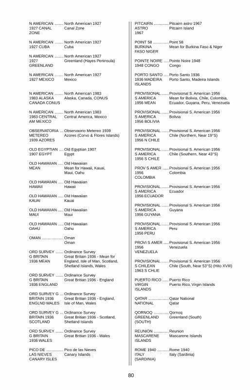
80
N AMERICAN ........1927 CANALZONE
N AMERICAN ........1927 CUBA
N AMERICAN ........1927GREENLAND
N AMERICAN ........1927 MEXICO
N AMERICAN ........1983 ALASKACANADA CONUS
N AMERICAN ........1983 CENTRALAM MEXICO
OBSERVATORIA ...METEREO1939 AZORES
OLD EGYPTIAN ....1907 EGYPT
OLD HAWAIIAN .....MEAN
OLD HAWAIIAN .....HAWAII
OLD HAWAIIAN .....KAUAI
OLD HAWAIIAN .....MAUI
OLD HAWAIIAN .....OAHU
OMAN ....................
ORD SURVEY .......G BRITAIN1936 MEAN
ORD SURVEY .......G BRITAIN1936 ENGLAND
ORD SURVEY G ...BRITAIN 1936ENGLND WALES
ORD SURVEY G ...BRITAIN 1936SCOTLAND
ORD SURVEY .......G BRITAIN1936 WALES
PICO DE ................LAS NIEVESCANARY ISLES
PITCAIRN ..............ASTRO1967
POINT 58 ...............BURKINAFASO NIGER
POINTE NOIRE .....1948 CONGO
PORTO SANTO .....1936 MADEIRAISLANDS
PROVISIONAL .......S AMERICA1956 MEAN
PROVISIONAL .......S AMERICA1956 BOLIVIA
PROVISIONAL .......S AMERICA1956 N CHILE
PROVISIONAL .......S AMERICA1956 S CHILE
PROV S AMER ......1956COLOMBIA
PROVISIONAL .......S AMERICA1956 ECUADOR
PROVISIONAL .......S AMERICA1956 GUYANA
PROVISIONAL .......S AMERICA1956 PERU
PROVI S AMER .....1956VENEZUELA
PROVISIONAL .......S CHILEAN1963 S CHLIE
PUERTO RICO ......VIRGINISLANDS
QATAR ...................NATIONAL
QORNOQ ..............GREENLAND(SOUTH)
REUNION ..............MASCARENEISLANDS
ROME 1940 ...........ITALY(SARDINIA)
North American 1927Canal Zone
North American 1927Cuba
North American 1927Greenland (Hayes Peninsula)
North American 1927Mexico
North American 1983Alaska, Canada, CONUS
North American 1983Central America, Mexico
Observaorio Metereo 1939Azores (Corvo & Flores Islands)
Old Egyptian 1907Egypt
Old HawaiianMean for Hawaii, Kauai,Maui, Oahu
Old HawaiianHawaii
Old HawaiianKauai
Old HawaiianMaui
Old HawaiianOahu
OmanOman
Ordinance SurveyGreat Britain 1936 - Mean forEngland, Isle of Man, Scotland,Shetland Islands, Wales
Ordinance SurveyGreat Britian 1936 - England
Ordinance SurveyGreat Britian 1936 - England,Isle of Man, Wales
Ordinance SurveyGreat Britian 1936 - Scotland,Shetland Islands
Ordinance SurveyGreat Britian 1936 - Wales
Pico de las NievesCanary Islands
Pitcairn astro 1967Pitcairn Island
Point 58Mean for Burkina Faso & Niger
Pointe Noire 1948Congo
Porto Santo 1936Porto Santo, Madeira Islands
Provisional S. American 1956Mean for Bolivia, Chile, Colombia,Ecuador, Guyana, Peru, Venezuela
Provisional S. American 1956Bolivia
Provisional S. American 1956Chile (Northern, Near 19°S)
Provisional S. American 1956Chile (Southern, Near 43°S)
Provisional S. American 1956Colombia
Provisional S. American 1956Ecuador
Provisional S. American 1956Guyana
Provisional S. American 1956Peru
Provisional S. American 1956Venezuela
Provisional S. American 1956Chile (South, Near 53°S) (Hito XVIII)
Puerto RicoPuerto Rico, Virgin Islands
Qatar NationalQatar
QornoqGreenland (South)
ReunionMascarene Islands
Rome 1940Italy (Sardinia)

81
RT 90 .....................
SANTO (DOS) .......’65 ESPIRITOSANTO ISLAND
SAO BRAZ .............AZORES
SAPPER HILL ........1943 EASTFALKLND ISLE
SCHWARZECK .....NAMIBIA
SELVAGEMGRANDESALVAGE ISLE
SOVIET ..................GEODETICSYSTEM 1985
S AMERICAN ........1969 MEAN
S AMERICAN ........1969ARGENTINA
S AMERICAN ........1969 BOLIVIA
S AMERICAN ........1969 BRAZIL
S AMERICAN ........1969 CHILE
S AMERICAN ........1969COLOMBIA
S AMERICAN ........1969ECUADOR
S AMERICAN ........1969 ECUADORGALAPAGOS
S AMERICAN ........1969 GUYANA
S AMERICAN ........1969PARAGUAY
S AMERICAN ........1969 PERU
S AMERICAN ........1969 TOBAGOAND TRINIDAD
S AMERICAN ........1969VENEZUELA
Sweden
Santo (DOS)1965 Espirito Santo Island
Sao BrazAzores (Sao Miguel,Santa Maria Islands)
Sapper Hill 1943East Falkland Island
SchwarzeckNambia
Selvagem GrandeSalvage Islands
SGS 85Soviet Geodetic System 1985
South American 1969Mean for Argentina, Bolivia,Brazil, Chile, Colombia, Ecuador,Guyana, Paraguay, Peru,Trinidad & Tobago, Venezuela
South American 1969Argentina
South American 1969Bolivia
South American 1969Brazil
South American 1969Chile
South American 1969Colombia
South American 1969Ecuador
South American 1969Ecuador (Baltra, Galapagos)
South American 1969Guyana
South American 1969Paraguay
South American 1969Peru
South American 1969Trinidad & Tobago
South American 1969Venezuela
SOUTH ASIA .........
SINGAPORE .........
TANANARIVE ........OBSERVATORY1925MADAGASCAR
TIMBALAI ..............1948 BRUNEIE MALAYSIA
TOKYO ...................MEAN
TOKYO ...................JAPAN
TOKYO ...................KOREA
TOKYO ...................
OKINAWA ..............
TRISTAN DA ..........CUNHAASTRO 1968
VITI LEVU ..............1916 FIJI
WAKE ....................
ENIWETOK ‘60 ......
MARSHALL ISL .....
WAKE ISLAND ......ASTRO 1952
WGS 1972 .............GLOBALDEFINITION
YACARE .................URUGUAY
ZANDERIJ .............SURINAME
South Asia
Singapore
Tananarive Observatory 1925Madagascar
Timbalai 1948Brunei, East Malaysia(Sabah, Sarawak)
TokyoMean for Japan, Korea, Okinawa
TokyoJapan
TokyoKorea
Tokyo
Okinawa
Tristan Astro 1968Tristan da Cunha
Viti Levu 1916Fiji (Viti Levu Island)
Wake
Eniwetok 1960
Marshall Islands
Wake Island Astro 1952Wake Atoll
WGS 1972Global Definition
YacareUruguay
ZanderijSuriname
82
EAGLE DATABASES LICENSE AGREEMENT
THIS IS A LEGAL AGREEMENT BETWEEN THE END-USER WHOFIRST PURCHASES THIS PRODUCT AS A CONSUMER ITEM FORPERSONAL, FAMILY, OR HOUSEHOLD USE (“YOU”) AND EAGLEELECTRONICS, THE MANUFACTURER OF THIS PRODUCT. (“WE”,“OUR”, OR “US”). USING THE PRODUCT ACCOMPANIED BY THISLICENSE AGREEMENT CONSTITUTES ACCEPTANCE OF THESETERMS AND CONDITIONS.
1. This License Agreement applies to the one or more databases thatyour product may contain. We refer to these singly as a “Database”and together as the “Databases.” Your product may thus include the“WBS Database” which contains worldwide background surfacemapping data, the “SmartMap Database” which contains inlandmapping data, or other Databases.
2. The Databases that your product may contain are licensed, not sold.We grant to you the nonexclusive, nonassignable right to use theseDatabases for supplemental navigation reference purposes, but onlyas long as you comply with the terms and conditions of this LicenseAgreement. We reserve the right to terminate this license if youviolate any aspect of this License Agreement. You are responsible forusing official government charts and prudent navigation for safetravel.
3. The Databases housed in your product are protected by the copy-right notices appearing on the product or its screen(s). You may NOTmodify, adapt, translate, reverse engineer, decompile, disassemble,rent, lease, or resell any Database, and you may NOT createderivative works based upon any Database or its contents.. Anyunauthorized reproduction, use, or transfer of a Database may be acrime and may subject you to damages and attorney fees.
4. This License Agreement will terminate immediately without priornotice from us if you fail to comply with or violate any of the provi-sions of this Agreement. Upon termination, you will promptly returnall products containing one or more Databases to us.
5. Prices and programs are subject to change without notice.
6. This License Agreement shall be governed by the laws of the Stateof Oklahoma and comprises the complete and exclusive under-standing between you and us concerning the above subject matter.

83
DATABASES LIMITED WARRANTY
“We”, “our”, or “us” refers to Eagle Electronics, the manufacturer of this product. “You” or“your” refers to the first person who purchases the product as a consumer item forpersonal, family, or household use. The Databases Limited Warranty applies to the oneor more databases that your product may contain. We refer to each of these as a“Database” or together as the “Databases.” Your product may thus include the “WBSDatabase” which contains worldwide background surface mapping data, the “SmartMapDatabase” which contains inland mapping data, or other Databases.
We warrant to you that we have accurately compiled, processed, and reproduced theportions of the source material on which the Databases are based. However, we areunder no obligation to provide updates to the Databases, and the data contained in theDatabases may be incomplete when compared to the source material. WE MAKE NOEXPRESS OR IMPLIED WARRANTY OF ANY KIND ABOUT THE ACCURACY OF THESOURCE MATERIAL ITSELF, INCLUDING BUT NOT LIMITED TO IMPLIED WARRAN-TIES OF MERCHANTABILITY OR FITNESS FOR A PARTICULAR PURPOSE.
If there is a defect in any Database, your exclusive remedy shall be, at our option, eithera refund of the price you paid for the product containing the defective Database or areplacement of such product. WE WILL NOT UNDER ANY CIRCUMSTANCES BELIABLE TO ANYONE FOR ANY SPECIAL, CONSEQUENTIAL, INCIDENTAL, OROTHER INDIRECT DAMAGE OF ANY KIND.
Some states do not allow the exclusion or limitation of incidental or consequentialdamages, so the above limitations or exclusions may not apply to you.
This warranty does NOT apply in the following circumstances: (1) when the product hasbeen serviced or repaired by anyone other than us, (2) when the product has beenconnected, installed, combined, altered, adjusted, or handled in a manner other thanaccording to the instructions furnished with the product, (3) when any serial number hasbeen effaced, altered, or removed, or (4) when any defect, problem, loss, or damagehas resulted from any accident, misuse, negligence, or carelessness, or from any failureto provide reasonable and necessary maintenance in accordance with the instructionsof the owner’s manual for the product.
We reserve the right to make changes or improvements in our products from time totime without incurring the obligation to install such improvements or changes onequipment or items previously manufactured.
This warranty gives you specific legal rights and you may also have other rights whichmay vary from state to state.
Your remedies under this warranty will be available so long as you can show in areasonable manner that the defect occurred within one (1) year from the date of youroriginal purchase, and we must receive your warranty claim no later than 30 days aftersuch 1-year period expires. Your claim must be substantiated by a dated sales receipt orsales slip.

84
Notes:

85
How to Obtain Service(Canadian Customers Only)
We back your investment in quality products with quick, expert service and genuineEagle replacement parts. If you need service or repairs, contact the Eagle FactoryCustomer Service Department at the toll-free number listed below. A technician maybe able to solve the problem and save you the inconvenience of returning your unit. Youwill be asked for your unit’s serial number.
800-324-1354Canada Only. Monday through Friday 8:00 A.M. - 8:00 P.M. Central Time.
How to Obtain Service(International Customers Only)
If you need service or repairs, contact the dealer in the country you purchased yourunit.
WARRANTY REPAIR WILL BE HONORED ONLY IN THE COUNTRYUNIT WAS PURCHASED.
Please follow the shipping instructions shown below on this page if you have to mailyour unit to the dealer. For proper testing, repair, and service, send a brief note with theproduct describing the problem. Be sure to include your name, return shipping ad-dress, and a daytime telephone number.
Shipping InformationWhen sending a product for repair, we recommend you do the following:1. Always use the original shipping container and filler material the product was packed
in when shipping your product.
2 Always insure the parcel against damage or loss during shipment. Eagle does notassume responsibility for goods lost or damaged in transit.
3. For proper testing, repair, and service, send a brief note with the product describ-ing the problem. Be sure to include your name, return shipping address, and adaytime telephone number.
Accessory Ordering InformationTo order accessories such as power cables or transducers, please contact:1. Your local marine dealer. Most quality dealers that handle marine electronic equip-
ment should be able to assist you with these items. Consult your local telephonedirectory for listings.
2. Canadian customers only can write:Lowrance/Eagle Canada, 919 Matheson Blvd., E. Mississauga, Ontario L4W2R7
or fax 905-629-3118
86
How to Obtain Service (U.S.A. Only)We back your investment in quality products with quick, expert serviceand genuine Eagle replacement parts. If you’re in the United States andyou have questions, please contact the Factory Customer Service De-partment using our toll-free number listed below. You must send the unitto the factory for warranty service or repair. Please call the factory beforesending the unit. You will be asked for your unit’s serial number (shown above).Use the following toll-free number:
800-324-1354U.S.A.only. Monday through Friday 8:00 A.M. - 8:00 P.M. Central time, except holidays.
Your unit is covered by a full one-year warranty. (See inside for completewarranty details.) If your unit fails and the failure is not covered by theoriginal warranty, Eagle has a flat-rate repair policy that covers your unitand accessories packed with the unit at the factory. There is a 180-daywarranty on all non-warranty repairs from the factory, which is similar tothe original warranty, but is for 180 days rather than one year. For furtherdetails, please call us at the above number.
Eagle also gives you free UPS shipping from anywhere in the continentalUnited States both to and from the factory for all warranty repairs. You canalso use the enclosed UPS shipping label for non-warranty shipments.See inside for more information.
Remember, non-warranty repairs are subject to Eagle’s published flat-ratecharges and 180-day warranty.
LITHO IN U.S.A. 988-0145-47