Accident Causation & Prevention - Class Direct · the primary structure of Naval Ships under...
42
ShipRight Design and Construction Structural Design Assessment Primary Structure of Naval Ships under Category NS2 March 2017 Working together for a safer world
Transcript of Accident Causation & Prevention - Class Direct · the primary structure of Naval Ships under...

ShipRight Design and Construction
Structural Design Assessment
Primary Structure of Naval Ships under Category NS2
March 2017
Working together
for a safer world

Document History
Document Date: Notes:
September 2015 Preliminary release
September 2016 Second draft release
March 2017 Final release
© Lloyd's Register Group Limited 2017. All rights reserved. Except as permitted under current legislation no part of this work may be photocopied, stored in a retrieval system, published, performed in public, adapted, broadcast, transmitted, recorded or reproduced in any form or by any means, without the prior permission of the copyright owner. Enquiries should be addressed to Lloyd's Register Group Limited, 71 Fenchurch Street, London, EC3M 4BS.
SDA procedure for Naval Ships under category NS2 March 2017
1
CONTENTS
Chapter 1 Introduction 2 Section 1 Application 2 2 Symbols 3 3 Direct calculation procedure report 4 Chapter 2 Global Response Analysis of Complete Ship 5 Section 1 Application 5 2 Objectives 5 3 Structural modelling 5 4 Loading conditions 8 5 Boundary conditions 16 6 Acceptance criteria 18 Chapter 3 Verification of Structural Details 24 Section 1 Application 24 2 Objectives 24 3 Structural modelling 24 4 Loading and boundary conditions 25 5 Acceptance criteria 26 Chapter 4 Verification of Primary Structure Supporting Decks 31 Section 1 Objectives 31 2 Structural modelling 31 3 Loading and boundary conditions 32 4 Acceptance criteria 32 Chapter 5 Verification of Primary Structure at Forward Region 34 Section 1 Application 34 2 Objectives 34 3 Structural modelling 34 4 Loading conditions 34 5 Boundary conditions 36 6 Acceptance criteria 36 Chapter 6 Adjustment of Global BM and SF 38 Section 1 Introduction 38 2 Derivation of BM and SF influence factors 38 3 Global stress adjustment 39

2
Chapter 1 Introduction Section 1 Application 1.1 General 1.1.1 The ShipRight Structural Design Assessment (SDA) procedure defined in this document is for the assessment of the strength of the primary structure of Naval Ships under category NS2 (hereinafter referred to as NS2 ships) using Finite Element (FE) methods. 1.1.2 The SDA notation is mandatory for NS2 ships where:
• it is required to utilise the load carrying capability of the superstructure or deck-houses for longitudinal strength and the superstructure or deck-houses are not full length and full width; or
• it is considered that the superstructure or deck-houses will be subject to a significant load from flexure of the hull girder; or • a limited number of transverse bulkheads above the bulkhead deck are present to carry the racking response; or • there are any novel or unusual structure arrangements; or • significant openings or discontinuities in the hull girder.
1.1.3 For NS2 ships other than those specified in Ch 1, 1.1 General 1.1.2 the SDA procedure may be applied on a voluntary basis. 1.1.4 Definitions of NS2 ships are specified in Lloyd’s Register (hereinafter referred to as LR) Rules and Regulations for the Classification of Naval Ships (hereinafter referred to as the Rules for Naval Ships), see Vol 1, Pt 1, Ch 2, 2.1 Applicable ship types 2.1.1. 1.1.5 The SDA procedure requires the following:
• a detailed analysis of the ship’s structural response to specified load scenarios; and • other direct calculations as applicable.
1.1.6 The minimum requirements specified in this procedure, in addition to the requirements in LR’s Rules for Naval Ships, are to be complied with. 1.1.7 The direct calculation of the ship’s structural response is to be based on a three-dimensional (3-D) shell FE analysis carried out in accordance with this document. 1.1.8 The SDA procedure comprises four parts:
• Chapter 2: Verification of global strength using a mathematical model of the entire hull. • Chapter 3: Verification of the structural response of components and details using follow-up fine mesh models. • Chapter 4: Verification of the strength of transverses and girders supporting decks. • Chapter 5: Verification of strength of primary structure at forward region under bow immersion and maximum bow acceleration
condition. 1.1.9 Ch 2 Global Response Analysis of Complete Ship and Ch 5 Verification of Primary Structure at Forward Region of this procedure are to be applied to all NS2 ships for which the SDA class notation is required. 1.1.10 Ch 3 Verification of Structural Details of this procedure, in addition to Ch 1, 1.1 General 1.1.9, is required for NS2 ships where there are details of high stress concentration, such as major hull openings and discontinuities, and novel or unusual features and arrangements. 1.1.11 The structural strength of the bottom structure is to be verified in accordance with Ch 2 Global Response Analysis of Complete Ship where:
• the pillaring system is not carried down to the tank top and aligned with double bottom girders; or • heavy or concentrated loads are arranged on the tank top; or • a novel or unusual arrangement of primary supporting members is proposed.
1.1.12 The transverse strength against racking response is to be verified in accordance with Ch 2 Global Response Analysis of Complete Ship where there are a limited number of transverse bulkheads in way of hangars or mission spaces to resist the racking response, or where there is a large mast structure. Separate models may be used to determine the racking response for superstructures. 1.1.13 Ch 4 Verification of Primary Structure Supporting Decks of this procedure, in addition to Ch 1, 1.1 General 1.1.9, is required for NS2 ships in order to verify the structural adequacy of the transverse and longitudinal primary members in supporting decks. 1.1.14 A detailed report of the calculations is to be submitted and must include the information listed in Ch 1, 3 Direct calculation procedure report. The report must show compliance with the specified structural design criteria specified in the relevant chapters of this procedure. 1.1.15 If computer programs are employed that are not recognised by LR, full particulars of these programs must also be submitted.

3
1.1.16 LR may, in certain circumstances, require the submission of computer input and output to further verify the adequacy of the calculations carried out. 1.1.17 Where alternative procedures are proposed, these are to be agreed with LR before commencement. 1.1.18 NS2 ships of unusual form or structural arrangements may need special consideration, and additional calculations to those contained in this procedure may be required. 1.1.19 It is recommended that the designer discusses with LR the SDA analysis requirements at an early stage of the design phase. Section 2 Symbols 2.1 Definition 2.1.1 The symbols used in this procedure are defined as follows:
LR = Rule length, in metres, see Vol 1, Pt 3, Ch 1, 5.2 Principal particulars of the Rules for Naval Ships BWL = waterline breadth, in metres, see Vol 1, Pt 3, Ch 1, 5.2 Principal particulars of the Rules for Naval Ships B = greatest moulded breadth, in metres, see Vol 1, Pt 3, Ch 1, 5.2 Principal particulars of the Rules for Naval Ships D = depth of ship, in metres, see Vol 1, Pt 3, Ch 1, 5.2 Principal particulars of the Rules for Naval Ships T = design draught, in metres, see Vol 1, Pt 3, Ch 1, 5.2 Principal particulars Rules for Naval Ships Cb = block coefficient, see Vol 1, Pt 3, Ch 1, 5.2 Principal particulars of the Rules for Naval Ships kL, ks = higher tensile steel factor, see Vol 1, Pt 6, Ch 5, 2.1 Design criteria of the Rules for Naval Ships SWSF = still water shear force, see Vol 1, Pt 5, Ch 4, 2.3 Still water shear forces of the Rules for Naval Ships SWBM = still water bending moment, see Vol 1, Pt 5, Ch 4, 2.2 Still water bending moments of the Rules for Naval Ships VWBM = vertical wave bending moment, see Vol 1, Pt 5, Ch 4, 3.3 Vertical wave bending moments of the Rules for Naval
Ships VWSF = vertical wave shear force, see Vol 1, Pt 5, Ch, 3.4 Vertical wave shear forces of the Rules for Naval Ships fs = service area factor, see Vol 1, Pt 5, Ch 2, 2.4 Service Area factors of the Rules for Naval Ships FfS = sagging (negative) moment correction factor, see Vol 1, Pt 5, Ch 4, 3.3 Vertical wave bending moments 3.3.1 of the
Rules for Naval Ships FfH = hogging (positive) moment correction factor, see Vol 1, Pt 5, Ch 4, 3.3 Vertical wave bending moments 3.3.1 of the
Rules for Naval Ships Mo = see Vol 1, Pt 5, Ch 4, 3.3 Vertical wave bending moments 3.3.1 of the Rules for Naval Ships g = acceleration due to gravity (9,81 m/s2) ρ = density of sea-water (1,025 kg/m3) h = local head for pressure evaluation t = thickness of plating σcr = critical buckling stress corrected for plasticity effects σc = elastic critical buckling stress σo = specified minimum yield stress of steel (special consideration to steel where σo ≥ 355 N/mm2)
= 0,2 per cent proof stress or 70 per cent of the ultimate strength of aluminium alloy, whichever is lesser, see Ch 13, 8.3 Fabrication and welding 8.3.2 of the LR’s Rules for the Manufacture, Testing and Certification of Materials
σactual = equivalent design stress σL = 235/kL N/mm2 = σo for aluminium alloy σVM = von Mises equivalent stress
= �σx2 + σy
2 - σxσy + 3τxy2
τ = shear stress λ = factor against elastic buckling = σcr/σactual σx = direct stress in element x direction σy = direct stress in element y direction τxy = shear stress in element xy plane
2.1.2 Consistent units to be used throughout the analysis. Results presentation in Newtons (N) and millimetres (mm) is preferred. 2.1.3 All parameters used in the Rule equations are to be in accordance with the units defined in the Rules for Naval Ships.

4
Section 3 Direct calculation procedure report 3.1 General 3.1.1 A report is to be submitted to LR for approval of the primary structure and global strength of the ship, which is to contain the following information:
• list of plans used including dates and versions;
• detailed description of structural modelling including all modelling assumptions;
• plots to demonstrate correct structural modelling and assigned properties;
• full details of material properties used for all components;
• details of boundary conditions;
• details of all load cases applied with calculated shear force (SF) and bending moment (BM) distributions;
• details of applied loadings and confirmation that individual and total applied loads are correct;
• details of boundary support forces and moments;
• plots and results that demonstrate the correct behaviour of the ship structural models to the applied loads;
• summaries and plots of global and local deflections;
• summaries and sufficient plots of von Mises, directional and shear stresses to demonstrate that the design criteria contained
in this SDA procedure has not been exceeded in any member;
• plate buckling analysis and results;
• pillar buckling analysis and results;
• tabulated results showing compliance, or otherwise, with the design criteria; and
• proposed amendments to structure where necessary, including revised assessment of stresses and buckling capabilities.

5
Chapter 2 Global Response Analysis of Complete Ship Section 1 Application 1.1 Introduction 1.1.1 For the application of Ch 2 Global Response Analysis of Complete Ship, see Ch 1, 1.1 General 1.1.8. Section 2 Objectives 2.1 General 2.1.1 The objectives of this Chapter are:
a) to establish the structural contribution of the superstructure in resisting hull girder loads. b) to derive the stress distribution over the complete cross-section and length of the ship taking due account of the behaviour
and effectiveness of the superstructure. c) to obtain the stress in the transverse structure due to racking, where it is considered to be necessary for the structure
configuration. d) when separate fine mesh models are used, to provide boundary conditions for the fine mesh models required by Ch 3
Verification of Structural Details for the investigation of the detailed stress response of the following critical structural components:
i) structure in way of superstructure or deck-house ends; ii) openings in the decks for silos, uptakes/downtakes and machinery removal; iii) cut-outs and openings in the shell and superstructure or deck-houses for boat and mission bays; iv) the structure in way of doors, openings for marine evacuation systems, accommodation ladders and other
significant shell, superstructure and deck-house sides and bulkhead openings; v) the structure in way of door openings in internal longitudinal bulkheads contributing to global hull girder strength or
where influenced by hull girder response; vi) major equipment supports; vii) areas of unusual structural arrangement.
Section 3 Structural modelling 3.1 General 3.1.1 The effectiveness of the superstructure is dependent on its length, flexibility of its support, integration at its ends, size and number of openings in side walls and internal decks. 3.1.2 A 3-D plate element model of the ship is to be used. This model should extend over the full length and depth of the ship. It is recommended that the model represents the full breadth of the ship. However, a half-breadth model may be used depending on the degree of structural symmetry. The model should represent, with reasonable accuracy, the actual geometric shape of the hull. All effective longitudinal material is to be included. Similarly all transverse primary structures, i.e. watertight and fire divisional bulkheads, are to be represented in the model. 3.1.3 The FE model is to be represented using a right-handed, Cartesian co-ordinate system with:
• x measured in the longitudinal direction, positive forward from the A.P.; • y measured in the transverse direction, positive to port from the centreline; • z measured in the vertical direction, positive upwards from the baseline.
3.1.4 The size and type of plate elements selected are to provide a satisfactory representation of the deflection behaviour of the decks and stress distribution within the transverse bulkhead structures. Two node line elements and four node plate elements are, in general, considered sufficient for the representation of the hull structure. The mesh requirements given in this document are based on the assumption that these elements are used in the finite element models. In general, the plate element mesh is to follow the primary stiffening arrangement. Thus, it is anticipated that:
• Longitudinally, there will be at least one element between transverses; but see Ch 2, 3.1 General 3.1.5 regarding acceptable aspect element ratios.
• Vertically, one element between longitudinal stiffeners. A minimum of three elements is preferred over the web depth of deck transverses and girders and double bottom floors and girders.
• Transversely, one element between longitudinal stiffeners. 3.1.5 Depending on the spacing of transverse members, it may be necessary to refine this mesh arrangement in the longitudinal direction to achieve satisfactory element aspect ratios. An aspect ratio of less than three is recommended, but acceptable aspect ratios are dependent on the analysis code being used. The basic mesh arrangement should also permit the inclusion of the features listed in Ch 2, 3.1 General 3.1.6.

6
3.1.6 All openings, such as door openings, deck openings and shell openings of a significant size are to be represented. Similarly, the model is to accurately reflect shell and superstructure side recesses, sweep brackets and superstructure breaks. 3.1.7 The fine mesh model may reflect the meshing level required by the Ch 3 Verification of Structural Details analysis. This avoids the necessity of having to create a third model (follow-up model Ch 3 Verification of Structural Details) with a different mesh arrangement and performance. 3.1.8 The FE model is to be based on gross plate thickness with thickness deduction equal to 25 per cent of the agreed corrosion margin. Owner’s extras and any additional thicknesses fitted to comply with the optional Enhanced Scantlings (ES) or military notations are not to be included in the FE model. Where there is a substantial increase in thickness which extends beyond one deck height and two watertight compartments, the impact of the thickness on model stiffness and local stress effects associated with the transition of the insert may need to be investigated using fine mesh in accordance with Ch 3 Verification of Structural Details. 3.1.9 All primary structures, such as deck plating, bottom and side shell plating, longitudinal bottom girders, longitudinal and transverse bulkhead plating, transverse floors, superstructure side, internal structural walls and racking frames casings where fitted, are to be represented by plate elements having both membrane and bending stiffness. Internal bulkheads, which are considered to have negligible contribution to the hull strength, may be ignored in the FE model. 3.1.10 Longitudinal deck girders, side transverses and deck transverses may be represented by line elements having appropriate axial and bending stiffness, and the appropriate stress recovery points. 3.1.11 Pillars, where fitted, may be represented by line elements having axial and bending stiffness and appropriate stress recovery points. If modelled in plate elements, and accurate nodal stress output is not available, a line element of nominal area will need to be arranged at the extremities of the section in order to obtain the extreme fibre stresses. 3.1.12 The secondary stiffeners are to be represented by line elements positioned in the plane of the plating. The line elements are to have axial and bending properties (bars) representing the stiffener with the eccentricity of the neutral axis modelled. Where appropriate, a single line element may represent more than one secondary stiffener. 3.1.13 Figure 2.3.1 Port side view of complete model to Figure 2.3.3 Local section of hull showing geometrical representation indicate acceptable mesh arrangements of various structural components of a typical NS2 ship.

7
Figure 2.3.1 Port side view of complete model
Figure 2.3.2 Centreline section view showing internal mesh
Figure 2.3.3 Local section of hull showing geometrical representation

8
Section 4 Loading conditions 4.1 General 4.1.1 The standard load combination cases specified in Table 2.4.1 Load combination cases for assessment are to be considered. The stresses and buckling factor of safety results from these load combinations are to be compared against the acceptance criteria specified in Ch 2, 6 Acceptance criteria. The purpose of the assessment is to ensure that the acceptance criteria in Ch 2, 6 Acceptance criteria are satisfied and additionally that the longitudinal strength of the hull structure is in compliance with the Rule loading scenario as specified in the Rules for Naval Ships. Table 2.4.1 Load combination cases for assessment
Load combination Description Still water loads Hull girder loads Additional
local loads
FE load cases (see Ch 2, 4.3 FE load cases)
LC1 Hogging
wave condition
Still water (hogging): • Deadweight and lightship • External pressure in still
water see Ch 2, 4.2 Load components 4.2.1
• Permissible still water bending moment and shear force (hogging)
• Hogging design wave bending moment and shear force, see Ch 2, 4.2 Load components 4.2.3
Local wave crest, see Note 4 and Ch 2, 4.2 Load components 4.2.8
SC1, SC3a, SC3b
(see Note 2)
LC2 Sagging
wave condition
Still water (sagging or minimum hogging): • Deadweight and lightship • External pressure in still
water see Ch 2, 4.2 Load components 4.2.2
• Permissible still water bending moment and shear force (sagging)
• Sagging design wave bending moment and shear force, see Ch 2, 4.2 Load components 4.2.4
Local wave trough, see Note 4 and Ch 2, 4.2 Load components 4.2.8
SC2, SC4a, SC4b
(see Note 2)
LC3
Maximum shear force amidships (see Note 3)
Still water (hogging): • Deadweight and lightship • External pressure in still
water see Ch 2, 4.2 Load components 4.2.1
• Permissible still water bending moment (hogging) and maximum permissible still water shear force
• Design wave bending moment and shear force, see Ch 2, 4.2 Load components 4.2.5
– SC1, SC5
(see Note 2)
LC4
Minimum shear force amidships (see Note 3)
Still water (sagging or minimum hogging): • Deadweight and lightship • External pressure in still
water see Ch 2, 4.2 Load components 4.2.2
• Permissible still water bending moment (sagging) and minimum permissible still water shear force
• Design wave bending moment and shear force, see Ch 2, 4.2 Load components 4.2.6
– SC2, SC6
(see Note 2)
LC5a (see Note 5)
Racking – port
• Deadweight and lightship • External pressure in still
water see Ch 2, 4.2 Load components 4.2.7
– –
SC7a
LC5b (see Note 5)
Racking – starboard (see Note 1)
SC7b
Note 1. If the structure is completely symmetrical about the centreline then the LC5b case may be omitted (note that in this case any scantling increases due to LC5a are to be applied to both sides of the ship). Note 2. The combined load case is to achieve the hull girder bending moment and shear force distribution specified. At locations where there is a variation between the hull girder loads resulting from the applied FE load cases and required values, the stresses are to be adjusted, see Ch 2, 6.1 Stress for assessment. Note 3. LC3 and LC4 are for the assessment of structure within the region 0,4LR to 0,6LR. Note 4. These load components are only require to be applied if the structural strength of the bottom structure is to be verified as in accordance with Ch 1, 1.1 General 1.1.11. Note 5. This load combination case only is required to be considered if the transverse strength against racking response is to be verified in accordance with Ch 1, 1.1 General 1.1.12.

9
4.2 Load components 4.2.1 Still water (hogging). A load case is to be prepared which fulfils the following criteria:
• Ship to be upright at or near to the deepest design draught. • The Still Water Bending Moment (SWBM) and Still Water Shear Force (SWSF) curves are to approximate, as far as is possible
given the limitation of a single condition, to the assigned, or specified, maximum permissible still water hogging condition envelope.
4.2.2 Still water (sagging or minimum hogging). A load case is to be prepared which fulfils the following criteria:
• Ship to be upright at or near to the lightest design draught. The draught at the start of life of the ship may be used. • The Still Water Bending Moment (SWBM) and Still Water Shear Force (SWSF) curves are to approximate, as far as is possible
given the limitation of a single condition, to the assigned, or specified, permissible still water sagging condition (or minimum hogging condition) envelope as appropriate.
4.2.3 Hogging design wave. Load combination LC1 is to achieve the following vertical wave bending moment and shear force distribution:
• The Rule hogging design vertical wave bending moment distribution as defined in Vol 1, Pt 5, Ch 4, 3.3 Vertical wave bending moments 3.3.1 of the Rules for Naval Ships.
• The design vertical wave shear force, QWH, associated with the hogging wave bending moment is to be obtained as follows:
Distance from aft end of LR QWH
0 0,0
0,2LR to 0,3LR 0,836 × FfH × Qo
0,4LR 0,65 × FfH × Qo
0,6LR -0,65 × FfH × Qo
0,7LR to 0,85LR -0,91 × FfH × Qo
LR 0,0
where,
𝑄o = 3 ∙𝑀o
𝐿R
Intermediate values of, QWH, are to be determined by linear interpolation. The shear force and bending moment distributions are illustrated in Figure 2.4.2 Load cases SC3a and SC4a.
4.2.4 Sagging design wave. Load combination LC2 is to achieve the following vertical wave bending moment and shear force distribution:
• The Rule sagging design vertical wave bending moment distribution as defined in Vol 1, Pt 5, Ch 4, 3.3 Vertical wave bending moments 3.3.1 of the Rules for Naval Ships.
• The design vertical wave shear force, QWS, associated with the sagging wave bending moment is to be obtained as follows:
Distance from aft end of LR QWH
0 0,0
0,15LR to 0,3LR 0,836 × FfS × Qo
0,4LR 0,65 × FfS × Qo
0,6LR -0,65 × FfS × Qo
0,7LR to 0,85LR -0,91 × FfS × Qo
LR 0,0
where Qo is defined in Ch 2, 4.2 Load components 4.2.3
Intermediate values of, QWS, are to be determined by linear interpolation. The shear force and bending moment distributions are illustrated in Figure 2.4.2 Load cases SC3a and SC4a.

10
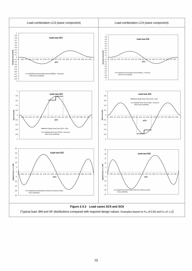
4.2.5 Design wave for maximum shear force amidships. Load combination LC3 is for the assessment of structure in the region between 0,4LR and 0,6LR. The load combination is to achieve the following vertical wave bending moment and shear force distribution:
• The vertical wave bending moment distribution, BM2(x), specified in Ch 2, 4.4 Procedure to apply the Rule design vertical wave BM and SF 4.4.4.
• The associated design vertical wave shear force, QW, is to be obtained as follows:
Distance from aft end of LR QW
0,4LR to 0,5LR 0,65 × FfH × Qo
0,5LR to 0,6LR -0,65 × FfS × Qo
where Qo is defined in Ch 2, 4.2 Load components 4.2.3
Intermediate values of QW are to be determined by linear interpolation. The wave shear force outside the range of 0,4LR and 0,6LR need not be greater than QWH or less than QWS specified in Ch 2, 4.2 Load components 4.2.3 and Ch 2, 4.2 Load components 4.2.4. The shear force and bending moment distributions are illustrated in Figure 2.4.3 Load cases SC5 and SC6.
4.2.6 Design wave for minimum shear force amidships. Load combination LC4 is for the assessment of structure in the region between 0,4LR and 0,6LR. The load combination is to achieve the following vertical wave bending moment and shear force distribution:
• The vertical wave bending moment distribution, -BM2(x), specified in Ch 2, 4.4 Procedure to apply the Rule design vertical wave BM and SF 4.4.4.
• The associated design vertical wave shear force, QW, is to be obtained as follows:
Distance from aft end of LR QW
0,4LR to 0,5LR 0,65 × FfS × Qo
0,5LR to 0,6LR -0,65 × FfH × Qo
where Qo is defined in Ch 2, 4.2 Load components 4.2.3
Intermediate values of QW are to be determined by linear interpolation. The wave shear force outside the range of 0,4LR and 0,6LR need not be greater than QWH or less than QWS specified in Ch 2, 4.2 Load components 4.2.3 and Ch 2, 4.2 Load components 4.2.4. The shear force and bending moment distributions are illustrated in Figure 2.4.3 Load cases SC5 and SC6.
4.2.7 Racking. Static pressure applied to stimulate a loading condition near to the design draught with a maximum vertical centre of gravity and a static heel angle equal the lesser of the following:
• tan-1(2 (D–T) /B), where T is the draught of the loading condition under consideration; • 30 degrees; • sin−1 ��0,45 + 0.1 𝐿R
𝐵� �0,54− 𝐿R
1270��;
but not to be taken as less than 22 degrees. 4.2.8 Local wave crest and wave trough. Application of wave pressure due to local wave crest or wave trough is defined in Figure 2.4.1 Pressure distribution for wave crest and trough. The wave crest or wave trough is to be acting over the full length of the FE model. 4.2.9 For ships of an unusual hull form, a suitable loads and motions study may be required to be performed in order to verify the applicability of the Rule design vertical wave loadings.

11
Txwl = local ship draught at xwl PwL = wave pressure at still waterline, equal to the value of Pw at waterline Pw = wave pressure calculated in accordance with Vol 1, Pt 5, Ch 3, 3.4 Hydrodynamic wave pressure, Pw of the Rules for
Naval Ships h = distance from still waterline (downward positive) The value of P is to be taken as -10h where P + 10h < 0
Figure 2.4.1 Pressure distribution for wave crest and trough
12
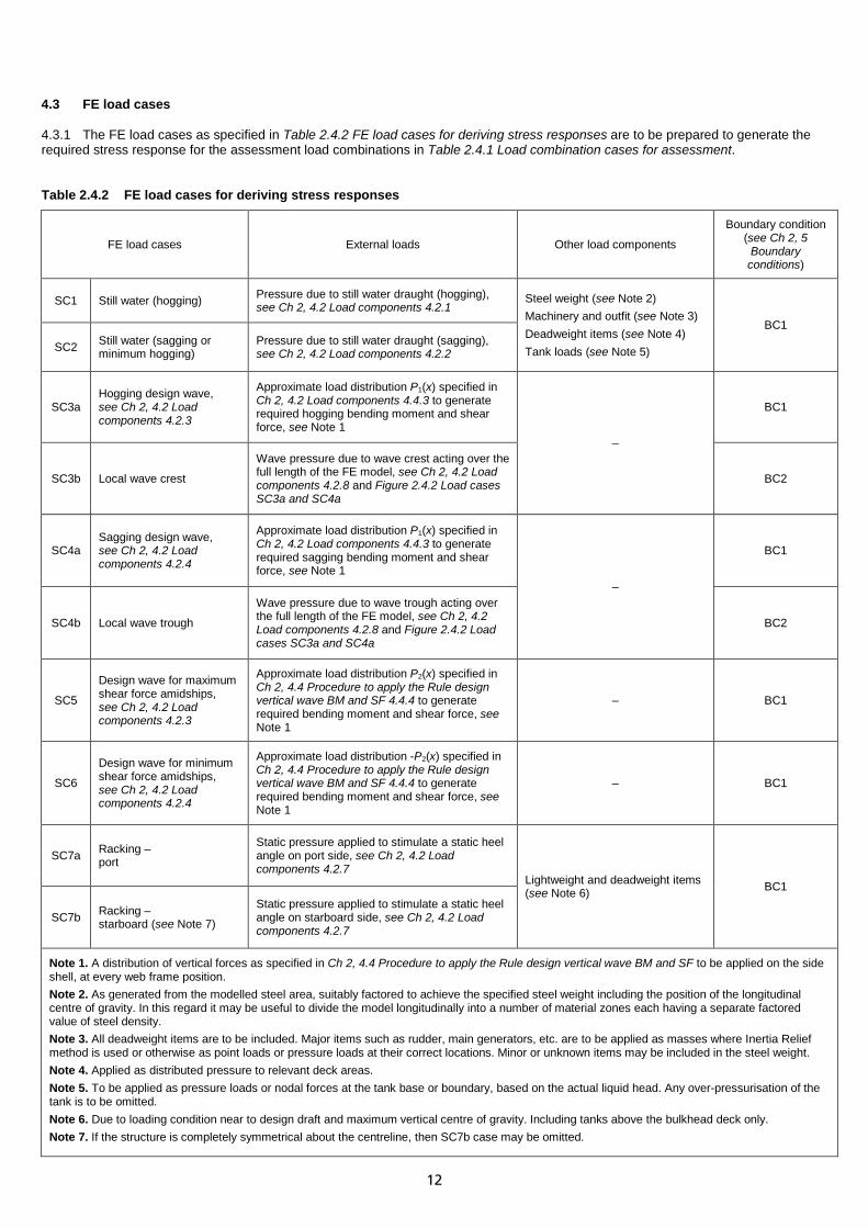
4.3 FE load cases 4.3.1 The FE load cases as specified in Table 2.4.2 FE load cases for deriving stress responses are to be prepared to generate the required stress response for the assessment load combinations in Table 2.4.1 Load combination cases for assessment. Table 2.4.2 FE load cases for deriving stress responses
FE load cases External loads Other load components
Boundary condition (see Ch 2, 5
Boundary conditions)
SC1 Still water (hogging) Pressure due to still water draught (hogging), see Ch 2, 4.2 Load components 4.2.1
Steel weight (see Note 2) Machinery and outfit (see Note 3) Deadweight items (see Note 4) Tank loads (see Note 5)
BC1
SC2 Still water (sagging or minimum hogging)
Pressure due to still water draught (sagging), see Ch 2, 4.2 Load components 4.2.2
SC3a Hogging design wave, see Ch 2, 4.2 Load components 4.2.3
Approximate load distribution P1(x) specified in Ch 2, 4.2 Load components 4.4.3 to generate required hogging bending moment and shear force, see Note 1
–
BC1
SC3b Local wave crest
Wave pressure due to wave crest acting over the full length of the FE model, see Ch 2, 4.2 Load components 4.2.8 and Figure 2.4.2 Load cases SC3a and SC4a
BC2
SC4a Sagging design wave, see Ch 2, 4.2 Load components 4.2.4
Approximate load distribution P1(x) specified in Ch 2, 4.2 Load components 4.4.3 to generate required sagging bending moment and shear force, see Note 1
–
BC1
SC4b Local wave trough
Wave pressure due to wave trough acting over the full length of the FE model, see Ch 2, 4.2 Load components 4.2.8 and Figure 2.4.2 Load cases SC3a and SC4a
BC2
SC5
Design wave for maximum shear force amidships, see Ch 2, 4.2 Load components 4.2.3
Approximate load distribution P2(x) specified in Ch 2, 4.4 Procedure to apply the Rule design vertical wave BM and SF 4.4.4 to generate required bending moment and shear force, see Note 1
– BC1
SC6
Design wave for minimum shear force amidships, see Ch 2, 4.2 Load components 4.2.4
Approximate load distribution -P2(x) specified in Ch 2, 4.4 Procedure to apply the Rule design vertical wave BM and SF 4.4.4 to generate required bending moment and shear force, see Note 1
– BC1
SC7a Racking – port
Static pressure applied to stimulate a static heel angle on port side, see Ch 2, 4.2 Load components 4.2.7
Lightweight and deadweight items (see Note 6) BC1
SC7b Racking – starboard (see Note 7)
Static pressure applied to stimulate a static heel angle on starboard side, see Ch 2, 4.2 Load components 4.2.7
Note 1. A distribution of vertical forces as specified in Ch 2, 4.4 Procedure to apply the Rule design vertical wave BM and SF to be applied on the side shell, at every web frame position. Note 2. As generated from the modelled steel area, suitably factored to achieve the specified steel weight including the position of the longitudinal centre of gravity. In this regard it may be useful to divide the model longitudinally into a number of material zones each having a separate factored value of steel density. Note 3. All deadweight items are to be included. Major items such as rudder, main generators, etc. are to be applied as masses where Inertia Relief method is used or otherwise as point loads or pressure loads at their correct locations. Minor or unknown items may be included in the steel weight. Note 4. Applied as distributed pressure to relevant deck areas. Note 5. To be applied as pressure loads or nodal forces at the tank base or boundary, based on the actual liquid head. Any over-pressurisation of the tank is to be omitted. Note 6. Due to loading condition near to design draft and maximum vertical centre of gravity. Including tanks above the bulkhead deck only. Note 7. If the structure is completely symmetrical about the centreline, then SC7b case may be omitted.

13
4.4 Procedure to apply the Rule design vertical wave BM and SF 4.4.1 The required design vertical wave bending moment and shear force are to be distributed along the length of the FE model in accordance with Table 2.4.1 Load combination cases for assessment. 4.4.2 The required bending moment and shear force distributions may be applied, as illustrated in Figure 2.4.2 Load cases SC3a and SC4a and Figure 2.4.3 Load cases SC5 and SC6, by applying the approximate load distributions P1(x) and P2(x) described below. 4.4.3 The approximated load distribution, P1(x), is applied to FE load cases SC3a and SC4a (see Table 2.4.2 FE load cases for deriving stress responses). The load distribution and the resulting shear force distribution, SF1(x), and bending moment distribution, BM1(x), are as follows:
𝑃1(𝑥) = 𝑀w𝐿R2
(20𝑎1𝑥3 + 12𝑎2𝑥2 + 6𝑎3𝑥 + 2𝑎4) kN/m
𝑆𝑆1(𝑥) = 𝑀w𝐿R
(5𝑎1𝑥3 + 4𝑎2𝑥2 + 3𝑎3𝑥 + 2𝑎4)𝑥 kN
𝐵𝑀1(𝑥) = 𝑀w(𝑎1𝑥3 + 𝑎2𝑥2 + 𝑎3𝑥 + 𝑎4)𝑥2 kNm
where, 𝑀w = 𝑆fH𝑀o for load case SC3a
𝑀w = 𝑆fS𝑀o for load case SC4a
𝑎1 = 7,841 𝑎2 = −1,457 𝑎3 = −20,609 𝑎4 = 14,225
𝑥 =𝑑𝐿R
; 0 ≤ 𝑥 ≤ 1
d = distance measured from the aft end of the Rule length, in meters.
4.4.4 The approximated load distribution, P2(x), is applied to FE load cases SC5 and SC6 (see Table 2.4.2 FE load cases for deriving stress responses). The load distribution and the resulting shear force distribution, SF2(x), and bending moment distribution, BM2(x), are as follows:
𝑃2(𝑥) = 𝑀w𝐿R2
(42𝑎1𝑥5 + 30𝑎2𝑥4 + 20𝑎3𝑥3 + 12𝑎4𝑥2 + 6𝑎5𝑥 + 2𝑎6) kN/m
𝑆𝑆2(𝑥) = 𝑀w𝐿R
(7𝑎1𝑥5 + 6𝑎2𝑥4 + 5𝑎3𝑥3 + 4𝑎4𝑥2 + 3𝑎5𝑥 + 2𝑎6)𝑥 kN
𝐵𝑀2(𝑥) = 𝑀w(𝑎1𝑥5 + 𝑎2𝑥4 + 𝑎3𝑥3 + 𝑎4𝑥2 + 𝑎5𝑥 + 𝑎6)𝑥2 kNm
where, 𝑀w = greater of |𝑆fH𝑀o| and |𝑆fS𝑀o| for load case SC5
𝑀w = lesser of −|𝑆fH𝑀o| and −|𝑆fS𝑀o| for load case SC6
𝑎1 = −130,68 𝑎2 = 457,39 𝑎3 = −589,55 𝑎4 = 330,4 𝑎5 = −68,3 𝑎6 = 0,74
𝑥 =𝑑𝐿R
; 0 ≤ 𝑥 ≤ 1
d = distance measured from the aft end of the Rule length, in meters.
4.4.5 The load distribution described in paragraphs Ch 2, 4.4 Procedure to apply the Rule design vertical wave BM and SF 4.4.3 and Ch 2, 4.4 Procedure to apply the Rule design vertical wave BM and SF 4.4.4 are to be applied to the FE model as a series of vertical nodal forces on the side shell, at every web frame position below the waterline. 4.4.6 Minor adjustment of the applied loads may be required to ensure global equilibrium.

14
4.4.7 A check should be carried out by tabular integration methods to ensure that the derived load distribution will result in the required vertical bending moment and shear force. 4.4.8 At locations where there is a variation between the applied FE loads and required loads as specified in Table 2.4.1 Load combination cases for assessment, the derived stresses are to be adjusted, see Ch 2, 6.1 Stress for assessment. 4.4.9 Other proposed methods of modelling the required vertical wave bending moment and shear force distributions will be specially considered.
Load combination LC1(hogging design wave component) Load combination LC2 (sagging design wave component)
Figure 2.4.2 Load cases SC3a and SC4a
(Typical load, BM and SF distributions compared with required design values. Examples based on FfH of 0,95 and FfS of -1,2)
0
0.1
0.2
0.3
0.4
0.5
0.6
0.7
0.8
0.9
1
1.1
1.2
1.3
1.4
0 0.05 0.1 0.15 0.2 0.25 0.3 0.35 0.4 0.45 0.5 0.55 0.6 0.65 0.7 0.75 0.8 0.85 0.9 0.95 1
Bend
ing
mom
ent/
Mo
d/LR
Load case SC3a
Rule design wave bending moment (Hog)
Applied wave bending moment BM1(x) (Hog)
-1.4
-1.3
-1.2
-1.1
-1
-0.9
-0.8
-0.7
-0.6
-0.5
-0.4
-0.3
-0.2
-0.1
0
0 0.05 0.1 0.15 0.2 0.25 0.3 0.35 0.4 0.45 0.5 0.55 0.6 0.65 0.7 0.75 0.8 0.85 0.9 0.95 1
Bend
ing
mom
ent/
Mo
d/LR
Load case SC4a
Rule design wave bending moment (Sag)
Applied wave bending moment BM1(x) (Sag)
-1.4
-1.2
-1
-0.8
-0.6
-0.4
-0.2
0
0.2
0.4
0.6
0.8
1
1.2
1.4
1.6
0 0.05 0.1 0.15 0.2 0.25 0.3 0.35 0.4 0.45 0.5 0.55 0.6 0.65 0.7 0.75 0.8 0.85 0.9 0.95 1Shea
r for
ce/Q
o
d/LR
Load case SC3a
Design wave shear force (Hog)
Applied shear force SF1(x) (Hog)
-1.4
-1.2
-1
-0.8
-0.6
-0.4
-0.2
0
0.2
0.4
0.6
0.8
1
1.2
1.4
1.6
0 0.05 0.1 0.15 0.2 0.25 0.3 0.35 0.4 0.45 0.5 0.55 0.6 0.65 0.7 0.75 0.8 0.85 0.9 0.95 1Shea
r for
ce/Q
o
d/LR
Load case SC4aDesign wave shear force (Hog)
Applied shear force SF1(x) (Sag)
-30
-20
-10
0
10
20
30
40
50
0 0.05 0.1 0.15 0.2 0.25 0.3 0.35 0.4 0.45 0.5 0.55 0.6 0.65 0.7 0.75 0.8 0.85 0.9 0.95 1Appl
ied
Load
x L
x L
/M
o
d/LR
Load case SC3a
Applied load distribution P1(x) (Hog)
-60
-50
-40
-30
-20
-10
0
10
20
30
0 0.05 0.1 0.15 0.2 0.25 0.3 0.35 0.4 0.45 0.5 0.55 0.6 0.65 0.7 0.75 0.8 0.85 0.9 0.95 1
Appl
ied
Load
x L
x L
/M
o
d/LR
Load case SC4a
Applied load distribution P1(x) (Sag)
15
Load combination LC3 (wave component) Load combination LC4 (wave component)
Figure 2.4.3 Load cases SC5 and SC6
(Typical load, BM and SF distributions compared with required design values. Examples based on FfH of 0,95 and FfS of -1,2)
-1-0.9-0.8-0.7-0.6-0.5-0.4-0.3-0.2-0.1
00.10.20.30.40.50.60.70.80.9
1
0 0.05 0.1 0.15 0.2 0.25 0.3 0.35 0.4 0.45 0.5 0.55 0.6 0.65 0.7 0.75 0.8 0.85 0.9 0.95 1
Bend
ing
mom
ent/
Mo
d/LR
Load case SC5
Applied wave bending moment BM2(x) - maximumshear force amidships
-1-0.9-0.8-0.7-0.6-0.5-0.4-0.3-0.2-0.1
00.10.20.30.40.50.60.70.80.9
1
0 0.05 0.1 0.15 0.2 0.25 0.3 0.35 0.4 0.45 0.5 0.55 0.6 0.65 0.7 0.75 0.8 0.85 0.9 0.95 1
Bend
ing
mom
ent/
Mo
d/LR
Load case SC6
Applied wave bending moment BM2(x) - minimumshear force amidships
-1
-0.8
-0.6
-0.4
-0.2
0
0.2
0.4
0.6
0.8
1
0 0.05 0.1 0.15 0.2 0.25 0.3 0.35 0.4 0.45 0.5 0.55 0.6 0.65 0.7 0.75 0.8 0.85 0.9 0.95 1
Shea
r for
ce/Q
o
d/LR
Load case SC5
Rule design shear force (0,4L - 0,6L)
Applied shear force SF2(x) - maximumshear force amidships
-1
-0.8
-0.6
-0.4
-0.2
0
0.2
0.4
0.6
0.8
1
0 0.05 0.1 0.15 0.2 0.25 0.3 0.35 0.4 0.45 0.5 0.55 0.6 0.65 0.7 0.75 0.8 0.85 0.9 0.95 1
Shea
r for
ce/Q
o
d/LR
Load case SC6
Rule design shear force (0,4L - 0,6L)
Applied shear force SF2(x) - minimumshear force amidships
-25
-20
-15
-10
-5
0
5
10
15
20
25
0 0.05 0.1 0.15 0.2 0.25 0.3 0.35 0.4 0.45 0.5 0.55 0.6 0.65 0.7 0.75 0.8 0.85 0.9 0.95 1
Appl
ied
Load
x L
x L
/M
o
d/LR
Load case SC5
Applied load distribution P2(x) for maximum shearforce amidships
-25
-20
-15
-10
-5
0
5
10
15
20
25
0 0.05 0.1 0.15 0.2 0.25 0.3 0.35 0.4 0.45 0.5 0.55 0.6 0.65 0.7 0.75 0.8 0.85 0.9 0.95 1
Appl
ied
Load
x L
x L
/M
o
d/LR
Load case SC6
Applied load distribution P2(x) for maximum shearforce amidships

16
Section 5 Boundary conditions 5.1 General 5.1.1 The FE loading cases specified in Ch 2, 4.3 FE load cases require boundary conditions as given in Table 2.5.1 Boundary conditions for a full-breadth model. 5.1.2 The boundary conditions specified in Table 2.5.2 Additional boundary conditions for a half-breadth model combined with those in Table 2.5.1 Boundary conditions for a full-breadth model are appropriate for a half-breadth model. 5.1.3 The model is to be free of imposed constraints except for those necessary to prevent rigid body motion. Care is to be taken to ensure that, within practicable limits, there is no net imbalance of forces and moments in any of the six degrees of freedom, see Ch 2, 5.2 Load balance procedure. Care is to be taken to ensure that the FE model is not over-constrained. 5.1.4 The boundary conditions described in this Section are preferred. However, alternative equivalent boundary conditions may be used. Table 2.5.1 Boundary conditions for a full-breadth model
Set Description
BC1
a) The model is to be free of imposed constraints, except for those necessary to prevent rigid body motion. Rigid body motions may be prevented by the use of free-body constraints (i.e. the Inertia Relief facility in Nastran terminology).
b) Alternatively, model may be constrained as follows: • At the A.P. on the centreline: Translation δy = δz = 0 • At the F.P. on the centreline: Translation δx = δy = δz = 0 • At the uppermost deck on the centreline at the F.P.: Translation δy = 0.
BC2
a) If for set BC1, free-body constraints (i.e. Inertia Relief method) are used, the model is to be additionally constrained as follows: • Uppermost continuous deck at the side shell intersection: Translation δx = δy = δz = 0.
b) Otherwise the model may be constrained as follows: • At the A.P. on the centreline: Translation δy = δz = 0 • At the F.P. on the centreline: Translation δx = δy = δz = 0 • Uppermost continuous deck at the side shell intersection: Translation δz = 0.
c) Any induced global bending of the ship is to be removed by application of vertical constraints at each web frame. In order to remove the reaction force at these vertical constraints, thus avoiding vicious stress response, it is recommended that counteracting vertical forces are distributed to the side shell nodes at every web frame to eliminate the reaction forces. The magnitude of these forces is to be such as to remove the vertical imbalance of the model caused by the applied load.
Note 1. Where a half-breadth ship model is employed the racking analysis loadings will require to be sub-divided into symmetric and anti-symmetric components with appropriate boundary conditions.

17
Table 2.5.2 Additional boundary conditions for a half-breadth model
Set Boundary conditions, centre line plane
BC1 Symmetry constrains:
• Translation δy = 0 • Rotation θx = θz = 0
BC2
Symmetry constrains: • Translation δy = 0 • Rotation θx = θz = 0
Anti-symmetry constrains: • Translation δx = δz = 0 • Rotation θy = 0
Note 1. These boundary conditions are additional to those given in Table 2.5.1 Boundary conditions for a full-breadth model and take precedence over the requirements of Table 2.5.1 Boundary conditions for a full-breadth model. Note 2. The transverse constraints in Table 2.5.1 Boundary conditions for a full-breadth model do not need to be included in the half-breadth model. Note 3. Care is to be taken to ensure that the FE model is not over-constrained and that there are no conflicting constraints.
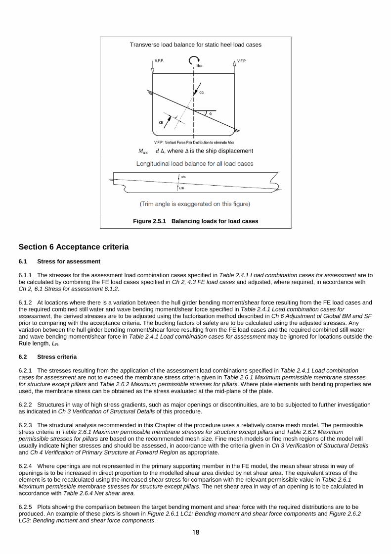
5.2 Load balance procedure 5.2.1 Balance of external pressure against inertia loads is necessary to minimise reaction forces at the constraints of the full ship FE model in order to obtain the correct structural response. 5.2.2 With the ship in either a vertical or heeled position, as specified by the load case considered, the waterline is to be adjusted vertically, and trim, using an iteration process, to achieve a vertically balanced position where the buoyancy force and trim moment are equal to that induced by the ship’s weight. Other proposed methods for load balancing (i.e. introducing counteracting vertical and horizontal forces) will be specially considered. 5.2.3 When calculating the forces and moments due to the lightship, deadweight items and external pressure attention should be paid to resolving the force components about the reference axes, taking into account effects of the trim angle and heel angle where appropriate. 5.2.4 For heeled load cases, SC7a and SC7b, care is to be taken with the balance of the racking (restoring) moment, Mxx, as shown in Figure 2.5.1 Balancing loads for load cases. 5.2.5 Inertia Relief method is preferred to be used to balance the ship FE model in a heeled condition to simulate the inertia loads acting on the structure due to accelerations caused by the unbalanced racking moment. 5.2.6 Alternately, the racking moment, Mxx, may be balanced by introducing equal and opposite vertical force pairs at the intersection of the side shell and freeboard deck at each frame along the ship length, see Figure 2.5.1 Balancing loads for load cases. The magnitude of the force, F, to be applied at each frame may be obtained as follow: 𝑆 = 𝑀xx
∑ 𝐵in1
n = total number of frames where the vertical force pairs are applied. Bi = the local beam at the level of the freeboard deck.
Other proposed methods to balance the racking moment will be specially considered. 5.2.7 For load cases SC3b and SC4b (wave crest and trough), the bending of the hull girder is to be removed by application of vertical constraints at each web frame, as specified in boundary conditions BC2 in Table 2.5.1 Boundary conditions for a full-breadth model. In order to remove the reaction force at these vertical constraints, thus avoiding vicious stress response, it is recommended that counteracting vertical forces or grounded springs are distributed to the side shell nodes at every web frame to eliminate the reaction forces. The magnitude of these forces is to be such as to remove the vertical imbalance of the model caused by the applied wave crest/trough pressure.
18
Transverse load balance for static heel load cases
Φ
𝑀xx = 𝑑 ∆, where ∆ is the ship displacement
Figure 2.5.1 Balancing loads for load cases
Section 6 Acceptance criteria 6.1 Stress for assessment 6.1.1 The stresses for the assessment load combination cases specified in Table 2.4.1 Load combination cases for assessment are to be calculated by combining the FE load cases specified in Ch 2, 4.3 FE load cases and adjusted, where required, in accordance with Ch 2, 6.1 Stress for assessment 6.1.2. 6.1.2 At locations where there is a variation between the hull girder bending moment/shear force resulting from the FE load cases and the required combined still water and wave bending moment/shear force specified in Table 2.4.1 Load combination cases for assessment, the derived stresses are to be adjusted using the factorisation method described in Ch 6 Adjustment of Global BM and SF prior to comparing with the acceptance criteria. The bucking factors of safety are to be calculated using the adjusted stresses. Any variation between the hull girder bending moment/shear force resulting from the FE load cases and the required combined still water and wave bending moment/shear force in Table 2.4.1 Load combination cases for assessment may be ignored for locations outside the Rule length, LR. 6.2 Stress criteria 6.2.1 The stresses resulting from the application of the assessment load combinations specified in Table 2.4.1 Load combination cases for assessment are not to exceed the membrane stress criteria given in Table 2.6.1 Maximum permissible membrane stresses for structure except pillars and Table 2.6.2 Maximum permissible stresses for pillars. Where plate elements with bending properties are used, the membrane stress can be obtained as the stress evaluated at the mid-plane of the plate. 6.2.2 Structures in way of high stress gradients, such as major openings or discontinuities, are to be subjected to further investigation as indicated in Ch 3 Verification of Structural Details of this procedure. 6.2.3 The structural analysis recommended in this Chapter of the procedure uses a relatively coarse mesh model. The permissible stress criteria in Table 2.6.1 Maximum permissible membrane stresses for structure except pillars and Table 2.6.2 Maximum permissible stresses for pillars are based on the recommended mesh size. Fine mesh models or fine mesh regions of the model will usually indicate higher stresses and should be assessed, in accordance with the criteria given in Ch 3 Verification of Structural Details and Ch 4 Verification of Primary Structure at Forward Region as appropriate. 6.2.4 Where openings are not represented in the primary supporting member in the FE model, the mean shear stress in way of openings is to be increased in direct proportion to the modelled shear area divided by net shear area. The equivalent stress of the element is to be recalculated using the increased shear stress for comparison with the relevant permissible value in Table 2.6.1 Maximum permissible membrane stresses for structure except pillars. The net shear area in way of an opening is to be calculated in accordance with Table 2.6.4 Net shear area. 6.2.5 Plots showing the comparison between the target bending moment and shear force with the required distributions are to be produced. An example of these plots is shown in Figure 2.6.1 LC1: Bending moment and shear force components and Figure 2.6.2 LC3: Bending moment and shear force components.

19
6.3 Buckling criteria 6.3.1 The buckling capability of plate panels is to be assessed based on the net plate thickness, i.e. excluding all corrosion margins, Owner’s extras and any additional thicknesses fitted to meet military loading requirements. 6.3.2 The critical buckling stress of plate panels is to be derived taking into account all relevant compressive and shear stress components and using a procedure such as that incorporated in the ShipRight software. 6.3.3 The stiffener influence factor, C, defined in Vol 1, Pt 6, Ch 2, Table 2.3.2 Buckling stress of plate panels of the Rules for Naval Ships, may be taken into account in calculating the critical buckling stress of wide panels subjected to compressive loading on the long edges of the panel. The stiffener influence factor, C, is not to be used in the calculation of critical buckling stress for compression applied on the short edges. 6.3.4 When the calculated elastic critical buckling stress, σc, exceeds 50 per cent of the specified minimum yield stress, then the buckling stress is to be adjusted for the effects of plasticity using the Johnson–Ostenfeld correction:
σcr = σc when σc ≤ 0,5 σo σcr = σo �1 − σo
4σc � when σc > 0,5 σo
where, σcr = critical buckling stress.
6.3.5 A minimum factor against elastic buckling, λ, is specified in Table 2.6.3 Minimum factor against buckling to be used. The column stability of pillars and vertical webs acting as pillars is to comply with the requirements of Table 2.6.2 Maximum permissible stresses for pillars. Provided that the wall or plate thickness of the pillar complies with the requirements specified in the Rules for Naval Ships, local wall buckling of the pillar is considered satisfactory. 6.3.6 Subject to Lloyd’s Register’s agreement, alternative methods for buckling assessments may be specially considered. Table 2.6.1 Maximum permissible membrane stresses for structure except pillars
Structural items Load case
Allowable stresses,
see Notes 1 & 2
σVM σx σy τxy
Bottom shell plating
LC1, LC2, LC3, LC4
σL 0,92 σL 0,63 σ0 –
Double bottom girders σL – – 0,46 σL
Inner bottom plating σL 0,92 σL 0,63 σ0 –
Double bottom floors 0,75 σ0 – 0,63 σ0 0,35 σ0
Side transverse 0,75 σ0 – 0,63 σ0 0,35 σ0
Other longitudinal effective structures 0,92 σL 0,75 σL – 0,46 σL
Other transverse structures 0,75 σ0 – 0,63 σ0 0,35 σ0
All structures LC5a, LC5b 0,75 σ0 0,63 σ0 0,63 σ0 0,35 σ0
Note 1. For plate elements the specified allowable stresses should be compared to the centroidal element membrane stress in the relevant structural item. For girders, stringers, vertical webs and floors the specified values of allowable shear stress relate to the mean shear stress over the depth of the member. For bulkhead, shell and deck plating, they relate to shear stress of single element.
Note 2. Where openings are not represented in the primary supporting member in the FE model, the mean shear stress in way of openings is to be increased in direct proportion to the modelled shear area divided by net shear area. The equivalent stress of the element is to be recalculated using the increased shear stress for comparison with relevant permissible value. The net shear area in way of an opening is to be calculated in accordance with Table 2.6.4 Net shear area. If the resulting stress level exceeds 90 per cent of the specified allowable value, further investigation by means of fine mesh follow-up models may be required.

20
Table 2.6.2 Maximum permissible stresses for pillars
Pillars Load cases Acceptance criteria See Note
In tension
LC1, LC2, LC3, LC4, LC5a, LC5b
σAxial ≤ 0,60σo 1, 2
σExtreme_fibre ≤ 0,84σo
In compression σAxial ≤ 0,80σcr
2 σExtreme_fibre ≤ 0,84σo + σAxial × (1 - σo/σcr)
All τ ≤ 0,47σo –
where,
σcr =
σo
�1+ σoE �Le
π r�2�
Le r
= effective length of pillar, in mm, and is taken as 0,8 overall length of pillar = least radius of gyration of pillar cross-section, in mm
Note 1. Special attention to be paid to the weld attachments of the heads and heels of tensile pillars. Note 2. For pillars, stresses to be calculated at the extreme fibre of the pillar section; if line elements are used to represent pillars then bending properties including relevant stress recovery points are to be specified. If 2-D elements are used to represent non-circular pillars, then stress is to be obtained for the node points at the extreme fibres of the pillar cross-section. If accurate nodal stresses are not available, the stresses are to be obtained from a line element of nominal area located at the extreme fibre of the pillar cross-section.
Table 2.6.3 Minimum factor against buckling to be used
Structural items
Applicable to
Buckling factor LC1, LC2, LC3, LC4 LC5a, LC5b
All structures 1,0
Bottom shell plating 1,0
Double bottom girders 1,0
Inner bottom plating 1,0
Double bottom floors 1,1
Side transverse 1,1
Other longitudinal effective structures 1,0
Other transverse structures 1,1
21
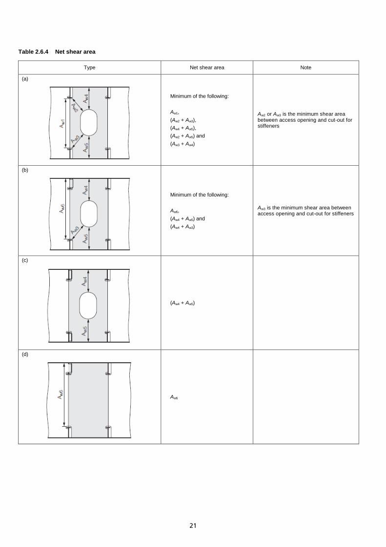
Table 2.6.4 Net shear area
Type Net shear area Note
(a)
Minimum of the following: Aw1, (Aw2 + Aw3), (Aw4 + Aw5), (Aw2 + Aw5) and (Aw3 + Aw4)
Aw2 or Aw3 is the minimum shear area between access opening and cut-out for stiffeners
(b)
Minimum of the following: Aw6, (Aw4 + Aw5) and (Aw4 + Aw3)
Aw3 is the minimum shear area between access opening and cut-out for stiffeners
(c)
(Aw4 + Aw5)
(d)
Aw6

22
Figure 2.6.1 LC1: Bending moment and shear force components (for illustration purposes only and not to be scaled)
-0.05 0.05 0.15 0.25 0.35 0.45 0.55 0.65 0.75 0.85 0.95 1.05
Shea
r For
ce
d/LR
Permissible SWSF (hog)FE load case SC1: SWSF (hog)
Load Combination LC1 - (hogging still water load component)
-0.05 0.05 0.15 0.25 0.35 0.45 0.55 0.65 0.75 0.85 0.95 1.05
Bend
ing
mom
ent
d/LR
Permissible SWBM (hog)
FE load case SC1: SWBM (hog)
Load Combination LC1 - (hogging still water load component)
-0.05 0.05 0.15 0.25 0.35 0.45 0.55 0.65 0.75 0.85 0.95 1.05
Shea
r For
ce
d/LR
Design VWSF (hog)FE load case SC3a: SF1 (hog)
Load Combination LC1 - (hogging wave component)
-0.05 0.05 0.15 0.25 0.35 0.45 0.55 0.65 0.75 0.85 0.95 1.05
Bend
ing
mom
ent
d/LR
Design VWBM (hog)FE load case SC3a: BM1 (hog)
Load Combination LC1 - (hogging wave component)
-0.05 0.05 0.15 0.25 0.35 0.45 0.55 0.65 0.75 0.85 0.95 1.05
Shea
r For
ce
d/LR
Permissible SWSF + Design VWSF (hog)
Combined shear force: SWSF (hog) + SF1 (hog)
Load Combination LC1 - (combined still water and wave component)-0.05 0.05 0.15 0.25 0.35 0.45 0.55 0.65 0.75 0.85 0.95 1.05
Bend
ing
mom
ent
d/LR
Permissible SWBM + DesignVWBM (hog)
Combined bendingmoment: SWBM (hog) +BM1 (hog)
Load Combination LC1 - (combined still water and wave component)

23
Figure 2.6.2 LC3: Bending moment and shear force components (for illustration purposes only and not to be scaled)
-0.05 0.05 0.15 0.25 0.35 0.45 0.55 0.65 0.75 0.85 0.95 1.05
Shea
r for
ce
d/LR
Design VWSF 0.4LR - 0.6LR (maximium)
FE load case SC5: SF2 (maximum shear force amidship)
Load Combination LC3 (maximum wave shear force component)
-0.05 0.05 0.15 0.25 0.35 0.45 0.55 0.65 0.75 0.85 0.95 1.05
Bend
ing
mom
ent
d/LR
FE load case SC1: SWBM (hog)
FE load case SC5: BM2
Bending moments for Load Combination LC3

24
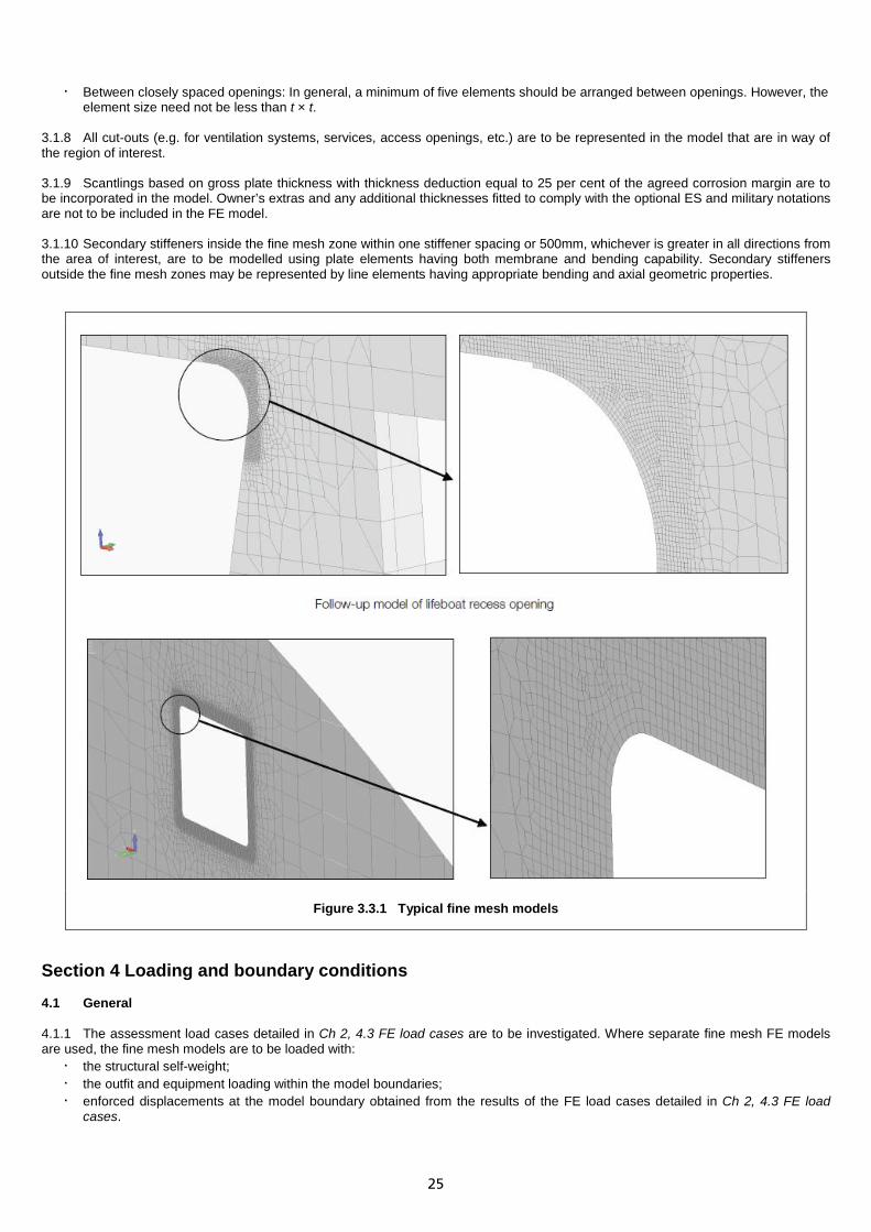
Chapter 3 Verification of Structural Details Section 1 Application 1.1 Introduction 1.1.1 For application of Ch 3 Verification of Structural Details, see Ch 1, 1.1 General 1.1.10. Section 2 Objectives 2.1 General 2.1.1 The objective of Ch 3 Verification of Structural Details is to determine the stress responses in way of highly stressed critical structural components and those with novel or unusual features, i.e. major equipment items and major mass loads, and to verify the stress levels are within acceptable limits. Section 3 Structural modelling 3.1 General 3.1.1 Separate detailed fine mesh FE models covering the structural components specified in Ch 3, 3.1 General 3.1.2 are to be prepared and loaded with enforced displacements obtained from the full ship global analysis, see Ch 2 Global Response Analysis of Complete Ship. Alternatively, these areas may be modelled in fine mesh and incorporated into the global FE model. Two node line elements and four node plate elements are, in general, considered sufficient for the representation of the hull structure. The mesh requirements given in this document are based on the assumption that these elements are used in the finite element models. 3.1.2 Fine mesh FE models are required for the areas detailed below. Typical models are indicated in Figure 3.3.1 Typical fine mesh models.
• transition at the ends of the superstructure; • large shell doors for ship’s boat or mission spaces; • steps/knuckles in upper decks where arranged transversely; • large deck openings for silos, uptakes and machinery removals; • in way of any novel or unusual feature which is expected to present a discontinuity or concentration of stress in the longitudinal
material; • structure in way of high stress concentration or areas exceeding the stress criteria specified in Ch 2 Global Response Analysis
of Complete Ship. 3.1.3 Where separate fine mesh FE models are used, the FE models are to be represented using a right-handed Cartesian co-ordinate system with:
• x measured in the longitudinal direction, positive forward from the A.P.; • y measured in the transverse direction, positive to port from the centreline; • z measured in the vertical direction, positive upwards from the baseline.
3.1.4 The plating and supporting primary structure are to be represented by plate elements having both membrane and bending capability. 3.1.5 The extent of fine mesh models is to be such that the application of boundary displacements (taken from Ch 2 Global Response Analysis of Complete Ship) will not invalidate the response at the relevant points of the local fine mesh model. The extent of fine mesh models is to be chosen carefully such that their boundaries coincide with primary members, such as girders and floors. 3.1.6 The structural geometry, particularly in areas of concern, is to be accurately represented. The level of refinement is to be such as to enable stress concentrations to be identified. 3.1.7 The element mesh size should comply with the following:
• The mesh size adopted should be such that the structural geometry can be adequately represented and the stress concentrations can be adequately determined. In general, the minimum required mesh size in fine mesh areas is not to be greater than 1/10 of the depth of the member (smallest dimension), 15t × 15t or 150×150 mm, whichever is the lesser, where t being the thickness of the main plate in way of area of interest. In some locations a finer mesh may be necessary to represent the structural geometry but need not be less than t × t. See Ch 3, 3.1 General 3.1.6.
• In way of radius corners, bracket radius edges and openings: In general, it is required that a minimum of 15 elements in a 90 degree arc of the free edge of the plate be achieved. However, the element size is not to be greater than 150×150 mm and need not be less than t × t. See Ch 3, 3.1 General 3.1.6.
• Where FE analysis programs do not supply accurate nodal stresses, a line element (e.g. rod element) of small nominal area is to be incorporated at the plating free edge to obtain the peak edge stresses.
25
• Between closely spaced openings: In general, a minimum of five elements should be arranged between openings. However, the element size need not be less than t × t.
3.1.8 All cut-outs (e.g. for ventilation systems, services, access openings, etc.) are to be represented in the model that are in way of the region of interest. 3.1.9 Scantlings based on gross plate thickness with thickness deduction equal to 25 per cent of the agreed corrosion margin are to be incorporated in the model. Owner’s extras and any additional thicknesses fitted to comply with the optional ES and military notations are not to be included in the FE model. 3.1.10 Secondary stiffeners inside the fine mesh zone within one stiffener spacing or 500mm, whichever is greater in all directions from the area of interest, are to be modelled using plate elements having both membrane and bending capability. Secondary stiffeners outside the fine mesh zones may be represented by line elements having appropriate bending and axial geometric properties.
Figure 3.3.1 Typical fine mesh models
Section 4 Loading and boundary conditions 4.1 General 4.1.1 The assessment load cases detailed in Ch 2, 4.3 FE load cases are to be investigated. Where separate fine mesh FE models are used, the fine mesh models are to be loaded with:
• the structural self-weight; • the outfit and equipment loading within the model boundaries; • enforced displacements at the model boundary obtained from the results of the FE load cases detailed in Ch 2, 4.3 FE load
cases.

26
Section 5 Acceptance criteria 5.1 Stress for assessment 5.1.1 The stress values derived from the FE load cases are to be factored by the ratio of the locally required bending moment/shear force as per Table 2.4.1 Load combination cases for assessment to the locally achieved bending moment/shear force following stress factorisation techniques specified in Ch 6 Adjustment of Global BM and SF prior to comparing with the acceptance criteria. Any variation between the hull girder bending moment/shear force resulting from the FE load cases and the required combined still water and wave bending moment/shear force in Table 2.4.1 Load combination cases for assessment may be ignored for locations outside the Rule length, LR. 5.2 Stress criteria 5.2.1 The von Mises and direct stresses in the plating between major openings, free edge of sweep brackets and edge of side screens and the direct (tangential) stresses at the free edge of the associated corner radii are to comply with the acceptance criteria in Table 3.5.1 Stress criteria for major openings, sweep brackets and side screens. 5.2.2 The von Mises, shear and direct stresses in the plating between window, door and other minor openings and the direct (tangential) stresses at the free edge of the associated corner radii are to comply with the acceptance criteria of membrane stress in Table 3.5.2 Stress criteria for minor openings, such as windows and doors, etc. 5.2.3 In additional to Ch 3, 5.2 Stress criteria 5.2.1 and Ch 3, 5.2 Stress criteria 5.2.2, small openings, other than those required by Ch 4 Verification of Primary Structure Supporting Decks, such as duct, cable, pipes and other outfitting penetrations with an equivalent area greater than or equal to 250×250 mm and lesser than or equal to 450×450 mm are to be selected for further assessment where:
2,13 �σx + σy� + 3,14 �τxy� ≥ σ0 Where, σx,σx, τxy are the elemental stresses in the coarse mesh where the opening has not been modelled.
5.2.4 The small openings selected for further assessment may be assessed using an appropriate Stress Concentration Factor (SCF) technique agreed by LR and assessed against the peak edge stress acceptance criteria in Table 3.5.2 Stress criteria for minor openings, such as windows and doors, etc. 5.2.5 Elsewhere stress levels are to comply with the acceptance criteria given in Table 2.6.1 Maximum permissible membrane stresses for structure except pillars.

27
Table 3.5.1 Stress criteria for major openings, sweep brackets and side screens
Load cases Structural item Stress component von Mises stress Direct stress Location
reference
LC1, LC2, LC3 and LC4
In way of free edge (e.g. openings and brackets, etc.)
Peak edge stress (see Note 1) – 1,5 G1 σ0 1(a)
Peak element centroid stress 1,2 G3 σ0 – 1(b)
Other fine meshed areas Peak element centroid stress σ0 – –
Hogging wave minus Sagging wave
LC1 - LC2 + (SC2 - SC1)
LC3 - LC4 + (SC2 - SC1)
In way of free edge (e.g. openings and brackets, etc.) Dynamic stress range:
𝑓prob 𝑓Ln 𝑆r 345 𝑓 𝑓sa ℎ 𝑘g 𝑘dl 𝐺2 𝑊s−n 𝑡_corr
1(a)
Other fine meshed areas in way of welds 1(c)
Symbols: G1 G2 G3
𝑆r σhog σsag 𝑓prob
𝑓Ln
f fsa
h
kdl kg
Ws-n
t_corr
n
= 0,67 = 0,85 = 0,77 = �σhog − σsag� = stress due to hogging wave = stress due to sagging wave = probability level correction factor = 0,625 = hogging/sagging non-linear correction factor
= 0,625 + 34 (𝐹fH−𝐹fS)
= see Table 3.5.3 Definition of f-factor and Figure 3.5.1 Definition of f-factors = 1,0 for dedicated North Atlantic service = 1,2 for world-wide service = 0,79 for 𝐿R = 100m
= 186108
𝐿R2 + 34105
𝐿R + 0,7 for 180m ≤ 𝐿R ≤ 320m
= 1,0 for 𝐿R > 320m Intermediate values are to be obtained by linear interpolation = (20/DFL)0,25 ; where DFL is the specified fatigue life in years but not to be taken as less than 20 = 1,0 in general = 1,12 for free edges where the edge corners have been removed and free edge has been ground smooth, see Note 2 = 1,12 for welds which have been suitably toe ground and profiled, see Note 3 = aluminium alloy and high tensile steel correction factor for free edges and plating = 1,0 for all steel grades having a nominal yield stress of 235 N/mm2 = 1,0 for all steel grades having a nominal yield stress of 270 N/mm2 = 1,0 for steel grades A and D having a nominal yield strength = 1,056 for steel grades EH32 and FH32 = 1,12 for steel grades EH36 and FH36 = 1,15 for steel grades EH40 and FH40 = 1,0 for all steel grades for all nominal yield strengths in way of welds or within 15mm from a weld toe = 0,32 for all aluminium alloys = thickness correction = for t ≥ 22 t_corr = (22/t)n = for t < 22 t_corr = 1,0 = see Table 3.5.4
Note 1. This is a theoretical peak stress obtained from a linear elastic finite element using a line element (e.g. rod element) of small nominal area incorporated at the plating free edge, or von Mises nodal stress values from the nodes on the free edge of the model. Note 2. Applicable to cut edges of plate with thickness up to 100mm. All visible defects, such as drag lines, should be removed from the flame cut edges by grinding or machining. Any flame cut edges are to be subsequently machined or ground smooth. Where the corners of the plate are removed in accordance with LR, ShipRight FDA – Level 1 Procedure, Ch 2, 2.4 Fabrication stage fatigue strength improvement methods 2.4.3, the additional fatigue life improvement factor as specified in the ShipRight FDA – Level 1 Procedure, Table 2.4.5 Fatigue strength improvement factors can be applied. Note 3. Guidance on suitable toe ground and profiled of welds can be found in LR, ShipRight FDA – Level 1 Procedure, Ch 2, 2.4 Fabrication stage fatigue strength improvement methods 2.4.3. Note 4. Where a ShipRight FDA Level 3 analysis is carried out and verified sufficient fatigue performance of a structural detail, the assessment against the dynamic stress range criteria for the structural detail can be waived.

28
Table 3.5.2 Stress criteria for minor openings, such as windows and doors, etc.
Load cases Structural item Stress component von Mises stress Direct stress Shear stress Location
reference
LC1, LC2, LC3 and LC4
All Fine meshed areas Peak element centroid stress 1,2 G1 σ0 – – –
In way of opening Peak edge stress, see Note 1 – 1,5 G1 σ0 – 1(a)
Average stress, see Note 2 G1 σ0 – – 1(d)
Between openings Average stress 0,94 σ0 – 0,47 σ0 2(a)
Other Fine meshed areas
Average stress, see Note 2 σ0 – – –
σcoarse, see Note 3 See Table 2.6.1 Maximum permissible membrane stresses for structure except pillars
–
Hogging wave minus Sagging wave
LC1 - LC2 + (SC2 - SC1)
LC3 - LC4 + (SC2 - SC1)
In way of opening Dynamic stress range:
𝑓prob 𝑓Ln 𝑆r 345 𝑓 𝑓sa ℎ 𝑘g 𝑘dl 𝐺2 𝑊s−n 𝑡_corr
1(a)
Other fine meshed areas in way of welds
1(c)
Symbols: G1 = 1,0 G2 = 1,0
For other symbols, see Table 3.5.1 Stress criteria for major openings, sweep brackets and side screens
Note 1. This is a theoretical peak stress obtained from a linear elastic finite element using a line element (e.g. rod element) of a small nominal area incorporated at the plating free edge, or von Mises nodal stress values from the nodes on the free edge of the model.
Note 2. The average stress from the element being assessed and the elements directly connected to its boundary nodes is to be calculated independently of the sign of the individual stress levels. Averaging is not to be carried across structural discontinuities or abutting structures.
Note 3. σcoarse are the values of von Mises stress, direct stress and shear stress, as required, averaged over an area equal to the size of the coarse mesh element in way of the structure being considered. The averaging is to be based only on elements with their boundary located within the desired area. Stress averaging is not to be carried out across structural discontinuity or abutting structure.
Note 4. Where a ShipRight FDA Level 3 analysis is carried out and verified sufficient fatigue performance of a structural detail, the assessment against the dynamic stress range criteria for the structural detail can be waived.

29
Table 3.5.3 Definition of f-factor
The value of the f-factor relates primarily to whether the detail is non-welded or welded and if welded, the proximity of the weld to the stress concentration. The f-factor, except as defined in (d), is independent of the geometrical arrangement of the detail being considered. The geometrical stress concentration associated with a particular detail is derived from the fine mesh model analysis.
Position (see Note 1) f-factor value
Steel Aluminium alloy
(a) In way of welded details except (c) 0,65 (see Note 2)
0,80 (see Note 2) (b) Weld ends or return welds at free edge of plate or attached member
(c) Opening with welded face plate 0,65
(see Note 2) 0,80
(see Note 2)
(d) For welded structure which is not adequately modelled in the analysis because the mesh size is too coarse (i.e. anti-buckling stiffeners close to edges of openings which are modelled as line elements or brackets modelled by plate elements larger than t × t)
0,48 (see Note 3)
0,55 (see Note 3)
(e) Free edges of structure, such that: • At a distance of d ≤ 15mm from a weld toe • Otherwise
(see Note 4) 0,65 1,0
(see Note 4) 0,80 1,0
Note 1. t is the lowest thickness of the welded plates at the position being considered. Note 2. The stress to be used is the element centroid principle stress in the plate element at the weld connection. Note 3. The stress in the model at the position where the structure will be located is to be used for the assessment. Note 4. The stress to be used for the assessment is either the axial stress from a line element arranged at the free edge, or von Mises nodal stress values from the nodes on the free edge of the model.
Table 3.5.4 Thickness correction factor, n
Joint category Thickness correction factor, n
As-built (see Note 1)
Improved (see Note 2)
Free edge (cut edge free of welds) 0,1 0,0
Butt welds normal to stress (see Note 4) 0,2 0,1
Butt welds parallel to stress (see Note 3) 0,1 0,1
Face plates attached to plate edges including return welds 0,1 0,1
Attachments normal to stress (see Note 4) 0,25 0,2
Welds at end of unsupported attachments parallel to stress 0,2 0,1
Welds at end of attachments parallel to stress: with support member in same direction as attachment (see Note 3)
0,0 0,0
Note 1. For free edge: For weld:
Note 2. For free edge: For fillet weld: For butt weld or seam:
Note 3. Parallel to stress: Note 4. Normal to stress:
Any cutting of edges by machine or flame cutting with a controlled procedure. As welded. Any cut edges subsequently machined or ground smooth. Weld toe treated by post-weld improvement method, or weld profile improved. Ground flush or weld toe treated by post-weld improvement method. 45
o < stress direction ≤ 90o to the normal to the weld.
0o ≤ stress direction ≤ 45
o to the normal to the weld.

30
Figure 3.5.1 Definition of f-factors (schematic only)

31
Chapter 4 Verification of Primary Structure Supporting Decks Section 1 Objectives 1.1 General 1.1.1 The objective of this Chapter is to consider the structural adequacy of the transverse and longitudinal primary structural members supporting decks. 1.1.2 Independent strength analyses are to be carried out on primary structural members supporting decks where one or more of the following conditions are satisfied:
• Openings in the primary member web plates exceed 25 per cent of the web depth. • The slots for the passage of longitudinals exceed 50 per cent of the web depth and lugs are not fitted. • Support of heavy equipment and fitting such as ship mast. • The primary members employ novel or unusual structural arrangements.
Section 2 Structural modelling 2.1 General 2.1.1 A 3-D FE model of the primary members including the attached deck plating and secondary members between adjacent primary members is to be developed. 2.1.2 The FE models are to be represented using a right-handed Cartesian co-ordinate system with:
• x measured in the longitudinal direction, positive forward from the A.P.; • y measured in the transverse direction, positive to port from the centreline; • z measured in the vertical direction, positive upwards from the baseline.
2.1.3 The modelled extent of the primary members is to be chosen such that a fully fixed boundary condition at the bulkheads or a symmetry boundary condition at the mid-span position can be assumed. In general, a model extent should be at least two transverse spaces. 2.1.4 All openings in the web plating including those for the passage of longitudinals are to be accurately represented. 2.1.5 The mesh density is to be sufficient to enable the detailed structural response to be obtained. For ‘Tee’ section members, a minimum of 10 elements in the web depth is generally considered sufficient. However, this will need to be refined in the areas around web openings. Mesh size is not to be less than t × t. Quadrilateral plate elements are to be used for plated areas such as deck and web plating and member face plates. However, if the primary member is of a symmetric type, then the member face plate may be represented by a line member. Line elements may be used for secondary stiffening members. 2.1.6 In general, the use of triangular plate elements is to be kept to an absolute minimum. Where possible, they are to be avoided in areas where there are likely to be at high stress or a high stress gradient. These include areas:
• in way of lightening/access holes; and • adjacent to brackets, knuckles or structural discontinuities.
2.1.7 Scantlings based on gross plate thickness with thickness deduction equal to 25 per cent of the agreed corrosion margin are to be incorporated in the model. Owner’s extras and any additional thicknesses fitted to comply with the optional ES and military notations are not to be included in the FE model. 2.1.8 A typical FE model of a deck girder and transverse is shown in Figure 4.2.1 Model of primary deck transverse and deck girder.
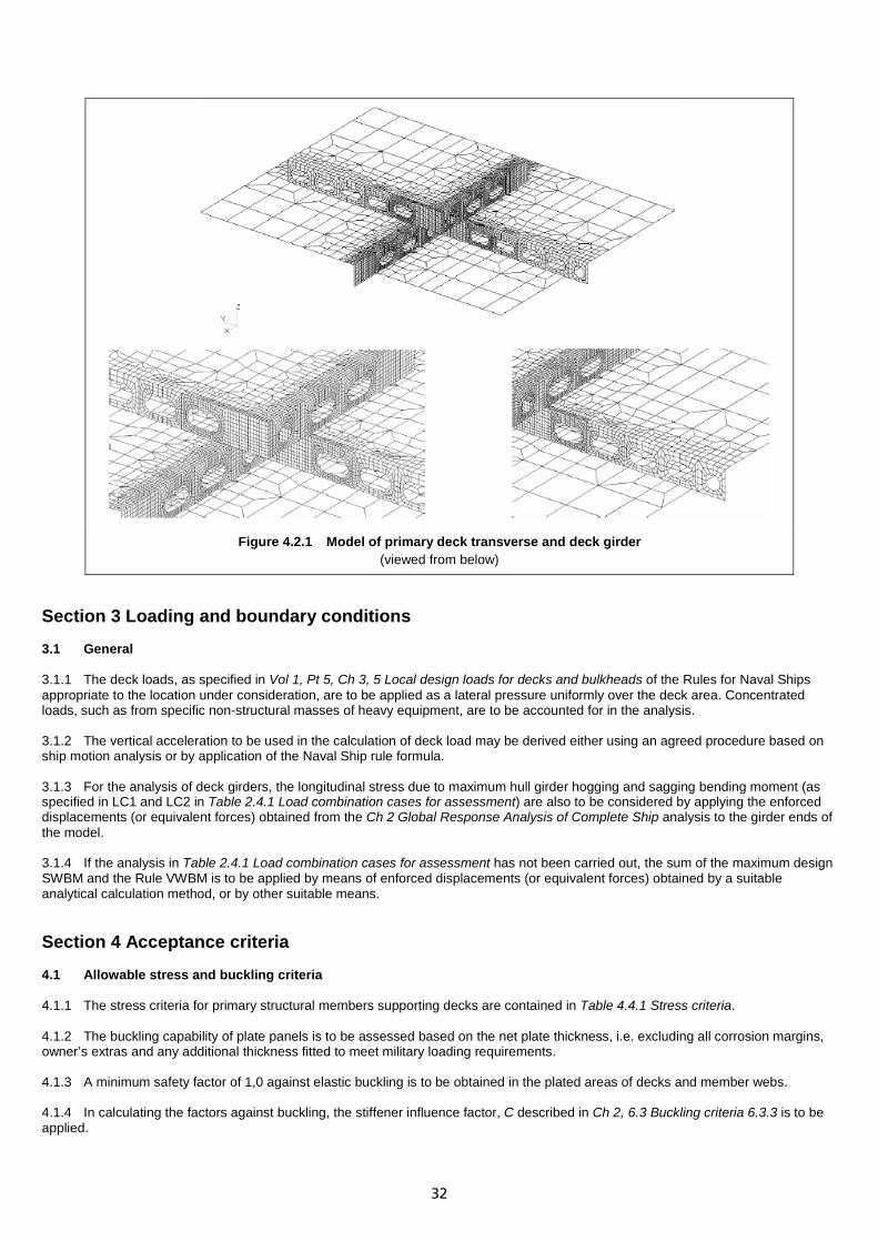
32
Figure 4.2.1 Model of primary deck transverse and deck girder
(viewed from below)
Section 3 Loading and boundary conditions 3.1 General 3.1.1 The deck loads, as specified in Vol 1, Pt 5, Ch 3, 5 Local design loads for decks and bulkheads of the Rules for Naval Ships appropriate to the location under consideration, are to be applied as a lateral pressure uniformly over the deck area. Concentrated loads, such as from specific non-structural masses of heavy equipment, are to be accounted for in the analysis. 3.1.2 The vertical acceleration to be used in the calculation of deck load may be derived either using an agreed procedure based on ship motion analysis or by application of the Naval Ship rule formula. 3.1.3 For the analysis of deck girders, the longitudinal stress due to maximum hull girder hogging and sagging bending moment (as specified in LC1 and LC2 in Table 2.4.1 Load combination cases for assessment) are also to be considered by applying the enforced displacements (or equivalent forces) obtained from the Ch 2 Global Response Analysis of Complete Ship analysis to the girder ends of the model. 3.1.4 If the analysis in Table 2.4.1 Load combination cases for assessment has not been carried out, the sum of the maximum design SWBM and the Rule VWBM is to be applied by means of enforced displacements (or equivalent forces) obtained by a suitable analytical calculation method, or by other suitable means. Section 4 Acceptance criteria 4.1 Allowable stress and buckling criteria 4.1.1 The stress criteria for primary structural members supporting decks are contained in Table 4.4.1 Stress criteria. 4.1.2 The buckling capability of plate panels is to be assessed based on the net plate thickness, i.e. excluding all corrosion margins, owner’s extras and any additional thickness fitted to meet military loading requirements. 4.1.3 A minimum safety factor of 1,0 against elastic buckling is to be obtained in the plated areas of decks and member webs. 4.1.4 In calculating the factors against buckling, the stiffener influence factor, C described in Ch 2, 6.3 Buckling criteria 6.3.3 is to be applied.
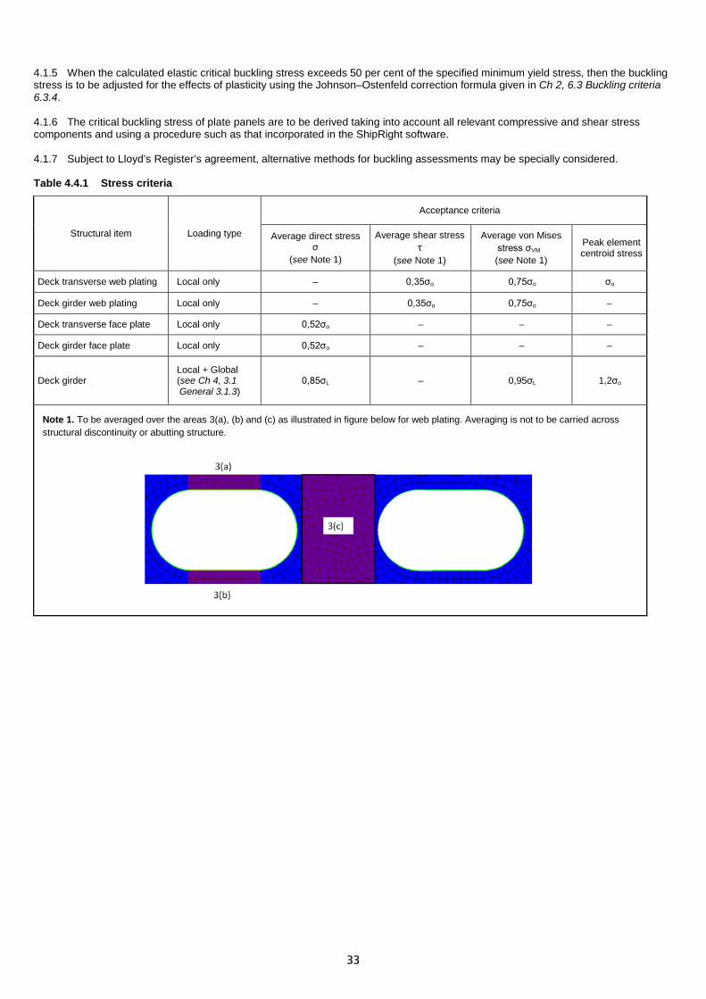
33
4.1.5 When the calculated elastic critical buckling stress exceeds 50 per cent of the specified minimum yield stress, then the buckling stress is to be adjusted for the effects of plasticity using the Johnson–Ostenfeld correction formula given in Ch 2, 6.3 Buckling criteria 6.3.4. 4.1.6 The critical buckling stress of plate panels are to be derived taking into account all relevant compressive and shear stress components and using a procedure such as that incorporated in the ShipRight software. 4.1.7 Subject to Lloyd’s Register’s agreement, alternative methods for buckling assessments may be specially considered. Table 4.4.1 Stress criteria
Structural item Loading type
Acceptance criteria
Average direct stress σ
(see Note 1)
Average shear stress τ
(see Note 1)
Average von Mises stress σVM (see Note 1)
Peak element centroid stress
Deck transverse web plating Local only – 0,35σo 0,75σo σo
Deck girder web plating Local only – 0,35σo 0,75σo –
Deck transverse face plate Local only 0,52σo – – –
Deck girder face plate Local only 0,52σo – – –
Deck girder Local + Global (see Ch 4, 3.1 General 3.1.3)
0,85σL – 0,95σL 1,2σo
Note 1. To be averaged over the areas 3(a), (b) and (c) as illustrated in figure below for web plating. Averaging is not to be carried across structural discontinuity or abutting structure.

34
Chapter 5 Verification of Primary Structure at Forward Region Section 1 Application 1.1 Introduction 1.1.1 This analysis is applicable to naval ships of category NS2 as specified in Vol 1, Pt 1, Ch 2, 2.1 Applicable ship types 2.1.1 of the Rules for Naval Ships. Section 2 Objectives 2.1 General 2.1.1 The objective of this Chapter is to assess the primary structures in the forward region of the ship in a heave down and bow pitched down condition under maximum vertical acceleration. In general, structures forward of 0,75LR are to be assessed. 2.1.2 All structural members should be examined, especially the response of transverse structures and side structures under the action of the external pressure induced transverse compressive loading, caused by the deep immersion of the ship's bow. Section 3 Structural modelling 3.1 General 3.1.1 The full ship FE model specified in Ch 2 Global Response Analysis of Complete Ship is to be used. Section 4 Loading conditions 4.1 General 4.1.1 A loading condition with the maximum forward draught is to be selected for this analysis. 4.1.2 The loads caused by maximum vertical acceleration in a bow pitched down condition are to be applied. This includes the load components arising from static and dynamic effects. 4.1.3 The loading condition to be used for the analysis should be discussed and agreed with LR at the earliest opportunity. 4.2 Heave down and bow pitched down condition 4.2.1 The bow pitched down condition with maximum vertical acceleration described in this Section is to be analysed. 4.2.2 The vertical acceleration formula given in Vol 1, Pt 5, Ch 3, 2.3 Design accelerations of the Rules for Naval Ships is modified, as below, to maintain a consistent acceleration curve over the model length. This modification takes into account of the fact that the pitch motion in the aft end of the ship results in a vertical acceleration component acting in the opposite direction to that at the forward end of the ship. The following formulae may be used to obtain the vertical acceleration factors. For heave downward and bow pitched down case:
az = a0 � 1 + �5,3 - 45LWL
�2� xwl - LCG
LWL�
2� 0,6
Cb �
1.5 for xwl ≥ LCG
az = a0 � 2 -� 1 + �5,3 - 45LWL
�2� xwl - LCG
LWL �
2� 0,6
Cb �
1.5 � for xwl < LCG
where, az non-dimensional vertical acceleration (i.e. relative to the acceleration of gravity), positive downward a0 non-dimensional heave acceleration given in Vol 1, Pt 5, Ch 3, 2.3 Design accelerations of the Rules for Naval Ships xwl longitudinal distance, in metres, measured forwards from the aft end of the load waterline (LWL) to the position or centre of
gravity of the item being considered, see Vol 1, Pt 5, Ch 3, 1.3 Symbols and definitions of the Rules for Naval Ships LCG longitudinal centre of gravity of the ship measured in metres from the aft end of the LWL for the design loading condition, see
Vol 1, Pt 5, Ch 3, 1.3 Symbols and definitions 1.3.4 of the Rules for Naval Ships

35
4.2.3 The following loads are to be applied to the FE model:
• external hydrostatic pressures due to the quasi-static sinusoidal wave, see Ch 5, 4.2 Heave down and bow pitched down condition 4.2.4 and Ch 5, 4.3 Procedure to derive external pressure;
• tank pressure loads acting on the tank structure. These loads are to include static pressure and dynamic pressure due to vertical accelerations;
• static forces and dynamic inertia forces of lightship and other deadweight items due to vertical accelerations. 4.2.4 This load case is to be evaluated using quasi-static techniques. The downward vertical accelerations are applied to all deadweight and lightship items and the ship is balanced on a sinusoidal wave. The generated loading condition reflects the ship at:
• maximum downward heave; • maximum bow down pitch and hence deep draught forward; • maximum downwards inertial force due to vertical acceleration over the forward end.
4.2.5 Alternatively, direct calculation procedures using an appropriate ship motion program can be used to derive the acceleration factors after consultation with LR. 4.3 Procedure to derive external pressure 4.3.1 The longitudinal mass distribution is to be divided into convenient longitudinal sections for all lightship and deadweight items in a similar way to that required for a still water loads analysis. All components of a loading condition are to be included in the analysis. Where necessary, adjustment to the FE model is to be made to match the required lightship and LCG position of the ship. 4.3.2 The vertical acceleration at the longitudinal centre of gravity of each section is to be calculated in accordance with Ch 5, 4.2 Heave down and bow pitched down condition 4.2.2. 4.3.3 Each section of lightship and deadweight is to be multiplied by its corresponding vertical acceleration to give the combined static and dynamic load distribution. 4.3.4 The load cases are evaluated using quasi-static techniques. The ship under combined static and dynamic vertical accelerations are to be balanced, with bow pitched down, on a sinusoidal wave with a wave height of Lf (in metres), wave length of Lpp and a wave trough position at 0,65Lpp, where Lf is defined in Vol 1, Pt 5, Ch 4, 3.3 Vertical wave bending moments of the Rules for Naval Ships. 4.3.5 The effect of longitudinal acceleration may be ignored in the determination of the ship balanced position. 4.3.6 The resulting quasi-static balanced position, as illustrated in Figure 5.4.1 Quasi-static balanced position of ship on a sinusoidal wave, is to be used to apply the external hydrostatic pressures to shell plating elements. The external pressure applied to the wetted plate elements may be considered to be static and calculated as a ρgh, where h is the vertical distance from the wave surface to the centre of the element and ρ is the density of sea-water, in tonnes/m3 (specific gravity to be taken as 1,025). Figure 5.4.2 External pressure distribution resulting from balanced position shows the external pressure distribution applied.
Figure 5.4.1 Quasi-static balanced position of ship on a sinusoidal wave

36
Figure 5.4.2 External pressure distribution resulting from balanced position
Section 5 Boundary conditions 5.1 General 5.1.1 The boundary conditions described in Ch 2, 5 Boundary conditions are preferred. However, alternative equivalent boundary conditions may be used. Section 6 Acceptance criteria 6.1 Allowable stress and buckling criteria 6.1.1 The structure is to comply with the stress and buckling acceptance criteria given in Table 5.6.1 Acceptance criteria. 6.1.2 The buckling capability of plate panels is to be assessed based on the net plate thickness, i.e. excluding all corrosion margins, Owner’s extras and any additional thickness fitted to meet military loading requirements. 6.1.3 In calculating the factors against buckling, the stiffener influence factor, C, can be applied (see Ch 2, 6.3 Buckling criteria 6.3.3). 6.1.4 When the calculated elastic critical buckling stress exceeds 50 per cent of the specified minimum yield stress, then the buckling stress is to be adjusted for the effects of plasticity using the Johnson–Ostenfeld correction formula given in Ch 2, 6.3 Buckling criteria 6.3.4. 6.1.5 The critical buckling stress of plate panels are to be derived taking into account all relevant compressive and shear stress components and using a procedure such as that incorporated in the ShipRight software. 6.1.6 Subject to Lloyd’s Register’s agreement, alternative methods for buckling assessments may be specially considered.
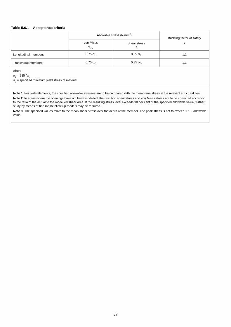
37
Table 5.6.1 Acceptance criteria
Allowable stress (N/mm2)
Buckling factor of safety
λ von Mises σ
VM
Shear stress τ
Longitudinal members 0,75 σL 0,35 σL 1,1
Transverse members 0,75 σo 0,35 σo 1,1
where, σL = 235 / k
L
σo = specified minimum yield stress of material
Note 1. For plate elements, the specified allowable stresses are to be compared with the membrane stress in the relevant structural item. Note 2. In areas where the openings have not been modelled, the resulting shear stress and von Mises stress are to be corrected according to the ratio of the actual to the modelled shear area. If the resulting stress level exceeds 90 per cent of the specified allowable value, further study by means of fine mesh follow-up models may be required. Note 3. The specified values relate to the mean shear stress over the depth of the member. The peak stress is not to exceed 1.1 × Allowable value.

38
Chapter 6 Adjustment of Global BM and SF Section 1 Introduction 1.1 General 1.1.1 The method described in this Chapter may be used for the purpose of adjusting the stress level when the resultant hull girder shear force and/or bending moment in the FE model deviates from required shear force and/or bending moment, see Ch 2, 6.1 Stress for assessment and Ch 3, 5.1 Stress for assessment. Section 2 Derivation of BM and SF influence factors 2.1 General 2.1.1 Under pure hull girder shear force and bending moment, the stress in an element is considered to be directly proportional to the load applied at the section under consideration. 2.1.2 The bending moment and shear force influence factors are to be derived for each element. The influence factors for a given element are obtained as follows:
σx1 = 𝐶Mx ∙ BM1 + 𝐶Qx ∙ SF1 σx2 = 𝐶Mx ∙ BM2 + 𝐶Qx ∙ SF2 σy1 = 𝐶My ∙ BM1 + 𝐶Qy ∙ SF1 σy2 = 𝐶My ∙ BM2 + 𝐶Qy ∙ SF2 τxy1 = 𝐶Mxy ∙ BM1 + 𝐶Qxy ∙ SF1 τxy2 = 𝐶Mxy ∙ BM2 + 𝐶Qxy ∙ SF2 where, 𝐶Mx, 𝐶My and 𝐶Mxy are the hull bending moment influence factors applying to σx, σy and τxy for the element 𝐶Qx, 𝐶Qy and 𝐶Qxy are the hull shear force influence factors applying to σx, σy and τxy for the element BM1, SF1 is the bending moment and shear force resulting from the application of distributed load 𝑃1 for load
case SC3a (see Ch 2, 4.4 Procedure to apply the Rule design vertical wave BM and SF 4.4.3) at the x-position of the centre of the element
BM2, SF2 is the bending moment and shear force resulting from the application of distributed load 𝑃2 for load case SC5 (see Ch 2, 4.4 Procedure to apply the Rule design vertical wave BM and SF 4.4.4) at the x-position of the centre of the element
σx1, σy1 and τxy1 are the element direct stresses and shear stress resulting from the application of distributed load 𝑃1
σx2, σy2 and τxy2 are the element direct stresses and shear stress resulting from the application of distributed load 𝑃2
It follows that:
𝐶Mx = (SF1 σx2− SF2 σx1)(BM2 SF1− BM1 SF2)
𝐶My = �SF1 σy2− SF2 σy1�(BM2 SF1− BM1 SF2)
𝐶Mxy = �SF1 τxy2− SF2 τxy1�(BM2 SF1− BM1 SF2)
𝐶Qx = (−BM1 σx2+ BM2 σx1)(BM2 SF1− BM1 SF2)
𝐶Qy = �−BM1 σy2+ BM2 σy1�(BM2 SF1− BM1 SF2)
𝐶Qxy = �−BM1 τxy2+ BM2 τxy1�(BM2 SF1− BM1 SF2)
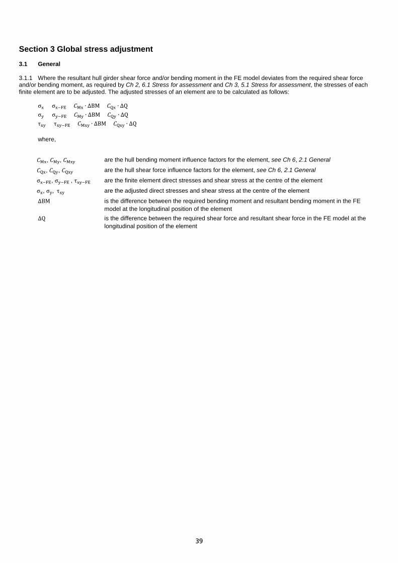
39
Section 3 Global stress adjustment 3.1 General 3.1.1 Where the resultant hull girder shear force and/or bending moment in the FE model deviates from the required shear force and/or bending moment, as required by Ch 2, 6.1 Stress for assessment and Ch 3, 5.1 Stress for assessment, the stresses of each finite element are to be adjusted. The adjusted stresses of an element are to be calculated as follows:
σx = σx−FE + 𝐶Mx ∙ ∆BM + 𝐶Qx ∙ ∆Q σy = σy−FE + 𝐶My ∙ ∆BM + 𝐶Qy ∙ ∆Q τxy = τxy−FE + 𝐶Mxy ∙ ∆BM + 𝐶Qxy ∙ ∆Q where,
𝐶Mx, 𝐶My, 𝐶Mxy are the hull bending moment influence factors for the element, see Ch 6, 2.1 General
𝐶Qx, 𝐶Qy, 𝐶Qxy are the hull shear force influence factors for the element, see Ch 6, 2.1 General
σx−FE, σy−FE , τxy−FE are the finite element direct stresses and shear stress at the centre of the element
σx, σy, τxy are the adjusted direct stresses and shear stress at the centre of the element
∆BM is the difference between the required bending moment and resultant bending moment in the FE model at the longitudinal position of the element
∆Q is the difference between the required shear force and resultant shear force in the FE model at the longitudinal position of the element

© Lloyd’s Register Group Limited 2017 Published by Lloyd’s Register Group Limited
Registered office (Reg. no. 08126909) 71 Fenchurch Street, London, EC3M 4BS
United Kingdom
Lloyd’s Register is a trading name of Lloyd’s Register Group Limited and its subsidiaries. For further details please see
http://www.lr.org/entities
Lloyd's Register Group Limited, its affiliates and subsidiaries and their respective officers, employees or agents are, individually and collectively, referred to in this clause as ‘Lloyd's Register’. Lloyd's Register assumes no responsibility and shall not be liable to any person for any loss, damage or expense caused by reliance on the information or advice in this document or howsoever provided, unless that person has signed a contract with the relevant Lloyd's Register entity for the provision of this information or advice and in that case any responsibility or liability is exclusively on the terms and conditions set out in that contract.
© Lloyd’s Register, 2017