Accessory Application Publication No. INSTALLATION...
18
Issue Date INSTALLATION INSTRUCTIONS Accessory Application Publication No. MII 16083 © 2017 American Honda Motor Co., Inc. - All Rights Reserved. PARTS LIST 08L72-HL4-F01 1 of 18 February 2017 WINCH MOUNT P/N 08L73-HL4-F01 After ‘16 SXS1000M3/M3P/M3LE SXS1000M5P/M5D/M5LE No. Description Qty (1) Installation Instructions URL 1 (2) Winch power cables* 1 (3) Winch battery cable 1 (4) Remote control sub harness 1 (5) Winch sub harness 1 (6) Wire tie 19 (7) Clip band 1 (8) Contactor cover 1 (9) Harness clip stay 1 (10) Contactor stay 1 (11) Contactor plate nut 1 (12) 5 mm nut 2 (13) 5 mm bolt 2 (14) Washer 2 (15) Lock washer (small) 2 (16) 6 mm flange bolt 2 (17) 5 mm shoulder bolt 2 (18) Rubber washer 2 (19) 5 mm flange nut 2 (20) Winch bracket 1 (21) 10 mm flange nut 2 (22) 10 mm flange bolt 2 (23) Lock washer (large) 4 (24) 8 mm bolt 4 (25) 10 mm bolt washer 2 (26) Right roller bracket 1 (27) Left roller bracket 1 (28) 8 mm flange bolt 2 *Some winch power cables will have five clip bands; updated cables will have only three clip bands. • If your winch power cables have five clip bands, bands B and C (indicated in the illustration), will not be used for installation. (25) (26) (27) (28) (20) (19) (13) (15) (10) (6) (2) (3) (4) (5) (1) (17) (18) (14) (7) (23) (24) (16) (11) (12) (9) (21) (22) (8) (B, C)
-
Upload
duongtuyen -
Category
Documents
-
view
214 -
download
0
Transcript of Accessory Application Publication No. INSTALLATION...

Issue DateINSTALLATIONINSTRUCTIONS
Accessory Application Publication No.
MII 16083
© 2017 American Honda Motor Co., Inc. - All Rights Reserved.
PARTS LIST
08L72-HL4-F011 of 18
February 2017
WINCH MOUNTP/N 08L73-HL4-F01
After ‘16SXS1000M3/M3P/M3LE
SXS1000M5P/M5D/M5LE
No. Description Qty
(1) Installation Instructions URL 1
(2) Winch power cables* 1
(3) Winch battery cable 1
(4) Remote control sub harness 1
(5) Winch sub harness 1
(6) Wire tie 19
(7) Clip band 1
(8) Contactor cover 1
(9) Harness clip stay 1
(10) Contactor stay 1
(11) Contactor plate nut 1
(12) 5 mm nut 2
(13) 5 mm bolt 2
(14) Washer 2
(15) Lock washer (small) 2
(16) 6 mm flange bolt 2
(17) 5 mm shoulder bolt 2
(18) Rubber washer 2
(19) 5 mm flange nut 2
(20) Winch bracket 1
(21) 10 mm flange nut 2
(22) 10 mm flange bolt 2
(23) Lock washer (large) 4
(24) 8 mm bolt 4
(25) 10 mm bolt washer 2
(26) Right roller bracket 1
(27) Left roller bracket 1
(28) 8 mm flange bolt 2
*Some winch power cables will have five clip bands; updated cables will have only three clip bands.
• If your winch power cables have five clip bands, bands B and C (indicated in the illustration), will not be used for installation.
(25)
(26)(27)
(28)
(20)
(19)
(13)
(15)
(10)
(6)
(2)
(3)
(4)
(5)
(1)
(17)
(18)
(14)
(7)
(23)
(24) (16)
(11)
(12)
(9)(21)
(22)
(8)
(B, C)

2 of 18
WINCH KITSold separately
(12)
(13)(14)
(15)
(7)
(1)
(2)
(3)
(9)
(6)
(8)
(5)
(10)
(11)
(4)
Not used.
No. Description Qty
(1) Winch 1
(2) Roller fairlead 1
(3) Hook 1
(4) Clevis pin 1
(5) Cotter pin 1
(6) Strap 1
(7) Remote control switch 1
(8) Contactor 1
(9) 6 mm flange nut 2
(10) 6 mm nut 4
(11) Lock washer 4
(12) Terminal boot 6
(13) Winching ATV NGW Guide 1
(14) Winch PV4500 Spec Sheet 1
(15) Limited Lifetime Warranty 1
CUSTOMER INFORMATION: The information in these installation instructions is intended for use only by skilled technicians who have the proper tools, equipment, and training to correctly and safely add equipment to your SxS. These procedures should not be attempted by “Do-it-yourselfers.”
BEFORE YOU BEGINThis kit describes the installation of a WARN SxS winch. Please read WARN’s Winching Technique guide provided with the winch prior to use of this product.
TOOLS AND SUPPLIES REQUIREDSocket (8, 10, 12 and 14 mm)
Ratchet
Box-end wrench (8, 10 and 14 mm)
Side cutters
Electric drill
Drill bit (5 and 7 mm)
Holesaw (18 mm)
Marker
Ruler
Electrical tape
Scissors
Wire or Wire tie (Length: 290 mm or more/Width: 5 mm)
Torque wrench
TORQUE CHARTTighten all screws, bolts, and nuts to their specified torque values. Refer to the Service Manual for the torque values of the removed parts.
Item N·m kgf·m Ibf·ft
5 mm bolt and nut 5.2 0.5 3.8
5 mm flange nut 5.2 0.5 3.8
6 mm nut 10 1.0 7
6 mm flange bolt and nut 12 1.2 9
8 mm bolt 22 2.2 16
8 mm flange bolt 27 2.8 20
10 mm flange nut 39 4.0 29
10 mm bolt washer 50 5.1 37

3 of 18
MAXIMUM WINCH CAPACITY
Winch Capacity 4,500 lb (2,041 kg)
SAFETYWhen installing your SxS winch system, read and follow all mounting and safety instructions. Always use caution when working with electricity and verify that there are no exposed electrical connections before energizing your winch circuit. For specifications and performance data, refer to the specification sheet supplied with your winch.
INSTALLATION CAUTION
• To prevent burns, allow the engine, exhaust system, radiator, etc., to cool before installing the accessory.
NOTE:
• Disconnect the battery negative (-) cable before installing this accessory.
• The memory of the clock will be erased when you disconnect the battery. Reset the clock after reconnecting the battery.
• Cut the wire ties at 5 mm from the lock part after attaching them to the wire harnesses. Do not allow the cut part of the wire tie to interfere with another harness or brake hose.
• Reinstall the removed parts on the vehicle and make sure that the wires and harnesses are not pinched.
• Always perform the heavy installation work with two people.
• For installation of this accessory on a SxS equipped with a horn, refer to the installation instructions included with the horn mount.
1. Remove the vehicle’s parts as shown.
BOLT (Save)
BOLT
2. Remove the front bumper as shown.
Remove the bolts as shown.
FRONT BUMPER
BOLT Repeat on the right side.

4 of 18
3. Remove the front hood as shown.
FRONT HOOD
4. Loosely install the right and left roller bracket to the front bumper as shown.
FRONT BUMPER (Reuse)
RIGHT ROLLER BRACKET
LEFT ROLLER BRACKET
8 mm FLANGE BOLT
5. Install the roller fairlead as shown.
FRONT BUMPER
10 mm FLANGE BOLT
ROLLER FAIRLEADMake sure that the bigger roller is positioned on the bottom.
10 mm FLANGE NUT
6. Tighten the loosely installed parts securely.
7. Drill an 18 mm hole into the instrument panel as shown.
• Drill hole at the center of the marked line.• Remove any burrs from the edge of the hole.
INSTRUMENT PANEL (BACK SIDE)
MARKED LINE
ELECTRIC DRILL(18 mm HOLE SAW)
8. Position the remote control sub harness as shown and mark this position.
INSTRUMENT PANEL (BACK SIDE)
REMOTE CONTROL SUB HARNESS
MARKER

5 of 18
9. Remove the remote control sub harness and drill at the marked point on the instrument panel using an electric drill.
• Remove any burrs from the edge of the hole.
INSTRUMENT PANEL (BACK SIDE)
MARK ELECTRIC DRILL (5 mm BIT)
10. Open the glove box and pass the remote control sub harness through the hole in the instrument panel.
REMOTE CONTROL SUB HARNESS
INSTRUMENT PANEL
OPENED HOLE
11. Install the remote control sub harness as shown.
INSTRUMENT PANEL (BACK SIDE)
5 mm BOLTWASHER
LOCK WASHER (small)
5 mm NUTREMOTE CONTROL SUB HARNESS
12. Drill holes into the front fender as shown.
• Drill holes at the center of the marked lines.• Remove any burrs from the edge of the hole.• Be careful not to damage the harness.
FRONT FENDER
MARKED LINE
ELECTRIC DRILL (7 mm BIT)
6 of 18
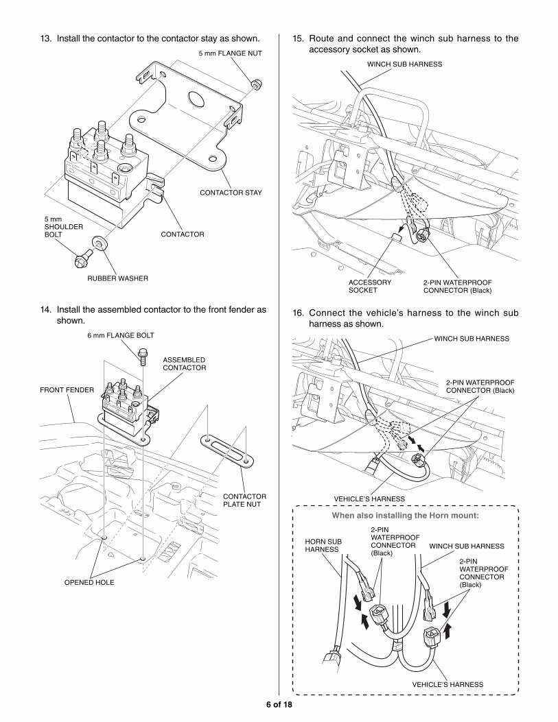
13. Install the contactor to the contactor stay as shown.
RUBBER WASHER
5 mm SHOULDER BOLT
5 mm FLANGE NUT
CONTACTOR
CONTACTOR STAY
14. Install the assembled contactor to the front fender as shown.
FRONT FENDER
ASSEMBLED CONTACTOR
CONTACTOR PLATE NUT
OPENED HOLE
6 mm FLANGE BOLT
15. Route and connect the winch sub harness to the accessory socket as shown.
WINCH SUB HARNESS
2-PIN WATERPROOF CONNECTOR (Black)
ACCESSORY SOCKET
16. Connect the vehicle’s harness to the winch sub harness as shown.
WINCH SUB HARNESS
2-PIN WATERPROOF CONNECTOR (Black)
VEHICLE’S HARNESS
When also installing the Horn mount:
HORN SUB HARNESS WINCH SUB HARNESS
2-PIN WATERPROOF CONNECTOR (Black)
2-PIN WATERPROOF CONNECTOR (Black)
VEHICLE’S HARNESS

7 of 18
17. Secure the winch sub harness with the wire tie as shown.
WINCH SUB HARNESS
WIRE TIESecure the winch sub harness to the vehicle’s harness.
18. Connect the winch sub harness and remote control sub harness as shown.
WINCH SUB HARNESS
3-PIN WATERPROOF CONNECTOR (White)
RUBBER
REMOTE CONTROL SUB HARNESS
REMOTE CONTROL SUB HARNESS
19. Secure the harnesses with the wire ties as shown.
WINCH SUB HARNESS
3-PIN WATERPROOF CONNECTOR (White)
WIRE TIESecure remote control sub harness to the vehicle’s harness.
WIRE TIESecure winch sub harness to the vehicle’s harness.
REMOTE CONTROL SUB HARNESS
20. Remove the bolt as shown.<Right side>
BOLT

8 of 18
21. Install the harness clip stay as shown.
When also installing the Horn mount:
BOLT (Reuse)HARNESS CLIP STAY
6 mm FLANGE BOLTIncluded in the Horn mount.
HARNESS CLIP STAY
ASSEMBLED HORN
22. Install the winch power cables as shown.
HARNESS CLIP STAY
WINCH POWER CABLES
CLIP BAND
23. Secure the winch power cables with the wire tie as shown.
WINCH POWER CABLESWIRE TIESecure the winch power cables to the frame.
24. Remove the coolant reserve tank from the stay by pulling it up while leaving the hoses connected. Set the reserve tank to the side.
RESERVE TANK

9 of 18
25. Route the winch power cables along the frame under the front panel. Secure the winch power cables with the wire ties as shown.
• Front Fender not shown for clarity.
WIRE TIE
26. Reinstall the coolant reserve tank in the reverse order of removal.
27. Route the winch power cables and secure them with the wire tie as shown.
WINCH POWER CABLES
WIRE TIESecure the winch power cables to the frame.
28. Install the winch power cables as shown.
CLIP BAND
WINCH POWER CABLES
10 of 18
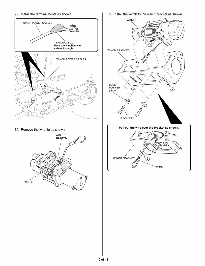
29. Install the terminal boots as shown.
WINCH POWER CABLES
WINCH POWER CABLES
TERMINAL BOOTPass the winch power cables through.
30. Remove the wire tie as shown.
WINCH
WIRE TIERemove.
31. Install the winch to the winch bracket as shown.
Pull out the wire over the bracket as shown.
LOCK WASHER (large)
WINCH
WINCH BRACKET
WIRE
WINCH BRACKET
8 mm BOLT

11 of 18
32. Loosely install the assembled winch as shown.<Front side>
ASSEMBLED WINCH
BOLT (Reuse)
33. Install the winch power cables as shown.
ASSEMBLED WINCH
6 mm FLANGE NUTIncluded in the Winch kit.
6 mm FLANGE NUTIncluded in the Winch kit.
TERMINAL
WINCH POWER CABLES
TAPE (Yellow)
TAPE (Blue)
WINCH POWER CABLE
TERMINAL BOOTCover the terminal.
34. Remove the blue tape from the factory installed winch ground cable. Remove the indicated clip band from the front fender.
Remove Blue Tape
Remove Clip Band
35. Route the winch power cables through the hole in the front fender as shown.
WINCH POWER CABLES
FRONT FENDER

12 of 18
36. Route the winch sub harness along the main harness as shown.
WINCH SUB HARNESS
37. Connect the sub harness to the contactor as shown.
SUB HARNESS
CONTACTOR
38. Install the terminal boots as shown.
WINCH POWER CABLES
WINCH POWER CABLES
TERMINAL BOOTPass the winch power cables through.
39. Install the winch power cables to the corresponding color terminal on the contactor as shown.
Install in the direction as shown.
TAPE (Yellow)
TAPE (Blue)
WINCH POWER CABLES
WINCH POWER CABLE
CONTACTOR
CONTACTOR
6 mm NUT LOCK WASHERIncluded in the Winch kit.
WINCH POWER CABLE

13 of 18
40. Remove the vehicle’s harness from the starter relay switch as shown.
NUT
STARTER RELAY
VEHICLE’S HARNESS
41. Cut the cover as shown.
VEHICLE’S HARNESS
COVER
COVER
TAPE (Discard)
SCISSORSCut.
42. Remove the cover as shown.
VEHICLE’S HARNESS
COVER (Discard)
43. Connect the winch battery cable as shown.
WINCH BATTERY CABLE
NUT (Reuse)Tighten together with the winch battery cable and vehicle’s harness.
STARTER RELAY
VEHICLE’S HARNESS
COVERCover the terminals after tightening the nut.

14 of 18
44. Install the terminal boot as shown.
WINCH BATTERY CABLE
WINCH BATTERY CABLE
TERMINAL BOOTPass the winch battery cable through.
45. Install the winch battery cable as shown.
Install in the direction as shown.
WINCH BATTERY CABLE
WINCH BATTERY CABLE
CONTACTOR
6 mm NUT
LOCK WASHERIncluded in the Winch kit.
CONTACTOR
46. Install the terminal boot as shown.
WINCH GROUND CABLE
WINCH GROUND CABLE
TERMINAL BOOTPass the winch ground cable through.
47. Install the winch ground cable as shown.
Install in the direction as shown.
WINCH GROUND CABLE
WINCH GROUND CABLE
CONTACTOR
6 mm NUT
LOCK WASHERIncluded in the Winch kit.
CONTACTOR

15 of 18
48. Cover each cable terminal with the terminal boot as shown.
TERMINAL BOOTCover the terminals.
TERMINAL BOOTCover the terminals.
49. Install the contactor cover as shown.
CONTACTOR
CONTACTOR COVER
50. Install the clip band as shown, and secure it to the front fender.
WINCH GROUND CABLE
WINCH SUB HARNESS
FRONT FENDER
CLIP BANDBundle the winch ground cable and winch sub harness.
CLIP BAND
OPEN HOLE
51. Secure the winch ground cable and sub harness with the wire tie as shown.
WINCH GROUND CABLE
WINCH SUB HARNESS
WIRE TIESecure the winch ground cable and winch sub harness to the vehicle’s harness.

16 of 18
52. Secure the winch sub harness with the wire ties as shown.
WIRE TIESecure the winch sub harness to the frame.
WINCH SUB HARNESS
53. Temporarily install mechanic’s wire or a wire tie as shown to secure the winch bracket to the A-arm.
<Left side>
MECHANIC’S WIRE or WIRE TIESecure the winch bracket to the A-arm.
WINCH BRACKET
54. Remove the loosely installed bolts.
• Repeat on the right side.
WINCH BRACKET
BOLT
55. Install the front bumper and winch bracket as shown.
• Repeat on the right side.• After installing winch bracket, remove the
wire or wire tie.
FRONT BUMPER
WINCH BRACKET
BOLT (Reuse)
BOLT (Reuse)
ROLLER FAIRLEADWIRE
10 mm BOLT WASHERDo not install when the vehicle is equipped with the plow.

17 of 18
56. Install the hook and strap as shown.<Front side>
CLEVIS PIN
COTTER PIN
COTTER PIN
CLEVIS PIN
HOOK
STRAP
57. Connect the remote control switch as shown.<Right side>
After connecting, put the remote control switch in the glove box as shown.
INSTRUMENT PANEL
GLOVE BOX
REMOTE CONTROL SWITCH
REMOTE CONTROL SWITCH
58. Confirm that wire harnesses are not caught or too tight.
59. Connect the battery negative (-) cable and check the function of all lights.

18 of 18
CHECK THE SYSTEM: 60. Before using the winch, verify the following:
• The wiring to all components is correct. All loose wires are secured tightly using wire-ties.
• There are no exposed wires or terminals. Cover any exposed wires or terminals with terminal boots, heat shrink tubing, or electrician’s tape.
• Turn the vehicle ignition switch to the ON position.
• Check the winch for proper operation. The wire rope should spool in and out in the direction indicated on the switch.