
Accessories for Protective Devices - Eatonpub/@sweden/documents/content/pct... · 4 Accessories for...
222
Auxiliary Switch Z-HK, Z-AHK; Tripping Signal Switch Z-NHK • Design according to IEC/EN 60947-5-1, IEC/EN 62019 • Can be mounted subsequently (screws) • The specified minimum voltages are per contact Take into account particularly in case of series connection! • Z-AHK, Z-NHK: Contact function with relative movement (self-cleaning contacts) • Contact material and design particularly suitable for extra low voltage • Z-NHK: The function of one of the two change-over contacts can be switched from “auxiliary switch” to “tripping signal switch” • Tripping signal contact transmits message of electric tripping, not mechani- cal switch-off • Test key for contact function “electrical tripping” Technical Data Connection diagrams Dimensions (mm) 21 13 22 14 Z-HK Z-AHK Z-NHK Z-HK Z-AHK Z-NHK Electrical Can be mounted from the left onto PFIM, PFR, dRCM CLS, L71, PFHM-2p CLS, L71, CFI6, PFHM-4p CKN, PKDM CKN, PKDM Can be mounted from the right onto – – PFIM, PFR, CFI6, PFHM, dRCM Contact function 1NO + 1NC 1NO + 1NC 2CO Rated voltage 250 V 250 V 250 V Frequency 50/60 Hz 50/60 Hz 50/60 Hz Rated current 8 A 4 A 4 A Rated thermal current I th 8 A 4 A 4 A Utilisation category AC13 Rated operational current I e 6A/250V AC 3A/250V AC 3A/250V AC 2A/440V AC – – Utilisation category AC15 Rated operational current I e – 2A/250V AC 2A/250V AC Utilisation category DC12 Rated operational current I e – 0.5A/110V DC 0.5A/110V DC Utilisation category DC13 Rated operational current I e 0.5A/230V DC – – 2A/110V DC – – 4A/60V DC – – Rated insulation voltage U I 250 V AC 250 V AC 250 V AC Minimum operational voltage per contact U min 24 V AC/DC 5 V DC 5 V DC Minimum operational current I min 50 mA AC/DC 10 mA DC 10 mA DC Rated peak withstand voltage U imp (1.2/50μ) 2.5 kV 2.5 kV 2.5 kV Conditional short circuit current I k with back-up fuse 6A or PLSM-B4-HS – 1 kA 1 kA Max. back-up fuse, overload and short circuit 8 A gL / CLS6-4/../B-HS 6 A gL / CLS6-4/../B-HS 6 A gL / CLS6-4/../B-HS Mechanical Tripping indicator “electrical tripping” – – blue/white Frame size 45 mm 45 mm 45 mm Device height 80 mm 80 mm 80 mm Device width 8.8 mm (0.5MU) 8.8 mm (0.5MU) 8.8 mm (0.5MU) Mounting onto switching dev. onto switching dev. onto switching dev. Degree of protection, built-in IP40 IP40 IP40 Terminal protection finger and hand touch safe according to BGV A3, ÖVE-EN 6 Terminals lift terminals lift terminals lift terminals Terminal capacity 0.5-2.5 mm 2 0.5-2.5 mm 2 0.5-2.5 mm 2 Terminal screws M3 (Pozidrive Z0) M3 (Pozidrive Z0) M3 (Pozidrive Z0) Fastening torque of terminal screws max. 0.8-1.0 Nm max. 0.8-1.0 Nm max. 0.8-1.0 Nm Z-HK Z-AHK Z-NHK Accessories for Protective Devices 1
Transcript of Accessories for Protective Devices - Eatonpub/@sweden/documents/content/pct... · 4 Accessories for...

Auxiliary Switch Z-HK, Z-AHK; Tripping Signal Switch Z-NHK• Design according to IEC/EN 60947-5-1, IEC/EN 62019• Can be mounted subsequently (screws)• The specified minimum voltages are per contact
Take into account particularly in case of series connection!• Z-AHK, Z-NHK: Contact function with relative movement (self-cleaning
contacts)• Contact material and design particularly suitable for extra low voltage• Z-NHK:The function of one of the two change-over contacts can be
switched from “auxiliary switch” to “tripping signal switch”• Tripping signal contact transmits message of electric tripping, not mechani-
cal switch-off• Test key for contact function “electrical tripping”
Technical Data
Connection diagrams
Dimensions (mm)
2113
2214
Z-HK Z-AHK Z-NHK
Z-HK Z-AHK Z-NHK
Electrical Can be mounted from the left onto PFIM, PFR, dRCM CLS, L71, PFHM-2p CLS, L71,
CFI6, PFHM-4p CKN, PKDM CKN, PKDMCan be mounted from the right onto – – PFIM, PFR, CFI6,
PFHM, dRCMContact function 1NO + 1NC 1NO + 1NC 2CORated voltage 250 V 250 V 250 VFrequency 50/60 Hz 50/60 Hz 50/60 HzRated current 8 A 4 A 4 ARated thermal current Ith 8 A 4 A 4 AUtilisation category AC13
Rated operational current Ie 6A/250V AC 3A/250V AC 3A/250V AC2A/440V AC – –
Utilisation category AC15Rated operational current Ie – 2A/250V AC 2A/250V AC
Utilisation category DC12Rated operational current Ie – 0.5A/110V DC 0.5A/110V DC
Utilisation category DC13Rated operational current Ie 0.5A/230V DC – –
2A/110V DC – –4A/60V DC – –
Rated insulation voltage UI 250 V AC 250 V AC 250 V ACMinimum operational voltage per contact Umin 24 V AC/DC 5 V DC 5 V DCMinimum operational current Imin 50 mA AC/DC 10 mA DC 10 mA DCRated peak withstand voltage Uimp (1.2/50µ) 2.5 kV 2.5 kV 2.5 kVConditional short circuit current Ik
with back-up fuse 6A or PLSM-B4-HS – 1 kA 1 kAMax. back-up fuse, overload and short circuit 8 A gL / CLS6-4/../B-HS 6 A gL / CLS6-4/../B-HS 6 A gL / CLS6-4/../B-HS
Mechanical Tripping indicator “electrical tripping” – – blue/whiteFrame size 45 mm 45 mm 45 mmDevice height 80 mm 80 mm 80 mmDevice width 8.8 mm (0.5MU) 8.8 mm (0.5MU) 8.8 mm (0.5MU)Mounting onto switching dev. onto switching dev. onto switching dev.Degree of protection, built-in IP40 IP40 IP40Terminal protection finger and hand touch safe according to BGV A3, ÖVE-EN 6Terminals lift terminals lift terminals lift terminalsTerminal capacity 0.5-2.5 mm2 0.5-2.5 mm2 0.5-2.5 mm2
Terminal screws M3 (Pozidrive Z0) M3 (Pozidrive Z0) M3 (Pozidrive Z0)Fastening torque of terminal screws max. 0.8-1.0 Nm max. 0.8-1.0 Nm max. 0.8-1.0 Nm
Z-HK Z-AHK Z-NHK
Accessories for Protective Devices
1

2
Accessories for Protective Devices
Example: Z-HK+PFIM
1NO+1NC 24V 50mA min.
Example: Z-AHK+CLS6
1NO+1NC 5V 10mA min.
Example: Z-NHK+CLS6 PFIM+Z-NHK
2CO 5V 10mA min.

3
Auxiliary Switch ZP-IHK, ZP-WHK; Tripping Signal Switch ZP-NHK• Design according to IEC/EN 62019• No screws required. Can be snapped onto PLS and PKNM subsequently• ZP-IHK, ZP-WHK: can be snapped on additionally 1 time onto itself • The specified minimum voltages are per contact. Take into account particu-
larly in case of series connection!• Contact material and design particularly suitable for extra low voltage.
Contact function with relative movement (self-cleaning contacts)e)• ZP-NHK:The function of one of the two change-over contacts can be
switched from “auxiliary switch” to "tripping signal switch"• Tripping signal contact transmits message of electric tripping, not mechani-
cal switch-off • Test key for contact function “electrical tripping”
Technical Data
Connection diagrams
Dimensions (mm)
ZP-IHK ZP-WHK ZP-NHK
Electrical Can be mounted from the left onto MCB: PLS, PLZ PLS, PLZ PLS, PLZ
RCD/MCB: PKNM PKNM PKNMAccessories: ZP-A40, ZP-ASA, ZP-A40, ZP-ASA, ZP-A40, ZP-ASA,
Z-MS Z-MS Z-MS1xZP-IHK, 1xZP-WHK 1xZP-IHK, 1xZP-WHK –
Contact function 1NO + 1NC 1CO 2CORated voltage 250 V 250 V 250 VFrequency 50/60 Hz 50/60 Hz 50/60 HzRated current 6 A 6 A 4 ARated thermal current Ith 6 A 6 A 4 AUtilisation category AC13
Rated operational current Ie 3A/250V AC 3A/250V AC 3A/250V ACUtilisation category AC15
Rated operational current Ie 2A/250V AC 2A/250V AC 2A/250V ACUtilisation category DC12
Rated operational current Ie 0.5A/110V DC 0.5A/110V DC 0.5A/110V DCRated insulation voltage UI 250 V AC 250 V AC 250 V ACMinimum operational voltage per contact Umin 5 V DC 5 V DC 5 V DCMinimum operational current Imin 10 mA DC 10 mA DC 10 mA DCRated peak withstand voltage Uimp (1.2/50µ) 2.5 kV 2.5 kV 2.5 kVConditional short circuit current Ik
with back-up fuse 6A or PLSM-B4-HS 1 kA 1 kA 1 kAMax. back-up fuse, overload and short circuit 6 A gL / PLSM-B4-HS 6 A gL / PLSM-B4-HS 6 A gL / PLSM-B4-HS
Mechanical Tripping indicator “electrical tripping” – – blue/whiteFrame size 45 mm 45 mm 45 mmDevice height 80 mm 80 mm 80 mmDevice width 8.8 mm (0.5MU) 8.8 mm (0.5MU) 8.8 mm (0.5MU)Degree of protection, built-in IP40 IP40 IP40Terminal protection finger and hand touch safe according to BGV A3, ÖVE-EN 6Terminals lift terminals lift terminals lift terminalsTerminal capacity 0.5-2.5 mm2 0.5-2.5 mm2 0.5-2.5 mm2
Terminal screws M4 (Pozidrive Z2) M4 (Pozidrive Z2) M3 (Pozidrive Z0)Fastening torque of terminal screws max. 1.2 Nm max. 1.2 Nm max. 0.8-1.0 Nm
Example: ZP-IHK (ZP-WHK) + PLS
Example: ZP-NHK + PLS
Accessories for Protective Devices
ZP-IHK ZP-WHK ZP-NHK
ZP-NHKZP-IHK, ZP-WHK
• ZP-NHK:The “Service button” is used to check whether or not the auxiliary switch is cor-rectly wired in the tripping-signal-switch position. Activating the “service button” willmechanically simulate an electrical switch-off, so the mechanism for the electrical switch-off will disengage and can be checked. The main switchgear (MCB, combined MCB/RCD orRCD …) connected to the ZP-NHK auxiliary switch does not need to trip as well during aninspection through the service button.

4
Accessories for Protective Devices
RCD Tripping Module Z-FAM (PFIM, PFHM-4p), Z-KAM (PKNM, PKDM, PFHM-2p)• For remote switch-off of RCDs, standard and electronic combined RCD/MCB
devices• Remote switch-off by one or several parallel potential-free contacts, e.g.
pushbutton max. rated current 3 A at 250 V, take into account maximumpushbutton voltage
• Remote tripping test by means of remote testing module Z-FW• Can be mounted subsequently, to be wired according to connection dia-
gram with the respective terminals of the RCD• Tripping module for PFIM 0.5A upon enquiry• No undesired voltage rise in the consumer system during remote switch-off
thanks to integrated breaker contact K1-K2
Technical Data
Z-FAM Z-KAM
Electrical Tripping module for PFIM, PFHM-4p, dRCM PKNM, PKDM, PFHM-2pRated voltage 230(400) V AC 230(400) V ACFrequency 50-60 Hz 50-60 HzRated tripping current IΔn 0.01 - 0.3 A 0.01 - 0.3 AFunction 1NO 1NO
Mechanical Frame size 45 mm 45 mmDevice height 80 mm 80 mmDevice width 8.8 mm (0.5MU) 8.8 mm (0.5MU)Degree of protection, built-in IP40 IP40Terminal capacity 1 - 2x2.5 mm2 1 - 2x2.5 mm2
Terminal protection finger and hand touch safe, according to BGV A3, ÖVE-EN 6
Connection diagram
Dimensions (mm)
8,8 8,8
Z7-FAM
8,8
4580
23Z7-KAM
44
60
5,5
PFIM-2p PFIM-4p, PFHM-4p PKNM, PKDM, PFHM-2p
Z-FAM Z-KAM
Connection examples Lay lines to the switching devices with double insulation and overload protection, e.g. 4A gL or CLS6-4..-HS
Connection diagram: PFIM-2p, RCD feed above
Connection diagram: PFIM-4p, RCD feed above
Connection diagram: PKNM, RCBO feed below
Connection diagram: PFIM-4p, RCD feed below
Z-FAM PFIM-4p
Z-FAM
PFIM-4pCLS6-4..-HS
Z-FAM PFIM-2p
Z-KAM
PKNMCLS6-4..-HS
W1 K1
Ω
W2 K2
Z-FAM Z-KAMW1
�
W2

5
Shunt Trip Release Z-ASA, ZP-ASA• Remote release for subsequent mounting onto PLS, CLS6,
PKN, PKDM, Z-A40, Z-MS• Module width 1MU• Additional installation of standard auxiliary switch is possible• Position indicator red - green• Type ZP-ASA for snap-on mounting
Technical Data
Connection diagram
Dimensions (mm)
1
2
Z-ASA24 Z-ASA230 ZP-ASA24 ZP-ASA230
Electrical Can be mounted onto RCDs, combined RCD/MCBs: CKN, PKDM CKN, PKDM PLS, PKN, CLS PLS, PKN, CLS
Accessories: ZP-A40, Z-MS, Z-TS ZP-A40, Z-MS, Z-TSOperational voltage range 12-110V AC 110-415V AC 12-110V AC 110-415V AC
12-60V DC 110-220V DC 12-60V DC 110-220V DCFrequency 50/60 Hz 50/60 Hz 50/60 Hz 50/60 HzPossible standard auxiliary switch Z-NHK Z-NHK ZP-NHK ZP-NHK
Mechanical Frame size 45 mm 45 mm 45 mm 45 mmDevice height 80 mm 80 mm 80 mm 80 mmDevice width 17.5 mm (1MU) 17.5 mm (1MU) 17.5 mm (1MU) 17.5 mm (1MU)Mounting quick fastening with 2 lock-in positions on DIN rail IEC/EN 60715Degree of protection, built-in IP40 IP40 IP40 IP40Terminal protection finger and hand touch safe according to BGV A3, ÖVE-EN 6Terminals open mouthed/lift open mouthed/lift open mouthed/lift open mouthed/lift
+ guide + guide Terminal capacity 1-25 mm2 1-25 mm2 1-25 mm2 1-25 mm2
Z-ASA ZP-ASA
Example: Z-ASA + PLS
Connection Example 230 V
Example: ZP-ASA + PLS
Connection Example 24 V
Accessories for Protective Devices

6
Accessories for Protective Devices
Connection Examplees 400V and 230VConnection Example Release
Connection exampleZ-USA/400 + Z-MS
Connection exampleZ-USA/230 + CLS
Undervoltage Release Z-USA, Z-USD• Tripping:
Instantaneous Z-USADelayed Z-USD, typ. 0,4 s
• Voltage control indicator blue/white• Service key for zero voltage switch-on for testing purposes• Can be used with PLS, CLS, Z-A40 and Z-MS
Technical Data
Z-US./115 Z-US./230 Z-US./400
Electrical Rated voltage Un 115 V AC 230 V AC 400 V ACFrequency 50-60 Hz 50-60 Hz 50-60 HzMaking threshold 80% of Un 80% of Un 80% of UnTripping threshold 50% of Un 50% of Un 50% of Un
Mechanical Frame size 45 mm 45 mm 45 mmDevice height 80 mm 80 mm 80 mmDevice width 17.5 mm (1MU) 17.5 mm (1MU) 17.5 mm (1MU)Mounting quick fastening on DIN rail IEC/EN 60715Degree of protection, built-in IP40 IP40 IP40Terminals open mouthed/lift open mouthed/lift open mouthed/liftTerminal capacity 1 - 2x2.5 mm2 1 - 2x2.5 mm2 1 - 2x2.5 mm2
Terminal protection finger and hand touch safe, according to BGV A3, ÖVE-EN 6
Connection diagram
Dimensions (mm)
0,4 s

7
Remote Control and Automatic Switching Z-FW• Shape compatible switching device suitable for subsequent installation for
automatic re-setting and remote control of CLS6, PFIM, PFHM-4p, dRCM, Z-A40, PFR, Z-MS
• Mechanical interlock, can be sealed with leads • Mechanical switching capability up to max. PFIM-100/4p, CLS6-100/4p• Operating and alarm display by green and red LED• Function extension with Switching Modul Z-FW-MO
Operating and trouble display by LED pre-assembled only with Z-FW...
Technical Data
Connection diagrams
Dimensions (mm)
Z-FW-LP Z-FW-LPD Z-FW-MO
Electrical Possible operating voltages 220-240 V AC 24-48 V DC –Frequency 50/60 Hz – –Testing module (0.5MU) for remote testing of RCDs Z-FW... Z-FW... –Control voltage for remote control – – 24-230 V AC/DCRelay output for tripping test with Z-FW – – 400 V AC max.Relay output for alarm, potential-free 5A/250V AC 5A/250V AC –Functions automatic restarting automatic restarting +ON/OFF/TESTFunction selector Automatic 5x, Automatic 5x, ON, OFF/RESET
OFF/RESET OFF/RESETRemote control function via telephone with Telecommander – – –
Mechanical Frame size 45 mm 45 mm 45 mmDevice height 80 mm 80 mm 80 mmDevice width 70 mm 70 mm 35 mmMounting quick fastening with 2 lock-in positions –
on DIN rail IEC/EN 60715Degree of protection, built-in IP40 IP40 IP40Terminal protection finger and hand touch safe according to BGV A3, ÖVE-EN 6Terminals lift terminals lift terminals lift terminalsTerminal capacity 2 x 1.5mm2 or 1 x 2.5mm2 2 x 1.5mm2 or 1 x 2.5mm2 4 x 1.5mm2 or 2 x 2.5mm2
Scope of delivery – – Coupling plug
Z-FW-LP, -LPD
Connection example
Connection diagram:PFIM-4p RCD feed aboveAlarm function and lamp*) discretionary polarity
PFIM-4p
Z-FW-LPD
CLS6-4..-HS
Accessories for Protective Devices
Z-FW-LP Z-FW-LPD Z-FW-MO
Z-FW-MO
PFIM-4p Z-FW-LP
Z-FW-MO
Voltage supplyAC /DC 24-230 VElectrical system
Pre-mounted SetsZ-FW-LP/MO Z-FW-LPD/MO

8
Accessories for Protective Devices
Remote Testing Module Z-FW (for Z-FW-LP)• External testing module with testing resistor for RCDs• Proper "external" test key function according to the applicable rules thanks to design adapted to the rated tripping current• For remote testing with remote control and automatic switching device Z-FW-LP• No undesired voltage rise in the consumer system during remote switch-off thanks to integrated breaker contact K1-K2• Can also be used as a remote tripping module for PFIM, PFHM
Dimensions (mm)
Connection examples
Connection diagram: PFIM-2p, RCD feed above
Connection diagram: PFIM-4p, RCD feed above
Z-FW
PFIM-4p Z-FW-LP
Z-FW PFIM-2p
Z-FW-LP

9
Accessories for Protective Devices
Switching interlocks IS/SPE-1TE, Z-IS/SPE-1TE• Without lockType IS/SPE-1TE:• for Isolators, RCDs, combined RCD/MCBs, ...Type Z-IS/SPE-1TE:• for MCBs and Circuit Breaker ZP-A

10
SPD Class B, Lightning Current Arrester SPI• Field of application: For the protection of low voltage distribution systems
against direct lightning stroke into the overhead power supply line or exter-nal lightning protection system (IEC 62305).
• Application according to IEC 60364-5-53 Clause 534• Test class in accordance with IEC 61643-1• SPD-type in accordance with EN 61643-1• Capsuled version: during the discharge process, the device does not issue
any hot ionised gases. Therefore, there is no need for keeping a safety dis-tance to flammable materials.
Technical Data
SPI-35/440 SPI-50/NPE SPI-100/NPE
Electrical Design capsuled capsuled capsuledResponding time tr < 100 ns < 100 ns < 100 nsVoltage protection level Up 1.5 kV 1.5 kV 1.5 kVMaximum continuous operating voltage UC 440 VAC 260 VAC 260 VATemporary overvoltage test value UT (200 ms) – 1200 VAC 1200 VAC
(5 s) UT = UC – –Rated frequency 50/60 Hz 50/60 Hz 50/60 HzDischarge current (8/20) µs Imax/In 35 kA 50 kA 100 kAImpulse current Iimp (10/350) µs
Peak current 35 kA 50 kA 100 kACharge Q 17.5 As 25 As 50 AsSpecific energy 305 kJ/Ω 625 kJ/Ω 2500 kJ/Ω
Insulation resistance RISO >10 MΩ >10 MΩ >10 MΩFollow current interrupt rating Ifi 3kAr.m.s/260V 500Ar.m.s/260V 100Ar.m.s/260V
1.5kAr.m.s/440V – –Short-circuit current strength at max. back-up fuse 25kAr.m.s – –Maximum back-up fuse 125 AgL – –Connection diagram
Mechanical Frame size 45 mm 45 mm 45 mmDevice height 90 mm 90 mm 90 mmDevice width 17.5 mm 17.5 mm 35 mmWeight 174 g 178 g 320 gUpper and lower lift terminal capacity
rigid 0.5 - 35 mm2 0.5 - 35 mm2 10 - 50 mm2
flexible 0.5 - 25 mm2 0.5 - 25 mm2 16 - 35 mm2
Tightening torque of terminal screws 4 - 4.5 Nm 4 - 4.5 Nm 6 - 8 NmMounting quick fastening on DIN rail IEC/EN 60715Degree of protection acc. to IEC 60529 (installed) IP20 (IP40)Accessories: busbars Z-GV-U/Permitted relative air humidity < 95%Permitted ambient temperature -40°C to +85°C
Dimensions (mm)SPI-35/440, SPI-50/NPE
I
SPI-100/NPE
Installation of lightning current arresters upstream of the meter is subject toco-ordination with the relevant power supply company. Installation of an r.m.s.ective protection cascade (SPD classes B, C, D)requires co-ordinated application of the respective protective devices. This isensured by a defined line length between protective devices. When usinglightning current arresters of type SPI in connection with surge arresters SPCwith a maximum continuous operating voltage Uc of 460 V AC, no specificline length or decoupling coils are required.
Practical Hint
Application ExampleAttention!SPI-.../NPE should be used only as a N-PE spark gap in a e.g. TT-system (con-nection type 2 according to IEC 60364-5-534 Clause 534)
Spark gapSPI-50/NPESPI-100/NPE
SPI-35/440
T1
SPI-50/NPE: for protection classIII, IV according to IEC 62305
SPI-100/NPE: for protection classI, II, III, IV according to IEC 62305
Surge Protection
SPI-35/440/3 SPI-3+1Lightning current arrester Sets, Lightning protection classes I, II, III, IV
. . .SPI-35/440
. . .SPI-100/NPE
. . .SPB-D-125
. . . .Z-GV-U/3
. . .Z-GV-U/6

SPD Class B+C, Lightning Current Arrester - Surge Arresters SPBT12• Field of application
For the protection of low voltage distribution systems against transientovervoltage caused by direct and indirect lightning stroke and switchingoperations.
• Application according to IEC 60364-5-53 Clause 534• Test class , in accordance with IEC 61643-1• SPD-type , in accordance with EN 61643-11• Lightning protection classes III and IV in accordance with IEC 62305• Busbars ZV-KSBI are available for all customary applications
III
Technical DataSPBT12-280... SPBT12-NPE100
Electrical per pole
Responding time (rate of voltage rise 5 kV/µs) < 25 ns < 100 nsVoltage protection level Up < 1.5kV < 1.5kVVoltage protection level at 5 kA (8/20) µs 950 V –Maximum continuous operating voltage UC 280 VAC 255 VACTemporary overvoltage test value UT 370 VAC (5 s) 1200 VAC (200 ms)Rated frequency 50/60 Hz 50/60 HzOpen circuit voltage Uoc 10 kV 20 kVNominal discharge current (8/20) µs In 25 kA 100 kAMaximum discharge current Imax 50 kA 100 kAImulse current Iimp (10/350) µs
Peak current 12.5 kA 100 kACharge Q 6.25 As 50 AsSpecific energy 39.1 kJ/Ω 2500 kJ/Ω
Follow current interrupt rating Ifi – 100 Ar.m.sMaximum back-up fuse 160 AgL/gG –Maximum short-circuit current 50 kAr.m.s –Connection diagram
MechanicalFrame size 45 mm 45 mmDevice height 80 mm 80 mmDevice width 17.5 mm 35 mmWeight 121 g 250 gPermitted ambient temperature -40°C to +70°C -40°C to +70°CDegree of protection (built-in) IP40 IP40Upper and lower lift terminal capacity 4 - 25 mm2 4 - 35 mm2
Upper and lower open mouthed terminals for busbar thickness up to 1.5 mm 1.5 mmTightening torque of terminal screws 2.4 - 3 Nm 2.4 - 3 NmQuick fastening on DIN rail according to IEC/EN 60715 IEC/EN 60715Accessories: busbars 16 mm2 Type ZV-KSBI ... Type ZV-KSBI ...
Block Diagram
T1
11
Surge Protection
Dimensions (mm)
T2
Lightning current arrester - surge arrester Sets, Lightning protection classes III, IVSPBT12-280 SPBT12-NPE100
SPBT12-280/2 SPBT12-280/3 SPBT12-280/4
. . .SPBT12-280

12
Surge Protection
SPD Class B+C, Lightning Current Arrester - Surge Arresters SPBT12-280• Field of application
For the protection of low voltage distribution systems against transientovervoltage caused by direct and indirect lightning stroke and switchingoperations.
• Application according to IEC 60364-5-53 Clause 534• Test class , in accordance with IEC 61643-1• SPD-type , in accordance with EN 61643-11• Lightning protection classes III and IV in accordance with IEC 62305• Busbars ZV-KSBI are available for all customary applications
III
Technical DataSPBT12-280-1+NPE SPBT12-280-3+NPE
Electrical per pole
Responding time (rate of voltage rise 5 kV/µs) L-N / N-PE < 25 ns / < 100 ns < 25 ns / < 100 nsVoltage protection level Up L-N / L-PE / N-PE < 1.5kV < 1.5kVMaximum continuous operating voltage UC L-N / N-PE 280 VAC / 255 VAC 280 VAC / 255 VACTemporary overvoltage test value UT (5 s) L-N / L-PE 348 VAC / 370 VAC 348 VAC / 370 VAC
(200 ms) N-PE 1200 VAC 1200 VACRated frequency 50/60 Hz 50/60 HzOpen circuit voltage Uoc 10 kV 20 kVNominal discharge current (8/20) µs In L-N / N-PE 25 kA / 100 kA 3x25 kA / 100 kAMaximum discharge current Imax L-N / N-PE 50 kA / 100 kA 3x50 kA / 100 kAImulse current Iimp (10/350) µs
Peak current L-N / N-PE 12.5 kA / 100 kA 3x12.5 kA / 100 kACharge Q 50 As 50 AsSpecific energy 2500 kJ/Ω 2500 kJ/Ω
Follow current interrupt rating Ifi N-PE 100 Ar.m.s 100 Ar.m.sMaximum back-up fuse 160 AgL/gG 160 AgL/gGMaximum short-circuit current 50 kAr.m.s 50 kAr.m.sConnection diagram
MechanicalFrame size 45 mm 45 mmDevice height 80 mm 80 mmDevice width 52.5 mm 87.5 mmWeight 375 g 626 gPermitted ambient temperature -40°C to +70°C -40°C to +70°CDegree of protection (built-in) IP40 IP40Upper and lower lift terminal capacity L, N 4 - 25 mm2 4 - 25 mm2
N, PE 4 - 35 mm2 4 - 35 mm2
Upper and lower open mouthed terminals for busbar thickness up to 1.5 mm 1.5 mmTightening torque of terminal screws 2.4 - 3 Nm 2.4 - 3 NmQuick fastening on DIN rail according to IEC/EN 60715 IEC/EN 60715Accessories: busbars 16 mm2 Type ZV-KSBI ... Type ZV-KSBI ...
Block Diagram
L
N
PE
T1
Lightning current arrester - surge arrester Sets, Lightning protection classes III, IV
T2
L1
N
PE L2 L3
SPBT12-280-1+NPE SPBT12-280-3+NPE
. . .SPBT12-280
. . .ASAUXSC-SPM
. . .SPI-100/NPE
. . .ASLTT-63SPBT12-280-3+NPE/BB SPBT12-280-1+NPE-AX SPBT12-280-3+NPE-AX

SPD Class B+C, SP-B+C/
Lightning current arrester - surge arrester Sets, Lightning protection classes I, II, III, IV
13
Surge Protection
• Field of application: For the protection of low voltage distribution systemsagainst direct lightning stroke into the overhead power supply line or exter-nal lightning protection system (IEC 62305) and against indirect lightningstroke and switching operations.
• Application according to IEC 60364-5-53 Clause 534• Test class and in accordance with IEC 61643-1• SPD-type and in accordance with EN 61643-11• Capsuled version: during the discharge process, the device does not issue
any hot ionised gases. Therefore, there is no need for keeping a safety dis-tance to flammable materials.
III
Technical Data
SP-B+C/3 SP-B+C/3+1
Electrical Design capsuled capsuledResponding time tr < 25 ns < 25 nsVoltage protection level Up 1.5 kV 1.5 kVMaximum continuous operating voltage UC L-(PE)N / N-PE 440 VAC / – 440 VAC / 260 VACTemporary overvoltage test value UT L-(PE)N UT = Uc UT = Uc
N-PE – 1200 VAC (200 ms)Rated frequency 50/60 Hz 50/60 HzDischarge current (8/20) µs Imax/In 3x35 kA 100 kAImpulse current Iimp (10/350) µs
Peak current 100 kA 100 kACharge Q 50 As 50 AsSpecific energy 2500 kJ/Ω 2500 kJ/Ω
Follow current interrupt rating Ifi L-(PE)N / N-PEat 260 V 3kArms / – 3kArms / 100Armsat 440 V 1,5kArms / – 1,5kArms / –
Short-circuit current strength at max. back-up fuse 25kArms 25kArmsMaximum back-up fuse 125 AgL 125 AgLConnection diagram
Mechanical Frame size 45 mm 45 mmDevice height 90 mm 90 mmDevice width 110 mm 164 mmWeight 1100 g 1420 gUpper and lower lift terminal capacity
rigid L, N, PEN / PE 0.5 - 35 mm2 0.5 - 35 mm2 / 10 - 50 mm2
flexible L, N, PEN / PE 0.5 - 25 mm2 0.5 - 25 mm2 / 16 - 35 mm2
Tightening torque of terminal screws 4 - 4.5 Nm 4 - 4.5 Nm / 6 - 8 NmMounting quick fastening on DIN rail IEC/EN 60715Degree of protection acc. to IEC 60529 (installed) IP20 (IP40)Accessories: busbars Z-GV-U/Permitted relative air humidity < 95%Permitted ambient temperature -40°C to +70°C
Dimensions (mm)
Installation of lightning current arresters upstream of the meter is subject toco-ordination with the relevant power supply company. Installation of an r.m.s.ective protection cascade (SPD classes B, C, D)requires co-ordinated application of the respective protective devices. This isensured by a defined line length between protective devices. When usinglightning current arresters of type SPI in connection with surge arresters SPCwith a maximum continuous operating voltage Uc of 460 V AC, no specificline length or decoupling coils are required.
Practical Hint
T1 T2
Lightning current arrester - surge arrester
. . .SPI-35/440
. . .SPI-100/NPE for protection class I, II, III, IV
. . .SPC-S-20/460/3
Lead-through terminal
. . .SPB-D-125
Busbar
. . .Z-GV-U/6
. . .Z-GV-U/9
. . .Z-GV-16/3P-3TE/6

14
Surge Protection
Busbar Connection Examples according to IEC 60364-5-53 Clause 534
SPD Class B SPI B
Lightning current arrester
. . .SPI-35/440
. . .SPI-100/NPE for protection class I, II, III, IV
SPI-50/NPE for protection class III, IV
Lead-through terminal
. . .SPB-D-125
Busbar
. . .Z-GV-U/2
. . .Z-GV-U/3
. . .Z-GV-U/4
. . .Z-GV-U/4 at SPI-100/NPE
Z-GV-U/3 at SPI-50/NPE
. . .Z-GV-U/6 (Z-GV-U/5 at SPI-50/NPE)
CT1 . .Connection type 1CT2 . .Connection type 2
3 x 240/415 V AC3 x 230/400 V AC3 x 220/380 V AC
TN-C-System TT-System 3 x 230 VAC IT-System 3 x 230 VAC
SPI-35/440/3
4 wires 2 wires
SPI-35/440/3
4 wires 3 wires
3 x 240/415 V AC3 x 230/400 V AC3 x 220/380 V AC
TN-S-System TT-System IT-System 3 x 230/400 VAC
SPI-3+1
CT2 CT2
5 wires 3 wires
TN-S-System
CT1 CT1
5 wires 3 wires

15
Busbar Connection Examples according to IEC 60364-5-53 Clause 534
SPD Class B+C SPI B SPC C
Lightning current arrester
. . .SPI-35/440
. . .SPI-100/NPE for protection class I, II, III, IV
SPI-50/NPE for protection class III, IV
. . .SPCT2-460/3
Lead-through terminal
. . .SPB-D-125
Busbar
. . .Z-GV-U/6
. . .Z-GV-U/9
. . .Z-GV-16/3P-3TE/6
CT2 . .Connection type 2
3 x 240/415 V AC3 x 230/400 V AC3 x 220/380 V AC
TN-C-System TT-System 3 x 230 VAC IT-System 3 x 230 VAC
SP-B+C/3
4 wires
SP-B+C/3
4 wires
3 x 240/415 V AC3 x 230/400 V AC3 x 220/380 V AC
TN-S-System TT-System IT-System 3 x 230/400 VAC
SP-B+C/3+1
CT2
5 wires
Surge Protection

16
Surge Protection
Application Examples according to IEC 60364-5-53 Clause 534
Lightning current arrester
. . .SPI-35/440
. . .SPI-100/NPE
. . .SPI-50/NPE
Surge arrester
. . .SPCT2-460/3
Lead-through terminal
. . .SPB-D-125
. . .ASLTT-63
Busbar
. . .ZV-KSBI-4TE
Protection Class I, II, III, IV
Protection Class III, IV
Main distribution board
Lightning currentarrester
Sub-distribu-tion board
Main distribution board
Lightning currentarrester
Sub-distribu-tion board
Main distribution board
Lightning currentarrester
Sub-distribu-tion board

17
SPD Class C, Surge Arresters SPC-E• Field of application
For the protection of low voltage distribution systems against transientovervoltage caused by indirect lightning stroke and switching operations.
• Test class according to IEC 61643-1+A1• SPD-type according to EN 61643-11• Busbars ZV-KSBI are available for all customary applications• Suitable for busbar connection to all Xtra Combinations switchgear
Technical Data
SPC-E-75 -130 -175 -280 -335 -385 -460 -580
Electrical
Responding time (rate of voltage rise 5 kV/µs) < 25 ns < 25 ns < 25 ns < 25 ns < 25 ns < 25 ns < 25 ns < 25 nsVoltage protection level at nominal discharge current < 550 V < 800 V < 1kV < 1.4kV < 1.6kV < 1.8kV < 2.2kV < 2.6kVVoltage protection level at 5 kA (8/20) µs 400 V 550 V 700 V 1000 V 1200 V 1350 V 1700 V 2000 VMaximum continuous operating voltage UC 75 VAC 130 VAC 175 VAC 280 VAC 335 VAC 385 VAC 460 VAC 580 VACTemporary overvoltage test value UT (5 s) = Uc = Uc = Uc 350 VAC 415 VAC 415 VAC 580 VAC = UcRated frequency 50/60 Hz 50/60 Hz 50/60 Hz 50/60 Hz 50/60 Hz 50/60 Hz 50/60 Hz 50/60 HzNominal discharge current (8/20) µs In 15 kA 20 kA 20 kA 20 kA 20 kA 20 kA 20 kA 20 kACharge Q at In 0.43 As 0.57 As 0.57 As 0.57 As 0.57 As 0.57 As 0.57 As 0.57 AsSpecific energy at In 3.2 kJ/Ω 5.7 kJ/Ω 5.7 kJ/Ω 5.7 kJ/Ω 5.7 kJ/Ω 5.7 kJ/Ω 5.7 kJ/Ω 5.7 kJ/ΩMaximum discharge current Imax 30 kA 40 kA 40 kA 40 kA 40 kA 40 kA 40 kA 40 kAPermissible back-up fuseMaximum short-circuit current
Connection diagram
Mechanical Frame size 45 mmDevice height 80 mmDevice width 17.5 mmWeight 97 gPermitted ambient temperature -40°C to +70°CDegree of protection (built-in) IP40Upper and lower lift terminal capacity 4 - 25 mm2
Upper and lower open mouthed terminals for busbar thickness up to 1.5 mmTightening torque of terminal screws 2.4 - 3 NmQuick fastening on DIN rail according to IEC/EN 60715Accessories: busbars 16 mm2 Type ZV-KSBI ...
Block Diagram
II
T2
Surge Protection
≤ 125 AgL50 kAr.m.s.
PLHT-C10020 kAr.m.s.

18
Surge Protection
Technical Data
SPC-E-N/PE
Electrical
Responding time (rate of voltage rise 5 kV/µs) < 100 nsVoltage protection level at nominal discharge current < 1.0 kVMaximum continuous operating voltage UC 260 VACTemporary overvoltage test value UT (200 ms) 1200 VACRated frequency 50/60 HzNominal discharge current (8/20) µs In 20 kACharge Q at In 0.57 AsSpecific energy at In 5.7 kJ/ΩMaximum discharge current Imax 40 kAFollow current interrupt rating Ifi 100 Ar.m.sMaximum back-up fuse –Maximum short-circuit current –Connection diagram
Mechanical Frame size 45 mmDevice height 80 mmDevice width 17.5 mmWeight 97 gPermitted ambient temperature -40°C to +70°CDegree of protection (built-in) IP40Upper and lower lift terminal capacity 4 - 25 mm2
Upper and lower open mouthed terminals for busbar thickness up to 1.5 mmTightening torque of terminal screws 2.4 - 3 NmQuick fastening on DIN rail according to IEC/EN 60715Accessories: busbars 16 mm2 Type ZV-KSBI ...
Dimensions (mm)
Application Examples SPC-E according to IEC 60364-5-53 Clause 534
SPC-E-280 SPC-E-280 SPC-E-460
SPC-E-460SPC-E-280 SPC-E-280SPC-
E-N/PE
Z-D63
SPC-E-
N/PE
Z-D63
SPC-E-
280G

19
Surge Protection
SPD Class C, Plug-in Surge Arresters SPCT2• Field of application:
For the protection of low voltage distribution systems against transientovervoltage caused by indirect lightning stroke and switching operations.
• Test class according to IEC 61643-1+A1• SPD-type according to EN 61643-11• Auxiliary switch SPC-S-HK for remote message transmission can be mount-
ed onto the device• Suitable for busbar connection to all Xtra Combinations switchgear• Busbars ZV-KSBI are available for all customary applications
Technical Data
Inserts SPCT2-075 SPCT2-130 SPCT2-175 SPCT2-280 SPCT2-335 SPCT2-385 SPCT2-460
Electrical
Mechanical coding x x x x x x xResponding time (rate of voltage rise 5 kV/µs) < 25 ns < 25 ns < 25 ns < 25 ns < 25 ns < 25 ns < 25 nsVoltage protection level at nominal discharge current / Uoc < 550 V < 800 V < 1.0 kV < 1.4 kV < 1.6 kV < 1.8 kV < 2.2 kVVoltage protection level at 5 kA (8/20) µs 400 V 550 V 700 V 1000 V 1200 V 1350 V 1700 VMaximum continuous operating voltage Uc 75 VAC 130 VAC 175 VAC 280 VAC 335 VAC 385 VAC 460 VACTemporary overvoltage test value UT (5 s) = UC = UC = UC 350 VAC 415 VAC 415 VAC 580 VACRated frequency 50/60 Hz 50/60 Hz 50/60 Hz 50/60 Hz 50/60 Hz 50/60 Hz 50/60 HzOpen circuit voltage Uoc – – – 10 kV 5 kV – –Nominal discharge current (8/20) µs In 15 kA 20 kA 15 kA 20 kA 20 kA 20 kA 20 kACharge Q at In 0.43 As 0.57 As 0.57 As 0.57 As 0.57 As 0.57 As 0.57 AsSpecific energy at In 3.2 kJ/Ω 5.7 kJ/Ω 5.7 kJ/Ω 5.7 kJ/Ω 5.7 kJ/Ω 5.7 kJ/Ω 5.7 kJ/ΩMaximum discharge current Imax 30 kA 40 kA 40 kA 40 kA 40 kA 40 kA 40 kAFollow current interrupt rating Ifi – – – – – – –Permissible back-up fuseMaximum short-circuit current
Connection diagram
Mechanical Frame size 45 mmDevice height 80 mmDevice width
1-pole 17.5 mm (1MU)1+1-pole 35 mm (2MU)2-pole 35 mm (2MU)3-pole 52.5 mm (3MU)3+1-pole 70 mm (4MU)4-pole 70 mm (4MU)
Mechanical coding1-pole x1+1-pole yx2-pole xx3-pole xxx3+1-pole yxxx4-pole xxxx
Weight Base 1P, 1+1P, 2P, 3P, 3+1P, 4P 53/120/120/180/240/240 gWeight Complete Devices 1P, 1+1P, 2P, 3P, 3+1P, 4P 110/201/220/330/412/440 gPermitted ambient temperature -40°C to +70°CDegree of protection (built-in) IP40Upper and lower lift terminal capacity 4 - 25 mm2
Upper and lower open mouthed terminals for busbar thickness up to 1.5 mmTightening torque of terminal screws 2.4 - 3 NmQuick fastening on DIN rail according to IEC/EN 60715Accessories: busbars 16 mm2 Type ZV-KSBI ...
Symbol
II
T2
≤ 125 AgL50 kAr.m.s.
PLHT-C10020 kAr.m.s.

20
Surge Protection
Technical Data
Inserts SPCT2-580 SPCT2-NPE
Electrical
Mechanical coding x yResponding time (rate of voltage rise 5 kV/µs) < 25 ns < 100 nsVoltage protection level at nominal discharge current / Uoc < 2.6 kV < 1.0 kVVoltage protection level at 5 kA (8/20) µs 2000 V –Maximum continuous operating voltage Uc 580 VAC 260 VACTemporary overvoltage test value UT = UC (5 s) 1200 VAC (200 ms)Rated frequency 50/60 Hz 50/60 HzNominal discharge current (8/20) µs In 20 kA 20 kACharge Q at In 0.57 As 0.57 AsSpecific energy at In 5.7 kJ/Ω 5.7 kJ/ΩMaximum discharge current Imax 40 kA 40 kAFollow current interrupt rating Ifi – 100 Ar.m.sPermissible back-up fuse –Maximum short-circuit current –
Connection diagram
Mechanical Frame size 45 mmDevice height 80 mmDevice width
1-pole 17.5 mm (1MU)1+1-pole 35 mm (2MU)2-pole 35 mm (2MU)3-pole 52.5 mm (3MU)3+1-pole 70 mm (4MU)4-pole 70 mm (4MU)
Mechanical coding1-pole x1+1-pole yx2-pole xx3-pole xxx3+1-pole yxxx4-pole xxxx
Weight Base 1P, 1+1P, 2P, 3P, 3+1P, 4P 53/120/120/180/240/240 gWeight Complete Devices 1P, 1+1P, 2P, 3P, 3+1P, 4P 110/201/220/330/412/440 gPermitted ambient temperature -40°C to +70°CDegree of protection (built-in) IP40Upper and lower lift terminal capacity 4 - 25 mm2
Upper and lower open mouthed terminals for busbar thickness up to 1.5 mmTightening torque of terminal screws 2.4 - 3 NmQuick fastening on DIN rail according to IEC/EN 60715Accessories: busbars 16 mm2 Type ZV-KSBI ...
Dimensions (mm)
≤ 125 AgL50 kAr.m.s.
PLHT-C10020 kAr.m.s.
21
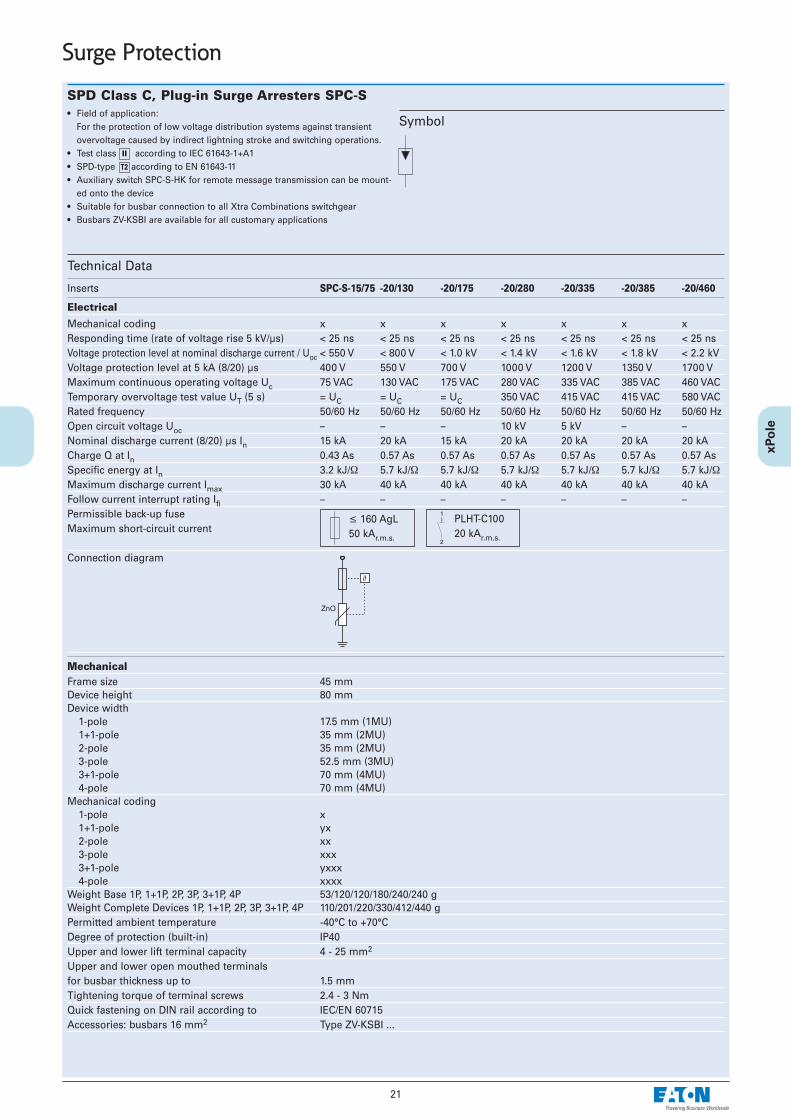
SPD Class C, Plug-in Surge Arresters SPC-S• Field of application:
For the protection of low voltage distribution systems against transientovervoltage caused by indirect lightning stroke and switching operations.
• Test class according to IEC 61643-1+A1• SPD-type according to EN 61643-11• Auxiliary switch SPC-S-HK for remote message transmission can be mount-
ed onto the device• Suitable for busbar connection to all Xtra Combinations switchgear• Busbars ZV-KSBI are available for all customary applications
Technical Data
Inserts SPC-S-15/75 -20/130 -20/175 -20/280 -20/335 -20/385 -20/460
Electrical
Mechanical coding x x x x x x xResponding time (rate of voltage rise 5 kV/µs) < 25 ns < 25 ns < 25 ns < 25 ns < 25 ns < 25 ns < 25 nsVoltage protection level at nominal discharge current / Uoc < 550 V < 800 V < 1.0 kV < 1.4 kV < 1.6 kV < 1.8 kV < 2.2 kVVoltage protection level at 5 kA (8/20) µs 400 V 550 V 700 V 1000 V 1200 V 1350 V 1700 VMaximum continuous operating voltage Uc 75 VAC 130 VAC 175 VAC 280 VAC 335 VAC 385 VAC 460 VACTemporary overvoltage test value UT (5 s) = UC = UC = UC 350 VAC 415 VAC 415 VAC 580 VACRated frequency 50/60 Hz 50/60 Hz 50/60 Hz 50/60 Hz 50/60 Hz 50/60 Hz 50/60 HzOpen circuit voltage Uoc – – – 10 kV 5 kV – –Nominal discharge current (8/20) µs In 15 kA 20 kA 15 kA 20 kA 20 kA 20 kA 20 kACharge Q at In 0.43 As 0.57 As 0.57 As 0.57 As 0.57 As 0.57 As 0.57 AsSpecific energy at In 3.2 kJ/Ω 5.7 kJ/Ω 5.7 kJ/Ω 5.7 kJ/Ω 5.7 kJ/Ω 5.7 kJ/Ω 5.7 kJ/ΩMaximum discharge current Imax 30 kA 40 kA 40 kA 40 kA 40 kA 40 kA 40 kAFollow current interrupt rating Ifi – – – – – – –Permissible back-up fuseMaximum short-circuit current
Connection diagram
Mechanical Frame size 45 mmDevice height 80 mmDevice width
1-pole 17.5 mm (1MU)1+1-pole 35 mm (2MU)2-pole 35 mm (2MU)3-pole 52.5 mm (3MU)3+1-pole 70 mm (4MU)4-pole 70 mm (4MU)
Mechanical coding1-pole x1+1-pole yx2-pole xx3-pole xxx3+1-pole yxxx4-pole xxxx
Weight Base 1P, 1+1P, 2P, 3P, 3+1P, 4P 53/120/120/180/240/240 gWeight Complete Devices 1P, 1+1P, 2P, 3P, 3+1P, 4P 110/201/220/330/412/440 gPermitted ambient temperature -40°C to +70°CDegree of protection (built-in) IP40Upper and lower lift terminal capacity 4 - 25 mm2
Upper and lower open mouthed terminals for busbar thickness up to 1.5 mmTightening torque of terminal screws 2.4 - 3 NmQuick fastening on DIN rail according to IEC/EN 60715Accessories: busbars 16 mm2 Type ZV-KSBI ...
Symbol
II
T2
Surge Protection
≤ 160 AgL50 kAr.m.s.
PLHT-C10020 kAr.m.s.
22
Surge Protection
Technical Data
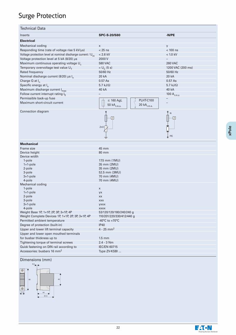
Inserts SPC-S-20/580 -N/PE
Electrical
Mechanical coding x yResponding time (rate of voltage rise 5 kV/µs) < 25 ns < 100 nsVoltage protection level at nominal discharge current / Uoc < 2.6 kV < 1.0 kVVoltage protection level at 5 kA (8/20) µs 2000 V –Maximum continuous operating voltage Uc 580 VAC 260 VACTemporary overvoltage test value UT = UC (5 s) 1200 VAC (200 ms)Rated frequency 50/60 Hz 50/60 HzNominal discharge current (8/20) µs In 20 kA 20 kACharge Q at In 0.57 As 0.57 AsSpecific energy at In 5.7 kJ/Ω 5.7 kJ/ΩMaximum discharge current Imax 40 kA 40 kAFollow current interrupt rating Ifi – 100 Ar.m.sPermissible back-up fuse –Maximum short-circuit current –
Connection diagram
Mechanical Frame size 45 mmDevice height 80 mmDevice width
1-pole 17.5 mm (1MU)1+1-pole 35 mm (2MU)2-pole 35 mm (2MU)3-pole 52.5 mm (3MU)3+1-pole 70 mm (4MU)4-pole 70 mm (4MU)
Mechanical coding1-pole x1+1-pole yx2-pole xx3-pole xxx3+1-pole yxxx4-pole xxxx
Weight Base 1P, 1+1P, 2P, 3P, 3+1P, 4P 53/120/120/180/240/240 gWeight Complete Devices 1P, 1+1P, 2P, 3P, 3+1P, 4P 110/201/220/330/412/440 gPermitted ambient temperature -40°C to +70°CDegree of protection (built-in) IP40Upper and lower lift terminal capacity 4 - 25 mm2
Upper and lower open mouthed terminals for busbar thickness up to 1.5 mmTightening torque of terminal screws 2.4 - 3 NmQuick fastening on DIN rail according to IEC/EN 60715Accessories: busbars 16 mm2 Type ZV-KSBI ...
Dimensions (mm)
≤ 160 AgL50 kAr.m.s.
PLHT-C10020 kAr.m.s.

23
Surge Protection
SPD Class C, Surge Arresters SPCT2-1+NPE, SPCT2-3+NPE• Field of application:
For the protection of low voltage distribution systems against transientovervoltage caused by indirect lightning stroke and switching operations.
• Test class according to IEC 61643-1+A1• SPD-type according to EN 61643-11• Auxiliary switch SPC-S-HK for remote message transmission can be mount-
ed onto the device• Suitable for busbar connection to all Xtra Combinations switchgear• Type SPC-S-3+1:
consists of 1 base SPC-S-S4-3+1, 1 insert SPC-S-N/PE and 3 inserts SPC-S-20/335
• Type SPC-S-1+1: consists of 1 base SPC-S-S2-1+1, 1 insert SPC-S-N/PE and 1 insert SPC-S-20/335
Technical Data
SPCT2-1+NPE SPCT2-3+NPE
Electrical
Mechanical coding yx yxxxResponding time (rate of voltage rise 5 kV/µs) L-N/N-PE/L-PE < 25ns/< 100ns/< 100ns < 25ns/< 100ns/< 100nsMaximum continuous operating voltage UC L-N/N-PE 335VAC/260VAC 280VAC/260VACTemporary overvoltage test value UT (5 s) L-N 415 VAC 350 VAC
(200 ms) N-PE 1200 VAC 1200 VACRated frequency 50/60 Hz 50/60 HzNominal discharge current In L-N/N-PE/L-PE 20 kA (8/20)µs 20 kA (8/20)µsVoltage protection level Up at In L-N/N-PE/L-PE ≤1600V/≤1000V/≤1650V ≤1000V/≤1000V/≤1300VMaximum discharge current Imax L-N/N-PE/L-PE 40 kA (8/20)µs 40 kA (8/20)µsFollow current interrupt rating Ifi N-PE 100 Ar.m.s. 100 Ar.m.s.Permissible back-up fuseMaximum short-circuit current
Connection diagram
x x x x
y y
Mechanical Mechanical coding of base yx yxxxFrame size 45 mm 45 mmDevice height 80 mm 80 mmDevice width 35 mm 70 mmWeight 201 g 412 gUpper and lower lift terminal capacity 1 - 25 mm2 1 - 25 mm2
Open-mouthed terminals at both sides for busbar thickness up to 1.5 mm 1.5 mmTightening torque of terminal screws 2.4 - 3 Nm 2.4 - 3 NmPermitted ambient temperature -40°C to +70°C -40°C to +70°CMounting quick fastening on DIN rail IEC/EN 60715Degree of protection (built-in) IP40 IP40
Dimensions (mm)
II
T2
L3
N N
L2L1
Application Examples
≤ 125 AgL50 kAr.m.s.
PLHT-C10020 kAr.m.s.
SPCT2-1+NPE SPCT2-3+NPE

24
Application Examples SPCT2 according to IEC 60364-5-53 Clause 534
Surge Protection
SPCT2-280/3 SPCT2-280/4
SPCT2-280/3 SPCT2-460/4
SPCT2-460/4 Z-D63
SPCT2-1+NPEG

25
Surge Protection
Content• The 3+1 circuit offers a universal solution for surge protection in low volt-
age distribution systems• Suitable for TT- and TN-S systems according to IEC 60364-5-53 Clause 534• Remote message transmission is possibly by mounting auxiliary switch
ASAUXSC-SPM• Busbar connected, minimum installation work required
SPCT2-335-3+NPE/BB- 1 unit SPC-S-3+1 surge arrester- 1 unit ASLTT-63 lead-through terminal- busbar included
Surge Arrester Set SPCT2-335-3+NPE/BB
SPD Class C, SPCT2
Surge arrester Sets

26
Auxiliary Switch for (Lightning Current Arrester-)Surge Arrester ASAUXSC-SPM• Field of application:
For mounting onto surge protective devices for external defect messagetransmission
• Design basically in accordance with IEC 60947-5-1• Can be mounted subsequently• Suitable for SPBT12-280/1, SPCT2
Technical Data
Electrical Rated insulation voltage 250 VRated frequency 50/60 HzSwitching contact 1 NC + 1 NOMinimum voltage per contact 24 VACRated operational current AC12 2A/250VACMaximum back-up fuse 2 A gLOvervoltage category IVPollution degree 2
Mechanical Frame size 45 mmDevice height 80 mmDevice width 8.8 mmWeight 41 gMounting screw-mountingDegree of protection, built-in IP40Finger and hand touch safe acc. to BGV A3, ÖVE-EN 6Upper and lower terminals lift terminalsTerminal capacity 2 x 2.5 mm2
Tightening torque of terminal screws 0.8 - 1 Nm
Connection diagram
Dimensions (mm)
Surge Protection
Application Examples
2113
2214
ASAUXSC-SPM
SPCT2 SPCT2 SPCT2

27
Surge Protection
Lead-Through Terminal for Surge Protective Devices, Class B, SPB-D-125• The lead-through terminal permits orderly wiring of SPDs of class B.
It serves as lead-through terminal in circuits requiring vertical connectionsfrom the upper to the lower SPD connection level.
Technical Data
Electrical Design basically in accordance with IEC 61643-1: 1998-02,
DIN VDE 0675 Part 6: 1989-11,IEC 61024-1: 1990-03,IEC 60947-7-1: 1989-10,DIN VDE 0110-1: 1997-04
Rated voltage UC 500 V AC/DCRated current IN 125 A / 30°CImpulse current (10/350) µs
Peak current 100 kACharge Q 50 AsSpecific energy 2,5 MJ/Ω
Overvoltage category III
Mechanical Frame size 45 mmDevice height 90 mmDevice width 17.5 mmMounting quick fastening on
DIN rail IEC/EN 60715Degree of protection, built-in IP40Upper and lower terminals lift and
open-mouthed terminalsTerminal capacity
rigid 0.5 - 35 mm2
flexible 0.5 - 25 mm2
Tightening torque of terminal screws 4-4.5 NmPermitted relative air humidity < 95%Pollution degree 2Resistance to climatic conditions F / DIN 40040Creepage a. clearance distances acc. to IEC 60664-1,
DIN VDE 0110-1:1997-04Temperature range -40 to +85°C
Connection diagram
Dimensions (mm) Connection type 2 according to IEC 60364-5-53 Clause 534
TT-System, TN-S-System , IT- System with Neutral
Lightning current arrester
. . . SPI-35/440
. . . SPI-100/NPE
. . . SPI-50/NPE
Lead-through terminal
. . . SPB-D-125
Busbar
. . . Z-GV-U/5
. . . Z-GV-U/6

Lead-Through Terminal for Surge Protective Devices, ASLTT-63• The lead-through terminal permits orderly wiring of SPDs.
It serves as lead-through terminal in circuits requiring vertical connectionsfrom the upper to the lower SPD connection level.
• 1-pole• Suitable for standard busbar connection to all Xtra Combination switchgear
Technical Data
Electrical Rated voltage 500V AC/DCRated current 63 ARated frequency 50/60 Hz
Mechanical Frame size 45 mmDevice height 80 mmDevice width 17.5 mmMounting quick fastening on
DIN rail IEC/EN 60715Degree of protection, built-in IP40Finger and hand touch safe acc. to BGV A3, ÖVE-EN 6Upper and lower terminals lift and
open-mouthed terminalsTerminal capacity 1 - 25 mm2
Busbar thickness 0.8 - 2 mmTightening torque of terminal screws 2.4 - 3 Nm
Connection diagram
Dimensions (mm) Application Example / Connection type 2 acc. to IEC 60364-5-53 Clause 534
SPCT2-335-3+NPE/BB
ASLTT-63
28
Surge Protection

29
Photovoltaic - Surge Protection
SPD-type T2 (Class C), Plug-in Surge Arresters SPPT2PA-...-2PE• Field of application:
For the protection of photovoltaic systems against transient overvoltagecaused by indirect lightning stroke and switching operations.
• Test class according to IEC 61643-1• SPD-type according to EN 61643-11• Types SPPT2PA-...-AX for remote message transmission of defective inserts
Connection diagrams
II
T2
SPPT2PA-...-2PE
Technical Data
SPPT2PA-600-2PE SPPT2PA-1000-2PE(-AX)
Electrical Responding time ≤ 25 ns ≤ 25 nsMaximum continuous operating voltage UC 600 V DC 1000 V DCRated frequency DC DCNominal discharge current In 15 kA (8/20) µs 15 kA (8/20) µsVoltage protection level Up ≤ 3 kV ≤ 5 kVResidual voltage at 5 kA (8/20) µs ≤ 2.5 kV ≤ 4 kVMaximum discharge current Imax 30 kA (8/20) µs 30 kA (8/20) µsPermissible back-up fuse – –Maximum short-circuit current Isc 80 A 80 AResidual current IPE ≤ 20 µA ≤ 20 µA
Mechanical Frame size 45 mm 45 mmDevice height 90 mm 90 mm (99 mm)Device width 35.6 mm 35.6 mmWeight 247 g 247 g (249 g)Upper and lower lift terminal capacity
fine- / solid strand 4-25/4-35 mm2/AWG11-2 4-25/4-35 mm2/AWG11-2Tightening torque of terminal screws 4.5 Nm 4.5 NmPermitted ambient temperature -40°C up to +80°C -40°C up to +80°CMounting quick fastening on DIN rail IEC/EN 60715Degree of protection IP20 IP20Polution degree 2 2
Dimensions (mm)
Auxiliary switch
Electrical Rated insulation voltage 250 VRated frequency 50/60 HzSwitching contact 1 COMinimum voltage per contact 5 V AC/DCRated operational current 1.5 A / 250 V AC
1.5 A / 30 V DCMin. admissible power 5 mA / 5 V
MechanicalTerminal capacity
fine- / solid strand 1.5/1.5 mm2/AWG28-16Tightening torque
of terminal screws 0.25 Nm
Application hints according to EN 50539-12
DC

30
Photovoltaic - Surge Protection
SPD-type T2 (Class C), Plug-in Surge Arresters SPPT2PA-...-2+1PE• Field of application:
For the protection of photovoltaic systems against transient overvoltagecaused by indirect lightning stroke and switching operations.
• Test class according to IEC 61643-1• SPD-type according to EN 61643-11• Galvanic seperation in unearthed systems by means of a spark gap• Types SPPT2PA-...-AX for remote message transmission of defective inserts
Connection diagrams
II
T2
SPPT2PA-...-2+1PE
Technical Data
SPPT2PA-600-2+1PE SPPT2PA-1000-2+1PE(-AX)
Electrical Responding time L+ -> L- / L -> PE ≤ 25 ns / ≤ 100 ns ≤ 25 ns / ≤ 100 nsMaximum continuous operating voltage UC 600 V DC 1000 V DCRated frequency DC DCNominal discharge current In 15 kA (8/20) µs 15 kA (8/20) µsVoltage protection level Up L+ -> L- / L -> PE ≤ 3 kV / ≤ 3 kV ≤ 5 kV / ≤ 3 kVResidual voltage at 5 kA (8/20) µs L+ -> L- / L -> PE ≤ 2.5 kV / ≤ 2 kV ≤ 4 kV / ≤ 2 kVMaximum discharge current Imax 30 kA (8/20) µs 30 kA (8/20) µsPermissible back-up fuse – –Maximum short-circuit current Isc 80 A 80 AResidual current IPE ≤ 20 µA ≤ 20 µA
Mechanical Frame size 45 mm 45 mmDevice height 90 mm 90 mm (99 mm)Device width 53.4 mm 53.4 mmWeight 318 g 318 g (323 g)Upper and lower lift terminal capacity
fine- / solid strand 4-25/4-35 mm2/AWG11-2 4-25/4-35 mm2/AWG11-2Tightening torque of terminal screws 4.5 Nm 4.5 NmPermitted ambient temperature -40°C up to +80°C -40°C up to +80°CMounting quick fastening on DIN rail IEC/EN 60715Degree of protection IP20 IP20Polution degree 2 2
Dimensions (mm)
Auxiliary switch
Electrical Rated insulation voltage 250 VRated frequency 50/60 HzSwitching contact 1 COMinimum voltage per contact 5 V AC/DCRated operational current 1.5 A / 250 V AC
1.5 A / 30 V DCMin. admissible power 5 mA / 5 V
MechanicalTerminal capacity
fine- / solid strand 1.5/1.5 mm2/AWG28-16Tightening torque
of terminal screws 0.25 Nm
Application hints according to EN 50539-12
DC

31
Photovoltaic - Surge Protection
Auxiliary Switch for Surge Arresters ASAUXSC-SPM• Field of application:
For mounting onto surge protective devices for external defect messagetransmission
• Design basically in accordance with IEC 60947-5-1• Can be mounted subsequently• Suitable for SPMT2PA
Technical Data
Electrical Rated insulation voltage 250 VRated frequency 50/60 HzSwitching contact 1 COMinimum voltage per contact 24 VACRated operational current AC12 2A/250VACMaximum back-up fuse 2 A gLOvervoltage category IVPollution degree 2
Mechanical Frame size 45 mmDevice height 80 mmDevice width 8.8 mmWeight 41 gMounting screw-mountingDegree of protection, built-in IP40Finger and hand touch safe acc. to BGV A3, ÖVE-EN 6Upper and lower terminals lift terminalsTerminal capacity 2 x 2.5 mm2
Tightening torque of terminal screws 0.8 - 1 Nm
Connection diagram
Dimensions (mm) Application Examples
SPCT2-280/2 SPBT12-280/3 SPCT2-460/4
AC
Lead-Through Terminal for Surge Protective Devices, SPD-type 2 (Class C), ASLTT-63• The lead-through terminal permits orderly wiring of SPDs types 2 (class C).
It serves as lead-through terminal in circuits requiring vertical connectionsfrom the upper to the lower SPD connection level.
• 1-pole• Suitable for standard busbar connection to EATON switchgear
Technical Data
Electrical Rated voltage 690V AC/DCRated current 63 ARated frequency 50/60 Hz
Mechanical Frame size 45 mmDevice height 80 mmDevice width 17.5 mmMounting quick fastening on
DIN rail IEC/EN 60715Degree of protection, built-in IP40Finger and hand touch safe acc. to BGV A3, ÖVE-EN 6Upper and lower terminals lift and
open-mouthed terminalsTerminal capacity 1 - 25 mm2
Busbar thickness 0.8 - 2 mmTightening torque of terminal screws 2.4 - 3 Nm
Connection diagram
Dimensions (mm) Application Example / Connection type 2 acc. to IEC 60364-5-53 Clause 534
SPCT2-335-3+NPE
ASLTT-63

32
Surge Protection
Busbars Z-GV-U/
Models
• Busbars Z-GV-U/ permit to implement customary SPD combinations• Suitable for SPI-..., SPB-D-125• The rated cross-section of Z-GV-U/ is 16 mm2
• The busbars must be cut to length in some cases
Marking Label SPI-BZS-L/N/PE• Can be affixed to SPI-..., SPB-D-125• Size 7 x 17mm• Colour: white
Technical Data
Electrical Rated voltage 230/400 V, 50/60 HzRated current 63 A
Mechanical Busbar cross section 16 mm2 Cu
Busbars ZV-KSBI
Models
• Busbars ZV-KSBI permit to implement customary SPD combinations• Suitable for SPB-..., SPC-..., Z-D63• The rated cross-section of ZV-KSBI is 16 mm2
• The busbars must be cut to length in some cases
Technical Data
Electrical Rated voltage 230/400 V, 50/60 HzRated current 63 A
Mechanical Busbar cross section 16 mm2 Cu

33
Surge Protection
SPD Class D, Surge Protective Device SPD-S-1+1, SPD-S-280/2• Field of application:
For fine protection of user equipment against transient overvoltage• For mounting on DIN rails in distribution boxes for electrical installation• No decoupling from upstream surge protection in the low voltage distribu-
tion system required• Test class according to IEC 61643-1+A1• SPD-type according to EN 61643-11• Suitable for high back-up fuse 63 A gL / C 63• Auxiliary switch SPC-S-HK for remote message transmission can be mount-
ed onto the device
Technical Data
SPD-S-1+1 SPD-S-280/2
Electrical
Mechanical coding yx xxResponding time (rate of voltage rise 5 kV/µs) L-N/N-PE/L-PE < 25ns/< 100ns/< 100ns L1-L2(N)/L2(N)-PE/L1-PE < 25nsMaximum continuous operating voltage UC L-N/N-PE 335VAC/260VAC L1-L2(N)/L2(N)-PE 280VACTemporary overvoltage test value UT (5 s) L-N/L-PE 350VAC/416VAC L-N/L-PE 350VAC/416VAC
(200 ms) N-PE 1200VAC N-PE 1200VACRated frequency 50/60 Hz 50/60 HzOpen circuit voltage UOC L-N/N-PE/L-PE 5kV L1-L2(N)/L2(N)-PE/L1-PE 10kVVoltage protection level Up at UOC L-N/N-PE/L-PE ≤ 1000V/≤ 900V/≤ 1000V L1-L2(N)/L2(N)-PE ≤ 950VNominal discharge current In L-N/N-PE/L-PE 2,5kA (8/20)µs L1-L2(N)/L2(N)-PE 5kA (8/20)µsVoltage protection level Up at In L-N/N-PE/L-PE ≤ 1000V/≤ 700V/≤ 1000V L1-L2(N)/L2(N)-PE ≤ 950VMaximum discharge current Imax L-N/N-PE/L-PE 10kA (8/20)µs L1-L2(N)/L2(N)-PE/L1-PE 10kA (8/20)µsFollow current interrupt rating Ifi N-PE 100 Ar.m.s. –Permissible back-up fuseMaximum short-circuit current
Connection diagram
x x
y x
Mechanical Mechanical coding of base yx xxFrame size 45 mm 45 mmDevice height 80 mm 80 mmDevice width 35 mm 35 mmWeight 220 g 220 gUpper and lower lift terminal capacity 1 - 25 mm2 1 - 25 mm2
Open-mouthed terminals at both sides for busbar thickness up to 1.5 mm 1.5 mmTightening torque of terminal screws 2.4 - 3 Nm 2.4 - 3 NmPermitted ambient temperature -40°C to +70°C -40°C to +70°CMounting quick fastening on DIN rail IEC/EN 60715Degree of protection (built-in) IP40 IP40
Dimensions (mm)
III
T3
Application Examples
≤ 63 AgL50 kAr.m.s.
≤ C6310 kAr.m.s.
34
Surge Protection
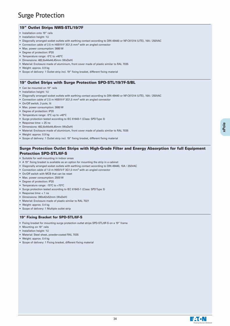
19” Outlet Strips NWS-STL/19/7F• Installation onto 19” rails• Installation height: 1U• Diagonally arranged socket outlets with earthing contact according to DIN 49440 or NF-C61314 (UTE), 16A / 250VAC• Connection cable of 2.5 m H05VV-F 3G1,5 mm2 with an angled connector• Max. power consumption: 3680 W• Degree of protection: IP20• Temperature range: -5°C to +40°C• Dimensions: 482,6x44x44,45mm (WxDxH)• Material: Enclosure made of aluminium, front cover made of plastic similar to RAL 7035• Weight: approx. 0.9 kg• Scope of delivery: 1 Outlet strip incl. 19“ fixing bracket, different fixing material
19" Outlet Strips with Surge Protection SPD-STL/19/7F-S/BL• Can be mounted on 19“ rails• Installation height: 1U• Diagonally arranged socket outlets with earthing contact according to DIN 49440 or NF-C61314 (UTE), 16A / 250VAC• Connection cable of 2.5 m H05VV-F 3G1,5 mm2 with an angled connector • On/Off switch, 2-pole, lit• Max. power consumption: 3680 W• Degree of protection: IP20• Temperature range: -5°C up to +40°C• Surge protection tested according to IEC 61643-1 (Class: SPD Type 3)• Response time: < 25 ns• Dimensions: 482,6x44x44,45mm (WxDxH)• Material: Enclosure made of aluminium, front cover made of plastic similar to RAL 7035• Weight: approx. 0.9 kg• Scope of delivery: 1 Outlet strip incl. 19“ fixing bracket, different fixing material
Surge Protection Outlet Strips with High-Grade Filter and Energy Absorption for full EquipmentProtection SPD-STL/6F-S• Suitable for wall-mounting in indoor areas• A 19“ fixing bracket is available as an option for mounting the strip in a cabinet • Diagonally arranged socket outlets with earthing contact according to DIN 49440, 10A / 250VAC • Connection cable of 1.0 m H05VV-F 3G1,0 mm2 with an angled connector• On/Off switch with MCB that can be reset • Max. power consumption: 2500 W• Degree of protection: IP20• Temperature range: -15°C to +70°C• Surge protection tested according to IEC 61643-1 (Class: SPD Type 3)• Response time: < 1 ns• Dimensions: 390x42x52mm (WxDxH)• Material: Enclosure made of plastic similar to RAL 7021 • Weight: approx. 0.4 kg• Scope of delivery: 1 Multiple outlet strip
19" Fixing Bracket for SPD-STL/6F-S
• Fixing bracket for mounting surge protection outlet strips SPD-STL/6F-S on a 19” frame• Mounting on 19” rails • Installation height: 1U• Material: Steel sheet, powder-coated RAL 7035• Weight: approx. 0.4 kg• Scope of delivery: 1 Fixing bracket, different fixing material

35
Surge Protection
Earthing/Equipotential Bonding
Equipotential Bonding Bar PAS-7x16
Dimensions (mm)
Earthing Bar for Antenna Lines PAS-HF-6
Dimensions (mm)
Earth Clip EBS
Dimensions (mm)
36
Power Frequency Overvoltage Protective Device (POP Device)
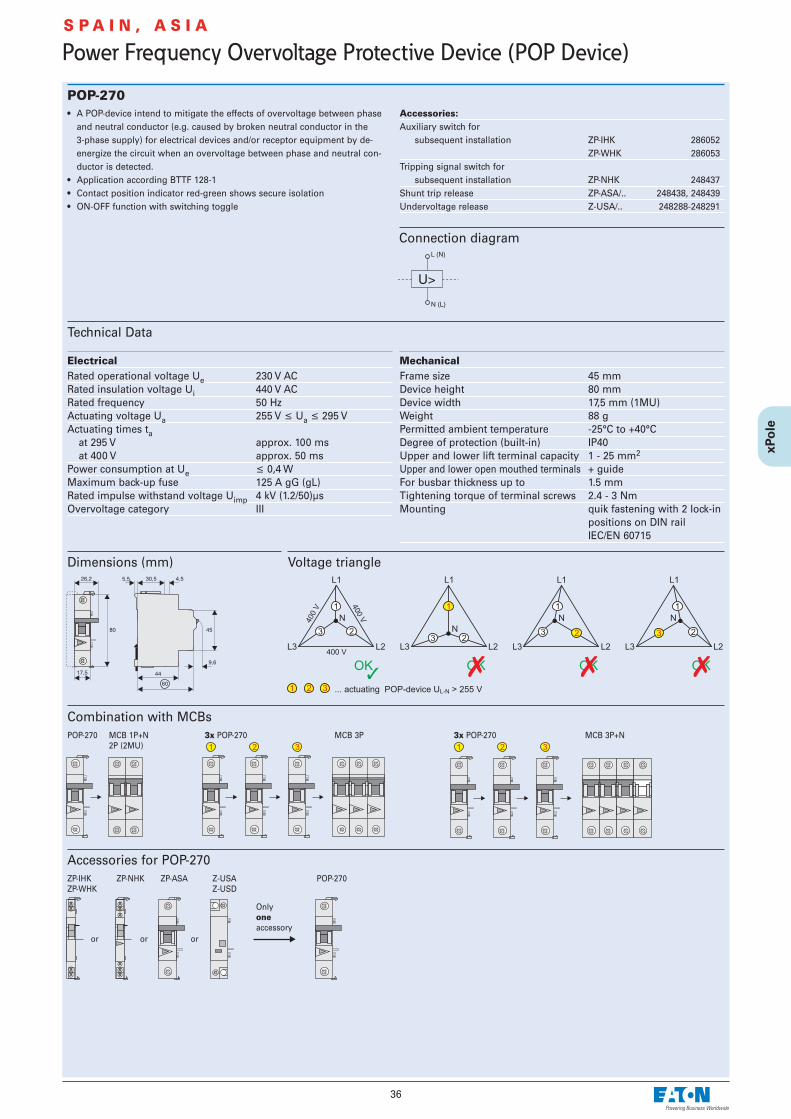
POP-270• A POP-device intend to mitigate the effects of overvoltage between phase
and neutral conductor (e.g. caused by broken neutral conductor in the 3-phase supply) for electrical devices and/or receptor equipment by de-energize the circuit when an overvoltage between phase and neutral con-ductor is detected.
• Application according BTTF 128-1• Contact position indicator red-green shows secure isolation• ON-OFF function with switching toggle
Accessories:Auxiliary switch for
subsequent installation ZP-IHK 286052ZP-WHK 286053
Tripping signal switch for subsequent installation ZP-NHK 248437
Shunt trip release ZP-ASA/.. 248438, 248439Undervoltage release Z-USA/.. 248288-248291
Technical Data
Electrical Rated operational voltage Ue 230 V ACRated insulation voltage Ui 440 V ACRated frequency 50 HzActuating voltage Ua 255 V ≤ Ua ≤ 295 VActuating times ta
at 295 V approx. 100 msat 400 V approx. 50 ms
Power consumption at Ue ≤ 0,4 WMaximum back-up fuse 125 A gG (gL)Rated impulse withstand voltage Uimp 4 kV (1.2/50)µsOvervoltage category III
Mechanical Frame size 45 mmDevice height 80 mmDevice width 17,5 mm (1MU)Weight 88 gPermitted ambient temperature -25°C to +40°CDegree of protection (built-in) IP40Upper and lower lift terminal capacity 1 - 25 mm2
Upper and lower open mouthed terminals + guideFor busbar thickness up to 1.5 mmTightening torque of terminal screws 2.4 - 3 NmMounting quik fastening with 2 lock-in
positions on DIN rail IEC/EN 60715
Connection diagram
Dimensions (mm) Voltage triangle
Combination with MCBsPOP-270 MCB 1P+N
2P (2MU)3x POP-270 MCB 3P 3x POP-270 MCB 3P+N
Accessories for POP-270ZP-IHKZP-WHK
or
ZP-NHK
or
ZP-ASA
or
Z-USAZ-USD
Only oneaccessory
POP-270
S P A I N , A S I A

37
Main Load Disconnector Switch (Isolator) IS• Load circuit breaker with isolating function• Design according to IEC/EN 60947-3• Highly wear resistant contacts• Quick make, black toggle• Terminal capacity 50 mm2
• Compatible busbars with switchgear series Xpole by use of the mouth ter-minal in combination with standard fork busbar
Technical Data
IS-16 IS-20 IS-25 IS-32 IS-40 IS-63 IS-80 IS-100 IS-125
Electrical Design according to IEC/EN 60947-3Rated voltage 240/415VFrequency 50/60 HzRated insulation voltage Ui 690 V~Rated peak withstand voltage Uimp 6 kVPollution degree 3Rated short-time withstand current Icw 2 kARated short-circuit making capacity Icm2.8 kARated current
240/415V, AC23A 16 A 20 A 25 A 32 A 40 A 63 A 80 A 100 A 125 ANumber of poles 1-, 2-, 3-, 4-poleMaximum back-up fuse 125 A gGShort circuit strength - with back-up fuse acc. to the applicable rules
IEC/EN 60947-3 12.5 kA 12.5 kA 12.5 kA 12.5 kA 12.5 kA 12.5 kA 12.5 kA 10 kA 10 kAEndurance
electrical comp. op. cycles ≥ 3,000 ≥ 3,000 ≥ 3,000 ≥ 3,000 ≥ 3,000 ≥ 3,000 ≥ 3,000 ≥ 3,000 ≥ 2,000mechanical comp. op. cycles ≥ 16,000 ≥ 16,000 ≥ 16,000 ≥ 16,000 ≥ 16,000 ≥ 16,000 ≥ 16,000 ≥ 16,000 ≥ 14,000
Mechanical Frame size 45 mmDevice height 80 mmDevice width 17.5mm/poleMounting quick fastening with 2 lock-in positions on DIN rail IEC/EN 60715Degree of protection, built-in IP40Terminal protection finger and hand touch safe according to BGV A3Terminals Twin-purpose terminalsTerminal capacity 2.5 - 50 mm2
Busbar thickness 0.8-1.0 mmFastening torque of terminal screws 2.5 - 5 NmFunction irrespective of the position of installation
Dimensions (mm)
Anti-tamperdeviceIS/SPE1TE
Terminal cover capsZ-IS/AK-1TE
Switching interlock IS/SPE-1TE
• Without lock• Also suitable for PFIM, CFI6, PKNM, CKN6
Terminal Cover Caps Z-IS/AK-1TE
• Can be sealed with leads• Modular design, width 1 MU
Connection diagram1-pole 2-pole 3-pole 4-pole
Controlling & Switching

38
Controlling & Switching
Circuit Breaker ZP-A• Design according to IEC/EN 60947-1, -3• Number of poles: 1, 2, 3, 3N• Rated current: 40 A, 63 A• Accessories for switchgear also for ZP-A usable!
Accessories:Auxiliary switch for
subsequent installation ZP-IHK 286052ZP-WHK 286053
Tripping signal contact forsubsequent installation ZP-NHK 248437
Shunt trip release ZP-ASA/.. 248438, 248439Undervoltage release Z-USA/.. 248288-248291Compact enclosure KLV-TC-2 276240
KLV-TC-4 276241Additional terminal 35mm2 Z-HA-EK/35 263960Switching interlock Z-IS/SPE-1TE 274418
Technical Data
Electrical Rated operational voltage Ue 230/400 V ACRated frequency 50 HzRated insulation voltage UI 440 VACRated peak withstand voltage Uimp 4 kV (1.2/50µ)Conventional thermal currentIth
ZP-A40 40 AZP-A63 63 A
Utilisation category AC22ARated operational current Ie
ZP-A40 40 A ACZP-A63 63 A AC
Utilisation category AC23ARated operational current Ie 16 A AC
Short circuit strengthwith back-up fuse 40 A gG 3 kA (U = 240V, cos ϕ = 0.87)
Enduranceelectrical comp. ≥ 8,000 operating cyclesmechanical comp. ≥ 20,000 operating cycles
Mechanical Frame size 45 mmDevice height 80 mmDevice width 17.5mm/poleMounting quick fastening on
DIN rail IEC/EN 60715Degree of protection, built-in IP40Upper and lower terminals lift terminals + guide for
secure terminalTerminal protection finger and hand touch safe,
BGV A3, ÖVE-EN 6Terminal capacity 1.5-25 mm2
Terminal screws M5 (Pozidrive) Z2Tightening torque of terminal screws max. 2.4 Nm
Connection diagrams
Dimensions (mm)
1-pole 2-pole 3-pole 3+N-pole

39
Practical Hint
e.g. 16(2)A .... Ratings for resistive/inductive consumers
ÖVE-SN45, § 305
....... Ratings for incandescent lamp load(AC 5b IEC 60947-4)
Practical Hint
ÖVE-SN45, § 207, IEC 60947-3
Switching contactin general
Switch withreduced air gap
Power circuitbreaker
Disconnector
Load disconnectorswitch
Fuse power circuitbreaker
Fuse disconnector
Fuse switch disconnector
Controlling & Switching

40
Controlling & Switching
MCB for Auxiliary Switch Circuits PLSM-B4/.-HS, CLS6-B4/..-HS• Design according to EN 60898-1, 4 A, Characteristic B• Very low let-through energy in order to prevent contact welding in auxiliary
swit ches of any and all switchgear, as well as thermostats controldevices, timers, etc.
• Busbar connection to CLS6, PFIM, PKN, ...
Technical Data
Connection diagram
Dimensions (mm)
e.g. 1-pole
PLSM-B4/.-HS CLS6-B4/..-HS
Electrical Number of poles 1-, 2-pole 1-, 1+N-, 2-poleRated voltage 230/400 V 230/400 VFrequency 50/60 Hz 50/60 HzRated current 4 A 4 ARated breaking capacity 10 kA 6 kA
Mechanical Frame size 45 mm 45 mmDevice height 80 mm 80 mmDevice width 17.5 mm (1MU) 17.5 mm (1MU)Mounting quick fastening with 2 lock-in positions on DIN rail IEC/EN 60715Degree of protection, built-in IP40 IP40Terminal protection finger and hand touch safe according to BGV A3, ÖVE-EN 6Terminals Twin-purpose terminals Twin-purpose terminalsTerminal capacity 1-25 mm2 1-25 mm2
Terminal screws M3 (Pozidrive) M3 (Pozidrive)Fastening torque of terminal screws 0.8-1.0 Nm 0.8-1.0 NmBusbar thickness 0.8 - 2 mm 0.8 - 2 mm
PLSM-B4/.-HS CLS6-B4/..-HS
Even auxiliary switches must be protected against overload and short circuitby means of suitable back-up fuses according to manufacturer specification.According to IEC 60947-5 a maximum back-up fuse is specified for conditionalshort circuit prevention up to 1,000 A. Therefore, connection of the auxiliaryswitch to the nearest MCB is not permitted. Danger of contact welding! TheMCB for auxiliary switch circuits ...-HS offers a simple solution.
Practical HintLet-through Energy PLSM-B4-HS
Let-through energy PLS., characteristic B, 1-pole
Prospective short-circuit current [A]
Let
thro
ugh
ener
gy I2 t
[A
2se
c]

41
Pushbutton Z-T; Control Switch Z-S/; Changeover Switch Z-S/.W• Design according to IEC 60669, VDE 0632• Types Z-S/WM and /2WM with central position (0-position)• Types Z-S/WTN and -2WTN with TAG-0-NACHT (DAY-0-NIGHT) printed onto
the device
Technical Data
Connection diagrams
Dimensions (mm)Z-T/ Z-S/.W
Z-T/ Z-S../ Z-S/.W
Electrical Rated voltage 230/400V AC 230/400V AC 230/400V ACFrequency 50 HZ 50 HZ 50 HZRated current 16A/230V~ 16A/230V~ 16A/230V~Switching capacity – 1.25 x In; 1.1 x Un 1.25 x In; 1.1 x UnShort circuit strength 10 kA 10 kA 10 kA
Mechanical Switching toggle – black blackPushbutton colour green - NO – –
black - NO/NCFrame size 45 mm 45 mm 45 mmDevice height 80 mm 80 mm 80 mmDevice width 17.5 mm (1MU) 17.5 mm (1MU) 17.5 mm (1MU)Mounting quick fastening with 2 lock-in positions on DIN rail IEC/EN 60715Degree of protection, built-in IP40 IP40 IP40Upper and lower terminals lift terminals lift terminals lift terminalsTerminal capacity 1-10 mm2 1-10 mm2 1-10 mm2
Terminal protection finger and hand touch safe, according to BGV A3, ÖVE-EN 6Resistance to climatic conditions acc. to IEC/EN 60068 acc. to IEC/EN 60068 acc. to IEC/EN 60068
Z-S../
Controlling & Switching
Z-T/ Z-S../ Z-S/W. Z-S/2W.
42
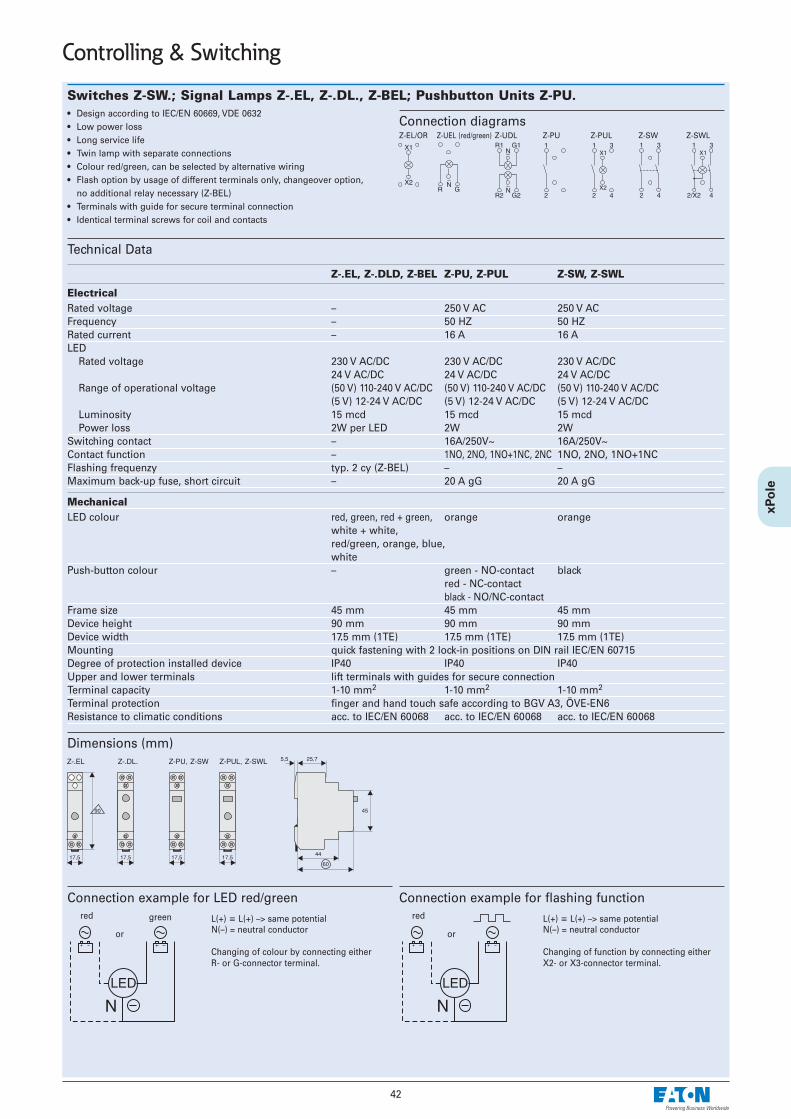
Switches Z-SW.; Signal Lamps Z-.EL, Z-.DL., Z-BEL; Pushbutton Units Z-PU.• Design according to IEC/EN 60669, VDE 0632• Low power loss• Long service life• Twin lamp with separate connections• Colour red/green, can be selected by alternative wiring• Flash option by usage of different terminals only, changeover option,
no additional relay necessary (Z-BEL)• Terminals with guide for secure terminal connection • Identical terminal screws for coil and contacts
Technical Data
Connection diagrams
Dimensions (mm)
Z-EL/OR Z-UEL (red/green) Z-UDL Z-PU Z-PUL Z-SW Z-SWL
Z-.EL, Z-.DLD, Z-BEL Z-PU, Z-PUL Z-SW, Z-SWL
ElectricalRated voltage – 250 V AC 250 V ACFrequency – 50 HZ 50 HZRated current – 16 A 16 ALED
Rated voltage 230 V AC/DC 230 V AC/DC 230 V AC/DC24 V AC/DC 24 V AC/DC 24 V AC/DC
Range of operational voltage (50 V) 110-240 V AC/DC (50 V) 110-240 V AC/DC (50 V) 110-240 V AC/DC(5 V) 12-24 V AC/DC (5 V) 12-24 V AC/DC (5 V) 12-24 V AC/DC
Luminosity 15 mcd 15 mcd 15 mcdPower loss 2W per LED 2W 2W
Switching contact – 16A/250V~ 16A/250V~Contact function – 1NO, 2NO, 1NO+1NC, 2NC 1NO, 2NO, 1NO+1NCFlashing frequenzy typ. 2 cy (Z-BEL) – –Maximum back-up fuse, short circuit – 20 A gG 20 A gG
MechanicalLED colour red, green, red + green, orange orange
white + white,red/green, orange, blue, white
Push-button colour – green - NO-contact blackred - NC-contactblack - NO/NC-contact
Frame size 45 mm 45 mm 45 mmDevice height 90 mm 90 mm 90 mmDevice width 17.5 mm (1TE) 17.5 mm (1TE) 17.5 mm (1TE)Mounting quick fastening with 2 lock-in positions on DIN rail IEC/EN 60715Degree of protection installed device IP40 IP40 IP40Upper and lower terminals lift terminals with guides for secure connectionTerminal capacity 1-10 mm2 1-10 mm2 1-10 mm2
Terminal protection finger and hand touch safe according to BGV A3, ÖVE-EN6Resistance to climatic conditions acc. to IEC/EN 60068 acc. to IEC/EN 60068 acc. to IEC/EN 60068
Connection example for LED red/greenL(+) ≡ L(+) –> same potentialN(–) = neutral conductor
Changing of colour by connecting eitherR- or G-connector terminal.
or
red green
Connection example for flashing functionL(+) ≡ L(+) –> same potentialN(–) = neutral conductor
Changing of function by connecting eitherX2- or X3-connector terminal.
or
red
Controlling & Switching

43
Controlling & Switching
Rotary Switch Z-DS• Rotary switches of series Z-DS are of a modular design:
The switch proper consists of the engaging work and the switching pack-age. The switching cams (for which it is also called cam switch) are drivenby a stable, torsion-proof aluminium shaft. The switching package consistsof one or several switching cells with one or two independent contacts.Connections of adjoining switch terminals (necessary in case of voltmeterchangeover switch Z-DSV) are contained in the pressed switch component.Consequently, there is no obstacle when connecting the connection lines.
• Application:Suitable for virtually any application, e.g. motor switch, garage doors, fans,shutters, heating system control, lighting fixtures, instrument switches, dif-ferent control purposes, etc.
Technical Data
Dimensions (mm)
Connection diagramsZ-DSA1-01 Z-DSA2-01 Z-DSA2-01-SL Z-DSU1-102 Z-DSU1-H0A
Z-DSU1-T0N Z-DSU2-102 Z-DSU2-H0A Z-DSU3-102 Z-DSU2-12
Z-DSV-LL Z-DSV-LLLN Z-DSV-LN Z-DSAM1-0123
Data acc. to IEC 60947-3, IEC 60947-5-1, VDE 0660, EN 60947-3, SEV
Nominal thermal current Ith open A 20Nominal thermal current Ithg hermetically enclosed A 20
Nominal operational voltage Ue V 690Uimp = 6 kVDisconnector conditions acc. to ÖVE, IEC met up to V 440
Circuit breaking capacity Iv3 x 220-440V A 160
3 x 500 V A 1003 x 660-690V A 80
Utilisation category AC21A, AC21BSwitching resistive loads including low overloadsNominal operational current In A 20
Utilisation category AC23A, AC23BSwitching motors and other highly inductive loadsNominal operational current In 400V A 16
Nominal power 220-240V kW 43-phase, 3-pole 380-440V kW 7.5
500V kW 7.5660-690V kW 7.5
Star-delta starting switchfor squirrel cage motorsNominal power3-phase, 3-pole 220-240V kW 3.7
380-415V kW 7.5
Utilisation category AC3Switching of 3-phase AC motorsNominal operational current In 400V A 12
Nominal power 220-240V kW 33-phase, 3-pole 380-440V kW 5.5
500V kW 5.5660-690V kW 5.5
Utilisation category AC15Switching of electromagnetic drives, contactors, valves, pull-type electromagnetsNominal operational current In up to 240V A 6
380-440V A 42-pole disconnection 500V A 5
Utilisation category DC21A, DC21BSwitching of resistive loadsTime constant L/R ≤ 1 msNominal operational current In1-pole 30V A 20
60V A 4110V A 0.6220V A 0.3440V A –
Utilisation category DC3 - DC5Switching of shunt motors and series motorsTime constant L/R ≤ 15 msNominal operational current In1-pole 30V A 8
60V A 1110V A 0.3
Terminal capacityone or several wires mm2 1 - 2,5fine wires mm2 0.75 - 2.5fine wires with wire end sleeve mm2 0.75 - 1.5terminal screw M3.5number of conductors per terminal 2
Switching of capacitive load maximum making capacity
up to 500V A 140
Degree of protectionfrom behind IP20

44
Short circuit protectionmax. fuse gL (gG) A 20Rated short-time withstand current(1 second current) 3000 A 250Conditional rated short circuit current kAr.m.s. 10
Short-time load capacityLoad duration 3s A 100(values applicable to already 10s A 60closed contacts only) 30s A 35
60s A 25
Rotary Switch Z-DS for Lighting Systems
Z-DS...
Utilisation category AC1 Rated operational current 60°C IeAC1 A 20
Utilisation category AC5a Rated operational power cosϕ 0,5 kW 1,1220-240V~ cosϕ 0,9 kW 0,4
DUO kW 3
Utilisation category AC5b Rated operational power kW 1,4220-240V~
Incandescent Lamps
Power Current Z-DS...
Utilisation category AC5b W A
Incandescent lamps AC5B 60 0,27 22100 0,45 13200 0,91 7300 1,36 4500 2,27 31000 4,5 1
max. number of lamps per current path at 230V, 50 Hz
Fluorescent Tubes, Mercury Arc Lamps
Utilisation category AC5a Power Current Capacitor Z-DS...
Lamp Types W A µF
Fluorescent tubes 11 0,16 - 60without compensation or 18 0,37 2,7 25with series compensation 24 0,35 2,5 25
36 0,43 3,4 2058 0,67 5,3 1465 0,67 5,3 1385 0,8 - 11
Fluorescent tubes 11 0,07 - 2 x 100lead-lag circuit 18 0,11 - 2 x 50
24 0,14 - 2 x 40
36 0,22 - 2 x 3058 0,35 - 2 x 2065 0,35 - 2 x 1585 0,47 - 2 x 10
Fluorescent tubes 11 0,16 2,0 30with parallel comp. 18 0,37 2,0 20
24 0,35 3,0 15
36 0,43 4,5 1058 0,67 7,0 665 0,67 7,0 585 0,8 8,0 4
Fluorescent tubes 18 0,09 - 40with electronic 36 0,16 - 20ballast 58 0,25 - 15
2 x 18 0,17 - 2 x 202 x 36 0,32 - 2 x 102 x 58 0,49 - 2 x 7
Mercury arc lamps, 50 0,61 - 16high pressure 80 0,8 - 12without compensation 125 1,15 - 8e.g.: HQL, HPL
250 2,15 - 4400 3,25 - 3700 5,4 - 11000 7,5 - 1
Mercury arc lamps, 50 0,28 7 7high pressure 80 0,41 8 5with compensation 125 0,65 10 3e.g.: HQL, HPL
250 1,22 18 2400 1,95 25 1700 3,45 45 11000 4,8 60 -
max. number of lamps per current path at 230V, 50 Hz
Controlling & Switching

45
Controlling & Switching
Power Current Capacitor Z-DS...
Lamp Types W A µF
Metal halide lamps 35 0,53 - 22without compensation 70 1 - 12e.g.. HQI, HPI 150 1,8 - 6
250 3 - 4400 3,5 - 31000 9,5 - 12000 16,5 - -
Metal halide lamps 35 0,25 6 8with compensation 70 0,45 12 4e.g.. HQI, HPI 150 0,75 20 2
250 1,5 33 1400 2,1 35 11000 5,8 95 -2000 11,5 148 -
Transformers 20 - - 40for low-voltage 50 - - 20halogen lamps 75 - - 13
100 - - 10150 - - 7200 - - 5300 - - 3
max. number of lamps per current path at 230V, 50 Hz
Metal Halide Lamps
Sodium Vapour Lamps
Power Current Capacitor Z-DS...
W A µF
Sodium vapour lamps 35 1,5 - 7low-pressure 55 1,5 - 7without compensation 90 2,4 - 4
135 3,5 - 3150 3,3 - 3180 3,3 - 3200 3,3 - 3
Sodium vapour lamps 35 0,31 20 3low-pressure 55 0,42 20 2with compensation 90 0,63 30 1
135 0,94 45 1150 1 40 1180 1,16 40 1200 1,32 25 1
Sodium vapour lamps 150 1,8 - 5high-pressure 250 3 - 4without compensation 330 3,7 - 3
400 4,7 - 21000 10,3 - 1
Sodium vapour lamps 150 0,83 20 2high pressure 250 1,5 33 2with compensation 330 2 40 1
400 2,4 48 11000 6,3 106 -
max. number of lamps per current path at 230V, 50 Hz

46
Controlling & Switching
Relay for low-level signals RELLVA, REHLVA, REMLVAThe electronic relay is a universal switching device designed especially fortransmitting small or low-level signals of electronic control systems.
The RELLVA has been designed to switch low-level signals. The relay can beenergized through analogue control signals of a roller-shutter or heating con-trol, for example. The switching contact allows to switch a binary signal fordigital inputs, for example of a programmable controller, of a control relay(e.g. EASY control relay) or of a Z-CC Communication Centre.The REHLVA in turn can switch higher loads of up to 5A 250V AC1. It can beenergized through a binary signal of a digital output, for example. The switch-ing contact can switch electrical consumers of up to 5A 250V AC1, but it can also be used for energizing contactors, for example. The REMLVA is a combination of the relays mentioned above. One relay isequipped with the switching contact for low-level signals, the other one withthe switching contact for higher loads up to 5A 250V AC1.
The multi-functional coil, which can be energized in a range from 24V to 250VAC and DC, covers a wide variety of applications. In addition, all types havetwo relays for separate energizing in one enclosure of 1 MU width.
• Electronic switching relay• Universal control voltage range from 24 to 250V AC/DC with a minimum of
power consumption• Switching of very small signals from 10mV / 1µA• Switching of higher loads of up to 5A 250VAC AC1• 2 relays for separate energizing in one enclosure of 1 MU width• 1 change-over contact for each relay with switch position indication by LED • No switching noise, hum-free• Railway service qualification tested
Technical Data
ElectricalStandard according IEC/EN 61810Number of poles 2x1EMC-Environment EN 61000-4-2, 61000-4-4,
61000-4-5, 61810-5Control circuitRated voltage Us 24-250V AC/DCRated frequency 0-50HzOperating range 0.90-1.1 x UsMinimum command duration 0.1sOperating noise nonRated peak withstand voltage Uimp 4kV (1.2/50µs)Duty 100%Trip coil power
switching on 0.1/24V; 1/250V VA/Wholding 0.1/24V; 1/250V VA/W
Load Circuit, Main ContactsChange over 2 (to be energized
seperately) Rated operational voltage Ue / Rated operational current Ie
RELLVA 30V DC / 2A220V DC / 0,3A
REHLVA 250V AC / 5A30V DC / 5A 300V DC / 0,25A
REMLVASwitching contact 11/12/14 30V DC / 2A
220V DC / 0,3ASwitching contact 21/22/24 250V AC / 5A
30V DC / 5A 300V DC / 0,25A
Minimum operational voltage Umin / Minimum operational current IminRELLVA 10mV / 10µAREHLVA 100mV / 10mAREMLVASwitching contact 11/12/14 10mV / 10µASwitching contact 21/22/24 100mV / 10mA
Rated insulation voltage Ui 500V DCRated peak withstand voltage Uimp 1.5kV between open con-
tacts; 2.5kV between contacts andcoil
MechanicalFrame size 45 mmDevice height 70 mmDevice width 17.8 mm (1 MU)Mounting quick fastening on DIN rail
IEC/EN 60715Degree of protection installed device IP20Mounting position as requiredShock resistance max. 750m/s2
Terminal capacity 1x 2.5 mm2 flexible1x 4 mm2 rigid2x 1.5 mm2 rigid
Temperature range -40 to +85°C
Connection diagram

47
Controlling & Switching
ExamplesRELLVA
REHLVA
Dimensions (mm)
Loade.g. submerged pump
powersupply

48
Installation Relays Z-R, Z-TNInstallation relays Z-R are suitable for switching 1-phase or 3-phase consumersup to 20 A. These devices for universal use in building installations and systemspermit implementation of the following applications and control functions: • Switching lighting systems and electrical heating systems• Switching ventilation and air conditioning systems, fans• Switching heat pumps• Switching electrically controlled roller doors/gates, and blinds • Switching incandescent lamps and gas discharge lampsThe installation relays of series Z-R./ meet the requirements of standards EN/IEC60947 and EN/IEC 1095.
EN/IEC 1095 deals with "Electromechanical contactors for household and simi-lar purposes." Compliance with this standard means meeting very high demandsin terms of safety for humans and property. EN/IEC 947 deals with "Electromagnetic contactors in electrical system manu-facturing".
Security:• Manual operation for testing purposes • Switching contacts with safe disconnection AC1 according to EN 60947-4-1 (Z-
R, Z-RK)• Optional optical operating status display by means of LED• Switching position indicated on the front side by manual operating key• All terminals - coil and contacts - equipped with guide for secure terminal con-
nection. Misplacement of wires impossible.• Main contacts can be connected to standard pin busbar• Made of hardly flammable materials and plastics free from chlorine and halo-
gens• Finger and hand touch safe according to VBG4
Advantages:• Available in three versions (Z-R, Z-RK, Z-RE)• Low switching noise, no humming• Easy to connect thanks to large terminals supplied open• Simple snap-on fastening on 35 mm DIN rail• High degree of flexibility thanks to a variety of contact configurations• Easy access for coil feed connection• Version with mechanical pre-selection of functions ON/AUTO/OFF (Z-TN)
ON/permanently ON: Contact permanently ON until a control pulse is switchedon and OFF again. Then, the relay reverts to the AUT position.AUT/AUTOMATIC: Standard relay function by control voltage at the coil.OFF/permanently OFF: Contacts permanently OFF, independently of the controlvoltage at the coil.
• Type Z-TN available only in AC, other coil voltages than 24V and 230V onrequest
Connection diagrams1MU Z-R“S” “SS” “SO” “OO”1 NO 2 NO 1 NO / 1 NC 2 NC
2MU Z-R 1MU Z-TN (with mechanical pre-selection)
“2S2O” “SS”2 NO / 2 NC 2 NO
Permitted installation positions
Packing density at full contact loadZ-R./Spacers recommended! (Z-DST)
Versionswith manual with manual with LED with mech.operation operation and LED pre-selection
Technical Data
Electrical Design according to IEC/EN 60947Rated voltage 250 V, 240/415 V ACRated current 20 A, 250 V ACRated current AC1 Ie 20 A AC1 (Z-R, Z-RK)Rated operational power Pe 4.6 kW 415 VNumber of poles 1 to 4Main contacts
NO/NC 1, 2 (1MU)3, 4 (2MU)
EMR compatibility BControl Circuit
Rated control feed voltage Us 8, 12, 24, 48, 110, 230, 240 V AC8, 12, 24, 110 V DC
Rated frequency 50 HzOperating range 0.85-1.1 x UsMaximum power of coils
pick-up 10-13 VA, 6-8 Wretaining 3,4-4,0 VA, 2,0-2,4 W
Minimum command duration > 50 msOperating noise no hummingRated peak withstand voltage Uimp 2 kV (1.2/50 µs)Duty 100%
Load CircuitRated operational voltage Ue 1p, 2p: 250VAC;
3p, 4p: 240/415VACMinimum operational voltage Umin 24 V AC/DC (Us 8-110 V)Rated insulation voltage Ui 500 VRated peak withstand voltage Uimp 4 kV (1.2/50 µs)Conventional thermal current Ith 20 A ACRated operational current Ie 20 A ACRated constant current Iu 20 A ACRated current DC
24 V Ie 16 A48 V Ie 12,5 A230 V Ie 1 A
Conditional rated short circuit current Iq 10 kA (with 20 A gL/gG)Duration of bouncing < 10 ms (typ. < 5 ms)
max 30° !
Controlling & Switching

49
Controlling & Switching
Dimensions (mm)
Technical Data (continued)
UTILISATION CATEGORIES 1MU, 2MU (except3S, 4S)AC-1 *)
Rated operational voltage Ue 250 V ACRated operational current Ie 20 A ACRated operational power AC-1 4000 W (cos ϕ = 0.8), 5000 VA
AC-3Rated operational voltage Ue 250 V ACRated operational current Ie 8 A ACRated operational power AC-3 900 W (cos ϕ = 0.45), 2000 VA
AC-5aRated operational voltageUe 250 V ACRated operational current Ie 10 A ACRated operational power AC-5a 1125 W (cos ϕ = 0.45), 2500 VA
AC-5bRated operational voltage Ue 230 V ACRated operational current Ie 8,8 A ACRated operational power AC-5b 2024 W
AC-7a (according to EN 61095)Rated operational voltage Ue 250 V ACRated operational current Ie 20 A ACRated operational power AC-7a 4000 W (cos ϕ = 0.8), 5000 VA
UTILISATION CATEGORIES 2MU (3S, 4S)AC-1 *)
Rated operational voltage Ue 240/415 V ACRated operational current Ie 20 A ACRated operational power AC-1 4000 W (cos ϕ = 0.8), 5000 VA
AC-3Rated operational voltage Ue 240/415 V ACRated operational current Ie 8 A ACRated operational power AC-3 900 W (cos ϕ = 0.45), 2000 VA
AC-5aRated operational voltage Ue 240/415 V ACRated operational current Ie 10 A ACRated operational power AC-5a 1125 W (cos ϕ = 0.45), 2500 VA
AC-5bRated operational voltage Ue 230/400 V ACRated operational current Ie 8,8 A ACRated operational power AC-5b 2024 W
AC-7a (according to EN 61095)Rated operational voltage Ue 240/415 V ACRated operational current Ie 20 A ACRated operational power AC-7a 4000 W (cos ϕ = 0.8), 5000 VA
AC-7b (according to EN 61095)Rated operational voltage Ue 240/415 V ACRated operational current Ie 10 A ACRated operational power AC-7b 1125 W (cos ϕ = 0.8), 2500 VA
Endurance electrical comp. ≥ 40x103 operating cyclesmechanical comp. ≥ 1x10⁶ operating cycles
Mechanical Frame size 45 mmDevice height 90 mmDevice width 17.5 mm (1MU)Mounting quick fastening on
DIN rail IEC/EN 60715Degree of protection installed device IP20Position of device in use works in any position,
however not hangingUpper and lower terminals lift terminals (captive)Terminal capacity
Contact and coil 0,5 - 10 mm2 one- or more wire0,5 - 6 mm2 fine-wire with wire end sleeve
Temperature range -20°C to +45°CTotal contact gap > 5mm / independent contactsContact material does not contain cadmium
*) suitable for insulation, tested on AC-1

50
Controlling & Switching
Power Current Capacitor Z-R
Lamp Types W A µF
Incandescent lamps 60 0,27 33
Low-voltage halogen 20 0,09 55lamps (12 or 24 V) 50 0,22 22with transformer / 75 0,33 14electronic transformer 100 0,43 11
150 0,65 7200 0,87 5300 1,3 3
Fluorescent tubes 11 0,16 1,3 62without compensation 18 0,37 2,7 27or with series comp. 24 0,35 2,5 27
36 0,43 3,4 2458 0,67 5,3 1565 0,67 5,3 1485 0,8 5,3 12
Fluorescent tubes 11 0,07 - 2 x 71lead-lag circuit 18 0,11 - 2 x 45
24 0,14 - 2 x 35
36 0,22 - 2 x 2258 0,35 - 2 x 1465 0,35 - 2 x 1485 0,47 - 2 x 10
Fluorescent tubes 11 0,16 3,0 34with parallel comp. 18 0,37 4,0 26
24 0,35 4,0 26
36 0,43 4,0 2658 0,67 7,0 1465 0,67 7,0 1485 0,8 8,0 13
Fluorescent tubes 18 0,09 - 32with electronic 36 0,16 - 16ballast 58 0,25 - 12
2 x 18 0,17 - 2 x 162 x 36 0,32 - 2 x 82 x 58 0,49 - 2 x 6
max. number of lamps per current path at 230V, 50 Hz

51
Installation Contactors Z-SCH, CMUCThese Installtion Contactors are design to cover all applications in residentialand commercial sites as for as example:• Switching of lighting systems• Switching of electrical heating systems• Switching of ventilation systems• Switching of air conditioning systems and fans• Switching of heat pumps• Switching of roller doors/gates and blinds • etc. etc.
Advantages and Safety:• Front-side switch position indicator• Compact frame• Large terminals• Low switching noise• No humming• High contact force for high switching capacity• Simple snap-on fastening of 35mm DIN rail• Finger and hand touch safe according to VGB 4• Hardly flammable materials and chlorine-free and halogen-free plastics are
used• Z-SCH
Innovative AC magnet system• CMUC
Innovative AC/DC magnet system
These products meets the requirement of the standards IEC/EN 60947-4-1 andIEC/EN 61095
Dimensions (mm)
Connection diagrams“13” “20” “22”1 NO / 3 NC 2 NO 2 NO / 2 NC
Z-SC1 NO / 1 NC
Permitted Installation Positions
Packing Density at full contact loadZ-SCH / CMUC
Spacers recommended!
Controlling & Switching
“31” “40” “04”3 NO / 1 NC 4 NO 4 NC
Z-SCH.../1/25 Z-SCH.../25 Z-SCH.../40, .../63CMUC.../25
Z-SC

52
Controlling & Switching
Technical Data of Installation Contactors Z-SCH, CMUCValues according to IEC 61095, EN 61095, VDE 0660, IEC 60947-4-1, EN 60947-4-1, VDE Z-SCH/25/.. Z-SCH/40/.. Z-SCH/63/.. Z-SC
CMUC.../25/
Utilisation category AC1 (e.g. heating system)
Rated operational current In (=Ith)open at 600C A 25 40 63 -
Service life of switching element S x 106 0,1 0,1 0,1 -
Rated operational power AC1220 - 240 V kW 9,5 16 25 -380 - 415 V kW 17 27,5 43 -
Lowest switching power V/mA 24/100 24/100 24/100 17/5
Utilisation category AC3(Switching of 3-phase AC motors)
Rated operational current In A 9 27 30 -
Service life of switching element S x 106 0,15 0,15 0,15 -
Rated power of 3-phase AC motors 220 V kW 2,2 7,5 8 -50-60 Hz 230-240V kW 2,5 8 8,5 -
380-415V kW 4 12,5 15 -
Utilisation category DC1(Switching of resistive loads, L/R < 15ms) values for make contacts
1-pole 24V DC A 25 40 63 -48V DC A 22 25 26 -60V DC A 18 19 21 -
110V DC A 5 7 8 -220V DC A 0,5 0,7 0,7 -
2-pole in series 24V DC A 25 40 63 -48V DC A 25 40 44 -60V DC A 25 33 36 -
110V DC A 16 17 18 -220V DC A 4 5 6 -
3-pole in series 24V DC A 25 40 63 -48V DC A 25 40 63 -60V DC A 25 40 61 -
110V DC A 25 31 34 -220V DC A 10 15 16 -
4-pole in series 24V DC A 25 40 63 -48V DC A 25 40 63 -60V DC A 25 40 63 -
110V DC A 25 40 63 -220V DC A 15 20 21 -
Utilisation category DC3 and DC5(Switching of inductive load, L/R < 15ms) values for make contacts
1-pole 24V DC A 15 23 25 -48V DC A 5 10 10 -60V DC A 4 5 5 -
110V DC A 1 1,5 1,5 -220V DC A 0,1 0,3 0,3 -
2-pole in series 24V DC A 25 40 45 -48V DC A 17 23 25 -60V DC A 13 15 15 -
110V DC A 5 5 5 -220V DC A 0,5 1 1 -
3-pole in series 24V DC A 25 40 63 -48V DC A 25 40 45 -60V DC A 25 30 30 -
110V DC A 15 15 15 -220V DC A 3 4 4 -
4-pole in series 24V DC A 25 40 63 -48V DC A 25 40 63 -60V DC A 25 40 63 -
110V DC A 25 40 45 -220V DC A 8 10 10 -
Main Switching Elements (Uimp = 4 kV
Rated insulation voltage Ui V AC 440 440 440 440Rated operational voltage Ue V AC 440 440 440 440
Permissible switching frequency z AC1, AC3 1/h 300 600 600 600Mechanical endurance S x 106 1 1 1 1
Auxiliary Switching Elements (Uimp = 4 kV)
Rated insulation voltage Ui V AC 440 440 440 440Nominal thermal current = Ith 400C A 25 40 63 10
600C A 25 40 63 6
Utilisation category AC15(Controlling of electromagnetic load)
Rated operational 220-240V A - - - 3current Ie 380-415V A - - - 2
440V A - - - 1,6
Utilisation category DC13(Controlling of electromagnetic load at DC)
Rated operational 24-60V A - - - 2current Ie 110V A - - - 0,4per pole 220V A - - - 0,1

53
Z-SCH/25/.. Z-SCH/40/.. Z-SCH/63/.. Z-SCCMUC.../25/
Trip Coil Power
Z-SCH Switching on VA 14 - 18 33 - 45 33 - 45 -Holding VA 4,4 - 8,4 7 7 -
W 1,6 - 3,2 2,6 2,6 -CMUC W 3-4
Operating range of trip coilsCoil voltage range (multiplication factor) 0,85 - 1,1 0,85 - 1,1 0,85 - 1,1 -
Pv Power loss per current path W 2 3 7 0,5
Pvges. Power loss 1-pole W 5,2 5,6 5,6 -per device 2-pole W 7,2 8,6 16,6 -at nominal current load 3-pole W 9,2 11,6 23,6 -
4-pole W 11,2 14,6 30,6 -
Switching noise (on and off)Typical mean values dB 80 78 78 -
Terminal capacityMain conductor one or several wires mm² 1,5 - 10 2,5 - 25 2,5 - 25 0,5 - 2,5
fine wires mm² 1,5 - 6 2,5 - 16 2,5 - 16 0,5 - 2,5fine wires with wire end sleeve mm² 1,5 - 6 2,5 - 16 2,5 - 16 0,5 - 1,5
number of conductors per terminal 1 1 1 2
Coil one or several wires mm² 0,75 - 2,5 0,75 - 2,5 0,75 - 2,5 -fine wires mm² 0,5 - 2,5 0,5 - 2,5 0,5 - 2,5 -
fine wires with wire end sleeve mm² 0,5 - 1,5 0,5 - 1,5 0,5 - 1,5 -number of conductors per terminal 1 1 1 -
Weight kg/unit 0,22 0,36 0,36 0,026
Short circuit protection (main circuit)Maximum nominal current of fuseCo-ordination type (1) gL (gG) A 35 63 80 -
Short circuit protection (auxiliary circuit)Maximum nominal current of fusesShort-circuit current 1kA, without fusing of contacts gL (gG) A - - - 10
Switching times at control voltage Us ±10%Make delay ms 9 - 15 11 - 15 11 - 15 -Break delay ms 4 - 8 6 - 13 6 - 13 -
Arc duration ms 10 - 15 10 - 15 10 - 15 -
Installation Contactors Z-SCH for Lighting Systems
The decisive factors are the type, connection and current consumption oflamps during switch-on and in permanent operation. Only 90 % of the con-tinuous current of switching devices should be used in view of higher cur-rent consumption as a result of increases of voltage. The maximum numberof lamps per phase that can be operated by a switching device is dependent
on the nominal current and making current of lamps on the one hand, andon the continuous current and making capacity of the switching devices onthe other. Thus, e.g. in lead-lag circuits, the continuous current of contactorscan be used, while this is not possible in fluorescent tubes with separatecompensation.
Z-SCH/25/.. Z-SCH/40/.. Z-SCH/63/.. Z-SCCMUC.../25/
Utilisation category AC1 Rated operational current IeAC1 A 25 (60°C) 40 (60°C) 63 (60°C) -
Making capacityRoot mean square Ir.m.s. A 200 360 480 -Peak value ISpitze A 280 510 680 -
Utilisation category AC5a Rated operational power (250 V) cosϕ 0,45 kW 1,3 3,4 5,5 -220-240V~ cosϕ 0,90 kW 1,2 3,1 5,1 -
DUO kW 3,7 6,3 10 -
Utilisation category AC5b Rated operational power kW 3 5,7 8 -240V~
Incandescent Lamps
The incandescent lamp filament has a very low ohmic resistance when it iscold. Therefore, when switching on, there is a high peak current
(up to 20x In). When switching off, only the nominal current is switched off.
Power Current Z-SCH/25/.. Z-SCH/40/.. Z-SCH/63/.. Z-SCCMUC.../25/
Utilisation category AC5b W A
Incandescent lamps AC5B 60 0,27 50 92 129 -100 0,45 30 55 77 -200 0,91 15 27 38 -300 1,36 10 19 26 -500 2,27 6 11 16 -1000 4,5 3 6 8 -
Low voltage halogen lamps (12 ur 24V) 20 0,09 52 110 174 -with transformer (with electronic transformer) 50 0,22 24 50 80 -
75 0,33 16 35 54 -100 0,43 12 27 43 -150 0,65 9 19 29 -200 0,87 6 14 23 -300 1,30 4 9 14 -
max. number of lamps per current path at 230V, 50 Hz
Controlling & Switching

54
Controlling & Switching
Fluorescent Tubes, Mercury Arc Lamps
High- and low pressure discharge lamps with mercury vapour, with or with-out fluorescent-coated glass body are perfectly identical in their electricalbehaviour. In order to limit the operational current and pre-conduction current, and toachieve the initial peak voltage, reactance coils are used as ballast.Capacitors are used for compensation of the resulting reactive current, which
are either connected in series with the coil (lead-lag circuit) or parallel to themains (separate compensation, very rarely used now). The high making cur-rent in case of separate compensation (max. 30 x nominal current of thecapacitor) which goes down quickly is usually attenuated considerably by thefeed line.
Utilisation category AC5aFluorescent lamps without comp. or with series comp. I = IeAC1 x 0,5
Lead-lag circuit (2x..) I = IeAC1 x 0,35
Fluorescent tubes parallelkomp. I = ISpitze / 100 (take into account compensation capacitor)
I / ILampe = number of connectable Fluorescent tubes with electronic ballast I = ISpitze / 50
lamps per current path Mercury arc lamps,HD without compensation I = IeAC1 x 0,5
Mercury arc lamps,HD with compensation I = ISpitze / 100 (take into account compensation capacitor)
Utilisation category AC5a Power Current Capacitor Z-SCH/25/.. Z-SCH/40/.. Z-SCH/63/.. Z-SCCMUC.../25/
Lamp Types W A µF
Fluorescent lamps 11 0,16 1,3 75 210 310 -without compensation or 18 0,37 2,7 34 90 140 -with series compensation 24 0,35 2,5 34 90 140 -
36 0,43 3,4 30 70 140 -58 0,67 5,3 20 45 70 -65 0,67 5,3 19 40 65 -85 0,8 5,3 16 35 60 -
Fluorescent tubes 11 0,07 - 2 x 110 2 x 220 2 x 250 -lead-lag circuit 18 0,11 - 2 x 55 2 x 130 2 x 200 -
24 0,14 - 2 x 44 2 x 110 2 x 160 -
36 0,22 - 2 x 33 2 x 70 2 x 100 -58 0,35 - 2 x 22 2 x 46 2 x 70 -65 0,35 - 2 x 16 2 x 40 2 x 60 -85 0,47 - 2 x 11 2 x 30 2 x 40 -
Fluorescent tubes 11 0,16 3,0 43 67 107 -with parallel comp. 18 0,37 4,0 32 50 80 -
24 0,35 4,0 32 50 80 -
36 0,43 4,0 32 50 80 -58 0,67 7,0 18 36 46 -65 0,67 7,0 18 36 46 -85 0,8 8,0 16 33 44 -
Fluorescent tubes 18 0,09 - 40 100 150 -with electronic 36 0,16 - 20 50 75 -ballast 58 0,25 - 15 30 55 -
80 0,4 - 10 20 30 -
2 x 18 0,17 - 2 x 20 2 x 50 2 x 60 -2 x 36 0,32 - 2 x 10 2 x 25 2 x 30 -2 x 58 0,49 - 2 x 7 2 x 15 2 x 20 -
Mercury arc lamps, 50 0,61 - 21 38 55 -high pressure 80 0,8 - 16 28 40 -without compensation 125 1,15 - 11 20 28 -e.g.: HQL, HPL
250 2,15 - 6 11 15 -400 3,25 - 4 7 10 -700 5,4 - 2 4 6 -1000 7,5 - 1 3 4 -
Mercury arc lamps, 50 0,28 7 18 36 50 -high pressure 80 0,41 8 16 31 44 -with parallel comp. 125 0,65 10 13 25 35 -e.g.: HQL, HPL
250 1,22 18 7 14 19 -400 1,95 25 5 10 14 -700 3,45 45 3 6 8 -1000 4,8 60 2 4 6 -
max. number of lamps per current path at 230V, 50 Hz

55
Power Current Capacitor Z-SCH/25/.. Z-SCH/40/.. Z-SCH/63/.. Z-SCCMUC.../25/
Lamp Types W A µF
Metal halide lamps 35 0,53 - 28 57 - -without compensation 70 1 - 15 30 - -e.g.. HQI, HPI 150 1,8 - 8 17 - -
250 3 - 5 10 - -400 3,5 - 4 8 - -1000 9,5 - 1 3 - -2000 16,5 - - 2 - -
400V per Pol 2000 10,5 - - 2 - -3500 18 - - 1 - -
Metal halide lamps 20 0,1 i 9 18 20 -with electronic ballast 35 0,2 i 6 11 13 -(50-125xIn) HQI 70 0,36 i 5 12 12 -
150 0,7 i 4 10 10 -
Metal halide lamps 35 0,25 6 21 42 58 -with compensation, 70 0,45 12 11 21 29 -with parallel comp. 150 0,75 20 4 13 18 -
e.g.. HQI, HPI 250 1,5 33 4 9 11 -400 2,1 35 1 9 10 -1000 5,8 95 - 3 4 -2000 11,5 148 - 2 2 -
400V per Pol 2000 6,6 58 - 3 4 -3500 11,6 100 - 2 3 -
Transformers 20 - - 52 110 174 -for low-voltage 50 - - 24 50 80 -halogen lamps 75 - - 16 35 54 -
100 - - 12 27 43 -150 - - 9 19 29 -200 - - 5 14 23 -300 - - 4 9 14 -
Metal Halide Lamps
Metal halide lamps are a version of high-pressure mercury arc lamps withhigher luminous efficiency and fidelity of colour (metalloids [halogens]added to the mercury fill up the Hg-spectrum with its many gaps). Ballastand ignition devices are necessary. Starting time 3 ... 5 minutes at 1.4 - 2 x I.After switching on, it is not possible to light the lamp again immediately(lamp extinguishes after a power cut-off of only 1/2 period). Therefore, in
many cases in important facilities ionisation of part of the lamps is main-tained by switching over to 415 V, 500 Hz (e.g. to an emergency power sup-ply). In this case, the lamp lights immediately after the mains voltage is onagain. Otherwise, this would take several minutes. When using suitable igni-tion devices, the lamps can be lit again immediately.
I / ILampe = number of connectable Metal halide lamps (HQI) without compensation I = IeAC1 x 0,5
lamps per current path Metal halide lamps (HQI) with compensation I = ISpitze / 100 (take into account compensation capacitor)
Transformer for low voltage halogen lamps I = ISpitze / 50
max. number of lamps per current path at 230V, 50 Hz
Controlling & Switching

56
Controlling & Switching
Sodium Vapour Lamps
For 200 W, 1200 mm high-pressure lamps and low-pressure lamps, reactancecoils are used as ballast. For smaller lamps, stray field transformers can beused as ballast. Take into account, the long starting period.Low pressure lamps: Without compens.: Making curr. 1 x XIe, cosϕ 0,3; starting time 5 .. 10min
Decisive for selection of device: 60% continuous currentI = IeAC1 x 0,6
With compensation: Making curr.: 20 x XIe, cosϕ 0,45; starting time 5 .. 10min(at 1,6 x In), I = ISpitze/200
High pressure lamps:Without compens.: Making curr. 1,4 x XIe, cosϕ 0,5; starting time 5 .. 10min
Decisive for selection of device: 60% continuous currentI = IeAC1 x 0,6
With compensation: Making curr.: 20 x XIe, cosϕ 0,95; starting time 5 .. 10min(at 1,6 x In)
Power Current Capacitor Z-SCH/25/.. Z-SCH/40/.. Z-SCH/63/.. Z-SCCMUC.../25/
W A µF
Sodium vapour lamps 35 1,5 - 9 22 30 -low-pressure 55 1,5 - 9 22 30 -without compensation 90 2,4 - 6 13 19 -
135 3,3 - 4 10 14 -150 3,3 - 4 10 14 -180 3,3 - 4 10 14 -200 3,3 - 4 10 14 -
Sodium vapour lamps 35 0,31 20 6 15 18 -low-pressure 55 0,42 20 4 15 18 -with compensation, 90 0,63 30 4 10 12 -
with parallel comp. 135 0,94 45 3 7 8 -150 1 40 3 8 9 -180 1,16 40 3 8 9 -200 1,32 30 - 10 12 -
Sodium vapour lamps 150 1,8 - 8 15 22 -high-pressure 250 3 - 5 10 13 -without compensation 330 3,7 - 4 8 10 -
400 4,7 - 3 6 8 -1000 10,3 - 1 3 4 -
Sodium vapour lamps 150 0,83 20 7 20 25 -high pressure 250 1,5 33 4 12 15 -with compensation, 330 2 40 3 10 13 -
with parallel comp. 400 2,4 48 2 8 12 -1000 6,3 106 1 4 6 -
Sodium vapour lamps 20 0,1 i 9 18 20 -high pressure 35 0,2 i 6 11 13 -with electronic ballast 70 0,36 i 5 12 12 -(50-125xIn) HQI 150 0,7 i 4 10 10 -
max. number of lamps per current path at 230V, 50 Hz

57
Controlling & Switching
Utilisation Categories of Contactors
Type of Utilisation Typical Applications Verification of Verification of switching capacitycurrent category electrical
l = Making current, Ic = Breaking current, service lifeIe = Rated operational current, U = Voltage, Switching on Switching off Switching on Switching offUe = Rated operational voltage Ie I U cosϕ Ic Ur cosϕ Ie I U cosϕ Ic Ur cosϕUr = Recovery voltage A Ie Ue Ie Ue A Ie Ue Ie Ue
AC AC-1 Non-inductive or slightly inductive load all values 1 1 0,95 1 1 0,95 all values 1,5 1,05 0,8 1,5 1,05 0,8Resistance furnaces
AC-2 Slip ring motors: starting, switching off all values 2,5 1 0,65 2,5 1 0,65 all values 4 1,05 0,65 4 1,05 0,8
AC-3 Squirrel cage motors: starting, switching off Ie ≤ 17 6 1 0,65 1 0,17 0,65 Ie ≤ 100 10 1,05 0,45 8 1,05 0,45(running motors4) Ie > 17 6 1 0,35 1 0,17 0,35 Ie > 100 8 1,05 0,35 6 1,05 0,35
AC-4 Squirrel cage motors: starting, plugging Ie ≤ 17 6 1 0,65 6 1 0,65 Ie ≤ 100 12 1,05 0,45 10 1,05 0,45reversing, inching Ie > 17 6 1 0,35 6 1 0,35 Ie > 100 10 1,05 0,35 8 1,05 0,35
AC-5 Switching of electric discharge lamp controls 3,0 1,05 0,45 3,0 1,05 0,45AC-5b Switching of incandescent lamps 1,52) 1,05 2) 1,052) 1,05 2)
AC-6a3) Switching of transformersAC-6b3) Switching of capacitor banks
AC-7a Slightly inductive loads in household according to 1,5 1,05 0,8 1,5 1,05 0,8appliances and similar applications manufacturer specifications
AC-7b Motor loads for household appliances 8,0 1,05 1) 8,0 1,05 1)
AC-8a Switching of hermetically enclosed refrigerant 6,0 1,05 1) 6,0 1,05 1)
compressor motors with manualreset of overload releases5)
AC-8b Switching of hermetically enclosed refrigerant 6,0 1,05 1) 6,0 1,05 1)
compressor motors with automaticreset of overload releases5)
DC DC-1 Non-inductive or slightly inductive load, all values 1 1 1 1 1 1 all values 1,5 1,05 1 1,5 1,05 1Resistance furnaces
DC-3 Shunt motors: starting, plugging, all values 2,5 1 2 2,5 1 2 all values 4 1,05 2,5 4 1,05 2,5reversing, inching, dynamic braking
DC-5 Series motors: starting, plugging, all values 2, 1 7,5 2,5 1 7,5 all values 4 1,05 2,5 4 1,05 2,5reversing, inching, dynamic braking
DC-6 Switching of incandescent lamps 1,52) 1,05 2) 1,52) 1,05 2)
according to IEC 947-4-1, EN 60 947 VDE 0660 Part 102
1) cosϕ = 0,45 for Ie ≤ 100 A; cosϕ = 0,35 for Ie ≤ 100 A.2) The tests must be carried out with an incandescent lamp load connected.3) In this case, the test data must be derived from the test values for AC-3 or AC-4 according to
a special table.4) Devices for utilisation category AC-3 may be used for occasional inching or plugging during a
limited period, such as for setting up a machine. However, during this limited period of time,the number of operations must not exceed five per minute or ten in a ten minute period.
5) Hermetically enclosed refrigerant compressor motor means a combination of a compressorand a motor both of which are housed in the same enclosure with no external shaft or shaftseals, the motor running in the refrigerant.
Utilisation Categories of Auxiliary Switches
Type of Utilisation Typical Applications Normal Divergent conditions of usecurrent category conditions
l = Making current, Ic = Breaking current, of useIe = Rated operational current, U = Voltage, Switching on Switching off Switching on Switching offUe = Rated operational voltage I U cosϕ I U cosϕ I U cosϕ I U cosϕUr = Recovery voltage Ie Ue Ie Ue Ie Ue Ie Uet0,95 = the time in ms until 95% of the
stationary current has been reachedP = Ue x Ie = Rated power in Watts
AC AC-12 Control of resistive and solid state loads 1 1 0,9 1 1 0,9 - - - - - -in optocoupler input circuits
AC-13 Control of solid state loads 2 1 0,65 1 1 0,65 10 1,1 0,65 1,1 1,1 0,65with transformerisolation
AC-14 Control of small electromagnetic loads 6 1 0,3 1 1 0,3 6 1,1 0,7 6 1,1 0,7(max. 72 VA)
AC-15 Control of electromagnetic loads 10 1 0,3 1 1 0,3 10 1,1 0,3 10 1,1 0,3(above 72 VA)
I U t0,95 I U t0,95 I U t0,95 I U t0,95Ie Ue Ie Ue Ie Ue Ie Ue
DC DC-12 Control of resistive and solid state loads 1 1 1 ms 1 1 1 ms - - - - - -in optocoupler input circuits
DC-13 Control of electromagnets 1 1 6xP1) 1 1 6xP1) 1,1 1,1 6xP1) 1,1 1,1 6xP1)
DC-14 Control of electromagnetic loads with 10 1 15 ms 1 1 15 ms 10 1,1 15 ms 10 1,1 15 mseconomy resistors in the circuit
according to IEC 947-4-1, EN 60 947 VDE 0660 Part 102
1) The value „6xP“ is the result of an empirical relationship which is found to represent most direct current magnetic loads up to an upper limit of P = 50W with 6 [ms]/[W] = 200 [ms]. Loads with a rated power above 50 W are composed of small loads located parallel to each other. Therefore, 300 ms is an upper limit independent of the power rating.

58
Impulse Relay Z-S.• Impulse relays according to EN/IEC 60669 for switching electrical con-
sumers in impulse operation.• Shape and terminal compatible with the installation relay range• Manual operation for testing purposes is possible• Separately switchable LED (Z-SB../SS) for signalling purposes• Glow lamps of illuminated pushbuttons connected parallel produce reactive
currents which may be compensated by a capacitor block in order to pre-vent excessive heating of coils in case of high numbers of glow lamps.
• Glow lamps parallel to control keys according to table• Main contacts can be connected to standard pin busbarSecurity:• Optional optical operating status display by means of LED• Switching position indicated on the front side by manual operating key• All terminals - coil and contacts - equipped with guide for secure terminal
connection. Misplacement of wires impossible.• Made of hardly flammable materials and plastics free from chlorine and
halogens.• Finger and hand touch safe according to VBG4Advantages:• Available in two versions (Z-S., Z-SB.)• Low switching noise and no humming• Easy to connect thanks to large terminals which are supplied open• Simple snap-on fastening on 35 mm DIN rail• High degree of flexibility thanks to a variety of contact configurations• Easy access for coil connection
Accessories:Capacitor block Z-S/KO 270588
Technical Data
Electrical Rated current (IEC/EN 60669-2-2)
250 V AC 16 ANumber of poles 1 to 4Main contacts
NO/NC 1 and 2 (1MU); 3 and 4 (2MU)CO 1 (1MU); 2 (2MU)
Control CircuitRated control feed voltage Us 8, 12, 24, 48, 230 V AC
8, 12, 24, 110 V DCAlternative control voltages, frequencies, and contact arrangements upon enquiry
Rated frequency 50 HzOperating range 0.9-1.1 x UsPickup power of coils 12 VA / 7 W typ.Max. number of parallel pushbutton units unlimitedMax. number of parallel illuminated pushbutton units 230 V 0.6 mA typ.
without compensation 8 units (1MU), 15 units (2MU)with compensation 1 x Z-SC/KO (Z-S/KO) 23 units (1MU), –with compensation 2 x Z-SC/KO (Z-S/KO) 46 units (1MU), 43 units (2MU)
Minimum command duration > 200 msOperating noise no hummingRated peak withstand voltage Uimp 2 kV (1.2/50 µs)Duty max. 1h, 100% with spacer
Load CircuitRated operational voltage Un 1p, 2p: 250VAC; 3p, 4p: 240/415VACMinimum operational voltage Umin 24 V AC/DC (Us 8-110 V)Rated insulation voltage Ui 500 VRated peak withstand voltage Uimp 4 kV (1.2/50 µs)Conventional thermal current Ith 16 A ACRated operational current Ie 16 A AC
Rated constant current Iu 16 A ACRated current DC
24 V Ie 16 A48 V Ie 12.5 A230 V Ie 1 A
Conditional rated short circuit current Iq 10 kA (with 20 A gL/gG)Duration of bouncing < 10 ms (typ. < 5 ms)
Endurance electrical comp. ≥ 40x103 operating cyclesmechanical comp. ≥ 1x10⁶ operating cycles
Mechanical Frame size 45 mmDevice height 90 mmDevice width 17.5 mm per MUMounting quick fastening on
DIN rail IEC/EN 60715Degree of protection installed device IP20Position of device in use works in any positionUpper and lower terminals lift terminals (captive)Terminal capacity
Contact and coil 0.5 - 10 mm2 one- or more wire0.5 - 6 mm2 fine-wire with wire end sleeve
Temperature range -20°C to +45°CTotal contact gap > 5mm / independent contactsContact material does not contain cadmium
Accessories Capacitor block 1.5 µF, 240 V AC
Connection diagrams1MU Z-S./.“S” “SS” “W” Z-SB../SS1 NO 2 NO 1 CO 2 NO
2MU Z-S./.“WW” “2S2O”2 CO 2 NO / 2 NC
Dimensions (mm)
!
Z-S/KO
Controlling & Switching

Power Current Capacitor Z-S
Lamp Types W A µF
Incandescent lamps 60 0,27 33
Low-voltage halogen 20 0,09 55lamps (12 or 24 V) 50 0,22 22with transformer / 75 0,33 14electronic transformer 100 0,43 11
150 0,65 7200 0,87 5300 1,3 3
Fluorescent tubes 11 0,16 1,3 62without compensation 18 0,37 2,7 27or with series comp. 24 0,35 2,5 27
36 0,43 3,4 2458 0,67 5,3 1565 0,67 5,3 1485 0,8 5,3 12
Fluorescent tubes 11 0,07 - 2 x 71lead-lag circuit 18 0,11 - 2 x 45
24 0,14 - 2 x 35
36 0,22 - 2 x 2258 0,35 - 2 x 1465 0,35 - 2 x 1485 0,47 - 2 x 10
Fluorescent tubes 11 0,16 3,0 34with parallel comp. 18 0,37 4,0 26
24 0,35 4,0 26
36 0,43 4,0 2658 0,67 7,0 1465 0,67 7,0 1485 0,8 8,0 13
Fluorescent tubes 18 0,09 - 32with electronic 36 0,16 - 16ballast 58 0,25 - 12
2 x 18 0,17 - 2 x 162 x 36 0,32 - 2 x 82 x 58 0,49 - 2 x 6
max. number of lamps per current path at 230V, 50 Hz
59
Devices for Modular Installation
Utilization Categories (acc. to IEC/EN 60947-4-1)
UTILIZATION CATEGORIES1MU (1NO, 2NO, 1NO+1NC, 1CO), 2MU (2NO+2NC, 2CO, 3NO+1NC)
AC-1Rated operational voltage Ue 250 V ACRated operational current Ie 16 A ACRated operational power AC-1 3200 W (cos ϕ = 0.8), 4000 VAMake-/break-current Ic (AC-1) 24 A AC
AC-3Rated operational voltage Ue 250 V ACRated operational current Ie 8 A ACRated operational power AC-3 900 W (cos ϕ = 0.45), 2000 VAMake-/break-current Ic (AC-3) 80 A AC
AC-5aRated operational voltage Ue 250 V ACRated operational current Ie 10 A ACRated operational power AC-5a 1125 W (cos ϕ = 0.45), 2500 VAMake-/break-current Ic (AC-5a) 30 A AC
AC-5bRated operational voltage Ue 230 V ACRated operational current Ie 8.8 A ACRated operational power AC-5b 2024 WMake-/break-current Ic (AC-5b) 13.2 A AC
AC-7a (acc. to EN 61095)Rated operational voltage Ue 250 V ACRated operational current Ie 16 A ACRated operational power AC-7a 3200 W (cos ϕ = 0.8), 4000 VAMake-/break-current Ic (AC-7a) 24 A AC
UTILIZATION CATEGORIES2MU (3NO, 4NO)
AC-1Rated operational voltage Ue 240/415 V ACRated operational current Ie 16 A ACRated operational power AC-1 3200 W (cos ϕ = 0.8), 4000 VAMake-/break-current Ic (AC-1) 24 A AC
AC-3Rated operational voltage Ue 240/415 V ACRated operational current Ie 8 A ACRated operational power AC-3 900 W (cos ϕ = 0.45), 2000 VAMake-/break-current Ic (AC-3) 80 A AC / 64 A AC
AC-5aRated operational voltage Ue 240/415 V ACRated operational current Ie 10 A ACRated operational power AC-5a 1125 W (cos ϕ = 0.45), 2500 VAMake-/break-current Ic (AC-5a) 30 A AC
AC-5bRated operational voltage Ue 230/400 V ACRated operational current Ie 8.8 A ACRated operational power AC-5b 2024 WMake-/break-current Ic (AC-5b) 13.2 A AC
AC-7a (acc. to EN 61095)Rated operational voltage Ue 240/415 V ACRated operational current Ie 16 A ACRated operational power AC-7a 3200 W (cos ϕ = 0.8), 4000 VAMake-/break-current Ic (AC-7a) 24 A AC
AC-7b (acc. to EN 61095)Rated operational voltage Ue 240/415 V ACRated operational current Ie 10 A ACRated operational power AC-7b 1125 W (cos ϕ = 0.8), 2500 VAMake-/break-current Ic (AC-7b) 30 A AC

60
Controlling & Switching
Impulse Relay with Switchable LED Optionally 5
LED FUNCTIONSImpulse relay
ControlON/OFF
Consumer
Same powersupply
LED on at CON-SUMER ON
LED flashes atCONSUMER ON
LED permanentlyON
LED flashes per-manently
LED flashes à permanently onwhen CONSUMER ON flasher relay
Applakation at 24 V AC and DC
LED controlled
LED continuously

61
Controlling & Switching
Impulse Relay Z-SC with Central Control• Impulse relay according to EN/IEC 60669 for switching electrical consumers
in impulse operation.• Local and central control, capable of switching 2-stage groups • Shape and terminal compatible with the installation relay range• Manual operation for testing purposes is possible• Glow lamps of illuminated pushbuttons connected parallel produce reactive
currents which may be compensated by a capacitor block in order to pre-vent excessive heating of coils in case of high numbers of glow lamps.
• Glow lamps parallel to control keys according to table• Main contacts can be connected to standard busbarSecurity:• Switching position indicated on the front side by manual operating key• All terminals - coil and contacts - equipped with guide for secure terminal
connection. Misplacement of wires impossible. • Made of hardly flammable materials and plastics free from chlorine and
halogens. • Finger and hand touch safe according to VBG4.Advantages:• Low switching noise and no humming• Easy to connect thanks to large terminals which are supplied open• Simple snap-on fastening on 35 mm DIN rail• High degree of flexibility thanks to a variety of contact configurations• Easy access for coil connection
Technical Data
Electrical Rated current (IEC/EN 60669-2-2)
250 V AC 16 ANumber of poles 1 to 3Main contacts
NO 1 (1MU), 3 (2MU)NO + NC 2+1 (2MU)CO + NO 1 (2MU)
Control CircuitRated control feed voltage Us 12, 24, 110, 230, 240 V ACAlternative control voltages, frequencies, and contact arrangements upon enquiryRated frequency 50 Hz; 50-60 Hz 240 VOperating range 0.9-1.1 x UsMaximum power of coils, pick-up Us = 24V: 25VA (15W)
Us = 230V: 32VA (19W)Max. number of parallel pushbutton units unlimitedMax. number of parallel illuminated pushbutton units 230 V 0.6 mA typ.
without compensation 4 units (1MU, 2MU)with compensation 1 x Z-SC/KO (Z-S/KO) 19 units (1MU), 9 units (2MU)with compensation 2 x Z-SC/KO (Z-S/KO) 30 units (1MU), 18 units (2MU)
Minimum command duration > 200 msOperating noise no hummingRated peak withstand voltage Uimp 2 kV (1.2/50 µs)Duty 100% (1MU) see above
<100% (2MU), 1 h max. withspacer
Load CircuitRated operational voltage Un 1p, 2p: 250VAC; 3p, 4p: 240/415VACMinimum operational voltage Umin 24 V AC/DC (Us 8-110 V)Rated insulation voltage Ui 500 VRated peak withstand voltage Uimp 4 kV (1.2/50 µs)Conventional thermal current Ith 16 A AC
Rated operational current Ie 16 A ACRated constant current Iu 16 A ACRated current DC
24 V Ie 16 A48 V Ie 12.5 A230 V Ie 1 A
Conditional rated short circuit current Iq 10 kA (with 20 A gL/gG)Duration of bouncing < 10 ms (typ. < 5 ms)
Endurance electrical comp. ≥ 40x103 operating cyclesmechanical comp. ≥ 1x10⁶ operating cycles
Mechanical Frame size 45 mmDevice height 90 mmDevice width 17.5 mm (1MU)Mounting quick fastening on
DIN rail IEC/EN 60715Degree of protection installed device IP20Position of device in use works in any positionUpper and lower terminals lift terminals (captive)Terminal capacity
Contact and coil 0.5 - 10 mm2 one- or more wire0.5 - 6 mm2 fine-wire with wire end sleeve
Temperature range -20°C to +45°CTotal contact gap > 5mm / independent contactsContact material does not contain cadmium
Accessories Capacitor block 1.5 µF, 240 V ACGroup block 240 V AC
Connection diagrams 1MU Z-SC./S 2MU Z-SC./.“S”1 NO
Dimensions (mm)
2MU Z-SC./.“2S1O” “3S”2 NO / 1 NC 3 NO
“1S1W”1 NO / 1 CO
• Permanent command, control by long pulse (1MU) and timer ispossible
!
!
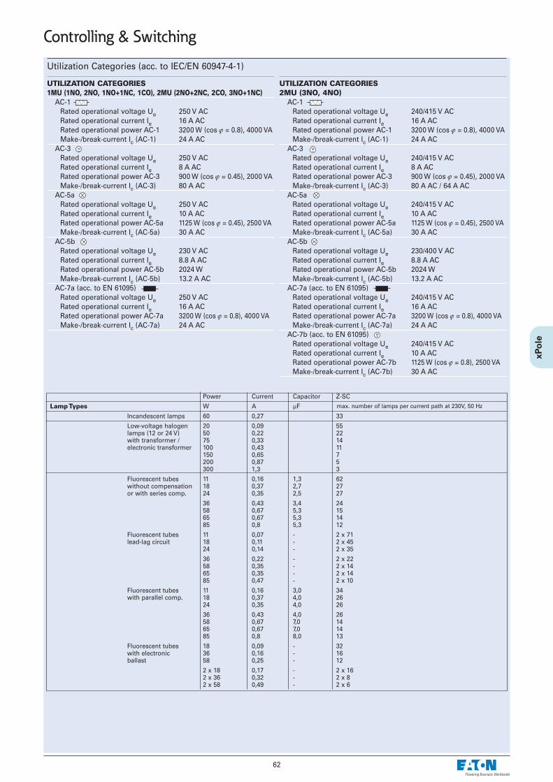
Utilization Categories (acc. to IEC/EN 60947-4-1)
UTILIZATION CATEGORIES1MU (1NO, 2NO, 1NO+1NC, 1CO), 2MU (2NO+2NC, 2CO, 3NO+1NC)
AC-1Rated operational voltage Ue 250 V ACRated operational current Ie 16 A ACRated operational power AC-1 3200 W (cos ϕ = 0.8), 4000 VAMake-/break-current Ic (AC-1) 24 A AC
AC-3Rated operational voltage Ue 250 V ACRated operational current Ie 8 A ACRated operational power AC-3 900 W (cos ϕ = 0.45), 2000 VAMake-/break-current Ic (AC-3) 80 A AC
AC-5aRated operational voltage Ue 250 V ACRated operational current Ie 10 A ACRated operational power AC-5a 1125 W (cos ϕ = 0.45), 2500 VAMake-/break-current Ic (AC-5a) 30 A AC
AC-5bRated operational voltage Ue 230 V ACRated operational current Ie 8.8 A ACRated operational power AC-5b 2024 WMake-/break-current Ic (AC-5b) 13.2 A AC
AC-7a (acc. to EN 61095)Rated operational voltage Ue 250 V ACRated operational current Ie 16 A ACRated operational power AC-7a 3200 W (cos ϕ = 0.8), 4000 VAMake-/break-current Ic (AC-7a) 24 A AC
UTILIZATION CATEGORIES2MU (3NO, 4NO)
AC-1Rated operational voltage Ue 240/415 V ACRated operational current Ie 16 A ACRated operational power AC-1 3200 W (cos ϕ = 0.8), 4000 VAMake-/break-current Ic (AC-1) 24 A AC
AC-3Rated operational voltage Ue 240/415 V ACRated operational current Ie 8 A ACRated operational power AC-3 900 W (cos ϕ = 0.45), 2000 VAMake-/break-current Ic (AC-3) 80 A AC / 64 A AC
AC-5aRated operational voltage Ue 240/415 V ACRated operational current Ie 10 A ACRated operational power AC-5a 1125 W (cos ϕ = 0.45), 2500 VAMake-/break-current Ic (AC-5a) 30 A AC
AC-5bRated operational voltage Ue 230/400 V ACRated operational current Ie 8.8 A ACRated operational power AC-5b 2024 WMake-/break-current Ic (AC-5b) 13.2 A AC
AC-7a (acc. to EN 61095)Rated operational voltage Ue 240/415 V ACRated operational current Ie 16 A ACRated operational power AC-7a 3200 W (cos ϕ = 0.8), 4000 VAMake-/break-current Ic (AC-7a) 24 A AC
AC-7b (acc. to EN 61095)Rated operational voltage Ue 240/415 V ACRated operational current Ie 10 A ACRated operational power AC-7b 1125 W (cos ϕ = 0.8), 2500 VAMake-/break-current Ic (AC-7b) 30 A AC
62
Controlling & Switching
Power Current Capacitor Z-SC
Lamp Types W A µF
Incandescent lamps 60 0,27 33
Low-voltage halogen 20 0,09 55lamps (12 or 24 V) 50 0,22 22with transformer / 75 0,33 14electronic transformer 100 0,43 11
150 0,65 7200 0,87 5300 1,3 3
Fluorescent tubes 11 0,16 1,3 62without compensation 18 0,37 2,7 27or with series comp. 24 0,35 2,5 27
36 0,43 3,4 2458 0,67 5,3 1565 0,67 5,3 1485 0,8 5,3 12
Fluorescent tubes 11 0,07 - 2 x 71lead-lag circuit 18 0,11 - 2 x 45
24 0,14 - 2 x 35
36 0,22 - 2 x 2258 0,35 - 2 x 1465 0,35 - 2 x 1485 0,47 - 2 x 10
Fluorescent tubes 11 0,16 3,0 34with parallel comp. 18 0,37 4,0 26
24 0,35 4,0 26
36 0,43 4,0 2658 0,67 7,0 1465 0,67 7,0 1485 0,8 8,0 13
Fluorescent tubes 18 0,09 - 32with electronic 36 0,16 - 16ballast 58 0,25 - 12
2 x 18 0,17 - 2 x 162 x 36 0,32 - 2 x 82 x 58 0,49 - 2 x 6
max. number of lamps per current path at 230V, 50 Hz

63
Block Diagram for Central, Group, and Local Control
*) Identical phase at A1 as well as at ON and OFF
Compensation by Means of Capacitor Block
SPC-E-280orSPC-S-20/280
Groupcontrol
Loca
l con
trol
Central control
OFF ON
Groupcontrol
OFF ON
OFF ON
Loca
l con
trol
Loca
l con
trol
Loca
l con
trol
Loca
l con
trol
Loca
l con
trol
SPC-E-280orSPC-S-20/280
units unit
Controlling & Switching

64
Controlling & Switching
Staircase Switch with switch-off warning and stop function TLE, TLK• Automatic electronic staircase switch• Switch-off warning can be switched off (type TLK)• Subsequent switching is possible, programmable long-time function• Power saving function, low switching noise• Automatic 3-/4 wire circuit recognition• Zero voltage safety thanks to memory function (type TLK)• Central control function (type TLK)• External voltage control input (type TLK)
Technical Data
ElectricalFeed voltage 230 VACRated voltage tolarance -15%, +10%Power consumption 6 VA (0.8 W)Rated frequency 48-63 HzDuty 100%Reset time 500 msAdjustment range 0,5 - 15 min.Overvoltage category III (in acc. with IEC 60664-1)Rated surge voltage 4 kVOutput Contact 1 NO (Terminals L-18)Rated voltage 250 VACConstant current 16 ASwitch on peak current (20 ms) 80 ASwitching capacity AC 4000 VA / AC1, 384 W / DCMaximum current 30 A / < 3sSwitching voltage 250 V AC1 / 24 V DCMinimum switching capacity DC 500 mWOutput indication yellow LED ( )Mechanical endurance 30 x 106 switching operationsElectrical endurance (AC1) 10 x 105 switching op. 16A/250V
Control input B1Connection (carrying voltage) Pushbutton T-N (3 wire circuit)
Pushbutton T-L (4 wire circuit)Glow lamps parallel to control keys max. 100 mAOverload protection electronicControl input C1-C2 (Type TLK) 8-230 V AC/DC
Mechanical Frame size 45 mmDevice height 87 mmDevice width 17.5 mm (1MU)Installation quick fastening on
DIN rail IEC/EN 60715Protection class / Polution degree IP20 / 2Type of connection lift terminal acc. to
VBG 4 (PZ1 required)Terminal capacity 1x 0.5-4 mm2
2x 0.5-2,5 mm2
Tightening torque max. 1 NmTemperature range -25°C to +55°COperation position any
Connection diagrams
Dimensions (mm)
LN
L
B1 N
N
L
B1
18
18
45
17,5
87
45
TLK
60
17,5
87
TLE
e.g. 3 wire circuit TLE e.g. 4 wire circuit with attic lighting TLK
LN
C1L
C2
B1 N
N
L
B1
8-230VAC/DC
18
18
.5
TLE
15
TLK
Zeitautomatik mit Abschaltvorwarnung
Dauerlicht
Ausgeschaltet
Stromstoßschalter
Stromstoßschalter nullspannungssichert [min.]
t [min.]
0,53
6
915
Mode:
Zeitautomatik2000 W
1000 W
500 W
max. 100 mA
5
10
Functional Description
B1
Rt
Mode
t 2t 3t
>2s <2s >2s <2s
R15s 10s 5s
Mode
R
Automatic timing :After pushing the button the output relay closes (terminals L-18) and the set timestarts to run. If the button is pushed again before the time t has lapsed the timere-starts from zero (subsequent switching function in accordance with EN 60669-2-3). Repeated quick pressing of the pushbutton ("pumping") leads to the additionof 2, 3 or more time intervals up to 60 min. Pushing the button once for a longtime (> 2 s) stops the running lighting period, and the relay switches off (power
saving function). In the function, the device generates short pulses (flickering)as a switch-of warning (according to DIN 18015-2), 15 s, 10 s, and 5 s prior to switching off.
The additional control input permits activating the staircase switch e.g. froman intercom system by means of a voltage from 8 to 230 V AC/DC in the
modes and . This input channel permits starting the lighting time, aswell as subsequent switching. Switching off (power saving function) and pro-gramming of longer lighting periods ("pumping") is not possible via this inputchannel.
>2s<2s
R
C1-C2
B1
UMode
Mode
<2s >2s >2s
>2s<2s
R
C1-C2
B1
U
<2s >2s >2s
Impulse mode :In the impulse mode each push of the button makes the output relay switch
over. In the function the output relay is always open after the feed voltage
has been applied. In the function the relay immediately picks up when thefeed voltage is applied provided that it was closed prior to the power failure.By applying a short voltage pulse (< 2 s) to the additional control input C1-C2the relay R is switched on (central ON).A longer voltage pulse (> 2 s) causes the relay R to switch off (central OFF).
Modes
Automatic timing
Automatic timing with switch-off warning
Permanent light
Off
Impulse relay
Impulse relay, zero-voltage proof

65
Time Lag Relays ZRFunctions• ZRER/W
E ON delayR OFF delay
• ZRMF1/W, ZRMF2/WWE ON delayR OFF delayWs Single shot leading edge with control inputWa Single shot trailing edge with control inputEs ON delay with control inputWu Single shot leading edge voltage controlledBp Flasher pause first
• ZRTAK/Wlp Asymmetric flasher pause firstli Asymmetric flasher pulse first
Indicators: ZRER/W, ZRMF1/W, ZRMF2/WW Green LED U/t ON: indication of supply voltageGreen LED U/t flashes: indication of time periodYellow LED R ON/OFF: indication of output relayZRTAK/W Green LED U/t ON: indication of supply voltageGreen LED U/t slow flashing: indication of time period t1 Green LED U/t fast flashing: indication of time period t2 Yellow LED R ON/OFF: indication of output relay
Technical Data
Electrical Design according to EN 60669Basic accuracy ±1% (of scale end value)Setting accuracy <5% (of scale end value)Repeating accuracy: <0.5% or ±5msEffect of voltage –Effect of temperature ≤0.01% / °CInput circuit:Feed voltage
Terminals A1-A2 24V to 240V AC/DC, 24V/-15% to 240V/+10%
Nominal frequency 48 to 63HzNominal consumption
Type: .../W 4VA (1.5W)Type: .../WW 6VA (2W)
Duty 100%Operational again after 100msResidual ripple in case of DC 10%Release voltage >30% of min. feed voltageOutput circuit: potential-free COSwitching capacity 2000 VA (8A / 250V AC)Fuse protection 8A quick-actingMechanical endurance 20 x 106 operating cyclesElectrical endurance
at a resistive load of 1000 VA 2 x 10⁵ operating cycles Switching frequency
at a resistive load of 100 VA max. 60/min,at a resistive load of 1000 VA (in acc. with IEC 60947-5-1) max. 6/min
Rated surge voltage 4kVOvervoltage category III (in acc. with IEC 60664-1)
Control contact:Input carrying potential Terminals A1-B1
loadable yesMaximum line length 10mMinimum control pulse length
DC 50msAC 100ms
Trigger level (sensitivity) automatic adaption to supply voltage
Mechanical Frame size 45 mmDevice height 87 mmDevice width 17.5 (/W) and 35 (/WW) mmDegree of protection, built-in IP40Position of installation optionalUpper and lower terminals Bow terminalTerminal protection finger and hand touch safe,
BGV A3, ÖVE-EN 6Terminal capacity
1 x 0,5-2,5 mm2 with/without multicore cable end1 x 4 mm2 without multicore cable end2 x 0,5-1,5 mm2 with/without multicore cable end2 x 2,5 mm2 flexible without multicore cable end
Tightening torque of terminal screws max. 1 NmPermitted relative humidity 15% to 85%
in acc. with IEC 60721-3-3 Class 3K3Ambient temperature -25 to +55°C
in acc. with IEC 60068-1Storage and transport temperature -25 to +70°CPollution degree 2
when built in 3
Connection diagram
Dimensions (mm)Time Ranges
Absolute time range Setting range1s 50ms 1s10s 500ms 10s1min 3s 1min10min 30s 10min1h 3min 1h10h 30min 10h100h 5h 100h
Controlling & Switching
Type ZRTAK/W Type ZRER/W, ZRMF1/W
Type ZRMF2/WW

66
Controlling & Switching
Description of Functions
• ON delay (E)When the supply voltage U is applied, the set interval t begins (green LED U/t flashes). After the interval t has expired (green LED U/t illuminated) the out-put relay R switches into on-position (yellow LED illuminated) This status remains until the supply voltage is interrupted. If the supply voltage is interruptedbe fore the expiry of the interval t, the interval already expired is erased and is restarted when the supply voltage is next applied.
• OFF delay (R)The supply voltage U must be constantly applied to the device (green LED U/t illuminated) When the control contact S is closed, the output relay R switchesinto on-position (yellow LED illuminated). If the control contact is opened, the set interval t begins (green LED flashes) After the interval t has expired(green LED U/t illuminated) the output relay switches into off-position (yellow LED not illuminated) If the control contact is closed again before the interval thas expired, the interval already expired is erased and is restarted.
• Single shot leading edge with control input (Ws)The supply voltage U must be constantly applied to the device (green LED U/t illuminated). When the control contact S is closed, the output relay R switch-es into on-position (green LED U/t illuminated) and the set interval t begins (green LED U/t flashes). After the interval t has expired (green LED U/t illuminat-ed) the output relay switches into off-position (yellow LED not illuminated). During the interval, the control contact can be operated any number of times. Afurther cycle can only be started when the cycle run has been completed.
• Single shot trailing edge with control input (Wa)The supply voltage U must be constantly applied to the device (green LED U/t illuminated). Closing the control contact S has no influence on the conditionof the output R. When the control contact is opened, the output relay switches into on-position (yellow LED illuminated) and the set interval t begins (greenLED U/t flashes). After the interval t has expired (green LED U/t illuminated), the output relay switches into off-position (yellow LED not illuminated). Duringthe interval, the control contact can be operated any number of times. A further cycle can only be started when the cycle run has been completed.
• ON delay with control input (Es)The supply voltage U must be constantly applied to the device (green LED U/t illuminated). When the control contact S is closed, the set interval t begins(green LED U/t flashes). After the interval t has expired (green LED U/t illuminated) the output relay R switches into on-position (yellow LED illuminated).This status remains until the control contact is opened again If the control contact is opened before the interval t has expired , the interval already expiredis erased and is restarted with the next cycle.
• Single shot leading edge voltage controlled (Wu)When the supply voltage U is applied, the output relay R switches into on-position (yellow LED illuminated) and the set interval t begins (green LED U/tflashes). After the interval t has expired (green LED U/t illuminated) the output relay switches into off-position (yellow LED not illuminated). This statusremains until the supply voltage is interrupted. If the supply voltage is interrupted before the interval t has expired. The output relay switches into off-posi-tion The interval already is erased and is restarted when the supply voltage is next applied.
• Flasher pause first (Bp)When the supply voltage U is applied, the set interval t begins (green LED U/t flashes). After the interval t has expired, the output relay R switches into on-position (yellow LED illuminated) and the set interval t begins again. After the interval t has expired. the output relay switches into off-position (yellow LEDnot illuminated). The output relay is triggered at a ratio of 1:1 until the supply voltage is interrupted.
• Asymmetric flasher pause first (lp)When the supply voltage U is applied, the set interval t1 begins (green LED U/t flashes slowly) After the interval t1 has expired. the output relay R switchesinto on-position (yellow LED illuminated) and the set interval t2 begins (green LED U/t flashes fast). After the interval t2 has expired, the output relayswitches into off-position (yellow LED not illuminated). The output relay is triggered at the ratio of t1:t2 until the supply voltage is interrupted.
• Asymmetric flasher pulse first (li)When the supply voltage U is applied, the output relay R switches into on-position (yellow LED illuminated) and the set interval t1 begins (green LED U/tflashes slowly). After the interval t1 has expired, the output relay switches into off-position (yellow LED not illuminated) and the set interval t2 begins(green LED U/t flashes fast). After the interval t2 has expired, the output relay switches into on-position (yellow LED illuminated). The output relay is trig-gered at the ratio of t1:t2 until the supply voltage is interrupted.
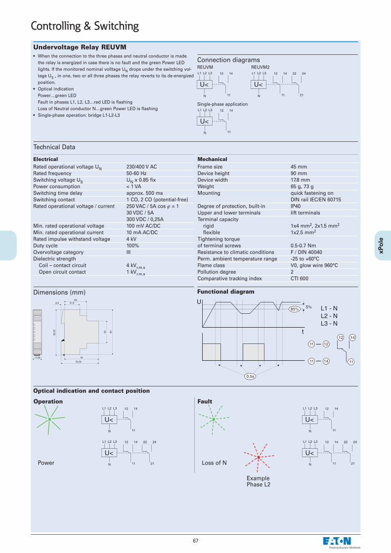
67
Controlling & Switching
Undervoltage Relay REUVM• When the connection to the three phases and neutral conductor is made
the relay is energized in case there is no fault and the green Power LEDlights. If the monitored nominal volltage UN drops under the switching vol-tage US , in one, two or all three phases the relay reverts to its de-energizedposition.
• Optical indicationPower…green LEDFault in phases L1, L2, L3…red LED is flashingLoss of Neutral conductor N…green Power LED is flashing
• Single-phase operation: bridge L1-L2-L3
Technical Data
Electrical Rated operational voltage UN 230/400 V ACRated frequency 50-60 HzSwitching voltage US UN x 0.85 fixPower consumption < 1 VASwitching time delay approx. 500 msSwitching contact 1 CO, 2 CO (potential-free)Rated operational voltage / current 250 VAC / 5A cos ϕ = 1
30 VDC / 5A300 VDC / 0,25A
Min. rated operational voltage 100 mV AC/DCMin. rated operational current 10 mA AC/DCRated impulse withstand voltage 4 kVDuty cycle 100%Overvoltage category IIIDielectric strength
Coil – contact circuit 4 kVr.m.sOpen circuit contact 1 kVr.m.s
Mechanical Frame size 45 mmDevice height 90 mmDevice width 17.8 mmWeight 65 g, 73 gMounting quick fastening on
DIN rail IEC/EN 60715Degree of protection, built-in IP40Upper and lower terminals lift terminalsTerminal capacity
rigid 1x4 mm2, 2x1.5 mm2
flexible 1x2.5 mm2
Tightening torque of terminal screws 0.5-0.7 NmResistance to climatic conditions F / DIN 40040Perm. ambient temperature range -25 to +60°CFlame class V0, glow wire 960°CPollution degree 2Comparative tracking index CTI 600
Connection diagrams
Dimensions (mm) Functional diagram
REUVM REUVM2
Single-phase application
Optical indication and contact position
Operation
Power
Fault
Loss of N
ExamplePhase L2

68
Controlling & Switching
Voltage Indication UVA• When the connection to the three phases and neutral conductor is made,
the green Power LED lights. If only two phases are connected, eg. L1 andL3, only these green LED`s lights, even at loss of Neutral conductor N.
• For use as voltage return indication in manual operated Mains-Emergency-system operation
• Large operational voltage range 85-690 V AC/DC
Technical Data
Electrical Rated operational voltage UN 230/400 V ACRated frequency 50-60 HzRated operational voltage 85-690 V AC/DCPower consumption < 3x 23 mWMax. permissible back-up fuse 16A gG (gL)Duty cycle 100%Rated impulse withstand voltage 6 kVOvervoltage category IV
Mechanical Frame size 45 mmDevice height 90 mmDevice width 17.8 mmWeight 42 gMounting quick fastening on
DIN rail IEC/EN 60715Degree of protection, built-in IP40Upper and lower terminals lift terminalsTerminal capacity
rigid 1x4 mm2, 2x1.5 mm2
flexible 1x2.5 mm2
Tightening torque of terminal screws 0.5 NmResistance to climatic conditions F / DIN 40040Perm. ambient temperature range -30 to +60°CFlame class V0, glow wire 960°CPollution degree 2Comparative tracking index CTI 600
Connection diagram
Dimensions (mm) Application and optical indication
L1
3N~
�N �
L3
�L2 �
L1
3~
�
L3
�L2 �
L1
1~DC
�N �–(+)+(–)

69
Controlling & Switching
Connection Example - "OR" Circuit, Extraction SystemConnection Example - Priority for Pump
Connection Example - Operating Status
N L1
U ~1
grün . . . Motor EINrot . . . . .Motor HALT
z.B. Z-UEL230
R G
L1
Priority-(Current) Relay Z-LAR/• For simple priority connection of important consumers• For fast current increase• Expensive peak loads are avoided efficiently (staggered heating)• Integrated auxiliary switch, 1 NC or 1 NO or 1 CO contact• NC and NO contact are potential free
Technical Data
Z-LAR/8 Z-LAR/16 Z-LAR/32
Electrical Nominal thermal current Ith 8 A 16 A 32 ARated voltage U 250V AC 250V AC 250V ACResponding current IAN ≥ 3 A ≥ 10 A ≥ 15 ARelease current IA ≤ 1.8 A ≤ 4.2 A ≤ 7.4 AMax. electrical switching frequency 3600/h 3600/h 3600/hRated insulation voltage Ui 440 V 440 V 440 VPower loss at Ith
Effective power 3.4 W 1.95 W 3.17 WApparent power 7.7 VA 4.66 VA 7.36 VA
Rated peak withstand voltage Uimp 4 kV 4 kV 4 kVBack-up fuse line protection max. 10 A max. 16 A max. 32 ASwitching contact:Function NC, NO, CO
Back-up fuse max. 1 A gL max. 1 A gL max. 1 A gLContact gap *) < 3 mm (µ) < 3 mm (µ) < 3 mm (µ)Switching capacity 1A/250V~ 1A/250V~ 1A/250V~Minimum switching capacity 300 mW 300 mW 300 mWMinimum operational voltage 12 V 12 V 12 V
Electrical endurance 100.000 operating cycles*) Do not use as the only means of isolating a device from the line voltage
Mechanical Frame size 45 mm 45 mm 45 mmDevice height 80 mm 80 mm 80 mmDevice width 17.5 mm (1MU) 17.5 mm (1MU) 17.5 mm (1MU)Mounting quick fastening on DIN rail IEC/EN 60715Degree of protection, built-in IP40 IP40 IP40Upper and lower terminals lift terminals lift terminals lift terminalsTerminal protection finger and hand touch safe, according to BGV A3, ÖVE-EN 6Terminal capacity
Main circuit 2 x 10 mm2 2 x 10 mm2 2 x 10 mm2
Auxiliary circuit 2 x 2.5 mm2 2 x 2.5 mm2 2 x 2.5 mm2
Fastening torque of terminal screwsMain circuit max. 2.4 Nm max. 2.4 Nm max. 2.4 NmAuxiliary circuit max. 1 Nm max. 1 Nm max. 1 Nm
Connection diagram
Dimensions (mm)
Typ -O Typ -S Typ -W
green . . . Motor ONred . . . . . Motor STOP
e.g. heatingsystem e.g. fan

Bioswitch FFS/16• Line voltage LED• AUTOMATIC ON/OFF switch• All-pole disconnection• 2 contacts NO• Not suitable for consumers with electronic control
Technical Data
Electrical Rated voltage 230 V AC
Tolerance -15% to +10%Rated frequency 48 - 63 HzRated consumption 11 VA (1.6 W)Duration of operation 100%Detecting voltage 200 - 250 mV DCCurrent consumption 32 mAMaking current 5 - 200 mABreaking current fix, approx. 70% of making
currentDrop-out voltage > 10% of the rated voltageTripping delay fixed, approx. 6 sRise time fixed, approx. 0.5 sBase accuracy ±10% (of max. scale value)Green LED ON: indication of supply voltageYellow LED ON: indication of relay output
Output circuit 2 potentialfree contacts NOSwitching capacity 4000 VA (16 A / 250 V AC)Back-up fuse 16 A fast actingMechanical life 30 x 106 operationsElectrical life 2 x 10⁵ operations
at 1000 VA resistive loadSwitching frequency max. 60/min.
at 100 VA resistive loadmax. 6/min. at 1000 VA resistive load(according to IEC 664-1)
Rated insulating voltage 250 V AC (according to IEC 664-1)
Rated surge voltage 4 kV, overvoltage cat. III (according to IEC 664-1)
Base load resistor Z-NKA... if high-impedance consumers areconnected to a ”Bio-switch”, the Z-NKA... is needed. By pressing thebutton, the Z-NKA... is activated for5 minutes. As long as any con-sumer is still switched on, the auto-matic deactivating of the Z-NKA...will have no effect.
Mechanical Frame size 45 mmDevice height 87 mmDevice width 35 mmMounting quick fastening on
DIN rail IEC/EN 60715Degree of protection, built-in IP40Installation in any positionTerminal protection finger and hand touch safe,
BGV A3, ÖVE-EN 6Torque max. 1 NmTerminal capacity 1 x 0.5-4 mm2
2 x 0.5-2.5 mm2
Ambient temperature -25°C to +55°CStorage temperature -25°C to +70°CTransport temperature -25°C to +70°CRelative humidity 15% to 85%
(acc. to IEC 721-3-3 class 3K3)
Degree of pollution 2, if built-in 3(acc. to IEC 664-1)
Connection diagram
Dimensions (mm) Connection Example
70
Controlling & Switching
Load 230V
Supply voltage 230V

71
Controlling & Switching
Digital Time Switches with a Weekly Program, for DIN Rail, TSDW1CO, TSDW2CO• Spring terminals• Text-based user guidance on the display• 56 memory cells• Interface for memory card (PC programming)• 10 years power backup (lithium battery)• Zero-cross switching for a relay-saving way of switching and for high lamp
loads• ON-OFF switching times• Pre-selected switching• Permanent ON/OFF switching• Integrated counter for operating hours • Vacation program• Display background lighting (can be switched off)• PIN coding• Automatic spring forward/fall back at daylight-saving start and end dates• For type TSDW1CO: 1 channel• For type TSDW2CO: 2 channels
Technical Data
TSDW1CO TSDW2CO
Electrical Operating voltage 230–240 V AC 230–240 V ACFrequency 50–60 Hz 50–60 HzPower backup 10 years 10 yearsSwitching capacity at 250 V AC, cos ϕ = 1 16 A 16 ASwitching capacity at 250 V AC, cos ϕ = 0.6 10 A 10 AIncandescent/halogen lamp load 2600 W 2600 WMin. switching capacity approx. 10 mA approx. 10 mAShortest switching time 1 minAccuracy ≤ ± 0.5 s/day (quartz) ≤ ± 0,5 s/day (quartz)Stand-by power 0.8 W 0.8 W
Mechanical Frame size 45 mm 45 mmInstallation width 36 mm 36 mmMounting DIN rail DIN railDegree of protection IP20 IP20Protection class II acc. to EN 60 730-1 II according to EN 60 730-1Ambient temperature -30 °C … +55 °C -30 °C … +55 °CCertification mark V V
Connection examples
Dimensions (mm)

72
Controlling & Switching
Digital Time Switch with a Weekly Program TSDW1CODG• Spring terminals• Text-based operator guidance on the display• 84 memory cells• Interface for memory card (PC programming)• 10 years power backup (lithium battery)• Zero-cross switching for a relay-saving way of switching and for high lamp
loads• ON/OFF switching times• Pulse program• Cyclical program• Pre-selected switching• Permanent ON/OFF switching• Expiry timer• Integrated counter for operating hours• Vacation program• 2 random programs• Display background lighting (can be switched off)• PIN coding• Automatic spring forward/fall back at daylight-saving start and end dates• Time synchronization is possible by connecting an external aerial, e. g. a
TSADCF or TSAGPSKIT aerial set• 1 Channel• External input
Technical Data
TSDW1CODG
Electrical Operating voltage 230–240 V ACFrequency 50–60 HzPower backup 10 yearsSwitching capacity at 250 V AC, cos ϕ = 1 16 ASwitching capacity at 250 V AC, cos ϕ = 0.6 10 AIncandescent/halogen lamp load 2600 WMin. switching capacity approx. 10 mAShortest switching time 1 sAccuracy ≤ ± 0.5 s/day (quartz) or DCF77/GPSStand-by power 1.4 W
Mechanical Frame size 45 mmInstallation width 36 mmMounting DIN railDegree of protection IP20Protection class II according to EN 60 730-1Ambient temperature -30 °C … +55 °CCertification mark V
Connection example
Dimensions (mm)

73
Controlling & Switching
Digital Time Switch with a Weekly Program TSDW1COMIN• 1 Channel• Screw-type terminals• Text-based operator guidance on the display• 28 memory cells• 3 years power backup (exchangeable lithium battery)• ON-OFF switching times • Pre-selected switching• Permanent ON/OFF switching• PIN coding• Automatic spring forward/fall back at daylight-saving start and end dates
Technical Data
TSDW1COMIN
Electrical Operating voltage 230 V ACFrequency 50–60 HzPower backup 3 yearsSwitching capacity at 250 V AC, cos ϕ = 1 16 ASwitching capacity at 250 V AC, cos ϕ = 0.6 6 AIncandescent/halogen lamp load 1000 WShortest switching time 1 minAccuracy ≤ ± 1 s/day (quartz)Stand-by power 0.4 W
Mechanical Frame size 45 mmInstallation width 17.5 mmMounting DIN railDegree of protection IP20Protection class II according to EN 60 730-1Ambient temperature –10 °C … +55 °CCertification mark V
Connection example
Dimensions (mm)

74
Controlling & Switching
Astro Time Switch with a Weekly Program TSDW1COA• Astronomical switching function (automatic calculation of sunrise and sun-
set times for the entire year) • Spring terminals• Text-based operator guidance on the display• Interface for memory card (PC programming)• 10 years power backup (lithium battery)• Zero-cross switching for a relay-saving way of switching and for high lamp
loads• Calculated astronomical switching times• Programmable ON/OFF switching times• Pre-selected switching• Permanent ON/OFF switching• Integrated counter for operating hours • Vacation program• Display background lighting (can be switched off)• PIN coding• Automatic spring forward/fall back at daylight-saving start and end dates• 1 Channel• 54 Memory cells
Technical Data
TSDW1COA
ElectricalOperating voltage 230–240 V ACFrequency 50–60 HzPower backup 10 yearsSwitching capacity at 250 V AC, cos ϕ = 1 16 ASwitching capacity at 250 V AC, cos ϕ = 0.6 10 AIncandescent/halogen lamp load 2600 WMin. switching capacity approx. 10 mAShortest switching time 1 minAccuracy ≤ ± 0.5 s/day (quartz)Stand-by power 0.8 W
MechanicalFrame size 45 mmInstallation width 36 mmMounting DIN railDegree of protection IP20Protection class II according to EN 60 730-1Ambient temperature -30 °C … +55 °CCertification mark V
Connection example
Dimensions (mm)

75
Controlling & Switching
Astronomical, digital Timer SA-TD/1W• Design according to DIN EN 60730• Digital timer in CMOS-technology• Microprocessor and quartz control• Programming by means of multi-function keys• LCD display• Programme data saved in case of power failure• Optionally in each programme impulse time (switching interval 1-99 s) or
fixed switching time (shortest switching interval 1 min) are possible• Direct manual switching of relay ON/OFF• Manual switching of relay to permanent operation ON/OFF (holiday opera-
tion)• Automatic change to summer/winter time• Automatic leap year adjustment• Terminal covers which can be sealed with leads available as accessories
Technical Data
SA-TD/1W
General Design according to EN 60730-1, EN 60730-2-7Rated voltage 230-240 V AC +10%/-15%Rated frequency 50-60 HzPower consumption max. 6 VADrive QuartzAccuracy at 20°C 1 s/dayPower reserve at 20°C 10 yearsType of battery LiOperating cycles > 40,000Degree of protection IP20Ambient temperature -30°C…+55°CStorage temperature -30°C…+55°CProtection class (acc. to EN 60 730-1) upon installation II
Switching contactsType of switching contact 1 x change-over contactContact material AgSnO2Switching capacity at 250 V~, cosϕ=1 16 ASwitching capacity at 250 V~, cosϕ=0.6 10 A
Programme featuresSwitching period WeekNumber of channels 1Min. switching time 1 min.Max. programme steps in the memory 732
Size & WeightModule units 2Width 35 mmHeight 65.5 mmLength 90 mmWeight 170 g
TerminalsTerminal capacity - fine stranded wire 1.....2.5 mm2
Terminal capacity - solid wire 1.....4 mm2
Size of terminal screw M3.5Type of screw head PZ size 1Max. torque 0.8 Nm
Block Diagrama
b
1 2 3
6 7 8
Dimensions (mm)

76
Digital Timers Z-SDM• Design according to DIN EN 60730• Digital timers in CMOS-technology• Microprocessor and quartz control• Programming by means of multi-function keys• LCD display• Program data saved in case of power failure• Optionally in each program impulse time (switching interval 1-99 s) or fixed
switching time (shortest switching interval 1 min) are possible• Direct manual switching of relay ON/OFF• Manual switching of relay to permanent operation ON/OFF (holiday opera-
tion)• Automatic change to summer/winter time• Automatic leap year adjustment• Terminal covers which can be sealed with leads available as accessories
Technical Data
Z-SDM/1K-TA Z-SDM/1K-WO Z-SDM/2K-WO
Electrical Rated voltage 230 V AC 230 V AC 230 V ACRated frequency 50/60 Hz 50/60 Hz 50/60 HzCurrent consumption 29mA, cos ϕ = 0,13 29mA, cos ϕ = 0,13 29mA, cos ϕ = 0,13Apparent power 6.6 VA 6.6 VA 6.6 VAReactive power -6.5 VAr -6.5 VAr -6.5 VArPower loss 0.9 W 0.9 W 0.9 WSwitching contact (potential-free) 1 CO 1 CO 2 COSwitching capacity
Rated insulation voltage 250 V 250 V 250 VRated current 16 A µ 16 A µ 16 A µResistive load 3000W, cos ϕ = 1 3000W, cos ϕ = 1 3000W, cos ϕ = 1Incandescent lamp load 1000W, cos ϕ = 1 1000W, cos ϕ = 1 1000W, cos ϕ = 1Inductive load 2A/250VAC cos ϕ = 0.6 2A/250VAC cos ϕ = 0.6 2A/250VAC cos ϕ = 0.6
Power reserve 250 h 250 h 250 hPower reserve storage NiMH storage battery NiMH storage battery NiMH storage batteryData saved by EEPROM EEPROM EEPROMAccuracy at 20°C approx. 1 s per day approx. 1 s per day approx. 1 s per daySwitching accuracy accurate to the second accurate to the second accurate to the secondQuartz frequency 32.768 MHz 32.768 MHz 32.768 MHzSwitching pairs freely programmable 20/day 20/week 20/weekSwitching interval 1 min. or 1 s 1 min. or 1 s 1 min. or 1 s
Mechanical Frame size 45 mm 45 mm 45 mmDevice height 90 mm 90 mm 90 mmDevice width 36 mm 36 mm 36 mmWeight 170 g 170 g 200 gMounting quick fastening on DIN rail IEC/EN 60715Degree of protection, built-in IP40 IP40 IP40Upper and lower terminals lift terminals lift terminals lift terminalsTerminal capacity
one-wire 1.5-4 mm2 1.5-4 mm2 1.5-4 mm2
fine wire 1-2.5 mm2 1-2.5 mm2 1-2.5 mm2
Tightening torque of terminal screws 0.8 Nm 0.8 Nm 0.8 NmPermitted relative humidity < 95% < 95% < 95%Perm. ambient temperature range 0 to +55°C 0 to +55°C 0 to +55°CFlame class acc. to EN 60730 D D D
Block Diagrama
b
1 2 3
6 7 8
Dimensions (mm)
For wall mounting
Controlling & Switching

77
Controlling & Switching
Analog Time Switches TSQD1NO, TSSD1NO• 1 MU• 1 Channel• Screw-type terminals• Manual switch with 3 positions: Permanent ON/AUTO/Permanent OFF• Switching status indication• For type TSQD1NO: with power backup (exchangeable NiMH cell)
- quartz-controlled• For type TSSD1NO: Daily program
- Without power backup- 96 switching segments- Mains-synchronized- Shortest switching time: 15 minutes
Technical Data
TSQD1NO TSSD1NO
ElectricalOperating voltage 230–240 V AC 230 V ACFrequency 50–60 Hz 50 HzProgram Daily program Daily programPower backup 3 days –Switching capacity at 250 V AC, cos ϕ = 1 16 A 16 ASwitching capacity at 250 V AC, cos ϕ = 0.6 4 A 4 AShortest switching time 15 min 15 minProgrammable Every 15 min Every 15 minAccuracy ≤ ± 1 s/day (quartz) Mains-synchronizedStand-by power 0.5 W 0.9 W
Mechanical Frame size 45 mm 45 mmInstallation width 17.5 mm 17.5 mmMounting DIN rail DIN railDegree of protection IP20 IP20Protection class II acc. to EN 60 730-1 II according to EN 60 730-1Ambient temperature –10 °C … +55 °C –25 °C … +50 °CCertification mark V V
Connection example
Dimensions (mm)

78
Controlling & Switching
Analog Time Switches TSQD1CO, TSSD1CO, TSQW1CO• 3 MUs• 1 Channel• Spring terminals• Pre-selected switching• Manual switch with 3 positions: Permanent ON/AUTO/Permanent OFF• Switching position indication• Type TSQD1CO:
- With power backup (NiMH cell)- Quartz-controlled- Clock-hands for time indication and 12h/24h recognition- Easy correction of spring forward/fall back at daylight-saving start and end
• Type TSQW1CO: - Weekly program- 84 Switching segments- Shortest switching time: 2 hours
• Type TSSD1CO: - Daily program- Without power backup- 96 Switching segments- Shortest switching time: 15 minutes- Clock-hands for time indication and 12h/24h recognition- Easy correction of spring forward/fall back at daylight-saving start and end
Technical Data
TSQD1CO TSSD1CO TSQW1CO
ElectricalOperating voltage 110–230 V AC 110–230 V AC 110–230 V ACFrequency 50–60 Hz 50 Hz 50–60 HzProgram Daily program Daily program Weekly programPower backup 200 hours, – 200 hours,
approx. 100 hours approx. 100 hourswith 110 V with 110 V
Switching capacity at 250 V AC, cos ϕ = 1 16 A 16 A 16 ASwitching capacity at 250 V AC, cos ϕ = 0.6 4 A 4 A 4 AShortest switching time 15 min 15 min 2 hProgrammable Every 15 min Every 15 min Every 2 hAccuracy ≤ ± 1 s/day (quartz) Mains-synchronized ≤ ± 1 s/day (quartz)Stand-by power 0.5 W 0.9 W 0.5 W
Mechanical Frame size 45 mm 45 mmInstallation width 52.5 mm 52.5 mm 52.5 mmMounting DIN rail DIN rail DIN railDegree of protection IP20 IP20 IP20Protection class II acc. to EN 60 730-1 II acc. to EN 60 730-1 II according to EN 60 730-1Ambient temperature –20 °C … +55 °C –20 °C … +55 °C –20 °C … +55 °CCertification mark V V V
Connection example
Dimensions (mm)

79
Controlling & Switching
Analogue Timers SU-T• Design according to EN 60730-1, EN 60730-2-7• Programming by means of switching slides
Technical Data
SU-TS/TA SU-TS/1W-TA SU-TS/WO SU-TQ/TA SU-TQ/1W-TA, -WO SU-TQ/2W-TW
GeneralDesign according to EN 60730-1, EN 60730-2-7Rated voltage 230 V AC ± 10 % 230 V AC ± 10 % 230 V AC ± 10 % 230 V AC ± 10 % 230 V AC ± 10 % 230 V AC ± 10 %Rated frequency 50 Hz 50 Hz 45-60 Hz 45-60 Hz 45-60 Hz 45-60 HzPower consumption max. 2.5 VA max. 2.5 VA max. 2.5 VA max. 2.5 VA max. 2.5 VA max. 2.5 VADrive Mains Mains Mains Quartz Quartz QuartzAccuracy at 20°C acc. to mains acc. to mains acc. to mains ≤±1 s/day ≤±1 s/day ≤±1 s/dayPower reserve at 20°C - - - >3 days >3 days >3 daysType of battery - - - NiMH NiMH NiMHOperating cycles >10,000 >10,000 >10,000 >10,000 >10,000 >10,000Degree of protection IP20 IP20 IP20 IP20 IP20 IP20Ambient temperature -25 °C...+50 °C -20 °C...+50 °C -10 °C...+50 °C -10 °C...+50 °C -20 °C...+50 °C -20 °C...+50 °CStorage temperature -25 °C...+50 °C -20 °C...+50 °C -10 °C...+50 °C -10 °C...+50 °C -20 °C...+50 °C -20 °C...+50 °CProtection class (acc. to EN 60 730-1) upon installation II II II II II II
Switching contactsType of switching cont. 1 x NO 1 x CO 1 x NO 1 x NO 1 x CO 2 x COContact material Solid silver Solid silver Solid silver Solid silver Solid silver Solid silverSwitching capacity at 250 V~, cosϕ=1 16 A 16 A 16 A 16 A 16 A 16 ASwitching capacity at 250 V~, cosϕ=0.6 4 A 4 A 4 A 4 A 4 A 4 A
Programme featuresSwitching period Day Day Week Day Day, Week WeekNumber of channels 1 1 1 1 1 2Shortest switching interval 15 min. 30 min. 2 hours 15 min. 30 min., 4 hours15 min.Max. programme steps in the memory 96 48 84 96 48 32/day
Size & WeightModule units 1 3 1 1 3 3Width 17.5 mm 52.5 mm 17.5 mm 17.5 mm 52.5 mm 52.5 mmHeight 65.5 mm 65.5 mm 65.5 mm 65.5 mm 65.5 mm 66.5 mmLength 90 mm 90 mm 90 mm 90 mm 90 mm 90 mmWeight 80 g 164 g 90 g 80 g 170 g, 172 g 175 g
TerminalsTerminal capacity -fine stranded wire 1.....2.5 mm2 1.....2.5 mm2 1.....2.5 mm2 1.....2.5 mm2 1.....2.5 mm2 1.....2.5 mm2
Terminal capacity - solid wire 1.....4 mm2 1.....4 mm2 1.....4 mm2 1.....4 mm2 1.....4 mm2 1.....4 mm2
Size of terminal screws M3.5 M3.5 M3.5 M3.5 M3.5 M3.5Type of screw head PZ size 1 PZ size 1 PZ size 1 PZ size 1 PZ size 1 PZ size 1Max. torque 2 Nm 2 Nm 2 Nm 2 Nm 2 Nm 2 Nm
Block Diagram
Dimensions (mm)SU-TS/TA, SU-TS/WO, SU-TQ/TA SU-TS/1W-TA, SU-TQ/1W-TA, SU-TQ/1W-WO, SU-TQ/2W-TW

80
Controlling & Switching
Analog Twilight Switches, for DIN Rail, SRSD1NO, SRSD1COW• Analog twilight switch• External surface or flush-mounted light sensor is incl. in the scope of deli-
very• Indication of the channel and switching status• Brightness level can be continuously adjusted• Type SRSD1NO: fixed switch-on and switch-off delay• Type SRSD1COW: Variable switch-on and switch-off delay
- Spring terminals - Expanded brightness range and variable delay time- Five adjustable brightness ranges for easy setting of the lux value - Zero-cross switching - Permanent OFF and permanent ON function can be set at the potentiome-
ter - Test function
Switching diagramsSRSD1NO SRSD1COW
Technical Data
SRSD1NO SRSD1COW
ElectricalOperating voltage 220–240 V AC 220–240 V ACFrequency 50–60 Hz 50–60 HzSetting range for brightness 2–100 lx 2–50000 lxSwitch-on delay 20 s 0–20 minContact type Make-contact Change-over contactSwitch output Potential-free Potential-free, not suitable for SELVSwitching capacity at 250 V AC, cos ϕ = 1 16 A 16 ASwitching capacity with fluorescent lamp load 10 AX 16AXMin. switching capacity – <10 mAIncandescent lamp load 2300 W 3600 WFluorescent lamp load (VVG - low-loss ballast) 2300 VA 3600 VA
non-compensated/series-compensated/duo switching
Energy saving lamps 9 x 7 W, 7 x 11 W, 34 x 7 W, 27 x 11 W, 7 x 15 W, 7 x 20 W, 24 x 15 W, 22 x 23 W7 x 23 W
Stand-by power 0.8 W 1.3 W
Mechanical Frame size 45 mm 45 mmInstallation width 17.5 mm 54 mmMounting DIN rail DIN railProtection class II IIAmbient temperature –25 °C … +50 °C –30 °C … +55 °CCertification mark V VMax. line length to the sensor 25 m 100 m
Dimensions (mm)SRSD1NO SRSD1COW

81
Controlling & Switching
Surface-Mounted Twilight Switch SRSW1NO• Twilight switch with an integrated light sensor• Cable entry is possible at the rear or from the bottom• Large terminal area• Setting the brightness value is possible from outside, without the need to
open the device • Wide angle of light incidence (approx. 180°)• Test button• Switch-on and switch-off delay can be adjusted• Brightness level can be continuously adjusted • Expanded brightness range
Switching diagram
Technical Data
SRSW1NO
ElectricalOperating voltage 220–230 V ACFrequency 50–60 HzSetting range for brightness 2–2000 lxSwitch-on delay 2–100 sContact type Make-contactSwitch output Not potential-free (230 V)Switching capacity at 230 V AC, cos ϕ = 1 16 ASwitching capacity at 230 V AC, cos ϕ = 0.3 10 AXIncandescent lamp load 2300 WFluorescent lamp load (VVG - low-loss ballast) 2300 VA
non-compensated/series-compensated/duo switching
Energy saving lamps 9 x 7 W, 7 x 11 W, 7 x 15 W, 7 x 20 W, 7 x 23 W
Stand-by power 0.6 W
MechanicalHeight 118.4 mmWidth 85 mmDepth 49.4 mmDegree of protection IP55Protection class IIAmbient temperature –35 °C … +55 °C
Dimensions (mm)SRSW1NO

82
Controlling & Switching
Twilight Switch with Timer, for DIN Rail, SRCD1CO• Twilight switch with an integrated weekly timer • Adjustable switch-on and switch-off delay • Brightness levels and switching-delay can separately be set for switch-on
and switch-off • Fixed times for ON and OFF (e.g. interruption during the night)• DuoFix spring terminals • Zero-cross switching to protect the relay contact and the lamp so as to
increase their service life• Interface for the OBELISK top2 memory card (PC programming)• Light sensor included in the scope of delivery • Permanent ON/OFF switching• Test function• Pre-selected switching• Display background lighting• PIN coding • Counter for operating hours • Display of the channel and switching status• Vacation and holiday program with annual function for fixed date and
variable date holidays (e.g. the ones that depend on Easter)• Different rules can be selected for daylight-saving start and end or they can
be freely selected • For type SRCD1CO:
- Analog twilight switch- 1 Channel- Analog setting of brightness levels
Switching diagram
Technical Data
SRCD1CO
Electrical Operating voltage 220–240 V ACFrequency 50–60 HzSetting range for brightness 2–2000 lxSwitch-on delay 0–59 minContact type Change-over contactSwitch output Potential-free, not suitable for SELVSwitching capacity at 250 V AC, cos ϕ = 1 16 ASwitching capacity at 250 V AC, cos ϕ = 0.6 10 ASwitching capacity with fluorescent lamp load 10 AXMin. switching capacity approx. 10 mAIncandescent lamp load 2600 WFluorescent lamp load (VVG - low-loss ballast) 2300 VA
non-compensated/series-compensated/duo-switching
Energy saving lamp 22 x 7 W, 18 x 11 W, 16 x 15 W, 16 x 20 W, 14 x 23 W
Stand-by power 1.3 W
MechanicalFrame size 45 mmInstallation width 52.5 mmMounting DIN railProtection class IIAmbient temperature –30 °C … +55 °CMax. line length to the sensor 100 m
Dimensions (mm)

83
Controlling & Switching
Light Intensity Switch for support rail assembly DS-TA, DS-TD• Device for automatic control of lighting systems• For outdoor installation • Wall mounting IP55• With integrated light sensor• Brightness range infinitely adjustable• Type DS-TA: can be combined with timers for time and light-dependent
control• Type DS-TA: with integrated timer• With make and break-time delay• Suitable for street lighting, yard or general outdoor lighting
Technical Data
DS-TA/WA DS-TA/VWA DS-TD/WA
GeneralDesign according to EN 60669-1, EN 60669-2-1Rated voltage 230 V AC / 220 V~ 230 V AC / 220 V~ 230 V AC / 220 V~Rated operating voltage tolerance -10%....+10% -10%....+10% -10%....+10%Rated frequency 50/60 Hz 50/60 Hz 50/60 HzPower consumption 3.5 VA 4.5 VA 2 VABrightness range 5 - 200 Lux 2 - 2000 Lux 2 - 200 Lux, digitalMax. cable length for sensor - - -Drive - - QuartzAccuracy at 20°C - - -Power reserve at 20°C - - 1.5 yearsType of battery - - Lithium, replacableOperating cycles 40,000 40,000 40,000Degree of protection IP55 IP55 IP55Ambient temperature -35°C...+55°C -35°C...+55°C -35°C...+55°CAmbient temperature - sensor - - -Storage temperature -40 °C...+70 °C -40 °C...+70 °C -40 °C...+70 °CStorage temperature - sensor -40 °C...+70 °C -40 °C...+70 °C -40 °C...+70 °CProtection class - device II II IIProtection class - sensor - - -
Switching contactsType of switching contact 1 x NO 1 x NO 1 x NOContact material Ag Sn O2 Ag Sn O2 Ag Sn O2Switching capacity at 250V~cosf=1 10 A 16 A 16 ASwitching capacity at 250 V~, cosf=0.6 6 A 10 A 10 ASwitching capacity with lamps
Incandescent lamps 1000 W 2300 W 2300 WHalogen lamps 1000 W 2300 W 2300 WFluorescent lamps
Non-compensated 1000 VA 2300 VA 2300 VACompensated in parallel 120 VA (18µF) 400 VA (42µF) 400 VALead-lag circuit - compensated in series 1000 VA 2300 VA 2300 VABallast - compensated 4 x 7W, 3 x 11W, 9 x 7W, 7 x 11W, 9 x 7W, 7 x 11W,
3 x 15W, 2 x 20W, 7 x 15W, 7 x 20W, 7 x 15W, 7 x 20W, 3 x 23W 7 x 23W 7 x 23W
Make-time delay 40 s 2-100 s 0-10 min, digitalBreak-time delay 40 s 2-100 s 0-10 min, digitalSwitching status indication Yes Yes YesNon-delayed switching status indication LED LED LED
Programme featuresNumber of channels 1 1 1Minimum switching time - - 1 min.Max. programme steps in the memory - - -Programming via EEPROM or software - - NoAutomatic change of clock to summer/winter time - - YesRandom switching - - NoHoliday programme - - NoImpulse switching - - NoCycle-based programme - - NoLCD background light - - No
Connection diagramDS-TA/WA DS-TA/VWA DS-TD/WA

84
Controlling & Switching
Dimensions (mm)
DS-TA/WA DS-TA/VWA DS-TD/WA
Size & weight Module units - - -Width 85 mm 85 mm 85 mmHeight 49.4 mm 49.4 mm 49.4 mmLength 118.4 mm 118.4 mm 118.4 mmWeight 202 g 247 g 320 g
TerminalsTerminal capacity - fine stranded wire 1.....2.5 mm2 1.....2.5 mm2 1.....2.5 mm2
Terminal capacity - solid wire 1.....4 mm2 1.....4 mm2 1.....4 mm2
Size of terminal screws M3 M3 M3Type of screw head Slotted, size 1 Slotted, size 1 Slotted, size 1Max. torque 0.5 Nm 0.5 Nm 0.5 Nm

85
Controlling & Switching
Technical Data
DS-TA/1S DS-TA/1W DS-TD/1W
GeneralDesign according to EN 60669-1, EN 60669-2-1Rated voltage 220-240 V AC 230 V AC 230 V ACRated operating voltage tolerance -15%....+10% -10%....+10% -10%....+10%Rated frequency 50-60 Hz 45-60 Hz 45-60 HzPower consumption approx. 6 VA approx. 5 VA approx. 5 VABrightness range 2 - 100 Lux 2 - 2000 Lux 2 - 2000 LuxMax. cable length for sensor 100 m 100 m 100 mDrive - - QuartzOperating cycles 40,000 40,000 40,000Degree of protection - control device IP20 IP20 IP20Degree of protection - sensor IP54/IP65 IP54/IP65 IP54/IP65Ambient temperature -25 °C...+50 °C -10 °C...+50 °C -10 °C...+50 °CAmbient temperature - sensor -40 °C...+70 °C -40 °C...+70 °C -40 °C...+70 °CStorage temperature -25 °C...+50 °C -25 °C...+50 °C -25 °C...+50 °CStorage temperature - sensor -40 °C...+70 °C -40 °C...+70 °C -40 °C...+70 °CProtection class - device II II IIProtection class - sensor II III III
Switching contactsType of switching contact 1 x NO 1 x CO 1 x COContact material Ag Sn O2 Ag Sn O2 Ag Sn O2Switching capacity at 250V~cosf=1 16 A 10 A 10 ASwitching capacity at 250 V~, cosf=0.6 10 A 6 A 6 ASwitching capacity with lamps
Incandescent lamps 2300 W 2300 W 2300 WHalogen lamps 2300 W 2300 W 2300 WFluorescent lamps
Non-compensated 2300 VA 2300 VA 2300 VACompensated in parallel 400 VA (42 µF) 400 VA (42 µF) 400 VA (42 µF)Lead-lag circuit - compensated in series 2300 VA 2300 VA 2300 VABallast - compensated 4 x 7W, 3 x 11W, 9 x 7W, 7 x 11W, 9 x 7W, 7 x 11W,
3 x 15W, 2 x 20W, 7 x 15W, 7 x 20W, 7 x 15W, 7 x 20W, 3 x 23W 7 x 23W 7 x 23W
Make-time delay 20 s 40 s 80 sBreak-time delay 80 s 40 s 80 sSwitching status indication Yes Yes YesNon-delayed switching status indication LED LED LED
Programme featuresNumber of channels 1 1 1Minimum switching time - - 1 min.Max. programme steps in the memory - - 42Programming via EEPROM or software - - NoAutomatic change of clock to summer/winter time - - YesRandom switching - - -Holiday programme - - Yes
Size & weightModule units 1 3 4Width 17.5 mm 52,5 mm 72 mmHeight 65.5 mm 65.5 mm 65.5 mmLength 90 mm 90 mm 90 mmWeight 172 g 330 g 330 g
Light Intensity Switch for wall mounting DS-TA, DS-TD• Device for automatic control of lighting systems • With external light sensor• Brightness range infinitely adjustable• Type DS-TA: can be combined with timers for time and light-dependent
control• Type DS-TD: with integrated timer for time and light-dependent control• With make and break-time delay• Supplied with light sensor IP65• Spare sensors available
Connection diagramsDS-TA/1S DS-TA/1W DS-TD/1W

86
Controlling & Switching
Dimensions (mm)DS-TA/1S DS-TA/1W DS-TD/1W
DS-TA/1S DS-TA/1W DS-TD/1W
TerminalsTerminal capacity - fine stranded wire 1.....2.5 mm2 1.....2.5 mm2 1.....2.5 mm2
Terminal capacity - solid wire 1.....4 mm2 1.....4 mm2 1.....4 mm2
Size of terminal screws M3.5 M3.5 M3.5Type of screw head PZ size 1 PZ size 1 PZ size 1Max. torque 0.8 Nm 0.8 Nm 0.8 Nm

87
Controlling & Switching
Light Sensor Z-DS/S
Dimensions (mm)
Technical Data
Z-DS/S-E Z-DS/S-A
GeneralUse built-in externalDesign according to EN 60669-1, EN 60669-2-1Max. cable length for sensor 100 m 100 mConnection cable 1.5 m -Degree of protection IP65 IP54Ambient temperature - sensor -40 °C...+70 °C -40 °C...+70 °CStorage temperature -40 °C...+70 °C -40 °C...+70 °CProtection class III III
Size & WeightModule units - -Width 20 mm 28 mmHeight PG 9 (diameter of thread) 28 mmLength 40.5 mm 85 mmWeight 52 g 55 g
TerminalsTerminal capacity - fine stranded wire 1.....1.5 mm2 1.....1.5 mm2
Terminal capacity - solid wire 1.....1.5 mm2 1.....1.5 mm2
Size of terminal screws M2.5 M2.5Type of screw heads PZ size 1 PZ size 1Max. torque 0.8 Nm 0.8 Nm
Z-DS/S-E Z-DS/S-A

88
Controlling & Switching
Light Intensity Switch Z-LMS, Light Sensor Z7-LMS/SENSOR• Device for automatic control of lighting systems• With external light sensor• Brightness range infinitely adjustable• Can be combined with timers for time- and light-dependent control• With make and break-time delay• Supplied with light sensor IP54• Spare sensors available (Z7-LMS/SENSOR)
Technical Data
Electrical Rated voltage 230 V AC +6% -10%Rated frequency 50-60 HzCurrent consumption 9.5 mAPower consumption 2.2 VASwitching contact 1 CO (potential-free)Rated insulation voltage 250 VRated current 16 A µSwitching capacity
Resistive load 3500W, cos ϕ = 1Incandescent lamp load 2300W, cos ϕ = 1Inductive load 3A / 250 V, cos ϕ = 0.8
Make delay 8 sBreak time delay 38 sSwitch status
Relay on red LEDSwitching point green LED
Setting range 2-1002-10002-10.000 Lux
Duty 100%
Mechanical Frame size 45 mmDevice height 90 mmDevice width 36 mmWeight 285 gMounting quick fastening on
DIN rail IEC/EN 60715Degree of protection, built-in IP40Upper and lower terminals lift terminalsTerminal capacity 0.5-2.5 mm2
Tightening torque of terminal screws 0.5 NmLine length to the light sensor max. 100m at 2 x 0.5 mm2
Perm. ambient temperature range 0 to +55°C
Connection diagram
Dimensions (mm)Z-LMS
For wall mounting

89
Controlling & Switching
xSystem EASY Control Relay
Technical data
EASY512-.. EASY7.. EASY8..
General informationStandards and regulations EN 55011, EN 55022, EN 6100-4, IEC 60068-2-6, IEC 60068-2-27Dimensions (W x H x D) mm 71.5 x 90 x 58 (4U) 107.5 x 90 x 72 (6U) 107.5 x 90 x 72 (6U)Weight kg 0.2 0.3 0.3Mounting DIN rail IEC/EN 60715, 35 mm or screw-mounting with device stands
ZB4-101-GF1 (accessory)
Terminal capacitySiolid mm2 0.2/4 (AWG 22-12) 0.2/4 (AWG 22-12) 0.2/4 (AWG 22-12)Flexible with ferrule mm2 0.2/2.5 (AWG 22-12) 0.2/2.5 (AWG 22-12) 0.2/2.5 (AWG 22-12)Slotted screwdriver mm 3.5 x 0.8 3.5 x 0.8 3.5 x 0.8Max. tightening torque Nm 0.6 0.6 0.6
Climatic environmental conditions Ambient temperature of operation °C -25 to +55, cold acc. to IEC 60068-2-1, heat acc. to IEC 60068-2-2Exposure to dew to be avoided through appropriate measuresLCD-display (clear reading) °C 0 to +55 0 to +55 0 to +55Storage °C -40 to +70 -40 to +70 -40 to +70Relative humidity, no exposure to dew (IEC/EN 60068-2-30) % 5 - 95 5 - 95 5 - 95Atmospheric pressure (operation) hPa 795 - 1080 795 - 1080 795 - 1080Corrosion resistance
IEC/EN 60068-2-42 - 4 days SO2 cm3/m3 10 10 10IEC/EN 60068-2-43 - 4 days H2S cm3/m3 1 1 1
Mechanical environmental conditions Pollution degree 2 2 2Degree of protection (IEC/EN 60529) IP20 IP20 IP20Vibrations (IEC/EN 60068-2-6)
Constant amplitude 0.15 mm Hz 10 - 57 10 - 57 10 - 57Constant acceleration 2 g Hz 57 - 150 57 - 150 57 - 150
Shock resistance (IEC/EN 60068-2-27) half-sinusoidal 15g/11ms shocks 18 18 18Tipping over (IEC/EN 60068-2-31), height of fall mm 50 50 50Free fall, packaged (IEC/EN 60068-2-32) m 1 1 1Mounting position horizontal/vertical horizontal/vertical horizontal /vertical
Dimensions (mm)
90 102
110
71.5
M4
10.75 50
35.75
EASY512-.. EASY7..
EASY8..
45
58
56.5
47.5
4.5
90 102
110
M4
107.5
75 16.2516.25
45
58
56.5
47.5
4.5
90 102
110
M4
107.5
75 16.2516.25
45
72
70.5
48.5
4.5

90
Controlling & Switching
xSystem Multifunction Display - MFD
Technical data
MFD-80..
General informationStandards and regulations EN 61000-6-1/-2/-3/-4, IEC 60068-2-6, IEC 60068-2-27Dimensions (W x H x D) mm 86.5 x 86.5 x 21.5 (with keys)
86.5 x 86.5 x 20 (without keys)Weight kg 0.13Mounting 2 x 22.5 mm, display fixed with 2 fastening rings
Climatic environmental conditionsAmbient temperature of operation °C -25 to +55, cold acc. to IEC 60068-2-1, heat acc. to IEC 60068-2-2Exposure to dew to be avoided through appropriate measures LCD-display (clear reading) °C -5 to +50
-10 to 0 with background light switched on (permanent operation)Storage °C -40 to +70Relative humidity, no exposure to dew (IEC/EN 60068-2-30) % 5 - 95Atmospheric pressure (operation) hPa 795 - 1080
Mechanical environmental conditions Pollution degree 3Degree of protection (IEC/EN 60529) IP65Vibrations (IEC/EN 60068-2-6)
Constant amplitude 0.15 mm Hz 10 - 57Constant acceleration 2 g Hz 57 - 150
Shock resistance (IEC/EN 60068-2-27) half-sinusoidal 15g/11ms shocks 18Tipping over (IEC/EN 60068-2-31), height of fall mm 50Free fall, packaged (IEC/EN 60068-2-32) m 1Mounting position horizontal/vertical
Dimensions (mm)
90
88.2
107.5
20 43.2
33.7
MFD-80..

91
Controlling & Switching
Communication Center Z-CC/2CO• Compact remote monitoring and controlling unit• The Communication Center keeps you informed for example, when the
RCD has tripped or when the room temperature in your weekend cottage isto low. Connect your alarm lines from fire detectors or security systems tothe Communication Center directly. Switch pumps, heating systems orother de vices with your mobile phone by SMS.
• The device can be fully configured via SMS (optionally it can be configuredvia the Web-Browser of a connected PC)
• Integrated quad-band GSM modem• 4 Digital inputs• 2 Relay outputs • Activated inputs triggers sending of SMS messages and e-mails up to
3 phone numbers and one e-mail address • Controlling outputs via SMS• The current status can be checked by SMS anytime
• Compatible with SIM cards of all common mobile communicationproviders (no SIM lock)
• It is also possible to check the current credit available on prepaid phonecards
• Connection to customer’s network is possible• Permanent intern control of the modem - functions are shown on the front
LEDs
Accessories:Power supply unit EASYPOW200 229424Temperature sensor for serial interface Z-CC/2CO-SE 119430Cross-over patch cord CAT5e DNW-PX/0200/RJ45/
RJ45/5E/CSUTP/GR/PV 237271
Technical Data
Electrical Power supply 12-24 VDC (min. 10 VDC
up to a max. of 30 VDC)Power consumption 1.5 W up to a max. of 6 WTemperature sensor d = 15.8 mm, length 106mm,
cable of 1.4 m length incl. 9-polesub-D-plug for RS232 connectorMeasuring range -10°C to +50°CAccuracy: +/- 2°C
Outputs 2 potential-free relay outputsAC: 5 A at 250 VACDC: 5 A up to 30 VDC, 0.3 A up to110 VDC and 0.12 A up to 220 VDCMax. switching capacity AC15 at 230VAC: 500 VA
Inputs 4; max. 12-24 VDC (2-4 mA), galvanically separated (optical cou-pler)
Ethernet interface For parameterization via a PC (Web-Browser). Connection to the PC and Comm -uni cation Center (Z-CC/2CO) bymeans of a cross-over networkcable (DNW-PX/0200/RJ45/RJ45).
RS232 interface 9-pole sub-D-plug; for connecting anexternal temperature sensor
Green LED ON Modem Status LED (LED flashesevery 3 seconds during registrationat the GSM-net)
Red LED ON Modem Acitivity LED (LED flasheswhen a SMS is sended or received)
Mechanical Frame size 45 mmDevice height 97 mmDevice width 105 mmMounting Quick-fastening for DIN rail
EN50022Degree of protection, built-in IP40
Dimensions (mm)Communication Center Z-CC/2CO Temperature sensor Z-CC/2CO-SE
cable length = 1400 mm
Sub-D-connector

92
Controlling & Switching
Basic circuit PC configuration
Message settings
Input 1 sends the following message: RCD has tripped!
Input 2 sends the following message: Smoke detector alert!
Input 3 sends the following message: Door contact alert!
Input 4 sends the following message: Water detector alert!
The above-listed messages will be sent to the following phone numbers, for example (max. 3):
+436501234567. +436761234567. +436641234567
The above-listed messages will be sent to the following e-mail address, for example:
Save
Temperature sensor
potential-free contact max. 24 V DCload
max. 5A/250VAC
Application example
Temperature sensor RF-system (mode M2 / binary input) RF-system (actuator)
Output
Inputs
Outputs
e.g.pump
e.g.refrigera-tor
Restarter
ON
Electric installation
e.g.Z-FW

93
Controlling & Switching
Signalling Devices, Buzzer Z-SUM, Bell Z-GLO
Technical Data
Electrical Rated voltage 12, 24, 230 VAC ±10%Frequency 50-60 HzPower loss
12 V 5 VA24 V, 230 V 10 VA
Duty 100% (5 min.)Volume
Bell Z-GLO 84 dB / 1 meterBuzzer Z-SUM 80 dB / 1 meter
Mechanical Frame size 45 mmDevice height 86 mmDevice width 17.5 mm (1MU)Mounting quick fastening on
DIN rail IEC/EN 60715Degree of protection IP20Upper and lower terminals lift terminalsTerminal screws captive screws Terminal capacity 1-10 mm2
Connection diagram
Dimensions (mm)

Signal bell ASBELL, Buzzer ASBUZZ230• Signal bells and buzzers are typically used in residential buildings and in
functional buildings such as shops, offices, banks etc. They are either usedto signalize alert conditions, or generally as audible sound signals.
• These devices are built-in devices installed in distribution cabinets. They aredesigned for short-time operation in compliance with the IEC 62080 stan-dard.
• Space-saving design of one module unit only. • Safe device protection thanks to PTC to avoid overloads and short-circuits.
Technical Data
ASBELL230 ASBELL12ASBUZZ230
Standards IEC 62080 IEC 62080Rated operating voltage Ue VAC 230 12Rated operating power Ps VA 5,5 4Working range at 50/60 Hz x Uc 0,94 ... 1,06 0,94 ... 1,06Rated frequency Hz 50 50Working range of frequency Hz 45 ... 65 45 ... 65Rated power loss Pv
In idle operation W 0,83 0,83Degree of pollution acc. to EN 61010-1 - 2 2Operating voltage acc. to EN 61010-1 VAC 230 12Insulating material group acc. to EN 61010-1 - II IISafe separation Air gap mm ≥3 ≥1,5
Creep distance within the devicemm ≥2,5 ≥1,5
Test voltage 50 Hz, 1 min. kv 1,25 1Flammability Class V0 V0Terminal capacity rigid mm2 1 x 6 or 2 x 4 1 x 6 or 2 x 4
flexible with wire end sleeve, min.mm2 0,75 0,75
Sound volume dB ≥75 ≥75Allowed range of ambient temperature °C -10 ... +55 -10 ... +55Degree of protection acc. to DIN EN 60529 - IP20, with conductors connected IP20, with conductors connectedProtection class acc. to DIN EN 61140 / VDE 0140 II II
Dimensions (mm)
ASBELL ASBUZZ230
Connection diagram
94
Controlling & Switching

95
Controlling & Switching
Siren ASSIR24
Technical Data
ASSIR24Data in compliance with EN 60669-1Supply Voltage 24 VAC/DCVoltage tolerance range ± 15%Power dissipation 2.4 VAAC Voltage test 2.5 kVSound level 105 dBOperative Temperature -10°C to +55°CStorage Temperature -25°C to +70°CDegree of protection IP20
Dimensions (mm)

96
Bell Transformers TR-G.• Bell transformers with separate windings according to EN 61558• Accessories: Suface Mounting Set (mounting plate, terminal covers)
Technical Data
TR-G/8 TR-G3/8 TR-G/8-S TR-G3/18 TR-G2/24
Electrical Rated output 8 VA 8 VA 8 VA 18 VA 24 VARated supply voltage range 230-240 V AC 230-240 V AC 230-240 V AC 230-240 V AC 230-240 V AC
at terminals 5-8 5-8 5-8 5-8 5-8Rated frequency 50 Hz 50 Hz 50 Hz 50 Hz 50 HzNo-load current 25 mA 26 mA 25 mA 36 mA 24 mARated supply current 69 mA 58 mA 69 mA 72/124/138 mA 155/160 mAPrimary resistance 616 Ω 667 Ω 616 Ω 229 Ω 616 ΩRated output voltage 8 VAC 4/8/12 VAC 8 VAC 4/8/12 VAC 12/24 VAC
at terminals 1-3 2-3/1-2/1-3 1-3 2-3/1-2/1-3 1-2/1-3No-load output voltage 13 V 4.9/12/16.8 V 13 V 5.9/12/17.8 V 16/31 VOutput voltage 8.4 V 3.8/7.9/12.2 V 8.4 V 4.3/8.4/12.7 V 12.2/23.2 V
at rated output current 1 A 1-1-0.67 A 1 A 2-2-1.5 A 2-1 ASecondary resistance 2 Ω 0.9/1.9/2.8 Ω 2 Ω 0.4/1/1.3 Ω 1/3 ΩPower loss in no-load operation 1.4 W 1.4 W 1.4 W 1.8 W 1.9 WTotal power loss at nominal load 7.1 W 6.2 W 7.1 W 11.6 W 11.9 WShort circuit proof PTC PTC PTC PTC PTCTest voltage (primary-secondary) 5 kV 5 kV 5 kV 5 kV 5 kVPollution degree P2 P2 P2 P2 P2
Mechanical Frame size 45 mm 45 mm 45 mm 45 mm 45 mmDevice height 90 mm 90 mm 90 mm 90 mm 90 mmDevice width 36 mm 36 mm 36 mm 36 mm 54 mmWeight 236 g 253 g 236 g 354 g 612 gMounting quick fastening on DIN rail IEC/EN 60715Degree of protection, built-in IP20 IP20 IP20 IP20 IP20Upper and lower terminals lift terminals lift terminals lift terminals lift terminals lift terminalsTerminal capacity 1 - 3x2.5 mm2 1 - 3x2.5 mm2 1 - 3x2.5 mm2 1 - 3x2.5 mm2 1 - 3x2.5 mm2
Tightning torque of terminal screws 0.5 Nm 0.5 Nm 0.5 Nm 0.5 Nm 0.5 NmPermitted relative humidity <95% <95% <95% <95% <95%Rated ambient temperature 40°C 40°C 40°C 40°C 35°CTemperature rise at intermittent duty
(20 x 1min. 100% and 5min. 20%) 24 K 24 K 24 K 26 K 31 KInsulation class E E E E EGlow wire-test 850°C 850°C 850°C 850°C 850°C
Connection diagrams (e.g.)TR-G/8 TR-G/8-S
Dimensions (mm) Practical Hint
Safety transformer(Fail-safe = no danger in case of failure)
Bell transformer
Short circuit-prooftransformer
According to EN 61558
Controlling & Switching

97
Controlling & Switching
Safety Transformers TR-G./..-SF• Safety transformers with separate windings according to EN 61558• Accessories: Suface Mounting Set (mounting plate, terminal covers)
Technical Data
TR-G2/24-SF TR-G2/24-SF2 TR-G2/63-SF
Electrical Rated output 24 VA 24 VA 63 VARated supply voltage range 230-240 V AC 230-240 V AC 230-240 V AC
at terminals 5-8 7-12 7-12Rated frequency 50 Hz 50 Hz 50 HzNo-load current 22 mA 58 mA 60 mARated supply current 100/150 mA 140/135 mA 340 mAPrimary resistance 133 Ω 92 Ω 41 ΩRated output voltage 8/12 VAC 12/24 VAC 12/24 VAC
at terminals 1-2/1-3 1-2/1-3 1-4/1-4 (terminal conn.)No-load output voltage 9.9/15.6 V 13.3/26.8 V 13.6/27.3 VOutput voltage 8.2/12.3 V 11.6/23.8 V 12/24.1 V
at rated output current 2-2 A 2-1 A 5.2-2.6 ASecondary resistance 0.5/0.75 Ω 0.45/0.95 Ω 0.15/0.6 ΩPower loss in no-load operation 1.8 W 4.3 W 4.1 WTotal power loss at nominal load 10.4 W 6.3 W 19.6 WDuty 100% 100% 100%Short circuit proof inherently (PTC) inherently (PTC) inherently (PTC)Test voltage (primary-secondary) 5 kV 5 kV 5 kVPollution degree P2 P2 P2
Mechanical Frame size 45 mm 45 mm 45 mmDevice height 90 mm 90 mm 90 mmDevice width 54 mm 90 mm 90 mmWeight 604 g 1087 g 1256 gMounting quick fastening on DIN rail IEC/EN 60715Degree of protection, built-in IP40 IP40 IP40Upper and lower terminals lift terminals lift terminals lift terminalsTerminal capacity 1 - 3x2,5 mm2 1 - 3x2,5 mm2 1 - 3x2,5 mm2
Tightning torque of terminal screws 0,5 Nm 0,5 Nm 0,5 NmPermitted relative humidity <95% <95% <95%Rated ambient temperature 25°C 35°C 25°CTemperature rise at uninterrupted duty 56 K 34 K 51 KInsulation class E F FGlow wire-test 850°C 850°C 850°C
Connection diagrams (e.g.)TR-G2/24/SF TR-G2/63-SF
Dimensions (mm) Practical Hint
Safety transformer(Fail-safe = no danger in case of failure)
Bell transformer
Short circuit-prooftransformer
According to EN 61558
= Terminal connection

98
Controlling & Switching
xCommand RMQ Titan® Command & Signalling Devices
Technical data
Contact elements LED-Elements1) Luminous push-buttonPush-button
General informationStandards and regulations IEC/EN 60947, VDE 0660Mechanical lifespan operations x 106 > 5 – >5Operating frequency operations/h ≤ 3600 – ≤ 3600Operating force N ≤ 5 – ≤ 5Operating torque (screw terminals) Nm ≤ 0.8 – –Degree of protection IEC/EN 60529 IP20 IP20 IP67, IP69KClimatic resistance 2) Humidity and heat, constant, according to IEC 60068-2-78
Humidity and heat, periodic, according to IEC 60068-2-30Ambient temperature1), open °C -25 to +70 -25 to +70 -25 to +70Mounting position any any anyShock resistance according to IEC 60068-2-27,
Shock duration 11 ms, half-sinusoidal g > 30 > 30 > 30Terminal capacity
Solid mm2 0.75 - 2.5 0.75 - 2.5 –Stranded mm2 0.5 - 2.5 0.5 - 2.5 –
Current pathsRated peak withstand voltage Uimp V AC 6000 6000 –Rated insulation voltage Ui V 500 500 –Overvoltage category/Pollution degree III/3 III/3 –Circuit safety HF
at 24 V DC / 5 mA failure rate < 10-7, < 1 failure – –to 107 switching operations
at 5 V DC / 1 mA failure rate < 5 x 10⁻⁶, < 1 failure – –to 5 x 10⁶ switching operations
Max. short-circuit protectionWithout fuse Type PKZM0-10/PLSM-B6 – –Fuse gG/gL A 10
Switching capacityRated operating current Ie
AC-15115 V A 6 – –120 V A 6 – –400 V A 4 – –500 V A 2 – –
DC-1324 V A 3 – –42 V A 1.7 – –60 V A 1.2 – –110 V A 0.8 – –220 V A 0.3 – –
Electric lifespanAC-15
230 V / 0.5 A operations x 106 1.6 – –230 V / 1 A operations x 106 1 – –230 V / 3 A operations x 106 0.7 – –
DC-1312 V / 2.8 A operations x 106 1.2 – –
1) > 200 V AC / 60 Hz: -25 to +55°C2) Indoor and protected outdoor position
Dimensions (mm)
11.5
Indicator lamp M22-L...
26.9
Selector M22-W.K...
10
Push-buttons M22-D...
47.75
20.6
o 2
9.7
Key-operated buttons M22-W.S...
37
4530
Installation depth

99
Controlling & Switching
xCommand LS-TITAN® Command & Signalling Devices
Technical data
Position switch LS-11
General information Standards and regulations IEC/EN 60947Climatic resistance Humidity and heat, constant, according to IEC 60068-2-3
Humidity and heat, periodic, according to IEC 60068-2-30Ambient temperature °C -25 to +70Mounting position anyDegree of protection IP66Cage-Clamp1) terminal capacity
Solid mm2 1 x (0.5-2.5)Flexible with ferrule according to DIN 46228 mm2 1 x (0.5-1.5)
Current paths/Switching capacity Rated peak withstand voltage Uimp V AC 4000Rated insulation voltage Ui V 400Overvoltage category/Pollution degree III/3Rated operating current Ie
AC-1524 V A 6230/240 V A 6400/415 V A 4
DC-1324 V A 10110 V A 1220 V A 0.5
Circuit safety HFat 24 V DC / 5 mA failure rate < 10-7, < 1 failure
to 107 operationsat 5 V DC / 1 mA failure rate < 5 x 10⁻⁶, < 1 failure
to 5 x 10⁶ operationsSupply frequency Hz max. 400Short-circuit resistance when closed (IEC/EN 60947-5-1)
Without fuse Type PKZM0-10/PLSM-B6Max. fuse gG/gL A 10
Short-circuit resistance IEC/EN 60947-5-1Max. fuse gG/gL A 6
Repetition accuracy mm ± 0.02
Mechanical specificationsLifespan
Standard-action switch operations x 106 8Snap-action switch operations x 106 8
Contact temperature of the actuating roller °C ≤ 100Shock resistance (half-sinusoidal shock 20 ms)
Standard-action switch g 25Snap-action switch g 2Basic device g –
Operating frequency operations/h ≤ 6000
1) Cage-Clamp is a registered trademark of Wago Kontakttechnik, D-32423 Minden
Dimensions (without actuation element) in mm
5.3
31
55
8.2
21
a
11.7
12.5
14
33.5
76
222025
4.3
4.3
507.
3
b
o 4
1.95
M20
Position switch LS-11...

100
Controlling & Switching
xStart Contactors
Technical data
DILM, DILA, ZB
General information Standards and regulations IEC/EN 60947, VDE 0660, UL, CSAMechanical lifespan
AC-operated operations x 106 10DC-operated operations x 106 10
Mechanical operating frequencyAC-operated operations/h 9000DC-operated operations/h 9000
Climatic resistance Humidity and heat, constant, according to IEC 60068-2-78Humidity and heat, periodical, according to IEC 60068-2-30
Ambient temperatureOpen °C -25 to +60Hermetically enclosed °C -25 to +40Storage °C -40 to +80
Mounting positionAC and DC-operated
Shock resistance (IEC/EN 60068-2-27)Half-sinusoidal shock 10 ms
Main switching elements - make contact g 10Auxiliary switching elements - make contact g 7Auxiliary switching elements - break contact g 5
Degree of protection IP20Protection against accidental contact in case of vertical actuation from the front
(VDE 0106 Section 100) finger and hand touch safe
Main current pathsRated peak withstand voltage Uimp V AC 8000Overvoltage category/Pollution degree III/3Rated insulation voltage Ui V 690Rated operating current Ue V 690Secure disconnection according to VDE 0106 Section 101 and Section 101/A1
between coil and contacts V AC 400between the contacts V AC 400
Making capacity cos ϕ according to IEC/EN 60947 up to 690 V A 112
Dimensions (mm)
6.9
4.734.4
113.8
132.1
146.75
55
57 86.4
104
Contactors DILM7-DILM12 Contactors DILM17-DILM32
6.9
4.734.4
113.8
132.1
146.75
55
57 86.4
104
Contactors DILM40-DILM65
45 83
65
48
35.5
39.5 29
.5
Motor-protective relay ZB12, ZB32
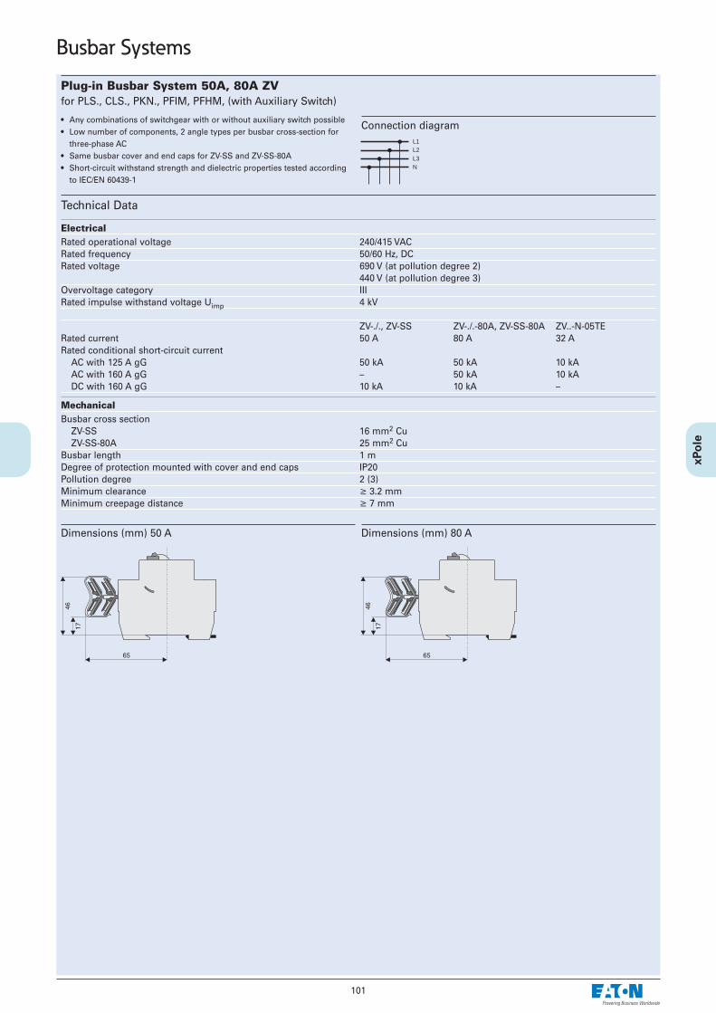
101
Dimensions (mm) 50 A Dimensions (mm) 80 A
Plug-in Busbar System 50A, 80A ZV for PLS., CLS., PKN., PFIM, PFHM, (with Auxiliary Switch)
• Any combinations of switchgear with or without auxiliary switch possible• Low number of components, 2 angle types per busbar cross-section for
three-phase AC• Same busbar cover and end caps for ZV-SS and ZV-SS-80A• Short-circuit withstand strength and dielectric properties tested according
to IEC/EN 60439-1
Technical Data
Electrical Rated operational voltage 240/415 VACRated frequency 50/60 Hz, DCRated voltage 690 V (at pollution degree 2)
440 V (at pollution degree 3)Overvoltage category IIIRated impulse withstand voltage Uimp 4 kV
ZV-./., ZV-SS ZV-./.-80A, ZV-SS-80A ZV..-N-05TERated current 50 A 80 A 32 ARated conditional short-circuit current
AC with 125 A gG 50 kA 50 kA 10 kAAC with 160 A gG – 50 kA 10 kADC with 160 A gG 10 kA 10 kA –
Mechanical Busbar cross section
ZV-SS 16 mm2 CuZV-SS-80A 25 mm2 Cu
Busbar length 1 mDegree of protection mounted with cover and end caps IP20Pollution degree 2 (3)Minimum clearance ≥ 3.2 mmMinimum creepage distance ≥ 7 mm
Connection diagramL1L2L3N
Busbar Systems

102
Busbar Systems
Dimensions (mm)
Busbar Block 10mm2, 16mm2 (Fork) Z-GVfor PLS., CLS., PKN., PFIM, PFHM, Z-SLS/D01 (with Auxiliary Switch also)
• Length 1m• Delivered without end caps. Please order separately.• Short version (/17, /16, /8) delivered with end caps.
Technical Data
Electrical Rated voltage 240/415 V, 50/60 HzRated current
10 mm2 63 A16 mm2 80 A
Short circuit strength 25 kA
Mechanical Busbar cross section 10 and 16 mm2 CuStep distance 17.8 mm
Z-GV-16-.P+HS 17.8/27 mm
Connection diagramL1L2L3N
Dimensions (mm)
Busbar Block 16mm2 (Fork + Pin) Z-GSV-16/for PLS.1N (1.5MU)• Length 1m• Delivered without end caps. Please order separately.• Short version (/9) delivered with end caps.
Technical Data
Electrical Rated voltage 240/415 V, 50/60 HzRated current 63 AShort circuit strength 25 kA
Mechanical Busbar cross section 16 mm2 CuStep distance 26.7 mm
Connection diagramL1L2L3N

103
AccessoriesWA_SG10602
End caps
Busbar Block 10mm2 (Pins) Z-SV...-SDfor Protected Earth Socket Z-SD230
• Delivered with end caps• Step (distance between two pins of identical phase, i. e. L or N) 2.5 MU• Length 1m
Technical Data
Electrical Rated voltage 230/400 V, 50/60 HzRated current 50 AShort circuit strength 25 kA
Mechanical Busbar cross section 10 mm2 CuStep distance 44 mm
Connection diagram
Dimesnions
AccessoriesSG4800
End caps
Busbar Block 10mm2 (Pins) Z-SV-10/, 16mm2 (Pins) Z-SV-16/for PLN. (1MU), Z-SI• Busbar block 10mm2 inclusive end caps, length 13MU• Busbar block 16mm2 without end caps, length 1m
Technical Data
Electrical Rated voltage 240/415 V, 50/60 HzRated current
10 mm2 50 A16 mm2 63 A
Short circuit strength 25 kA
Mechanical Busbar cross section 10/16 mm2 CuStep distance 17.95 mm
Connection diagramZ-SV-../3P+N-3TE..
WA_SG10702
Connection terminalZ-EK/25/QL
WA_SG10702
Connection terminalZ-EK/25
WA_SG10702
Connection terminalZ-EK/25/QL
WA_SG10702
Connection terminalZ-EK/25
WA_SG10702
Connection terminalZ-EK/25/Q
SG07703
Connection terminalZ-EK/25/K
Busbar Systems
Examples

104
Busbar Systems
Busbar Block 12 TE 10mm2 (Fork + Pins) Z-GSV-10/ for PLN. (1MU) + RCD
• 12 MU busbar elements incl. end caps
Technical Data
Electrical Rated voltage 240/415 V, 50/60 HzRated current 63 AShort circuit strength 25 kA
Mechanical Busbar cross section 10 mm2 CuStep distance 17.95 mm
Connection diagram
AccessoriesWA_SG10702
Connection terminalZ-EK/25/QL
WA_SG10702
Connection terminalZ-EK/25
Busbar Block 13 TE 10mm2 (Fork + Pins) Z-GSV-10/ for 1x RCD + PLG. (1MU)
• 13 MU busbar elements without end caps
Technical Data
Electrical Rated voltage 240/415 V, 50/60 HzRated current 63 AShort circuit strength 25 kA
Mechanical Busbar cross section 10 mm2 CuStep distance 17.95 mm
Connection diagram
AccessoriesWA_SG10602
End caps
WA_SG10702
Connection terminalZ-EK/25/QL
WA_SG10702
Connection terminalZ-EK/25
Z-GSV-10/3P+N/12-O
Z-GSV-10/3P+N-F/13

105
Busbar Systems
Busbar Block 10mm2 (Pins) Z-SV-10/1P+N-F/for PLG. (1MU) + RCD
• Busbar elements without end caps
Technical Data
Electrical Rated voltage 240/415 V, 50/60 HzRated current 63 AOvervoltage category IIIRated impulse withstand voltage Uimp 4 kVRated conditional short-circuit current
AC with 125 A gG 10 kA
Mechanical Busbar cross section 10 mm2 CuStep distance 17.8 mmFlame class acc. to UL94 V0, glow wire tested 960°CPollution degree 2Comparative tracking index CTI 300Minimum clearance ≥ 5,5 mmMinimum creepage distance ≥ 5 mm
Connection diagram
Dimensions (mm)Z-SV-10/1P+N-F/6
Z-SV-10/1P+N-F/9
Z-SV-10/1P+N-F/13

106
Busbar Systems
Busbar Block UL489 (Pin), Z-SV/UL-16/for FAZ-NA, FAZ-RT
Technical Data UL489 IEC/EN60947-2
Electrical Rated operational voltage 480/277 VAC
96 VDCRated frequency 50/60 HzRated voltage – 690 VACOvervoltage category – IIIRated impulse withstand voltage Uimp – 9.5 kVRated current 80 A 80 ARated conditional short-circuit current AC with 350 A gG – 15 kAShort-circuit current 10 kA –
Mechanical Busbar cross section – 16 mm2 CuFlame class acc. to UL94 V0Pollution degree – 2Comparative tracking index – CTI 600Minimum clearance (intern/extern) – > 9.5 / 25.4 mmMinimum creepage distance (intern/extern) – > 12.7 / 50.8 mmResistance to climatic conditions – acc. to DIN/EN60068
Connection diagramZ-SV/UL-16/3P-3TE Z-SV/UL-16/2P-2TE Z-SV/UL-16/1P-1TE
• Tested according to UL489• Do not cut• Extension terminal 35 mm2 Z-EK/35/UL for copper conductors• For covering of not used pins use busbar tag shrouds ZV-BS-UL
Dimensions (mm)Z-SV/UL-16/.TE/6 Z-SV/UL-16/.TE/12
Z-SV/UL-16/.TE/18
ZV-BS-UL
Z-EK/35/UL
Busbar Connection Example Z-EK/35/ULUL489 IEC/EN60947-2
# 2-14 AWG 2.5-35 mm2
60/75°C Cu Cu
0.56 in 14 mm
tested acc. to Tightening torque of terminal screws
UL486A # 14 AWG ≥ 2.3 Nm
UL486B # 8-12 AWG ≥ 2.8 Nm
UL486E # 6-1 AWG 4 Nm

107
Busbar Systems
Busbar Block 16mm2 (Pins) Z-SV-16/3Pfor Z-SLS, PLHT, D0.-SO/ (1.5MU)
Busbar Block 35mm2 (Pins) Z-SV-35for Z-SLS, PLHT, PLHT-V, D0.-SO/ (1.5MU)
• End caps are to be ordered separatelyException Z-SV-35/3P+N-6TE
• Halogenfree plastic
Technical Data
Z-SV-16 Z-SV-35
Electrical Rated operational voltage 240/415 VAC 240/415 VACRated frequency 50/60 Hz 50/60 HzRated voltage 500 V 690 VOvervoltage category III IIIRated impulse withstand voltage Uimp 4 kV 6 kVRated current 80 A 110 ARated conditional short-circuit current AC with 350 A gG 50 kAr.m.s. 100 kAr.m.s.
Mechanical Busbar cross section 16 mm2 Cu 35 mm2 CuStep distance 27 mm 27 mm (Z-SV-35/PLHT-V 30.5 mm)Flame class V0, Glow wire-test 960°C V0, Glow wire-test 850°CDegree of protection, with end caps IP20 IP20Pollution degree 2 2Comparative tracking index CTI 300 CTI 600Minimum clearance ≥ 5 mm ≥ 4.3 mmMinimum creepage distance ≥ 10.2 mm ≥ 6.7 mm
Connection diagram3P+N 3P 1P
Dimensions (mm)n A B C D E F G H I
Z-SV-16/3P 35 27 5 945 971 14,9 31 1,5 17 19Z-SV-35/3P 35 27 8,5 945 1000 19,7 38,4 2,5 21,5 23,9Z-SV-35/PLHT-V 32 30,5 8,5 976 1000 19,7 38,4 2,5 21,5 23,9
Z-SV-35/3P+N-6TE
Z-SV-35/1P
Accessories for Z-SV-16Wa_sg10802
Connection terminalZ-EK/50
Accessories for Z-SV-35Wa_sg10802
Connection terminalsZ-EK/95, Z-EK/95-3N, Z-EK/95-1

108
Busbar Systems
Fork-Type Euro-Vario Busbar 10mm2, 16mm2 (Fork) EVG for PLS., CLS., PKN., PFIM, PFHM, PFNM (with Auxiliarx Switch)
Euro Vario busbars (EVG) offer maximum user comfort and a high degree ofsafety. Using EVG busbars helps to save up to 30 % assembly time as compared toconventional systems.
The danger of flashover is minimised since there is no need of cutting, bur-ring, or cleaning.No end caps are needed.
Technical Data
Electrical Rated voltage 240/415 V, 50/60 HzRated current
10 mm2 63 A16 mm2 80 A
Short circuit strength 25 kA
Mechanical Busbar length 2, 6, 9, 12, 16, 20 MUBusbar cross section 10 mm2 / 16 mm2
Step distance10 mm2 17,8mm / 26,8mm / 71,2mm16 mm2 17,8mm / 27mm / 71,2mm

109
Fuse Devices
Technical Data
Electrical Number of poles 1P, 3PRated voltage 400 VAC, 250 VDCRated current
D01 16 AD02 63 A
Conditional short-circuit currenttested wit inserts 50 kA (AC)Operating class gG (gL) 8 kA (DC)
Mechanical Frame size 45 mmDevice height 68 mmDevice width 27 mm per poleWeight 1P 3P
74 g 213 gElectrical thread D02 E18Mounting
Quick fastening on DIN rail 35 mm acc. to IEC/EN 60715Screw fastening on mounting plate screw ≤4 mm, head ≤7 mm
Upper and lower terminals lift terminalTerminal capacity 1.5-35 mm2
Tightening torque of terminal screws 3.5 Nm
Comparative tracking index CTI 600Flame class acc. to UL94 V0
Fuse-Base FCFBD02DI-.• According to DIN VDE 0636-301• For Fuse-links size D02 and D01• Casn be sealed with leads• Silicone-, halogen- and phosphorfree
• Cartridge-ring adapter inserts ASGRD02-.A required for current coding• Low-loss stainless steel terminal (anti-magnetic)
Dimensions (mm)
Busbar Examples
Terminal capacity Z-EK/95, Z-EK/95-1:25-95 mm2 rigid/stranded16-70 mm2 flexible with wire end ferrules
3-phases 16 mm2
1-phase 35 mm23-phases 35 mm2
D0
Mounting position

110
Fuse Devices
Switch-Disconnector-Fuse Z-SLS/D01• Design according to IEC/EN 60947-3• Mechanical current coding by means of integrated, adjustable coding ring• Plug-in technology without screw caps• Visual tripping indicator is flashing• Suitable for the following fuse-links
D01: 2, 4, 6, 10, 16 A
Technical Data
Electrical Number of poles 1P, 1P+N, 2P, 3P, 3P+NRated operational voltage Ue
AC 400 VDC 1P to 60V / 2P to 110V
Rated operational current Ie 16 ARated uninterrupted current Iu 16 ARated short-circuit making capacity Icm 50 kAr.m.sUtilization category AC 22 B, DC 21 BOvervoltage category IVRated impulse withstand voltage Uimp 6 kVPower loss per current path 0.64 W at IePower loss per current path with fuse-link 2.24 W at Ie
Mechanical Frame size 45 mmDevice height 86 mmDevice width 17.5 mm per pole (1MU)Weight 1P 1P+N 2P 3P 3P+N
90g 170g 180g 270g 350gMounting quick fastening on
DIN rail IEC/EN 60715Degree of protection IP20Upper and lower terminals lift terminalsTerminal capacity 1.5-25 mm2
Tightening torque of terminal screws max. 2.5 NmTemperature range -25 to +60°CFlame class V0, glow-wire tested 960°CPollution degree 3Comparative tracking index CTI 600
Connection diagram
Dimensions (mm)
Busbar Connection Examples
1P 1P+N 2P 3P 3P+N
or
D0

111
Fuse-Switch-Disconnector Z-SLS/NEOZ, Standard• Design according to IEC/EN 60947-3• Mechanical current coding• Plug-in technology without screw caps• Suitable for the following fuse-links
D01: 1, 2, 4, 6, 10, 16 AD02: 20, 25, 35, 50, 63 A
• Can be sealed with leads
Technical Data
Electrical Number of poles 1P, 1P+N, 2P, 3P, 3P+NRated operational voltage Ue
AC 400 VDC 1P to 110V / 2P to 220V
Rated operational current Ie 63 ARated uninterrupted current Iu 63 ARated short-circuit making capacity Icm 50 kAr.m.sUtilization category AC 22 B, DC 21 BOvervoltage category IVRated impulse withstand voltage Uimp 6 kVPower loss per current path 0.5 W at IePower loss per current path with fuse-link 7.5 W at Ie
Mechanical Frame size 45 mmDevice height 86 mmDevice width 27 mm per pole (1.5MU)Weight 1P 1P+N 2P 3P 3P+N
113g 225g 224g 450g 472gMounting quick fastening on
DIN rail IEC/EN 60715Degree of protection IP20Upper and lower terminals lift terminalsTerminal capacity 1.5-35 mm2
Tightening torque of terminal screws max. 4.5 NmTemperature range -25 to +60°CFlame class V0, glow-wire tested 960°CPollution degree 3Comparative tracking index CTI 600
Connection diagram
Dimensions (mm)
Busbar Connection Examples
Terminal capacity Terminal capacity
Terminal capacity
Terminal capacity
Fuse Devices
1P 1P+N 2P 3P 3P+N
D0

112
Fuse-Switch-Disconnector Z-SLS/CEK, Complete with Captive Current Code• Design according to IEC/EN 60947-3• Can be used as main fuse downstream of the meter according to the
Technical Connection Rules of the Austrian Power Supply Companies("TAEV")
• Current coding by the manufacturer• Plug-in technology without screw caps• Suitable for the following fuse-links
D01: 10, 16 AD02: 25, 35, 40, 50, 63 A
• Can be sealed with leadsType Z-SLS/CEK• No visual tripping indicatorType Z-SLS/CEK..-SP• Visual tripping indicator• Equipped with neutral lead through terminal• Integrated switch-locking
Technical Data
Electrical Number of poles 1P, 3PRated operational voltage Ue
AC 400 VRated uninterrupted current Iu
1P 10, 16, 25 A3P 16, 25, 35, 40, 50, 63 A
Rated short-circuit making capacity Icm 50 kAr.m.sUtilization category AC 22 BOvervoltage category IVRated impulse withstand voltage Uimp 6 kVPower loss per current path 0.5 W at IePower loss per current path with fuse-link 7.5 W at Ie
Mechanical Frame size 45 mmDevice height 86 mmDevice width 27mm per pole (1.5MU)Weight 147 g / 441 gMounting quick fastening on
DIN rail IEC/EN 60715Degree of protection IP20Upper and lower terminals lift terminalsTerminal capacity 1.5-35 mm2
Tightening torque of terminal screws max. 4.5 NmTemperature range -25 to +60°CFlame class V0, glow-wire tested 960°CPollution degree 3Comparative tracking index CTI 600
Connection diagrams
Dimensions (mm)
Busbar Connection Example
Terminal capacity
Fuse Devices
1P 3P
D0

113
Fuse Devices
Fuse-Switch-Disconnector Z-SLK/NEOZ, with Fuse Monitoring• Design according to IEC/EN 60947-3• Fuse monitoring by relay contact• Mechanical current coding• Plug-in technology without screw caps• Suitable for the following fuse-links
D01: 1, 2, 4, 6, 10, 16 AD02: 20, 25, 35, 50, 63 A
• Can be sealed with leads• Other AC/DC voltages requires special types
Technical Data
Electrical Number of poles 1P, 1P+N, 2P, 3P, 3P+NRated operational voltage Ue
AC: 1P 60-230 V AC2P, 3P, 3P+N 60-400 V AC
DC: 1P 60-110 V DC2P 60-220 V DC
Rated operational current Ie 63 ARated uninterrupted current Iu 63 ARated short-circuit making capacity Icm 50 kAr.m.s1 NO 5A/250VUtilization category AC 22 B, DC 21 BOvervoltage category IVRated impulse withstand voltage Uimp 6 kVPower loss per current path 0.5 W at IePower loss per current path with fuse-link 7.5 W at Ie
Relay Component - ElectricalOperational voltage range 24-240 V AC/DCOperational voltage tolerance ±10%Power consumption 5 VAFrequency 50-60 HzFunction display
Line voltage 1 LEDTrouble 1 LED
Duty 100%Responding delay approx. 100 msReset time approx. 100 msRelay contacts 2 CO, 5A/250VAuxiliary switch
Rated impulse withstand voltage 4 kVOvervoltage category III
Mechanical Frame size 45 mmDevice height 86 mmDevice width 27mm/pole (1.5MU) + 27mmWeight 1P 2P 3P 3P+N
224g 345g 450g 590gMounting quick fastening on
DIN rail IEC/EN 60715Degree of protection IP20Upper and lower terminals lift terminalsTerminal capacity 1.5-35 mm2
Tightening torque of terminal screws max. 4.5 NmTemperature range -25 to +60°CFlame class V0, glow-wire tested 960°CPollution degree 3Comparative tracking index CTI 600
Relay Component - MechanicalUpper and lower terminals lift terminalsTerminal capacity
rigid 0.14-4 mm2
flexible 0.14-2.5 mm2
Tightening torque of terminal screws 0.5-0.7 Nm
Connection diagram
Dimensions (mm)
Block Diagram Function - Switch position Relay - Fuse Monitoring
Uv . . . Supply voltage relay
1P 2P 3P
3P+N
D0

114
Fuse-link Sets complete Z-SLS/B, Z-SLS/E• Fuse-links with flashing function (Z-SLS/B) in case of disconnection• Fuse-links without flashing function (Z-SLS/E) upon enquiry, not on stock• Supplied as a set with 3 fuse-links and 3 gauge-pieces in plastic box of dif-
ferent colours which can be mounted onto DIN rail.• Dimensions of plastic box:
Frame size 45 mmDepth 75 mmWidth 54 mm
Technical Data
Electrical Operating class gG (gL)Rated voltage Z-SLS/B/24 Z-SLS/B Z-SLS/E
AC 24 - 60 V 60 - 400 V 400 V DC 24 - 60 V 220 V
Test voltage 5 kV
Mechanical Size
D01 1, 2, 4, 6, 10, 13, 16 AD02 20, 25, 32, 35, 40, 50, 63 A
Connection diagram
Fuse Devices
CharacteristicsTime/current characteristics of D0-Fuse-links 2 ... 63A gG(gL) Let-through characteristics of D0-Fuse-links 2 ... 63A gG(gL)
310
210
110
010
-110
-210
-310
2 4 110 2 4
210 2 4
310 2 4
410
Schm
elz
ze
ittin
s
Unbeeinflusster Strom I in AP
Nennstrom I in AN2 4 6 10 16 20 25 35 50 632I 2P I 2P
20
10
4
2
1
0,4
0,2
0,1
0,1 0,2 0,4 1 2 4 10 20 100
Kurzschlussstrom I in kAP
Ne
nn
str
om
Iin
AN
2
4
6
10
16
20
25
35
50
63
Du
rch
lassstr
om
Iin
kA
D
ß
Mtgrö
tem
Gle
ihst
rom
glie
d
i
c
One
Gle
ichst
rom
glie
d
h
Möglic
he
Sto
ßku
rzsc
hlu
ssst
röm
e
Prospective current IP in A
Rated current IN in A
Virt
ual p
re-a
rcin
g tim
e t i
n s
Let-
thro
ugh
curr
ent I
Din
kA
Prospective short-circuit current IP in kA
Rate
d cu
rren
t IN
in A
Poss
ible s
hort-
circu
t pea
k cur
rent
s
With la
rgest
direc
t curr
ent c
ompo
nent
Withou
t dire
ct curr
ent co
mponen
t
Solid-link Set Z-SLS/TR-SET• Supplied as a set with 3 solid-links inserts and 3 gauge-pieces in plastic box
which can be mounted onto DIN rail.• Dimensions of plastic box:
Frame size 45 mmDepth 75 mmWidth 54 mm
Technical Data
Electrical Rated voltage 400 V ACRated uninterrupted current Iu 63 ATest voltage 5 kV
Mechanical Size D02 63 A
Connection diagram
D0

115
Fuse Devices
Fuse-Switch-Disconnector with visual tripping indicator Z-SLS/CB - Current coding by means of cartridge-ring adapter inserts• Design according to IEC/EN 60947-3• Current coding by means of cartridge-ring adapter inserts• Visual tripping indicator is flashing• Suitable for the following fuse-links
D01: 2, 4, 6, 10, 16 A with cartridge-ring adapter insert Z-D02-D01/PE-.. and adapter spring Z-SLS/CB-HF
D02: 20, 25, 35, 50, 63 A• Can be sealed with leads
Technical Data
Electrical Number of poles 1P, 1+N, 2P, 3P, 3+NRated operational voltage Ue
AC 400 VDC 1P to 110V / 2P to 220V
Rated operational current Ie 63 ARated uninterrupted current Iu 63 ARated short-circuit making capacity Icm 50 kAr.m.sUtilization category AC 22 BOvervoltage category IVRated impulse withstand voltage Uimp 6 kVPower loss per current path 0.5 W at IePower loss per current path with fuse-link 7.5 W at Ie
Mechanical Frame size 45 mmDevice height 86 mmDevice width 27 mm per pole (1.5MU)weight 1P 1+N 2P 3P 3+N
120g 230g 230g 350g 448gMounting quick fastening on
DIN rail IEC/EN 60715Degree of protection IP20Upper and lower terminals lift terminalsTerminal capacity 1.5-35 mm2
Tightening torque of terminal screws max. 4.5 NmTemperature range -25 to +60°CFlame class V0, glow-wire tested 960°CPollution degree 3Comparative tracking index CTI 600
Connection diagram
Dimensions (mm)
Busbar Connection Examples
Terminal capacityTerminal capacity
Terminal capacity
D0
Poles Dimension a[mm]
1P 271+N 542P 542+N 813P 814P 108

116
Fuse Devices
Switch-Disconnector-Fuse D02-LTS - Current coding by means of cartridge-ring adapter inserts• Design according to IEC/EN 60947-3• Current coding by means of cartridge-ring adapter inserts• Visual tripping indicator is flashing• Thermal monitoring with integrated thermo switch• Suitable for fuse-links with operating classes gG (gL), aM
D01: 2, 4, 6, 10, 16 A with cartridge-ring adapter insert Z-D02-D01/PE-.. and adapter spring Z-D02-LTS-HF
D02: 20, 25, 35, 50, 63 ACylindrical 10x38 up to 32 A with adapter spring Z-D02-LTS-HF
• Can be sealed with leads
Technical Data
Electrical Number of poles 3P, 3P+N, 3P+HKRated operational voltage Ue
AC 400 VRated operational current Ie 63 ARated uninterrupted current Iu 63 ARated short-circuit making capacity Icm 50 kAr.m.sUtilization category AC 22 BOvervoltage category IVRated impulse withstand voltage Uimp 6 kVPower loss per current path 1.8 W at IePower loss per current path with fuse-link 7.3 W at IeMax. permissible power loss of fuse-links 5.5 WAuxiliary switch
1 NO 5 A / 250 V ACMax. thermal back-up protection 2 A gL: PLSM-B4/...-HS,
CLS6-B4/...-HSThermo switch
1 NCAC cosϕ = 1 2,5 A / 250 VAC cosϕ = 0.6 1,5 A / 250 VDC 1,6 A / 24 V
1,2 A / 48 V
Mechanical Frame size 45 mmDevice height 84 mmDevice width 18 mm per pole (1MU)Weight 3P 3P+N 3P+HK
340 g 380 g 380 gMounting quick fastening on
DIN rail IEC/EN 60715Degree of protection IP20Upper and lower terminals lift terminalsTerminal capacity 1.5-25 mm2
Tightening torque of terminal screws max. 3 NmTemperature range -25 to +60°CFlame class V0, glow-wire tested 960°CPollution degree 3Comparative tracking index CTI 600Femal push-on connector 0.8 x 2.5 mm
Connection diagram
Dimensions (mm)
Busbar Connection Example 3P, 3P+N
3P 3P+N 3P+HK
EVG-16/4PHAS/8MODUL
D0 C

117
Fuse Devices
Fuse-Disconnector for Industrial Applications Z-SH.• Design according to IEC/EN 60947-3• Version
without visual tripping indicator Z-SHwith visual tripping indicator Z-SHL
• Can be sealed with leads• Supplied without fuse-links
Technical Data
Electrical Number of poles 1P, 1P+N, 2P, 3P, 3P+NRated voltage
1P, 1P+N 230 V AC2P, 3P, 3P+N 400 V AC
Rated operational current Ie 32 AConditional short-circuit current 10 kAr.m.sUtilization category AC 20 BRated impulse withstand voltage Uimp 4 kVFuse-links 10, 16, 20, 25 and 32 A
Operating class gG(gL)/aMMax. Power loss per current path 3.2 W
Mechanical Frame size 45 mmDevice height 80 mmDevice width acc. to dimensioned drawingWeight Z-SH Z-SHL
1P 74g 76g1P+N 84g 86g2P 156g 158g3P 234g 236g4P 244g 246g
Mounting quick fastening on DIN rail IEC/EN 60715
Degree of protection (built-in) IP20 (IP40)Upper and lower terminals lift terminalsTerminal capacity 1.5-10 mm2
Tightening torque of terminal screws max. 2 NmDimensions of fuse-link 10.3 x 38 mm
Connection diagram
Dimensions (mm)
Visual Tripping Indicator Attention
Do not switch the fuse-disconnector under load!
OFF
Z-SH/3N
top
C

118
Fuse-Disconnector for Household Applications Z-SI.• Design according to IEC/EN 60947-3• Version
without visual tripping indicator Z-SIwith visual tripping indicator Z-SIL
• Can be sealed with leads• The open fuse drawer can be secured against re-switch-on by means of a
padlock• Supplied without fuse-links
Technical Data
Electrical Number of poles 1P, 1P+NRated voltage 230 V ACRated operational current Ie 32 AConditional short-circuit current 10 kAr.m.sUtilization category AC 20 BRated impulse withstand voltage Uimp 4 kVFuse-links 10, 16, 20, 25 and 32 A
Operating class gG (gL)/aMMax. Power loss 3.2 W
Mechanical Frame size 45 mmDevice height 80 mmDevice width 17.5 mmWeight Z-SI Z-SIL
1P 74g 76g1P+N 84g 86g
Mounting quick fastening on DIN rail IEC/EN 60715
Degree of protection (built-in) IP20 (IP40)Upper and lower terminals lift terminalsTerminal capacity 1.5-10 mm2
Tightening torque of terminal screws max. 2 NmDimensions of fuse-link
Rated current (A) (mm)10 8.5 x 2316 10.3 x 25.820 8.5 x 31.525 10.3 x 31.532 10.3 x 38
Connection diagram
Dimensions (mm)
Visual Tripping Indicator Attention
Do not switch the fuse-disconnector under load!
OFF
top
Fuse Devices C

119
Fuse Devices
Fuse-Switch-Disconnector C10-SLS, VLC• Design according to IEC/EN 60947-3• Types /L with visual tripping indicator (flashing)• Suitable for cylindrical fuse-links with operating classes gG, aM
10x38 C10-SLS14x51 VLC1422x58 VLC22
• Can be sealed with leads• Supplied without fuse-links
Technical Data
C10-SLS VLC14 VLC22
ElectricalNumber of poles 1P, 1P+N, 2P, 3P, 3P+N 1P, 1P+N, 2P, 3P, 3P+N 1P, 1P+N, 2P, 3P, 3P+NRated operational voltage Ue
1P 690 V, 50 Hz 690 V, 50 Hz 690 V, 50 Hz1P+N 400 V, 50 Hz 690 V, 50 Hz 690 V, 50 Hz2P, 3P, 3P+N 690 V, 50 Hz 690 V, 50 Hz 690 V, 50 Hz
Rated operational current Ie 32 A 50 A 100 ARated conditional short-circuit current 100 kA (at 400 V) 100 kA 100 kARated short-time withstand current Icw 300 A 600 A 1200 AUtilization category AC 22 B AC 22 B AC 21 BRated insulation voltage Ui 690 V 690 V 690 VOvervoltage category II IV IVRated impulse withstand voltage Uimp 4 kV 8 kV 8 kVPower loss per current path without fuse-link 0.9 W 1 W 3.1 WMaximum permissible power loss of fuse-links
gG 3 W 5 W 9.5 WaM 1.2 W 3 W 7 W
Mechanical Frame size 45 mm 45 mm 45 mmDevice height 83.3 mm 94 mm 121 mmDevice width 17.5 mm per pole 27 mm per pole 36 mm per poleWeight
1P 58 g 100 g 160 g1P+N 70 g 222 g 355 g2P 120 g 201 g 310 g3P 180 g 308 g 480 g3P+N 195 g 437 g 680 g
Mounting Quick fastening on DIN rail IEC/EN 60715Degree of protection IP20 IP20 IP20Terminals above and below lift terminals lift terminals lift terminalsTerminal capacity 0.5 - 10 mm2 1.5 - 35mm2 4 - 50 mm2
AWG 20-8 AWG 16-2 –Tightening torque of terminal screws ≤ 1,2 Nm 2.5 - 3 Nm 2.5 - 3 NmAmbient temperature range -25 to +40°C -25 to +40°C -25 to +40°CFlame class glow wire tested 960°C glow wire tested 960°C glow wire tested 960°CPollution degree 2 1 1Comparative tracking index CTI 450 CTI 400 CTI 400
Connection diagram
Dimensions (mm)
1P 1P+N 2P 3P 3P+N
17,5/pole27/pole 36/pole
C

120
Fuse Devices
Fuse-Disconnector FCFDC10DI-..-SOL• Design according to
IEC 60947-1 Ed. 4.0, EN 60947-1:1999+A1:2000+A2:2001IEC 60947-3 Ed. 2.1, EN 60947-3:1999+A1:2001
• Types L with visual tripping indicator• Suitable for cylindrical fuse-links photovoltaic application
10x38 according to IEC 60269, UL284-4• Can be sealed with leads• Supplied without fuse-links
Technical Data
ElectricalNumber of poles 1P, 2PRated voltage Ue 1000 V DCRated current Ie 25 ARated conditional short-circuit current 10 kAUtilization category DC 20 BRated insulation voltage Ui 1000 V DCOvervoltage category IIIRated impulse withstand voltage Uimp 6 kVPower loss per current path without fuse-link 0.9 WMaximum permissible power loss of fuse-links 3 W
Mechanical Frame size 45 mmDevice height 83.3 mmDevice width 17.5 mm per poleWeight
1P 58 g2P 70 g
Mounting Quick fastening on DIN rail IEC/EN 60715
Degree of protection IP20Terminals above and below lift terminalsTerminal capacity 0.5 - 10 mm2
AWG 20-8Tightening torque of terminal screws 1.2 NmAmbient temperature range -25 to +40°CFlame class glow wire tested 960°CPollution degree 2Comparative tracking index CTI 450
Connection diagram
Dimensions (mm)
1P 2P 1P 2P
17,5
FCFDC10DI-.-SOL FCFDC10DI-.L-SOL
CDC
Connection diagram
- Strings+ Strings
Output
Input
+ -
1 3 5
2 4 6
- Strings+ Strings
Output (M20)
Input
+ -
1
+ -
3 5
2 4 6
- Strings+ Strings
Output
Input
+ -
1 3 5
2 4 6
- Strings+ Strings
Output (M16)
Input (M12)
+ -
1 3 5
2 4 6
SOL20/2MC3SOL20/2MC4SOL30/2MC3SOL30/2MC4
SOL20/2MVSOL30/2MV
SOL20/4MC3SOL20/4MC4SOL30/4MC3SOL30/4MC4
- Strings + Strings
Input (M12)
Output (M20)+ -
+ -
1 3 5
2 4 6
- Strings+ Strings
Input
Output (M20)+ -
+ -
1 3 5
2 4 6
SOL60/4MV SOL60/8MC3SOL60/8MC4
SOL60/4MC3SOL60/4MC4

121
Technical Data
Electrical Number of poles 3Rated operational voltage Ue 400 V ACRated frequency 40-60 HzRated operational current Ie 63 AConv. thermal current with fuse-links Ith 63 ARated duty uninterrupted dutyRated conditional short-circuit current 50 kAr.m.s.Overvoltage category IVRated impulse withstand voltage Uimp 6 kVPower loss per current path 0.5 WPower loss of base without fuse-links 1.5 WMax. permissible power loss of fuse-links 5.5 W
Mechanical Device height 201 mmDevice width 27 / 36 / 54 mmWeight 163 g / 184 g / 205 gMounting onto busbars, 12x5/10, 15x5/10, 20x5/10,
without drilling or screwing 25x5/10, 30x5/10Degree of protection while operating IP20Terminals Lift terminalsTerminal capacity 1.5-35 mm2
Tightening torque of terminal screws 3-4 NmElectrical thread type E18Ambient temperature range -25°C bis +55°CPollution degree 3Flame class according UL94 V0Comparative tracking index CTI 600Climatic resistance: moist heat constant acc. to IEC 60068-2-78
cyclical acc. to IEC 60068-2-30
Slide Fuse-Base D02 (+D01); D02-SO/63/3-R27, Z-D02/R/3• Design according to IEC/EN 60269-1, VDE 0636 part 301• Vertical and horizontal mounting possible• Delivered empty and without screw caps• For 60 mm - busbar system, 5 or 10 mm thick• Rail detent for 12, 15, 20, 25, 30mm wide busbars• Does not contain halogens, phosphorus or silicon
• Recyclable• Marking area on the base and cover• For fuse-links DIN 49522 D02 20...63A 400VAC / 250VDC• For cartridge-ring adapter inserts DIN 49523• Cartridge-ring adapter inserts Z-D02-D01-PE-.. for D01 fuse-links 1...16 A
available
Dimensions (mm)
32
ca. 50
Beschriftung 9 x 21
60
60
14
27
178
193
34,5
Beschriftung 10 X 24
10
194
201
Marking Marking
Fuse Devices
Z-D02/R/3 Z-D02/R/3-36 Z-D02/R/3-54 Z-D02-S-AB-SETFront plate support
Covered busbar supportwith Set Z-D02-S-AB-SET
Marking
D0

122
Fuse Devices
Switch-Disconnector-Fuse D02 (+D01), D02-S/63/3-RS• Design according to IEC/EN 60947-3• For 60 mm busbar system, busbar thickness 5 or 10 mm • Rail detent for busbars, 20 and 30 mm wide • Delivered empty and without screw caps• Current coding by means of cartridge-ring adapter inserts• Suitable for the following fuse-links
D01: 2, 4, 6, 10, 16 A with cartridge-ring adapter insert Z-D02-D01/PE-.. and adapter spring Z-D02/SIKA-HF
D02: 20, 25, 35, 50, 63 A• Can be sealed with leads
Technical Data
Electrical Number of poles 3PRated operational voltage Ue
AC 400 V / 40-60 HzRated operational current Ie 63 AConventional thermal current
with fuse-links Ith 63 ARated duty Uninterrupted dutyRated conditional short-circuit current 50 kAr.m.sUtilization category AC 23 BOvervoltage category IIIRated impulse withstand voltage Uimp 8 kVPower loss per current path 2 W at IePower loss per current path with fuse-link 7.5 W at IeMax. permissible power loss of fuse-links 5.5 W
Mechanical Device height 212 mmDevice width 36 mmWeight 260 gMounting with a distance between
busbars of 60 mmDegree of protection (in use) IP30Terminals lift terminalsTerminal capacity 1.5-25 mm2 CuTightening torque of terminal screws max. 2,6 NmElectrical thread E18Temperature range -25 to +55°CPollution degree 3
Connection diagram
Dimensions (mm)Cut-out for front plate
D0

123
Fuse Devices
Slide Switch-Disconnector-Fuse D02 (+D01) + C, D02-LTS/63/3.-R• Design according to IEC/EN 60947-3• Vertical and horizontal mounting possible• Supplied empty• Current coding by means of cartridge-ring adapter inserts• Suitable for fuse-links
D01: 2, 4, 6, 10, 16 A with cartridge-ring adapter insertsZ-D02-D01/PE-.. and adapter spring Z-D02-LTS-HF
D02: 20, 25, 35, 50, 63 ACylindrical 10x38: 1 - 32 A
• Can be sealed with leads, lockable
Technical Data
ElectricalNumber of poles 3P/3P+NRated operational voltage Ue
AC 400 V / 40-60 HzRated operational current Ie 63 ARated uninterrupted current Iu 63 ARated duty Uninterupted dutyRated short-circuit capacity Icm, Icn 50 kAr.m.s.Utilization category AC 22 BOvervoltage category IVRated impulse withstand voltage Uimp 6 kVPower loss per current path 1.5 W at IePower loss per current path
with fuse-link 7 W at IeMax. permissible power loss
of fuse-links 5.5 W
MechanicalDevice height 3P/3P+N 226/262 mmDevice width 27 mmWeight 340 gMounting onto busbars, 12x5/10 mm
without drilling or screwing 15x5/10 mm20x5/10 mm25x5/10 mm30x5/10 mm
Degree of protection while operating IP20/IP40(built-in)
Terminals Lift terminalsTerminal capacity 1.5-35 mm2 CuTightening torqueof terminal screws max. 4 NmTemperature range -25 to +55°CPollution degree 3
Connection diagram
Auxiliary switch electrical1 CO 5 A / 250 V ACMax. thermal back-up protection 2 A gL
PLSM-B4/..-HS / CLS6-B4/...-HS
Connection Femal push-on connector 2.8 x 0.5 mm
Dimensions (mm)
D0 C
D02-LTS/63/3-R D02-LTS/63/3-R-HK D02-LTS/63/3N-R D02-LTS/63/3N-R-HK
3P 3P+N

124
Fuse Devices
Slide Fuse-Base DII and DIII, DII.-SO/
DII-SO/25/3-R(-PS) DIII-SO/63/3-R(-PS)
ElectricalNumber of poles 3 3Rated operational voltage Ue 500 V AC 690 V ACRated frequency 40-60 Hz 40-60 HzRated operational current Ie 25 A 63 AConv. thermal current with fuse-links Ith 25 A 63 ARated duty uninterrupted duty uninterrupted dutyRated conditional short-circuit current 50 kAr.m.s. 50 kAr.m.s.Overvoltage category III IIIRated impulse withstand voltage Uimp 4 kV 4 kVPower loss per current path 0.4 W 3.34 WPower loss of base without fuse-links 1.2 W 10 WMax. permissible power loss of fuse-links 4 W 7 W
MechanicalDevice height 200 mm 200 mmDevice width 45 mm 54 mmWeight 140 g 150 gMounting onto busbars, without drilling or screwing 12x5/10 12x5/10
20x5/10 20x5/1025x5/10 25x5/1030x5/10 30x5/10
Degree of protection while operating IP20 IP20Terminals Lift terminals Lift terminalsTerminal capacity 1.5-25 mm2 1.5-25 mm2
Tightening torque of terminal screws 2.6 Nm 2.6 NmElectrical thread type E27 E33Ambient temperature range -25 to +55°C *) -25 to +55°C *)
*) (35°C normal temperature, at 55°C with reduced operational current)Pollution degree 3 3Climatic resistance: moist heat constant acc. to IEC 60068-2-78, cyclical acc. to IEC 60068-2-30
Technical Data
• Design according to IEC/EN 60269-1, VDE 0636 Part 301• Vertical and horizontal mounting possible• Delivered empty, without screw caps
Dimensions (mm)
Type A
DII-SO/25/3-R(-PS) 45DIII-SO/63/3-R(-PS) 54
D

125
Fuse Devices
V E R S I O N W E S T
NHNH-Fuse-Switch-Disconnector LTS-100/C00/3-R, GST00-160-40-60-AOU..• Mounting height max. 2000 m• Break-proof, flexible connection chamber• Fully insulated, shock hazard protected in acc. with IEC/EN 60947 or BGV A3• The base body is made of glass fibre reinforced, high-temperature resistant,
self-extinguishing and halogen-free plastic• The contact system consists of separately spring-loaded silver-plated copper
contacts• The switch cover is made of glass fibre reinforced, self-extinguishing, silicone and chlorine-free thermoplast• The switch cover features large viewing windows allowing to read the labelling and to see the flat indicator of the NH-fuse-links• The viewing windows provide test holes • Vertical and horizontal mounting position is possible • Delivery without NH-fuse-links
LTS-100/C00/3-R GST00-...-AOU GST00-...-AOU-F
ElectricalTechnical data according to IEC/EN 60947-3Rated operational voltage Ue V AC 500 500 / 690 500 / 690Rated operational voltage Ue V DC 220 220 / 440 220 / 440Rated operational current Ie A 100 160 / 100 160 / 100Rated frequency Hz 40 - 60 40 - 60 40 - 60Rated conditional short-circuit current AC kAr.m.s. 50 50 50Rated conditional short-circuit current DC kAr.m.s. 25 25 25Utilization category AC 22 B
Rated making capacity A 300 480 / 300 480 / 300Rated breaking capacity A 300 480 / 300 480 / 300
Utilization category DC 21 B Rated making capacity A 400 150 150Rated breaking capacity A 400 150 150
Service life electrical - operating cycles 300 300 300Service life mechanical - operating cycles 1700 1700 1700Power loss with Ith AC, without NH-SE W 11.5 6.9 / 2.7 6.9 / 2.7Power loss with Ith DC, without NH-SE W 7.7 4.6 / 1.8 4.6 / 1.8Rated insulation voltage Ui V AC 500 750 750Overvoltage category III III IIIRated impulse withstand voltage Uimp kV 8 8 8
Max. Fuse-linkSize NH000 NH00 NH00Max. rated current gL/gG A 100 160 160Max. permissible power loss of NH-SE Pv W 7.5 12 12
MechanicalBusbar mounting mm 20x5/10 20x5/10 20x5/10
30x5/10 25x5/10 25x5/1030x5/10 30x5/10
Tightening torque Nm – 4 4Ambient temperature range °C -25 to +55 -25 to +55 -25 to +55Degree of protection (open front cover) IP20 (IP10) IP20 (IP10) IP20 (IP10)Pollution degree 3 3 3Weight kg 0.57 0.93 0.93Climatic resistance: moist heat constant according to IEC 60068-2-78, cyclical according to IEC 60068-2-30
Cross sections of connectionsFlat connection (F) F1)
Screw M8Cable lug mm2 1 x 10-95Flat busbar mm 20 x 10Tightening torque Nm 12 - 15
Clamp-type terminal (S) / Lift terminal (K) K1) K1) SStranded Cu mm2 1.5 - 50 1,5 - 70 10 - 95Cu-Band, No. of layers mm 6 x 9 x 0.8 6 x 9 x 0.8 6 x 9 x 0.8
x widthx thickness
Tightening torque Nm 2.6 2.6 2.6Prism terminal
Stranded Al/Cu mm2 10 - 70Tightening torque Nm 2.6
Double-prism terminal Stranded Al/Cu mm2
Tightening torque Nm
1) Standard-connection in the delivery condition
Connection diagram3P

126
Fuse Devices
V E R S I O N W E S T
NHNH-Fuse-Switch-Disconnector GST...• Mounting height max. 2000 m• Break-proof, flexible connection chamber• Fully insulated, shock hazard protected in acc. with IEC/EN 60947 or BGV A3• The base body is made of glass fibre reinforced, high-temperature resistant,
self-extinguishing and halogen-free plastic• The contact system consists of separately spring-loaded silver-plated copper
contacts• The switch cover is made of glass fibre reinforced, self-extinguishing, silicone and chlorine-free thermoplast• The switch cover features large viewing windows allowing to read the labelling and to see the flat indicator of the NH-fuse-links• The viewing windows provide test holes • Vertical and horizontal mounting position is possible • Delivery without NH-fuse-links
GST1.. GST2.. GST3..
ElectricalTechnical data according to IEC/EN 60947-3Rated operational voltage Ue V AC 500 / 690 500 / 690 500 / 690Rated operational voltage Ue V DC 220 / 440 220 / 440 220 / 440Rated operational current Ie A 250 / 200 400 / 315 630 / 500Rated frequency Hz 40 - 60 40 - 60 40 - 60Rated conditional short-circuit current AC kAr.m.s. 50 50 50Rated conditional short-circuit current DC kAr.m.s. 25 25 25Utilization category AC 22 B
Rated making capacity A 750 / 600 1200 / 945 1890 / 1500Rated breaking capacity A 750 / 600 1200 / 945 1890 / 1500
Utilization category DC 21 B Rated making capacity A 300 475 750Rated breaking capacity A 300 475 750
Service life electrical - operating cycles 200 200 200Service life mechanical - operating cycles 1400 800 800Power loss with Ith AC, without NH-SE W 12.9 / 8.3 27 / 16.7 52 / 32.8Power loss with Ith DC, without NH-SE W 8.6 / 5.5 18 / 11.2 34.7 / 21.8Rated insulation voltage Ui V AC 750 750 750Overvoltage category III III IIIRated impulse withstand voltage Uimp kV 8 8 8
Max. Fuse-linkSize NH1 NH2 NH3Max. rated current gL/gG A 250 400 630Max. permissible power loss of NH-SE Pv W 23 34 48
MechanicalBusbar mounting mm 20x5/10 20x5/10 20x5/10
30x5/10 30x5/10 30x5/10
Tightening torque Nm 6 6 6Ambient temperature range °C -25 to +55 -25 to +55 -25 to +55Degree of protection (open front cover) IP20 (IP10) IP20 (IP10) IP20 (IP10)Pollution degree 3 3 3Weight kg 4.4 5.3 6.6Climatic resistance: moist heat constant according to IEC 60068-2-78, cyclical according to IEC 60068-2-30
Cross sections of connectionsFlat connection (F) F1) F1) F1)
Screw M10 M10 M10Cable lug mm2 1 x 25-150 1 x 25-240 1 x 25-300Flat busbar mm 30 x 10 30 x 10 30 x 10Tightening torque Nm 30 - 35 30 - 35 30 - 35
Clamp-type terminal (S) / Lift terminal (K) S S SStranded Cu mm2 25 - 150 25 - 240 25 - 300Cu-Band, No. of layers mm 6 x 16 x 0.8 10 x 16 x 0.8 11 x 21 x 1
x widthx thickness
Tightening torque Nm 9.5 23 23Prism terminal
Stranded Al/Cu mm2 70 - 150 120 - 240 120 - 300Tightening torque Nm 4.5 11 11
Double-prism terminal Stranded Al/Cu mm2 2x70-95 2x120-150 2x120-240Tightening torque Nm 4.5 11 11
1) Standard-connection in the delivery condition
Connection diagram3P

127
Fuse Devices
V E R S I O N W E S T
NHSwitch Cover with Fuse Monitoring for NH-Fuse-Switch-Disconnector GST...• Operation indication
In working order –> 1 green LED Fuse blown –> 3 red LEDs L1, L2, L3
• Working current principle• VDE-requirements regarding touch voltage (> 1000 Ohm/V) are complied
with.To release, turn off the upstream main switch!
• Not applicable for single phase application
Connection diagram
Technical data
Electrical Technical data according to IEC/EN 60255,
VDE 0435 Part 303Rated voltage Ue 3 x 400 V AC - 690 V ACVoltage range 0,9 ... 1,1xUeRated frequency 50-60 HzConsumption 1.5 VA (L2/L3)Rated insulation voltage Ui 690 VOvervoltage category IIIRated impulse withstand voltage Uimp 6 kV
Relay contacts 1 NC, 1 NOTechnical data according to EN 60204, EN 50178,
VDE 0106Rated voltage 250 V ACRated current Ith 8 A DCMax. making current 15 AUtilization category AC 15 DC13
Rated operational voltage Ue 230VAC 24VAC 24VDC 220VDCRated operational current Ie 1 A 4 A 1 A 0,5 A
Minimum switching load 5 V AC/DC, 300 mW, 5 mAMax. switching capacity
AC 1 2000 VA250 V AC 15 400 VA250 V AC 3 300 W
Endurance electrical comp. 80 x 103 operating cycles AC 1Maximum back-up fuse 4 A gL/gG / PLSM-B4...-HS
MechanicalTerminals Lift terminalsTerminal capacity
stranded 0.25 - 1.5 mm2
Tightening torqueof terminal screws 0.5 - 0.6 NmEndurance mechanical comp. > 10 x 106 operating cyclesResponse/Release time < 500 msDepree of protection IP20Temperature range -10 to +55°CPollution degree 3
Functional diagram
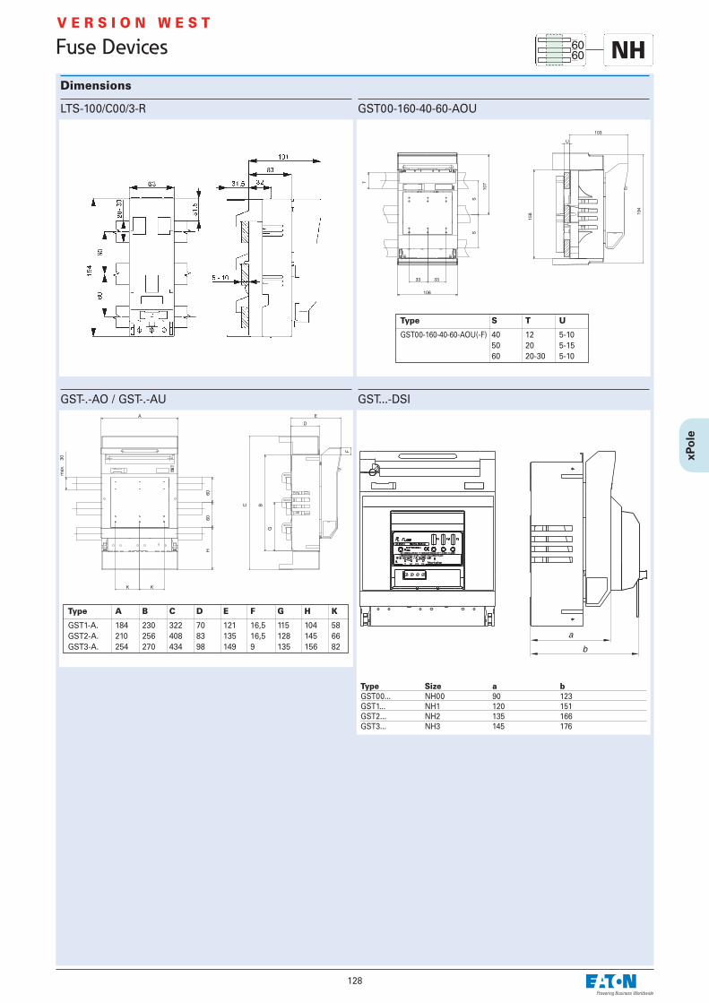
128
Fuse Devices NHV E R S I O N W E S T
Dimensions
GST00-160-40-60-AOU
GST-.-AO / GST-.-AU
Type S T U
GST00-160-40-60-AOU(-F) 40 12 5-1050 20 5-1560 20-30 5-10
Type A B C D E F G H K
GST1-A. 184 230 322 70 121 16,5 115 104 58GST2-A. 210 256 408 83 135 16,5 128 145 66GST3-A. 254 270 434 98 149 9 135 156 82
LTS-100/C00/3-R
GST...-DSI
Type Size a bGST00... NH00 90 123GST1... NH1 120 151GST2... NH2 135 166GST3... NH3 145 176

129
Fuse Devices
NH-Fuse-Switch-Disconnector LTS, 3-pole, xPole• Supplied without NH-fuse-links• Symmetrical device - top or bottom connection is possible • Modular cable cover system for cable lugs or terminals can be expanded as
required• Standard LTS-160/00/3E-R and LTS-250/1/3-R are equipped with locks which
can be sealed with leads• The switch cover features large viewing windows permitting to see the
marking and the flat indicator of the NH-fuse-links.• The windows of LTS-160/00/3-R, LTS-250/1/3-R and LTS-400/2/3-R are
hinged and permit testing of the fuse-links - without affecting touch protec-tion IP20
• The switch cover can be removed in the OFF position• Parking position of switch cover is possible• The base body consists of a glass-fibre reinforced high-temperature-resist-
ant, non-flammable, self-extinguishing and halogen-free plastic• The single-part contact system is corrosion- and torsion-proof. The copper
contacts are nickel-plated, and the contact springs are made of stainlesssteel
• The protective cover consists of a glass-fibre re-enforced, high-tempera-ture-resistant, self-extinguishing and halogen-free plastic
Technical Data
LTS-100/C00/3-R LTS-160/00/3E-R LTS-160/00/3-R LTS-250/1/3-R LTS-400/2/3-R
Electrical Technical data according to IEC/EN 60947 IEC/EN 60947 IEC/EN 60947 IEC/EN 60947 IEC/EN 60947Size C00 00 00 1 2Number of poles/phases 3 3 3 3 3Conventional free air thermal current
with NH-fuse-links Ith 100 A 160 A 160 A 250 A 400 AMax. permitted nominal power loss
of NH-fuse-links 7.5 W 12 W 12 W 23 W 34 WConventional free air thermal current
with solid-links Ith 160 A 200 A 200 A 400 A 530 AMax. permitted nominal power loss
of solid-links – 1.2 W 1.2 W 2.6 W 9 WUtilization category AC 23 B
Rated operational voltage Ue – 400 V AC 400 V AC 400 V AC 400 V AC Rated operational current Ie – 160 A 160 A 250 A 400 ARated short-circuit making capacity – 80 kA 80 kA 80 kA 80 kA
Utilization category AC 22 BRated operational voltage Ue 500 V AC 500 V AC 500 V AC 500 V AC 500 V AC Rated operational current Ie 100 A 160 A 160 A 250 A 400 ARated short-circuit making capacity 50 kA 80 kA 80 kA 50 kA 80 kA
Utilization category AC 21 BRated operational voltage Ue – 690 V AC 690 V AC 690 V AC 690 V ACRated operational current Ie – 125 A 125 A 200 A 315 ARated short-circuit making capacity – 50 kA 50 kA 50 kA 80 kA
Rated insulation voltage Ui 750 V 1000 V 1000 V 1000 V 1000 VRated impulse withstand voltage Uimp 8 kV 8 kV 8 kV 12 kV 12 kVRated frequency 50-60 Hz 50-60 Hz 50-60 Hz 50-60 Hz 50-60 HzRated duty uninterrupted duty uninterrupted duty uninterrupted duty uninterrupted duty uninterrupted dutyRated short-circuit making capacity Icm
with solid-links – 6.2 kAsw 6.2 kAsw 8.2 kAsw 10.6 kAswRated short-time withstand current Icw
with solid-links – 4 kA/1s 4 kA/1s 8 kA/1s 13 kA/1sPower loss without NH-fuse-links – 10W at 160A 10W at 160A 28W at 250A 53W at 400APower loss without solid-links – 16W at 200A 16W at 200A – –
Mechanical Standard connection Lift terminal Lift terminal Clamp strap M10 M10
For cable lugs 1.5-50mm2 Cu 2.5-70mm2 Cu M8 max. 2x70mm2 CU 2x150mm2 Cu 2x240mm2 Cu2x95mm2 Al 2x185mm2 Al 2x240mm2 Al
For busbar max. width – - 20 mm 30 mm 35 mmFor busbar system with distance (mm) 60 60 60 / 40 60 / 40 60 / 40For busbars
max. width x thickness (mm) 30x10 30x10 / 12x10 30x10 / 12x10 30x10 / 12x10 30x10 / 12x10min. width x thickness (mm) 20x5 12x5 12x5 12x5 12x5
Ambient temperature range -5°C to +40°C -5°C to +40°C -5°C to +40°C -5°C to +40°C -5°C to +40°CDegree of protection IP 20 IP 30 IP 20 IP 20 IP 20Pollution degree 3 3 3 3 3
Connection diagram3P
NHV E R S I O N E A S T

Dimensions (mm)
Cable Terminal Connections LTS-100/00/3-R
Lift terminal:Cross section Cu 1.5-50 mm2
Band 6 x 9 x 0,8Tightening torque 2.6 Nm
130
Fuse Devices
LTS-100/C00/3-R
Cut-out for front plate
NHV E R S I O N E A S T
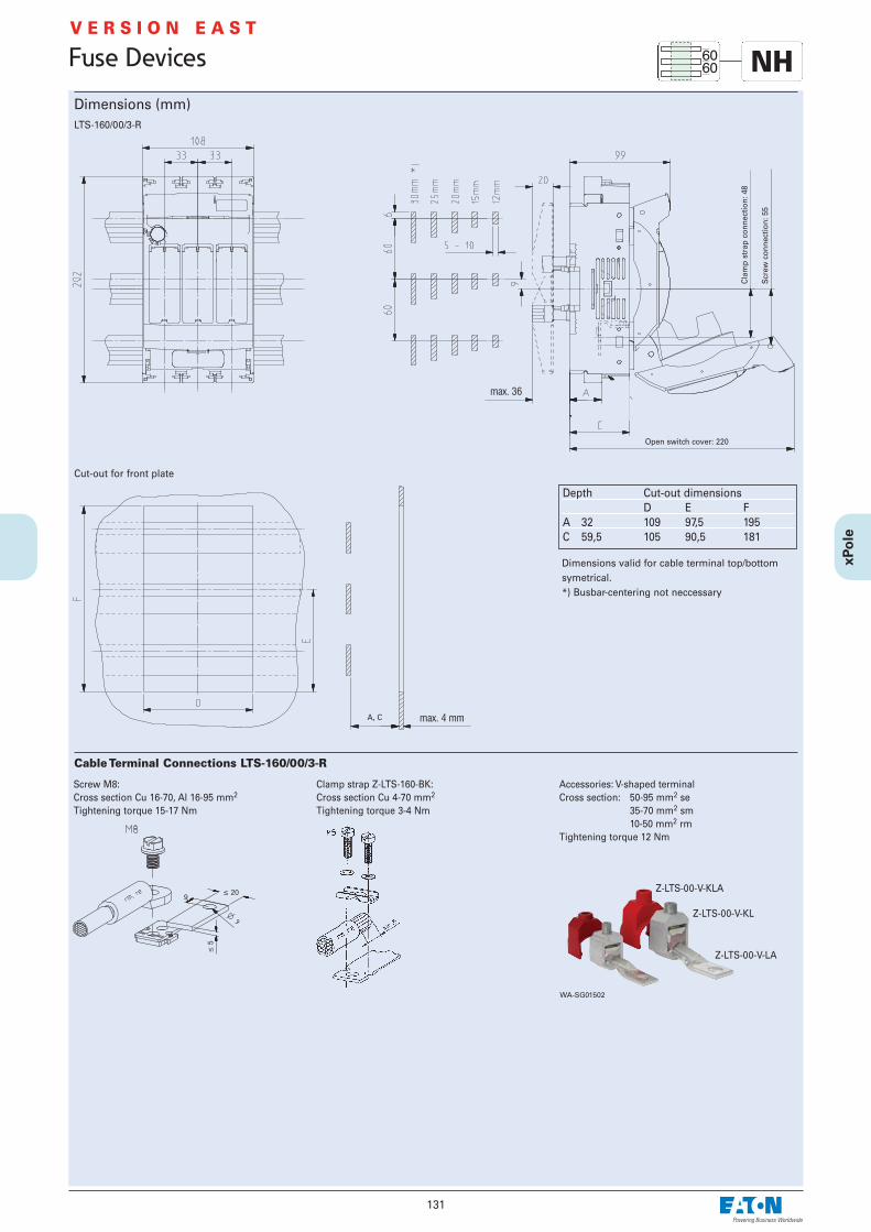
131
Fuse Devices
Dimensions (mm)
Depth Cut-out dimensionsD E F
A 32 109 97,5 195C 59,5 105 90,5 181
LTS-160/00/3-R
Cut-out for front plate
Dimensions valid for cable terminal top/bottomsymetrical.*) Busbar-centering not neccessary
Cable Terminal Connections LTS-160/00/3-R
� 209
�5
Screw M8:Cross section Cu 16-70, Al 16-95 mm2
Tightening torque 15-17 Nm
Clamp strap Z-LTS-160-BK:Cross section Cu 4-70 mm2
Tightening torque 3-4 Nm
Accessories: V-shaped terminalCross section: 50-95 mm2 se
35-70 mm2 sm10-50 mm2 rm
Tightening torque 12 Nm
WA-SG01502
Z-LTS-00-V-KLA
Z-LTS-00-V-KL
Z-LTS-00-V-LA
Open switch cover: 220
Cla
mp
stra
p co
nnec
tion:
48
Scr
ew c
onne
ctio
n: 5
5
A, C
NHV E R S I O N E A S T

132
Fuse Devices
Dimensions (mm)
Depth Cut-out dimensionsC D E
A 32 109 31.5 195B 60 107 13.5 159
LTS-160/00/3E-R
Cut-out for front plate
Dimensions valid for cable terminal top/bottom symetrical.
Cable Terminal Connections LTS-160/00/3E-R
Cross section Cu 2.5-70 mm2
Tightening torque 6 Nm
NHV E R S I O N E A S T
Busbar support can be overbuilt

133
Fuse Devices
Dimensions (mm)LTS-250/1/3-R
Cut-out for front plate
Dimensions valid for cable terminal top/bottomsymetrical.
Cable Terminal Connections LTS-250/1/3-R
Busbar 10 mm5 mm with spacer
Screw connection Bolt connection
Screw M10 x 25Tightening torque 20 Nm Nut M10
Tightening torque 20 Nm
Lock washer
Shim
M10 flexible disk
Lug
Shim
Screw M10 x 25Tightening torque 20 Nm
Accessories: Clamp strap Z-LTS-250-BK
Screw M6 x 30Tightening torque 6 Nm
Lock washer
Suitable : for round conductor 70-150 mm2 rmfor rails or laminated copper 18 x 7-18
Copper Rails
10
30
10
11
Screw- and bolt connectionSuitable for lugs according to:
DIN 46235 max. 10-150 mm2
DIN 46234 max. 10-150 mm2
DIN 46329 max. 10-185 mm2
NHV E R S I O N E A S T
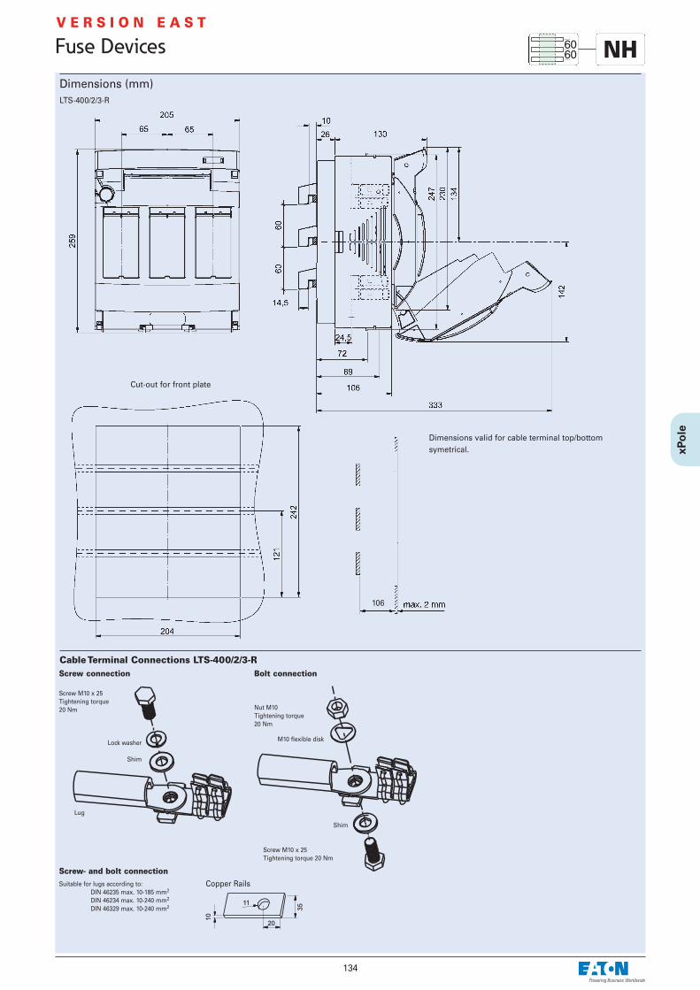
Dimensions (mm)
Cable Terminal Connections LTS-400/2/3-R
134
Fuse Devices
LTS-400/2/3-R
Cut-out for front plate
Dimensions valid for cable terminal top/bottomsymetrical.
106
Screw connection Bolt connection
Screw M10 x 25Tightening torque 20 Nm Nut M10
Tightening torque 20 Nm
Lock washer
Shim
M10 flexible disk
Lug
Shim
Screw M10 x 25Tightening torque 20 Nm
Suitable for lugs according to:DIN 46235 max. 10-185 mm2
DIN 46234 max. 10-240 mm2
DIN 46329 max. 10-240 mm2
Copper Rails
20
35
10
11
Screw- and bolt connection
NHV E R S I O N E A S T

135
Fuse Devices
NH-Vertical Fuse-Switch-Disconnector NH-SLS, 3-pole• Supplied without NH-fuse-links • Can be installed both in a vertical and horizontal position • Symmetrical device - top or bottom connection is possible• Break-proof, flexible connection chamber• Fully insulated, shock hazard protected in accordance with IEC/EN 60947 or
BGV A3• The base body is made of glass fibre reinforced, high-temperature resist-
ant, self-extinguishing and halogen-free plastic • The contact system consists of separately spring-loaded silver-plated cop-
per contacts• The switch cover is made of glass fibre reinforced, self-extinguishing, sili-
cone and chlorine-free thermoplast • The switch cover features large viewing windows allowing to read the
labelling and to see the flat indicator of the NH-fuse-links • The viewing windows provide self-closing test holes • The switch cover can be deposited (“park position”)
Technical Data
NH-SLS-00/160-60(-SI)
Electrical Technical data according to IEC/EN 60947-3Size 00Number of poles/phases 3Conventional free air thermal current Ith
with NH-fuse-links 160 AMax. permissible power loss ofNH-fuse-links 12 WUtilization category AC 23 B
Rated operational voltage Ue 400 V AC Rated operational current Ie 160 ARated conditional short-circuit current
with fuse-links 50 kAUtilization categories AC 22 B, AC 21 B
Rated operational voltage Ue 690 V AC (400 V AC)Rated operational current Ie 160 ARated conditional short-circuit current
with fuse-links 50 kARated insulation voltage Ui 1000 V (400 V)Overvoltage category IIIRated impulse withstand voltage Uimp 8 kV (4 kV)Rated frequency 50-60 HzRated duty uninterrupted duty *Power loss without NH-fuse-links 20 W at 160A
Mechanical Mounting onto busbar system without drilling or screwing
12x5/10 mm20x5/10 mm25x5/10 mm30x5/10 mm
Standard connection - screw M8Cable lugs - Cu-conductor according to rated currentsas detailed in IEC/EN 60947-1 1 x 70 mm2
Flat busbars 20x8 mmTightening torque 12 Nm
Standard connection - clamp strap 2 x M5Stranded Cu 1.5 x 70 mm2
Copper band: No. of layers x width x height 9 x 9 x 0.8 mmFlat busbars 12x10 mmTightening torque 3 Nm
Ambient temperature range -5°C to +40°CDegree of protection IP30Pollution degree 3
Connection diagram
* In case of uninterrupted duty of several devices placed side by side, please take account of the rated load factor detailed in VDE 0660Part 500 / EN 60439-1, Table 1. For sizes 00/1-3 the distance to grounded elements must be at least 50/100 mm at the top and 25/50 mm at the side.
Remote reset
without bridge: memory functionwith bridge:without memory function
Electronic Fuse Monitoring• Operation indication
Fuse in working order –> 1 green LED Fuse blown, cover open –> 1 red LED
• Working current principle, alternatively with memory function/remote reset• Internal resistance of the measuring paths within the MOhm-range, VDE-
requirements regarding touch voltage (> 1000 Ohm/V) are complied with. To release, turn off the upstream main switch!
• When using feeder bars the lines connected to the fuse monitoring systemmust be changed as follows: L1<>L1’, L2<>L2’, L3<>L3’
Functional diagram
Electronic Fuse Monitoring
Electrical Technical data according to IEC/EN 60255,
VDE 0435 Part 303Rated voltage Ue 3 x 400 V ACVoltage range 0,8 ... 1,1xUeRated frequency 50-60 HzConsumption 2 VA (L2/L3)Rated insulation voltage Ui 400 VOvervoltage category IIIRated impulse withstand voltage Uimp 4 kV
Relay contacts 2 COTechnical data according to EN 60947-5-1Rated voltage 250 V ACRated current Ith 4 AUtilization category AC 15
Rated operational voltage Ue 230 V ACRated operational current Ie 1 A
Endurance electrical comp. 1.5 x 10⁵ operating cyclesMaximum back-up fuse 4 A gL/gG / PLSM-B4...-HS
MechanicalTerminals Lift terminalsTerminal capacity
solid 2 x 2.5 mm2
stranded 2 x 1.5 mm2
Tightening torqueof terminal screws 0.8 NmEndurance mechanical comp. > 108 operating cyclesResponse/Release time < 500 ms
NHV E R S I O N W E S T

136
Fuse Devices
Dimensions (mm)NH-SLS-00/160-60(-SI)
Cut-out for front plate
m . . . . . . Number of vertical fuse-switch-disconnectors
Connections NH-SLS-00/160...
Screw M8:Tightening torque 12 Nm
Clamp Straps:Cross section rm, f+AE 1.5-70 mm2; la. Cu 12 x 1-10 mmTightening torque 3 Nm
rm . . . . . round strandedf+AE . . . . flexible + wire end ferrulesla. Cu . . . laminated flexible copper busbar
* NH-SLS-00/160-60-SI (with electronic fusemonitoring)
Drill-free mounting with terminal clamps - tightening torque 8 Nm
NHV E R S I O N W E S T

137
Fuse Devices
NH-Vertical Fuse-Switch-Disconnector LTS-L, 3-pole• Supplied without NH-fuse-links• Vertical and horizontal position of installation is possible• Symmetrical device - top or bottom connection is possible• Break-proof, flexible connection chamber• Fully insulated, finger and hand touch-safe according to IEC/EN 60947 and
BGV A3• Laterally offset ventilation slots in order to avoid flash-over to adjoining
vertical switching devices • The base body consists of a glass-fibre reinforced high-temperature resist-
ant self-extinguishing and halogen-free plastic• The single-part contact system is corrosion- and torsion-proof. The copper
contacts are nickel-plated • The switch cover consists of a glass-fibre re-enforced, self-extinguishing
and halogen-free plastic • The switch cover features large viewing windows permitting to see the
marking and the flat indicator of the NH-fuse-links. • The sliding viewing windows feature test holes • The switch cover can be deposited ("park position")
Technical Data
LTS-L/160/00-60-10-R
Electrical Technical data according to IEC/EN 60947Size 00Number of poles/phases 3Conventional free air thermal current
with NH-fuse-links Ith 160 AMax. permissible power loss
of NH-fuse-links 12 WConventional free air thermal current
with solid-links Ith 250 AMax. permissible power loss
of solid-links 1.2 WUtilization category AC 23 B
Rated operational voltage Ue 400 V ACRated operational current Ie 160 ARated short-circuit making capacity
with fuse-links 80 kAUtilization category AC 22 B
Rated operational voltage Ue 500 V ACRated operational current Ie 160 ARated short-circuit making capacity
with fuse-links 80 kAUtilization category AC 21 B
Rated operational voltage Ue 690 V ACRated operational current Ie 100 ARated short-circuit making capacity
with fuse-links 10 kARated insulation voltage Ui 1000 VRated impulse withstand voltage Uimp 8 kVRated frequency 50-60 HzRated duty uninterrupted dutyRated short-circuit making capacity Icm
with solid-links 4.5 kAswRated short-time withstand current Icw
with solid-links 4.5 kA/1sPower loss without NH-fuse-links 20 W at 160APower loss without solid-links 49 W at 200A
Mechanical Mounting onto busbar system
Hooked clamps for busbar thickness 10 mmScrews –
Standard connection Clamp Straps 70mm2
For cable lugs M8 max. 1x70mm2
For busbar max. width 20 mmAmbient temperature range -5°C to +40°CDegree of protection IP 2LxPollution degree 3
Connection diagram
V E R S I O N E A S T
NH

138
Fuse Devices
V E R S I O N E A S T
NHDimensions (mm)
Cable Terminal Connections LTS-L/160/00
� 209
�5
Accessories: Screw M8Cross section Cu 16-70, Al 16-95 mm2
Tightening torque 15-17 Nm
Clamp strap Z-LTS-160-BK:Cross section Cu 4-70 mm2
Tightening torque 3-4 Nm
re . . . . . . round solidrm . . . . . round strandedse . . . . . . sectorial solidsm . . . . . sectorial stranded
�
60
60
75
LTS-L/160/00
m . . . . . . number of fuse-switch- disconnectors

139
Fuse Devices
NH-Vertical Fuse-Switch-Disconnector NH-SLS, 3-pole• Supplied without NH-fuse-links • Can be installed both in a vertical and horizontal position • Symmetrical device - top or bottom connection is possible• Break-proof, flexible connection chamber• Fully insulated, finger and hand touch-save in accordance with IEC/EN
60947 or BGV A3• The base body is made of glass fibre-reinforced, high-temperature resist-
ant, self-extinguishing and halogen-free plastic • The contact system consists of separately spring-loaded silver-plated cop-
per contacts• The switch cover is made of glass fibre-reinforced, self-extinguishing, sili-
cone and chlorine-free thermoplast • The switch cover features large viewing windows allowing to read the
labelling and to see the flat indicator of the NH-fuse-links • The viewing windows provide self-closing test holes • The switch cover can be deposited (“park position”)
Technical Data
NH-SLS-00/160(-SI) NH-SLS-1/250(-SI) NH-SLS-2/400(-SI) NH-SLS-3/630(-SI)
Electrical Technical data according to IEC/EN 60947-3 IEC/EN 60947-3 IEC/EN 60947-3 IEC/EN 60947-3Size 00 1 2 3Number of poles/phases 3 3 3 3Conventional free air thermal current Ith
with NH-fuse-links 160 A 250 A 400 A 630 AMax. permissible power loss ofNH-fuse-links 12 W 23 W 34 W 48 WUtilization category AC 23 B
Rated operational voltage Ue 400 V AC 500 (400) V AC 500 (400) V AC 500 (400) V ACRated operational current Ie 160 A 250 A 400 A 630 ARated conditional short-circuit current
with fuse-links 50 kA 100 kA 100 kA 100 kAUtilization categories AC 22 B, AC 21 B
Rated operational voltage Ue 690 (–) V AC 690 (–) V AC 690 (–) V AC 690 (–) V ACRated operational current Ie 160 (–) A 250 (–) A 400 (–) A 630 (–) ARated conditional short-circuit current
with fuse-links 50 kA 100 kA 100 kA 100 kARated insulation voltage Ui 1000 V 1000 V 1000 V 1000 VOvervoltage category III III III IIIRated impulse withstand voltage Uimp 8 (4) kV 12 (4) kV 12 (4) kV 12 (4) kVRated frequency 50-60 Hz 50-60 Hz 50-60 Hz 50-60 HzRated duty uninterrupted duty * uninterrupted duty * uninterrupted duty * uninterrupted duty *Power loss without NH-fuse-links 20 W at 160A 30 W at 250A 67 W at 400A 116 W at 630A
Mechanical Mounting onto busbar system
Terminal clamps for busbar thickness 10 mm 10 mm 10 mm 10 mmScrews for busbar thickness 5-10 mm 5-10 mm 5-10 mm 5-10 mm
M8 M12 M12 M12Standard connection - screw M8 M10 M10 M12
Cable lugs - Cu-conductor according to rated currentsas detailed in IEC/EN 60947-1 1 x 70 mm2 120 mm2 240 mm2 2 x 185 mm2
Busbars of a max. width of 20 mm 30 mm 30 mm 30 mmAmbient temperature range -5°C to +40°C -5°C to +40°C -5°C to +40°C -5°C to +40°CDegree of protection IP30 IP30 IP30 IP30Pollution degree 3 3 3 3
* In case of uninterrupted duty of several devices placed side by side, please take account of the rated load factor detailed in VDE 0660Part 500 / EN 60439-1, Table 1. For sizes 00/1-3 the distance to grounded elements must be at least 50/100 mm at the top and 25/50 mm at the side.
Connection diagramNH-SLS NH-SLS-...-SI
NHV E R S I O N W E S T
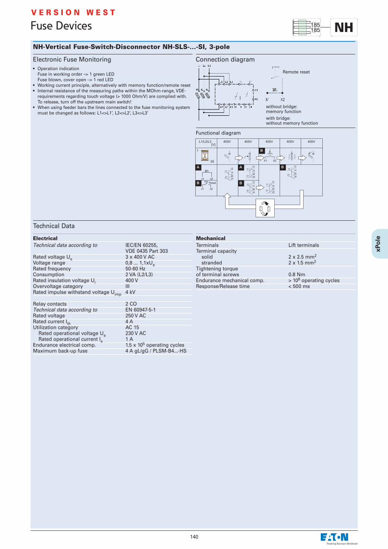
140
Fuse Devices
NH-Vertical Fuse-Switch-Disconnector NH-SLS-...-SI, 3-pole
Technical Data
Connection diagram
Remote reset
without bridge: memory functionwith bridge:without memory function
Electronic Fuse Monitoring• Operation indication
Fuse in working order –> 1 green LED Fuse blown, cover open –> 1 red LED
• Working current principle, alternatively with memory function/remote reset• Internal resistance of the measuring paths within the MOhm-range, VDE-
requirements regarding touch voltage (> 1000 Ohm/V) are complied with. To release, turn off the upstream main switch!
• When using feeder bars the lines connected to the fuse monitoring systemmust be changed as follows: L1<>L1’, L2<>L2’, L3<>L3’
Functional diagram
Electrical Technical data according to IEC/EN 60255,
VDE 0435 Part 303Rated voltage Ue 3 x 400 V ACVoltage range 0,8 ... 1,1xUeRated frequency 50-60 HzConsumption 2 VA (L2/L3)Rated insulation voltage Ui 400 VOvervoltage category IIIRated impulse withstand voltage Uimp 4 kV
Relay contacts 2 COTechnical data according to EN 60947-5-1Rated voltage 250 V ACRated current Ith 4 AUtilization category AC 15
Rated operational voltage Ue 230 V ACRated operational current Ie 1 A
Endurance electrical comp. 1.5 x 10⁵ operating cyclesMaximum back-up fuse 4 A gL/gG / PLSM-B4...-HS
MechanicalTerminals Lift terminalsTerminal capacity
solid 2 x 2.5 mm2
stranded 2 x 1.5 mm2
Tightening torqueof terminal screws 0.8 NmEndurance mechanical comp. > 108 operating cyclesResponse/Release time < 500 ms
NHV E R S I O N W E S T

141
Fuse Devices
Dimensions (mm)
Connections NH-SLS-00/160...
Screw M8:Tightening torque 12 Nm
Clamp Straps:Cross section rm, f+AE 1.5-70 mm2; la. Cu 12 x 1-10 mmTightening torque 3 Nm
rm . . . . . round strandedf+AE . . . . flexible + wire end ferrulesla. Cu . . . laminated flexible copper busbar
Cut-out for front plate
NH-SLS-00/160(-SI)
Cut-out for front plateDrill-free mounting with terminal clamps - tightening torque 8 Nm
Mounting with screws M8 - Cu with drilled holes - tightening torque 12-14 Nm
SG00906
m . . . . . . Number of vertical fuse-switch-disconnectors
* NH-SLS-00/160-SI (with electronic fusemonitoring)
m . . . . . . Number of vertical fuse-switch-disconnectors
* NH-SLS-00/160-SI (with electronic fusemonitoring)
wa_sg02702
V E R S I O N W E S T
NH

142
Fuse Devices
Dimensions (mm)NH-SLS-1/250(-SI), NH-SLS-2/400(-SI), NH-SLS-3/630(-SI)
Connections NH-SLSScrew:Tightening torque Size 1: M10 30-35 Nm
Size 2: M10 30-35 NmSize 3: M12 35-40 Nm
Accessory: terminal clamps Z-NH-SLS-KRUFor drill-free mounting onto the busbar system
SG00706
Cut-out for front plateDrill-free mounting with terminal clamps - tightening torque 30 Nm
n . . . . . . Number of vertical fuse-switch-dis-connectors
Mounting with screws M12 - Cu with drilled holes - tightening torque Size 1: 35-40 NmSize 2: 35-40 NmSize 3: 40-45 Nm
* NH-SLS-...-SI (with electronic fusemonitoring)
Cut-out for front plate
n . . . . . . Number of vertical fuse-switch-dis-connectors
* NH-SLS-...-SI (with electronic fusemonitoring)
NHV E R S I O N W E S T
Cen
ter
of t
he b
usba
r sy
stem
Cen
ter
of t
he b
usba
r sy
stem

143
Fuse Devices
Dimensions (mm)Combination of NH-SLS-00/160(-SI) and NH-SLS-1/250(-SI), NH-SLS-2/400(-SI), NH-SLS-3/630(-SI)
Drill-free mounting with terminal clamps
Screw-mounting - Cu with drilled holes
Cut-out for front plate(without electronic fuse monitoring)
m . . . . Number of single adapters n . . . . . Number of vertical fuse-switch-discon-
nectors NH-SLS size 1-3 and of double adapters
Cut-out for front plate(without electronic fuse monitoring)
m . . . . Number of single adapters n . . . . . Number of vertical fuse-switch-discon-
nectors NH-SLS size 1-3 and of double adapters
Single adapter Z-NH-SLS-00-SAD-KR
Double adapter Z-NH-SLS-00-SADDSingle adapter Z-NH-SLS-00-SAD
NHV E R S I O N W E S T

144
Fuse Devices
NH In-line Fuse Switch Disconnectors, 3 poles, FCFSDNH00BB100...• Center-to-center distance of 100 mm between the phases • Size 00
Technical Data
FCFSDNH00BB100(-CTO)
ElectricalFor LV HRC fuse-links acc. to DIN VDE 0636-2 Size 000/00Rated operational voltage Ue V AC 690Rated operational current Ie
1) A 160Conv. free air thermal current Ith
with fuse-links 1) A 160Conv. free air thermal current Ith
with solid-links 1) A 210Rated frequency Hz 40 - 60Rated insulation voltage Ui V AC 800Total power loss at Ith (without fuse-links) Pv W 18Rated impuls withstand voltage Uimp kV 8Utilization category (AC-22B)
400 V A 160500 V A 160690 V A 100
Rated conditional short-circuit current 2) kA 80Rated short-time withstand current Icw ka –Max. permissible power loss Pa
per fuse-link W 12
MechanicalFlat terminal
Bolt diameter M8Cable lug (DIN 46235) mm2 1 x 10-95 (max. 25 mm width)Flat bar mm 20 x 10Tightening torque Ma Nm 12 - 15
ClampClamping cross-section mm2 round 1,5 - 70 Cu / flat 6 x 9 x 0,8Tightening torque Ma Nm 2,6
Degree of protection, front side, device fittedOperating condition IP30Switching element open IP10
Ambient temperature Tamb 3) °C -25 up to +55
Rated operating mode uninterrupted dutyActuation dependent manual operationMounting position vertical, horizontalAltitude m up to 2000Pollution degree 3Overvoltage category III
1) In case of mounting of several units in low voltage switchgear-combinations , please consider rated diversity factors acc. to EN 60439-1.2) Type tested with LV-HRC-fuse-links characteristic gG.3) 35°C Normal temperature, at 55°C with reduced operating current.
NH
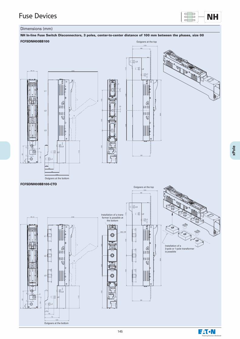
145
Fuse Devices
Dimensions (mm)
FCFSDNH00BB100
NH
Outgoers at the top
Outgoers at the bottom
FCFSDNH00BB100-CTOOutgoers at the top
Outgoers at the bottom
Installation of a trans-former is possible at
the bottom
Installation of a 3-pole or 1-pole transformeris possible
NH In-line Fuse Switch Disconnectors, 3 poles, center-to-center distance of 100 mm between the phases, size 00

146
Fuse Devices NHNH In-line Fuse Switch Disconnectors, 3 poles, FCFSDNH.BB185...• Center-to-center distance of 185 mm between the phases• Sizes 1, 2, 3
Technical Data
FCFSDNH1BB185(-CTO) FCFSDNH2BB185(-CTO) FCFSDNH3BB185(-CTO)
ElectricalFor LV HRC fuse-links acc. to DIN VDE 0636-2 Size 1 2 3Rated operational voltage Ue V AC 690 690 690Rated operational current Ie
1) A 250 400 630Conv. free air thermal current Ith
with fuse-links 1) A 250 400 630Conv. free air thermal current Ith
with solid-links 1) A 400 630 800Rated frequency Hz 40 - 60 40 - 60 40 - 60Rated insulation voltage Ui V AC 1000 1000 1000Total power loss at Ith (without fuse-links) Pv W 23 54 115Rated impuls withstand voltage Uimp kV 12 12 12Utilization category
400 V A 250 (AC-23B) 400 (AC-23B) 630 (AC-22B)500 V A 250 (AC-22B) 400 (AC-22B) 630 (AC-22B)690 V A 250 (AC-22B) 400 (AC-22B) 630 (AC-21B)
Rated conditional short-circuit current 2) kA 110 110 110 2a)
Rated short-time withstand current Icw ka 14,5 14,5 14,5Max. permissible power loss Pa
per fuse-link W 32 45 48
MechanicalFlat terminal
Bolt diameter M10 M12 M12Cable lug (DIN 46235) mm2 1 x 25-150 1 x 25-240 1 x 25-300 (max 43mm width)Flat bar mm 30 x 10 30 x 10 30 x 10Tightening torque Ma Nm 30 - 35 35 - 40 35 - 40
Degree of protection, front side, device fittedOperating condition IP30 IP30 IP30Switching element open IP10 IP10 IP10
Ambient temperature Tamb 3) °C -25 up to +55 -25 up to +55 -25 up to +55
Rated operating mode uninterrupted duty uninterrupted duty uninterrupted dutyActuation dependent manual operation dependent manual operation dependent manual operationMounting position vertical, horizontal vertical, horizontal vertical, horizontalAltitude m up to 2000 up to 2000 up to 2000Pollution degree 3 3 3Overvoltage category IV IV IV
1) In case of mounting of several units in low voltage switchgear-combinations , please consider rated diversity factors acc. to EN 60439-1.2) Type tested at AC 725 V with LV-HRC-fuse-links characteristic gG.3) 35°C Normal temperature, at 55°C with reduced operating current.

147
Fuse Devices NHDimensions (mm)
FCFSDNH1BB185
Connection at the top (Ao)Connection at the bottom (Au)
FCFSDNH2BB185, FCFSDNH3BB185
Connection at the top (Ao)Connection at the bottom (Au)
NH In-line Fuse Switch Disconnectors, 3 poles, center-to-center distance of 185 mm between the phases, size 1 - size 3

148
Fuse Devices NH
FCFSDNH1BB185-CTO
Connection at the top (Ao)Connection at the bottom (Au)
FCFSDNH2BB185-CTO, FCFSDNH3BB185-CTO
Connection at the top (Ao)Connection at the bottom (Au)
NH In-line Fuse Switch Disconnectors, 3 poles, center-to-center distance of 185 mm between the phases , size 1 - size 3,for installating transformers
Installation of a 3-pole or 1-pole trans-former is possible
Installation of a 3-pole or 1-pole trans-former is possible
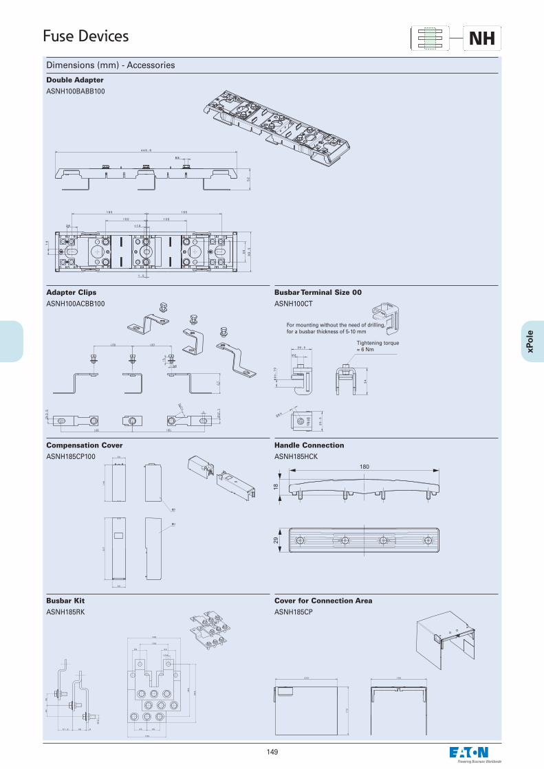
149
Fuse Devices NHDimensions (mm) - Accessories
ASNH100BABB100
Double Adapter
ASNH100ACBB100
Adapter Clips
ASNH100CT
Busbar Terminal Size 00
For mounting without the need of drilling,for a busbar thickness of 5-10 mm
Tightening torque= 6 Nm
ASNH185CP100
Compensation Cover
ASNH185HCK
Handle Connection
ASNH185RK
Busbar Kit
ASNH185CP
Cover for Connection Area
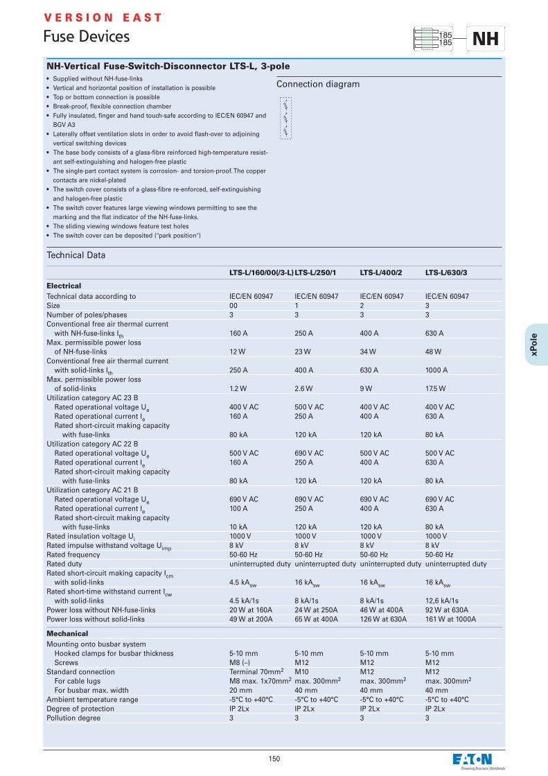
150
NH-Vertical Fuse-Switch-Disconnector LTS-L, 3-pole• Supplied without NH-fuse-links• Vertical and horizontal position of installation is possible• Top or bottom connection is possible• Break-proof, flexible connection chamber• Fully insulated, finger and hand touch-safe according to IEC/EN 60947 and
BGV A3• Laterally offset ventilation slots in order to avoid flash-over to adjoining
vertical switching devices • The base body consists of a glass-fibre reinforced high-temperature resist-
ant self-extinguishing and halogen-free plastic• The single-part contact system is corrosion- and torsion-proof. The copper
contacts are nickel-plated • The switch cover consists of a glass-fibre re-enforced, self-extinguishing
and halogen-free plastic • The switch cover features large viewing windows permitting to see the
marking and the flat indicator of the NH-fuse-links. • The sliding viewing windows feature test holes • The switch cover can be deposited ("park position")
Technical Data
LTS-L/160/00(/3-L) LTS-L/250/1 LTS-L/400/2 LTS-L/630/3
Electrical Technical data according to IEC/EN 60947 IEC/EN 60947 IEC/EN 60947 IEC/EN 60947Size 00 1 2 3Number of poles/phases 3 3 3 3Conventional free air thermal current
with NH-fuse-links Ith 160 A 250 A 400 A 630 AMax. permissible power loss
of NH-fuse-links 12 W 23 W 34 W 48 WConventional free air thermal current
with solid-links Ith 250 A 400 A 630 A 1000 AMax. permissible power loss
of solid-links 1.2 W 2.6 W 9 W 17.5 WUtilization category AC 23 B
Rated operational voltage Ue 400 V AC 500 V AC 400 V AC 400 V ACRated operational current Ie 160 A 250 A 400 A 630 ARated short-circuit making capacity
with fuse-links 80 kA 120 kA 120 kA 80 kAUtilization category AC 22 B
Rated operational voltage Ue 500 V AC 690 V AC 500 V AC 500 V AC Rated operational current Ie 160 A 250 A 400 A 630 ARated short-circuit making capacity
with fuse-links 80 kA 120 kA 120 kA 80 kAUtilization category AC 21 B
Rated operational voltage Ue 690 V AC 690 V AC 690 V AC 690 V ACRated operational current Ie 100 A 250 A 400 A 630 ARated short-circuit making capacity
with fuse-links 10 kA 120 kA 120 kA 80 kARated insulation voltage Ui 1000 V 1000 V 1000 V 1000 VRated impulse withstand voltage Uimp 8 kV 8 kV 8 kV 8 kVRated frequency 50-60 Hz 50-60 Hz 50-60 Hz 50-60 HzRated duty uninterrupted duty uninterrupted duty uninterrupted duty uninterrupted dutyRated short-circuit making capacity Icm
with solid-links 4.5 kAsw 16 kAsw 16 kAsw 16 kAswRated short-time withstand current Icw
with solid-links 4.5 kA/1s 8 kA/1s 8 kA/1s 12,6 kA/1sPower loss without NH-fuse-links 20 W at 160A 24 W at 250A 46 W at 400A 92 W at 630APower loss without solid-links 49 W at 200A 65 W at 400A 126 W at 630A 161 W at 1000A
Mechanical Mounting onto busbar system
Hooked clamps for busbar thickness 5-10 mm 5-10 mm 5-10 mm 5-10 mmScrews M8 (–) M12 M12 M12
Standard connection Terminal 70mm2 M10 M12 M12For cable lugs M8 max. 1x70mm2 max. 300mm2 max. 300mm2 max. 300mm2
For busbar max. width 20 mm 40 mm 40 mm 40 mmAmbient temperature range -5°C to +40°C -5°C to +40°C -5°C to +40°C -5°C to +40°CDegree of protection IP 2Lx IP 2Lx IP 2Lx IP 2LxPollution degree 3 3 3 3
Connection diagram
Fuse Devices NHV E R S I O N E A S T
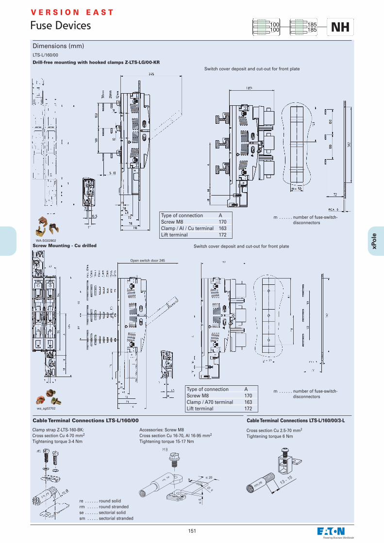
151
Fuse Devices
Dimensions (mm)
Cable Terminal Connections LTS-L/160/00
� 209
�5
Accessories: Screw M8Cross section Cu 16-70, Al 16-95 mm2
Tightening torque 15-17 Nm
Clamp strap Z-LTS-160-BK:Cross section Cu 4-70 mm2
Tightening torque 3-4 Nm
re . . . . . . round solidrm . . . . . round strandedse . . . . . . sectorial solidsm . . . . . sectorial stranded
Switch cover deposit and cut-out for front plate
LTS-L/160/00
Switch cover deposit and cut-out for front plateDrill-free mounting with hooked clamps Z-LTS-LG/00-KR
Screw Mounting - Cu drilled
wa_sg02702
m . . . . . . number of fuse-switch- disconnectors
WA-SG02802
m . . . . . . number of fuse-switch- disconnectors
Open switch door 245
V E R S I O N E A S T
NH
Cable Terminal Connections LTS-L/160/00/3-L
Cross section Cu 2.5-70 mm2
Tightening torque 6 Nm
Type of connection AScrew M8 170Clamp / Al / Cu terminal 163Lift terminal 172
Type of connection AScrew M8 170Clamp / A70 terminal 163Lift terminal 172

152
Fuse Devices
Dimensions (mm)LTS-L/250/1, LTS-L/400/2, LTS-L/630/3
Cable Terminal Connections LTS-L/250/1, LTS-L/400/2, LTS-L/630/3Bolt connection:Cross section max. 300 mm2
Tightening torque 35±3 NmAccessories: Cable lug max. width 45 mm
Accessories: Hooked Clamps Z-LTS-L-KRFor direct mounting without drilling ontobus bar system.
WA-SG14703
Cut-out for cable output
Drill-free mounting with hooked clamps
n . . . . . . number of vertical fuse-switch-disconnectors
Screw Mounting - Cu drilled
n . . . . . . number of vertical fuse-switch-disconnectors
Open switch doorPark position with max. dimension of fuse-links size 3
size
above
Central distance (divi-sion)
Central cover
Cen
ter
of t
he b
usba
r sy
stem
Busbar upperedge
NHV E R S I O N E A S T
size
below
size
size
1) Dimensions to busbar upper edge
size

153
Fuse Devices
Dimensions (mm)Kombination LTS-L/160/00 and LTS-L/250/1, LTS-L/400/2, LTS-L/630/3
Cut-out for front plateDrill-free mounting with hooked clamps
m . . . . . . number of Single Adapter (LTS-L/160/00)n . . . . . . number of vertical fuse-switch-disconnectors
LTS-L/250/1 to LTS-L/630/3 and Double Adapter
Z-LT
S-L
-KA
Front plate
Z-LTS-L/160-SADD-KR . . . Double AdapterZ-LTS-L/160-SAD-KR . . . . Single Adapter
Cut-out for front plate
Screw Mounting - Cu drilled
m . . . . . . number of Single Adapter (LTS-L/160/00)n . . . . . . number of vertical fuse-switch-disconnectors
LTS-L/250/1 to LTS-L/630/3 and Double Adapter
Z-LT
S-L
-KA
Front plate
Z-LTS-L/160-SADD . . . . . . Double AdapterZ-LTS-LG/00-SAD . . . . . . Single Adapter
NHV E R S I O N E A S T
above below

NH-Fuse-Switch-Disconnector LTS, 1- and 3-pole, xPole• Supplied without NH-fuse-links• Symmetrical device - top or bottom connection is possible • Modular cable cover system for cable lugs or terminals can be expanded as
required• Standard LTS-160/00/3E and LTS-250/1/3 are equipped with locks which can
be sealed with leads• The switch cover features large viewing windows permitting to see the
marking and the flat indicator of the NH-fuse-links.• The windows of LTS-160/00/3, LTS-250/1/3, LTS-400/2/3 and LTS-630/3/3 are
hinged and permit testing of the fuse-links - without affecting touch protection IP20
• The switch cover can be removed in the OFF position• Parking position of switch cover is possible• The base body consists of a glass-fibre reinforced high-temperature-resist-
ant, non-flammable, self-extinguishing and halogen-free plastic• The single-part contact system is corrosion- and torsion-proof. The copper
contacts are nickel-plated, and the contact springs are made of stainlesssteel
• The protective cover consists of a glass-fibre re-enforced, high-tempera-ture-resistant, self-extinguishing and halogen-free plastic
Technical Data
LTS-160/00/1 LTS-160/00/3(E) LTS-250/1/3 LTS-400/2/3 LTS-630/3/3
Electrical Technical data according to IEC/EN 60947 IEC/EN 60947 IEC/EN 60947 IEC/EN 60947 IEC/EN 60947Size 00 00 1 2 3Number of poles/phases 1 3 3 3 3Conventional free air thermal current
with NH-fuse-links Ith 160 A 160 A 250 A 400 A 630 AMax. permissible power loss
of NH-fuse-links 12 W 12 W 23 W 34 W 48 WConventional free air thermal current
with solid-links Ith 200 A 200 A 400 A 630 A 780 AMax. permissible power loss
of solid-links 1.2 W 1.2 W 2.6 W 9 W 17.5 WUtilization category AC 23 B
Rated operational voltage Ue 400 V AC 400 V AC 400 V AC 400 V AC 400 V ACRated operational current Ie 160 A 160 A 250 A 400 A 630 ARated short-circuit making capacity
with fuse-links 80 kA 80 kA 80 kA 80 kA 80 kAUtilization category AC 22 B
Rated operational voltage Ue 500 V AC 500 V AC 500 V AC 500 V AC 500 V AC Rated operational current Ie 160 A 160 A 250 A 400 A 630 ARated short-circuit making capacity
with fuse-links 80 kA 80 kA 50 kA 80 kA 80 kAUtilization category AC 21 B
Rated operational voltage Ue 690 V AC 690 V AC 690 V AC 690 V AC 690 V ACRated operational current Ie 125 A 125 A 200 A 315 A 500 ARated short-circuit making capacity
with fuse-links 50 kA 50 kA 50 kA 80 kA 50 kARated insulation voltage Ui 1000 V 1000 V 1000 V 1000 V 1000 VRated impulse withstand voltage Uimp 8 kV 8 kV 12 kV 12 kV 12 kVRated frequency 50-60 Hz 50-60 Hz 50-60 Hz 50-60 Hz 50-60 HzRated duty uninterrupted duty uninterrupted duty uninterrupted duty uninterrupted duty uninterrupted dutyRated short-circuit making capacity Icm
with solid-links 6.2 kAsw 6.2 kAsw 8.2 kAsw 10.6 kAsw 18.6 kAswRated short-time withstand current Icw
with solid-links 4 kA/1s 4 kA/1s 8 kA/1s 13 kA/1s 13 kA/1sPower loss without NH-fuse-links 2.3W at 160A 7W at 160A 10W at 250A 20W at 400A 40W at 630APower loss without solid-links 3.3W at 200A 10W at 200A 24W at 400A 50W at 630A 150W at 1000A
Mechanical Standard connection Clamp strap Clamp strap M10 M10 M12
For cable lugs M8 max. 2x70mm2 M8 max. 2x70mm2 Cu 2x150mm2 Cu 2x240mm2 Cu 2x240mm2 Cu2x95mm2 Al 2x95mm2 Al 2x185mm2 Al 2x240mm2 Al 2x300mm2 Al
For busbar max. width 20 mm 20 mm 30 mm 35 mm 45 mmAmbient temperature range -5°C to +40°C -5°C to +40°C -5°C to +40°C -5°C to +40°C -5°C to +40°CDegree of protection IP 20 IP 20 IP 20 IP 20 IP 20Pollution degree 3 3 3 3 3
Connection diagrams1P 3P
154
Fuse Devices
V E R S I O N E A S T
NH

155
Dimensions (mm)LTS-160/00/1
Dimensions for bottom fixing and front plate cut-out for bottom fixing without cover shield
Max. thickness of front plate 4 mm
Front plate
Connection centre
Fixing centreConnection centre
Connection centre
Cable Terminal Connections LTS-160/00/1
� 209
�5
Accessories: Screw M8Cross section Cu 16-70, Al 16-95 mm2
Tightening torque 15-17 Nm
Clamp strap Z-LTS-160-BK:Cross section Cu 4-70 mm2
Tightening torque 3-4 Nm
Accessories: V-shaped terminalCross section: 50-95 mm2 se
35-70 mm2 sm10-50 mm2 rm
Tightening torque 12 Nm
WA-SG01502
Z-LTS-00-V-KLA
Z-LTS-00-V-KL
Z-LTS-00-V-LA
Fuse Devices
re . . . . . . round solidrm . . . . . round strandedse . . . . . . sectorial solidsm . . . . . sectorial stranded
V E R S I O N E A S T
NH

Fuse Devices
156
Dimensions (mm)LTS-160/00/3
Dimensions for bottom fixing and front plate cut-out for bottom fixing without cover shield
Cable Terminal Connections LTS-160/00/3
� 209
�5
Accessories: Screw M8Cross section Cu 16-70, Al 16-95 mm2
Tightening torque 15-17 Nm
Clamp strap Z-LTS-160-BK:Cross section Cu 4-70 mm2
Tightening torque 3-4 Nm
Accessories: V-shaped terminalCross section: 50-95 mm2 se
35-70 mm2 sm10-50 mm2 rm
Tightening torque 12 Nm
WA-SG01502
Z-LTS-00-V-KLA
Z-LTS-00-V-KL
Z-LTS-00-V-LA
Max. thickness of front plate 4 mm
Front plate
Connection centre
Connection centre
Connection centre
re . . . . . . round solidrm . . . . . round strandedse . . . . . . sectorial solidsm . . . . . sectorial stranded
V E R S I O N E A S T
NH

Dimensions (mm)LTS-160/00/3
Dimensions for bottom fixing and front plate cut-out for bottom fixing without cover shield
Cable Terminal Connections LTS-160/00/3
� 209
�5
Accessories: Screw M8Cross section Cu 16-70, Al 16-95 mm2
Tightening torque 15-17 Nm
Clamp strap Z-LTS-160-BK:Cross section Cu 4-70 mm2
Tightening torque 3-4 Nm
Accessories: V-shaped terminalCross section: 50-95 mm2 se
35-70 mm2 sm10-50 mm2 rm
Tightening torque 12 Nm
WA-SG01502
Z-LTS-00-V-KLA
Z-LTS-00-V-KL
Z-LTS-00-V-LA
Front plate
Connection centre
Connection centre
Connection centre
re . . . . . . round solidrm . . . . . round strandedse . . . . . . sectorial solidsm . . . . . sectorial stranded
V E R S I O N E A S T
157
Fuse Devices
Symmetric switch, same dimensions for cable connection at the top or bottom
NH

158
Fuse Devices
Dimensions (mm)
Busbar Block 35mm2 Z-LTS-00/3-SV for LTS-160/00/3(E)
• Delivered with end caps.• Extension terminal Z-LTS-EK/95 available
Technical Data
Electrical Rated voltage 690/400 V, 50 HzRated current
Feeding from the side 110 AFeeding in the middle 220 A
Rated conditional short-circuit currentwith back-up fuse 250 A gG(gL) 100 kAr.m.s
Mechanical Busbar cross section 35 mm2 CuStep distance 33 mm / 108.5 mmWeight 446 g
Connection diagram
Example
WA_SG10902
Z-LTS-EK/95Terminal capacity
NHV E R S I O N E A S T

159
Dimensions (mm)LTS-250/1/3
Dimensions for bottom fixing and front plate cut-out for bottom fixing without cover shield
Cable Terminal Connections LTS-250/1/3
Screw connection
Connection centre
Max. thickness of front plate 2 mm
Front plate
Mounting centre
Connection centre
Bolt connection
Fuse Devices
Screw M10 x 25Tightening torque 20 Nm Nut M10
Tightening torque 20 Nm
Lock washer
Shim
M10 flexible disk
Lug
Shim
Screw M10 x 25Tightening torque 20 Nm
Accessories: Clamp strap Z-LTS-250-BK
Screw M6 x 30Tightening torque 6 Nm
Lock washer
Suitable : for round conductor 70-150 mm2 rmfor rails or laminated copper 18 x 7-18
Copper Rails
10
30
10
11
Screw- and bolt connectionSuitable for lugs according to:
DIN 46235 max. 10-150 mm2
DIN 46234 max. 10-150 mm2
DIN 46329 max. 10-185 mm2
V E R S I O N E A S T
NH

Dimensions (mm)LTS-400/2/3
Dimensions for bottom fixing and front plate cut-out for bottom fixing without cover shield
Cable Terminal Connections LTS-400/2/3Screw connection
Front plate
Mounting centre
Connection centre
Bolt connection
160
Fuse Devices
Mounting centre
Connection centre
Connection centre
Screw M10 x 25Tightening torque 20 Nm Nut M10
Tightening torque 20 Nm
Lock washer
Shim
M10 flexible disk
Lug
Shim
Screw M10 x 25Tightening torque 20 Nm
Suitable for lugs according to:DIN 46235 max. 10-185 mm2
DIN 46234 max. 10-240 mm2
DIN 46329 max. 10-240 mm2
Copper Rails
20
35
10
11
Screw- and bolt connection
V E R S I O N E A S T
NH

161
Fuse Devices
Dimensions (mm)LTS-630/3/3
Cable Terminal Connections LTS-630/3/3
Screw connection Bolt connection
Screw M12 x 30Tightening torque35 Nm Nut M12
Tightening torque35 Nm
M12 flexible diskM12 flexible disk
Lug
Shim
Screw M12 x 30Tightening torque 35 Nm
Suitable for lugs according to:DIN 46235 max. 10-240 mm2
DIN 46234 max. 10-240 mm2
DIN 46329 max. 10-300 mm2
Front plate
Mounting centre
Connection centre
Lug
Copper Rails
25
45
10
14
Screw- and bolt connection
V E R S I O N E A S T
NH

162
Fuse Devices
Busbar Adapter Z-LTS-...-SAD/100-KR, 3-pole• For the drill-free mounting of LTS fuse-switch-disconnectors on busbar sys-
tems with a distance between busbars of 100 mm• Mounting requires little time and space• Connection on top or bottom possible
Connection diagram
Technical Data
Adapter Size Distance between Mounting Max. BusbarBusbars Cross Section
Z-LTS-250-SAD/100-KR 1 100 mm Hex screw M10 15 Nm 60 x 10 mmZ-LTS-400-SAD/100-KR 2 100 mm Hex screw M10 15 Nm 60 x 10 mmZ-LTS-630-SAD/100-KR 3 100 mm Hex screw M10 15 Nm 60 x 10 mm
Dimensions (mm)
NHV E R S I O N E A S T
Symmetrical adapter, same dimensions for cable connection on top or bottom
Adapter Size NH-Fuse-Switch-Disconnector a b e f g h iZ-LTS-250-SAD/100-KR 1 LTS-250/1/3 137 22 185 91 127 168,5 121Z-LTS-400-SAD/100-KR 2 LTS-400/2/3 157 22 204,5 106 134 168,5 124Z-LTS-630-SAD/100-KR 3 LTS-630/3/3 174,5 22 256 122 155 168,5 124
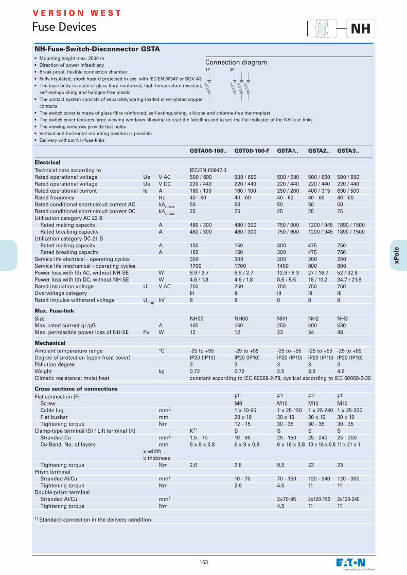
163
Fuse Devices
V E R S I O N W E S T
NH-Fuse-Switch-Disconnector GSTA• Mounting height max. 2000 m• Direction of power infeed: any• Break-proof, flexible connection chamber• Fully insulated, shock hazard protected in acc. with IEC/EN 60947 or BGV A3• The base body is made of glass fibre reinforced, high-temperature resistant,
self-extinguishing and halogen-free plastic• The contact system consists of separately spring-loaded silver-plated copper
contacts• The switch cover is made of glass fibre reinforced, self-extinguishing, silicone and chlorine-free thermoplast• The switch cover features large viewing windows allowing to read the labelling and to see the flat indicator of the NH-fuse-links• The viewing windows provide test holes • Vertical and horizontal mounting position is possible • Delivery without NH-fuse-links
GSTA00-160.. GST00-160-F GSTA1.. GSTA2.. GSTA3..
ElectricalTechnical data according to IEC/EN 60947-3Rated operational voltage Ue V AC 500 / 690 500 / 690 500 / 690 500 / 690 500 / 690Rated operational voltage Ue V DC 220 / 440 220 / 440 220 / 440 220 / 440 220 / 440Rated operational current Ie A 160 / 100 160 / 100 250 / 200 400 / 315 630 / 500Rated frequency Hz 40 - 60 40 - 60 40 - 60 40 - 60 40 - 60Rated conditional short-circuit current AC kAr.m.s. 50 50 50 50 50Rated conditional short-circuit current DC kAr.m.s. 25 25 25 25 25Utilization category AC 22 B
Rated making capacity A 480 / 300 480 / 300 750 / 600 1200 / 945 1890 / 1500Rated breaking capacity A 480 / 300 480 / 300 750 / 600 1200 / 945 1890 / 1500
Utilization category DC 21 B Rated making capacity A 150 150 300 475 750Rated breaking capacity A 150 150 300 475 750
Service life electrical - operating cycles 300 300 200 200 200Service life mechanical - operating cycles 1700 1700 1400 800 800Power loss with Ith AC, without NH-SE W 6.9 / 2.7 6.9 / 2.7 12.9 / 8.3 27 / 16.7 52 / 32.8Power loss with Ith DC, without NH-SE W 4.6 / 1.8 4.6 / 1.8 8.6 / 5.5 18 / 11.2 34.7 / 21.8Rated insulation voltage Ui V AC 750 750 750 750 750Overvoltage category III III III III IIIRated impulse withstand voltage Uimp kV 8 8 8 8 8
Max. Fuse-linkSize NH00 NH00 NH1 NH2 NH3Max. rated current gL/gG A 160 160 250 400 630Max. permissible power loss of NH-SE Pv W 12 12 23 34 48
MechanicalAmbient temperature range °C -25 to +55 -25 to +55 -25 to +55 -25 to +55 -25 to +55Degree of protection (open front cover) IP20 (IP10) IP20 (IP10) IP20 (IP10) IP20 (IP10) IP20 (IP10)Pollution degree 3 3 3 3 3Weight kg 0.72 0.72 2.5 3.3 4.6Climatic resistance: moist heat constant according to IEC 60068-2-78, cyclical according to IEC 60068-2-30
Cross sections of connectionsFlat connection (F) F1) F1) F1) F1)
Screw M8 M10 M10 M10Cable lug mm2 1 x 10-95 1 x 25-150 1 x 25-240 1 x 25-300Flat busbar mm 20 x 10 30 x 10 30 x 10 30 x 10Tightening torque Nm 12 - 15 30 - 35 30 - 35 30 - 35
Clamp-type terminal (S) / Lift terminal (K) K1) S S S SStranded Cu mm2 1,5 - 70 10 - 95 25 - 150 25 - 240 25 - 300Cu-Band, No. of layers mm 6 x 9 x 0.8 6 x 9 x 0.8 6 x 16 x 0.8 10 x 16 x 0.8 11 x 21 x 1
x widthx thickness
Tightening torque Nm 2.6 2.6 9.5 23 23Prism terminal
Stranded Al/Cu mm2 10 - 70 70 - 150 120 - 240 120 - 300Tightening torque Nm 2.6 4.5 11 11
Double-prism terminal Stranded Al/Cu mm2 2x70-95 2x120-150 2x120-240Tightening torque Nm 4.5 11 11
1) Standard-connection in the delivery condition
Connection diagram1P 3P
NH

164
Fuse Devices
V E R S I O N W E S T
Switch Cover with Fuse Monitoring for NH-Fuse-Switch-Disconnector GST...• Operation indication
In working order –> 1 green LED Fuse blown –> 3 red LEDs L1, L2, L3
• Working current principle• VDE-requirements regarding touch voltage (> 1000 Ohm/V) are complied
with.To release, turn off the upstream main switch!
• Not applicable for single phase application
Connection diagram
Technical data
Electrical Technical data according to IEC/EN 60255,
VDE 0435 Part 303Rated voltage Ue 3 x 400 V AC - 690 V ACVoltage range 0,9 ... 1,1xUeRated frequency 50-60 HzConsumption 1.5 VA (L2/L3)Rated insulation voltage Ui 690 VOvervoltage category IIIRated impulse withstand voltage Uimp 6 kV
Relay contacts 1 NC, 1 NOTechnical data according to EN 60204, EN 50178,
VDE 0106Rated voltage 250 V ACRated current Ith 8 A DCMax. making current 15 AUtilization category AC 15 DC13
Rated operational voltage Ue 230VAC 24VAC 24VDC 220VDCRated operational current Ie 1 A 4 A 1 A 0,5 A
Minimum switching load 5 V AC/DC, 300 mW, 5 mAMax. switching capacity
AC 1 2000 VA250 V AC 15 400 VA250 V AC 3 300 W
Endurance electrical comp. 80 x 103 operating cycles AC 1Maximum back-up fuse 4 A gL/gG / PLSM-B4...-HS
MechanicalTerminals Lift terminalsTerminal capacity
stranded 0.25 - 1.5 mm2
Tightening torqueof terminal screws 0.5 - 0.6 NmEndurance mechanical comp. > 10 x 106 operating cyclesResponse/Release time < 500 msDepree of protection IP20Temperature range -10 to +55°CPollution degree 3
Functional diagram
NH

165
Fuse Devices
V E R S I O N W E S T
Dimensions (mm)
NH
Type A B D E F G KGSTA00-160(-F) 105,5 149 45 86 20 79 33GSTA1 184 230 68 119 16,5 115 58GSTA2 210 256 81 133 16,5 128 66GSTA3 254 270 96 147 9 135 82
1-poleGSTA00-160-1P
3-poleGSTA00-160(-F), GSTA1, GSTA2, GSTA3
Type Size a bGST00... NH00 90 123GST1... NH1 120 151GST2... NH2 135 166GST3... NH3 145 176
GST...-DSI

166
Screw Caps Z-D0./SK
Technical Data
Electrical Rated current
D01 max. 16 AD02 max. 63 A
Mechanical Electrical thread
D01 E14D02 E18
A complete and functioning D-fuse system consists of base + fuse-link + car-tridge-ring adapter insert + screw cap.The cartridge-ring adapter insert is not required for the highest rated currentof each size (D01...16A and D02...63A).
Practical Hint
Cartridge Ring Adapter Insert Z-D0./PE, Z-D02-D01/PE
Technical Data
Electrical Rated current
D01 2 - 10 AD02 20 - 50 AD02-D01 2 - 16 A
• According to DIN 49523• Used for current coding of D0.-SO, Z-D02/R/3,
Z-SLS/CB
• Used for D0.-SO, Z-D02/R/3• Adapter spring Z-D02/SIKA-HF for application of D01 fuse-links into the
screw cap Z-D02/SK available
Fuse-Links Z-D0./SE• According to DIN VDE 0636, DIN 49522• For fuse-switch-disconnectors Z-SLS, -SLK• For fuse-bases D0.-SO and Z-D02/R/3
Connection diagram
Technical Data
Electrical Operating class gG (gL)Rated voltage
AC 400 V DC 220 V
Rated frequency 45-65 HzRated insulation voltage Ui 2500 VRated short-circuit breaking capacity 50kA (AC), 8kA (DC)
Mechanical Size
D01 1, 2, 4, 6, 10, 13, 16 AD02 20, 25, 32, 35, 40, 50, 63 A
Fuse Devices
Characteristics Z-D0./SETime/current characteristics of Z-D0-Fuse-links 2 ... 63A gG(gL) Let-through characteristics of Z-D0-Fuse-links 2 ... 63A gG(gL)
310
210
110
010
-110
-210
-310
2 4 110 2 4
210 2 4
310 2 4
410
Schm
elz
ze
ittin
s
Unbeeinflusster Strom I in AP
Nennstrom I in AN2 4 6 10 16 20 25 35 50 632I 2P I 2P
20
10
4
2
1
0,4
0,2
0,1
0,1 0,2 0,4 1 2 4 10 20 100
Kurzschlussstrom I in kAP
Ne
nn
str
om
Iin
AN
2
4
6
10
16
20
25
35
50
63
Du
rch
lassstr
om
Iin
kA
D
ß
Mtgrö
tem
Gle
ihst
rom
glie
d
i
c
One
Gle
ichst
rom
glie
d
h
Möglic
he
Sto
ßku
rzsc
hlu
ssst
röm
e
Prospective current IP in A
Rated current IN in A
Virt
ual p
re-a
rcin
g tim
e t i
n s
Let-
thro
ugh
curr
ent I
Din
kA
Prospective short-circuit current IP in kA
Rate
d cu
rren
t In
in A
Poss
ible s
hort-
circu
t pea
k cur
rent
s
With la
rgest
direc
t curr
ent c
ompo
nent
Withou
t dire
ct curr
ent co
mponen
t
D0
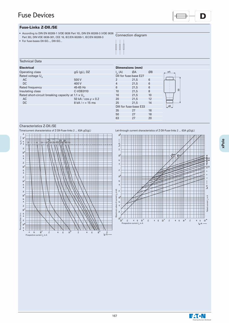
167
Fuse Devices
Fuse-Links Z-DII./SE• According to DIN EN 60269-1 (VDE 0636 Part 10), DIN EN 60269-3 (VDE 0636
Part 30), DIN VDE 0636-301, CEE 16, IEC/EN 60269-1, IEC/EN 60269-3• For fuse-bases DII-SO..., DIII-SO...
Connection diagram
Technical Data
Electrical Operating class gG (gL), DZRated voltage Un
AC 500 V DC 400 V
Rated frequency 45-65 HzInsulating class C-VDE0110Rated short-circuit breaking capacity at 1.1 x Un
AC 50 kA / cos ϕ = 0.2DC 8 kA / τ = 15 ms
Dimensions (mm) In (A) ØA ØBDII for fuse-base E272 21,5 64 21,5 66 21,5 610 21,5 816 21,5 1020 21,5 1225 21,5 14DIII for fuse-base E3335 27 1650 27 1863 27 20
Characteristics Z-DII./SETime/current characteristics of Z-DII-Fuse-links 2 ... 63A gG(gL) Let-through current characteristics of Z-DII-Fuse-links 2 ... 63A gG(gL)
Prospective current Ip in A
Pre-
arci
ng ti
me
t in
s
Max
imum
val
ue o
f cur
rent
I Din
kA
Rate
d cu
rren
t In
in A
Prospective current Ip in A
D

Characteristics Z-DII./SEMelting energy characteristics I2t/A of Z-DII-Fuse-links 2 ... 63A gG(gL) Time/current characteristics of Z-DII-Fuse-links 2 ... 63A DZ
Prospective current Ip in A
I2 A v
alue
in A
2 (s)
Pre-
arci
ng ti
me
t in
s
Prospective current Ip in A
168
Fuse Devices D

169
Fuse Devices
Gauge Ring Z-DII./PE
Technical Data
Electrical Rated current
DII 2 - 20 ADIII 2 - 50 A
• Used for current coding of DII.-SO/...
Screw Caps Z-DII./SK
Technical Data
Electrical Rated current
DII max. 25 ADIII max. 63 A
Rated voltageZ-DII/SK 500 V AC / 400 V DCZ-DIII/SK 500 V AC / 400 V DCZ-DIII/SK-690 690 V AC
Mechanical Electrical thread
DII E27DIII E33
Dimensions (mm)In (A) A B C DZ-DII/SK 34 44 12 35Z-DIII/SK 43 44 12 43Z-DIII/SK-690 43 65 12 43
A complete and functioning D-fuse system consists of – base for screw-in gauge ring + fuse-link + screw-in gauge ring + screw cap– base for gauge ring + fuse-link + gauge ring + screw capThe gauge ring is not required for the highest rated current of each size (DII ... 25 A and DIII ... 63 A).
Practical Hint
• Used for DII.-SO
Screw-in Gauge Ring Z-DII./PS
Technical Data
Electrical Rated current
DII 2 - 25 ADIII 35 - 63 A
Dimensions (mm) In (A) A B C DDII for fuse-base E272 3/16” 6.5 17 244 3/16” 6.5 17 246 3/16” 6.5 17 2410 3/16” 8.5 17 2416 3/16” 10.5 17 2420 3/16” 12.5 17 2425 3/16” 14.5 17 24DIII for fuse-base E3335 3/16” 16.5 17 2450 3/16” 18.5 17 2463 3/16” 20.5 17 24
• Used for current coding of DII.-SO/...-PS
D

Fuse-Links Z-C../SE• According to IEC 60269-1 and IEC 60269-2-1• For fuse-switch-disconnectors C10-SLS, VLC, C10-CCI• Operating classes gG (gL) and aM available
Connection diagram
Technical Data
Electrical Z-C10/SE Z-C14/SE Z-C22/SE10x38 14x51 22x58
Operating class gG (gL) gG (gL) gG (gL)Rated voltage Un 1 - 25 A / 500 V AC 2 - 32 A / 690 V AC 16 - 40 A / 690 V AC
32 A / 400 V AC 40 - 50 A / 500 V AC 50 - 100 A / 500 V ACOperating class aM aM aMRated voltage Un 1 - 16 A / 500 V AC 2 - 25 A / 690 V AC 16 - 50 A / 690 V AC
20 - 32 A / 400 V AC 32 - 50 A / 500 V AC 80 - 100 A / 500 V ACRated frequency 50 Hz 50 Hz 50 HzRated short-circuit breaking capacity 100 kA 100 kA 100 kA
170
Fuse Devices
Dimensions (mm) Type Size a bmax. c dmin. rZ-C10 10x38 38.0±0.6 10.5 10.3±0.1 6 1.5±0.5Z-C14 14x51 51.0+0.6/-1 13.8 14.3±0.1 7.5 2±0.5Z-C22 22x58 58.0+1/-2 16.2 22.2±0.1 11 2±0.5
Operating class gG - Power dissipations 400 V / 500 V / 690 Vmax. 3 W acc. IEC 60269-2 max. 5 W acc. IEC 60269-2 max. 9,5 W acc. IEC 60269-2
Rated current In 10x38 14x51 22x581 0,552 0,90 1,454 1,45 1,606 1,55 1,958 1,05 1,4010 1,10 1,4512 1,55 1,9516 2,85 3,00 3,0520 2,80 3,15 3,4025 2,95 4,10 4,4032 3,00 4,80 5,1040 4,75 7,2050 4,95 7,6063 8,0080 8,20100 9,40
Max. Power dissipation
CCylindrical Fuse-Links
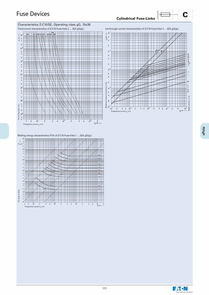
171
Fuse Devices
Characteristics Z-C10/SE, Operating class gG, 10x38Time/current characteristics of Z-C10-Fuse-links 2 ... 32A gG(gL) Let-through current characteristics of Z-C10-Fuse-links 2 ... 32A gG(gL)
Prospective current Ip in A
Pre-
arci
ng ti
me
t in
s
Max
imum
val
ue o
f cur
rent
I Din
kA
Rate
d cu
rren
t In
in A
Prospective current Ip in A
Melting energy characteristics I2t/A of Z-C10-Fuse-links 1 ... 32A gG(gL)
Prospective current Ip in A
I2 A v
alue
in A
2 (s)
CCylindrical Fuse-Links

172
Fuse Devices
Characteristics Z-C14/SE, Operating class gG, 14x51Time/current characteristics of Z-C14-Fuse-links 2 ... 50A gG(gL) Let-through current characteristics of Z-C14-Fuse-links 2 ... 50A gG(gL)
Prospective current Ip in A
Pre-
arci
ng ti
me
t in
s
Max
imum
val
ue o
f cur
rent
I Din
kA
Rate
d cu
rren
t In
in A
Prospective current Ip in A
Melting energy characteristics I2t/A of Z-C14-Fuse-links 2 ... 50A gG(gL)
Prospective current Ip in A
I2 A v
alue
in A
2 (s)
CCylindrical Fuse-Links

Characteristics Z-C22/SE, Operating class gG, 14x51Time/current characteristics of Z-C22-Fuse-links 16 ... 100A gG(gL) Let-through current characteristics of Z-C22-Fuse-links 16 ... 100A gG(gL)
Prospective current Ip in A
Pre-
arci
ng ti
me
t in
s
Max
imum
val
ue o
f cur
rent
I Din
kA
Rate
d cu
rren
t In
in A
Prospective current Ip in A
173
Fuse Devices
Melting energy characteristics I2t/A of Z-C22-Fuse-links 16 ... 100A gG(gL)
Prospective current Ip in A
I2 A v
alue
in A
2 (s)
CCylindrical Fuse-Links
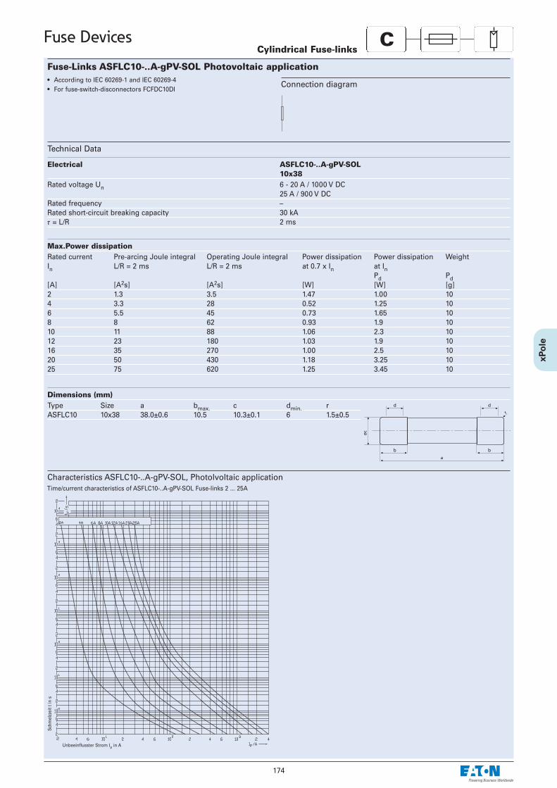
174
Fuse Devices
Fuse-Links ASFLC10-..A-gPV-SOL Photovoltaic application• According to IEC 60269-1 and IEC 60269-4• For fuse-switch-disconnectors FCFDC10DI
Connection diagram
Technical Data
Electrical ASFLC10-..A-gPV-SOL10x38
Rated voltage Un 6 - 20 A / 1000 V DC25 A / 900 V DC
Rated frequency –Rated short-circuit breaking capacity 30 kAτ = L/R 2 ms
Dimensions (mm) Type Size a bmax. c dmin. rASFLC10 10x38 38.0±0.6 10.5 10.3±0.1 6 1.5±0.5
Max.Power dissipationRated current Pre-arcing Joule integral Operating Joule integral Power dissipation Power dissipation WeightIn L/R = 2 ms L/R = 2 ms at 0.7 x In at In
Pd Pd[A] [A2s] [A2s] [W] [W] [g]2 1.3 3.5 1.47 1.00 104 3.3 28 0.52 1.25 106 5.5 45 0.73 1.65 108 8 62 0.93 1.9 1010 11 88 1.06 2.3 1012 23 180 1.03 1.9 1016 35 270 1.00 2.5 1020 50 430 1.18 3.25 1025 75 620 1.25 3.45 10
Cylindrical Fuse-links
Characteristics ASFLC10-..A-gPV-SOL, Photolvoltaic applicationTime/current characteristics of ASFLC10-..A-gPV-SOL Fuse-links 2 ... 25A
Unbeeinflusster Strom Ip in A
Schm
elzz
eit t
in s
C

175
Fuse Devices
NH-Fuse-Links Z-NH• Design according to ÖVE-SN 40, IEC 60269, VDE 0636, SEV 1066• Dimensions according to Austrian standard ÖNORM E-6020, DIN 43.620• NH-fuse-links of operating class gG/gL are used for line protection. They
reliably disconnect overcurrent and short-circuit current above the permit-ted levels up to the nominal breaking current.
• gG/gL NH-fuse-links also protect electrical systems and equipment againstthe electrodynamic effects of high short-circuit currents.
• Insulating bodies of steatite/corderite • Full contact blade of silver-plated copper
• Double blow-out indicator (flat indicator and centre indicator), live grips• Corrosion-proof• NH-fuse-links have a selectivity of 1:1.6 (ratio of the series-connected nomi-
nal currents), permitting optimum utilization and protection of line cross-sections.
• Strict current limitation permits reduced mechanical dimensions of electri-cal systems
• High breaking capacity of 120 kA
Technical Data
Z-NH-00/ Z-NH-1/ Z-NH-2/ Z-NH-3/
Electrical Nominal voltage
AC 500 V AC 500 V AC 500 V AC 500 V ACDC 230 V DC 440 V DC 440 V DC 440 V DC
Nominal current 25-160 A 50-250 A 100-400 A 250-630 ARated frequency 45-62 Hz 45-62 Hz 45-62 Hz 45-62 HzNominal breaking capacity
AC 120 kA 120 kA 120 kA 120 kADC 25 kA 25 kA 25 kA 25 kA
Max. Power lossIn = 10 A 1.1 W - - -
16 A 1.6 W - - -20 A 1.7 W - - -25 A 1.9 W - - -35 A 3.0 W - - -40 A 3.5 W - - -50 A 4.6 W 5.4 W - -63 A 5.4 W 6.3 W - -80 A 5.1 W 7.2 W - -100 A 6.9 W 8.6 W 8.8 W -125 A 10.3 W 11.9 W 12.1 W -160 A 11.0 W 13.9 W 14.0 W -200 A - 15.2 W 15.2 W -250 A - 21.8 W 21.8 W 19.4 W315 A - - 23.7 W 23.7 W400 A - - 30.5 W 30.5 W500 A - - - 42.0 W630 A - - - 47.0 W
Connection diagram
Dimensions (mm)Type Size A B C D E F G H KZ-NH-00/ up to 100 A 000 79 53 47 35 15 21 52 7.5 6
125 - 160 A 00 79 53 47 35 15 28 56 12 6Z-NH-1/ up to 160 A 1C 135 68 65 40 15 28 61 12 6
200 - 250 A 1 135 72 65 40 20 46 65 14 6Z-NH-2/ up to 250 A 2C 150 72 65 48 20 46 73 14 6
315 - 400 A 2 150 72 65 48 26 54 73 14 6Z-NH-3/ up to 400 A 3C 150 72 65 60 26 54 84 14 6
500 - 630 A 3 150 72 65 60 33 65 84 14 6
NH

176
Fuse Devices
Let-through Current Characteristic, Current Limitation Diagram
The characteristic shows the limited let-through current values (peak values) depending on the prospectiveshort-circuit current (r. m. s.) under unfavourable connection conditions and depending on the respectivenominal current.
ID let-through currentIG declining DC componentIp prospective short-circuit currentIs surge short-circuit current = Ip·κ·√2κ κ=2 for cosϕ=0, κ=1 for cosϕ=1
Correction Factor for DC Component
a Surge short-circuit current without DC component (κ = 1)
b Surge short-circuit current with maximum DC component (κ = 2)
Time-Current CharacteristicsThe time-current characteristics are valid at an ambient temperature of 20±5°C Cand for the cable (line) cross-sections assigned in the regulations for test arrange-ments.
For NH-fuse-links 2 - 630 A operating class gL/gG
NH

177
Measuring Instruments
Power Meter KWZ• Power meter according to IEC/EN 61036 for sub-measurement• For active energy• 3-phase AC types also suitable for uneven load• Type KWZ-230: single-phase kWh-meter• Type Z-KWZ-3PH: for 4-wire 3-phase AC system with external transducer
X/5A; Type Z-MG/WA.Transducer ratios according to table
• Type Z-KWZ-3PH-25: For 4-wire 3-phase AC system with direct connection
Technical Data
KWZ-230
Electrical Rated voltage Un 230 V ACWorking range 0.9 - 1.2 x UnRated current Ib 10A, directMaximum currentImax 40 ARated frequency 50/60HzOverload short time –Back-up fuse MCB: C40
40 A gG/gLSealable noAuxiliary voltage from measurement
Power consumption –Power loss 2 WInput signal sinusoidalPower factor cosϕ=0.5 inductive to cosϕ=0,8 capacitiveAccuracy class 1Resolution 0.1 kWhLED signal 640 pulse/kWhOwn consumption per phase <8 VADIP adjustment switch for –
transducer ratiosPulse output rated values 5-48V DC, 50mA
Pulse value (jumper) 10 pulse/kWhSwitching contact (potential-free) 1 NORated peak withstand voltage(1.2/50) µs 5 kVTest voltage 50Hz/1min. 2.5 kV
Mechanical Frame size 45 mmDevice height 90 mmDevice width 35 mm (2MU)Weight 180 gCalibrateable noDisplay 5+1digitMaximum display reading 99999,9kWhHeight of figures 4 mmMounting quick fastening on DIN rail IEC/EN 60715Degree of protection, built-in IP51Upper and lower terminals lift terminalsTerminal capacity 12mm2 (2.5mm2 pulse-outp.)Tightening torque of terminal screws 2 NmPermitted relative humidity 90%Perm. ambient temperature range -5 to +55°CFlame class acc. to UL 94 V0
Connection diagram
Dimensions (mm)
KWZ-230
Load
Output
N
6 8
L
3 7
41
KWZ-230

178
Measuring Instruments
Power Meter KWZ-3PH• Power meter according to EN 62053 for sub-measurement• For active/reactive energy• For unbalanced load• Programming by front keyboard, 2 keys• Sealability front frame and terminal
Technical Data
KWZ-3PH KWZ-3PH-63
Electrical Rated voltage Un 230-240/400-415 V AC 230-240/400-415 V ACWorking range 110-254/190-440 V AC 110-254/190-440 V ACRated current Ib 1 and 5 A 10 AMaximum current Imax 6 A 63 AMaximum back-up fuse MCB: B10 or 10A gG/gL MCB: C63 or 63A gG/gL
(only voltage pathes)Rated frequency 50 and 60 Hz 50 and 60 HzFrequency range 47-63 Hz 47-63 HzPower consumption per phase (current path) ≤0.5 VA (each phase) ≤4 VA (each phase)Overcurrent short time 20 x Imax / 0.5 s 30 x Imax / 10 msAuxiliary voltage from measurement from measurementInput signal sinusoidal sinusoidalAccuracy class 1 1Metering LED 1 pulse / 0.1 Wh 1 pulse / WhPulse output rated values max. 110V AC/DC, 50mA max. 110V AC/DC, 50mA
Switching contact (potential-free) Opto coupler Opto couplerS0-Interface according S0-Interface according DIN 43864 / EN 62053-31 DIN 43864 / EN 62053-31
Pulse frequency (selectable) 1 pulse / 10Wh-100Wh-1kWh-10kWh 1 pulse / 1Wh-10Wh--100Wh1kWh-10kWhoptional 1 pulse / 10VArh-100VArh- optional 1 pulse / 10VArh-100VArh-1kVArh-10kVArh 1kVArh-10kVArh
Pulse duration (selectable) 50-100-150-200-300-400-500 ms 50-100-150-200-300-400-500 msProgrammable parameters connection (1-phase, 3-phases connection (3-phases 3- or 4-wire),
3- or 4-wire), external VT and counting, power demand, pulseCT-ratio, power demand, outputpulse output
Overvoltage category III IIIInsulation voltage rating (phase - phase) 450 V 300 V Rated impulse withstand voltage (1.2/50) µs 5 kV 5 kVTest voltage
Input/pulse-output 2.75 kV 2.75 kVall circuits and earth 4 kV 4 kV
Protection class II II
Mechanical Frame size 45 mm 45 mmDevice height 89 mm 89 mmDevice width 71.2 mm 71.2 mmWeight 260 g 260 gDisplay LCD 8 digit LCD 8 digitDigit height 6 mm 6 mmMaximum display setable 999999,99 kWhResolution setable 10 WMeasurement display subdivided on 6 pages subdivided on 7 pagesMounting quick fastening on DIN rail IEC/EN 60715Degree of protection, front frame / terminals IP52 / IP20 IP52 / IP20Upper and lower terminals screw terminals screw terminalsTerminal capacity
Current terminal rigid cable 0.05-4mm2 input: rigid cable 1-10mm2
flexible cable 0.05-2.5mm2 flexible cable 1-13mm2
Voltage terminal rigid cable 0.05-4mm2 output: rigid cable 1-4mm2
flexible cable 0.05-2.5mm2 flexible cable 1-3mm2
Permitted relative air humidity suitable for tropical dissipation suitable for tropical dissipationReference temperature 23°C ±2°C 23°C ±2°CPerm. ambient temperature range -5 to +55°C -5 to +55°CStorage and transportation temperature range -25 to +70°C -25 to +70°CPollution degree 2 2
Connection diagramKWZ-3PH KWZ-3PH-63

179
Measuring Instruments
Dimensions (mm)
Wiring diagrams KWZ-3PH
1-phase 3-phases3-wiresbalanced
3-phases3-wiresunbalanced
3-phases3-wiresunbalanced
3-phases3-wiresunbalanced
3-phases3-wiresunbalanced
3-phases4-wiresbalanced
3-phases4-wiresunbalanced
Wiring diagrams KWZ-3PH-63
3-phases3-wires
3-phases4-wires
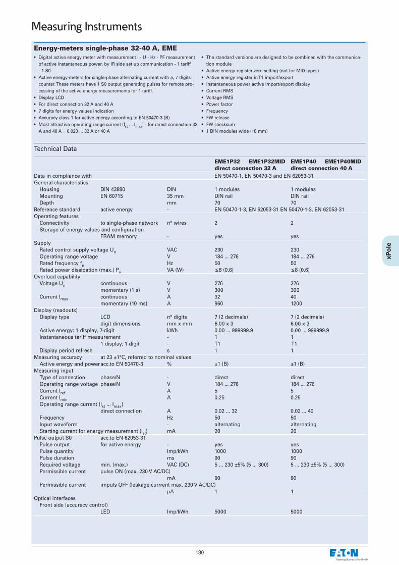
180
Measuring Instruments
Energy-meters single-phase 32-40 A, EME• Digital active energy meter with measurement I - U - Hz - PF measurement
of active instantaneous power, by IR side set up communication - 1 tariff - 1 S0
• Active energy-meters for single-phase alternating current with a, 7 digitscounter. These meters have 1 S0 output generating pulses for remote pro-cessing of the active energy measurements for 1 tariff.
• Display LCD• For direct connection 32 A and 40 A• 7 digits for energy values indication• Accuracy class 1 for active energy according to EN 50470-3 (B)• Most attractive operating range current (Ist ... Imax) - for direct connection 32
A and 40 A = 0.020 ... 32 A or 40 A
• The standard versions are designed to be combined with the communica-tion module
• Active energy register zero setting (not for MID types)• Active energy register in T1 import/export• Instantaneous power active import/export display• Current RMS• Voltage RMS• Power factor• Frequency• FW release• FW checksum• 1 DIN modules wide (18 mm)
Technical Data
EME1P32 EME1P32MID EME1P40 EME1P40MIDdirect connection 32 A direct connection 40 A
Data in compliance with EN 50470-1, EN 50470-3 and EN 62053-31General characteristics
Housing DIN 43880 DIN 1 modules 1 modulesMounting EN 60715 35 mm DIN rail DIN railDepth mm 70 70
Reference standard active energy - EN 50470-1-3, EN 62053-31 EN 50470-1-3, EN 62053-31Operating features
Connectivity to single-phase network n° wires 2 2Storage of energy values and configuration
FRAM memory - yes yesSupply
Rated control supply voltage Un VAC 230 230Operating range voltage V 184 ... 276 184 ... 276Rated frequency fn Hz 50 50Rated power dissipation (max.) Pv VA (W) ≤8 (0.6) ≤8 (0.6)
Overload capabilityVoltage Un continuous V 276 276
momentary (1 s) V 300 300Current Imax continuous A 32 40
momentary (10 ms) A 960 1200Display (readouts)
Display type LCD n° digits 7 (2 decimals) 7 (2 decimals)digit dimensions mm x mm 6.00 x 3 6.00 x 3
Active energy: 1 display, 7-digit kWh 0.00 ... 999999.9 0.00 ... 999999.9Instantaneous tariff measurement - 1 1
1 display, 1-digit - T1 T1Display period refresh s 1 1
Measuring accuracy at 23 ±1°C, referred to nominal valuesActive energy and poweracc.to EN 50470-3 % ±1 (B) ±1 (B)
Measuring inputType of connection phase/N - direct directOperating range voltage phase/N V 184 ... 276 184 ... 276Current Iref A 5 5Current Imin A 0.25 0.25Operating range current (Ist ... Imax)
direct connection A 0.02 ... 32 0.02 ... 40Frequency Hz 50 50Input waveform - alternating alternatingStarting current for energy measurement (Ist) mA 20 20
Pulse output S0 acc.to EN 62053-31Pulse output for active energy - yes yesPulse quantity Imp/kWh 1000 1000Pulse duration ms 90 90Required voltage min. (max.) VAC (DC) 5 ... 230 ±5% (5 ... 300) 5 ... 230 ±5% (5 ... 300)Permissible current pulse ON (max. 230 V AC/DC)
mA 90 90Permissible current impuls OFF (leakage currrent max. 230 V AC/DC)
µA 1 1Optical interfaces
Front side (accuracy control) LED Imp/kWh 5000 5000

181
Measuring Instruments
EME1P32 EME1P32MID EME1P40 EME1P40MIDdirect connection 32 A direct connection 40 A
Safety acc. to EN 50470-1Indoor meter - yes yesDegree of pollution - 2 2Operational voltage V 300 300AC voltage test (EN 50470-3, 7.2) kV 4 4Impulse voltage test 1.2/50 µs-kV 6 6Protection class (EN 50470) class II IIHousing material flame resistance
UL 94 class V0 V0Safety-sealing between upper and lower housing part
- no yes no yesAdaptor for Communication
Plug-and-play technology - • •LAN Interface (TCP/IP) Ethernet 802.3 EMECLAN 10/100 Mbps 10/100 MbpsModbus RTU, Ascii RS-485 3 wires EMECMODB up to 19.200 bps up to 19.200 bpsM-Bus RS-485 2 wires EMECMBUS up to 9.600 bps up to 9.600 bps
Connection terminalsType cage main current paths
screw head Z +/- POZIDRIV PZ1 PZ1Type cage pulse output blade for slotted screw mm PZ0 PZ0Terminal capacity main current paths
solid wire min. (max.) mm2 16 16stranded wire with sleeve min. (max.)
mm2 16 16Terminal capacity pulse outlet
solid wire min. (max.) mm2 0.15 (2.5) 0.15 (2.5)stranded wire with sleeve min. (max.)
mm2 0.15 (4) 0.15 (4)Environmental conditions
Mechanical environment - M1 M1Electromagnetic environment - E2 E2Operating temperature °C -10 ... +55 -10 ... +55Limit temperature of transportation and storage °C -25 ... +70 -25 ... +70Relative humidity (not condensation) % ≤80 ≤80Vibrations 50 Hz sinusoidal vibration amplitude
mm ±0.075 ±0.075Degree protectionhousing when mounted in front (terminal)
- IP51*)/IP20 IP51*)/IP20
*) For the installation in a cabinet at least with IP51 protection
Dimensions (mm) Connection diagram
A Miniature Circuit Breaker of 32Aor 40A is recommended.

182
Measuring Instruments
Energy-meters single-phase 80 A, EME• Digital active and reactive energy meter with measurement of active and
reactive instantaneous power, by IR side set up communication - 2 tariffs -2 S0
• Active and reaktive (not for MID types) energy-meters for single-phasealternating current with either 1, 7 digits digital counters. These metershave 2 S0 output generating pulses for remote processing of the energyactive and reactive measurements for 2 tariffs.
• Green backlighted LCD• For direct connection 80 A• 7 digits for energy values indication• Accuracy class 1 for active energy and power according to EN 50470-3 (B)
• Accuracy class 2 for reactive energy and power according to EN 62053-23• Most attractive operating range current (Ist ... Imax) for direct connection
80 A = 0.02 ... 80 A• The standard versions are designed to be combined with the communica-
tion module• Energy register zero setting (not for MID types)• Energy register for import and export• Instantaneous power active and reactive display (MID types: only active
power)• Sealable terminal covers• 2 DIN modules wide (36 mm)
Technical Data
EME1P80 EME1P80MID direct connection 80 A
Data in compliance with EN 50470-1, EN 50470-3, EN 62053-23 and EN 62053-31General characteristics
Housing DIN 43880 DIN 2 modulesMounting EN 60715 35 mm DIN railDepth mm 70
Reference standard active energy - EN 50470-1-3, EN 62053-23-31reactive energy - pulse output
Operating featuresConnectivity to single-phase network n° wires 2Storage of energy values and configuration
digital display (EEPROM) - yesDisplay tariffs identifier for active and reactive energy
n° 2 T1 and T2Supply
Rated control supply voltage Un VAC 230Operating range voltage V 184 ... 276Rated frequency fn Hz 50 Rated power dissipation (max.) Pv VA (W) ≤8 (0.6)
Overload capabilityVoltage Un continuous V 276
momentary (1 s) V 300 Current Imax continuous A 80
momentary (10 ms) A 2400Display (readouts)
Display type LCD n° digits 7 (1 decimal)digit dimensions mm x mm 6.00 x 3
Active energy: 1 display, 7-digit tariffs 1-2 kWh 000000.0 ... 999999.9
+ display import or export (arrow) overflow kWh 999999.9 ... 000000.0
Reactive energy: 1 display, 7-digit tariffs 1-2 kvarh 000000.0 ... 999999.9
+ display import or export (arrow) overflow kvarh 999999.9 ... 000000.0
Instantaneous active power: 1 display, 3-digit W, kW or MW 000 ... 999Instantaneous reactive power: 1 display, 3-digit var, kvar or Mvar 000 ... 999Instantaneous tariff measurement - 1
1 display, 1-digit - T1 or T2Display period refresh s 1
Measuring accuracy at 23 ±1°C, referred to nominal valuesActive energy and poweracc.to EN 50470-3 % BReactive energy and power
acc.to EN 62053-23 % 2Measuring input
Type of connection phase/N - direct Operating range voltage phase/N V 184 ... 276 Current Iref A 15Current Imin A 0.75Operating range current (Ist ... Imax)
direct connection A 0.025 ... 80Frequency Hz 50 Input waveform - sinusoidalStarting current for energy measurement (Ist) mA 25

183
Measuring Instruments
EME1P80 EME1P80MID direct connection 80 A
Pulse output S0 acc.to EN 62053-31Pulse output for active and reactive energy T1 and T2 yesPulse quantity Imp/kWh 1000Pulse duration ms 30 ±2 msRequired voltage min. (max.) VAC (DC) 5 ... 230 ±5% (5 ... 300)Permissible current pulse ON (max. 230 V AC/DC)
mA 90Permissible current impuls OFF (leakage currrent max. 230 V AC/DC)
µA 1Optical interfaces
Front side (accuracy control) LED Imp/kWh 1000
Safety acc. to EN 50470-1Indoor meter - yesDegree of pollution - 2Operational voltage V 300AC voltage test (EN 50470-3, 7.2) kV 4Impulse voltage test 1.2/50 µs-kV 6Protection class (EN 50470) class IIHousing material flame resistance
UL 94 class V0Safety-sealing between upper and lower housing part
- no yesAdaptor for Communication
Plug-and-play technology - • LAN Interface (TCP/IP) Ethernet 802.3 EMECLAN 10/100 MbpsModbus RTU, Ascii RS-485 3 wires EMECMODB up to 19.200 bpsM-Bus RS-485 2 wires EMECMBUS up to 9.600 bps
Connection terminalsType cage main current paths
screw head Z +/- POZIDRIV PZ2Type cage pulse output blade for slotted screw mm 0.8 x 3.5Terminal capacity main current paths
solid wire min. (max.) mm2 1.5 (35)stranded wire with sleeve min. (max.)
mm2 1.5 (35)Terminal capacity pulse outlet
solid wire min. (max.) mm2 0.14 (2.5)stranded wire with sleeve min. (max.)
mm2 0.14 (1.5)Environmental conditions
Mechanical environment - M1Electromagnetic environment - E2Operating temperature °C -10 ... +55Limit temperature of transportation and storage °C -25 ... +70Relative humidity (not condensation) % ≤80Vibrations 50 Hz sinusoidal vibration amplitude
mm ±0.075Degree protectionhousing when mounted in front (terminal)
- IP51*)/IP20
*) For the installation in a cabinet at least with IP51 protection
Dimensions (mm) Connection diagram
A Miniature Circuit Breaker of 80Ais recommended.

184
Measuring Instruments
Energy-meters single-phase 125 A, EME• Digital active and reactive energy meter with measurement of active and
reactive instantaneous power, by IR side set up communication - 2 tariffs• Active energy-meters for single-phase alternating current with either 2,
8 digits digital counters. These meters have 2 S0 output generating pulsesfor remote processing of the energy active and reactive measurements for2 tariffs.
• Green backlighted LCD• For direct connection 125 A• 8 digits for energy values indication• Accuracy class 1 for active energy and power according to EN 50470-3 (B)• Accuracy class 2 for reactive energy and power according to EN 62053-23
• Most attractive operating range current (Ist ... Imax) for direct connection 125 A = 0.020 ... 125 A
• The standard versions are designed to be combined with the communica-tion module
• Energy register zero setting (not for MID types)• Energy register for import and export• Instantaneous power active and reactive display• Sealable terminal covers• 3 DIN modules wide (52 mm)
Technical Data
EME1P125 EME1P125MIDdirect connection 125 A
Data in compliance with EN 50470-1, EN 50470-3, EN 62053-23 and EN 62053-31General characteristics
Housing DIN 43880 DIN 3 modulesMounting EN 60715 35 mm DIN railDepth mm 70
Reference standard active energy - EN 50470-1-3, EN 62053-23-31reactive energy - pulse output
Operating featuresConnectivity to single-phase network n° wires 2Storage of energy values and configuration
digital display (EEPROM) - yesDisplay tariffs identifier for active and reactive energy
n° 2 T1 and T2Supply
Rated control supply voltage Un VAC 230Operating range voltage V 184 ... 276Rated frequency fn Hz 50 Rated power dissipation (max.) Pv VA (W) ≤8 (0.6)
Overload capabilityVoltage Un continuous V 276
momentary (1 s) V 300 Current Imax continuous A 125
momentary (10 ms) A 3750Display (readouts)
Display type LCD n° digits 8 (2 decimal)digit dimensions mm x mm 6.00 x 3
Active energy: 1 display, 8 digit tariffs 2 Wh 0.01
+ display import or export (arrow) overflow MWh 999999.99
Reactive energy: 1 display, 8 digit tariffs 2 varh 0.01
+ display import or export (arrow) overflow Mvarh 999999.99
Instantaneous active power: 1 display, 3-digit W, kW or MW 000 ... 999Instantaneous reactive power: 1 display, 3-digit var, kvar or Mvar 000 ... 999Instantaneous tariff measurement - 1
1 display, 1-digit - T1 or T2Display period refresh s 1
Measuring accuracy at 23 ±1°C, referred to nominal valuesActive energy and poweracc.to EN 50470-3 % BReactive energy and power
acc.to EN 62053-23 % 2Measuring input
Type of connection phase/N - direct Operating range voltage phase/N V 184 ... 276 Current Iref A 5Current Imin A 0.25Operating range current (Ist ... Imax)
direct connection A 0.020 ... 125Frequency Hz 50 Input waveform - sinusoidalStarting current for energy measurement (Ist) mA 20

185
Measuring Instruments
EME1P125 EME1P125MIDdirect connection 125 A
Pulse output S0 acc.to EN 62053-31Pulse output for active and reactive energy T1 and T2 yesPulse quantity Imp/kWh 1000Pulse duration ms 30 ±2 msRequired voltage min. (max.) VAC (DC) 5 ... 230 ±5% (5 ... 300)Permissible current pulse ON (max. 230 V AC/DC)
mA 90Permissible current impuls OFF (leakage currrent max. 230 V AC/DC)
µA 1Optical interfaces
Front side (accuracy control) LED Imp/kWh 1000
Safety acc. to EN 50470-1Indoor meter - yesDegree of pollution - 2Operational voltage V 300AC voltage test (EN 50470-3, 7.2) kV 4Impulse voltage test 1.2/50 µs-kV 6Protection class (EN 50470) class IIHousing material flame resistance
UL 94 class V0Safety-sealing between upper and lower housing part
- no yesAdaptor for Communication
Plug-and-play technology - • LAN Interface (TCP/IP) Ethernet 802.3 EMECLAN 10/100 MbpsModbus RTU, Ascii RS-485 3 wires EMECMODB up to 19.200 bpsM-Bus RS-485 2 wires EMECMBUS up to 9.600 bps
Connection terminalsType cage main current paths
screw head Z +/- POZIDRIV PZ2Type cage pulse output blade for slotted screw mm 0.8 x 3.5Terminal capacity main current paths
solid wire min. (max.) mm2 1.5 (50)stranded wire with sleeve min. (max.)
mm2 1.5 (50)Terminal capacity pulse outlet
solid wire min. (max.) mm2 1 (4)stranded wire with sleeve min. (max.)
mm2 1 (2.5)Environmental conditions
Mechanical environment - M1Electromagnetic environment - E2Operating temperature °C -10 ... +55Limit temperature of transportation and storage °C -25 ... +70Relative humidity (not condensation) % ≤80Vibrations 50 Hz sinusoidal vibration amplitude
mm ±0.075Degree protectionhousing when mounted in front (terminal)
- IP51*)/IP20
*) For the installation in a cabinet at least with IP51 protection
Dimensions (mm) Connection diagram
A Miniature Circuit Breaker of 125Ais recommended.

186
Measuring Instruments
Energy-meters three-phase, transformer 5 A, direct 80 A, EME• Digital active and reactive energy-meter with measurement of active and
reactive instantaneous power, by IR side set up communication - 2 tariffs -2 S0 (MID types: displays only active power).
• Active energy-meters for three-phase alternating current with either 2,8 digits digital counters. These meters have 2 S0 output generating pulsesfor remote processing of the instantaneous energy active and reactivemeasurements for 2 tariffs.
• Green backlighted LCD• For direct connection 80 A, or for transformer .../5 A• For transformer primary current of 5 A to 10.000/5 A. Input is in 5 A incre-
ments• 8 digits - 8 display for energy values indication• Detection of connection errors (phase transposition)
• Accuracy class 1 for active energy and power according to EN 50470-3 (B)• Accuracy class 2 for reactive energy and power according to EN 62053-23• Most attractive operating range current (Ist ... Imax), for direct connection 80
A = 0.015 ... 80 A, for connection by CT .../5 A = 0.003 ... 5 A• The standard versions are designed to be combined with the communica-
tion module• Energy register zero setting (not for MID types)• Energy register for import and export• Instantaneous power active and reactive display (MID types: only active
power)• Sealable terminal covers• 4 DIN modules wide (72 mm)
Technical Data
EME3P80 EME3P80MID EME3PCT EME3PCTMIDdirect connection 80 A CT connection till 10.000/5 A
Data in compliance with EN 50470-1, EN 50470-3, EN 62053-23 and EN 62053-31General characteristics
Housing DIN 43880 DIN 4 modules 4 modules Mounting EN 60715 35 mm DIN rail DIN rail Depth mm 70 70
Reference standard active energy - EN 50470-1-3 EN 50470-1-3pulse output EN 62053-31 EN 62053-31
Operating featuresConnectivity to single/three-phase network
n° wires 2-4 4Storage of energy values and configuration
digital display (EEPROM) - yes yesDisplay tariffs identifier for active and reactive energy
n° 2 T1 and T2 T1 and T2Supply
Rated control supply voltage Un VAC 230 230Operating range voltage V 184 ... 276 184 ... 276 Rated frequency fn Hz 50 50 Rated power dissipation (max. for phase) Pv VA (W) ≤8 (0.6) ≤8 (0.6)
Overload capabilityVoltage Un continuous; phase/phase V 480 480
1 second: phase/phase V 800 800 continuous; phase/N V 276 276 1 second: phase/N V 460 460
Current Imax continuous A 80 6momentary (0,5 s) A - 120momentary (10 ms) A 2400 -
Display (readouts)Connection errors and phase out
discernible from phase-sequence indication - PHASE Err PHASE Err
Display type LCD n° digits 8 (2 decimal) 8 (2 decimal)digit dimensions mm x mm 6.00 x 3 6.00 x 3
Active energy: 1 display, 8 digit tariffs 2 Wh 0.01 0.01
+ display import or export (arrow) overflow MWh 999999.99 999999.99
Reactive energy: 1 display, 8-digit tariffs 2 varh 0.01 0.01
+ display import or export (arrow) overflow Mvarh 999999.99 999999.99
Instantaneous active power: 1 display, 3-digit W, kW or MW 000 ... 999 000 ... 999Instantaneous reactive power: 1 display, 3-digit var, kvar or Mvar 000 ... 999 000 ... 999Instantaneous tariff measurement
1 display, 1-digit - T1 or T2 T1 or T2 Transformer primary current A - 5 ... 10.000Display period refresh s 1 1
Measuring accuracyActive energy and power acc.to EN 50470-3 class 1 B BReactive energy and power acc.to EN 62053-23 class 2 2 2

187
Measuring Instruments
EME3P80 EME3P80MID EME3PCT EME3PCTMIDdirect connection 80 A CT connection till 10.000/5 A
Measuring inputType of connection direct transformer .../5 AVoltage Un phase/phase V 400 400
phase/N V 230 230 Operating range voltage phase/phase V 319 ... 480 319 ... 480
phase/N V 184 ... 276 184 ... 276 Current Iref A 5 -Current In A - 5Current Imin A 0.25 0.05Operating range current (Ist ... Imax)
direct connection A 0.015 ... 80 -transformer connection (CT) A - 0.003 ... 6
Transformer current primary current of the transformer A - 5 ...10.000
smallest input step adjustment - in 5 A stepsA - 5
Frequency Hz 50 50 Input waveform - sinusoidal sinusoidal Starting current for energy measurement (Ist) mA 15 3
Pulse output SO acc.to EN 62053-31Pulse output for act. and react. energy T1 and T2 yes yesQuantity pulse output for direct connection 80 A Imp/kWh 500 -
depending on the transf. factor. Imp/kWh - 100-10-1
Pulse duration ms 30 ±2 30 ±2Required voltage min. (max.) VAC (DC) 5 ... 230 ±5% (5 ... 300) 5 ... 230 ±5% (5 ... 300)Permissible current pulse ON (max. 230 V AC/DC)
mA 90 90Permissible current pulse OFF (leakage current max. 230 V AC/DC)
µA 1 1Optical interfaces
Front side (accuracy control) LED Imp/kWh 1000 10.000
Safety acc. to EN 50470-1Indoor meter - yes yesDegree of pollution - 2 2Operational voltage V 300 300AC voltage test (EN 50470-3, 7.2) kV 4 4Impulse voltage test 1.2/50 µs-kV 6 6Protection class (EN 50470) class II IIHousing material flame resistance
UL 94 class V0 V0Safety-sealing between upper and lower housing part
- yes no no yesAdaptor for Communication
Plug-and-play technology - • •LAN (TCP/IP) interface Ethernet 802.3 EMECLAN 10/100 Mbps 10/100 MbpsModbus RTU, Ascii interface
RS-485 - 3 wires EMECMODB up to 19.200 bps up to 19.200 bpsM-Bus interface RS-485 - 2 wires EMECMBUS up to 9.600 bps up to 9.600 bps
Connection terminalsType cage main current paths
screw head Z +/- POZIDRIV PZ2 PZ1Type cage pulse output blade for slotted screw mm 0.8 x 3.5 0.8 x 3.5Terminal capacity main current paths
solid wire min. (max.) mm2 1.5 (35) 1 (4)stranded wire with sleeve min. (max.)
mm2 1.5 (35) 1 (4)Terminal capacity pulse outlet
solid wire min. (max.) mm2 1 (4) 1 (4)stranded wire with sleeve min. (max.)
mm2 1 (2.5) 1 (4)

188
Measuring Instruments
EME3P80 EME3P80MID EME3PCT EME3PCTMIDdirect connection 80 A CT connection till 10.000/5 A
Environmental conditionsMechanical environment - M1 M1Electromagnetic environment - E2 E2Operating temperature °C -10 ... +55 -10 ... +55Limit temperature of transportation and storage °C -25 ... +70 -25 ... +70Relative humidity (not condensation) % ≤80 ≤80Vibrations 50 Hz sinusoidal vibration amplitude
mm ±0.075 ±0.075Degree protectionhousing when mounted in front (terminal)
- IP51*)/IP20 IP51*)/IP20
*) For the installation in a cabinet at least with IP51 protection
Dimensions (mm) Connection diagrams
A Miniature Circuit Breaker of 80Ais recommended.
Wire N needs to be connected tothe meter.
Direct connection 80 A

189
Measuring Instruments
Dimensions (mm) Connection diagrams
Wire N needs to be connected to the meter.
Instructions for the connection of transformer countersA Miniature Circuit Breaker of 6A is recommended. Currenttransformers must not be operated with open terminals sincedangerous high voltages might occur which may result in per-sonal injuriesand property damage. In addition to this, the transformers areexposed to thermal overload.
Connection through CT .../5 A till 10.000/5 A

190
Measuring Instruments
Energy-meters three-phase 125 A, EME• Digital active and reactive energy-meter with measurement of active and
reactive instantaneous power, by IR side set up communication - 2 tariffs -2 S0 (MID types: displays only active power).
• Active energy-meters for three-phase alternating current with either 2,8 digits digital counters. These meters have 2 S0 output generating pulsesfor remote processing of the instantaneous energy active and reactivemeasurements for 2 tariffs.
• Green backlighted LCD• For direct connection 125 A• 8 digits - 8 display for energy values indication• Detection of connection errors (phase transposition)• Accuracy class 1 for active energy and power according to EN 50470-3 (B)
• Accuracy class 2 for reactive energy and power according to EN 62053-23• Most attractive operating range current (Ist ... Imax) for direct connection
125 A = 0.020 ... 125 A• The standard versions are designed to be combined with the communica-
tion module• Energy register zero setting (not for MID types)• Energy register for import and export• Instantaneous power active and reactive display (MID types: only active
power)• Sealable terminal covers• 6 DIN modules wide (108 mm)
Technical Data
EME3P125 EME3P125MIDdirect connection 125 A
Data in compliance with EN 50470-1, EN 50470-3, EN 62053-23 and EN 62053-31General characteristics
Housing DIN 43880 DIN 6 modulesMounting EN 60715 35 mm DIN railDepth mm 70
Reference standard active energy - EN 50470-1-3reactive energy - pulse output EN 62053-23-31
Operating featuresConnectivity to single/three-phase network
n° wires 2-4Storage of energy values and configuration
digital display (EEPROM) - yesDisplay tariffs identifier for active and reactive energy
n° 2 T1 and T2Supply
Rated control supply voltage Un VAC 230Operating range voltage V 184 ... 276Rated frequency fn Hz 50 Rated power dissipation (max.) Pv VA (W) ≤8 (0.6)
Overload capabilityVoltage Un continuous; phase/phase V 480
1 second: phase/phase V 800 continuous; phase/N V 276 1 second: phase/N V 300
Current Imax continuous A 125momentary (10 ms) A 3750
Display (readouts)Connection errors and phase out
discernible from phase-sequence indication - PHASE Err
Display type LCD n° digits 8 (2 decimal)digit dimensions mm x mm 6.00 x 3
Active energy: 1 display, 8 digit tariffs 2 Wh 0.01
+ display import or export (arrow) overflow MWh 999999.99
Reactive energy: 1 display, 8 digit tariffs 2 varh 0.01
+ display import or export (arrow) overflow Mvarh 999999.99
Instantaneous active power: 1 display, 3-digit W, kW or MW 000 ... 999Instantaneous reactive power: 1 display, 3-digit var, kvar or Mvar 000 ... 999Instantaneous tariff measurement - 1
1 display, 1-digit - T1 or T2Display period refresh s 1
Measuring accuracyActive energy and poweracc.to EN 50470-3 % BReactive energy and power
acc.to EN 62053-23 % 2Measuring input
Type of connection direct Voltage Un phase/phase V 400
phase/N V 230Operating range voltage phase/phase V 319 ... 480
phase/N V 184 ... 276

191
Measuring Instruments
EME3P125 EME3P125MIDdirect connection 125 A
Measuring inputCurrent Iref A 5Current Imin A 0.25Operating range current (Ist ... Imax)
direct connection A 0.020 ... 125Frequency Hz 50 ±2%Input waveform - sinusoidalStarting current for energy measurement (Ist) mA 20
Pulse output S0 acc.to EN 62053-31Pulse output for active and reactive energy T1 and T2 yesQuantity pulse output Imp/kWh 500Pulse duration ms 30 ±2 msRequired voltage min. (max.) VAC (DC) 5 ... 230 ±5% (5 ... 300)Permissible current pulse ON (max. 230 V AC/DC)
mA 90Permissible current impuls OFF (leakage currrent max. 230 V AC/DC)
µA 1Optical interfaces
Front side (accuracy control) LED Imp/kWh 1000
Safety acc. to EN 50470-1Indoor meter - yesDegree of pollution - 2Operational voltage V 300AC voltage test (EN 50470-3, 7.2) kV 4Impulse voltage test 1.2/50 µs-kV 6Protection class (EN 50470) class IIHousing material flame resistance
UL 94 class V0Safety-sealing between upper and lower housing part
- no yesAdaptor for Communication
Plug-and-play technology - • LAN (TCP/IP) interface Ethernet 802.3 EMECLAN 10/100 MbpsModbus RTU, Ascii interface
RS-485 - 3 wires EMECMODB up to 19.200 bpsM-Bus interface RS-485 - 2 wires ENECMBUS up to 9.600 bps
Connection terminalsType cage main current paths
screw head Z +/- POZIDRIV PZ2Type cage pulse output blade for slotted screw mm 0.8 x 3.5Terminal capacity main current paths
solid wire min. (max.) mm2 1.5 (50)stranded wire with sleeve min. (max.)
mm2 1.5 (50)Terminal capacity pulse outlet
solid wire min. (max.) mm2 1 (4)stranded wire with sleeve min. (max.)
mm2 1 (2.5)Environmental conditions
Mechanical environment - M1Electromagnetic environment - E2Operating temperature °C -10 ... +55Limit temperature of transportation and storage °C -25 ... +70Relative humidity (not condensation) % ≤80Vibrations 50 Hz sinusoidal vibration amplitude
mm ±0.075Degree protectionhousing when mounted in front (terminal)
- IP51*)/IP20
*) For the installation in a cabinet at least with IP51 protection

192
Measuring Instruments
Dimensions (mm) Connection diagrams
A Miniature Circuit Breaker of125A is recommended.
Wire N needs to be connect-ed to the meter.

193
Measuring Instruments
LAN-TCP/IP interface EMECLAN• Additional communication modules for Energy-meter, Network analyzer
and Power-meters• Additional module for LAN-TCP/IP connection for energy, power, V, I, cosϕ,
frequency• Data transfer speed LAN limited Mbit/s 100
• HW interface RJ 45 connector• SW protocol TCP/IP• Suitable for both single-phase and three-phase energy meters• 1 DIN module wide (18 mm)
Technical Data
EMECLANData in compliance with IEC 60950, EN 61000-6-2, EN 61000-6-3 and EN 61000-4-2General characteristics
Housing DIN 43880 DIN 1 moduleMounting EN 60715 35 mm DIN railDepth mm 70
Power supplyAuxiliary voltage rating Un VAC 230Auxiliary power rating W ≤1.5Auxiliary voltage range VAC 0.80 ... 1.20 x UnFrequency rating Hz 50/60Frequency range Hz 45 ... 65
Operating featuresSystem start - automatic at connection of auxiliary powerLAN Server data addressing - by means of it IP addressData transfer speed LAN limited Mbit/s ≤100User interface for setup and management
Web browser W3C HTML 4.01 compliantSuitable for both single-phase and three-phase energy meters yes
LAN InterfaceHW interface - RJ 45 connectorSW protocol - TCP/IP
Interface to measuring instrumentHW interface optical IR n° 2 (Tx, Rx)SW protocol - proprietary
Safety acc. to IEC 60950Degree pollution - 2Overvoltage category - IIWorking voltage V 300Clearance mm ≥4Creepage distance mm ≥4Test voltage impulse (1,2/50 µs) peak value
on AC power supply kV 450 Hz 1 min kV 4
Housing material flame resistance UL 94 class V0
Connection terminalsType cage main current paths
screw head Z +/- POZIDRIV PZ0Terminal capacity solid wire min. (max.) mm2 0.15 (2.5)
stranded wire with sleeve min. (max.) mm2 0.15 (4)
Environmental conditionsOperating temperature °C 0 ... +55Limit temperature of transportation and storage °C -25 ... +70Relative humidity % ≤80Vibrations 50 Hz sinusoidal vibration amplitude
mm ±0.25Protection class acc.to IEC 60950 - IIDegree of protection housing when mounted in front IP20
Dimensions (mm)

194
Measuring Instruments
M-Bus interface EMECMBUS• Additional communication modules for Energy-meter, Network analyzer
and Power-meters• Additional module for M-Bus connection for energy, power, V, I, cosϕ, fre-
quency
• M-Bus according to EN1434• Suitable for both single-phase and three-phase energy meters• 1 DIN module wide (18 mm)
Technical Data
EMECMBUSData in compliance with EN 13757-1-2-3, IEC 60950, EN 61000-6-2, EN 61000-6-3 and
EN 61000-4-2General characteristics
Housing DIN 43880 DIN 1 moduleMounting EN 60715 35 mm DIN railDepth mm 70
Power supplyPower supply - through bus connection
Operating featuresSuitable for both single-phase and three-phase energy meters yes
M-bus interfaceHW interface - 2 screw clampsSW protocol - M-Bus according to EN1434Baudrate Baud 300-9600
Interface to measuring instrumentHW interface optical IR n° 2 (Tx, Rx)SW protocol - proprietary
Safety acc. to IEC 60950Degree pollution - 2Overvoltage category - IIWorking voltage V 24 ... 36Clearance in equipment mm ≥1.5
on PCB (not coated) mm ≥1.5Creepage distance mm ≥2.1Test voltage impulse (1,2/50 µs)
peak value kV 2.550 Hz 1 min kV 1.35
Housing material flame resistance UL 94 class V0
Connection terminalsType cage main current paths
screw head Z +/- POZIDRIV PZ0Terminal capacity solid wire min. (max.) mm2 0.15 (2.5)
stranded wire with sleeve min. (max.) mm2 0.15 (4)
Environmental conditionsOperating temperature °C 0 ... +55Limit temperature of transportation and storage °C -25 ... +70Relative humidity % ≤80Vibrations 50 Hz sinusoidal vibration amplitude
mm ±0.25Protection class acc.to IEC 60950 - IIDegree of protection housing when mounted in front IP20
Dimensions (mm)

195
Measuring Instruments
Modbus interface RTU and Ascii EMECMODB• Additional communication modules for Energy-meter, Network analyzer
and Power-meters• Additional module for Modbus RTU and Ascii connection for energy,
power, V, I, cosϕ, frequency
• Protocols Modbus Ascii - Modbus RTU• Suitable for both single-phase and three-phase energy meters• 1 DIN module wide (18 mm)
Technical Data
EMECMODBData in compliance with IEC 60950, EN 61000-6-2, EN 61000-6-3 and EN 61000-4-2General characteristics
Housing DIN 43880 DIN 1 moduleMounting EN 60715 35 mm DIN railDepth mm 70
Power supplyAuxiliary voltage rating Un VAC 230Auxiliary power rating W ≤10Auxiliary voltage range VAC 0.80 ... 1.20 x UnFrequency rating Hz 50/60Frequency range Hz 45 ... 65
Operating featuresProtocol selectable by software - Modbus RTU or AsciiSuitable for both single-phase and three-phase energy meters yes
Modbus interfaceHW interface RS-485 terminals n° 3 (+/-, cable shield)Input resistance UL (kΩ) 1 (12)Termination resistance Ω 80SW protocol SW selectable - Modbus Ascii - Modbus RTUData transfer speed SW selectable baud ≤38.400 - default 19200Parity - none/even - default: noneAddressing - 1 to 247
Interface to measuring instrumentHW interface optical IR n° 2 (Tx, Rx)SW protocol - proprietary
Safety acc. to IEC 60950Degree pollution - 2Overvoltage category - IIWorking voltage V 300Clearance mm ≥4Creepage distance mm ≥4Test voltage impulse (1,2/50 µs) peak value
on AC power supply kV 2.5on telecommunication network
kV 1.550 Hz 1 min kV 2.5
Housing material flame resistance UL 94 class V0
Connection terminalsType cage main current paths
screw head Z +/- POZIDRIV PZ0Terminal capacity solid wire min. (max.) mm2 0.15 (2.5)
stranded wire with sleeve min. (max.) mm2 0.15 (4)
Environmental conditionsOperating temperature °C 0 ... +55Limit temperature of transportation and storage °C -25 ... +70Relative humidity % ≤80Vibrations 50 Hz sinusoidal vibration amplitude
mm ±0.25Protection class acc.to IEC 60950 - IIDegree of protection housing when mounted in front IP20
Dimensions (mm)

196
Measuring Instruments
BASIC Energy-meters three-phase, transformer 5 A, EME• Active energy-meters for three-phase alternating current with either 2,
9 digits digital counters. These meters have 1 S0 output generating pulsesfor remote processing of the instantaneous energy active measurementsfor 2 tariffs.
• Three-phase digital active energy-meter with connection by CT .../5 A, up to10.000/5 A - 0.05-5 (6) A - 2 tariffs - 2 S0
• For transformer .../5 A• For transformer primary current of 5 A to 10.000/5 A. Input is in 5 A incre-
ments• 9 digits - 4 display for energy values indication• Detection of connection errors (phase transposition and phase missing)
• Accuracy class 1 for active energy and power according to EN 50470-3 (B)• Most attractive operating range current (Ist ... Imax), for connection by
CT .../5 A = 0.003 ... 5 A• Energy register zero setting (not for MID types)• Energy register for import and export• Sealable terminal covers• 4 DIN modules wide (72 mm)
Technical Data
EME3PCTB EME3PCTBMIDCT connection till 10.000/5 A
Data in compliance with EN 50470-1, EN 50470-3 and EN 62053-31General characteristics
Housing DIN 43880 DIN 4 modulesMounting EN 60715 35 mm DIN railDepth mm 70
Reference standard active energy - EN 50470-1-3pulse output EN 62053-31
Operating featuresConnectivity to three-phase network n° wires 4Storage of energy values and configuration
digital display (EEPROM) - yesDisplay tariffs identifier for active energy n° 2 T1 and T2
SupplyRated control supply voltage Un VAC 230Operating range voltage V 184 ... 276Rated frequency fn Hz 50Rated power dissipation (max. for phase) Pv VA (W) ≤8 (0.6)
Overload capabilityVoltage Un continuous; phase/phase V 480
1 second: phase/phase V 800continuous; phase/N V 2761 second: phase/N V 300
Current Imax continuous A 6momentary (0,5 s) A 120momentary (10 ms) A -
Display (readouts)Connection errors and phase out
discernible from phase-sequence indication - PHASE Err
Display type LCD n° digits 9 (2 decimal)digit dimensions mm x mm 6.00 x 3
Active energy: 1 display, 9 digit - 2 tariffs min. measuring energy kWh 0.01
+ display import or export (arrow) max. measuring overflow kWh 9999999.99
Instantaneous tariff measurement 1 display, 1-digit - T1 or T2
Transformer primary current A 5 ... 10.000Display period refresh s 1
Measuring accuracyActive energy acc.to EN 50470-3 class 1 B
Measuring inputType of connection transformer .../5 AVoltage Un phase/phase V 400
phase/N V 230Operating range voltage phase/phase V 319 ... 480
phase/N V 184 ... 276Current Iref A -Current In A 5Current Imin A 0.05Operating range current (Ist ... Imax)
direct connection A -transformer connection (CT) A 0.003 ... 6

197
Measuring Instruments
EME3PCTB EME3PCTBMIDCT connection till 10.000/5 A
Measuring inputTransformer current primary current of the transformer
A 5 ...10.000smallest input step adjustment in 5 A steps
A 5Frequency Hz 50Input waveform - sinusoidalStarting current for energy measurement (Ist) mA 3
Pulse output S0 acc.to EN 62053-31Pulse output for active and reactive energy T1 and T2 yesQuantity pulse output for direct connection 63 A Imp/kWh -
depending on the transf. factor Imp/kWh 100-10-1
Pulse duration ms 30 ±2 msRequired voltage min. (max.) VAC (DC) 5 ... 230 ±5% (5 ... 300)Permissible current pulse ON (max. 230 V AC/DC)
mA 90Permissible current impuls OFF (leakage currrent max. 230 V AC/DC)
µA 1Optical interfaces
Front side (accuracy control) LED Imp/kWh 10.000
Safety acc. to EN 50470-1Indoor meter - yesDegree of pollution - 2Operational voltage V 300AC voltage test (EN 50470-3, 7.2) kV 4Impulse voltage test 1.2/50 µs-kV 6Protection class (EN 50470) class IIHousing material flame resistance
UL 94 class V0Safety-sealing between upper and lower housing part
- no yesConnection terminals
Type cage main current paths screw head Z +/- POZIDRIV PZ1
Type cage pulse output blade for slotted screw mm 0.8 x 3.5Terminal capacity main current paths
solid wire min. (max.) mm2 1 (4)stranded wire with sleeve min. (max.)
mm2 1 (4)Terminal capacity pulse outlet
solid wire min. (max.) mm2 1 (4)stranded wire with sleeve min. (max.)
mm2 1 (4)Environmental conditions
Mechanical environment - M1Electromagnetic environment - E2Operating temperature °C -10 ... +55Limit temperature of transportation and storage °C -25 ... +70Relative humidity (not condensation) % ≤80Vibrations 50 Hz sinusoidal vibration amplitude
mm ±0.075Degree protectionhousing when mounted in front (terminal)
- IP51*)/IP20
*) For the installation in a cabinet at least with IP51 protection

198
Measuring Instruments
Dimensions (mm)Connection diagrams
Wire N needs to be connected to the meter.
Instructions for the connection of transformer countersA Miniature Circuit Breaker of 6A is recommended.Current transformers must not be operated with open terminalssince dangerous high voltages might occur whichmay result in personal injuries and property damage. In addi-tion to this, the transformers are exposed to thermal overload.
Connection through CT .../5 A till 10.000/5 A

199
Measuring Instruments
BASIC Energy-meters three-phase, direct 63 A, EME• Active energy-meters for three-phase alternating current with either 2,
9 digits digital counters. These meters have 2 S0 output generating pulsesfor remote processing of the instantaneous energy active measurementsfor 2 tariffs.
• Three-phase digital active energy-meter with direct connection 0.25-5 (63) A- 2 tariffs - 2 S0
• For direct connection 63 A• 9 digits - display for 4 energy values indication• Detection of connection errors (phase transposition and phase missing)• Accuracy class 1 for active energy and power according to EN 50470-3 (B)
• Most attractive operating range current (Ist ... Imax), for direct connection 63 A = 0.015 ... 63 A
• Energy register zero setting (not for MID types)• Energy register for import and export• Sealable terminal covers• 4 DIN modules wide (72 mm)
Technical Data
EME3P63B EME3P63MIDdirect connection 63 A direct connection 63 A
Data in compliance with EN 50470-1, EN 50470-3 and EN 62053-31General characteristics
Housing DIN 43880 DIN 4 modules 4 modules Mounting EN 60715 35 mm DIN rail DIN rail Depth mm 70 70
Reference standard active energy - EN 50470-1-3 EN 50470-1-3pulse output EN 62053-31 EN 62053-31
Operating featuresConnectivity to three-phase network n° wires 4 4Storage of energy values and configuration
digital display (EEPROM) - yes yesDisplay tariffs identifier for active energy n° 2 T1 and T2 T1 and T2
SupplyRated control supply voltage Un VAC 230 230Operating range voltage V 184 ... 276 184 ... 276 Rated frequency fn Hz 50 50Rated power dissipation (max. for phase) Pv VA (W) ≤8 (0.6) ≤8 (0.6)
Overload capabilityVoltage Un continuous; phase/phase V 480 480
1 second: phase/phase V 800 800 continuous; phase/N V 276 276 1 second: phase/N V 300 300
Current Imax continuous A 63 63momentary (0,5 s) A - - momentary (10 ms) A 1900 1900
Display (readouts)Connection errors and phase out
discernible from phase-sequence indication - PHASE Err PHASE Err
Display type LCD n° digits 9 (2 decimal) 9 (2 decimal) digit dimensions mm x mm 6.00 x 3 6.00 x 3
Active energy: 1 display, 9 digit - 2 tariffs min. measuring energy kWh 0.01 0.01
+ display import or export (arrow) max. measuring overflow kWh 9999999.99 9999999.99
Instantaneous tariff measurement 1 display, 1-digit - T1 or T2 T1 or T2
Transformer primary current A - - Display period refresh s 1 1
Measuring accuracyActive energy acc.to EN 50470-3 class 1 B B
Measuring inputType of connection direct directVoltage Un phase/phase V 400 400
phase/N V 230 230 Operating range voltage phase/phase V 319 ... 480 319 ... 480
phase/N V 184 ... 276 184 ... 276Current Iref A 5 5 Current In A - - Current Imin A 0.25 0.25 Operating range current (Ist ... Imax)
direct connection A 0.015 ... 80 0.015 ... 80 transformer connection (CT) A - -

200
Measuring Instruments
EME3P63B EME3P63MIDdirect connection 63 A direct connection 63 A
Measuring inputTransformer current primary current of the transformer
A - - smallest input step adjustment - -
A - - Frequency Hz 50 50 Input waveform - sinusoidal sinusoidal Starting current for energy measurement (Ist) mA 15 15
Pulse output S0 acc.to EN 62053-31Pulse output for active and reactive energy T1 and T2 yes yesQuantity pulse output for direct connection 63 A Imp/kWh 500 500
depending on the transf. factor Imp/kWh - -
Pulse duration ms 30 ±2 ms 30 ±2 ms Required voltage min. (max.) VAC (DC) 5 ... 230 ±5% (5 ... 300) 5 ... 230 ±5% (5 ... 300)Permissible current pulse ON (max. 230 V AC/DC)
mA 90 90Permissible current impuls OFF (leakage currrent max. 230 V AC/DC)
µA 1 1Optical interfaces
Front side (accuracy control) LED Imp/kWh 1000 1000
Safety acc. to EN 50470-1Indoor meter - yes yesDegree of pollution - 2 2Operational voltage V 300 300AC voltage test (EN 50470-3, 7.2) kV 4 4Impulse voltage test 1.2/50 µs-kV 6 6Protection class (EN 50470) class II IIHousing material flame resistance
UL 94 class V0 V0Safety-sealing between upper and lower housing part
- yes yesConnection terminals
Type cage main current paths screw head Z +/- POZIDRIV PZ2 PZ2
Type cage pulse output blade for slotted screw mm 0.8 x 3.5 0.8 x 3.5 Terminal capacity main current paths
solid wire min. (max.) mm2 1.5 (35) 1.5 (35) stranded wire with sleeve min. (max.)
mm2 1.5 (35) 1.5 (35) Terminal capacity pulse outlet
solid wire min. (max.) mm2 1 (4) 1 (4) stranded wire with sleeve min. (max.)
mm2 1 (2.5) 1 (2.5) Environmental conditions
Mechanical environment - M1 M1Electromagnetic environment - E2 E2Operating temperature °C -10 ... +55 -10 ... +55Limit temperature of transportation and storage °C -25 ... +70 -25 ... +70Relative humidity (not condensation) % ≤80 ≤80Vibrations 50 Hz sinusoidal vibration amplitude
mm ±0.075 ±0.075Degree protectionhousing when mounted in front (terminal)
- IP51*)/IP20 IP51*)/IP20
*) For the installation in a cabinet at least with IP51 protection

201
Measuring Instruments
Dimensions (mm) Connection diagrams
A Miniature Circuit Breaker of 63Ais recommended.
Wire N needs to be connected tothe meter.
Direct connection 63 A

202
Measuring Instruments
BASIC Energy-meters three-phase, 63 A, EME• Digital active energy meter with partial active energy counter resettable
and inbuilt communication Modbus RTU- 2 tariffs• Three-phase digital active energy-meter with direct connection 0.25-5
(63) A, and inbuilt communication Modbus RTU - 2 tariffs• For direct connection 63 A• 9 digits for 8 energy indication values• Detection of connection errors (phase transposition and phase missing)• Accuracy class 1 for active energy and power according to EN 50470-3 (B)
• Most attractive operating range current (Ist ... Imax), for direct connection 63 A = 0.015 ... 63 A
• Energy register zero setting (not for MID types)• Energy register “Partial” zero setting also for MID types• Sealable terminal covers• Energy register for delivery and supply• 4 DIN modules wide (72 mm)
Technical Data
EME3P63BMODBUS EME3P63BMODBUSMIDdirect connection 63 A direct connection 63 A
Data in compliance with EN 50470-1, EN 50470-3 and EN 62053-31General characteristics
Housing DIN 43880 DIN 4 modules 4 modules Mounting EN 60715 35 mm DIN rail DIN rail Depth mm 70 70
Reference standard active energy - EN 50470-1-3 EN 50470-1-3pulse output EN 62053-31 EN 62053-31
Operating featuresConnectivity to three-phase network n° wires 4 4 Storage of energy values and configuration
digital display (EEPROM) - yes yesDisplay tariffs identifier for active energy n° 2 T1 and T2 T1 and T2
SupplyRated control supply voltage Un VAC 230 230Operating range voltage V 184 ... 276 184 ... 276 Rated frequency fn Hz 50 50 Rated power dissipation (max. for phase) Pv VA (W) ≤8 (0.6) ≤8 (0.6)
Overload capabilityVoltage Un continuous; phase/phase V 480 480
1 second: phase/phase V 800 800 continuous; phase/N V 276 276 1 second: phase/N V 300 300
Current Imax continuous A 80 80 momentary (0,5 s) A - - momentary (10 ms) A 2400 2400
Display (readouts)Connection errors and phase out
discernible from phase-sequence indication - PHASE Err PHASE Err
Display type LCD n° digits 9 (2 decimal) 9 (2 decimal) digit dimensions mm x mm 6.00 x 3 6.00 x 3
Active energy: 1 display, 9 digit - 2 tariffs min. measuring energy kWh 0.01 0.01
+ display import or export (arrow) max. measuring overflow kWh 9999999.99 9999999.99
Instantaneous tariff measurement 1 display, 1-digit - T1 or T2 T1 or T2
Transformer primary current A - - Display period refresh s 1 1
Measuring accuracyActive energy acc.to EN 50470-3 class 1 B B
Measuring inputType of connection direct directVoltage Un phase/phase V 400 400
phase/N V 230 230 Operating range voltage phase/phase V 319 ... 480 319 ... 480
phase/N V 184 ... 276 184 ... 276 Current Iref A 5 5 Current In A - - Current Imin A 0.25 0.25Operating range current (Ist ... Imax)
direct connection A 0.015 ... 63 0.015 ... 63 transformer connection (CT) A - -
Transformer current primary current of the transformer A - -
smallest input step adjustment - -A - -
Frequency Hz 50 50 Input waveform - sinusoidal sinusoidal Starting current for energy measurement (Ist) mA 15 15

203
Measuring Instruments
EME3P63BMODBUS EME3P63BMODBUSMIDdirect connection 63 A direct connection 63 A
Optical interfacesFront side (accuracy control)
LED Imp/kWh 1000 1000Safety acc. to EN 50470-1
Indoor meter - yes yesDegree of pollution - 2 2Operational voltage V 300 300AC voltage test (EN 50470-3, 7.2) kV 4 4Impulse voltage test 1.2/50 µs-kV 6 6Protection class (EN 50470) class II IIHousing material flame resistance
UL 94 class V0 V0Safety-sealing between upper and lower housing part
- yes yesEmbedded communication
Modbus RTU RS-485 - 3 wires - up to 19.200 bps up to 19.200 bpsConnection terminals
Type cage main current paths screw head Z +/- POZIDRIV PZ2 PZ2
Type cage pulse output blade for slotted screw mm 0.8 x 3.5 0.8 x 3.5Terminal capacity main current paths
solid wire min. (max.) mm2 1.5 (35) 1.5 (35)stranded wire with sleeve min. (max.)
mm2 1.5 (35) 1.5 (35)Terminal capacity pulse outlet
solid wire min. (max.) mm2 1 (4) 1 (4) stranded wire with sleeve min. (max.)
mm2 1 (2.5) 1 (2.5) Environmental conditions
Mechanical environment - M1 M1Electromagnetic environment - E2 E2Operating temperature °C -10 ... +55 -10 ... +55Limit temperature of transportation and storage °C -25 ... +70 -25 ... +70Relative humidity (not condensation) % ≤80 ≤80Vibrations 50 Hz sinusoidal vibration amplitude
mm ±0.075 ±0.075Degree protectionhousing when mounted in front (terminal)
- IP51*)/IP20 IP51*)/IP20
*) For the installation in a cabinet at least with IP51 protection
Dimensions (mm) Connection diagrams
Wire N needs to be connected tothe meter.
A Miniature Circuit Breaker of 63Ais recommended.

204
Measuring Instruments
BASIC Energy-meters three-phase, direct 80 A, EME• Active energy-meters for three-phase alternating current with either 2,
9 digits digital counters. These meters have 2 S0 output generating pulsesfor remote processing of the instantaneous energy active measurementsfor 2 tariffs.
• Three-phase digital active energy-meter with direct connection 0.015 (80) A- 2 tariffs - 2 S0
• For direct connection 80 A• 9 digits - display for 4 energy values indication• Detection of connection errors (phase transposition and phase missing)• Accuracy class 1 for active energy and power according to EN 50470-3 (B)
• Most attractive operating range current (Ist ... Imax), for direct connection 80 A = 0.015 ... 80 A
• Energy register zero setting (not for MID types)• Energy register for import and export• Sealable terminal covers• 4 DIN modules wide (72 mm)
Technical Data
EME3P80BMIDdirect connection 80 A
Data in compliance with EN 50470-1, EN 50470-3 and EN 62053-31General characteristics
Housing DIN 43880 DIN 4 modules Mounting EN 60715 35 mm DIN rail Depth mm 70
Reference standard active energy - EN 50470-1-3pulse output EN 62053-31
Operating featuresConnectivity to three-phase network n° wires 4 Storage of energy values and configuration
digital display (EEPROM) - yesDisplay tariffs identifier for active energy n° 2 T1 and T2
SupplyRated control supply voltage Un VAC 230Operating range voltage V 184 ... 276 Rated frequency fn Hz 50Rated power dissipation (max. for phase) Pv VA (W) ≤8 (0.6)
Overload capabilityVoltage Un continuous; phase/phase V 480
1 second: phase/phase V 800 continuous; phase/N V 276 1 second: phase/N V 300
Current Imax continuous A 80 momentary (0,5 s) A - momentary (10 ms) A 2400
Display (readouts)Connection errors and phase out
discernible from phase-sequence indication - PHASE Err
Display type LCD n° digits 9 (2 decimal) digit dimensions mm x mm 6.00 x 3
Active energy: 1 display, 9 digit - 2 tariffs min. measuring energy kWh 0.01
+ display import or export (arrow) max. measuring overflow kWh 9999999.99
Instantaneous tariff measurement 1 display, 1-digit - T1 or T2
Transformer primary current A - Display period refresh s 1
Measuring accuracyActive energy acc.to EN 50470-3 class 1 B
Measuring inputType of connection directVoltage Un phase/phase V 400
phase/N V 230 Operating range voltage phase/phase V 319 ... 480
phase/N V 184 ... 276Current Iref A 5 Current In A - Current Imin A 0.25 Operating range current (Ist ... Imax)
direct connection A 0.015 ... 80 transformer connection (CT) A -

205
Measuring Instruments
EME3P80BMIDdirect connection 80 A
Measuring inputTransformer current primary current of the transformer
A - smallest input step adjustment -
A - Frequency Hz 50 Input waveform - sinusoidal Starting current for energy measurement (Ist) mA 15
Pulse output S0 acc.to EN 62053-31Pulse output for active and reactive energy T1 and T2 yesQuantity pulse output for direct connection 63 A Imp/kWh 500
depending on the transf. factor Imp/kWh -
Pulse duration ms 30 ±2 ms Required voltage min. (max.) VAC (DC) 5 ... 230 ±5% (5 ... 300)Permissible current pulse ON (max. 230 V AC/DC)
mA 90Permissible current impuls OFF (leakage currrent max. 230 V AC/DC)
µA 1Optical interfaces
Front side (accuracy control) LED Imp/kWh 1000
Safety acc. to EN 50470-1Indoor meter - yesDegree of pollution - 2Operational voltage V 300AC voltage test (EN 50470-3, 7.2) kV 4Impulse voltage test 1.2/50 µs-kV 6Protection class (EN 50470) class IIHousing material flame resistance
UL 94 class V0Safety-sealing between upper and lower housing part
- yesConnection terminals
Type cage main current paths screw head Z +/- POZIDRIV PZ2
Type cage pulse output blade for slotted screw mm 0.8 x 3.5 Terminal capacity main current paths
solid wire min. (max.) mm2 1.5 (35) stranded wire with sleeve min. (max.)
mm2 1.5 (35) Terminal capacity pulse outlet
solid wire min. (max.) mm2 1 (4) stranded wire with sleeve min. (max.)
mm2 1 (2.5) Environmental conditions
Mechanical environment - M1Electromagnetic environment - E2Operating temperature °C -10 ... +55Limit temperature of transportation and storage °C -25 ... +70Relative humidity (not condensation) % ≤80Vibrations 50 Hz sinusoidal vibration amplitude
mm ±0.075Degree protectionhousing when mounted in front (terminal)
- IP51*)/IP20
*) For the installation in a cabinet at least with IP51 protection

206
Measuring Instruments
Dimensions (mm) Connection diagrams
A Miniature Circuit Breaker of 80Ais recommended.
Wire N needs to be connected tothe meter.
Direct connection 80 A

207
Measuring Instruments
BASIC Energy-meters three-phase, 80 A, EME• Digital active energy meter with partial active energy counter resettable
and inbuilt communication Modbus RTU- 2 tariffs• Three-phase digital active energy-meter with direct connection 0.015 (80) A,
and inbuilt communication Modbus RTU - 2 tariffs• For direct connection 80 A• 9 digits for 8 energy indication values• Detection of connection errors (phase transposition and phase missing)
• Accuracy class 1 for active energy and power according to EN 50470-3 (B)• Most attractive operating range current (Ist ... Imax), for direct connection
80 A = 0.015 ... 80 A• Energy register zero setting (not for MID types)• Energy register “Partial” zero setting• Sealable terminal covers• 4 DIN modules wide (72 mm)
Technical Data
EME3P80BMODBUSMIDdirect connection 80 A
Data in compliance with EN 50470-1, EN 50470-3 and EN 62053-31General characteristics
Housing DIN 43880 DIN 4 modules Mounting EN 60715 35 mm DIN rail Depth mm 70
Reference standard active energy - EN 50470-1-3pulse output EN 62053-31
Operating featuresConnectivity to three-phase network n° wires 4 Storage of energy values and configuration
digital display (EEPROM) - yesDisplay tariffs identifier for active energy n° 2 T1 and T2
SupplyRated control supply voltage Un VAC 230Operating range voltage V 184 ... 276 Rated frequency fn Hz 50 Rated power dissipation (max. for phase) Pv VA (W) ≤8 (0.6)
Overload capabilityVoltage Un continuous; phase/phase V 480
1 second: phase/phase V 800 continuous; phase/N V 276 1 second: phase/N V 300
Current Imax continuous A 80 momentary (0,5 s) A - momentary (10 ms) A 2400
Display (readouts)Connection errors and phase out
discernible from phase-sequence indication - PHASE Err
Display type LCD n° digits 9 (2 decimal) digit dimensions mm x mm 6.00 x 3
Active energy: 1 display, 9 digit - 2 tariffs min. measuring energy kWh 0.01
+ display import or export (arrow) max. measuring overflow kWh 9999999.99
Instantaneous tariff measurement 1 display, 1-digit - T1 or T2
Transformer primary current A - Display period refresh s 1
Measuring accuracyActive energy acc.to EN 50470-3 class 1 B
Measuring inputType of connection direct Voltage Un phase/phase V 400
phase/N V 230 Operating range voltage phase/phase V 319 ... 480
phase/N V 184 ... 276 Current Iref A 5 Current In A - Current Imin A 0.25Operating range current (Ist ... Imax)
direct connection A 0.015 ... 80 transformer connection (CT) A -
Transformer current primary current of the transformer A -
smallest input step adjustment -A -
Frequency Hz 50 Input waveform - sinusoidal Starting current for energy measurement (Ist) mA 15

208
Measuring Instruments
EME3P80BMODBUSMIDdirect connection 80 A
Optical interfacesFront side (accuracy control)
LED Imp/kWh 1000Safety acc. to EN 50470-1
Indoor meter - yesDegree of pollution - 2Operational voltage V 300AC voltage test (EN 50470-3, 7.2) kV 4Impulse voltage test 1.2/50 µs-kV 6Protection class (EN 50470) class IIHousing material flame resistance
UL 94 class V0Safety-sealing between upper and lower housing part
- yesEmbedded communication
Modbus RTU RS-485 - 3 wires - up to 19.200 bpsConnection terminals
Type cage main current paths screw head Z +/- POZIDRIV PZ2
Type cage pulse output blade for slotted screw mm 0.8 x 3.5Terminal capacity main current paths
solid wire min. (max.) mm2 1.5 (35)stranded wire with sleeve min. (max.)
mm2 1.5 (35)Terminal capacity pulse outlet
solid wire min. (max.) mm2 1 (4) stranded wire with sleeve min. (max.)
mm2 1 (2.5) Environmental conditions
Mechanical environment - M1Electromagnetic environment - E2Operating temperature °C -10 ... +55Limit temperature of transportation and storage °C -25 ... +70Relative humidity (not condensation) % ≤80Vibrations 50 Hz sinusoidal vibration amplitude
mm ±0.075Degree protectionhousing when mounted in front (terminal)
- IP51*)/IP20
*) For the installation in a cabinet at least with IP51 protection
Dimensions (mm) Connection diagrams
Wire N needs to be connected tothe meter.
A Miniature Circuit Breaker of 80Ais recommended.

209
Measuring Instruments
Analogue Measuring Instruments Z-MG• Analogue ammeters and voltmeters• For measuring single-phase AC voltages and currents• Direct measuring range up to 40 A (AC)• Type Z-MG/AA5-WS with exchangeable dial for transducer operation up to
600 A• Exchangeable dial (Z-MG/WS...)• Moving iron measuring unit• Accessories
Voltmeter changeover switch, see type Z-DSV.
Technical Data
Z-MG/AA-10 Z-MG/AA-40 Z-MG/AA5-WS Z-MG/VA-250 Z-MG/VA-500
Electrical Rated voltage Un – – – 250 V AC 500 V ACRated current In 10 A 40 A 5 AInput signal symmetric, sinusoidal, form factor 1.11Rated frequency 50 Hz 50 Hz 50 Hz 50 Hz 50 HzOperational frequency 45-65 Hz 45-65 Hz 45-65 Hz 45-65 Hz 45-65 HzMeasuring accuracy class 1.5 1.5 1.5 1.5 1.5Measuring range 0 - In 0 - In 0 - In 0 - Un 0 - UnPower consumption <1,1 VA <1,1 VA <1,1 VA <3 VA <3 VAExceeding of measuring range
permanently 1.2xIn 1.2xIn 1.2xIn 1.2xUn 1.2xUnshort time 10xIn/5s 10xIn/5s 10xIn/5s 2xUn/5s 2xUn/5s
Rated insulation voltage 0.6 kV 0.6 kV 0.6 kV 0.6 kV 0.6 kVTest voltage 50Hz/1min. 2 kV 2 kV 2 kV 2 kV 2 kV
Mechanical Frame size 45 mm 45 mm 45 mm 45 mm 45 mmDevice height 89 mm 89 mm 89 mm 89 mm 89 mmDevice width 70 mm 70 mm 70 mm 70 mm 70 mmWeight 130 g 130 g 130 g 130 g 130 gMounting quick fastening on DIN rail IEC/EN 60715Degree of protection, built-in IP50 IP50 IP50 IP50 IP50Upper and lower terminals lift terminals lift terminals lift terminals lift terminals lift terminalsTerminal capacity 4 mm2 8 mm2 4 mm2 4 mm2 4 mm2
Tightening torque of terminal screws 1 Nm 1.8 Nm 1 Nm 1 Nm 1 NmPermitted relative humidity 65% 65% 65% 65% 65%Perm. ambient temperature range -25 to +50°C -25 to +50°C -25 to +50°C -25 to +50°C -25 to +50°CFlame class acc. to UL 94 V1 V1 V1 V1 V1
Block Diagram
Dimensions (mm)

210
Digital Measuring Instruments Z-MG• Digital ammeters and voltmeters• For measuring single-phase AC voltages and currents• 7 segment display, green LEDs• LED overload display• Direct measuring range up to 20 A (Z-MG/AD-20)
Via current transformer X/5A (Z-MG/AD-999) display up to 999A.• Type Z-MG/AD-999:
Possible current transformer ratios 15/5, 20/5, 25/5, 40/5, 60/5, 100/5, 150/5,200/5, 250/5, 400/5, 600/5, 1000/5 adjustable
• Type Z-MG/VD+AD+S:has a alarms intervention display - blinking message “AL”
• Accessories: Voltmeter changeover switch, see type Z-DSV.
Technical Data
Z-MG/AD-20 Z-MG/AD-999 Z-MG/VD-600 Z-MG/VD+AD Z-MG/VD+AD+S
Electrical Rated voltage Un – – 600 V AC 500 V AC 500 V ACRated current In 20 A 5 A – 5 A 5 AAuxiliary voltage 230V, 50Hz 230V, 50Hz 230V, 50Hz 230V, 50Hz 230V, 50HzPower consumption auxiliary voltage < 4.5 VA < 4.5 VA < 4.5 VA < 2.5 VA < 2.5 VAInput signal wave form symmetric, sinusoidal, form factor 1.11Rated frequency 50 Hz 50 Hz 50 Hz 50 Hz 50 HzOperational frequency 45-65 Hz 45-65 Hz 45-65 Hz 47-63 Hz 47-63 HzMeasuring accuracy ±1% +1 digit ±1% +1 digit ±1% +1 digit ±1% +1 digit ±1% +1 digitResolution 1 digit 1 digit 1 digit 1V/0.01-10A 1V/0.01-10ANumber of measuring operations per second 3 3 3 0.67 0.67Measuring range 0 - In 0 - In 0 - Un 0-600V/0,1-6A 0-600V/0,1-6APower consumption
Voltage input – – – <0.1VA <0.1VACurrent input <1.1 VA <1.1 VA – <0.6VA <0.6VA
Input impedance – – >1MΩ – –Exceeding of measuring range
permanently 2xIn 2xIn 1.1xUn 1.2xUn/1.2xIn 1.2xUn/1.2xInshort time 2.5xIn/5s 10xIn/5s – 2xIn/5s 2xIn/5s
Rated insulation voltage 0.66 kV 0.66 kV 0.66 kV 0.66 kV 0.66 kVTest voltage 50Hz/1min. 2 kV 2 kV 2 kV 3 kV 3 kV
Contact (alarms) 2 pcs. – – – – programmableType – – – – min. and/or max.Set point – – – – 0-120%Hysteresis – – – – 0-set pointDelay – – – – 0-60s (1s steps)Relay state – – – – energised/de-energ.Contacts range – – – – 5A/250VAC
Mechanical Frame size 45 mm 45 mm 45 mm 45 mm 45 mmDevice height 89.5 mm 89.5 mm 89.5 mm 89.5 mm 89.5 mmDevice width 71.2 mm 71.2 mm 71.2 mm 71.2 mm 71.2 mmMaximum display reading 999 999 999 999 999Height of figures 14 mm 14 mm 14 mm 14 mm 14 mmWeight 300 g 300 g 300 g 250 g 270 gMounting quick fastening on DIN rail IEC/EN 60715Degree of protection, built-in IP50 IP50 IP50 IP50 IP50Upper and lower terminals lift terminals lift terminals lift terminals lift terminals lift terminalsTerminal capacity 4 mm2 4 mm2 4 mm2 4 mm2 4 mm2
Tightening torque of terminal screws 0.6 Nm 0.6 Nm 0.6 Nm 0.6 Nm 0.6 NmPermitted relative humidity 95% 95% 95% 20-80% 20-80%Perm. ambient temperature range -10°C to +55°C -10°C to +55°C -10°C to +55°C -5°C to +55°C -5°C to +55°CFlame class acc. to UL 94 V1 V1 V1 V1 V1
Connection diagram
Dimensions (mm)Z-MG/VD+AD Range 5AZ-MG/VD+AD+S Display 5.00
Resolution 10mARange 10A 15A 20A 25A 30A 40A 50A 60A 70A 75A 80ADisplay 10.0 15.0 20.0 25.0 30.0 40.0 50.0 60.0 70.0 75.0 80.0Resolution 100mARange 100A 120A 150A 160A 200A 250A 300A 400A 500A 600A 700A 750A 800ADisplay 100 120 150 160 200 250 300 400 500 600 700 750 800Resolution 1ARange 1kA 1,2kA 1,5kA 1,6kA 2kA 2,5kA 3kA 4kA 5kA 6kA 7kA 7,5kA 8kADisplay 1.00 1.20 1.50 1.60 2.00 2.50 3.00 4.00 5.00 6.00 7.00 7.50 8.00Resolution 10A
Measuring range - resolution
14 12
230V~
15 20
A,V
Z-MG/VD+AD
Measuring Instruments

211
Measuring Instruments
Voltmeter EMV600 - Ammeter EMA20• Digital measuring instruments offer greater readout immediacy for the
value displayed. They also offer the advantage of having no moving partswhich are subject to wear over the long term, an issue which can affect theprecision and reliability of the instrument.
• Voltmeter AC• Ammeter AC• 2 DIN modules wide (36 mm)
Technical Data
Voltmeter AmmeterEMV600 EMA20
Data in compliance with EN 61010-1, EN 61000-6-2, EN 61000-6-3General characteristics
Housing DIN 43880 DIN 2 modules 2 modulesMounting EN 60715 35 mm DIN rail DIN railDepth mm 70 70Reference standard - DIN 43751-1-2 DIN 43751-1-2
Power supplyVoltage VAC 230 230Operating range voltage VAC 0.90 ... 1.15 0.90 ... 1.15Frequency rating Hz 50 50Operating range frequency Hz 45 ... 65 45 ... 65Power rating VA 2 2
Overload capabilityVoltage Un continuous V 1.2 x voltage rating -
momentary (1 s) V 1.3 x voltage rating -Current Ib/In continuous A - 1.1 x current rating
momentary (1 s) A - 10 x current ratingDisplay (readouts)
Voltage 3 digits h = 10 mm V 12 ... 600 -voltages >600 V - HHH -voltages <12 V - --- -
Current 3 digits h = 10 mm A - 0.4 ... 20 (a)0.1 ... 5 (b) (CT operat.)
currents >10 A - 20 A/5 A (connection CT) A - HHH
currents <0.1 A - 0.2 A - 0.4 A (connection CT) A - ---
Readout refresh rate readout/s 4 4Measuring accuracy at 23 ±1°C referred to nominal values
Voltage % ±1 ±1 digit -Current % - ± 0.5 ±1 digitTemperature (deviating) % for °C ±0.03 ±0.03
Measuring inputConnectivity - direct direct (a)(b < 5 A)
with CT .../5 A (b)Voltage Un V 600 -Measurement range voltage V 12 ... 600 -Current Ib/In A - 20 (a) 5 (b)Measurement range current A - 0.4 ... 20 (a)
0.2 ... 10 (b)(0.1 ... 5) x transformer ratio (b)
Frequency rating Hz 50 50Measurement range frequency Hz 45 ... 65 45 ... 65Input waveform - synus. symmetric synus. symmetric
Safety acc. to EN 61010-1Degree pollution - 2 2Overvoltage category - II IIWorking voltage V 300 600Material group - II IIClearance mm ≥3.0 ≥1.5Creepage distance inside the equipment mm ≥4.3 ≥2.1
on printed wiring boards (not coated) mm ≥3.0 ≥1.5
Test voltage impulse (1,2/50 µs) peak valuekV 4.0 2.5
50 Hz 1 min kV 2.2 1.35Housing material flame resistance
UL 94 class V0 V0

212
Measuring Instruments
Voltmeter AmmeterEMV600 EMA20
Connection terminalsType cage screw head Z +/- POZIDRIV PZ1 PZ1Terminal capacity solid wire min. (max.) mm2 1 (6) 1 (6)
stranded wire with sleeve min. (max.) mm2 1 (6) 1 (6)
Environmental conditionsOperating temperature °C 0 ... +55 0 ... +55Limit temperature of transportation and storage °C -25 ... +70 -25 ... +70Relative humidity % ≤80 ≤80Vibrations (sinusoidal) 50 Hz sinusoidal vibration amplitude
mm ±0.25 ±0.25Protection class acc.to EN 61010-1 - II IIDegree of protection housing when mounted (terminal) IP52 (IP20) IP52 (IP20)
Dimensions (mm) Connection diagrams

213
Measuring Instruments
Accessories for Measuring Instruments
Current Transformer for Cable Z-MG/WAK, Current Transformer for Busbar Z-MG/WAS,
• Transform high currents to standard measuring currents• Current transformers help to cut costs when installing and connecting bus-
bar system• Recommended from 40 A upward• Accuracy classes
Class 0.5: for accurate measurement and calibrated kWh-metersClass 1: for general measurement and non-calibrated kWh-metersClass 3: for coarse measurement, relays and for protection
• When winding several turns of the primary cable around the current trans-former, you will receive half the primary current per turn while power andclass remain unchanged.
Technical Data
Z-MG/WAK Z-MG/WAS
Electrical Max. service voltage 720 V 720 VSecondary current 5 A 5 ARated frequency 50-60 Hz 50-60 HzCable diameter 21 mm 23 mm, 30 mmBusbar cross section – 30 x 10 mm, 40 x 10 mm, 50 x 12 mm
Class P [VA] Class P [VA]Primary nominal current IpN 40 A 3 1.350 A 3 1.560 A 3 1.580 A 3 2100 A 1 1.5150 A 1 3200 A 1 3250 A 0.5 2300 A 0.5 2400 A 0.5 3500 A 0.5 10600 A 0.5 10800 A 0.5 101000 A 0.5 10
Connections P1 (K) primary input, P2 (L) primary output, s1 (k) secondary input, s2 (l) secondary outputNominal thermic short-time current Ith 60 x IpN for 1 s 60 x IpN for 1 sNominal dynamic short circuit current Idyn 2.5 x Ith for 1 s 2.5 x Ith for 1 sPermanent overload 1.2 x IpN 1.2 x IpNInsulation class (IEC 85) E ETest voltage 50Hz/1min. 6 kV 6 kV
Mechanical Mounting quick fastening on DIN rail IEC/EN 60715,
wall mounting, directly onto the cable or onto busbar
Degree of protection IP30 IP30Secondary connection plug-in terminals 6.3 mm plug-in terminals 6.3 mmPermitted relative humidity 80% 80%Perm. ambient temperature range -20 to +50°C -20 to +50°CMax. temperature of busbars – 70°C
Connection diagram
Dimensions (mm)
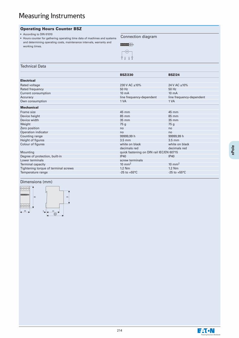
214
Measuring Instruments
Operating Hours Counter BSZ• According to DIN 61010• Hours counter for gathering operating time data of machines and systems
and determining operating costs, maintenance intervals, warranty andworking times.
Technical Data
BSZ/230 BSZ/24
Electrical Rated voltage 230 V AC ±10% 24 V AC ±10%Rated frequency 50 Hz 50 HzCurrent consumption 10 mA 10 mAAccuracy line frequency-dependent line frequency-dependentOwn consumption 1 VA 1 VA
Mechanical Frame size 45 mm 45 mmDevice height 85 mm 85 mmDevice width 35 mm 35 mmWeight 75 g 75 gZero position no noOperation indicator no noCounting range 99999,99 h 99999,99 hHeight of figures 3.5 mm 3.5 mmColour of figures white on black white on black
decimals red decimals redMounting quick fastening on DIN rail IEC/EN 60715Degree of protection, built-in IP40 IP40Lower terminals screw terminalsTerminal capacity 10 mm2 10 mm2
Tightening torque of terminal screws 1.2 Nm 1.2 NmTemperature range -25 to +55°C -25 to +55°C
Connection diagram
Dimensions (mm)

215
Measuring Instruments
Operating Hours Counter ASOHC230• The operating hours counter registers the operating hours to an accuracy
of two decimals (hundredths of a second).• Power supply for terminals 1 and 3 of the electronic counter is required to
enable the device to continuously display the measured values. If terminal3 is supplied with voltage (at DC “+“), the counting process will get started.Supplying terminal 4 with voltage for a moment (at DC “+“) will reset thecounter.
• In case of a power failure, the counting result will be saved for an indefiniteperiod of time (EEPROM). Once power is back again, counting will be con-tinued from the value that has been saved before.
• The 7-digit LCD display can be reset electrically or manually.• Time counters are used for a reliable collection of production and service
hours, which allows an accurate planning and monitoring of productionprocesses, maintenance cycles and warranty periods.
Technical Data
ASOHC230Standards DIN VDE 0435-110, DIN EN 60255-6, UL 863Approvals UL 863, UL File No. E300537, CSA C22.2 No. 6 and 55Rated control supply voltage Uc VAC 230Working range at 50/60 Hz x Uc 0,9 ... 1,1Rated frequency Hz 50Rated power loss Pv VA <1Type of operation counting of - hoursDisplay Cyclometer register h 00000,00Terminals ±Screws (Philips) - 1Terminal capacity rigid mm2 1,5
flexible with wire end sleeve, min.mm2 0,75
Allowed range of ambient temperature °C -10 ... +70Degree of protection acc. to DIN EN 60529 - IP20, with conductors connectedProtection class acc. to DIN EN 61140 / VDE 0140 IIAllowed range of air humidity % <80
Dimensions (mm)
Connection diagram

216
Pulse Counter Z-IMZ• According to DIN 61010
Technical Data
Z-IMZ/230 Z-IMZ/24
Electrical Rated voltage 230 V AC ±10% 24 V AC ±10%Rated frequency 50 Hz 50 HzCurrent consumption 8 mA 10 mAAccuracy – –Counting frequency max. 10 pulse/s max. 10 pulse/sPulse duration / interval 10 ms 10 msDuty 100% 100%Own consumption 1.84 VA 0.24 VA
Mechanical Frame size 45 mm 45 mmDevice height 90 mm 90 mmDevice width 35 mm 35 mmWeight 60 g 60 gZero position no noOperation indicator no noCounting range 9999999 pulses 9999999 pulsesHeight of figures 4 mm 4 mmColour of figures white on black white on blackMounting quick fastening on DIN rail IEC/EN 60715Degree of protection, built-in IP65 IP65Lower terminals screw terminalsTerminal capacity 0.14-4 mm2 0.14-4 mm2
Tightening torque of terminal screws 0.8 Nm 0.8 NmTemperature range -10 to +70°C -10 to +70°C
Connection diagram
Dimensions (mm)
Z-IMZ
Measuring Instruments
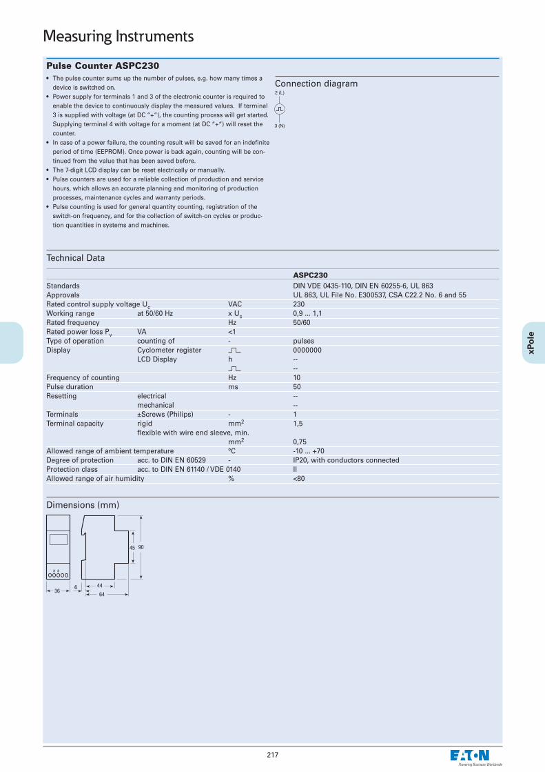
217
Measuring Instruments
Pulse Counter ASPC230• The pulse counter sums up the number of pulses, e.g. how many times a
device is switched on.• Power supply for terminals 1 and 3 of the electronic counter is required to
enable the device to continuously display the measured values. If terminal3 is supplied with voltage (at DC “+“), the counting process will get started.Supplying terminal 4 with voltage for a moment (at DC “+“) will reset thecounter.
• In case of a power failure, the counting result will be saved for an indefiniteperiod of time (EEPROM). Once power is back again, counting will be con-tinued from the value that has been saved before.
• The 7-digit LCD display can be reset electrically or manually.• Pulse counters are used for a reliable collection of production and service
hours, which allows an accurate planning and monitoring of productionprocesses, maintenance cycles and warranty periods.
• Pulse counting is used for general quantity counting, registration of theswitch-on frequency, and for the collection of switch-on cycles or produc-tion quantities in systems and machines.
Technical Data
ASPC230Standards DIN VDE 0435-110, DIN EN 60255-6, UL 863Approvals UL 863, UL File No. E300537, CSA C22.2 No. 6 and 55Rated control supply voltage Uc VAC 230Working range at 50/60 Hz x Uc 0,9 ... 1,1Rated frequency Hz 50/60Rated power loss Pv VA <1Type of operation counting of - pulsesDisplay Cyclometer register 0000000
LCD Display h ----
Frequency of counting Hz 10Pulse duration ms 50Resetting electrical --
mechanical --Terminals ±Screws (Philips) - 1Terminal capacity rigid mm2 1,5
flexible with wire end sleeve, min.mm2 0,75
Allowed range of ambient temperature °C -10 ... +70Degree of protection acc. to DIN EN 60529 - IP20, with conductors connectedProtection class acc. to DIN EN 61140 / VDE 0140 IIAllowed range of air humidity % <80
Dimensions (mm)
Connection diagram

Protective Earth Socket Z-SD230• Design according to VDE, ÖVE• Modular busbar connection system L/N• Screw fastening is possible• Width 2.5MU• Busbar block Z7-SD/1P+N 10 mm2 available• Model -BS with child protection device and earth pin
Technical Data
Electrical Rated voltage 250V ACRated current 10/16 A
Mechanical Frame size 45 mmDevice height 76 mmDevice width 44 mmMounting quick fastening on
DIN rail IEC/EN 60715,screw fastening is possible
Degree of protection, built-in IP40Upper and lower terminals lift terminalsTerminal capacity 1 to 2x2.5 mm2
Connection diagram
Dimensions (mm)Z-SD230 Z-SD230-BS
218
Other Accessories
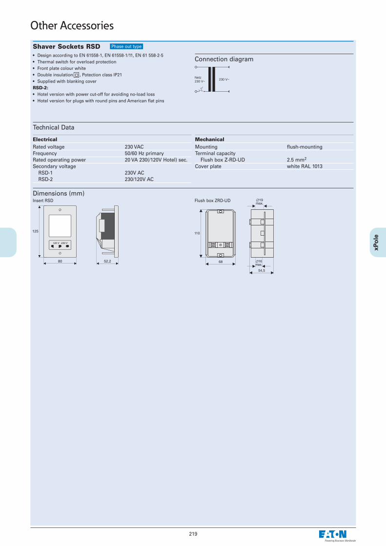
219
Other Accessories
Shaver Sockets RSD• Design according to EN 61558-1, EN 61558-1/11, EN 61 558-2-5• Thermal switch for overload protection• Front plate colour white• Double insulation , Potection class IP21 • Supplied with blanking coverRSD-2:• Hotel version with power cut-off for avoiding no-load loss• Hotel version for plugs with round pins and American flat pins
Technical Data
Electrical Rated voltage 230 VACFrequency 50/60 Hz primaryRated operating power 20 VA 230(/120V Hotel) sec.Secondary voltage
RSD-1 230V ACRSD-2 230/120V AC
Mechanical Mounting flush-mountingTerminal capacity
Flush box Z-RD-UD 2.5 mm2
Cover plate white RAL 1013
Connection diagram
Dimensions (mm)
Netz230 V~
230 V~
Insert RSD Flush box ZRD-UD
Phase out type

220
Neutral Terminal, Feeder Block Z-D• Compatible with standard busbar to Xtra Combination devices• Z-D80: Feeder block for busbar system 80 A.
Lift terminal (35 mm2) and open mouthed terminal above, lift terminal (50 mm2) below.Busbar positioning optionally above or below
• Z-D80: with testing bush 4mm Ø, 10 A for N-conductor
Technical Data
Connection diagrams
Dimensions (mm)
N
N
Z-D63 Z-D63/P Z-D80
Z-D63 Z-D63/P
Z-D63 Z-D63/P Z-D80
Electrical Rated current 63 A 63 A 100 AFrequency 50-60 Hz 50-60 Hz 50-60 HzN-conductor test bush – 10 A, Ø 4 –
Mechanical Frame size 45 mm 45 mm 45 mmDevice height 80 mm 80 mm 80 mmDevice width 17.5 mm (1MU) 17.5 mm (1MU) 17.5 mm (1MU)Mounting quick fastening with 2 lock-in positions on DIN rail IEC/EN 60715Degree of protection, built-in IP40 IP40 IP40Terminals
above open mouthed/lift open mouthed/lift open mouthed/liftbelow open mouthed/lift open mouthed/lift lift terminals
Terminal capacityabove 1-25 mm2 1-25 mm2 1-35 mm2
below 1-25 mm2 1-25 mm2 2.5-50 mm2
Terminal protection finger and hand touch safe, gemäß BGV A3, ÖVE-EN 6Busbar thickness 0.8 - 2 mm 0.8 - 2 mm 0.8 - 2 mm
Z-D80
Other Accessories

221
Other Accessories
Front Plate Tripping Device Z-MFPA• Mechanical tripping device for PLSM, CLS, Z-A40, PKNM and PKDM,
responds when the front plate of a distribution box is removed• Maximum tripping capacity: 4 + 4 poles symmetrically• Can be interlocked by twisting when the tripping pin is in the pressed posi-
tion
Technical Data
Mechanical Frame size 45 mmDevice height 80 mmDevice width 17.5 mmMounting quick fastening on
DIN rail IEC/EN 60715Degree of protection, built-in IP40
Function Diagram
Dimensions (mm)
17,5
4580
44
60
Function

222
Compact Enclosure KLV-TC• Compact enclosure, degree of protection IP30• Without door• For 45 mm devices for modular installation
Technical Data
KLV-TC-2 KLV-TC-4 KLV-TC-4-TB KLV-TC-8 KLV-TC-8-TB1KLV-TC-8-TB1
MechanicalModule units (MU) 1+1 3+1 3+1 6+2 6+2 6+2Weight 0.09 kg 0.15 kg 0.17 kg 0.32 kg 0.35 kg 0.36 kgTerminal Support wirh Terminal Block – – KLV-TC-TB-4/4 – KLV-TC-TBC-4/4 KLV-TC-TBC-4/4+4
Dimensions (mm)
A B C(Outside dimensions)
KLV-TC-2 50 135 72KLV-TC-4 90 160 78KLV-TC-8 162 170 78
Terminal Support wirh Terminal Block
Type Designation Number of Terminal Weight KLV-TC-TB-4/4 2 x 10mm2 + 2 x 16 mm2 0.018 kgKLV-TC-TBC-4/4 2 x 10mm2 + 2 x 16 mm2 0.030 kgKLV-TC-TBC-4/4+4 2 x (2 x 10mm2 + 2 x 16 mm2) 0.045kg
Other Accessories