
Accessories for Network Interfaces Manual
158
Accessories for Network Interfaces CAN / LIN / IO / ETHERNET / FlexRay Version 6.2 | English
Transcript of Accessories for Network Interfaces Manual

Accessories for Network InterfacesCAN / LIN / IO / ETHERNET / FlexRay
Version 6.2 | English

Imprint
Vector InformatikGmbHIngersheimer Straße 24D-70499 Stuttgart
The information and data given in this user manual can be changed without prior notice. No part of this manual may be reproduced in anyform or by any means without the written permission of the publisher, regardless of which method or which instruments, electronic ormechanical, are used. All technical information, drafts, etc. are liable to law of copyright protection.
© Copyright 2017, Vector InformatikGmbH. All rights reserved.

Contents
Accessories Manual Version 6.2 3
Contents
1 Introduction 91.1 About this User Manual 10
1.2 Important Notes 111.2.1 Safety Instructions and HazardWarnings 111.2.2 Certification 111.2.3 Warranty 111.2.4 Registered Trademarks 11
2 Accessories Finder 122.1 Accessories for CANboardXL (PCI, PCIe, PXI) 14
2.2 Accessories for CANcardXL 14
2.3 Accessories for CANcardXLe 15
2.4 Accessories for CANcaseXL 15
2.5 Accessories for CANcaseXL log 16
2.6 Accessories for VN0601 16
2.7 Accessories for VN1610 17
2.8 Accessories for VN1611 17
2.9 Accessories for VN1630A 17
2.10 Accessories for VN1640A 18
2.11 Accessories for VN1630 log 18
2.12 Accessories for VN2610 19
2.13 Accessories for VN2640 19
2.14 Accessories for VN3300 20
2.15 Accessories for VN3600 20
2.16 Accessories for VN5610A 21
2.17 Accessories for VN5640 22
2.18 Accessories for VN7570 23
2.19 Accessories for VN7572 24
2.20 Accessories for VN7600 25
2.21 Accessories for VN7610 26
2.22 Accessories for VN7640 26
2.23 Accessories for VN8810 27
2.24 Accessories for VN8910A 27
2.25 Accessories for VN8911 28
2.26 Accessories for VN8912A 29
Contents
Accessories Manual Version 6.2 4
2.27 Accessories for VN8914 29
2.28 Accessories for VN8950 30
2.29 Accessories for VN8970 30
2.30 Accessories for VN8972 31
3 Transceiver - Products 323.1 Piggybacks 333.1.1 CAN High-Speed 343.1.2 CAN Low-Speed (fault tolerant) 343.1.3 LIN 343.1.4 SingleWire CAN 353.1.5 Truck & Trailer CAN 353.1.6 Digital/Analog IO 353.1.7 J1708 353.1.8 FlexRay 36
3.2 Cabs 373.2.1 CAN High-Speed 373.2.2 CAN Low-Speed (fault tolerant) 383.2.3 LIN 383.2.4 SingleWire CAN 383.2.5 Truck & Trailer CAN 383.2.6 Digital/Analog IO 383.2.7 J1708 39
3.3 TWINcabs 403.3.1 CAN High-/Low-Speed (fault tolerant) 403.3.2 LIN 40
3.4 Other Designs 41
3.5 Compatibility with VN Interface Family 42
3.6 Compatibility with XL Interface Family 44
4 Transceiver - Technical Data 464.1 D-SUB Pin Assignment 48
4.2 CAN High-Speed 504.2.1 General Information 504.2.2 251 504.2.3 251opto 514.2.4 251mag 514.2.5 251fibre 524.2.6 1040mag 53

Contents
Accessories Manual Version 6.2 5
4.2.7 1041Aopto 544.2.8 1041Amag 564.2.9 1050 564.2.10 1050opto 564.2.11 1050mag 574.2.12 1051cap 574.2.13 1057Gcap 57
4.3 CAN Low-Speed (fault tolerant) 584.3.1 General Information 584.3.2 1054 594.3.3 1054opto 604.3.4 1054mag 614.3.5 1055cap 62
4.4 LIN 634.4.1 General Information 634.4.2 7269mag 64
4.5 SingleWire CAN 664.5.1 General Information 664.5.2 5790c 664.5.3 5790opto c 684.5.4 7356cap 69
4.6 J1708 704.6.1 General Information 704.6.2 65176opto 70
4.7 Truck & Trailer CAN 714.7.1 General Information 714.7.2 10011opto 72
4.8 Special Design 734.8.1 CANcab EVA 73
4.9 FlexRay 744.9.1 General Information 744.9.2 1080Amag 744.9.3 1082cap 75
5 IOcab 8444opto 765.1 Introduction 77
5.2 Digital Inputs andOutputs 795.2.1 Important Notes on Real TimeCapability of Digital Outputs 80
5.3 Analog Inputs andOutputs 82

Contents
Accessories Manual Version 6.2 6
5.4 Digital PWMOutput / Capture Inputs 84
5.5 Data Logging 86
5.6 Firmware Update 87
5.7 Technical Data 89
6 IOpiggy 8642 926.1 General Information 93
6.2 Digital Inputs andOutputs 94
6.3 Analog Inputs andOutputs 97
6.4 PWMOutputs (PWM0/PWM1) 98
6.5 PWM Input (PWM0) 98
6.6 Analog Comparator 98
6.7 D-SUB15 Pin Assignment 99
6.8 Technical Data 100
7 Cables and Connectors 1027.1 CAN/LIN 1047.1.1 CANcable0 1047.1.2 CANcable1 1047.1.3 CANcableA 1057.1.4 CANcableTnT 1057.1.5 CANcableTnT Term 1057.1.6 CANcableY 1067.1.7 CANcable 2Y 1077.1.8 CANterm 120 1087.1.9 CANcable Set Pro 108
7.2 MOST 1097.2.1 ECLCable 1097.2.2 Fiber Optic Cable 1097.2.3 Fiber Optic Cable Coupling 110
7.3 FlexRay 1117.3.1 FRcable A 1117.3.2 FRcable AB 1117.3.3 FRterm 1127.3.4 FRcable Set 1127.3.5 FR/CANcable 2Y 113
7.4 BroadR-Reach 1147.4.1 BRcable 2Y 114

Contents
Accessories Manual Version 6.2 7
7.5 OBDcables 1157.5.1 OBDcable CAN 1157.5.2 OBDcable OEMGM 1167.5.3 OBDcable OEM01 1177.5.4 OBDcable VN88 1187.5.5 OBDcable VN88A 119
7.6 Miscellaneous 1207.6.1 Connection Cable Binder Type 711 (3-pin) 1207.6.2 Breakout Box D62Y9 1217.6.3 VNcable DSUB62 1237.6.4 VNcable DSUB62 A 1237.6.5 VNcable DSUB62 B 1247.6.6 VNcable D62Y9 1257.6.7 VNcable DSUB37 1267.6.8 Terminal Block DSUB37 1277.6.9 Breakout Box VN88 1287.6.10 VX1362B CAN Cable Lemo/Banana Plugs 1.5M 1297.6.11 USB Cables 1307.6.11.1 USB Cable 2.0 1307.6.11.2 USB Cable 3.0 (A-B, 1.8m) 1307.6.11.3 USB Cable 3.0 (Type B Conn. with Screws) 131
8 Power Supply 1328.1 Vector Power Supply Units 1338.1.1 Vector Power Supply 12V/1.25A 1338.1.2 Vector Power Supply 12V/2.5A 1338.1.3 Vector Power Supply ODU MINI-SNAP 134
8.2 On-Board Power Supply 1358.2.1 Car Power Supply Cable 12V with Binder 1358.2.2 Vehicle Input <> ODU MINI-SNAP 135
8.3 Power Supply Cable 1368.3.1 Banana Plug <> Binder 3-Pin 1368.3.2 ODU Connector / Bunch Plugs 1378.3.3 Power Adapter OBDII – ODU Mini Snap 137
9 Time Synchronization 1389.1 Time Synchronization 1399.1.1 General Information 1399.1.2 Software Sync 1419.1.3 Hardware Sync 142
9.2 SYNCcables 144

Contents
Accessories Manual Version 6.2 8
9.2.1 SYNCcableXL 1449.2.2 SYNCcable50 144
9.3 SYNCboxes 1459.3.1 Multi SYNCbox External 1459.3.2 Multi SYNCbox Internal 1469.3.3 Multi SYNCbox Active 1479.3.4 SyncBox XL 148
10 Miscellaneous 14910.1 CardSafe 150
10.2 CANcaseXL log CardFix Kit – SD Card Protection 151
10.3 Front Panel for VN8900 151
10.4 Fix Kit 32mmDevice 151
10.5 2.4 & 5GHz Antenna SMA-R Std. 152
10.6 2.4 & 5.2 GHz Antenna SMA-R Asia 152
10.7 Protection Kit 1040 15310.7.1 Mounting Instructions 153
10.8 SD/SDHC Memory Cards 15610.8.1 SD Memory Card (X82) 2 GB 15610.8.2 SDHC Memory Card (X82) 8 GB 15610.8.3 SDHC Memory Card (X) 16GB 15610.8.4 SDHC Memory Card (SXT) 32GB 156
10.9 CFast Card Reader USB 3.0 (external) 157

1 Introduction
Accessories Manual Version 6.2 9
1 IntroductionIn this chapter you find the following information:
1.1 About this User Manual 10
1.2 Important Notes 111.2.1 Safety Instructions and HazardWarnings 111.2.2 Certification 111.2.3 Warranty 111.2.4 Registered Trademarks 11

1 Introduction
Accessories Manual Version 6.2 10
1.1 About this User ManualConventions In the two following charts you will find the conventions used in the user manual
regarding utilized spellings and symbols.
Style Utilizationbold Blocks, surface elements, window- and dialog names of the soft-
ware. Accentuation of warnings and advices.[OK]File|Save
Push buttons in bracketsNotation for menus andmenu entries
Microsoft Legally protected proper names and side notes.Source Code File name and source code.Hyperlink Hyperlinks and references.<CTRL>+<S> Notation for shortcuts.
Symbol UtilizationThis symbol calls your attention to warnings.
Here you can obtain supplemental information.
Here you can find additional information.
Here is an example that has been prepared for you.
Step-by-step instructions provide assistance at these points.
Instructions on editing files are found at these points.
This symbol warns you not to edit the specified file.

1 Introduction
Accessories Manual Version 6.2 11
1.2 Important Notes
1.2.1 Safety Instructions and Hazard Warnings
Caution!This accessory is designed for the operation of a Vector interface whichmay controland/or otherwise influence the behavior of control systems and electronic controlunits. The operation of such interfacemay lead to serious hazards for life, body andproperty. In order to avoid personal injuries and damage to property, you have toread and understand the safety instructions and hazard warnings which are applic-able for the interface prior to its installation and use. Keep this documentation(manual) and the documentation of the interface always near the interface.
1.2.2 CertificationCertified QualityManagement System
Vector Informatik GmbH has ISO 9001:2008 certification. The ISO standard is a glob-ally recognized standard.
1.2.3 WarrantyRestrictionof warranty
We reserve the right to change the contents of the documentation and the softwarewithout notice. Vector Informatik GmbH assumes no liability for correct contents ordamages which are resulted from the usage of the documentation. We are grateful forreferences tomistakes or for suggestions for improvement to be able to offer youevenmore efficient products in the future.
1.2.4 Registered TrademarksRegisteredtrademarks
All trademarks mentioned in this documentation and if necessary third partyregistered are absolutely subject to the conditions of each valid label right and therights of particular registered proprietor. All trademarks, trade names or companynames are or can be trademarks or registered trademarks of their particular pro-prietors. All rights which are not expressly allowed are reserved. If an explicit label oftrademarks, which are used in this documentation, fails, should not mean that a nameis free of third party rights.
> Windows, Windows 7, Windows 8.1, Windows 10are trademarks of theMicrosoft Corporation.

2 Accessories Finder
Accessories Manual Version 6.2 12
2 Accessories FinderIn this chapter you find the following information:
2.1 Accessories for CANboardXL (PCI, PCIe, PXI) 14
2.2 Accessories for CANcardXL 14
2.3 Accessories for CANcardXLe 15
2.4 Accessories for CANcaseXL 15
2.5 Accessories for CANcaseXL log 16
2.6 Accessories for VN0601 16
2.7 Accessories for VN1610 17
2.8 Accessories for VN1611 17
2.9 Accessories for VN1630A 17
2.10 Accessories for VN1640A 18
2.11 Accessories for VN1630 log 18
2.12 Accessories for VN2610 19
2.13 Accessories for VN2640 19
2.14 Accessories for VN3300 20
2.15 Accessories for VN3600 20
2.16 Accessories for VN5610A 21
2.17 Accessories for VN5640 22
2.18 Accessories for VN7570 23
2.19 Accessories for VN7572 24
2.20 Accessories for VN7600 25
2.21 Accessories for VN7610 26
2.22 Accessories for VN7640 26
2.23 Accessories for VN8810 27
2.24 Accessories for VN8910A 27
2.25 Accessories for VN8911 28
2.26 Accessories for VN8912A 29

2 Accessories Finder
Accessories Manual Version 6.2 13
2.27 Accessories for VN8914 29
2.28 Accessories for VN8950 30
2.29 Accessories for VN8970 30
2.30 Accessories for VN8972 31

2 Accessories Finder
Accessories Manual Version 6.2 14
2.1 Accessories for CANboardXL (PCI, PCIe, PXI)Bus transceiver > CAN-/LINpiggies (see section Compatibility with XL Interface Family on page 44)
Cables andconnectors
> CANcable0 (page 104)> CANcable1 (page 104)> CANcableA (page 105)> CANcable TnT (page 105)> CANcable TnT Term (page 105)> CANcable Y (page 106)> CANterm 120 (page 108)> CANcable Set Pro (page 108)> SYNCcableXL (page 144)> SYNCcable50 (page 144)> Multi SYNCbox external (page 145)> Multi SYNCbox internal (page 146)> Multi SYNCbox active (page 147)> Connection Cable Binder Type 711 (page 120)
2.2 Accessories for CANcardXLBus transceiver > CAN-/LINcabs (see section Compatibility with XL Interface Family on page 44)
> IOcab 8444opto (see section Compatibility with XL Interface Family on page 44)
Cables andconnectors
> CANcable0 (page 104)> CANcable1 (page 104)> CANcableA (page 105)> CANcable TnT (page 105)> CANcable TnT Term (page 105)> CANcable Y (page 106)> CANterm 120 (page 108)> CANcable Set Pro (page 108)> SYNCcableXL (page 144)> SYNCcable50 (page 144)> SyncBox XL (page 148)> Multi SYNCbox external (page 145)> Multi SYNCbox internal (page 146)> Multi SYNCbox active (page 147)> Connection Cable Binder Type 711 (page 120)

2 Accessories Finder
Accessories Manual Version 6.2 15
2.3 Accessories for CANcardXLeBus transceiver > CAN-/LINcabs (see section Compatibility with XL Interface Family on page 44)
> TWINcabs (see section Compatibility with XL Interface Family on page 44)> IOcab 8444opto (see section Compatibility with XL Interface Family on page 44)
Cables andconnectors
> CANcable0 (page 104)> CANcable1 (page 104)> CANcableA (page 105)> CANcable TnT (page 105)> CANcable TnT Term (page 105)> CANcable Y (page 106)> CANterm 120 (page 108)> CANcable Set Pro (page 108)> SYNCcableXL (page 144)> SYNCcable50 (page 144)> SyncBox XL (page 148)> Multi SYNCbox external (page 145)> Multi SYNCbox internal (page 146)> Multi SYNCbox active (page 147)> Connection Cable Binder Type 711 (page 120)
2.4 Accessories for CANcaseXLBus transceiver > CAN-/LINpiggies (see section Compatibility with XL Interface Family on page 44)
Cables andconnectors
> CANcable0 (page 104)> CANcable1 (page 104)> CANcableA (page 105)> CANcable TnT (page 105)> CANcable TnT Term (page 105)> CANcable Y (page 106)> CANterm 120 (page 108)> CANcable Set Pro (page 108)> SYNCcableXL (page 144)> SYNCcable50 (page 144)> Multi SYNCbox external (page 145)> Multi SYNCbox internal (page 146)> Multi SYNCbox active (page 147)> Connection Cable Binder Type 711 (page 120)> USB Cable 2.0 (page 130)
Power supply > Vector Power Supply 12V/1.25A (page 133)> Banana Plug <> Binder 3-Pin (page 136)

2 Accessories Finder
Accessories Manual Version 6.2 16
> Car Power Supply Cable 12V with Binder (page 135)
Miscellaneous > Fix Kit 32mmDevice (page 151)
2.5 Accessories for CANcaseXL logBus transceiver > CAN-/LINpiggies (see section Compatibility with XL Interface Family on page 44)
Cables andconnectors
> CANcable0 (page 104)> CANcable1 (page 104)> CANcableA (page 105)> CANcable TnT (page 105)> CANcable TnT Term (page 105)> CANcable Y (page 106)> CANterm 120 (page 108)> CANcable Set Pro (page 108)> SYNCcableXL (page 144)> SYNCcable50 (page 144)> Multi SYNCbox external (page 145)> Multi SYNCbox internal (page 146)> Multi SYNCbox active (page 147)> Connection Cable Binder Type 711 (page 120)> USB Cable 2.0 (page 130)
Power supply > Vector Power Supply 12V/1.25A (page 133)> Banana Plug <> Binder 3-Pin (page 136)> Car Power Supply Cable 12V with Binder (page 135)
Miscellaneous > Fix Kit 32mmDevice (page 151)
2.6 Accessories for VN0601Cables andconnectors
> VNcable DSUB37 (page 126)> Terminal Block DSUB37 (page 127)> SYNCcableXL (page 144)> SYNCcable50 (page 144)> Multi SYNCbox external (page 145)> Multi SYNCbox internal (page 146)> Multi SYNCbox active (page 147)> Connection Cable Binder Type 711 (page 120)> USB Cable 2.0 (page 130)

2 Accessories Finder
Accessories Manual Version 6.2 17
2.7 Accessories for VN1610Cables andconnectors
> CANcable0 (page 104)> CANcable1 (page 104)> CANcableA (page 105)> CANcable TnT (page 105)> CANcable Y (page 106)> CANcable 2Y (page 107)> CANterm 120 (page 108)> CANcable Set Pro (page 108)
2.8 Accessories for VN1611Cables andconnectors
> CANcable0 (page 104)> CANcable1 (page 104)> CANcableA (page 105)> CANcable TnT (page 105)> CANcable Y (page 106)> CANcable 2Y (page 107)> CANterm 120 (page 108)> CANcable Set Pro (page 108)
2.9 Accessories for VN1630ABus transceiver > CAN-/LINpiggies (see section Compatibility with VN Interface Family on page 42)
Cables andconnectors
> CANcable0 (page 104)> CANcable1 (page 104)> CANcableA (page 105)> CANcable TnT (page 105)> CANcable Y (page 106)> CANcable 2Y (page 107)> CANterm 120 (page 108)> CANcable Set Pro (page 108)> SYNCcableXL (page 144)> SYNCcable50 (page 144)> Multi SYNCbox external (page 145)> Multi SYNCbox internal (page 146)> Multi SYNCbox active (page 147)> Connection Cable Binder Type 711 (page 120)> USB Cable 2.0 (page 130)
Miscellaneous > Fix Kit 32mmDevice (page 151)
2 Accessories Finder
Accessories Manual Version 6.2 18
2.10 Accessories for VN1640ABus transceiver > CAN-/LINpiggies (see section Compatibility with VN Interface Family on page 42)
Cables andconnectors
> CANcable0 (page 104)> CANcable1 (page 104)> CANcableA (page 105)> CANcable TnT (page 105)> CANcable Y (page 106)> CANterm 120 (page 108)> CANcable Set Pro (page 108)> SYNCcableXL (page 144)> SYNCcable50 (page 144)> Multi SYNCbox external (page 145)> Multi SYNCbox internal (page 146)> Multi SYNCbox active (page 147)> Connection Cable Binder Type 711 (page 120)> USB Cable 2.0 (page 130)
Miscellaneous > Protection Kit 1040 (page 153)
2.11 Accessories for VN1630 logBus transceiver > CAN-/LINpiggies (see section Compatibility with VN Interface Family on page 42)
Cables andconnectors
> CANcable0 (page 104)> CANcable1 (page 104)> CANcableA (page 105)> CANcable TnT (page 105)> CANcable TnT Term (page 105)> CANcable Y (page 106)> CANcable 2Y (page 107)> CANterm 120 (page 108)> CANcable Set Pro (page 108)> SYNCcableXL (page 144)> SYNCcable50 (page 144)> Multi SYNCbox external (page 145)> Multi SYNCbox internal (page 146)> Multi SYNCbox active (page 147)> Connection Cable Binder Type 711 (page 120)> USB Cable 2.0 (page 130)
Power supply > Banana Plug <> Binder 3-Pin (page 136)
Miscellaneous > Fix Kit 32mmDevice (page 151)

2 Accessories Finder
Accessories Manual Version 6.2 19
> SD/SDHC Memory Cards (page 156)
2.12 Accessories for VN2610Cables andconnectors
> Fiber Optic Cable (page 109)> Fiber Optic Cable Coupling (page 110)> SYNCcableXL (page 144)> SYNCcable50 (page 144)> Multi SYNCbox external (page 145)> Multi SYNCbox internal (page 146)> Multi SYNCbox active (page 147)> Connection Cable Binder Type 711 (page 120)> USB Cable 2.0 (page 130)
Power supply > Vector Power Supply 12V/1.25A (page 133)> Banana Plug <> Binder 3-Pin (page 136)> Car Power Supply Cable 12V with Binder (page 135)
Miscellaneous > Fix Kit 32mmDevice (page 151)
2.13 Accessories for VN2640Cables andconnectors
> Fiber Optic Cable (page 109)> Fiber Optic Cable Coupling (page 110)> ECL cable (page 109)> SYNCcableXL (page 144)> SYNCcable50 (page 144)> Multi SYNCbox external (page 145)> Multi SYNCbox internal (page 146)> Multi SYNCbox active (page 147)> Connection Cable Binder Type 711 (page 120)> USB Cable 2.0 (page 130)
Power supply > Vector Power Supply 12V/1.25A (page 133)> Banana Plug <> Binder 3-Pin (page 136)> Car Power Supply Cable 12V with Binder (page 135)
Miscellaneous > Fix Kit 32mmDevice (page 151)

2 Accessories Finder
Accessories Manual Version 6.2 20
2.14 Accessories for VN3300Bus transceiver > FRpiggies (see section Compatibility with VN Interface Family on page 42)
Cables andconnectors
> FRcable A (page 111)> FRcable AB (page 111)> FRterm (page 112)> FRcable Set (page 112)> SYNCcableXL (page 144)> SYNCcable50 (page 144)> Multi SYNCbox external (page 145)> Multi SYNCbox internal (page 146)> Multi SYNCbox active (page 147)> Connection Cable Binder Type 711 (page 120)
2.15 Accessories for VN3600Bus transceiver > FRpiggies (see section Compatibility with VN Interface Family on page 42)
Cables andconnectors
> FRcable A (page 111)> FRcable AB (page 111)> FRterm (page 112)> FRcable Set (page 112)> SYNCcableXL (page 144)> SYNCcable50 (page 144)> Multi SYNCbox external (page 145)> Multi SYNCbox internal (page 146)> Multi SYNCbox active (page 147)> Connection Cable Binder Type 711 (page 120)> USB Cable 2.0 (page 130)
Power supply > Vector Power Supply 12V/1.25A (page 133)> Banana Plug <> Binder 3-Pin (page 136)> Car Power Supply Cable 12V with Binder (page 135)
Miscellaneous > Fix Kit 32mmDevice (page 151)

2 Accessories Finder
Accessories Manual Version 6.2 21
2.16 Accessories for VN5610ACables andconnectors
> BRcable 2Y (page 114)> CANcable1 (page 104)> CANcableA (page 105)> CANcable TnT (page 105)> CANcable Y (page 106)> CANcable 2Y (page 107)> CANterm 120 (page 108)> CANcable Set Pro (page 108)> SYNCcableXL (page 144)> SYNCcable50 (page 144)> Multi SYNCbox external (page 145)> Multi SYNCbox internal (page 146)> Multi SYNCbox active (page 147)> Connection Cable Binder Type 711 (page 120)> Cable Lemo/Banana Plugs (page 129)> USB Cable 2.0 (page 130)
Power supply > Vector Power Supply 12V/1.25A (page 133)> Banana Plug <> Binder 3-Pin (page 136)> Car Power Supply Cable 12V with Binder (page 135)
Miscellaneous > Fix Kit 32mmDevice (page 151)

2 Accessories Finder
Accessories Manual Version 6.2 22
2.17 Accessories for VN5640Cables andconnectors
> BRcable 2Y (page 114)> CANcable1 (page 104)> CANcableA (page 105)> CANcable TnT (page 105)> CANcable Y (page 106)> CANcable 2Y (page 107)> CANterm 120 (page 108)> CANcable Set Pro (page 108)> SYNCcableXL (page 144)> SYNCcable50 (page 144)> Multi SYNCbox external (page 145)> Multi SYNCbox internal (page 146)> Multi SYNCbox active (page 147)> Connection Cable Binder Type 711 (page 120)> USB Cable 3.0 (page 130)
Power supply > Vector Power Supply ODU MINI-SNAP (page 134)> Vehicle Input <> ODU MINI-SNAP (page 135)> ODU Connector / Bunch Plugs (page 137)
2 Accessories Finder
Accessories Manual Version 6.2 23
2.18 Accessories for VN7570Bus transceiver > FRpiggies (see section Compatibility with VN Interface Family on page 42)
> CAN-/LINpiggies (see section Compatibility with VN Interface Family on page 42)> IOpiggy 8642 (see section Compatibility with VN Interface Family on page 42)
Cables andconnectors
> Breakout Box D62Y9 (page 114)> VNcable DSUB62 for Breakout Box (page 123)> VNcable DSUB62 A (page 123)> VNcable DSUB62 B (page 124)> VNcable D62Y9 (page 125)> FRcable A (page 111)> FRcable AB (page 111)> FRterm (page 112)> FRcable Set (page 112)> CANcable0 (page 104)> CANcable1 (page 104)> CANcableA (page 105)> CANcable TnT (page 105)> CANcable TnT Term (page 105)> CANcable Y (page 106)> CANterm 120 (page 108)> CANcable Set Pro (page 108)> SYNCcableXL (page 144)> SYNCcable50 (page 144)> Multi SYNCbox external (page 145)> Multi SYNCbox internal (page 146)> Multi SYNCbox active (page 147)> Connection Cable Binder Type 711 (page 120)

2 Accessories Finder
Accessories Manual Version 6.2 24
2.19 Accessories for VN7572Bus transceiver > FRpiggies (see section Compatibility with VN Interface Family on page 42)
> CAN-/LINpiggies (see section Compatibility with VN Interface Family on page 42)> IOpiggy 8642 (see section Compatibility with VN Interface Family on page 42)
Cables andconnectors
> Breakout Box D62Y9 (page 114)> VNcable DSUB62 for Breakout Box (page 123)> VNcable DSUB62 A (page 123)> VNcable DSUB62 B (page 124)> VNcable D62Y9 (page 125)> FRcable A (page 111)> FRcable AB (page 111)> FRterm (page 112)> FRcable Set (page 112)> CANcable0 (page 104)> CANcable1 (page 104)> CANcableA (page 105)> CANcable TnT (page 105)> CANcable TnT Term (page 105)> CANcable Y (page 106)> CANterm 120 (page 108)> CANcable Set Pro (page 108)> SYNCcableXL (page 144)> SYNCcable50 (page 144)> Multi SYNCbox external (page 145)> Multi SYNCbox internal (page 146)> Multi SYNCbox active (page 147)> Connection Cable Binder Type 711 (page 120)

2 Accessories Finder
Accessories Manual Version 6.2 25
2.20 Accessories for VN7600Bus transceiver > FRpiggies (see section Compatibility with VN Interface Family on page 42)
> CAN-/LINpiggies (see section Compatibility with VN Interface Family on page 42)
Cables andconnectors
> FRcable A (page 111)> FRcable AB (page 111)> FRterm (page 112)> FRcable Set (page 112)> CANcable0 (page 104)> CANcable1 (page 104)> CANcableA (page 105)> CANcable TnT (page 105)> CANcable TnT Term (page 105)> CANcable Y (page 106)> CANterm 120 (page 108)> CANcable Set Pro (page 108)> SYNCcableXL (page 144)> SYNCcable50 (page 144)> Multi SYNCbox external (page 145)> Multi SYNCbox internal (page 146)> Multi SYNCbox active (page 147)> Connection Cable Binder Type 711 (page 120)> USB Cable 2.0 (page 130)
Power supply > Vector Power Supply 12V/1.25A (page 133)> Banana Plug <> Binder 3-Pin (page 136)> Car Power Supply Cable 12V with Binder (page 135)
Miscellaneous > Protection Kit 1040 (page 153)

2 Accessories Finder
Accessories Manual Version 6.2 26
2.21 Accessories for VN7610Cables andconnectors
> FR/CANcable 2Y (page 113)> FRcable A (page 111)> FRcable AB (page 111)> FRterm (page 112)> FRcable Set (page 112)> CANcable0 (page 104)> CANcable1 (page 104)> CANcableA (page 105)> CANcable TnT (page 105)> CANcable Y (page 106)> CANterm 120 (page 108)> CANcable Set Pro (page 108)
2.22 Accessories for VN7640Bus transceiver > FRpiggies (see section Compatibility with VN Interface Family on page 42)
> CAN-/LINpiggies (see section Compatibility with VN Interface Family on page 42)
Cables andconnectors
> FRcable A (page 111)> FRcable AB (page 111)> FRterm (page 112)> FRcable Set (page 112)> CANcable0 (page 104)> CANcable1 (page 104)> CANcableA (page 105)> CANcable Y (page 106)> CANterm 120 (page 108)> CANcable Set Pro (page 108)> SYNCcableXL (page 144)> SYNCcable50 (page 144)> Multi SYNCbox external (page 145)> Multi SYNCbox internal (page 146)> Multi SYNCbox active (page 147)> Connection Cable Binder Type 711 (page 120)> USB Cable 2.0 (page 130)
Power supply > Vector Power Supply 12V/1.25A (page 133)> Banana Plug <> Binder 3-Pin (page 136)

2 Accessories Finder
Accessories Manual Version 6.2 27
2.23 Accessories for VN8810Cables andconnectors
> OBDcable VN88 (page 118)> OBDcable VN88A (page 119)> Breakout Box VN88 (page 128)> SYNCcableXL (page 144)> SYNCcable50 (page 144)> SyncBox XL (page 148)> Multi SYNCbox external (page 145)> Multi SYNCbox internal (page 146)> Multi SYNCbox active (page 147)> Connection Cable Binder Type 711 (page 120)> USB Cable 3.0 (page 130)
Power supply > Vector Power Supply ODU MINI-SNAP (page 134)> Vehicle Input <> ODU MINI-SNAP (page 135)> ODU Connector / Bunch Plugs (page 137)> Power Adapter OBDII – ODU Mini Snap (page 137)
Miscellaneous > 2.4 & 5GHz Antenna SMA-R Std. (page 152)> 2.4 & 5.2 GHz Antenna SMA-R Asia (page 152)> CFast Card Reader USB 3.0 (external) (page 157)
2.24 Accessories for VN8910ACables andconnectors
> SYNCcableXL (page 144)> SYNCcable50 (page 144)> Multi SYNCbox external (page 145)> Multi SYNCbox internal (page 146)> Multi SYNCbox active (page 147)> Connection Cable Binder Type 711 (page 120)> USB Cable 2.0 (page 130)
Power supply > Vector Power Supply ODU MINI-SNAP (page 134)> Vehicle Input <> ODU MINI-SNAP (page 135)> ODU Connector / Bunch Plugs (page 137)
Miscellaneous > Front Panel for VN8900 (page 151)

2 Accessories Finder
Accessories Manual Version 6.2 28
2.25 Accessories for VN8911Cables andconnectors
> SYNCcableXL (page 144)> SYNCcable50 (page 144)> Multi SYNCbox external (page 145)> Multi SYNCbox internal (page 146)> Multi SYNCbox active (page 147)> Connection Cable Binder Type 711 (page 120)> USB Cable 3.0 (page 130)
Power supply > Vector Power Supply ODU MINI-SNAP (page 134)> Vehicle Input <> ODU MINI-SNAP (page 135)> ODU Connector / Bunch Plugs (page 137)
Miscellaneous > SD/SDHC Memory Cards (page 156)> Front Panel for VN8900 (page 151)> CFast Card Reader USB 3.0 (external) (page 157)

2 Accessories Finder
Accessories Manual Version 6.2 29
2.26 Accessories for VN8912ACables andconnectors
> SYNCcableXL (page 144)> SYNCcable50 (page 144)> Multi SYNCbox external (page 145)> Multi SYNCbox internal (page 146)> Multi SYNCbox active (page 147)> Connection Cable Binder Type 711 (page 120)> USB Cable 3.0 (page 130)
Power supply > Vector Power Supply ODU MINI-SNAP (page 134)> Vehicle Input <> ODU MINI-SNAP (page 135)> ODU Connector / Bunch Plugs (page 137)
Miscellaneous > Front Panel for VN8900 (page 151)> CFast Card Reader USB 3.0 (external) (page 157)
2.27 Accessories for VN8914Cables andconnectors
> SYNCcableXL (page 144)> SYNCcable50 (page 144)> Multi SYNCbox external (page 145)> Multi SYNCbox internal (page 146)> Multi SYNCbox active (page 147)> Connection Cable Binder Type 711 (page 120)> USB Cable 3.0 (page 130)> USB Cable 3.0 (Type B Conn. with Screws) (page 131)
Power supply > Vector Power Supply ODU MINI-SNAP (page 134)> Vehicle Input <> ODU MINI-SNAP (page 135)> ODU Connector / Bunch Plugs (page 137)
Miscellaneous > SD/SDHC Memory Cards (page 156)> Front Panel for VN8900 (page 151)> CFast Card Reader USB 3.0 (external) (page 157)
2 Accessories Finder
Accessories Manual Version 6.2 30
2.28 Accessories for VN8950Bus transceiver > CAN-/LINpiggies (see section Compatibility with VN Interface Family on page 42)
> IOpiggy 8642 (see section Compatibility with VN Interface Family on page 42)
Cables andconnectors
> CANcable0 (page 104)> CANcable1 (page 104)> CANcableA (page 105)> CANcable TnT (page 105)> CANcable TnT Term (page 105)> CANcable Y (page 106)> CANterm 120 (page 108)> CANcable Set Pro (page 108)
2.29 Accessories for VN8970Bus transceiver > FRpiggies (see section Compatibility with VN Interface Family on page 42)
> CAN-/LINpiggies (see section Compatibility with VN Interface Family on page 42)> IOpiggy 8642 (see section Compatibility with VN Interface Family on page 42)
Cables andconnectors
> FRcable A (page 111)> FRcable AB (page 111)> FRterm (page 112)> FRcable Set (page 112)> CANcable0 (page 104)> CANcable1 (page 104)> CANcableA (page 105)> CANcable TnT (page 105)> CANcable TnT Term (page 105)> CANcable Y (page 106)> CANcable 2Y (page 107)> CANterm 120 (page 108)> CANcable Set Pro (page 108)

2 Accessories Finder
Accessories Manual Version 6.2 31
2.30 Accessories for VN8972Bus transceiver > FRpiggies (see section Compatibility with VN Interface Family on page 42)
> CAN-/LINpiggies (see section Compatibility with VN Interface Family on page 42)> IOpiggy 8642 (see section Compatibility with VN Interface Family on page 42)
Cables andconnectors
> FRcable A (page 111)> FRcable AB (page 111)> FRterm (page 112)> FRcable Set (page 112)> CANcable0 (page 104)> CANcable1 (page 104)> CANcableA (page 105)> CANcable TnT (page 105)> CANcable TnT Term (page 105)> CANcable Y (page 106)> CANcable 2Y (page 107)> CANterm 120 (page 108)> CANcable Set Pro (page 108)

3 Transceiver - Products
Accessories Manual Version 6.2 32
3 Transceiver - ProductsIn this chapter you find the following information:
3.1 Piggybacks 333.1.1 CAN High-Speed 343.1.2 CAN Low-Speed (fault tolerant) 343.1.3 LIN 343.1.4 SingleWire CAN 353.1.5 Truck & Trailer CAN 353.1.6 Digital/Analog IO 353.1.7 J1708 353.1.8 FlexRay 36
3.2 Cabs 373.2.1 CAN High-Speed 373.2.2 CAN Low-Speed (fault tolerant) 383.2.3 LIN 383.2.4 SingleWire CAN 383.2.5 Truck & Trailer CAN 383.2.6 Digital/Analog IO 383.2.7 J1708 39
3.3 TWINcabs 403.3.1 CAN High-/Low-Speed (fault tolerant) 403.3.2 LIN 40
3.4 Other Designs 41
3.5 Compatibility with VN Interface Family 42
3.6 Compatibility with XL Interface Family 44

3 Transceiver - Products
Accessories Manual Version 6.2 33
3.1 PiggybacksProperties A Piggyback implements the interconnection of the network interface to a specific bus
(e. g. CAN/LIN/IO/FlexRay) by the use of various transceivers. The Piggyback isinserted in the network interface and can be replaced according to the bus require-ments (please take note of the instructions in the network interface user manual).
Figure 1: Piggyback
Figure 2: Example with VN1630A

3 Transceiver - Products
Accessories Manual Version 6.2 34
3.1.1 CAN High-Speed
CANpiggy Transceiver Description Part no.251 82C251 Without galvanic isolation. 22015
251mag 82C251 Magnetically decoupled. *251opto 82C251 Optically decoupled. *1040mag TJA1040 Magnetically decoupled.
Useful for partially powered networks.22084
1041Amag TJA1041A Magnetically decoupled, wake-up capable. 220821041Aopto TJA1041A Optically decoupled, wake-up capable. *
1050 TJA1050 Without galvanic isolation. *1050mag TJA1050 Magnetically decoupled. 220831050opto TJA1050 Optically decoupled. *1051cap TJA1051 Capacitively decoupled.
Suitable for 2Mbit/s CAN andfor CAN FD up to 8Mbit/s.
22122
1057Gcap TJA1057G Capacitively decoupled.Suitable for 2Mbit/s CAN andfor CAN FD up to 8Mbit/s.
22070
* discontinued
3.1.2 CAN Low-Speed (fault tolerant)
CANpiggy Transceiver Description Part no.1054 TJA1054 Without galvanic isolation. *
1054opto TJA1054 Optically decoupled.Switchable terminating resistor.
*
1054mag TJA1054 Magnetically decoupled.Switchable terminating resistor.
*
1055cap TJA1055 Capacitively decoupled.Switchable terminating resistor.
22069
* discontinued
3.1.3 LIN
LINpiggy Transceiver Description Part no.7269mag TLE7269 Magnetically decoupled. Compatible to LIN2.x
physical layer (12 V and 24 V). Provides dom-inant and recessive stress functionality.
22093

3 Transceiver - Products
Accessories Manual Version 6.2 35
3.1.4 Single Wire CAN
CANpiggy Transceiver Description Part no.5790opto c AU5790 Optically decoupled. 100 Ω resistance can be
activated automatically upon switching over tohigh-speedmode. External power supplyrequired.
*
7356cap NCV7356 Capacitively decoupled. 100 Ω resistance canbe activated automatically upon switching overto high-speedmode. External power supplyrequired.
22244
* discontinued
3.1.5 Truck & Trailer CAN
CANpiggy Transceiver Description Part no.10011opto B10011S Optically decoupled.
External power supply required.22031
3.1.6 Digital/Analog IO
IOpiggy Transceiver Description Part no.8642 - For the VN8900 interface family. Used for gen-
eration andmeasurement of analog and digitalsignals (see section IOpiggy 8642 on page 92).
22208
3.1.7 J1708
J1708piggy Transceiver Description Part no.65176opto SN65176B Optically decoupled. 22060

3 Transceiver - Products
Accessories Manual Version 6.2 36
3.1.8 FlexRay
FRpiggy Transceiver Description Part no.1080 2x TJA1080
(Ch A and B)Without galvanic isolation. *
1080Amag 2x TJA1080A(Ch A and B)
Magnetically decoupled. *
1082cap 2x TJA1082(Ch A and B)
Capacitively decoupled.With trigger feature.
22099
* discontinued
FRpiggyC Transceiver Description Part no.1082cap 2x TJA1082
(Ch A and B)Compact FRpiggy.Capacitively decoupled.With trigger feature.
22121

3 Transceiver - Products
Accessories Manual Version 6.2 37
3.2 CabsProperties Cabs are designed for use with CANcardXL/CANcardXLe and implement the inter-
connection of the network interface to a specific bus (e. g. CAN/LIN/IO) by the use ofvarious transceivers. Cabs are connected to CANcardXL/CANcardXLe and can bechanged according to the bus requirements.
Cab withone D-SUBconnector
Figure 3: Cab with a single channel
Technical data Channels 1Housing ABS plasticDimensions 100mm x 16mm x 16mm (4.0 x 0.6 x 0.6 in)Cable length Approx. 30 cm (1 ft.) at both endsWeight Approx. 100 g (3.5 oz.)Connectors PC side: 15-pin plug-type connector to CANcardXL/XLe
Bus side: D-SUB9 connector per DIN 41652
3.2.1 CAN High-Speed
CANcab Transceiver Description Part no.251 82C251 Without galvanic isolation. 22003
251mag 82C251 Magnetically decoupled. 22049251opto 82C251 Optically decoupled. 22008251fibre PCA82C251 Twowire fiber optic cable. 220581040mag TJA1040 Magnetically decoupled.
Useful for partially powered networks.22080
1041Amag TJA1041A Magnetically decoupled, wake-up capable. 220781041Aopto TJA1041A Optically decoupled, wake-up capable. *
1050 TJA1050 Without galvanic isolation. *1050mag TJA1050 Magnetically decoupled. 220791050opto TJA1050 Optically decoupled. *
* discontinued

3 Transceiver - Products
Accessories Manual Version 6.2 38
3.2.2 CAN Low-Speed (fault tolerant)
CANcab Transceiver Description Part no.1054 TJA1054 Without galvanic isolation. *
1054opto TJA1054 Optically decoupled.Switchable terminating resistor.
*
1054mag TJA1054 Magnetically decoupled.Switchable terminating resistor.
22081
* discontinued
3.2.3 LIN
LINcab Transceiver Description Part no.7269mag TLE7269 Magnetically decoupled. Compatible to LIN2.x
physical layer (12 V and 24 V). Provides dom-inant and recessive stress functionality.
22094
3.2.4 Single Wire CAN
CANcab Transceiver Description Part no.5790c AU5790 Without galvanic isolation. 100 Ω resistance
can be activated automatically upon switchingover to high-speedmode. External power sup-ply required.
*
5790opto c AU5790 Optically decoupled. 100 Ω resistance can beactivated automatically upon switching over tohigh-speedmode. External power supplyrequired.
22051
* discontinued
3.2.5 Truck & Trailer CAN
CANcab Transceiver Description Part no.10011opto B10011S Optically decoupled.
External power supply required.22055
3.2.6 Digital/Analog IO
IOcab Transceiver Description Part no.8444opto - Used for generation andmeasurement of ana-
log and digital signals(see section IOcab 8444-opto on page 76).
22067

3 Transceiver - Products
Accessories Manual Version 6.2 39
3.2.7 J1708
J1708cab Transceiver Description Part no.65176opto SN65176B Optically decoupled. 22056

3 Transceiver - Products
Accessories Manual Version 6.2 40
3.3 TWINcabsProperties The TWINcabmerges two Cabs in one and is designed for use with CANcardXLe.
One TWINcab offers two channels. The channel numbers are either 1/3 or 2/4 depend-ing on the used connector on the CANcardXLe. If two TWINcabs on one CAN-cardXLe are being used, four channels are available at the same time.
NoteThe TWINcabs cannot be used with CANcardXL.
TWINcab withtwo D-SUBconnectors
Figure 4: Example TWINcab with 2xCAN
Technical data Channels 2Housing ABS plasticDimensions 110mm x 35mm x 17mm (4.3 x 1.3 x 0.67 in)Cable length Approx. 30 cm (1 ft.) at both endsWeight Approx. 105 g (3.75 oz)Connectors PC side: 15-pin plug-type connector to CANcardXLe
Bus side: 2x D-SUB9 connector per DIN 41652Insulation voltage 50 V
3.3.1 CAN High-/Low-Speed (fault tolerant)
TWINcab Transceiver Description Part no.2x
1041Amag2x TJA1041A Magnetically decoupled. 22086
1x1041Amag1x 1054A
1x TJA1041A1x TJA1054A
Magnetically decoupled. With one high-speedand one low-speed transceiver.Wakeup-capable.
22092
3.3.2 LIN
TWINcab Transceiver Description Part no.2x
7269mag2x TLE7269 Compatible to LIN2.x physical layer (12 V and
24 V). Provides dominant and recessive stressfunctionality.
22088

3 Transceiver - Products
Accessories Manual Version 6.2 41
3.4 Other DesignsCab Transceiver Description Part no.EVA User-
specificEvaluation kit: Mounting of the CANcab user-specifically with bus transceivers using pre-assembled breadboards (see section CANcabEVA on page 73).
22009

3 Transceiver - Products
Accessories Manual Version 6.2 42
3.5 Compatibility with VN Interface FamilyTransceiver Suitable transceivers for your network interface can be found in the following table.
Transceiver
VN
16
00
Inte
rfa
ce
Fa
mily
VN
33
00
/V
N3
60
0
VN7570
VN7572
VN7600
VN7640
VN8950
VN8970
VN8972
Design Piggy Piggy Piggy Piggy Piggy Piggy Piggy Piggy Piggy
CAN High-Speed 251 X - - - X - - - -251opto - - O O X - O O O
251mag X - X X X O X X X
251fibre - - - - - - - - -
1040mag X - X X X X X X X
1041opto - - O O X - O O O
1041Aopto - - O O X - O O O
1041Amag X - X X X X X X X
1050 O - - - X - - - -
1050opto - - O O X - O O O
1050mag X - X X X X X X X
1051cap X - X X X X X X X
1057Gcap X - X X X X X X X
CAN Low-Speed 1054 O - - - X - - - -1054opto - - O - X - O O -
1054mag X - X - X - X X -
1055cap X - X X X X X X X
SingleWire CAN 5790c O - - - O - - - -5790opto c X - X O X - X X O
7356cap X - X X X X X X X
Truck&Trailer CAN 10011opto - - X X X - X X X
LIN 6258opto - - - - - - - - -6259opto - - - - - - - - -
6259mag X - X X - - X X X
7259mag X - X X - - X X X
7269mag X - X X - X X X X
FlexRay 1080 - X - - X - - - -1080mag - X - - X - - X -
1080Amag - X - - X - - X -
1082cap - X X1 X1 X X1 - X X1

3 Transceiver - Products
Accessories Manual Version 6.2 43
Transceiver
VN
16
00
Inte
rfa
ce
Fa
mily
VN
33
00
/V
N3
60
0
VN7570
VN7572
VN7600
VN7640
VN8950
VN8970
VN8972
Design Piggy Piggy Piggy Piggy Piggy Piggy Piggy Piggy Piggy
Miscellaneous 8444opto - - - - - - - - -8642 - - X X - - X X X
J170865176opto
X - X X - - X X X
CabTwinPiggy
Cab (see section Cabson page 37)TWINcab (see section TWINcabson page 40)Piggyback (see section Piggybackson page 33)
XO
-
supportednot recommended(mags/capshave better propagation delaysand less current consumption)not supported
123
Compact FlexRayPiggybacksonlyPiggybackonlysupported with a future driver update
ReferencePlease refer to our Vector KnowledgeBase for the latest list:https://vector.com/kbp/entry/219/.

3 Transceiver - Products
Accessories Manual Version 6.2 44
3.6 Compatibility with XL Interface FamilyTransceiver Suitable transceivers for your network interface can be found in the following table.
Transceiver
CANcardXL
CANcardXLe
CA
Nb
oa
rd X
L /
CA
Nc
as
eX
L
Design Cab Cab/Twin Piggy
CAN High-Speed 251 X X X251opto X X X
251mag X X X
251fibre X X -
1040mag X X X
1041opto X X X
1041Aopto X X X
1041Amag X X X
1050 X X X
1050opto X X X
1050mag X X X
1051cap -2 -2 X
1057Gcap -2 -2 X
CAN Low-Speed 1054 X X X1054opto X X X
1054mag X X X
1055cap -2 -2 X
SingleWire CAN 5790c X X X5790opto c X X X
7356cap -2 -2 X
Truck&Trailer CAN 10011opto X X X
LIN 6258opto X X X6259opto X X X
6259mag X X X
7259mag X X X
7269mag X X X
FlexRay 1080 - - -1080mag - - -
1080Amag - - -
1082cap - - -

3 Transceiver - Products
Accessories Manual Version 6.2 45
Transceiver
CANcardXL
CANcardXLe
CA
Nb
oa
rd X
L /
CA
Nc
as
eX
L
Design Cab Cab/Twin
Piggy
Miscellaneous 8444opto X X -8642 - - -
J170865176opto
X X X
CabTwinPiggy
Cab (see section Cabson page 37)TWINcab (see section TWINcabson page 40)Piggyback (see section Piggybackson page 33)
XO
-
supportednot recommended(mags/capshave better propagation delaysand less current consumption)not supported
123
Compact FlexRayPiggybacksonlyPiggybackonlysupported with a future driver update
ReferencePlease refer to our Vector KnowledgeBase for the latest list:https://vector.com/kbp/entry/219/.

4 Transceiver - Technical Data
Accessories Manual Version 6.2 46
4 Transceiver - Technical DataIn this chapter you find the following information:
4.1 D-SUB Pin Assignment 48
4.2 CAN High-Speed 504.2.1 General Information 504.2.2 251 504.2.3 251opto 514.2.4 251mag 514.2.5 251fibre 524.2.6 1040mag 534.2.7 1041Aopto 544.2.8 1041Amag 564.2.9 1050 564.2.10 1050opto 564.2.11 1050mag 574.2.12 1051cap 574.2.13 1057Gcap 57
4.3 CAN Low-Speed (fault tolerant) 584.3.1 General Information 584.3.2 1054 594.3.3 1054opto 604.3.4 1054mag 614.3.5 1055cap 62
4.4 LIN 634.4.1 General Information 634.4.2 7269mag 64
4.5 Single Wire CAN 664.5.1 General Information 664.5.2 5790c 664.5.3 5790opto c 684.5.4 7356cap 69
4.6 J1708 704.6.1 General Information 704.6.2 65176opto 70
4.7 Truck & Trailer CAN 714.7.1 General Information 714.7.2 10011opto 72
4.8 Special Design 73

4 Transceiver - Technical Data
Accessories Manual Version 6.2 47
4.8.1 CANcab EVA 73
4.9 FlexRay 744.9.1 General Information 744.9.2 1080Amag 744.9.3 1082cap 75

4 Transceiver - Technical Data
Accessories Manual Version 6.2 48
4.1 D-SUB Pin AssignmentPrimary pinassignment
The following table shows the pin assignment of the network interface’s D-SUB con-nector, when a Cab/Piggyback is used individually or, if the D-SUB has a double pinassignment, used as the primary channel.
Pin 1 Pin 2 Pin 3 Pin 4 Pin 5 Pin 6 Pin 7 Pin 8 Pin 9
CAN High-Speed 251 - CAN L GND - Shield - CAN H - -
251opto - CAN L VB- - Shield - CAN H - -
251mag - CAN L VB- - Shield - CAN H - -
251fibre - CAN L VB- - Shield - CAN H - VB+
1040mag - CAN L VB- Split Shield - CAN H - -
1041Aopto - CAN L VB- Split Shield - CAN H - (VB+)
1041Amag - CAN L VB- Split Shield - CAN H - (VB+)
1050 - CAN L GND - Shield - CAN H - -
1050opto - CAN L VB- - Shield - CAN H - -
1050mag - CAN L VB- - Shield - CAN H - -
1051cap - CAN L VB- - Shield - CAN H - -
1057Gcap - CAN L VB- - Shield - CAN H - -
CAN Low-Speed 1054 - CAN L GND - Shield - CAN H - (VBatt)
1054opto - CAN L VB- -/RT1 Shield - CAN H -/RT2 (VB+)
1054mag - CAN L VB- -/RT1 Shield - CAN H -/RT2 (VB+)
1055cap - CAN L VB- RT1 Shield - CAN H - (VB+)
SingleWire CAN 5790c - - GND R100 Shield - CAN - VBatt
5790opto c - - VB- R100 Shield - CAN - VB+
7356cap - - VB- R100 Shield - CAN - VB+
Truck & Trailer CAN 10011opto - CAN L VB- - Shield - CAN H - Vs
LIN 7269mag - - VB- Pdis Shield - LIN - (VB+)
FlexRay 1080Amag - BMA VB- BMB Shield - BPA BPB -
1082cap Trig BMA VB- BMB Shield - BPA BPB -
J1708 65176opto - A VB- - Shield - B - -
IO 8444opto see section IOcab 8444opto on page 768642 see section IOpiggy 8642 on page 92
Details Pin Description- Reserved, e. g. for the secondary pin assignment of built-in transceivers
in a network interface (e. g. VN1630 CH1/CH3, CH2/4).CAN H CAN High.
CAN L CAN Low.
GND Ground.
VB- Electrically decoupled ground.
VB+ Positive supply voltage for electrically decoupled Cabs/Piggybacks.For voltage range see technical data of the according transceiver.

4 Transceiver - Technical Data
Accessories Manual Version 6.2 49
Details Pin Description(VB+) VB+optional.
Vs Positive supply voltage for Truck&Trailer CAN.
Shield Shield.
VBatt Positive supply voltage for Cabs/Piggybackswithout galvanic isolation.For voltage range see technical data of the according transceiver.
(VBatt) VBatt optional.
R100 If a single-wire CANcab/CANpiggy is operated in a high-speed network, a terminatingresistor must be placed in the network between CAN High andGND/VB-. In high-speedmode, the CANcab/CANpiggy connects such a resistor (100Ohm) in the circuit when ashunt is placed between pin 7 (CAN High) and pin 4 (R100).
Pdis Power disable. If pin 4 (Pdis) is connected to pin 3 (VB-), the internal power supply is dis-abled. In this case an external power supply is required at pin 9 (VB+).
RT1 Only CANcab 1054mag, CANpiggy 1055cap:If this pin is connected to pin 3 (VB-), the internal terminating resistor is reduced to500 Ohm. Note: Also valid for CANpiggy1054magwhen used with VN8970 or VN1600interface family.
RT2 Only CANpiggy 1054mag:If this pin is connected to pin 3 (VB-), the internal terminating resistor is reduced to500 Ohm. Note: Not valid for VN8970 or VN1600 interface family. See RT1.
Trig Trigger (see user’smanual for further details).
BP Busplus.
BM Busminus.
4 Transceiver - Technical Data
Accessories Manual Version 6.2 50
4.2 CAN High-Speed
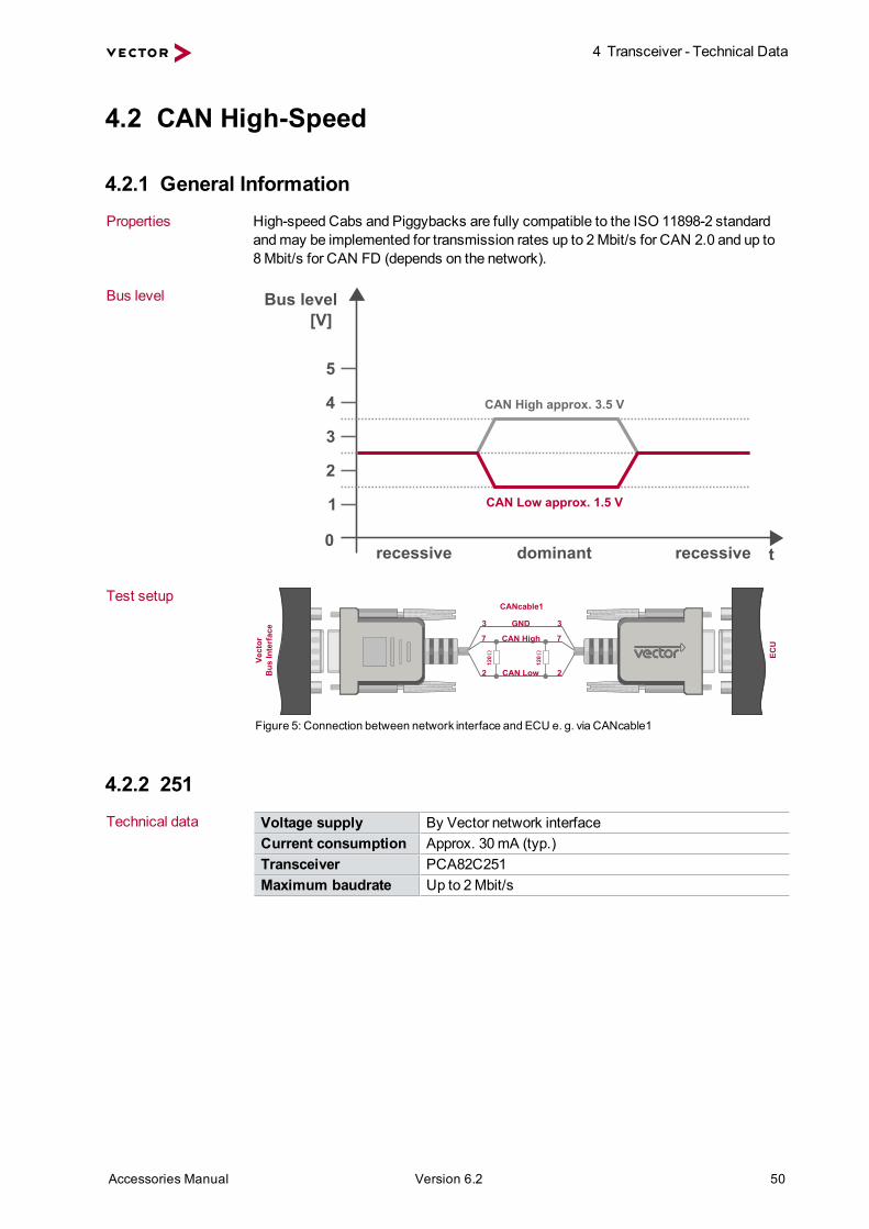
4.2.1 General InformationProperties High-speed Cabs and Piggybacks are fully compatible to the ISO 11898-2 standard
andmay be implemented for transmission rates up to 2Mbit/s for CAN 2.0 and up to8 Mbit/s for CAN FD (depends on the network).
Bus level Bus level[V]
5
4
3
2
1
0
CAN High approx. 3.5 V
CAN Low approx. 1.5 V
recessive dominant recessive t
Test setup
CAN High7 7
CANcable1
3
2
3
2CAN Low
120Ve
ctor
Bus
Inte
rfac
e
ECU
120
GND
Figure 5: Connection between network interface and ECU e. g. via CANcable1
4.2.2 251Technical data Voltage supply By Vector network interface
Current consumption Approx. 30mA (typ.)Transceiver PCA82C251Maximum baudrate Up to 2Mbit/s

4 Transceiver - Technical Data
Accessories Manual Version 6.2 51
4.2.3 251optoTechnical data Voltage supply By Vector network interface
Current consumption Approx. 60mA (typ.)Transceiver PCA82C251Maximum baudrate 1Mbit/sIsolation Optical: HCPL-0720-500 or compatibleInsulation voltage 50 V
Galvanicisolation
With this transceiver, the network interface is electrically isolated from the CAN bus.The transceivers’ voltage supply is electrically isolated via a DC/DC converter.
4.2.4 251magTechnical data Voltage supply By Vector network interface
Current consumption Approx. 60mA (typ.)Transceiver PCA82C251Maximum baudrate Up to 2Mbit/sIsolation Magnetically: ADuM 1100Insulation voltage 50 V
Galvanicisolation
With this transceiver, the network interface is electrically isolated from the CAN bus.The transceivers’ voltage supply is electrically isolated via a DC/DC converter.

4 Transceiver - Technical Data
Accessories Manual Version 6.2 52
4.2.5 251fibre
NoteThe 251fibre is only available as Cab.
Technical data Voltage supply PC side: by Vector network interfaceBus side: external supply 6 V…36 V DC
Current consumption PC side: 50mA at 250 kBit/sBus side: 50mA (typ.)
Transceiver PCA82C251 or compatibleMaximum baudrate 500 kbit/sOptocoupler HCPL-0720-500 or compatible
(typ. delay time approx. 30 ns)Fiber optic connector HP type HFBR 0508Fiber optic coupler HP HFBR1528/HFBR2528Total delay time 360 ns (typ.) + 2 x 5 ns/m fiber LWLDimensions 76mm x 30mm x 22mm (approx. 3 x 1.2 x 0.9 in)Weight 150 gHousing Black anodized aluminumMaximal length 25m (1mm POF), at 500 kbit/s (85% sampling point)
50m (200 µm HCS), at 250 kbit/s (85% sampling point)
Hardware The CANcab 251fibre consists of two separate components, which are inter-connected by a two-conductor fiber-optic cable. One component is connected to theCANcardXL via the I/O connector, and the other component is connected to the CANbus via a D-SUB9 connector. The CANcab 251fibre is connected via a HFBR-0508(optical couplers: HP modules HFBR-1528/HFBR-2528).
max. 50 m
Vect
orC
AN
card
XL
Figure 6: Connecting CANcab 251fibre to CANcardXL
Bus-sidevoltage supply
The CANcab 251fibre has to be externally supplied via pin 9.
VB+9 9
VB-3 3
CAN H7 7
CAN L2 2
ECU
CA
Nca
b 25
1fib
re
Shield5 5
120
120
Figure 7: Connecting CANcab 251fibre to ECU

4 Transceiver - Technical Data
Accessories Manual Version 6.2 53
4.2.6 1040magTechnical data Voltage supply By Vector network interface
Transceiver TJA1040Maximum baudrate 1Mbit/sMinimal baudrate 40 kbit/sIsolation Magnetically: ADuM 1100Insulation voltage 50 VFurther properties No unwanted error frames are generated
(e. g. during shutdown)
Galvanicisolation
With this transceiver, the network interface is electrically isolated from the CAN bus.The transceivers’ voltage supply is electrically isolated via a DC/DC converter.

4 Transceiver - Technical Data
Accessories Manual Version 6.2 54
4.2.7 1041AoptoTechnical data Voltage supply By Vector network interface
or external 12 V…18 V DCTransceiver TJA1041AMaximum baudrate 1Mbit/sMinimal baudrate 40 kbit/sIsolation Optical: HCPL-0720-500 or compatible
(typ. delay time approx. 30 ns)Insulation voltage 50 V
Galvanicisolation
With this transceiver, the network interface is electrically isolated from the CAN bus.The transceivers’ voltage supply is electrically isolated via a DC/DC converter.
External voltagesupply
An external voltage supply is possible via pin 9 at the D-SUB9 connector. The undervoltage error detection of the transceiver is not possible in this case. This applies toboth VBatt and VCC.
Split termination The concept of the split termination is depicted in the figure below. In normal mode,this terminates the commonmode signals via a capacitor to ground at the center tappoint of the two 60Ohm resistors. This is an attempt to achieve a kind of stabilizationof the recessive bus voltage of approx. 2.5 V. In all other modes, pin 4 is high imped-ance, and therefore the split termination is deactivated. The recommended capa-citance value of capacitor CSplit is 4.7 nF.
The series resistance in the split line that is recommended for some applications isnot needed here, since a lost groundmay be caused only by a defect in the CANcab/-CANpiggy.
VB+9 9
VB-3 3CAN H7 7
CAN L2 2
60
Csplitt4 4Ve
ctor
Bus
Inte
rfac
e
ECU
60
60 60
Figure 8: Setup example with external voltage supply and split termination
Programming of thenormal andsleepMode
The CANcab/CANpiggy 1041Aopto/mag supports both normal mode and sleepmode.
Switching between thesemodes is either done with the xlCANSetChannelTrans-ceiver function of the XL Driver Library or with the CAPL function setCanCabsMode.Regarding this function it should be noted that the channel number is the logical chan-nel number used by CANalyzer or CANoe according to the allocation in the VectorHardware Configuration.
The setCanCabsMode function has four parameters: ntype, nchannel, nmode andnflags each of type long. For high-speed CANcabs/CANpiggies the following valuesare valid:

4 Transceiver - Technical Data
Accessories Manual Version 6.2 55
setCanCabsMode ntype Meaning0 Reserved andmust be set to 0
nchannel Meaning0…n CAN channel to be set
nmode Meaning0 NORMAL1 SLEEP
nflags Meaning1 AUTOWAKEUP, only together with SLEEP
ExampleThe following example shows how to switch the CANcab/CANpiggy 1041A-opto/mag to standby mode with CANalyzer/CANoe and a CAPL program.
variables{}
on key '1'{ write ("CAN1 High-Speed: Normal Mode"); setCanCabsMode(0, 1, 0, 0);}
on key '2'{ write ("CAN1 High-Speed: Sleep Mode"); setCanCabsMode(0, 1, 1, 1);}
on key '3'{ write ("CAN2 High-Speed: Normal Mode"); setCanCabsMode(0, 2, 0, 0);}
on key '4'{ write ("CAN2 High-Speed: Sleep Mode"); setCanCabsMode(0, 2, 1, 1);}

4 Transceiver - Technical Data
Accessories Manual Version 6.2 56
4.2.8 1041AmagTechnical data Voltage supply By Vector network interface
or external 12 V…18 V DCTransceiver TJA1041AMaximum baudrate 1Mbit/sMinimal baudrate 40 kbit/sIsolation Magnetically: ADuM 1100Insulation voltage 50 VFurther properties No unwanted error frames are generated
(e. g. during shutdown)
Galvanicisolation
With this transceiver, the network interface is electrically isolated from the CAN bus.The transceivers’ voltage supply is electrically isolated via a DC/DC converter.
ReferenceProgramming of the normal/sleepmode see section 1041Aopto on page 54.
4.2.9 1050Technical data Voltage supply By Vector network interface
Current consumption Approx. 30mA (typ.)Transceiver TJA1050Maximum baudrate 1Mbit/s
4.2.10 1050optoTechnical data Voltage supply By Vector network interface
Current consumption Approx. 60mA (typ.)Transceiver TJA1050Maximum baudrate 1Mbit/sIsolation Optical: HCPL-0720-500 or compatibleInsulation voltage 50 V
Galvanicisolation
With this transceiver, the network interface is electrically isolated from the CAN bus.The transceivers’ voltage supply is electrically isolated via a DC/DC converter.

4 Transceiver - Technical Data
Accessories Manual Version 6.2 57
4.2.11 1050magTechnical data Voltage supply By Vector network interface
Current consumption Approx. 60mA (typ.)Transceiver TJA1050Maximum baudrate 1Mbit/sIsolation Magnetically: ADuM 1100Insulation voltage 50 VFurther properties No unwanted error frames are generated
(e.g. during shutdown)
Galvanicisolation
With this transceiver, the network interface is electrically isolated from the CAN bus.The transceivers’ voltage supply is electrically isolated via a DC/DC converter.
4.2.12 1051cap
NoteThis transceiver is available as Piggyback only.
Technical data Voltage supply By Vector network interfaceCurrent consumption Approx. 60mA (typ.)Transceiver TJA1051Maximum baudrate CAN High-Speed: 2Mbit/s
CAN FD: up to 8Mbit/sFurther properties No unwanted error frames are generated
(e.g. during shutdown)
Galvanicisolation
With this transceiver, the network interface is electrically isolated from the CAN bus.The transceivers’ voltage supply is electrically isolated via a DC/DC converter.
4.2.13 1057Gcap
NoteThis transceiver is available as Piggyback only.
Technical data Voltage supply By Vector network interfaceTransceiver TJA1057GMaximum baudrate CAN High-Speed: 2Mbit/s
CAN FD: up to 8Mbit/sFurther properties No unwanted error frames are generated
(e.g. during shutdown)
Galvanicisolation
With this transceiver, the network interface is electrically isolated from the CAN bus.The transceivers’ voltage supply is electrically isolated via a DC/DC converter.

4 Transceiver - Technical Data
Accessories Manual Version 6.2 58
4.3 CAN Low-Speed (fault tolerant)
4.3.1 General InformationProperties The low-speed CANcabs/CANpiggies are fully compatible to the ISO 11898-3 stand-
ard and can be implemented for transmission rates of up to 125 kbit/s.
Bus level innormal mode
Bus level[V]
5
4
3
2
1
0 CAN High max. 0.3 V
CAN Low min. 4.7 V
recessive dominant recessive max. 1.4 V
min. 3.6 V
t
Bus level instandby / sleepmode
> CAN LowApprox. voltage supply
> CAN HighApprox. 0 V
NoteThe voltage value of CAN Low depends onmany factors andmay fluctuate sig-nificantly in practice.
If all bus nodes are in sleepmode, the transceivers connect CAN Low to VBatt viathe terminating resistance RTL. Since the transceivers have different supplyvoltages, this results in cross currents between the CAN nodes via the terminatingresistors. In sleepmode, this can lead to false readings whenmeasuring supply cur-rents.
Test setup
Vect
orB
us In
terf
ace
ECU
CAN High / LINGND
CAN Low
73
2(VB+)9
73
29
CANcable0
Figure 9: Connection between network interface and ECU e. g. via CANcable0

4 Transceiver - Technical Data
Accessories Manual Version 6.2 59
4.3.2 1054Technical data Voltage supply By Vector network interface
or external 12 V…18 V DCCurrent consumption Approx. 20mA (typ.)Transceiver TJA1054Maximum baudrate 125 kbit/sMinimal baudrate 40 kbit/s
Programming ofnormal/sleepmodes
The 1054 (mag/opto) supports both normal mode and sleepmode.
It is possible to toggle between themodes either with the xlCANSetChannelTrans-ceiver function of the XL Driver Library or with the CAPL function setCanCabsMode.Regarding this function, it should be noted that the channel number is the logical chan-nel number used by CANalyzer or CANoe according to the allocation in the VectorHardware Configuration.
The setCanCabsMode function has four parameters: ntype, nchannel, nmode andnflags each of type long. For low-speed CANcabs/CANpiggies the following valuesare valid:
setCanCabsMode ntype Meaning0 Reserved andmust be set to 0
nchannel Meaning0…n CAN channel to be set
nmode Meaning0 NORMAL1 SLEEP
nflags Meaning1 AUTOWAKEUP, only with SLEEP

4 Transceiver - Technical Data
Accessories Manual Version 6.2 60
ExampleThe following example shows how to switch the CANcab/CANpiggy 1054(mag/-opto) to standby mode with CANalyzer/CANoe and a CAPL program.
variables{}
on key '1'{ write ("CAN1 Low-Speed: Normal Mode"); setCanCabsMode(0, 1, 0, 0);}
on key '2'{ write ("CAN1 Low-Speed: Sleep Mode"); setCanCabsMode(0, 1, 1, 1);}
on key '3'{ write ("CAN2 Low-Speed: Normal Mode"); setCanCabsMode(0, 2, 0, 0);}
on key '4'{ write ("CAN2 Low-Speed: Sleep Mode"); setCanCabsMode(0, 2, 1, 1);}
4.3.3 1054optoTechnical data Voltage supply By Vector network interface
or external 12 V…18 V DCCurrent consumption Approx. 60mA (typ.)Transceiver TJA1054Maximum baudrate 125 kbit/sMinimal baudrate 40 kbit/sIsolation Optical: HCPL-0720-500 or compatibleInsulation voltage 50 VFurther properties Switchable terminating resistor
(see section 1054mag on page 61)
Galvanicisolation
With this transceiver, the network interface is electrically isolated from the CAN bus.The transceivers’ voltage supply is electrically isolated via a DC/DC converter.
Externalvoltage supply
The bus-side voltage can be supplied by an external voltage source. This is especiallyrecommended if current measurements are performed on the ECU while the CAN busis in sleepmode.
ReferenceProgramming of the normal/sleepmode see section 1054 on page 59.

4 Transceiver - Technical Data
Accessories Manual Version 6.2 61
4.3.4 1054magTechnical data Voltage supply By Vector network interface
or external 12 V…18 V DCCurrent consumption Approx. 60mA (typ.)Transceiver TJA1054Maximal baudrate 125 kbit/sMinimal baudrate 40 kbit/sIsolation Magnetically: ADuM 1100Insulation voltage 50 VFurther properties No unwanted error frames are generated
(e.g. during shutdown).Switchable terminating resistor.
Galvanicisolation
With this transceiver, the network interface is electrically isolated from the CAN bus.The transceivers’ voltage supply is electrically isolated via a DC/DC converter.
Externalvoltage supply
The bus-side voltage can be supplied by an external voltage source. This is especiallyrecommended if current measurements are performed on the ECU while the CAN busis in sleepmode.
Switchableterminating resistors
The 1054opto/mag has an internal switchable terminating resistor.Via parallel connection, the terminating resistor is reduced from 4.7 kOhm to500 Ohm. This is useful in applications where only a few ECUs exist in the network.
4.7 kΩ 560 Ω
4.7 kΩ 560 Ω
RTH
CAN High
CAN Low
RTL
TJA
1054
Figure 10: Switching terminating resistors
To enable the terminating resistor, pin 4 or pin 8 of the D-SUB9 connector has to beconnected to ground (see details on RT1/RT2 on page 48). If pin 4 or pin 8 is not con-nected to ground, the value of the terminating resistor is 4.7 kOhm.
ReferenceProgramming of the normal/sleepmode see section 1054 on page 59.

4 Transceiver - Technical Data
Accessories Manual Version 6.2 62
4.3.5 1055cap
NoteThis transceiver is available as Piggyback only.
Technical data Voltage supply By Vector network interfaceor external 12 V…18 V DC
Transceiver TJA1055Maximal baudrate 125 kbit/sMinimal baudrate 40 kbit/sFurther properties No unwanted error frames are generated
(e.g. during shutdown).Switchable terminating resistor
Galvanicisolation
With this transceiver, the network interface is electrically isolated from the CAN bus.The transceivers’ voltage supply is electrically isolated via a DC/DC converter.
Externalvoltage supply
The bus-side voltage can be supplied by an external voltage source. This is especiallyrecommended if current measurements are performed on the ECU while the CAN busis in sleepmode.
Switchableterminating resistors
The 1055cap has an internal switchable terminating resistor.Via parallel connection, the terminating resistor is reduced from 4.7 kOhm to 500Ohm. This is useful in applications where only a few ECUs exist in the network.
4.7 kΩ 560 Ω
4.7 kΩ 560 Ω
RTH
CAN High
CAN Low
RTL
TJA
1055
Figure 11: Switching terminating resistors
To enable the terminating resistor, pin 4 of the D-SUB9 connector has to be con-nected to ground (see details on RT1 on page 42). If pin 4 is not connected to ground,the value of the terminating resistor is 4.7 kOhm.
ReferenceProgramming of the normal/sleepmode see section 1054 on page 59.

4 Transceiver - Technical Data
Accessories Manual Version 6.2 63
4.4 LIN
4.4.1 General InformationProperties The LINcab/LINpiggy conforms to the LIN standard (Local Interconnect Network) and
is specified for transmission rates of up to 20 kbit/s in normal mode as well as115 kbit/s in flashmode.
The LIN bus communicates over a single-wire bus and is based on amaster-slaveconcept. Consequently, no arbitration or collisionmanagement is needed in the slavenodes.
LIN communication principle:
> The LIN master generates themessage header and places it on the bus. Themes-sage header consists of the sync break, sync field and ID field.
> The addressed LIN slave node places its message response on the bus after themessage header. Themessage response is composed of 0...7 data bytes and achecksum field.
> The individual bytes of amessage are transmitted according to the conventionalUART protocol (1 start bit, 8 data bits, and 1 stop bit).
Bus level The following figure depicts the voltage levels on the LIN bus. VBatt is the supplyvoltage of the ECU that is LIN master. The bus voltage can be changed to the recess-ive case (VSup) by means of filter elements and dynamic voltage changes in the sup-ply voltage of themaster ECU.
Bus level[V]
t
VBatt
VSup
Vrec
Vdom
dominant recessive dominant
Bus-sidevoltage supply
Since the recessive level on the bus depends on the supply voltage of themaster, it isadvisable to operate the LINcab/LINpiggy with an external supply voltage that is alsoused by the other bus nodes. This prevents cross currents between the individualnodes on the LIN bus.
Connecting pin 4 (Pdis) with pin 3 (VB-) of the D-SUB of the network interface dis-ables the internal voltage supply of the LINcab/LINpiggy. This makes it possible toperform measurements on the LIN bus, even with an external supply below 12 V.

4 Transceiver - Technical Data
Accessories Manual Version 6.2 64
NoteIf an external master resistor and an external voltage supply are being used at theD-SUB9 connector of the LINcab/LINpiggy, a diode should be connected in series(see figure below). Otherwise the LINcab/LINpiggy would be supplied by the LINbus over the external master resistor, if the external voltage supply was broken.This damping diode is necessary according to the LIN specification.
1
2
3
4
59
8
7
6
RMaster
+12 V
4.4.2 7269magTechnical data Voltage supply By Vector network interface
or external 12 V…36 V DCCurrent consumption 30mA (typ.)Transceiver TLE7269Maximal baudrate Normal mode: 20 kbit/s
Flashmode: 115 kbit/s*
*Depending on the busphysics, themaximum data rate can be up to330 kbit/s, see notes in the network interfacemanuals.
Isolation Magnetically: ADuM 1100Insulation voltage 50 VBus termination Mastermode: 1 kOhm
Slavemode: 30 kOhm
Galvanicisolation
With this transceiver, the network interface is electrically isolated from the LIN bus.The transceivers’ voltage supply is electrically isolated via a DC/DC converter.
Properties The 7269mag transceiver is designed for 24 V applications. In addition, it has a timeout counter, which avoids a constant dominant level on the LIN bus in error cases.Theminimum switch off time of the transceiver is 6ms.
Stress functionality The stress functionality of the LINcab/TWINcab and LINpiggy enables you to disturbthe LIN bus by dominant or recessive disturbing bits. The disturbing bits can be anylength.
NoteRecessive disturbing sequences have no current limitation, but dominant disturbingbits are protected by a 100mA fuse.
In case of dominant disturbing bits the LINcab/TWINcab/LINpiggy 7269mag has aprotection against thermal overloads. The LINcab/TWINcab/LINpiggy must beexternally supplied to use recessive disturbingmode.
Minimal baudrate Due to the dominant timeout (6…20ms) of the TLE7269, it may not be possible to

4 Transceiver - Technical Data
Accessories Manual Version 6.2 65
transmit a LIN header at baudrates below 5 kbit/s with themaximum break-field of 30bits (minimum 13 bits):
Baudrate = [1/(minimal Timeout [ms]/Break-Field-Length [bit]] * 1000Baudrate = [1/( 6 ms/30 bit)] * 1000Baudrate = 5000 bits/seconds
Therefore dominant sequences longer than 6ms (e. g. for LIN headers below 5 kbit/s)are created using the LINcab's/LINpiggy's integrated transistor circuitry.
Flashmode The flashmode enables higher data transmission rates which can be used for pro-grammingmicrocontrollers during the ECU production. This is possible by anincreased slew rate of the transceiver, whichmay also affect EMC properties.

4 Transceiver - Technical Data
Accessories Manual Version 6.2 66
4.5 Single Wire CAN
4.5.1 General InformationBus Levels Bus level
[V]
5
0t
12 dominant
dominant
recessiveNormal Mode High Voltage Mode (HV)
Bus communication To establish communications between the individual network nodes, VB+ has to beconnected to pin 9, GND/VB- to pin 3 and CAN to pin 7 at the D-SUB connector.
If the SingleWire CANcab/CANpiggy is operated in a high-speed network, a ter-minating resistor must be available between CAN High andGND/VB-. In high-speedmode, such a resistor (100Ohm) is enabled by the CANcab/CANpiggy if pin 7 (CANHigh) is connected to pin 4 (R100).
The resistor is disabled, if the CANcab/CANpiggy switches back to normal mode. Toimplement higher impedance terminating resistances, another resistor (RR)may alsobe added instead of a direct connection between CAN High and R100. The total res-istance is RR +100Ohm.
4.5.2 5790cTechnical data Voltage supply External 12 V…18 V DC
Transceiver AU5790Maximal baudrate Low-speed: 40 kbit/s
High-speed: 100 kbit/s
Externalvoltage supply
The CANcab/CANpiggy has to be operated with an external voltage supply. Thisvoltage is used as the level for the dominant state of the wake-upmessage.
Programmingtransceiver modes
The SingleWire CAN transceiver supports normal mode, high-speedmode and sleepmode.
Switching the transceiver modes is either done by the xlCANSetChannelTrans-ceiver function of the XL Driver Library or by the CAPL function setCanCabsMode.Regarding this function it should be noted that the channel number used byCANalyzer or CANoe is the logical channel number. Furthermore, it is not possible toset themode explicitly for one channel while preserving themode of the other chan-nel; modes must always be set for both channels.

4 Transceiver - Technical Data
Accessories Manual Version 6.2 67
The setCanCabsMode function has four parameters: ntype, nchannel, nmode andnflags each of type long. For SingleWire CANcabs/CANpiggies the following valuesare valid:
setCanCabsMode ntype Meaning0 Reserved andmust be set to 0
nchannel Meaning0…n CAN channel to be set
nmode Meaning0 NORMAL1 SLEEP2 HIVOLTAGE3 HISPEED
nflags Meaning1 AUTOWAKEUP, only with SLEEP2 HIGHPRIO, only CANcab 5790c, 1 = clear send buffer
Transmission rate For normal data exchange, normal mode is used with a transmission rate of up to40 kbit/s. The high-speedmode is available for transmission rates up to 100 kbit/s, forexample for flash programming. However, in this mode the number of bus nodes is lim-ited. The high-voltagemode is needed to send the high-voltage wakeupmessage(12 V). The transceiver’s transmitter is deactivated in sleepmode. Additionally, thereis a high priority flag which clears all send buffers.
4 Transceiver - Technical Data
Accessories Manual Version 6.2 68
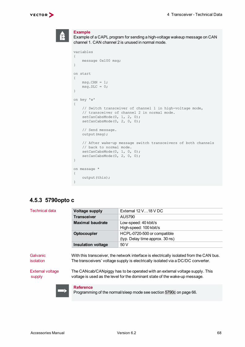
ExampleExample of a CAPL program for sending a high-voltage wakeupmessage on CANchannel 1. CAN channel 2 is unused in normal mode.
variables{ message 0x100 msg;}
on start{ msg.CAN = 1; msg.DLC = 0;}
on key 'w'{ // Switch transceiver of channel 1 in high-voltage mode, // transceiver of channel 2 in normal mode. setCanCabsMode(0, 1, 2, 0); setCanCabsMode(0, 2, 0, 0);
// Send message. output(msg);
// After wake-up message switch transceivers of both channels // back to normal mode. setCanCabsMode(0, 1, 0, 0); setCanCabsMode(0, 2, 0, 0);}
on message *{ output(this);}
4.5.3 5790opto cTechnical data Voltage supply External 12 V…18 V DC
Transceiver AU5790Maximal baudrate Low-speed: 40 kbit/s
High-speed: 100 kbit/sOptocoupler HCPL-0720-500 or compatible
(typ. Delay time approx. 30 ns)Insulation voltage 50 V
Galvanicisolation
With this transceiver, the network interface is electrically isolated from the CAN bus.The transceivers’ voltage supply is electrically isolated via a DC/DC converter.
External voltagesupply
The CANcab/CANpiggy has to be operated with an external voltage supply. Thisvoltage is used as the level for the dominant state of the wake-upmessage.
ReferenceProgramming of the normal/sleepmode see section 5790c on page 66.

4 Transceiver - Technical Data
Accessories Manual Version 6.2 69
4.5.4 7356cap
NoteThis transceiver is available as Piggyback only.
Technical data Voltage supply External 12 V…18 V DCTransceiver NCV7356Maximum baudrate Low-speed: 40 kbit/s
High-speed: 100 kbit/sFurther properties No unwanted error frames are generated
(e.g. during shutdown)
Galvanicisolation
With this transceiver, the network interface is electrically isolated from the CAN bus.The transceivers’ voltage supply is electrically isolated via a DC/DC converter.
External voltagesupply
The CANcab/CANpiggy has to be operated with an external voltage supply. Thisvoltage is used as the level for the dominant state of the wake-upmessage.
ReferenceProgramming of the normal/sleepmode see section 5790c on page 66.

4 Transceiver - Technical Data
Accessories Manual Version 6.2 70
4.6 J1708
4.6.1 General InformationProperties These transceivers enable access to serial networks according SAE standard J1708
respective J1587 and is used predominantly in commercial vehicles. Typical appli-cations of the J1708 network are diagnostic and process data communication.
4.6.2 65176optoTechnical data Voltage supply By Vector network interface
Current consumption Approx. 200mATransceiver SN65176BMaximal baudrate 9.6 kbit/sIsolation Optical: HCPL-0720-500 or compatibleBus termination yes, 2 x 4.7 kOhm
Galvanicisolation
With this transceiver, the network interface is electrically isolated from the CAN bus.The transceivers’ voltage supply is electrically isolated via a DC/DC converter.

4 Transceiver - Technical Data
Accessories Manual Version 6.2 71
4.7 Truck & Trailer CAN
4.7.1 General InformationProperties The Truck & Trailer CANcab/CANpiggy is compatible with the ISO 11992-1 standard
and has been developed for CAN low-speed applications in the commercial vehiclearea. Themaximum transmission speed is 250 kbit/s. The possible single-wire modesfor this transceiver are only supported by the XL Driver Library.
Bus level Bus level[V]
VCAN Low
t
dominantlogical "0"
recessivelogical "1"
0
VCAN High
Recessive state The recessive state is described by the following voltage relation:
VS: bus side voltage
VCAN_H = 1/3 VS
VCAN_L = 2/3 VS
Dominant state For the dominant levels this relation applies:
VCAN_H = 2/3 VS
VCAN_L = 1/3 VS
Differential voltage This yields the following differential voltage:
Vdiff = VCAN_L - VCAN_H
Vdiff = 1/3 VS recessive state
Vdiff = -1/3 VS dominant state

4 Transceiver - Technical Data
Accessories Manual Version 6.2 72
4.7.2 10011optoTechnical data Voltage supply External 16 V…32 V DC
Current consumption 120mA (typ.)Transceiver B10011SMaximal baudrate 250 kbit/sIsolation Optical: HCPL-0720-500 or compatibleInsulation voltage 50 V
Galvanicisolation
With this transceiver, the network interface is electrically isolated from the CAN bus.The transceivers’ voltage supply is electrically isolated via a DC/DC converter.
Connection cable The following connection cables can be used with the 10011opto:> CANcable TnT (page 105)> CANcable TnT Term (page 105)
Test setup withCANcable TnT
Vs
VB-
CAN High
CAN Low
9
3
7
2
Hardware The CANcable TnT has a D-SUB9 connector and four bunch plugs to connect to anexternal voltage supply and the CAN bus.
According to ISO 11992-1, a Truck & Trailer CAN system consists of two nodes,which should be terminated. If the Vector network interface is used together with theCANcab/CANpiggy 10011opto to observe bus traffic between two real ECUs, theCANcable TnT should be used, since both ECUs already have a terminating resistor.If only one real ECU is connected to the CANcab/CANpiggy 10011opto, the CANc-able TnT Term should be used.
Bus-sidevoltage supply
The CANcab/CANpiggy 10011opto has to be operated with an external voltage sup-ply. ISO 11992-1 specifies at least 16 V supply voltage (VS) for 24 V systems.

4 Transceiver - Technical Data
Accessories Manual Version 6.2 73
4.8 Special Design
4.8.1 CANcab EVAGeneral The CANcab EVA is an evaluation kit which can be used to customize the connection
setup between the CANcardXL/CANcardXLe and the CAN bus. For this purpose thePCB can be populated with specific bus transceivers.
Connection pointsfor cable to CANcardXL.Soldered connectors CN1, TB2, TB4.
Series of holes for+5 V power supply. Series of holes for GND.
Connection pointsfor cable to CAN bus.Soldered connector CN2.
Hole grid PC-board forapplication-specific component placement.
Signals from andto CANcardXL.
To C
AN
card
XL To CA
N bus

4 Transceiver - Technical Data
Accessories Manual Version 6.2 74
4.9 FlexRay
4.9.1 General InformationProperties The FlexRay transceivers are compatible to the FlexRay Communications System
Electrical Physical Layer Specification Version 2.1 Rev. A and can be used with10 Mbit/s per channel (A/B).
Bus level Bus level[V]
5
4
3
2
1
0
BM 1.5 V
BP 3.5 V
Idle Low Power
tIdle Data n Data n+1 Data n+2
BM 3.5 V
BP 1.5 V
logical '1' logical '0'
4.9.2 1080Amag
NoteThis transceiver is available as Piggyback only.
Technical data Voltage supply By Vector network interfaceTransceiver TJA1080ABaudrate 10Mbit/s
Galvanicisolation
With this transceiver, the network interface is electrically isolated from the FlexRaybus. The transceivers’ voltage supply is electrically isolated via a DC/DC converter.

4 Transceiver - Technical Data
Accessories Manual Version 6.2 75
4.9.3 1082cap
NoteThis transceiver is available as Piggyback only.
Technical data Voltage supply By Vector network interfaceTransceiver TJA1082Baudrate 10Mbit/sFurther properties Trigger
Galvanicisolation
With this transceiver, the network interface is electrically isolated from the FlexRaybus. The transceivers’ voltage supply is electrically isolated via a DC/DC converter.
Trigger The FlexRay interface family offers a pin for dedicated trigger applications (see theaccording pin assignment). The configuration of the trigger and its action is set in theapplication (e. g. CANoe). The following picture depicts the internal circuit of the trig-ger pin.
Logic
+5V
4k7 Ohm
TriggerOutput
Figure 12: Trigger output
Output The application's trigger releases a falling edge on the trigger pin. By using externalpull up resistors, themaximum allowed load is 5 mA.
Level[V]
5
4
3
2
1
0
t
trigger in application
high level 3 V ... 5.5 V
low level 0 V ... 0.7 V
output voltage
Figure 13: Trigger output
5 IOcab 8444opto
Accessories Manual Version 6.2 76
5 IOcab 8444optoIn this chapter you find the following information:
5.1 Introduction 77
5.2 Digital Inputs and Outputs 795.2.1 Important Notes on Real TimeCapability of Digital Outputs 80
5.3 Analog Inputs and Outputs 82
5.4 Digital PWM Output / Capture Inputs 84
5.5 Data Logging 86
5.6 Firmware Update 87
5.7 Technical Data 89

5 IOcab 8444opto
Accessories Manual Version 6.2 77
5.1 IntroductionSystem requirements The IOcab can be connected to theCANcardXL or to theCANcardXLe only. Other
interface cards are not supported.
The IOcab is supported by:> CANoe Version 5.0 SP2 or higher> CANape Version 5.0 SP2 or higher> XLDriver Library 5.0 or higher
Functionaldescription
The IOcab 8444opto was specifically developed for measurement and control appli-cations in the CAN, LIN andMOST environments. It is used in automotive develop-ment applications and in industrial automation and related areas.
The IOcab offers these features:> 8x digital input> 4x digital output> 4x analog input> 4x analog output> 1x analog comparator> 1x PWM (pulse widthmodulation) output> 2x Capture input (only one input can be used at the same time)
as well as> highly-precise acquisition and stimulation over all inputs and outputs> synchronization of CAN, LIN, MOST, and FlexRay messages.
The time stamp generated at eachmeasurement point makes it possible to achieveprecise time correlation between ameasurement point andmessages on different bussystems.
Electrical isolation has been integrated in the IOcab to protect the connected com-puter and to avoidmeasurement errors. This decouplingmethod electrically isolatesthe PC from all signals of the D-SUB15 connector. However, there is no electrical iso-lation between the various signals of the D-SUB15 connector. The shielding (shell ofthe D-SUB15 socket) is connected to PC ground.

5 IOcab 8444opto
Accessories Manual Version 6.2 78
Connectors andpin assignments
The IOcab is connected to the PC with a CANcardXL/XLe via a 15-pin flat-cable con-nector. The user can access the digital and analog inputs and outputs of the IOcab viathe 15-pin D-SUB connector.
The pin assignment of the D-SUB15 plug connector is as follows:
Pin assignment Pin Name Description1 DIO0 Digital Input 0/Output 02 DIO2 Digital Input 2/Output 13 DIO4 Digital Input 4/Output 2/Capture In 24 DIO6 Digital Input 6/Output 35 DPWM Digital PWMOut/Capture In 16 AGND Reference ground for Analog In/Out7 AIO1 Analog Input 1/Output 18 AIO3 Analog Input 3/Output 3/Comp.Trigger9 DIO1 Digital Input 1/Output 010 DIO3 Digital Input 3/Output 111 DIO5 Digital Input 5/Output 212 DIO7 Digital Input 7/Output 313 DGND Reference ground for Digital Input and PWM14 AIO0 Analog Input 0/Output 015 AIO2 Analog Input 2/Output 2
Shield Shielding PC ground
Shielding AGND andDGND are routed separately for shielding reasons, but are directly con-nected (low frequency) in IOcab 8444opto.
1
2
3
4
512
11
10
9
6
7
815
14
13

5 IOcab 8444opto
Accessories Manual Version 6.2 79
5.2 Digital Inputs and OutputsImplementation The digital outputs are implemented in the IOcab by semiconductor switches, which
can interconnect two D-SUB15 plug connector pins. This allows the user to connectboth Vcc (high-side switches) andGND (low-side switches).
NoteThe digital outputs themselves cannot supply any power; rather they only switch avoltage that has been externally applied. The internal protective circuitry of thedigital outputs only protects the circuit from electrostatic discharge.
When connecting inductive loads, the IOcabmust be externally protected from highinductive voltages (e. g. free-wheeling diodes) to prevent damage. Continuous shortcircuiting of multiple digital outputs results in a risk of thermal overload.
Circuitinterconnections
In this arrangement the digital inputs and outputs utilize the same IO pins on theD-SUB15 plug connector. Figure 15 shows their circuit interconnections:
Circuit diagram ofdigital inputsand outputs
12
12
12
12
DSUB15
11
22
33
44
55
66
77
88
99
1010
1111
1212
1313
1414
1515
DOUT0
DOUT0
DOUT1
DOUT1
DOUT2
DOUT2
DOUT3
DOUT3
DIN0DIN1DIN2DIN3DIN4DIN5DIN6DIN7
DIN_GND
Figure 14: Digital inputs and outputs
Trigger events With this circuit, when a digital output is used and the internal output switch is closed,two digital input or output lines are always shorted together. Nevertheless, all digitalinputs are read-back capable, whereby for example precise switching time points canbe defined by the trigger functionality of the inputs.
The voltages at DIN0…DIN7 always reference DGND and can be read by the user inresponse to a trigger event, cyclically or by polling.

5 IOcab 8444opto
Accessories Manual Version 6.2 80
5.2.1 Important Notes on Real Time Capability of Digital OutputsSwitching delaysof photoMOS relays
The IOcab 8444opto possesses at the digital outputs photoMOS relays and is not cap-able for real time applications (e. g. serial communication) due to their switching onand off delays. The following example explains these facts.
Asymmetrical output The figure below shows a possible scenario where the digital output is controlled byan application (e. g. CANoe). The times for pulse high and pulse low are sym-metrically each with 50ms (20 Hz). The switching-on delay ∆t1 of the photoMOSrelay in this example is approx. 870 µs, but the switching-off delay ∆t2 is only 460 µs.This causes a shorter pulse high time than pulse low. The digital output is asym-metrical.
Pulse offset at thedigital output
Commands
Commands
IOcab 8444optoDigital Output Pin
t1 t2
Figure 15: Pulse offset
Latencies Besides the named delays, additional latencies could occur during the communica-tion between the application and IOcab firmware. Each command is acknowledgedinside the IOcab. Afterwards, the IOcab firmware passes the next available commandto the digital output. If the acknowledgement is missing, all incoming commands arerejected except the last one, which is buffered in a special register. When themissingacknowledgement is received, the last buffered state is written to the digital output.
NoteToo fast command sequences may not be properly handled, so that completepulses could be lost on the digital output (see next figure).
To avoidmissing pulses, we recommend amaximum switching frequency of 20 Hz.Switching frequencies above 20 Hz could cause sporadic or frequently pulselosses. This behavior is affected due the chosen PC configuration, the operatingsystem and the PC load respectively.
Section Digital PWMOutput / Capture Inputs on page 84 explains a way how to gen-erate a PWM directly with the IOcab.

5 IOcab 8444opto
Accessories Manual Version 6.2 81
Missing pulse atthe digital output CANoe
IOcab 8444optoDigital Output Pin
Driver
s = set lows = set highs = set low
1
2
3
s 1 s 2 s 3
X Xignored
commands
waiting foracknowledge
com
man
ds 1
ackn
owle
dge
s 1
com
man
ds 3
(last
sta
te)
missingpulse
Figure 16: Missing pulses

5 IOcab 8444opto
Accessories Manual Version 6.2 82
5.3 Analog Inputs and OutputsAnalog pins All functions of the analog inputs and outputs AIO0…AIO3 of the IOcab 8444opto
share four pins of the D-SUB15 connector. For each of the four analog pins, there isan output driver that can be activated or deactivated. If the output driver of an analogpin is deactivated, an external applied voltage can bemeasured over the associatedanalog inputs. If the output driver of an analog pin has been activated, it drives thevoltage configured for the output. To protect the output driver, a diode was placed inseries with it which isolates the driver from an external applied voltage. The voltagedrop of the diode is compensated by the output driver. However, it is not possible forthe output to draw a current in this way.
Although the outputs are protected against short circuit, the IOcab 8444opto can skipinto an internal error state. After the short circuits have been corrected, the IOcabmust be reinitialized.
NoteThe analog output driver can be destroyed in input or output mode if a negativevoltage is applied to AIO0…AIO3 (VAIO0…VAIO3 < VAGND) andmust be avoided!
Measurement ranges Twomeasurement ranges, H(igh) and L(ow), are available at AIO0 and AIO1 for themeasurement of voltages. In the Lmeasurement range voltages from 0 to 8.192 Voltcan bemeasured and in theH measurement range voltages from 0 to 32.768 Volt.AIO2 and AIO3may only be used with theH measurement range. Measurementranges are selected during configuration. It is not possible to measure the voltage ofan analog pin in bothmeasurement ranges simultaneously.
Conversion of an analog input signal takes approx. 44 µs. Since conversion of all acti-vated analog inputs is sequentially performed, a delay is associated with the con-version that depends on the number of activated channels. The time stamp of ameasurement always references the time point of the trigger event or measurementstart on the lowest activated channel.
Circuit connectionsof analog inputs andoutputs
12
3
5
+
-
/SHDN
19k6
19k6
19k6
19k6
2k8
10nF
10k
2k8
10nF
10nF
2k8
10nF
10k
10nF
10k
10k
10nF
2k8
DSUB15
11
22
33
44
55
66
77
88
99
1010
1111
1212
1313
1414
1515
DAC3
AOUT0AOUT1AOUT2AOUT3
AGND
AIN0 Range 0.. 8.1VAIN0 Range 0.. 32.7V
AcompAref
AIN1 Range 0.. 8.1V
AIN2 Range 0.. 32.7VAIN1 Range 0.. 32.7V
AIN3 Range 0.. 32.7V
Figure 17: Analog inputs and outputs

5 IOcab 8444opto
Accessories Manual Version 6.2 83
Comparator AIO3 also has the option of initiating ameasurement, in parallel to a runningmea-surement, by means of an internal analog comparator that triggers when an upperand/or lower configurable trigger threshold has been exceeded.
The comparator’s output value can also be polled by the application while the com-parator function is activated.
Themeasurement of voltage changes always involves a delay when using the analoginput circuitry. This also applies to the analog comparator. The jump delay can be cal-culated by the following formula:
Time delay of the comparator24.5 x 10-6 sPreset trigger voltage of the comparator
Input voltage
Starting voltage from which a jump is made to VAIN3
Delay As an example consider a voltage jump from 10 V to 24 V with a trigger threshold of 12V. This would result in a delay of

5 IOcab 8444opto
Accessories Manual Version 6.2 84
5.4 Digital PWM Output / Capture InputsGeneral notes D-SUB15 pin 5 (DPWM) can be used to generate pulse widthmodulated signals. As
an alternative either this pin (DPWM) or pin 10 (DIO4) can be used tomeasure fre-quencies (capturemode), whereby the two Capture Inputs differ from one another intheir thresholds and voltage ranges. The required function and channel are selected inthe configuration. It is not possible to use both the PWM and capturemode and bothCapture Inputs simultaneously. At a pin only onemode is selectable at a time.
Circuitinterconnections ofPWM and capturefunctions
DSUB15
11
22
33
44
55
66
77
88
99
1010
1111
1212
1313
1414
1515
Capture Input 1DIN_GND
PWM
Capture Input 2
Figure 18: PWMandCapture
PWM or frequencygenerator
The IOcab 8444opto can be used for PWM or frequency generator, which generatesfrequencies from 40Hz to 500 Hz and from 2.4 kHz to 100 kHz. Themaximum fre-quency is essentially limited by the pin’s output protection circuit.
The pulse widthmay be set between 0.0% and 100.0%. The resolution of the pulsewidth depends on the frequency; this dependency is shown in the following graph:
PWM resolution as afunction of frequency 11
10
9
8
7
65
4
3
2
1
01 10 100 1.000 10.000
PWM resolution related to frequency
f=39.06 kHz
Res
olut
ion
(bit)
Capturemode In capturemode both the pulse and pause times of a signal can be simultaneouslydetermined for a signal at the DPWM pin or DIO4 pin of the D-SUB15 connector. Oneof the three possible measurement ranges must be selected beforemeasurement.Pulse and pause times between 5 μs and 50ms can bemeasured over the Capture

5 IOcab 8444opto
Accessories Manual Version 6.2 85
Inputs. This corresponds to amaximum input frequency of 100 kHz at a pulse width of50%.
NoteIf the IOcab is used in capturemode even if there is no signal connected to the cap-ture input, the capturemeasurement is canceled by a timeout after 500ms. In thisperiod of time no other measurement is executed.

5 IOcab 8444opto
Accessories Manual Version 6.2 86
5.5 Data Logging
Trigger, polling andcyclic measurement
All measurements can be initiated by three different events:> measurement on trigger,> measurement on polling or> cyclic measurement.
However, only one of themethods listed abovemay be configured for a specific mea-surement. One of the following two events may be enabled in the configuration andused as the trigger source:> level change (H→L and L→H) at DIO0...DIO3> triggering of the analog comparator
“Measurement on polling“ represents a polling procedure in which ameasurement isnot initiated until a request for measurement is received from the application. Then therequested data are polled and transferred. With cyclic measurement interval timesbetween 1ms and 65 seconds may be used. If this time expires the required signalsare automatically measured and transferred to the application.

5 IOcab 8444opto
Accessories Manual Version 6.2 87
5.6 Firmware UpdateProgrammingfirmware
The firmware of the control processor in the IOcab 8444optomay be updated to thelatest revision level at any later time.
Step by Step ProcedureFollow these instructions to update the IOcab 8444opto:
1. Connect the IOcab8444 with an inserted CANcardXL/XLe.
2. Open the folder \Firmware Update\IOcab8444opto\WinBoot on theVector Driver Disk.
3. Start WinBoot.exe. On the first execution youmay get the following error mes-sage:
4. OpenVector Hardware Config and assignWinBoot|CAN1 to the IOcab 8444-opto to be updated.
5. Start WinBoot.exe again. The IOcab 8444opto can be accessed now.

5 IOcab 8444opto
Accessories Manual Version 6.2 88
6. Click [Select File…] and open the hex file in folder\Firmware Update\IOcab8444opto\Firmware.
7. Click [Start Download]. The programm starts the downloading process.
8. The followingmessage appears:
9. Click [Exit] and closeWinBoot.

5 IOcab 8444opto
Accessories Manual Version 6.2 89
5.7 Technical DataSupply voltage By Vector CANcardXL/XLe; +5 VCurrent consumption Typ. 180mA; max. 200mAElectrical isolation Max. 50 V,
between PC and IO only; not between IOsDGND and AGND are internally connected
Time stamp precision 2 μs
Digital InputsNumber of inputs 8Max. input voltage1 -36 V…36 V (DIO0…DIO7 related to DGND)Max. difference voltage1 36 V (DIO0…DIO7 related to DIO0…DIO7)Input voltage LOW -36 V…2.5 V (DIO0…DIO3 related to DGND)
-36 V…1.4 V (DIO4…DIO7 related to DGND)Input voltage HIGH 6.2 V…36 V (DIO0…DOI3 related to DGND)
5.9 V…36 V (DIO4…DIO7 related to DGND)DIO0…DIO3 Switching threshold typ.: 4.0 VDIO4…DIO7 Switching threshold typ.:
2.0 V and 4.7 V; Schmitt-TriggerProtection circuits By suppressor diodes 36 V, 70mWInput resistance >200 kΩ (DIO0…DIO3)
>40 kΩ (DIO4…DIO7)Input capacitance ~ 25 nF at pin
Digital OutputsNumber of outputs 4Max. input voltage1 -36 V…36 V (DIO0…DIO7 related to DGND)Max. difference voltage1 36 V (DIO0…DIO7 related to DIO0…DIO7)Current loading - 200mA…+200mA (e.g. DIO0 referenced to
DIO1)Protection circuits Short circuit by resetable fuses
overvoltage by 36 V suppressor diodesON resistance <5ΩSwitching times Typ.: 0.5 ms, max.: 3 ms
1If the range exceeds the devicemay be destroyed.

5 IOcab 8444opto
Accessories Manual Version 6.2 90
PWM OutputNumber of outputs 1Frequency range 2 ranges: 40 Hz …500Hz; 2.5 kHz …100 kHzTiming accuracy For frequency range 40 Hz …500Hz:
The timing accuracy of the software PWM dependson the number of measurements defined by theuser (trigger, cyclic measurement and polling).Best results can be reached if nomeasurement isdefined and no output is changed.
For frequency range 2.5 kHz …100 kHz:< 1%
Duty cycle 0.0%…100.0% (Resolution < 5%)Resolution Up to 10 BitVoltage reference DGNDProtection circuits By suppressor diode, 500mWOutput voltage LOW 0 V…0.6 VOutput voltage HIGH 3.8 V…5.5 VOutput resistance ~320Ω
Capture InputsNumber of inputs 2Minimum pulse/pause length 5 μsMaximum pulse/pause length 50msAccuracy ±1%Input characteristic Schmitt TriggerDPWM – InputMax. input voltage1 -6 V … 12 V (DPWM related to DGND)Input voltage LOW -6.0 V…1.0 VInput voltage HIGH 4.0 V…12 VSwitching threshold typ. 1.4 V and 3.2 VDIO4 – InputMax. input voltage1 -36 V…36 V (DIO4 related to DGND)Max. difference voltage1 36 V (DIO4 related to DIO0…DIO7)Input voltage LOW -36 V…1.4 VInput voltage HIGH 5.9 V…36 VSwitching threshold typ. 2.0 V and 4. 7V
Analog InputsNumber of inputs 4Max. input voltage1 0 V…36 V (AIN0…AIN3 related to AGND)Measurement range AIN0, AIN1: 2 ranges, 0… 8.192 V, 0… 32.768 V
AIN2, AIN3: 1 ranges, 0… 32.768 VResolution 10 bit in all measurement rangesMeasuring accuracy ±1.5%Input resistances 0 V…10 V: 8 kΩ (AIO0 and AIO1)
10 V…36 V: 4.7 kΩ (AIO0 and AIO1)AIO2 and AIO3: 0 V …36 V: 8 kΩ
1If the range exceeds the devicemay be destroyed.

5 IOcab 8444opto
Accessories Manual Version 6.2 91
Analog InputsSampling rate 1 kHz; 3 kHz over XL Driver LibraryConversion time ~ 44 µs per channelLimit frequency of input filter Range 0…8.192 V:3.1 kHz
Range 0… 32.768 V:6.4 kHzTime stamp precision 2 µs plus delay of input filterProtection circuits By suppressor diodes 36 V, 70mW,
no polarity protection.
Analog OutputsNumber of outputs 4Max. back voltage1 VAIN0…VAIN3 > VAGND: 0 V … 36 V
VAIN0…VAIN3 < VAGND: not allowedOutput voltage range 0… 4.096 VResolution 12 BitFunction Open emitter with input resistors as
pull-down resistorsAccuracy ±1.5%Current load capacity +0…+5mA (-0 to -5mA not possible,
open emitter)Circuit protection Short circuit (AIO0…AIO3 related to AGND):
any length of time,max. current: 11mA1 per outputby suppressor diodes 36 V
Analog ComparatorNumber of comparators 1Trigger threshold 0 V…32.768 V, configurable, 10 bit resolutionFunction May be used as trigger or statically polledInput characteristic See Analog Input AIO3.
Acquisition MethodsTrigger One Trigger, DIN0, DIN1, DIN2, DIN3 or analog
comparatorCyclic measurement Measurement interval configurable: 1ms to 65 sec.Polling / querying By application
1If the range exceeds the devicemay be destroyed.

6 IOpiggy 8642
Accessories Manual Version 6.2 92
6 IOpiggy 8642In this chapter you find the following information:
6.1 General Information 93
6.2 Digital Inputs and Outputs 94
6.3 Analog Inputs and Outputs 97
6.4 PWM Outputs (PWM0/PWM1) 98
6.5 PWM Input (PWM0) 98
6.6 Analog Comparator 98
6.7 D-SUB15 Pin Assignment 99
6.8 Technical Data 100

6 IOpiggy 8642
Accessories Manual Version 6.2 93
6.1 General InformationIntroduction The IOpiggy 8642 is a plug-in board (Piggyback) that is ideal for measurements and
outputs of digital or analog signals. This plug-in board can be used with the followingVector devices:
> VN7570 / VN7572 FlexRay/CAN/LIN/IO network interfaceMeasurement lines accessible via D-SUB62 connector.
> VN8950 CAN/LIN moduleMeasurement lines accessible on channel 5 via D-SUB15 connector.
> VN8970 / VN8972 FlexRay/CAN/LIN moduleMeasurement lines accessible on channel 9 via D-SUB15 connector.
Signal lines The IOpiggy 8642 offers a total of thirteen signal lines. Depending on the con-figuration, themaximum selectable IO lines are:> 8x digital input> 6x digital output> 4x analog input> 2x analog output> 2x PWM output> 1x PWM input> 1x analog comparator
NoteThe lines may be operated as either input or output. Mixed operation of one line isnot possible. Mixed configuration of different lines is allowed.
The configuration is performed in your measurement application (e. g. CANoe). Youcan define your ownmeasurement condition there for each definedmeasurementgroup. When a condition is fulfilled, the related signal values of themeasurementgroup are acquired and passed to the application.
Measurementgroup 1
Measurementgroup 2
Measurementgroup 3
Digital In 0...3 Analog In 0...3 Capture7Measurement
Condition7Measurement
Condition7Measurement
Condition
The followingmeasurement conditions are available for selection:
> Periodic measurement
> Selective polling in themeasurement application
> Measurement by level changes (trigger)(High→ Low and Low→ High) at the digital outputs
> Measurement on triggering of the analog comparator(see section Analog Comparator on page 98)

6 IOpiggy 8642
Accessories Manual Version 6.2 94
6.2 Digital Inputs and Outputs
Description All digital signal lines can be used as either an input or output. This can be configuredin themeasurement application (e. g. CANoe). The following diagram illustrates theswitching logic:
Switching logicfor digital signals Digital Out 0 / PWM 1 1
Digital In 0
IOpiggy 8642 logic
1
2
3
4
512
11
10
9
6
7
815
14
13
D-SUB15
Digital Out 1 9
Digital In 1
Digital Out 2 2
Digital In 2
Digital Out 3 10
Digital In 3
Digital GND 13
Digital Out 4a 3
Digital In 4
Digital Out 4b 11
Digital In 5
Digital Out 5a 4
Digital In 6
Digital Out 5b 12
Digital In 7
Inputs The switching threshold can be defined over a range of 0 V…20 V for all eight digitalinputs (Digital In 0…7) with a constant hysteresis of 1 V.
To Processor
Digital Input
147k 40 V
5 pF
Digital GND
22 pF
+
-
Digital GND
1.33M
Application Depending Reference
Figure 19: Digital input

6 IOpiggy 8642
Accessories Manual Version 6.2 95
Outputs You can operate the digital outputs in three different modes. They are configured inyour measurement application.
From Processor
Digital GND
5 V / 12 V
Digital Output
40 V5 pF22 pF
Digital GND
Figure 20: Digital output
> Push-Pull (only Digital Out 0…3)The LOW state corresponds to digital GND, and the HIGH state corresponds tothe internal output voltage defined (by software). To prevent short circuits, youshould never interconnect two push-pull outputs. Since the push driver loads theinternal supply, the push output delivers less current than the pull input can take.
> Open-Collector (only Digital Out 0…3)The LOW state corresponds to digital GND, and the HIGH state corresponds tothe external voltage applied via a pull-up resistor. The current rating of the Open-Collector output is higher than that of the Push-Pull outputs.
> MOS switch (only Digital Out 4a/4b and 5a/5b)Floating switch for switching external signals. The signals to be switched are con-nected to the a/b lines provided. Suitable for all signals between 0 V and 36 V.
NoteThe digital outputs 4a/4b and 5a/5b of the IOpiggy 8642 are realized as switchingoutputs through photo-MOS relays. The relays have an activation delay of 550µs and a deactivation delay of 100 µs at 25°C. The limit frequency of the relaysindicates the damping of the signal to be switched (the signal forms can bechanged).
Example
Digital output in Open-Collector modeDigital Out 0 and 1 are configured as Open-Collector outputs. Afterwards, a con-stant voltage can be applied via a pull up resistor. While LOW is defined withDigital GND, HIGH depends on the applied voltages.
34 125
12 10 9
678
15 14 13
R1 R2
VCC1 VCC2
91
Digital Out 1 (Open-Collector)Digital Out 0 (Open-Collector)
Digital GND 1313

6 IOpiggy 8642
Accessories Manual Version 6.2 96
Example
Digital output with external signal sourceThis example involves toggling a sinusoidal source voltage Vsignal in on and offarbitrarily. In the example, this is done by applying Vsignal in to Digital In 4. Thevoltages can now be toggled on and off at Digital Out 4b via the internal switch.Themeasurement application controls switching.
34 125
12 10 9
678
15 14 13 11
11
3
Digital Out 4b (V signal out)
Digital In 4 (V signal in)
internalswitch
[V]
5
0t
Vsignal outVsignal in

6 IOpiggy 8642
Accessories Manual Version 6.2 97
6.3 Analog Inputs and OutputsDescription The IOpiggy 8642 has four analog inputs. Optionally, the first two inputs (A0 and A1)
can be used as analog outputs. This can be configured in themeasurement appli-cation (e. g. CANoe). The following diagram illustrates the switching logic:
IOpiggy 8642 logic
1
2
3
4
512
11
10
9
6
7
815
14
13
D-SUB15
Analog In 0
Analog Out 0
Analog In 1 7
Analog Out 1
Analog In 2
Analog In 3
Analog GND 6
14
15
8
Inputs You can operate the analog inputs in the followingmode:
> Single-Ended (Analog In 0 … 3)The common reference potential for measurement of the voltages is Analog GND.Four independent signal lines are available for this.
Analog Input
332k
1M
33 V45 pF
Analog GND
1 nF
To Processor ADC INOUT
+
-
Figure 21: Analog input
Outputs A voltage between 0 V and 12 V can be output. An analog output can drive amax-imum current of 10mA (at 5 V) and 6mA (at 12 V) respectively.
Analog Output270
33 V45 pF1 nF
From Processor DAC OUTIN
Analog GND
0...12 V
Analog GND
Amp
Figure 22: Analog output

6 IOpiggy 8642
Accessories Manual Version 6.2 98
6.4 PWM Outputs (PWM0/PWM1)Description The IOpiggy 8642 has PWM generators at pin 1 (PWM 1) and at pin 5 (PWM 0), which
are operated at a common frequency. The configurable frequency range is between0.02 Hz and 20 kHz. The two PWM duty cycles are configured in themeasurementapplication andmay be set independently over the range 0.0% to 100.0%. The dutycycle resolution is 8 bits over the entire frequency range.
6.5 PWM Input (PWM0)Description You can use the PWM input to measure the duty cycle of a PWM signal.
Theminimum pulse width is 1 μs. This yields amaximum input frequency of 100 kHz(at a 50% duty cycle).
6.6 Analog ComparatorDescription The analog comparator is permanently connected to Analog Input 0 and enables trig-
ger-controlledmeasurements. A threshold is defined in themeasurement applicationfor this purpose. If the upper or lower threshold limit is exceeded, this triggers a singlemeasurement at the configuredmeasurement groups (see section General Inform-ation on page 93).
The trigger can be configured for three cases:> Trigger when upper limit exceeded> Trigger when lower limit exceeded> Trigger on either upper or lower limit violation

6 IOpiggy 8642
Accessories Manual Version 6.2 99
6.7 D-SUB15 Pin AssignmentPin Pinout 1 Pinout 2 Pinout 3 Pinout 41 Digital In 0 Digital Out 01 Digital Out 02 PWM 12 Digital In 2 Digital Out 21 Digital Out 22 -3 Digital In 4 Digital Out 4a3 - -4 Digital In 6 Digital Out 5a3 - -5 PWM 0 Capture - -6 Analog GND7 Analog In 1 Analog Out 1 - -8 Analog In 3 - - -9 Digital In 1 Digital Out 11 Digital Out 12 -10 Digital In 3 Digital Out 31 Digital Out 32 -11 Digital In 5 Digital Out 4b3 - -12 Digital In 7 Digital Out 5b3 - -13 Digital GND14 Analog In 0 Analog Out 0 - -15 Analog In 2 - - -1Push-Pull2Open-Drain3 a/b line: switched byPhotoMOS relais, external signal at a is switched to b.

6 IOpiggy 8642
Accessories Manual Version 6.2 100
6.8 Technical DataSupply voltage By base unitPower consumption Typ. 0.5W, max. 1.25W
Digital InputsNumber 8x TTL with variable switching threshold and fixed
switching hysteresis.Input voltage 0 V…36 VSwitching hysteresis 1000mV ± 10%,
configurable threshold 0 V…20 VSwitching time 300… 500 nsInput resistance 1.33MOhm
Digital OutputsNumber 6Output voltage Push-Pull: 5 V or 12 V
(for all digital outputs collectively)
OC: 0 V…36 VMOS switch: -36 V…+36 V
Current carrying capacityat inactive analog outputs
Push: max. 80mA at 5 V ormax. 24mA at 12 V(for all digital outputs collectively)OC/Pull:100mAMOS switch:450mA
Output current Max. 400mWProtection circuit Push: Current monitoring circuit on overload
OC/Pull: Short circuit by self-resetting fuseMOS switch: Short circuit by self-resetting fuse
On resistance External signals: max. 2.5 Ohm (MOS)Output capacitance External signals: 1.5 pF (MOS)Switching time Internal: 500 ns
External signalstyp. activation delay: 550 µs at 25°Ctyp. deactivation delay: 100 µs at 25°C
Analog InputsNumber of inputs 4 single-endedMeasurement range Single-ended: 0 V…36 VInput resistance Single-ended: 1MOhmResolution 12 bitAccuracy 0.1% of themeasured value +/- 20mVSampling rate Max. 1 kHz

6 IOpiggy 8642
Accessories Manual Version 6.2 101
Analog OutputsNumber of outputs 2Voltage range 0 V…12 VAccuracy 2%Resolution 12 bitConversion time 9 µsCurrent carrying capacityat inactive digital outputs
Max. 10mA at 5 V and 6mA at 12 V
Output resistance ~ 290Ohm
PWM Outputs (PWM0 / PWM1)Number of outputs 2, both with the same frequency and with variable
duty cyclesFrequency range 0.02 Hz …20 kHz at 8 bitResolution 8 bitLevels Low: 0 V
High: 5 V or 12 V (collectively with digital outputs)Current carrying capacity PWM0
Push: max. 80mA at 5 V ormax. 24mA at 12 V(for all digital outputs collectively)
PWM0/PWM1Pull: max. 100mA
Protection circuit PWM0Push: Current monitoring circuiton overload
Output resistance < 100Ohm
PWM Input (PWM0)Number of inputs 1Pulse / pause times Min: 5 µsPrecision ±1%TTL Levels LOW: 0 V … < VHIGH (0 V … 0.7 V)
HIGH: > VLOW… < VREF (1.7 V…3.3 V)Input voltage 0 V…36 V

7 Cables and Connectors
Accessories Manual Version 6.2 102
7 Cables and ConnectorsIn this chapter you find the following information:
7.1 CAN/LIN 1047.1.1 CANcable0 1047.1.2 CANcable1 1047.1.3 CANcableA 1057.1.4 CANcableTnT 1057.1.5 CANcableTnT Term 1057.1.6 CANcableY 1067.1.7 CANcable 2Y 1077.1.8 CANterm 120 1087.1.9 CANcable Set Pro 108
7.2 MOST 1097.2.1 ECLCable 1097.2.2 Fiber Optic Cable 1097.2.3 Fiber Optic Cable Coupling 110
7.3 FlexRay 1117.3.1 FRcable A 1117.3.2 FRcable AB 1117.3.3 FRterm 1127.3.4 FRcable Set 1127.3.5 FR/CANcable 2Y 113
7.4 BroadR-Reach 1147.4.1 BRcable 2Y 114
7.5 OBDcables 1157.5.1 OBDcable CAN 1157.5.2 OBDcable OEMGM 1167.5.3 OBDcable OEM01 1177.5.4 OBDcable VN88 1187.5.5 OBDcable VN88A 119
7.6 Miscellaneous 1207.6.1 Connection Cable Binder Type 711 (3-pin) 1207.6.2 Breakout Box D62Y9 1217.6.3 VNcable DSUB62 1237.6.4 VNcable DSUB62 A 1237.6.5 VNcable DSUB62 B 1247.6.6 VNcable D62Y9 1257.6.7 VNcable DSUB37 126

7 Cables and Connectors
Accessories Manual Version 6.2 103
7.6.8 Terminal Block DSUB37 1277.6.9 Breakout Box VN88 1287.6.10 VX1362B CAN Cable Lemo/Banana Plugs 1.5M 1297.6.11 USB Cables 130

7 Cables and Connectors
Accessories Manual Version 6.2 104
7.1 CAN/LIN
7.1.1 CANcable0Low-speed cable Description CAN/LIN connection cable
Note: When using with devices that have a primary and a sec-ondary D-SUB9 pin assignment, only the primary channel isaccessible.
Length 0.3mConnectors 2x female D-SUB9 connectorsProperties Without terminating resistorsPart number 05002
SetupCAN High / LIN
GND
CAN Low
73
2(VB+)9
73
29
CANcable0
7.1.2 CANcable1High-speed cable Description CAN connection cable
Note: When using with devices that have a primary and a sec-ondary D-SUB9 pin assignment, only the primary channel isaccessible.
Length 0.3mConnectors 2x female D-SUB9 connectorsProperties Two parallel 120Ohm terminating resistorsPart number 05001
Setup
CAN High7 7
CANcable1
3
2
3
2CAN Low
120
120
GND

7 Cables and Connectors
Accessories Manual Version 6.2 105
7.1.3 CANcableAAll-purpose cable Description CAN/LIN connection cable
Length 0.5mConnectors 1x female D-SUB9 connector
4x stripped wiresPart number Included in CANcable Set Pro (part number 05060)
Setup9
3
7
2
VB+
VB-
CAN High / LIN
CAN Low
7.1.4 CANcableTnTTruck & Trailer CAN Description Connection cable for Truck & Trailer (ISO 11992) and CAN
Length 1.5mConnectors 1x female D-SUB9 connector
4x bunch plugsProperties Without terminating resistorPart number 05016
Setup 9
3
7
2
Vs
VB-
CAN High
CAN Low
7.1.5 CANcableTnT TermTruck & Trailer CAN Description Connection cable for Truck & Trailer (ISO 11992)
Length 1.5mConnectors 1x female D-SUB9 connector
4x bunch plugsProperties With terminating resistorsPart number 05015
Setup 9
3
7
2
Vs
VB-
CAN High
CAN Low

7 Cables and Connectors
Accessories Manual Version 6.2 106
7.1.6 CANcableYExtension cable Description Y extension cable for CAN or LIN
Length 2m (overall length)Connectors 3x female D-SUB9 connectorsProperties Including gender changerPart number Included in CANcable Set Pro (part number 05060)
SetupCAN High
VB-
7
3
2
7
3
2
VB+9 9
CAN Low

7 Cables and Connectors
Accessories Manual Version 6.2 107
7.1.7 CANcable 2YY cable Description Y cable for Vector CAN/LIN interfaces with D-SUB9 double assign-
ment (VN1600 interface family, VN8970 etc.). Splits the doubleassignment into two separate D-SUB9 connectors (CH A and CHB).
Examples:
> VN1610CH1/2→Channel 1 (CH A) and 2 (CH B)
> VN1630CH1/3→Channel 1 (CH A) and 3 (CH B)CH2/4→Channel 2 (CH A) and 4 (CH B)
> VN8970CH1/5→Channel 1 (CH A) and 5 (CH B)CH2/6→Channel 2 (CH A) and 6 (CH B)CH3/7→Channel 3 (CH A) and 7 (CH B)CH4/8→Channel 4 (CH A) and 8 (CH B)
The pin assignments of the D-SUB9 connectors CH A and CH Bdepend on the used bus transceivers inside the interface (see sec-tion D-SUB Pin Assignment on page 48).
Length 0.3mConnectors 1x female D-SUB9 connector
2x male D-SUB9 connectorsPart number 05075
Setup CAN Low2 2
GND / VB-3 3
CAN High / LIN7 7
Special function4 4
CAN Low 1 2
GND 6 3
CAN High 8 7
Shield5 5
Shield5 5
(VB+)9 9
CH A
CH B

7 Cables and Connectors
Accessories Manual Version 6.2 108
7.1.8 CANterm 120Terminating resistor Description CAN adapter for high-speed CAN buses
Note: When using with devices that have a primary and a sec-ondary D-SUB9 pin assignment, only the primary channel isaccessible.
Connectors 1x female D-SUB9 connector1x male D-SUB9 connector
Properties One 120Ohm terminating resistorPart number 05004
SetupC
AN
120
2 7
120
7.1.9 CANcable Set Pro
Description Cable set for CAN/LIN incl.:> 1x CANcable0> 1x CANcableY> 2x CANcableA> 2x CANterm 120> 2x Gender changer male/male> 1x Gender changer female/female
Part number 05060

7 Cables and Connectors
Accessories Manual Version 6.2 109
7.2 MOST
7.2.1 ECL CableECL Description ECL cable for VN2640
Length 1.5mConnectors 1x male 3-pin Binder connectors (type 711)
3x stripped wiresPart number 30014
Setup3 1
2123
VbatECLGND
7.2.2 Fiber Optic Cable
Description The devices of the VN2600 Family can be connected with theMOST bus by using the Vector MOST fiber optic cable.
Length 1mConnectors 1x StandardMOST 2+0 connector
2x POF fiber optic cables2x HFBR 4531 connector
Minimumbendingradius
Theminimum bending radius of the POF fiber optic cables used is50mm. Bending radii less than 50mm can cause permanent dam-age to the fibers.
Part number 22041
Direction arrows are printed on the fiber optic cables for better distinction. These indi-cate the beam direction of the light.

7 Cables and Connectors
Accessories Manual Version 6.2 110
7.2.3 Fiber Optic Cable CouplingCoupling Description TheMOST fiber optic cable can be connected to other HFBR con-
nectors with the included HFBR coupling. For this, the fiber endsare just stuck into the couplings. To release the connection, justpull out the connectors.
Part number 22042

7 Cables and Connectors
Accessories Manual Version 6.2 111
7.3 FlexRay
7.3.1 FRcable A
Description Cable for connection of a FlexRay Interface to the FlexRay bus(Channel A)
Length 1mConnectors 2x D-SUB9 connectors (female)Properties Provides only channel A at the FlexRay interfacePart number Included in FRcable Set (part number 05062)
SetupBM Channel A
GND
Shield
BP Channel A
reserved
2
3
5
7
9
2
3
5
7
9
7.3.2 FRcable AB
Description Cable for connection of a FlexRay Interface to the FlexRay bus(Channel A and B)
Length 1mConnectors 3x D-SUB9 connectors (female)Properties Provides channel A and B at the FlexRay interface. The pin assign-
ment of both single ended connectors is identical and suitable forreplacement of an existing FlexCard configuration.
Part number Included in FRcable Set (part number 05062)
SetupBM Channel A
GND
Shield
BP Channel A
reserved
2
3
5
7
9
2
3
5
7
9
BM Channel B
GND
Shield
BP Channel B
reserved
4
3
5
8
9
2
3
5
7
9

7 Cables and Connectors
Accessories Manual Version 6.2 112
7.3.3 FRterm
Description FlexRay adapter for termination of a FlexRay cluster (channel Aand B). Pin assignment suited forVN3300/VN3600/VN7600/VN8970.
Connectors 1x D-SUB9 connector (female)1x D-SUB9 connector (male)
Properties 2x 100Ohm terminating resistorPart number 05057
SetupFl
exR
ay 1
00
2 7
100
1004 8
7.3.4 FRcable Set
Description Cable set for FlexRay incl.:> 1x FRcable A> 1x FRcable AB> 2x FRterm
Part number 05062

7 Cables and Connectors
Accessories Manual Version 6.2 113
7.3.5 FR/CANcable 2YY cable Description Y cable for Vector FR/CAN interfaces with D-SUB9 double assign-
ment (e. g. VN7610). Splits the double assignment into two sep-arate D-SUB9 connectors.
Length 0.3mConnectors 1x female D-SUB9 connector
2x male D-SUB9 connectorsPart number 05099
Setup BM Channel ABP Channel A
27
27
CAN Low 1 2
36 NAC DNG
33 yaRxelF DNG
BM Channel B
BP Channel B
4
8
4
8
CAN High 9 7

7 Cables and Connectors
Accessories Manual Version 6.2 114
7.4 BroadR-Reach
7.4.1 BRcable 2YY cable Description Y cable for VN5600 interfaces with D-SUB9 double assignment.
Splits the double assignment into two separate D-SUB9 con-nectors (CH A and CH B), each with a separate BroadR-Reachchannel.
Length 0.36m (overall length)Connectors 1x female D-SUB9 connector
2x male D-SUB9 connectorsPart number 05103
Setup
P1 4
N2 5
P4 4
N5 5
CH A
CH B

7 Cables and Connectors
Accessories Manual Version 6.2 115
7.5 OBDcables
7.5.1 OBDcable CANConnection cable Description OBD-II to D-SUB9 cable for CAN High-Speed
Length 2mConnectors 1x 16-pin OBD-II connector (male)
1x D-SUB9 (female)Part number 22089
Setup
CAN Low14 2GND5 3
CAN High6 7
High-Speed

7 Cables and Connectors
Accessories Manual Version 6.2 116
7.5.2 OBDcable OEM GMConnection cable Description OBD-II to D-SUB9 cable (GM specific layout)
Length 2mConnectors 1x 16-pin OBD-II connector (male)
2x D-SUB9 (female)Part number 22247
SetupMid-Speed CAN Low11 1
GND5 3Single Wire CAN1 7
Mid-Speed CAN High3 8VBatt16 9
Chassis Exp. Bus Low13 1High-Speed CAN Low14 2
High-Speed CAN High6 7Chassis Exp. Bus High12 8
Example of usage TheOBDcable OEMGM is designed for usage with VN1630/VN1630A. Please usethe following Piggyback configuration:> CH1: SingleWire CAN, e. g. CANpiggy 7356cap> CH2: CAN High-Speed, e. g. CANpiggy 1051cap
Connect the ODBcable OEMGM as follows:
OBDcable OEM GM
VN1630/VN1630A

7 Cables and Connectors
Accessories Manual Version 6.2 117
7.5.3 OBDcable OEM01Connection cable Description OBD-II to D-SUB9 cable (for BMS, HS, IMS)
Length 2mConnectors 1x 16-pin OBD-II connector (male)
3x D-SUB9 (female)Part number 22071
SetupVendor Specific11 2
GND5 3Vendor Specific3 7
CAN Low14 2
GND5 3
CAN High6 7
Vendor Specific8 2GND5 3
Vendor Specific1 7
BMS
High-Speed
IMS
VBatt16 9

7 Cables and Connectors
Accessories Manual Version 6.2 118
7.5.4 OBDcable VN88Connection cable Description OBD-II to ODU cable for VN8810
Length 1m (overall length)Connectors 1x 16-pin OBD-II connector (male), Type B (24 V)
1x 22-pin ODU connector (male)Temp. range -40 °C ... +85 °CMin. bendingradius allowed
repeated: 10.9 cm (10 x Ø)single: 5.45 cm (5 x Ø)
Part number 05106
OBD-II Pin Assignment1 Not connected2 Not connected3 100BaseT RX+4 Chassis GND5 Signal GND (LIN / K-Line)6 CAN High-Speed High7 LIN/K-Line Data8 DoIP Activation Line9 Not connected10 Not connected11 100BaseT RX-12 100BaseT TX+13 100BaseT TX-14 CAN High-Speed Low15 Not connected16 VBatt, permanent positive voltage, supply voltage for VN8810
NoteThe pin assignment of the OBD-II connector is according to option #1 ISO/DIS13400-4:2015-07.

7 Cables and Connectors
Accessories Manual Version 6.2 119
7.5.5 OBDcable VN88AConnection cable Description OBD-II to ODU cable for VN8810
Length 3m (overall length)Connectors 1x 16-pin OBD-II connector (male), Type B (24 V)
1x 22-pin ODU connector (male)Temp. range -40 °C ... +85 °CMin. bendingradius allowed
repeated: 10.9 cm (10 x Ø)single: 5.45 cm (5 x Ø)
Part number 05105
OBD-II Pin Assignment1 Not connected2 Not connected3 100BaseT RX+4 Chassis GND5 Signal GND (LIN / K-Line)6 CAN High-Speed High7 LIN/K-Line Data8 DoIP Activation Line9 Not connected10 Not connected11 100BaseT RX-12 100BaseT TX+13 100BaseT TX-14 CAN High-Speed Low15 Not connected16 VBatt, permanent positive voltage, supply voltage for VN8810
NoteThe pin assignment of the OBD-II connector is according to option #1 ISO/DIS13400-4:2015-07.

7 Cables and Connectors
Accessories Manual Version 6.2 120
7.6 Miscellaneous
7.6.1 Connection Cable Binder Type 711 (3-pin)All-purpose cable Description Connection cable for time synchronization at Vector devices
Length 1.5mConnectors 1x female 3-pin Binder connector (type 711)
3x stripped wiresPart number 30011
Setup 123
VbatSignalGND
1
2
3

7 Cables and Connectors
Accessories Manual Version 6.2 121
7.6.2 Breakout Box D62Y9Breakout box Description Breakout box for VN7570 and VN7572
(requires VNcable DSUB62 or VNcable DSUB62 A)Dimensions 165mm x 52mm x 69mm (W x H x D),
incl. rubber feet and connectorsWeight 580 gConnectors 1x D-SUB62 (female)
8x D-SUB9 (male)1x D-SUB15 (female)
Properties Can bemounted with 4x M4 screwsPart number 05090
CH1...CH8 Assignment for Piggybacks Assignment for On-board CAND-SUB62 D-SUB9 D-SUB62 D-SUB9
CH1 CH2 CH3 CH4 CH1…CH4 CH5 CH6 CH7 CH8 CH5…CH845 47 50 53 (1)* - - - - (1) N.C.22 3 28 9 (2)* 12 13 14 15 (2) CAN Low1 25 7 31 (3)* 54 55 56 57 (3) GND23 4 29 10 (4)* - - - - (4) N.C.6 6 6 6 (5)* 6 6 6 6 (5) Shield2 26 8 32 (6)* - - - - (6) N.C.24 5 30 11 (7)* 33 34 35 36 (7) CAN High43 27 48 51 (8)* - - - - (8) N.C.44 46 49 52 (9)* - - - - (9) N.C.* Dependson the inserted Piggyback in VN7570/VN7572.N.C. Not connected
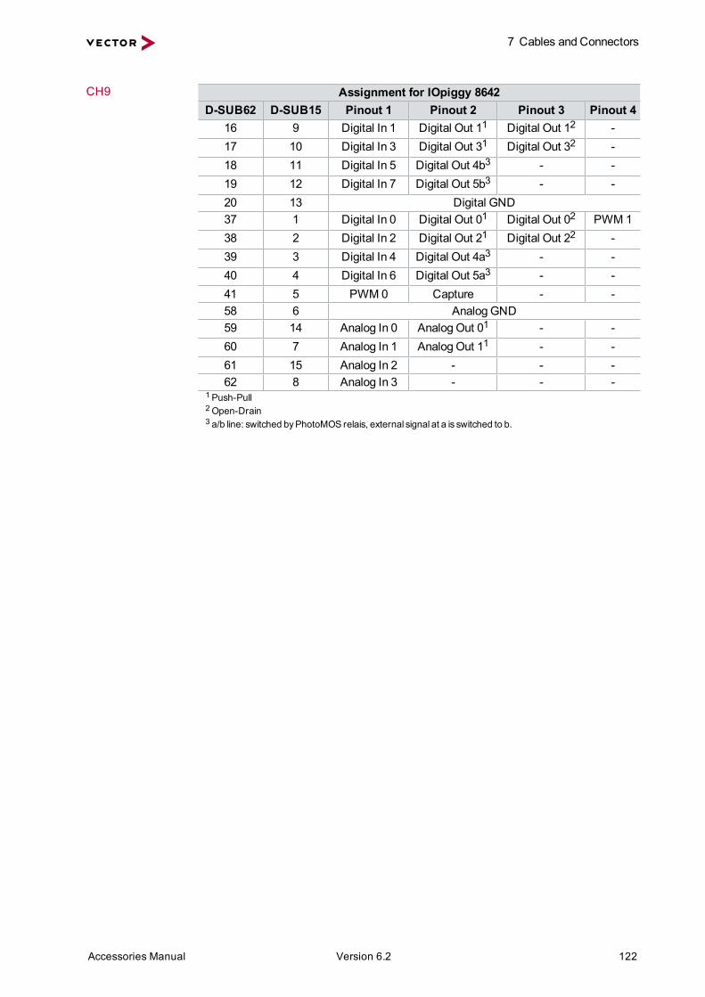
7 Cables and Connectors
Accessories Manual Version 6.2 122
CH9 Assignment for IOpiggy 8642D-SUB62 D-SUB15 Pinout 1 Pinout 2 Pinout 3 Pinout 4
16 9 Digital In 1 Digital Out 11 Digital Out 12 -17 10 Digital In 3 Digital Out 31 Digital Out 32 -18 11 Digital In 5 Digital Out 4b3 - -19 12 Digital In 7 Digital Out 5b3 - -20 13 Digital GND37 1 Digital In 0 Digital Out 01 Digital Out 02 PWM 138 2 Digital In 2 Digital Out 21 Digital Out 22 -39 3 Digital In 4 Digital Out 4a3 - -40 4 Digital In 6 Digital Out 5a3 - -41 5 PWM 0 Capture - -58 6 Analog GND59 14 Analog In 0 Analog Out 01 - -60 7 Analog In 1 Analog Out 11 - -61 15 Analog In 2 - - -62 8 Analog In 3 - - -
1Push-Pull2Open-Drain3 a/b line: switched byPhotoMOS relais, external signal at a is switched to b.

7 Cables and Connectors
Accessories Manual Version 6.2 123
7.6.3 VNcable DSUB62Breakout box cable Description Connection cable with D-SUB62 connectors
for Breakout Box D62Y9, VN7570 and VN7572Length 0.5m (cable only)
0.6m (overall length)Connectors 1x D-SUB62 (male)
1x D-SUB62 (female)Part number 05087
7.6.4 VNcable DSUB62 ABreakout box cable Description Connection cable with D-SUB62 connectors
for Breakout Box D62Y9, VN7570 and VN7572Length 1.2m (cable only)
1.3m (overall length)Connectors 1x D-SUB62 (male)
1x D-SUB62 (female)Part number 05093

7 Cables and Connectors
Accessories Manual Version 6.2 124
7.6.5 VNcable DSUB62 BConnection cable Description Connection cable with D-SUB62 connector and open end
Length 2m (overall length)Connectors 1x D-SUB62 (female)
62x wiresPart number 05095
Pin assignment Pin Color Pin ColorTP 1
44dark brownbrown-white
TP 1940
greygrey-black
TP 245
redred-black
TP 2041
grey-redblue-grey
TP 35
red-whitered-blue
TP 2224
grey-yellowgrey-green
TP 427
orangeorange-black
TP 2343
whitewhite-black
TP 662
red-orangeorange-green
TP 2546
white-redwhite-light blue
TP 749
orange-whitegrey-white
TP 2647
yellow-whitewhite-light green
TP 850
yellowyellow-black
TP 2830
pinkpink-black
TP 911
red-yellowyellow-blue
TP 2948
pink-redpink-blue
TP 1051
yellow-whitelight yellow-black
TP 3152
pink-whitepink-yellow
TP 1233
greengreen-black
TP 3253
light greenlight green-black
TP 1334
green-whitelight green-blue
TP 5455
light green-yellowlight green-green
TP 1435
green-bluelight green-red
TP 5657
light bluelight blue-black
TP 1536
blueblue-white
TP 5859
light blue-redlight blue-blue
TP 1637
blue-redviolet-red
TP 6061
light blue-yellowlight blue-green
TP 1738
violetviolet-white
2142
not connectednot connected
TP 1839
violet-greenviolet-blue
TP= twisted pair

7 Cables and Connectors
Accessories Manual Version 6.2 125
7.6.6 VNcable D62Y9Y cable Description Adapter cable for VN7570 and VN7572
Length approx. 0.5m (overall length)approx. 0.4m without connectors
Connectors 1x D-SUB62 (female)1x D-SUB15 (female)8x D-SUB9 (male)
Part number 05088
CH1...CH8 Assignment for Piggybacks Assignment for On-board CAND-SUB62 D-SUB9 D-SUB62 D-SUB9
CH1 CH2 CH3 CH4 CH1…CH4 CH5 CH6 CH7 CH8 CH5…CH845 47 50 53 (1)* - - - - (1) N.C.22 3 28 9 (2)* 12 13 14 15 (2) CAN Low1 25 7 31 (3)* 54 55 56 57 (3) GND23 4 29 10 (4)* - - - - (4) N.C.6 6 6 6 (5)* 6 6 6 6 (5) Shield2 26 8 32 (6)* - - - - (6) N.C.24 5 30 11 (7)* 33 34 35 36 (7) CAN High43 27 48 51 (8)* - - - - (8) N.C.44 46 49 52 (9)* - - - - (9) N.C.* Dependson the inserted Piggyback in VN7570/VN7572.N.C. Not connected
CH9 Assignment for IOpiggy 8642D-SUB62 D-SUB15 Pinout 1 Pinout 2 Pinout 3 Pinout 4
16 9 Digital In 1 Digital Out 11 Digital Out 12 -17 10 Digital In 3 Digital Out 31 Digital Out 32 -18 11 Digital In 5 Digital Out 4b3 - -19 12 Digital In 7 Digital Out 5b3 - -20 13 Digital GND37 1 Digital In 0 Digital Out 01 Digital Out 02 PWM 138 2 Digital In 2 Digital Out 21 Digital Out 22 -39 3 Digital In 4 Digital Out 4a3 - -

7 Cables and Connectors
Accessories Manual Version 6.2 126
CH9 Assignment for IOpiggy 8642D-SUB62 D-SUB15 Pinout 1 Pinout 2 Pinout 3 Pinout 4
40 4 Digital In 6 Digital Out 5a3 - -41 5 PWM 0 Capture - -58 6 Analog GND59 14 Analog In 0 Analog Out 01 - -60 7 Analog In 1 Analog Out 11 - -61 15 Analog In 2 - - -62 8 Analog In 3 - - -
1Push-Pull2Open-Drain3 a/b line: switched byPhotoMOS relais, external signal at a is switched to b.
7.6.7 VNcable DSUB37Connection cable Description Connection cable with D-SUB37 connectors
Length 1.5mConnectors 1x D-SUB37 (male)
1x D-SUB37 (female)Part number 05097

7 Cables and Connectors
Accessories Manual Version 6.2 127
7.6.8 Terminal Block DSUB37Terminal block Description Terminal block with 37 CAGE CLAMP® connectors to D-SUB37
(requires VNcable DSUB37)Dimensions 102mm x 34mm x 85mmWeight 102 gConnectors 1x row with 19 CAGE CLAMP® connectors
1x row with 18 CAGE CLAMP® connectors1x D-SUB37 (female)
Part number 05098
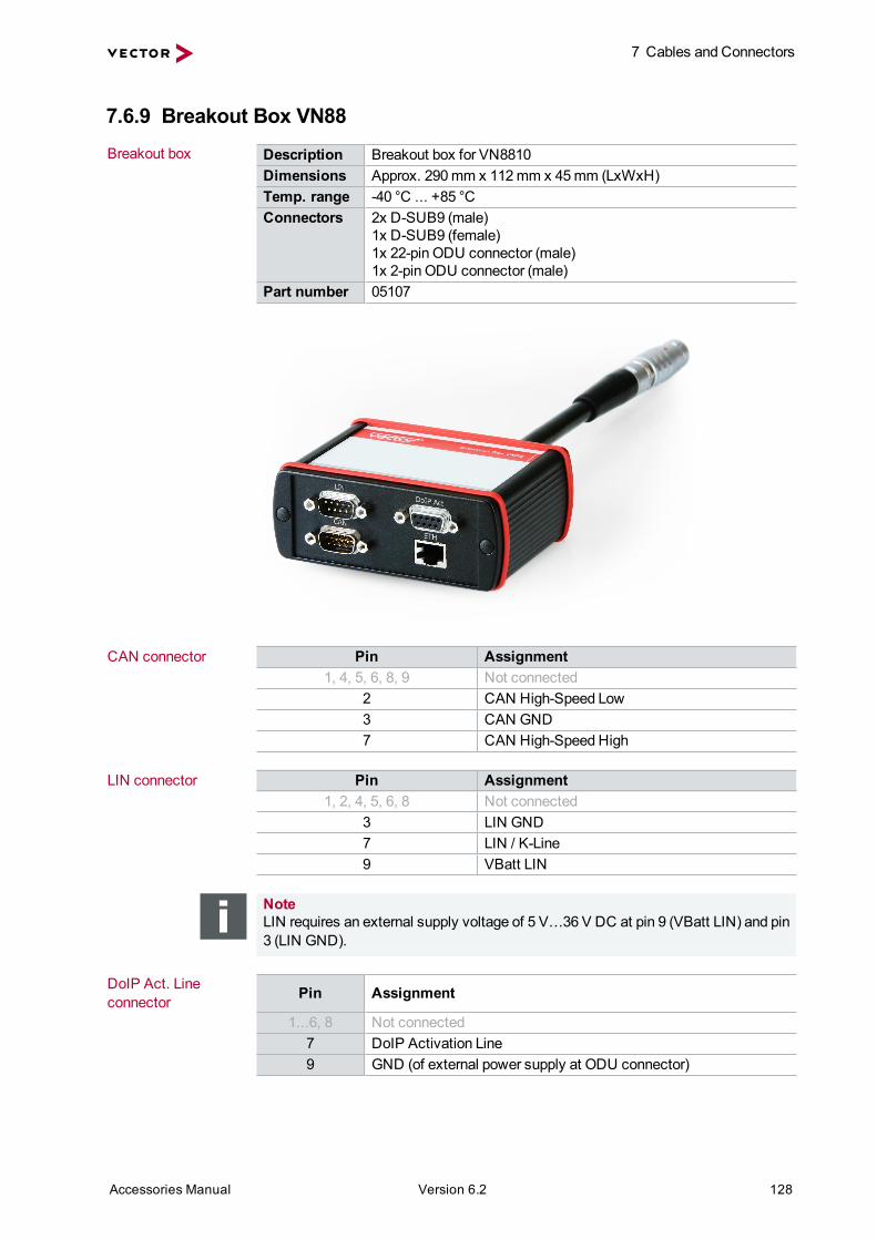
7 Cables and Connectors
Accessories Manual Version 6.2 128
7.6.9 Breakout Box VN88Breakout box Description Breakout box for VN8810
Dimensions Approx. 290mm x 112mm x 45mm (LxWxH)Temp. range -40 °C ... +85 °CConnectors 2x D-SUB9 (male)
1x D-SUB9 (female)1x 22-pin ODU connector (male)1x 2-pin ODU connector (male)
Part number 05107
CAN connector Pin Assignment1, 4, 5, 6, 8, 9 Not connected
2 CAN High-Speed Low3 CAN GND7 CAN High-Speed High
LIN connector Pin Assignment1, 2, 4, 5, 6, 8 Not connected
3 LIN GND7 LIN / K-Line9 VBatt LIN
NoteLIN requires an external supply voltage of 5 V…36 V DC at pin 9 (VBatt LIN) and pin3 (LIN GND).
DoIP Act. Lineconnector Pin Assignment
1...6, 8 Not connected7 DoIP Activation Line9 GND (of external power supply at ODU connector)

7 Cables and Connectors
Accessories Manual Version 6.2 129
7.6.10 VX1362B CAN Cable Lemo/Banana Plugs 1.5MConnection cable Description Adapter cable for Vector devices
Length 1.5mConnectors 1x Lemo connector
2x banana plugs (4mm)Part number 22258
Setup2
1
1
2
DIO
GND

7 Cables and Connectors
Accessories Manual Version 6.2 130
7.6.11 USB Cables
7.6.11.1 USB Cable 2.0
Technical data Description Standard USB 2.0 cable.Length approx. 1.8mConnectors 1x connector type A
1x connector type BPart number 05011
7.6.11.2 USB Cable 3.0 (A-B, 1.8m)
Technical data Description Standard USB 3.0 cable.Length approx. 1.8mConnectors 1x connector type A
1x connector type BPart number 05092
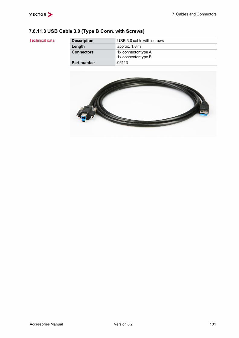
7 Cables and Connectors
Accessories Manual Version 6.2 131
7.6.11.3 USB Cable 3.0 (Type B Conn. with Screws)
Technical data Description USB 3.0 cable with screwsLength approx. 1.8mConnectors 1x connector type A
1x connector type BPart number 05113

8 Power Supply
Accessories Manual Version 6.2 132
8 Power SupplyIn this chapter you find the following information:
8.1 Vector Power Supply Units 1338.1.1 Vector Power Supply 12V/1.25A 1338.1.2 Vector Power Supply 12V/2.5A 1338.1.3 Vector Power Supply ODU MINI-SNAP 134
8.2 On-Board Power Supply 1358.2.1 Car Power Supply Cable 12V with Binder 1358.2.2 Vehicle Input <> ODU MINI-SNAP 135
8.3 Power Supply Cable 1368.3.1 Banana Plug <> Binder 3-Pin 1368.3.2 ODU Connector / Bunch Plugs 1378.3.3 Power Adapter OBDII – ODU Mini Snap 137

8 Power Supply
Accessories Manual Version 6.2 133
8.1 Vector Power Supply Units
8.1.1 Vector Power Supply 12V/1.25APower supply unitfor Vector devices
Description Power supply unit with 12 V and 1.25 A,with changeable adapters for USA and Europe(GB adapter on request)
Length 2mConnectors 1x adapter for USA
1x adapter for Europe1x 3-pin Binder connector (type 711)
Part number 05024
8.1.2 Vector Power Supply 12V/2.5APower supply unitfor Vector devices
Description Power supply unit with 12 V and 2.5 A,with changeable adapters for USA and Europe(GB adapter on request)
Length 2mConnectors 1x adapter for USA
1x adapter for Europe1x 5-pin Binder connector (type 711)
Part number 05020

8 Power Supply
Accessories Manual Version 6.2 134
8.1.3 Vector Power Supply ODU MINI-SNAPPower supply unitfor Vector devices
Description Power supply unit with 24 V and 2.5 A
Connectors 1x adapter for Europe1x ODU S11L0C-P02NPL0-5200
Part number 05068
Connection cable Description Connection cable for power supply unit (part number 05068)Connectors Adapter for USA/JapanPart number 05071
Connection cable Description Connection cable for power supply unit (part number 05068)Connectors Adapter for UKPart number 05070
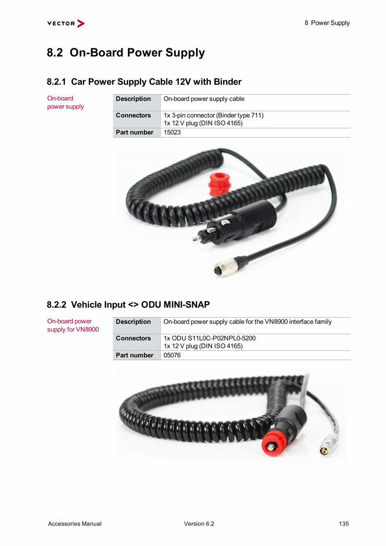
8 Power Supply
Accessories Manual Version 6.2 135
8.2 On-Board Power Supply
8.2.1 Car Power Supply Cable 12V with BinderOn-boardpower supply
Description On-board power supply cable
Connectors 1x 3-pin connector (Binder type 711)1x 12 V plug (DIN ISO 4165)
Part number 15023
8.2.2 Vehicle Input <> ODU MINI-SNAPOn-board powersupply for VN8900
Description On-board power supply cable for the VN8900 interface family
Connectors 1x ODU S11L0C-P02NPL0-52001x 12 V plug (DIN ISO 4165)
Part number 05076

8 Power Supply
Accessories Manual Version 6.2 136
8.3 Power Supply Cable
8.3.1 Banana Plug <> Binder 3-PinPower cable Description Power cable for Vector devices
Length 1.5mConnectors 1x female 3-pin Binder connector (type 711)
2x banana plugs (4mm)Part number 30012
Setup1
3
+12 V
GND1
2
3
Caution!The power supply port does not have any overload protection. Whenever the deviceis powered through this cable, a fuse (slow-acting) must be provided in the supplyline.

8 Power Supply
Accessories Manual Version 6.2 137
8.3.2 ODU Connector / Bunch PlugsODU Description Two-conductor power supply cable for base units
Length approx. 2mConnectors 1x ODU connector (type S11L0C-P02NPL0-6200)
2x bunch plugs (power supply)Temperature range In mobile state: -30 °C …+70 °C
In stationary state: -40 °C …+85 °CPart number 05069
Cable setup
Caution!The power supply port does not have any overload protection. Whenever the deviceis powered through this cable, a fuse (slow-acting) must be provided in the supplyline.
8.3.3 Power Adapter OBDII – ODU Mini SnapConnection cable Description OBD-II/ODU power supply cable for VN8810
(this cable requires OBDcable VN88 or OBDcable VN88A)Length approx. 30 cm (overall length)Connectors 1x 16-pin OBD-II connector (female), Type B (24 V)
1x 2-pin ODU connector (male)Part number 05104
OBD-II Pin Assignment ODU Pin16 VBatt 14 Chassis GND 2
Example of usage Vector Power Supply ODU MINI-SNAP
(05068)
OBDcable VN88/
OBDcable VN88A
Vehicle InputODU MINI-SNAP
(05076)
ODU Connector / Bunch Plugs
(05069)
Power Adapter
OBDII - ODU Mini Snap
VN8810

9 Time Synchronization
Accessories Manual Version 6.2 138
9 Time SynchronizationIn this chapter you find the following information:
9.1 Time Synchronization 1399.1.1 General Information 1399.1.2 Software Sync 1419.1.3 Hardware Sync 142
9.2 SYNCcables 1449.2.1 SYNCcableXL 1449.2.2 SYNCcable50 144
9.3 SYNCboxes 1459.3.1 Multi SYNCbox External 1459.3.2 Multi SYNCbox Internal 1469.3.3 Multi SYNCbox Active 1479.3.4 SyncBox XL 148

9 Time Synchronization
Accessories Manual Version 6.2 139
9.1 Time Synchronization
9.1.1 General InformationTime stampsand events
Time stamps are useful when analyzing incoming or outgoing data or eventsequences on a specific bus.
Figure 23: Time stampsof two CAN channels in CANalyzer
Generatingtime stamps
Each event which is sent or received by a Vector network interface has an accuratetime stamp. Time stamps are generated for each channel in the Vector network inter-face. The base for these time stamps is a common hardware clock in the device.
CAN
VectorCAN Interface
CH1 CH2
Time Stamp Clock
PCCANalyzer/CANoe
USB
Figure 24: Common time stamp clock for each channel
If themeasurement setup requires more than one Vector network interface, a syn-chronization of all connected interfaces and their hardware clocks is needed.
Due tomanufacturing and temperature tolerances, the hardware clocks may vary inspeed, so time stamps of various Vector devices drift over time.

9 Time Synchronization
Accessories Manual Version 6.2 140
CAN
FlexRay
VectorCAN Interface
CH1 CH2Time Stamp Clock
PC
VectorFR Interface
CHA CHBTime Stamp Clock
sec0.0000000.1003760.2003820.3003720.4004060.5005930.600242
sec0.0000000.1003830.2009820.3014560.4026120.5038850.604092
CANalyzer/CANoeUSB USB
Figure 25: Example of unsynchronized network interfaces. Independent time stampsdrift apart
To compensate for these time stamp deviations between the Vector network inter-faces, the time stamps can be either synchronized by software or by hardware (seenext section).
NoteThe accuracy of the software and hardware sync depends on the interface. Furtherinformation on specific values can be found in the technical data of the respectivedevices.

9 Time Synchronization
Accessories Manual Version 6.2 141
9.1.2 Software SyncSynchronizationby software
The software time synchronization is driver-based and available for all applicationswithout any restrictions. The time stamp deviations from different Vector network inter-faces are calculated and synchronized to the common PC clock. For this purpose nofurther hardware setup is required.
CAN
FlexRay
VectorCAN Interface
CH1 CH2Time Stamp Clock
VectorFR Interface
CHA CHBTime Stamp Clock
synchronizationby software (PC clock)
sec0.0000001.1003561.2003622.3003622.4003563.5003533.600362
PC
sec0.0000001.1004131.2004212.3004292.4004193.5004153.600420
PC clockCANalyzer/CANoeUSB USB
Figure 26: Time stampsof devicesare synchronized to the PC clock
The setting of the software time synchronization can be changed in theVector Hard-ware Config tool inGeneral information | Settings | Software time syn-chronization.
Figure 27: Switching on the software synchronization
> YESThe software time synchronization is active.
> NOThe software time synchronization is not active. Use this setting only if the Vectornetwork interfaces are being synchronized over the sync line or if only a singledevice is used.

9 Time Synchronization
Accessories Manual Version 6.2 142
9.1.3 Hardware SyncSynchronizationby hardware
A more accurate time synchronization of multiple devices is provided by the hardwaresynchronization which has to be supported by the application (e. g. CANalyzer,CANoe). Two Vector network interfaces can therefore be connected with theSYNCcableXL (see page 144).
In order to synchronize up to five devices at the same time, a distribution box is avail-able (see sectionMulti SYNCbox External on page 145 and sectionMulti SYNCboxInternal on page 146).
VN1630A
VN5610A
VN1640A
Multi SYNCbox external
VN1640A
USB PC
PC
VN7570
SYNCcable XL
SYNCcable XL
SYNCcable XL
SYNCcable XL
USB PC
Vector Devices
USB PC
USB PC
USB PC
Power
Figure 28: Example of a time synchronization with multiple devices
VN5610A
VN8912A
Power
VN5610A
VN1640A
Multi SYNCbox external
VN1640A
USB
VN
8912
A
USB PC
SYNCcable XLSYNCcable XL
SYNCcable XL
SYNCcable XL
Power
Power
Figure 29: Example of a time synchronization with VN8912A and additional devices

9 Time Synchronization
Accessories Manual Version 6.2 143
At each falling edge on the sync line which is initiated by the application, the Vectornetwork interface generates a time stamp that is provided to the application. Thisallows the application to calculate the deviations between the network interfaces andto synchronize the time stamps to a common time base (master clock) which isdefined by the application.
CANalyzer/CANoe
CAN
FlexRay
VectorCAN Interface
CH2Time Stamp Clock
USB
VectorFR Interface
CHBMaster Time Stamp Clock
synchronizationby hardware (SYNCcable)
sec0.0000001.1003751.2003812.3003712.4004053.5005923.600241
CH1 CHA
sec0.0000001.1003761.2003822.3003722.4004063.5005933.600242
PC
USB
Figure 30: Time stampsare synchronized to themaster clock
NoteThe hardware synchronizationmust be supported by the application. For furtherinformation please refer to the relevant applicationmanual. Please note that the soft-ware synchronizationmust be disabled (seeVector Hardware Config | Generalinformation | Settings | Software time synchronization) if the hardware syn-chronization is used.

9 Time Synchronization
Accessories Manual Version 6.2 144
9.2 SYNCcables
9.2.1 SYNCcableXLSynchronizationcable
Description Connection cable for time synchronization of Vector devices
Length 2mConnectors 2x female 3-pin Binder connectors (type 711)Part number 05018
Setup 123
123
+12 VSyncGND
1 3
2
9.2.2 SYNCcable50Synchronizationcable
Description Connection cable for time synchronization for Vector devices
Length 0.5mConnectors 2x female 3-pin Binder connectors (type 711)Part number 05083
Setup 123
123
+12 VSyncGND
1 3
2

9 Time Synchronization
Accessories Manual Version 6.2 145
9.3 SYNCboxes
9.3.1 Multi SYNCbox ExternalSynchronizationdistributor
Description Distributor in plastic case for time synchronization.For up to five Vector devices.
Connectors 5x male 3-pin connectors (Binder type 711)Part number 05085
Setup
3
12
3
12
3
12
3
12
3
12
GND
Sync
NoteWithin the sync system, up to five devices can be synchronized. Cascading of mul-tiple Multi SYNCboxes to increase the number of devices is not possible.
Example
VN1630A
VN5610A
VN1640A
Multi SYNCbox external
VN1640A
USB PC
PC
VN7570
SYNCcable XL
SYNCcable XL
SYNCcable XL
SYNCcable XL
USB PC
Vector Devices
USB PC
USB PC
USB PC
Power

9 Time Synchronization
Accessories Manual Version 6.2 146
9.3.2 Multi SYNCbox InternalSynchronizationdistributor
Description Distributor in PC slot bracket for time synchronization.For up to five Vector devices.
Connectors 5x male 3-pin connectors (Binder type 711)Part number 05084
Setup
3
12
3
12
3
12
3
12
3
12
GND
Sync
NoteWithin the sync system, up to five devices can be synchronized. Cascading of mul-tiple Multi SYNCboxes to increase the number of devices is not possible.
Example
Multi SYNCbox internal
PC
VN7570SYNCcable XL
VN7572
SYNCcable XL
USB PC
Vector Devices
VN1630A
VN5610A
VN1640A
USB PC
SYNCcable XL
SYNCcable XL
USB PC
USB PC
Power

9 Time Synchronization
Accessories Manual Version 6.2 147
9.3.3 Multi SYNCbox ActiveSynchronizationdistributor
Description Active synchronization distributor in plastic case.For five or more Vector devices.
Connectors 12x male 3-pin connector (Binder type 711)Part number 05112
SYNC in/out Pin Assignment1 Not connected2 Synchronization line3 Ground
312
DC in Pin Assignment1 Power supply (5 V…60 V DC, typ. 12 V)2 Not connected3 Ground
312
NoteCascading of multiple Multi SYNCboxes active to increase the number of SYNCout is not possible.
Example
VN1630A
SYN
C o
ut
SYN
C o
ut
SYN
C in
DC
in
VN1630A
VN5610A
MultiSYNCbox
active
USB PCPC
VN7570SYNCcable XL (In)
Vector Devices
USB PCPower
VN1630A
USB PC
VN1640A
VN1640A
USB PC
USB PC
VN1630A
SYNCcable XL (Out)
SYNCcable XL (Out) SYNCcable XL (Out)
USB PCUSB PC
Power

9 Time Synchronization
Accessories Manual Version 6.2 148
9.3.4 SyncBox XLSynchronizationof CANcardXL/XLe
The SyncBox XL is designed to synchronizemultiple CANcardXL/XLe among each orwith other Vector network interfaces.
Synchronizationof different interfaces
PCMCIA Interface
CANcardXLPCI Interface
CANboardXLCANpiggyLINpiggy
SyncBox XL SyncBox XLSYNCcableXL
CAN/LIN Bus
CANcabLINcab
CANcabLINcab
PCMCIA Interface
CANcardXLUSB Interface
CANcaseXLCANpiggyLINpiggy
Technical data Housing ABS plasticCable length Approx. 30 cm to CANcardXL/XLeWeight Approx. 100 gConnectors PC side: 15-pin plug connector to CANcardXL/XLe
Bus side: 15-pin socket to CANcab or LINcabSync side: 2x 3-pin Binder connectors (type 711)
Part number 22013

10 Miscellaneous
Accessories Manual Version 6.2 149
10 MiscellaneousIn this chapter you find the following information:
10.1 CardSafe 150
10.2 CANcaseXL log CardFix Kit – SD Card Protection 151
10.3 Front Panel for VN8900 151
10.4 Fix Kit 32mm Device 151
10.5 2.4 & 5 GHz Antenna SMA-R Std. 152
10.6 2.4 & 5.2 GHz Antenna SMA-R Asia 152
10.7 Protection Kit 1040 15310.7.1 Mounting Instructions 153
10.8 SD/SDHC Memory Cards 15610.8.1 SD Memory Card (X82) 2 GB 15610.8.2 SDHC Memory Card (X82) 8 GB 15610.8.3 SDHC Memory Card (X) 16GB 15610.8.4 SDHC Memory Card (SXT) 32GB 156
10.9 CFast Card Reader USB 3.0 (external) 157

10 Miscellaneous
Accessories Manual Version 6.2 150
10.1 CardSafeProtection againstmechanical damages
When using notebooks, especially on the test bench or in a test vehicle, the PCMCIAconnectors are frequently subjected tomechanical stresses - the consequence is thesnapping-off of the connectors. The patented connector fixing provided by VectorInformatik's CardSafe offers effective, sensible protection.
CardSafe consists of a base plate and connector fixingmade of robust metal. Thebase plate is fastened to the underside of the notebook with a belt and does not haveto be removed during transport. Elaborate and time-consumingmounting is thus unne-cessary.
If cables are connected to the PC card and they should also be protected, the con-nector fixing is used with a handle on the base plate. By tightening 2 adjustmentscrews, the connectors are fixed securely. The connector fixing can be unbolted fromthe notebook easily with a coin when the notebook is being transported.
Part number 05023.

10 Miscellaneous
Accessories Manual Version 6.2 151
10.2 CANcaseXL log CardFix Kit – SD Card ProtectionPrevent insertion andrejection of SD card
The standard delivery of the CANcaseXL log allows the user to insert and remove theSD card from outside. In some situations, for example to prevent thefts, the insertedSD card shall not be removable. The CardFix Kit is an ideal protection solution,because the back side plate with the SD card slot is replaced by a closed plate. Thusthe SD card cannot be removed so easily anymore.
Part number 07132.
NoteA detailed instruction is delivered with the kit. However, themodification of yourCANcaseXL log can be done by our service.
10.3 Front Panel for VN8900Technical data Description For use with VN8900 interface family without a slide-in module
(e. g. VN8950, VN8970, VN8972)Part number 07148
10.4 Fix Kit 32mm DeviceTechnical data Description Fixing Kit containing 4 pcs. of wall brackets for ALUbos housing.
Part number 07139

10 Miscellaneous
Accessories Manual Version 6.2 152
10.5 2.4 & 5 GHz Antenna SMA-R Std.Technical data Description Standard antenna for EU, USA and other non-Asian countries.
Suitable for 2.4 GHz and 5GHz applications.Part number 07169
ReferenceA suitable antenna for Asian countries can be found section 2.4 & 5.2 GHz AntennaSMA-R Asia on page 152.
10.6 2.4 & 5.2 GHz Antenna SMA-R AsiaTechnical data Description Standard antenna for Asia.
Suitable for 2.4 GHz and 5.2 GHz applications.Part number 07170
ReferenceA suitable antenna for EU, USA and other non-Asia countries can be found section2.4 & 5GHz Antenna SMA-R Std. on page 152.

10 Miscellaneous
Accessories Manual Version 6.2 153
10.7 Protection Kit 1040Technical data Description This protection kit contains two rubber bumpers which replace the
standard sealing of housing size 1040.Part number 05110
Example
Figure 31: Top side Figure 32: Bottom side
10.7.1 Mounting Instructions
Caution!To prevent electrical damage during assembly, you should avoid touching the lowerand upper sides of the PC boards.
Caution!Always disconnect the power supply before assembling.
Step by Step Procedure
1. Remove all cables from the device.
2. Loosen the housing screws on the side with the four D-SUB9 connectors. Thisrequires removing the two black decorative caps.

10 Miscellaneous
Accessories Manual Version 6.2 154
3. Carefully pull the PC-board out of the housing.
4. Remove the red standard sealing by pulling it over the black panel. Do not pullthe sealing over the board to avoid damages on the components!
5. Pull the replacement rubber bumper over the black panel. Do not pull the seal-ing over the board to avoid damages on the components! Adjust the rubberbumper until it properly fits on the panel.

10 Miscellaneous
Accessories Manual Version 6.2 155
6. Place the board back in the housing. This operation involves placing the hous-ing on a table with its back side (side with the bar code) facing upward. Theninsert the board facing upward into the first guide rails. It should be possible toslide the board in the housing up to a few millimeters from the end without for-cing it in.
7. Close the housing by applying light pressure and then secure it with the appro-priate screw fasteners. The screws should be secure but not excessively tight.
8. Please also attach the two black decorative caps.
9. Repeat the steps with the opposite panel.
10 Miscellaneous
Accessories Manual Version 6.2 156
10.8 SD/SDHC Memory Cards
10.8.1 SD Memory Card (X82) 2 GBTechnical data Description 2GB SD flash card
Part number 22300
10.8.2 SDHC Memory Card (X82) 8 GBTechnical data Description 8GB SDHC Flash Card (industrial grade),
optimized for long endurancePart number 22331
10.8.3 SDHC Memory Card (X) 16 GBTechnical data Description 16GB SDHC flash card (industrial grade),
optimized for long endurancePart number 22243
10.8.4 SDHC Memory Card (SXT) 32 GBTechnical data Description 32GB SDHC flash card (industrial grade)
Part number 22362

10 Miscellaneous
Accessories Manual Version 6.2 157
10.9 CFast Card Reader USB 3.0 (external)Technical data Description CFast Memory Card Reader USB 3.0.
Part number 22268

Get More Information
Visit our website for:> News> Products> Demo software> Support> Training classes> Addresses
www.vector.com