
Access V4.X Configuration manual · Version Document Preliminary 003 Access V4.X Configuration...
34
Access V4.X Configuration manual EN Document in original language | 153830 · A001
Transcript of Access V4.X Configuration manual · Version Document Preliminary 003 Access V4.X Configuration...

Access V4.X Configuration manual
EN
Document in original language | 153830 · A001
Version Document
Preliminary 003 Access V4.X Configuration manual
1 (33) 2019-05-13
Contents 1. About the manual ................................................................................................................................. 3
Basic settings ............................................................................................................................................. 3
Access levels .......................................................................................................................................... 3
Date and time ....................................................................................................................................... 3
Preference unit settings ........................................................................................................................ 3
Communication ......................................................................................................................................... 4
Terminals ............................................................................................................................................... 4
Software connectors ............................................................................................................................. 4
Port function ......................................................................................................................................... 5
Communication devices ........................................................................................................................ 6
2. Configuration ........................................................................................................................................ 8
Configuration steps ................................................................................................................................... 8
Temperature control ................................................................................................................................. 9
Temperature control types ................................................................................................................... 9
Heating/Cooling sequences ................................................................................................................ 10
Step controller .................................................................................................................................... 18
Changover settings .............................................................................................................................. 19
Support control ................................................................................................................................... 19
Free cooling ......................................................................................................................................... 21
Pretreatment ...................................................................................................................................... 22
Summer/winter mode ........................................................................................................................ 22
Cooling recovery mode ....................................................................................................................... 23
Extra controller ................................................................................................................................... 23
External setpoint device ..................................................................................................................... 24
Fan control .............................................................................................................................................. 25
Fan control type .................................................................................................................................. 25
Fan configuration ................................................................................................................................ 26
Fan levels ............................................................................................................................................. 27
Fan compensation ............................................................................................................................... 27
Extra fan motor control....................................................................................................................... 28
Humidity control ..................................................................................................................................... 29
Humidification ..................................................................................................................................... 29
Dehumidification ................................................................................................................................. 29

Version Document
Preliminary 003 Access V4.X Configuration manual
2 (33) 2019-05-13
CO2 control ............................................................................................................................................. 30
Fan start/stop ...................................................................................................................................... 30
Mixing damper function ...................................................................................................................... 30
Enthalpy control ...................................................................................................................................... 31
Dampers .................................................................................................................................................. 31
I/O allocation settings ............................................................................................................................. 31
Starting up and stopping the unit ............................................................................................................... 32
Schedule .................................................................................................................................................. 32
Extended running .................................................................................................................................... 33
External stop ........................................................................................................................................... 33

Version Document
Preliminary 003 Access V4.X Configuration manual
3 (33) 2019-05-13
1. About the manual
This manual is intended to guide while configuring basic functions of the Access controller. It also gives a
general overview of the software and interface.
1.1 Basic settings
Access levels
The controller has four user access levels. The active user access level is indicated by icon.
End user When logged out
Read /write — Home page. Possible actions in end user mode are to stop the air handling unit for maintenance (e.g. filter exchange), change the time for extended run and change the temperature setpoint.
Operator mode (Log in with 1111)
Read and write privileges (except Configuration).
Service mode (Log in with 0612)
Full read and write privileges.
Date and time
ACCESS controller has a year-base clock function. The clock has an automatic summertime/wintertime
change-over.
Date and time can be set
Time settings > Date / Time
Preference unit settings
Preferred units for temperature, flow and pressure can be set
Configuration > System settings > Preference unit settings
Save and restore
Commissioning settings can be stored in a local memory.
Version Document
Preliminary 003 Access V4.X Configuration manual
4 (33) 2019-05-13
Configuration > System Settings > Save and restore settings >
Save commissioning settings – saves all recently made changes.
Restore to commissioning settings – restores to last saved commissioning settings.
Restore to factory settings – resets settings to state of delivered unit.
1.2 Communication
Terminals
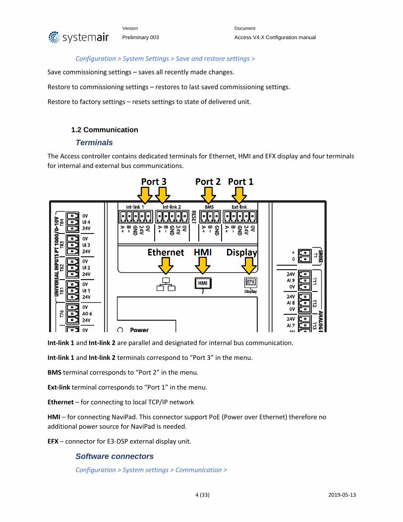
The Access controller contains dedicated terminals for Ethernet, HMI and EFX display and four terminals
for internal and external bus communications.
Int-link 1 and Int-link 2 are parallel and designated for internal bus communication.
Int-link 1 and Int-link 2 terminals correspond to “Port 3” in the menu.
BMS terminal corresponds to “Port 2” in the menu.
Ext-link terminal corresponds to “Port 1” in the menu.
Ethernet – for connecting to local TCP/IP network
HMI – for connecting NaviPad. This connector support PoE (Power over Ethernet) therefore no
additional power source for NaviPad is needed.
EFX – connector for E3-DSP external display unit.
Software connectors
Configuration > System settings > Communication >

Version Document
Preliminary 003 Access V4.X Configuration manual
5 (33) 2019-05-13
The communication ports in the Access controller Port 1 (Ext-link), Port 2 (BMS) and Port 3 (Int-link 1|2)
can be configured for particular function.
Port function
These ports can operate as follows:
EXOline slave – Connection to EXO SCADA system and application tool;
EXOline master – Connection to expansion units and Pressigo pressure transmitters;
Modbus slave – Connection to BMS via Modbus RTU;
Modbus master – Bus communication to components inside AHU;
BACnet MSTP slave - Connection to BMS via BACnet MSTP;
External display – Connection to touch display;
EFX master – communication to expansion units via EFX protocol.
Message format
For proper communication, the right message format needs to be configured. Available formats and
description
Baud rate Description
9k6 bps 9600bps
14k4 bps 14400bps
19k2 bps 19200bps

Version Document
Preliminary 003 Access V4.X Configuration manual
6 (33) 2019-05-13
28k8 bps 28800bps
38k4 bps 38400bps
57k6 bps 57600bps
76k8 bps 76800bps
115k2 bps 115200bps
Cloud
Cloud function must be enabled if the controller shall access “Systemair Connect” cloud service. The
provided serial number is unique identification of the controller and must be entered upon request
while registering at “Systemair Connect”.
Configuration > System settings > Communication > Cloud >
BACnet
BACnet/IP shall be enabled if controller is connected to BMS via this protocol. The following entries
include device name and BACnet communication related settings.
Communication devices
Configuration > System settings > Communication devices >
The Access controller supports up to 20 devices connected via communication BUS (Modbus and
EXOline).
Only limited number of predefined device models is supported.
List of supported brands and models:
Device type
Fan / FC (Modbus)
Rotary exchanger (Modbus)
Pressure transmitter (Modbus / EXOline)
Actuator (Modbus)
Expansion unit (EXOline)
Model Vacon RHC200 PDTxxC (Modbus) Belimo E8
Lenze IBC VariMax PDTxxC-2 (Modbus)
Emerson HK DPT-Dual-MOD-2500 (Modbus)
LS iG5A PDTxxC (EXOline) E15
LS iS7 PDTxxC-2 (EXOline) E28
EBM-PAPST
DANFOSS FC101
ABB ACSxxx
Ziehl blue
Configuration > System Settings > Communication devices > Device (n) > Address >
Modbus devices on the bus must have unique address assigned. The address shall be the same as set in
the device. The device shall also hold the same message format and baud rate settings as the port it is
connected to (see port function).
Function

Version Document
Preliminary 003 Access V4.X Configuration manual
7 (33) 2019-05-13
Configuration > System Settings > Communication devices > Device (n) > Function >
Every device on the bus must have function assigned. Different functions are available in dependence on
device type:
Device type
Fan (Modbus)
Rotary Exchanger (Modbus) *1
Pressure transmitter
Damper (Modbus)
Expansion unit (EXOline)
Function
Supply air fan
Heating *1 Exp1 Heating *1 Exp1
Exhaust air fan
Exchanger*1 Exp2 Exchanger*1 Exp2
Cooling *1 Exp3 Cooling *1 Exp3
Recirculation 1 *1 Exp4 Recirculation 1 *1 Exp4
Recirculation 2 *1 Exp5 Recirculation 2 *1 Exp5
Fan heating/cooling *1 Exp6 Fan heating/cooling
*1 Exp6
Heating 2 *1 Exp7 Heating 2 *1 Exp7
Cooling 2 *1 Exp8 Cooling 2 *1 Exp8
Exchanger extract *1 Exp9 Exchanger extract *1 Exp9
Extra heating/cooling capacity *1
Exp10 Extra heating/cooling capacity *1
Exp10
Recirculation air
Outdoor air
Exhaust air *1 Only active sequence are selectable
Name
Configuration > System Settings > Communication devices > Device (n) > Name >
Enter a unique device name.
This name will be used in Device “drop down list” when you select Device under I/O allocation.

Version Document
Preliminary 003 Access V4.X Configuration manual
8 (33) 2019-05-13
2. Configuration
2.1 Configuration steps
The configuration of controller shall start with activation of functions to be used.
Configuration order of control system and menu
Description Flow The navigation path
Select function to activate: e.g. Heater 2, cooler 2, Support control, Free cooling, fire function etc. Activation
Configuration ►Functions ► Function Activation
How the function should be designed: e.g. Electric, water, frost protection, fire damper etc.
Configuration
Configuration ►Functions
Select I/Os for activated function: e.g. AO2, DI4, DO6, UI4
Allocation
Configuration ► I/O allocation
How the function will work: e.g. Min limit value, max limit value, setpoint etc.
Operation settings
Data & Settings
Version Document
Preliminary 003 Access V4.X Configuration manual
9 (33) 2019-05-13
2.2 Temperature control
Temperature controller is a closed loop system which includes measurement, processing and
adjustment.
Temperature control types
To maintain comfort temperature the controller constantly adjusts supply air temperature. It can be set
constant or variable depending on parameters of choice. Several temperature control types are
available:
Configuration > Functions > Function activation > Temperature control type >
Supply air
The supply air temperature is kept at the setpoint value by controlling the output signals. The controller
is reverse acting, i e. the output will increase for decreasing temperature.
Supply air outdoor compensated
The supply air temperature setpoint is outdoor temperature compensated using a control curve with 4
node points.
Room cascade
Cascade control of room temperature and supply air temperature to achieve a constant, settable room
temperature. The room controller output signal generates the supply air controller’s setpoint value. The
room controller uses an own PI loops.
1..4 room sensors can be connected. The average value of selected sensors is used in the control loop.
Extract air cascade
Cascade control of extract air temperature and supply air temperature to achieve a constant, settable
room temperature. The extract air controller output signal generates the supply air controller’s setpoint
value. The extract controller used an own PI loop.
Room (summer) else supply air
Outdoor temperature dependent switching between supply air temperature control and room
temperature control.
When the outdoor temperature is lower than a settable limit (winter), outdoor compensated supply air
temperature control will be active, otherwise (summer) cascaded room temperature control as in room
cascade type.
Extract air (summer) else supply air
Outdoor temperature dependent switching between supply air temperature control and extract air
temperature control.
When the outdoor temperature is lower than a settable limit (winter), outdoor compensated supply air
temperature control will be active, otherwise (summer) cascaded extract air temperature control as in
extract air cascade type.

Version Document
Preliminary 003 Access V4.X Configuration manual
10 (33) 2019-05-13
Room outdoor compensated
The room temperature can be compensated when the outdoor temperature increases. One can, for
instance, imagine accepting a slightly higher room temperature if it is warm outside or, conversely, a
slightly lower temperature if it is chilly. This function is included to conserve energy.
Extract air outdoor compensated
The extract air temperature can be compensated when the outdoor temperature increases. One can, for
instance, imagine accepting a slightly higher extract air temperature if it is warm outside or, conversely,
a slightly lower extract air temperature if it is chilly. This function is included to conserve energy.
Extract air dependent supply air
A difference between extract air temperature and supply air temperature can be configured to maintain
the supply air temperature setpoint to follow extract air temperature with this difference (+10°C to -
10°C). Supply air temperature setpoint = extract air temperature + difference.
Heating/Cooling sequences
The supply air temperature is adjusted by controlling the output signals for AHU’s components by
regulating corresponding sequences. Up to 10 sequences with separate PID control settings can be used.
Each sequence can be set for Heating, Cooling, Exchanger, Damper, Pressure/flow compensation or set
as Not used.
For standardization all 10 sequences have predefined names to cover the most frequent configurations
of AHUs. The sequences are also identified by letter A to J.
The order of sequence activation is set by assigning order number for heating and cooling. As in
configuration example bellow in case of heating demand, the Exchanger (SEQ-B) will start first and
Heating (SEQ-A) will follow second.
In case of cooling demand, the Exchanger (SEQ-B) will start first and the Cooling (SEQ-C) will follow
second.
Configuration > Functions > Function activation > Heating/Cooling sequences >
Position Heating Cooling Start Heating
Start Cooling
Name
SEQ-A 2 Off 0% 0% Heating
SEQ-B 1 1 0% 0% Exchanger
SEQ-C Off 2 0% 0% Cooling
SEQ-D Off Off 0% 0% Recirculation 1
SEQ-E Off Off 0% 0% Recirculation 2
SEQ-F Off Off 0% 0% Fan heating/cooling
SEQ-G Off Off 0% 0% Heating 2
SEQ-H Off Off 0% 0% Cooling 2
SEQ-I Off Off 0% 0% Exchanger extract
SEQ-J Off Off 0% 0% Extra heating/cooling capacity

Version Document
Preliminary 003 Access V4.X Configuration manual
11 (33) 2019-05-13
If required sequence overlapping or dead band can be set by adjusting “Start Heating” and “Start
Cooling” sequence parameters. Adjustable range is -100% .. +100%. Negative starting point will create
sequence overlap while positive starting point will delay start of the selected sequence.
Position Heating Cooling Start Heating
Start Cooling
Name
SEQ-A 2 Off 50% 0% 0% Heating
SEQ-B 1 1 0% 0% Exchanger
SEQ-C Off 2 0% -25% 0% Cooling
SEQ-D Off Off 0% 0% Recirculation 1
SEQ-E Off Off 0% 0% Recirculation 2
SEQ-F Off Off 0% 0% Fan heating/cooling
SEQ-G Off Off 0% 0% Heating 2
SEQ-H Off Off 0% 0% Cooling 2
SEQ-I Off Off 0% 0% Exchanger extract
SEQ-J Off Off 0% 0% Extra heating/cooling capacity

Version Document
Preliminary 003 Access V4.X Configuration manual
12 (33) 2019-05-13
Sequence type
Each active sequence has to be defined for control of specific device type. Selecting device type reveals
relevant settings (e.g. if water heating is selected, then pump control and frost protection options will be
available).
Configured sequences (for electric heating and DX cooling) can be used as input for step controllers.
Configuration > Functions > Function activation > Heating/Cooling sequence setup > Step
controller
For combined heating/cooling – changeover option for connecting two sequences can be configured.
Configuration > Functions > Function activation > Heating/Cooling sequence setup >
Changeover settings
Heating
Water heating
When the unit is in running mode the heating valve is controlled by the analogue output and digital
output (“SEQ-A pump”) for pump control and/or signal (“SEQ-A start”) for start heating.
Pump indication
A feedback from pump (“Feedback SEQ-A”) can be used, “running indication or alarm indication.
Frost protection temperature sensor

Version Document
Preliminary 003 Access V4.X Configuration manual
13 (33) 2019-05-13
The heater return water temperature is measured using the analogue input (”Frost protection sensor”).
Low temperatures will generate an internal, proportional signal that is used to force the heating valve
open thereby preventing freeze-up of the heater.
The internal signal will begin to rise as the frost protection temperature falls below “Alarm limitation
running mode” + “P-band running mode” in order to reach 100 % output when the signal has fallen to
“Alarm limitation running mode”.
Frost guard
When ”Internal signal” reaches 100 % or the digital input (”Defrost switch”) is activated, the unit is shut
down, the heating output is set to completely open mode and an alarm is activated. The unit is restarted
when the alarm has been acknowledged and the temperature for the frost protection sensor has risen
above “Alarm limit frost” + “P-Band”.
The frost protection alarm limits is set in the:
Settings: Data & settings > Temperature control > Heating and/or Heating 2.
Standby mode
If frost protection is activated, the controller will go into ”Standby mode” when the running mode
switches to ”Off”. The “Standby mode” will control the heating output to maintain a constant settable
temperature at the frost protection sensor “Setpoint Standby mode”.
Electric heating
Control
The heating is controlled using the analogue output and/or signal for start heating or step controller to
control 1..4 digital output steps.
Overheat protection
On Activate of the digital input “Overheated electric heater” the unit will be shut down, either according
to the stop sequence described in section Start/stop of unit or as an emergency shutdown. The unit will
restart after the alarm has been acknowledged and “Electric heating is overheated” has reset.
Flow switch
Note that activation of the input signal “Flow switch” will also stop the unit. Note: It is important that
the high temperature thermostat is hardwired to disconnect the power to the heater. That is to ensure
that the heating is shut down when the thermostat is activated even if the Access controller should be
faulty.
Fast stop on overheating
If the function "Fast stop on overheating" is active, the fans will be immediately stopped when there is
an overheating alarm, regardless of the set cool-down time.
Step controller heating
Activation: By configuring the electrical heater the step switch will be activated in the menu.

Version Document
Preliminary 003 Access V4.X Configuration manual
14 (33) 2019-05-13
Configuration: Configuration > Functions > Function activation > Heating/Cooling sequence setup >
Step controller 1 (Step controller 2)
Cooling
Water cooling
Control
When the unit is in running mode the heating valve is controlled by the analogue output and digital
output for pump control and/or signal for start heating.
Pump indication
A feedback from pump can be used, running indication or alarm indication.
DX cooling
Step controller Heating / DX cooling
As alternative or complement to the above mentioned analogue control, heating and cooling can be
activated in steps. The internal signal is then used to activate digital outputs for control of the
heaters/chillers. Up to four heater outputs and three cooler outputs can be configured. There are two
possible modes:
Sequential control
Each output step has individually settable on and off values in percent of the control signal. The number
of steps is equal to the number of heater/chiller groups. Minimum on and off times can be set, i.e. the
minimum time the step has to be inactive or active for a change to occur.
Binary control
The heater power outputs should be binary weighted (1:2:4:8). The number of loads to be controlled is
set. Thereafter the program will automatically calculate the individual Activate levels. Switching
differential and minimum on/off times can be set.
DX cooler modes
DX cooling with room or extract air control
If DX cooling is used in conjunction with room temperature control or extract air temperature control,
there are two Configure alternatives, DX cooling or DX cooling with exchanger control.
DX cooling without exchanger control
When running cascade control, the supply air controller setpoint is normally controlled by the
room/extract air controller output signal.
When DX cooling is activated, the supply air controller setpoint is lowered to five degrees (adjustable)
below the setpoint given by the room/extract air controller. This prevents the DX cooling from being
activated/deactivated too often.
DX cooling with exchanger control

Version Document
Preliminary 003 Access V4.X Configuration manual
15 (33) 2019-05-13
When running cascade control, the supply air controller setpoint is normally controlled by the
room/extract air controller output signal.
When DX cooling is activated, the supply air controller setpoint is lowered to five degrees (adjustable)
below the setpoint given by the room/extract air controller. This prevents the DX cooling from being
activated/deactivated too often. If the supply air temperature falls below the setpoint given by the
room/extract air controller, the heat exchanger output will be activated in order to try to maintain the
supply air setpoint given by the room/extract air controller. The output uses P-control with a P-band of
half the setpoint lowering (adjustable, 2.5°C as default). The setpoint given by the room/extract air
controller cannot drop below the set min limit. When there is no longer a cooling demand, the supply air
controller setpoint will return to the value given by the room/extract air controller.
Note: The function cannot be used if the exchanger signal controls a mixing damper.
Example:
The room controller gives a supply air setpoint of 16°C. If there is a cooling demand, the supply air
controller setpoint is lowered to 11°C (16 – 5) and DX cooling is activated. Should the supply air
temperature fall below 16°C, the exchanger output will be activated and reach 100 % output when the
supply air temperature has fallen to 13.5°C (16 - 2.5).
Blocking of DX cooling at low outdoor temperature
DX cooling can be blocked when the outdoor temperature is low. It is possible to block the three cooling
steps individually or to block all DX cooling. The temperature limits are adjustable (+13°C default) and
have a fixed one degree hysteresis.
When two DX cooling steps are used with binary function, the cooling effect is divided into three steps.
The desired blocking level can be set individually for each of these steps.
When three DX cooling steps are used with binary function, the cooling effect is divided into seven
steps. However, the controller still only has three blocking level settings. Therefore, Blocking step 1 will
apply to binary steps 1 and 2, Blocking step 2 to binary steps 3 and 4, and Blocking step 3 to binary steps
5, 6..etc.
Blocking of DX cooling at low supply air fan speed
When DX cooling is used in conjunction with pressure controlled or flow controlled fans it is possible to
block DX cooling if the supply air fan control signal falls below a preset values. For sequential control,
the blocking level is individually settable for each DX cooling step.
When two DX cooling steps are used with binary function, the cooling effect is divided into three steps.
The desired blocking level can be set individually for each of these steps.
When three DX cooling steps are used with binary function, the cooling effect is divided into seven
steps. However, the controller still only has three blocking level settings. Therefore, Blocking step 1 will
apply to binary steps 1 and 2, Blocking step 2 to binary steps 3 and 4, and Blocking step 3 to binary steps
5, 6 and 7.
Blocking of DX cooling on cooling pump alarm Access can be configured to block DX cooling on cooling
pump alarm. In- and outputs
Version Document
Preliminary 003 Access V4.X Configuration manual
16 (33) 2019-05-13
Override of reduced speed for DX cooling
Override to normal quantity of air for DX cooling when the unit runs on reduced quantity of air. The fans
can be set to normal operation when cooling is required at high outdoor temperatures (e.g. >14°C, the
same temperature limit as for blocking of DX cooling).
Step controller
Activate: By configuring Cooler DX, the step switch will be activated in the menu.
Configuration > Functions > Function Activation> Heating/Cooling sequence setup > Step controller 1
(Step controller 2)
DX with exchanger control
Exchanger
Rotary
Control
Rotational speed is controlled by the analogue signal ”Exchanger”. A rotary controller alarm feedback
can be connected to the digital input ”Rotary exchanger alarm”. An alarm is generated if this input is
activated.
Function to prevent the heat exchanger from frost:
A temperature sensor, exhaust air, outdoor air or extra controller sensor can be used as a prevention
sensor. It is possible to set a starting temperature. This represents both the minimum time that the
function should be active, the supply air fan and extract air fan compensation, as well as the minimum
time before the next prevention cycle should begin. While the cycle is active, “Defrosting” is shown in
the NaviPad.
Plate
Control
The airflow through the exchanger is controlled by a shut-off damper and a by-pass damper. Both
dampers are controlled by the same analogue output ”Exchanger”.
Defrosting temperature monitoring
Configuration > Functions > Temerature control > Defrosting temperature monitoring >
Defrosting is activated either when the digital signal ”Defrosting” is activated or when the value of the
analogue input ”Defrosting temperature” falls below the defrosting limit (-3°C), or when the analogue
signal ”Exchanger extract air pressure sensor” rises above the set value for the current pressure. It is
deactivated when the digital signal is reset, or alternatively when the analogue signal exceeds/falls
below the limit value plus a settable differential.
When defrosting:
A PID-controller compares the defrosting setpoint with the signal ”Defrosting exchanger”. The smallest
of the output signal from this controller and the output from the ordinary controller is used as output to
the dampers.

Version Document
Preliminary 003 Access V4.X Configuration manual
17 (33) 2019-05-13
Defrosting pressure monitoring
Configuration > Functions > Temerature control > Defrosting pressure monitoring >
Defrosting is activated by measuring the pressure difference over the exchangers extract/exhaust side.
The differential pressure transmitter is auto calibrated by the system to obtain the correct pressure in
relation to the airflow.
Manual calibration is possible, e. g. after cleaning of exchanger. Defrosting is possible with by-pass or
stop defrosting, adjustable in the display.
Defrosting is stopped when the desired, adjustable decrease in pressure over the heat exchanger is
obtained.
If the decrease of pressure does not happen during defrost cycle, the air handling unit is stopped and an
alarm is shown in the display.
Sectional defrosting
Configuration > Functions > Temerature control > Sectional defrosting >
Demand for defrosting is monitored by differential pressure drop over Extract and Exhaust sides of the
plate heat exchanger.
The airflow through heat exchanger is controlled by separate controller (Section Defrosting Module =
SDM) and dampers dividing the exchanger into sections. Maximum of 5 damper configuration (4
(exchanger) +1 (bypass)) can be implemented.
The SDM is controlled by the main controller’s signals Digital output (Defrosting start) and Analog
output (Exchanger control). If defrosting is required, a digital output on the main controller is activated.
The function ends if differential pressure drop decreases below preset limit.
Liquid
Control
A mixing valve in the exchanger circulation system is controlled by the analogue signal ”Exchanger” and
digital output (“SEQ-A pump”) for pump control and/or signal (“SEQ-A start”) for start heating.
Defrosting temperature monitoring
Deicing is activated either when the digital input sensor ”Defrosting temperature” is activated, when the
value falls below the deicing limit (-3°C). It is deactivated when the digital input is reset or the analogue
input rises above the limit value plus a settable differential.
On deicing: A PI-controller compares the deicing setpoint with the signal ”Defrosting Exchanger”. The
lesser of the output signal from this controller and the output from the ordinary controller is used as
output to the actuator.
Pump indication
A feedback from pump (“Pump SEQ-B”) can be used, running indication or alarm indication (“Feedback
SEQ-B”).

Version Document
Preliminary 003 Access V4.X Configuration manual
18 (33) 2019-05-13
Efficiency presentation
Defrosting
Damper
Fan setpoint compensation
It is possible to select whether the compensation (0...10000) should increase or decrease the fan
setpoint. The 0...10000 compensation follows the current control quantity for the fans.
Configuration > Functions > Function Activation> Heating/Cooling sequence setup > Fan
heating/cooling
Data & Settings > Temperature control > Fan heating/cooling
Step controller
Two step controllers are available if electric heater, DX cooler or change-over is used for heating or
cooling. The internal signal is then used to activate digital outputs for control of the heaters/chillers.
In order to get acces to step controller settings the Heating or Cooling sequences have to be configured
first.
Configuration > Functions > Function activation > Heating/Cooling sequence setup >
The configured sequence now can be used by step controller
Configuration > Functions > Function activation > Heating/Cooling sequence setup > Step
controller
Two operation modes for step controllers are available:
Sequential control
Each output step has individually settable on and off values in percent of the control signal. The number
of steps is equal to the number of heater/chiller groups. Minimum on and off times can be set, i.e. the
minimum time the step has to be inactive or active for a change to occur.
Binary control
The heater power outputs should be binary weighted (1:2:4:8 for 4 step controller). The number of loads
to be controlled is set. Thereafter the program will automatically calculate the individual activation
levels. Switching differential and minimum on/off times can be set. The number of heating steps will be:
2no. of groups-1. In binary mode, the analogue output signal may be used to fill out between the steps.
The signal will go 0…100 % between the activation of each step. The load connected to the analogue
signal should have the same size as the smallest of the binary groups. In the example below there are 4
heater groups (1:1:2:4) and the total number of heating steps is eight.

Version Document
Preliminary 003 Access V4.X Configuration manual
19 (33) 2019-05-13
Changover settings
Configuration > Function Configure
Changeover 1 sequence for heating Heater
Changeover 1 sequence for cooling Cooler
Changeover 2 sequence for heating disable
Changeover 2 sequence for cooling disable
Data & Settings > In-/output status > Digital input (Analogue output)(digital output)*1
Change-over is a function for installations with 2-pipe systems. It makes it possible to use the same pipe
for both heating and cooling, depending on whether heating or cooling is required.
A special analogue output signal, "Changeover 1 (2)*2", is used for Change-over control. Switching
between heating and cooling can be done in two ways. A digital Change-over input signal
“Cooling/(heating) changeover 1(2) is normally used. Open contact gives heating control and closed
contact gives cooling control. If the input has not been configured, change-over is handled by the
internal controller signal. The output signal (AO “changeover 1(2)” and DO “changeover 1(2)”) will follow
the two regular output signals "Heating" and "Cooling". For heating control, the digital outputs Heating
“SEQ-A start” or “SEQ-A pump” are active. For cooling control the digital outputs Cooling “SEQ-C start”
or “SEQ-C pump” are activate.
If frost protection sensor has been configured, it will function in the usual way when heating is active.
However, when cooling is active, it will only be used for indicating temperature.
*1 Digital input (Analogue output)(digital output) = Digital input, Analogue outputs and Digital outputs
*2 Changeover 1(2) = Changeover 1 and Changeover 2
Support control
Activation: Configuration > Functions > Function activation > Support control > “Yes”
Configuration: Configuration > Functions > Support control >
Version Document
Preliminary 003 Access V4.X Configuration manual
20 (33) 2019-05-13
Enable support control when ventilation unit is shut down
• No
• Yes
Extract air fan running during support control
• No
• Yes
Settings: Data & Setings > Demand control > Support Control >
Support control is normally used when room temperature control or extract air control has been
configured. When extract air control is configured a room sensor must be installed. “Support control
Heating” or “Support control Cooling” will run if Support control is configured, the running mode is in
Off-state (timer control OFF and not in extended running) and if conditions call for support control (see
below). Minimum run time is settable 0 to 720 minutes (FS= 20 minutes).
Support control can also be configured when supply air temperature control is used, if a room sensor is
installed. The controller uses the configured min. (FS=15°C) and max. (FS=30°C) limitation values as
support control setpoints. However, in this case the min. and max. limitation values cannot be changed.
To change the values, temporarily configure room control, change the min. and max. values and then
change back to supply air control.
Support control can also be configured to start only with the supply air fan. In this mode, the extract air
fan is not active. This requires a digital output to be configured, which controls the recirculation damper
to open completely so the supply air fan can circulate the air to and from the room. The digital output is
called “recirculation damper”.
Support control heating
Demand for support control heating is when the room temperature is lower than the start value which is
settable 0 to 30°C. The fans will run at the preset speed, the heater and the heat exchanger are
controlled by the supply air temperature controller with the configured max limitation for the supply air
(FS=30°C) as setpoint and the cooling is shut off (0%). Support control heating stops when the room
temperature rises to the stop value and the minimum run time has been exceeded or the running mode
changes to ”On”.
Support control cooling
Demand for support control cooling is when the room temperature is higher than the start value which
is settable 20 to 50°C. The fans will run at the preset speed, the heater and the heat exchanger are shut
down (0 %) and the cooling is controlled by the supply air temperature controller with the configured
minimum limitation (FS=15°C) as setpoint. Support control cooling stops when the temperature falls
below the stop value and the minimum run time has been exceeded or the running mode changes to
”On”.
Version Document
Preliminary 003 Access V4.X Configuration manual
21 (33) 2019-05-13
Free cooling
This function is used during the summer to cool the building night-time using cool outdoor air, thereby
reducing the need for cooling during the day and saving energy.
Configuration > Functions > Function Activation > Free cooling > “Yes”
Free cooling requires an outdoor sensor (or an inlet temperature sensor) and either a room sensor or an
extract air sensor. The outdoor sensor can be placed in the fresh air inlet duct. Free cooling is only
activated when all the start conditions are fulfilled.
Start conditions:
• Less than four days have passed since the unit was last in running mode.
• The outdoor temperature during the previous running period exceeded a set limit (22°C).
• It is between 00:00 and 07:00 in the day (settable).
• The unit is stopped by schedule
• The unit is scheduled to run in next 24 hours.
Data & Settings > Demand Control > Free cooling >
If the outdoor sensor is located in the fresh air inlet duct and/or an extract air sensor is selected and ALL
the start conditions are fulfilled, free cooling is activated and will run for 3 minutes to ensure that the
temperature measurement when using an extract air sensor reflects the corresponding room
temperature and that the outdoor temperature sensor senses the outdoor temperature even if it is
placed in the fresh air inlet duct. If the outdoor sensor is not located in the fresh air inlet duct and a
room sensor is selected, the unit will not start free cooling as long as all the temperatures are not within
the start and stop temperature intervals.
After three minutes, the stop conditions will be controlled. Stop conditions:
• Outdoor temp above the set max. value (18°C) or below the set min. value (condensation risk,
10°C).
• The room temp/extract air temp. is below the set stop value (18°C).
• The unit is running by schedule, extended running or is stopped by external switch..
• It is past 07:00 in the day.
If any stop condition is fulfilled after three minutes, the unit will stop again. Otherwise, operation will
continue until a stop condition is fulfilled.
When free cooling is active, the fans run at normal speed or the set value for pressure/flow control. An
offset can also be entered for the fan setpoints during free cooling. The digital output ”Free cool run” is
active. The outputs Sequences (temperature) are interlocked.
After free cooling has been active, the heating output is blocked for 60 minutes (configurable time).

Version Document
Preliminary 003 Access V4.X Configuration manual
22 (33) 2019-05-13
Data & Settings > Demand Control > Free cooling > Time to block heat output after free cooling
>
Pretreatment
Configuration > Functions > Function Activation > Pretreatment > “Yes”
Pretreatment activation during free cooling
Configuration > Functions > Pretreatment >
Control of dampers and pump for preheated or pre-cooled outdoor air via an underground intake
channel. The digital output ”Pretreatment” is set to preheating when the unit is started and the outdoor
temperature is below the set heating start limit (default 8°C) or to precooling when the outdoor
temperature is above the set cooling start limit (default 19°C).
If the outdoor temperature exceeds the set heating start limit by more than 1°C (fixed), preheating will
be aborted, as well as if the outdoor temperature falls below the cooling start limit by 1°C.
If a sensor is configured in the intake duct (”intaketemp”) this temperature will be compared with the
outdoor temperature. If the temperature in the intake duct does not exceed the outdoor temperature
by more than 1°C (adjustable) 5 minutes (adjustable) after start-up when using preheating, preheating
will be aborted. The same conditions apply to precooling, i.e. if the intake temperature is not more than
1°C (adjustable) cooler than the outdoor temperature, precooling will be aborted.
Pretreatment always starts at start-up of the unit, if the outdoor temperature so permits. If
pretreatment is aborted due to a small difference between the intake temperature and the outdoor
temperature, pretreatment will be blocked for 6 hours. Then pretreatment will start (if the outdoor
temperature so permits) and run for at least 5 minutes (adjustable)
Data & Settings > Temperature control > Pretreatment>
Summer/winter mode
In addition to normal temperature setpoint, the additional setpoint for summer time can be activated
Configuration > Functions > Temperature control > Summer/Winter mode > “Yes”
Options for switching the modes include schedule, changeover, digital input or outdoor temperature
setpoint.
Configuration > Functions > Temperature control > Summer/Winter mode > Type of switch
summer/winter
The second Supply, Extract or Room temperature setpoint then will be available (depends on
temperature control type.
Supply: Data & Settings > Temperature control > Supply air controller > Setpoint summer supply
air >
Extract: Data & Settings > Temperature control > Extract air controller > Setpoint summer
extract air >
Room: Data & Settings > Temperature control > Room controller > Setpoint summer room >
Version Document
Preliminary 003 Access V4.X Configuration manual
23 (33) 2019-05-13
Cooling recovery mode
Activation of cooling recovery mode enables use of exchanger and damper sequences for reusing cool
extract air.
Configuration > Functions > Temperature control > Cooling recovery mode > “On”
The mode activates if there is a demand for cooling and the extract air temperature is a settable amount
lower than the outdoor temperature.
Configuration > Functions > Temperature control > Temperature difference to start cooling
recovery >
The function also activates the heating function “Free heating”. If there is demand for heating and the
outdoor temperature is higher than the extract air temperature, outdoor air will primarily be used.
Extra controller
Activation: Configuration > Functions > Function Activation > Extra controller > “Yes”
Configuration: Configuration > Functions > Extra controller
Start/Stop function extra controller
• Off
• Always running
• Running if unit is running
• Defrosting
Control mode extra controller
• Heating
• Cooling
An independent temperature control circuit for control of for example after-heaters. The circuit can be
configured to heating or cooling. It has an analogue input signal for temperature sensors and an
analogue output signal 0…10 V. There is also a digital output signal which is activated when the analogue
output signal is above 1 V and deactivated when the analogue signal is below 0.1 V. The circuit can be
configured to be active all the time or to be active only when the main unit is running at normal speed.
The extra controller can also be used for humidity control. The cooling battery will be used for
dehumidification if the room/extract air humidity is too high. The function uses the sensor “Extra unit
temp” and is placed immediately after the cooling battery. The function also requires use of a room
humidity or extract air humidity sensor.
Example:
If the room humidity exceeds the setpoint for the function, the cooling battery will be controlled by the
external controller. The heater is controlled normally. When the room humidity falls below the setpoint
once more, the cooling control will return to normal control. A hysteresis of 1 % is added to the
function.

Version Document
Preliminary 003 Access V4.X Configuration manual
24 (33) 2019-05-13
The function can be used for “Cascaded room temperature control”, “Cascade connected extract air
temperature control”, “Outdoor compensated room temperature control” as well as “Outdoor
compensated extract air control”.
An alarm will be triggered if “Extra controller” is in manual position or if a sensor error occurs.
Settings: Data & settings > Temperature control > Supply air controller
• Setpoint extra controller
• 18 °C
• Temperature extra controller
• Actual value for Extra temperature controller
External setpoint device
An external setpoint device, e.g. TBI-PT1000 or TG-R4/PT1000 can be connected. The setpoint device
must follow the PT1000 resistance curve. The unit is connected to the analogue input signal ”External
setpoint device”.
Configuration > Functions > Temperature control > External setpoint device >

Version Document
Preliminary 003 Access V4.X Configuration manual
25 (33) 2019-05-13
2.3 Fan control
Fan control type
Configuration > Functions > Function activation > Fan control type >
Pressure
During pressure control, two separate signals are used for supply and extract air and two separate
analogue input signals for supply and extract air for pressure transmitters. The fan speeds are adjusted
to maintaining constant pressure.
Flow
Instead of giving a pressure setpoint value, it is possible to use an airflow volume value. The value from
the pressure transmitter is recalculated to a volume flow
Manual
Variable speed drive-controlled fans can be controlled at a fixed rotational speed. The rotational speed
is selected by setting a fixed output signal (0 – 100%). Values for normal and reduced speed can be
configured for each fan.
Fans that are run with a fixed output signal can also be compensated (see the section above). In this
mode, pressure sensors are not needed.
External
Two 0…10 V input signals are used for direct control of variable speed drive-controlled fans. The signal is
received from e.g. a VAV unit. The signal controls the fans 0…100% (0…10 V on the analogue output).
Pressure transmitters are not used in this control mode.
Supply air pressure and extract air fan slave
The rotational speed of the supply air fan is controlled by a pressure transmitter (”Pressure supply air”)
which is placed in the supply air duct. The extract air fan does not have a pressure transmitter, instead
you let the output for the extract air fan follow the control signal for the supply air fan. A scaling factor
can be added if the characteristics of the extract air fan are not the same as the characteristics of the
supply air fan. (Only pressure control of the supply air fan is possible using this function.) The extract air
fan will start directly at 50% after the start delay. Then the heating of the exchanger will work for this
operating mode as well. When the supply air fan starts, the extract air fan will be slave controlled by the
supply air flow.
Supply air pressure with extract air flow slave
The rotational speed of the supply air fan is controlled by a pressure transmitter (“Pressure supply air”)
which is placed in the supply air duct. The extract air fan is controlled by the supply air flow, to achieve a
balanced ventilation. A pressure transmitter ("Flow supply air") which is placed in the supply air fan cone
gives a measured value of the present supply air flow. A corresponding pressure transmitter (”Flow
extract air”) is placed in the extract air fan cone and gives a measured value of the extract air flow.
The supply air flow is the setpoint used for control of the extract air fan. A scaling factor can be added if
the extract air fan does not have the same characteristics as the supply air fan.
Extract air pressure with supply air slave
The rotational speed of the extract air fan is controlled by a pressure transmitter (“Pressure extract air”)
which is placed in the extract air duct. The supply air fan has no pressure transmitter. Instead, the supply
Version Document
Preliminary 003 Access V4.X Configuration manual
26 (33) 2019-05-13
air fan output is made to follow the extract air fan control signal. A scaling factor can be added if the
supply air fan characteristics are not the same as the characteristics of the extract air fan (only pressure
control of the extract air fan is possible using this function).
Extract air fan pressure with supply air flow slave
The rotational speed of the extract air fan is controlled by a pressure transmitter (”Pressure extract air”)
which is placed in the extract air duct. The supply air fan is controlled by the extract air duct flow to
achieve a balanced ventilation. A pressure transmitter (“Flow extract air”) placed in the extract air fan
cone provides a measurement of the current extract air flow. A corresponding pressure transmitter
(“Flow supply air”) is placed in the supply air fan cone, providing a measurement of the supply air flow.
The supply air fan is controlled using the extract air flow as a setpoint. A scaling factor can be added if
the supply air fan does not have the same characteristics as the extract air fan.
Fan configuration
The controller supports number of Modbus communication capable fans. Such fans can be controlled
over internal bus of the unit. Alternatively, the fans can be hardwired to signal terminals of the
controller and controlled directly. Depending on preferred fan control type – several configuration
options are available.
Configuration: Configuration > Functions > Fan control >
The air handling unit can be a single flow (Supply air or Extract air) or two flow (Supply air + Extract air).
Flow presentation
Flow presentation is active if flow control type has been chosen. As an option representation can be
enabled to display flow of both fans even when pressure control or slave control is used.
If flow display is enabled by this option or by fan control type – right flow calculation settings should be
entered.
Configuration > Functions > Fan control > Flow calculation supply (extract) air >
k-factor describes the characteristics of fan’s impeller. It is usually provided on the informational sticker
on the fan or in catalog data.
x-factor normally shouldn’t be changed.
The following formulas for calculation of flow:
𝑭𝒍𝒐𝒘 = [𝑲 − 𝒇𝒂𝒄𝒕𝒐𝒓] ∗ [𝑷𝒓𝒆𝒔𝒔𝒖𝒓𝒆][𝑿−𝒇𝒂𝒄𝒕𝒐𝒓]
𝑰𝑭 𝑿 = 𝟎, 𝟓
𝑷𝒓𝒆𝒔𝒔𝒖𝒓𝒆𝟎,𝟓 = √𝒑𝒓𝒆𝒔𝒔𝒖𝒓𝒆
Type of feedback Supply air fan (Extract air fan)
The controller supports simultaneous use of analog and digital fan operation watchdogs.

Version Document
Preliminary 003 Access V4.X Configuration manual
27 (33) 2019-05-13
When running variable speed drive-controlled fans, the pressure signal from each respective fan’s
pressure transmitter is normally used as run indication signal. If the pressure or flow falls below the set
value during normal operation, a malfunction alarm is activated.
Data & Settings > Fan control > Supply air fan > Min pressure for supply air fan indication
Data & Settings > Fan control > Supply air fan > Min flow for supply air fan indication
There are two fan monitoring options if digital inputs are used for fan operation feedback. They can be
configured either for indication of the motor running or for monitoring of motor alarm contacts.
Configuration > Functions > Fan control >
An input configured for run indication should normally be closed during operation.
Open input when the motor is running, i.e. motor control output is activated, will generate an alarm.
For supply air fans and extract air fans, there is also a conflict alarm, i. e. an alarm if the run indication
input is closed even though the motor control output is not activated.
An input configured as motor protection should be normally open, i. e. closed contact when the motor is
running, i.e. motor control output is activated, will generate an alarm.
Fan levels
The controller supports up to three operation speeds (Low, Normal and High):
Configuration > Functions > Function Activation > Fan levels >
After activating operation speed levels the setpoint for each fan and each level can be set:
Data & Settings > Fan control > Fan setpoints >
Changing between the fan operation levels is done using the schedule by activating extended operation
function with digital input signals.
Fan compensation
Despite of active fan level, upon the need the actual fan speed can be adjusted by defining
compensation curves.
Configuration > Functions > Function Activation > Fan compensation curves > “Yes”
The function allows to set up to three independent curves. They can be used to set a compensation
based on the configured analogue input signal (temperature, pressure, flow humidity, CO2).
The compensation can be selected to apply to both fan or only one of the fan, to low, normal, high or all
speeds and only when defrosting.
Configuration > Functions > Fan compensation curves >
The curve has three parameter pairs which correspond to the value of the compensation at three
different related sensor values.
Data & Settings > Fan control > Fan compensation curves >

Version Document
Preliminary 003 Access V4.X Configuration manual
28 (33) 2019-05-13
Extra fan motor control
Configuration > Functions > Extra fan motor control
Motor control 1
• None
• Motor protection
• Run indication
Mode motor control 1
• Only Digital input
• Normal time channel
• Extra time channel 4
Stop delay motor control 1
• 0.. s
Motor control 2
• None
• Motor protection
• Run indication
Mode motor control 2
• Only Digital input
• Normal time channel
• Extra time channel 4
Stop delay motor control 2
• 0.. s
Data & Settings > Fan control > Extra fan motor control

Version Document
Preliminary 003 Access V4.X Configuration manual
29 (33) 2019-05-13
2.4 Humidity control
Humidity control can be configured as Humidification, Dehumidification or both Humidification and
Dehumidification.
Activation: Configuration > Functions > Function Activation
Configuration: Configuration > Functions > Humidity/Dehumidify
Settings: Data & Settings > Humidity controller
Two humidity sensors can be connected, a room sensor for control and an optional duct sensor for
maximum limiting. The limit sensor can be omitted.
The humidity control is handled by a PI-controller.
The humidity sensors must give 0…10 V DC for 0…100 % RH.
Humidification
An analogue output is used to control a humidifier. The output will increase on decreasing humidity. A
digital output can also be used to start a humidifier.
Maximum limitation function using duct humidity sensor:
If the maximum limitation is 80 % RH and the hysteresis is 20 % RH, the controller output signal will
begin decreasing at 60 % RH. When halfway to 80 % RH (i.e. when at 70 % RH), half the output signal will
be damped. If the humidity in the duct still reaches 80 % RH, the entire output signal will be damped.
Dehumidification
An analogue output is used to control a dehumidifier. The output will increase on increasing humidity. A
digital output can also be used to start a dehumidifier.
Humidification/dehumidification
An analogue output is used to control a humidifier. The output will increase on decreasing humidity.
The cooling output Y3 will be activated for dehumidification through condensation. The output will
increase on increasing humidity. This signal overrides the cooling signal from the temperature controller
so the output can be activated for dehumidification even if the temperature controller demand is zero.
For good temperature control when using cooling for dehumidification it is important that the cooler is
placed first in the air stream so that the exchanger and heater can be used to reheat the air after
dehumidification.
Digital humidity signal
A digital output signal, "Dehumidification/Humidification", can be used for on/off control of
humidifiers/dehumidifiers. The output signal has an Activate value and a Deactivate value which are
connected to the humidity controller output. The signal is activated when the humidity controller output
rises above the set Activate value and is deactivated when the humidity controller output drops below
the set Deactivate value.

Version Document
Preliminary 003 Access V4.X Configuration manual
30 (33) 2019-05-13
If a start signal is needed for a cooling unit or a magnetic valve for DX dehumidification, the digital
output signal “Start P1-Cooling” should be used. In this case, the “pump” stop delay should be set to 0 s.
2.5 CO2 control
In applications with varying occupancy the fan speeds, mixing damper or both can be controlled by the
air quality as measured by a CO2 sensor.
With the CO2 function it’s possible to start and stop the fans, compensate the fan speed and in
combination with mixing damper let in more outdoor air depending on the CO2 value.
Fan start/stop
Configuration > Functions > Function Activation > CO2 control > Fan start/stop function
When the function is activated with start/stop function and the CO2 value rises above settable start
value the fans will start at configured speed, if they are not already running.
Configuration > Functions > CO2 control >
Should the CO2 value continue to rise, the fan speed can increase if compensation with CO2 value is
configured (see Fan compensation).
The fans will stop when the CO2 value falls to a settable hysteresis (default: 160 ppm) below the start
value.
Data & Settings > Demand control > CO2 >
Mixing damper function
Configuration > Functions > Function Activation > CO2 control > Mixing damper function
Activation of recirculation function is required for visual representation of the mixing damper in the
flowchart.
Configuration > Functions > Function Activation > Recirculation > “Yes”
CO2 control by mixing damper involves configuration of temperature control sequences “Recirculation
1” and “Recirculation 2”.
Recirculation 1 shall be used as driving signal for Mixing damper.
Recirculation 2 shall be used as driving signal for Outdoor air (Fresh air) damper
Primary use for mixing function is to save energy by recirculating extracted air. Mixing damper would
open first followed by closing of outdoor air damper. Increased ratio of recirculated air would save more
energy but would also increase CO2. To keep CO2 at acceptable level the CO2 controller regulates back
(close mixing and open outdoor air dampers) to reduce mixing ratio.
The CO2 control option must be activated to make sequence output CO2 dependent.
Configuration > Functions > Function activation > Heating/Cooling sequences > Recirculation 1
> CO2 control > CO2 sequence 1

Version Document
Preliminary 003 Access V4.X Configuration manual
31 (33) 2019-05-13
Configuration > Functions > Function activation > Heating/Cooling sequences > Recirculation 2
> CO2 control > CO2 sequence 2
If just supply air fan is used for recirculating mixed air, the extract air fan should be slowed down to keep
balance of fresh and exhaust air flows.
Configuration > Functions > Fan control > Extract air fan slaved by exchanger supply air flow >
“Yes”
Parameters of flow calculation through the exchanger then can be adjusted
Configuration > Functions > Fan control > Flow calculation exchanger supply air >
The setpoint of acceptable CO2 level can be set
Data & Settings > Demand Control > CO2 Control > Setpoint mixing damper >
The PID parameters of the CO2 controller can also be adjusted
Configuration > PID controllers > CO2
2.6 Enthalpy control
Measures and compares the energy content (enthalpy) of the outdoor air and the extract air
(temperature and air humidity). When this function is active, the mixing damper signal will be
overridden to recirculation if the enthalpy is higher outdoors than indoors.
Calculating the enthalpy means to calculate the energy content of the air, taking into consideration both
the temperature and the air humidity. The value is given in energy per kilogram air (kJ/kg). If enthalpy
control is configured, enthalpy is calculated both outdoors and for the extract air. If the enthalpy is
higher outdoors than in the extract air, the recirculation damper function will be overridden to increase
the recirculation. The function is not active when using free cooling, in which case outdoor air is used for
cooling the room instead. For the enthalpy calculation to be made the functions enthalpy control and
cooling recovery must be active.
2.7 Dampers
Used dampers can be selected
Configuration > Functions > Function activation > Damper >
If Extract air damper is used instead of Exhaust air or if they both are used in combination, the settings
for flowchart can be changed
Configuration > Functions > Flow chart setup >
2.8 I/O allocation settings
I/O allocation settings show only sensors/signals that are activated in configuration. The allocation of
inputs and outputs defines the routes for data exchange between controller and connected devices.
Configuration > I/O allocation settings >
The actual devices (sensors, fans, transmitters, switches, pumps etc.) that are not connected over
internal bus line should be hardwired directly to the controller‘s or expansion unit‘s ternimals.

Version Document
Preliminary 003 Access V4.X Configuration manual
32 (33) 2019-05-13
3. Starting up and stopping the unit
The unit can be put into operation using schedule, extended running switch, forced recirculation switch
or if conditions for free cooling are met. It is possible that few running modes are active at the same
time. In that case the unit runs at running mode which has higher priority.
3.1 Schedule
Access controller has a year-base clock function. This means that a week-schedule with holiday periods
for a full year can be set. The clock has an automatic summertime/wintertime change-over.
Each day has up to two individual running periods. For 24 hour running, set a period to 00:00 – 24:00. To
disable a period, set it to 00:00 – 00:00. If both periods of a day are set to 00:00 – 00:00, the unit will not
run at that speed that day. For 24 hour running, set a period to 00:00 – 24:00.
If you want to run the unit from one day to another, e.g. from Mon 22:00 to Tue 09:00, the desired
running time for both days must be entered.
If the unit shall run at that speed during the holiday period – it can also be scheduled here.
There can be up to three independent schedules (one for each fan speed in use). If on/off recirculation is
used with scheduled control, the additional “Extra time channel 4” schedule will be available.
If running periods in schedules overlap, the schedule for the higher speed gets the priority
Lowest priority Highest priority
Active Mode/Speed Recirculation (Extra Time Channel 4)
Low Speed Normal Speed High Speed
ON OFF OFF OFF Recirculation
ON ON OFF OFF Low Speed
ON ON ON OFF Normal Speed
ON ON ON ON High Speed
Up to 24 individual holiday periods can be configured. A holiday period can be anything from one day up
to 365 days. Holiday schedules has priority over other schedules.
Time settings > Schedule > Holiday calendar

Version Document
Preliminary 003 Access V4.X Configuration manual
33 (33) 2019-05-13
3.2 Extended running
Digital inputs can be used to force the unit to start although the timer says the running mode should be
“Off”.
Configuration > Functions > Function Activation > Extended operation > “Yes”
The unit can be set for extended running at one or all available speeds
Configuration > Functions > Extended operation >
Digital input of the controller must be assigned for extended running switch
Configuration > I/O allocation settings > Digital inputs >
If momentary switch is used to activate the function, the time for extended operation can be set
Time settings > Extended operation stop delay >
Then time is set to 0min, the unit will only run if the digital input is closed.
3.3 External stop
The ”External stop” signal will stop the unit, even if the timer or any of the extended operation signals
says it should stay in running mode.
Configuration > Functions > Function Activation > External stop > “Yes”
Digital inputs of the controller must be assigned for external stop function
Configuration > I/O allocation settings > Digital inputs >


![SJ-20110901092928-006-ZXUN RCP (V4[1].11.10) Resourse Control Platform Data Configuration Guide (Basic Configuration Volume)](https://static.fdocuments.us/doc/165x107/55720d37497959fc0b8c58f5/sj-20110901092928-006-zxun-rcp-v411110-resourse-control-platform-data-configuration-guide-basic-configuration-volume.jpg)


