Accelerating Science TRIZ inventive methodology in ... · PDF fileAccelerating Science TRIZ...
44
Accelerating Science TRIZ inventive methodology in illustrations Elena Seraia *1 and Andrei Seryi 2 1 Nuffield Department of Medicine, Target Discovery Institute HTS, University of Oxford 2 Department of Physics and John Adams Institute, University of Oxford 29 July 2016 Abstract Theory of Inventive Problem Solving (TRIZ) [1] is a powerful tool widely used in engineering community. It is based on identification of a physical contradiction in a problem, and based on the corresponding pair of contradicting parameters selecting a few of suitable inventive principles, narrowing down the choice and leading to a much faster solution of a problem. It is remarkable that TRIZ methodology can also be applied to scientific disciplines. Many of TRIZ inventive principles can be post factum identified in various in scientific inventions and discoveries. However, additional inventive principles, more suitable for scientific disciplines, should be introduced and added to standard TRIZ, and some of the standard inventive principles need to be reformulated to be better applicable to science — we call this extension Accelerating Science TRIZ [2]. In this short note we describe and illustrate the AS-TRIZ inventive principles via scientific examples, identifying AS-TRIZ inventive prin- ciples in discoveries and inventions originated from physics, biology, and other areas. This brief note, we believe, is yet one more step towards bringing TRIZ methodology closer into the scientific community. * [email protected] 1 arXiv:1608.00536v1 [physics.ed-ph] 29 Jul 2016
Transcript of Accelerating Science TRIZ inventive methodology in ... · PDF fileAccelerating Science TRIZ...
Accelerating Science TRIZ inventivemethodology in illustrations
Elena Seraia∗1 and Andrei Seryi2
1Nuffield Department of Medicine,Target Discovery Institute HTS, University of Oxford
2Department of Physics and John Adams Institute,University of Oxford
29 July 2016
Abstract
Theory of Inventive Problem Solving (TRIZ) [1] is a powerful toolwidely used in engineering community. It is based on identification ofa physical contradiction in a problem, and based on the correspondingpair of contradicting parameters selecting a few of suitable inventiveprinciples, narrowing down the choice and leading to a much fastersolution of a problem.
It is remarkable that TRIZ methodology can also be applied toscientific disciplines. Many of TRIZ inventive principles can be postfactum identified in various in scientific inventions and discoveries.However, additional inventive principles, more suitable for scientificdisciplines, should be introduced and added to standard TRIZ, andsome of the standard inventive principles need to be reformulated tobe better applicable to science — we call this extension AcceleratingScience TRIZ [2].
In this short note we describe and illustrate the AS-TRIZ inventiveprinciples via scientific examples, identifying AS-TRIZ inventive prin-ciples in discoveries and inventions originated from physics, biology,and other areas.
This brief note, we believe, is yet one more step towards bringingTRIZ methodology closer into the scientific community.
1
arX
iv:1
608.
0053
6v1
[ph
ysic
s.ed
-ph]
29
Jul 2
016

Introduction
TRIZ – Theory of Inventive Problem Solving – was developed by GenrikhAltshuller in the Soviet Union in the mid-20th century [1]. The ideas whichled to development of TRIZ emerged when the author was working in 1946 inpatent office. In the next several decades after that Altshuller and his teamanalyzed many thousands of patents, trying to discover patterns to identifywhat makes a patent successful. Following his work in the patent office,between 1956 and 1985 he formulated TRIZ and, together with his team,developed it further. Since then, TRIZ has gradually become one of themost powerful tools in the industrial world. For example, in his 7 March 2013contribution to the business magazine Forbes, “What Makes Samsung SuchAn Innovative Company?”, Haydn Shaughnessy wrote1 that TRIZ “becamethe bedrock of innovation at Samsung”, and that “TRIZ is now an obligatoryskill set if you want to advance within Samsung”.
The authors of TRIZ devised the following four cornerstones for themethod: the same problems and solutions appear again and again but indifferent industries; there is a recognizable technological evolution path forall industries; innovative patents (which are about a quarter of the total) usescience and engineering theories outside of their own area or industry; and aninnovative patent uncovers and solves contradictions. In addition, the teamcreated a detailed methodology, which employs tables of typical contradict-ing parameters and a wonderfully universal table of 40 inventive principles.The TRIZ method consists in finding a pair of contradicting parameters ina problem, which, using the TRIZ inventive tables, immediately leads to theselection of only a few suitable inventive principles that narrow down thechoice and result in a faster solution to a problem.
TRIZ method of inventiveness, although created originally for engineer-ing, is universal and can also be applied to science. Indeed, TRIZ method-ology provides another way to look at the world — combined with scienceit creates a powerful and eye-opening amalgam of science and inventiveness.TRIZ is particularly helpful for building bridges of understanding betweencompletely different scientific disciplines, and therefore its should be in par-ticular useful to educational and research organizations that endeavor tobreak barriers between disciplines.
It is this ability to create bridges between different disciplines that in-spired the authors to develop novel textbooks [2, 3] that connect physics ofaccelerators, lasers and plasma via the art and methodology of inventiveness.
1http://www.forbes.com/sites/haydnshaughnessy/2013/03/07/why-is-samsung-such-an-innovative-company/
2

We will refer to the methods developed in these books further below.Still, experience shows that knowledge of TRIZ is nearly non-existent in
the scientific departments of western universities. Moreover, it is not unusualto hear about unsuccessful attempts to introduce TRIZ into the graduatecourses of universities science departments. Indeed, in many or most ofthese cases, the apparent reason for the failure is that the canonical versionof TRIZ was introduced to science PhD students in the same way that TRIZ istaught to engineers in industrial companies. This may be a mistake, becausescience students are rightfully more critically minded and justifiably skepticalabout overly prescriptive step-by-step methods. Indeed, a critically thinkingscientist would immediately question the canonical number of 40 inventiveprinciples, and would also note that identifying just a pair of contradictingparameters is a first-order approximation, and so on.
A more suitable approach to introduce TRIZ to graduate students, whichtakes into account the lessons learnt by our predecessors, could be different.Instead of teaching graduate students the ready-to-use methodology, it mightbe better to take them through the process of recreating parts of TRIZ by an-alyzing various inventions and discoveries from scientific disciplines, showingthat the TRIZ inventive principles can be efficiently applied to science. Inthe process, additional inventive principles that are more suitable for scien-tific disciplines could be found and added to standard TRIZ, or the standardTRIZ principles would be adjusted.
In our recent textbooks [2, 3], we call this extension “Accelerating Science(AS) TRIZ”, where “accelerating” refers not to charged particle accelerators,but instead highlights that TRIZ can help to boost various areas of science.The textbooks and the methodology itself is now starting to been used in sci-ence courses in Oxford, and intensively used in USPAS courses - US ParticleAccelerator School, and demonstrated a boost in creativity of students.
The illustrations of inventive principles presented in the following pageswere in fact created for the recent USPAS-2016 course2 “Unifying physics ofaccelerators, lasers and plasma”.
In the following pages we will present illustrations of inventive principleswith brief commentaries. We have decided for this note to keep the canonicalnumber of 40 inventive principles, however we in some cases slightly renamedsome of them or adjusted their description.
The continuous process of adjustments the definitions and creating newexamples should continue, and we encourage the readers to proactively par-ticipate in this process, as this would be the most efficient way to learn andmaster the TRIZ methodology.
2http://uspas.fnal.gov/programs/2016/colorado/courses/unifying-physics.shtml
3
1 Segmentation
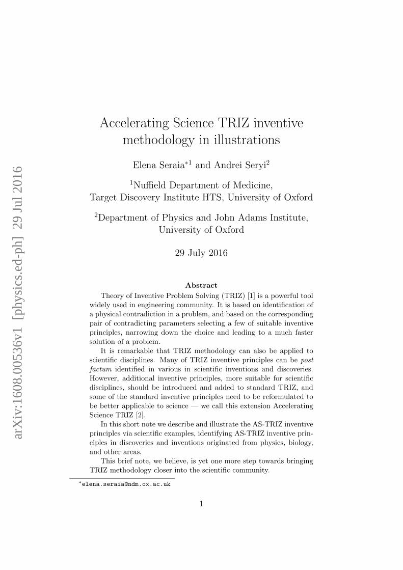
The inventive principle segmentation may involve dividing an object intoindependent parts, making an object easy to disassemble, or increasing thedegree of fragmentation or segmentation.
1. Segmentation • Divide an object into independent parts.
• Make an object easy to disassemble. • Increase the degree of fragmentation or segmentation.
Scatterer
Multi-leaf steel collimator
or carved brass personalized
collimator
Polyethylene bolus (Compensator)
Cancer site.
Proton beam
Proton source
Range modulator wheel
Multi-leaf steel collimator
Proton therapy
Figure 1: Inventive principle “Segmentation”.
An example we selected to illustrate this principle is a multi-leaf steelcollimator used in a beamline for particle therapy. This collimator is neededto shape the proton beam in such a way that it will correspond to the shapeof the target (cancer site). Sometime, a solid personalized collimator usedfor these purposes, however it needs to be machined each time for specificcase. An adjustable collimator, made from segmented steel leafs, make thetreatment planning and delivery much more efficient.
4

2 Taking out
The inventive principle taking out may involve separating an interferingpart or property from an object or singling out the only necessary part (orproperty) of an object.
2.Taking out • Separate an interfering part or property from an object;
• Single out the only necessary part (or property) of an object.
Beam losses distributed
Quadrupoles
Local losses
Quadrupoles Collimator
Collimation of the beam to localize beam losses
Figure 2: Inventive principle “Taking out”.
An example we selected to illustrate this principle is a collimator of thebeam halo intended to localize beam losses (which represent an interferingproperty in this case) in accelerators.
The top picture above shows a beamline of an accelerator without a colli-mator. In this case particles from beam halo can be lost everywhere, creatingproblems associated with, for example, increased radiation in every location.
Inserting a collimator in one location (bottom picture) would eliminatelosses everywhere except the collimator itself, which itself can be treatedspecially, e.g. additional radiation shielding can be installed around thecollimator. Therefore, by inserting the collimator we have separated theinterfering property (losses) from the system.
5
3 Local quality
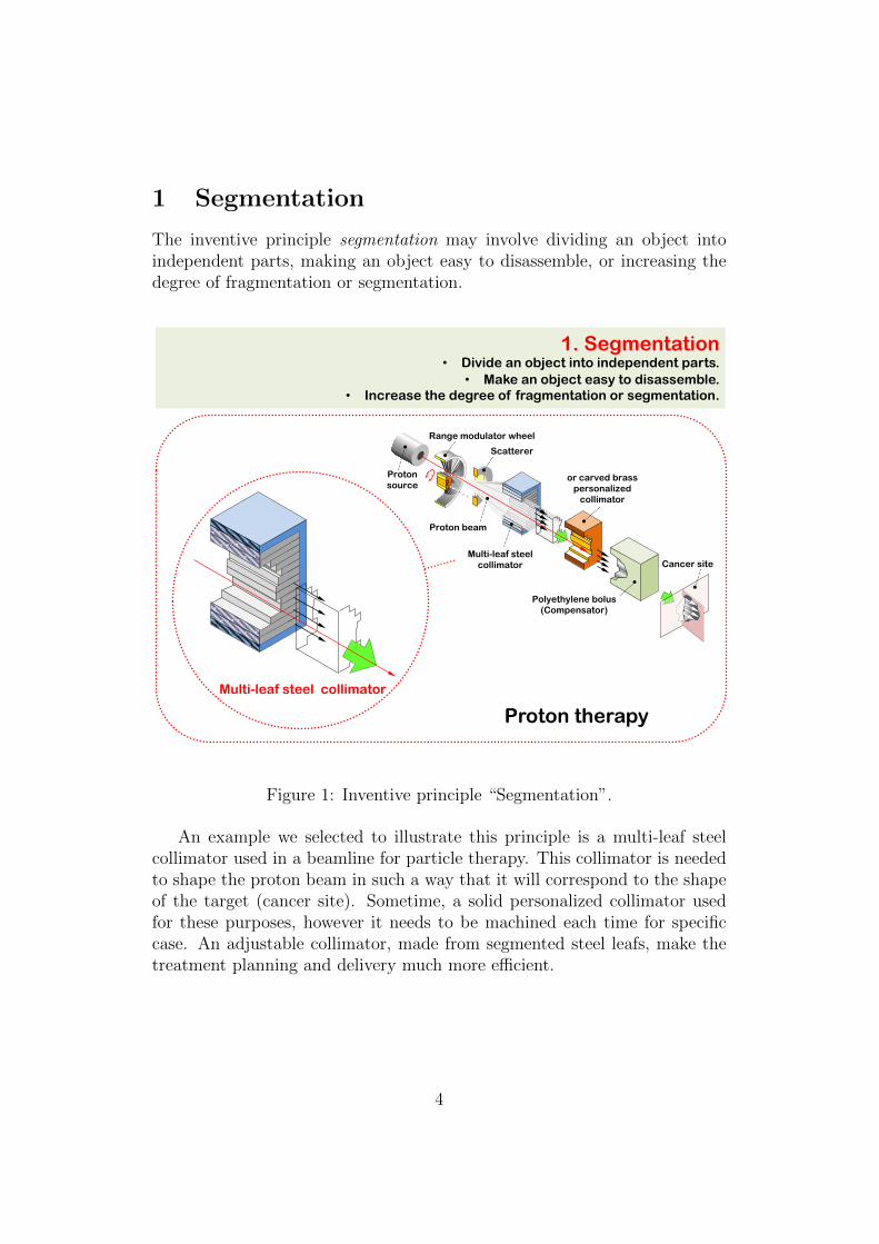
The inventive principle local quality may involve changing an object’s struc-ture from uniform to non-uniform, changing an external environment (orexternal influence) from uniform to non-uniform, making each part of an ob-ject function in conditions most suitable for its operation, or making eachpart of an object fulfill a different and useful function.
3. Local quality • Change an object's structure from uniform to non-uniform, change an external
environment (or external influence) from uniform to non-uniform. • Make each part of an object function in conditions most suitable for its operation.
• Make each part of an object fulfill a different and useful function.
Enzo Palmieri, A.A.Rossi, R. Vaglio, “Experimental Results on Thermal Boundary Resistance for Nb and Nb/Cu”, Science, Oct 2014
Nb coated copper cavity
Figure 3: Inventive principle “Local quality”.
An example we selected to illustrate this principle is a superconductingresonator cavity, where the bulk of the cavity is made from copper, howeverthe inner surface is covered by niobium.
While typically the superconducting cavities are made entirely from nio-bium, which is an expensive material, an arrangement as shown in the illus-tration would allow to considerably save on material cost of such cavities,provided, of course, that results of the ongoing studies3 will be successful.
3Enzo Palmieri, A.A. Rossi, R. Vaglio, Experimental Results on Thermal BoundaryResistance for Nb and Nb/Cu, Science, Oct 2014.
6

4 Asymmetry
The inventive principle asymmetry may involve changing the shape of anobject from symmetrical to asymmetrical, or, if an object is asymmetrical,increasing the degree of its asymmetry.
4. Asymmetry • Change the shape of an object from symmetrical to asymmetrical. • If an object is asymmetrical, increase its degree of asymmetry.
Quadrupole lenses
IP
Translucent concave mirror
Translucent concave mirror
X-rays
Laser
Bending magnets
RF gun
Bending magnets
Beam dump
Coupling cavity
Cryostat
Accelerating cavities
Decelerating cavities
Cavities are slightly different to resonate on the main mode but be decoupled for all higher order modes
R. Ainsworth, G. Burt, I. V. Konoplev, A. Seryi, arXiv:1509.03675, 2015
Figure 4: Inventive principle “Asymmetry”.
We illustrate this principle via asymmetrical design of the dual-axis cou-pled cavities in the compact energy-recovery based linac4 shown above.
In this linac an accelerated electron beam, after radiation generation,comes back to the decelerating part of the cavity, where the beam returnsits energy to the system. In order to avoid instabilities of the beam whichcan be created in this system, all high order modes of the cavities need tobe decoupled. This is achieved by introducing carefully designed asymmetrybetween every cell of the two cavities.
4R. Ainsworth, G. Burt, I. V. Konoplev, A. Seryi, Asymmetric Dual Axis Energy Re-covery Linac for Ultra-High Flux sources of coherent X-ray/THz radiation: InvestigationsTowards its Ultimate Performance, arXiv:1509.03675, physics.acc-ph, Sep 2015.
7

5 Merging
The inventive principle merging may involve bringing closer together (ormerging) identical or similar objects, assembling identical or similar partsto perform parallel operations, or making operations contiguous or parallel;bringing them together in time.
4. Asymmetry Change the shape of an object from symmetrical to asymmetrical.
If an object is asymmetrical, increase its degree of asymmetry.
5. Merging • Bring closer together (or merge) identical or similar objects, assemble
identical or similar parts to perform parallel operations. • Make operations contiguous or parallel; bring them together in time.
Single-channel and Multi-channel (8- and 12-) pipettes
96- or 384-channel Modular Dispense Technology™ (MDT) dispense heads.
PerkinElmer Janus.
Illustration: PerkinElmer
Figure 5: Inventive principle “Merging”.
An example we selected to illustrate this principle is multi-channel pipettesand modular dispensers that are now indispensable for biological studieswhere many samples, many genes, or many variations of drugs need to bestudied and analyzed in parallel.
8

6 Universality
The inventive principle universality may involve making a part or objectperform multiple functions or eliminating the need for other parts.
6. Universality • Make a part or object perform multiple functions;
eliminate the need for other parts.
e- e+
Beam dump
Make beam dump of linear collider to be sub-
critical reactor to generate power or
make neutrino factory out of it
e e π
π ν~ 1 km
ν~ 10 km
Near detector Far detector
I.F. Ginzburg, arXiv:1411.3295, 2014
Figure 6: Inventive principle “Universality”.
An example we selected to illustrate this principle is the following peculiardesign proposal for the beam dump of a linear collider. This beam dumpneeds to take and absorb, typically, 10 MW of CW power in the form of250-500 GeV electron or positron beam. This energy is mostly waisted andgoes to heat. A suggestion was made5 that this beam could in fact be usedto either feed a sub-critical reactor to generate electric power or perhaps tomake a neutrino factory out of it. Therefore, the beam dump of this designof a linear collider performs multiple functions and becomes universal.
5I.F. Ginzburg, Beam Dump problem and Neutrino Factory Based on a e+e LinearCollider, arXiv:1411.3295, physics.acc-ph, Oct 2014.
9

7 Nested doll
The inventive principle nested doll may involve placing one object insideanother, placing each object, in turn, inside the other, making one part passthrough a cavity in the other.
7. Nested doll • Place one object inside another; place each object, in turn, inside the other.
• Make one part pass through a cavity in the other.
High energy physics detectors
Figure 7: Inventive principle “Nested doll”.
An example we selected to illustrate this principle (which is also called in-ventive principle of Russian dolls) is the construction of a high-energy physicsdetector, where many different sub-detectors are inserted into one another,to enhance the accuracy of detecting elusive particles.
10

8 Anti-force
In standard TRIZ this principle is called “anti-weight”, however for scienceapplications it needs to be re-defined as “anti-force”, since gravity often playsnegligible role on particles or nano- and micro-objects science deals with,while electromagnetic forces can be much more important.
The inventive principle anti-force may involve compensating for the forceon an object, merging it with other objects that provide compensating force,etc., as explained in the figure below.
8. Anti-weight force • To compensate for the weight of force on an object, merge it with other objects
that provide compensating force. • To compensate for the weight of force on an object, make it interact with the
environment (e.g. use aerodynamic, hydrodynamic, buoyancy and other forces).
Heating of plasma with neutral beams
Stripping Foil
RF Heating
Joule Heating
Figure 8: Inventive principle AS-TRIZ “Anti-force”, named “Anti-weight”in standard TRIZ.
We illustrate this principle with the heating system for plasma in Toka-mak, where accelerated beam heats plasma. To avoid beam sensing the fieldof solenoid or plasma, the beam is made of neutral atoms, obtained by strip-ping electrons from the initial beam of hydrogen negative ions.
11

9 Preliminary anti-action
The inventive principle preliminary anti-action may involve replacing an ac-tion, which is known to produce both harmful and useful effects, with ananti-action to control those harmful effects.
9. Preliminary anti-action • If it will be necessary to do an action with both harmful and useful effects, this
action should be replaced with anti-actions to control harmful effects. • Create beforehand stresses in an object that will oppose known undesirable
working stresses later on.
Local chromatic correction
Quadrupole
δ>0
δ=0
δ<0
Sextupole + Quadrupole
δ>0 δ=0 δ<0
δ>0 δ=0 δ<0
P. Raimondi, A. Seryi, PRL, 86, 3779 (2001)
Figure 9: Inventive principle “Preliminary anti-action”.
An example we selected to illustrate this principle is a final focus withlocal chromatic correction6. Any strong focusing optics suffer from chro-matic aberrations, as shown on the left part of the picture. Local chromaticcorrection involves dispersing the beam in energies prior it arrives to finallenses, and also inserting nonlinear magnet – sextupole next to the final lens,which cancels the chromatic aberrations, thus acting against is. As a resultof this preliminary anti-action the beam gets focused nicely into a tight spotas shown on the right picture.
6Pantaleo Raimondi and Andrei Seryi, Novel Final Focus Design for Future LinearColliders, Phys. Rev. Lett., 86,3779, Apr 2001.
12

10 Preliminary action
The inventive principle preliminary action may involve performing, beforeit is needed, the required change of an object (either fully or partially), orpre-arranging objects such that they can come into action from the mostconvenient place and without losing time for their delivery.
10. Preliminary action • Perform, before it is needed, the required change of an object
(either fully or partially). • Pre-arrange objects such that they can come into action from the most convenient
place and without losing time for their delivery.
Crabbed collisions
x
x
RF kick
A
B
IP
IP
Figure 10: Inventive principle “Preliminary action”.
An example we selected to illustrate this principle is a crabbed collision.In a linear collider the electron and positron beams need to collide with asmall crossing angle, as shown on the left side of the picture. However, theiroverlap during collision would then be incomplete and the luminosity wouldthus decrease. In order to prevent this loss, the beams, before collisions,can pass through a radio-frequency cavity, which would give to the beams auseful kick, in such a way that the head and tails of the beam receive kicksin different directions. The beams will therefore start to rotate and come tothe collision point with a proper orientation, ensuring full overlap.
13

11 Beforehand cushioning
The inventive principle beforehand cushioning may involve preparing emer-gency means beforehand to compensate for the relatively low reliability ofan object.
11. Beforehand cushioning • Prepare emergency means beforehand to compensate for the relatively
low reliability of an object.
Scatterer
Multi-leaf steel collimator
or carved brass personalized
collimator
Polyethylene bolus (Compensator)
Cancer site.
Proton beam
Proton source
Range modulator wheel
Polyethylene bolus (Compensator)
Cancer site.
Proton therapy
Figure 11: Inventive principle “Beforehand cushioning”.
An example we selected to illustrate this principle is a bolus (compen-sator) for the proton therapy beamline. The thickness of the bolus is varieddepending on location and therefore it will modify the energy of differentparts of the proton beam, and correspondingly modify the penetration depthof the protons, matching the shape of the cancer site.
The reader may argue that this example suit better the previous principleof preliminary action. If so, we would encourage the reader to suggest otherexamples, such as for example emergency kicker that would dump the beamin an accelerator in case of an accident, to prevent losses of the beam intoprecious superconducting magnets.
14
12 Equipotentiality
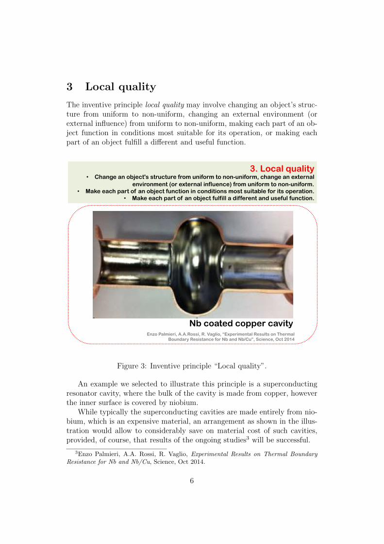
The inventive principle equipotentiality may involve limiting position changesof an object in gravity or other potential field (e.g. changing operating con-ditions to eliminate the need to raise or lower the objects in a gravity field).
12. Equipotentiality • In a potential field, limit position changes (e.g. change operating conditions to
eliminate the need to raise or lower objects in a gravity field).
Laser cooling
νL= ν0-‐ δ ν0 ν0+ δ
δ δ
Ab
sorp
tio
n Laser
Figure 12: Inventive principle “Equipotentiality”.
An example we selected to illustrate this principle is a laser cooling, whereinteraction of laser with atom (excitation of the atom) occurs only when theyare “at the same potential”, i.e. when the velocity of the atom is such thatdue to Doppler shift the laser frequency corresponds to the energy of theatom excitation.
15

13 The other way round
The inventive principle the other way round (which can be also called prin-ciple of system and anti-system) may involve inverting the action(s) used tosolve the problem or turning the object (or process) “upside down”.
13. The other way round • Invert the action(s) used to solve the problem
(e.g. instead of cooling an object, heat it). • Make movable parts (or the external environment) fixed, and fixed parts movable.
• Turn the object (or process) “upside down”.
Cloud and bubble chambers
Figure 13: Inventive principle “The other way round”.
We illustrate this principle via consideration of the cloud and bubblechambers. TRIZ textbooks often cite Charles Wilsons cloud chamber (in-vented in 1911) and Donald Glasers bubble chamber (invented in 1952) asexamples of this principle “system and anti-system”.
Indeed, the cloud chamber works on the principle of bubbles of liquidcreated in gas, whereas the bubble chamber uses bubbles of gas created inliquid. If the TRIZ inventive principle of system/anti-system were applied,the invention of the bubble chamber would follow immediately and not almosthalf a century after the invention of the cloud chamber.
16

14 Spheroidality – Curvature
The inventive principle spheroidality – curvature may involve using, insteadof rectilinear parts, surfaces, or forms, curvilinear ones, moving from flatsurfaces to spherical ones, etc.
14. Spheroidality – Curvature • Instead of using rectilinear parts, surfaces, or forms, use curvilinear ones; move
from flat surfaces to spherical ones; from parts shaped as a cube (parallelepiped) to ball-shaped structures.
• Use rollers, balls, spirals, domes. • Go from linear to rotary motion, use centrifugal forces.
Pill-box and crab-cavity
Figure 14: Inventive principle “Spheroidality – Curvature”.
An example we selected to illustrate this principle is cavity resonator –pill-box style as shown on the left side of the pictures, and elliptical cavity(where shapes are rounded and consist of various connected ellipses). Aparticular example shown on the right corresponds to the cavity which canproduce crabbing kick mentioned in the principle 10, but it can also be anyother similar cavity. Rounding the shapes of the resonator in such a wayallows to achieve better and smooth distribution of fields and currents alongthe walls of the cavity and correspondingly higher fields generated by thecavity on beam axis.
17

15 Dynamics
The inventive principle dynamics may involve allowing (or designing) thecharacteristics of an object, external environment, or process to change to beoptimal.
15. Dynamics • Allow (or design) the characteristics of an object, external environment, or process
to change to be optimal or to find an optimal operating condition. • Divide an object into parts capable of movement relative to each other.
• If an object (or process) is rigid or inflexible, make it movable or adaptive.
Travelling focus
V. Balakin, 1991
Figure 15: Inventive principle “Dynamics”.
An example we selected to illustrate this principle is a travelling focusidea7 intended to increase luminosity of linear colliders. The fields of theopposite beam during collision of e+ and e- beams can create an additionalfocusing which can help to squeeze the beams even tighter. However, for thisadditional focusing to work most optimally, the focal point for each beamneeds to move during collision in such a way that it would coincide with thelocation of the head of the opposite beam. The location of the focal point isshown by arrows of corresponding color. Such dynamic modification of thecolliding beams would then give some increase of the luminosity.
7Balakin, V., Travelling Focus Regime for Linear Collider VLEPP, Proc. of 1991 IEEEPAC, p.3273, 1991.
18

16 Partial or excessive actions
The inventive principle partial or excessive actions may involve, in case if100% of the effect is hard to achieve with a given solution or method, using“slightly less” or “slightly more” of the same method, to make the problemconsiderably easier to solve.
16. Partial or excessive actions • If 100 percent of an object is hard to achieve using a given solution method then,
by using “slightly less” or “slightly more” of the same method, the problem may be considerably easier to solve.
Electron Calorimeter
Time Projection Chamber or Si Tracker
Vertex Detector
Luminosity Calorimeter
Detectors
Beam Calorimeter
IP Chamber
Dual Anti-
solenoid
Outgoing Beam
Incoming Beam
x50
x
y
x2 x
y
Main solenoid effect
Anti-solenoid effect
Huge coupling due to overlap of solenoid with Final Doublet quads => partial compensation by weak anti-solenoid
Y. Nosochkov, A. Seryi, PRSTAB, 8, 021001 (2005)
Figure 16: Inventive principle “Partial or excessive actions”.
An example we selected to illustrate this principle is the design conceptof a weak antisolenoid8 intended for compensating the beam X-Y couplingeffects in the interaction region of a linear collider. The anomalously largecoupling effects arise due to overlap of the field of the main solenoid with thefinal focusing lenses. Properly adjusted weak anti-solenoid can compensatea large fraction of these detrimental effects, making the problem much easierto solve with upstream coupling correctors.
8Y. Nosochkov, A. Seryi, PRSTAB, 8, 021001 , 2005.
19
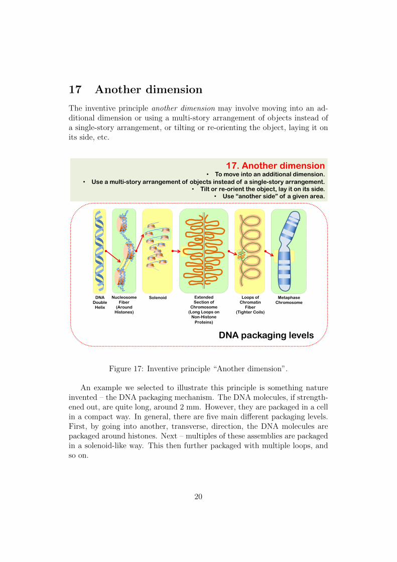
17 Another dimension
The inventive principle another dimension may involve moving into an ad-ditional dimension or using a multi-story arrangement of objects instead ofa single-story arrangement, or tilting or re-orienting the object, laying it onits side, etc.
17. Another dimension • To move into an additional dimension.
• Use a multi-story arrangement of objects instead of a single-story arrangement. • Tilt or re-orient the object, lay it on its side.
• Use “another side” of a given area.
DNA Double
Helix
Nucleosome Fiber
(Around Histones)
Solenoid Loops of Chromatin
Fiber (Tighter Coils)
Extended Section of
Chromosome (Long Loops on
Non-Histone Proteins)
Metaphase Chromosome
DNA packaging levels
Figure 17: Inventive principle “Another dimension”.
An example we selected to illustrate this principle is something natureinvented – the DNA packaging mechanism. The DNA molecules, if strength-ened out, are quite long, around 2 mm. However, they are packaged in a cellin a compact way. In general, there are five main different packaging levels.First, by going into another, transverse, direction, the DNA molecules arepackaged around histones. Next – multiples of these assemblies are packagedin a solenoid-like way. This then further packaged with multiple loops, andso on.
20

18 Oscillations and resonances
In standard TRIZ this method is called “Mechanical vibration”, however forscience applications this principle should better be re-defined as “Oscillationsand resonances”. The inventive principle oscillations and resonances mayinvolve causing an object to oscillate or vibrate, increasing its frequency(e.g. from microwave to optical), using an object’s resonant frequency, etc.
18. Mechanical vibration Oscillations and resonances • Cause an object to oscillate or vibrate.
• Increase its frequency (even up to the ultrasonic from microwave to optical).
• Use an object's resonant frequency.
• Use piezoelectric vibrators instead of mechanical ones.
• Use combined ultrasonic and electromagnetic field oscillations.
Stochastic cooling => optical stochastic cooling
Microwave
amplifier
Microwave
pickup Optical
amplifier
Optical
pickup
Figure 18: Inventive principle AS-TRIZ “Oscillations and resonances”,named “Mechanical vibration” in TRIZ .
We illustrate this principle with the design concept of optical stochas-tic cooling which represents further evolution of stochastic cooling. Boththese methods are designed to decrease phase space volume of a beam ofcharged particle in accelerators. Stochastic cooling relies on microwave rangeof frequencies, for detection of particles and acting on them, while opticalstochastic cooling relies on, correspondingly, optical frequencies.
21

19 Periodic action
The inventive principle periodic action may involve, instead of continuousaction, using periodic or pulsating actions.
19. Periodic action • Instead of continuous action, use periodic or pulsating actions.
• If an action is already periodic, change the periodic magnitude or frequency. • Use pauses between impulses to perform a different action.
e-
Bending Magnet
e-
Wiggler
e-
Undulator
Devices for generation of synchrotron radiation
Figure 19: Inventive principle “Periodic action”.
We illustrate this principle via consideration of devices for generation ofsynchrotron radiation. This radiation is generated when relativistic chargedparticles move on a curved trajectory, loosing parts of its electromagneticfield. The simplest way to generate such radiation is to pass particles via abending magnet, as shown on the left side of the picture. However, muchbetter characteristic of radiation (brightness, etc) can be obtained if thisprocess is repeated – i.e. the particles are passed through a sequence of bendsof different polarity. Such arrangements of bends are called wigglers andundulators and are now widely used in synchrotron radiation light sources.
22

20 Continuity of useful action
The inventive principle continuity of useful action may involve carrying onwork continuously, making all parts of an object work at full load, all thetime, eliminating all idle or intermittent actions or work.
20. Continuity of useful action • Carry on work continuously; make all parts of an object work at full load,
all the time. • Eliminate all idle or intermittent actions or work.
Top off injection
0 8 16 24
1
2
3
4
5
Time (hours)
Current (arb. units)
(a)
(b)
Figure 20: Inventive principle “Continuity of useful action”.
We illustrate this principle via a concept of top-off injection for syn-chrotron light sources. In these sources radiation is generated by circulatingelectron beam which can decay due to losses, and thus the circulating currentas well as the intensity of generated radiation decrease with time, as shownon the left side of the picture. The circulating beam is renewed seldom, whenthe new beam is injected.
An alternative way to operate the light source is to arrange almost con-tinuous injection so that the fresh portion of the beam would be injected veryoften, considerably increasing the efficiency of the light source and also elim-inating any thermal effects associated with variations of circulating currentor intensity of the emitted radiation.
23

21 Skipping
The inventive principle skipping may involve conducting a process, or certainstages of it (e.g. destructible, harmful or hazardous operations) at high speed.
21. Skipping • Conduct a process , or certain stages (e.g. destructible, harmful or hazardous
operations) at high speed.
Crossing transition energy
with γt jump technique
Separatrix
Unstable Stable
Separatrix
Unstable Stable
ϕ
ϕ
ϕ
ϕ
Vrf
P1 P2
5.0
6.0
7.0
0 -20 20 40 Time (ms)
γt unperturbed
γt jump γ
Figure 21: Inventive principle “Skipping”.
An example we selected to illustrate this principle is a gamma-jump tech-nique used in accelerators. In proton circular accelerators in particular thereis a notion of critical energy – at this energy (the relativistic factor corre-sponding to this energy is called γt) the stable phase (of the acceleratingresonator) flips to the other side of the sine wave. Passing the critical energyduring acceleration therefore requires jumping the phase of the resonator, toavoid beam getting lost. Still, some disturbance of the beam unavoidablyhappens, due to such transition.
The critical energy value depends on the properties of the focusing opticsof the accelerator. It is possible, therefore, to program the optics changein such a way, that transition through the critical energy will happen muchfaster, significantly reducing the detrimental effects on the accelerated beam.
24
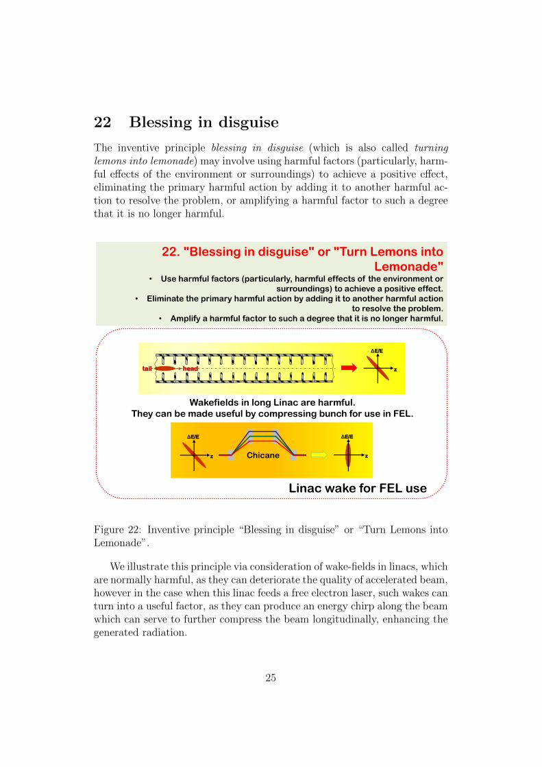
22 Blessing in disguise
The inventive principle blessing in disguise (which is also called turninglemons into lemonade) may involve using harmful factors (particularly, harm-ful effects of the environment or surroundings) to achieve a positive effect,eliminating the primary harmful action by adding it to another harmful ac-tion to resolve the problem, or amplifying a harmful factor to such a degreethat it is no longer harmful.
22. "Blessing in disguise" or "Turn Lemons into
Lemonade" • Use harmful factors (particularly, harmful effects of the environment or
surroundings) to achieve a positive effect.
• Eliminate the primary harmful action by adding it to another harmful action
to resolve the problem.
• Amplify a harmful factor to such a degree that it is no longer harmful.
Linac wake for FEL use
ΔE/E
z head tail
Wakefields in long Linac are harmful.
They can be made useful by compressing bunch for use in FEL.
ΔE/E
z
ΔE/E
z Chicane
Figure 22: Inventive principle “Blessing in disguise” or “Turn Lemons intoLemonade”.
We illustrate this principle via consideration of wake-fields in linacs, whichare normally harmful, as they can deteriorate the quality of accelerated beam,however in the case when this linac feeds a free electron laser, such wakes canturn into a useful factor, as they can produce an energy chirp along the beamwhich can serve to further compress the beam longitudinally, enhancing thegenerated radiation.
25

23 Feedback
The inventive principle feedback may involve introducing feedback of feed-forward links into the process (referring back, cross-checking) to improve theprocess or an action.
23. Feedback • Introduce feedback (referring back, cross-checking) to improve a process or
action. • If feedback is already used, change its magnitude or influence.
Stochastic cooling
Kicker
Figure 23: Inventive principle “Feedback”.
An example we selected to illustrate this principle is a concept of stochas-tic cooling intended for reduction of phase space volume of the circulating inan accelerator beam. This is done via first detecting oscillations of particlesin one location, sending the amplified signal which carries information aboutthese oscillation along a shorter path than the particle takes to travel, andacting on the same particle with a kick that would decrease its oscillation.
26
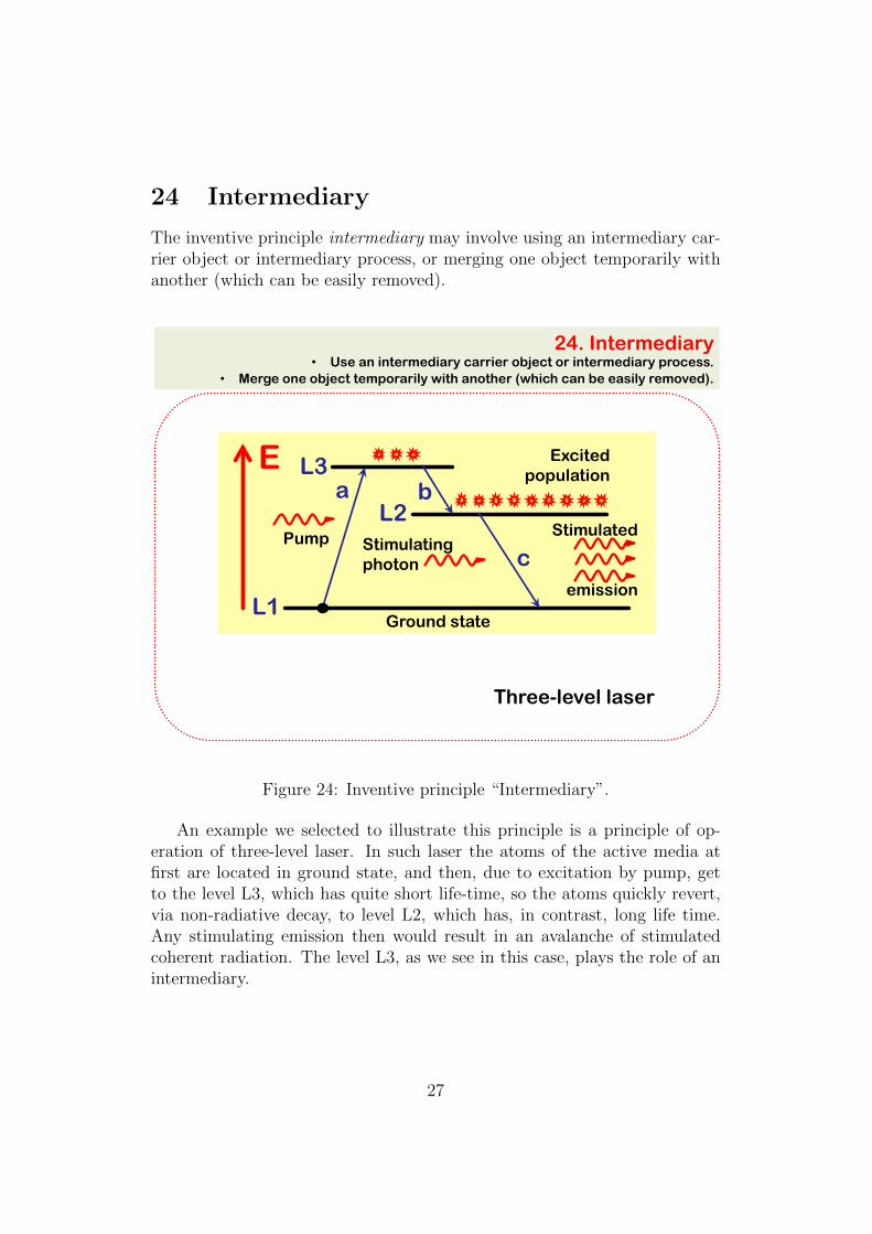
24 Intermediary
The inventive principle intermediary may involve using an intermediary car-rier object or intermediary process, or merging one object temporarily withanother (which can be easily removed).
24. Intermediary • Use an intermediary carrier object or intermediary process.
• Merge one object temporarily with another (which can be easily removed).
Three-level laser
L3
L2
L1
Pump Stimulating photon
Ground state
Excited population
Stimulated
emission
E a
c
b
Figure 24: Inventive principle “Intermediary”.
An example we selected to illustrate this principle is a principle of op-eration of three-level laser. In such laser the atoms of the active media atfirst are located in ground state, and then, due to excitation by pump, getto the level L3, which has quite short life-time, so the atoms quickly revert,via non-radiative decay, to level L2, which has, in contrast, long life time.Any stimulating emission then would result in an avalanche of stimulatedcoherent radiation. The level L3, as we see in this case, plays the role of anintermediary.
27
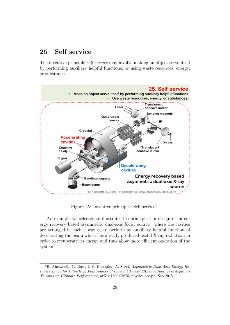
25 Self service
The inventive principle self service may involve making an object serve itselfby performing auxiliary helpful functions, or using waste resources, energy,or substances.
25. Self service • Make an object serve itself by performing auxiliary helpful functions
• Use waste resources, energy, or substances.
Quadrupole lenses IP
Translucent concave mirror
Translucent concave mirror
X-rays
Laser
Bending magnets
RF gun
Bending magnets
Beam dump
Coupling cavity
Cryostat
Accelerating cavities
Decelerating cavities
Energy recovery based asymmetric dual-axis X-ray
source R. Ainsworth, G. Burt, I. V. Konoplev, A. Seryi, arXiv:1509.03675, 2015
Figure 25: Inventive principle “Self service”.
An example we selected to illustrate this principle is a design of an en-ergy recovery based asymmetric dual-axis X-ray source9, where the cavitiesare arranged in such a way as to perform an auxiliary helpful function ofdecelerating the beam which has already produced useful X-ray radiation, inorder to recuperate its energy and thus allow more efficient operation of thesystem.
9R. Ainsworth, G. Burt, I. V. Konoplev, A. Seryi, Asymmetric Dual Axis Energy Re-covery Linac for Ultra-High Flux sources of coherent X-ray/THz radiation: InvestigationsTowards its Ultimate Performance, arXiv:1509.03675, physics.acc-ph, Sep 2015.
28

26 Copying
The inventive principle copying may involve using, instead of an unavailable,expensive or fragile object, its simpler and inexpensive copies, or replacingan object, or process with optical copies.
26. Copying • Instead of an unavailable, expensive, fragile object,
use simpler and inexpensive copies. • Replace an object, or process with optical copies.
• If visible optical copies are already used, move to infrared or ultraviolet copies.
Synchrotron radiation profile monitor
CCD Camera
Figure 26: Inventive principle “Copying”.
An example we selected to illustrate this principle is a concept of syn-chrotron light beam size monitor. The beam of charged particles, circulatingin an accelerator, emits synchrotron radiation, when it is passing bendingmagnets. Beam size monitors such as wires crossing the beams are invasive,and should be avoided. Synchrotron radiation however allows to create non-destructive monitors, when this radiation is directed with mirrors to detectorand its profile analyzed. Therefore, instead of fragile beam which could beanalyzed with a crossing wire, its optical copy is analyzed in this case todetermine its beam size.
29
27 Cheap short-living objects
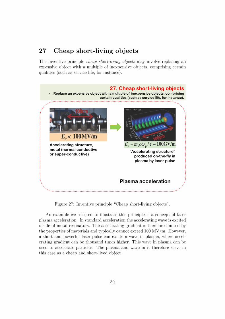
The inventive principle cheap short-living objects may involve replacing anexpensive object with a multiple of inexpensive objects, comprising certainqualities (such as service life, for instance).
27. Cheap short-living objects • Replace an expensive object with a multiple of inexpensive objects, comprising
certain qualities (such as service life, for instance).
Accelerating structure,
metal (normal conductive
or super-conductive) “Accelerating structure”
produced on-the-fly in
plasma by laser pulse
Plasma acceleration
Figure 27: Inventive principle “Cheap short-living objects”.
An example we selected to illustrate this principle is a concept of laserplasma acceleration. In standard acceleration the accelerating wave is excitedinside of metal resonators. The accelerating gradient is therefore limited bythe properties of materials and typically cannot exceed 100 MV/m. However,a short and powerful laser pulse can excite a wave in plasma, where accel-erating gradient can be thousand times higher. This wave in plasma can beused to accelerate particles. The plasma and wave in it therefore serve inthis case as a cheap and short-lived object.
30

28 Mechanics substitution
The inventive principle mechanics substitution may involve replacing me-chanical means with electromagnetic or sensory (acoustic, taste or smell)means.
28. Mechanics substitution • Replace a mechanical means with a sensory (optical, acoustic, taste or smell)
means. • Use electric, magnetic and electromagnetic fields to interact with the object. • Change from static to movable fields, from unstructured fields to those having
structure. • Use fields in conjunction with field-activated (e.g. ferromagnetic) particles.
Van der Graaf to Cockcroft-Walton generator
+ +
+ +
+ +
+
+ +
Metal sphere Collecting brush
Metal brush
Rubber belt
C
C
C
C
C
C
6U
4U
2U
U~
Figure 28: Inventive principle “Mechanics substitution”.
We illustrate this principle via considerations of electrostatic generatorsof two kinds. In the first type shown on the left part of the picture the electriccharges are delivered to the metal sphere by the moving rubber belt. Thecharged are deposited on the belt by a system of sharp needles. This is Vander Graaf generator. In the second case a sequence of diode-based rectifiersis used to amplify the voltage to a high level, sufficient for accelerating ofcharged particles. This is called Cockcroft-Walton generator.
31

29 Pneumatics and hydraulics
The inventive principle pneumatics and hydraulics may involve using gasand liquid parts of an object instead of solid parts (e.g. inflatable, filled withliquids, air cushion, hydrostatic, hydro-reactive).
29.Pneumatics and hydraulics • Use gas and liquid parts of an object instead of solid parts (e.g. inflatable, filled
with liquids, air cushion, hydrostatic, hydro-reactive).
Illustration: ORNL
Liquid mercury target
Figure 29: Inventive principle “Pneumatics and hydraulics”.
An example we selected to illustrate this principle is a design concept ofa liquid beam target. Beam targets are often needed, for example, for pro-duction of positrons or neutrons from accelerated electron or proton beams.Considerable amount of heat is deposited in the targets during its interactionwith the beam. Preventing destruction of the target can be done by makingit rotating, or, ultimately, already “destroyed”, i.e., in this case, liquid.
32

30 Flexible shells and thin films
The inventive principle flexible shells and thin films may involve using flexibleshells and thin films instead of three dimensional structures or isolating theobject from the external environment using flexible shells and thin films.
30. Flexible shells and thin films • Use flexible shells and thin films instead of three dimensional structures
• Isolate the object from the external environment using flexible shells and thin films.
Light sail laser-plasma ion acceleration
Figure 30: Inventive principle “Flexible shells and thin films”.
An example we selected to illustrate this principle is a concept of lightsail laser-plasma ion acceleration. Laser plasma acceleration of ions is usuallyachieved via interaction of powerful short laser pulse with solid target. Thismethod, however, does not produce a nice mono-energetic accelerated beam.From the other side, shining the laser onto a very thin film creates radiationpressure driven acceleration of the entire film, and correspondingly the ionbeam accelerated in such a case will have much better properties.
33
31 Porous materials
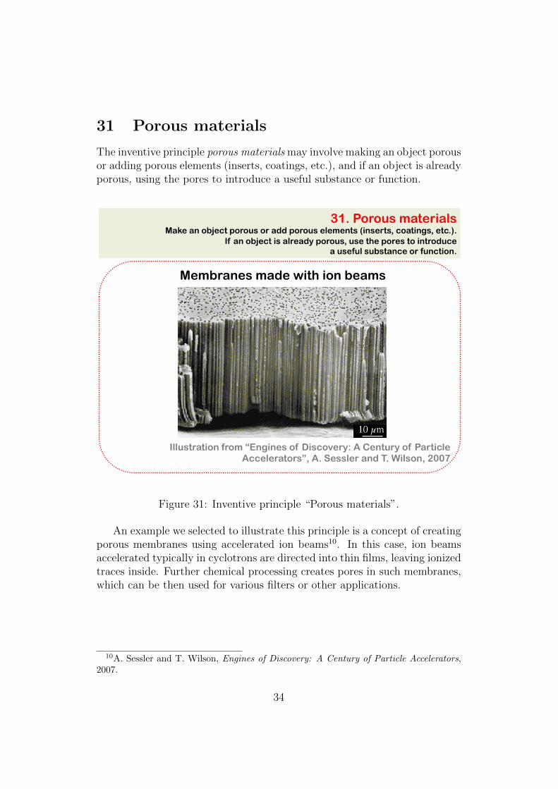
The inventive principle porous materials may involve making an object porousor adding porous elements (inserts, coatings, etc.), and if an object is alreadyporous, using the pores to introduce a useful substance or function.
31. Porous materials Make an object porous or add porous elements (inserts, coatings, etc.).
If an object is already porous, use the pores to introduce a useful substance or function.
Illustration from “Engines of Discovery: A Century of Particle Accelerators”, A. Sessler and T. Wilson, 2007
Membranes made with ion beams
Figure 31: Inventive principle “Porous materials”.
An example we selected to illustrate this principle is a concept of creatingporous membranes using accelerated ion beams10. In this case, ion beamsaccelerated typically in cyclotrons are directed into thin films, leaving ionizedtraces inside. Further chemical processing creates pores in such membranes,which can be then used for various filters or other applications.
10A. Sessler and T. Wilson, Engines of Discovery: A Century of Particle Accelerators,2007.
34

32 Color changes
The inventive principle color changes may involve changing the color of anobject or its external environment, changing the transparency of an objector its external environment, changing the emissivity properties of an objectsubject to radiant heating, etc.
32. Color changes • Change the color of an object or its external environment.
• Change the transparency of an object or its external environment. • To improve observability of things that are difficult to see, use colored additives or
luminescent elements. • Change the emissivity properties of an object subject to radiant heating.
E2
E1
ωs ω1
ω2
Optical Parametric Chirped Pulse Amplification - OPCPA
Optical Parametric
process
Figure 32: Inventive principle “Color changes”.
An example we selected to illustrate this principle is a principle of OPCPA– Optical Parametric Chirped Pulse Amplification. In this method a nonlin-ear crystal is used, which emits two different wavelengths when pumped witha single wavelength. This crystal can be used in an optical amplifier, whena pump laser beam and a signal laser beam are sent onto the crystal, andout from the crystal an amplified signal and depleted pump beams emerge.If the signal beam is chirped, the output amplified signal is also chirped.Change of the color by the nonlinear crystal via optical parametric processis an illustration of the color changes inventive principle.
35

33 Homogeneity
The inventive principle homogeneity or expressing it in Latin similia similibuscurantur may involve making objects interacting with a given object of thesame material (or material with identical properties).
33. Homogeneity (Similia similibus curantur) • Make objects interacting with a given object of the same material
(or material with identical properties).
Electron cooling
Figure 33: Inventive principle “Homogeneity”.
An example we selected to illustrate this principle is a concept of electroncooling. This cooling method is aimed at decrease of the phase space volumeof charged particle beam, for example the beam of anti-protons. The coolingis done by overlapping the anti-proton beam with the beam of electrons goingin the same direction and with the same velocity. Hot anti-protons, collidingwith colder electrons, will transfer their energy to electrons, and after manypassages through the electron beam will cool down. So, here we cure similarwith similar – cool charged particles with other type of charged particles.
36

34 Discarding and recovering
The inventive principle discarding and recovering may involve making por-tions of an object that have fulfilled their functions go away (discard bydissolving, evaporating, etc.) or modifying these directly during operation,or, conversely, restoring consumable parts of an object directly in operation.
34.Discarding and recovering • Make portions of an object that have fulfilled their functions go away (discard by
dissolving, evaporating, etc.) or modify these directly during operation. • Conversely, restore consumable parts of an object directly in operation.
Semiconductor Saturable Absorber Mirror - SESAM
Bragg mirror (SESAM)
Translucent concave mirror
Active medium
Dichroic mirror
Quantum well absorber
Output
Figure 34: Inventive principle “Discarding and recovering”.
An example we selected to illustrate this principle is a SemiconductorSaturable Absorber Mirror – so called SESAM. Such device is used in thesystem of short laser pulse generator and plays the role of a mirror, which,when the stored in the laser cavity light reaches certain intensity, “disap-pears” due to saturation effects, thus releasing all stored laser light out fromthe cavity in the form of a short intense laser pulse. The SESAM is thus amirror that is discarded at a proper moment.
37

35 Parameter changes
The inventive principle parameter changes may involve changing an object’sphysical state (e.g. to a gas, liquid, or solid), changing the concentration orconsistency, changing the degree of flexibility, changing the temperature, etc.
35. Parameter changes • Change an object's physical state (e.g. to a gas, liquid, or solid.)
• Change the concentration or consistency. • Change the degree of flexibility.
• Change the temperature.
15o C 20o C 25o C 40o C
Fiber geometry
Slab geometry
Fiber lasers
Figure 35: Inventive principle “Parameter changes”.
We illustrate this principle via consideration of variation of the ratio ofthe surface area of an object to the volume of the object. Maxwell or ther-modynamic equations indicate that changing the volume to surface ratio canchange characteristics of the object such as cooling rate or its electromag-netic field. We illustrate this via an example of a cat, who can change itssurface area depending on the environmental temperature, to control its cool-ing rate, or via an example of fiber lasers, which, in comparison with laserswith standard geometry of active media, have much higher surface area,therefore better cooling, and correspondingly can have higher repetition rateand higher efficiency.
38

36 Phase transitions
The inventive principle phase transitions may involve using phenomena oc-curring during phase transitions (e.g. volume changes, loss or absorption ofheat, etc.).
36. Phase transitions • Use phenomena occurring during phase transitions (e.g. volume changes, loss or
absorption of heat, etc.).
Phase transition
ρ
T Tc Superconductivity
Figure 36: Inventive principle “Phase transitions”.
An example we selected to illustrate this principle is a phenomenon ofsuperconductivity when the electrical resistance of certain materials can dropto zero when temperature decreases below the critical one.
39

37 Thermal or electrical expansion
or property change
The inventive principle thermal or electrical expansion or property changemay involve using thermal or electrical expansion (or contraction) or otherproperty change of materials, or using multiple materials with different co-efficients of thermal expansion (property change).
37. Thermal or electrical expansion or property change • Use thermal or electrical expansion (or contraction) or other property change of
materials. • If thermal or electrical expansion (property change) is being used, use multiple
materials with different coefficients of thermal expansion (property change).
Electro-optic effect ― dependence of optical
properties of objects such as
absorption or refraction (Pockels effect)
on the applied electric field
Concave mirror
Pockels cell
Mirror
Translucent concave mirror
Active medium
Figure 37: Inventive principle “Thermal or electrical expansion or propertychange”.
An example we selected to illustrate this principle is an electro-optic effect– dependence of optical properties of objects such as absorption or refraction(Pockels effect) on the applied electric field. In the example shown on thispicture this effect is used to create ultra-short laser pulses.
40
38 Strong oxidants
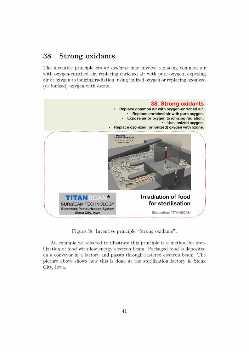
The inventive principle strong oxidants may involve replacing common airwith oxygen-enriched air, replacing enriched air with pure oxygen, exposingair or oxygen to ionizing radiation, using ionized oxygen or replacing ozonized(or ionized) oxygen with ozone.
38. Strong oxidants • Replace common air with oxygen-enriched air.
• Replace enriched air with pure oxygen. • Expose air or oxygen to ionizing radiation.
• Use ionized oxygen. • Replace ozonized (or ionized) oxygen with ozone.
Irradiation of food for sterilisation
TITANSCAN* SURεβEAM TECHNOLOGY Electronic Pasteurization System
Sioux City, Iowa Illustration: TITANSCAN
Figure 38: Inventive principle “Strong oxidants”.
An example we selected to illustrate this principle is a method for ster-ilization of food with low energy electron beam. Packaged food is depositedon a conveyor in a factory and passes through rastered electron beam. Thepicture above shows how this is done at the sterilization factory in SiouxCity, Iowa.
41

39 Inert atmosphere
The inventive principle inert atmosphere may involve replacing a normalenvironment with an inert one, or adding neutral parts, or inert additives toan object.
39. Inert atmosphere • Replace a normal environment with an inert one. • Add neutral parts, or inert additives to an object.
Sulfur hexafluoride (SF6 or Elegas) is a colorless non-
flammable gas with excellent electric
insulating and arc-quenching capacity. It is
widely used in the fields of electric, laser, medical,
meteorological, freezing, fire-fighting, chemical,
military, space aviation, nonferrous metallurgy and
physical research areas.
S FF
FF
FFSF6
Air
105
104
103
102 10-4 10-3 10-2 10-1 100
pd (cm•atm)
V (
v)
Figure 39: Inventive principle “Inert atmosphere”.
An example we selected to illustrate this principle is a method of usingsulfur hexafluoride (SF6 or Elegas), which is a colorless non-flammable gaswith excellent electric insulating and arc-quenching capacity. This gas canbe used, in particular, to fill the interior of electrostatic generators (Vander Graaf or Cockcroft-Walton types) in order to reach higher voltage andtherefore higher energy of accelerated particles. The curves on the left side ofthe picture show a comparison of electrical discharge voltage versus the valueof pressure multiplied by the gap between electrodes for SF6 in comparisonwith an air.
42
40 Composite materials
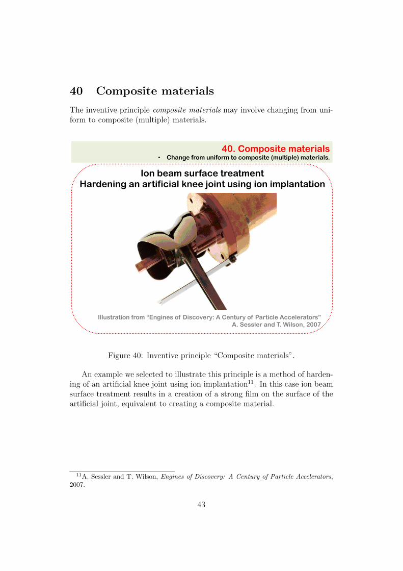
The inventive principle composite materials may involve changing from uni-form to composite (multiple) materials.
40. Composite materials • Change from uniform to composite (multiple) materials.
Ion beam surface treatment Hardening an artificial knee joint using ion implantation
Illustration from “Engines of Discovery: A Century of Particle Accelerators” A. Sessler and T. Wilson, 2007
Figure 40: Inventive principle “Composite materials”.
An example we selected to illustrate this principle is a method of harden-ing of an artificial knee joint using ion implantation11. In this case ion beamsurface treatment results in a creation of a strong film on the surface of theartificial joint, equivalent to creating a composite material.
11A. Sessler and T. Wilson, Engines of Discovery: A Century of Particle Accelerators,2007.
43
Discussion and conclusion
Suggested illustrations of inventive principles, we hope, will be useful to stim-ulate the readers to think about inventive ways to solve scientific problemsthey encounter in their research. The examples we suggested are often notideal and could certainly be improved – we welcome our readers to partici-pate in creation of better examples. And most importantly, we welcome thereaders to use the methodology of inventive problem solving in their research,and beyond.
References
[1] Altshuller, G., “Innovation Algorithm: TRIZ, systematic innovation andtechnical creativity”, first ed. Worcester, MA: Technical Innovation Cen-ter, Inc. (1999).
[2] Seryi, A., “Unifying Physics of Accelerators, Lasers and Plasma”, CRCPress, Taylor & Francis Group, (2015).
[3] Seryi, A.A., Seraia, E.I., “Inventing Instruments of Future Science”,URSS Publishing company. In Russian. Published in June 2016, ISBN978-5-9710-3185-7, (2016).
44