Accelerated Bridge Construction: Four Bridge Deck ......These four bridges are included in the...
117
Accelerated Bridge Construction: Four Bridge Deck Replacements in Region 5 Oakgrove Construction, Inc. General Contractors • Since 1961
Transcript of Accelerated Bridge Construction: Four Bridge Deck ......These four bridges are included in the...
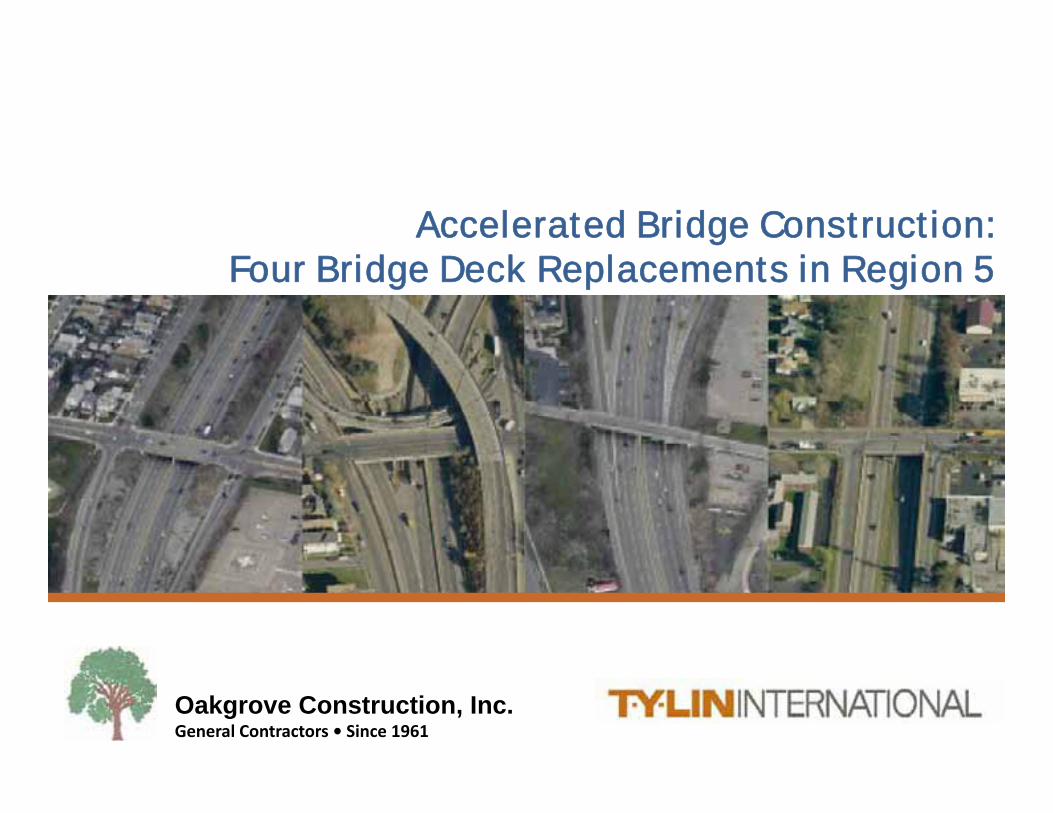
Accelerated Bridge Construction:Four Bridge Deck Replacements in Region 5
Oakgrove Construction, Inc. General Contractors • Since 1961
These four bridges are included in the NYSDOT Accelerated Bridge Construction Program (ABC) mainly consisting of bridge decks replacements. In spring 2012 these bridges were included in the Design-Build phase of the ABC program however,Design-Build prices came out too highBridges were then split up by Region and included in the ABC Design-Bid-Build Contracts (Phase 1A). TY Lin International was awarded the rehabilitation design of these four bridges in the fall of 2012.
Project Introduction
TY Lin International – Structural, M&PT
Watts Engineering – Environmental, Utility Design and Coordination, Sign Supports
Ravi Engineering– Survey
NYSDOT Region 5 – Pier Rehabilitation, Signal Conduit Layout
Design Team
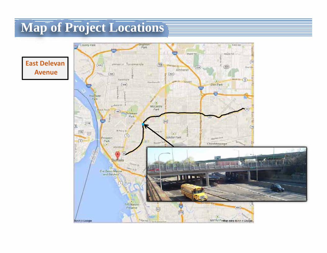
Map of Project Locations
East DelevanAvenue
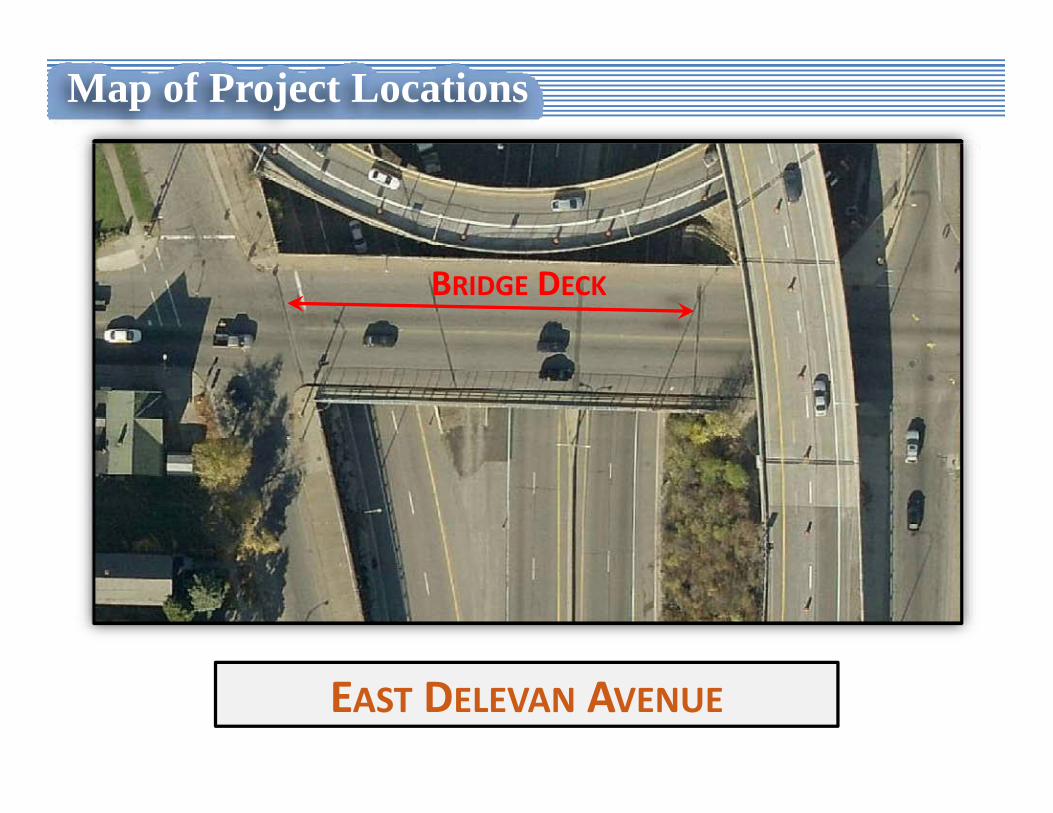
Map of Project Locations
EAST DELEVAN AVENUE
BRIDGE DECK
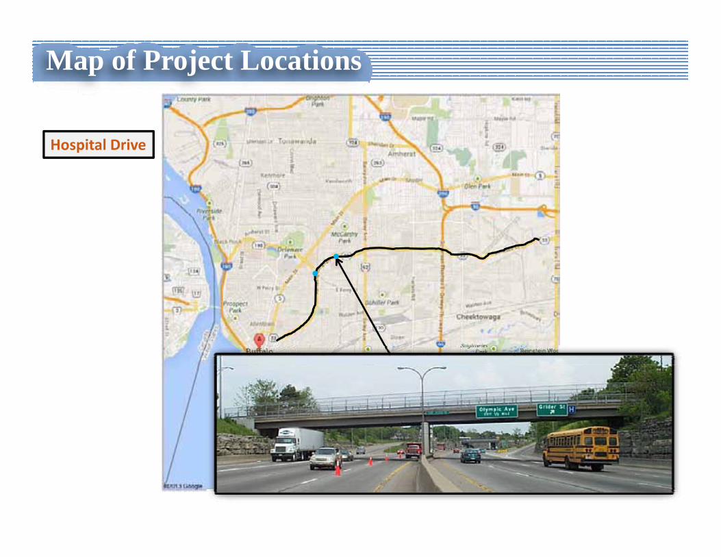
Map of Project Locations
Hospital Drive
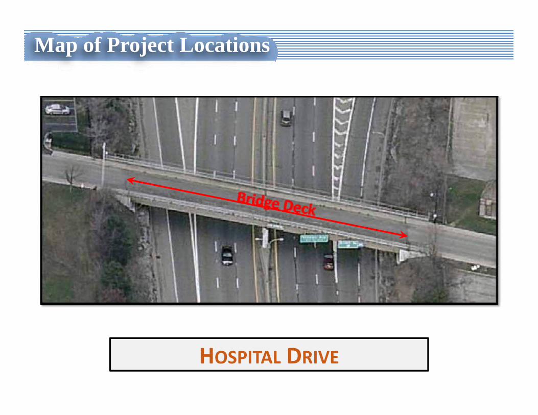
Map of Project Locations
HOSPITAL DRIVE
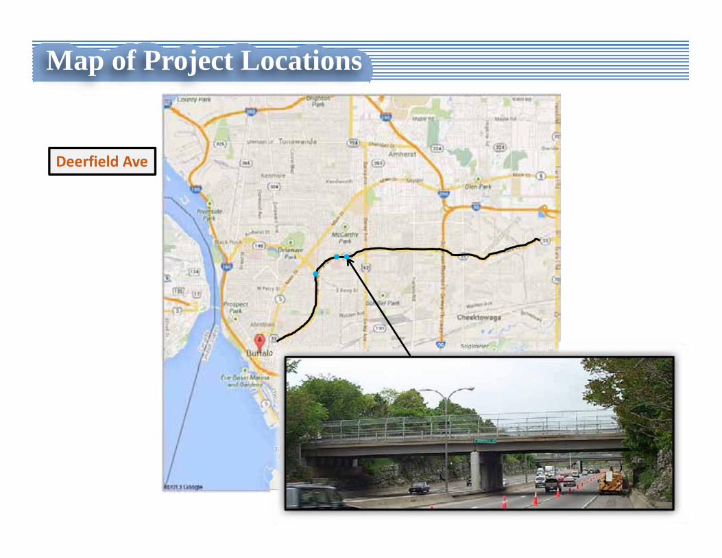
Map of Project Locations
Deerfield Ave
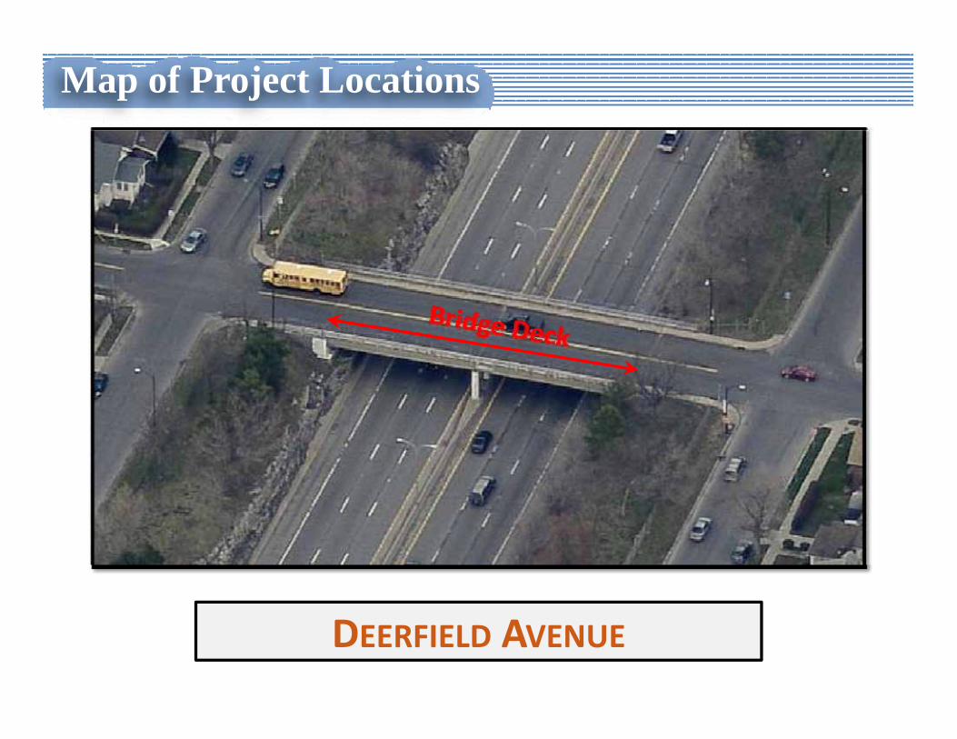
Map of Project Locations
DEERFIELD AVENUE
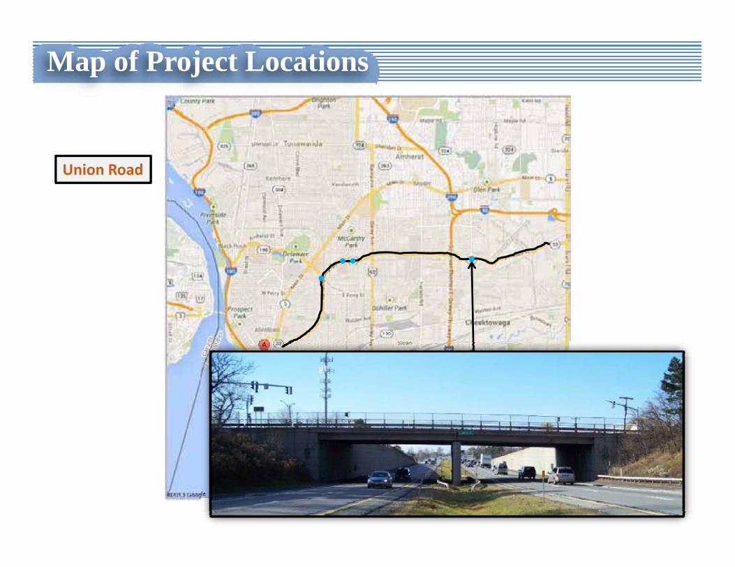
Map of Project Locations
Union Road
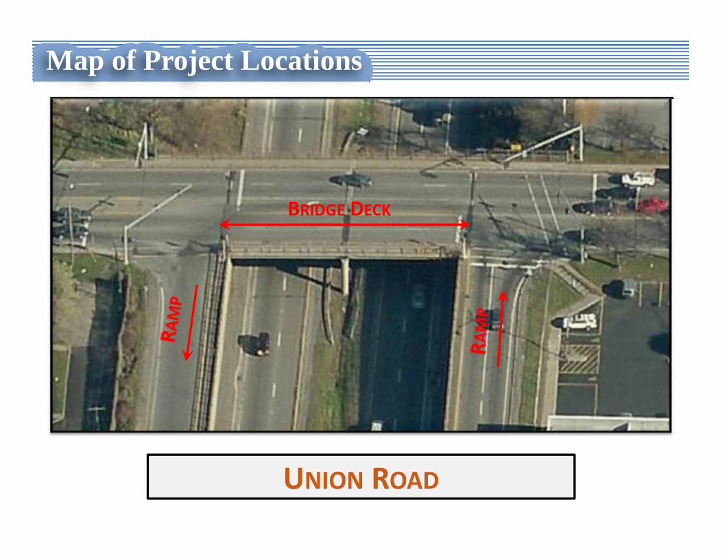
Map of Project Locations
UNION ROAD
BRIDGE DECK
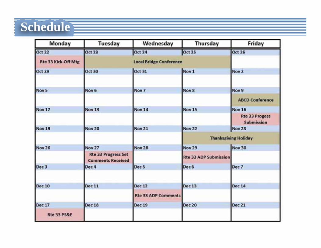
Schedule
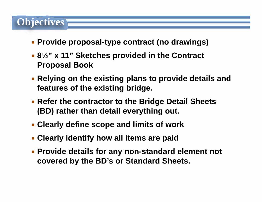
Provide proposal-type contract (no drawings)8½” x 11” Sketches provided in the Contract Proposal BookRelying on the existing plans to provide details and features of the existing bridge.Refer the contractor to the Bridge Detail Sheets (BD) rather than detail everything out.Clearly define scope and limits of workClearly identify how all items are paidProvide details for any non-standard element not covered by the BD’s or Standard Sheets.
Objectives
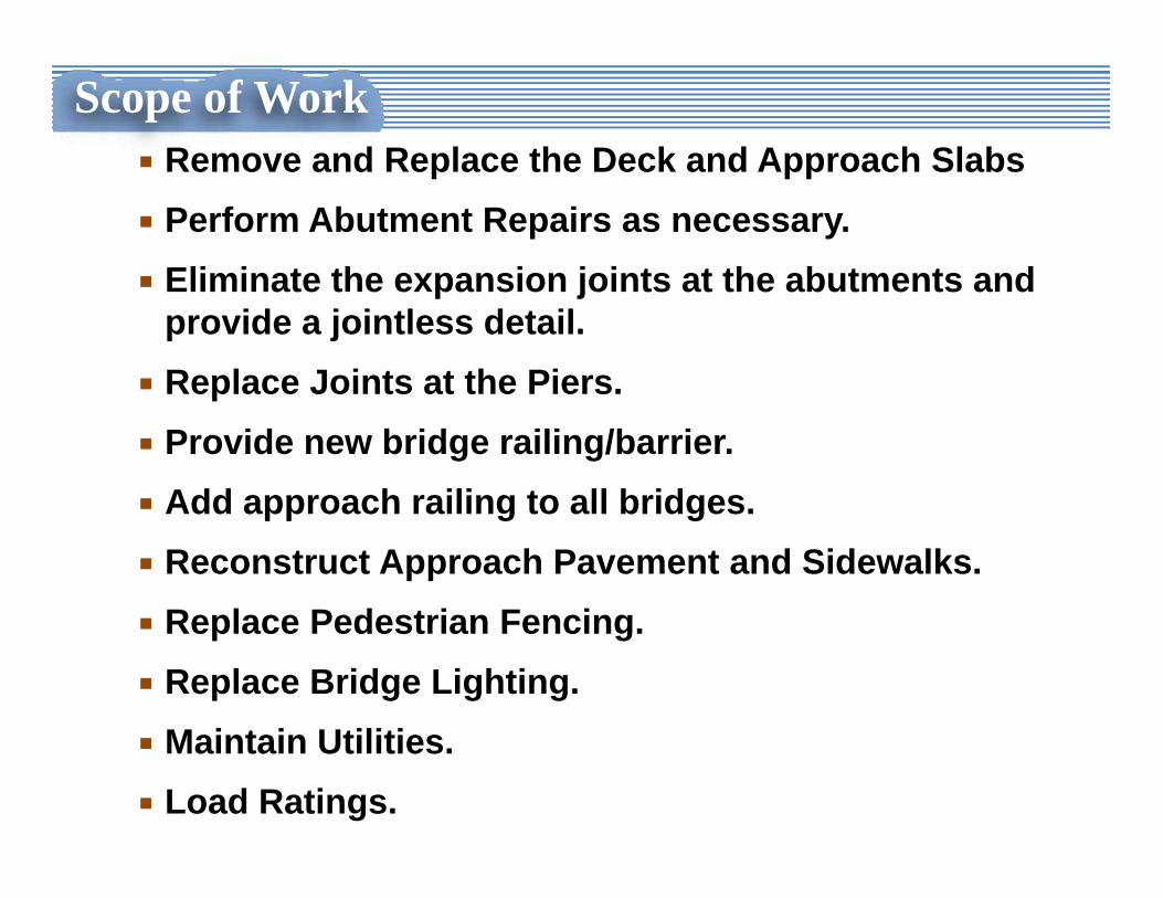
Scope of WorkRemove and Replace the Deck and Approach SlabsPerform Abutment Repairs as necessary. Eliminate the expansion joints at the abutments and provide a jointless detail.Replace Joints at the Piers.Provide new bridge railing/barrier.Add approach railing to all bridges.Reconstruct Approach Pavement and Sidewalks.Replace Pedestrian Fencing.Replace Bridge Lighting.Maintain Utilities.Load Ratings.
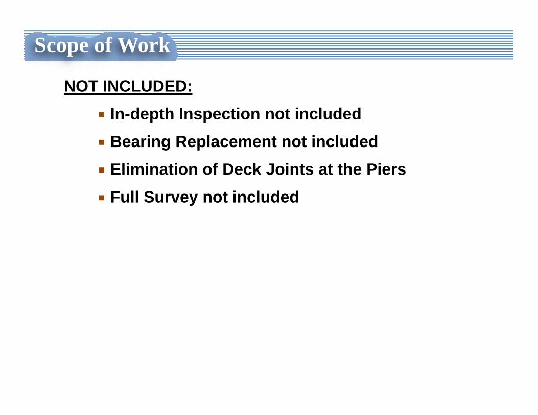
Scope of Work
NOT INCLUDED:In-depth Inspection not includedBearing Replacement not includedElimination of Deck Joints at the PiersFull Survey not included
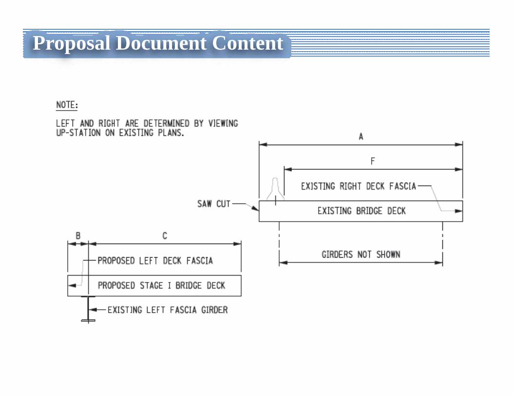
Proposal Document ContentTitle SheetScope of WorkLocation MapBridge Deck Replacement Information
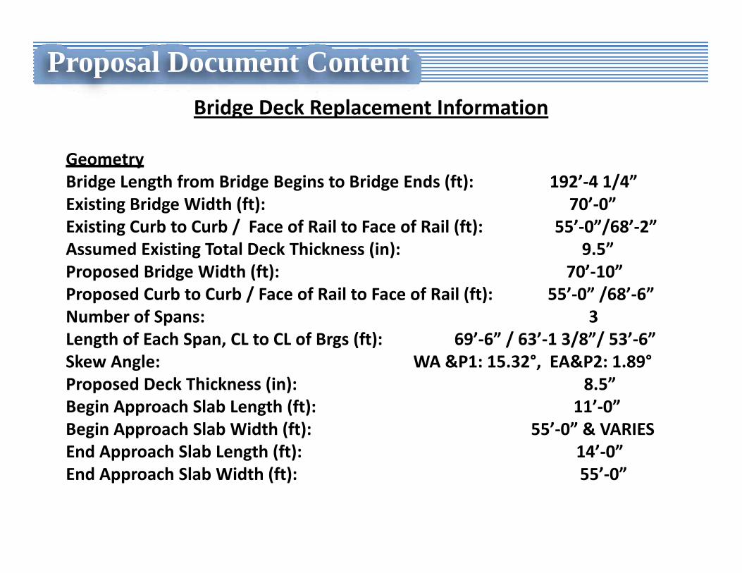
Proposal Document ContentBridge Deck Replacement Information
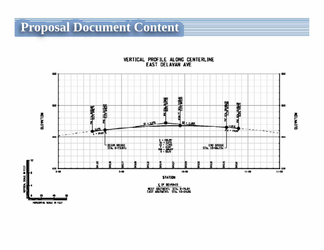
GeometryBridge Length from Bridge Begins to Bridge Ends (ft): 192’‐4 1/4”Existing Bridge Width (ft): 70’‐0”Existing Curb to Curb / Face of Rail to Face of Rail (ft): 55’‐0”/68’‐2”Assumed Existing Total Deck Thickness (in): 9.5”Proposed Bridge Width (ft): 70’‐10”Proposed Curb to Curb / Face of Rail to Face of Rail (ft): 55’‐0” /68’‐6”Number of Spans: 3Length of Each Span, CL to CL of Brgs (ft): 69’‐6” / 63’‐1 3/8”/ 53’‐6”Skew Angle: WA &P1: 15.32°, EA&P2: 1.89°Proposed Deck Thickness (in): 8.5”Begin Approach Slab Length (ft): 11’‐0”Begin Approach Slab Width (ft): 55’‐0” & VARIESEnd Approach Slab Length (ft): 14’‐0”End Approach Slab Width (ft): 55’‐0”
Proposal Document Content
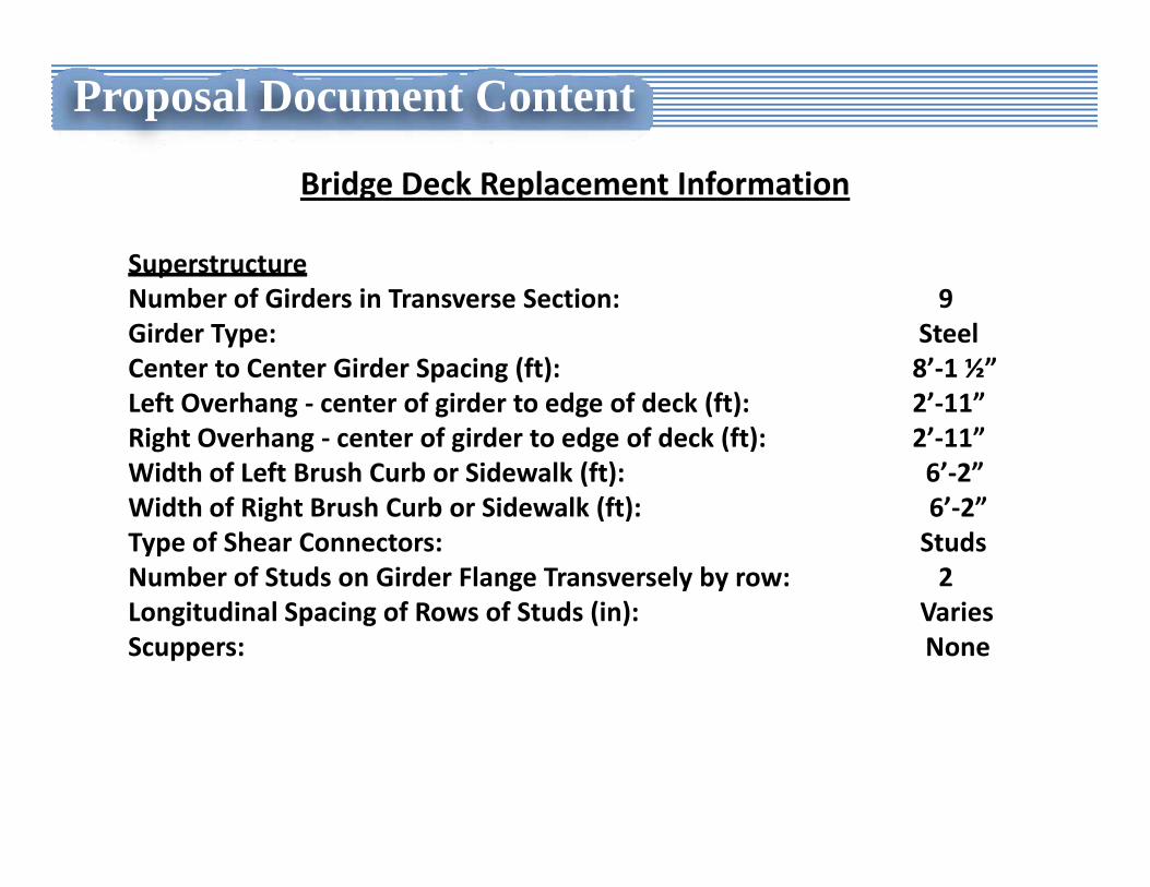
Bridge Deck Replacement Information
SuperstructureNumber of Girders in Transverse Section: 9Girder Type: SteelCenter to Center Girder Spacing (ft): 8’‐1 ½”Left Overhang ‐ center of girder to edge of deck (ft): 2’‐11”Right Overhang ‐ center of girder to edge of deck (ft): 2’‐11”Width of Left Brush Curb or Sidewalk (ft): 6’‐2”Width of Right Brush Curb or Sidewalk (ft): 6’‐2”Type of Shear Connectors: Studs Number of Studs on Girder Flange Transversely by row: 2Longitudinal Spacing of Rows of Studs (in): VariesScuppers: None
Proposal Document Content
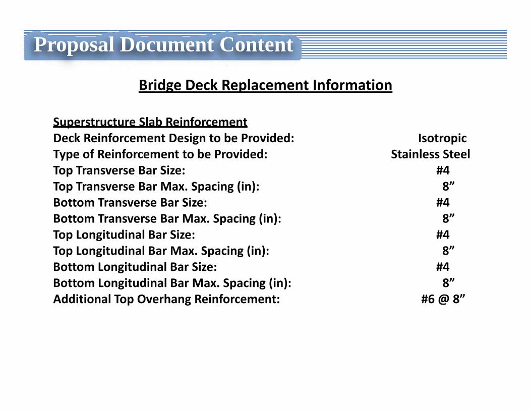
Bridge Deck Replacement Information
Superstructure Slab ReinforcementDeck Reinforcement Design to be Provided: IsotropicType of Reinforcement to be Provided: Stainless SteelTop Transverse Bar Size: #4Top Transverse Bar Max. Spacing (in): 8”Bottom Transverse Bar Size: #4Bottom Transverse Bar Max. Spacing (in): 8”Top Longitudinal Bar Size: #4Top Longitudinal Bar Max. Spacing (in): 8”Bottom Longitudinal Bar Size: #4Bottom Longitudinal Bar Max. Spacing (in): 8”Additional Top Overhang Reinforcement: #6 @ 8”
Proposal Document Content
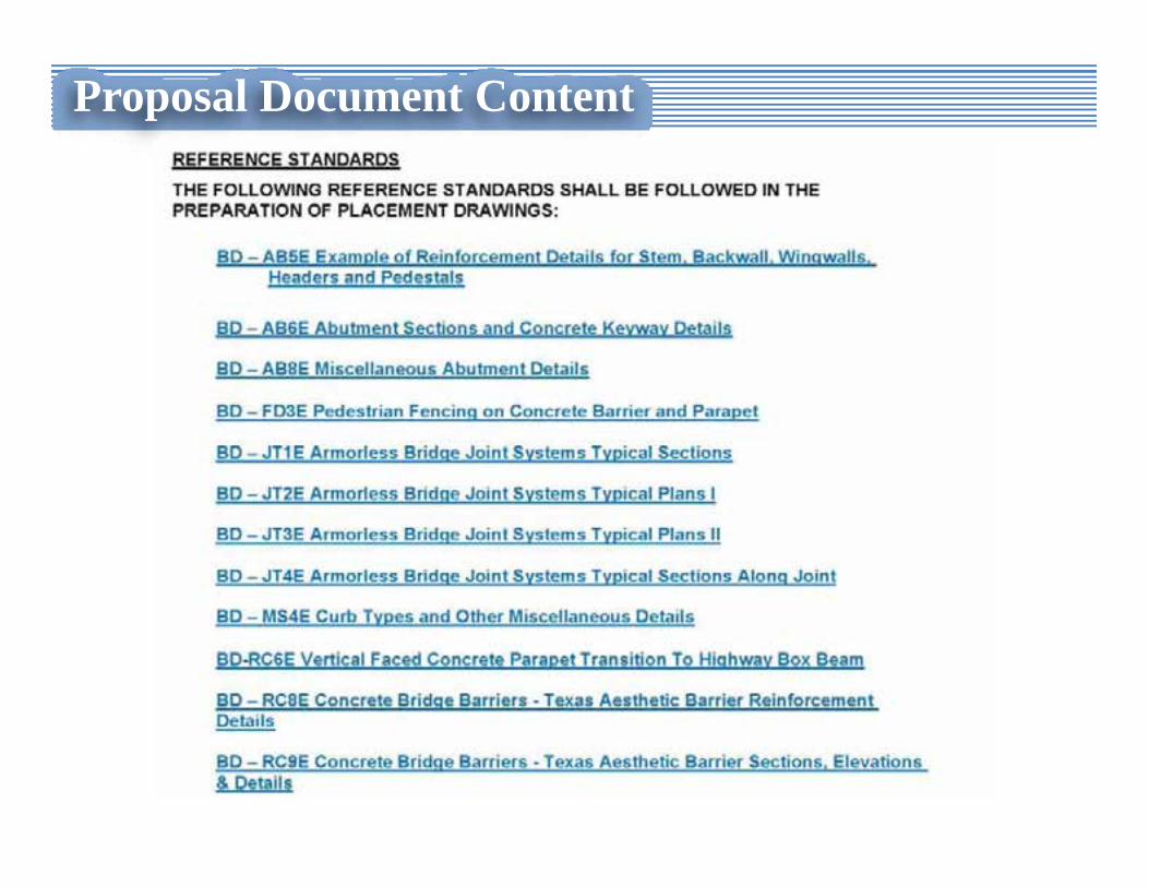
Proposal Document ContentTitle SheetScope of WorkLocation MapBridge Deck Replacement InformationGeneral Notes – Includes Standard Notes, BD References, Pay Item Limit Notes
Proposal Document Content
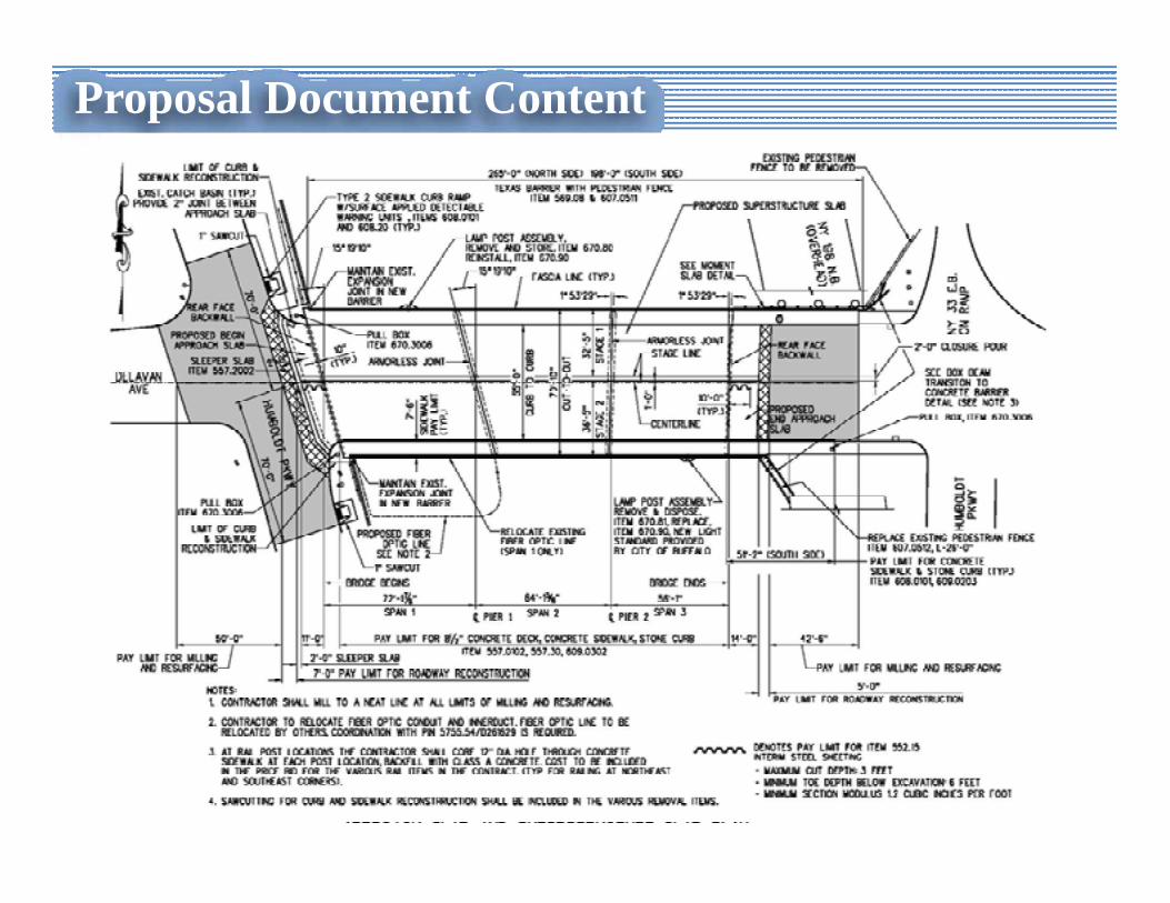
Proposal Document ContentTitle SheetScope of WorkLocation MapBridge Deck Replacement InformationGeneral Notes – Includes Standard Notes, BD References, Pay Item Limit NotesGeneral Plan
Proposal Document Content
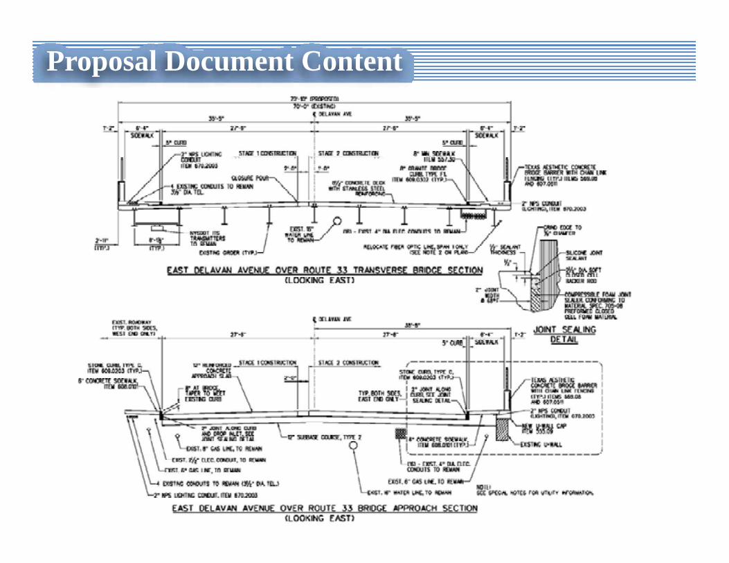
Proposal Document ContentTitle SheetScope of WorkLocation MapBridge Deck Replacement InformationGeneral Notes – Includes Standard Notes, BD References, Pay Item Limit NotesGeneral PlanBridge & Approach Cross-Section
Proposal Document Content
Proposal Document ContentTitle SheetScope of WorkLocation MapBridge Deck Replacement InformationGeneral Notes – Includes Standard Notes, BD References, Pay Item Limit NotesGeneral PlanBridge & Approach Cross-SectionProfile
Proposal Document Content
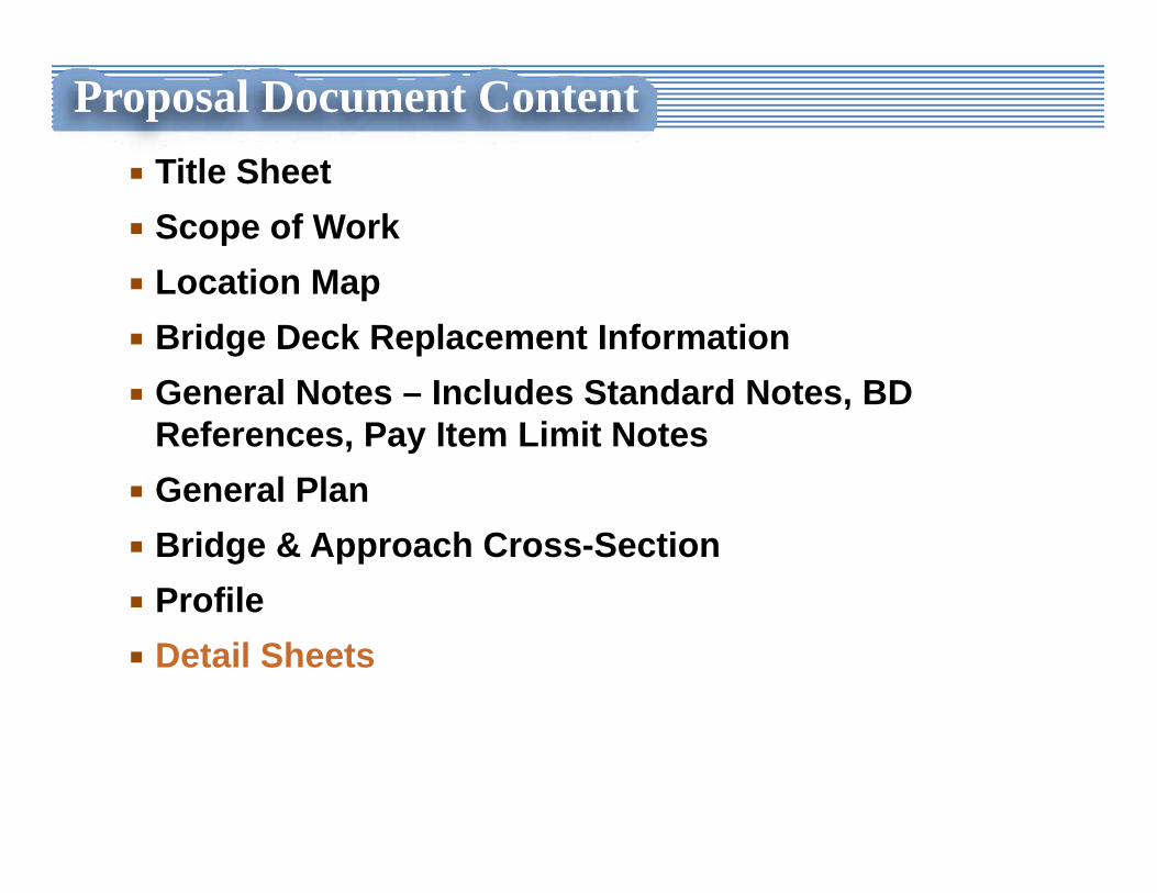
Proposal Document ContentTitle SheetScope of WorkLocation MapBridge Deck Replacement InformationGeneral Notes – Includes Standard Notes, BD References, Pay Item Limit NotesGeneral PlanBridge & Approach Cross-SectionProfileDetail Sheets
Proposal Document Content
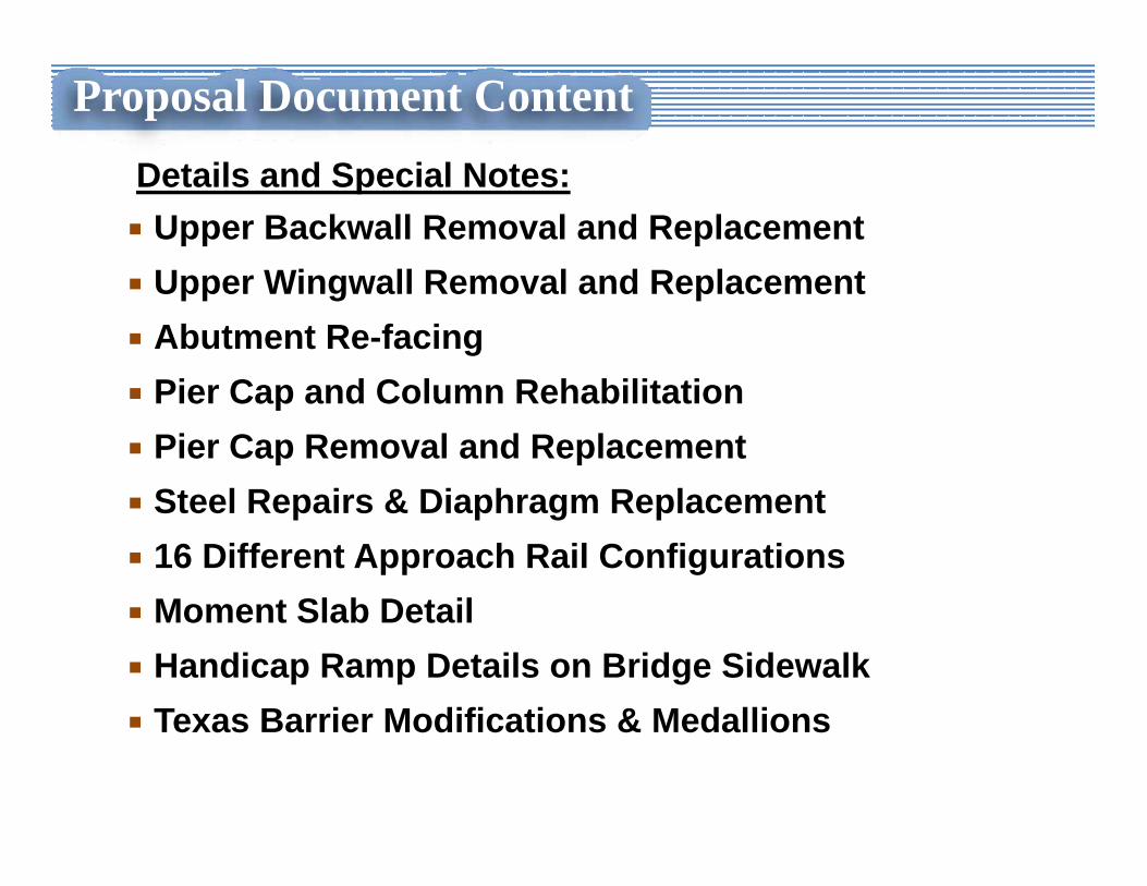
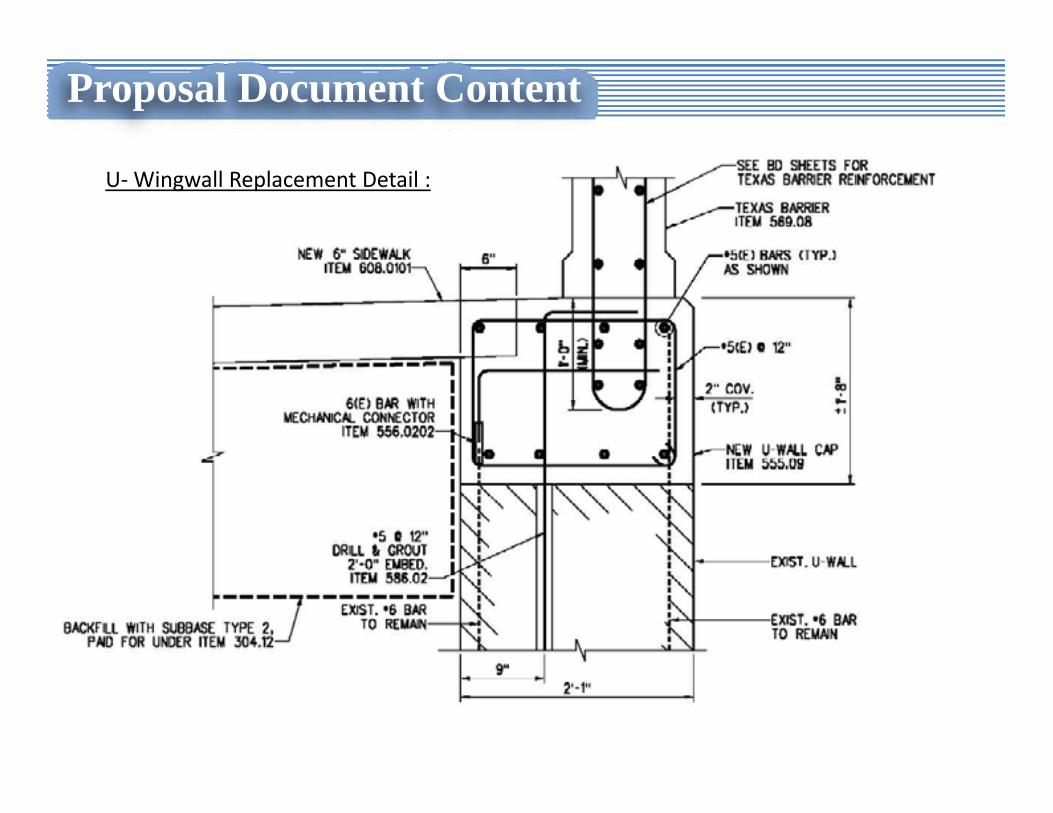
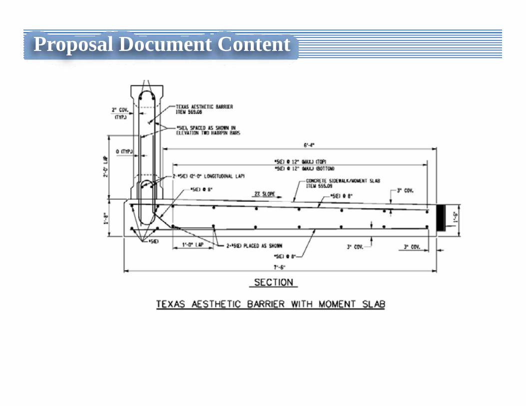
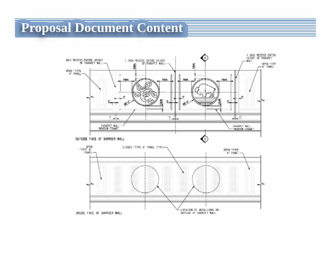
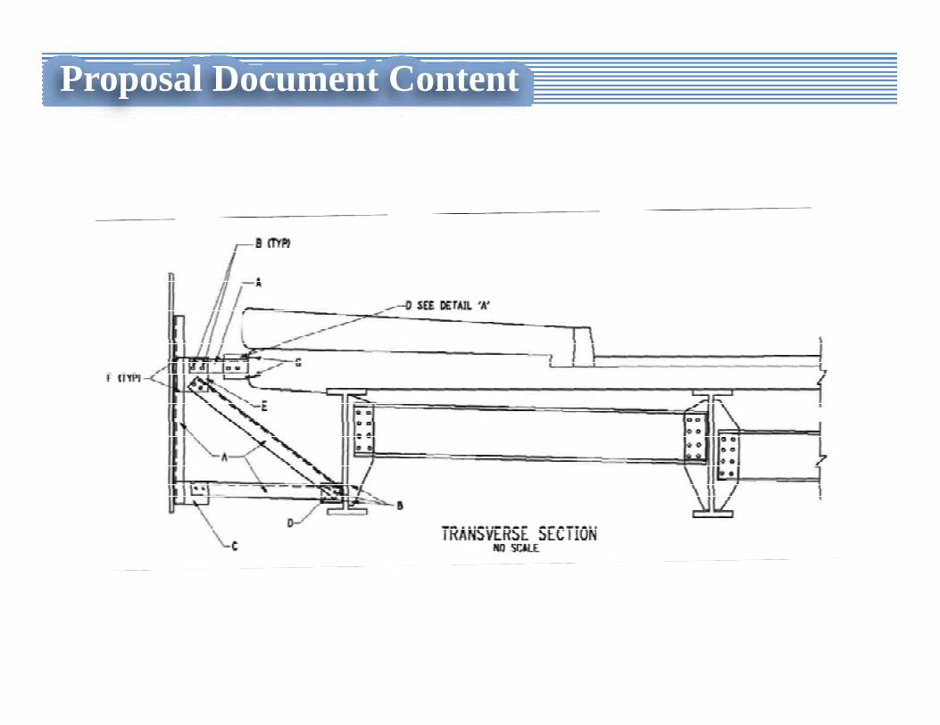
Upper Backwall Removal and ReplacementUpper Wingwall Removal and ReplacementAbutment Re-facingPier Cap and Column RehabilitationPier Cap Removal and ReplacementSteel Repairs & Diaphragm Replacement16 Different Approach Rail ConfigurationsMoment Slab DetailHandicap Ramp Details on Bridge SidewalkTexas Barrier Modifications & Medallions
Details and Special Notes:
Proposal Document Content
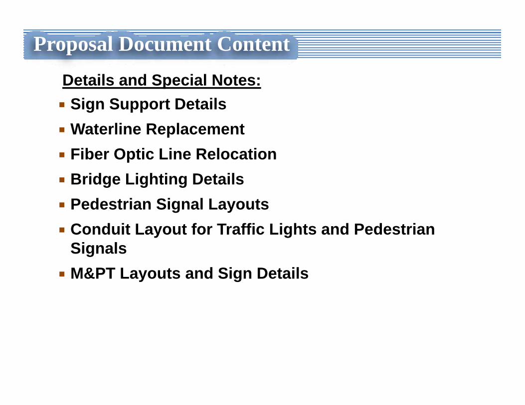
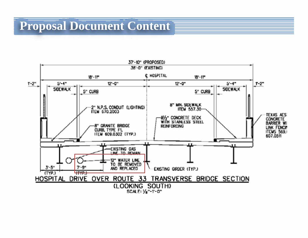
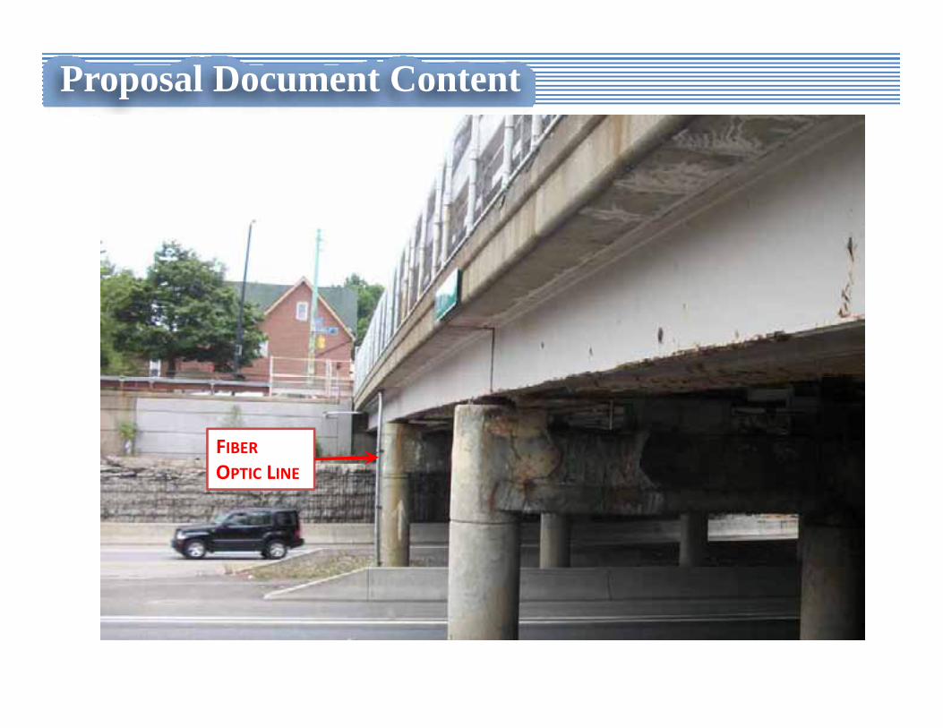
Sign Support DetailsWaterline Replacement Fiber Optic Line RelocationBridge Lighting DetailsPedestrian Signal LayoutsConduit Layout for Traffic Lights and Pedestrian SignalsM&PT Layouts and Sign Details
Details and Special Notes:
Proposal Document Content
U‐Wingwall Replacement Detail :
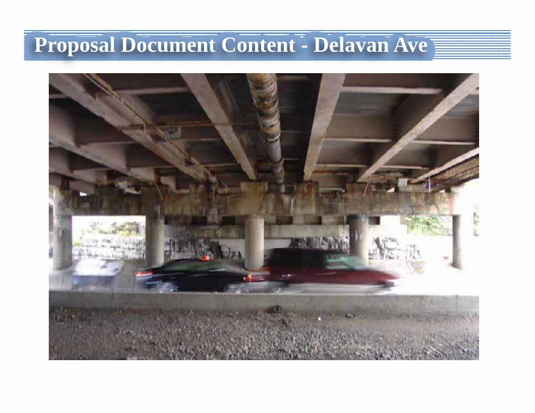
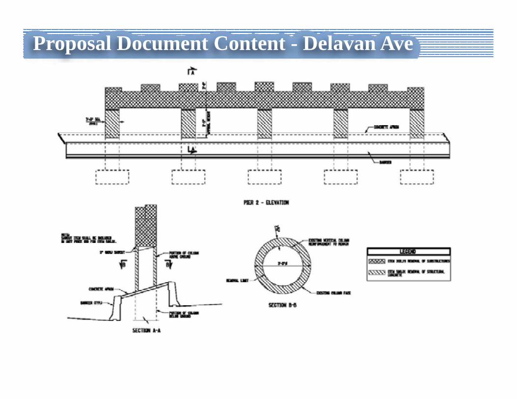
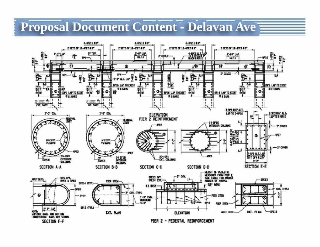
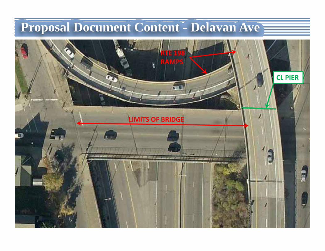
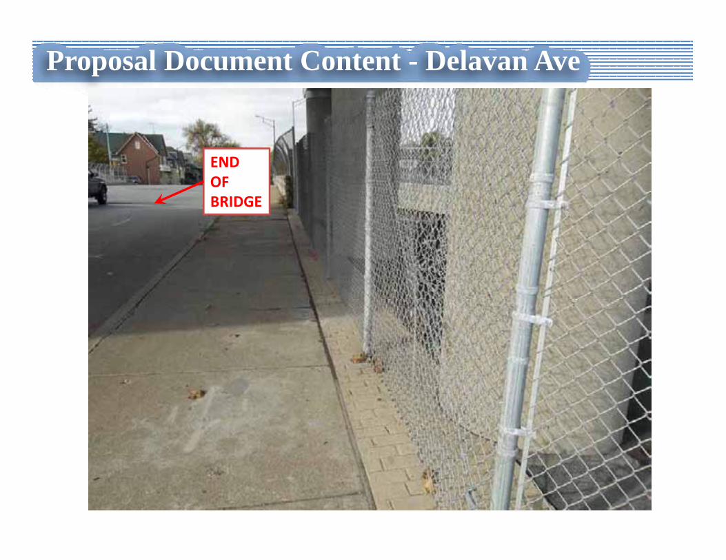
Proposal Document Content - Delavan Ave
Proposal Document Content - Delavan Ave
Proposal Document Content - Delavan Ave
Proposal Document Content - Delavan Ave
LIMITS OF BRIDGE
RTE 198 RAMPS
CL PIER
Proposal Document Content - Delavan Ave
END OF BRIDGE
Proposal Document Content
Proposal Document Content
Proposal Document Content
Proposal Document Content
Proposal Document Content
FIBEROPTIC LINE
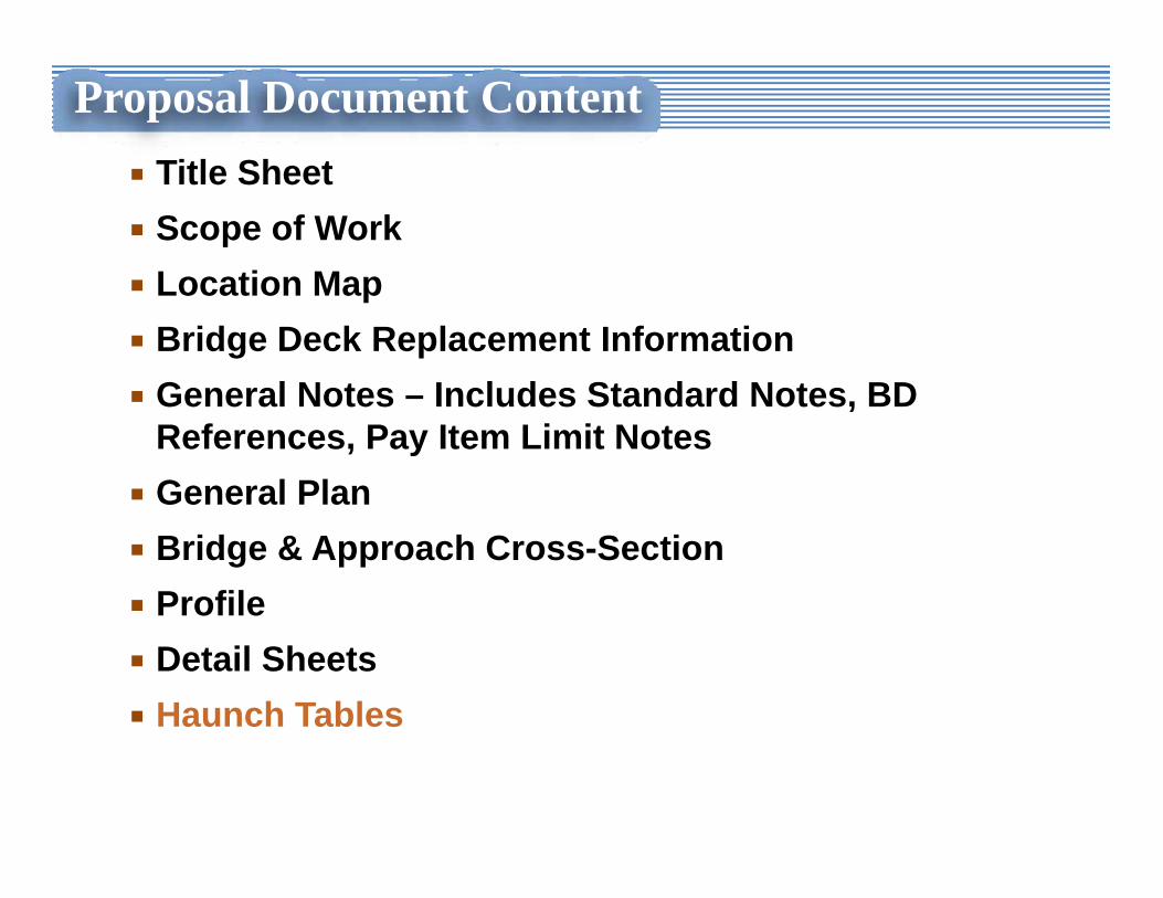
Proposal Document ContentTitle SheetScope of WorkLocation MapBridge Deck Replacement InformationGeneral Notes – Includes Standard Notes, BD References, Pay Item Limit NotesGeneral PlanBridge & Approach Cross-SectionProfileDetail SheetsHaunch Tables
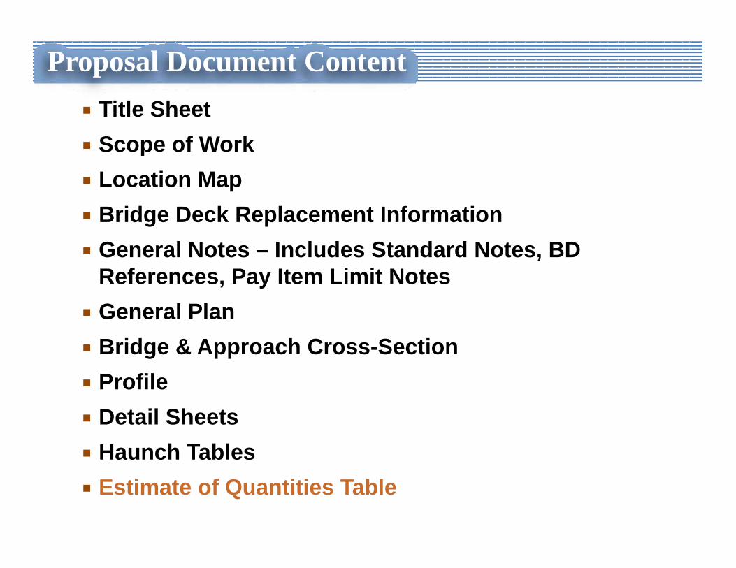
Proposal Document ContentTitle SheetScope of WorkLocation MapBridge Deck Replacement InformationGeneral Notes – Includes Standard Notes, BD References, Pay Item Limit NotesGeneral PlanBridge & Approach Cross-SectionProfileDetail SheetsHaunch TablesEstimate of Quantities Table
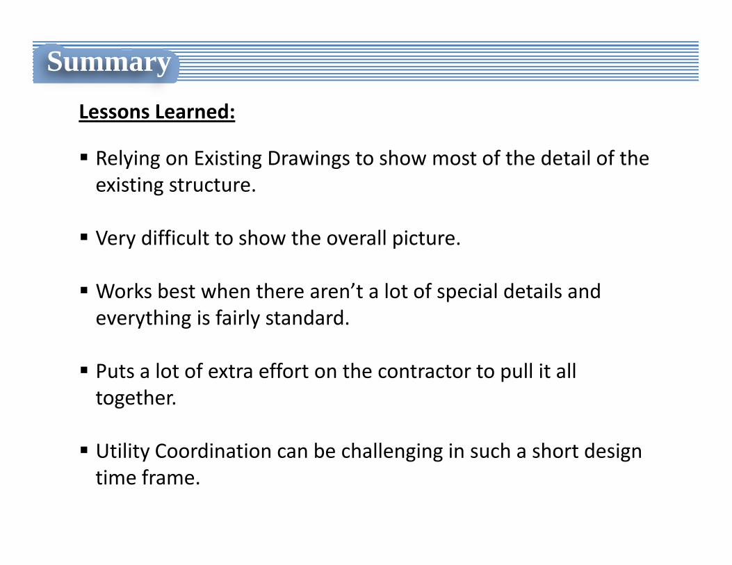
SummaryLessons Learned:
Relying on Existing Drawings to show most of the detail of the existing structure.
Very difficult to show the overall picture.
Works best when there aren’t a lot of special details and everything is fairly standard.
Puts a lot of extra effort on the contractor to pull it all together.
Utility Coordination can be challenging in such a short design time frame.
Construction Phase
Construction Phase
• Building a Bridge Job without Plan Drawings
• Contractor’s Perspective
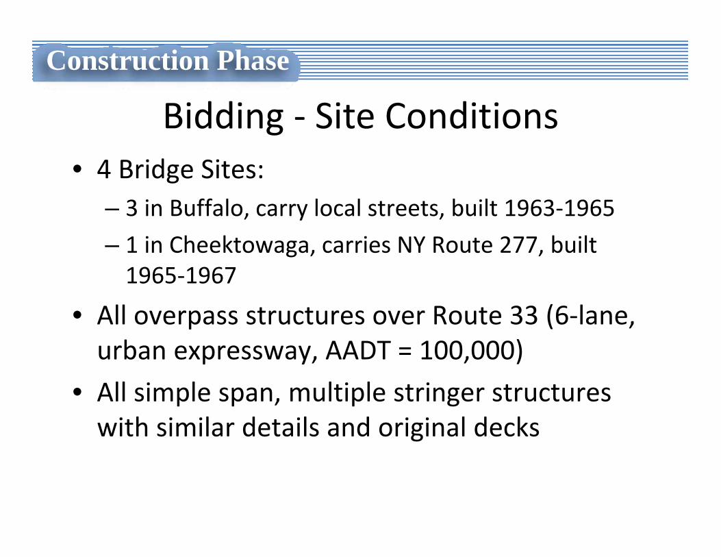
Bidding ‐ Site Conditions• 4 Bridge Sites:
– 3 in Buffalo, carry local streets, built 1963‐1965
– 1 in Cheektowaga, carries NY Route 277, built 1965‐1967
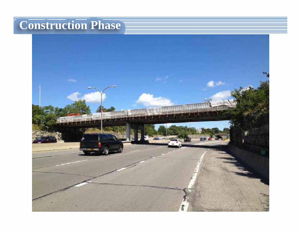
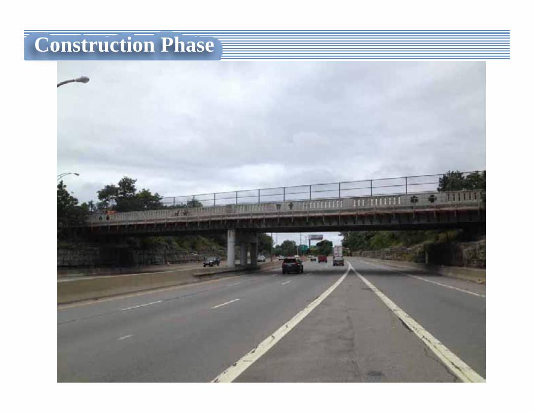
• All overpass structures over Route 33 (6‐lane, urban expressway, AADT = 100,000)
• All simple span, multiple stringer structures with similar details and original decks
Construction Phase
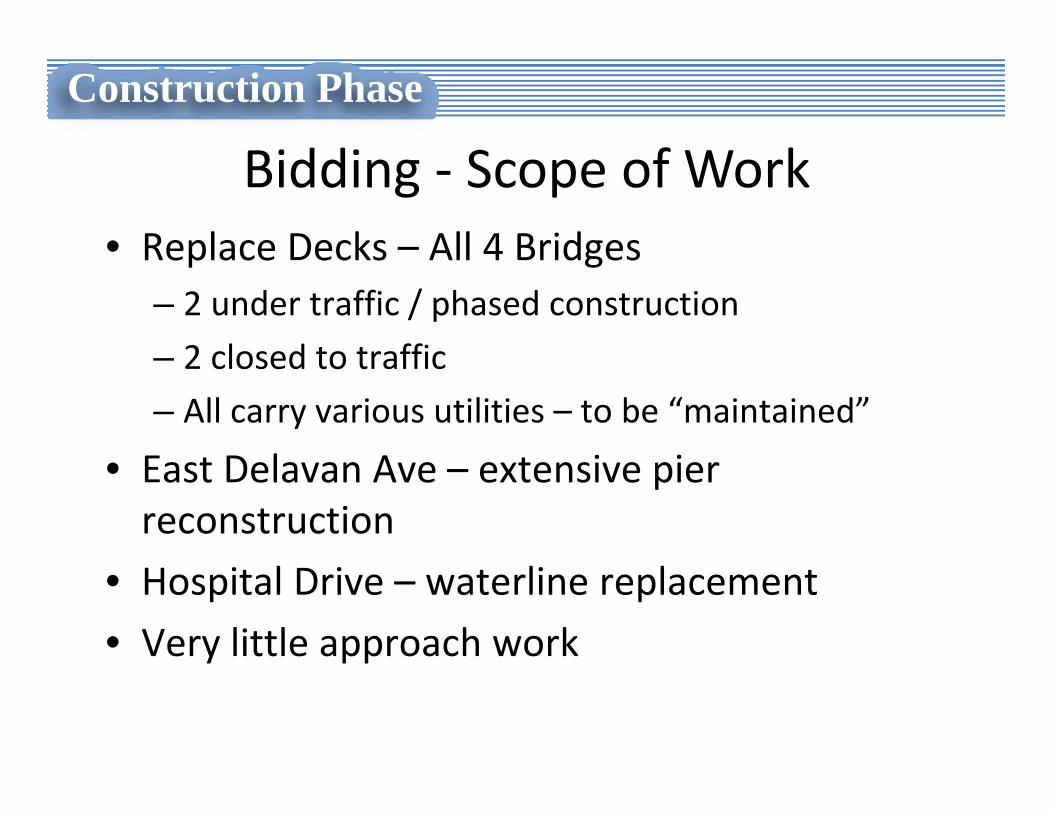
Bidding ‐ Scope of Work• Replace Decks – All 4 Bridges
– 2 under traffic / phased construction
– 2 closed to traffic
– All carry various utilities – to be “maintained”
• East Delavan Ave – extensive pier reconstruction
• Hospital Drive – waterline replacement
• Very little approach work
Construction Phase
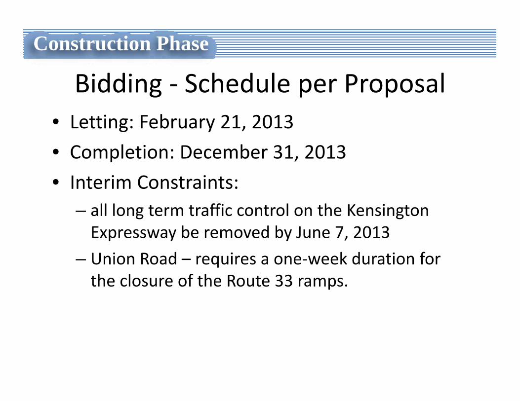
Bidding ‐ Schedule per Proposal• Letting: February 21, 2013
• Completion: December 31, 2013
• Interim Constraints:– all long term traffic control on the Kensington Expressway be removed by June 7, 2013
– Union Road – requires a one‐week duration for the closure of the Route 33 ramps.
Construction Phase
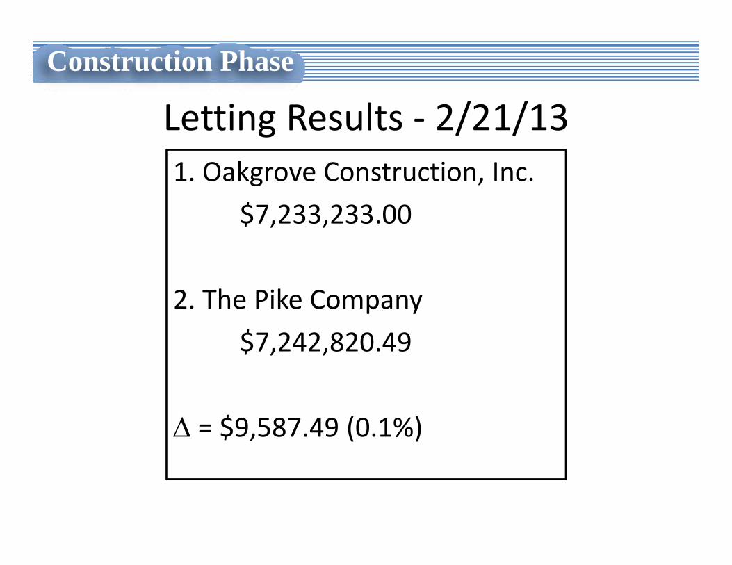
Letting Results ‐ 2/21/13 1. Oakgrove Construction, Inc.
$7,233,233.00
2. The Pike Company
$7,242,820.49
Δ = $9,587.49 (0.1%)
Construction Phase
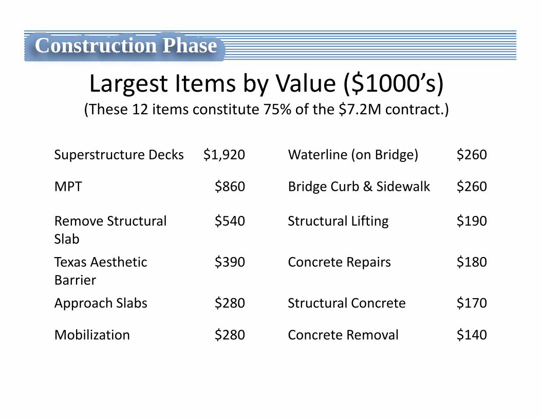
Largest Items by Value ($1000’s)(These 12 items constitute 75% of the $7.2M contract.)
Superstructure Decks $1,920 Waterline (on Bridge) $260
MPT $860 Bridge Curb & Sidewalk $260
Remove StructuralSlab
$540 Structural Lifting $190
Texas Aesthetic Barrier
$390 Concrete Repairs $180
Approach Slabs $280 Structural Concrete $170
Mobilization $280 Concrete Removal $140
Construction Phase
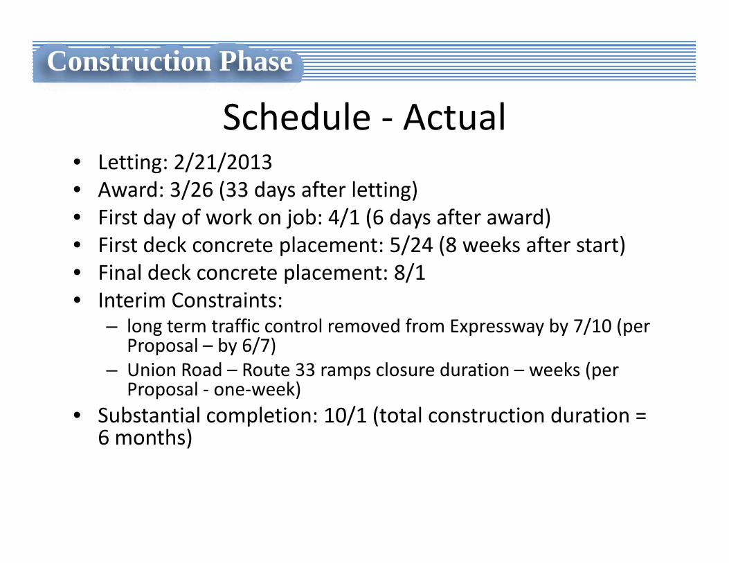
Schedule ‐ Actual• Letting: 2/21/2013• Award: 3/26 (33 days after letting)• First day of work on job: 4/1 (6 days after award)• First deck concrete placement: 5/24 (8 weeks after start)• Final deck concrete placement: 8/1• Interim Constraints:
– long term traffic control removed from Expressway by 7/10 (per Proposal – by 6/7)
– Union Road – Route 33 ramps closure duration – weeks (per Proposal ‐ one‐week)
• Substantial completion: 10/1 (total construction duration = 6 months)
Construction Phase
Contractor Submittals• All submittals made electronically via “ProjectWise”
• Most prepared by engineers familiar with NYSDOT practices
• All reviewed NYSDOT Main Office Structures
• Quick review turnaround is mandatory for successful Accelerated Bridge Construction
• “New York Works Program”
Construction Phase
Required Submittals• Rebar ‐ Placement Drawings & Bar Lists
– (45 dwgs, 35 resubmits)• Texas Aesthetic Barrier ‐ Elevations & Details
– (20 dwgs)• Structural Lifting
– Drawings & Calcs• Structural Steel Repairs, Bridge‐Mounted Sign Structures– Shop dwgs, Erection dwgs, Welding Procedure Specs
• Various Others
Construction Phase
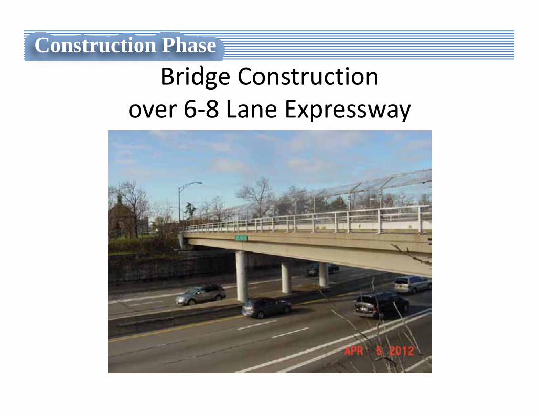
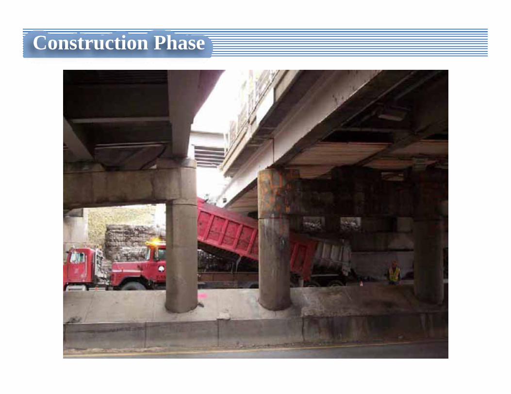
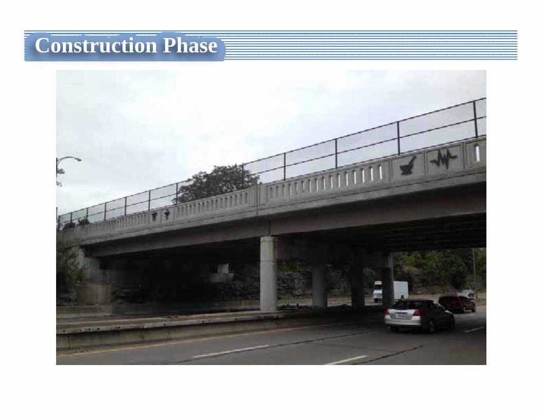
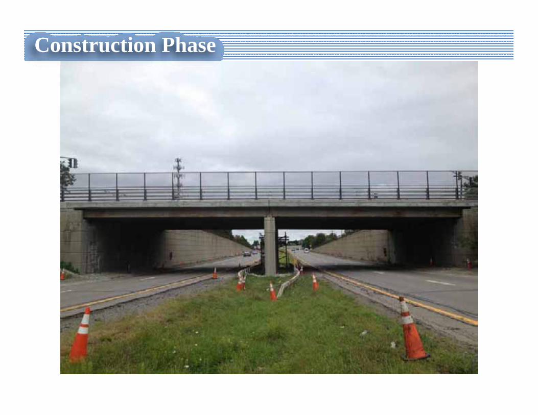
Bridge Construction over 6‐8 Lane Expressway
Construction Phase
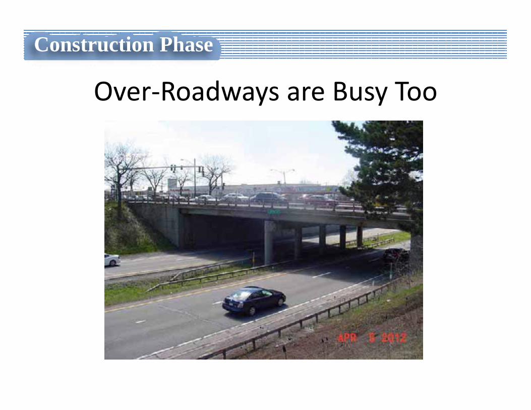
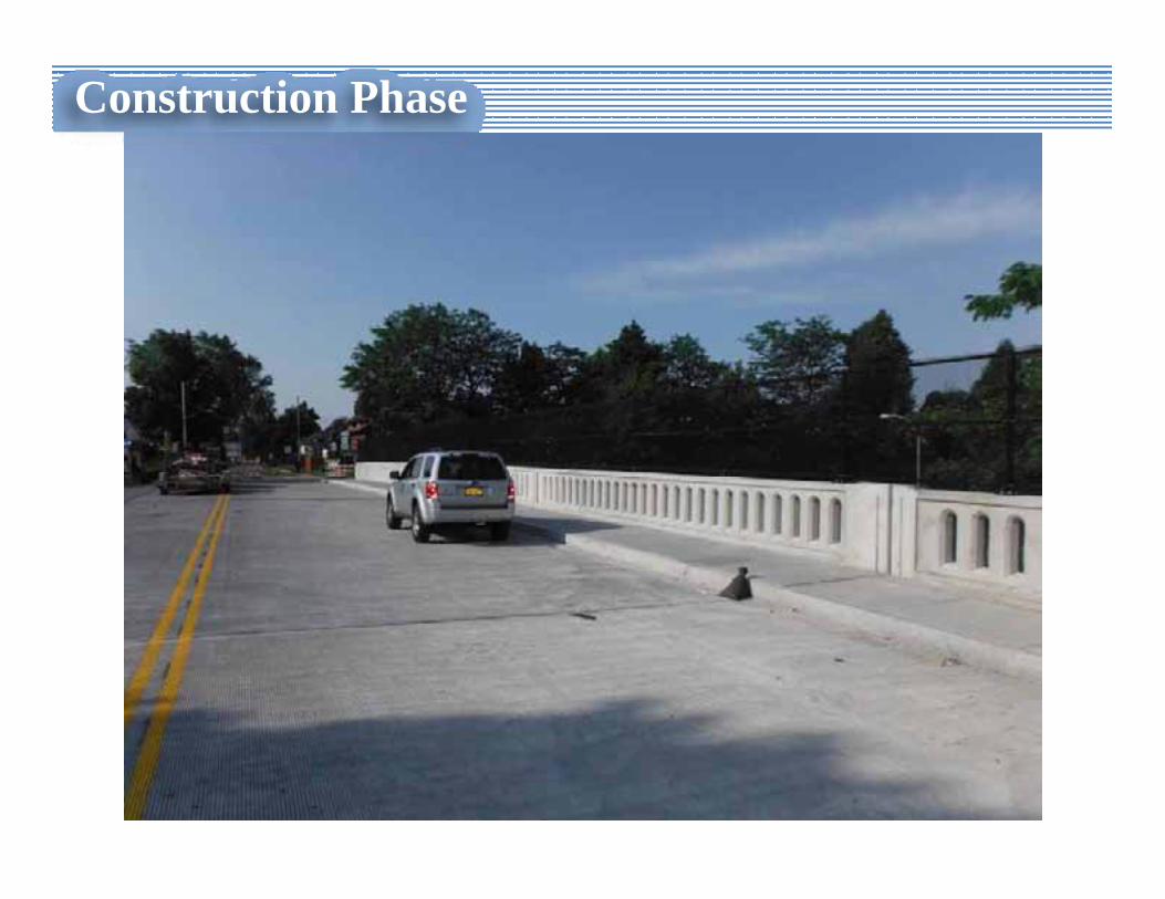
Over‐Roadways are Busy Too
Construction Phase
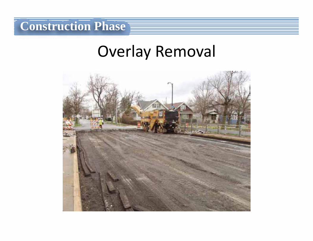
Overlay Removal
Construction Phase
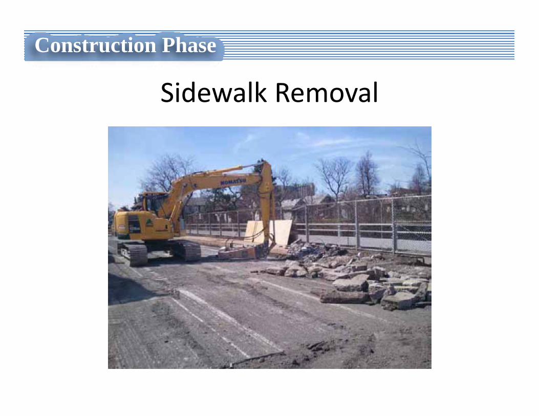
Sidewalk Removal
Construction Phase
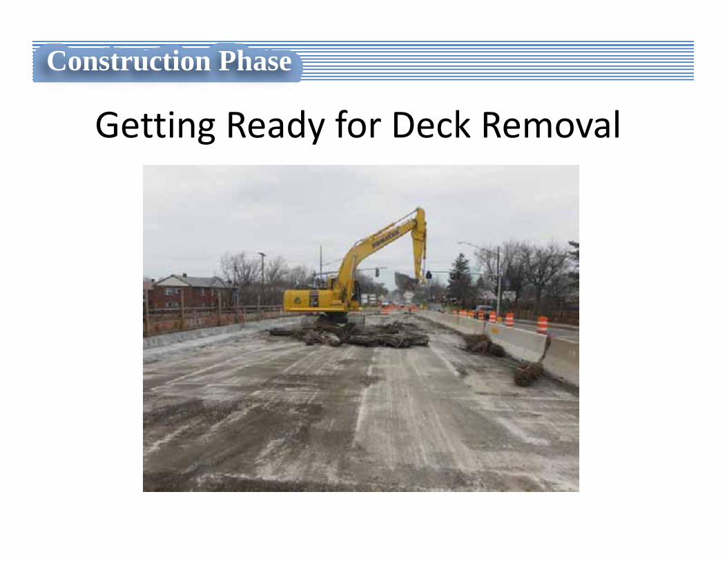
Getting Ready for Deck Removal
Construction Phase
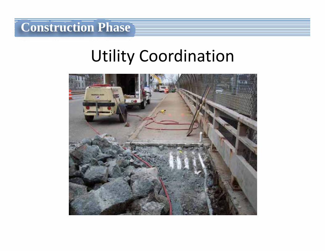
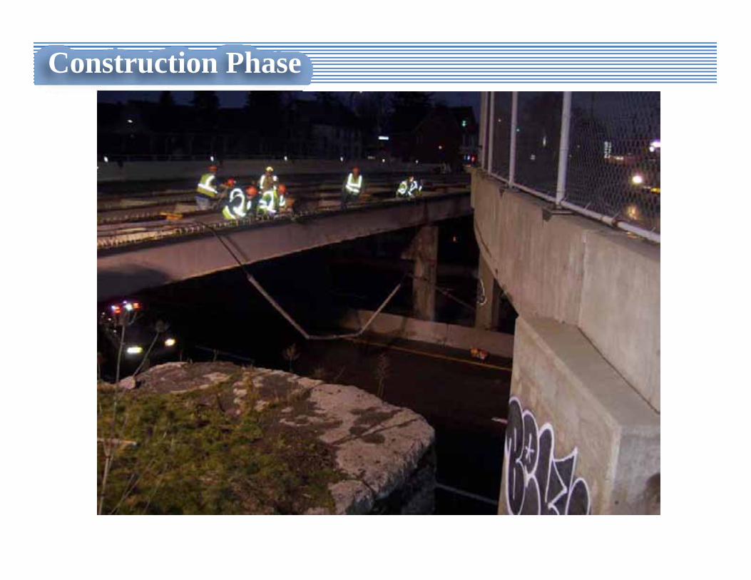
Utility Coordination
Construction Phase
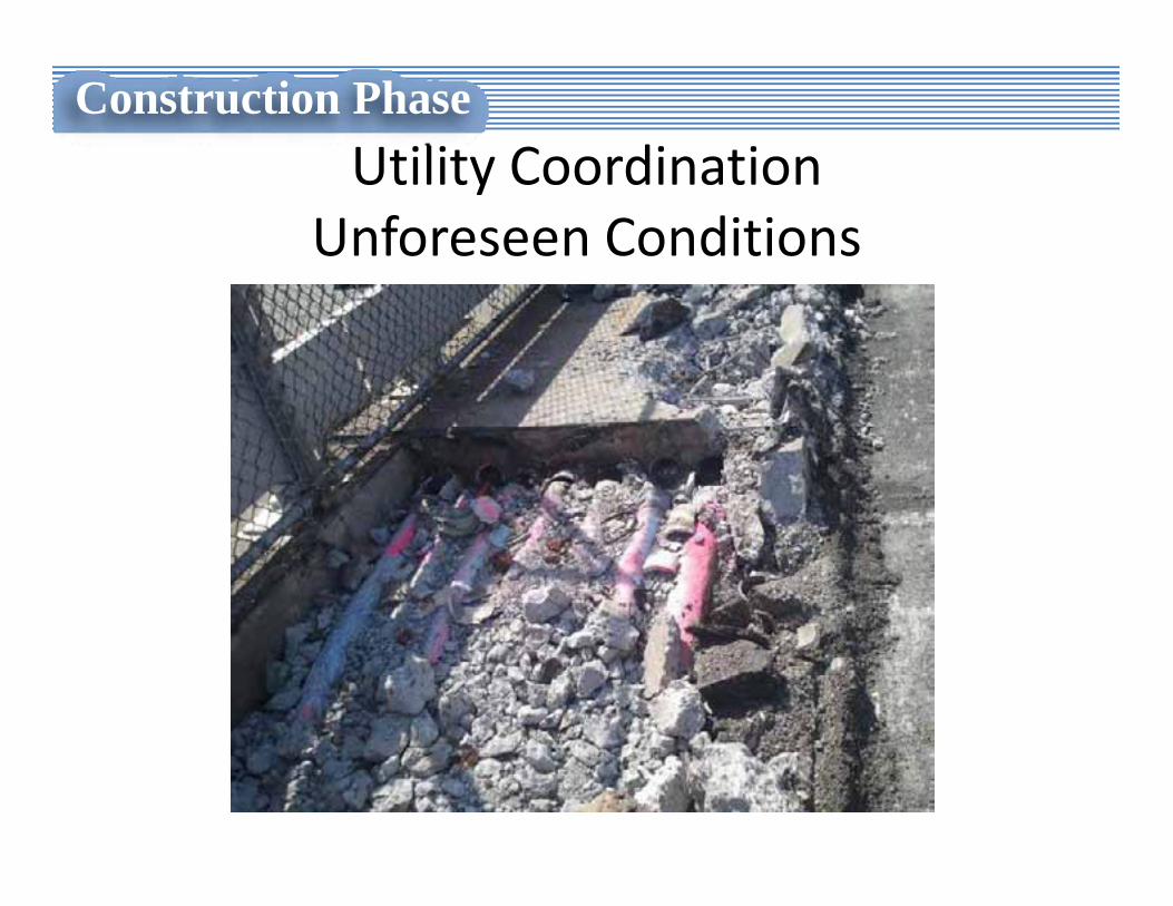
Utility Coordination Unforeseen Conditions
Construction Phase
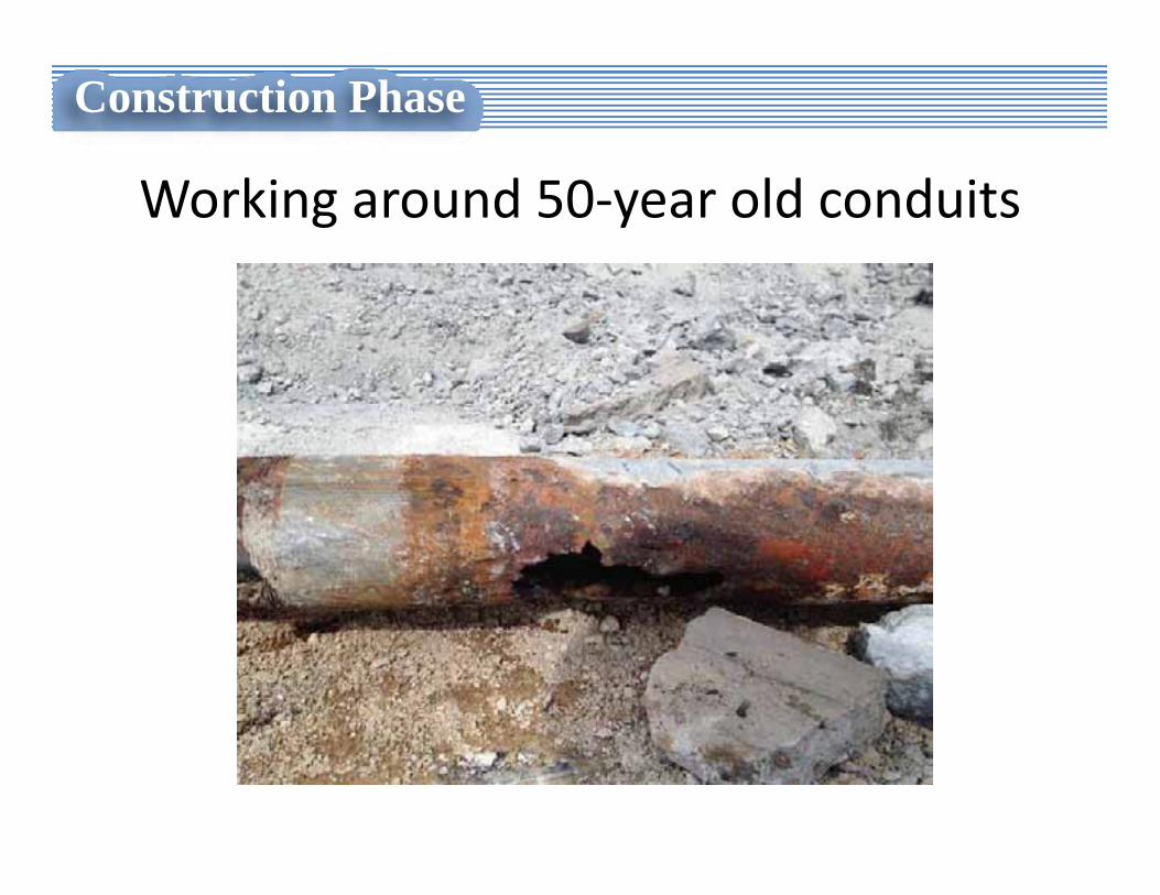
Working around 50‐year old conduits
Construction Phase
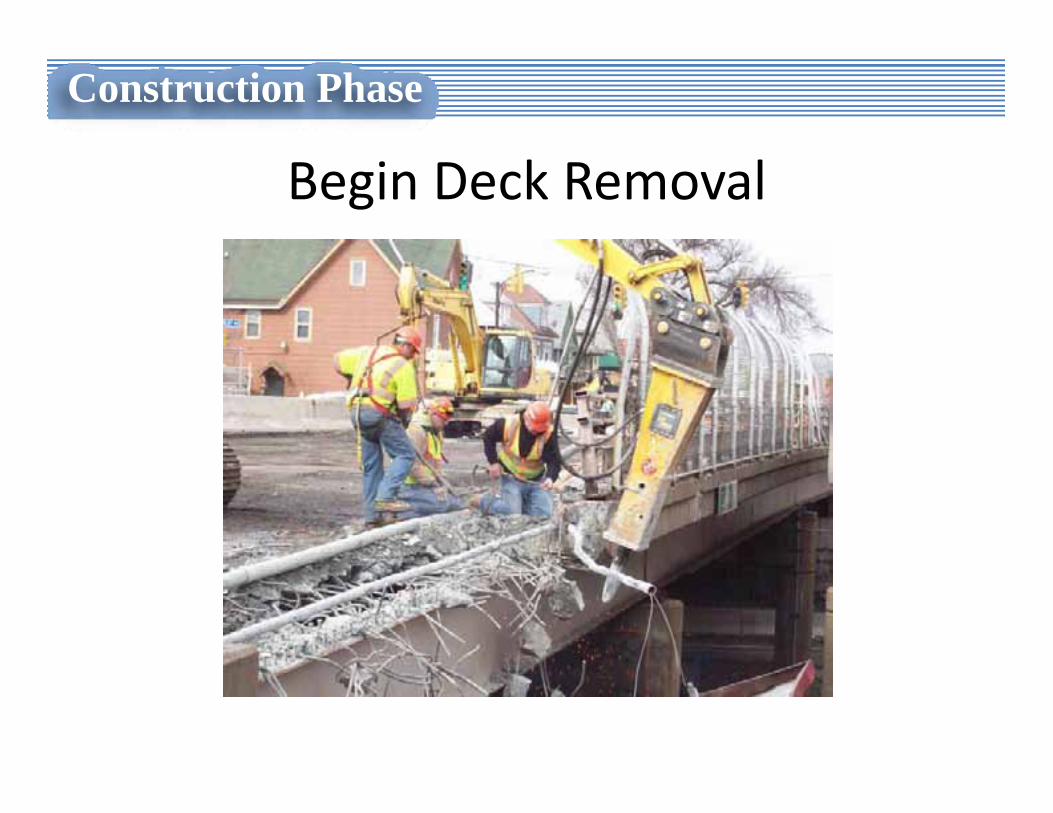
Begin Deck Removal
Construction Phase
Construction Phase

Construction Phase
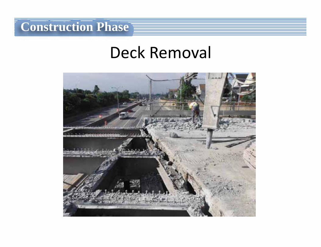
Deck Removal
Construction Phase
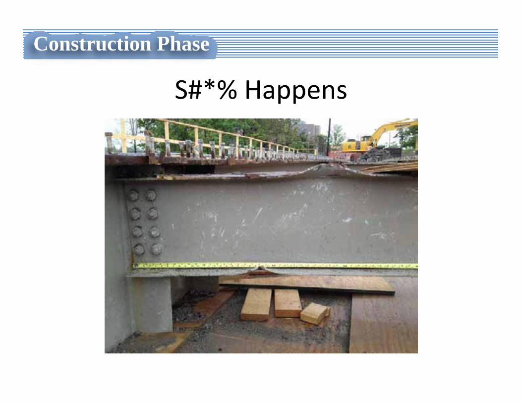
S#*% Happens
Construction Phase
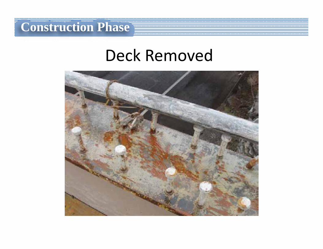
Deck Removed
Construction Phase
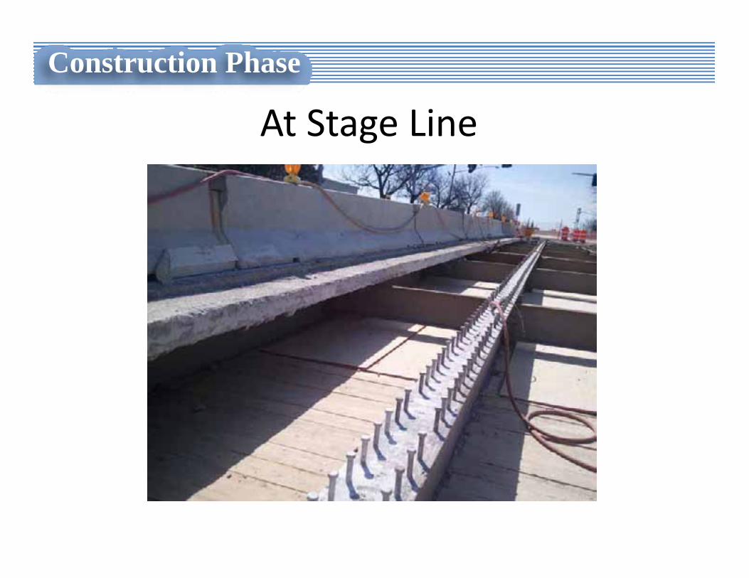
At Stage Line
Construction Phase
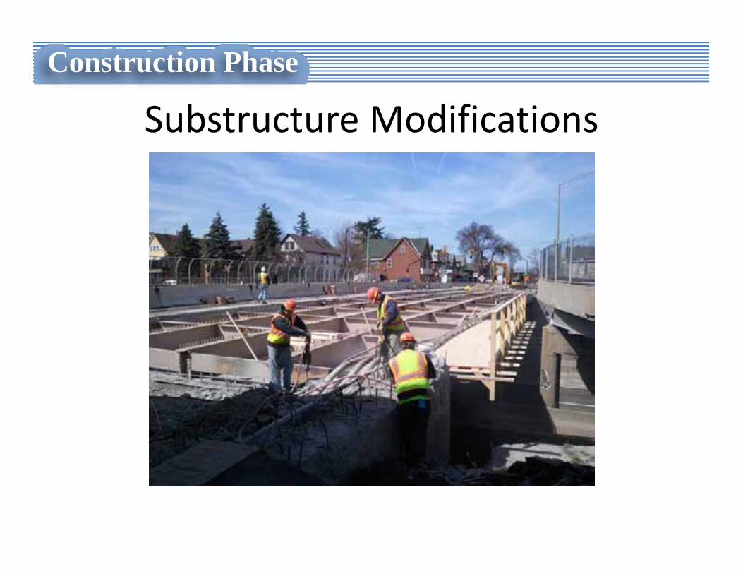
Substructure Modifications
Construction Phase
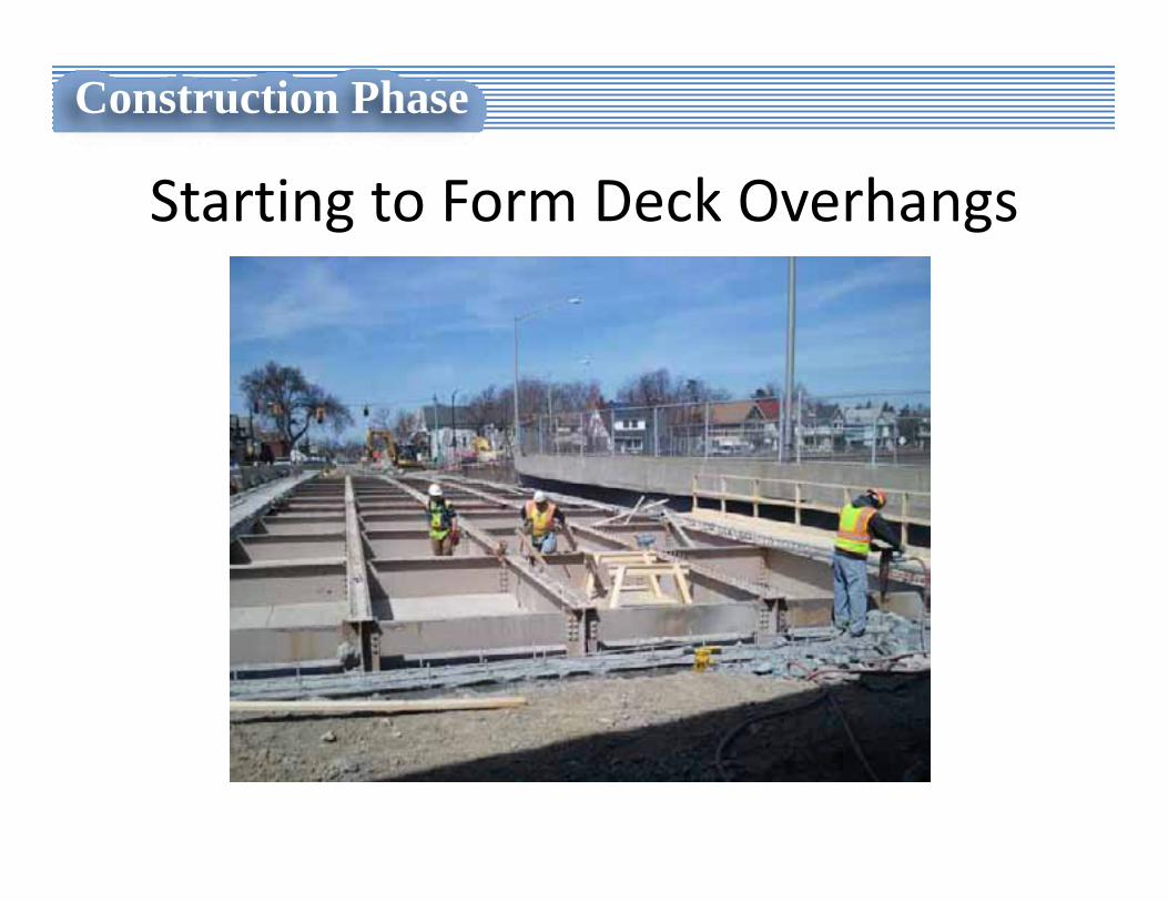
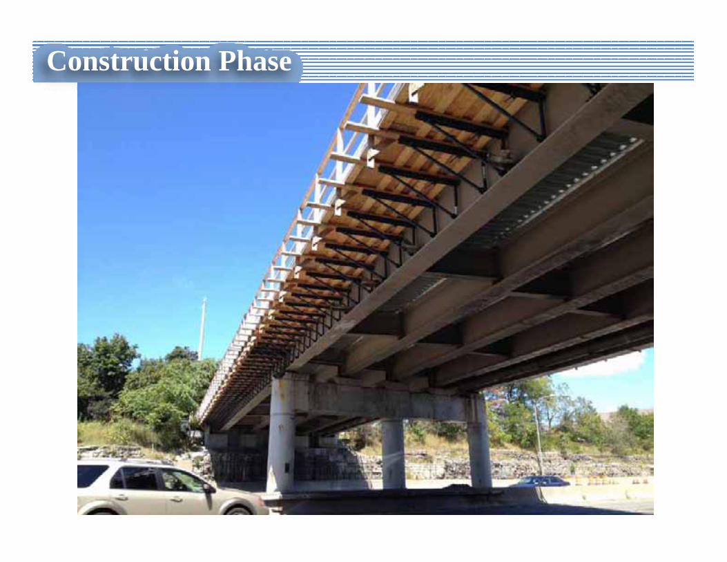
Starting to Form Deck Overhangs
Construction Phase
Construction Phase
Construction Phase
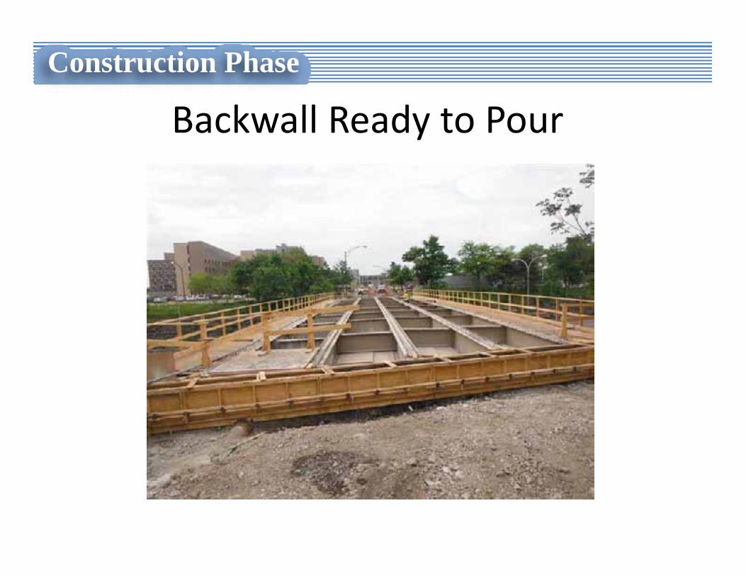
Backwall Ready to Pour
Construction Phase
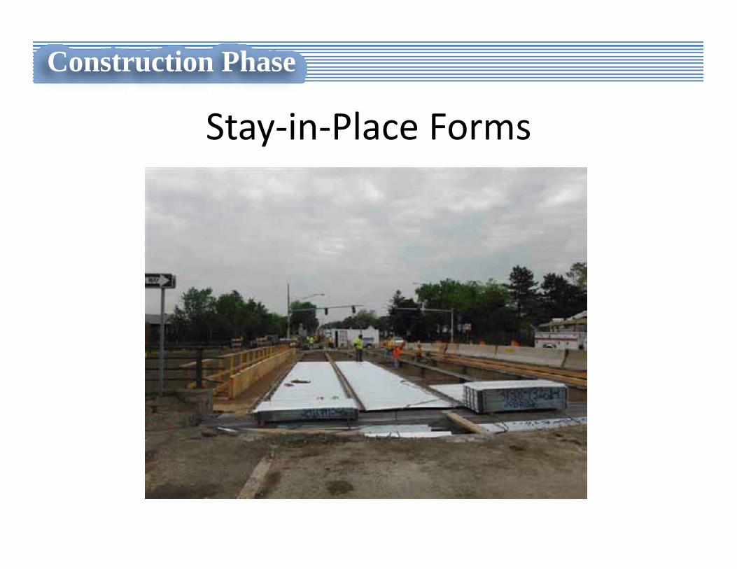
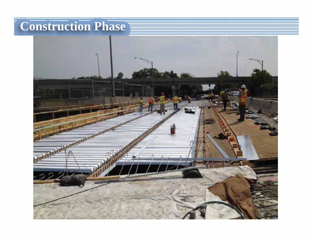
Stay‐in‐Place Forms
Construction Phase
Construction Phase

Construction Phase
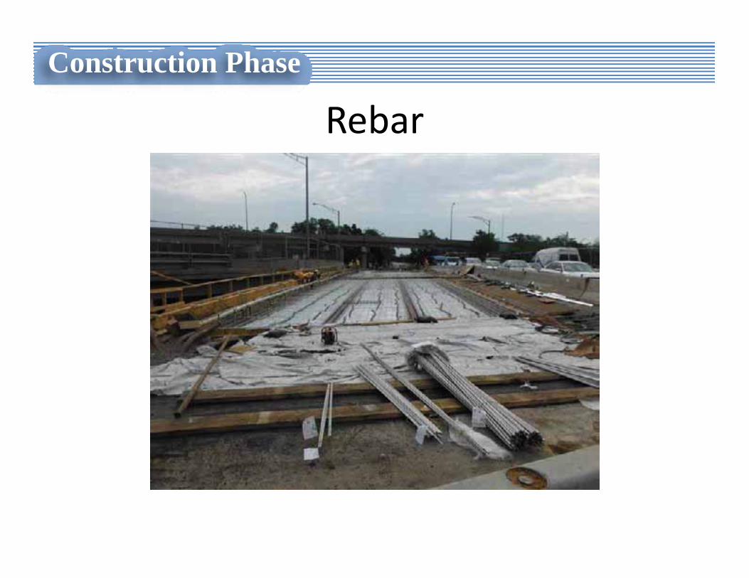
Rebar
Construction Phase
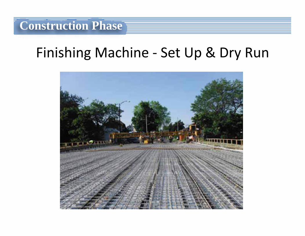
Finishing Machine ‐ Set Up & Dry Run
Construction Phase
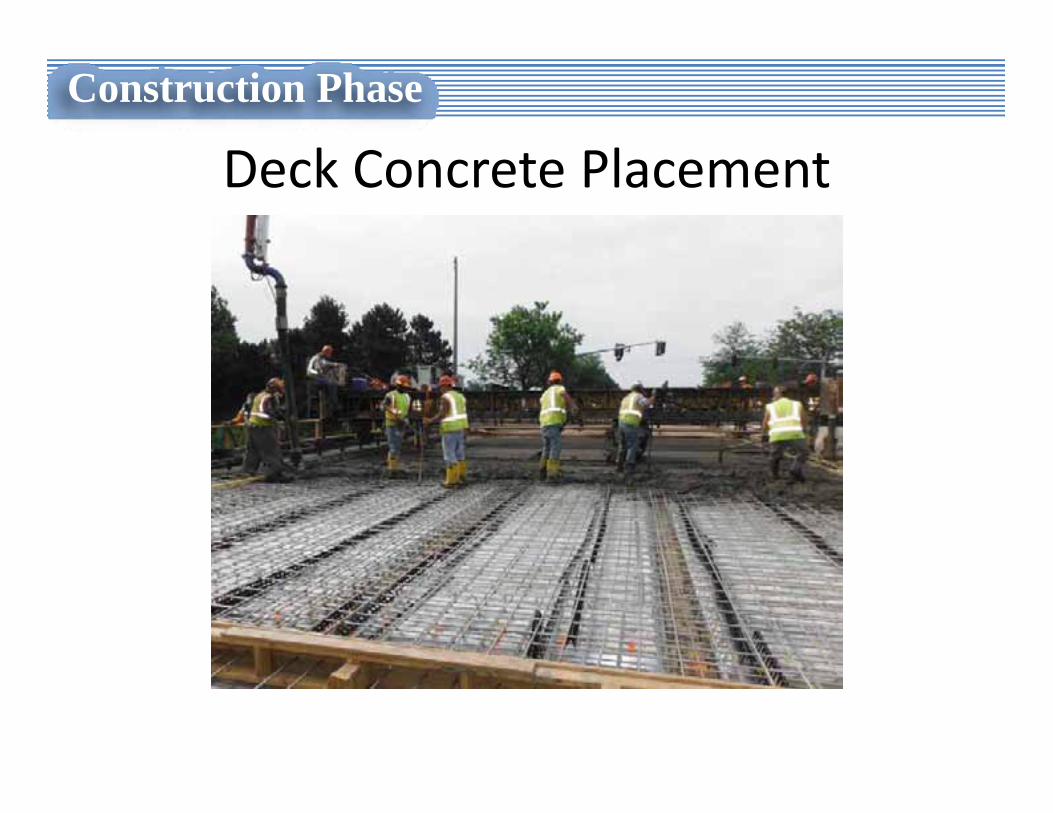
Deck Concrete Placement
Construction Phase
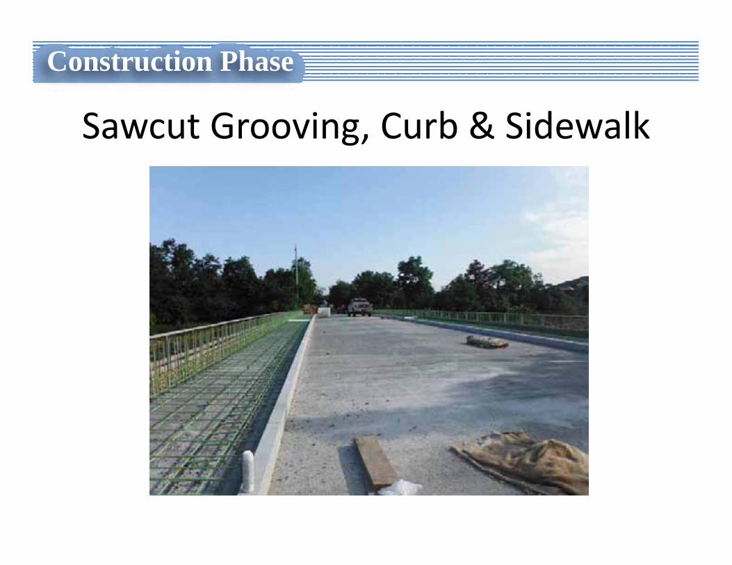
Sawcut Grooving, Curb & Sidewalk
Construction Phase
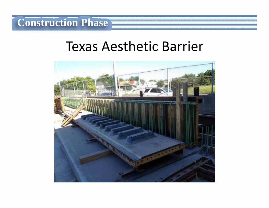
Texas Aesthetic Barrier
Construction Phase
Construction Phase
Construction Phase
Construction Phase
Construction Phase
Construction Phase
Construction Phase
• Contractor’s Perspective
“8 ½ x 11 Delivery Method”
Construction Phase
Drawbacks
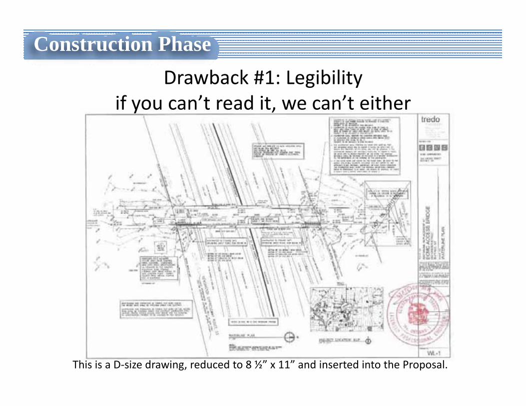
This is a D‐size drawing, reduced to 8 ½” x 11” and inserted into the Proposal.
Construction PhaseDrawback #1: Legibility
if you can’t read it, we can’t either
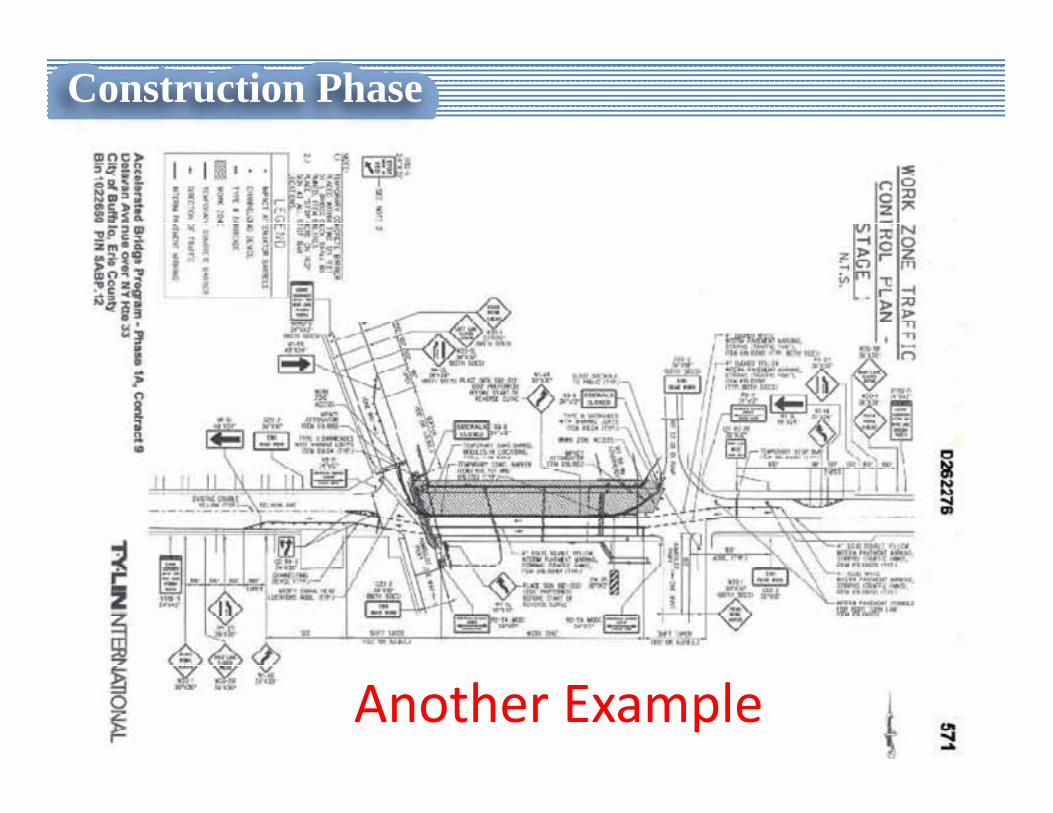
Another Example
Construction Phase
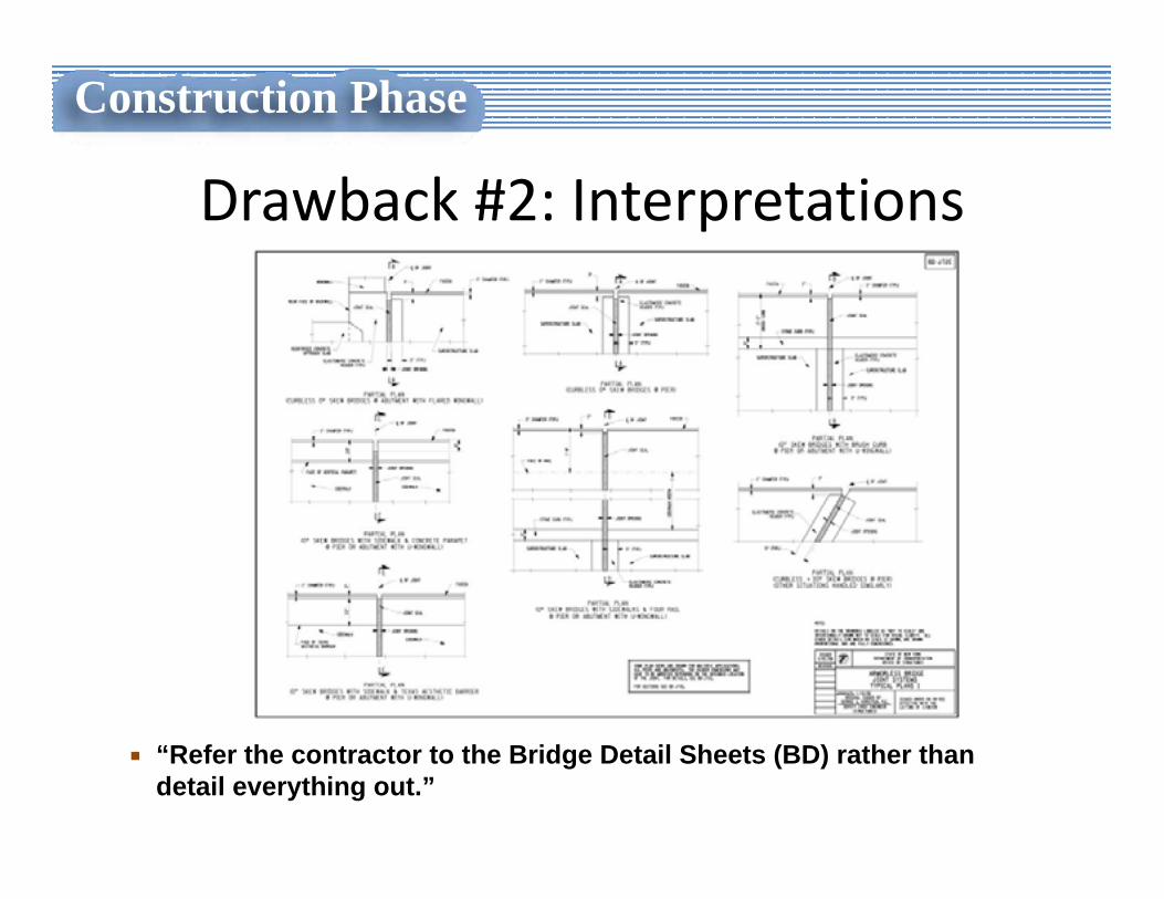
Drawback #2: Interpretations
“Refer the contractor to the Bridge Detail Sheets (BD) rather than detail everything out.”
Construction Phase
Drawback #3: Loss of The Big Picture• Simplified details do not show the interrelationship between different components of the job. This limits the constructor’s ability to plan the work.
• Example: listing of proposed dimensions has all the data you need, but doesn’t clue you in that there is another bridge overhead that will be in your way.
Construction Phase
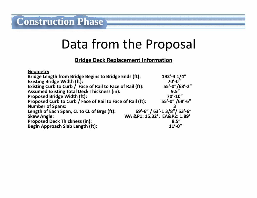
Data from the ProposalBridge Deck Replacement Information
GeometryBridge Length from Bridge Begins to Bridge Ends (ft): 192’‐4 1/4”Existing Bridge Width (ft): 70’‐0”Existing Curb to Curb / Face of Rail to Face of Rail (ft): 55’‐0”/68’‐2”Assumed Existing Total Deck Thickness (in): 9.5”Proposed Bridge Width (ft): 70’‐10”Proposed Curb to Curb / Face of Rail to Face of Rail (ft): 55’‐0” /68’‐6”Number of Spans: 3Length of Each Span, CL to CL of Brgs (ft): 69’‐6” / 63’‐1 3/8”/ 53’‐6”Skew Angle: WA &P1: 15.32°, EA&P2: 1.89°Proposed Deck Thickness (in): 8.5”Begin Approach Slab Length (ft): 11’‐0”
Construction Phase
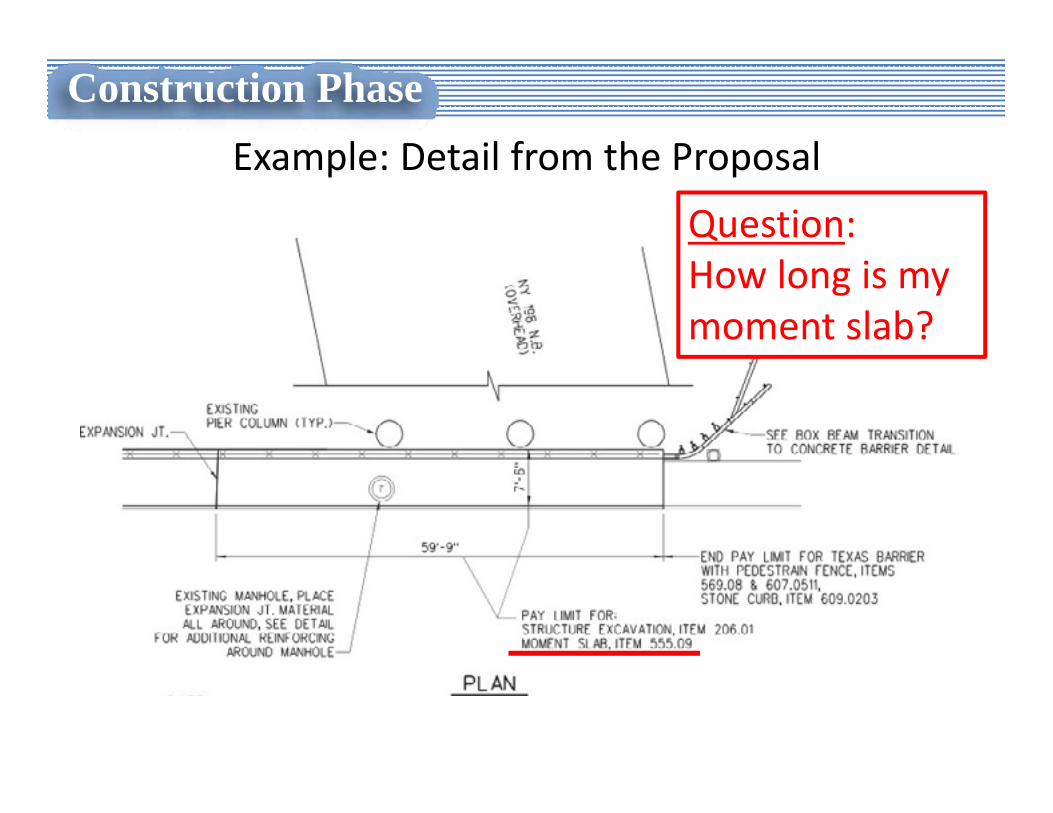
Example: Detail from the Proposal
Construction Phase
Question:How long is my moment slab?
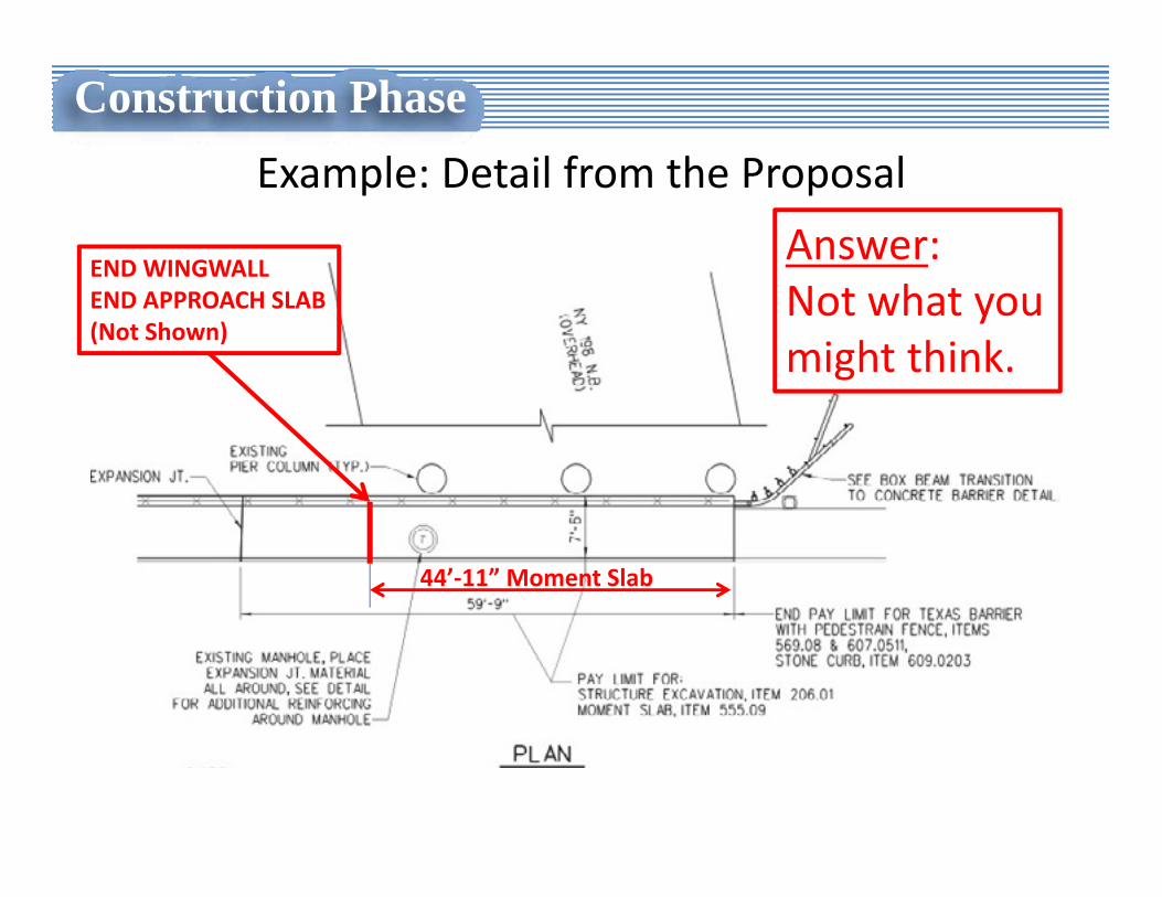
Example: Detail from the Proposal
Construction Phase
Answer:Not what you might think.
END WINGWALLEND APPROACH SLAB(Not Shown)
44’‐11” Moment Slab
Drawback #4:Contractor Develops the Design
• Design engineers typically do this, so they are experts at it.
• Contractor’s engineers can do this, but it is not their ordinary line of business.
• Which way is better?
Construction Phase
Drawback #4, cont.Contractor Develops the Design
• In construction, there is not enough time to do sufficient field survey.
• Must rely on record drawings.
Construction Phase
Drawback #5: Insufficient Time for Utility
Coordination
• Utility Coordination takes time.
• Can physically put out plans out in 2 months.
• What happens when utility coordination takes longer than that??
Construction Phase
Construction Phase
Utility Coordination is a Must
• You cannot get around utility coordination.
• Utility coordination should be done during design phase or problems are essentially guaranteed.
• If not during design phase, guess when?
Construction Phase
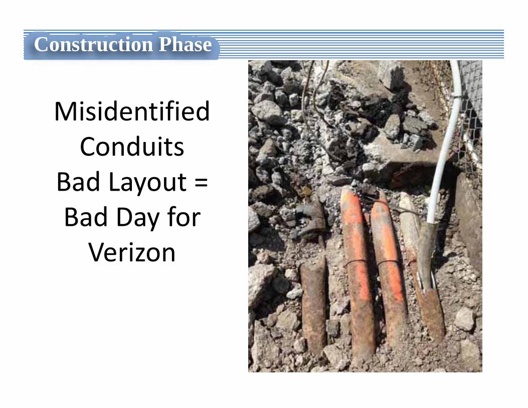
Misidentified Conduits
Bad Layout = Bad Day for Verizon
Construction Phase
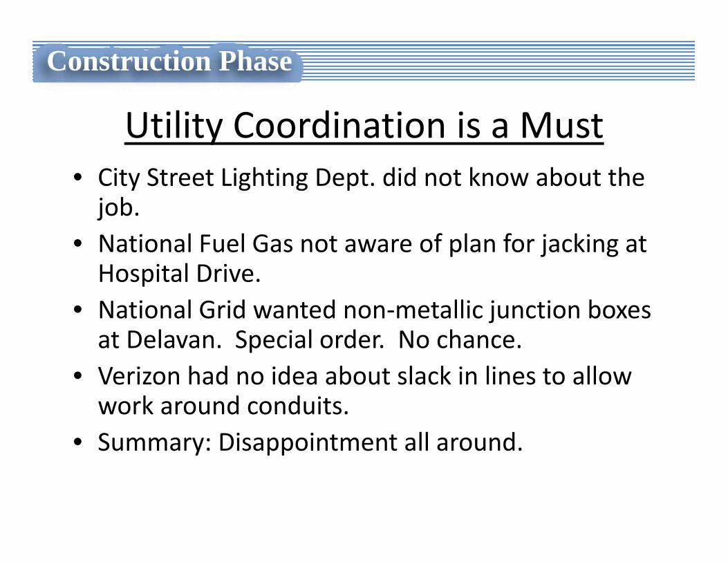
Utility Coordination is a Must• City Street Lighting Dept. did not know about the job.
• National Fuel Gas not aware of plan for jacking at Hospital Drive.
• National Grid wanted non‐metallic junction boxes at Delavan. Special order. No chance.
• Verizon had no idea about slack in lines to allow work around conduits.
• Summary: Disappointment all around.
Construction Phase
Drawback #6Is there Sufficient Time for
Engineering???
• BD sheets include generic details.
• Details need to be tweaked to match the specifics of the job.
• Dealing with design details is time consuming and can be costly during construction.
Construction Phase
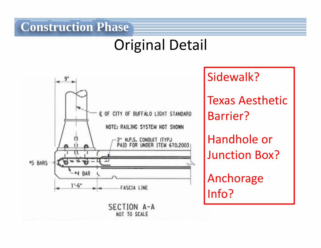
Original Detail
Sidewalk?
Texas Aesthetic Barrier?
Handhole or Junction Box?
Anchorage Info?
Construction Phase
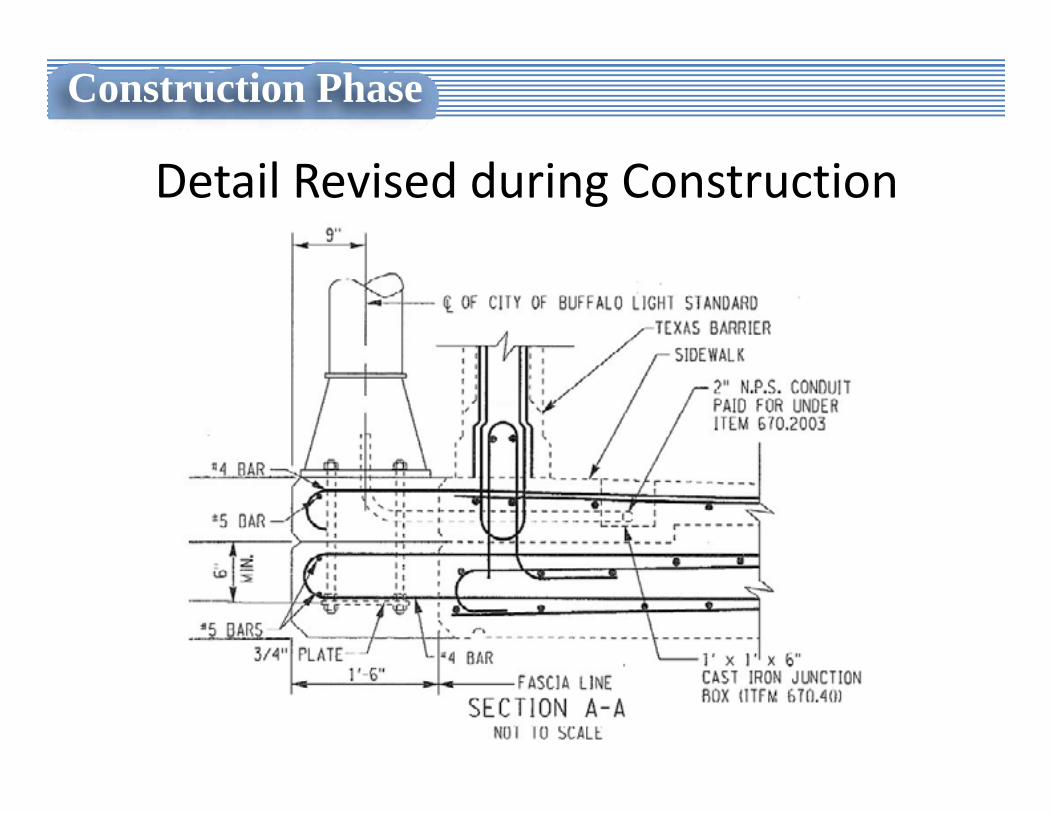
Detail Revised during Construction
Construction Phase
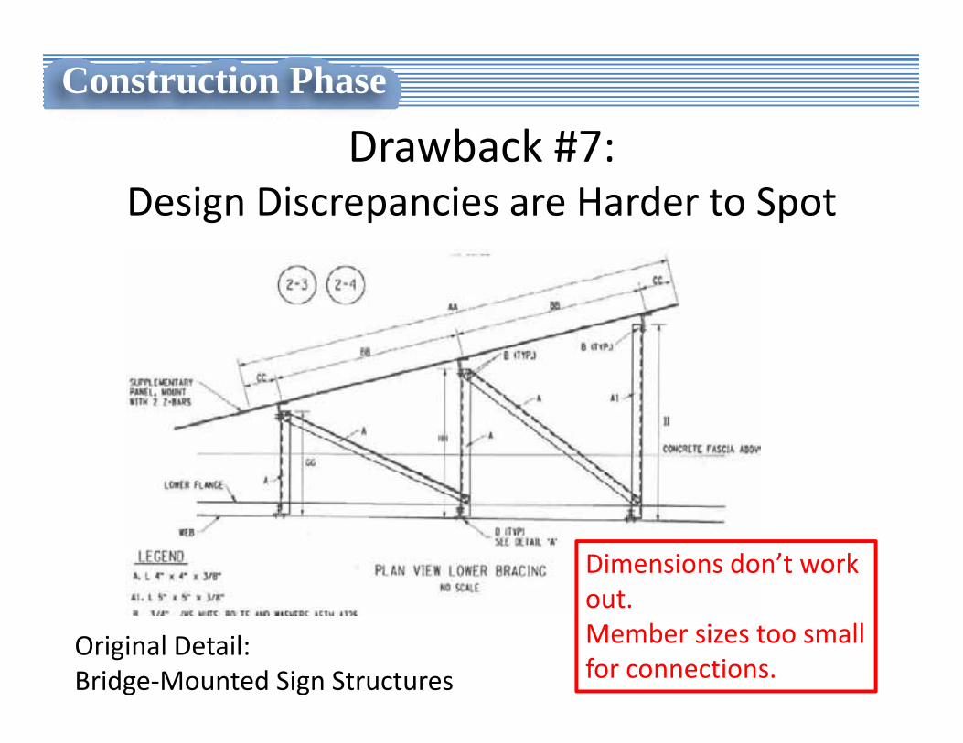
Drawback #7:Design Discrepancies are Harder to Spot
Construction Phase
Dimensions don’t work out.Member sizes too small for connections.
Original Detail: Bridge‐Mounted Sign Structures
Drawback #8:Record Plans for Future Use
• What will the as‐built plans look like for this job?
Construction Phase

Construction Phase
Advantages
Advantage #1:
• Shorter design duration gets more work out on the street faster.
Construction Phase
PDH Questions
1. This project was part of what NYSDOT Program?
a) Design‐Build Program
b) Accelerated Bridge Construction Program
c) Bridge Replacement Program
d) None of the above
PDH Questions
1. This project was part of what NYSDOT Program?
a) Accelerated Bridge Construction (ABC) Program
PDH Questions
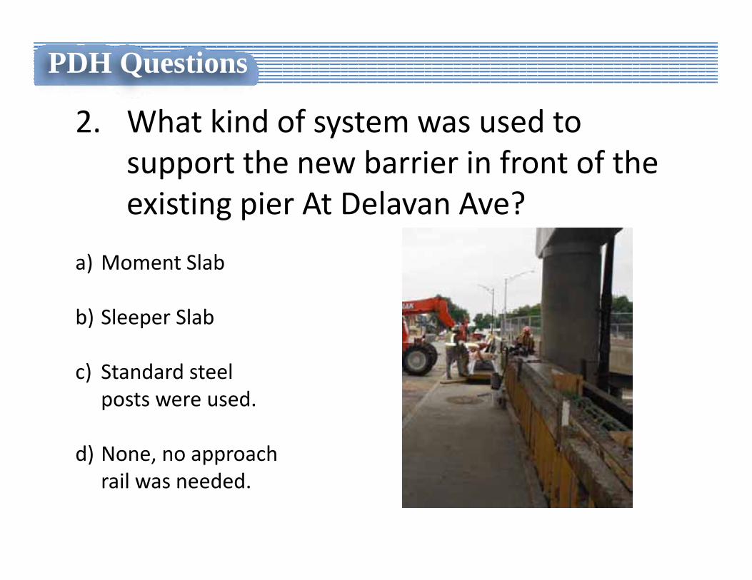
2. What kind of system was used to support the new barrier in front of the existing pier At Delavan Ave?
a) Moment Slab
b) Sleeper Slab
c) Standard steel posts were used.
d) None, no approach rail was needed.
PDH Questions
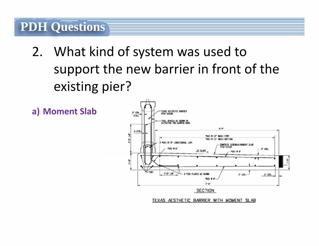
2. What kind of system was used to support the new barrier in front of the existing pier?
a) Moment Slab
PDH Questions
3. The advantage(s) for using stainless steel deck reinforcement on this project was?
a) Allowed the deck thickness to be reduced by 1”.
b) Allowed for the construction of a concrete haunch without raising the roadway profile.
c) Reduced the dead load on the existing stringers yielding a higher load rating.
d) All of the above.
PDH Questions
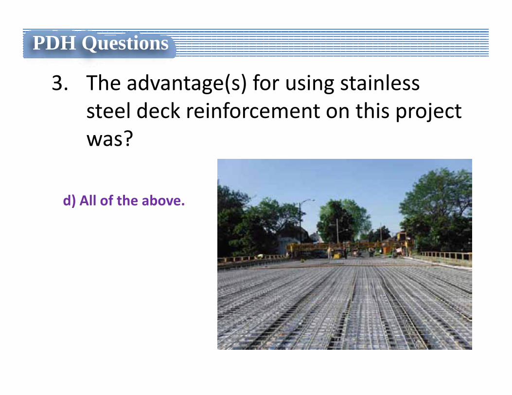
3. The advantage(s) for using stainless steel deck reinforcement on this project was?
d) All of the above.

Region 5 Bridge Deck Replacements
Questions?