
AC890PX High Power Inverter - SDS Drives · 620 VECTOR LINK SERIES PLC ... • Individual LINK 1...
34
AC890PX High Power Inverter
Transcript of AC890PX High Power Inverter - SDS Drives · 620 VECTOR LINK SERIES PLC ... • Individual LINK 1...
AC890PX High Power Inverter

The history of SSD LINK 1989-1996
• LINK 1 was the first fiber optic peer-to-peer network of its kind.
• Its sole purpose was to control a coordinated drive system.
• Used primarily with the 570L DC Link drive and later, the 590L and much later, the 620L AC vector Link drive.
• With speeds of 2.7MB, and all modules communicating at the same time, it was blazing fast for its time.
• Fiber optic cable was thin, light, and was not plagued with electrical noise issues. A single loop of fiber, linking drive to drive was the only signal connection required for a coordinated system.

The history of SSD LINK 1989-1996
• There were Link 1 modules for digital and analog I/O, serial communication and processor modules that provided memory to hold function blocks. (570L, 590L drives had no function block memory)
• A one-page CRT Link touchscreen provided operator input and monitoring.
• ConfigEd and SAM software suite was used to program all components and monitor their performance on-line.
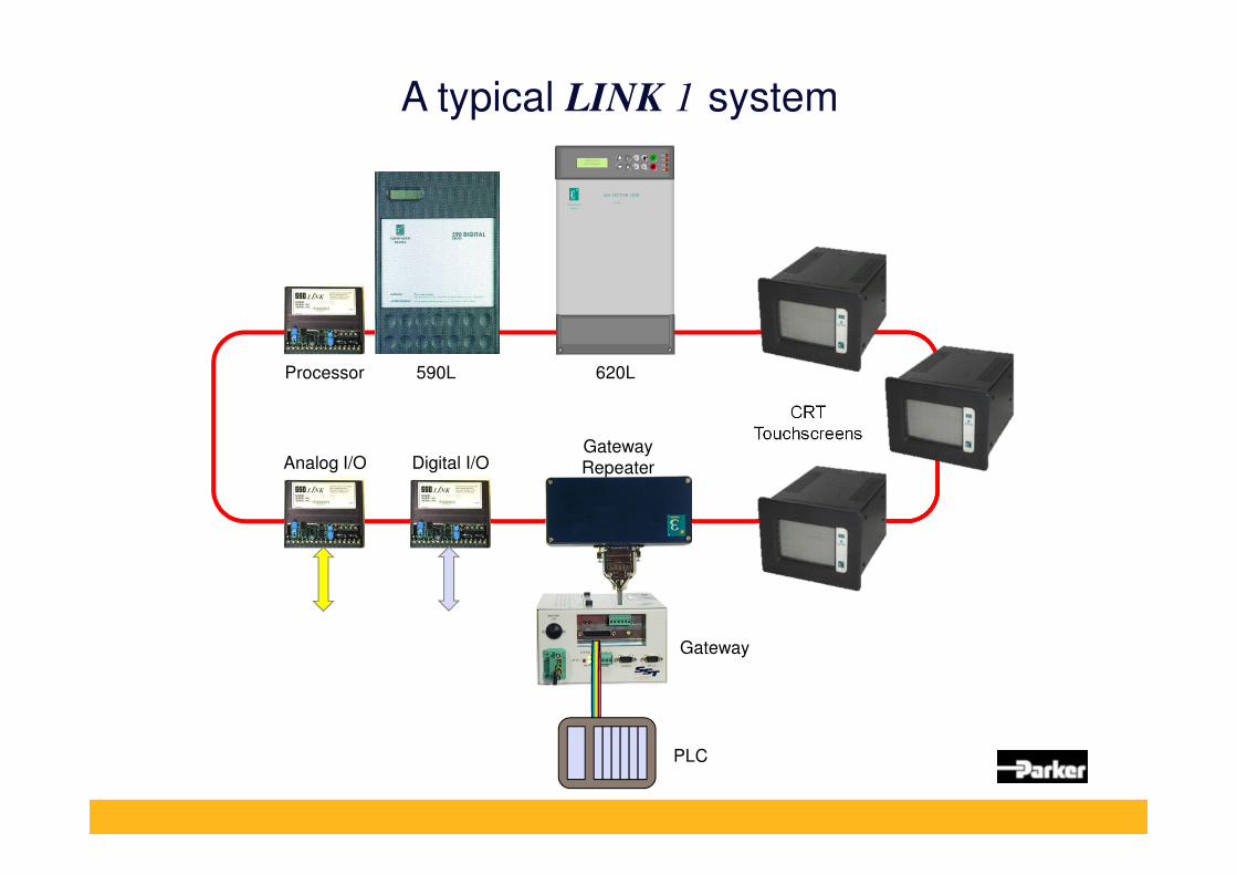
A typical LINK 1 system
DIAGNOSTICS
SPEED DEMAND
E
M
Local
Prog Jog
Health
Run
Brake
Local
EUROTHERM
DRIVES
620 VECTOR LINK
SERIES
PLC
590L 620LProcessor
Analog I/O Digital I/OGateway
Repeater
CRT
Touchscreens
Gateway
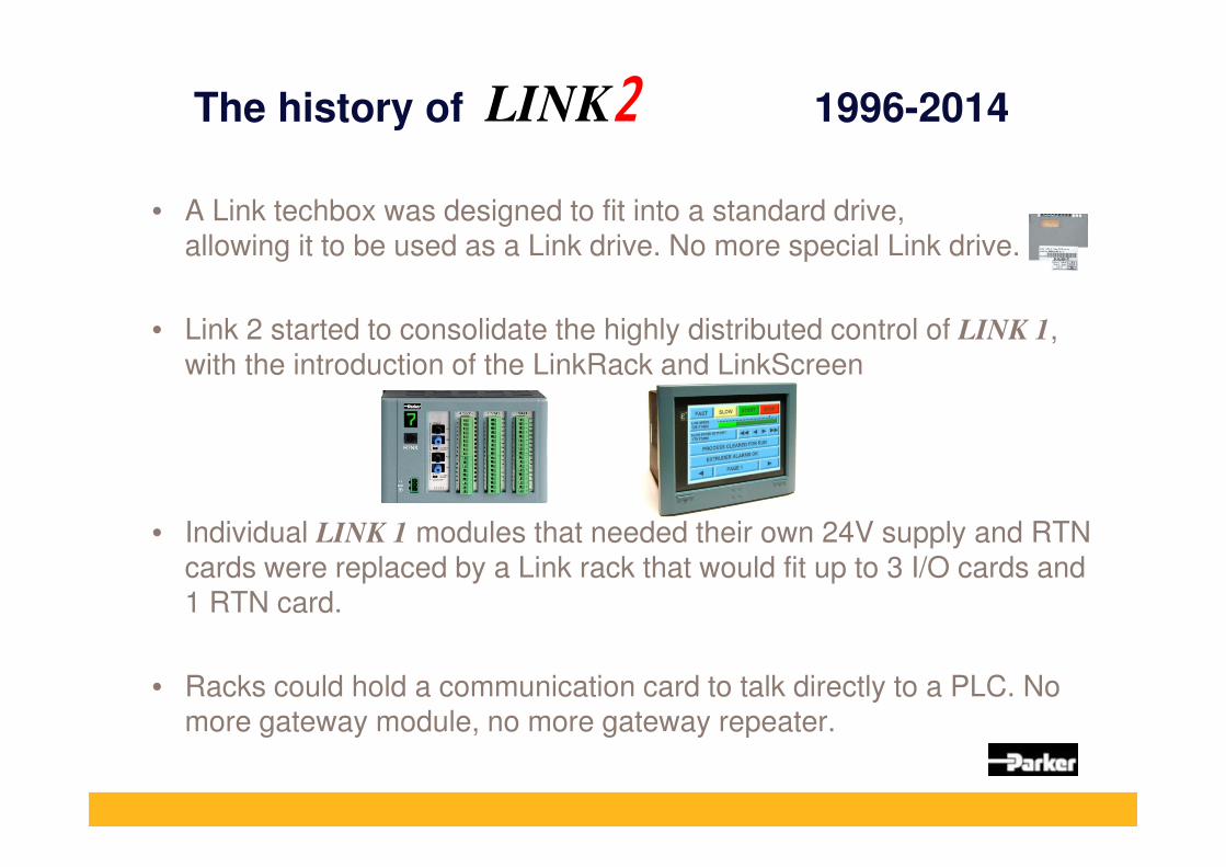
The history of 1996-2014
• A Link techbox was designed to fit into a standard drive, allowing it to be used as a Link drive. No more special Link drive.
• Link 2 started to consolidate the highly distributed control of LINK 1,
with the introduction of the LinkRack and LinkScreen
• Individual LINK 1 modules that needed their own 24V supply and RTN
cards were replaced by a Link rack that would fit up to 3 I/O cards and 1 RTN card.
• Racks could hold a communication card to talk directly to a PLC. No more gateway module, no more gateway repeater.
LINK

The history of 1996-2014
• The touchscreen was now LCD based, and could be configured with multiple pages of screens. It also doubled-up as a rack.
• Racks and screens were powered by 120VAC, eliminating large 24VDC power supplies used in LINK 1 systems.
• Both the rack and screen had enough memory and storage to hold a 6-section drive system configuration.
• DSD software now had the monitoring part built-in. No more separate packages for designing and set-up/monitoring.
LINK
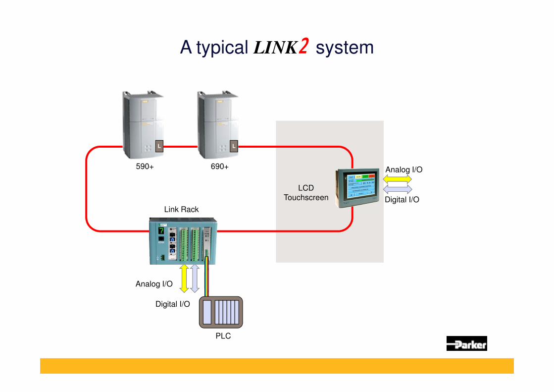
A typical LINK system
PLC
590+
Analog I/O
Digital I/O
Link Rack
690+
L L
LCD
Touchscreen
Analog I/O
Digital I/O

Introducing
• LINKnet is an Ethernet based modern version of our SSD LINK fiber optic system. CAT-6 cables replace fiber. No more repeaters.
• It caters to existing LINK customers whose fiber optic systems are several years old, and in need of modernization.
• A LINKnet techbox that fits in the same spot as the LINK techbox on 590+ and 690+ drives.
2014

Introducing
• Customers get to keep their panels, 590+ and 690+ drives, and change out only the techbox and the fiber optic network.
• Huge savings for the customer, resulting in future business.
• Link I/O will be replaced by Ethernet remote I/O modules.
• Any Link touchscreens will be replaced by TS8000 in phase 1.
• It is the new peer-to-peer network for 590+ and 690+ drive systems.
2014

New LINKnet Hardware
LINKnet HMI
Ethernet peer to peer
support & Modbus TCP/IP
fieldbus
Phase III(December 2015?)
LINKnet 890 Option Card
with Ethernet
Peer to Peer Support &
Modbus TCP/IP fieldbus
Phase II(March 2015)
Phase I(May 2014)
LINKnet Tech. Box
with Ethernet
Peer to Peer Support &
Modbus TCP/IP fieldbus
+ Remote I/O support
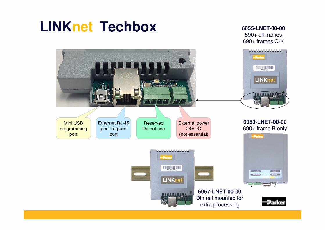
LINKnet Techbox
Mini USB
programming
port
Ethernet RJ-45
peer-to-peer
port
Reserved
Do not use
External power
24VDC
(not essential)
6055-LNET-00-00590+ all frames
690+ frames C-K
6053-LNET-00-00690+ frame B only
6057-LNET-00-00Din rail mounted for
extra processing

Current Peer to Peer Support
TS8000590+ 690+ L5392 L5300
LINKfiber optic
690+
PLC
FireWire
TS8000
L5300 PLCAC890 AC890AC890

Future Peer to Peer Support
LINKnet DC590+ AC690+
TS8000AC890 AC890
3rd Party
HMI3rd Party
Remote I/O
Modbus TCP/IP
Modbus
TCP
PLC
I/O support
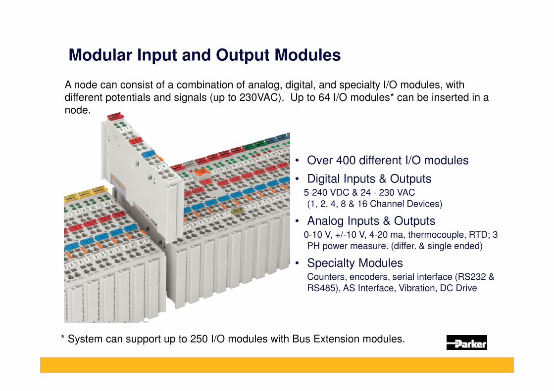
Modular Input and Output Modules
A node can consist of a combination of analog, digital, and specialty I/O modules, with
different potentials and signals (up to 230VAC). Up to 64 I/O modules* can be inserted in a
node.
* System can support up to 250 I/O modules with Bus Extension modules.
• Over 400 different I/O modules
• Digital Inputs & Outputs5-240 VDC & 24 - 230 VAC
(1, 2, 4, 8 & 16 Channel Devices)
• Analog Inputs & Outputs0-10 V, +/-10 V, 4-20 ma, thermocouple, RTD; 3
PH power measure. (differ. & single ended)
• Specialty ModulesCounters, encoders, serial interface (RS232 &
RS485), AS Interface, Vibration, DC Drive
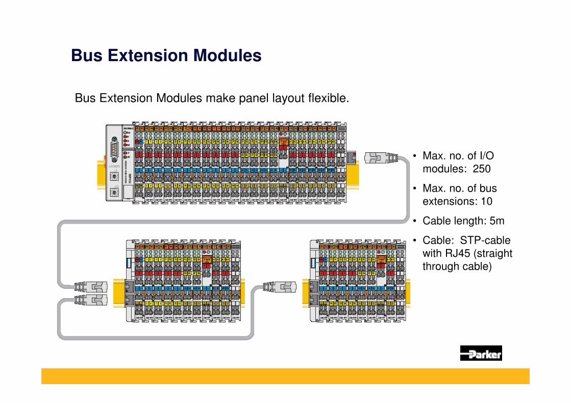
Bus Extension Modules
Bus Extension Modules make panel layout flexible.
• Max. no. of I/O
modules: 250
• Max. no. of bus
extensions: 10
• Cable length: 5m
• Cable: STP-cable
with RJ45 (straight
through cable)

DSE programming & on-line Software

ConfigEd / DSD > DSE highlights
• DSE replaces ConfigEd, SAM and DSD as the software tool for both designing and on-line use. Version 3.00 or later supports LINKnet.
• Newer platform, compatible with Windows XP, 7, 8, 32/64 bit.
• Newer features like remote IP address access.
• More intuitive interface, with icons for frequently used features.
• Monitoring and Charting of any parameter from any address.
• Several other ease-of-use improvements.

LINKnet - DSE advantages
• No more -100 to + 100% limitation, as in LINK 1 and 2.
• No more 83.33% scaling for speed signals.
• No more 50% scaling for torque and current signals.
• Easy setup and mapping for I/O and communication cards.
• Update on-line from within DSE. No more Manger
• Import/export projects from inside DSE. No more Manager.

DSE packages
• DSE Development is the designer’s package. It creates and manages projects and configurations of entire lines.
• DSE Runtime is the maintenance package. It has full editing rights, same as DSE Development, but it cannot be used to program new projects or new modules.
• If you have ConfigEd or DSD, you will need to purchase the equivalent DSE package.
• If you have DSE already, there is no charge. Just update to version 3.00 or later by checking for updates from within DSE.

Read and write directly to Ethernet I/O

Read and write directly to PLC or HMI

Mapping PLC and HMI I/O
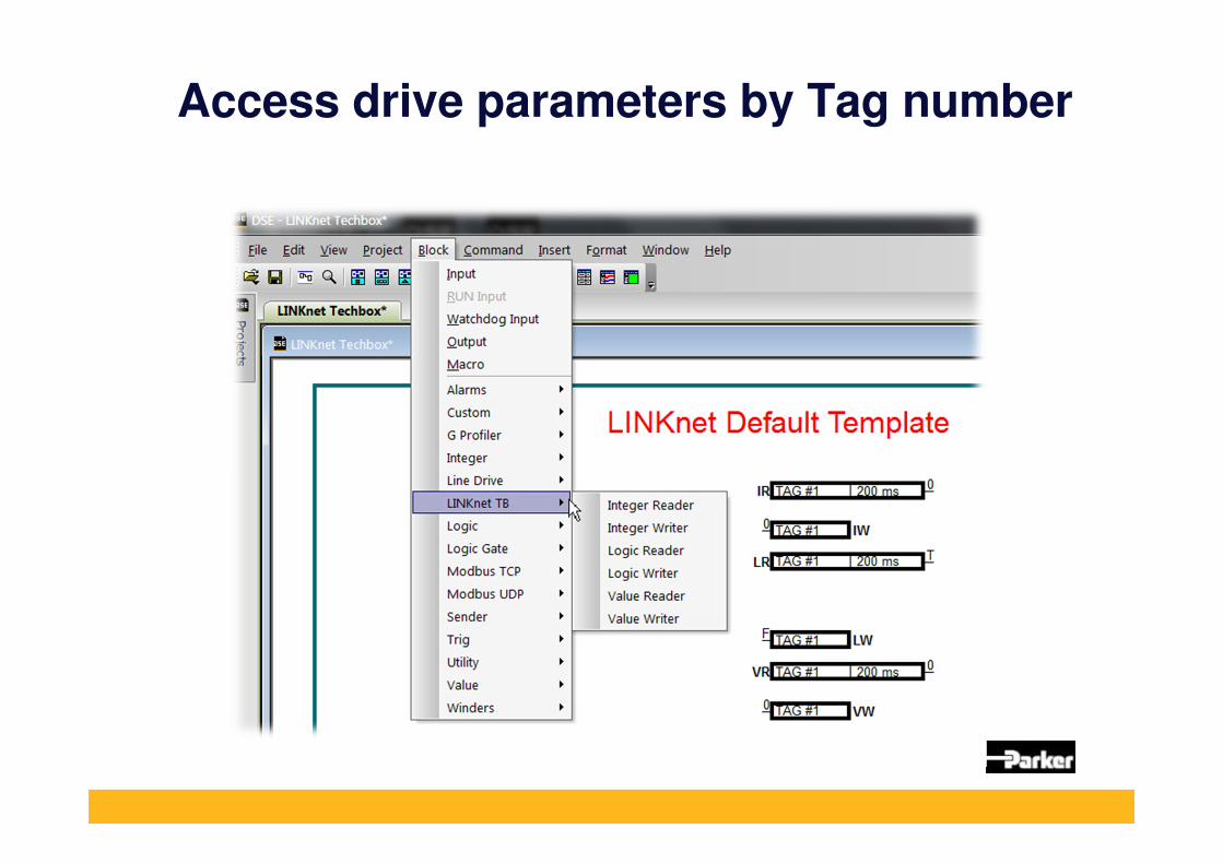
Access drive parameters by Tag number

Network Diagnostics
• System Control block now monitors Ethernet network integrity
• System Control block now monitors TB to drive comms
• All these outputs can be actioned as desired or displayed on HMI
Ethernet comms
TB to drive comms

Retrofit plan

Upgrade scope
When trying to specify an upgrade for an existing LINK line, use the following guidelines:
• Is it a LINK 1 system or a LINK 2 system?
• How many drive sections?
• How many locations/enclosures?
• How many points of analog and digital I/O?
• Where is the I/O distributed?
• How many touchscreens? How many total pages?
• How much extra processing in various modules?
• Any fieldbus communication present?

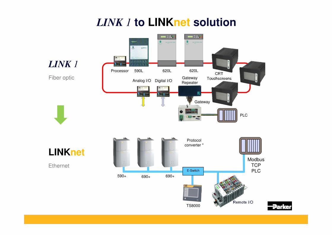
LINK 1 to LINKnet
Is it a LINK 1 system or a LINK 2 system? LINK 1
How many drive sections? 1 DC, 2 AC (new drives)
How many locations/enclosures? 3
How many points of analog and digital I/O? Analog 4+1, Digital 6+4
Where is the I/O distributed? 1 location
How many touchscreens? How many total pages? 3 screens, 3 pages, no proc.
How much extra processing in various modules? 1 page
Any fieldbus communication present? Ethernet
DIAGNOSTICS
SPEED
DEMAND
E
M
Local
Prog Jog
He
alt
hR
u
nB
ra
keLo
cal
EUROTHERM
DRIVES
620 VECTOR LINKSERIES
PLC
590L 620LProcessor
Digital I/OGateway
Repeater
CRT
Touchscreens
Gateway
DIAGNOSTICS
SPEED
DEMAND
E
M
Local
Prog Jog
He
alt
hR
u
nB
ra
keLo
cal
EUROTHERM
DRIVES
620 VECTOR LINKSERIES
620L
Analog I/O
LINK 1
Fiber optic
1 page
1 DC drive 2 AC drives
4 in, 1 out
6 in, 4 out
3 screens1 page each
Ethernet PLC
LINK 1 to LINKnet solutionDIAGNOSTICS
SPEED
DEMAND
E
M
Local
Prog Jog
He
alt
hR
u
nB
ra
keLo
cal
EUROTHERM
DRIVES
620 VECTOR LINKSERIES
PLC
590L 620LProcessor
Digital I/OGateway
Repeater
CRT
Touchscreens
Gateway
DIAGNOSTICS
SPEED
DEMAND
E
M
Local
Prog Jog
He
alt
hR
u
nB
ra
keLo
cal
EUROTHERM
DRIVES
620 VECTOR LINKSERIES
620L
Analog I/O
LINK 1
Fiber optic
590+ 690+690+
TS8000Remote I/O
Protocol
converter *
E-Switch
LINKnet
EthernetModbus
TCP
PLC
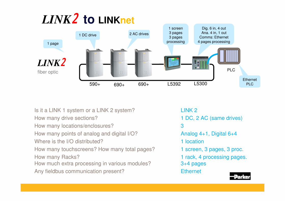
LINK to LINKnet
Is it a LINK 1 system or a LINK 2 system? LINK 2
How many drive sections? 1 DC, 2 AC (same drives)
How many locations/enclosures? 3
How many points of analog and digital I/O? Analog 4+1, Digital 6+4
Where is the I/O distributed? 1 location
How many touchscreens? How many total pages? 1 screen, 3 pages, 3 proc.
How many Racks? 1 rack, 4 processing pages.
How much extra processing in various modules? 3+4 pages
Any fieldbus communication present? Ethernet
590+ 690+ L5392 L5300
LINKfiber optic
690+
PLC
1 page
1 DC drive 2 AC drives
1 screen3 pages3 pages
processing
Ethernet PLC
Dig. 6 in, 4 outAna. 4 in, 1 out
Comms: Ethernet4 pages processing

LINK to LINKnet solution
590+ 690+ L5392 L5300
LINKfiber optic
690+
PLC
590+ 690+690+
TS8000Remote I/O
Modbus
TCP
PLCE-Switch
LINKnet
Ethernet

• SSD Drives has over 1200 LINK systems in the field. There are many more designed by our Integrators.
• Most are ripe for modernization.
• LINKnet opens the door to:
• Sales opportunities
• Modern Ethernet network
• Same look and feel for the Customer
• Easier integration with PLC and I/O
• Customer retention
Upgrade opportunities
Thank You!