AC500 – the scalable PLC for customized automation · PDF file2 The scalable AC500 PLC...
52
Technical information AC500 – the scalable PLC for customized automation
Transcript of AC500 – the scalable PLC for customized automation · PDF file2 The scalable AC500 PLC...
Technical information
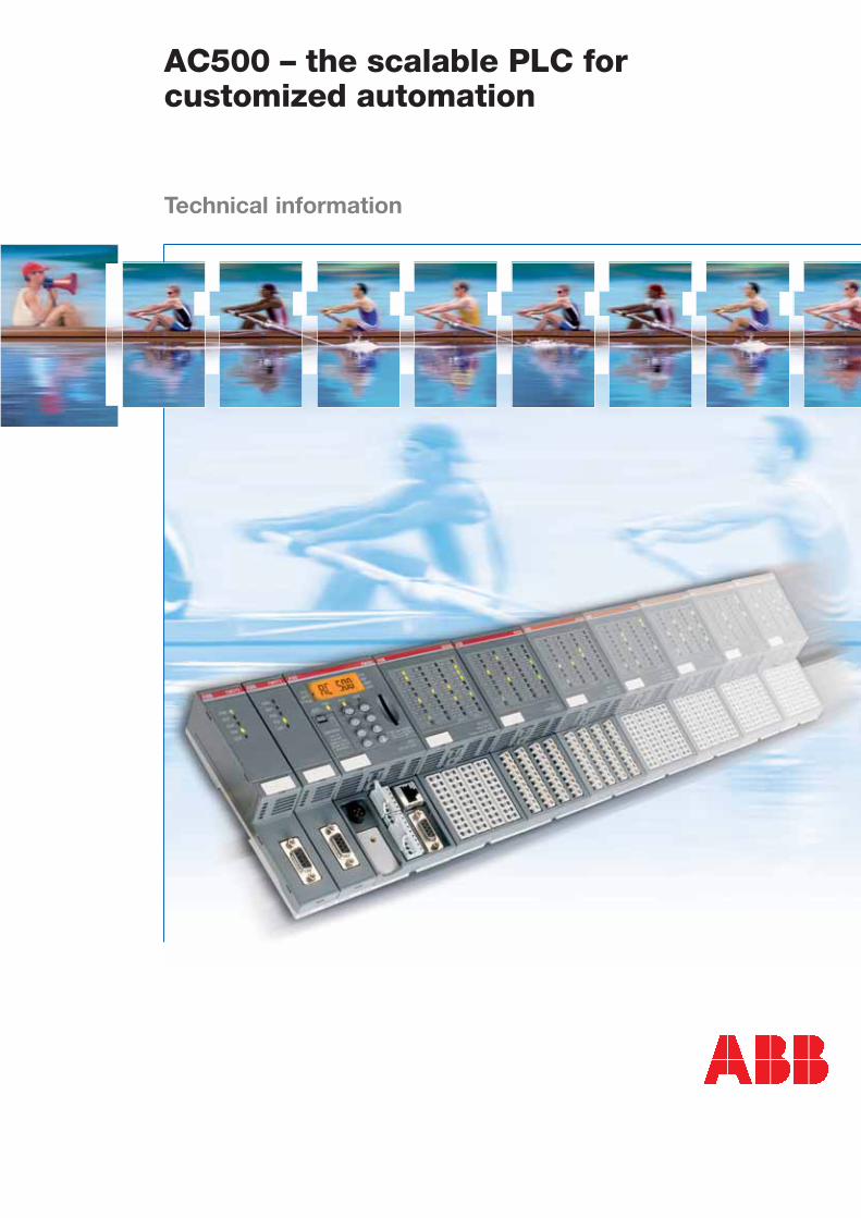
AC500 – the scalable PLC forcustomized automation
2
The scalable AC500 PLC – flexible, cost-efficient, future-friendly
Customers’ requirements met to perfection
Simple, consistent expandability, flexible when choosing a field bus, and designed for future market trends –
those are some of the demands made on an automation platform, particularly in the mechanical engineering
sector, but in plant engineering as well. These needs have been worked out in a close dialog with customers
and end-users. And now, they have been realized in the design and high functionality of the new scalable
AC500 PLC.
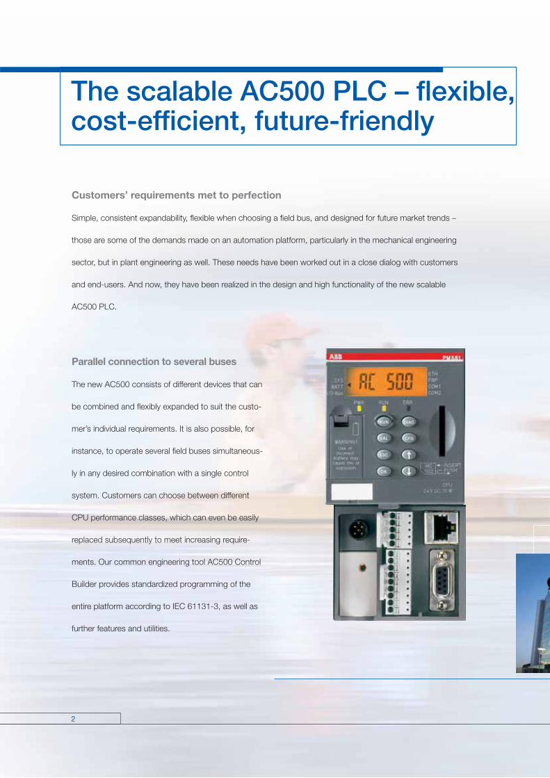
Parallel connection to several buses
The new AC500 consists of different devices that can
be combined and flexibly expanded to suit the custo-
mer’s individual requirements. It is also possible, for
instance, to operate several field buses simultaneous-
ly in any desired combination with a single control
system. Customers can choose between different
CPU performance classes, which can even be easily
replaced subsequently to meet increasing require-
ments. Our common engineering tool AC500 Control
Builder provides standardized programming of the
entire platform according to IEC 61131-3, as well as
further features and utilities.

3
Guarantees your safe investment in future
Besides the high performance capabilities of the system regarding handling, reliability and ease of mainte-
nance, also the long-term availability of the chosen system plays a decisive role: Your safe investment must be
ensured in future. With the new AC500, ABB offers a modern high-performance platform which is suitable for
future-oriented automation concepts and open for new trends and market requirements.
AC500 – the first choice everywhere
The AC500 is an optimum selection for applications like the following:
packaging machines plastics machines printing presses crane engineering energy optimization building engineering pumping installations marine engineering wind power installations air-conditioning/refrigeration systems tunnel construction …

4
Flexible choice of the field bus
Flexibility in the choice of a field bus without needing
to replace any field devices: That’s the basic idea
behind the field bus plug (FBP). Thanks to this intelli-
gent plug connector, field devices „become“ field-
bus-neutral. Thus, changing the field bus (often due
to end-user’s wishes), only requires the replacement
of the plug connector itself – the field devices and
terminal wiring can be retained.
The FBP is the link to a communicative series of
switching and automation components, which can
thus be combined with standard field bus systems
in the easiest way.
Bus-neutral field devices:
Everything you need forswitching and control
Circuit-breaker Universal Motor Controller Motor Starter AC500 Slave
5
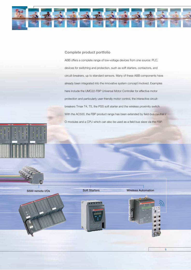
Complete product portfolio
ABB offers a complete range of low-voltage devices from one source: PLC,
devices for switching and protection, such as soft starters, contactors, and
circuit-breakers, up to standard sensors. Many of these ABB components have
already been integrated into the innovative system concept involved. Examples
here include the UMC22-FBP Universal Motor Controller for effective motor
protection and particularly user-friendly motor control, the interactive circuit-
breakers Tmax T4, T5, the PSS soft starter and the wireless proximity switch.
With the AC500, the FBP product range has been extended by field-bus-neutral I/
O modules and a CPU which can also be used as a field bus slave via the FBP.
S500 remote I/Os Soft Starters Wireless Automation
6
Clear advantages thanks to clear structures
Flexibility as program
Thanks to its scalability, the AC500 PLC can be adapted to the most different automation tasks: The devices concerned can
be used and combined in a flexible way. The number of different parts to be kept in stock is correspondingly minimized.
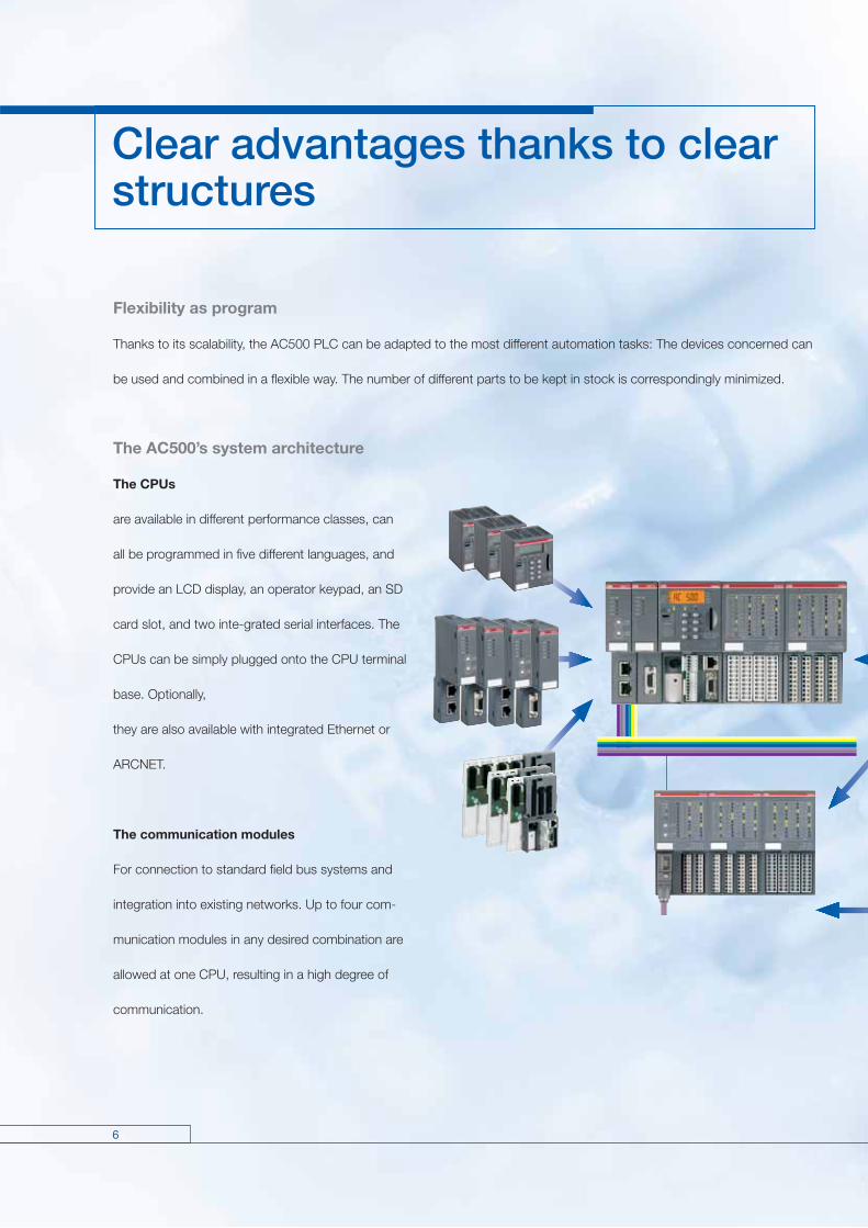
The AC500’s system architecture
The CPUs
are available in different performance classes, can
all be programmed in five different languages, and
provide an LCD display, an operator keypad, an SD
card slot, and two inte-grated serial interfaces. The
CPUs can be simply plugged onto the CPU terminal
base. Optionally,
they are also available with integrated Ethernet or
ARCNET.
The communication modules
For connection to standard field bus systems and
integration into existing networks. Up to four com-
munication modules in any desired combination are
allowed at one CPU, resulting in a high degree of
communication.

7
2
1
31
5
4
67
The CPU terminal base
Available in three different versions, enables easy
plugging of the CPU and one, two or four communi-
cation modules.
The I/O modules
Digital and analog in different versions. Can be simply
plugged onto the terminal units – for local expansion
of the CPU (max. ten local I/O modu les) and decen-
tralized expansion via the FBP interface. Flexible use
thanks to configurable channels.
The terminal units
Multi-purpose usage for both digital and analog I/Os,
for 1, 2 and 3-wire designs. Enable simple prewiring
without electronics. For 24 V DC and 230 V AC,
optionally for spring or screw-type terminals.
The FBP interface module
With embedded digital I/Os and a field-bus-neutral
interface for connecting the chosen Fieldbus Plug
(FBP). For decentralized expansion by up to seven
I/O modules.
The SD card
Optional downloading and uploading the user
program without a PC and for data logging.
1 Back-lighted LCD display and keypad
2 SD card slot
3 Plug-in communication modules
(1 to max. 4)
4 Optionally with integrated Ethernet
or ARCNET
5 Fieldbus neutral interface for slave function
and for programming
6 Two serial interfaces for programming,
ASCII, Modbus or CS31 field bus (master)
7 Expandable by up to ten local I/O modules
8
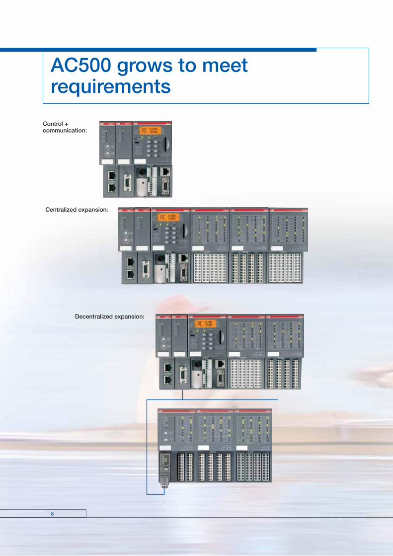
AC500 grows to meetrequirements
Control + communication:
Decentralized expansion:
Centralized expansion:

9
Network
Modem
Networked and communicative

10
Member of Automation Alliance
Programming
Control Builder AC500, Programming Tool PS501
Control Builder AC500 is the engineering tool for all CPU performance classes of the AC500, designed for
standardized IEC 61131-3 programming in five different languages. Other features of this tool are: Configurati-
on of the overall system including field buses and interfaces, extensive diagnostic functions, alarm handling,
integrated visualization and open software interfaces.
The Programming Tool PS501 also allows to select between different languages such as English, German,
Spanish, French, Italian, Russian and Chinese.
11
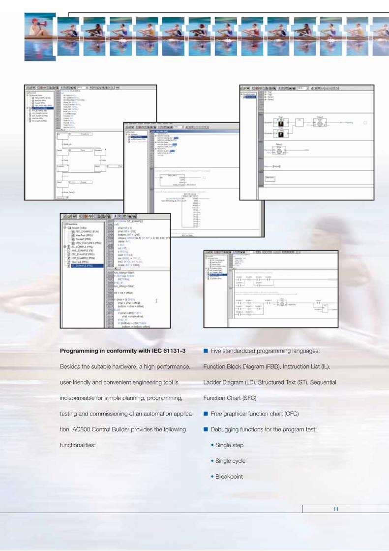
Five standardized programming languages:
Function Block Diagram (FBD), Instruction List (IL),
Ladder Diagram (LD), Structured Text (ST), Sequen tial
Function Chart (SFC)
Free graphical function chart (CFC)
Debugging functions for the program test:
• Single step
• Single cycle
• Breakpoint
Programming in conformity with IEC 61131-3
Besides the suitable hardware, a high-performance,
user-friendly and convenient engineering tool is
indispensable for simple planning, programming,
testing and commissioning of an automation applica-
tion. AC500 Control Builder provides the following
functionalities:

12
Programming
Offline simulation
IEC 61131-3 commands can be simulated without a
PLC being connected, including the relevant mal-
functions. After the program test, the application can
be downloaded to the control system.
Sampling trace
Timing diagrams for process variables and storage of
data in a ring buffer with event trigger.
Recipe management and watch lists
Values of selected variables are displayed. Pre-
defined values can be assigned to variables which
can then be downloaded to the control system all at
once (“Write recipe”). Ongoing values from the control
system can also be pre-assigned for reading into the
Watch and Recipe Manager, and stored in memory
there (“Read recipe). These functions are also helpful, for
example, for setting and entering control parameters.
Visualization
Includes color change, moving elements, bitmaps,
text display, allows input of setpoint values and
display of process variables read from the PLC,
dynamic bar diagrams, alarm and event manage-
ment, function keys and ActiveX elements. The
visualizations package is also available individually as
a separate software-licence (PS501-HMI).
13
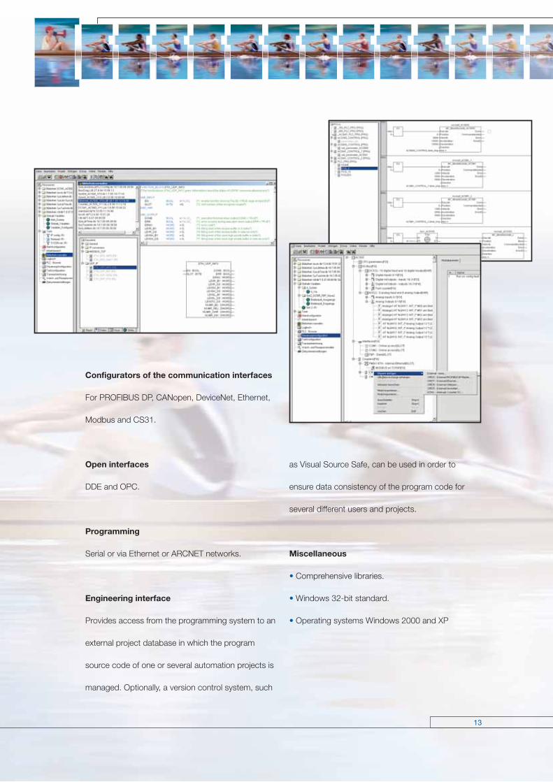
Configurators of the communication interfaces
For PROFIBUS DP, CANopen, DeviceNet, Ethernet,
Modbus and CS31.
Open interfaces
DDE and OPC.
Programming
Serial or via Ethernet or ARCNET networks.
Engineering interface
Provides access from the programming system to an
external project database in which the program
source code of one or several automation projects is
managed. Optionally, a version control system, such
as Visual Source Safe, can be used in order to
ensure data consistency of the program code for
several different users and projects.
Miscellaneous
• Comprehensive libraries.
• Windows 32-bit standard.
• Operating systems Windows 2000 and XP

14
CP400 and CP500 – the operator interfaces
Obvious Human-machine communication
ABB offers an extensive range of human machine interfaces (HMIs). The two families CP400 and CP500
provide many different displays to choose from, which satisfy application-specific demands regarding required
operator actions and information density. Whether it’s a simple device for displaying text, a graphic-capability
device or a touch-panel with color display, the entire range of control terminals meets the requirements for
maximized transparency and efficiency for the automation task.
15
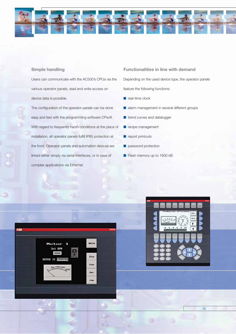
Functionalities in line with demand
Depending on the used device type, the operator panels
feature the following functions:
real-time clock
alarm management in several different groups
trend curves and datalogger
recipe management
report printouts
password protection
Flash memory up to 1600 kB
Simple handling
Users can communicate with the AC500’s CPUs via the
various operator panels, read and write access on
device data is possible.
The configuration of the operator panels can be done
easy and fast with the programming software CPsoft.
With regard to frequently harsh conditions at the place of
installation, all operator panels fulfill IP65 protection at
the front. Operator panels and automation devices are
linked either simply via serial interfaces, or in case of
complex applications via Ethernet.

16
Operator Terminals CP400
Easy testing and use
Test your projects, screens and alarms as well as
your communication and controller functions quickly
via on- and off-line simulation. Change language
quickly and easily using the multi-language support
function.
Secured data and operations
Protect your fi les and machine confi gurations using
global and object-specifi c passwords (9 protection
levels) to prevent downloading of the application.
Performance
Quick and easy project creation and management
Quickly view and easily manage your project components using the screen
manager (detailed list or screen miniatures). Simplify the creation, modifi ca-
tion, sorting and identifi cation of your project data via the cross-references
function.
Simplifi ed adaptability and connectivity
SConnect your HMIs to the various automation
equipment:
via the various possible protocols for ABB AC31,
series 40&50, series 90, AC500 PLCs and more
than 100 leading PLCs on the market, where the
display acts as gateway. The multi protocol also
allows data to be exchanged between the various
controllers.
via multi-channel communication (Connecting a
controller to each available port via different
protocols, transferring values between drivers via
macros, using the values of various controllers in
the calculations).
via the multiple
connection media
(RS232, RS485,
RS422or Ethernet…)
increasing connection capacities.
17
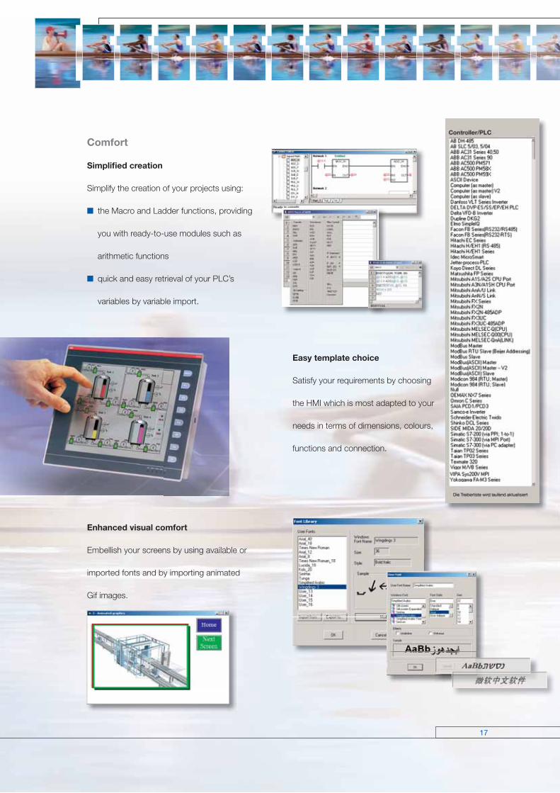
Comfort
Simplifi ed creation
Simplify the creation of your projects using:
the Macro and Ladder functions, providing
you with ready-to-use modules such as
arithmetic functions
quick and easy retrieval of your PLC’s
variables by variable import.
Enhanced visual comfort
Embellish your screens by using available or
imported fonts and by importing animated
Gif images.
Easy template choice
Satisfy your requirements by choosing
the HMI which is most adapted to your
needs in terms of dimensions, colours,
functions and connection.
18
Ethernet
Ethernet operates with a data rate of 10 MBit/s and as Fast-
Ethernet with 100 MBit/s. Ethernet utilizes the producer/consumer
model. This means that every station possesses equal rights. While it is transmitting, all other stations listen
in and accept the data directed to them. Bus access is regulated by the CSMA/CD procedure (Carrier-
Sense Multiple-Access with Collision Detection), where each station may autonomously transmit when the
bus is free. If a collision occurs, if two stations begin to transmit simultaneously, both of them will stop
transmission and wait for a randomly determined time before they transmit again. Ethernet defines the
Layers 1 (Physical Link) and 2 (Data Link) of the OSI model.
The AC500 supports transmission and reception of data using TCP/IP and/or UDP/IP. Further application
layers can be implemented by subsequent loading. Simultaneous operation of TCP/IP, UDP/IP and applica-
tion layer is also assured. The IP, TCP, UDP, ARP, RP, BOOTP, and DHCP protocols are supported as a
standard feature, as application layer Modbus/TCP.
Topology
Star- or ring-shaped using Ethernet hub or switch.
Data transmission
Max. 10 MB/s with 10 Base T and max. 100 MB/s
with Fast-Ethernet.
Transmission media
Twisted-pair cables with RJ45 connector. The
maximum cable length is 100 m for 100 MB/s.
Diagnostics
Detailed diagnostic messages for rapid trouble-
shooting are shown on the CPU display.
In addition, the device status is indicated at the
communication module by four LEDs.
Communication – Ethernet
19
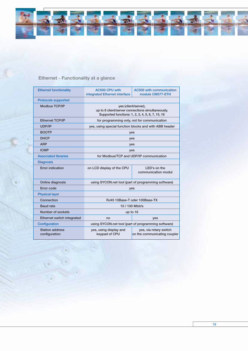
Ethernet - Functionality at a glance
Ethernet functionality AC500 CPU with AC500 with communication integrated Ethernet interface module CM577-ETH
Protocols supported
Modbus TCP/IP yes (client/server), up to 8 client/server connections simultaneously. Supported functions: 1, 2, 3, 4, 5, 6, 7, 15, 16
Ethernet TCP/IP for programming only, not for communication
UDP/IP yes, using special function blocks and with ABB header
BOOTP yes
DHCP yes
ARP yes
ICMP yes
Associated libraries for Modbus/TCP and UDP/IP communication
Diagnosis
Error indication on LCD display of the CPU LED's on the communication modul
Online diagnosis using SYCON.net tool (part of programming software)
Error code yes
Physical layer
Connection RJ45 10Base-T oder 100Base-TX
Baud rate 10 / 100 Mbit/s
Number of sockets up to 16
Ethernet switch integrated no yes
Configuration using SYCON.net tool (part of programming software)
Station address yes, using display and yes, via rotary switchconfiguration keypad of CPU on the communicating coupler

20
Communication – PROFIBUS DP
PROFIBUS DP
(Process Field Bus - Decentral Periphery)
PROFIBUS DP is an open, high-speed and widely-used field bus.
It provides multi-master and master-slave communication in the field
area. This field bus can accordingly be used for AC500 and AC31 control system series and for field-bus-
neutral FBP devices (decentralized I/Os and intelligent switching devices) via the PROFIBUS-FBP connector.
Communication
The masters rule data traffic on the bus. When in
possession of the bus access authorization (token),
the masters can transmit data without an external
request. The passive devices, known as slaves, do
not receive any bus access rights; they acknowledge
messages received, or respond to a query from a
master. Baud rates from 9.6 kBaud to 12 MBaud are
supported. A maximum of 126 devices can be
operated on the bus.
Data exchange
This is handled predominantly in cyclical mode be-
tween master and slave. The requisite communication
functions have been specified by the PROFIBUS DP
basic functions in accordance with EN 50170. Each
master has full write and read access to its assigned
slaves, but only read access to the slaves assigned to
other bus masters. There is no direct data exchange
between masters. Acyclical services (DP-V1) for
parameterization and diagnostics between master and
slave are also available. This is performed in parallel to
the master’s cyclical user data traffic.
Diagnostics
Detailed diagnostic messages for rapid trouble-
shooting are shown on the CPU display. In addition,
the device status is indicated at the communica-tion
module by four LEDs.
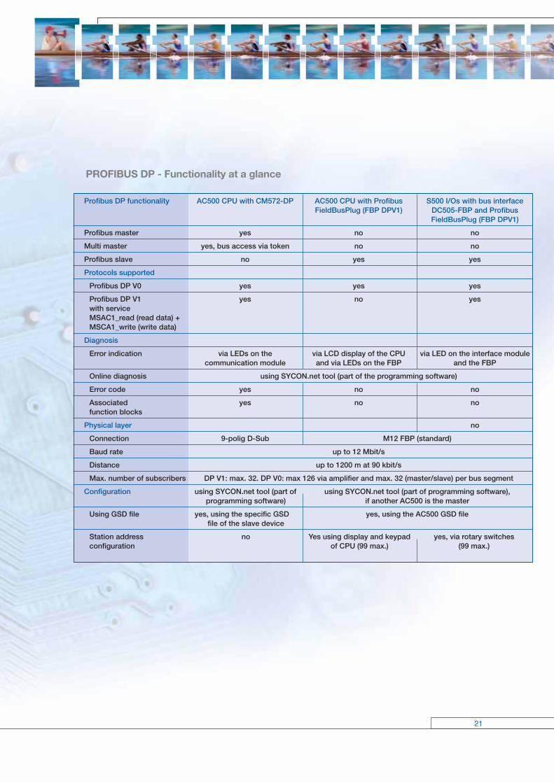
PROFIBUS DP - Functionality at a glance
21
Profibus DP functionality AC500 CPU with CM572-DP AC500 CPU with Profibus S500 I/Os with bus interface FieldBusPlug (FBP DPV1) DC505-FBP and Profibus FieldBusPlug (FBP DPV1)
Profibus master yes no no
Multi master yes, bus access via token no no
Profibus slave no yes yes
Protocols supported
Profibus DP V0 yes yes yes
Profibus DP V1 yes no yeswith serviceMSAC1_read (read data) + MSCA1_write (write data)
Diagnosis
Error indication via LEDs on the via LCD display of the CPU via LED on the interface module communication module and via LEDs on the FBP and the FBP
Online diagnosis using SYCON.net tool (part of the programming software)
Error code yes no no
Associated yes no nofunction blocks
Physical layer no
Connection 9-polig D-Sub M12 FBP (standard)
Baud rate up to 12 Mbit/s
Distance up to 1200 m at 90 kbit/s
Max. number of subscribers DP V1: max. 32. DP V0: max 126 via amplifier and max. 32 (master/slave) per bus segment
Configuration using SYCON.net tool (part of using SYCON.net tool (part of programming software), programming software) if another AC500 is the master
Using GSD file yes, using the specific GSD yes, using the AC500 GSD file file of the slave device
Station address no Yes using display and keypad yes, via rotary switchesconfiguration of CPU (99 max.) (99 max.)
22
Communication – Modbus®
Modbus® RTU (developed by Modicon in 1979)
Modbus® RTU is an open master/slave protocol, and can be easily implemented on serial interfaces.
Numerous automation systems have Modbus® RTU interfaces as standard or optional features, and are thus
easily able to communicate with the AC500 via its integrated COM1 and COM2 interfaces (RS232 or RS485).
The Modbus® is used not only in industrial applications, but also in building installations, in energy optimization
systems, for long-distance data transmission and for linking up operator panels.
Communication
By polling, i.e. the master transmits a request to the
slave and then receives the response. Both interfaces
COM1 and COM2 can operate simultaneously as
Modbus interfaces. The Modbus operating mode of
an interface is set using the engineering tool.
Topology
Point-to-point via RS232 or multi-point via RS485.
With RS232, a maximum of one master and one
slave is possible, while with RS485 one master and a
maximum of 31 slaves can be operated. The maxi-
mum cable length is 15 m with RS232 and 1.2 km
with RS485.
Data transfer
Max. 115.2 kB/s. Each telegram has a 16-bit CRC
appended. The telegrams permit process data (input/
output data) to be written and read, either individually
or in groups. The data are packed in the RTU format.
Transmission media
May vary. One widely used option is the RS485 bus
physics, a twisted-pair, shielded cable with termina-
tors.
Diagnostics
Detailed diagnostic messages for rapid trouble-shoot-
ing are shown on the CPU display.
23
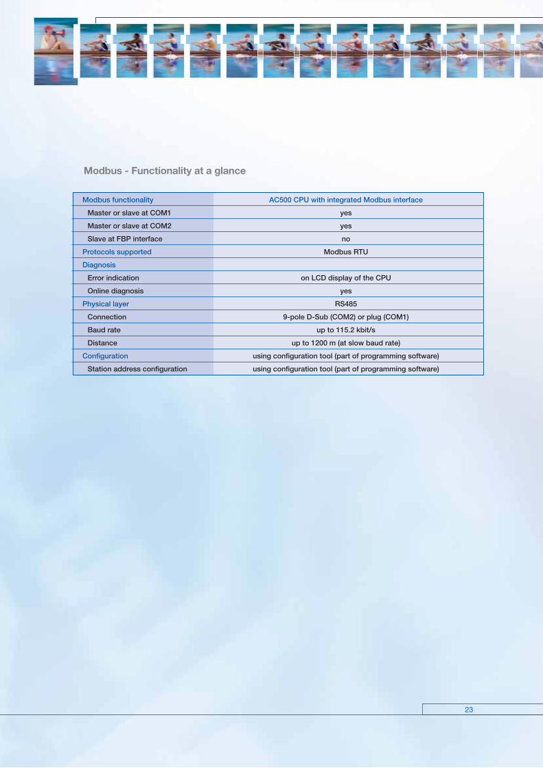
Modbus - Functionality at a glance
Modbus functionality AC500 CPU with integrated Modbus interface
Master or slave at COM1 yes
Master or slave at COM2 yes
Slave at FBP interface no
Protocols supported Modbus RTU
Diagnosis
Error indication on LCD display of the CPU
Online diagnosis yes
Physical layer RS485
Connection 9-pole D-Sub (COM2) or plug (COM1)
Baud rate up to 115.2 kbit/s
Distance up to 1200 m (at slow baud rate)
Configuration using configuration tool (part of programming software)
Station address configuration using configuration tool (part of programming software)

24
Communication – CANopen and DeviceNet
CANopen (Controller Area Network) and
DeviceNet
The CAN protocol was originally developed for the European auto-
motive industry, so as to replace expensive cabling by an affordable
network cable. Today, it is also used in the field of automation for
transmitting process data between control systems, decentralized
I/O modules, drives, valves, etc. CAN features a high level of transmission security, since large portions of the
monitoring mechanisms have been implemented directly in the CAN chip. DeviceNet and CANopen utilize the
physical structure and the data transport mechanisms of CAN (Controller Area Network). The difference lies in
the transmission protocols. DeviceNet and CANopen can be used correspondingly for the AC500 and AC31
controller series and for field-bus-neutral FBP devices (decentralized I/Os and intelligent switching devices).
Data transmission
Two types of message have been defined: I/O data
transfer and direct link. I/O data transfer is used for
time-critical process data, while the direct link can
be, for example, used for diagnostic messages.
Bus access for subscribers
The connection ID with the lower address has higher
priority on the bus. Data is transmitted by the source,
while the sinks (i.e. receivers of the data) have like-
wise been specified during the configuration phase.

Transmission rate 125 kBit/s 250 kBit/s 500 kBit/s
Max. cable length of trunk line 500 m 250 m 100 mTrunk cable (1610 ft) (820 ft) (328 ft)
Max. cable length of trunk line 100 m 100 m 100 mDrop cable (328 ft) (328 ft) (328 ft)
Max. cable length per branch line 6 m 6 m 6 mTrunk cable/Drop cable (20 ft) (20 ft) (20 ft)
Max. cable length total branch line 156 m 78 m 39 mTrunk cable/Drop cable (512 ft) (256 ft) (128 ft)
25
CANopen
The bus operates on the master/slave principle with
one master and up to 127 slaves. A shielded twisted-
pair cable is used, according to ISO 11898. Cable
lengths and transmission rates: from max. 40 m at
1 MBit/s to 1000 m at 20 kBit/s.
DeviceNet
The bus operates on the multi-master and/or the
master/slave principle, with up to 64 bus subscribers.
Two types of shielded twisted-pair cables are used:
trunk cable for the main line and drop cable for the
branch line.
Diagnostics
Detailed diagnostic messages for rapid trouble-
shooting are shown on the CPU display. In addition,
the device status is indicated at the communication
module by four LEDs.

CANopen - Functionality at a glance
26
Communication – CANopen and DeviceNet
CANopen functionality AC500 with communication AC500 CPU with CANopen S500 I/Os with bus interface module CM578-CN FieldBusPlug (FBP) DC505-FBP and CANopen FieldBusPlug (FBP)
Master yes (client) no no
Slave no yes yes
Protocols supported
CAN 2.0A (11 bit identifier) yes yes yes
CAN 2.0B (29 bit identifier) yes no no
CiA DS401 integrated yes no nodevice profile
CiA DS402 integrated yes no nodevice profile
CiA DS406 integrated yes no nodevice profile
Data transfer
Event triggered yes yes yes
Synchronous yes yes yes
Cyclic yes yes yes
Remote PDO transmission yes yes yes
Node guarding yes yes yes
Heartbeat yes yes yes
Diagnosis
Error indication using LEDs on the via LCD-Display of the CPU via LEDs on the interface communication module and the LEDs on the FBP module and on the FBP
Online diagnosis using SYCON.net tool (part of programming software)
Error code yes no no
Associated yes no nofunction blocks
Physical layer
ISO11898 yes yes yes
Connection 5-pole Combicon M12 M12
Baud rate up to 1 Mbit/s up to 500 kbit/s up to 500 kbit/s
Distance up to 1000 m at 20 kbit/s
Configuration using SYCON.net tool (part of programming software)
Configuration yes, using the specific EDS yes, EDS-file of the AC500 yes, EDS file to be using EDS file file of the slave device; configured according the non-modular EDS files only existing HW (EDS Generator part of the programming software)
Station address no yes, via display and yes, via rotary switchconfiguration keypad of the CPU on the interface module (max. 99) (max. 99)

DeviceNet - Functionality at a glance
27
DeviceNet Functionality AC500 with communication AC500 CPU with DeviceNet S500 I/Os with bus interface module CM575-DN FieldBusPlug (FBP) DC505-FBP and DeviceNet FieldBusPlug (FBP)
Master yes no no
Slave no yes yes
Protocols supported
DeviceNet (server) no yes yes
DeviceNet (client) yes no no
Data transfer
Polling yes yes yes
State changes yes yes yes
Cyclic yes yes yes
Bit strobe yes no no
Peer-to-Peer (acyclic) yes no yes
Diagnosis
Error indication using LEDs on the via LCD display of the CPU via LEDs on the interface communication module and LEDs on the FBP module and the FBP
Online diagnosis using SYCON.net tool (part of programming software)
Error code yes no no
Associated yes no nofunction blocks
Physical layer
ISO11898 yes yes yes
Connection 5-pole Combicon M12 M12
Baud rate up to 500 kbit/s up to 500 kbit/s up to 500 kbit/s
Distance up to 500m at 125 kbit/s
Configuration using SYCON.net tool (part of programming software)
Using EDS file yes, using the specific EDS file yes, using AC500 EDS file yes, EDS file to be of the slave device; configured according the non-modular EDS files only existing HW (EDS Generator part of the programming software)
Station address yes, using display and keypad yes, via rotary switches configuration of the CPU (99 max.) on the communication module (max. 99)

28
ARCNET (Attached Resource Computer NETwork)
ARCNET is an open, multi-purpose field bus solution with real-time capability. It can be used for
multi-master networking and for programming the AC500 and AC31 controller series, but also for connecting
additional ARCNET subscribers, e.g. PCs via an appropriate interface card (see catalog).
Topology
ARCNET is one of the few networks that can be
operated in every conceivable topology. Options
include bus, star, or tree topologies, or mixtures of
these. This means that ARCNET can be used for a
broad field of different applications.
Bus assignments
ARCNET operates on the token-passing procedure,
where each subscriber has equal rights.
Configuration mechanisms
ARCNET allows to add and to remove subscribers
from the network during runtime. When a new
subscriber is added, the entire network will be re-
configured.
Communication – ARCNET
ARCNET functionality AC500 CPU with integrated ARCNET interface
ARCNET for programming yes
ARCNET for communication in preparation
Collision-free data transmission yes
Guaranteed response times yes
Real-time support through token passing yes
Handshake protocol between sender and recipient yes
Variable network topology: yesBus, tree and star topologies incl. mixed topologies
Variable use of media for networking: yesCoax cable, twisted-pair cable and optical fibre
Automatic connect/disconnect of subscribers yes
Diagnosis
Error indication on LCD display of the CPU
Online diagnosis yes
Error code yes
Physical layer Token-passing system
Connection Coax cabel, type RG62/U 93ΩBaud rate 2.5 Mbit/s
Max. number of stations 255, with max. 8 stations per segment
Maximum length of segments 300m
Hub/switch integrated no
Configuration using configuration tool (part of programming software)
Station address configuration using display and keypad of the CPU

29
ARCNET
Security mechanisms
A 16-bit CRC is appended to every data packet, and
checked by the recipient. If the token is lost, a recon-
figuration routine will be initiated, and the network will
automatically be restructured. Additionally, diagnostic
registers are available.
Physical characteristics
ABB recommends coaxial cables as transmission
medium, for direct connection to the CPU. But also
twisted-pair cables or (glass, plastic) fiber-optic cables
can be connected via bus converters. The line lengths
that can be achieved without any intermediate ampli-
fiers depend not only on the used medium, but also
on the selected baud rate and the number of subscri-
bers. The ranges per segment vary from approximate-
ly 120 m for a simple two-wire bus, up to 3 km for
fiber-optics, in each case at 2.5 MBit/s. By providing
appropriate hubs, different topologies and transmis-
sion media can be combined with each other and the
transmission distance can be increased. The coaxial
cables used are a type with 93 Ohm, e.g. RG 62.
The permissible twisted-pair cables are specified in
IEEE 802.3i-1990. At 2.5 MBit/s and with coaxial
cables, for example, the maximum length of a bus
segment is 300 m with eight subscribers and without
a hub. With twisted-pair cables, under the same
conditions, a maximum length of approximately
120 m can be achieved. The maximum transmis -
sion length depends on the number of connected
subscribers. With coaxial cables, a maximum of
16 km can be achieved; with twisted-pair cables
approximately 6 km, in each case at 2.5 MBit/s. The
fiber-optic link provides the highest degree of inter-
ference immunity. With glass fiber-optics, distances
of up to 3 km are possible at 2.5 MBit/s; with plastic
fiber-optic cables only small distances of up to approx-
imately 100 m. The baud rate plays no significant role
in fiber-optic cable transmission. Here, the range can
as well be extended using hubs.
Diagnostics
Detailed diagnostic messages for rapid trouble-
shooting are shown on the CPU display.
30
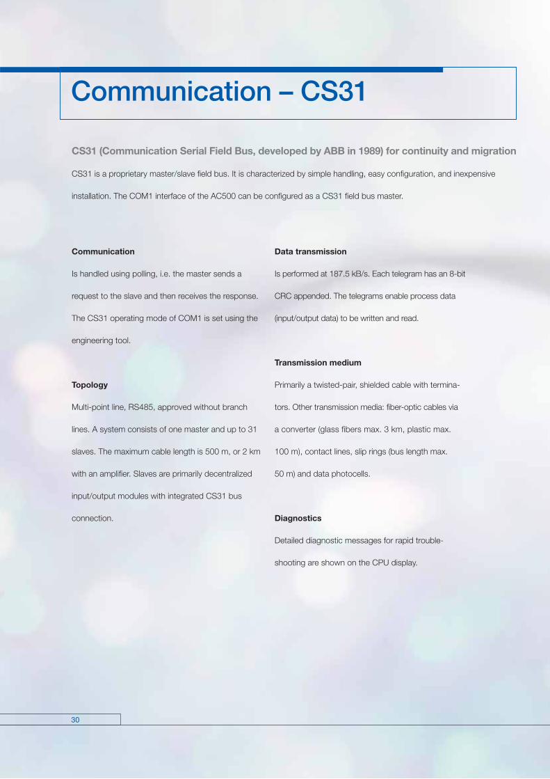
CS31 (Communication Serial Field Bus, developed by ABB in 1989) for continuity and migration
CS31 is a proprietary master/slave field bus. It is characterized by simple handling, easy configuration, and inexpensive
installation. The COM1 interface of the AC500 can be configured as a CS31 field bus master.
Communication
Is handled using polling, i.e. the master sends a
request to the slave and then receives the response.
The CS31 operating mode of COM1 is set using the
engineering tool.
Topology
Multi-point line, RS485, approved without branch
lines. A system consists of one master and up to 31
slaves. The maximum cable length is 500 m, or 2 km
with an amplifier. Slaves are primarily decentralized
input/output modules with integrated CS31 bus
connection.
Communication – CS31
Data transmission
Is performed at 187.5 kB/s. Each telegram has an 8-bit
CRC appended. The telegrams enable process data
(input/output data) to be written and read.
Transmission medium
Primarily a twisted-pair, shielded cable with termina-
tors. Other transmission media: fiber-optic cables via
a converter (glass fibers max. 3 km, plastic max.
100 m), contact lines, slip rings (bus length max.
50 m) and data photocells.
Diagnostics
Detailed diagnostic messages for rapid trouble-
shooting are shown on the CPU display.

CS31 functionality AC500 CPU with integrated CS31 S500-FBP I/O with bus interface interface DC551-CS31
Master yes, at COM1 no
Slave no yes
Protocols supported ABB CS31 protocol
Diagnosis
Error indication on LCD display of the CPU via module LEDs
Online diagnosis yes
Error code erros are recorded in the diagnosis system of the CPU
Associated function blocks yes
Physical layer RS485
Connection plug at COM1 screw-type or spring-type terminals
Baud rate 187.5 kbit/s
Distance up to 500 m; up to 2000 m using a repeater
Max. number of modules on fieldbus 31 modules max. Please note: The DC551 bus interface occupies one or two module addresses (if counters are configured onboard). Depending on the configuration, connected extension modules can occupy further module addresses.
Configuration using configuration tool (part of programming software)
Station address configuration no using rotary switches (99 max.)
31
CS31
32
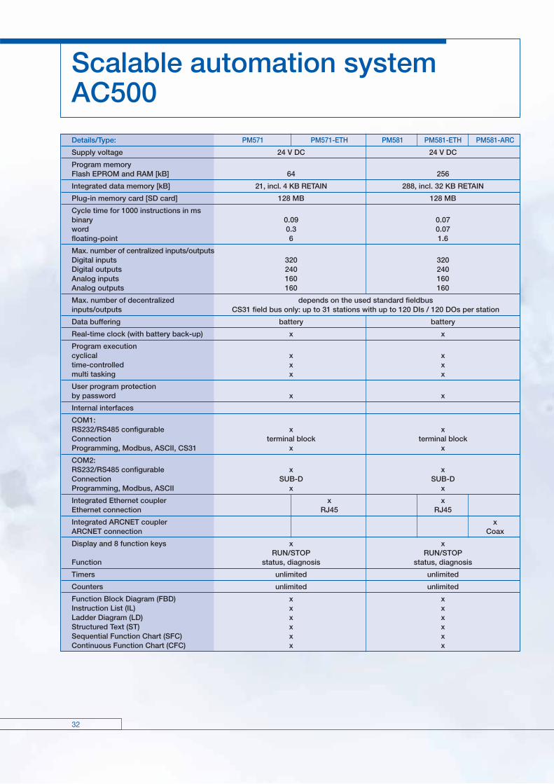
Scalable automation system AC500Details/Type: PM571 PM571-ETH PM581 PM581-ETH PM581-ARC
Supply voltage 24 V DC 24 V DC
Program memoryFlash EPROM and RAM [kB] 64 256
Integrated data memory [kB] 21, incl. 4 KB RETAIN 288, incl. 32 KB RETAIN
Plug-in memory card [SD card] 128 MB 128 MB
Cycle time for 1000 instructions in msbinary 0.09 0.07word 0.3 0.07floating-point 6 1.6
Max. number of centralized inputs/outputsDigital inputs 320 320Digital outputs 240 240Analog inputs 160 160Analog outputs 160 160
Max. number of decentralized depends on the used standard fieldbusinputs/outputs CS31 field bus only: up to 31 stations with up to 120 DIs / 120 DOs per station
Data buffering battery battery
Real-time clock (with battery back-up) x x
Program executioncyclical x x time-controlled x x multi tasking x x
User program protectionby password x x
Internal interfaces
COM1:RS232/RS485 configurable x xConnection terminal block terminal blockProgramming, Modbus, ASCII, CS31 x x
COM2:RS232/RS485 configurable x xConnection SUB-D SUB-DProgramming, Modbus, ASCII x x
Integrated Ethernet coupler x xEthernet connection RJ45 RJ45
Integrated ARCNET coupler xARCNET connection Coax
Display and 8 function keys x x RUN/STOP RUN/STOPFunction status, diagnosis status, diagnosis
Timers unlimited unlimited
Counters unlimited unlimited
Function Block Diagram (FBD) x xInstruction List (IL) x xLadder Diagram (LD) x xStructured Text (ST) x xSequential Function Chart (SFC) x xContinuous Function Chart (CFC) x x
33
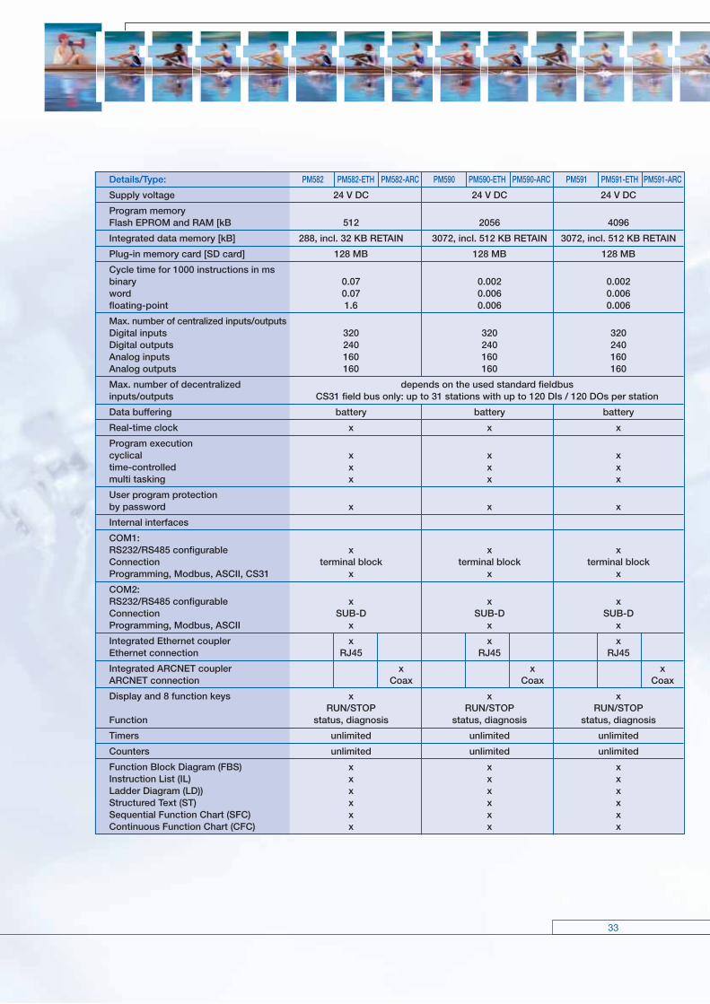
Details/Type: PM582 PM582-ETH PM582-ARC PM590 PM590-ETH PM590-ARC PM591 PM591-ETH PM591-ARC
Supply voltage 24 V DC 24 V DC 24 V DC
Program memoryFlash EPROM and RAM [kB 512 2056 4096
Integrated data memory [kB] 288, incl. 32 KB RETAIN 3072, incl. 512 KB RETAIN 3072, incl. 512 KB RETAIN
Plug-in memory card [SD card] 128 MB 128 MB 128 MB
Cycle time for 1000 instructions in msbinary 0.07 0.002 0.002word 0.07 0.006 0.006floating-point 1.6 0.006 0.006
Max. number of centralized inputs/outputsDigital inputs 320 320 320Digital outputs 240 240 240Analog inputs 160 160 160Analog outputs 160 160 160
Max. number of decentralized depends on the used standard fieldbusinputs/outputs CS31 field bus only: up to 31 stations with up to 120 DIs / 120 DOs per station
Data buffering battery battery battery
Real-time clock x x x
Program executioncyclical x x xtime-controlled x x xmulti tasking x x x
User program protectionby password x x x
Internal interfaces
COM1:RS232/RS485 configurable x x xConnection terminal block terminal block terminal blockProgramming, Modbus, ASCII, CS31 x x x
COM2:RS232/RS485 configurable x x xConnection SUB-D SUB-D SUB-DProgramming, Modbus, ASCII x x x
Integrated Ethernet coupler x x xEthernet connection RJ45 RJ45 RJ45
Integrated ARCNET coupler x x xARCNET connection Coax Coax Coax
Display and 8 function keys x x x RUN/STOP RUN/STOP RUN/STOP Function status, diagnosis status, diagnosis status, diagnosis
Timers unlimited unlimited unlimited
Counters unlimited unlimited unlimited
Function Block Diagram (FBS) x x xInstruction List (IL) x x xLadder Diagram (LD)) x x xStructured Text (ST) x x xSequential Function Chart (SFC) x x xContinuous Function Chart (CFC) x x x

3434
Scalable automation system AC500
Digital I/O modules Interface modules
DI524 DC522 DC523 DC532 DX522 DX531 DC541 DC505-FBP DC551-CS31
Number of channels per module
Digital inputs DI 32 – – 16 8 8 – 8 8
Digital outputs DO – – – – 8 4 – – –
Configurable channels DC (configurable as inputs or outputs)
– 16 24 16 – – 8 8 16
Additional configuration of channels as
fast counterConfiguration of max. 2 channels per module.
Operating modes see table on page 33.– Yes.
See table onpage 34 for
possibleconfigurations
–
Configurationof max. 2 chan-nels p. module.
Operating modes see table on
page 33.
pulse-width modulator – – – – – – – –
rpm, time and frequency counter – – – – – – – –
interrupt I/O – – – – – – – –
Occupies max. 1 DO or DC when used as counter – x x x – – – – x
Connection via terminal block TB5xx x x x x x x – x x
Connection via CPU terminal base. Occupiesone communication module slot.
– – – – – – x – –
Digital inputs
Input signal voltage 24 V DC230 V AC or 120 V AC
24 V DC 24 V DC 24 V DC
Frequency range – 47 … 63 Hz – – –
Input characteristic acc. to EN61132-2 Type 1 Type 2 Type 1 Type 1 Type 1
0 signal – 3 V DC ... + 5 V DC 0 ... 40 V AC– 3 V DC ... +
5 V DC– 3 V DC ... + 5 V DC
Undefined signal state > + 5 V DC ... < + 15 V DC> 40 V AC ...< 74 V AC
> + 5 V DC ... < + 15 V DC
> + 5 V DC ... < + 15 V DC
1 signal + 15 V DC ... + 30 V DC 74 ... 265 V AC> + 5 V DC ... < + 15 V DC
+ 15 V DC ... + 30 V DC
Residual ripple, range for 0 signal – 3 V DC ... + 5 V DC –– 3 V DC ... + 5 V DC
– 3 V DC ... + 5 V DC
Residual ripple, range for 1 signal + 15 V DC ... + 30 V DC –+ 15 V DC ... +
30 V DC+ 15 V DC ... + 30 V DC
Input time delay(0 -> 1 or 1 -> 0)
8 ms typically, configurable from 0.1 up to 32 ms20 ms
typically
8 ms typically,configurable
from 0.1 up to32 ms
8 ms typically,configurable from0.1 up to 32 ms
Input current per channel
at input voltage + 24 V DC 5 mA typ. – 5 mA typ. 5 mA typ.
at input voltage + 5 V DC > 1 mA – > 1 mA > 1 mA
at input voltage + 15 V DC > 5 mA – > 5 mA > 5 mA
at input voltage + 30 V DC < 8 mA < 8 mA < 8 mA
at input voltage 159 V AC – > 7 mA – – –
at input voltage 40 V AC – < 5 mA – – –
Digital outputs
Transistor outputs 24 V DC, 0.5 A – x x x – – x x x
Readback of output – x x x – – x x x
Relay outputs, supplied via process voltageUP, changeover contacts
– – – – x x – x –
Switching of 24 V load – x x x x x x x x
Switching of 230 V load – – – – x x – – –
Output voltage at signal state 1 Process voltage UP minus 0.8 V – –Process
voltage UPminus 0.8 V
Process voltage UPminus 0.8 V
Output current
Nominal current per channel – 500 mA at UP = 24 V500 mA atUP = 24 V
500 mA at UP = 24 V
Maximum (total current of all channels) – 8 A 8A 4 A 8 A
Residual current at signal state 0 – < 0.5 mA < 0.5 mA < 0.5 mA
Demagnetization when switching offinductive loads – by internal varistors by internal
varistors by internal varistors
3535
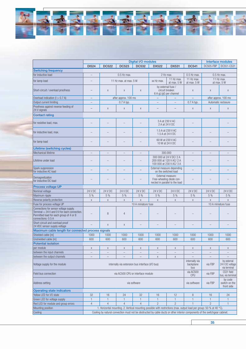
Switching frequencyfor inductive load – 0.5 Hz max. 2 Hz max. 0.5 Hz max. 0.5 Hz max.
for lamp load – 11 Hz max. at max. 5 W xx Hz max. 11 Hz max.at max. 5 W
11 Hz max.at max. 5 W
11 Hz max.at max. 5 W
Short-circuit / overload proofness – x x xby external fuse /circuit breaker.
6 A gL/gG per channelx x x
Overload indication (I > 0.7 A) – after approx. 100 ms – – – after approx. 100 msOutput current limiting – 0.7 A typ. – – 0.7 A typ. Automatic reclosureProofness against reverse feeding of24 V signals – x x x – – x x x
Contact rating
for resistive load, max. – – – – 3 A at 230 V AC2 A at 24 V DC – –
for inductive load, max. – – – – 1.5 A at 230 V AC1.5 A at 24 V DC – – –
for lamp load – – – – 60 W at 230 V AC10 W at 24 V DC – – –
Lifetime (switching cycles)Mechanical lifetime – – – – 300.000 – – –
Lifetime under load – – – –300 000 at 24 V DC/ 2 A200 000 at 120 V AC/ 2 A100 000 at 230 V AC/ 3 A
– – –
Spark suppressionfor inductive AC load – – – – External measure depending
on the switched load – – –
Demagnetizationfor inductive DC load – – – –
External measure:Free-wheeling diode con-
nected in parallel to the load– – –
Process voltage UPNominal voltage 24 V DC 24 V DC 24 V DC 24 V DC 24 V DC 24 V DC 24 V DC 24 V DC 24 V DCMaximum ripple 5 % 5 % 5 % 5 % 5 % 5 % 5 % 5 % 5 %Reverse polarity protection x x x x x x x x xFuse for process voltage UP 10 A miniature fuse 10 A miniature fuseConnections for sensor voltage supply.Terminal + 24 V and 0 V for each connection.Permitted load for each group of 4 or 8connections: 0.5 A
– 8 4 – – – – – –
Short-circuit and overload proof24 VDC sensor supply voltage – x x – – – – – –
Maximum cable length for connected process signalsShielded cable [m] 1000 1000 1000 1000 1000 1000 1000 1000 1000Unshielded cable [m] 600 600 600 600 600 600 600 600 600Potential isolationper module x x x x x x x x xbetween the input channels – – – – – – – – –between the output channels – – – – x x – – –
Voltage supply for the module internally via extension bus interface (I/O bus)internally viabackplane
busvia FBP
by external24 V DC voltage
via terminal
Field bus connection via AC500 CPU or interface module via AC500CPU via FBP CS31 field
bus, via terminal
Address setting via software via software via FBPby code
switch on thefront side
Operating state indicatorsYellow LED for I/O state 32 16 24 32 16 12 8 16 24Green LED for voltage supply 1 1 1 1 1 1 1 1 1Red LED for module and group errors 4 4 4 4 2 2 1 2 1Mounting position 1. Horizontal mounting. 2. Vertical mounting possible with restrictions (max. output load per group: 50 % at 40 °C).Cooling Cooling by natural convection must not be obstructed by cable ducts or other interior components of the switchgear cabinet.
Digital I/O modules Interface modulesDI524 DC522 DC523 DC532 DX522 DX531 DC541 DC505-FBP DC551-CS31
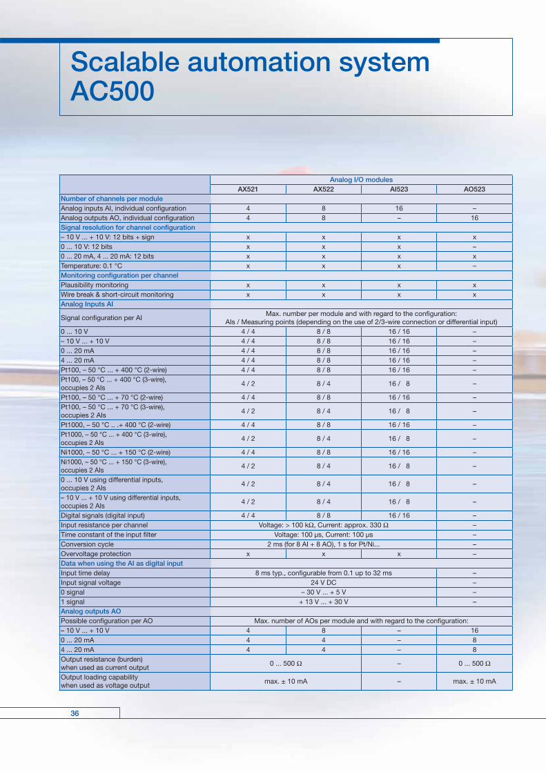
Analog I/O modulesAX521 AX522 AI523 AO523
Number of channels per moduleAnalog inputs AI, individual configuration 4 8 16 –Analog outputs AO, individual configuration 4 8 – 16Signal resolution for channel configuration– 10 V ... + 10 V: 12 bits + sign x x x x0 ... 10 V: 12 bits x x x –0 ... 20 mA, 4 ... 20 mA: 12 bits x x x xTemperature: 0.1 °C x x x –Monitoring configuration per channelPlausibility monitoring x x x xWire break & short-circuit monitoring x x x xAnalog Inputs AI
Signal configuration per AIMax. number per module and with regard to the configuration:
AIs / Measuring points (depending on the use of 2/3-wire connection or differential input)0 ... 10 V 4 / 4 8 / 8 16 / 16 –– 10 V ... + 10 V 4 / 4 8 / 8 16 / 16 –0 ... 20 mA 4 / 4 8 / 8 16 / 16 –4 ... 20 mA 4 / 4 8 / 8 16 / 16 –Pt100, – 50 °C ... + 400 °C (2-wire) 4 / 4 8 / 8 16 / 16 –Pt100, – 50 °C ... + 400 °C (3-wire),occupies 2 AIs
4 / 2 8 / 4 16 / 8 –
Pt100, – 50 °C ... + 70 °C (2-wire) 4 / 4 8 / 8 16 / 16 –Pt100, – 50 °C ... + 70 °C (3-wire),occupies 2 AIs
4 / 2 8 / 4 16 / 8 –
Pt1000, – 50 °C .. .+ 400 °C (2-wire) 4 / 4 8 / 8 16 / 16 –Pt1000, – 50 °C ... + 400 °C (3-wire),occupies 2 AIs
4 / 2 8 / 4 16 / 8 –
Ni1000, – 50 °C ... + 150 °C (2-wire) 4 / 4 8 / 8 16 / 16 –Ni1000, – 50 °C ... + 150 °C (3-wire),occupies 2 AIs
4 / 2 8 / 4 16 / 8 –
0 ... 10 V using differential inputs,occupies 2 AIs
4 / 2 8 / 4 16 / 8 –
– 10 V ... + 10 V using differential inputs,occupies 2 AIs
4 / 2 8 / 4 16 / 8 –
Digital signals (digital input) 4 / 4 8 / 8 16 / 16 –Input resistance per channel Voltage: > 100 kΩ, Current: approx. 330 Ω –Time constant of the input filter Voltage: 100 µs, Current: 100 µs –Conversion cycle 2 ms (for 8 AI + 8 AO), 1 s for Pt/Ni... –Overvoltage protection x x x –Data when using the AI as digital inputInput time delay 8 ms typ., configurable from 0.1 up to 32 ms –Input signal voltage 24 V DC –0 signal – 30 V ... + 5 V –1 signal + 13 V ... + 30 V –Analog outputs AOPossible configuration per AO Max. number of AOs per module and with regard to the configuration:– 10 V ... + 10 V 4 8 – 160 ... 20 mA 4 4 – 84 ... 20 mA 4 4 – 8Output resistance (burden)when used as current output
0 ... 500 Ω – 0 ... 500 Ω
Output loading capabilitywhen used as voltage output
max. ± 10 mA – max. ± 10 mA
3636
Scalable automation system AC500
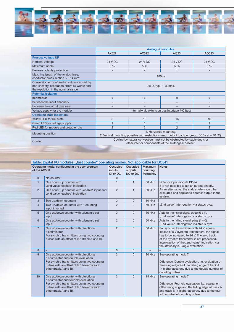
Process voltage UPNominal voltage 24 V DC 24 V DC 24 V DC 24 V DCMaximum ripple 5 % 5 % 5 % 5 %Reverse polarity protection x x x xMax. line length of the analog lines,conductor cross section > 0.14 mm²
100 m
Conversion error of analog values caused bynon-linearity, calibration errors ex works andthe resolution in the nominal range
0.5 % typ., 1 % max.
Potential isolationper module x x x xbetween the input channels – – – –between the output channels – – – –Voltage supply for the module internally via extension bus interface (I/O bus)Operating state indicatorsYellow LED for I/O state 8 16 16 16Green LED for voltage supply 1 1 1 1Red LED for module and group errors 2 2 2 2
Mounting position1. Horizontal mounting.
2. Vertical mounting possible with restrictions (max. output load per group: 50 % at + 40 °C).
CoolingCooling by natural convection must not be obstructed by cable ducts or
other interior components of the switchgear cabinet.
Table: Digital I/O modules, „fast counter“ operating modes. Not applicable for DC541Operating mode, configured in the user program of the AC500
OccupiedinputsDI or DC
OccupiedoutputsDO or DC
Maximumcountingfrequency
Notes
0 No counter 0 0 – –1 One count-up counter with
„end value reached“ indication1 1 50 kHz Note for input module DI524:
It is not possible to set an output directly.As an alternative, the status byte should beevaluated and applied to another output in thesystem.
2 One count-up counter with „enable“ input and„end value reached“ indication
2 1 50 kHz
3 Two up/down counters 2 0 50 kHz„End value“ interrogation via status byte.4 Two up/down counters with 1 counting
input inverted2 0 50 kHz
5 One up/down counter with „dynamic set“ input
2 0 50 kHz Acts to the rising signal edge (0->1).„End value“ interrogation via status byte.
6 One up/down counter with „dynamic set“ input
2 0 50 kHz Acts to the falling signal edge (1->0).„End value“ interrogation via status byte.
7 One up/down counter with directionaldiscriminator.For synchro transmitters using two countingpulses with an offset of 90° (track A and B).
2 0 50 kHz For synchro transmitters with 24 V signals. Incase of 5 V synchro transmitters, the signalhas to be increased to 24 V. The zero trackof the synchro transmitter is not processed.Interrogation of the „end value“ indication via the status byte. Single evaluation.
8 – 0 0 – –9 One up/down counter with directional
discriminator and double evaluation.For synchro transmitters using two countingpulses with an offset of 90° towards each other (track A and B).
2 0 30 kHz See operating mode 7.
Difference: Double evaluation, i.e. evaluation ofthe rising edge and the falling edge of track A-> higher accuracy due to the double number ofcounting pulses.
10 One up/down counter with directionaldiscriminator and fourfold evaluation.For synchro transmitters using two countingpulses with an offset of 90° towards each other (track A and B).
2 0 15 kHz See operating mode 7.
Difference: Fourfold evaluation, i.e. evaluation ofthe rising edge and the falling edge of track A and track B -> higher accuracy due to the four-fold number of counting pulses.
Analog I/O modulesAX521 AX522 AI523 AO523
3737

Table: Possible configurations for the multifunctional module DC541
Configurationas
Function/ Configuration
for channel no.Chan.
0Chan.
1Chan.
2Chan.
3Chan.
4-7
Max. no.of chan-
nelsfor thisfunction
Remarks and notes regarding possible alternativecombinations of the remaining channels (a and b)
Mode 1: Interrupt functionality, mutually exclusive with mode 2 (counting functionality)
InterruptDigital input 1 1 1 1 4 8 Each channel can be configured individually as interrupt
input or interrupt output.Digital output 1 1 1 1 4 8Mode 2: Counting functionality and multifunctional I/Os, mutually exclusive with mode 1 (interrupt functionality)
Mul
tifu
ncti
ona
l I/O
s, d
igit
al I/
Os,
PW
M, c
oun
ter,
tim
e an
d f
req
uenc
y m
easu
rem
ent
Digital input 1 1 1 1 4 8 Usual input.Digital output 1 1 1 1 4 8 Usual output.PWM, resoluti-on10 kHz 1 1 1 1 4 8 Outputs a pulsed signal with an adjustable on-off ratio.
Up/downcounter, 50 kHz 1 1 OK
*1)OK*1)
OK*1) 2
*1)a) Both channels (0 and 1) configured as 50 kHz counters=> channels 2 to 7 can be configured as digital I/Os.b) Only one channel (0 or 1) configured as 50 kHz counter=> the second channel can be configured as counter< 50 kHz or for time/frequency measurement with a max.resolution of 200 µs. The remaining channels (2 to 7) canbe configured as digital I/Os.
Up/downcounter, 5 kHz 1 1 1 1 OK
*2) 4
*2)a) Four channels (0 to 3) configured as 5 kHz counters=> channels 4 to 7 can be configured as digital I/Os.b) Not all of the four channels 0 to 3 configured as 5 kHzcounter => the remaining channels (of chan. 0 to 3) can beconfigured as counters for 2.5 kHz or for time/frequencymeasurement with a max. resolution of 200 µs as desired.The remaining channels (4 to 7) can be configured asdigital I/Os.
Up/downcounter, 2.5 kHz
1 1 1 1 4 8
Time/frequencymeasurement,resolution 1 µs
1 OK*3)
OK*3)
OK*3)
OK*3) 1
*3)Channel 0 configured for a max. resolution of 50 µs=> channels (1 to 7) can be configured as digital I/Os.
Time/frequencymeasurement,resolution 100 µs
1 1 OK*4)
OK*4)
OK*4) 2
*4)a) Both channels (0 and 1) configured for a max. resolutionof 50 µs => chan. 2 to 7 can be configured as digital I/Os.b) Only one channel (0 or 1) configured for a max. resolutionof 50 µs => the second channel can be configured ascounter < 50 kHz or for time/frequency measurement witha max. resolution of 200 µs. The remaining channels (2 to7) can be configured as digital I/Os.
Time/frequencymeasurement,resolution 200 µs
1 1 1 1 4 8 Times, frequencies and rotational speeds are measuredwith a maximum resolution of 200 µs.
Fas
t co
unte
r
Bidirectional32 bit counter,50 kHz max.
Channels 0 to 3:track A, track B, zero track,
touch trigger
OK*6) 1
For connection of an incremental transmitter. For signalsup to 50 kHz (corresponds to a motor with a rotationalspeed of 3000 rpm). The counter always occupies the first4 channels (0 to 3).*6) The remaining channels (4 to 7) can be configuredas limit values, as 5 kHz counters, for time/frequencymeasurement with a resolution of 200 µs or as digital I/Os.
Shaft (endlesscounting) 1 OK
*7) 1
„Endless“ forward counting. An overflow occurscorresponding to the 32 bit value.*7) The remaining channels can be configured aslimit values, as 5 kHz counters, for time/frequencymeasurement with a resolution of 200 µs or as digital I/Os.
32 bit counterincl. sign 1 OK
*8) 1*8) The remaining channels can be configured aslimit values, as 5 kHz counters, for time/frequencymeasurement with a resolution of 200 µs or as digital I/Os.
Limit values for32 bit counter
OK *9) 1 1
Various counting values of the 32 bit counter can bedisplayed directly via these outputs.*9) In this case, the channels 0 to 3 are used as 32 bit counters.
3838
Scalable automation system AC500

Operating and environmental conditions / System dataVoltages according to EN 61131-2
24 V DC Process and supply voltage 24 V DC (–15%, +20% without residual ripple) Absolute limits 19.2 V ... 30 V incl. residual ripple Residual ripple < 5% Polarity reversal protection 10 s
120 V AC Supply voltage 120 V AC (–15%, +10%) Frequency 47 Hz ... 62.4 Hz/50 ... 60 Hz (–6%, +4%)
230 V AC Supply voltage 230 V AC (–15 %, +10%) Frequency 47 Hz ... 62.4 Hz/50 ... 60 Hz (–6%, +4%)
120–240 V AC Wide voltage input Voltage 102 V ... 264 V/120 V ... 240 V (–15%, +10%) Frequency 47 Hz ... 62.4 Hz/50 ... 60 Hz (– 6%, +4%)
Power failure bridging time according DC supply Failure < 10 ms, time between 2 failures > 1 s, PS2to EN 61131-2 AC supply Failure < 0.5 periods, time between 2 failures > 1 s
Temperature Operation 0 °C ... +60 °C for horizontal mounting Storage -25 °C ... +75 °C Transport -25 °C ... +75 °C
Humidity 95% max., no condensation
Air pressure Operation > 800 hPa /< 2000 m Storage > 660 hPa / < 3500 m
Creepage distances and clearances The creepage distances and clearances correspond to Overvoltage Category II, Pollution Severity 2
Electromagnetic compatibilityInterference immunity
against electrostatic discharge (ESD) acc. to EN 61000-4-2, Zone B, Criteria B interference voltage with air discharge 8 kVinterference voltage with contact discharge 6 kV
Interference immunity
against radiated interferences (CW radiated) acc. to EN 61000-4-3, Zone B, Criteria A Test field strength 10 V/m
Interference immunity
against transient interference voltages (burst) acc. to EN 61000-4-4, Zone B, Criteria B
Interference immunity
against conduction-bound interferences (CW conducted) acc. to EN 61000-4-6, Zone B, Criteria ATest voltage 3V Zone B
Impulse voltage acc. to EN 61000-4-5, Zone B, Criteria B
Emitted interferences acc. to EN 55011, Group 1, Class A
Mechanical data Connection type / terminals Mounting horizontalDegree of protection IP 20Housing acc. to UL 94Vibration resistance all three axes 2 Hz ... 15 Hz, continuously 3.5 mm 15 Hz ... 150 Hz, continuously 1 g (4 g in preparation)Vibration resistance with SD card plugged in 15 Hz ... 150 Hz, continuously 1 gShock resistance all three axes 15 g, 11 ms, semi-sinusoidalDevice mounting DIN top-hat rail acc. to DIN EN 50022 35 mm, overall height 7,5 mm or 15 mmScrew mounting Screws with 4 mm diameterTorque 1.2 Nm
3939

40
Operating and displayingOperator panels CP400 – Overview
CP410M CP420B CP430B CP430-ETH
Reference 1SBP 260 181 R1001 1SBP 260 182 R1001 1SBP 260 183 R1001 1SBP 260 184 R1001
Screen type LCD16 gray
Touch16 blue, STN
Touch16 blue, STN
Touch16 blue, STN
Screen size 3'' 4.7'' 5.7'' 5.7''l
Display resolution (pixels) 160 x 80 320 x 240 320 x 240 320 x 240
Helligkeit (cd/m2) 36 110 110 110
Contrast adjustment via rotary switch via touch panal via touch panel and via rotary
switch on the back
via touch panel and via rotary
switch on the back
Backlight type LED CCFT CCFT CCFT
Backlight life time (h) 75.000 50.000 50.000 50.000
Touch screen life time (number of touch operations)
> 500.000 > 1.000.000 > 1.000.000 > 1.000.000
Function keys 16 (10 can be used as function keys)
-5 function keys + 1 menu key
5 function keys + 1 menu key
Ethernt - - -
Alarm management -
Recipe management - - -
Memory - - - 512 KB
Trend curves -
Data storage (CF card – Compact Flash)
- - - -
Communication interface 1 2 2 2
USB 2.0- - - -
Printer port - - -
Voltage supply < 330 mA < 500 mA < 840 mA < 840 mA
Housing dimensions (W x H x D) in mm 173 x 106 x 52 170 x 103 x 45 195 x 145 x 60 195 x 145 x 60
Weight (kg) 0,65 0,47 0,81 0,81
32-Bit-RISC-Prozessor
Graphic and Text
Macro and Ladder
Online- and Offline-Simulation
Real Time Clock
Password protection
4 MB Flash Memory
24 V DC ± 15% supply voltage
Ambient temperature: 0 bis 50 °C
Protection class IP65
Conform to RoHs
41
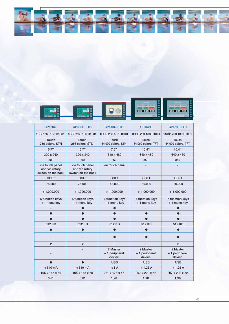
CP430C CP430B-ETH CP440C-ETH CP450T CP450T-ETH
1SBP 260 185 R1001 1SBP 260 186 R1001 1SBP 260 187 R1001 1SBP 260 188 R1001 1SBP 260 189 R1001
Touch256 colors, STN
Touch256 colors, STN
Touch64.000 colors, STN
Touch64.000 colors, TFT
Touch64.000 colors, TFT
5.7'' 5.7'' 7.5'' 10.4'' 10.4''
320 x 240 320 x 240 640 x 480 640 x 480 640 x 480
300 300 350 350 350
via touch panel and via rotary
switch on the back
via touch panel and via rotary
switch on the back
via touch panal - -
CCFT CCFT CCFT CCFT CCFT
75.000 75.000 45.000 50.000 50.000
> 1.000.000 > 1.000.000 > 1.000.000 > 1.000.000 > 1.000.000
5 function keys + 1 menu key
5 function keys + 1 menu key
6 function keys + 1 menu key
7 function keys + 1 menu key
7 function keys + 1 menu key
- -
512 KB 512 KB 512 KB 512 KB 512 KB
- -
2 2 3 3 3
-- 2 Master
+ 1 peripheral device
2 Master + 1 peripheral
device
2 Master + 1 peripheral
device
USB USB USB
< 840 mA < 840 mA < 1 A < 1,25 A < 1,25 A
195 x 145 x 60 195 x 145 x 60 231 x 176 x 47 297 x 222 x 52 297 x 222 x 52
0,81 0,81 1,20 1,90 1,90

CP501 CP502 CP503 CP511 CP512
Ident. Nr. 1SBP 260170 R1001 1SBP 260171 R1001 1SBP 260172 R1001 1SBP 260173 R1001 1SBP 260174 R1001
Display type STN-LCDwith backlight
STN-LCDwith backlight
STN-LCDwith backlight
STN-LCDwith backlight
S/W-STN-LCDwith backlight
Display Text Text Text graphics and text graphics and text
Display size 2 lines x 16 characters 2 lines x 20 characters 4 lines x 20 characters 240 x 64 pixels 240 x 128 pixels
Display areaW x H (mm)
55.7 x 11.0 73.5 x 11.5 70.4 x 20.8 5.2"127.2 x 33.9
5.3" 120.0 x 64.0
Text height (mm) 5 5 5 variable variable
LEDs 5 (2 colors) 16 (2 colors) 16 (2 colors)
Function keys/other keys
4 3 / 20 5 / 22(with labels)
8 (with labels)
16(8 with labeling strip)
Web functions
Buzzer
Alarm management 1 group 4 groups 4 groups
Time channel
Real-time clock
Trend curves real-time historical
Data logger
Recipemanagement
Report printing
Passwordprotection
8 levels 8 levels 8 levels 8 levels
Multilanguagesupport
Applicationmemory
16 kB Flash 64 kB Flash 64 kB Flash 400 kB Flash 400 kB Flash
Voltage supply 5 / 24 V DC 24 V DC 24 V DC 24 V DC 24 V DC
Current consumption 150 mA 450 mA 450 mA
Ambienttemperature
0 – 50 °C 0 – 50 °C 0 – 50 °C 0 – 50 °C 0 – 50 °C
Communicationinterfaces RS232 oder RS422
RS232, RS422RS485
RS232, RS422RS232, RS422
EthernetRS232, RS422
Expansion slot – – – 1 1
Degree of protectionfront cover
IP65 IP65 IP65 IP65 IP65
DimensionsW x H x D (mm)
104 x 69 x 38 142 x 100 x 29 147 x 163,5 x 38 211 x 198 x 69 214 x 232 x 87
Weight (kg) 0.2 0.5 0.7 1.5 1.4
42
Operating and displayingOperator panels CP500 – Overview
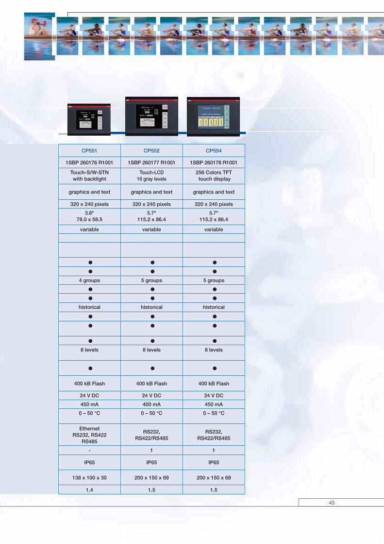
CP551 CP552 CP554
1SBP 260176 R1001 1SBP 260177 R1001 1SBP 260178 R1001
Touch-S/W-STNwith backlight
Touch-LCD16 gray levels
256 Colors TFT touch display
graphics and text graphics and text graphics and text
320 x 240 pixels 320 x 240 pixels 320 x 240 pixels
3.8"78.0 x 58.5
5.7"115.2 x 86.4
5.7"115.2 x 86.4
variable variable variable
4 groups 5 groups 5 groups
historical historical historical
8 levels 8 levels 8 levels
400 kB Flash 400 kB Flash 400 kB Flash
24 V DC 24 V DC 24 V DC
450 mA 400 mA 450 mA
0 – 50 °C 0 – 50 °C 0 – 50 °C
EthernetRS232, RS422
RS485
RS232, RS422/RS485
RS232, RS422/RS485
- 1 1
IP65 IP65 IP65
138 x 100 x 30 200 x 150 x 69 200 x 150 x 69
1.4 1.5 1.5
43
44
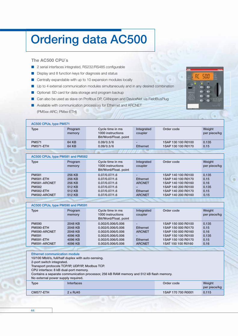
Ordering data AC500
The AC500 CPU´s 2 serial interfaces integrated, RS232/RS485 configurable
Display and 8 function keys for diagnosis and status
Centrally expandable with up to 10 expansion modules locally
Up to 4 external communication modules simultaneously and in any desired combination
Optional: SD card for data storage and program backup
Can also be used as slave on Profibus DP, CANopen and DeviceNet via FieldBusPlug
Available with communication processors for Ethernet and ARCNET
(PM5xx-ARC; PMxx-ETH)
AC500 CPUs, type PM571
Type Program Cycle time in ms Integrated Order code Weight memory 1000 instructions coupler per piece/kg Bit/Word/Float. point
PM571 64 KB 0.09/0.3/6 - 1SAP 130 100 R0100 0.135 PM571-ETH 64 KB 0.09/0.3/6 Ethernet 1SAP 130 100 R0170 0.15
AC500 CPUs, type PM581 and PM582
Type Program Cycle time in ms Integrated Order code Weight memory 1000 instructions coupler per piece/kg Bit/Word/Float. point
PM581 256 KB 0.07/0.07/1.6 - 1SAP 140 100 R0100 0.135 PM581-ETH 256 KB 0.07/0.07/1.6 Ethernet 1SAP 140 100 R0170 0.15 PM581-ARCNET 256 KB 0.07/0.07/1.6 ARCNET 1SAP 140 100 R0160 0.16PM582 512 KB 0.07/0.07/1.6 – 1SAP 140 200 R0100 0.135PM582-ETH 512 KB 0.07/0.07/1.6 Ethernet 1SAP 140 200 R0170 0.15PM582-ARCNET 512 KB 0.07/0.07/1.6 ARCNET 1SAP 140 200 R0160 0.15
AC500 CPUs, type PM590 and PM591
Type Program Cycle time in ms Integrated Order code Weight memory 1000 instructions coupler per piece/kg Bit/Word/Float. point
PM590 2048 KB 0.002/0.006/0.006 - 1SAP 150 000 R0100 0.135 PM590-ETH 2048 KB 0.002/0.006/0.006 Ethernet 1SAP 150 000 R0170 0.15PM590-ARCNET 2048 KB 0.002/0.006/0.006 ARCNET 1SAP 150 000 R0160 0.16 PM591 4096 KB 0.002/0.006/0.006 - 1SAP 150 100 R0100 0.135PM591-ETH 4096 KB 0.002/0.006/0.006 Ethernet 1SAP 150 100 R0170 0.15PM591-ARCNET 4096 KB 0.002/0.006/0.006 ARCNET 1SAT 150 100 R0160 0.16
Ethernet communication module10/100 Mbit/s, full/half duplex with auto-sensing.2-port switch integrated.Transport protocols TCP/IP, UDP/IP, Modbus TCP.CPU interface: 8 kB dual-port memory.Contains a separate communication processor, 256 kB RAM memory and 512 kB flash memory.No external power supply required.
Type Interfaces Order code Weight per piece/kg
CM577-ETH 2 x RJ45 1SAP 170 700 R0001 0.115

45
Profibus DP communication moduleFor Profi bus DP master V0/V1. Multi master funcitonality. Transfer rate: 9.6 kbit/s up to 12 Mbit/s. Max. no. of subscribers: 126 (V0) or 32 (V1). CPU interface: 8 kB dual-port memory. Contains a separate communication processor and 256 kB RAM memory.No external power supply required.
Type Interface Order code Weight per piece/kg
CM572-DP Sub-D socket 1SAP 170 200 R0001 0.115
DeviceNet communication moduleFor DeviceNet master. Transfer rate: 125 kbit/s, 250 kbit/s, 500 kbit/s.CPU interface: 8 kB dual-port memory.Contains a separate communication processor, 256 kB RAM memory and 512 kB fl ash memory.No external power supply required.
Type Interface Order code Weight per piece/kg
CM575-DN Plug-in terminal block, spring-type terminals 1SAP 170 500 R0001 0.115
CANopen communication moduleFor CANopen master. Transfer rate: 10 kbit/s up to 1 Mbit/s.CPU interface: 8 kB dual-port memory.Contains a separate communication processor, 256 kB RAM memory and 512 kB fl ash memory.No external power supply required.
Type Interface Order code Weight per piece/kg
CM578-CN Plug-in terminal block, spring-type terminals 1SAP 170 800 R0001 0.115
Terminal baseFor mounting and connection of the CPUs and communication modules1 to 4 plug-in communication modulesConnection for communication coupler integrated in the CPUI/O interface for direct connection of up to 10 expansion modulesFieldbus-neutral FieldBusPlug-Slave interfaceConnection COM1: 9-pole pluggable terminal blockConnection COM2: 9-pole SUB-D (socket)
Type Number of Connection for coupler Order code Weight coupler slots integrated in the CPU per piece/kg
TB511-ETH 1 Ethernet RJ45 1SAP 111 100 R0170 TB511-ARCNET 1 ARCNET COAX 1SAP 111 100 R0160 TB521-ETH 2 Ethernet RJ45 1SAP 112 100 R0170 0.215TB521-ARCNET 2 ARCNET COAX 1SAP 112 100 R0160 TB541-ETH 4 Ethernet RJ45 1SAP 114 100 R0170
Interface modulesFor decentralized I/OsDC505-FBP Communication via FieldBusPlug with Profi bus DP or DeviceNet (in preparation: CANopen) Fieldbus-dependent FieldBusPlug requiredDC551-CS31 Communication via internal interface with CS31 system bus Plug-in electronic modules, terminal block TU551 or TU552 required DC: Channels can be confi gured individually as inputs or outputs
Type Number of Input Output Order code Weight DI/DO/DC signal signal per piece/kg
DC505-FBP 8/–/ 8 24 V DC Trans. 24 V DC, 0.5 A 1SAP 220 000 R0001 0.3DC551-CS31 8/ –/16 24 V DC Trans. 24 V DC, 0.5 A 1SAP 220 500 R0001 0.3

46
Ordering data AC500
Digital input/output modules- For central expansion of the AC500 CPUs (up to 10 digital or analog modules in any combination)- For decentralized expansion in combination with interface module DC505-FBP or DC551-CS31 (up to 7 digital or analog modules with a maximum of 4 analog modules)- Plug-in electronic modules, terminal block required (refer to table below)- Exception: DC541 (occupies one communication module slot on the CPU terminal base, no terminal block required)- DC: Channels can be confi gured individually as inputs or outputs.
Type Number of Input Relay/ Output Order code Weight DI/ DO/DC signal transistor signal per piece/kg outputs
DI524 32 /–/– 24 V DC – – 1SAP 240 000 R0001 0.2DC522 –/–/16 24 V DC Transistor 24 V DC, 0.5 A 1SAP 240 600 R0001 0.2DC523 –/–/24 24 V DC Transistor 24 V DC, 0.5 A 1SAP 240 500 R0001 0.2DC532 16/–/16 24 V DC Transistor 24 V DC, 0.5 A 1SAP 240 100 R0001 0.2DX522 8/8/– 24 V DC Relay 230 V AC, 3 A1) 1SAP 245 200 R0001 0.3DX531 8/4/– 230 V AC Relay 230 V AC, 3 A1) 1SAP 245 000 R0001 0.3DC541-CM2) –/–/8 24 V DC Transistor 24 V DC, 0.5 A 1SAP 270 000 R0001 0.1
1) Relay outputs, changeover contacts2) Multifunctional module, refer to table on page 29 for details
Analog input/output modules- For central expansion of the AC500 CPUs (up to 10 digital or analog modules in any combination)- For decentralized expansion in combination with interface module DC505-FBP or DC551-CS31 (up to 7 digital or analog modules with a maximum of 4 analog modules)- Plug-in electronic modules, terminal block required (refer to table below)- Each channel can be confi gured individually- Resolution: 12 bits + sign
Type Number of Input Output Order code Weight AI /AO signal signal per piece/kg
AI523 16 / 0 0 ... 10 V, ±10 V - 1SAP 250 300 R0001 0.2AX521 4 / 4 0/4 ... 20 mA 1SAP 250 100 R0001 0.2AX522 8 / 8 (max. Pt100, Pt1000 ±10 V 1SAP 250 000 R0001 0.2 4 current outputs) Ni1000 0 /4 ... 20 mAAO523 0 / 16 (max. - 1SAP 250 200 R0001 0.2 8 current outputs)
Terminal blocksFor digital and analog expansion modules and interface modules.Please note: For modules with relay outputs, terminal blocks for 230 V AC (TU531/TU532) are required!For the module-terminal block assignments, please consult the table!
for I/O modules for interface modules TU515 TU516 TU531 TU532 TU505-FBP TU506-FBP TU551-CS31 TU552-CS31 screw-type spring-type screw-type spring-type screw-type spring-type screw-type spring-typeDI524 x xDC522 x xDC523 x xDC532 x xDX522 x xDX531 x xAI523 x xAX521 x xAX522 x xAO523 x xDC505-FBP x xDC551-CS31 x x
47
Type for Supply Connection type Order code Weight per piece/kg
TU505-FBP FBP interface modules Screw-type terminals 1SAP 210 200 R0001 0.3TU506-FBP FBP interface modules Spring-type terminals 1SAP 210 000 R0001 0.3 TU515 I/O modules 24 V DC Screw-type terminals 1SAP 212 200 R0001 0.3 TU516 I/O modules 24 V DC Spring-type terminals 1SAP 212 000 R0001 0.3 TU531 I/O modules AC / relay 230 V AC Screw-type terminals 1SAP 217 200 R0001 0.3 TU532 I/O modules AC / relay 230 V AC Spring-type terminals 1SAP 217 000 R0001 0.3 TU551-CS31 CS31 interface modules 24 V DC Screw-type terminals 1SAP 210 600 R0001 0.3TU552-CS31 CS31 interface modules 24 V DC Spring-type terminals 1SAP 210 400 R0001 0.3
Accessories for AC500
Type for Description Order code Weight per piece/kg
TK501 AC500 CPUs Programming cable Sub-D/Sub-D, 1SAP 180 200 R0001 0.4 COM2 length 5 m TK502 AC500 CPUs Programming cable Sub-D/ 1SAP 180 200 R0101 0.4 COM1 terminal block, length 5 mUTF21-FBP Cable for program- Connection to PC via USB interface. 1SAJ 929 400 R0001 0.1 ming the AC500 via Includes USB extension cable and the integrated fieldbus installation CD. neutral interface MC502 AC500 CPUs Memory card (SD card) 128 MB 1SAP 180 100 R0001 0.1TA521 AC500 CPUs Lithium battery for data buffering 1SAP 180 300 R0001 0.1TA523 I/O modules Pluggable marker holder for 1SAP 180 500 R0001 0.3 I/O modules, packing unit incl. 10 pcs. TA524 Terminal base Communication module, dummy housing 1SAP 180 600 R0001TA525 I/O modules White labels, packing unit incl. 10 pcs. 1SAP 180 700 R0001 0.1TA526 CPU terminal base Accessories for back plate mounting, 1SAP 180 800 R0001 0.2 packing unit incl. 10 pcs.TA527 CPU terminal base 5-pole power plug for AC500. Spare 1SAP 181 100 R0001 0.2 part. Can be plugged to CPU terminal base TB5x1. Packing unit incl. 5 pcs.TA528 CPU terminal base 9-pole COM1 plug for AC500. Spare 1 SAP 181 200 R0001 0.2 part. Can be plugged to CPU terminal base TB5x1. Packing unit incl. 5 pcs.
Programming package PS501 Control BuilderFor all AC500 CPUsAll programming languages according to IEC 61131-3Contains: 5 programming languages, sampling - trace, debugging, offline simulation, integrated visualization, trace recording (multi-channel), recipe management, Continuous Function ChartLanguages: English, German, Spanish, French, Italian, Russian, ChineseScope of delivery: Software, libraries and documentation (PDF) on CD-ROM
Type for Description Order code Weight per piece/kg
PS501-PROG all AC500 CPUs Programming package PS501 1SAP 190 100 R0002 0.3 Control Builder AC500PS541-HMI License for runtime visualization package. 1SAP 190 500 R0001 0.3 For installation and visualization of images created with the programming package PS501. Delivery includes license code and documentation.

48
Ordering data CP400
Operator panels with graphics displayLCD screen with backlight
Type Pixels Display Order code Weight p. piece/kg
CP410 M 160 x 80 3", 16 gray levels 1SBP 260 181 R1001 0.65
Operator panels with touch display
Type Pixels Display Order code Weight p. piece/kg
CP420 B 320 x 240 4,7", 16 blue levels 1SBP 260 182 R1001 0.47CP430 B 320 x 240 5,7", 16 blue levels 1SBP 260 183 R1001 0.81CP420 B-ETH 320 x 240 5,7", 16 blue levels 1SBP 260 184 R1001 0.81CP430 C 320 x 240 5,7", 256 color STN 1SBP 260 185 R1001 0.81CP430 C-ETH 320 x 240 5,7", 256 color STN 1SBP 260 186 R1001 0.81CP440 C-ETH 640 x 480 7,7", 64.000 color STN 1SBP 260 187 R1001 1.20CP450 T 640 x 480 10,4", 64.000 color TFT 1SBP 260 188 R1001 1.90CP450 T-ETH 640 x 480 10,4", 64.000 color TFT 1SBP 260 189 R1001 1.90
Programming cables CP400
Type Plug on CP400 side Description Order code Weight p. piece/kg
TK401 SubD9 Connection to COM1 of CP400. 1SBN 260 216 R1001 0.18 Length: 4 mTK402 SubD25 Connection to COM2 of CP400. 1SBN 260 217 R1001 0.23 Length: 4 m
Communication cables CP400 (connection operator panel <-> PLC)
Type Plug on PLC side PLC Order code Weight p. piece/kg
TK403 MiniDin AC31 Series 40..50 1SBN 260 218 R1001 0.12TK404 SubD9 AC31 Series 90 1SBN 260 220 R1001 0.12TK405 SubD9 AC500 1SBN 260 221 R1001 0.13
Programming software
Type Description Order code Weight p. piece/kg
CP400Soft Programming software for CP400 operator panels. 1SBS 260 284 R1001 0.07 Delivery includes the programming software and corresponding documentation on CD-ROM.

49
Ordering data CP500
Operator panels with text display
Type Lines Charact. Function LEDs Interfaces Order code Weight per line keys / other p. piece/kg keys
CP501 2 16 4 RS232 or RS422 1SBP 260 170 R1001 0.1CP502 2 20 3 / 20 RS232, RS422, RS485 1SBP 260 171 R1001 0.5CP503 4 20 5 / 22 5 RS232, RS422 1SBP 260 172 R1001 0.7
Operator panels with graphics display
Type Pixels Function keys / LEDs Interfaces Order code Weight other keys p. piece/kg
CP511 240 x 64 8 / 22 16 RS232, RS422 1SBP 260 173 R1001 1.5CP512 240 x 128 6 / 22 16 RS232, RS422 1SBP 260 174 R1001 1.4
Operator panels with touch display
Type Pixels Display Interfaces Order code Weight p. piece/kg
CP551 320 x 240 B/W - STN RS232, RS422, RS485 1SBP 260 176 R1001 1.4CP552 320 x 240 B/W - STN RS232, RS422, RS485 1SBP 260 177 R1001 1.5CP554 320 x 240 Color TFT RS232, RS422, RS485 1SBP 260 178 R1001 1.5
Programming cables
Type Interface Order code Weight p. piece/kg
CAB5 RS232 1SBN 260 210 R1001CAB6 RS232/RS422 converter 1SBN 260 211 R1001
Communication cables
Type Controller Order code Weight p. piece/kg
CAB45 Series 40 / 50 MiniDin 1SBN 260 213 R1001CAB90 Series 90 1SBN 260 214 R1001CAB8 RS422/RS485 converter 1SBN 260 212 R1001CAB57 Series AC500 SubD9 1SBN 260 215 R1001
Programming software for operator panels CP5xx
Type Description Order code Weight p. piece/kg
CPsoft Software, documentation on CD 1SBS 260 283 R1001
50
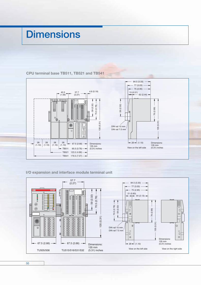
I/O expansion and interface module terminal unit
CPU terminal base TB511, TB521 and TB541
Dimensions

51
Like all ABB products, the AC500 components, are
tested in conformity with the applicable European,
North American and international guidelines, and
approved by the organizations responsible. For the
applicable approvals please refer to our ABB web
site or contact your local ABB representative.
Certified quality
The entire process involved in creating an ABB
product – from the original idea to the actual sale – is,
of course, monitored by a quality management
process certified under DIN ISO 9001.
In harmony with the natural environment
Protection of the natural environment is integral to
ABB’s corporate philosophy. This includes both
resource-economy and the avoidance of problematical
substances, plus recycling-friendly construction and
long-lived products. These aspects are taken fully on
board by an integrated eco-management system
conforming to ISO 14001, whose implementation is
repeatedly verified by regular eco-audits. And for
newly developed products ABB now conducts a
lifecycle assessment as well.
Relevant approvals
Pub
licat
ion
Num
ber:
2C
DC
125
002
B02
07
Prin
ted
in th
e Fe
dera
l Rep
ublic
of G
erm
any
(04.
09 ·
2 · V
CM
)
Sub
ject
to a
ltera
tion
Comprehensively customer support
ABB draws upon its long years of experience in low-voltage engi-
neering to provide you with a comprehensive range of support
services available worldwide. You can call upon contact persons in
our country sales offices. For all questions to do with automation
engineering you can also contact our consultants by phone or fax.
Special seminars and training courses are offered for many ABB
products and systems, not least covering the automation of
machinery and production lines. On request, we will also be plea-
sed to provide on-the-spot training at your own premises. Just talk
to your regional consultant.
ABB Global Contact Directory
The ABB Contact Directory (http://www.abb.com/contacts/) helps you fi nd local contacts for ABB products in your country. Please select the relevant product group from the dropdown menu to the right or from the page.
ABB STOTZ-KONTAKT GmbHP. O. Box 10 16 80D-69006 HeidelbergTelephone: ++49 62 21 / 701-0Telefax: ++49 62 21 / 701-240http://www.abb.com/plc
ABB FranceAutomation Products DivisionExport Department10, rue Ampère Z.I. - B.P 114F-69685 Chassieu cedex / FranceTel.: 33 (0)4 7222 1722Fax.: 33 (0)4 7222 1935