AC2012-3681: INTEGRATINGTHEMECHANICALENGINEERINGCUR- RICULUM USING A LONG … · AC2012-3681:...
11
AC 2012-3681: INTEGRATING THE MECHANICAL ENGINEERING CUR- RICULUM USING A LONG-TERM GREEN DESIGN PROJECT Dr. Eric Constans, Rowan University Eric Constans is the Chair of the Mechanical Engineering program at Rowan University. His research interests include engineering education, design optimization, and acoustics. Dr. Jennifer Kadlowec, Rowan University Dr. Hong Zhang, Rowan University Dr. Bonnie Angelone, Rowan University Psychology c American Society for Engineering Education, 2012
Transcript of AC2012-3681: INTEGRATINGTHEMECHANICALENGINEERINGCUR- RICULUM USING A LONG … · AC2012-3681:...

AC 2012-3681: INTEGRATING THE MECHANICAL ENGINEERING CUR-RICULUM USING A LONG-TERM GREEN DESIGN PROJECT
Dr. Eric Constans, Rowan University
Eric Constans is the Chair of the Mechanical Engineering program at Rowan University. His researchinterests include engineering education, design optimization, and acoustics.
Dr. Jennifer Kadlowec, Rowan UniversityDr. Hong Zhang, Rowan UniversityDr. Bonnie Angelone, Rowan University
Psychology
c©American Society for Engineering Education, 2012

Integrating the Mechanical Engineering Curriculum
using a Long-Term Green Design Project
Part 1: The Hybrid Powertrain Project
Abstract
Subjects that are separate in the curriculum, such as thermodynamics and mechanical design, are
integrated in practice, since thermal and mechanical systems must function cohesively in real
mechanical systems (e.g. an air conditioner). With this in mind, we are beginning the
implementation of a novel, potentially transformative approach to integrating coursework
through five semesters of the core mechanical engineering curriculum.
The centerpiece of this research is a long-term design/build/test project that will be developed by
students over the course of five semesters. The project, a bench-scale hybrid powertrain, is
implemented in modules, so that parts of the project may be completed in disparate courses such
as Thermodynamics, System Dynamics and Control, and Fluid Mechanics. This paper describes
each module, and provides information on how the modules are integrated into a cohesive
system at the end of the project.
Introduction
The authors have embarked upon a study whose goal is to study the effect of a long term hands-
on design project on core concept retention. This paper describes the “hardware” portion of the
research – the system to be designed and built by the students over the course of five semesters.
Assessing changes (if any) in student learning forms an integral part of this research, but will
described in a forthcoming paper.
Ensuring retention of critical engineering concepts can be quite challenging. Hearing a variation
on “but we never learned this!” is an all-too-frequent experience for most instructors, and many
students feel justified in jettisoning all knowledge of a subject once the final examination is past.
The situation is well summarized by Avitabile1:
The unfortunate part is that as soon as the test is over or the course is completed, the
students often just forget the material since they have no reason to retain the
compartmentalized, modularized material.
Subjects that are separate in the curriculum, such as thermodynamics and mechanical design, are
integrated in practice, since thermal and mechanical systems must function cohesively in real
mechanical systems (e.g. an air conditioner). With this in mind, we propose to implement a
novel, potentially transformative approach to integrating coursework through five semesters of
the core mechanical engineering curriculum. The proposed work will test two hypotheses:
1. A long-term design project that integrates knowledge from multiple courses strengthens
student knowledge retention.

2. A large-scale design project requiring tools from many courses improves student
problem-solving and design skills.
By integrating five semesters of the mechanical engineering curriculum into a cohesive whole,
this project has the potential to transform the way undergraduate education is delivered. Before
and after testing will be conducted to assess a) change in retention between courses and b)
change in student problem-solving and design skills.
Background
Many sources have made the case for reforming engineering education to reflect modern trends.
Most notably, a recent National Academy of Engineering (NAE) report found that2
Engineering education must avoid the cliché of teaching more and more about less and
less, until it teaches everything about nothing. Addressing this problem may involve
reconsideration of the basic structure of engineering departments and the infrastructure
for evaluating the performance of professors as much as it does selecting the coursework
students should be taught.
The report also stressed the importance of teaching young engineers the merits of sustainable
design3 and ecologically-friendly practices. The proposed work addresses two of the main
concerns of the NAE report: modernization of the engineering curriculum through
multidisciplinary integration and stressing “green engineering” at the design level.
Research has demonstrated several advantages of Project-Based Learning over traditional lecture
methods, especially in STEM fields (see, e.g. [4]). Accordingly, we have adopted a project-
based approach to integrating coursework across the mechanical engineering curriculum. A
more thorough discussion of the merits of Project-Based Instruction is given in an accompanying
paper9. The purpose of the following paper is to describe the hardware systems used to
implement the project.
The authors have significant experience in developing and implementing multidisciplinary
projects – especially ones that integrate distinct courses in the mechanical engineering
curriculum (Mechanical Design, Thermodynamics and System Dynamics)5, 6, 7
. In brief, our
students have designed, built and tested (in friendly competition) several large-scale design
projects including an air compressor, an air powered engine (modeled on a steam engine
mechanism), an air-motor speed control system, among others. Each of these projects was
conducted collaboratively between two traditionally separate courses, which required close
collaboration between the affected instructors.
Having this level of experience and knowledge at our disposal, we feel confident in embarking
upon an even more ambitious student project: integrating five semesters of coursework through
the design, fabrication and testing of a small-scale hybrid powertrain system. Informed by the
latest research in project-based learning, this project will incorporate all of the lessons we have
learned over the past ten years.

Overview of Proposed Work
For this work we have made the air engine project one component of a much more complicated
system to be developed across a range of courses, including Machine Design, Mechanical
Design, Thermal-Fluid Sciences and System Dynamics. In short, we will use the design and
fabrication of a Hybrid Electric Vehicle Powertrain, discussed below, to integrate the majority of
the core mechanical engineering courses.
Recent increases in energy costs, especially for fossil fuels, have made highly fuel-efficient
vehicles very desirable. Additionally, problems associated with greenhouse gas emissions,
especially global warming, demand innovative technologies. One promising solution to this
crisis is the use of vehicles with hybrid gasoline/electric powertrains. Most major automobile
manufacturers are now selling hybrids (most famously, the Toyota Prius) and hybrids make up
nearly 3% of light-duty vehicle sales.
Unfortunately, much of the benefit of this innovative technology is lost to US engineers, since
the design and development of the vehicles with the highest sales figures were done elsewhere.
In fact, less than 10% of hybrid-electric vehicle sales went to US manufacturers in the years
2005–20098. To regain the lead in such cutting-edge technologies, US engineering students must
become more proficient in the kind of multidisciplinary design that created hybrid-electric
vehicles.
The hybrid-electric powertrain project is divided into six discrete modules, each of which can be
completed in a few regularly-scheduled laboratory periods. A simplified diagram of a hybrid
powertrain is shown in Figure 1. The powertrain is very similar to the one used in a first-
generation Toyota Prius. In this design, power is supplied to a load using an air motor and
motor/generator. The contributions of the air motor and motor/generator are combined in the
planetary gearset, which is in turn regulated by a second DC electric motor. The strategy
employed by the controller is to keep the output shaft turning at a constant speed, despite
variations in load. It does this by regulating the 1) air flow to the air motor, 2) the electrical flow
between the battery pack and the motor/generator and 3) the speed of the sun gear in the
planetary gearset.
Beginning in the Spring of 2012, the students will design and fabricate the components shown in
Table 1. Each module is designed to be stand-alone; that is, students can implement the Electric
Motor Speed Control module without having completed the Planetary Gearset module. But
completing all the modules in sequence, it is hoped, will lead to a much deeper, broader
understanding of core concepts in mechanical engineering.

FIGURE 1: SCHEMATIC OF HYBRID-ELECTRIC POWERTRAIN
Table 1: Design/Build Project Timeline
Semester Course Module
Year 1
(2011-2012)
Fall
Spring ME Lab Arduino-based tachometer
Year 2
(2012-2013)
Fall Thermal-Fluid Sciences I
Machine Design
Air-powered motor
Planetary gearset
Spring Thermal-Fluid Sciences II Air valve selection and implementation
Year 3
(2013-2014)
Fall System Dynamics and Control I Electric motor speed control
Spring System Dynamics and Control II Overall control system
A Description of the Modules
A rendering of the proposed hybrid powertrain is shown in Figure 2. On the right side of the
figure is the Air Motor, the primary source of power for the system. The air motor is driven by
compressed air, whose flow rate is regulated by the Air Flow Regulator. At the center of the
diagram is the Motor/Generator, which may charge the Battery Pack depending upon load
requirements. The Electric Motor and the Air Motor serve as inputs into the Planetary Gearset,
at the center of the diagram. The output of the planetary gearset drives the Motor/Generator,
which is directly coupled to the Output Shaft. The load is an electromagnetic brake programmed
to provide an interesting load cycle to the system. This type of variable load can be used to
simulate the varying road load requirements of a vehicle executing a city driving cycle, for
example.
Motor/Generator Load Box
DC Motor
Air MotorAir Supply
Battery Pack
Speed sensor (tachometer)
Valve or Switch
Mechanical power
Electrical or air power
Sun Gear
Carrier
Ring Gear
Planetary
gearset
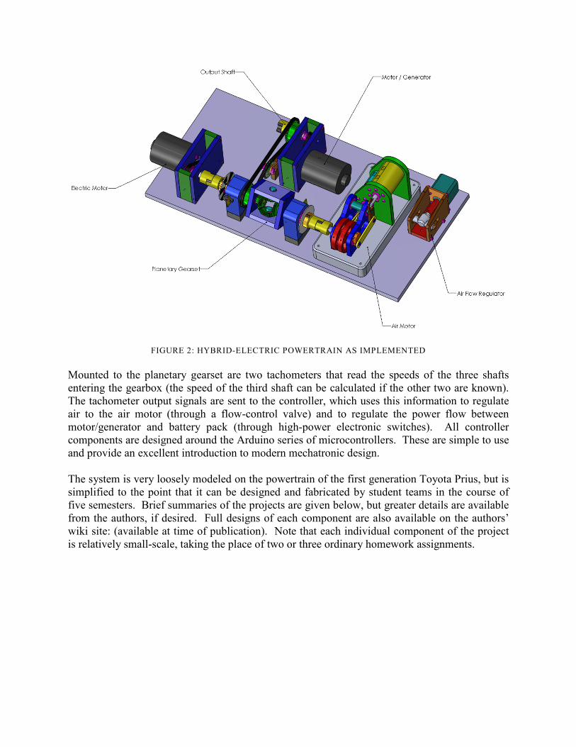
Mounted to the planetary gearset are two tachometers that read the speeds of the three shafts
entering the gearbox (the speed of the third shaft can be calculated if the other two are known).
The tachometer output signals are sent to the controller, which uses this information to regulate
air to the air motor (through a flow-control valve) and to regulate the power flow between
motor/generator and battery pack (through high-power electronic switches). All controller
components are designed around the Arduino series of microcontrollers. These are simple to use
and provide an excellent introduction to modern mechatronic design.
The system is very loosely modeled on the powertrain of the first generation Toyota Prius, but is
simplified to the point that it can be designed and fabricated by student teams in the course of
five semesters. Brief summaries of the projects are given below, but greater details are available
from the authors, if desired. Full designs of each component are also available on the authors’
wiki site: (available at time of publication). Note that each individual component of the project
is relatively small-scale, taking the place of two or three ordinary homework assignments.
FIGURE 2: HYBRID-ELECTRIC POWERTRAIN AS IMPLEMENTED

FIGURE 3: TACHOMETER
1. Arduino-Based Tachometer
The first project that students will encounter is the Arduino-based tachometer. This project will
take place during the second semester of their sophomore year, in the Mechanical Engineering
Laboratory course. The students will experiment with various rotational speed sensor types (Hall
Effect, daisywheel, etc.) before designing and fabricating their own tachometers. At the end of
this module, students will be able to effectively design and fabricate simple mechatronic sensing
devices using the Arduino microcontroller. A sample tachometer design, using a “daisy wheel”
and optical sensor, is shown in Figure 3 above.
FIGURE 4: THE AIR MOTOR
2. The Air Motor
The air motor will be designed and fabricated as part of the Machine Design and Thermal
Sciences I courses. The motor is powered by compressed air from an air tank. The students’
learning outcomes for the project are as follows:

1. Design and fabricate a functioning air-powered reciprocating engine.
2. Use Thermodynamic and Machine Design principles to maximize the efficiency of the
engine. This is accomplished through optimization of cylinder bore, stroke length, valve
timing and other design variables.
A sample design for an air motor is shown in Figure 4 above. The mechanism for this motor is
based on simple steam engine designs and several classes of Rowan University students have
successfully completed the air motor project to date.
FIGURE 5: PLANETARY GEARSET
3. Planetary Gearset
The learning outcomes of the planetary gearset project are twofold. The primary goal is for
students to learn how to design a transmission for specified inputs/outputs. The secondary goal
is for students to apply stress analysis techniques to make their gearboxes as small and light as
possible.
Since the hybrid powertrain system transmits relatively small loads, the gears and shafts may be
made of low strength material, such as nylon. For the differential gearbox project the students
will design the gears and spider in SolidWorks 3D CAD software. They will fabricate the
gearbox enclosure and other parts in the Rowan Engineering machine shop facility. At the end
of the project, the students will test their gearboxes to a specified load limit, with a significant
portion of the grade dependent upon the survival of the gears through testing. Credit will also be
awarded based upon the strength/weight ratio of the gearboxes.
A sample planetary gearbox design is shown in Figure 5 above. The “differential” design has the
advantage of not requiring a large ring gear (lower cost and size) but is constrained to a specified
set of gear ratios. A traditional planetary gearset (with sun, planets and carrier) is more versatile,
but is more complicated to design and fabricate. Students will be given the choice of topology,
but grading criteria will be uniform for all groups.

FIGURE 6: THE AIR FLOW REGULATOR
4. Air Flow Regulator
One topic in the Thermal Sciences course sequence is the physics of internal fluid flow. Part of
this exploration involves pressure losses and flow control aspects of valves, providing an
excellent landscape to design a flow-control valve. To begin this process, students first will
investigate existing off-the-shelf valves.
Building on this understanding, the students will have two design options: 1) alter off-the-shelf
valves or 2) design new valves to meet the flow control characteristics of the drive train system.
To reduce the amount of experimental trial and error, Comsol Multiphysics, a finite element
analysis tool, will be used to predict the fluid behavior inside the tortuous path of the throttle
valve. The learning outcomes for this exercise are twofold: first, the use of commercial CFD
software in design and second, the application of different types of commercially-available
valves. Students will be assessed in two categories:
1. Control Valve Design: size, approximate cost, performance (valve sizing coefficient (Cv),
valve hysteresis, response time, air motor control, reliability and manufacturability.
2. Experimental Work: the design of experiments, an uncertainty analysis, and the quality of
their final report.
A sample flow regulator design is shown in Figure 6 above. Here, a commercial air flow
regulator has been coupled with an inexpensive stepper motor, which may be controlled through
an Arduino board.
5. DC Motor Speed Control
For the fifth module, students will design and implement a control scheme to maintain constant
speed on the DC motor. The control scheme will be implemented using Arduino and the motor
speed will be measured using the tachometers fabricated earlier. The learning objective is the
use of a simple PID scheme for speed control under variable loading.

6. Overall System Controller
At the end of the fifth semester, all important parts of the hybrid powertrain will have been
constructed and tested. It remains only to integrate the components into a complete system. This
will be done as the final project in System Dynamics and Control II, a second-semester course in
the senior year.
Final integration will require the students to design and test an appropriate system-wide control
strategy. Possible student competitions could include tests to see how “far” each team’s power
train could travel through a variable drive cycle with a fixed amount of compressed air available.
The learning outcome for this module is the design and implementation of a digital controller.
This outcome will be assessed through observing the effectiveness of the student controller
designs and also the efficiency of their overall hybrid powertrain systems.
Conclusion
Almost all current technological innovation – nanotechnology, advanced transportation,
bioengineering – occurs at the intersection of disciplines, and yet engineering education is still
delivered in a modular, compartmentalized fashion. To educate the engineer of the 21st century,
we should provide students with multidisciplinary design opportunities, before their final
semester.
This paper describes the use of a long-term sustainable design project to integrate high-level
course work in the Mechanical Engineering curriculum. Based upon the latest research, and
upon the investigators’ own experience, we believe that this approach has the potential to
transform the way undergraduate engineering education is delivered. The modules described
here can be adopted (either wholesale or piecemeal) by a wide variety of institutions. More
information about the modules can be found at the authors’ wiki site: (will be available at time of
publication).
Acknowledgement
The authors wish to acknowledge the support of the NSF-TUES program in the Division of
Undergraduate Education, DUE-1044532, which made this research possible. Any opinions,
findings, and conclusions or recommendations expressed in this material are those of the authors
and do not necessarily reflect the views of the National Science Foundation.
References Cited 1. Avitabile, P. “And more again on the state of engineering education, Part 2 of 3 – Improvement” Journal of
Sound and Vibration 39 (6) 5 (2005)
2. The Engineer of 2020: Visions of Engineering in the New Century. National Academy of Engineering, (2004)
3. Conference Report on Green Engineering: Defining Principles. National Science Foundation (2003)
4. Dym, C.L., Agogino, A.M., Eris, O., Frey, D.D., and Leifer, L.J. “Engineering Design Thinking, Teaching and
Learning” J. of Eng. Educ., 94, 103 (2005)

5. Constans, E.W. and Gabler, H.C. “Coupling Thermodynamics and Mechanical Design in a Cross-Curricular
Undergraduate Design Project.” Frontiers in Engineering Education, Kansas City, MO (2000)
6. Bhatia, K.K. and Constans, E.W. “Steam Power: Novel Use of an Engine Design Project to Cross-Link
Knowledge from Courses in both Mechanical Design and Synthesis and Thermodynamics” Frontiers in
Education Conference, San Diego, CA (2006)
7. Constans, E.W. and Vaughn, T. “Operating Outside the Comfort Zone: Mechanical Engineers Design and Build
an Electronic Motor Speed Controller in a System Dynamics Course”, ASEE Annual Meeting, Pittsburgh, PA
(2008)
8. Electric Drive Transportation Association (www.electricdrive.org)
9. Constans, E., Angelone, B., Bhatia, K., Kadlowec, J., Merrill, T. and Zhang, H. “Integrating the Mechanical
Engineering Curriculum using a Long-Term Green Design Project” Proceedings of the 2012 American Society
for Engineering Education Annual Conference, San Antonio, TX (2012) paper #3681.