AC POWER ANALYSIS Tunku Muhammad Nizar Bin Tunku Mansur Pegawai Latihan Vokasional Pusat Pengajian...
72
AC POWER ANALYSIS Tunku Muhammad Nizar Bin Tunku Mansur Pegawai Latihan Vokasional Pusat Pengajian Kejuruteraan Sistem Elektrik
-
Upload
jean-phelps -
Category
Documents
-
view
240 -
download
1
Transcript of AC POWER ANALYSIS Tunku Muhammad Nizar Bin Tunku Mansur Pegawai Latihan Vokasional Pusat Pengajian...

AC POWER ANALYSIS
Tunku Muhammad Nizar Bin Tunku MansurPegawai Latihan Vokasional
Pusat Pengajian Kejuruteraan Sistem Elektrik

2
Content
Average Power Maximum Average Power Transfer Complex Power Power Factor Correction

3
AVERAGE POWER
4
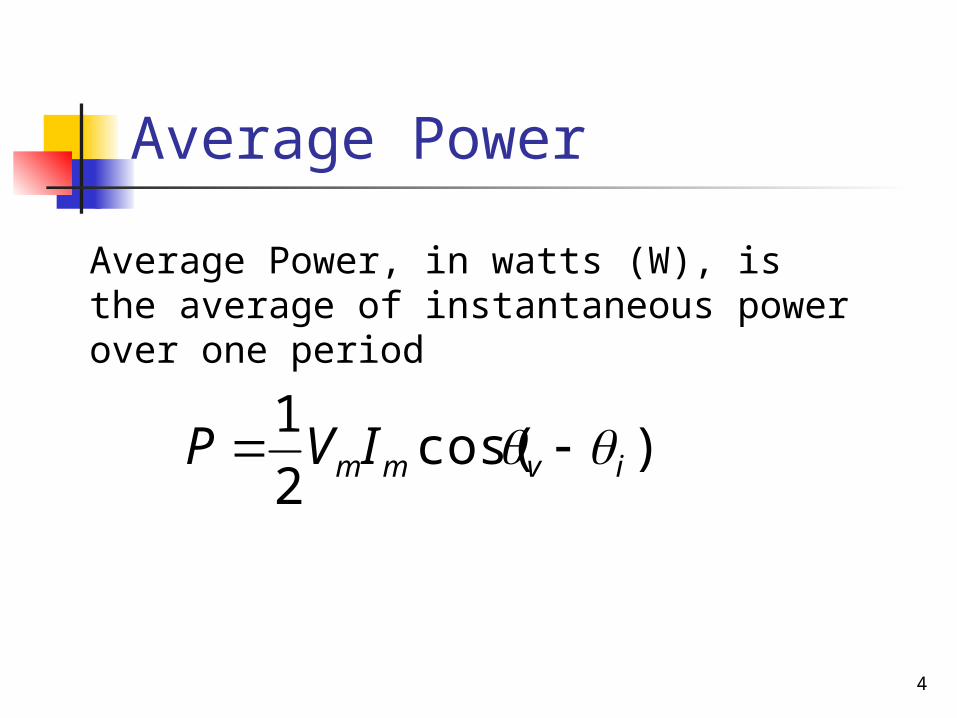
Average Power
)cos(2
1ivmmIVP
Average Power, in watts (W), is the average of instantaneous power over one period
5
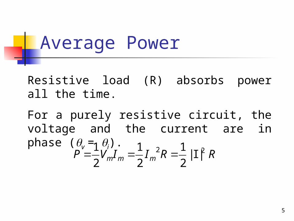
Average Power
RRIIVP mmm22 |I|
2
1
2
1
2
1
Resistive load (R) absorbs power all the time.
For a purely resistive circuit, the voltage and the current are in phase (v = i).
6
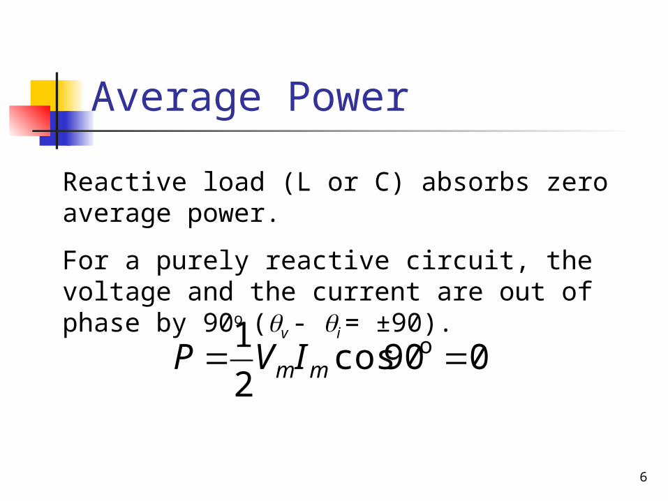
Average Power
090cos2
1 o mmIVP
Reactive load (L or C) absorbs zero average power.
For a purely reactive circuit, the voltage and the current are out of phase by 90o (v - i = ±90).

7
Exercise 11.3Find the average power supplied by the source and the average power absorb by the resistor
8
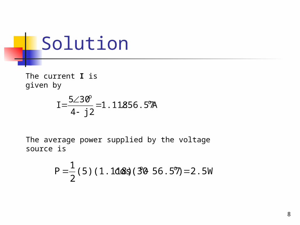
Solution
A56.571.118j24
305I o
o
2.5W)56.57cos(30(5)(1.118)2
1P oo
The current I is given by
The average power supplied by the voltage source is
9
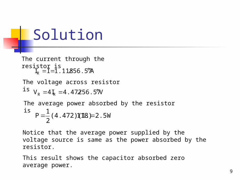
Solution
2.5W118)(4.472)(1.2
1P
Notice that the average power supplied by the voltage source is same as the power absorbed by the resistor.
This result shows the capacitor absorbed zero average power.
The average power absorbed by the resistor is
V56.574.4724IV oRR
The current through the resistor is
A56.571.118II oR
The voltage across resistor is

10
Practice Problem 11.3Calculate the average power absorbed by the resistor and the inductor. Then find the average power supplied by the voltage source
11
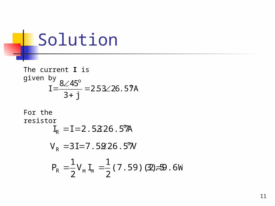
Solution
A.576253.2j3
548I o
o
V26.577.593IV oR
The current I is given by
For the resistor
A26.572.53II oR
9.6W3)(7.59)(2.52
1IV
2
1P mmR

12
Solution
9.6W)26.57os(45(8)(2.53)c2
1P oo
V.5716153.2jIV oLL
The average power supplied by the voltage source is
For the inductor
A26.572.53II oL
0W)3)cos(90(2.53)(2.52
1P o
L
Notice that the average absorbed by the resistor is same as the power supplied by the voltage source.
This result shows the inductor also absorbed zero average power.

13
MAXIMUM AVERAGE POWER
TRANSFER
14
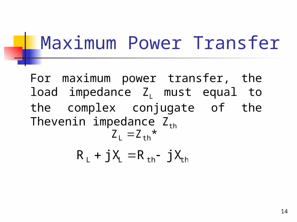
Maximum Power Transfer
*ZZ thL
For maximum power transfer, the load impedance ZL must equal to the complex conjugate of the Thevenin impedance Zth
ththLL jXRjXR

15
Maximum Average Power
The Maximum Average Power delivered to the load is
)jX(R)jX(R
V
ZZ
VI
LLthth
th
Lth
th
L2 R|I|
2
1P
2LTh
2LTh
L2
Th
)X(X)R(R
R|V|
2
1
The current through the load is
16
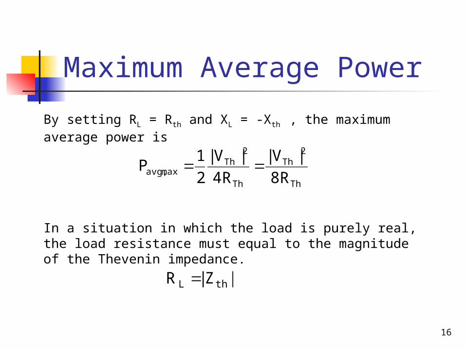
Maximum Average Power
In a situation in which the load is purely real, the load resistance must equal to the magnitude of the Thevenin impedance.
|Z|R thL
Th
2Th
Th
2Th
maxavg, 8R
|V|
4R
|V|
2
1P
By setting RL = Rth and XL = -Xth , the maximum average power is
17
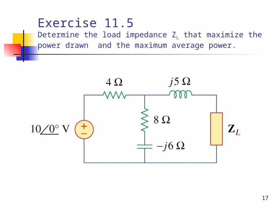
Exercise 11.5Determine the load impedance ZL that maximize the power drawn and the maximum average power.

18
Solution
j6)(8||4j5ZTh
V10.37.454 o
j4.467)Ω(2.933
First we obtain the Thevenin equivalent
To find Zth, consider circuit (a)
)0(10j6)-(84
j6)-(8V o
Th
To find Vth, consider circuit (b)

19
Solution
j4.467)Ω(2.933*ZZ ThL
From the result obtained, the load impedance draws the maximum power from the circuit when
The maximum average power is
2.368W8(2.933)
(7.454)
8R
|V|P
2
Th
2Th
max
20
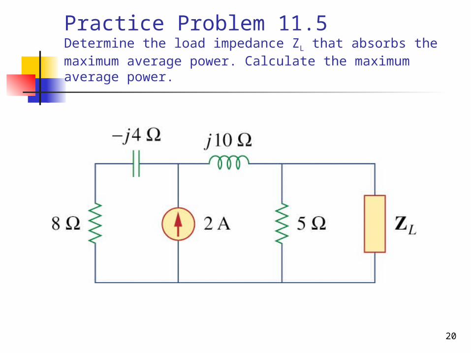
Practice Problem 11.5Determine the load impedance ZL that absorbs the maximum average power. Calculate the maximum average power.

21
Solution
j10)j4(8||5ZTh
A.3415249.1 o
j0.7317)Ω(3.415
First we obtain the Thevenin equivalentTo find Zth, consider circuit (a)
V51.346.255IV oTh
To find Vth, consider circuit (b)
By using current divider (2)j105j48
j48I

22
Solution
j0.7317)Ω(3.415*ZZ ThL
From the result obtained, the load impedance draws the maximum power from the circuit when
The maximum average power is
W429.18(3.415)
(6.25)
8R
|V|P
2
Th
2Th
max

23
Example 11.6Find the value of RL that will absorbs maximum average power. Then calculate that power.
24
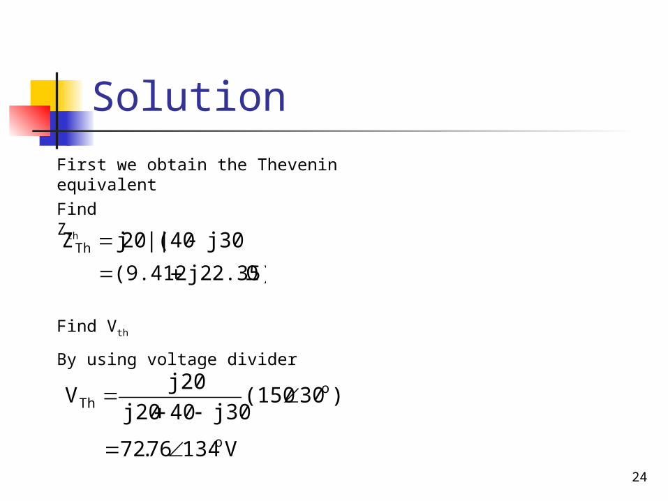
Solution
j30)(40||20jZTh
V13476.72 o
j22.35)Ω(9.412
First we obtain the Thevenin equivalent
Find Zth
Find Vth
By using voltage divider
)30(150j3040j20
j20V o
Th

25
Solution
22ThL (22.35)(9.412)|Z|R
24.25j22.35)(9.412
13472.76
RZ
VI
o
LTh
Th
25.24
The value of RL that will absorb the maximum average power is
The maximum average power is
39.29W24.25(1.8)2
1R|I|
2
1P 2
L2
max
A100.421.8 o
The current through the load is
26
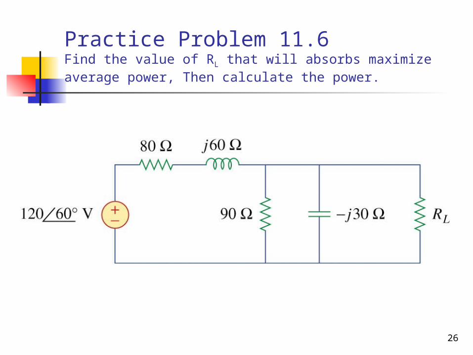
Practice Problem 11.6Find the value of RL that will absorbs maximize average power, Then calculate the power.

27
Solution
j24.57)Ω(17.181Z||ZZ 21Th
V91.3198.35 o
j6008Z1
First we obtain the Thevenin equivalentTo find Zth let
To find Vth
By using voltage divider
)60(120ZZ
ZV o
21
2Th
j27)9(j30)(||90Z2 and
Then

28
Solution
30|Z|R ThL
03j24.57)(17.181
91.31-98.53
RZ
VI
o
LTh
Th
The value of RL that will absorb the maximum average power is
The maximum average power is
6.863W)0(3(0.6764)2
1R|I|
2
1P 2
L2
max
A4.40.6764 o
The current through the load is

29
COMPLEX POWER

30
Complex Power
Apparent Power, S (VA) Real Power, P (Watts) Reactive Power, Q (VAR) Power Factor, cos

31
Complex Power Complex power is the product of the
rms voltage phasor and the complex conjugate of the rms current phasor.
Measured in volt-amperes or VA As a complex quantity
Its real part is real power, P Its imaginary part is reactive power, Q
32
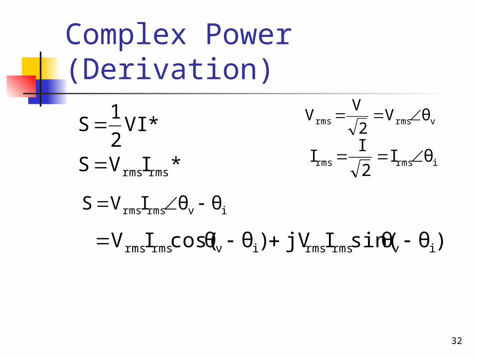
Complex Power (Derivation)
*VI2
1S
irmsrms θI2
II
ivrmsrms θθIVS
vrmsrms θV2
VV
)θsin(θIjV)θcos(θIV ivrmsrmsivrmsrms
*IVS rmsrms

33
Complex Power (Derivation)
jX)(RIS rms2
XjIRI rms2
rms2
ZIS rms2

34
Complex Power (Derivation)
)θcos(θIVP ivrmsrms
)θθsin(IVQ ivrmsrms
XIQ rms2
RIP rms2
From derivation, we notice that the real power is
and also the reactive power
or
or
35
Real or Average Power
The real power is the average power delivered to a load.
Measured in watts (W) The only useful power The actual power dissipated by the
load
36
Reactive Power The reactive power, Q is the imaginary
parts of complex power. The unit of Q is volt-ampere reactive
(VAR). It represents a lossless interchange
between the load and the source Q = 0 for resistive load (unity pf) Q < 0 for capacitive load (leading pf) Q > 0 for inductive load (lagging pf)
37
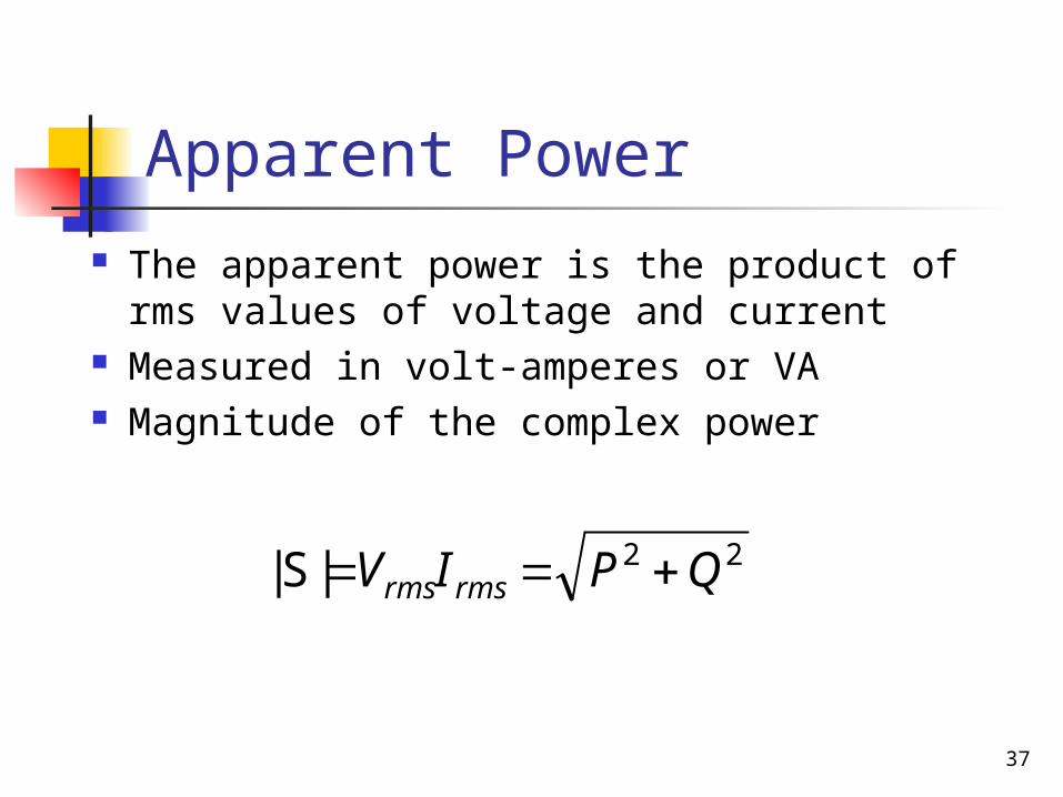
Apparent Power The apparent power is the product of
rms values of voltage and current Measured in volt-amperes or VA Magnitude of the complex power
22|S| QPIV rmsrms
38
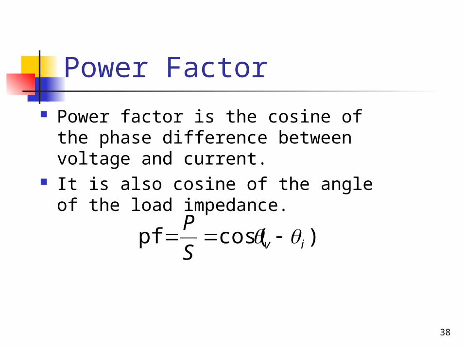
Power Factor Power factor is the cosine of the
phase difference between voltage and current.
It is also cosine of the angle of the load impedance.
)cos(pf ivS
P

39
Power Factor The range of pf is between zero and
unity. For a purely resistive load, the voltage
and current are in phase so that v- i = 0 and pf = 1, the apparent power is equal to average power.
For a purely reactive load, v- i = 90 and pf = 0, the average power is zero.

40
Power Triangular
Comparison between the power triangular (a) and the impedance triangular (b).

41
Problem 11.46
For the following voltage and current phasors, calculate the complex power, apparent power, real power and reactive power. Specify whether the pf is leading or lagging.
a) V = 22030o Vrms, I = 0.560o Arms.
b) V = 250-10o Vrms, I = 6.2-25o Arms.
c) V = 1200o Vrms, I = 2.4-15o Arms.
d) V = 16045o Vrms, I = 8.590o Arms.

42
Solution
a) S = VI* = (22030o)( 0.5-60o) = 110-30o VA = 95.26 – j55 VA
Apparent power = 110 VAReal Power = 95.26 WReactive Power = -55 VARpf is leading because current leads voltage
b) S = VI* = (250-10o)(6.225o) = 155015o VA = 1497.2 + j401.2 VA
Apparent power = 1550 VAReal Power = 1497.2 WReactive Power = 401.2 VARpf is lagging because current lags voltage
c) S = VI* = (1200o)( 2.415o) = 28815o VA = 278.2 + j74.54 VA
Apparent power = 288 VAReal Power = 278.2 WReactive Power = 74.54 VARpf is lagging because current lags voltage
d) S = VI* = (16045o)(8.5-90o) = 1360-45o VA = 961.7 – j961.7 VA
Apparent power = 1360 VAReal Power = 961.7 WReactive Power = -961.7 VARpf is leading because current leads voltage
43
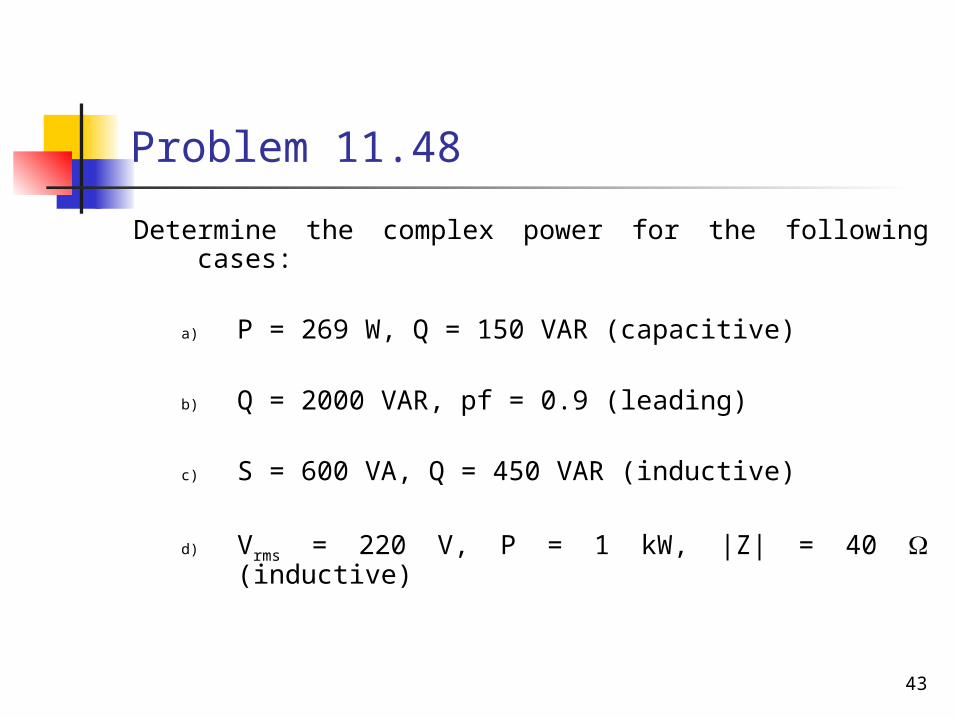
Problem 11.48
Determine the complex power for the following cases:
a) P = 269 W, Q = 150 VAR (capacitive)
b) Q = 2000 VAR, pf = 0.9 (leading)
c) S = 600 VA, Q = 450 VAR (inductive)
d) Vrms = 220 V, P = 1 kW, |Z| = 40 (inductive)

44
Solutiona) Given P = 269W, Q = 150VAR
(capacitive)
Complex power,
b) Given Q = 2000VAR, pf = 0.9 (leading)
j150)VA269(j QPS
j2000)VA4129(j QPS
opf 84.259.0cos
VA25.84-4588 o
31.4588)84.25sin(
2000
sinsin
o
QSSQ
48.4129cos SP
VA29.14308 o
Complex power,
45
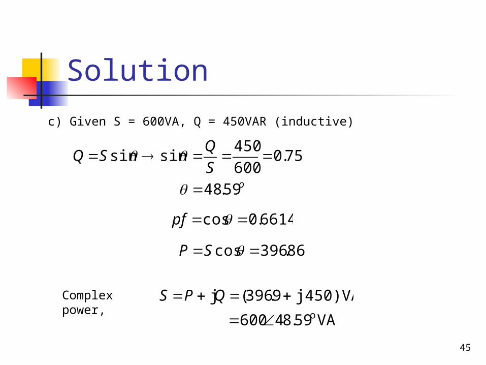
Solution
c) Given S = 600VA, Q = 450VAR (inductive)
j450)VA9.396(j QPS
6614.0cos pf
VA59.84600 o
75.0600
450sinsin
S
QSQ
86.396cos SP
Complex power,
o59.48
46
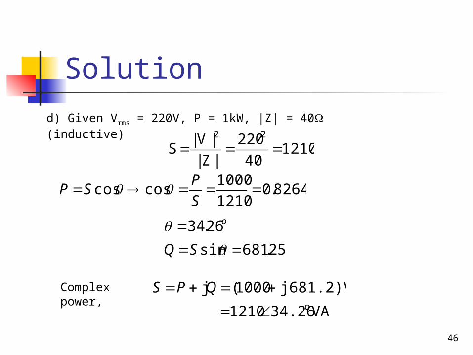
Solution
d) Given Vrms = 220V, P = 1kW, |Z| = 40 (inductive)
j681.2)VA1000(j QPS
121040
220
|Z|
|V|S
22
VA34.261210 o
8264.01210
1000coscos
S
PSP
25.681sin SQ
Complex power,
o26.34

47
Problem 11.42
A 110Vrms, 60Hz source is applied to a load impedance Z. The apparent power entering the load is 120VA at a power factor of 0.707 lagging. Calculate
a) The complex power
b) The rms current supplied to the load.
c) Determine Z
d) Assuming that Z = R + j L, find the value of R and L.

48
Solution
j84.84VA84.48sinjcos SSS
rmsrms IVS
Given S = 120VA, pf = 0.707 = cos = 45o
a) the complex power
A091.1110
120
rmsrms V
SI
b) the rms current supplied to the load

49
Solution
ZIS rms2
71.278ωL
d) value of R and L
If Z = R + jL then Z = 71.278 + j 71.278
)278.71278.71(2
jI
SZ
rms
0.1891H2
278.71L
f
71.278ΩR
c) the impedance Z
50
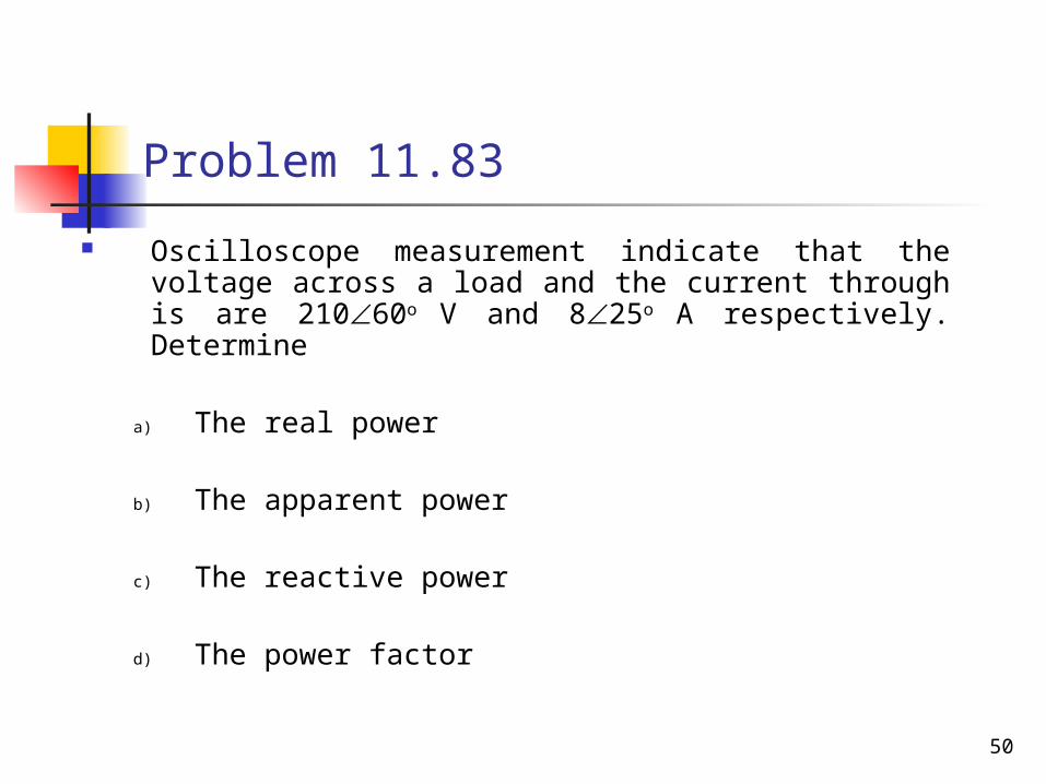
Problem 11.83
Oscilloscope measurement indicate that the voltage across a load and the current through is are 21060o
V and 825o A respectively. Determine
a) The real power
b) The apparent power
c) The reactive power
d) The power factor

51
Solution
688.1W)(35cos840)(35cos oo SP
VA840S
a) the real power
d) the power factor
ging)0.8191(lag)35cos( o S
Ppf
c) the reactive power
j481.8)VA(688.1)VA35(840 o
)25)(860(2102
1VI*
2
1 oo S
.8VAR814)(35sin840)(35sin oo SQ
b) the apparent power

52
POWER FACTOR CORRECTION

53
Power Factor Correction
The process of increasing the power factor without altering the voltage or current to the original load.
It may be viewed as the addition of a reactive element (usually capacitor) in parallel with the load in order to make the power factor closer to unity.
54
Power Factor Correction
Normally, most loads are inductive. Thus power factor is improved or corrected by installing a capacitor in parallel with the load.
In circuit analysis, an inductive load is modeled as a series combination of an inductor and a resistor.
55
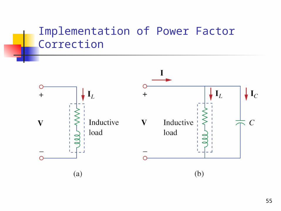
Implementation of Power Factor Correction
56
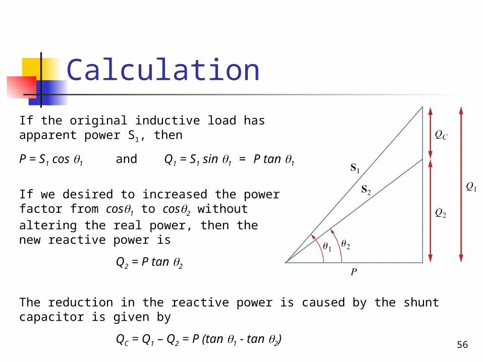
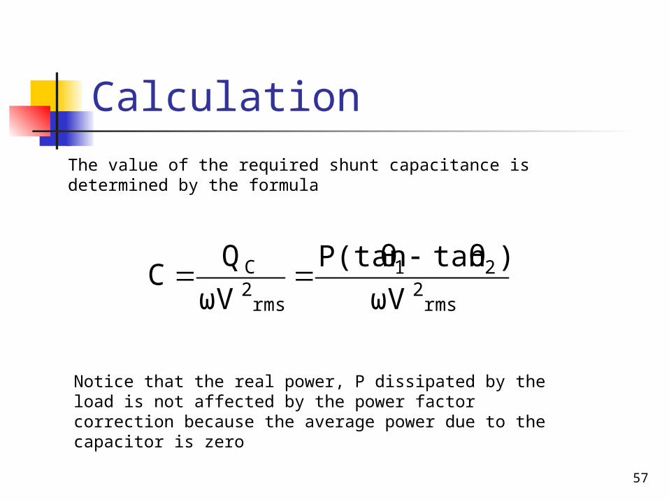
Calculation
If the original inductive load has apparent power S1, then
P = S1 cos 1 and Q1 = S1 sin 1 = P tan 1
If we desired to increased the power factor from cos1 to cos2 without altering the real power, then the new reactive power is
Q2 = P tan 2
The reduction in the reactive power is caused by the shunt capacitor is given by
QC = Q1 – Q2 = P (tan 1 - tan 2)
57
Calculation
rms2
21
rms2C
ωV
)tanθP(tanθ
ωV
QC
The value of the required shunt capacitance is determined by the formula
Notice that the real power, P dissipated by the load is not affected by the power factor correction because the average power due to the capacitor is zero
58
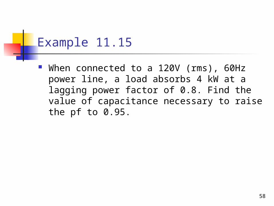
Example 11.15
When connected to a 120V (rms), 60Hz power line, a load absorbs 4 kW at a lagging power factor of 0.8. Find the value of capacitance necessary to raise the pf to 0.95.
59
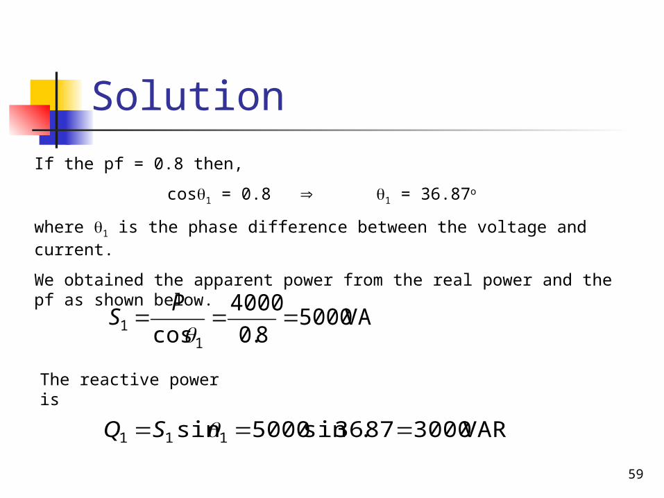
Solution
VA50008.0
4000
cos 11
P
S
If the pf = 0.8 then,
cos1 = 0.8 1 = 36.87o
where 1 is the phase difference between the voltage and current.
We obtained the apparent power from the real power and the pf as shown below.
The reactive power is
VAR300087.36sin5000sin 111 SQ

60
Solution
VA5.421095.0
4000
cos 22
P
S
When the pf raised to 0.95,
cos2 = 0.95 2 = 18.19o
The real power P has not changed. But the apparent power has changed. The new value is
The new reactive power is
VAR4.1314sin 222 SQ

61
Solution
VAR6.16854.1314300021 QQQC
The difference between the new and the old reactive power is due to the parallel addition of the capacitor to the load.
The reactive power due to the capacitor is
The value of capacitance added is
μF5.310)120)(60(2
6.168522
rms
C
V
QC

62
Practice Problem 11.15
Find the value of parallel capacitance needed to correct a load of 140 kVAR at 0.85 lagging pf to unity pf. Assume the load is supplied by a 110V (rms) 60Hz power line.
63
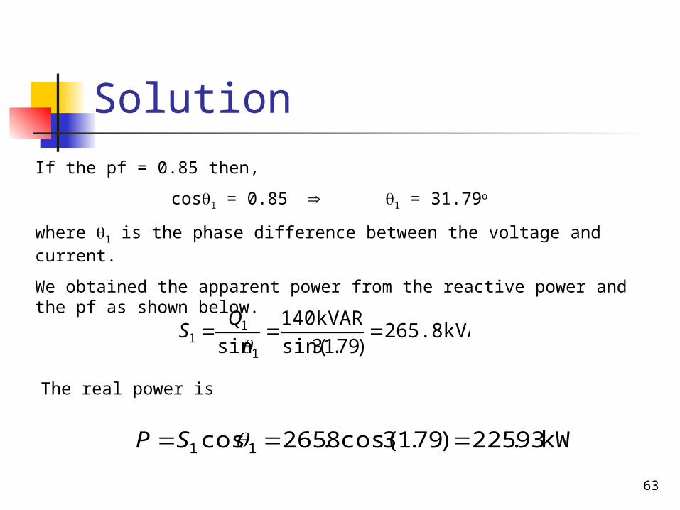
Solution
265.8kVA)79.31sin(
140kVAR
sin 1
11
Q
S
If the pf = 0.85 then,
cos1 = 0.85 1 = 31.79o
where 1 is the phase difference between the voltage and current.
We obtained the apparent power from the reactive power and the pf as shown below.
The real power is
kW93.225)79.31cos(8.265cos 11 SP

64
Solution
kVA93.2251
kW93.225
cos 22
P
S
When the pf raised to 1 (unity),
cos2 = 1 2 = 0o
The real power P has not changed. But the apparent power has changed. The new value is
The new reactive power is
0sin 222 SQ

65
Solution
kVAR140014000021 QQQC
The difference between the new and the old reactive power due to the parallel addition of the capacitor to the load.
The reactive power due to the capacitor is
The value of capacitance is
mF69.30)110)(60(2
140kVAR22
rms
C
V
QC

66
Problem 11.82
A 240Vrms, 60Hz source supplies a parallel combination of a 5 kW heater and a 30 kVA induction motor whose power factor is 0.82. Determine
a) The system apparent powerb) The system reactive powerc) The kVA rating of a capacitor required to
adjust the system power factor to 0.9 laggingd) The value of capacitance required
67
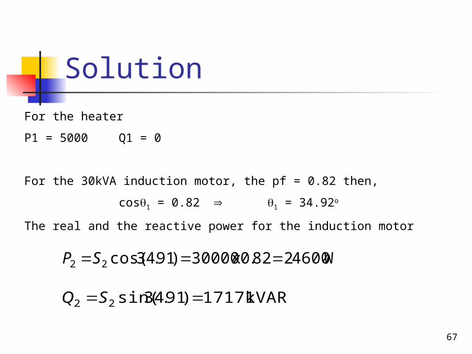
Solution
W4600282.0x30000)91.34cos(22 SP
For the heater
P1 = 5000 Q1 = 0
For the 30kVA induction motor, the pf = 0.82 then,
cos1 = 0.82 1 = 34.92o
The real and the reactive power for the induction motor
kVAR17171)91.34sin(22 SQ
68
Solution
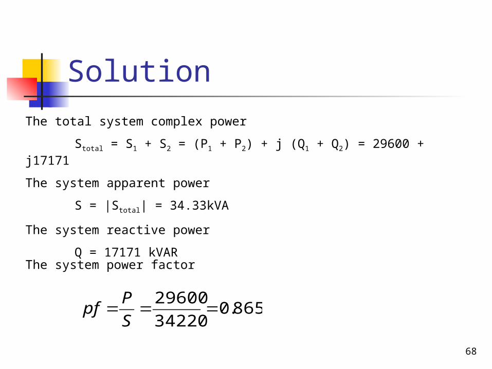
The total system complex power
Stotal = S1 + S2 = (P1 + P2) + j (Q1 + Q2) = 29600 + j17171
The system apparent power
S = |Stotal| = 34.33kVA
The system reactive power
Q = 17171 kVAR
The system power factor
865.034220
29600
S
Ppf

69
Solution
The system pf = 0.865 then,
cos1 = 0.865 1 = 30.12o
The new system pf = 0.9 then, cos2 = 0.9 2 = 25.84o
The rating for the capacitance required to adjust the power factor to 0.9
QC = P (tan 1 + tan 2) = 29600 (tan 30.12 + tan 25.84) = 2833kVAR
70
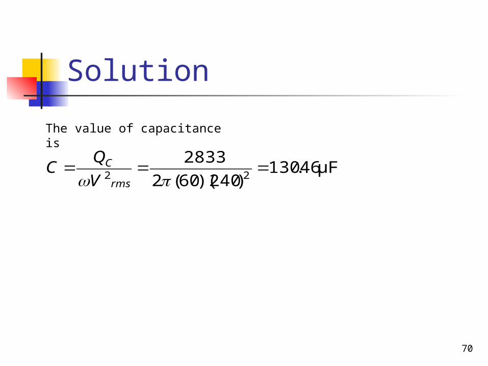
Solution
The value of capacitance is
μF46.130)240)(60(2
283322
rms
C
V
QC
71
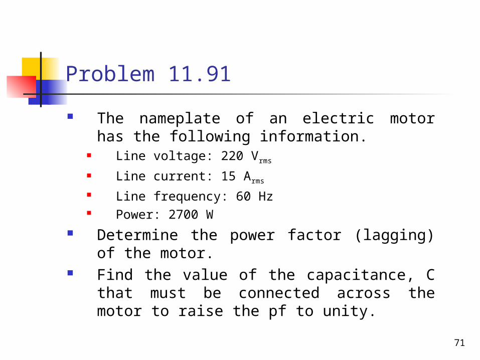
Problem 11.91
The nameplate of an electric motor has the following information.
Line voltage: 220 Vrms
Line current: 15 Arms
Line frequency: 60 Hz Power: 2700 W
Determine the power factor (lagging) of the motor.
Find the value of the capacitance, C that must be connected across the motor to raise the pf to unity.
72
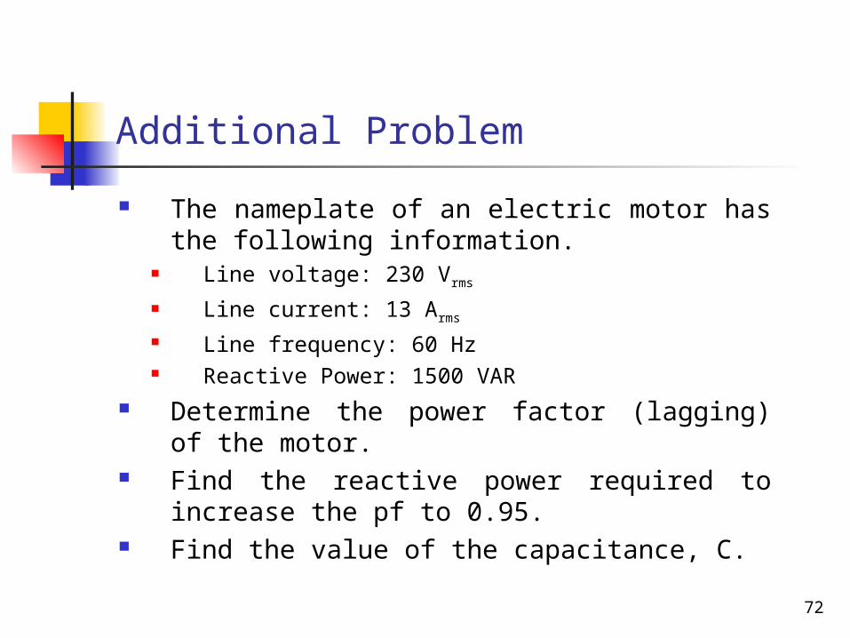
Additional Problem
The nameplate of an electric motor has the following information.
Line voltage: 230 Vrms
Line current: 13 Arms
Line frequency: 60 Hz Reactive Power: 1500 VAR
Determine the power factor (lagging) of the motor.
Find the reactive power required to increase the pf to 0.95.
Find the value of the capacitance, C.