A/C-HEATER SYSTEM - AUTOMATICbgbonline.celicatech.com/89tech/ac heater system auto.pdf · The...
18
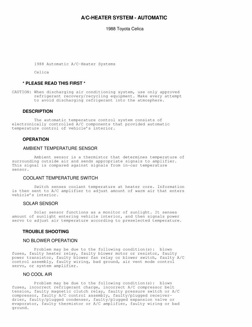
A/C-HEATER SYSTEM - AUTOMATIC 1988 Toyota Celica 1988 Automatic A/C-Heater Systems Celica * PLEASE READ THIS FIRST * CAUTION: When discharging air conditioning system, use only approved refrigerant recovery/recycling equipment. Make every attempt to avoid discharging refrigerant into the atmosphere. DESCRIPTION The automatic temperature control system consists of electronically controlled A/C components that provided automatic temperature control of vehicle’s interior. OPERATION AMBIENT TEMPERATURE SENSOR Ambient sensor is a thermistor that determines temperature of surrounding outside air and sends appropriate signals to amplifier. This signal is compared against signals from in-car temperature sensor. COOLANT TEMPERATURE SWITCH Switch senses coolant temperature at heater core. Information is then sent to A/C amplifier to adjust amount of warm air that enters vehicle’s interior. SOLAR SENSOR Solar sensor functions as a monitor of sunlight. It senses amount of sunlight entering vehicle interior, and then signals power servo to adjust air temperature according to preselected temperature. TROUBLE SHOOTING NO BLOWER OPERATION Problem may be due to the following condition(s): blown fuses, faulty heater relay, faulty blower motor or resistor, faulty power transistor, faulty blower fan relay or blower switch, faulty A/C control assembly, faulty wiring, bad ground, air vent mode control servo, or system amplifier. NO COOL AIR Problem may be due to the following condition(s): blown fuses, incorrect refrigerant charge, incorrect A/C compressor belt tension, faulty magnetic clutch relay, faulty pressure switch or A/C compressor, faulty A/C control assembly, faulty/plugged receiver- drier, faulty/plugged condenser, faulty/plugged expansion valve or evaporator, faulty thermistor or A/C amplifier, faulty wiring or bad ground.
Transcript of A/C-HEATER SYSTEM - AUTOMATICbgbonline.celicatech.com/89tech/ac heater system auto.pdf · The...
�A/C-HEATER SYSTEM - AUTOMATIC
�1988 Toyota Celica
1988 Automatic A/C-Heater Systems
Celica
* PLEASE READ THIS FIRST *
CAUTION: When discharging air conditioning system, use only approved refrigerant recovery/recycling equipment. Make every attempt to avoid discharging refrigerant into the atmosphere.
DESCRIPTION
The automatic temperature control system consists ofelectronically controlled A/C components that provided automatictemperature control of vehicle’s interior.
OPERATION
AMBIENT TEMPERATURE SENSOR
Ambient sensor is a thermistor that determines temperature ofsurrounding outside air and sends appropriate signals to amplifier.This signal is compared against signals from in-car temperaturesensor.
COOLANT TEMPERATURE SWITCH
Switch senses coolant temperature at heater core. Informationis then sent to A/C amplifier to adjust amount of warm air that entersvehicle’s interior.
SOLAR SENSOR
Solar sensor functions as a monitor of sunlight. It sensesamount of sunlight entering vehicle interior, and then signals powerservo to adjust air temperature according to preselected temperature.
TROUBLE SHOOTING
NO BLOWER OPERATION
Problem may be due to the following condition(s): blownfuses, faulty heater relay, faulty blower motor or resistor, faultypower transistor, faulty blower fan relay or blower switch, faulty A/Ccontrol assembly, faulty wiring, bad ground, air vent mode controlservo, or system amplifier.
NO COOL AIR
Problem may be due to the following condition(s): blownfuses, incorrect refrigerant charge, incorrect A/C compressor belttension, faulty magnetic clutch relay, faulty pressure switch or A/Ccompressor, faulty A/C control assembly, faulty/plugged receiver-drier, faulty/plugged condenser, faulty/plugged expansion valve orevaporator, faulty thermistor or A/C amplifier, faulty wiring or badground.
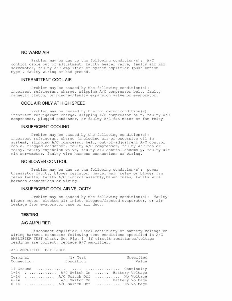
NO WARM AIR
Problem may be due to the following condition(s): A/Ccontrol cable out of adjustment, faulty heater valve, faulty air mixservomotor, faulty A/C amplifier or system amplifier (push-buttontype), faulty wiring or bad ground.
INTERMITTENT COOL AIR
Problem may be caused by the following condition(s):incorrect refrigerant charge, slipping A/C compressor belt, faultymagnetic clutch, or plugged/faulty expansion valve or evaporator.
COOL AIR ONLY AT HIGH SPEED
Problem may be caused by the following condition(s):incorrect refrigerant charge, slipping A/C compressor belt, faulty A/Ccompressor, plugged condenser, or faulty A/C fan motor or fan relay.
INSUFFICIENT COOLING
Problem may be caused by the following condition(s):incorrect refrigerant charge (including air or excessive oil insystem), slipping A/C compressor belt, out-of-adjustment A/C controlcable, clogged condenser, faulty A/C compressor, faulty A/C fan orrelay, faulty expansion valve, faulty A/C control assembly, faulty airmix servomotor, faulty wire harness connections or wiring.
NO BLOWER CONTROL
Problem may be due to the following condition(s): powertransistor faulty, blower resistor, heater main relay or blower fanrelay faulty, faulty A/C control assembly,blown fuses, faulty wireharness connections or wiring.
INSUFFICIENT COOL AIR VELOCITY
Problem may be caused by the following condition(s): faultyblower motor, blocked air inlet, clogged/frosted evaporator, or airleakage from evaporator case or air duct.
TESTING
A/C AMPLIFIER
Disconnect amplifier. Check continuity or battery voltage onwiring harness connector following test conditions specified in A/CAMPLIFIER TEST chart. See Fig. 1. If circuit resistance/voltagereadings are correct, replace A/C amplifier.
A/C AMPLIFIER TEST TABLE�����������������������������������������������������������������������������������������������������������������������
Terminal (1) Test SpecifiedConnection Condition Value
14-Ground ............. ..... ............... Continuity1-14 .............. A/C Switch On ...... Battery Voltage1-14 ............. A/C Switch Off ........... No Voltage6-14 .............. A/C Switch On ...... Battery Voltage6-14 ............. A/C Switch Off ........... No Voltage
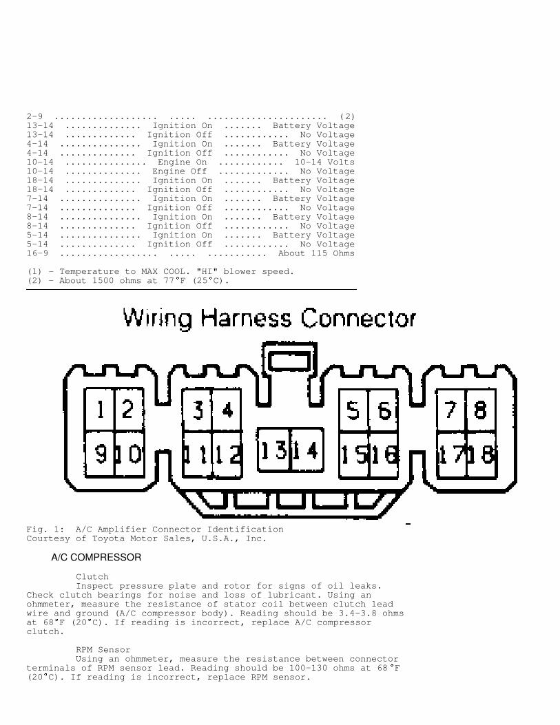
2-9 ................... ..... ...................... (2)13-14 .............. Ignition On ....... Battery Voltage13-14 ............. Ignition Off ............ No Voltage4-14 ............... Ignition On ....... Battery Voltage4-14 .............. Ignition Off ............ No Voltage10-14 ............... Engine On ............ 10-14 Volts10-14 .............. Engine Off ............. No Voltage18-14 .............. Ignition On ....... Battery Voltage18-14 ............. Ignition Off ............ No Voltage7-14 ............... Ignition On ....... Battery Voltage7-14 .............. Ignition Off ............ No Voltage8-14 ............... Ignition On ....... Battery Voltage8-14 .............. Ignition Off ............ No Voltage5-14 ............... Ignition On ....... Battery Voltage5-14 .............. Ignition Off ............ No Voltage16-9 .................. ..... ........... About 115 Ohms
(1) - Temperature to MAX COOL. "HI" blower speed.(2) - About 1500 ohms at 77
�
F (25�
C).�����������������������������������������������������������������������������������������������������������������������
Fig. 1: A/C Amplifier Connector IdentificationCourtesy of Toyota Motor Sales, U.S.A., Inc.
A/C COMPRESSOR
Clutch Inspect pressure plate and rotor for signs of oil leaks.Check clutch bearings for noise and loss of lubricant. Using anohmmeter, measure the resistance of stator coil between clutch leadwire and ground (A/C compressor body). Reading should be 3.4-3.8 ohmsat 68
�
F (20�
C). If reading is incorrect, replace A/C compressorclutch.
RPM Sensor Using an ohmmeter, measure the resistance between connectorterminals of RPM sensor lead. Reading should be 100-130 ohms at 68
�
F(20
�
C). If reading is incorrect, replace RPM sensor.

Fig. 2: Automatic A/C-Heater System ComponentsCourtesy of Toyota Motor Sales, U.S.A., Inc.
A/C TEMPERATURE CONTROL SYSTEM
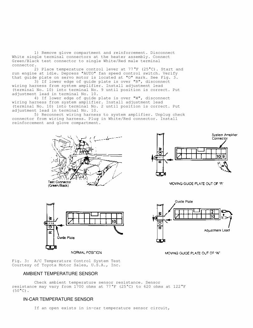
1) Remove glove compartment and reinforcement. DisconnectWhite single terminal connectors at the heater assembly. ConnectGreen/Black test connector to single White/Red male terminalconnector. 2) Place temperature control lever at 77
�
F (25�
C). Start andrun engine at idle. Depress "AUTO" fan speed control switch. Verifythat guide plate on servo motor is located at "O" mark. See Fig. 3. 3) If lower edge of guide plate is over "R", disconnectwiring harness from system amplifier. Install adjustment lead(terminal No. 10) into terminal No. 9 until position is correct. Putadjustment lead in terminal No. 10. 4) If lower edge of guide plate is over "W", disconnectwiring harness from system amplifier. Install adjustment lead(terminal No. 10) into terminal No. 2 until position is correct. Putadjustment lead in terminal No. 10. 5) Reconnect wiring harness to system amplifier. Unplug checkconnector from wiring harness. Plug in White/Red connector. Installreinforcement and glove compartment.
Fig. 3: A/C Temperature Control System TestCourtesy of Toyota Motor Sales, U.S.A., Inc.
AMBIENT TEMPERATURE SENSOR
Check ambient temperature sensor resistance. Sensorresistance may vary from 1700 ohms at 77
�
F (25�
C) to 620 ohms at 122�
F(50
�
C).
IN-CAR TEMPERATURE SENSOR
If an open exists in in-car temperature sensor circuit,
system will operate at maximum heating. If sensor circuit has a short,system will operate at maximum cooling. Sensor resistance may varyfrom 1700 ohms at 77
�
F (25�
C) to 620 ohms at 122�
F (50�
C).
SOLAR SENSOR
Unplug solar sensor connector and check sensor continuity. Ifno continuity exists, replace solar sensor.
REFRIGERANT PRESSURE SWITCHES
Dual Pressure Switch Check refrigerant pressure. Pressure must be more than 30 psi(2.1 kg/cm
�
) when ambient temperature is more than 32�
F (0�
C). ChargeA/C system if necessary. Using an ohmmeter, check continuity betweenterminals of dual pressure switch. Ohmmeter must indicate zero ohms.If continuity exist, replace switch.
High Pressure Switch Disconnect high pressure switch lead from wiring harness.Using an ohmmeter, check continuity between terminals of high pressureswitch. Ohmmeter reading must be zero ohms. If continuity exists,replace switch.
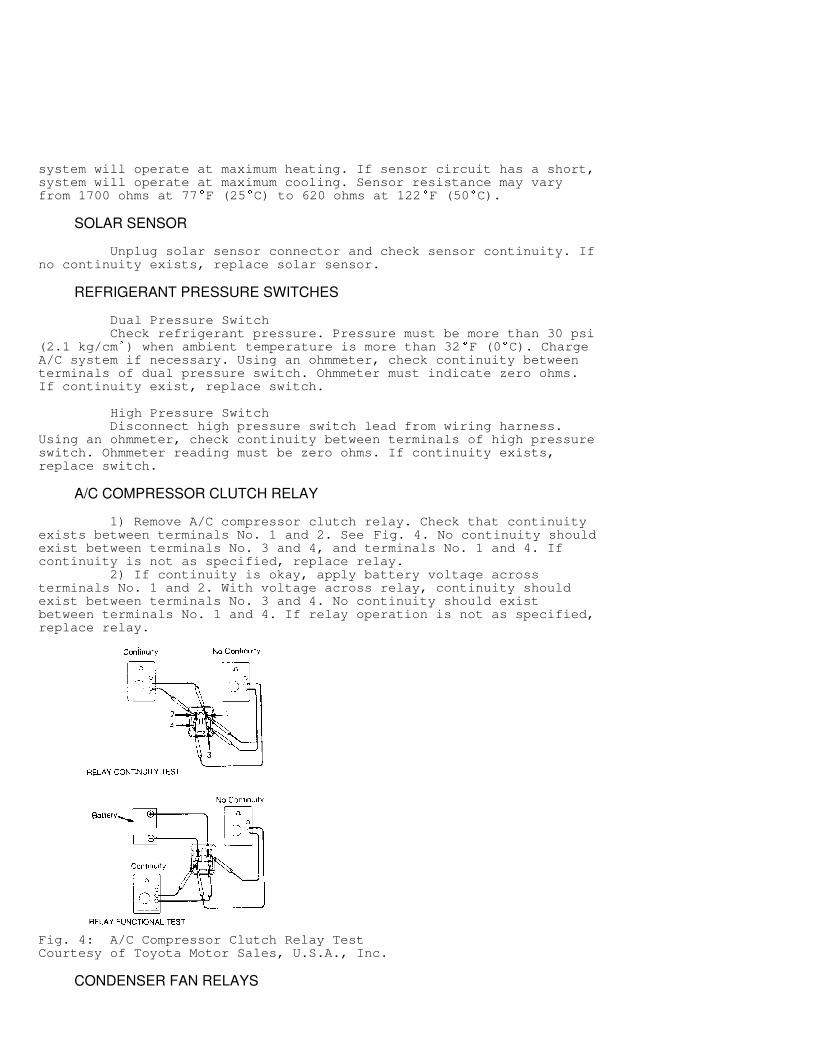
A/C COMPRESSOR CLUTCH RELAY
1) Remove A/C compressor clutch relay. Check that continuityexists between terminals No. 1 and 2. See Fig. 4. No continuity shouldexist between terminals No. 3 and 4, and terminals No. 1 and 4. Ifcontinuity is not as specified, replace relay. 2) If continuity is okay, apply battery voltage acrossterminals No. 1 and 2. With voltage across relay, continuity shouldexist between terminals No. 3 and 4. No continuity should existbetween terminals No. 1 and 4. If relay operation is not as specified,replace relay.
Fig. 4: A/C Compressor Clutch Relay TestCourtesy of Toyota Motor Sales, U.S.A., Inc.
CONDENSER FAN RELAYS
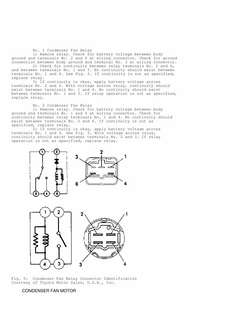
No. 1 Condenser Fan Relay 1) Remove relay. Check for battery voltage between bodyground and terminals No. 2 and 6 at wiring connector. Check for groundconnection between body ground and terminal No. 3 at wiring connector. 2) Check for continuity between relay terminals No. 2 and 6,and between terminals No. 1 and 3. No continuity should exist betweenterminals No. 1 and 4. See Fig. 5. If continuity is not as specified,replace relay. 3) If continuity is okay, apply battery voltage acrossterminals No. 2 and 6. With voltage across relay, continuity shouldexist between terminals No. 1 and 4. No continuity should existbetween terminals No. 1 and 3. If relay operation is not as specified,replace relay.
No. 2 Condenser Fan Relay 1) Remove relay. Check for battery voltage between bodyground and terminals No. 1 and 4 at wiring connector. Check forcontinuity between relay terminals No. 1 and 4. No continuity shouldexist between terminals No. 2 and 4. If continuity is not asspecified, replace relay. 2) If continuity is okay, apply battery voltage acrossterminals No. 1 and 4. See Fig. 5. With voltage across relay,continuity should exist between terminals No. 2 and 3. If relayoperation is not as specified, replace relay.
Fig. 5: Condenser Fan Relay Connector IdentificationCourtesy of Toyota Motor Sales, U.S.A., Inc.
CONDENSER FAN MOTOR
3S-GE Engine 1) Fan motor operates according to coolant temperature andA/C mode switch position. See 3S-GE ENGINE CONDENSER FAN MOTORSPECIFICATIONS table. 2) Unplug condenser fan motor connector. Using ammeter andjumper wires, apply battery voltage to connector. Motor should operatesmoothly and draw 6.0-7.4 amps. If not, replace condenser fan motor.
3S-GE ENGINE CONDENSER FAN MOTOR SPECIFICATIONS TABLE�����������������������������������������������������������������������������������������������������������������������
A/C Switch A/C Coolant Temp. Fan MotorPosition Clutch
�
F (�
C) Speed
Off ............ Off ..... 194 (90) or Less ...... OffOn ............. Off ..... 194 (90) or More ...... HighOn ............. On ...... 194 (90) or Less ...... LowOn ............. On .. (1) 194 (90) or More ..... High
(1) - With specified temperature or with refrigerant pressure at 220 psi (15.5 kg/cm
�
) or more.�����������������������������������������������������������������������������������������������������������������������
3S-FE Engine 1) Fan motor operates according to coolant temperature andA/C mode switch position. See 3S-FE ENGINE CONDENSER FAN MOTORSPECIFICATIONS table. 2) Unplug condenser fan motor connector. Using ammeter andjumper wires, apply battery voltage to connector. Motor should operatesmoothly and draw 6.0-7.4 amps. If not, replace condenser fan motor.
3S-FE ENGINE CONDENSER FAN MOTOR SPECIFICATIONS TABLE�����������������������������������������������������������������������������������������������������������������������
A/C Switch A/C Coolant Temp. Fan MotorPosition Clutch
�
F (�
C) Speed
Off ........... Off ..... 194 (90) or Less ....... OffOff ........... Off ..... 194 (90) or More ....... OffOn ............ Off ..... 194 (90) or Less ....... OffOn ............ Off ..... 194 (90) or More ...... HighOn ............. On ..... 194 (90) or Less ....... LowOn ............. On .. (1) 194 (90) or More ...... High
(1) - With specified temperature or with refrigerant pressure at 220 psi (15.5 kg/cm
�
) or more.�����������������������������������������������������������������������������������������������������������������������
HEATER A/C CONTROLS
A/C Indicator Light Disconnect electrical connector at control panel. Connectjumper lead from battery positive terminal to terminal No. B5. Connectjumper lead from battery negative terminal to terminal No. B2. WithA/C control switch pushed in, check that indicator light is lit. SeeFig. 6
A/C Switch Disconnect electrical connector at control panel. Using anohmmeter, check that continuity exists across terminals No. B5 and B6,and terminals No. B6 and B2 with A/C switch in the on position. Thereshould be no continuity when A/C switch is off. See Fig. 6
Blower Switch Detach multi-pin terminal from blower switch. Use ohmmeter to
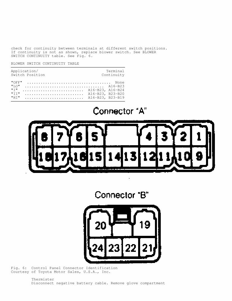
check for continuity between terminals at different switch positions.If continuity is not as shown, replace blower switch. See BLOWERSWITCH CONTINUITY table. See Fig. 6.
BLOWER SWITCH CONTINUITY TABLE���������������������������������������������������������������������������������������������������
Application/ TerminalSwitch Position Continuity
"OFF" ..................................... None"LO" ................................... A16-B23"I" ........................... A16-B23, A16-B24"II" .......................... A16-B23, B23-B20"HI" .......................... A16-B23, B23-B19���������������������������������������������������������������������������������������������������
Fig. 6: Control Panel Connector IdentificationCourtesy of Toyota Motor Sales, U.S.A., Inc.
Thermister Disconnect negative battery cable. Remove glove compartment
and under cover. Using an ohmmeter, measure resistance at thermistorconnector. Resistance should be 1500 ohms at 77
�
F (25�
C). If readingis not as indicated, replace thermister
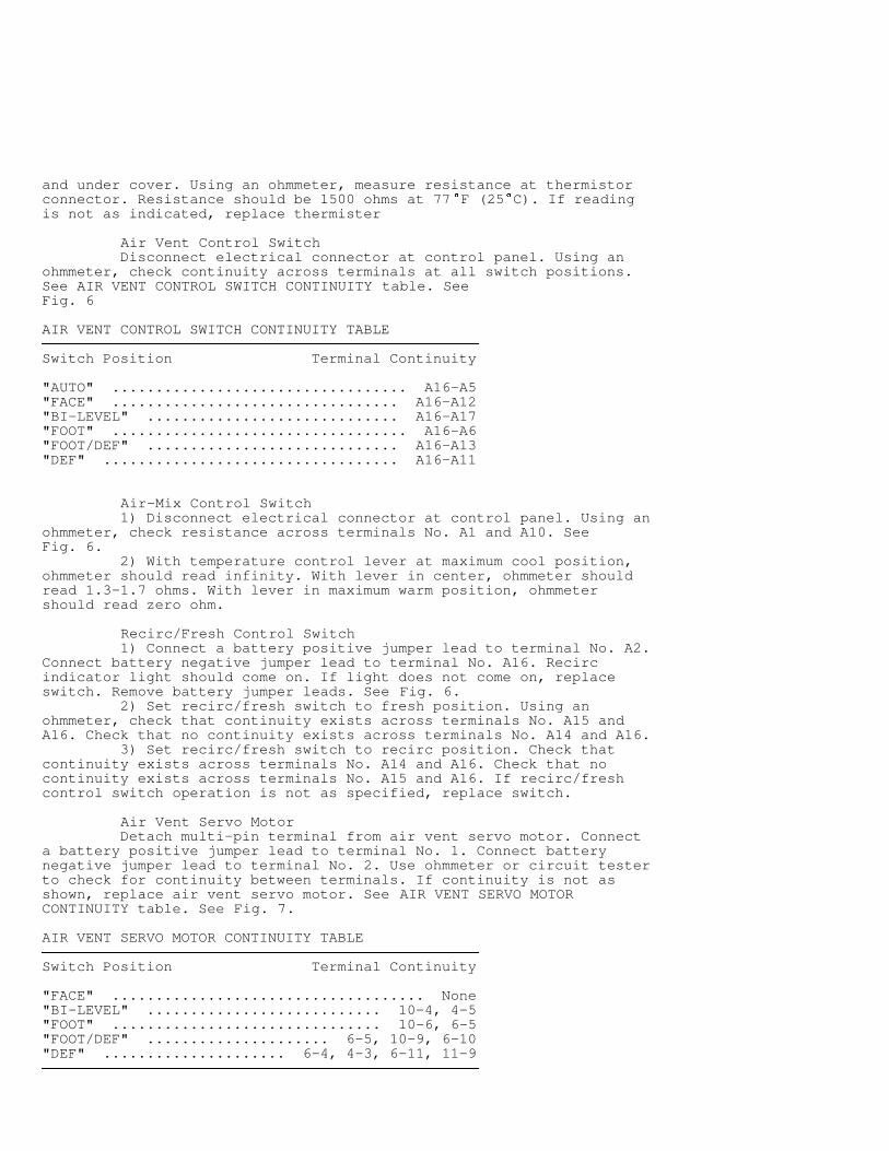
Air Vent Control Switch Disconnect electrical connector at control panel. Using anohmmeter, check continuity across terminals at all switch positions.See AIR VENT CONTROL SWITCH CONTINUITY table. SeeFig. 6
AIR VENT CONTROL SWITCH CONTINUITY TABLE���������������������������������������������������������������������������������������������������
Switch Position Terminal Continuity
"AUTO" .................................. A16-A5"FACE" ................................. A16-A12"BI-LEVEL" ............................. A16-A17"FOOT" .................................. A16-A6"FOOT/DEF" ............................. A16-A13"DEF" .................................. A16-A11���������������������������������������������������������������������������������������������������
Air-Mix Control Switch 1) Disconnect electrical connector at control panel. Using anohmmeter, check resistance across terminals No. A1 and A10. SeeFig. 6. 2) With temperature control lever at maximum cool position,ohmmeter should read infinity. With lever in center, ohmmeter shouldread 1.3-1.7 ohms. With lever in maximum warm position, ohmmetershould read zero ohm.
Recirc/Fresh Control Switch 1) Connect a battery positive jumper lead to terminal No. A2.Connect battery negative jumper lead to terminal No. A16. Recircindicator light should come on. If light does not come on, replaceswitch. Remove battery jumper leads. See Fig. 6. 2) Set recirc/fresh switch to fresh position. Using anohmmeter, check that continuity exists across terminals No. A15 andA16. Check that no continuity exists across terminals No. A14 and A16. 3) Set recirc/fresh switch to recirc position. Check thatcontinuity exists across terminals No. A14 and A16. Check that nocontinuity exists across terminals No. A15 and A16. If recirc/freshcontrol switch operation is not as specified, replace switch.
Air Vent Servo Motor Detach multi-pin terminal from air vent servo motor. Connecta battery positive jumper lead to terminal No. 1. Connect batterynegative jumper lead to terminal No. 2. Use ohmmeter or circuit testerto check for continuity between terminals. If continuity is not asshown, replace air vent servo motor. See AIR VENT SERVO MOTORCONTINUITY table. See Fig. 7.
AIR VENT SERVO MOTOR CONTINUITY TABLE���������������������������������������������������������������������������������������������������
Switch Position Terminal Continuity
"FACE" .................................... None"BI-LEVEL" ........................... 10-4, 4-5"FOOT" ............................... 10-6, 6-5"FOOT/DEF" ..................... 6-5, 10-9, 6-10"DEF" ..................... 6-4, 4-3, 6-11, 11-9���������������������������������������������������������������������������������������������������
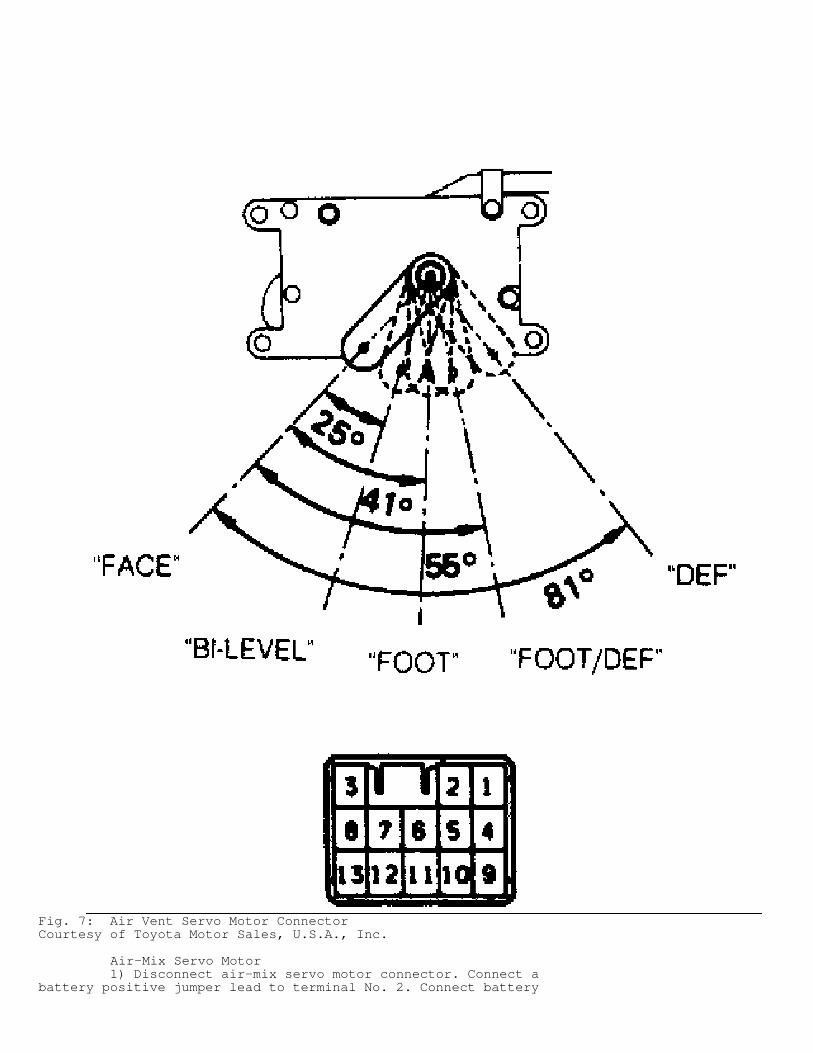
Fig. 7: Air Vent Servo Motor ConnectorCourtesy of Toyota Motor Sales, U.S.A., Inc.
Air-Mix Servo Motor 1) Disconnect air-mix servo motor connector. Connect abattery positive jumper lead to terminal No. 2. Connect battery
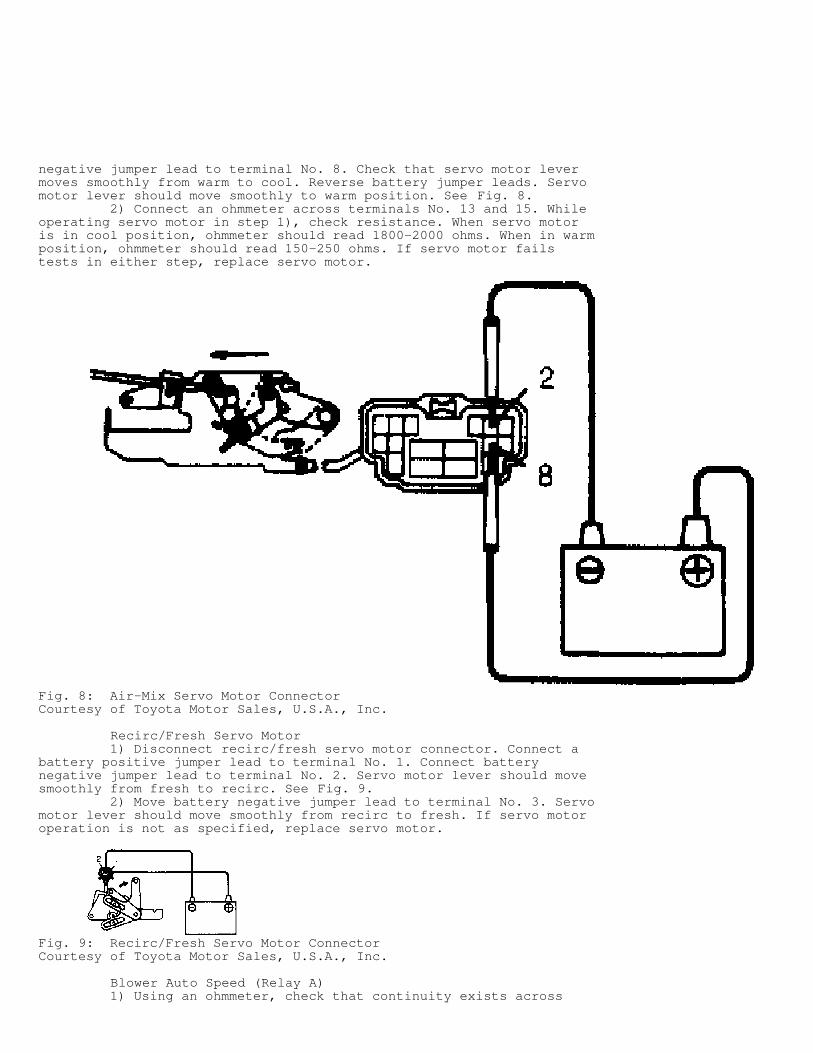
negative jumper lead to terminal No. 8. Check that servo motor levermoves smoothly from warm to cool. Reverse battery jumper leads. Servomotor lever should move smoothly to warm position. See Fig. 8. 2) Connect an ohmmeter across terminals No. 13 and 15. Whileoperating servo motor in step 1), check resistance. When servo motoris in cool position, ohmmeter should read 1800-2000 ohms. When in warmposition, ohmmeter should read 150-250 ohms. If servo motor failstests in either step, replace servo motor.
Fig. 8: Air-Mix Servo Motor ConnectorCourtesy of Toyota Motor Sales, U.S.A., Inc.
Recirc/Fresh Servo Motor 1) Disconnect recirc/fresh servo motor connector. Connect abattery positive jumper lead to terminal No. 1. Connect batterynegative jumper lead to terminal No. 2. Servo motor lever should movesmoothly from fresh to recirc. See Fig. 9. 2) Move battery negative jumper lead to terminal No. 3. Servomotor lever should move smoothly from recirc to fresh. If servo motoroperation is not as specified, replace servo motor.
Fig. 9: Recirc/Fresh Servo Motor ConnectorCourtesy of Toyota Motor Sales, U.S.A., Inc.
Blower Auto Speed (Relay A) 1) Using an ohmmeter, check that continuity exists across
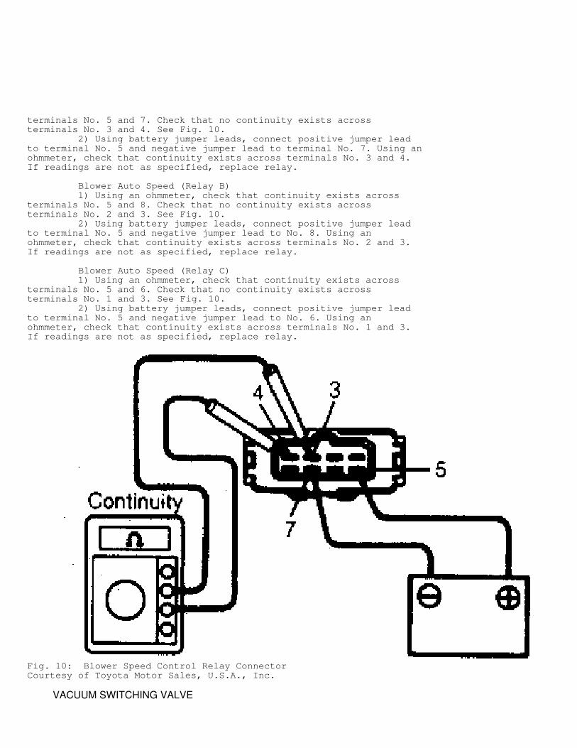
terminals No. 5 and 7. Check that no continuity exists acrossterminals No. 3 and 4. See Fig. 10. 2) Using battery jumper leads, connect positive jumper leadto terminal No. 5 and negative jumper lead to terminal No. 7. Using anohmmeter, check that continuity exists across terminals No. 3 and 4.If readings are not as specified, replace relay.
Blower Auto Speed (Relay B) 1) Using an ohmmeter, check that continuity exists acrossterminals No. 5 and 8. Check that no continuity exists acrossterminals No. 2 and 3. See Fig. 10. 2) Using battery jumper leads, connect positive jumper leadto terminal No. 5 and negative jumper lead to No. 8. Using anohmmeter, check that continuity exists across terminals No. 2 and 3.If readings are not as specified, replace relay.
Blower Auto Speed (Relay C) 1) Using an ohmmeter, check that continuity exists acrossterminals No. 5 and 6. Check that no continuity exists acrossterminals No. 1 and 3. See Fig. 10. 2) Using battery jumper leads, connect positive jumper leadto terminal No. 5 and negative jumper lead to No. 6. Using anohmmeter, check that continuity exists across terminals No. 1 and 3.If readings are not as specified, replace relay.
Fig. 10: Blower Speed Control Relay ConnectorCourtesy of Toyota Motor Sales, U.S.A., Inc.
VACUUM SWITCHING VALVE
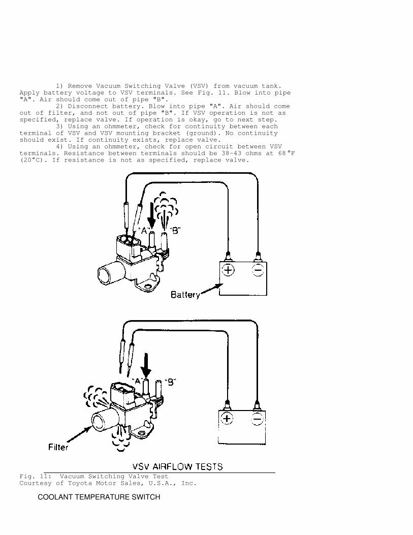
1) Remove Vacuum Switching Valve (VSV) from vacuum tank.Apply battery voltage to VSV terminals. See Fig. 11. Blow into pipe"A". Air should come out of pipe "B". 2) Disconnect battery. Blow into pipe "A". Air should comeout of filter, and not out of pipe "B". If VSV operation is not asspecified, replace valve. If operation is okay, go to next step. 3) Using an ohmmeter, check for continuity between eachterminal of VSV and VSV mounting bracket (ground). No continuityshould exist. If continuity exists, replace valve. 4) Using an ohmmeter, check for open circuit between VSVterminals. Resistance between terminals should be 38-43 ohms at 68
�
F(20
�
C). If resistance is not as specified, replace valve.
Fig. 11: Vacuum Switching Valve TestCourtesy of Toyota Motor Sales, U.S.A., Inc.
COOLANT TEMPERATURE SWITCH
Remove coolant temperature switch from heater case. Unplugcoolant temperature switch connector. Immerse switch in 59-77
�
F (15-25
�
C) water. Continuity should exist between terminals No. 1 and 3.Immerse switch in 95-113
�
F (35-45�
C) water. Continuity should existbetween terminals No. 2 and 4.
NOTE: Terminal No. 1 and 2 are near connector lock tab. Terminal No. 3 and 4 are opposite tab (flat portion of connector).
REMOVAL & INSTALLATION
COMPRESSOR
Removal & Installation 1) Start and run engine with A/C on for 10 minutes.Disconnect battery cables and remove battery. Disconnect A/Ccompressor leads from wiring harness. Discharge A/C system usingapproved refrigerant recovery/recycling equipment. 2) Disconnect hoses from compressor and cap all openings.Loosen drive belt, remove compressor mounting bolts and A/Ccompressor. To install, reverse removal procedure. Charge A/C systemand check for leaks.
RECEIVER-DRIER
Removal & Installation Discharge A/C system using approved refrigerantrecovery/recycling equipment. Disconnect lines from top of receiver-drier and cap all openings. Remove receiver-drier from holder. Toinstall, reverse removal procedure. If receiver-drier is replaced, add.7 ounces of refrigerant oil to receiver-drier. Charge A/C system andcheck for leaks.
CONDENSER
Removal & Installation 1) Discharge A/C system using approved refrigerantrecovery/recycling equipment. Remove grille and under cover. Removecenter brace and horn. Disconnect discharge hose, suction hose, liquidline, and suction hose from condenser. Cap all openings. Removecondenser. 2) To install, reverse removal procedure. If receiver-drieris replaced, add 1.4-1.7 ounces of refrigerant oil to receiver-drier.Charge A/C system and check for leaks.
A/C AMPLIFIER, THERMISTOR, EXPANSION VALVE & EVAPORATOR
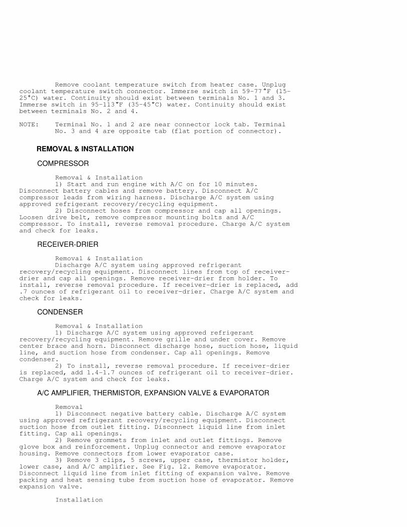
Removal 1) Disconnect negative battery cable. Discharge A/C systemusing approved refrigerant recovery/recycling equipment. Disconnectsuction hose from outlet fitting. Disconnect liquid line from inletfitting. Cap all openings. 2) Remove grommets from inlet and outlet fittings. Removeglove box and reinforcement. Unplug connector and remove evaporatorhousing. Remove connectors from lower evaporator case. 3) Remove 3 clips, 5 screws, upper case, thermistor holder,lower case, and A/C amplifier. See Fig. 12. Remove evaporator.Disconnect liquid line from inlet fitting of expansion valve. Removepacking and heat sensing tube from suction hose of evaporator. Removeexpansion valve.
Installation
To install, reverse removal procedure. If evaporator isreplaced, add 1.4-1.7 ounces of refrigerant oil to evaporator. ChargeA/C system and check for leaks.
Fig. 12: Exploded View of Evaporator AssemblyCourtesy of Toyota Motor Sales, U.S.A., Inc.
A/C SYSTEM SPECIFICATIONS
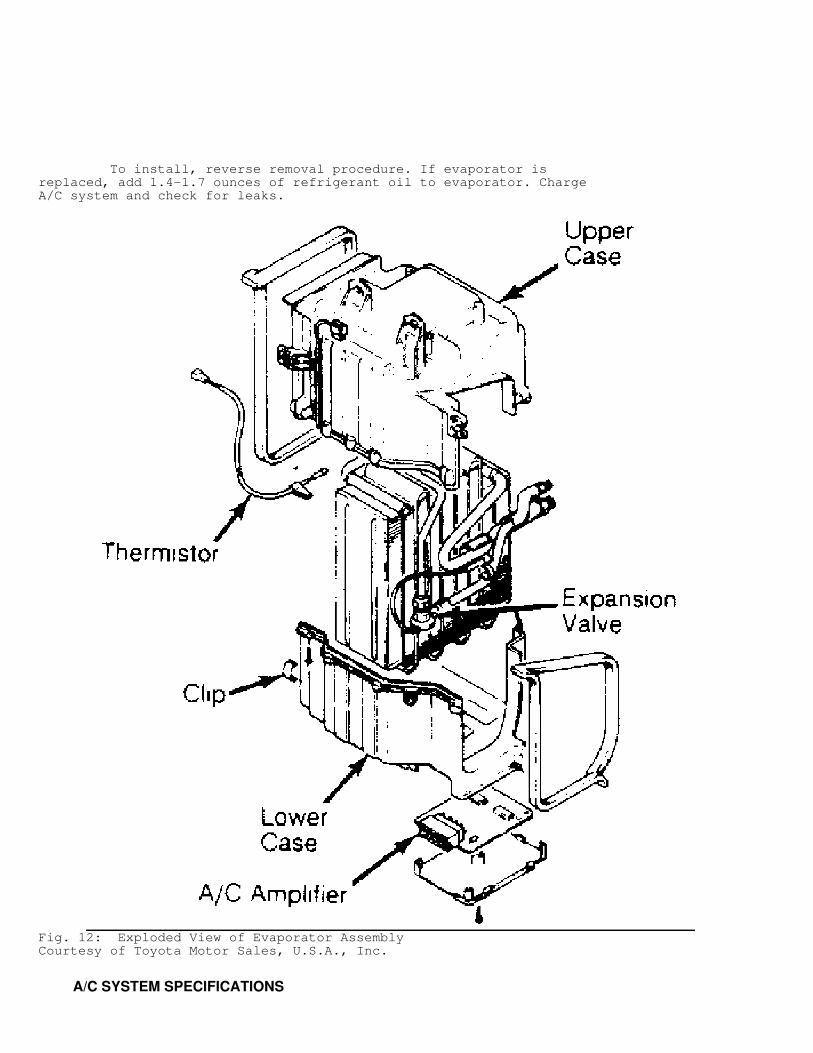
A/C SYSTEM SPECIFICATIONS TABLE�����������������������������������������������������������������������������������������������������������������������
Application Specification
System Type ............................... Cycling ClutchCompressor Type .................. Nippondenso 10-CylinderR-12 Capacity .................................. 21-27 oz.Normal System Pressure Low Side .................... 21-28 psi (1.5-2.0 kg/cm
�
) High Side ............... 206-213 psi (14.5-15.0 kg/cm
�
)Drive Belt Deflection ................................ (1)
(1) - Belt deflection is 165-175 lbs. using belt tension gauge. Belt deflection is 120-130 lbs. for used belt.�����������������������������������������������������������������������������������������������������������������������
WIRING DIAGRAMS
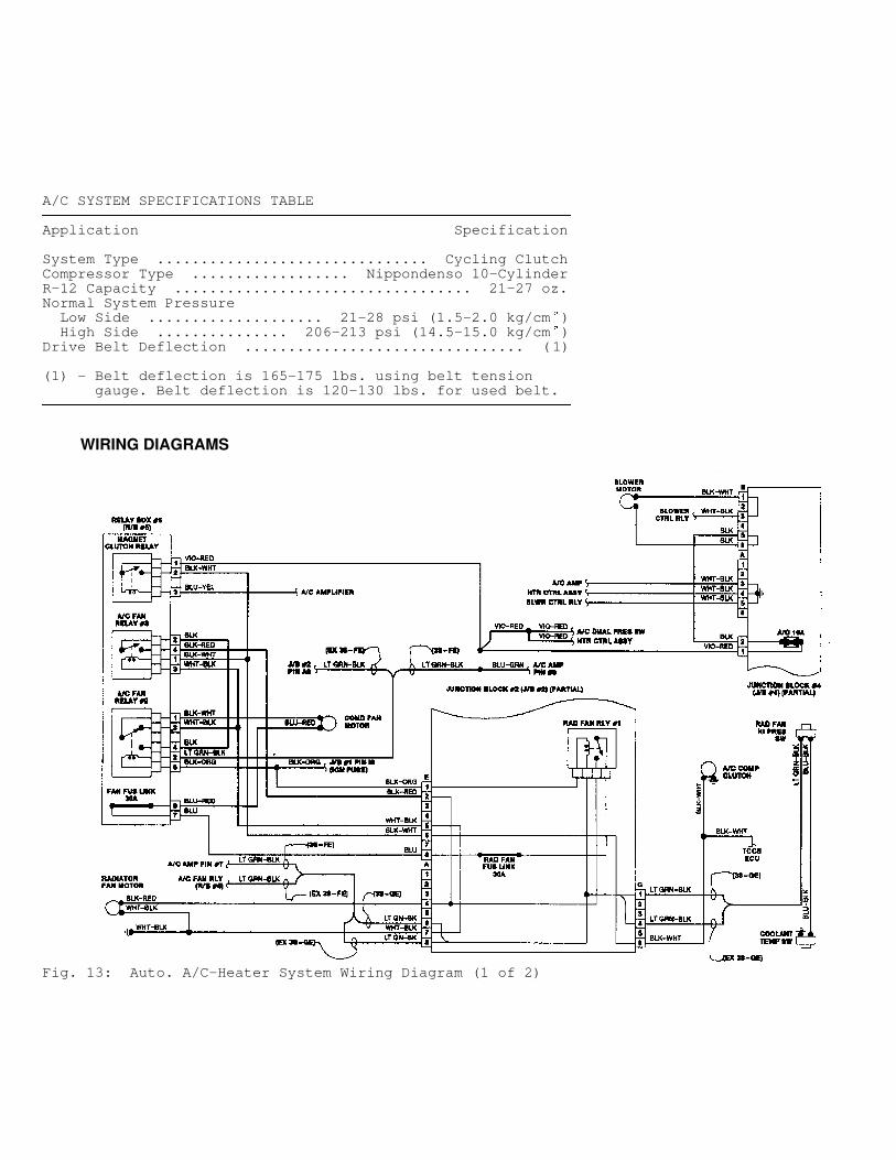
Fig. 13: Auto. A/C-Heater System Wiring Diagram (1 of 2)
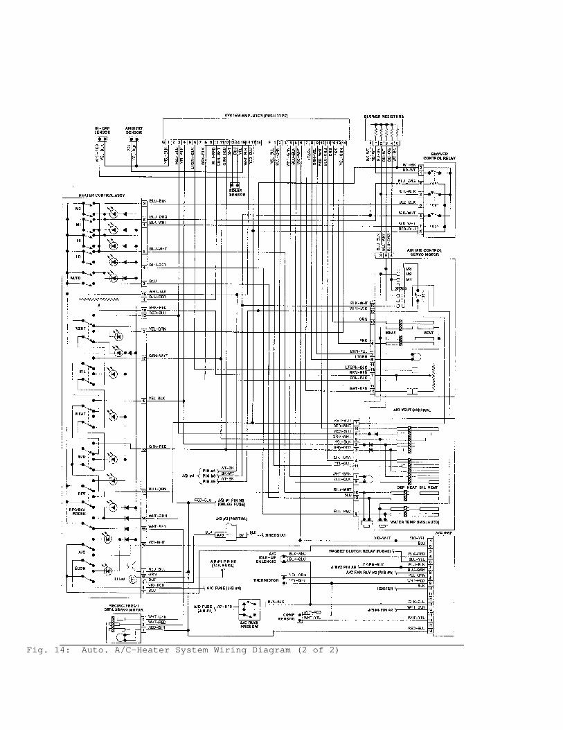
Fig. 14: Auto. A/C-Heater System Wiring Diagram (2 of 2)