AC & DC MACHINESb) Capacitor start / capacitor run or two-capacitor motor. 2. Mention two important...
35
AC & DC MACHINES (ADM) Facilitator Guide
Transcript of AC & DC MACHINESb) Capacitor start / capacitor run or two-capacitor motor. 2. Mention two important...

AC & DC MACHINES
(ADM)
Facilitator Guide

TABLE OF CONTENTS
INTRODUCTION PAGE 1 PROCEDURES PAGE 2 MODULE 1 PAGE 4 MODULE 2 PAGE 5 MODULE 3 PAGE 6 MODEL ANSWERS ADM-1 SELF-TEST EXERCISE NO. 1 PAGE 8 SELF-TEST EXERCISE NO. 2 PAGE 9 SELF-TEST EXERCISE NO. 3 PAGE 10 SELF-TEST EXERCISE NO. 4 PAGE 12 SELF-TEST EXERCISE NO. 5 PAGE 13 SELF-TEST EXERCISE NO. 6 PAGE 15 ADM-2 SELF-TEST EXERCISE NO. 1 PAGE 16 SELF-TEST EXERCISE NO. 2 PAGE 17 SELF-TEST EXERCISE NO. 3 PAGE 18 SELF-TEST EXERCISE NO. 4 PAGE 20 SELF-TEST EXERCISE NO. 5 PAGE 21 SELF-TEST EXERCISE NO. 6 PAGE 22 ADM-3 SELF-TEST EXERCISE NO. 1 PAGE 24 SELF-TEST EXERCISE NO. 2 PAGE 25 SELF-TEST EXERCISE NO. 3 PAGE 27 SELF-TEST EXERCISE NO. 4 PAGE 29 SELF-TEST EXERCISE NO. 5 PAGE 30 STANDARD CHECKLIST PAGE 31
CONTACT DETAILS: https://techav.co.za

Back to Table of Contects 1
INTRODUCTION This series of instructional modules is aimed at providing basic instruction on the operation
of AC and DC machines.
The series covers single phase, three phase and DC motors and generators. Each module has
been designed to be able to "stand alone", i.e. trainees may select any module according to
requirement.
It is assumed that learners have a working knowledge of both AC and DC operating
principles.

Back to Table of Contects 2
PROCEDURE FOR CONDUCTING PROGRAMMES
IMPORTANT NOTE
This series is a training aid only and in no way replaces an experienced Facilitator. Your
knowledge and experience in the field of AC / DC motors is a vital input to the Learner's
learning process.
WORKBOOKS
o Every Learner should be provided with his / her own workbook.
o The workbook guides learners. The workbook ideally should be read before viewing
the video material.
o Self-tests or exercises are provided in the workbooks. Learners should attempt these
on their own, and then assess their own performance.
o Model answers to the questions are provided in this Facilitator Guide.
PRACTICAL EXERCISES
o A learner is guided, from the text, to perform a suggested practical exercise. It is
very important that these exercises are performed under YOUR SUPERVISION.
o Wherever a procedure involves operating upon a live unit, please ensure that all
safety procedures are strictly adhered to.
VIDEO PROGRAMMES
o Learner will request the video programme relevant to the module being attempted.
o The videos provide visual reference to general procedures or basic facts. It is strongly
suggested that you (the Facilitator) view the videos to become familiar with the
material.
o Learners should view the videos after reading their workbook (resource notes).
Videos may be viewed several times or as often as necessary in order that the facts /
procedures are understood.
o Review breaks, featured in the videos, are intended to provide for practical (or
theoretical) assignments. Many Facilitators use the Review breaks to discuss issues
with their learners.
o Upon completion of viewing, ensure that the videos have been returned to you.
ASSESSING COMPETENCY
This is done according to the relevant industry standard pertaining to your company or
organisation.

Back to Table of Contects 3
TRAINING ENVIRONMENT
In order to achieve best results, training should be conducted in a properly equipped
training centre (or dedicated area) which ideally would include:
o All necessary tools and test equipment.
o An assortment of relevant AC / DC motors and generators.
TRAINING OBJECTIVE OVERALL
Upon successful completion of the any module in the series the learner(s) will demonstrate
his / her ability to perform the following:
o Describe the working principles of the machine under review.
o Perform all electrical and mechanical tests.
GIVEN
o The required input in the form of visual demonstration and written information.
o The necessary tools and testing devices.
o The necessary motor or generator.
HOW WELL
The above objectives to be achieved in terms of industry standards.

Back to Table of Contects 4
MODULE NO.1 (ADM-1)
SUBJECT: SINGLE PHASE CAPACITOR MOTORS
OBJECTIVES (TRAINING OBJECTIVE)
Upon completion of this module the learner should be able to:
o Identify by name the key components and state their functions.
o Describe the basic operating principles of a capacitor motor.
o Perform the basic electrical and mechanical test procedures on a capacitor motor.
TRAINING AIDS REQUIRED
o Learner Workbook.
o Video programme ADM-1.
o Single phase capacitor motors (assorted).
SUMMARY OF SUBJECT MATTER
This module provides the need to know details regarding the operation of single-phase
capacitor type motors.
The procedures for performing electrical tests and mechanical inspections are also covered.
Back to Table of Contects 5
MODULE NO.2 (ADM-2)
SUBJECT: THREE PHASE MOTORS
OBJECTIVES (TRAINING OBJECTIVE)
Upon completion of this module the learner should be able to:
o Identify by name the key components and state their functions.
o Describe the basic operating principles of a three-phase motor.
o Perform the basic electrical and mechanical test procedures on a three-phase motor.
TRAINING AIDS REQUIRED
o Learner workbook.
o Video programme ADM-2.
o Three-phase motors.
SUMMARY OF SUBJECT MATTER
This module provides the generally accepted explanation of typical three-phase motor
construction and operation.
The procedures for performing electrical tests and mechanical inspections are also covered.

Back to Table of Contects 6
MODULE NO.3 (ADM-3)
SUBJECT: DC MOTORS AND GENERATORS
OBJECTIVES (TRAINING OBJECTIVE)
Upon completion of this module the learner should be able to:
o Identify by name the key components and state their functions.
o Describe the basic operating principles of a DC motor.
o Perform the basic electrical and mechanical test procedures on a DC motor.
TRAINING AIDS REQUIRED
o Lerner Workbook.
o Video programme ADM-3.
o DC motors / generators.
SUMMARY OF SUBJECT MATTER
This module provides the generally accepted explanation of the operating principles
involved in DC motors and generators.
The procedures for performing electrical tests and mechanical inspections are also covered.

Back to Table of Contects 7
MODEL ANSWERS / RESPONSES
(TO LEARNER SELF-TEST EXERCISES)
NOTE
o The following pages provide typical answers to the theoretical questions asked in the
Learners self-test exercises (contained in the workbook).
o As some answers or responses require the learner to explain in his / her own words
then you (the Facilitator) will need to assess the response in light of given inputs.
Back to Table of Contects 8
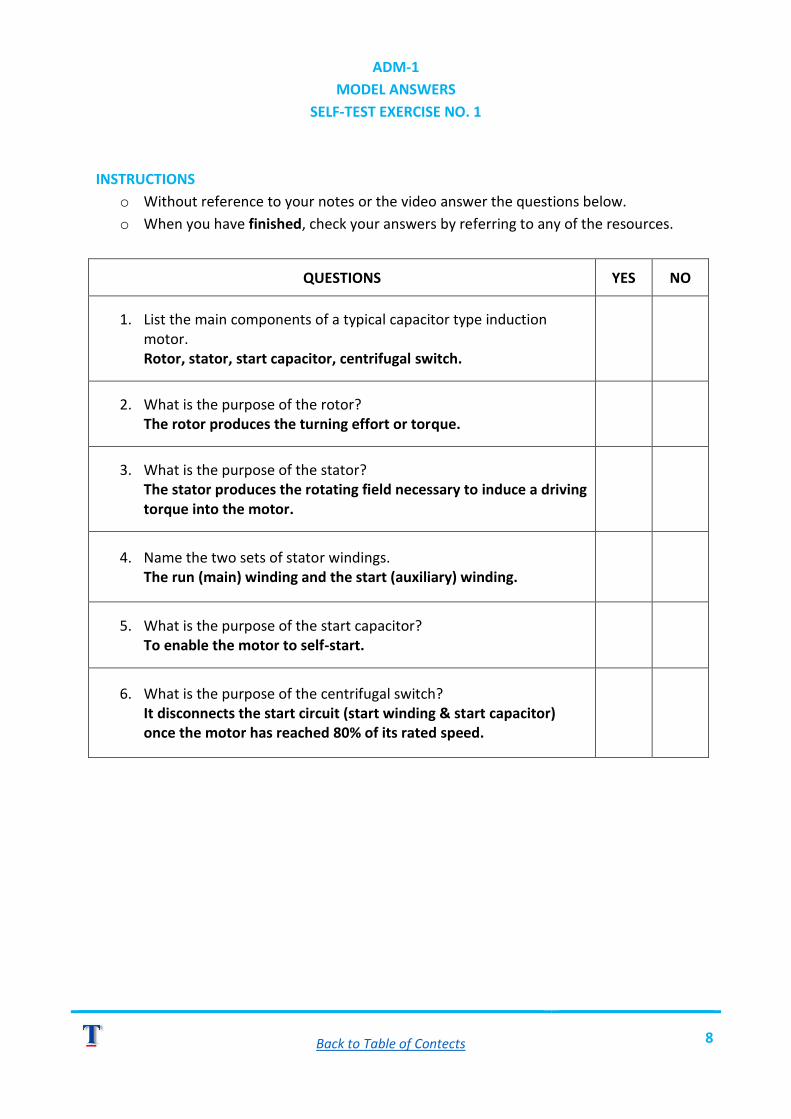
ADM-1
MODEL ANSWERS
SELF-TEST EXERCISE NO. 1
INSTRUCTIONS
o Without reference to your notes or the video answer the questions below.
o When you have finished, check your answers by referring to any of the resources.
QUESTIONS YES NO
1. List the main components of a typical capacitor type induction motor. Rotor, stator, start capacitor, centrifugal switch.
2. What is the purpose of the rotor? The rotor produces the turning effort or torque.
3. What is the purpose of the stator? The stator produces the rotating field necessary to induce a driving torque into the motor.
4. Name the two sets of stator windings. The run (main) winding and the start (auxiliary) winding.
5. What is the purpose of the start capacitor? To enable the motor to self-start.
6. What is the purpose of the centrifugal switch? It disconnects the start circuit (start winding & start capacitor) once the motor has reached 80% of its rated speed.

Back to Table of Contects 9
ADM-1
MODEL ANSWERS
SELF-TEST EXERCISE NO. 2
INSTRUCTIONS
o Without reference to your notes or the video answer the questions below.
o When you have finished, check your answers by referring to any of the resources.
QUESTIONS YES NO
1. Describe the nature of the field produced by the run winding. A pulsating magnetic field changing direction at the rate of the supply frequency.
2. How can we get the rotor to turn? By a mechanical impulse – i.e. giving the rotor a kick or push start.
3. How is it possible to get the rotor to self-start? By an auxiliary or start winding positioned at 90 degrees (geometrically displaced) to the run winding.
4. What is the function of the start capacitor? The start capacitor assists the motor to self-start by creating an electrical phase shift to the current flowing in the start winding.
5. What happens to the start circuit once the motor reaches 80% of its rated speed? The start winding and start capacitor are no longer required since the rotor has self-started. They are disconnected from the supply by a switch.
6. How is the direction of rotation changed? By swapping the start winding connections to the main supply.
7. What do you suppose would happen if the start and run windings were both swapped together? There would be no change in the direction of rotation.

Back to Table of Contects 10
ADM-1
MODEL ANSWERS
SELF-TEST EXERCISE NO. 3
INSTRUCTIONS
o Without reference to your notes or the video answer the questions below.
o When you have finished, check your answers by referring to any of the resources.
QUESTIONS YES NO
1. The run winding has more turns of thicker wire. How does this affect the electrical characteristic of the winding? The winding is more inductive than resistive (more turns = more inductance).
2. The start winding has less turns of thinner wire. How does this affect the electrical characteristic of the winding? The winding is more resistive than inductive (thinner wire = more resistance).
3. The windings are designed to enable the motor to self-start. Describe how this is achieved with respect to applied voltage and current. The current in the start winding must lead the current in the run winding by approximately 90 degrees. If the currents are 90 degrees out of phase, then so are the fields produced by these currents, and the effect is a rotating magnetic field system.
4. The speed of the rotor is always less than the speed of the rotating magnetic field. How is the speed difference expressed? As slip.
5. The synchronous speed of an induction motor is dependent on two parameters. Name them. a) The frequency of the main supply. b) The number of pole pairs in the stator.

Back to Table of Contects 11
6. What is the synchronous speed of a 4-pole motor operating from a 60 Hz. supply? Speed = Freq. X 60 / No. of Pole Pairs = 1800 revs/min.
7. The start circuit is usually disconnected by a centrifugal switch. Name another type of switch. An electrically operated potential relay switch.

Back to Table of Contects 12
ADM-1
MODEL ANSWERS
SELF-TEST EXERCISE NO. 4
INSTRUCTIONS
o Without reference to your notes or the video answer the questions below.
o When you have finished, check your answers by referring to any of the resources.
QUESTIONS YES NO
1. Name two other types of capacitor motor. a) Capacitor run or permanent split motor. b) Capacitor start / capacitor run or two-capacitor motor.
2. Mention two important points concerning the run capacitor. a) It is continuously rated (it can remain connected to the supply
without the risk of failure). b) The value of capacitance is in the order of 20 F (it is much
smaller in value than that of the start capacitor).
3. Name two features of the capacitor start / capacitor run motor. The motor exhibits both good starting and good running torque.

Back to Table of Contects 13
ADM-1
MODEL ANSWERS
SELF-TEST EXERCISE NO. 5
INSTRUCTIONS
o Without reference to your notes or the video answer the questions below.
o When you have finished, check your answers by referring to any of the resources.
QUESTIONS YES NO
1. Tick the correct statement. a) Motors should be tested as a routine part of a good
maintenance schedule. b) Motors should be tested in order to find out when they will fail. c) Motors should be tested to improve their performance and save
on electricity.
2. List the three main electrical tests that are discussed in this section. a) Continuity (windings, centrifugal switch and capacitor/s). b) Insulation resistance tests between windings. c) Insulation resistance between windings, centrifugal switch,
capacitor/s and earth.
3. What type of measuring instrument would you use to measure the resistance of the windings (continuity)? Analogue or digital multi-meter.
4. When using an analogue multi-meter what must you do before taking any readings? Select the correct resistance scale (low ohms) and zero the meter using the zero adjustment control.
5. When the test leads of a digital multi-meter are shorted together, the resistance reading is not zero. Explain why this is so. The meter is measuring the resistance of the test leads.
Back to Table of Contects 14
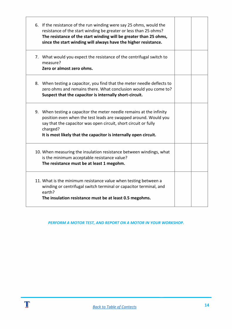
6. If the resistance of the run winding were say 25 ohms, would the resistance of the start winding be greater or less than 25 ohms? The resistance of the start winding will be greater than 25 ohms, since the start winding will always have the higher resistance.
7. What would you expect the resistance of the centrifugal switch to measure? Zero or almost zero ohms.
8. When testing a capacitor, you find that the meter needle deflects to zero ohms and remains there. What conclusion would you come to? Suspect that the capacitor is internally short-circuit.
9. When testing a capacitor the meter needle remains at the infinity position even when the test leads are swapped around. Would you say that the capacitor was open circuit, short circuit or fully charged? It is most likely that the capacitor is internally open circuit.
10. When measuring the insulation resistance between windings, what is the minimum acceptable resistance value? The resistance must be at least 1 megohm.
11. What is the minimum resistance value when testing between a winding or centrifugal switch terminal or capacitor terminal, and earth? The insulation resistance must be at least 0.5 megohms.
PERFORM A MOTOR TEST, AND REPORT ON A MOTOR IN YOUR WORKSHOP.

Back to Table of Contects 15
ADM-1
MODEL ANSWERS
SELF-TEST EXERCISE NO. 6
INSTRUCTIONS
o Without reference to your notes or the video answer the questions below.
o When you have finished, check your answers by referring to any of the resources.
QUESTION YES NO
1. Name six key components that must be checked, stating briefly what you would be on the lookout for. i) Bearings – abnormal noise. ii) Shaft & Keyway – Excessive wear. iii) Stator frame & end shields – cracks, breaks, missing
through-bolts. iv) Fan & fan blades – Damaged or broken blades. v) Terminal box – Cracks, breaks, missing parts. vi) Nameplate – firmly attached to frame & legible.
PERFORM A MECHANICAL CHECK ON A CAPACITOR MOTOR.

Back to Table of Contects 16
ADM-2
MODEL ANSWERS
SELF-TEST EXERCISE NO. 1
INSTRUCTIONS
o Without reference to your notes or the video answer the questions below.
o When you have finished, check your answers by referring to any of the resources.
QUESTIONS YES NO
1. List the two main components in a three-phase cage induction motor. Rotor, stator.
2. What is the basic purpose of the rotor? The rotor produces the turning effort or torque.
3. What is the purpose of the stator? The stator produces the rotating field necessary to induce a driving torque into the rotor.
4. Complete the following sentence: The stator has three windings. When connected to a three-phase supply the coils produce a ROTATING field.

Back to Table of Contects 17
ADM-2
MODEL ANSWERS
SELF-TEST EXERCISE NO. 2
INSTRUCTIONS
o Without reference to your notes or the video answer the questions below.
o When you have finished, check your answers by referring to any of the resources.
QUESTION YES NO
1. What kind of field is produced when a three phase 50 Hz AC current flows in the stator windings? A rotating magnetic field changing polarity at the rate of 50 times per second.
2. What is slip? The difference in speed between the synchronous speed and the actual speed of the motor.
3. The synchronous speed of an induction motor is determined by two parameters. Name them. The frequency of the main supply and the number of pole pairs in the stator windings.
4. What is the synchronous speed of a B-pole motor operating from a 60 Hz. Supply? Speed = freq. x 60 / no. of pole pairs = 60 x 60/4 = 900 r.p.m.
5. How would you change the direction of rotation? Swap any two phases supplying power to the motor.

Back to Table of Contects 18
ADM-2
MODEL ANSWERS
SELF-TEST EXERCISE NO. 3
INSTRUCTIONS
o Without reference to your notes or the video answer the questions below.
o When you have finished, check your answers by referring to any of the resources.
QUESTION YES NO
1. Tick the correct statement. a) Motors should be tested as a routine part of a good
maintenance schedule. b) Motors should be tested in order to find out when they will fail. c) Motors should be tested to improve their performance and save
on electricity.
2. List the three main electrical tests that are discussed in this section. i) Continuity (measure the resistance of each winding). ii) Insulation resistance tests between each winding. iii) Insulation resistance tests between winding and earth.
3. Name the type of measuring instrument would you use to measure the resistance of the windings. Analogue or digital multi-meter.
4. When using an analogue multi-meter what must you do before making any resistance measurements? Select the correct resistance scale (low ohms) and zero the meter using the zero adjustment control.
5. When the test leads of a digital multi-meter are shorted together, the resistance reading is greater than zero ohms. Why is this is so? The meter is measuring the resistance of the test leads.
6. When measuring the insulation resistance between windings, what is the minimum acceptable resistance value? The resistance must be at least 1 megohm.

Back to Table of Contects 19
7. What is the minimum resistance value when testing between a winding and earth? The insulation resistance must be at least 0,5 megohms.
Back to Table of Contects 20
ADM-2
MODEL ANSWERS
SELF-TEST EXERCISE NO. 4
INSTRUCTIONS
o Without reference to your notes or the video answer the questions below.
o When you have finished, check your answers by referring to any of the resources.
QUESTION YES NO
1. Name six key components that must be checked, stating briefly what you would be on the lookout for. i) Bearings – abnormal noise. ii) Shaft & Keyway – Excessive wear. iii) Stator frame & end shields – cracks, breaks, missing
through-bolts. iv) Fan & fan blades – Damaged or broken blades. v) Terminal box – Cracks, breaks, missing parts. vi) Nameplate – firmly attached to frame & legible.
PERFORM A MECHANICAL INSPECTION, AND REPORT ON A MOTOR IN YOUR WORKSHOP.
Back to Table of Contects 21
ADM-2
MODEL ANSWERS
SELF-TEST EXERCISE NO. 5
INSTRUCTIONS
o Without reference to your notes or the video answer the questions below.
o When you have finished, check your answers by referring to any of the resources.
QUESTIONS YES NO
1. Complete the following sentence: The difference between a cage induction motor and a slip ring motor lies in the construction of the ROTOR.
2. How can the output characteristics of an induction motor be changed? By adding resistance into the rotor windings.
3. Complete the following sentence: Increasing the resistance in the rotor circuit will affect the TORQUE and the SPEED characteristics of the motor.

Back to Table of Contects 22
ADM-2
MODEL ANSWERS
SELF-TEST EXERCISE NO. 6
INSTRUCTIONS
o Without reference to your notes or the video answer the questions below.
o When you have finished, check your answers by referring to any of the resources.
QUESTIONS YES NO
1. How do we get electrical access the rotor windings? Via the three slip rings.
2. Name two electrical tests to be performed on the rotor. Continuity & insulation resistance to earth.
3. Complete the following sentence. The windings must be balanced. This means that the ohmic resistance of all three windings must be within 5% of each other.
4. When performing an insulation test between the windings and earth, what is the accepted minimum resistance? 0,5 megohm.
5. Complete the following sentences. Slip rings must be free from GREASE, OIL & GRIT
6. When checking the brush rigging, look out for the following: Pigtails must not be LOOSE or DAMAGED.
7. The length of each brush should not be WORN beyond specified limits.
8. Brush holders must be clean so that the BRUSH can move FREELY inside the holder.
9. Spring pressure must be firm: -loss of tension will result in POOR ELECTRICAL CONTACT between the brush and slip ring.

Back to Table of Contects 23
10. The tip of each brush should be shaped to ensure MAXIMUM CONTACT between the slip-ring and the brush
11. Brush alignment must be checked to ensure that the brush rides IN THE CENTRE of the slip ring.
PERFORM ELECTRICAL TESTS ON A SLIP-RING MOTOR IN YOUR WORKSHOP, AND REPORT YOUR
RESULTS. PERFORM A MECHANICAL INSPECTION, AND REPORT ON A MOTOR IN YOUR
WORKSHOP.

Back to Table of Contects 24
ADM-3
MODEL ANSWERS
SELF-TEST EXERCISE NO. 1
INSTRUCTIONS
o Without reference to your notes or the video answer the questions below.
o When you have finished, check your answers by referring to any of the resources.
QUESTIONS YES NO
1. List the two main components of a DC motor. Armature & Stator.
2. What is the purpose of the armature? The armature produces the turning effort or torque.
3. What is the purpose of the stator? The stator produces the static magnetic field which reacts with the field produced in the armature to cause motion.
4. What is connected to the commutator? The ends of all the armature coils.
5. What is the function of the brushes? The brushes pass DC to the armature windings.
Back to Table of Contects 25
ADM-3
MODEL ANSWERS
SELF-TEST EXERCISE NO. 2
INSTRUCTIONS
o Without reference to your notes or the video answer the questions below.
o When you have finished, check your answers by referring to any of the resources.
QUESTIONS YES NO
1. Complete the following sentence: UNLIKE poles attract, whilst LIKE poles repel.
2. What is the function of the commutator? It functions as a reversing switch, changing the direction of the current flowing in the armature winding as the armature rotates.
3. How do we set the switching position or point of commutation? By adjusting the position of the brushes.
4. The brushes should be set to switch at a pre-determined position. What is that position called? The magnetic neutral position.
5. What will happen when a switch interrupts the current flowing in a DC circuit? An arc will be drawn across the switch contacts.
6. Why is it necessary to reduce the size of the arc? To prevent damage to the switching contact surfaces produced by the arcing.
7. What is back or counter-emf? It is the voltage generated when a current carrying conductor moves at right angles to a magnetic field.

Back to Table of Contects 26
8. What three factors determine the magnitude of the back or counter-emf?
a) Field strength produced by the main field. b) The number of turns in the armature circuits. c) The speed of rotation of the armature.
9. How does the back emf affect the current drawn by a motor? As the back emf increases, the current drawn by the motor decreases.

Back to Table of Contects 27
ADM-3
MODEL ANSWERS
SELF-TEST EXERCISE NO. 3
INSTRUCTIONS
o Without reference to your notes or the video answer the questions below.
o When you have finished, check your answers by referring to any of the resources.
QUESTIONS YES NO
1. Name one useful characteristic of a series connected DC motor. High starting torque.
2. What is the series motor used for? Traction applications, locos and battery driven loading equipment.
3. What happens to a series wound motor when the load is suddenly removed? The motor over-speeds.
4. Describe the characteristics of a shunt winding. It consists of many turns of fine insulated copper wire.
5. How is the field winding connected in a shunt motor? The winding is connected in parallel with or in shunt with the armature.
6. Name an important characteristic of a shunt machine. Constant speed machine.
7. Name the two windings of a compound motor. Series and shunt windings.
8. Name two characteristics of a compound motor. Good starting torque and good speed regulation.
9. How can a DC motor be made to over-speed (electrically)? By decreasing the strength of the shunt field using a rheostat (shunt field regulator).

Back to Table of Contects 28
10. How can a DC motor be made to run under-speed (electrically)? By connecting a variable resistance in the armature circuit.
11. How would you reverse the direction of rotation in a DC motor? By swapping the armature connection.
12. Name the output characteristics of a series, shunt and compound generator. Series - constant current machine. Shunt - constant voltage machine. Compound - constant output voltage under varying loads.

Back to Table of Contects 29
ADM-3
MODEL ANSWERS
SELF-TEST EXERCISE NO. 4
INSTRUCTIONS
o Without reference to your notes or the video answer the questions below.
o When you have finished, check your answers by referring to any of the resources.
QUESTIONS YES NO
1. Tick the correct statement. a) Motors should be tested as a routine part of a good
maintenance schedule. b) Motors should be tested in order to find out when they will fail. c) Motors should be tested to improve their performance and save
on electricity.
2. Name the type of measuring instrument used to measure the resistance of the windings. Analogue or digital multi-meter.
3. When using an analogue multi-meter what must you do before making any resistance measurements? Select the correct resistance scale (low ohms) and zero the meter using the zero adjustment control.
4. When the test leads of a digital multi-meter are shorted together, the resistance reading is greater than zero ohms. Why is this is so? The meter is measuring the resistance of the test leads.
5. When measuring the insulation resistance between windings, what is the minimum acceptable resistance value? The resistance must be at least 1 megohm.
6. What is the minimum resistance value when testing between a winding and earth? The insulation resistance must be at least 0,5 megohms.
PERFORM AN ELECTRICAL TEST AND REPORT ON A MOTOR IN YOUR WORKSHOP.

Back to Table of Contects 30
ADM-3
MODEL ANSWERS
SELF-TEST EXERCISE NO. 5
INSTRUCTIONS
o Without reference to your notes or the video answer the questions below.
o When you have finished, check your answers by referring to any of the resources.
QUESTIONS YES NO
1. Name six key components that must be checked, stating briefly what you would be on the lookout for. i) Bearings - abnormal noise. ii) Shaft & keyway -excessive wear. iii) Stator frame & end-shields - cracks, breaks, missing
through-bolts. iv) Fan & fan blades - damaged or broken blades. v) Terminal box - cracks, breaks, missing parts. vi) Nameplate -firmly attached to frame and legible.
2. What should you look for when checking the surface of the commutator? It must not show signs of uneven wear & the surface must be clean.
3. What important check must be made when examining the brushes? That the brushes are not worn beyond the specified limits.
4. When examining the brush holder, what should you look for? That the brush can move freely inside the holder.

Back to Table of Contects 31
STANDARD CHECKLIST (ELECTRICAL)
Terminal Board Layout
1. Continuity test
Electrical part Ohmic Value Acceptable yes/no (If no – why?)
Series winding
Shunt winding
Armature
2.1 Insulation resistance test (Between windings)
Series 1 – Shunt 1
Series 1 – Shunt 2
Series 2 – Shunt 2
Series 2 – Shunt 1
2.2 Insulation resistance test (Between windings & Earth) Series winding to Earth
Series 1 – Earth
Series 2 – Earth
Shunt winding to Earth
Shunt 1 – Earth
Shunt 2 – Earth

Back to Table of Contects 32
Shunt winding to Earth
Armature 1 – Earth
Armature 2 – Earth
ELECTRICAL CHECKLIST (Cont.)
Terminal Board Layout
Electrical part Ohmic Value Acceptable yes/no (If no – why?)
3. Armature Resistance Test (Armature coils)
Test for S/C coils
Test for S/C coils
3.1. Armature Resistance Test (Coils/Bars to Earth)
4. Continuity Test (Interpole windings)
Interpole winding
4.1 Insulation Resistance Test (Windings & Earth)
Interpole winding

Back to Table of Contects 33
5. Brush-gear (Brush holder & Earth)
Brush 1 – Earth
Brush 2 - Earth


![Untitled-1 [] · Run Capacitor Stator Winding Relay Rotary Switch Rotor Start capacitor Main or Run Windin Stator Winding Main Winding Start capacitor Rotor](https://static.fdocuments.us/doc/165x107/5fc791720420d159865384b0/untitled-1-run-capacitor-stator-winding-relay-rotary-switch-rotor-start-capacitor.jpg)