AC 20-151B - Airworthiness Approval of Traffic Alert and ... · Collision Avoidance System (TCAS)...
72
Advisory U.S. Department of Transportation Federal Aviation Circular Administration Subject: Airworthiness Approval of Traffic Date: 03/18/14 AC No: 20-151B Alert and Collision Avoidance Systems Initiated By: AIR-130 (TCAS II), Versions 7.0 & 7.1 and Associated Mode S Transponders This advisory circular (AC) provides applicants with guidance for obtaining an airworthiness approval for traffic alert collision avoidance systems II (TCAS II). It also provides guidance for certification of a stand-alone Mode S transponder system. This AC includes the TCAS II versions 7.0 and 7.1 (TSO-C119b and TSO-C119c respectively) along with the latest iteration, which is version 7.1, containing hybrid surveillance functionality as defined by TSO-C119d.
Transcript of AC 20-151B - Airworthiness Approval of Traffic Alert and ... · Collision Avoidance System (TCAS)...

Advisory US Department of Transportation Federal Aviation Circular Administration
Subject Airworthiness Approval of Traffic Date 031814 AC No 20-151B Alert and Collision Avoidance Systems Initiated By AIR-130 (TCAS II) Versions 70 amp 71 and Associated Mode S Transponders
This advisory circular (AC) provides applicants with guidance for obtaining an airworthiness approval for traffic alert collision avoidance systems II (TCAS II) It also provides guidance for certification of a stand-alone Mode S transponder system This AC includes the TCAS II versions 70 and 71 (TSO-C119b and TSO-C119c respectively) along with the latest iteration which is version 71 containing hybrid surveillance functionality as defined by TSO-C119d
031814 AC 20-151B
TABLE OF CONTENTS
CHAPTER 1 GENERAL INFORMATION 1
1-1 Purpose of this Advisory Circular 1 1-2 Who this AC applies to 1 1-3 Cancellation 1 1-4 Significant Changes 1 1-5 Scope 2
CHAPTER 2 TCAS II SYSTEM 3
Section A System Description 3 2-1 Description of a TCAS II System 3 2-2 System Advisories 3 2-3 System Flight Deck Displays 3 2-4 Mode S Transponder 3 2-5 Hybrid Surveillance 4
Section B System Components and Requirements 4 2-6 Mode S Transponder 4 2-7 Pilot Control 5 2-8 Antennas 5 2-9 The TCAS Processor 6 2-10 Traffic Display 7 2-11 Resolution Advisory Display 7 2-12 CautionWarning Lights 8 2-13 Aural Alert Requirements 8
Section C Airworthiness Considerations 10 2-14 Certification Program 10 2-15 Equipment Compatibility Requirements 10 2-16 Aircraft Performance Considerations 12 2-17 Evaluating Aircraft Performance 12 2-18 How Aircraft Systems Should Interface with TCAS II 18 2-19 Verifying and Validating TCAS II Software 20 2-20 Testing for Failures System Safety Analysis 21 2-21 Maintenance Considerations for Hybrid Surveillance
Functionality (TSO-C119d only) 21
CHAPTER 3 TEST AND EVALUATION (INITIAL APPROVAL) 23
3-1 General 23 3-2 Create a Test Plan 23 3-3 Basic Ground Tests 23 3-4 Basic Flight Tests 25 3-5 Planned Encounter Flight Tests 26 3-6 Mode S Transponder Tests 27
ii
031814 AC 20-151B
CHAPTER 4 FOLLOW-ON APPROVALS (STCS OR AMENDED STC) 31
4-1 The Need for Tests and a Plan 31 4-2 Ground Tests and Evaluations 31 4-3 Flight Tests 33 4-4 Upgrading an Existing TCAS II Installation 35
CHAPTER 5 AIRPLANE FLIGHT MANUAL SUPPLEMENT 36
5-1 Contents of an AFMS 36 5-2 TCAS V71 AFMS Example 36
APPENDIX A EXAMPLE TCAS II V71 AFMS A-1
APPENDIX B TRANSPONDER GROUND TESTS amp EVALUATIONS B-1
APPENDIX C BACKGROUND C-1
1 Early TCAS C-1 2 Recent TCAS Developments C-1
APPENDIX D RELATED DOCUMENTSD-1
1 14 CFR Parts D-1 2 FAA ACs D-2 3 FAA TSOs D-2 4 FAA Other D-2 5 RTCA Inc Publications D-3 6 SAE InternationalD-3 7 AERONAUTICAL RADIO INC (ARINC)D-4 8 International Civil Aviation Organization (ICAO)D-4 9 JAA D-4 10 EASA D-4
APPENDIX E DEFINITIONS AND ACRONYMS E-1
TABLE OF FIGURES
Figure A-1 TCAS IITransponder Control Panel (Example)A-4 Figure A-2 TCAS II ndash Traffic Display (Example)A-5 Figure A-3 TCAS II Traffic Display (Example)A-6 Figure A-4 TCAS II Instantaneous Vertical Speed Indicator (Example) A-8 Figure A-5 TCAS II Examples ndash Preventive RAs A-10 Figure A-6 TCAS II Examples ndash Initial Corrective RAsA-11 Figure A-7 TCAS II Examples ndash Modifications to Initial Corrective RAs A-12
TABLE OF TABLES
Table 1 Maneuvers 15 Table 2 System Inhibits 18 Table A-1 TCAS IITransponder Function Selector A-4 Table A-2 Displayed Aircraft Symbols (Examples) A-5
iii
031814 AC 20-151B
Table A-3A Paddle Switch REL ALTFL Switch A-6 Table A-3B AboveNormBelow SwitchA-7 Table A-4 Instantaneous Vertical Speed Indicator A-9 Table E-1 Acronyms E-3
iv
031814 AC 20-151B
Chapter 1 General Information
1-1 Purpose of this Advisory Circular
a Wersquove written this advisory circular (AC) to guide applicants seeking airworthiness approval for TCAS II version 71 (V71) that are certified to technical standard order (TSO) C119c or TSO-C119d Traffic Alert and Collision Avoidance System (TCAS) Airborne Equipment TCAS II with Hybrid Surveillance Guidance is also provided for those applicants seeking airworthiness approval for stand-alone Mode S transponders that are certified to TSOshyC112d Air Traffic Control Radar Beacon SystemMode Select (ATCRBSMode S) Airborne Equipment The guidance presented in this AC can also be used for those seeking airworthiness approval for TCAS II version 70 (V70) that are certified to TSO-C119b Traffic Alert and Collision Avoidance System (TCAS) Airborne Equipment TCAS II and associated Mode S transponders
b This AC is not mandatory and does not constitute a regulation In it we describe an acceptable means though it is not the only means to gain airworthiness approval of TCAS II versions 70 and 71 systems However if you use the means described you must follow it in its entirety The term ldquomustrdquo is used to indicate mandatory requirements when following the guidance in this AC The terms ldquoshouldrdquo and ldquorecommendrdquo are used when following the guidance is recommended but not required to comply with this AC
1-2 Who this AC applies to Applicants seeking a type certificate (TC) amended type certificate or supplemental type certificate (STC) under Title 14 of the Code of Federal Regulation (14 CFR) part 25 for initial approval and follow-on approvals of TCAS II equipment or stand alone Mode S transponder equipment References to 14 CFR part 25 are appropriate when TCAS II is installed on transport category airplanes When TCAS II is to be certified for non-transport category airplanes use the equivalents to the above 14 CFR part 25 sections in other parts of the regulations Although this AC is intended for TCAS II installed on transport category airplanes it provides useful guidance for part 23 installations when the equivalent ACs and sections of 14 CFR part 23 are referenced
1-3 Cancellation This revision cancels AC 20-151A
1-4 Significant Changes This AC has been revised to accommodate the changes of TCAS V71 incorporate lessons learned since the last revision to the AC and add policy for the hybrid surveillance functionality The most significant change associated with the latest iteration of the TCAS II TSO Standard TSO-C119d is the requirement to incorporate RTCADO-300A Hybrid Surveillance functionality This requirement has been added principally as a means of reducing congestion on the 1090 Mhz frequency while airborne and when on the ground From the pilotrsquos perspective when the equipment is airborne there will be no difference in operation of a TSOshyC119d traffic display verses the earlier variants However when the aircraft is on the ground and TCAS is placed in the TA or TARA mode traffic advisories will not be annunciated This change will mitigate unnecessarily burdening the 1090 Mhz frequency when TCAS is operated on the ground While on the ground a TSO-C119d TCAS unit will only perform passive (ie
1
031814 AC 20-151B
automatic dependent surveillance-broadcast (ADS-B)) surveillance of aircraft transmitting extended squitter This precludes annunciation of traffic advisories ie display of the filled amber (or yellow) symbol(s) on any aircraft while own-ship is on the ground Traffic in the vicinity of own-ship with operable transponders (transmitting qualified ADS-B transmissions) will still be tracked and displayed by TCAS To ensure that hidden failures of hybrid surveillance are not resident in airborne TCAS II units for long periods of time failures of TSOshyC119d hybrid surveillance must be annunciated to the flight crew or the continued airworthiness of that functionality must be assessed during periodic scheduled maintenance tasks Depending on the level of avionics integration in the aircraft different methods can be used to ensure the continued airworthiness of the hybrid surveillance
1-5 Scope
a In this AC we cover design aspects characteristics mechanization testing and the criticality of system failure cases for TCAS II V70 and V71 and associated Mode S transponders Our guidance is directed at systems that provide traffic advisories (TA) and resolution advisories (RA) in the vertical sense only (TCAS II) and where operational performance standards are defined in technical documents developed by a joint air transport industry-government group (the RTCA Inc Special Committee SC-147)
b We also cover the TCAS II hybrid surveillance which is now included in a TCAS II system
c We do not cover traffic symbology for traffic displays in which TCAS and Airborne Separation Assistance System (ASAS) are integrated
d We do not cover Mode S Extended Squitter or Mode S ElementaryEnhanced surveillance
(1) For guidance on Mode S Elementary surveillance refer to Joint Aviation Authorities (JAA) Temporary Guidance Leaflet (TGL) 13 Revision 1 Certification of Mode S Transponder Systems for Elementary Surveillance
(2) For guidance on Mode S Enhanced surveillance refer to Acceptable Means of Compliance (AMC) 20-13 Certification of Mode S Transponder Systems for Enhanced Surveillance
2
031814 AC 20-151B
Chapter 2 TCAS II System
Section A System Description
2-1 Description of a TCAS II System TCAS II is an airborne traffic alert and collision avoidance system that interrogates air traffic control (ATC) transponders in nearby aircraft and uses computer processing to identify and display potential and predicted collision threats The system is designed to protect a volume of airspace around the TCAS II equipped aircraft The system will provide appropriate aural and visual advisories to the flight crew to take action to ensure adequate separation when the computer analysis of the intruding aircraft transponder replies predict a penetration of the protected airspace The TCAS II system can only generate RAs for intruders equipped with responding Mode S or Mode C transponders which provide information on the altitude of the threat aircraft Traffic advisories can be generated for any aircraft equipped with an operative Mode S or an ATCRBS transponder regardless of its ability to provide information on the intruder aircraftrsquos altitude We view TCAS II equipment as a supplement to the pilot who has the primary responsibility for avoiding midair collisions The TCAS II system provides no indication of aircraft without operative transponders TCAS II does not alter or diminish the pilotrsquos basic authority and responsibility to ensure safe flight
2-2 System Advisories The system provides two types of advisories
a Traffic advisories indicate the relative positions of intruding aircraft that are approximately 20 - 48 seconds from the closest point of approach (CPA) depending on the sensitivity level (SL) and may a short time later require a RA TAs also give the flight crew the opportunity to visually acquire the intruding aircraft out-the-window
b RAs provide a vertical avoidance maneuver to increase separation when the computer predicts the threat aircraft is between 15-35 seconds from the closest point of approach depending on the SL
2-3 System Flight Deck Displays The system provides two types of flight deck displays
a A traffic display depicts the relative position of ATC transponder-equipped aircraft
b An RA display for each pilot indicates the appropriate vertical maneuver to avoid a threat The RA display provides the pilot with information on the vertical speed or pitch angle to fly in order to avoid a threat The RA display is typically implemented on an instantaneous vertical speed indicator (IVSI) a vertical speed tape that is part of a Primary Flight Display (PFD) or using pitch cues displayed on the PFD
2-4 Mode S Transponder
a The TCAS II aircraft must be equipped with a Mode S ATC transponder which provides air-to-air communications for coordinating the resolution maneuvers between TCAS II equipped aircraft
3
031814 AC 20-151B
b The Mode S transponder also provides discrete-address replies to interrogations from ground stations and other aircraft equipped with TCAS II
2-5 Hybrid Surveillance Hybrid surveillance is a function of TCAS that is used as a means to decrease Mode S interrogations Aircraft may use passive surveillance instead of active surveillance to track intruders that meet validation criteria and are not projected to be near-term collision threats Active surveillance uses the standard TCAS transponder interrogation that provides range bearing and altitude to the intruder Passive surveillance uses ADS-B data broadcast from other aircraft The passive surveillance data is broadcast and received through the use of Mode S Extended Squitter that is 1090 megahertz (MHz) ADS-B Hybrid surveillance does not degrade the performance of TCAS active surveillance This is a requirement and is tested by ensuring that active surveillance performs as specified by the TCAS II performance standards
Section B System Components and Requirements
2-6 Mode S Transponder
a A Mode S transponder is required for TCAS II operation It is an enhanced version of ATCRBS transponders that is interoperable and compatible with the current ATCRBS Each aircraft equipped with a Mode S transponder is assigned a discrete address code Mode S also provides the air-to-air data link between TCAS II-equipped aircraft to coordinate resolution maneuvers This ensures that the RA displayed in one TCAS II-equipped aircraft is compatible with the maneuver displayed in the other TCAS II equipped aircraft It has the capability to provide a data link between the equipped aircraft and the ground and performs all the functions of current ATCRBS transponders A Mode S transponder may be installed independently or with a TCAS II installation The performance standard for Mode S installed independently of TCAS is provided in TSO-C112d Requirements paragraph 3
b The discrete aircraft address for the Mode S transponder must be obtained from the appropriate airworthiness authority of the country in which the aircraft is registered for each aircraft in which a Mode S transponder is installed For US registered aircraft obtain the discrete aircraft address from the Federal Aviation Administration Mike Monroney Aeronautical Center Aircraft Registration Information AFS-750 PO Box 25504 Oklahoma City OK 73125 Telephone (405) 954-3116
NOTE The ICAO 24-bit aircraft address is a uniquely assigned aircraft identification that also identifies the country of registration For civil aircraft registered in the US the ICAO 24-bit aircraft address is established as a function of the aircraftrsquos registration number (for example N1234A) There have been occurrences where two airplanes report identical ICAO 24-bit aircraft addresses This problem can be caused when a change in registration numbers occurs When an airplanersquos registration number is changed the operator should verify that the ICAO 24-bit aircraft address and the new registration number have a one-to-one correspondence
4
031814 AC 20-151B
2-7 Pilot Control A pilot control for the TCAS equipment must be provided
a Provide a means to select the following
(1) Operation of TCAS II in the TARA mode and Mode S transponder simultaneously
(2) Operation of TCAS II in the TA mode and Mode S transponder simultaneously
(3) Operation of TCAS II in the standby mode
b Also provide the following additional features
(1) A means to select the assigned ATCRBS (MODE A 4096) code
(2) A means to initiate the transponder ldquoIDENTrdquo function
(3) A means to initiate the TCAS II self-test
(4) A means to suppress transponder altitude (Mode C) reporting
c The following optional controls may be provided
(1) Selection of the weather radar only
(2) Control to select the display of traffic within selected altitude bands
(3) Selection of the weather radar and traffic display simultaneously
(4) Selection of actual flight level (FL) or relative altitude of traffic
(5) Selection of TCAS traffic information on multi-function displays
NOTE Guidance addressing integration of controls for TCAS and ADS-B In installations is provided in AC 20-172 ( ) Airworthiness Approval for ADS-B In Systems and Applications
2-8 Antennas The Mode S transponder must have a top and bottom omnidirectional antenna (also know as diversity antennas) The TCAS II must have a top directional antenna and a bottom omnidirectional or directional antenna
5
031814 AC 20-151B
a Directional antennas
(1) For an aircraft installation locate the TCAS II directional antenna on the top forward fuselage as close to the centerline as possible
(2) If more than one directional antenna is provided locate the second antenna in a similar manner on the lower fuselage
(3) Mount the TCAS II antennas on the aircraft with at least 20 decibel (dB) isolation from other L band frequency antennas
(4) Since the antenna diameter may be large some structural considerations may be necessary and a centerline offset resulting in an angular offset of up to 5 degrees is acceptable
(5) The maximum height of the directional antenna is expected to be approximately 1 inch and therefore is not considered susceptible to icing effects in the general area of the proposed installation Otherwise consider anti-icing provisions RTCADO-185 Section 3 Volume I provides antenna selection and performance criteria
(6) For propeller-driven aircraft investigate the location and performance of the directional antenna for minimum blockage and to ensure that the propellers do not interfere with system operation
b Omni-directional antennas Mount the TCAS II omni-directional antenna on the bottom of the aircraft fuselage as close to the centerline as possible with at least 20 dB isolation from other L band frequency antennas Mount the Mode S transponder antennas at locations chosen for adequate isolation and signal coverage These antennas may be standard ATCRBS transponder antennas
c Structural analysis Submit a structural analysis of the antenna installations showing compliance with the applicable regulations of 14 CFR to the FAA
2-9 The TCAS Processor The TCAS II processor unit uses both transponder reply information and information from the aircraft to identify and to display potential and predicted collision threats and to issue RAs to avoid the threat aircraft The TCAS II processor unit must comply with the environmental requirements and minimum performance standards specified in TSO-C119b TSO-C119c or TSO-C119d as applicable A manufacturer of TSO equipment can obtain authorization to produce equipment that deviates from the detailed criteria of the TSO as provided for in 14 CFR sect 21609 The FAA ACO approving the initial installation of the TCAS II equipment must verify that the TCAS II processor design does not differ from the criteria specified in RTCADO-185A or RTCADO-185B as applicable The TCAS II processor also includes hybrid surveillance functionality which only applies to TSO C119cd (optional for TSO C119c required for TSO-C119d)rdquo
6
031814 AC 20-151B
2-10 Traffic Display
a Purpose The primary purpose of the traffic display is to aid the flight crew in the out-the-window visual acquisition of transponder-equipped aircraft This is accomplished by displaying the intruder aircraftrsquos horizontal and if altitude information is available vertical position relative to the TCAS II equipped aircraft The TCAS II systems provide traffic information on Mode A (no altitude data available) Mode C and Mode S transponder-equipped aircraft A secondary purpose of the traffic display is to give the flight crew confidence in proper system operation and time to prepare to maneuver the aircraft if TCAS II issues a RA
b Description Traffic displays may take several forms They may be independent stand alone integrated and time-shared with digital color radar integrated with instantaneous vertical speed indicators (IVSI) or integrated with other displays such as electronic horizontal situation indicators (EHSI) navigation or other multifunction displays If the traffic display uses a multifunction display shared with other services such as aircraft communications addressing and reporting system (ACARS) the traffic display function must be immediately available for display by a single selection accessible to both pilots
c Symbologyfeature criteria The FAA worked closely with the Air Transport Association (ATA) National Aeronautical and Space Administration (NASA) and both the SAE S-7 and G-10 Committees to standardize TCAS II symbology and features The consensus we reached for TCAS II symbols is provided in RTCADO-185 You can use other symbology and features if you use human factors methodology to demonstrate that a clear and substantial benefit can be derived Otherwise the traffic display must depict or provide the symbology features or information provided in RTCADO-185A or RTCADO-185B Section 226 as applicable
2-11 Resolution Advisory Display
a Purpose The purpose of the RA display is to give each pilot the information to readily correct the aircraft flight path or to prevent a maneuver that would significantly reduce the vertical separation between the pilotrsquos aircraft (own aircraft) and a threat aircraft
b Description The RA display may be integrated with the two primary IVSIs on the flight deck integrated into the PFD or incorporated into a head-up display (HUD) Refer to RTCADO-185A or RTCADO-185B Section 226 as applicable for descriptions and requirements for the various resolution display implementations
c Symbology We worked closely with the ATA NASA and both the SAE S-7 and G-10 Committees to standardize TCAS II RA features The consensus we reached for TCAS II RA displays is provided in RTCADO-185 You can use other symbology and features if you use human factors methodology to demonstrate that a clear and substantial benefit can be derived Otherwise the RA display must depict or provide the symbology features or information shown in RTCADO-185A or RTCADO-185B Section 226 as applicable The use of new TCAS symbology will require testing throughout the flight envelope to determine accuracy overunder shoot tendencies flight technical error and potential confusion resulting
7
031814 AC 20-151B
from the proposed symbology If you are using new symbology contact the appropriate FAA ACO early in the development cycle
d Failures Provide indications for TCAS II failures (for example TCAS II unable to generate RAs) Provide annunciation for the TA only mode Electrical IVSI failures must also be annunciated
2-12 CautionWarning Lights
a Discrete caution andor warning lights may be installed that are separate from the traffic display The purpose of these additional indicators is to annunciate the presence of potentially threatening intruder aircraft at times when the pilotrsquos attention may be diverted from the primary TCAS display Two different discrete TCAS II annunciators have been used
(1) A discrete amber (or yellow) caution annunciator which indicates the presence of a TCAS II TA Installation of this discrete caution annunciator is optional When installed it must be located in each pilotrsquos primary field of view and be inhibited below 400 feet above ground level (AGL)
(2) A discrete red warning annunciator that indicates the presence of a TCAS II RA This red warning must be located in each pilotrsquos primary field of view and be inhibited below 900 feet AGL An IVSI with a lighted red arc or an alphanumeric message on the electronic attitude display indicator (EADI) is acceptable instead of this discrete warning annunciator
b Because of the number of TCAS II advisories expected in service the basic aircraft master caution and warning system should not be interfaced with these TCAS II cautionwarning discretes Overuse of the primary aircraft caution and warning system tends to reduce its effectiveness in annunciating non-TCAS II system failures
c Discrete visual alerts should remain on until canceled by the pilot or until the aircraft is no longer considered an intruder or a threat by TCAS II
2-13 Aural Alert Requirements
a Annunciate each TCAS II aural alert by a dedicated voice message over a cockpit speaker at a volume adequate for clear understanding at high cockpit noise levels but not excessively loud at low noise levels The evaluation includes the case where a flight crew member is wearing a headset covering the outboard ear when appropriate In turbo-prop aircraft where the aircrew utilizes headsets via the aircraft audio distribution panel the aural messages should hold the same acceptable volume and intelligibility during both low and high cockpit noise levels
b Annunciate TCAS II TAs by the voice message ldquoTRAFFIC TRAFFICrdquo stated once for each TA
c Annunciate TCAS II RAs by the following voice messages as appropriate
8
031814 AC 20-151B
(1) ldquoCLIMB CLIMBrdquo-- climb at the rate depicted by the green (fly to) arc or line on the IVSI or other suitable indicator
(2) ldquoDESCEND DESCENDrdquo-- descend at the rate depicted by the green (fly to) arc or line on the IVSI or other suitable indicator
(3) ldquoMONITOR VERTICAL SPEEDrdquo-- ensure that vertical speed is out of the illuminated IVSI red arc or line or other suitable indication
(4) ldquoADJUST VERTICAL SPEED ADJUSTrdquo-- modify the vertical speed to a value within the illuminated green arc or line or outside the prohibited area on other suitable indications This aural is annunciated only by V70 TCAS II units
(5) rdquoLEVEL OFF LEVEL OFFrdquo -- reduce vertical speed to zero feet per minute A green arc or line will be illuminated beginning at zero feet per minute This can be issued as the initial RA or as a subsequent RA This aural is annunciated only by V71 TCAS II units
(6) ldquoCLEAR OF CONFLICTrdquo-- range is increasing and separation is adequate expeditiously return to the applicable clearance unless otherwise directed by ATC
(7) ldquoCLIMB CROSSING CLIMB CLIMB CROSSING CLIMBrdquo-- climb at the rate depicted by the green (fly to) arc or line on the IVSI or other suitable indicator Safe separation will best be achieved by climbing through the threatrsquos flight path
(8) ldquoDESCEND CROSSING DESCEND DESCEND CROSSING DESCENDrdquo-shydescend at the rate depicted by the green (fly to) arc or line on the IVSI or other suitable indicator Safe separation will best be achieved by descending through the threatrsquos flight path
(9) ldquoMAINTAIN VERTICAL SPEED MAINTAINrdquo-- maintain the existing climb or descent rate as depicted by the green (fly to) arc or line on the IVSI or other suitable indicator Safe separation is best achieved by not altering the existing vertical speed
(10) ldquoMAINTAIN VERTICAL SPEED CROSSING MAINTAINrdquo-- maintain the existing climb or descent rate as depicted by the green (fly to) arc or line on the IVSI or other suitable indicator Safe separation will best be achieved by not altering the existing vertical speed and climbing or descending through the threatrsquos flight path
d The following voice messages are required to annunciate enhanced TCAS II maneuvers when the initial RA does not provide sufficient vertical separation The tone and inflection must connote increased urgency
(1) ldquoINCREASE CLIMB INCREASE CLIMBrdquo--climb at the rate depicted by the green (fly to) arc or line on the IVSI or other suitable indicator Received after ldquoCLIMBrdquo advisory and indicates an additional climb rate is required to achieve safe vertical separation from a maneuvering threat aircraft
9
031814 AC 20-151B
(2) ldquoINCREASE DESCENT INCREASE DESCENTrdquo--descend at the rate depicted by the green (fly to) arc or line on the IVSI or other suitable indicator Received after ldquoDESCENDrdquo advisory and indicates additional descent rate is required to achieve safe vertical separation from a maneuvering threat aircraft
(3) ldquoCLIMB - CLIMB NOW CLIMB - CLIMB NOWrdquo--climb at the rate depicted by the green (fly to) arc or line on the IVSI or other suitable indicator Received after a ldquoDESCENDrdquo RA and indicates a reversal in direction is required to achieve safe vertical separation from a maneuvering threat aircraft
(4) ldquoDESCEND - DESCEND NOW DESCEND - DESCEND NOWrdquo--descend at the rate depicted by the green (fly to) arc or line on the IVSI or other suitable indicator Received after a ldquoCLIMBrdquo RA and indicates a reversal in direction is required to achieve safe vertical separation from a maneuvering threat aircraft
e All TCAS II aural alerts must be inhibited below 400 ft AGL while descending and inhibited below 600 ft AGL while climbing
f Both increases and decreases in the threat level must be aurally annunciated
g In general other messages that are clear and unambiguous will be evaluated on an individual basis Do not use messages that contain negatives (for example ldquoDONrsquoT CLIMBrdquo)
Section C Airworthiness Considerations
2-14 Certification Program
a This AC will guide your installation of TCAS II V70 or V71 equipment and Mode S transponders TCAS II installation includes the TCAS the Mode S transponder antennas control panels and display components These components are all certified initially as a single installed system Any change in any of the system part numbers requires either a new Initial Approval or a Follow-On Approval The system displays information and provides advisories in a number of formats The degree of system integration to perform these functions is extensive and as a result your program must be directed toward airworthiness approval through the type certification or supplemental type certification process
b Certification plan Develop a comprehensive certification plan Include how yoursquoll comply with the applicable certification requirements and list the substantiating data and necessary tests in your plan Include a system description and an estimated time schedule A well-developed certification plan will be of significant value both to you (the applicant) and the appropriate FAA certification office
2-15 Equipment Compatibility Requirements Make an evaluation to show that the TCAS II system communicates with other approved TCAS II systems made by other manufacturers Include a TCAS II to TCAS II coordination demonstration or equivalent with at least one other
10
031814 AC 20-151B
manufacturerrsquos approved TCAS II system in your evaluation If it can be shown for a specific design that communication link failures are no more hazardous than encountering a Mode C intruder then these tests are not necessary Also after completing mature bench tests future certification experience may show that these tests are no longer necessary Submit evidence to show that you performed TCAStransponder interoperability bench tests using the same TCAStransponder pairing (the same part numbers) as the installation seeking certification Interoperability bench tests can be satisfied by either of the following
a Execute the following RTCADO-185A or RTCADO-185B tests as applicable using the actual TCAS unit and Mode S transponder seeking certification
(1) 242231 and 2
(2) 242241
(3) 2422421 3 and 5-8 and
(4) 24225
b Execute the following tests in RTCADO-181E as applicable Minimum Operational Performance Standards for Air Traffic Control Radar Beacon SystemMode Select (ATCRBSMode S) Airborne Equipment using the actual TCAS unit and Mode S transponder seeking certification
(1) Procedure 30
(2) Procedure 31 a-d
(3) Procedure 32a-c and d (1 amp 2)
(4) Procedure 34
(5) Procedure 36 a and c and
(6) Procedure 37 a and b
c In addition execute the following RTCADO-181E tests as applicable using a TCAS simulator coupled with the actual Mode S transponder
(1) Procedure 31e
(2) Procedure 32d (3-16)
(3) Procedure 33
(4) Procedure 35
11
031814 AC 20-151B
(5) Procedure 36b
(6) Procedure 37c and
(7) Procedure 38
2-16 Aircraft Performance Considerations Use paragraphs 2-16 through 2-17 and Table 1 of this AC to help you evaluate the need to inhibit TCAS II CLIMB andor INCREASE CLIMB RAs resulting from inadequate aircraft climb performance The collision avoidance maneuvers posted as RAs by TCAS II assume an aircraftrsquos ability to safely achieve them If itrsquos likely the required response to CLIMB and INCREASE CLIMB RAs are beyond the performance capability of the aircraft then TCAS II must know beforehand so it can change strategy and issue an alternative RA These performance limits must be provided to TCAS II from the aircraft interface and discrete settings relative to altitude andor aircraft configuration However carefully consider the need to inhibit TCAS II CLIMB or INCREASE CLIMB RAs since the alternative RAs may not provide the optimum solution to the encounter Inhibiting these RAs will increase the likelihood of TCAS II
a Issuing crossing maneuvers (crossing through an intruderrsquos altitude) thus increasing the probability that an RA may be thwarted by the intruder maneuvering
b Causing an increase in DESCEND RAs at low altitude and
c Providing no RAs if below the descend inhibit altitude of 1200 feet AGL during takeoff and 1000 feet AGL on approach
2-17 Evaluating Aircraft Performance The configuration interface may need switches or sensors besides the basic airplane flap position switches to prevent unnecessary TCAS II inhibits For example if CLIMB RAs need to be inhibited for the maximum takeoff flap setting only and no switch exists to sense that position install an additional switch instead of simply using one that may exist at lesser flap angle settings
a Because TCAS II can only accept a limited number of inputs related to airplane performance itrsquos not possible to automatically inhibit CLIMB and INCREASE CLIMB RAs in all cases where it may be appropriate to inhibit such RAs In these cases TCAS II may command maneuvers that may significantly reduce stall margins or result in stall warnings Conditions where this may occur include bank angles greater than 15 degrees weightaltitudetemperature combinations outside the envelope shown in Table 1 initial speeds below those shown in Table 1 one engine inoperative leaving the aircraft configuration fixed for climb RAs on landing transition to go-around and abnormal configurations such as landing gear not retractable Provide information concerning this aspect of TCAS in the airplane flight manual (AFM) or airplane flight manual supplement (AFMS) so that flight crews may take appropriate action
12
031814 AC 20-151B
b An aircraftrsquos low altitude climb capability during takeoff approach or landing is significantly affected by the aircraftrsquos configuration true airspeed available during initial climb to safely trade for climb rate if needed and the initial airspeed margin from the current stall speed
(1) Table 1 Conditions 1 through 3 apply to the takeoff and initial climb configuration analysis
(2) Table 1 Conditions 4 through 6 apply to the approach flap configuration analysis when operating in the terminal area with the flaps set at less than the landing flaps
(3) Table 1 Conditions 7 through 9 apply to the landing flight regime analysis To be consistent with normal operation indicate in the AFM or AFMS that when a climb RA occurs with the aircraft in the landing configuration the pilot should initiate the normal go-around procedure when complying with the TCAS II RA Therefore we can assume that the flaps are being retracted from the landing position to the go-around position when evaluating Table 1 Conditions 7 through 9
c To prevent very unlikely combinations of events such as weightaltitudetemperature limiting conditions in conjunction with low airspeed high drag configurations and unusual encounter geometries causing climb inhibits when the aircraftrsquos performance is more than adequate the entry and exit conditions and RAs in Table 1 are structured into two classes of encounters
(1) Maneuvers A and B represent reasonably severe combinations of entry conditions and RAs and restricts the exit conditions to an airspeed of 12VS1 (or 113VSR1 for those airplanes that use reference stall speed (VSR) in lieu of stalling speed (VS))
(2) Maneuver C represents reasonably worst-case combinations of entry conditions and RAs and this very unlikely event may require flying near stall warning conditions through the recovery
(3) Airspeeds between 12VS1 (or 113VSR1 for those airplanes that use reference stall speed (VSR) in lieu of stalling speed (VS)) and stall warning represent a range of usable airspeeds that may be traded for climb performance (as is currently recommended for wind shear recovery) for evaluation of this low probability event The altitudetemperature envelope represents a range of values that exist at busy airports in the continental United States Operations outside this envelope may require special crew procedures if the normal AFM weight altitude temperature and configuration limitations are not sufficiently compensating such as operation at Mexico City
d For those airplanes that may routinely operate at low climb airspeeds during the clean configuration enroute phase of flight such as propeller commuter airplanes consider providing a discrete to the TCAS II based on airspeed Such an input derived from a TCAS II interface system would provide for CLIMB or INCREASE CLIMB RA inhibits when the airplane is in the clean configuration and operating below a certain airspeed We consider such a scheme appropriate instead of an across-the-board inhibit for the clean configuration regardless of flight
13
031814 AC 20-151B
regime (which is not considered to provide the best overall level of safety as previously discussed for other configurations)
e An aircraftrsquos climb capability when operating at or near maximum approved operating altitude is also affected by excess thrust and true airspeed that may be available to safely trade for climb rate Climb RAs should not be inhibited if the aircraft has adequate performance available or because it may exceed its maximum certificated altitude by several hundred feet during an RA Configurations that should be evaluated in this flight regime are shown in Table 1 Conditions 10 and 11 If the aircraft is approved for significant alternative configurations (such as spare engine pod and gear down operation) then the initial airspeed used for the analysis should be appropriate for them In the analysis of the aircraftrsquos ability to accelerate and return to the initial speed and altitude following the RA an undershoot of approximately 200 feet is permissible
f In icing conditions the aircraft limited performance weights are reduced and sometimes the operating speeds increased to account for icing system bleeds and residual ice drag on the unprotected surfaces Therefore the capability to perform the TCAS II maneuvers remains essentially unchanged eliminating the need to provide additional RA inhibits under these circumstances However if a particular aircraft design shows marginal capability to operate in the icing environment consider additional RA inhibits enabled by icing system activation
g If Table 1 Maneuver A causes operation at airspeeds below the minimum then inhibit the CLIMB RA If Table 1 Maneuver B or C causes operation at airspeeds below the minimum then inhibit the INCREASE CLIMB RA However early recovery of 1 to 2 seconds is of little or no consequence on the collision avoidance maneuver and a higher overall level of safety will be achieved if inhibits are not provided under these circumstances as previously discussed in paragraph 2-16
14
031814 AC 20-151B
Table 1 Maneuvers
CO
ND
ITIO
N
FLIGHT REGIME
WEIGHT ALTITUDE
TEMPERATURE1 THRUST FLAPS GEAR
AIRSPEED2
MA
NE
UV
ER
3
INITIAL MINIMUM
1 Takeoff Part 25 climb limit Maximum rated takeoff All takeoff Up V2+204 12VS1 5 thru RA A
2 Takeoff Part 25 climb limit Maximum rated takeoff All takeoff Up V2+204 12VS1 5 thru RA B
3 Takeoff Part 25 Climb limit Maximum rated takeoff All takeoff Up AFM all-engine takeoff speed6
15deg bank to stall warning7 thru recovery
C
4 Approach Part 25 Climb limit Spin up to max go-around thrust during maneuver from thrust for level flight
Less than landing
Up 16VS1 12VS1 5 thru RA A
5 Approach Part 25 Climb limit Spin up to max go-around thrust during maneuver from thrust for level flight
Less than landing
Up 16VS1 12VS1 5 thru RA B
6 Approach Part 25 Climb limit Spin up to max go-around thrust during maneuver from thrust for level flight
Less than landing
Up or down to
up
Min maneuver speed from training procedures
15deg bank to stall earning7 thru recovery
C
7 Landing Transition to Go-Around at RA
Part 25 Climb limit Spin up to max go-around thrust during maneuver from thrust required for 3deg glideslope
Transition from landing flap to go-around flap
Down to up
VREF + 10 12VS1 5 thru RA A
8 Landing Transition to Go-Around at RA
Part 25 Climb limit Spin up to max go-around thrust during maneuver from thrust required for 3deg glideslope
Transition from landing flap to go-around flap
Down to up
VREF + 10 12VS1 5 thru RA B
15
031814 AC 20-151B
Table 1 Maneuvers (continued)
CO
ND
ITIO
N
FLIGHT REGIME
WEIGHT ALTITUDE
TEMPERATURE1 THRUST FLAPS GEAR
AIRSPEED2
MA
NE
UV
ER
3
INITIAL MINIMUM
9 Landing Transition to Go-Around at RA
Part 25 climb limit Spin up to max go-around thrust during maneuver from thrust required for 3deg glideslope
Transition from landing flap to go-around flap
Down to up
VREF + airspeed addition from training procedures
15deg bank to stall warning7 thru recovery
C
10 En Route Critical WtAlt giving 03g to buffet onset
Thrust for level flight increased to max continuous if required
Up Up Long-range cruise
Higher of 12VS 5 if
defined or buffet onset
A
11 En Route Critical WtAlt giving 03g to buffet onset
Thrust for level flight increased to max continuous if required
Up Up Long-range cruise
Higher of 12VS 5 if
defined or buffet onset
B
NOTES1 Weight = Lesser of climb limit or structural Airport Pressure Altitude = sea level to 5300 ft Temperature = ISA plusmn 50 degF Conditions 1 through 3 evaluated 700 ft above airport Conditions 4 - 9 evaluated 1700 ft above airport
2 For those airplanes that use reference stall speed (VSR) in lieu of stalling speed (VS) replace 12 VS1 with 113 VSR1 12VS with 113 VSR and 16 VS1 with 15 VSR1
3 Maneuvers
Maneuver A evaluates the TCAS II CLIMB RA From the initial steady-state condition after a 3-second pilot-reaction time delay rotate the aircraft at 125 g to attain +1500 feet per minute climb Hold until the total duration of the RA of 25 seconds has elapsed Recover to attain the initial trim airspeed
Maneuver B evaluates the TCAS II INCREASE CLIMB RA following a CLIMB RA From the initial steady-state condition after a 3-second pilot-reaction time delay rotate the aircraft at 125 g to attain +1500 feet per minute climb Hold until 15 seconds has elapsed from when the CLIMB RA was issued Then after a 1-second pilot reaction time-delay to the INCREASE CLIMB RA rotate the aircraft again at 125 g to attain +2500 feet per minute climb and hold until the total duration of the RA of 25 seconds has elapsed Recover to attain the initial trim airspeed
16
031814 AC 20-151B
Maneuver C evaluates a maximum duration TCAS II INCREASE CLIMB RA following a minimum duration CLIMB RA From the initial steady-state condition after a 3-second pilot-reaction time delay rotate the aircraft at 125 g targeting +1500 feet per minute climb until 6 seconds has elapsed from when the CLIMB RA was issued Then after a 1-second pilot-reaction time delay to the INCREASE CLIMB RA rotate the aircraft again at 125 g to attain +2500 feet per minute climb and hold until the total duration of the RA of 25 seconds has elapsed Recover to attain the initial trim airspeed
4 Vy + 10 for nontransport category aircraft without a defined V2
5 For those airplanes where the power-on stalling speed is significantly reduced from the power-off stalling speed use 11 VS or 108VSR for those airplanes that use reference stall speed (VSR) in lieu of stalling speed (VS)
6 Vy for nontransport category aircraft without a defined V2
7 For those airplanes where the power-on stalling speed is significantly reduced from the power-off stalling speed use VS1 or 094VSR1 for those airplanes that use reference stall speed (VSR) in lieu of stalling speed (VS)
17
031814 AC 20-151B
h A summary of the system inhibits (limitations) programmed into the TCAS II computer is given in Table 2 below
Table 2 System Inhibits
INHIBIT PARAMETERS
Increase Descent RA Inhibited below 1650 ft AGL while climbing and inhibited below 1450 ft AGL while descending
Descend RA Inhibited below 1200 ft AGL while climbing and inhibited below 1000 ft AGL while descending
TA Voice Messages Inhibited below 400 ft AGL while descending and inhibited below 600 ft AGL while climbing
RAs Inhibited below 1100 ft AGL while climbing and inhibited below 900 ft AGL while descending (TCAS automatically reverts to TA only)
Self-Test Can be inhibited when airborne
Advisory Priority Automatically reverts to TA only when higher priority advisories (such as GPWSTAWS and windshear) occur
Climb RA Can be inhibited based upon aircraft performance capability
Increase Climb RA Can be inhibited based upon aircraft performance capability
2-18 How Aircraft Systems Should Interface with TCAS II
a Pressure altitude information The pressure altitude data must be from the most accurate source available in the aircraft and it must correspond to that being transmitted by the associated Mode S transponder The accuracy of the altitude data must be at least that specified in RTCA-DO-185A or RTCADO-185B paragraph 328 as applicable It must be shown that the resolution of the altimetry source is compatible with TCAS II The altitude source with the finest compatible resolution must be used When available the resolution should be in increments of 10 feet or less Also provide information to indicate when the pressure altitude information is invalid
b Radio altitude information Provide radio altitude information to the TCAS II to inhibit
(1) INCREASE DESCENT RAs below 1650 ft AGL while climbing and below 1450 ft AGL while descending
(2) DESCEND RAs below 1200 ft AGL while climbing and below 1000 ft AGL while descending
18
031814 AC 20-151B
(3) All TA voice messages (aural traffic advisories) below 400 ft AGL while descending and below 600 ft AGL while climbing and
(4) All RAs below 1100 ft AGL while climbing and below 900 ft AGL while descending to allow automatic sensitivity level selection when close to the ground and to determine that individual targets are on the ground
(5) Also provide information to indicate when the radio altitude information is invalid
c Aircraft configuration Use discrete information from flaps slat landing gear andor other aircraft configuration sensors to ensure that TCAS II appropriately inhibits CLIMB and INCREASE CLIMB RAs to the airplane performance limits as described in paragraph 2-16 and 2-17
d Aircraft identification Provide discrete information to the Mode S transponder for the unique aircraft Mode S identification code and its maximum airspeed capability
e Attitude Aircraft pitch and roll attitude may be provided to assist with stabilization of the directional antenna function to assure surveillance and to ensure TA display data remain unaffected by aircraft normal maneuvers If attitude information is used by TCAS II provide information to indicate when the attitude data are invalid
f Heading Aircraft heading may be provided for the TA display reference presentation Information must also be provided to indicate when the heading data are invalid
g System failure display Provide an indication to indicate when RAs are not possible due to failure of the TCAS II equipment or any of its sensors or displays
h Altitude alerter data You may provide the current clearance altitude from the altitude alerter to enable TCAS II to select RAs that are more consistent with the aircraftrsquos altitude clearance once the immediate collision threat has been resolved
NOTE Altitude alert functionality is optional per RTCADO-185A and RTCADO-185B Not all TSO-C119( ) TCAS II units will have this option available
i Mode S Transponder Gillham altitude input requirements The Gillham format uses 11 discrete wires that depending on which wires are turned off or on represent an altitude value The Gillham format is sometimes called a blind encoder as error detection andor correction on the wires is not conducted For this reason ARINC 718 Mark 3 Air Traffic Control Transponder (ATCRBSMODE S) dated December 1989 states ldquoPins have been reserved to permit the direct application of Gillham code data to the transponder This practice is not encouraged because of concerns that a ldquostuck bitrdquo in the coded input could be the cause of serious errors in TCAS II resolution advisoriesrdquo This is a failure mode peculiar to the Gillham code against which protection is virtually impossible If Gillham coded altitude use cannot be
19
031814 AC 20-151B
avoided for the TCAS II installations two sources of altitude information must be connected to the transponder and their values compared All transponder altitude comparator failures must be annunciated
j Hybrid surveillance failure annunciations (TSO-C119d units only) For aircraft equipped with centralized alert and warning system and or an onboard maintenance system consideration should be given to integrating the hybrid surveillance alerting functionality into the system so as to alert the crew with an appropriate failure annunciation Refer to section 2-21 for more information
2-19 Verifying and Validating TCAS II Software It is required for the first installation of a manufacturerrsquos TCAS II equipment to verify and validate TCAS II software using the procedures outlined below Also apply these procedures to subsequent software changes to a manufacturerrsquos TCAS II equipment A manufacturer may provide a design that partitions the software which affects RAs from other software such as that necessary for the traffic display The TCAS II manufacturer may not use the minor change authority of the TSO system to change any software not partitioned from the software that affects RAs
a Verification and validation of TCAS II software represents a unique challenge Collision avoidance algorithms commonly called ldquothe CAS logicrdquo are specified in detail in a formal statechart representation in the CAS requirements specification (CRS) in RTCADO-185A Volume II and RTCADO-185B Volume II In addition Attachment A of Volume II provides a software design specification in pseudocode that meets these requirements This detail is required because the coordination algorithms in the CAS logic assume that the software implemented by all manufacturers will have exactly the same CAS logic However the surveillance software necessary to establish and maintain the relative tracks of nearby transponder-equipped aircraft and the software necessary to provide the interface with the Mode S transponder and with other aircraft sensors and displays must be developed by the manufacturer of the TCAS II equipment This hybrid approach to the specification of the software requirements means that the application of the software criteria in RTCADO-178B Software Considerations in Airborne Systems and Equipment Certifications dated December 1 1992 for the detailed CAS requirements and the pseudocode software design have been satisfied by the FAA and our contractors while the remaining requirements of RTCADO-178B are the responsibility of the manufacturer
b If software is used for the display of TCAS II RAs or in the operation of the Mode S transponder data link the verification and validation of this software must be done to Level B requirements as defined in RTCADO-178B Also apply these procedures when the TCAS II manufacturer develops the software requirements for the TCAS II processor associated with functions other than surveillance or the CAS logic With the software design specified in RTCADO-185A Volume II or RTCADO-185B Volume II the manufacturer of the TCAS II processor should conduct code walk-throughs and develop and perform module tests and module integration tests to verify that the specified software design was implemented correctly This includes the surveillance software necessary to establish and maintain the relative tracks of nearby transponder-equipped aircraft
20
031814 AC 20-151B
c The functional tests required by TSO-C119b and TSO-C119cTSO-C119d as described in RTCADO-185A Volume I and RTCADO-185B Volume I respectively do not provide complete testing for the TCAS II processor software However coverage analysis performed on the CAS test suite described in Volume I demonstrated that each column of every transition table and macro and each identity transition in the CAS requirements specification in RTCADO-185A Volume II or RTCADO-185B Volume II is tested by the CAS test suite Thus the CAS test suite provides more than full decision coverage (but not full condition coverage) as defined in RTCADO-178B TCAS II manufacturers must develop additional functional tests that correspond to the detailed requirements that they develop for the TCAS II processor The potential consequences of software errors in the TCAS II processor or resolution display require the manufacturer to provide a structural coverage analysis showing single condition test coverage of all instructions at the source code that can affect the generation and display of RAs These tests may be a combination of module tests module integration tests and functional tests
d Equipment produced under a TSO has obtained FAA concurrence that the software for the equipment was produced in accordance with RTCADO-178B for a particular software level Subsequent installations of the same TCAS II equipment on other aircraft types do not require any additional verification if the software and the interface is not changed
2-20 Testing for Failures System Safety Analysis Unannunciated failures of the TCAS II equipment its associated transponder or sensors or displays that could generate an incorrect RA must be improbable This can be accomplished using the methods described in AC 251309-1A System Design and Analysis We expect that a functional hazard assessment (FHA) a failure modes and effects analysis (FMEA) and a quantitative probability analysis of the TCAS II equipment Mode S transponder displays and sensors (including altitude information sources) will be necessary to establish that a false RA is improbable Specifically show that the probability of an incorrect RA without a failure annunciation is on the order of 10 x 10-4 per flight hour in the terminal environment and 10 x 10-5 per flight hour in the enroute environment The frequency of encounters where another aircraft could present a potential threat depends on the density of aircraft in the airspace In terminal airspace the frequency may be assumed to be once every 10 hours and in enroute airspace it may be once every 200 hours You may establish different frequencies based on operational data Provide these analyses for the first installation of TCAS II equipment on a new model aircraft For subsequent installations of the same equipment in other aircraft you may use some of the same analyses paying particular attention to the differences in the altitude sensors that are used
NOTE Develop software involved in generating RAs to RTCADO178B Level B standards
2-21 Maintenance Considerations for Hybrid Surveillance Functionality (TSO-C119d only)
a RTCADO-300A section 2210 Monitoring Requirements provides a means for annunciation or recording of failures of own-ship latitude longitude andor ground speed inputs
21
031814 AC 20-151B
Note that a failure of any of these inputs will not cause TCAS to fail but it will disable the hybrid surveillance functionality
b To ensure that hidden failures are not resident in airborne TCAS II units for long periods of time failures of hybrid surveillance must be annunciated to the flight crew or the continued airworthiness must be assessed during periodic scheduled maintenance tasks Periodic reliability reporting for the hybrid surveillance functionality is also required Depending on the level of avionics integration in the aircraft different methods can be used to ensure the continued airworthiness of the hybrid surveillance such as
(1) For those aircraft equipped with an engine indicating and crew alerting (EICAS) system (or other similar annunciation system) integrate the failure information into the warning system such that a failure of hybrid surveillance is annunciated to the flight crew
(2) For aircraft equipped with an onboard maintenance computer interfaced with TCAS add a scheduled maintenance task to the aircraftrsquos maintenance program to check for presence of any existing or past failures of hybrid surveillance Take corrective action as specified by the TCAS manufacturer
(3) For aircraft without a centralized warning system andor an onboard maintenance computer add a scheduled maintenance task to the aircraftrsquos maintenance program to check for presence of any existing or past failures of hybrid surveillance and to ensure hybrid surveillance is functional Take corrective action as specified by the TCAS manufacturer
(4) If a scheduled maintenance task is employed the installer must establish the initial frequency of the task in conjunction with the manufacturer of the TCAS equipment but on a frequency not to exceed two calendar years between tasks Normal maintenance escalation procedures could later be used to extend the maintenance frequency when adequate justification to do so is provided to the cognizant ACO Coordinate any such extension request with the ACO prior to implementation of changes
c Operators of TCAS equipment with hybrid surveillance are required to report hybrid surveillance maintenance history to the TCAS manufacturer periodically but not to exceed 18 calendar months between reports
22
031814 AC 20-151B
Chapter 3 Test and Evaluation (Initial Approval)
3-1 General Test the first installation of a manufacturerrsquos TCAS II or Mode S transponder system This will verify the design and installation performs its intended function under the expected operating conditions and that there are no adverse interactions between the TCAS II Mode S transponder and existing aircraft systems The test will also show that other aircraft equipment has not been adversely affected
3-2 Create a Test Plan Provide a test plan that includes adequate testing to perform this verification This test plan will generally require a combination of ground tests basic flight tests and flight tests involving planned encounters with another TCAS II equipped aircraft You can use an aircraft other than a transport category aircraft for either the TCAS II installation or for the air-to-air cooperative flights The rest of this chapter lists and explains the minimum elements of the test plan
3-3 Basic Ground Tests
a Bearing accuracy Demonstrate the bearing estimation accuracy of the TCAS II system as installed in the aircraft Measure the bearing accuracy using a calibrated antenna range that allows precise echo controlled far field angle-of-arrival measurements at or slightly above zero degrees elevation and over 360 degrees in azimuth The bearing accuracy may also be measured using a fixed transponder location while rotating the test aircraft on a compass rose while measuring the bearing angles at 30-degree intervals Alternately the airplane is fixed and the transponder may be moved (refer to Appendix B for cautionary note on testing) Manual readout of the bearing estimate may be done directly from a plan position display on the traffic advisory display Alternatively the bearing estimates may be automatically recorded or read from a special test display A maximum error of plusmn15 degrees in azimuth is acceptable however larger errors are acceptable in the area of the tail (for example within plusmn45 degrees of the tail) when that area is not visible from the cockpit In this case aircraft structure may interfere with the signal path
b Sensor failures Evaluate simulated failures of the aircraft sensors integrated with TCAS II to determine that the resulting system failure state agrees with the predicted results These tests should be part of the ground test plan
c Electromagnetic interference (EMI) Survey the flight deck EMI to determine that the TCAS II equipment is not a source of objectionable conducted or radiated interference to previously installed systems or equipment and that operation of the TCAS II equipment is not adversely affected by conducted or radiated interference from previously installed systems and equipment Pay attention for possible interference with TCAS II equipment from weather radar particularly if operating in the C-band
d Evaluate the general arrangement and operation of controls displays circuit breakers annunciators and placards of the TCAS II system Conduct a human factors evaluation of the controls displays and annunciators Evaluate the TCAS controls and the controls of installed
23
031814 AC 20-151B
systems that interact with TCAS (for example transponders) to determine that they are designed and located to prevent inadvertent actuation Evaluate TCAS displays and annunciations to determine that they support flight crew awareness of TCAS status changes which could result from TCAS mode selections intentional pilot actuation of other installed systems or inadvertent pilot actions with TCAS or other installed systems Evaluate TCAS displays to ensure all information is at a minimum legible unambiguous and attention-getting (as applicable) In particular where transponder functions are integrated with other system controls ensure that unintended transponder mode switching especially switching to STANDBY or OFF is not possible Pay close attention to line select keys touch screens or cursor controlled trackballs as these can be susceptible to unintended mode selection resulting from their location in the flight deck (for example proximity to a foot rest or adjacent to a temporary stowage area)
e Evaluate the TCAS II self-test features and failure mode displays and annunciators
f Verify that the pressure altitude source and radio altimeter are properly interfaced with the TCAS II equipment
g Verify that the windshear and the ground proximity warning systemterrain awareness warning system (GPWSTAWS) warnings and TCAS II voice alerts are compatible Also verify that windshear or GPWSTAWS warnings can be clearly understood and that TCAS II is automatically switched to the TA Only mode when TCAS II and windshear voice or GPWSTAWS announcements simultaneously occur The alert priorities should be windshear GPWSTAWS and then TCAS II
h Verify the performance of TCAS II traffic display by observing any available area traffic
i Evaluate the TCAS II system installation for satisfactory identification accessibility and visibility during both day and night conditions
j Determine that any configuration of discretes associated with the TCAS II logic including inhibits of climb RAs operate properly (Changes in logic or function with aircraft configuration altitude or speed)
k Verify that the ICAO 24-bit aircraft address and maximum airspeed are correct Additionally verify that other features which may be optional such as extended squitter aircraft identification reporting or other data link uses also function correctly Verify that the transponder and data sources meet the requirements of the failure condition classifications associated with the features For example an unannunciated failure of the transponder extended squitter resulting in erroneous information being transmitted is at least a major failure condition
l If connected verify that the altitude alerter is providing correct data to TCAS and that the TCAS II V70 or V71 logic as applicable correctly weakens or strengthens the displayed RA using the altitude alerter input
m Verify that the airground inputs are connected properly
24
031814 AC 20-151B
NOTE 1 CAUTION - When the aircraft is on the ground the Mode S transponder must be inhibited from replying to any Mode A Mode C Mode ACS all-call interrogations and Mode S-only all-call interrogations
NOTE 2 This inhibit is usually accomplished via an appropriate transponder pin connected through the weight-on-wheels switch but it might also be accomplished through some other automatic means (for example velocityaltitude algorithm etc) The inhibit means must be verified during ground testing
NOTE 3 While on the ground the transponder normally should stop output of acquisition squitters (short squits) and should continue output of extended squitters (known as long squits or ADS-B) in the surface format and it should reply to any discretely-addressed aircraft interrogations This too should be verified during ground testing The exact conditions for transmission of acquisition squitter are specified in DO-181E section paragraph 221826 Acquisition Squitter Protocols
3-4 Basic Flight Tests
a During all phases of flight determine if there is any mutual interference with any other aircraft system Have all installed systems including the weather radar operating during the flight test
b Evaluate TCAS II aural messages for acceptable volume and intelligibility during both low and high cockpit noise levels (idle descent at low speed and high power at maximum operating limit speed Vmo) with headset covering outboard ear only (when appropriate) and without headsets In the case of turbo-prop aircraft where the aircrew utilizes headsets via the aircraft audio distribution panel the aural messages should hold the same acceptable volume and intelligibility during both low and high cockpit noise levels If the TCAS II TEST is used to simulate voice announcements ensure that the audio level is not changed by use of the TEST function
c Demonstrate that traffic information remains valid and usable when the aircraft is pitched plusmn15 degrees and rolled approximately 30 degrees during normal maneuvers by observing area traffic in the traffic advisory display
d Evaluate the effective surveillance range of the traffic display including target azimuth reasonableness and track stability Use of targets of opportunity or a non-transport category (low speed) aircraft as a target for these tests is permissible
25
031814 AC 20-151B
e Determine that any configuration discretes (changes in logic or function with aircraft configuration altitude or speed) associated with the TCAS II logic including inhibits of climb RAs operate properly unless previously demonstrated during ground tests
f Perform the additional flight tests in RTCADO-185A or RTCADO-185B paragraph 344 as applicable unless previously accomplished under TSO-C119b or TSO-C119cTSOshyC119d respectively
g Evaluate TCAS II for noninterference during coupled autopilot and flight director (FD) approaches to the lowest minimums approved for the aircraft
h Before any cooperative flight tests at any altitude involving the TCAS II-equipped aircraft and another aircraft fly both aircraft in close formation to ensure matched altimetry readouts These checks should be flown at the speeds and altitudes to be used for the tests
i Evaluate all selectable modes of the TCAS II to determine that they perform their intended function and that the operating mode is clearly and uniquely annunciated
j Re-evaluate any previously installed aircraft systems that required changes as a result of the TCAS II installation (For example electronic flight instrument system (EFIS) FD PFD navigation displays (ND) IVSI interface etc)
k When hybrid surveillance functionality is included perform the flight tests in RTCADO-300 or DO-300A MOPS for Traffic Alert and Collision Avoidance System II (TCAS II) Hybrid surveillance dated December 13 2006 and dated Mar 20 2013 respectively paragraph 3 as appropriate unless previously accomplished under TSO-C119c or TSO-C119d
3-5 Planned Encounter Flight Tests The objective of these flight tests is to demonstrate adequate TCAS II surveillance and to verify smooth predictable TCAS II performance First establish the appropriate safety rules static system leak test (if necessitated by having opened the system) and altimeter correlation between the encounter aircraft and the TCAS aircraft The following encounters between the TCAS II aircraft and a dedicated intruder aircraft should be flown to assure that the TCAS II aircraft system performs its intended function by generating TAs and RAs and is consistent with RTCADO-185A or RTCADO-185B as applicable and RTCADO-300 or RTCADO-300A as appropriate The intruder aircraft must be equipped with a previously approved transponder installation capable of Mode A Mode C and for those tests necessary Mode S TCAS II and ADS-B Mode S Extended Squitter if appropriate These tests are also intended to expose the installed TCAS II system to a reasonable number of carefully controlled encounters that are likely to occur in service This matrix covers the envelope of encounter speeds altitudes and geometries that have in the past identified flaws in surveillance logic and antenna mechanization that were not detected earlier by bench tests Fly the following encounters
a Intruder overtaking TCAS II aircraft (from the aft quadrants)
b Head-on
26
031814 AC 20-151B
(1) Low and high closure speeds
(2) Above climb limit TCAS II to TCAS II
(3) TCAS II against Mode C with TCAS II above intruder and above climb limit (intent is to force TCAS II aircraft to descend)
(4) At 3000 feet over calm water to evaluate multipath protection
c Converging
(1) Crossing (intruder above TCAS II descending or vice versa)
(2) Evaluate the TA-only mode during planned encounters
(3) Evaluate a mix of intruder transponder modes (A C S and S with extended squitter) but primary emphasis should be on TCAS II-to-TCAS II coordination and on Mode C replies from the intruder aircraft
(4) Evaluate a mix of encounters with TCAS II both above and below the intruder
(5) If a flight test is necessary to ensure compatibility with other designs verify correct air-to-air coordination between the test TCAS II and another manufacturerrsquos previously approved equipment (refer to paragraph 2-15)
(6) Evaluate the effect of electrical transients (bus transfer) during encounters The TCAS II should not experience adverse effects No false TAs or RAs should be generated as a result of electrical transients Normal TCAS II functions and displays should be restored within approximately three seconds
3-6 Mode S Transponder Tests
a This guidance doesnrsquot cover Mode S Extended Squitter or Mode S ElementaryEnhanced surveillance
b The tests described in these paragraphs may be used to obtain the certification of a stand-alone Mode S transponder installation (an installation without TCAS II) These tests should also be used to evaluate a Mode S transponder installed as part of a TCAS II installation The tests primarily verify the installed antenna(s) are compatible with the Mode S transponder and provide an adequate response to ground radar interrogations during normal aircraft maneuvers
c Additionally these tests demonstrate that the Mode S transponder functions properly as installed and does not interfere with other aircraft electronic equipment The need for a detailed flight test is reduced when the Mode S transponder and antenna installation are identical
27
031814 AC 20-151B
or similar to that of previously approved ATCRBS transponder installation If a previously installed and certified transponder is being upgraded all of the guidance in this section is not necessarily required to approve the upgrade A careful examination of the proposed transponder upgrade should be accomplished to determine which of the tests specified in this section are necessary and appropriate Typical testing associated with the initial installation and certification of a new transponder may not be necessary when upgrading a previously approved transponder For example if a software upgrade is being considered which would add extended squitter functionality to a transponder in a previously approved installation detailed flights would not be required if appropriate ground testing adequately evaluates the added functionality
NOTE 1 CAUTION When conducting flight testing of the transponder or TCAS system you must prevent being a source of interference to ATC or other TCAS aircraft operating in the area For example using a fixed transponder to simulate an intruder aircraft can cause data to be transmitted which produce false targets for the ground ATC surveillance systems or airborne TCAS aircraft These false indications of ldquointruder aircraftrdquo could result in unnecessary ATC communications and possibly in TCAS induced aircraft maneuvers Therefore conduct such testing in coordination with ATC
NOTE 2 The conduct of this test requires cooperation with ATC radar controllers Coordination with ATC is important before the flight test for any necessary approval of the flight and agreement with the flight test procedures During the flight test communication will be required with the controller monitoring the aircraft and reporting transponder performance data
d If the Mode S transponder uses a top mounted antenna in addition to a bottom mounted antenna installed at or near the same location used by a previously approved ATCRBS transponder antenna conduct a comprehensive ground test and evaluation in accordance with Appendix B and perform a functional flight test The transponder code altitude reporting and ldquoIDENTrdquo features of the transponder should be exercised during normal maneuvering There should be no objectionable behavior observed by the ATC controller
e If a Mode S transponder is installed in an aircraft which does not have a previously approved ATCRBS transponder installation or that uses a bottom mounted antenna location which differs significantly from that used by a previously approved ATCRBS transponder antenna conduct the following ground and flight tests
NOTE References to the radar facility are references to the radar that provides the data used by the ATC controller(s) during the flight test for monitoring the aircraft and reporting transponder performance data These are not references to the ATC facility with the radar displays used by the controllers
28
031814 AC 20-151B
(1) Conduct ground tests and evaluations per Appendix B
(2) Climb and Distance Coverage Begin at a distance of at least 10 nautical miles (NM) from and an altitude of 2000 to 3000 feet above the radar facility and using a transponder code assigned by ATC fly on a heading that will pass the aircraft over the radar facility At a distance of 5 to 10 NM beyond the radar facility fly the aircraft at its normal maximum climb attitude to within 90 percent of the certificated altitude for the aircraft maintaining the aircraft heading within 5 degrees of the track from the radar facility After reaching the maximum altitude for which the aircraft is certificated fly level at the maximum altitude to 160 NM for turbojet and some turboprop powered airplanes (or 80 NM for most other aircraft) from the radar facility (Distance from the radar facility is a function of the airplanersquos maximum certificated altitude) Communicate with the ATC controller for evidence of transponder dropout During the flight check the ldquoIDENTrdquo mode of the ATC transponder to assure that it is performing its intended function There should be no unexpected dropouts (no return for two or more sweeps) Uncontrollable ringing that hinders use of the ground radar is unsatisfactory
(3) Long Range Reception At 90 percent of maximum certificated altitude perform left and right 360-degree turns at bank angles of 8 to 10 degrees The aircraft should be at least 160 (or 80) NM from the radar facility During these turns request that the ATC controller monitor the radar displays There should be no dropouts (no return for two or more sweeps)
(4) High Angle Reception Perform two 360-degree turns one to the right and one to the left at bank angles of 8 to 10 degrees with the airplane at a distance of 50 to 70 NM from the radar facility and at an altitude of at least 35000 feet or within 90 percent of the maximum altitude for which the aircraft is certificated There should be no dropouts (no return for two or more sweeps) Switch the transponder to a new code assigned by the ATC controller The aircraft secondary return on the ATC controllerrsquos radar display should indicate a Mode A code change
(5) High Altitude Cruise Within 90 percent of the aircraftrsquos maximum certificated altitude or its maximum operating altitude beginning at a point 160 (or 80) NM from the radar facility fly on a course that will pass over the radar facility The ATC controller should report no unexpected transponder dropout or ldquoring aroundrdquo
(6) Surveillance Approach Beginning at or above 90 percent of the certificated maximum altitude for the aircraft perform a letdown and approach to a runway of an airport served by Airport Surveillance Radar (ASR) having an ATCRBS facility Make the approach at the maximum normal rate of descent Normal approach and landing configuration for the aircraft should continue down to an altitude of 200 feet or less above the ground radar antenna elevation Not more than one dropout should occur for any 10 sweeps during final approach Uncontrolled ringing that hinders use of the ground radar is unsatisfactory
(7) Holding and Orbiting Patterns
(a) At an altitude of 2000 feet above the radar antenna or minimum obstruction clearance altitude (whichever is greater) with landing flaps and gear extended fly left and right
29
031814 AC 20-151B
360-degree turns approximately 10 miles from the radar facility There should be no signal dropouts
(b) At an altitude of 2000 feet above the radar antenna or minimum obstruction clearance altitude (whichever is greater) fly 45 degree sectors of left and right 10 mile orbital patterns around a radar facility with gear and landing flaps extended There should be no signal dropouts
(8) Altitude Reporting Conduct a functional test of the altitude encoder by comparison with ATC displayed altitudes Verify correspondence at several altitudes between ATC readings and the Captainrsquos altimeter when set at or corrected to 2992 inches of mercury (or equivalent)
30
031814 AC 20-151B
Chapter 4 Follow-on Approvals (STCs or Amended STC or Amended TC)
4-1 The Need for Tests and a Plan
a Provide a test plan including adequate aircraft ground testing and evaluations to verify that the design and installation performs its intended function when installed in a different aircraft type under the expected operating conditions There should be no adverse interactions between the TCAS II or Mode S transponder and existing aircraft systems and prior approvals of present aircraft equipment should not be compromised This test plan will generally require a combination of ground tests basic flight tests and flight tests involving planned encounters with a Mode C equipped aircraft or the use of a suitably located fixed transponder The test plan should contain as a minimum the elements of paragraph 3-6 and those covered in the next paragraphs
b Flight-testing of TCAS II or Mode S transponder systems for follow-on approvals (previously approved TCAS II or Mode S transponder equipment installed in a different aircraft type) may need to be conducted to verify that the design and installation performs its intended function under the expected operating conditions Determine that there are no adverse interactions between the TCAS II or Mode S transponder and existing aircraft systems and that prior approvals of present aircraft equipment have not been compromised
NOTE CAUTION When flight testing the transponder or TCAS system you must prevent being a source of interference to ATC or other TCAS aircraft operating in the area For example using a fixed transponder to simulate an intruder aircraft can cause data to be transmitted which produce false targets for the ground ATC surveillance systems or airborne TCAS aircraft False indications of ldquointruder aircraftrdquo could result in unnecessary ATC communications and possibly in TCAS induced aircraft maneuvers Conduct such testing in coordination with ATC
4-2 Ground Tests and Evaluations
a Evaluate the general arrangement and operation of controls displays circuit breakers annunciators and placards of the TCAS II system Conduct a human factors evaluation of the controls displays and annunciators Evaluate the TCAS controls and the controls of installed systems that interact with TCAS (for example transponders) to determine that they are designed and located to prevent inadvertent actuation Evaluate TCAS displays and annunciations to determine that they support flight crew awareness of TCAS status changes which could result from TCAS mode selections intentional pilot actuation of other installed systems or inadvertent pilot actions with TCAS or other installed systems Evaluate TCAS displays to ensure all information is at a minimum legible unambiguous and attention-getting (as applicable) In particular where transponder functions are integrated with other system controls ensure that unintended transponder mode switching especially switching to STANDBY or OFF is not
31
031814 AC 20-151B
possible Pay close attention to line select keys touch screens or cursor controlled trackballs as these can be susceptible to unintended mode selection resulting from their location in the flight deck (for example proximity to a foot rest or adjacent to a temporary stowage area)
b Evaluate the TCAS II self-test features and failure mode displays and annunciators
c Verify that the pressure altitude source and radio altimeter are properly interfaced with the TCAS II equipment
d Measure the performance of the directional antenna for 360 degrees coverage at 30 degree intervals as specified under basic ground tests paragraph 3-3a
e Evaluate the TCAS II system installation for satisfactory identification accessibility and visibility during both day and night conditions
f Determine that any configuration discretes (changes in logic or function with aircraft configuration altitude or speed) associated with the TCAS II logic including inhibits of climb RAs operate properly
g Verify that the ICAO 24-bit aircraft address and maximum airspeed are correct Verify that the transponder and data sources meet the requirements of the failure condition classifications associated with the features
h Verify that the windshear and GPWSTAWS warnings and TCAS II voice alerts are compatible Also verify that windshear and GPWSTAWS warnings can be clearly understood and that TCAS II is automatically switched to the TA Only mode when TCAS II and windshear voice or GPWSTAWS announcements simultaneously occur The alert priorities should be windshear GPWSTAWS and then TCAS II
i If connected verify that the altitude alerter is providing correct data to TCAS and that the TCAS II logic correctly weakens or strengthens the displayed RA using the altitude alerter input
j Verify that the airground inputs are connected properly
NOTE 1 CAUTION When the aircraft is on the ground the Mode S transponder must be inhibited from replying to any Mode A Mode C Mode ACS all-call interrogations and Mode S-only all-call interrogations
NOTE 2 This inhibit is usually accomplished via an appropriate transponder pin connected through the weight-on-wheels switch but it might also be accomplished through some other automatic means (for example velocityaltitude algorithm etc) The inhibit means must be verified during ground testing
32
031814 AC 20-151B
NOTE 3 While on the ground the transponder normally should stop output of acquisition squitters (short squits) and should continue output of extended squitters (known as long squits or ADS-B) in the surface format and it should reply to any discretely addressed aircraft interrogations This too should be verified during ground testing The exact conditions for transmission of acquisition squitter are specified in DO-181E paragraph 221826 Acquisition Squitter Protocols
4-3 Flight Tests
a The certification policy for follow-on approvals (STC or amended STC) of TCAS II V70 or V71 units is that flight tests may not be required if the appropriate testing is performed on the ground to certify that the V70 or V71 unit was correctly installed and that any new interfaces operate correctly with the TCAS II logic
b If we determine that certification flight-testing is required demonstrate the following
(1) Verify proper operation of the traffic display by observing proximate traffic at least one TA and at least one RA Confirm that the appropriate aural alerts occur correctly with the TA and RA The advisories may be generated by
(a) Planned encounters with an intruder aircraft operating a transponder with Mode C capability
NOTE Before any cooperative flight tests at any altitude involving the TCAS II equipped aircraft and another aircraft fly both aircraft in close formation to assure matched altimetry readouts These checks should be flown at the speeds and altitudes to be used for the tests
(b) Encounters with an operating Mode C transponder installed at a fixed ground location which reports an appropriate test altitude
NOTE CAUTION When flight testing the transponder or TCAS system you must prevent being a source of interference to ATC or other TCAS aircraft operating in the area For example using a fixed transponder to simulate an intruder aircraft can cause data to be transmitted which produce false targets for the ground ATC surveillance systems or airborne TCAS aircraft These false indications of ldquointruder aircraftrdquo could result in unnecessary ATC communications and possibly in TCAS induced aircraft maneuvers Conduct such testing in coordination with ATC
(c) Encounters with aircraft targets of opportunity
(d) The use of suitable test equipment during ground tests
33
031814 AC 20-151B
NOTE CAUTION When ground testing the transponder or TCAS system you must prevent being a source of interference to ATC or other TCAS aircraft operating in the area Ground maintenance checks or ramp testing (such as altimetry or bearing accuracy testing) can cause data to be transmitted which produce false targets for the ground ATC surveillance systems or airborne TCAS aircraft These false indications of ldquointruder aircraftrdquo could result in unnecessary ATC communications and possibly in TCAS induced aircraft maneuvers Conduct such testing in coordination with ATC and use antenna shielding (transmission absorption covers or caps) to prevent test data that could generate false intruder information from being transmitted Using high-powered hangar-mounted transponders to conduct ramp testing is not an acceptable means to test either transponder ramp or TCAS
(2) During all phases of flight determine if there is any mutual interference with any other aircraft system
(3) Evaluate TCAS II aural messages for acceptable volume and intelligibility during both low and high cockpit noise levels (idle descent at low speed and high power at Vmo) with and without headsets covering the outboard ear where appropriate In turbo-prop aircraft where the aircrew uses headsets via the aircraft audio distribution panel the aural messages should hold the same acceptable volume and intelligibility during both low and high cockpit noise levels If the TCAS II TEST is used to simulate voice announcements ensure that the audio level is not changed by use of the TEST function
(4) Evaluate the effective surveillance range of the traffic display including target azimuth reasonableness and track stability You may use a non-transport (low speed) Mode C equipped aircraft as a target or a fixed transponder or suitable test equipment for these tests
NOTE CAUTION When flight testing the transponder or TCAS system you must prevent being a source of interference to ATC or other TCAS aircraft operating in the area For example using a fixed transponder to simulate an intruder aircraft can cause data to be transmitted which produce false targets for the ground ATC surveillance systems or airborne TCAS aircraft These false indications of ldquointruder aircraftrdquo could result in unnecessary ATC communications and possibly in TCAS induced aircraft maneuvers Conduct such testing in coordination with ATC
(5) Evaluate the Mode S transponder air-to-ground ATCRBS function against an appropriate ground facility
(6) Determine that any configuration discretes associated with the TCAS II logic including inhibits of aural annunciations and RAs operate properly unless previously
34
031814 AC 20-151B
demonstrated during ground tests (These include changes in logic or function with aircraft configuration altitude or speed)
(7) Evaluate TCAS II for noninterference during coupled autopilot and flight director approaches to the lowest minimums approved for the aircraft
(8) Evaluate all selectable modes of the TCAS II to determine that they perform their intended function
(9) Reevaluate any previously installed aircraft systems that have required changes as a result of the TCAS II installation (such as CMC EFIS EICAS FD PFD ND IVSI and interface)
4-4 Upgrading an Existing TCAS II Installation If you are upgrading an existing approved TCAS II installation to a higher TCAS II version (ie V70 or V71) and the higher version installation is only a software change then no additional certification flight tests are required to obtain a follow-on STC or amended STC or an amended TC The appropriate aircraft ground tests of paragraph 4-2 are considered sufficient to ensure that the higher version TCAS II software is operating properly However if the upgrade to a higher version TCAS II unit involves changes other than a software change (such as the addition of new interfaces) flight tests in accordance with paragraph 4-3b may be required
35
031814 AC 20-151B
Chapter 5 Airplane Flight Manual Supplement
5-1 Contents of an AFMS The AFMS should provide the appropriate system limitations and procedures and a comprehensive description of all normal modes of operation including expected flight crew actions
5-2 TCAS V71 AFMS Example Refer to Appendix A for an example of the elements and extent of detail that may be shown by a typical AFMS (specific performance data inhibits and procedures may vary with system design and aircraft type)
36
031814 AC 20-151B Appendix A
Appendix A Example TCAS II V71 AFMS
INTRODUCTION
Descriptive material and procedures in this Airplane Flight Manual Supplement (AFMS) example may when appropriate be replaced by reference in the AFMS to the TCAS II equipment supplierrsquos pilot operating guide However the AFMS reference to this guide must specify date and revision level and not be open ended such as ldquoor later revisionrdquo unless the pilotrsquos guide is specifically FAA approved Also the AFMS must define the specific configuration approved from the various options contained in the pilotrsquos guide for example which model control panel whether the pilot initiated self-test is available in flight range features TA vertical display features and so forth
-EXAMPLEshy
AIRPLANE FLIGHT MANUAL SUPPLEMENT
(Example for an aircraft equipped with IVSIRA displays)
DESCRIPTION
The TCAS II is an on-board collision avoidance and traffic situation display system with computer processing to identify and display intruding and threatening collision aircraft and issue resolution advisories in the form of vertical maneuver guidance on the pilot and copilotrsquos instantaneous vertical speed indicators (IVSI) From the transponder replies TCAS II determines relative altitude range and bearing of any ATCRBS or Mode S equipped aircraft with altitude reporting From this TCAS II will determine the level of advisory using standardized algorithms The TCAS II will resolve multiple aircraft encounters ATCRBS equipped aircraft that only reply with Mode A information will not provide altitude information therefore TCAS II will not issue resolution advisories for these aircraft but can issue traffic advisories The TCAS II will not detect aircraft that are not equipped with transponders
The TCAS II installation consists of one TCAS II processor one top mounted directional antenna one bottom mounted blade (or directional antenna) one Mode S transponder with control panel and top and bottom antennas one traffic advisory display with control panel (if not combined with the IVSIRA indicators) two resolution advisory displays one overhead speaker for voice messages (cautionwarning lights) and associated wiring
The TCAS II provides two levels of advisories
1 If the traffic gets within 25 to 48 seconds depending upon altitude of projected Closest Point of Approach (CPA) it is then considered an intruder and an aural and visual traffic advisory (TA) is issued This level calls attention to what may develop into a collision threat using the traffic advisory display and the voice message ldquoTRAFFIC - TRAFFICrdquo It permits mental and physical preparation for a possible maneuver to follow and assists the pilot in achieving visual acquisition of the intruding aircraft
A-1
031814 AC 20-151B Appendix A
2 If the intruder gets within 15 to 35 seconds depending upon altitude of CPA it is considered a threat and an aural and visual resolution advisory (RA) is issued This level provides a recommended vertical maneuver using modified IVSIs and voice messages to provide adequate vertical separation from the threat aircraft or prevents initiation of a maneuver that would place the TCAS II aircraft in jeopardy The TCAS II is considered a backup system to the ldquoSEE AND AVOIDrdquo concept and the ATC surveillance The TCAS II resolution advisories are annunciated by the following voice messages as appropriate along with the expected pilot response
(1) ldquoCLIMB CLIMBrdquo--climb at the rate depicted by the green (fly to) arc on the IVSI nominally between 1500 and 2000 fpm
(2) ldquoDESCEND DESCENDrdquo--descend at the rate depicted by the green (fly to) arc on the IVSI nominally between 1500 and 2000 fpm
(3) ldquoMONITOR VERTICAL SPEEDrdquo--ensure that vertical speed is out of the illuminated IVSI red arc until the RA is completed
(4) ldquoLEVEL OFF LEVEL OFFrdquo -- reduce vertical speed to zero feet per minute A green arc will be illuminated beginning at zero feet per minute This can be issued as the initial RA or as a subsequent RA
(5) ldquoCLEAR OF CONFLICTrdquo--range is increasing and separation is adequate Expeditiously return to the applicable ATC clearance unless otherwise directed by ATC
(6) ldquoCLIMB CROSSING CLIMB CLIMB CROSSING CLIMBrdquo--climb at the rate depicted by the green (fly to) arc on the IVSI nominally between 1500 and 2000 fpm Safe separation will best be achieved by climbing through the threatrsquos flight path
(7) ldquoDESCEND CROSSING DESCEND DESCEND CROSSING DESCENDrdquo-shydescend at the rate depicted by the green (fly to) arc on the IVSI nominally between 1500 and 2000 fpm Safe separation will best be achieved by descending through the intruderrsquos flight path
(8) ldquoMAINTAIN VERTICAL SPEED MAINTAINrdquo--continue the existing climb or descent rate or other vertical speed as depicted by the green (fly to) arc on the IVSI
(9) ldquoMAINTAIN VERTICAL SPEED CROSSING MAINTAINrdquo--continue the existing climb or descent rate or other vertical speed as depicted by the green (fly to) arc on the IVSI Safe separation will best be achieved by not altering the existing vertical speed and climbing or descending through the threatrsquos flight path
The following voice messages annunciate enhanced TCAS II maneuvers when initial RA does not provide sufficient vertical separation The tone and inflection indicate increased urgency
A-2
031814 AC 20-151B Appendix A
(1) ldquoINCREASE CLIMB INCREASE CLIMBrdquo--climb at the rate depicted by the green (fly-to) arc on the IVSI nominally between 2500 and 3000 fpm Received after ldquoCLIMBrdquo advisory and indicates additional climb rate is required to achieve safe vertical separation from a maneuvering aircraft
(2) ldquoINCREASE DESCENT INCREASE DESCENTrdquo--descend at the rate depicted by the green (fly-to) arc on the IVSI nominally between 2500 and 3000 fpm Received after ldquoDESCENDrdquo advisory and indicates additional descent rate is required to achieve safe vertical separation from a maneuvering aircraft
(3) ldquoCLIMB ndash CLIMB NOW CLIMB ndash CLIMB NOWrdquo--climb at the rate depicted by the green (fly-to) arc on the IVSI nominally between 1500 and 2000 fpm Received after a ldquoDESCENDrdquo resolution advisory and indicates a reversal in direction is required to achieve safe vertical separation from a maneuvering threat aircraft
(4) ldquoDESCEND ndash DESCEND NOW DESCEND ndash DESCEND NOWrdquo-descend at the rate depicted by the green (fly-to) arc on the IVSI nominally between 1500 and 2000 fpm Received after a ldquoCLIMBrdquo resolution advisory and indicates a reversal in direction is required to achieve safe vertical separation from a maneuvering threat aircraft
A-3
031814 AC 20-151B Appendix A
Figure A-1 TCAS IITransponder Control Panel (Example)
Table A-1 TCAS IITransponder Function Selector
TEST Holding the TCAS IITransponder function selector in TEST for 2 to 3 seconds will activate the system test sequence In the TEST position read maintenance messages on the display Use discretion when selecting TEST in flight since both TCAS II and the transponder will be inhibited for approximately 20 seconds The function selector is spring loaded to STBY
STBY Activates TCAS II and XPDR warmup cycles XPDR Transponder is on TCAS II is in warmup cycle TA Transponder is on Only the ldquoTraffic Advisoryrdquo or ldquoTArdquo function of the TCAS II
is on No ldquoResolution Advisoriesrdquo will be received in this position The written warning ldquoTA ONLYrdquo will appear on the display and the yellow ldquoRA OFFrdquo flag will be in view on both IVSIs
TARA Transponder is on All TCAS II functions are on No TCAS II flags should be present on either IVSI
XPDR Fail Light (Red)
Indicates a transponder system failure when the transponder is on Comes on during ldquoTESTrdquo but goes off after approximately 3 seconds if the transponder is OK
Code Indicator
Indicates code selected with the code selectors
IDENT Causes the word IDENT to flash in the aircraft data block on the ATC display ALT
RPTG Provides automatic altitude reporting to ATC
Code Selectors
Select the transponder code Left and right selectors consist of a large knob and a small knob Each knob controls one digit of the code
A-4
031814 AC 20-151B Appendix A
Figure A-2 TCAS II ndash Traffic Display (Example)
Table A-2 Displayed Aircraft Symbols (Examples)
Arrow indicates that the target is climbing uarr or descending darr at a rate of at least 500 fpm
Relative altitude is displayed in the proximity of the aircraft symbol in hundreds of feet A ldquo+rdquo preceding the relative altitude indicates the target is above you and a ldquo-ldquo indicates it is below you
Unfilled white diamond Non-threatening traffic without altitude reporting If altitude reporting the altitude data will be displayed
+07 Solid White diamond Proximity traffic 700 feet above Non-threatening altitude reporting traffic within 1200 feet vertically and 6nm horizontally Aircraft without altitude reporting will be assumed to be co-altitude and will be displayed as a solid diamond when within 6nm even though they may not be within 1200 feet vertically
darr
-03
Solid yellow circle ldquoTArdquo 300 feet below descending with a rate of at least 500 fpm
+00 Solid red square ldquoRArdquo level at your altitude
Own-ship Airplane symbol in white just below the center of CRT On a dedicated display or when in the TFC Mode on a combination TCAS IIRADAR Display
(Compass Arc)
This arc is repeater of the Captains compass (Not required for TCAS II Display)
(Range Rings)
3nm ndash Small ring with ticks at clock positions 5 NM ndash Large ring made of dots
A-5
031814 AC 20-151B Appendix A
Figure A-3 TCAS II Traffic Display (Example)
Table A-3A Paddle Switch REL ALTFL Switch
REL ALT
Paddle switch is spring loaded to the center position Display shows relative altitude ldquoREL ALTrdquo in hundreds of feet above (+) or below (-) your aircraft
FL Allows display of traffic flight levels referenced to 2992 for 15 seconds Your FL is displayed in lower left corner Three digits are shown except for negative flight levels that are shown as ndash xxx When the current barometric pressure is not available and the TCAS II aircraft is below FL 180 the FL position is automatically inhibited
RANGE The maximum forward range on the traffic display is set at range selected by the range knob Ranges of 3 5 10 20 NM are available and the selected range is annunciated on the traffic display
BRT Knob
Controls brightness of the display
A-6
031814 AC 20-151B Appendix A
Table A-3B AboveNormBelow Switch
ABOVE Displays altitude-reporting traffic from 2700 feet below to 9900 feet above the TCAS II aircraft The selection of this mode is annunciated by ABOVE being displayed on the traffic display This selection has no effect on the functioning of the collision avoidance logic
NORM Displays altitude reporting traffic from 2700 feet below to 2700 feet above the TCAS II aircraft
BELOW Displays altitude-reporting traffic from 2700 feet above to 9900 feet below the TCAS II aircraft The selection of this mode is annunciated by BELOW being displayed on the traffic display This selection has no effect on the functioning of the collision avoidance logic
OFF-SCALE TRAFFIC ADVISORY - If TCAS II tracks an intruder that is outside the selected range of the display but that has entered the Caution or Warning areas one-half of the appropriate symbol will appear at the appropriate bearing at the edge of the display area The symbol will appear in its proper color and have its data tag displayed providing there is room For example a TA intruder with a high closure rate and which is directly ahead and 300 feet below your airplane will appear as an amber-filled half circle at the 12 orsquoclock position on the edge of the display area The data tag ldquo-03rdquo will appear below the half symbol If this intruder is above your altitude the data tag is not visible An off-scale RA intruder will appear as a red-filled half square with data tag displayed if room permits
NO BEARING ADVISORIES - When TCAS II cannot track the bearing of an intruder the traffic advisory will appear in the lower center of the display just below the own-airplane symbol The advisory will present appropriate color-coded traffic information This phenomenon usually is caused either by temporary antenna shielding (caused by steep bank angles) or a failure in the TCAS II bearing antenna Up to two lines of information can be displayed ldquoTA 52 -06uarrrdquo for example means an intruder is creating a Traffic Advisory 52 nautical miles away 600 feet below and climbing in excess of 500 FPM This advisory is written in amber or yellow ldquoRA 06 00rdquo means resolution advisory traffic is 06 nautical miles away at the same altitude This advisory is written in red TCAS IIrsquos ability to compute a traffic or resolution advisory is not degraded by lack of bearing information
A-7
031814 AC 20-151B Appendix A
Figure A-4 TCAS II Instantaneous Vertical Speed Indicator (Example)
Red Arc
Green Arc
Key to Colors in Figures
A-8
031814 AC 20-151B Appendix A
Table A-1 Instantaneous Vertical Speed Indicator
Indicates vertical speed in feet per minute The IVSI is a normal instantaneous vertical speed indicator and the presence of the lights or the flags will not interfere with the ability of the needle to indicate vertical speeds
REDGREEN EYEBROW LIGHTS Eyebrow lights are invisible until they illuminate as part of a TCAS II ldquoRESOLUTION ADVISORYrdquo or system ldquoTESTrdquo These lights indicate a vertical speed regime which will provide safe traffic separation The green lights form a wider band than red lights
IVSI Status Window Flags
T C BLACK Normal operation A S
T C AMBER FLAG Indicates Unusable TCAS II information A S
RT WHITE ldquoRA OFFrdquo FLAG Always displayed when TCAS AC IITRANSPONDER function selector is in STBY XPDR or TA Will also OA be displayed with selector in RATA if ldquoRAsrdquo are inhibited andor FS inoperative F
A-9
031814 AC 20-151B Appendix A
Figure A-5 TCAS II Examples ndash Preventive RAs
A-10
031814 AC 20-151B Appendix A
Figure A-6 TCAS II Examples ndash Initial Corrective RAs
A-11
031814 AC 20-151B Appendix A
Figure A-7 TCAS II Examples ndash Modifications to Initial Corrective RAs
A-12
031814 AC 20-151B Appendix A
SECTION I ndash LIMITATIONS
(1) Pilots are authorized to deviate from their current ATC clearance to comply with a TCAS II resolution advisory (RA)
(2) Maneuvers based solely on a traffic advisory (TA) or on information displayed on the traffic display are not authorized
SECTION II - EMERGENCY PROCEDURES
(1) No change from basic airplane flight manual
SECTION III ndash PROCEDURES
(1) TCAS II Flight Procedures
Compliance with a TCAS II resolution advisory (RA) is necessary unless the pilot considers it unsafe to do so or unless the pilot has information about the cause of the RA and can maintain safe separation for example visual acquisition of and safe separation from a nearby aircraft on a parallel approach
NOTE CAUTION Once a non-crossing RA has been issued safe operation could be compromised if current vertical speed is changed except as necessary to comply with the RA This is because TCAS II-to-TCAS II coordination may be in progress with the intruder airplane and any change in vertical speed that does not comply with the RA may negate the effectiveness of the other airplanersquos compliance with its RA
NOTE WARNING Noncompliance with a crossing RA by one airplane may result in reduced vertical separation therefore safe horizontal separation must also be assured by visual means
Because of the limited number of inputs to TCAS II for airplane performance inhibits in some instances where inhibiting RAs may be appropriate it is not possible to do so In these cases TCAS II may command maneuvers that may significantly reduce stall margins or result in stall warning Therefore the stall warning stick shaker must be respected when following an RA Conditions where this may occur include
(a) Bank angle in excess of 15 degrees
(b) One engine inoperative
(c) Abnormal configurations such as landing gear not retractable etc
(d) Leaving airplane in inappropriate configurations when climb RA occurs
A-13
031814 AC 20-151B Appendix A
(e) Operation at airports outside of 0 to 5300 feet MSL or temperatures outside of ISA plusmn50degF
(f) Speeds below normal operating speeds
(g) Buffet margin less than 03 g
The TCAS II RA algorithms are based on the pilot initiating the initial 025 g acceleration maneuver within approximately 5 seconds Pilot response is expected within approximately 25 seconds if an additional RA is issued (The increase rate and rate reversal RAs are based on a 035 g acceleration maneuver) Because of these requirements and the rate limits of the autopilots all RA responses must be hand-flown and not with the autopilot or autothrottles engaged
NOTE Evasive maneuvering should be limited to the minimum required to comply with the RA Excessive responses to RAs are not desirable or appropriate because of other potential traffic and ATC consequences From level flight proper response to an RA typically results in an overall altitude deviation of 300 to 500 feet in order to successfully resolve a traffic conflict
Modified advisories are posted after the response to an initial advisory has been completed and the TCAS II airplane is projected to have adequate altitude separation from the intruder The initial RA is said to weaken indicating a return towards the original flight path or clearance is allowed When the initial advisory weakens the green arc is repositioned to indicate level flight the magnitude of the red arc decreased and ldquoLEVEL OFF LEVEL OFFrdquo is announced The modified RA indicates a return to level flight so that the altitude displacement in response to the initial RA can be minimized This RA will remain displayed until the ldquoCLEAR OF CONFLICTrdquo aural annunciation is issued Following the weakening advisory will greatly reduce the ultimate altitude deviation caused by the original corrective resolution advisory
If a ldquoCLIMBrdquo RA is issued while in the landing configuration initiate normal go-around procedures
NOTE Initiating go-around procedure for a ldquoCLIMBrdquo RA does not mandate a missed approach It is intended to ensure the airplane is properly configured for the TCAS II maneuver In most cases the TCAS II event will be resolved with only minor deviation to the intended flight path and sufficient time and altitude may exist to recover safely to the desired flight path
The pilot should not initiate evasive maneuvers using information from the traffic display only or on a traffic advisory (TA) only without visually sighting the traffic These displays and advisories are intended only for assistance in visually locating the traffic and lack the flight path trends necessary for use in evasive maneuvering However unnecessary resolution advisories can be issued by TCAS II when other aircraft are operating at an altitude adjacent to the one that has been assigned to the climbing or descending TCAS aircraft When climbing or descending
A-14
031814 AC 20-151B Appendix A
in an environment where these unnecessary advisories are considered likely to occur (based on either airspace design air traffic communications visual acquisition or utilization of traffic displays) a reduction in vertical velocity is recommended until reaching the assigned altitude As appropriate the vertical velocity should be reduced to a rate between 500 and 1500 ftmin when approaching an altitude between 1000 and 2000 ft above or below the altitude assigned in the ATC instruction or clearance
After deviating from an ATC clearance or instruction in response to a TCAS II RA notify ATC of the deviation as soon as possible
Following a TCAS II ldquoCLEAR OF CONFLICTrdquo advisory the pilot should expeditiously return to the applicable ATC clearance unless otherwise directed by ATC
NOTE The threat aircraft track or altitude information can be lost during an RA If so the RA will terminate without a ldquoCLEAR OF CONFLICTrdquo annunciation
(2) TCAS II Operation
Pilot-Initiated TCAS II self-test
(a) The TCAS II should be tested using the pilot-initiated self-test feature during cockpit preparation A successful test is indicated by (provide test results from particular TCAS II system)
(b) Use of the self-test function in flight will inhibit TCAS II operation for up to (provide time for a particular TCAS II system) seconds
(c) The ATC transponder will not function during some portion of the self-test sequence
(d) All aircraft systems providing information to TCAS II must be operating in their normal mode during the Self-Test
Ground Operation
(a) When equipped with a TSO-C119c or earlier TCAS II unit
(1) To preclude unnecessary transponder interrogations and possible interference with ground surveillance systems do not activate TCAS (TA or TARA mode) until taking the active runway for departure Selection of XPDR is adequate for ATC and nearby Automatic Dependent Surveillance-Broadcast equipped aircraft to ldquoseerdquo the aircraft while taxiing on the airport surface
(2) After landing and clearing of the runway de-select from TA or TARA mode Select XPNDR while taxiing to the ramp area Upon shutdown select STBY on the transponder
A-15
031814 AC 20-151B Appendix A
(b) When equipped with a TSO-C119d or later TCAS unit
(1) To preclude unnecessary transponder interrogations and possible interference with ground surveillance systems do not activate TCAS (TA or TARA mode) until taking the active runway for departure Selection of XPDR is adequate for ATC and nearby Automatic Dependent Surveillance-Broadcast equipped aircraft to ldquoseerdquo the aircraft while taxiing on the airport surface
NOTE The TA symbol will not be annunciated for any target while own-ship is on the ground when TA or TARA mode is selected
(2) After landing and clearing of the runway de-select from TA or TARA mode Select XPNDR while taxiing to the ramp area Upon shutdown select STBY on the transponder
A-16
031814 AC 20-151B Appendix A
TA Mode
(a) The TA position should only be used to preclude unnecessary RAs when intentionally operating near other aircraft such as to closely spaced parallel runways (less than 1200 feet apart)
(b) In TA mode RAs will not be issued
WX-ONLY Mode
(a) When WX-ONLY mode is selected traffic information traffic advisories and resolution advisories are inhibited on the weather radarscope Therefore this mode should be used only in the event TCAS interferes with weather information (This example is to show the kind of procedure to be developed Procedures will vary depending upon installation such as pop-up display modes PFDND implementation etc)
(3) TCAS II System Characteristics
(a) ldquoCLIMBrdquo RAs are inhibited with flaps greater than XX degrees
(b) When below 1000 feet AGL the TCAS II will automatically switch into the TA only mode
(c) ldquoINCREASE CLIMBrdquo RAs are inhibited with flaps greater than XX degrees
(d) ldquoDESCENDrdquo RAs are inhibited below 1200 feet AGL while climbing and below 1000 feet AGL while descending
(e) ldquoINCREASE DESCENTrdquo RAs are inhibited below 1450 feet AGL
(f) Voice messages are inhibited below 600 feet AGL while climbing and below 400 feet AGL while descending
(g) The TCAS II surveillance may not function at distances less than 900 feet
(h) During windshear andor GPWSTAWS warnings TCAS II switches automatically into a TA only mode with aural annunciation inhibited In this mode RAs are not issued and current RAs become TAs The TCAS II remains in TA Only mode for 10 seconds after the windshear or GPWSTAWS warning is removed TCAS II aural annunciations are enabled immediately following the removal of the windshear or GPWSTAWS warning aural annunciation
A-17
031814 AC 20-151B Appendix A
(4) TCAS II Abnormal Procedures
NOTE These examples are to show the kinds of abnormal procedures to be developed Procedures will vary depending upon the installation such as dual Mode S and so forth
RA OFF Flag in IVSI
(a) Verify TCAS IItransponder function selector is in TARA position
(b) If TARA is selected and ldquoRA OFFrdquo flag is in view then the pilot with the operable IVSI (flag not in view) should be the pilot flying
AMBER FLAG in IVSI
(a) Check XPDR FAIL light
(b) If OFF select other altitude source
(c) If ON select alternate ATCRBS transponder (TCAS II will no longer be available)
XPDR FAIL Light Illuminated
(a) Select alternate ATCRBS transponder (TCAS II will no longer be available)
Hybrid Surveillance Failure Annunciation
(a) For installations that are capable of annunciating hybrid surveillance failures to the pilot
(1) Make a logbook entry to record the failure No other crew action is required TCAS continues to provide traffic annunciation and collision avoidance protection even when hybrid surveillance has failed
SECTION IV ndash PERFORMANCE
(a) No change from basic airplane flight manual
A-18
031814 AC 20-151B Appendix B
Appendix B Transponder Ground Tests amp Evaluations
1 Tests and Evaluations Using a suitable calibrated transponder test set conduct the following tests
NOTE CAUTION When conducting any ground testing of the transponder or TCAS system you must prevent being a source of interference to ATC or other TCAS aircraft operating in the area Ground maintenance checks or ramp testing (such as altimetry or bearing accuracy testing) can cause data to be transmitted which produce false targets for the ground ATC surveillance systems or airborne TCAS aircraft These false indications of ldquointruder aircraftrdquo could result in unnecessary ATC communications and possibly in TCAS induced aircraft maneuvers Therefore conduct such testing in coordination with ATC and use antenna shielding (that is transmission absorption covers or caps) to prevent test data that could generate false intruder information from being transmitted Using high-powered hangar-mounted transponders to conduct ramp testing is NOT an acceptable means for conducting either TCAS or transponder ramp testing
a Mode Test Identifies modes of operation Interrogations are made in Modes A C and S (uplink format 11) to determine which modes the transponder replies to These are the modes tested during the Auto Test sequence
b Reply Delay Interrogates with valid modes and verifies Reply delay minus Range delay (average of best 8 out of 13 replies) equals
(1) 12800 micros (plusmn025 micros) for Mode S
(2) 300 micros (plusmn050 micros) for ATCRBS
c Reply Jitter Interrogates with valid modes and verifies using best 8 out of 13 replies Reply Jitter (changes In Reply Delay) is less than or equal to
(1) 005 micros for Mode S
(2) 006 micros for Intermode (All-Call)
(3) 010 micros for ATCRBS
B-1
031814 AC 20-151B Appendix B
d ATCRBS Reply Interrogates with ATCRBS (Modes A and C) interrogations and verifies
(1) F1 to F2 spacing is 203 micros (plusmn010 micros)
(2) F1 and F2 pulse width between the 05 amplitude point on the leading and trailing edge is 045 micros (plusmn010 micros)
e SLS Level Interrogates with valid ATCRBS Interrogations including P2 pulse Interrogations are conducted with P2 level at -9 dB and then again at 0 dB Test verifies
(1) Transponder does not reply when P2 level is at 0 dB (UUT is suppressed)
(2) Transponder replies when P2 level is at -9 dB (UUT is not suppressed)
f ATCRBS-Only All-Call Interrogates with an ATCRBS-only All-Call and verifies
(1) If Mode S is valid no reply is received from a Mode S transponder
(2) If no Mode S reply is received from an ATCRBS transponder
g Mode S All-Call Interrogates with the ATCRBS (mode A) Mode S All-Call Address received in downlink format (DF) 11 is then used in an uplink format (UF) 4 interrogation to solicit a DF4 reply The address received is decoded and compared with the address sent
h Invalid ICAO 24-bit aircraft address Interrogates with Mode S interrogations using two addresses different from the address determined by the Mode S All-Call UF11 Test verifies no reply is received Addresses used are one greater and 256 greater than the correct address
i SPR OnOff Interrogates with a Mode S interrogation with the Synchronous Phase Reversal (SPR) on verifying correct reply is received Then same interrogation is sent again with the SPR off verifying no reply is received
j Mode S UF0 Interrogates with Mode S uplink format 0 (Short air-to-air surveillance ACAS) verifying reply is received that has correct altitude (compared with Mode C altitude) address (compared with Mode Test address) and format
k Mode S UF4 Interrogates with Mode S uplink format 4 (Surveillance altitude request) verifying reply is received that has correct altitude (compared with Mode C altitude) address (compared with Mode Test address) and format
l Mode S UF5 Interrogates with Mode S uplink format 5 (Surveillance identity request) verifying reply is received that has correct identity (compared with Mode A identity) address (compared with Mode Test address) and format
B-2
031814 AC 20-151B Appendix B
m Mode S UF11 Interrogates with Mode S uplink format 11 verifying reply is received that has correct address (compared with Mode Test address) and format
n Mode S UF16 Interrogates with Mode S uplink format 16 (Long air-to-air surveillance ACAS) verifying reply if received has correct altitude (compared with the Mode C altitude) address (compared with Mode Test address) and format No reply to UF16 does not fail Mode S in Auto Test
o Mode S UF20 Interrogates with Mode S uplink format 20 (Comm A altitude request) verifying reply received has correct altitude (compared with Mode C altitude) address (compared with Mode Test address) and format No reply to UF20 does not fail Mode S in Auto Test
p Mode S UF21 Interrogates with Mode S uplink format 21 (Comm A identity request) verifying reply received has correct identity (compared with Mode A identity) address (compared with Mode Test address) and format No reply to UF21 does not fail Mode S in Auto Test
q Acquisition Squitter Verifies squitters are being received from the UUT every 08 to 12 seconds
r Frequency Verifies frequency of transponder is 1090 MHz (plusmn frequency tolerance as specified by equipment manufacturer) Frequency is displayed in the Auto Test screen
s Diversity Verifies diversity isolation (power level difference between UUT ldquoOnrdquo antenna squitters and ldquoOffrdquo antenna squitters) is greater than or equal to 20 dB Diversity isolation is displayed in Auto Test screen
NOTE To ensure gt=20 dB dynamic range test must be run within 50 feet (1524 meters) of UUT antenna being tested
t MTL Difference Verifies Receiver Sensitivity (MTL) to Mode A interrogations equals MTL to Mode C interrogations (plusmn10 dB)
u Altitude Reporting Verifies the reported altitude in the AC field of DF0 DF4 D16 and D20 corresponds to the value provided from the on-board altitude source to the transponder and is reported with the quantization indicated by the Q bit in the AC field For aircraft with 25 foot or better pressure altitude sources pressure altitude information should be reported in 25shyfoot increments Pressure altitude data obtained from a source with larger than 25-foot resolution must not be reported using 25-foot increments
NOTE To ensure the correct reporting of altitude with the proper quantization the aircraft altitude must be incremented over a 300-foot range in 25 foot increments
B-3
031814 AC 20-151B Appendix C
Appendix C Background
1 Early TCAS The airline industry has been working with the Air Transport Association of America (ATA) since 1955 toward a collision avoidance system It was not until the midshy1970s however that research centered on using signals from ATCRBS airborne transponders as the cooperative element of a collision avoidance system This technical approach allows a collision avoidance capability on the flight deck which is independent of the ground system In 1981 the FAA announced our decision to implement an aircraft collision avoidance concept called the Traffic Alert and Collision Avoidance System (TCAS) The concept is based upon agency and industry development efforts in the areas of beacon based collision avoidance systems and air-to-air discrete address communications techniques utilizing Mode S airborne transponder message formats
a A short time later prototypes of TCAS II were installed on two Piedmont Airlines Boeing 727 aircraft and were flown on regularly scheduled flights Although the displays were located outside the view of the flight crew and seen only by trained observers these tests did provide valuable information on the frequency and circumstances of alerts and their potential for interaction with the ATC system On a follow-on phase II program a later version of TCAS II was installed on a single Piedmont Airlines Boeing 727 and the system was certified in April 1986 then subsequently approved for operational evaluation in early 1987 Since the equipment was not developed to full standards the system was only operated in visual meteorological conditions Although the flight crew operated the system the evaluation was primarily for the purpose of data collection and its correlation with flight crew and observer observation and response
b Later versions of TCAS II manufactured by BendixKing Air Transport Avionics Division were installed and approved on United Airlines airplanes in early 1988 Similar units manufactured by Honeywell were installed and approved on Northwest Airlines airplanes in late 1988 This limited installation program operated TCAS II units approved for operation as a full-time system in both visual and instrument meteorological conditions on three different aircraft types The operational evaluation programs continued through 1988 to validate the operational suitability of the systems
2 Recent TCAS Developments
a Since the early 1990s an operational evaluation known as the TCAS Transition Program (TTP) collected and analyzed data on the performance and use of TCAS II in both the US National Airspace System (NAS) and in other airspace worldwide As a result of these analyses changes to TCAS II were developed tested and implemented in the early to mid 1990s These changes collectively known as TCAS II V70 were implemented by industry in the late 1990s TCAS II V70 complies with the International Civil Aviation Organization (ICAO) Standards and Recommended Practices (SARP) for ACAS II TCAS II V70 is mandated for carriage in Australia India and certain European countries and was mandated for carriage in 2003 by ICAO In addition if you operate an aircraft that is equipped with TCAS II in RVSM airspace it must be a TCAS II that meets TSO-C119b (V70) or a later version
C-1
031814 AC 20-151B Appendix C
b Investigation of operational problems resulted in changes to TCAS II V70 The changes resulting from that investigation resulted in TCAS II V71
c While developing corrective action for the operational problems the Federal Aviation Administration (FAA) along with industry representatives decided to develop performance standards for TCAS II Hybrid Surveillance That work resulted in creation of RTCADO-300 Minimum Operational Performance Standards (MOPS) for Traffic Alert and Collision Avoidance System II (TCAS II) Hybrid Surveillance
C-2
031814 AC 20-151B Appendix D
Appendix D Related Documents
1 14 CFR Parts You can apply current portions of 14 CFR for the design substantiation certification and operational approval of TCAS II and Mode S transponders Sections prescribing requirements for these types of systems are listed below Order copies of 14 CFR Parts 21 23 25 27 29 43 91 121 and 135 from the Superintendent of Documents Government Printing Office Washington DC 20402-9325 telephone (202) 512-1800 fax (202) 512-2250 You can also get copies from the Government Printing Office (GPO) electronic CFR Internet website at httpwwwgpoaccessgovcfr
a 14 CFR sect 25301 Loads
b 14 CFR sect 25303 Factor of safety
c 14 CFR sect 25305 Strength and deformation
d 14 CFR sect 25561 General
e 14 CFR sect 25603 Materials
f 14 CFR sect 25609 Protection of structure
g 14 CFR sect 25629 Aeroelastic stability requirements
h 14 CFR sect 25869 Fire protection systems
i 14 CFR sect 251301 Function and installation
j 14 CFR sect 251302 Installed systems and equipment for use by the flightcrew
k 14 CFR sect 251303 Flight and navigation instruments
l 14 CFR sect 251307 Miscellaneous equipment
m 14 CFR sect 251309 Equipment systems and installations
n 14 CFR sect 251316 System Lightning Protection
o 14 CFR sect 251317 High-intensity Radiated Field (HIRF) Protection
p 14 CFR sect 251321 Arrangement and visibility
q 14 CFR sect 251322 Warning caution and advisory lights
r 14 CFR sect 251331 Instruments using a power supply
s 14 CFR sect 251333 Instrument systems
t 14 CFR sect 251335 Flight director systems
u 14 CFR sect 251351 Electrical Systems and Equipment General
v 14 CFR sect 251353 Electrical equipment and installations
w 14 CFR sect 251355 Distribution system
x 14 CFR sect 251357 Circuit protective devices
D-1
031814 AC 20-151B Appendix D
y 14 CFR sect 251381 Instrument lights
z 14 CFR sect 251431 Electronic equipment
aa 14 CFR sect 251541 Markings and Placards General
bb 14 CFR sect 251581 Airplane Flight Manual General
cc 14 CFR sect 251585 Operating procedures
NOTE References to 14 CFR part 25 are appropriate when installing TCAS II on transport category airplanes When TCAS II is to be certified for non-transport category airplanes use the equivalents to the above 14 CFR part 25 sections in other parts of the regulations
2 FAA ACs You will find a current list of ACs on the FAA Internet website httpwwwfaagovregulations_policiesadvisory_circulars
a AC 20-131A Airworthiness Approval of Traffic Alert and Collision Avoidance Systems (TCAS II) and associated Mode S Transponders
b AC 20-115 Radio Technical Commission on Aeronautics (RTCA) Document DOshy178B
c AC 251309-1A System Design and Analysis
d AC 25-11A Electronic Flight Deck Displays
e AC 120-55C Air Carrier Operational Approval and Use of TCAS II
3 FAA TSOs You will find a current list of TSOs on the FAA Internet website Regulatory and Guidance Library at httprglfaagov You will also find the TSO Index of Articles at the same site
a TSO-C112d Air Traffic Control Radar Beacon SystemMode Select (ATCRBSMode S) Airborne Equipment
b TSO-C119d Traffic Alert and Collision Avoidance System (TCAS) Airborne Equipment TCAS II With Hybrid Surveillance Functionality
4 FAA Other You will find this related information on the FAA Internet website Regulatory and Guidance Library at httprglfaagov The document is posted adjacent to the links for AC 20-151 and TSO-C119
a Introduction to TCAS II V71 Feb 28 2011
D-2
031814 AC 20-151B Appendix D
5 RTCA Inc Publications Order RTCA documents from RTCA Inc 1828 L Street NW Suite 805 Washington DC 20036 or order online at wwwrtcaorg
a RTCADO-160G Environmental Conditions and Test Procedures for Airborne Equipment dated December 12 2010
b RTCADO-178B Software Considerations in Airborne Systems and Equipment Certifications dated December 1 1992
c RTCADO-181E (or later revision) Minimum Operational Performance Standards for Air Traffic Control Radar Beacon SystemMode Select (ATCRBSMode S) Airborne Equipment dated March 17 2011
d RTCADO-185A Minimum Operational Performance Standards for Traffic Alert and Collision Avoidance Systems II (TCAS II) dated December 16 1997
e RTCADO-185B Minimum Operational Performance Standards for Traffic Alert and Collision Avoidance Systems II (TCAS II) dated June 19 2008
f RTCADO-185B Minimum Operational Performance Standards for Traffic Alert and Collision Avoidance Systems II (TCAS II) Version 71 Change 1 dated Jul 1 2009
g RTCADO-185B Minimum Operational Performance Standards for Traffic Alert and Collision Avoidance Systems II (TCAS II)Version 71 dated Mar 20 2013
h RTCADO-300A Minimum Operational Performance Standards for Traffic Alert and Collision Avoidance System II (TCAS II) Hybrid Surveillance dated Mar 20 2013
6 SAE International Order SAE documents from SAE International 400 Commonwealth Drive Warrendale PA 15096-0001 telephone (724) 776-4970 fax (724) 776-0790 Also order copies online at wwwsaeorg
a ARP 926B FaultFailure Analysis Procedure dated June 11 1997
b ARP 1834A FaultFailure Analysis for Digital Systems and Equipment dated June 1 1997
c ARP 41027 Electronic Displays dated July 1 1988
d ARP 41028 Flight Deck Head-Up Displays dated November 1 1998
e ARP 4754 Certification Considerations for Highly Integrated or Complex Aircraft Systems dated November 1 1996
f ARP 4761 Guidelines and Methods for Conducting the Safety Assessment Process on Civil Airborne Systems and Equipment dated December 1 1996
D-3
031814 AC 20-151B Appendix D
7 AERONAUTICAL RADIO INC (ARINC) Publications are available from ARINC 2551 Riva Road Annapolis Maryland 21401 telephone 1-800-633-6882 or online at wwwarinccom
a ARINC 718( ) Mark 3 Air Traffic Control Transponder (ATCRBSMODE S)
b ARINC 735( ) Mark 2 Traffic Alert And Collision Avoidance System (TCAS)
8 International Civil Aviation Organization (ICAO) Publications are available from ICAO Attention Customer Service unit 999 University Street Montreal Quebec Canada H3C5H7 telephone +1 514-954-8022 facsimile 514-954-6769 sitatex YULCAYA email salesicaoint or on line at httpwwwicaoint
a Airborne Collision Avoidance System (ACAS) Manual document 9863 First Edition dated 2006
9 JAA JAA documents transposed to publications of the European Aviation Safety Agency (EASA) are available on the EASA web site at wwweasaeuint JAA documents are also available on the EUROCONTROL site at wwweurocontrolint
a JAA Temporary Guidance Leaflet (TGL) 13 Revision 1
10 EASA Publications are available on the EASA web site at wwweasaeuint
a AMC 20-13 Certification of Mode S Transponder Systems for Enhanced Surveillance
D-4
031814 AC 20-151B Appendix E
Appendix E Definitions and Acronyms
1 Definitions a Active surveillance Using TCAS interrogations and subsequent replies to
update or acquire a TCAS track
b Advisory Message given to alert the flight crew of converging aircraft andor a potential collision
c Air traffic control radar beacon system (ATCRBS) Secondary surveillance radar system with ground based interrogators and airborne transponders capable of operation on Modes A and C
d Alert Indication (aural or visual) that informs the flight crew in a timely manner about converging aircraft or potential collision
e Automatic dependent surveillance broadcast (ADS-B) A function on an aircraft or vehicle that automatically broadcasts its own aircrafts identity state vector (horizontal and vertical position and velocity) associated quality and performance parameters (accuracy and integrity) and other information Broadcast links include the 1090 MHz extended squitter (ES) and the universal asynchronous transceiver (UAT) broadcast on 978MHz
f Coast Condition which occurs when TCAS II does not receive a reply to an interrogation from an intruder for which it has established a track resulting in the logic continuing the track based on previous track characteristics
g Corrective resolution advisory Advises the pilot to either deviate from current vertical speed such as CLIMB when the aircraft is level or to maintain an existing climb or descent rate
NOTE In TCAS II V70 and V71 a ldquoMaintain Rate RArdquo is classified as a corrective RA solely to provide a green fly-to arc or zone on a vertical speed indicator
h Discrete Separate complete and distinct signal
i Failure Inability of a system subsystem unit or part to perform within previously specified limits
j False advisory Advisory caused by a false track or TCAS II malfunction
k Fruit Intruder replies corrupted by the receipt of undesired transponder replies elicited by ground interrogators and other TCAS II interrogators
E-1
031814 AC 20-151B Appendix E
l Hybrid Surveillance Combined use of active and passive surveillance to update a TCAS track
m Incorrect resolution advisory RA occurring when a threat is present but because of a failure of the installed TCAS II Mode S transponder or associated sensors commands a maneuver that reduces separation to the threat
n Intruder Aircraft satisfying the TCAS II traffic advisory detection criteria
o Mode A Type of secondary surveillance radar (SSR) equipment or mode of operation that replies by selected 4096 code (nonaltitude) when interrogated
p Mode C Type of secondary surveillance radar (SSR) equipment or mode of operation that replies with aircraft altitude information when interrogated
q Mode S Type of secondary surveillance radar (SSR) equipment that replies to Mode A and Mode C ground interrogations a discrete address and other aircraft information in response to interrogations from the ground or air
r Other traffic Aircraft more than plusmn1200 feet vertical or 6 nautical miles (NM) from own aircraft that are neither RA nor TA
s Passive surveillance The use of airborne position messages to update a TCAS track
t Preventive resolution advisory Requires a pilot to avoid certain deviations from current vertical rate (for example a Do Not Climb RA when the aircraft is level)
u Proximate traffic Aircraft within 6 NM in range and within plusmn1200 feet vertically from own aircraft but does not meet the TCAS II thresholds of a TA or RA
v Resolution advisory Aural voice and display information provided by TCAS II to a flight crew advising that a particular maneuver should or should not be performed to attain or maintain minimum safe vertical separation from an intruder
w Resolution display Shows vertical guidance depicting areas to ldquofly tordquo andor avoid above or below the TCAS II equipped aircraft
x Sense A direction that an RA may take (either Climb or Descend) relative to the existing flight path of own aircraft
y Threat An intruder that satisfies the threat detection logic and thus requires an RA
z Track Estimated position and velocity of a single aircraft based on correlated surveillance data reports
E-2
031814 AC 20-151B Appendix E
aa Traffic Aircraft with an operating transponder capable of being tracked and displayed by a TCAS-equipped aircraft
bb Traffic advisory (TA) Aural voice and display information from TCAS II to a flight crew identifying the location of nearby traffic meeting certain minimum separation criteria
cc Traffic display Horizontal position of transponder-equipped aircraft relative to the TCAS II equipped aircraft
2 Acronyms Table E-1 Acronyms
Acronym Definition 14 CFR Title 14 of the Code of Federal Regulations ACARS Aircraft communications addressing and reporting system ADS-B Automatic dependent surveillance - broadcast AFM Airplane flight manual AFMS Airplane flight manual supplement AGL Above ground level ASR Airport surveillance radar AMC Acceptable Means of Compliance ATA Air Transport Association ATC Air traffic control ATCRBS Air traffic control radar beacon system CAS Collision avoidance algorithm or CAS logic CMC Central Maintenance Computer CRS CAS requirements specification dB Decibel EADI Electronic attitude display indicator EFIS Electronic flight instrument system EHSI Electronic horizontal situation indicators EMI Electromagnetic interference FAA Federal Aviation Administration FD Flight director FHA Functional hazard assessment FL Flight level
E-3
031814 AC 20-151B Appendix E
Table E-1 Acronyms (continued)
FMEA Failure modes and effects analysis FPM Feet Per Minute GPS Global positioning system GPWSTAWS Ground proximity warning systemterrain awareness warning system HUD Heads-up device ICAO International Civil Aviation Organization IVSI Instantaneous vertical speed indicators JAA Joint Aviation Authorities MHz Megahertz NAS National Aerospace System ND Navigation display NM Nautical mile PFD Primary flight display RVSM reduced vertical separation minimum RA Resolution advisory SARP Standards and Recommended Practices STC Supplemental type certificate TA Traffic advisory TC Type certificate TCAS II Traffic alert and collision avoidance system TSO Technical standard order TTP TCAS transition program Vmo Maximum operating limit speed
E-4
- Chapter 1 General Information
- Chapter 2 TCAS II System
-
- 2-10 Traffic Display
-
- Chapter 3 Test and Evaluation (Initial Approval)
- Chapter 4 Follow-on Approvals (STCs or Amended STC or Amended TC)
- Chapter 5 Airplane Flight Manual Supplement
-
- Appendix A Example TCAS II V71 AFMS
- Appendix B Transponder Ground Tests amp Evaluations
- Appendix C Background
- 2 Recent TCAS Developments
-
- Appendix D Related Documents
- Appendix E Definitions and Acronyms
-

031814 AC 20-151B
b The Mode S transponder also provides discrete-address replies to interrogations from ground stations and other aircraft equipped with TCAS II
2-5 Hybrid Surveillance Hybrid surveillance is a function of TCAS that is used as a means to decrease Mode S interrogations Aircraft may use passive surveillance instead of active surveillance to track intruders that meet validation criteria and are not projected to be near-term collision threats Active surveillance uses the standard TCAS transponder interrogation that provides range bearing and altitude to the intruder Passive surveillance uses ADS-B data broadcast from other aircraft The passive surveillance data is broadcast and received through the use of Mode S Extended Squitter that is 1090 megahertz (MHz) ADS-B Hybrid surveillance does not degrade the performance of TCAS active surveillance This is a requirement and is tested by ensuring that active surveillance performs as specified by the TCAS II performance standards
Section B System Components and Requirements
2-6 Mode S Transponder
a A Mode S transponder is required for TCAS II operation It is an enhanced version of ATCRBS transponders that is interoperable and compatible with the current ATCRBS Each aircraft equipped with a Mode S transponder is assigned a discrete address code Mode S also provides the air-to-air data link between TCAS II-equipped aircraft to coordinate resolution maneuvers This ensures that the RA displayed in one TCAS II-equipped aircraft is compatible with the maneuver displayed in the other TCAS II equipped aircraft It has the capability to provide a data link between the equipped aircraft and the ground and performs all the functions of current ATCRBS transponders A Mode S transponder may be installed independently or with a TCAS II installation The performance standard for Mode S installed independently of TCAS is provided in TSO-C112d Requirements paragraph 3
b The discrete aircraft address for the Mode S transponder must be obtained from the appropriate airworthiness authority of the country in which the aircraft is registered for each aircraft in which a Mode S transponder is installed For US registered aircraft obtain the discrete aircraft address from the Federal Aviation Administration Mike Monroney Aeronautical Center Aircraft Registration Information AFS-750 PO Box 25504 Oklahoma City OK 73125 Telephone (405) 954-3116
NOTE The ICAO 24-bit aircraft address is a uniquely assigned aircraft identification that also identifies the country of registration For civil aircraft registered in the US the ICAO 24-bit aircraft address is established as a function of the aircraftrsquos registration number (for example N1234A) There have been occurrences where two airplanes report identical ICAO 24-bit aircraft addresses This problem can be caused when a change in registration numbers occurs When an airplanersquos registration number is changed the operator should verify that the ICAO 24-bit aircraft address and the new registration number have a one-to-one correspondence
4
031814 AC 20-151B
2-7 Pilot Control A pilot control for the TCAS equipment must be provided
a Provide a means to select the following
(1) Operation of TCAS II in the TARA mode and Mode S transponder simultaneously
(2) Operation of TCAS II in the TA mode and Mode S transponder simultaneously
(3) Operation of TCAS II in the standby mode
b Also provide the following additional features
(1) A means to select the assigned ATCRBS (MODE A 4096) code
(2) A means to initiate the transponder ldquoIDENTrdquo function
(3) A means to initiate the TCAS II self-test
(4) A means to suppress transponder altitude (Mode C) reporting
c The following optional controls may be provided
(1) Selection of the weather radar only
(2) Control to select the display of traffic within selected altitude bands
(3) Selection of the weather radar and traffic display simultaneously
(4) Selection of actual flight level (FL) or relative altitude of traffic
(5) Selection of TCAS traffic information on multi-function displays
NOTE Guidance addressing integration of controls for TCAS and ADS-B In installations is provided in AC 20-172 ( ) Airworthiness Approval for ADS-B In Systems and Applications
2-8 Antennas The Mode S transponder must have a top and bottom omnidirectional antenna (also know as diversity antennas) The TCAS II must have a top directional antenna and a bottom omnidirectional or directional antenna
5
031814 AC 20-151B
a Directional antennas
(1) For an aircraft installation locate the TCAS II directional antenna on the top forward fuselage as close to the centerline as possible
(2) If more than one directional antenna is provided locate the second antenna in a similar manner on the lower fuselage
(3) Mount the TCAS II antennas on the aircraft with at least 20 decibel (dB) isolation from other L band frequency antennas
(4) Since the antenna diameter may be large some structural considerations may be necessary and a centerline offset resulting in an angular offset of up to 5 degrees is acceptable
(5) The maximum height of the directional antenna is expected to be approximately 1 inch and therefore is not considered susceptible to icing effects in the general area of the proposed installation Otherwise consider anti-icing provisions RTCADO-185 Section 3 Volume I provides antenna selection and performance criteria
(6) For propeller-driven aircraft investigate the location and performance of the directional antenna for minimum blockage and to ensure that the propellers do not interfere with system operation
b Omni-directional antennas Mount the TCAS II omni-directional antenna on the bottom of the aircraft fuselage as close to the centerline as possible with at least 20 dB isolation from other L band frequency antennas Mount the Mode S transponder antennas at locations chosen for adequate isolation and signal coverage These antennas may be standard ATCRBS transponder antennas
c Structural analysis Submit a structural analysis of the antenna installations showing compliance with the applicable regulations of 14 CFR to the FAA
2-9 The TCAS Processor The TCAS II processor unit uses both transponder reply information and information from the aircraft to identify and to display potential and predicted collision threats and to issue RAs to avoid the threat aircraft The TCAS II processor unit must comply with the environmental requirements and minimum performance standards specified in TSO-C119b TSO-C119c or TSO-C119d as applicable A manufacturer of TSO equipment can obtain authorization to produce equipment that deviates from the detailed criteria of the TSO as provided for in 14 CFR sect 21609 The FAA ACO approving the initial installation of the TCAS II equipment must verify that the TCAS II processor design does not differ from the criteria specified in RTCADO-185A or RTCADO-185B as applicable The TCAS II processor also includes hybrid surveillance functionality which only applies to TSO C119cd (optional for TSO C119c required for TSO-C119d)rdquo
6
031814 AC 20-151B
2-10 Traffic Display
a Purpose The primary purpose of the traffic display is to aid the flight crew in the out-the-window visual acquisition of transponder-equipped aircraft This is accomplished by displaying the intruder aircraftrsquos horizontal and if altitude information is available vertical position relative to the TCAS II equipped aircraft The TCAS II systems provide traffic information on Mode A (no altitude data available) Mode C and Mode S transponder-equipped aircraft A secondary purpose of the traffic display is to give the flight crew confidence in proper system operation and time to prepare to maneuver the aircraft if TCAS II issues a RA
b Description Traffic displays may take several forms They may be independent stand alone integrated and time-shared with digital color radar integrated with instantaneous vertical speed indicators (IVSI) or integrated with other displays such as electronic horizontal situation indicators (EHSI) navigation or other multifunction displays If the traffic display uses a multifunction display shared with other services such as aircraft communications addressing and reporting system (ACARS) the traffic display function must be immediately available for display by a single selection accessible to both pilots
c Symbologyfeature criteria The FAA worked closely with the Air Transport Association (ATA) National Aeronautical and Space Administration (NASA) and both the SAE S-7 and G-10 Committees to standardize TCAS II symbology and features The consensus we reached for TCAS II symbols is provided in RTCADO-185 You can use other symbology and features if you use human factors methodology to demonstrate that a clear and substantial benefit can be derived Otherwise the traffic display must depict or provide the symbology features or information provided in RTCADO-185A or RTCADO-185B Section 226 as applicable
2-11 Resolution Advisory Display
a Purpose The purpose of the RA display is to give each pilot the information to readily correct the aircraft flight path or to prevent a maneuver that would significantly reduce the vertical separation between the pilotrsquos aircraft (own aircraft) and a threat aircraft
b Description The RA display may be integrated with the two primary IVSIs on the flight deck integrated into the PFD or incorporated into a head-up display (HUD) Refer to RTCADO-185A or RTCADO-185B Section 226 as applicable for descriptions and requirements for the various resolution display implementations
c Symbology We worked closely with the ATA NASA and both the SAE S-7 and G-10 Committees to standardize TCAS II RA features The consensus we reached for TCAS II RA displays is provided in RTCADO-185 You can use other symbology and features if you use human factors methodology to demonstrate that a clear and substantial benefit can be derived Otherwise the RA display must depict or provide the symbology features or information shown in RTCADO-185A or RTCADO-185B Section 226 as applicable The use of new TCAS symbology will require testing throughout the flight envelope to determine accuracy overunder shoot tendencies flight technical error and potential confusion resulting
7
031814 AC 20-151B
from the proposed symbology If you are using new symbology contact the appropriate FAA ACO early in the development cycle
d Failures Provide indications for TCAS II failures (for example TCAS II unable to generate RAs) Provide annunciation for the TA only mode Electrical IVSI failures must also be annunciated
2-12 CautionWarning Lights
a Discrete caution andor warning lights may be installed that are separate from the traffic display The purpose of these additional indicators is to annunciate the presence of potentially threatening intruder aircraft at times when the pilotrsquos attention may be diverted from the primary TCAS display Two different discrete TCAS II annunciators have been used
(1) A discrete amber (or yellow) caution annunciator which indicates the presence of a TCAS II TA Installation of this discrete caution annunciator is optional When installed it must be located in each pilotrsquos primary field of view and be inhibited below 400 feet above ground level (AGL)
(2) A discrete red warning annunciator that indicates the presence of a TCAS II RA This red warning must be located in each pilotrsquos primary field of view and be inhibited below 900 feet AGL An IVSI with a lighted red arc or an alphanumeric message on the electronic attitude display indicator (EADI) is acceptable instead of this discrete warning annunciator
b Because of the number of TCAS II advisories expected in service the basic aircraft master caution and warning system should not be interfaced with these TCAS II cautionwarning discretes Overuse of the primary aircraft caution and warning system tends to reduce its effectiveness in annunciating non-TCAS II system failures
c Discrete visual alerts should remain on until canceled by the pilot or until the aircraft is no longer considered an intruder or a threat by TCAS II
2-13 Aural Alert Requirements
a Annunciate each TCAS II aural alert by a dedicated voice message over a cockpit speaker at a volume adequate for clear understanding at high cockpit noise levels but not excessively loud at low noise levels The evaluation includes the case where a flight crew member is wearing a headset covering the outboard ear when appropriate In turbo-prop aircraft where the aircrew utilizes headsets via the aircraft audio distribution panel the aural messages should hold the same acceptable volume and intelligibility during both low and high cockpit noise levels
b Annunciate TCAS II TAs by the voice message ldquoTRAFFIC TRAFFICrdquo stated once for each TA
c Annunciate TCAS II RAs by the following voice messages as appropriate
8
031814 AC 20-151B
(1) ldquoCLIMB CLIMBrdquo-- climb at the rate depicted by the green (fly to) arc or line on the IVSI or other suitable indicator
(2) ldquoDESCEND DESCENDrdquo-- descend at the rate depicted by the green (fly to) arc or line on the IVSI or other suitable indicator
(3) ldquoMONITOR VERTICAL SPEEDrdquo-- ensure that vertical speed is out of the illuminated IVSI red arc or line or other suitable indication
(4) ldquoADJUST VERTICAL SPEED ADJUSTrdquo-- modify the vertical speed to a value within the illuminated green arc or line or outside the prohibited area on other suitable indications This aural is annunciated only by V70 TCAS II units
(5) rdquoLEVEL OFF LEVEL OFFrdquo -- reduce vertical speed to zero feet per minute A green arc or line will be illuminated beginning at zero feet per minute This can be issued as the initial RA or as a subsequent RA This aural is annunciated only by V71 TCAS II units
(6) ldquoCLEAR OF CONFLICTrdquo-- range is increasing and separation is adequate expeditiously return to the applicable clearance unless otherwise directed by ATC
(7) ldquoCLIMB CROSSING CLIMB CLIMB CROSSING CLIMBrdquo-- climb at the rate depicted by the green (fly to) arc or line on the IVSI or other suitable indicator Safe separation will best be achieved by climbing through the threatrsquos flight path
(8) ldquoDESCEND CROSSING DESCEND DESCEND CROSSING DESCENDrdquo-shydescend at the rate depicted by the green (fly to) arc or line on the IVSI or other suitable indicator Safe separation will best be achieved by descending through the threatrsquos flight path
(9) ldquoMAINTAIN VERTICAL SPEED MAINTAINrdquo-- maintain the existing climb or descent rate as depicted by the green (fly to) arc or line on the IVSI or other suitable indicator Safe separation is best achieved by not altering the existing vertical speed
(10) ldquoMAINTAIN VERTICAL SPEED CROSSING MAINTAINrdquo-- maintain the existing climb or descent rate as depicted by the green (fly to) arc or line on the IVSI or other suitable indicator Safe separation will best be achieved by not altering the existing vertical speed and climbing or descending through the threatrsquos flight path
d The following voice messages are required to annunciate enhanced TCAS II maneuvers when the initial RA does not provide sufficient vertical separation The tone and inflection must connote increased urgency
(1) ldquoINCREASE CLIMB INCREASE CLIMBrdquo--climb at the rate depicted by the green (fly to) arc or line on the IVSI or other suitable indicator Received after ldquoCLIMBrdquo advisory and indicates an additional climb rate is required to achieve safe vertical separation from a maneuvering threat aircraft
9
031814 AC 20-151B
(2) ldquoINCREASE DESCENT INCREASE DESCENTrdquo--descend at the rate depicted by the green (fly to) arc or line on the IVSI or other suitable indicator Received after ldquoDESCENDrdquo advisory and indicates additional descent rate is required to achieve safe vertical separation from a maneuvering threat aircraft
(3) ldquoCLIMB - CLIMB NOW CLIMB - CLIMB NOWrdquo--climb at the rate depicted by the green (fly to) arc or line on the IVSI or other suitable indicator Received after a ldquoDESCENDrdquo RA and indicates a reversal in direction is required to achieve safe vertical separation from a maneuvering threat aircraft
(4) ldquoDESCEND - DESCEND NOW DESCEND - DESCEND NOWrdquo--descend at the rate depicted by the green (fly to) arc or line on the IVSI or other suitable indicator Received after a ldquoCLIMBrdquo RA and indicates a reversal in direction is required to achieve safe vertical separation from a maneuvering threat aircraft
e All TCAS II aural alerts must be inhibited below 400 ft AGL while descending and inhibited below 600 ft AGL while climbing
f Both increases and decreases in the threat level must be aurally annunciated
g In general other messages that are clear and unambiguous will be evaluated on an individual basis Do not use messages that contain negatives (for example ldquoDONrsquoT CLIMBrdquo)
Section C Airworthiness Considerations
2-14 Certification Program
a This AC will guide your installation of TCAS II V70 or V71 equipment and Mode S transponders TCAS II installation includes the TCAS the Mode S transponder antennas control panels and display components These components are all certified initially as a single installed system Any change in any of the system part numbers requires either a new Initial Approval or a Follow-On Approval The system displays information and provides advisories in a number of formats The degree of system integration to perform these functions is extensive and as a result your program must be directed toward airworthiness approval through the type certification or supplemental type certification process
b Certification plan Develop a comprehensive certification plan Include how yoursquoll comply with the applicable certification requirements and list the substantiating data and necessary tests in your plan Include a system description and an estimated time schedule A well-developed certification plan will be of significant value both to you (the applicant) and the appropriate FAA certification office
2-15 Equipment Compatibility Requirements Make an evaluation to show that the TCAS II system communicates with other approved TCAS II systems made by other manufacturers Include a TCAS II to TCAS II coordination demonstration or equivalent with at least one other
10
031814 AC 20-151B
manufacturerrsquos approved TCAS II system in your evaluation If it can be shown for a specific design that communication link failures are no more hazardous than encountering a Mode C intruder then these tests are not necessary Also after completing mature bench tests future certification experience may show that these tests are no longer necessary Submit evidence to show that you performed TCAStransponder interoperability bench tests using the same TCAStransponder pairing (the same part numbers) as the installation seeking certification Interoperability bench tests can be satisfied by either of the following
a Execute the following RTCADO-185A or RTCADO-185B tests as applicable using the actual TCAS unit and Mode S transponder seeking certification
(1) 242231 and 2
(2) 242241
(3) 2422421 3 and 5-8 and
(4) 24225
b Execute the following tests in RTCADO-181E as applicable Minimum Operational Performance Standards for Air Traffic Control Radar Beacon SystemMode Select (ATCRBSMode S) Airborne Equipment using the actual TCAS unit and Mode S transponder seeking certification
(1) Procedure 30
(2) Procedure 31 a-d
(3) Procedure 32a-c and d (1 amp 2)
(4) Procedure 34
(5) Procedure 36 a and c and
(6) Procedure 37 a and b
c In addition execute the following RTCADO-181E tests as applicable using a TCAS simulator coupled with the actual Mode S transponder
(1) Procedure 31e
(2) Procedure 32d (3-16)
(3) Procedure 33
(4) Procedure 35
11
031814 AC 20-151B
(5) Procedure 36b
(6) Procedure 37c and
(7) Procedure 38
2-16 Aircraft Performance Considerations Use paragraphs 2-16 through 2-17 and Table 1 of this AC to help you evaluate the need to inhibit TCAS II CLIMB andor INCREASE CLIMB RAs resulting from inadequate aircraft climb performance The collision avoidance maneuvers posted as RAs by TCAS II assume an aircraftrsquos ability to safely achieve them If itrsquos likely the required response to CLIMB and INCREASE CLIMB RAs are beyond the performance capability of the aircraft then TCAS II must know beforehand so it can change strategy and issue an alternative RA These performance limits must be provided to TCAS II from the aircraft interface and discrete settings relative to altitude andor aircraft configuration However carefully consider the need to inhibit TCAS II CLIMB or INCREASE CLIMB RAs since the alternative RAs may not provide the optimum solution to the encounter Inhibiting these RAs will increase the likelihood of TCAS II
a Issuing crossing maneuvers (crossing through an intruderrsquos altitude) thus increasing the probability that an RA may be thwarted by the intruder maneuvering
b Causing an increase in DESCEND RAs at low altitude and
c Providing no RAs if below the descend inhibit altitude of 1200 feet AGL during takeoff and 1000 feet AGL on approach
2-17 Evaluating Aircraft Performance The configuration interface may need switches or sensors besides the basic airplane flap position switches to prevent unnecessary TCAS II inhibits For example if CLIMB RAs need to be inhibited for the maximum takeoff flap setting only and no switch exists to sense that position install an additional switch instead of simply using one that may exist at lesser flap angle settings
a Because TCAS II can only accept a limited number of inputs related to airplane performance itrsquos not possible to automatically inhibit CLIMB and INCREASE CLIMB RAs in all cases where it may be appropriate to inhibit such RAs In these cases TCAS II may command maneuvers that may significantly reduce stall margins or result in stall warnings Conditions where this may occur include bank angles greater than 15 degrees weightaltitudetemperature combinations outside the envelope shown in Table 1 initial speeds below those shown in Table 1 one engine inoperative leaving the aircraft configuration fixed for climb RAs on landing transition to go-around and abnormal configurations such as landing gear not retractable Provide information concerning this aspect of TCAS in the airplane flight manual (AFM) or airplane flight manual supplement (AFMS) so that flight crews may take appropriate action
12
031814 AC 20-151B
b An aircraftrsquos low altitude climb capability during takeoff approach or landing is significantly affected by the aircraftrsquos configuration true airspeed available during initial climb to safely trade for climb rate if needed and the initial airspeed margin from the current stall speed
(1) Table 1 Conditions 1 through 3 apply to the takeoff and initial climb configuration analysis
(2) Table 1 Conditions 4 through 6 apply to the approach flap configuration analysis when operating in the terminal area with the flaps set at less than the landing flaps
(3) Table 1 Conditions 7 through 9 apply to the landing flight regime analysis To be consistent with normal operation indicate in the AFM or AFMS that when a climb RA occurs with the aircraft in the landing configuration the pilot should initiate the normal go-around procedure when complying with the TCAS II RA Therefore we can assume that the flaps are being retracted from the landing position to the go-around position when evaluating Table 1 Conditions 7 through 9
c To prevent very unlikely combinations of events such as weightaltitudetemperature limiting conditions in conjunction with low airspeed high drag configurations and unusual encounter geometries causing climb inhibits when the aircraftrsquos performance is more than adequate the entry and exit conditions and RAs in Table 1 are structured into two classes of encounters
(1) Maneuvers A and B represent reasonably severe combinations of entry conditions and RAs and restricts the exit conditions to an airspeed of 12VS1 (or 113VSR1 for those airplanes that use reference stall speed (VSR) in lieu of stalling speed (VS))
(2) Maneuver C represents reasonably worst-case combinations of entry conditions and RAs and this very unlikely event may require flying near stall warning conditions through the recovery
(3) Airspeeds between 12VS1 (or 113VSR1 for those airplanes that use reference stall speed (VSR) in lieu of stalling speed (VS)) and stall warning represent a range of usable airspeeds that may be traded for climb performance (as is currently recommended for wind shear recovery) for evaluation of this low probability event The altitudetemperature envelope represents a range of values that exist at busy airports in the continental United States Operations outside this envelope may require special crew procedures if the normal AFM weight altitude temperature and configuration limitations are not sufficiently compensating such as operation at Mexico City
d For those airplanes that may routinely operate at low climb airspeeds during the clean configuration enroute phase of flight such as propeller commuter airplanes consider providing a discrete to the TCAS II based on airspeed Such an input derived from a TCAS II interface system would provide for CLIMB or INCREASE CLIMB RA inhibits when the airplane is in the clean configuration and operating below a certain airspeed We consider such a scheme appropriate instead of an across-the-board inhibit for the clean configuration regardless of flight
13
031814 AC 20-151B
regime (which is not considered to provide the best overall level of safety as previously discussed for other configurations)
e An aircraftrsquos climb capability when operating at or near maximum approved operating altitude is also affected by excess thrust and true airspeed that may be available to safely trade for climb rate Climb RAs should not be inhibited if the aircraft has adequate performance available or because it may exceed its maximum certificated altitude by several hundred feet during an RA Configurations that should be evaluated in this flight regime are shown in Table 1 Conditions 10 and 11 If the aircraft is approved for significant alternative configurations (such as spare engine pod and gear down operation) then the initial airspeed used for the analysis should be appropriate for them In the analysis of the aircraftrsquos ability to accelerate and return to the initial speed and altitude following the RA an undershoot of approximately 200 feet is permissible
f In icing conditions the aircraft limited performance weights are reduced and sometimes the operating speeds increased to account for icing system bleeds and residual ice drag on the unprotected surfaces Therefore the capability to perform the TCAS II maneuvers remains essentially unchanged eliminating the need to provide additional RA inhibits under these circumstances However if a particular aircraft design shows marginal capability to operate in the icing environment consider additional RA inhibits enabled by icing system activation
g If Table 1 Maneuver A causes operation at airspeeds below the minimum then inhibit the CLIMB RA If Table 1 Maneuver B or C causes operation at airspeeds below the minimum then inhibit the INCREASE CLIMB RA However early recovery of 1 to 2 seconds is of little or no consequence on the collision avoidance maneuver and a higher overall level of safety will be achieved if inhibits are not provided under these circumstances as previously discussed in paragraph 2-16
14
031814 AC 20-151B
Table 1 Maneuvers
CO
ND
ITIO
N
FLIGHT REGIME
WEIGHT ALTITUDE
TEMPERATURE1 THRUST FLAPS GEAR
AIRSPEED2
MA
NE
UV
ER
3
INITIAL MINIMUM
1 Takeoff Part 25 climb limit Maximum rated takeoff All takeoff Up V2+204 12VS1 5 thru RA A
2 Takeoff Part 25 climb limit Maximum rated takeoff All takeoff Up V2+204 12VS1 5 thru RA B
3 Takeoff Part 25 Climb limit Maximum rated takeoff All takeoff Up AFM all-engine takeoff speed6
15deg bank to stall warning7 thru recovery
C
4 Approach Part 25 Climb limit Spin up to max go-around thrust during maneuver from thrust for level flight
Less than landing
Up 16VS1 12VS1 5 thru RA A
5 Approach Part 25 Climb limit Spin up to max go-around thrust during maneuver from thrust for level flight
Less than landing
Up 16VS1 12VS1 5 thru RA B
6 Approach Part 25 Climb limit Spin up to max go-around thrust during maneuver from thrust for level flight
Less than landing
Up or down to
up
Min maneuver speed from training procedures
15deg bank to stall earning7 thru recovery
C
7 Landing Transition to Go-Around at RA
Part 25 Climb limit Spin up to max go-around thrust during maneuver from thrust required for 3deg glideslope
Transition from landing flap to go-around flap
Down to up
VREF + 10 12VS1 5 thru RA A
8 Landing Transition to Go-Around at RA
Part 25 Climb limit Spin up to max go-around thrust during maneuver from thrust required for 3deg glideslope
Transition from landing flap to go-around flap
Down to up
VREF + 10 12VS1 5 thru RA B
15
031814 AC 20-151B
Table 1 Maneuvers (continued)
CO
ND
ITIO
N
FLIGHT REGIME
WEIGHT ALTITUDE
TEMPERATURE1 THRUST FLAPS GEAR
AIRSPEED2
MA
NE
UV
ER
3
INITIAL MINIMUM
9 Landing Transition to Go-Around at RA
Part 25 climb limit Spin up to max go-around thrust during maneuver from thrust required for 3deg glideslope
Transition from landing flap to go-around flap
Down to up
VREF + airspeed addition from training procedures
15deg bank to stall warning7 thru recovery
C
10 En Route Critical WtAlt giving 03g to buffet onset
Thrust for level flight increased to max continuous if required
Up Up Long-range cruise
Higher of 12VS 5 if
defined or buffet onset
A
11 En Route Critical WtAlt giving 03g to buffet onset
Thrust for level flight increased to max continuous if required
Up Up Long-range cruise
Higher of 12VS 5 if
defined or buffet onset
B
NOTES1 Weight = Lesser of climb limit or structural Airport Pressure Altitude = sea level to 5300 ft Temperature = ISA plusmn 50 degF Conditions 1 through 3 evaluated 700 ft above airport Conditions 4 - 9 evaluated 1700 ft above airport
2 For those airplanes that use reference stall speed (VSR) in lieu of stalling speed (VS) replace 12 VS1 with 113 VSR1 12VS with 113 VSR and 16 VS1 with 15 VSR1
3 Maneuvers
Maneuver A evaluates the TCAS II CLIMB RA From the initial steady-state condition after a 3-second pilot-reaction time delay rotate the aircraft at 125 g to attain +1500 feet per minute climb Hold until the total duration of the RA of 25 seconds has elapsed Recover to attain the initial trim airspeed
Maneuver B evaluates the TCAS II INCREASE CLIMB RA following a CLIMB RA From the initial steady-state condition after a 3-second pilot-reaction time delay rotate the aircraft at 125 g to attain +1500 feet per minute climb Hold until 15 seconds has elapsed from when the CLIMB RA was issued Then after a 1-second pilot reaction time-delay to the INCREASE CLIMB RA rotate the aircraft again at 125 g to attain +2500 feet per minute climb and hold until the total duration of the RA of 25 seconds has elapsed Recover to attain the initial trim airspeed
16
031814 AC 20-151B
Maneuver C evaluates a maximum duration TCAS II INCREASE CLIMB RA following a minimum duration CLIMB RA From the initial steady-state condition after a 3-second pilot-reaction time delay rotate the aircraft at 125 g targeting +1500 feet per minute climb until 6 seconds has elapsed from when the CLIMB RA was issued Then after a 1-second pilot-reaction time delay to the INCREASE CLIMB RA rotate the aircraft again at 125 g to attain +2500 feet per minute climb and hold until the total duration of the RA of 25 seconds has elapsed Recover to attain the initial trim airspeed
4 Vy + 10 for nontransport category aircraft without a defined V2
5 For those airplanes where the power-on stalling speed is significantly reduced from the power-off stalling speed use 11 VS or 108VSR for those airplanes that use reference stall speed (VSR) in lieu of stalling speed (VS)
6 Vy for nontransport category aircraft without a defined V2
7 For those airplanes where the power-on stalling speed is significantly reduced from the power-off stalling speed use VS1 or 094VSR1 for those airplanes that use reference stall speed (VSR) in lieu of stalling speed (VS)
17
031814 AC 20-151B
h A summary of the system inhibits (limitations) programmed into the TCAS II computer is given in Table 2 below
Table 2 System Inhibits
INHIBIT PARAMETERS
Increase Descent RA Inhibited below 1650 ft AGL while climbing and inhibited below 1450 ft AGL while descending
Descend RA Inhibited below 1200 ft AGL while climbing and inhibited below 1000 ft AGL while descending
TA Voice Messages Inhibited below 400 ft AGL while descending and inhibited below 600 ft AGL while climbing
RAs Inhibited below 1100 ft AGL while climbing and inhibited below 900 ft AGL while descending (TCAS automatically reverts to TA only)
Self-Test Can be inhibited when airborne
Advisory Priority Automatically reverts to TA only when higher priority advisories (such as GPWSTAWS and windshear) occur
Climb RA Can be inhibited based upon aircraft performance capability
Increase Climb RA Can be inhibited based upon aircraft performance capability
2-18 How Aircraft Systems Should Interface with TCAS II
a Pressure altitude information The pressure altitude data must be from the most accurate source available in the aircraft and it must correspond to that being transmitted by the associated Mode S transponder The accuracy of the altitude data must be at least that specified in RTCA-DO-185A or RTCADO-185B paragraph 328 as applicable It must be shown that the resolution of the altimetry source is compatible with TCAS II The altitude source with the finest compatible resolution must be used When available the resolution should be in increments of 10 feet or less Also provide information to indicate when the pressure altitude information is invalid
b Radio altitude information Provide radio altitude information to the TCAS II to inhibit
(1) INCREASE DESCENT RAs below 1650 ft AGL while climbing and below 1450 ft AGL while descending
(2) DESCEND RAs below 1200 ft AGL while climbing and below 1000 ft AGL while descending
18
031814 AC 20-151B
(3) All TA voice messages (aural traffic advisories) below 400 ft AGL while descending and below 600 ft AGL while climbing and
(4) All RAs below 1100 ft AGL while climbing and below 900 ft AGL while descending to allow automatic sensitivity level selection when close to the ground and to determine that individual targets are on the ground
(5) Also provide information to indicate when the radio altitude information is invalid
c Aircraft configuration Use discrete information from flaps slat landing gear andor other aircraft configuration sensors to ensure that TCAS II appropriately inhibits CLIMB and INCREASE CLIMB RAs to the airplane performance limits as described in paragraph 2-16 and 2-17
d Aircraft identification Provide discrete information to the Mode S transponder for the unique aircraft Mode S identification code and its maximum airspeed capability
e Attitude Aircraft pitch and roll attitude may be provided to assist with stabilization of the directional antenna function to assure surveillance and to ensure TA display data remain unaffected by aircraft normal maneuvers If attitude information is used by TCAS II provide information to indicate when the attitude data are invalid
f Heading Aircraft heading may be provided for the TA display reference presentation Information must also be provided to indicate when the heading data are invalid
g System failure display Provide an indication to indicate when RAs are not possible due to failure of the TCAS II equipment or any of its sensors or displays
h Altitude alerter data You may provide the current clearance altitude from the altitude alerter to enable TCAS II to select RAs that are more consistent with the aircraftrsquos altitude clearance once the immediate collision threat has been resolved
NOTE Altitude alert functionality is optional per RTCADO-185A and RTCADO-185B Not all TSO-C119( ) TCAS II units will have this option available
i Mode S Transponder Gillham altitude input requirements The Gillham format uses 11 discrete wires that depending on which wires are turned off or on represent an altitude value The Gillham format is sometimes called a blind encoder as error detection andor correction on the wires is not conducted For this reason ARINC 718 Mark 3 Air Traffic Control Transponder (ATCRBSMODE S) dated December 1989 states ldquoPins have been reserved to permit the direct application of Gillham code data to the transponder This practice is not encouraged because of concerns that a ldquostuck bitrdquo in the coded input could be the cause of serious errors in TCAS II resolution advisoriesrdquo This is a failure mode peculiar to the Gillham code against which protection is virtually impossible If Gillham coded altitude use cannot be
19
031814 AC 20-151B
avoided for the TCAS II installations two sources of altitude information must be connected to the transponder and their values compared All transponder altitude comparator failures must be annunciated
j Hybrid surveillance failure annunciations (TSO-C119d units only) For aircraft equipped with centralized alert and warning system and or an onboard maintenance system consideration should be given to integrating the hybrid surveillance alerting functionality into the system so as to alert the crew with an appropriate failure annunciation Refer to section 2-21 for more information
2-19 Verifying and Validating TCAS II Software It is required for the first installation of a manufacturerrsquos TCAS II equipment to verify and validate TCAS II software using the procedures outlined below Also apply these procedures to subsequent software changes to a manufacturerrsquos TCAS II equipment A manufacturer may provide a design that partitions the software which affects RAs from other software such as that necessary for the traffic display The TCAS II manufacturer may not use the minor change authority of the TSO system to change any software not partitioned from the software that affects RAs
a Verification and validation of TCAS II software represents a unique challenge Collision avoidance algorithms commonly called ldquothe CAS logicrdquo are specified in detail in a formal statechart representation in the CAS requirements specification (CRS) in RTCADO-185A Volume II and RTCADO-185B Volume II In addition Attachment A of Volume II provides a software design specification in pseudocode that meets these requirements This detail is required because the coordination algorithms in the CAS logic assume that the software implemented by all manufacturers will have exactly the same CAS logic However the surveillance software necessary to establish and maintain the relative tracks of nearby transponder-equipped aircraft and the software necessary to provide the interface with the Mode S transponder and with other aircraft sensors and displays must be developed by the manufacturer of the TCAS II equipment This hybrid approach to the specification of the software requirements means that the application of the software criteria in RTCADO-178B Software Considerations in Airborne Systems and Equipment Certifications dated December 1 1992 for the detailed CAS requirements and the pseudocode software design have been satisfied by the FAA and our contractors while the remaining requirements of RTCADO-178B are the responsibility of the manufacturer
b If software is used for the display of TCAS II RAs or in the operation of the Mode S transponder data link the verification and validation of this software must be done to Level B requirements as defined in RTCADO-178B Also apply these procedures when the TCAS II manufacturer develops the software requirements for the TCAS II processor associated with functions other than surveillance or the CAS logic With the software design specified in RTCADO-185A Volume II or RTCADO-185B Volume II the manufacturer of the TCAS II processor should conduct code walk-throughs and develop and perform module tests and module integration tests to verify that the specified software design was implemented correctly This includes the surveillance software necessary to establish and maintain the relative tracks of nearby transponder-equipped aircraft
20
031814 AC 20-151B
c The functional tests required by TSO-C119b and TSO-C119cTSO-C119d as described in RTCADO-185A Volume I and RTCADO-185B Volume I respectively do not provide complete testing for the TCAS II processor software However coverage analysis performed on the CAS test suite described in Volume I demonstrated that each column of every transition table and macro and each identity transition in the CAS requirements specification in RTCADO-185A Volume II or RTCADO-185B Volume II is tested by the CAS test suite Thus the CAS test suite provides more than full decision coverage (but not full condition coverage) as defined in RTCADO-178B TCAS II manufacturers must develop additional functional tests that correspond to the detailed requirements that they develop for the TCAS II processor The potential consequences of software errors in the TCAS II processor or resolution display require the manufacturer to provide a structural coverage analysis showing single condition test coverage of all instructions at the source code that can affect the generation and display of RAs These tests may be a combination of module tests module integration tests and functional tests
d Equipment produced under a TSO has obtained FAA concurrence that the software for the equipment was produced in accordance with RTCADO-178B for a particular software level Subsequent installations of the same TCAS II equipment on other aircraft types do not require any additional verification if the software and the interface is not changed
2-20 Testing for Failures System Safety Analysis Unannunciated failures of the TCAS II equipment its associated transponder or sensors or displays that could generate an incorrect RA must be improbable This can be accomplished using the methods described in AC 251309-1A System Design and Analysis We expect that a functional hazard assessment (FHA) a failure modes and effects analysis (FMEA) and a quantitative probability analysis of the TCAS II equipment Mode S transponder displays and sensors (including altitude information sources) will be necessary to establish that a false RA is improbable Specifically show that the probability of an incorrect RA without a failure annunciation is on the order of 10 x 10-4 per flight hour in the terminal environment and 10 x 10-5 per flight hour in the enroute environment The frequency of encounters where another aircraft could present a potential threat depends on the density of aircraft in the airspace In terminal airspace the frequency may be assumed to be once every 10 hours and in enroute airspace it may be once every 200 hours You may establish different frequencies based on operational data Provide these analyses for the first installation of TCAS II equipment on a new model aircraft For subsequent installations of the same equipment in other aircraft you may use some of the same analyses paying particular attention to the differences in the altitude sensors that are used
NOTE Develop software involved in generating RAs to RTCADO178B Level B standards
2-21 Maintenance Considerations for Hybrid Surveillance Functionality (TSO-C119d only)
a RTCADO-300A section 2210 Monitoring Requirements provides a means for annunciation or recording of failures of own-ship latitude longitude andor ground speed inputs
21
031814 AC 20-151B
Note that a failure of any of these inputs will not cause TCAS to fail but it will disable the hybrid surveillance functionality
b To ensure that hidden failures are not resident in airborne TCAS II units for long periods of time failures of hybrid surveillance must be annunciated to the flight crew or the continued airworthiness must be assessed during periodic scheduled maintenance tasks Periodic reliability reporting for the hybrid surveillance functionality is also required Depending on the level of avionics integration in the aircraft different methods can be used to ensure the continued airworthiness of the hybrid surveillance such as
(1) For those aircraft equipped with an engine indicating and crew alerting (EICAS) system (or other similar annunciation system) integrate the failure information into the warning system such that a failure of hybrid surveillance is annunciated to the flight crew
(2) For aircraft equipped with an onboard maintenance computer interfaced with TCAS add a scheduled maintenance task to the aircraftrsquos maintenance program to check for presence of any existing or past failures of hybrid surveillance Take corrective action as specified by the TCAS manufacturer
(3) For aircraft without a centralized warning system andor an onboard maintenance computer add a scheduled maintenance task to the aircraftrsquos maintenance program to check for presence of any existing or past failures of hybrid surveillance and to ensure hybrid surveillance is functional Take corrective action as specified by the TCAS manufacturer
(4) If a scheduled maintenance task is employed the installer must establish the initial frequency of the task in conjunction with the manufacturer of the TCAS equipment but on a frequency not to exceed two calendar years between tasks Normal maintenance escalation procedures could later be used to extend the maintenance frequency when adequate justification to do so is provided to the cognizant ACO Coordinate any such extension request with the ACO prior to implementation of changes
c Operators of TCAS equipment with hybrid surveillance are required to report hybrid surveillance maintenance history to the TCAS manufacturer periodically but not to exceed 18 calendar months between reports
22
031814 AC 20-151B
Chapter 3 Test and Evaluation (Initial Approval)
3-1 General Test the first installation of a manufacturerrsquos TCAS II or Mode S transponder system This will verify the design and installation performs its intended function under the expected operating conditions and that there are no adverse interactions between the TCAS II Mode S transponder and existing aircraft systems The test will also show that other aircraft equipment has not been adversely affected
3-2 Create a Test Plan Provide a test plan that includes adequate testing to perform this verification This test plan will generally require a combination of ground tests basic flight tests and flight tests involving planned encounters with another TCAS II equipped aircraft You can use an aircraft other than a transport category aircraft for either the TCAS II installation or for the air-to-air cooperative flights The rest of this chapter lists and explains the minimum elements of the test plan
3-3 Basic Ground Tests
a Bearing accuracy Demonstrate the bearing estimation accuracy of the TCAS II system as installed in the aircraft Measure the bearing accuracy using a calibrated antenna range that allows precise echo controlled far field angle-of-arrival measurements at or slightly above zero degrees elevation and over 360 degrees in azimuth The bearing accuracy may also be measured using a fixed transponder location while rotating the test aircraft on a compass rose while measuring the bearing angles at 30-degree intervals Alternately the airplane is fixed and the transponder may be moved (refer to Appendix B for cautionary note on testing) Manual readout of the bearing estimate may be done directly from a plan position display on the traffic advisory display Alternatively the bearing estimates may be automatically recorded or read from a special test display A maximum error of plusmn15 degrees in azimuth is acceptable however larger errors are acceptable in the area of the tail (for example within plusmn45 degrees of the tail) when that area is not visible from the cockpit In this case aircraft structure may interfere with the signal path
b Sensor failures Evaluate simulated failures of the aircraft sensors integrated with TCAS II to determine that the resulting system failure state agrees with the predicted results These tests should be part of the ground test plan
c Electromagnetic interference (EMI) Survey the flight deck EMI to determine that the TCAS II equipment is not a source of objectionable conducted or radiated interference to previously installed systems or equipment and that operation of the TCAS II equipment is not adversely affected by conducted or radiated interference from previously installed systems and equipment Pay attention for possible interference with TCAS II equipment from weather radar particularly if operating in the C-band
d Evaluate the general arrangement and operation of controls displays circuit breakers annunciators and placards of the TCAS II system Conduct a human factors evaluation of the controls displays and annunciators Evaluate the TCAS controls and the controls of installed
23
031814 AC 20-151B
systems that interact with TCAS (for example transponders) to determine that they are designed and located to prevent inadvertent actuation Evaluate TCAS displays and annunciations to determine that they support flight crew awareness of TCAS status changes which could result from TCAS mode selections intentional pilot actuation of other installed systems or inadvertent pilot actions with TCAS or other installed systems Evaluate TCAS displays to ensure all information is at a minimum legible unambiguous and attention-getting (as applicable) In particular where transponder functions are integrated with other system controls ensure that unintended transponder mode switching especially switching to STANDBY or OFF is not possible Pay close attention to line select keys touch screens or cursor controlled trackballs as these can be susceptible to unintended mode selection resulting from their location in the flight deck (for example proximity to a foot rest or adjacent to a temporary stowage area)
e Evaluate the TCAS II self-test features and failure mode displays and annunciators
f Verify that the pressure altitude source and radio altimeter are properly interfaced with the TCAS II equipment
g Verify that the windshear and the ground proximity warning systemterrain awareness warning system (GPWSTAWS) warnings and TCAS II voice alerts are compatible Also verify that windshear or GPWSTAWS warnings can be clearly understood and that TCAS II is automatically switched to the TA Only mode when TCAS II and windshear voice or GPWSTAWS announcements simultaneously occur The alert priorities should be windshear GPWSTAWS and then TCAS II
h Verify the performance of TCAS II traffic display by observing any available area traffic
i Evaluate the TCAS II system installation for satisfactory identification accessibility and visibility during both day and night conditions
j Determine that any configuration of discretes associated with the TCAS II logic including inhibits of climb RAs operate properly (Changes in logic or function with aircraft configuration altitude or speed)
k Verify that the ICAO 24-bit aircraft address and maximum airspeed are correct Additionally verify that other features which may be optional such as extended squitter aircraft identification reporting or other data link uses also function correctly Verify that the transponder and data sources meet the requirements of the failure condition classifications associated with the features For example an unannunciated failure of the transponder extended squitter resulting in erroneous information being transmitted is at least a major failure condition
l If connected verify that the altitude alerter is providing correct data to TCAS and that the TCAS II V70 or V71 logic as applicable correctly weakens or strengthens the displayed RA using the altitude alerter input
m Verify that the airground inputs are connected properly
24
031814 AC 20-151B
NOTE 1 CAUTION - When the aircraft is on the ground the Mode S transponder must be inhibited from replying to any Mode A Mode C Mode ACS all-call interrogations and Mode S-only all-call interrogations
NOTE 2 This inhibit is usually accomplished via an appropriate transponder pin connected through the weight-on-wheels switch but it might also be accomplished through some other automatic means (for example velocityaltitude algorithm etc) The inhibit means must be verified during ground testing
NOTE 3 While on the ground the transponder normally should stop output of acquisition squitters (short squits) and should continue output of extended squitters (known as long squits or ADS-B) in the surface format and it should reply to any discretely-addressed aircraft interrogations This too should be verified during ground testing The exact conditions for transmission of acquisition squitter are specified in DO-181E section paragraph 221826 Acquisition Squitter Protocols
3-4 Basic Flight Tests
a During all phases of flight determine if there is any mutual interference with any other aircraft system Have all installed systems including the weather radar operating during the flight test
b Evaluate TCAS II aural messages for acceptable volume and intelligibility during both low and high cockpit noise levels (idle descent at low speed and high power at maximum operating limit speed Vmo) with headset covering outboard ear only (when appropriate) and without headsets In the case of turbo-prop aircraft where the aircrew utilizes headsets via the aircraft audio distribution panel the aural messages should hold the same acceptable volume and intelligibility during both low and high cockpit noise levels If the TCAS II TEST is used to simulate voice announcements ensure that the audio level is not changed by use of the TEST function
c Demonstrate that traffic information remains valid and usable when the aircraft is pitched plusmn15 degrees and rolled approximately 30 degrees during normal maneuvers by observing area traffic in the traffic advisory display
d Evaluate the effective surveillance range of the traffic display including target azimuth reasonableness and track stability Use of targets of opportunity or a non-transport category (low speed) aircraft as a target for these tests is permissible
25
031814 AC 20-151B
e Determine that any configuration discretes (changes in logic or function with aircraft configuration altitude or speed) associated with the TCAS II logic including inhibits of climb RAs operate properly unless previously demonstrated during ground tests
f Perform the additional flight tests in RTCADO-185A or RTCADO-185B paragraph 344 as applicable unless previously accomplished under TSO-C119b or TSO-C119cTSOshyC119d respectively
g Evaluate TCAS II for noninterference during coupled autopilot and flight director (FD) approaches to the lowest minimums approved for the aircraft
h Before any cooperative flight tests at any altitude involving the TCAS II-equipped aircraft and another aircraft fly both aircraft in close formation to ensure matched altimetry readouts These checks should be flown at the speeds and altitudes to be used for the tests
i Evaluate all selectable modes of the TCAS II to determine that they perform their intended function and that the operating mode is clearly and uniquely annunciated
j Re-evaluate any previously installed aircraft systems that required changes as a result of the TCAS II installation (For example electronic flight instrument system (EFIS) FD PFD navigation displays (ND) IVSI interface etc)
k When hybrid surveillance functionality is included perform the flight tests in RTCADO-300 or DO-300A MOPS for Traffic Alert and Collision Avoidance System II (TCAS II) Hybrid surveillance dated December 13 2006 and dated Mar 20 2013 respectively paragraph 3 as appropriate unless previously accomplished under TSO-C119c or TSO-C119d
3-5 Planned Encounter Flight Tests The objective of these flight tests is to demonstrate adequate TCAS II surveillance and to verify smooth predictable TCAS II performance First establish the appropriate safety rules static system leak test (if necessitated by having opened the system) and altimeter correlation between the encounter aircraft and the TCAS aircraft The following encounters between the TCAS II aircraft and a dedicated intruder aircraft should be flown to assure that the TCAS II aircraft system performs its intended function by generating TAs and RAs and is consistent with RTCADO-185A or RTCADO-185B as applicable and RTCADO-300 or RTCADO-300A as appropriate The intruder aircraft must be equipped with a previously approved transponder installation capable of Mode A Mode C and for those tests necessary Mode S TCAS II and ADS-B Mode S Extended Squitter if appropriate These tests are also intended to expose the installed TCAS II system to a reasonable number of carefully controlled encounters that are likely to occur in service This matrix covers the envelope of encounter speeds altitudes and geometries that have in the past identified flaws in surveillance logic and antenna mechanization that were not detected earlier by bench tests Fly the following encounters
a Intruder overtaking TCAS II aircraft (from the aft quadrants)
b Head-on
26
031814 AC 20-151B
(1) Low and high closure speeds
(2) Above climb limit TCAS II to TCAS II
(3) TCAS II against Mode C with TCAS II above intruder and above climb limit (intent is to force TCAS II aircraft to descend)
(4) At 3000 feet over calm water to evaluate multipath protection
c Converging
(1) Crossing (intruder above TCAS II descending or vice versa)
(2) Evaluate the TA-only mode during planned encounters
(3) Evaluate a mix of intruder transponder modes (A C S and S with extended squitter) but primary emphasis should be on TCAS II-to-TCAS II coordination and on Mode C replies from the intruder aircraft
(4) Evaluate a mix of encounters with TCAS II both above and below the intruder
(5) If a flight test is necessary to ensure compatibility with other designs verify correct air-to-air coordination between the test TCAS II and another manufacturerrsquos previously approved equipment (refer to paragraph 2-15)
(6) Evaluate the effect of electrical transients (bus transfer) during encounters The TCAS II should not experience adverse effects No false TAs or RAs should be generated as a result of electrical transients Normal TCAS II functions and displays should be restored within approximately three seconds
3-6 Mode S Transponder Tests
a This guidance doesnrsquot cover Mode S Extended Squitter or Mode S ElementaryEnhanced surveillance
b The tests described in these paragraphs may be used to obtain the certification of a stand-alone Mode S transponder installation (an installation without TCAS II) These tests should also be used to evaluate a Mode S transponder installed as part of a TCAS II installation The tests primarily verify the installed antenna(s) are compatible with the Mode S transponder and provide an adequate response to ground radar interrogations during normal aircraft maneuvers
c Additionally these tests demonstrate that the Mode S transponder functions properly as installed and does not interfere with other aircraft electronic equipment The need for a detailed flight test is reduced when the Mode S transponder and antenna installation are identical
27
031814 AC 20-151B
or similar to that of previously approved ATCRBS transponder installation If a previously installed and certified transponder is being upgraded all of the guidance in this section is not necessarily required to approve the upgrade A careful examination of the proposed transponder upgrade should be accomplished to determine which of the tests specified in this section are necessary and appropriate Typical testing associated with the initial installation and certification of a new transponder may not be necessary when upgrading a previously approved transponder For example if a software upgrade is being considered which would add extended squitter functionality to a transponder in a previously approved installation detailed flights would not be required if appropriate ground testing adequately evaluates the added functionality
NOTE 1 CAUTION When conducting flight testing of the transponder or TCAS system you must prevent being a source of interference to ATC or other TCAS aircraft operating in the area For example using a fixed transponder to simulate an intruder aircraft can cause data to be transmitted which produce false targets for the ground ATC surveillance systems or airborne TCAS aircraft These false indications of ldquointruder aircraftrdquo could result in unnecessary ATC communications and possibly in TCAS induced aircraft maneuvers Therefore conduct such testing in coordination with ATC
NOTE 2 The conduct of this test requires cooperation with ATC radar controllers Coordination with ATC is important before the flight test for any necessary approval of the flight and agreement with the flight test procedures During the flight test communication will be required with the controller monitoring the aircraft and reporting transponder performance data
d If the Mode S transponder uses a top mounted antenna in addition to a bottom mounted antenna installed at or near the same location used by a previously approved ATCRBS transponder antenna conduct a comprehensive ground test and evaluation in accordance with Appendix B and perform a functional flight test The transponder code altitude reporting and ldquoIDENTrdquo features of the transponder should be exercised during normal maneuvering There should be no objectionable behavior observed by the ATC controller
e If a Mode S transponder is installed in an aircraft which does not have a previously approved ATCRBS transponder installation or that uses a bottom mounted antenna location which differs significantly from that used by a previously approved ATCRBS transponder antenna conduct the following ground and flight tests
NOTE References to the radar facility are references to the radar that provides the data used by the ATC controller(s) during the flight test for monitoring the aircraft and reporting transponder performance data These are not references to the ATC facility with the radar displays used by the controllers
28
031814 AC 20-151B
(1) Conduct ground tests and evaluations per Appendix B
(2) Climb and Distance Coverage Begin at a distance of at least 10 nautical miles (NM) from and an altitude of 2000 to 3000 feet above the radar facility and using a transponder code assigned by ATC fly on a heading that will pass the aircraft over the radar facility At a distance of 5 to 10 NM beyond the radar facility fly the aircraft at its normal maximum climb attitude to within 90 percent of the certificated altitude for the aircraft maintaining the aircraft heading within 5 degrees of the track from the radar facility After reaching the maximum altitude for which the aircraft is certificated fly level at the maximum altitude to 160 NM for turbojet and some turboprop powered airplanes (or 80 NM for most other aircraft) from the radar facility (Distance from the radar facility is a function of the airplanersquos maximum certificated altitude) Communicate with the ATC controller for evidence of transponder dropout During the flight check the ldquoIDENTrdquo mode of the ATC transponder to assure that it is performing its intended function There should be no unexpected dropouts (no return for two or more sweeps) Uncontrollable ringing that hinders use of the ground radar is unsatisfactory
(3) Long Range Reception At 90 percent of maximum certificated altitude perform left and right 360-degree turns at bank angles of 8 to 10 degrees The aircraft should be at least 160 (or 80) NM from the radar facility During these turns request that the ATC controller monitor the radar displays There should be no dropouts (no return for two or more sweeps)
(4) High Angle Reception Perform two 360-degree turns one to the right and one to the left at bank angles of 8 to 10 degrees with the airplane at a distance of 50 to 70 NM from the radar facility and at an altitude of at least 35000 feet or within 90 percent of the maximum altitude for which the aircraft is certificated There should be no dropouts (no return for two or more sweeps) Switch the transponder to a new code assigned by the ATC controller The aircraft secondary return on the ATC controllerrsquos radar display should indicate a Mode A code change
(5) High Altitude Cruise Within 90 percent of the aircraftrsquos maximum certificated altitude or its maximum operating altitude beginning at a point 160 (or 80) NM from the radar facility fly on a course that will pass over the radar facility The ATC controller should report no unexpected transponder dropout or ldquoring aroundrdquo
(6) Surveillance Approach Beginning at or above 90 percent of the certificated maximum altitude for the aircraft perform a letdown and approach to a runway of an airport served by Airport Surveillance Radar (ASR) having an ATCRBS facility Make the approach at the maximum normal rate of descent Normal approach and landing configuration for the aircraft should continue down to an altitude of 200 feet or less above the ground radar antenna elevation Not more than one dropout should occur for any 10 sweeps during final approach Uncontrolled ringing that hinders use of the ground radar is unsatisfactory
(7) Holding and Orbiting Patterns
(a) At an altitude of 2000 feet above the radar antenna or minimum obstruction clearance altitude (whichever is greater) with landing flaps and gear extended fly left and right
29
031814 AC 20-151B
360-degree turns approximately 10 miles from the radar facility There should be no signal dropouts
(b) At an altitude of 2000 feet above the radar antenna or minimum obstruction clearance altitude (whichever is greater) fly 45 degree sectors of left and right 10 mile orbital patterns around a radar facility with gear and landing flaps extended There should be no signal dropouts
(8) Altitude Reporting Conduct a functional test of the altitude encoder by comparison with ATC displayed altitudes Verify correspondence at several altitudes between ATC readings and the Captainrsquos altimeter when set at or corrected to 2992 inches of mercury (or equivalent)
30
031814 AC 20-151B
Chapter 4 Follow-on Approvals (STCs or Amended STC or Amended TC)
4-1 The Need for Tests and a Plan
a Provide a test plan including adequate aircraft ground testing and evaluations to verify that the design and installation performs its intended function when installed in a different aircraft type under the expected operating conditions There should be no adverse interactions between the TCAS II or Mode S transponder and existing aircraft systems and prior approvals of present aircraft equipment should not be compromised This test plan will generally require a combination of ground tests basic flight tests and flight tests involving planned encounters with a Mode C equipped aircraft or the use of a suitably located fixed transponder The test plan should contain as a minimum the elements of paragraph 3-6 and those covered in the next paragraphs
b Flight-testing of TCAS II or Mode S transponder systems for follow-on approvals (previously approved TCAS II or Mode S transponder equipment installed in a different aircraft type) may need to be conducted to verify that the design and installation performs its intended function under the expected operating conditions Determine that there are no adverse interactions between the TCAS II or Mode S transponder and existing aircraft systems and that prior approvals of present aircraft equipment have not been compromised
NOTE CAUTION When flight testing the transponder or TCAS system you must prevent being a source of interference to ATC or other TCAS aircraft operating in the area For example using a fixed transponder to simulate an intruder aircraft can cause data to be transmitted which produce false targets for the ground ATC surveillance systems or airborne TCAS aircraft False indications of ldquointruder aircraftrdquo could result in unnecessary ATC communications and possibly in TCAS induced aircraft maneuvers Conduct such testing in coordination with ATC
4-2 Ground Tests and Evaluations
a Evaluate the general arrangement and operation of controls displays circuit breakers annunciators and placards of the TCAS II system Conduct a human factors evaluation of the controls displays and annunciators Evaluate the TCAS controls and the controls of installed systems that interact with TCAS (for example transponders) to determine that they are designed and located to prevent inadvertent actuation Evaluate TCAS displays and annunciations to determine that they support flight crew awareness of TCAS status changes which could result from TCAS mode selections intentional pilot actuation of other installed systems or inadvertent pilot actions with TCAS or other installed systems Evaluate TCAS displays to ensure all information is at a minimum legible unambiguous and attention-getting (as applicable) In particular where transponder functions are integrated with other system controls ensure that unintended transponder mode switching especially switching to STANDBY or OFF is not
31
031814 AC 20-151B
possible Pay close attention to line select keys touch screens or cursor controlled trackballs as these can be susceptible to unintended mode selection resulting from their location in the flight deck (for example proximity to a foot rest or adjacent to a temporary stowage area)
b Evaluate the TCAS II self-test features and failure mode displays and annunciators
c Verify that the pressure altitude source and radio altimeter are properly interfaced with the TCAS II equipment
d Measure the performance of the directional antenna for 360 degrees coverage at 30 degree intervals as specified under basic ground tests paragraph 3-3a
e Evaluate the TCAS II system installation for satisfactory identification accessibility and visibility during both day and night conditions
f Determine that any configuration discretes (changes in logic or function with aircraft configuration altitude or speed) associated with the TCAS II logic including inhibits of climb RAs operate properly
g Verify that the ICAO 24-bit aircraft address and maximum airspeed are correct Verify that the transponder and data sources meet the requirements of the failure condition classifications associated with the features
h Verify that the windshear and GPWSTAWS warnings and TCAS II voice alerts are compatible Also verify that windshear and GPWSTAWS warnings can be clearly understood and that TCAS II is automatically switched to the TA Only mode when TCAS II and windshear voice or GPWSTAWS announcements simultaneously occur The alert priorities should be windshear GPWSTAWS and then TCAS II
i If connected verify that the altitude alerter is providing correct data to TCAS and that the TCAS II logic correctly weakens or strengthens the displayed RA using the altitude alerter input
j Verify that the airground inputs are connected properly
NOTE 1 CAUTION When the aircraft is on the ground the Mode S transponder must be inhibited from replying to any Mode A Mode C Mode ACS all-call interrogations and Mode S-only all-call interrogations
NOTE 2 This inhibit is usually accomplished via an appropriate transponder pin connected through the weight-on-wheels switch but it might also be accomplished through some other automatic means (for example velocityaltitude algorithm etc) The inhibit means must be verified during ground testing
32
031814 AC 20-151B
NOTE 3 While on the ground the transponder normally should stop output of acquisition squitters (short squits) and should continue output of extended squitters (known as long squits or ADS-B) in the surface format and it should reply to any discretely addressed aircraft interrogations This too should be verified during ground testing The exact conditions for transmission of acquisition squitter are specified in DO-181E paragraph 221826 Acquisition Squitter Protocols
4-3 Flight Tests
a The certification policy for follow-on approvals (STC or amended STC) of TCAS II V70 or V71 units is that flight tests may not be required if the appropriate testing is performed on the ground to certify that the V70 or V71 unit was correctly installed and that any new interfaces operate correctly with the TCAS II logic
b If we determine that certification flight-testing is required demonstrate the following
(1) Verify proper operation of the traffic display by observing proximate traffic at least one TA and at least one RA Confirm that the appropriate aural alerts occur correctly with the TA and RA The advisories may be generated by
(a) Planned encounters with an intruder aircraft operating a transponder with Mode C capability
NOTE Before any cooperative flight tests at any altitude involving the TCAS II equipped aircraft and another aircraft fly both aircraft in close formation to assure matched altimetry readouts These checks should be flown at the speeds and altitudes to be used for the tests
(b) Encounters with an operating Mode C transponder installed at a fixed ground location which reports an appropriate test altitude
NOTE CAUTION When flight testing the transponder or TCAS system you must prevent being a source of interference to ATC or other TCAS aircraft operating in the area For example using a fixed transponder to simulate an intruder aircraft can cause data to be transmitted which produce false targets for the ground ATC surveillance systems or airborne TCAS aircraft These false indications of ldquointruder aircraftrdquo could result in unnecessary ATC communications and possibly in TCAS induced aircraft maneuvers Conduct such testing in coordination with ATC
(c) Encounters with aircraft targets of opportunity
(d) The use of suitable test equipment during ground tests
33
031814 AC 20-151B
NOTE CAUTION When ground testing the transponder or TCAS system you must prevent being a source of interference to ATC or other TCAS aircraft operating in the area Ground maintenance checks or ramp testing (such as altimetry or bearing accuracy testing) can cause data to be transmitted which produce false targets for the ground ATC surveillance systems or airborne TCAS aircraft These false indications of ldquointruder aircraftrdquo could result in unnecessary ATC communications and possibly in TCAS induced aircraft maneuvers Conduct such testing in coordination with ATC and use antenna shielding (transmission absorption covers or caps) to prevent test data that could generate false intruder information from being transmitted Using high-powered hangar-mounted transponders to conduct ramp testing is not an acceptable means to test either transponder ramp or TCAS
(2) During all phases of flight determine if there is any mutual interference with any other aircraft system
(3) Evaluate TCAS II aural messages for acceptable volume and intelligibility during both low and high cockpit noise levels (idle descent at low speed and high power at Vmo) with and without headsets covering the outboard ear where appropriate In turbo-prop aircraft where the aircrew uses headsets via the aircraft audio distribution panel the aural messages should hold the same acceptable volume and intelligibility during both low and high cockpit noise levels If the TCAS II TEST is used to simulate voice announcements ensure that the audio level is not changed by use of the TEST function
(4) Evaluate the effective surveillance range of the traffic display including target azimuth reasonableness and track stability You may use a non-transport (low speed) Mode C equipped aircraft as a target or a fixed transponder or suitable test equipment for these tests
NOTE CAUTION When flight testing the transponder or TCAS system you must prevent being a source of interference to ATC or other TCAS aircraft operating in the area For example using a fixed transponder to simulate an intruder aircraft can cause data to be transmitted which produce false targets for the ground ATC surveillance systems or airborne TCAS aircraft These false indications of ldquointruder aircraftrdquo could result in unnecessary ATC communications and possibly in TCAS induced aircraft maneuvers Conduct such testing in coordination with ATC
(5) Evaluate the Mode S transponder air-to-ground ATCRBS function against an appropriate ground facility
(6) Determine that any configuration discretes associated with the TCAS II logic including inhibits of aural annunciations and RAs operate properly unless previously
34
031814 AC 20-151B
demonstrated during ground tests (These include changes in logic or function with aircraft configuration altitude or speed)
(7) Evaluate TCAS II for noninterference during coupled autopilot and flight director approaches to the lowest minimums approved for the aircraft
(8) Evaluate all selectable modes of the TCAS II to determine that they perform their intended function
(9) Reevaluate any previously installed aircraft systems that have required changes as a result of the TCAS II installation (such as CMC EFIS EICAS FD PFD ND IVSI and interface)
4-4 Upgrading an Existing TCAS II Installation If you are upgrading an existing approved TCAS II installation to a higher TCAS II version (ie V70 or V71) and the higher version installation is only a software change then no additional certification flight tests are required to obtain a follow-on STC or amended STC or an amended TC The appropriate aircraft ground tests of paragraph 4-2 are considered sufficient to ensure that the higher version TCAS II software is operating properly However if the upgrade to a higher version TCAS II unit involves changes other than a software change (such as the addition of new interfaces) flight tests in accordance with paragraph 4-3b may be required
35
031814 AC 20-151B
Chapter 5 Airplane Flight Manual Supplement
5-1 Contents of an AFMS The AFMS should provide the appropriate system limitations and procedures and a comprehensive description of all normal modes of operation including expected flight crew actions
5-2 TCAS V71 AFMS Example Refer to Appendix A for an example of the elements and extent of detail that may be shown by a typical AFMS (specific performance data inhibits and procedures may vary with system design and aircraft type)
36
031814 AC 20-151B Appendix A
Appendix A Example TCAS II V71 AFMS
INTRODUCTION
Descriptive material and procedures in this Airplane Flight Manual Supplement (AFMS) example may when appropriate be replaced by reference in the AFMS to the TCAS II equipment supplierrsquos pilot operating guide However the AFMS reference to this guide must specify date and revision level and not be open ended such as ldquoor later revisionrdquo unless the pilotrsquos guide is specifically FAA approved Also the AFMS must define the specific configuration approved from the various options contained in the pilotrsquos guide for example which model control panel whether the pilot initiated self-test is available in flight range features TA vertical display features and so forth
-EXAMPLEshy
AIRPLANE FLIGHT MANUAL SUPPLEMENT
(Example for an aircraft equipped with IVSIRA displays)
DESCRIPTION
The TCAS II is an on-board collision avoidance and traffic situation display system with computer processing to identify and display intruding and threatening collision aircraft and issue resolution advisories in the form of vertical maneuver guidance on the pilot and copilotrsquos instantaneous vertical speed indicators (IVSI) From the transponder replies TCAS II determines relative altitude range and bearing of any ATCRBS or Mode S equipped aircraft with altitude reporting From this TCAS II will determine the level of advisory using standardized algorithms The TCAS II will resolve multiple aircraft encounters ATCRBS equipped aircraft that only reply with Mode A information will not provide altitude information therefore TCAS II will not issue resolution advisories for these aircraft but can issue traffic advisories The TCAS II will not detect aircraft that are not equipped with transponders
The TCAS II installation consists of one TCAS II processor one top mounted directional antenna one bottom mounted blade (or directional antenna) one Mode S transponder with control panel and top and bottom antennas one traffic advisory display with control panel (if not combined with the IVSIRA indicators) two resolution advisory displays one overhead speaker for voice messages (cautionwarning lights) and associated wiring
The TCAS II provides two levels of advisories
1 If the traffic gets within 25 to 48 seconds depending upon altitude of projected Closest Point of Approach (CPA) it is then considered an intruder and an aural and visual traffic advisory (TA) is issued This level calls attention to what may develop into a collision threat using the traffic advisory display and the voice message ldquoTRAFFIC - TRAFFICrdquo It permits mental and physical preparation for a possible maneuver to follow and assists the pilot in achieving visual acquisition of the intruding aircraft
A-1
031814 AC 20-151B Appendix A
2 If the intruder gets within 15 to 35 seconds depending upon altitude of CPA it is considered a threat and an aural and visual resolution advisory (RA) is issued This level provides a recommended vertical maneuver using modified IVSIs and voice messages to provide adequate vertical separation from the threat aircraft or prevents initiation of a maneuver that would place the TCAS II aircraft in jeopardy The TCAS II is considered a backup system to the ldquoSEE AND AVOIDrdquo concept and the ATC surveillance The TCAS II resolution advisories are annunciated by the following voice messages as appropriate along with the expected pilot response
(1) ldquoCLIMB CLIMBrdquo--climb at the rate depicted by the green (fly to) arc on the IVSI nominally between 1500 and 2000 fpm
(2) ldquoDESCEND DESCENDrdquo--descend at the rate depicted by the green (fly to) arc on the IVSI nominally between 1500 and 2000 fpm
(3) ldquoMONITOR VERTICAL SPEEDrdquo--ensure that vertical speed is out of the illuminated IVSI red arc until the RA is completed
(4) ldquoLEVEL OFF LEVEL OFFrdquo -- reduce vertical speed to zero feet per minute A green arc will be illuminated beginning at zero feet per minute This can be issued as the initial RA or as a subsequent RA
(5) ldquoCLEAR OF CONFLICTrdquo--range is increasing and separation is adequate Expeditiously return to the applicable ATC clearance unless otherwise directed by ATC
(6) ldquoCLIMB CROSSING CLIMB CLIMB CROSSING CLIMBrdquo--climb at the rate depicted by the green (fly to) arc on the IVSI nominally between 1500 and 2000 fpm Safe separation will best be achieved by climbing through the threatrsquos flight path
(7) ldquoDESCEND CROSSING DESCEND DESCEND CROSSING DESCENDrdquo-shydescend at the rate depicted by the green (fly to) arc on the IVSI nominally between 1500 and 2000 fpm Safe separation will best be achieved by descending through the intruderrsquos flight path
(8) ldquoMAINTAIN VERTICAL SPEED MAINTAINrdquo--continue the existing climb or descent rate or other vertical speed as depicted by the green (fly to) arc on the IVSI
(9) ldquoMAINTAIN VERTICAL SPEED CROSSING MAINTAINrdquo--continue the existing climb or descent rate or other vertical speed as depicted by the green (fly to) arc on the IVSI Safe separation will best be achieved by not altering the existing vertical speed and climbing or descending through the threatrsquos flight path
The following voice messages annunciate enhanced TCAS II maneuvers when initial RA does not provide sufficient vertical separation The tone and inflection indicate increased urgency
A-2
031814 AC 20-151B Appendix A
(1) ldquoINCREASE CLIMB INCREASE CLIMBrdquo--climb at the rate depicted by the green (fly-to) arc on the IVSI nominally between 2500 and 3000 fpm Received after ldquoCLIMBrdquo advisory and indicates additional climb rate is required to achieve safe vertical separation from a maneuvering aircraft
(2) ldquoINCREASE DESCENT INCREASE DESCENTrdquo--descend at the rate depicted by the green (fly-to) arc on the IVSI nominally between 2500 and 3000 fpm Received after ldquoDESCENDrdquo advisory and indicates additional descent rate is required to achieve safe vertical separation from a maneuvering aircraft
(3) ldquoCLIMB ndash CLIMB NOW CLIMB ndash CLIMB NOWrdquo--climb at the rate depicted by the green (fly-to) arc on the IVSI nominally between 1500 and 2000 fpm Received after a ldquoDESCENDrdquo resolution advisory and indicates a reversal in direction is required to achieve safe vertical separation from a maneuvering threat aircraft
(4) ldquoDESCEND ndash DESCEND NOW DESCEND ndash DESCEND NOWrdquo-descend at the rate depicted by the green (fly-to) arc on the IVSI nominally between 1500 and 2000 fpm Received after a ldquoCLIMBrdquo resolution advisory and indicates a reversal in direction is required to achieve safe vertical separation from a maneuvering threat aircraft
A-3
031814 AC 20-151B Appendix A
Figure A-1 TCAS IITransponder Control Panel (Example)
Table A-1 TCAS IITransponder Function Selector
TEST Holding the TCAS IITransponder function selector in TEST for 2 to 3 seconds will activate the system test sequence In the TEST position read maintenance messages on the display Use discretion when selecting TEST in flight since both TCAS II and the transponder will be inhibited for approximately 20 seconds The function selector is spring loaded to STBY
STBY Activates TCAS II and XPDR warmup cycles XPDR Transponder is on TCAS II is in warmup cycle TA Transponder is on Only the ldquoTraffic Advisoryrdquo or ldquoTArdquo function of the TCAS II
is on No ldquoResolution Advisoriesrdquo will be received in this position The written warning ldquoTA ONLYrdquo will appear on the display and the yellow ldquoRA OFFrdquo flag will be in view on both IVSIs
TARA Transponder is on All TCAS II functions are on No TCAS II flags should be present on either IVSI
XPDR Fail Light (Red)
Indicates a transponder system failure when the transponder is on Comes on during ldquoTESTrdquo but goes off after approximately 3 seconds if the transponder is OK
Code Indicator
Indicates code selected with the code selectors
IDENT Causes the word IDENT to flash in the aircraft data block on the ATC display ALT
RPTG Provides automatic altitude reporting to ATC
Code Selectors
Select the transponder code Left and right selectors consist of a large knob and a small knob Each knob controls one digit of the code
A-4
031814 AC 20-151B Appendix A
Figure A-2 TCAS II ndash Traffic Display (Example)
Table A-2 Displayed Aircraft Symbols (Examples)
Arrow indicates that the target is climbing uarr or descending darr at a rate of at least 500 fpm
Relative altitude is displayed in the proximity of the aircraft symbol in hundreds of feet A ldquo+rdquo preceding the relative altitude indicates the target is above you and a ldquo-ldquo indicates it is below you
Unfilled white diamond Non-threatening traffic without altitude reporting If altitude reporting the altitude data will be displayed
+07 Solid White diamond Proximity traffic 700 feet above Non-threatening altitude reporting traffic within 1200 feet vertically and 6nm horizontally Aircraft without altitude reporting will be assumed to be co-altitude and will be displayed as a solid diamond when within 6nm even though they may not be within 1200 feet vertically
darr
-03
Solid yellow circle ldquoTArdquo 300 feet below descending with a rate of at least 500 fpm
+00 Solid red square ldquoRArdquo level at your altitude
Own-ship Airplane symbol in white just below the center of CRT On a dedicated display or when in the TFC Mode on a combination TCAS IIRADAR Display
(Compass Arc)
This arc is repeater of the Captains compass (Not required for TCAS II Display)
(Range Rings)
3nm ndash Small ring with ticks at clock positions 5 NM ndash Large ring made of dots
A-5
031814 AC 20-151B Appendix A
Figure A-3 TCAS II Traffic Display (Example)
Table A-3A Paddle Switch REL ALTFL Switch
REL ALT
Paddle switch is spring loaded to the center position Display shows relative altitude ldquoREL ALTrdquo in hundreds of feet above (+) or below (-) your aircraft
FL Allows display of traffic flight levels referenced to 2992 for 15 seconds Your FL is displayed in lower left corner Three digits are shown except for negative flight levels that are shown as ndash xxx When the current barometric pressure is not available and the TCAS II aircraft is below FL 180 the FL position is automatically inhibited
RANGE The maximum forward range on the traffic display is set at range selected by the range knob Ranges of 3 5 10 20 NM are available and the selected range is annunciated on the traffic display
BRT Knob
Controls brightness of the display
A-6
031814 AC 20-151B Appendix A
Table A-3B AboveNormBelow Switch
ABOVE Displays altitude-reporting traffic from 2700 feet below to 9900 feet above the TCAS II aircraft The selection of this mode is annunciated by ABOVE being displayed on the traffic display This selection has no effect on the functioning of the collision avoidance logic
NORM Displays altitude reporting traffic from 2700 feet below to 2700 feet above the TCAS II aircraft
BELOW Displays altitude-reporting traffic from 2700 feet above to 9900 feet below the TCAS II aircraft The selection of this mode is annunciated by BELOW being displayed on the traffic display This selection has no effect on the functioning of the collision avoidance logic
OFF-SCALE TRAFFIC ADVISORY - If TCAS II tracks an intruder that is outside the selected range of the display but that has entered the Caution or Warning areas one-half of the appropriate symbol will appear at the appropriate bearing at the edge of the display area The symbol will appear in its proper color and have its data tag displayed providing there is room For example a TA intruder with a high closure rate and which is directly ahead and 300 feet below your airplane will appear as an amber-filled half circle at the 12 orsquoclock position on the edge of the display area The data tag ldquo-03rdquo will appear below the half symbol If this intruder is above your altitude the data tag is not visible An off-scale RA intruder will appear as a red-filled half square with data tag displayed if room permits
NO BEARING ADVISORIES - When TCAS II cannot track the bearing of an intruder the traffic advisory will appear in the lower center of the display just below the own-airplane symbol The advisory will present appropriate color-coded traffic information This phenomenon usually is caused either by temporary antenna shielding (caused by steep bank angles) or a failure in the TCAS II bearing antenna Up to two lines of information can be displayed ldquoTA 52 -06uarrrdquo for example means an intruder is creating a Traffic Advisory 52 nautical miles away 600 feet below and climbing in excess of 500 FPM This advisory is written in amber or yellow ldquoRA 06 00rdquo means resolution advisory traffic is 06 nautical miles away at the same altitude This advisory is written in red TCAS IIrsquos ability to compute a traffic or resolution advisory is not degraded by lack of bearing information
A-7
031814 AC 20-151B Appendix A
Figure A-4 TCAS II Instantaneous Vertical Speed Indicator (Example)
Red Arc
Green Arc
Key to Colors in Figures
A-8
031814 AC 20-151B Appendix A
Table A-1 Instantaneous Vertical Speed Indicator
Indicates vertical speed in feet per minute The IVSI is a normal instantaneous vertical speed indicator and the presence of the lights or the flags will not interfere with the ability of the needle to indicate vertical speeds
REDGREEN EYEBROW LIGHTS Eyebrow lights are invisible until they illuminate as part of a TCAS II ldquoRESOLUTION ADVISORYrdquo or system ldquoTESTrdquo These lights indicate a vertical speed regime which will provide safe traffic separation The green lights form a wider band than red lights
IVSI Status Window Flags
T C BLACK Normal operation A S
T C AMBER FLAG Indicates Unusable TCAS II information A S
RT WHITE ldquoRA OFFrdquo FLAG Always displayed when TCAS AC IITRANSPONDER function selector is in STBY XPDR or TA Will also OA be displayed with selector in RATA if ldquoRAsrdquo are inhibited andor FS inoperative F
A-9
031814 AC 20-151B Appendix A
Figure A-5 TCAS II Examples ndash Preventive RAs
A-10
031814 AC 20-151B Appendix A
Figure A-6 TCAS II Examples ndash Initial Corrective RAs
A-11
031814 AC 20-151B Appendix A
Figure A-7 TCAS II Examples ndash Modifications to Initial Corrective RAs
A-12
031814 AC 20-151B Appendix A
SECTION I ndash LIMITATIONS
(1) Pilots are authorized to deviate from their current ATC clearance to comply with a TCAS II resolution advisory (RA)
(2) Maneuvers based solely on a traffic advisory (TA) or on information displayed on the traffic display are not authorized
SECTION II - EMERGENCY PROCEDURES
(1) No change from basic airplane flight manual
SECTION III ndash PROCEDURES
(1) TCAS II Flight Procedures
Compliance with a TCAS II resolution advisory (RA) is necessary unless the pilot considers it unsafe to do so or unless the pilot has information about the cause of the RA and can maintain safe separation for example visual acquisition of and safe separation from a nearby aircraft on a parallel approach
NOTE CAUTION Once a non-crossing RA has been issued safe operation could be compromised if current vertical speed is changed except as necessary to comply with the RA This is because TCAS II-to-TCAS II coordination may be in progress with the intruder airplane and any change in vertical speed that does not comply with the RA may negate the effectiveness of the other airplanersquos compliance with its RA
NOTE WARNING Noncompliance with a crossing RA by one airplane may result in reduced vertical separation therefore safe horizontal separation must also be assured by visual means
Because of the limited number of inputs to TCAS II for airplane performance inhibits in some instances where inhibiting RAs may be appropriate it is not possible to do so In these cases TCAS II may command maneuvers that may significantly reduce stall margins or result in stall warning Therefore the stall warning stick shaker must be respected when following an RA Conditions where this may occur include
(a) Bank angle in excess of 15 degrees
(b) One engine inoperative
(c) Abnormal configurations such as landing gear not retractable etc
(d) Leaving airplane in inappropriate configurations when climb RA occurs
A-13
031814 AC 20-151B Appendix A
(e) Operation at airports outside of 0 to 5300 feet MSL or temperatures outside of ISA plusmn50degF
(f) Speeds below normal operating speeds
(g) Buffet margin less than 03 g
The TCAS II RA algorithms are based on the pilot initiating the initial 025 g acceleration maneuver within approximately 5 seconds Pilot response is expected within approximately 25 seconds if an additional RA is issued (The increase rate and rate reversal RAs are based on a 035 g acceleration maneuver) Because of these requirements and the rate limits of the autopilots all RA responses must be hand-flown and not with the autopilot or autothrottles engaged
NOTE Evasive maneuvering should be limited to the minimum required to comply with the RA Excessive responses to RAs are not desirable or appropriate because of other potential traffic and ATC consequences From level flight proper response to an RA typically results in an overall altitude deviation of 300 to 500 feet in order to successfully resolve a traffic conflict
Modified advisories are posted after the response to an initial advisory has been completed and the TCAS II airplane is projected to have adequate altitude separation from the intruder The initial RA is said to weaken indicating a return towards the original flight path or clearance is allowed When the initial advisory weakens the green arc is repositioned to indicate level flight the magnitude of the red arc decreased and ldquoLEVEL OFF LEVEL OFFrdquo is announced The modified RA indicates a return to level flight so that the altitude displacement in response to the initial RA can be minimized This RA will remain displayed until the ldquoCLEAR OF CONFLICTrdquo aural annunciation is issued Following the weakening advisory will greatly reduce the ultimate altitude deviation caused by the original corrective resolution advisory
If a ldquoCLIMBrdquo RA is issued while in the landing configuration initiate normal go-around procedures
NOTE Initiating go-around procedure for a ldquoCLIMBrdquo RA does not mandate a missed approach It is intended to ensure the airplane is properly configured for the TCAS II maneuver In most cases the TCAS II event will be resolved with only minor deviation to the intended flight path and sufficient time and altitude may exist to recover safely to the desired flight path
The pilot should not initiate evasive maneuvers using information from the traffic display only or on a traffic advisory (TA) only without visually sighting the traffic These displays and advisories are intended only for assistance in visually locating the traffic and lack the flight path trends necessary for use in evasive maneuvering However unnecessary resolution advisories can be issued by TCAS II when other aircraft are operating at an altitude adjacent to the one that has been assigned to the climbing or descending TCAS aircraft When climbing or descending
A-14
031814 AC 20-151B Appendix A
in an environment where these unnecessary advisories are considered likely to occur (based on either airspace design air traffic communications visual acquisition or utilization of traffic displays) a reduction in vertical velocity is recommended until reaching the assigned altitude As appropriate the vertical velocity should be reduced to a rate between 500 and 1500 ftmin when approaching an altitude between 1000 and 2000 ft above or below the altitude assigned in the ATC instruction or clearance
After deviating from an ATC clearance or instruction in response to a TCAS II RA notify ATC of the deviation as soon as possible
Following a TCAS II ldquoCLEAR OF CONFLICTrdquo advisory the pilot should expeditiously return to the applicable ATC clearance unless otherwise directed by ATC
NOTE The threat aircraft track or altitude information can be lost during an RA If so the RA will terminate without a ldquoCLEAR OF CONFLICTrdquo annunciation
(2) TCAS II Operation
Pilot-Initiated TCAS II self-test
(a) The TCAS II should be tested using the pilot-initiated self-test feature during cockpit preparation A successful test is indicated by (provide test results from particular TCAS II system)
(b) Use of the self-test function in flight will inhibit TCAS II operation for up to (provide time for a particular TCAS II system) seconds
(c) The ATC transponder will not function during some portion of the self-test sequence
(d) All aircraft systems providing information to TCAS II must be operating in their normal mode during the Self-Test
Ground Operation
(a) When equipped with a TSO-C119c or earlier TCAS II unit
(1) To preclude unnecessary transponder interrogations and possible interference with ground surveillance systems do not activate TCAS (TA or TARA mode) until taking the active runway for departure Selection of XPDR is adequate for ATC and nearby Automatic Dependent Surveillance-Broadcast equipped aircraft to ldquoseerdquo the aircraft while taxiing on the airport surface
(2) After landing and clearing of the runway de-select from TA or TARA mode Select XPNDR while taxiing to the ramp area Upon shutdown select STBY on the transponder
A-15
031814 AC 20-151B Appendix A
(b) When equipped with a TSO-C119d or later TCAS unit
(1) To preclude unnecessary transponder interrogations and possible interference with ground surveillance systems do not activate TCAS (TA or TARA mode) until taking the active runway for departure Selection of XPDR is adequate for ATC and nearby Automatic Dependent Surveillance-Broadcast equipped aircraft to ldquoseerdquo the aircraft while taxiing on the airport surface
NOTE The TA symbol will not be annunciated for any target while own-ship is on the ground when TA or TARA mode is selected
(2) After landing and clearing of the runway de-select from TA or TARA mode Select XPNDR while taxiing to the ramp area Upon shutdown select STBY on the transponder
A-16
031814 AC 20-151B Appendix A
TA Mode
(a) The TA position should only be used to preclude unnecessary RAs when intentionally operating near other aircraft such as to closely spaced parallel runways (less than 1200 feet apart)
(b) In TA mode RAs will not be issued
WX-ONLY Mode
(a) When WX-ONLY mode is selected traffic information traffic advisories and resolution advisories are inhibited on the weather radarscope Therefore this mode should be used only in the event TCAS interferes with weather information (This example is to show the kind of procedure to be developed Procedures will vary depending upon installation such as pop-up display modes PFDND implementation etc)
(3) TCAS II System Characteristics
(a) ldquoCLIMBrdquo RAs are inhibited with flaps greater than XX degrees
(b) When below 1000 feet AGL the TCAS II will automatically switch into the TA only mode
(c) ldquoINCREASE CLIMBrdquo RAs are inhibited with flaps greater than XX degrees
(d) ldquoDESCENDrdquo RAs are inhibited below 1200 feet AGL while climbing and below 1000 feet AGL while descending
(e) ldquoINCREASE DESCENTrdquo RAs are inhibited below 1450 feet AGL
(f) Voice messages are inhibited below 600 feet AGL while climbing and below 400 feet AGL while descending
(g) The TCAS II surveillance may not function at distances less than 900 feet
(h) During windshear andor GPWSTAWS warnings TCAS II switches automatically into a TA only mode with aural annunciation inhibited In this mode RAs are not issued and current RAs become TAs The TCAS II remains in TA Only mode for 10 seconds after the windshear or GPWSTAWS warning is removed TCAS II aural annunciations are enabled immediately following the removal of the windshear or GPWSTAWS warning aural annunciation
A-17
031814 AC 20-151B Appendix A
(4) TCAS II Abnormal Procedures
NOTE These examples are to show the kinds of abnormal procedures to be developed Procedures will vary depending upon the installation such as dual Mode S and so forth
RA OFF Flag in IVSI
(a) Verify TCAS IItransponder function selector is in TARA position
(b) If TARA is selected and ldquoRA OFFrdquo flag is in view then the pilot with the operable IVSI (flag not in view) should be the pilot flying
AMBER FLAG in IVSI
(a) Check XPDR FAIL light
(b) If OFF select other altitude source
(c) If ON select alternate ATCRBS transponder (TCAS II will no longer be available)
XPDR FAIL Light Illuminated
(a) Select alternate ATCRBS transponder (TCAS II will no longer be available)
Hybrid Surveillance Failure Annunciation
(a) For installations that are capable of annunciating hybrid surveillance failures to the pilot
(1) Make a logbook entry to record the failure No other crew action is required TCAS continues to provide traffic annunciation and collision avoidance protection even when hybrid surveillance has failed
SECTION IV ndash PERFORMANCE
(a) No change from basic airplane flight manual
A-18
031814 AC 20-151B Appendix B
Appendix B Transponder Ground Tests amp Evaluations
1 Tests and Evaluations Using a suitable calibrated transponder test set conduct the following tests
NOTE CAUTION When conducting any ground testing of the transponder or TCAS system you must prevent being a source of interference to ATC or other TCAS aircraft operating in the area Ground maintenance checks or ramp testing (such as altimetry or bearing accuracy testing) can cause data to be transmitted which produce false targets for the ground ATC surveillance systems or airborne TCAS aircraft These false indications of ldquointruder aircraftrdquo could result in unnecessary ATC communications and possibly in TCAS induced aircraft maneuvers Therefore conduct such testing in coordination with ATC and use antenna shielding (that is transmission absorption covers or caps) to prevent test data that could generate false intruder information from being transmitted Using high-powered hangar-mounted transponders to conduct ramp testing is NOT an acceptable means for conducting either TCAS or transponder ramp testing
a Mode Test Identifies modes of operation Interrogations are made in Modes A C and S (uplink format 11) to determine which modes the transponder replies to These are the modes tested during the Auto Test sequence
b Reply Delay Interrogates with valid modes and verifies Reply delay minus Range delay (average of best 8 out of 13 replies) equals
(1) 12800 micros (plusmn025 micros) for Mode S
(2) 300 micros (plusmn050 micros) for ATCRBS
c Reply Jitter Interrogates with valid modes and verifies using best 8 out of 13 replies Reply Jitter (changes In Reply Delay) is less than or equal to
(1) 005 micros for Mode S
(2) 006 micros for Intermode (All-Call)
(3) 010 micros for ATCRBS
B-1
031814 AC 20-151B Appendix B
d ATCRBS Reply Interrogates with ATCRBS (Modes A and C) interrogations and verifies
(1) F1 to F2 spacing is 203 micros (plusmn010 micros)
(2) F1 and F2 pulse width between the 05 amplitude point on the leading and trailing edge is 045 micros (plusmn010 micros)
e SLS Level Interrogates with valid ATCRBS Interrogations including P2 pulse Interrogations are conducted with P2 level at -9 dB and then again at 0 dB Test verifies
(1) Transponder does not reply when P2 level is at 0 dB (UUT is suppressed)
(2) Transponder replies when P2 level is at -9 dB (UUT is not suppressed)
f ATCRBS-Only All-Call Interrogates with an ATCRBS-only All-Call and verifies
(1) If Mode S is valid no reply is received from a Mode S transponder
(2) If no Mode S reply is received from an ATCRBS transponder
g Mode S All-Call Interrogates with the ATCRBS (mode A) Mode S All-Call Address received in downlink format (DF) 11 is then used in an uplink format (UF) 4 interrogation to solicit a DF4 reply The address received is decoded and compared with the address sent
h Invalid ICAO 24-bit aircraft address Interrogates with Mode S interrogations using two addresses different from the address determined by the Mode S All-Call UF11 Test verifies no reply is received Addresses used are one greater and 256 greater than the correct address
i SPR OnOff Interrogates with a Mode S interrogation with the Synchronous Phase Reversal (SPR) on verifying correct reply is received Then same interrogation is sent again with the SPR off verifying no reply is received
j Mode S UF0 Interrogates with Mode S uplink format 0 (Short air-to-air surveillance ACAS) verifying reply is received that has correct altitude (compared with Mode C altitude) address (compared with Mode Test address) and format
k Mode S UF4 Interrogates with Mode S uplink format 4 (Surveillance altitude request) verifying reply is received that has correct altitude (compared with Mode C altitude) address (compared with Mode Test address) and format
l Mode S UF5 Interrogates with Mode S uplink format 5 (Surveillance identity request) verifying reply is received that has correct identity (compared with Mode A identity) address (compared with Mode Test address) and format
B-2
031814 AC 20-151B Appendix B
m Mode S UF11 Interrogates with Mode S uplink format 11 verifying reply is received that has correct address (compared with Mode Test address) and format
n Mode S UF16 Interrogates with Mode S uplink format 16 (Long air-to-air surveillance ACAS) verifying reply if received has correct altitude (compared with the Mode C altitude) address (compared with Mode Test address) and format No reply to UF16 does not fail Mode S in Auto Test
o Mode S UF20 Interrogates with Mode S uplink format 20 (Comm A altitude request) verifying reply received has correct altitude (compared with Mode C altitude) address (compared with Mode Test address) and format No reply to UF20 does not fail Mode S in Auto Test
p Mode S UF21 Interrogates with Mode S uplink format 21 (Comm A identity request) verifying reply received has correct identity (compared with Mode A identity) address (compared with Mode Test address) and format No reply to UF21 does not fail Mode S in Auto Test
q Acquisition Squitter Verifies squitters are being received from the UUT every 08 to 12 seconds
r Frequency Verifies frequency of transponder is 1090 MHz (plusmn frequency tolerance as specified by equipment manufacturer) Frequency is displayed in the Auto Test screen
s Diversity Verifies diversity isolation (power level difference between UUT ldquoOnrdquo antenna squitters and ldquoOffrdquo antenna squitters) is greater than or equal to 20 dB Diversity isolation is displayed in Auto Test screen
NOTE To ensure gt=20 dB dynamic range test must be run within 50 feet (1524 meters) of UUT antenna being tested
t MTL Difference Verifies Receiver Sensitivity (MTL) to Mode A interrogations equals MTL to Mode C interrogations (plusmn10 dB)
u Altitude Reporting Verifies the reported altitude in the AC field of DF0 DF4 D16 and D20 corresponds to the value provided from the on-board altitude source to the transponder and is reported with the quantization indicated by the Q bit in the AC field For aircraft with 25 foot or better pressure altitude sources pressure altitude information should be reported in 25shyfoot increments Pressure altitude data obtained from a source with larger than 25-foot resolution must not be reported using 25-foot increments
NOTE To ensure the correct reporting of altitude with the proper quantization the aircraft altitude must be incremented over a 300-foot range in 25 foot increments
B-3
031814 AC 20-151B Appendix C
Appendix C Background
1 Early TCAS The airline industry has been working with the Air Transport Association of America (ATA) since 1955 toward a collision avoidance system It was not until the midshy1970s however that research centered on using signals from ATCRBS airborne transponders as the cooperative element of a collision avoidance system This technical approach allows a collision avoidance capability on the flight deck which is independent of the ground system In 1981 the FAA announced our decision to implement an aircraft collision avoidance concept called the Traffic Alert and Collision Avoidance System (TCAS) The concept is based upon agency and industry development efforts in the areas of beacon based collision avoidance systems and air-to-air discrete address communications techniques utilizing Mode S airborne transponder message formats
a A short time later prototypes of TCAS II were installed on two Piedmont Airlines Boeing 727 aircraft and were flown on regularly scheduled flights Although the displays were located outside the view of the flight crew and seen only by trained observers these tests did provide valuable information on the frequency and circumstances of alerts and their potential for interaction with the ATC system On a follow-on phase II program a later version of TCAS II was installed on a single Piedmont Airlines Boeing 727 and the system was certified in April 1986 then subsequently approved for operational evaluation in early 1987 Since the equipment was not developed to full standards the system was only operated in visual meteorological conditions Although the flight crew operated the system the evaluation was primarily for the purpose of data collection and its correlation with flight crew and observer observation and response
b Later versions of TCAS II manufactured by BendixKing Air Transport Avionics Division were installed and approved on United Airlines airplanes in early 1988 Similar units manufactured by Honeywell were installed and approved on Northwest Airlines airplanes in late 1988 This limited installation program operated TCAS II units approved for operation as a full-time system in both visual and instrument meteorological conditions on three different aircraft types The operational evaluation programs continued through 1988 to validate the operational suitability of the systems
2 Recent TCAS Developments
a Since the early 1990s an operational evaluation known as the TCAS Transition Program (TTP) collected and analyzed data on the performance and use of TCAS II in both the US National Airspace System (NAS) and in other airspace worldwide As a result of these analyses changes to TCAS II were developed tested and implemented in the early to mid 1990s These changes collectively known as TCAS II V70 were implemented by industry in the late 1990s TCAS II V70 complies with the International Civil Aviation Organization (ICAO) Standards and Recommended Practices (SARP) for ACAS II TCAS II V70 is mandated for carriage in Australia India and certain European countries and was mandated for carriage in 2003 by ICAO In addition if you operate an aircraft that is equipped with TCAS II in RVSM airspace it must be a TCAS II that meets TSO-C119b (V70) or a later version
C-1
031814 AC 20-151B Appendix C
b Investigation of operational problems resulted in changes to TCAS II V70 The changes resulting from that investigation resulted in TCAS II V71
c While developing corrective action for the operational problems the Federal Aviation Administration (FAA) along with industry representatives decided to develop performance standards for TCAS II Hybrid Surveillance That work resulted in creation of RTCADO-300 Minimum Operational Performance Standards (MOPS) for Traffic Alert and Collision Avoidance System II (TCAS II) Hybrid Surveillance
C-2
031814 AC 20-151B Appendix D
Appendix D Related Documents
1 14 CFR Parts You can apply current portions of 14 CFR for the design substantiation certification and operational approval of TCAS II and Mode S transponders Sections prescribing requirements for these types of systems are listed below Order copies of 14 CFR Parts 21 23 25 27 29 43 91 121 and 135 from the Superintendent of Documents Government Printing Office Washington DC 20402-9325 telephone (202) 512-1800 fax (202) 512-2250 You can also get copies from the Government Printing Office (GPO) electronic CFR Internet website at httpwwwgpoaccessgovcfr
a 14 CFR sect 25301 Loads
b 14 CFR sect 25303 Factor of safety
c 14 CFR sect 25305 Strength and deformation
d 14 CFR sect 25561 General
e 14 CFR sect 25603 Materials
f 14 CFR sect 25609 Protection of structure
g 14 CFR sect 25629 Aeroelastic stability requirements
h 14 CFR sect 25869 Fire protection systems
i 14 CFR sect 251301 Function and installation
j 14 CFR sect 251302 Installed systems and equipment for use by the flightcrew
k 14 CFR sect 251303 Flight and navigation instruments
l 14 CFR sect 251307 Miscellaneous equipment
m 14 CFR sect 251309 Equipment systems and installations
n 14 CFR sect 251316 System Lightning Protection
o 14 CFR sect 251317 High-intensity Radiated Field (HIRF) Protection
p 14 CFR sect 251321 Arrangement and visibility
q 14 CFR sect 251322 Warning caution and advisory lights
r 14 CFR sect 251331 Instruments using a power supply
s 14 CFR sect 251333 Instrument systems
t 14 CFR sect 251335 Flight director systems
u 14 CFR sect 251351 Electrical Systems and Equipment General
v 14 CFR sect 251353 Electrical equipment and installations
w 14 CFR sect 251355 Distribution system
x 14 CFR sect 251357 Circuit protective devices
D-1
031814 AC 20-151B Appendix D
y 14 CFR sect 251381 Instrument lights
z 14 CFR sect 251431 Electronic equipment
aa 14 CFR sect 251541 Markings and Placards General
bb 14 CFR sect 251581 Airplane Flight Manual General
cc 14 CFR sect 251585 Operating procedures
NOTE References to 14 CFR part 25 are appropriate when installing TCAS II on transport category airplanes When TCAS II is to be certified for non-transport category airplanes use the equivalents to the above 14 CFR part 25 sections in other parts of the regulations
2 FAA ACs You will find a current list of ACs on the FAA Internet website httpwwwfaagovregulations_policiesadvisory_circulars
a AC 20-131A Airworthiness Approval of Traffic Alert and Collision Avoidance Systems (TCAS II) and associated Mode S Transponders
b AC 20-115 Radio Technical Commission on Aeronautics (RTCA) Document DOshy178B
c AC 251309-1A System Design and Analysis
d AC 25-11A Electronic Flight Deck Displays
e AC 120-55C Air Carrier Operational Approval and Use of TCAS II
3 FAA TSOs You will find a current list of TSOs on the FAA Internet website Regulatory and Guidance Library at httprglfaagov You will also find the TSO Index of Articles at the same site
a TSO-C112d Air Traffic Control Radar Beacon SystemMode Select (ATCRBSMode S) Airborne Equipment
b TSO-C119d Traffic Alert and Collision Avoidance System (TCAS) Airborne Equipment TCAS II With Hybrid Surveillance Functionality
4 FAA Other You will find this related information on the FAA Internet website Regulatory and Guidance Library at httprglfaagov The document is posted adjacent to the links for AC 20-151 and TSO-C119
a Introduction to TCAS II V71 Feb 28 2011
D-2
031814 AC 20-151B Appendix D
5 RTCA Inc Publications Order RTCA documents from RTCA Inc 1828 L Street NW Suite 805 Washington DC 20036 or order online at wwwrtcaorg
a RTCADO-160G Environmental Conditions and Test Procedures for Airborne Equipment dated December 12 2010
b RTCADO-178B Software Considerations in Airborne Systems and Equipment Certifications dated December 1 1992
c RTCADO-181E (or later revision) Minimum Operational Performance Standards for Air Traffic Control Radar Beacon SystemMode Select (ATCRBSMode S) Airborne Equipment dated March 17 2011
d RTCADO-185A Minimum Operational Performance Standards for Traffic Alert and Collision Avoidance Systems II (TCAS II) dated December 16 1997
e RTCADO-185B Minimum Operational Performance Standards for Traffic Alert and Collision Avoidance Systems II (TCAS II) dated June 19 2008
f RTCADO-185B Minimum Operational Performance Standards for Traffic Alert and Collision Avoidance Systems II (TCAS II) Version 71 Change 1 dated Jul 1 2009
g RTCADO-185B Minimum Operational Performance Standards for Traffic Alert and Collision Avoidance Systems II (TCAS II)Version 71 dated Mar 20 2013
h RTCADO-300A Minimum Operational Performance Standards for Traffic Alert and Collision Avoidance System II (TCAS II) Hybrid Surveillance dated Mar 20 2013
6 SAE International Order SAE documents from SAE International 400 Commonwealth Drive Warrendale PA 15096-0001 telephone (724) 776-4970 fax (724) 776-0790 Also order copies online at wwwsaeorg
a ARP 926B FaultFailure Analysis Procedure dated June 11 1997
b ARP 1834A FaultFailure Analysis for Digital Systems and Equipment dated June 1 1997
c ARP 41027 Electronic Displays dated July 1 1988
d ARP 41028 Flight Deck Head-Up Displays dated November 1 1998
e ARP 4754 Certification Considerations for Highly Integrated or Complex Aircraft Systems dated November 1 1996
f ARP 4761 Guidelines and Methods for Conducting the Safety Assessment Process on Civil Airborne Systems and Equipment dated December 1 1996
D-3
031814 AC 20-151B Appendix D
7 AERONAUTICAL RADIO INC (ARINC) Publications are available from ARINC 2551 Riva Road Annapolis Maryland 21401 telephone 1-800-633-6882 or online at wwwarinccom
a ARINC 718( ) Mark 3 Air Traffic Control Transponder (ATCRBSMODE S)
b ARINC 735( ) Mark 2 Traffic Alert And Collision Avoidance System (TCAS)
8 International Civil Aviation Organization (ICAO) Publications are available from ICAO Attention Customer Service unit 999 University Street Montreal Quebec Canada H3C5H7 telephone +1 514-954-8022 facsimile 514-954-6769 sitatex YULCAYA email salesicaoint or on line at httpwwwicaoint
a Airborne Collision Avoidance System (ACAS) Manual document 9863 First Edition dated 2006
9 JAA JAA documents transposed to publications of the European Aviation Safety Agency (EASA) are available on the EASA web site at wwweasaeuint JAA documents are also available on the EUROCONTROL site at wwweurocontrolint
a JAA Temporary Guidance Leaflet (TGL) 13 Revision 1
10 EASA Publications are available on the EASA web site at wwweasaeuint
a AMC 20-13 Certification of Mode S Transponder Systems for Enhanced Surveillance
D-4
031814 AC 20-151B Appendix E
Appendix E Definitions and Acronyms
1 Definitions a Active surveillance Using TCAS interrogations and subsequent replies to
update or acquire a TCAS track
b Advisory Message given to alert the flight crew of converging aircraft andor a potential collision
c Air traffic control radar beacon system (ATCRBS) Secondary surveillance radar system with ground based interrogators and airborne transponders capable of operation on Modes A and C
d Alert Indication (aural or visual) that informs the flight crew in a timely manner about converging aircraft or potential collision
e Automatic dependent surveillance broadcast (ADS-B) A function on an aircraft or vehicle that automatically broadcasts its own aircrafts identity state vector (horizontal and vertical position and velocity) associated quality and performance parameters (accuracy and integrity) and other information Broadcast links include the 1090 MHz extended squitter (ES) and the universal asynchronous transceiver (UAT) broadcast on 978MHz
f Coast Condition which occurs when TCAS II does not receive a reply to an interrogation from an intruder for which it has established a track resulting in the logic continuing the track based on previous track characteristics
g Corrective resolution advisory Advises the pilot to either deviate from current vertical speed such as CLIMB when the aircraft is level or to maintain an existing climb or descent rate
NOTE In TCAS II V70 and V71 a ldquoMaintain Rate RArdquo is classified as a corrective RA solely to provide a green fly-to arc or zone on a vertical speed indicator
h Discrete Separate complete and distinct signal
i Failure Inability of a system subsystem unit or part to perform within previously specified limits
j False advisory Advisory caused by a false track or TCAS II malfunction
k Fruit Intruder replies corrupted by the receipt of undesired transponder replies elicited by ground interrogators and other TCAS II interrogators
E-1
031814 AC 20-151B Appendix E
l Hybrid Surveillance Combined use of active and passive surveillance to update a TCAS track
m Incorrect resolution advisory RA occurring when a threat is present but because of a failure of the installed TCAS II Mode S transponder or associated sensors commands a maneuver that reduces separation to the threat
n Intruder Aircraft satisfying the TCAS II traffic advisory detection criteria
o Mode A Type of secondary surveillance radar (SSR) equipment or mode of operation that replies by selected 4096 code (nonaltitude) when interrogated
p Mode C Type of secondary surveillance radar (SSR) equipment or mode of operation that replies with aircraft altitude information when interrogated
q Mode S Type of secondary surveillance radar (SSR) equipment that replies to Mode A and Mode C ground interrogations a discrete address and other aircraft information in response to interrogations from the ground or air
r Other traffic Aircraft more than plusmn1200 feet vertical or 6 nautical miles (NM) from own aircraft that are neither RA nor TA
s Passive surveillance The use of airborne position messages to update a TCAS track
t Preventive resolution advisory Requires a pilot to avoid certain deviations from current vertical rate (for example a Do Not Climb RA when the aircraft is level)
u Proximate traffic Aircraft within 6 NM in range and within plusmn1200 feet vertically from own aircraft but does not meet the TCAS II thresholds of a TA or RA
v Resolution advisory Aural voice and display information provided by TCAS II to a flight crew advising that a particular maneuver should or should not be performed to attain or maintain minimum safe vertical separation from an intruder
w Resolution display Shows vertical guidance depicting areas to ldquofly tordquo andor avoid above or below the TCAS II equipped aircraft
x Sense A direction that an RA may take (either Climb or Descend) relative to the existing flight path of own aircraft
y Threat An intruder that satisfies the threat detection logic and thus requires an RA
z Track Estimated position and velocity of a single aircraft based on correlated surveillance data reports
E-2
031814 AC 20-151B Appendix E
aa Traffic Aircraft with an operating transponder capable of being tracked and displayed by a TCAS-equipped aircraft
bb Traffic advisory (TA) Aural voice and display information from TCAS II to a flight crew identifying the location of nearby traffic meeting certain minimum separation criteria
cc Traffic display Horizontal position of transponder-equipped aircraft relative to the TCAS II equipped aircraft
2 Acronyms Table E-1 Acronyms
Acronym Definition 14 CFR Title 14 of the Code of Federal Regulations ACARS Aircraft communications addressing and reporting system ADS-B Automatic dependent surveillance - broadcast AFM Airplane flight manual AFMS Airplane flight manual supplement AGL Above ground level ASR Airport surveillance radar AMC Acceptable Means of Compliance ATA Air Transport Association ATC Air traffic control ATCRBS Air traffic control radar beacon system CAS Collision avoidance algorithm or CAS logic CMC Central Maintenance Computer CRS CAS requirements specification dB Decibel EADI Electronic attitude display indicator EFIS Electronic flight instrument system EHSI Electronic horizontal situation indicators EMI Electromagnetic interference FAA Federal Aviation Administration FD Flight director FHA Functional hazard assessment FL Flight level
E-3
031814 AC 20-151B Appendix E
Table E-1 Acronyms (continued)
FMEA Failure modes and effects analysis FPM Feet Per Minute GPS Global positioning system GPWSTAWS Ground proximity warning systemterrain awareness warning system HUD Heads-up device ICAO International Civil Aviation Organization IVSI Instantaneous vertical speed indicators JAA Joint Aviation Authorities MHz Megahertz NAS National Aerospace System ND Navigation display NM Nautical mile PFD Primary flight display RVSM reduced vertical separation minimum RA Resolution advisory SARP Standards and Recommended Practices STC Supplemental type certificate TA Traffic advisory TC Type certificate TCAS II Traffic alert and collision avoidance system TSO Technical standard order TTP TCAS transition program Vmo Maximum operating limit speed
E-4
- Chapter 1 General Information
- Chapter 2 TCAS II System
-
- 2-10 Traffic Display
-
- Chapter 3 Test and Evaluation (Initial Approval)
- Chapter 4 Follow-on Approvals (STCs or Amended STC or Amended TC)
- Chapter 5 Airplane Flight Manual Supplement
-
- Appendix A Example TCAS II V71 AFMS
- Appendix B Transponder Ground Tests amp Evaluations
- Appendix C Background
- 2 Recent TCAS Developments
-
- Appendix D Related Documents
- Appendix E Definitions and Acronyms
-
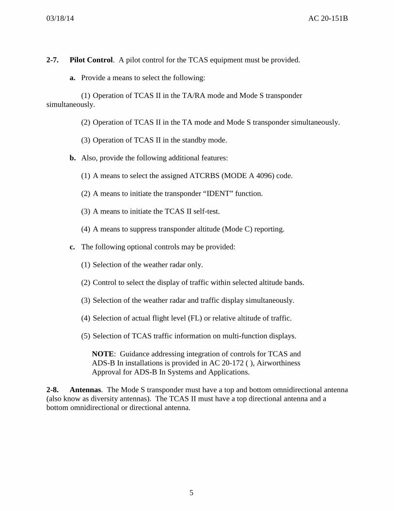
031814 AC 20-151B
Maneuver C evaluates a maximum duration TCAS II INCREASE CLIMB RA following a minimum duration CLIMB RA From the initial steady-state condition after a 3-second pilot-reaction time delay rotate the aircraft at 125 g targeting +1500 feet per minute climb until 6 seconds has elapsed from when the CLIMB RA was issued Then after a 1-second pilot-reaction time delay to the INCREASE CLIMB RA rotate the aircraft again at 125 g to attain +2500 feet per minute climb and hold until the total duration of the RA of 25 seconds has elapsed Recover to attain the initial trim airspeed
4 Vy + 10 for nontransport category aircraft without a defined V2
5 For those airplanes where the power-on stalling speed is significantly reduced from the power-off stalling speed use 11 VS or 108VSR for those airplanes that use reference stall speed (VSR) in lieu of stalling speed (VS)
6 Vy for nontransport category aircraft without a defined V2
7 For those airplanes where the power-on stalling speed is significantly reduced from the power-off stalling speed use VS1 or 094VSR1 for those airplanes that use reference stall speed (VSR) in lieu of stalling speed (VS)
17
031814 AC 20-151B
h A summary of the system inhibits (limitations) programmed into the TCAS II computer is given in Table 2 below
Table 2 System Inhibits
INHIBIT PARAMETERS
Increase Descent RA Inhibited below 1650 ft AGL while climbing and inhibited below 1450 ft AGL while descending
Descend RA Inhibited below 1200 ft AGL while climbing and inhibited below 1000 ft AGL while descending
TA Voice Messages Inhibited below 400 ft AGL while descending and inhibited below 600 ft AGL while climbing
RAs Inhibited below 1100 ft AGL while climbing and inhibited below 900 ft AGL while descending (TCAS automatically reverts to TA only)
Self-Test Can be inhibited when airborne
Advisory Priority Automatically reverts to TA only when higher priority advisories (such as GPWSTAWS and windshear) occur
Climb RA Can be inhibited based upon aircraft performance capability
Increase Climb RA Can be inhibited based upon aircraft performance capability
2-18 How Aircraft Systems Should Interface with TCAS II
a Pressure altitude information The pressure altitude data must be from the most accurate source available in the aircraft and it must correspond to that being transmitted by the associated Mode S transponder The accuracy of the altitude data must be at least that specified in RTCA-DO-185A or RTCADO-185B paragraph 328 as applicable It must be shown that the resolution of the altimetry source is compatible with TCAS II The altitude source with the finest compatible resolution must be used When available the resolution should be in increments of 10 feet or less Also provide information to indicate when the pressure altitude information is invalid
b Radio altitude information Provide radio altitude information to the TCAS II to inhibit
(1) INCREASE DESCENT RAs below 1650 ft AGL while climbing and below 1450 ft AGL while descending
(2) DESCEND RAs below 1200 ft AGL while climbing and below 1000 ft AGL while descending
18
031814 AC 20-151B
(3) All TA voice messages (aural traffic advisories) below 400 ft AGL while descending and below 600 ft AGL while climbing and
(4) All RAs below 1100 ft AGL while climbing and below 900 ft AGL while descending to allow automatic sensitivity level selection when close to the ground and to determine that individual targets are on the ground
(5) Also provide information to indicate when the radio altitude information is invalid
c Aircraft configuration Use discrete information from flaps slat landing gear andor other aircraft configuration sensors to ensure that TCAS II appropriately inhibits CLIMB and INCREASE CLIMB RAs to the airplane performance limits as described in paragraph 2-16 and 2-17
d Aircraft identification Provide discrete information to the Mode S transponder for the unique aircraft Mode S identification code and its maximum airspeed capability
e Attitude Aircraft pitch and roll attitude may be provided to assist with stabilization of the directional antenna function to assure surveillance and to ensure TA display data remain unaffected by aircraft normal maneuvers If attitude information is used by TCAS II provide information to indicate when the attitude data are invalid
f Heading Aircraft heading may be provided for the TA display reference presentation Information must also be provided to indicate when the heading data are invalid
g System failure display Provide an indication to indicate when RAs are not possible due to failure of the TCAS II equipment or any of its sensors or displays
h Altitude alerter data You may provide the current clearance altitude from the altitude alerter to enable TCAS II to select RAs that are more consistent with the aircraftrsquos altitude clearance once the immediate collision threat has been resolved
NOTE Altitude alert functionality is optional per RTCADO-185A and RTCADO-185B Not all TSO-C119( ) TCAS II units will have this option available
i Mode S Transponder Gillham altitude input requirements The Gillham format uses 11 discrete wires that depending on which wires are turned off or on represent an altitude value The Gillham format is sometimes called a blind encoder as error detection andor correction on the wires is not conducted For this reason ARINC 718 Mark 3 Air Traffic Control Transponder (ATCRBSMODE S) dated December 1989 states ldquoPins have been reserved to permit the direct application of Gillham code data to the transponder This practice is not encouraged because of concerns that a ldquostuck bitrdquo in the coded input could be the cause of serious errors in TCAS II resolution advisoriesrdquo This is a failure mode peculiar to the Gillham code against which protection is virtually impossible If Gillham coded altitude use cannot be
19
031814 AC 20-151B
avoided for the TCAS II installations two sources of altitude information must be connected to the transponder and their values compared All transponder altitude comparator failures must be annunciated
j Hybrid surveillance failure annunciations (TSO-C119d units only) For aircraft equipped with centralized alert and warning system and or an onboard maintenance system consideration should be given to integrating the hybrid surveillance alerting functionality into the system so as to alert the crew with an appropriate failure annunciation Refer to section 2-21 for more information
2-19 Verifying and Validating TCAS II Software It is required for the first installation of a manufacturerrsquos TCAS II equipment to verify and validate TCAS II software using the procedures outlined below Also apply these procedures to subsequent software changes to a manufacturerrsquos TCAS II equipment A manufacturer may provide a design that partitions the software which affects RAs from other software such as that necessary for the traffic display The TCAS II manufacturer may not use the minor change authority of the TSO system to change any software not partitioned from the software that affects RAs
a Verification and validation of TCAS II software represents a unique challenge Collision avoidance algorithms commonly called ldquothe CAS logicrdquo are specified in detail in a formal statechart representation in the CAS requirements specification (CRS) in RTCADO-185A Volume II and RTCADO-185B Volume II In addition Attachment A of Volume II provides a software design specification in pseudocode that meets these requirements This detail is required because the coordination algorithms in the CAS logic assume that the software implemented by all manufacturers will have exactly the same CAS logic However the surveillance software necessary to establish and maintain the relative tracks of nearby transponder-equipped aircraft and the software necessary to provide the interface with the Mode S transponder and with other aircraft sensors and displays must be developed by the manufacturer of the TCAS II equipment This hybrid approach to the specification of the software requirements means that the application of the software criteria in RTCADO-178B Software Considerations in Airborne Systems and Equipment Certifications dated December 1 1992 for the detailed CAS requirements and the pseudocode software design have been satisfied by the FAA and our contractors while the remaining requirements of RTCADO-178B are the responsibility of the manufacturer
b If software is used for the display of TCAS II RAs or in the operation of the Mode S transponder data link the verification and validation of this software must be done to Level B requirements as defined in RTCADO-178B Also apply these procedures when the TCAS II manufacturer develops the software requirements for the TCAS II processor associated with functions other than surveillance or the CAS logic With the software design specified in RTCADO-185A Volume II or RTCADO-185B Volume II the manufacturer of the TCAS II processor should conduct code walk-throughs and develop and perform module tests and module integration tests to verify that the specified software design was implemented correctly This includes the surveillance software necessary to establish and maintain the relative tracks of nearby transponder-equipped aircraft
20
031814 AC 20-151B
c The functional tests required by TSO-C119b and TSO-C119cTSO-C119d as described in RTCADO-185A Volume I and RTCADO-185B Volume I respectively do not provide complete testing for the TCAS II processor software However coverage analysis performed on the CAS test suite described in Volume I demonstrated that each column of every transition table and macro and each identity transition in the CAS requirements specification in RTCADO-185A Volume II or RTCADO-185B Volume II is tested by the CAS test suite Thus the CAS test suite provides more than full decision coverage (but not full condition coverage) as defined in RTCADO-178B TCAS II manufacturers must develop additional functional tests that correspond to the detailed requirements that they develop for the TCAS II processor The potential consequences of software errors in the TCAS II processor or resolution display require the manufacturer to provide a structural coverage analysis showing single condition test coverage of all instructions at the source code that can affect the generation and display of RAs These tests may be a combination of module tests module integration tests and functional tests
d Equipment produced under a TSO has obtained FAA concurrence that the software for the equipment was produced in accordance with RTCADO-178B for a particular software level Subsequent installations of the same TCAS II equipment on other aircraft types do not require any additional verification if the software and the interface is not changed
2-20 Testing for Failures System Safety Analysis Unannunciated failures of the TCAS II equipment its associated transponder or sensors or displays that could generate an incorrect RA must be improbable This can be accomplished using the methods described in AC 251309-1A System Design and Analysis We expect that a functional hazard assessment (FHA) a failure modes and effects analysis (FMEA) and a quantitative probability analysis of the TCAS II equipment Mode S transponder displays and sensors (including altitude information sources) will be necessary to establish that a false RA is improbable Specifically show that the probability of an incorrect RA without a failure annunciation is on the order of 10 x 10-4 per flight hour in the terminal environment and 10 x 10-5 per flight hour in the enroute environment The frequency of encounters where another aircraft could present a potential threat depends on the density of aircraft in the airspace In terminal airspace the frequency may be assumed to be once every 10 hours and in enroute airspace it may be once every 200 hours You may establish different frequencies based on operational data Provide these analyses for the first installation of TCAS II equipment on a new model aircraft For subsequent installations of the same equipment in other aircraft you may use some of the same analyses paying particular attention to the differences in the altitude sensors that are used
NOTE Develop software involved in generating RAs to RTCADO178B Level B standards
2-21 Maintenance Considerations for Hybrid Surveillance Functionality (TSO-C119d only)
a RTCADO-300A section 2210 Monitoring Requirements provides a means for annunciation or recording of failures of own-ship latitude longitude andor ground speed inputs
21
031814 AC 20-151B
Note that a failure of any of these inputs will not cause TCAS to fail but it will disable the hybrid surveillance functionality
b To ensure that hidden failures are not resident in airborne TCAS II units for long periods of time failures of hybrid surveillance must be annunciated to the flight crew or the continued airworthiness must be assessed during periodic scheduled maintenance tasks Periodic reliability reporting for the hybrid surveillance functionality is also required Depending on the level of avionics integration in the aircraft different methods can be used to ensure the continued airworthiness of the hybrid surveillance such as
(1) For those aircraft equipped with an engine indicating and crew alerting (EICAS) system (or other similar annunciation system) integrate the failure information into the warning system such that a failure of hybrid surveillance is annunciated to the flight crew
(2) For aircraft equipped with an onboard maintenance computer interfaced with TCAS add a scheduled maintenance task to the aircraftrsquos maintenance program to check for presence of any existing or past failures of hybrid surveillance Take corrective action as specified by the TCAS manufacturer
(3) For aircraft without a centralized warning system andor an onboard maintenance computer add a scheduled maintenance task to the aircraftrsquos maintenance program to check for presence of any existing or past failures of hybrid surveillance and to ensure hybrid surveillance is functional Take corrective action as specified by the TCAS manufacturer
(4) If a scheduled maintenance task is employed the installer must establish the initial frequency of the task in conjunction with the manufacturer of the TCAS equipment but on a frequency not to exceed two calendar years between tasks Normal maintenance escalation procedures could later be used to extend the maintenance frequency when adequate justification to do so is provided to the cognizant ACO Coordinate any such extension request with the ACO prior to implementation of changes
c Operators of TCAS equipment with hybrid surveillance are required to report hybrid surveillance maintenance history to the TCAS manufacturer periodically but not to exceed 18 calendar months between reports
22
031814 AC 20-151B
Chapter 3 Test and Evaluation (Initial Approval)
3-1 General Test the first installation of a manufacturerrsquos TCAS II or Mode S transponder system This will verify the design and installation performs its intended function under the expected operating conditions and that there are no adverse interactions between the TCAS II Mode S transponder and existing aircraft systems The test will also show that other aircraft equipment has not been adversely affected
3-2 Create a Test Plan Provide a test plan that includes adequate testing to perform this verification This test plan will generally require a combination of ground tests basic flight tests and flight tests involving planned encounters with another TCAS II equipped aircraft You can use an aircraft other than a transport category aircraft for either the TCAS II installation or for the air-to-air cooperative flights The rest of this chapter lists and explains the minimum elements of the test plan
3-3 Basic Ground Tests
a Bearing accuracy Demonstrate the bearing estimation accuracy of the TCAS II system as installed in the aircraft Measure the bearing accuracy using a calibrated antenna range that allows precise echo controlled far field angle-of-arrival measurements at or slightly above zero degrees elevation and over 360 degrees in azimuth The bearing accuracy may also be measured using a fixed transponder location while rotating the test aircraft on a compass rose while measuring the bearing angles at 30-degree intervals Alternately the airplane is fixed and the transponder may be moved (refer to Appendix B for cautionary note on testing) Manual readout of the bearing estimate may be done directly from a plan position display on the traffic advisory display Alternatively the bearing estimates may be automatically recorded or read from a special test display A maximum error of plusmn15 degrees in azimuth is acceptable however larger errors are acceptable in the area of the tail (for example within plusmn45 degrees of the tail) when that area is not visible from the cockpit In this case aircraft structure may interfere with the signal path
b Sensor failures Evaluate simulated failures of the aircraft sensors integrated with TCAS II to determine that the resulting system failure state agrees with the predicted results These tests should be part of the ground test plan
c Electromagnetic interference (EMI) Survey the flight deck EMI to determine that the TCAS II equipment is not a source of objectionable conducted or radiated interference to previously installed systems or equipment and that operation of the TCAS II equipment is not adversely affected by conducted or radiated interference from previously installed systems and equipment Pay attention for possible interference with TCAS II equipment from weather radar particularly if operating in the C-band
d Evaluate the general arrangement and operation of controls displays circuit breakers annunciators and placards of the TCAS II system Conduct a human factors evaluation of the controls displays and annunciators Evaluate the TCAS controls and the controls of installed
23
031814 AC 20-151B
systems that interact with TCAS (for example transponders) to determine that they are designed and located to prevent inadvertent actuation Evaluate TCAS displays and annunciations to determine that they support flight crew awareness of TCAS status changes which could result from TCAS mode selections intentional pilot actuation of other installed systems or inadvertent pilot actions with TCAS or other installed systems Evaluate TCAS displays to ensure all information is at a minimum legible unambiguous and attention-getting (as applicable) In particular where transponder functions are integrated with other system controls ensure that unintended transponder mode switching especially switching to STANDBY or OFF is not possible Pay close attention to line select keys touch screens or cursor controlled trackballs as these can be susceptible to unintended mode selection resulting from their location in the flight deck (for example proximity to a foot rest or adjacent to a temporary stowage area)
e Evaluate the TCAS II self-test features and failure mode displays and annunciators
f Verify that the pressure altitude source and radio altimeter are properly interfaced with the TCAS II equipment
g Verify that the windshear and the ground proximity warning systemterrain awareness warning system (GPWSTAWS) warnings and TCAS II voice alerts are compatible Also verify that windshear or GPWSTAWS warnings can be clearly understood and that TCAS II is automatically switched to the TA Only mode when TCAS II and windshear voice or GPWSTAWS announcements simultaneously occur The alert priorities should be windshear GPWSTAWS and then TCAS II
h Verify the performance of TCAS II traffic display by observing any available area traffic
i Evaluate the TCAS II system installation for satisfactory identification accessibility and visibility during both day and night conditions
j Determine that any configuration of discretes associated with the TCAS II logic including inhibits of climb RAs operate properly (Changes in logic or function with aircraft configuration altitude or speed)
k Verify that the ICAO 24-bit aircraft address and maximum airspeed are correct Additionally verify that other features which may be optional such as extended squitter aircraft identification reporting or other data link uses also function correctly Verify that the transponder and data sources meet the requirements of the failure condition classifications associated with the features For example an unannunciated failure of the transponder extended squitter resulting in erroneous information being transmitted is at least a major failure condition
l If connected verify that the altitude alerter is providing correct data to TCAS and that the TCAS II V70 or V71 logic as applicable correctly weakens or strengthens the displayed RA using the altitude alerter input
m Verify that the airground inputs are connected properly
24
031814 AC 20-151B
NOTE 1 CAUTION - When the aircraft is on the ground the Mode S transponder must be inhibited from replying to any Mode A Mode C Mode ACS all-call interrogations and Mode S-only all-call interrogations
NOTE 2 This inhibit is usually accomplished via an appropriate transponder pin connected through the weight-on-wheels switch but it might also be accomplished through some other automatic means (for example velocityaltitude algorithm etc) The inhibit means must be verified during ground testing
NOTE 3 While on the ground the transponder normally should stop output of acquisition squitters (short squits) and should continue output of extended squitters (known as long squits or ADS-B) in the surface format and it should reply to any discretely-addressed aircraft interrogations This too should be verified during ground testing The exact conditions for transmission of acquisition squitter are specified in DO-181E section paragraph 221826 Acquisition Squitter Protocols
3-4 Basic Flight Tests
a During all phases of flight determine if there is any mutual interference with any other aircraft system Have all installed systems including the weather radar operating during the flight test
b Evaluate TCAS II aural messages for acceptable volume and intelligibility during both low and high cockpit noise levels (idle descent at low speed and high power at maximum operating limit speed Vmo) with headset covering outboard ear only (when appropriate) and without headsets In the case of turbo-prop aircraft where the aircrew utilizes headsets via the aircraft audio distribution panel the aural messages should hold the same acceptable volume and intelligibility during both low and high cockpit noise levels If the TCAS II TEST is used to simulate voice announcements ensure that the audio level is not changed by use of the TEST function
c Demonstrate that traffic information remains valid and usable when the aircraft is pitched plusmn15 degrees and rolled approximately 30 degrees during normal maneuvers by observing area traffic in the traffic advisory display
d Evaluate the effective surveillance range of the traffic display including target azimuth reasonableness and track stability Use of targets of opportunity or a non-transport category (low speed) aircraft as a target for these tests is permissible
25
031814 AC 20-151B
e Determine that any configuration discretes (changes in logic or function with aircraft configuration altitude or speed) associated with the TCAS II logic including inhibits of climb RAs operate properly unless previously demonstrated during ground tests
f Perform the additional flight tests in RTCADO-185A or RTCADO-185B paragraph 344 as applicable unless previously accomplished under TSO-C119b or TSO-C119cTSOshyC119d respectively
g Evaluate TCAS II for noninterference during coupled autopilot and flight director (FD) approaches to the lowest minimums approved for the aircraft
h Before any cooperative flight tests at any altitude involving the TCAS II-equipped aircraft and another aircraft fly both aircraft in close formation to ensure matched altimetry readouts These checks should be flown at the speeds and altitudes to be used for the tests
i Evaluate all selectable modes of the TCAS II to determine that they perform their intended function and that the operating mode is clearly and uniquely annunciated
j Re-evaluate any previously installed aircraft systems that required changes as a result of the TCAS II installation (For example electronic flight instrument system (EFIS) FD PFD navigation displays (ND) IVSI interface etc)
k When hybrid surveillance functionality is included perform the flight tests in RTCADO-300 or DO-300A MOPS for Traffic Alert and Collision Avoidance System II (TCAS II) Hybrid surveillance dated December 13 2006 and dated Mar 20 2013 respectively paragraph 3 as appropriate unless previously accomplished under TSO-C119c or TSO-C119d
3-5 Planned Encounter Flight Tests The objective of these flight tests is to demonstrate adequate TCAS II surveillance and to verify smooth predictable TCAS II performance First establish the appropriate safety rules static system leak test (if necessitated by having opened the system) and altimeter correlation between the encounter aircraft and the TCAS aircraft The following encounters between the TCAS II aircraft and a dedicated intruder aircraft should be flown to assure that the TCAS II aircraft system performs its intended function by generating TAs and RAs and is consistent with RTCADO-185A or RTCADO-185B as applicable and RTCADO-300 or RTCADO-300A as appropriate The intruder aircraft must be equipped with a previously approved transponder installation capable of Mode A Mode C and for those tests necessary Mode S TCAS II and ADS-B Mode S Extended Squitter if appropriate These tests are also intended to expose the installed TCAS II system to a reasonable number of carefully controlled encounters that are likely to occur in service This matrix covers the envelope of encounter speeds altitudes and geometries that have in the past identified flaws in surveillance logic and antenna mechanization that were not detected earlier by bench tests Fly the following encounters
a Intruder overtaking TCAS II aircraft (from the aft quadrants)
b Head-on
26
031814 AC 20-151B
(1) Low and high closure speeds
(2) Above climb limit TCAS II to TCAS II
(3) TCAS II against Mode C with TCAS II above intruder and above climb limit (intent is to force TCAS II aircraft to descend)
(4) At 3000 feet over calm water to evaluate multipath protection
c Converging
(1) Crossing (intruder above TCAS II descending or vice versa)
(2) Evaluate the TA-only mode during planned encounters
(3) Evaluate a mix of intruder transponder modes (A C S and S with extended squitter) but primary emphasis should be on TCAS II-to-TCAS II coordination and on Mode C replies from the intruder aircraft
(4) Evaluate a mix of encounters with TCAS II both above and below the intruder
(5) If a flight test is necessary to ensure compatibility with other designs verify correct air-to-air coordination between the test TCAS II and another manufacturerrsquos previously approved equipment (refer to paragraph 2-15)
(6) Evaluate the effect of electrical transients (bus transfer) during encounters The TCAS II should not experience adverse effects No false TAs or RAs should be generated as a result of electrical transients Normal TCAS II functions and displays should be restored within approximately three seconds
3-6 Mode S Transponder Tests
a This guidance doesnrsquot cover Mode S Extended Squitter or Mode S ElementaryEnhanced surveillance
b The tests described in these paragraphs may be used to obtain the certification of a stand-alone Mode S transponder installation (an installation without TCAS II) These tests should also be used to evaluate a Mode S transponder installed as part of a TCAS II installation The tests primarily verify the installed antenna(s) are compatible with the Mode S transponder and provide an adequate response to ground radar interrogations during normal aircraft maneuvers
c Additionally these tests demonstrate that the Mode S transponder functions properly as installed and does not interfere with other aircraft electronic equipment The need for a detailed flight test is reduced when the Mode S transponder and antenna installation are identical
27
031814 AC 20-151B
or similar to that of previously approved ATCRBS transponder installation If a previously installed and certified transponder is being upgraded all of the guidance in this section is not necessarily required to approve the upgrade A careful examination of the proposed transponder upgrade should be accomplished to determine which of the tests specified in this section are necessary and appropriate Typical testing associated with the initial installation and certification of a new transponder may not be necessary when upgrading a previously approved transponder For example if a software upgrade is being considered which would add extended squitter functionality to a transponder in a previously approved installation detailed flights would not be required if appropriate ground testing adequately evaluates the added functionality
NOTE 1 CAUTION When conducting flight testing of the transponder or TCAS system you must prevent being a source of interference to ATC or other TCAS aircraft operating in the area For example using a fixed transponder to simulate an intruder aircraft can cause data to be transmitted which produce false targets for the ground ATC surveillance systems or airborne TCAS aircraft These false indications of ldquointruder aircraftrdquo could result in unnecessary ATC communications and possibly in TCAS induced aircraft maneuvers Therefore conduct such testing in coordination with ATC
NOTE 2 The conduct of this test requires cooperation with ATC radar controllers Coordination with ATC is important before the flight test for any necessary approval of the flight and agreement with the flight test procedures During the flight test communication will be required with the controller monitoring the aircraft and reporting transponder performance data
d If the Mode S transponder uses a top mounted antenna in addition to a bottom mounted antenna installed at or near the same location used by a previously approved ATCRBS transponder antenna conduct a comprehensive ground test and evaluation in accordance with Appendix B and perform a functional flight test The transponder code altitude reporting and ldquoIDENTrdquo features of the transponder should be exercised during normal maneuvering There should be no objectionable behavior observed by the ATC controller
e If a Mode S transponder is installed in an aircraft which does not have a previously approved ATCRBS transponder installation or that uses a bottom mounted antenna location which differs significantly from that used by a previously approved ATCRBS transponder antenna conduct the following ground and flight tests
NOTE References to the radar facility are references to the radar that provides the data used by the ATC controller(s) during the flight test for monitoring the aircraft and reporting transponder performance data These are not references to the ATC facility with the radar displays used by the controllers
28
031814 AC 20-151B
(1) Conduct ground tests and evaluations per Appendix B
(2) Climb and Distance Coverage Begin at a distance of at least 10 nautical miles (NM) from and an altitude of 2000 to 3000 feet above the radar facility and using a transponder code assigned by ATC fly on a heading that will pass the aircraft over the radar facility At a distance of 5 to 10 NM beyond the radar facility fly the aircraft at its normal maximum climb attitude to within 90 percent of the certificated altitude for the aircraft maintaining the aircraft heading within 5 degrees of the track from the radar facility After reaching the maximum altitude for which the aircraft is certificated fly level at the maximum altitude to 160 NM for turbojet and some turboprop powered airplanes (or 80 NM for most other aircraft) from the radar facility (Distance from the radar facility is a function of the airplanersquos maximum certificated altitude) Communicate with the ATC controller for evidence of transponder dropout During the flight check the ldquoIDENTrdquo mode of the ATC transponder to assure that it is performing its intended function There should be no unexpected dropouts (no return for two or more sweeps) Uncontrollable ringing that hinders use of the ground radar is unsatisfactory
(3) Long Range Reception At 90 percent of maximum certificated altitude perform left and right 360-degree turns at bank angles of 8 to 10 degrees The aircraft should be at least 160 (or 80) NM from the radar facility During these turns request that the ATC controller monitor the radar displays There should be no dropouts (no return for two or more sweeps)
(4) High Angle Reception Perform two 360-degree turns one to the right and one to the left at bank angles of 8 to 10 degrees with the airplane at a distance of 50 to 70 NM from the radar facility and at an altitude of at least 35000 feet or within 90 percent of the maximum altitude for which the aircraft is certificated There should be no dropouts (no return for two or more sweeps) Switch the transponder to a new code assigned by the ATC controller The aircraft secondary return on the ATC controllerrsquos radar display should indicate a Mode A code change
(5) High Altitude Cruise Within 90 percent of the aircraftrsquos maximum certificated altitude or its maximum operating altitude beginning at a point 160 (or 80) NM from the radar facility fly on a course that will pass over the radar facility The ATC controller should report no unexpected transponder dropout or ldquoring aroundrdquo
(6) Surveillance Approach Beginning at or above 90 percent of the certificated maximum altitude for the aircraft perform a letdown and approach to a runway of an airport served by Airport Surveillance Radar (ASR) having an ATCRBS facility Make the approach at the maximum normal rate of descent Normal approach and landing configuration for the aircraft should continue down to an altitude of 200 feet or less above the ground radar antenna elevation Not more than one dropout should occur for any 10 sweeps during final approach Uncontrolled ringing that hinders use of the ground radar is unsatisfactory
(7) Holding and Orbiting Patterns
(a) At an altitude of 2000 feet above the radar antenna or minimum obstruction clearance altitude (whichever is greater) with landing flaps and gear extended fly left and right
29
031814 AC 20-151B
360-degree turns approximately 10 miles from the radar facility There should be no signal dropouts
(b) At an altitude of 2000 feet above the radar antenna or minimum obstruction clearance altitude (whichever is greater) fly 45 degree sectors of left and right 10 mile orbital patterns around a radar facility with gear and landing flaps extended There should be no signal dropouts
(8) Altitude Reporting Conduct a functional test of the altitude encoder by comparison with ATC displayed altitudes Verify correspondence at several altitudes between ATC readings and the Captainrsquos altimeter when set at or corrected to 2992 inches of mercury (or equivalent)
30
031814 AC 20-151B
Chapter 4 Follow-on Approvals (STCs or Amended STC or Amended TC)
4-1 The Need for Tests and a Plan
a Provide a test plan including adequate aircraft ground testing and evaluations to verify that the design and installation performs its intended function when installed in a different aircraft type under the expected operating conditions There should be no adverse interactions between the TCAS II or Mode S transponder and existing aircraft systems and prior approvals of present aircraft equipment should not be compromised This test plan will generally require a combination of ground tests basic flight tests and flight tests involving planned encounters with a Mode C equipped aircraft or the use of a suitably located fixed transponder The test plan should contain as a minimum the elements of paragraph 3-6 and those covered in the next paragraphs
b Flight-testing of TCAS II or Mode S transponder systems for follow-on approvals (previously approved TCAS II or Mode S transponder equipment installed in a different aircraft type) may need to be conducted to verify that the design and installation performs its intended function under the expected operating conditions Determine that there are no adverse interactions between the TCAS II or Mode S transponder and existing aircraft systems and that prior approvals of present aircraft equipment have not been compromised
NOTE CAUTION When flight testing the transponder or TCAS system you must prevent being a source of interference to ATC or other TCAS aircraft operating in the area For example using a fixed transponder to simulate an intruder aircraft can cause data to be transmitted which produce false targets for the ground ATC surveillance systems or airborne TCAS aircraft False indications of ldquointruder aircraftrdquo could result in unnecessary ATC communications and possibly in TCAS induced aircraft maneuvers Conduct such testing in coordination with ATC
4-2 Ground Tests and Evaluations
a Evaluate the general arrangement and operation of controls displays circuit breakers annunciators and placards of the TCAS II system Conduct a human factors evaluation of the controls displays and annunciators Evaluate the TCAS controls and the controls of installed systems that interact with TCAS (for example transponders) to determine that they are designed and located to prevent inadvertent actuation Evaluate TCAS displays and annunciations to determine that they support flight crew awareness of TCAS status changes which could result from TCAS mode selections intentional pilot actuation of other installed systems or inadvertent pilot actions with TCAS or other installed systems Evaluate TCAS displays to ensure all information is at a minimum legible unambiguous and attention-getting (as applicable) In particular where transponder functions are integrated with other system controls ensure that unintended transponder mode switching especially switching to STANDBY or OFF is not
31
031814 AC 20-151B
possible Pay close attention to line select keys touch screens or cursor controlled trackballs as these can be susceptible to unintended mode selection resulting from their location in the flight deck (for example proximity to a foot rest or adjacent to a temporary stowage area)
b Evaluate the TCAS II self-test features and failure mode displays and annunciators
c Verify that the pressure altitude source and radio altimeter are properly interfaced with the TCAS II equipment
d Measure the performance of the directional antenna for 360 degrees coverage at 30 degree intervals as specified under basic ground tests paragraph 3-3a
e Evaluate the TCAS II system installation for satisfactory identification accessibility and visibility during both day and night conditions
f Determine that any configuration discretes (changes in logic or function with aircraft configuration altitude or speed) associated with the TCAS II logic including inhibits of climb RAs operate properly
g Verify that the ICAO 24-bit aircraft address and maximum airspeed are correct Verify that the transponder and data sources meet the requirements of the failure condition classifications associated with the features
h Verify that the windshear and GPWSTAWS warnings and TCAS II voice alerts are compatible Also verify that windshear and GPWSTAWS warnings can be clearly understood and that TCAS II is automatically switched to the TA Only mode when TCAS II and windshear voice or GPWSTAWS announcements simultaneously occur The alert priorities should be windshear GPWSTAWS and then TCAS II
i If connected verify that the altitude alerter is providing correct data to TCAS and that the TCAS II logic correctly weakens or strengthens the displayed RA using the altitude alerter input
j Verify that the airground inputs are connected properly
NOTE 1 CAUTION When the aircraft is on the ground the Mode S transponder must be inhibited from replying to any Mode A Mode C Mode ACS all-call interrogations and Mode S-only all-call interrogations
NOTE 2 This inhibit is usually accomplished via an appropriate transponder pin connected through the weight-on-wheels switch but it might also be accomplished through some other automatic means (for example velocityaltitude algorithm etc) The inhibit means must be verified during ground testing
32
031814 AC 20-151B
NOTE 3 While on the ground the transponder normally should stop output of acquisition squitters (short squits) and should continue output of extended squitters (known as long squits or ADS-B) in the surface format and it should reply to any discretely addressed aircraft interrogations This too should be verified during ground testing The exact conditions for transmission of acquisition squitter are specified in DO-181E paragraph 221826 Acquisition Squitter Protocols
4-3 Flight Tests
a The certification policy for follow-on approvals (STC or amended STC) of TCAS II V70 or V71 units is that flight tests may not be required if the appropriate testing is performed on the ground to certify that the V70 or V71 unit was correctly installed and that any new interfaces operate correctly with the TCAS II logic
b If we determine that certification flight-testing is required demonstrate the following
(1) Verify proper operation of the traffic display by observing proximate traffic at least one TA and at least one RA Confirm that the appropriate aural alerts occur correctly with the TA and RA The advisories may be generated by
(a) Planned encounters with an intruder aircraft operating a transponder with Mode C capability
NOTE Before any cooperative flight tests at any altitude involving the TCAS II equipped aircraft and another aircraft fly both aircraft in close formation to assure matched altimetry readouts These checks should be flown at the speeds and altitudes to be used for the tests
(b) Encounters with an operating Mode C transponder installed at a fixed ground location which reports an appropriate test altitude
NOTE CAUTION When flight testing the transponder or TCAS system you must prevent being a source of interference to ATC or other TCAS aircraft operating in the area For example using a fixed transponder to simulate an intruder aircraft can cause data to be transmitted which produce false targets for the ground ATC surveillance systems or airborne TCAS aircraft These false indications of ldquointruder aircraftrdquo could result in unnecessary ATC communications and possibly in TCAS induced aircraft maneuvers Conduct such testing in coordination with ATC
(c) Encounters with aircraft targets of opportunity
(d) The use of suitable test equipment during ground tests
33
031814 AC 20-151B
NOTE CAUTION When ground testing the transponder or TCAS system you must prevent being a source of interference to ATC or other TCAS aircraft operating in the area Ground maintenance checks or ramp testing (such as altimetry or bearing accuracy testing) can cause data to be transmitted which produce false targets for the ground ATC surveillance systems or airborne TCAS aircraft These false indications of ldquointruder aircraftrdquo could result in unnecessary ATC communications and possibly in TCAS induced aircraft maneuvers Conduct such testing in coordination with ATC and use antenna shielding (transmission absorption covers or caps) to prevent test data that could generate false intruder information from being transmitted Using high-powered hangar-mounted transponders to conduct ramp testing is not an acceptable means to test either transponder ramp or TCAS
(2) During all phases of flight determine if there is any mutual interference with any other aircraft system
(3) Evaluate TCAS II aural messages for acceptable volume and intelligibility during both low and high cockpit noise levels (idle descent at low speed and high power at Vmo) with and without headsets covering the outboard ear where appropriate In turbo-prop aircraft where the aircrew uses headsets via the aircraft audio distribution panel the aural messages should hold the same acceptable volume and intelligibility during both low and high cockpit noise levels If the TCAS II TEST is used to simulate voice announcements ensure that the audio level is not changed by use of the TEST function
(4) Evaluate the effective surveillance range of the traffic display including target azimuth reasonableness and track stability You may use a non-transport (low speed) Mode C equipped aircraft as a target or a fixed transponder or suitable test equipment for these tests
NOTE CAUTION When flight testing the transponder or TCAS system you must prevent being a source of interference to ATC or other TCAS aircraft operating in the area For example using a fixed transponder to simulate an intruder aircraft can cause data to be transmitted which produce false targets for the ground ATC surveillance systems or airborne TCAS aircraft These false indications of ldquointruder aircraftrdquo could result in unnecessary ATC communications and possibly in TCAS induced aircraft maneuvers Conduct such testing in coordination with ATC
(5) Evaluate the Mode S transponder air-to-ground ATCRBS function against an appropriate ground facility
(6) Determine that any configuration discretes associated with the TCAS II logic including inhibits of aural annunciations and RAs operate properly unless previously
34
031814 AC 20-151B
demonstrated during ground tests (These include changes in logic or function with aircraft configuration altitude or speed)
(7) Evaluate TCAS II for noninterference during coupled autopilot and flight director approaches to the lowest minimums approved for the aircraft
(8) Evaluate all selectable modes of the TCAS II to determine that they perform their intended function
(9) Reevaluate any previously installed aircraft systems that have required changes as a result of the TCAS II installation (such as CMC EFIS EICAS FD PFD ND IVSI and interface)
4-4 Upgrading an Existing TCAS II Installation If you are upgrading an existing approved TCAS II installation to a higher TCAS II version (ie V70 or V71) and the higher version installation is only a software change then no additional certification flight tests are required to obtain a follow-on STC or amended STC or an amended TC The appropriate aircraft ground tests of paragraph 4-2 are considered sufficient to ensure that the higher version TCAS II software is operating properly However if the upgrade to a higher version TCAS II unit involves changes other than a software change (such as the addition of new interfaces) flight tests in accordance with paragraph 4-3b may be required
35
031814 AC 20-151B
Chapter 5 Airplane Flight Manual Supplement
5-1 Contents of an AFMS The AFMS should provide the appropriate system limitations and procedures and a comprehensive description of all normal modes of operation including expected flight crew actions
5-2 TCAS V71 AFMS Example Refer to Appendix A for an example of the elements and extent of detail that may be shown by a typical AFMS (specific performance data inhibits and procedures may vary with system design and aircraft type)
36
031814 AC 20-151B Appendix A
Appendix A Example TCAS II V71 AFMS
INTRODUCTION
Descriptive material and procedures in this Airplane Flight Manual Supplement (AFMS) example may when appropriate be replaced by reference in the AFMS to the TCAS II equipment supplierrsquos pilot operating guide However the AFMS reference to this guide must specify date and revision level and not be open ended such as ldquoor later revisionrdquo unless the pilotrsquos guide is specifically FAA approved Also the AFMS must define the specific configuration approved from the various options contained in the pilotrsquos guide for example which model control panel whether the pilot initiated self-test is available in flight range features TA vertical display features and so forth
-EXAMPLEshy
AIRPLANE FLIGHT MANUAL SUPPLEMENT
(Example for an aircraft equipped with IVSIRA displays)
DESCRIPTION
The TCAS II is an on-board collision avoidance and traffic situation display system with computer processing to identify and display intruding and threatening collision aircraft and issue resolution advisories in the form of vertical maneuver guidance on the pilot and copilotrsquos instantaneous vertical speed indicators (IVSI) From the transponder replies TCAS II determines relative altitude range and bearing of any ATCRBS or Mode S equipped aircraft with altitude reporting From this TCAS II will determine the level of advisory using standardized algorithms The TCAS II will resolve multiple aircraft encounters ATCRBS equipped aircraft that only reply with Mode A information will not provide altitude information therefore TCAS II will not issue resolution advisories for these aircraft but can issue traffic advisories The TCAS II will not detect aircraft that are not equipped with transponders
The TCAS II installation consists of one TCAS II processor one top mounted directional antenna one bottom mounted blade (or directional antenna) one Mode S transponder with control panel and top and bottom antennas one traffic advisory display with control panel (if not combined with the IVSIRA indicators) two resolution advisory displays one overhead speaker for voice messages (cautionwarning lights) and associated wiring
The TCAS II provides two levels of advisories
1 If the traffic gets within 25 to 48 seconds depending upon altitude of projected Closest Point of Approach (CPA) it is then considered an intruder and an aural and visual traffic advisory (TA) is issued This level calls attention to what may develop into a collision threat using the traffic advisory display and the voice message ldquoTRAFFIC - TRAFFICrdquo It permits mental and physical preparation for a possible maneuver to follow and assists the pilot in achieving visual acquisition of the intruding aircraft
A-1
031814 AC 20-151B Appendix A
2 If the intruder gets within 15 to 35 seconds depending upon altitude of CPA it is considered a threat and an aural and visual resolution advisory (RA) is issued This level provides a recommended vertical maneuver using modified IVSIs and voice messages to provide adequate vertical separation from the threat aircraft or prevents initiation of a maneuver that would place the TCAS II aircraft in jeopardy The TCAS II is considered a backup system to the ldquoSEE AND AVOIDrdquo concept and the ATC surveillance The TCAS II resolution advisories are annunciated by the following voice messages as appropriate along with the expected pilot response
(1) ldquoCLIMB CLIMBrdquo--climb at the rate depicted by the green (fly to) arc on the IVSI nominally between 1500 and 2000 fpm
(2) ldquoDESCEND DESCENDrdquo--descend at the rate depicted by the green (fly to) arc on the IVSI nominally between 1500 and 2000 fpm
(3) ldquoMONITOR VERTICAL SPEEDrdquo--ensure that vertical speed is out of the illuminated IVSI red arc until the RA is completed
(4) ldquoLEVEL OFF LEVEL OFFrdquo -- reduce vertical speed to zero feet per minute A green arc will be illuminated beginning at zero feet per minute This can be issued as the initial RA or as a subsequent RA
(5) ldquoCLEAR OF CONFLICTrdquo--range is increasing and separation is adequate Expeditiously return to the applicable ATC clearance unless otherwise directed by ATC
(6) ldquoCLIMB CROSSING CLIMB CLIMB CROSSING CLIMBrdquo--climb at the rate depicted by the green (fly to) arc on the IVSI nominally between 1500 and 2000 fpm Safe separation will best be achieved by climbing through the threatrsquos flight path
(7) ldquoDESCEND CROSSING DESCEND DESCEND CROSSING DESCENDrdquo-shydescend at the rate depicted by the green (fly to) arc on the IVSI nominally between 1500 and 2000 fpm Safe separation will best be achieved by descending through the intruderrsquos flight path
(8) ldquoMAINTAIN VERTICAL SPEED MAINTAINrdquo--continue the existing climb or descent rate or other vertical speed as depicted by the green (fly to) arc on the IVSI
(9) ldquoMAINTAIN VERTICAL SPEED CROSSING MAINTAINrdquo--continue the existing climb or descent rate or other vertical speed as depicted by the green (fly to) arc on the IVSI Safe separation will best be achieved by not altering the existing vertical speed and climbing or descending through the threatrsquos flight path
The following voice messages annunciate enhanced TCAS II maneuvers when initial RA does not provide sufficient vertical separation The tone and inflection indicate increased urgency
A-2
031814 AC 20-151B Appendix A
(1) ldquoINCREASE CLIMB INCREASE CLIMBrdquo--climb at the rate depicted by the green (fly-to) arc on the IVSI nominally between 2500 and 3000 fpm Received after ldquoCLIMBrdquo advisory and indicates additional climb rate is required to achieve safe vertical separation from a maneuvering aircraft
(2) ldquoINCREASE DESCENT INCREASE DESCENTrdquo--descend at the rate depicted by the green (fly-to) arc on the IVSI nominally between 2500 and 3000 fpm Received after ldquoDESCENDrdquo advisory and indicates additional descent rate is required to achieve safe vertical separation from a maneuvering aircraft
(3) ldquoCLIMB ndash CLIMB NOW CLIMB ndash CLIMB NOWrdquo--climb at the rate depicted by the green (fly-to) arc on the IVSI nominally between 1500 and 2000 fpm Received after a ldquoDESCENDrdquo resolution advisory and indicates a reversal in direction is required to achieve safe vertical separation from a maneuvering threat aircraft
(4) ldquoDESCEND ndash DESCEND NOW DESCEND ndash DESCEND NOWrdquo-descend at the rate depicted by the green (fly-to) arc on the IVSI nominally between 1500 and 2000 fpm Received after a ldquoCLIMBrdquo resolution advisory and indicates a reversal in direction is required to achieve safe vertical separation from a maneuvering threat aircraft
A-3
031814 AC 20-151B Appendix A
Figure A-1 TCAS IITransponder Control Panel (Example)
Table A-1 TCAS IITransponder Function Selector
TEST Holding the TCAS IITransponder function selector in TEST for 2 to 3 seconds will activate the system test sequence In the TEST position read maintenance messages on the display Use discretion when selecting TEST in flight since both TCAS II and the transponder will be inhibited for approximately 20 seconds The function selector is spring loaded to STBY
STBY Activates TCAS II and XPDR warmup cycles XPDR Transponder is on TCAS II is in warmup cycle TA Transponder is on Only the ldquoTraffic Advisoryrdquo or ldquoTArdquo function of the TCAS II
is on No ldquoResolution Advisoriesrdquo will be received in this position The written warning ldquoTA ONLYrdquo will appear on the display and the yellow ldquoRA OFFrdquo flag will be in view on both IVSIs
TARA Transponder is on All TCAS II functions are on No TCAS II flags should be present on either IVSI
XPDR Fail Light (Red)
Indicates a transponder system failure when the transponder is on Comes on during ldquoTESTrdquo but goes off after approximately 3 seconds if the transponder is OK
Code Indicator
Indicates code selected with the code selectors
IDENT Causes the word IDENT to flash in the aircraft data block on the ATC display ALT
RPTG Provides automatic altitude reporting to ATC
Code Selectors
Select the transponder code Left and right selectors consist of a large knob and a small knob Each knob controls one digit of the code
A-4
031814 AC 20-151B Appendix A
Figure A-2 TCAS II ndash Traffic Display (Example)
Table A-2 Displayed Aircraft Symbols (Examples)
Arrow indicates that the target is climbing uarr or descending darr at a rate of at least 500 fpm
Relative altitude is displayed in the proximity of the aircraft symbol in hundreds of feet A ldquo+rdquo preceding the relative altitude indicates the target is above you and a ldquo-ldquo indicates it is below you
Unfilled white diamond Non-threatening traffic without altitude reporting If altitude reporting the altitude data will be displayed
+07 Solid White diamond Proximity traffic 700 feet above Non-threatening altitude reporting traffic within 1200 feet vertically and 6nm horizontally Aircraft without altitude reporting will be assumed to be co-altitude and will be displayed as a solid diamond when within 6nm even though they may not be within 1200 feet vertically
darr
-03
Solid yellow circle ldquoTArdquo 300 feet below descending with a rate of at least 500 fpm
+00 Solid red square ldquoRArdquo level at your altitude
Own-ship Airplane symbol in white just below the center of CRT On a dedicated display or when in the TFC Mode on a combination TCAS IIRADAR Display
(Compass Arc)
This arc is repeater of the Captains compass (Not required for TCAS II Display)
(Range Rings)
3nm ndash Small ring with ticks at clock positions 5 NM ndash Large ring made of dots
A-5
031814 AC 20-151B Appendix A
Figure A-3 TCAS II Traffic Display (Example)
Table A-3A Paddle Switch REL ALTFL Switch
REL ALT
Paddle switch is spring loaded to the center position Display shows relative altitude ldquoREL ALTrdquo in hundreds of feet above (+) or below (-) your aircraft
FL Allows display of traffic flight levels referenced to 2992 for 15 seconds Your FL is displayed in lower left corner Three digits are shown except for negative flight levels that are shown as ndash xxx When the current barometric pressure is not available and the TCAS II aircraft is below FL 180 the FL position is automatically inhibited
RANGE The maximum forward range on the traffic display is set at range selected by the range knob Ranges of 3 5 10 20 NM are available and the selected range is annunciated on the traffic display
BRT Knob
Controls brightness of the display
A-6
031814 AC 20-151B Appendix A
Table A-3B AboveNormBelow Switch
ABOVE Displays altitude-reporting traffic from 2700 feet below to 9900 feet above the TCAS II aircraft The selection of this mode is annunciated by ABOVE being displayed on the traffic display This selection has no effect on the functioning of the collision avoidance logic
NORM Displays altitude reporting traffic from 2700 feet below to 2700 feet above the TCAS II aircraft
BELOW Displays altitude-reporting traffic from 2700 feet above to 9900 feet below the TCAS II aircraft The selection of this mode is annunciated by BELOW being displayed on the traffic display This selection has no effect on the functioning of the collision avoidance logic
OFF-SCALE TRAFFIC ADVISORY - If TCAS II tracks an intruder that is outside the selected range of the display but that has entered the Caution or Warning areas one-half of the appropriate symbol will appear at the appropriate bearing at the edge of the display area The symbol will appear in its proper color and have its data tag displayed providing there is room For example a TA intruder with a high closure rate and which is directly ahead and 300 feet below your airplane will appear as an amber-filled half circle at the 12 orsquoclock position on the edge of the display area The data tag ldquo-03rdquo will appear below the half symbol If this intruder is above your altitude the data tag is not visible An off-scale RA intruder will appear as a red-filled half square with data tag displayed if room permits
NO BEARING ADVISORIES - When TCAS II cannot track the bearing of an intruder the traffic advisory will appear in the lower center of the display just below the own-airplane symbol The advisory will present appropriate color-coded traffic information This phenomenon usually is caused either by temporary antenna shielding (caused by steep bank angles) or a failure in the TCAS II bearing antenna Up to two lines of information can be displayed ldquoTA 52 -06uarrrdquo for example means an intruder is creating a Traffic Advisory 52 nautical miles away 600 feet below and climbing in excess of 500 FPM This advisory is written in amber or yellow ldquoRA 06 00rdquo means resolution advisory traffic is 06 nautical miles away at the same altitude This advisory is written in red TCAS IIrsquos ability to compute a traffic or resolution advisory is not degraded by lack of bearing information
A-7
031814 AC 20-151B Appendix A
Figure A-4 TCAS II Instantaneous Vertical Speed Indicator (Example)
Red Arc
Green Arc
Key to Colors in Figures
A-8
031814 AC 20-151B Appendix A
Table A-1 Instantaneous Vertical Speed Indicator
Indicates vertical speed in feet per minute The IVSI is a normal instantaneous vertical speed indicator and the presence of the lights or the flags will not interfere with the ability of the needle to indicate vertical speeds
REDGREEN EYEBROW LIGHTS Eyebrow lights are invisible until they illuminate as part of a TCAS II ldquoRESOLUTION ADVISORYrdquo or system ldquoTESTrdquo These lights indicate a vertical speed regime which will provide safe traffic separation The green lights form a wider band than red lights
IVSI Status Window Flags
T C BLACK Normal operation A S
T C AMBER FLAG Indicates Unusable TCAS II information A S
RT WHITE ldquoRA OFFrdquo FLAG Always displayed when TCAS AC IITRANSPONDER function selector is in STBY XPDR or TA Will also OA be displayed with selector in RATA if ldquoRAsrdquo are inhibited andor FS inoperative F
A-9
031814 AC 20-151B Appendix A
Figure A-5 TCAS II Examples ndash Preventive RAs
A-10
031814 AC 20-151B Appendix A
Figure A-6 TCAS II Examples ndash Initial Corrective RAs
A-11
031814 AC 20-151B Appendix A
Figure A-7 TCAS II Examples ndash Modifications to Initial Corrective RAs
A-12
031814 AC 20-151B Appendix A
SECTION I ndash LIMITATIONS
(1) Pilots are authorized to deviate from their current ATC clearance to comply with a TCAS II resolution advisory (RA)
(2) Maneuvers based solely on a traffic advisory (TA) or on information displayed on the traffic display are not authorized
SECTION II - EMERGENCY PROCEDURES
(1) No change from basic airplane flight manual
SECTION III ndash PROCEDURES
(1) TCAS II Flight Procedures
Compliance with a TCAS II resolution advisory (RA) is necessary unless the pilot considers it unsafe to do so or unless the pilot has information about the cause of the RA and can maintain safe separation for example visual acquisition of and safe separation from a nearby aircraft on a parallel approach
NOTE CAUTION Once a non-crossing RA has been issued safe operation could be compromised if current vertical speed is changed except as necessary to comply with the RA This is because TCAS II-to-TCAS II coordination may be in progress with the intruder airplane and any change in vertical speed that does not comply with the RA may negate the effectiveness of the other airplanersquos compliance with its RA
NOTE WARNING Noncompliance with a crossing RA by one airplane may result in reduced vertical separation therefore safe horizontal separation must also be assured by visual means
Because of the limited number of inputs to TCAS II for airplane performance inhibits in some instances where inhibiting RAs may be appropriate it is not possible to do so In these cases TCAS II may command maneuvers that may significantly reduce stall margins or result in stall warning Therefore the stall warning stick shaker must be respected when following an RA Conditions where this may occur include
(a) Bank angle in excess of 15 degrees
(b) One engine inoperative
(c) Abnormal configurations such as landing gear not retractable etc
(d) Leaving airplane in inappropriate configurations when climb RA occurs
A-13
031814 AC 20-151B Appendix A
(e) Operation at airports outside of 0 to 5300 feet MSL or temperatures outside of ISA plusmn50degF
(f) Speeds below normal operating speeds
(g) Buffet margin less than 03 g
The TCAS II RA algorithms are based on the pilot initiating the initial 025 g acceleration maneuver within approximately 5 seconds Pilot response is expected within approximately 25 seconds if an additional RA is issued (The increase rate and rate reversal RAs are based on a 035 g acceleration maneuver) Because of these requirements and the rate limits of the autopilots all RA responses must be hand-flown and not with the autopilot or autothrottles engaged
NOTE Evasive maneuvering should be limited to the minimum required to comply with the RA Excessive responses to RAs are not desirable or appropriate because of other potential traffic and ATC consequences From level flight proper response to an RA typically results in an overall altitude deviation of 300 to 500 feet in order to successfully resolve a traffic conflict
Modified advisories are posted after the response to an initial advisory has been completed and the TCAS II airplane is projected to have adequate altitude separation from the intruder The initial RA is said to weaken indicating a return towards the original flight path or clearance is allowed When the initial advisory weakens the green arc is repositioned to indicate level flight the magnitude of the red arc decreased and ldquoLEVEL OFF LEVEL OFFrdquo is announced The modified RA indicates a return to level flight so that the altitude displacement in response to the initial RA can be minimized This RA will remain displayed until the ldquoCLEAR OF CONFLICTrdquo aural annunciation is issued Following the weakening advisory will greatly reduce the ultimate altitude deviation caused by the original corrective resolution advisory
If a ldquoCLIMBrdquo RA is issued while in the landing configuration initiate normal go-around procedures
NOTE Initiating go-around procedure for a ldquoCLIMBrdquo RA does not mandate a missed approach It is intended to ensure the airplane is properly configured for the TCAS II maneuver In most cases the TCAS II event will be resolved with only minor deviation to the intended flight path and sufficient time and altitude may exist to recover safely to the desired flight path
The pilot should not initiate evasive maneuvers using information from the traffic display only or on a traffic advisory (TA) only without visually sighting the traffic These displays and advisories are intended only for assistance in visually locating the traffic and lack the flight path trends necessary for use in evasive maneuvering However unnecessary resolution advisories can be issued by TCAS II when other aircraft are operating at an altitude adjacent to the one that has been assigned to the climbing or descending TCAS aircraft When climbing or descending
A-14
031814 AC 20-151B Appendix A
in an environment where these unnecessary advisories are considered likely to occur (based on either airspace design air traffic communications visual acquisition or utilization of traffic displays) a reduction in vertical velocity is recommended until reaching the assigned altitude As appropriate the vertical velocity should be reduced to a rate between 500 and 1500 ftmin when approaching an altitude between 1000 and 2000 ft above or below the altitude assigned in the ATC instruction or clearance
After deviating from an ATC clearance or instruction in response to a TCAS II RA notify ATC of the deviation as soon as possible
Following a TCAS II ldquoCLEAR OF CONFLICTrdquo advisory the pilot should expeditiously return to the applicable ATC clearance unless otherwise directed by ATC
NOTE The threat aircraft track or altitude information can be lost during an RA If so the RA will terminate without a ldquoCLEAR OF CONFLICTrdquo annunciation
(2) TCAS II Operation
Pilot-Initiated TCAS II self-test
(a) The TCAS II should be tested using the pilot-initiated self-test feature during cockpit preparation A successful test is indicated by (provide test results from particular TCAS II system)
(b) Use of the self-test function in flight will inhibit TCAS II operation for up to (provide time for a particular TCAS II system) seconds
(c) The ATC transponder will not function during some portion of the self-test sequence
(d) All aircraft systems providing information to TCAS II must be operating in their normal mode during the Self-Test
Ground Operation
(a) When equipped with a TSO-C119c or earlier TCAS II unit
(1) To preclude unnecessary transponder interrogations and possible interference with ground surveillance systems do not activate TCAS (TA or TARA mode) until taking the active runway for departure Selection of XPDR is adequate for ATC and nearby Automatic Dependent Surveillance-Broadcast equipped aircraft to ldquoseerdquo the aircraft while taxiing on the airport surface
(2) After landing and clearing of the runway de-select from TA or TARA mode Select XPNDR while taxiing to the ramp area Upon shutdown select STBY on the transponder
A-15
031814 AC 20-151B Appendix A
(b) When equipped with a TSO-C119d or later TCAS unit
(1) To preclude unnecessary transponder interrogations and possible interference with ground surveillance systems do not activate TCAS (TA or TARA mode) until taking the active runway for departure Selection of XPDR is adequate for ATC and nearby Automatic Dependent Surveillance-Broadcast equipped aircraft to ldquoseerdquo the aircraft while taxiing on the airport surface
NOTE The TA symbol will not be annunciated for any target while own-ship is on the ground when TA or TARA mode is selected
(2) After landing and clearing of the runway de-select from TA or TARA mode Select XPNDR while taxiing to the ramp area Upon shutdown select STBY on the transponder
A-16
031814 AC 20-151B Appendix A
TA Mode
(a) The TA position should only be used to preclude unnecessary RAs when intentionally operating near other aircraft such as to closely spaced parallel runways (less than 1200 feet apart)
(b) In TA mode RAs will not be issued
WX-ONLY Mode
(a) When WX-ONLY mode is selected traffic information traffic advisories and resolution advisories are inhibited on the weather radarscope Therefore this mode should be used only in the event TCAS interferes with weather information (This example is to show the kind of procedure to be developed Procedures will vary depending upon installation such as pop-up display modes PFDND implementation etc)
(3) TCAS II System Characteristics
(a) ldquoCLIMBrdquo RAs are inhibited with flaps greater than XX degrees
(b) When below 1000 feet AGL the TCAS II will automatically switch into the TA only mode
(c) ldquoINCREASE CLIMBrdquo RAs are inhibited with flaps greater than XX degrees
(d) ldquoDESCENDrdquo RAs are inhibited below 1200 feet AGL while climbing and below 1000 feet AGL while descending
(e) ldquoINCREASE DESCENTrdquo RAs are inhibited below 1450 feet AGL
(f) Voice messages are inhibited below 600 feet AGL while climbing and below 400 feet AGL while descending
(g) The TCAS II surveillance may not function at distances less than 900 feet
(h) During windshear andor GPWSTAWS warnings TCAS II switches automatically into a TA only mode with aural annunciation inhibited In this mode RAs are not issued and current RAs become TAs The TCAS II remains in TA Only mode for 10 seconds after the windshear or GPWSTAWS warning is removed TCAS II aural annunciations are enabled immediately following the removal of the windshear or GPWSTAWS warning aural annunciation
A-17
031814 AC 20-151B Appendix A
(4) TCAS II Abnormal Procedures
NOTE These examples are to show the kinds of abnormal procedures to be developed Procedures will vary depending upon the installation such as dual Mode S and so forth
RA OFF Flag in IVSI
(a) Verify TCAS IItransponder function selector is in TARA position
(b) If TARA is selected and ldquoRA OFFrdquo flag is in view then the pilot with the operable IVSI (flag not in view) should be the pilot flying
AMBER FLAG in IVSI
(a) Check XPDR FAIL light
(b) If OFF select other altitude source
(c) If ON select alternate ATCRBS transponder (TCAS II will no longer be available)
XPDR FAIL Light Illuminated
(a) Select alternate ATCRBS transponder (TCAS II will no longer be available)
Hybrid Surveillance Failure Annunciation
(a) For installations that are capable of annunciating hybrid surveillance failures to the pilot
(1) Make a logbook entry to record the failure No other crew action is required TCAS continues to provide traffic annunciation and collision avoidance protection even when hybrid surveillance has failed
SECTION IV ndash PERFORMANCE
(a) No change from basic airplane flight manual
A-18
031814 AC 20-151B Appendix B
Appendix B Transponder Ground Tests amp Evaluations
1 Tests and Evaluations Using a suitable calibrated transponder test set conduct the following tests
NOTE CAUTION When conducting any ground testing of the transponder or TCAS system you must prevent being a source of interference to ATC or other TCAS aircraft operating in the area Ground maintenance checks or ramp testing (such as altimetry or bearing accuracy testing) can cause data to be transmitted which produce false targets for the ground ATC surveillance systems or airborne TCAS aircraft These false indications of ldquointruder aircraftrdquo could result in unnecessary ATC communications and possibly in TCAS induced aircraft maneuvers Therefore conduct such testing in coordination with ATC and use antenna shielding (that is transmission absorption covers or caps) to prevent test data that could generate false intruder information from being transmitted Using high-powered hangar-mounted transponders to conduct ramp testing is NOT an acceptable means for conducting either TCAS or transponder ramp testing
a Mode Test Identifies modes of operation Interrogations are made in Modes A C and S (uplink format 11) to determine which modes the transponder replies to These are the modes tested during the Auto Test sequence
b Reply Delay Interrogates with valid modes and verifies Reply delay minus Range delay (average of best 8 out of 13 replies) equals
(1) 12800 micros (plusmn025 micros) for Mode S
(2) 300 micros (plusmn050 micros) for ATCRBS
c Reply Jitter Interrogates with valid modes and verifies using best 8 out of 13 replies Reply Jitter (changes In Reply Delay) is less than or equal to
(1) 005 micros for Mode S
(2) 006 micros for Intermode (All-Call)
(3) 010 micros for ATCRBS
B-1
031814 AC 20-151B Appendix B
d ATCRBS Reply Interrogates with ATCRBS (Modes A and C) interrogations and verifies
(1) F1 to F2 spacing is 203 micros (plusmn010 micros)
(2) F1 and F2 pulse width between the 05 amplitude point on the leading and trailing edge is 045 micros (plusmn010 micros)
e SLS Level Interrogates with valid ATCRBS Interrogations including P2 pulse Interrogations are conducted with P2 level at -9 dB and then again at 0 dB Test verifies
(1) Transponder does not reply when P2 level is at 0 dB (UUT is suppressed)
(2) Transponder replies when P2 level is at -9 dB (UUT is not suppressed)
f ATCRBS-Only All-Call Interrogates with an ATCRBS-only All-Call and verifies
(1) If Mode S is valid no reply is received from a Mode S transponder
(2) If no Mode S reply is received from an ATCRBS transponder
g Mode S All-Call Interrogates with the ATCRBS (mode A) Mode S All-Call Address received in downlink format (DF) 11 is then used in an uplink format (UF) 4 interrogation to solicit a DF4 reply The address received is decoded and compared with the address sent
h Invalid ICAO 24-bit aircraft address Interrogates with Mode S interrogations using two addresses different from the address determined by the Mode S All-Call UF11 Test verifies no reply is received Addresses used are one greater and 256 greater than the correct address
i SPR OnOff Interrogates with a Mode S interrogation with the Synchronous Phase Reversal (SPR) on verifying correct reply is received Then same interrogation is sent again with the SPR off verifying no reply is received
j Mode S UF0 Interrogates with Mode S uplink format 0 (Short air-to-air surveillance ACAS) verifying reply is received that has correct altitude (compared with Mode C altitude) address (compared with Mode Test address) and format
k Mode S UF4 Interrogates with Mode S uplink format 4 (Surveillance altitude request) verifying reply is received that has correct altitude (compared with Mode C altitude) address (compared with Mode Test address) and format
l Mode S UF5 Interrogates with Mode S uplink format 5 (Surveillance identity request) verifying reply is received that has correct identity (compared with Mode A identity) address (compared with Mode Test address) and format
B-2
031814 AC 20-151B Appendix B
m Mode S UF11 Interrogates with Mode S uplink format 11 verifying reply is received that has correct address (compared with Mode Test address) and format
n Mode S UF16 Interrogates with Mode S uplink format 16 (Long air-to-air surveillance ACAS) verifying reply if received has correct altitude (compared with the Mode C altitude) address (compared with Mode Test address) and format No reply to UF16 does not fail Mode S in Auto Test
o Mode S UF20 Interrogates with Mode S uplink format 20 (Comm A altitude request) verifying reply received has correct altitude (compared with Mode C altitude) address (compared with Mode Test address) and format No reply to UF20 does not fail Mode S in Auto Test
p Mode S UF21 Interrogates with Mode S uplink format 21 (Comm A identity request) verifying reply received has correct identity (compared with Mode A identity) address (compared with Mode Test address) and format No reply to UF21 does not fail Mode S in Auto Test
q Acquisition Squitter Verifies squitters are being received from the UUT every 08 to 12 seconds
r Frequency Verifies frequency of transponder is 1090 MHz (plusmn frequency tolerance as specified by equipment manufacturer) Frequency is displayed in the Auto Test screen
s Diversity Verifies diversity isolation (power level difference between UUT ldquoOnrdquo antenna squitters and ldquoOffrdquo antenna squitters) is greater than or equal to 20 dB Diversity isolation is displayed in Auto Test screen
NOTE To ensure gt=20 dB dynamic range test must be run within 50 feet (1524 meters) of UUT antenna being tested
t MTL Difference Verifies Receiver Sensitivity (MTL) to Mode A interrogations equals MTL to Mode C interrogations (plusmn10 dB)
u Altitude Reporting Verifies the reported altitude in the AC field of DF0 DF4 D16 and D20 corresponds to the value provided from the on-board altitude source to the transponder and is reported with the quantization indicated by the Q bit in the AC field For aircraft with 25 foot or better pressure altitude sources pressure altitude information should be reported in 25shyfoot increments Pressure altitude data obtained from a source with larger than 25-foot resolution must not be reported using 25-foot increments
NOTE To ensure the correct reporting of altitude with the proper quantization the aircraft altitude must be incremented over a 300-foot range in 25 foot increments
B-3
031814 AC 20-151B Appendix C
Appendix C Background
1 Early TCAS The airline industry has been working with the Air Transport Association of America (ATA) since 1955 toward a collision avoidance system It was not until the midshy1970s however that research centered on using signals from ATCRBS airborne transponders as the cooperative element of a collision avoidance system This technical approach allows a collision avoidance capability on the flight deck which is independent of the ground system In 1981 the FAA announced our decision to implement an aircraft collision avoidance concept called the Traffic Alert and Collision Avoidance System (TCAS) The concept is based upon agency and industry development efforts in the areas of beacon based collision avoidance systems and air-to-air discrete address communications techniques utilizing Mode S airborne transponder message formats
a A short time later prototypes of TCAS II were installed on two Piedmont Airlines Boeing 727 aircraft and were flown on regularly scheduled flights Although the displays were located outside the view of the flight crew and seen only by trained observers these tests did provide valuable information on the frequency and circumstances of alerts and their potential for interaction with the ATC system On a follow-on phase II program a later version of TCAS II was installed on a single Piedmont Airlines Boeing 727 and the system was certified in April 1986 then subsequently approved for operational evaluation in early 1987 Since the equipment was not developed to full standards the system was only operated in visual meteorological conditions Although the flight crew operated the system the evaluation was primarily for the purpose of data collection and its correlation with flight crew and observer observation and response
b Later versions of TCAS II manufactured by BendixKing Air Transport Avionics Division were installed and approved on United Airlines airplanes in early 1988 Similar units manufactured by Honeywell were installed and approved on Northwest Airlines airplanes in late 1988 This limited installation program operated TCAS II units approved for operation as a full-time system in both visual and instrument meteorological conditions on three different aircraft types The operational evaluation programs continued through 1988 to validate the operational suitability of the systems
2 Recent TCAS Developments
a Since the early 1990s an operational evaluation known as the TCAS Transition Program (TTP) collected and analyzed data on the performance and use of TCAS II in both the US National Airspace System (NAS) and in other airspace worldwide As a result of these analyses changes to TCAS II were developed tested and implemented in the early to mid 1990s These changes collectively known as TCAS II V70 were implemented by industry in the late 1990s TCAS II V70 complies with the International Civil Aviation Organization (ICAO) Standards and Recommended Practices (SARP) for ACAS II TCAS II V70 is mandated for carriage in Australia India and certain European countries and was mandated for carriage in 2003 by ICAO In addition if you operate an aircraft that is equipped with TCAS II in RVSM airspace it must be a TCAS II that meets TSO-C119b (V70) or a later version
C-1
031814 AC 20-151B Appendix C
b Investigation of operational problems resulted in changes to TCAS II V70 The changes resulting from that investigation resulted in TCAS II V71
c While developing corrective action for the operational problems the Federal Aviation Administration (FAA) along with industry representatives decided to develop performance standards for TCAS II Hybrid Surveillance That work resulted in creation of RTCADO-300 Minimum Operational Performance Standards (MOPS) for Traffic Alert and Collision Avoidance System II (TCAS II) Hybrid Surveillance
C-2
031814 AC 20-151B Appendix D
Appendix D Related Documents
1 14 CFR Parts You can apply current portions of 14 CFR for the design substantiation certification and operational approval of TCAS II and Mode S transponders Sections prescribing requirements for these types of systems are listed below Order copies of 14 CFR Parts 21 23 25 27 29 43 91 121 and 135 from the Superintendent of Documents Government Printing Office Washington DC 20402-9325 telephone (202) 512-1800 fax (202) 512-2250 You can also get copies from the Government Printing Office (GPO) electronic CFR Internet website at httpwwwgpoaccessgovcfr
a 14 CFR sect 25301 Loads
b 14 CFR sect 25303 Factor of safety
c 14 CFR sect 25305 Strength and deformation
d 14 CFR sect 25561 General
e 14 CFR sect 25603 Materials
f 14 CFR sect 25609 Protection of structure
g 14 CFR sect 25629 Aeroelastic stability requirements
h 14 CFR sect 25869 Fire protection systems
i 14 CFR sect 251301 Function and installation
j 14 CFR sect 251302 Installed systems and equipment for use by the flightcrew
k 14 CFR sect 251303 Flight and navigation instruments
l 14 CFR sect 251307 Miscellaneous equipment
m 14 CFR sect 251309 Equipment systems and installations
n 14 CFR sect 251316 System Lightning Protection
o 14 CFR sect 251317 High-intensity Radiated Field (HIRF) Protection
p 14 CFR sect 251321 Arrangement and visibility
q 14 CFR sect 251322 Warning caution and advisory lights
r 14 CFR sect 251331 Instruments using a power supply
s 14 CFR sect 251333 Instrument systems
t 14 CFR sect 251335 Flight director systems
u 14 CFR sect 251351 Electrical Systems and Equipment General
v 14 CFR sect 251353 Electrical equipment and installations
w 14 CFR sect 251355 Distribution system
x 14 CFR sect 251357 Circuit protective devices
D-1
031814 AC 20-151B Appendix D
y 14 CFR sect 251381 Instrument lights
z 14 CFR sect 251431 Electronic equipment
aa 14 CFR sect 251541 Markings and Placards General
bb 14 CFR sect 251581 Airplane Flight Manual General
cc 14 CFR sect 251585 Operating procedures
NOTE References to 14 CFR part 25 are appropriate when installing TCAS II on transport category airplanes When TCAS II is to be certified for non-transport category airplanes use the equivalents to the above 14 CFR part 25 sections in other parts of the regulations
2 FAA ACs You will find a current list of ACs on the FAA Internet website httpwwwfaagovregulations_policiesadvisory_circulars
a AC 20-131A Airworthiness Approval of Traffic Alert and Collision Avoidance Systems (TCAS II) and associated Mode S Transponders
b AC 20-115 Radio Technical Commission on Aeronautics (RTCA) Document DOshy178B
c AC 251309-1A System Design and Analysis
d AC 25-11A Electronic Flight Deck Displays
e AC 120-55C Air Carrier Operational Approval and Use of TCAS II
3 FAA TSOs You will find a current list of TSOs on the FAA Internet website Regulatory and Guidance Library at httprglfaagov You will also find the TSO Index of Articles at the same site
a TSO-C112d Air Traffic Control Radar Beacon SystemMode Select (ATCRBSMode S) Airborne Equipment
b TSO-C119d Traffic Alert and Collision Avoidance System (TCAS) Airborne Equipment TCAS II With Hybrid Surveillance Functionality
4 FAA Other You will find this related information on the FAA Internet website Regulatory and Guidance Library at httprglfaagov The document is posted adjacent to the links for AC 20-151 and TSO-C119
a Introduction to TCAS II V71 Feb 28 2011
D-2
031814 AC 20-151B Appendix D
5 RTCA Inc Publications Order RTCA documents from RTCA Inc 1828 L Street NW Suite 805 Washington DC 20036 or order online at wwwrtcaorg
a RTCADO-160G Environmental Conditions and Test Procedures for Airborne Equipment dated December 12 2010
b RTCADO-178B Software Considerations in Airborne Systems and Equipment Certifications dated December 1 1992
c RTCADO-181E (or later revision) Minimum Operational Performance Standards for Air Traffic Control Radar Beacon SystemMode Select (ATCRBSMode S) Airborne Equipment dated March 17 2011
d RTCADO-185A Minimum Operational Performance Standards for Traffic Alert and Collision Avoidance Systems II (TCAS II) dated December 16 1997
e RTCADO-185B Minimum Operational Performance Standards for Traffic Alert and Collision Avoidance Systems II (TCAS II) dated June 19 2008
f RTCADO-185B Minimum Operational Performance Standards for Traffic Alert and Collision Avoidance Systems II (TCAS II) Version 71 Change 1 dated Jul 1 2009
g RTCADO-185B Minimum Operational Performance Standards for Traffic Alert and Collision Avoidance Systems II (TCAS II)Version 71 dated Mar 20 2013
h RTCADO-300A Minimum Operational Performance Standards for Traffic Alert and Collision Avoidance System II (TCAS II) Hybrid Surveillance dated Mar 20 2013
6 SAE International Order SAE documents from SAE International 400 Commonwealth Drive Warrendale PA 15096-0001 telephone (724) 776-4970 fax (724) 776-0790 Also order copies online at wwwsaeorg
a ARP 926B FaultFailure Analysis Procedure dated June 11 1997
b ARP 1834A FaultFailure Analysis for Digital Systems and Equipment dated June 1 1997
c ARP 41027 Electronic Displays dated July 1 1988
d ARP 41028 Flight Deck Head-Up Displays dated November 1 1998
e ARP 4754 Certification Considerations for Highly Integrated or Complex Aircraft Systems dated November 1 1996
f ARP 4761 Guidelines and Methods for Conducting the Safety Assessment Process on Civil Airborne Systems and Equipment dated December 1 1996
D-3
031814 AC 20-151B Appendix D
7 AERONAUTICAL RADIO INC (ARINC) Publications are available from ARINC 2551 Riva Road Annapolis Maryland 21401 telephone 1-800-633-6882 or online at wwwarinccom
a ARINC 718( ) Mark 3 Air Traffic Control Transponder (ATCRBSMODE S)
b ARINC 735( ) Mark 2 Traffic Alert And Collision Avoidance System (TCAS)
8 International Civil Aviation Organization (ICAO) Publications are available from ICAO Attention Customer Service unit 999 University Street Montreal Quebec Canada H3C5H7 telephone +1 514-954-8022 facsimile 514-954-6769 sitatex YULCAYA email salesicaoint or on line at httpwwwicaoint
a Airborne Collision Avoidance System (ACAS) Manual document 9863 First Edition dated 2006
9 JAA JAA documents transposed to publications of the European Aviation Safety Agency (EASA) are available on the EASA web site at wwweasaeuint JAA documents are also available on the EUROCONTROL site at wwweurocontrolint
a JAA Temporary Guidance Leaflet (TGL) 13 Revision 1
10 EASA Publications are available on the EASA web site at wwweasaeuint
a AMC 20-13 Certification of Mode S Transponder Systems for Enhanced Surveillance
D-4
031814 AC 20-151B Appendix E
Appendix E Definitions and Acronyms
1 Definitions a Active surveillance Using TCAS interrogations and subsequent replies to
update or acquire a TCAS track
b Advisory Message given to alert the flight crew of converging aircraft andor a potential collision
c Air traffic control radar beacon system (ATCRBS) Secondary surveillance radar system with ground based interrogators and airborne transponders capable of operation on Modes A and C
d Alert Indication (aural or visual) that informs the flight crew in a timely manner about converging aircraft or potential collision
e Automatic dependent surveillance broadcast (ADS-B) A function on an aircraft or vehicle that automatically broadcasts its own aircrafts identity state vector (horizontal and vertical position and velocity) associated quality and performance parameters (accuracy and integrity) and other information Broadcast links include the 1090 MHz extended squitter (ES) and the universal asynchronous transceiver (UAT) broadcast on 978MHz
f Coast Condition which occurs when TCAS II does not receive a reply to an interrogation from an intruder for which it has established a track resulting in the logic continuing the track based on previous track characteristics
g Corrective resolution advisory Advises the pilot to either deviate from current vertical speed such as CLIMB when the aircraft is level or to maintain an existing climb or descent rate
NOTE In TCAS II V70 and V71 a ldquoMaintain Rate RArdquo is classified as a corrective RA solely to provide a green fly-to arc or zone on a vertical speed indicator
h Discrete Separate complete and distinct signal
i Failure Inability of a system subsystem unit or part to perform within previously specified limits
j False advisory Advisory caused by a false track or TCAS II malfunction
k Fruit Intruder replies corrupted by the receipt of undesired transponder replies elicited by ground interrogators and other TCAS II interrogators
E-1
031814 AC 20-151B Appendix E
l Hybrid Surveillance Combined use of active and passive surveillance to update a TCAS track
m Incorrect resolution advisory RA occurring when a threat is present but because of a failure of the installed TCAS II Mode S transponder or associated sensors commands a maneuver that reduces separation to the threat
n Intruder Aircraft satisfying the TCAS II traffic advisory detection criteria
o Mode A Type of secondary surveillance radar (SSR) equipment or mode of operation that replies by selected 4096 code (nonaltitude) when interrogated
p Mode C Type of secondary surveillance radar (SSR) equipment or mode of operation that replies with aircraft altitude information when interrogated
q Mode S Type of secondary surveillance radar (SSR) equipment that replies to Mode A and Mode C ground interrogations a discrete address and other aircraft information in response to interrogations from the ground or air
r Other traffic Aircraft more than plusmn1200 feet vertical or 6 nautical miles (NM) from own aircraft that are neither RA nor TA
s Passive surveillance The use of airborne position messages to update a TCAS track
t Preventive resolution advisory Requires a pilot to avoid certain deviations from current vertical rate (for example a Do Not Climb RA when the aircraft is level)
u Proximate traffic Aircraft within 6 NM in range and within plusmn1200 feet vertically from own aircraft but does not meet the TCAS II thresholds of a TA or RA
v Resolution advisory Aural voice and display information provided by TCAS II to a flight crew advising that a particular maneuver should or should not be performed to attain or maintain minimum safe vertical separation from an intruder
w Resolution display Shows vertical guidance depicting areas to ldquofly tordquo andor avoid above or below the TCAS II equipped aircraft
x Sense A direction that an RA may take (either Climb or Descend) relative to the existing flight path of own aircraft
y Threat An intruder that satisfies the threat detection logic and thus requires an RA
z Track Estimated position and velocity of a single aircraft based on correlated surveillance data reports
E-2
031814 AC 20-151B Appendix E
aa Traffic Aircraft with an operating transponder capable of being tracked and displayed by a TCAS-equipped aircraft
bb Traffic advisory (TA) Aural voice and display information from TCAS II to a flight crew identifying the location of nearby traffic meeting certain minimum separation criteria
cc Traffic display Horizontal position of transponder-equipped aircraft relative to the TCAS II equipped aircraft
2 Acronyms Table E-1 Acronyms
Acronym Definition 14 CFR Title 14 of the Code of Federal Regulations ACARS Aircraft communications addressing and reporting system ADS-B Automatic dependent surveillance - broadcast AFM Airplane flight manual AFMS Airplane flight manual supplement AGL Above ground level ASR Airport surveillance radar AMC Acceptable Means of Compliance ATA Air Transport Association ATC Air traffic control ATCRBS Air traffic control radar beacon system CAS Collision avoidance algorithm or CAS logic CMC Central Maintenance Computer CRS CAS requirements specification dB Decibel EADI Electronic attitude display indicator EFIS Electronic flight instrument system EHSI Electronic horizontal situation indicators EMI Electromagnetic interference FAA Federal Aviation Administration FD Flight director FHA Functional hazard assessment FL Flight level
E-3
031814 AC 20-151B Appendix E
Table E-1 Acronyms (continued)
FMEA Failure modes and effects analysis FPM Feet Per Minute GPS Global positioning system GPWSTAWS Ground proximity warning systemterrain awareness warning system HUD Heads-up device ICAO International Civil Aviation Organization IVSI Instantaneous vertical speed indicators JAA Joint Aviation Authorities MHz Megahertz NAS National Aerospace System ND Navigation display NM Nautical mile PFD Primary flight display RVSM reduced vertical separation minimum RA Resolution advisory SARP Standards and Recommended Practices STC Supplemental type certificate TA Traffic advisory TC Type certificate TCAS II Traffic alert and collision avoidance system TSO Technical standard order TTP TCAS transition program Vmo Maximum operating limit speed
E-4
- Chapter 1 General Information
- Chapter 2 TCAS II System
-
- 2-10 Traffic Display
-
- Chapter 3 Test and Evaluation (Initial Approval)
- Chapter 4 Follow-on Approvals (STCs or Amended STC or Amended TC)
- Chapter 5 Airplane Flight Manual Supplement
-
- Appendix A Example TCAS II V71 AFMS
- Appendix B Transponder Ground Tests amp Evaluations
- Appendix C Background
- 2 Recent TCAS Developments
-
- Appendix D Related Documents
- Appendix E Definitions and Acronyms
-
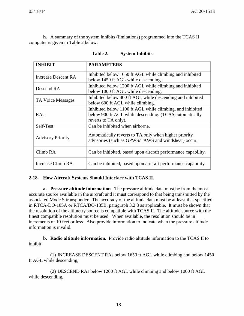
031814 AC 20-151B
h A summary of the system inhibits (limitations) programmed into the TCAS II computer is given in Table 2 below
Table 2 System Inhibits
INHIBIT PARAMETERS
Increase Descent RA Inhibited below 1650 ft AGL while climbing and inhibited below 1450 ft AGL while descending
Descend RA Inhibited below 1200 ft AGL while climbing and inhibited below 1000 ft AGL while descending
TA Voice Messages Inhibited below 400 ft AGL while descending and inhibited below 600 ft AGL while climbing
RAs Inhibited below 1100 ft AGL while climbing and inhibited below 900 ft AGL while descending (TCAS automatically reverts to TA only)
Self-Test Can be inhibited when airborne
Advisory Priority Automatically reverts to TA only when higher priority advisories (such as GPWSTAWS and windshear) occur
Climb RA Can be inhibited based upon aircraft performance capability
Increase Climb RA Can be inhibited based upon aircraft performance capability
2-18 How Aircraft Systems Should Interface with TCAS II
a Pressure altitude information The pressure altitude data must be from the most accurate source available in the aircraft and it must correspond to that being transmitted by the associated Mode S transponder The accuracy of the altitude data must be at least that specified in RTCA-DO-185A or RTCADO-185B paragraph 328 as applicable It must be shown that the resolution of the altimetry source is compatible with TCAS II The altitude source with the finest compatible resolution must be used When available the resolution should be in increments of 10 feet or less Also provide information to indicate when the pressure altitude information is invalid
b Radio altitude information Provide radio altitude information to the TCAS II to inhibit
(1) INCREASE DESCENT RAs below 1650 ft AGL while climbing and below 1450 ft AGL while descending
(2) DESCEND RAs below 1200 ft AGL while climbing and below 1000 ft AGL while descending
18
031814 AC 20-151B
(3) All TA voice messages (aural traffic advisories) below 400 ft AGL while descending and below 600 ft AGL while climbing and
(4) All RAs below 1100 ft AGL while climbing and below 900 ft AGL while descending to allow automatic sensitivity level selection when close to the ground and to determine that individual targets are on the ground
(5) Also provide information to indicate when the radio altitude information is invalid
c Aircraft configuration Use discrete information from flaps slat landing gear andor other aircraft configuration sensors to ensure that TCAS II appropriately inhibits CLIMB and INCREASE CLIMB RAs to the airplane performance limits as described in paragraph 2-16 and 2-17
d Aircraft identification Provide discrete information to the Mode S transponder for the unique aircraft Mode S identification code and its maximum airspeed capability
e Attitude Aircraft pitch and roll attitude may be provided to assist with stabilization of the directional antenna function to assure surveillance and to ensure TA display data remain unaffected by aircraft normal maneuvers If attitude information is used by TCAS II provide information to indicate when the attitude data are invalid
f Heading Aircraft heading may be provided for the TA display reference presentation Information must also be provided to indicate when the heading data are invalid
g System failure display Provide an indication to indicate when RAs are not possible due to failure of the TCAS II equipment or any of its sensors or displays
h Altitude alerter data You may provide the current clearance altitude from the altitude alerter to enable TCAS II to select RAs that are more consistent with the aircraftrsquos altitude clearance once the immediate collision threat has been resolved
NOTE Altitude alert functionality is optional per RTCADO-185A and RTCADO-185B Not all TSO-C119( ) TCAS II units will have this option available
i Mode S Transponder Gillham altitude input requirements The Gillham format uses 11 discrete wires that depending on which wires are turned off or on represent an altitude value The Gillham format is sometimes called a blind encoder as error detection andor correction on the wires is not conducted For this reason ARINC 718 Mark 3 Air Traffic Control Transponder (ATCRBSMODE S) dated December 1989 states ldquoPins have been reserved to permit the direct application of Gillham code data to the transponder This practice is not encouraged because of concerns that a ldquostuck bitrdquo in the coded input could be the cause of serious errors in TCAS II resolution advisoriesrdquo This is a failure mode peculiar to the Gillham code against which protection is virtually impossible If Gillham coded altitude use cannot be
19
031814 AC 20-151B
avoided for the TCAS II installations two sources of altitude information must be connected to the transponder and their values compared All transponder altitude comparator failures must be annunciated
j Hybrid surveillance failure annunciations (TSO-C119d units only) For aircraft equipped with centralized alert and warning system and or an onboard maintenance system consideration should be given to integrating the hybrid surveillance alerting functionality into the system so as to alert the crew with an appropriate failure annunciation Refer to section 2-21 for more information
2-19 Verifying and Validating TCAS II Software It is required for the first installation of a manufacturerrsquos TCAS II equipment to verify and validate TCAS II software using the procedures outlined below Also apply these procedures to subsequent software changes to a manufacturerrsquos TCAS II equipment A manufacturer may provide a design that partitions the software which affects RAs from other software such as that necessary for the traffic display The TCAS II manufacturer may not use the minor change authority of the TSO system to change any software not partitioned from the software that affects RAs
a Verification and validation of TCAS II software represents a unique challenge Collision avoidance algorithms commonly called ldquothe CAS logicrdquo are specified in detail in a formal statechart representation in the CAS requirements specification (CRS) in RTCADO-185A Volume II and RTCADO-185B Volume II In addition Attachment A of Volume II provides a software design specification in pseudocode that meets these requirements This detail is required because the coordination algorithms in the CAS logic assume that the software implemented by all manufacturers will have exactly the same CAS logic However the surveillance software necessary to establish and maintain the relative tracks of nearby transponder-equipped aircraft and the software necessary to provide the interface with the Mode S transponder and with other aircraft sensors and displays must be developed by the manufacturer of the TCAS II equipment This hybrid approach to the specification of the software requirements means that the application of the software criteria in RTCADO-178B Software Considerations in Airborne Systems and Equipment Certifications dated December 1 1992 for the detailed CAS requirements and the pseudocode software design have been satisfied by the FAA and our contractors while the remaining requirements of RTCADO-178B are the responsibility of the manufacturer
b If software is used for the display of TCAS II RAs or in the operation of the Mode S transponder data link the verification and validation of this software must be done to Level B requirements as defined in RTCADO-178B Also apply these procedures when the TCAS II manufacturer develops the software requirements for the TCAS II processor associated with functions other than surveillance or the CAS logic With the software design specified in RTCADO-185A Volume II or RTCADO-185B Volume II the manufacturer of the TCAS II processor should conduct code walk-throughs and develop and perform module tests and module integration tests to verify that the specified software design was implemented correctly This includes the surveillance software necessary to establish and maintain the relative tracks of nearby transponder-equipped aircraft
20
031814 AC 20-151B
c The functional tests required by TSO-C119b and TSO-C119cTSO-C119d as described in RTCADO-185A Volume I and RTCADO-185B Volume I respectively do not provide complete testing for the TCAS II processor software However coverage analysis performed on the CAS test suite described in Volume I demonstrated that each column of every transition table and macro and each identity transition in the CAS requirements specification in RTCADO-185A Volume II or RTCADO-185B Volume II is tested by the CAS test suite Thus the CAS test suite provides more than full decision coverage (but not full condition coverage) as defined in RTCADO-178B TCAS II manufacturers must develop additional functional tests that correspond to the detailed requirements that they develop for the TCAS II processor The potential consequences of software errors in the TCAS II processor or resolution display require the manufacturer to provide a structural coverage analysis showing single condition test coverage of all instructions at the source code that can affect the generation and display of RAs These tests may be a combination of module tests module integration tests and functional tests
d Equipment produced under a TSO has obtained FAA concurrence that the software for the equipment was produced in accordance with RTCADO-178B for a particular software level Subsequent installations of the same TCAS II equipment on other aircraft types do not require any additional verification if the software and the interface is not changed
2-20 Testing for Failures System Safety Analysis Unannunciated failures of the TCAS II equipment its associated transponder or sensors or displays that could generate an incorrect RA must be improbable This can be accomplished using the methods described in AC 251309-1A System Design and Analysis We expect that a functional hazard assessment (FHA) a failure modes and effects analysis (FMEA) and a quantitative probability analysis of the TCAS II equipment Mode S transponder displays and sensors (including altitude information sources) will be necessary to establish that a false RA is improbable Specifically show that the probability of an incorrect RA without a failure annunciation is on the order of 10 x 10-4 per flight hour in the terminal environment and 10 x 10-5 per flight hour in the enroute environment The frequency of encounters where another aircraft could present a potential threat depends on the density of aircraft in the airspace In terminal airspace the frequency may be assumed to be once every 10 hours and in enroute airspace it may be once every 200 hours You may establish different frequencies based on operational data Provide these analyses for the first installation of TCAS II equipment on a new model aircraft For subsequent installations of the same equipment in other aircraft you may use some of the same analyses paying particular attention to the differences in the altitude sensors that are used
NOTE Develop software involved in generating RAs to RTCADO178B Level B standards
2-21 Maintenance Considerations for Hybrid Surveillance Functionality (TSO-C119d only)
a RTCADO-300A section 2210 Monitoring Requirements provides a means for annunciation or recording of failures of own-ship latitude longitude andor ground speed inputs
21
031814 AC 20-151B
Note that a failure of any of these inputs will not cause TCAS to fail but it will disable the hybrid surveillance functionality
b To ensure that hidden failures are not resident in airborne TCAS II units for long periods of time failures of hybrid surveillance must be annunciated to the flight crew or the continued airworthiness must be assessed during periodic scheduled maintenance tasks Periodic reliability reporting for the hybrid surveillance functionality is also required Depending on the level of avionics integration in the aircraft different methods can be used to ensure the continued airworthiness of the hybrid surveillance such as
(1) For those aircraft equipped with an engine indicating and crew alerting (EICAS) system (or other similar annunciation system) integrate the failure information into the warning system such that a failure of hybrid surveillance is annunciated to the flight crew
(2) For aircraft equipped with an onboard maintenance computer interfaced with TCAS add a scheduled maintenance task to the aircraftrsquos maintenance program to check for presence of any existing or past failures of hybrid surveillance Take corrective action as specified by the TCAS manufacturer
(3) For aircraft without a centralized warning system andor an onboard maintenance computer add a scheduled maintenance task to the aircraftrsquos maintenance program to check for presence of any existing or past failures of hybrid surveillance and to ensure hybrid surveillance is functional Take corrective action as specified by the TCAS manufacturer
(4) If a scheduled maintenance task is employed the installer must establish the initial frequency of the task in conjunction with the manufacturer of the TCAS equipment but on a frequency not to exceed two calendar years between tasks Normal maintenance escalation procedures could later be used to extend the maintenance frequency when adequate justification to do so is provided to the cognizant ACO Coordinate any such extension request with the ACO prior to implementation of changes
c Operators of TCAS equipment with hybrid surveillance are required to report hybrid surveillance maintenance history to the TCAS manufacturer periodically but not to exceed 18 calendar months between reports
22
031814 AC 20-151B
Chapter 3 Test and Evaluation (Initial Approval)
3-1 General Test the first installation of a manufacturerrsquos TCAS II or Mode S transponder system This will verify the design and installation performs its intended function under the expected operating conditions and that there are no adverse interactions between the TCAS II Mode S transponder and existing aircraft systems The test will also show that other aircraft equipment has not been adversely affected
3-2 Create a Test Plan Provide a test plan that includes adequate testing to perform this verification This test plan will generally require a combination of ground tests basic flight tests and flight tests involving planned encounters with another TCAS II equipped aircraft You can use an aircraft other than a transport category aircraft for either the TCAS II installation or for the air-to-air cooperative flights The rest of this chapter lists and explains the minimum elements of the test plan
3-3 Basic Ground Tests
a Bearing accuracy Demonstrate the bearing estimation accuracy of the TCAS II system as installed in the aircraft Measure the bearing accuracy using a calibrated antenna range that allows precise echo controlled far field angle-of-arrival measurements at or slightly above zero degrees elevation and over 360 degrees in azimuth The bearing accuracy may also be measured using a fixed transponder location while rotating the test aircraft on a compass rose while measuring the bearing angles at 30-degree intervals Alternately the airplane is fixed and the transponder may be moved (refer to Appendix B for cautionary note on testing) Manual readout of the bearing estimate may be done directly from a plan position display on the traffic advisory display Alternatively the bearing estimates may be automatically recorded or read from a special test display A maximum error of plusmn15 degrees in azimuth is acceptable however larger errors are acceptable in the area of the tail (for example within plusmn45 degrees of the tail) when that area is not visible from the cockpit In this case aircraft structure may interfere with the signal path
b Sensor failures Evaluate simulated failures of the aircraft sensors integrated with TCAS II to determine that the resulting system failure state agrees with the predicted results These tests should be part of the ground test plan
c Electromagnetic interference (EMI) Survey the flight deck EMI to determine that the TCAS II equipment is not a source of objectionable conducted or radiated interference to previously installed systems or equipment and that operation of the TCAS II equipment is not adversely affected by conducted or radiated interference from previously installed systems and equipment Pay attention for possible interference with TCAS II equipment from weather radar particularly if operating in the C-band
d Evaluate the general arrangement and operation of controls displays circuit breakers annunciators and placards of the TCAS II system Conduct a human factors evaluation of the controls displays and annunciators Evaluate the TCAS controls and the controls of installed
23
031814 AC 20-151B
systems that interact with TCAS (for example transponders) to determine that they are designed and located to prevent inadvertent actuation Evaluate TCAS displays and annunciations to determine that they support flight crew awareness of TCAS status changes which could result from TCAS mode selections intentional pilot actuation of other installed systems or inadvertent pilot actions with TCAS or other installed systems Evaluate TCAS displays to ensure all information is at a minimum legible unambiguous and attention-getting (as applicable) In particular where transponder functions are integrated with other system controls ensure that unintended transponder mode switching especially switching to STANDBY or OFF is not possible Pay close attention to line select keys touch screens or cursor controlled trackballs as these can be susceptible to unintended mode selection resulting from their location in the flight deck (for example proximity to a foot rest or adjacent to a temporary stowage area)
e Evaluate the TCAS II self-test features and failure mode displays and annunciators
f Verify that the pressure altitude source and radio altimeter are properly interfaced with the TCAS II equipment
g Verify that the windshear and the ground proximity warning systemterrain awareness warning system (GPWSTAWS) warnings and TCAS II voice alerts are compatible Also verify that windshear or GPWSTAWS warnings can be clearly understood and that TCAS II is automatically switched to the TA Only mode when TCAS II and windshear voice or GPWSTAWS announcements simultaneously occur The alert priorities should be windshear GPWSTAWS and then TCAS II
h Verify the performance of TCAS II traffic display by observing any available area traffic
i Evaluate the TCAS II system installation for satisfactory identification accessibility and visibility during both day and night conditions
j Determine that any configuration of discretes associated with the TCAS II logic including inhibits of climb RAs operate properly (Changes in logic or function with aircraft configuration altitude or speed)
k Verify that the ICAO 24-bit aircraft address and maximum airspeed are correct Additionally verify that other features which may be optional such as extended squitter aircraft identification reporting or other data link uses also function correctly Verify that the transponder and data sources meet the requirements of the failure condition classifications associated with the features For example an unannunciated failure of the transponder extended squitter resulting in erroneous information being transmitted is at least a major failure condition
l If connected verify that the altitude alerter is providing correct data to TCAS and that the TCAS II V70 or V71 logic as applicable correctly weakens or strengthens the displayed RA using the altitude alerter input
m Verify that the airground inputs are connected properly
24
031814 AC 20-151B
NOTE 1 CAUTION - When the aircraft is on the ground the Mode S transponder must be inhibited from replying to any Mode A Mode C Mode ACS all-call interrogations and Mode S-only all-call interrogations
NOTE 2 This inhibit is usually accomplished via an appropriate transponder pin connected through the weight-on-wheels switch but it might also be accomplished through some other automatic means (for example velocityaltitude algorithm etc) The inhibit means must be verified during ground testing
NOTE 3 While on the ground the transponder normally should stop output of acquisition squitters (short squits) and should continue output of extended squitters (known as long squits or ADS-B) in the surface format and it should reply to any discretely-addressed aircraft interrogations This too should be verified during ground testing The exact conditions for transmission of acquisition squitter are specified in DO-181E section paragraph 221826 Acquisition Squitter Protocols
3-4 Basic Flight Tests
a During all phases of flight determine if there is any mutual interference with any other aircraft system Have all installed systems including the weather radar operating during the flight test
b Evaluate TCAS II aural messages for acceptable volume and intelligibility during both low and high cockpit noise levels (idle descent at low speed and high power at maximum operating limit speed Vmo) with headset covering outboard ear only (when appropriate) and without headsets In the case of turbo-prop aircraft where the aircrew utilizes headsets via the aircraft audio distribution panel the aural messages should hold the same acceptable volume and intelligibility during both low and high cockpit noise levels If the TCAS II TEST is used to simulate voice announcements ensure that the audio level is not changed by use of the TEST function
c Demonstrate that traffic information remains valid and usable when the aircraft is pitched plusmn15 degrees and rolled approximately 30 degrees during normal maneuvers by observing area traffic in the traffic advisory display
d Evaluate the effective surveillance range of the traffic display including target azimuth reasonableness and track stability Use of targets of opportunity or a non-transport category (low speed) aircraft as a target for these tests is permissible
25
031814 AC 20-151B
e Determine that any configuration discretes (changes in logic or function with aircraft configuration altitude or speed) associated with the TCAS II logic including inhibits of climb RAs operate properly unless previously demonstrated during ground tests
f Perform the additional flight tests in RTCADO-185A or RTCADO-185B paragraph 344 as applicable unless previously accomplished under TSO-C119b or TSO-C119cTSOshyC119d respectively
g Evaluate TCAS II for noninterference during coupled autopilot and flight director (FD) approaches to the lowest minimums approved for the aircraft
h Before any cooperative flight tests at any altitude involving the TCAS II-equipped aircraft and another aircraft fly both aircraft in close formation to ensure matched altimetry readouts These checks should be flown at the speeds and altitudes to be used for the tests
i Evaluate all selectable modes of the TCAS II to determine that they perform their intended function and that the operating mode is clearly and uniquely annunciated
j Re-evaluate any previously installed aircraft systems that required changes as a result of the TCAS II installation (For example electronic flight instrument system (EFIS) FD PFD navigation displays (ND) IVSI interface etc)
k When hybrid surveillance functionality is included perform the flight tests in RTCADO-300 or DO-300A MOPS for Traffic Alert and Collision Avoidance System II (TCAS II) Hybrid surveillance dated December 13 2006 and dated Mar 20 2013 respectively paragraph 3 as appropriate unless previously accomplished under TSO-C119c or TSO-C119d
3-5 Planned Encounter Flight Tests The objective of these flight tests is to demonstrate adequate TCAS II surveillance and to verify smooth predictable TCAS II performance First establish the appropriate safety rules static system leak test (if necessitated by having opened the system) and altimeter correlation between the encounter aircraft and the TCAS aircraft The following encounters between the TCAS II aircraft and a dedicated intruder aircraft should be flown to assure that the TCAS II aircraft system performs its intended function by generating TAs and RAs and is consistent with RTCADO-185A or RTCADO-185B as applicable and RTCADO-300 or RTCADO-300A as appropriate The intruder aircraft must be equipped with a previously approved transponder installation capable of Mode A Mode C and for those tests necessary Mode S TCAS II and ADS-B Mode S Extended Squitter if appropriate These tests are also intended to expose the installed TCAS II system to a reasonable number of carefully controlled encounters that are likely to occur in service This matrix covers the envelope of encounter speeds altitudes and geometries that have in the past identified flaws in surveillance logic and antenna mechanization that were not detected earlier by bench tests Fly the following encounters
a Intruder overtaking TCAS II aircraft (from the aft quadrants)
b Head-on
26
031814 AC 20-151B
(1) Low and high closure speeds
(2) Above climb limit TCAS II to TCAS II
(3) TCAS II against Mode C with TCAS II above intruder and above climb limit (intent is to force TCAS II aircraft to descend)
(4) At 3000 feet over calm water to evaluate multipath protection
c Converging
(1) Crossing (intruder above TCAS II descending or vice versa)
(2) Evaluate the TA-only mode during planned encounters
(3) Evaluate a mix of intruder transponder modes (A C S and S with extended squitter) but primary emphasis should be on TCAS II-to-TCAS II coordination and on Mode C replies from the intruder aircraft
(4) Evaluate a mix of encounters with TCAS II both above and below the intruder
(5) If a flight test is necessary to ensure compatibility with other designs verify correct air-to-air coordination between the test TCAS II and another manufacturerrsquos previously approved equipment (refer to paragraph 2-15)
(6) Evaluate the effect of electrical transients (bus transfer) during encounters The TCAS II should not experience adverse effects No false TAs or RAs should be generated as a result of electrical transients Normal TCAS II functions and displays should be restored within approximately three seconds
3-6 Mode S Transponder Tests
a This guidance doesnrsquot cover Mode S Extended Squitter or Mode S ElementaryEnhanced surveillance
b The tests described in these paragraphs may be used to obtain the certification of a stand-alone Mode S transponder installation (an installation without TCAS II) These tests should also be used to evaluate a Mode S transponder installed as part of a TCAS II installation The tests primarily verify the installed antenna(s) are compatible with the Mode S transponder and provide an adequate response to ground radar interrogations during normal aircraft maneuvers
c Additionally these tests demonstrate that the Mode S transponder functions properly as installed and does not interfere with other aircraft electronic equipment The need for a detailed flight test is reduced when the Mode S transponder and antenna installation are identical
27
031814 AC 20-151B
or similar to that of previously approved ATCRBS transponder installation If a previously installed and certified transponder is being upgraded all of the guidance in this section is not necessarily required to approve the upgrade A careful examination of the proposed transponder upgrade should be accomplished to determine which of the tests specified in this section are necessary and appropriate Typical testing associated with the initial installation and certification of a new transponder may not be necessary when upgrading a previously approved transponder For example if a software upgrade is being considered which would add extended squitter functionality to a transponder in a previously approved installation detailed flights would not be required if appropriate ground testing adequately evaluates the added functionality
NOTE 1 CAUTION When conducting flight testing of the transponder or TCAS system you must prevent being a source of interference to ATC or other TCAS aircraft operating in the area For example using a fixed transponder to simulate an intruder aircraft can cause data to be transmitted which produce false targets for the ground ATC surveillance systems or airborne TCAS aircraft These false indications of ldquointruder aircraftrdquo could result in unnecessary ATC communications and possibly in TCAS induced aircraft maneuvers Therefore conduct such testing in coordination with ATC
NOTE 2 The conduct of this test requires cooperation with ATC radar controllers Coordination with ATC is important before the flight test for any necessary approval of the flight and agreement with the flight test procedures During the flight test communication will be required with the controller monitoring the aircraft and reporting transponder performance data
d If the Mode S transponder uses a top mounted antenna in addition to a bottom mounted antenna installed at or near the same location used by a previously approved ATCRBS transponder antenna conduct a comprehensive ground test and evaluation in accordance with Appendix B and perform a functional flight test The transponder code altitude reporting and ldquoIDENTrdquo features of the transponder should be exercised during normal maneuvering There should be no objectionable behavior observed by the ATC controller
e If a Mode S transponder is installed in an aircraft which does not have a previously approved ATCRBS transponder installation or that uses a bottom mounted antenna location which differs significantly from that used by a previously approved ATCRBS transponder antenna conduct the following ground and flight tests
NOTE References to the radar facility are references to the radar that provides the data used by the ATC controller(s) during the flight test for monitoring the aircraft and reporting transponder performance data These are not references to the ATC facility with the radar displays used by the controllers
28
031814 AC 20-151B
(1) Conduct ground tests and evaluations per Appendix B
(2) Climb and Distance Coverage Begin at a distance of at least 10 nautical miles (NM) from and an altitude of 2000 to 3000 feet above the radar facility and using a transponder code assigned by ATC fly on a heading that will pass the aircraft over the radar facility At a distance of 5 to 10 NM beyond the radar facility fly the aircraft at its normal maximum climb attitude to within 90 percent of the certificated altitude for the aircraft maintaining the aircraft heading within 5 degrees of the track from the radar facility After reaching the maximum altitude for which the aircraft is certificated fly level at the maximum altitude to 160 NM for turbojet and some turboprop powered airplanes (or 80 NM for most other aircraft) from the radar facility (Distance from the radar facility is a function of the airplanersquos maximum certificated altitude) Communicate with the ATC controller for evidence of transponder dropout During the flight check the ldquoIDENTrdquo mode of the ATC transponder to assure that it is performing its intended function There should be no unexpected dropouts (no return for two or more sweeps) Uncontrollable ringing that hinders use of the ground radar is unsatisfactory
(3) Long Range Reception At 90 percent of maximum certificated altitude perform left and right 360-degree turns at bank angles of 8 to 10 degrees The aircraft should be at least 160 (or 80) NM from the radar facility During these turns request that the ATC controller monitor the radar displays There should be no dropouts (no return for two or more sweeps)
(4) High Angle Reception Perform two 360-degree turns one to the right and one to the left at bank angles of 8 to 10 degrees with the airplane at a distance of 50 to 70 NM from the radar facility and at an altitude of at least 35000 feet or within 90 percent of the maximum altitude for which the aircraft is certificated There should be no dropouts (no return for two or more sweeps) Switch the transponder to a new code assigned by the ATC controller The aircraft secondary return on the ATC controllerrsquos radar display should indicate a Mode A code change
(5) High Altitude Cruise Within 90 percent of the aircraftrsquos maximum certificated altitude or its maximum operating altitude beginning at a point 160 (or 80) NM from the radar facility fly on a course that will pass over the radar facility The ATC controller should report no unexpected transponder dropout or ldquoring aroundrdquo
(6) Surveillance Approach Beginning at or above 90 percent of the certificated maximum altitude for the aircraft perform a letdown and approach to a runway of an airport served by Airport Surveillance Radar (ASR) having an ATCRBS facility Make the approach at the maximum normal rate of descent Normal approach and landing configuration for the aircraft should continue down to an altitude of 200 feet or less above the ground radar antenna elevation Not more than one dropout should occur for any 10 sweeps during final approach Uncontrolled ringing that hinders use of the ground radar is unsatisfactory
(7) Holding and Orbiting Patterns
(a) At an altitude of 2000 feet above the radar antenna or minimum obstruction clearance altitude (whichever is greater) with landing flaps and gear extended fly left and right
29
031814 AC 20-151B
360-degree turns approximately 10 miles from the radar facility There should be no signal dropouts
(b) At an altitude of 2000 feet above the radar antenna or minimum obstruction clearance altitude (whichever is greater) fly 45 degree sectors of left and right 10 mile orbital patterns around a radar facility with gear and landing flaps extended There should be no signal dropouts
(8) Altitude Reporting Conduct a functional test of the altitude encoder by comparison with ATC displayed altitudes Verify correspondence at several altitudes between ATC readings and the Captainrsquos altimeter when set at or corrected to 2992 inches of mercury (or equivalent)
30
031814 AC 20-151B
Chapter 4 Follow-on Approvals (STCs or Amended STC or Amended TC)
4-1 The Need for Tests and a Plan
a Provide a test plan including adequate aircraft ground testing and evaluations to verify that the design and installation performs its intended function when installed in a different aircraft type under the expected operating conditions There should be no adverse interactions between the TCAS II or Mode S transponder and existing aircraft systems and prior approvals of present aircraft equipment should not be compromised This test plan will generally require a combination of ground tests basic flight tests and flight tests involving planned encounters with a Mode C equipped aircraft or the use of a suitably located fixed transponder The test plan should contain as a minimum the elements of paragraph 3-6 and those covered in the next paragraphs
b Flight-testing of TCAS II or Mode S transponder systems for follow-on approvals (previously approved TCAS II or Mode S transponder equipment installed in a different aircraft type) may need to be conducted to verify that the design and installation performs its intended function under the expected operating conditions Determine that there are no adverse interactions between the TCAS II or Mode S transponder and existing aircraft systems and that prior approvals of present aircraft equipment have not been compromised
NOTE CAUTION When flight testing the transponder or TCAS system you must prevent being a source of interference to ATC or other TCAS aircraft operating in the area For example using a fixed transponder to simulate an intruder aircraft can cause data to be transmitted which produce false targets for the ground ATC surveillance systems or airborne TCAS aircraft False indications of ldquointruder aircraftrdquo could result in unnecessary ATC communications and possibly in TCAS induced aircraft maneuvers Conduct such testing in coordination with ATC
4-2 Ground Tests and Evaluations
a Evaluate the general arrangement and operation of controls displays circuit breakers annunciators and placards of the TCAS II system Conduct a human factors evaluation of the controls displays and annunciators Evaluate the TCAS controls and the controls of installed systems that interact with TCAS (for example transponders) to determine that they are designed and located to prevent inadvertent actuation Evaluate TCAS displays and annunciations to determine that they support flight crew awareness of TCAS status changes which could result from TCAS mode selections intentional pilot actuation of other installed systems or inadvertent pilot actions with TCAS or other installed systems Evaluate TCAS displays to ensure all information is at a minimum legible unambiguous and attention-getting (as applicable) In particular where transponder functions are integrated with other system controls ensure that unintended transponder mode switching especially switching to STANDBY or OFF is not
31
031814 AC 20-151B
possible Pay close attention to line select keys touch screens or cursor controlled trackballs as these can be susceptible to unintended mode selection resulting from their location in the flight deck (for example proximity to a foot rest or adjacent to a temporary stowage area)
b Evaluate the TCAS II self-test features and failure mode displays and annunciators
c Verify that the pressure altitude source and radio altimeter are properly interfaced with the TCAS II equipment
d Measure the performance of the directional antenna for 360 degrees coverage at 30 degree intervals as specified under basic ground tests paragraph 3-3a
e Evaluate the TCAS II system installation for satisfactory identification accessibility and visibility during both day and night conditions
f Determine that any configuration discretes (changes in logic or function with aircraft configuration altitude or speed) associated with the TCAS II logic including inhibits of climb RAs operate properly
g Verify that the ICAO 24-bit aircraft address and maximum airspeed are correct Verify that the transponder and data sources meet the requirements of the failure condition classifications associated with the features
h Verify that the windshear and GPWSTAWS warnings and TCAS II voice alerts are compatible Also verify that windshear and GPWSTAWS warnings can be clearly understood and that TCAS II is automatically switched to the TA Only mode when TCAS II and windshear voice or GPWSTAWS announcements simultaneously occur The alert priorities should be windshear GPWSTAWS and then TCAS II
i If connected verify that the altitude alerter is providing correct data to TCAS and that the TCAS II logic correctly weakens or strengthens the displayed RA using the altitude alerter input
j Verify that the airground inputs are connected properly
NOTE 1 CAUTION When the aircraft is on the ground the Mode S transponder must be inhibited from replying to any Mode A Mode C Mode ACS all-call interrogations and Mode S-only all-call interrogations
NOTE 2 This inhibit is usually accomplished via an appropriate transponder pin connected through the weight-on-wheels switch but it might also be accomplished through some other automatic means (for example velocityaltitude algorithm etc) The inhibit means must be verified during ground testing
32
031814 AC 20-151B
NOTE 3 While on the ground the transponder normally should stop output of acquisition squitters (short squits) and should continue output of extended squitters (known as long squits or ADS-B) in the surface format and it should reply to any discretely addressed aircraft interrogations This too should be verified during ground testing The exact conditions for transmission of acquisition squitter are specified in DO-181E paragraph 221826 Acquisition Squitter Protocols
4-3 Flight Tests
a The certification policy for follow-on approvals (STC or amended STC) of TCAS II V70 or V71 units is that flight tests may not be required if the appropriate testing is performed on the ground to certify that the V70 or V71 unit was correctly installed and that any new interfaces operate correctly with the TCAS II logic
b If we determine that certification flight-testing is required demonstrate the following
(1) Verify proper operation of the traffic display by observing proximate traffic at least one TA and at least one RA Confirm that the appropriate aural alerts occur correctly with the TA and RA The advisories may be generated by
(a) Planned encounters with an intruder aircraft operating a transponder with Mode C capability
NOTE Before any cooperative flight tests at any altitude involving the TCAS II equipped aircraft and another aircraft fly both aircraft in close formation to assure matched altimetry readouts These checks should be flown at the speeds and altitudes to be used for the tests
(b) Encounters with an operating Mode C transponder installed at a fixed ground location which reports an appropriate test altitude
NOTE CAUTION When flight testing the transponder or TCAS system you must prevent being a source of interference to ATC or other TCAS aircraft operating in the area For example using a fixed transponder to simulate an intruder aircraft can cause data to be transmitted which produce false targets for the ground ATC surveillance systems or airborne TCAS aircraft These false indications of ldquointruder aircraftrdquo could result in unnecessary ATC communications and possibly in TCAS induced aircraft maneuvers Conduct such testing in coordination with ATC
(c) Encounters with aircraft targets of opportunity
(d) The use of suitable test equipment during ground tests
33
031814 AC 20-151B
NOTE CAUTION When ground testing the transponder or TCAS system you must prevent being a source of interference to ATC or other TCAS aircraft operating in the area Ground maintenance checks or ramp testing (such as altimetry or bearing accuracy testing) can cause data to be transmitted which produce false targets for the ground ATC surveillance systems or airborne TCAS aircraft These false indications of ldquointruder aircraftrdquo could result in unnecessary ATC communications and possibly in TCAS induced aircraft maneuvers Conduct such testing in coordination with ATC and use antenna shielding (transmission absorption covers or caps) to prevent test data that could generate false intruder information from being transmitted Using high-powered hangar-mounted transponders to conduct ramp testing is not an acceptable means to test either transponder ramp or TCAS
(2) During all phases of flight determine if there is any mutual interference with any other aircraft system
(3) Evaluate TCAS II aural messages for acceptable volume and intelligibility during both low and high cockpit noise levels (idle descent at low speed and high power at Vmo) with and without headsets covering the outboard ear where appropriate In turbo-prop aircraft where the aircrew uses headsets via the aircraft audio distribution panel the aural messages should hold the same acceptable volume and intelligibility during both low and high cockpit noise levels If the TCAS II TEST is used to simulate voice announcements ensure that the audio level is not changed by use of the TEST function
(4) Evaluate the effective surveillance range of the traffic display including target azimuth reasonableness and track stability You may use a non-transport (low speed) Mode C equipped aircraft as a target or a fixed transponder or suitable test equipment for these tests
NOTE CAUTION When flight testing the transponder or TCAS system you must prevent being a source of interference to ATC or other TCAS aircraft operating in the area For example using a fixed transponder to simulate an intruder aircraft can cause data to be transmitted which produce false targets for the ground ATC surveillance systems or airborne TCAS aircraft These false indications of ldquointruder aircraftrdquo could result in unnecessary ATC communications and possibly in TCAS induced aircraft maneuvers Conduct such testing in coordination with ATC
(5) Evaluate the Mode S transponder air-to-ground ATCRBS function against an appropriate ground facility
(6) Determine that any configuration discretes associated with the TCAS II logic including inhibits of aural annunciations and RAs operate properly unless previously
34
031814 AC 20-151B
demonstrated during ground tests (These include changes in logic or function with aircraft configuration altitude or speed)
(7) Evaluate TCAS II for noninterference during coupled autopilot and flight director approaches to the lowest minimums approved for the aircraft
(8) Evaluate all selectable modes of the TCAS II to determine that they perform their intended function
(9) Reevaluate any previously installed aircraft systems that have required changes as a result of the TCAS II installation (such as CMC EFIS EICAS FD PFD ND IVSI and interface)
4-4 Upgrading an Existing TCAS II Installation If you are upgrading an existing approved TCAS II installation to a higher TCAS II version (ie V70 or V71) and the higher version installation is only a software change then no additional certification flight tests are required to obtain a follow-on STC or amended STC or an amended TC The appropriate aircraft ground tests of paragraph 4-2 are considered sufficient to ensure that the higher version TCAS II software is operating properly However if the upgrade to a higher version TCAS II unit involves changes other than a software change (such as the addition of new interfaces) flight tests in accordance with paragraph 4-3b may be required
35
031814 AC 20-151B
Chapter 5 Airplane Flight Manual Supplement
5-1 Contents of an AFMS The AFMS should provide the appropriate system limitations and procedures and a comprehensive description of all normal modes of operation including expected flight crew actions
5-2 TCAS V71 AFMS Example Refer to Appendix A for an example of the elements and extent of detail that may be shown by a typical AFMS (specific performance data inhibits and procedures may vary with system design and aircraft type)
36
031814 AC 20-151B Appendix A
Appendix A Example TCAS II V71 AFMS
INTRODUCTION
Descriptive material and procedures in this Airplane Flight Manual Supplement (AFMS) example may when appropriate be replaced by reference in the AFMS to the TCAS II equipment supplierrsquos pilot operating guide However the AFMS reference to this guide must specify date and revision level and not be open ended such as ldquoor later revisionrdquo unless the pilotrsquos guide is specifically FAA approved Also the AFMS must define the specific configuration approved from the various options contained in the pilotrsquos guide for example which model control panel whether the pilot initiated self-test is available in flight range features TA vertical display features and so forth
-EXAMPLEshy
AIRPLANE FLIGHT MANUAL SUPPLEMENT
(Example for an aircraft equipped with IVSIRA displays)
DESCRIPTION
The TCAS II is an on-board collision avoidance and traffic situation display system with computer processing to identify and display intruding and threatening collision aircraft and issue resolution advisories in the form of vertical maneuver guidance on the pilot and copilotrsquos instantaneous vertical speed indicators (IVSI) From the transponder replies TCAS II determines relative altitude range and bearing of any ATCRBS or Mode S equipped aircraft with altitude reporting From this TCAS II will determine the level of advisory using standardized algorithms The TCAS II will resolve multiple aircraft encounters ATCRBS equipped aircraft that only reply with Mode A information will not provide altitude information therefore TCAS II will not issue resolution advisories for these aircraft but can issue traffic advisories The TCAS II will not detect aircraft that are not equipped with transponders
The TCAS II installation consists of one TCAS II processor one top mounted directional antenna one bottom mounted blade (or directional antenna) one Mode S transponder with control panel and top and bottom antennas one traffic advisory display with control panel (if not combined with the IVSIRA indicators) two resolution advisory displays one overhead speaker for voice messages (cautionwarning lights) and associated wiring
The TCAS II provides two levels of advisories
1 If the traffic gets within 25 to 48 seconds depending upon altitude of projected Closest Point of Approach (CPA) it is then considered an intruder and an aural and visual traffic advisory (TA) is issued This level calls attention to what may develop into a collision threat using the traffic advisory display and the voice message ldquoTRAFFIC - TRAFFICrdquo It permits mental and physical preparation for a possible maneuver to follow and assists the pilot in achieving visual acquisition of the intruding aircraft
A-1
031814 AC 20-151B Appendix A
2 If the intruder gets within 15 to 35 seconds depending upon altitude of CPA it is considered a threat and an aural and visual resolution advisory (RA) is issued This level provides a recommended vertical maneuver using modified IVSIs and voice messages to provide adequate vertical separation from the threat aircraft or prevents initiation of a maneuver that would place the TCAS II aircraft in jeopardy The TCAS II is considered a backup system to the ldquoSEE AND AVOIDrdquo concept and the ATC surveillance The TCAS II resolution advisories are annunciated by the following voice messages as appropriate along with the expected pilot response
(1) ldquoCLIMB CLIMBrdquo--climb at the rate depicted by the green (fly to) arc on the IVSI nominally between 1500 and 2000 fpm
(2) ldquoDESCEND DESCENDrdquo--descend at the rate depicted by the green (fly to) arc on the IVSI nominally between 1500 and 2000 fpm
(3) ldquoMONITOR VERTICAL SPEEDrdquo--ensure that vertical speed is out of the illuminated IVSI red arc until the RA is completed
(4) ldquoLEVEL OFF LEVEL OFFrdquo -- reduce vertical speed to zero feet per minute A green arc will be illuminated beginning at zero feet per minute This can be issued as the initial RA or as a subsequent RA
(5) ldquoCLEAR OF CONFLICTrdquo--range is increasing and separation is adequate Expeditiously return to the applicable ATC clearance unless otherwise directed by ATC
(6) ldquoCLIMB CROSSING CLIMB CLIMB CROSSING CLIMBrdquo--climb at the rate depicted by the green (fly to) arc on the IVSI nominally between 1500 and 2000 fpm Safe separation will best be achieved by climbing through the threatrsquos flight path
(7) ldquoDESCEND CROSSING DESCEND DESCEND CROSSING DESCENDrdquo-shydescend at the rate depicted by the green (fly to) arc on the IVSI nominally between 1500 and 2000 fpm Safe separation will best be achieved by descending through the intruderrsquos flight path
(8) ldquoMAINTAIN VERTICAL SPEED MAINTAINrdquo--continue the existing climb or descent rate or other vertical speed as depicted by the green (fly to) arc on the IVSI
(9) ldquoMAINTAIN VERTICAL SPEED CROSSING MAINTAINrdquo--continue the existing climb or descent rate or other vertical speed as depicted by the green (fly to) arc on the IVSI Safe separation will best be achieved by not altering the existing vertical speed and climbing or descending through the threatrsquos flight path
The following voice messages annunciate enhanced TCAS II maneuvers when initial RA does not provide sufficient vertical separation The tone and inflection indicate increased urgency
A-2
031814 AC 20-151B Appendix A
(1) ldquoINCREASE CLIMB INCREASE CLIMBrdquo--climb at the rate depicted by the green (fly-to) arc on the IVSI nominally between 2500 and 3000 fpm Received after ldquoCLIMBrdquo advisory and indicates additional climb rate is required to achieve safe vertical separation from a maneuvering aircraft
(2) ldquoINCREASE DESCENT INCREASE DESCENTrdquo--descend at the rate depicted by the green (fly-to) arc on the IVSI nominally between 2500 and 3000 fpm Received after ldquoDESCENDrdquo advisory and indicates additional descent rate is required to achieve safe vertical separation from a maneuvering aircraft
(3) ldquoCLIMB ndash CLIMB NOW CLIMB ndash CLIMB NOWrdquo--climb at the rate depicted by the green (fly-to) arc on the IVSI nominally between 1500 and 2000 fpm Received after a ldquoDESCENDrdquo resolution advisory and indicates a reversal in direction is required to achieve safe vertical separation from a maneuvering threat aircraft
(4) ldquoDESCEND ndash DESCEND NOW DESCEND ndash DESCEND NOWrdquo-descend at the rate depicted by the green (fly-to) arc on the IVSI nominally between 1500 and 2000 fpm Received after a ldquoCLIMBrdquo resolution advisory and indicates a reversal in direction is required to achieve safe vertical separation from a maneuvering threat aircraft
A-3
031814 AC 20-151B Appendix A
Figure A-1 TCAS IITransponder Control Panel (Example)
Table A-1 TCAS IITransponder Function Selector
TEST Holding the TCAS IITransponder function selector in TEST for 2 to 3 seconds will activate the system test sequence In the TEST position read maintenance messages on the display Use discretion when selecting TEST in flight since both TCAS II and the transponder will be inhibited for approximately 20 seconds The function selector is spring loaded to STBY
STBY Activates TCAS II and XPDR warmup cycles XPDR Transponder is on TCAS II is in warmup cycle TA Transponder is on Only the ldquoTraffic Advisoryrdquo or ldquoTArdquo function of the TCAS II
is on No ldquoResolution Advisoriesrdquo will be received in this position The written warning ldquoTA ONLYrdquo will appear on the display and the yellow ldquoRA OFFrdquo flag will be in view on both IVSIs
TARA Transponder is on All TCAS II functions are on No TCAS II flags should be present on either IVSI
XPDR Fail Light (Red)
Indicates a transponder system failure when the transponder is on Comes on during ldquoTESTrdquo but goes off after approximately 3 seconds if the transponder is OK
Code Indicator
Indicates code selected with the code selectors
IDENT Causes the word IDENT to flash in the aircraft data block on the ATC display ALT
RPTG Provides automatic altitude reporting to ATC
Code Selectors
Select the transponder code Left and right selectors consist of a large knob and a small knob Each knob controls one digit of the code
A-4
031814 AC 20-151B Appendix A
Figure A-2 TCAS II ndash Traffic Display (Example)
Table A-2 Displayed Aircraft Symbols (Examples)
Arrow indicates that the target is climbing uarr or descending darr at a rate of at least 500 fpm
Relative altitude is displayed in the proximity of the aircraft symbol in hundreds of feet A ldquo+rdquo preceding the relative altitude indicates the target is above you and a ldquo-ldquo indicates it is below you
Unfilled white diamond Non-threatening traffic without altitude reporting If altitude reporting the altitude data will be displayed
+07 Solid White diamond Proximity traffic 700 feet above Non-threatening altitude reporting traffic within 1200 feet vertically and 6nm horizontally Aircraft without altitude reporting will be assumed to be co-altitude and will be displayed as a solid diamond when within 6nm even though they may not be within 1200 feet vertically
darr
-03
Solid yellow circle ldquoTArdquo 300 feet below descending with a rate of at least 500 fpm
+00 Solid red square ldquoRArdquo level at your altitude
Own-ship Airplane symbol in white just below the center of CRT On a dedicated display or when in the TFC Mode on a combination TCAS IIRADAR Display
(Compass Arc)
This arc is repeater of the Captains compass (Not required for TCAS II Display)
(Range Rings)
3nm ndash Small ring with ticks at clock positions 5 NM ndash Large ring made of dots
A-5
031814 AC 20-151B Appendix A
Figure A-3 TCAS II Traffic Display (Example)
Table A-3A Paddle Switch REL ALTFL Switch
REL ALT
Paddle switch is spring loaded to the center position Display shows relative altitude ldquoREL ALTrdquo in hundreds of feet above (+) or below (-) your aircraft
FL Allows display of traffic flight levels referenced to 2992 for 15 seconds Your FL is displayed in lower left corner Three digits are shown except for negative flight levels that are shown as ndash xxx When the current barometric pressure is not available and the TCAS II aircraft is below FL 180 the FL position is automatically inhibited
RANGE The maximum forward range on the traffic display is set at range selected by the range knob Ranges of 3 5 10 20 NM are available and the selected range is annunciated on the traffic display
BRT Knob
Controls brightness of the display
A-6
031814 AC 20-151B Appendix A
Table A-3B AboveNormBelow Switch
ABOVE Displays altitude-reporting traffic from 2700 feet below to 9900 feet above the TCAS II aircraft The selection of this mode is annunciated by ABOVE being displayed on the traffic display This selection has no effect on the functioning of the collision avoidance logic
NORM Displays altitude reporting traffic from 2700 feet below to 2700 feet above the TCAS II aircraft
BELOW Displays altitude-reporting traffic from 2700 feet above to 9900 feet below the TCAS II aircraft The selection of this mode is annunciated by BELOW being displayed on the traffic display This selection has no effect on the functioning of the collision avoidance logic
OFF-SCALE TRAFFIC ADVISORY - If TCAS II tracks an intruder that is outside the selected range of the display but that has entered the Caution or Warning areas one-half of the appropriate symbol will appear at the appropriate bearing at the edge of the display area The symbol will appear in its proper color and have its data tag displayed providing there is room For example a TA intruder with a high closure rate and which is directly ahead and 300 feet below your airplane will appear as an amber-filled half circle at the 12 orsquoclock position on the edge of the display area The data tag ldquo-03rdquo will appear below the half symbol If this intruder is above your altitude the data tag is not visible An off-scale RA intruder will appear as a red-filled half square with data tag displayed if room permits
NO BEARING ADVISORIES - When TCAS II cannot track the bearing of an intruder the traffic advisory will appear in the lower center of the display just below the own-airplane symbol The advisory will present appropriate color-coded traffic information This phenomenon usually is caused either by temporary antenna shielding (caused by steep bank angles) or a failure in the TCAS II bearing antenna Up to two lines of information can be displayed ldquoTA 52 -06uarrrdquo for example means an intruder is creating a Traffic Advisory 52 nautical miles away 600 feet below and climbing in excess of 500 FPM This advisory is written in amber or yellow ldquoRA 06 00rdquo means resolution advisory traffic is 06 nautical miles away at the same altitude This advisory is written in red TCAS IIrsquos ability to compute a traffic or resolution advisory is not degraded by lack of bearing information
A-7
031814 AC 20-151B Appendix A
Figure A-4 TCAS II Instantaneous Vertical Speed Indicator (Example)
Red Arc
Green Arc
Key to Colors in Figures
A-8
031814 AC 20-151B Appendix A
Table A-1 Instantaneous Vertical Speed Indicator
Indicates vertical speed in feet per minute The IVSI is a normal instantaneous vertical speed indicator and the presence of the lights or the flags will not interfere with the ability of the needle to indicate vertical speeds
REDGREEN EYEBROW LIGHTS Eyebrow lights are invisible until they illuminate as part of a TCAS II ldquoRESOLUTION ADVISORYrdquo or system ldquoTESTrdquo These lights indicate a vertical speed regime which will provide safe traffic separation The green lights form a wider band than red lights
IVSI Status Window Flags
T C BLACK Normal operation A S
T C AMBER FLAG Indicates Unusable TCAS II information A S
RT WHITE ldquoRA OFFrdquo FLAG Always displayed when TCAS AC IITRANSPONDER function selector is in STBY XPDR or TA Will also OA be displayed with selector in RATA if ldquoRAsrdquo are inhibited andor FS inoperative F
A-9
031814 AC 20-151B Appendix A
Figure A-5 TCAS II Examples ndash Preventive RAs
A-10
031814 AC 20-151B Appendix A
Figure A-6 TCAS II Examples ndash Initial Corrective RAs
A-11
031814 AC 20-151B Appendix A
Figure A-7 TCAS II Examples ndash Modifications to Initial Corrective RAs
A-12
031814 AC 20-151B Appendix A
SECTION I ndash LIMITATIONS
(1) Pilots are authorized to deviate from their current ATC clearance to comply with a TCAS II resolution advisory (RA)
(2) Maneuvers based solely on a traffic advisory (TA) or on information displayed on the traffic display are not authorized
SECTION II - EMERGENCY PROCEDURES
(1) No change from basic airplane flight manual
SECTION III ndash PROCEDURES
(1) TCAS II Flight Procedures
Compliance with a TCAS II resolution advisory (RA) is necessary unless the pilot considers it unsafe to do so or unless the pilot has information about the cause of the RA and can maintain safe separation for example visual acquisition of and safe separation from a nearby aircraft on a parallel approach
NOTE CAUTION Once a non-crossing RA has been issued safe operation could be compromised if current vertical speed is changed except as necessary to comply with the RA This is because TCAS II-to-TCAS II coordination may be in progress with the intruder airplane and any change in vertical speed that does not comply with the RA may negate the effectiveness of the other airplanersquos compliance with its RA
NOTE WARNING Noncompliance with a crossing RA by one airplane may result in reduced vertical separation therefore safe horizontal separation must also be assured by visual means
Because of the limited number of inputs to TCAS II for airplane performance inhibits in some instances where inhibiting RAs may be appropriate it is not possible to do so In these cases TCAS II may command maneuvers that may significantly reduce stall margins or result in stall warning Therefore the stall warning stick shaker must be respected when following an RA Conditions where this may occur include
(a) Bank angle in excess of 15 degrees
(b) One engine inoperative
(c) Abnormal configurations such as landing gear not retractable etc
(d) Leaving airplane in inappropriate configurations when climb RA occurs
A-13
031814 AC 20-151B Appendix A
(e) Operation at airports outside of 0 to 5300 feet MSL or temperatures outside of ISA plusmn50degF
(f) Speeds below normal operating speeds
(g) Buffet margin less than 03 g
The TCAS II RA algorithms are based on the pilot initiating the initial 025 g acceleration maneuver within approximately 5 seconds Pilot response is expected within approximately 25 seconds if an additional RA is issued (The increase rate and rate reversal RAs are based on a 035 g acceleration maneuver) Because of these requirements and the rate limits of the autopilots all RA responses must be hand-flown and not with the autopilot or autothrottles engaged
NOTE Evasive maneuvering should be limited to the minimum required to comply with the RA Excessive responses to RAs are not desirable or appropriate because of other potential traffic and ATC consequences From level flight proper response to an RA typically results in an overall altitude deviation of 300 to 500 feet in order to successfully resolve a traffic conflict
Modified advisories are posted after the response to an initial advisory has been completed and the TCAS II airplane is projected to have adequate altitude separation from the intruder The initial RA is said to weaken indicating a return towards the original flight path or clearance is allowed When the initial advisory weakens the green arc is repositioned to indicate level flight the magnitude of the red arc decreased and ldquoLEVEL OFF LEVEL OFFrdquo is announced The modified RA indicates a return to level flight so that the altitude displacement in response to the initial RA can be minimized This RA will remain displayed until the ldquoCLEAR OF CONFLICTrdquo aural annunciation is issued Following the weakening advisory will greatly reduce the ultimate altitude deviation caused by the original corrective resolution advisory
If a ldquoCLIMBrdquo RA is issued while in the landing configuration initiate normal go-around procedures
NOTE Initiating go-around procedure for a ldquoCLIMBrdquo RA does not mandate a missed approach It is intended to ensure the airplane is properly configured for the TCAS II maneuver In most cases the TCAS II event will be resolved with only minor deviation to the intended flight path and sufficient time and altitude may exist to recover safely to the desired flight path
The pilot should not initiate evasive maneuvers using information from the traffic display only or on a traffic advisory (TA) only without visually sighting the traffic These displays and advisories are intended only for assistance in visually locating the traffic and lack the flight path trends necessary for use in evasive maneuvering However unnecessary resolution advisories can be issued by TCAS II when other aircraft are operating at an altitude adjacent to the one that has been assigned to the climbing or descending TCAS aircraft When climbing or descending
A-14
031814 AC 20-151B Appendix A
in an environment where these unnecessary advisories are considered likely to occur (based on either airspace design air traffic communications visual acquisition or utilization of traffic displays) a reduction in vertical velocity is recommended until reaching the assigned altitude As appropriate the vertical velocity should be reduced to a rate between 500 and 1500 ftmin when approaching an altitude between 1000 and 2000 ft above or below the altitude assigned in the ATC instruction or clearance
After deviating from an ATC clearance or instruction in response to a TCAS II RA notify ATC of the deviation as soon as possible
Following a TCAS II ldquoCLEAR OF CONFLICTrdquo advisory the pilot should expeditiously return to the applicable ATC clearance unless otherwise directed by ATC
NOTE The threat aircraft track or altitude information can be lost during an RA If so the RA will terminate without a ldquoCLEAR OF CONFLICTrdquo annunciation
(2) TCAS II Operation
Pilot-Initiated TCAS II self-test
(a) The TCAS II should be tested using the pilot-initiated self-test feature during cockpit preparation A successful test is indicated by (provide test results from particular TCAS II system)
(b) Use of the self-test function in flight will inhibit TCAS II operation for up to (provide time for a particular TCAS II system) seconds
(c) The ATC transponder will not function during some portion of the self-test sequence
(d) All aircraft systems providing information to TCAS II must be operating in their normal mode during the Self-Test
Ground Operation
(a) When equipped with a TSO-C119c or earlier TCAS II unit
(1) To preclude unnecessary transponder interrogations and possible interference with ground surveillance systems do not activate TCAS (TA or TARA mode) until taking the active runway for departure Selection of XPDR is adequate for ATC and nearby Automatic Dependent Surveillance-Broadcast equipped aircraft to ldquoseerdquo the aircraft while taxiing on the airport surface
(2) After landing and clearing of the runway de-select from TA or TARA mode Select XPNDR while taxiing to the ramp area Upon shutdown select STBY on the transponder
A-15
031814 AC 20-151B Appendix A
(b) When equipped with a TSO-C119d or later TCAS unit
(1) To preclude unnecessary transponder interrogations and possible interference with ground surveillance systems do not activate TCAS (TA or TARA mode) until taking the active runway for departure Selection of XPDR is adequate for ATC and nearby Automatic Dependent Surveillance-Broadcast equipped aircraft to ldquoseerdquo the aircraft while taxiing on the airport surface
NOTE The TA symbol will not be annunciated for any target while own-ship is on the ground when TA or TARA mode is selected
(2) After landing and clearing of the runway de-select from TA or TARA mode Select XPNDR while taxiing to the ramp area Upon shutdown select STBY on the transponder
A-16
031814 AC 20-151B Appendix A
TA Mode
(a) The TA position should only be used to preclude unnecessary RAs when intentionally operating near other aircraft such as to closely spaced parallel runways (less than 1200 feet apart)
(b) In TA mode RAs will not be issued
WX-ONLY Mode
(a) When WX-ONLY mode is selected traffic information traffic advisories and resolution advisories are inhibited on the weather radarscope Therefore this mode should be used only in the event TCAS interferes with weather information (This example is to show the kind of procedure to be developed Procedures will vary depending upon installation such as pop-up display modes PFDND implementation etc)
(3) TCAS II System Characteristics
(a) ldquoCLIMBrdquo RAs are inhibited with flaps greater than XX degrees
(b) When below 1000 feet AGL the TCAS II will automatically switch into the TA only mode
(c) ldquoINCREASE CLIMBrdquo RAs are inhibited with flaps greater than XX degrees
(d) ldquoDESCENDrdquo RAs are inhibited below 1200 feet AGL while climbing and below 1000 feet AGL while descending
(e) ldquoINCREASE DESCENTrdquo RAs are inhibited below 1450 feet AGL
(f) Voice messages are inhibited below 600 feet AGL while climbing and below 400 feet AGL while descending
(g) The TCAS II surveillance may not function at distances less than 900 feet
(h) During windshear andor GPWSTAWS warnings TCAS II switches automatically into a TA only mode with aural annunciation inhibited In this mode RAs are not issued and current RAs become TAs The TCAS II remains in TA Only mode for 10 seconds after the windshear or GPWSTAWS warning is removed TCAS II aural annunciations are enabled immediately following the removal of the windshear or GPWSTAWS warning aural annunciation
A-17
031814 AC 20-151B Appendix A
(4) TCAS II Abnormal Procedures
NOTE These examples are to show the kinds of abnormal procedures to be developed Procedures will vary depending upon the installation such as dual Mode S and so forth
RA OFF Flag in IVSI
(a) Verify TCAS IItransponder function selector is in TARA position
(b) If TARA is selected and ldquoRA OFFrdquo flag is in view then the pilot with the operable IVSI (flag not in view) should be the pilot flying
AMBER FLAG in IVSI
(a) Check XPDR FAIL light
(b) If OFF select other altitude source
(c) If ON select alternate ATCRBS transponder (TCAS II will no longer be available)
XPDR FAIL Light Illuminated
(a) Select alternate ATCRBS transponder (TCAS II will no longer be available)
Hybrid Surveillance Failure Annunciation
(a) For installations that are capable of annunciating hybrid surveillance failures to the pilot
(1) Make a logbook entry to record the failure No other crew action is required TCAS continues to provide traffic annunciation and collision avoidance protection even when hybrid surveillance has failed
SECTION IV ndash PERFORMANCE
(a) No change from basic airplane flight manual
A-18
031814 AC 20-151B Appendix B
Appendix B Transponder Ground Tests amp Evaluations
1 Tests and Evaluations Using a suitable calibrated transponder test set conduct the following tests
NOTE CAUTION When conducting any ground testing of the transponder or TCAS system you must prevent being a source of interference to ATC or other TCAS aircraft operating in the area Ground maintenance checks or ramp testing (such as altimetry or bearing accuracy testing) can cause data to be transmitted which produce false targets for the ground ATC surveillance systems or airborne TCAS aircraft These false indications of ldquointruder aircraftrdquo could result in unnecessary ATC communications and possibly in TCAS induced aircraft maneuvers Therefore conduct such testing in coordination with ATC and use antenna shielding (that is transmission absorption covers or caps) to prevent test data that could generate false intruder information from being transmitted Using high-powered hangar-mounted transponders to conduct ramp testing is NOT an acceptable means for conducting either TCAS or transponder ramp testing
a Mode Test Identifies modes of operation Interrogations are made in Modes A C and S (uplink format 11) to determine which modes the transponder replies to These are the modes tested during the Auto Test sequence
b Reply Delay Interrogates with valid modes and verifies Reply delay minus Range delay (average of best 8 out of 13 replies) equals
(1) 12800 micros (plusmn025 micros) for Mode S
(2) 300 micros (plusmn050 micros) for ATCRBS
c Reply Jitter Interrogates with valid modes and verifies using best 8 out of 13 replies Reply Jitter (changes In Reply Delay) is less than or equal to
(1) 005 micros for Mode S
(2) 006 micros for Intermode (All-Call)
(3) 010 micros for ATCRBS
B-1
031814 AC 20-151B Appendix B
d ATCRBS Reply Interrogates with ATCRBS (Modes A and C) interrogations and verifies
(1) F1 to F2 spacing is 203 micros (plusmn010 micros)
(2) F1 and F2 pulse width between the 05 amplitude point on the leading and trailing edge is 045 micros (plusmn010 micros)
e SLS Level Interrogates with valid ATCRBS Interrogations including P2 pulse Interrogations are conducted with P2 level at -9 dB and then again at 0 dB Test verifies
(1) Transponder does not reply when P2 level is at 0 dB (UUT is suppressed)
(2) Transponder replies when P2 level is at -9 dB (UUT is not suppressed)
f ATCRBS-Only All-Call Interrogates with an ATCRBS-only All-Call and verifies
(1) If Mode S is valid no reply is received from a Mode S transponder
(2) If no Mode S reply is received from an ATCRBS transponder
g Mode S All-Call Interrogates with the ATCRBS (mode A) Mode S All-Call Address received in downlink format (DF) 11 is then used in an uplink format (UF) 4 interrogation to solicit a DF4 reply The address received is decoded and compared with the address sent
h Invalid ICAO 24-bit aircraft address Interrogates with Mode S interrogations using two addresses different from the address determined by the Mode S All-Call UF11 Test verifies no reply is received Addresses used are one greater and 256 greater than the correct address
i SPR OnOff Interrogates with a Mode S interrogation with the Synchronous Phase Reversal (SPR) on verifying correct reply is received Then same interrogation is sent again with the SPR off verifying no reply is received
j Mode S UF0 Interrogates with Mode S uplink format 0 (Short air-to-air surveillance ACAS) verifying reply is received that has correct altitude (compared with Mode C altitude) address (compared with Mode Test address) and format
k Mode S UF4 Interrogates with Mode S uplink format 4 (Surveillance altitude request) verifying reply is received that has correct altitude (compared with Mode C altitude) address (compared with Mode Test address) and format
l Mode S UF5 Interrogates with Mode S uplink format 5 (Surveillance identity request) verifying reply is received that has correct identity (compared with Mode A identity) address (compared with Mode Test address) and format
B-2
031814 AC 20-151B Appendix B
m Mode S UF11 Interrogates with Mode S uplink format 11 verifying reply is received that has correct address (compared with Mode Test address) and format
n Mode S UF16 Interrogates with Mode S uplink format 16 (Long air-to-air surveillance ACAS) verifying reply if received has correct altitude (compared with the Mode C altitude) address (compared with Mode Test address) and format No reply to UF16 does not fail Mode S in Auto Test
o Mode S UF20 Interrogates with Mode S uplink format 20 (Comm A altitude request) verifying reply received has correct altitude (compared with Mode C altitude) address (compared with Mode Test address) and format No reply to UF20 does not fail Mode S in Auto Test
p Mode S UF21 Interrogates with Mode S uplink format 21 (Comm A identity request) verifying reply received has correct identity (compared with Mode A identity) address (compared with Mode Test address) and format No reply to UF21 does not fail Mode S in Auto Test
q Acquisition Squitter Verifies squitters are being received from the UUT every 08 to 12 seconds
r Frequency Verifies frequency of transponder is 1090 MHz (plusmn frequency tolerance as specified by equipment manufacturer) Frequency is displayed in the Auto Test screen
s Diversity Verifies diversity isolation (power level difference between UUT ldquoOnrdquo antenna squitters and ldquoOffrdquo antenna squitters) is greater than or equal to 20 dB Diversity isolation is displayed in Auto Test screen
NOTE To ensure gt=20 dB dynamic range test must be run within 50 feet (1524 meters) of UUT antenna being tested
t MTL Difference Verifies Receiver Sensitivity (MTL) to Mode A interrogations equals MTL to Mode C interrogations (plusmn10 dB)
u Altitude Reporting Verifies the reported altitude in the AC field of DF0 DF4 D16 and D20 corresponds to the value provided from the on-board altitude source to the transponder and is reported with the quantization indicated by the Q bit in the AC field For aircraft with 25 foot or better pressure altitude sources pressure altitude information should be reported in 25shyfoot increments Pressure altitude data obtained from a source with larger than 25-foot resolution must not be reported using 25-foot increments
NOTE To ensure the correct reporting of altitude with the proper quantization the aircraft altitude must be incremented over a 300-foot range in 25 foot increments
B-3
031814 AC 20-151B Appendix C
Appendix C Background
1 Early TCAS The airline industry has been working with the Air Transport Association of America (ATA) since 1955 toward a collision avoidance system It was not until the midshy1970s however that research centered on using signals from ATCRBS airborne transponders as the cooperative element of a collision avoidance system This technical approach allows a collision avoidance capability on the flight deck which is independent of the ground system In 1981 the FAA announced our decision to implement an aircraft collision avoidance concept called the Traffic Alert and Collision Avoidance System (TCAS) The concept is based upon agency and industry development efforts in the areas of beacon based collision avoidance systems and air-to-air discrete address communications techniques utilizing Mode S airborne transponder message formats
a A short time later prototypes of TCAS II were installed on two Piedmont Airlines Boeing 727 aircraft and were flown on regularly scheduled flights Although the displays were located outside the view of the flight crew and seen only by trained observers these tests did provide valuable information on the frequency and circumstances of alerts and their potential for interaction with the ATC system On a follow-on phase II program a later version of TCAS II was installed on a single Piedmont Airlines Boeing 727 and the system was certified in April 1986 then subsequently approved for operational evaluation in early 1987 Since the equipment was not developed to full standards the system was only operated in visual meteorological conditions Although the flight crew operated the system the evaluation was primarily for the purpose of data collection and its correlation with flight crew and observer observation and response
b Later versions of TCAS II manufactured by BendixKing Air Transport Avionics Division were installed and approved on United Airlines airplanes in early 1988 Similar units manufactured by Honeywell were installed and approved on Northwest Airlines airplanes in late 1988 This limited installation program operated TCAS II units approved for operation as a full-time system in both visual and instrument meteorological conditions on three different aircraft types The operational evaluation programs continued through 1988 to validate the operational suitability of the systems
2 Recent TCAS Developments
a Since the early 1990s an operational evaluation known as the TCAS Transition Program (TTP) collected and analyzed data on the performance and use of TCAS II in both the US National Airspace System (NAS) and in other airspace worldwide As a result of these analyses changes to TCAS II were developed tested and implemented in the early to mid 1990s These changes collectively known as TCAS II V70 were implemented by industry in the late 1990s TCAS II V70 complies with the International Civil Aviation Organization (ICAO) Standards and Recommended Practices (SARP) for ACAS II TCAS II V70 is mandated for carriage in Australia India and certain European countries and was mandated for carriage in 2003 by ICAO In addition if you operate an aircraft that is equipped with TCAS II in RVSM airspace it must be a TCAS II that meets TSO-C119b (V70) or a later version
C-1
031814 AC 20-151B Appendix C
b Investigation of operational problems resulted in changes to TCAS II V70 The changes resulting from that investigation resulted in TCAS II V71
c While developing corrective action for the operational problems the Federal Aviation Administration (FAA) along with industry representatives decided to develop performance standards for TCAS II Hybrid Surveillance That work resulted in creation of RTCADO-300 Minimum Operational Performance Standards (MOPS) for Traffic Alert and Collision Avoidance System II (TCAS II) Hybrid Surveillance
C-2
031814 AC 20-151B Appendix D
Appendix D Related Documents
1 14 CFR Parts You can apply current portions of 14 CFR for the design substantiation certification and operational approval of TCAS II and Mode S transponders Sections prescribing requirements for these types of systems are listed below Order copies of 14 CFR Parts 21 23 25 27 29 43 91 121 and 135 from the Superintendent of Documents Government Printing Office Washington DC 20402-9325 telephone (202) 512-1800 fax (202) 512-2250 You can also get copies from the Government Printing Office (GPO) electronic CFR Internet website at httpwwwgpoaccessgovcfr
a 14 CFR sect 25301 Loads
b 14 CFR sect 25303 Factor of safety
c 14 CFR sect 25305 Strength and deformation
d 14 CFR sect 25561 General
e 14 CFR sect 25603 Materials
f 14 CFR sect 25609 Protection of structure
g 14 CFR sect 25629 Aeroelastic stability requirements
h 14 CFR sect 25869 Fire protection systems
i 14 CFR sect 251301 Function and installation
j 14 CFR sect 251302 Installed systems and equipment for use by the flightcrew
k 14 CFR sect 251303 Flight and navigation instruments
l 14 CFR sect 251307 Miscellaneous equipment
m 14 CFR sect 251309 Equipment systems and installations
n 14 CFR sect 251316 System Lightning Protection
o 14 CFR sect 251317 High-intensity Radiated Field (HIRF) Protection
p 14 CFR sect 251321 Arrangement and visibility
q 14 CFR sect 251322 Warning caution and advisory lights
r 14 CFR sect 251331 Instruments using a power supply
s 14 CFR sect 251333 Instrument systems
t 14 CFR sect 251335 Flight director systems
u 14 CFR sect 251351 Electrical Systems and Equipment General
v 14 CFR sect 251353 Electrical equipment and installations
w 14 CFR sect 251355 Distribution system
x 14 CFR sect 251357 Circuit protective devices
D-1
031814 AC 20-151B Appendix D
y 14 CFR sect 251381 Instrument lights
z 14 CFR sect 251431 Electronic equipment
aa 14 CFR sect 251541 Markings and Placards General
bb 14 CFR sect 251581 Airplane Flight Manual General
cc 14 CFR sect 251585 Operating procedures
NOTE References to 14 CFR part 25 are appropriate when installing TCAS II on transport category airplanes When TCAS II is to be certified for non-transport category airplanes use the equivalents to the above 14 CFR part 25 sections in other parts of the regulations
2 FAA ACs You will find a current list of ACs on the FAA Internet website httpwwwfaagovregulations_policiesadvisory_circulars
a AC 20-131A Airworthiness Approval of Traffic Alert and Collision Avoidance Systems (TCAS II) and associated Mode S Transponders
b AC 20-115 Radio Technical Commission on Aeronautics (RTCA) Document DOshy178B
c AC 251309-1A System Design and Analysis
d AC 25-11A Electronic Flight Deck Displays
e AC 120-55C Air Carrier Operational Approval and Use of TCAS II
3 FAA TSOs You will find a current list of TSOs on the FAA Internet website Regulatory and Guidance Library at httprglfaagov You will also find the TSO Index of Articles at the same site
a TSO-C112d Air Traffic Control Radar Beacon SystemMode Select (ATCRBSMode S) Airborne Equipment
b TSO-C119d Traffic Alert and Collision Avoidance System (TCAS) Airborne Equipment TCAS II With Hybrid Surveillance Functionality
4 FAA Other You will find this related information on the FAA Internet website Regulatory and Guidance Library at httprglfaagov The document is posted adjacent to the links for AC 20-151 and TSO-C119
a Introduction to TCAS II V71 Feb 28 2011
D-2
031814 AC 20-151B Appendix D
5 RTCA Inc Publications Order RTCA documents from RTCA Inc 1828 L Street NW Suite 805 Washington DC 20036 or order online at wwwrtcaorg
a RTCADO-160G Environmental Conditions and Test Procedures for Airborne Equipment dated December 12 2010
b RTCADO-178B Software Considerations in Airborne Systems and Equipment Certifications dated December 1 1992
c RTCADO-181E (or later revision) Minimum Operational Performance Standards for Air Traffic Control Radar Beacon SystemMode Select (ATCRBSMode S) Airborne Equipment dated March 17 2011
d RTCADO-185A Minimum Operational Performance Standards for Traffic Alert and Collision Avoidance Systems II (TCAS II) dated December 16 1997
e RTCADO-185B Minimum Operational Performance Standards for Traffic Alert and Collision Avoidance Systems II (TCAS II) dated June 19 2008
f RTCADO-185B Minimum Operational Performance Standards for Traffic Alert and Collision Avoidance Systems II (TCAS II) Version 71 Change 1 dated Jul 1 2009
g RTCADO-185B Minimum Operational Performance Standards for Traffic Alert and Collision Avoidance Systems II (TCAS II)Version 71 dated Mar 20 2013
h RTCADO-300A Minimum Operational Performance Standards for Traffic Alert and Collision Avoidance System II (TCAS II) Hybrid Surveillance dated Mar 20 2013
6 SAE International Order SAE documents from SAE International 400 Commonwealth Drive Warrendale PA 15096-0001 telephone (724) 776-4970 fax (724) 776-0790 Also order copies online at wwwsaeorg
a ARP 926B FaultFailure Analysis Procedure dated June 11 1997
b ARP 1834A FaultFailure Analysis for Digital Systems and Equipment dated June 1 1997
c ARP 41027 Electronic Displays dated July 1 1988
d ARP 41028 Flight Deck Head-Up Displays dated November 1 1998
e ARP 4754 Certification Considerations for Highly Integrated or Complex Aircraft Systems dated November 1 1996
f ARP 4761 Guidelines and Methods for Conducting the Safety Assessment Process on Civil Airborne Systems and Equipment dated December 1 1996
D-3
031814 AC 20-151B Appendix D
7 AERONAUTICAL RADIO INC (ARINC) Publications are available from ARINC 2551 Riva Road Annapolis Maryland 21401 telephone 1-800-633-6882 or online at wwwarinccom
a ARINC 718( ) Mark 3 Air Traffic Control Transponder (ATCRBSMODE S)
b ARINC 735( ) Mark 2 Traffic Alert And Collision Avoidance System (TCAS)
8 International Civil Aviation Organization (ICAO) Publications are available from ICAO Attention Customer Service unit 999 University Street Montreal Quebec Canada H3C5H7 telephone +1 514-954-8022 facsimile 514-954-6769 sitatex YULCAYA email salesicaoint or on line at httpwwwicaoint
a Airborne Collision Avoidance System (ACAS) Manual document 9863 First Edition dated 2006
9 JAA JAA documents transposed to publications of the European Aviation Safety Agency (EASA) are available on the EASA web site at wwweasaeuint JAA documents are also available on the EUROCONTROL site at wwweurocontrolint
a JAA Temporary Guidance Leaflet (TGL) 13 Revision 1
10 EASA Publications are available on the EASA web site at wwweasaeuint
a AMC 20-13 Certification of Mode S Transponder Systems for Enhanced Surveillance
D-4
031814 AC 20-151B Appendix E
Appendix E Definitions and Acronyms
1 Definitions a Active surveillance Using TCAS interrogations and subsequent replies to
update or acquire a TCAS track
b Advisory Message given to alert the flight crew of converging aircraft andor a potential collision
c Air traffic control radar beacon system (ATCRBS) Secondary surveillance radar system with ground based interrogators and airborne transponders capable of operation on Modes A and C
d Alert Indication (aural or visual) that informs the flight crew in a timely manner about converging aircraft or potential collision
e Automatic dependent surveillance broadcast (ADS-B) A function on an aircraft or vehicle that automatically broadcasts its own aircrafts identity state vector (horizontal and vertical position and velocity) associated quality and performance parameters (accuracy and integrity) and other information Broadcast links include the 1090 MHz extended squitter (ES) and the universal asynchronous transceiver (UAT) broadcast on 978MHz
f Coast Condition which occurs when TCAS II does not receive a reply to an interrogation from an intruder for which it has established a track resulting in the logic continuing the track based on previous track characteristics
g Corrective resolution advisory Advises the pilot to either deviate from current vertical speed such as CLIMB when the aircraft is level or to maintain an existing climb or descent rate
NOTE In TCAS II V70 and V71 a ldquoMaintain Rate RArdquo is classified as a corrective RA solely to provide a green fly-to arc or zone on a vertical speed indicator
h Discrete Separate complete and distinct signal
i Failure Inability of a system subsystem unit or part to perform within previously specified limits
j False advisory Advisory caused by a false track or TCAS II malfunction
k Fruit Intruder replies corrupted by the receipt of undesired transponder replies elicited by ground interrogators and other TCAS II interrogators
E-1
031814 AC 20-151B Appendix E
l Hybrid Surveillance Combined use of active and passive surveillance to update a TCAS track
m Incorrect resolution advisory RA occurring when a threat is present but because of a failure of the installed TCAS II Mode S transponder or associated sensors commands a maneuver that reduces separation to the threat
n Intruder Aircraft satisfying the TCAS II traffic advisory detection criteria
o Mode A Type of secondary surveillance radar (SSR) equipment or mode of operation that replies by selected 4096 code (nonaltitude) when interrogated
p Mode C Type of secondary surveillance radar (SSR) equipment or mode of operation that replies with aircraft altitude information when interrogated
q Mode S Type of secondary surveillance radar (SSR) equipment that replies to Mode A and Mode C ground interrogations a discrete address and other aircraft information in response to interrogations from the ground or air
r Other traffic Aircraft more than plusmn1200 feet vertical or 6 nautical miles (NM) from own aircraft that are neither RA nor TA
s Passive surveillance The use of airborne position messages to update a TCAS track
t Preventive resolution advisory Requires a pilot to avoid certain deviations from current vertical rate (for example a Do Not Climb RA when the aircraft is level)
u Proximate traffic Aircraft within 6 NM in range and within plusmn1200 feet vertically from own aircraft but does not meet the TCAS II thresholds of a TA or RA
v Resolution advisory Aural voice and display information provided by TCAS II to a flight crew advising that a particular maneuver should or should not be performed to attain or maintain minimum safe vertical separation from an intruder
w Resolution display Shows vertical guidance depicting areas to ldquofly tordquo andor avoid above or below the TCAS II equipped aircraft
x Sense A direction that an RA may take (either Climb or Descend) relative to the existing flight path of own aircraft
y Threat An intruder that satisfies the threat detection logic and thus requires an RA
z Track Estimated position and velocity of a single aircraft based on correlated surveillance data reports
E-2
031814 AC 20-151B Appendix E
aa Traffic Aircraft with an operating transponder capable of being tracked and displayed by a TCAS-equipped aircraft
bb Traffic advisory (TA) Aural voice and display information from TCAS II to a flight crew identifying the location of nearby traffic meeting certain minimum separation criteria
cc Traffic display Horizontal position of transponder-equipped aircraft relative to the TCAS II equipped aircraft
2 Acronyms Table E-1 Acronyms
Acronym Definition 14 CFR Title 14 of the Code of Federal Regulations ACARS Aircraft communications addressing and reporting system ADS-B Automatic dependent surveillance - broadcast AFM Airplane flight manual AFMS Airplane flight manual supplement AGL Above ground level ASR Airport surveillance radar AMC Acceptable Means of Compliance ATA Air Transport Association ATC Air traffic control ATCRBS Air traffic control radar beacon system CAS Collision avoidance algorithm or CAS logic CMC Central Maintenance Computer CRS CAS requirements specification dB Decibel EADI Electronic attitude display indicator EFIS Electronic flight instrument system EHSI Electronic horizontal situation indicators EMI Electromagnetic interference FAA Federal Aviation Administration FD Flight director FHA Functional hazard assessment FL Flight level
E-3
031814 AC 20-151B Appendix E
Table E-1 Acronyms (continued)
FMEA Failure modes and effects analysis FPM Feet Per Minute GPS Global positioning system GPWSTAWS Ground proximity warning systemterrain awareness warning system HUD Heads-up device ICAO International Civil Aviation Organization IVSI Instantaneous vertical speed indicators JAA Joint Aviation Authorities MHz Megahertz NAS National Aerospace System ND Navigation display NM Nautical mile PFD Primary flight display RVSM reduced vertical separation minimum RA Resolution advisory SARP Standards and Recommended Practices STC Supplemental type certificate TA Traffic advisory TC Type certificate TCAS II Traffic alert and collision avoidance system TSO Technical standard order TTP TCAS transition program Vmo Maximum operating limit speed
E-4
- Chapter 1 General Information
- Chapter 2 TCAS II System
-
- 2-10 Traffic Display
-
- Chapter 3 Test and Evaluation (Initial Approval)
- Chapter 4 Follow-on Approvals (STCs or Amended STC or Amended TC)
- Chapter 5 Airplane Flight Manual Supplement
-
- Appendix A Example TCAS II V71 AFMS
- Appendix B Transponder Ground Tests amp Evaluations
- Appendix C Background
- 2 Recent TCAS Developments
-
- Appendix D Related Documents
- Appendix E Definitions and Acronyms
-
031814 AC 20-151B
(3) All TA voice messages (aural traffic advisories) below 400 ft AGL while descending and below 600 ft AGL while climbing and
(4) All RAs below 1100 ft AGL while climbing and below 900 ft AGL while descending to allow automatic sensitivity level selection when close to the ground and to determine that individual targets are on the ground
(5) Also provide information to indicate when the radio altitude information is invalid
c Aircraft configuration Use discrete information from flaps slat landing gear andor other aircraft configuration sensors to ensure that TCAS II appropriately inhibits CLIMB and INCREASE CLIMB RAs to the airplane performance limits as described in paragraph 2-16 and 2-17
d Aircraft identification Provide discrete information to the Mode S transponder for the unique aircraft Mode S identification code and its maximum airspeed capability
e Attitude Aircraft pitch and roll attitude may be provided to assist with stabilization of the directional antenna function to assure surveillance and to ensure TA display data remain unaffected by aircraft normal maneuvers If attitude information is used by TCAS II provide information to indicate when the attitude data are invalid
f Heading Aircraft heading may be provided for the TA display reference presentation Information must also be provided to indicate when the heading data are invalid
g System failure display Provide an indication to indicate when RAs are not possible due to failure of the TCAS II equipment or any of its sensors or displays
h Altitude alerter data You may provide the current clearance altitude from the altitude alerter to enable TCAS II to select RAs that are more consistent with the aircraftrsquos altitude clearance once the immediate collision threat has been resolved
NOTE Altitude alert functionality is optional per RTCADO-185A and RTCADO-185B Not all TSO-C119( ) TCAS II units will have this option available
i Mode S Transponder Gillham altitude input requirements The Gillham format uses 11 discrete wires that depending on which wires are turned off or on represent an altitude value The Gillham format is sometimes called a blind encoder as error detection andor correction on the wires is not conducted For this reason ARINC 718 Mark 3 Air Traffic Control Transponder (ATCRBSMODE S) dated December 1989 states ldquoPins have been reserved to permit the direct application of Gillham code data to the transponder This practice is not encouraged because of concerns that a ldquostuck bitrdquo in the coded input could be the cause of serious errors in TCAS II resolution advisoriesrdquo This is a failure mode peculiar to the Gillham code against which protection is virtually impossible If Gillham coded altitude use cannot be
19
031814 AC 20-151B
avoided for the TCAS II installations two sources of altitude information must be connected to the transponder and their values compared All transponder altitude comparator failures must be annunciated
j Hybrid surveillance failure annunciations (TSO-C119d units only) For aircraft equipped with centralized alert and warning system and or an onboard maintenance system consideration should be given to integrating the hybrid surveillance alerting functionality into the system so as to alert the crew with an appropriate failure annunciation Refer to section 2-21 for more information
2-19 Verifying and Validating TCAS II Software It is required for the first installation of a manufacturerrsquos TCAS II equipment to verify and validate TCAS II software using the procedures outlined below Also apply these procedures to subsequent software changes to a manufacturerrsquos TCAS II equipment A manufacturer may provide a design that partitions the software which affects RAs from other software such as that necessary for the traffic display The TCAS II manufacturer may not use the minor change authority of the TSO system to change any software not partitioned from the software that affects RAs
a Verification and validation of TCAS II software represents a unique challenge Collision avoidance algorithms commonly called ldquothe CAS logicrdquo are specified in detail in a formal statechart representation in the CAS requirements specification (CRS) in RTCADO-185A Volume II and RTCADO-185B Volume II In addition Attachment A of Volume II provides a software design specification in pseudocode that meets these requirements This detail is required because the coordination algorithms in the CAS logic assume that the software implemented by all manufacturers will have exactly the same CAS logic However the surveillance software necessary to establish and maintain the relative tracks of nearby transponder-equipped aircraft and the software necessary to provide the interface with the Mode S transponder and with other aircraft sensors and displays must be developed by the manufacturer of the TCAS II equipment This hybrid approach to the specification of the software requirements means that the application of the software criteria in RTCADO-178B Software Considerations in Airborne Systems and Equipment Certifications dated December 1 1992 for the detailed CAS requirements and the pseudocode software design have been satisfied by the FAA and our contractors while the remaining requirements of RTCADO-178B are the responsibility of the manufacturer
b If software is used for the display of TCAS II RAs or in the operation of the Mode S transponder data link the verification and validation of this software must be done to Level B requirements as defined in RTCADO-178B Also apply these procedures when the TCAS II manufacturer develops the software requirements for the TCAS II processor associated with functions other than surveillance or the CAS logic With the software design specified in RTCADO-185A Volume II or RTCADO-185B Volume II the manufacturer of the TCAS II processor should conduct code walk-throughs and develop and perform module tests and module integration tests to verify that the specified software design was implemented correctly This includes the surveillance software necessary to establish and maintain the relative tracks of nearby transponder-equipped aircraft
20
031814 AC 20-151B
c The functional tests required by TSO-C119b and TSO-C119cTSO-C119d as described in RTCADO-185A Volume I and RTCADO-185B Volume I respectively do not provide complete testing for the TCAS II processor software However coverage analysis performed on the CAS test suite described in Volume I demonstrated that each column of every transition table and macro and each identity transition in the CAS requirements specification in RTCADO-185A Volume II or RTCADO-185B Volume II is tested by the CAS test suite Thus the CAS test suite provides more than full decision coverage (but not full condition coverage) as defined in RTCADO-178B TCAS II manufacturers must develop additional functional tests that correspond to the detailed requirements that they develop for the TCAS II processor The potential consequences of software errors in the TCAS II processor or resolution display require the manufacturer to provide a structural coverage analysis showing single condition test coverage of all instructions at the source code that can affect the generation and display of RAs These tests may be a combination of module tests module integration tests and functional tests
d Equipment produced under a TSO has obtained FAA concurrence that the software for the equipment was produced in accordance with RTCADO-178B for a particular software level Subsequent installations of the same TCAS II equipment on other aircraft types do not require any additional verification if the software and the interface is not changed
2-20 Testing for Failures System Safety Analysis Unannunciated failures of the TCAS II equipment its associated transponder or sensors or displays that could generate an incorrect RA must be improbable This can be accomplished using the methods described in AC 251309-1A System Design and Analysis We expect that a functional hazard assessment (FHA) a failure modes and effects analysis (FMEA) and a quantitative probability analysis of the TCAS II equipment Mode S transponder displays and sensors (including altitude information sources) will be necessary to establish that a false RA is improbable Specifically show that the probability of an incorrect RA without a failure annunciation is on the order of 10 x 10-4 per flight hour in the terminal environment and 10 x 10-5 per flight hour in the enroute environment The frequency of encounters where another aircraft could present a potential threat depends on the density of aircraft in the airspace In terminal airspace the frequency may be assumed to be once every 10 hours and in enroute airspace it may be once every 200 hours You may establish different frequencies based on operational data Provide these analyses for the first installation of TCAS II equipment on a new model aircraft For subsequent installations of the same equipment in other aircraft you may use some of the same analyses paying particular attention to the differences in the altitude sensors that are used
NOTE Develop software involved in generating RAs to RTCADO178B Level B standards
2-21 Maintenance Considerations for Hybrid Surveillance Functionality (TSO-C119d only)
a RTCADO-300A section 2210 Monitoring Requirements provides a means for annunciation or recording of failures of own-ship latitude longitude andor ground speed inputs
21
031814 AC 20-151B
Note that a failure of any of these inputs will not cause TCAS to fail but it will disable the hybrid surveillance functionality
b To ensure that hidden failures are not resident in airborne TCAS II units for long periods of time failures of hybrid surveillance must be annunciated to the flight crew or the continued airworthiness must be assessed during periodic scheduled maintenance tasks Periodic reliability reporting for the hybrid surveillance functionality is also required Depending on the level of avionics integration in the aircraft different methods can be used to ensure the continued airworthiness of the hybrid surveillance such as
(1) For those aircraft equipped with an engine indicating and crew alerting (EICAS) system (or other similar annunciation system) integrate the failure information into the warning system such that a failure of hybrid surveillance is annunciated to the flight crew
(2) For aircraft equipped with an onboard maintenance computer interfaced with TCAS add a scheduled maintenance task to the aircraftrsquos maintenance program to check for presence of any existing or past failures of hybrid surveillance Take corrective action as specified by the TCAS manufacturer
(3) For aircraft without a centralized warning system andor an onboard maintenance computer add a scheduled maintenance task to the aircraftrsquos maintenance program to check for presence of any existing or past failures of hybrid surveillance and to ensure hybrid surveillance is functional Take corrective action as specified by the TCAS manufacturer
(4) If a scheduled maintenance task is employed the installer must establish the initial frequency of the task in conjunction with the manufacturer of the TCAS equipment but on a frequency not to exceed two calendar years between tasks Normal maintenance escalation procedures could later be used to extend the maintenance frequency when adequate justification to do so is provided to the cognizant ACO Coordinate any such extension request with the ACO prior to implementation of changes
c Operators of TCAS equipment with hybrid surveillance are required to report hybrid surveillance maintenance history to the TCAS manufacturer periodically but not to exceed 18 calendar months between reports
22
031814 AC 20-151B
Chapter 3 Test and Evaluation (Initial Approval)
3-1 General Test the first installation of a manufacturerrsquos TCAS II or Mode S transponder system This will verify the design and installation performs its intended function under the expected operating conditions and that there are no adverse interactions between the TCAS II Mode S transponder and existing aircraft systems The test will also show that other aircraft equipment has not been adversely affected
3-2 Create a Test Plan Provide a test plan that includes adequate testing to perform this verification This test plan will generally require a combination of ground tests basic flight tests and flight tests involving planned encounters with another TCAS II equipped aircraft You can use an aircraft other than a transport category aircraft for either the TCAS II installation or for the air-to-air cooperative flights The rest of this chapter lists and explains the minimum elements of the test plan
3-3 Basic Ground Tests
a Bearing accuracy Demonstrate the bearing estimation accuracy of the TCAS II system as installed in the aircraft Measure the bearing accuracy using a calibrated antenna range that allows precise echo controlled far field angle-of-arrival measurements at or slightly above zero degrees elevation and over 360 degrees in azimuth The bearing accuracy may also be measured using a fixed transponder location while rotating the test aircraft on a compass rose while measuring the bearing angles at 30-degree intervals Alternately the airplane is fixed and the transponder may be moved (refer to Appendix B for cautionary note on testing) Manual readout of the bearing estimate may be done directly from a plan position display on the traffic advisory display Alternatively the bearing estimates may be automatically recorded or read from a special test display A maximum error of plusmn15 degrees in azimuth is acceptable however larger errors are acceptable in the area of the tail (for example within plusmn45 degrees of the tail) when that area is not visible from the cockpit In this case aircraft structure may interfere with the signal path
b Sensor failures Evaluate simulated failures of the aircraft sensors integrated with TCAS II to determine that the resulting system failure state agrees with the predicted results These tests should be part of the ground test plan
c Electromagnetic interference (EMI) Survey the flight deck EMI to determine that the TCAS II equipment is not a source of objectionable conducted or radiated interference to previously installed systems or equipment and that operation of the TCAS II equipment is not adversely affected by conducted or radiated interference from previously installed systems and equipment Pay attention for possible interference with TCAS II equipment from weather radar particularly if operating in the C-band
d Evaluate the general arrangement and operation of controls displays circuit breakers annunciators and placards of the TCAS II system Conduct a human factors evaluation of the controls displays and annunciators Evaluate the TCAS controls and the controls of installed
23
031814 AC 20-151B
systems that interact with TCAS (for example transponders) to determine that they are designed and located to prevent inadvertent actuation Evaluate TCAS displays and annunciations to determine that they support flight crew awareness of TCAS status changes which could result from TCAS mode selections intentional pilot actuation of other installed systems or inadvertent pilot actions with TCAS or other installed systems Evaluate TCAS displays to ensure all information is at a minimum legible unambiguous and attention-getting (as applicable) In particular where transponder functions are integrated with other system controls ensure that unintended transponder mode switching especially switching to STANDBY or OFF is not possible Pay close attention to line select keys touch screens or cursor controlled trackballs as these can be susceptible to unintended mode selection resulting from their location in the flight deck (for example proximity to a foot rest or adjacent to a temporary stowage area)
e Evaluate the TCAS II self-test features and failure mode displays and annunciators
f Verify that the pressure altitude source and radio altimeter are properly interfaced with the TCAS II equipment
g Verify that the windshear and the ground proximity warning systemterrain awareness warning system (GPWSTAWS) warnings and TCAS II voice alerts are compatible Also verify that windshear or GPWSTAWS warnings can be clearly understood and that TCAS II is automatically switched to the TA Only mode when TCAS II and windshear voice or GPWSTAWS announcements simultaneously occur The alert priorities should be windshear GPWSTAWS and then TCAS II
h Verify the performance of TCAS II traffic display by observing any available area traffic
i Evaluate the TCAS II system installation for satisfactory identification accessibility and visibility during both day and night conditions
j Determine that any configuration of discretes associated with the TCAS II logic including inhibits of climb RAs operate properly (Changes in logic or function with aircraft configuration altitude or speed)
k Verify that the ICAO 24-bit aircraft address and maximum airspeed are correct Additionally verify that other features which may be optional such as extended squitter aircraft identification reporting or other data link uses also function correctly Verify that the transponder and data sources meet the requirements of the failure condition classifications associated with the features For example an unannunciated failure of the transponder extended squitter resulting in erroneous information being transmitted is at least a major failure condition
l If connected verify that the altitude alerter is providing correct data to TCAS and that the TCAS II V70 or V71 logic as applicable correctly weakens or strengthens the displayed RA using the altitude alerter input
m Verify that the airground inputs are connected properly
24
031814 AC 20-151B
NOTE 1 CAUTION - When the aircraft is on the ground the Mode S transponder must be inhibited from replying to any Mode A Mode C Mode ACS all-call interrogations and Mode S-only all-call interrogations
NOTE 2 This inhibit is usually accomplished via an appropriate transponder pin connected through the weight-on-wheels switch but it might also be accomplished through some other automatic means (for example velocityaltitude algorithm etc) The inhibit means must be verified during ground testing
NOTE 3 While on the ground the transponder normally should stop output of acquisition squitters (short squits) and should continue output of extended squitters (known as long squits or ADS-B) in the surface format and it should reply to any discretely-addressed aircraft interrogations This too should be verified during ground testing The exact conditions for transmission of acquisition squitter are specified in DO-181E section paragraph 221826 Acquisition Squitter Protocols
3-4 Basic Flight Tests
a During all phases of flight determine if there is any mutual interference with any other aircraft system Have all installed systems including the weather radar operating during the flight test
b Evaluate TCAS II aural messages for acceptable volume and intelligibility during both low and high cockpit noise levels (idle descent at low speed and high power at maximum operating limit speed Vmo) with headset covering outboard ear only (when appropriate) and without headsets In the case of turbo-prop aircraft where the aircrew utilizes headsets via the aircraft audio distribution panel the aural messages should hold the same acceptable volume and intelligibility during both low and high cockpit noise levels If the TCAS II TEST is used to simulate voice announcements ensure that the audio level is not changed by use of the TEST function
c Demonstrate that traffic information remains valid and usable when the aircraft is pitched plusmn15 degrees and rolled approximately 30 degrees during normal maneuvers by observing area traffic in the traffic advisory display
d Evaluate the effective surveillance range of the traffic display including target azimuth reasonableness and track stability Use of targets of opportunity or a non-transport category (low speed) aircraft as a target for these tests is permissible
25
031814 AC 20-151B
e Determine that any configuration discretes (changes in logic or function with aircraft configuration altitude or speed) associated with the TCAS II logic including inhibits of climb RAs operate properly unless previously demonstrated during ground tests
f Perform the additional flight tests in RTCADO-185A or RTCADO-185B paragraph 344 as applicable unless previously accomplished under TSO-C119b or TSO-C119cTSOshyC119d respectively
g Evaluate TCAS II for noninterference during coupled autopilot and flight director (FD) approaches to the lowest minimums approved for the aircraft
h Before any cooperative flight tests at any altitude involving the TCAS II-equipped aircraft and another aircraft fly both aircraft in close formation to ensure matched altimetry readouts These checks should be flown at the speeds and altitudes to be used for the tests
i Evaluate all selectable modes of the TCAS II to determine that they perform their intended function and that the operating mode is clearly and uniquely annunciated
j Re-evaluate any previously installed aircraft systems that required changes as a result of the TCAS II installation (For example electronic flight instrument system (EFIS) FD PFD navigation displays (ND) IVSI interface etc)
k When hybrid surveillance functionality is included perform the flight tests in RTCADO-300 or DO-300A MOPS for Traffic Alert and Collision Avoidance System II (TCAS II) Hybrid surveillance dated December 13 2006 and dated Mar 20 2013 respectively paragraph 3 as appropriate unless previously accomplished under TSO-C119c or TSO-C119d
3-5 Planned Encounter Flight Tests The objective of these flight tests is to demonstrate adequate TCAS II surveillance and to verify smooth predictable TCAS II performance First establish the appropriate safety rules static system leak test (if necessitated by having opened the system) and altimeter correlation between the encounter aircraft and the TCAS aircraft The following encounters between the TCAS II aircraft and a dedicated intruder aircraft should be flown to assure that the TCAS II aircraft system performs its intended function by generating TAs and RAs and is consistent with RTCADO-185A or RTCADO-185B as applicable and RTCADO-300 or RTCADO-300A as appropriate The intruder aircraft must be equipped with a previously approved transponder installation capable of Mode A Mode C and for those tests necessary Mode S TCAS II and ADS-B Mode S Extended Squitter if appropriate These tests are also intended to expose the installed TCAS II system to a reasonable number of carefully controlled encounters that are likely to occur in service This matrix covers the envelope of encounter speeds altitudes and geometries that have in the past identified flaws in surveillance logic and antenna mechanization that were not detected earlier by bench tests Fly the following encounters
a Intruder overtaking TCAS II aircraft (from the aft quadrants)
b Head-on
26
031814 AC 20-151B
(1) Low and high closure speeds
(2) Above climb limit TCAS II to TCAS II
(3) TCAS II against Mode C with TCAS II above intruder and above climb limit (intent is to force TCAS II aircraft to descend)
(4) At 3000 feet over calm water to evaluate multipath protection
c Converging
(1) Crossing (intruder above TCAS II descending or vice versa)
(2) Evaluate the TA-only mode during planned encounters
(3) Evaluate a mix of intruder transponder modes (A C S and S with extended squitter) but primary emphasis should be on TCAS II-to-TCAS II coordination and on Mode C replies from the intruder aircraft
(4) Evaluate a mix of encounters with TCAS II both above and below the intruder
(5) If a flight test is necessary to ensure compatibility with other designs verify correct air-to-air coordination between the test TCAS II and another manufacturerrsquos previously approved equipment (refer to paragraph 2-15)
(6) Evaluate the effect of electrical transients (bus transfer) during encounters The TCAS II should not experience adverse effects No false TAs or RAs should be generated as a result of electrical transients Normal TCAS II functions and displays should be restored within approximately three seconds
3-6 Mode S Transponder Tests
a This guidance doesnrsquot cover Mode S Extended Squitter or Mode S ElementaryEnhanced surveillance
b The tests described in these paragraphs may be used to obtain the certification of a stand-alone Mode S transponder installation (an installation without TCAS II) These tests should also be used to evaluate a Mode S transponder installed as part of a TCAS II installation The tests primarily verify the installed antenna(s) are compatible with the Mode S transponder and provide an adequate response to ground radar interrogations during normal aircraft maneuvers
c Additionally these tests demonstrate that the Mode S transponder functions properly as installed and does not interfere with other aircraft electronic equipment The need for a detailed flight test is reduced when the Mode S transponder and antenna installation are identical
27
031814 AC 20-151B
or similar to that of previously approved ATCRBS transponder installation If a previously installed and certified transponder is being upgraded all of the guidance in this section is not necessarily required to approve the upgrade A careful examination of the proposed transponder upgrade should be accomplished to determine which of the tests specified in this section are necessary and appropriate Typical testing associated with the initial installation and certification of a new transponder may not be necessary when upgrading a previously approved transponder For example if a software upgrade is being considered which would add extended squitter functionality to a transponder in a previously approved installation detailed flights would not be required if appropriate ground testing adequately evaluates the added functionality
NOTE 1 CAUTION When conducting flight testing of the transponder or TCAS system you must prevent being a source of interference to ATC or other TCAS aircraft operating in the area For example using a fixed transponder to simulate an intruder aircraft can cause data to be transmitted which produce false targets for the ground ATC surveillance systems or airborne TCAS aircraft These false indications of ldquointruder aircraftrdquo could result in unnecessary ATC communications and possibly in TCAS induced aircraft maneuvers Therefore conduct such testing in coordination with ATC
NOTE 2 The conduct of this test requires cooperation with ATC radar controllers Coordination with ATC is important before the flight test for any necessary approval of the flight and agreement with the flight test procedures During the flight test communication will be required with the controller monitoring the aircraft and reporting transponder performance data
d If the Mode S transponder uses a top mounted antenna in addition to a bottom mounted antenna installed at or near the same location used by a previously approved ATCRBS transponder antenna conduct a comprehensive ground test and evaluation in accordance with Appendix B and perform a functional flight test The transponder code altitude reporting and ldquoIDENTrdquo features of the transponder should be exercised during normal maneuvering There should be no objectionable behavior observed by the ATC controller
e If a Mode S transponder is installed in an aircraft which does not have a previously approved ATCRBS transponder installation or that uses a bottom mounted antenna location which differs significantly from that used by a previously approved ATCRBS transponder antenna conduct the following ground and flight tests
NOTE References to the radar facility are references to the radar that provides the data used by the ATC controller(s) during the flight test for monitoring the aircraft and reporting transponder performance data These are not references to the ATC facility with the radar displays used by the controllers
28
031814 AC 20-151B
(1) Conduct ground tests and evaluations per Appendix B
(2) Climb and Distance Coverage Begin at a distance of at least 10 nautical miles (NM) from and an altitude of 2000 to 3000 feet above the radar facility and using a transponder code assigned by ATC fly on a heading that will pass the aircraft over the radar facility At a distance of 5 to 10 NM beyond the radar facility fly the aircraft at its normal maximum climb attitude to within 90 percent of the certificated altitude for the aircraft maintaining the aircraft heading within 5 degrees of the track from the radar facility After reaching the maximum altitude for which the aircraft is certificated fly level at the maximum altitude to 160 NM for turbojet and some turboprop powered airplanes (or 80 NM for most other aircraft) from the radar facility (Distance from the radar facility is a function of the airplanersquos maximum certificated altitude) Communicate with the ATC controller for evidence of transponder dropout During the flight check the ldquoIDENTrdquo mode of the ATC transponder to assure that it is performing its intended function There should be no unexpected dropouts (no return for two or more sweeps) Uncontrollable ringing that hinders use of the ground radar is unsatisfactory
(3) Long Range Reception At 90 percent of maximum certificated altitude perform left and right 360-degree turns at bank angles of 8 to 10 degrees The aircraft should be at least 160 (or 80) NM from the radar facility During these turns request that the ATC controller monitor the radar displays There should be no dropouts (no return for two or more sweeps)
(4) High Angle Reception Perform two 360-degree turns one to the right and one to the left at bank angles of 8 to 10 degrees with the airplane at a distance of 50 to 70 NM from the radar facility and at an altitude of at least 35000 feet or within 90 percent of the maximum altitude for which the aircraft is certificated There should be no dropouts (no return for two or more sweeps) Switch the transponder to a new code assigned by the ATC controller The aircraft secondary return on the ATC controllerrsquos radar display should indicate a Mode A code change
(5) High Altitude Cruise Within 90 percent of the aircraftrsquos maximum certificated altitude or its maximum operating altitude beginning at a point 160 (or 80) NM from the radar facility fly on a course that will pass over the radar facility The ATC controller should report no unexpected transponder dropout or ldquoring aroundrdquo
(6) Surveillance Approach Beginning at or above 90 percent of the certificated maximum altitude for the aircraft perform a letdown and approach to a runway of an airport served by Airport Surveillance Radar (ASR) having an ATCRBS facility Make the approach at the maximum normal rate of descent Normal approach and landing configuration for the aircraft should continue down to an altitude of 200 feet or less above the ground radar antenna elevation Not more than one dropout should occur for any 10 sweeps during final approach Uncontrolled ringing that hinders use of the ground radar is unsatisfactory
(7) Holding and Orbiting Patterns
(a) At an altitude of 2000 feet above the radar antenna or minimum obstruction clearance altitude (whichever is greater) with landing flaps and gear extended fly left and right
29
031814 AC 20-151B
360-degree turns approximately 10 miles from the radar facility There should be no signal dropouts
(b) At an altitude of 2000 feet above the radar antenna or minimum obstruction clearance altitude (whichever is greater) fly 45 degree sectors of left and right 10 mile orbital patterns around a radar facility with gear and landing flaps extended There should be no signal dropouts
(8) Altitude Reporting Conduct a functional test of the altitude encoder by comparison with ATC displayed altitudes Verify correspondence at several altitudes between ATC readings and the Captainrsquos altimeter when set at or corrected to 2992 inches of mercury (or equivalent)
30
031814 AC 20-151B
Chapter 4 Follow-on Approvals (STCs or Amended STC or Amended TC)
4-1 The Need for Tests and a Plan
a Provide a test plan including adequate aircraft ground testing and evaluations to verify that the design and installation performs its intended function when installed in a different aircraft type under the expected operating conditions There should be no adverse interactions between the TCAS II or Mode S transponder and existing aircraft systems and prior approvals of present aircraft equipment should not be compromised This test plan will generally require a combination of ground tests basic flight tests and flight tests involving planned encounters with a Mode C equipped aircraft or the use of a suitably located fixed transponder The test plan should contain as a minimum the elements of paragraph 3-6 and those covered in the next paragraphs
b Flight-testing of TCAS II or Mode S transponder systems for follow-on approvals (previously approved TCAS II or Mode S transponder equipment installed in a different aircraft type) may need to be conducted to verify that the design and installation performs its intended function under the expected operating conditions Determine that there are no adverse interactions between the TCAS II or Mode S transponder and existing aircraft systems and that prior approvals of present aircraft equipment have not been compromised
NOTE CAUTION When flight testing the transponder or TCAS system you must prevent being a source of interference to ATC or other TCAS aircraft operating in the area For example using a fixed transponder to simulate an intruder aircraft can cause data to be transmitted which produce false targets for the ground ATC surveillance systems or airborne TCAS aircraft False indications of ldquointruder aircraftrdquo could result in unnecessary ATC communications and possibly in TCAS induced aircraft maneuvers Conduct such testing in coordination with ATC
4-2 Ground Tests and Evaluations
a Evaluate the general arrangement and operation of controls displays circuit breakers annunciators and placards of the TCAS II system Conduct a human factors evaluation of the controls displays and annunciators Evaluate the TCAS controls and the controls of installed systems that interact with TCAS (for example transponders) to determine that they are designed and located to prevent inadvertent actuation Evaluate TCAS displays and annunciations to determine that they support flight crew awareness of TCAS status changes which could result from TCAS mode selections intentional pilot actuation of other installed systems or inadvertent pilot actions with TCAS or other installed systems Evaluate TCAS displays to ensure all information is at a minimum legible unambiguous and attention-getting (as applicable) In particular where transponder functions are integrated with other system controls ensure that unintended transponder mode switching especially switching to STANDBY or OFF is not
31
031814 AC 20-151B
possible Pay close attention to line select keys touch screens or cursor controlled trackballs as these can be susceptible to unintended mode selection resulting from their location in the flight deck (for example proximity to a foot rest or adjacent to a temporary stowage area)
b Evaluate the TCAS II self-test features and failure mode displays and annunciators
c Verify that the pressure altitude source and radio altimeter are properly interfaced with the TCAS II equipment
d Measure the performance of the directional antenna for 360 degrees coverage at 30 degree intervals as specified under basic ground tests paragraph 3-3a
e Evaluate the TCAS II system installation for satisfactory identification accessibility and visibility during both day and night conditions
f Determine that any configuration discretes (changes in logic or function with aircraft configuration altitude or speed) associated with the TCAS II logic including inhibits of climb RAs operate properly
g Verify that the ICAO 24-bit aircraft address and maximum airspeed are correct Verify that the transponder and data sources meet the requirements of the failure condition classifications associated with the features
h Verify that the windshear and GPWSTAWS warnings and TCAS II voice alerts are compatible Also verify that windshear and GPWSTAWS warnings can be clearly understood and that TCAS II is automatically switched to the TA Only mode when TCAS II and windshear voice or GPWSTAWS announcements simultaneously occur The alert priorities should be windshear GPWSTAWS and then TCAS II
i If connected verify that the altitude alerter is providing correct data to TCAS and that the TCAS II logic correctly weakens or strengthens the displayed RA using the altitude alerter input
j Verify that the airground inputs are connected properly
NOTE 1 CAUTION When the aircraft is on the ground the Mode S transponder must be inhibited from replying to any Mode A Mode C Mode ACS all-call interrogations and Mode S-only all-call interrogations
NOTE 2 This inhibit is usually accomplished via an appropriate transponder pin connected through the weight-on-wheels switch but it might also be accomplished through some other automatic means (for example velocityaltitude algorithm etc) The inhibit means must be verified during ground testing
32
031814 AC 20-151B
NOTE 3 While on the ground the transponder normally should stop output of acquisition squitters (short squits) and should continue output of extended squitters (known as long squits or ADS-B) in the surface format and it should reply to any discretely addressed aircraft interrogations This too should be verified during ground testing The exact conditions for transmission of acquisition squitter are specified in DO-181E paragraph 221826 Acquisition Squitter Protocols
4-3 Flight Tests
a The certification policy for follow-on approvals (STC or amended STC) of TCAS II V70 or V71 units is that flight tests may not be required if the appropriate testing is performed on the ground to certify that the V70 or V71 unit was correctly installed and that any new interfaces operate correctly with the TCAS II logic
b If we determine that certification flight-testing is required demonstrate the following
(1) Verify proper operation of the traffic display by observing proximate traffic at least one TA and at least one RA Confirm that the appropriate aural alerts occur correctly with the TA and RA The advisories may be generated by
(a) Planned encounters with an intruder aircraft operating a transponder with Mode C capability
NOTE Before any cooperative flight tests at any altitude involving the TCAS II equipped aircraft and another aircraft fly both aircraft in close formation to assure matched altimetry readouts These checks should be flown at the speeds and altitudes to be used for the tests
(b) Encounters with an operating Mode C transponder installed at a fixed ground location which reports an appropriate test altitude
NOTE CAUTION When flight testing the transponder or TCAS system you must prevent being a source of interference to ATC or other TCAS aircraft operating in the area For example using a fixed transponder to simulate an intruder aircraft can cause data to be transmitted which produce false targets for the ground ATC surveillance systems or airborne TCAS aircraft These false indications of ldquointruder aircraftrdquo could result in unnecessary ATC communications and possibly in TCAS induced aircraft maneuvers Conduct such testing in coordination with ATC
(c) Encounters with aircraft targets of opportunity
(d) The use of suitable test equipment during ground tests
33
031814 AC 20-151B
NOTE CAUTION When ground testing the transponder or TCAS system you must prevent being a source of interference to ATC or other TCAS aircraft operating in the area Ground maintenance checks or ramp testing (such as altimetry or bearing accuracy testing) can cause data to be transmitted which produce false targets for the ground ATC surveillance systems or airborne TCAS aircraft These false indications of ldquointruder aircraftrdquo could result in unnecessary ATC communications and possibly in TCAS induced aircraft maneuvers Conduct such testing in coordination with ATC and use antenna shielding (transmission absorption covers or caps) to prevent test data that could generate false intruder information from being transmitted Using high-powered hangar-mounted transponders to conduct ramp testing is not an acceptable means to test either transponder ramp or TCAS
(2) During all phases of flight determine if there is any mutual interference with any other aircraft system
(3) Evaluate TCAS II aural messages for acceptable volume and intelligibility during both low and high cockpit noise levels (idle descent at low speed and high power at Vmo) with and without headsets covering the outboard ear where appropriate In turbo-prop aircraft where the aircrew uses headsets via the aircraft audio distribution panel the aural messages should hold the same acceptable volume and intelligibility during both low and high cockpit noise levels If the TCAS II TEST is used to simulate voice announcements ensure that the audio level is not changed by use of the TEST function
(4) Evaluate the effective surveillance range of the traffic display including target azimuth reasonableness and track stability You may use a non-transport (low speed) Mode C equipped aircraft as a target or a fixed transponder or suitable test equipment for these tests
NOTE CAUTION When flight testing the transponder or TCAS system you must prevent being a source of interference to ATC or other TCAS aircraft operating in the area For example using a fixed transponder to simulate an intruder aircraft can cause data to be transmitted which produce false targets for the ground ATC surveillance systems or airborne TCAS aircraft These false indications of ldquointruder aircraftrdquo could result in unnecessary ATC communications and possibly in TCAS induced aircraft maneuvers Conduct such testing in coordination with ATC
(5) Evaluate the Mode S transponder air-to-ground ATCRBS function against an appropriate ground facility
(6) Determine that any configuration discretes associated with the TCAS II logic including inhibits of aural annunciations and RAs operate properly unless previously
34
031814 AC 20-151B
demonstrated during ground tests (These include changes in logic or function with aircraft configuration altitude or speed)
(7) Evaluate TCAS II for noninterference during coupled autopilot and flight director approaches to the lowest minimums approved for the aircraft
(8) Evaluate all selectable modes of the TCAS II to determine that they perform their intended function
(9) Reevaluate any previously installed aircraft systems that have required changes as a result of the TCAS II installation (such as CMC EFIS EICAS FD PFD ND IVSI and interface)
4-4 Upgrading an Existing TCAS II Installation If you are upgrading an existing approved TCAS II installation to a higher TCAS II version (ie V70 or V71) and the higher version installation is only a software change then no additional certification flight tests are required to obtain a follow-on STC or amended STC or an amended TC The appropriate aircraft ground tests of paragraph 4-2 are considered sufficient to ensure that the higher version TCAS II software is operating properly However if the upgrade to a higher version TCAS II unit involves changes other than a software change (such as the addition of new interfaces) flight tests in accordance with paragraph 4-3b may be required
35
031814 AC 20-151B
Chapter 5 Airplane Flight Manual Supplement
5-1 Contents of an AFMS The AFMS should provide the appropriate system limitations and procedures and a comprehensive description of all normal modes of operation including expected flight crew actions
5-2 TCAS V71 AFMS Example Refer to Appendix A for an example of the elements and extent of detail that may be shown by a typical AFMS (specific performance data inhibits and procedures may vary with system design and aircraft type)
36
031814 AC 20-151B Appendix A
Appendix A Example TCAS II V71 AFMS
INTRODUCTION
Descriptive material and procedures in this Airplane Flight Manual Supplement (AFMS) example may when appropriate be replaced by reference in the AFMS to the TCAS II equipment supplierrsquos pilot operating guide However the AFMS reference to this guide must specify date and revision level and not be open ended such as ldquoor later revisionrdquo unless the pilotrsquos guide is specifically FAA approved Also the AFMS must define the specific configuration approved from the various options contained in the pilotrsquos guide for example which model control panel whether the pilot initiated self-test is available in flight range features TA vertical display features and so forth
-EXAMPLEshy
AIRPLANE FLIGHT MANUAL SUPPLEMENT
(Example for an aircraft equipped with IVSIRA displays)
DESCRIPTION
The TCAS II is an on-board collision avoidance and traffic situation display system with computer processing to identify and display intruding and threatening collision aircraft and issue resolution advisories in the form of vertical maneuver guidance on the pilot and copilotrsquos instantaneous vertical speed indicators (IVSI) From the transponder replies TCAS II determines relative altitude range and bearing of any ATCRBS or Mode S equipped aircraft with altitude reporting From this TCAS II will determine the level of advisory using standardized algorithms The TCAS II will resolve multiple aircraft encounters ATCRBS equipped aircraft that only reply with Mode A information will not provide altitude information therefore TCAS II will not issue resolution advisories for these aircraft but can issue traffic advisories The TCAS II will not detect aircraft that are not equipped with transponders
The TCAS II installation consists of one TCAS II processor one top mounted directional antenna one bottom mounted blade (or directional antenna) one Mode S transponder with control panel and top and bottom antennas one traffic advisory display with control panel (if not combined with the IVSIRA indicators) two resolution advisory displays one overhead speaker for voice messages (cautionwarning lights) and associated wiring
The TCAS II provides two levels of advisories
1 If the traffic gets within 25 to 48 seconds depending upon altitude of projected Closest Point of Approach (CPA) it is then considered an intruder and an aural and visual traffic advisory (TA) is issued This level calls attention to what may develop into a collision threat using the traffic advisory display and the voice message ldquoTRAFFIC - TRAFFICrdquo It permits mental and physical preparation for a possible maneuver to follow and assists the pilot in achieving visual acquisition of the intruding aircraft
A-1
031814 AC 20-151B Appendix A
2 If the intruder gets within 15 to 35 seconds depending upon altitude of CPA it is considered a threat and an aural and visual resolution advisory (RA) is issued This level provides a recommended vertical maneuver using modified IVSIs and voice messages to provide adequate vertical separation from the threat aircraft or prevents initiation of a maneuver that would place the TCAS II aircraft in jeopardy The TCAS II is considered a backup system to the ldquoSEE AND AVOIDrdquo concept and the ATC surveillance The TCAS II resolution advisories are annunciated by the following voice messages as appropriate along with the expected pilot response
(1) ldquoCLIMB CLIMBrdquo--climb at the rate depicted by the green (fly to) arc on the IVSI nominally between 1500 and 2000 fpm
(2) ldquoDESCEND DESCENDrdquo--descend at the rate depicted by the green (fly to) arc on the IVSI nominally between 1500 and 2000 fpm
(3) ldquoMONITOR VERTICAL SPEEDrdquo--ensure that vertical speed is out of the illuminated IVSI red arc until the RA is completed
(4) ldquoLEVEL OFF LEVEL OFFrdquo -- reduce vertical speed to zero feet per minute A green arc will be illuminated beginning at zero feet per minute This can be issued as the initial RA or as a subsequent RA
(5) ldquoCLEAR OF CONFLICTrdquo--range is increasing and separation is adequate Expeditiously return to the applicable ATC clearance unless otherwise directed by ATC
(6) ldquoCLIMB CROSSING CLIMB CLIMB CROSSING CLIMBrdquo--climb at the rate depicted by the green (fly to) arc on the IVSI nominally between 1500 and 2000 fpm Safe separation will best be achieved by climbing through the threatrsquos flight path
(7) ldquoDESCEND CROSSING DESCEND DESCEND CROSSING DESCENDrdquo-shydescend at the rate depicted by the green (fly to) arc on the IVSI nominally between 1500 and 2000 fpm Safe separation will best be achieved by descending through the intruderrsquos flight path
(8) ldquoMAINTAIN VERTICAL SPEED MAINTAINrdquo--continue the existing climb or descent rate or other vertical speed as depicted by the green (fly to) arc on the IVSI
(9) ldquoMAINTAIN VERTICAL SPEED CROSSING MAINTAINrdquo--continue the existing climb or descent rate or other vertical speed as depicted by the green (fly to) arc on the IVSI Safe separation will best be achieved by not altering the existing vertical speed and climbing or descending through the threatrsquos flight path
The following voice messages annunciate enhanced TCAS II maneuvers when initial RA does not provide sufficient vertical separation The tone and inflection indicate increased urgency
A-2
031814 AC 20-151B Appendix A
(1) ldquoINCREASE CLIMB INCREASE CLIMBrdquo--climb at the rate depicted by the green (fly-to) arc on the IVSI nominally between 2500 and 3000 fpm Received after ldquoCLIMBrdquo advisory and indicates additional climb rate is required to achieve safe vertical separation from a maneuvering aircraft
(2) ldquoINCREASE DESCENT INCREASE DESCENTrdquo--descend at the rate depicted by the green (fly-to) arc on the IVSI nominally between 2500 and 3000 fpm Received after ldquoDESCENDrdquo advisory and indicates additional descent rate is required to achieve safe vertical separation from a maneuvering aircraft
(3) ldquoCLIMB ndash CLIMB NOW CLIMB ndash CLIMB NOWrdquo--climb at the rate depicted by the green (fly-to) arc on the IVSI nominally between 1500 and 2000 fpm Received after a ldquoDESCENDrdquo resolution advisory and indicates a reversal in direction is required to achieve safe vertical separation from a maneuvering threat aircraft
(4) ldquoDESCEND ndash DESCEND NOW DESCEND ndash DESCEND NOWrdquo-descend at the rate depicted by the green (fly-to) arc on the IVSI nominally between 1500 and 2000 fpm Received after a ldquoCLIMBrdquo resolution advisory and indicates a reversal in direction is required to achieve safe vertical separation from a maneuvering threat aircraft
A-3
031814 AC 20-151B Appendix A
Figure A-1 TCAS IITransponder Control Panel (Example)
Table A-1 TCAS IITransponder Function Selector
TEST Holding the TCAS IITransponder function selector in TEST for 2 to 3 seconds will activate the system test sequence In the TEST position read maintenance messages on the display Use discretion when selecting TEST in flight since both TCAS II and the transponder will be inhibited for approximately 20 seconds The function selector is spring loaded to STBY
STBY Activates TCAS II and XPDR warmup cycles XPDR Transponder is on TCAS II is in warmup cycle TA Transponder is on Only the ldquoTraffic Advisoryrdquo or ldquoTArdquo function of the TCAS II
is on No ldquoResolution Advisoriesrdquo will be received in this position The written warning ldquoTA ONLYrdquo will appear on the display and the yellow ldquoRA OFFrdquo flag will be in view on both IVSIs
TARA Transponder is on All TCAS II functions are on No TCAS II flags should be present on either IVSI
XPDR Fail Light (Red)
Indicates a transponder system failure when the transponder is on Comes on during ldquoTESTrdquo but goes off after approximately 3 seconds if the transponder is OK
Code Indicator
Indicates code selected with the code selectors
IDENT Causes the word IDENT to flash in the aircraft data block on the ATC display ALT
RPTG Provides automatic altitude reporting to ATC
Code Selectors
Select the transponder code Left and right selectors consist of a large knob and a small knob Each knob controls one digit of the code
A-4
031814 AC 20-151B Appendix A
Figure A-2 TCAS II ndash Traffic Display (Example)
Table A-2 Displayed Aircraft Symbols (Examples)
Arrow indicates that the target is climbing uarr or descending darr at a rate of at least 500 fpm
Relative altitude is displayed in the proximity of the aircraft symbol in hundreds of feet A ldquo+rdquo preceding the relative altitude indicates the target is above you and a ldquo-ldquo indicates it is below you
Unfilled white diamond Non-threatening traffic without altitude reporting If altitude reporting the altitude data will be displayed
+07 Solid White diamond Proximity traffic 700 feet above Non-threatening altitude reporting traffic within 1200 feet vertically and 6nm horizontally Aircraft without altitude reporting will be assumed to be co-altitude and will be displayed as a solid diamond when within 6nm even though they may not be within 1200 feet vertically
darr
-03
Solid yellow circle ldquoTArdquo 300 feet below descending with a rate of at least 500 fpm
+00 Solid red square ldquoRArdquo level at your altitude
Own-ship Airplane symbol in white just below the center of CRT On a dedicated display or when in the TFC Mode on a combination TCAS IIRADAR Display
(Compass Arc)
This arc is repeater of the Captains compass (Not required for TCAS II Display)
(Range Rings)
3nm ndash Small ring with ticks at clock positions 5 NM ndash Large ring made of dots
A-5
031814 AC 20-151B Appendix A
Figure A-3 TCAS II Traffic Display (Example)
Table A-3A Paddle Switch REL ALTFL Switch
REL ALT
Paddle switch is spring loaded to the center position Display shows relative altitude ldquoREL ALTrdquo in hundreds of feet above (+) or below (-) your aircraft
FL Allows display of traffic flight levels referenced to 2992 for 15 seconds Your FL is displayed in lower left corner Three digits are shown except for negative flight levels that are shown as ndash xxx When the current barometric pressure is not available and the TCAS II aircraft is below FL 180 the FL position is automatically inhibited
RANGE The maximum forward range on the traffic display is set at range selected by the range knob Ranges of 3 5 10 20 NM are available and the selected range is annunciated on the traffic display
BRT Knob
Controls brightness of the display
A-6
031814 AC 20-151B Appendix A
Table A-3B AboveNormBelow Switch
ABOVE Displays altitude-reporting traffic from 2700 feet below to 9900 feet above the TCAS II aircraft The selection of this mode is annunciated by ABOVE being displayed on the traffic display This selection has no effect on the functioning of the collision avoidance logic
NORM Displays altitude reporting traffic from 2700 feet below to 2700 feet above the TCAS II aircraft
BELOW Displays altitude-reporting traffic from 2700 feet above to 9900 feet below the TCAS II aircraft The selection of this mode is annunciated by BELOW being displayed on the traffic display This selection has no effect on the functioning of the collision avoidance logic
OFF-SCALE TRAFFIC ADVISORY - If TCAS II tracks an intruder that is outside the selected range of the display but that has entered the Caution or Warning areas one-half of the appropriate symbol will appear at the appropriate bearing at the edge of the display area The symbol will appear in its proper color and have its data tag displayed providing there is room For example a TA intruder with a high closure rate and which is directly ahead and 300 feet below your airplane will appear as an amber-filled half circle at the 12 orsquoclock position on the edge of the display area The data tag ldquo-03rdquo will appear below the half symbol If this intruder is above your altitude the data tag is not visible An off-scale RA intruder will appear as a red-filled half square with data tag displayed if room permits
NO BEARING ADVISORIES - When TCAS II cannot track the bearing of an intruder the traffic advisory will appear in the lower center of the display just below the own-airplane symbol The advisory will present appropriate color-coded traffic information This phenomenon usually is caused either by temporary antenna shielding (caused by steep bank angles) or a failure in the TCAS II bearing antenna Up to two lines of information can be displayed ldquoTA 52 -06uarrrdquo for example means an intruder is creating a Traffic Advisory 52 nautical miles away 600 feet below and climbing in excess of 500 FPM This advisory is written in amber or yellow ldquoRA 06 00rdquo means resolution advisory traffic is 06 nautical miles away at the same altitude This advisory is written in red TCAS IIrsquos ability to compute a traffic or resolution advisory is not degraded by lack of bearing information
A-7
031814 AC 20-151B Appendix A
Figure A-4 TCAS II Instantaneous Vertical Speed Indicator (Example)
Red Arc
Green Arc
Key to Colors in Figures
A-8
031814 AC 20-151B Appendix A
Table A-1 Instantaneous Vertical Speed Indicator
Indicates vertical speed in feet per minute The IVSI is a normal instantaneous vertical speed indicator and the presence of the lights or the flags will not interfere with the ability of the needle to indicate vertical speeds
REDGREEN EYEBROW LIGHTS Eyebrow lights are invisible until they illuminate as part of a TCAS II ldquoRESOLUTION ADVISORYrdquo or system ldquoTESTrdquo These lights indicate a vertical speed regime which will provide safe traffic separation The green lights form a wider band than red lights
IVSI Status Window Flags
T C BLACK Normal operation A S
T C AMBER FLAG Indicates Unusable TCAS II information A S
RT WHITE ldquoRA OFFrdquo FLAG Always displayed when TCAS AC IITRANSPONDER function selector is in STBY XPDR or TA Will also OA be displayed with selector in RATA if ldquoRAsrdquo are inhibited andor FS inoperative F
A-9
031814 AC 20-151B Appendix A
Figure A-5 TCAS II Examples ndash Preventive RAs
A-10
031814 AC 20-151B Appendix A
Figure A-6 TCAS II Examples ndash Initial Corrective RAs
A-11
031814 AC 20-151B Appendix A
Figure A-7 TCAS II Examples ndash Modifications to Initial Corrective RAs
A-12
031814 AC 20-151B Appendix A
SECTION I ndash LIMITATIONS
(1) Pilots are authorized to deviate from their current ATC clearance to comply with a TCAS II resolution advisory (RA)
(2) Maneuvers based solely on a traffic advisory (TA) or on information displayed on the traffic display are not authorized
SECTION II - EMERGENCY PROCEDURES
(1) No change from basic airplane flight manual
SECTION III ndash PROCEDURES
(1) TCAS II Flight Procedures
Compliance with a TCAS II resolution advisory (RA) is necessary unless the pilot considers it unsafe to do so or unless the pilot has information about the cause of the RA and can maintain safe separation for example visual acquisition of and safe separation from a nearby aircraft on a parallel approach
NOTE CAUTION Once a non-crossing RA has been issued safe operation could be compromised if current vertical speed is changed except as necessary to comply with the RA This is because TCAS II-to-TCAS II coordination may be in progress with the intruder airplane and any change in vertical speed that does not comply with the RA may negate the effectiveness of the other airplanersquos compliance with its RA
NOTE WARNING Noncompliance with a crossing RA by one airplane may result in reduced vertical separation therefore safe horizontal separation must also be assured by visual means
Because of the limited number of inputs to TCAS II for airplane performance inhibits in some instances where inhibiting RAs may be appropriate it is not possible to do so In these cases TCAS II may command maneuvers that may significantly reduce stall margins or result in stall warning Therefore the stall warning stick shaker must be respected when following an RA Conditions where this may occur include
(a) Bank angle in excess of 15 degrees
(b) One engine inoperative
(c) Abnormal configurations such as landing gear not retractable etc
(d) Leaving airplane in inappropriate configurations when climb RA occurs
A-13
031814 AC 20-151B Appendix A
(e) Operation at airports outside of 0 to 5300 feet MSL or temperatures outside of ISA plusmn50degF
(f) Speeds below normal operating speeds
(g) Buffet margin less than 03 g
The TCAS II RA algorithms are based on the pilot initiating the initial 025 g acceleration maneuver within approximately 5 seconds Pilot response is expected within approximately 25 seconds if an additional RA is issued (The increase rate and rate reversal RAs are based on a 035 g acceleration maneuver) Because of these requirements and the rate limits of the autopilots all RA responses must be hand-flown and not with the autopilot or autothrottles engaged
NOTE Evasive maneuvering should be limited to the minimum required to comply with the RA Excessive responses to RAs are not desirable or appropriate because of other potential traffic and ATC consequences From level flight proper response to an RA typically results in an overall altitude deviation of 300 to 500 feet in order to successfully resolve a traffic conflict
Modified advisories are posted after the response to an initial advisory has been completed and the TCAS II airplane is projected to have adequate altitude separation from the intruder The initial RA is said to weaken indicating a return towards the original flight path or clearance is allowed When the initial advisory weakens the green arc is repositioned to indicate level flight the magnitude of the red arc decreased and ldquoLEVEL OFF LEVEL OFFrdquo is announced The modified RA indicates a return to level flight so that the altitude displacement in response to the initial RA can be minimized This RA will remain displayed until the ldquoCLEAR OF CONFLICTrdquo aural annunciation is issued Following the weakening advisory will greatly reduce the ultimate altitude deviation caused by the original corrective resolution advisory
If a ldquoCLIMBrdquo RA is issued while in the landing configuration initiate normal go-around procedures
NOTE Initiating go-around procedure for a ldquoCLIMBrdquo RA does not mandate a missed approach It is intended to ensure the airplane is properly configured for the TCAS II maneuver In most cases the TCAS II event will be resolved with only minor deviation to the intended flight path and sufficient time and altitude may exist to recover safely to the desired flight path
The pilot should not initiate evasive maneuvers using information from the traffic display only or on a traffic advisory (TA) only without visually sighting the traffic These displays and advisories are intended only for assistance in visually locating the traffic and lack the flight path trends necessary for use in evasive maneuvering However unnecessary resolution advisories can be issued by TCAS II when other aircraft are operating at an altitude adjacent to the one that has been assigned to the climbing or descending TCAS aircraft When climbing or descending
A-14
031814 AC 20-151B Appendix A
in an environment where these unnecessary advisories are considered likely to occur (based on either airspace design air traffic communications visual acquisition or utilization of traffic displays) a reduction in vertical velocity is recommended until reaching the assigned altitude As appropriate the vertical velocity should be reduced to a rate between 500 and 1500 ftmin when approaching an altitude between 1000 and 2000 ft above or below the altitude assigned in the ATC instruction or clearance
After deviating from an ATC clearance or instruction in response to a TCAS II RA notify ATC of the deviation as soon as possible
Following a TCAS II ldquoCLEAR OF CONFLICTrdquo advisory the pilot should expeditiously return to the applicable ATC clearance unless otherwise directed by ATC
NOTE The threat aircraft track or altitude information can be lost during an RA If so the RA will terminate without a ldquoCLEAR OF CONFLICTrdquo annunciation
(2) TCAS II Operation
Pilot-Initiated TCAS II self-test
(a) The TCAS II should be tested using the pilot-initiated self-test feature during cockpit preparation A successful test is indicated by (provide test results from particular TCAS II system)
(b) Use of the self-test function in flight will inhibit TCAS II operation for up to (provide time for a particular TCAS II system) seconds
(c) The ATC transponder will not function during some portion of the self-test sequence
(d) All aircraft systems providing information to TCAS II must be operating in their normal mode during the Self-Test
Ground Operation
(a) When equipped with a TSO-C119c or earlier TCAS II unit
(1) To preclude unnecessary transponder interrogations and possible interference with ground surveillance systems do not activate TCAS (TA or TARA mode) until taking the active runway for departure Selection of XPDR is adequate for ATC and nearby Automatic Dependent Surveillance-Broadcast equipped aircraft to ldquoseerdquo the aircraft while taxiing on the airport surface
(2) After landing and clearing of the runway de-select from TA or TARA mode Select XPNDR while taxiing to the ramp area Upon shutdown select STBY on the transponder
A-15
031814 AC 20-151B Appendix A
(b) When equipped with a TSO-C119d or later TCAS unit
(1) To preclude unnecessary transponder interrogations and possible interference with ground surveillance systems do not activate TCAS (TA or TARA mode) until taking the active runway for departure Selection of XPDR is adequate for ATC and nearby Automatic Dependent Surveillance-Broadcast equipped aircraft to ldquoseerdquo the aircraft while taxiing on the airport surface
NOTE The TA symbol will not be annunciated for any target while own-ship is on the ground when TA or TARA mode is selected
(2) After landing and clearing of the runway de-select from TA or TARA mode Select XPNDR while taxiing to the ramp area Upon shutdown select STBY on the transponder
A-16
031814 AC 20-151B Appendix A
TA Mode
(a) The TA position should only be used to preclude unnecessary RAs when intentionally operating near other aircraft such as to closely spaced parallel runways (less than 1200 feet apart)
(b) In TA mode RAs will not be issued
WX-ONLY Mode
(a) When WX-ONLY mode is selected traffic information traffic advisories and resolution advisories are inhibited on the weather radarscope Therefore this mode should be used only in the event TCAS interferes with weather information (This example is to show the kind of procedure to be developed Procedures will vary depending upon installation such as pop-up display modes PFDND implementation etc)
(3) TCAS II System Characteristics
(a) ldquoCLIMBrdquo RAs are inhibited with flaps greater than XX degrees
(b) When below 1000 feet AGL the TCAS II will automatically switch into the TA only mode
(c) ldquoINCREASE CLIMBrdquo RAs are inhibited with flaps greater than XX degrees
(d) ldquoDESCENDrdquo RAs are inhibited below 1200 feet AGL while climbing and below 1000 feet AGL while descending
(e) ldquoINCREASE DESCENTrdquo RAs are inhibited below 1450 feet AGL
(f) Voice messages are inhibited below 600 feet AGL while climbing and below 400 feet AGL while descending
(g) The TCAS II surveillance may not function at distances less than 900 feet
(h) During windshear andor GPWSTAWS warnings TCAS II switches automatically into a TA only mode with aural annunciation inhibited In this mode RAs are not issued and current RAs become TAs The TCAS II remains in TA Only mode for 10 seconds after the windshear or GPWSTAWS warning is removed TCAS II aural annunciations are enabled immediately following the removal of the windshear or GPWSTAWS warning aural annunciation
A-17
031814 AC 20-151B Appendix A
(4) TCAS II Abnormal Procedures
NOTE These examples are to show the kinds of abnormal procedures to be developed Procedures will vary depending upon the installation such as dual Mode S and so forth
RA OFF Flag in IVSI
(a) Verify TCAS IItransponder function selector is in TARA position
(b) If TARA is selected and ldquoRA OFFrdquo flag is in view then the pilot with the operable IVSI (flag not in view) should be the pilot flying
AMBER FLAG in IVSI
(a) Check XPDR FAIL light
(b) If OFF select other altitude source
(c) If ON select alternate ATCRBS transponder (TCAS II will no longer be available)
XPDR FAIL Light Illuminated
(a) Select alternate ATCRBS transponder (TCAS II will no longer be available)
Hybrid Surveillance Failure Annunciation
(a) For installations that are capable of annunciating hybrid surveillance failures to the pilot
(1) Make a logbook entry to record the failure No other crew action is required TCAS continues to provide traffic annunciation and collision avoidance protection even when hybrid surveillance has failed
SECTION IV ndash PERFORMANCE
(a) No change from basic airplane flight manual
A-18
031814 AC 20-151B Appendix B
Appendix B Transponder Ground Tests amp Evaluations
1 Tests and Evaluations Using a suitable calibrated transponder test set conduct the following tests
NOTE CAUTION When conducting any ground testing of the transponder or TCAS system you must prevent being a source of interference to ATC or other TCAS aircraft operating in the area Ground maintenance checks or ramp testing (such as altimetry or bearing accuracy testing) can cause data to be transmitted which produce false targets for the ground ATC surveillance systems or airborne TCAS aircraft These false indications of ldquointruder aircraftrdquo could result in unnecessary ATC communications and possibly in TCAS induced aircraft maneuvers Therefore conduct such testing in coordination with ATC and use antenna shielding (that is transmission absorption covers or caps) to prevent test data that could generate false intruder information from being transmitted Using high-powered hangar-mounted transponders to conduct ramp testing is NOT an acceptable means for conducting either TCAS or transponder ramp testing
a Mode Test Identifies modes of operation Interrogations are made in Modes A C and S (uplink format 11) to determine which modes the transponder replies to These are the modes tested during the Auto Test sequence
b Reply Delay Interrogates with valid modes and verifies Reply delay minus Range delay (average of best 8 out of 13 replies) equals
(1) 12800 micros (plusmn025 micros) for Mode S
(2) 300 micros (plusmn050 micros) for ATCRBS
c Reply Jitter Interrogates with valid modes and verifies using best 8 out of 13 replies Reply Jitter (changes In Reply Delay) is less than or equal to
(1) 005 micros for Mode S
(2) 006 micros for Intermode (All-Call)
(3) 010 micros for ATCRBS
B-1
031814 AC 20-151B Appendix B
d ATCRBS Reply Interrogates with ATCRBS (Modes A and C) interrogations and verifies
(1) F1 to F2 spacing is 203 micros (plusmn010 micros)
(2) F1 and F2 pulse width between the 05 amplitude point on the leading and trailing edge is 045 micros (plusmn010 micros)
e SLS Level Interrogates with valid ATCRBS Interrogations including P2 pulse Interrogations are conducted with P2 level at -9 dB and then again at 0 dB Test verifies
(1) Transponder does not reply when P2 level is at 0 dB (UUT is suppressed)
(2) Transponder replies when P2 level is at -9 dB (UUT is not suppressed)
f ATCRBS-Only All-Call Interrogates with an ATCRBS-only All-Call and verifies
(1) If Mode S is valid no reply is received from a Mode S transponder
(2) If no Mode S reply is received from an ATCRBS transponder
g Mode S All-Call Interrogates with the ATCRBS (mode A) Mode S All-Call Address received in downlink format (DF) 11 is then used in an uplink format (UF) 4 interrogation to solicit a DF4 reply The address received is decoded and compared with the address sent
h Invalid ICAO 24-bit aircraft address Interrogates with Mode S interrogations using two addresses different from the address determined by the Mode S All-Call UF11 Test verifies no reply is received Addresses used are one greater and 256 greater than the correct address
i SPR OnOff Interrogates with a Mode S interrogation with the Synchronous Phase Reversal (SPR) on verifying correct reply is received Then same interrogation is sent again with the SPR off verifying no reply is received
j Mode S UF0 Interrogates with Mode S uplink format 0 (Short air-to-air surveillance ACAS) verifying reply is received that has correct altitude (compared with Mode C altitude) address (compared with Mode Test address) and format
k Mode S UF4 Interrogates with Mode S uplink format 4 (Surveillance altitude request) verifying reply is received that has correct altitude (compared with Mode C altitude) address (compared with Mode Test address) and format
l Mode S UF5 Interrogates with Mode S uplink format 5 (Surveillance identity request) verifying reply is received that has correct identity (compared with Mode A identity) address (compared with Mode Test address) and format
B-2
031814 AC 20-151B Appendix B
m Mode S UF11 Interrogates with Mode S uplink format 11 verifying reply is received that has correct address (compared with Mode Test address) and format
n Mode S UF16 Interrogates with Mode S uplink format 16 (Long air-to-air surveillance ACAS) verifying reply if received has correct altitude (compared with the Mode C altitude) address (compared with Mode Test address) and format No reply to UF16 does not fail Mode S in Auto Test
o Mode S UF20 Interrogates with Mode S uplink format 20 (Comm A altitude request) verifying reply received has correct altitude (compared with Mode C altitude) address (compared with Mode Test address) and format No reply to UF20 does not fail Mode S in Auto Test
p Mode S UF21 Interrogates with Mode S uplink format 21 (Comm A identity request) verifying reply received has correct identity (compared with Mode A identity) address (compared with Mode Test address) and format No reply to UF21 does not fail Mode S in Auto Test
q Acquisition Squitter Verifies squitters are being received from the UUT every 08 to 12 seconds
r Frequency Verifies frequency of transponder is 1090 MHz (plusmn frequency tolerance as specified by equipment manufacturer) Frequency is displayed in the Auto Test screen
s Diversity Verifies diversity isolation (power level difference between UUT ldquoOnrdquo antenna squitters and ldquoOffrdquo antenna squitters) is greater than or equal to 20 dB Diversity isolation is displayed in Auto Test screen
NOTE To ensure gt=20 dB dynamic range test must be run within 50 feet (1524 meters) of UUT antenna being tested
t MTL Difference Verifies Receiver Sensitivity (MTL) to Mode A interrogations equals MTL to Mode C interrogations (plusmn10 dB)
u Altitude Reporting Verifies the reported altitude in the AC field of DF0 DF4 D16 and D20 corresponds to the value provided from the on-board altitude source to the transponder and is reported with the quantization indicated by the Q bit in the AC field For aircraft with 25 foot or better pressure altitude sources pressure altitude information should be reported in 25shyfoot increments Pressure altitude data obtained from a source with larger than 25-foot resolution must not be reported using 25-foot increments
NOTE To ensure the correct reporting of altitude with the proper quantization the aircraft altitude must be incremented over a 300-foot range in 25 foot increments
B-3
031814 AC 20-151B Appendix C
Appendix C Background
1 Early TCAS The airline industry has been working with the Air Transport Association of America (ATA) since 1955 toward a collision avoidance system It was not until the midshy1970s however that research centered on using signals from ATCRBS airborne transponders as the cooperative element of a collision avoidance system This technical approach allows a collision avoidance capability on the flight deck which is independent of the ground system In 1981 the FAA announced our decision to implement an aircraft collision avoidance concept called the Traffic Alert and Collision Avoidance System (TCAS) The concept is based upon agency and industry development efforts in the areas of beacon based collision avoidance systems and air-to-air discrete address communications techniques utilizing Mode S airborne transponder message formats
a A short time later prototypes of TCAS II were installed on two Piedmont Airlines Boeing 727 aircraft and were flown on regularly scheduled flights Although the displays were located outside the view of the flight crew and seen only by trained observers these tests did provide valuable information on the frequency and circumstances of alerts and their potential for interaction with the ATC system On a follow-on phase II program a later version of TCAS II was installed on a single Piedmont Airlines Boeing 727 and the system was certified in April 1986 then subsequently approved for operational evaluation in early 1987 Since the equipment was not developed to full standards the system was only operated in visual meteorological conditions Although the flight crew operated the system the evaluation was primarily for the purpose of data collection and its correlation with flight crew and observer observation and response
b Later versions of TCAS II manufactured by BendixKing Air Transport Avionics Division were installed and approved on United Airlines airplanes in early 1988 Similar units manufactured by Honeywell were installed and approved on Northwest Airlines airplanes in late 1988 This limited installation program operated TCAS II units approved for operation as a full-time system in both visual and instrument meteorological conditions on three different aircraft types The operational evaluation programs continued through 1988 to validate the operational suitability of the systems
2 Recent TCAS Developments
a Since the early 1990s an operational evaluation known as the TCAS Transition Program (TTP) collected and analyzed data on the performance and use of TCAS II in both the US National Airspace System (NAS) and in other airspace worldwide As a result of these analyses changes to TCAS II were developed tested and implemented in the early to mid 1990s These changes collectively known as TCAS II V70 were implemented by industry in the late 1990s TCAS II V70 complies with the International Civil Aviation Organization (ICAO) Standards and Recommended Practices (SARP) for ACAS II TCAS II V70 is mandated for carriage in Australia India and certain European countries and was mandated for carriage in 2003 by ICAO In addition if you operate an aircraft that is equipped with TCAS II in RVSM airspace it must be a TCAS II that meets TSO-C119b (V70) or a later version
C-1
031814 AC 20-151B Appendix C
b Investigation of operational problems resulted in changes to TCAS II V70 The changes resulting from that investigation resulted in TCAS II V71
c While developing corrective action for the operational problems the Federal Aviation Administration (FAA) along with industry representatives decided to develop performance standards for TCAS II Hybrid Surveillance That work resulted in creation of RTCADO-300 Minimum Operational Performance Standards (MOPS) for Traffic Alert and Collision Avoidance System II (TCAS II) Hybrid Surveillance
C-2
031814 AC 20-151B Appendix D
Appendix D Related Documents
1 14 CFR Parts You can apply current portions of 14 CFR for the design substantiation certification and operational approval of TCAS II and Mode S transponders Sections prescribing requirements for these types of systems are listed below Order copies of 14 CFR Parts 21 23 25 27 29 43 91 121 and 135 from the Superintendent of Documents Government Printing Office Washington DC 20402-9325 telephone (202) 512-1800 fax (202) 512-2250 You can also get copies from the Government Printing Office (GPO) electronic CFR Internet website at httpwwwgpoaccessgovcfr
a 14 CFR sect 25301 Loads
b 14 CFR sect 25303 Factor of safety
c 14 CFR sect 25305 Strength and deformation
d 14 CFR sect 25561 General
e 14 CFR sect 25603 Materials
f 14 CFR sect 25609 Protection of structure
g 14 CFR sect 25629 Aeroelastic stability requirements
h 14 CFR sect 25869 Fire protection systems
i 14 CFR sect 251301 Function and installation
j 14 CFR sect 251302 Installed systems and equipment for use by the flightcrew
k 14 CFR sect 251303 Flight and navigation instruments
l 14 CFR sect 251307 Miscellaneous equipment
m 14 CFR sect 251309 Equipment systems and installations
n 14 CFR sect 251316 System Lightning Protection
o 14 CFR sect 251317 High-intensity Radiated Field (HIRF) Protection
p 14 CFR sect 251321 Arrangement and visibility
q 14 CFR sect 251322 Warning caution and advisory lights
r 14 CFR sect 251331 Instruments using a power supply
s 14 CFR sect 251333 Instrument systems
t 14 CFR sect 251335 Flight director systems
u 14 CFR sect 251351 Electrical Systems and Equipment General
v 14 CFR sect 251353 Electrical equipment and installations
w 14 CFR sect 251355 Distribution system
x 14 CFR sect 251357 Circuit protective devices
D-1
031814 AC 20-151B Appendix D
y 14 CFR sect 251381 Instrument lights
z 14 CFR sect 251431 Electronic equipment
aa 14 CFR sect 251541 Markings and Placards General
bb 14 CFR sect 251581 Airplane Flight Manual General
cc 14 CFR sect 251585 Operating procedures
NOTE References to 14 CFR part 25 are appropriate when installing TCAS II on transport category airplanes When TCAS II is to be certified for non-transport category airplanes use the equivalents to the above 14 CFR part 25 sections in other parts of the regulations
2 FAA ACs You will find a current list of ACs on the FAA Internet website httpwwwfaagovregulations_policiesadvisory_circulars
a AC 20-131A Airworthiness Approval of Traffic Alert and Collision Avoidance Systems (TCAS II) and associated Mode S Transponders
b AC 20-115 Radio Technical Commission on Aeronautics (RTCA) Document DOshy178B
c AC 251309-1A System Design and Analysis
d AC 25-11A Electronic Flight Deck Displays
e AC 120-55C Air Carrier Operational Approval and Use of TCAS II
3 FAA TSOs You will find a current list of TSOs on the FAA Internet website Regulatory and Guidance Library at httprglfaagov You will also find the TSO Index of Articles at the same site
a TSO-C112d Air Traffic Control Radar Beacon SystemMode Select (ATCRBSMode S) Airborne Equipment
b TSO-C119d Traffic Alert and Collision Avoidance System (TCAS) Airborne Equipment TCAS II With Hybrid Surveillance Functionality
4 FAA Other You will find this related information on the FAA Internet website Regulatory and Guidance Library at httprglfaagov The document is posted adjacent to the links for AC 20-151 and TSO-C119
a Introduction to TCAS II V71 Feb 28 2011
D-2
031814 AC 20-151B Appendix D
5 RTCA Inc Publications Order RTCA documents from RTCA Inc 1828 L Street NW Suite 805 Washington DC 20036 or order online at wwwrtcaorg
a RTCADO-160G Environmental Conditions and Test Procedures for Airborne Equipment dated December 12 2010
b RTCADO-178B Software Considerations in Airborne Systems and Equipment Certifications dated December 1 1992
c RTCADO-181E (or later revision) Minimum Operational Performance Standards for Air Traffic Control Radar Beacon SystemMode Select (ATCRBSMode S) Airborne Equipment dated March 17 2011
d RTCADO-185A Minimum Operational Performance Standards for Traffic Alert and Collision Avoidance Systems II (TCAS II) dated December 16 1997
e RTCADO-185B Minimum Operational Performance Standards for Traffic Alert and Collision Avoidance Systems II (TCAS II) dated June 19 2008
f RTCADO-185B Minimum Operational Performance Standards for Traffic Alert and Collision Avoidance Systems II (TCAS II) Version 71 Change 1 dated Jul 1 2009
g RTCADO-185B Minimum Operational Performance Standards for Traffic Alert and Collision Avoidance Systems II (TCAS II)Version 71 dated Mar 20 2013
h RTCADO-300A Minimum Operational Performance Standards for Traffic Alert and Collision Avoidance System II (TCAS II) Hybrid Surveillance dated Mar 20 2013
6 SAE International Order SAE documents from SAE International 400 Commonwealth Drive Warrendale PA 15096-0001 telephone (724) 776-4970 fax (724) 776-0790 Also order copies online at wwwsaeorg
a ARP 926B FaultFailure Analysis Procedure dated June 11 1997
b ARP 1834A FaultFailure Analysis for Digital Systems and Equipment dated June 1 1997
c ARP 41027 Electronic Displays dated July 1 1988
d ARP 41028 Flight Deck Head-Up Displays dated November 1 1998
e ARP 4754 Certification Considerations for Highly Integrated or Complex Aircraft Systems dated November 1 1996
f ARP 4761 Guidelines and Methods for Conducting the Safety Assessment Process on Civil Airborne Systems and Equipment dated December 1 1996
D-3
031814 AC 20-151B Appendix D
7 AERONAUTICAL RADIO INC (ARINC) Publications are available from ARINC 2551 Riva Road Annapolis Maryland 21401 telephone 1-800-633-6882 or online at wwwarinccom
a ARINC 718( ) Mark 3 Air Traffic Control Transponder (ATCRBSMODE S)
b ARINC 735( ) Mark 2 Traffic Alert And Collision Avoidance System (TCAS)
8 International Civil Aviation Organization (ICAO) Publications are available from ICAO Attention Customer Service unit 999 University Street Montreal Quebec Canada H3C5H7 telephone +1 514-954-8022 facsimile 514-954-6769 sitatex YULCAYA email salesicaoint or on line at httpwwwicaoint
a Airborne Collision Avoidance System (ACAS) Manual document 9863 First Edition dated 2006
9 JAA JAA documents transposed to publications of the European Aviation Safety Agency (EASA) are available on the EASA web site at wwweasaeuint JAA documents are also available on the EUROCONTROL site at wwweurocontrolint
a JAA Temporary Guidance Leaflet (TGL) 13 Revision 1
10 EASA Publications are available on the EASA web site at wwweasaeuint
a AMC 20-13 Certification of Mode S Transponder Systems for Enhanced Surveillance
D-4
031814 AC 20-151B Appendix E
Appendix E Definitions and Acronyms
1 Definitions a Active surveillance Using TCAS interrogations and subsequent replies to
update or acquire a TCAS track
b Advisory Message given to alert the flight crew of converging aircraft andor a potential collision
c Air traffic control radar beacon system (ATCRBS) Secondary surveillance radar system with ground based interrogators and airborne transponders capable of operation on Modes A and C
d Alert Indication (aural or visual) that informs the flight crew in a timely manner about converging aircraft or potential collision
e Automatic dependent surveillance broadcast (ADS-B) A function on an aircraft or vehicle that automatically broadcasts its own aircrafts identity state vector (horizontal and vertical position and velocity) associated quality and performance parameters (accuracy and integrity) and other information Broadcast links include the 1090 MHz extended squitter (ES) and the universal asynchronous transceiver (UAT) broadcast on 978MHz
f Coast Condition which occurs when TCAS II does not receive a reply to an interrogation from an intruder for which it has established a track resulting in the logic continuing the track based on previous track characteristics
g Corrective resolution advisory Advises the pilot to either deviate from current vertical speed such as CLIMB when the aircraft is level or to maintain an existing climb or descent rate
NOTE In TCAS II V70 and V71 a ldquoMaintain Rate RArdquo is classified as a corrective RA solely to provide a green fly-to arc or zone on a vertical speed indicator
h Discrete Separate complete and distinct signal
i Failure Inability of a system subsystem unit or part to perform within previously specified limits
j False advisory Advisory caused by a false track or TCAS II malfunction
k Fruit Intruder replies corrupted by the receipt of undesired transponder replies elicited by ground interrogators and other TCAS II interrogators
E-1
031814 AC 20-151B Appendix E
l Hybrid Surveillance Combined use of active and passive surveillance to update a TCAS track
m Incorrect resolution advisory RA occurring when a threat is present but because of a failure of the installed TCAS II Mode S transponder or associated sensors commands a maneuver that reduces separation to the threat
n Intruder Aircraft satisfying the TCAS II traffic advisory detection criteria
o Mode A Type of secondary surveillance radar (SSR) equipment or mode of operation that replies by selected 4096 code (nonaltitude) when interrogated
p Mode C Type of secondary surveillance radar (SSR) equipment or mode of operation that replies with aircraft altitude information when interrogated
q Mode S Type of secondary surveillance radar (SSR) equipment that replies to Mode A and Mode C ground interrogations a discrete address and other aircraft information in response to interrogations from the ground or air
r Other traffic Aircraft more than plusmn1200 feet vertical or 6 nautical miles (NM) from own aircraft that are neither RA nor TA
s Passive surveillance The use of airborne position messages to update a TCAS track
t Preventive resolution advisory Requires a pilot to avoid certain deviations from current vertical rate (for example a Do Not Climb RA when the aircraft is level)
u Proximate traffic Aircraft within 6 NM in range and within plusmn1200 feet vertically from own aircraft but does not meet the TCAS II thresholds of a TA or RA
v Resolution advisory Aural voice and display information provided by TCAS II to a flight crew advising that a particular maneuver should or should not be performed to attain or maintain minimum safe vertical separation from an intruder
w Resolution display Shows vertical guidance depicting areas to ldquofly tordquo andor avoid above or below the TCAS II equipped aircraft
x Sense A direction that an RA may take (either Climb or Descend) relative to the existing flight path of own aircraft
y Threat An intruder that satisfies the threat detection logic and thus requires an RA
z Track Estimated position and velocity of a single aircraft based on correlated surveillance data reports
E-2
031814 AC 20-151B Appendix E
aa Traffic Aircraft with an operating transponder capable of being tracked and displayed by a TCAS-equipped aircraft
bb Traffic advisory (TA) Aural voice and display information from TCAS II to a flight crew identifying the location of nearby traffic meeting certain minimum separation criteria
cc Traffic display Horizontal position of transponder-equipped aircraft relative to the TCAS II equipped aircraft
2 Acronyms Table E-1 Acronyms
Acronym Definition 14 CFR Title 14 of the Code of Federal Regulations ACARS Aircraft communications addressing and reporting system ADS-B Automatic dependent surveillance - broadcast AFM Airplane flight manual AFMS Airplane flight manual supplement AGL Above ground level ASR Airport surveillance radar AMC Acceptable Means of Compliance ATA Air Transport Association ATC Air traffic control ATCRBS Air traffic control radar beacon system CAS Collision avoidance algorithm or CAS logic CMC Central Maintenance Computer CRS CAS requirements specification dB Decibel EADI Electronic attitude display indicator EFIS Electronic flight instrument system EHSI Electronic horizontal situation indicators EMI Electromagnetic interference FAA Federal Aviation Administration FD Flight director FHA Functional hazard assessment FL Flight level
E-3
031814 AC 20-151B Appendix E
Table E-1 Acronyms (continued)
FMEA Failure modes and effects analysis FPM Feet Per Minute GPS Global positioning system GPWSTAWS Ground proximity warning systemterrain awareness warning system HUD Heads-up device ICAO International Civil Aviation Organization IVSI Instantaneous vertical speed indicators JAA Joint Aviation Authorities MHz Megahertz NAS National Aerospace System ND Navigation display NM Nautical mile PFD Primary flight display RVSM reduced vertical separation minimum RA Resolution advisory SARP Standards and Recommended Practices STC Supplemental type certificate TA Traffic advisory TC Type certificate TCAS II Traffic alert and collision avoidance system TSO Technical standard order TTP TCAS transition program Vmo Maximum operating limit speed
E-4
- Chapter 1 General Information
- Chapter 2 TCAS II System
-
- 2-10 Traffic Display
-
- Chapter 3 Test and Evaluation (Initial Approval)
- Chapter 4 Follow-on Approvals (STCs or Amended STC or Amended TC)
- Chapter 5 Airplane Flight Manual Supplement
-
- Appendix A Example TCAS II V71 AFMS
- Appendix B Transponder Ground Tests amp Evaluations
- Appendix C Background
- 2 Recent TCAS Developments
-
- Appendix D Related Documents
- Appendix E Definitions and Acronyms
-

031814 AC 20-151B
avoided for the TCAS II installations two sources of altitude information must be connected to the transponder and their values compared All transponder altitude comparator failures must be annunciated
j Hybrid surveillance failure annunciations (TSO-C119d units only) For aircraft equipped with centralized alert and warning system and or an onboard maintenance system consideration should be given to integrating the hybrid surveillance alerting functionality into the system so as to alert the crew with an appropriate failure annunciation Refer to section 2-21 for more information
2-19 Verifying and Validating TCAS II Software It is required for the first installation of a manufacturerrsquos TCAS II equipment to verify and validate TCAS II software using the procedures outlined below Also apply these procedures to subsequent software changes to a manufacturerrsquos TCAS II equipment A manufacturer may provide a design that partitions the software which affects RAs from other software such as that necessary for the traffic display The TCAS II manufacturer may not use the minor change authority of the TSO system to change any software not partitioned from the software that affects RAs
a Verification and validation of TCAS II software represents a unique challenge Collision avoidance algorithms commonly called ldquothe CAS logicrdquo are specified in detail in a formal statechart representation in the CAS requirements specification (CRS) in RTCADO-185A Volume II and RTCADO-185B Volume II In addition Attachment A of Volume II provides a software design specification in pseudocode that meets these requirements This detail is required because the coordination algorithms in the CAS logic assume that the software implemented by all manufacturers will have exactly the same CAS logic However the surveillance software necessary to establish and maintain the relative tracks of nearby transponder-equipped aircraft and the software necessary to provide the interface with the Mode S transponder and with other aircraft sensors and displays must be developed by the manufacturer of the TCAS II equipment This hybrid approach to the specification of the software requirements means that the application of the software criteria in RTCADO-178B Software Considerations in Airborne Systems and Equipment Certifications dated December 1 1992 for the detailed CAS requirements and the pseudocode software design have been satisfied by the FAA and our contractors while the remaining requirements of RTCADO-178B are the responsibility of the manufacturer
b If software is used for the display of TCAS II RAs or in the operation of the Mode S transponder data link the verification and validation of this software must be done to Level B requirements as defined in RTCADO-178B Also apply these procedures when the TCAS II manufacturer develops the software requirements for the TCAS II processor associated with functions other than surveillance or the CAS logic With the software design specified in RTCADO-185A Volume II or RTCADO-185B Volume II the manufacturer of the TCAS II processor should conduct code walk-throughs and develop and perform module tests and module integration tests to verify that the specified software design was implemented correctly This includes the surveillance software necessary to establish and maintain the relative tracks of nearby transponder-equipped aircraft
20
031814 AC 20-151B
c The functional tests required by TSO-C119b and TSO-C119cTSO-C119d as described in RTCADO-185A Volume I and RTCADO-185B Volume I respectively do not provide complete testing for the TCAS II processor software However coverage analysis performed on the CAS test suite described in Volume I demonstrated that each column of every transition table and macro and each identity transition in the CAS requirements specification in RTCADO-185A Volume II or RTCADO-185B Volume II is tested by the CAS test suite Thus the CAS test suite provides more than full decision coverage (but not full condition coverage) as defined in RTCADO-178B TCAS II manufacturers must develop additional functional tests that correspond to the detailed requirements that they develop for the TCAS II processor The potential consequences of software errors in the TCAS II processor or resolution display require the manufacturer to provide a structural coverage analysis showing single condition test coverage of all instructions at the source code that can affect the generation and display of RAs These tests may be a combination of module tests module integration tests and functional tests
d Equipment produced under a TSO has obtained FAA concurrence that the software for the equipment was produced in accordance with RTCADO-178B for a particular software level Subsequent installations of the same TCAS II equipment on other aircraft types do not require any additional verification if the software and the interface is not changed
2-20 Testing for Failures System Safety Analysis Unannunciated failures of the TCAS II equipment its associated transponder or sensors or displays that could generate an incorrect RA must be improbable This can be accomplished using the methods described in AC 251309-1A System Design and Analysis We expect that a functional hazard assessment (FHA) a failure modes and effects analysis (FMEA) and a quantitative probability analysis of the TCAS II equipment Mode S transponder displays and sensors (including altitude information sources) will be necessary to establish that a false RA is improbable Specifically show that the probability of an incorrect RA without a failure annunciation is on the order of 10 x 10-4 per flight hour in the terminal environment and 10 x 10-5 per flight hour in the enroute environment The frequency of encounters where another aircraft could present a potential threat depends on the density of aircraft in the airspace In terminal airspace the frequency may be assumed to be once every 10 hours and in enroute airspace it may be once every 200 hours You may establish different frequencies based on operational data Provide these analyses for the first installation of TCAS II equipment on a new model aircraft For subsequent installations of the same equipment in other aircraft you may use some of the same analyses paying particular attention to the differences in the altitude sensors that are used
NOTE Develop software involved in generating RAs to RTCADO178B Level B standards
2-21 Maintenance Considerations for Hybrid Surveillance Functionality (TSO-C119d only)
a RTCADO-300A section 2210 Monitoring Requirements provides a means for annunciation or recording of failures of own-ship latitude longitude andor ground speed inputs
21
031814 AC 20-151B
Note that a failure of any of these inputs will not cause TCAS to fail but it will disable the hybrid surveillance functionality
b To ensure that hidden failures are not resident in airborne TCAS II units for long periods of time failures of hybrid surveillance must be annunciated to the flight crew or the continued airworthiness must be assessed during periodic scheduled maintenance tasks Periodic reliability reporting for the hybrid surveillance functionality is also required Depending on the level of avionics integration in the aircraft different methods can be used to ensure the continued airworthiness of the hybrid surveillance such as
(1) For those aircraft equipped with an engine indicating and crew alerting (EICAS) system (or other similar annunciation system) integrate the failure information into the warning system such that a failure of hybrid surveillance is annunciated to the flight crew
(2) For aircraft equipped with an onboard maintenance computer interfaced with TCAS add a scheduled maintenance task to the aircraftrsquos maintenance program to check for presence of any existing or past failures of hybrid surveillance Take corrective action as specified by the TCAS manufacturer
(3) For aircraft without a centralized warning system andor an onboard maintenance computer add a scheduled maintenance task to the aircraftrsquos maintenance program to check for presence of any existing or past failures of hybrid surveillance and to ensure hybrid surveillance is functional Take corrective action as specified by the TCAS manufacturer
(4) If a scheduled maintenance task is employed the installer must establish the initial frequency of the task in conjunction with the manufacturer of the TCAS equipment but on a frequency not to exceed two calendar years between tasks Normal maintenance escalation procedures could later be used to extend the maintenance frequency when adequate justification to do so is provided to the cognizant ACO Coordinate any such extension request with the ACO prior to implementation of changes
c Operators of TCAS equipment with hybrid surveillance are required to report hybrid surveillance maintenance history to the TCAS manufacturer periodically but not to exceed 18 calendar months between reports
22
031814 AC 20-151B
Chapter 3 Test and Evaluation (Initial Approval)
3-1 General Test the first installation of a manufacturerrsquos TCAS II or Mode S transponder system This will verify the design and installation performs its intended function under the expected operating conditions and that there are no adverse interactions between the TCAS II Mode S transponder and existing aircraft systems The test will also show that other aircraft equipment has not been adversely affected
3-2 Create a Test Plan Provide a test plan that includes adequate testing to perform this verification This test plan will generally require a combination of ground tests basic flight tests and flight tests involving planned encounters with another TCAS II equipped aircraft You can use an aircraft other than a transport category aircraft for either the TCAS II installation or for the air-to-air cooperative flights The rest of this chapter lists and explains the minimum elements of the test plan
3-3 Basic Ground Tests
a Bearing accuracy Demonstrate the bearing estimation accuracy of the TCAS II system as installed in the aircraft Measure the bearing accuracy using a calibrated antenna range that allows precise echo controlled far field angle-of-arrival measurements at or slightly above zero degrees elevation and over 360 degrees in azimuth The bearing accuracy may also be measured using a fixed transponder location while rotating the test aircraft on a compass rose while measuring the bearing angles at 30-degree intervals Alternately the airplane is fixed and the transponder may be moved (refer to Appendix B for cautionary note on testing) Manual readout of the bearing estimate may be done directly from a plan position display on the traffic advisory display Alternatively the bearing estimates may be automatically recorded or read from a special test display A maximum error of plusmn15 degrees in azimuth is acceptable however larger errors are acceptable in the area of the tail (for example within plusmn45 degrees of the tail) when that area is not visible from the cockpit In this case aircraft structure may interfere with the signal path
b Sensor failures Evaluate simulated failures of the aircraft sensors integrated with TCAS II to determine that the resulting system failure state agrees with the predicted results These tests should be part of the ground test plan
c Electromagnetic interference (EMI) Survey the flight deck EMI to determine that the TCAS II equipment is not a source of objectionable conducted or radiated interference to previously installed systems or equipment and that operation of the TCAS II equipment is not adversely affected by conducted or radiated interference from previously installed systems and equipment Pay attention for possible interference with TCAS II equipment from weather radar particularly if operating in the C-band
d Evaluate the general arrangement and operation of controls displays circuit breakers annunciators and placards of the TCAS II system Conduct a human factors evaluation of the controls displays and annunciators Evaluate the TCAS controls and the controls of installed
23
031814 AC 20-151B
systems that interact with TCAS (for example transponders) to determine that they are designed and located to prevent inadvertent actuation Evaluate TCAS displays and annunciations to determine that they support flight crew awareness of TCAS status changes which could result from TCAS mode selections intentional pilot actuation of other installed systems or inadvertent pilot actions with TCAS or other installed systems Evaluate TCAS displays to ensure all information is at a minimum legible unambiguous and attention-getting (as applicable) In particular where transponder functions are integrated with other system controls ensure that unintended transponder mode switching especially switching to STANDBY or OFF is not possible Pay close attention to line select keys touch screens or cursor controlled trackballs as these can be susceptible to unintended mode selection resulting from their location in the flight deck (for example proximity to a foot rest or adjacent to a temporary stowage area)
e Evaluate the TCAS II self-test features and failure mode displays and annunciators
f Verify that the pressure altitude source and radio altimeter are properly interfaced with the TCAS II equipment
g Verify that the windshear and the ground proximity warning systemterrain awareness warning system (GPWSTAWS) warnings and TCAS II voice alerts are compatible Also verify that windshear or GPWSTAWS warnings can be clearly understood and that TCAS II is automatically switched to the TA Only mode when TCAS II and windshear voice or GPWSTAWS announcements simultaneously occur The alert priorities should be windshear GPWSTAWS and then TCAS II
h Verify the performance of TCAS II traffic display by observing any available area traffic
i Evaluate the TCAS II system installation for satisfactory identification accessibility and visibility during both day and night conditions
j Determine that any configuration of discretes associated with the TCAS II logic including inhibits of climb RAs operate properly (Changes in logic or function with aircraft configuration altitude or speed)
k Verify that the ICAO 24-bit aircraft address and maximum airspeed are correct Additionally verify that other features which may be optional such as extended squitter aircraft identification reporting or other data link uses also function correctly Verify that the transponder and data sources meet the requirements of the failure condition classifications associated with the features For example an unannunciated failure of the transponder extended squitter resulting in erroneous information being transmitted is at least a major failure condition
l If connected verify that the altitude alerter is providing correct data to TCAS and that the TCAS II V70 or V71 logic as applicable correctly weakens or strengthens the displayed RA using the altitude alerter input
m Verify that the airground inputs are connected properly
24
031814 AC 20-151B
NOTE 1 CAUTION - When the aircraft is on the ground the Mode S transponder must be inhibited from replying to any Mode A Mode C Mode ACS all-call interrogations and Mode S-only all-call interrogations
NOTE 2 This inhibit is usually accomplished via an appropriate transponder pin connected through the weight-on-wheels switch but it might also be accomplished through some other automatic means (for example velocityaltitude algorithm etc) The inhibit means must be verified during ground testing
NOTE 3 While on the ground the transponder normally should stop output of acquisition squitters (short squits) and should continue output of extended squitters (known as long squits or ADS-B) in the surface format and it should reply to any discretely-addressed aircraft interrogations This too should be verified during ground testing The exact conditions for transmission of acquisition squitter are specified in DO-181E section paragraph 221826 Acquisition Squitter Protocols
3-4 Basic Flight Tests
a During all phases of flight determine if there is any mutual interference with any other aircraft system Have all installed systems including the weather radar operating during the flight test
b Evaluate TCAS II aural messages for acceptable volume and intelligibility during both low and high cockpit noise levels (idle descent at low speed and high power at maximum operating limit speed Vmo) with headset covering outboard ear only (when appropriate) and without headsets In the case of turbo-prop aircraft where the aircrew utilizes headsets via the aircraft audio distribution panel the aural messages should hold the same acceptable volume and intelligibility during both low and high cockpit noise levels If the TCAS II TEST is used to simulate voice announcements ensure that the audio level is not changed by use of the TEST function
c Demonstrate that traffic information remains valid and usable when the aircraft is pitched plusmn15 degrees and rolled approximately 30 degrees during normal maneuvers by observing area traffic in the traffic advisory display
d Evaluate the effective surveillance range of the traffic display including target azimuth reasonableness and track stability Use of targets of opportunity or a non-transport category (low speed) aircraft as a target for these tests is permissible
25
031814 AC 20-151B
e Determine that any configuration discretes (changes in logic or function with aircraft configuration altitude or speed) associated with the TCAS II logic including inhibits of climb RAs operate properly unless previously demonstrated during ground tests
f Perform the additional flight tests in RTCADO-185A or RTCADO-185B paragraph 344 as applicable unless previously accomplished under TSO-C119b or TSO-C119cTSOshyC119d respectively
g Evaluate TCAS II for noninterference during coupled autopilot and flight director (FD) approaches to the lowest minimums approved for the aircraft
h Before any cooperative flight tests at any altitude involving the TCAS II-equipped aircraft and another aircraft fly both aircraft in close formation to ensure matched altimetry readouts These checks should be flown at the speeds and altitudes to be used for the tests
i Evaluate all selectable modes of the TCAS II to determine that they perform their intended function and that the operating mode is clearly and uniquely annunciated
j Re-evaluate any previously installed aircraft systems that required changes as a result of the TCAS II installation (For example electronic flight instrument system (EFIS) FD PFD navigation displays (ND) IVSI interface etc)
k When hybrid surveillance functionality is included perform the flight tests in RTCADO-300 or DO-300A MOPS for Traffic Alert and Collision Avoidance System II (TCAS II) Hybrid surveillance dated December 13 2006 and dated Mar 20 2013 respectively paragraph 3 as appropriate unless previously accomplished under TSO-C119c or TSO-C119d
3-5 Planned Encounter Flight Tests The objective of these flight tests is to demonstrate adequate TCAS II surveillance and to verify smooth predictable TCAS II performance First establish the appropriate safety rules static system leak test (if necessitated by having opened the system) and altimeter correlation between the encounter aircraft and the TCAS aircraft The following encounters between the TCAS II aircraft and a dedicated intruder aircraft should be flown to assure that the TCAS II aircraft system performs its intended function by generating TAs and RAs and is consistent with RTCADO-185A or RTCADO-185B as applicable and RTCADO-300 or RTCADO-300A as appropriate The intruder aircraft must be equipped with a previously approved transponder installation capable of Mode A Mode C and for those tests necessary Mode S TCAS II and ADS-B Mode S Extended Squitter if appropriate These tests are also intended to expose the installed TCAS II system to a reasonable number of carefully controlled encounters that are likely to occur in service This matrix covers the envelope of encounter speeds altitudes and geometries that have in the past identified flaws in surveillance logic and antenna mechanization that were not detected earlier by bench tests Fly the following encounters
a Intruder overtaking TCAS II aircraft (from the aft quadrants)
b Head-on
26
031814 AC 20-151B
(1) Low and high closure speeds
(2) Above climb limit TCAS II to TCAS II
(3) TCAS II against Mode C with TCAS II above intruder and above climb limit (intent is to force TCAS II aircraft to descend)
(4) At 3000 feet over calm water to evaluate multipath protection
c Converging
(1) Crossing (intruder above TCAS II descending or vice versa)
(2) Evaluate the TA-only mode during planned encounters
(3) Evaluate a mix of intruder transponder modes (A C S and S with extended squitter) but primary emphasis should be on TCAS II-to-TCAS II coordination and on Mode C replies from the intruder aircraft
(4) Evaluate a mix of encounters with TCAS II both above and below the intruder
(5) If a flight test is necessary to ensure compatibility with other designs verify correct air-to-air coordination between the test TCAS II and another manufacturerrsquos previously approved equipment (refer to paragraph 2-15)
(6) Evaluate the effect of electrical transients (bus transfer) during encounters The TCAS II should not experience adverse effects No false TAs or RAs should be generated as a result of electrical transients Normal TCAS II functions and displays should be restored within approximately three seconds
3-6 Mode S Transponder Tests
a This guidance doesnrsquot cover Mode S Extended Squitter or Mode S ElementaryEnhanced surveillance
b The tests described in these paragraphs may be used to obtain the certification of a stand-alone Mode S transponder installation (an installation without TCAS II) These tests should also be used to evaluate a Mode S transponder installed as part of a TCAS II installation The tests primarily verify the installed antenna(s) are compatible with the Mode S transponder and provide an adequate response to ground radar interrogations during normal aircraft maneuvers
c Additionally these tests demonstrate that the Mode S transponder functions properly as installed and does not interfere with other aircraft electronic equipment The need for a detailed flight test is reduced when the Mode S transponder and antenna installation are identical
27
031814 AC 20-151B
or similar to that of previously approved ATCRBS transponder installation If a previously installed and certified transponder is being upgraded all of the guidance in this section is not necessarily required to approve the upgrade A careful examination of the proposed transponder upgrade should be accomplished to determine which of the tests specified in this section are necessary and appropriate Typical testing associated with the initial installation and certification of a new transponder may not be necessary when upgrading a previously approved transponder For example if a software upgrade is being considered which would add extended squitter functionality to a transponder in a previously approved installation detailed flights would not be required if appropriate ground testing adequately evaluates the added functionality
NOTE 1 CAUTION When conducting flight testing of the transponder or TCAS system you must prevent being a source of interference to ATC or other TCAS aircraft operating in the area For example using a fixed transponder to simulate an intruder aircraft can cause data to be transmitted which produce false targets for the ground ATC surveillance systems or airborne TCAS aircraft These false indications of ldquointruder aircraftrdquo could result in unnecessary ATC communications and possibly in TCAS induced aircraft maneuvers Therefore conduct such testing in coordination with ATC
NOTE 2 The conduct of this test requires cooperation with ATC radar controllers Coordination with ATC is important before the flight test for any necessary approval of the flight and agreement with the flight test procedures During the flight test communication will be required with the controller monitoring the aircraft and reporting transponder performance data
d If the Mode S transponder uses a top mounted antenna in addition to a bottom mounted antenna installed at or near the same location used by a previously approved ATCRBS transponder antenna conduct a comprehensive ground test and evaluation in accordance with Appendix B and perform a functional flight test The transponder code altitude reporting and ldquoIDENTrdquo features of the transponder should be exercised during normal maneuvering There should be no objectionable behavior observed by the ATC controller
e If a Mode S transponder is installed in an aircraft which does not have a previously approved ATCRBS transponder installation or that uses a bottom mounted antenna location which differs significantly from that used by a previously approved ATCRBS transponder antenna conduct the following ground and flight tests
NOTE References to the radar facility are references to the radar that provides the data used by the ATC controller(s) during the flight test for monitoring the aircraft and reporting transponder performance data These are not references to the ATC facility with the radar displays used by the controllers
28
031814 AC 20-151B
(1) Conduct ground tests and evaluations per Appendix B
(2) Climb and Distance Coverage Begin at a distance of at least 10 nautical miles (NM) from and an altitude of 2000 to 3000 feet above the radar facility and using a transponder code assigned by ATC fly on a heading that will pass the aircraft over the radar facility At a distance of 5 to 10 NM beyond the radar facility fly the aircraft at its normal maximum climb attitude to within 90 percent of the certificated altitude for the aircraft maintaining the aircraft heading within 5 degrees of the track from the radar facility After reaching the maximum altitude for which the aircraft is certificated fly level at the maximum altitude to 160 NM for turbojet and some turboprop powered airplanes (or 80 NM for most other aircraft) from the radar facility (Distance from the radar facility is a function of the airplanersquos maximum certificated altitude) Communicate with the ATC controller for evidence of transponder dropout During the flight check the ldquoIDENTrdquo mode of the ATC transponder to assure that it is performing its intended function There should be no unexpected dropouts (no return for two or more sweeps) Uncontrollable ringing that hinders use of the ground radar is unsatisfactory
(3) Long Range Reception At 90 percent of maximum certificated altitude perform left and right 360-degree turns at bank angles of 8 to 10 degrees The aircraft should be at least 160 (or 80) NM from the radar facility During these turns request that the ATC controller monitor the radar displays There should be no dropouts (no return for two or more sweeps)
(4) High Angle Reception Perform two 360-degree turns one to the right and one to the left at bank angles of 8 to 10 degrees with the airplane at a distance of 50 to 70 NM from the radar facility and at an altitude of at least 35000 feet or within 90 percent of the maximum altitude for which the aircraft is certificated There should be no dropouts (no return for two or more sweeps) Switch the transponder to a new code assigned by the ATC controller The aircraft secondary return on the ATC controllerrsquos radar display should indicate a Mode A code change
(5) High Altitude Cruise Within 90 percent of the aircraftrsquos maximum certificated altitude or its maximum operating altitude beginning at a point 160 (or 80) NM from the radar facility fly on a course that will pass over the radar facility The ATC controller should report no unexpected transponder dropout or ldquoring aroundrdquo
(6) Surveillance Approach Beginning at or above 90 percent of the certificated maximum altitude for the aircraft perform a letdown and approach to a runway of an airport served by Airport Surveillance Radar (ASR) having an ATCRBS facility Make the approach at the maximum normal rate of descent Normal approach and landing configuration for the aircraft should continue down to an altitude of 200 feet or less above the ground radar antenna elevation Not more than one dropout should occur for any 10 sweeps during final approach Uncontrolled ringing that hinders use of the ground radar is unsatisfactory
(7) Holding and Orbiting Patterns
(a) At an altitude of 2000 feet above the radar antenna or minimum obstruction clearance altitude (whichever is greater) with landing flaps and gear extended fly left and right
29
031814 AC 20-151B
360-degree turns approximately 10 miles from the radar facility There should be no signal dropouts
(b) At an altitude of 2000 feet above the radar antenna or minimum obstruction clearance altitude (whichever is greater) fly 45 degree sectors of left and right 10 mile orbital patterns around a radar facility with gear and landing flaps extended There should be no signal dropouts
(8) Altitude Reporting Conduct a functional test of the altitude encoder by comparison with ATC displayed altitudes Verify correspondence at several altitudes between ATC readings and the Captainrsquos altimeter when set at or corrected to 2992 inches of mercury (or equivalent)
30
031814 AC 20-151B
Chapter 4 Follow-on Approvals (STCs or Amended STC or Amended TC)
4-1 The Need for Tests and a Plan
a Provide a test plan including adequate aircraft ground testing and evaluations to verify that the design and installation performs its intended function when installed in a different aircraft type under the expected operating conditions There should be no adverse interactions between the TCAS II or Mode S transponder and existing aircraft systems and prior approvals of present aircraft equipment should not be compromised This test plan will generally require a combination of ground tests basic flight tests and flight tests involving planned encounters with a Mode C equipped aircraft or the use of a suitably located fixed transponder The test plan should contain as a minimum the elements of paragraph 3-6 and those covered in the next paragraphs
b Flight-testing of TCAS II or Mode S transponder systems for follow-on approvals (previously approved TCAS II or Mode S transponder equipment installed in a different aircraft type) may need to be conducted to verify that the design and installation performs its intended function under the expected operating conditions Determine that there are no adverse interactions between the TCAS II or Mode S transponder and existing aircraft systems and that prior approvals of present aircraft equipment have not been compromised
NOTE CAUTION When flight testing the transponder or TCAS system you must prevent being a source of interference to ATC or other TCAS aircraft operating in the area For example using a fixed transponder to simulate an intruder aircraft can cause data to be transmitted which produce false targets for the ground ATC surveillance systems or airborne TCAS aircraft False indications of ldquointruder aircraftrdquo could result in unnecessary ATC communications and possibly in TCAS induced aircraft maneuvers Conduct such testing in coordination with ATC
4-2 Ground Tests and Evaluations
a Evaluate the general arrangement and operation of controls displays circuit breakers annunciators and placards of the TCAS II system Conduct a human factors evaluation of the controls displays and annunciators Evaluate the TCAS controls and the controls of installed systems that interact with TCAS (for example transponders) to determine that they are designed and located to prevent inadvertent actuation Evaluate TCAS displays and annunciations to determine that they support flight crew awareness of TCAS status changes which could result from TCAS mode selections intentional pilot actuation of other installed systems or inadvertent pilot actions with TCAS or other installed systems Evaluate TCAS displays to ensure all information is at a minimum legible unambiguous and attention-getting (as applicable) In particular where transponder functions are integrated with other system controls ensure that unintended transponder mode switching especially switching to STANDBY or OFF is not
31
031814 AC 20-151B
possible Pay close attention to line select keys touch screens or cursor controlled trackballs as these can be susceptible to unintended mode selection resulting from their location in the flight deck (for example proximity to a foot rest or adjacent to a temporary stowage area)
b Evaluate the TCAS II self-test features and failure mode displays and annunciators
c Verify that the pressure altitude source and radio altimeter are properly interfaced with the TCAS II equipment
d Measure the performance of the directional antenna for 360 degrees coverage at 30 degree intervals as specified under basic ground tests paragraph 3-3a
e Evaluate the TCAS II system installation for satisfactory identification accessibility and visibility during both day and night conditions
f Determine that any configuration discretes (changes in logic or function with aircraft configuration altitude or speed) associated with the TCAS II logic including inhibits of climb RAs operate properly
g Verify that the ICAO 24-bit aircraft address and maximum airspeed are correct Verify that the transponder and data sources meet the requirements of the failure condition classifications associated with the features
h Verify that the windshear and GPWSTAWS warnings and TCAS II voice alerts are compatible Also verify that windshear and GPWSTAWS warnings can be clearly understood and that TCAS II is automatically switched to the TA Only mode when TCAS II and windshear voice or GPWSTAWS announcements simultaneously occur The alert priorities should be windshear GPWSTAWS and then TCAS II
i If connected verify that the altitude alerter is providing correct data to TCAS and that the TCAS II logic correctly weakens or strengthens the displayed RA using the altitude alerter input
j Verify that the airground inputs are connected properly
NOTE 1 CAUTION When the aircraft is on the ground the Mode S transponder must be inhibited from replying to any Mode A Mode C Mode ACS all-call interrogations and Mode S-only all-call interrogations
NOTE 2 This inhibit is usually accomplished via an appropriate transponder pin connected through the weight-on-wheels switch but it might also be accomplished through some other automatic means (for example velocityaltitude algorithm etc) The inhibit means must be verified during ground testing
32
031814 AC 20-151B
NOTE 3 While on the ground the transponder normally should stop output of acquisition squitters (short squits) and should continue output of extended squitters (known as long squits or ADS-B) in the surface format and it should reply to any discretely addressed aircraft interrogations This too should be verified during ground testing The exact conditions for transmission of acquisition squitter are specified in DO-181E paragraph 221826 Acquisition Squitter Protocols
4-3 Flight Tests
a The certification policy for follow-on approvals (STC or amended STC) of TCAS II V70 or V71 units is that flight tests may not be required if the appropriate testing is performed on the ground to certify that the V70 or V71 unit was correctly installed and that any new interfaces operate correctly with the TCAS II logic
b If we determine that certification flight-testing is required demonstrate the following
(1) Verify proper operation of the traffic display by observing proximate traffic at least one TA and at least one RA Confirm that the appropriate aural alerts occur correctly with the TA and RA The advisories may be generated by
(a) Planned encounters with an intruder aircraft operating a transponder with Mode C capability
NOTE Before any cooperative flight tests at any altitude involving the TCAS II equipped aircraft and another aircraft fly both aircraft in close formation to assure matched altimetry readouts These checks should be flown at the speeds and altitudes to be used for the tests
(b) Encounters with an operating Mode C transponder installed at a fixed ground location which reports an appropriate test altitude
NOTE CAUTION When flight testing the transponder or TCAS system you must prevent being a source of interference to ATC or other TCAS aircraft operating in the area For example using a fixed transponder to simulate an intruder aircraft can cause data to be transmitted which produce false targets for the ground ATC surveillance systems or airborne TCAS aircraft These false indications of ldquointruder aircraftrdquo could result in unnecessary ATC communications and possibly in TCAS induced aircraft maneuvers Conduct such testing in coordination with ATC
(c) Encounters with aircraft targets of opportunity
(d) The use of suitable test equipment during ground tests
33
031814 AC 20-151B
NOTE CAUTION When ground testing the transponder or TCAS system you must prevent being a source of interference to ATC or other TCAS aircraft operating in the area Ground maintenance checks or ramp testing (such as altimetry or bearing accuracy testing) can cause data to be transmitted which produce false targets for the ground ATC surveillance systems or airborne TCAS aircraft These false indications of ldquointruder aircraftrdquo could result in unnecessary ATC communications and possibly in TCAS induced aircraft maneuvers Conduct such testing in coordination with ATC and use antenna shielding (transmission absorption covers or caps) to prevent test data that could generate false intruder information from being transmitted Using high-powered hangar-mounted transponders to conduct ramp testing is not an acceptable means to test either transponder ramp or TCAS
(2) During all phases of flight determine if there is any mutual interference with any other aircraft system
(3) Evaluate TCAS II aural messages for acceptable volume and intelligibility during both low and high cockpit noise levels (idle descent at low speed and high power at Vmo) with and without headsets covering the outboard ear where appropriate In turbo-prop aircraft where the aircrew uses headsets via the aircraft audio distribution panel the aural messages should hold the same acceptable volume and intelligibility during both low and high cockpit noise levels If the TCAS II TEST is used to simulate voice announcements ensure that the audio level is not changed by use of the TEST function
(4) Evaluate the effective surveillance range of the traffic display including target azimuth reasonableness and track stability You may use a non-transport (low speed) Mode C equipped aircraft as a target or a fixed transponder or suitable test equipment for these tests
NOTE CAUTION When flight testing the transponder or TCAS system you must prevent being a source of interference to ATC or other TCAS aircraft operating in the area For example using a fixed transponder to simulate an intruder aircraft can cause data to be transmitted which produce false targets for the ground ATC surveillance systems or airborne TCAS aircraft These false indications of ldquointruder aircraftrdquo could result in unnecessary ATC communications and possibly in TCAS induced aircraft maneuvers Conduct such testing in coordination with ATC
(5) Evaluate the Mode S transponder air-to-ground ATCRBS function against an appropriate ground facility
(6) Determine that any configuration discretes associated with the TCAS II logic including inhibits of aural annunciations and RAs operate properly unless previously
34
031814 AC 20-151B
demonstrated during ground tests (These include changes in logic or function with aircraft configuration altitude or speed)
(7) Evaluate TCAS II for noninterference during coupled autopilot and flight director approaches to the lowest minimums approved for the aircraft
(8) Evaluate all selectable modes of the TCAS II to determine that they perform their intended function
(9) Reevaluate any previously installed aircraft systems that have required changes as a result of the TCAS II installation (such as CMC EFIS EICAS FD PFD ND IVSI and interface)
4-4 Upgrading an Existing TCAS II Installation If you are upgrading an existing approved TCAS II installation to a higher TCAS II version (ie V70 or V71) and the higher version installation is only a software change then no additional certification flight tests are required to obtain a follow-on STC or amended STC or an amended TC The appropriate aircraft ground tests of paragraph 4-2 are considered sufficient to ensure that the higher version TCAS II software is operating properly However if the upgrade to a higher version TCAS II unit involves changes other than a software change (such as the addition of new interfaces) flight tests in accordance with paragraph 4-3b may be required
35
031814 AC 20-151B
Chapter 5 Airplane Flight Manual Supplement
5-1 Contents of an AFMS The AFMS should provide the appropriate system limitations and procedures and a comprehensive description of all normal modes of operation including expected flight crew actions
5-2 TCAS V71 AFMS Example Refer to Appendix A for an example of the elements and extent of detail that may be shown by a typical AFMS (specific performance data inhibits and procedures may vary with system design and aircraft type)
36
031814 AC 20-151B Appendix A
Appendix A Example TCAS II V71 AFMS
INTRODUCTION
Descriptive material and procedures in this Airplane Flight Manual Supplement (AFMS) example may when appropriate be replaced by reference in the AFMS to the TCAS II equipment supplierrsquos pilot operating guide However the AFMS reference to this guide must specify date and revision level and not be open ended such as ldquoor later revisionrdquo unless the pilotrsquos guide is specifically FAA approved Also the AFMS must define the specific configuration approved from the various options contained in the pilotrsquos guide for example which model control panel whether the pilot initiated self-test is available in flight range features TA vertical display features and so forth
-EXAMPLEshy
AIRPLANE FLIGHT MANUAL SUPPLEMENT
(Example for an aircraft equipped with IVSIRA displays)
DESCRIPTION
The TCAS II is an on-board collision avoidance and traffic situation display system with computer processing to identify and display intruding and threatening collision aircraft and issue resolution advisories in the form of vertical maneuver guidance on the pilot and copilotrsquos instantaneous vertical speed indicators (IVSI) From the transponder replies TCAS II determines relative altitude range and bearing of any ATCRBS or Mode S equipped aircraft with altitude reporting From this TCAS II will determine the level of advisory using standardized algorithms The TCAS II will resolve multiple aircraft encounters ATCRBS equipped aircraft that only reply with Mode A information will not provide altitude information therefore TCAS II will not issue resolution advisories for these aircraft but can issue traffic advisories The TCAS II will not detect aircraft that are not equipped with transponders
The TCAS II installation consists of one TCAS II processor one top mounted directional antenna one bottom mounted blade (or directional antenna) one Mode S transponder with control panel and top and bottom antennas one traffic advisory display with control panel (if not combined with the IVSIRA indicators) two resolution advisory displays one overhead speaker for voice messages (cautionwarning lights) and associated wiring
The TCAS II provides two levels of advisories
1 If the traffic gets within 25 to 48 seconds depending upon altitude of projected Closest Point of Approach (CPA) it is then considered an intruder and an aural and visual traffic advisory (TA) is issued This level calls attention to what may develop into a collision threat using the traffic advisory display and the voice message ldquoTRAFFIC - TRAFFICrdquo It permits mental and physical preparation for a possible maneuver to follow and assists the pilot in achieving visual acquisition of the intruding aircraft
A-1
031814 AC 20-151B Appendix A
2 If the intruder gets within 15 to 35 seconds depending upon altitude of CPA it is considered a threat and an aural and visual resolution advisory (RA) is issued This level provides a recommended vertical maneuver using modified IVSIs and voice messages to provide adequate vertical separation from the threat aircraft or prevents initiation of a maneuver that would place the TCAS II aircraft in jeopardy The TCAS II is considered a backup system to the ldquoSEE AND AVOIDrdquo concept and the ATC surveillance The TCAS II resolution advisories are annunciated by the following voice messages as appropriate along with the expected pilot response
(1) ldquoCLIMB CLIMBrdquo--climb at the rate depicted by the green (fly to) arc on the IVSI nominally between 1500 and 2000 fpm
(2) ldquoDESCEND DESCENDrdquo--descend at the rate depicted by the green (fly to) arc on the IVSI nominally between 1500 and 2000 fpm
(3) ldquoMONITOR VERTICAL SPEEDrdquo--ensure that vertical speed is out of the illuminated IVSI red arc until the RA is completed
(4) ldquoLEVEL OFF LEVEL OFFrdquo -- reduce vertical speed to zero feet per minute A green arc will be illuminated beginning at zero feet per minute This can be issued as the initial RA or as a subsequent RA
(5) ldquoCLEAR OF CONFLICTrdquo--range is increasing and separation is adequate Expeditiously return to the applicable ATC clearance unless otherwise directed by ATC
(6) ldquoCLIMB CROSSING CLIMB CLIMB CROSSING CLIMBrdquo--climb at the rate depicted by the green (fly to) arc on the IVSI nominally between 1500 and 2000 fpm Safe separation will best be achieved by climbing through the threatrsquos flight path
(7) ldquoDESCEND CROSSING DESCEND DESCEND CROSSING DESCENDrdquo-shydescend at the rate depicted by the green (fly to) arc on the IVSI nominally between 1500 and 2000 fpm Safe separation will best be achieved by descending through the intruderrsquos flight path
(8) ldquoMAINTAIN VERTICAL SPEED MAINTAINrdquo--continue the existing climb or descent rate or other vertical speed as depicted by the green (fly to) arc on the IVSI
(9) ldquoMAINTAIN VERTICAL SPEED CROSSING MAINTAINrdquo--continue the existing climb or descent rate or other vertical speed as depicted by the green (fly to) arc on the IVSI Safe separation will best be achieved by not altering the existing vertical speed and climbing or descending through the threatrsquos flight path
The following voice messages annunciate enhanced TCAS II maneuvers when initial RA does not provide sufficient vertical separation The tone and inflection indicate increased urgency
A-2
031814 AC 20-151B Appendix A
(1) ldquoINCREASE CLIMB INCREASE CLIMBrdquo--climb at the rate depicted by the green (fly-to) arc on the IVSI nominally between 2500 and 3000 fpm Received after ldquoCLIMBrdquo advisory and indicates additional climb rate is required to achieve safe vertical separation from a maneuvering aircraft
(2) ldquoINCREASE DESCENT INCREASE DESCENTrdquo--descend at the rate depicted by the green (fly-to) arc on the IVSI nominally between 2500 and 3000 fpm Received after ldquoDESCENDrdquo advisory and indicates additional descent rate is required to achieve safe vertical separation from a maneuvering aircraft
(3) ldquoCLIMB ndash CLIMB NOW CLIMB ndash CLIMB NOWrdquo--climb at the rate depicted by the green (fly-to) arc on the IVSI nominally between 1500 and 2000 fpm Received after a ldquoDESCENDrdquo resolution advisory and indicates a reversal in direction is required to achieve safe vertical separation from a maneuvering threat aircraft
(4) ldquoDESCEND ndash DESCEND NOW DESCEND ndash DESCEND NOWrdquo-descend at the rate depicted by the green (fly-to) arc on the IVSI nominally between 1500 and 2000 fpm Received after a ldquoCLIMBrdquo resolution advisory and indicates a reversal in direction is required to achieve safe vertical separation from a maneuvering threat aircraft
A-3
031814 AC 20-151B Appendix A
Figure A-1 TCAS IITransponder Control Panel (Example)
Table A-1 TCAS IITransponder Function Selector
TEST Holding the TCAS IITransponder function selector in TEST for 2 to 3 seconds will activate the system test sequence In the TEST position read maintenance messages on the display Use discretion when selecting TEST in flight since both TCAS II and the transponder will be inhibited for approximately 20 seconds The function selector is spring loaded to STBY
STBY Activates TCAS II and XPDR warmup cycles XPDR Transponder is on TCAS II is in warmup cycle TA Transponder is on Only the ldquoTraffic Advisoryrdquo or ldquoTArdquo function of the TCAS II
is on No ldquoResolution Advisoriesrdquo will be received in this position The written warning ldquoTA ONLYrdquo will appear on the display and the yellow ldquoRA OFFrdquo flag will be in view on both IVSIs
TARA Transponder is on All TCAS II functions are on No TCAS II flags should be present on either IVSI
XPDR Fail Light (Red)
Indicates a transponder system failure when the transponder is on Comes on during ldquoTESTrdquo but goes off after approximately 3 seconds if the transponder is OK
Code Indicator
Indicates code selected with the code selectors
IDENT Causes the word IDENT to flash in the aircraft data block on the ATC display ALT
RPTG Provides automatic altitude reporting to ATC
Code Selectors
Select the transponder code Left and right selectors consist of a large knob and a small knob Each knob controls one digit of the code
A-4
031814 AC 20-151B Appendix A
Figure A-2 TCAS II ndash Traffic Display (Example)
Table A-2 Displayed Aircraft Symbols (Examples)
Arrow indicates that the target is climbing uarr or descending darr at a rate of at least 500 fpm
Relative altitude is displayed in the proximity of the aircraft symbol in hundreds of feet A ldquo+rdquo preceding the relative altitude indicates the target is above you and a ldquo-ldquo indicates it is below you
Unfilled white diamond Non-threatening traffic without altitude reporting If altitude reporting the altitude data will be displayed
+07 Solid White diamond Proximity traffic 700 feet above Non-threatening altitude reporting traffic within 1200 feet vertically and 6nm horizontally Aircraft without altitude reporting will be assumed to be co-altitude and will be displayed as a solid diamond when within 6nm even though they may not be within 1200 feet vertically
darr
-03
Solid yellow circle ldquoTArdquo 300 feet below descending with a rate of at least 500 fpm
+00 Solid red square ldquoRArdquo level at your altitude
Own-ship Airplane symbol in white just below the center of CRT On a dedicated display or when in the TFC Mode on a combination TCAS IIRADAR Display
(Compass Arc)
This arc is repeater of the Captains compass (Not required for TCAS II Display)
(Range Rings)
3nm ndash Small ring with ticks at clock positions 5 NM ndash Large ring made of dots
A-5
031814 AC 20-151B Appendix A
Figure A-3 TCAS II Traffic Display (Example)
Table A-3A Paddle Switch REL ALTFL Switch
REL ALT
Paddle switch is spring loaded to the center position Display shows relative altitude ldquoREL ALTrdquo in hundreds of feet above (+) or below (-) your aircraft
FL Allows display of traffic flight levels referenced to 2992 for 15 seconds Your FL is displayed in lower left corner Three digits are shown except for negative flight levels that are shown as ndash xxx When the current barometric pressure is not available and the TCAS II aircraft is below FL 180 the FL position is automatically inhibited
RANGE The maximum forward range on the traffic display is set at range selected by the range knob Ranges of 3 5 10 20 NM are available and the selected range is annunciated on the traffic display
BRT Knob
Controls brightness of the display
A-6
031814 AC 20-151B Appendix A
Table A-3B AboveNormBelow Switch
ABOVE Displays altitude-reporting traffic from 2700 feet below to 9900 feet above the TCAS II aircraft The selection of this mode is annunciated by ABOVE being displayed on the traffic display This selection has no effect on the functioning of the collision avoidance logic
NORM Displays altitude reporting traffic from 2700 feet below to 2700 feet above the TCAS II aircraft
BELOW Displays altitude-reporting traffic from 2700 feet above to 9900 feet below the TCAS II aircraft The selection of this mode is annunciated by BELOW being displayed on the traffic display This selection has no effect on the functioning of the collision avoidance logic
OFF-SCALE TRAFFIC ADVISORY - If TCAS II tracks an intruder that is outside the selected range of the display but that has entered the Caution or Warning areas one-half of the appropriate symbol will appear at the appropriate bearing at the edge of the display area The symbol will appear in its proper color and have its data tag displayed providing there is room For example a TA intruder with a high closure rate and which is directly ahead and 300 feet below your airplane will appear as an amber-filled half circle at the 12 orsquoclock position on the edge of the display area The data tag ldquo-03rdquo will appear below the half symbol If this intruder is above your altitude the data tag is not visible An off-scale RA intruder will appear as a red-filled half square with data tag displayed if room permits
NO BEARING ADVISORIES - When TCAS II cannot track the bearing of an intruder the traffic advisory will appear in the lower center of the display just below the own-airplane symbol The advisory will present appropriate color-coded traffic information This phenomenon usually is caused either by temporary antenna shielding (caused by steep bank angles) or a failure in the TCAS II bearing antenna Up to two lines of information can be displayed ldquoTA 52 -06uarrrdquo for example means an intruder is creating a Traffic Advisory 52 nautical miles away 600 feet below and climbing in excess of 500 FPM This advisory is written in amber or yellow ldquoRA 06 00rdquo means resolution advisory traffic is 06 nautical miles away at the same altitude This advisory is written in red TCAS IIrsquos ability to compute a traffic or resolution advisory is not degraded by lack of bearing information
A-7
031814 AC 20-151B Appendix A
Figure A-4 TCAS II Instantaneous Vertical Speed Indicator (Example)
Red Arc
Green Arc
Key to Colors in Figures
A-8
031814 AC 20-151B Appendix A
Table A-1 Instantaneous Vertical Speed Indicator
Indicates vertical speed in feet per minute The IVSI is a normal instantaneous vertical speed indicator and the presence of the lights or the flags will not interfere with the ability of the needle to indicate vertical speeds
REDGREEN EYEBROW LIGHTS Eyebrow lights are invisible until they illuminate as part of a TCAS II ldquoRESOLUTION ADVISORYrdquo or system ldquoTESTrdquo These lights indicate a vertical speed regime which will provide safe traffic separation The green lights form a wider band than red lights
IVSI Status Window Flags
T C BLACK Normal operation A S
T C AMBER FLAG Indicates Unusable TCAS II information A S
RT WHITE ldquoRA OFFrdquo FLAG Always displayed when TCAS AC IITRANSPONDER function selector is in STBY XPDR or TA Will also OA be displayed with selector in RATA if ldquoRAsrdquo are inhibited andor FS inoperative F
A-9
031814 AC 20-151B Appendix A
Figure A-5 TCAS II Examples ndash Preventive RAs
A-10
031814 AC 20-151B Appendix A
Figure A-6 TCAS II Examples ndash Initial Corrective RAs
A-11
031814 AC 20-151B Appendix A
Figure A-7 TCAS II Examples ndash Modifications to Initial Corrective RAs
A-12
031814 AC 20-151B Appendix A
SECTION I ndash LIMITATIONS
(1) Pilots are authorized to deviate from their current ATC clearance to comply with a TCAS II resolution advisory (RA)
(2) Maneuvers based solely on a traffic advisory (TA) or on information displayed on the traffic display are not authorized
SECTION II - EMERGENCY PROCEDURES
(1) No change from basic airplane flight manual
SECTION III ndash PROCEDURES
(1) TCAS II Flight Procedures
Compliance with a TCAS II resolution advisory (RA) is necessary unless the pilot considers it unsafe to do so or unless the pilot has information about the cause of the RA and can maintain safe separation for example visual acquisition of and safe separation from a nearby aircraft on a parallel approach
NOTE CAUTION Once a non-crossing RA has been issued safe operation could be compromised if current vertical speed is changed except as necessary to comply with the RA This is because TCAS II-to-TCAS II coordination may be in progress with the intruder airplane and any change in vertical speed that does not comply with the RA may negate the effectiveness of the other airplanersquos compliance with its RA
NOTE WARNING Noncompliance with a crossing RA by one airplane may result in reduced vertical separation therefore safe horizontal separation must also be assured by visual means
Because of the limited number of inputs to TCAS II for airplane performance inhibits in some instances where inhibiting RAs may be appropriate it is not possible to do so In these cases TCAS II may command maneuvers that may significantly reduce stall margins or result in stall warning Therefore the stall warning stick shaker must be respected when following an RA Conditions where this may occur include
(a) Bank angle in excess of 15 degrees
(b) One engine inoperative
(c) Abnormal configurations such as landing gear not retractable etc
(d) Leaving airplane in inappropriate configurations when climb RA occurs
A-13
031814 AC 20-151B Appendix A
(e) Operation at airports outside of 0 to 5300 feet MSL or temperatures outside of ISA plusmn50degF
(f) Speeds below normal operating speeds
(g) Buffet margin less than 03 g
The TCAS II RA algorithms are based on the pilot initiating the initial 025 g acceleration maneuver within approximately 5 seconds Pilot response is expected within approximately 25 seconds if an additional RA is issued (The increase rate and rate reversal RAs are based on a 035 g acceleration maneuver) Because of these requirements and the rate limits of the autopilots all RA responses must be hand-flown and not with the autopilot or autothrottles engaged
NOTE Evasive maneuvering should be limited to the minimum required to comply with the RA Excessive responses to RAs are not desirable or appropriate because of other potential traffic and ATC consequences From level flight proper response to an RA typically results in an overall altitude deviation of 300 to 500 feet in order to successfully resolve a traffic conflict
Modified advisories are posted after the response to an initial advisory has been completed and the TCAS II airplane is projected to have adequate altitude separation from the intruder The initial RA is said to weaken indicating a return towards the original flight path or clearance is allowed When the initial advisory weakens the green arc is repositioned to indicate level flight the magnitude of the red arc decreased and ldquoLEVEL OFF LEVEL OFFrdquo is announced The modified RA indicates a return to level flight so that the altitude displacement in response to the initial RA can be minimized This RA will remain displayed until the ldquoCLEAR OF CONFLICTrdquo aural annunciation is issued Following the weakening advisory will greatly reduce the ultimate altitude deviation caused by the original corrective resolution advisory
If a ldquoCLIMBrdquo RA is issued while in the landing configuration initiate normal go-around procedures
NOTE Initiating go-around procedure for a ldquoCLIMBrdquo RA does not mandate a missed approach It is intended to ensure the airplane is properly configured for the TCAS II maneuver In most cases the TCAS II event will be resolved with only minor deviation to the intended flight path and sufficient time and altitude may exist to recover safely to the desired flight path
The pilot should not initiate evasive maneuvers using information from the traffic display only or on a traffic advisory (TA) only without visually sighting the traffic These displays and advisories are intended only for assistance in visually locating the traffic and lack the flight path trends necessary for use in evasive maneuvering However unnecessary resolution advisories can be issued by TCAS II when other aircraft are operating at an altitude adjacent to the one that has been assigned to the climbing or descending TCAS aircraft When climbing or descending
A-14
031814 AC 20-151B Appendix A
in an environment where these unnecessary advisories are considered likely to occur (based on either airspace design air traffic communications visual acquisition or utilization of traffic displays) a reduction in vertical velocity is recommended until reaching the assigned altitude As appropriate the vertical velocity should be reduced to a rate between 500 and 1500 ftmin when approaching an altitude between 1000 and 2000 ft above or below the altitude assigned in the ATC instruction or clearance
After deviating from an ATC clearance or instruction in response to a TCAS II RA notify ATC of the deviation as soon as possible
Following a TCAS II ldquoCLEAR OF CONFLICTrdquo advisory the pilot should expeditiously return to the applicable ATC clearance unless otherwise directed by ATC
NOTE The threat aircraft track or altitude information can be lost during an RA If so the RA will terminate without a ldquoCLEAR OF CONFLICTrdquo annunciation
(2) TCAS II Operation
Pilot-Initiated TCAS II self-test
(a) The TCAS II should be tested using the pilot-initiated self-test feature during cockpit preparation A successful test is indicated by (provide test results from particular TCAS II system)
(b) Use of the self-test function in flight will inhibit TCAS II operation for up to (provide time for a particular TCAS II system) seconds
(c) The ATC transponder will not function during some portion of the self-test sequence
(d) All aircraft systems providing information to TCAS II must be operating in their normal mode during the Self-Test
Ground Operation
(a) When equipped with a TSO-C119c or earlier TCAS II unit
(1) To preclude unnecessary transponder interrogations and possible interference with ground surveillance systems do not activate TCAS (TA or TARA mode) until taking the active runway for departure Selection of XPDR is adequate for ATC and nearby Automatic Dependent Surveillance-Broadcast equipped aircraft to ldquoseerdquo the aircraft while taxiing on the airport surface
(2) After landing and clearing of the runway de-select from TA or TARA mode Select XPNDR while taxiing to the ramp area Upon shutdown select STBY on the transponder
A-15
031814 AC 20-151B Appendix A
(b) When equipped with a TSO-C119d or later TCAS unit
(1) To preclude unnecessary transponder interrogations and possible interference with ground surveillance systems do not activate TCAS (TA or TARA mode) until taking the active runway for departure Selection of XPDR is adequate for ATC and nearby Automatic Dependent Surveillance-Broadcast equipped aircraft to ldquoseerdquo the aircraft while taxiing on the airport surface
NOTE The TA symbol will not be annunciated for any target while own-ship is on the ground when TA or TARA mode is selected
(2) After landing and clearing of the runway de-select from TA or TARA mode Select XPNDR while taxiing to the ramp area Upon shutdown select STBY on the transponder
A-16
031814 AC 20-151B Appendix A
TA Mode
(a) The TA position should only be used to preclude unnecessary RAs when intentionally operating near other aircraft such as to closely spaced parallel runways (less than 1200 feet apart)
(b) In TA mode RAs will not be issued
WX-ONLY Mode
(a) When WX-ONLY mode is selected traffic information traffic advisories and resolution advisories are inhibited on the weather radarscope Therefore this mode should be used only in the event TCAS interferes with weather information (This example is to show the kind of procedure to be developed Procedures will vary depending upon installation such as pop-up display modes PFDND implementation etc)
(3) TCAS II System Characteristics
(a) ldquoCLIMBrdquo RAs are inhibited with flaps greater than XX degrees
(b) When below 1000 feet AGL the TCAS II will automatically switch into the TA only mode
(c) ldquoINCREASE CLIMBrdquo RAs are inhibited with flaps greater than XX degrees
(d) ldquoDESCENDrdquo RAs are inhibited below 1200 feet AGL while climbing and below 1000 feet AGL while descending
(e) ldquoINCREASE DESCENTrdquo RAs are inhibited below 1450 feet AGL
(f) Voice messages are inhibited below 600 feet AGL while climbing and below 400 feet AGL while descending
(g) The TCAS II surveillance may not function at distances less than 900 feet
(h) During windshear andor GPWSTAWS warnings TCAS II switches automatically into a TA only mode with aural annunciation inhibited In this mode RAs are not issued and current RAs become TAs The TCAS II remains in TA Only mode for 10 seconds after the windshear or GPWSTAWS warning is removed TCAS II aural annunciations are enabled immediately following the removal of the windshear or GPWSTAWS warning aural annunciation
A-17
031814 AC 20-151B Appendix A
(4) TCAS II Abnormal Procedures
NOTE These examples are to show the kinds of abnormal procedures to be developed Procedures will vary depending upon the installation such as dual Mode S and so forth
RA OFF Flag in IVSI
(a) Verify TCAS IItransponder function selector is in TARA position
(b) If TARA is selected and ldquoRA OFFrdquo flag is in view then the pilot with the operable IVSI (flag not in view) should be the pilot flying
AMBER FLAG in IVSI
(a) Check XPDR FAIL light
(b) If OFF select other altitude source
(c) If ON select alternate ATCRBS transponder (TCAS II will no longer be available)
XPDR FAIL Light Illuminated
(a) Select alternate ATCRBS transponder (TCAS II will no longer be available)
Hybrid Surveillance Failure Annunciation
(a) For installations that are capable of annunciating hybrid surveillance failures to the pilot
(1) Make a logbook entry to record the failure No other crew action is required TCAS continues to provide traffic annunciation and collision avoidance protection even when hybrid surveillance has failed
SECTION IV ndash PERFORMANCE
(a) No change from basic airplane flight manual
A-18
031814 AC 20-151B Appendix B
Appendix B Transponder Ground Tests amp Evaluations
1 Tests and Evaluations Using a suitable calibrated transponder test set conduct the following tests
NOTE CAUTION When conducting any ground testing of the transponder or TCAS system you must prevent being a source of interference to ATC or other TCAS aircraft operating in the area Ground maintenance checks or ramp testing (such as altimetry or bearing accuracy testing) can cause data to be transmitted which produce false targets for the ground ATC surveillance systems or airborne TCAS aircraft These false indications of ldquointruder aircraftrdquo could result in unnecessary ATC communications and possibly in TCAS induced aircraft maneuvers Therefore conduct such testing in coordination with ATC and use antenna shielding (that is transmission absorption covers or caps) to prevent test data that could generate false intruder information from being transmitted Using high-powered hangar-mounted transponders to conduct ramp testing is NOT an acceptable means for conducting either TCAS or transponder ramp testing
a Mode Test Identifies modes of operation Interrogations are made in Modes A C and S (uplink format 11) to determine which modes the transponder replies to These are the modes tested during the Auto Test sequence
b Reply Delay Interrogates with valid modes and verifies Reply delay minus Range delay (average of best 8 out of 13 replies) equals
(1) 12800 micros (plusmn025 micros) for Mode S
(2) 300 micros (plusmn050 micros) for ATCRBS
c Reply Jitter Interrogates with valid modes and verifies using best 8 out of 13 replies Reply Jitter (changes In Reply Delay) is less than or equal to
(1) 005 micros for Mode S
(2) 006 micros for Intermode (All-Call)
(3) 010 micros for ATCRBS
B-1
031814 AC 20-151B Appendix B
d ATCRBS Reply Interrogates with ATCRBS (Modes A and C) interrogations and verifies
(1) F1 to F2 spacing is 203 micros (plusmn010 micros)
(2) F1 and F2 pulse width between the 05 amplitude point on the leading and trailing edge is 045 micros (plusmn010 micros)
e SLS Level Interrogates with valid ATCRBS Interrogations including P2 pulse Interrogations are conducted with P2 level at -9 dB and then again at 0 dB Test verifies
(1) Transponder does not reply when P2 level is at 0 dB (UUT is suppressed)
(2) Transponder replies when P2 level is at -9 dB (UUT is not suppressed)
f ATCRBS-Only All-Call Interrogates with an ATCRBS-only All-Call and verifies
(1) If Mode S is valid no reply is received from a Mode S transponder
(2) If no Mode S reply is received from an ATCRBS transponder
g Mode S All-Call Interrogates with the ATCRBS (mode A) Mode S All-Call Address received in downlink format (DF) 11 is then used in an uplink format (UF) 4 interrogation to solicit a DF4 reply The address received is decoded and compared with the address sent
h Invalid ICAO 24-bit aircraft address Interrogates with Mode S interrogations using two addresses different from the address determined by the Mode S All-Call UF11 Test verifies no reply is received Addresses used are one greater and 256 greater than the correct address
i SPR OnOff Interrogates with a Mode S interrogation with the Synchronous Phase Reversal (SPR) on verifying correct reply is received Then same interrogation is sent again with the SPR off verifying no reply is received
j Mode S UF0 Interrogates with Mode S uplink format 0 (Short air-to-air surveillance ACAS) verifying reply is received that has correct altitude (compared with Mode C altitude) address (compared with Mode Test address) and format
k Mode S UF4 Interrogates with Mode S uplink format 4 (Surveillance altitude request) verifying reply is received that has correct altitude (compared with Mode C altitude) address (compared with Mode Test address) and format
l Mode S UF5 Interrogates with Mode S uplink format 5 (Surveillance identity request) verifying reply is received that has correct identity (compared with Mode A identity) address (compared with Mode Test address) and format
B-2
031814 AC 20-151B Appendix B
m Mode S UF11 Interrogates with Mode S uplink format 11 verifying reply is received that has correct address (compared with Mode Test address) and format
n Mode S UF16 Interrogates with Mode S uplink format 16 (Long air-to-air surveillance ACAS) verifying reply if received has correct altitude (compared with the Mode C altitude) address (compared with Mode Test address) and format No reply to UF16 does not fail Mode S in Auto Test
o Mode S UF20 Interrogates with Mode S uplink format 20 (Comm A altitude request) verifying reply received has correct altitude (compared with Mode C altitude) address (compared with Mode Test address) and format No reply to UF20 does not fail Mode S in Auto Test
p Mode S UF21 Interrogates with Mode S uplink format 21 (Comm A identity request) verifying reply received has correct identity (compared with Mode A identity) address (compared with Mode Test address) and format No reply to UF21 does not fail Mode S in Auto Test
q Acquisition Squitter Verifies squitters are being received from the UUT every 08 to 12 seconds
r Frequency Verifies frequency of transponder is 1090 MHz (plusmn frequency tolerance as specified by equipment manufacturer) Frequency is displayed in the Auto Test screen
s Diversity Verifies diversity isolation (power level difference between UUT ldquoOnrdquo antenna squitters and ldquoOffrdquo antenna squitters) is greater than or equal to 20 dB Diversity isolation is displayed in Auto Test screen
NOTE To ensure gt=20 dB dynamic range test must be run within 50 feet (1524 meters) of UUT antenna being tested
t MTL Difference Verifies Receiver Sensitivity (MTL) to Mode A interrogations equals MTL to Mode C interrogations (plusmn10 dB)
u Altitude Reporting Verifies the reported altitude in the AC field of DF0 DF4 D16 and D20 corresponds to the value provided from the on-board altitude source to the transponder and is reported with the quantization indicated by the Q bit in the AC field For aircraft with 25 foot or better pressure altitude sources pressure altitude information should be reported in 25shyfoot increments Pressure altitude data obtained from a source with larger than 25-foot resolution must not be reported using 25-foot increments
NOTE To ensure the correct reporting of altitude with the proper quantization the aircraft altitude must be incremented over a 300-foot range in 25 foot increments
B-3
031814 AC 20-151B Appendix C
Appendix C Background
1 Early TCAS The airline industry has been working with the Air Transport Association of America (ATA) since 1955 toward a collision avoidance system It was not until the midshy1970s however that research centered on using signals from ATCRBS airborne transponders as the cooperative element of a collision avoidance system This technical approach allows a collision avoidance capability on the flight deck which is independent of the ground system In 1981 the FAA announced our decision to implement an aircraft collision avoidance concept called the Traffic Alert and Collision Avoidance System (TCAS) The concept is based upon agency and industry development efforts in the areas of beacon based collision avoidance systems and air-to-air discrete address communications techniques utilizing Mode S airborne transponder message formats
a A short time later prototypes of TCAS II were installed on two Piedmont Airlines Boeing 727 aircraft and were flown on regularly scheduled flights Although the displays were located outside the view of the flight crew and seen only by trained observers these tests did provide valuable information on the frequency and circumstances of alerts and their potential for interaction with the ATC system On a follow-on phase II program a later version of TCAS II was installed on a single Piedmont Airlines Boeing 727 and the system was certified in April 1986 then subsequently approved for operational evaluation in early 1987 Since the equipment was not developed to full standards the system was only operated in visual meteorological conditions Although the flight crew operated the system the evaluation was primarily for the purpose of data collection and its correlation with flight crew and observer observation and response
b Later versions of TCAS II manufactured by BendixKing Air Transport Avionics Division were installed and approved on United Airlines airplanes in early 1988 Similar units manufactured by Honeywell were installed and approved on Northwest Airlines airplanes in late 1988 This limited installation program operated TCAS II units approved for operation as a full-time system in both visual and instrument meteorological conditions on three different aircraft types The operational evaluation programs continued through 1988 to validate the operational suitability of the systems
2 Recent TCAS Developments
a Since the early 1990s an operational evaluation known as the TCAS Transition Program (TTP) collected and analyzed data on the performance and use of TCAS II in both the US National Airspace System (NAS) and in other airspace worldwide As a result of these analyses changes to TCAS II were developed tested and implemented in the early to mid 1990s These changes collectively known as TCAS II V70 were implemented by industry in the late 1990s TCAS II V70 complies with the International Civil Aviation Organization (ICAO) Standards and Recommended Practices (SARP) for ACAS II TCAS II V70 is mandated for carriage in Australia India and certain European countries and was mandated for carriage in 2003 by ICAO In addition if you operate an aircraft that is equipped with TCAS II in RVSM airspace it must be a TCAS II that meets TSO-C119b (V70) or a later version
C-1
031814 AC 20-151B Appendix C
b Investigation of operational problems resulted in changes to TCAS II V70 The changes resulting from that investigation resulted in TCAS II V71
c While developing corrective action for the operational problems the Federal Aviation Administration (FAA) along with industry representatives decided to develop performance standards for TCAS II Hybrid Surveillance That work resulted in creation of RTCADO-300 Minimum Operational Performance Standards (MOPS) for Traffic Alert and Collision Avoidance System II (TCAS II) Hybrid Surveillance
C-2
031814 AC 20-151B Appendix D
Appendix D Related Documents
1 14 CFR Parts You can apply current portions of 14 CFR for the design substantiation certification and operational approval of TCAS II and Mode S transponders Sections prescribing requirements for these types of systems are listed below Order copies of 14 CFR Parts 21 23 25 27 29 43 91 121 and 135 from the Superintendent of Documents Government Printing Office Washington DC 20402-9325 telephone (202) 512-1800 fax (202) 512-2250 You can also get copies from the Government Printing Office (GPO) electronic CFR Internet website at httpwwwgpoaccessgovcfr
a 14 CFR sect 25301 Loads
b 14 CFR sect 25303 Factor of safety
c 14 CFR sect 25305 Strength and deformation
d 14 CFR sect 25561 General
e 14 CFR sect 25603 Materials
f 14 CFR sect 25609 Protection of structure
g 14 CFR sect 25629 Aeroelastic stability requirements
h 14 CFR sect 25869 Fire protection systems
i 14 CFR sect 251301 Function and installation
j 14 CFR sect 251302 Installed systems and equipment for use by the flightcrew
k 14 CFR sect 251303 Flight and navigation instruments
l 14 CFR sect 251307 Miscellaneous equipment
m 14 CFR sect 251309 Equipment systems and installations
n 14 CFR sect 251316 System Lightning Protection
o 14 CFR sect 251317 High-intensity Radiated Field (HIRF) Protection
p 14 CFR sect 251321 Arrangement and visibility
q 14 CFR sect 251322 Warning caution and advisory lights
r 14 CFR sect 251331 Instruments using a power supply
s 14 CFR sect 251333 Instrument systems
t 14 CFR sect 251335 Flight director systems
u 14 CFR sect 251351 Electrical Systems and Equipment General
v 14 CFR sect 251353 Electrical equipment and installations
w 14 CFR sect 251355 Distribution system
x 14 CFR sect 251357 Circuit protective devices
D-1
031814 AC 20-151B Appendix D
y 14 CFR sect 251381 Instrument lights
z 14 CFR sect 251431 Electronic equipment
aa 14 CFR sect 251541 Markings and Placards General
bb 14 CFR sect 251581 Airplane Flight Manual General
cc 14 CFR sect 251585 Operating procedures
NOTE References to 14 CFR part 25 are appropriate when installing TCAS II on transport category airplanes When TCAS II is to be certified for non-transport category airplanes use the equivalents to the above 14 CFR part 25 sections in other parts of the regulations
2 FAA ACs You will find a current list of ACs on the FAA Internet website httpwwwfaagovregulations_policiesadvisory_circulars
a AC 20-131A Airworthiness Approval of Traffic Alert and Collision Avoidance Systems (TCAS II) and associated Mode S Transponders
b AC 20-115 Radio Technical Commission on Aeronautics (RTCA) Document DOshy178B
c AC 251309-1A System Design and Analysis
d AC 25-11A Electronic Flight Deck Displays
e AC 120-55C Air Carrier Operational Approval and Use of TCAS II
3 FAA TSOs You will find a current list of TSOs on the FAA Internet website Regulatory and Guidance Library at httprglfaagov You will also find the TSO Index of Articles at the same site
a TSO-C112d Air Traffic Control Radar Beacon SystemMode Select (ATCRBSMode S) Airborne Equipment
b TSO-C119d Traffic Alert and Collision Avoidance System (TCAS) Airborne Equipment TCAS II With Hybrid Surveillance Functionality
4 FAA Other You will find this related information on the FAA Internet website Regulatory and Guidance Library at httprglfaagov The document is posted adjacent to the links for AC 20-151 and TSO-C119
a Introduction to TCAS II V71 Feb 28 2011
D-2
031814 AC 20-151B Appendix D
5 RTCA Inc Publications Order RTCA documents from RTCA Inc 1828 L Street NW Suite 805 Washington DC 20036 or order online at wwwrtcaorg
a RTCADO-160G Environmental Conditions and Test Procedures for Airborne Equipment dated December 12 2010
b RTCADO-178B Software Considerations in Airborne Systems and Equipment Certifications dated December 1 1992
c RTCADO-181E (or later revision) Minimum Operational Performance Standards for Air Traffic Control Radar Beacon SystemMode Select (ATCRBSMode S) Airborne Equipment dated March 17 2011
d RTCADO-185A Minimum Operational Performance Standards for Traffic Alert and Collision Avoidance Systems II (TCAS II) dated December 16 1997
e RTCADO-185B Minimum Operational Performance Standards for Traffic Alert and Collision Avoidance Systems II (TCAS II) dated June 19 2008
f RTCADO-185B Minimum Operational Performance Standards for Traffic Alert and Collision Avoidance Systems II (TCAS II) Version 71 Change 1 dated Jul 1 2009
g RTCADO-185B Minimum Operational Performance Standards for Traffic Alert and Collision Avoidance Systems II (TCAS II)Version 71 dated Mar 20 2013
h RTCADO-300A Minimum Operational Performance Standards for Traffic Alert and Collision Avoidance System II (TCAS II) Hybrid Surveillance dated Mar 20 2013
6 SAE International Order SAE documents from SAE International 400 Commonwealth Drive Warrendale PA 15096-0001 telephone (724) 776-4970 fax (724) 776-0790 Also order copies online at wwwsaeorg
a ARP 926B FaultFailure Analysis Procedure dated June 11 1997
b ARP 1834A FaultFailure Analysis for Digital Systems and Equipment dated June 1 1997
c ARP 41027 Electronic Displays dated July 1 1988
d ARP 41028 Flight Deck Head-Up Displays dated November 1 1998
e ARP 4754 Certification Considerations for Highly Integrated or Complex Aircraft Systems dated November 1 1996
f ARP 4761 Guidelines and Methods for Conducting the Safety Assessment Process on Civil Airborne Systems and Equipment dated December 1 1996
D-3
031814 AC 20-151B Appendix D
7 AERONAUTICAL RADIO INC (ARINC) Publications are available from ARINC 2551 Riva Road Annapolis Maryland 21401 telephone 1-800-633-6882 or online at wwwarinccom
a ARINC 718( ) Mark 3 Air Traffic Control Transponder (ATCRBSMODE S)
b ARINC 735( ) Mark 2 Traffic Alert And Collision Avoidance System (TCAS)
8 International Civil Aviation Organization (ICAO) Publications are available from ICAO Attention Customer Service unit 999 University Street Montreal Quebec Canada H3C5H7 telephone +1 514-954-8022 facsimile 514-954-6769 sitatex YULCAYA email salesicaoint or on line at httpwwwicaoint
a Airborne Collision Avoidance System (ACAS) Manual document 9863 First Edition dated 2006
9 JAA JAA documents transposed to publications of the European Aviation Safety Agency (EASA) are available on the EASA web site at wwweasaeuint JAA documents are also available on the EUROCONTROL site at wwweurocontrolint
a JAA Temporary Guidance Leaflet (TGL) 13 Revision 1
10 EASA Publications are available on the EASA web site at wwweasaeuint
a AMC 20-13 Certification of Mode S Transponder Systems for Enhanced Surveillance
D-4
031814 AC 20-151B Appendix E
Appendix E Definitions and Acronyms
1 Definitions a Active surveillance Using TCAS interrogations and subsequent replies to
update or acquire a TCAS track
b Advisory Message given to alert the flight crew of converging aircraft andor a potential collision
c Air traffic control radar beacon system (ATCRBS) Secondary surveillance radar system with ground based interrogators and airborne transponders capable of operation on Modes A and C
d Alert Indication (aural or visual) that informs the flight crew in a timely manner about converging aircraft or potential collision
e Automatic dependent surveillance broadcast (ADS-B) A function on an aircraft or vehicle that automatically broadcasts its own aircrafts identity state vector (horizontal and vertical position and velocity) associated quality and performance parameters (accuracy and integrity) and other information Broadcast links include the 1090 MHz extended squitter (ES) and the universal asynchronous transceiver (UAT) broadcast on 978MHz
f Coast Condition which occurs when TCAS II does not receive a reply to an interrogation from an intruder for which it has established a track resulting in the logic continuing the track based on previous track characteristics
g Corrective resolution advisory Advises the pilot to either deviate from current vertical speed such as CLIMB when the aircraft is level or to maintain an existing climb or descent rate
NOTE In TCAS II V70 and V71 a ldquoMaintain Rate RArdquo is classified as a corrective RA solely to provide a green fly-to arc or zone on a vertical speed indicator
h Discrete Separate complete and distinct signal
i Failure Inability of a system subsystem unit or part to perform within previously specified limits
j False advisory Advisory caused by a false track or TCAS II malfunction
k Fruit Intruder replies corrupted by the receipt of undesired transponder replies elicited by ground interrogators and other TCAS II interrogators
E-1
031814 AC 20-151B Appendix E
l Hybrid Surveillance Combined use of active and passive surveillance to update a TCAS track
m Incorrect resolution advisory RA occurring when a threat is present but because of a failure of the installed TCAS II Mode S transponder or associated sensors commands a maneuver that reduces separation to the threat
n Intruder Aircraft satisfying the TCAS II traffic advisory detection criteria
o Mode A Type of secondary surveillance radar (SSR) equipment or mode of operation that replies by selected 4096 code (nonaltitude) when interrogated
p Mode C Type of secondary surveillance radar (SSR) equipment or mode of operation that replies with aircraft altitude information when interrogated
q Mode S Type of secondary surveillance radar (SSR) equipment that replies to Mode A and Mode C ground interrogations a discrete address and other aircraft information in response to interrogations from the ground or air
r Other traffic Aircraft more than plusmn1200 feet vertical or 6 nautical miles (NM) from own aircraft that are neither RA nor TA
s Passive surveillance The use of airborne position messages to update a TCAS track
t Preventive resolution advisory Requires a pilot to avoid certain deviations from current vertical rate (for example a Do Not Climb RA when the aircraft is level)
u Proximate traffic Aircraft within 6 NM in range and within plusmn1200 feet vertically from own aircraft but does not meet the TCAS II thresholds of a TA or RA
v Resolution advisory Aural voice and display information provided by TCAS II to a flight crew advising that a particular maneuver should or should not be performed to attain or maintain minimum safe vertical separation from an intruder
w Resolution display Shows vertical guidance depicting areas to ldquofly tordquo andor avoid above or below the TCAS II equipped aircraft
x Sense A direction that an RA may take (either Climb or Descend) relative to the existing flight path of own aircraft
y Threat An intruder that satisfies the threat detection logic and thus requires an RA
z Track Estimated position and velocity of a single aircraft based on correlated surveillance data reports
E-2
031814 AC 20-151B Appendix E
aa Traffic Aircraft with an operating transponder capable of being tracked and displayed by a TCAS-equipped aircraft
bb Traffic advisory (TA) Aural voice and display information from TCAS II to a flight crew identifying the location of nearby traffic meeting certain minimum separation criteria
cc Traffic display Horizontal position of transponder-equipped aircraft relative to the TCAS II equipped aircraft
2 Acronyms Table E-1 Acronyms
Acronym Definition 14 CFR Title 14 of the Code of Federal Regulations ACARS Aircraft communications addressing and reporting system ADS-B Automatic dependent surveillance - broadcast AFM Airplane flight manual AFMS Airplane flight manual supplement AGL Above ground level ASR Airport surveillance radar AMC Acceptable Means of Compliance ATA Air Transport Association ATC Air traffic control ATCRBS Air traffic control radar beacon system CAS Collision avoidance algorithm or CAS logic CMC Central Maintenance Computer CRS CAS requirements specification dB Decibel EADI Electronic attitude display indicator EFIS Electronic flight instrument system EHSI Electronic horizontal situation indicators EMI Electromagnetic interference FAA Federal Aviation Administration FD Flight director FHA Functional hazard assessment FL Flight level
E-3
031814 AC 20-151B Appendix E
Table E-1 Acronyms (continued)
FMEA Failure modes and effects analysis FPM Feet Per Minute GPS Global positioning system GPWSTAWS Ground proximity warning systemterrain awareness warning system HUD Heads-up device ICAO International Civil Aviation Organization IVSI Instantaneous vertical speed indicators JAA Joint Aviation Authorities MHz Megahertz NAS National Aerospace System ND Navigation display NM Nautical mile PFD Primary flight display RVSM reduced vertical separation minimum RA Resolution advisory SARP Standards and Recommended Practices STC Supplemental type certificate TA Traffic advisory TC Type certificate TCAS II Traffic alert and collision avoidance system TSO Technical standard order TTP TCAS transition program Vmo Maximum operating limit speed
E-4
- Chapter 1 General Information
- Chapter 2 TCAS II System
-
- 2-10 Traffic Display
-
- Chapter 3 Test and Evaluation (Initial Approval)
- Chapter 4 Follow-on Approvals (STCs or Amended STC or Amended TC)
- Chapter 5 Airplane Flight Manual Supplement
-
- Appendix A Example TCAS II V71 AFMS
- Appendix B Transponder Ground Tests amp Evaluations
- Appendix C Background
- 2 Recent TCAS Developments
-
- Appendix D Related Documents
- Appendix E Definitions and Acronyms
-
031814 AC 20-151B
Note that a failure of any of these inputs will not cause TCAS to fail but it will disable the hybrid surveillance functionality
b To ensure that hidden failures are not resident in airborne TCAS II units for long periods of time failures of hybrid surveillance must be annunciated to the flight crew or the continued airworthiness must be assessed during periodic scheduled maintenance tasks Periodic reliability reporting for the hybrid surveillance functionality is also required Depending on the level of avionics integration in the aircraft different methods can be used to ensure the continued airworthiness of the hybrid surveillance such as
(1) For those aircraft equipped with an engine indicating and crew alerting (EICAS) system (or other similar annunciation system) integrate the failure information into the warning system such that a failure of hybrid surveillance is annunciated to the flight crew
(2) For aircraft equipped with an onboard maintenance computer interfaced with TCAS add a scheduled maintenance task to the aircraftrsquos maintenance program to check for presence of any existing or past failures of hybrid surveillance Take corrective action as specified by the TCAS manufacturer
(3) For aircraft without a centralized warning system andor an onboard maintenance computer add a scheduled maintenance task to the aircraftrsquos maintenance program to check for presence of any existing or past failures of hybrid surveillance and to ensure hybrid surveillance is functional Take corrective action as specified by the TCAS manufacturer
(4) If a scheduled maintenance task is employed the installer must establish the initial frequency of the task in conjunction with the manufacturer of the TCAS equipment but on a frequency not to exceed two calendar years between tasks Normal maintenance escalation procedures could later be used to extend the maintenance frequency when adequate justification to do so is provided to the cognizant ACO Coordinate any such extension request with the ACO prior to implementation of changes
c Operators of TCAS equipment with hybrid surveillance are required to report hybrid surveillance maintenance history to the TCAS manufacturer periodically but not to exceed 18 calendar months between reports
22
031814 AC 20-151B
Chapter 3 Test and Evaluation (Initial Approval)
3-1 General Test the first installation of a manufacturerrsquos TCAS II or Mode S transponder system This will verify the design and installation performs its intended function under the expected operating conditions and that there are no adverse interactions between the TCAS II Mode S transponder and existing aircraft systems The test will also show that other aircraft equipment has not been adversely affected
3-2 Create a Test Plan Provide a test plan that includes adequate testing to perform this verification This test plan will generally require a combination of ground tests basic flight tests and flight tests involving planned encounters with another TCAS II equipped aircraft You can use an aircraft other than a transport category aircraft for either the TCAS II installation or for the air-to-air cooperative flights The rest of this chapter lists and explains the minimum elements of the test plan
3-3 Basic Ground Tests
a Bearing accuracy Demonstrate the bearing estimation accuracy of the TCAS II system as installed in the aircraft Measure the bearing accuracy using a calibrated antenna range that allows precise echo controlled far field angle-of-arrival measurements at or slightly above zero degrees elevation and over 360 degrees in azimuth The bearing accuracy may also be measured using a fixed transponder location while rotating the test aircraft on a compass rose while measuring the bearing angles at 30-degree intervals Alternately the airplane is fixed and the transponder may be moved (refer to Appendix B for cautionary note on testing) Manual readout of the bearing estimate may be done directly from a plan position display on the traffic advisory display Alternatively the bearing estimates may be automatically recorded or read from a special test display A maximum error of plusmn15 degrees in azimuth is acceptable however larger errors are acceptable in the area of the tail (for example within plusmn45 degrees of the tail) when that area is not visible from the cockpit In this case aircraft structure may interfere with the signal path
b Sensor failures Evaluate simulated failures of the aircraft sensors integrated with TCAS II to determine that the resulting system failure state agrees with the predicted results These tests should be part of the ground test plan
c Electromagnetic interference (EMI) Survey the flight deck EMI to determine that the TCAS II equipment is not a source of objectionable conducted or radiated interference to previously installed systems or equipment and that operation of the TCAS II equipment is not adversely affected by conducted or radiated interference from previously installed systems and equipment Pay attention for possible interference with TCAS II equipment from weather radar particularly if operating in the C-band
d Evaluate the general arrangement and operation of controls displays circuit breakers annunciators and placards of the TCAS II system Conduct a human factors evaluation of the controls displays and annunciators Evaluate the TCAS controls and the controls of installed
23
031814 AC 20-151B
systems that interact with TCAS (for example transponders) to determine that they are designed and located to prevent inadvertent actuation Evaluate TCAS displays and annunciations to determine that they support flight crew awareness of TCAS status changes which could result from TCAS mode selections intentional pilot actuation of other installed systems or inadvertent pilot actions with TCAS or other installed systems Evaluate TCAS displays to ensure all information is at a minimum legible unambiguous and attention-getting (as applicable) In particular where transponder functions are integrated with other system controls ensure that unintended transponder mode switching especially switching to STANDBY or OFF is not possible Pay close attention to line select keys touch screens or cursor controlled trackballs as these can be susceptible to unintended mode selection resulting from their location in the flight deck (for example proximity to a foot rest or adjacent to a temporary stowage area)
e Evaluate the TCAS II self-test features and failure mode displays and annunciators
f Verify that the pressure altitude source and radio altimeter are properly interfaced with the TCAS II equipment
g Verify that the windshear and the ground proximity warning systemterrain awareness warning system (GPWSTAWS) warnings and TCAS II voice alerts are compatible Also verify that windshear or GPWSTAWS warnings can be clearly understood and that TCAS II is automatically switched to the TA Only mode when TCAS II and windshear voice or GPWSTAWS announcements simultaneously occur The alert priorities should be windshear GPWSTAWS and then TCAS II
h Verify the performance of TCAS II traffic display by observing any available area traffic
i Evaluate the TCAS II system installation for satisfactory identification accessibility and visibility during both day and night conditions
j Determine that any configuration of discretes associated with the TCAS II logic including inhibits of climb RAs operate properly (Changes in logic or function with aircraft configuration altitude or speed)
k Verify that the ICAO 24-bit aircraft address and maximum airspeed are correct Additionally verify that other features which may be optional such as extended squitter aircraft identification reporting or other data link uses also function correctly Verify that the transponder and data sources meet the requirements of the failure condition classifications associated with the features For example an unannunciated failure of the transponder extended squitter resulting in erroneous information being transmitted is at least a major failure condition
l If connected verify that the altitude alerter is providing correct data to TCAS and that the TCAS II V70 or V71 logic as applicable correctly weakens or strengthens the displayed RA using the altitude alerter input
m Verify that the airground inputs are connected properly
24
031814 AC 20-151B
NOTE 1 CAUTION - When the aircraft is on the ground the Mode S transponder must be inhibited from replying to any Mode A Mode C Mode ACS all-call interrogations and Mode S-only all-call interrogations
NOTE 2 This inhibit is usually accomplished via an appropriate transponder pin connected through the weight-on-wheels switch but it might also be accomplished through some other automatic means (for example velocityaltitude algorithm etc) The inhibit means must be verified during ground testing
NOTE 3 While on the ground the transponder normally should stop output of acquisition squitters (short squits) and should continue output of extended squitters (known as long squits or ADS-B) in the surface format and it should reply to any discretely-addressed aircraft interrogations This too should be verified during ground testing The exact conditions for transmission of acquisition squitter are specified in DO-181E section paragraph 221826 Acquisition Squitter Protocols
3-4 Basic Flight Tests
a During all phases of flight determine if there is any mutual interference with any other aircraft system Have all installed systems including the weather radar operating during the flight test
b Evaluate TCAS II aural messages for acceptable volume and intelligibility during both low and high cockpit noise levels (idle descent at low speed and high power at maximum operating limit speed Vmo) with headset covering outboard ear only (when appropriate) and without headsets In the case of turbo-prop aircraft where the aircrew utilizes headsets via the aircraft audio distribution panel the aural messages should hold the same acceptable volume and intelligibility during both low and high cockpit noise levels If the TCAS II TEST is used to simulate voice announcements ensure that the audio level is not changed by use of the TEST function
c Demonstrate that traffic information remains valid and usable when the aircraft is pitched plusmn15 degrees and rolled approximately 30 degrees during normal maneuvers by observing area traffic in the traffic advisory display
d Evaluate the effective surveillance range of the traffic display including target azimuth reasonableness and track stability Use of targets of opportunity or a non-transport category (low speed) aircraft as a target for these tests is permissible
25
031814 AC 20-151B
e Determine that any configuration discretes (changes in logic or function with aircraft configuration altitude or speed) associated with the TCAS II logic including inhibits of climb RAs operate properly unless previously demonstrated during ground tests
f Perform the additional flight tests in RTCADO-185A or RTCADO-185B paragraph 344 as applicable unless previously accomplished under TSO-C119b or TSO-C119cTSOshyC119d respectively
g Evaluate TCAS II for noninterference during coupled autopilot and flight director (FD) approaches to the lowest minimums approved for the aircraft
h Before any cooperative flight tests at any altitude involving the TCAS II-equipped aircraft and another aircraft fly both aircraft in close formation to ensure matched altimetry readouts These checks should be flown at the speeds and altitudes to be used for the tests
i Evaluate all selectable modes of the TCAS II to determine that they perform their intended function and that the operating mode is clearly and uniquely annunciated
j Re-evaluate any previously installed aircraft systems that required changes as a result of the TCAS II installation (For example electronic flight instrument system (EFIS) FD PFD navigation displays (ND) IVSI interface etc)
k When hybrid surveillance functionality is included perform the flight tests in RTCADO-300 or DO-300A MOPS for Traffic Alert and Collision Avoidance System II (TCAS II) Hybrid surveillance dated December 13 2006 and dated Mar 20 2013 respectively paragraph 3 as appropriate unless previously accomplished under TSO-C119c or TSO-C119d
3-5 Planned Encounter Flight Tests The objective of these flight tests is to demonstrate adequate TCAS II surveillance and to verify smooth predictable TCAS II performance First establish the appropriate safety rules static system leak test (if necessitated by having opened the system) and altimeter correlation between the encounter aircraft and the TCAS aircraft The following encounters between the TCAS II aircraft and a dedicated intruder aircraft should be flown to assure that the TCAS II aircraft system performs its intended function by generating TAs and RAs and is consistent with RTCADO-185A or RTCADO-185B as applicable and RTCADO-300 or RTCADO-300A as appropriate The intruder aircraft must be equipped with a previously approved transponder installation capable of Mode A Mode C and for those tests necessary Mode S TCAS II and ADS-B Mode S Extended Squitter if appropriate These tests are also intended to expose the installed TCAS II system to a reasonable number of carefully controlled encounters that are likely to occur in service This matrix covers the envelope of encounter speeds altitudes and geometries that have in the past identified flaws in surveillance logic and antenna mechanization that were not detected earlier by bench tests Fly the following encounters
a Intruder overtaking TCAS II aircraft (from the aft quadrants)
b Head-on
26
031814 AC 20-151B
(1) Low and high closure speeds
(2) Above climb limit TCAS II to TCAS II
(3) TCAS II against Mode C with TCAS II above intruder and above climb limit (intent is to force TCAS II aircraft to descend)
(4) At 3000 feet over calm water to evaluate multipath protection
c Converging
(1) Crossing (intruder above TCAS II descending or vice versa)
(2) Evaluate the TA-only mode during planned encounters
(3) Evaluate a mix of intruder transponder modes (A C S and S with extended squitter) but primary emphasis should be on TCAS II-to-TCAS II coordination and on Mode C replies from the intruder aircraft
(4) Evaluate a mix of encounters with TCAS II both above and below the intruder
(5) If a flight test is necessary to ensure compatibility with other designs verify correct air-to-air coordination between the test TCAS II and another manufacturerrsquos previously approved equipment (refer to paragraph 2-15)
(6) Evaluate the effect of electrical transients (bus transfer) during encounters The TCAS II should not experience adverse effects No false TAs or RAs should be generated as a result of electrical transients Normal TCAS II functions and displays should be restored within approximately three seconds
3-6 Mode S Transponder Tests
a This guidance doesnrsquot cover Mode S Extended Squitter or Mode S ElementaryEnhanced surveillance
b The tests described in these paragraphs may be used to obtain the certification of a stand-alone Mode S transponder installation (an installation without TCAS II) These tests should also be used to evaluate a Mode S transponder installed as part of a TCAS II installation The tests primarily verify the installed antenna(s) are compatible with the Mode S transponder and provide an adequate response to ground radar interrogations during normal aircraft maneuvers
c Additionally these tests demonstrate that the Mode S transponder functions properly as installed and does not interfere with other aircraft electronic equipment The need for a detailed flight test is reduced when the Mode S transponder and antenna installation are identical
27
031814 AC 20-151B
or similar to that of previously approved ATCRBS transponder installation If a previously installed and certified transponder is being upgraded all of the guidance in this section is not necessarily required to approve the upgrade A careful examination of the proposed transponder upgrade should be accomplished to determine which of the tests specified in this section are necessary and appropriate Typical testing associated with the initial installation and certification of a new transponder may not be necessary when upgrading a previously approved transponder For example if a software upgrade is being considered which would add extended squitter functionality to a transponder in a previously approved installation detailed flights would not be required if appropriate ground testing adequately evaluates the added functionality
NOTE 1 CAUTION When conducting flight testing of the transponder or TCAS system you must prevent being a source of interference to ATC or other TCAS aircraft operating in the area For example using a fixed transponder to simulate an intruder aircraft can cause data to be transmitted which produce false targets for the ground ATC surveillance systems or airborne TCAS aircraft These false indications of ldquointruder aircraftrdquo could result in unnecessary ATC communications and possibly in TCAS induced aircraft maneuvers Therefore conduct such testing in coordination with ATC
NOTE 2 The conduct of this test requires cooperation with ATC radar controllers Coordination with ATC is important before the flight test for any necessary approval of the flight and agreement with the flight test procedures During the flight test communication will be required with the controller monitoring the aircraft and reporting transponder performance data
d If the Mode S transponder uses a top mounted antenna in addition to a bottom mounted antenna installed at or near the same location used by a previously approved ATCRBS transponder antenna conduct a comprehensive ground test and evaluation in accordance with Appendix B and perform a functional flight test The transponder code altitude reporting and ldquoIDENTrdquo features of the transponder should be exercised during normal maneuvering There should be no objectionable behavior observed by the ATC controller
e If a Mode S transponder is installed in an aircraft which does not have a previously approved ATCRBS transponder installation or that uses a bottom mounted antenna location which differs significantly from that used by a previously approved ATCRBS transponder antenna conduct the following ground and flight tests
NOTE References to the radar facility are references to the radar that provides the data used by the ATC controller(s) during the flight test for monitoring the aircraft and reporting transponder performance data These are not references to the ATC facility with the radar displays used by the controllers
28
031814 AC 20-151B
(1) Conduct ground tests and evaluations per Appendix B
(2) Climb and Distance Coverage Begin at a distance of at least 10 nautical miles (NM) from and an altitude of 2000 to 3000 feet above the radar facility and using a transponder code assigned by ATC fly on a heading that will pass the aircraft over the radar facility At a distance of 5 to 10 NM beyond the radar facility fly the aircraft at its normal maximum climb attitude to within 90 percent of the certificated altitude for the aircraft maintaining the aircraft heading within 5 degrees of the track from the radar facility After reaching the maximum altitude for which the aircraft is certificated fly level at the maximum altitude to 160 NM for turbojet and some turboprop powered airplanes (or 80 NM for most other aircraft) from the radar facility (Distance from the radar facility is a function of the airplanersquos maximum certificated altitude) Communicate with the ATC controller for evidence of transponder dropout During the flight check the ldquoIDENTrdquo mode of the ATC transponder to assure that it is performing its intended function There should be no unexpected dropouts (no return for two or more sweeps) Uncontrollable ringing that hinders use of the ground radar is unsatisfactory
(3) Long Range Reception At 90 percent of maximum certificated altitude perform left and right 360-degree turns at bank angles of 8 to 10 degrees The aircraft should be at least 160 (or 80) NM from the radar facility During these turns request that the ATC controller monitor the radar displays There should be no dropouts (no return for two or more sweeps)
(4) High Angle Reception Perform two 360-degree turns one to the right and one to the left at bank angles of 8 to 10 degrees with the airplane at a distance of 50 to 70 NM from the radar facility and at an altitude of at least 35000 feet or within 90 percent of the maximum altitude for which the aircraft is certificated There should be no dropouts (no return for two or more sweeps) Switch the transponder to a new code assigned by the ATC controller The aircraft secondary return on the ATC controllerrsquos radar display should indicate a Mode A code change
(5) High Altitude Cruise Within 90 percent of the aircraftrsquos maximum certificated altitude or its maximum operating altitude beginning at a point 160 (or 80) NM from the radar facility fly on a course that will pass over the radar facility The ATC controller should report no unexpected transponder dropout or ldquoring aroundrdquo
(6) Surveillance Approach Beginning at or above 90 percent of the certificated maximum altitude for the aircraft perform a letdown and approach to a runway of an airport served by Airport Surveillance Radar (ASR) having an ATCRBS facility Make the approach at the maximum normal rate of descent Normal approach and landing configuration for the aircraft should continue down to an altitude of 200 feet or less above the ground radar antenna elevation Not more than one dropout should occur for any 10 sweeps during final approach Uncontrolled ringing that hinders use of the ground radar is unsatisfactory
(7) Holding and Orbiting Patterns
(a) At an altitude of 2000 feet above the radar antenna or minimum obstruction clearance altitude (whichever is greater) with landing flaps and gear extended fly left and right
29
031814 AC 20-151B
360-degree turns approximately 10 miles from the radar facility There should be no signal dropouts
(b) At an altitude of 2000 feet above the radar antenna or minimum obstruction clearance altitude (whichever is greater) fly 45 degree sectors of left and right 10 mile orbital patterns around a radar facility with gear and landing flaps extended There should be no signal dropouts
(8) Altitude Reporting Conduct a functional test of the altitude encoder by comparison with ATC displayed altitudes Verify correspondence at several altitudes between ATC readings and the Captainrsquos altimeter when set at or corrected to 2992 inches of mercury (or equivalent)
30
031814 AC 20-151B
Chapter 4 Follow-on Approvals (STCs or Amended STC or Amended TC)
4-1 The Need for Tests and a Plan
a Provide a test plan including adequate aircraft ground testing and evaluations to verify that the design and installation performs its intended function when installed in a different aircraft type under the expected operating conditions There should be no adverse interactions between the TCAS II or Mode S transponder and existing aircraft systems and prior approvals of present aircraft equipment should not be compromised This test plan will generally require a combination of ground tests basic flight tests and flight tests involving planned encounters with a Mode C equipped aircraft or the use of a suitably located fixed transponder The test plan should contain as a minimum the elements of paragraph 3-6 and those covered in the next paragraphs
b Flight-testing of TCAS II or Mode S transponder systems for follow-on approvals (previously approved TCAS II or Mode S transponder equipment installed in a different aircraft type) may need to be conducted to verify that the design and installation performs its intended function under the expected operating conditions Determine that there are no adverse interactions between the TCAS II or Mode S transponder and existing aircraft systems and that prior approvals of present aircraft equipment have not been compromised
NOTE CAUTION When flight testing the transponder or TCAS system you must prevent being a source of interference to ATC or other TCAS aircraft operating in the area For example using a fixed transponder to simulate an intruder aircraft can cause data to be transmitted which produce false targets for the ground ATC surveillance systems or airborne TCAS aircraft False indications of ldquointruder aircraftrdquo could result in unnecessary ATC communications and possibly in TCAS induced aircraft maneuvers Conduct such testing in coordination with ATC
4-2 Ground Tests and Evaluations
a Evaluate the general arrangement and operation of controls displays circuit breakers annunciators and placards of the TCAS II system Conduct a human factors evaluation of the controls displays and annunciators Evaluate the TCAS controls and the controls of installed systems that interact with TCAS (for example transponders) to determine that they are designed and located to prevent inadvertent actuation Evaluate TCAS displays and annunciations to determine that they support flight crew awareness of TCAS status changes which could result from TCAS mode selections intentional pilot actuation of other installed systems or inadvertent pilot actions with TCAS or other installed systems Evaluate TCAS displays to ensure all information is at a minimum legible unambiguous and attention-getting (as applicable) In particular where transponder functions are integrated with other system controls ensure that unintended transponder mode switching especially switching to STANDBY or OFF is not
31
031814 AC 20-151B
possible Pay close attention to line select keys touch screens or cursor controlled trackballs as these can be susceptible to unintended mode selection resulting from their location in the flight deck (for example proximity to a foot rest or adjacent to a temporary stowage area)
b Evaluate the TCAS II self-test features and failure mode displays and annunciators
c Verify that the pressure altitude source and radio altimeter are properly interfaced with the TCAS II equipment
d Measure the performance of the directional antenna for 360 degrees coverage at 30 degree intervals as specified under basic ground tests paragraph 3-3a
e Evaluate the TCAS II system installation for satisfactory identification accessibility and visibility during both day and night conditions
f Determine that any configuration discretes (changes in logic or function with aircraft configuration altitude or speed) associated with the TCAS II logic including inhibits of climb RAs operate properly
g Verify that the ICAO 24-bit aircraft address and maximum airspeed are correct Verify that the transponder and data sources meet the requirements of the failure condition classifications associated with the features
h Verify that the windshear and GPWSTAWS warnings and TCAS II voice alerts are compatible Also verify that windshear and GPWSTAWS warnings can be clearly understood and that TCAS II is automatically switched to the TA Only mode when TCAS II and windshear voice or GPWSTAWS announcements simultaneously occur The alert priorities should be windshear GPWSTAWS and then TCAS II
i If connected verify that the altitude alerter is providing correct data to TCAS and that the TCAS II logic correctly weakens or strengthens the displayed RA using the altitude alerter input
j Verify that the airground inputs are connected properly
NOTE 1 CAUTION When the aircraft is on the ground the Mode S transponder must be inhibited from replying to any Mode A Mode C Mode ACS all-call interrogations and Mode S-only all-call interrogations
NOTE 2 This inhibit is usually accomplished via an appropriate transponder pin connected through the weight-on-wheels switch but it might also be accomplished through some other automatic means (for example velocityaltitude algorithm etc) The inhibit means must be verified during ground testing
32
031814 AC 20-151B
NOTE 3 While on the ground the transponder normally should stop output of acquisition squitters (short squits) and should continue output of extended squitters (known as long squits or ADS-B) in the surface format and it should reply to any discretely addressed aircraft interrogations This too should be verified during ground testing The exact conditions for transmission of acquisition squitter are specified in DO-181E paragraph 221826 Acquisition Squitter Protocols
4-3 Flight Tests
a The certification policy for follow-on approvals (STC or amended STC) of TCAS II V70 or V71 units is that flight tests may not be required if the appropriate testing is performed on the ground to certify that the V70 or V71 unit was correctly installed and that any new interfaces operate correctly with the TCAS II logic
b If we determine that certification flight-testing is required demonstrate the following
(1) Verify proper operation of the traffic display by observing proximate traffic at least one TA and at least one RA Confirm that the appropriate aural alerts occur correctly with the TA and RA The advisories may be generated by
(a) Planned encounters with an intruder aircraft operating a transponder with Mode C capability
NOTE Before any cooperative flight tests at any altitude involving the TCAS II equipped aircraft and another aircraft fly both aircraft in close formation to assure matched altimetry readouts These checks should be flown at the speeds and altitudes to be used for the tests
(b) Encounters with an operating Mode C transponder installed at a fixed ground location which reports an appropriate test altitude
NOTE CAUTION When flight testing the transponder or TCAS system you must prevent being a source of interference to ATC or other TCAS aircraft operating in the area For example using a fixed transponder to simulate an intruder aircraft can cause data to be transmitted which produce false targets for the ground ATC surveillance systems or airborne TCAS aircraft These false indications of ldquointruder aircraftrdquo could result in unnecessary ATC communications and possibly in TCAS induced aircraft maneuvers Conduct such testing in coordination with ATC
(c) Encounters with aircraft targets of opportunity
(d) The use of suitable test equipment during ground tests
33
031814 AC 20-151B
NOTE CAUTION When ground testing the transponder or TCAS system you must prevent being a source of interference to ATC or other TCAS aircraft operating in the area Ground maintenance checks or ramp testing (such as altimetry or bearing accuracy testing) can cause data to be transmitted which produce false targets for the ground ATC surveillance systems or airborne TCAS aircraft These false indications of ldquointruder aircraftrdquo could result in unnecessary ATC communications and possibly in TCAS induced aircraft maneuvers Conduct such testing in coordination with ATC and use antenna shielding (transmission absorption covers or caps) to prevent test data that could generate false intruder information from being transmitted Using high-powered hangar-mounted transponders to conduct ramp testing is not an acceptable means to test either transponder ramp or TCAS
(2) During all phases of flight determine if there is any mutual interference with any other aircraft system
(3) Evaluate TCAS II aural messages for acceptable volume and intelligibility during both low and high cockpit noise levels (idle descent at low speed and high power at Vmo) with and without headsets covering the outboard ear where appropriate In turbo-prop aircraft where the aircrew uses headsets via the aircraft audio distribution panel the aural messages should hold the same acceptable volume and intelligibility during both low and high cockpit noise levels If the TCAS II TEST is used to simulate voice announcements ensure that the audio level is not changed by use of the TEST function
(4) Evaluate the effective surveillance range of the traffic display including target azimuth reasonableness and track stability You may use a non-transport (low speed) Mode C equipped aircraft as a target or a fixed transponder or suitable test equipment for these tests
NOTE CAUTION When flight testing the transponder or TCAS system you must prevent being a source of interference to ATC or other TCAS aircraft operating in the area For example using a fixed transponder to simulate an intruder aircraft can cause data to be transmitted which produce false targets for the ground ATC surveillance systems or airborne TCAS aircraft These false indications of ldquointruder aircraftrdquo could result in unnecessary ATC communications and possibly in TCAS induced aircraft maneuvers Conduct such testing in coordination with ATC
(5) Evaluate the Mode S transponder air-to-ground ATCRBS function against an appropriate ground facility
(6) Determine that any configuration discretes associated with the TCAS II logic including inhibits of aural annunciations and RAs operate properly unless previously
34
031814 AC 20-151B
demonstrated during ground tests (These include changes in logic or function with aircraft configuration altitude or speed)
(7) Evaluate TCAS II for noninterference during coupled autopilot and flight director approaches to the lowest minimums approved for the aircraft
(8) Evaluate all selectable modes of the TCAS II to determine that they perform their intended function
(9) Reevaluate any previously installed aircraft systems that have required changes as a result of the TCAS II installation (such as CMC EFIS EICAS FD PFD ND IVSI and interface)
4-4 Upgrading an Existing TCAS II Installation If you are upgrading an existing approved TCAS II installation to a higher TCAS II version (ie V70 or V71) and the higher version installation is only a software change then no additional certification flight tests are required to obtain a follow-on STC or amended STC or an amended TC The appropriate aircraft ground tests of paragraph 4-2 are considered sufficient to ensure that the higher version TCAS II software is operating properly However if the upgrade to a higher version TCAS II unit involves changes other than a software change (such as the addition of new interfaces) flight tests in accordance with paragraph 4-3b may be required
35
031814 AC 20-151B
Chapter 5 Airplane Flight Manual Supplement
5-1 Contents of an AFMS The AFMS should provide the appropriate system limitations and procedures and a comprehensive description of all normal modes of operation including expected flight crew actions
5-2 TCAS V71 AFMS Example Refer to Appendix A for an example of the elements and extent of detail that may be shown by a typical AFMS (specific performance data inhibits and procedures may vary with system design and aircraft type)
36
031814 AC 20-151B Appendix A
Appendix A Example TCAS II V71 AFMS
INTRODUCTION
Descriptive material and procedures in this Airplane Flight Manual Supplement (AFMS) example may when appropriate be replaced by reference in the AFMS to the TCAS II equipment supplierrsquos pilot operating guide However the AFMS reference to this guide must specify date and revision level and not be open ended such as ldquoor later revisionrdquo unless the pilotrsquos guide is specifically FAA approved Also the AFMS must define the specific configuration approved from the various options contained in the pilotrsquos guide for example which model control panel whether the pilot initiated self-test is available in flight range features TA vertical display features and so forth
-EXAMPLEshy
AIRPLANE FLIGHT MANUAL SUPPLEMENT
(Example for an aircraft equipped with IVSIRA displays)
DESCRIPTION
The TCAS II is an on-board collision avoidance and traffic situation display system with computer processing to identify and display intruding and threatening collision aircraft and issue resolution advisories in the form of vertical maneuver guidance on the pilot and copilotrsquos instantaneous vertical speed indicators (IVSI) From the transponder replies TCAS II determines relative altitude range and bearing of any ATCRBS or Mode S equipped aircraft with altitude reporting From this TCAS II will determine the level of advisory using standardized algorithms The TCAS II will resolve multiple aircraft encounters ATCRBS equipped aircraft that only reply with Mode A information will not provide altitude information therefore TCAS II will not issue resolution advisories for these aircraft but can issue traffic advisories The TCAS II will not detect aircraft that are not equipped with transponders
The TCAS II installation consists of one TCAS II processor one top mounted directional antenna one bottom mounted blade (or directional antenna) one Mode S transponder with control panel and top and bottom antennas one traffic advisory display with control panel (if not combined with the IVSIRA indicators) two resolution advisory displays one overhead speaker for voice messages (cautionwarning lights) and associated wiring
The TCAS II provides two levels of advisories
1 If the traffic gets within 25 to 48 seconds depending upon altitude of projected Closest Point of Approach (CPA) it is then considered an intruder and an aural and visual traffic advisory (TA) is issued This level calls attention to what may develop into a collision threat using the traffic advisory display and the voice message ldquoTRAFFIC - TRAFFICrdquo It permits mental and physical preparation for a possible maneuver to follow and assists the pilot in achieving visual acquisition of the intruding aircraft
A-1
031814 AC 20-151B Appendix A
2 If the intruder gets within 15 to 35 seconds depending upon altitude of CPA it is considered a threat and an aural and visual resolution advisory (RA) is issued This level provides a recommended vertical maneuver using modified IVSIs and voice messages to provide adequate vertical separation from the threat aircraft or prevents initiation of a maneuver that would place the TCAS II aircraft in jeopardy The TCAS II is considered a backup system to the ldquoSEE AND AVOIDrdquo concept and the ATC surveillance The TCAS II resolution advisories are annunciated by the following voice messages as appropriate along with the expected pilot response
(1) ldquoCLIMB CLIMBrdquo--climb at the rate depicted by the green (fly to) arc on the IVSI nominally between 1500 and 2000 fpm
(2) ldquoDESCEND DESCENDrdquo--descend at the rate depicted by the green (fly to) arc on the IVSI nominally between 1500 and 2000 fpm
(3) ldquoMONITOR VERTICAL SPEEDrdquo--ensure that vertical speed is out of the illuminated IVSI red arc until the RA is completed
(4) ldquoLEVEL OFF LEVEL OFFrdquo -- reduce vertical speed to zero feet per minute A green arc will be illuminated beginning at zero feet per minute This can be issued as the initial RA or as a subsequent RA
(5) ldquoCLEAR OF CONFLICTrdquo--range is increasing and separation is adequate Expeditiously return to the applicable ATC clearance unless otherwise directed by ATC
(6) ldquoCLIMB CROSSING CLIMB CLIMB CROSSING CLIMBrdquo--climb at the rate depicted by the green (fly to) arc on the IVSI nominally between 1500 and 2000 fpm Safe separation will best be achieved by climbing through the threatrsquos flight path
(7) ldquoDESCEND CROSSING DESCEND DESCEND CROSSING DESCENDrdquo-shydescend at the rate depicted by the green (fly to) arc on the IVSI nominally between 1500 and 2000 fpm Safe separation will best be achieved by descending through the intruderrsquos flight path
(8) ldquoMAINTAIN VERTICAL SPEED MAINTAINrdquo--continue the existing climb or descent rate or other vertical speed as depicted by the green (fly to) arc on the IVSI
(9) ldquoMAINTAIN VERTICAL SPEED CROSSING MAINTAINrdquo--continue the existing climb or descent rate or other vertical speed as depicted by the green (fly to) arc on the IVSI Safe separation will best be achieved by not altering the existing vertical speed and climbing or descending through the threatrsquos flight path
The following voice messages annunciate enhanced TCAS II maneuvers when initial RA does not provide sufficient vertical separation The tone and inflection indicate increased urgency
A-2
031814 AC 20-151B Appendix A
(1) ldquoINCREASE CLIMB INCREASE CLIMBrdquo--climb at the rate depicted by the green (fly-to) arc on the IVSI nominally between 2500 and 3000 fpm Received after ldquoCLIMBrdquo advisory and indicates additional climb rate is required to achieve safe vertical separation from a maneuvering aircraft
(2) ldquoINCREASE DESCENT INCREASE DESCENTrdquo--descend at the rate depicted by the green (fly-to) arc on the IVSI nominally between 2500 and 3000 fpm Received after ldquoDESCENDrdquo advisory and indicates additional descent rate is required to achieve safe vertical separation from a maneuvering aircraft
(3) ldquoCLIMB ndash CLIMB NOW CLIMB ndash CLIMB NOWrdquo--climb at the rate depicted by the green (fly-to) arc on the IVSI nominally between 1500 and 2000 fpm Received after a ldquoDESCENDrdquo resolution advisory and indicates a reversal in direction is required to achieve safe vertical separation from a maneuvering threat aircraft
(4) ldquoDESCEND ndash DESCEND NOW DESCEND ndash DESCEND NOWrdquo-descend at the rate depicted by the green (fly-to) arc on the IVSI nominally between 1500 and 2000 fpm Received after a ldquoCLIMBrdquo resolution advisory and indicates a reversal in direction is required to achieve safe vertical separation from a maneuvering threat aircraft
A-3
031814 AC 20-151B Appendix A
Figure A-1 TCAS IITransponder Control Panel (Example)
Table A-1 TCAS IITransponder Function Selector
TEST Holding the TCAS IITransponder function selector in TEST for 2 to 3 seconds will activate the system test sequence In the TEST position read maintenance messages on the display Use discretion when selecting TEST in flight since both TCAS II and the transponder will be inhibited for approximately 20 seconds The function selector is spring loaded to STBY
STBY Activates TCAS II and XPDR warmup cycles XPDR Transponder is on TCAS II is in warmup cycle TA Transponder is on Only the ldquoTraffic Advisoryrdquo or ldquoTArdquo function of the TCAS II
is on No ldquoResolution Advisoriesrdquo will be received in this position The written warning ldquoTA ONLYrdquo will appear on the display and the yellow ldquoRA OFFrdquo flag will be in view on both IVSIs
TARA Transponder is on All TCAS II functions are on No TCAS II flags should be present on either IVSI
XPDR Fail Light (Red)
Indicates a transponder system failure when the transponder is on Comes on during ldquoTESTrdquo but goes off after approximately 3 seconds if the transponder is OK
Code Indicator
Indicates code selected with the code selectors
IDENT Causes the word IDENT to flash in the aircraft data block on the ATC display ALT
RPTG Provides automatic altitude reporting to ATC
Code Selectors
Select the transponder code Left and right selectors consist of a large knob and a small knob Each knob controls one digit of the code
A-4
031814 AC 20-151B Appendix A
Figure A-2 TCAS II ndash Traffic Display (Example)
Table A-2 Displayed Aircraft Symbols (Examples)
Arrow indicates that the target is climbing uarr or descending darr at a rate of at least 500 fpm
Relative altitude is displayed in the proximity of the aircraft symbol in hundreds of feet A ldquo+rdquo preceding the relative altitude indicates the target is above you and a ldquo-ldquo indicates it is below you
Unfilled white diamond Non-threatening traffic without altitude reporting If altitude reporting the altitude data will be displayed
+07 Solid White diamond Proximity traffic 700 feet above Non-threatening altitude reporting traffic within 1200 feet vertically and 6nm horizontally Aircraft without altitude reporting will be assumed to be co-altitude and will be displayed as a solid diamond when within 6nm even though they may not be within 1200 feet vertically
darr
-03
Solid yellow circle ldquoTArdquo 300 feet below descending with a rate of at least 500 fpm
+00 Solid red square ldquoRArdquo level at your altitude
Own-ship Airplane symbol in white just below the center of CRT On a dedicated display or when in the TFC Mode on a combination TCAS IIRADAR Display
(Compass Arc)
This arc is repeater of the Captains compass (Not required for TCAS II Display)
(Range Rings)
3nm ndash Small ring with ticks at clock positions 5 NM ndash Large ring made of dots
A-5
031814 AC 20-151B Appendix A
Figure A-3 TCAS II Traffic Display (Example)
Table A-3A Paddle Switch REL ALTFL Switch
REL ALT
Paddle switch is spring loaded to the center position Display shows relative altitude ldquoREL ALTrdquo in hundreds of feet above (+) or below (-) your aircraft
FL Allows display of traffic flight levels referenced to 2992 for 15 seconds Your FL is displayed in lower left corner Three digits are shown except for negative flight levels that are shown as ndash xxx When the current barometric pressure is not available and the TCAS II aircraft is below FL 180 the FL position is automatically inhibited
RANGE The maximum forward range on the traffic display is set at range selected by the range knob Ranges of 3 5 10 20 NM are available and the selected range is annunciated on the traffic display
BRT Knob
Controls brightness of the display
A-6
031814 AC 20-151B Appendix A
Table A-3B AboveNormBelow Switch
ABOVE Displays altitude-reporting traffic from 2700 feet below to 9900 feet above the TCAS II aircraft The selection of this mode is annunciated by ABOVE being displayed on the traffic display This selection has no effect on the functioning of the collision avoidance logic
NORM Displays altitude reporting traffic from 2700 feet below to 2700 feet above the TCAS II aircraft
BELOW Displays altitude-reporting traffic from 2700 feet above to 9900 feet below the TCAS II aircraft The selection of this mode is annunciated by BELOW being displayed on the traffic display This selection has no effect on the functioning of the collision avoidance logic
OFF-SCALE TRAFFIC ADVISORY - If TCAS II tracks an intruder that is outside the selected range of the display but that has entered the Caution or Warning areas one-half of the appropriate symbol will appear at the appropriate bearing at the edge of the display area The symbol will appear in its proper color and have its data tag displayed providing there is room For example a TA intruder with a high closure rate and which is directly ahead and 300 feet below your airplane will appear as an amber-filled half circle at the 12 orsquoclock position on the edge of the display area The data tag ldquo-03rdquo will appear below the half symbol If this intruder is above your altitude the data tag is not visible An off-scale RA intruder will appear as a red-filled half square with data tag displayed if room permits
NO BEARING ADVISORIES - When TCAS II cannot track the bearing of an intruder the traffic advisory will appear in the lower center of the display just below the own-airplane symbol The advisory will present appropriate color-coded traffic information This phenomenon usually is caused either by temporary antenna shielding (caused by steep bank angles) or a failure in the TCAS II bearing antenna Up to two lines of information can be displayed ldquoTA 52 -06uarrrdquo for example means an intruder is creating a Traffic Advisory 52 nautical miles away 600 feet below and climbing in excess of 500 FPM This advisory is written in amber or yellow ldquoRA 06 00rdquo means resolution advisory traffic is 06 nautical miles away at the same altitude This advisory is written in red TCAS IIrsquos ability to compute a traffic or resolution advisory is not degraded by lack of bearing information
A-7
031814 AC 20-151B Appendix A
Figure A-4 TCAS II Instantaneous Vertical Speed Indicator (Example)
Red Arc
Green Arc
Key to Colors in Figures
A-8
031814 AC 20-151B Appendix A
Table A-1 Instantaneous Vertical Speed Indicator
Indicates vertical speed in feet per minute The IVSI is a normal instantaneous vertical speed indicator and the presence of the lights or the flags will not interfere with the ability of the needle to indicate vertical speeds
REDGREEN EYEBROW LIGHTS Eyebrow lights are invisible until they illuminate as part of a TCAS II ldquoRESOLUTION ADVISORYrdquo or system ldquoTESTrdquo These lights indicate a vertical speed regime which will provide safe traffic separation The green lights form a wider band than red lights
IVSI Status Window Flags
T C BLACK Normal operation A S
T C AMBER FLAG Indicates Unusable TCAS II information A S
RT WHITE ldquoRA OFFrdquo FLAG Always displayed when TCAS AC IITRANSPONDER function selector is in STBY XPDR or TA Will also OA be displayed with selector in RATA if ldquoRAsrdquo are inhibited andor FS inoperative F
A-9
031814 AC 20-151B Appendix A
Figure A-5 TCAS II Examples ndash Preventive RAs
A-10
031814 AC 20-151B Appendix A
Figure A-6 TCAS II Examples ndash Initial Corrective RAs
A-11
031814 AC 20-151B Appendix A
Figure A-7 TCAS II Examples ndash Modifications to Initial Corrective RAs
A-12
031814 AC 20-151B Appendix A
SECTION I ndash LIMITATIONS
(1) Pilots are authorized to deviate from their current ATC clearance to comply with a TCAS II resolution advisory (RA)
(2) Maneuvers based solely on a traffic advisory (TA) or on information displayed on the traffic display are not authorized
SECTION II - EMERGENCY PROCEDURES
(1) No change from basic airplane flight manual
SECTION III ndash PROCEDURES
(1) TCAS II Flight Procedures
Compliance with a TCAS II resolution advisory (RA) is necessary unless the pilot considers it unsafe to do so or unless the pilot has information about the cause of the RA and can maintain safe separation for example visual acquisition of and safe separation from a nearby aircraft on a parallel approach
NOTE CAUTION Once a non-crossing RA has been issued safe operation could be compromised if current vertical speed is changed except as necessary to comply with the RA This is because TCAS II-to-TCAS II coordination may be in progress with the intruder airplane and any change in vertical speed that does not comply with the RA may negate the effectiveness of the other airplanersquos compliance with its RA
NOTE WARNING Noncompliance with a crossing RA by one airplane may result in reduced vertical separation therefore safe horizontal separation must also be assured by visual means
Because of the limited number of inputs to TCAS II for airplane performance inhibits in some instances where inhibiting RAs may be appropriate it is not possible to do so In these cases TCAS II may command maneuvers that may significantly reduce stall margins or result in stall warning Therefore the stall warning stick shaker must be respected when following an RA Conditions where this may occur include
(a) Bank angle in excess of 15 degrees
(b) One engine inoperative
(c) Abnormal configurations such as landing gear not retractable etc
(d) Leaving airplane in inappropriate configurations when climb RA occurs
A-13
031814 AC 20-151B Appendix A
(e) Operation at airports outside of 0 to 5300 feet MSL or temperatures outside of ISA plusmn50degF
(f) Speeds below normal operating speeds
(g) Buffet margin less than 03 g
The TCAS II RA algorithms are based on the pilot initiating the initial 025 g acceleration maneuver within approximately 5 seconds Pilot response is expected within approximately 25 seconds if an additional RA is issued (The increase rate and rate reversal RAs are based on a 035 g acceleration maneuver) Because of these requirements and the rate limits of the autopilots all RA responses must be hand-flown and not with the autopilot or autothrottles engaged
NOTE Evasive maneuvering should be limited to the minimum required to comply with the RA Excessive responses to RAs are not desirable or appropriate because of other potential traffic and ATC consequences From level flight proper response to an RA typically results in an overall altitude deviation of 300 to 500 feet in order to successfully resolve a traffic conflict
Modified advisories are posted after the response to an initial advisory has been completed and the TCAS II airplane is projected to have adequate altitude separation from the intruder The initial RA is said to weaken indicating a return towards the original flight path or clearance is allowed When the initial advisory weakens the green arc is repositioned to indicate level flight the magnitude of the red arc decreased and ldquoLEVEL OFF LEVEL OFFrdquo is announced The modified RA indicates a return to level flight so that the altitude displacement in response to the initial RA can be minimized This RA will remain displayed until the ldquoCLEAR OF CONFLICTrdquo aural annunciation is issued Following the weakening advisory will greatly reduce the ultimate altitude deviation caused by the original corrective resolution advisory
If a ldquoCLIMBrdquo RA is issued while in the landing configuration initiate normal go-around procedures
NOTE Initiating go-around procedure for a ldquoCLIMBrdquo RA does not mandate a missed approach It is intended to ensure the airplane is properly configured for the TCAS II maneuver In most cases the TCAS II event will be resolved with only minor deviation to the intended flight path and sufficient time and altitude may exist to recover safely to the desired flight path
The pilot should not initiate evasive maneuvers using information from the traffic display only or on a traffic advisory (TA) only without visually sighting the traffic These displays and advisories are intended only for assistance in visually locating the traffic and lack the flight path trends necessary for use in evasive maneuvering However unnecessary resolution advisories can be issued by TCAS II when other aircraft are operating at an altitude adjacent to the one that has been assigned to the climbing or descending TCAS aircraft When climbing or descending
A-14
031814 AC 20-151B Appendix A
in an environment where these unnecessary advisories are considered likely to occur (based on either airspace design air traffic communications visual acquisition or utilization of traffic displays) a reduction in vertical velocity is recommended until reaching the assigned altitude As appropriate the vertical velocity should be reduced to a rate between 500 and 1500 ftmin when approaching an altitude between 1000 and 2000 ft above or below the altitude assigned in the ATC instruction or clearance
After deviating from an ATC clearance or instruction in response to a TCAS II RA notify ATC of the deviation as soon as possible
Following a TCAS II ldquoCLEAR OF CONFLICTrdquo advisory the pilot should expeditiously return to the applicable ATC clearance unless otherwise directed by ATC
NOTE The threat aircraft track or altitude information can be lost during an RA If so the RA will terminate without a ldquoCLEAR OF CONFLICTrdquo annunciation
(2) TCAS II Operation
Pilot-Initiated TCAS II self-test
(a) The TCAS II should be tested using the pilot-initiated self-test feature during cockpit preparation A successful test is indicated by (provide test results from particular TCAS II system)
(b) Use of the self-test function in flight will inhibit TCAS II operation for up to (provide time for a particular TCAS II system) seconds
(c) The ATC transponder will not function during some portion of the self-test sequence
(d) All aircraft systems providing information to TCAS II must be operating in their normal mode during the Self-Test
Ground Operation
(a) When equipped with a TSO-C119c or earlier TCAS II unit
(1) To preclude unnecessary transponder interrogations and possible interference with ground surveillance systems do not activate TCAS (TA or TARA mode) until taking the active runway for departure Selection of XPDR is adequate for ATC and nearby Automatic Dependent Surveillance-Broadcast equipped aircraft to ldquoseerdquo the aircraft while taxiing on the airport surface
(2) After landing and clearing of the runway de-select from TA or TARA mode Select XPNDR while taxiing to the ramp area Upon shutdown select STBY on the transponder
A-15
031814 AC 20-151B Appendix A
(b) When equipped with a TSO-C119d or later TCAS unit
(1) To preclude unnecessary transponder interrogations and possible interference with ground surveillance systems do not activate TCAS (TA or TARA mode) until taking the active runway for departure Selection of XPDR is adequate for ATC and nearby Automatic Dependent Surveillance-Broadcast equipped aircraft to ldquoseerdquo the aircraft while taxiing on the airport surface
NOTE The TA symbol will not be annunciated for any target while own-ship is on the ground when TA or TARA mode is selected
(2) After landing and clearing of the runway de-select from TA or TARA mode Select XPNDR while taxiing to the ramp area Upon shutdown select STBY on the transponder
A-16
031814 AC 20-151B Appendix A
TA Mode
(a) The TA position should only be used to preclude unnecessary RAs when intentionally operating near other aircraft such as to closely spaced parallel runways (less than 1200 feet apart)
(b) In TA mode RAs will not be issued
WX-ONLY Mode
(a) When WX-ONLY mode is selected traffic information traffic advisories and resolution advisories are inhibited on the weather radarscope Therefore this mode should be used only in the event TCAS interferes with weather information (This example is to show the kind of procedure to be developed Procedures will vary depending upon installation such as pop-up display modes PFDND implementation etc)
(3) TCAS II System Characteristics
(a) ldquoCLIMBrdquo RAs are inhibited with flaps greater than XX degrees
(b) When below 1000 feet AGL the TCAS II will automatically switch into the TA only mode
(c) ldquoINCREASE CLIMBrdquo RAs are inhibited with flaps greater than XX degrees
(d) ldquoDESCENDrdquo RAs are inhibited below 1200 feet AGL while climbing and below 1000 feet AGL while descending
(e) ldquoINCREASE DESCENTrdquo RAs are inhibited below 1450 feet AGL
(f) Voice messages are inhibited below 600 feet AGL while climbing and below 400 feet AGL while descending
(g) The TCAS II surveillance may not function at distances less than 900 feet
(h) During windshear andor GPWSTAWS warnings TCAS II switches automatically into a TA only mode with aural annunciation inhibited In this mode RAs are not issued and current RAs become TAs The TCAS II remains in TA Only mode for 10 seconds after the windshear or GPWSTAWS warning is removed TCAS II aural annunciations are enabled immediately following the removal of the windshear or GPWSTAWS warning aural annunciation
A-17
031814 AC 20-151B Appendix A
(4) TCAS II Abnormal Procedures
NOTE These examples are to show the kinds of abnormal procedures to be developed Procedures will vary depending upon the installation such as dual Mode S and so forth
RA OFF Flag in IVSI
(a) Verify TCAS IItransponder function selector is in TARA position
(b) If TARA is selected and ldquoRA OFFrdquo flag is in view then the pilot with the operable IVSI (flag not in view) should be the pilot flying
AMBER FLAG in IVSI
(a) Check XPDR FAIL light
(b) If OFF select other altitude source
(c) If ON select alternate ATCRBS transponder (TCAS II will no longer be available)
XPDR FAIL Light Illuminated
(a) Select alternate ATCRBS transponder (TCAS II will no longer be available)
Hybrid Surveillance Failure Annunciation
(a) For installations that are capable of annunciating hybrid surveillance failures to the pilot
(1) Make a logbook entry to record the failure No other crew action is required TCAS continues to provide traffic annunciation and collision avoidance protection even when hybrid surveillance has failed
SECTION IV ndash PERFORMANCE
(a) No change from basic airplane flight manual
A-18
031814 AC 20-151B Appendix B
Appendix B Transponder Ground Tests amp Evaluations
1 Tests and Evaluations Using a suitable calibrated transponder test set conduct the following tests
NOTE CAUTION When conducting any ground testing of the transponder or TCAS system you must prevent being a source of interference to ATC or other TCAS aircraft operating in the area Ground maintenance checks or ramp testing (such as altimetry or bearing accuracy testing) can cause data to be transmitted which produce false targets for the ground ATC surveillance systems or airborne TCAS aircraft These false indications of ldquointruder aircraftrdquo could result in unnecessary ATC communications and possibly in TCAS induced aircraft maneuvers Therefore conduct such testing in coordination with ATC and use antenna shielding (that is transmission absorption covers or caps) to prevent test data that could generate false intruder information from being transmitted Using high-powered hangar-mounted transponders to conduct ramp testing is NOT an acceptable means for conducting either TCAS or transponder ramp testing
a Mode Test Identifies modes of operation Interrogations are made in Modes A C and S (uplink format 11) to determine which modes the transponder replies to These are the modes tested during the Auto Test sequence
b Reply Delay Interrogates with valid modes and verifies Reply delay minus Range delay (average of best 8 out of 13 replies) equals
(1) 12800 micros (plusmn025 micros) for Mode S
(2) 300 micros (plusmn050 micros) for ATCRBS
c Reply Jitter Interrogates with valid modes and verifies using best 8 out of 13 replies Reply Jitter (changes In Reply Delay) is less than or equal to
(1) 005 micros for Mode S
(2) 006 micros for Intermode (All-Call)
(3) 010 micros for ATCRBS
B-1
031814 AC 20-151B Appendix B
d ATCRBS Reply Interrogates with ATCRBS (Modes A and C) interrogations and verifies
(1) F1 to F2 spacing is 203 micros (plusmn010 micros)
(2) F1 and F2 pulse width between the 05 amplitude point on the leading and trailing edge is 045 micros (plusmn010 micros)
e SLS Level Interrogates with valid ATCRBS Interrogations including P2 pulse Interrogations are conducted with P2 level at -9 dB and then again at 0 dB Test verifies
(1) Transponder does not reply when P2 level is at 0 dB (UUT is suppressed)
(2) Transponder replies when P2 level is at -9 dB (UUT is not suppressed)
f ATCRBS-Only All-Call Interrogates with an ATCRBS-only All-Call and verifies
(1) If Mode S is valid no reply is received from a Mode S transponder
(2) If no Mode S reply is received from an ATCRBS transponder
g Mode S All-Call Interrogates with the ATCRBS (mode A) Mode S All-Call Address received in downlink format (DF) 11 is then used in an uplink format (UF) 4 interrogation to solicit a DF4 reply The address received is decoded and compared with the address sent
h Invalid ICAO 24-bit aircraft address Interrogates with Mode S interrogations using two addresses different from the address determined by the Mode S All-Call UF11 Test verifies no reply is received Addresses used are one greater and 256 greater than the correct address
i SPR OnOff Interrogates with a Mode S interrogation with the Synchronous Phase Reversal (SPR) on verifying correct reply is received Then same interrogation is sent again with the SPR off verifying no reply is received
j Mode S UF0 Interrogates with Mode S uplink format 0 (Short air-to-air surveillance ACAS) verifying reply is received that has correct altitude (compared with Mode C altitude) address (compared with Mode Test address) and format
k Mode S UF4 Interrogates with Mode S uplink format 4 (Surveillance altitude request) verifying reply is received that has correct altitude (compared with Mode C altitude) address (compared with Mode Test address) and format
l Mode S UF5 Interrogates with Mode S uplink format 5 (Surveillance identity request) verifying reply is received that has correct identity (compared with Mode A identity) address (compared with Mode Test address) and format
B-2
031814 AC 20-151B Appendix B
m Mode S UF11 Interrogates with Mode S uplink format 11 verifying reply is received that has correct address (compared with Mode Test address) and format
n Mode S UF16 Interrogates with Mode S uplink format 16 (Long air-to-air surveillance ACAS) verifying reply if received has correct altitude (compared with the Mode C altitude) address (compared with Mode Test address) and format No reply to UF16 does not fail Mode S in Auto Test
o Mode S UF20 Interrogates with Mode S uplink format 20 (Comm A altitude request) verifying reply received has correct altitude (compared with Mode C altitude) address (compared with Mode Test address) and format No reply to UF20 does not fail Mode S in Auto Test
p Mode S UF21 Interrogates with Mode S uplink format 21 (Comm A identity request) verifying reply received has correct identity (compared with Mode A identity) address (compared with Mode Test address) and format No reply to UF21 does not fail Mode S in Auto Test
q Acquisition Squitter Verifies squitters are being received from the UUT every 08 to 12 seconds
r Frequency Verifies frequency of transponder is 1090 MHz (plusmn frequency tolerance as specified by equipment manufacturer) Frequency is displayed in the Auto Test screen
s Diversity Verifies diversity isolation (power level difference between UUT ldquoOnrdquo antenna squitters and ldquoOffrdquo antenna squitters) is greater than or equal to 20 dB Diversity isolation is displayed in Auto Test screen
NOTE To ensure gt=20 dB dynamic range test must be run within 50 feet (1524 meters) of UUT antenna being tested
t MTL Difference Verifies Receiver Sensitivity (MTL) to Mode A interrogations equals MTL to Mode C interrogations (plusmn10 dB)
u Altitude Reporting Verifies the reported altitude in the AC field of DF0 DF4 D16 and D20 corresponds to the value provided from the on-board altitude source to the transponder and is reported with the quantization indicated by the Q bit in the AC field For aircraft with 25 foot or better pressure altitude sources pressure altitude information should be reported in 25shyfoot increments Pressure altitude data obtained from a source with larger than 25-foot resolution must not be reported using 25-foot increments
NOTE To ensure the correct reporting of altitude with the proper quantization the aircraft altitude must be incremented over a 300-foot range in 25 foot increments
B-3
031814 AC 20-151B Appendix C
Appendix C Background
1 Early TCAS The airline industry has been working with the Air Transport Association of America (ATA) since 1955 toward a collision avoidance system It was not until the midshy1970s however that research centered on using signals from ATCRBS airborne transponders as the cooperative element of a collision avoidance system This technical approach allows a collision avoidance capability on the flight deck which is independent of the ground system In 1981 the FAA announced our decision to implement an aircraft collision avoidance concept called the Traffic Alert and Collision Avoidance System (TCAS) The concept is based upon agency and industry development efforts in the areas of beacon based collision avoidance systems and air-to-air discrete address communications techniques utilizing Mode S airborne transponder message formats
a A short time later prototypes of TCAS II were installed on two Piedmont Airlines Boeing 727 aircraft and were flown on regularly scheduled flights Although the displays were located outside the view of the flight crew and seen only by trained observers these tests did provide valuable information on the frequency and circumstances of alerts and their potential for interaction with the ATC system On a follow-on phase II program a later version of TCAS II was installed on a single Piedmont Airlines Boeing 727 and the system was certified in April 1986 then subsequently approved for operational evaluation in early 1987 Since the equipment was not developed to full standards the system was only operated in visual meteorological conditions Although the flight crew operated the system the evaluation was primarily for the purpose of data collection and its correlation with flight crew and observer observation and response
b Later versions of TCAS II manufactured by BendixKing Air Transport Avionics Division were installed and approved on United Airlines airplanes in early 1988 Similar units manufactured by Honeywell were installed and approved on Northwest Airlines airplanes in late 1988 This limited installation program operated TCAS II units approved for operation as a full-time system in both visual and instrument meteorological conditions on three different aircraft types The operational evaluation programs continued through 1988 to validate the operational suitability of the systems
2 Recent TCAS Developments
a Since the early 1990s an operational evaluation known as the TCAS Transition Program (TTP) collected and analyzed data on the performance and use of TCAS II in both the US National Airspace System (NAS) and in other airspace worldwide As a result of these analyses changes to TCAS II were developed tested and implemented in the early to mid 1990s These changes collectively known as TCAS II V70 were implemented by industry in the late 1990s TCAS II V70 complies with the International Civil Aviation Organization (ICAO) Standards and Recommended Practices (SARP) for ACAS II TCAS II V70 is mandated for carriage in Australia India and certain European countries and was mandated for carriage in 2003 by ICAO In addition if you operate an aircraft that is equipped with TCAS II in RVSM airspace it must be a TCAS II that meets TSO-C119b (V70) or a later version
C-1
031814 AC 20-151B Appendix C
b Investigation of operational problems resulted in changes to TCAS II V70 The changes resulting from that investigation resulted in TCAS II V71
c While developing corrective action for the operational problems the Federal Aviation Administration (FAA) along with industry representatives decided to develop performance standards for TCAS II Hybrid Surveillance That work resulted in creation of RTCADO-300 Minimum Operational Performance Standards (MOPS) for Traffic Alert and Collision Avoidance System II (TCAS II) Hybrid Surveillance
C-2
031814 AC 20-151B Appendix D
Appendix D Related Documents
1 14 CFR Parts You can apply current portions of 14 CFR for the design substantiation certification and operational approval of TCAS II and Mode S transponders Sections prescribing requirements for these types of systems are listed below Order copies of 14 CFR Parts 21 23 25 27 29 43 91 121 and 135 from the Superintendent of Documents Government Printing Office Washington DC 20402-9325 telephone (202) 512-1800 fax (202) 512-2250 You can also get copies from the Government Printing Office (GPO) electronic CFR Internet website at httpwwwgpoaccessgovcfr
a 14 CFR sect 25301 Loads
b 14 CFR sect 25303 Factor of safety
c 14 CFR sect 25305 Strength and deformation
d 14 CFR sect 25561 General
e 14 CFR sect 25603 Materials
f 14 CFR sect 25609 Protection of structure
g 14 CFR sect 25629 Aeroelastic stability requirements
h 14 CFR sect 25869 Fire protection systems
i 14 CFR sect 251301 Function and installation
j 14 CFR sect 251302 Installed systems and equipment for use by the flightcrew
k 14 CFR sect 251303 Flight and navigation instruments
l 14 CFR sect 251307 Miscellaneous equipment
m 14 CFR sect 251309 Equipment systems and installations
n 14 CFR sect 251316 System Lightning Protection
o 14 CFR sect 251317 High-intensity Radiated Field (HIRF) Protection
p 14 CFR sect 251321 Arrangement and visibility
q 14 CFR sect 251322 Warning caution and advisory lights
r 14 CFR sect 251331 Instruments using a power supply
s 14 CFR sect 251333 Instrument systems
t 14 CFR sect 251335 Flight director systems
u 14 CFR sect 251351 Electrical Systems and Equipment General
v 14 CFR sect 251353 Electrical equipment and installations
w 14 CFR sect 251355 Distribution system
x 14 CFR sect 251357 Circuit protective devices
D-1
031814 AC 20-151B Appendix D
y 14 CFR sect 251381 Instrument lights
z 14 CFR sect 251431 Electronic equipment
aa 14 CFR sect 251541 Markings and Placards General
bb 14 CFR sect 251581 Airplane Flight Manual General
cc 14 CFR sect 251585 Operating procedures
NOTE References to 14 CFR part 25 are appropriate when installing TCAS II on transport category airplanes When TCAS II is to be certified for non-transport category airplanes use the equivalents to the above 14 CFR part 25 sections in other parts of the regulations
2 FAA ACs You will find a current list of ACs on the FAA Internet website httpwwwfaagovregulations_policiesadvisory_circulars
a AC 20-131A Airworthiness Approval of Traffic Alert and Collision Avoidance Systems (TCAS II) and associated Mode S Transponders
b AC 20-115 Radio Technical Commission on Aeronautics (RTCA) Document DOshy178B
c AC 251309-1A System Design and Analysis
d AC 25-11A Electronic Flight Deck Displays
e AC 120-55C Air Carrier Operational Approval and Use of TCAS II
3 FAA TSOs You will find a current list of TSOs on the FAA Internet website Regulatory and Guidance Library at httprglfaagov You will also find the TSO Index of Articles at the same site
a TSO-C112d Air Traffic Control Radar Beacon SystemMode Select (ATCRBSMode S) Airborne Equipment
b TSO-C119d Traffic Alert and Collision Avoidance System (TCAS) Airborne Equipment TCAS II With Hybrid Surveillance Functionality
4 FAA Other You will find this related information on the FAA Internet website Regulatory and Guidance Library at httprglfaagov The document is posted adjacent to the links for AC 20-151 and TSO-C119
a Introduction to TCAS II V71 Feb 28 2011
D-2
031814 AC 20-151B Appendix D
5 RTCA Inc Publications Order RTCA documents from RTCA Inc 1828 L Street NW Suite 805 Washington DC 20036 or order online at wwwrtcaorg
a RTCADO-160G Environmental Conditions and Test Procedures for Airborne Equipment dated December 12 2010
b RTCADO-178B Software Considerations in Airborne Systems and Equipment Certifications dated December 1 1992
c RTCADO-181E (or later revision) Minimum Operational Performance Standards for Air Traffic Control Radar Beacon SystemMode Select (ATCRBSMode S) Airborne Equipment dated March 17 2011
d RTCADO-185A Minimum Operational Performance Standards for Traffic Alert and Collision Avoidance Systems II (TCAS II) dated December 16 1997
e RTCADO-185B Minimum Operational Performance Standards for Traffic Alert and Collision Avoidance Systems II (TCAS II) dated June 19 2008
f RTCADO-185B Minimum Operational Performance Standards for Traffic Alert and Collision Avoidance Systems II (TCAS II) Version 71 Change 1 dated Jul 1 2009
g RTCADO-185B Minimum Operational Performance Standards for Traffic Alert and Collision Avoidance Systems II (TCAS II)Version 71 dated Mar 20 2013
h RTCADO-300A Minimum Operational Performance Standards for Traffic Alert and Collision Avoidance System II (TCAS II) Hybrid Surveillance dated Mar 20 2013
6 SAE International Order SAE documents from SAE International 400 Commonwealth Drive Warrendale PA 15096-0001 telephone (724) 776-4970 fax (724) 776-0790 Also order copies online at wwwsaeorg
a ARP 926B FaultFailure Analysis Procedure dated June 11 1997
b ARP 1834A FaultFailure Analysis for Digital Systems and Equipment dated June 1 1997
c ARP 41027 Electronic Displays dated July 1 1988
d ARP 41028 Flight Deck Head-Up Displays dated November 1 1998
e ARP 4754 Certification Considerations for Highly Integrated or Complex Aircraft Systems dated November 1 1996
f ARP 4761 Guidelines and Methods for Conducting the Safety Assessment Process on Civil Airborne Systems and Equipment dated December 1 1996
D-3
031814 AC 20-151B Appendix D
7 AERONAUTICAL RADIO INC (ARINC) Publications are available from ARINC 2551 Riva Road Annapolis Maryland 21401 telephone 1-800-633-6882 or online at wwwarinccom
a ARINC 718( ) Mark 3 Air Traffic Control Transponder (ATCRBSMODE S)
b ARINC 735( ) Mark 2 Traffic Alert And Collision Avoidance System (TCAS)
8 International Civil Aviation Organization (ICAO) Publications are available from ICAO Attention Customer Service unit 999 University Street Montreal Quebec Canada H3C5H7 telephone +1 514-954-8022 facsimile 514-954-6769 sitatex YULCAYA email salesicaoint or on line at httpwwwicaoint
a Airborne Collision Avoidance System (ACAS) Manual document 9863 First Edition dated 2006
9 JAA JAA documents transposed to publications of the European Aviation Safety Agency (EASA) are available on the EASA web site at wwweasaeuint JAA documents are also available on the EUROCONTROL site at wwweurocontrolint
a JAA Temporary Guidance Leaflet (TGL) 13 Revision 1
10 EASA Publications are available on the EASA web site at wwweasaeuint
a AMC 20-13 Certification of Mode S Transponder Systems for Enhanced Surveillance
D-4
031814 AC 20-151B Appendix E
Appendix E Definitions and Acronyms
1 Definitions a Active surveillance Using TCAS interrogations and subsequent replies to
update or acquire a TCAS track
b Advisory Message given to alert the flight crew of converging aircraft andor a potential collision
c Air traffic control radar beacon system (ATCRBS) Secondary surveillance radar system with ground based interrogators and airborne transponders capable of operation on Modes A and C
d Alert Indication (aural or visual) that informs the flight crew in a timely manner about converging aircraft or potential collision
e Automatic dependent surveillance broadcast (ADS-B) A function on an aircraft or vehicle that automatically broadcasts its own aircrafts identity state vector (horizontal and vertical position and velocity) associated quality and performance parameters (accuracy and integrity) and other information Broadcast links include the 1090 MHz extended squitter (ES) and the universal asynchronous transceiver (UAT) broadcast on 978MHz
f Coast Condition which occurs when TCAS II does not receive a reply to an interrogation from an intruder for which it has established a track resulting in the logic continuing the track based on previous track characteristics
g Corrective resolution advisory Advises the pilot to either deviate from current vertical speed such as CLIMB when the aircraft is level or to maintain an existing climb or descent rate
NOTE In TCAS II V70 and V71 a ldquoMaintain Rate RArdquo is classified as a corrective RA solely to provide a green fly-to arc or zone on a vertical speed indicator
h Discrete Separate complete and distinct signal
i Failure Inability of a system subsystem unit or part to perform within previously specified limits
j False advisory Advisory caused by a false track or TCAS II malfunction
k Fruit Intruder replies corrupted by the receipt of undesired transponder replies elicited by ground interrogators and other TCAS II interrogators
E-1
031814 AC 20-151B Appendix E
l Hybrid Surveillance Combined use of active and passive surveillance to update a TCAS track
m Incorrect resolution advisory RA occurring when a threat is present but because of a failure of the installed TCAS II Mode S transponder or associated sensors commands a maneuver that reduces separation to the threat
n Intruder Aircraft satisfying the TCAS II traffic advisory detection criteria
o Mode A Type of secondary surveillance radar (SSR) equipment or mode of operation that replies by selected 4096 code (nonaltitude) when interrogated
p Mode C Type of secondary surveillance radar (SSR) equipment or mode of operation that replies with aircraft altitude information when interrogated
q Mode S Type of secondary surveillance radar (SSR) equipment that replies to Mode A and Mode C ground interrogations a discrete address and other aircraft information in response to interrogations from the ground or air
r Other traffic Aircraft more than plusmn1200 feet vertical or 6 nautical miles (NM) from own aircraft that are neither RA nor TA
s Passive surveillance The use of airborne position messages to update a TCAS track
t Preventive resolution advisory Requires a pilot to avoid certain deviations from current vertical rate (for example a Do Not Climb RA when the aircraft is level)
u Proximate traffic Aircraft within 6 NM in range and within plusmn1200 feet vertically from own aircraft but does not meet the TCAS II thresholds of a TA or RA
v Resolution advisory Aural voice and display information provided by TCAS II to a flight crew advising that a particular maneuver should or should not be performed to attain or maintain minimum safe vertical separation from an intruder
w Resolution display Shows vertical guidance depicting areas to ldquofly tordquo andor avoid above or below the TCAS II equipped aircraft
x Sense A direction that an RA may take (either Climb or Descend) relative to the existing flight path of own aircraft
y Threat An intruder that satisfies the threat detection logic and thus requires an RA
z Track Estimated position and velocity of a single aircraft based on correlated surveillance data reports
E-2
031814 AC 20-151B Appendix E
aa Traffic Aircraft with an operating transponder capable of being tracked and displayed by a TCAS-equipped aircraft
bb Traffic advisory (TA) Aural voice and display information from TCAS II to a flight crew identifying the location of nearby traffic meeting certain minimum separation criteria
cc Traffic display Horizontal position of transponder-equipped aircraft relative to the TCAS II equipped aircraft
2 Acronyms Table E-1 Acronyms
Acronym Definition 14 CFR Title 14 of the Code of Federal Regulations ACARS Aircraft communications addressing and reporting system ADS-B Automatic dependent surveillance - broadcast AFM Airplane flight manual AFMS Airplane flight manual supplement AGL Above ground level ASR Airport surveillance radar AMC Acceptable Means of Compliance ATA Air Transport Association ATC Air traffic control ATCRBS Air traffic control radar beacon system CAS Collision avoidance algorithm or CAS logic CMC Central Maintenance Computer CRS CAS requirements specification dB Decibel EADI Electronic attitude display indicator EFIS Electronic flight instrument system EHSI Electronic horizontal situation indicators EMI Electromagnetic interference FAA Federal Aviation Administration FD Flight director FHA Functional hazard assessment FL Flight level
E-3
031814 AC 20-151B Appendix E
Table E-1 Acronyms (continued)
FMEA Failure modes and effects analysis FPM Feet Per Minute GPS Global positioning system GPWSTAWS Ground proximity warning systemterrain awareness warning system HUD Heads-up device ICAO International Civil Aviation Organization IVSI Instantaneous vertical speed indicators JAA Joint Aviation Authorities MHz Megahertz NAS National Aerospace System ND Navigation display NM Nautical mile PFD Primary flight display RVSM reduced vertical separation minimum RA Resolution advisory SARP Standards and Recommended Practices STC Supplemental type certificate TA Traffic advisory TC Type certificate TCAS II Traffic alert and collision avoidance system TSO Technical standard order TTP TCAS transition program Vmo Maximum operating limit speed
E-4
- Chapter 1 General Information
- Chapter 2 TCAS II System
-
- 2-10 Traffic Display
-
- Chapter 3 Test and Evaluation (Initial Approval)
- Chapter 4 Follow-on Approvals (STCs or Amended STC or Amended TC)
- Chapter 5 Airplane Flight Manual Supplement
-
- Appendix A Example TCAS II V71 AFMS
- Appendix B Transponder Ground Tests amp Evaluations
- Appendix C Background
- 2 Recent TCAS Developments
-
- Appendix D Related Documents
- Appendix E Definitions and Acronyms
-

031814 AC 20-151B
systems that interact with TCAS (for example transponders) to determine that they are designed and located to prevent inadvertent actuation Evaluate TCAS displays and annunciations to determine that they support flight crew awareness of TCAS status changes which could result from TCAS mode selections intentional pilot actuation of other installed systems or inadvertent pilot actions with TCAS or other installed systems Evaluate TCAS displays to ensure all information is at a minimum legible unambiguous and attention-getting (as applicable) In particular where transponder functions are integrated with other system controls ensure that unintended transponder mode switching especially switching to STANDBY or OFF is not possible Pay close attention to line select keys touch screens or cursor controlled trackballs as these can be susceptible to unintended mode selection resulting from their location in the flight deck (for example proximity to a foot rest or adjacent to a temporary stowage area)
e Evaluate the TCAS II self-test features and failure mode displays and annunciators
f Verify that the pressure altitude source and radio altimeter are properly interfaced with the TCAS II equipment
g Verify that the windshear and the ground proximity warning systemterrain awareness warning system (GPWSTAWS) warnings and TCAS II voice alerts are compatible Also verify that windshear or GPWSTAWS warnings can be clearly understood and that TCAS II is automatically switched to the TA Only mode when TCAS II and windshear voice or GPWSTAWS announcements simultaneously occur The alert priorities should be windshear GPWSTAWS and then TCAS II
h Verify the performance of TCAS II traffic display by observing any available area traffic
i Evaluate the TCAS II system installation for satisfactory identification accessibility and visibility during both day and night conditions
j Determine that any configuration of discretes associated with the TCAS II logic including inhibits of climb RAs operate properly (Changes in logic or function with aircraft configuration altitude or speed)
k Verify that the ICAO 24-bit aircraft address and maximum airspeed are correct Additionally verify that other features which may be optional such as extended squitter aircraft identification reporting or other data link uses also function correctly Verify that the transponder and data sources meet the requirements of the failure condition classifications associated with the features For example an unannunciated failure of the transponder extended squitter resulting in erroneous information being transmitted is at least a major failure condition
l If connected verify that the altitude alerter is providing correct data to TCAS and that the TCAS II V70 or V71 logic as applicable correctly weakens or strengthens the displayed RA using the altitude alerter input
m Verify that the airground inputs are connected properly
24
031814 AC 20-151B
NOTE 1 CAUTION - When the aircraft is on the ground the Mode S transponder must be inhibited from replying to any Mode A Mode C Mode ACS all-call interrogations and Mode S-only all-call interrogations
NOTE 2 This inhibit is usually accomplished via an appropriate transponder pin connected through the weight-on-wheels switch but it might also be accomplished through some other automatic means (for example velocityaltitude algorithm etc) The inhibit means must be verified during ground testing
NOTE 3 While on the ground the transponder normally should stop output of acquisition squitters (short squits) and should continue output of extended squitters (known as long squits or ADS-B) in the surface format and it should reply to any discretely-addressed aircraft interrogations This too should be verified during ground testing The exact conditions for transmission of acquisition squitter are specified in DO-181E section paragraph 221826 Acquisition Squitter Protocols
3-4 Basic Flight Tests
a During all phases of flight determine if there is any mutual interference with any other aircraft system Have all installed systems including the weather radar operating during the flight test
b Evaluate TCAS II aural messages for acceptable volume and intelligibility during both low and high cockpit noise levels (idle descent at low speed and high power at maximum operating limit speed Vmo) with headset covering outboard ear only (when appropriate) and without headsets In the case of turbo-prop aircraft where the aircrew utilizes headsets via the aircraft audio distribution panel the aural messages should hold the same acceptable volume and intelligibility during both low and high cockpit noise levels If the TCAS II TEST is used to simulate voice announcements ensure that the audio level is not changed by use of the TEST function
c Demonstrate that traffic information remains valid and usable when the aircraft is pitched plusmn15 degrees and rolled approximately 30 degrees during normal maneuvers by observing area traffic in the traffic advisory display
d Evaluate the effective surveillance range of the traffic display including target azimuth reasonableness and track stability Use of targets of opportunity or a non-transport category (low speed) aircraft as a target for these tests is permissible
25
031814 AC 20-151B
e Determine that any configuration discretes (changes in logic or function with aircraft configuration altitude or speed) associated with the TCAS II logic including inhibits of climb RAs operate properly unless previously demonstrated during ground tests
f Perform the additional flight tests in RTCADO-185A or RTCADO-185B paragraph 344 as applicable unless previously accomplished under TSO-C119b or TSO-C119cTSOshyC119d respectively
g Evaluate TCAS II for noninterference during coupled autopilot and flight director (FD) approaches to the lowest minimums approved for the aircraft
h Before any cooperative flight tests at any altitude involving the TCAS II-equipped aircraft and another aircraft fly both aircraft in close formation to ensure matched altimetry readouts These checks should be flown at the speeds and altitudes to be used for the tests
i Evaluate all selectable modes of the TCAS II to determine that they perform their intended function and that the operating mode is clearly and uniquely annunciated
j Re-evaluate any previously installed aircraft systems that required changes as a result of the TCAS II installation (For example electronic flight instrument system (EFIS) FD PFD navigation displays (ND) IVSI interface etc)
k When hybrid surveillance functionality is included perform the flight tests in RTCADO-300 or DO-300A MOPS for Traffic Alert and Collision Avoidance System II (TCAS II) Hybrid surveillance dated December 13 2006 and dated Mar 20 2013 respectively paragraph 3 as appropriate unless previously accomplished under TSO-C119c or TSO-C119d
3-5 Planned Encounter Flight Tests The objective of these flight tests is to demonstrate adequate TCAS II surveillance and to verify smooth predictable TCAS II performance First establish the appropriate safety rules static system leak test (if necessitated by having opened the system) and altimeter correlation between the encounter aircraft and the TCAS aircraft The following encounters between the TCAS II aircraft and a dedicated intruder aircraft should be flown to assure that the TCAS II aircraft system performs its intended function by generating TAs and RAs and is consistent with RTCADO-185A or RTCADO-185B as applicable and RTCADO-300 or RTCADO-300A as appropriate The intruder aircraft must be equipped with a previously approved transponder installation capable of Mode A Mode C and for those tests necessary Mode S TCAS II and ADS-B Mode S Extended Squitter if appropriate These tests are also intended to expose the installed TCAS II system to a reasonable number of carefully controlled encounters that are likely to occur in service This matrix covers the envelope of encounter speeds altitudes and geometries that have in the past identified flaws in surveillance logic and antenna mechanization that were not detected earlier by bench tests Fly the following encounters
a Intruder overtaking TCAS II aircraft (from the aft quadrants)
b Head-on
26
031814 AC 20-151B
(1) Low and high closure speeds
(2) Above climb limit TCAS II to TCAS II
(3) TCAS II against Mode C with TCAS II above intruder and above climb limit (intent is to force TCAS II aircraft to descend)
(4) At 3000 feet over calm water to evaluate multipath protection
c Converging
(1) Crossing (intruder above TCAS II descending or vice versa)
(2) Evaluate the TA-only mode during planned encounters
(3) Evaluate a mix of intruder transponder modes (A C S and S with extended squitter) but primary emphasis should be on TCAS II-to-TCAS II coordination and on Mode C replies from the intruder aircraft
(4) Evaluate a mix of encounters with TCAS II both above and below the intruder
(5) If a flight test is necessary to ensure compatibility with other designs verify correct air-to-air coordination between the test TCAS II and another manufacturerrsquos previously approved equipment (refer to paragraph 2-15)
(6) Evaluate the effect of electrical transients (bus transfer) during encounters The TCAS II should not experience adverse effects No false TAs or RAs should be generated as a result of electrical transients Normal TCAS II functions and displays should be restored within approximately three seconds
3-6 Mode S Transponder Tests
a This guidance doesnrsquot cover Mode S Extended Squitter or Mode S ElementaryEnhanced surveillance
b The tests described in these paragraphs may be used to obtain the certification of a stand-alone Mode S transponder installation (an installation without TCAS II) These tests should also be used to evaluate a Mode S transponder installed as part of a TCAS II installation The tests primarily verify the installed antenna(s) are compatible with the Mode S transponder and provide an adequate response to ground radar interrogations during normal aircraft maneuvers
c Additionally these tests demonstrate that the Mode S transponder functions properly as installed and does not interfere with other aircraft electronic equipment The need for a detailed flight test is reduced when the Mode S transponder and antenna installation are identical
27
031814 AC 20-151B
or similar to that of previously approved ATCRBS transponder installation If a previously installed and certified transponder is being upgraded all of the guidance in this section is not necessarily required to approve the upgrade A careful examination of the proposed transponder upgrade should be accomplished to determine which of the tests specified in this section are necessary and appropriate Typical testing associated with the initial installation and certification of a new transponder may not be necessary when upgrading a previously approved transponder For example if a software upgrade is being considered which would add extended squitter functionality to a transponder in a previously approved installation detailed flights would not be required if appropriate ground testing adequately evaluates the added functionality
NOTE 1 CAUTION When conducting flight testing of the transponder or TCAS system you must prevent being a source of interference to ATC or other TCAS aircraft operating in the area For example using a fixed transponder to simulate an intruder aircraft can cause data to be transmitted which produce false targets for the ground ATC surveillance systems or airborne TCAS aircraft These false indications of ldquointruder aircraftrdquo could result in unnecessary ATC communications and possibly in TCAS induced aircraft maneuvers Therefore conduct such testing in coordination with ATC
NOTE 2 The conduct of this test requires cooperation with ATC radar controllers Coordination with ATC is important before the flight test for any necessary approval of the flight and agreement with the flight test procedures During the flight test communication will be required with the controller monitoring the aircraft and reporting transponder performance data
d If the Mode S transponder uses a top mounted antenna in addition to a bottom mounted antenna installed at or near the same location used by a previously approved ATCRBS transponder antenna conduct a comprehensive ground test and evaluation in accordance with Appendix B and perform a functional flight test The transponder code altitude reporting and ldquoIDENTrdquo features of the transponder should be exercised during normal maneuvering There should be no objectionable behavior observed by the ATC controller
e If a Mode S transponder is installed in an aircraft which does not have a previously approved ATCRBS transponder installation or that uses a bottom mounted antenna location which differs significantly from that used by a previously approved ATCRBS transponder antenna conduct the following ground and flight tests
NOTE References to the radar facility are references to the radar that provides the data used by the ATC controller(s) during the flight test for monitoring the aircraft and reporting transponder performance data These are not references to the ATC facility with the radar displays used by the controllers
28
031814 AC 20-151B
(1) Conduct ground tests and evaluations per Appendix B
(2) Climb and Distance Coverage Begin at a distance of at least 10 nautical miles (NM) from and an altitude of 2000 to 3000 feet above the radar facility and using a transponder code assigned by ATC fly on a heading that will pass the aircraft over the radar facility At a distance of 5 to 10 NM beyond the radar facility fly the aircraft at its normal maximum climb attitude to within 90 percent of the certificated altitude for the aircraft maintaining the aircraft heading within 5 degrees of the track from the radar facility After reaching the maximum altitude for which the aircraft is certificated fly level at the maximum altitude to 160 NM for turbojet and some turboprop powered airplanes (or 80 NM for most other aircraft) from the radar facility (Distance from the radar facility is a function of the airplanersquos maximum certificated altitude) Communicate with the ATC controller for evidence of transponder dropout During the flight check the ldquoIDENTrdquo mode of the ATC transponder to assure that it is performing its intended function There should be no unexpected dropouts (no return for two or more sweeps) Uncontrollable ringing that hinders use of the ground radar is unsatisfactory
(3) Long Range Reception At 90 percent of maximum certificated altitude perform left and right 360-degree turns at bank angles of 8 to 10 degrees The aircraft should be at least 160 (or 80) NM from the radar facility During these turns request that the ATC controller monitor the radar displays There should be no dropouts (no return for two or more sweeps)
(4) High Angle Reception Perform two 360-degree turns one to the right and one to the left at bank angles of 8 to 10 degrees with the airplane at a distance of 50 to 70 NM from the radar facility and at an altitude of at least 35000 feet or within 90 percent of the maximum altitude for which the aircraft is certificated There should be no dropouts (no return for two or more sweeps) Switch the transponder to a new code assigned by the ATC controller The aircraft secondary return on the ATC controllerrsquos radar display should indicate a Mode A code change
(5) High Altitude Cruise Within 90 percent of the aircraftrsquos maximum certificated altitude or its maximum operating altitude beginning at a point 160 (or 80) NM from the radar facility fly on a course that will pass over the radar facility The ATC controller should report no unexpected transponder dropout or ldquoring aroundrdquo
(6) Surveillance Approach Beginning at or above 90 percent of the certificated maximum altitude for the aircraft perform a letdown and approach to a runway of an airport served by Airport Surveillance Radar (ASR) having an ATCRBS facility Make the approach at the maximum normal rate of descent Normal approach and landing configuration for the aircraft should continue down to an altitude of 200 feet or less above the ground radar antenna elevation Not more than one dropout should occur for any 10 sweeps during final approach Uncontrolled ringing that hinders use of the ground radar is unsatisfactory
(7) Holding and Orbiting Patterns
(a) At an altitude of 2000 feet above the radar antenna or minimum obstruction clearance altitude (whichever is greater) with landing flaps and gear extended fly left and right
29
031814 AC 20-151B
360-degree turns approximately 10 miles from the radar facility There should be no signal dropouts
(b) At an altitude of 2000 feet above the radar antenna or minimum obstruction clearance altitude (whichever is greater) fly 45 degree sectors of left and right 10 mile orbital patterns around a radar facility with gear and landing flaps extended There should be no signal dropouts
(8) Altitude Reporting Conduct a functional test of the altitude encoder by comparison with ATC displayed altitudes Verify correspondence at several altitudes between ATC readings and the Captainrsquos altimeter when set at or corrected to 2992 inches of mercury (or equivalent)
30
031814 AC 20-151B
Chapter 4 Follow-on Approvals (STCs or Amended STC or Amended TC)
4-1 The Need for Tests and a Plan
a Provide a test plan including adequate aircraft ground testing and evaluations to verify that the design and installation performs its intended function when installed in a different aircraft type under the expected operating conditions There should be no adverse interactions between the TCAS II or Mode S transponder and existing aircraft systems and prior approvals of present aircraft equipment should not be compromised This test plan will generally require a combination of ground tests basic flight tests and flight tests involving planned encounters with a Mode C equipped aircraft or the use of a suitably located fixed transponder The test plan should contain as a minimum the elements of paragraph 3-6 and those covered in the next paragraphs
b Flight-testing of TCAS II or Mode S transponder systems for follow-on approvals (previously approved TCAS II or Mode S transponder equipment installed in a different aircraft type) may need to be conducted to verify that the design and installation performs its intended function under the expected operating conditions Determine that there are no adverse interactions between the TCAS II or Mode S transponder and existing aircraft systems and that prior approvals of present aircraft equipment have not been compromised
NOTE CAUTION When flight testing the transponder or TCAS system you must prevent being a source of interference to ATC or other TCAS aircraft operating in the area For example using a fixed transponder to simulate an intruder aircraft can cause data to be transmitted which produce false targets for the ground ATC surveillance systems or airborne TCAS aircraft False indications of ldquointruder aircraftrdquo could result in unnecessary ATC communications and possibly in TCAS induced aircraft maneuvers Conduct such testing in coordination with ATC
4-2 Ground Tests and Evaluations
a Evaluate the general arrangement and operation of controls displays circuit breakers annunciators and placards of the TCAS II system Conduct a human factors evaluation of the controls displays and annunciators Evaluate the TCAS controls and the controls of installed systems that interact with TCAS (for example transponders) to determine that they are designed and located to prevent inadvertent actuation Evaluate TCAS displays and annunciations to determine that they support flight crew awareness of TCAS status changes which could result from TCAS mode selections intentional pilot actuation of other installed systems or inadvertent pilot actions with TCAS or other installed systems Evaluate TCAS displays to ensure all information is at a minimum legible unambiguous and attention-getting (as applicable) In particular where transponder functions are integrated with other system controls ensure that unintended transponder mode switching especially switching to STANDBY or OFF is not
31
031814 AC 20-151B
possible Pay close attention to line select keys touch screens or cursor controlled trackballs as these can be susceptible to unintended mode selection resulting from their location in the flight deck (for example proximity to a foot rest or adjacent to a temporary stowage area)
b Evaluate the TCAS II self-test features and failure mode displays and annunciators
c Verify that the pressure altitude source and radio altimeter are properly interfaced with the TCAS II equipment
d Measure the performance of the directional antenna for 360 degrees coverage at 30 degree intervals as specified under basic ground tests paragraph 3-3a
e Evaluate the TCAS II system installation for satisfactory identification accessibility and visibility during both day and night conditions
f Determine that any configuration discretes (changes in logic or function with aircraft configuration altitude or speed) associated with the TCAS II logic including inhibits of climb RAs operate properly
g Verify that the ICAO 24-bit aircraft address and maximum airspeed are correct Verify that the transponder and data sources meet the requirements of the failure condition classifications associated with the features
h Verify that the windshear and GPWSTAWS warnings and TCAS II voice alerts are compatible Also verify that windshear and GPWSTAWS warnings can be clearly understood and that TCAS II is automatically switched to the TA Only mode when TCAS II and windshear voice or GPWSTAWS announcements simultaneously occur The alert priorities should be windshear GPWSTAWS and then TCAS II
i If connected verify that the altitude alerter is providing correct data to TCAS and that the TCAS II logic correctly weakens or strengthens the displayed RA using the altitude alerter input
j Verify that the airground inputs are connected properly
NOTE 1 CAUTION When the aircraft is on the ground the Mode S transponder must be inhibited from replying to any Mode A Mode C Mode ACS all-call interrogations and Mode S-only all-call interrogations
NOTE 2 This inhibit is usually accomplished via an appropriate transponder pin connected through the weight-on-wheels switch but it might also be accomplished through some other automatic means (for example velocityaltitude algorithm etc) The inhibit means must be verified during ground testing
32
031814 AC 20-151B
NOTE 3 While on the ground the transponder normally should stop output of acquisition squitters (short squits) and should continue output of extended squitters (known as long squits or ADS-B) in the surface format and it should reply to any discretely addressed aircraft interrogations This too should be verified during ground testing The exact conditions for transmission of acquisition squitter are specified in DO-181E paragraph 221826 Acquisition Squitter Protocols
4-3 Flight Tests
a The certification policy for follow-on approvals (STC or amended STC) of TCAS II V70 or V71 units is that flight tests may not be required if the appropriate testing is performed on the ground to certify that the V70 or V71 unit was correctly installed and that any new interfaces operate correctly with the TCAS II logic
b If we determine that certification flight-testing is required demonstrate the following
(1) Verify proper operation of the traffic display by observing proximate traffic at least one TA and at least one RA Confirm that the appropriate aural alerts occur correctly with the TA and RA The advisories may be generated by
(a) Planned encounters with an intruder aircraft operating a transponder with Mode C capability
NOTE Before any cooperative flight tests at any altitude involving the TCAS II equipped aircraft and another aircraft fly both aircraft in close formation to assure matched altimetry readouts These checks should be flown at the speeds and altitudes to be used for the tests
(b) Encounters with an operating Mode C transponder installed at a fixed ground location which reports an appropriate test altitude
NOTE CAUTION When flight testing the transponder or TCAS system you must prevent being a source of interference to ATC or other TCAS aircraft operating in the area For example using a fixed transponder to simulate an intruder aircraft can cause data to be transmitted which produce false targets for the ground ATC surveillance systems or airborne TCAS aircraft These false indications of ldquointruder aircraftrdquo could result in unnecessary ATC communications and possibly in TCAS induced aircraft maneuvers Conduct such testing in coordination with ATC
(c) Encounters with aircraft targets of opportunity
(d) The use of suitable test equipment during ground tests
33
031814 AC 20-151B
NOTE CAUTION When ground testing the transponder or TCAS system you must prevent being a source of interference to ATC or other TCAS aircraft operating in the area Ground maintenance checks or ramp testing (such as altimetry or bearing accuracy testing) can cause data to be transmitted which produce false targets for the ground ATC surveillance systems or airborne TCAS aircraft These false indications of ldquointruder aircraftrdquo could result in unnecessary ATC communications and possibly in TCAS induced aircraft maneuvers Conduct such testing in coordination with ATC and use antenna shielding (transmission absorption covers or caps) to prevent test data that could generate false intruder information from being transmitted Using high-powered hangar-mounted transponders to conduct ramp testing is not an acceptable means to test either transponder ramp or TCAS
(2) During all phases of flight determine if there is any mutual interference with any other aircraft system
(3) Evaluate TCAS II aural messages for acceptable volume and intelligibility during both low and high cockpit noise levels (idle descent at low speed and high power at Vmo) with and without headsets covering the outboard ear where appropriate In turbo-prop aircraft where the aircrew uses headsets via the aircraft audio distribution panel the aural messages should hold the same acceptable volume and intelligibility during both low and high cockpit noise levels If the TCAS II TEST is used to simulate voice announcements ensure that the audio level is not changed by use of the TEST function
(4) Evaluate the effective surveillance range of the traffic display including target azimuth reasonableness and track stability You may use a non-transport (low speed) Mode C equipped aircraft as a target or a fixed transponder or suitable test equipment for these tests
NOTE CAUTION When flight testing the transponder or TCAS system you must prevent being a source of interference to ATC or other TCAS aircraft operating in the area For example using a fixed transponder to simulate an intruder aircraft can cause data to be transmitted which produce false targets for the ground ATC surveillance systems or airborne TCAS aircraft These false indications of ldquointruder aircraftrdquo could result in unnecessary ATC communications and possibly in TCAS induced aircraft maneuvers Conduct such testing in coordination with ATC
(5) Evaluate the Mode S transponder air-to-ground ATCRBS function against an appropriate ground facility
(6) Determine that any configuration discretes associated with the TCAS II logic including inhibits of aural annunciations and RAs operate properly unless previously
34
031814 AC 20-151B
demonstrated during ground tests (These include changes in logic or function with aircraft configuration altitude or speed)
(7) Evaluate TCAS II for noninterference during coupled autopilot and flight director approaches to the lowest minimums approved for the aircraft
(8) Evaluate all selectable modes of the TCAS II to determine that they perform their intended function
(9) Reevaluate any previously installed aircraft systems that have required changes as a result of the TCAS II installation (such as CMC EFIS EICAS FD PFD ND IVSI and interface)
4-4 Upgrading an Existing TCAS II Installation If you are upgrading an existing approved TCAS II installation to a higher TCAS II version (ie V70 or V71) and the higher version installation is only a software change then no additional certification flight tests are required to obtain a follow-on STC or amended STC or an amended TC The appropriate aircraft ground tests of paragraph 4-2 are considered sufficient to ensure that the higher version TCAS II software is operating properly However if the upgrade to a higher version TCAS II unit involves changes other than a software change (such as the addition of new interfaces) flight tests in accordance with paragraph 4-3b may be required
35
031814 AC 20-151B
Chapter 5 Airplane Flight Manual Supplement
5-1 Contents of an AFMS The AFMS should provide the appropriate system limitations and procedures and a comprehensive description of all normal modes of operation including expected flight crew actions
5-2 TCAS V71 AFMS Example Refer to Appendix A for an example of the elements and extent of detail that may be shown by a typical AFMS (specific performance data inhibits and procedures may vary with system design and aircraft type)
36
031814 AC 20-151B Appendix A
Appendix A Example TCAS II V71 AFMS
INTRODUCTION
Descriptive material and procedures in this Airplane Flight Manual Supplement (AFMS) example may when appropriate be replaced by reference in the AFMS to the TCAS II equipment supplierrsquos pilot operating guide However the AFMS reference to this guide must specify date and revision level and not be open ended such as ldquoor later revisionrdquo unless the pilotrsquos guide is specifically FAA approved Also the AFMS must define the specific configuration approved from the various options contained in the pilotrsquos guide for example which model control panel whether the pilot initiated self-test is available in flight range features TA vertical display features and so forth
-EXAMPLEshy
AIRPLANE FLIGHT MANUAL SUPPLEMENT
(Example for an aircraft equipped with IVSIRA displays)
DESCRIPTION
The TCAS II is an on-board collision avoidance and traffic situation display system with computer processing to identify and display intruding and threatening collision aircraft and issue resolution advisories in the form of vertical maneuver guidance on the pilot and copilotrsquos instantaneous vertical speed indicators (IVSI) From the transponder replies TCAS II determines relative altitude range and bearing of any ATCRBS or Mode S equipped aircraft with altitude reporting From this TCAS II will determine the level of advisory using standardized algorithms The TCAS II will resolve multiple aircraft encounters ATCRBS equipped aircraft that only reply with Mode A information will not provide altitude information therefore TCAS II will not issue resolution advisories for these aircraft but can issue traffic advisories The TCAS II will not detect aircraft that are not equipped with transponders
The TCAS II installation consists of one TCAS II processor one top mounted directional antenna one bottom mounted blade (or directional antenna) one Mode S transponder with control panel and top and bottom antennas one traffic advisory display with control panel (if not combined with the IVSIRA indicators) two resolution advisory displays one overhead speaker for voice messages (cautionwarning lights) and associated wiring
The TCAS II provides two levels of advisories
1 If the traffic gets within 25 to 48 seconds depending upon altitude of projected Closest Point of Approach (CPA) it is then considered an intruder and an aural and visual traffic advisory (TA) is issued This level calls attention to what may develop into a collision threat using the traffic advisory display and the voice message ldquoTRAFFIC - TRAFFICrdquo It permits mental and physical preparation for a possible maneuver to follow and assists the pilot in achieving visual acquisition of the intruding aircraft
A-1
031814 AC 20-151B Appendix A
2 If the intruder gets within 15 to 35 seconds depending upon altitude of CPA it is considered a threat and an aural and visual resolution advisory (RA) is issued This level provides a recommended vertical maneuver using modified IVSIs and voice messages to provide adequate vertical separation from the threat aircraft or prevents initiation of a maneuver that would place the TCAS II aircraft in jeopardy The TCAS II is considered a backup system to the ldquoSEE AND AVOIDrdquo concept and the ATC surveillance The TCAS II resolution advisories are annunciated by the following voice messages as appropriate along with the expected pilot response
(1) ldquoCLIMB CLIMBrdquo--climb at the rate depicted by the green (fly to) arc on the IVSI nominally between 1500 and 2000 fpm
(2) ldquoDESCEND DESCENDrdquo--descend at the rate depicted by the green (fly to) arc on the IVSI nominally between 1500 and 2000 fpm
(3) ldquoMONITOR VERTICAL SPEEDrdquo--ensure that vertical speed is out of the illuminated IVSI red arc until the RA is completed
(4) ldquoLEVEL OFF LEVEL OFFrdquo -- reduce vertical speed to zero feet per minute A green arc will be illuminated beginning at zero feet per minute This can be issued as the initial RA or as a subsequent RA
(5) ldquoCLEAR OF CONFLICTrdquo--range is increasing and separation is adequate Expeditiously return to the applicable ATC clearance unless otherwise directed by ATC
(6) ldquoCLIMB CROSSING CLIMB CLIMB CROSSING CLIMBrdquo--climb at the rate depicted by the green (fly to) arc on the IVSI nominally between 1500 and 2000 fpm Safe separation will best be achieved by climbing through the threatrsquos flight path
(7) ldquoDESCEND CROSSING DESCEND DESCEND CROSSING DESCENDrdquo-shydescend at the rate depicted by the green (fly to) arc on the IVSI nominally between 1500 and 2000 fpm Safe separation will best be achieved by descending through the intruderrsquos flight path
(8) ldquoMAINTAIN VERTICAL SPEED MAINTAINrdquo--continue the existing climb or descent rate or other vertical speed as depicted by the green (fly to) arc on the IVSI
(9) ldquoMAINTAIN VERTICAL SPEED CROSSING MAINTAINrdquo--continue the existing climb or descent rate or other vertical speed as depicted by the green (fly to) arc on the IVSI Safe separation will best be achieved by not altering the existing vertical speed and climbing or descending through the threatrsquos flight path
The following voice messages annunciate enhanced TCAS II maneuvers when initial RA does not provide sufficient vertical separation The tone and inflection indicate increased urgency
A-2
031814 AC 20-151B Appendix A
(1) ldquoINCREASE CLIMB INCREASE CLIMBrdquo--climb at the rate depicted by the green (fly-to) arc on the IVSI nominally between 2500 and 3000 fpm Received after ldquoCLIMBrdquo advisory and indicates additional climb rate is required to achieve safe vertical separation from a maneuvering aircraft
(2) ldquoINCREASE DESCENT INCREASE DESCENTrdquo--descend at the rate depicted by the green (fly-to) arc on the IVSI nominally between 2500 and 3000 fpm Received after ldquoDESCENDrdquo advisory and indicates additional descent rate is required to achieve safe vertical separation from a maneuvering aircraft
(3) ldquoCLIMB ndash CLIMB NOW CLIMB ndash CLIMB NOWrdquo--climb at the rate depicted by the green (fly-to) arc on the IVSI nominally between 1500 and 2000 fpm Received after a ldquoDESCENDrdquo resolution advisory and indicates a reversal in direction is required to achieve safe vertical separation from a maneuvering threat aircraft
(4) ldquoDESCEND ndash DESCEND NOW DESCEND ndash DESCEND NOWrdquo-descend at the rate depicted by the green (fly-to) arc on the IVSI nominally between 1500 and 2000 fpm Received after a ldquoCLIMBrdquo resolution advisory and indicates a reversal in direction is required to achieve safe vertical separation from a maneuvering threat aircraft
A-3
031814 AC 20-151B Appendix A
Figure A-1 TCAS IITransponder Control Panel (Example)
Table A-1 TCAS IITransponder Function Selector
TEST Holding the TCAS IITransponder function selector in TEST for 2 to 3 seconds will activate the system test sequence In the TEST position read maintenance messages on the display Use discretion when selecting TEST in flight since both TCAS II and the transponder will be inhibited for approximately 20 seconds The function selector is spring loaded to STBY
STBY Activates TCAS II and XPDR warmup cycles XPDR Transponder is on TCAS II is in warmup cycle TA Transponder is on Only the ldquoTraffic Advisoryrdquo or ldquoTArdquo function of the TCAS II
is on No ldquoResolution Advisoriesrdquo will be received in this position The written warning ldquoTA ONLYrdquo will appear on the display and the yellow ldquoRA OFFrdquo flag will be in view on both IVSIs
TARA Transponder is on All TCAS II functions are on No TCAS II flags should be present on either IVSI
XPDR Fail Light (Red)
Indicates a transponder system failure when the transponder is on Comes on during ldquoTESTrdquo but goes off after approximately 3 seconds if the transponder is OK
Code Indicator
Indicates code selected with the code selectors
IDENT Causes the word IDENT to flash in the aircraft data block on the ATC display ALT
RPTG Provides automatic altitude reporting to ATC
Code Selectors
Select the transponder code Left and right selectors consist of a large knob and a small knob Each knob controls one digit of the code
A-4
031814 AC 20-151B Appendix A
Figure A-2 TCAS II ndash Traffic Display (Example)
Table A-2 Displayed Aircraft Symbols (Examples)
Arrow indicates that the target is climbing uarr or descending darr at a rate of at least 500 fpm
Relative altitude is displayed in the proximity of the aircraft symbol in hundreds of feet A ldquo+rdquo preceding the relative altitude indicates the target is above you and a ldquo-ldquo indicates it is below you
Unfilled white diamond Non-threatening traffic without altitude reporting If altitude reporting the altitude data will be displayed
+07 Solid White diamond Proximity traffic 700 feet above Non-threatening altitude reporting traffic within 1200 feet vertically and 6nm horizontally Aircraft without altitude reporting will be assumed to be co-altitude and will be displayed as a solid diamond when within 6nm even though they may not be within 1200 feet vertically
darr
-03
Solid yellow circle ldquoTArdquo 300 feet below descending with a rate of at least 500 fpm
+00 Solid red square ldquoRArdquo level at your altitude
Own-ship Airplane symbol in white just below the center of CRT On a dedicated display or when in the TFC Mode on a combination TCAS IIRADAR Display
(Compass Arc)
This arc is repeater of the Captains compass (Not required for TCAS II Display)
(Range Rings)
3nm ndash Small ring with ticks at clock positions 5 NM ndash Large ring made of dots
A-5
031814 AC 20-151B Appendix A
Figure A-3 TCAS II Traffic Display (Example)
Table A-3A Paddle Switch REL ALTFL Switch
REL ALT
Paddle switch is spring loaded to the center position Display shows relative altitude ldquoREL ALTrdquo in hundreds of feet above (+) or below (-) your aircraft
FL Allows display of traffic flight levels referenced to 2992 for 15 seconds Your FL is displayed in lower left corner Three digits are shown except for negative flight levels that are shown as ndash xxx When the current barometric pressure is not available and the TCAS II aircraft is below FL 180 the FL position is automatically inhibited
RANGE The maximum forward range on the traffic display is set at range selected by the range knob Ranges of 3 5 10 20 NM are available and the selected range is annunciated on the traffic display
BRT Knob
Controls brightness of the display
A-6
031814 AC 20-151B Appendix A
Table A-3B AboveNormBelow Switch
ABOVE Displays altitude-reporting traffic from 2700 feet below to 9900 feet above the TCAS II aircraft The selection of this mode is annunciated by ABOVE being displayed on the traffic display This selection has no effect on the functioning of the collision avoidance logic
NORM Displays altitude reporting traffic from 2700 feet below to 2700 feet above the TCAS II aircraft
BELOW Displays altitude-reporting traffic from 2700 feet above to 9900 feet below the TCAS II aircraft The selection of this mode is annunciated by BELOW being displayed on the traffic display This selection has no effect on the functioning of the collision avoidance logic
OFF-SCALE TRAFFIC ADVISORY - If TCAS II tracks an intruder that is outside the selected range of the display but that has entered the Caution or Warning areas one-half of the appropriate symbol will appear at the appropriate bearing at the edge of the display area The symbol will appear in its proper color and have its data tag displayed providing there is room For example a TA intruder with a high closure rate and which is directly ahead and 300 feet below your airplane will appear as an amber-filled half circle at the 12 orsquoclock position on the edge of the display area The data tag ldquo-03rdquo will appear below the half symbol If this intruder is above your altitude the data tag is not visible An off-scale RA intruder will appear as a red-filled half square with data tag displayed if room permits
NO BEARING ADVISORIES - When TCAS II cannot track the bearing of an intruder the traffic advisory will appear in the lower center of the display just below the own-airplane symbol The advisory will present appropriate color-coded traffic information This phenomenon usually is caused either by temporary antenna shielding (caused by steep bank angles) or a failure in the TCAS II bearing antenna Up to two lines of information can be displayed ldquoTA 52 -06uarrrdquo for example means an intruder is creating a Traffic Advisory 52 nautical miles away 600 feet below and climbing in excess of 500 FPM This advisory is written in amber or yellow ldquoRA 06 00rdquo means resolution advisory traffic is 06 nautical miles away at the same altitude This advisory is written in red TCAS IIrsquos ability to compute a traffic or resolution advisory is not degraded by lack of bearing information
A-7
031814 AC 20-151B Appendix A
Figure A-4 TCAS II Instantaneous Vertical Speed Indicator (Example)
Red Arc
Green Arc
Key to Colors in Figures
A-8
031814 AC 20-151B Appendix A
Table A-1 Instantaneous Vertical Speed Indicator
Indicates vertical speed in feet per minute The IVSI is a normal instantaneous vertical speed indicator and the presence of the lights or the flags will not interfere with the ability of the needle to indicate vertical speeds
REDGREEN EYEBROW LIGHTS Eyebrow lights are invisible until they illuminate as part of a TCAS II ldquoRESOLUTION ADVISORYrdquo or system ldquoTESTrdquo These lights indicate a vertical speed regime which will provide safe traffic separation The green lights form a wider band than red lights
IVSI Status Window Flags
T C BLACK Normal operation A S
T C AMBER FLAG Indicates Unusable TCAS II information A S
RT WHITE ldquoRA OFFrdquo FLAG Always displayed when TCAS AC IITRANSPONDER function selector is in STBY XPDR or TA Will also OA be displayed with selector in RATA if ldquoRAsrdquo are inhibited andor FS inoperative F
A-9
031814 AC 20-151B Appendix A
Figure A-5 TCAS II Examples ndash Preventive RAs
A-10
031814 AC 20-151B Appendix A
Figure A-6 TCAS II Examples ndash Initial Corrective RAs
A-11
031814 AC 20-151B Appendix A
Figure A-7 TCAS II Examples ndash Modifications to Initial Corrective RAs
A-12
031814 AC 20-151B Appendix A
SECTION I ndash LIMITATIONS
(1) Pilots are authorized to deviate from their current ATC clearance to comply with a TCAS II resolution advisory (RA)
(2) Maneuvers based solely on a traffic advisory (TA) or on information displayed on the traffic display are not authorized
SECTION II - EMERGENCY PROCEDURES
(1) No change from basic airplane flight manual
SECTION III ndash PROCEDURES
(1) TCAS II Flight Procedures
Compliance with a TCAS II resolution advisory (RA) is necessary unless the pilot considers it unsafe to do so or unless the pilot has information about the cause of the RA and can maintain safe separation for example visual acquisition of and safe separation from a nearby aircraft on a parallel approach
NOTE CAUTION Once a non-crossing RA has been issued safe operation could be compromised if current vertical speed is changed except as necessary to comply with the RA This is because TCAS II-to-TCAS II coordination may be in progress with the intruder airplane and any change in vertical speed that does not comply with the RA may negate the effectiveness of the other airplanersquos compliance with its RA
NOTE WARNING Noncompliance with a crossing RA by one airplane may result in reduced vertical separation therefore safe horizontal separation must also be assured by visual means
Because of the limited number of inputs to TCAS II for airplane performance inhibits in some instances where inhibiting RAs may be appropriate it is not possible to do so In these cases TCAS II may command maneuvers that may significantly reduce stall margins or result in stall warning Therefore the stall warning stick shaker must be respected when following an RA Conditions where this may occur include
(a) Bank angle in excess of 15 degrees
(b) One engine inoperative
(c) Abnormal configurations such as landing gear not retractable etc
(d) Leaving airplane in inappropriate configurations when climb RA occurs
A-13
031814 AC 20-151B Appendix A
(e) Operation at airports outside of 0 to 5300 feet MSL or temperatures outside of ISA plusmn50degF
(f) Speeds below normal operating speeds
(g) Buffet margin less than 03 g
The TCAS II RA algorithms are based on the pilot initiating the initial 025 g acceleration maneuver within approximately 5 seconds Pilot response is expected within approximately 25 seconds if an additional RA is issued (The increase rate and rate reversal RAs are based on a 035 g acceleration maneuver) Because of these requirements and the rate limits of the autopilots all RA responses must be hand-flown and not with the autopilot or autothrottles engaged
NOTE Evasive maneuvering should be limited to the minimum required to comply with the RA Excessive responses to RAs are not desirable or appropriate because of other potential traffic and ATC consequences From level flight proper response to an RA typically results in an overall altitude deviation of 300 to 500 feet in order to successfully resolve a traffic conflict
Modified advisories are posted after the response to an initial advisory has been completed and the TCAS II airplane is projected to have adequate altitude separation from the intruder The initial RA is said to weaken indicating a return towards the original flight path or clearance is allowed When the initial advisory weakens the green arc is repositioned to indicate level flight the magnitude of the red arc decreased and ldquoLEVEL OFF LEVEL OFFrdquo is announced The modified RA indicates a return to level flight so that the altitude displacement in response to the initial RA can be minimized This RA will remain displayed until the ldquoCLEAR OF CONFLICTrdquo aural annunciation is issued Following the weakening advisory will greatly reduce the ultimate altitude deviation caused by the original corrective resolution advisory
If a ldquoCLIMBrdquo RA is issued while in the landing configuration initiate normal go-around procedures
NOTE Initiating go-around procedure for a ldquoCLIMBrdquo RA does not mandate a missed approach It is intended to ensure the airplane is properly configured for the TCAS II maneuver In most cases the TCAS II event will be resolved with only minor deviation to the intended flight path and sufficient time and altitude may exist to recover safely to the desired flight path
The pilot should not initiate evasive maneuvers using information from the traffic display only or on a traffic advisory (TA) only without visually sighting the traffic These displays and advisories are intended only for assistance in visually locating the traffic and lack the flight path trends necessary for use in evasive maneuvering However unnecessary resolution advisories can be issued by TCAS II when other aircraft are operating at an altitude adjacent to the one that has been assigned to the climbing or descending TCAS aircraft When climbing or descending
A-14
031814 AC 20-151B Appendix A
in an environment where these unnecessary advisories are considered likely to occur (based on either airspace design air traffic communications visual acquisition or utilization of traffic displays) a reduction in vertical velocity is recommended until reaching the assigned altitude As appropriate the vertical velocity should be reduced to a rate between 500 and 1500 ftmin when approaching an altitude between 1000 and 2000 ft above or below the altitude assigned in the ATC instruction or clearance
After deviating from an ATC clearance or instruction in response to a TCAS II RA notify ATC of the deviation as soon as possible
Following a TCAS II ldquoCLEAR OF CONFLICTrdquo advisory the pilot should expeditiously return to the applicable ATC clearance unless otherwise directed by ATC
NOTE The threat aircraft track or altitude information can be lost during an RA If so the RA will terminate without a ldquoCLEAR OF CONFLICTrdquo annunciation
(2) TCAS II Operation
Pilot-Initiated TCAS II self-test
(a) The TCAS II should be tested using the pilot-initiated self-test feature during cockpit preparation A successful test is indicated by (provide test results from particular TCAS II system)
(b) Use of the self-test function in flight will inhibit TCAS II operation for up to (provide time for a particular TCAS II system) seconds
(c) The ATC transponder will not function during some portion of the self-test sequence
(d) All aircraft systems providing information to TCAS II must be operating in their normal mode during the Self-Test
Ground Operation
(a) When equipped with a TSO-C119c or earlier TCAS II unit
(1) To preclude unnecessary transponder interrogations and possible interference with ground surveillance systems do not activate TCAS (TA or TARA mode) until taking the active runway for departure Selection of XPDR is adequate for ATC and nearby Automatic Dependent Surveillance-Broadcast equipped aircraft to ldquoseerdquo the aircraft while taxiing on the airport surface
(2) After landing and clearing of the runway de-select from TA or TARA mode Select XPNDR while taxiing to the ramp area Upon shutdown select STBY on the transponder
A-15
031814 AC 20-151B Appendix A
(b) When equipped with a TSO-C119d or later TCAS unit
(1) To preclude unnecessary transponder interrogations and possible interference with ground surveillance systems do not activate TCAS (TA or TARA mode) until taking the active runway for departure Selection of XPDR is adequate for ATC and nearby Automatic Dependent Surveillance-Broadcast equipped aircraft to ldquoseerdquo the aircraft while taxiing on the airport surface
NOTE The TA symbol will not be annunciated for any target while own-ship is on the ground when TA or TARA mode is selected
(2) After landing and clearing of the runway de-select from TA or TARA mode Select XPNDR while taxiing to the ramp area Upon shutdown select STBY on the transponder
A-16
031814 AC 20-151B Appendix A
TA Mode
(a) The TA position should only be used to preclude unnecessary RAs when intentionally operating near other aircraft such as to closely spaced parallel runways (less than 1200 feet apart)
(b) In TA mode RAs will not be issued
WX-ONLY Mode
(a) When WX-ONLY mode is selected traffic information traffic advisories and resolution advisories are inhibited on the weather radarscope Therefore this mode should be used only in the event TCAS interferes with weather information (This example is to show the kind of procedure to be developed Procedures will vary depending upon installation such as pop-up display modes PFDND implementation etc)
(3) TCAS II System Characteristics
(a) ldquoCLIMBrdquo RAs are inhibited with flaps greater than XX degrees
(b) When below 1000 feet AGL the TCAS II will automatically switch into the TA only mode
(c) ldquoINCREASE CLIMBrdquo RAs are inhibited with flaps greater than XX degrees
(d) ldquoDESCENDrdquo RAs are inhibited below 1200 feet AGL while climbing and below 1000 feet AGL while descending
(e) ldquoINCREASE DESCENTrdquo RAs are inhibited below 1450 feet AGL
(f) Voice messages are inhibited below 600 feet AGL while climbing and below 400 feet AGL while descending
(g) The TCAS II surveillance may not function at distances less than 900 feet
(h) During windshear andor GPWSTAWS warnings TCAS II switches automatically into a TA only mode with aural annunciation inhibited In this mode RAs are not issued and current RAs become TAs The TCAS II remains in TA Only mode for 10 seconds after the windshear or GPWSTAWS warning is removed TCAS II aural annunciations are enabled immediately following the removal of the windshear or GPWSTAWS warning aural annunciation
A-17
031814 AC 20-151B Appendix A
(4) TCAS II Abnormal Procedures
NOTE These examples are to show the kinds of abnormal procedures to be developed Procedures will vary depending upon the installation such as dual Mode S and so forth
RA OFF Flag in IVSI
(a) Verify TCAS IItransponder function selector is in TARA position
(b) If TARA is selected and ldquoRA OFFrdquo flag is in view then the pilot with the operable IVSI (flag not in view) should be the pilot flying
AMBER FLAG in IVSI
(a) Check XPDR FAIL light
(b) If OFF select other altitude source
(c) If ON select alternate ATCRBS transponder (TCAS II will no longer be available)
XPDR FAIL Light Illuminated
(a) Select alternate ATCRBS transponder (TCAS II will no longer be available)
Hybrid Surveillance Failure Annunciation
(a) For installations that are capable of annunciating hybrid surveillance failures to the pilot
(1) Make a logbook entry to record the failure No other crew action is required TCAS continues to provide traffic annunciation and collision avoidance protection even when hybrid surveillance has failed
SECTION IV ndash PERFORMANCE
(a) No change from basic airplane flight manual
A-18
031814 AC 20-151B Appendix B
Appendix B Transponder Ground Tests amp Evaluations
1 Tests and Evaluations Using a suitable calibrated transponder test set conduct the following tests
NOTE CAUTION When conducting any ground testing of the transponder or TCAS system you must prevent being a source of interference to ATC or other TCAS aircraft operating in the area Ground maintenance checks or ramp testing (such as altimetry or bearing accuracy testing) can cause data to be transmitted which produce false targets for the ground ATC surveillance systems or airborne TCAS aircraft These false indications of ldquointruder aircraftrdquo could result in unnecessary ATC communications and possibly in TCAS induced aircraft maneuvers Therefore conduct such testing in coordination with ATC and use antenna shielding (that is transmission absorption covers or caps) to prevent test data that could generate false intruder information from being transmitted Using high-powered hangar-mounted transponders to conduct ramp testing is NOT an acceptable means for conducting either TCAS or transponder ramp testing
a Mode Test Identifies modes of operation Interrogations are made in Modes A C and S (uplink format 11) to determine which modes the transponder replies to These are the modes tested during the Auto Test sequence
b Reply Delay Interrogates with valid modes and verifies Reply delay minus Range delay (average of best 8 out of 13 replies) equals
(1) 12800 micros (plusmn025 micros) for Mode S
(2) 300 micros (plusmn050 micros) for ATCRBS
c Reply Jitter Interrogates with valid modes and verifies using best 8 out of 13 replies Reply Jitter (changes In Reply Delay) is less than or equal to
(1) 005 micros for Mode S
(2) 006 micros for Intermode (All-Call)
(3) 010 micros for ATCRBS
B-1
031814 AC 20-151B Appendix B
d ATCRBS Reply Interrogates with ATCRBS (Modes A and C) interrogations and verifies
(1) F1 to F2 spacing is 203 micros (plusmn010 micros)
(2) F1 and F2 pulse width between the 05 amplitude point on the leading and trailing edge is 045 micros (plusmn010 micros)
e SLS Level Interrogates with valid ATCRBS Interrogations including P2 pulse Interrogations are conducted with P2 level at -9 dB and then again at 0 dB Test verifies
(1) Transponder does not reply when P2 level is at 0 dB (UUT is suppressed)
(2) Transponder replies when P2 level is at -9 dB (UUT is not suppressed)
f ATCRBS-Only All-Call Interrogates with an ATCRBS-only All-Call and verifies
(1) If Mode S is valid no reply is received from a Mode S transponder
(2) If no Mode S reply is received from an ATCRBS transponder
g Mode S All-Call Interrogates with the ATCRBS (mode A) Mode S All-Call Address received in downlink format (DF) 11 is then used in an uplink format (UF) 4 interrogation to solicit a DF4 reply The address received is decoded and compared with the address sent
h Invalid ICAO 24-bit aircraft address Interrogates with Mode S interrogations using two addresses different from the address determined by the Mode S All-Call UF11 Test verifies no reply is received Addresses used are one greater and 256 greater than the correct address
i SPR OnOff Interrogates with a Mode S interrogation with the Synchronous Phase Reversal (SPR) on verifying correct reply is received Then same interrogation is sent again with the SPR off verifying no reply is received
j Mode S UF0 Interrogates with Mode S uplink format 0 (Short air-to-air surveillance ACAS) verifying reply is received that has correct altitude (compared with Mode C altitude) address (compared with Mode Test address) and format
k Mode S UF4 Interrogates with Mode S uplink format 4 (Surveillance altitude request) verifying reply is received that has correct altitude (compared with Mode C altitude) address (compared with Mode Test address) and format
l Mode S UF5 Interrogates with Mode S uplink format 5 (Surveillance identity request) verifying reply is received that has correct identity (compared with Mode A identity) address (compared with Mode Test address) and format
B-2
031814 AC 20-151B Appendix B
m Mode S UF11 Interrogates with Mode S uplink format 11 verifying reply is received that has correct address (compared with Mode Test address) and format
n Mode S UF16 Interrogates with Mode S uplink format 16 (Long air-to-air surveillance ACAS) verifying reply if received has correct altitude (compared with the Mode C altitude) address (compared with Mode Test address) and format No reply to UF16 does not fail Mode S in Auto Test
o Mode S UF20 Interrogates with Mode S uplink format 20 (Comm A altitude request) verifying reply received has correct altitude (compared with Mode C altitude) address (compared with Mode Test address) and format No reply to UF20 does not fail Mode S in Auto Test
p Mode S UF21 Interrogates with Mode S uplink format 21 (Comm A identity request) verifying reply received has correct identity (compared with Mode A identity) address (compared with Mode Test address) and format No reply to UF21 does not fail Mode S in Auto Test
q Acquisition Squitter Verifies squitters are being received from the UUT every 08 to 12 seconds
r Frequency Verifies frequency of transponder is 1090 MHz (plusmn frequency tolerance as specified by equipment manufacturer) Frequency is displayed in the Auto Test screen
s Diversity Verifies diversity isolation (power level difference between UUT ldquoOnrdquo antenna squitters and ldquoOffrdquo antenna squitters) is greater than or equal to 20 dB Diversity isolation is displayed in Auto Test screen
NOTE To ensure gt=20 dB dynamic range test must be run within 50 feet (1524 meters) of UUT antenna being tested
t MTL Difference Verifies Receiver Sensitivity (MTL) to Mode A interrogations equals MTL to Mode C interrogations (plusmn10 dB)
u Altitude Reporting Verifies the reported altitude in the AC field of DF0 DF4 D16 and D20 corresponds to the value provided from the on-board altitude source to the transponder and is reported with the quantization indicated by the Q bit in the AC field For aircraft with 25 foot or better pressure altitude sources pressure altitude information should be reported in 25shyfoot increments Pressure altitude data obtained from a source with larger than 25-foot resolution must not be reported using 25-foot increments
NOTE To ensure the correct reporting of altitude with the proper quantization the aircraft altitude must be incremented over a 300-foot range in 25 foot increments
B-3
031814 AC 20-151B Appendix C
Appendix C Background
1 Early TCAS The airline industry has been working with the Air Transport Association of America (ATA) since 1955 toward a collision avoidance system It was not until the midshy1970s however that research centered on using signals from ATCRBS airborne transponders as the cooperative element of a collision avoidance system This technical approach allows a collision avoidance capability on the flight deck which is independent of the ground system In 1981 the FAA announced our decision to implement an aircraft collision avoidance concept called the Traffic Alert and Collision Avoidance System (TCAS) The concept is based upon agency and industry development efforts in the areas of beacon based collision avoidance systems and air-to-air discrete address communications techniques utilizing Mode S airborne transponder message formats
a A short time later prototypes of TCAS II were installed on two Piedmont Airlines Boeing 727 aircraft and were flown on regularly scheduled flights Although the displays were located outside the view of the flight crew and seen only by trained observers these tests did provide valuable information on the frequency and circumstances of alerts and their potential for interaction with the ATC system On a follow-on phase II program a later version of TCAS II was installed on a single Piedmont Airlines Boeing 727 and the system was certified in April 1986 then subsequently approved for operational evaluation in early 1987 Since the equipment was not developed to full standards the system was only operated in visual meteorological conditions Although the flight crew operated the system the evaluation was primarily for the purpose of data collection and its correlation with flight crew and observer observation and response
b Later versions of TCAS II manufactured by BendixKing Air Transport Avionics Division were installed and approved on United Airlines airplanes in early 1988 Similar units manufactured by Honeywell were installed and approved on Northwest Airlines airplanes in late 1988 This limited installation program operated TCAS II units approved for operation as a full-time system in both visual and instrument meteorological conditions on three different aircraft types The operational evaluation programs continued through 1988 to validate the operational suitability of the systems
2 Recent TCAS Developments
a Since the early 1990s an operational evaluation known as the TCAS Transition Program (TTP) collected and analyzed data on the performance and use of TCAS II in both the US National Airspace System (NAS) and in other airspace worldwide As a result of these analyses changes to TCAS II were developed tested and implemented in the early to mid 1990s These changes collectively known as TCAS II V70 were implemented by industry in the late 1990s TCAS II V70 complies with the International Civil Aviation Organization (ICAO) Standards and Recommended Practices (SARP) for ACAS II TCAS II V70 is mandated for carriage in Australia India and certain European countries and was mandated for carriage in 2003 by ICAO In addition if you operate an aircraft that is equipped with TCAS II in RVSM airspace it must be a TCAS II that meets TSO-C119b (V70) or a later version
C-1
031814 AC 20-151B Appendix C
b Investigation of operational problems resulted in changes to TCAS II V70 The changes resulting from that investigation resulted in TCAS II V71
c While developing corrective action for the operational problems the Federal Aviation Administration (FAA) along with industry representatives decided to develop performance standards for TCAS II Hybrid Surveillance That work resulted in creation of RTCADO-300 Minimum Operational Performance Standards (MOPS) for Traffic Alert and Collision Avoidance System II (TCAS II) Hybrid Surveillance
C-2
031814 AC 20-151B Appendix D
Appendix D Related Documents
1 14 CFR Parts You can apply current portions of 14 CFR for the design substantiation certification and operational approval of TCAS II and Mode S transponders Sections prescribing requirements for these types of systems are listed below Order copies of 14 CFR Parts 21 23 25 27 29 43 91 121 and 135 from the Superintendent of Documents Government Printing Office Washington DC 20402-9325 telephone (202) 512-1800 fax (202) 512-2250 You can also get copies from the Government Printing Office (GPO) electronic CFR Internet website at httpwwwgpoaccessgovcfr
a 14 CFR sect 25301 Loads
b 14 CFR sect 25303 Factor of safety
c 14 CFR sect 25305 Strength and deformation
d 14 CFR sect 25561 General
e 14 CFR sect 25603 Materials
f 14 CFR sect 25609 Protection of structure
g 14 CFR sect 25629 Aeroelastic stability requirements
h 14 CFR sect 25869 Fire protection systems
i 14 CFR sect 251301 Function and installation
j 14 CFR sect 251302 Installed systems and equipment for use by the flightcrew
k 14 CFR sect 251303 Flight and navigation instruments
l 14 CFR sect 251307 Miscellaneous equipment
m 14 CFR sect 251309 Equipment systems and installations
n 14 CFR sect 251316 System Lightning Protection
o 14 CFR sect 251317 High-intensity Radiated Field (HIRF) Protection
p 14 CFR sect 251321 Arrangement and visibility
q 14 CFR sect 251322 Warning caution and advisory lights
r 14 CFR sect 251331 Instruments using a power supply
s 14 CFR sect 251333 Instrument systems
t 14 CFR sect 251335 Flight director systems
u 14 CFR sect 251351 Electrical Systems and Equipment General
v 14 CFR sect 251353 Electrical equipment and installations
w 14 CFR sect 251355 Distribution system
x 14 CFR sect 251357 Circuit protective devices
D-1
031814 AC 20-151B Appendix D
y 14 CFR sect 251381 Instrument lights
z 14 CFR sect 251431 Electronic equipment
aa 14 CFR sect 251541 Markings and Placards General
bb 14 CFR sect 251581 Airplane Flight Manual General
cc 14 CFR sect 251585 Operating procedures
NOTE References to 14 CFR part 25 are appropriate when installing TCAS II on transport category airplanes When TCAS II is to be certified for non-transport category airplanes use the equivalents to the above 14 CFR part 25 sections in other parts of the regulations
2 FAA ACs You will find a current list of ACs on the FAA Internet website httpwwwfaagovregulations_policiesadvisory_circulars
a AC 20-131A Airworthiness Approval of Traffic Alert and Collision Avoidance Systems (TCAS II) and associated Mode S Transponders
b AC 20-115 Radio Technical Commission on Aeronautics (RTCA) Document DOshy178B
c AC 251309-1A System Design and Analysis
d AC 25-11A Electronic Flight Deck Displays
e AC 120-55C Air Carrier Operational Approval and Use of TCAS II
3 FAA TSOs You will find a current list of TSOs on the FAA Internet website Regulatory and Guidance Library at httprglfaagov You will also find the TSO Index of Articles at the same site
a TSO-C112d Air Traffic Control Radar Beacon SystemMode Select (ATCRBSMode S) Airborne Equipment
b TSO-C119d Traffic Alert and Collision Avoidance System (TCAS) Airborne Equipment TCAS II With Hybrid Surveillance Functionality
4 FAA Other You will find this related information on the FAA Internet website Regulatory and Guidance Library at httprglfaagov The document is posted adjacent to the links for AC 20-151 and TSO-C119
a Introduction to TCAS II V71 Feb 28 2011
D-2
031814 AC 20-151B Appendix D
5 RTCA Inc Publications Order RTCA documents from RTCA Inc 1828 L Street NW Suite 805 Washington DC 20036 or order online at wwwrtcaorg
a RTCADO-160G Environmental Conditions and Test Procedures for Airborne Equipment dated December 12 2010
b RTCADO-178B Software Considerations in Airborne Systems and Equipment Certifications dated December 1 1992
c RTCADO-181E (or later revision) Minimum Operational Performance Standards for Air Traffic Control Radar Beacon SystemMode Select (ATCRBSMode S) Airborne Equipment dated March 17 2011
d RTCADO-185A Minimum Operational Performance Standards for Traffic Alert and Collision Avoidance Systems II (TCAS II) dated December 16 1997
e RTCADO-185B Minimum Operational Performance Standards for Traffic Alert and Collision Avoidance Systems II (TCAS II) dated June 19 2008
f RTCADO-185B Minimum Operational Performance Standards for Traffic Alert and Collision Avoidance Systems II (TCAS II) Version 71 Change 1 dated Jul 1 2009
g RTCADO-185B Minimum Operational Performance Standards for Traffic Alert and Collision Avoidance Systems II (TCAS II)Version 71 dated Mar 20 2013
h RTCADO-300A Minimum Operational Performance Standards for Traffic Alert and Collision Avoidance System II (TCAS II) Hybrid Surveillance dated Mar 20 2013
6 SAE International Order SAE documents from SAE International 400 Commonwealth Drive Warrendale PA 15096-0001 telephone (724) 776-4970 fax (724) 776-0790 Also order copies online at wwwsaeorg
a ARP 926B FaultFailure Analysis Procedure dated June 11 1997
b ARP 1834A FaultFailure Analysis for Digital Systems and Equipment dated June 1 1997
c ARP 41027 Electronic Displays dated July 1 1988
d ARP 41028 Flight Deck Head-Up Displays dated November 1 1998
e ARP 4754 Certification Considerations for Highly Integrated or Complex Aircraft Systems dated November 1 1996
f ARP 4761 Guidelines and Methods for Conducting the Safety Assessment Process on Civil Airborne Systems and Equipment dated December 1 1996
D-3
031814 AC 20-151B Appendix D
7 AERONAUTICAL RADIO INC (ARINC) Publications are available from ARINC 2551 Riva Road Annapolis Maryland 21401 telephone 1-800-633-6882 or online at wwwarinccom
a ARINC 718( ) Mark 3 Air Traffic Control Transponder (ATCRBSMODE S)
b ARINC 735( ) Mark 2 Traffic Alert And Collision Avoidance System (TCAS)
8 International Civil Aviation Organization (ICAO) Publications are available from ICAO Attention Customer Service unit 999 University Street Montreal Quebec Canada H3C5H7 telephone +1 514-954-8022 facsimile 514-954-6769 sitatex YULCAYA email salesicaoint or on line at httpwwwicaoint
a Airborne Collision Avoidance System (ACAS) Manual document 9863 First Edition dated 2006
9 JAA JAA documents transposed to publications of the European Aviation Safety Agency (EASA) are available on the EASA web site at wwweasaeuint JAA documents are also available on the EUROCONTROL site at wwweurocontrolint
a JAA Temporary Guidance Leaflet (TGL) 13 Revision 1
10 EASA Publications are available on the EASA web site at wwweasaeuint
a AMC 20-13 Certification of Mode S Transponder Systems for Enhanced Surveillance
D-4
031814 AC 20-151B Appendix E
Appendix E Definitions and Acronyms
1 Definitions a Active surveillance Using TCAS interrogations and subsequent replies to
update or acquire a TCAS track
b Advisory Message given to alert the flight crew of converging aircraft andor a potential collision
c Air traffic control radar beacon system (ATCRBS) Secondary surveillance radar system with ground based interrogators and airborne transponders capable of operation on Modes A and C
d Alert Indication (aural or visual) that informs the flight crew in a timely manner about converging aircraft or potential collision
e Automatic dependent surveillance broadcast (ADS-B) A function on an aircraft or vehicle that automatically broadcasts its own aircrafts identity state vector (horizontal and vertical position and velocity) associated quality and performance parameters (accuracy and integrity) and other information Broadcast links include the 1090 MHz extended squitter (ES) and the universal asynchronous transceiver (UAT) broadcast on 978MHz
f Coast Condition which occurs when TCAS II does not receive a reply to an interrogation from an intruder for which it has established a track resulting in the logic continuing the track based on previous track characteristics
g Corrective resolution advisory Advises the pilot to either deviate from current vertical speed such as CLIMB when the aircraft is level or to maintain an existing climb or descent rate
NOTE In TCAS II V70 and V71 a ldquoMaintain Rate RArdquo is classified as a corrective RA solely to provide a green fly-to arc or zone on a vertical speed indicator
h Discrete Separate complete and distinct signal
i Failure Inability of a system subsystem unit or part to perform within previously specified limits
j False advisory Advisory caused by a false track or TCAS II malfunction
k Fruit Intruder replies corrupted by the receipt of undesired transponder replies elicited by ground interrogators and other TCAS II interrogators
E-1
031814 AC 20-151B Appendix E
l Hybrid Surveillance Combined use of active and passive surveillance to update a TCAS track
m Incorrect resolution advisory RA occurring when a threat is present but because of a failure of the installed TCAS II Mode S transponder or associated sensors commands a maneuver that reduces separation to the threat
n Intruder Aircraft satisfying the TCAS II traffic advisory detection criteria
o Mode A Type of secondary surveillance radar (SSR) equipment or mode of operation that replies by selected 4096 code (nonaltitude) when interrogated
p Mode C Type of secondary surveillance radar (SSR) equipment or mode of operation that replies with aircraft altitude information when interrogated
q Mode S Type of secondary surveillance radar (SSR) equipment that replies to Mode A and Mode C ground interrogations a discrete address and other aircraft information in response to interrogations from the ground or air
r Other traffic Aircraft more than plusmn1200 feet vertical or 6 nautical miles (NM) from own aircraft that are neither RA nor TA
s Passive surveillance The use of airborne position messages to update a TCAS track
t Preventive resolution advisory Requires a pilot to avoid certain deviations from current vertical rate (for example a Do Not Climb RA when the aircraft is level)
u Proximate traffic Aircraft within 6 NM in range and within plusmn1200 feet vertically from own aircraft but does not meet the TCAS II thresholds of a TA or RA
v Resolution advisory Aural voice and display information provided by TCAS II to a flight crew advising that a particular maneuver should or should not be performed to attain or maintain minimum safe vertical separation from an intruder
w Resolution display Shows vertical guidance depicting areas to ldquofly tordquo andor avoid above or below the TCAS II equipped aircraft
x Sense A direction that an RA may take (either Climb or Descend) relative to the existing flight path of own aircraft
y Threat An intruder that satisfies the threat detection logic and thus requires an RA
z Track Estimated position and velocity of a single aircraft based on correlated surveillance data reports
E-2
031814 AC 20-151B Appendix E
aa Traffic Aircraft with an operating transponder capable of being tracked and displayed by a TCAS-equipped aircraft
bb Traffic advisory (TA) Aural voice and display information from TCAS II to a flight crew identifying the location of nearby traffic meeting certain minimum separation criteria
cc Traffic display Horizontal position of transponder-equipped aircraft relative to the TCAS II equipped aircraft
2 Acronyms Table E-1 Acronyms
Acronym Definition 14 CFR Title 14 of the Code of Federal Regulations ACARS Aircraft communications addressing and reporting system ADS-B Automatic dependent surveillance - broadcast AFM Airplane flight manual AFMS Airplane flight manual supplement AGL Above ground level ASR Airport surveillance radar AMC Acceptable Means of Compliance ATA Air Transport Association ATC Air traffic control ATCRBS Air traffic control radar beacon system CAS Collision avoidance algorithm or CAS logic CMC Central Maintenance Computer CRS CAS requirements specification dB Decibel EADI Electronic attitude display indicator EFIS Electronic flight instrument system EHSI Electronic horizontal situation indicators EMI Electromagnetic interference FAA Federal Aviation Administration FD Flight director FHA Functional hazard assessment FL Flight level
E-3
031814 AC 20-151B Appendix E
Table E-1 Acronyms (continued)
FMEA Failure modes and effects analysis FPM Feet Per Minute GPS Global positioning system GPWSTAWS Ground proximity warning systemterrain awareness warning system HUD Heads-up device ICAO International Civil Aviation Organization IVSI Instantaneous vertical speed indicators JAA Joint Aviation Authorities MHz Megahertz NAS National Aerospace System ND Navigation display NM Nautical mile PFD Primary flight display RVSM reduced vertical separation minimum RA Resolution advisory SARP Standards and Recommended Practices STC Supplemental type certificate TA Traffic advisory TC Type certificate TCAS II Traffic alert and collision avoidance system TSO Technical standard order TTP TCAS transition program Vmo Maximum operating limit speed
E-4
- Chapter 1 General Information
- Chapter 2 TCAS II System
-
- 2-10 Traffic Display
-
- Chapter 3 Test and Evaluation (Initial Approval)
- Chapter 4 Follow-on Approvals (STCs or Amended STC or Amended TC)
- Chapter 5 Airplane Flight Manual Supplement
-
- Appendix A Example TCAS II V71 AFMS
- Appendix B Transponder Ground Tests amp Evaluations
- Appendix C Background
- 2 Recent TCAS Developments
-
- Appendix D Related Documents
- Appendix E Definitions and Acronyms
-
031814 AC 20-151B
NOTE 1 CAUTION - When the aircraft is on the ground the Mode S transponder must be inhibited from replying to any Mode A Mode C Mode ACS all-call interrogations and Mode S-only all-call interrogations
NOTE 2 This inhibit is usually accomplished via an appropriate transponder pin connected through the weight-on-wheels switch but it might also be accomplished through some other automatic means (for example velocityaltitude algorithm etc) The inhibit means must be verified during ground testing
NOTE 3 While on the ground the transponder normally should stop output of acquisition squitters (short squits) and should continue output of extended squitters (known as long squits or ADS-B) in the surface format and it should reply to any discretely-addressed aircraft interrogations This too should be verified during ground testing The exact conditions for transmission of acquisition squitter are specified in DO-181E section paragraph 221826 Acquisition Squitter Protocols
3-4 Basic Flight Tests
a During all phases of flight determine if there is any mutual interference with any other aircraft system Have all installed systems including the weather radar operating during the flight test
b Evaluate TCAS II aural messages for acceptable volume and intelligibility during both low and high cockpit noise levels (idle descent at low speed and high power at maximum operating limit speed Vmo) with headset covering outboard ear only (when appropriate) and without headsets In the case of turbo-prop aircraft where the aircrew utilizes headsets via the aircraft audio distribution panel the aural messages should hold the same acceptable volume and intelligibility during both low and high cockpit noise levels If the TCAS II TEST is used to simulate voice announcements ensure that the audio level is not changed by use of the TEST function
c Demonstrate that traffic information remains valid and usable when the aircraft is pitched plusmn15 degrees and rolled approximately 30 degrees during normal maneuvers by observing area traffic in the traffic advisory display
d Evaluate the effective surveillance range of the traffic display including target azimuth reasonableness and track stability Use of targets of opportunity or a non-transport category (low speed) aircraft as a target for these tests is permissible
25
031814 AC 20-151B
e Determine that any configuration discretes (changes in logic or function with aircraft configuration altitude or speed) associated with the TCAS II logic including inhibits of climb RAs operate properly unless previously demonstrated during ground tests
f Perform the additional flight tests in RTCADO-185A or RTCADO-185B paragraph 344 as applicable unless previously accomplished under TSO-C119b or TSO-C119cTSOshyC119d respectively
g Evaluate TCAS II for noninterference during coupled autopilot and flight director (FD) approaches to the lowest minimums approved for the aircraft
h Before any cooperative flight tests at any altitude involving the TCAS II-equipped aircraft and another aircraft fly both aircraft in close formation to ensure matched altimetry readouts These checks should be flown at the speeds and altitudes to be used for the tests
i Evaluate all selectable modes of the TCAS II to determine that they perform their intended function and that the operating mode is clearly and uniquely annunciated
j Re-evaluate any previously installed aircraft systems that required changes as a result of the TCAS II installation (For example electronic flight instrument system (EFIS) FD PFD navigation displays (ND) IVSI interface etc)
k When hybrid surveillance functionality is included perform the flight tests in RTCADO-300 or DO-300A MOPS for Traffic Alert and Collision Avoidance System II (TCAS II) Hybrid surveillance dated December 13 2006 and dated Mar 20 2013 respectively paragraph 3 as appropriate unless previously accomplished under TSO-C119c or TSO-C119d
3-5 Planned Encounter Flight Tests The objective of these flight tests is to demonstrate adequate TCAS II surveillance and to verify smooth predictable TCAS II performance First establish the appropriate safety rules static system leak test (if necessitated by having opened the system) and altimeter correlation between the encounter aircraft and the TCAS aircraft The following encounters between the TCAS II aircraft and a dedicated intruder aircraft should be flown to assure that the TCAS II aircraft system performs its intended function by generating TAs and RAs and is consistent with RTCADO-185A or RTCADO-185B as applicable and RTCADO-300 or RTCADO-300A as appropriate The intruder aircraft must be equipped with a previously approved transponder installation capable of Mode A Mode C and for those tests necessary Mode S TCAS II and ADS-B Mode S Extended Squitter if appropriate These tests are also intended to expose the installed TCAS II system to a reasonable number of carefully controlled encounters that are likely to occur in service This matrix covers the envelope of encounter speeds altitudes and geometries that have in the past identified flaws in surveillance logic and antenna mechanization that were not detected earlier by bench tests Fly the following encounters
a Intruder overtaking TCAS II aircraft (from the aft quadrants)
b Head-on
26
031814 AC 20-151B
(1) Low and high closure speeds
(2) Above climb limit TCAS II to TCAS II
(3) TCAS II against Mode C with TCAS II above intruder and above climb limit (intent is to force TCAS II aircraft to descend)
(4) At 3000 feet over calm water to evaluate multipath protection
c Converging
(1) Crossing (intruder above TCAS II descending or vice versa)
(2) Evaluate the TA-only mode during planned encounters
(3) Evaluate a mix of intruder transponder modes (A C S and S with extended squitter) but primary emphasis should be on TCAS II-to-TCAS II coordination and on Mode C replies from the intruder aircraft
(4) Evaluate a mix of encounters with TCAS II both above and below the intruder
(5) If a flight test is necessary to ensure compatibility with other designs verify correct air-to-air coordination between the test TCAS II and another manufacturerrsquos previously approved equipment (refer to paragraph 2-15)
(6) Evaluate the effect of electrical transients (bus transfer) during encounters The TCAS II should not experience adverse effects No false TAs or RAs should be generated as a result of electrical transients Normal TCAS II functions and displays should be restored within approximately three seconds
3-6 Mode S Transponder Tests
a This guidance doesnrsquot cover Mode S Extended Squitter or Mode S ElementaryEnhanced surveillance
b The tests described in these paragraphs may be used to obtain the certification of a stand-alone Mode S transponder installation (an installation without TCAS II) These tests should also be used to evaluate a Mode S transponder installed as part of a TCAS II installation The tests primarily verify the installed antenna(s) are compatible with the Mode S transponder and provide an adequate response to ground radar interrogations during normal aircraft maneuvers
c Additionally these tests demonstrate that the Mode S transponder functions properly as installed and does not interfere with other aircraft electronic equipment The need for a detailed flight test is reduced when the Mode S transponder and antenna installation are identical
27
031814 AC 20-151B
or similar to that of previously approved ATCRBS transponder installation If a previously installed and certified transponder is being upgraded all of the guidance in this section is not necessarily required to approve the upgrade A careful examination of the proposed transponder upgrade should be accomplished to determine which of the tests specified in this section are necessary and appropriate Typical testing associated with the initial installation and certification of a new transponder may not be necessary when upgrading a previously approved transponder For example if a software upgrade is being considered which would add extended squitter functionality to a transponder in a previously approved installation detailed flights would not be required if appropriate ground testing adequately evaluates the added functionality
NOTE 1 CAUTION When conducting flight testing of the transponder or TCAS system you must prevent being a source of interference to ATC or other TCAS aircraft operating in the area For example using a fixed transponder to simulate an intruder aircraft can cause data to be transmitted which produce false targets for the ground ATC surveillance systems or airborne TCAS aircraft These false indications of ldquointruder aircraftrdquo could result in unnecessary ATC communications and possibly in TCAS induced aircraft maneuvers Therefore conduct such testing in coordination with ATC
NOTE 2 The conduct of this test requires cooperation with ATC radar controllers Coordination with ATC is important before the flight test for any necessary approval of the flight and agreement with the flight test procedures During the flight test communication will be required with the controller monitoring the aircraft and reporting transponder performance data
d If the Mode S transponder uses a top mounted antenna in addition to a bottom mounted antenna installed at or near the same location used by a previously approved ATCRBS transponder antenna conduct a comprehensive ground test and evaluation in accordance with Appendix B and perform a functional flight test The transponder code altitude reporting and ldquoIDENTrdquo features of the transponder should be exercised during normal maneuvering There should be no objectionable behavior observed by the ATC controller
e If a Mode S transponder is installed in an aircraft which does not have a previously approved ATCRBS transponder installation or that uses a bottom mounted antenna location which differs significantly from that used by a previously approved ATCRBS transponder antenna conduct the following ground and flight tests
NOTE References to the radar facility are references to the radar that provides the data used by the ATC controller(s) during the flight test for monitoring the aircraft and reporting transponder performance data These are not references to the ATC facility with the radar displays used by the controllers
28
031814 AC 20-151B
(1) Conduct ground tests and evaluations per Appendix B
(2) Climb and Distance Coverage Begin at a distance of at least 10 nautical miles (NM) from and an altitude of 2000 to 3000 feet above the radar facility and using a transponder code assigned by ATC fly on a heading that will pass the aircraft over the radar facility At a distance of 5 to 10 NM beyond the radar facility fly the aircraft at its normal maximum climb attitude to within 90 percent of the certificated altitude for the aircraft maintaining the aircraft heading within 5 degrees of the track from the radar facility After reaching the maximum altitude for which the aircraft is certificated fly level at the maximum altitude to 160 NM for turbojet and some turboprop powered airplanes (or 80 NM for most other aircraft) from the radar facility (Distance from the radar facility is a function of the airplanersquos maximum certificated altitude) Communicate with the ATC controller for evidence of transponder dropout During the flight check the ldquoIDENTrdquo mode of the ATC transponder to assure that it is performing its intended function There should be no unexpected dropouts (no return for two or more sweeps) Uncontrollable ringing that hinders use of the ground radar is unsatisfactory
(3) Long Range Reception At 90 percent of maximum certificated altitude perform left and right 360-degree turns at bank angles of 8 to 10 degrees The aircraft should be at least 160 (or 80) NM from the radar facility During these turns request that the ATC controller monitor the radar displays There should be no dropouts (no return for two or more sweeps)
(4) High Angle Reception Perform two 360-degree turns one to the right and one to the left at bank angles of 8 to 10 degrees with the airplane at a distance of 50 to 70 NM from the radar facility and at an altitude of at least 35000 feet or within 90 percent of the maximum altitude for which the aircraft is certificated There should be no dropouts (no return for two or more sweeps) Switch the transponder to a new code assigned by the ATC controller The aircraft secondary return on the ATC controllerrsquos radar display should indicate a Mode A code change
(5) High Altitude Cruise Within 90 percent of the aircraftrsquos maximum certificated altitude or its maximum operating altitude beginning at a point 160 (or 80) NM from the radar facility fly on a course that will pass over the radar facility The ATC controller should report no unexpected transponder dropout or ldquoring aroundrdquo
(6) Surveillance Approach Beginning at or above 90 percent of the certificated maximum altitude for the aircraft perform a letdown and approach to a runway of an airport served by Airport Surveillance Radar (ASR) having an ATCRBS facility Make the approach at the maximum normal rate of descent Normal approach and landing configuration for the aircraft should continue down to an altitude of 200 feet or less above the ground radar antenna elevation Not more than one dropout should occur for any 10 sweeps during final approach Uncontrolled ringing that hinders use of the ground radar is unsatisfactory
(7) Holding and Orbiting Patterns
(a) At an altitude of 2000 feet above the radar antenna or minimum obstruction clearance altitude (whichever is greater) with landing flaps and gear extended fly left and right
29
031814 AC 20-151B
360-degree turns approximately 10 miles from the radar facility There should be no signal dropouts
(b) At an altitude of 2000 feet above the radar antenna or minimum obstruction clearance altitude (whichever is greater) fly 45 degree sectors of left and right 10 mile orbital patterns around a radar facility with gear and landing flaps extended There should be no signal dropouts
(8) Altitude Reporting Conduct a functional test of the altitude encoder by comparison with ATC displayed altitudes Verify correspondence at several altitudes between ATC readings and the Captainrsquos altimeter when set at or corrected to 2992 inches of mercury (or equivalent)
30
031814 AC 20-151B
Chapter 4 Follow-on Approvals (STCs or Amended STC or Amended TC)
4-1 The Need for Tests and a Plan
a Provide a test plan including adequate aircraft ground testing and evaluations to verify that the design and installation performs its intended function when installed in a different aircraft type under the expected operating conditions There should be no adverse interactions between the TCAS II or Mode S transponder and existing aircraft systems and prior approvals of present aircraft equipment should not be compromised This test plan will generally require a combination of ground tests basic flight tests and flight tests involving planned encounters with a Mode C equipped aircraft or the use of a suitably located fixed transponder The test plan should contain as a minimum the elements of paragraph 3-6 and those covered in the next paragraphs
b Flight-testing of TCAS II or Mode S transponder systems for follow-on approvals (previously approved TCAS II or Mode S transponder equipment installed in a different aircraft type) may need to be conducted to verify that the design and installation performs its intended function under the expected operating conditions Determine that there are no adverse interactions between the TCAS II or Mode S transponder and existing aircraft systems and that prior approvals of present aircraft equipment have not been compromised
NOTE CAUTION When flight testing the transponder or TCAS system you must prevent being a source of interference to ATC or other TCAS aircraft operating in the area For example using a fixed transponder to simulate an intruder aircraft can cause data to be transmitted which produce false targets for the ground ATC surveillance systems or airborne TCAS aircraft False indications of ldquointruder aircraftrdquo could result in unnecessary ATC communications and possibly in TCAS induced aircraft maneuvers Conduct such testing in coordination with ATC
4-2 Ground Tests and Evaluations
a Evaluate the general arrangement and operation of controls displays circuit breakers annunciators and placards of the TCAS II system Conduct a human factors evaluation of the controls displays and annunciators Evaluate the TCAS controls and the controls of installed systems that interact with TCAS (for example transponders) to determine that they are designed and located to prevent inadvertent actuation Evaluate TCAS displays and annunciations to determine that they support flight crew awareness of TCAS status changes which could result from TCAS mode selections intentional pilot actuation of other installed systems or inadvertent pilot actions with TCAS or other installed systems Evaluate TCAS displays to ensure all information is at a minimum legible unambiguous and attention-getting (as applicable) In particular where transponder functions are integrated with other system controls ensure that unintended transponder mode switching especially switching to STANDBY or OFF is not
31
031814 AC 20-151B
possible Pay close attention to line select keys touch screens or cursor controlled trackballs as these can be susceptible to unintended mode selection resulting from their location in the flight deck (for example proximity to a foot rest or adjacent to a temporary stowage area)
b Evaluate the TCAS II self-test features and failure mode displays and annunciators
c Verify that the pressure altitude source and radio altimeter are properly interfaced with the TCAS II equipment
d Measure the performance of the directional antenna for 360 degrees coverage at 30 degree intervals as specified under basic ground tests paragraph 3-3a
e Evaluate the TCAS II system installation for satisfactory identification accessibility and visibility during both day and night conditions
f Determine that any configuration discretes (changes in logic or function with aircraft configuration altitude or speed) associated with the TCAS II logic including inhibits of climb RAs operate properly
g Verify that the ICAO 24-bit aircraft address and maximum airspeed are correct Verify that the transponder and data sources meet the requirements of the failure condition classifications associated with the features
h Verify that the windshear and GPWSTAWS warnings and TCAS II voice alerts are compatible Also verify that windshear and GPWSTAWS warnings can be clearly understood and that TCAS II is automatically switched to the TA Only mode when TCAS II and windshear voice or GPWSTAWS announcements simultaneously occur The alert priorities should be windshear GPWSTAWS and then TCAS II
i If connected verify that the altitude alerter is providing correct data to TCAS and that the TCAS II logic correctly weakens or strengthens the displayed RA using the altitude alerter input
j Verify that the airground inputs are connected properly
NOTE 1 CAUTION When the aircraft is on the ground the Mode S transponder must be inhibited from replying to any Mode A Mode C Mode ACS all-call interrogations and Mode S-only all-call interrogations
NOTE 2 This inhibit is usually accomplished via an appropriate transponder pin connected through the weight-on-wheels switch but it might also be accomplished through some other automatic means (for example velocityaltitude algorithm etc) The inhibit means must be verified during ground testing
32
031814 AC 20-151B
NOTE 3 While on the ground the transponder normally should stop output of acquisition squitters (short squits) and should continue output of extended squitters (known as long squits or ADS-B) in the surface format and it should reply to any discretely addressed aircraft interrogations This too should be verified during ground testing The exact conditions for transmission of acquisition squitter are specified in DO-181E paragraph 221826 Acquisition Squitter Protocols
4-3 Flight Tests
a The certification policy for follow-on approvals (STC or amended STC) of TCAS II V70 or V71 units is that flight tests may not be required if the appropriate testing is performed on the ground to certify that the V70 or V71 unit was correctly installed and that any new interfaces operate correctly with the TCAS II logic
b If we determine that certification flight-testing is required demonstrate the following
(1) Verify proper operation of the traffic display by observing proximate traffic at least one TA and at least one RA Confirm that the appropriate aural alerts occur correctly with the TA and RA The advisories may be generated by
(a) Planned encounters with an intruder aircraft operating a transponder with Mode C capability
NOTE Before any cooperative flight tests at any altitude involving the TCAS II equipped aircraft and another aircraft fly both aircraft in close formation to assure matched altimetry readouts These checks should be flown at the speeds and altitudes to be used for the tests
(b) Encounters with an operating Mode C transponder installed at a fixed ground location which reports an appropriate test altitude
NOTE CAUTION When flight testing the transponder or TCAS system you must prevent being a source of interference to ATC or other TCAS aircraft operating in the area For example using a fixed transponder to simulate an intruder aircraft can cause data to be transmitted which produce false targets for the ground ATC surveillance systems or airborne TCAS aircraft These false indications of ldquointruder aircraftrdquo could result in unnecessary ATC communications and possibly in TCAS induced aircraft maneuvers Conduct such testing in coordination with ATC
(c) Encounters with aircraft targets of opportunity
(d) The use of suitable test equipment during ground tests
33
031814 AC 20-151B
NOTE CAUTION When ground testing the transponder or TCAS system you must prevent being a source of interference to ATC or other TCAS aircraft operating in the area Ground maintenance checks or ramp testing (such as altimetry or bearing accuracy testing) can cause data to be transmitted which produce false targets for the ground ATC surveillance systems or airborne TCAS aircraft These false indications of ldquointruder aircraftrdquo could result in unnecessary ATC communications and possibly in TCAS induced aircraft maneuvers Conduct such testing in coordination with ATC and use antenna shielding (transmission absorption covers or caps) to prevent test data that could generate false intruder information from being transmitted Using high-powered hangar-mounted transponders to conduct ramp testing is not an acceptable means to test either transponder ramp or TCAS
(2) During all phases of flight determine if there is any mutual interference with any other aircraft system
(3) Evaluate TCAS II aural messages for acceptable volume and intelligibility during both low and high cockpit noise levels (idle descent at low speed and high power at Vmo) with and without headsets covering the outboard ear where appropriate In turbo-prop aircraft where the aircrew uses headsets via the aircraft audio distribution panel the aural messages should hold the same acceptable volume and intelligibility during both low and high cockpit noise levels If the TCAS II TEST is used to simulate voice announcements ensure that the audio level is not changed by use of the TEST function
(4) Evaluate the effective surveillance range of the traffic display including target azimuth reasonableness and track stability You may use a non-transport (low speed) Mode C equipped aircraft as a target or a fixed transponder or suitable test equipment for these tests
NOTE CAUTION When flight testing the transponder or TCAS system you must prevent being a source of interference to ATC or other TCAS aircraft operating in the area For example using a fixed transponder to simulate an intruder aircraft can cause data to be transmitted which produce false targets for the ground ATC surveillance systems or airborne TCAS aircraft These false indications of ldquointruder aircraftrdquo could result in unnecessary ATC communications and possibly in TCAS induced aircraft maneuvers Conduct such testing in coordination with ATC
(5) Evaluate the Mode S transponder air-to-ground ATCRBS function against an appropriate ground facility
(6) Determine that any configuration discretes associated with the TCAS II logic including inhibits of aural annunciations and RAs operate properly unless previously
34
031814 AC 20-151B
demonstrated during ground tests (These include changes in logic or function with aircraft configuration altitude or speed)
(7) Evaluate TCAS II for noninterference during coupled autopilot and flight director approaches to the lowest minimums approved for the aircraft
(8) Evaluate all selectable modes of the TCAS II to determine that they perform their intended function
(9) Reevaluate any previously installed aircraft systems that have required changes as a result of the TCAS II installation (such as CMC EFIS EICAS FD PFD ND IVSI and interface)
4-4 Upgrading an Existing TCAS II Installation If you are upgrading an existing approved TCAS II installation to a higher TCAS II version (ie V70 or V71) and the higher version installation is only a software change then no additional certification flight tests are required to obtain a follow-on STC or amended STC or an amended TC The appropriate aircraft ground tests of paragraph 4-2 are considered sufficient to ensure that the higher version TCAS II software is operating properly However if the upgrade to a higher version TCAS II unit involves changes other than a software change (such as the addition of new interfaces) flight tests in accordance with paragraph 4-3b may be required
35
031814 AC 20-151B
Chapter 5 Airplane Flight Manual Supplement
5-1 Contents of an AFMS The AFMS should provide the appropriate system limitations and procedures and a comprehensive description of all normal modes of operation including expected flight crew actions
5-2 TCAS V71 AFMS Example Refer to Appendix A for an example of the elements and extent of detail that may be shown by a typical AFMS (specific performance data inhibits and procedures may vary with system design and aircraft type)
36
031814 AC 20-151B Appendix A
Appendix A Example TCAS II V71 AFMS
INTRODUCTION
Descriptive material and procedures in this Airplane Flight Manual Supplement (AFMS) example may when appropriate be replaced by reference in the AFMS to the TCAS II equipment supplierrsquos pilot operating guide However the AFMS reference to this guide must specify date and revision level and not be open ended such as ldquoor later revisionrdquo unless the pilotrsquos guide is specifically FAA approved Also the AFMS must define the specific configuration approved from the various options contained in the pilotrsquos guide for example which model control panel whether the pilot initiated self-test is available in flight range features TA vertical display features and so forth
-EXAMPLEshy
AIRPLANE FLIGHT MANUAL SUPPLEMENT
(Example for an aircraft equipped with IVSIRA displays)
DESCRIPTION
The TCAS II is an on-board collision avoidance and traffic situation display system with computer processing to identify and display intruding and threatening collision aircraft and issue resolution advisories in the form of vertical maneuver guidance on the pilot and copilotrsquos instantaneous vertical speed indicators (IVSI) From the transponder replies TCAS II determines relative altitude range and bearing of any ATCRBS or Mode S equipped aircraft with altitude reporting From this TCAS II will determine the level of advisory using standardized algorithms The TCAS II will resolve multiple aircraft encounters ATCRBS equipped aircraft that only reply with Mode A information will not provide altitude information therefore TCAS II will not issue resolution advisories for these aircraft but can issue traffic advisories The TCAS II will not detect aircraft that are not equipped with transponders
The TCAS II installation consists of one TCAS II processor one top mounted directional antenna one bottom mounted blade (or directional antenna) one Mode S transponder with control panel and top and bottom antennas one traffic advisory display with control panel (if not combined with the IVSIRA indicators) two resolution advisory displays one overhead speaker for voice messages (cautionwarning lights) and associated wiring
The TCAS II provides two levels of advisories
1 If the traffic gets within 25 to 48 seconds depending upon altitude of projected Closest Point of Approach (CPA) it is then considered an intruder and an aural and visual traffic advisory (TA) is issued This level calls attention to what may develop into a collision threat using the traffic advisory display and the voice message ldquoTRAFFIC - TRAFFICrdquo It permits mental and physical preparation for a possible maneuver to follow and assists the pilot in achieving visual acquisition of the intruding aircraft
A-1
031814 AC 20-151B Appendix A
2 If the intruder gets within 15 to 35 seconds depending upon altitude of CPA it is considered a threat and an aural and visual resolution advisory (RA) is issued This level provides a recommended vertical maneuver using modified IVSIs and voice messages to provide adequate vertical separation from the threat aircraft or prevents initiation of a maneuver that would place the TCAS II aircraft in jeopardy The TCAS II is considered a backup system to the ldquoSEE AND AVOIDrdquo concept and the ATC surveillance The TCAS II resolution advisories are annunciated by the following voice messages as appropriate along with the expected pilot response
(1) ldquoCLIMB CLIMBrdquo--climb at the rate depicted by the green (fly to) arc on the IVSI nominally between 1500 and 2000 fpm
(2) ldquoDESCEND DESCENDrdquo--descend at the rate depicted by the green (fly to) arc on the IVSI nominally between 1500 and 2000 fpm
(3) ldquoMONITOR VERTICAL SPEEDrdquo--ensure that vertical speed is out of the illuminated IVSI red arc until the RA is completed
(4) ldquoLEVEL OFF LEVEL OFFrdquo -- reduce vertical speed to zero feet per minute A green arc will be illuminated beginning at zero feet per minute This can be issued as the initial RA or as a subsequent RA
(5) ldquoCLEAR OF CONFLICTrdquo--range is increasing and separation is adequate Expeditiously return to the applicable ATC clearance unless otherwise directed by ATC
(6) ldquoCLIMB CROSSING CLIMB CLIMB CROSSING CLIMBrdquo--climb at the rate depicted by the green (fly to) arc on the IVSI nominally between 1500 and 2000 fpm Safe separation will best be achieved by climbing through the threatrsquos flight path
(7) ldquoDESCEND CROSSING DESCEND DESCEND CROSSING DESCENDrdquo-shydescend at the rate depicted by the green (fly to) arc on the IVSI nominally between 1500 and 2000 fpm Safe separation will best be achieved by descending through the intruderrsquos flight path
(8) ldquoMAINTAIN VERTICAL SPEED MAINTAINrdquo--continue the existing climb or descent rate or other vertical speed as depicted by the green (fly to) arc on the IVSI
(9) ldquoMAINTAIN VERTICAL SPEED CROSSING MAINTAINrdquo--continue the existing climb or descent rate or other vertical speed as depicted by the green (fly to) arc on the IVSI Safe separation will best be achieved by not altering the existing vertical speed and climbing or descending through the threatrsquos flight path
The following voice messages annunciate enhanced TCAS II maneuvers when initial RA does not provide sufficient vertical separation The tone and inflection indicate increased urgency
A-2
031814 AC 20-151B Appendix A
(1) ldquoINCREASE CLIMB INCREASE CLIMBrdquo--climb at the rate depicted by the green (fly-to) arc on the IVSI nominally between 2500 and 3000 fpm Received after ldquoCLIMBrdquo advisory and indicates additional climb rate is required to achieve safe vertical separation from a maneuvering aircraft
(2) ldquoINCREASE DESCENT INCREASE DESCENTrdquo--descend at the rate depicted by the green (fly-to) arc on the IVSI nominally between 2500 and 3000 fpm Received after ldquoDESCENDrdquo advisory and indicates additional descent rate is required to achieve safe vertical separation from a maneuvering aircraft
(3) ldquoCLIMB ndash CLIMB NOW CLIMB ndash CLIMB NOWrdquo--climb at the rate depicted by the green (fly-to) arc on the IVSI nominally between 1500 and 2000 fpm Received after a ldquoDESCENDrdquo resolution advisory and indicates a reversal in direction is required to achieve safe vertical separation from a maneuvering threat aircraft
(4) ldquoDESCEND ndash DESCEND NOW DESCEND ndash DESCEND NOWrdquo-descend at the rate depicted by the green (fly-to) arc on the IVSI nominally between 1500 and 2000 fpm Received after a ldquoCLIMBrdquo resolution advisory and indicates a reversal in direction is required to achieve safe vertical separation from a maneuvering threat aircraft
A-3
031814 AC 20-151B Appendix A
Figure A-1 TCAS IITransponder Control Panel (Example)
Table A-1 TCAS IITransponder Function Selector
TEST Holding the TCAS IITransponder function selector in TEST for 2 to 3 seconds will activate the system test sequence In the TEST position read maintenance messages on the display Use discretion when selecting TEST in flight since both TCAS II and the transponder will be inhibited for approximately 20 seconds The function selector is spring loaded to STBY
STBY Activates TCAS II and XPDR warmup cycles XPDR Transponder is on TCAS II is in warmup cycle TA Transponder is on Only the ldquoTraffic Advisoryrdquo or ldquoTArdquo function of the TCAS II
is on No ldquoResolution Advisoriesrdquo will be received in this position The written warning ldquoTA ONLYrdquo will appear on the display and the yellow ldquoRA OFFrdquo flag will be in view on both IVSIs
TARA Transponder is on All TCAS II functions are on No TCAS II flags should be present on either IVSI
XPDR Fail Light (Red)
Indicates a transponder system failure when the transponder is on Comes on during ldquoTESTrdquo but goes off after approximately 3 seconds if the transponder is OK
Code Indicator
Indicates code selected with the code selectors
IDENT Causes the word IDENT to flash in the aircraft data block on the ATC display ALT
RPTG Provides automatic altitude reporting to ATC
Code Selectors
Select the transponder code Left and right selectors consist of a large knob and a small knob Each knob controls one digit of the code
A-4
031814 AC 20-151B Appendix A
Figure A-2 TCAS II ndash Traffic Display (Example)
Table A-2 Displayed Aircraft Symbols (Examples)
Arrow indicates that the target is climbing uarr or descending darr at a rate of at least 500 fpm
Relative altitude is displayed in the proximity of the aircraft symbol in hundreds of feet A ldquo+rdquo preceding the relative altitude indicates the target is above you and a ldquo-ldquo indicates it is below you
Unfilled white diamond Non-threatening traffic without altitude reporting If altitude reporting the altitude data will be displayed
+07 Solid White diamond Proximity traffic 700 feet above Non-threatening altitude reporting traffic within 1200 feet vertically and 6nm horizontally Aircraft without altitude reporting will be assumed to be co-altitude and will be displayed as a solid diamond when within 6nm even though they may not be within 1200 feet vertically
darr
-03
Solid yellow circle ldquoTArdquo 300 feet below descending with a rate of at least 500 fpm
+00 Solid red square ldquoRArdquo level at your altitude
Own-ship Airplane symbol in white just below the center of CRT On a dedicated display or when in the TFC Mode on a combination TCAS IIRADAR Display
(Compass Arc)
This arc is repeater of the Captains compass (Not required for TCAS II Display)
(Range Rings)
3nm ndash Small ring with ticks at clock positions 5 NM ndash Large ring made of dots
A-5
031814 AC 20-151B Appendix A
Figure A-3 TCAS II Traffic Display (Example)
Table A-3A Paddle Switch REL ALTFL Switch
REL ALT
Paddle switch is spring loaded to the center position Display shows relative altitude ldquoREL ALTrdquo in hundreds of feet above (+) or below (-) your aircraft
FL Allows display of traffic flight levels referenced to 2992 for 15 seconds Your FL is displayed in lower left corner Three digits are shown except for negative flight levels that are shown as ndash xxx When the current barometric pressure is not available and the TCAS II aircraft is below FL 180 the FL position is automatically inhibited
RANGE The maximum forward range on the traffic display is set at range selected by the range knob Ranges of 3 5 10 20 NM are available and the selected range is annunciated on the traffic display
BRT Knob
Controls brightness of the display
A-6
031814 AC 20-151B Appendix A
Table A-3B AboveNormBelow Switch
ABOVE Displays altitude-reporting traffic from 2700 feet below to 9900 feet above the TCAS II aircraft The selection of this mode is annunciated by ABOVE being displayed on the traffic display This selection has no effect on the functioning of the collision avoidance logic
NORM Displays altitude reporting traffic from 2700 feet below to 2700 feet above the TCAS II aircraft
BELOW Displays altitude-reporting traffic from 2700 feet above to 9900 feet below the TCAS II aircraft The selection of this mode is annunciated by BELOW being displayed on the traffic display This selection has no effect on the functioning of the collision avoidance logic
OFF-SCALE TRAFFIC ADVISORY - If TCAS II tracks an intruder that is outside the selected range of the display but that has entered the Caution or Warning areas one-half of the appropriate symbol will appear at the appropriate bearing at the edge of the display area The symbol will appear in its proper color and have its data tag displayed providing there is room For example a TA intruder with a high closure rate and which is directly ahead and 300 feet below your airplane will appear as an amber-filled half circle at the 12 orsquoclock position on the edge of the display area The data tag ldquo-03rdquo will appear below the half symbol If this intruder is above your altitude the data tag is not visible An off-scale RA intruder will appear as a red-filled half square with data tag displayed if room permits
NO BEARING ADVISORIES - When TCAS II cannot track the bearing of an intruder the traffic advisory will appear in the lower center of the display just below the own-airplane symbol The advisory will present appropriate color-coded traffic information This phenomenon usually is caused either by temporary antenna shielding (caused by steep bank angles) or a failure in the TCAS II bearing antenna Up to two lines of information can be displayed ldquoTA 52 -06uarrrdquo for example means an intruder is creating a Traffic Advisory 52 nautical miles away 600 feet below and climbing in excess of 500 FPM This advisory is written in amber or yellow ldquoRA 06 00rdquo means resolution advisory traffic is 06 nautical miles away at the same altitude This advisory is written in red TCAS IIrsquos ability to compute a traffic or resolution advisory is not degraded by lack of bearing information
A-7
031814 AC 20-151B Appendix A
Figure A-4 TCAS II Instantaneous Vertical Speed Indicator (Example)
Red Arc
Green Arc
Key to Colors in Figures
A-8
031814 AC 20-151B Appendix A
Table A-1 Instantaneous Vertical Speed Indicator
Indicates vertical speed in feet per minute The IVSI is a normal instantaneous vertical speed indicator and the presence of the lights or the flags will not interfere with the ability of the needle to indicate vertical speeds
REDGREEN EYEBROW LIGHTS Eyebrow lights are invisible until they illuminate as part of a TCAS II ldquoRESOLUTION ADVISORYrdquo or system ldquoTESTrdquo These lights indicate a vertical speed regime which will provide safe traffic separation The green lights form a wider band than red lights
IVSI Status Window Flags
T C BLACK Normal operation A S
T C AMBER FLAG Indicates Unusable TCAS II information A S
RT WHITE ldquoRA OFFrdquo FLAG Always displayed when TCAS AC IITRANSPONDER function selector is in STBY XPDR or TA Will also OA be displayed with selector in RATA if ldquoRAsrdquo are inhibited andor FS inoperative F
A-9
031814 AC 20-151B Appendix A
Figure A-5 TCAS II Examples ndash Preventive RAs
A-10
031814 AC 20-151B Appendix A
Figure A-6 TCAS II Examples ndash Initial Corrective RAs
A-11
031814 AC 20-151B Appendix A
Figure A-7 TCAS II Examples ndash Modifications to Initial Corrective RAs
A-12
031814 AC 20-151B Appendix A
SECTION I ndash LIMITATIONS
(1) Pilots are authorized to deviate from their current ATC clearance to comply with a TCAS II resolution advisory (RA)
(2) Maneuvers based solely on a traffic advisory (TA) or on information displayed on the traffic display are not authorized
SECTION II - EMERGENCY PROCEDURES
(1) No change from basic airplane flight manual
SECTION III ndash PROCEDURES
(1) TCAS II Flight Procedures
Compliance with a TCAS II resolution advisory (RA) is necessary unless the pilot considers it unsafe to do so or unless the pilot has information about the cause of the RA and can maintain safe separation for example visual acquisition of and safe separation from a nearby aircraft on a parallel approach
NOTE CAUTION Once a non-crossing RA has been issued safe operation could be compromised if current vertical speed is changed except as necessary to comply with the RA This is because TCAS II-to-TCAS II coordination may be in progress with the intruder airplane and any change in vertical speed that does not comply with the RA may negate the effectiveness of the other airplanersquos compliance with its RA
NOTE WARNING Noncompliance with a crossing RA by one airplane may result in reduced vertical separation therefore safe horizontal separation must also be assured by visual means
Because of the limited number of inputs to TCAS II for airplane performance inhibits in some instances where inhibiting RAs may be appropriate it is not possible to do so In these cases TCAS II may command maneuvers that may significantly reduce stall margins or result in stall warning Therefore the stall warning stick shaker must be respected when following an RA Conditions where this may occur include
(a) Bank angle in excess of 15 degrees
(b) One engine inoperative
(c) Abnormal configurations such as landing gear not retractable etc
(d) Leaving airplane in inappropriate configurations when climb RA occurs
A-13
031814 AC 20-151B Appendix A
(e) Operation at airports outside of 0 to 5300 feet MSL or temperatures outside of ISA plusmn50degF
(f) Speeds below normal operating speeds
(g) Buffet margin less than 03 g
The TCAS II RA algorithms are based on the pilot initiating the initial 025 g acceleration maneuver within approximately 5 seconds Pilot response is expected within approximately 25 seconds if an additional RA is issued (The increase rate and rate reversal RAs are based on a 035 g acceleration maneuver) Because of these requirements and the rate limits of the autopilots all RA responses must be hand-flown and not with the autopilot or autothrottles engaged
NOTE Evasive maneuvering should be limited to the minimum required to comply with the RA Excessive responses to RAs are not desirable or appropriate because of other potential traffic and ATC consequences From level flight proper response to an RA typically results in an overall altitude deviation of 300 to 500 feet in order to successfully resolve a traffic conflict
Modified advisories are posted after the response to an initial advisory has been completed and the TCAS II airplane is projected to have adequate altitude separation from the intruder The initial RA is said to weaken indicating a return towards the original flight path or clearance is allowed When the initial advisory weakens the green arc is repositioned to indicate level flight the magnitude of the red arc decreased and ldquoLEVEL OFF LEVEL OFFrdquo is announced The modified RA indicates a return to level flight so that the altitude displacement in response to the initial RA can be minimized This RA will remain displayed until the ldquoCLEAR OF CONFLICTrdquo aural annunciation is issued Following the weakening advisory will greatly reduce the ultimate altitude deviation caused by the original corrective resolution advisory
If a ldquoCLIMBrdquo RA is issued while in the landing configuration initiate normal go-around procedures
NOTE Initiating go-around procedure for a ldquoCLIMBrdquo RA does not mandate a missed approach It is intended to ensure the airplane is properly configured for the TCAS II maneuver In most cases the TCAS II event will be resolved with only minor deviation to the intended flight path and sufficient time and altitude may exist to recover safely to the desired flight path
The pilot should not initiate evasive maneuvers using information from the traffic display only or on a traffic advisory (TA) only without visually sighting the traffic These displays and advisories are intended only for assistance in visually locating the traffic and lack the flight path trends necessary for use in evasive maneuvering However unnecessary resolution advisories can be issued by TCAS II when other aircraft are operating at an altitude adjacent to the one that has been assigned to the climbing or descending TCAS aircraft When climbing or descending
A-14
031814 AC 20-151B Appendix A
in an environment where these unnecessary advisories are considered likely to occur (based on either airspace design air traffic communications visual acquisition or utilization of traffic displays) a reduction in vertical velocity is recommended until reaching the assigned altitude As appropriate the vertical velocity should be reduced to a rate between 500 and 1500 ftmin when approaching an altitude between 1000 and 2000 ft above or below the altitude assigned in the ATC instruction or clearance
After deviating from an ATC clearance or instruction in response to a TCAS II RA notify ATC of the deviation as soon as possible
Following a TCAS II ldquoCLEAR OF CONFLICTrdquo advisory the pilot should expeditiously return to the applicable ATC clearance unless otherwise directed by ATC
NOTE The threat aircraft track or altitude information can be lost during an RA If so the RA will terminate without a ldquoCLEAR OF CONFLICTrdquo annunciation
(2) TCAS II Operation
Pilot-Initiated TCAS II self-test
(a) The TCAS II should be tested using the pilot-initiated self-test feature during cockpit preparation A successful test is indicated by (provide test results from particular TCAS II system)
(b) Use of the self-test function in flight will inhibit TCAS II operation for up to (provide time for a particular TCAS II system) seconds
(c) The ATC transponder will not function during some portion of the self-test sequence
(d) All aircraft systems providing information to TCAS II must be operating in their normal mode during the Self-Test
Ground Operation
(a) When equipped with a TSO-C119c or earlier TCAS II unit
(1) To preclude unnecessary transponder interrogations and possible interference with ground surveillance systems do not activate TCAS (TA or TARA mode) until taking the active runway for departure Selection of XPDR is adequate for ATC and nearby Automatic Dependent Surveillance-Broadcast equipped aircraft to ldquoseerdquo the aircraft while taxiing on the airport surface
(2) After landing and clearing of the runway de-select from TA or TARA mode Select XPNDR while taxiing to the ramp area Upon shutdown select STBY on the transponder
A-15
031814 AC 20-151B Appendix A
(b) When equipped with a TSO-C119d or later TCAS unit
(1) To preclude unnecessary transponder interrogations and possible interference with ground surveillance systems do not activate TCAS (TA or TARA mode) until taking the active runway for departure Selection of XPDR is adequate for ATC and nearby Automatic Dependent Surveillance-Broadcast equipped aircraft to ldquoseerdquo the aircraft while taxiing on the airport surface
NOTE The TA symbol will not be annunciated for any target while own-ship is on the ground when TA or TARA mode is selected
(2) After landing and clearing of the runway de-select from TA or TARA mode Select XPNDR while taxiing to the ramp area Upon shutdown select STBY on the transponder
A-16
031814 AC 20-151B Appendix A
TA Mode
(a) The TA position should only be used to preclude unnecessary RAs when intentionally operating near other aircraft such as to closely spaced parallel runways (less than 1200 feet apart)
(b) In TA mode RAs will not be issued
WX-ONLY Mode
(a) When WX-ONLY mode is selected traffic information traffic advisories and resolution advisories are inhibited on the weather radarscope Therefore this mode should be used only in the event TCAS interferes with weather information (This example is to show the kind of procedure to be developed Procedures will vary depending upon installation such as pop-up display modes PFDND implementation etc)
(3) TCAS II System Characteristics
(a) ldquoCLIMBrdquo RAs are inhibited with flaps greater than XX degrees
(b) When below 1000 feet AGL the TCAS II will automatically switch into the TA only mode
(c) ldquoINCREASE CLIMBrdquo RAs are inhibited with flaps greater than XX degrees
(d) ldquoDESCENDrdquo RAs are inhibited below 1200 feet AGL while climbing and below 1000 feet AGL while descending
(e) ldquoINCREASE DESCENTrdquo RAs are inhibited below 1450 feet AGL
(f) Voice messages are inhibited below 600 feet AGL while climbing and below 400 feet AGL while descending
(g) The TCAS II surveillance may not function at distances less than 900 feet
(h) During windshear andor GPWSTAWS warnings TCAS II switches automatically into a TA only mode with aural annunciation inhibited In this mode RAs are not issued and current RAs become TAs The TCAS II remains in TA Only mode for 10 seconds after the windshear or GPWSTAWS warning is removed TCAS II aural annunciations are enabled immediately following the removal of the windshear or GPWSTAWS warning aural annunciation
A-17
031814 AC 20-151B Appendix A
(4) TCAS II Abnormal Procedures
NOTE These examples are to show the kinds of abnormal procedures to be developed Procedures will vary depending upon the installation such as dual Mode S and so forth
RA OFF Flag in IVSI
(a) Verify TCAS IItransponder function selector is in TARA position
(b) If TARA is selected and ldquoRA OFFrdquo flag is in view then the pilot with the operable IVSI (flag not in view) should be the pilot flying
AMBER FLAG in IVSI
(a) Check XPDR FAIL light
(b) If OFF select other altitude source
(c) If ON select alternate ATCRBS transponder (TCAS II will no longer be available)
XPDR FAIL Light Illuminated
(a) Select alternate ATCRBS transponder (TCAS II will no longer be available)
Hybrid Surveillance Failure Annunciation
(a) For installations that are capable of annunciating hybrid surveillance failures to the pilot
(1) Make a logbook entry to record the failure No other crew action is required TCAS continues to provide traffic annunciation and collision avoidance protection even when hybrid surveillance has failed
SECTION IV ndash PERFORMANCE
(a) No change from basic airplane flight manual
A-18
031814 AC 20-151B Appendix B
Appendix B Transponder Ground Tests amp Evaluations
1 Tests and Evaluations Using a suitable calibrated transponder test set conduct the following tests
NOTE CAUTION When conducting any ground testing of the transponder or TCAS system you must prevent being a source of interference to ATC or other TCAS aircraft operating in the area Ground maintenance checks or ramp testing (such as altimetry or bearing accuracy testing) can cause data to be transmitted which produce false targets for the ground ATC surveillance systems or airborne TCAS aircraft These false indications of ldquointruder aircraftrdquo could result in unnecessary ATC communications and possibly in TCAS induced aircraft maneuvers Therefore conduct such testing in coordination with ATC and use antenna shielding (that is transmission absorption covers or caps) to prevent test data that could generate false intruder information from being transmitted Using high-powered hangar-mounted transponders to conduct ramp testing is NOT an acceptable means for conducting either TCAS or transponder ramp testing
a Mode Test Identifies modes of operation Interrogations are made in Modes A C and S (uplink format 11) to determine which modes the transponder replies to These are the modes tested during the Auto Test sequence
b Reply Delay Interrogates with valid modes and verifies Reply delay minus Range delay (average of best 8 out of 13 replies) equals
(1) 12800 micros (plusmn025 micros) for Mode S
(2) 300 micros (plusmn050 micros) for ATCRBS
c Reply Jitter Interrogates with valid modes and verifies using best 8 out of 13 replies Reply Jitter (changes In Reply Delay) is less than or equal to
(1) 005 micros for Mode S
(2) 006 micros for Intermode (All-Call)
(3) 010 micros for ATCRBS
B-1
031814 AC 20-151B Appendix B
d ATCRBS Reply Interrogates with ATCRBS (Modes A and C) interrogations and verifies
(1) F1 to F2 spacing is 203 micros (plusmn010 micros)
(2) F1 and F2 pulse width between the 05 amplitude point on the leading and trailing edge is 045 micros (plusmn010 micros)
e SLS Level Interrogates with valid ATCRBS Interrogations including P2 pulse Interrogations are conducted with P2 level at -9 dB and then again at 0 dB Test verifies
(1) Transponder does not reply when P2 level is at 0 dB (UUT is suppressed)
(2) Transponder replies when P2 level is at -9 dB (UUT is not suppressed)
f ATCRBS-Only All-Call Interrogates with an ATCRBS-only All-Call and verifies
(1) If Mode S is valid no reply is received from a Mode S transponder
(2) If no Mode S reply is received from an ATCRBS transponder
g Mode S All-Call Interrogates with the ATCRBS (mode A) Mode S All-Call Address received in downlink format (DF) 11 is then used in an uplink format (UF) 4 interrogation to solicit a DF4 reply The address received is decoded and compared with the address sent
h Invalid ICAO 24-bit aircraft address Interrogates with Mode S interrogations using two addresses different from the address determined by the Mode S All-Call UF11 Test verifies no reply is received Addresses used are one greater and 256 greater than the correct address
i SPR OnOff Interrogates with a Mode S interrogation with the Synchronous Phase Reversal (SPR) on verifying correct reply is received Then same interrogation is sent again with the SPR off verifying no reply is received
j Mode S UF0 Interrogates with Mode S uplink format 0 (Short air-to-air surveillance ACAS) verifying reply is received that has correct altitude (compared with Mode C altitude) address (compared with Mode Test address) and format
k Mode S UF4 Interrogates with Mode S uplink format 4 (Surveillance altitude request) verifying reply is received that has correct altitude (compared with Mode C altitude) address (compared with Mode Test address) and format
l Mode S UF5 Interrogates with Mode S uplink format 5 (Surveillance identity request) verifying reply is received that has correct identity (compared with Mode A identity) address (compared with Mode Test address) and format
B-2
031814 AC 20-151B Appendix B
m Mode S UF11 Interrogates with Mode S uplink format 11 verifying reply is received that has correct address (compared with Mode Test address) and format
n Mode S UF16 Interrogates with Mode S uplink format 16 (Long air-to-air surveillance ACAS) verifying reply if received has correct altitude (compared with the Mode C altitude) address (compared with Mode Test address) and format No reply to UF16 does not fail Mode S in Auto Test
o Mode S UF20 Interrogates with Mode S uplink format 20 (Comm A altitude request) verifying reply received has correct altitude (compared with Mode C altitude) address (compared with Mode Test address) and format No reply to UF20 does not fail Mode S in Auto Test
p Mode S UF21 Interrogates with Mode S uplink format 21 (Comm A identity request) verifying reply received has correct identity (compared with Mode A identity) address (compared with Mode Test address) and format No reply to UF21 does not fail Mode S in Auto Test
q Acquisition Squitter Verifies squitters are being received from the UUT every 08 to 12 seconds
r Frequency Verifies frequency of transponder is 1090 MHz (plusmn frequency tolerance as specified by equipment manufacturer) Frequency is displayed in the Auto Test screen
s Diversity Verifies diversity isolation (power level difference between UUT ldquoOnrdquo antenna squitters and ldquoOffrdquo antenna squitters) is greater than or equal to 20 dB Diversity isolation is displayed in Auto Test screen
NOTE To ensure gt=20 dB dynamic range test must be run within 50 feet (1524 meters) of UUT antenna being tested
t MTL Difference Verifies Receiver Sensitivity (MTL) to Mode A interrogations equals MTL to Mode C interrogations (plusmn10 dB)
u Altitude Reporting Verifies the reported altitude in the AC field of DF0 DF4 D16 and D20 corresponds to the value provided from the on-board altitude source to the transponder and is reported with the quantization indicated by the Q bit in the AC field For aircraft with 25 foot or better pressure altitude sources pressure altitude information should be reported in 25shyfoot increments Pressure altitude data obtained from a source with larger than 25-foot resolution must not be reported using 25-foot increments
NOTE To ensure the correct reporting of altitude with the proper quantization the aircraft altitude must be incremented over a 300-foot range in 25 foot increments
B-3
031814 AC 20-151B Appendix C
Appendix C Background
1 Early TCAS The airline industry has been working with the Air Transport Association of America (ATA) since 1955 toward a collision avoidance system It was not until the midshy1970s however that research centered on using signals from ATCRBS airborne transponders as the cooperative element of a collision avoidance system This technical approach allows a collision avoidance capability on the flight deck which is independent of the ground system In 1981 the FAA announced our decision to implement an aircraft collision avoidance concept called the Traffic Alert and Collision Avoidance System (TCAS) The concept is based upon agency and industry development efforts in the areas of beacon based collision avoidance systems and air-to-air discrete address communications techniques utilizing Mode S airborne transponder message formats
a A short time later prototypes of TCAS II were installed on two Piedmont Airlines Boeing 727 aircraft and were flown on regularly scheduled flights Although the displays were located outside the view of the flight crew and seen only by trained observers these tests did provide valuable information on the frequency and circumstances of alerts and their potential for interaction with the ATC system On a follow-on phase II program a later version of TCAS II was installed on a single Piedmont Airlines Boeing 727 and the system was certified in April 1986 then subsequently approved for operational evaluation in early 1987 Since the equipment was not developed to full standards the system was only operated in visual meteorological conditions Although the flight crew operated the system the evaluation was primarily for the purpose of data collection and its correlation with flight crew and observer observation and response
b Later versions of TCAS II manufactured by BendixKing Air Transport Avionics Division were installed and approved on United Airlines airplanes in early 1988 Similar units manufactured by Honeywell were installed and approved on Northwest Airlines airplanes in late 1988 This limited installation program operated TCAS II units approved for operation as a full-time system in both visual and instrument meteorological conditions on three different aircraft types The operational evaluation programs continued through 1988 to validate the operational suitability of the systems
2 Recent TCAS Developments
a Since the early 1990s an operational evaluation known as the TCAS Transition Program (TTP) collected and analyzed data on the performance and use of TCAS II in both the US National Airspace System (NAS) and in other airspace worldwide As a result of these analyses changes to TCAS II were developed tested and implemented in the early to mid 1990s These changes collectively known as TCAS II V70 were implemented by industry in the late 1990s TCAS II V70 complies with the International Civil Aviation Organization (ICAO) Standards and Recommended Practices (SARP) for ACAS II TCAS II V70 is mandated for carriage in Australia India and certain European countries and was mandated for carriage in 2003 by ICAO In addition if you operate an aircraft that is equipped with TCAS II in RVSM airspace it must be a TCAS II that meets TSO-C119b (V70) or a later version
C-1
031814 AC 20-151B Appendix C
b Investigation of operational problems resulted in changes to TCAS II V70 The changes resulting from that investigation resulted in TCAS II V71
c While developing corrective action for the operational problems the Federal Aviation Administration (FAA) along with industry representatives decided to develop performance standards for TCAS II Hybrid Surveillance That work resulted in creation of RTCADO-300 Minimum Operational Performance Standards (MOPS) for Traffic Alert and Collision Avoidance System II (TCAS II) Hybrid Surveillance
C-2
031814 AC 20-151B Appendix D
Appendix D Related Documents
1 14 CFR Parts You can apply current portions of 14 CFR for the design substantiation certification and operational approval of TCAS II and Mode S transponders Sections prescribing requirements for these types of systems are listed below Order copies of 14 CFR Parts 21 23 25 27 29 43 91 121 and 135 from the Superintendent of Documents Government Printing Office Washington DC 20402-9325 telephone (202) 512-1800 fax (202) 512-2250 You can also get copies from the Government Printing Office (GPO) electronic CFR Internet website at httpwwwgpoaccessgovcfr
a 14 CFR sect 25301 Loads
b 14 CFR sect 25303 Factor of safety
c 14 CFR sect 25305 Strength and deformation
d 14 CFR sect 25561 General
e 14 CFR sect 25603 Materials
f 14 CFR sect 25609 Protection of structure
g 14 CFR sect 25629 Aeroelastic stability requirements
h 14 CFR sect 25869 Fire protection systems
i 14 CFR sect 251301 Function and installation
j 14 CFR sect 251302 Installed systems and equipment for use by the flightcrew
k 14 CFR sect 251303 Flight and navigation instruments
l 14 CFR sect 251307 Miscellaneous equipment
m 14 CFR sect 251309 Equipment systems and installations
n 14 CFR sect 251316 System Lightning Protection
o 14 CFR sect 251317 High-intensity Radiated Field (HIRF) Protection
p 14 CFR sect 251321 Arrangement and visibility
q 14 CFR sect 251322 Warning caution and advisory lights
r 14 CFR sect 251331 Instruments using a power supply
s 14 CFR sect 251333 Instrument systems
t 14 CFR sect 251335 Flight director systems
u 14 CFR sect 251351 Electrical Systems and Equipment General
v 14 CFR sect 251353 Electrical equipment and installations
w 14 CFR sect 251355 Distribution system
x 14 CFR sect 251357 Circuit protective devices
D-1
031814 AC 20-151B Appendix D
y 14 CFR sect 251381 Instrument lights
z 14 CFR sect 251431 Electronic equipment
aa 14 CFR sect 251541 Markings and Placards General
bb 14 CFR sect 251581 Airplane Flight Manual General
cc 14 CFR sect 251585 Operating procedures
NOTE References to 14 CFR part 25 are appropriate when installing TCAS II on transport category airplanes When TCAS II is to be certified for non-transport category airplanes use the equivalents to the above 14 CFR part 25 sections in other parts of the regulations
2 FAA ACs You will find a current list of ACs on the FAA Internet website httpwwwfaagovregulations_policiesadvisory_circulars
a AC 20-131A Airworthiness Approval of Traffic Alert and Collision Avoidance Systems (TCAS II) and associated Mode S Transponders
b AC 20-115 Radio Technical Commission on Aeronautics (RTCA) Document DOshy178B
c AC 251309-1A System Design and Analysis
d AC 25-11A Electronic Flight Deck Displays
e AC 120-55C Air Carrier Operational Approval and Use of TCAS II
3 FAA TSOs You will find a current list of TSOs on the FAA Internet website Regulatory and Guidance Library at httprglfaagov You will also find the TSO Index of Articles at the same site
a TSO-C112d Air Traffic Control Radar Beacon SystemMode Select (ATCRBSMode S) Airborne Equipment
b TSO-C119d Traffic Alert and Collision Avoidance System (TCAS) Airborne Equipment TCAS II With Hybrid Surveillance Functionality
4 FAA Other You will find this related information on the FAA Internet website Regulatory and Guidance Library at httprglfaagov The document is posted adjacent to the links for AC 20-151 and TSO-C119
a Introduction to TCAS II V71 Feb 28 2011
D-2
031814 AC 20-151B Appendix D
5 RTCA Inc Publications Order RTCA documents from RTCA Inc 1828 L Street NW Suite 805 Washington DC 20036 or order online at wwwrtcaorg
a RTCADO-160G Environmental Conditions and Test Procedures for Airborne Equipment dated December 12 2010
b RTCADO-178B Software Considerations in Airborne Systems and Equipment Certifications dated December 1 1992
c RTCADO-181E (or later revision) Minimum Operational Performance Standards for Air Traffic Control Radar Beacon SystemMode Select (ATCRBSMode S) Airborne Equipment dated March 17 2011
d RTCADO-185A Minimum Operational Performance Standards for Traffic Alert and Collision Avoidance Systems II (TCAS II) dated December 16 1997
e RTCADO-185B Minimum Operational Performance Standards for Traffic Alert and Collision Avoidance Systems II (TCAS II) dated June 19 2008
f RTCADO-185B Minimum Operational Performance Standards for Traffic Alert and Collision Avoidance Systems II (TCAS II) Version 71 Change 1 dated Jul 1 2009
g RTCADO-185B Minimum Operational Performance Standards for Traffic Alert and Collision Avoidance Systems II (TCAS II)Version 71 dated Mar 20 2013
h RTCADO-300A Minimum Operational Performance Standards for Traffic Alert and Collision Avoidance System II (TCAS II) Hybrid Surveillance dated Mar 20 2013
6 SAE International Order SAE documents from SAE International 400 Commonwealth Drive Warrendale PA 15096-0001 telephone (724) 776-4970 fax (724) 776-0790 Also order copies online at wwwsaeorg
a ARP 926B FaultFailure Analysis Procedure dated June 11 1997
b ARP 1834A FaultFailure Analysis for Digital Systems and Equipment dated June 1 1997
c ARP 41027 Electronic Displays dated July 1 1988
d ARP 41028 Flight Deck Head-Up Displays dated November 1 1998
e ARP 4754 Certification Considerations for Highly Integrated or Complex Aircraft Systems dated November 1 1996
f ARP 4761 Guidelines and Methods for Conducting the Safety Assessment Process on Civil Airborne Systems and Equipment dated December 1 1996
D-3
031814 AC 20-151B Appendix D
7 AERONAUTICAL RADIO INC (ARINC) Publications are available from ARINC 2551 Riva Road Annapolis Maryland 21401 telephone 1-800-633-6882 or online at wwwarinccom
a ARINC 718( ) Mark 3 Air Traffic Control Transponder (ATCRBSMODE S)
b ARINC 735( ) Mark 2 Traffic Alert And Collision Avoidance System (TCAS)
8 International Civil Aviation Organization (ICAO) Publications are available from ICAO Attention Customer Service unit 999 University Street Montreal Quebec Canada H3C5H7 telephone +1 514-954-8022 facsimile 514-954-6769 sitatex YULCAYA email salesicaoint or on line at httpwwwicaoint
a Airborne Collision Avoidance System (ACAS) Manual document 9863 First Edition dated 2006
9 JAA JAA documents transposed to publications of the European Aviation Safety Agency (EASA) are available on the EASA web site at wwweasaeuint JAA documents are also available on the EUROCONTROL site at wwweurocontrolint
a JAA Temporary Guidance Leaflet (TGL) 13 Revision 1
10 EASA Publications are available on the EASA web site at wwweasaeuint
a AMC 20-13 Certification of Mode S Transponder Systems for Enhanced Surveillance
D-4
031814 AC 20-151B Appendix E
Appendix E Definitions and Acronyms
1 Definitions a Active surveillance Using TCAS interrogations and subsequent replies to
update or acquire a TCAS track
b Advisory Message given to alert the flight crew of converging aircraft andor a potential collision
c Air traffic control radar beacon system (ATCRBS) Secondary surveillance radar system with ground based interrogators and airborne transponders capable of operation on Modes A and C
d Alert Indication (aural or visual) that informs the flight crew in a timely manner about converging aircraft or potential collision
e Automatic dependent surveillance broadcast (ADS-B) A function on an aircraft or vehicle that automatically broadcasts its own aircrafts identity state vector (horizontal and vertical position and velocity) associated quality and performance parameters (accuracy and integrity) and other information Broadcast links include the 1090 MHz extended squitter (ES) and the universal asynchronous transceiver (UAT) broadcast on 978MHz
f Coast Condition which occurs when TCAS II does not receive a reply to an interrogation from an intruder for which it has established a track resulting in the logic continuing the track based on previous track characteristics
g Corrective resolution advisory Advises the pilot to either deviate from current vertical speed such as CLIMB when the aircraft is level or to maintain an existing climb or descent rate
NOTE In TCAS II V70 and V71 a ldquoMaintain Rate RArdquo is classified as a corrective RA solely to provide a green fly-to arc or zone on a vertical speed indicator
h Discrete Separate complete and distinct signal
i Failure Inability of a system subsystem unit or part to perform within previously specified limits
j False advisory Advisory caused by a false track or TCAS II malfunction
k Fruit Intruder replies corrupted by the receipt of undesired transponder replies elicited by ground interrogators and other TCAS II interrogators
E-1
031814 AC 20-151B Appendix E
l Hybrid Surveillance Combined use of active and passive surveillance to update a TCAS track
m Incorrect resolution advisory RA occurring when a threat is present but because of a failure of the installed TCAS II Mode S transponder or associated sensors commands a maneuver that reduces separation to the threat
n Intruder Aircraft satisfying the TCAS II traffic advisory detection criteria
o Mode A Type of secondary surveillance radar (SSR) equipment or mode of operation that replies by selected 4096 code (nonaltitude) when interrogated
p Mode C Type of secondary surveillance radar (SSR) equipment or mode of operation that replies with aircraft altitude information when interrogated
q Mode S Type of secondary surveillance radar (SSR) equipment that replies to Mode A and Mode C ground interrogations a discrete address and other aircraft information in response to interrogations from the ground or air
r Other traffic Aircraft more than plusmn1200 feet vertical or 6 nautical miles (NM) from own aircraft that are neither RA nor TA
s Passive surveillance The use of airborne position messages to update a TCAS track
t Preventive resolution advisory Requires a pilot to avoid certain deviations from current vertical rate (for example a Do Not Climb RA when the aircraft is level)
u Proximate traffic Aircraft within 6 NM in range and within plusmn1200 feet vertically from own aircraft but does not meet the TCAS II thresholds of a TA or RA
v Resolution advisory Aural voice and display information provided by TCAS II to a flight crew advising that a particular maneuver should or should not be performed to attain or maintain minimum safe vertical separation from an intruder
w Resolution display Shows vertical guidance depicting areas to ldquofly tordquo andor avoid above or below the TCAS II equipped aircraft
x Sense A direction that an RA may take (either Climb or Descend) relative to the existing flight path of own aircraft
y Threat An intruder that satisfies the threat detection logic and thus requires an RA
z Track Estimated position and velocity of a single aircraft based on correlated surveillance data reports
E-2
031814 AC 20-151B Appendix E
aa Traffic Aircraft with an operating transponder capable of being tracked and displayed by a TCAS-equipped aircraft
bb Traffic advisory (TA) Aural voice and display information from TCAS II to a flight crew identifying the location of nearby traffic meeting certain minimum separation criteria
cc Traffic display Horizontal position of transponder-equipped aircraft relative to the TCAS II equipped aircraft
2 Acronyms Table E-1 Acronyms
Acronym Definition 14 CFR Title 14 of the Code of Federal Regulations ACARS Aircraft communications addressing and reporting system ADS-B Automatic dependent surveillance - broadcast AFM Airplane flight manual AFMS Airplane flight manual supplement AGL Above ground level ASR Airport surveillance radar AMC Acceptable Means of Compliance ATA Air Transport Association ATC Air traffic control ATCRBS Air traffic control radar beacon system CAS Collision avoidance algorithm or CAS logic CMC Central Maintenance Computer CRS CAS requirements specification dB Decibel EADI Electronic attitude display indicator EFIS Electronic flight instrument system EHSI Electronic horizontal situation indicators EMI Electromagnetic interference FAA Federal Aviation Administration FD Flight director FHA Functional hazard assessment FL Flight level
E-3
031814 AC 20-151B Appendix E
Table E-1 Acronyms (continued)
FMEA Failure modes and effects analysis FPM Feet Per Minute GPS Global positioning system GPWSTAWS Ground proximity warning systemterrain awareness warning system HUD Heads-up device ICAO International Civil Aviation Organization IVSI Instantaneous vertical speed indicators JAA Joint Aviation Authorities MHz Megahertz NAS National Aerospace System ND Navigation display NM Nautical mile PFD Primary flight display RVSM reduced vertical separation minimum RA Resolution advisory SARP Standards and Recommended Practices STC Supplemental type certificate TA Traffic advisory TC Type certificate TCAS II Traffic alert and collision avoidance system TSO Technical standard order TTP TCAS transition program Vmo Maximum operating limit speed
E-4
- Chapter 1 General Information
- Chapter 2 TCAS II System
-
- 2-10 Traffic Display
-
- Chapter 3 Test and Evaluation (Initial Approval)
- Chapter 4 Follow-on Approvals (STCs or Amended STC or Amended TC)
- Chapter 5 Airplane Flight Manual Supplement
-
- Appendix A Example TCAS II V71 AFMS
- Appendix B Transponder Ground Tests amp Evaluations
- Appendix C Background
- 2 Recent TCAS Developments
-
- Appendix D Related Documents
- Appendix E Definitions and Acronyms
-

031814 AC 20-151B
(1) Conduct ground tests and evaluations per Appendix B
(2) Climb and Distance Coverage Begin at a distance of at least 10 nautical miles (NM) from and an altitude of 2000 to 3000 feet above the radar facility and using a transponder code assigned by ATC fly on a heading that will pass the aircraft over the radar facility At a distance of 5 to 10 NM beyond the radar facility fly the aircraft at its normal maximum climb attitude to within 90 percent of the certificated altitude for the aircraft maintaining the aircraft heading within 5 degrees of the track from the radar facility After reaching the maximum altitude for which the aircraft is certificated fly level at the maximum altitude to 160 NM for turbojet and some turboprop powered airplanes (or 80 NM for most other aircraft) from the radar facility (Distance from the radar facility is a function of the airplanersquos maximum certificated altitude) Communicate with the ATC controller for evidence of transponder dropout During the flight check the ldquoIDENTrdquo mode of the ATC transponder to assure that it is performing its intended function There should be no unexpected dropouts (no return for two or more sweeps) Uncontrollable ringing that hinders use of the ground radar is unsatisfactory
(3) Long Range Reception At 90 percent of maximum certificated altitude perform left and right 360-degree turns at bank angles of 8 to 10 degrees The aircraft should be at least 160 (or 80) NM from the radar facility During these turns request that the ATC controller monitor the radar displays There should be no dropouts (no return for two or more sweeps)
(4) High Angle Reception Perform two 360-degree turns one to the right and one to the left at bank angles of 8 to 10 degrees with the airplane at a distance of 50 to 70 NM from the radar facility and at an altitude of at least 35000 feet or within 90 percent of the maximum altitude for which the aircraft is certificated There should be no dropouts (no return for two or more sweeps) Switch the transponder to a new code assigned by the ATC controller The aircraft secondary return on the ATC controllerrsquos radar display should indicate a Mode A code change
(5) High Altitude Cruise Within 90 percent of the aircraftrsquos maximum certificated altitude or its maximum operating altitude beginning at a point 160 (or 80) NM from the radar facility fly on a course that will pass over the radar facility The ATC controller should report no unexpected transponder dropout or ldquoring aroundrdquo
(6) Surveillance Approach Beginning at or above 90 percent of the certificated maximum altitude for the aircraft perform a letdown and approach to a runway of an airport served by Airport Surveillance Radar (ASR) having an ATCRBS facility Make the approach at the maximum normal rate of descent Normal approach and landing configuration for the aircraft should continue down to an altitude of 200 feet or less above the ground radar antenna elevation Not more than one dropout should occur for any 10 sweeps during final approach Uncontrolled ringing that hinders use of the ground radar is unsatisfactory
(7) Holding and Orbiting Patterns
(a) At an altitude of 2000 feet above the radar antenna or minimum obstruction clearance altitude (whichever is greater) with landing flaps and gear extended fly left and right
29
031814 AC 20-151B
360-degree turns approximately 10 miles from the radar facility There should be no signal dropouts
(b) At an altitude of 2000 feet above the radar antenna or minimum obstruction clearance altitude (whichever is greater) fly 45 degree sectors of left and right 10 mile orbital patterns around a radar facility with gear and landing flaps extended There should be no signal dropouts
(8) Altitude Reporting Conduct a functional test of the altitude encoder by comparison with ATC displayed altitudes Verify correspondence at several altitudes between ATC readings and the Captainrsquos altimeter when set at or corrected to 2992 inches of mercury (or equivalent)
30
031814 AC 20-151B
Chapter 4 Follow-on Approvals (STCs or Amended STC or Amended TC)
4-1 The Need for Tests and a Plan
a Provide a test plan including adequate aircraft ground testing and evaluations to verify that the design and installation performs its intended function when installed in a different aircraft type under the expected operating conditions There should be no adverse interactions between the TCAS II or Mode S transponder and existing aircraft systems and prior approvals of present aircraft equipment should not be compromised This test plan will generally require a combination of ground tests basic flight tests and flight tests involving planned encounters with a Mode C equipped aircraft or the use of a suitably located fixed transponder The test plan should contain as a minimum the elements of paragraph 3-6 and those covered in the next paragraphs
b Flight-testing of TCAS II or Mode S transponder systems for follow-on approvals (previously approved TCAS II or Mode S transponder equipment installed in a different aircraft type) may need to be conducted to verify that the design and installation performs its intended function under the expected operating conditions Determine that there are no adverse interactions between the TCAS II or Mode S transponder and existing aircraft systems and that prior approvals of present aircraft equipment have not been compromised
NOTE CAUTION When flight testing the transponder or TCAS system you must prevent being a source of interference to ATC or other TCAS aircraft operating in the area For example using a fixed transponder to simulate an intruder aircraft can cause data to be transmitted which produce false targets for the ground ATC surveillance systems or airborne TCAS aircraft False indications of ldquointruder aircraftrdquo could result in unnecessary ATC communications and possibly in TCAS induced aircraft maneuvers Conduct such testing in coordination with ATC
4-2 Ground Tests and Evaluations
a Evaluate the general arrangement and operation of controls displays circuit breakers annunciators and placards of the TCAS II system Conduct a human factors evaluation of the controls displays and annunciators Evaluate the TCAS controls and the controls of installed systems that interact with TCAS (for example transponders) to determine that they are designed and located to prevent inadvertent actuation Evaluate TCAS displays and annunciations to determine that they support flight crew awareness of TCAS status changes which could result from TCAS mode selections intentional pilot actuation of other installed systems or inadvertent pilot actions with TCAS or other installed systems Evaluate TCAS displays to ensure all information is at a minimum legible unambiguous and attention-getting (as applicable) In particular where transponder functions are integrated with other system controls ensure that unintended transponder mode switching especially switching to STANDBY or OFF is not
31
031814 AC 20-151B
possible Pay close attention to line select keys touch screens or cursor controlled trackballs as these can be susceptible to unintended mode selection resulting from their location in the flight deck (for example proximity to a foot rest or adjacent to a temporary stowage area)
b Evaluate the TCAS II self-test features and failure mode displays and annunciators
c Verify that the pressure altitude source and radio altimeter are properly interfaced with the TCAS II equipment
d Measure the performance of the directional antenna for 360 degrees coverage at 30 degree intervals as specified under basic ground tests paragraph 3-3a
e Evaluate the TCAS II system installation for satisfactory identification accessibility and visibility during both day and night conditions
f Determine that any configuration discretes (changes in logic or function with aircraft configuration altitude or speed) associated with the TCAS II logic including inhibits of climb RAs operate properly
g Verify that the ICAO 24-bit aircraft address and maximum airspeed are correct Verify that the transponder and data sources meet the requirements of the failure condition classifications associated with the features
h Verify that the windshear and GPWSTAWS warnings and TCAS II voice alerts are compatible Also verify that windshear and GPWSTAWS warnings can be clearly understood and that TCAS II is automatically switched to the TA Only mode when TCAS II and windshear voice or GPWSTAWS announcements simultaneously occur The alert priorities should be windshear GPWSTAWS and then TCAS II
i If connected verify that the altitude alerter is providing correct data to TCAS and that the TCAS II logic correctly weakens or strengthens the displayed RA using the altitude alerter input
j Verify that the airground inputs are connected properly
NOTE 1 CAUTION When the aircraft is on the ground the Mode S transponder must be inhibited from replying to any Mode A Mode C Mode ACS all-call interrogations and Mode S-only all-call interrogations
NOTE 2 This inhibit is usually accomplished via an appropriate transponder pin connected through the weight-on-wheels switch but it might also be accomplished through some other automatic means (for example velocityaltitude algorithm etc) The inhibit means must be verified during ground testing
32
031814 AC 20-151B
NOTE 3 While on the ground the transponder normally should stop output of acquisition squitters (short squits) and should continue output of extended squitters (known as long squits or ADS-B) in the surface format and it should reply to any discretely addressed aircraft interrogations This too should be verified during ground testing The exact conditions for transmission of acquisition squitter are specified in DO-181E paragraph 221826 Acquisition Squitter Protocols
4-3 Flight Tests
a The certification policy for follow-on approvals (STC or amended STC) of TCAS II V70 or V71 units is that flight tests may not be required if the appropriate testing is performed on the ground to certify that the V70 or V71 unit was correctly installed and that any new interfaces operate correctly with the TCAS II logic
b If we determine that certification flight-testing is required demonstrate the following
(1) Verify proper operation of the traffic display by observing proximate traffic at least one TA and at least one RA Confirm that the appropriate aural alerts occur correctly with the TA and RA The advisories may be generated by
(a) Planned encounters with an intruder aircraft operating a transponder with Mode C capability
NOTE Before any cooperative flight tests at any altitude involving the TCAS II equipped aircraft and another aircraft fly both aircraft in close formation to assure matched altimetry readouts These checks should be flown at the speeds and altitudes to be used for the tests
(b) Encounters with an operating Mode C transponder installed at a fixed ground location which reports an appropriate test altitude
NOTE CAUTION When flight testing the transponder or TCAS system you must prevent being a source of interference to ATC or other TCAS aircraft operating in the area For example using a fixed transponder to simulate an intruder aircraft can cause data to be transmitted which produce false targets for the ground ATC surveillance systems or airborne TCAS aircraft These false indications of ldquointruder aircraftrdquo could result in unnecessary ATC communications and possibly in TCAS induced aircraft maneuvers Conduct such testing in coordination with ATC
(c) Encounters with aircraft targets of opportunity
(d) The use of suitable test equipment during ground tests
33
031814 AC 20-151B
NOTE CAUTION When ground testing the transponder or TCAS system you must prevent being a source of interference to ATC or other TCAS aircraft operating in the area Ground maintenance checks or ramp testing (such as altimetry or bearing accuracy testing) can cause data to be transmitted which produce false targets for the ground ATC surveillance systems or airborne TCAS aircraft These false indications of ldquointruder aircraftrdquo could result in unnecessary ATC communications and possibly in TCAS induced aircraft maneuvers Conduct such testing in coordination with ATC and use antenna shielding (transmission absorption covers or caps) to prevent test data that could generate false intruder information from being transmitted Using high-powered hangar-mounted transponders to conduct ramp testing is not an acceptable means to test either transponder ramp or TCAS
(2) During all phases of flight determine if there is any mutual interference with any other aircraft system
(3) Evaluate TCAS II aural messages for acceptable volume and intelligibility during both low and high cockpit noise levels (idle descent at low speed and high power at Vmo) with and without headsets covering the outboard ear where appropriate In turbo-prop aircraft where the aircrew uses headsets via the aircraft audio distribution panel the aural messages should hold the same acceptable volume and intelligibility during both low and high cockpit noise levels If the TCAS II TEST is used to simulate voice announcements ensure that the audio level is not changed by use of the TEST function
(4) Evaluate the effective surveillance range of the traffic display including target azimuth reasonableness and track stability You may use a non-transport (low speed) Mode C equipped aircraft as a target or a fixed transponder or suitable test equipment for these tests
NOTE CAUTION When flight testing the transponder or TCAS system you must prevent being a source of interference to ATC or other TCAS aircraft operating in the area For example using a fixed transponder to simulate an intruder aircraft can cause data to be transmitted which produce false targets for the ground ATC surveillance systems or airborne TCAS aircraft These false indications of ldquointruder aircraftrdquo could result in unnecessary ATC communications and possibly in TCAS induced aircraft maneuvers Conduct such testing in coordination with ATC
(5) Evaluate the Mode S transponder air-to-ground ATCRBS function against an appropriate ground facility
(6) Determine that any configuration discretes associated with the TCAS II logic including inhibits of aural annunciations and RAs operate properly unless previously
34
031814 AC 20-151B
demonstrated during ground tests (These include changes in logic or function with aircraft configuration altitude or speed)
(7) Evaluate TCAS II for noninterference during coupled autopilot and flight director approaches to the lowest minimums approved for the aircraft
(8) Evaluate all selectable modes of the TCAS II to determine that they perform their intended function
(9) Reevaluate any previously installed aircraft systems that have required changes as a result of the TCAS II installation (such as CMC EFIS EICAS FD PFD ND IVSI and interface)
4-4 Upgrading an Existing TCAS II Installation If you are upgrading an existing approved TCAS II installation to a higher TCAS II version (ie V70 or V71) and the higher version installation is only a software change then no additional certification flight tests are required to obtain a follow-on STC or amended STC or an amended TC The appropriate aircraft ground tests of paragraph 4-2 are considered sufficient to ensure that the higher version TCAS II software is operating properly However if the upgrade to a higher version TCAS II unit involves changes other than a software change (such as the addition of new interfaces) flight tests in accordance with paragraph 4-3b may be required
35
031814 AC 20-151B
Chapter 5 Airplane Flight Manual Supplement
5-1 Contents of an AFMS The AFMS should provide the appropriate system limitations and procedures and a comprehensive description of all normal modes of operation including expected flight crew actions
5-2 TCAS V71 AFMS Example Refer to Appendix A for an example of the elements and extent of detail that may be shown by a typical AFMS (specific performance data inhibits and procedures may vary with system design and aircraft type)
36
031814 AC 20-151B Appendix A
Appendix A Example TCAS II V71 AFMS
INTRODUCTION
Descriptive material and procedures in this Airplane Flight Manual Supplement (AFMS) example may when appropriate be replaced by reference in the AFMS to the TCAS II equipment supplierrsquos pilot operating guide However the AFMS reference to this guide must specify date and revision level and not be open ended such as ldquoor later revisionrdquo unless the pilotrsquos guide is specifically FAA approved Also the AFMS must define the specific configuration approved from the various options contained in the pilotrsquos guide for example which model control panel whether the pilot initiated self-test is available in flight range features TA vertical display features and so forth
-EXAMPLEshy
AIRPLANE FLIGHT MANUAL SUPPLEMENT
(Example for an aircraft equipped with IVSIRA displays)
DESCRIPTION
The TCAS II is an on-board collision avoidance and traffic situation display system with computer processing to identify and display intruding and threatening collision aircraft and issue resolution advisories in the form of vertical maneuver guidance on the pilot and copilotrsquos instantaneous vertical speed indicators (IVSI) From the transponder replies TCAS II determines relative altitude range and bearing of any ATCRBS or Mode S equipped aircraft with altitude reporting From this TCAS II will determine the level of advisory using standardized algorithms The TCAS II will resolve multiple aircraft encounters ATCRBS equipped aircraft that only reply with Mode A information will not provide altitude information therefore TCAS II will not issue resolution advisories for these aircraft but can issue traffic advisories The TCAS II will not detect aircraft that are not equipped with transponders
The TCAS II installation consists of one TCAS II processor one top mounted directional antenna one bottom mounted blade (or directional antenna) one Mode S transponder with control panel and top and bottom antennas one traffic advisory display with control panel (if not combined with the IVSIRA indicators) two resolution advisory displays one overhead speaker for voice messages (cautionwarning lights) and associated wiring
The TCAS II provides two levels of advisories
1 If the traffic gets within 25 to 48 seconds depending upon altitude of projected Closest Point of Approach (CPA) it is then considered an intruder and an aural and visual traffic advisory (TA) is issued This level calls attention to what may develop into a collision threat using the traffic advisory display and the voice message ldquoTRAFFIC - TRAFFICrdquo It permits mental and physical preparation for a possible maneuver to follow and assists the pilot in achieving visual acquisition of the intruding aircraft
A-1
031814 AC 20-151B Appendix A
2 If the intruder gets within 15 to 35 seconds depending upon altitude of CPA it is considered a threat and an aural and visual resolution advisory (RA) is issued This level provides a recommended vertical maneuver using modified IVSIs and voice messages to provide adequate vertical separation from the threat aircraft or prevents initiation of a maneuver that would place the TCAS II aircraft in jeopardy The TCAS II is considered a backup system to the ldquoSEE AND AVOIDrdquo concept and the ATC surveillance The TCAS II resolution advisories are annunciated by the following voice messages as appropriate along with the expected pilot response
(1) ldquoCLIMB CLIMBrdquo--climb at the rate depicted by the green (fly to) arc on the IVSI nominally between 1500 and 2000 fpm
(2) ldquoDESCEND DESCENDrdquo--descend at the rate depicted by the green (fly to) arc on the IVSI nominally between 1500 and 2000 fpm
(3) ldquoMONITOR VERTICAL SPEEDrdquo--ensure that vertical speed is out of the illuminated IVSI red arc until the RA is completed
(4) ldquoLEVEL OFF LEVEL OFFrdquo -- reduce vertical speed to zero feet per minute A green arc will be illuminated beginning at zero feet per minute This can be issued as the initial RA or as a subsequent RA
(5) ldquoCLEAR OF CONFLICTrdquo--range is increasing and separation is adequate Expeditiously return to the applicable ATC clearance unless otherwise directed by ATC
(6) ldquoCLIMB CROSSING CLIMB CLIMB CROSSING CLIMBrdquo--climb at the rate depicted by the green (fly to) arc on the IVSI nominally between 1500 and 2000 fpm Safe separation will best be achieved by climbing through the threatrsquos flight path
(7) ldquoDESCEND CROSSING DESCEND DESCEND CROSSING DESCENDrdquo-shydescend at the rate depicted by the green (fly to) arc on the IVSI nominally between 1500 and 2000 fpm Safe separation will best be achieved by descending through the intruderrsquos flight path
(8) ldquoMAINTAIN VERTICAL SPEED MAINTAINrdquo--continue the existing climb or descent rate or other vertical speed as depicted by the green (fly to) arc on the IVSI
(9) ldquoMAINTAIN VERTICAL SPEED CROSSING MAINTAINrdquo--continue the existing climb or descent rate or other vertical speed as depicted by the green (fly to) arc on the IVSI Safe separation will best be achieved by not altering the existing vertical speed and climbing or descending through the threatrsquos flight path
The following voice messages annunciate enhanced TCAS II maneuvers when initial RA does not provide sufficient vertical separation The tone and inflection indicate increased urgency
A-2
031814 AC 20-151B Appendix A
(1) ldquoINCREASE CLIMB INCREASE CLIMBrdquo--climb at the rate depicted by the green (fly-to) arc on the IVSI nominally between 2500 and 3000 fpm Received after ldquoCLIMBrdquo advisory and indicates additional climb rate is required to achieve safe vertical separation from a maneuvering aircraft
(2) ldquoINCREASE DESCENT INCREASE DESCENTrdquo--descend at the rate depicted by the green (fly-to) arc on the IVSI nominally between 2500 and 3000 fpm Received after ldquoDESCENDrdquo advisory and indicates additional descent rate is required to achieve safe vertical separation from a maneuvering aircraft
(3) ldquoCLIMB ndash CLIMB NOW CLIMB ndash CLIMB NOWrdquo--climb at the rate depicted by the green (fly-to) arc on the IVSI nominally between 1500 and 2000 fpm Received after a ldquoDESCENDrdquo resolution advisory and indicates a reversal in direction is required to achieve safe vertical separation from a maneuvering threat aircraft
(4) ldquoDESCEND ndash DESCEND NOW DESCEND ndash DESCEND NOWrdquo-descend at the rate depicted by the green (fly-to) arc on the IVSI nominally between 1500 and 2000 fpm Received after a ldquoCLIMBrdquo resolution advisory and indicates a reversal in direction is required to achieve safe vertical separation from a maneuvering threat aircraft
A-3
031814 AC 20-151B Appendix A
Figure A-1 TCAS IITransponder Control Panel (Example)
Table A-1 TCAS IITransponder Function Selector
TEST Holding the TCAS IITransponder function selector in TEST for 2 to 3 seconds will activate the system test sequence In the TEST position read maintenance messages on the display Use discretion when selecting TEST in flight since both TCAS II and the transponder will be inhibited for approximately 20 seconds The function selector is spring loaded to STBY
STBY Activates TCAS II and XPDR warmup cycles XPDR Transponder is on TCAS II is in warmup cycle TA Transponder is on Only the ldquoTraffic Advisoryrdquo or ldquoTArdquo function of the TCAS II
is on No ldquoResolution Advisoriesrdquo will be received in this position The written warning ldquoTA ONLYrdquo will appear on the display and the yellow ldquoRA OFFrdquo flag will be in view on both IVSIs
TARA Transponder is on All TCAS II functions are on No TCAS II flags should be present on either IVSI
XPDR Fail Light (Red)
Indicates a transponder system failure when the transponder is on Comes on during ldquoTESTrdquo but goes off after approximately 3 seconds if the transponder is OK
Code Indicator
Indicates code selected with the code selectors
IDENT Causes the word IDENT to flash in the aircraft data block on the ATC display ALT
RPTG Provides automatic altitude reporting to ATC
Code Selectors
Select the transponder code Left and right selectors consist of a large knob and a small knob Each knob controls one digit of the code
A-4
031814 AC 20-151B Appendix A
Figure A-2 TCAS II ndash Traffic Display (Example)
Table A-2 Displayed Aircraft Symbols (Examples)
Arrow indicates that the target is climbing uarr or descending darr at a rate of at least 500 fpm
Relative altitude is displayed in the proximity of the aircraft symbol in hundreds of feet A ldquo+rdquo preceding the relative altitude indicates the target is above you and a ldquo-ldquo indicates it is below you
Unfilled white diamond Non-threatening traffic without altitude reporting If altitude reporting the altitude data will be displayed
+07 Solid White diamond Proximity traffic 700 feet above Non-threatening altitude reporting traffic within 1200 feet vertically and 6nm horizontally Aircraft without altitude reporting will be assumed to be co-altitude and will be displayed as a solid diamond when within 6nm even though they may not be within 1200 feet vertically
darr
-03
Solid yellow circle ldquoTArdquo 300 feet below descending with a rate of at least 500 fpm
+00 Solid red square ldquoRArdquo level at your altitude
Own-ship Airplane symbol in white just below the center of CRT On a dedicated display or when in the TFC Mode on a combination TCAS IIRADAR Display
(Compass Arc)
This arc is repeater of the Captains compass (Not required for TCAS II Display)
(Range Rings)
3nm ndash Small ring with ticks at clock positions 5 NM ndash Large ring made of dots
A-5
031814 AC 20-151B Appendix A
Figure A-3 TCAS II Traffic Display (Example)
Table A-3A Paddle Switch REL ALTFL Switch
REL ALT
Paddle switch is spring loaded to the center position Display shows relative altitude ldquoREL ALTrdquo in hundreds of feet above (+) or below (-) your aircraft
FL Allows display of traffic flight levels referenced to 2992 for 15 seconds Your FL is displayed in lower left corner Three digits are shown except for negative flight levels that are shown as ndash xxx When the current barometric pressure is not available and the TCAS II aircraft is below FL 180 the FL position is automatically inhibited
RANGE The maximum forward range on the traffic display is set at range selected by the range knob Ranges of 3 5 10 20 NM are available and the selected range is annunciated on the traffic display
BRT Knob
Controls brightness of the display
A-6
031814 AC 20-151B Appendix A
Table A-3B AboveNormBelow Switch
ABOVE Displays altitude-reporting traffic from 2700 feet below to 9900 feet above the TCAS II aircraft The selection of this mode is annunciated by ABOVE being displayed on the traffic display This selection has no effect on the functioning of the collision avoidance logic
NORM Displays altitude reporting traffic from 2700 feet below to 2700 feet above the TCAS II aircraft
BELOW Displays altitude-reporting traffic from 2700 feet above to 9900 feet below the TCAS II aircraft The selection of this mode is annunciated by BELOW being displayed on the traffic display This selection has no effect on the functioning of the collision avoidance logic
OFF-SCALE TRAFFIC ADVISORY - If TCAS II tracks an intruder that is outside the selected range of the display but that has entered the Caution or Warning areas one-half of the appropriate symbol will appear at the appropriate bearing at the edge of the display area The symbol will appear in its proper color and have its data tag displayed providing there is room For example a TA intruder with a high closure rate and which is directly ahead and 300 feet below your airplane will appear as an amber-filled half circle at the 12 orsquoclock position on the edge of the display area The data tag ldquo-03rdquo will appear below the half symbol If this intruder is above your altitude the data tag is not visible An off-scale RA intruder will appear as a red-filled half square with data tag displayed if room permits
NO BEARING ADVISORIES - When TCAS II cannot track the bearing of an intruder the traffic advisory will appear in the lower center of the display just below the own-airplane symbol The advisory will present appropriate color-coded traffic information This phenomenon usually is caused either by temporary antenna shielding (caused by steep bank angles) or a failure in the TCAS II bearing antenna Up to two lines of information can be displayed ldquoTA 52 -06uarrrdquo for example means an intruder is creating a Traffic Advisory 52 nautical miles away 600 feet below and climbing in excess of 500 FPM This advisory is written in amber or yellow ldquoRA 06 00rdquo means resolution advisory traffic is 06 nautical miles away at the same altitude This advisory is written in red TCAS IIrsquos ability to compute a traffic or resolution advisory is not degraded by lack of bearing information
A-7
031814 AC 20-151B Appendix A
Figure A-4 TCAS II Instantaneous Vertical Speed Indicator (Example)
Red Arc
Green Arc
Key to Colors in Figures
A-8
031814 AC 20-151B Appendix A
Table A-1 Instantaneous Vertical Speed Indicator
Indicates vertical speed in feet per minute The IVSI is a normal instantaneous vertical speed indicator and the presence of the lights or the flags will not interfere with the ability of the needle to indicate vertical speeds
REDGREEN EYEBROW LIGHTS Eyebrow lights are invisible until they illuminate as part of a TCAS II ldquoRESOLUTION ADVISORYrdquo or system ldquoTESTrdquo These lights indicate a vertical speed regime which will provide safe traffic separation The green lights form a wider band than red lights
IVSI Status Window Flags
T C BLACK Normal operation A S
T C AMBER FLAG Indicates Unusable TCAS II information A S
RT WHITE ldquoRA OFFrdquo FLAG Always displayed when TCAS AC IITRANSPONDER function selector is in STBY XPDR or TA Will also OA be displayed with selector in RATA if ldquoRAsrdquo are inhibited andor FS inoperative F
A-9
031814 AC 20-151B Appendix A
Figure A-5 TCAS II Examples ndash Preventive RAs
A-10
031814 AC 20-151B Appendix A
Figure A-6 TCAS II Examples ndash Initial Corrective RAs
A-11
031814 AC 20-151B Appendix A
Figure A-7 TCAS II Examples ndash Modifications to Initial Corrective RAs
A-12
031814 AC 20-151B Appendix A
SECTION I ndash LIMITATIONS
(1) Pilots are authorized to deviate from their current ATC clearance to comply with a TCAS II resolution advisory (RA)
(2) Maneuvers based solely on a traffic advisory (TA) or on information displayed on the traffic display are not authorized
SECTION II - EMERGENCY PROCEDURES
(1) No change from basic airplane flight manual
SECTION III ndash PROCEDURES
(1) TCAS II Flight Procedures
Compliance with a TCAS II resolution advisory (RA) is necessary unless the pilot considers it unsafe to do so or unless the pilot has information about the cause of the RA and can maintain safe separation for example visual acquisition of and safe separation from a nearby aircraft on a parallel approach
NOTE CAUTION Once a non-crossing RA has been issued safe operation could be compromised if current vertical speed is changed except as necessary to comply with the RA This is because TCAS II-to-TCAS II coordination may be in progress with the intruder airplane and any change in vertical speed that does not comply with the RA may negate the effectiveness of the other airplanersquos compliance with its RA
NOTE WARNING Noncompliance with a crossing RA by one airplane may result in reduced vertical separation therefore safe horizontal separation must also be assured by visual means
Because of the limited number of inputs to TCAS II for airplane performance inhibits in some instances where inhibiting RAs may be appropriate it is not possible to do so In these cases TCAS II may command maneuvers that may significantly reduce stall margins or result in stall warning Therefore the stall warning stick shaker must be respected when following an RA Conditions where this may occur include
(a) Bank angle in excess of 15 degrees
(b) One engine inoperative
(c) Abnormal configurations such as landing gear not retractable etc
(d) Leaving airplane in inappropriate configurations when climb RA occurs
A-13
031814 AC 20-151B Appendix A
(e) Operation at airports outside of 0 to 5300 feet MSL or temperatures outside of ISA plusmn50degF
(f) Speeds below normal operating speeds
(g) Buffet margin less than 03 g
The TCAS II RA algorithms are based on the pilot initiating the initial 025 g acceleration maneuver within approximately 5 seconds Pilot response is expected within approximately 25 seconds if an additional RA is issued (The increase rate and rate reversal RAs are based on a 035 g acceleration maneuver) Because of these requirements and the rate limits of the autopilots all RA responses must be hand-flown and not with the autopilot or autothrottles engaged
NOTE Evasive maneuvering should be limited to the minimum required to comply with the RA Excessive responses to RAs are not desirable or appropriate because of other potential traffic and ATC consequences From level flight proper response to an RA typically results in an overall altitude deviation of 300 to 500 feet in order to successfully resolve a traffic conflict
Modified advisories are posted after the response to an initial advisory has been completed and the TCAS II airplane is projected to have adequate altitude separation from the intruder The initial RA is said to weaken indicating a return towards the original flight path or clearance is allowed When the initial advisory weakens the green arc is repositioned to indicate level flight the magnitude of the red arc decreased and ldquoLEVEL OFF LEVEL OFFrdquo is announced The modified RA indicates a return to level flight so that the altitude displacement in response to the initial RA can be minimized This RA will remain displayed until the ldquoCLEAR OF CONFLICTrdquo aural annunciation is issued Following the weakening advisory will greatly reduce the ultimate altitude deviation caused by the original corrective resolution advisory
If a ldquoCLIMBrdquo RA is issued while in the landing configuration initiate normal go-around procedures
NOTE Initiating go-around procedure for a ldquoCLIMBrdquo RA does not mandate a missed approach It is intended to ensure the airplane is properly configured for the TCAS II maneuver In most cases the TCAS II event will be resolved with only minor deviation to the intended flight path and sufficient time and altitude may exist to recover safely to the desired flight path
The pilot should not initiate evasive maneuvers using information from the traffic display only or on a traffic advisory (TA) only without visually sighting the traffic These displays and advisories are intended only for assistance in visually locating the traffic and lack the flight path trends necessary for use in evasive maneuvering However unnecessary resolution advisories can be issued by TCAS II when other aircraft are operating at an altitude adjacent to the one that has been assigned to the climbing or descending TCAS aircraft When climbing or descending
A-14
031814 AC 20-151B Appendix A
in an environment where these unnecessary advisories are considered likely to occur (based on either airspace design air traffic communications visual acquisition or utilization of traffic displays) a reduction in vertical velocity is recommended until reaching the assigned altitude As appropriate the vertical velocity should be reduced to a rate between 500 and 1500 ftmin when approaching an altitude between 1000 and 2000 ft above or below the altitude assigned in the ATC instruction or clearance
After deviating from an ATC clearance or instruction in response to a TCAS II RA notify ATC of the deviation as soon as possible
Following a TCAS II ldquoCLEAR OF CONFLICTrdquo advisory the pilot should expeditiously return to the applicable ATC clearance unless otherwise directed by ATC
NOTE The threat aircraft track or altitude information can be lost during an RA If so the RA will terminate without a ldquoCLEAR OF CONFLICTrdquo annunciation
(2) TCAS II Operation
Pilot-Initiated TCAS II self-test
(a) The TCAS II should be tested using the pilot-initiated self-test feature during cockpit preparation A successful test is indicated by (provide test results from particular TCAS II system)
(b) Use of the self-test function in flight will inhibit TCAS II operation for up to (provide time for a particular TCAS II system) seconds
(c) The ATC transponder will not function during some portion of the self-test sequence
(d) All aircraft systems providing information to TCAS II must be operating in their normal mode during the Self-Test
Ground Operation
(a) When equipped with a TSO-C119c or earlier TCAS II unit
(1) To preclude unnecessary transponder interrogations and possible interference with ground surveillance systems do not activate TCAS (TA or TARA mode) until taking the active runway for departure Selection of XPDR is adequate for ATC and nearby Automatic Dependent Surveillance-Broadcast equipped aircraft to ldquoseerdquo the aircraft while taxiing on the airport surface
(2) After landing and clearing of the runway de-select from TA or TARA mode Select XPNDR while taxiing to the ramp area Upon shutdown select STBY on the transponder
A-15
031814 AC 20-151B Appendix A
(b) When equipped with a TSO-C119d or later TCAS unit
(1) To preclude unnecessary transponder interrogations and possible interference with ground surveillance systems do not activate TCAS (TA or TARA mode) until taking the active runway for departure Selection of XPDR is adequate for ATC and nearby Automatic Dependent Surveillance-Broadcast equipped aircraft to ldquoseerdquo the aircraft while taxiing on the airport surface
NOTE The TA symbol will not be annunciated for any target while own-ship is on the ground when TA or TARA mode is selected
(2) After landing and clearing of the runway de-select from TA or TARA mode Select XPNDR while taxiing to the ramp area Upon shutdown select STBY on the transponder
A-16
031814 AC 20-151B Appendix A
TA Mode
(a) The TA position should only be used to preclude unnecessary RAs when intentionally operating near other aircraft such as to closely spaced parallel runways (less than 1200 feet apart)
(b) In TA mode RAs will not be issued
WX-ONLY Mode
(a) When WX-ONLY mode is selected traffic information traffic advisories and resolution advisories are inhibited on the weather radarscope Therefore this mode should be used only in the event TCAS interferes with weather information (This example is to show the kind of procedure to be developed Procedures will vary depending upon installation such as pop-up display modes PFDND implementation etc)
(3) TCAS II System Characteristics
(a) ldquoCLIMBrdquo RAs are inhibited with flaps greater than XX degrees
(b) When below 1000 feet AGL the TCAS II will automatically switch into the TA only mode
(c) ldquoINCREASE CLIMBrdquo RAs are inhibited with flaps greater than XX degrees
(d) ldquoDESCENDrdquo RAs are inhibited below 1200 feet AGL while climbing and below 1000 feet AGL while descending
(e) ldquoINCREASE DESCENTrdquo RAs are inhibited below 1450 feet AGL
(f) Voice messages are inhibited below 600 feet AGL while climbing and below 400 feet AGL while descending
(g) The TCAS II surveillance may not function at distances less than 900 feet
(h) During windshear andor GPWSTAWS warnings TCAS II switches automatically into a TA only mode with aural annunciation inhibited In this mode RAs are not issued and current RAs become TAs The TCAS II remains in TA Only mode for 10 seconds after the windshear or GPWSTAWS warning is removed TCAS II aural annunciations are enabled immediately following the removal of the windshear or GPWSTAWS warning aural annunciation
A-17
031814 AC 20-151B Appendix A
(4) TCAS II Abnormal Procedures
NOTE These examples are to show the kinds of abnormal procedures to be developed Procedures will vary depending upon the installation such as dual Mode S and so forth
RA OFF Flag in IVSI
(a) Verify TCAS IItransponder function selector is in TARA position
(b) If TARA is selected and ldquoRA OFFrdquo flag is in view then the pilot with the operable IVSI (flag not in view) should be the pilot flying
AMBER FLAG in IVSI
(a) Check XPDR FAIL light
(b) If OFF select other altitude source
(c) If ON select alternate ATCRBS transponder (TCAS II will no longer be available)
XPDR FAIL Light Illuminated
(a) Select alternate ATCRBS transponder (TCAS II will no longer be available)
Hybrid Surveillance Failure Annunciation
(a) For installations that are capable of annunciating hybrid surveillance failures to the pilot
(1) Make a logbook entry to record the failure No other crew action is required TCAS continues to provide traffic annunciation and collision avoidance protection even when hybrid surveillance has failed
SECTION IV ndash PERFORMANCE
(a) No change from basic airplane flight manual
A-18
031814 AC 20-151B Appendix B
Appendix B Transponder Ground Tests amp Evaluations
1 Tests and Evaluations Using a suitable calibrated transponder test set conduct the following tests
NOTE CAUTION When conducting any ground testing of the transponder or TCAS system you must prevent being a source of interference to ATC or other TCAS aircraft operating in the area Ground maintenance checks or ramp testing (such as altimetry or bearing accuracy testing) can cause data to be transmitted which produce false targets for the ground ATC surveillance systems or airborne TCAS aircraft These false indications of ldquointruder aircraftrdquo could result in unnecessary ATC communications and possibly in TCAS induced aircraft maneuvers Therefore conduct such testing in coordination with ATC and use antenna shielding (that is transmission absorption covers or caps) to prevent test data that could generate false intruder information from being transmitted Using high-powered hangar-mounted transponders to conduct ramp testing is NOT an acceptable means for conducting either TCAS or transponder ramp testing
a Mode Test Identifies modes of operation Interrogations are made in Modes A C and S (uplink format 11) to determine which modes the transponder replies to These are the modes tested during the Auto Test sequence
b Reply Delay Interrogates with valid modes and verifies Reply delay minus Range delay (average of best 8 out of 13 replies) equals
(1) 12800 micros (plusmn025 micros) for Mode S
(2) 300 micros (plusmn050 micros) for ATCRBS
c Reply Jitter Interrogates with valid modes and verifies using best 8 out of 13 replies Reply Jitter (changes In Reply Delay) is less than or equal to
(1) 005 micros for Mode S
(2) 006 micros for Intermode (All-Call)
(3) 010 micros for ATCRBS
B-1
031814 AC 20-151B Appendix B
d ATCRBS Reply Interrogates with ATCRBS (Modes A and C) interrogations and verifies
(1) F1 to F2 spacing is 203 micros (plusmn010 micros)
(2) F1 and F2 pulse width between the 05 amplitude point on the leading and trailing edge is 045 micros (plusmn010 micros)
e SLS Level Interrogates with valid ATCRBS Interrogations including P2 pulse Interrogations are conducted with P2 level at -9 dB and then again at 0 dB Test verifies
(1) Transponder does not reply when P2 level is at 0 dB (UUT is suppressed)
(2) Transponder replies when P2 level is at -9 dB (UUT is not suppressed)
f ATCRBS-Only All-Call Interrogates with an ATCRBS-only All-Call and verifies
(1) If Mode S is valid no reply is received from a Mode S transponder
(2) If no Mode S reply is received from an ATCRBS transponder
g Mode S All-Call Interrogates with the ATCRBS (mode A) Mode S All-Call Address received in downlink format (DF) 11 is then used in an uplink format (UF) 4 interrogation to solicit a DF4 reply The address received is decoded and compared with the address sent
h Invalid ICAO 24-bit aircraft address Interrogates with Mode S interrogations using two addresses different from the address determined by the Mode S All-Call UF11 Test verifies no reply is received Addresses used are one greater and 256 greater than the correct address
i SPR OnOff Interrogates with a Mode S interrogation with the Synchronous Phase Reversal (SPR) on verifying correct reply is received Then same interrogation is sent again with the SPR off verifying no reply is received
j Mode S UF0 Interrogates with Mode S uplink format 0 (Short air-to-air surveillance ACAS) verifying reply is received that has correct altitude (compared with Mode C altitude) address (compared with Mode Test address) and format
k Mode S UF4 Interrogates with Mode S uplink format 4 (Surveillance altitude request) verifying reply is received that has correct altitude (compared with Mode C altitude) address (compared with Mode Test address) and format
l Mode S UF5 Interrogates with Mode S uplink format 5 (Surveillance identity request) verifying reply is received that has correct identity (compared with Mode A identity) address (compared with Mode Test address) and format
B-2
031814 AC 20-151B Appendix B
m Mode S UF11 Interrogates with Mode S uplink format 11 verifying reply is received that has correct address (compared with Mode Test address) and format
n Mode S UF16 Interrogates with Mode S uplink format 16 (Long air-to-air surveillance ACAS) verifying reply if received has correct altitude (compared with the Mode C altitude) address (compared with Mode Test address) and format No reply to UF16 does not fail Mode S in Auto Test
o Mode S UF20 Interrogates with Mode S uplink format 20 (Comm A altitude request) verifying reply received has correct altitude (compared with Mode C altitude) address (compared with Mode Test address) and format No reply to UF20 does not fail Mode S in Auto Test
p Mode S UF21 Interrogates with Mode S uplink format 21 (Comm A identity request) verifying reply received has correct identity (compared with Mode A identity) address (compared with Mode Test address) and format No reply to UF21 does not fail Mode S in Auto Test
q Acquisition Squitter Verifies squitters are being received from the UUT every 08 to 12 seconds
r Frequency Verifies frequency of transponder is 1090 MHz (plusmn frequency tolerance as specified by equipment manufacturer) Frequency is displayed in the Auto Test screen
s Diversity Verifies diversity isolation (power level difference between UUT ldquoOnrdquo antenna squitters and ldquoOffrdquo antenna squitters) is greater than or equal to 20 dB Diversity isolation is displayed in Auto Test screen
NOTE To ensure gt=20 dB dynamic range test must be run within 50 feet (1524 meters) of UUT antenna being tested
t MTL Difference Verifies Receiver Sensitivity (MTL) to Mode A interrogations equals MTL to Mode C interrogations (plusmn10 dB)
u Altitude Reporting Verifies the reported altitude in the AC field of DF0 DF4 D16 and D20 corresponds to the value provided from the on-board altitude source to the transponder and is reported with the quantization indicated by the Q bit in the AC field For aircraft with 25 foot or better pressure altitude sources pressure altitude information should be reported in 25shyfoot increments Pressure altitude data obtained from a source with larger than 25-foot resolution must not be reported using 25-foot increments
NOTE To ensure the correct reporting of altitude with the proper quantization the aircraft altitude must be incremented over a 300-foot range in 25 foot increments
B-3
031814 AC 20-151B Appendix C
Appendix C Background
1 Early TCAS The airline industry has been working with the Air Transport Association of America (ATA) since 1955 toward a collision avoidance system It was not until the midshy1970s however that research centered on using signals from ATCRBS airborne transponders as the cooperative element of a collision avoidance system This technical approach allows a collision avoidance capability on the flight deck which is independent of the ground system In 1981 the FAA announced our decision to implement an aircraft collision avoidance concept called the Traffic Alert and Collision Avoidance System (TCAS) The concept is based upon agency and industry development efforts in the areas of beacon based collision avoidance systems and air-to-air discrete address communications techniques utilizing Mode S airborne transponder message formats
a A short time later prototypes of TCAS II were installed on two Piedmont Airlines Boeing 727 aircraft and were flown on regularly scheduled flights Although the displays were located outside the view of the flight crew and seen only by trained observers these tests did provide valuable information on the frequency and circumstances of alerts and their potential for interaction with the ATC system On a follow-on phase II program a later version of TCAS II was installed on a single Piedmont Airlines Boeing 727 and the system was certified in April 1986 then subsequently approved for operational evaluation in early 1987 Since the equipment was not developed to full standards the system was only operated in visual meteorological conditions Although the flight crew operated the system the evaluation was primarily for the purpose of data collection and its correlation with flight crew and observer observation and response
b Later versions of TCAS II manufactured by BendixKing Air Transport Avionics Division were installed and approved on United Airlines airplanes in early 1988 Similar units manufactured by Honeywell were installed and approved on Northwest Airlines airplanes in late 1988 This limited installation program operated TCAS II units approved for operation as a full-time system in both visual and instrument meteorological conditions on three different aircraft types The operational evaluation programs continued through 1988 to validate the operational suitability of the systems
2 Recent TCAS Developments
a Since the early 1990s an operational evaluation known as the TCAS Transition Program (TTP) collected and analyzed data on the performance and use of TCAS II in both the US National Airspace System (NAS) and in other airspace worldwide As a result of these analyses changes to TCAS II were developed tested and implemented in the early to mid 1990s These changes collectively known as TCAS II V70 were implemented by industry in the late 1990s TCAS II V70 complies with the International Civil Aviation Organization (ICAO) Standards and Recommended Practices (SARP) for ACAS II TCAS II V70 is mandated for carriage in Australia India and certain European countries and was mandated for carriage in 2003 by ICAO In addition if you operate an aircraft that is equipped with TCAS II in RVSM airspace it must be a TCAS II that meets TSO-C119b (V70) or a later version
C-1
031814 AC 20-151B Appendix C
b Investigation of operational problems resulted in changes to TCAS II V70 The changes resulting from that investigation resulted in TCAS II V71
c While developing corrective action for the operational problems the Federal Aviation Administration (FAA) along with industry representatives decided to develop performance standards for TCAS II Hybrid Surveillance That work resulted in creation of RTCADO-300 Minimum Operational Performance Standards (MOPS) for Traffic Alert and Collision Avoidance System II (TCAS II) Hybrid Surveillance
C-2
031814 AC 20-151B Appendix D
Appendix D Related Documents
1 14 CFR Parts You can apply current portions of 14 CFR for the design substantiation certification and operational approval of TCAS II and Mode S transponders Sections prescribing requirements for these types of systems are listed below Order copies of 14 CFR Parts 21 23 25 27 29 43 91 121 and 135 from the Superintendent of Documents Government Printing Office Washington DC 20402-9325 telephone (202) 512-1800 fax (202) 512-2250 You can also get copies from the Government Printing Office (GPO) electronic CFR Internet website at httpwwwgpoaccessgovcfr
a 14 CFR sect 25301 Loads
b 14 CFR sect 25303 Factor of safety
c 14 CFR sect 25305 Strength and deformation
d 14 CFR sect 25561 General
e 14 CFR sect 25603 Materials
f 14 CFR sect 25609 Protection of structure
g 14 CFR sect 25629 Aeroelastic stability requirements
h 14 CFR sect 25869 Fire protection systems
i 14 CFR sect 251301 Function and installation
j 14 CFR sect 251302 Installed systems and equipment for use by the flightcrew
k 14 CFR sect 251303 Flight and navigation instruments
l 14 CFR sect 251307 Miscellaneous equipment
m 14 CFR sect 251309 Equipment systems and installations
n 14 CFR sect 251316 System Lightning Protection
o 14 CFR sect 251317 High-intensity Radiated Field (HIRF) Protection
p 14 CFR sect 251321 Arrangement and visibility
q 14 CFR sect 251322 Warning caution and advisory lights
r 14 CFR sect 251331 Instruments using a power supply
s 14 CFR sect 251333 Instrument systems
t 14 CFR sect 251335 Flight director systems
u 14 CFR sect 251351 Electrical Systems and Equipment General
v 14 CFR sect 251353 Electrical equipment and installations
w 14 CFR sect 251355 Distribution system
x 14 CFR sect 251357 Circuit protective devices
D-1
031814 AC 20-151B Appendix D
y 14 CFR sect 251381 Instrument lights
z 14 CFR sect 251431 Electronic equipment
aa 14 CFR sect 251541 Markings and Placards General
bb 14 CFR sect 251581 Airplane Flight Manual General
cc 14 CFR sect 251585 Operating procedures
NOTE References to 14 CFR part 25 are appropriate when installing TCAS II on transport category airplanes When TCAS II is to be certified for non-transport category airplanes use the equivalents to the above 14 CFR part 25 sections in other parts of the regulations
2 FAA ACs You will find a current list of ACs on the FAA Internet website httpwwwfaagovregulations_policiesadvisory_circulars
a AC 20-131A Airworthiness Approval of Traffic Alert and Collision Avoidance Systems (TCAS II) and associated Mode S Transponders
b AC 20-115 Radio Technical Commission on Aeronautics (RTCA) Document DOshy178B
c AC 251309-1A System Design and Analysis
d AC 25-11A Electronic Flight Deck Displays
e AC 120-55C Air Carrier Operational Approval and Use of TCAS II
3 FAA TSOs You will find a current list of TSOs on the FAA Internet website Regulatory and Guidance Library at httprglfaagov You will also find the TSO Index of Articles at the same site
a TSO-C112d Air Traffic Control Radar Beacon SystemMode Select (ATCRBSMode S) Airborne Equipment
b TSO-C119d Traffic Alert and Collision Avoidance System (TCAS) Airborne Equipment TCAS II With Hybrid Surveillance Functionality
4 FAA Other You will find this related information on the FAA Internet website Regulatory and Guidance Library at httprglfaagov The document is posted adjacent to the links for AC 20-151 and TSO-C119
a Introduction to TCAS II V71 Feb 28 2011
D-2
031814 AC 20-151B Appendix D
5 RTCA Inc Publications Order RTCA documents from RTCA Inc 1828 L Street NW Suite 805 Washington DC 20036 or order online at wwwrtcaorg
a RTCADO-160G Environmental Conditions and Test Procedures for Airborne Equipment dated December 12 2010
b RTCADO-178B Software Considerations in Airborne Systems and Equipment Certifications dated December 1 1992
c RTCADO-181E (or later revision) Minimum Operational Performance Standards for Air Traffic Control Radar Beacon SystemMode Select (ATCRBSMode S) Airborne Equipment dated March 17 2011
d RTCADO-185A Minimum Operational Performance Standards for Traffic Alert and Collision Avoidance Systems II (TCAS II) dated December 16 1997
e RTCADO-185B Minimum Operational Performance Standards for Traffic Alert and Collision Avoidance Systems II (TCAS II) dated June 19 2008
f RTCADO-185B Minimum Operational Performance Standards for Traffic Alert and Collision Avoidance Systems II (TCAS II) Version 71 Change 1 dated Jul 1 2009
g RTCADO-185B Minimum Operational Performance Standards for Traffic Alert and Collision Avoidance Systems II (TCAS II)Version 71 dated Mar 20 2013
h RTCADO-300A Minimum Operational Performance Standards for Traffic Alert and Collision Avoidance System II (TCAS II) Hybrid Surveillance dated Mar 20 2013
6 SAE International Order SAE documents from SAE International 400 Commonwealth Drive Warrendale PA 15096-0001 telephone (724) 776-4970 fax (724) 776-0790 Also order copies online at wwwsaeorg
a ARP 926B FaultFailure Analysis Procedure dated June 11 1997
b ARP 1834A FaultFailure Analysis for Digital Systems and Equipment dated June 1 1997
c ARP 41027 Electronic Displays dated July 1 1988
d ARP 41028 Flight Deck Head-Up Displays dated November 1 1998
e ARP 4754 Certification Considerations for Highly Integrated or Complex Aircraft Systems dated November 1 1996
f ARP 4761 Guidelines and Methods for Conducting the Safety Assessment Process on Civil Airborne Systems and Equipment dated December 1 1996
D-3
031814 AC 20-151B Appendix D
7 AERONAUTICAL RADIO INC (ARINC) Publications are available from ARINC 2551 Riva Road Annapolis Maryland 21401 telephone 1-800-633-6882 or online at wwwarinccom
a ARINC 718( ) Mark 3 Air Traffic Control Transponder (ATCRBSMODE S)
b ARINC 735( ) Mark 2 Traffic Alert And Collision Avoidance System (TCAS)
8 International Civil Aviation Organization (ICAO) Publications are available from ICAO Attention Customer Service unit 999 University Street Montreal Quebec Canada H3C5H7 telephone +1 514-954-8022 facsimile 514-954-6769 sitatex YULCAYA email salesicaoint or on line at httpwwwicaoint
a Airborne Collision Avoidance System (ACAS) Manual document 9863 First Edition dated 2006
9 JAA JAA documents transposed to publications of the European Aviation Safety Agency (EASA) are available on the EASA web site at wwweasaeuint JAA documents are also available on the EUROCONTROL site at wwweurocontrolint
a JAA Temporary Guidance Leaflet (TGL) 13 Revision 1
10 EASA Publications are available on the EASA web site at wwweasaeuint
a AMC 20-13 Certification of Mode S Transponder Systems for Enhanced Surveillance
D-4
031814 AC 20-151B Appendix E
Appendix E Definitions and Acronyms
1 Definitions a Active surveillance Using TCAS interrogations and subsequent replies to
update or acquire a TCAS track
b Advisory Message given to alert the flight crew of converging aircraft andor a potential collision
c Air traffic control radar beacon system (ATCRBS) Secondary surveillance radar system with ground based interrogators and airborne transponders capable of operation on Modes A and C
d Alert Indication (aural or visual) that informs the flight crew in a timely manner about converging aircraft or potential collision
e Automatic dependent surveillance broadcast (ADS-B) A function on an aircraft or vehicle that automatically broadcasts its own aircrafts identity state vector (horizontal and vertical position and velocity) associated quality and performance parameters (accuracy and integrity) and other information Broadcast links include the 1090 MHz extended squitter (ES) and the universal asynchronous transceiver (UAT) broadcast on 978MHz
f Coast Condition which occurs when TCAS II does not receive a reply to an interrogation from an intruder for which it has established a track resulting in the logic continuing the track based on previous track characteristics
g Corrective resolution advisory Advises the pilot to either deviate from current vertical speed such as CLIMB when the aircraft is level or to maintain an existing climb or descent rate
NOTE In TCAS II V70 and V71 a ldquoMaintain Rate RArdquo is classified as a corrective RA solely to provide a green fly-to arc or zone on a vertical speed indicator
h Discrete Separate complete and distinct signal
i Failure Inability of a system subsystem unit or part to perform within previously specified limits
j False advisory Advisory caused by a false track or TCAS II malfunction
k Fruit Intruder replies corrupted by the receipt of undesired transponder replies elicited by ground interrogators and other TCAS II interrogators
E-1
031814 AC 20-151B Appendix E
l Hybrid Surveillance Combined use of active and passive surveillance to update a TCAS track
m Incorrect resolution advisory RA occurring when a threat is present but because of a failure of the installed TCAS II Mode S transponder or associated sensors commands a maneuver that reduces separation to the threat
n Intruder Aircraft satisfying the TCAS II traffic advisory detection criteria
o Mode A Type of secondary surveillance radar (SSR) equipment or mode of operation that replies by selected 4096 code (nonaltitude) when interrogated
p Mode C Type of secondary surveillance radar (SSR) equipment or mode of operation that replies with aircraft altitude information when interrogated
q Mode S Type of secondary surveillance radar (SSR) equipment that replies to Mode A and Mode C ground interrogations a discrete address and other aircraft information in response to interrogations from the ground or air
r Other traffic Aircraft more than plusmn1200 feet vertical or 6 nautical miles (NM) from own aircraft that are neither RA nor TA
s Passive surveillance The use of airborne position messages to update a TCAS track
t Preventive resolution advisory Requires a pilot to avoid certain deviations from current vertical rate (for example a Do Not Climb RA when the aircraft is level)
u Proximate traffic Aircraft within 6 NM in range and within plusmn1200 feet vertically from own aircraft but does not meet the TCAS II thresholds of a TA or RA
v Resolution advisory Aural voice and display information provided by TCAS II to a flight crew advising that a particular maneuver should or should not be performed to attain or maintain minimum safe vertical separation from an intruder
w Resolution display Shows vertical guidance depicting areas to ldquofly tordquo andor avoid above or below the TCAS II equipped aircraft
x Sense A direction that an RA may take (either Climb or Descend) relative to the existing flight path of own aircraft
y Threat An intruder that satisfies the threat detection logic and thus requires an RA
z Track Estimated position and velocity of a single aircraft based on correlated surveillance data reports
E-2
031814 AC 20-151B Appendix E
aa Traffic Aircraft with an operating transponder capable of being tracked and displayed by a TCAS-equipped aircraft
bb Traffic advisory (TA) Aural voice and display information from TCAS II to a flight crew identifying the location of nearby traffic meeting certain minimum separation criteria
cc Traffic display Horizontal position of transponder-equipped aircraft relative to the TCAS II equipped aircraft
2 Acronyms Table E-1 Acronyms
Acronym Definition 14 CFR Title 14 of the Code of Federal Regulations ACARS Aircraft communications addressing and reporting system ADS-B Automatic dependent surveillance - broadcast AFM Airplane flight manual AFMS Airplane flight manual supplement AGL Above ground level ASR Airport surveillance radar AMC Acceptable Means of Compliance ATA Air Transport Association ATC Air traffic control ATCRBS Air traffic control radar beacon system CAS Collision avoidance algorithm or CAS logic CMC Central Maintenance Computer CRS CAS requirements specification dB Decibel EADI Electronic attitude display indicator EFIS Electronic flight instrument system EHSI Electronic horizontal situation indicators EMI Electromagnetic interference FAA Federal Aviation Administration FD Flight director FHA Functional hazard assessment FL Flight level
E-3
031814 AC 20-151B Appendix E
Table E-1 Acronyms (continued)
FMEA Failure modes and effects analysis FPM Feet Per Minute GPS Global positioning system GPWSTAWS Ground proximity warning systemterrain awareness warning system HUD Heads-up device ICAO International Civil Aviation Organization IVSI Instantaneous vertical speed indicators JAA Joint Aviation Authorities MHz Megahertz NAS National Aerospace System ND Navigation display NM Nautical mile PFD Primary flight display RVSM reduced vertical separation minimum RA Resolution advisory SARP Standards and Recommended Practices STC Supplemental type certificate TA Traffic advisory TC Type certificate TCAS II Traffic alert and collision avoidance system TSO Technical standard order TTP TCAS transition program Vmo Maximum operating limit speed
E-4
- Chapter 1 General Information
- Chapter 2 TCAS II System
-
- 2-10 Traffic Display
-
- Chapter 3 Test and Evaluation (Initial Approval)
- Chapter 4 Follow-on Approvals (STCs or Amended STC or Amended TC)
- Chapter 5 Airplane Flight Manual Supplement
-
- Appendix A Example TCAS II V71 AFMS
- Appendix B Transponder Ground Tests amp Evaluations
- Appendix C Background
- 2 Recent TCAS Developments
-
- Appendix D Related Documents
- Appendix E Definitions and Acronyms
-
031814 AC 20-151B
360-degree turns approximately 10 miles from the radar facility There should be no signal dropouts
(b) At an altitude of 2000 feet above the radar antenna or minimum obstruction clearance altitude (whichever is greater) fly 45 degree sectors of left and right 10 mile orbital patterns around a radar facility with gear and landing flaps extended There should be no signal dropouts
(8) Altitude Reporting Conduct a functional test of the altitude encoder by comparison with ATC displayed altitudes Verify correspondence at several altitudes between ATC readings and the Captainrsquos altimeter when set at or corrected to 2992 inches of mercury (or equivalent)
30
031814 AC 20-151B
Chapter 4 Follow-on Approvals (STCs or Amended STC or Amended TC)
4-1 The Need for Tests and a Plan
a Provide a test plan including adequate aircraft ground testing and evaluations to verify that the design and installation performs its intended function when installed in a different aircraft type under the expected operating conditions There should be no adverse interactions between the TCAS II or Mode S transponder and existing aircraft systems and prior approvals of present aircraft equipment should not be compromised This test plan will generally require a combination of ground tests basic flight tests and flight tests involving planned encounters with a Mode C equipped aircraft or the use of a suitably located fixed transponder The test plan should contain as a minimum the elements of paragraph 3-6 and those covered in the next paragraphs
b Flight-testing of TCAS II or Mode S transponder systems for follow-on approvals (previously approved TCAS II or Mode S transponder equipment installed in a different aircraft type) may need to be conducted to verify that the design and installation performs its intended function under the expected operating conditions Determine that there are no adverse interactions between the TCAS II or Mode S transponder and existing aircraft systems and that prior approvals of present aircraft equipment have not been compromised
NOTE CAUTION When flight testing the transponder or TCAS system you must prevent being a source of interference to ATC or other TCAS aircraft operating in the area For example using a fixed transponder to simulate an intruder aircraft can cause data to be transmitted which produce false targets for the ground ATC surveillance systems or airborne TCAS aircraft False indications of ldquointruder aircraftrdquo could result in unnecessary ATC communications and possibly in TCAS induced aircraft maneuvers Conduct such testing in coordination with ATC
4-2 Ground Tests and Evaluations
a Evaluate the general arrangement and operation of controls displays circuit breakers annunciators and placards of the TCAS II system Conduct a human factors evaluation of the controls displays and annunciators Evaluate the TCAS controls and the controls of installed systems that interact with TCAS (for example transponders) to determine that they are designed and located to prevent inadvertent actuation Evaluate TCAS displays and annunciations to determine that they support flight crew awareness of TCAS status changes which could result from TCAS mode selections intentional pilot actuation of other installed systems or inadvertent pilot actions with TCAS or other installed systems Evaluate TCAS displays to ensure all information is at a minimum legible unambiguous and attention-getting (as applicable) In particular where transponder functions are integrated with other system controls ensure that unintended transponder mode switching especially switching to STANDBY or OFF is not
31
031814 AC 20-151B
possible Pay close attention to line select keys touch screens or cursor controlled trackballs as these can be susceptible to unintended mode selection resulting from their location in the flight deck (for example proximity to a foot rest or adjacent to a temporary stowage area)
b Evaluate the TCAS II self-test features and failure mode displays and annunciators
c Verify that the pressure altitude source and radio altimeter are properly interfaced with the TCAS II equipment
d Measure the performance of the directional antenna for 360 degrees coverage at 30 degree intervals as specified under basic ground tests paragraph 3-3a
e Evaluate the TCAS II system installation for satisfactory identification accessibility and visibility during both day and night conditions
f Determine that any configuration discretes (changes in logic or function with aircraft configuration altitude or speed) associated with the TCAS II logic including inhibits of climb RAs operate properly
g Verify that the ICAO 24-bit aircraft address and maximum airspeed are correct Verify that the transponder and data sources meet the requirements of the failure condition classifications associated with the features
h Verify that the windshear and GPWSTAWS warnings and TCAS II voice alerts are compatible Also verify that windshear and GPWSTAWS warnings can be clearly understood and that TCAS II is automatically switched to the TA Only mode when TCAS II and windshear voice or GPWSTAWS announcements simultaneously occur The alert priorities should be windshear GPWSTAWS and then TCAS II
i If connected verify that the altitude alerter is providing correct data to TCAS and that the TCAS II logic correctly weakens or strengthens the displayed RA using the altitude alerter input
j Verify that the airground inputs are connected properly
NOTE 1 CAUTION When the aircraft is on the ground the Mode S transponder must be inhibited from replying to any Mode A Mode C Mode ACS all-call interrogations and Mode S-only all-call interrogations
NOTE 2 This inhibit is usually accomplished via an appropriate transponder pin connected through the weight-on-wheels switch but it might also be accomplished through some other automatic means (for example velocityaltitude algorithm etc) The inhibit means must be verified during ground testing
32
031814 AC 20-151B
NOTE 3 While on the ground the transponder normally should stop output of acquisition squitters (short squits) and should continue output of extended squitters (known as long squits or ADS-B) in the surface format and it should reply to any discretely addressed aircraft interrogations This too should be verified during ground testing The exact conditions for transmission of acquisition squitter are specified in DO-181E paragraph 221826 Acquisition Squitter Protocols
4-3 Flight Tests
a The certification policy for follow-on approvals (STC or amended STC) of TCAS II V70 or V71 units is that flight tests may not be required if the appropriate testing is performed on the ground to certify that the V70 or V71 unit was correctly installed and that any new interfaces operate correctly with the TCAS II logic
b If we determine that certification flight-testing is required demonstrate the following
(1) Verify proper operation of the traffic display by observing proximate traffic at least one TA and at least one RA Confirm that the appropriate aural alerts occur correctly with the TA and RA The advisories may be generated by
(a) Planned encounters with an intruder aircraft operating a transponder with Mode C capability
NOTE Before any cooperative flight tests at any altitude involving the TCAS II equipped aircraft and another aircraft fly both aircraft in close formation to assure matched altimetry readouts These checks should be flown at the speeds and altitudes to be used for the tests
(b) Encounters with an operating Mode C transponder installed at a fixed ground location which reports an appropriate test altitude
NOTE CAUTION When flight testing the transponder or TCAS system you must prevent being a source of interference to ATC or other TCAS aircraft operating in the area For example using a fixed transponder to simulate an intruder aircraft can cause data to be transmitted which produce false targets for the ground ATC surveillance systems or airborne TCAS aircraft These false indications of ldquointruder aircraftrdquo could result in unnecessary ATC communications and possibly in TCAS induced aircraft maneuvers Conduct such testing in coordination with ATC
(c) Encounters with aircraft targets of opportunity
(d) The use of suitable test equipment during ground tests
33
031814 AC 20-151B
NOTE CAUTION When ground testing the transponder or TCAS system you must prevent being a source of interference to ATC or other TCAS aircraft operating in the area Ground maintenance checks or ramp testing (such as altimetry or bearing accuracy testing) can cause data to be transmitted which produce false targets for the ground ATC surveillance systems or airborne TCAS aircraft These false indications of ldquointruder aircraftrdquo could result in unnecessary ATC communications and possibly in TCAS induced aircraft maneuvers Conduct such testing in coordination with ATC and use antenna shielding (transmission absorption covers or caps) to prevent test data that could generate false intruder information from being transmitted Using high-powered hangar-mounted transponders to conduct ramp testing is not an acceptable means to test either transponder ramp or TCAS
(2) During all phases of flight determine if there is any mutual interference with any other aircraft system
(3) Evaluate TCAS II aural messages for acceptable volume and intelligibility during both low and high cockpit noise levels (idle descent at low speed and high power at Vmo) with and without headsets covering the outboard ear where appropriate In turbo-prop aircraft where the aircrew uses headsets via the aircraft audio distribution panel the aural messages should hold the same acceptable volume and intelligibility during both low and high cockpit noise levels If the TCAS II TEST is used to simulate voice announcements ensure that the audio level is not changed by use of the TEST function
(4) Evaluate the effective surveillance range of the traffic display including target azimuth reasonableness and track stability You may use a non-transport (low speed) Mode C equipped aircraft as a target or a fixed transponder or suitable test equipment for these tests
NOTE CAUTION When flight testing the transponder or TCAS system you must prevent being a source of interference to ATC or other TCAS aircraft operating in the area For example using a fixed transponder to simulate an intruder aircraft can cause data to be transmitted which produce false targets for the ground ATC surveillance systems or airborne TCAS aircraft These false indications of ldquointruder aircraftrdquo could result in unnecessary ATC communications and possibly in TCAS induced aircraft maneuvers Conduct such testing in coordination with ATC
(5) Evaluate the Mode S transponder air-to-ground ATCRBS function against an appropriate ground facility
(6) Determine that any configuration discretes associated with the TCAS II logic including inhibits of aural annunciations and RAs operate properly unless previously
34
031814 AC 20-151B
demonstrated during ground tests (These include changes in logic or function with aircraft configuration altitude or speed)
(7) Evaluate TCAS II for noninterference during coupled autopilot and flight director approaches to the lowest minimums approved for the aircraft
(8) Evaluate all selectable modes of the TCAS II to determine that they perform their intended function
(9) Reevaluate any previously installed aircraft systems that have required changes as a result of the TCAS II installation (such as CMC EFIS EICAS FD PFD ND IVSI and interface)
4-4 Upgrading an Existing TCAS II Installation If you are upgrading an existing approved TCAS II installation to a higher TCAS II version (ie V70 or V71) and the higher version installation is only a software change then no additional certification flight tests are required to obtain a follow-on STC or amended STC or an amended TC The appropriate aircraft ground tests of paragraph 4-2 are considered sufficient to ensure that the higher version TCAS II software is operating properly However if the upgrade to a higher version TCAS II unit involves changes other than a software change (such as the addition of new interfaces) flight tests in accordance with paragraph 4-3b may be required
35
031814 AC 20-151B
Chapter 5 Airplane Flight Manual Supplement
5-1 Contents of an AFMS The AFMS should provide the appropriate system limitations and procedures and a comprehensive description of all normal modes of operation including expected flight crew actions
5-2 TCAS V71 AFMS Example Refer to Appendix A for an example of the elements and extent of detail that may be shown by a typical AFMS (specific performance data inhibits and procedures may vary with system design and aircraft type)
36
031814 AC 20-151B Appendix A
Appendix A Example TCAS II V71 AFMS
INTRODUCTION
Descriptive material and procedures in this Airplane Flight Manual Supplement (AFMS) example may when appropriate be replaced by reference in the AFMS to the TCAS II equipment supplierrsquos pilot operating guide However the AFMS reference to this guide must specify date and revision level and not be open ended such as ldquoor later revisionrdquo unless the pilotrsquos guide is specifically FAA approved Also the AFMS must define the specific configuration approved from the various options contained in the pilotrsquos guide for example which model control panel whether the pilot initiated self-test is available in flight range features TA vertical display features and so forth
-EXAMPLEshy
AIRPLANE FLIGHT MANUAL SUPPLEMENT
(Example for an aircraft equipped with IVSIRA displays)
DESCRIPTION
The TCAS II is an on-board collision avoidance and traffic situation display system with computer processing to identify and display intruding and threatening collision aircraft and issue resolution advisories in the form of vertical maneuver guidance on the pilot and copilotrsquos instantaneous vertical speed indicators (IVSI) From the transponder replies TCAS II determines relative altitude range and bearing of any ATCRBS or Mode S equipped aircraft with altitude reporting From this TCAS II will determine the level of advisory using standardized algorithms The TCAS II will resolve multiple aircraft encounters ATCRBS equipped aircraft that only reply with Mode A information will not provide altitude information therefore TCAS II will not issue resolution advisories for these aircraft but can issue traffic advisories The TCAS II will not detect aircraft that are not equipped with transponders
The TCAS II installation consists of one TCAS II processor one top mounted directional antenna one bottom mounted blade (or directional antenna) one Mode S transponder with control panel and top and bottom antennas one traffic advisory display with control panel (if not combined with the IVSIRA indicators) two resolution advisory displays one overhead speaker for voice messages (cautionwarning lights) and associated wiring
The TCAS II provides two levels of advisories
1 If the traffic gets within 25 to 48 seconds depending upon altitude of projected Closest Point of Approach (CPA) it is then considered an intruder and an aural and visual traffic advisory (TA) is issued This level calls attention to what may develop into a collision threat using the traffic advisory display and the voice message ldquoTRAFFIC - TRAFFICrdquo It permits mental and physical preparation for a possible maneuver to follow and assists the pilot in achieving visual acquisition of the intruding aircraft
A-1
031814 AC 20-151B Appendix A
2 If the intruder gets within 15 to 35 seconds depending upon altitude of CPA it is considered a threat and an aural and visual resolution advisory (RA) is issued This level provides a recommended vertical maneuver using modified IVSIs and voice messages to provide adequate vertical separation from the threat aircraft or prevents initiation of a maneuver that would place the TCAS II aircraft in jeopardy The TCAS II is considered a backup system to the ldquoSEE AND AVOIDrdquo concept and the ATC surveillance The TCAS II resolution advisories are annunciated by the following voice messages as appropriate along with the expected pilot response
(1) ldquoCLIMB CLIMBrdquo--climb at the rate depicted by the green (fly to) arc on the IVSI nominally between 1500 and 2000 fpm
(2) ldquoDESCEND DESCENDrdquo--descend at the rate depicted by the green (fly to) arc on the IVSI nominally between 1500 and 2000 fpm
(3) ldquoMONITOR VERTICAL SPEEDrdquo--ensure that vertical speed is out of the illuminated IVSI red arc until the RA is completed
(4) ldquoLEVEL OFF LEVEL OFFrdquo -- reduce vertical speed to zero feet per minute A green arc will be illuminated beginning at zero feet per minute This can be issued as the initial RA or as a subsequent RA
(5) ldquoCLEAR OF CONFLICTrdquo--range is increasing and separation is adequate Expeditiously return to the applicable ATC clearance unless otherwise directed by ATC
(6) ldquoCLIMB CROSSING CLIMB CLIMB CROSSING CLIMBrdquo--climb at the rate depicted by the green (fly to) arc on the IVSI nominally between 1500 and 2000 fpm Safe separation will best be achieved by climbing through the threatrsquos flight path
(7) ldquoDESCEND CROSSING DESCEND DESCEND CROSSING DESCENDrdquo-shydescend at the rate depicted by the green (fly to) arc on the IVSI nominally between 1500 and 2000 fpm Safe separation will best be achieved by descending through the intruderrsquos flight path
(8) ldquoMAINTAIN VERTICAL SPEED MAINTAINrdquo--continue the existing climb or descent rate or other vertical speed as depicted by the green (fly to) arc on the IVSI
(9) ldquoMAINTAIN VERTICAL SPEED CROSSING MAINTAINrdquo--continue the existing climb or descent rate or other vertical speed as depicted by the green (fly to) arc on the IVSI Safe separation will best be achieved by not altering the existing vertical speed and climbing or descending through the threatrsquos flight path
The following voice messages annunciate enhanced TCAS II maneuvers when initial RA does not provide sufficient vertical separation The tone and inflection indicate increased urgency
A-2
031814 AC 20-151B Appendix A
(1) ldquoINCREASE CLIMB INCREASE CLIMBrdquo--climb at the rate depicted by the green (fly-to) arc on the IVSI nominally between 2500 and 3000 fpm Received after ldquoCLIMBrdquo advisory and indicates additional climb rate is required to achieve safe vertical separation from a maneuvering aircraft
(2) ldquoINCREASE DESCENT INCREASE DESCENTrdquo--descend at the rate depicted by the green (fly-to) arc on the IVSI nominally between 2500 and 3000 fpm Received after ldquoDESCENDrdquo advisory and indicates additional descent rate is required to achieve safe vertical separation from a maneuvering aircraft
(3) ldquoCLIMB ndash CLIMB NOW CLIMB ndash CLIMB NOWrdquo--climb at the rate depicted by the green (fly-to) arc on the IVSI nominally between 1500 and 2000 fpm Received after a ldquoDESCENDrdquo resolution advisory and indicates a reversal in direction is required to achieve safe vertical separation from a maneuvering threat aircraft
(4) ldquoDESCEND ndash DESCEND NOW DESCEND ndash DESCEND NOWrdquo-descend at the rate depicted by the green (fly-to) arc on the IVSI nominally between 1500 and 2000 fpm Received after a ldquoCLIMBrdquo resolution advisory and indicates a reversal in direction is required to achieve safe vertical separation from a maneuvering threat aircraft
A-3
031814 AC 20-151B Appendix A
Figure A-1 TCAS IITransponder Control Panel (Example)
Table A-1 TCAS IITransponder Function Selector
TEST Holding the TCAS IITransponder function selector in TEST for 2 to 3 seconds will activate the system test sequence In the TEST position read maintenance messages on the display Use discretion when selecting TEST in flight since both TCAS II and the transponder will be inhibited for approximately 20 seconds The function selector is spring loaded to STBY
STBY Activates TCAS II and XPDR warmup cycles XPDR Transponder is on TCAS II is in warmup cycle TA Transponder is on Only the ldquoTraffic Advisoryrdquo or ldquoTArdquo function of the TCAS II
is on No ldquoResolution Advisoriesrdquo will be received in this position The written warning ldquoTA ONLYrdquo will appear on the display and the yellow ldquoRA OFFrdquo flag will be in view on both IVSIs
TARA Transponder is on All TCAS II functions are on No TCAS II flags should be present on either IVSI
XPDR Fail Light (Red)
Indicates a transponder system failure when the transponder is on Comes on during ldquoTESTrdquo but goes off after approximately 3 seconds if the transponder is OK
Code Indicator
Indicates code selected with the code selectors
IDENT Causes the word IDENT to flash in the aircraft data block on the ATC display ALT
RPTG Provides automatic altitude reporting to ATC
Code Selectors
Select the transponder code Left and right selectors consist of a large knob and a small knob Each knob controls one digit of the code
A-4
031814 AC 20-151B Appendix A
Figure A-2 TCAS II ndash Traffic Display (Example)
Table A-2 Displayed Aircraft Symbols (Examples)
Arrow indicates that the target is climbing uarr or descending darr at a rate of at least 500 fpm
Relative altitude is displayed in the proximity of the aircraft symbol in hundreds of feet A ldquo+rdquo preceding the relative altitude indicates the target is above you and a ldquo-ldquo indicates it is below you
Unfilled white diamond Non-threatening traffic without altitude reporting If altitude reporting the altitude data will be displayed
+07 Solid White diamond Proximity traffic 700 feet above Non-threatening altitude reporting traffic within 1200 feet vertically and 6nm horizontally Aircraft without altitude reporting will be assumed to be co-altitude and will be displayed as a solid diamond when within 6nm even though they may not be within 1200 feet vertically
darr
-03
Solid yellow circle ldquoTArdquo 300 feet below descending with a rate of at least 500 fpm
+00 Solid red square ldquoRArdquo level at your altitude
Own-ship Airplane symbol in white just below the center of CRT On a dedicated display or when in the TFC Mode on a combination TCAS IIRADAR Display
(Compass Arc)
This arc is repeater of the Captains compass (Not required for TCAS II Display)
(Range Rings)
3nm ndash Small ring with ticks at clock positions 5 NM ndash Large ring made of dots
A-5
031814 AC 20-151B Appendix A
Figure A-3 TCAS II Traffic Display (Example)
Table A-3A Paddle Switch REL ALTFL Switch
REL ALT
Paddle switch is spring loaded to the center position Display shows relative altitude ldquoREL ALTrdquo in hundreds of feet above (+) or below (-) your aircraft
FL Allows display of traffic flight levels referenced to 2992 for 15 seconds Your FL is displayed in lower left corner Three digits are shown except for negative flight levels that are shown as ndash xxx When the current barometric pressure is not available and the TCAS II aircraft is below FL 180 the FL position is automatically inhibited
RANGE The maximum forward range on the traffic display is set at range selected by the range knob Ranges of 3 5 10 20 NM are available and the selected range is annunciated on the traffic display
BRT Knob
Controls brightness of the display
A-6
031814 AC 20-151B Appendix A
Table A-3B AboveNormBelow Switch
ABOVE Displays altitude-reporting traffic from 2700 feet below to 9900 feet above the TCAS II aircraft The selection of this mode is annunciated by ABOVE being displayed on the traffic display This selection has no effect on the functioning of the collision avoidance logic
NORM Displays altitude reporting traffic from 2700 feet below to 2700 feet above the TCAS II aircraft
BELOW Displays altitude-reporting traffic from 2700 feet above to 9900 feet below the TCAS II aircraft The selection of this mode is annunciated by BELOW being displayed on the traffic display This selection has no effect on the functioning of the collision avoidance logic
OFF-SCALE TRAFFIC ADVISORY - If TCAS II tracks an intruder that is outside the selected range of the display but that has entered the Caution or Warning areas one-half of the appropriate symbol will appear at the appropriate bearing at the edge of the display area The symbol will appear in its proper color and have its data tag displayed providing there is room For example a TA intruder with a high closure rate and which is directly ahead and 300 feet below your airplane will appear as an amber-filled half circle at the 12 orsquoclock position on the edge of the display area The data tag ldquo-03rdquo will appear below the half symbol If this intruder is above your altitude the data tag is not visible An off-scale RA intruder will appear as a red-filled half square with data tag displayed if room permits
NO BEARING ADVISORIES - When TCAS II cannot track the bearing of an intruder the traffic advisory will appear in the lower center of the display just below the own-airplane symbol The advisory will present appropriate color-coded traffic information This phenomenon usually is caused either by temporary antenna shielding (caused by steep bank angles) or a failure in the TCAS II bearing antenna Up to two lines of information can be displayed ldquoTA 52 -06uarrrdquo for example means an intruder is creating a Traffic Advisory 52 nautical miles away 600 feet below and climbing in excess of 500 FPM This advisory is written in amber or yellow ldquoRA 06 00rdquo means resolution advisory traffic is 06 nautical miles away at the same altitude This advisory is written in red TCAS IIrsquos ability to compute a traffic or resolution advisory is not degraded by lack of bearing information
A-7
031814 AC 20-151B Appendix A
Figure A-4 TCAS II Instantaneous Vertical Speed Indicator (Example)
Red Arc
Green Arc
Key to Colors in Figures
A-8
031814 AC 20-151B Appendix A
Table A-1 Instantaneous Vertical Speed Indicator
Indicates vertical speed in feet per minute The IVSI is a normal instantaneous vertical speed indicator and the presence of the lights or the flags will not interfere with the ability of the needle to indicate vertical speeds
REDGREEN EYEBROW LIGHTS Eyebrow lights are invisible until they illuminate as part of a TCAS II ldquoRESOLUTION ADVISORYrdquo or system ldquoTESTrdquo These lights indicate a vertical speed regime which will provide safe traffic separation The green lights form a wider band than red lights
IVSI Status Window Flags
T C BLACK Normal operation A S
T C AMBER FLAG Indicates Unusable TCAS II information A S
RT WHITE ldquoRA OFFrdquo FLAG Always displayed when TCAS AC IITRANSPONDER function selector is in STBY XPDR or TA Will also OA be displayed with selector in RATA if ldquoRAsrdquo are inhibited andor FS inoperative F
A-9
031814 AC 20-151B Appendix A
Figure A-5 TCAS II Examples ndash Preventive RAs
A-10
031814 AC 20-151B Appendix A
Figure A-6 TCAS II Examples ndash Initial Corrective RAs
A-11
031814 AC 20-151B Appendix A
Figure A-7 TCAS II Examples ndash Modifications to Initial Corrective RAs
A-12
031814 AC 20-151B Appendix A
SECTION I ndash LIMITATIONS
(1) Pilots are authorized to deviate from their current ATC clearance to comply with a TCAS II resolution advisory (RA)
(2) Maneuvers based solely on a traffic advisory (TA) or on information displayed on the traffic display are not authorized
SECTION II - EMERGENCY PROCEDURES
(1) No change from basic airplane flight manual
SECTION III ndash PROCEDURES
(1) TCAS II Flight Procedures
Compliance with a TCAS II resolution advisory (RA) is necessary unless the pilot considers it unsafe to do so or unless the pilot has information about the cause of the RA and can maintain safe separation for example visual acquisition of and safe separation from a nearby aircraft on a parallel approach
NOTE CAUTION Once a non-crossing RA has been issued safe operation could be compromised if current vertical speed is changed except as necessary to comply with the RA This is because TCAS II-to-TCAS II coordination may be in progress with the intruder airplane and any change in vertical speed that does not comply with the RA may negate the effectiveness of the other airplanersquos compliance with its RA
NOTE WARNING Noncompliance with a crossing RA by one airplane may result in reduced vertical separation therefore safe horizontal separation must also be assured by visual means
Because of the limited number of inputs to TCAS II for airplane performance inhibits in some instances where inhibiting RAs may be appropriate it is not possible to do so In these cases TCAS II may command maneuvers that may significantly reduce stall margins or result in stall warning Therefore the stall warning stick shaker must be respected when following an RA Conditions where this may occur include
(a) Bank angle in excess of 15 degrees
(b) One engine inoperative
(c) Abnormal configurations such as landing gear not retractable etc
(d) Leaving airplane in inappropriate configurations when climb RA occurs
A-13
031814 AC 20-151B Appendix A
(e) Operation at airports outside of 0 to 5300 feet MSL or temperatures outside of ISA plusmn50degF
(f) Speeds below normal operating speeds
(g) Buffet margin less than 03 g
The TCAS II RA algorithms are based on the pilot initiating the initial 025 g acceleration maneuver within approximately 5 seconds Pilot response is expected within approximately 25 seconds if an additional RA is issued (The increase rate and rate reversal RAs are based on a 035 g acceleration maneuver) Because of these requirements and the rate limits of the autopilots all RA responses must be hand-flown and not with the autopilot or autothrottles engaged
NOTE Evasive maneuvering should be limited to the minimum required to comply with the RA Excessive responses to RAs are not desirable or appropriate because of other potential traffic and ATC consequences From level flight proper response to an RA typically results in an overall altitude deviation of 300 to 500 feet in order to successfully resolve a traffic conflict
Modified advisories are posted after the response to an initial advisory has been completed and the TCAS II airplane is projected to have adequate altitude separation from the intruder The initial RA is said to weaken indicating a return towards the original flight path or clearance is allowed When the initial advisory weakens the green arc is repositioned to indicate level flight the magnitude of the red arc decreased and ldquoLEVEL OFF LEVEL OFFrdquo is announced The modified RA indicates a return to level flight so that the altitude displacement in response to the initial RA can be minimized This RA will remain displayed until the ldquoCLEAR OF CONFLICTrdquo aural annunciation is issued Following the weakening advisory will greatly reduce the ultimate altitude deviation caused by the original corrective resolution advisory
If a ldquoCLIMBrdquo RA is issued while in the landing configuration initiate normal go-around procedures
NOTE Initiating go-around procedure for a ldquoCLIMBrdquo RA does not mandate a missed approach It is intended to ensure the airplane is properly configured for the TCAS II maneuver In most cases the TCAS II event will be resolved with only minor deviation to the intended flight path and sufficient time and altitude may exist to recover safely to the desired flight path
The pilot should not initiate evasive maneuvers using information from the traffic display only or on a traffic advisory (TA) only without visually sighting the traffic These displays and advisories are intended only for assistance in visually locating the traffic and lack the flight path trends necessary for use in evasive maneuvering However unnecessary resolution advisories can be issued by TCAS II when other aircraft are operating at an altitude adjacent to the one that has been assigned to the climbing or descending TCAS aircraft When climbing or descending
A-14
031814 AC 20-151B Appendix A
in an environment where these unnecessary advisories are considered likely to occur (based on either airspace design air traffic communications visual acquisition or utilization of traffic displays) a reduction in vertical velocity is recommended until reaching the assigned altitude As appropriate the vertical velocity should be reduced to a rate between 500 and 1500 ftmin when approaching an altitude between 1000 and 2000 ft above or below the altitude assigned in the ATC instruction or clearance
After deviating from an ATC clearance or instruction in response to a TCAS II RA notify ATC of the deviation as soon as possible
Following a TCAS II ldquoCLEAR OF CONFLICTrdquo advisory the pilot should expeditiously return to the applicable ATC clearance unless otherwise directed by ATC
NOTE The threat aircraft track or altitude information can be lost during an RA If so the RA will terminate without a ldquoCLEAR OF CONFLICTrdquo annunciation
(2) TCAS II Operation
Pilot-Initiated TCAS II self-test
(a) The TCAS II should be tested using the pilot-initiated self-test feature during cockpit preparation A successful test is indicated by (provide test results from particular TCAS II system)
(b) Use of the self-test function in flight will inhibit TCAS II operation for up to (provide time for a particular TCAS II system) seconds
(c) The ATC transponder will not function during some portion of the self-test sequence
(d) All aircraft systems providing information to TCAS II must be operating in their normal mode during the Self-Test
Ground Operation
(a) When equipped with a TSO-C119c or earlier TCAS II unit
(1) To preclude unnecessary transponder interrogations and possible interference with ground surveillance systems do not activate TCAS (TA or TARA mode) until taking the active runway for departure Selection of XPDR is adequate for ATC and nearby Automatic Dependent Surveillance-Broadcast equipped aircraft to ldquoseerdquo the aircraft while taxiing on the airport surface
(2) After landing and clearing of the runway de-select from TA or TARA mode Select XPNDR while taxiing to the ramp area Upon shutdown select STBY on the transponder
A-15
031814 AC 20-151B Appendix A
(b) When equipped with a TSO-C119d or later TCAS unit
(1) To preclude unnecessary transponder interrogations and possible interference with ground surveillance systems do not activate TCAS (TA or TARA mode) until taking the active runway for departure Selection of XPDR is adequate for ATC and nearby Automatic Dependent Surveillance-Broadcast equipped aircraft to ldquoseerdquo the aircraft while taxiing on the airport surface
NOTE The TA symbol will not be annunciated for any target while own-ship is on the ground when TA or TARA mode is selected
(2) After landing and clearing of the runway de-select from TA or TARA mode Select XPNDR while taxiing to the ramp area Upon shutdown select STBY on the transponder
A-16
031814 AC 20-151B Appendix A
TA Mode
(a) The TA position should only be used to preclude unnecessary RAs when intentionally operating near other aircraft such as to closely spaced parallel runways (less than 1200 feet apart)
(b) In TA mode RAs will not be issued
WX-ONLY Mode
(a) When WX-ONLY mode is selected traffic information traffic advisories and resolution advisories are inhibited on the weather radarscope Therefore this mode should be used only in the event TCAS interferes with weather information (This example is to show the kind of procedure to be developed Procedures will vary depending upon installation such as pop-up display modes PFDND implementation etc)
(3) TCAS II System Characteristics
(a) ldquoCLIMBrdquo RAs are inhibited with flaps greater than XX degrees
(b) When below 1000 feet AGL the TCAS II will automatically switch into the TA only mode
(c) ldquoINCREASE CLIMBrdquo RAs are inhibited with flaps greater than XX degrees
(d) ldquoDESCENDrdquo RAs are inhibited below 1200 feet AGL while climbing and below 1000 feet AGL while descending
(e) ldquoINCREASE DESCENTrdquo RAs are inhibited below 1450 feet AGL
(f) Voice messages are inhibited below 600 feet AGL while climbing and below 400 feet AGL while descending
(g) The TCAS II surveillance may not function at distances less than 900 feet
(h) During windshear andor GPWSTAWS warnings TCAS II switches automatically into a TA only mode with aural annunciation inhibited In this mode RAs are not issued and current RAs become TAs The TCAS II remains in TA Only mode for 10 seconds after the windshear or GPWSTAWS warning is removed TCAS II aural annunciations are enabled immediately following the removal of the windshear or GPWSTAWS warning aural annunciation
A-17
031814 AC 20-151B Appendix A
(4) TCAS II Abnormal Procedures
NOTE These examples are to show the kinds of abnormal procedures to be developed Procedures will vary depending upon the installation such as dual Mode S and so forth
RA OFF Flag in IVSI
(a) Verify TCAS IItransponder function selector is in TARA position
(b) If TARA is selected and ldquoRA OFFrdquo flag is in view then the pilot with the operable IVSI (flag not in view) should be the pilot flying
AMBER FLAG in IVSI
(a) Check XPDR FAIL light
(b) If OFF select other altitude source
(c) If ON select alternate ATCRBS transponder (TCAS II will no longer be available)
XPDR FAIL Light Illuminated
(a) Select alternate ATCRBS transponder (TCAS II will no longer be available)
Hybrid Surveillance Failure Annunciation
(a) For installations that are capable of annunciating hybrid surveillance failures to the pilot
(1) Make a logbook entry to record the failure No other crew action is required TCAS continues to provide traffic annunciation and collision avoidance protection even when hybrid surveillance has failed
SECTION IV ndash PERFORMANCE
(a) No change from basic airplane flight manual
A-18
031814 AC 20-151B Appendix B
Appendix B Transponder Ground Tests amp Evaluations
1 Tests and Evaluations Using a suitable calibrated transponder test set conduct the following tests
NOTE CAUTION When conducting any ground testing of the transponder or TCAS system you must prevent being a source of interference to ATC or other TCAS aircraft operating in the area Ground maintenance checks or ramp testing (such as altimetry or bearing accuracy testing) can cause data to be transmitted which produce false targets for the ground ATC surveillance systems or airborne TCAS aircraft These false indications of ldquointruder aircraftrdquo could result in unnecessary ATC communications and possibly in TCAS induced aircraft maneuvers Therefore conduct such testing in coordination with ATC and use antenna shielding (that is transmission absorption covers or caps) to prevent test data that could generate false intruder information from being transmitted Using high-powered hangar-mounted transponders to conduct ramp testing is NOT an acceptable means for conducting either TCAS or transponder ramp testing
a Mode Test Identifies modes of operation Interrogations are made in Modes A C and S (uplink format 11) to determine which modes the transponder replies to These are the modes tested during the Auto Test sequence
b Reply Delay Interrogates with valid modes and verifies Reply delay minus Range delay (average of best 8 out of 13 replies) equals
(1) 12800 micros (plusmn025 micros) for Mode S
(2) 300 micros (plusmn050 micros) for ATCRBS
c Reply Jitter Interrogates with valid modes and verifies using best 8 out of 13 replies Reply Jitter (changes In Reply Delay) is less than or equal to
(1) 005 micros for Mode S
(2) 006 micros for Intermode (All-Call)
(3) 010 micros for ATCRBS
B-1
031814 AC 20-151B Appendix B
d ATCRBS Reply Interrogates with ATCRBS (Modes A and C) interrogations and verifies
(1) F1 to F2 spacing is 203 micros (plusmn010 micros)
(2) F1 and F2 pulse width between the 05 amplitude point on the leading and trailing edge is 045 micros (plusmn010 micros)
e SLS Level Interrogates with valid ATCRBS Interrogations including P2 pulse Interrogations are conducted with P2 level at -9 dB and then again at 0 dB Test verifies
(1) Transponder does not reply when P2 level is at 0 dB (UUT is suppressed)
(2) Transponder replies when P2 level is at -9 dB (UUT is not suppressed)
f ATCRBS-Only All-Call Interrogates with an ATCRBS-only All-Call and verifies
(1) If Mode S is valid no reply is received from a Mode S transponder
(2) If no Mode S reply is received from an ATCRBS transponder
g Mode S All-Call Interrogates with the ATCRBS (mode A) Mode S All-Call Address received in downlink format (DF) 11 is then used in an uplink format (UF) 4 interrogation to solicit a DF4 reply The address received is decoded and compared with the address sent
h Invalid ICAO 24-bit aircraft address Interrogates with Mode S interrogations using two addresses different from the address determined by the Mode S All-Call UF11 Test verifies no reply is received Addresses used are one greater and 256 greater than the correct address
i SPR OnOff Interrogates with a Mode S interrogation with the Synchronous Phase Reversal (SPR) on verifying correct reply is received Then same interrogation is sent again with the SPR off verifying no reply is received
j Mode S UF0 Interrogates with Mode S uplink format 0 (Short air-to-air surveillance ACAS) verifying reply is received that has correct altitude (compared with Mode C altitude) address (compared with Mode Test address) and format
k Mode S UF4 Interrogates with Mode S uplink format 4 (Surveillance altitude request) verifying reply is received that has correct altitude (compared with Mode C altitude) address (compared with Mode Test address) and format
l Mode S UF5 Interrogates with Mode S uplink format 5 (Surveillance identity request) verifying reply is received that has correct identity (compared with Mode A identity) address (compared with Mode Test address) and format
B-2
031814 AC 20-151B Appendix B
m Mode S UF11 Interrogates with Mode S uplink format 11 verifying reply is received that has correct address (compared with Mode Test address) and format
n Mode S UF16 Interrogates with Mode S uplink format 16 (Long air-to-air surveillance ACAS) verifying reply if received has correct altitude (compared with the Mode C altitude) address (compared with Mode Test address) and format No reply to UF16 does not fail Mode S in Auto Test
o Mode S UF20 Interrogates with Mode S uplink format 20 (Comm A altitude request) verifying reply received has correct altitude (compared with Mode C altitude) address (compared with Mode Test address) and format No reply to UF20 does not fail Mode S in Auto Test
p Mode S UF21 Interrogates with Mode S uplink format 21 (Comm A identity request) verifying reply received has correct identity (compared with Mode A identity) address (compared with Mode Test address) and format No reply to UF21 does not fail Mode S in Auto Test
q Acquisition Squitter Verifies squitters are being received from the UUT every 08 to 12 seconds
r Frequency Verifies frequency of transponder is 1090 MHz (plusmn frequency tolerance as specified by equipment manufacturer) Frequency is displayed in the Auto Test screen
s Diversity Verifies diversity isolation (power level difference between UUT ldquoOnrdquo antenna squitters and ldquoOffrdquo antenna squitters) is greater than or equal to 20 dB Diversity isolation is displayed in Auto Test screen
NOTE To ensure gt=20 dB dynamic range test must be run within 50 feet (1524 meters) of UUT antenna being tested
t MTL Difference Verifies Receiver Sensitivity (MTL) to Mode A interrogations equals MTL to Mode C interrogations (plusmn10 dB)
u Altitude Reporting Verifies the reported altitude in the AC field of DF0 DF4 D16 and D20 corresponds to the value provided from the on-board altitude source to the transponder and is reported with the quantization indicated by the Q bit in the AC field For aircraft with 25 foot or better pressure altitude sources pressure altitude information should be reported in 25shyfoot increments Pressure altitude data obtained from a source with larger than 25-foot resolution must not be reported using 25-foot increments
NOTE To ensure the correct reporting of altitude with the proper quantization the aircraft altitude must be incremented over a 300-foot range in 25 foot increments
B-3
031814 AC 20-151B Appendix C
Appendix C Background
1 Early TCAS The airline industry has been working with the Air Transport Association of America (ATA) since 1955 toward a collision avoidance system It was not until the midshy1970s however that research centered on using signals from ATCRBS airborne transponders as the cooperative element of a collision avoidance system This technical approach allows a collision avoidance capability on the flight deck which is independent of the ground system In 1981 the FAA announced our decision to implement an aircraft collision avoidance concept called the Traffic Alert and Collision Avoidance System (TCAS) The concept is based upon agency and industry development efforts in the areas of beacon based collision avoidance systems and air-to-air discrete address communications techniques utilizing Mode S airborne transponder message formats
a A short time later prototypes of TCAS II were installed on two Piedmont Airlines Boeing 727 aircraft and were flown on regularly scheduled flights Although the displays were located outside the view of the flight crew and seen only by trained observers these tests did provide valuable information on the frequency and circumstances of alerts and their potential for interaction with the ATC system On a follow-on phase II program a later version of TCAS II was installed on a single Piedmont Airlines Boeing 727 and the system was certified in April 1986 then subsequently approved for operational evaluation in early 1987 Since the equipment was not developed to full standards the system was only operated in visual meteorological conditions Although the flight crew operated the system the evaluation was primarily for the purpose of data collection and its correlation with flight crew and observer observation and response
b Later versions of TCAS II manufactured by BendixKing Air Transport Avionics Division were installed and approved on United Airlines airplanes in early 1988 Similar units manufactured by Honeywell were installed and approved on Northwest Airlines airplanes in late 1988 This limited installation program operated TCAS II units approved for operation as a full-time system in both visual and instrument meteorological conditions on three different aircraft types The operational evaluation programs continued through 1988 to validate the operational suitability of the systems
2 Recent TCAS Developments
a Since the early 1990s an operational evaluation known as the TCAS Transition Program (TTP) collected and analyzed data on the performance and use of TCAS II in both the US National Airspace System (NAS) and in other airspace worldwide As a result of these analyses changes to TCAS II were developed tested and implemented in the early to mid 1990s These changes collectively known as TCAS II V70 were implemented by industry in the late 1990s TCAS II V70 complies with the International Civil Aviation Organization (ICAO) Standards and Recommended Practices (SARP) for ACAS II TCAS II V70 is mandated for carriage in Australia India and certain European countries and was mandated for carriage in 2003 by ICAO In addition if you operate an aircraft that is equipped with TCAS II in RVSM airspace it must be a TCAS II that meets TSO-C119b (V70) or a later version
C-1
031814 AC 20-151B Appendix C
b Investigation of operational problems resulted in changes to TCAS II V70 The changes resulting from that investigation resulted in TCAS II V71
c While developing corrective action for the operational problems the Federal Aviation Administration (FAA) along with industry representatives decided to develop performance standards for TCAS II Hybrid Surveillance That work resulted in creation of RTCADO-300 Minimum Operational Performance Standards (MOPS) for Traffic Alert and Collision Avoidance System II (TCAS II) Hybrid Surveillance
C-2
031814 AC 20-151B Appendix D
Appendix D Related Documents
1 14 CFR Parts You can apply current portions of 14 CFR for the design substantiation certification and operational approval of TCAS II and Mode S transponders Sections prescribing requirements for these types of systems are listed below Order copies of 14 CFR Parts 21 23 25 27 29 43 91 121 and 135 from the Superintendent of Documents Government Printing Office Washington DC 20402-9325 telephone (202) 512-1800 fax (202) 512-2250 You can also get copies from the Government Printing Office (GPO) electronic CFR Internet website at httpwwwgpoaccessgovcfr
a 14 CFR sect 25301 Loads
b 14 CFR sect 25303 Factor of safety
c 14 CFR sect 25305 Strength and deformation
d 14 CFR sect 25561 General
e 14 CFR sect 25603 Materials
f 14 CFR sect 25609 Protection of structure
g 14 CFR sect 25629 Aeroelastic stability requirements
h 14 CFR sect 25869 Fire protection systems
i 14 CFR sect 251301 Function and installation
j 14 CFR sect 251302 Installed systems and equipment for use by the flightcrew
k 14 CFR sect 251303 Flight and navigation instruments
l 14 CFR sect 251307 Miscellaneous equipment
m 14 CFR sect 251309 Equipment systems and installations
n 14 CFR sect 251316 System Lightning Protection
o 14 CFR sect 251317 High-intensity Radiated Field (HIRF) Protection
p 14 CFR sect 251321 Arrangement and visibility
q 14 CFR sect 251322 Warning caution and advisory lights
r 14 CFR sect 251331 Instruments using a power supply
s 14 CFR sect 251333 Instrument systems
t 14 CFR sect 251335 Flight director systems
u 14 CFR sect 251351 Electrical Systems and Equipment General
v 14 CFR sect 251353 Electrical equipment and installations
w 14 CFR sect 251355 Distribution system
x 14 CFR sect 251357 Circuit protective devices
D-1
031814 AC 20-151B Appendix D
y 14 CFR sect 251381 Instrument lights
z 14 CFR sect 251431 Electronic equipment
aa 14 CFR sect 251541 Markings and Placards General
bb 14 CFR sect 251581 Airplane Flight Manual General
cc 14 CFR sect 251585 Operating procedures
NOTE References to 14 CFR part 25 are appropriate when installing TCAS II on transport category airplanes When TCAS II is to be certified for non-transport category airplanes use the equivalents to the above 14 CFR part 25 sections in other parts of the regulations
2 FAA ACs You will find a current list of ACs on the FAA Internet website httpwwwfaagovregulations_policiesadvisory_circulars
a AC 20-131A Airworthiness Approval of Traffic Alert and Collision Avoidance Systems (TCAS II) and associated Mode S Transponders
b AC 20-115 Radio Technical Commission on Aeronautics (RTCA) Document DOshy178B
c AC 251309-1A System Design and Analysis
d AC 25-11A Electronic Flight Deck Displays
e AC 120-55C Air Carrier Operational Approval and Use of TCAS II
3 FAA TSOs You will find a current list of TSOs on the FAA Internet website Regulatory and Guidance Library at httprglfaagov You will also find the TSO Index of Articles at the same site
a TSO-C112d Air Traffic Control Radar Beacon SystemMode Select (ATCRBSMode S) Airborne Equipment
b TSO-C119d Traffic Alert and Collision Avoidance System (TCAS) Airborne Equipment TCAS II With Hybrid Surveillance Functionality
4 FAA Other You will find this related information on the FAA Internet website Regulatory and Guidance Library at httprglfaagov The document is posted adjacent to the links for AC 20-151 and TSO-C119
a Introduction to TCAS II V71 Feb 28 2011
D-2
031814 AC 20-151B Appendix D
5 RTCA Inc Publications Order RTCA documents from RTCA Inc 1828 L Street NW Suite 805 Washington DC 20036 or order online at wwwrtcaorg
a RTCADO-160G Environmental Conditions and Test Procedures for Airborne Equipment dated December 12 2010
b RTCADO-178B Software Considerations in Airborne Systems and Equipment Certifications dated December 1 1992
c RTCADO-181E (or later revision) Minimum Operational Performance Standards for Air Traffic Control Radar Beacon SystemMode Select (ATCRBSMode S) Airborne Equipment dated March 17 2011
d RTCADO-185A Minimum Operational Performance Standards for Traffic Alert and Collision Avoidance Systems II (TCAS II) dated December 16 1997
e RTCADO-185B Minimum Operational Performance Standards for Traffic Alert and Collision Avoidance Systems II (TCAS II) dated June 19 2008
f RTCADO-185B Minimum Operational Performance Standards for Traffic Alert and Collision Avoidance Systems II (TCAS II) Version 71 Change 1 dated Jul 1 2009
g RTCADO-185B Minimum Operational Performance Standards for Traffic Alert and Collision Avoidance Systems II (TCAS II)Version 71 dated Mar 20 2013
h RTCADO-300A Minimum Operational Performance Standards for Traffic Alert and Collision Avoidance System II (TCAS II) Hybrid Surveillance dated Mar 20 2013
6 SAE International Order SAE documents from SAE International 400 Commonwealth Drive Warrendale PA 15096-0001 telephone (724) 776-4970 fax (724) 776-0790 Also order copies online at wwwsaeorg
a ARP 926B FaultFailure Analysis Procedure dated June 11 1997
b ARP 1834A FaultFailure Analysis for Digital Systems and Equipment dated June 1 1997
c ARP 41027 Electronic Displays dated July 1 1988
d ARP 41028 Flight Deck Head-Up Displays dated November 1 1998
e ARP 4754 Certification Considerations for Highly Integrated or Complex Aircraft Systems dated November 1 1996
f ARP 4761 Guidelines and Methods for Conducting the Safety Assessment Process on Civil Airborne Systems and Equipment dated December 1 1996
D-3
031814 AC 20-151B Appendix D
7 AERONAUTICAL RADIO INC (ARINC) Publications are available from ARINC 2551 Riva Road Annapolis Maryland 21401 telephone 1-800-633-6882 or online at wwwarinccom
a ARINC 718( ) Mark 3 Air Traffic Control Transponder (ATCRBSMODE S)
b ARINC 735( ) Mark 2 Traffic Alert And Collision Avoidance System (TCAS)
8 International Civil Aviation Organization (ICAO) Publications are available from ICAO Attention Customer Service unit 999 University Street Montreal Quebec Canada H3C5H7 telephone +1 514-954-8022 facsimile 514-954-6769 sitatex YULCAYA email salesicaoint or on line at httpwwwicaoint
a Airborne Collision Avoidance System (ACAS) Manual document 9863 First Edition dated 2006
9 JAA JAA documents transposed to publications of the European Aviation Safety Agency (EASA) are available on the EASA web site at wwweasaeuint JAA documents are also available on the EUROCONTROL site at wwweurocontrolint
a JAA Temporary Guidance Leaflet (TGL) 13 Revision 1
10 EASA Publications are available on the EASA web site at wwweasaeuint
a AMC 20-13 Certification of Mode S Transponder Systems for Enhanced Surveillance
D-4
031814 AC 20-151B Appendix E
Appendix E Definitions and Acronyms
1 Definitions a Active surveillance Using TCAS interrogations and subsequent replies to
update or acquire a TCAS track
b Advisory Message given to alert the flight crew of converging aircraft andor a potential collision
c Air traffic control radar beacon system (ATCRBS) Secondary surveillance radar system with ground based interrogators and airborne transponders capable of operation on Modes A and C
d Alert Indication (aural or visual) that informs the flight crew in a timely manner about converging aircraft or potential collision
e Automatic dependent surveillance broadcast (ADS-B) A function on an aircraft or vehicle that automatically broadcasts its own aircrafts identity state vector (horizontal and vertical position and velocity) associated quality and performance parameters (accuracy and integrity) and other information Broadcast links include the 1090 MHz extended squitter (ES) and the universal asynchronous transceiver (UAT) broadcast on 978MHz
f Coast Condition which occurs when TCAS II does not receive a reply to an interrogation from an intruder for which it has established a track resulting in the logic continuing the track based on previous track characteristics
g Corrective resolution advisory Advises the pilot to either deviate from current vertical speed such as CLIMB when the aircraft is level or to maintain an existing climb or descent rate
NOTE In TCAS II V70 and V71 a ldquoMaintain Rate RArdquo is classified as a corrective RA solely to provide a green fly-to arc or zone on a vertical speed indicator
h Discrete Separate complete and distinct signal
i Failure Inability of a system subsystem unit or part to perform within previously specified limits
j False advisory Advisory caused by a false track or TCAS II malfunction
k Fruit Intruder replies corrupted by the receipt of undesired transponder replies elicited by ground interrogators and other TCAS II interrogators
E-1
031814 AC 20-151B Appendix E
l Hybrid Surveillance Combined use of active and passive surveillance to update a TCAS track
m Incorrect resolution advisory RA occurring when a threat is present but because of a failure of the installed TCAS II Mode S transponder or associated sensors commands a maneuver that reduces separation to the threat
n Intruder Aircraft satisfying the TCAS II traffic advisory detection criteria
o Mode A Type of secondary surveillance radar (SSR) equipment or mode of operation that replies by selected 4096 code (nonaltitude) when interrogated
p Mode C Type of secondary surveillance radar (SSR) equipment or mode of operation that replies with aircraft altitude information when interrogated
q Mode S Type of secondary surveillance radar (SSR) equipment that replies to Mode A and Mode C ground interrogations a discrete address and other aircraft information in response to interrogations from the ground or air
r Other traffic Aircraft more than plusmn1200 feet vertical or 6 nautical miles (NM) from own aircraft that are neither RA nor TA
s Passive surveillance The use of airborne position messages to update a TCAS track
t Preventive resolution advisory Requires a pilot to avoid certain deviations from current vertical rate (for example a Do Not Climb RA when the aircraft is level)
u Proximate traffic Aircraft within 6 NM in range and within plusmn1200 feet vertically from own aircraft but does not meet the TCAS II thresholds of a TA or RA
v Resolution advisory Aural voice and display information provided by TCAS II to a flight crew advising that a particular maneuver should or should not be performed to attain or maintain minimum safe vertical separation from an intruder
w Resolution display Shows vertical guidance depicting areas to ldquofly tordquo andor avoid above or below the TCAS II equipped aircraft
x Sense A direction that an RA may take (either Climb or Descend) relative to the existing flight path of own aircraft
y Threat An intruder that satisfies the threat detection logic and thus requires an RA
z Track Estimated position and velocity of a single aircraft based on correlated surveillance data reports
E-2
031814 AC 20-151B Appendix E
aa Traffic Aircraft with an operating transponder capable of being tracked and displayed by a TCAS-equipped aircraft
bb Traffic advisory (TA) Aural voice and display information from TCAS II to a flight crew identifying the location of nearby traffic meeting certain minimum separation criteria
cc Traffic display Horizontal position of transponder-equipped aircraft relative to the TCAS II equipped aircraft
2 Acronyms Table E-1 Acronyms
Acronym Definition 14 CFR Title 14 of the Code of Federal Regulations ACARS Aircraft communications addressing and reporting system ADS-B Automatic dependent surveillance - broadcast AFM Airplane flight manual AFMS Airplane flight manual supplement AGL Above ground level ASR Airport surveillance radar AMC Acceptable Means of Compliance ATA Air Transport Association ATC Air traffic control ATCRBS Air traffic control radar beacon system CAS Collision avoidance algorithm or CAS logic CMC Central Maintenance Computer CRS CAS requirements specification dB Decibel EADI Electronic attitude display indicator EFIS Electronic flight instrument system EHSI Electronic horizontal situation indicators EMI Electromagnetic interference FAA Federal Aviation Administration FD Flight director FHA Functional hazard assessment FL Flight level
E-3
031814 AC 20-151B Appendix E
Table E-1 Acronyms (continued)
FMEA Failure modes and effects analysis FPM Feet Per Minute GPS Global positioning system GPWSTAWS Ground proximity warning systemterrain awareness warning system HUD Heads-up device ICAO International Civil Aviation Organization IVSI Instantaneous vertical speed indicators JAA Joint Aviation Authorities MHz Megahertz NAS National Aerospace System ND Navigation display NM Nautical mile PFD Primary flight display RVSM reduced vertical separation minimum RA Resolution advisory SARP Standards and Recommended Practices STC Supplemental type certificate TA Traffic advisory TC Type certificate TCAS II Traffic alert and collision avoidance system TSO Technical standard order TTP TCAS transition program Vmo Maximum operating limit speed
E-4
- Chapter 1 General Information
- Chapter 2 TCAS II System
-
- 2-10 Traffic Display
-
- Chapter 3 Test and Evaluation (Initial Approval)
- Chapter 4 Follow-on Approvals (STCs or Amended STC or Amended TC)
- Chapter 5 Airplane Flight Manual Supplement
-
- Appendix A Example TCAS II V71 AFMS
- Appendix B Transponder Ground Tests amp Evaluations
- Appendix C Background
- 2 Recent TCAS Developments
-
- Appendix D Related Documents
- Appendix E Definitions and Acronyms
-

031814 AC 20-151B
Chapter 4 Follow-on Approvals (STCs or Amended STC or Amended TC)
4-1 The Need for Tests and a Plan
a Provide a test plan including adequate aircraft ground testing and evaluations to verify that the design and installation performs its intended function when installed in a different aircraft type under the expected operating conditions There should be no adverse interactions between the TCAS II or Mode S transponder and existing aircraft systems and prior approvals of present aircraft equipment should not be compromised This test plan will generally require a combination of ground tests basic flight tests and flight tests involving planned encounters with a Mode C equipped aircraft or the use of a suitably located fixed transponder The test plan should contain as a minimum the elements of paragraph 3-6 and those covered in the next paragraphs
b Flight-testing of TCAS II or Mode S transponder systems for follow-on approvals (previously approved TCAS II or Mode S transponder equipment installed in a different aircraft type) may need to be conducted to verify that the design and installation performs its intended function under the expected operating conditions Determine that there are no adverse interactions between the TCAS II or Mode S transponder and existing aircraft systems and that prior approvals of present aircraft equipment have not been compromised
NOTE CAUTION When flight testing the transponder or TCAS system you must prevent being a source of interference to ATC or other TCAS aircraft operating in the area For example using a fixed transponder to simulate an intruder aircraft can cause data to be transmitted which produce false targets for the ground ATC surveillance systems or airborne TCAS aircraft False indications of ldquointruder aircraftrdquo could result in unnecessary ATC communications and possibly in TCAS induced aircraft maneuvers Conduct such testing in coordination with ATC
4-2 Ground Tests and Evaluations
a Evaluate the general arrangement and operation of controls displays circuit breakers annunciators and placards of the TCAS II system Conduct a human factors evaluation of the controls displays and annunciators Evaluate the TCAS controls and the controls of installed systems that interact with TCAS (for example transponders) to determine that they are designed and located to prevent inadvertent actuation Evaluate TCAS displays and annunciations to determine that they support flight crew awareness of TCAS status changes which could result from TCAS mode selections intentional pilot actuation of other installed systems or inadvertent pilot actions with TCAS or other installed systems Evaluate TCAS displays to ensure all information is at a minimum legible unambiguous and attention-getting (as applicable) In particular where transponder functions are integrated with other system controls ensure that unintended transponder mode switching especially switching to STANDBY or OFF is not
31
031814 AC 20-151B
possible Pay close attention to line select keys touch screens or cursor controlled trackballs as these can be susceptible to unintended mode selection resulting from their location in the flight deck (for example proximity to a foot rest or adjacent to a temporary stowage area)
b Evaluate the TCAS II self-test features and failure mode displays and annunciators
c Verify that the pressure altitude source and radio altimeter are properly interfaced with the TCAS II equipment
d Measure the performance of the directional antenna for 360 degrees coverage at 30 degree intervals as specified under basic ground tests paragraph 3-3a
e Evaluate the TCAS II system installation for satisfactory identification accessibility and visibility during both day and night conditions
f Determine that any configuration discretes (changes in logic or function with aircraft configuration altitude or speed) associated with the TCAS II logic including inhibits of climb RAs operate properly
g Verify that the ICAO 24-bit aircraft address and maximum airspeed are correct Verify that the transponder and data sources meet the requirements of the failure condition classifications associated with the features
h Verify that the windshear and GPWSTAWS warnings and TCAS II voice alerts are compatible Also verify that windshear and GPWSTAWS warnings can be clearly understood and that TCAS II is automatically switched to the TA Only mode when TCAS II and windshear voice or GPWSTAWS announcements simultaneously occur The alert priorities should be windshear GPWSTAWS and then TCAS II
i If connected verify that the altitude alerter is providing correct data to TCAS and that the TCAS II logic correctly weakens or strengthens the displayed RA using the altitude alerter input
j Verify that the airground inputs are connected properly
NOTE 1 CAUTION When the aircraft is on the ground the Mode S transponder must be inhibited from replying to any Mode A Mode C Mode ACS all-call interrogations and Mode S-only all-call interrogations
NOTE 2 This inhibit is usually accomplished via an appropriate transponder pin connected through the weight-on-wheels switch but it might also be accomplished through some other automatic means (for example velocityaltitude algorithm etc) The inhibit means must be verified during ground testing
32
031814 AC 20-151B
NOTE 3 While on the ground the transponder normally should stop output of acquisition squitters (short squits) and should continue output of extended squitters (known as long squits or ADS-B) in the surface format and it should reply to any discretely addressed aircraft interrogations This too should be verified during ground testing The exact conditions for transmission of acquisition squitter are specified in DO-181E paragraph 221826 Acquisition Squitter Protocols
4-3 Flight Tests
a The certification policy for follow-on approvals (STC or amended STC) of TCAS II V70 or V71 units is that flight tests may not be required if the appropriate testing is performed on the ground to certify that the V70 or V71 unit was correctly installed and that any new interfaces operate correctly with the TCAS II logic
b If we determine that certification flight-testing is required demonstrate the following
(1) Verify proper operation of the traffic display by observing proximate traffic at least one TA and at least one RA Confirm that the appropriate aural alerts occur correctly with the TA and RA The advisories may be generated by
(a) Planned encounters with an intruder aircraft operating a transponder with Mode C capability
NOTE Before any cooperative flight tests at any altitude involving the TCAS II equipped aircraft and another aircraft fly both aircraft in close formation to assure matched altimetry readouts These checks should be flown at the speeds and altitudes to be used for the tests
(b) Encounters with an operating Mode C transponder installed at a fixed ground location which reports an appropriate test altitude
NOTE CAUTION When flight testing the transponder or TCAS system you must prevent being a source of interference to ATC or other TCAS aircraft operating in the area For example using a fixed transponder to simulate an intruder aircraft can cause data to be transmitted which produce false targets for the ground ATC surveillance systems or airborne TCAS aircraft These false indications of ldquointruder aircraftrdquo could result in unnecessary ATC communications and possibly in TCAS induced aircraft maneuvers Conduct such testing in coordination with ATC
(c) Encounters with aircraft targets of opportunity
(d) The use of suitable test equipment during ground tests
33
031814 AC 20-151B
NOTE CAUTION When ground testing the transponder or TCAS system you must prevent being a source of interference to ATC or other TCAS aircraft operating in the area Ground maintenance checks or ramp testing (such as altimetry or bearing accuracy testing) can cause data to be transmitted which produce false targets for the ground ATC surveillance systems or airborne TCAS aircraft These false indications of ldquointruder aircraftrdquo could result in unnecessary ATC communications and possibly in TCAS induced aircraft maneuvers Conduct such testing in coordination with ATC and use antenna shielding (transmission absorption covers or caps) to prevent test data that could generate false intruder information from being transmitted Using high-powered hangar-mounted transponders to conduct ramp testing is not an acceptable means to test either transponder ramp or TCAS
(2) During all phases of flight determine if there is any mutual interference with any other aircraft system
(3) Evaluate TCAS II aural messages for acceptable volume and intelligibility during both low and high cockpit noise levels (idle descent at low speed and high power at Vmo) with and without headsets covering the outboard ear where appropriate In turbo-prop aircraft where the aircrew uses headsets via the aircraft audio distribution panel the aural messages should hold the same acceptable volume and intelligibility during both low and high cockpit noise levels If the TCAS II TEST is used to simulate voice announcements ensure that the audio level is not changed by use of the TEST function
(4) Evaluate the effective surveillance range of the traffic display including target azimuth reasonableness and track stability You may use a non-transport (low speed) Mode C equipped aircraft as a target or a fixed transponder or suitable test equipment for these tests
NOTE CAUTION When flight testing the transponder or TCAS system you must prevent being a source of interference to ATC or other TCAS aircraft operating in the area For example using a fixed transponder to simulate an intruder aircraft can cause data to be transmitted which produce false targets for the ground ATC surveillance systems or airborne TCAS aircraft These false indications of ldquointruder aircraftrdquo could result in unnecessary ATC communications and possibly in TCAS induced aircraft maneuvers Conduct such testing in coordination with ATC
(5) Evaluate the Mode S transponder air-to-ground ATCRBS function against an appropriate ground facility
(6) Determine that any configuration discretes associated with the TCAS II logic including inhibits of aural annunciations and RAs operate properly unless previously
34
031814 AC 20-151B
demonstrated during ground tests (These include changes in logic or function with aircraft configuration altitude or speed)
(7) Evaluate TCAS II for noninterference during coupled autopilot and flight director approaches to the lowest minimums approved for the aircraft
(8) Evaluate all selectable modes of the TCAS II to determine that they perform their intended function
(9) Reevaluate any previously installed aircraft systems that have required changes as a result of the TCAS II installation (such as CMC EFIS EICAS FD PFD ND IVSI and interface)
4-4 Upgrading an Existing TCAS II Installation If you are upgrading an existing approved TCAS II installation to a higher TCAS II version (ie V70 or V71) and the higher version installation is only a software change then no additional certification flight tests are required to obtain a follow-on STC or amended STC or an amended TC The appropriate aircraft ground tests of paragraph 4-2 are considered sufficient to ensure that the higher version TCAS II software is operating properly However if the upgrade to a higher version TCAS II unit involves changes other than a software change (such as the addition of new interfaces) flight tests in accordance with paragraph 4-3b may be required
35
031814 AC 20-151B
Chapter 5 Airplane Flight Manual Supplement
5-1 Contents of an AFMS The AFMS should provide the appropriate system limitations and procedures and a comprehensive description of all normal modes of operation including expected flight crew actions
5-2 TCAS V71 AFMS Example Refer to Appendix A for an example of the elements and extent of detail that may be shown by a typical AFMS (specific performance data inhibits and procedures may vary with system design and aircraft type)
36
031814 AC 20-151B Appendix A
Appendix A Example TCAS II V71 AFMS
INTRODUCTION
Descriptive material and procedures in this Airplane Flight Manual Supplement (AFMS) example may when appropriate be replaced by reference in the AFMS to the TCAS II equipment supplierrsquos pilot operating guide However the AFMS reference to this guide must specify date and revision level and not be open ended such as ldquoor later revisionrdquo unless the pilotrsquos guide is specifically FAA approved Also the AFMS must define the specific configuration approved from the various options contained in the pilotrsquos guide for example which model control panel whether the pilot initiated self-test is available in flight range features TA vertical display features and so forth
-EXAMPLEshy
AIRPLANE FLIGHT MANUAL SUPPLEMENT
(Example for an aircraft equipped with IVSIRA displays)
DESCRIPTION
The TCAS II is an on-board collision avoidance and traffic situation display system with computer processing to identify and display intruding and threatening collision aircraft and issue resolution advisories in the form of vertical maneuver guidance on the pilot and copilotrsquos instantaneous vertical speed indicators (IVSI) From the transponder replies TCAS II determines relative altitude range and bearing of any ATCRBS or Mode S equipped aircraft with altitude reporting From this TCAS II will determine the level of advisory using standardized algorithms The TCAS II will resolve multiple aircraft encounters ATCRBS equipped aircraft that only reply with Mode A information will not provide altitude information therefore TCAS II will not issue resolution advisories for these aircraft but can issue traffic advisories The TCAS II will not detect aircraft that are not equipped with transponders
The TCAS II installation consists of one TCAS II processor one top mounted directional antenna one bottom mounted blade (or directional antenna) one Mode S transponder with control panel and top and bottom antennas one traffic advisory display with control panel (if not combined with the IVSIRA indicators) two resolution advisory displays one overhead speaker for voice messages (cautionwarning lights) and associated wiring
The TCAS II provides two levels of advisories
1 If the traffic gets within 25 to 48 seconds depending upon altitude of projected Closest Point of Approach (CPA) it is then considered an intruder and an aural and visual traffic advisory (TA) is issued This level calls attention to what may develop into a collision threat using the traffic advisory display and the voice message ldquoTRAFFIC - TRAFFICrdquo It permits mental and physical preparation for a possible maneuver to follow and assists the pilot in achieving visual acquisition of the intruding aircraft
A-1
031814 AC 20-151B Appendix A
2 If the intruder gets within 15 to 35 seconds depending upon altitude of CPA it is considered a threat and an aural and visual resolution advisory (RA) is issued This level provides a recommended vertical maneuver using modified IVSIs and voice messages to provide adequate vertical separation from the threat aircraft or prevents initiation of a maneuver that would place the TCAS II aircraft in jeopardy The TCAS II is considered a backup system to the ldquoSEE AND AVOIDrdquo concept and the ATC surveillance The TCAS II resolution advisories are annunciated by the following voice messages as appropriate along with the expected pilot response
(1) ldquoCLIMB CLIMBrdquo--climb at the rate depicted by the green (fly to) arc on the IVSI nominally between 1500 and 2000 fpm
(2) ldquoDESCEND DESCENDrdquo--descend at the rate depicted by the green (fly to) arc on the IVSI nominally between 1500 and 2000 fpm
(3) ldquoMONITOR VERTICAL SPEEDrdquo--ensure that vertical speed is out of the illuminated IVSI red arc until the RA is completed
(4) ldquoLEVEL OFF LEVEL OFFrdquo -- reduce vertical speed to zero feet per minute A green arc will be illuminated beginning at zero feet per minute This can be issued as the initial RA or as a subsequent RA
(5) ldquoCLEAR OF CONFLICTrdquo--range is increasing and separation is adequate Expeditiously return to the applicable ATC clearance unless otherwise directed by ATC
(6) ldquoCLIMB CROSSING CLIMB CLIMB CROSSING CLIMBrdquo--climb at the rate depicted by the green (fly to) arc on the IVSI nominally between 1500 and 2000 fpm Safe separation will best be achieved by climbing through the threatrsquos flight path
(7) ldquoDESCEND CROSSING DESCEND DESCEND CROSSING DESCENDrdquo-shydescend at the rate depicted by the green (fly to) arc on the IVSI nominally between 1500 and 2000 fpm Safe separation will best be achieved by descending through the intruderrsquos flight path
(8) ldquoMAINTAIN VERTICAL SPEED MAINTAINrdquo--continue the existing climb or descent rate or other vertical speed as depicted by the green (fly to) arc on the IVSI
(9) ldquoMAINTAIN VERTICAL SPEED CROSSING MAINTAINrdquo--continue the existing climb or descent rate or other vertical speed as depicted by the green (fly to) arc on the IVSI Safe separation will best be achieved by not altering the existing vertical speed and climbing or descending through the threatrsquos flight path
The following voice messages annunciate enhanced TCAS II maneuvers when initial RA does not provide sufficient vertical separation The tone and inflection indicate increased urgency
A-2
031814 AC 20-151B Appendix A
(1) ldquoINCREASE CLIMB INCREASE CLIMBrdquo--climb at the rate depicted by the green (fly-to) arc on the IVSI nominally between 2500 and 3000 fpm Received after ldquoCLIMBrdquo advisory and indicates additional climb rate is required to achieve safe vertical separation from a maneuvering aircraft
(2) ldquoINCREASE DESCENT INCREASE DESCENTrdquo--descend at the rate depicted by the green (fly-to) arc on the IVSI nominally between 2500 and 3000 fpm Received after ldquoDESCENDrdquo advisory and indicates additional descent rate is required to achieve safe vertical separation from a maneuvering aircraft
(3) ldquoCLIMB ndash CLIMB NOW CLIMB ndash CLIMB NOWrdquo--climb at the rate depicted by the green (fly-to) arc on the IVSI nominally between 1500 and 2000 fpm Received after a ldquoDESCENDrdquo resolution advisory and indicates a reversal in direction is required to achieve safe vertical separation from a maneuvering threat aircraft
(4) ldquoDESCEND ndash DESCEND NOW DESCEND ndash DESCEND NOWrdquo-descend at the rate depicted by the green (fly-to) arc on the IVSI nominally between 1500 and 2000 fpm Received after a ldquoCLIMBrdquo resolution advisory and indicates a reversal in direction is required to achieve safe vertical separation from a maneuvering threat aircraft
A-3
031814 AC 20-151B Appendix A
Figure A-1 TCAS IITransponder Control Panel (Example)
Table A-1 TCAS IITransponder Function Selector
TEST Holding the TCAS IITransponder function selector in TEST for 2 to 3 seconds will activate the system test sequence In the TEST position read maintenance messages on the display Use discretion when selecting TEST in flight since both TCAS II and the transponder will be inhibited for approximately 20 seconds The function selector is spring loaded to STBY
STBY Activates TCAS II and XPDR warmup cycles XPDR Transponder is on TCAS II is in warmup cycle TA Transponder is on Only the ldquoTraffic Advisoryrdquo or ldquoTArdquo function of the TCAS II
is on No ldquoResolution Advisoriesrdquo will be received in this position The written warning ldquoTA ONLYrdquo will appear on the display and the yellow ldquoRA OFFrdquo flag will be in view on both IVSIs
TARA Transponder is on All TCAS II functions are on No TCAS II flags should be present on either IVSI
XPDR Fail Light (Red)
Indicates a transponder system failure when the transponder is on Comes on during ldquoTESTrdquo but goes off after approximately 3 seconds if the transponder is OK
Code Indicator
Indicates code selected with the code selectors
IDENT Causes the word IDENT to flash in the aircraft data block on the ATC display ALT
RPTG Provides automatic altitude reporting to ATC
Code Selectors
Select the transponder code Left and right selectors consist of a large knob and a small knob Each knob controls one digit of the code
A-4
031814 AC 20-151B Appendix A
Figure A-2 TCAS II ndash Traffic Display (Example)
Table A-2 Displayed Aircraft Symbols (Examples)
Arrow indicates that the target is climbing uarr or descending darr at a rate of at least 500 fpm
Relative altitude is displayed in the proximity of the aircraft symbol in hundreds of feet A ldquo+rdquo preceding the relative altitude indicates the target is above you and a ldquo-ldquo indicates it is below you
Unfilled white diamond Non-threatening traffic without altitude reporting If altitude reporting the altitude data will be displayed
+07 Solid White diamond Proximity traffic 700 feet above Non-threatening altitude reporting traffic within 1200 feet vertically and 6nm horizontally Aircraft without altitude reporting will be assumed to be co-altitude and will be displayed as a solid diamond when within 6nm even though they may not be within 1200 feet vertically
darr
-03
Solid yellow circle ldquoTArdquo 300 feet below descending with a rate of at least 500 fpm
+00 Solid red square ldquoRArdquo level at your altitude
Own-ship Airplane symbol in white just below the center of CRT On a dedicated display or when in the TFC Mode on a combination TCAS IIRADAR Display
(Compass Arc)
This arc is repeater of the Captains compass (Not required for TCAS II Display)
(Range Rings)
3nm ndash Small ring with ticks at clock positions 5 NM ndash Large ring made of dots
A-5
031814 AC 20-151B Appendix A
Figure A-3 TCAS II Traffic Display (Example)
Table A-3A Paddle Switch REL ALTFL Switch
REL ALT
Paddle switch is spring loaded to the center position Display shows relative altitude ldquoREL ALTrdquo in hundreds of feet above (+) or below (-) your aircraft
FL Allows display of traffic flight levels referenced to 2992 for 15 seconds Your FL is displayed in lower left corner Three digits are shown except for negative flight levels that are shown as ndash xxx When the current barometric pressure is not available and the TCAS II aircraft is below FL 180 the FL position is automatically inhibited
RANGE The maximum forward range on the traffic display is set at range selected by the range knob Ranges of 3 5 10 20 NM are available and the selected range is annunciated on the traffic display
BRT Knob
Controls brightness of the display
A-6
031814 AC 20-151B Appendix A
Table A-3B AboveNormBelow Switch
ABOVE Displays altitude-reporting traffic from 2700 feet below to 9900 feet above the TCAS II aircraft The selection of this mode is annunciated by ABOVE being displayed on the traffic display This selection has no effect on the functioning of the collision avoidance logic
NORM Displays altitude reporting traffic from 2700 feet below to 2700 feet above the TCAS II aircraft
BELOW Displays altitude-reporting traffic from 2700 feet above to 9900 feet below the TCAS II aircraft The selection of this mode is annunciated by BELOW being displayed on the traffic display This selection has no effect on the functioning of the collision avoidance logic
OFF-SCALE TRAFFIC ADVISORY - If TCAS II tracks an intruder that is outside the selected range of the display but that has entered the Caution or Warning areas one-half of the appropriate symbol will appear at the appropriate bearing at the edge of the display area The symbol will appear in its proper color and have its data tag displayed providing there is room For example a TA intruder with a high closure rate and which is directly ahead and 300 feet below your airplane will appear as an amber-filled half circle at the 12 orsquoclock position on the edge of the display area The data tag ldquo-03rdquo will appear below the half symbol If this intruder is above your altitude the data tag is not visible An off-scale RA intruder will appear as a red-filled half square with data tag displayed if room permits
NO BEARING ADVISORIES - When TCAS II cannot track the bearing of an intruder the traffic advisory will appear in the lower center of the display just below the own-airplane symbol The advisory will present appropriate color-coded traffic information This phenomenon usually is caused either by temporary antenna shielding (caused by steep bank angles) or a failure in the TCAS II bearing antenna Up to two lines of information can be displayed ldquoTA 52 -06uarrrdquo for example means an intruder is creating a Traffic Advisory 52 nautical miles away 600 feet below and climbing in excess of 500 FPM This advisory is written in amber or yellow ldquoRA 06 00rdquo means resolution advisory traffic is 06 nautical miles away at the same altitude This advisory is written in red TCAS IIrsquos ability to compute a traffic or resolution advisory is not degraded by lack of bearing information
A-7
031814 AC 20-151B Appendix A
Figure A-4 TCAS II Instantaneous Vertical Speed Indicator (Example)
Red Arc
Green Arc
Key to Colors in Figures
A-8
031814 AC 20-151B Appendix A
Table A-1 Instantaneous Vertical Speed Indicator
Indicates vertical speed in feet per minute The IVSI is a normal instantaneous vertical speed indicator and the presence of the lights or the flags will not interfere with the ability of the needle to indicate vertical speeds
REDGREEN EYEBROW LIGHTS Eyebrow lights are invisible until they illuminate as part of a TCAS II ldquoRESOLUTION ADVISORYrdquo or system ldquoTESTrdquo These lights indicate a vertical speed regime which will provide safe traffic separation The green lights form a wider band than red lights
IVSI Status Window Flags
T C BLACK Normal operation A S
T C AMBER FLAG Indicates Unusable TCAS II information A S
RT WHITE ldquoRA OFFrdquo FLAG Always displayed when TCAS AC IITRANSPONDER function selector is in STBY XPDR or TA Will also OA be displayed with selector in RATA if ldquoRAsrdquo are inhibited andor FS inoperative F
A-9
031814 AC 20-151B Appendix A
Figure A-5 TCAS II Examples ndash Preventive RAs
A-10
031814 AC 20-151B Appendix A
Figure A-6 TCAS II Examples ndash Initial Corrective RAs
A-11
031814 AC 20-151B Appendix A
Figure A-7 TCAS II Examples ndash Modifications to Initial Corrective RAs
A-12
031814 AC 20-151B Appendix A
SECTION I ndash LIMITATIONS
(1) Pilots are authorized to deviate from their current ATC clearance to comply with a TCAS II resolution advisory (RA)
(2) Maneuvers based solely on a traffic advisory (TA) or on information displayed on the traffic display are not authorized
SECTION II - EMERGENCY PROCEDURES
(1) No change from basic airplane flight manual
SECTION III ndash PROCEDURES
(1) TCAS II Flight Procedures
Compliance with a TCAS II resolution advisory (RA) is necessary unless the pilot considers it unsafe to do so or unless the pilot has information about the cause of the RA and can maintain safe separation for example visual acquisition of and safe separation from a nearby aircraft on a parallel approach
NOTE CAUTION Once a non-crossing RA has been issued safe operation could be compromised if current vertical speed is changed except as necessary to comply with the RA This is because TCAS II-to-TCAS II coordination may be in progress with the intruder airplane and any change in vertical speed that does not comply with the RA may negate the effectiveness of the other airplanersquos compliance with its RA
NOTE WARNING Noncompliance with a crossing RA by one airplane may result in reduced vertical separation therefore safe horizontal separation must also be assured by visual means
Because of the limited number of inputs to TCAS II for airplane performance inhibits in some instances where inhibiting RAs may be appropriate it is not possible to do so In these cases TCAS II may command maneuvers that may significantly reduce stall margins or result in stall warning Therefore the stall warning stick shaker must be respected when following an RA Conditions where this may occur include
(a) Bank angle in excess of 15 degrees
(b) One engine inoperative
(c) Abnormal configurations such as landing gear not retractable etc
(d) Leaving airplane in inappropriate configurations when climb RA occurs
A-13
031814 AC 20-151B Appendix A
(e) Operation at airports outside of 0 to 5300 feet MSL or temperatures outside of ISA plusmn50degF
(f) Speeds below normal operating speeds
(g) Buffet margin less than 03 g
The TCAS II RA algorithms are based on the pilot initiating the initial 025 g acceleration maneuver within approximately 5 seconds Pilot response is expected within approximately 25 seconds if an additional RA is issued (The increase rate and rate reversal RAs are based on a 035 g acceleration maneuver) Because of these requirements and the rate limits of the autopilots all RA responses must be hand-flown and not with the autopilot or autothrottles engaged
NOTE Evasive maneuvering should be limited to the minimum required to comply with the RA Excessive responses to RAs are not desirable or appropriate because of other potential traffic and ATC consequences From level flight proper response to an RA typically results in an overall altitude deviation of 300 to 500 feet in order to successfully resolve a traffic conflict
Modified advisories are posted after the response to an initial advisory has been completed and the TCAS II airplane is projected to have adequate altitude separation from the intruder The initial RA is said to weaken indicating a return towards the original flight path or clearance is allowed When the initial advisory weakens the green arc is repositioned to indicate level flight the magnitude of the red arc decreased and ldquoLEVEL OFF LEVEL OFFrdquo is announced The modified RA indicates a return to level flight so that the altitude displacement in response to the initial RA can be minimized This RA will remain displayed until the ldquoCLEAR OF CONFLICTrdquo aural annunciation is issued Following the weakening advisory will greatly reduce the ultimate altitude deviation caused by the original corrective resolution advisory
If a ldquoCLIMBrdquo RA is issued while in the landing configuration initiate normal go-around procedures
NOTE Initiating go-around procedure for a ldquoCLIMBrdquo RA does not mandate a missed approach It is intended to ensure the airplane is properly configured for the TCAS II maneuver In most cases the TCAS II event will be resolved with only minor deviation to the intended flight path and sufficient time and altitude may exist to recover safely to the desired flight path
The pilot should not initiate evasive maneuvers using information from the traffic display only or on a traffic advisory (TA) only without visually sighting the traffic These displays and advisories are intended only for assistance in visually locating the traffic and lack the flight path trends necessary for use in evasive maneuvering However unnecessary resolution advisories can be issued by TCAS II when other aircraft are operating at an altitude adjacent to the one that has been assigned to the climbing or descending TCAS aircraft When climbing or descending
A-14
031814 AC 20-151B Appendix A
in an environment where these unnecessary advisories are considered likely to occur (based on either airspace design air traffic communications visual acquisition or utilization of traffic displays) a reduction in vertical velocity is recommended until reaching the assigned altitude As appropriate the vertical velocity should be reduced to a rate between 500 and 1500 ftmin when approaching an altitude between 1000 and 2000 ft above or below the altitude assigned in the ATC instruction or clearance
After deviating from an ATC clearance or instruction in response to a TCAS II RA notify ATC of the deviation as soon as possible
Following a TCAS II ldquoCLEAR OF CONFLICTrdquo advisory the pilot should expeditiously return to the applicable ATC clearance unless otherwise directed by ATC
NOTE The threat aircraft track or altitude information can be lost during an RA If so the RA will terminate without a ldquoCLEAR OF CONFLICTrdquo annunciation
(2) TCAS II Operation
Pilot-Initiated TCAS II self-test
(a) The TCAS II should be tested using the pilot-initiated self-test feature during cockpit preparation A successful test is indicated by (provide test results from particular TCAS II system)
(b) Use of the self-test function in flight will inhibit TCAS II operation for up to (provide time for a particular TCAS II system) seconds
(c) The ATC transponder will not function during some portion of the self-test sequence
(d) All aircraft systems providing information to TCAS II must be operating in their normal mode during the Self-Test
Ground Operation
(a) When equipped with a TSO-C119c or earlier TCAS II unit
(1) To preclude unnecessary transponder interrogations and possible interference with ground surveillance systems do not activate TCAS (TA or TARA mode) until taking the active runway for departure Selection of XPDR is adequate for ATC and nearby Automatic Dependent Surveillance-Broadcast equipped aircraft to ldquoseerdquo the aircraft while taxiing on the airport surface
(2) After landing and clearing of the runway de-select from TA or TARA mode Select XPNDR while taxiing to the ramp area Upon shutdown select STBY on the transponder
A-15
031814 AC 20-151B Appendix A
(b) When equipped with a TSO-C119d or later TCAS unit
(1) To preclude unnecessary transponder interrogations and possible interference with ground surveillance systems do not activate TCAS (TA or TARA mode) until taking the active runway for departure Selection of XPDR is adequate for ATC and nearby Automatic Dependent Surveillance-Broadcast equipped aircraft to ldquoseerdquo the aircraft while taxiing on the airport surface
NOTE The TA symbol will not be annunciated for any target while own-ship is on the ground when TA or TARA mode is selected
(2) After landing and clearing of the runway de-select from TA or TARA mode Select XPNDR while taxiing to the ramp area Upon shutdown select STBY on the transponder
A-16
031814 AC 20-151B Appendix A
TA Mode
(a) The TA position should only be used to preclude unnecessary RAs when intentionally operating near other aircraft such as to closely spaced parallel runways (less than 1200 feet apart)
(b) In TA mode RAs will not be issued
WX-ONLY Mode
(a) When WX-ONLY mode is selected traffic information traffic advisories and resolution advisories are inhibited on the weather radarscope Therefore this mode should be used only in the event TCAS interferes with weather information (This example is to show the kind of procedure to be developed Procedures will vary depending upon installation such as pop-up display modes PFDND implementation etc)
(3) TCAS II System Characteristics
(a) ldquoCLIMBrdquo RAs are inhibited with flaps greater than XX degrees
(b) When below 1000 feet AGL the TCAS II will automatically switch into the TA only mode
(c) ldquoINCREASE CLIMBrdquo RAs are inhibited with flaps greater than XX degrees
(d) ldquoDESCENDrdquo RAs are inhibited below 1200 feet AGL while climbing and below 1000 feet AGL while descending
(e) ldquoINCREASE DESCENTrdquo RAs are inhibited below 1450 feet AGL
(f) Voice messages are inhibited below 600 feet AGL while climbing and below 400 feet AGL while descending
(g) The TCAS II surveillance may not function at distances less than 900 feet
(h) During windshear andor GPWSTAWS warnings TCAS II switches automatically into a TA only mode with aural annunciation inhibited In this mode RAs are not issued and current RAs become TAs The TCAS II remains in TA Only mode for 10 seconds after the windshear or GPWSTAWS warning is removed TCAS II aural annunciations are enabled immediately following the removal of the windshear or GPWSTAWS warning aural annunciation
A-17
031814 AC 20-151B Appendix A
(4) TCAS II Abnormal Procedures
NOTE These examples are to show the kinds of abnormal procedures to be developed Procedures will vary depending upon the installation such as dual Mode S and so forth
RA OFF Flag in IVSI
(a) Verify TCAS IItransponder function selector is in TARA position
(b) If TARA is selected and ldquoRA OFFrdquo flag is in view then the pilot with the operable IVSI (flag not in view) should be the pilot flying
AMBER FLAG in IVSI
(a) Check XPDR FAIL light
(b) If OFF select other altitude source
(c) If ON select alternate ATCRBS transponder (TCAS II will no longer be available)
XPDR FAIL Light Illuminated
(a) Select alternate ATCRBS transponder (TCAS II will no longer be available)
Hybrid Surveillance Failure Annunciation
(a) For installations that are capable of annunciating hybrid surveillance failures to the pilot
(1) Make a logbook entry to record the failure No other crew action is required TCAS continues to provide traffic annunciation and collision avoidance protection even when hybrid surveillance has failed
SECTION IV ndash PERFORMANCE
(a) No change from basic airplane flight manual
A-18
031814 AC 20-151B Appendix B
Appendix B Transponder Ground Tests amp Evaluations
1 Tests and Evaluations Using a suitable calibrated transponder test set conduct the following tests
NOTE CAUTION When conducting any ground testing of the transponder or TCAS system you must prevent being a source of interference to ATC or other TCAS aircraft operating in the area Ground maintenance checks or ramp testing (such as altimetry or bearing accuracy testing) can cause data to be transmitted which produce false targets for the ground ATC surveillance systems or airborne TCAS aircraft These false indications of ldquointruder aircraftrdquo could result in unnecessary ATC communications and possibly in TCAS induced aircraft maneuvers Therefore conduct such testing in coordination with ATC and use antenna shielding (that is transmission absorption covers or caps) to prevent test data that could generate false intruder information from being transmitted Using high-powered hangar-mounted transponders to conduct ramp testing is NOT an acceptable means for conducting either TCAS or transponder ramp testing
a Mode Test Identifies modes of operation Interrogations are made in Modes A C and S (uplink format 11) to determine which modes the transponder replies to These are the modes tested during the Auto Test sequence
b Reply Delay Interrogates with valid modes and verifies Reply delay minus Range delay (average of best 8 out of 13 replies) equals
(1) 12800 micros (plusmn025 micros) for Mode S
(2) 300 micros (plusmn050 micros) for ATCRBS
c Reply Jitter Interrogates with valid modes and verifies using best 8 out of 13 replies Reply Jitter (changes In Reply Delay) is less than or equal to
(1) 005 micros for Mode S
(2) 006 micros for Intermode (All-Call)
(3) 010 micros for ATCRBS
B-1
031814 AC 20-151B Appendix B
d ATCRBS Reply Interrogates with ATCRBS (Modes A and C) interrogations and verifies
(1) F1 to F2 spacing is 203 micros (plusmn010 micros)
(2) F1 and F2 pulse width between the 05 amplitude point on the leading and trailing edge is 045 micros (plusmn010 micros)
e SLS Level Interrogates with valid ATCRBS Interrogations including P2 pulse Interrogations are conducted with P2 level at -9 dB and then again at 0 dB Test verifies
(1) Transponder does not reply when P2 level is at 0 dB (UUT is suppressed)
(2) Transponder replies when P2 level is at -9 dB (UUT is not suppressed)
f ATCRBS-Only All-Call Interrogates with an ATCRBS-only All-Call and verifies
(1) If Mode S is valid no reply is received from a Mode S transponder
(2) If no Mode S reply is received from an ATCRBS transponder
g Mode S All-Call Interrogates with the ATCRBS (mode A) Mode S All-Call Address received in downlink format (DF) 11 is then used in an uplink format (UF) 4 interrogation to solicit a DF4 reply The address received is decoded and compared with the address sent
h Invalid ICAO 24-bit aircraft address Interrogates with Mode S interrogations using two addresses different from the address determined by the Mode S All-Call UF11 Test verifies no reply is received Addresses used are one greater and 256 greater than the correct address
i SPR OnOff Interrogates with a Mode S interrogation with the Synchronous Phase Reversal (SPR) on verifying correct reply is received Then same interrogation is sent again with the SPR off verifying no reply is received
j Mode S UF0 Interrogates with Mode S uplink format 0 (Short air-to-air surveillance ACAS) verifying reply is received that has correct altitude (compared with Mode C altitude) address (compared with Mode Test address) and format
k Mode S UF4 Interrogates with Mode S uplink format 4 (Surveillance altitude request) verifying reply is received that has correct altitude (compared with Mode C altitude) address (compared with Mode Test address) and format
l Mode S UF5 Interrogates with Mode S uplink format 5 (Surveillance identity request) verifying reply is received that has correct identity (compared with Mode A identity) address (compared with Mode Test address) and format
B-2
031814 AC 20-151B Appendix B
m Mode S UF11 Interrogates with Mode S uplink format 11 verifying reply is received that has correct address (compared with Mode Test address) and format
n Mode S UF16 Interrogates with Mode S uplink format 16 (Long air-to-air surveillance ACAS) verifying reply if received has correct altitude (compared with the Mode C altitude) address (compared with Mode Test address) and format No reply to UF16 does not fail Mode S in Auto Test
o Mode S UF20 Interrogates with Mode S uplink format 20 (Comm A altitude request) verifying reply received has correct altitude (compared with Mode C altitude) address (compared with Mode Test address) and format No reply to UF20 does not fail Mode S in Auto Test
p Mode S UF21 Interrogates with Mode S uplink format 21 (Comm A identity request) verifying reply received has correct identity (compared with Mode A identity) address (compared with Mode Test address) and format No reply to UF21 does not fail Mode S in Auto Test
q Acquisition Squitter Verifies squitters are being received from the UUT every 08 to 12 seconds
r Frequency Verifies frequency of transponder is 1090 MHz (plusmn frequency tolerance as specified by equipment manufacturer) Frequency is displayed in the Auto Test screen
s Diversity Verifies diversity isolation (power level difference between UUT ldquoOnrdquo antenna squitters and ldquoOffrdquo antenna squitters) is greater than or equal to 20 dB Diversity isolation is displayed in Auto Test screen
NOTE To ensure gt=20 dB dynamic range test must be run within 50 feet (1524 meters) of UUT antenna being tested
t MTL Difference Verifies Receiver Sensitivity (MTL) to Mode A interrogations equals MTL to Mode C interrogations (plusmn10 dB)
u Altitude Reporting Verifies the reported altitude in the AC field of DF0 DF4 D16 and D20 corresponds to the value provided from the on-board altitude source to the transponder and is reported with the quantization indicated by the Q bit in the AC field For aircraft with 25 foot or better pressure altitude sources pressure altitude information should be reported in 25shyfoot increments Pressure altitude data obtained from a source with larger than 25-foot resolution must not be reported using 25-foot increments
NOTE To ensure the correct reporting of altitude with the proper quantization the aircraft altitude must be incremented over a 300-foot range in 25 foot increments
B-3
031814 AC 20-151B Appendix C
Appendix C Background
1 Early TCAS The airline industry has been working with the Air Transport Association of America (ATA) since 1955 toward a collision avoidance system It was not until the midshy1970s however that research centered on using signals from ATCRBS airborne transponders as the cooperative element of a collision avoidance system This technical approach allows a collision avoidance capability on the flight deck which is independent of the ground system In 1981 the FAA announced our decision to implement an aircraft collision avoidance concept called the Traffic Alert and Collision Avoidance System (TCAS) The concept is based upon agency and industry development efforts in the areas of beacon based collision avoidance systems and air-to-air discrete address communications techniques utilizing Mode S airborne transponder message formats
a A short time later prototypes of TCAS II were installed on two Piedmont Airlines Boeing 727 aircraft and were flown on regularly scheduled flights Although the displays were located outside the view of the flight crew and seen only by trained observers these tests did provide valuable information on the frequency and circumstances of alerts and their potential for interaction with the ATC system On a follow-on phase II program a later version of TCAS II was installed on a single Piedmont Airlines Boeing 727 and the system was certified in April 1986 then subsequently approved for operational evaluation in early 1987 Since the equipment was not developed to full standards the system was only operated in visual meteorological conditions Although the flight crew operated the system the evaluation was primarily for the purpose of data collection and its correlation with flight crew and observer observation and response
b Later versions of TCAS II manufactured by BendixKing Air Transport Avionics Division were installed and approved on United Airlines airplanes in early 1988 Similar units manufactured by Honeywell were installed and approved on Northwest Airlines airplanes in late 1988 This limited installation program operated TCAS II units approved for operation as a full-time system in both visual and instrument meteorological conditions on three different aircraft types The operational evaluation programs continued through 1988 to validate the operational suitability of the systems
2 Recent TCAS Developments
a Since the early 1990s an operational evaluation known as the TCAS Transition Program (TTP) collected and analyzed data on the performance and use of TCAS II in both the US National Airspace System (NAS) and in other airspace worldwide As a result of these analyses changes to TCAS II were developed tested and implemented in the early to mid 1990s These changes collectively known as TCAS II V70 were implemented by industry in the late 1990s TCAS II V70 complies with the International Civil Aviation Organization (ICAO) Standards and Recommended Practices (SARP) for ACAS II TCAS II V70 is mandated for carriage in Australia India and certain European countries and was mandated for carriage in 2003 by ICAO In addition if you operate an aircraft that is equipped with TCAS II in RVSM airspace it must be a TCAS II that meets TSO-C119b (V70) or a later version
C-1
031814 AC 20-151B Appendix C
b Investigation of operational problems resulted in changes to TCAS II V70 The changes resulting from that investigation resulted in TCAS II V71
c While developing corrective action for the operational problems the Federal Aviation Administration (FAA) along with industry representatives decided to develop performance standards for TCAS II Hybrid Surveillance That work resulted in creation of RTCADO-300 Minimum Operational Performance Standards (MOPS) for Traffic Alert and Collision Avoidance System II (TCAS II) Hybrid Surveillance
C-2
031814 AC 20-151B Appendix D
Appendix D Related Documents
1 14 CFR Parts You can apply current portions of 14 CFR for the design substantiation certification and operational approval of TCAS II and Mode S transponders Sections prescribing requirements for these types of systems are listed below Order copies of 14 CFR Parts 21 23 25 27 29 43 91 121 and 135 from the Superintendent of Documents Government Printing Office Washington DC 20402-9325 telephone (202) 512-1800 fax (202) 512-2250 You can also get copies from the Government Printing Office (GPO) electronic CFR Internet website at httpwwwgpoaccessgovcfr
a 14 CFR sect 25301 Loads
b 14 CFR sect 25303 Factor of safety
c 14 CFR sect 25305 Strength and deformation
d 14 CFR sect 25561 General
e 14 CFR sect 25603 Materials
f 14 CFR sect 25609 Protection of structure
g 14 CFR sect 25629 Aeroelastic stability requirements
h 14 CFR sect 25869 Fire protection systems
i 14 CFR sect 251301 Function and installation
j 14 CFR sect 251302 Installed systems and equipment for use by the flightcrew
k 14 CFR sect 251303 Flight and navigation instruments
l 14 CFR sect 251307 Miscellaneous equipment
m 14 CFR sect 251309 Equipment systems and installations
n 14 CFR sect 251316 System Lightning Protection
o 14 CFR sect 251317 High-intensity Radiated Field (HIRF) Protection
p 14 CFR sect 251321 Arrangement and visibility
q 14 CFR sect 251322 Warning caution and advisory lights
r 14 CFR sect 251331 Instruments using a power supply
s 14 CFR sect 251333 Instrument systems
t 14 CFR sect 251335 Flight director systems
u 14 CFR sect 251351 Electrical Systems and Equipment General
v 14 CFR sect 251353 Electrical equipment and installations
w 14 CFR sect 251355 Distribution system
x 14 CFR sect 251357 Circuit protective devices
D-1
031814 AC 20-151B Appendix D
y 14 CFR sect 251381 Instrument lights
z 14 CFR sect 251431 Electronic equipment
aa 14 CFR sect 251541 Markings and Placards General
bb 14 CFR sect 251581 Airplane Flight Manual General
cc 14 CFR sect 251585 Operating procedures
NOTE References to 14 CFR part 25 are appropriate when installing TCAS II on transport category airplanes When TCAS II is to be certified for non-transport category airplanes use the equivalents to the above 14 CFR part 25 sections in other parts of the regulations
2 FAA ACs You will find a current list of ACs on the FAA Internet website httpwwwfaagovregulations_policiesadvisory_circulars
a AC 20-131A Airworthiness Approval of Traffic Alert and Collision Avoidance Systems (TCAS II) and associated Mode S Transponders
b AC 20-115 Radio Technical Commission on Aeronautics (RTCA) Document DOshy178B
c AC 251309-1A System Design and Analysis
d AC 25-11A Electronic Flight Deck Displays
e AC 120-55C Air Carrier Operational Approval and Use of TCAS II
3 FAA TSOs You will find a current list of TSOs on the FAA Internet website Regulatory and Guidance Library at httprglfaagov You will also find the TSO Index of Articles at the same site
a TSO-C112d Air Traffic Control Radar Beacon SystemMode Select (ATCRBSMode S) Airborne Equipment
b TSO-C119d Traffic Alert and Collision Avoidance System (TCAS) Airborne Equipment TCAS II With Hybrid Surveillance Functionality
4 FAA Other You will find this related information on the FAA Internet website Regulatory and Guidance Library at httprglfaagov The document is posted adjacent to the links for AC 20-151 and TSO-C119
a Introduction to TCAS II V71 Feb 28 2011
D-2
031814 AC 20-151B Appendix D
5 RTCA Inc Publications Order RTCA documents from RTCA Inc 1828 L Street NW Suite 805 Washington DC 20036 or order online at wwwrtcaorg
a RTCADO-160G Environmental Conditions and Test Procedures for Airborne Equipment dated December 12 2010
b RTCADO-178B Software Considerations in Airborne Systems and Equipment Certifications dated December 1 1992
c RTCADO-181E (or later revision) Minimum Operational Performance Standards for Air Traffic Control Radar Beacon SystemMode Select (ATCRBSMode S) Airborne Equipment dated March 17 2011
d RTCADO-185A Minimum Operational Performance Standards for Traffic Alert and Collision Avoidance Systems II (TCAS II) dated December 16 1997
e RTCADO-185B Minimum Operational Performance Standards for Traffic Alert and Collision Avoidance Systems II (TCAS II) dated June 19 2008
f RTCADO-185B Minimum Operational Performance Standards for Traffic Alert and Collision Avoidance Systems II (TCAS II) Version 71 Change 1 dated Jul 1 2009
g RTCADO-185B Minimum Operational Performance Standards for Traffic Alert and Collision Avoidance Systems II (TCAS II)Version 71 dated Mar 20 2013
h RTCADO-300A Minimum Operational Performance Standards for Traffic Alert and Collision Avoidance System II (TCAS II) Hybrid Surveillance dated Mar 20 2013
6 SAE International Order SAE documents from SAE International 400 Commonwealth Drive Warrendale PA 15096-0001 telephone (724) 776-4970 fax (724) 776-0790 Also order copies online at wwwsaeorg
a ARP 926B FaultFailure Analysis Procedure dated June 11 1997
b ARP 1834A FaultFailure Analysis for Digital Systems and Equipment dated June 1 1997
c ARP 41027 Electronic Displays dated July 1 1988
d ARP 41028 Flight Deck Head-Up Displays dated November 1 1998
e ARP 4754 Certification Considerations for Highly Integrated or Complex Aircraft Systems dated November 1 1996
f ARP 4761 Guidelines and Methods for Conducting the Safety Assessment Process on Civil Airborne Systems and Equipment dated December 1 1996
D-3
031814 AC 20-151B Appendix D
7 AERONAUTICAL RADIO INC (ARINC) Publications are available from ARINC 2551 Riva Road Annapolis Maryland 21401 telephone 1-800-633-6882 or online at wwwarinccom
a ARINC 718( ) Mark 3 Air Traffic Control Transponder (ATCRBSMODE S)
b ARINC 735( ) Mark 2 Traffic Alert And Collision Avoidance System (TCAS)
8 International Civil Aviation Organization (ICAO) Publications are available from ICAO Attention Customer Service unit 999 University Street Montreal Quebec Canada H3C5H7 telephone +1 514-954-8022 facsimile 514-954-6769 sitatex YULCAYA email salesicaoint or on line at httpwwwicaoint
a Airborne Collision Avoidance System (ACAS) Manual document 9863 First Edition dated 2006
9 JAA JAA documents transposed to publications of the European Aviation Safety Agency (EASA) are available on the EASA web site at wwweasaeuint JAA documents are also available on the EUROCONTROL site at wwweurocontrolint
a JAA Temporary Guidance Leaflet (TGL) 13 Revision 1
10 EASA Publications are available on the EASA web site at wwweasaeuint
a AMC 20-13 Certification of Mode S Transponder Systems for Enhanced Surveillance
D-4
031814 AC 20-151B Appendix E
Appendix E Definitions and Acronyms
1 Definitions a Active surveillance Using TCAS interrogations and subsequent replies to
update or acquire a TCAS track
b Advisory Message given to alert the flight crew of converging aircraft andor a potential collision
c Air traffic control radar beacon system (ATCRBS) Secondary surveillance radar system with ground based interrogators and airborne transponders capable of operation on Modes A and C
d Alert Indication (aural or visual) that informs the flight crew in a timely manner about converging aircraft or potential collision
e Automatic dependent surveillance broadcast (ADS-B) A function on an aircraft or vehicle that automatically broadcasts its own aircrafts identity state vector (horizontal and vertical position and velocity) associated quality and performance parameters (accuracy and integrity) and other information Broadcast links include the 1090 MHz extended squitter (ES) and the universal asynchronous transceiver (UAT) broadcast on 978MHz
f Coast Condition which occurs when TCAS II does not receive a reply to an interrogation from an intruder for which it has established a track resulting in the logic continuing the track based on previous track characteristics
g Corrective resolution advisory Advises the pilot to either deviate from current vertical speed such as CLIMB when the aircraft is level or to maintain an existing climb or descent rate
NOTE In TCAS II V70 and V71 a ldquoMaintain Rate RArdquo is classified as a corrective RA solely to provide a green fly-to arc or zone on a vertical speed indicator
h Discrete Separate complete and distinct signal
i Failure Inability of a system subsystem unit or part to perform within previously specified limits
j False advisory Advisory caused by a false track or TCAS II malfunction
k Fruit Intruder replies corrupted by the receipt of undesired transponder replies elicited by ground interrogators and other TCAS II interrogators
E-1
031814 AC 20-151B Appendix E
l Hybrid Surveillance Combined use of active and passive surveillance to update a TCAS track
m Incorrect resolution advisory RA occurring when a threat is present but because of a failure of the installed TCAS II Mode S transponder or associated sensors commands a maneuver that reduces separation to the threat
n Intruder Aircraft satisfying the TCAS II traffic advisory detection criteria
o Mode A Type of secondary surveillance radar (SSR) equipment or mode of operation that replies by selected 4096 code (nonaltitude) when interrogated
p Mode C Type of secondary surveillance radar (SSR) equipment or mode of operation that replies with aircraft altitude information when interrogated
q Mode S Type of secondary surveillance radar (SSR) equipment that replies to Mode A and Mode C ground interrogations a discrete address and other aircraft information in response to interrogations from the ground or air
r Other traffic Aircraft more than plusmn1200 feet vertical or 6 nautical miles (NM) from own aircraft that are neither RA nor TA
s Passive surveillance The use of airborne position messages to update a TCAS track
t Preventive resolution advisory Requires a pilot to avoid certain deviations from current vertical rate (for example a Do Not Climb RA when the aircraft is level)
u Proximate traffic Aircraft within 6 NM in range and within plusmn1200 feet vertically from own aircraft but does not meet the TCAS II thresholds of a TA or RA
v Resolution advisory Aural voice and display information provided by TCAS II to a flight crew advising that a particular maneuver should or should not be performed to attain or maintain minimum safe vertical separation from an intruder
w Resolution display Shows vertical guidance depicting areas to ldquofly tordquo andor avoid above or below the TCAS II equipped aircraft
x Sense A direction that an RA may take (either Climb or Descend) relative to the existing flight path of own aircraft
y Threat An intruder that satisfies the threat detection logic and thus requires an RA
z Track Estimated position and velocity of a single aircraft based on correlated surveillance data reports
E-2
031814 AC 20-151B Appendix E
aa Traffic Aircraft with an operating transponder capable of being tracked and displayed by a TCAS-equipped aircraft
bb Traffic advisory (TA) Aural voice and display information from TCAS II to a flight crew identifying the location of nearby traffic meeting certain minimum separation criteria
cc Traffic display Horizontal position of transponder-equipped aircraft relative to the TCAS II equipped aircraft
2 Acronyms Table E-1 Acronyms
Acronym Definition 14 CFR Title 14 of the Code of Federal Regulations ACARS Aircraft communications addressing and reporting system ADS-B Automatic dependent surveillance - broadcast AFM Airplane flight manual AFMS Airplane flight manual supplement AGL Above ground level ASR Airport surveillance radar AMC Acceptable Means of Compliance ATA Air Transport Association ATC Air traffic control ATCRBS Air traffic control radar beacon system CAS Collision avoidance algorithm or CAS logic CMC Central Maintenance Computer CRS CAS requirements specification dB Decibel EADI Electronic attitude display indicator EFIS Electronic flight instrument system EHSI Electronic horizontal situation indicators EMI Electromagnetic interference FAA Federal Aviation Administration FD Flight director FHA Functional hazard assessment FL Flight level
E-3
031814 AC 20-151B Appendix E
Table E-1 Acronyms (continued)
FMEA Failure modes and effects analysis FPM Feet Per Minute GPS Global positioning system GPWSTAWS Ground proximity warning systemterrain awareness warning system HUD Heads-up device ICAO International Civil Aviation Organization IVSI Instantaneous vertical speed indicators JAA Joint Aviation Authorities MHz Megahertz NAS National Aerospace System ND Navigation display NM Nautical mile PFD Primary flight display RVSM reduced vertical separation minimum RA Resolution advisory SARP Standards and Recommended Practices STC Supplemental type certificate TA Traffic advisory TC Type certificate TCAS II Traffic alert and collision avoidance system TSO Technical standard order TTP TCAS transition program Vmo Maximum operating limit speed
E-4
- Chapter 1 General Information
- Chapter 2 TCAS II System
-
- 2-10 Traffic Display
-
- Chapter 3 Test and Evaluation (Initial Approval)
- Chapter 4 Follow-on Approvals (STCs or Amended STC or Amended TC)
- Chapter 5 Airplane Flight Manual Supplement
-
- Appendix A Example TCAS II V71 AFMS
- Appendix B Transponder Ground Tests amp Evaluations
- Appendix C Background
- 2 Recent TCAS Developments
-
- Appendix D Related Documents
- Appendix E Definitions and Acronyms
-
031814 AC 20-151B
possible Pay close attention to line select keys touch screens or cursor controlled trackballs as these can be susceptible to unintended mode selection resulting from their location in the flight deck (for example proximity to a foot rest or adjacent to a temporary stowage area)
b Evaluate the TCAS II self-test features and failure mode displays and annunciators
c Verify that the pressure altitude source and radio altimeter are properly interfaced with the TCAS II equipment
d Measure the performance of the directional antenna for 360 degrees coverage at 30 degree intervals as specified under basic ground tests paragraph 3-3a
e Evaluate the TCAS II system installation for satisfactory identification accessibility and visibility during both day and night conditions
f Determine that any configuration discretes (changes in logic or function with aircraft configuration altitude or speed) associated with the TCAS II logic including inhibits of climb RAs operate properly
g Verify that the ICAO 24-bit aircraft address and maximum airspeed are correct Verify that the transponder and data sources meet the requirements of the failure condition classifications associated with the features
h Verify that the windshear and GPWSTAWS warnings and TCAS II voice alerts are compatible Also verify that windshear and GPWSTAWS warnings can be clearly understood and that TCAS II is automatically switched to the TA Only mode when TCAS II and windshear voice or GPWSTAWS announcements simultaneously occur The alert priorities should be windshear GPWSTAWS and then TCAS II
i If connected verify that the altitude alerter is providing correct data to TCAS and that the TCAS II logic correctly weakens or strengthens the displayed RA using the altitude alerter input
j Verify that the airground inputs are connected properly
NOTE 1 CAUTION When the aircraft is on the ground the Mode S transponder must be inhibited from replying to any Mode A Mode C Mode ACS all-call interrogations and Mode S-only all-call interrogations
NOTE 2 This inhibit is usually accomplished via an appropriate transponder pin connected through the weight-on-wheels switch but it might also be accomplished through some other automatic means (for example velocityaltitude algorithm etc) The inhibit means must be verified during ground testing
32
031814 AC 20-151B
NOTE 3 While on the ground the transponder normally should stop output of acquisition squitters (short squits) and should continue output of extended squitters (known as long squits or ADS-B) in the surface format and it should reply to any discretely addressed aircraft interrogations This too should be verified during ground testing The exact conditions for transmission of acquisition squitter are specified in DO-181E paragraph 221826 Acquisition Squitter Protocols
4-3 Flight Tests
a The certification policy for follow-on approvals (STC or amended STC) of TCAS II V70 or V71 units is that flight tests may not be required if the appropriate testing is performed on the ground to certify that the V70 or V71 unit was correctly installed and that any new interfaces operate correctly with the TCAS II logic
b If we determine that certification flight-testing is required demonstrate the following
(1) Verify proper operation of the traffic display by observing proximate traffic at least one TA and at least one RA Confirm that the appropriate aural alerts occur correctly with the TA and RA The advisories may be generated by
(a) Planned encounters with an intruder aircraft operating a transponder with Mode C capability
NOTE Before any cooperative flight tests at any altitude involving the TCAS II equipped aircraft and another aircraft fly both aircraft in close formation to assure matched altimetry readouts These checks should be flown at the speeds and altitudes to be used for the tests
(b) Encounters with an operating Mode C transponder installed at a fixed ground location which reports an appropriate test altitude
NOTE CAUTION When flight testing the transponder or TCAS system you must prevent being a source of interference to ATC or other TCAS aircraft operating in the area For example using a fixed transponder to simulate an intruder aircraft can cause data to be transmitted which produce false targets for the ground ATC surveillance systems or airborne TCAS aircraft These false indications of ldquointruder aircraftrdquo could result in unnecessary ATC communications and possibly in TCAS induced aircraft maneuvers Conduct such testing in coordination with ATC
(c) Encounters with aircraft targets of opportunity
(d) The use of suitable test equipment during ground tests
33
031814 AC 20-151B
NOTE CAUTION When ground testing the transponder or TCAS system you must prevent being a source of interference to ATC or other TCAS aircraft operating in the area Ground maintenance checks or ramp testing (such as altimetry or bearing accuracy testing) can cause data to be transmitted which produce false targets for the ground ATC surveillance systems or airborne TCAS aircraft These false indications of ldquointruder aircraftrdquo could result in unnecessary ATC communications and possibly in TCAS induced aircraft maneuvers Conduct such testing in coordination with ATC and use antenna shielding (transmission absorption covers or caps) to prevent test data that could generate false intruder information from being transmitted Using high-powered hangar-mounted transponders to conduct ramp testing is not an acceptable means to test either transponder ramp or TCAS
(2) During all phases of flight determine if there is any mutual interference with any other aircraft system
(3) Evaluate TCAS II aural messages for acceptable volume and intelligibility during both low and high cockpit noise levels (idle descent at low speed and high power at Vmo) with and without headsets covering the outboard ear where appropriate In turbo-prop aircraft where the aircrew uses headsets via the aircraft audio distribution panel the aural messages should hold the same acceptable volume and intelligibility during both low and high cockpit noise levels If the TCAS II TEST is used to simulate voice announcements ensure that the audio level is not changed by use of the TEST function
(4) Evaluate the effective surveillance range of the traffic display including target azimuth reasonableness and track stability You may use a non-transport (low speed) Mode C equipped aircraft as a target or a fixed transponder or suitable test equipment for these tests
NOTE CAUTION When flight testing the transponder or TCAS system you must prevent being a source of interference to ATC or other TCAS aircraft operating in the area For example using a fixed transponder to simulate an intruder aircraft can cause data to be transmitted which produce false targets for the ground ATC surveillance systems or airborne TCAS aircraft These false indications of ldquointruder aircraftrdquo could result in unnecessary ATC communications and possibly in TCAS induced aircraft maneuvers Conduct such testing in coordination with ATC
(5) Evaluate the Mode S transponder air-to-ground ATCRBS function against an appropriate ground facility
(6) Determine that any configuration discretes associated with the TCAS II logic including inhibits of aural annunciations and RAs operate properly unless previously
34
031814 AC 20-151B
demonstrated during ground tests (These include changes in logic or function with aircraft configuration altitude or speed)
(7) Evaluate TCAS II for noninterference during coupled autopilot and flight director approaches to the lowest minimums approved for the aircraft
(8) Evaluate all selectable modes of the TCAS II to determine that they perform their intended function
(9) Reevaluate any previously installed aircraft systems that have required changes as a result of the TCAS II installation (such as CMC EFIS EICAS FD PFD ND IVSI and interface)
4-4 Upgrading an Existing TCAS II Installation If you are upgrading an existing approved TCAS II installation to a higher TCAS II version (ie V70 or V71) and the higher version installation is only a software change then no additional certification flight tests are required to obtain a follow-on STC or amended STC or an amended TC The appropriate aircraft ground tests of paragraph 4-2 are considered sufficient to ensure that the higher version TCAS II software is operating properly However if the upgrade to a higher version TCAS II unit involves changes other than a software change (such as the addition of new interfaces) flight tests in accordance with paragraph 4-3b may be required
35
031814 AC 20-151B
Chapter 5 Airplane Flight Manual Supplement
5-1 Contents of an AFMS The AFMS should provide the appropriate system limitations and procedures and a comprehensive description of all normal modes of operation including expected flight crew actions
5-2 TCAS V71 AFMS Example Refer to Appendix A for an example of the elements and extent of detail that may be shown by a typical AFMS (specific performance data inhibits and procedures may vary with system design and aircraft type)
36
031814 AC 20-151B Appendix A
Appendix A Example TCAS II V71 AFMS
INTRODUCTION
Descriptive material and procedures in this Airplane Flight Manual Supplement (AFMS) example may when appropriate be replaced by reference in the AFMS to the TCAS II equipment supplierrsquos pilot operating guide However the AFMS reference to this guide must specify date and revision level and not be open ended such as ldquoor later revisionrdquo unless the pilotrsquos guide is specifically FAA approved Also the AFMS must define the specific configuration approved from the various options contained in the pilotrsquos guide for example which model control panel whether the pilot initiated self-test is available in flight range features TA vertical display features and so forth
-EXAMPLEshy
AIRPLANE FLIGHT MANUAL SUPPLEMENT
(Example for an aircraft equipped with IVSIRA displays)
DESCRIPTION
The TCAS II is an on-board collision avoidance and traffic situation display system with computer processing to identify and display intruding and threatening collision aircraft and issue resolution advisories in the form of vertical maneuver guidance on the pilot and copilotrsquos instantaneous vertical speed indicators (IVSI) From the transponder replies TCAS II determines relative altitude range and bearing of any ATCRBS or Mode S equipped aircraft with altitude reporting From this TCAS II will determine the level of advisory using standardized algorithms The TCAS II will resolve multiple aircraft encounters ATCRBS equipped aircraft that only reply with Mode A information will not provide altitude information therefore TCAS II will not issue resolution advisories for these aircraft but can issue traffic advisories The TCAS II will not detect aircraft that are not equipped with transponders
The TCAS II installation consists of one TCAS II processor one top mounted directional antenna one bottom mounted blade (or directional antenna) one Mode S transponder with control panel and top and bottom antennas one traffic advisory display with control panel (if not combined with the IVSIRA indicators) two resolution advisory displays one overhead speaker for voice messages (cautionwarning lights) and associated wiring
The TCAS II provides two levels of advisories
1 If the traffic gets within 25 to 48 seconds depending upon altitude of projected Closest Point of Approach (CPA) it is then considered an intruder and an aural and visual traffic advisory (TA) is issued This level calls attention to what may develop into a collision threat using the traffic advisory display and the voice message ldquoTRAFFIC - TRAFFICrdquo It permits mental and physical preparation for a possible maneuver to follow and assists the pilot in achieving visual acquisition of the intruding aircraft
A-1
031814 AC 20-151B Appendix A
2 If the intruder gets within 15 to 35 seconds depending upon altitude of CPA it is considered a threat and an aural and visual resolution advisory (RA) is issued This level provides a recommended vertical maneuver using modified IVSIs and voice messages to provide adequate vertical separation from the threat aircraft or prevents initiation of a maneuver that would place the TCAS II aircraft in jeopardy The TCAS II is considered a backup system to the ldquoSEE AND AVOIDrdquo concept and the ATC surveillance The TCAS II resolution advisories are annunciated by the following voice messages as appropriate along with the expected pilot response
(1) ldquoCLIMB CLIMBrdquo--climb at the rate depicted by the green (fly to) arc on the IVSI nominally between 1500 and 2000 fpm
(2) ldquoDESCEND DESCENDrdquo--descend at the rate depicted by the green (fly to) arc on the IVSI nominally between 1500 and 2000 fpm
(3) ldquoMONITOR VERTICAL SPEEDrdquo--ensure that vertical speed is out of the illuminated IVSI red arc until the RA is completed
(4) ldquoLEVEL OFF LEVEL OFFrdquo -- reduce vertical speed to zero feet per minute A green arc will be illuminated beginning at zero feet per minute This can be issued as the initial RA or as a subsequent RA
(5) ldquoCLEAR OF CONFLICTrdquo--range is increasing and separation is adequate Expeditiously return to the applicable ATC clearance unless otherwise directed by ATC
(6) ldquoCLIMB CROSSING CLIMB CLIMB CROSSING CLIMBrdquo--climb at the rate depicted by the green (fly to) arc on the IVSI nominally between 1500 and 2000 fpm Safe separation will best be achieved by climbing through the threatrsquos flight path
(7) ldquoDESCEND CROSSING DESCEND DESCEND CROSSING DESCENDrdquo-shydescend at the rate depicted by the green (fly to) arc on the IVSI nominally between 1500 and 2000 fpm Safe separation will best be achieved by descending through the intruderrsquos flight path
(8) ldquoMAINTAIN VERTICAL SPEED MAINTAINrdquo--continue the existing climb or descent rate or other vertical speed as depicted by the green (fly to) arc on the IVSI
(9) ldquoMAINTAIN VERTICAL SPEED CROSSING MAINTAINrdquo--continue the existing climb or descent rate or other vertical speed as depicted by the green (fly to) arc on the IVSI Safe separation will best be achieved by not altering the existing vertical speed and climbing or descending through the threatrsquos flight path
The following voice messages annunciate enhanced TCAS II maneuvers when initial RA does not provide sufficient vertical separation The tone and inflection indicate increased urgency
A-2
031814 AC 20-151B Appendix A
(1) ldquoINCREASE CLIMB INCREASE CLIMBrdquo--climb at the rate depicted by the green (fly-to) arc on the IVSI nominally between 2500 and 3000 fpm Received after ldquoCLIMBrdquo advisory and indicates additional climb rate is required to achieve safe vertical separation from a maneuvering aircraft
(2) ldquoINCREASE DESCENT INCREASE DESCENTrdquo--descend at the rate depicted by the green (fly-to) arc on the IVSI nominally between 2500 and 3000 fpm Received after ldquoDESCENDrdquo advisory and indicates additional descent rate is required to achieve safe vertical separation from a maneuvering aircraft
(3) ldquoCLIMB ndash CLIMB NOW CLIMB ndash CLIMB NOWrdquo--climb at the rate depicted by the green (fly-to) arc on the IVSI nominally between 1500 and 2000 fpm Received after a ldquoDESCENDrdquo resolution advisory and indicates a reversal in direction is required to achieve safe vertical separation from a maneuvering threat aircraft
(4) ldquoDESCEND ndash DESCEND NOW DESCEND ndash DESCEND NOWrdquo-descend at the rate depicted by the green (fly-to) arc on the IVSI nominally between 1500 and 2000 fpm Received after a ldquoCLIMBrdquo resolution advisory and indicates a reversal in direction is required to achieve safe vertical separation from a maneuvering threat aircraft
A-3
031814 AC 20-151B Appendix A
Figure A-1 TCAS IITransponder Control Panel (Example)
Table A-1 TCAS IITransponder Function Selector
TEST Holding the TCAS IITransponder function selector in TEST for 2 to 3 seconds will activate the system test sequence In the TEST position read maintenance messages on the display Use discretion when selecting TEST in flight since both TCAS II and the transponder will be inhibited for approximately 20 seconds The function selector is spring loaded to STBY
STBY Activates TCAS II and XPDR warmup cycles XPDR Transponder is on TCAS II is in warmup cycle TA Transponder is on Only the ldquoTraffic Advisoryrdquo or ldquoTArdquo function of the TCAS II
is on No ldquoResolution Advisoriesrdquo will be received in this position The written warning ldquoTA ONLYrdquo will appear on the display and the yellow ldquoRA OFFrdquo flag will be in view on both IVSIs
TARA Transponder is on All TCAS II functions are on No TCAS II flags should be present on either IVSI
XPDR Fail Light (Red)
Indicates a transponder system failure when the transponder is on Comes on during ldquoTESTrdquo but goes off after approximately 3 seconds if the transponder is OK
Code Indicator
Indicates code selected with the code selectors
IDENT Causes the word IDENT to flash in the aircraft data block on the ATC display ALT
RPTG Provides automatic altitude reporting to ATC
Code Selectors
Select the transponder code Left and right selectors consist of a large knob and a small knob Each knob controls one digit of the code
A-4
031814 AC 20-151B Appendix A
Figure A-2 TCAS II ndash Traffic Display (Example)
Table A-2 Displayed Aircraft Symbols (Examples)
Arrow indicates that the target is climbing uarr or descending darr at a rate of at least 500 fpm
Relative altitude is displayed in the proximity of the aircraft symbol in hundreds of feet A ldquo+rdquo preceding the relative altitude indicates the target is above you and a ldquo-ldquo indicates it is below you
Unfilled white diamond Non-threatening traffic without altitude reporting If altitude reporting the altitude data will be displayed
+07 Solid White diamond Proximity traffic 700 feet above Non-threatening altitude reporting traffic within 1200 feet vertically and 6nm horizontally Aircraft without altitude reporting will be assumed to be co-altitude and will be displayed as a solid diamond when within 6nm even though they may not be within 1200 feet vertically
darr
-03
Solid yellow circle ldquoTArdquo 300 feet below descending with a rate of at least 500 fpm
+00 Solid red square ldquoRArdquo level at your altitude
Own-ship Airplane symbol in white just below the center of CRT On a dedicated display or when in the TFC Mode on a combination TCAS IIRADAR Display
(Compass Arc)
This arc is repeater of the Captains compass (Not required for TCAS II Display)
(Range Rings)
3nm ndash Small ring with ticks at clock positions 5 NM ndash Large ring made of dots
A-5
031814 AC 20-151B Appendix A
Figure A-3 TCAS II Traffic Display (Example)
Table A-3A Paddle Switch REL ALTFL Switch
REL ALT
Paddle switch is spring loaded to the center position Display shows relative altitude ldquoREL ALTrdquo in hundreds of feet above (+) or below (-) your aircraft
FL Allows display of traffic flight levels referenced to 2992 for 15 seconds Your FL is displayed in lower left corner Three digits are shown except for negative flight levels that are shown as ndash xxx When the current barometric pressure is not available and the TCAS II aircraft is below FL 180 the FL position is automatically inhibited
RANGE The maximum forward range on the traffic display is set at range selected by the range knob Ranges of 3 5 10 20 NM are available and the selected range is annunciated on the traffic display
BRT Knob
Controls brightness of the display
A-6
031814 AC 20-151B Appendix A
Table A-3B AboveNormBelow Switch
ABOVE Displays altitude-reporting traffic from 2700 feet below to 9900 feet above the TCAS II aircraft The selection of this mode is annunciated by ABOVE being displayed on the traffic display This selection has no effect on the functioning of the collision avoidance logic
NORM Displays altitude reporting traffic from 2700 feet below to 2700 feet above the TCAS II aircraft
BELOW Displays altitude-reporting traffic from 2700 feet above to 9900 feet below the TCAS II aircraft The selection of this mode is annunciated by BELOW being displayed on the traffic display This selection has no effect on the functioning of the collision avoidance logic
OFF-SCALE TRAFFIC ADVISORY - If TCAS II tracks an intruder that is outside the selected range of the display but that has entered the Caution or Warning areas one-half of the appropriate symbol will appear at the appropriate bearing at the edge of the display area The symbol will appear in its proper color and have its data tag displayed providing there is room For example a TA intruder with a high closure rate and which is directly ahead and 300 feet below your airplane will appear as an amber-filled half circle at the 12 orsquoclock position on the edge of the display area The data tag ldquo-03rdquo will appear below the half symbol If this intruder is above your altitude the data tag is not visible An off-scale RA intruder will appear as a red-filled half square with data tag displayed if room permits
NO BEARING ADVISORIES - When TCAS II cannot track the bearing of an intruder the traffic advisory will appear in the lower center of the display just below the own-airplane symbol The advisory will present appropriate color-coded traffic information This phenomenon usually is caused either by temporary antenna shielding (caused by steep bank angles) or a failure in the TCAS II bearing antenna Up to two lines of information can be displayed ldquoTA 52 -06uarrrdquo for example means an intruder is creating a Traffic Advisory 52 nautical miles away 600 feet below and climbing in excess of 500 FPM This advisory is written in amber or yellow ldquoRA 06 00rdquo means resolution advisory traffic is 06 nautical miles away at the same altitude This advisory is written in red TCAS IIrsquos ability to compute a traffic or resolution advisory is not degraded by lack of bearing information
A-7
031814 AC 20-151B Appendix A
Figure A-4 TCAS II Instantaneous Vertical Speed Indicator (Example)
Red Arc
Green Arc
Key to Colors in Figures
A-8
031814 AC 20-151B Appendix A
Table A-1 Instantaneous Vertical Speed Indicator
Indicates vertical speed in feet per minute The IVSI is a normal instantaneous vertical speed indicator and the presence of the lights or the flags will not interfere with the ability of the needle to indicate vertical speeds
REDGREEN EYEBROW LIGHTS Eyebrow lights are invisible until they illuminate as part of a TCAS II ldquoRESOLUTION ADVISORYrdquo or system ldquoTESTrdquo These lights indicate a vertical speed regime which will provide safe traffic separation The green lights form a wider band than red lights
IVSI Status Window Flags
T C BLACK Normal operation A S
T C AMBER FLAG Indicates Unusable TCAS II information A S
RT WHITE ldquoRA OFFrdquo FLAG Always displayed when TCAS AC IITRANSPONDER function selector is in STBY XPDR or TA Will also OA be displayed with selector in RATA if ldquoRAsrdquo are inhibited andor FS inoperative F
A-9
031814 AC 20-151B Appendix A
Figure A-5 TCAS II Examples ndash Preventive RAs
A-10
031814 AC 20-151B Appendix A
Figure A-6 TCAS II Examples ndash Initial Corrective RAs
A-11
031814 AC 20-151B Appendix A
Figure A-7 TCAS II Examples ndash Modifications to Initial Corrective RAs
A-12
031814 AC 20-151B Appendix A
SECTION I ndash LIMITATIONS
(1) Pilots are authorized to deviate from their current ATC clearance to comply with a TCAS II resolution advisory (RA)
(2) Maneuvers based solely on a traffic advisory (TA) or on information displayed on the traffic display are not authorized
SECTION II - EMERGENCY PROCEDURES
(1) No change from basic airplane flight manual
SECTION III ndash PROCEDURES
(1) TCAS II Flight Procedures
Compliance with a TCAS II resolution advisory (RA) is necessary unless the pilot considers it unsafe to do so or unless the pilot has information about the cause of the RA and can maintain safe separation for example visual acquisition of and safe separation from a nearby aircraft on a parallel approach
NOTE CAUTION Once a non-crossing RA has been issued safe operation could be compromised if current vertical speed is changed except as necessary to comply with the RA This is because TCAS II-to-TCAS II coordination may be in progress with the intruder airplane and any change in vertical speed that does not comply with the RA may negate the effectiveness of the other airplanersquos compliance with its RA
NOTE WARNING Noncompliance with a crossing RA by one airplane may result in reduced vertical separation therefore safe horizontal separation must also be assured by visual means
Because of the limited number of inputs to TCAS II for airplane performance inhibits in some instances where inhibiting RAs may be appropriate it is not possible to do so In these cases TCAS II may command maneuvers that may significantly reduce stall margins or result in stall warning Therefore the stall warning stick shaker must be respected when following an RA Conditions where this may occur include
(a) Bank angle in excess of 15 degrees
(b) One engine inoperative
(c) Abnormal configurations such as landing gear not retractable etc
(d) Leaving airplane in inappropriate configurations when climb RA occurs
A-13
031814 AC 20-151B Appendix A
(e) Operation at airports outside of 0 to 5300 feet MSL or temperatures outside of ISA plusmn50degF
(f) Speeds below normal operating speeds
(g) Buffet margin less than 03 g
The TCAS II RA algorithms are based on the pilot initiating the initial 025 g acceleration maneuver within approximately 5 seconds Pilot response is expected within approximately 25 seconds if an additional RA is issued (The increase rate and rate reversal RAs are based on a 035 g acceleration maneuver) Because of these requirements and the rate limits of the autopilots all RA responses must be hand-flown and not with the autopilot or autothrottles engaged
NOTE Evasive maneuvering should be limited to the minimum required to comply with the RA Excessive responses to RAs are not desirable or appropriate because of other potential traffic and ATC consequences From level flight proper response to an RA typically results in an overall altitude deviation of 300 to 500 feet in order to successfully resolve a traffic conflict
Modified advisories are posted after the response to an initial advisory has been completed and the TCAS II airplane is projected to have adequate altitude separation from the intruder The initial RA is said to weaken indicating a return towards the original flight path or clearance is allowed When the initial advisory weakens the green arc is repositioned to indicate level flight the magnitude of the red arc decreased and ldquoLEVEL OFF LEVEL OFFrdquo is announced The modified RA indicates a return to level flight so that the altitude displacement in response to the initial RA can be minimized This RA will remain displayed until the ldquoCLEAR OF CONFLICTrdquo aural annunciation is issued Following the weakening advisory will greatly reduce the ultimate altitude deviation caused by the original corrective resolution advisory
If a ldquoCLIMBrdquo RA is issued while in the landing configuration initiate normal go-around procedures
NOTE Initiating go-around procedure for a ldquoCLIMBrdquo RA does not mandate a missed approach It is intended to ensure the airplane is properly configured for the TCAS II maneuver In most cases the TCAS II event will be resolved with only minor deviation to the intended flight path and sufficient time and altitude may exist to recover safely to the desired flight path
The pilot should not initiate evasive maneuvers using information from the traffic display only or on a traffic advisory (TA) only without visually sighting the traffic These displays and advisories are intended only for assistance in visually locating the traffic and lack the flight path trends necessary for use in evasive maneuvering However unnecessary resolution advisories can be issued by TCAS II when other aircraft are operating at an altitude adjacent to the one that has been assigned to the climbing or descending TCAS aircraft When climbing or descending
A-14
031814 AC 20-151B Appendix A
in an environment where these unnecessary advisories are considered likely to occur (based on either airspace design air traffic communications visual acquisition or utilization of traffic displays) a reduction in vertical velocity is recommended until reaching the assigned altitude As appropriate the vertical velocity should be reduced to a rate between 500 and 1500 ftmin when approaching an altitude between 1000 and 2000 ft above or below the altitude assigned in the ATC instruction or clearance
After deviating from an ATC clearance or instruction in response to a TCAS II RA notify ATC of the deviation as soon as possible
Following a TCAS II ldquoCLEAR OF CONFLICTrdquo advisory the pilot should expeditiously return to the applicable ATC clearance unless otherwise directed by ATC
NOTE The threat aircraft track or altitude information can be lost during an RA If so the RA will terminate without a ldquoCLEAR OF CONFLICTrdquo annunciation
(2) TCAS II Operation
Pilot-Initiated TCAS II self-test
(a) The TCAS II should be tested using the pilot-initiated self-test feature during cockpit preparation A successful test is indicated by (provide test results from particular TCAS II system)
(b) Use of the self-test function in flight will inhibit TCAS II operation for up to (provide time for a particular TCAS II system) seconds
(c) The ATC transponder will not function during some portion of the self-test sequence
(d) All aircraft systems providing information to TCAS II must be operating in their normal mode during the Self-Test
Ground Operation
(a) When equipped with a TSO-C119c or earlier TCAS II unit
(1) To preclude unnecessary transponder interrogations and possible interference with ground surveillance systems do not activate TCAS (TA or TARA mode) until taking the active runway for departure Selection of XPDR is adequate for ATC and nearby Automatic Dependent Surveillance-Broadcast equipped aircraft to ldquoseerdquo the aircraft while taxiing on the airport surface
(2) After landing and clearing of the runway de-select from TA or TARA mode Select XPNDR while taxiing to the ramp area Upon shutdown select STBY on the transponder
A-15
031814 AC 20-151B Appendix A
(b) When equipped with a TSO-C119d or later TCAS unit
(1) To preclude unnecessary transponder interrogations and possible interference with ground surveillance systems do not activate TCAS (TA or TARA mode) until taking the active runway for departure Selection of XPDR is adequate for ATC and nearby Automatic Dependent Surveillance-Broadcast equipped aircraft to ldquoseerdquo the aircraft while taxiing on the airport surface
NOTE The TA symbol will not be annunciated for any target while own-ship is on the ground when TA or TARA mode is selected
(2) After landing and clearing of the runway de-select from TA or TARA mode Select XPNDR while taxiing to the ramp area Upon shutdown select STBY on the transponder
A-16
031814 AC 20-151B Appendix A
TA Mode
(a) The TA position should only be used to preclude unnecessary RAs when intentionally operating near other aircraft such as to closely spaced parallel runways (less than 1200 feet apart)
(b) In TA mode RAs will not be issued
WX-ONLY Mode
(a) When WX-ONLY mode is selected traffic information traffic advisories and resolution advisories are inhibited on the weather radarscope Therefore this mode should be used only in the event TCAS interferes with weather information (This example is to show the kind of procedure to be developed Procedures will vary depending upon installation such as pop-up display modes PFDND implementation etc)
(3) TCAS II System Characteristics
(a) ldquoCLIMBrdquo RAs are inhibited with flaps greater than XX degrees
(b) When below 1000 feet AGL the TCAS II will automatically switch into the TA only mode
(c) ldquoINCREASE CLIMBrdquo RAs are inhibited with flaps greater than XX degrees
(d) ldquoDESCENDrdquo RAs are inhibited below 1200 feet AGL while climbing and below 1000 feet AGL while descending
(e) ldquoINCREASE DESCENTrdquo RAs are inhibited below 1450 feet AGL
(f) Voice messages are inhibited below 600 feet AGL while climbing and below 400 feet AGL while descending
(g) The TCAS II surveillance may not function at distances less than 900 feet
(h) During windshear andor GPWSTAWS warnings TCAS II switches automatically into a TA only mode with aural annunciation inhibited In this mode RAs are not issued and current RAs become TAs The TCAS II remains in TA Only mode for 10 seconds after the windshear or GPWSTAWS warning is removed TCAS II aural annunciations are enabled immediately following the removal of the windshear or GPWSTAWS warning aural annunciation
A-17
031814 AC 20-151B Appendix A
(4) TCAS II Abnormal Procedures
NOTE These examples are to show the kinds of abnormal procedures to be developed Procedures will vary depending upon the installation such as dual Mode S and so forth
RA OFF Flag in IVSI
(a) Verify TCAS IItransponder function selector is in TARA position
(b) If TARA is selected and ldquoRA OFFrdquo flag is in view then the pilot with the operable IVSI (flag not in view) should be the pilot flying
AMBER FLAG in IVSI
(a) Check XPDR FAIL light
(b) If OFF select other altitude source
(c) If ON select alternate ATCRBS transponder (TCAS II will no longer be available)
XPDR FAIL Light Illuminated
(a) Select alternate ATCRBS transponder (TCAS II will no longer be available)
Hybrid Surveillance Failure Annunciation
(a) For installations that are capable of annunciating hybrid surveillance failures to the pilot
(1) Make a logbook entry to record the failure No other crew action is required TCAS continues to provide traffic annunciation and collision avoidance protection even when hybrid surveillance has failed
SECTION IV ndash PERFORMANCE
(a) No change from basic airplane flight manual
A-18
031814 AC 20-151B Appendix B
Appendix B Transponder Ground Tests amp Evaluations
1 Tests and Evaluations Using a suitable calibrated transponder test set conduct the following tests
NOTE CAUTION When conducting any ground testing of the transponder or TCAS system you must prevent being a source of interference to ATC or other TCAS aircraft operating in the area Ground maintenance checks or ramp testing (such as altimetry or bearing accuracy testing) can cause data to be transmitted which produce false targets for the ground ATC surveillance systems or airborne TCAS aircraft These false indications of ldquointruder aircraftrdquo could result in unnecessary ATC communications and possibly in TCAS induced aircraft maneuvers Therefore conduct such testing in coordination with ATC and use antenna shielding (that is transmission absorption covers or caps) to prevent test data that could generate false intruder information from being transmitted Using high-powered hangar-mounted transponders to conduct ramp testing is NOT an acceptable means for conducting either TCAS or transponder ramp testing
a Mode Test Identifies modes of operation Interrogations are made in Modes A C and S (uplink format 11) to determine which modes the transponder replies to These are the modes tested during the Auto Test sequence
b Reply Delay Interrogates with valid modes and verifies Reply delay minus Range delay (average of best 8 out of 13 replies) equals
(1) 12800 micros (plusmn025 micros) for Mode S
(2) 300 micros (plusmn050 micros) for ATCRBS
c Reply Jitter Interrogates with valid modes and verifies using best 8 out of 13 replies Reply Jitter (changes In Reply Delay) is less than or equal to
(1) 005 micros for Mode S
(2) 006 micros for Intermode (All-Call)
(3) 010 micros for ATCRBS
B-1
031814 AC 20-151B Appendix B
d ATCRBS Reply Interrogates with ATCRBS (Modes A and C) interrogations and verifies
(1) F1 to F2 spacing is 203 micros (plusmn010 micros)
(2) F1 and F2 pulse width between the 05 amplitude point on the leading and trailing edge is 045 micros (plusmn010 micros)
e SLS Level Interrogates with valid ATCRBS Interrogations including P2 pulse Interrogations are conducted with P2 level at -9 dB and then again at 0 dB Test verifies
(1) Transponder does not reply when P2 level is at 0 dB (UUT is suppressed)
(2) Transponder replies when P2 level is at -9 dB (UUT is not suppressed)
f ATCRBS-Only All-Call Interrogates with an ATCRBS-only All-Call and verifies
(1) If Mode S is valid no reply is received from a Mode S transponder
(2) If no Mode S reply is received from an ATCRBS transponder
g Mode S All-Call Interrogates with the ATCRBS (mode A) Mode S All-Call Address received in downlink format (DF) 11 is then used in an uplink format (UF) 4 interrogation to solicit a DF4 reply The address received is decoded and compared with the address sent
h Invalid ICAO 24-bit aircraft address Interrogates with Mode S interrogations using two addresses different from the address determined by the Mode S All-Call UF11 Test verifies no reply is received Addresses used are one greater and 256 greater than the correct address
i SPR OnOff Interrogates with a Mode S interrogation with the Synchronous Phase Reversal (SPR) on verifying correct reply is received Then same interrogation is sent again with the SPR off verifying no reply is received
j Mode S UF0 Interrogates with Mode S uplink format 0 (Short air-to-air surveillance ACAS) verifying reply is received that has correct altitude (compared with Mode C altitude) address (compared with Mode Test address) and format
k Mode S UF4 Interrogates with Mode S uplink format 4 (Surveillance altitude request) verifying reply is received that has correct altitude (compared with Mode C altitude) address (compared with Mode Test address) and format
l Mode S UF5 Interrogates with Mode S uplink format 5 (Surveillance identity request) verifying reply is received that has correct identity (compared with Mode A identity) address (compared with Mode Test address) and format
B-2
031814 AC 20-151B Appendix B
m Mode S UF11 Interrogates with Mode S uplink format 11 verifying reply is received that has correct address (compared with Mode Test address) and format
n Mode S UF16 Interrogates with Mode S uplink format 16 (Long air-to-air surveillance ACAS) verifying reply if received has correct altitude (compared with the Mode C altitude) address (compared with Mode Test address) and format No reply to UF16 does not fail Mode S in Auto Test
o Mode S UF20 Interrogates with Mode S uplink format 20 (Comm A altitude request) verifying reply received has correct altitude (compared with Mode C altitude) address (compared with Mode Test address) and format No reply to UF20 does not fail Mode S in Auto Test
p Mode S UF21 Interrogates with Mode S uplink format 21 (Comm A identity request) verifying reply received has correct identity (compared with Mode A identity) address (compared with Mode Test address) and format No reply to UF21 does not fail Mode S in Auto Test
q Acquisition Squitter Verifies squitters are being received from the UUT every 08 to 12 seconds
r Frequency Verifies frequency of transponder is 1090 MHz (plusmn frequency tolerance as specified by equipment manufacturer) Frequency is displayed in the Auto Test screen
s Diversity Verifies diversity isolation (power level difference between UUT ldquoOnrdquo antenna squitters and ldquoOffrdquo antenna squitters) is greater than or equal to 20 dB Diversity isolation is displayed in Auto Test screen
NOTE To ensure gt=20 dB dynamic range test must be run within 50 feet (1524 meters) of UUT antenna being tested
t MTL Difference Verifies Receiver Sensitivity (MTL) to Mode A interrogations equals MTL to Mode C interrogations (plusmn10 dB)
u Altitude Reporting Verifies the reported altitude in the AC field of DF0 DF4 D16 and D20 corresponds to the value provided from the on-board altitude source to the transponder and is reported with the quantization indicated by the Q bit in the AC field For aircraft with 25 foot or better pressure altitude sources pressure altitude information should be reported in 25shyfoot increments Pressure altitude data obtained from a source with larger than 25-foot resolution must not be reported using 25-foot increments
NOTE To ensure the correct reporting of altitude with the proper quantization the aircraft altitude must be incremented over a 300-foot range in 25 foot increments
B-3
031814 AC 20-151B Appendix C
Appendix C Background
1 Early TCAS The airline industry has been working with the Air Transport Association of America (ATA) since 1955 toward a collision avoidance system It was not until the midshy1970s however that research centered on using signals from ATCRBS airborne transponders as the cooperative element of a collision avoidance system This technical approach allows a collision avoidance capability on the flight deck which is independent of the ground system In 1981 the FAA announced our decision to implement an aircraft collision avoidance concept called the Traffic Alert and Collision Avoidance System (TCAS) The concept is based upon agency and industry development efforts in the areas of beacon based collision avoidance systems and air-to-air discrete address communications techniques utilizing Mode S airborne transponder message formats
a A short time later prototypes of TCAS II were installed on two Piedmont Airlines Boeing 727 aircraft and were flown on regularly scheduled flights Although the displays were located outside the view of the flight crew and seen only by trained observers these tests did provide valuable information on the frequency and circumstances of alerts and their potential for interaction with the ATC system On a follow-on phase II program a later version of TCAS II was installed on a single Piedmont Airlines Boeing 727 and the system was certified in April 1986 then subsequently approved for operational evaluation in early 1987 Since the equipment was not developed to full standards the system was only operated in visual meteorological conditions Although the flight crew operated the system the evaluation was primarily for the purpose of data collection and its correlation with flight crew and observer observation and response
b Later versions of TCAS II manufactured by BendixKing Air Transport Avionics Division were installed and approved on United Airlines airplanes in early 1988 Similar units manufactured by Honeywell were installed and approved on Northwest Airlines airplanes in late 1988 This limited installation program operated TCAS II units approved for operation as a full-time system in both visual and instrument meteorological conditions on three different aircraft types The operational evaluation programs continued through 1988 to validate the operational suitability of the systems
2 Recent TCAS Developments
a Since the early 1990s an operational evaluation known as the TCAS Transition Program (TTP) collected and analyzed data on the performance and use of TCAS II in both the US National Airspace System (NAS) and in other airspace worldwide As a result of these analyses changes to TCAS II were developed tested and implemented in the early to mid 1990s These changes collectively known as TCAS II V70 were implemented by industry in the late 1990s TCAS II V70 complies with the International Civil Aviation Organization (ICAO) Standards and Recommended Practices (SARP) for ACAS II TCAS II V70 is mandated for carriage in Australia India and certain European countries and was mandated for carriage in 2003 by ICAO In addition if you operate an aircraft that is equipped with TCAS II in RVSM airspace it must be a TCAS II that meets TSO-C119b (V70) or a later version
C-1
031814 AC 20-151B Appendix C
b Investigation of operational problems resulted in changes to TCAS II V70 The changes resulting from that investigation resulted in TCAS II V71
c While developing corrective action for the operational problems the Federal Aviation Administration (FAA) along with industry representatives decided to develop performance standards for TCAS II Hybrid Surveillance That work resulted in creation of RTCADO-300 Minimum Operational Performance Standards (MOPS) for Traffic Alert and Collision Avoidance System II (TCAS II) Hybrid Surveillance
C-2
031814 AC 20-151B Appendix D
Appendix D Related Documents
1 14 CFR Parts You can apply current portions of 14 CFR for the design substantiation certification and operational approval of TCAS II and Mode S transponders Sections prescribing requirements for these types of systems are listed below Order copies of 14 CFR Parts 21 23 25 27 29 43 91 121 and 135 from the Superintendent of Documents Government Printing Office Washington DC 20402-9325 telephone (202) 512-1800 fax (202) 512-2250 You can also get copies from the Government Printing Office (GPO) electronic CFR Internet website at httpwwwgpoaccessgovcfr
a 14 CFR sect 25301 Loads
b 14 CFR sect 25303 Factor of safety
c 14 CFR sect 25305 Strength and deformation
d 14 CFR sect 25561 General
e 14 CFR sect 25603 Materials
f 14 CFR sect 25609 Protection of structure
g 14 CFR sect 25629 Aeroelastic stability requirements
h 14 CFR sect 25869 Fire protection systems
i 14 CFR sect 251301 Function and installation
j 14 CFR sect 251302 Installed systems and equipment for use by the flightcrew
k 14 CFR sect 251303 Flight and navigation instruments
l 14 CFR sect 251307 Miscellaneous equipment
m 14 CFR sect 251309 Equipment systems and installations
n 14 CFR sect 251316 System Lightning Protection
o 14 CFR sect 251317 High-intensity Radiated Field (HIRF) Protection
p 14 CFR sect 251321 Arrangement and visibility
q 14 CFR sect 251322 Warning caution and advisory lights
r 14 CFR sect 251331 Instruments using a power supply
s 14 CFR sect 251333 Instrument systems
t 14 CFR sect 251335 Flight director systems
u 14 CFR sect 251351 Electrical Systems and Equipment General
v 14 CFR sect 251353 Electrical equipment and installations
w 14 CFR sect 251355 Distribution system
x 14 CFR sect 251357 Circuit protective devices
D-1
031814 AC 20-151B Appendix D
y 14 CFR sect 251381 Instrument lights
z 14 CFR sect 251431 Electronic equipment
aa 14 CFR sect 251541 Markings and Placards General
bb 14 CFR sect 251581 Airplane Flight Manual General
cc 14 CFR sect 251585 Operating procedures
NOTE References to 14 CFR part 25 are appropriate when installing TCAS II on transport category airplanes When TCAS II is to be certified for non-transport category airplanes use the equivalents to the above 14 CFR part 25 sections in other parts of the regulations
2 FAA ACs You will find a current list of ACs on the FAA Internet website httpwwwfaagovregulations_policiesadvisory_circulars
a AC 20-131A Airworthiness Approval of Traffic Alert and Collision Avoidance Systems (TCAS II) and associated Mode S Transponders
b AC 20-115 Radio Technical Commission on Aeronautics (RTCA) Document DOshy178B
c AC 251309-1A System Design and Analysis
d AC 25-11A Electronic Flight Deck Displays
e AC 120-55C Air Carrier Operational Approval and Use of TCAS II
3 FAA TSOs You will find a current list of TSOs on the FAA Internet website Regulatory and Guidance Library at httprglfaagov You will also find the TSO Index of Articles at the same site
a TSO-C112d Air Traffic Control Radar Beacon SystemMode Select (ATCRBSMode S) Airborne Equipment
b TSO-C119d Traffic Alert and Collision Avoidance System (TCAS) Airborne Equipment TCAS II With Hybrid Surveillance Functionality
4 FAA Other You will find this related information on the FAA Internet website Regulatory and Guidance Library at httprglfaagov The document is posted adjacent to the links for AC 20-151 and TSO-C119
a Introduction to TCAS II V71 Feb 28 2011
D-2
031814 AC 20-151B Appendix D
5 RTCA Inc Publications Order RTCA documents from RTCA Inc 1828 L Street NW Suite 805 Washington DC 20036 or order online at wwwrtcaorg
a RTCADO-160G Environmental Conditions and Test Procedures for Airborne Equipment dated December 12 2010
b RTCADO-178B Software Considerations in Airborne Systems and Equipment Certifications dated December 1 1992
c RTCADO-181E (or later revision) Minimum Operational Performance Standards for Air Traffic Control Radar Beacon SystemMode Select (ATCRBSMode S) Airborne Equipment dated March 17 2011
d RTCADO-185A Minimum Operational Performance Standards for Traffic Alert and Collision Avoidance Systems II (TCAS II) dated December 16 1997
e RTCADO-185B Minimum Operational Performance Standards for Traffic Alert and Collision Avoidance Systems II (TCAS II) dated June 19 2008
f RTCADO-185B Minimum Operational Performance Standards for Traffic Alert and Collision Avoidance Systems II (TCAS II) Version 71 Change 1 dated Jul 1 2009
g RTCADO-185B Minimum Operational Performance Standards for Traffic Alert and Collision Avoidance Systems II (TCAS II)Version 71 dated Mar 20 2013
h RTCADO-300A Minimum Operational Performance Standards for Traffic Alert and Collision Avoidance System II (TCAS II) Hybrid Surveillance dated Mar 20 2013
6 SAE International Order SAE documents from SAE International 400 Commonwealth Drive Warrendale PA 15096-0001 telephone (724) 776-4970 fax (724) 776-0790 Also order copies online at wwwsaeorg
a ARP 926B FaultFailure Analysis Procedure dated June 11 1997
b ARP 1834A FaultFailure Analysis for Digital Systems and Equipment dated June 1 1997
c ARP 41027 Electronic Displays dated July 1 1988
d ARP 41028 Flight Deck Head-Up Displays dated November 1 1998
e ARP 4754 Certification Considerations for Highly Integrated or Complex Aircraft Systems dated November 1 1996
f ARP 4761 Guidelines and Methods for Conducting the Safety Assessment Process on Civil Airborne Systems and Equipment dated December 1 1996
D-3
031814 AC 20-151B Appendix D
7 AERONAUTICAL RADIO INC (ARINC) Publications are available from ARINC 2551 Riva Road Annapolis Maryland 21401 telephone 1-800-633-6882 or online at wwwarinccom
a ARINC 718( ) Mark 3 Air Traffic Control Transponder (ATCRBSMODE S)
b ARINC 735( ) Mark 2 Traffic Alert And Collision Avoidance System (TCAS)
8 International Civil Aviation Organization (ICAO) Publications are available from ICAO Attention Customer Service unit 999 University Street Montreal Quebec Canada H3C5H7 telephone +1 514-954-8022 facsimile 514-954-6769 sitatex YULCAYA email salesicaoint or on line at httpwwwicaoint
a Airborne Collision Avoidance System (ACAS) Manual document 9863 First Edition dated 2006
9 JAA JAA documents transposed to publications of the European Aviation Safety Agency (EASA) are available on the EASA web site at wwweasaeuint JAA documents are also available on the EUROCONTROL site at wwweurocontrolint
a JAA Temporary Guidance Leaflet (TGL) 13 Revision 1
10 EASA Publications are available on the EASA web site at wwweasaeuint
a AMC 20-13 Certification of Mode S Transponder Systems for Enhanced Surveillance
D-4
031814 AC 20-151B Appendix E
Appendix E Definitions and Acronyms
1 Definitions a Active surveillance Using TCAS interrogations and subsequent replies to
update or acquire a TCAS track
b Advisory Message given to alert the flight crew of converging aircraft andor a potential collision
c Air traffic control radar beacon system (ATCRBS) Secondary surveillance radar system with ground based interrogators and airborne transponders capable of operation on Modes A and C
d Alert Indication (aural or visual) that informs the flight crew in a timely manner about converging aircraft or potential collision
e Automatic dependent surveillance broadcast (ADS-B) A function on an aircraft or vehicle that automatically broadcasts its own aircrafts identity state vector (horizontal and vertical position and velocity) associated quality and performance parameters (accuracy and integrity) and other information Broadcast links include the 1090 MHz extended squitter (ES) and the universal asynchronous transceiver (UAT) broadcast on 978MHz
f Coast Condition which occurs when TCAS II does not receive a reply to an interrogation from an intruder for which it has established a track resulting in the logic continuing the track based on previous track characteristics
g Corrective resolution advisory Advises the pilot to either deviate from current vertical speed such as CLIMB when the aircraft is level or to maintain an existing climb or descent rate
NOTE In TCAS II V70 and V71 a ldquoMaintain Rate RArdquo is classified as a corrective RA solely to provide a green fly-to arc or zone on a vertical speed indicator
h Discrete Separate complete and distinct signal
i Failure Inability of a system subsystem unit or part to perform within previously specified limits
j False advisory Advisory caused by a false track or TCAS II malfunction
k Fruit Intruder replies corrupted by the receipt of undesired transponder replies elicited by ground interrogators and other TCAS II interrogators
E-1
031814 AC 20-151B Appendix E
l Hybrid Surveillance Combined use of active and passive surveillance to update a TCAS track
m Incorrect resolution advisory RA occurring when a threat is present but because of a failure of the installed TCAS II Mode S transponder or associated sensors commands a maneuver that reduces separation to the threat
n Intruder Aircraft satisfying the TCAS II traffic advisory detection criteria
o Mode A Type of secondary surveillance radar (SSR) equipment or mode of operation that replies by selected 4096 code (nonaltitude) when interrogated
p Mode C Type of secondary surveillance radar (SSR) equipment or mode of operation that replies with aircraft altitude information when interrogated
q Mode S Type of secondary surveillance radar (SSR) equipment that replies to Mode A and Mode C ground interrogations a discrete address and other aircraft information in response to interrogations from the ground or air
r Other traffic Aircraft more than plusmn1200 feet vertical or 6 nautical miles (NM) from own aircraft that are neither RA nor TA
s Passive surveillance The use of airborne position messages to update a TCAS track
t Preventive resolution advisory Requires a pilot to avoid certain deviations from current vertical rate (for example a Do Not Climb RA when the aircraft is level)
u Proximate traffic Aircraft within 6 NM in range and within plusmn1200 feet vertically from own aircraft but does not meet the TCAS II thresholds of a TA or RA
v Resolution advisory Aural voice and display information provided by TCAS II to a flight crew advising that a particular maneuver should or should not be performed to attain or maintain minimum safe vertical separation from an intruder
w Resolution display Shows vertical guidance depicting areas to ldquofly tordquo andor avoid above or below the TCAS II equipped aircraft
x Sense A direction that an RA may take (either Climb or Descend) relative to the existing flight path of own aircraft
y Threat An intruder that satisfies the threat detection logic and thus requires an RA
z Track Estimated position and velocity of a single aircraft based on correlated surveillance data reports
E-2
031814 AC 20-151B Appendix E
aa Traffic Aircraft with an operating transponder capable of being tracked and displayed by a TCAS-equipped aircraft
bb Traffic advisory (TA) Aural voice and display information from TCAS II to a flight crew identifying the location of nearby traffic meeting certain minimum separation criteria
cc Traffic display Horizontal position of transponder-equipped aircraft relative to the TCAS II equipped aircraft
2 Acronyms Table E-1 Acronyms
Acronym Definition 14 CFR Title 14 of the Code of Federal Regulations ACARS Aircraft communications addressing and reporting system ADS-B Automatic dependent surveillance - broadcast AFM Airplane flight manual AFMS Airplane flight manual supplement AGL Above ground level ASR Airport surveillance radar AMC Acceptable Means of Compliance ATA Air Transport Association ATC Air traffic control ATCRBS Air traffic control radar beacon system CAS Collision avoidance algorithm or CAS logic CMC Central Maintenance Computer CRS CAS requirements specification dB Decibel EADI Electronic attitude display indicator EFIS Electronic flight instrument system EHSI Electronic horizontal situation indicators EMI Electromagnetic interference FAA Federal Aviation Administration FD Flight director FHA Functional hazard assessment FL Flight level
E-3
031814 AC 20-151B Appendix E
Table E-1 Acronyms (continued)
FMEA Failure modes and effects analysis FPM Feet Per Minute GPS Global positioning system GPWSTAWS Ground proximity warning systemterrain awareness warning system HUD Heads-up device ICAO International Civil Aviation Organization IVSI Instantaneous vertical speed indicators JAA Joint Aviation Authorities MHz Megahertz NAS National Aerospace System ND Navigation display NM Nautical mile PFD Primary flight display RVSM reduced vertical separation minimum RA Resolution advisory SARP Standards and Recommended Practices STC Supplemental type certificate TA Traffic advisory TC Type certificate TCAS II Traffic alert and collision avoidance system TSO Technical standard order TTP TCAS transition program Vmo Maximum operating limit speed
E-4
- Chapter 1 General Information
- Chapter 2 TCAS II System
-
- 2-10 Traffic Display
-
- Chapter 3 Test and Evaluation (Initial Approval)
- Chapter 4 Follow-on Approvals (STCs or Amended STC or Amended TC)
- Chapter 5 Airplane Flight Manual Supplement
-
- Appendix A Example TCAS II V71 AFMS
- Appendix B Transponder Ground Tests amp Evaluations
- Appendix C Background
- 2 Recent TCAS Developments
-
- Appendix D Related Documents
- Appendix E Definitions and Acronyms
-

031814 AC 20-151B
NOTE 3 While on the ground the transponder normally should stop output of acquisition squitters (short squits) and should continue output of extended squitters (known as long squits or ADS-B) in the surface format and it should reply to any discretely addressed aircraft interrogations This too should be verified during ground testing The exact conditions for transmission of acquisition squitter are specified in DO-181E paragraph 221826 Acquisition Squitter Protocols
4-3 Flight Tests
a The certification policy for follow-on approvals (STC or amended STC) of TCAS II V70 or V71 units is that flight tests may not be required if the appropriate testing is performed on the ground to certify that the V70 or V71 unit was correctly installed and that any new interfaces operate correctly with the TCAS II logic
b If we determine that certification flight-testing is required demonstrate the following
(1) Verify proper operation of the traffic display by observing proximate traffic at least one TA and at least one RA Confirm that the appropriate aural alerts occur correctly with the TA and RA The advisories may be generated by
(a) Planned encounters with an intruder aircraft operating a transponder with Mode C capability
NOTE Before any cooperative flight tests at any altitude involving the TCAS II equipped aircraft and another aircraft fly both aircraft in close formation to assure matched altimetry readouts These checks should be flown at the speeds and altitudes to be used for the tests
(b) Encounters with an operating Mode C transponder installed at a fixed ground location which reports an appropriate test altitude
NOTE CAUTION When flight testing the transponder or TCAS system you must prevent being a source of interference to ATC or other TCAS aircraft operating in the area For example using a fixed transponder to simulate an intruder aircraft can cause data to be transmitted which produce false targets for the ground ATC surveillance systems or airborne TCAS aircraft These false indications of ldquointruder aircraftrdquo could result in unnecessary ATC communications and possibly in TCAS induced aircraft maneuvers Conduct such testing in coordination with ATC
(c) Encounters with aircraft targets of opportunity
(d) The use of suitable test equipment during ground tests
33
031814 AC 20-151B
NOTE CAUTION When ground testing the transponder or TCAS system you must prevent being a source of interference to ATC or other TCAS aircraft operating in the area Ground maintenance checks or ramp testing (such as altimetry or bearing accuracy testing) can cause data to be transmitted which produce false targets for the ground ATC surveillance systems or airborne TCAS aircraft These false indications of ldquointruder aircraftrdquo could result in unnecessary ATC communications and possibly in TCAS induced aircraft maneuvers Conduct such testing in coordination with ATC and use antenna shielding (transmission absorption covers or caps) to prevent test data that could generate false intruder information from being transmitted Using high-powered hangar-mounted transponders to conduct ramp testing is not an acceptable means to test either transponder ramp or TCAS
(2) During all phases of flight determine if there is any mutual interference with any other aircraft system
(3) Evaluate TCAS II aural messages for acceptable volume and intelligibility during both low and high cockpit noise levels (idle descent at low speed and high power at Vmo) with and without headsets covering the outboard ear where appropriate In turbo-prop aircraft where the aircrew uses headsets via the aircraft audio distribution panel the aural messages should hold the same acceptable volume and intelligibility during both low and high cockpit noise levels If the TCAS II TEST is used to simulate voice announcements ensure that the audio level is not changed by use of the TEST function
(4) Evaluate the effective surveillance range of the traffic display including target azimuth reasonableness and track stability You may use a non-transport (low speed) Mode C equipped aircraft as a target or a fixed transponder or suitable test equipment for these tests
NOTE CAUTION When flight testing the transponder or TCAS system you must prevent being a source of interference to ATC or other TCAS aircraft operating in the area For example using a fixed transponder to simulate an intruder aircraft can cause data to be transmitted which produce false targets for the ground ATC surveillance systems or airborne TCAS aircraft These false indications of ldquointruder aircraftrdquo could result in unnecessary ATC communications and possibly in TCAS induced aircraft maneuvers Conduct such testing in coordination with ATC
(5) Evaluate the Mode S transponder air-to-ground ATCRBS function against an appropriate ground facility
(6) Determine that any configuration discretes associated with the TCAS II logic including inhibits of aural annunciations and RAs operate properly unless previously
34
031814 AC 20-151B
demonstrated during ground tests (These include changes in logic or function with aircraft configuration altitude or speed)
(7) Evaluate TCAS II for noninterference during coupled autopilot and flight director approaches to the lowest minimums approved for the aircraft
(8) Evaluate all selectable modes of the TCAS II to determine that they perform their intended function
(9) Reevaluate any previously installed aircraft systems that have required changes as a result of the TCAS II installation (such as CMC EFIS EICAS FD PFD ND IVSI and interface)
4-4 Upgrading an Existing TCAS II Installation If you are upgrading an existing approved TCAS II installation to a higher TCAS II version (ie V70 or V71) and the higher version installation is only a software change then no additional certification flight tests are required to obtain a follow-on STC or amended STC or an amended TC The appropriate aircraft ground tests of paragraph 4-2 are considered sufficient to ensure that the higher version TCAS II software is operating properly However if the upgrade to a higher version TCAS II unit involves changes other than a software change (such as the addition of new interfaces) flight tests in accordance with paragraph 4-3b may be required
35
031814 AC 20-151B
Chapter 5 Airplane Flight Manual Supplement
5-1 Contents of an AFMS The AFMS should provide the appropriate system limitations and procedures and a comprehensive description of all normal modes of operation including expected flight crew actions
5-2 TCAS V71 AFMS Example Refer to Appendix A for an example of the elements and extent of detail that may be shown by a typical AFMS (specific performance data inhibits and procedures may vary with system design and aircraft type)
36
031814 AC 20-151B Appendix A
Appendix A Example TCAS II V71 AFMS
INTRODUCTION
Descriptive material and procedures in this Airplane Flight Manual Supplement (AFMS) example may when appropriate be replaced by reference in the AFMS to the TCAS II equipment supplierrsquos pilot operating guide However the AFMS reference to this guide must specify date and revision level and not be open ended such as ldquoor later revisionrdquo unless the pilotrsquos guide is specifically FAA approved Also the AFMS must define the specific configuration approved from the various options contained in the pilotrsquos guide for example which model control panel whether the pilot initiated self-test is available in flight range features TA vertical display features and so forth
-EXAMPLEshy
AIRPLANE FLIGHT MANUAL SUPPLEMENT
(Example for an aircraft equipped with IVSIRA displays)
DESCRIPTION
The TCAS II is an on-board collision avoidance and traffic situation display system with computer processing to identify and display intruding and threatening collision aircraft and issue resolution advisories in the form of vertical maneuver guidance on the pilot and copilotrsquos instantaneous vertical speed indicators (IVSI) From the transponder replies TCAS II determines relative altitude range and bearing of any ATCRBS or Mode S equipped aircraft with altitude reporting From this TCAS II will determine the level of advisory using standardized algorithms The TCAS II will resolve multiple aircraft encounters ATCRBS equipped aircraft that only reply with Mode A information will not provide altitude information therefore TCAS II will not issue resolution advisories for these aircraft but can issue traffic advisories The TCAS II will not detect aircraft that are not equipped with transponders
The TCAS II installation consists of one TCAS II processor one top mounted directional antenna one bottom mounted blade (or directional antenna) one Mode S transponder with control panel and top and bottom antennas one traffic advisory display with control panel (if not combined with the IVSIRA indicators) two resolution advisory displays one overhead speaker for voice messages (cautionwarning lights) and associated wiring
The TCAS II provides two levels of advisories
1 If the traffic gets within 25 to 48 seconds depending upon altitude of projected Closest Point of Approach (CPA) it is then considered an intruder and an aural and visual traffic advisory (TA) is issued This level calls attention to what may develop into a collision threat using the traffic advisory display and the voice message ldquoTRAFFIC - TRAFFICrdquo It permits mental and physical preparation for a possible maneuver to follow and assists the pilot in achieving visual acquisition of the intruding aircraft
A-1
031814 AC 20-151B Appendix A
2 If the intruder gets within 15 to 35 seconds depending upon altitude of CPA it is considered a threat and an aural and visual resolution advisory (RA) is issued This level provides a recommended vertical maneuver using modified IVSIs and voice messages to provide adequate vertical separation from the threat aircraft or prevents initiation of a maneuver that would place the TCAS II aircraft in jeopardy The TCAS II is considered a backup system to the ldquoSEE AND AVOIDrdquo concept and the ATC surveillance The TCAS II resolution advisories are annunciated by the following voice messages as appropriate along with the expected pilot response
(1) ldquoCLIMB CLIMBrdquo--climb at the rate depicted by the green (fly to) arc on the IVSI nominally between 1500 and 2000 fpm
(2) ldquoDESCEND DESCENDrdquo--descend at the rate depicted by the green (fly to) arc on the IVSI nominally between 1500 and 2000 fpm
(3) ldquoMONITOR VERTICAL SPEEDrdquo--ensure that vertical speed is out of the illuminated IVSI red arc until the RA is completed
(4) ldquoLEVEL OFF LEVEL OFFrdquo -- reduce vertical speed to zero feet per minute A green arc will be illuminated beginning at zero feet per minute This can be issued as the initial RA or as a subsequent RA
(5) ldquoCLEAR OF CONFLICTrdquo--range is increasing and separation is adequate Expeditiously return to the applicable ATC clearance unless otherwise directed by ATC
(6) ldquoCLIMB CROSSING CLIMB CLIMB CROSSING CLIMBrdquo--climb at the rate depicted by the green (fly to) arc on the IVSI nominally between 1500 and 2000 fpm Safe separation will best be achieved by climbing through the threatrsquos flight path
(7) ldquoDESCEND CROSSING DESCEND DESCEND CROSSING DESCENDrdquo-shydescend at the rate depicted by the green (fly to) arc on the IVSI nominally between 1500 and 2000 fpm Safe separation will best be achieved by descending through the intruderrsquos flight path
(8) ldquoMAINTAIN VERTICAL SPEED MAINTAINrdquo--continue the existing climb or descent rate or other vertical speed as depicted by the green (fly to) arc on the IVSI
(9) ldquoMAINTAIN VERTICAL SPEED CROSSING MAINTAINrdquo--continue the existing climb or descent rate or other vertical speed as depicted by the green (fly to) arc on the IVSI Safe separation will best be achieved by not altering the existing vertical speed and climbing or descending through the threatrsquos flight path
The following voice messages annunciate enhanced TCAS II maneuvers when initial RA does not provide sufficient vertical separation The tone and inflection indicate increased urgency
A-2
031814 AC 20-151B Appendix A
(1) ldquoINCREASE CLIMB INCREASE CLIMBrdquo--climb at the rate depicted by the green (fly-to) arc on the IVSI nominally between 2500 and 3000 fpm Received after ldquoCLIMBrdquo advisory and indicates additional climb rate is required to achieve safe vertical separation from a maneuvering aircraft
(2) ldquoINCREASE DESCENT INCREASE DESCENTrdquo--descend at the rate depicted by the green (fly-to) arc on the IVSI nominally between 2500 and 3000 fpm Received after ldquoDESCENDrdquo advisory and indicates additional descent rate is required to achieve safe vertical separation from a maneuvering aircraft
(3) ldquoCLIMB ndash CLIMB NOW CLIMB ndash CLIMB NOWrdquo--climb at the rate depicted by the green (fly-to) arc on the IVSI nominally between 1500 and 2000 fpm Received after a ldquoDESCENDrdquo resolution advisory and indicates a reversal in direction is required to achieve safe vertical separation from a maneuvering threat aircraft
(4) ldquoDESCEND ndash DESCEND NOW DESCEND ndash DESCEND NOWrdquo-descend at the rate depicted by the green (fly-to) arc on the IVSI nominally between 1500 and 2000 fpm Received after a ldquoCLIMBrdquo resolution advisory and indicates a reversal in direction is required to achieve safe vertical separation from a maneuvering threat aircraft
A-3
031814 AC 20-151B Appendix A
Figure A-1 TCAS IITransponder Control Panel (Example)
Table A-1 TCAS IITransponder Function Selector
TEST Holding the TCAS IITransponder function selector in TEST for 2 to 3 seconds will activate the system test sequence In the TEST position read maintenance messages on the display Use discretion when selecting TEST in flight since both TCAS II and the transponder will be inhibited for approximately 20 seconds The function selector is spring loaded to STBY
STBY Activates TCAS II and XPDR warmup cycles XPDR Transponder is on TCAS II is in warmup cycle TA Transponder is on Only the ldquoTraffic Advisoryrdquo or ldquoTArdquo function of the TCAS II
is on No ldquoResolution Advisoriesrdquo will be received in this position The written warning ldquoTA ONLYrdquo will appear on the display and the yellow ldquoRA OFFrdquo flag will be in view on both IVSIs
TARA Transponder is on All TCAS II functions are on No TCAS II flags should be present on either IVSI
XPDR Fail Light (Red)
Indicates a transponder system failure when the transponder is on Comes on during ldquoTESTrdquo but goes off after approximately 3 seconds if the transponder is OK
Code Indicator
Indicates code selected with the code selectors
IDENT Causes the word IDENT to flash in the aircraft data block on the ATC display ALT
RPTG Provides automatic altitude reporting to ATC
Code Selectors
Select the transponder code Left and right selectors consist of a large knob and a small knob Each knob controls one digit of the code
A-4
031814 AC 20-151B Appendix A
Figure A-2 TCAS II ndash Traffic Display (Example)
Table A-2 Displayed Aircraft Symbols (Examples)
Arrow indicates that the target is climbing uarr or descending darr at a rate of at least 500 fpm
Relative altitude is displayed in the proximity of the aircraft symbol in hundreds of feet A ldquo+rdquo preceding the relative altitude indicates the target is above you and a ldquo-ldquo indicates it is below you
Unfilled white diamond Non-threatening traffic without altitude reporting If altitude reporting the altitude data will be displayed
+07 Solid White diamond Proximity traffic 700 feet above Non-threatening altitude reporting traffic within 1200 feet vertically and 6nm horizontally Aircraft without altitude reporting will be assumed to be co-altitude and will be displayed as a solid diamond when within 6nm even though they may not be within 1200 feet vertically
darr
-03
Solid yellow circle ldquoTArdquo 300 feet below descending with a rate of at least 500 fpm
+00 Solid red square ldquoRArdquo level at your altitude
Own-ship Airplane symbol in white just below the center of CRT On a dedicated display or when in the TFC Mode on a combination TCAS IIRADAR Display
(Compass Arc)
This arc is repeater of the Captains compass (Not required for TCAS II Display)
(Range Rings)
3nm ndash Small ring with ticks at clock positions 5 NM ndash Large ring made of dots
A-5
031814 AC 20-151B Appendix A
Figure A-3 TCAS II Traffic Display (Example)
Table A-3A Paddle Switch REL ALTFL Switch
REL ALT
Paddle switch is spring loaded to the center position Display shows relative altitude ldquoREL ALTrdquo in hundreds of feet above (+) or below (-) your aircraft
FL Allows display of traffic flight levels referenced to 2992 for 15 seconds Your FL is displayed in lower left corner Three digits are shown except for negative flight levels that are shown as ndash xxx When the current barometric pressure is not available and the TCAS II aircraft is below FL 180 the FL position is automatically inhibited
RANGE The maximum forward range on the traffic display is set at range selected by the range knob Ranges of 3 5 10 20 NM are available and the selected range is annunciated on the traffic display
BRT Knob
Controls brightness of the display
A-6
031814 AC 20-151B Appendix A
Table A-3B AboveNormBelow Switch
ABOVE Displays altitude-reporting traffic from 2700 feet below to 9900 feet above the TCAS II aircraft The selection of this mode is annunciated by ABOVE being displayed on the traffic display This selection has no effect on the functioning of the collision avoidance logic
NORM Displays altitude reporting traffic from 2700 feet below to 2700 feet above the TCAS II aircraft
BELOW Displays altitude-reporting traffic from 2700 feet above to 9900 feet below the TCAS II aircraft The selection of this mode is annunciated by BELOW being displayed on the traffic display This selection has no effect on the functioning of the collision avoidance logic
OFF-SCALE TRAFFIC ADVISORY - If TCAS II tracks an intruder that is outside the selected range of the display but that has entered the Caution or Warning areas one-half of the appropriate symbol will appear at the appropriate bearing at the edge of the display area The symbol will appear in its proper color and have its data tag displayed providing there is room For example a TA intruder with a high closure rate and which is directly ahead and 300 feet below your airplane will appear as an amber-filled half circle at the 12 orsquoclock position on the edge of the display area The data tag ldquo-03rdquo will appear below the half symbol If this intruder is above your altitude the data tag is not visible An off-scale RA intruder will appear as a red-filled half square with data tag displayed if room permits
NO BEARING ADVISORIES - When TCAS II cannot track the bearing of an intruder the traffic advisory will appear in the lower center of the display just below the own-airplane symbol The advisory will present appropriate color-coded traffic information This phenomenon usually is caused either by temporary antenna shielding (caused by steep bank angles) or a failure in the TCAS II bearing antenna Up to two lines of information can be displayed ldquoTA 52 -06uarrrdquo for example means an intruder is creating a Traffic Advisory 52 nautical miles away 600 feet below and climbing in excess of 500 FPM This advisory is written in amber or yellow ldquoRA 06 00rdquo means resolution advisory traffic is 06 nautical miles away at the same altitude This advisory is written in red TCAS IIrsquos ability to compute a traffic or resolution advisory is not degraded by lack of bearing information
A-7
031814 AC 20-151B Appendix A
Figure A-4 TCAS II Instantaneous Vertical Speed Indicator (Example)
Red Arc
Green Arc
Key to Colors in Figures
A-8
031814 AC 20-151B Appendix A
Table A-1 Instantaneous Vertical Speed Indicator
Indicates vertical speed in feet per minute The IVSI is a normal instantaneous vertical speed indicator and the presence of the lights or the flags will not interfere with the ability of the needle to indicate vertical speeds
REDGREEN EYEBROW LIGHTS Eyebrow lights are invisible until they illuminate as part of a TCAS II ldquoRESOLUTION ADVISORYrdquo or system ldquoTESTrdquo These lights indicate a vertical speed regime which will provide safe traffic separation The green lights form a wider band than red lights
IVSI Status Window Flags
T C BLACK Normal operation A S
T C AMBER FLAG Indicates Unusable TCAS II information A S
RT WHITE ldquoRA OFFrdquo FLAG Always displayed when TCAS AC IITRANSPONDER function selector is in STBY XPDR or TA Will also OA be displayed with selector in RATA if ldquoRAsrdquo are inhibited andor FS inoperative F
A-9
031814 AC 20-151B Appendix A
Figure A-5 TCAS II Examples ndash Preventive RAs
A-10
031814 AC 20-151B Appendix A
Figure A-6 TCAS II Examples ndash Initial Corrective RAs
A-11
031814 AC 20-151B Appendix A
Figure A-7 TCAS II Examples ndash Modifications to Initial Corrective RAs
A-12
031814 AC 20-151B Appendix A
SECTION I ndash LIMITATIONS
(1) Pilots are authorized to deviate from their current ATC clearance to comply with a TCAS II resolution advisory (RA)
(2) Maneuvers based solely on a traffic advisory (TA) or on information displayed on the traffic display are not authorized
SECTION II - EMERGENCY PROCEDURES
(1) No change from basic airplane flight manual
SECTION III ndash PROCEDURES
(1) TCAS II Flight Procedures
Compliance with a TCAS II resolution advisory (RA) is necessary unless the pilot considers it unsafe to do so or unless the pilot has information about the cause of the RA and can maintain safe separation for example visual acquisition of and safe separation from a nearby aircraft on a parallel approach
NOTE CAUTION Once a non-crossing RA has been issued safe operation could be compromised if current vertical speed is changed except as necessary to comply with the RA This is because TCAS II-to-TCAS II coordination may be in progress with the intruder airplane and any change in vertical speed that does not comply with the RA may negate the effectiveness of the other airplanersquos compliance with its RA
NOTE WARNING Noncompliance with a crossing RA by one airplane may result in reduced vertical separation therefore safe horizontal separation must also be assured by visual means
Because of the limited number of inputs to TCAS II for airplane performance inhibits in some instances where inhibiting RAs may be appropriate it is not possible to do so In these cases TCAS II may command maneuvers that may significantly reduce stall margins or result in stall warning Therefore the stall warning stick shaker must be respected when following an RA Conditions where this may occur include
(a) Bank angle in excess of 15 degrees
(b) One engine inoperative
(c) Abnormal configurations such as landing gear not retractable etc
(d) Leaving airplane in inappropriate configurations when climb RA occurs
A-13
031814 AC 20-151B Appendix A
(e) Operation at airports outside of 0 to 5300 feet MSL or temperatures outside of ISA plusmn50degF
(f) Speeds below normal operating speeds
(g) Buffet margin less than 03 g
The TCAS II RA algorithms are based on the pilot initiating the initial 025 g acceleration maneuver within approximately 5 seconds Pilot response is expected within approximately 25 seconds if an additional RA is issued (The increase rate and rate reversal RAs are based on a 035 g acceleration maneuver) Because of these requirements and the rate limits of the autopilots all RA responses must be hand-flown and not with the autopilot or autothrottles engaged
NOTE Evasive maneuvering should be limited to the minimum required to comply with the RA Excessive responses to RAs are not desirable or appropriate because of other potential traffic and ATC consequences From level flight proper response to an RA typically results in an overall altitude deviation of 300 to 500 feet in order to successfully resolve a traffic conflict
Modified advisories are posted after the response to an initial advisory has been completed and the TCAS II airplane is projected to have adequate altitude separation from the intruder The initial RA is said to weaken indicating a return towards the original flight path or clearance is allowed When the initial advisory weakens the green arc is repositioned to indicate level flight the magnitude of the red arc decreased and ldquoLEVEL OFF LEVEL OFFrdquo is announced The modified RA indicates a return to level flight so that the altitude displacement in response to the initial RA can be minimized This RA will remain displayed until the ldquoCLEAR OF CONFLICTrdquo aural annunciation is issued Following the weakening advisory will greatly reduce the ultimate altitude deviation caused by the original corrective resolution advisory
If a ldquoCLIMBrdquo RA is issued while in the landing configuration initiate normal go-around procedures
NOTE Initiating go-around procedure for a ldquoCLIMBrdquo RA does not mandate a missed approach It is intended to ensure the airplane is properly configured for the TCAS II maneuver In most cases the TCAS II event will be resolved with only minor deviation to the intended flight path and sufficient time and altitude may exist to recover safely to the desired flight path
The pilot should not initiate evasive maneuvers using information from the traffic display only or on a traffic advisory (TA) only without visually sighting the traffic These displays and advisories are intended only for assistance in visually locating the traffic and lack the flight path trends necessary for use in evasive maneuvering However unnecessary resolution advisories can be issued by TCAS II when other aircraft are operating at an altitude adjacent to the one that has been assigned to the climbing or descending TCAS aircraft When climbing or descending
A-14
031814 AC 20-151B Appendix A
in an environment where these unnecessary advisories are considered likely to occur (based on either airspace design air traffic communications visual acquisition or utilization of traffic displays) a reduction in vertical velocity is recommended until reaching the assigned altitude As appropriate the vertical velocity should be reduced to a rate between 500 and 1500 ftmin when approaching an altitude between 1000 and 2000 ft above or below the altitude assigned in the ATC instruction or clearance
After deviating from an ATC clearance or instruction in response to a TCAS II RA notify ATC of the deviation as soon as possible
Following a TCAS II ldquoCLEAR OF CONFLICTrdquo advisory the pilot should expeditiously return to the applicable ATC clearance unless otherwise directed by ATC
NOTE The threat aircraft track or altitude information can be lost during an RA If so the RA will terminate without a ldquoCLEAR OF CONFLICTrdquo annunciation
(2) TCAS II Operation
Pilot-Initiated TCAS II self-test
(a) The TCAS II should be tested using the pilot-initiated self-test feature during cockpit preparation A successful test is indicated by (provide test results from particular TCAS II system)
(b) Use of the self-test function in flight will inhibit TCAS II operation for up to (provide time for a particular TCAS II system) seconds
(c) The ATC transponder will not function during some portion of the self-test sequence
(d) All aircraft systems providing information to TCAS II must be operating in their normal mode during the Self-Test
Ground Operation
(a) When equipped with a TSO-C119c or earlier TCAS II unit
(1) To preclude unnecessary transponder interrogations and possible interference with ground surveillance systems do not activate TCAS (TA or TARA mode) until taking the active runway for departure Selection of XPDR is adequate for ATC and nearby Automatic Dependent Surveillance-Broadcast equipped aircraft to ldquoseerdquo the aircraft while taxiing on the airport surface
(2) After landing and clearing of the runway de-select from TA or TARA mode Select XPNDR while taxiing to the ramp area Upon shutdown select STBY on the transponder
A-15
031814 AC 20-151B Appendix A
(b) When equipped with a TSO-C119d or later TCAS unit
(1) To preclude unnecessary transponder interrogations and possible interference with ground surveillance systems do not activate TCAS (TA or TARA mode) until taking the active runway for departure Selection of XPDR is adequate for ATC and nearby Automatic Dependent Surveillance-Broadcast equipped aircraft to ldquoseerdquo the aircraft while taxiing on the airport surface
NOTE The TA symbol will not be annunciated for any target while own-ship is on the ground when TA or TARA mode is selected
(2) After landing and clearing of the runway de-select from TA or TARA mode Select XPNDR while taxiing to the ramp area Upon shutdown select STBY on the transponder
A-16
031814 AC 20-151B Appendix A
TA Mode
(a) The TA position should only be used to preclude unnecessary RAs when intentionally operating near other aircraft such as to closely spaced parallel runways (less than 1200 feet apart)
(b) In TA mode RAs will not be issued
WX-ONLY Mode
(a) When WX-ONLY mode is selected traffic information traffic advisories and resolution advisories are inhibited on the weather radarscope Therefore this mode should be used only in the event TCAS interferes with weather information (This example is to show the kind of procedure to be developed Procedures will vary depending upon installation such as pop-up display modes PFDND implementation etc)
(3) TCAS II System Characteristics
(a) ldquoCLIMBrdquo RAs are inhibited with flaps greater than XX degrees
(b) When below 1000 feet AGL the TCAS II will automatically switch into the TA only mode
(c) ldquoINCREASE CLIMBrdquo RAs are inhibited with flaps greater than XX degrees
(d) ldquoDESCENDrdquo RAs are inhibited below 1200 feet AGL while climbing and below 1000 feet AGL while descending
(e) ldquoINCREASE DESCENTrdquo RAs are inhibited below 1450 feet AGL
(f) Voice messages are inhibited below 600 feet AGL while climbing and below 400 feet AGL while descending
(g) The TCAS II surveillance may not function at distances less than 900 feet
(h) During windshear andor GPWSTAWS warnings TCAS II switches automatically into a TA only mode with aural annunciation inhibited In this mode RAs are not issued and current RAs become TAs The TCAS II remains in TA Only mode for 10 seconds after the windshear or GPWSTAWS warning is removed TCAS II aural annunciations are enabled immediately following the removal of the windshear or GPWSTAWS warning aural annunciation
A-17
031814 AC 20-151B Appendix A
(4) TCAS II Abnormal Procedures
NOTE These examples are to show the kinds of abnormal procedures to be developed Procedures will vary depending upon the installation such as dual Mode S and so forth
RA OFF Flag in IVSI
(a) Verify TCAS IItransponder function selector is in TARA position
(b) If TARA is selected and ldquoRA OFFrdquo flag is in view then the pilot with the operable IVSI (flag not in view) should be the pilot flying
AMBER FLAG in IVSI
(a) Check XPDR FAIL light
(b) If OFF select other altitude source
(c) If ON select alternate ATCRBS transponder (TCAS II will no longer be available)
XPDR FAIL Light Illuminated
(a) Select alternate ATCRBS transponder (TCAS II will no longer be available)
Hybrid Surveillance Failure Annunciation
(a) For installations that are capable of annunciating hybrid surveillance failures to the pilot
(1) Make a logbook entry to record the failure No other crew action is required TCAS continues to provide traffic annunciation and collision avoidance protection even when hybrid surveillance has failed
SECTION IV ndash PERFORMANCE
(a) No change from basic airplane flight manual
A-18
031814 AC 20-151B Appendix B
Appendix B Transponder Ground Tests amp Evaluations
1 Tests and Evaluations Using a suitable calibrated transponder test set conduct the following tests
NOTE CAUTION When conducting any ground testing of the transponder or TCAS system you must prevent being a source of interference to ATC or other TCAS aircraft operating in the area Ground maintenance checks or ramp testing (such as altimetry or bearing accuracy testing) can cause data to be transmitted which produce false targets for the ground ATC surveillance systems or airborne TCAS aircraft These false indications of ldquointruder aircraftrdquo could result in unnecessary ATC communications and possibly in TCAS induced aircraft maneuvers Therefore conduct such testing in coordination with ATC and use antenna shielding (that is transmission absorption covers or caps) to prevent test data that could generate false intruder information from being transmitted Using high-powered hangar-mounted transponders to conduct ramp testing is NOT an acceptable means for conducting either TCAS or transponder ramp testing
a Mode Test Identifies modes of operation Interrogations are made in Modes A C and S (uplink format 11) to determine which modes the transponder replies to These are the modes tested during the Auto Test sequence
b Reply Delay Interrogates with valid modes and verifies Reply delay minus Range delay (average of best 8 out of 13 replies) equals
(1) 12800 micros (plusmn025 micros) for Mode S
(2) 300 micros (plusmn050 micros) for ATCRBS
c Reply Jitter Interrogates with valid modes and verifies using best 8 out of 13 replies Reply Jitter (changes In Reply Delay) is less than or equal to
(1) 005 micros for Mode S
(2) 006 micros for Intermode (All-Call)
(3) 010 micros for ATCRBS
B-1
031814 AC 20-151B Appendix B
d ATCRBS Reply Interrogates with ATCRBS (Modes A and C) interrogations and verifies
(1) F1 to F2 spacing is 203 micros (plusmn010 micros)
(2) F1 and F2 pulse width between the 05 amplitude point on the leading and trailing edge is 045 micros (plusmn010 micros)
e SLS Level Interrogates with valid ATCRBS Interrogations including P2 pulse Interrogations are conducted with P2 level at -9 dB and then again at 0 dB Test verifies
(1) Transponder does not reply when P2 level is at 0 dB (UUT is suppressed)
(2) Transponder replies when P2 level is at -9 dB (UUT is not suppressed)
f ATCRBS-Only All-Call Interrogates with an ATCRBS-only All-Call and verifies
(1) If Mode S is valid no reply is received from a Mode S transponder
(2) If no Mode S reply is received from an ATCRBS transponder
g Mode S All-Call Interrogates with the ATCRBS (mode A) Mode S All-Call Address received in downlink format (DF) 11 is then used in an uplink format (UF) 4 interrogation to solicit a DF4 reply The address received is decoded and compared with the address sent
h Invalid ICAO 24-bit aircraft address Interrogates with Mode S interrogations using two addresses different from the address determined by the Mode S All-Call UF11 Test verifies no reply is received Addresses used are one greater and 256 greater than the correct address
i SPR OnOff Interrogates with a Mode S interrogation with the Synchronous Phase Reversal (SPR) on verifying correct reply is received Then same interrogation is sent again with the SPR off verifying no reply is received
j Mode S UF0 Interrogates with Mode S uplink format 0 (Short air-to-air surveillance ACAS) verifying reply is received that has correct altitude (compared with Mode C altitude) address (compared with Mode Test address) and format
k Mode S UF4 Interrogates with Mode S uplink format 4 (Surveillance altitude request) verifying reply is received that has correct altitude (compared with Mode C altitude) address (compared with Mode Test address) and format
l Mode S UF5 Interrogates with Mode S uplink format 5 (Surveillance identity request) verifying reply is received that has correct identity (compared with Mode A identity) address (compared with Mode Test address) and format
B-2
031814 AC 20-151B Appendix B
m Mode S UF11 Interrogates with Mode S uplink format 11 verifying reply is received that has correct address (compared with Mode Test address) and format
n Mode S UF16 Interrogates with Mode S uplink format 16 (Long air-to-air surveillance ACAS) verifying reply if received has correct altitude (compared with the Mode C altitude) address (compared with Mode Test address) and format No reply to UF16 does not fail Mode S in Auto Test
o Mode S UF20 Interrogates with Mode S uplink format 20 (Comm A altitude request) verifying reply received has correct altitude (compared with Mode C altitude) address (compared with Mode Test address) and format No reply to UF20 does not fail Mode S in Auto Test
p Mode S UF21 Interrogates with Mode S uplink format 21 (Comm A identity request) verifying reply received has correct identity (compared with Mode A identity) address (compared with Mode Test address) and format No reply to UF21 does not fail Mode S in Auto Test
q Acquisition Squitter Verifies squitters are being received from the UUT every 08 to 12 seconds
r Frequency Verifies frequency of transponder is 1090 MHz (plusmn frequency tolerance as specified by equipment manufacturer) Frequency is displayed in the Auto Test screen
s Diversity Verifies diversity isolation (power level difference between UUT ldquoOnrdquo antenna squitters and ldquoOffrdquo antenna squitters) is greater than or equal to 20 dB Diversity isolation is displayed in Auto Test screen
NOTE To ensure gt=20 dB dynamic range test must be run within 50 feet (1524 meters) of UUT antenna being tested
t MTL Difference Verifies Receiver Sensitivity (MTL) to Mode A interrogations equals MTL to Mode C interrogations (plusmn10 dB)
u Altitude Reporting Verifies the reported altitude in the AC field of DF0 DF4 D16 and D20 corresponds to the value provided from the on-board altitude source to the transponder and is reported with the quantization indicated by the Q bit in the AC field For aircraft with 25 foot or better pressure altitude sources pressure altitude information should be reported in 25shyfoot increments Pressure altitude data obtained from a source with larger than 25-foot resolution must not be reported using 25-foot increments
NOTE To ensure the correct reporting of altitude with the proper quantization the aircraft altitude must be incremented over a 300-foot range in 25 foot increments
B-3
031814 AC 20-151B Appendix C
Appendix C Background
1 Early TCAS The airline industry has been working with the Air Transport Association of America (ATA) since 1955 toward a collision avoidance system It was not until the midshy1970s however that research centered on using signals from ATCRBS airborne transponders as the cooperative element of a collision avoidance system This technical approach allows a collision avoidance capability on the flight deck which is independent of the ground system In 1981 the FAA announced our decision to implement an aircraft collision avoidance concept called the Traffic Alert and Collision Avoidance System (TCAS) The concept is based upon agency and industry development efforts in the areas of beacon based collision avoidance systems and air-to-air discrete address communications techniques utilizing Mode S airborne transponder message formats
a A short time later prototypes of TCAS II were installed on two Piedmont Airlines Boeing 727 aircraft and were flown on regularly scheduled flights Although the displays were located outside the view of the flight crew and seen only by trained observers these tests did provide valuable information on the frequency and circumstances of alerts and their potential for interaction with the ATC system On a follow-on phase II program a later version of TCAS II was installed on a single Piedmont Airlines Boeing 727 and the system was certified in April 1986 then subsequently approved for operational evaluation in early 1987 Since the equipment was not developed to full standards the system was only operated in visual meteorological conditions Although the flight crew operated the system the evaluation was primarily for the purpose of data collection and its correlation with flight crew and observer observation and response
b Later versions of TCAS II manufactured by BendixKing Air Transport Avionics Division were installed and approved on United Airlines airplanes in early 1988 Similar units manufactured by Honeywell were installed and approved on Northwest Airlines airplanes in late 1988 This limited installation program operated TCAS II units approved for operation as a full-time system in both visual and instrument meteorological conditions on three different aircraft types The operational evaluation programs continued through 1988 to validate the operational suitability of the systems
2 Recent TCAS Developments
a Since the early 1990s an operational evaluation known as the TCAS Transition Program (TTP) collected and analyzed data on the performance and use of TCAS II in both the US National Airspace System (NAS) and in other airspace worldwide As a result of these analyses changes to TCAS II were developed tested and implemented in the early to mid 1990s These changes collectively known as TCAS II V70 were implemented by industry in the late 1990s TCAS II V70 complies with the International Civil Aviation Organization (ICAO) Standards and Recommended Practices (SARP) for ACAS II TCAS II V70 is mandated for carriage in Australia India and certain European countries and was mandated for carriage in 2003 by ICAO In addition if you operate an aircraft that is equipped with TCAS II in RVSM airspace it must be a TCAS II that meets TSO-C119b (V70) or a later version
C-1
031814 AC 20-151B Appendix C
b Investigation of operational problems resulted in changes to TCAS II V70 The changes resulting from that investigation resulted in TCAS II V71
c While developing corrective action for the operational problems the Federal Aviation Administration (FAA) along with industry representatives decided to develop performance standards for TCAS II Hybrid Surveillance That work resulted in creation of RTCADO-300 Minimum Operational Performance Standards (MOPS) for Traffic Alert and Collision Avoidance System II (TCAS II) Hybrid Surveillance
C-2
031814 AC 20-151B Appendix D
Appendix D Related Documents
1 14 CFR Parts You can apply current portions of 14 CFR for the design substantiation certification and operational approval of TCAS II and Mode S transponders Sections prescribing requirements for these types of systems are listed below Order copies of 14 CFR Parts 21 23 25 27 29 43 91 121 and 135 from the Superintendent of Documents Government Printing Office Washington DC 20402-9325 telephone (202) 512-1800 fax (202) 512-2250 You can also get copies from the Government Printing Office (GPO) electronic CFR Internet website at httpwwwgpoaccessgovcfr
a 14 CFR sect 25301 Loads
b 14 CFR sect 25303 Factor of safety
c 14 CFR sect 25305 Strength and deformation
d 14 CFR sect 25561 General
e 14 CFR sect 25603 Materials
f 14 CFR sect 25609 Protection of structure
g 14 CFR sect 25629 Aeroelastic stability requirements
h 14 CFR sect 25869 Fire protection systems
i 14 CFR sect 251301 Function and installation
j 14 CFR sect 251302 Installed systems and equipment for use by the flightcrew
k 14 CFR sect 251303 Flight and navigation instruments
l 14 CFR sect 251307 Miscellaneous equipment
m 14 CFR sect 251309 Equipment systems and installations
n 14 CFR sect 251316 System Lightning Protection
o 14 CFR sect 251317 High-intensity Radiated Field (HIRF) Protection
p 14 CFR sect 251321 Arrangement and visibility
q 14 CFR sect 251322 Warning caution and advisory lights
r 14 CFR sect 251331 Instruments using a power supply
s 14 CFR sect 251333 Instrument systems
t 14 CFR sect 251335 Flight director systems
u 14 CFR sect 251351 Electrical Systems and Equipment General
v 14 CFR sect 251353 Electrical equipment and installations
w 14 CFR sect 251355 Distribution system
x 14 CFR sect 251357 Circuit protective devices
D-1
031814 AC 20-151B Appendix D
y 14 CFR sect 251381 Instrument lights
z 14 CFR sect 251431 Electronic equipment
aa 14 CFR sect 251541 Markings and Placards General
bb 14 CFR sect 251581 Airplane Flight Manual General
cc 14 CFR sect 251585 Operating procedures
NOTE References to 14 CFR part 25 are appropriate when installing TCAS II on transport category airplanes When TCAS II is to be certified for non-transport category airplanes use the equivalents to the above 14 CFR part 25 sections in other parts of the regulations
2 FAA ACs You will find a current list of ACs on the FAA Internet website httpwwwfaagovregulations_policiesadvisory_circulars
a AC 20-131A Airworthiness Approval of Traffic Alert and Collision Avoidance Systems (TCAS II) and associated Mode S Transponders
b AC 20-115 Radio Technical Commission on Aeronautics (RTCA) Document DOshy178B
c AC 251309-1A System Design and Analysis
d AC 25-11A Electronic Flight Deck Displays
e AC 120-55C Air Carrier Operational Approval and Use of TCAS II
3 FAA TSOs You will find a current list of TSOs on the FAA Internet website Regulatory and Guidance Library at httprglfaagov You will also find the TSO Index of Articles at the same site
a TSO-C112d Air Traffic Control Radar Beacon SystemMode Select (ATCRBSMode S) Airborne Equipment
b TSO-C119d Traffic Alert and Collision Avoidance System (TCAS) Airborne Equipment TCAS II With Hybrid Surveillance Functionality
4 FAA Other You will find this related information on the FAA Internet website Regulatory and Guidance Library at httprglfaagov The document is posted adjacent to the links for AC 20-151 and TSO-C119
a Introduction to TCAS II V71 Feb 28 2011
D-2
031814 AC 20-151B Appendix D
5 RTCA Inc Publications Order RTCA documents from RTCA Inc 1828 L Street NW Suite 805 Washington DC 20036 or order online at wwwrtcaorg
a RTCADO-160G Environmental Conditions and Test Procedures for Airborne Equipment dated December 12 2010
b RTCADO-178B Software Considerations in Airborne Systems and Equipment Certifications dated December 1 1992
c RTCADO-181E (or later revision) Minimum Operational Performance Standards for Air Traffic Control Radar Beacon SystemMode Select (ATCRBSMode S) Airborne Equipment dated March 17 2011
d RTCADO-185A Minimum Operational Performance Standards for Traffic Alert and Collision Avoidance Systems II (TCAS II) dated December 16 1997
e RTCADO-185B Minimum Operational Performance Standards for Traffic Alert and Collision Avoidance Systems II (TCAS II) dated June 19 2008
f RTCADO-185B Minimum Operational Performance Standards for Traffic Alert and Collision Avoidance Systems II (TCAS II) Version 71 Change 1 dated Jul 1 2009
g RTCADO-185B Minimum Operational Performance Standards for Traffic Alert and Collision Avoidance Systems II (TCAS II)Version 71 dated Mar 20 2013
h RTCADO-300A Minimum Operational Performance Standards for Traffic Alert and Collision Avoidance System II (TCAS II) Hybrid Surveillance dated Mar 20 2013
6 SAE International Order SAE documents from SAE International 400 Commonwealth Drive Warrendale PA 15096-0001 telephone (724) 776-4970 fax (724) 776-0790 Also order copies online at wwwsaeorg
a ARP 926B FaultFailure Analysis Procedure dated June 11 1997
b ARP 1834A FaultFailure Analysis for Digital Systems and Equipment dated June 1 1997
c ARP 41027 Electronic Displays dated July 1 1988
d ARP 41028 Flight Deck Head-Up Displays dated November 1 1998
e ARP 4754 Certification Considerations for Highly Integrated or Complex Aircraft Systems dated November 1 1996
f ARP 4761 Guidelines and Methods for Conducting the Safety Assessment Process on Civil Airborne Systems and Equipment dated December 1 1996
D-3
031814 AC 20-151B Appendix D
7 AERONAUTICAL RADIO INC (ARINC) Publications are available from ARINC 2551 Riva Road Annapolis Maryland 21401 telephone 1-800-633-6882 or online at wwwarinccom
a ARINC 718( ) Mark 3 Air Traffic Control Transponder (ATCRBSMODE S)
b ARINC 735( ) Mark 2 Traffic Alert And Collision Avoidance System (TCAS)
8 International Civil Aviation Organization (ICAO) Publications are available from ICAO Attention Customer Service unit 999 University Street Montreal Quebec Canada H3C5H7 telephone +1 514-954-8022 facsimile 514-954-6769 sitatex YULCAYA email salesicaoint or on line at httpwwwicaoint
a Airborne Collision Avoidance System (ACAS) Manual document 9863 First Edition dated 2006
9 JAA JAA documents transposed to publications of the European Aviation Safety Agency (EASA) are available on the EASA web site at wwweasaeuint JAA documents are also available on the EUROCONTROL site at wwweurocontrolint
a JAA Temporary Guidance Leaflet (TGL) 13 Revision 1
10 EASA Publications are available on the EASA web site at wwweasaeuint
a AMC 20-13 Certification of Mode S Transponder Systems for Enhanced Surveillance
D-4
031814 AC 20-151B Appendix E
Appendix E Definitions and Acronyms
1 Definitions a Active surveillance Using TCAS interrogations and subsequent replies to
update or acquire a TCAS track
b Advisory Message given to alert the flight crew of converging aircraft andor a potential collision
c Air traffic control radar beacon system (ATCRBS) Secondary surveillance radar system with ground based interrogators and airborne transponders capable of operation on Modes A and C
d Alert Indication (aural or visual) that informs the flight crew in a timely manner about converging aircraft or potential collision
e Automatic dependent surveillance broadcast (ADS-B) A function on an aircraft or vehicle that automatically broadcasts its own aircrafts identity state vector (horizontal and vertical position and velocity) associated quality and performance parameters (accuracy and integrity) and other information Broadcast links include the 1090 MHz extended squitter (ES) and the universal asynchronous transceiver (UAT) broadcast on 978MHz
f Coast Condition which occurs when TCAS II does not receive a reply to an interrogation from an intruder for which it has established a track resulting in the logic continuing the track based on previous track characteristics
g Corrective resolution advisory Advises the pilot to either deviate from current vertical speed such as CLIMB when the aircraft is level or to maintain an existing climb or descent rate
NOTE In TCAS II V70 and V71 a ldquoMaintain Rate RArdquo is classified as a corrective RA solely to provide a green fly-to arc or zone on a vertical speed indicator
h Discrete Separate complete and distinct signal
i Failure Inability of a system subsystem unit or part to perform within previously specified limits
j False advisory Advisory caused by a false track or TCAS II malfunction
k Fruit Intruder replies corrupted by the receipt of undesired transponder replies elicited by ground interrogators and other TCAS II interrogators
E-1
031814 AC 20-151B Appendix E
l Hybrid Surveillance Combined use of active and passive surveillance to update a TCAS track
m Incorrect resolution advisory RA occurring when a threat is present but because of a failure of the installed TCAS II Mode S transponder or associated sensors commands a maneuver that reduces separation to the threat
n Intruder Aircraft satisfying the TCAS II traffic advisory detection criteria
o Mode A Type of secondary surveillance radar (SSR) equipment or mode of operation that replies by selected 4096 code (nonaltitude) when interrogated
p Mode C Type of secondary surveillance radar (SSR) equipment or mode of operation that replies with aircraft altitude information when interrogated
q Mode S Type of secondary surveillance radar (SSR) equipment that replies to Mode A and Mode C ground interrogations a discrete address and other aircraft information in response to interrogations from the ground or air
r Other traffic Aircraft more than plusmn1200 feet vertical or 6 nautical miles (NM) from own aircraft that are neither RA nor TA
s Passive surveillance The use of airborne position messages to update a TCAS track
t Preventive resolution advisory Requires a pilot to avoid certain deviations from current vertical rate (for example a Do Not Climb RA when the aircraft is level)
u Proximate traffic Aircraft within 6 NM in range and within plusmn1200 feet vertically from own aircraft but does not meet the TCAS II thresholds of a TA or RA
v Resolution advisory Aural voice and display information provided by TCAS II to a flight crew advising that a particular maneuver should or should not be performed to attain or maintain minimum safe vertical separation from an intruder
w Resolution display Shows vertical guidance depicting areas to ldquofly tordquo andor avoid above or below the TCAS II equipped aircraft
x Sense A direction that an RA may take (either Climb or Descend) relative to the existing flight path of own aircraft
y Threat An intruder that satisfies the threat detection logic and thus requires an RA
z Track Estimated position and velocity of a single aircraft based on correlated surveillance data reports
E-2
031814 AC 20-151B Appendix E
aa Traffic Aircraft with an operating transponder capable of being tracked and displayed by a TCAS-equipped aircraft
bb Traffic advisory (TA) Aural voice and display information from TCAS II to a flight crew identifying the location of nearby traffic meeting certain minimum separation criteria
cc Traffic display Horizontal position of transponder-equipped aircraft relative to the TCAS II equipped aircraft
2 Acronyms Table E-1 Acronyms
Acronym Definition 14 CFR Title 14 of the Code of Federal Regulations ACARS Aircraft communications addressing and reporting system ADS-B Automatic dependent surveillance - broadcast AFM Airplane flight manual AFMS Airplane flight manual supplement AGL Above ground level ASR Airport surveillance radar AMC Acceptable Means of Compliance ATA Air Transport Association ATC Air traffic control ATCRBS Air traffic control radar beacon system CAS Collision avoidance algorithm or CAS logic CMC Central Maintenance Computer CRS CAS requirements specification dB Decibel EADI Electronic attitude display indicator EFIS Electronic flight instrument system EHSI Electronic horizontal situation indicators EMI Electromagnetic interference FAA Federal Aviation Administration FD Flight director FHA Functional hazard assessment FL Flight level
E-3
031814 AC 20-151B Appendix E
Table E-1 Acronyms (continued)
FMEA Failure modes and effects analysis FPM Feet Per Minute GPS Global positioning system GPWSTAWS Ground proximity warning systemterrain awareness warning system HUD Heads-up device ICAO International Civil Aviation Organization IVSI Instantaneous vertical speed indicators JAA Joint Aviation Authorities MHz Megahertz NAS National Aerospace System ND Navigation display NM Nautical mile PFD Primary flight display RVSM reduced vertical separation minimum RA Resolution advisory SARP Standards and Recommended Practices STC Supplemental type certificate TA Traffic advisory TC Type certificate TCAS II Traffic alert and collision avoidance system TSO Technical standard order TTP TCAS transition program Vmo Maximum operating limit speed
E-4
- Chapter 1 General Information
- Chapter 2 TCAS II System
-
- 2-10 Traffic Display
-
- Chapter 3 Test and Evaluation (Initial Approval)
- Chapter 4 Follow-on Approvals (STCs or Amended STC or Amended TC)
- Chapter 5 Airplane Flight Manual Supplement
-
- Appendix A Example TCAS II V71 AFMS
- Appendix B Transponder Ground Tests amp Evaluations
- Appendix C Background
- 2 Recent TCAS Developments
-
- Appendix D Related Documents
- Appendix E Definitions and Acronyms
-
031814 AC 20-151B
NOTE CAUTION When ground testing the transponder or TCAS system you must prevent being a source of interference to ATC or other TCAS aircraft operating in the area Ground maintenance checks or ramp testing (such as altimetry or bearing accuracy testing) can cause data to be transmitted which produce false targets for the ground ATC surveillance systems or airborne TCAS aircraft These false indications of ldquointruder aircraftrdquo could result in unnecessary ATC communications and possibly in TCAS induced aircraft maneuvers Conduct such testing in coordination with ATC and use antenna shielding (transmission absorption covers or caps) to prevent test data that could generate false intruder information from being transmitted Using high-powered hangar-mounted transponders to conduct ramp testing is not an acceptable means to test either transponder ramp or TCAS
(2) During all phases of flight determine if there is any mutual interference with any other aircraft system
(3) Evaluate TCAS II aural messages for acceptable volume and intelligibility during both low and high cockpit noise levels (idle descent at low speed and high power at Vmo) with and without headsets covering the outboard ear where appropriate In turbo-prop aircraft where the aircrew uses headsets via the aircraft audio distribution panel the aural messages should hold the same acceptable volume and intelligibility during both low and high cockpit noise levels If the TCAS II TEST is used to simulate voice announcements ensure that the audio level is not changed by use of the TEST function
(4) Evaluate the effective surveillance range of the traffic display including target azimuth reasonableness and track stability You may use a non-transport (low speed) Mode C equipped aircraft as a target or a fixed transponder or suitable test equipment for these tests
NOTE CAUTION When flight testing the transponder or TCAS system you must prevent being a source of interference to ATC or other TCAS aircraft operating in the area For example using a fixed transponder to simulate an intruder aircraft can cause data to be transmitted which produce false targets for the ground ATC surveillance systems or airborne TCAS aircraft These false indications of ldquointruder aircraftrdquo could result in unnecessary ATC communications and possibly in TCAS induced aircraft maneuvers Conduct such testing in coordination with ATC
(5) Evaluate the Mode S transponder air-to-ground ATCRBS function against an appropriate ground facility
(6) Determine that any configuration discretes associated with the TCAS II logic including inhibits of aural annunciations and RAs operate properly unless previously
34
031814 AC 20-151B
demonstrated during ground tests (These include changes in logic or function with aircraft configuration altitude or speed)
(7) Evaluate TCAS II for noninterference during coupled autopilot and flight director approaches to the lowest minimums approved for the aircraft
(8) Evaluate all selectable modes of the TCAS II to determine that they perform their intended function
(9) Reevaluate any previously installed aircraft systems that have required changes as a result of the TCAS II installation (such as CMC EFIS EICAS FD PFD ND IVSI and interface)
4-4 Upgrading an Existing TCAS II Installation If you are upgrading an existing approved TCAS II installation to a higher TCAS II version (ie V70 or V71) and the higher version installation is only a software change then no additional certification flight tests are required to obtain a follow-on STC or amended STC or an amended TC The appropriate aircraft ground tests of paragraph 4-2 are considered sufficient to ensure that the higher version TCAS II software is operating properly However if the upgrade to a higher version TCAS II unit involves changes other than a software change (such as the addition of new interfaces) flight tests in accordance with paragraph 4-3b may be required
35
031814 AC 20-151B
Chapter 5 Airplane Flight Manual Supplement
5-1 Contents of an AFMS The AFMS should provide the appropriate system limitations and procedures and a comprehensive description of all normal modes of operation including expected flight crew actions
5-2 TCAS V71 AFMS Example Refer to Appendix A for an example of the elements and extent of detail that may be shown by a typical AFMS (specific performance data inhibits and procedures may vary with system design and aircraft type)
36
031814 AC 20-151B Appendix A
Appendix A Example TCAS II V71 AFMS
INTRODUCTION
Descriptive material and procedures in this Airplane Flight Manual Supplement (AFMS) example may when appropriate be replaced by reference in the AFMS to the TCAS II equipment supplierrsquos pilot operating guide However the AFMS reference to this guide must specify date and revision level and not be open ended such as ldquoor later revisionrdquo unless the pilotrsquos guide is specifically FAA approved Also the AFMS must define the specific configuration approved from the various options contained in the pilotrsquos guide for example which model control panel whether the pilot initiated self-test is available in flight range features TA vertical display features and so forth
-EXAMPLEshy
AIRPLANE FLIGHT MANUAL SUPPLEMENT
(Example for an aircraft equipped with IVSIRA displays)
DESCRIPTION
The TCAS II is an on-board collision avoidance and traffic situation display system with computer processing to identify and display intruding and threatening collision aircraft and issue resolution advisories in the form of vertical maneuver guidance on the pilot and copilotrsquos instantaneous vertical speed indicators (IVSI) From the transponder replies TCAS II determines relative altitude range and bearing of any ATCRBS or Mode S equipped aircraft with altitude reporting From this TCAS II will determine the level of advisory using standardized algorithms The TCAS II will resolve multiple aircraft encounters ATCRBS equipped aircraft that only reply with Mode A information will not provide altitude information therefore TCAS II will not issue resolution advisories for these aircraft but can issue traffic advisories The TCAS II will not detect aircraft that are not equipped with transponders
The TCAS II installation consists of one TCAS II processor one top mounted directional antenna one bottom mounted blade (or directional antenna) one Mode S transponder with control panel and top and bottom antennas one traffic advisory display with control panel (if not combined with the IVSIRA indicators) two resolution advisory displays one overhead speaker for voice messages (cautionwarning lights) and associated wiring
The TCAS II provides two levels of advisories
1 If the traffic gets within 25 to 48 seconds depending upon altitude of projected Closest Point of Approach (CPA) it is then considered an intruder and an aural and visual traffic advisory (TA) is issued This level calls attention to what may develop into a collision threat using the traffic advisory display and the voice message ldquoTRAFFIC - TRAFFICrdquo It permits mental and physical preparation for a possible maneuver to follow and assists the pilot in achieving visual acquisition of the intruding aircraft
A-1
031814 AC 20-151B Appendix A
2 If the intruder gets within 15 to 35 seconds depending upon altitude of CPA it is considered a threat and an aural and visual resolution advisory (RA) is issued This level provides a recommended vertical maneuver using modified IVSIs and voice messages to provide adequate vertical separation from the threat aircraft or prevents initiation of a maneuver that would place the TCAS II aircraft in jeopardy The TCAS II is considered a backup system to the ldquoSEE AND AVOIDrdquo concept and the ATC surveillance The TCAS II resolution advisories are annunciated by the following voice messages as appropriate along with the expected pilot response
(1) ldquoCLIMB CLIMBrdquo--climb at the rate depicted by the green (fly to) arc on the IVSI nominally between 1500 and 2000 fpm
(2) ldquoDESCEND DESCENDrdquo--descend at the rate depicted by the green (fly to) arc on the IVSI nominally between 1500 and 2000 fpm
(3) ldquoMONITOR VERTICAL SPEEDrdquo--ensure that vertical speed is out of the illuminated IVSI red arc until the RA is completed
(4) ldquoLEVEL OFF LEVEL OFFrdquo -- reduce vertical speed to zero feet per minute A green arc will be illuminated beginning at zero feet per minute This can be issued as the initial RA or as a subsequent RA
(5) ldquoCLEAR OF CONFLICTrdquo--range is increasing and separation is adequate Expeditiously return to the applicable ATC clearance unless otherwise directed by ATC
(6) ldquoCLIMB CROSSING CLIMB CLIMB CROSSING CLIMBrdquo--climb at the rate depicted by the green (fly to) arc on the IVSI nominally between 1500 and 2000 fpm Safe separation will best be achieved by climbing through the threatrsquos flight path
(7) ldquoDESCEND CROSSING DESCEND DESCEND CROSSING DESCENDrdquo-shydescend at the rate depicted by the green (fly to) arc on the IVSI nominally between 1500 and 2000 fpm Safe separation will best be achieved by descending through the intruderrsquos flight path
(8) ldquoMAINTAIN VERTICAL SPEED MAINTAINrdquo--continue the existing climb or descent rate or other vertical speed as depicted by the green (fly to) arc on the IVSI
(9) ldquoMAINTAIN VERTICAL SPEED CROSSING MAINTAINrdquo--continue the existing climb or descent rate or other vertical speed as depicted by the green (fly to) arc on the IVSI Safe separation will best be achieved by not altering the existing vertical speed and climbing or descending through the threatrsquos flight path
The following voice messages annunciate enhanced TCAS II maneuvers when initial RA does not provide sufficient vertical separation The tone and inflection indicate increased urgency
A-2
031814 AC 20-151B Appendix A
(1) ldquoINCREASE CLIMB INCREASE CLIMBrdquo--climb at the rate depicted by the green (fly-to) arc on the IVSI nominally between 2500 and 3000 fpm Received after ldquoCLIMBrdquo advisory and indicates additional climb rate is required to achieve safe vertical separation from a maneuvering aircraft
(2) ldquoINCREASE DESCENT INCREASE DESCENTrdquo--descend at the rate depicted by the green (fly-to) arc on the IVSI nominally between 2500 and 3000 fpm Received after ldquoDESCENDrdquo advisory and indicates additional descent rate is required to achieve safe vertical separation from a maneuvering aircraft
(3) ldquoCLIMB ndash CLIMB NOW CLIMB ndash CLIMB NOWrdquo--climb at the rate depicted by the green (fly-to) arc on the IVSI nominally between 1500 and 2000 fpm Received after a ldquoDESCENDrdquo resolution advisory and indicates a reversal in direction is required to achieve safe vertical separation from a maneuvering threat aircraft
(4) ldquoDESCEND ndash DESCEND NOW DESCEND ndash DESCEND NOWrdquo-descend at the rate depicted by the green (fly-to) arc on the IVSI nominally between 1500 and 2000 fpm Received after a ldquoCLIMBrdquo resolution advisory and indicates a reversal in direction is required to achieve safe vertical separation from a maneuvering threat aircraft
A-3
031814 AC 20-151B Appendix A
Figure A-1 TCAS IITransponder Control Panel (Example)
Table A-1 TCAS IITransponder Function Selector
TEST Holding the TCAS IITransponder function selector in TEST for 2 to 3 seconds will activate the system test sequence In the TEST position read maintenance messages on the display Use discretion when selecting TEST in flight since both TCAS II and the transponder will be inhibited for approximately 20 seconds The function selector is spring loaded to STBY
STBY Activates TCAS II and XPDR warmup cycles XPDR Transponder is on TCAS II is in warmup cycle TA Transponder is on Only the ldquoTraffic Advisoryrdquo or ldquoTArdquo function of the TCAS II
is on No ldquoResolution Advisoriesrdquo will be received in this position The written warning ldquoTA ONLYrdquo will appear on the display and the yellow ldquoRA OFFrdquo flag will be in view on both IVSIs
TARA Transponder is on All TCAS II functions are on No TCAS II flags should be present on either IVSI
XPDR Fail Light (Red)
Indicates a transponder system failure when the transponder is on Comes on during ldquoTESTrdquo but goes off after approximately 3 seconds if the transponder is OK
Code Indicator
Indicates code selected with the code selectors
IDENT Causes the word IDENT to flash in the aircraft data block on the ATC display ALT
RPTG Provides automatic altitude reporting to ATC
Code Selectors
Select the transponder code Left and right selectors consist of a large knob and a small knob Each knob controls one digit of the code
A-4
031814 AC 20-151B Appendix A
Figure A-2 TCAS II ndash Traffic Display (Example)
Table A-2 Displayed Aircraft Symbols (Examples)
Arrow indicates that the target is climbing uarr or descending darr at a rate of at least 500 fpm
Relative altitude is displayed in the proximity of the aircraft symbol in hundreds of feet A ldquo+rdquo preceding the relative altitude indicates the target is above you and a ldquo-ldquo indicates it is below you
Unfilled white diamond Non-threatening traffic without altitude reporting If altitude reporting the altitude data will be displayed
+07 Solid White diamond Proximity traffic 700 feet above Non-threatening altitude reporting traffic within 1200 feet vertically and 6nm horizontally Aircraft without altitude reporting will be assumed to be co-altitude and will be displayed as a solid diamond when within 6nm even though they may not be within 1200 feet vertically
darr
-03
Solid yellow circle ldquoTArdquo 300 feet below descending with a rate of at least 500 fpm
+00 Solid red square ldquoRArdquo level at your altitude
Own-ship Airplane symbol in white just below the center of CRT On a dedicated display or when in the TFC Mode on a combination TCAS IIRADAR Display
(Compass Arc)
This arc is repeater of the Captains compass (Not required for TCAS II Display)
(Range Rings)
3nm ndash Small ring with ticks at clock positions 5 NM ndash Large ring made of dots
A-5
031814 AC 20-151B Appendix A
Figure A-3 TCAS II Traffic Display (Example)
Table A-3A Paddle Switch REL ALTFL Switch
REL ALT
Paddle switch is spring loaded to the center position Display shows relative altitude ldquoREL ALTrdquo in hundreds of feet above (+) or below (-) your aircraft
FL Allows display of traffic flight levels referenced to 2992 for 15 seconds Your FL is displayed in lower left corner Three digits are shown except for negative flight levels that are shown as ndash xxx When the current barometric pressure is not available and the TCAS II aircraft is below FL 180 the FL position is automatically inhibited
RANGE The maximum forward range on the traffic display is set at range selected by the range knob Ranges of 3 5 10 20 NM are available and the selected range is annunciated on the traffic display
BRT Knob
Controls brightness of the display
A-6
031814 AC 20-151B Appendix A
Table A-3B AboveNormBelow Switch
ABOVE Displays altitude-reporting traffic from 2700 feet below to 9900 feet above the TCAS II aircraft The selection of this mode is annunciated by ABOVE being displayed on the traffic display This selection has no effect on the functioning of the collision avoidance logic
NORM Displays altitude reporting traffic from 2700 feet below to 2700 feet above the TCAS II aircraft
BELOW Displays altitude-reporting traffic from 2700 feet above to 9900 feet below the TCAS II aircraft The selection of this mode is annunciated by BELOW being displayed on the traffic display This selection has no effect on the functioning of the collision avoidance logic
OFF-SCALE TRAFFIC ADVISORY - If TCAS II tracks an intruder that is outside the selected range of the display but that has entered the Caution or Warning areas one-half of the appropriate symbol will appear at the appropriate bearing at the edge of the display area The symbol will appear in its proper color and have its data tag displayed providing there is room For example a TA intruder with a high closure rate and which is directly ahead and 300 feet below your airplane will appear as an amber-filled half circle at the 12 orsquoclock position on the edge of the display area The data tag ldquo-03rdquo will appear below the half symbol If this intruder is above your altitude the data tag is not visible An off-scale RA intruder will appear as a red-filled half square with data tag displayed if room permits
NO BEARING ADVISORIES - When TCAS II cannot track the bearing of an intruder the traffic advisory will appear in the lower center of the display just below the own-airplane symbol The advisory will present appropriate color-coded traffic information This phenomenon usually is caused either by temporary antenna shielding (caused by steep bank angles) or a failure in the TCAS II bearing antenna Up to two lines of information can be displayed ldquoTA 52 -06uarrrdquo for example means an intruder is creating a Traffic Advisory 52 nautical miles away 600 feet below and climbing in excess of 500 FPM This advisory is written in amber or yellow ldquoRA 06 00rdquo means resolution advisory traffic is 06 nautical miles away at the same altitude This advisory is written in red TCAS IIrsquos ability to compute a traffic or resolution advisory is not degraded by lack of bearing information
A-7
031814 AC 20-151B Appendix A
Figure A-4 TCAS II Instantaneous Vertical Speed Indicator (Example)
Red Arc
Green Arc
Key to Colors in Figures
A-8
031814 AC 20-151B Appendix A
Table A-1 Instantaneous Vertical Speed Indicator
Indicates vertical speed in feet per minute The IVSI is a normal instantaneous vertical speed indicator and the presence of the lights or the flags will not interfere with the ability of the needle to indicate vertical speeds
REDGREEN EYEBROW LIGHTS Eyebrow lights are invisible until they illuminate as part of a TCAS II ldquoRESOLUTION ADVISORYrdquo or system ldquoTESTrdquo These lights indicate a vertical speed regime which will provide safe traffic separation The green lights form a wider band than red lights
IVSI Status Window Flags
T C BLACK Normal operation A S
T C AMBER FLAG Indicates Unusable TCAS II information A S
RT WHITE ldquoRA OFFrdquo FLAG Always displayed when TCAS AC IITRANSPONDER function selector is in STBY XPDR or TA Will also OA be displayed with selector in RATA if ldquoRAsrdquo are inhibited andor FS inoperative F
A-9
031814 AC 20-151B Appendix A
Figure A-5 TCAS II Examples ndash Preventive RAs
A-10
031814 AC 20-151B Appendix A
Figure A-6 TCAS II Examples ndash Initial Corrective RAs
A-11
031814 AC 20-151B Appendix A
Figure A-7 TCAS II Examples ndash Modifications to Initial Corrective RAs
A-12
031814 AC 20-151B Appendix A
SECTION I ndash LIMITATIONS
(1) Pilots are authorized to deviate from their current ATC clearance to comply with a TCAS II resolution advisory (RA)
(2) Maneuvers based solely on a traffic advisory (TA) or on information displayed on the traffic display are not authorized
SECTION II - EMERGENCY PROCEDURES
(1) No change from basic airplane flight manual
SECTION III ndash PROCEDURES
(1) TCAS II Flight Procedures
Compliance with a TCAS II resolution advisory (RA) is necessary unless the pilot considers it unsafe to do so or unless the pilot has information about the cause of the RA and can maintain safe separation for example visual acquisition of and safe separation from a nearby aircraft on a parallel approach
NOTE CAUTION Once a non-crossing RA has been issued safe operation could be compromised if current vertical speed is changed except as necessary to comply with the RA This is because TCAS II-to-TCAS II coordination may be in progress with the intruder airplane and any change in vertical speed that does not comply with the RA may negate the effectiveness of the other airplanersquos compliance with its RA
NOTE WARNING Noncompliance with a crossing RA by one airplane may result in reduced vertical separation therefore safe horizontal separation must also be assured by visual means
Because of the limited number of inputs to TCAS II for airplane performance inhibits in some instances where inhibiting RAs may be appropriate it is not possible to do so In these cases TCAS II may command maneuvers that may significantly reduce stall margins or result in stall warning Therefore the stall warning stick shaker must be respected when following an RA Conditions where this may occur include
(a) Bank angle in excess of 15 degrees
(b) One engine inoperative
(c) Abnormal configurations such as landing gear not retractable etc
(d) Leaving airplane in inappropriate configurations when climb RA occurs
A-13
031814 AC 20-151B Appendix A
(e) Operation at airports outside of 0 to 5300 feet MSL or temperatures outside of ISA plusmn50degF
(f) Speeds below normal operating speeds
(g) Buffet margin less than 03 g
The TCAS II RA algorithms are based on the pilot initiating the initial 025 g acceleration maneuver within approximately 5 seconds Pilot response is expected within approximately 25 seconds if an additional RA is issued (The increase rate and rate reversal RAs are based on a 035 g acceleration maneuver) Because of these requirements and the rate limits of the autopilots all RA responses must be hand-flown and not with the autopilot or autothrottles engaged
NOTE Evasive maneuvering should be limited to the minimum required to comply with the RA Excessive responses to RAs are not desirable or appropriate because of other potential traffic and ATC consequences From level flight proper response to an RA typically results in an overall altitude deviation of 300 to 500 feet in order to successfully resolve a traffic conflict
Modified advisories are posted after the response to an initial advisory has been completed and the TCAS II airplane is projected to have adequate altitude separation from the intruder The initial RA is said to weaken indicating a return towards the original flight path or clearance is allowed When the initial advisory weakens the green arc is repositioned to indicate level flight the magnitude of the red arc decreased and ldquoLEVEL OFF LEVEL OFFrdquo is announced The modified RA indicates a return to level flight so that the altitude displacement in response to the initial RA can be minimized This RA will remain displayed until the ldquoCLEAR OF CONFLICTrdquo aural annunciation is issued Following the weakening advisory will greatly reduce the ultimate altitude deviation caused by the original corrective resolution advisory
If a ldquoCLIMBrdquo RA is issued while in the landing configuration initiate normal go-around procedures
NOTE Initiating go-around procedure for a ldquoCLIMBrdquo RA does not mandate a missed approach It is intended to ensure the airplane is properly configured for the TCAS II maneuver In most cases the TCAS II event will be resolved with only minor deviation to the intended flight path and sufficient time and altitude may exist to recover safely to the desired flight path
The pilot should not initiate evasive maneuvers using information from the traffic display only or on a traffic advisory (TA) only without visually sighting the traffic These displays and advisories are intended only for assistance in visually locating the traffic and lack the flight path trends necessary for use in evasive maneuvering However unnecessary resolution advisories can be issued by TCAS II when other aircraft are operating at an altitude adjacent to the one that has been assigned to the climbing or descending TCAS aircraft When climbing or descending
A-14
031814 AC 20-151B Appendix A
in an environment where these unnecessary advisories are considered likely to occur (based on either airspace design air traffic communications visual acquisition or utilization of traffic displays) a reduction in vertical velocity is recommended until reaching the assigned altitude As appropriate the vertical velocity should be reduced to a rate between 500 and 1500 ftmin when approaching an altitude between 1000 and 2000 ft above or below the altitude assigned in the ATC instruction or clearance
After deviating from an ATC clearance or instruction in response to a TCAS II RA notify ATC of the deviation as soon as possible
Following a TCAS II ldquoCLEAR OF CONFLICTrdquo advisory the pilot should expeditiously return to the applicable ATC clearance unless otherwise directed by ATC
NOTE The threat aircraft track or altitude information can be lost during an RA If so the RA will terminate without a ldquoCLEAR OF CONFLICTrdquo annunciation
(2) TCAS II Operation
Pilot-Initiated TCAS II self-test
(a) The TCAS II should be tested using the pilot-initiated self-test feature during cockpit preparation A successful test is indicated by (provide test results from particular TCAS II system)
(b) Use of the self-test function in flight will inhibit TCAS II operation for up to (provide time for a particular TCAS II system) seconds
(c) The ATC transponder will not function during some portion of the self-test sequence
(d) All aircraft systems providing information to TCAS II must be operating in their normal mode during the Self-Test
Ground Operation
(a) When equipped with a TSO-C119c or earlier TCAS II unit
(1) To preclude unnecessary transponder interrogations and possible interference with ground surveillance systems do not activate TCAS (TA or TARA mode) until taking the active runway for departure Selection of XPDR is adequate for ATC and nearby Automatic Dependent Surveillance-Broadcast equipped aircraft to ldquoseerdquo the aircraft while taxiing on the airport surface
(2) After landing and clearing of the runway de-select from TA or TARA mode Select XPNDR while taxiing to the ramp area Upon shutdown select STBY on the transponder
A-15
031814 AC 20-151B Appendix A
(b) When equipped with a TSO-C119d or later TCAS unit
(1) To preclude unnecessary transponder interrogations and possible interference with ground surveillance systems do not activate TCAS (TA or TARA mode) until taking the active runway for departure Selection of XPDR is adequate for ATC and nearby Automatic Dependent Surveillance-Broadcast equipped aircraft to ldquoseerdquo the aircraft while taxiing on the airport surface
NOTE The TA symbol will not be annunciated for any target while own-ship is on the ground when TA or TARA mode is selected
(2) After landing and clearing of the runway de-select from TA or TARA mode Select XPNDR while taxiing to the ramp area Upon shutdown select STBY on the transponder
A-16
031814 AC 20-151B Appendix A
TA Mode
(a) The TA position should only be used to preclude unnecessary RAs when intentionally operating near other aircraft such as to closely spaced parallel runways (less than 1200 feet apart)
(b) In TA mode RAs will not be issued
WX-ONLY Mode
(a) When WX-ONLY mode is selected traffic information traffic advisories and resolution advisories are inhibited on the weather radarscope Therefore this mode should be used only in the event TCAS interferes with weather information (This example is to show the kind of procedure to be developed Procedures will vary depending upon installation such as pop-up display modes PFDND implementation etc)
(3) TCAS II System Characteristics
(a) ldquoCLIMBrdquo RAs are inhibited with flaps greater than XX degrees
(b) When below 1000 feet AGL the TCAS II will automatically switch into the TA only mode
(c) ldquoINCREASE CLIMBrdquo RAs are inhibited with flaps greater than XX degrees
(d) ldquoDESCENDrdquo RAs are inhibited below 1200 feet AGL while climbing and below 1000 feet AGL while descending
(e) ldquoINCREASE DESCENTrdquo RAs are inhibited below 1450 feet AGL
(f) Voice messages are inhibited below 600 feet AGL while climbing and below 400 feet AGL while descending
(g) The TCAS II surveillance may not function at distances less than 900 feet
(h) During windshear andor GPWSTAWS warnings TCAS II switches automatically into a TA only mode with aural annunciation inhibited In this mode RAs are not issued and current RAs become TAs The TCAS II remains in TA Only mode for 10 seconds after the windshear or GPWSTAWS warning is removed TCAS II aural annunciations are enabled immediately following the removal of the windshear or GPWSTAWS warning aural annunciation
A-17
031814 AC 20-151B Appendix A
(4) TCAS II Abnormal Procedures
NOTE These examples are to show the kinds of abnormal procedures to be developed Procedures will vary depending upon the installation such as dual Mode S and so forth
RA OFF Flag in IVSI
(a) Verify TCAS IItransponder function selector is in TARA position
(b) If TARA is selected and ldquoRA OFFrdquo flag is in view then the pilot with the operable IVSI (flag not in view) should be the pilot flying
AMBER FLAG in IVSI
(a) Check XPDR FAIL light
(b) If OFF select other altitude source
(c) If ON select alternate ATCRBS transponder (TCAS II will no longer be available)
XPDR FAIL Light Illuminated
(a) Select alternate ATCRBS transponder (TCAS II will no longer be available)
Hybrid Surveillance Failure Annunciation
(a) For installations that are capable of annunciating hybrid surveillance failures to the pilot
(1) Make a logbook entry to record the failure No other crew action is required TCAS continues to provide traffic annunciation and collision avoidance protection even when hybrid surveillance has failed
SECTION IV ndash PERFORMANCE
(a) No change from basic airplane flight manual
A-18
031814 AC 20-151B Appendix B
Appendix B Transponder Ground Tests amp Evaluations
1 Tests and Evaluations Using a suitable calibrated transponder test set conduct the following tests
NOTE CAUTION When conducting any ground testing of the transponder or TCAS system you must prevent being a source of interference to ATC or other TCAS aircraft operating in the area Ground maintenance checks or ramp testing (such as altimetry or bearing accuracy testing) can cause data to be transmitted which produce false targets for the ground ATC surveillance systems or airborne TCAS aircraft These false indications of ldquointruder aircraftrdquo could result in unnecessary ATC communications and possibly in TCAS induced aircraft maneuvers Therefore conduct such testing in coordination with ATC and use antenna shielding (that is transmission absorption covers or caps) to prevent test data that could generate false intruder information from being transmitted Using high-powered hangar-mounted transponders to conduct ramp testing is NOT an acceptable means for conducting either TCAS or transponder ramp testing
a Mode Test Identifies modes of operation Interrogations are made in Modes A C and S (uplink format 11) to determine which modes the transponder replies to These are the modes tested during the Auto Test sequence
b Reply Delay Interrogates with valid modes and verifies Reply delay minus Range delay (average of best 8 out of 13 replies) equals
(1) 12800 micros (plusmn025 micros) for Mode S
(2) 300 micros (plusmn050 micros) for ATCRBS
c Reply Jitter Interrogates with valid modes and verifies using best 8 out of 13 replies Reply Jitter (changes In Reply Delay) is less than or equal to
(1) 005 micros for Mode S
(2) 006 micros for Intermode (All-Call)
(3) 010 micros for ATCRBS
B-1
031814 AC 20-151B Appendix B
d ATCRBS Reply Interrogates with ATCRBS (Modes A and C) interrogations and verifies
(1) F1 to F2 spacing is 203 micros (plusmn010 micros)
(2) F1 and F2 pulse width between the 05 amplitude point on the leading and trailing edge is 045 micros (plusmn010 micros)
e SLS Level Interrogates with valid ATCRBS Interrogations including P2 pulse Interrogations are conducted with P2 level at -9 dB and then again at 0 dB Test verifies
(1) Transponder does not reply when P2 level is at 0 dB (UUT is suppressed)
(2) Transponder replies when P2 level is at -9 dB (UUT is not suppressed)
f ATCRBS-Only All-Call Interrogates with an ATCRBS-only All-Call and verifies
(1) If Mode S is valid no reply is received from a Mode S transponder
(2) If no Mode S reply is received from an ATCRBS transponder
g Mode S All-Call Interrogates with the ATCRBS (mode A) Mode S All-Call Address received in downlink format (DF) 11 is then used in an uplink format (UF) 4 interrogation to solicit a DF4 reply The address received is decoded and compared with the address sent
h Invalid ICAO 24-bit aircraft address Interrogates with Mode S interrogations using two addresses different from the address determined by the Mode S All-Call UF11 Test verifies no reply is received Addresses used are one greater and 256 greater than the correct address
i SPR OnOff Interrogates with a Mode S interrogation with the Synchronous Phase Reversal (SPR) on verifying correct reply is received Then same interrogation is sent again with the SPR off verifying no reply is received
j Mode S UF0 Interrogates with Mode S uplink format 0 (Short air-to-air surveillance ACAS) verifying reply is received that has correct altitude (compared with Mode C altitude) address (compared with Mode Test address) and format
k Mode S UF4 Interrogates with Mode S uplink format 4 (Surveillance altitude request) verifying reply is received that has correct altitude (compared with Mode C altitude) address (compared with Mode Test address) and format
l Mode S UF5 Interrogates with Mode S uplink format 5 (Surveillance identity request) verifying reply is received that has correct identity (compared with Mode A identity) address (compared with Mode Test address) and format
B-2
031814 AC 20-151B Appendix B
m Mode S UF11 Interrogates with Mode S uplink format 11 verifying reply is received that has correct address (compared with Mode Test address) and format
n Mode S UF16 Interrogates with Mode S uplink format 16 (Long air-to-air surveillance ACAS) verifying reply if received has correct altitude (compared with the Mode C altitude) address (compared with Mode Test address) and format No reply to UF16 does not fail Mode S in Auto Test
o Mode S UF20 Interrogates with Mode S uplink format 20 (Comm A altitude request) verifying reply received has correct altitude (compared with Mode C altitude) address (compared with Mode Test address) and format No reply to UF20 does not fail Mode S in Auto Test
p Mode S UF21 Interrogates with Mode S uplink format 21 (Comm A identity request) verifying reply received has correct identity (compared with Mode A identity) address (compared with Mode Test address) and format No reply to UF21 does not fail Mode S in Auto Test
q Acquisition Squitter Verifies squitters are being received from the UUT every 08 to 12 seconds
r Frequency Verifies frequency of transponder is 1090 MHz (plusmn frequency tolerance as specified by equipment manufacturer) Frequency is displayed in the Auto Test screen
s Diversity Verifies diversity isolation (power level difference between UUT ldquoOnrdquo antenna squitters and ldquoOffrdquo antenna squitters) is greater than or equal to 20 dB Diversity isolation is displayed in Auto Test screen
NOTE To ensure gt=20 dB dynamic range test must be run within 50 feet (1524 meters) of UUT antenna being tested
t MTL Difference Verifies Receiver Sensitivity (MTL) to Mode A interrogations equals MTL to Mode C interrogations (plusmn10 dB)
u Altitude Reporting Verifies the reported altitude in the AC field of DF0 DF4 D16 and D20 corresponds to the value provided from the on-board altitude source to the transponder and is reported with the quantization indicated by the Q bit in the AC field For aircraft with 25 foot or better pressure altitude sources pressure altitude information should be reported in 25shyfoot increments Pressure altitude data obtained from a source with larger than 25-foot resolution must not be reported using 25-foot increments
NOTE To ensure the correct reporting of altitude with the proper quantization the aircraft altitude must be incremented over a 300-foot range in 25 foot increments
B-3
031814 AC 20-151B Appendix C
Appendix C Background
1 Early TCAS The airline industry has been working with the Air Transport Association of America (ATA) since 1955 toward a collision avoidance system It was not until the midshy1970s however that research centered on using signals from ATCRBS airborne transponders as the cooperative element of a collision avoidance system This technical approach allows a collision avoidance capability on the flight deck which is independent of the ground system In 1981 the FAA announced our decision to implement an aircraft collision avoidance concept called the Traffic Alert and Collision Avoidance System (TCAS) The concept is based upon agency and industry development efforts in the areas of beacon based collision avoidance systems and air-to-air discrete address communications techniques utilizing Mode S airborne transponder message formats
a A short time later prototypes of TCAS II were installed on two Piedmont Airlines Boeing 727 aircraft and were flown on regularly scheduled flights Although the displays were located outside the view of the flight crew and seen only by trained observers these tests did provide valuable information on the frequency and circumstances of alerts and their potential for interaction with the ATC system On a follow-on phase II program a later version of TCAS II was installed on a single Piedmont Airlines Boeing 727 and the system was certified in April 1986 then subsequently approved for operational evaluation in early 1987 Since the equipment was not developed to full standards the system was only operated in visual meteorological conditions Although the flight crew operated the system the evaluation was primarily for the purpose of data collection and its correlation with flight crew and observer observation and response
b Later versions of TCAS II manufactured by BendixKing Air Transport Avionics Division were installed and approved on United Airlines airplanes in early 1988 Similar units manufactured by Honeywell were installed and approved on Northwest Airlines airplanes in late 1988 This limited installation program operated TCAS II units approved for operation as a full-time system in both visual and instrument meteorological conditions on three different aircraft types The operational evaluation programs continued through 1988 to validate the operational suitability of the systems
2 Recent TCAS Developments
a Since the early 1990s an operational evaluation known as the TCAS Transition Program (TTP) collected and analyzed data on the performance and use of TCAS II in both the US National Airspace System (NAS) and in other airspace worldwide As a result of these analyses changes to TCAS II were developed tested and implemented in the early to mid 1990s These changes collectively known as TCAS II V70 were implemented by industry in the late 1990s TCAS II V70 complies with the International Civil Aviation Organization (ICAO) Standards and Recommended Practices (SARP) for ACAS II TCAS II V70 is mandated for carriage in Australia India and certain European countries and was mandated for carriage in 2003 by ICAO In addition if you operate an aircraft that is equipped with TCAS II in RVSM airspace it must be a TCAS II that meets TSO-C119b (V70) or a later version
C-1
031814 AC 20-151B Appendix C
b Investigation of operational problems resulted in changes to TCAS II V70 The changes resulting from that investigation resulted in TCAS II V71
c While developing corrective action for the operational problems the Federal Aviation Administration (FAA) along with industry representatives decided to develop performance standards for TCAS II Hybrid Surveillance That work resulted in creation of RTCADO-300 Minimum Operational Performance Standards (MOPS) for Traffic Alert and Collision Avoidance System II (TCAS II) Hybrid Surveillance
C-2
031814 AC 20-151B Appendix D
Appendix D Related Documents
1 14 CFR Parts You can apply current portions of 14 CFR for the design substantiation certification and operational approval of TCAS II and Mode S transponders Sections prescribing requirements for these types of systems are listed below Order copies of 14 CFR Parts 21 23 25 27 29 43 91 121 and 135 from the Superintendent of Documents Government Printing Office Washington DC 20402-9325 telephone (202) 512-1800 fax (202) 512-2250 You can also get copies from the Government Printing Office (GPO) electronic CFR Internet website at httpwwwgpoaccessgovcfr
a 14 CFR sect 25301 Loads
b 14 CFR sect 25303 Factor of safety
c 14 CFR sect 25305 Strength and deformation
d 14 CFR sect 25561 General
e 14 CFR sect 25603 Materials
f 14 CFR sect 25609 Protection of structure
g 14 CFR sect 25629 Aeroelastic stability requirements
h 14 CFR sect 25869 Fire protection systems
i 14 CFR sect 251301 Function and installation
j 14 CFR sect 251302 Installed systems and equipment for use by the flightcrew
k 14 CFR sect 251303 Flight and navigation instruments
l 14 CFR sect 251307 Miscellaneous equipment
m 14 CFR sect 251309 Equipment systems and installations
n 14 CFR sect 251316 System Lightning Protection
o 14 CFR sect 251317 High-intensity Radiated Field (HIRF) Protection
p 14 CFR sect 251321 Arrangement and visibility
q 14 CFR sect 251322 Warning caution and advisory lights
r 14 CFR sect 251331 Instruments using a power supply
s 14 CFR sect 251333 Instrument systems
t 14 CFR sect 251335 Flight director systems
u 14 CFR sect 251351 Electrical Systems and Equipment General
v 14 CFR sect 251353 Electrical equipment and installations
w 14 CFR sect 251355 Distribution system
x 14 CFR sect 251357 Circuit protective devices
D-1
031814 AC 20-151B Appendix D
y 14 CFR sect 251381 Instrument lights
z 14 CFR sect 251431 Electronic equipment
aa 14 CFR sect 251541 Markings and Placards General
bb 14 CFR sect 251581 Airplane Flight Manual General
cc 14 CFR sect 251585 Operating procedures
NOTE References to 14 CFR part 25 are appropriate when installing TCAS II on transport category airplanes When TCAS II is to be certified for non-transport category airplanes use the equivalents to the above 14 CFR part 25 sections in other parts of the regulations
2 FAA ACs You will find a current list of ACs on the FAA Internet website httpwwwfaagovregulations_policiesadvisory_circulars
a AC 20-131A Airworthiness Approval of Traffic Alert and Collision Avoidance Systems (TCAS II) and associated Mode S Transponders
b AC 20-115 Radio Technical Commission on Aeronautics (RTCA) Document DOshy178B
c AC 251309-1A System Design and Analysis
d AC 25-11A Electronic Flight Deck Displays
e AC 120-55C Air Carrier Operational Approval and Use of TCAS II
3 FAA TSOs You will find a current list of TSOs on the FAA Internet website Regulatory and Guidance Library at httprglfaagov You will also find the TSO Index of Articles at the same site
a TSO-C112d Air Traffic Control Radar Beacon SystemMode Select (ATCRBSMode S) Airborne Equipment
b TSO-C119d Traffic Alert and Collision Avoidance System (TCAS) Airborne Equipment TCAS II With Hybrid Surveillance Functionality
4 FAA Other You will find this related information on the FAA Internet website Regulatory and Guidance Library at httprglfaagov The document is posted adjacent to the links for AC 20-151 and TSO-C119
a Introduction to TCAS II V71 Feb 28 2011
D-2
031814 AC 20-151B Appendix D
5 RTCA Inc Publications Order RTCA documents from RTCA Inc 1828 L Street NW Suite 805 Washington DC 20036 or order online at wwwrtcaorg
a RTCADO-160G Environmental Conditions and Test Procedures for Airborne Equipment dated December 12 2010
b RTCADO-178B Software Considerations in Airborne Systems and Equipment Certifications dated December 1 1992
c RTCADO-181E (or later revision) Minimum Operational Performance Standards for Air Traffic Control Radar Beacon SystemMode Select (ATCRBSMode S) Airborne Equipment dated March 17 2011
d RTCADO-185A Minimum Operational Performance Standards for Traffic Alert and Collision Avoidance Systems II (TCAS II) dated December 16 1997
e RTCADO-185B Minimum Operational Performance Standards for Traffic Alert and Collision Avoidance Systems II (TCAS II) dated June 19 2008
f RTCADO-185B Minimum Operational Performance Standards for Traffic Alert and Collision Avoidance Systems II (TCAS II) Version 71 Change 1 dated Jul 1 2009
g RTCADO-185B Minimum Operational Performance Standards for Traffic Alert and Collision Avoidance Systems II (TCAS II)Version 71 dated Mar 20 2013
h RTCADO-300A Minimum Operational Performance Standards for Traffic Alert and Collision Avoidance System II (TCAS II) Hybrid Surveillance dated Mar 20 2013
6 SAE International Order SAE documents from SAE International 400 Commonwealth Drive Warrendale PA 15096-0001 telephone (724) 776-4970 fax (724) 776-0790 Also order copies online at wwwsaeorg
a ARP 926B FaultFailure Analysis Procedure dated June 11 1997
b ARP 1834A FaultFailure Analysis for Digital Systems and Equipment dated June 1 1997
c ARP 41027 Electronic Displays dated July 1 1988
d ARP 41028 Flight Deck Head-Up Displays dated November 1 1998
e ARP 4754 Certification Considerations for Highly Integrated or Complex Aircraft Systems dated November 1 1996
f ARP 4761 Guidelines and Methods for Conducting the Safety Assessment Process on Civil Airborne Systems and Equipment dated December 1 1996
D-3
031814 AC 20-151B Appendix D
7 AERONAUTICAL RADIO INC (ARINC) Publications are available from ARINC 2551 Riva Road Annapolis Maryland 21401 telephone 1-800-633-6882 or online at wwwarinccom
a ARINC 718( ) Mark 3 Air Traffic Control Transponder (ATCRBSMODE S)
b ARINC 735( ) Mark 2 Traffic Alert And Collision Avoidance System (TCAS)
8 International Civil Aviation Organization (ICAO) Publications are available from ICAO Attention Customer Service unit 999 University Street Montreal Quebec Canada H3C5H7 telephone +1 514-954-8022 facsimile 514-954-6769 sitatex YULCAYA email salesicaoint or on line at httpwwwicaoint
a Airborne Collision Avoidance System (ACAS) Manual document 9863 First Edition dated 2006
9 JAA JAA documents transposed to publications of the European Aviation Safety Agency (EASA) are available on the EASA web site at wwweasaeuint JAA documents are also available on the EUROCONTROL site at wwweurocontrolint
a JAA Temporary Guidance Leaflet (TGL) 13 Revision 1
10 EASA Publications are available on the EASA web site at wwweasaeuint
a AMC 20-13 Certification of Mode S Transponder Systems for Enhanced Surveillance
D-4
031814 AC 20-151B Appendix E
Appendix E Definitions and Acronyms
1 Definitions a Active surveillance Using TCAS interrogations and subsequent replies to
update or acquire a TCAS track
b Advisory Message given to alert the flight crew of converging aircraft andor a potential collision
c Air traffic control radar beacon system (ATCRBS) Secondary surveillance radar system with ground based interrogators and airborne transponders capable of operation on Modes A and C
d Alert Indication (aural or visual) that informs the flight crew in a timely manner about converging aircraft or potential collision
e Automatic dependent surveillance broadcast (ADS-B) A function on an aircraft or vehicle that automatically broadcasts its own aircrafts identity state vector (horizontal and vertical position and velocity) associated quality and performance parameters (accuracy and integrity) and other information Broadcast links include the 1090 MHz extended squitter (ES) and the universal asynchronous transceiver (UAT) broadcast on 978MHz
f Coast Condition which occurs when TCAS II does not receive a reply to an interrogation from an intruder for which it has established a track resulting in the logic continuing the track based on previous track characteristics
g Corrective resolution advisory Advises the pilot to either deviate from current vertical speed such as CLIMB when the aircraft is level or to maintain an existing climb or descent rate
NOTE In TCAS II V70 and V71 a ldquoMaintain Rate RArdquo is classified as a corrective RA solely to provide a green fly-to arc or zone on a vertical speed indicator
h Discrete Separate complete and distinct signal
i Failure Inability of a system subsystem unit or part to perform within previously specified limits
j False advisory Advisory caused by a false track or TCAS II malfunction
k Fruit Intruder replies corrupted by the receipt of undesired transponder replies elicited by ground interrogators and other TCAS II interrogators
E-1
031814 AC 20-151B Appendix E
l Hybrid Surveillance Combined use of active and passive surveillance to update a TCAS track
m Incorrect resolution advisory RA occurring when a threat is present but because of a failure of the installed TCAS II Mode S transponder or associated sensors commands a maneuver that reduces separation to the threat
n Intruder Aircraft satisfying the TCAS II traffic advisory detection criteria
o Mode A Type of secondary surveillance radar (SSR) equipment or mode of operation that replies by selected 4096 code (nonaltitude) when interrogated
p Mode C Type of secondary surveillance radar (SSR) equipment or mode of operation that replies with aircraft altitude information when interrogated
q Mode S Type of secondary surveillance radar (SSR) equipment that replies to Mode A and Mode C ground interrogations a discrete address and other aircraft information in response to interrogations from the ground or air
r Other traffic Aircraft more than plusmn1200 feet vertical or 6 nautical miles (NM) from own aircraft that are neither RA nor TA
s Passive surveillance The use of airborne position messages to update a TCAS track
t Preventive resolution advisory Requires a pilot to avoid certain deviations from current vertical rate (for example a Do Not Climb RA when the aircraft is level)
u Proximate traffic Aircraft within 6 NM in range and within plusmn1200 feet vertically from own aircraft but does not meet the TCAS II thresholds of a TA or RA
v Resolution advisory Aural voice and display information provided by TCAS II to a flight crew advising that a particular maneuver should or should not be performed to attain or maintain minimum safe vertical separation from an intruder
w Resolution display Shows vertical guidance depicting areas to ldquofly tordquo andor avoid above or below the TCAS II equipped aircraft
x Sense A direction that an RA may take (either Climb or Descend) relative to the existing flight path of own aircraft
y Threat An intruder that satisfies the threat detection logic and thus requires an RA
z Track Estimated position and velocity of a single aircraft based on correlated surveillance data reports
E-2
031814 AC 20-151B Appendix E
aa Traffic Aircraft with an operating transponder capable of being tracked and displayed by a TCAS-equipped aircraft
bb Traffic advisory (TA) Aural voice and display information from TCAS II to a flight crew identifying the location of nearby traffic meeting certain minimum separation criteria
cc Traffic display Horizontal position of transponder-equipped aircraft relative to the TCAS II equipped aircraft
2 Acronyms Table E-1 Acronyms
Acronym Definition 14 CFR Title 14 of the Code of Federal Regulations ACARS Aircraft communications addressing and reporting system ADS-B Automatic dependent surveillance - broadcast AFM Airplane flight manual AFMS Airplane flight manual supplement AGL Above ground level ASR Airport surveillance radar AMC Acceptable Means of Compliance ATA Air Transport Association ATC Air traffic control ATCRBS Air traffic control radar beacon system CAS Collision avoidance algorithm or CAS logic CMC Central Maintenance Computer CRS CAS requirements specification dB Decibel EADI Electronic attitude display indicator EFIS Electronic flight instrument system EHSI Electronic horizontal situation indicators EMI Electromagnetic interference FAA Federal Aviation Administration FD Flight director FHA Functional hazard assessment FL Flight level
E-3
031814 AC 20-151B Appendix E
Table E-1 Acronyms (continued)
FMEA Failure modes and effects analysis FPM Feet Per Minute GPS Global positioning system GPWSTAWS Ground proximity warning systemterrain awareness warning system HUD Heads-up device ICAO International Civil Aviation Organization IVSI Instantaneous vertical speed indicators JAA Joint Aviation Authorities MHz Megahertz NAS National Aerospace System ND Navigation display NM Nautical mile PFD Primary flight display RVSM reduced vertical separation minimum RA Resolution advisory SARP Standards and Recommended Practices STC Supplemental type certificate TA Traffic advisory TC Type certificate TCAS II Traffic alert and collision avoidance system TSO Technical standard order TTP TCAS transition program Vmo Maximum operating limit speed
E-4
- Chapter 1 General Information
- Chapter 2 TCAS II System
-
- 2-10 Traffic Display
-
- Chapter 3 Test and Evaluation (Initial Approval)
- Chapter 4 Follow-on Approvals (STCs or Amended STC or Amended TC)
- Chapter 5 Airplane Flight Manual Supplement
-
- Appendix A Example TCAS II V71 AFMS
- Appendix B Transponder Ground Tests amp Evaluations
- Appendix C Background
- 2 Recent TCAS Developments
-
- Appendix D Related Documents
- Appendix E Definitions and Acronyms
-

031814 AC 20-151B
Chapter 5 Airplane Flight Manual Supplement
5-1 Contents of an AFMS The AFMS should provide the appropriate system limitations and procedures and a comprehensive description of all normal modes of operation including expected flight crew actions
5-2 TCAS V71 AFMS Example Refer to Appendix A for an example of the elements and extent of detail that may be shown by a typical AFMS (specific performance data inhibits and procedures may vary with system design and aircraft type)
36
031814 AC 20-151B Appendix A
Appendix A Example TCAS II V71 AFMS
INTRODUCTION
Descriptive material and procedures in this Airplane Flight Manual Supplement (AFMS) example may when appropriate be replaced by reference in the AFMS to the TCAS II equipment supplierrsquos pilot operating guide However the AFMS reference to this guide must specify date and revision level and not be open ended such as ldquoor later revisionrdquo unless the pilotrsquos guide is specifically FAA approved Also the AFMS must define the specific configuration approved from the various options contained in the pilotrsquos guide for example which model control panel whether the pilot initiated self-test is available in flight range features TA vertical display features and so forth
-EXAMPLEshy
AIRPLANE FLIGHT MANUAL SUPPLEMENT
(Example for an aircraft equipped with IVSIRA displays)
DESCRIPTION
The TCAS II is an on-board collision avoidance and traffic situation display system with computer processing to identify and display intruding and threatening collision aircraft and issue resolution advisories in the form of vertical maneuver guidance on the pilot and copilotrsquos instantaneous vertical speed indicators (IVSI) From the transponder replies TCAS II determines relative altitude range and bearing of any ATCRBS or Mode S equipped aircraft with altitude reporting From this TCAS II will determine the level of advisory using standardized algorithms The TCAS II will resolve multiple aircraft encounters ATCRBS equipped aircraft that only reply with Mode A information will not provide altitude information therefore TCAS II will not issue resolution advisories for these aircraft but can issue traffic advisories The TCAS II will not detect aircraft that are not equipped with transponders
The TCAS II installation consists of one TCAS II processor one top mounted directional antenna one bottom mounted blade (or directional antenna) one Mode S transponder with control panel and top and bottom antennas one traffic advisory display with control panel (if not combined with the IVSIRA indicators) two resolution advisory displays one overhead speaker for voice messages (cautionwarning lights) and associated wiring
The TCAS II provides two levels of advisories
1 If the traffic gets within 25 to 48 seconds depending upon altitude of projected Closest Point of Approach (CPA) it is then considered an intruder and an aural and visual traffic advisory (TA) is issued This level calls attention to what may develop into a collision threat using the traffic advisory display and the voice message ldquoTRAFFIC - TRAFFICrdquo It permits mental and physical preparation for a possible maneuver to follow and assists the pilot in achieving visual acquisition of the intruding aircraft
A-1
031814 AC 20-151B Appendix A
2 If the intruder gets within 15 to 35 seconds depending upon altitude of CPA it is considered a threat and an aural and visual resolution advisory (RA) is issued This level provides a recommended vertical maneuver using modified IVSIs and voice messages to provide adequate vertical separation from the threat aircraft or prevents initiation of a maneuver that would place the TCAS II aircraft in jeopardy The TCAS II is considered a backup system to the ldquoSEE AND AVOIDrdquo concept and the ATC surveillance The TCAS II resolution advisories are annunciated by the following voice messages as appropriate along with the expected pilot response
(1) ldquoCLIMB CLIMBrdquo--climb at the rate depicted by the green (fly to) arc on the IVSI nominally between 1500 and 2000 fpm
(2) ldquoDESCEND DESCENDrdquo--descend at the rate depicted by the green (fly to) arc on the IVSI nominally between 1500 and 2000 fpm
(3) ldquoMONITOR VERTICAL SPEEDrdquo--ensure that vertical speed is out of the illuminated IVSI red arc until the RA is completed
(4) ldquoLEVEL OFF LEVEL OFFrdquo -- reduce vertical speed to zero feet per minute A green arc will be illuminated beginning at zero feet per minute This can be issued as the initial RA or as a subsequent RA
(5) ldquoCLEAR OF CONFLICTrdquo--range is increasing and separation is adequate Expeditiously return to the applicable ATC clearance unless otherwise directed by ATC
(6) ldquoCLIMB CROSSING CLIMB CLIMB CROSSING CLIMBrdquo--climb at the rate depicted by the green (fly to) arc on the IVSI nominally between 1500 and 2000 fpm Safe separation will best be achieved by climbing through the threatrsquos flight path
(7) ldquoDESCEND CROSSING DESCEND DESCEND CROSSING DESCENDrdquo-shydescend at the rate depicted by the green (fly to) arc on the IVSI nominally between 1500 and 2000 fpm Safe separation will best be achieved by descending through the intruderrsquos flight path
(8) ldquoMAINTAIN VERTICAL SPEED MAINTAINrdquo--continue the existing climb or descent rate or other vertical speed as depicted by the green (fly to) arc on the IVSI
(9) ldquoMAINTAIN VERTICAL SPEED CROSSING MAINTAINrdquo--continue the existing climb or descent rate or other vertical speed as depicted by the green (fly to) arc on the IVSI Safe separation will best be achieved by not altering the existing vertical speed and climbing or descending through the threatrsquos flight path
The following voice messages annunciate enhanced TCAS II maneuvers when initial RA does not provide sufficient vertical separation The tone and inflection indicate increased urgency
A-2
031814 AC 20-151B Appendix A
(1) ldquoINCREASE CLIMB INCREASE CLIMBrdquo--climb at the rate depicted by the green (fly-to) arc on the IVSI nominally between 2500 and 3000 fpm Received after ldquoCLIMBrdquo advisory and indicates additional climb rate is required to achieve safe vertical separation from a maneuvering aircraft
(2) ldquoINCREASE DESCENT INCREASE DESCENTrdquo--descend at the rate depicted by the green (fly-to) arc on the IVSI nominally between 2500 and 3000 fpm Received after ldquoDESCENDrdquo advisory and indicates additional descent rate is required to achieve safe vertical separation from a maneuvering aircraft
(3) ldquoCLIMB ndash CLIMB NOW CLIMB ndash CLIMB NOWrdquo--climb at the rate depicted by the green (fly-to) arc on the IVSI nominally between 1500 and 2000 fpm Received after a ldquoDESCENDrdquo resolution advisory and indicates a reversal in direction is required to achieve safe vertical separation from a maneuvering threat aircraft
(4) ldquoDESCEND ndash DESCEND NOW DESCEND ndash DESCEND NOWrdquo-descend at the rate depicted by the green (fly-to) arc on the IVSI nominally between 1500 and 2000 fpm Received after a ldquoCLIMBrdquo resolution advisory and indicates a reversal in direction is required to achieve safe vertical separation from a maneuvering threat aircraft
A-3
031814 AC 20-151B Appendix A
Figure A-1 TCAS IITransponder Control Panel (Example)
Table A-1 TCAS IITransponder Function Selector
TEST Holding the TCAS IITransponder function selector in TEST for 2 to 3 seconds will activate the system test sequence In the TEST position read maintenance messages on the display Use discretion when selecting TEST in flight since both TCAS II and the transponder will be inhibited for approximately 20 seconds The function selector is spring loaded to STBY
STBY Activates TCAS II and XPDR warmup cycles XPDR Transponder is on TCAS II is in warmup cycle TA Transponder is on Only the ldquoTraffic Advisoryrdquo or ldquoTArdquo function of the TCAS II
is on No ldquoResolution Advisoriesrdquo will be received in this position The written warning ldquoTA ONLYrdquo will appear on the display and the yellow ldquoRA OFFrdquo flag will be in view on both IVSIs
TARA Transponder is on All TCAS II functions are on No TCAS II flags should be present on either IVSI
XPDR Fail Light (Red)
Indicates a transponder system failure when the transponder is on Comes on during ldquoTESTrdquo but goes off after approximately 3 seconds if the transponder is OK
Code Indicator
Indicates code selected with the code selectors
IDENT Causes the word IDENT to flash in the aircraft data block on the ATC display ALT
RPTG Provides automatic altitude reporting to ATC
Code Selectors
Select the transponder code Left and right selectors consist of a large knob and a small knob Each knob controls one digit of the code
A-4
031814 AC 20-151B Appendix A
Figure A-2 TCAS II ndash Traffic Display (Example)
Table A-2 Displayed Aircraft Symbols (Examples)
Arrow indicates that the target is climbing uarr or descending darr at a rate of at least 500 fpm
Relative altitude is displayed in the proximity of the aircraft symbol in hundreds of feet A ldquo+rdquo preceding the relative altitude indicates the target is above you and a ldquo-ldquo indicates it is below you
Unfilled white diamond Non-threatening traffic without altitude reporting If altitude reporting the altitude data will be displayed
+07 Solid White diamond Proximity traffic 700 feet above Non-threatening altitude reporting traffic within 1200 feet vertically and 6nm horizontally Aircraft without altitude reporting will be assumed to be co-altitude and will be displayed as a solid diamond when within 6nm even though they may not be within 1200 feet vertically
darr
-03
Solid yellow circle ldquoTArdquo 300 feet below descending with a rate of at least 500 fpm
+00 Solid red square ldquoRArdquo level at your altitude
Own-ship Airplane symbol in white just below the center of CRT On a dedicated display or when in the TFC Mode on a combination TCAS IIRADAR Display
(Compass Arc)
This arc is repeater of the Captains compass (Not required for TCAS II Display)
(Range Rings)
3nm ndash Small ring with ticks at clock positions 5 NM ndash Large ring made of dots
A-5
031814 AC 20-151B Appendix A
Figure A-3 TCAS II Traffic Display (Example)
Table A-3A Paddle Switch REL ALTFL Switch
REL ALT
Paddle switch is spring loaded to the center position Display shows relative altitude ldquoREL ALTrdquo in hundreds of feet above (+) or below (-) your aircraft
FL Allows display of traffic flight levels referenced to 2992 for 15 seconds Your FL is displayed in lower left corner Three digits are shown except for negative flight levels that are shown as ndash xxx When the current barometric pressure is not available and the TCAS II aircraft is below FL 180 the FL position is automatically inhibited
RANGE The maximum forward range on the traffic display is set at range selected by the range knob Ranges of 3 5 10 20 NM are available and the selected range is annunciated on the traffic display
BRT Knob
Controls brightness of the display
A-6
031814 AC 20-151B Appendix A
Table A-3B AboveNormBelow Switch
ABOVE Displays altitude-reporting traffic from 2700 feet below to 9900 feet above the TCAS II aircraft The selection of this mode is annunciated by ABOVE being displayed on the traffic display This selection has no effect on the functioning of the collision avoidance logic
NORM Displays altitude reporting traffic from 2700 feet below to 2700 feet above the TCAS II aircraft
BELOW Displays altitude-reporting traffic from 2700 feet above to 9900 feet below the TCAS II aircraft The selection of this mode is annunciated by BELOW being displayed on the traffic display This selection has no effect on the functioning of the collision avoidance logic
OFF-SCALE TRAFFIC ADVISORY - If TCAS II tracks an intruder that is outside the selected range of the display but that has entered the Caution or Warning areas one-half of the appropriate symbol will appear at the appropriate bearing at the edge of the display area The symbol will appear in its proper color and have its data tag displayed providing there is room For example a TA intruder with a high closure rate and which is directly ahead and 300 feet below your airplane will appear as an amber-filled half circle at the 12 orsquoclock position on the edge of the display area The data tag ldquo-03rdquo will appear below the half symbol If this intruder is above your altitude the data tag is not visible An off-scale RA intruder will appear as a red-filled half square with data tag displayed if room permits
NO BEARING ADVISORIES - When TCAS II cannot track the bearing of an intruder the traffic advisory will appear in the lower center of the display just below the own-airplane symbol The advisory will present appropriate color-coded traffic information This phenomenon usually is caused either by temporary antenna shielding (caused by steep bank angles) or a failure in the TCAS II bearing antenna Up to two lines of information can be displayed ldquoTA 52 -06uarrrdquo for example means an intruder is creating a Traffic Advisory 52 nautical miles away 600 feet below and climbing in excess of 500 FPM This advisory is written in amber or yellow ldquoRA 06 00rdquo means resolution advisory traffic is 06 nautical miles away at the same altitude This advisory is written in red TCAS IIrsquos ability to compute a traffic or resolution advisory is not degraded by lack of bearing information
A-7
031814 AC 20-151B Appendix A
Figure A-4 TCAS II Instantaneous Vertical Speed Indicator (Example)
Red Arc
Green Arc
Key to Colors in Figures
A-8
031814 AC 20-151B Appendix A
Table A-1 Instantaneous Vertical Speed Indicator
Indicates vertical speed in feet per minute The IVSI is a normal instantaneous vertical speed indicator and the presence of the lights or the flags will not interfere with the ability of the needle to indicate vertical speeds
REDGREEN EYEBROW LIGHTS Eyebrow lights are invisible until they illuminate as part of a TCAS II ldquoRESOLUTION ADVISORYrdquo or system ldquoTESTrdquo These lights indicate a vertical speed regime which will provide safe traffic separation The green lights form a wider band than red lights
IVSI Status Window Flags
T C BLACK Normal operation A S
T C AMBER FLAG Indicates Unusable TCAS II information A S
RT WHITE ldquoRA OFFrdquo FLAG Always displayed when TCAS AC IITRANSPONDER function selector is in STBY XPDR or TA Will also OA be displayed with selector in RATA if ldquoRAsrdquo are inhibited andor FS inoperative F
A-9
031814 AC 20-151B Appendix A
Figure A-5 TCAS II Examples ndash Preventive RAs
A-10
031814 AC 20-151B Appendix A
Figure A-6 TCAS II Examples ndash Initial Corrective RAs
A-11
031814 AC 20-151B Appendix A
Figure A-7 TCAS II Examples ndash Modifications to Initial Corrective RAs
A-12
031814 AC 20-151B Appendix A
SECTION I ndash LIMITATIONS
(1) Pilots are authorized to deviate from their current ATC clearance to comply with a TCAS II resolution advisory (RA)
(2) Maneuvers based solely on a traffic advisory (TA) or on information displayed on the traffic display are not authorized
SECTION II - EMERGENCY PROCEDURES
(1) No change from basic airplane flight manual
SECTION III ndash PROCEDURES
(1) TCAS II Flight Procedures
Compliance with a TCAS II resolution advisory (RA) is necessary unless the pilot considers it unsafe to do so or unless the pilot has information about the cause of the RA and can maintain safe separation for example visual acquisition of and safe separation from a nearby aircraft on a parallel approach
NOTE CAUTION Once a non-crossing RA has been issued safe operation could be compromised if current vertical speed is changed except as necessary to comply with the RA This is because TCAS II-to-TCAS II coordination may be in progress with the intruder airplane and any change in vertical speed that does not comply with the RA may negate the effectiveness of the other airplanersquos compliance with its RA
NOTE WARNING Noncompliance with a crossing RA by one airplane may result in reduced vertical separation therefore safe horizontal separation must also be assured by visual means
Because of the limited number of inputs to TCAS II for airplane performance inhibits in some instances where inhibiting RAs may be appropriate it is not possible to do so In these cases TCAS II may command maneuvers that may significantly reduce stall margins or result in stall warning Therefore the stall warning stick shaker must be respected when following an RA Conditions where this may occur include
(a) Bank angle in excess of 15 degrees
(b) One engine inoperative
(c) Abnormal configurations such as landing gear not retractable etc
(d) Leaving airplane in inappropriate configurations when climb RA occurs
A-13
031814 AC 20-151B Appendix A
(e) Operation at airports outside of 0 to 5300 feet MSL or temperatures outside of ISA plusmn50degF
(f) Speeds below normal operating speeds
(g) Buffet margin less than 03 g
The TCAS II RA algorithms are based on the pilot initiating the initial 025 g acceleration maneuver within approximately 5 seconds Pilot response is expected within approximately 25 seconds if an additional RA is issued (The increase rate and rate reversal RAs are based on a 035 g acceleration maneuver) Because of these requirements and the rate limits of the autopilots all RA responses must be hand-flown and not with the autopilot or autothrottles engaged
NOTE Evasive maneuvering should be limited to the minimum required to comply with the RA Excessive responses to RAs are not desirable or appropriate because of other potential traffic and ATC consequences From level flight proper response to an RA typically results in an overall altitude deviation of 300 to 500 feet in order to successfully resolve a traffic conflict
Modified advisories are posted after the response to an initial advisory has been completed and the TCAS II airplane is projected to have adequate altitude separation from the intruder The initial RA is said to weaken indicating a return towards the original flight path or clearance is allowed When the initial advisory weakens the green arc is repositioned to indicate level flight the magnitude of the red arc decreased and ldquoLEVEL OFF LEVEL OFFrdquo is announced The modified RA indicates a return to level flight so that the altitude displacement in response to the initial RA can be minimized This RA will remain displayed until the ldquoCLEAR OF CONFLICTrdquo aural annunciation is issued Following the weakening advisory will greatly reduce the ultimate altitude deviation caused by the original corrective resolution advisory
If a ldquoCLIMBrdquo RA is issued while in the landing configuration initiate normal go-around procedures
NOTE Initiating go-around procedure for a ldquoCLIMBrdquo RA does not mandate a missed approach It is intended to ensure the airplane is properly configured for the TCAS II maneuver In most cases the TCAS II event will be resolved with only minor deviation to the intended flight path and sufficient time and altitude may exist to recover safely to the desired flight path
The pilot should not initiate evasive maneuvers using information from the traffic display only or on a traffic advisory (TA) only without visually sighting the traffic These displays and advisories are intended only for assistance in visually locating the traffic and lack the flight path trends necessary for use in evasive maneuvering However unnecessary resolution advisories can be issued by TCAS II when other aircraft are operating at an altitude adjacent to the one that has been assigned to the climbing or descending TCAS aircraft When climbing or descending
A-14
031814 AC 20-151B Appendix A
in an environment where these unnecessary advisories are considered likely to occur (based on either airspace design air traffic communications visual acquisition or utilization of traffic displays) a reduction in vertical velocity is recommended until reaching the assigned altitude As appropriate the vertical velocity should be reduced to a rate between 500 and 1500 ftmin when approaching an altitude between 1000 and 2000 ft above or below the altitude assigned in the ATC instruction or clearance
After deviating from an ATC clearance or instruction in response to a TCAS II RA notify ATC of the deviation as soon as possible
Following a TCAS II ldquoCLEAR OF CONFLICTrdquo advisory the pilot should expeditiously return to the applicable ATC clearance unless otherwise directed by ATC
NOTE The threat aircraft track or altitude information can be lost during an RA If so the RA will terminate without a ldquoCLEAR OF CONFLICTrdquo annunciation
(2) TCAS II Operation
Pilot-Initiated TCAS II self-test
(a) The TCAS II should be tested using the pilot-initiated self-test feature during cockpit preparation A successful test is indicated by (provide test results from particular TCAS II system)
(b) Use of the self-test function in flight will inhibit TCAS II operation for up to (provide time for a particular TCAS II system) seconds
(c) The ATC transponder will not function during some portion of the self-test sequence
(d) All aircraft systems providing information to TCAS II must be operating in their normal mode during the Self-Test
Ground Operation
(a) When equipped with a TSO-C119c or earlier TCAS II unit
(1) To preclude unnecessary transponder interrogations and possible interference with ground surveillance systems do not activate TCAS (TA or TARA mode) until taking the active runway for departure Selection of XPDR is adequate for ATC and nearby Automatic Dependent Surveillance-Broadcast equipped aircraft to ldquoseerdquo the aircraft while taxiing on the airport surface
(2) After landing and clearing of the runway de-select from TA or TARA mode Select XPNDR while taxiing to the ramp area Upon shutdown select STBY on the transponder
A-15
031814 AC 20-151B Appendix A
(b) When equipped with a TSO-C119d or later TCAS unit
(1) To preclude unnecessary transponder interrogations and possible interference with ground surveillance systems do not activate TCAS (TA or TARA mode) until taking the active runway for departure Selection of XPDR is adequate for ATC and nearby Automatic Dependent Surveillance-Broadcast equipped aircraft to ldquoseerdquo the aircraft while taxiing on the airport surface
NOTE The TA symbol will not be annunciated for any target while own-ship is on the ground when TA or TARA mode is selected
(2) After landing and clearing of the runway de-select from TA or TARA mode Select XPNDR while taxiing to the ramp area Upon shutdown select STBY on the transponder
A-16
031814 AC 20-151B Appendix A
TA Mode
(a) The TA position should only be used to preclude unnecessary RAs when intentionally operating near other aircraft such as to closely spaced parallel runways (less than 1200 feet apart)
(b) In TA mode RAs will not be issued
WX-ONLY Mode
(a) When WX-ONLY mode is selected traffic information traffic advisories and resolution advisories are inhibited on the weather radarscope Therefore this mode should be used only in the event TCAS interferes with weather information (This example is to show the kind of procedure to be developed Procedures will vary depending upon installation such as pop-up display modes PFDND implementation etc)
(3) TCAS II System Characteristics
(a) ldquoCLIMBrdquo RAs are inhibited with flaps greater than XX degrees
(b) When below 1000 feet AGL the TCAS II will automatically switch into the TA only mode
(c) ldquoINCREASE CLIMBrdquo RAs are inhibited with flaps greater than XX degrees
(d) ldquoDESCENDrdquo RAs are inhibited below 1200 feet AGL while climbing and below 1000 feet AGL while descending
(e) ldquoINCREASE DESCENTrdquo RAs are inhibited below 1450 feet AGL
(f) Voice messages are inhibited below 600 feet AGL while climbing and below 400 feet AGL while descending
(g) The TCAS II surveillance may not function at distances less than 900 feet
(h) During windshear andor GPWSTAWS warnings TCAS II switches automatically into a TA only mode with aural annunciation inhibited In this mode RAs are not issued and current RAs become TAs The TCAS II remains in TA Only mode for 10 seconds after the windshear or GPWSTAWS warning is removed TCAS II aural annunciations are enabled immediately following the removal of the windshear or GPWSTAWS warning aural annunciation
A-17
031814 AC 20-151B Appendix A
(4) TCAS II Abnormal Procedures
NOTE These examples are to show the kinds of abnormal procedures to be developed Procedures will vary depending upon the installation such as dual Mode S and so forth
RA OFF Flag in IVSI
(a) Verify TCAS IItransponder function selector is in TARA position
(b) If TARA is selected and ldquoRA OFFrdquo flag is in view then the pilot with the operable IVSI (flag not in view) should be the pilot flying
AMBER FLAG in IVSI
(a) Check XPDR FAIL light
(b) If OFF select other altitude source
(c) If ON select alternate ATCRBS transponder (TCAS II will no longer be available)
XPDR FAIL Light Illuminated
(a) Select alternate ATCRBS transponder (TCAS II will no longer be available)
Hybrid Surveillance Failure Annunciation
(a) For installations that are capable of annunciating hybrid surveillance failures to the pilot
(1) Make a logbook entry to record the failure No other crew action is required TCAS continues to provide traffic annunciation and collision avoidance protection even when hybrid surveillance has failed
SECTION IV ndash PERFORMANCE
(a) No change from basic airplane flight manual
A-18
031814 AC 20-151B Appendix B
Appendix B Transponder Ground Tests amp Evaluations
1 Tests and Evaluations Using a suitable calibrated transponder test set conduct the following tests
NOTE CAUTION When conducting any ground testing of the transponder or TCAS system you must prevent being a source of interference to ATC or other TCAS aircraft operating in the area Ground maintenance checks or ramp testing (such as altimetry or bearing accuracy testing) can cause data to be transmitted which produce false targets for the ground ATC surveillance systems or airborne TCAS aircraft These false indications of ldquointruder aircraftrdquo could result in unnecessary ATC communications and possibly in TCAS induced aircraft maneuvers Therefore conduct such testing in coordination with ATC and use antenna shielding (that is transmission absorption covers or caps) to prevent test data that could generate false intruder information from being transmitted Using high-powered hangar-mounted transponders to conduct ramp testing is NOT an acceptable means for conducting either TCAS or transponder ramp testing
a Mode Test Identifies modes of operation Interrogations are made in Modes A C and S (uplink format 11) to determine which modes the transponder replies to These are the modes tested during the Auto Test sequence
b Reply Delay Interrogates with valid modes and verifies Reply delay minus Range delay (average of best 8 out of 13 replies) equals
(1) 12800 micros (plusmn025 micros) for Mode S
(2) 300 micros (plusmn050 micros) for ATCRBS
c Reply Jitter Interrogates with valid modes and verifies using best 8 out of 13 replies Reply Jitter (changes In Reply Delay) is less than or equal to
(1) 005 micros for Mode S
(2) 006 micros for Intermode (All-Call)
(3) 010 micros for ATCRBS
B-1
031814 AC 20-151B Appendix B
d ATCRBS Reply Interrogates with ATCRBS (Modes A and C) interrogations and verifies
(1) F1 to F2 spacing is 203 micros (plusmn010 micros)
(2) F1 and F2 pulse width between the 05 amplitude point on the leading and trailing edge is 045 micros (plusmn010 micros)
e SLS Level Interrogates with valid ATCRBS Interrogations including P2 pulse Interrogations are conducted with P2 level at -9 dB and then again at 0 dB Test verifies
(1) Transponder does not reply when P2 level is at 0 dB (UUT is suppressed)
(2) Transponder replies when P2 level is at -9 dB (UUT is not suppressed)
f ATCRBS-Only All-Call Interrogates with an ATCRBS-only All-Call and verifies
(1) If Mode S is valid no reply is received from a Mode S transponder
(2) If no Mode S reply is received from an ATCRBS transponder
g Mode S All-Call Interrogates with the ATCRBS (mode A) Mode S All-Call Address received in downlink format (DF) 11 is then used in an uplink format (UF) 4 interrogation to solicit a DF4 reply The address received is decoded and compared with the address sent
h Invalid ICAO 24-bit aircraft address Interrogates with Mode S interrogations using two addresses different from the address determined by the Mode S All-Call UF11 Test verifies no reply is received Addresses used are one greater and 256 greater than the correct address
i SPR OnOff Interrogates with a Mode S interrogation with the Synchronous Phase Reversal (SPR) on verifying correct reply is received Then same interrogation is sent again with the SPR off verifying no reply is received
j Mode S UF0 Interrogates with Mode S uplink format 0 (Short air-to-air surveillance ACAS) verifying reply is received that has correct altitude (compared with Mode C altitude) address (compared with Mode Test address) and format
k Mode S UF4 Interrogates with Mode S uplink format 4 (Surveillance altitude request) verifying reply is received that has correct altitude (compared with Mode C altitude) address (compared with Mode Test address) and format
l Mode S UF5 Interrogates with Mode S uplink format 5 (Surveillance identity request) verifying reply is received that has correct identity (compared with Mode A identity) address (compared with Mode Test address) and format
B-2
031814 AC 20-151B Appendix B
m Mode S UF11 Interrogates with Mode S uplink format 11 verifying reply is received that has correct address (compared with Mode Test address) and format
n Mode S UF16 Interrogates with Mode S uplink format 16 (Long air-to-air surveillance ACAS) verifying reply if received has correct altitude (compared with the Mode C altitude) address (compared with Mode Test address) and format No reply to UF16 does not fail Mode S in Auto Test
o Mode S UF20 Interrogates with Mode S uplink format 20 (Comm A altitude request) verifying reply received has correct altitude (compared with Mode C altitude) address (compared with Mode Test address) and format No reply to UF20 does not fail Mode S in Auto Test
p Mode S UF21 Interrogates with Mode S uplink format 21 (Comm A identity request) verifying reply received has correct identity (compared with Mode A identity) address (compared with Mode Test address) and format No reply to UF21 does not fail Mode S in Auto Test
q Acquisition Squitter Verifies squitters are being received from the UUT every 08 to 12 seconds
r Frequency Verifies frequency of transponder is 1090 MHz (plusmn frequency tolerance as specified by equipment manufacturer) Frequency is displayed in the Auto Test screen
s Diversity Verifies diversity isolation (power level difference between UUT ldquoOnrdquo antenna squitters and ldquoOffrdquo antenna squitters) is greater than or equal to 20 dB Diversity isolation is displayed in Auto Test screen
NOTE To ensure gt=20 dB dynamic range test must be run within 50 feet (1524 meters) of UUT antenna being tested
t MTL Difference Verifies Receiver Sensitivity (MTL) to Mode A interrogations equals MTL to Mode C interrogations (plusmn10 dB)
u Altitude Reporting Verifies the reported altitude in the AC field of DF0 DF4 D16 and D20 corresponds to the value provided from the on-board altitude source to the transponder and is reported with the quantization indicated by the Q bit in the AC field For aircraft with 25 foot or better pressure altitude sources pressure altitude information should be reported in 25shyfoot increments Pressure altitude data obtained from a source with larger than 25-foot resolution must not be reported using 25-foot increments
NOTE To ensure the correct reporting of altitude with the proper quantization the aircraft altitude must be incremented over a 300-foot range in 25 foot increments
B-3
031814 AC 20-151B Appendix C
Appendix C Background
1 Early TCAS The airline industry has been working with the Air Transport Association of America (ATA) since 1955 toward a collision avoidance system It was not until the midshy1970s however that research centered on using signals from ATCRBS airborne transponders as the cooperative element of a collision avoidance system This technical approach allows a collision avoidance capability on the flight deck which is independent of the ground system In 1981 the FAA announced our decision to implement an aircraft collision avoidance concept called the Traffic Alert and Collision Avoidance System (TCAS) The concept is based upon agency and industry development efforts in the areas of beacon based collision avoidance systems and air-to-air discrete address communications techniques utilizing Mode S airborne transponder message formats
a A short time later prototypes of TCAS II were installed on two Piedmont Airlines Boeing 727 aircraft and were flown on regularly scheduled flights Although the displays were located outside the view of the flight crew and seen only by trained observers these tests did provide valuable information on the frequency and circumstances of alerts and their potential for interaction with the ATC system On a follow-on phase II program a later version of TCAS II was installed on a single Piedmont Airlines Boeing 727 and the system was certified in April 1986 then subsequently approved for operational evaluation in early 1987 Since the equipment was not developed to full standards the system was only operated in visual meteorological conditions Although the flight crew operated the system the evaluation was primarily for the purpose of data collection and its correlation with flight crew and observer observation and response
b Later versions of TCAS II manufactured by BendixKing Air Transport Avionics Division were installed and approved on United Airlines airplanes in early 1988 Similar units manufactured by Honeywell were installed and approved on Northwest Airlines airplanes in late 1988 This limited installation program operated TCAS II units approved for operation as a full-time system in both visual and instrument meteorological conditions on three different aircraft types The operational evaluation programs continued through 1988 to validate the operational suitability of the systems
2 Recent TCAS Developments
a Since the early 1990s an operational evaluation known as the TCAS Transition Program (TTP) collected and analyzed data on the performance and use of TCAS II in both the US National Airspace System (NAS) and in other airspace worldwide As a result of these analyses changes to TCAS II were developed tested and implemented in the early to mid 1990s These changes collectively known as TCAS II V70 were implemented by industry in the late 1990s TCAS II V70 complies with the International Civil Aviation Organization (ICAO) Standards and Recommended Practices (SARP) for ACAS II TCAS II V70 is mandated for carriage in Australia India and certain European countries and was mandated for carriage in 2003 by ICAO In addition if you operate an aircraft that is equipped with TCAS II in RVSM airspace it must be a TCAS II that meets TSO-C119b (V70) or a later version
C-1
031814 AC 20-151B Appendix C
b Investigation of operational problems resulted in changes to TCAS II V70 The changes resulting from that investigation resulted in TCAS II V71
c While developing corrective action for the operational problems the Federal Aviation Administration (FAA) along with industry representatives decided to develop performance standards for TCAS II Hybrid Surveillance That work resulted in creation of RTCADO-300 Minimum Operational Performance Standards (MOPS) for Traffic Alert and Collision Avoidance System II (TCAS II) Hybrid Surveillance
C-2
031814 AC 20-151B Appendix D
Appendix D Related Documents
1 14 CFR Parts You can apply current portions of 14 CFR for the design substantiation certification and operational approval of TCAS II and Mode S transponders Sections prescribing requirements for these types of systems are listed below Order copies of 14 CFR Parts 21 23 25 27 29 43 91 121 and 135 from the Superintendent of Documents Government Printing Office Washington DC 20402-9325 telephone (202) 512-1800 fax (202) 512-2250 You can also get copies from the Government Printing Office (GPO) electronic CFR Internet website at httpwwwgpoaccessgovcfr
a 14 CFR sect 25301 Loads
b 14 CFR sect 25303 Factor of safety
c 14 CFR sect 25305 Strength and deformation
d 14 CFR sect 25561 General
e 14 CFR sect 25603 Materials
f 14 CFR sect 25609 Protection of structure
g 14 CFR sect 25629 Aeroelastic stability requirements
h 14 CFR sect 25869 Fire protection systems
i 14 CFR sect 251301 Function and installation
j 14 CFR sect 251302 Installed systems and equipment for use by the flightcrew
k 14 CFR sect 251303 Flight and navigation instruments
l 14 CFR sect 251307 Miscellaneous equipment
m 14 CFR sect 251309 Equipment systems and installations
n 14 CFR sect 251316 System Lightning Protection
o 14 CFR sect 251317 High-intensity Radiated Field (HIRF) Protection
p 14 CFR sect 251321 Arrangement and visibility
q 14 CFR sect 251322 Warning caution and advisory lights
r 14 CFR sect 251331 Instruments using a power supply
s 14 CFR sect 251333 Instrument systems
t 14 CFR sect 251335 Flight director systems
u 14 CFR sect 251351 Electrical Systems and Equipment General
v 14 CFR sect 251353 Electrical equipment and installations
w 14 CFR sect 251355 Distribution system
x 14 CFR sect 251357 Circuit protective devices
D-1
031814 AC 20-151B Appendix D
y 14 CFR sect 251381 Instrument lights
z 14 CFR sect 251431 Electronic equipment
aa 14 CFR sect 251541 Markings and Placards General
bb 14 CFR sect 251581 Airplane Flight Manual General
cc 14 CFR sect 251585 Operating procedures
NOTE References to 14 CFR part 25 are appropriate when installing TCAS II on transport category airplanes When TCAS II is to be certified for non-transport category airplanes use the equivalents to the above 14 CFR part 25 sections in other parts of the regulations
2 FAA ACs You will find a current list of ACs on the FAA Internet website httpwwwfaagovregulations_policiesadvisory_circulars
a AC 20-131A Airworthiness Approval of Traffic Alert and Collision Avoidance Systems (TCAS II) and associated Mode S Transponders
b AC 20-115 Radio Technical Commission on Aeronautics (RTCA) Document DOshy178B
c AC 251309-1A System Design and Analysis
d AC 25-11A Electronic Flight Deck Displays
e AC 120-55C Air Carrier Operational Approval and Use of TCAS II
3 FAA TSOs You will find a current list of TSOs on the FAA Internet website Regulatory and Guidance Library at httprglfaagov You will also find the TSO Index of Articles at the same site
a TSO-C112d Air Traffic Control Radar Beacon SystemMode Select (ATCRBSMode S) Airborne Equipment
b TSO-C119d Traffic Alert and Collision Avoidance System (TCAS) Airborne Equipment TCAS II With Hybrid Surveillance Functionality
4 FAA Other You will find this related information on the FAA Internet website Regulatory and Guidance Library at httprglfaagov The document is posted adjacent to the links for AC 20-151 and TSO-C119
a Introduction to TCAS II V71 Feb 28 2011
D-2
031814 AC 20-151B Appendix D
5 RTCA Inc Publications Order RTCA documents from RTCA Inc 1828 L Street NW Suite 805 Washington DC 20036 or order online at wwwrtcaorg
a RTCADO-160G Environmental Conditions and Test Procedures for Airborne Equipment dated December 12 2010
b RTCADO-178B Software Considerations in Airborne Systems and Equipment Certifications dated December 1 1992
c RTCADO-181E (or later revision) Minimum Operational Performance Standards for Air Traffic Control Radar Beacon SystemMode Select (ATCRBSMode S) Airborne Equipment dated March 17 2011
d RTCADO-185A Minimum Operational Performance Standards for Traffic Alert and Collision Avoidance Systems II (TCAS II) dated December 16 1997
e RTCADO-185B Minimum Operational Performance Standards for Traffic Alert and Collision Avoidance Systems II (TCAS II) dated June 19 2008
f RTCADO-185B Minimum Operational Performance Standards for Traffic Alert and Collision Avoidance Systems II (TCAS II) Version 71 Change 1 dated Jul 1 2009
g RTCADO-185B Minimum Operational Performance Standards for Traffic Alert and Collision Avoidance Systems II (TCAS II)Version 71 dated Mar 20 2013
h RTCADO-300A Minimum Operational Performance Standards for Traffic Alert and Collision Avoidance System II (TCAS II) Hybrid Surveillance dated Mar 20 2013
6 SAE International Order SAE documents from SAE International 400 Commonwealth Drive Warrendale PA 15096-0001 telephone (724) 776-4970 fax (724) 776-0790 Also order copies online at wwwsaeorg
a ARP 926B FaultFailure Analysis Procedure dated June 11 1997
b ARP 1834A FaultFailure Analysis for Digital Systems and Equipment dated June 1 1997
c ARP 41027 Electronic Displays dated July 1 1988
d ARP 41028 Flight Deck Head-Up Displays dated November 1 1998
e ARP 4754 Certification Considerations for Highly Integrated or Complex Aircraft Systems dated November 1 1996
f ARP 4761 Guidelines and Methods for Conducting the Safety Assessment Process on Civil Airborne Systems and Equipment dated December 1 1996
D-3
031814 AC 20-151B Appendix D
7 AERONAUTICAL RADIO INC (ARINC) Publications are available from ARINC 2551 Riva Road Annapolis Maryland 21401 telephone 1-800-633-6882 or online at wwwarinccom
a ARINC 718( ) Mark 3 Air Traffic Control Transponder (ATCRBSMODE S)
b ARINC 735( ) Mark 2 Traffic Alert And Collision Avoidance System (TCAS)
8 International Civil Aviation Organization (ICAO) Publications are available from ICAO Attention Customer Service unit 999 University Street Montreal Quebec Canada H3C5H7 telephone +1 514-954-8022 facsimile 514-954-6769 sitatex YULCAYA email salesicaoint or on line at httpwwwicaoint
a Airborne Collision Avoidance System (ACAS) Manual document 9863 First Edition dated 2006
9 JAA JAA documents transposed to publications of the European Aviation Safety Agency (EASA) are available on the EASA web site at wwweasaeuint JAA documents are also available on the EUROCONTROL site at wwweurocontrolint
a JAA Temporary Guidance Leaflet (TGL) 13 Revision 1
10 EASA Publications are available on the EASA web site at wwweasaeuint
a AMC 20-13 Certification of Mode S Transponder Systems for Enhanced Surveillance
D-4
031814 AC 20-151B Appendix E
Appendix E Definitions and Acronyms
1 Definitions a Active surveillance Using TCAS interrogations and subsequent replies to
update or acquire a TCAS track
b Advisory Message given to alert the flight crew of converging aircraft andor a potential collision
c Air traffic control radar beacon system (ATCRBS) Secondary surveillance radar system with ground based interrogators and airborne transponders capable of operation on Modes A and C
d Alert Indication (aural or visual) that informs the flight crew in a timely manner about converging aircraft or potential collision
e Automatic dependent surveillance broadcast (ADS-B) A function on an aircraft or vehicle that automatically broadcasts its own aircrafts identity state vector (horizontal and vertical position and velocity) associated quality and performance parameters (accuracy and integrity) and other information Broadcast links include the 1090 MHz extended squitter (ES) and the universal asynchronous transceiver (UAT) broadcast on 978MHz
f Coast Condition which occurs when TCAS II does not receive a reply to an interrogation from an intruder for which it has established a track resulting in the logic continuing the track based on previous track characteristics
g Corrective resolution advisory Advises the pilot to either deviate from current vertical speed such as CLIMB when the aircraft is level or to maintain an existing climb or descent rate
NOTE In TCAS II V70 and V71 a ldquoMaintain Rate RArdquo is classified as a corrective RA solely to provide a green fly-to arc or zone on a vertical speed indicator
h Discrete Separate complete and distinct signal
i Failure Inability of a system subsystem unit or part to perform within previously specified limits
j False advisory Advisory caused by a false track or TCAS II malfunction
k Fruit Intruder replies corrupted by the receipt of undesired transponder replies elicited by ground interrogators and other TCAS II interrogators
E-1
031814 AC 20-151B Appendix E
l Hybrid Surveillance Combined use of active and passive surveillance to update a TCAS track
m Incorrect resolution advisory RA occurring when a threat is present but because of a failure of the installed TCAS II Mode S transponder or associated sensors commands a maneuver that reduces separation to the threat
n Intruder Aircraft satisfying the TCAS II traffic advisory detection criteria
o Mode A Type of secondary surveillance radar (SSR) equipment or mode of operation that replies by selected 4096 code (nonaltitude) when interrogated
p Mode C Type of secondary surveillance radar (SSR) equipment or mode of operation that replies with aircraft altitude information when interrogated
q Mode S Type of secondary surveillance radar (SSR) equipment that replies to Mode A and Mode C ground interrogations a discrete address and other aircraft information in response to interrogations from the ground or air
r Other traffic Aircraft more than plusmn1200 feet vertical or 6 nautical miles (NM) from own aircraft that are neither RA nor TA
s Passive surveillance The use of airborne position messages to update a TCAS track
t Preventive resolution advisory Requires a pilot to avoid certain deviations from current vertical rate (for example a Do Not Climb RA when the aircraft is level)
u Proximate traffic Aircraft within 6 NM in range and within plusmn1200 feet vertically from own aircraft but does not meet the TCAS II thresholds of a TA or RA
v Resolution advisory Aural voice and display information provided by TCAS II to a flight crew advising that a particular maneuver should or should not be performed to attain or maintain minimum safe vertical separation from an intruder
w Resolution display Shows vertical guidance depicting areas to ldquofly tordquo andor avoid above or below the TCAS II equipped aircraft
x Sense A direction that an RA may take (either Climb or Descend) relative to the existing flight path of own aircraft
y Threat An intruder that satisfies the threat detection logic and thus requires an RA
z Track Estimated position and velocity of a single aircraft based on correlated surveillance data reports
E-2
031814 AC 20-151B Appendix E
aa Traffic Aircraft with an operating transponder capable of being tracked and displayed by a TCAS-equipped aircraft
bb Traffic advisory (TA) Aural voice and display information from TCAS II to a flight crew identifying the location of nearby traffic meeting certain minimum separation criteria
cc Traffic display Horizontal position of transponder-equipped aircraft relative to the TCAS II equipped aircraft
2 Acronyms Table E-1 Acronyms
Acronym Definition 14 CFR Title 14 of the Code of Federal Regulations ACARS Aircraft communications addressing and reporting system ADS-B Automatic dependent surveillance - broadcast AFM Airplane flight manual AFMS Airplane flight manual supplement AGL Above ground level ASR Airport surveillance radar AMC Acceptable Means of Compliance ATA Air Transport Association ATC Air traffic control ATCRBS Air traffic control radar beacon system CAS Collision avoidance algorithm or CAS logic CMC Central Maintenance Computer CRS CAS requirements specification dB Decibel EADI Electronic attitude display indicator EFIS Electronic flight instrument system EHSI Electronic horizontal situation indicators EMI Electromagnetic interference FAA Federal Aviation Administration FD Flight director FHA Functional hazard assessment FL Flight level
E-3
031814 AC 20-151B Appendix E
Table E-1 Acronyms (continued)
FMEA Failure modes and effects analysis FPM Feet Per Minute GPS Global positioning system GPWSTAWS Ground proximity warning systemterrain awareness warning system HUD Heads-up device ICAO International Civil Aviation Organization IVSI Instantaneous vertical speed indicators JAA Joint Aviation Authorities MHz Megahertz NAS National Aerospace System ND Navigation display NM Nautical mile PFD Primary flight display RVSM reduced vertical separation minimum RA Resolution advisory SARP Standards and Recommended Practices STC Supplemental type certificate TA Traffic advisory TC Type certificate TCAS II Traffic alert and collision avoidance system TSO Technical standard order TTP TCAS transition program Vmo Maximum operating limit speed
E-4
- Chapter 1 General Information
- Chapter 2 TCAS II System
-
- 2-10 Traffic Display
-
- Chapter 3 Test and Evaluation (Initial Approval)
- Chapter 4 Follow-on Approvals (STCs or Amended STC or Amended TC)
- Chapter 5 Airplane Flight Manual Supplement
-
- Appendix A Example TCAS II V71 AFMS
- Appendix B Transponder Ground Tests amp Evaluations
- Appendix C Background
- 2 Recent TCAS Developments
-
- Appendix D Related Documents
- Appendix E Definitions and Acronyms
-

031814 AC 20-151B Appendix A
(1) ldquoINCREASE CLIMB INCREASE CLIMBrdquo--climb at the rate depicted by the green (fly-to) arc on the IVSI nominally between 2500 and 3000 fpm Received after ldquoCLIMBrdquo advisory and indicates additional climb rate is required to achieve safe vertical separation from a maneuvering aircraft
(2) ldquoINCREASE DESCENT INCREASE DESCENTrdquo--descend at the rate depicted by the green (fly-to) arc on the IVSI nominally between 2500 and 3000 fpm Received after ldquoDESCENDrdquo advisory and indicates additional descent rate is required to achieve safe vertical separation from a maneuvering aircraft
(3) ldquoCLIMB ndash CLIMB NOW CLIMB ndash CLIMB NOWrdquo--climb at the rate depicted by the green (fly-to) arc on the IVSI nominally between 1500 and 2000 fpm Received after a ldquoDESCENDrdquo resolution advisory and indicates a reversal in direction is required to achieve safe vertical separation from a maneuvering threat aircraft
(4) ldquoDESCEND ndash DESCEND NOW DESCEND ndash DESCEND NOWrdquo-descend at the rate depicted by the green (fly-to) arc on the IVSI nominally between 1500 and 2000 fpm Received after a ldquoCLIMBrdquo resolution advisory and indicates a reversal in direction is required to achieve safe vertical separation from a maneuvering threat aircraft
A-3
031814 AC 20-151B Appendix A
Figure A-1 TCAS IITransponder Control Panel (Example)
Table A-1 TCAS IITransponder Function Selector
TEST Holding the TCAS IITransponder function selector in TEST for 2 to 3 seconds will activate the system test sequence In the TEST position read maintenance messages on the display Use discretion when selecting TEST in flight since both TCAS II and the transponder will be inhibited for approximately 20 seconds The function selector is spring loaded to STBY
STBY Activates TCAS II and XPDR warmup cycles XPDR Transponder is on TCAS II is in warmup cycle TA Transponder is on Only the ldquoTraffic Advisoryrdquo or ldquoTArdquo function of the TCAS II
is on No ldquoResolution Advisoriesrdquo will be received in this position The written warning ldquoTA ONLYrdquo will appear on the display and the yellow ldquoRA OFFrdquo flag will be in view on both IVSIs
TARA Transponder is on All TCAS II functions are on No TCAS II flags should be present on either IVSI
XPDR Fail Light (Red)
Indicates a transponder system failure when the transponder is on Comes on during ldquoTESTrdquo but goes off after approximately 3 seconds if the transponder is OK
Code Indicator
Indicates code selected with the code selectors
IDENT Causes the word IDENT to flash in the aircraft data block on the ATC display ALT
RPTG Provides automatic altitude reporting to ATC
Code Selectors
Select the transponder code Left and right selectors consist of a large knob and a small knob Each knob controls one digit of the code
A-4
031814 AC 20-151B Appendix A
Figure A-2 TCAS II ndash Traffic Display (Example)
Table A-2 Displayed Aircraft Symbols (Examples)
Arrow indicates that the target is climbing uarr or descending darr at a rate of at least 500 fpm
Relative altitude is displayed in the proximity of the aircraft symbol in hundreds of feet A ldquo+rdquo preceding the relative altitude indicates the target is above you and a ldquo-ldquo indicates it is below you
Unfilled white diamond Non-threatening traffic without altitude reporting If altitude reporting the altitude data will be displayed
+07 Solid White diamond Proximity traffic 700 feet above Non-threatening altitude reporting traffic within 1200 feet vertically and 6nm horizontally Aircraft without altitude reporting will be assumed to be co-altitude and will be displayed as a solid diamond when within 6nm even though they may not be within 1200 feet vertically
darr
-03
Solid yellow circle ldquoTArdquo 300 feet below descending with a rate of at least 500 fpm
+00 Solid red square ldquoRArdquo level at your altitude
Own-ship Airplane symbol in white just below the center of CRT On a dedicated display or when in the TFC Mode on a combination TCAS IIRADAR Display
(Compass Arc)
This arc is repeater of the Captains compass (Not required for TCAS II Display)
(Range Rings)
3nm ndash Small ring with ticks at clock positions 5 NM ndash Large ring made of dots
A-5
031814 AC 20-151B Appendix A
Figure A-3 TCAS II Traffic Display (Example)
Table A-3A Paddle Switch REL ALTFL Switch
REL ALT
Paddle switch is spring loaded to the center position Display shows relative altitude ldquoREL ALTrdquo in hundreds of feet above (+) or below (-) your aircraft
FL Allows display of traffic flight levels referenced to 2992 for 15 seconds Your FL is displayed in lower left corner Three digits are shown except for negative flight levels that are shown as ndash xxx When the current barometric pressure is not available and the TCAS II aircraft is below FL 180 the FL position is automatically inhibited
RANGE The maximum forward range on the traffic display is set at range selected by the range knob Ranges of 3 5 10 20 NM are available and the selected range is annunciated on the traffic display
BRT Knob
Controls brightness of the display
A-6
031814 AC 20-151B Appendix A
Table A-3B AboveNormBelow Switch
ABOVE Displays altitude-reporting traffic from 2700 feet below to 9900 feet above the TCAS II aircraft The selection of this mode is annunciated by ABOVE being displayed on the traffic display This selection has no effect on the functioning of the collision avoidance logic
NORM Displays altitude reporting traffic from 2700 feet below to 2700 feet above the TCAS II aircraft
BELOW Displays altitude-reporting traffic from 2700 feet above to 9900 feet below the TCAS II aircraft The selection of this mode is annunciated by BELOW being displayed on the traffic display This selection has no effect on the functioning of the collision avoidance logic
OFF-SCALE TRAFFIC ADVISORY - If TCAS II tracks an intruder that is outside the selected range of the display but that has entered the Caution or Warning areas one-half of the appropriate symbol will appear at the appropriate bearing at the edge of the display area The symbol will appear in its proper color and have its data tag displayed providing there is room For example a TA intruder with a high closure rate and which is directly ahead and 300 feet below your airplane will appear as an amber-filled half circle at the 12 orsquoclock position on the edge of the display area The data tag ldquo-03rdquo will appear below the half symbol If this intruder is above your altitude the data tag is not visible An off-scale RA intruder will appear as a red-filled half square with data tag displayed if room permits
NO BEARING ADVISORIES - When TCAS II cannot track the bearing of an intruder the traffic advisory will appear in the lower center of the display just below the own-airplane symbol The advisory will present appropriate color-coded traffic information This phenomenon usually is caused either by temporary antenna shielding (caused by steep bank angles) or a failure in the TCAS II bearing antenna Up to two lines of information can be displayed ldquoTA 52 -06uarrrdquo for example means an intruder is creating a Traffic Advisory 52 nautical miles away 600 feet below and climbing in excess of 500 FPM This advisory is written in amber or yellow ldquoRA 06 00rdquo means resolution advisory traffic is 06 nautical miles away at the same altitude This advisory is written in red TCAS IIrsquos ability to compute a traffic or resolution advisory is not degraded by lack of bearing information
A-7
031814 AC 20-151B Appendix A
Figure A-4 TCAS II Instantaneous Vertical Speed Indicator (Example)
Red Arc
Green Arc
Key to Colors in Figures
A-8
031814 AC 20-151B Appendix A
Table A-1 Instantaneous Vertical Speed Indicator
Indicates vertical speed in feet per minute The IVSI is a normal instantaneous vertical speed indicator and the presence of the lights or the flags will not interfere with the ability of the needle to indicate vertical speeds
REDGREEN EYEBROW LIGHTS Eyebrow lights are invisible until they illuminate as part of a TCAS II ldquoRESOLUTION ADVISORYrdquo or system ldquoTESTrdquo These lights indicate a vertical speed regime which will provide safe traffic separation The green lights form a wider band than red lights
IVSI Status Window Flags
T C BLACK Normal operation A S
T C AMBER FLAG Indicates Unusable TCAS II information A S
RT WHITE ldquoRA OFFrdquo FLAG Always displayed when TCAS AC IITRANSPONDER function selector is in STBY XPDR or TA Will also OA be displayed with selector in RATA if ldquoRAsrdquo are inhibited andor FS inoperative F
A-9
031814 AC 20-151B Appendix A
Figure A-5 TCAS II Examples ndash Preventive RAs
A-10
031814 AC 20-151B Appendix A
Figure A-6 TCAS II Examples ndash Initial Corrective RAs
A-11
031814 AC 20-151B Appendix A
Figure A-7 TCAS II Examples ndash Modifications to Initial Corrective RAs
A-12
031814 AC 20-151B Appendix A
SECTION I ndash LIMITATIONS
(1) Pilots are authorized to deviate from their current ATC clearance to comply with a TCAS II resolution advisory (RA)
(2) Maneuvers based solely on a traffic advisory (TA) or on information displayed on the traffic display are not authorized
SECTION II - EMERGENCY PROCEDURES
(1) No change from basic airplane flight manual
SECTION III ndash PROCEDURES
(1) TCAS II Flight Procedures
Compliance with a TCAS II resolution advisory (RA) is necessary unless the pilot considers it unsafe to do so or unless the pilot has information about the cause of the RA and can maintain safe separation for example visual acquisition of and safe separation from a nearby aircraft on a parallel approach
NOTE CAUTION Once a non-crossing RA has been issued safe operation could be compromised if current vertical speed is changed except as necessary to comply with the RA This is because TCAS II-to-TCAS II coordination may be in progress with the intruder airplane and any change in vertical speed that does not comply with the RA may negate the effectiveness of the other airplanersquos compliance with its RA
NOTE WARNING Noncompliance with a crossing RA by one airplane may result in reduced vertical separation therefore safe horizontal separation must also be assured by visual means
Because of the limited number of inputs to TCAS II for airplane performance inhibits in some instances where inhibiting RAs may be appropriate it is not possible to do so In these cases TCAS II may command maneuvers that may significantly reduce stall margins or result in stall warning Therefore the stall warning stick shaker must be respected when following an RA Conditions where this may occur include
(a) Bank angle in excess of 15 degrees
(b) One engine inoperative
(c) Abnormal configurations such as landing gear not retractable etc
(d) Leaving airplane in inappropriate configurations when climb RA occurs
A-13
031814 AC 20-151B Appendix A
(e) Operation at airports outside of 0 to 5300 feet MSL or temperatures outside of ISA plusmn50degF
(f) Speeds below normal operating speeds
(g) Buffet margin less than 03 g
The TCAS II RA algorithms are based on the pilot initiating the initial 025 g acceleration maneuver within approximately 5 seconds Pilot response is expected within approximately 25 seconds if an additional RA is issued (The increase rate and rate reversal RAs are based on a 035 g acceleration maneuver) Because of these requirements and the rate limits of the autopilots all RA responses must be hand-flown and not with the autopilot or autothrottles engaged
NOTE Evasive maneuvering should be limited to the minimum required to comply with the RA Excessive responses to RAs are not desirable or appropriate because of other potential traffic and ATC consequences From level flight proper response to an RA typically results in an overall altitude deviation of 300 to 500 feet in order to successfully resolve a traffic conflict
Modified advisories are posted after the response to an initial advisory has been completed and the TCAS II airplane is projected to have adequate altitude separation from the intruder The initial RA is said to weaken indicating a return towards the original flight path or clearance is allowed When the initial advisory weakens the green arc is repositioned to indicate level flight the magnitude of the red arc decreased and ldquoLEVEL OFF LEVEL OFFrdquo is announced The modified RA indicates a return to level flight so that the altitude displacement in response to the initial RA can be minimized This RA will remain displayed until the ldquoCLEAR OF CONFLICTrdquo aural annunciation is issued Following the weakening advisory will greatly reduce the ultimate altitude deviation caused by the original corrective resolution advisory
If a ldquoCLIMBrdquo RA is issued while in the landing configuration initiate normal go-around procedures
NOTE Initiating go-around procedure for a ldquoCLIMBrdquo RA does not mandate a missed approach It is intended to ensure the airplane is properly configured for the TCAS II maneuver In most cases the TCAS II event will be resolved with only minor deviation to the intended flight path and sufficient time and altitude may exist to recover safely to the desired flight path
The pilot should not initiate evasive maneuvers using information from the traffic display only or on a traffic advisory (TA) only without visually sighting the traffic These displays and advisories are intended only for assistance in visually locating the traffic and lack the flight path trends necessary for use in evasive maneuvering However unnecessary resolution advisories can be issued by TCAS II when other aircraft are operating at an altitude adjacent to the one that has been assigned to the climbing or descending TCAS aircraft When climbing or descending
A-14
031814 AC 20-151B Appendix A
in an environment where these unnecessary advisories are considered likely to occur (based on either airspace design air traffic communications visual acquisition or utilization of traffic displays) a reduction in vertical velocity is recommended until reaching the assigned altitude As appropriate the vertical velocity should be reduced to a rate between 500 and 1500 ftmin when approaching an altitude between 1000 and 2000 ft above or below the altitude assigned in the ATC instruction or clearance
After deviating from an ATC clearance or instruction in response to a TCAS II RA notify ATC of the deviation as soon as possible
Following a TCAS II ldquoCLEAR OF CONFLICTrdquo advisory the pilot should expeditiously return to the applicable ATC clearance unless otherwise directed by ATC
NOTE The threat aircraft track or altitude information can be lost during an RA If so the RA will terminate without a ldquoCLEAR OF CONFLICTrdquo annunciation
(2) TCAS II Operation
Pilot-Initiated TCAS II self-test
(a) The TCAS II should be tested using the pilot-initiated self-test feature during cockpit preparation A successful test is indicated by (provide test results from particular TCAS II system)
(b) Use of the self-test function in flight will inhibit TCAS II operation for up to (provide time for a particular TCAS II system) seconds
(c) The ATC transponder will not function during some portion of the self-test sequence
(d) All aircraft systems providing information to TCAS II must be operating in their normal mode during the Self-Test
Ground Operation
(a) When equipped with a TSO-C119c or earlier TCAS II unit
(1) To preclude unnecessary transponder interrogations and possible interference with ground surveillance systems do not activate TCAS (TA or TARA mode) until taking the active runway for departure Selection of XPDR is adequate for ATC and nearby Automatic Dependent Surveillance-Broadcast equipped aircraft to ldquoseerdquo the aircraft while taxiing on the airport surface
(2) After landing and clearing of the runway de-select from TA or TARA mode Select XPNDR while taxiing to the ramp area Upon shutdown select STBY on the transponder
A-15
031814 AC 20-151B Appendix A
(b) When equipped with a TSO-C119d or later TCAS unit
(1) To preclude unnecessary transponder interrogations and possible interference with ground surveillance systems do not activate TCAS (TA or TARA mode) until taking the active runway for departure Selection of XPDR is adequate for ATC and nearby Automatic Dependent Surveillance-Broadcast equipped aircraft to ldquoseerdquo the aircraft while taxiing on the airport surface
NOTE The TA symbol will not be annunciated for any target while own-ship is on the ground when TA or TARA mode is selected
(2) After landing and clearing of the runway de-select from TA or TARA mode Select XPNDR while taxiing to the ramp area Upon shutdown select STBY on the transponder
A-16
031814 AC 20-151B Appendix A
TA Mode
(a) The TA position should only be used to preclude unnecessary RAs when intentionally operating near other aircraft such as to closely spaced parallel runways (less than 1200 feet apart)
(b) In TA mode RAs will not be issued
WX-ONLY Mode
(a) When WX-ONLY mode is selected traffic information traffic advisories and resolution advisories are inhibited on the weather radarscope Therefore this mode should be used only in the event TCAS interferes with weather information (This example is to show the kind of procedure to be developed Procedures will vary depending upon installation such as pop-up display modes PFDND implementation etc)
(3) TCAS II System Characteristics
(a) ldquoCLIMBrdquo RAs are inhibited with flaps greater than XX degrees
(b) When below 1000 feet AGL the TCAS II will automatically switch into the TA only mode
(c) ldquoINCREASE CLIMBrdquo RAs are inhibited with flaps greater than XX degrees
(d) ldquoDESCENDrdquo RAs are inhibited below 1200 feet AGL while climbing and below 1000 feet AGL while descending
(e) ldquoINCREASE DESCENTrdquo RAs are inhibited below 1450 feet AGL
(f) Voice messages are inhibited below 600 feet AGL while climbing and below 400 feet AGL while descending
(g) The TCAS II surveillance may not function at distances less than 900 feet
(h) During windshear andor GPWSTAWS warnings TCAS II switches automatically into a TA only mode with aural annunciation inhibited In this mode RAs are not issued and current RAs become TAs The TCAS II remains in TA Only mode for 10 seconds after the windshear or GPWSTAWS warning is removed TCAS II aural annunciations are enabled immediately following the removal of the windshear or GPWSTAWS warning aural annunciation
A-17
031814 AC 20-151B Appendix A
(4) TCAS II Abnormal Procedures
NOTE These examples are to show the kinds of abnormal procedures to be developed Procedures will vary depending upon the installation such as dual Mode S and so forth
RA OFF Flag in IVSI
(a) Verify TCAS IItransponder function selector is in TARA position
(b) If TARA is selected and ldquoRA OFFrdquo flag is in view then the pilot with the operable IVSI (flag not in view) should be the pilot flying
AMBER FLAG in IVSI
(a) Check XPDR FAIL light
(b) If OFF select other altitude source
(c) If ON select alternate ATCRBS transponder (TCAS II will no longer be available)
XPDR FAIL Light Illuminated
(a) Select alternate ATCRBS transponder (TCAS II will no longer be available)
Hybrid Surveillance Failure Annunciation
(a) For installations that are capable of annunciating hybrid surveillance failures to the pilot
(1) Make a logbook entry to record the failure No other crew action is required TCAS continues to provide traffic annunciation and collision avoidance protection even when hybrid surveillance has failed
SECTION IV ndash PERFORMANCE
(a) No change from basic airplane flight manual
A-18
031814 AC 20-151B Appendix B
Appendix B Transponder Ground Tests amp Evaluations
1 Tests and Evaluations Using a suitable calibrated transponder test set conduct the following tests
NOTE CAUTION When conducting any ground testing of the transponder or TCAS system you must prevent being a source of interference to ATC or other TCAS aircraft operating in the area Ground maintenance checks or ramp testing (such as altimetry or bearing accuracy testing) can cause data to be transmitted which produce false targets for the ground ATC surveillance systems or airborne TCAS aircraft These false indications of ldquointruder aircraftrdquo could result in unnecessary ATC communications and possibly in TCAS induced aircraft maneuvers Therefore conduct such testing in coordination with ATC and use antenna shielding (that is transmission absorption covers or caps) to prevent test data that could generate false intruder information from being transmitted Using high-powered hangar-mounted transponders to conduct ramp testing is NOT an acceptable means for conducting either TCAS or transponder ramp testing
a Mode Test Identifies modes of operation Interrogations are made in Modes A C and S (uplink format 11) to determine which modes the transponder replies to These are the modes tested during the Auto Test sequence
b Reply Delay Interrogates with valid modes and verifies Reply delay minus Range delay (average of best 8 out of 13 replies) equals
(1) 12800 micros (plusmn025 micros) for Mode S
(2) 300 micros (plusmn050 micros) for ATCRBS
c Reply Jitter Interrogates with valid modes and verifies using best 8 out of 13 replies Reply Jitter (changes In Reply Delay) is less than or equal to
(1) 005 micros for Mode S
(2) 006 micros for Intermode (All-Call)
(3) 010 micros for ATCRBS
B-1
031814 AC 20-151B Appendix B
d ATCRBS Reply Interrogates with ATCRBS (Modes A and C) interrogations and verifies
(1) F1 to F2 spacing is 203 micros (plusmn010 micros)
(2) F1 and F2 pulse width between the 05 amplitude point on the leading and trailing edge is 045 micros (plusmn010 micros)
e SLS Level Interrogates with valid ATCRBS Interrogations including P2 pulse Interrogations are conducted with P2 level at -9 dB and then again at 0 dB Test verifies
(1) Transponder does not reply when P2 level is at 0 dB (UUT is suppressed)
(2) Transponder replies when P2 level is at -9 dB (UUT is not suppressed)
f ATCRBS-Only All-Call Interrogates with an ATCRBS-only All-Call and verifies
(1) If Mode S is valid no reply is received from a Mode S transponder
(2) If no Mode S reply is received from an ATCRBS transponder
g Mode S All-Call Interrogates with the ATCRBS (mode A) Mode S All-Call Address received in downlink format (DF) 11 is then used in an uplink format (UF) 4 interrogation to solicit a DF4 reply The address received is decoded and compared with the address sent
h Invalid ICAO 24-bit aircraft address Interrogates with Mode S interrogations using two addresses different from the address determined by the Mode S All-Call UF11 Test verifies no reply is received Addresses used are one greater and 256 greater than the correct address
i SPR OnOff Interrogates with a Mode S interrogation with the Synchronous Phase Reversal (SPR) on verifying correct reply is received Then same interrogation is sent again with the SPR off verifying no reply is received
j Mode S UF0 Interrogates with Mode S uplink format 0 (Short air-to-air surveillance ACAS) verifying reply is received that has correct altitude (compared with Mode C altitude) address (compared with Mode Test address) and format
k Mode S UF4 Interrogates with Mode S uplink format 4 (Surveillance altitude request) verifying reply is received that has correct altitude (compared with Mode C altitude) address (compared with Mode Test address) and format
l Mode S UF5 Interrogates with Mode S uplink format 5 (Surveillance identity request) verifying reply is received that has correct identity (compared with Mode A identity) address (compared with Mode Test address) and format
B-2
031814 AC 20-151B Appendix B
m Mode S UF11 Interrogates with Mode S uplink format 11 verifying reply is received that has correct address (compared with Mode Test address) and format
n Mode S UF16 Interrogates with Mode S uplink format 16 (Long air-to-air surveillance ACAS) verifying reply if received has correct altitude (compared with the Mode C altitude) address (compared with Mode Test address) and format No reply to UF16 does not fail Mode S in Auto Test
o Mode S UF20 Interrogates with Mode S uplink format 20 (Comm A altitude request) verifying reply received has correct altitude (compared with Mode C altitude) address (compared with Mode Test address) and format No reply to UF20 does not fail Mode S in Auto Test
p Mode S UF21 Interrogates with Mode S uplink format 21 (Comm A identity request) verifying reply received has correct identity (compared with Mode A identity) address (compared with Mode Test address) and format No reply to UF21 does not fail Mode S in Auto Test
q Acquisition Squitter Verifies squitters are being received from the UUT every 08 to 12 seconds
r Frequency Verifies frequency of transponder is 1090 MHz (plusmn frequency tolerance as specified by equipment manufacturer) Frequency is displayed in the Auto Test screen
s Diversity Verifies diversity isolation (power level difference between UUT ldquoOnrdquo antenna squitters and ldquoOffrdquo antenna squitters) is greater than or equal to 20 dB Diversity isolation is displayed in Auto Test screen
NOTE To ensure gt=20 dB dynamic range test must be run within 50 feet (1524 meters) of UUT antenna being tested
t MTL Difference Verifies Receiver Sensitivity (MTL) to Mode A interrogations equals MTL to Mode C interrogations (plusmn10 dB)
u Altitude Reporting Verifies the reported altitude in the AC field of DF0 DF4 D16 and D20 corresponds to the value provided from the on-board altitude source to the transponder and is reported with the quantization indicated by the Q bit in the AC field For aircraft with 25 foot or better pressure altitude sources pressure altitude information should be reported in 25shyfoot increments Pressure altitude data obtained from a source with larger than 25-foot resolution must not be reported using 25-foot increments
NOTE To ensure the correct reporting of altitude with the proper quantization the aircraft altitude must be incremented over a 300-foot range in 25 foot increments
B-3
031814 AC 20-151B Appendix C
Appendix C Background
1 Early TCAS The airline industry has been working with the Air Transport Association of America (ATA) since 1955 toward a collision avoidance system It was not until the midshy1970s however that research centered on using signals from ATCRBS airborne transponders as the cooperative element of a collision avoidance system This technical approach allows a collision avoidance capability on the flight deck which is independent of the ground system In 1981 the FAA announced our decision to implement an aircraft collision avoidance concept called the Traffic Alert and Collision Avoidance System (TCAS) The concept is based upon agency and industry development efforts in the areas of beacon based collision avoidance systems and air-to-air discrete address communications techniques utilizing Mode S airborne transponder message formats
a A short time later prototypes of TCAS II were installed on two Piedmont Airlines Boeing 727 aircraft and were flown on regularly scheduled flights Although the displays were located outside the view of the flight crew and seen only by trained observers these tests did provide valuable information on the frequency and circumstances of alerts and their potential for interaction with the ATC system On a follow-on phase II program a later version of TCAS II was installed on a single Piedmont Airlines Boeing 727 and the system was certified in April 1986 then subsequently approved for operational evaluation in early 1987 Since the equipment was not developed to full standards the system was only operated in visual meteorological conditions Although the flight crew operated the system the evaluation was primarily for the purpose of data collection and its correlation with flight crew and observer observation and response
b Later versions of TCAS II manufactured by BendixKing Air Transport Avionics Division were installed and approved on United Airlines airplanes in early 1988 Similar units manufactured by Honeywell were installed and approved on Northwest Airlines airplanes in late 1988 This limited installation program operated TCAS II units approved for operation as a full-time system in both visual and instrument meteorological conditions on three different aircraft types The operational evaluation programs continued through 1988 to validate the operational suitability of the systems
2 Recent TCAS Developments
a Since the early 1990s an operational evaluation known as the TCAS Transition Program (TTP) collected and analyzed data on the performance and use of TCAS II in both the US National Airspace System (NAS) and in other airspace worldwide As a result of these analyses changes to TCAS II were developed tested and implemented in the early to mid 1990s These changes collectively known as TCAS II V70 were implemented by industry in the late 1990s TCAS II V70 complies with the International Civil Aviation Organization (ICAO) Standards and Recommended Practices (SARP) for ACAS II TCAS II V70 is mandated for carriage in Australia India and certain European countries and was mandated for carriage in 2003 by ICAO In addition if you operate an aircraft that is equipped with TCAS II in RVSM airspace it must be a TCAS II that meets TSO-C119b (V70) or a later version
C-1
031814 AC 20-151B Appendix C
b Investigation of operational problems resulted in changes to TCAS II V70 The changes resulting from that investigation resulted in TCAS II V71
c While developing corrective action for the operational problems the Federal Aviation Administration (FAA) along with industry representatives decided to develop performance standards for TCAS II Hybrid Surveillance That work resulted in creation of RTCADO-300 Minimum Operational Performance Standards (MOPS) for Traffic Alert and Collision Avoidance System II (TCAS II) Hybrid Surveillance
C-2
031814 AC 20-151B Appendix D
Appendix D Related Documents
1 14 CFR Parts You can apply current portions of 14 CFR for the design substantiation certification and operational approval of TCAS II and Mode S transponders Sections prescribing requirements for these types of systems are listed below Order copies of 14 CFR Parts 21 23 25 27 29 43 91 121 and 135 from the Superintendent of Documents Government Printing Office Washington DC 20402-9325 telephone (202) 512-1800 fax (202) 512-2250 You can also get copies from the Government Printing Office (GPO) electronic CFR Internet website at httpwwwgpoaccessgovcfr
a 14 CFR sect 25301 Loads
b 14 CFR sect 25303 Factor of safety
c 14 CFR sect 25305 Strength and deformation
d 14 CFR sect 25561 General
e 14 CFR sect 25603 Materials
f 14 CFR sect 25609 Protection of structure
g 14 CFR sect 25629 Aeroelastic stability requirements
h 14 CFR sect 25869 Fire protection systems
i 14 CFR sect 251301 Function and installation
j 14 CFR sect 251302 Installed systems and equipment for use by the flightcrew
k 14 CFR sect 251303 Flight and navigation instruments
l 14 CFR sect 251307 Miscellaneous equipment
m 14 CFR sect 251309 Equipment systems and installations
n 14 CFR sect 251316 System Lightning Protection
o 14 CFR sect 251317 High-intensity Radiated Field (HIRF) Protection
p 14 CFR sect 251321 Arrangement and visibility
q 14 CFR sect 251322 Warning caution and advisory lights
r 14 CFR sect 251331 Instruments using a power supply
s 14 CFR sect 251333 Instrument systems
t 14 CFR sect 251335 Flight director systems
u 14 CFR sect 251351 Electrical Systems and Equipment General
v 14 CFR sect 251353 Electrical equipment and installations
w 14 CFR sect 251355 Distribution system
x 14 CFR sect 251357 Circuit protective devices
D-1
031814 AC 20-151B Appendix D
y 14 CFR sect 251381 Instrument lights
z 14 CFR sect 251431 Electronic equipment
aa 14 CFR sect 251541 Markings and Placards General
bb 14 CFR sect 251581 Airplane Flight Manual General
cc 14 CFR sect 251585 Operating procedures
NOTE References to 14 CFR part 25 are appropriate when installing TCAS II on transport category airplanes When TCAS II is to be certified for non-transport category airplanes use the equivalents to the above 14 CFR part 25 sections in other parts of the regulations
2 FAA ACs You will find a current list of ACs on the FAA Internet website httpwwwfaagovregulations_policiesadvisory_circulars
a AC 20-131A Airworthiness Approval of Traffic Alert and Collision Avoidance Systems (TCAS II) and associated Mode S Transponders
b AC 20-115 Radio Technical Commission on Aeronautics (RTCA) Document DOshy178B
c AC 251309-1A System Design and Analysis
d AC 25-11A Electronic Flight Deck Displays
e AC 120-55C Air Carrier Operational Approval and Use of TCAS II
3 FAA TSOs You will find a current list of TSOs on the FAA Internet website Regulatory and Guidance Library at httprglfaagov You will also find the TSO Index of Articles at the same site
a TSO-C112d Air Traffic Control Radar Beacon SystemMode Select (ATCRBSMode S) Airborne Equipment
b TSO-C119d Traffic Alert and Collision Avoidance System (TCAS) Airborne Equipment TCAS II With Hybrid Surveillance Functionality
4 FAA Other You will find this related information on the FAA Internet website Regulatory and Guidance Library at httprglfaagov The document is posted adjacent to the links for AC 20-151 and TSO-C119
a Introduction to TCAS II V71 Feb 28 2011
D-2
031814 AC 20-151B Appendix D
5 RTCA Inc Publications Order RTCA documents from RTCA Inc 1828 L Street NW Suite 805 Washington DC 20036 or order online at wwwrtcaorg
a RTCADO-160G Environmental Conditions and Test Procedures for Airborne Equipment dated December 12 2010
b RTCADO-178B Software Considerations in Airborne Systems and Equipment Certifications dated December 1 1992
c RTCADO-181E (or later revision) Minimum Operational Performance Standards for Air Traffic Control Radar Beacon SystemMode Select (ATCRBSMode S) Airborne Equipment dated March 17 2011
d RTCADO-185A Minimum Operational Performance Standards for Traffic Alert and Collision Avoidance Systems II (TCAS II) dated December 16 1997
e RTCADO-185B Minimum Operational Performance Standards for Traffic Alert and Collision Avoidance Systems II (TCAS II) dated June 19 2008
f RTCADO-185B Minimum Operational Performance Standards for Traffic Alert and Collision Avoidance Systems II (TCAS II) Version 71 Change 1 dated Jul 1 2009
g RTCADO-185B Minimum Operational Performance Standards for Traffic Alert and Collision Avoidance Systems II (TCAS II)Version 71 dated Mar 20 2013
h RTCADO-300A Minimum Operational Performance Standards for Traffic Alert and Collision Avoidance System II (TCAS II) Hybrid Surveillance dated Mar 20 2013
6 SAE International Order SAE documents from SAE International 400 Commonwealth Drive Warrendale PA 15096-0001 telephone (724) 776-4970 fax (724) 776-0790 Also order copies online at wwwsaeorg
a ARP 926B FaultFailure Analysis Procedure dated June 11 1997
b ARP 1834A FaultFailure Analysis for Digital Systems and Equipment dated June 1 1997
c ARP 41027 Electronic Displays dated July 1 1988
d ARP 41028 Flight Deck Head-Up Displays dated November 1 1998
e ARP 4754 Certification Considerations for Highly Integrated or Complex Aircraft Systems dated November 1 1996
f ARP 4761 Guidelines and Methods for Conducting the Safety Assessment Process on Civil Airborne Systems and Equipment dated December 1 1996
D-3
031814 AC 20-151B Appendix D
7 AERONAUTICAL RADIO INC (ARINC) Publications are available from ARINC 2551 Riva Road Annapolis Maryland 21401 telephone 1-800-633-6882 or online at wwwarinccom
a ARINC 718( ) Mark 3 Air Traffic Control Transponder (ATCRBSMODE S)
b ARINC 735( ) Mark 2 Traffic Alert And Collision Avoidance System (TCAS)
8 International Civil Aviation Organization (ICAO) Publications are available from ICAO Attention Customer Service unit 999 University Street Montreal Quebec Canada H3C5H7 telephone +1 514-954-8022 facsimile 514-954-6769 sitatex YULCAYA email salesicaoint or on line at httpwwwicaoint
a Airborne Collision Avoidance System (ACAS) Manual document 9863 First Edition dated 2006
9 JAA JAA documents transposed to publications of the European Aviation Safety Agency (EASA) are available on the EASA web site at wwweasaeuint JAA documents are also available on the EUROCONTROL site at wwweurocontrolint
a JAA Temporary Guidance Leaflet (TGL) 13 Revision 1
10 EASA Publications are available on the EASA web site at wwweasaeuint
a AMC 20-13 Certification of Mode S Transponder Systems for Enhanced Surveillance
D-4
031814 AC 20-151B Appendix E
Appendix E Definitions and Acronyms
1 Definitions a Active surveillance Using TCAS interrogations and subsequent replies to
update or acquire a TCAS track
b Advisory Message given to alert the flight crew of converging aircraft andor a potential collision
c Air traffic control radar beacon system (ATCRBS) Secondary surveillance radar system with ground based interrogators and airborne transponders capable of operation on Modes A and C
d Alert Indication (aural or visual) that informs the flight crew in a timely manner about converging aircraft or potential collision
e Automatic dependent surveillance broadcast (ADS-B) A function on an aircraft or vehicle that automatically broadcasts its own aircrafts identity state vector (horizontal and vertical position and velocity) associated quality and performance parameters (accuracy and integrity) and other information Broadcast links include the 1090 MHz extended squitter (ES) and the universal asynchronous transceiver (UAT) broadcast on 978MHz
f Coast Condition which occurs when TCAS II does not receive a reply to an interrogation from an intruder for which it has established a track resulting in the logic continuing the track based on previous track characteristics
g Corrective resolution advisory Advises the pilot to either deviate from current vertical speed such as CLIMB when the aircraft is level or to maintain an existing climb or descent rate
NOTE In TCAS II V70 and V71 a ldquoMaintain Rate RArdquo is classified as a corrective RA solely to provide a green fly-to arc or zone on a vertical speed indicator
h Discrete Separate complete and distinct signal
i Failure Inability of a system subsystem unit or part to perform within previously specified limits
j False advisory Advisory caused by a false track or TCAS II malfunction
k Fruit Intruder replies corrupted by the receipt of undesired transponder replies elicited by ground interrogators and other TCAS II interrogators
E-1
031814 AC 20-151B Appendix E
l Hybrid Surveillance Combined use of active and passive surveillance to update a TCAS track
m Incorrect resolution advisory RA occurring when a threat is present but because of a failure of the installed TCAS II Mode S transponder or associated sensors commands a maneuver that reduces separation to the threat
n Intruder Aircraft satisfying the TCAS II traffic advisory detection criteria
o Mode A Type of secondary surveillance radar (SSR) equipment or mode of operation that replies by selected 4096 code (nonaltitude) when interrogated
p Mode C Type of secondary surveillance radar (SSR) equipment or mode of operation that replies with aircraft altitude information when interrogated
q Mode S Type of secondary surveillance radar (SSR) equipment that replies to Mode A and Mode C ground interrogations a discrete address and other aircraft information in response to interrogations from the ground or air
r Other traffic Aircraft more than plusmn1200 feet vertical or 6 nautical miles (NM) from own aircraft that are neither RA nor TA
s Passive surveillance The use of airborne position messages to update a TCAS track
t Preventive resolution advisory Requires a pilot to avoid certain deviations from current vertical rate (for example a Do Not Climb RA when the aircraft is level)
u Proximate traffic Aircraft within 6 NM in range and within plusmn1200 feet vertically from own aircraft but does not meet the TCAS II thresholds of a TA or RA
v Resolution advisory Aural voice and display information provided by TCAS II to a flight crew advising that a particular maneuver should or should not be performed to attain or maintain minimum safe vertical separation from an intruder
w Resolution display Shows vertical guidance depicting areas to ldquofly tordquo andor avoid above or below the TCAS II equipped aircraft
x Sense A direction that an RA may take (either Climb or Descend) relative to the existing flight path of own aircraft
y Threat An intruder that satisfies the threat detection logic and thus requires an RA
z Track Estimated position and velocity of a single aircraft based on correlated surveillance data reports
E-2
031814 AC 20-151B Appendix E
aa Traffic Aircraft with an operating transponder capable of being tracked and displayed by a TCAS-equipped aircraft
bb Traffic advisory (TA) Aural voice and display information from TCAS II to a flight crew identifying the location of nearby traffic meeting certain minimum separation criteria
cc Traffic display Horizontal position of transponder-equipped aircraft relative to the TCAS II equipped aircraft
2 Acronyms Table E-1 Acronyms
Acronym Definition 14 CFR Title 14 of the Code of Federal Regulations ACARS Aircraft communications addressing and reporting system ADS-B Automatic dependent surveillance - broadcast AFM Airplane flight manual AFMS Airplane flight manual supplement AGL Above ground level ASR Airport surveillance radar AMC Acceptable Means of Compliance ATA Air Transport Association ATC Air traffic control ATCRBS Air traffic control radar beacon system CAS Collision avoidance algorithm or CAS logic CMC Central Maintenance Computer CRS CAS requirements specification dB Decibel EADI Electronic attitude display indicator EFIS Electronic flight instrument system EHSI Electronic horizontal situation indicators EMI Electromagnetic interference FAA Federal Aviation Administration FD Flight director FHA Functional hazard assessment FL Flight level
E-3
031814 AC 20-151B Appendix E
Table E-1 Acronyms (continued)
FMEA Failure modes and effects analysis FPM Feet Per Minute GPS Global positioning system GPWSTAWS Ground proximity warning systemterrain awareness warning system HUD Heads-up device ICAO International Civil Aviation Organization IVSI Instantaneous vertical speed indicators JAA Joint Aviation Authorities MHz Megahertz NAS National Aerospace System ND Navigation display NM Nautical mile PFD Primary flight display RVSM reduced vertical separation minimum RA Resolution advisory SARP Standards and Recommended Practices STC Supplemental type certificate TA Traffic advisory TC Type certificate TCAS II Traffic alert and collision avoidance system TSO Technical standard order TTP TCAS transition program Vmo Maximum operating limit speed
E-4
- Chapter 1 General Information
- Chapter 2 TCAS II System
-
- 2-10 Traffic Display
-
- Chapter 3 Test and Evaluation (Initial Approval)
- Chapter 4 Follow-on Approvals (STCs or Amended STC or Amended TC)
- Chapter 5 Airplane Flight Manual Supplement
-
- Appendix A Example TCAS II V71 AFMS
- Appendix B Transponder Ground Tests amp Evaluations
- Appendix C Background
- 2 Recent TCAS Developments
-
- Appendix D Related Documents
- Appendix E Definitions and Acronyms
-
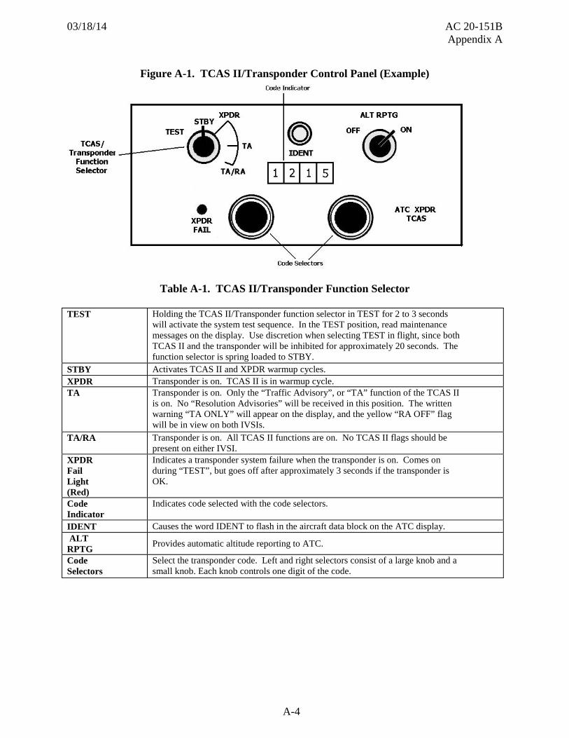
031814 AC 20-151B Appendix A
Figure A-7 TCAS II Examples ndash Modifications to Initial Corrective RAs
A-12
031814 AC 20-151B Appendix A
SECTION I ndash LIMITATIONS
(1) Pilots are authorized to deviate from their current ATC clearance to comply with a TCAS II resolution advisory (RA)
(2) Maneuvers based solely on a traffic advisory (TA) or on information displayed on the traffic display are not authorized
SECTION II - EMERGENCY PROCEDURES
(1) No change from basic airplane flight manual
SECTION III ndash PROCEDURES
(1) TCAS II Flight Procedures
Compliance with a TCAS II resolution advisory (RA) is necessary unless the pilot considers it unsafe to do so or unless the pilot has information about the cause of the RA and can maintain safe separation for example visual acquisition of and safe separation from a nearby aircraft on a parallel approach
NOTE CAUTION Once a non-crossing RA has been issued safe operation could be compromised if current vertical speed is changed except as necessary to comply with the RA This is because TCAS II-to-TCAS II coordination may be in progress with the intruder airplane and any change in vertical speed that does not comply with the RA may negate the effectiveness of the other airplanersquos compliance with its RA
NOTE WARNING Noncompliance with a crossing RA by one airplane may result in reduced vertical separation therefore safe horizontal separation must also be assured by visual means
Because of the limited number of inputs to TCAS II for airplane performance inhibits in some instances where inhibiting RAs may be appropriate it is not possible to do so In these cases TCAS II may command maneuvers that may significantly reduce stall margins or result in stall warning Therefore the stall warning stick shaker must be respected when following an RA Conditions where this may occur include
(a) Bank angle in excess of 15 degrees
(b) One engine inoperative
(c) Abnormal configurations such as landing gear not retractable etc
(d) Leaving airplane in inappropriate configurations when climb RA occurs
A-13
031814 AC 20-151B Appendix A
(e) Operation at airports outside of 0 to 5300 feet MSL or temperatures outside of ISA plusmn50degF
(f) Speeds below normal operating speeds
(g) Buffet margin less than 03 g
The TCAS II RA algorithms are based on the pilot initiating the initial 025 g acceleration maneuver within approximately 5 seconds Pilot response is expected within approximately 25 seconds if an additional RA is issued (The increase rate and rate reversal RAs are based on a 035 g acceleration maneuver) Because of these requirements and the rate limits of the autopilots all RA responses must be hand-flown and not with the autopilot or autothrottles engaged
NOTE Evasive maneuvering should be limited to the minimum required to comply with the RA Excessive responses to RAs are not desirable or appropriate because of other potential traffic and ATC consequences From level flight proper response to an RA typically results in an overall altitude deviation of 300 to 500 feet in order to successfully resolve a traffic conflict
Modified advisories are posted after the response to an initial advisory has been completed and the TCAS II airplane is projected to have adequate altitude separation from the intruder The initial RA is said to weaken indicating a return towards the original flight path or clearance is allowed When the initial advisory weakens the green arc is repositioned to indicate level flight the magnitude of the red arc decreased and ldquoLEVEL OFF LEVEL OFFrdquo is announced The modified RA indicates a return to level flight so that the altitude displacement in response to the initial RA can be minimized This RA will remain displayed until the ldquoCLEAR OF CONFLICTrdquo aural annunciation is issued Following the weakening advisory will greatly reduce the ultimate altitude deviation caused by the original corrective resolution advisory
If a ldquoCLIMBrdquo RA is issued while in the landing configuration initiate normal go-around procedures
NOTE Initiating go-around procedure for a ldquoCLIMBrdquo RA does not mandate a missed approach It is intended to ensure the airplane is properly configured for the TCAS II maneuver In most cases the TCAS II event will be resolved with only minor deviation to the intended flight path and sufficient time and altitude may exist to recover safely to the desired flight path
The pilot should not initiate evasive maneuvers using information from the traffic display only or on a traffic advisory (TA) only without visually sighting the traffic These displays and advisories are intended only for assistance in visually locating the traffic and lack the flight path trends necessary for use in evasive maneuvering However unnecessary resolution advisories can be issued by TCAS II when other aircraft are operating at an altitude adjacent to the one that has been assigned to the climbing or descending TCAS aircraft When climbing or descending
A-14
031814 AC 20-151B Appendix A
in an environment where these unnecessary advisories are considered likely to occur (based on either airspace design air traffic communications visual acquisition or utilization of traffic displays) a reduction in vertical velocity is recommended until reaching the assigned altitude As appropriate the vertical velocity should be reduced to a rate between 500 and 1500 ftmin when approaching an altitude between 1000 and 2000 ft above or below the altitude assigned in the ATC instruction or clearance
After deviating from an ATC clearance or instruction in response to a TCAS II RA notify ATC of the deviation as soon as possible
Following a TCAS II ldquoCLEAR OF CONFLICTrdquo advisory the pilot should expeditiously return to the applicable ATC clearance unless otherwise directed by ATC
NOTE The threat aircraft track or altitude information can be lost during an RA If so the RA will terminate without a ldquoCLEAR OF CONFLICTrdquo annunciation
(2) TCAS II Operation
Pilot-Initiated TCAS II self-test
(a) The TCAS II should be tested using the pilot-initiated self-test feature during cockpit preparation A successful test is indicated by (provide test results from particular TCAS II system)
(b) Use of the self-test function in flight will inhibit TCAS II operation for up to (provide time for a particular TCAS II system) seconds
(c) The ATC transponder will not function during some portion of the self-test sequence
(d) All aircraft systems providing information to TCAS II must be operating in their normal mode during the Self-Test
Ground Operation
(a) When equipped with a TSO-C119c or earlier TCAS II unit
(1) To preclude unnecessary transponder interrogations and possible interference with ground surveillance systems do not activate TCAS (TA or TARA mode) until taking the active runway for departure Selection of XPDR is adequate for ATC and nearby Automatic Dependent Surveillance-Broadcast equipped aircraft to ldquoseerdquo the aircraft while taxiing on the airport surface
(2) After landing and clearing of the runway de-select from TA or TARA mode Select XPNDR while taxiing to the ramp area Upon shutdown select STBY on the transponder
A-15
031814 AC 20-151B Appendix A
(b) When equipped with a TSO-C119d or later TCAS unit
(1) To preclude unnecessary transponder interrogations and possible interference with ground surveillance systems do not activate TCAS (TA or TARA mode) until taking the active runway for departure Selection of XPDR is adequate for ATC and nearby Automatic Dependent Surveillance-Broadcast equipped aircraft to ldquoseerdquo the aircraft while taxiing on the airport surface
NOTE The TA symbol will not be annunciated for any target while own-ship is on the ground when TA or TARA mode is selected
(2) After landing and clearing of the runway de-select from TA or TARA mode Select XPNDR while taxiing to the ramp area Upon shutdown select STBY on the transponder
A-16
031814 AC 20-151B Appendix A
TA Mode
(a) The TA position should only be used to preclude unnecessary RAs when intentionally operating near other aircraft such as to closely spaced parallel runways (less than 1200 feet apart)
(b) In TA mode RAs will not be issued
WX-ONLY Mode
(a) When WX-ONLY mode is selected traffic information traffic advisories and resolution advisories are inhibited on the weather radarscope Therefore this mode should be used only in the event TCAS interferes with weather information (This example is to show the kind of procedure to be developed Procedures will vary depending upon installation such as pop-up display modes PFDND implementation etc)
(3) TCAS II System Characteristics
(a) ldquoCLIMBrdquo RAs are inhibited with flaps greater than XX degrees
(b) When below 1000 feet AGL the TCAS II will automatically switch into the TA only mode
(c) ldquoINCREASE CLIMBrdquo RAs are inhibited with flaps greater than XX degrees
(d) ldquoDESCENDrdquo RAs are inhibited below 1200 feet AGL while climbing and below 1000 feet AGL while descending
(e) ldquoINCREASE DESCENTrdquo RAs are inhibited below 1450 feet AGL
(f) Voice messages are inhibited below 600 feet AGL while climbing and below 400 feet AGL while descending
(g) The TCAS II surveillance may not function at distances less than 900 feet
(h) During windshear andor GPWSTAWS warnings TCAS II switches automatically into a TA only mode with aural annunciation inhibited In this mode RAs are not issued and current RAs become TAs The TCAS II remains in TA Only mode for 10 seconds after the windshear or GPWSTAWS warning is removed TCAS II aural annunciations are enabled immediately following the removal of the windshear or GPWSTAWS warning aural annunciation
A-17
031814 AC 20-151B Appendix A
(4) TCAS II Abnormal Procedures
NOTE These examples are to show the kinds of abnormal procedures to be developed Procedures will vary depending upon the installation such as dual Mode S and so forth
RA OFF Flag in IVSI
(a) Verify TCAS IItransponder function selector is in TARA position
(b) If TARA is selected and ldquoRA OFFrdquo flag is in view then the pilot with the operable IVSI (flag not in view) should be the pilot flying
AMBER FLAG in IVSI
(a) Check XPDR FAIL light
(b) If OFF select other altitude source
(c) If ON select alternate ATCRBS transponder (TCAS II will no longer be available)
XPDR FAIL Light Illuminated
(a) Select alternate ATCRBS transponder (TCAS II will no longer be available)
Hybrid Surveillance Failure Annunciation
(a) For installations that are capable of annunciating hybrid surveillance failures to the pilot
(1) Make a logbook entry to record the failure No other crew action is required TCAS continues to provide traffic annunciation and collision avoidance protection even when hybrid surveillance has failed
SECTION IV ndash PERFORMANCE
(a) No change from basic airplane flight manual
A-18
031814 AC 20-151B Appendix B
Appendix B Transponder Ground Tests amp Evaluations
1 Tests and Evaluations Using a suitable calibrated transponder test set conduct the following tests
NOTE CAUTION When conducting any ground testing of the transponder or TCAS system you must prevent being a source of interference to ATC or other TCAS aircraft operating in the area Ground maintenance checks or ramp testing (such as altimetry or bearing accuracy testing) can cause data to be transmitted which produce false targets for the ground ATC surveillance systems or airborne TCAS aircraft These false indications of ldquointruder aircraftrdquo could result in unnecessary ATC communications and possibly in TCAS induced aircraft maneuvers Therefore conduct such testing in coordination with ATC and use antenna shielding (that is transmission absorption covers or caps) to prevent test data that could generate false intruder information from being transmitted Using high-powered hangar-mounted transponders to conduct ramp testing is NOT an acceptable means for conducting either TCAS or transponder ramp testing
a Mode Test Identifies modes of operation Interrogations are made in Modes A C and S (uplink format 11) to determine which modes the transponder replies to These are the modes tested during the Auto Test sequence
b Reply Delay Interrogates with valid modes and verifies Reply delay minus Range delay (average of best 8 out of 13 replies) equals
(1) 12800 micros (plusmn025 micros) for Mode S
(2) 300 micros (plusmn050 micros) for ATCRBS
c Reply Jitter Interrogates with valid modes and verifies using best 8 out of 13 replies Reply Jitter (changes In Reply Delay) is less than or equal to
(1) 005 micros for Mode S
(2) 006 micros for Intermode (All-Call)
(3) 010 micros for ATCRBS
B-1
031814 AC 20-151B Appendix B
d ATCRBS Reply Interrogates with ATCRBS (Modes A and C) interrogations and verifies
(1) F1 to F2 spacing is 203 micros (plusmn010 micros)
(2) F1 and F2 pulse width between the 05 amplitude point on the leading and trailing edge is 045 micros (plusmn010 micros)
e SLS Level Interrogates with valid ATCRBS Interrogations including P2 pulse Interrogations are conducted with P2 level at -9 dB and then again at 0 dB Test verifies
(1) Transponder does not reply when P2 level is at 0 dB (UUT is suppressed)
(2) Transponder replies when P2 level is at -9 dB (UUT is not suppressed)
f ATCRBS-Only All-Call Interrogates with an ATCRBS-only All-Call and verifies
(1) If Mode S is valid no reply is received from a Mode S transponder
(2) If no Mode S reply is received from an ATCRBS transponder
g Mode S All-Call Interrogates with the ATCRBS (mode A) Mode S All-Call Address received in downlink format (DF) 11 is then used in an uplink format (UF) 4 interrogation to solicit a DF4 reply The address received is decoded and compared with the address sent
h Invalid ICAO 24-bit aircraft address Interrogates with Mode S interrogations using two addresses different from the address determined by the Mode S All-Call UF11 Test verifies no reply is received Addresses used are one greater and 256 greater than the correct address
i SPR OnOff Interrogates with a Mode S interrogation with the Synchronous Phase Reversal (SPR) on verifying correct reply is received Then same interrogation is sent again with the SPR off verifying no reply is received
j Mode S UF0 Interrogates with Mode S uplink format 0 (Short air-to-air surveillance ACAS) verifying reply is received that has correct altitude (compared with Mode C altitude) address (compared with Mode Test address) and format
k Mode S UF4 Interrogates with Mode S uplink format 4 (Surveillance altitude request) verifying reply is received that has correct altitude (compared with Mode C altitude) address (compared with Mode Test address) and format
l Mode S UF5 Interrogates with Mode S uplink format 5 (Surveillance identity request) verifying reply is received that has correct identity (compared with Mode A identity) address (compared with Mode Test address) and format
B-2
031814 AC 20-151B Appendix B
m Mode S UF11 Interrogates with Mode S uplink format 11 verifying reply is received that has correct address (compared with Mode Test address) and format
n Mode S UF16 Interrogates with Mode S uplink format 16 (Long air-to-air surveillance ACAS) verifying reply if received has correct altitude (compared with the Mode C altitude) address (compared with Mode Test address) and format No reply to UF16 does not fail Mode S in Auto Test
o Mode S UF20 Interrogates with Mode S uplink format 20 (Comm A altitude request) verifying reply received has correct altitude (compared with Mode C altitude) address (compared with Mode Test address) and format No reply to UF20 does not fail Mode S in Auto Test
p Mode S UF21 Interrogates with Mode S uplink format 21 (Comm A identity request) verifying reply received has correct identity (compared with Mode A identity) address (compared with Mode Test address) and format No reply to UF21 does not fail Mode S in Auto Test
q Acquisition Squitter Verifies squitters are being received from the UUT every 08 to 12 seconds
r Frequency Verifies frequency of transponder is 1090 MHz (plusmn frequency tolerance as specified by equipment manufacturer) Frequency is displayed in the Auto Test screen
s Diversity Verifies diversity isolation (power level difference between UUT ldquoOnrdquo antenna squitters and ldquoOffrdquo antenna squitters) is greater than or equal to 20 dB Diversity isolation is displayed in Auto Test screen
NOTE To ensure gt=20 dB dynamic range test must be run within 50 feet (1524 meters) of UUT antenna being tested
t MTL Difference Verifies Receiver Sensitivity (MTL) to Mode A interrogations equals MTL to Mode C interrogations (plusmn10 dB)
u Altitude Reporting Verifies the reported altitude in the AC field of DF0 DF4 D16 and D20 corresponds to the value provided from the on-board altitude source to the transponder and is reported with the quantization indicated by the Q bit in the AC field For aircraft with 25 foot or better pressure altitude sources pressure altitude information should be reported in 25shyfoot increments Pressure altitude data obtained from a source with larger than 25-foot resolution must not be reported using 25-foot increments
NOTE To ensure the correct reporting of altitude with the proper quantization the aircraft altitude must be incremented over a 300-foot range in 25 foot increments
B-3
031814 AC 20-151B Appendix C
Appendix C Background
1 Early TCAS The airline industry has been working with the Air Transport Association of America (ATA) since 1955 toward a collision avoidance system It was not until the midshy1970s however that research centered on using signals from ATCRBS airborne transponders as the cooperative element of a collision avoidance system This technical approach allows a collision avoidance capability on the flight deck which is independent of the ground system In 1981 the FAA announced our decision to implement an aircraft collision avoidance concept called the Traffic Alert and Collision Avoidance System (TCAS) The concept is based upon agency and industry development efforts in the areas of beacon based collision avoidance systems and air-to-air discrete address communications techniques utilizing Mode S airborne transponder message formats
a A short time later prototypes of TCAS II were installed on two Piedmont Airlines Boeing 727 aircraft and were flown on regularly scheduled flights Although the displays were located outside the view of the flight crew and seen only by trained observers these tests did provide valuable information on the frequency and circumstances of alerts and their potential for interaction with the ATC system On a follow-on phase II program a later version of TCAS II was installed on a single Piedmont Airlines Boeing 727 and the system was certified in April 1986 then subsequently approved for operational evaluation in early 1987 Since the equipment was not developed to full standards the system was only operated in visual meteorological conditions Although the flight crew operated the system the evaluation was primarily for the purpose of data collection and its correlation with flight crew and observer observation and response
b Later versions of TCAS II manufactured by BendixKing Air Transport Avionics Division were installed and approved on United Airlines airplanes in early 1988 Similar units manufactured by Honeywell were installed and approved on Northwest Airlines airplanes in late 1988 This limited installation program operated TCAS II units approved for operation as a full-time system in both visual and instrument meteorological conditions on three different aircraft types The operational evaluation programs continued through 1988 to validate the operational suitability of the systems
2 Recent TCAS Developments
a Since the early 1990s an operational evaluation known as the TCAS Transition Program (TTP) collected and analyzed data on the performance and use of TCAS II in both the US National Airspace System (NAS) and in other airspace worldwide As a result of these analyses changes to TCAS II were developed tested and implemented in the early to mid 1990s These changes collectively known as TCAS II V70 were implemented by industry in the late 1990s TCAS II V70 complies with the International Civil Aviation Organization (ICAO) Standards and Recommended Practices (SARP) for ACAS II TCAS II V70 is mandated for carriage in Australia India and certain European countries and was mandated for carriage in 2003 by ICAO In addition if you operate an aircraft that is equipped with TCAS II in RVSM airspace it must be a TCAS II that meets TSO-C119b (V70) or a later version
C-1
031814 AC 20-151B Appendix C
b Investigation of operational problems resulted in changes to TCAS II V70 The changes resulting from that investigation resulted in TCAS II V71
c While developing corrective action for the operational problems the Federal Aviation Administration (FAA) along with industry representatives decided to develop performance standards for TCAS II Hybrid Surveillance That work resulted in creation of RTCADO-300 Minimum Operational Performance Standards (MOPS) for Traffic Alert and Collision Avoidance System II (TCAS II) Hybrid Surveillance
C-2
031814 AC 20-151B Appendix D
Appendix D Related Documents
1 14 CFR Parts You can apply current portions of 14 CFR for the design substantiation certification and operational approval of TCAS II and Mode S transponders Sections prescribing requirements for these types of systems are listed below Order copies of 14 CFR Parts 21 23 25 27 29 43 91 121 and 135 from the Superintendent of Documents Government Printing Office Washington DC 20402-9325 telephone (202) 512-1800 fax (202) 512-2250 You can also get copies from the Government Printing Office (GPO) electronic CFR Internet website at httpwwwgpoaccessgovcfr
a 14 CFR sect 25301 Loads
b 14 CFR sect 25303 Factor of safety
c 14 CFR sect 25305 Strength and deformation
d 14 CFR sect 25561 General
e 14 CFR sect 25603 Materials
f 14 CFR sect 25609 Protection of structure
g 14 CFR sect 25629 Aeroelastic stability requirements
h 14 CFR sect 25869 Fire protection systems
i 14 CFR sect 251301 Function and installation
j 14 CFR sect 251302 Installed systems and equipment for use by the flightcrew
k 14 CFR sect 251303 Flight and navigation instruments
l 14 CFR sect 251307 Miscellaneous equipment
m 14 CFR sect 251309 Equipment systems and installations
n 14 CFR sect 251316 System Lightning Protection
o 14 CFR sect 251317 High-intensity Radiated Field (HIRF) Protection
p 14 CFR sect 251321 Arrangement and visibility
q 14 CFR sect 251322 Warning caution and advisory lights
r 14 CFR sect 251331 Instruments using a power supply
s 14 CFR sect 251333 Instrument systems
t 14 CFR sect 251335 Flight director systems
u 14 CFR sect 251351 Electrical Systems and Equipment General
v 14 CFR sect 251353 Electrical equipment and installations
w 14 CFR sect 251355 Distribution system
x 14 CFR sect 251357 Circuit protective devices
D-1
031814 AC 20-151B Appendix D
y 14 CFR sect 251381 Instrument lights
z 14 CFR sect 251431 Electronic equipment
aa 14 CFR sect 251541 Markings and Placards General
bb 14 CFR sect 251581 Airplane Flight Manual General
cc 14 CFR sect 251585 Operating procedures
NOTE References to 14 CFR part 25 are appropriate when installing TCAS II on transport category airplanes When TCAS II is to be certified for non-transport category airplanes use the equivalents to the above 14 CFR part 25 sections in other parts of the regulations
2 FAA ACs You will find a current list of ACs on the FAA Internet website httpwwwfaagovregulations_policiesadvisory_circulars
a AC 20-131A Airworthiness Approval of Traffic Alert and Collision Avoidance Systems (TCAS II) and associated Mode S Transponders
b AC 20-115 Radio Technical Commission on Aeronautics (RTCA) Document DOshy178B
c AC 251309-1A System Design and Analysis
d AC 25-11A Electronic Flight Deck Displays
e AC 120-55C Air Carrier Operational Approval and Use of TCAS II
3 FAA TSOs You will find a current list of TSOs on the FAA Internet website Regulatory and Guidance Library at httprglfaagov You will also find the TSO Index of Articles at the same site
a TSO-C112d Air Traffic Control Radar Beacon SystemMode Select (ATCRBSMode S) Airborne Equipment
b TSO-C119d Traffic Alert and Collision Avoidance System (TCAS) Airborne Equipment TCAS II With Hybrid Surveillance Functionality
4 FAA Other You will find this related information on the FAA Internet website Regulatory and Guidance Library at httprglfaagov The document is posted adjacent to the links for AC 20-151 and TSO-C119
a Introduction to TCAS II V71 Feb 28 2011
D-2
031814 AC 20-151B Appendix D
5 RTCA Inc Publications Order RTCA documents from RTCA Inc 1828 L Street NW Suite 805 Washington DC 20036 or order online at wwwrtcaorg
a RTCADO-160G Environmental Conditions and Test Procedures for Airborne Equipment dated December 12 2010
b RTCADO-178B Software Considerations in Airborne Systems and Equipment Certifications dated December 1 1992
c RTCADO-181E (or later revision) Minimum Operational Performance Standards for Air Traffic Control Radar Beacon SystemMode Select (ATCRBSMode S) Airborne Equipment dated March 17 2011
d RTCADO-185A Minimum Operational Performance Standards for Traffic Alert and Collision Avoidance Systems II (TCAS II) dated December 16 1997
e RTCADO-185B Minimum Operational Performance Standards for Traffic Alert and Collision Avoidance Systems II (TCAS II) dated June 19 2008
f RTCADO-185B Minimum Operational Performance Standards for Traffic Alert and Collision Avoidance Systems II (TCAS II) Version 71 Change 1 dated Jul 1 2009
g RTCADO-185B Minimum Operational Performance Standards for Traffic Alert and Collision Avoidance Systems II (TCAS II)Version 71 dated Mar 20 2013
h RTCADO-300A Minimum Operational Performance Standards for Traffic Alert and Collision Avoidance System II (TCAS II) Hybrid Surveillance dated Mar 20 2013
6 SAE International Order SAE documents from SAE International 400 Commonwealth Drive Warrendale PA 15096-0001 telephone (724) 776-4970 fax (724) 776-0790 Also order copies online at wwwsaeorg
a ARP 926B FaultFailure Analysis Procedure dated June 11 1997
b ARP 1834A FaultFailure Analysis for Digital Systems and Equipment dated June 1 1997
c ARP 41027 Electronic Displays dated July 1 1988
d ARP 41028 Flight Deck Head-Up Displays dated November 1 1998
e ARP 4754 Certification Considerations for Highly Integrated or Complex Aircraft Systems dated November 1 1996
f ARP 4761 Guidelines and Methods for Conducting the Safety Assessment Process on Civil Airborne Systems and Equipment dated December 1 1996
D-3
031814 AC 20-151B Appendix D
7 AERONAUTICAL RADIO INC (ARINC) Publications are available from ARINC 2551 Riva Road Annapolis Maryland 21401 telephone 1-800-633-6882 or online at wwwarinccom
a ARINC 718( ) Mark 3 Air Traffic Control Transponder (ATCRBSMODE S)
b ARINC 735( ) Mark 2 Traffic Alert And Collision Avoidance System (TCAS)
8 International Civil Aviation Organization (ICAO) Publications are available from ICAO Attention Customer Service unit 999 University Street Montreal Quebec Canada H3C5H7 telephone +1 514-954-8022 facsimile 514-954-6769 sitatex YULCAYA email salesicaoint or on line at httpwwwicaoint
a Airborne Collision Avoidance System (ACAS) Manual document 9863 First Edition dated 2006
9 JAA JAA documents transposed to publications of the European Aviation Safety Agency (EASA) are available on the EASA web site at wwweasaeuint JAA documents are also available on the EUROCONTROL site at wwweurocontrolint
a JAA Temporary Guidance Leaflet (TGL) 13 Revision 1
10 EASA Publications are available on the EASA web site at wwweasaeuint
a AMC 20-13 Certification of Mode S Transponder Systems for Enhanced Surveillance
D-4
031814 AC 20-151B Appendix E
Appendix E Definitions and Acronyms
1 Definitions a Active surveillance Using TCAS interrogations and subsequent replies to
update or acquire a TCAS track
b Advisory Message given to alert the flight crew of converging aircraft andor a potential collision
c Air traffic control radar beacon system (ATCRBS) Secondary surveillance radar system with ground based interrogators and airborne transponders capable of operation on Modes A and C
d Alert Indication (aural or visual) that informs the flight crew in a timely manner about converging aircraft or potential collision
e Automatic dependent surveillance broadcast (ADS-B) A function on an aircraft or vehicle that automatically broadcasts its own aircrafts identity state vector (horizontal and vertical position and velocity) associated quality and performance parameters (accuracy and integrity) and other information Broadcast links include the 1090 MHz extended squitter (ES) and the universal asynchronous transceiver (UAT) broadcast on 978MHz
f Coast Condition which occurs when TCAS II does not receive a reply to an interrogation from an intruder for which it has established a track resulting in the logic continuing the track based on previous track characteristics
g Corrective resolution advisory Advises the pilot to either deviate from current vertical speed such as CLIMB when the aircraft is level or to maintain an existing climb or descent rate
NOTE In TCAS II V70 and V71 a ldquoMaintain Rate RArdquo is classified as a corrective RA solely to provide a green fly-to arc or zone on a vertical speed indicator
h Discrete Separate complete and distinct signal
i Failure Inability of a system subsystem unit or part to perform within previously specified limits
j False advisory Advisory caused by a false track or TCAS II malfunction
k Fruit Intruder replies corrupted by the receipt of undesired transponder replies elicited by ground interrogators and other TCAS II interrogators
E-1
031814 AC 20-151B Appendix E
l Hybrid Surveillance Combined use of active and passive surveillance to update a TCAS track
m Incorrect resolution advisory RA occurring when a threat is present but because of a failure of the installed TCAS II Mode S transponder or associated sensors commands a maneuver that reduces separation to the threat
n Intruder Aircraft satisfying the TCAS II traffic advisory detection criteria
o Mode A Type of secondary surveillance radar (SSR) equipment or mode of operation that replies by selected 4096 code (nonaltitude) when interrogated
p Mode C Type of secondary surveillance radar (SSR) equipment or mode of operation that replies with aircraft altitude information when interrogated
q Mode S Type of secondary surveillance radar (SSR) equipment that replies to Mode A and Mode C ground interrogations a discrete address and other aircraft information in response to interrogations from the ground or air
r Other traffic Aircraft more than plusmn1200 feet vertical or 6 nautical miles (NM) from own aircraft that are neither RA nor TA
s Passive surveillance The use of airborne position messages to update a TCAS track
t Preventive resolution advisory Requires a pilot to avoid certain deviations from current vertical rate (for example a Do Not Climb RA when the aircraft is level)
u Proximate traffic Aircraft within 6 NM in range and within plusmn1200 feet vertically from own aircraft but does not meet the TCAS II thresholds of a TA or RA
v Resolution advisory Aural voice and display information provided by TCAS II to a flight crew advising that a particular maneuver should or should not be performed to attain or maintain minimum safe vertical separation from an intruder
w Resolution display Shows vertical guidance depicting areas to ldquofly tordquo andor avoid above or below the TCAS II equipped aircraft
x Sense A direction that an RA may take (either Climb or Descend) relative to the existing flight path of own aircraft
y Threat An intruder that satisfies the threat detection logic and thus requires an RA
z Track Estimated position and velocity of a single aircraft based on correlated surveillance data reports
E-2
031814 AC 20-151B Appendix E
aa Traffic Aircraft with an operating transponder capable of being tracked and displayed by a TCAS-equipped aircraft
bb Traffic advisory (TA) Aural voice and display information from TCAS II to a flight crew identifying the location of nearby traffic meeting certain minimum separation criteria
cc Traffic display Horizontal position of transponder-equipped aircraft relative to the TCAS II equipped aircraft
2 Acronyms Table E-1 Acronyms
Acronym Definition 14 CFR Title 14 of the Code of Federal Regulations ACARS Aircraft communications addressing and reporting system ADS-B Automatic dependent surveillance - broadcast AFM Airplane flight manual AFMS Airplane flight manual supplement AGL Above ground level ASR Airport surveillance radar AMC Acceptable Means of Compliance ATA Air Transport Association ATC Air traffic control ATCRBS Air traffic control radar beacon system CAS Collision avoidance algorithm or CAS logic CMC Central Maintenance Computer CRS CAS requirements specification dB Decibel EADI Electronic attitude display indicator EFIS Electronic flight instrument system EHSI Electronic horizontal situation indicators EMI Electromagnetic interference FAA Federal Aviation Administration FD Flight director FHA Functional hazard assessment FL Flight level
E-3
031814 AC 20-151B Appendix E
Table E-1 Acronyms (continued)
FMEA Failure modes and effects analysis FPM Feet Per Minute GPS Global positioning system GPWSTAWS Ground proximity warning systemterrain awareness warning system HUD Heads-up device ICAO International Civil Aviation Organization IVSI Instantaneous vertical speed indicators JAA Joint Aviation Authorities MHz Megahertz NAS National Aerospace System ND Navigation display NM Nautical mile PFD Primary flight display RVSM reduced vertical separation minimum RA Resolution advisory SARP Standards and Recommended Practices STC Supplemental type certificate TA Traffic advisory TC Type certificate TCAS II Traffic alert and collision avoidance system TSO Technical standard order TTP TCAS transition program Vmo Maximum operating limit speed
E-4
- Chapter 1 General Information
- Chapter 2 TCAS II System
-
- 2-10 Traffic Display
-
- Chapter 3 Test and Evaluation (Initial Approval)
- Chapter 4 Follow-on Approvals (STCs or Amended STC or Amended TC)
- Chapter 5 Airplane Flight Manual Supplement
-
- Appendix A Example TCAS II V71 AFMS
- Appendix B Transponder Ground Tests amp Evaluations
- Appendix C Background
- 2 Recent TCAS Developments
-
- Appendix D Related Documents
- Appendix E Definitions and Acronyms
-
031814 AC 20-151B Appendix A
SECTION I ndash LIMITATIONS
(1) Pilots are authorized to deviate from their current ATC clearance to comply with a TCAS II resolution advisory (RA)
(2) Maneuvers based solely on a traffic advisory (TA) or on information displayed on the traffic display are not authorized
SECTION II - EMERGENCY PROCEDURES
(1) No change from basic airplane flight manual
SECTION III ndash PROCEDURES
(1) TCAS II Flight Procedures
Compliance with a TCAS II resolution advisory (RA) is necessary unless the pilot considers it unsafe to do so or unless the pilot has information about the cause of the RA and can maintain safe separation for example visual acquisition of and safe separation from a nearby aircraft on a parallel approach
NOTE CAUTION Once a non-crossing RA has been issued safe operation could be compromised if current vertical speed is changed except as necessary to comply with the RA This is because TCAS II-to-TCAS II coordination may be in progress with the intruder airplane and any change in vertical speed that does not comply with the RA may negate the effectiveness of the other airplanersquos compliance with its RA
NOTE WARNING Noncompliance with a crossing RA by one airplane may result in reduced vertical separation therefore safe horizontal separation must also be assured by visual means
Because of the limited number of inputs to TCAS II for airplane performance inhibits in some instances where inhibiting RAs may be appropriate it is not possible to do so In these cases TCAS II may command maneuvers that may significantly reduce stall margins or result in stall warning Therefore the stall warning stick shaker must be respected when following an RA Conditions where this may occur include
(a) Bank angle in excess of 15 degrees
(b) One engine inoperative
(c) Abnormal configurations such as landing gear not retractable etc
(d) Leaving airplane in inappropriate configurations when climb RA occurs
A-13
031814 AC 20-151B Appendix A
(e) Operation at airports outside of 0 to 5300 feet MSL or temperatures outside of ISA plusmn50degF
(f) Speeds below normal operating speeds
(g) Buffet margin less than 03 g
The TCAS II RA algorithms are based on the pilot initiating the initial 025 g acceleration maneuver within approximately 5 seconds Pilot response is expected within approximately 25 seconds if an additional RA is issued (The increase rate and rate reversal RAs are based on a 035 g acceleration maneuver) Because of these requirements and the rate limits of the autopilots all RA responses must be hand-flown and not with the autopilot or autothrottles engaged
NOTE Evasive maneuvering should be limited to the minimum required to comply with the RA Excessive responses to RAs are not desirable or appropriate because of other potential traffic and ATC consequences From level flight proper response to an RA typically results in an overall altitude deviation of 300 to 500 feet in order to successfully resolve a traffic conflict
Modified advisories are posted after the response to an initial advisory has been completed and the TCAS II airplane is projected to have adequate altitude separation from the intruder The initial RA is said to weaken indicating a return towards the original flight path or clearance is allowed When the initial advisory weakens the green arc is repositioned to indicate level flight the magnitude of the red arc decreased and ldquoLEVEL OFF LEVEL OFFrdquo is announced The modified RA indicates a return to level flight so that the altitude displacement in response to the initial RA can be minimized This RA will remain displayed until the ldquoCLEAR OF CONFLICTrdquo aural annunciation is issued Following the weakening advisory will greatly reduce the ultimate altitude deviation caused by the original corrective resolution advisory
If a ldquoCLIMBrdquo RA is issued while in the landing configuration initiate normal go-around procedures
NOTE Initiating go-around procedure for a ldquoCLIMBrdquo RA does not mandate a missed approach It is intended to ensure the airplane is properly configured for the TCAS II maneuver In most cases the TCAS II event will be resolved with only minor deviation to the intended flight path and sufficient time and altitude may exist to recover safely to the desired flight path
The pilot should not initiate evasive maneuvers using information from the traffic display only or on a traffic advisory (TA) only without visually sighting the traffic These displays and advisories are intended only for assistance in visually locating the traffic and lack the flight path trends necessary for use in evasive maneuvering However unnecessary resolution advisories can be issued by TCAS II when other aircraft are operating at an altitude adjacent to the one that has been assigned to the climbing or descending TCAS aircraft When climbing or descending
A-14
031814 AC 20-151B Appendix A
in an environment where these unnecessary advisories are considered likely to occur (based on either airspace design air traffic communications visual acquisition or utilization of traffic displays) a reduction in vertical velocity is recommended until reaching the assigned altitude As appropriate the vertical velocity should be reduced to a rate between 500 and 1500 ftmin when approaching an altitude between 1000 and 2000 ft above or below the altitude assigned in the ATC instruction or clearance
After deviating from an ATC clearance or instruction in response to a TCAS II RA notify ATC of the deviation as soon as possible
Following a TCAS II ldquoCLEAR OF CONFLICTrdquo advisory the pilot should expeditiously return to the applicable ATC clearance unless otherwise directed by ATC
NOTE The threat aircraft track or altitude information can be lost during an RA If so the RA will terminate without a ldquoCLEAR OF CONFLICTrdquo annunciation
(2) TCAS II Operation
Pilot-Initiated TCAS II self-test
(a) The TCAS II should be tested using the pilot-initiated self-test feature during cockpit preparation A successful test is indicated by (provide test results from particular TCAS II system)
(b) Use of the self-test function in flight will inhibit TCAS II operation for up to (provide time for a particular TCAS II system) seconds
(c) The ATC transponder will not function during some portion of the self-test sequence
(d) All aircraft systems providing information to TCAS II must be operating in their normal mode during the Self-Test
Ground Operation
(a) When equipped with a TSO-C119c or earlier TCAS II unit
(1) To preclude unnecessary transponder interrogations and possible interference with ground surveillance systems do not activate TCAS (TA or TARA mode) until taking the active runway for departure Selection of XPDR is adequate for ATC and nearby Automatic Dependent Surveillance-Broadcast equipped aircraft to ldquoseerdquo the aircraft while taxiing on the airport surface
(2) After landing and clearing of the runway de-select from TA or TARA mode Select XPNDR while taxiing to the ramp area Upon shutdown select STBY on the transponder
A-15
031814 AC 20-151B Appendix A
(b) When equipped with a TSO-C119d or later TCAS unit
(1) To preclude unnecessary transponder interrogations and possible interference with ground surveillance systems do not activate TCAS (TA or TARA mode) until taking the active runway for departure Selection of XPDR is adequate for ATC and nearby Automatic Dependent Surveillance-Broadcast equipped aircraft to ldquoseerdquo the aircraft while taxiing on the airport surface
NOTE The TA symbol will not be annunciated for any target while own-ship is on the ground when TA or TARA mode is selected
(2) After landing and clearing of the runway de-select from TA or TARA mode Select XPNDR while taxiing to the ramp area Upon shutdown select STBY on the transponder
A-16
031814 AC 20-151B Appendix A
TA Mode
(a) The TA position should only be used to preclude unnecessary RAs when intentionally operating near other aircraft such as to closely spaced parallel runways (less than 1200 feet apart)
(b) In TA mode RAs will not be issued
WX-ONLY Mode
(a) When WX-ONLY mode is selected traffic information traffic advisories and resolution advisories are inhibited on the weather radarscope Therefore this mode should be used only in the event TCAS interferes with weather information (This example is to show the kind of procedure to be developed Procedures will vary depending upon installation such as pop-up display modes PFDND implementation etc)
(3) TCAS II System Characteristics
(a) ldquoCLIMBrdquo RAs are inhibited with flaps greater than XX degrees
(b) When below 1000 feet AGL the TCAS II will automatically switch into the TA only mode
(c) ldquoINCREASE CLIMBrdquo RAs are inhibited with flaps greater than XX degrees
(d) ldquoDESCENDrdquo RAs are inhibited below 1200 feet AGL while climbing and below 1000 feet AGL while descending
(e) ldquoINCREASE DESCENTrdquo RAs are inhibited below 1450 feet AGL
(f) Voice messages are inhibited below 600 feet AGL while climbing and below 400 feet AGL while descending
(g) The TCAS II surveillance may not function at distances less than 900 feet
(h) During windshear andor GPWSTAWS warnings TCAS II switches automatically into a TA only mode with aural annunciation inhibited In this mode RAs are not issued and current RAs become TAs The TCAS II remains in TA Only mode for 10 seconds after the windshear or GPWSTAWS warning is removed TCAS II aural annunciations are enabled immediately following the removal of the windshear or GPWSTAWS warning aural annunciation
A-17
031814 AC 20-151B Appendix A
(4) TCAS II Abnormal Procedures
NOTE These examples are to show the kinds of abnormal procedures to be developed Procedures will vary depending upon the installation such as dual Mode S and so forth
RA OFF Flag in IVSI
(a) Verify TCAS IItransponder function selector is in TARA position
(b) If TARA is selected and ldquoRA OFFrdquo flag is in view then the pilot with the operable IVSI (flag not in view) should be the pilot flying
AMBER FLAG in IVSI
(a) Check XPDR FAIL light
(b) If OFF select other altitude source
(c) If ON select alternate ATCRBS transponder (TCAS II will no longer be available)
XPDR FAIL Light Illuminated
(a) Select alternate ATCRBS transponder (TCAS II will no longer be available)
Hybrid Surveillance Failure Annunciation
(a) For installations that are capable of annunciating hybrid surveillance failures to the pilot
(1) Make a logbook entry to record the failure No other crew action is required TCAS continues to provide traffic annunciation and collision avoidance protection even when hybrid surveillance has failed
SECTION IV ndash PERFORMANCE
(a) No change from basic airplane flight manual
A-18
031814 AC 20-151B Appendix B
Appendix B Transponder Ground Tests amp Evaluations
1 Tests and Evaluations Using a suitable calibrated transponder test set conduct the following tests
NOTE CAUTION When conducting any ground testing of the transponder or TCAS system you must prevent being a source of interference to ATC or other TCAS aircraft operating in the area Ground maintenance checks or ramp testing (such as altimetry or bearing accuracy testing) can cause data to be transmitted which produce false targets for the ground ATC surveillance systems or airborne TCAS aircraft These false indications of ldquointruder aircraftrdquo could result in unnecessary ATC communications and possibly in TCAS induced aircraft maneuvers Therefore conduct such testing in coordination with ATC and use antenna shielding (that is transmission absorption covers or caps) to prevent test data that could generate false intruder information from being transmitted Using high-powered hangar-mounted transponders to conduct ramp testing is NOT an acceptable means for conducting either TCAS or transponder ramp testing
a Mode Test Identifies modes of operation Interrogations are made in Modes A C and S (uplink format 11) to determine which modes the transponder replies to These are the modes tested during the Auto Test sequence
b Reply Delay Interrogates with valid modes and verifies Reply delay minus Range delay (average of best 8 out of 13 replies) equals
(1) 12800 micros (plusmn025 micros) for Mode S
(2) 300 micros (plusmn050 micros) for ATCRBS
c Reply Jitter Interrogates with valid modes and verifies using best 8 out of 13 replies Reply Jitter (changes In Reply Delay) is less than or equal to
(1) 005 micros for Mode S
(2) 006 micros for Intermode (All-Call)
(3) 010 micros for ATCRBS
B-1
031814 AC 20-151B Appendix B
d ATCRBS Reply Interrogates with ATCRBS (Modes A and C) interrogations and verifies
(1) F1 to F2 spacing is 203 micros (plusmn010 micros)
(2) F1 and F2 pulse width between the 05 amplitude point on the leading and trailing edge is 045 micros (plusmn010 micros)
e SLS Level Interrogates with valid ATCRBS Interrogations including P2 pulse Interrogations are conducted with P2 level at -9 dB and then again at 0 dB Test verifies
(1) Transponder does not reply when P2 level is at 0 dB (UUT is suppressed)
(2) Transponder replies when P2 level is at -9 dB (UUT is not suppressed)
f ATCRBS-Only All-Call Interrogates with an ATCRBS-only All-Call and verifies
(1) If Mode S is valid no reply is received from a Mode S transponder
(2) If no Mode S reply is received from an ATCRBS transponder
g Mode S All-Call Interrogates with the ATCRBS (mode A) Mode S All-Call Address received in downlink format (DF) 11 is then used in an uplink format (UF) 4 interrogation to solicit a DF4 reply The address received is decoded and compared with the address sent
h Invalid ICAO 24-bit aircraft address Interrogates with Mode S interrogations using two addresses different from the address determined by the Mode S All-Call UF11 Test verifies no reply is received Addresses used are one greater and 256 greater than the correct address
i SPR OnOff Interrogates with a Mode S interrogation with the Synchronous Phase Reversal (SPR) on verifying correct reply is received Then same interrogation is sent again with the SPR off verifying no reply is received
j Mode S UF0 Interrogates with Mode S uplink format 0 (Short air-to-air surveillance ACAS) verifying reply is received that has correct altitude (compared with Mode C altitude) address (compared with Mode Test address) and format
k Mode S UF4 Interrogates with Mode S uplink format 4 (Surveillance altitude request) verifying reply is received that has correct altitude (compared with Mode C altitude) address (compared with Mode Test address) and format
l Mode S UF5 Interrogates with Mode S uplink format 5 (Surveillance identity request) verifying reply is received that has correct identity (compared with Mode A identity) address (compared with Mode Test address) and format
B-2
031814 AC 20-151B Appendix B
m Mode S UF11 Interrogates with Mode S uplink format 11 verifying reply is received that has correct address (compared with Mode Test address) and format
n Mode S UF16 Interrogates with Mode S uplink format 16 (Long air-to-air surveillance ACAS) verifying reply if received has correct altitude (compared with the Mode C altitude) address (compared with Mode Test address) and format No reply to UF16 does not fail Mode S in Auto Test
o Mode S UF20 Interrogates with Mode S uplink format 20 (Comm A altitude request) verifying reply received has correct altitude (compared with Mode C altitude) address (compared with Mode Test address) and format No reply to UF20 does not fail Mode S in Auto Test
p Mode S UF21 Interrogates with Mode S uplink format 21 (Comm A identity request) verifying reply received has correct identity (compared with Mode A identity) address (compared with Mode Test address) and format No reply to UF21 does not fail Mode S in Auto Test
q Acquisition Squitter Verifies squitters are being received from the UUT every 08 to 12 seconds
r Frequency Verifies frequency of transponder is 1090 MHz (plusmn frequency tolerance as specified by equipment manufacturer) Frequency is displayed in the Auto Test screen
s Diversity Verifies diversity isolation (power level difference between UUT ldquoOnrdquo antenna squitters and ldquoOffrdquo antenna squitters) is greater than or equal to 20 dB Diversity isolation is displayed in Auto Test screen
NOTE To ensure gt=20 dB dynamic range test must be run within 50 feet (1524 meters) of UUT antenna being tested
t MTL Difference Verifies Receiver Sensitivity (MTL) to Mode A interrogations equals MTL to Mode C interrogations (plusmn10 dB)
u Altitude Reporting Verifies the reported altitude in the AC field of DF0 DF4 D16 and D20 corresponds to the value provided from the on-board altitude source to the transponder and is reported with the quantization indicated by the Q bit in the AC field For aircraft with 25 foot or better pressure altitude sources pressure altitude information should be reported in 25shyfoot increments Pressure altitude data obtained from a source with larger than 25-foot resolution must not be reported using 25-foot increments
NOTE To ensure the correct reporting of altitude with the proper quantization the aircraft altitude must be incremented over a 300-foot range in 25 foot increments
B-3
031814 AC 20-151B Appendix C
Appendix C Background
1 Early TCAS The airline industry has been working with the Air Transport Association of America (ATA) since 1955 toward a collision avoidance system It was not until the midshy1970s however that research centered on using signals from ATCRBS airborne transponders as the cooperative element of a collision avoidance system This technical approach allows a collision avoidance capability on the flight deck which is independent of the ground system In 1981 the FAA announced our decision to implement an aircraft collision avoidance concept called the Traffic Alert and Collision Avoidance System (TCAS) The concept is based upon agency and industry development efforts in the areas of beacon based collision avoidance systems and air-to-air discrete address communications techniques utilizing Mode S airborne transponder message formats
a A short time later prototypes of TCAS II were installed on two Piedmont Airlines Boeing 727 aircraft and were flown on regularly scheduled flights Although the displays were located outside the view of the flight crew and seen only by trained observers these tests did provide valuable information on the frequency and circumstances of alerts and their potential for interaction with the ATC system On a follow-on phase II program a later version of TCAS II was installed on a single Piedmont Airlines Boeing 727 and the system was certified in April 1986 then subsequently approved for operational evaluation in early 1987 Since the equipment was not developed to full standards the system was only operated in visual meteorological conditions Although the flight crew operated the system the evaluation was primarily for the purpose of data collection and its correlation with flight crew and observer observation and response
b Later versions of TCAS II manufactured by BendixKing Air Transport Avionics Division were installed and approved on United Airlines airplanes in early 1988 Similar units manufactured by Honeywell were installed and approved on Northwest Airlines airplanes in late 1988 This limited installation program operated TCAS II units approved for operation as a full-time system in both visual and instrument meteorological conditions on three different aircraft types The operational evaluation programs continued through 1988 to validate the operational suitability of the systems
2 Recent TCAS Developments
a Since the early 1990s an operational evaluation known as the TCAS Transition Program (TTP) collected and analyzed data on the performance and use of TCAS II in both the US National Airspace System (NAS) and in other airspace worldwide As a result of these analyses changes to TCAS II were developed tested and implemented in the early to mid 1990s These changes collectively known as TCAS II V70 were implemented by industry in the late 1990s TCAS II V70 complies with the International Civil Aviation Organization (ICAO) Standards and Recommended Practices (SARP) for ACAS II TCAS II V70 is mandated for carriage in Australia India and certain European countries and was mandated for carriage in 2003 by ICAO In addition if you operate an aircraft that is equipped with TCAS II in RVSM airspace it must be a TCAS II that meets TSO-C119b (V70) or a later version
C-1
031814 AC 20-151B Appendix C
b Investigation of operational problems resulted in changes to TCAS II V70 The changes resulting from that investigation resulted in TCAS II V71
c While developing corrective action for the operational problems the Federal Aviation Administration (FAA) along with industry representatives decided to develop performance standards for TCAS II Hybrid Surveillance That work resulted in creation of RTCADO-300 Minimum Operational Performance Standards (MOPS) for Traffic Alert and Collision Avoidance System II (TCAS II) Hybrid Surveillance
C-2
031814 AC 20-151B Appendix D
Appendix D Related Documents
1 14 CFR Parts You can apply current portions of 14 CFR for the design substantiation certification and operational approval of TCAS II and Mode S transponders Sections prescribing requirements for these types of systems are listed below Order copies of 14 CFR Parts 21 23 25 27 29 43 91 121 and 135 from the Superintendent of Documents Government Printing Office Washington DC 20402-9325 telephone (202) 512-1800 fax (202) 512-2250 You can also get copies from the Government Printing Office (GPO) electronic CFR Internet website at httpwwwgpoaccessgovcfr
a 14 CFR sect 25301 Loads
b 14 CFR sect 25303 Factor of safety
c 14 CFR sect 25305 Strength and deformation
d 14 CFR sect 25561 General
e 14 CFR sect 25603 Materials
f 14 CFR sect 25609 Protection of structure
g 14 CFR sect 25629 Aeroelastic stability requirements
h 14 CFR sect 25869 Fire protection systems
i 14 CFR sect 251301 Function and installation
j 14 CFR sect 251302 Installed systems and equipment for use by the flightcrew
k 14 CFR sect 251303 Flight and navigation instruments
l 14 CFR sect 251307 Miscellaneous equipment
m 14 CFR sect 251309 Equipment systems and installations
n 14 CFR sect 251316 System Lightning Protection
o 14 CFR sect 251317 High-intensity Radiated Field (HIRF) Protection
p 14 CFR sect 251321 Arrangement and visibility
q 14 CFR sect 251322 Warning caution and advisory lights
r 14 CFR sect 251331 Instruments using a power supply
s 14 CFR sect 251333 Instrument systems
t 14 CFR sect 251335 Flight director systems
u 14 CFR sect 251351 Electrical Systems and Equipment General
v 14 CFR sect 251353 Electrical equipment and installations
w 14 CFR sect 251355 Distribution system
x 14 CFR sect 251357 Circuit protective devices
D-1
031814 AC 20-151B Appendix D
y 14 CFR sect 251381 Instrument lights
z 14 CFR sect 251431 Electronic equipment
aa 14 CFR sect 251541 Markings and Placards General
bb 14 CFR sect 251581 Airplane Flight Manual General
cc 14 CFR sect 251585 Operating procedures
NOTE References to 14 CFR part 25 are appropriate when installing TCAS II on transport category airplanes When TCAS II is to be certified for non-transport category airplanes use the equivalents to the above 14 CFR part 25 sections in other parts of the regulations
2 FAA ACs You will find a current list of ACs on the FAA Internet website httpwwwfaagovregulations_policiesadvisory_circulars
a AC 20-131A Airworthiness Approval of Traffic Alert and Collision Avoidance Systems (TCAS II) and associated Mode S Transponders
b AC 20-115 Radio Technical Commission on Aeronautics (RTCA) Document DOshy178B
c AC 251309-1A System Design and Analysis
d AC 25-11A Electronic Flight Deck Displays
e AC 120-55C Air Carrier Operational Approval and Use of TCAS II
3 FAA TSOs You will find a current list of TSOs on the FAA Internet website Regulatory and Guidance Library at httprglfaagov You will also find the TSO Index of Articles at the same site
a TSO-C112d Air Traffic Control Radar Beacon SystemMode Select (ATCRBSMode S) Airborne Equipment
b TSO-C119d Traffic Alert and Collision Avoidance System (TCAS) Airborne Equipment TCAS II With Hybrid Surveillance Functionality
4 FAA Other You will find this related information on the FAA Internet website Regulatory and Guidance Library at httprglfaagov The document is posted adjacent to the links for AC 20-151 and TSO-C119
a Introduction to TCAS II V71 Feb 28 2011
D-2
031814 AC 20-151B Appendix D
5 RTCA Inc Publications Order RTCA documents from RTCA Inc 1828 L Street NW Suite 805 Washington DC 20036 or order online at wwwrtcaorg
a RTCADO-160G Environmental Conditions and Test Procedures for Airborne Equipment dated December 12 2010
b RTCADO-178B Software Considerations in Airborne Systems and Equipment Certifications dated December 1 1992
c RTCADO-181E (or later revision) Minimum Operational Performance Standards for Air Traffic Control Radar Beacon SystemMode Select (ATCRBSMode S) Airborne Equipment dated March 17 2011
d RTCADO-185A Minimum Operational Performance Standards for Traffic Alert and Collision Avoidance Systems II (TCAS II) dated December 16 1997
e RTCADO-185B Minimum Operational Performance Standards for Traffic Alert and Collision Avoidance Systems II (TCAS II) dated June 19 2008
f RTCADO-185B Minimum Operational Performance Standards for Traffic Alert and Collision Avoidance Systems II (TCAS II) Version 71 Change 1 dated Jul 1 2009
g RTCADO-185B Minimum Operational Performance Standards for Traffic Alert and Collision Avoidance Systems II (TCAS II)Version 71 dated Mar 20 2013
h RTCADO-300A Minimum Operational Performance Standards for Traffic Alert and Collision Avoidance System II (TCAS II) Hybrid Surveillance dated Mar 20 2013
6 SAE International Order SAE documents from SAE International 400 Commonwealth Drive Warrendale PA 15096-0001 telephone (724) 776-4970 fax (724) 776-0790 Also order copies online at wwwsaeorg
a ARP 926B FaultFailure Analysis Procedure dated June 11 1997
b ARP 1834A FaultFailure Analysis for Digital Systems and Equipment dated June 1 1997
c ARP 41027 Electronic Displays dated July 1 1988
d ARP 41028 Flight Deck Head-Up Displays dated November 1 1998
e ARP 4754 Certification Considerations for Highly Integrated or Complex Aircraft Systems dated November 1 1996
f ARP 4761 Guidelines and Methods for Conducting the Safety Assessment Process on Civil Airborne Systems and Equipment dated December 1 1996
D-3
031814 AC 20-151B Appendix D
7 AERONAUTICAL RADIO INC (ARINC) Publications are available from ARINC 2551 Riva Road Annapolis Maryland 21401 telephone 1-800-633-6882 or online at wwwarinccom
a ARINC 718( ) Mark 3 Air Traffic Control Transponder (ATCRBSMODE S)
b ARINC 735( ) Mark 2 Traffic Alert And Collision Avoidance System (TCAS)
8 International Civil Aviation Organization (ICAO) Publications are available from ICAO Attention Customer Service unit 999 University Street Montreal Quebec Canada H3C5H7 telephone +1 514-954-8022 facsimile 514-954-6769 sitatex YULCAYA email salesicaoint or on line at httpwwwicaoint
a Airborne Collision Avoidance System (ACAS) Manual document 9863 First Edition dated 2006
9 JAA JAA documents transposed to publications of the European Aviation Safety Agency (EASA) are available on the EASA web site at wwweasaeuint JAA documents are also available on the EUROCONTROL site at wwweurocontrolint
a JAA Temporary Guidance Leaflet (TGL) 13 Revision 1
10 EASA Publications are available on the EASA web site at wwweasaeuint
a AMC 20-13 Certification of Mode S Transponder Systems for Enhanced Surveillance
D-4
031814 AC 20-151B Appendix E
Appendix E Definitions and Acronyms
1 Definitions a Active surveillance Using TCAS interrogations and subsequent replies to
update or acquire a TCAS track
b Advisory Message given to alert the flight crew of converging aircraft andor a potential collision
c Air traffic control radar beacon system (ATCRBS) Secondary surveillance radar system with ground based interrogators and airborne transponders capable of operation on Modes A and C
d Alert Indication (aural or visual) that informs the flight crew in a timely manner about converging aircraft or potential collision
e Automatic dependent surveillance broadcast (ADS-B) A function on an aircraft or vehicle that automatically broadcasts its own aircrafts identity state vector (horizontal and vertical position and velocity) associated quality and performance parameters (accuracy and integrity) and other information Broadcast links include the 1090 MHz extended squitter (ES) and the universal asynchronous transceiver (UAT) broadcast on 978MHz
f Coast Condition which occurs when TCAS II does not receive a reply to an interrogation from an intruder for which it has established a track resulting in the logic continuing the track based on previous track characteristics
g Corrective resolution advisory Advises the pilot to either deviate from current vertical speed such as CLIMB when the aircraft is level or to maintain an existing climb or descent rate
NOTE In TCAS II V70 and V71 a ldquoMaintain Rate RArdquo is classified as a corrective RA solely to provide a green fly-to arc or zone on a vertical speed indicator
h Discrete Separate complete and distinct signal
i Failure Inability of a system subsystem unit or part to perform within previously specified limits
j False advisory Advisory caused by a false track or TCAS II malfunction
k Fruit Intruder replies corrupted by the receipt of undesired transponder replies elicited by ground interrogators and other TCAS II interrogators
E-1
031814 AC 20-151B Appendix E
l Hybrid Surveillance Combined use of active and passive surveillance to update a TCAS track
m Incorrect resolution advisory RA occurring when a threat is present but because of a failure of the installed TCAS II Mode S transponder or associated sensors commands a maneuver that reduces separation to the threat
n Intruder Aircraft satisfying the TCAS II traffic advisory detection criteria
o Mode A Type of secondary surveillance radar (SSR) equipment or mode of operation that replies by selected 4096 code (nonaltitude) when interrogated
p Mode C Type of secondary surveillance radar (SSR) equipment or mode of operation that replies with aircraft altitude information when interrogated
q Mode S Type of secondary surveillance radar (SSR) equipment that replies to Mode A and Mode C ground interrogations a discrete address and other aircraft information in response to interrogations from the ground or air
r Other traffic Aircraft more than plusmn1200 feet vertical or 6 nautical miles (NM) from own aircraft that are neither RA nor TA
s Passive surveillance The use of airborne position messages to update a TCAS track
t Preventive resolution advisory Requires a pilot to avoid certain deviations from current vertical rate (for example a Do Not Climb RA when the aircraft is level)
u Proximate traffic Aircraft within 6 NM in range and within plusmn1200 feet vertically from own aircraft but does not meet the TCAS II thresholds of a TA or RA
v Resolution advisory Aural voice and display information provided by TCAS II to a flight crew advising that a particular maneuver should or should not be performed to attain or maintain minimum safe vertical separation from an intruder
w Resolution display Shows vertical guidance depicting areas to ldquofly tordquo andor avoid above or below the TCAS II equipped aircraft
x Sense A direction that an RA may take (either Climb or Descend) relative to the existing flight path of own aircraft
y Threat An intruder that satisfies the threat detection logic and thus requires an RA
z Track Estimated position and velocity of a single aircraft based on correlated surveillance data reports
E-2
031814 AC 20-151B Appendix E
aa Traffic Aircraft with an operating transponder capable of being tracked and displayed by a TCAS-equipped aircraft
bb Traffic advisory (TA) Aural voice and display information from TCAS II to a flight crew identifying the location of nearby traffic meeting certain minimum separation criteria
cc Traffic display Horizontal position of transponder-equipped aircraft relative to the TCAS II equipped aircraft
2 Acronyms Table E-1 Acronyms
Acronym Definition 14 CFR Title 14 of the Code of Federal Regulations ACARS Aircraft communications addressing and reporting system ADS-B Automatic dependent surveillance - broadcast AFM Airplane flight manual AFMS Airplane flight manual supplement AGL Above ground level ASR Airport surveillance radar AMC Acceptable Means of Compliance ATA Air Transport Association ATC Air traffic control ATCRBS Air traffic control radar beacon system CAS Collision avoidance algorithm or CAS logic CMC Central Maintenance Computer CRS CAS requirements specification dB Decibel EADI Electronic attitude display indicator EFIS Electronic flight instrument system EHSI Electronic horizontal situation indicators EMI Electromagnetic interference FAA Federal Aviation Administration FD Flight director FHA Functional hazard assessment FL Flight level
E-3
031814 AC 20-151B Appendix E
Table E-1 Acronyms (continued)
FMEA Failure modes and effects analysis FPM Feet Per Minute GPS Global positioning system GPWSTAWS Ground proximity warning systemterrain awareness warning system HUD Heads-up device ICAO International Civil Aviation Organization IVSI Instantaneous vertical speed indicators JAA Joint Aviation Authorities MHz Megahertz NAS National Aerospace System ND Navigation display NM Nautical mile PFD Primary flight display RVSM reduced vertical separation minimum RA Resolution advisory SARP Standards and Recommended Practices STC Supplemental type certificate TA Traffic advisory TC Type certificate TCAS II Traffic alert and collision avoidance system TSO Technical standard order TTP TCAS transition program Vmo Maximum operating limit speed
E-4
- Chapter 1 General Information
- Chapter 2 TCAS II System
-
- 2-10 Traffic Display
-
- Chapter 3 Test and Evaluation (Initial Approval)
- Chapter 4 Follow-on Approvals (STCs or Amended STC or Amended TC)
- Chapter 5 Airplane Flight Manual Supplement
-
- Appendix A Example TCAS II V71 AFMS
- Appendix B Transponder Ground Tests amp Evaluations
- Appendix C Background
- 2 Recent TCAS Developments
-
- Appendix D Related Documents
- Appendix E Definitions and Acronyms
-

031814 AC 20-151B Appendix A
in an environment where these unnecessary advisories are considered likely to occur (based on either airspace design air traffic communications visual acquisition or utilization of traffic displays) a reduction in vertical velocity is recommended until reaching the assigned altitude As appropriate the vertical velocity should be reduced to a rate between 500 and 1500 ftmin when approaching an altitude between 1000 and 2000 ft above or below the altitude assigned in the ATC instruction or clearance
After deviating from an ATC clearance or instruction in response to a TCAS II RA notify ATC of the deviation as soon as possible
Following a TCAS II ldquoCLEAR OF CONFLICTrdquo advisory the pilot should expeditiously return to the applicable ATC clearance unless otherwise directed by ATC
NOTE The threat aircraft track or altitude information can be lost during an RA If so the RA will terminate without a ldquoCLEAR OF CONFLICTrdquo annunciation
(2) TCAS II Operation
Pilot-Initiated TCAS II self-test
(a) The TCAS II should be tested using the pilot-initiated self-test feature during cockpit preparation A successful test is indicated by (provide test results from particular TCAS II system)
(b) Use of the self-test function in flight will inhibit TCAS II operation for up to (provide time for a particular TCAS II system) seconds
(c) The ATC transponder will not function during some portion of the self-test sequence
(d) All aircraft systems providing information to TCAS II must be operating in their normal mode during the Self-Test
Ground Operation
(a) When equipped with a TSO-C119c or earlier TCAS II unit
(1) To preclude unnecessary transponder interrogations and possible interference with ground surveillance systems do not activate TCAS (TA or TARA mode) until taking the active runway for departure Selection of XPDR is adequate for ATC and nearby Automatic Dependent Surveillance-Broadcast equipped aircraft to ldquoseerdquo the aircraft while taxiing on the airport surface
(2) After landing and clearing of the runway de-select from TA or TARA mode Select XPNDR while taxiing to the ramp area Upon shutdown select STBY on the transponder
A-15
031814 AC 20-151B Appendix A
(b) When equipped with a TSO-C119d or later TCAS unit
(1) To preclude unnecessary transponder interrogations and possible interference with ground surveillance systems do not activate TCAS (TA or TARA mode) until taking the active runway for departure Selection of XPDR is adequate for ATC and nearby Automatic Dependent Surveillance-Broadcast equipped aircraft to ldquoseerdquo the aircraft while taxiing on the airport surface
NOTE The TA symbol will not be annunciated for any target while own-ship is on the ground when TA or TARA mode is selected
(2) After landing and clearing of the runway de-select from TA or TARA mode Select XPNDR while taxiing to the ramp area Upon shutdown select STBY on the transponder
A-16
031814 AC 20-151B Appendix A
TA Mode
(a) The TA position should only be used to preclude unnecessary RAs when intentionally operating near other aircraft such as to closely spaced parallel runways (less than 1200 feet apart)
(b) In TA mode RAs will not be issued
WX-ONLY Mode
(a) When WX-ONLY mode is selected traffic information traffic advisories and resolution advisories are inhibited on the weather radarscope Therefore this mode should be used only in the event TCAS interferes with weather information (This example is to show the kind of procedure to be developed Procedures will vary depending upon installation such as pop-up display modes PFDND implementation etc)
(3) TCAS II System Characteristics
(a) ldquoCLIMBrdquo RAs are inhibited with flaps greater than XX degrees
(b) When below 1000 feet AGL the TCAS II will automatically switch into the TA only mode
(c) ldquoINCREASE CLIMBrdquo RAs are inhibited with flaps greater than XX degrees
(d) ldquoDESCENDrdquo RAs are inhibited below 1200 feet AGL while climbing and below 1000 feet AGL while descending
(e) ldquoINCREASE DESCENTrdquo RAs are inhibited below 1450 feet AGL
(f) Voice messages are inhibited below 600 feet AGL while climbing and below 400 feet AGL while descending
(g) The TCAS II surveillance may not function at distances less than 900 feet
(h) During windshear andor GPWSTAWS warnings TCAS II switches automatically into a TA only mode with aural annunciation inhibited In this mode RAs are not issued and current RAs become TAs The TCAS II remains in TA Only mode for 10 seconds after the windshear or GPWSTAWS warning is removed TCAS II aural annunciations are enabled immediately following the removal of the windshear or GPWSTAWS warning aural annunciation
A-17
031814 AC 20-151B Appendix A
(4) TCAS II Abnormal Procedures
NOTE These examples are to show the kinds of abnormal procedures to be developed Procedures will vary depending upon the installation such as dual Mode S and so forth
RA OFF Flag in IVSI
(a) Verify TCAS IItransponder function selector is in TARA position
(b) If TARA is selected and ldquoRA OFFrdquo flag is in view then the pilot with the operable IVSI (flag not in view) should be the pilot flying
AMBER FLAG in IVSI
(a) Check XPDR FAIL light
(b) If OFF select other altitude source
(c) If ON select alternate ATCRBS transponder (TCAS II will no longer be available)
XPDR FAIL Light Illuminated
(a) Select alternate ATCRBS transponder (TCAS II will no longer be available)
Hybrid Surveillance Failure Annunciation
(a) For installations that are capable of annunciating hybrid surveillance failures to the pilot
(1) Make a logbook entry to record the failure No other crew action is required TCAS continues to provide traffic annunciation and collision avoidance protection even when hybrid surveillance has failed
SECTION IV ndash PERFORMANCE
(a) No change from basic airplane flight manual
A-18
031814 AC 20-151B Appendix B
Appendix B Transponder Ground Tests amp Evaluations
1 Tests and Evaluations Using a suitable calibrated transponder test set conduct the following tests
NOTE CAUTION When conducting any ground testing of the transponder or TCAS system you must prevent being a source of interference to ATC or other TCAS aircraft operating in the area Ground maintenance checks or ramp testing (such as altimetry or bearing accuracy testing) can cause data to be transmitted which produce false targets for the ground ATC surveillance systems or airborne TCAS aircraft These false indications of ldquointruder aircraftrdquo could result in unnecessary ATC communications and possibly in TCAS induced aircraft maneuvers Therefore conduct such testing in coordination with ATC and use antenna shielding (that is transmission absorption covers or caps) to prevent test data that could generate false intruder information from being transmitted Using high-powered hangar-mounted transponders to conduct ramp testing is NOT an acceptable means for conducting either TCAS or transponder ramp testing
a Mode Test Identifies modes of operation Interrogations are made in Modes A C and S (uplink format 11) to determine which modes the transponder replies to These are the modes tested during the Auto Test sequence
b Reply Delay Interrogates with valid modes and verifies Reply delay minus Range delay (average of best 8 out of 13 replies) equals
(1) 12800 micros (plusmn025 micros) for Mode S
(2) 300 micros (plusmn050 micros) for ATCRBS
c Reply Jitter Interrogates with valid modes and verifies using best 8 out of 13 replies Reply Jitter (changes In Reply Delay) is less than or equal to
(1) 005 micros for Mode S
(2) 006 micros for Intermode (All-Call)
(3) 010 micros for ATCRBS
B-1
031814 AC 20-151B Appendix B
d ATCRBS Reply Interrogates with ATCRBS (Modes A and C) interrogations and verifies
(1) F1 to F2 spacing is 203 micros (plusmn010 micros)
(2) F1 and F2 pulse width between the 05 amplitude point on the leading and trailing edge is 045 micros (plusmn010 micros)
e SLS Level Interrogates with valid ATCRBS Interrogations including P2 pulse Interrogations are conducted with P2 level at -9 dB and then again at 0 dB Test verifies
(1) Transponder does not reply when P2 level is at 0 dB (UUT is suppressed)
(2) Transponder replies when P2 level is at -9 dB (UUT is not suppressed)
f ATCRBS-Only All-Call Interrogates with an ATCRBS-only All-Call and verifies
(1) If Mode S is valid no reply is received from a Mode S transponder
(2) If no Mode S reply is received from an ATCRBS transponder
g Mode S All-Call Interrogates with the ATCRBS (mode A) Mode S All-Call Address received in downlink format (DF) 11 is then used in an uplink format (UF) 4 interrogation to solicit a DF4 reply The address received is decoded and compared with the address sent
h Invalid ICAO 24-bit aircraft address Interrogates with Mode S interrogations using two addresses different from the address determined by the Mode S All-Call UF11 Test verifies no reply is received Addresses used are one greater and 256 greater than the correct address
i SPR OnOff Interrogates with a Mode S interrogation with the Synchronous Phase Reversal (SPR) on verifying correct reply is received Then same interrogation is sent again with the SPR off verifying no reply is received
j Mode S UF0 Interrogates with Mode S uplink format 0 (Short air-to-air surveillance ACAS) verifying reply is received that has correct altitude (compared with Mode C altitude) address (compared with Mode Test address) and format
k Mode S UF4 Interrogates with Mode S uplink format 4 (Surveillance altitude request) verifying reply is received that has correct altitude (compared with Mode C altitude) address (compared with Mode Test address) and format
l Mode S UF5 Interrogates with Mode S uplink format 5 (Surveillance identity request) verifying reply is received that has correct identity (compared with Mode A identity) address (compared with Mode Test address) and format
B-2
031814 AC 20-151B Appendix B
m Mode S UF11 Interrogates with Mode S uplink format 11 verifying reply is received that has correct address (compared with Mode Test address) and format
n Mode S UF16 Interrogates with Mode S uplink format 16 (Long air-to-air surveillance ACAS) verifying reply if received has correct altitude (compared with the Mode C altitude) address (compared with Mode Test address) and format No reply to UF16 does not fail Mode S in Auto Test
o Mode S UF20 Interrogates with Mode S uplink format 20 (Comm A altitude request) verifying reply received has correct altitude (compared with Mode C altitude) address (compared with Mode Test address) and format No reply to UF20 does not fail Mode S in Auto Test
p Mode S UF21 Interrogates with Mode S uplink format 21 (Comm A identity request) verifying reply received has correct identity (compared with Mode A identity) address (compared with Mode Test address) and format No reply to UF21 does not fail Mode S in Auto Test
q Acquisition Squitter Verifies squitters are being received from the UUT every 08 to 12 seconds
r Frequency Verifies frequency of transponder is 1090 MHz (plusmn frequency tolerance as specified by equipment manufacturer) Frequency is displayed in the Auto Test screen
s Diversity Verifies diversity isolation (power level difference between UUT ldquoOnrdquo antenna squitters and ldquoOffrdquo antenna squitters) is greater than or equal to 20 dB Diversity isolation is displayed in Auto Test screen
NOTE To ensure gt=20 dB dynamic range test must be run within 50 feet (1524 meters) of UUT antenna being tested
t MTL Difference Verifies Receiver Sensitivity (MTL) to Mode A interrogations equals MTL to Mode C interrogations (plusmn10 dB)
u Altitude Reporting Verifies the reported altitude in the AC field of DF0 DF4 D16 and D20 corresponds to the value provided from the on-board altitude source to the transponder and is reported with the quantization indicated by the Q bit in the AC field For aircraft with 25 foot or better pressure altitude sources pressure altitude information should be reported in 25shyfoot increments Pressure altitude data obtained from a source with larger than 25-foot resolution must not be reported using 25-foot increments
NOTE To ensure the correct reporting of altitude with the proper quantization the aircraft altitude must be incremented over a 300-foot range in 25 foot increments
B-3
031814 AC 20-151B Appendix C
Appendix C Background
1 Early TCAS The airline industry has been working with the Air Transport Association of America (ATA) since 1955 toward a collision avoidance system It was not until the midshy1970s however that research centered on using signals from ATCRBS airborne transponders as the cooperative element of a collision avoidance system This technical approach allows a collision avoidance capability on the flight deck which is independent of the ground system In 1981 the FAA announced our decision to implement an aircraft collision avoidance concept called the Traffic Alert and Collision Avoidance System (TCAS) The concept is based upon agency and industry development efforts in the areas of beacon based collision avoidance systems and air-to-air discrete address communications techniques utilizing Mode S airborne transponder message formats
a A short time later prototypes of TCAS II were installed on two Piedmont Airlines Boeing 727 aircraft and were flown on regularly scheduled flights Although the displays were located outside the view of the flight crew and seen only by trained observers these tests did provide valuable information on the frequency and circumstances of alerts and their potential for interaction with the ATC system On a follow-on phase II program a later version of TCAS II was installed on a single Piedmont Airlines Boeing 727 and the system was certified in April 1986 then subsequently approved for operational evaluation in early 1987 Since the equipment was not developed to full standards the system was only operated in visual meteorological conditions Although the flight crew operated the system the evaluation was primarily for the purpose of data collection and its correlation with flight crew and observer observation and response
b Later versions of TCAS II manufactured by BendixKing Air Transport Avionics Division were installed and approved on United Airlines airplanes in early 1988 Similar units manufactured by Honeywell were installed and approved on Northwest Airlines airplanes in late 1988 This limited installation program operated TCAS II units approved for operation as a full-time system in both visual and instrument meteorological conditions on three different aircraft types The operational evaluation programs continued through 1988 to validate the operational suitability of the systems
2 Recent TCAS Developments
a Since the early 1990s an operational evaluation known as the TCAS Transition Program (TTP) collected and analyzed data on the performance and use of TCAS II in both the US National Airspace System (NAS) and in other airspace worldwide As a result of these analyses changes to TCAS II were developed tested and implemented in the early to mid 1990s These changes collectively known as TCAS II V70 were implemented by industry in the late 1990s TCAS II V70 complies with the International Civil Aviation Organization (ICAO) Standards and Recommended Practices (SARP) for ACAS II TCAS II V70 is mandated for carriage in Australia India and certain European countries and was mandated for carriage in 2003 by ICAO In addition if you operate an aircraft that is equipped with TCAS II in RVSM airspace it must be a TCAS II that meets TSO-C119b (V70) or a later version
C-1
031814 AC 20-151B Appendix C
b Investigation of operational problems resulted in changes to TCAS II V70 The changes resulting from that investigation resulted in TCAS II V71
c While developing corrective action for the operational problems the Federal Aviation Administration (FAA) along with industry representatives decided to develop performance standards for TCAS II Hybrid Surveillance That work resulted in creation of RTCADO-300 Minimum Operational Performance Standards (MOPS) for Traffic Alert and Collision Avoidance System II (TCAS II) Hybrid Surveillance
C-2
031814 AC 20-151B Appendix D
Appendix D Related Documents
1 14 CFR Parts You can apply current portions of 14 CFR for the design substantiation certification and operational approval of TCAS II and Mode S transponders Sections prescribing requirements for these types of systems are listed below Order copies of 14 CFR Parts 21 23 25 27 29 43 91 121 and 135 from the Superintendent of Documents Government Printing Office Washington DC 20402-9325 telephone (202) 512-1800 fax (202) 512-2250 You can also get copies from the Government Printing Office (GPO) electronic CFR Internet website at httpwwwgpoaccessgovcfr
a 14 CFR sect 25301 Loads
b 14 CFR sect 25303 Factor of safety
c 14 CFR sect 25305 Strength and deformation
d 14 CFR sect 25561 General
e 14 CFR sect 25603 Materials
f 14 CFR sect 25609 Protection of structure
g 14 CFR sect 25629 Aeroelastic stability requirements
h 14 CFR sect 25869 Fire protection systems
i 14 CFR sect 251301 Function and installation
j 14 CFR sect 251302 Installed systems and equipment for use by the flightcrew
k 14 CFR sect 251303 Flight and navigation instruments
l 14 CFR sect 251307 Miscellaneous equipment
m 14 CFR sect 251309 Equipment systems and installations
n 14 CFR sect 251316 System Lightning Protection
o 14 CFR sect 251317 High-intensity Radiated Field (HIRF) Protection
p 14 CFR sect 251321 Arrangement and visibility
q 14 CFR sect 251322 Warning caution and advisory lights
r 14 CFR sect 251331 Instruments using a power supply
s 14 CFR sect 251333 Instrument systems
t 14 CFR sect 251335 Flight director systems
u 14 CFR sect 251351 Electrical Systems and Equipment General
v 14 CFR sect 251353 Electrical equipment and installations
w 14 CFR sect 251355 Distribution system
x 14 CFR sect 251357 Circuit protective devices
D-1
031814 AC 20-151B Appendix D
y 14 CFR sect 251381 Instrument lights
z 14 CFR sect 251431 Electronic equipment
aa 14 CFR sect 251541 Markings and Placards General
bb 14 CFR sect 251581 Airplane Flight Manual General
cc 14 CFR sect 251585 Operating procedures
NOTE References to 14 CFR part 25 are appropriate when installing TCAS II on transport category airplanes When TCAS II is to be certified for non-transport category airplanes use the equivalents to the above 14 CFR part 25 sections in other parts of the regulations
2 FAA ACs You will find a current list of ACs on the FAA Internet website httpwwwfaagovregulations_policiesadvisory_circulars
a AC 20-131A Airworthiness Approval of Traffic Alert and Collision Avoidance Systems (TCAS II) and associated Mode S Transponders
b AC 20-115 Radio Technical Commission on Aeronautics (RTCA) Document DOshy178B
c AC 251309-1A System Design and Analysis
d AC 25-11A Electronic Flight Deck Displays
e AC 120-55C Air Carrier Operational Approval and Use of TCAS II
3 FAA TSOs You will find a current list of TSOs on the FAA Internet website Regulatory and Guidance Library at httprglfaagov You will also find the TSO Index of Articles at the same site
a TSO-C112d Air Traffic Control Radar Beacon SystemMode Select (ATCRBSMode S) Airborne Equipment
b TSO-C119d Traffic Alert and Collision Avoidance System (TCAS) Airborne Equipment TCAS II With Hybrid Surveillance Functionality
4 FAA Other You will find this related information on the FAA Internet website Regulatory and Guidance Library at httprglfaagov The document is posted adjacent to the links for AC 20-151 and TSO-C119
a Introduction to TCAS II V71 Feb 28 2011
D-2
031814 AC 20-151B Appendix D
5 RTCA Inc Publications Order RTCA documents from RTCA Inc 1828 L Street NW Suite 805 Washington DC 20036 or order online at wwwrtcaorg
a RTCADO-160G Environmental Conditions and Test Procedures for Airborne Equipment dated December 12 2010
b RTCADO-178B Software Considerations in Airborne Systems and Equipment Certifications dated December 1 1992
c RTCADO-181E (or later revision) Minimum Operational Performance Standards for Air Traffic Control Radar Beacon SystemMode Select (ATCRBSMode S) Airborne Equipment dated March 17 2011
d RTCADO-185A Minimum Operational Performance Standards for Traffic Alert and Collision Avoidance Systems II (TCAS II) dated December 16 1997
e RTCADO-185B Minimum Operational Performance Standards for Traffic Alert and Collision Avoidance Systems II (TCAS II) dated June 19 2008
f RTCADO-185B Minimum Operational Performance Standards for Traffic Alert and Collision Avoidance Systems II (TCAS II) Version 71 Change 1 dated Jul 1 2009
g RTCADO-185B Minimum Operational Performance Standards for Traffic Alert and Collision Avoidance Systems II (TCAS II)Version 71 dated Mar 20 2013
h RTCADO-300A Minimum Operational Performance Standards for Traffic Alert and Collision Avoidance System II (TCAS II) Hybrid Surveillance dated Mar 20 2013
6 SAE International Order SAE documents from SAE International 400 Commonwealth Drive Warrendale PA 15096-0001 telephone (724) 776-4970 fax (724) 776-0790 Also order copies online at wwwsaeorg
a ARP 926B FaultFailure Analysis Procedure dated June 11 1997
b ARP 1834A FaultFailure Analysis for Digital Systems and Equipment dated June 1 1997
c ARP 41027 Electronic Displays dated July 1 1988
d ARP 41028 Flight Deck Head-Up Displays dated November 1 1998
e ARP 4754 Certification Considerations for Highly Integrated or Complex Aircraft Systems dated November 1 1996
f ARP 4761 Guidelines and Methods for Conducting the Safety Assessment Process on Civil Airborne Systems and Equipment dated December 1 1996
D-3
031814 AC 20-151B Appendix D
7 AERONAUTICAL RADIO INC (ARINC) Publications are available from ARINC 2551 Riva Road Annapolis Maryland 21401 telephone 1-800-633-6882 or online at wwwarinccom
a ARINC 718( ) Mark 3 Air Traffic Control Transponder (ATCRBSMODE S)
b ARINC 735( ) Mark 2 Traffic Alert And Collision Avoidance System (TCAS)
8 International Civil Aviation Organization (ICAO) Publications are available from ICAO Attention Customer Service unit 999 University Street Montreal Quebec Canada H3C5H7 telephone +1 514-954-8022 facsimile 514-954-6769 sitatex YULCAYA email salesicaoint or on line at httpwwwicaoint
a Airborne Collision Avoidance System (ACAS) Manual document 9863 First Edition dated 2006
9 JAA JAA documents transposed to publications of the European Aviation Safety Agency (EASA) are available on the EASA web site at wwweasaeuint JAA documents are also available on the EUROCONTROL site at wwweurocontrolint
a JAA Temporary Guidance Leaflet (TGL) 13 Revision 1
10 EASA Publications are available on the EASA web site at wwweasaeuint
a AMC 20-13 Certification of Mode S Transponder Systems for Enhanced Surveillance
D-4
031814 AC 20-151B Appendix E
Appendix E Definitions and Acronyms
1 Definitions a Active surveillance Using TCAS interrogations and subsequent replies to
update or acquire a TCAS track
b Advisory Message given to alert the flight crew of converging aircraft andor a potential collision
c Air traffic control radar beacon system (ATCRBS) Secondary surveillance radar system with ground based interrogators and airborne transponders capable of operation on Modes A and C
d Alert Indication (aural or visual) that informs the flight crew in a timely manner about converging aircraft or potential collision
e Automatic dependent surveillance broadcast (ADS-B) A function on an aircraft or vehicle that automatically broadcasts its own aircrafts identity state vector (horizontal and vertical position and velocity) associated quality and performance parameters (accuracy and integrity) and other information Broadcast links include the 1090 MHz extended squitter (ES) and the universal asynchronous transceiver (UAT) broadcast on 978MHz
f Coast Condition which occurs when TCAS II does not receive a reply to an interrogation from an intruder for which it has established a track resulting in the logic continuing the track based on previous track characteristics
g Corrective resolution advisory Advises the pilot to either deviate from current vertical speed such as CLIMB when the aircraft is level or to maintain an existing climb or descent rate
NOTE In TCAS II V70 and V71 a ldquoMaintain Rate RArdquo is classified as a corrective RA solely to provide a green fly-to arc or zone on a vertical speed indicator
h Discrete Separate complete and distinct signal
i Failure Inability of a system subsystem unit or part to perform within previously specified limits
j False advisory Advisory caused by a false track or TCAS II malfunction
k Fruit Intruder replies corrupted by the receipt of undesired transponder replies elicited by ground interrogators and other TCAS II interrogators
E-1
031814 AC 20-151B Appendix E
l Hybrid Surveillance Combined use of active and passive surveillance to update a TCAS track
m Incorrect resolution advisory RA occurring when a threat is present but because of a failure of the installed TCAS II Mode S transponder or associated sensors commands a maneuver that reduces separation to the threat
n Intruder Aircraft satisfying the TCAS II traffic advisory detection criteria
o Mode A Type of secondary surveillance radar (SSR) equipment or mode of operation that replies by selected 4096 code (nonaltitude) when interrogated
p Mode C Type of secondary surveillance radar (SSR) equipment or mode of operation that replies with aircraft altitude information when interrogated
q Mode S Type of secondary surveillance radar (SSR) equipment that replies to Mode A and Mode C ground interrogations a discrete address and other aircraft information in response to interrogations from the ground or air
r Other traffic Aircraft more than plusmn1200 feet vertical or 6 nautical miles (NM) from own aircraft that are neither RA nor TA
s Passive surveillance The use of airborne position messages to update a TCAS track
t Preventive resolution advisory Requires a pilot to avoid certain deviations from current vertical rate (for example a Do Not Climb RA when the aircraft is level)
u Proximate traffic Aircraft within 6 NM in range and within plusmn1200 feet vertically from own aircraft but does not meet the TCAS II thresholds of a TA or RA
v Resolution advisory Aural voice and display information provided by TCAS II to a flight crew advising that a particular maneuver should or should not be performed to attain or maintain minimum safe vertical separation from an intruder
w Resolution display Shows vertical guidance depicting areas to ldquofly tordquo andor avoid above or below the TCAS II equipped aircraft
x Sense A direction that an RA may take (either Climb or Descend) relative to the existing flight path of own aircraft
y Threat An intruder that satisfies the threat detection logic and thus requires an RA
z Track Estimated position and velocity of a single aircraft based on correlated surveillance data reports
E-2
031814 AC 20-151B Appendix E
aa Traffic Aircraft with an operating transponder capable of being tracked and displayed by a TCAS-equipped aircraft
bb Traffic advisory (TA) Aural voice and display information from TCAS II to a flight crew identifying the location of nearby traffic meeting certain minimum separation criteria
cc Traffic display Horizontal position of transponder-equipped aircraft relative to the TCAS II equipped aircraft
2 Acronyms Table E-1 Acronyms
Acronym Definition 14 CFR Title 14 of the Code of Federal Regulations ACARS Aircraft communications addressing and reporting system ADS-B Automatic dependent surveillance - broadcast AFM Airplane flight manual AFMS Airplane flight manual supplement AGL Above ground level ASR Airport surveillance radar AMC Acceptable Means of Compliance ATA Air Transport Association ATC Air traffic control ATCRBS Air traffic control radar beacon system CAS Collision avoidance algorithm or CAS logic CMC Central Maintenance Computer CRS CAS requirements specification dB Decibel EADI Electronic attitude display indicator EFIS Electronic flight instrument system EHSI Electronic horizontal situation indicators EMI Electromagnetic interference FAA Federal Aviation Administration FD Flight director FHA Functional hazard assessment FL Flight level
E-3
031814 AC 20-151B Appendix E
Table E-1 Acronyms (continued)
FMEA Failure modes and effects analysis FPM Feet Per Minute GPS Global positioning system GPWSTAWS Ground proximity warning systemterrain awareness warning system HUD Heads-up device ICAO International Civil Aviation Organization IVSI Instantaneous vertical speed indicators JAA Joint Aviation Authorities MHz Megahertz NAS National Aerospace System ND Navigation display NM Nautical mile PFD Primary flight display RVSM reduced vertical separation minimum RA Resolution advisory SARP Standards and Recommended Practices STC Supplemental type certificate TA Traffic advisory TC Type certificate TCAS II Traffic alert and collision avoidance system TSO Technical standard order TTP TCAS transition program Vmo Maximum operating limit speed
E-4
- Chapter 1 General Information
- Chapter 2 TCAS II System
-
- 2-10 Traffic Display
-
- Chapter 3 Test and Evaluation (Initial Approval)
- Chapter 4 Follow-on Approvals (STCs or Amended STC or Amended TC)
- Chapter 5 Airplane Flight Manual Supplement
-
- Appendix A Example TCAS II V71 AFMS
- Appendix B Transponder Ground Tests amp Evaluations
- Appendix C Background
- 2 Recent TCAS Developments
-
- Appendix D Related Documents
- Appendix E Definitions and Acronyms
-
031814 AC 20-151B Appendix A
(b) When equipped with a TSO-C119d or later TCAS unit
(1) To preclude unnecessary transponder interrogations and possible interference with ground surveillance systems do not activate TCAS (TA or TARA mode) until taking the active runway for departure Selection of XPDR is adequate for ATC and nearby Automatic Dependent Surveillance-Broadcast equipped aircraft to ldquoseerdquo the aircraft while taxiing on the airport surface
NOTE The TA symbol will not be annunciated for any target while own-ship is on the ground when TA or TARA mode is selected
(2) After landing and clearing of the runway de-select from TA or TARA mode Select XPNDR while taxiing to the ramp area Upon shutdown select STBY on the transponder
A-16
031814 AC 20-151B Appendix A
TA Mode
(a) The TA position should only be used to preclude unnecessary RAs when intentionally operating near other aircraft such as to closely spaced parallel runways (less than 1200 feet apart)
(b) In TA mode RAs will not be issued
WX-ONLY Mode
(a) When WX-ONLY mode is selected traffic information traffic advisories and resolution advisories are inhibited on the weather radarscope Therefore this mode should be used only in the event TCAS interferes with weather information (This example is to show the kind of procedure to be developed Procedures will vary depending upon installation such as pop-up display modes PFDND implementation etc)
(3) TCAS II System Characteristics
(a) ldquoCLIMBrdquo RAs are inhibited with flaps greater than XX degrees
(b) When below 1000 feet AGL the TCAS II will automatically switch into the TA only mode
(c) ldquoINCREASE CLIMBrdquo RAs are inhibited with flaps greater than XX degrees
(d) ldquoDESCENDrdquo RAs are inhibited below 1200 feet AGL while climbing and below 1000 feet AGL while descending
(e) ldquoINCREASE DESCENTrdquo RAs are inhibited below 1450 feet AGL
(f) Voice messages are inhibited below 600 feet AGL while climbing and below 400 feet AGL while descending
(g) The TCAS II surveillance may not function at distances less than 900 feet
(h) During windshear andor GPWSTAWS warnings TCAS II switches automatically into a TA only mode with aural annunciation inhibited In this mode RAs are not issued and current RAs become TAs The TCAS II remains in TA Only mode for 10 seconds after the windshear or GPWSTAWS warning is removed TCAS II aural annunciations are enabled immediately following the removal of the windshear or GPWSTAWS warning aural annunciation
A-17
031814 AC 20-151B Appendix A
(4) TCAS II Abnormal Procedures
NOTE These examples are to show the kinds of abnormal procedures to be developed Procedures will vary depending upon the installation such as dual Mode S and so forth
RA OFF Flag in IVSI
(a) Verify TCAS IItransponder function selector is in TARA position
(b) If TARA is selected and ldquoRA OFFrdquo flag is in view then the pilot with the operable IVSI (flag not in view) should be the pilot flying
AMBER FLAG in IVSI
(a) Check XPDR FAIL light
(b) If OFF select other altitude source
(c) If ON select alternate ATCRBS transponder (TCAS II will no longer be available)
XPDR FAIL Light Illuminated
(a) Select alternate ATCRBS transponder (TCAS II will no longer be available)
Hybrid Surveillance Failure Annunciation
(a) For installations that are capable of annunciating hybrid surveillance failures to the pilot
(1) Make a logbook entry to record the failure No other crew action is required TCAS continues to provide traffic annunciation and collision avoidance protection even when hybrid surveillance has failed
SECTION IV ndash PERFORMANCE
(a) No change from basic airplane flight manual
A-18
031814 AC 20-151B Appendix B
Appendix B Transponder Ground Tests amp Evaluations
1 Tests and Evaluations Using a suitable calibrated transponder test set conduct the following tests
NOTE CAUTION When conducting any ground testing of the transponder or TCAS system you must prevent being a source of interference to ATC or other TCAS aircraft operating in the area Ground maintenance checks or ramp testing (such as altimetry or bearing accuracy testing) can cause data to be transmitted which produce false targets for the ground ATC surveillance systems or airborne TCAS aircraft These false indications of ldquointruder aircraftrdquo could result in unnecessary ATC communications and possibly in TCAS induced aircraft maneuvers Therefore conduct such testing in coordination with ATC and use antenna shielding (that is transmission absorption covers or caps) to prevent test data that could generate false intruder information from being transmitted Using high-powered hangar-mounted transponders to conduct ramp testing is NOT an acceptable means for conducting either TCAS or transponder ramp testing
a Mode Test Identifies modes of operation Interrogations are made in Modes A C and S (uplink format 11) to determine which modes the transponder replies to These are the modes tested during the Auto Test sequence
b Reply Delay Interrogates with valid modes and verifies Reply delay minus Range delay (average of best 8 out of 13 replies) equals
(1) 12800 micros (plusmn025 micros) for Mode S
(2) 300 micros (plusmn050 micros) for ATCRBS
c Reply Jitter Interrogates with valid modes and verifies using best 8 out of 13 replies Reply Jitter (changes In Reply Delay) is less than or equal to
(1) 005 micros for Mode S
(2) 006 micros for Intermode (All-Call)
(3) 010 micros for ATCRBS
B-1
031814 AC 20-151B Appendix B
d ATCRBS Reply Interrogates with ATCRBS (Modes A and C) interrogations and verifies
(1) F1 to F2 spacing is 203 micros (plusmn010 micros)
(2) F1 and F2 pulse width between the 05 amplitude point on the leading and trailing edge is 045 micros (plusmn010 micros)
e SLS Level Interrogates with valid ATCRBS Interrogations including P2 pulse Interrogations are conducted with P2 level at -9 dB and then again at 0 dB Test verifies
(1) Transponder does not reply when P2 level is at 0 dB (UUT is suppressed)
(2) Transponder replies when P2 level is at -9 dB (UUT is not suppressed)
f ATCRBS-Only All-Call Interrogates with an ATCRBS-only All-Call and verifies
(1) If Mode S is valid no reply is received from a Mode S transponder
(2) If no Mode S reply is received from an ATCRBS transponder
g Mode S All-Call Interrogates with the ATCRBS (mode A) Mode S All-Call Address received in downlink format (DF) 11 is then used in an uplink format (UF) 4 interrogation to solicit a DF4 reply The address received is decoded and compared with the address sent
h Invalid ICAO 24-bit aircraft address Interrogates with Mode S interrogations using two addresses different from the address determined by the Mode S All-Call UF11 Test verifies no reply is received Addresses used are one greater and 256 greater than the correct address
i SPR OnOff Interrogates with a Mode S interrogation with the Synchronous Phase Reversal (SPR) on verifying correct reply is received Then same interrogation is sent again with the SPR off verifying no reply is received
j Mode S UF0 Interrogates with Mode S uplink format 0 (Short air-to-air surveillance ACAS) verifying reply is received that has correct altitude (compared with Mode C altitude) address (compared with Mode Test address) and format
k Mode S UF4 Interrogates with Mode S uplink format 4 (Surveillance altitude request) verifying reply is received that has correct altitude (compared with Mode C altitude) address (compared with Mode Test address) and format
l Mode S UF5 Interrogates with Mode S uplink format 5 (Surveillance identity request) verifying reply is received that has correct identity (compared with Mode A identity) address (compared with Mode Test address) and format
B-2
031814 AC 20-151B Appendix B
m Mode S UF11 Interrogates with Mode S uplink format 11 verifying reply is received that has correct address (compared with Mode Test address) and format
n Mode S UF16 Interrogates with Mode S uplink format 16 (Long air-to-air surveillance ACAS) verifying reply if received has correct altitude (compared with the Mode C altitude) address (compared with Mode Test address) and format No reply to UF16 does not fail Mode S in Auto Test
o Mode S UF20 Interrogates with Mode S uplink format 20 (Comm A altitude request) verifying reply received has correct altitude (compared with Mode C altitude) address (compared with Mode Test address) and format No reply to UF20 does not fail Mode S in Auto Test
p Mode S UF21 Interrogates with Mode S uplink format 21 (Comm A identity request) verifying reply received has correct identity (compared with Mode A identity) address (compared with Mode Test address) and format No reply to UF21 does not fail Mode S in Auto Test
q Acquisition Squitter Verifies squitters are being received from the UUT every 08 to 12 seconds
r Frequency Verifies frequency of transponder is 1090 MHz (plusmn frequency tolerance as specified by equipment manufacturer) Frequency is displayed in the Auto Test screen
s Diversity Verifies diversity isolation (power level difference between UUT ldquoOnrdquo antenna squitters and ldquoOffrdquo antenna squitters) is greater than or equal to 20 dB Diversity isolation is displayed in Auto Test screen
NOTE To ensure gt=20 dB dynamic range test must be run within 50 feet (1524 meters) of UUT antenna being tested
t MTL Difference Verifies Receiver Sensitivity (MTL) to Mode A interrogations equals MTL to Mode C interrogations (plusmn10 dB)
u Altitude Reporting Verifies the reported altitude in the AC field of DF0 DF4 D16 and D20 corresponds to the value provided from the on-board altitude source to the transponder and is reported with the quantization indicated by the Q bit in the AC field For aircraft with 25 foot or better pressure altitude sources pressure altitude information should be reported in 25shyfoot increments Pressure altitude data obtained from a source with larger than 25-foot resolution must not be reported using 25-foot increments
NOTE To ensure the correct reporting of altitude with the proper quantization the aircraft altitude must be incremented over a 300-foot range in 25 foot increments
B-3
031814 AC 20-151B Appendix C
Appendix C Background
1 Early TCAS The airline industry has been working with the Air Transport Association of America (ATA) since 1955 toward a collision avoidance system It was not until the midshy1970s however that research centered on using signals from ATCRBS airborne transponders as the cooperative element of a collision avoidance system This technical approach allows a collision avoidance capability on the flight deck which is independent of the ground system In 1981 the FAA announced our decision to implement an aircraft collision avoidance concept called the Traffic Alert and Collision Avoidance System (TCAS) The concept is based upon agency and industry development efforts in the areas of beacon based collision avoidance systems and air-to-air discrete address communications techniques utilizing Mode S airborne transponder message formats
a A short time later prototypes of TCAS II were installed on two Piedmont Airlines Boeing 727 aircraft and were flown on regularly scheduled flights Although the displays were located outside the view of the flight crew and seen only by trained observers these tests did provide valuable information on the frequency and circumstances of alerts and their potential for interaction with the ATC system On a follow-on phase II program a later version of TCAS II was installed on a single Piedmont Airlines Boeing 727 and the system was certified in April 1986 then subsequently approved for operational evaluation in early 1987 Since the equipment was not developed to full standards the system was only operated in visual meteorological conditions Although the flight crew operated the system the evaluation was primarily for the purpose of data collection and its correlation with flight crew and observer observation and response
b Later versions of TCAS II manufactured by BendixKing Air Transport Avionics Division were installed and approved on United Airlines airplanes in early 1988 Similar units manufactured by Honeywell were installed and approved on Northwest Airlines airplanes in late 1988 This limited installation program operated TCAS II units approved for operation as a full-time system in both visual and instrument meteorological conditions on three different aircraft types The operational evaluation programs continued through 1988 to validate the operational suitability of the systems
2 Recent TCAS Developments
a Since the early 1990s an operational evaluation known as the TCAS Transition Program (TTP) collected and analyzed data on the performance and use of TCAS II in both the US National Airspace System (NAS) and in other airspace worldwide As a result of these analyses changes to TCAS II were developed tested and implemented in the early to mid 1990s These changes collectively known as TCAS II V70 were implemented by industry in the late 1990s TCAS II V70 complies with the International Civil Aviation Organization (ICAO) Standards and Recommended Practices (SARP) for ACAS II TCAS II V70 is mandated for carriage in Australia India and certain European countries and was mandated for carriage in 2003 by ICAO In addition if you operate an aircraft that is equipped with TCAS II in RVSM airspace it must be a TCAS II that meets TSO-C119b (V70) or a later version
C-1
031814 AC 20-151B Appendix C
b Investigation of operational problems resulted in changes to TCAS II V70 The changes resulting from that investigation resulted in TCAS II V71
c While developing corrective action for the operational problems the Federal Aviation Administration (FAA) along with industry representatives decided to develop performance standards for TCAS II Hybrid Surveillance That work resulted in creation of RTCADO-300 Minimum Operational Performance Standards (MOPS) for Traffic Alert and Collision Avoidance System II (TCAS II) Hybrid Surveillance
C-2
031814 AC 20-151B Appendix D
Appendix D Related Documents
1 14 CFR Parts You can apply current portions of 14 CFR for the design substantiation certification and operational approval of TCAS II and Mode S transponders Sections prescribing requirements for these types of systems are listed below Order copies of 14 CFR Parts 21 23 25 27 29 43 91 121 and 135 from the Superintendent of Documents Government Printing Office Washington DC 20402-9325 telephone (202) 512-1800 fax (202) 512-2250 You can also get copies from the Government Printing Office (GPO) electronic CFR Internet website at httpwwwgpoaccessgovcfr
a 14 CFR sect 25301 Loads
b 14 CFR sect 25303 Factor of safety
c 14 CFR sect 25305 Strength and deformation
d 14 CFR sect 25561 General
e 14 CFR sect 25603 Materials
f 14 CFR sect 25609 Protection of structure
g 14 CFR sect 25629 Aeroelastic stability requirements
h 14 CFR sect 25869 Fire protection systems
i 14 CFR sect 251301 Function and installation
j 14 CFR sect 251302 Installed systems and equipment for use by the flightcrew
k 14 CFR sect 251303 Flight and navigation instruments
l 14 CFR sect 251307 Miscellaneous equipment
m 14 CFR sect 251309 Equipment systems and installations
n 14 CFR sect 251316 System Lightning Protection
o 14 CFR sect 251317 High-intensity Radiated Field (HIRF) Protection
p 14 CFR sect 251321 Arrangement and visibility
q 14 CFR sect 251322 Warning caution and advisory lights
r 14 CFR sect 251331 Instruments using a power supply
s 14 CFR sect 251333 Instrument systems
t 14 CFR sect 251335 Flight director systems
u 14 CFR sect 251351 Electrical Systems and Equipment General
v 14 CFR sect 251353 Electrical equipment and installations
w 14 CFR sect 251355 Distribution system
x 14 CFR sect 251357 Circuit protective devices
D-1
031814 AC 20-151B Appendix D
y 14 CFR sect 251381 Instrument lights
z 14 CFR sect 251431 Electronic equipment
aa 14 CFR sect 251541 Markings and Placards General
bb 14 CFR sect 251581 Airplane Flight Manual General
cc 14 CFR sect 251585 Operating procedures
NOTE References to 14 CFR part 25 are appropriate when installing TCAS II on transport category airplanes When TCAS II is to be certified for non-transport category airplanes use the equivalents to the above 14 CFR part 25 sections in other parts of the regulations
2 FAA ACs You will find a current list of ACs on the FAA Internet website httpwwwfaagovregulations_policiesadvisory_circulars
a AC 20-131A Airworthiness Approval of Traffic Alert and Collision Avoidance Systems (TCAS II) and associated Mode S Transponders
b AC 20-115 Radio Technical Commission on Aeronautics (RTCA) Document DOshy178B
c AC 251309-1A System Design and Analysis
d AC 25-11A Electronic Flight Deck Displays
e AC 120-55C Air Carrier Operational Approval and Use of TCAS II
3 FAA TSOs You will find a current list of TSOs on the FAA Internet website Regulatory and Guidance Library at httprglfaagov You will also find the TSO Index of Articles at the same site
a TSO-C112d Air Traffic Control Radar Beacon SystemMode Select (ATCRBSMode S) Airborne Equipment
b TSO-C119d Traffic Alert and Collision Avoidance System (TCAS) Airborne Equipment TCAS II With Hybrid Surveillance Functionality
4 FAA Other You will find this related information on the FAA Internet website Regulatory and Guidance Library at httprglfaagov The document is posted adjacent to the links for AC 20-151 and TSO-C119
a Introduction to TCAS II V71 Feb 28 2011
D-2
031814 AC 20-151B Appendix D
5 RTCA Inc Publications Order RTCA documents from RTCA Inc 1828 L Street NW Suite 805 Washington DC 20036 or order online at wwwrtcaorg
a RTCADO-160G Environmental Conditions and Test Procedures for Airborne Equipment dated December 12 2010
b RTCADO-178B Software Considerations in Airborne Systems and Equipment Certifications dated December 1 1992
c RTCADO-181E (or later revision) Minimum Operational Performance Standards for Air Traffic Control Radar Beacon SystemMode Select (ATCRBSMode S) Airborne Equipment dated March 17 2011
d RTCADO-185A Minimum Operational Performance Standards for Traffic Alert and Collision Avoidance Systems II (TCAS II) dated December 16 1997
e RTCADO-185B Minimum Operational Performance Standards for Traffic Alert and Collision Avoidance Systems II (TCAS II) dated June 19 2008
f RTCADO-185B Minimum Operational Performance Standards for Traffic Alert and Collision Avoidance Systems II (TCAS II) Version 71 Change 1 dated Jul 1 2009
g RTCADO-185B Minimum Operational Performance Standards for Traffic Alert and Collision Avoidance Systems II (TCAS II)Version 71 dated Mar 20 2013
h RTCADO-300A Minimum Operational Performance Standards for Traffic Alert and Collision Avoidance System II (TCAS II) Hybrid Surveillance dated Mar 20 2013
6 SAE International Order SAE documents from SAE International 400 Commonwealth Drive Warrendale PA 15096-0001 telephone (724) 776-4970 fax (724) 776-0790 Also order copies online at wwwsaeorg
a ARP 926B FaultFailure Analysis Procedure dated June 11 1997
b ARP 1834A FaultFailure Analysis for Digital Systems and Equipment dated June 1 1997
c ARP 41027 Electronic Displays dated July 1 1988
d ARP 41028 Flight Deck Head-Up Displays dated November 1 1998
e ARP 4754 Certification Considerations for Highly Integrated or Complex Aircraft Systems dated November 1 1996
f ARP 4761 Guidelines and Methods for Conducting the Safety Assessment Process on Civil Airborne Systems and Equipment dated December 1 1996
D-3
031814 AC 20-151B Appendix D
7 AERONAUTICAL RADIO INC (ARINC) Publications are available from ARINC 2551 Riva Road Annapolis Maryland 21401 telephone 1-800-633-6882 or online at wwwarinccom
a ARINC 718( ) Mark 3 Air Traffic Control Transponder (ATCRBSMODE S)
b ARINC 735( ) Mark 2 Traffic Alert And Collision Avoidance System (TCAS)
8 International Civil Aviation Organization (ICAO) Publications are available from ICAO Attention Customer Service unit 999 University Street Montreal Quebec Canada H3C5H7 telephone +1 514-954-8022 facsimile 514-954-6769 sitatex YULCAYA email salesicaoint or on line at httpwwwicaoint
a Airborne Collision Avoidance System (ACAS) Manual document 9863 First Edition dated 2006
9 JAA JAA documents transposed to publications of the European Aviation Safety Agency (EASA) are available on the EASA web site at wwweasaeuint JAA documents are also available on the EUROCONTROL site at wwweurocontrolint
a JAA Temporary Guidance Leaflet (TGL) 13 Revision 1
10 EASA Publications are available on the EASA web site at wwweasaeuint
a AMC 20-13 Certification of Mode S Transponder Systems for Enhanced Surveillance
D-4
031814 AC 20-151B Appendix E
Appendix E Definitions and Acronyms
1 Definitions a Active surveillance Using TCAS interrogations and subsequent replies to
update or acquire a TCAS track
b Advisory Message given to alert the flight crew of converging aircraft andor a potential collision
c Air traffic control radar beacon system (ATCRBS) Secondary surveillance radar system with ground based interrogators and airborne transponders capable of operation on Modes A and C
d Alert Indication (aural or visual) that informs the flight crew in a timely manner about converging aircraft or potential collision
e Automatic dependent surveillance broadcast (ADS-B) A function on an aircraft or vehicle that automatically broadcasts its own aircrafts identity state vector (horizontal and vertical position and velocity) associated quality and performance parameters (accuracy and integrity) and other information Broadcast links include the 1090 MHz extended squitter (ES) and the universal asynchronous transceiver (UAT) broadcast on 978MHz
f Coast Condition which occurs when TCAS II does not receive a reply to an interrogation from an intruder for which it has established a track resulting in the logic continuing the track based on previous track characteristics
g Corrective resolution advisory Advises the pilot to either deviate from current vertical speed such as CLIMB when the aircraft is level or to maintain an existing climb or descent rate
NOTE In TCAS II V70 and V71 a ldquoMaintain Rate RArdquo is classified as a corrective RA solely to provide a green fly-to arc or zone on a vertical speed indicator
h Discrete Separate complete and distinct signal
i Failure Inability of a system subsystem unit or part to perform within previously specified limits
j False advisory Advisory caused by a false track or TCAS II malfunction
k Fruit Intruder replies corrupted by the receipt of undesired transponder replies elicited by ground interrogators and other TCAS II interrogators
E-1
031814 AC 20-151B Appendix E
l Hybrid Surveillance Combined use of active and passive surveillance to update a TCAS track
m Incorrect resolution advisory RA occurring when a threat is present but because of a failure of the installed TCAS II Mode S transponder or associated sensors commands a maneuver that reduces separation to the threat
n Intruder Aircraft satisfying the TCAS II traffic advisory detection criteria
o Mode A Type of secondary surveillance radar (SSR) equipment or mode of operation that replies by selected 4096 code (nonaltitude) when interrogated
p Mode C Type of secondary surveillance radar (SSR) equipment or mode of operation that replies with aircraft altitude information when interrogated
q Mode S Type of secondary surveillance radar (SSR) equipment that replies to Mode A and Mode C ground interrogations a discrete address and other aircraft information in response to interrogations from the ground or air
r Other traffic Aircraft more than plusmn1200 feet vertical or 6 nautical miles (NM) from own aircraft that are neither RA nor TA
s Passive surveillance The use of airborne position messages to update a TCAS track
t Preventive resolution advisory Requires a pilot to avoid certain deviations from current vertical rate (for example a Do Not Climb RA when the aircraft is level)
u Proximate traffic Aircraft within 6 NM in range and within plusmn1200 feet vertically from own aircraft but does not meet the TCAS II thresholds of a TA or RA
v Resolution advisory Aural voice and display information provided by TCAS II to a flight crew advising that a particular maneuver should or should not be performed to attain or maintain minimum safe vertical separation from an intruder
w Resolution display Shows vertical guidance depicting areas to ldquofly tordquo andor avoid above or below the TCAS II equipped aircraft
x Sense A direction that an RA may take (either Climb or Descend) relative to the existing flight path of own aircraft
y Threat An intruder that satisfies the threat detection logic and thus requires an RA
z Track Estimated position and velocity of a single aircraft based on correlated surveillance data reports
E-2
031814 AC 20-151B Appendix E
aa Traffic Aircraft with an operating transponder capable of being tracked and displayed by a TCAS-equipped aircraft
bb Traffic advisory (TA) Aural voice and display information from TCAS II to a flight crew identifying the location of nearby traffic meeting certain minimum separation criteria
cc Traffic display Horizontal position of transponder-equipped aircraft relative to the TCAS II equipped aircraft
2 Acronyms Table E-1 Acronyms
Acronym Definition 14 CFR Title 14 of the Code of Federal Regulations ACARS Aircraft communications addressing and reporting system ADS-B Automatic dependent surveillance - broadcast AFM Airplane flight manual AFMS Airplane flight manual supplement AGL Above ground level ASR Airport surveillance radar AMC Acceptable Means of Compliance ATA Air Transport Association ATC Air traffic control ATCRBS Air traffic control radar beacon system CAS Collision avoidance algorithm or CAS logic CMC Central Maintenance Computer CRS CAS requirements specification dB Decibel EADI Electronic attitude display indicator EFIS Electronic flight instrument system EHSI Electronic horizontal situation indicators EMI Electromagnetic interference FAA Federal Aviation Administration FD Flight director FHA Functional hazard assessment FL Flight level
E-3
031814 AC 20-151B Appendix E
Table E-1 Acronyms (continued)
FMEA Failure modes and effects analysis FPM Feet Per Minute GPS Global positioning system GPWSTAWS Ground proximity warning systemterrain awareness warning system HUD Heads-up device ICAO International Civil Aviation Organization IVSI Instantaneous vertical speed indicators JAA Joint Aviation Authorities MHz Megahertz NAS National Aerospace System ND Navigation display NM Nautical mile PFD Primary flight display RVSM reduced vertical separation minimum RA Resolution advisory SARP Standards and Recommended Practices STC Supplemental type certificate TA Traffic advisory TC Type certificate TCAS II Traffic alert and collision avoidance system TSO Technical standard order TTP TCAS transition program Vmo Maximum operating limit speed
E-4
- Chapter 1 General Information
- Chapter 2 TCAS II System
-
- 2-10 Traffic Display
-
- Chapter 3 Test and Evaluation (Initial Approval)
- Chapter 4 Follow-on Approvals (STCs or Amended STC or Amended TC)
- Chapter 5 Airplane Flight Manual Supplement
-
- Appendix A Example TCAS II V71 AFMS
- Appendix B Transponder Ground Tests amp Evaluations
- Appendix C Background
- 2 Recent TCAS Developments
-
- Appendix D Related Documents
- Appendix E Definitions and Acronyms
-

031814 AC 20-151B Appendix A
(4) TCAS II Abnormal Procedures
NOTE These examples are to show the kinds of abnormal procedures to be developed Procedures will vary depending upon the installation such as dual Mode S and so forth
RA OFF Flag in IVSI
(a) Verify TCAS IItransponder function selector is in TARA position
(b) If TARA is selected and ldquoRA OFFrdquo flag is in view then the pilot with the operable IVSI (flag not in view) should be the pilot flying
AMBER FLAG in IVSI
(a) Check XPDR FAIL light
(b) If OFF select other altitude source
(c) If ON select alternate ATCRBS transponder (TCAS II will no longer be available)
XPDR FAIL Light Illuminated
(a) Select alternate ATCRBS transponder (TCAS II will no longer be available)
Hybrid Surveillance Failure Annunciation
(a) For installations that are capable of annunciating hybrid surveillance failures to the pilot
(1) Make a logbook entry to record the failure No other crew action is required TCAS continues to provide traffic annunciation and collision avoidance protection even when hybrid surveillance has failed
SECTION IV ndash PERFORMANCE
(a) No change from basic airplane flight manual
A-18
031814 AC 20-151B Appendix B
Appendix B Transponder Ground Tests amp Evaluations
1 Tests and Evaluations Using a suitable calibrated transponder test set conduct the following tests
NOTE CAUTION When conducting any ground testing of the transponder or TCAS system you must prevent being a source of interference to ATC or other TCAS aircraft operating in the area Ground maintenance checks or ramp testing (such as altimetry or bearing accuracy testing) can cause data to be transmitted which produce false targets for the ground ATC surveillance systems or airborne TCAS aircraft These false indications of ldquointruder aircraftrdquo could result in unnecessary ATC communications and possibly in TCAS induced aircraft maneuvers Therefore conduct such testing in coordination with ATC and use antenna shielding (that is transmission absorption covers or caps) to prevent test data that could generate false intruder information from being transmitted Using high-powered hangar-mounted transponders to conduct ramp testing is NOT an acceptable means for conducting either TCAS or transponder ramp testing
a Mode Test Identifies modes of operation Interrogations are made in Modes A C and S (uplink format 11) to determine which modes the transponder replies to These are the modes tested during the Auto Test sequence
b Reply Delay Interrogates with valid modes and verifies Reply delay minus Range delay (average of best 8 out of 13 replies) equals
(1) 12800 micros (plusmn025 micros) for Mode S
(2) 300 micros (plusmn050 micros) for ATCRBS
c Reply Jitter Interrogates with valid modes and verifies using best 8 out of 13 replies Reply Jitter (changes In Reply Delay) is less than or equal to
(1) 005 micros for Mode S
(2) 006 micros for Intermode (All-Call)
(3) 010 micros for ATCRBS
B-1
031814 AC 20-151B Appendix B
d ATCRBS Reply Interrogates with ATCRBS (Modes A and C) interrogations and verifies
(1) F1 to F2 spacing is 203 micros (plusmn010 micros)
(2) F1 and F2 pulse width between the 05 amplitude point on the leading and trailing edge is 045 micros (plusmn010 micros)
e SLS Level Interrogates with valid ATCRBS Interrogations including P2 pulse Interrogations are conducted with P2 level at -9 dB and then again at 0 dB Test verifies
(1) Transponder does not reply when P2 level is at 0 dB (UUT is suppressed)
(2) Transponder replies when P2 level is at -9 dB (UUT is not suppressed)
f ATCRBS-Only All-Call Interrogates with an ATCRBS-only All-Call and verifies
(1) If Mode S is valid no reply is received from a Mode S transponder
(2) If no Mode S reply is received from an ATCRBS transponder
g Mode S All-Call Interrogates with the ATCRBS (mode A) Mode S All-Call Address received in downlink format (DF) 11 is then used in an uplink format (UF) 4 interrogation to solicit a DF4 reply The address received is decoded and compared with the address sent
h Invalid ICAO 24-bit aircraft address Interrogates with Mode S interrogations using two addresses different from the address determined by the Mode S All-Call UF11 Test verifies no reply is received Addresses used are one greater and 256 greater than the correct address
i SPR OnOff Interrogates with a Mode S interrogation with the Synchronous Phase Reversal (SPR) on verifying correct reply is received Then same interrogation is sent again with the SPR off verifying no reply is received
j Mode S UF0 Interrogates with Mode S uplink format 0 (Short air-to-air surveillance ACAS) verifying reply is received that has correct altitude (compared with Mode C altitude) address (compared with Mode Test address) and format
k Mode S UF4 Interrogates with Mode S uplink format 4 (Surveillance altitude request) verifying reply is received that has correct altitude (compared with Mode C altitude) address (compared with Mode Test address) and format
l Mode S UF5 Interrogates with Mode S uplink format 5 (Surveillance identity request) verifying reply is received that has correct identity (compared with Mode A identity) address (compared with Mode Test address) and format
B-2
031814 AC 20-151B Appendix B
m Mode S UF11 Interrogates with Mode S uplink format 11 verifying reply is received that has correct address (compared with Mode Test address) and format
n Mode S UF16 Interrogates with Mode S uplink format 16 (Long air-to-air surveillance ACAS) verifying reply if received has correct altitude (compared with the Mode C altitude) address (compared with Mode Test address) and format No reply to UF16 does not fail Mode S in Auto Test
o Mode S UF20 Interrogates with Mode S uplink format 20 (Comm A altitude request) verifying reply received has correct altitude (compared with Mode C altitude) address (compared with Mode Test address) and format No reply to UF20 does not fail Mode S in Auto Test
p Mode S UF21 Interrogates with Mode S uplink format 21 (Comm A identity request) verifying reply received has correct identity (compared with Mode A identity) address (compared with Mode Test address) and format No reply to UF21 does not fail Mode S in Auto Test
q Acquisition Squitter Verifies squitters are being received from the UUT every 08 to 12 seconds
r Frequency Verifies frequency of transponder is 1090 MHz (plusmn frequency tolerance as specified by equipment manufacturer) Frequency is displayed in the Auto Test screen
s Diversity Verifies diversity isolation (power level difference between UUT ldquoOnrdquo antenna squitters and ldquoOffrdquo antenna squitters) is greater than or equal to 20 dB Diversity isolation is displayed in Auto Test screen
NOTE To ensure gt=20 dB dynamic range test must be run within 50 feet (1524 meters) of UUT antenna being tested
t MTL Difference Verifies Receiver Sensitivity (MTL) to Mode A interrogations equals MTL to Mode C interrogations (plusmn10 dB)
u Altitude Reporting Verifies the reported altitude in the AC field of DF0 DF4 D16 and D20 corresponds to the value provided from the on-board altitude source to the transponder and is reported with the quantization indicated by the Q bit in the AC field For aircraft with 25 foot or better pressure altitude sources pressure altitude information should be reported in 25shyfoot increments Pressure altitude data obtained from a source with larger than 25-foot resolution must not be reported using 25-foot increments
NOTE To ensure the correct reporting of altitude with the proper quantization the aircraft altitude must be incremented over a 300-foot range in 25 foot increments
B-3
031814 AC 20-151B Appendix C
Appendix C Background
1 Early TCAS The airline industry has been working with the Air Transport Association of America (ATA) since 1955 toward a collision avoidance system It was not until the midshy1970s however that research centered on using signals from ATCRBS airborne transponders as the cooperative element of a collision avoidance system This technical approach allows a collision avoidance capability on the flight deck which is independent of the ground system In 1981 the FAA announced our decision to implement an aircraft collision avoidance concept called the Traffic Alert and Collision Avoidance System (TCAS) The concept is based upon agency and industry development efforts in the areas of beacon based collision avoidance systems and air-to-air discrete address communications techniques utilizing Mode S airborne transponder message formats
a A short time later prototypes of TCAS II were installed on two Piedmont Airlines Boeing 727 aircraft and were flown on regularly scheduled flights Although the displays were located outside the view of the flight crew and seen only by trained observers these tests did provide valuable information on the frequency and circumstances of alerts and their potential for interaction with the ATC system On a follow-on phase II program a later version of TCAS II was installed on a single Piedmont Airlines Boeing 727 and the system was certified in April 1986 then subsequently approved for operational evaluation in early 1987 Since the equipment was not developed to full standards the system was only operated in visual meteorological conditions Although the flight crew operated the system the evaluation was primarily for the purpose of data collection and its correlation with flight crew and observer observation and response
b Later versions of TCAS II manufactured by BendixKing Air Transport Avionics Division were installed and approved on United Airlines airplanes in early 1988 Similar units manufactured by Honeywell were installed and approved on Northwest Airlines airplanes in late 1988 This limited installation program operated TCAS II units approved for operation as a full-time system in both visual and instrument meteorological conditions on three different aircraft types The operational evaluation programs continued through 1988 to validate the operational suitability of the systems
2 Recent TCAS Developments
a Since the early 1990s an operational evaluation known as the TCAS Transition Program (TTP) collected and analyzed data on the performance and use of TCAS II in both the US National Airspace System (NAS) and in other airspace worldwide As a result of these analyses changes to TCAS II were developed tested and implemented in the early to mid 1990s These changes collectively known as TCAS II V70 were implemented by industry in the late 1990s TCAS II V70 complies with the International Civil Aviation Organization (ICAO) Standards and Recommended Practices (SARP) for ACAS II TCAS II V70 is mandated for carriage in Australia India and certain European countries and was mandated for carriage in 2003 by ICAO In addition if you operate an aircraft that is equipped with TCAS II in RVSM airspace it must be a TCAS II that meets TSO-C119b (V70) or a later version
C-1
031814 AC 20-151B Appendix C
b Investigation of operational problems resulted in changes to TCAS II V70 The changes resulting from that investigation resulted in TCAS II V71
c While developing corrective action for the operational problems the Federal Aviation Administration (FAA) along with industry representatives decided to develop performance standards for TCAS II Hybrid Surveillance That work resulted in creation of RTCADO-300 Minimum Operational Performance Standards (MOPS) for Traffic Alert and Collision Avoidance System II (TCAS II) Hybrid Surveillance
C-2
031814 AC 20-151B Appendix D
Appendix D Related Documents
1 14 CFR Parts You can apply current portions of 14 CFR for the design substantiation certification and operational approval of TCAS II and Mode S transponders Sections prescribing requirements for these types of systems are listed below Order copies of 14 CFR Parts 21 23 25 27 29 43 91 121 and 135 from the Superintendent of Documents Government Printing Office Washington DC 20402-9325 telephone (202) 512-1800 fax (202) 512-2250 You can also get copies from the Government Printing Office (GPO) electronic CFR Internet website at httpwwwgpoaccessgovcfr
a 14 CFR sect 25301 Loads
b 14 CFR sect 25303 Factor of safety
c 14 CFR sect 25305 Strength and deformation
d 14 CFR sect 25561 General
e 14 CFR sect 25603 Materials
f 14 CFR sect 25609 Protection of structure
g 14 CFR sect 25629 Aeroelastic stability requirements
h 14 CFR sect 25869 Fire protection systems
i 14 CFR sect 251301 Function and installation
j 14 CFR sect 251302 Installed systems and equipment for use by the flightcrew
k 14 CFR sect 251303 Flight and navigation instruments
l 14 CFR sect 251307 Miscellaneous equipment
m 14 CFR sect 251309 Equipment systems and installations
n 14 CFR sect 251316 System Lightning Protection
o 14 CFR sect 251317 High-intensity Radiated Field (HIRF) Protection
p 14 CFR sect 251321 Arrangement and visibility
q 14 CFR sect 251322 Warning caution and advisory lights
r 14 CFR sect 251331 Instruments using a power supply
s 14 CFR sect 251333 Instrument systems
t 14 CFR sect 251335 Flight director systems
u 14 CFR sect 251351 Electrical Systems and Equipment General
v 14 CFR sect 251353 Electrical equipment and installations
w 14 CFR sect 251355 Distribution system
x 14 CFR sect 251357 Circuit protective devices
D-1
031814 AC 20-151B Appendix D
y 14 CFR sect 251381 Instrument lights
z 14 CFR sect 251431 Electronic equipment
aa 14 CFR sect 251541 Markings and Placards General
bb 14 CFR sect 251581 Airplane Flight Manual General
cc 14 CFR sect 251585 Operating procedures
NOTE References to 14 CFR part 25 are appropriate when installing TCAS II on transport category airplanes When TCAS II is to be certified for non-transport category airplanes use the equivalents to the above 14 CFR part 25 sections in other parts of the regulations
2 FAA ACs You will find a current list of ACs on the FAA Internet website httpwwwfaagovregulations_policiesadvisory_circulars
a AC 20-131A Airworthiness Approval of Traffic Alert and Collision Avoidance Systems (TCAS II) and associated Mode S Transponders
b AC 20-115 Radio Technical Commission on Aeronautics (RTCA) Document DOshy178B
c AC 251309-1A System Design and Analysis
d AC 25-11A Electronic Flight Deck Displays
e AC 120-55C Air Carrier Operational Approval and Use of TCAS II
3 FAA TSOs You will find a current list of TSOs on the FAA Internet website Regulatory and Guidance Library at httprglfaagov You will also find the TSO Index of Articles at the same site
a TSO-C112d Air Traffic Control Radar Beacon SystemMode Select (ATCRBSMode S) Airborne Equipment
b TSO-C119d Traffic Alert and Collision Avoidance System (TCAS) Airborne Equipment TCAS II With Hybrid Surveillance Functionality
4 FAA Other You will find this related information on the FAA Internet website Regulatory and Guidance Library at httprglfaagov The document is posted adjacent to the links for AC 20-151 and TSO-C119
a Introduction to TCAS II V71 Feb 28 2011
D-2
031814 AC 20-151B Appendix D
5 RTCA Inc Publications Order RTCA documents from RTCA Inc 1828 L Street NW Suite 805 Washington DC 20036 or order online at wwwrtcaorg
a RTCADO-160G Environmental Conditions and Test Procedures for Airborne Equipment dated December 12 2010
b RTCADO-178B Software Considerations in Airborne Systems and Equipment Certifications dated December 1 1992
c RTCADO-181E (or later revision) Minimum Operational Performance Standards for Air Traffic Control Radar Beacon SystemMode Select (ATCRBSMode S) Airborne Equipment dated March 17 2011
d RTCADO-185A Minimum Operational Performance Standards for Traffic Alert and Collision Avoidance Systems II (TCAS II) dated December 16 1997
e RTCADO-185B Minimum Operational Performance Standards for Traffic Alert and Collision Avoidance Systems II (TCAS II) dated June 19 2008
f RTCADO-185B Minimum Operational Performance Standards for Traffic Alert and Collision Avoidance Systems II (TCAS II) Version 71 Change 1 dated Jul 1 2009
g RTCADO-185B Minimum Operational Performance Standards for Traffic Alert and Collision Avoidance Systems II (TCAS II)Version 71 dated Mar 20 2013
h RTCADO-300A Minimum Operational Performance Standards for Traffic Alert and Collision Avoidance System II (TCAS II) Hybrid Surveillance dated Mar 20 2013
6 SAE International Order SAE documents from SAE International 400 Commonwealth Drive Warrendale PA 15096-0001 telephone (724) 776-4970 fax (724) 776-0790 Also order copies online at wwwsaeorg
a ARP 926B FaultFailure Analysis Procedure dated June 11 1997
b ARP 1834A FaultFailure Analysis for Digital Systems and Equipment dated June 1 1997
c ARP 41027 Electronic Displays dated July 1 1988
d ARP 41028 Flight Deck Head-Up Displays dated November 1 1998
e ARP 4754 Certification Considerations for Highly Integrated or Complex Aircraft Systems dated November 1 1996
f ARP 4761 Guidelines and Methods for Conducting the Safety Assessment Process on Civil Airborne Systems and Equipment dated December 1 1996
D-3
031814 AC 20-151B Appendix D
7 AERONAUTICAL RADIO INC (ARINC) Publications are available from ARINC 2551 Riva Road Annapolis Maryland 21401 telephone 1-800-633-6882 or online at wwwarinccom
a ARINC 718( ) Mark 3 Air Traffic Control Transponder (ATCRBSMODE S)
b ARINC 735( ) Mark 2 Traffic Alert And Collision Avoidance System (TCAS)
8 International Civil Aviation Organization (ICAO) Publications are available from ICAO Attention Customer Service unit 999 University Street Montreal Quebec Canada H3C5H7 telephone +1 514-954-8022 facsimile 514-954-6769 sitatex YULCAYA email salesicaoint or on line at httpwwwicaoint
a Airborne Collision Avoidance System (ACAS) Manual document 9863 First Edition dated 2006
9 JAA JAA documents transposed to publications of the European Aviation Safety Agency (EASA) are available on the EASA web site at wwweasaeuint JAA documents are also available on the EUROCONTROL site at wwweurocontrolint
a JAA Temporary Guidance Leaflet (TGL) 13 Revision 1
10 EASA Publications are available on the EASA web site at wwweasaeuint
a AMC 20-13 Certification of Mode S Transponder Systems for Enhanced Surveillance
D-4
031814 AC 20-151B Appendix E
Appendix E Definitions and Acronyms
1 Definitions a Active surveillance Using TCAS interrogations and subsequent replies to
update or acquire a TCAS track
b Advisory Message given to alert the flight crew of converging aircraft andor a potential collision
c Air traffic control radar beacon system (ATCRBS) Secondary surveillance radar system with ground based interrogators and airborne transponders capable of operation on Modes A and C
d Alert Indication (aural or visual) that informs the flight crew in a timely manner about converging aircraft or potential collision
e Automatic dependent surveillance broadcast (ADS-B) A function on an aircraft or vehicle that automatically broadcasts its own aircrafts identity state vector (horizontal and vertical position and velocity) associated quality and performance parameters (accuracy and integrity) and other information Broadcast links include the 1090 MHz extended squitter (ES) and the universal asynchronous transceiver (UAT) broadcast on 978MHz
f Coast Condition which occurs when TCAS II does not receive a reply to an interrogation from an intruder for which it has established a track resulting in the logic continuing the track based on previous track characteristics
g Corrective resolution advisory Advises the pilot to either deviate from current vertical speed such as CLIMB when the aircraft is level or to maintain an existing climb or descent rate
NOTE In TCAS II V70 and V71 a ldquoMaintain Rate RArdquo is classified as a corrective RA solely to provide a green fly-to arc or zone on a vertical speed indicator
h Discrete Separate complete and distinct signal
i Failure Inability of a system subsystem unit or part to perform within previously specified limits
j False advisory Advisory caused by a false track or TCAS II malfunction
k Fruit Intruder replies corrupted by the receipt of undesired transponder replies elicited by ground interrogators and other TCAS II interrogators
E-1
031814 AC 20-151B Appendix E
l Hybrid Surveillance Combined use of active and passive surveillance to update a TCAS track
m Incorrect resolution advisory RA occurring when a threat is present but because of a failure of the installed TCAS II Mode S transponder or associated sensors commands a maneuver that reduces separation to the threat
n Intruder Aircraft satisfying the TCAS II traffic advisory detection criteria
o Mode A Type of secondary surveillance radar (SSR) equipment or mode of operation that replies by selected 4096 code (nonaltitude) when interrogated
p Mode C Type of secondary surveillance radar (SSR) equipment or mode of operation that replies with aircraft altitude information when interrogated
q Mode S Type of secondary surveillance radar (SSR) equipment that replies to Mode A and Mode C ground interrogations a discrete address and other aircraft information in response to interrogations from the ground or air
r Other traffic Aircraft more than plusmn1200 feet vertical or 6 nautical miles (NM) from own aircraft that are neither RA nor TA
s Passive surveillance The use of airborne position messages to update a TCAS track
t Preventive resolution advisory Requires a pilot to avoid certain deviations from current vertical rate (for example a Do Not Climb RA when the aircraft is level)
u Proximate traffic Aircraft within 6 NM in range and within plusmn1200 feet vertically from own aircraft but does not meet the TCAS II thresholds of a TA or RA
v Resolution advisory Aural voice and display information provided by TCAS II to a flight crew advising that a particular maneuver should or should not be performed to attain or maintain minimum safe vertical separation from an intruder
w Resolution display Shows vertical guidance depicting areas to ldquofly tordquo andor avoid above or below the TCAS II equipped aircraft
x Sense A direction that an RA may take (either Climb or Descend) relative to the existing flight path of own aircraft
y Threat An intruder that satisfies the threat detection logic and thus requires an RA
z Track Estimated position and velocity of a single aircraft based on correlated surveillance data reports
E-2
031814 AC 20-151B Appendix E
aa Traffic Aircraft with an operating transponder capable of being tracked and displayed by a TCAS-equipped aircraft
bb Traffic advisory (TA) Aural voice and display information from TCAS II to a flight crew identifying the location of nearby traffic meeting certain minimum separation criteria
cc Traffic display Horizontal position of transponder-equipped aircraft relative to the TCAS II equipped aircraft
2 Acronyms Table E-1 Acronyms
Acronym Definition 14 CFR Title 14 of the Code of Federal Regulations ACARS Aircraft communications addressing and reporting system ADS-B Automatic dependent surveillance - broadcast AFM Airplane flight manual AFMS Airplane flight manual supplement AGL Above ground level ASR Airport surveillance radar AMC Acceptable Means of Compliance ATA Air Transport Association ATC Air traffic control ATCRBS Air traffic control radar beacon system CAS Collision avoidance algorithm or CAS logic CMC Central Maintenance Computer CRS CAS requirements specification dB Decibel EADI Electronic attitude display indicator EFIS Electronic flight instrument system EHSI Electronic horizontal situation indicators EMI Electromagnetic interference FAA Federal Aviation Administration FD Flight director FHA Functional hazard assessment FL Flight level
E-3
031814 AC 20-151B Appendix E
Table E-1 Acronyms (continued)
FMEA Failure modes and effects analysis FPM Feet Per Minute GPS Global positioning system GPWSTAWS Ground proximity warning systemterrain awareness warning system HUD Heads-up device ICAO International Civil Aviation Organization IVSI Instantaneous vertical speed indicators JAA Joint Aviation Authorities MHz Megahertz NAS National Aerospace System ND Navigation display NM Nautical mile PFD Primary flight display RVSM reduced vertical separation minimum RA Resolution advisory SARP Standards and Recommended Practices STC Supplemental type certificate TA Traffic advisory TC Type certificate TCAS II Traffic alert and collision avoidance system TSO Technical standard order TTP TCAS transition program Vmo Maximum operating limit speed
E-4
- Chapter 1 General Information
- Chapter 2 TCAS II System
-
- 2-10 Traffic Display
-
- Chapter 3 Test and Evaluation (Initial Approval)
- Chapter 4 Follow-on Approvals (STCs or Amended STC or Amended TC)
- Chapter 5 Airplane Flight Manual Supplement
-
- Appendix A Example TCAS II V71 AFMS
- Appendix B Transponder Ground Tests amp Evaluations
- Appendix C Background
- 2 Recent TCAS Developments
-
- Appendix D Related Documents
- Appendix E Definitions and Acronyms
-
031814 AC 20-151B Appendix B
d ATCRBS Reply Interrogates with ATCRBS (Modes A and C) interrogations and verifies
(1) F1 to F2 spacing is 203 micros (plusmn010 micros)
(2) F1 and F2 pulse width between the 05 amplitude point on the leading and trailing edge is 045 micros (plusmn010 micros)
e SLS Level Interrogates with valid ATCRBS Interrogations including P2 pulse Interrogations are conducted with P2 level at -9 dB and then again at 0 dB Test verifies
(1) Transponder does not reply when P2 level is at 0 dB (UUT is suppressed)
(2) Transponder replies when P2 level is at -9 dB (UUT is not suppressed)
f ATCRBS-Only All-Call Interrogates with an ATCRBS-only All-Call and verifies
(1) If Mode S is valid no reply is received from a Mode S transponder
(2) If no Mode S reply is received from an ATCRBS transponder
g Mode S All-Call Interrogates with the ATCRBS (mode A) Mode S All-Call Address received in downlink format (DF) 11 is then used in an uplink format (UF) 4 interrogation to solicit a DF4 reply The address received is decoded and compared with the address sent
h Invalid ICAO 24-bit aircraft address Interrogates with Mode S interrogations using two addresses different from the address determined by the Mode S All-Call UF11 Test verifies no reply is received Addresses used are one greater and 256 greater than the correct address
i SPR OnOff Interrogates with a Mode S interrogation with the Synchronous Phase Reversal (SPR) on verifying correct reply is received Then same interrogation is sent again with the SPR off verifying no reply is received
j Mode S UF0 Interrogates with Mode S uplink format 0 (Short air-to-air surveillance ACAS) verifying reply is received that has correct altitude (compared with Mode C altitude) address (compared with Mode Test address) and format
k Mode S UF4 Interrogates with Mode S uplink format 4 (Surveillance altitude request) verifying reply is received that has correct altitude (compared with Mode C altitude) address (compared with Mode Test address) and format
l Mode S UF5 Interrogates with Mode S uplink format 5 (Surveillance identity request) verifying reply is received that has correct identity (compared with Mode A identity) address (compared with Mode Test address) and format
B-2
031814 AC 20-151B Appendix B
m Mode S UF11 Interrogates with Mode S uplink format 11 verifying reply is received that has correct address (compared with Mode Test address) and format
n Mode S UF16 Interrogates with Mode S uplink format 16 (Long air-to-air surveillance ACAS) verifying reply if received has correct altitude (compared with the Mode C altitude) address (compared with Mode Test address) and format No reply to UF16 does not fail Mode S in Auto Test
o Mode S UF20 Interrogates with Mode S uplink format 20 (Comm A altitude request) verifying reply received has correct altitude (compared with Mode C altitude) address (compared with Mode Test address) and format No reply to UF20 does not fail Mode S in Auto Test
p Mode S UF21 Interrogates with Mode S uplink format 21 (Comm A identity request) verifying reply received has correct identity (compared with Mode A identity) address (compared with Mode Test address) and format No reply to UF21 does not fail Mode S in Auto Test
q Acquisition Squitter Verifies squitters are being received from the UUT every 08 to 12 seconds
r Frequency Verifies frequency of transponder is 1090 MHz (plusmn frequency tolerance as specified by equipment manufacturer) Frequency is displayed in the Auto Test screen
s Diversity Verifies diversity isolation (power level difference between UUT ldquoOnrdquo antenna squitters and ldquoOffrdquo antenna squitters) is greater than or equal to 20 dB Diversity isolation is displayed in Auto Test screen
NOTE To ensure gt=20 dB dynamic range test must be run within 50 feet (1524 meters) of UUT antenna being tested
t MTL Difference Verifies Receiver Sensitivity (MTL) to Mode A interrogations equals MTL to Mode C interrogations (plusmn10 dB)
u Altitude Reporting Verifies the reported altitude in the AC field of DF0 DF4 D16 and D20 corresponds to the value provided from the on-board altitude source to the transponder and is reported with the quantization indicated by the Q bit in the AC field For aircraft with 25 foot or better pressure altitude sources pressure altitude information should be reported in 25shyfoot increments Pressure altitude data obtained from a source with larger than 25-foot resolution must not be reported using 25-foot increments
NOTE To ensure the correct reporting of altitude with the proper quantization the aircraft altitude must be incremented over a 300-foot range in 25 foot increments
B-3
031814 AC 20-151B Appendix C
Appendix C Background
1 Early TCAS The airline industry has been working with the Air Transport Association of America (ATA) since 1955 toward a collision avoidance system It was not until the midshy1970s however that research centered on using signals from ATCRBS airborne transponders as the cooperative element of a collision avoidance system This technical approach allows a collision avoidance capability on the flight deck which is independent of the ground system In 1981 the FAA announced our decision to implement an aircraft collision avoidance concept called the Traffic Alert and Collision Avoidance System (TCAS) The concept is based upon agency and industry development efforts in the areas of beacon based collision avoidance systems and air-to-air discrete address communications techniques utilizing Mode S airborne transponder message formats
a A short time later prototypes of TCAS II were installed on two Piedmont Airlines Boeing 727 aircraft and were flown on regularly scheduled flights Although the displays were located outside the view of the flight crew and seen only by trained observers these tests did provide valuable information on the frequency and circumstances of alerts and their potential for interaction with the ATC system On a follow-on phase II program a later version of TCAS II was installed on a single Piedmont Airlines Boeing 727 and the system was certified in April 1986 then subsequently approved for operational evaluation in early 1987 Since the equipment was not developed to full standards the system was only operated in visual meteorological conditions Although the flight crew operated the system the evaluation was primarily for the purpose of data collection and its correlation with flight crew and observer observation and response
b Later versions of TCAS II manufactured by BendixKing Air Transport Avionics Division were installed and approved on United Airlines airplanes in early 1988 Similar units manufactured by Honeywell were installed and approved on Northwest Airlines airplanes in late 1988 This limited installation program operated TCAS II units approved for operation as a full-time system in both visual and instrument meteorological conditions on three different aircraft types The operational evaluation programs continued through 1988 to validate the operational suitability of the systems
2 Recent TCAS Developments
a Since the early 1990s an operational evaluation known as the TCAS Transition Program (TTP) collected and analyzed data on the performance and use of TCAS II in both the US National Airspace System (NAS) and in other airspace worldwide As a result of these analyses changes to TCAS II were developed tested and implemented in the early to mid 1990s These changes collectively known as TCAS II V70 were implemented by industry in the late 1990s TCAS II V70 complies with the International Civil Aviation Organization (ICAO) Standards and Recommended Practices (SARP) for ACAS II TCAS II V70 is mandated for carriage in Australia India and certain European countries and was mandated for carriage in 2003 by ICAO In addition if you operate an aircraft that is equipped with TCAS II in RVSM airspace it must be a TCAS II that meets TSO-C119b (V70) or a later version
C-1
031814 AC 20-151B Appendix C
b Investigation of operational problems resulted in changes to TCAS II V70 The changes resulting from that investigation resulted in TCAS II V71
c While developing corrective action for the operational problems the Federal Aviation Administration (FAA) along with industry representatives decided to develop performance standards for TCAS II Hybrid Surveillance That work resulted in creation of RTCADO-300 Minimum Operational Performance Standards (MOPS) for Traffic Alert and Collision Avoidance System II (TCAS II) Hybrid Surveillance
C-2
031814 AC 20-151B Appendix D
Appendix D Related Documents
1 14 CFR Parts You can apply current portions of 14 CFR for the design substantiation certification and operational approval of TCAS II and Mode S transponders Sections prescribing requirements for these types of systems are listed below Order copies of 14 CFR Parts 21 23 25 27 29 43 91 121 and 135 from the Superintendent of Documents Government Printing Office Washington DC 20402-9325 telephone (202) 512-1800 fax (202) 512-2250 You can also get copies from the Government Printing Office (GPO) electronic CFR Internet website at httpwwwgpoaccessgovcfr
a 14 CFR sect 25301 Loads
b 14 CFR sect 25303 Factor of safety
c 14 CFR sect 25305 Strength and deformation
d 14 CFR sect 25561 General
e 14 CFR sect 25603 Materials
f 14 CFR sect 25609 Protection of structure
g 14 CFR sect 25629 Aeroelastic stability requirements
h 14 CFR sect 25869 Fire protection systems
i 14 CFR sect 251301 Function and installation
j 14 CFR sect 251302 Installed systems and equipment for use by the flightcrew
k 14 CFR sect 251303 Flight and navigation instruments
l 14 CFR sect 251307 Miscellaneous equipment
m 14 CFR sect 251309 Equipment systems and installations
n 14 CFR sect 251316 System Lightning Protection
o 14 CFR sect 251317 High-intensity Radiated Field (HIRF) Protection
p 14 CFR sect 251321 Arrangement and visibility
q 14 CFR sect 251322 Warning caution and advisory lights
r 14 CFR sect 251331 Instruments using a power supply
s 14 CFR sect 251333 Instrument systems
t 14 CFR sect 251335 Flight director systems
u 14 CFR sect 251351 Electrical Systems and Equipment General
v 14 CFR sect 251353 Electrical equipment and installations
w 14 CFR sect 251355 Distribution system
x 14 CFR sect 251357 Circuit protective devices
D-1
031814 AC 20-151B Appendix D
y 14 CFR sect 251381 Instrument lights
z 14 CFR sect 251431 Electronic equipment
aa 14 CFR sect 251541 Markings and Placards General
bb 14 CFR sect 251581 Airplane Flight Manual General
cc 14 CFR sect 251585 Operating procedures
NOTE References to 14 CFR part 25 are appropriate when installing TCAS II on transport category airplanes When TCAS II is to be certified for non-transport category airplanes use the equivalents to the above 14 CFR part 25 sections in other parts of the regulations
2 FAA ACs You will find a current list of ACs on the FAA Internet website httpwwwfaagovregulations_policiesadvisory_circulars
a AC 20-131A Airworthiness Approval of Traffic Alert and Collision Avoidance Systems (TCAS II) and associated Mode S Transponders
b AC 20-115 Radio Technical Commission on Aeronautics (RTCA) Document DOshy178B
c AC 251309-1A System Design and Analysis
d AC 25-11A Electronic Flight Deck Displays
e AC 120-55C Air Carrier Operational Approval and Use of TCAS II
3 FAA TSOs You will find a current list of TSOs on the FAA Internet website Regulatory and Guidance Library at httprglfaagov You will also find the TSO Index of Articles at the same site
a TSO-C112d Air Traffic Control Radar Beacon SystemMode Select (ATCRBSMode S) Airborne Equipment
b TSO-C119d Traffic Alert and Collision Avoidance System (TCAS) Airborne Equipment TCAS II With Hybrid Surveillance Functionality
4 FAA Other You will find this related information on the FAA Internet website Regulatory and Guidance Library at httprglfaagov The document is posted adjacent to the links for AC 20-151 and TSO-C119
a Introduction to TCAS II V71 Feb 28 2011
D-2
031814 AC 20-151B Appendix D
5 RTCA Inc Publications Order RTCA documents from RTCA Inc 1828 L Street NW Suite 805 Washington DC 20036 or order online at wwwrtcaorg
a RTCADO-160G Environmental Conditions and Test Procedures for Airborne Equipment dated December 12 2010
b RTCADO-178B Software Considerations in Airborne Systems and Equipment Certifications dated December 1 1992
c RTCADO-181E (or later revision) Minimum Operational Performance Standards for Air Traffic Control Radar Beacon SystemMode Select (ATCRBSMode S) Airborne Equipment dated March 17 2011
d RTCADO-185A Minimum Operational Performance Standards for Traffic Alert and Collision Avoidance Systems II (TCAS II) dated December 16 1997
e RTCADO-185B Minimum Operational Performance Standards for Traffic Alert and Collision Avoidance Systems II (TCAS II) dated June 19 2008
f RTCADO-185B Minimum Operational Performance Standards for Traffic Alert and Collision Avoidance Systems II (TCAS II) Version 71 Change 1 dated Jul 1 2009
g RTCADO-185B Minimum Operational Performance Standards for Traffic Alert and Collision Avoidance Systems II (TCAS II)Version 71 dated Mar 20 2013
h RTCADO-300A Minimum Operational Performance Standards for Traffic Alert and Collision Avoidance System II (TCAS II) Hybrid Surveillance dated Mar 20 2013
6 SAE International Order SAE documents from SAE International 400 Commonwealth Drive Warrendale PA 15096-0001 telephone (724) 776-4970 fax (724) 776-0790 Also order copies online at wwwsaeorg
a ARP 926B FaultFailure Analysis Procedure dated June 11 1997
b ARP 1834A FaultFailure Analysis for Digital Systems and Equipment dated June 1 1997
c ARP 41027 Electronic Displays dated July 1 1988
d ARP 41028 Flight Deck Head-Up Displays dated November 1 1998
e ARP 4754 Certification Considerations for Highly Integrated or Complex Aircraft Systems dated November 1 1996
f ARP 4761 Guidelines and Methods for Conducting the Safety Assessment Process on Civil Airborne Systems and Equipment dated December 1 1996
D-3
031814 AC 20-151B Appendix D
7 AERONAUTICAL RADIO INC (ARINC) Publications are available from ARINC 2551 Riva Road Annapolis Maryland 21401 telephone 1-800-633-6882 or online at wwwarinccom
a ARINC 718( ) Mark 3 Air Traffic Control Transponder (ATCRBSMODE S)
b ARINC 735( ) Mark 2 Traffic Alert And Collision Avoidance System (TCAS)
8 International Civil Aviation Organization (ICAO) Publications are available from ICAO Attention Customer Service unit 999 University Street Montreal Quebec Canada H3C5H7 telephone +1 514-954-8022 facsimile 514-954-6769 sitatex YULCAYA email salesicaoint or on line at httpwwwicaoint
a Airborne Collision Avoidance System (ACAS) Manual document 9863 First Edition dated 2006
9 JAA JAA documents transposed to publications of the European Aviation Safety Agency (EASA) are available on the EASA web site at wwweasaeuint JAA documents are also available on the EUROCONTROL site at wwweurocontrolint
a JAA Temporary Guidance Leaflet (TGL) 13 Revision 1
10 EASA Publications are available on the EASA web site at wwweasaeuint
a AMC 20-13 Certification of Mode S Transponder Systems for Enhanced Surveillance
D-4
031814 AC 20-151B Appendix E
Appendix E Definitions and Acronyms
1 Definitions a Active surveillance Using TCAS interrogations and subsequent replies to
update or acquire a TCAS track
b Advisory Message given to alert the flight crew of converging aircraft andor a potential collision
c Air traffic control radar beacon system (ATCRBS) Secondary surveillance radar system with ground based interrogators and airborne transponders capable of operation on Modes A and C
d Alert Indication (aural or visual) that informs the flight crew in a timely manner about converging aircraft or potential collision
e Automatic dependent surveillance broadcast (ADS-B) A function on an aircraft or vehicle that automatically broadcasts its own aircrafts identity state vector (horizontal and vertical position and velocity) associated quality and performance parameters (accuracy and integrity) and other information Broadcast links include the 1090 MHz extended squitter (ES) and the universal asynchronous transceiver (UAT) broadcast on 978MHz
f Coast Condition which occurs when TCAS II does not receive a reply to an interrogation from an intruder for which it has established a track resulting in the logic continuing the track based on previous track characteristics
g Corrective resolution advisory Advises the pilot to either deviate from current vertical speed such as CLIMB when the aircraft is level or to maintain an existing climb or descent rate
NOTE In TCAS II V70 and V71 a ldquoMaintain Rate RArdquo is classified as a corrective RA solely to provide a green fly-to arc or zone on a vertical speed indicator
h Discrete Separate complete and distinct signal
i Failure Inability of a system subsystem unit or part to perform within previously specified limits
j False advisory Advisory caused by a false track or TCAS II malfunction
k Fruit Intruder replies corrupted by the receipt of undesired transponder replies elicited by ground interrogators and other TCAS II interrogators
E-1
031814 AC 20-151B Appendix E
l Hybrid Surveillance Combined use of active and passive surveillance to update a TCAS track
m Incorrect resolution advisory RA occurring when a threat is present but because of a failure of the installed TCAS II Mode S transponder or associated sensors commands a maneuver that reduces separation to the threat
n Intruder Aircraft satisfying the TCAS II traffic advisory detection criteria
o Mode A Type of secondary surveillance radar (SSR) equipment or mode of operation that replies by selected 4096 code (nonaltitude) when interrogated
p Mode C Type of secondary surveillance radar (SSR) equipment or mode of operation that replies with aircraft altitude information when interrogated
q Mode S Type of secondary surveillance radar (SSR) equipment that replies to Mode A and Mode C ground interrogations a discrete address and other aircraft information in response to interrogations from the ground or air
r Other traffic Aircraft more than plusmn1200 feet vertical or 6 nautical miles (NM) from own aircraft that are neither RA nor TA
s Passive surveillance The use of airborne position messages to update a TCAS track
t Preventive resolution advisory Requires a pilot to avoid certain deviations from current vertical rate (for example a Do Not Climb RA when the aircraft is level)
u Proximate traffic Aircraft within 6 NM in range and within plusmn1200 feet vertically from own aircraft but does not meet the TCAS II thresholds of a TA or RA
v Resolution advisory Aural voice and display information provided by TCAS II to a flight crew advising that a particular maneuver should or should not be performed to attain or maintain minimum safe vertical separation from an intruder
w Resolution display Shows vertical guidance depicting areas to ldquofly tordquo andor avoid above or below the TCAS II equipped aircraft
x Sense A direction that an RA may take (either Climb or Descend) relative to the existing flight path of own aircraft
y Threat An intruder that satisfies the threat detection logic and thus requires an RA
z Track Estimated position and velocity of a single aircraft based on correlated surveillance data reports
E-2
031814 AC 20-151B Appendix E
aa Traffic Aircraft with an operating transponder capable of being tracked and displayed by a TCAS-equipped aircraft
bb Traffic advisory (TA) Aural voice and display information from TCAS II to a flight crew identifying the location of nearby traffic meeting certain minimum separation criteria
cc Traffic display Horizontal position of transponder-equipped aircraft relative to the TCAS II equipped aircraft
2 Acronyms Table E-1 Acronyms
Acronym Definition 14 CFR Title 14 of the Code of Federal Regulations ACARS Aircraft communications addressing and reporting system ADS-B Automatic dependent surveillance - broadcast AFM Airplane flight manual AFMS Airplane flight manual supplement AGL Above ground level ASR Airport surveillance radar AMC Acceptable Means of Compliance ATA Air Transport Association ATC Air traffic control ATCRBS Air traffic control radar beacon system CAS Collision avoidance algorithm or CAS logic CMC Central Maintenance Computer CRS CAS requirements specification dB Decibel EADI Electronic attitude display indicator EFIS Electronic flight instrument system EHSI Electronic horizontal situation indicators EMI Electromagnetic interference FAA Federal Aviation Administration FD Flight director FHA Functional hazard assessment FL Flight level
E-3
031814 AC 20-151B Appendix E
Table E-1 Acronyms (continued)
FMEA Failure modes and effects analysis FPM Feet Per Minute GPS Global positioning system GPWSTAWS Ground proximity warning systemterrain awareness warning system HUD Heads-up device ICAO International Civil Aviation Organization IVSI Instantaneous vertical speed indicators JAA Joint Aviation Authorities MHz Megahertz NAS National Aerospace System ND Navigation display NM Nautical mile PFD Primary flight display RVSM reduced vertical separation minimum RA Resolution advisory SARP Standards and Recommended Practices STC Supplemental type certificate TA Traffic advisory TC Type certificate TCAS II Traffic alert and collision avoidance system TSO Technical standard order TTP TCAS transition program Vmo Maximum operating limit speed
E-4
- Chapter 1 General Information
- Chapter 2 TCAS II System
-
- 2-10 Traffic Display
-
- Chapter 3 Test and Evaluation (Initial Approval)
- Chapter 4 Follow-on Approvals (STCs or Amended STC or Amended TC)
- Chapter 5 Airplane Flight Manual Supplement
-
- Appendix A Example TCAS II V71 AFMS
- Appendix B Transponder Ground Tests amp Evaluations
- Appendix C Background
- 2 Recent TCAS Developments
-
- Appendix D Related Documents
- Appendix E Definitions and Acronyms
-

031814 AC 20-151B Appendix C
b Investigation of operational problems resulted in changes to TCAS II V70 The changes resulting from that investigation resulted in TCAS II V71
c While developing corrective action for the operational problems the Federal Aviation Administration (FAA) along with industry representatives decided to develop performance standards for TCAS II Hybrid Surveillance That work resulted in creation of RTCADO-300 Minimum Operational Performance Standards (MOPS) for Traffic Alert and Collision Avoidance System II (TCAS II) Hybrid Surveillance
C-2
031814 AC 20-151B Appendix D
Appendix D Related Documents
1 14 CFR Parts You can apply current portions of 14 CFR for the design substantiation certification and operational approval of TCAS II and Mode S transponders Sections prescribing requirements for these types of systems are listed below Order copies of 14 CFR Parts 21 23 25 27 29 43 91 121 and 135 from the Superintendent of Documents Government Printing Office Washington DC 20402-9325 telephone (202) 512-1800 fax (202) 512-2250 You can also get copies from the Government Printing Office (GPO) electronic CFR Internet website at httpwwwgpoaccessgovcfr
a 14 CFR sect 25301 Loads
b 14 CFR sect 25303 Factor of safety
c 14 CFR sect 25305 Strength and deformation
d 14 CFR sect 25561 General
e 14 CFR sect 25603 Materials
f 14 CFR sect 25609 Protection of structure
g 14 CFR sect 25629 Aeroelastic stability requirements
h 14 CFR sect 25869 Fire protection systems
i 14 CFR sect 251301 Function and installation
j 14 CFR sect 251302 Installed systems and equipment for use by the flightcrew
k 14 CFR sect 251303 Flight and navigation instruments
l 14 CFR sect 251307 Miscellaneous equipment
m 14 CFR sect 251309 Equipment systems and installations
n 14 CFR sect 251316 System Lightning Protection
o 14 CFR sect 251317 High-intensity Radiated Field (HIRF) Protection
p 14 CFR sect 251321 Arrangement and visibility
q 14 CFR sect 251322 Warning caution and advisory lights
r 14 CFR sect 251331 Instruments using a power supply
s 14 CFR sect 251333 Instrument systems
t 14 CFR sect 251335 Flight director systems
u 14 CFR sect 251351 Electrical Systems and Equipment General
v 14 CFR sect 251353 Electrical equipment and installations
w 14 CFR sect 251355 Distribution system
x 14 CFR sect 251357 Circuit protective devices
D-1
031814 AC 20-151B Appendix D
y 14 CFR sect 251381 Instrument lights
z 14 CFR sect 251431 Electronic equipment
aa 14 CFR sect 251541 Markings and Placards General
bb 14 CFR sect 251581 Airplane Flight Manual General
cc 14 CFR sect 251585 Operating procedures
NOTE References to 14 CFR part 25 are appropriate when installing TCAS II on transport category airplanes When TCAS II is to be certified for non-transport category airplanes use the equivalents to the above 14 CFR part 25 sections in other parts of the regulations
2 FAA ACs You will find a current list of ACs on the FAA Internet website httpwwwfaagovregulations_policiesadvisory_circulars
a AC 20-131A Airworthiness Approval of Traffic Alert and Collision Avoidance Systems (TCAS II) and associated Mode S Transponders
b AC 20-115 Radio Technical Commission on Aeronautics (RTCA) Document DOshy178B
c AC 251309-1A System Design and Analysis
d AC 25-11A Electronic Flight Deck Displays
e AC 120-55C Air Carrier Operational Approval and Use of TCAS II
3 FAA TSOs You will find a current list of TSOs on the FAA Internet website Regulatory and Guidance Library at httprglfaagov You will also find the TSO Index of Articles at the same site
a TSO-C112d Air Traffic Control Radar Beacon SystemMode Select (ATCRBSMode S) Airborne Equipment
b TSO-C119d Traffic Alert and Collision Avoidance System (TCAS) Airborne Equipment TCAS II With Hybrid Surveillance Functionality
4 FAA Other You will find this related information on the FAA Internet website Regulatory and Guidance Library at httprglfaagov The document is posted adjacent to the links for AC 20-151 and TSO-C119
a Introduction to TCAS II V71 Feb 28 2011
D-2
031814 AC 20-151B Appendix D
5 RTCA Inc Publications Order RTCA documents from RTCA Inc 1828 L Street NW Suite 805 Washington DC 20036 or order online at wwwrtcaorg
a RTCADO-160G Environmental Conditions and Test Procedures for Airborne Equipment dated December 12 2010
b RTCADO-178B Software Considerations in Airborne Systems and Equipment Certifications dated December 1 1992
c RTCADO-181E (or later revision) Minimum Operational Performance Standards for Air Traffic Control Radar Beacon SystemMode Select (ATCRBSMode S) Airborne Equipment dated March 17 2011
d RTCADO-185A Minimum Operational Performance Standards for Traffic Alert and Collision Avoidance Systems II (TCAS II) dated December 16 1997
e RTCADO-185B Minimum Operational Performance Standards for Traffic Alert and Collision Avoidance Systems II (TCAS II) dated June 19 2008
f RTCADO-185B Minimum Operational Performance Standards for Traffic Alert and Collision Avoidance Systems II (TCAS II) Version 71 Change 1 dated Jul 1 2009
g RTCADO-185B Minimum Operational Performance Standards for Traffic Alert and Collision Avoidance Systems II (TCAS II)Version 71 dated Mar 20 2013
h RTCADO-300A Minimum Operational Performance Standards for Traffic Alert and Collision Avoidance System II (TCAS II) Hybrid Surveillance dated Mar 20 2013
6 SAE International Order SAE documents from SAE International 400 Commonwealth Drive Warrendale PA 15096-0001 telephone (724) 776-4970 fax (724) 776-0790 Also order copies online at wwwsaeorg
a ARP 926B FaultFailure Analysis Procedure dated June 11 1997
b ARP 1834A FaultFailure Analysis for Digital Systems and Equipment dated June 1 1997
c ARP 41027 Electronic Displays dated July 1 1988
d ARP 41028 Flight Deck Head-Up Displays dated November 1 1998
e ARP 4754 Certification Considerations for Highly Integrated or Complex Aircraft Systems dated November 1 1996
f ARP 4761 Guidelines and Methods for Conducting the Safety Assessment Process on Civil Airborne Systems and Equipment dated December 1 1996
D-3
031814 AC 20-151B Appendix D
7 AERONAUTICAL RADIO INC (ARINC) Publications are available from ARINC 2551 Riva Road Annapolis Maryland 21401 telephone 1-800-633-6882 or online at wwwarinccom
a ARINC 718( ) Mark 3 Air Traffic Control Transponder (ATCRBSMODE S)
b ARINC 735( ) Mark 2 Traffic Alert And Collision Avoidance System (TCAS)
8 International Civil Aviation Organization (ICAO) Publications are available from ICAO Attention Customer Service unit 999 University Street Montreal Quebec Canada H3C5H7 telephone +1 514-954-8022 facsimile 514-954-6769 sitatex YULCAYA email salesicaoint or on line at httpwwwicaoint
a Airborne Collision Avoidance System (ACAS) Manual document 9863 First Edition dated 2006
9 JAA JAA documents transposed to publications of the European Aviation Safety Agency (EASA) are available on the EASA web site at wwweasaeuint JAA documents are also available on the EUROCONTROL site at wwweurocontrolint
a JAA Temporary Guidance Leaflet (TGL) 13 Revision 1
10 EASA Publications are available on the EASA web site at wwweasaeuint
a AMC 20-13 Certification of Mode S Transponder Systems for Enhanced Surveillance
D-4
031814 AC 20-151B Appendix E
Appendix E Definitions and Acronyms
1 Definitions a Active surveillance Using TCAS interrogations and subsequent replies to
update or acquire a TCAS track
b Advisory Message given to alert the flight crew of converging aircraft andor a potential collision
c Air traffic control radar beacon system (ATCRBS) Secondary surveillance radar system with ground based interrogators and airborne transponders capable of operation on Modes A and C
d Alert Indication (aural or visual) that informs the flight crew in a timely manner about converging aircraft or potential collision
e Automatic dependent surveillance broadcast (ADS-B) A function on an aircraft or vehicle that automatically broadcasts its own aircrafts identity state vector (horizontal and vertical position and velocity) associated quality and performance parameters (accuracy and integrity) and other information Broadcast links include the 1090 MHz extended squitter (ES) and the universal asynchronous transceiver (UAT) broadcast on 978MHz
f Coast Condition which occurs when TCAS II does not receive a reply to an interrogation from an intruder for which it has established a track resulting in the logic continuing the track based on previous track characteristics
g Corrective resolution advisory Advises the pilot to either deviate from current vertical speed such as CLIMB when the aircraft is level or to maintain an existing climb or descent rate
NOTE In TCAS II V70 and V71 a ldquoMaintain Rate RArdquo is classified as a corrective RA solely to provide a green fly-to arc or zone on a vertical speed indicator
h Discrete Separate complete and distinct signal
i Failure Inability of a system subsystem unit or part to perform within previously specified limits
j False advisory Advisory caused by a false track or TCAS II malfunction
k Fruit Intruder replies corrupted by the receipt of undesired transponder replies elicited by ground interrogators and other TCAS II interrogators
E-1
031814 AC 20-151B Appendix E
l Hybrid Surveillance Combined use of active and passive surveillance to update a TCAS track
m Incorrect resolution advisory RA occurring when a threat is present but because of a failure of the installed TCAS II Mode S transponder or associated sensors commands a maneuver that reduces separation to the threat
n Intruder Aircraft satisfying the TCAS II traffic advisory detection criteria
o Mode A Type of secondary surveillance radar (SSR) equipment or mode of operation that replies by selected 4096 code (nonaltitude) when interrogated
p Mode C Type of secondary surveillance radar (SSR) equipment or mode of operation that replies with aircraft altitude information when interrogated
q Mode S Type of secondary surveillance radar (SSR) equipment that replies to Mode A and Mode C ground interrogations a discrete address and other aircraft information in response to interrogations from the ground or air
r Other traffic Aircraft more than plusmn1200 feet vertical or 6 nautical miles (NM) from own aircraft that are neither RA nor TA
s Passive surveillance The use of airborne position messages to update a TCAS track
t Preventive resolution advisory Requires a pilot to avoid certain deviations from current vertical rate (for example a Do Not Climb RA when the aircraft is level)
u Proximate traffic Aircraft within 6 NM in range and within plusmn1200 feet vertically from own aircraft but does not meet the TCAS II thresholds of a TA or RA
v Resolution advisory Aural voice and display information provided by TCAS II to a flight crew advising that a particular maneuver should or should not be performed to attain or maintain minimum safe vertical separation from an intruder
w Resolution display Shows vertical guidance depicting areas to ldquofly tordquo andor avoid above or below the TCAS II equipped aircraft
x Sense A direction that an RA may take (either Climb or Descend) relative to the existing flight path of own aircraft
y Threat An intruder that satisfies the threat detection logic and thus requires an RA
z Track Estimated position and velocity of a single aircraft based on correlated surveillance data reports
E-2
031814 AC 20-151B Appendix E
aa Traffic Aircraft with an operating transponder capable of being tracked and displayed by a TCAS-equipped aircraft
bb Traffic advisory (TA) Aural voice and display information from TCAS II to a flight crew identifying the location of nearby traffic meeting certain minimum separation criteria
cc Traffic display Horizontal position of transponder-equipped aircraft relative to the TCAS II equipped aircraft
2 Acronyms Table E-1 Acronyms
Acronym Definition 14 CFR Title 14 of the Code of Federal Regulations ACARS Aircraft communications addressing and reporting system ADS-B Automatic dependent surveillance - broadcast AFM Airplane flight manual AFMS Airplane flight manual supplement AGL Above ground level ASR Airport surveillance radar AMC Acceptable Means of Compliance ATA Air Transport Association ATC Air traffic control ATCRBS Air traffic control radar beacon system CAS Collision avoidance algorithm or CAS logic CMC Central Maintenance Computer CRS CAS requirements specification dB Decibel EADI Electronic attitude display indicator EFIS Electronic flight instrument system EHSI Electronic horizontal situation indicators EMI Electromagnetic interference FAA Federal Aviation Administration FD Flight director FHA Functional hazard assessment FL Flight level
E-3
031814 AC 20-151B Appendix E
Table E-1 Acronyms (continued)
FMEA Failure modes and effects analysis FPM Feet Per Minute GPS Global positioning system GPWSTAWS Ground proximity warning systemterrain awareness warning system HUD Heads-up device ICAO International Civil Aviation Organization IVSI Instantaneous vertical speed indicators JAA Joint Aviation Authorities MHz Megahertz NAS National Aerospace System ND Navigation display NM Nautical mile PFD Primary flight display RVSM reduced vertical separation minimum RA Resolution advisory SARP Standards and Recommended Practices STC Supplemental type certificate TA Traffic advisory TC Type certificate TCAS II Traffic alert and collision avoidance system TSO Technical standard order TTP TCAS transition program Vmo Maximum operating limit speed
E-4
- Chapter 1 General Information
- Chapter 2 TCAS II System
-
- 2-10 Traffic Display
-
- Chapter 3 Test and Evaluation (Initial Approval)
- Chapter 4 Follow-on Approvals (STCs or Amended STC or Amended TC)
- Chapter 5 Airplane Flight Manual Supplement
-
- Appendix A Example TCAS II V71 AFMS
- Appendix B Transponder Ground Tests amp Evaluations
- Appendix C Background
- 2 Recent TCAS Developments
-
- Appendix D Related Documents
- Appendix E Definitions and Acronyms
-

031814 AC 20-151B Appendix D
5 RTCA Inc Publications Order RTCA documents from RTCA Inc 1828 L Street NW Suite 805 Washington DC 20036 or order online at wwwrtcaorg
a RTCADO-160G Environmental Conditions and Test Procedures for Airborne Equipment dated December 12 2010
b RTCADO-178B Software Considerations in Airborne Systems and Equipment Certifications dated December 1 1992
c RTCADO-181E (or later revision) Minimum Operational Performance Standards for Air Traffic Control Radar Beacon SystemMode Select (ATCRBSMode S) Airborne Equipment dated March 17 2011
d RTCADO-185A Minimum Operational Performance Standards for Traffic Alert and Collision Avoidance Systems II (TCAS II) dated December 16 1997
e RTCADO-185B Minimum Operational Performance Standards for Traffic Alert and Collision Avoidance Systems II (TCAS II) dated June 19 2008
f RTCADO-185B Minimum Operational Performance Standards for Traffic Alert and Collision Avoidance Systems II (TCAS II) Version 71 Change 1 dated Jul 1 2009
g RTCADO-185B Minimum Operational Performance Standards for Traffic Alert and Collision Avoidance Systems II (TCAS II)Version 71 dated Mar 20 2013
h RTCADO-300A Minimum Operational Performance Standards for Traffic Alert and Collision Avoidance System II (TCAS II) Hybrid Surveillance dated Mar 20 2013
6 SAE International Order SAE documents from SAE International 400 Commonwealth Drive Warrendale PA 15096-0001 telephone (724) 776-4970 fax (724) 776-0790 Also order copies online at wwwsaeorg
a ARP 926B FaultFailure Analysis Procedure dated June 11 1997
b ARP 1834A FaultFailure Analysis for Digital Systems and Equipment dated June 1 1997
c ARP 41027 Electronic Displays dated July 1 1988
d ARP 41028 Flight Deck Head-Up Displays dated November 1 1998
e ARP 4754 Certification Considerations for Highly Integrated or Complex Aircraft Systems dated November 1 1996
f ARP 4761 Guidelines and Methods for Conducting the Safety Assessment Process on Civil Airborne Systems and Equipment dated December 1 1996
D-3
031814 AC 20-151B Appendix D
7 AERONAUTICAL RADIO INC (ARINC) Publications are available from ARINC 2551 Riva Road Annapolis Maryland 21401 telephone 1-800-633-6882 or online at wwwarinccom
a ARINC 718( ) Mark 3 Air Traffic Control Transponder (ATCRBSMODE S)
b ARINC 735( ) Mark 2 Traffic Alert And Collision Avoidance System (TCAS)
8 International Civil Aviation Organization (ICAO) Publications are available from ICAO Attention Customer Service unit 999 University Street Montreal Quebec Canada H3C5H7 telephone +1 514-954-8022 facsimile 514-954-6769 sitatex YULCAYA email salesicaoint or on line at httpwwwicaoint
a Airborne Collision Avoidance System (ACAS) Manual document 9863 First Edition dated 2006
9 JAA JAA documents transposed to publications of the European Aviation Safety Agency (EASA) are available on the EASA web site at wwweasaeuint JAA documents are also available on the EUROCONTROL site at wwweurocontrolint
a JAA Temporary Guidance Leaflet (TGL) 13 Revision 1
10 EASA Publications are available on the EASA web site at wwweasaeuint
a AMC 20-13 Certification of Mode S Transponder Systems for Enhanced Surveillance
D-4
031814 AC 20-151B Appendix E
Appendix E Definitions and Acronyms
1 Definitions a Active surveillance Using TCAS interrogations and subsequent replies to
update or acquire a TCAS track
b Advisory Message given to alert the flight crew of converging aircraft andor a potential collision
c Air traffic control radar beacon system (ATCRBS) Secondary surveillance radar system with ground based interrogators and airborne transponders capable of operation on Modes A and C
d Alert Indication (aural or visual) that informs the flight crew in a timely manner about converging aircraft or potential collision
e Automatic dependent surveillance broadcast (ADS-B) A function on an aircraft or vehicle that automatically broadcasts its own aircrafts identity state vector (horizontal and vertical position and velocity) associated quality and performance parameters (accuracy and integrity) and other information Broadcast links include the 1090 MHz extended squitter (ES) and the universal asynchronous transceiver (UAT) broadcast on 978MHz
f Coast Condition which occurs when TCAS II does not receive a reply to an interrogation from an intruder for which it has established a track resulting in the logic continuing the track based on previous track characteristics
g Corrective resolution advisory Advises the pilot to either deviate from current vertical speed such as CLIMB when the aircraft is level or to maintain an existing climb or descent rate
NOTE In TCAS II V70 and V71 a ldquoMaintain Rate RArdquo is classified as a corrective RA solely to provide a green fly-to arc or zone on a vertical speed indicator
h Discrete Separate complete and distinct signal
i Failure Inability of a system subsystem unit or part to perform within previously specified limits
j False advisory Advisory caused by a false track or TCAS II malfunction
k Fruit Intruder replies corrupted by the receipt of undesired transponder replies elicited by ground interrogators and other TCAS II interrogators
E-1
031814 AC 20-151B Appendix E
l Hybrid Surveillance Combined use of active and passive surveillance to update a TCAS track
m Incorrect resolution advisory RA occurring when a threat is present but because of a failure of the installed TCAS II Mode S transponder or associated sensors commands a maneuver that reduces separation to the threat
n Intruder Aircraft satisfying the TCAS II traffic advisory detection criteria
o Mode A Type of secondary surveillance radar (SSR) equipment or mode of operation that replies by selected 4096 code (nonaltitude) when interrogated
p Mode C Type of secondary surveillance radar (SSR) equipment or mode of operation that replies with aircraft altitude information when interrogated
q Mode S Type of secondary surveillance radar (SSR) equipment that replies to Mode A and Mode C ground interrogations a discrete address and other aircraft information in response to interrogations from the ground or air
r Other traffic Aircraft more than plusmn1200 feet vertical or 6 nautical miles (NM) from own aircraft that are neither RA nor TA
s Passive surveillance The use of airborne position messages to update a TCAS track
t Preventive resolution advisory Requires a pilot to avoid certain deviations from current vertical rate (for example a Do Not Climb RA when the aircraft is level)
u Proximate traffic Aircraft within 6 NM in range and within plusmn1200 feet vertically from own aircraft but does not meet the TCAS II thresholds of a TA or RA
v Resolution advisory Aural voice and display information provided by TCAS II to a flight crew advising that a particular maneuver should or should not be performed to attain or maintain minimum safe vertical separation from an intruder
w Resolution display Shows vertical guidance depicting areas to ldquofly tordquo andor avoid above or below the TCAS II equipped aircraft
x Sense A direction that an RA may take (either Climb or Descend) relative to the existing flight path of own aircraft
y Threat An intruder that satisfies the threat detection logic and thus requires an RA
z Track Estimated position and velocity of a single aircraft based on correlated surveillance data reports
E-2
031814 AC 20-151B Appendix E
aa Traffic Aircraft with an operating transponder capable of being tracked and displayed by a TCAS-equipped aircraft
bb Traffic advisory (TA) Aural voice and display information from TCAS II to a flight crew identifying the location of nearby traffic meeting certain minimum separation criteria
cc Traffic display Horizontal position of transponder-equipped aircraft relative to the TCAS II equipped aircraft
2 Acronyms Table E-1 Acronyms
Acronym Definition 14 CFR Title 14 of the Code of Federal Regulations ACARS Aircraft communications addressing and reporting system ADS-B Automatic dependent surveillance - broadcast AFM Airplane flight manual AFMS Airplane flight manual supplement AGL Above ground level ASR Airport surveillance radar AMC Acceptable Means of Compliance ATA Air Transport Association ATC Air traffic control ATCRBS Air traffic control radar beacon system CAS Collision avoidance algorithm or CAS logic CMC Central Maintenance Computer CRS CAS requirements specification dB Decibel EADI Electronic attitude display indicator EFIS Electronic flight instrument system EHSI Electronic horizontal situation indicators EMI Electromagnetic interference FAA Federal Aviation Administration FD Flight director FHA Functional hazard assessment FL Flight level
E-3
031814 AC 20-151B Appendix E
Table E-1 Acronyms (continued)
FMEA Failure modes and effects analysis FPM Feet Per Minute GPS Global positioning system GPWSTAWS Ground proximity warning systemterrain awareness warning system HUD Heads-up device ICAO International Civil Aviation Organization IVSI Instantaneous vertical speed indicators JAA Joint Aviation Authorities MHz Megahertz NAS National Aerospace System ND Navigation display NM Nautical mile PFD Primary flight display RVSM reduced vertical separation minimum RA Resolution advisory SARP Standards and Recommended Practices STC Supplemental type certificate TA Traffic advisory TC Type certificate TCAS II Traffic alert and collision avoidance system TSO Technical standard order TTP TCAS transition program Vmo Maximum operating limit speed
E-4
- Chapter 1 General Information
- Chapter 2 TCAS II System
-
- 2-10 Traffic Display
-
- Chapter 3 Test and Evaluation (Initial Approval)
- Chapter 4 Follow-on Approvals (STCs or Amended STC or Amended TC)
- Chapter 5 Airplane Flight Manual Supplement
-
- Appendix A Example TCAS II V71 AFMS
- Appendix B Transponder Ground Tests amp Evaluations
- Appendix C Background
- 2 Recent TCAS Developments
-
- Appendix D Related Documents
- Appendix E Definitions and Acronyms
-

031814 AC 20-151B Appendix E
Table E-1 Acronyms (continued)
FMEA Failure modes and effects analysis FPM Feet Per Minute GPS Global positioning system GPWSTAWS Ground proximity warning systemterrain awareness warning system HUD Heads-up device ICAO International Civil Aviation Organization IVSI Instantaneous vertical speed indicators JAA Joint Aviation Authorities MHz Megahertz NAS National Aerospace System ND Navigation display NM Nautical mile PFD Primary flight display RVSM reduced vertical separation minimum RA Resolution advisory SARP Standards and Recommended Practices STC Supplemental type certificate TA Traffic advisory TC Type certificate TCAS II Traffic alert and collision avoidance system TSO Technical standard order TTP TCAS transition program Vmo Maximum operating limit speed
E-4
- Chapter 1 General Information
- Chapter 2 TCAS II System
-
- 2-10 Traffic Display
-
- Chapter 3 Test and Evaluation (Initial Approval)
- Chapter 4 Follow-on Approvals (STCs or Amended STC or Amended TC)
- Chapter 5 Airplane Flight Manual Supplement
-
- Appendix A Example TCAS II V71 AFMS
- Appendix B Transponder Ground Tests amp Evaluations
- Appendix C Background
- 2 Recent TCAS Developments
-
- Appendix D Related Documents
- Appendix E Definitions and Acronyms
-