
AC 135-17 - PILOT GUIDE Small Aircraft Ground …...FAR Sections 121.629, 125.221, 135.227, and...
35
Advisory U.S. Department of Transportation Federal Aviation Administration Circular AC 135-17 DATE: 12/14/1994 AC No: 135-17 Date: 12/14/94 Initiated by: AFS-200 Subject: PILOT GUIDE Small Aircraft Ground Deicing PREFACE This advisory circular (AC) contains information and recommendations to assist pilots in conducting ground operations during weather conditions conducive to aircraft icing. It also contains information that can be used by other flight crewmembers, maintenance, servicing, and other aviation personnel responsible for ground deicing and aviation safety in general. Prudent operators will find that this information can further enhance safe operations and procedures. This AC contains recent information and guidance regarding deicing and anti-icing fluids and procedures for their use. It provides information and guidance on how to comply with the clean aircraft concept, which requires the aircraft critical surfaces be free of contamination prior to beginning takeoff. This AC has been reproduced in a size and format intended to make it easily added to flight manuals and checklists, or carried in flight cases. The guidelines and procedures included in this AC are advisory. This AC does not change, or authorize any deviations from the Federal Aviation Regulations (FAR). /s/ William J. White Deputy Director, Flight Standards Service
Transcript of AC 135-17 - PILOT GUIDE Small Aircraft Ground …...FAR Sections 121.629, 125.221, 135.227, and...

AdvisoryU.S. Department of Transportation Federal Aviation Administration Circular
AC 135-17 DATE: 12/14/1994
AC No: 135-17
Date: 12/14/94
Initiated by: AFS-200
Subject: PILOT GUIDE Small Aircraft Ground Deicing
PREFACE
This advisory circular (AC) contains information and recommendations to assist pilots in conducting ground operations during weather conditions conducive to aircraft icing. It also contains information that can be used by other flight crewmembers, maintenance, servicing, and other aviation personnel responsible for ground deicing and aviation safety in general. Prudent operators will find that this information can further enhance safe operations and procedures.
This AC contains recent information and guidance regarding deicing and anti-icing fluids and procedures for their use. It provides information and guidance on how to comply with the clean aircraft concept, which requires the aircraft critical surfaces be free of contamination prior to beginning takeoff.
This AC has been reproduced in a size and format intended to make it easily added to flight manuals and checklists, or carried in flight cases. The guidelines and procedures included in this AC are advisory. This AC does not change, or authorize any deviations from the Federal Aviation Regulations (FAR).
/s/ William J. White Deputy Director, Flight Standards Service

CONTENTS Page
Preface i Introduction 1 Practices for pilots to ensure clean aircraft 2 Frozen contaminants and their causes 4 Effects of contamination 8 Figure 1. Typical effect of contamination on lift
and drag 9 Figure 2. Typical effect of wing surface contamination
on airplane stall speed 10 Key points 12 Cold weather preflight procedures 15 Post-deicing/anti-icing checks 17 Pretakeoff contamination checks 18 Types of deicing and anti-icing equipment and facilities 19 Deicing/anti-icing equipment commonly used for small
airplanes 20 Deicing and anti-icing fluids 21 Characteristics of FPD fluids 25 Temperature buffer 27 Holdover times 28 Deicing and anti-icing procedures 29 Health effects 36 Appendix A A-1
Table 1. Guideline for Application of SAE Type I Fluid Mixture A-3
Table 2. Guideline for Holdover Times Anticipated for SAE Type I Fluid Mixture as a Function of Weather Conditions and OAT A-4
Table 3. Guideline for Application of SAE Type II Fluid Mixtures A-5
Table 4. Guideline for Holdover Times Anticipated for SAE Type II Fluid Mixtures as a Function of Weather Conditions and OAT A-7
INTRODUCTION
FAR Sections 121.629, 125.221, 135.227, and 91.527 prohibit takeoff when snow, ice, or frost is adhering to wings, propellers, or control surfaces of an aircraft. This is commonly referred to as the clean aircraft concept. The degradation in aircraft performance and changes in flight characteristics when frozen contaminants are present are wide ranging, unpredictable, and highly dependent upon individual aircraft design. The magnitude of these effects can be significant. It is imperative that takeoff not be attempted unless the PIC has made certain, as required by the FAR, that all critical areas of the aircraft are free of ice, snow, and frost formations.
The clean aircraft concept is essential to safe flight operations. The PIC has the ultimate responsibility to determine if the aircraft is clean and that the aircraft is in a condition for safe flight. This requirement may be met if the PIC obtains

verification from properly trained and qualified ground personnel that the aircraft is ready for flight. The general consensus of the aviation community is that a critical ingredient in ensuring a safe takeoff in conditions conducive to aircraft icing is visual and/or physical inspection of critical aircraft surfaces and components shortly before takeoff.
Understanding the need for a clean aircraft requires knowledge of:
* Adverse effects of ice, snow, or frost on aircraft performance and flight characteristics, including: decreased thrust, decreased lift, increased stall speed, trim changes, and altered stall characteristics and handling qualities;
* Various procedures available for aircraft ground deicing and anti-icing, including the use and effectiveness of freezing point depressant (FPD) fluids;
* Capabilities and limitations of these procedures in various weather conditions;
* Critical areas of aircraft such as the wings, propellers, control surfaces, airspeed, altimeter, rate of climb, and flight attitude instrument systems; and
To achieve compliance with the clean aircraft concept, it is imperative that takeoff not be attempted in any aircraft unless the pilot-in-command (PIC) is certain that critical components of the aircraft are free of frozen contaminants. The revised rules in Parts 121, 125, and 135 of the FAR are intended to achieve implementation of the clean aircraft concept. The new regulations require that the operator develop specific procedures for the PIC. Those procedures may require having, in place, specific procedures, qualified personnel, and adequate equipment, and supplies.
FAA AC 20-117 provides general information for the basic understanding of aircraft ground deicing issues and philosophy, including the definition of frozen contaminants and how they can affect aircraft performance and flight characteristics. The information contained herein is intended for basic understanding purposes and as a quick-reference guide for pilots of small aircraft (commuter, air taxi, and general aviation). For aircraft type specific procedures, pilots should refer to the aircraft flight manuals or other manufacturer documents developed for that particular type aircraft.
PRACTICES FOR PILOTS TO ACHIEVE A CLEAN AIRCRAFT
* The ultimate responsibility for the safety of the flight rests with the pilot in command of the aircraft.
* For FAR Parts 135 and 125 operations a pretakeoff

contamination check must be completed within 5 minutes prior to beginning takeoff.
* The fact that FAR's require that pretakeoff contamination checks be completed at least 5 minutes prior to beginning takeoff does not mean that the aircraft will always be safe for takeoff for a 5 minute period, or any other specific period of time. Under some weather or operational conditions (as described later), the time of effectiveness of FPD fluids may be less than 1 minute. Under those conditions, it is recommended that takeoff be delayed until the weather conditions abate and then additional checks should be conducted just prior to initiating takeoff roll to achieve compliance with the clean aircraft concept.
* Be knowledgeable of the adverse effects of surface roughness on aircraft performance and flight characteristics.
* Be knowledgeable of ground deicing and anti-icing practices and procedures being used on your aircraft, whether this service is being performed by your company, a service contractor, a fixed-base operator, or others.
* Do not allow deicing and anti-icing activities until you are familiar with the ground deicing practices and quality control procedures of the service organization.
* Be knowledgeable of critical areas of your aircraft and ensure that these areas are properly deiced and anti-iced.
* Ensure that proper precautions are taken during the deicing process to avoid damage to aircraft components, surfaces, and instrumentation sensors.
* Ensure that a thorough post-deicing/anti-icing check is performed as part of the deicing/anti-icing process.
* Be knowledgeable of the function, capabilities, limitations, and operations of the ice protection systems installed on your aircraft.
* Be aware that the time of effectiveness of FPD deicing or anti-icing treatments can only be estimated because of the many variables that influence this time (holdover time).
* The holdover times of deicing/anti-icing fluids should be used as guidelines and should not be relied upon as the sole basis for a decision to takeoff.
* Deicing and anti-icing should be performed at the latest possible time before taxi to the takeoff position.
* Accumulation of ice, frost, or snow on top of deicing or anti-icing fluids must be considered as adhering to the aircraft. Takeoff should not be attempted.
* Do not start engines until it has been ascertained that all

ice deposits have been removed. Ice particles shed from rotating components (such as propellers) may damage the aircraft or injure ground personnel.
* Be aware that certain operations may produce recirculation of ice crystals, snow, or moisture.
* Be aware that operations in close proximity to other aircraft can induce snow, other ice particles, or moisture to be blown onto critical aircraft components, or can cause dry snow to melt and refreeze.
* It is not advisable to take off if snow or slush is observed splashing onto critical areas of the aircraft, such as wing leading edges, or trailing edge flaps during taxi.
* FPD fluids used during ground deicing are not intended for, and do not provide, ice protection during flight.
FROZEN CONTAMINANTS AND THEIR CAUSES
Frozen contaminants in the form of ice, snow, or frost can form and accumulate on exterior surfaces of an aircraft on the ground. These contaminates may be caused by weather and or operational conditions conducive of icing, generally described as follows:
Aircraft on the ground or in flight are susceptible to accumulation of ice formations (FROZEN CONTAMINANTS) under various atmospheric and operational conditions. It is generally accepted that icing conditions (during flight or ground operations) can occur and ice protection systems or procedures should be activated when OAT is below 50 degrees F (10 degrees C) and visible moisture in any form is present or when there is standing water, ice, or snow on the runway and/or taxiways.
AIRCRAFT IN-FLIGHT can encounter a variety of atmospheric conditions that will individually or in combination produce ice formations on various components of the aircraft. These conditions include:
* Supercooled Clouds. Clouds containing water droplets (at ambient temperatures below 32 degrees F) that have remained in the liquid state. Supercooled water droplets are very small (generally in the range of 5 to 100 micrometers) and will freeze upon impact with another object. Water droplets can remain in the liquid state at ambient temperatures as low as -40 degrees F. The rate of ice accretion and shape of ice formed on an aircraft component are dependent upon many factors such as cloud liquid water content, ambient temperature, droplet size, and component size, shape, and velocity.
NOTE: One micrometer (micron) is one millionth of one meter or 0.00003937 inches.
* Ice Crystal Clouds. Clouds existing usually at very cold temperatures where moisture has frozen to the solid or

crystal state.
* Mixed Conditions. Clouds at ambient temperatures below 32 degrees F containing a mixture of ice crystals and supercooled water droplets.
* Freezing Rain and Drizzle. Precipitation existing within clouds or below clouds at ambient temperatures below 32 degrees F where rain droplets remain in the supercooled liquid state. Freezing rain is generally differentiated from freezing drizzle as a function of droplet size where rain droplets range from 500 to 2000 microns and freezing drizzle droplets range less than 500 microns.
AIRCRAFT ON THE GROUND, when parked or during ground operations, are susceptible to many of the conditions that can be encountered in flight in addition to conditions peculiar to ground operations. These include:
* Frozen precipitation such as snow, sleet, or hail.
* Residual ice from a previous flight. Such contaminants may exist on leading edges of wings, empennage, trailing edge flaps, and other surfaces.
* Operation on ramps, taxiways, and runways containing moisture, slush, or snow. Residual ice or slush accumulated on airframe components during landing and taxi operations on contaminated runways, taxiways and ramps, can remain in place if low temperatures and other weather conditions exist unless identified and removed. Contaminants of this type are commonly found in wheel wells, on landing gear components, trailing edge flaps, undersurfaces of wings and horizontal stabilizers, and other components.
* Supercooled ground fog and ice fog. Similar to supercooled clouds found at altitude but caused by advection or night time cooling and existing near ground level.
* Blowing snow. Snow blown by ambient winds, other aircraft or ground support equipment from snow drifts, other aircraft, buildings, or other ground structures.
* Recirculated snow. Snow made airborne by engine, propeller, or rotor wash. Operation of jet engines in reverse thrust, reverse pitch propellers, and helicopter rotor blades are common causes of snow recirculation.
* High relative humidity. Conditions that may produce frost formations on aircraft surfaces having a temperature at or below the dew or frost point. Frost accumulations are common during overnight ground storage and after landing where aircraft surface temperatures remain cold following descent from higher altitudes. This is a common occurrence on lower wing surfaces in the vicinity of fuel cells. Frost and other ice formations can also occur on upper wing surfaces in contact with cold fuel. On some aircraft clear

ice formations can occur that are difficult to detect.
* Frost. Frost, including hoar frost, is crystallized deposit, formed from water vapor on surfaces which are at or below 0 degrees C (32 degrees F).
* Underwing Frost. Operational experience as well as research experiments with several aircraft have indicated that underwing frost formations do not generally influence aircraft performance and flight characteristics as severely as leading edge and upper wing frost; however, it must be understood that some aircraft designs may be more sensitive to underwing frost than others and particular aircraft could be unsafe with underwing frost. It is required that underwing frost be removed unless the FAA Aircraft Certification Office accepts the aircraft manufacturer's data for such operations.
* Polished Frost. FAR 135 and other rules for small aircraft allow takeoff with frost formations on the wing surfaces if the frost is polished smooth, thereby reducing the amount of surface roughness. It is recommended that all wing frost be removed by means of conventional deicing process, however, if polishing of frost is desired, the aircraft manufacturers' recommended procedures should be followed.
* Clear Ice Phenomena. Some aircraft have experienced formations of clear ice on the upper surfaces of wings in the vicinity of integral fuel tanks. Such ice is difficult to see and in many instances can not be detected other than by touch with the bare hand or by means of a special purpose ice detector. These phenomena typically occur on aircraft that have flown high-altitude missions for a sufficient time to cold-soak fuel in integral tanks, and the fuel remaining in these tanks, after landing, is sufficient to contact upper wing skins causing clear ice to form when rain, drizzle, wet snow, or high humidity is present (at, above, or below freezing ambient temperatures). Upperwing frost can also occur under conditions of high relative humidity.
Other potential locations of frozen contamination
* Areas under leading edge slats and portions of trailing edge flaps (e.g.; leading edges and upper surfaces of multisegment fowler flaps) might not be exposed to anti-icing
fluids during the deicing/anti-icing process. Such unprotected areas may be exposed and susceptible to icing during precipitation or high relative humidity conditions, in taxi, takeoff queue, or takeoff configurations.
* Leading edges of wings, empennage, slotted flaps, engine air inlets, etc.; of arriving aircraft may contain residual ice formations from previous flights. If ambient conditions are not such that these formations would be dissipated by natural means, or removed by means of a deicing process, they will remain and can have significant effect upon aircraft performance and flight characteristics during

subsequent operations.
* Wing flap tracks, landing gear wheel wells, control bays, control seals, engine cowl inlets, etc,
* Ports, orifices, vents, air and fluid drains.
* Propellers, and other rotating components during ground operations are exposed to conditions similar to those of forward flight. Some aircraft require operation of inflight ice protection equipment while on the ground. Others may prohibit, or inhibit by design, operation of such equipment during ground operations.
THE EFFECTS OF CONTAMINATION
Test data indicate that ice, snow, or frost formations having thickness and surface roughness similar to medium or course sandpaper on the leading edge and upper surfaces of a wing can reduce wing lift by as much as 30 percent and increase drag by 40 percent. See figure 1. As illustrated in Figure 2, greater surface roughness can increase these values. Some aircraft are more susceptible to the effects of surface roughness than others.
---------------------------------------------------------------Figure 1. Typical Effect of Contamination on Lift and Drag
¢FIGURE NOT INCLUDED| ---------------------------------------------------------------
As illustrated in Figure 2, greater surface roughness can increase these values. Some aircraft are more susceptible to the effects of surface roughness than others.
---------------------------------------------------------------Figure 2. Typical Effect of Wing Surface Contamination on
Airplane Stall Speed ¢FIGURE NOT INCLUDED|
---------------------------------------------------------------
Changes in lift and drag significantly increase stall speed, reduce controllability, and alter aircraft flight characteristics. Thicker or rougher frozen contaminants can have increasing adverse effects on lift, drag, stall speed, stability and control, and aircraft performance with the primary influence being surface roughness located on critical portions of an aerodynamic surface. These adverse effects on the aerodynamic properties of the airfoil may result in sudden departure from the commanded flight path and may not be preceded by any indications or aerodynamic warning to the pilot. Therefore, it is imperative that takeoff not be attempted unless the PIC has made certain that the critical surfaces and components of the aircraft are free of adhering ice, snow, or frost formations.
More than 30 factors have been identified that can influence whether ice, snow, or frost may accumulate and cause surface roughness on an aircraft and affect the anti-icing abilities of FPD fluids. These factors, among others, include: ambient

temperature; aircraft surface (skin) temperature; deicing fluid type, temperature, and concentration; relative humidity; and wind velocity and direction.
Snow, frost, slush, and other ice formations on other components of the aircraft, can cause undesirable local air flow disturbances, or restriction of air and fluid vents. They can cause mechanical interference and restricted movement of flight controls, flap, slat, speed brake, landing gear retraction, and other mechanisms which are necessary for safe flight.
Ice formations on turbine engine and carburetor air intakes can cause a power loss, and if dislodged and ingested into the engine, can cause engine damage and/or failure.
Ice formations on external instrumentation sensors, such as pitot/static ports, and angle of attack sensors can cause improper indications or improper operation of certain systems and components that may be critical to safe flight.
KEY POINTS
The following list provides key points regarding operations in ground icing conditions and aircraft deicing and anti-icing procedures for small aircraft.
* Most ground deicing-related accidents have occurred when the aircraft was not deiced before takeoff attempt.
* The deicing process is intended to restore the aircraft to a clean configuration so that neither degradation of aerodynamic characteristics nor mechanical interference from contaminants will occur.
* The decision of whether or not to deice an aircraft is an integral part of the deicing process.
* It is essential that the PIC have a thorough understanding of the deicing and anti-icing process and the approved procedures necessary to ensure that the aircraft is clean for takeoff.
* Heated solutions of FPD, water, or both are more effective in the deicing process than unheated solutions because thermal energy is used to melt the ice, snow, or frost formations.
* Unheated FPD fluids or aqueous solutions, especially AEA, SAE and ISO Type II, are generally more effective in the anti-icing process because the final fluid film thickness is greater.
* Anti-icing should be performed as near to the takeoff time as possible to minimize the risk of exceeding the useful life or time of effectiveness of the anti-icing fluid.
* The freezing point of the final anti-icing coating should be

as low as possible. The recommended minimum ambient temperature vs. freeze point buffers are shown below:
_________________________________________________________________ Fluid Type OAT** Range Buffer
_________________________________________________________________ AEA, SAE and ISO Type I All 18 degrees F AEA, SAE and ISO Type II above 19 degrees F 50 degrees F AEA, SAE and ISO Type II below 19 degrees F 13 degrees F
** OAT - Outside Air Temperature _________________________________________________________________
WARNING: SOME DEICING/ANTI-ICING FLUIDS MAY NOT BE APPROVED FOR USE ON CERTAIN AIRCRAFT. YOUR AIRCRAFT SHOULD NOT BE DEICED OR ANTI-ICED WITH FLUIDS OR PROCEDURES NOT APPROVED FOR USE ON YOUR AIRCRAFT TYPE. AEA/SAE/ISO TYPE I FLUIDS SHOULD NOT BE USED IN THE CONCENTRATE FORM. THEY SHALL BE DILUTED WITH WATER BEFORE USE IN ACCORDANCE WITH MANUFACTURER'S INSTRUCTIONS.
* Undiluted SAE and ISO Type II fluids contain no less than 50 percent glycols and have a freeze point of -32 degrees C (-25.6 degrees F) minimum. Diluted solutions have higher (warmer temperature) freeze points.
* SAE and ISO Type II fluids have a longer time of effectiveness than conventional North American or SAE and ISO Type I fluids.
* A post-deicing/anti-icing check should be performed during or immediately following the ground deicing and anti-icing process.
* Flight tests performed by manufacturers of large transport category aircraft have shown that most SAE and ISO Type II fluid flows off lifting surfaces by rotation speeds (V sub R) on the order of 85 knots or greater. Most fluid remaining dissipates during 2nd segment climb. Some large aircraft experience performance degradation due to fluid residue and may require weight or other takeoff compensation. Degradation of takeoff and climb performance, induced by Type II fluids, may be significant on smaller airplanes.
* Flight tests with some small and large airplanes have indicated that the test pilot does not usually notice FPD fluid induced changes in performance (lift-off speed, lift-off deck angle, best angle of climb, best climb rate) and flight characteristics (stall margin, control margins, and stability margins) even though these changes have occurred and could be dangerous.
* Propwash from operating propellers can cause rapid degradation (blowoff) of FPD; e.g., SAE Type II fluids on wing and other surfaces within the slipstream.
* Some fluid residue may remain throughout the flight in aerodynamically quiet areas. The aircraft manufacturer

should have determined that this residue (in aerodynamically quiet areas) will have no significant adverse effect on aircraft performance, handling qualities, or component operation. However, this residue should be cleared periodically.
* Windshield wipers may alone be a good indication that the aircraft is clean. However, if windshield wipers are iced, it might indicate that other critical aircraft components are no longer clean and are also contaminated.
* Deicing procedures and equipment developed for large transport airplanes may not be appropriate for some smaller aircraft.
* Conditions that are conducive to aircraft icing during ground operations include:
- Precipitation in the form of snow, freezing rain drizzle, sleet, and hail.
- High relative humidity and low aircraft skin temperature.
- Blowing or recirculated snow, other ice crystals or water droplets.
- Splashing of water or slush.
* Certain conditions can cause ice to remain on the aircraft even though ground conditions, other than ambient temperature, are not conducive to ground icing. All residual frozen contamination must be removed prior to subsequent takeoff.
- Residual ice formations may remain on leading edges of wings and other surfaces following flight operations in airborne icing conditions. The aircraft should always be inspected for residual ice formations and these ice formations must be removed (properly deiced) prior to departure.
- Pneumatic boots, commonly used on small airplanes of the type used in many FAR 135 operations, may retain some residual ice on leading edge boots and aft of the boots during and following flight in icing conditions.
COLD WEATHER PREFLIGHT INSPECTION PROCEDURES
* Pilot preflight inspection/cold weather preflight inspection procedures. This is the normal walk-around preflight inspection conducted by a pilot. This inspection should be used to note any aircraft surface contamination and initiate any required deicing/anti-icing operations.
* A thorough preflight inspection is more important in temperature extremes because those temperature extremes may affect the aircraft or its performance. At extremely low temperatures, the urge to hurry the preflight of the aircraft is natural, particularly when the aircraft is

outside and adverse weather conditions exists, which make the preflight physically uncomfortable for the pilots. This is the very time to perform the most thorough preflight inspection.
* Aircraft areas that require special attention during a preflight during cold weather operations depend on the aircraft design and should be identified in the certificate holder's training program. The preflight should include, at a minimum, all items recommended by the aircraft manufacturer. A preflight should include items appropriate to the specific aircraft type. Generally, those items may include:
- Wing leading edges, upper and lower surfaces. - Vertical and horizontal stabilizing devices, leading
edges, upper surfaces, lower surfaces, and side panels. - Lift/drag devices such as trailing edge flaps. - Spoilers and speed brakes. - All control surfaces and control balance bays. - Propellers. - Engine inlets, particle separators, and screens. - Windshields and other windows necessary for visibility. - Antennas. - Fuselage. - Exposed instrumentation devices such as angle-of-attack
vanes, pitot-static pressure probes, and static ports. - Fuel tank and fuel cap vents. - Cooling and auxiliary power unit (APU) air intakes, and
exhausts. - Landing gear.
* Blowing Snow. If an aircraft is exposed to blowing snow, special attention should be given to openings in the aircraft where snow can enter, freeze, and obstruct normal operations. The following openings should be free of snow and ice before flight:
- Pitot tubes and static system sensing ports. - Wheel wells. - Heater intakes. - Engine air intakes and carburetor intakes. - Elevator and rudder controls. - Fuel vents.
POST-DEICING/ANTI-ICING CHECKS
Post-deicing/anti-icing checks should be performed as part of the deicing and anti-icing process. Generally, the following items should be checked, as applicable to the aircraft type and recommended by the manufacturer.
* Wing leading edges, upper surfaces, and lower surfaces;
* Vertical and horizontal stabilizing devices, leading edges, upper surfaces, lower surfaces, and side panels;

* High-lift devices such as leading-edge slats and leading or trailing-edge flaps;
* Propellers;
* Spoilers and speed brakes;
* All control surfaces and control balance bays;
* Engine inlets, particle separators, and screens;
* Windshields and other windows necessary for flight crew visibility;
* Antennas;
* Fuselage;
* Exposed instrumentation devices such as angle-of-attack vanes, pitot-static pressure probes, static ports, and temperature probes;
* Fuel tank and fuel cap vents;
* Cooling and auxiliary power unit (APU) air intakes, inlets, and exhausts; and
* Landing gear.
PRETAKEOFF CONTAMINATION CHECKS
FAR Parts 135 and 125 require that a pretakeoff contamination check be completed within 5 minutes prior to beginning takeoff.
A pretakeoff contamination check is a check to make sure the wings and control surfaces are free of frost, ice, or snow.
Procedures for conducting this aircraft type specific check must be approved by the certificate holder's principal operations inspector (POI) and referenced or described in the certificate holder's operations specifications.
CAUTION: Under extreme weather or operational conditions contamination can occur in less than 5 minutes.
The components that can be checked vary by aircraft type and design. In some aircraft, the entire wing and portions of the empennage are visible from the cockpit or the cabin. In other aircraft, these surfaces are positioned such that only portions of the upper surface or lower surface of the wings are in view. Undersurfaces of wings and the undercarriage are viewable only from high-wing-type aircraft. A practice in use by some operators is to perform a visual inspection or check of wing surfaces, leading edges, engine inlets, and other components of the aircraft that are in view from either the cockpit or cabin, whichever provides the maximum visibility. The PIC may require the assistance of trained and qualified ground personnel to

conduct the pretakeoff contamination check.
If any aircraft surfaces have not been treated with FPD fluid, the PIC or another trained crewmember should look for, and examine any evidence of, melting snow and possible freezing. If the aircraft has been treated with FPD fluids, aircraft surfaces should appear glossy, smooth, and wet. If these checks indicate accumulations of ice, snow, or frost, or ice formation that may have been induced by taxi operations, the aircraft should be re-deiced/anti-iced.
TYPES OF DEICING AND ANTI-ICING EQUIPMENT AND FACILITIES
General - Manual methods of deicing provide a capability, in clear weather, to clean an aircraft adequately to allow a safe takeoff and flight. In inclement, cold weather conditions, however, the only alternative is sometimes limited to placing the aircraft in a protected area such as a hangar to perform the cleaning process by available means. A common practice developed is to clean the aircraft in the hangar and provide a protective coating of FPD fluid (anti-icing) to protect the aircraft from ice or snow accumulation for a limited period of time prior to takeoff. Most modern airports have traffic conditions and limitations of hangar space that, for the most part, preclude indoor ground deicing. These airports usually have one or more fixed base operators who have the equipment, capability, and experience to clean the aircraft and provide brief protection to allow a safe takeoff to be performed. Many airlines have repositioned ground deicing equipment for ramp deicing at major airports where icing conditions are prevalent in the United States, Canada, and European countries. Some airports or operators have installed permanently stationed equipment at central locations where aircraft can be deiced and anti-iced. Discussions of these types of facilities are contained in AC 20-117 and AC 150/5300-14.
Warm Hangars - Early methods employed the use of hangars to avoid exposure to the elements or to provide a place for warming the aircraft and melting ice, frost, and snow formations prior to departure. This method generally requires that all moisture that could freeze is either removed or the aircraft is also treated with FPD fluid to preclude freezing upon removal of the aircraft from the warm hangar into below freezing ambient conditions. Some operators use warm hangars for the complete deicing and anti-icing process with fluids.
Wing and Other Covers - The use of wing covers and covers for other critical components such as windshields, engine air intakes, pitot probes, etc., are useful to lessen the extent of manual work or deicing fluid required to remove frost, snow, or other ice formations from the aircraft.
Mechanical Methods - Various devices such as brooms, brushes, ropes, squeegees, fire hoses, or other devices; have been used to remove dry snow accumulations, to remove the bulk of large wet snow deposits, or to polish frost to a smooth surface. These

manual methods require that caution be exercised to preclude damage to aircraft skins and other critical components.
Deicing and Anti-icing Fluids - These fluids are used for quickly removing frost and to prevent or retard ice formation during overnight storage. In addition, they are used to assist in melting and removal of snow or other ice formations such as would develop as a result of freezing rain or drizzle, and for assisting in the removal of ice or frost formations accumulated during a previous flight.
DEICING/ANTI-ICING EQUIPMENT COMMONLY USED FOR SMALL AIRPLANES
Portable Spray Equipment and Dispensers - Various methods of applying FPD fluids have been utilized in the past, such as use of portable, pressurized containers with spray wands, mopping the fluid on the surface requiring treatment from a bucket, use of hand pumps attached to a supply tank and spreading the solution with a mop, brush or other suitable devices to, in time, melt the ice to the extent that it can be removed by manual means.
Mobile Deicing and Anti-icing Equipment - Several manufacturers of various types of aircraft ground deicing equipment exist today to meet the ground support equipment demands of the aviation community. These ground support equipments vary in types from simple trailers hauling a 55 gallon drum of FPD fluid with a wobble pump and mop to sophisticated equipment capable of heating and dispensing large quantities of water and deicing fluid and capable of elevating deicing personnel to heights necessary to have access to any area of the largest of today's aircraft. Some of this equipment may not be compatible for use on small airplanes because of the very high pressures and very high temperatures used in the deicing process for large airplanes.
Central and remote deicing
Deicing and anti-icing near the departure end of the runway has obvious advantages, some of which are highlighted as follows:
* Provides a place for conducting pretakeoff contamination checks.
* Reduces the time between deicing/anti-icing and takeoff.
This practice is encouraged where adequate facilities exist and if performed by trained and qualified personnel.
DEICING AND ANTI-ICING FLUIDS
Common practice, developed by the North American and European aviation communities over many years of experience, is to deice and anti-ice an aircraft before takeoff. Various techniques of ground deicing and anti-icing have been developed. The most common of these techniques is to use FPD fluids in the ground deicing process and to anti-ice with a protective film of FPD fluid to delay the reforming of ice, snow, or frost.

Commercially available FPD fluids used for aircraft deicing are ethylene glycol or propylene glycol based. The general characteristics of these fluids are described in table 1.
The basic philosophy of using FPD fluids for aircraft deicing is to decrease the freezing point of water in either the liquid or crystal (ice) phase. FPD fluids are highly soluble in water; however, ice is slow to absorb FPD or to melt when in contact with it. If frost, ice, or snow is adhering to an aircraft surface, the formation may be melted by repeated application of proper quantities of FPD fluid. This process can be significantly accelerated by thermal energy from heated fluids. As the ice melts, the FPD mixes with the water thereby diluting the FPD. As dilution occurs, the resulting mixture may begin to run off. If all the ice is not melted, additional applications of FPD become necessary until the fluid penetrates to the aircraft surface. When all ice has melted, the remaining liquid residue is a mixture of water and FPD. The resulting film could freeze (begin to crystallize) with only a slight temperature decrease.
---------------------------------------------------------------Table 1. General Characteristics of Commercially Available FPD's
_________________________________________________________________ Common ¦ Primary ¦Viscosity¦Primary ¦ Notes Name ¦ Active ¦ ¦ Use ¦
¦Ingredients¦ ¦ ¦ ___________¦___________¦_________¦________¦______________________ Traditional¦Ethylene, ¦ ¦ ¦ Includes
North ¦propylene, ¦ ¦ ¦*SAE AMS 1425, SAE American ¦diethylene ¦ Low ¦Deicing ¦AMS 1427, AF 3609,
¦glycols &/ ¦ ¦ ¦Mil-A-4823, other pre¦or isopropyl ¦ ¦1993 Mil-Spec Fluids &
¦ alcohol ¦ ¦ ¦other commercially ¦ ¦ ¦ ¦available fluids
___________¦___________¦_________¦________¦______________________ AEA Type I ¦Propylene, ¦ ¦ ¦Propylene Glycol based SAE Type I ¦ &/or ¦ Low ¦Deicing ¦fluids not to be (AMS 1424) ¦diethylene ¦ ¦ ¦used undiluted @ OAT ISO Type I ¦ glycol ¦ ¦ ¦< 14 degrees F (10
¦ ¦ ¦ ¦degrees C). Aircraft ¦ ¦ ¦ ¦performance changes ¦ ¦ ¦ ¦may result.
___________¦___________¦_________¦________¦______________________ ¦Propylene ¦ ¦ ¦
AEA Type II¦ &/or ¦ ¦Deicing ¦ SAE Type II¦diethylene ¦ Low ¦ and ¦For use on aircraft (AMS 1428) ¦ glycol ¦ ¦ anti- ¦with V sub R > 85 kt. ISO Type II¦& polymeric¦ ¦ icing ¦Lower viscosity than
¦thickeners ¦ High ¦ ¦AEA Type II ¦ ¦ ¦ ¦produced before ¦ ¦ ¦ ¦1988.
___________¦___________¦_________¦________¦______________________ Old Mil ¦ Ethylene, ¦ Low ¦ ¦ Type I ¦ propylene ¦ ¦ ¦No fire inhibitor.
¦ glycol ¦ ¦Deicing ¦May not conform to SAE New Mil ¦Propylene ¦ Med ¦ ¦Type I Spec. See AC

Type I ¦glycol base¦ ¦ ¦20-117 for more detail ___________¦___________¦_________¦________¦______________________ Old Mil ¦Ethylene & ¦ ¦ ¦With fire inhibitor. Type II ¦ propylene ¦ Low ¦Deicing ¦Does not conform to
& ¦ glycol ¦ ¦ ¦SAE Type II Spec. New Mil ¦ ¦ ¦ ¦See AC 20-117 for more Type II ¦ ¦ ¦ ¦detail ___________¦___________¦_________¦________¦______________________
Arktika ¦ ¦ Low ¦Deicing ¦Not currently approved ¦ Ethylene ¦ ¦ ¦as AEA, SAE, or ISO
Arktika 200¦ glycol ¦ ¦ ¦Type I or Type II. ¦ & ¦ High ¦ Anti- ¦Effects on ¦ thickeners¦ ¦ Icing ¦Aerodynamics unknown. ¦ ¦ ¦ ¦Prevalent in Russia
___________¦___________¦_________¦________¦______________________ * Beginning with the 1993-1994 winter season, North American manufacturers intend to no longer produce AMS1425 and AMS1427 in favor of the new AMS1424. ---------------------------------------------------------------
Traditional North American Fluids
As shown in table 1, there are various types of FPD's available. These fluids are produced by chemical manufacturers in North America and Europe. The FPD's used to deice aircraft in North America are usually composed of ethylene or propylene glycol combined with water and other ingredients. Users can purchase this deicing fluid in a concentrated form (80 percent-90 percent glycol) or in a solution that is approximately 50 percent glycol with 50 percent water by volume.
ISO Commercial Fluids
These fluids were originally known as AEA Type I and Type II. Specifications for these two types of FPD's are provided in the ISO guidelines as ISO 11075, "Aircraft deicing/anti-icing Newtonian fluids ISO Type I" and ISO 11078, "Aircraft deicing/anti-icing non-Newtonian fluids ISO Type II."
SAE Commercial Fluids.
SAE Type I and Type II fluids are very similar in all respects to ISO Type I and Type II fluids. The minor differences will not be presented in this AC. These FPD's, specified by the SAE and ISO as Type I and Type II, are distinguished by material requirement, freezing point, rheological properties (viscosity and plasticity), and anti-icing performance.
SAE and ISO Type I Fluids.
These fluids in the concentrated form contain a minimum of 80 percent glycols and are considered "unthickened" because of their relatively low viscosity. These fluids are used heated and diluted for deicing or anti-icing, but provide very limited anti-icing protection.
SAE and ISO Type II Fluids.

These fluids contain a minimum of 50 percent glycols and are considered "thickened" because of added thickening agents that enable the fluid to be deposited in a thicker film and to remain on the aircraft surfaces until the time of takeoff. These fluids are used for deicing and anti-icing, and provide greater protection than do Type I fluids against ice, frost, or snow formation in conditions conducive to aircraft icing on the ground.
SAE and ISO Type II fluids are designed for use on aircraft with V sub R greater than 85 knots. As with any deicing or anti-icing fluid, SAE and ISO Type II fluids should not be applied unless the aircraft manufacturer has approved their use regardless of rotation speed. SAE and ISO Type II fluids are effective anti-icers because of their high viscosity and pseudoplastic behavior. They are designed to remain on the wings of an aircraft during ground operations or short term storage, thereby providing some anti-icing protection, but to readily flow off the wings during takeoff. When these fluids are subjected to shear stress, such as that experienced during a takeoff run, their viscosity decreases drastically, allowing the fluids to flow off the wings and causing little adverse effect on the aircraft's aerodynamic performance.
The anti-icing effectiveness of SAE and ISO Type II fluids is dependent upon the pseudoplastic behavior which can be altered by improper deicing/anti-icing equipment or handling. Some of the North American airlines have updated deicing and anti-icing equipment, fluid storage facilities, deicing and anti-icing procedures, quality control procedures, and training programs to accommodate the distinct characteristics of SAE and ISO Type II fluids. Testing indicates that SAE and ISO Type II fluids, if applied with improper equipment, may lose 20 percent to 60 percent of anti-icing performance.
SAE and ISO Type II fluids have been in the process of introduction in North America since 1985. Widespread use of SAE and ISO Type II fluids began to occur in 1990. Similar fluids, but with slight differences in characteristics, have been developed, introduced, and used in Canada.
Military Deicing Fluids
The U.S. Department of Defense has issued military specifications, "Anti-Icing and Deicing-Defrosting Fluids." These documents specify specified the following types of FPD's:
* MIL-A-4823C Type I - standard * MIL-A-4823C Type II - standard with inhibitor * MIL-A-4823D Type I (propylene glycol base) * MIL-A-4823D Type II (ethylene and propylene glycol mix)
Military Types I and II fluids are essentially the same, except that Military Type II fluids contain a fire inhibitor. Military Types I and II fluids are unrelated to SAE and ISO Types I and II fluids.

SAE Type III Fluids.
Specifications for fluids for use on small aircraft which would last longer but yet would have minimal aerodynamic effect, are being developed. These fluids are referred to as Type III fluids. Fluids of this type have been developed and used to a limited extent, in large airplane operations, and have generally been referred to as Type I 1/2 fluids as they possess characteristics in between Type I and Type II; i.e., last longer than Type I with less aerodynamic effect than Type II.
Use of Antifreeze and Unapproved Fluids
Use FPD fluids that are approved for use by the aircraft manufacturer. Some fluids may not be compatible with aircraft materials and finishes and some may have characteristics that impair aircraft performance and flight characteristics or cause control surface instabilities. Use of automotive anti-freeze is NOT approved. Its time of effectiveness (holdover time) and its effects on aircraft aerodynamic performance is generally unknown.
CHARACTERISTICS OF FPD FLUIDS
Chemical Composition of FPD Fluids
Commercially available FPD fluids are of the ethylene glycol, diethylene glycol, or propylene glycol family. The exact formulas of various manufacturers' fluids are proprietary. It is important to understand that some commercially available FPD fluids contain one or more of these glycols plus small quantities of additives and water. Various FPD manufacturers, upon request, will premix aqueous solutions of FPD for specific customer reasons. Before using a solution of FPD, it is imperative that the ingredients be checked by close examination of the stock number and by a quality control examination to ascertain that the fluid supply conforms to the user need. FPD fluid manufacturers can supply methodology and suggest equipment needed for quality control examinations. It is desirable that the pilot understand the criticality of effective quality control.
Freezing Characteristics of FPD Fluids
Before a fluid is used on an aircraft, it is crucial that the user knows and understands its freezing characteristics. These characteristics can be determined through understanding of the fluid procurement specifications and tolerances and through quality control inspections. FPD fluids are either premixed (diluted with water) by the manufacturer or mixed by the user from bulk supplies. To ensure known freezing characteristics, samples of the final mixture should be analyzed before use.
FPD Fluid Strength When Applied
Fluid strength or the ratio of FPD ingredients, such as glycol, to water should be known if proper precautions, such as those outlined above, are taken before application. It is crucial to

realize that fluid strength is a significant factor in deicing and anti-icing properties. Fluid strength affects the time that the FPD fluid may remain effective (holdover time).
Tables 1-2 and 1-4, Appendix A, present guidelines for estimated holdover times of SAE and ISO Type II and SAE and ISO Type I fluids respectively as a function of weather conditions and OAT.
Do not use pure (100 percent) ethylene glycol or pure propylene glycol fluids in nonprecipitation conditions. The reasons for this caution are explained below.
* The freezing point of pure ethylene glycol is much higher than when diluted with water. Slight temperature decreases can be induced by factors such as cold-soaked fuel in integral tanks, reduction of solar radiation by clouds obscuring the sun, ambient temperature cooling, wind effects, and lowered temperature during development of wing lift. If the freezing point of the remaining film is found to be insufficient, the deicing/anti-icing procedure should be repeated before the aircraft is released for flight.
* Full strength (undiluted) propylene glycol, having a strength of about 88 percent glycol at temperatures less than -10 degrees C (+14 degrees F), is quite viscous. In this form, propylene glycol based fluids have been found to produce lift reductions of about 20 percent. Propylene glycol FPD fluids are not intended to be used in the undiluted state.
TEMPERATURE BUFFER
American Practice
The practice developed and accepted by the North American air carrier industry using traditional North American fluids is to ensure that the remaining film has a freeze point of at least 20 degrees F below (lower than) ambient temperature.
European and Canadian Practice
The practice developed by the European air carrier industry has been to ensure that the freezing point of residual SAE and ISO Type I fluids is at least 10 degrees C (18 degrees F) below ambient temperature. This is similar to the North American practice, except for metric conversion differences. For SAE and ISO Type II fluids, the freeze temperature should be at least 7 degrees C (13 degrees F) below ambient temperature. This temperature difference between SAE and ISO Type I and SAE and ISO Type II FPD fluids is primarily to accommodate differences in fluid dilution rates which occur in freezing precipitation. Type II fluids, which are thicker, will not dilute to the same extent in a given period of time.
Current FAA Recommendations
Generally the holdover time is increased with an expansion of the

temperature buffer. Therefore, if the choice is available, use the maximum buffers. Greater buffers require the use of more glycol, which is more costly and which increases the burden for collection and processing of FPD spillage and runoff. FPD fluid mixtures and their attendant buffers should be determined after consideration of the following factors in the listed order of priority.
* Safety * Availability * Environmental impact * Cost
For traditional North American and AEA, SAE and ISO Type I Fluids, the freeze point buffer of the anti-icing fluid should be as great as possible but not less than 10 degrees C (18 degrees F).
For AEA, SAE and ISO Type II Fluids, the freeze point buffer should not be less than those recommended by the SAE and ISO which is currently 7 degrees C (13 degrees F) at ambient temperatures below -7 degrees C (19 degrees F) and 3 degrees C (5 degrees F) at ambient temperatures above -7 degrees C (19 degrees F).
AC 20-117 Recommendation
The FAA's recommendation, published in AC 20-117 is to ensure that the fluid freeze point is at least 20 degrees F (11 degrees C) below the colder of the ambient or aircraft surface (skin) temperature. The reasons for this differential are to delay refreezing of the anti-icing fluid and to take into consideration such factors as:
* Temperature reduction during climb or in the production of aerodynamic forces, and the possibility that residual fluids (on surfaces, in balance bays, etc.) will freeze at attitude;
* Freezing potential in conditions conducive to icing. As freezing precipitation or moisture from any source contacts and is absorbed by the residual anti-icing fluid, the freeze point is increased. A greater temperature buffer provides a longer holdover time due to this effect; and
* Quality control margin for error.
HOLDOVER TIMES
Holdover Time. For Part 135 operators that do not have an approved deicing/anti-icing program (under Section 135.227(b)(3)), which complies with Section 121.629(c), the use of holdover timetables is for use in departure planning only. The use of holdover times for these Part 135 operators does not relieve the pilot from conducting a pretakeoff contamination check. For Part 135 operators that have an approved deicing/anti-icing program (under Section 135.227(b)(3)), they

must follow the appropriate Part 121 procedures.
Holdover time is the estimated time deicing/anti-icing fluid will prevent the formation of frost or ice and the accumulation of snow on the protected surfaces of an aircraft.
Holdover time begins when the final application of deicing/antiicing fluid commences and expires when the deicing/anti-icing
fluid applied to the aircraft loses its effectiveness.
Holdover time tables are based on fluid type, fluid concentration, outside air temperature (OAT) and various weather conditions, e.g., frost, freezing fog, snow, freezing rain. SAE/ISO holdover tables and how they are used are explained in Appendix A.
Many other variables may affect holdover times, some of these include:
* Aircraft surface (skin) temperature; * Operation in close proximity to other aircraft, equipment,
and structures; * Operation on snow, slush, or wet ramps, taxiways, and
runways; * Precipitation rate; * Relative humidity; * Wind velocity and direction.
DEICING AND ANTI-ICING PROCEDURES
Depending on the type of accumulation on the surfaces and components of the aircraft and the type of aircraft, operational procedures employed in aircraft ground deicing and anti-icing vary.
Ground deicing and anti-icing procedures vary depending primarily on aircraft type, type of ice accumulations on the aircraft, and FPD fluid type. All pilots should become familiar with the procedures recommended by the aircraft manufacturer in the Aircraft Flight Manual (AFM) or the maintenance manual and, where appropriate, the aircraft service manual.
The general procedures used by aircraft operators are similar and are based on the procedures recommended by the aircraft manufacturer, which, in turn, may be based upon procedures recommended by the fluid manufacturer, engine manufacturer, the SAE, ISO, AEA, and other standardization organizations.
CAUTION: If improperly used, some deicing/anti-icing fluids can cause undesirable and potentially dangerous changes in aircraft performance, stability, and control. In addition, the fluid may not remain effective for the expected time.
Ice, snow, frost, and slush should be removed before takeoff. Any frozen contamination may be removed by placing the aircraft in a heated hangar or by other normal deicing procedures.

Frost, including underwing frost in the vicinity of integral fuel tanks should be removed before takeoff. On some small aircraft frost formations may be polished smooth. Underwing frost may be allowed on some aircraft if the aircraft manufacturer has underwing data accepted by the FAA Aircraft Certification Office showing that the aircraft can be operated safely under such conditions.
Dry, powdery snow can be removed by sweeping with an appropriate brush or broom or by blowing cold air or nitrogen gas or other inert gasses across the aircraft surface. Heavy, wet snow can be removed by mechanical means such as squeegees and brooms, by using heated water, solutions of heated water and deicing/anti-icing fluids, or a combination of these techniques.
Any frozen contamination may be removed by placing the aircraft in a heated hangar or by other normal deicing procedures.
Deicing and anti-icing aircraft with fluids
An aircraft must be systematically deiced and anti-iced in weather conditions conducive to icing. The specific deicing method and procedure used depends upon the aircraft type, available equipment, and the deicing/anti-icing fluids available. Aircraft operating under FAR 135 and other small airplanes may not be permitted to use or have available some of the modern deicing/anti-icing fluids. Each aircraft surface requires a specific technique to achieve a clean aircraft.
The wings are the main lifting surfaces of the aircraft and must be free of contaminants to operate efficiently. An accumulation of upperwing frost, snow, or ice changes the airflow characteristics over the wing, reduces its lifting capabilities, increases drag, increases stall speed, and changes pitching moments. The weight increase is slight, and weight effects are secondary to the effects of surface roughness.
On most aircraft, deicing of the wing should begin at the leading-edge wing tip, sweeping in the aft and inboard direction. This process avoids increasing the snowload on outboard wing sections, which under some very heavy snow conditions could produce excessive wing stresses. This method also (for most aircraft) reduces the possibility of flushing ice or snow deposits into conventional balance bays and cavities.
If ice accumulation is present in areas such as flap tracks and control cavities, it may be necessary to spray from the trailing edge forward. Also, under some weather (wind) or ramp conditions, it may be necessary to spray from the trailing edge. Propellers should be thoroughly deiced in the static mode assuring that all blades are uniformly clean.
The extendible surfaces of the wing (i.e., leading-edge flaps or slats and trailing-edge flaps) should be retracted to avoid accumulating frost, snow, or ice during time at the gate or in overnight storage. A surface that is extended in weather conditions requiring deicing and anti-icing should be visually

inspected to ensure that the surface, tracks, hinges, seals, and actuators are free of any contaminants before retraction. Flaps and slats retracted during anti-icing will not receive a protective film of FPD fluid and may freeze in precipitation or frost conditions. Consult the AFM, AOM, or Maintenance Manual for recommended procedures to determine the most appropriate slat and flap management procedures.
Tail surfaces require the same caution afforded the wing during the deicing procedure. The balance bay area between moveable and stationary tail surfaces and areas adjacent to balance horns should be closely inspected. For some aircraft, positioning the horizontal stabilizer in the leading-edge-down position allows the FPD fluid and contaminants to run off rather than into balance bays. For some aircraft, the horizontal stabilizer must be in the leading-edge-up position during deicing. Some aircraft, with fixed or movable horizontal stabilizer, may require the elevator to be in a preset position.
Balance bays, control cavities, and gap seals should be inspected to ensure cleanliness and proper drainage. When contaminants do collect in the surface juncture, they must be removed to prevent the seals from freezing and impeding the movement of the control surface.
The fuselage should be deiced and anti-iced from the top down. Clearing the top of the fuselage manually instead of by spraying also requires that personnel use caution not to damage protruding equipment (e.g., antennas) while deicing. Spraying the upper section with heated FPD fluid first allows the fluid to flow down, warming the sides of the fuselage and removing accumulations. This is also effective when deicing the windows and windshield of the aircraft, since direct spraying of the surfaces can cause thermal shock resulting in cracking or crazing of the windows. The FPD fluid must be removed from the flight crew's window to maintain optimal visibility.
Deicing the top of the fuselage is especially important on aircraft with aft-mounted centerline and aft-side fuselage mounted engines. The ingestion of ice or snow into a turbine engine may result in compressor stalls or damage to the engine.
The nose of the aircraft (radome area on some aircraft) should be deiced to eliminate snow or ice accumulations from being projected into the crew's field of vision during takeoff. This area may also contain navigation and guidance equipment; and if so, it must be cleared of accumulations to ensure proper operation of these sensors.
Also, special precautions are necessary to ensure that residual fluids do not enter sensitive instrumentation or flow over the cockpit windows during taxi or takeoff.
Cargo and passenger doors must also be deiced and anti-iced in order to ensure proper operation. All hinges, tracks, and seals should be inspected to ensure that they are free of contamination. Frozen contamination may also cause damage and

leakage on cargo and passenger door seals.
Sensor orifices and probes along the fuselage require caution during the application of FPD fluid. Direct spraying into these openings and resulting fluid residue can result in faulty instrument readings. Also, when protective covers used during applications are not removed, faulty instrument readings can result.
In the use of heated water alone, care must be taken to assure that water freezing does not reoccur or that water does not collect in pockets, such as control balance bays, control seals, etc. where refreezing might occur. Use of water alone for deicing is generally limited to temperatures above 27 degrees F (-3 degrees C) and where the water is heated (to facilitate deicing and evaporation) to about 140 degrees F, followed by very close inspection to assure that refreezing does not occur.
A number of deicing/anti-icing fluids are available for use on commercial large transport category aircraft and some small aircraft, typically used in FAR 135 operations, if approved for use by the aircraft manufacturer. The FPD's used most often in the past were glycol-based fluids produced by a number of North American, European, and Russian chemical manufacturers. Most common fluids in use today conform to SAE or ISO specifications. Tables 1 and 3 in Appendix A relate guidance suggested by the SAE based upon SAE and ISO recommendations for application of SAE or ISO Type I and Type II fluids. In any case, the procedures for deicing and anti-icing your aircraft must conform to the procedures developed for your aircraft and contained in your operations manual and other documentation.
Heating of deicing/anti-icing fluids increases their deicing effectiveness; however, in the anti-icing process, unheated fluids are generally more effective. SAE and ISO Type II fluids are more effective (last longer) in providing anti-icing protection than traditional North American fluids and SAE and ISO Type I fluids. (See section entitled "Deicing and Anti-icing Fluids" for more complete description of fluid types)
Deicing and anti-icing with fluids may be performed as a one-step or two-step process, depending on predetermined practices, prevailing weather conditions, concentration of FPD used, and available deicing equipment and facilities.
The one-stop procedure is accomplished using a heated FPD mixture. In this process, the residual FPD fluid film provides a very limited anti-icing protection. This protection can be enhanced by the use of cold fluids or by the use of techniques to cool heated fluid during the deicing process. A technique used commonly in the past is to spray on a final coat of deicing fluid using a very fine mist, applied in an arched trajectory so as to cool the fluid before contact. With most fluids this produces a thicker fluid film which will have slightly enhanced anti-icing effectiveness. Using this procedure caution must be exercised to assure that the deicing fluid has not begun to crystallize before application of the final overspray.

The two-step procedure involves separate deicing and anti-icing steps. Deicing is accomplished with hot water or a hot mixture of FPD and water. The ambient weather conditions and the type of accumulation to be removed from the aircraft must be considered when determining which deicing fluid to use (see Tables 1 and 3 for guidance, Appendix A).
Only fluids approved for use on your aircraft should be used.
The second (anti-icing) step involves applying SAE or ISO Type II (if approved for use) or a richer mixture (but never the full, undiluted concentrate) of the deicing fluid, preferably unheated, to the critical surfaces of the aircraft.
CAUTION: Exercise caution when using the two-step technique to ensure that freezing has not occurred within the fluid previously applied.
When heated water alone is used in the deicing process, the second step must be performed before refreezing occurs -generally within 3 minutes after the beginning of the first
(deicing) step. If necessary, the process is conducted area-by-area.
CAUTION: SAE and ISO Type II fluids are designed for use on aircraft with rotation speeds (V sub R) in excess of 85 knots and therefore may not be usable on many small aircraft operating under FAR 135 and other rules. As with any deicing or antiicing fluid, AEA, SAE, or ISO Type II fluid should not be used
unless the aircraft manufacturer has approved its use.
Under no circumstances should AEA, SAE or ISO Type II fluids, in the concentrated (neat) form, be applied to the following areas of an aircraft:
* Pitot heads and angle-of-attack sensors; * Control surface cavities; * Cockpit windows and nose of fuselage; * Lower portion of fuselage underneath nose (on radome of some
aircraft); * Static ports; * Air inlets; and * Engines.
Some of these areas can be deiced and anti-iced using a diluted traditional North American or SAE Type I fluid however care should always be exercised to assure that neither FPD fluid nor water enter pitot or static ports. Aircraft and engine manufacturer recommended procedures should be strictly followed when deicing/anti-icing these areas. Some aircraft manufacturers require that protective covers be used during the deicing process.
CAUTION: Protective covers not removed following deicing have caused accidents in the past. Post deicing and pretakeoff inspections and checks must include checks to ensure that covers

have been property removed and stowed.
The freezing point of residual fluids on aircraft surfaces resulting from FPD fluids mixing with precipitation or melted ice should be at least the values presented in tables 1, 2, and 3, Appendix A. FPD freezing points can be determined by using a refractometer or similar devices and methods.
Deicing the Engine Area
Minimal amounts of FPD fluid should be used to deice the engine area and APU. FPD fluids ingested in the APU (if installed) can cause smoke and vapors to enter the cabin. Engine air intake areas should be inspected for the presence of ice immediately after shutdown. Any accumulation should be removed while the engine is cooling and before installation of plugs and covers. Any accumulation of water must be removed to prevent the compressor from freezing. A light coating of deicing fluid applied to the plug may prevent the plugs from freezing to the nacelle.
Fluid residue on engine fan or compressor blades can reduce engine performance or cause stall or surge. In addition, this could increase the possibility of, or the quantity of, glycol vapors entering the aircraft through the engine bleed air system.
Most turbojet and turboprop engine manufacturers recommend, and some AFM's require, that thrust levers be periodically advanced to an N1 rpm of 70 percent to 80 percent during ground operations. This practice is intended to prevent ice buildup that can result in reduced thrust, dynamic imbalance of the fan or compressor, or excessive induction of shed ice. The pilot must be aware of these operating procedures and should comply with procedures established for the aircraft.
NOTE: On turboprop aircraft approved for use of and using SAE Type II fluids specific procedures must be followed to prevent blowoff of FPD fluid during high engine operating speeds prior to takeoff. In most operations this can be done by operation with the propellers disking (flat pitch) for engine runups and by performing taxi operations with minimum thrust and acceleration. Use of reverse thrust is also discouraged since this may cause contamination of the FPD fluid.
HEALTH EFFECTS
Pilots must be aware of the potential heath effects of deicing and anti-icing fluids in order to ensure that proper precautions are taken during the deicing and anti-icing process and to better ensure the well-being of passengers and flightcrew. Passengers and crew should be shielded from all FPD fluid vapors by turning off all cabin air intakes during the deicing and anti-icing process. Exposure to vapors or aerosols of any FPD fluid may cause transitory irritation of the eyes. Exposure to ethylene glycol vapor in a poorly ventilated area may cause nose and throat irritations, headaches, nausea, vomiting, and dizziness.
All glycols cause some irritation upon contact with the eyes or the skin. Although the irritation is described as "negligible," chemical manufacturers recommend avoiding skin contact with FPD and wearing protective clothing when performing normal deicing operations.
Ethylene and diethylene glycol are moderately toxic for humans. Swallowing small amounts of ethylene or ethylene glycol may cause abdominal discomfort and pain, dizziness, and effects on the central nervous system and kidneys. Because the glycol contained in FPD fluids is considerably diluted with water and other additives, it is highly unlikely that deicing personnel would ingest anything close to a lethal amount (3 to 4 ounces of pure glycol). Detailed information on health effects and proper safety precautions for any commercial FPD fluid is contained in the material safety data sheet for that fluid which is available from the fluid manufacturer and should be on file with the operator providing the deicing or anti-icing service.
APPENDIX A APPLICATION GUIDELINES
INTRODUCTION
This appendix contains guidelines which have been adopted as an American National Standard in the SAE publication, Aerospace Recommended Practice ARP4737. These guidelines are not mandatory for use and are presented herein as one acceptable method of complying with Federal Aviation Regulations. Other methods may also be acceptable.
The holdover time guidelines described herein, Tables 2 and 4, are extracted from SAE Aerospace Recommended Practice (ARP) 4737 along with application procedures which are summarized by Tables 1 and 3. The ARP reflects the procedures being used by major North American air carriers for deicing and anti-icing of large transport airplanes.
PRECAUTIONS
* ARP4737 may change periodically
* Existing procedures based upon large airplanes
* Deicing and anti-icing fluids developed for large airplanes may not be applicable for use on some small airplanes
* Holdover times shown in the holdover time tables are the result of an assessment of operational experience and laboratory testing.
* Weather conditions subject to interpretation
* Typical misinterpretations of holdover time guidance include:

- The assumption that the ranges indicate minimum and maximum holdover times.
- The assumption that a 5 minute period is always valid.
Estimating Holdover Time
If the holdover time tables are approved for use in conjunction with your operations extreme caution must be exercised to assure that neither misinterpretation nor improper use occurs. This section of this AC is intended to provide the rationale for these safeguards and to provide methodology that may be used. This is considered generic guidance only. Specific methods and procedures appearing in your operations specifications, AFM's, etc. should be used unless there is conflict with the guidance contained herein.
Proper interpretations of holdover time tables
The range of values given in tables 2 and 4, of this Appendix, represent two maximums. For example, Table 4 gives "0:15-0:30" (meaning 15-30 minutes) for snow in the OAT range 19 degrees F to 32 degrees F for a 75/25 mixture of SAE Type II fluid. Proper interpretation of this particular time range is that under various weather conditions and the conditions stated in this table the estimated holdover time range may be between 15 minutes and 30 minutes. Generally for snow, the lower range has been found to be a useful approximation for moderate, steadily falling snow (zero to light winds) while the upper range is a useful approximation for light steadily falling snow. Therefore, as a general rule, the maximum time within the holdover time range applies in light precipitation conditions, and the minimum time applies to moderate precipitation conditions. It should be noted the SAE and ISO holdover timetables specifically state that holdover time protection will be shortened in heavy weather conditions. The effectiveness of deicing/anti-icing fluids is based on a number of variables (e.g., temperature, moisture content of the precipitation, wind, and aircraft skin temperature). The holdover timetables are to be used for departure planning and in conjunction with pretakeoff check procedures.
Proper training and specific knowledge on the part of ground and flight crews is considered essential to preclude improper and indiscriminate use of holdover time tables. Tables 2 and 4 should only be used in conjunction with the SAE deicing procedures document (ARP4737).
---------------------------------------------------------------TABLE 1 - Guideline for Application of SAE Type I Fluid Mixture
(Minimum Concentration) as a Function of OAT _________________________________________________________________ OAT ¦ 1 Step ¦ 2 Step Procedure
¦ Procedure ¦ ¦ Deicing/ ¦
___________________¦ Anti-icing ¦________________________________ Degrees C¦Degrees F¦ ¦ 1st Step ¦ 2nd Step

¦ ¦ ¦ Deicing ¦ Anti-Icing * _________¦_________¦____________¦_______________¦________________
¦ ¦ ¦Water heated to¦ ¦ ¦ ¦60 degrees C ¦
-3 ¦ 27 and ¦ FP of ¦(140 degrees F)¦ FP of fluid and ¦ above ¦ heated ** ¦minimum at the ¦ mixture shall
above ¦ ¦ fluid ¦ nozzle, or a ¦ be at least ¦ ¦ mixture ¦ heated mix of ¦ 10 degrees C ¦ ¦ should be ¦ fluid and ¦ (18 degrees F) ¦ ¦ at least ¦ water ¦ below actual ¦ ¦10 degrees C¦ ¦ OAT ¦ ¦(18 degrees ¦ ¦
_________¦_________¦F) below OAT¦_______________¦________________ below ¦ below ¦ ¦ FP of heated ¦ -3 ¦ 27 ¦ ¦ fluid mixture ¦
¦ ¦ ¦ shall not be ¦ ¦ ¦ ¦ more that ¦ ¦ ¦ ¦ 3 degrees C ¦ ¦ ¦ ¦ (5 degrees F) ¦ ¦ ¦ ¦ above actual ¦ ¦ ¦ ¦ OAT ¦
_________¦_________¦____________¦_______________¦________________ o C Degrees Celsius
o F Degrees Fahrenheit
OAT Outside Air Temperature FP Freezing Point
Heated Fluid - Fluid temperature not less than 60 degrees C (140 degrees F) at the nozzle is desirable.
* To be applied before 1st Step fluid freezes, typically within 3 minutes
** Clean aircraft may be anti-iced with cold fluid
CAUTION: THE TIME OF PROTECTION WILL BE SHORTENED IN HEAVY WEATHER CONDITIONS. HIGH WIND VELOCITY AND JET BLAST MAY CAUSE A DEGRADATION OF THE PROTECTIVE FILM. IF THESE CONDITIONS OCCUR THE TIME OF PROTECTION MAY BE SHORTENED CONSIDERABLY. THIS IS ALSO THE CASE WHEN THE FUEL TEMPERATURE IS SIGNIFICANTLY LOWER THAN OAT.
CAUTION: AIRCRAFT SKIN TEMPERATURE AND OAT MAY DIFFER. ---------------------------------------------------------------
---------------------------------------------------------------
TABLE 2 - Guideline for Holdover Times Anticipated for SAE Type I Fluid Mixture as a Function of Weather Conditions and OAT
THE RESPONSIBILITY FOR THE APPLICATION OF THESE DATA REMAINS WITH THE USER AND SHOULD ONLY BE USED IN CONJUNCTION WITH THE SAE METHODS DOCUMENT (SEE CAUTIONS).
FP of SAE Type I Fluid Mixture Must be at least 10 degrees C (18

degrees F) below OAT _________________________________________________________________
OAT ¦ Appropriate Holdover Times Under Various Weather ¦ Conditions (hours:minutes)
______________¦__________________________________________________ ¦ ¦ FROST ¦FREEZING ¦ SNOW ¦FREEZING ¦RAIN ON
o ¦ o ¦ ¦ FOG ¦ ¦ RAIN ¦ COLD C ¦ F ¦ ¦ ¦ ¦ ¦ SOAKED
¦ ¦ ¦ ¦ ¦ ¦ WING ______¦_______¦_________¦_________¦_________¦_________¦__________ 0 and¦ 32 and¦0:18-0:45¦0:12-0:30¦0:06-0:15¦0:02-0:05¦0:06-0:15 above¦ above ¦ ¦ ¦ ¦ ¦
______¦_______¦_________¦_________¦_________¦_________¦_________ below¦ below ¦ ¦ ¦ ¦ ¦
0 ¦ 32 ¦ ¦ ¦ ¦ ¦ to ¦ to ¦0:18-0:45¦0:06-0:15¦0:06-0:15¦0:01-0:03¦ -7 ¦ 19 ¦ ¦ ¦ ¦ ¦
______¦_______¦_________¦_________¦_________¦_________¦ below¦ below ¦0:12-0:30¦0:06-0:15¦0:06-0:15¦
-7 ¦ 19 ¦ ¦ ¦ ¦ ______¦_______¦_________¦_________¦_________¦ _________________________________________________________________ o C = Degrees Celsius
o F = Degrees Fahrenheit
OAT = Outside Air Temperature FP = Freezing Point
CAUTION: CLEAR ICE MAY REQUIRE TOUCH FOR CONFIRMATION.
CAUTION: THIS TABLE IS FOR USE IN DEPARTURE PLANNING ONLY AND IT SHOULD BE USED IN CONJUNCTION WITH PRETAKEOFF CHECK PROCEDURES.
CAUTION: THE TIME OF PROTECTION WILL BE SHORTENED IN HEAVY WEATHER CONDITIONS. HIGH WIND VELOCITY AND JET BLAST MAY CAUSE A DEGRADATION OF THE PROTECTIVE FILM. IF THESE CONDITIONS OCCUR, THE TIME OF PROTECTION MAY BE SHORTENED CONSIDERABLY. THIS IS ALSO THE CASE WHEN THE FUEL TEMPERATURE IS SIGNIFICANTLY LOWER THAN OAT.
---------------------------------------------------------------
---------------------------------------------------------------TABLE 3 - Guideline for Application of SAE Type II Fluid Mixtures
(Minimum Concentrations) as a Function of OAT _________________________________________________________________
¦ Concentration, Heated - Fluid/Water Ratio OAT ¦ (Vol %/Vol %)
¦____________________________________________________ ¦1 Step Procedure¦ 2 Step Procedure ¦Deicing/ ¦
____________¦Anti-icing ¦___________________________________ o ¦ o ¦ ¦ 1st Step Deicing ¦ 2nd Step C ¦ F ¦ ¦ ¦Anti-icing
_____¦______¦________________¦_______________________¦___________
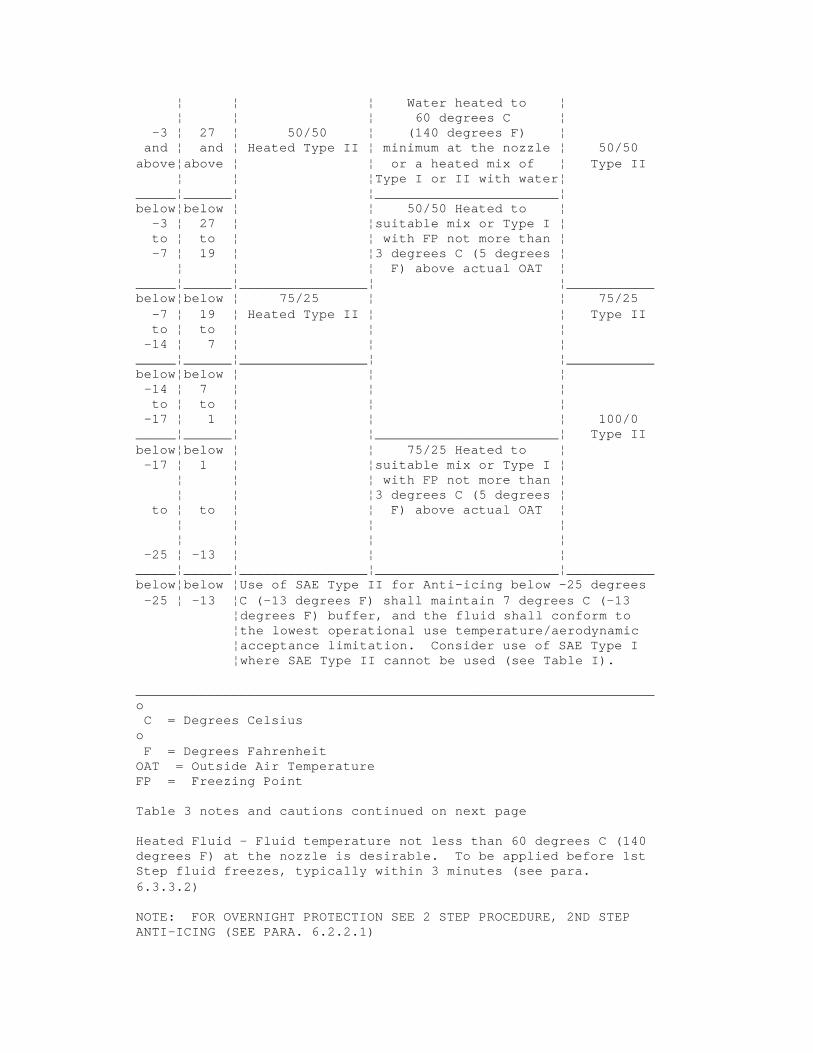
¦ ¦ ¦ Water heated to ¦ ¦ ¦ ¦ 60 degrees C ¦
-3 ¦ 27 ¦ 50/50 ¦ (140 degrees F) ¦ and ¦ and ¦ Heated Type II ¦ minimum at the nozzle ¦ 50/50
above¦above ¦ ¦ or a heated mix of ¦ Type II ¦ ¦ ¦Type I or II with water¦
_____¦______¦ ¦_______________________¦ below¦below ¦ ¦ 50/50 Heated to ¦
-3 ¦ 27 ¦ ¦suitable mix or Type I ¦ to ¦ to ¦ ¦ with FP not more than ¦ -7 ¦ 19 ¦ ¦3 degrees C (5 degrees ¦
¦ ¦ ¦ F) above actual OAT ¦ _____¦______¦________________¦ ¦___________ below¦below ¦ 75/25 ¦ ¦ 75/25
-7 ¦ 19 ¦ Heated Type II ¦ ¦ Type II to ¦ to ¦ ¦ ¦
-14 ¦ 7 ¦ ¦ ¦ _____¦______¦________________¦ ¦___________ below¦below ¦ ¦ ¦ -14 ¦ 7 ¦ ¦ ¦ to ¦ to ¦ ¦ ¦
-17 ¦ 1 ¦ ¦ ¦ 100/0 _____¦______¦ ¦_______________________¦ Type II below¦below ¦ ¦ 75/25 Heated to ¦ -17 ¦ 1 ¦ ¦suitable mix or Type I ¦
¦ ¦ ¦ with FP not more than ¦ ¦ ¦ ¦3 degrees C (5 degrees ¦
to ¦ to ¦ ¦ F) above actual OAT ¦ ¦ ¦ ¦ ¦ ¦ ¦ ¦ ¦
-25 ¦ -13 ¦ ¦ ¦ _____¦______¦________________¦_______________________¦___________ below¦below ¦Use of SAE Type II for Anti-icing below -25 degrees -25 ¦ -13 ¦C (-13 degrees F) shall maintain 7 degrees C (-13
¦degrees F) buffer, and the fluid shall conform to ¦the lowest operational use temperature/aerodynamic ¦acceptance limitation. Consider use of SAE Type I ¦where SAE Type II cannot be used (see Table I).
_________________________________________________________________ o C = Degrees Celsius
o F = Degrees Fahrenheit
OAT = Outside Air Temperature FP = Freezing Point
Table 3 notes and cautions continued on next page
Heated Fluid - Fluid temperature not less than 60 degrees C (140 degrees F) at the nozzle is desirable. To be applied before 1st Step fluid freezes, typically within 3 minutes (see para. 6.3.3.2)
NOTE: FOR OVERNIGHT PROTECTION SEE 2 STEP PROCEDURE, 2ND STEP ANTI-ICING (SEE PARA. 6.2.2.1)

CAUTION: THE TIME OF PROTECTION WILL BE SHORTENED IN HEAVY WEATHER CONDITIONS. HIGH WIND VELOCITY AND JET BLAST MAY CAUSE A DEGRADATION OF THE PROTECTIVE FILM. IF THESE CONDITIONS OCCUR THE TIME OF PROTECTION MAY BE SHORTENED CONSIDERABLY. THIS IS ALSO THE CASE WHEN THE FUEL TEMPERATURE IS SIGNIFICANTLY LOWER THAN OAT.
CAUTION: AIRCRAFT SKIN TEMPERATURE AND OAT MAY DIFFER. ---------------------------------------------------------------
---------------------------------------------------------------TABLE 4 - Guideline for Holdover Times Anticipated for SAE Type II Fluid Mixtures as a Function of Weather
Conditions and OAT
THE RESPONSIBILITY FOR THE APPLICATION OF THESE DATA REMAINS WITH THE USER AND SHOULD ONLY BE USED IN CONJUNCTION WITH SAE METHODS DOCUMENT. (SEE CAUTIONS) _________________________________________________________________
OAT ¦SAE Type II Fluid¦ Approximate Holdover Times ¦ Concentration ¦ under Various Weather ¦ Neat-Fluid/Water¦ Conditions (hours:minutes)
______________¦ (Vol %/Vol % ¦________________________________ o ¦ o ¦ ¦ FROST* ¦ FREEZING ¦ SNOW C ¦ F ¦ ¦ ¦ FOG ¦
¦ ¦ ¦ ¦ ¦ ¦ ¦ ¦ ¦ ¦
______¦_______¦_________________¦________¦___________¦___________ ¦ ¦ 100/0 ¦ 12:00 ¦ 1:15-3:00 ¦ 0:25-1:00 ¦ ¦ ¦ ¦ ¦
0 ¦ 32 ¦ ¦ ¦ ¦ and ¦ and ¦ ¦ ¦ ¦
above¦ above ¦_________________¦________¦___________¦___________ ¦ ¦ 75/25 ¦ 6:00 ¦ 0:50-2:00 ¦0:20-0:45 ¦ ¦_________________¦________¦___________¦___________ ¦ ¦ 50/50 ¦ 4:00 ¦ 0:35-1:30 ¦ 0:15-0:30
______¦_______¦_________________¦________¦___________¦___________ below¦ below ¦ 100/0 ¦ 8:00 ¦ 0:35-1:30 ¦ 0:20-0:45
¦ ¦ ¦ ¦ ¦ 0 ¦ 32 ¦ ¦ ¦ ¦
¦ ¦ ¦ ¦ ¦ to ¦ to ¦ ¦ ¦ ¦
¦ ¦ ¦ ¦ ¦ -7 ¦ 19 ¦_________________¦________¦___________¦___________
¦ ¦ 75/25 ¦ 5:00 ¦ 0:25-1:00 ¦ 0:15-0:30 ¦ ¦_________________¦________¦___________¦___________ ¦ ¦ 50/50 ¦ 3:00 ¦ 0:20-0:45 ¦ 0:05-0:15
______¦_______¦_________________¦________¦___________¦___________ below¦ below ¦ 100/0 ¦ 8:00 ¦ 0:35-1:30 ¦ 0:20-0:45 -7 ¦ 19 ¦ ¦ ¦ ¦ to ¦ to ¦ ¦ ¦ ¦
-14 ¦ 7 ¦_________________¦________¦___________¦__________ ¦ ¦ 75/25 ¦ 5:00 ¦ 0:25-1:00 ¦ 0:15-0:30
______¦_______¦_________________¦________¦___________¦___________ below¦ below ¦ ¦ ¦ ¦ -14 ¦ 7 ¦ ¦ ¦ ¦ to ¦ to ¦ 100/0 ¦ 8:00 ¦ 0:35-1:30 ¦ 0:20-0:45

-25 ¦ -13 ¦ ¦ ¦ ¦ ______¦_______¦_________________¦________¦___________¦___________ below¦ below ¦ 100/0 ¦Use of SAE Type II for Anti
-25 ¦ -13 ¦ ¦icing below -25 degrees C (-13 ¦ ¦ ¦degrees F) must maintain 7 ¦ ¦ ¦degrees C (-13 degrees F) ¦ ¦ ¦buffer, and the fluid shall ¦ ¦ ¦conform to the lowest ¦ ¦ ¦operational use temperature/ ¦ ¦ ¦aerodynamic acceptance ¦ ¦ ¦limitation. Consider use of SAE ¦ ¦ ¦Type I where SAE Type II cannot ¦ ¦ ¦be used.
______¦_______¦_________________¦________________________________ _________________________________________________________________
OAT ¦SAE Type II Fluid¦ Approximate Holdover Times ¦ Concentration ¦ under Various Weather ¦ Neat-Fluid/Water¦ Conditions (hours:minutes)
______________¦ (Vol %/Vol % ¦________________________________ o ¦ o ¦ ¦ FREEZING RAIN ¦ RAIN ON COLD C ¦ F ¦ ¦ ¦ SOAKED WING
¦ ¦ ¦ ¦ ¦ ¦ ¦ ¦
______¦_______¦_________________¦_______________¦________________ ¦ ¦ 100/0 ¦ 0:08-0:20 ¦ 0:24-1:00 ¦ ¦ ¦ ¦
0 ¦ 32 ¦ ¦ ¦ and ¦ and ¦ ¦ ¦
above¦ above ¦_________________¦_______________¦________________ ¦ ¦ 75/25 ¦ 0:04-0:10 ¦ 0:18-0:45 ¦ ¦_________________¦_______________¦________________ ¦ ¦ 50/50 ¦ 0:02-0:05 ¦ 0:12-0:30
______¦_______¦_________________¦________________________________ below¦ below ¦ 100/0 ¦ 0:08-0:20 ¦
¦ ¦ ¦ ¦ 0 ¦ 32 ¦ ¦ ¦
¦ ¦ ¦ ¦ to ¦ to ¦ ¦ ¦
¦ ¦ ¦ ¦ -7 ¦ 19 ¦_________________¦_______________¦
¦ ¦ 75/25 ¦ 0:04-0:10 ¦ ¦ ¦_________________¦_______________¦ ¦ ¦ 50/50 ¦ 0:01-0:03 ¦
______¦_______¦_________________¦_______________¦ below¦ below ¦ 100/0 ¦ -7 ¦ 19 ¦ ¦ to ¦ to ¦ ¦
-14 ¦ 7 ¦_________________¦ ¦ ¦ 75/25 ¦
______¦_______¦_________________¦ below¦ below ¦ ¦ -14 ¦ 7 ¦ ¦ to ¦ to ¦ 100/0 ¦
-25 ¦ -13 ¦ ¦ ______¦_______¦_________________¦________________________________ below¦ below ¦ 100/0 ¦Use of SAE Type II for Anti
-25 ¦ -13 ¦ ¦icing below -25 degrees C (-13

¦ ¦ ¦degrees F) must maintain 7 ¦ ¦ ¦degrees C (-13 degrees F) ¦ ¦ ¦buffer, and the fluid shall ¦ ¦ ¦conform to the lowest ¦ ¦ ¦operational use temperature/ ¦ ¦ ¦aerodynamic acceptance ¦ ¦ ¦limitation. Consider use of SAE ¦ ¦ ¦Type I where SAE Type II cannot ¦ ¦ ¦be used.
______¦_______¦_________________¦________________________________ o C Celsius
o F Degrees Fahrenheit
OAT Outside Air Temperature VOL Volume * for maintenance purposes
CAUTION: CLEAR ICE MAY REQUIRE TOUCH FOR CONFIRMATION.
CAUTION: THIS TABLE IS FOR USE IN DEPARTURE PLANNING ONLY AND IT SHOULD BE USED IN CONJUNCTION WITH PRETAKEOFF CHECK PROCEDURES.
Table 4 cautions continued on next page.
CAUTION: THE TIME OF PROTECTION WILL BE SHORTENED IN HEAVY WEATHER CONDITIONS. HIGH WIND VELOCITY AND JET BLAST MAY CAUSE A DEGRADATION OF THE PROTECTIVE FILM. IF THESE CONDITIONS OCCUR THE TIME OF PROTECTION MAY BE SHORTENED CONSIDERABLY. THIS IS ALSO THE CASE WHEN THE FUEL TEMPERATURE IS SIGNIFICANTLY LOWER THAN OAT. ---------------------------------------------------------------


![Design and Fabrication of Tilt -Hexacopter with Image ... · pentacopter [ five propellers], hexacopter [ six propellers], octocopter [ eight propellers], etc. Here , the design methodologies,](https://static.fdocuments.us/doc/165x107/5e21c800611caa04ab6d729c/design-and-fabrication-of-tilt-hexacopter-with-image-pentacopter-five-propellers.jpg)

