Abutment Design Example Design Example Chris Byrum Doug Parmerlee Example Bridge Evaluate Existing...
89
Abutment Design Example Chris Byrum Doug Parmerlee
Transcript of Abutment Design Example Design Example Chris Byrum Doug Parmerlee Example Bridge Evaluate Existing...
Abutment Design Example
Chris Byrum Doug Parmerlee


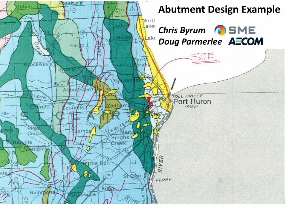
Example Bridge
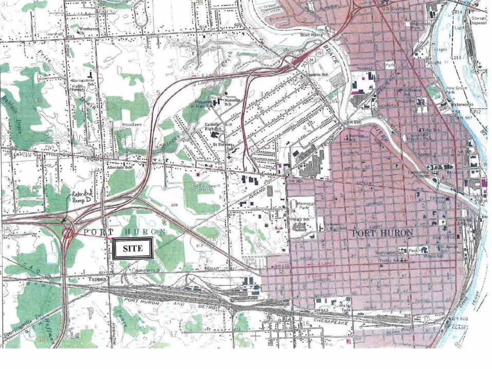
Evaluate Existing Test Hole Data
Not much before 1940MDOT Housel Soil Mechanics 1940-80sASTM SPT N-modified values

Evaluate Existing Test Hole Data
Not much before 1940MDOT Housel Soil Mechanics 1940-80sASTM SPT N-modified values

Evaluate Existing Test Hole Data
Not much before 1940MDOT Housel Soil Mechanics 1940-80sASTM SPT N-modified values
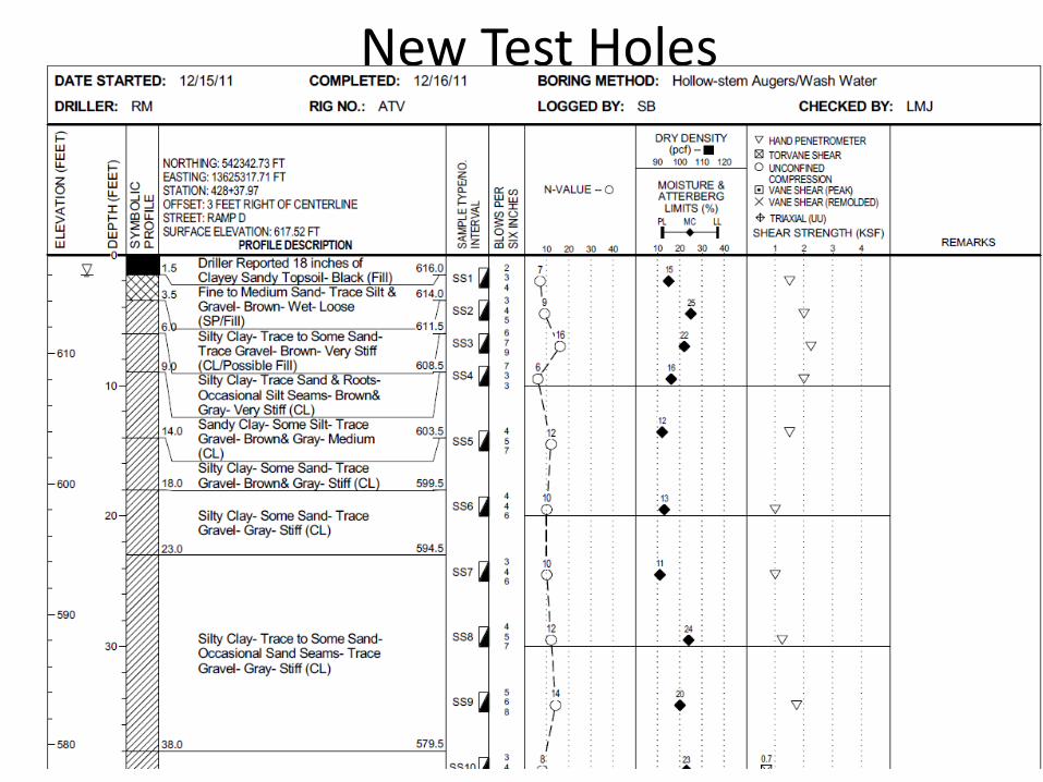
New Test Holes
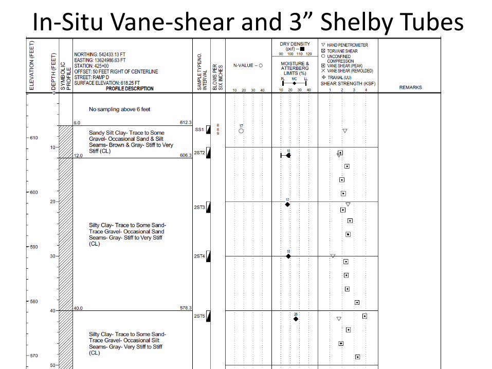
In-Situ Vane-shear and 3” Shelby Tubes


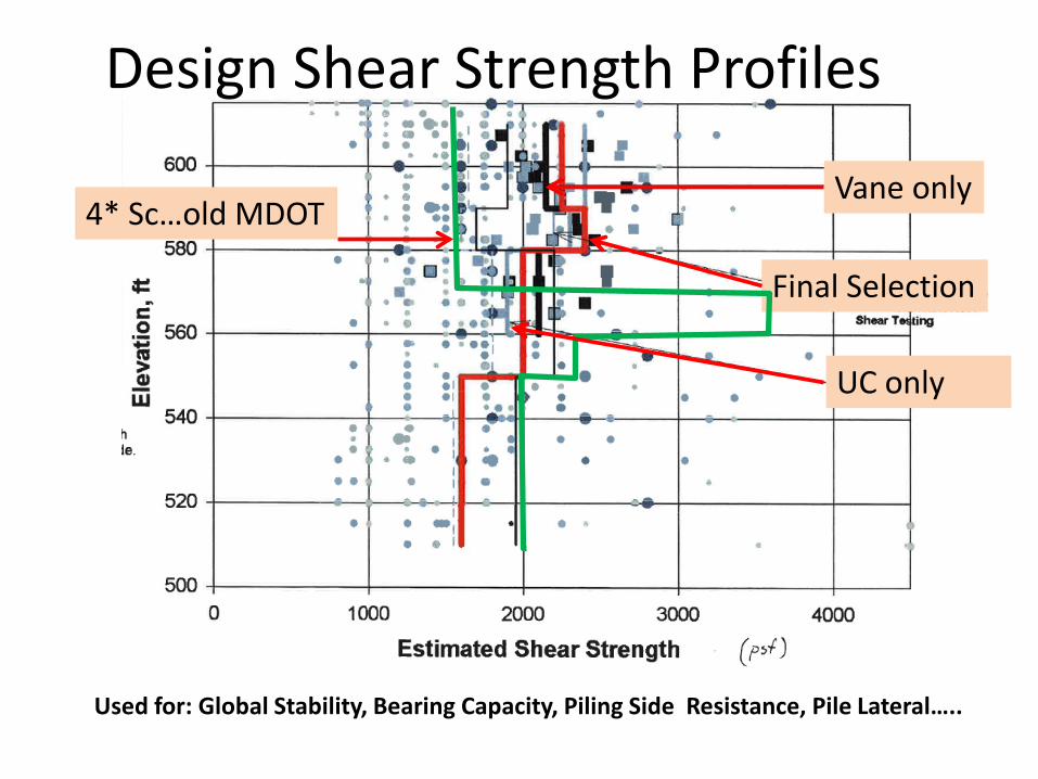
Design Shear Strength Profiles
Vane only
Final Selection
UC only
4* Sc…old MDOT
Used for: Global Stability, Bearing Capacity, Piling Side Resistance, Pile Lateral…..


Used for Piling Tip Resistance
External Stability
• Task 1: Lateral Squeeze • Task 2: Global Stability• Task 3: Settlement Analyses• Task 4:Bearing Capacity
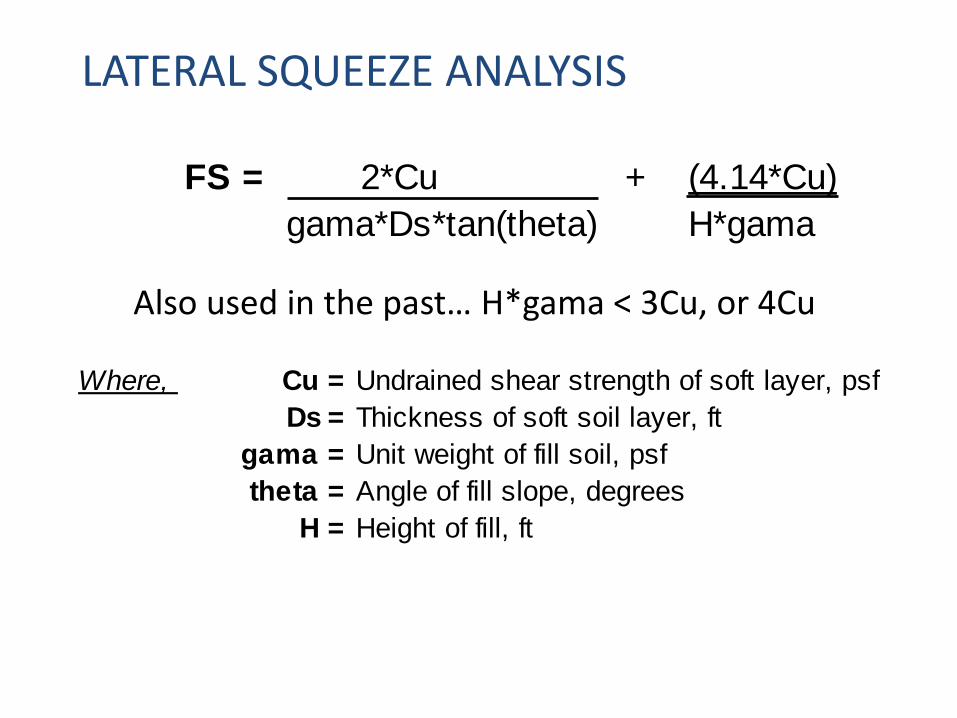
FS = 2*Cu + (4.14*Cu)gama*Ds*tan(theta) H*gama
Where, Cu = Undrained shear strength of soft layer, psfDs = Thickness of soft soil layer, ft
gama = Unit weight of fill soil, psftheta = Angle of fill slope, degrees
H = Height of fill, ft
Also used in the past… H*gama < 3Cu, or 4Cu
LATERAL SQUEEZE ANALYSIS
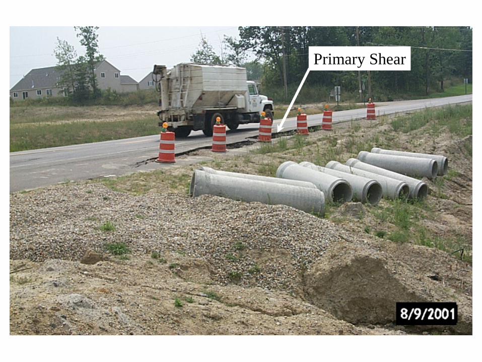
Primary Shear
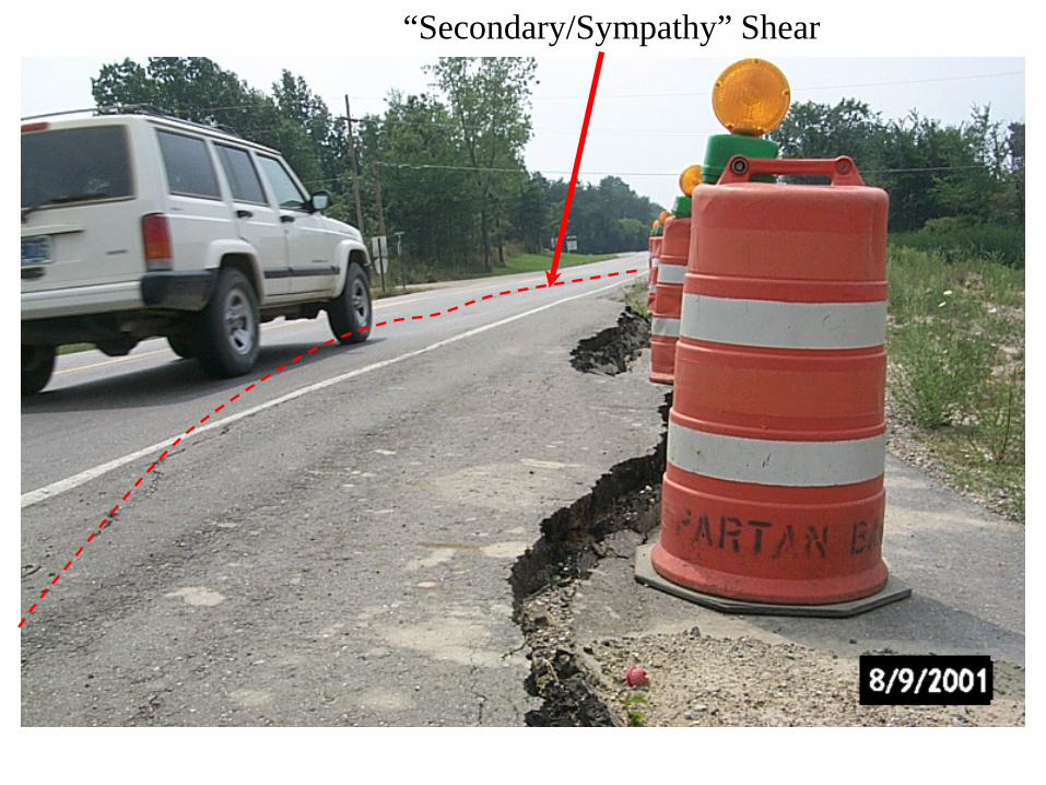
“Secondary/Sympathy” Shear
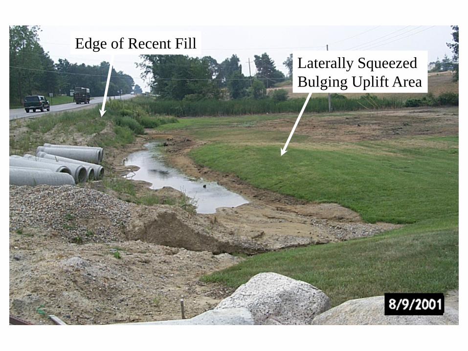
Laterally SqueezedBulging Uplift Area
Edge of Recent Fill

H = 6 to 7 feet
Previous Scenario

Utility Contractor Adds Weight
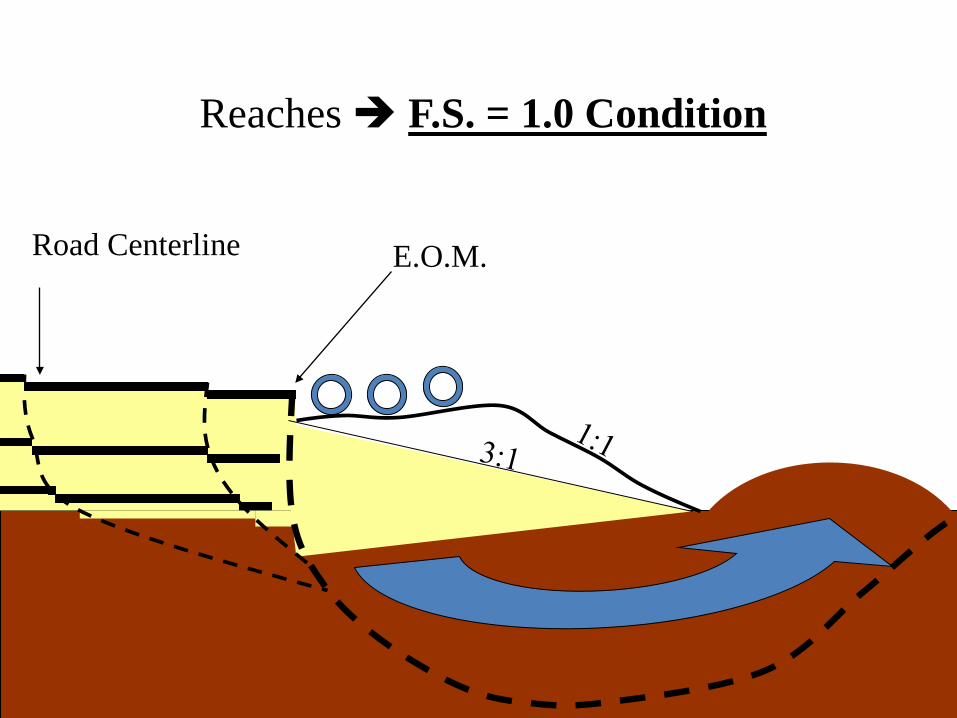
Road Centerline E.O.M.
Reaches F.S. = 1.0 Condition

Failure BackcalculationFS = 2*Cu + (4.14*Cu)
gama*Ds*tan(theta) H*gamaComponent 1 Component 2 FS
Cu = 180 psf 0.10 0.92 1.01Ds = 30 ft
gama = 125 pcf 3*Cu = 540theta = 45 degrees 4*Cu = 720
H = 6.5 ft gama*H = 812.5
For FS = 1

Example Bridge
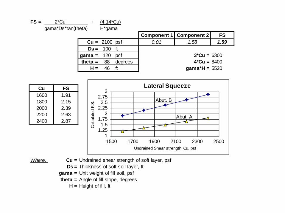
FS = 2*Cu + (4.14*Cu)gama*Ds*tan(theta) H*gama
Component 1 Component 2 FSCu = 2100 psf 0.01 1.58 1.59Ds = 100 ft
gama = 120 pcf 3*Cu = 6300theta = 88 degrees 4*Cu = 8400
H = 46 ft gama*H = 5520
Cu FS1600 1.911800 2.152000 2.392200 2.632400 2.87
Where, Cu = Undrained shear strength of soft layer, psfDs = Thickness of soft soil layer, ft
gama = Unit weight of fill soil, psftheta = Angle of fill slope, degrees
H = Height of fill, ft
11.251.5
1.752
2.252.5
2.753
1500 1700 1900 2100 2300 2500
Calc
ulat
ed F
.S.
Undrained Shear strength, Cu, psf
Lateral Squeeze
Abut. B
Abut. A

GLOBAL STABILITY ANALYSISAbutment A

Abutment ASet 2% strain force > 1.1 FS force

Abutment ASet ultimate force > 1.3 FS force
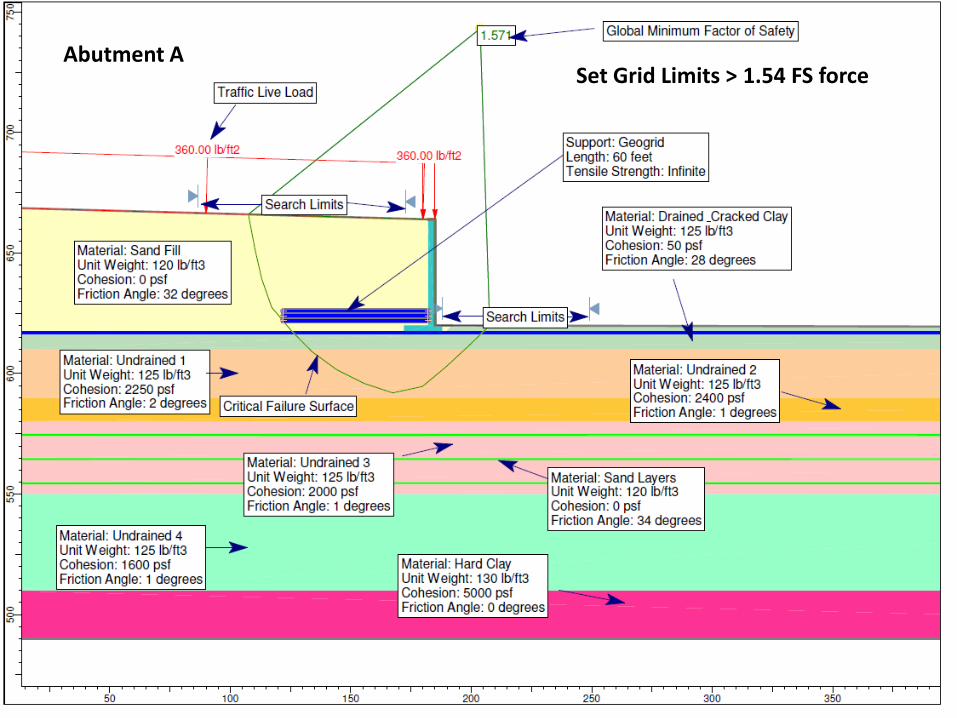
Abutment ASet Grid Limits > 1.54 FS force
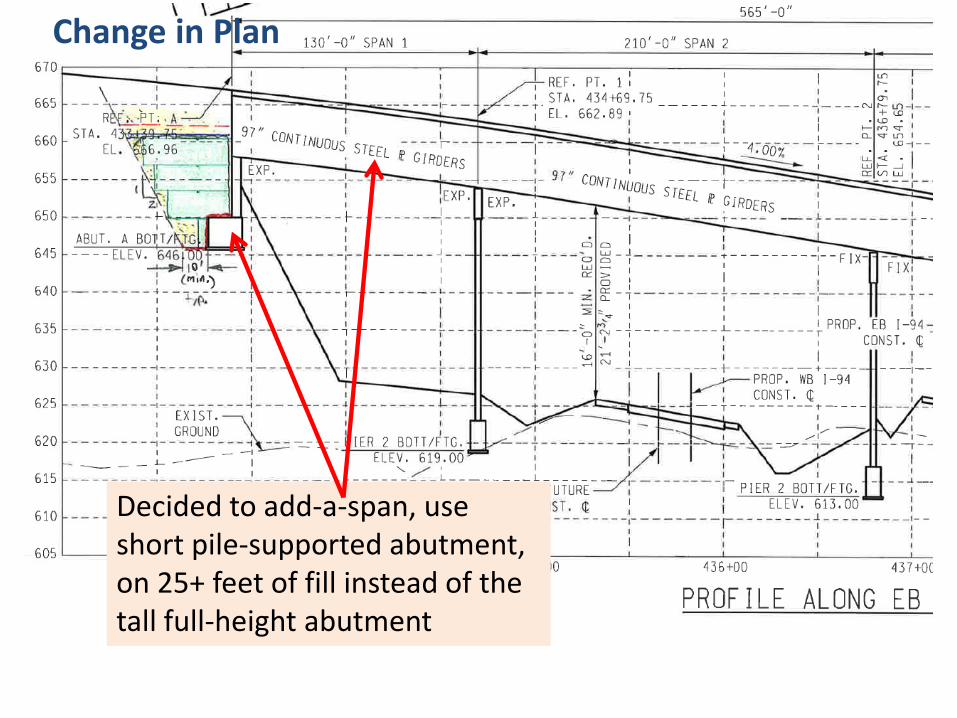
Decided to add-a-span, use short pile-supported abutment, on 25+ feet of fill instead of the tall full-height abutment
Change in Plan

Abutment A
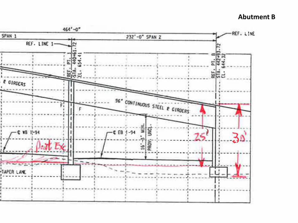
Abutment B
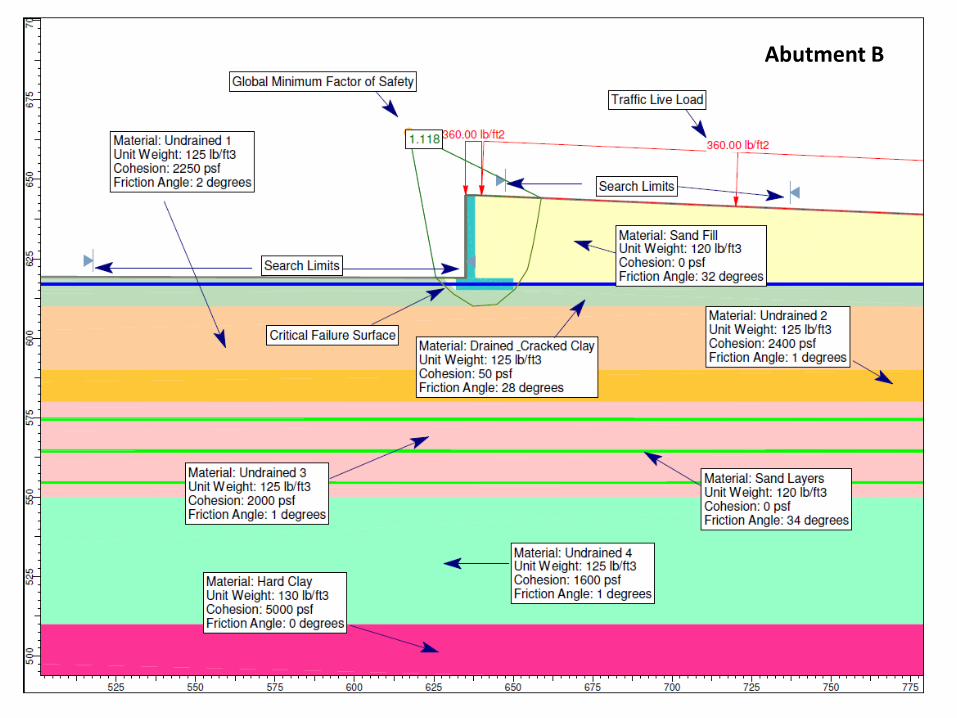
Abutment B
Abutment B
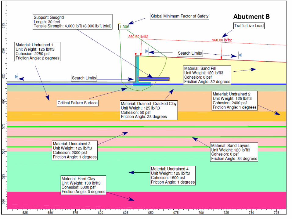
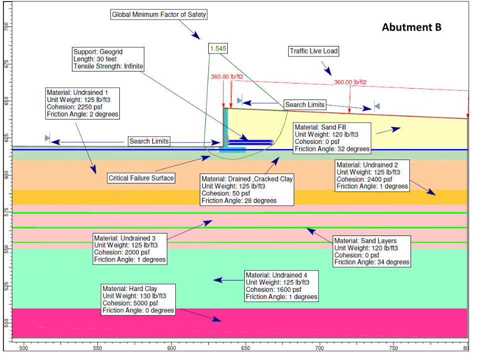
Abutment B
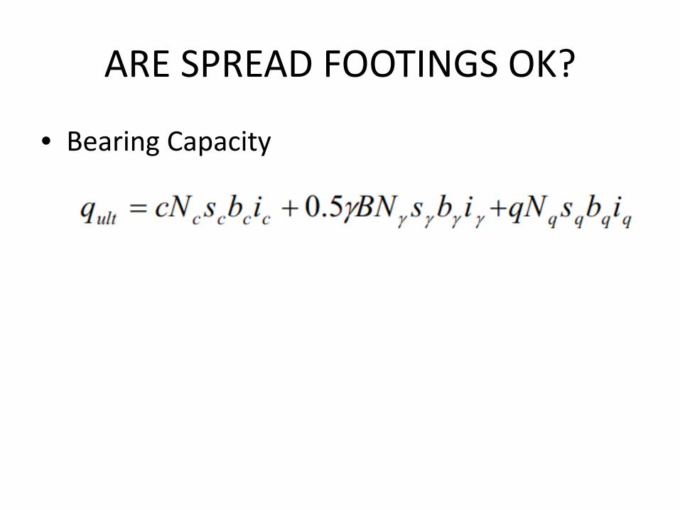
ARE SPREAD FOOTINGS OK?
• Bearing Capacity

ARE SPREAD FOOTINGS OK?
• Bearing Capacity
……Factored B.C. = approx. 5000 - 6000 psf
Approach Embankment Weight next to Abutment:Abut. A = 48*125 = 6000 psf not likely!Abut. B = 30 * 125 = 3750 psf maybe

ARE SPREAD FOOTINGS OK?• Settlement Management
• Need to estimate settlement of footings caused by approach embankments
• And Footing pressures causing settlement serviceability-limit (1-inch and 1.5-inch limits)
• Pre-loads? Lightweight Fills? Pile Downdrag?

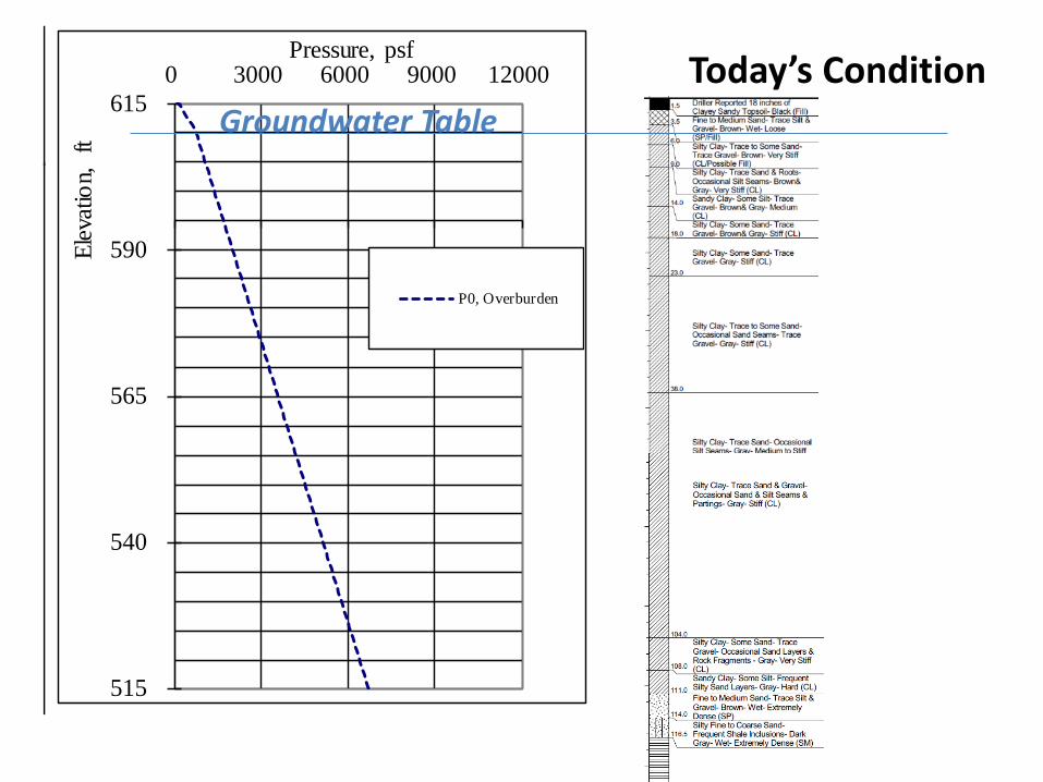
SETTLEMENT MANAGEMENT

SETTLEMENT MANAGEMENT
515
540
565
590
6150 3000 6000 9000 12000
Elev
atio
n, f
tPressure, psf
P0, Overburden
Today’s ConditionGroundwater Table
515
540
565
590
6150 3000 6000 9000 12000
Elev
atio
n, f
tPressure, psf
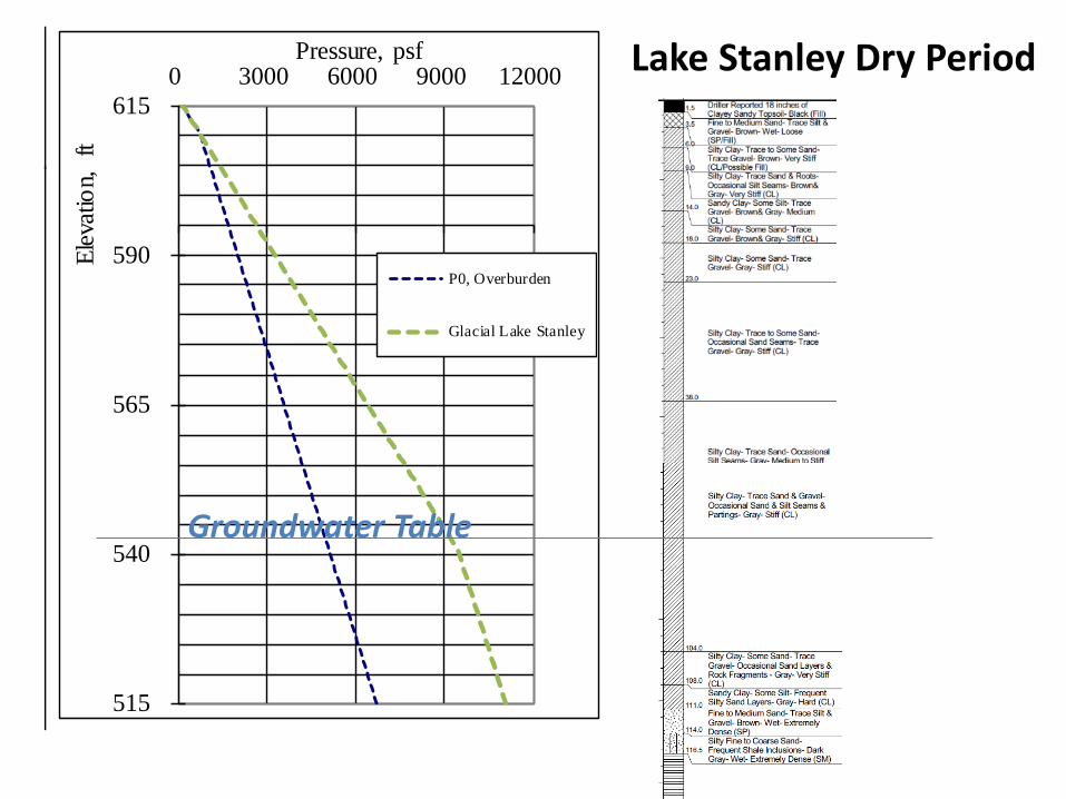
P0, Overburden
Glacial Lake Stanley
Lake Stanley Dry Period
Groundwater Table
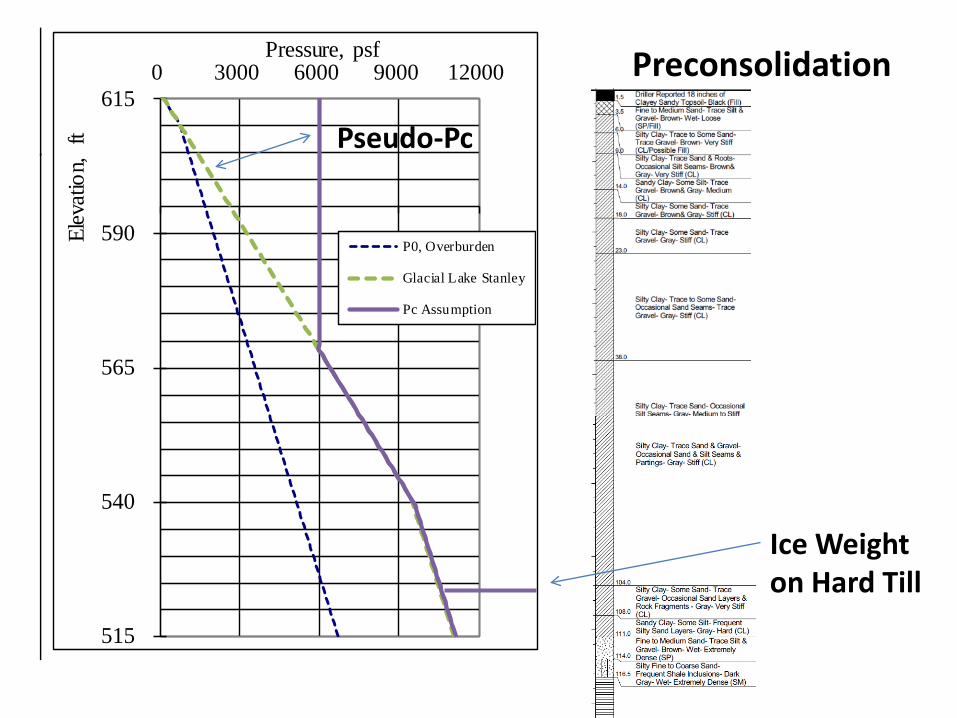
515
540
565
590
6150 3000 6000 9000 12000
Elev
atio
n, f
tPressure, psf
P0, Overburden
Glacial Lake Stanley
Pc Assumption
Preconsolidation
Pseudo-Pc
Ice Weight on Hard Till
515
540
565
590
6150 3000 6000 9000 12000
Elev
atio
n, f
tPressure, psf
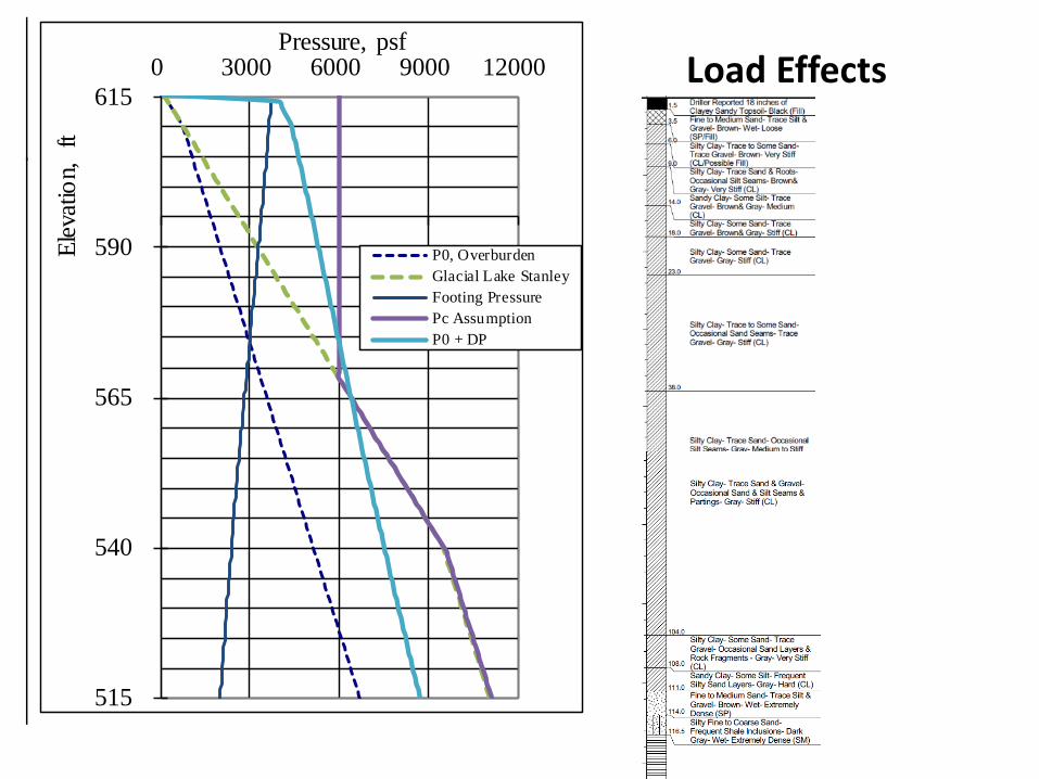
P0, OverburdenGlacial Lake StanleyFooting PressurePc AssumptionP0 + DP
Load Effects

515
540
565
590
6150 3000 6000 9000 12000
Elev
atio
n, f
tPressure, psf
P0, OverburdenGlacial Lake StanleyFooting PressurePc AssumptionP0 + DP
515
540
565
590
6150 2 4 6 8
Elev
atio
n, f
t
Settlement, in
Uc = 100%Uc = 75%Uc = 50%Uc = 25%

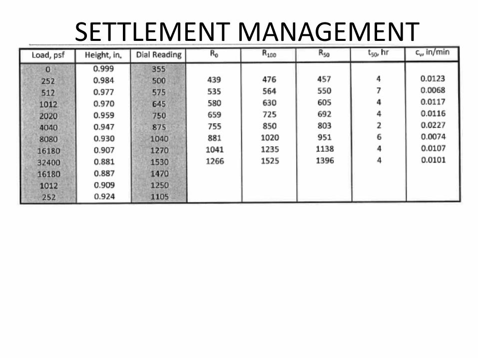
SETTLEMENT MANAGEMENT
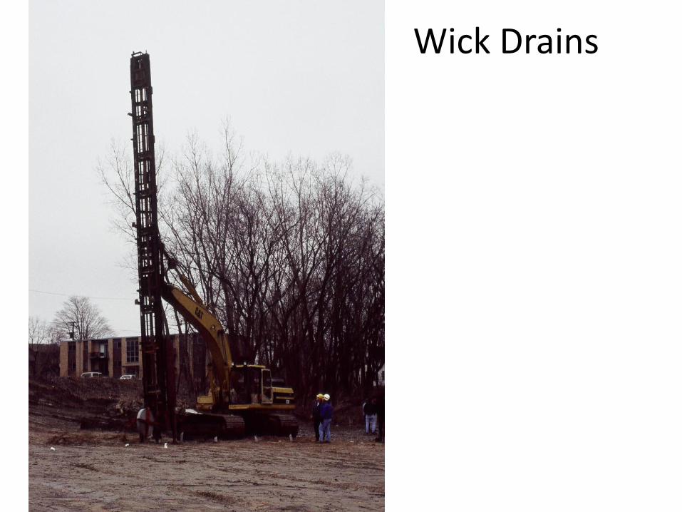
Wick Drains

Wick Drains


Wick Drains

Example Bridge
14” 10” (5-20 years w/o wicks) 6” 8”
Settlement Estimates – Soil Only, no footing pressures
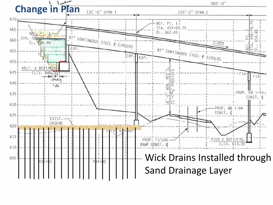
Change in Plan
Wick Drains Installed throughSand Drainage Layer

Change in Plan
Pre-Load to this Elev.
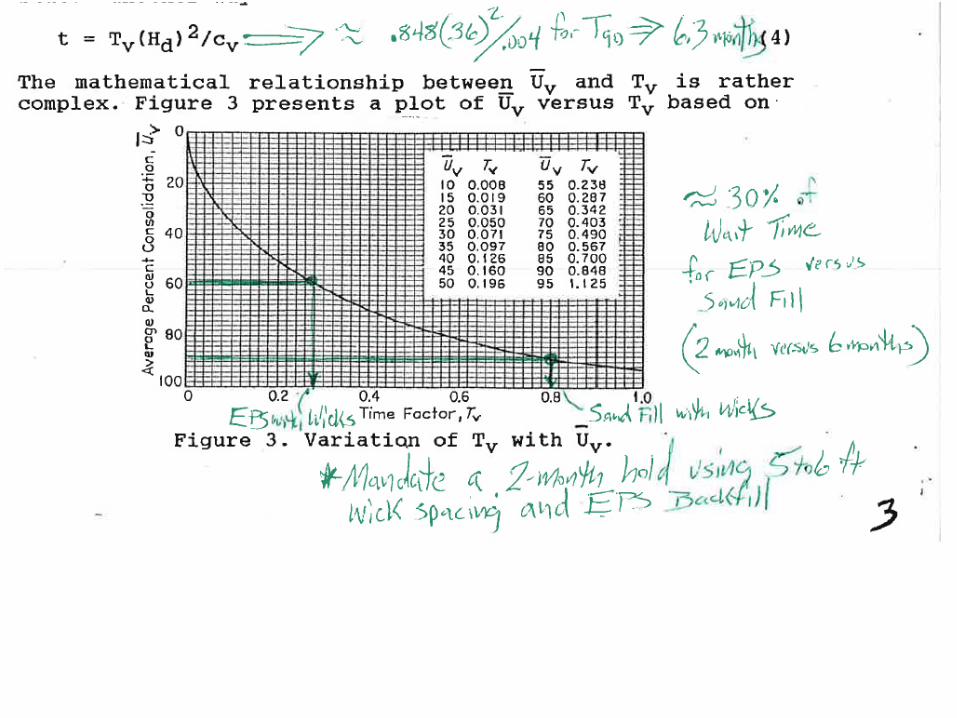
7” (6 month wait for T90)
Settlement Estimates

Change in Plan
EPS Block
H-Piles
Less than 0.4” remains (ZERO Downdrag!!!!!)
Settlement Estimates
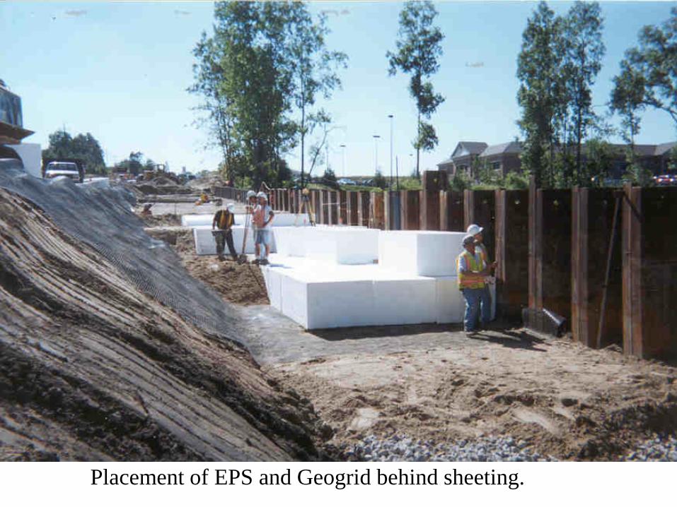
Placement of EPS and Geogrid behind sheeting.
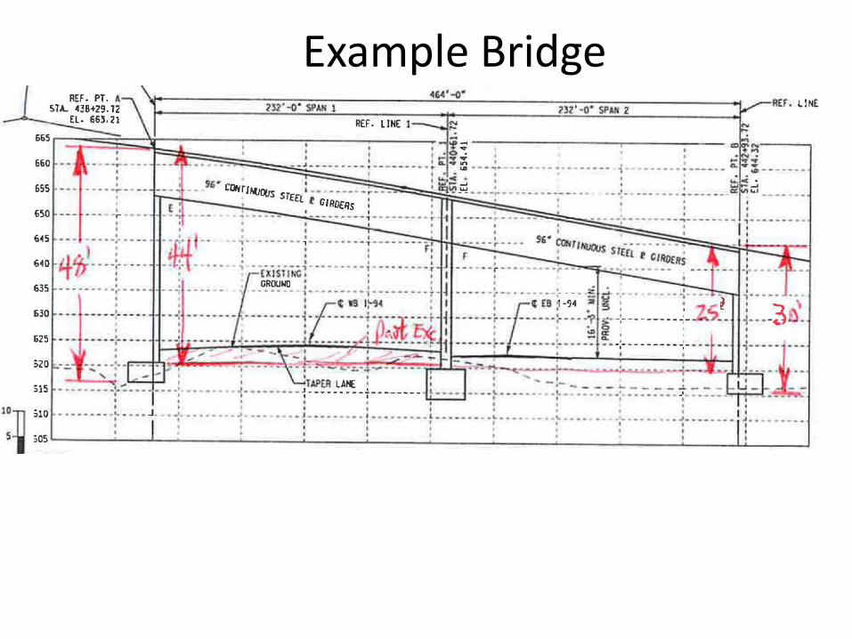
Example Bridge

Wick Drains Installed throughSand Drainage Layer
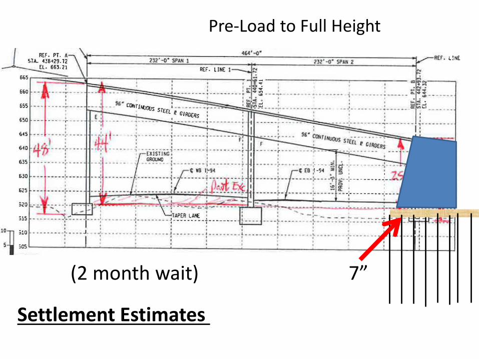
Pre-Load to Full Height
(2 month wait) 7”
Settlement Estimates

EPS Block
Remove Pre-Load, Piles, and Partial EPS
Est. Settlement =60% of “all-sand” pre-load
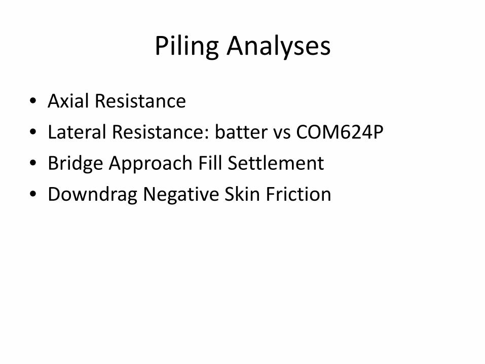
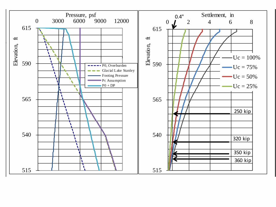
Piling Analyses
• Axial Resistance• Lateral Resistance: batter vs COM624P• Bridge Approach Fill Settlement• Downdrag Negative Skin Friction
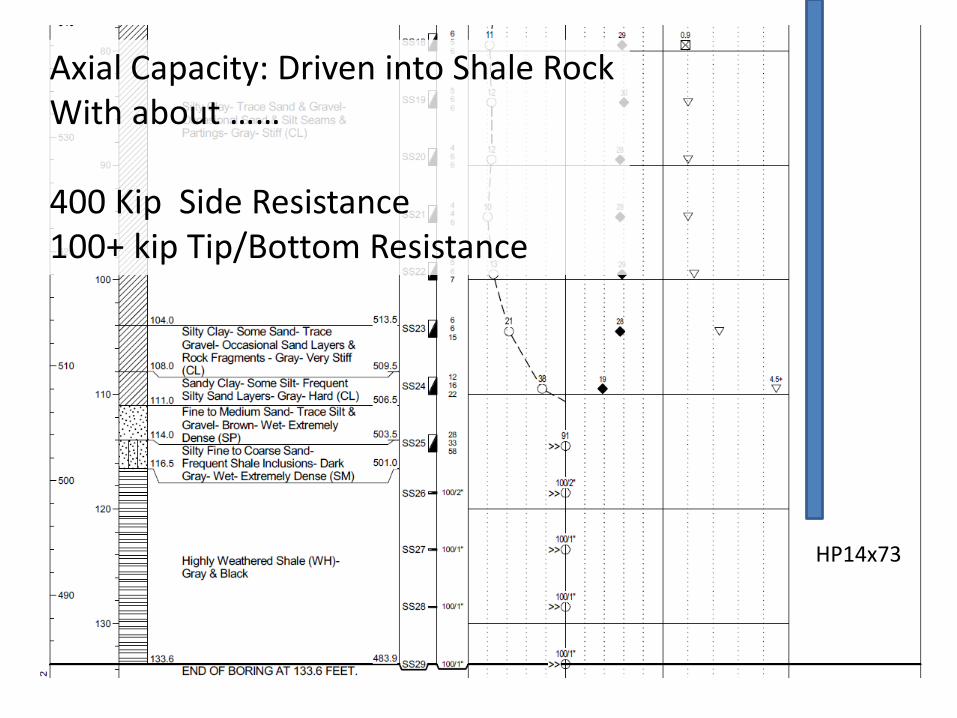
Axial Capacity: Driven into Shale RockWith about ……
400 Kip Side Resistance100+ kip Tip/Bottom Resistance
HP14x73


0.4” settlement
515
540
565
590
6150 3000 6000 9000 12000
Elev
atio
n, f
tPressure, psf
P0, OverburdenGlacial Lake StanleyFooting PressurePc AssumptionP0 + DP
515
540
565
590
6150 2 4 6 8
Elev
atio
n, f
t
Settlement, in
Uc = 100%Uc = 75%Uc = 50%Uc = 25%
0.4"
250 kip
320 kip
350 kip360 kip

515
540
565
590
6150 3000 6000 9000 12000
Elev
atio
n, f
tPressure, psf
P0, OverburdenGlacial Lake StanleyFooting PressurePc AssumptionP0 + DP
515
540
565
590
6150 2 4 6 8
Elev
atio
n, f
t
Settlement, in
Uc = 100%Uc = 75%Uc = 50%Uc = 25%
0.4"
250 kip
320 kip
350 kip360 kip
220 kip
310 kip
340 kip
355 kip
0.5"
An extra 0.1” allowance for elastic pile shortening….
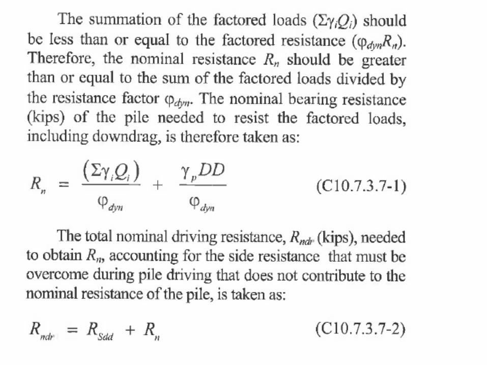

For Rndr = 500 kip HP14x73, 25% settlement remaining:
Rn = 500 – 220(250/400) = 362.5 kips
Qp = 0.75(362.5) – 220 = 52 kips/pile OUCH!!!!
Drive 500 kip pile, only 52 kip available for bridge weight!!!
NO GO!!
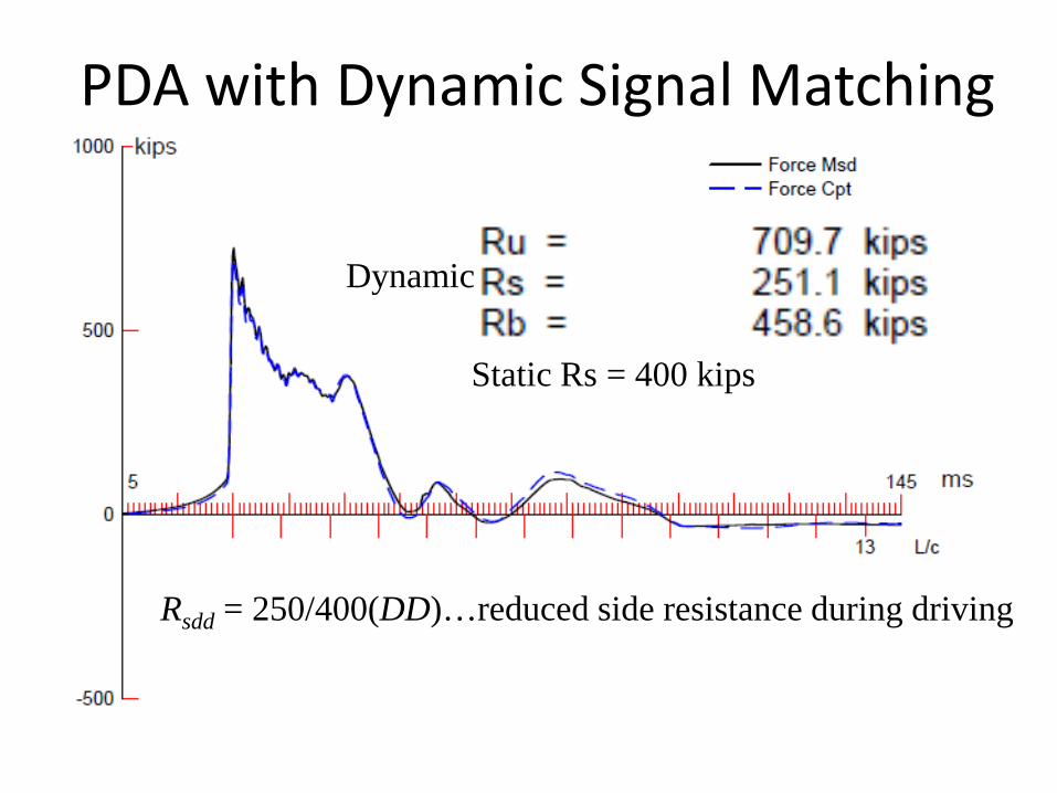
PDA with Dynamic Signal Matching
Rsdd = 250/400(DD)…reduced side resistance during driving
Static Rs = 400 kips
Dynamic

515
540
565
590
6150 3000 6000 9000 12000
Elev
atio
n, f
tPressure, psf
P0, OverburdenGlacial Lake StanleyFooting PressurePc AssumptionP0 + DP
515
540
565
590
6150 2 4 6 8
Elev
atio
n, f
t
Settlement, in
Uc = 100%Uc = 75%Uc = 50%Uc = 25%
0.4"
250 kip
320 kip
350 kip360 kip
220 kip
310 kip
340 kip
355 kip
0.5"
An extra 0.1” allowance for elastic pile shortening….

Pile Lateral Resistance
• COM624P• LPILE
0
20
40
60
80
100
120
140
160
180
-0.5 0 0.5 1 1.5
Dep
th B
elow
Foo
ting,
in
Lateral Deflection, in
9-kip
15-kip
20-kip
25-kip
30-kip
Lateral Load
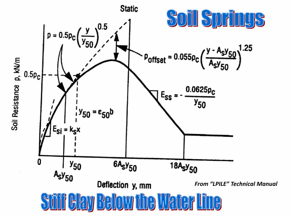
From “LPILE” Technical Manual

W
Q
p
P = soil pressure
MV
From “LPILE” Technical Manual

List of Recs Given To Bridge Engineer• Global Stability• Settlement Amounts and Rates• Spreads versus Deep Foundations• Lateral Resistances• Special Provisions/Materials Specifications• Construction Considerations
– Water control– Surface preparation– Temporary Walls– Vibrations– Geotechnical Instrumentation needed?

Doug Parmerlee
• Overview of Abutment Design Concepts
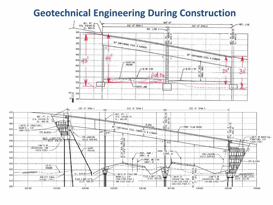
Geotechnical Engineering During Construction
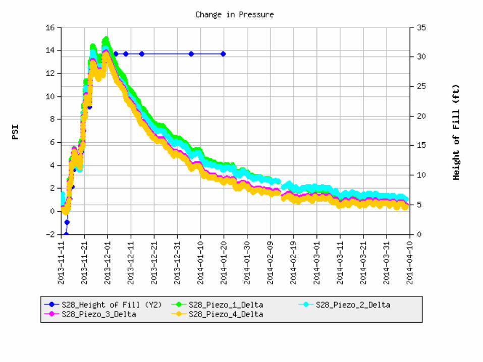
Geotechnical Field Monitoring
• Pile Axial Capacity• Settlement Rates and Amounts• Geosynthetics: Limits/Continuity/Splicing• Lightweight Fills: Limits/Materials

PDA with Dynamic Signal Matching
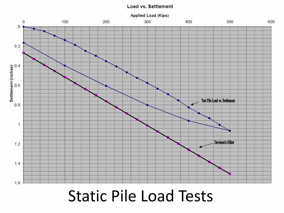
Static Pile Load Tests

Soil Pore Pressure Dissipation

M EI d zdx
=2
2
Michigan’s State Fossil:
Mastodon
Ancient Glacial Lake “Beach” on top ofGrand Portal Point, Pictured Rocks


![Bengal Money-Lenders Act, 1940 - wbrsrsa.orgwbrsrsa.org/exam_pdf/Bengal Money-Lenders Act, 1940.pdf · The Bengal Money-Lenders Act, 1940 Bengal Act X of 1940 [1st August, 1940] An](https://static.fdocuments.us/doc/165x107/5d66e94e88c99356368b9c71/bengal-money-lenders-act-1940-money-lenders-act-1940pdf-the-bengal-money-lenders.jpg)