Abstracts of American Reports on RC Columns Investigations 1930
39
- r;'-,'" l. '. / , .>. 'I' .;: ;, t •• . 7':, ) ... ABflTRACTS OF AMh1tICAlf' REPOHTS --- ........._ ........ -- .Q!! HEINFoRCED CONCRS"rE COL tim .... !W;,.,._· EB_··_T ..... __ I__ ON_S .... ITepared b7 Ingo Lyse fRITZ LABORATORY" '.,.; LEHIGH UNIVERSITY " BH:,LEHEiVl, PENNSYLVANIA 14-6.1 - .. I I I T 1· i
description
RC Columns
Transcript of Abstracts of American Reports on RC Columns Investigations 1930

- r;'-,'"l. '. /, .>.
'I' .;:;, .~t ••
.7':,)...
ABflTRACTS OF AMh1tICAlf' REPOHTS---........._........ --
.Q!! HEINFoRCED CONCRS"rE COLtim ....!W;,.,._·EB_··_T.....IG_'A=~__I__ON_S....
ITepared b7
Ingo Lyse
fRITZ ENGfr;EEt{r:~G LABORATORY"'.,.; LEHIGH UNIVERSITY
" BH:,LEHEiVl, PENNSYLVANIA
14-6.1
- ..
III
T1·i

Author
OONTENTS... _.... --...... --. .........
Ye~-'No.ot Qoltmm.s
Tested
Gaetano Lanza 1903 28 1
E. J. McOal1stland 1905 13 2
J. E. RowaN 1906 126 5
A. N. Talbot 1907 18 5,
A. u. Talbot ·190'7 51 9
Houghton and Cowles 1908 19 12
Gillespie and Swan 1908 ., 15\~
M. o. Withey 1909 20 15
Peter Gillespie 1910 25 19
H. c. Berry 1910 9 22
!Ji. 0 .. Witney 19U 66 24
A. c. I. Committee 1915 24 27
Vjantmore, Brodie and Carey 1915 104 30
McKibben and Merr111 1916 33 saRiqhan,Brandtzaeg and Bro\'in 1929 23 35
~ .Total 568 Oolumns
.. ,.••• -I

where
DISCUSSION OF NOTE ON 'raE COEFFIC+ENT OF ELASTICITY
OF CONCRETE AND MORTAR BEA1~ DURING FLEXURE
by Gaetano Lanza
In Tran'saction,s 01' the imlerican Society of Civil Engineers
Vol. 50, June, 1903, page 483,-----,-..tI!"*-----....----.--.---,--.__, ,__.__, .__._.-.--__'_,__. , _
Twenty-eight columns were included in this report. Four~
teen were 8 in. square, of which four were 6 ft. long,. four were" '
12 ft. long, and six were 17 ft. long.' Seven columns were 10 in.
square, of which two were, 6 ft. long, fO,ur were 12 ft~, long, and
one was 17 -ft. long. Seven plain Qoncrete colUmns were 8 in.
square and 5 ft. long. The concrete mix was 1':3:4 by volume.
The water c<:>ntent varied from 6 to 7-1/2% by-weight. Some of the
columns were built w~th One reinforcing rod placed at the center
of the sec~ion~, and others with four rods p~aced respectively at
the middle points of the fout. half diagonals of the section. The
rods in the 8-in. square columns ended 1/2 in. from each end of
pc f(At + 'rAft)
£ = strength 'of concrete
A' and Aft =;: areas of conorete and steel respectively, and
n = n c mOduili~us ratio
The strength results generally gave higher values than
those 'computed. The age at test varied from 28 to 45 days.

)
. ,"',
2
RESULTS OF COMPARATIVE TESTS dF
PL.AIN AND REINFORCED CONCRETE COLuMNs
by E. J. :McCa~~tland
In Engineering News, . Vol. 43, 1905, page 6J.4
The tes·ts wer~ carried out at 'Corneli Univers i ty, and,
included 13 plain and reinforced concrete oolumns. Two kinds
·Qf lateral reinforcement were used, tiesaIidspirals., The.,
colwnns were" 10 in.' in dlameterand 40 in.' long•.. ,'i'he ooncrete
mix was 1:3:5. Three of theoolumns were of·mortar,of 1:3 mix.
The 1190ps had ,ia cross";'section of 1/8 by 2: in. and were sp,aced, [\
5 in. on ,center$ 1~ three of t~e Qolumns, and 10 in~ in three
. others. The outl3ide diameter of t.he hoops 90rrespo'nded to that
of thecolumns~ , The columns having lateral but no lon~itudinal
reinforcement should have an average maximum. load ?f 216,800 lb ••'tcomputed by Considere t s .formula. Columns wi'tih lateral and lon..
gi tudinal reinforcement failed at 157,900 Ib'. a&ainst a"comput-,
eO. value of 219,800 Ib~ The latter, ho~e1'eI", had the ties
spaQed 10 in. on centers. The ,low value has been at::bributed to
the fact that the rods were not entirely embedded in the oon
crete, but were free to ,buckle away from the ,column between
hoops, and hence were pr09ably never stressef to the elastic /'
11m~t.
\\.
3
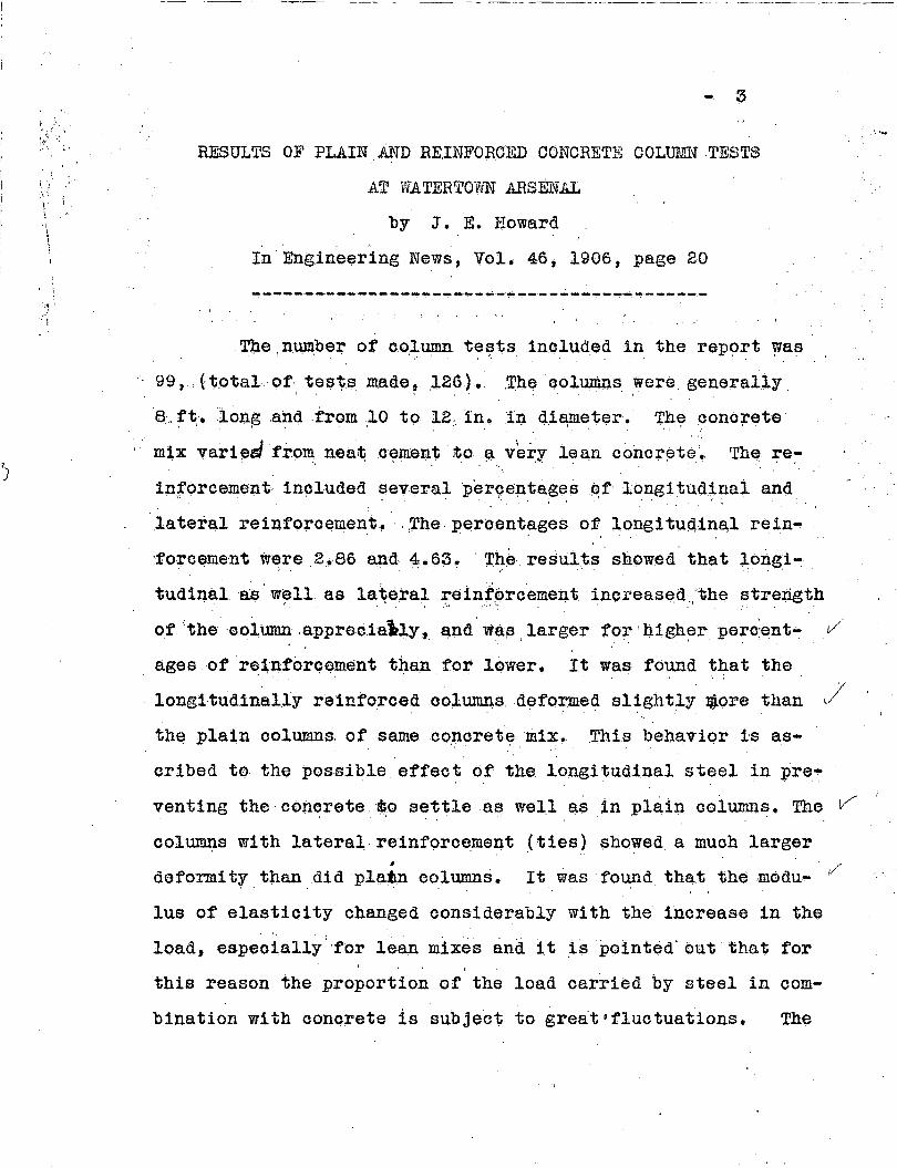
RESULTS OF PLAIN AND REINFORCED CONCRETE COLmn~·TESTS
AT WATERTOVUN ARSENAL
by J. E. Boward,
In Engineering News, Vol, 40, 1900, page 20
~ ....--_._--- -_._------ ...- ~'-' .... - ....---~--,-'---------~--;~---~.- -,---,-
.Tlle ,numbe~ of c9.l.~ t~~ts1nQlud.e~ in the report was
99 t' (,V.otal. o.t', tesvs rnade~ ,126.). ,The coluni.Il$ were. generally.
8" f~. ion~ ,a~dfroIll ..10 to 12:, in. in 4.iElflleter. ThE? ?ono;retel ;';
mix vari~slfr.()m neat.c~ment to .~ v'ery lea,n concr~te~ The ~e:-
inforcement· 1,n(}luded ~everalpergeptaf!es~f long1tud~:p.al and
,lateral reinforcement,. . .The. pero.entages of longi tU~i,1na.l rein-. ',. '. - '.
'forceme'nt w~re2.. 80 a.p.d, 4: .. 63. r,r'I:e' resul,ts show~d t.hat long.i~
tUd1~al,e.:s'w~ll asla~eral teinf&rcement inoreased.,'the strength'.
0.1' 'the 'oolum.n,apprecialily,. a,.nd \V8.F3, larger fo~ tl1gh~r 'perc,~nt~. t/
ages of r~1nforQementthan.for lower. It was found that the
/longi·tudinally reinforced oolurn.ns,d~formed s11ghtly JR.ore than v
th~ plain columns, of same co,ncretemix. .This beh~vior is as-
cribed to the possible et'fec~ of the. longituqinal steel in pre
venting the' cOncrete. ~o settle a~ well as~n pl~in oolumns•.The V i
oolumns with lateral, reinforo~ment(ties) $howed a much largerI
defoI'nlity.than.didplajm 09lumns. 1/It was t'ound that the .modu-
Ius of elasticity changed considerably with the inorease in the
load, espeoially:'t'or lean mixes and it ,is 'pointed' out· that for
this reason the proportion of the load oarried. by steel in com-
bination with conorete is sUbjeot to great'fluotuations. The

~. i
',' ;.
---- --- .~--,--- -
.Watertown Arsenal_by J. E•.Howard -
·.1,o~gitudinal reinforoement is. recommended to hav.e an elas;tic
5
TESTS OF CONCRETE AliD REllr.FORCED CONCRETE COLtllilliS, ,
(:: . :':: .;:-~'JSERIES OF 1906
by A.,·N., Talbot" '
I~":Bulletin NOi!lCi, Univ~r8ity oJ' Illinois,
Eng~neering Experimen1; Station (F~bruary, 190'7)
- - - - ,-' - -, -- .- - - '. :' '~ - ...
"" al rods and some
in order to hold
, "
,,'reinforoed ooltuims~ The' 'reinforo'emeult' Qonsfsted' of long! tUd1'iJ,-,
columns had ties' ,~rO\lIld:' thelongl tudinai' rods .',
them in: p1aoe'.' 'The s~i' \l~ed' was Attica r1voer v·/
sand and the coarse aggt;egate con~isted C?f crushed, 'ne'arlY pur,e
liIllestone from Karika.kee~ Th~ 'ooarse aggregate:pa~sed a 1:' in.
screen and retained on a 1/~-1n.' screen." 'The 'conorete mix' W'as, .' 1
1:2:3-3/4 by loose volume for all the OOlUIIU1S.
'fhe reinforoement ooneis'ted of plain reund mild steel
bars of an average yield point of 39,800 lb.' per sq. in.; arid
ultimate strength 01'59 ,2001~. per sq. in. Rods df$/4~1n.'
diameter were used in the 12-'1n. square oolumns, arid the ties
were 1/4-1no round rods.
Two specimens were made of a kind~The OOl~s were
9 and 12 in. square and 6, 9, and 12 ft. long. The oonorete
oontrol ~pihoimens were l2-1n. o~besand 8 by 1o-in.' cylinders. v
Three different reinforcements w~re llsed, (1), Ji~ reinforoement.
(2) vertioal rods in the oornerS ,only, (3) vertical rods in the
oorners tied together at every 12-in. height by 1/4-1n. rods'.

--- ~----~-o
-----------------------------
6
.... .,' The vertical r9ds were m'ade 1 iIi. shorter than
-, .~.-.
the columns with the intention of having 1/2 ill. of con
cr~te over the rods at each end~' In some cases, however,
the rods settied down to the bottom.
All specimens were capped with Plaster of Paris
before the'testtng. The longitudinal deformations were
obtained by mean~ of 'extensometers attached to the columns,
In six columns the load was increased prog~es~ively until
failure, in ten the load was released at 1 to 2 thirds of
the ultimate, and then reapplied. The load was released
tWice'on one column, tUldone brOke, accidentally when bei~g t-/,
placed in the machine. The percentages of reinforoements,, ,
were 1.2 and 1.'5 for the 9 and 12-in. oo.;J.umns respectiv;61;r,/,
and the age at test varied from 5~ to 71 days.
Most of the columns failed in the ,top or bottQm third
,of the height, only thr.ee failed near the center. Ten failed
near the top and foUr near the bottom. In estimating the
load oarried by the steel and that carried by the concrete
Talbot sub~tracted from the total load the amount found for
the steel by'multiplying the m~a~ured unit deformation with
the modulus of elastioity for steel. This difference had to
be oarried by the conorete.
The strain-stress relation for ooncrete is given as a
typical parabolic ourve with the vertex at the ultimate strength
of the concrete. The average value for the absoissa of the ver
tex of the parabola was found to be about 0.90134. The final

-_~.:.._""..;...:-".."'~~.;.:~... -,~ ..'_""~ ...:.--.r...:;~' ........' ".c..>''_=-"
7
deformation was lower for the reinforced oolumns than for
the pla1l:1 ones.,
The average ultim~te load for the plain columns was
1553 lb. per sq.• in. ~ varying frQm l07S9 to 2004,. The average. . . . . \ .
variation from the averag~ was 18% which was not cons,idered
lar~e. The average strength of the 12-1n.cubes 'was 2205
lb, •. pers9-.in., and of the 8 by 16-in. oylinders, 1490 lb.
~er sq.l,n. Talbot stated that two things are noticeab'le in
the resul~s,,,, (1) Thfj.t the maximum stresses te.kenby the
conorete in reinfo~ced columns are less then for the ple~n
conorete oolumn:;;, and '(?) that t,he .range of results is" ,
greater. He also :;;tated ~hat ~t would seem that in general
the po~itionof the ends ,of tlhereinforcing rods has not af
fected the re:;;ul1is 1n~nymarkedmanner,a.nd there is no ap
parent reason for giving greater or less weight to the
strength of any oolumn; even though ,he recognized the danger
of slippl~g of the ends of the bars.,
~e average concrete strength in the reinforced
c~lumns based on the giVen method of computation was 1243 lb.", I' • .'
per sq. in., or Xl$i tting colwnn 10, 1290 Ib .'per sq. in., with v
an average variati()n ,of 16%. With no allowance for steel,
,the reinforced concrete columns gave an average of 1746 lb.
per sq. in. gross area.. . ,
The concrete 'strength in reinforced columns was 15%, .. I' '."
less than that of the plain columns.
,- 8
--_. -
The ties dldnot inorease the strength o~ ohange
the .oond1tionaf failure.'
iA d1sc,v.seion is th~n given of Tests 'on Concrete
GOlumnfS at ,Wa1;er.tQwnArsenal reported in Tests 'ot Metals
for 1904.; .~ese'oo'lumns Were Of 1:2':4 mix by ·volume.
The bars were plaoed 1~7 /8 in. frQm ,the' ,surfaoe, and where
mQre,than four rods were used, the remaining rods were
p~a~ed,symmetr1oallY in the inter~or.'A'varietyof for.ms
of reinforoement was used. The rods were cut to exact" ,
length and'always had a direct bearing 'upon the bearing" " .
p~ates of thE') ,testing maQhine ~ ~he loads werere.:J..ease.d
seye:rE:;l,t1~es~ gener~lly ten or more, and the age at test
was a.beut ~..1/2 1llQnths.,. I ~
The parab6l1~ stl:'ess~stra.l!l relat.1on seemsdto hold
also for these columns. The n:umbar of oolumns included WSS
7,01' which one~ pla.:1nconcrete.
n·Astudy of the results 'shows that there is no marked
charaoteristic df:tference'~neither stiffness or strength tor
column/?ma.de w~th' aIlyspeoial form0:f reinforcing bars or
wi thany givan amount of 'reinforcament. For leaner odmorete t J
and hence greater porosity'; the differenoe in the elastio
limits of the bars lUay be expected to ,have an effect upon)1
the results., .

.~
9
TESTS OF CONCRETE AND' REINFORCED C'ONCRETE' QOLmn~S
l}ulletin No. 20,
~. -....... '- -
$EBIE,S OF 1907
by
Arthur N. Talbot
University of IllinoisEngineering Experiment S.tation (1907)
~ .- - ~' - - - ~, - - ~
Twenty~on~ plain oolumns and 30 laterally reinforced
columns were inoluded in the teste! reported. Generally the
columns were 12 i~. in diameter and ,10 ft. long, but a fevv
oolumns were included in which th~ ratio ot length to diameter. .
rang~d trom6Ato 13. Eighteen of the reinforoed oolumns had L-~.. ' . . 1 "
bands as lateral reinforcement and' 12 had spirals. Oontrol
oylinders of the oonorete oonsisted of 12-1n. cubes, 6-in.'. .
, oUbes, t:lnd 8 by l6-inl oylinders. The mixe.s ranged from a
1:1.5:3 to a 1:4;8, the largest nwnber of colwnns being of a
1:2:4 mi~.
The reinforoed oolumns had a 1/16 to 1/4-.dm.oover'ing. .'
o,t the reinforcement. The oolumns remained in the molds for
10 days. Aft,ar removal from the molds,. the 'oplumns 'were
sprinkled twice a day'until they were tested.
Longitudinal and lateral deforma't!ion observations
were made.

- 10
The ,top of the'oolumn WEll? capped with a plaster
of Pariscu'slllion', and both bottom and, top capping plates L-//
;r~main~d' Qnthe'oolump.'during testing.
Tests of plain colunm8' and th~:lr control sp~c'imenst· ." " • !, ' ,.
showed' tI~at the ,c~bes. W~l'e gen.erallYstronger ~han th~" ~
columns, a:Q.d· that the' cylind~rs and columns were of nearly
equal strength.. 'The ~la1noolumns g~nera.~ly failed at ~he
iniq-section. Two typ~s pffa-ilure Qccurred, one termed
diagQnal shear, and the other .called simple compression •
.0.1 colu.mnshaving rioh concre~e mixe~ showed diagonal,shear
failure,. and those hav1,ng lean mixe.s.sho,wed simple compres-. ",' .' '.
sion failure. The strength of ·the plain columns incr~ased
with an increase in the richness of the mix. It was found!,It· _"
that the strengths inoreased proportionally tel the '.increase ';'<\
of the ratio by weight of cement tQ total aggregate. It is .,
pointed Qut t.hat the increase in strength is.not proportiop.~l" '
to the increase in cost so that the richer mixes would be the
':,
; I
. more eoonomical for a given strength of columns. The varia
tion in strength of the concrete was large. For th~ li2:4
concrete tested at 80 days" the individual values ranged from
27% above to 35% below the average strength. the average vari
a.tion was ,12%.
The m9du1us of e1astiOl$YglVen~is th~ initial modu- V
Ius, and it was foun,d that the modulus at an age of one-half
year wa.s a'bout the same as that for 60 days.
- 11
The value found for Poisson's ratio for a 1:2:4 mix
at 60 days varied. ,from about 1/10 to 1/6 and near the ulti
mate load the value probably reached 1/4.
The total amount of shortening at maximum load for lat
eral reinforoed columns wa~ much larger than fQr plain 'columns.
The maximumstre.in for lateral reinforoe,d, oolumns varied from
0.006 to 0.015, or 6 to 20 times the maximum strain of plain
columns. The longitudinal stress-strain curve of laterally re
inforoed columns was nearly qf the same shape as that for plain.. . '.. . .
columns up to the poin't; of fa11ure of the plain columns. Beyohd" .
this point thestra1n incre,aaed very rapidly with tbe increase
in stress.•.t:.
The ini tial modulus of elast1c1't;y' wa.s found to be "; '.
less for laterally re1nforc,edcolumns than for plain columns of
the same concrete mix~
The columns reinforced with bands showed an increase in
strength due to the reinforoement apprmdmatelYequal to the
yield-point stress of the steel.c' 'l;imes t1].e area of the steel re
gardless of the strength 'of the Qonorete. The spirally reinforc~d.'
column~see~to incr'ease in strengt:b.,: Sligl;1tlY ~ore. than the yield-
point strength of the spiral, and 'little dif,ference was found be
tween the strength of ,high qarbon and mild steel spiral. The
strength formul~ given for lateral reinforced columns is:
c :;: C t + pC", where C == max~mum strength of column, Ct = max-
imum strength of plain conorete column,C" == coeffioient for the
lateral reinforoement, and p = peroent of lateral reinforoement.
For columns reinforced with band, the values given are:
C == 1600 + 65,000, .and for columns with spiral reinforcement:
C == 1600 '+ 100.000p/

- 12
TESTS OF B,lliNFORCED CONCRETE COLUMNS
at
Minneapolis, Minnesota
by
J •. G~ Houghton and W. P. Cowles
In Engineering News, Vol. 60. 1908, page 608
--,-~-~-~~---~--~------------------------------
The tests included 17 reinforced and 2 plain con
crete oolumns. ' The columns were 9 in. square and the
length was 9 ft. for the reinforced, and 5 ft. for the
plain columns. The lateral reinforcement oonsisted of
ties. The longitUdinal ~einforcement varied from 0 to
2.43%. The conorete mix was 1:2:3.5 and the.age at test
varied from 52 to 158 days. The test results were very
erratio so that no clear-cut conclusion could be drawn.
There was no recognizable relation between the ultimate
strength and the type or amount of ~einforcament. The
reinforced columns averaged about 25% stronger than the
plain columns, though five of the 17 failed at lower
loads than the plain columns.

- 13
REINFORCED CONCRETE COLUMNS
by
P. Gillespie and W.G. Swan
<Published in The Canadian Engineer. .
May 1, 1908 (Vol. 15, No.1S)
~ - - - .- - - - - - - ~. - ~ - - -. ~
Experiments were carried out on seven columns in the
testing labor~tory of the Department of Engineering of Toronto
University. The columns had a cross-section Of 3-1/2 by 5 in.
and varied in length trom 20 to 84 in. Five of the columns
had 2.5% longitudinal reinforcement. The lateral reinforce
ment consisted of 3/l6-in. ~teel hoops spaced 3.5 in. oncen
ter for two of the columns, while the other three had 3/16-in."(1.spirals with 3.5~ pitch. Neat cement cappings placed the day
before the tests, gave satisfactory results. Deformation meas
urements were taken by me~ns of electric contact devioes which
gave readings to 0.0001 in. The strain-stress curve deviated
from a straight line almost from the start. In computing the
stress in steel and concre~e, the asswnption of steel and con
crete deforming together,was adopted. The steel had an elas
tic limit of 42,800 lb. per sq.in•• and an ultimate strength
of 66,400 lb. per sq. in. The ultimate strength of the plain
concrete columns was 1643 lb. per sq.in.

·... 14
The authors show that the strength of the oollllllns
lV4s determined. ~y thetormula:
O' 11;I. C. (1 + (n-l) ..p)where 0' is the strength based on total Qros$ section,
C is the strength of the ooncrete.
n is the ratio I~ for the stress 0,
and p is the ratioot longitudinal reinforoement. The
modulus of elasticity of conoreteat the elastio'limit of
the steel was foWidtQ be 1,000,000 so tha.t !! \V8.s30 a't
time of failure.' The oomput~d maximum stress amounted to
2415 lb. per sq.1n., While the teste gave an average of
2280 lb. per sq. In. ; whldh lsconsldered a very good cheek.·
It is pointed out that the hoops seem to 'have no effeot upon
~he ultimate strength of -the oolunms. Closer spaoing of the~- \ :
hoops or smaller pitoh of the 'spirals would probably give
different results., The results of the tests ware very~1-
torm.'.
,.,;. _Y-"- .• , ...~,-.... ·V, r, .;>__ ...---.-~",.-.-'-.' •• ,~
. ~

- 15
TESTS ON PLAIN .AND REINFORCED' CONCRETE COLUMNS'
by M.o. Withey
Bulletin of the' University of Wisconsin .. No.300 (1909), . .
This series of tests included 20 columns 10 ft,. in, . , . :".
~ength. Five different types were used; (1) plain conorete .
columns, '(2) colU:m:ns reinforced with latticed angle struc
tural steel columns, (3)oolumns reinf~rced With high car-
'bon steelviire spirals, .( 4)' oolumns re inforced with '
!III '
'spirals 'and longl~udlnal inild steel'rods, and (5) oolumns
reinfo'rced with longitudinal mild steel rods. All rein;f'oroed
columns had a pro~ectlve shell of one or two inohes thickness
outside the ste.el~ The oonoret,ewas of,a 1:2:4 Pit± by ,volume,
and 'the mixing water varied from~.S to lO%'of the weight of
the dry materials. ,The va.riation ,in .water oont~nt was found
to be, due mostly' to the, variation .in'moisture in ,th(i) sand., Two
, or three 6 by 8-1n.. contrQlcylinders,were made With ea9h
column. All oolumns'Qf,a certain series were made on the
same day. The longitudinal rods were milled to a uniform
length,. > The columns ,wer{;lv capped w1.th I-l,mortar and the thiok
ness of the caps over the ends of the rods or angles of rein-, ,
forc~ent was never more than 1/32 in. The columns remained
in the molds six days and from then on they were wetted tWioe
- -- -_._----_.----

-'16
,a day for one week. after'whioh they Viere oUred in the air
of the ~aborator,y unt~l tested'atthe age of about two months,
A blotting papal:- was inserted'between ea6h;end.'of the oolumn
and the bearing plate Defore the' testirig~"Longidutinal 'deform
ation and latera). de'f~eQt'1on were ObserVed,." ,Jill ~ttempt to
measure lateraidarormation was also'mad~but given up~ ~he. .' , ;'. . ': "', - " .'
mod!.1lu,S ?f elas~lo~tyot ~he c,oJ;ltroloyl~ndel;"s.wa~ d,ete,:r:wmin~d.
'nlemodulu;;,?f elas~ioity Of ~be qontrol,oyl1nde:t>s ,a.t
on~-third ult+ma~e str~ngthaveraged 3.000,000 lb., per sq.,in.. \ '
The, average ultllmate stren,gt;h was 227~ ~b. per s,q.i~., ~nd the
maximum,,,.ariat~on from, the average was 16%. The stress-strain
vu;rve for the ~Ylinders tollo~e-d ye!-!y near~y a,parabola,havln~
its vertex at ~he ultimate strength. , ,, "
The plai,n oolumnE3, gave a, streng,th equal 1;0 91%, of the
ultimate strength of the 90ntrol oylinder~,.: The m9dulus., of'" t ../ • "., ' "
elastioitr for the ~lain oOlumns wa~ cons~de~ably larger ,than
:eor the cylinders and rorthe longitudinal reinforoed oolumns.. ... . ...'. . .' "', \, ',.', . . .. '
The cO:lumns having eitruotural,steel shapes as re,1n
forcement were oonsiderably,tougher than, the plain oolumns., . ' '. '. .
The proteotiveshell started to crack and partly spall off
shortly arter the elastio limit or the :r;einforcement; had be~n
reachf?d or the ult~ate defo~tion ofpla1n ooncreteexoeeded.
The ultimate strehgth flgure.J on gross areas c11f thes~ columns,.I

- 17
was no larger than of the plain columns.. Columns with the
pr.oteotiv:e shell chipped off .before the testing ~howed ap~ ~.
p~oximately the s~e s~rengthas the core of the oolumns
with protective shello Tests on the reinforcement alone
~?ld o~ .plain oolumns alo,ne, indioated that the maximum load
oarried by the core of the reinforoed oolumns·was nearly
equal to the SUJ.1l .of the loads oarr.1ed by the rein:rorcement
and by the plain co~umn.
fhe eolUI!lI1s hav:ing spiral reinfor<;lement showed'high
stren~ths a~ well as toughness., The stress-strain ourves'
for these:oolumns were much the same as for the plain columns
up to a eerta~n stress. Beyond this stress the strain in
oreasedverymuoh with a smallinorease in stress, and the
curve became praotically a straight line. The protec,tive
shell craoked and fell offbef9r$ the ~lt~ate load was~...
reaohed. The increase in· stren.~th dU~ to. 1% sp~ral was found
to Qorrespond to 98,000 lb. per.s9-.i~h. for spiral ef yield- V-'
point stress of 97,700 lb. per. sq~in.I .,-' - , ";,
The columns reinforced both with longitudinal and
spiral reinforoement showed a Qonsiderably higher ,ultimate
strength than did the plain columns and the oolumns with
spirals ~9ril~' The protective shell started to cra.ok after //,,/
the steel had been' stressed bey~:md its elastic linl1 t and
the strength of the shell was entirely destroyed before the

- 18
,max~mumload was reaohed. The average increase in strength
attributed to on~ per oent longitudinal re1llforoement was
204; lb. per .sq.in., of oore area. or 20,400 lb •.per sq~ iZh of l~,
steel. The yield-po~nt stres;;ot the .longitudinal reinforoe-
.ment was 41,570 80 that an effeC?tiyeness of about 50% was ob.·
tained.
The oolumns having 10ng1~Ud~nal ,but no spiral rein
forcement, failedsudde~~lY with the steel buckling out between
the lateral ties. The increase in str~ngth attributed to one" .' ' .
per oent longitudinal reinforcement was found to be about 37%. , ,
of the yield-:-point stre~s of the steel.
~n the summary ~t is pointed out that t~~ columns were
exoeptionally uniform in streng1ih.

I
.. 19
REINFORCED CONCRETE COLt!MNS
by Pet~r Gillespie
in The Canadian Engineer, Maroh 25, 1910, Vol.1S, No.12
- .. - - - - - - - ... ....-- - .. .. - - .- _.- _. - _. - - - - - -~
The tests reported in this artiole inoluded a total of .
25 oolumns. Theool~s we;re&in.·ln diameter and 21 in.
long. The longitudinal reinforoement varied from 0 to 4.42%
and ·the lateral from 0 to 5.7%. The lateral reinforoement
oonsistedof hoops welded from steel flats ,and were of two·
thicknesse.s, 0.05 and 0.12 in•.
One group of columns had no longitudinal steel except
the three strips of thin iron spacers. Certain of the hoops
were left exposed·so that deformationsoould be measured by
means of mirror extensometers•. Longitudinal deformations were
measured by means of an oompressometer of a 50-in. gage length.
The results showed that the steel stress variedw.i th the com
pressive stress in the ooncrete, and indioated that ·the oon
crete within the hoops uqder highcompre~sion stresses. had
reached a state of partial placticity. After releasing the
heavy loadS. the extensometer on the hoops did not completely
reoover, indicating that the flow of the concrete had left the,
steel in a state of residual tens.1on since usually the steel
had not even approached the elastic. limit; The following re
lation between the compressive stress in the concrete and the

tI
t~,,.ir1\
i.
I.I
II',.,
- 20
accompanying stress in the encirdling bands was given;
f s~-
.. 9 where-f o 94 + 1!.p
f s is stress in steel,
f c is stress in concrete,
P is per cent Qf steel bands,
9 is the stiffness ratio and
1/4 1s poisson's·ratio•.
This equation shows that the effect of theperoent of steel on
tlie f s ratio is rather small" The testres.ults oheck thisf c ,
formula .fairly well andi,ndicate that' the stress. in the hoops
for the .kind .of material used is about twice theoompressive, • ,. - - •. • > -' .. .'
stress in the concrete. .-It is stated that from. th~se and other,
tests, it wou~d be fair to allow 1000 lb. per sq.in. grqss
strength per per-cent of hooping reinforcement' used~ Tests on
cOlunmshaving long~tud1nal as well as hooping re~nforoement,
indicate higher strength than without ?OOps,.
A comparison of cost of rich and lean concrete columns
desig~ed fora given strength, is given and shows a great ad
vantage of the rich mix over the ~ean one. It was found more
economical tq increase the richness of the mix th~ ,to increa~e
the amount of reinforcement, in order to obtain a given strength.
A comparison w~·th steel columns also' showed that concrete.-.s muoh
cheaper than steel.

- 21
The experime~tal work~as oarried out at the
Testing Laboratory of .the McGill University in M~ntreal
and in the .Labor~tory ,of Applied Mechanics i~ the'Uni- .
versity of Toro~to.

---~--~----
... 22
':rESTS OF CONORETE CO;LUMNS M:ADEUNpER BUl;LDING CONDITIONS. .
by H~ C. Berry ~
In E;ng1neer1;ng News, Vo)., 61, page 206~ 19;1.0
...-.... -'_._-'-'...._----'---'.._---'~-,..,..~~""'""----"_ .........~--~- ....'-~,---,..-~~~--~~.~
Tests were made on 9 ~U11size,plain,and reinforced• • .' ~ • I • '. •
ooncrete columns made under the' actual.oonditions' of build
ingoonstruotibn. The colUIllIia were 14, in, square and 12, ft ..
long, Three of ,the Qolumns were of plain. oonorete" three
hadlong1tud1nal reinforoement'(1,,15%) arid three hadsp1ral( , , ". ~
in addition to the long1tUd1,na,ireinfor6'emen1;( l~ $,5% sp1r~1, . . ';'.' !: ..'. ',' ... .' . '
and 2.4% longitudinal)-o" :~e, spiral' con.sisted,Of ~:5/16+in.
round wire wound on 12 in. di,ameter at a 1-1/2 in. pitc~.,- . " .' . .
The concrete was of 1;2:4 ml'x having 3/4 in., maximum size
6~ aggregate. The yield~po1rit stress, of the longitudinal
rei.nforcement was 44,000 lp. per sq.,1n., :a.Iid the ultimate, '
strength6l,OOO lb. per sq.in., 'J.'hi.ee'8 by 16-1n. cylinders
and three 6-1n. oubes served as control speoimens. The av
erage strength of the oubeswas 2,880 lb. per sq.in., and
of the oylinders 2 ;420 lb. per ;sq.in. The average ~tre~gth
of the plain cqlumns was 2,500 lb. per sq. in. The average
strength ,of the co.lumns ha,vip.g' 1.15% long~ tUd:i,nal bu1;;no
spiral reinforcement was 2,580 lb. per sq. In. and the streng1:ih
of the columns with 2.4% longitudinal and 1 0 75% spiral rein
forcement was. 2,810 lb. persq.in. The uniformiiiy1n test

- 23
results was very good, the "maximum variation from the aver
age being less than '10%. The modll,lus"o:t' elastic :l,.1;y for
stress less than 500 lb. per sq. in. was less'for the'pla,11i .
columns, than. for the re in:f0rced ,col~s_.,
however, was no:t large.I -
Th!3 di ffer~nQ,e,I • " •
The ,maximum l~ad$ o:q the reinforced ¢,~l,Un,ms ,agrre~d '
within 10% with valuef;l obtained ,by the form~la:
P :;= A. l'c (1 + (n~l ) •p),. -. ..... ' "
if 2',500 ,is used as the valu~ .tor, f ()' ,and 10 for n. ,The'j'
strength results were based on full area (J,f the column"
for' it was evident that the concrete J:mtside the spir~J.
helped to support the lQad until the maximum, Ylas reached.

- 24
TESTS OF ammFORPED CONQRETE COLUMNS
SERIES OF '1910
by M•. 0.' Wi they
·Bulletin of·the University of Wisoonsin, No. 466 (1911.)
-, - _..' ~ ~. ~, - '- - - - - .~ ~, ~ ~_. -. '- _.. ,~ -~' ,-This bulletin contains the report of a continuation
of the column investigat~on repQrted inBul~etin 300. Sixty-
The purpose, .': . .
six columns were made 'ahd': the results reported.
0.1' the tests was to study: (1) the effeQt of varying the p$r
centage of spiral re1nforcemen~; (2)tha effect of varying• I
the percentage of longi tUd1nal reinforoement j ( 3) .the effect
of varying the richness of the mixture. (4) the effect of a. .
"
small number of repeated loadings, (5) the effect of main-
ta~ning.a constant load for different·time intervals,' (6)
the behavior of columris eocentrically loaded, (7) the rela....
tive value of plain and ,deformed bars for longitudinal re1n
forcement, and (8) the affeots of differences 'in end' conditions•
<.
.The spiral reinforoement was cut to .the oolumn length
and the ends or the wire were turned inward so as to provide
anchorage against slipping. The longitudinal rods weremillad" j.
to approximately the same length and were tied to the inside
of the spiral at regular intervals. The columns were oapped
with a 1-1 mortar, the' oapping plate being forced down upon

- 25
the ends of the longitudinal bars as far as possible. The
colmnns remained in the molds for four to six" days. After
the removal of the forms th~ cQlumns were wetted twice a
day for at least one week and thereafter once a week until
tested.
Both longitudinal and lateral deformations were ob-
served.
The results of the tests showed that closely spaced
spiral reinforcemend increased the toughness greatly, and
the ultimate strength considerably, but did not materially
raise the yield point. Longitudinal reinforoement used in
spirally reinforced oolumns increased the yield-point and
ultimate strength of th~ columns.
Columns of different oonerete mixes showed that the
richer mixes were the more economical for a given strength
and that an increase in riohess of the mix was more economi~
cal for adding strength to the oolumn than an increase in
peroentage Of longitudinal reinforcement."
The tests on oolumnsloaCied eocentrioally showed"
that a :fair agreement existed between test results and
values computed by the general formula:
S :: £ + M.eA ._, .I

· Columns with longitudinal bars spread into a footing showed
about the same strength a.s similar columns vested ~pon
!netal bases provided the footing was made suffioiently thiok.
The general equation f9r t1l6 yield-point stress of
reinforced concrete columns was given as:
:J;l....- == (l-p)fo ,+ pfeA·
and for ultimate strength:
1: == (1-1') f o +pfs +K.p'. f~A
where P ::: maximum load
Pl = yield-point load
A ::: area inside of spiral, '
p ::: percentage of longitudinal steel
1" == percentage of lateral steel
f o == ultimate strength of oonorete
fa ::: yield-point stress of longitudinal steel
fa' :: yield-point stress of lateral steel
K ::: a constant

the formula:
,. '..
.... 27
REPORt Olf OOMMITTEE .
on REINFO'ItC!;DOOl~QRED AlID BUILDING-tAWS
TES'I'S OF' REn~OROED CQNC!lliTE COLm'lNll
In Prooeedings, AItierict'ln Concrete Inst1tute, li)15; page 407
Twenty...four oolumns were tested. 'l'hesp1ral rein
forcement was eIther. 0 ~ l~ oX' 2%. and. thelQngltudlnal r()...·
lnforc~ment var1edf'rQln. 0 to6~~ B9:thlQIl$ttud1nal an.d
lateral deformation .measurements were taken. The oolumns
hatl g~nerally a dlameterQ:t 211Xl..., ~h~ sp;iral diameter
being 20 in.... and the,shat,t length was 9ft~ 4 in. Two
columns were designed t() show the ef'feo~ Of the,prQteotiV$
she.l1 ann had a diameter Qf24 in. Theoonor$te was a
1:1...1/2;3 mix. Two a by ':Ur'l"in .. eylinderswere l'lltide with
each column.. Af!l!# at test was 11.5 days.
oolumns \11thlong1tudinal r e1ntQrOement. bu.t nospiral t gave strength resU1ttl approx1m.at.ely QccOrding tQ
f ~ 3000 (l~p) + 40.000p
The oyllnder strength of the Qoncrete had an average of e.:p~
pro~1mately 3000 lb. per aq.. ln. Theap1rally reinforced
column.sshowed. that tbS spire.1w8.a ve~Y$.llghtly st~e$sed..
tor loads below the maximum. found for oolwnns wi th nO spi.ral .
reinforcement.. Beyond this load the splraJ. was stretched

- 28
mora rapidly and at thElmax1mum 'l,oad qn the column the
spiral was nearly stretched to its ultimate strength.
Hardly any spalling off was found for the oolumns at
maximum load. 'rhe equation given for streng~h Ofs,pi-:
rally reinforced columns was:
f = 3000 (l-p) + 40,OOOp + 160,000 (1-l0p) q
where p is percentage of longitudinal and q percentage
of spiral reinforoement.. "
The two oolumns having fireproofing shell gave the
same maximum strength as the c01~s without 'shell. The
shell did not cr~ok -or spall off before the maxim~ load, ,
had been reached. At maximum load the shell rapidly cracked
and part of the shell fell off.
Thef01lowing 'oonclusions were reached from these
tests:
)1 1 • They seem to oonfirm the current practioe as to
the effect of varying peroentages of longitudinal reinforoe-,
ment within the range of these tests as e~ressed in the
following formula; f = 1'0 (l-p) + n.• fc·.p ,
2~ They indioate. that oolumns with spiral reinforoement
are stronger and tougher _than columns withno spiral reinforce-
mente

------~, ,'-'-
... 29
3. For these tests it would appear that the spiral
relnforcemellt ,is approximately four,'times a~ effeotive in "
giving ultimate- strength to the, oolumn as the same volume
of longitudinal reinforcement..
4. It appears that the effeot of the longitUdinal
reinforcement decreases B..$ the peroentage of "spiral rein- J
. 'J' '.tlBroement increas'es.
, ,, ,
,

-------- -- - ------.- --~ ----
- 30
~ORT QN -.A SERIES OF TESTS 'ON CONORETE COLtJrv.1NS'
REINFORQED WITH ,A SPIRAL OF STEEL
C. G.,wrentmere:, Hugh Brodie"and C:~' O~ Carey
In Tran~aoti'ons" , AT!J.er1oaD. S'oo1e'tyof Civil Engineers
1915., Vol~ 78~ ,page 97
....- .... - -'- - - ~ - _. - -. - ~ -.
A total of 104 oolumns were tested in this investi
gation. Allcoiumns were approximately'4 in. in·diameter
and 27 in. long. The Qonerete mix was 1:2:4 by loose volume
~d was m~xed by hand. The mix was rather w~t but did not
segr\3gate~ The columns,were.oured in water and t~sted in a
.oushion of san.d-'G;reat oare was taken in observamg lond1tu~·.\
dinal and J.atera)., deformations. 1.'he 'pereentageof spiral re-
inforcement varied from 0 to 4.10~. All, groups of columns
showed an increase in. strength with age at test. Plain con
crete columns With spiral wound on the outside under tension
before the test, showed higher strength than didoolumnsor
iginaJ.ly reinforced wi1;h1;he same amount of spiral. The de... '
formation of plain columns was found to be less' for the same
stress than for the spirally r~inforced columns.I
The following conclusions were draWn from the investi-
gation:
JJ 1. The value pf Poisson's ratio is approx1lna.tely efor Short-time, and 7 for long~time tests.
2. The value of n is in general below 10, only ex-.... ., .
ceeding that value for short-time and high stress.

-,31
3•. Spiral reintorcem~nt does not, by its restraining
'ette,ct on the 'oore,' per~ept;ibly.efte'ct the value '9f m. .: ....
(Poisson's ratIo). or n (moduli ratio} for stresses be-.- - ..... , :~ .. , ... ,
. . . -
low 900 rIb. per ·sq.in.
4. $pira1 ~e;inforoement does not peroeptibly ·assist
theoonorete in 'carryIng the load within the l;imits of
ordinary working stre:sses. .. . .. ',....,
, '
. 5. The limit at which the tirst visible sign'ot tail-. - /
ure ,ooours is"ralseCl;")iby .sp+r~lr.einfor<)eme.nt" This ef..... '... . ,'~ .
"
feot is.gr,eatest in short time tests,an(1'is perceptible
fo:v al~ per.oentages of reln,foroement •
. 8. TP.e plain ool1;1ID1l fails 'tl?ruptl~, g:l,vlng n6 warnin,g of, ,
approaohing oollap~e. ~e hopped qol~ ~ay be ,depended on
to give warn~ngatapprQaohingfai~ureat from 70 to 90%qf,.
the, ulti~atestreng~J1, ~llen' notle~.~ than ,o~50% steel is used.. , '.
?. The detormation is quite, irregular up to about 400 lb'.. . '. -' '.
per sq.intabove.this it is quite regular up to allmit which
is not defined by these, tests, but is well above allewable
working stres~es.,
, The t~s ts indi'qate, but oannot be said to prove oon~
elusively that;" J . .
8. The ult~ate stren~~h of the oolumn is increased by
spiral reinforoement by an amount roughly proportional te
th$i--e;_. quantit;y of.~teel ,used, up .. to the l.imit of 1.58%; and
above ~his limit the ultimate streng~h is'si~Rly the amount
Whioh,qanbe carried by tht), granular ~ore·suppo:rtedby the. 1)
spira~, but with no cohesion, q:f' its own.

--._---
- 32
( TESTS ON CONCRETE COLUMNS, PLAIN AND REINFORCED
by Frank P. McKibben and A. S. Mer!"!ll
In Proceedings; American Concrete Institute
1916, Vol. 12, page 200
~ - - - - - - - - - - - _. - - - - ~ ~
Ther:number of columns tested was 33. The columns
were about 14 in. in diameter and from p to 20 ft. long.
The concrete mix was 1:2:4. Nine columns were of plain
concrete and 24 reinforced. The spiral reinforcement varied
from 0.46 to 3.82%, and the longitudinal reinforcement from
o to 4%. The purpose of the tests was to study on the follow
ing subjects; lateral and longitudinal Ileforxnations, e.ffect of "
increasing the percentage of spiral steel, effect of length on
plain~ as well as on spirally reinforced columns, the value of
longitudinal as compared with spiral reinforcement.
The maximwn size of coarse. aggregate was about 1-1/2 in..J. \;.
The .average weight of water was 8% ~f th~ combined weights of;~;~" ,.
cement, sand, and stone. One S by l6-in., control cylinder was
made and tested simultaneously with each column. The columns
had no fireproofing shell. The yield-point stress of th~ spi
ral wire was about 67,000 lb. per sq.in., and of the vertical
steel 33,000 in tension and 35,000 lb. per sq. in. in compression.

- 33
The age attest varied from ¢~ to 82 days. The oolumns were
sprinkled twice daily from the time of removal from ~orm un
'til time of test. The oontrol oylinderi3 were stored in moist, . '
sand throughout the ouring period. The average ultimate
strength of the oontrol oylinders from the plain columns was
2174 lb. per sq.in.. The average ult imate strength of the. ,
pla.in columns was 2090 'lb'.· per sq. in. for 5-ft. columns, 1767
for lO-ft. columns,'and 1748 J:b.per sq. in. for 20-ft. columns,
A considerabie' variation was .found in the modulus of
elastic! ty as well as in Poisson's ratio foriind~V;1~dual plain
oolumns. During the applioation of the loads, the first
visible effect of oompression was the buckling of the outer
straps of the spacers for the spirals, which be-gan at unit
compressive stresses slightly aboye the ultimata strength of
plain conorete. At higher stresses this was :fO,::Llowed by spal
ling of the ooncrete. Except for the 20-ft. columns which"
buckled nearly 2 in., failure in almost all cases was acoomp~
anied by breaking of spirals shortly after the maximum load
had been reaohed. The spiral reinforcement increased the
ultimate s,trength praotically in proportion to the per,centage
of the spiral up to a perc~ntage\of'l%. : For percentages
larger than one, the rate. of· inorease was ,not so great. For
the 10-ft. oolumns 0.46% spira.l increased' the strength by 89%,
0.96% increa.sed the strength 169%, and 1.95% increased the
strength 205% over the strength of the plain columns. For

,
stresses less th~ about 2500 lbo per sq.in., the longitu-
dinal deformations were only slightly. affected by the spiral
reinforcement. but under ',large compressive stresses the
spiral restrained the lateral swelling of the concrete so
that the' lqngi tudinal deformat10.ns ,were retarded. '!'he longi
tudinal steel affeoted the longitudinal deformations very'
little at low loads •. The ultimate strength of the columns
increased qUite regularly with the increase in longitudinal
.reinforcement.

- 36
THE FAILURE OF PLAIN AND SPill-ALLY REINFORCED CONCRETE
IN C0MPRESSION
by ~\ E.. Ri,chart , .{U1tc:m Brandtza.eg~ and R. ,L. Brown. .
tJt1iversity of Illinpis, ,Bulletin:No'. 190, 1929
~. .~ ~ - ~ - - ~ - - ~. ~ ,~ _._- - - - ~ .- ~ ~
The tests included 23 oolumns 10 in.. in dia.m,eter and
40 in•. long. The peroentageo't spiral.reinforcem.ent varied
from 0 to 4.41% and thre~ k1np.s of wires were used, annealed
drawn, rolled mild', and' suspens':ton cable WIre.. .FQr the plainI
oolumns 1'1ve· similar Sp6()1mens were made,. )Vhile three of a kind
were used for the other groups~ The concrete mix was 1:~~;2.5
by loose volume for all spec1m.ens."·The ne.t Viater-cementratio
.' was 0.8?· by loose volum. and the a.verage slump was 6.9 in:
!1'ests of the,spiral wires shOWed that the stress-strain.!'!\
CUI'ves for the wires wereohanged by the o<;>iling so that no "t ~.
sharp yield point was eV1dent~
The columns ·'and their control cyl:tnders were capped '., ,
with neat cement :pa~itesoon'at:ter the J'!lB.ldng. The specimens
were removed from the molds when ;~wo ,days 'Old, and stored
under wet burlap \for 24 days. . .The burlap was then' removed). . .
and the specimens allQwed to, dry fOI" two days and then- tested.'
During the ,·testing it was noted \ that if a spirally
re.inforced column had been loaded to its maximum load, and
\!I

~ 36
loading was stopped for a short time and ,'th~J+ resum~d, a.
Second m~imum load was obtained. This. second maximum
load was usually slightly higher than the first.
The foll~wing table gives the average s1;rength for
columns having different. amotints,ot spiral rein1'orcement.
Strength ofControl
Cyl~nders
lb .per sq". in"
Percent, ,". SpiralRe1rifor()e~
ment
strengthof 'Columnlb. pers'q., in.
K(nd ot Y1,eld~,point'Sp:J.ral strength'Wire of Wire
, lb. per sq. in.
2425 0 21.30 .~. , .., t..... .1-r;\,.!'~
2700 0.50 '2£?80 Arinealed Drawn 67,000
2725 1.11 3590 Annealed "prawn 61,000
2730 '2.0'7 .>,' 3665 Rolled Mild 38,000
"2615 2.64 ·4295 Rolled "" Mild "40,000".
2775 4.41 ' , 6430 Rolled Mild 46,000
2685 1.96, .", 7880 suspension Cable 106,q,OO
Def~~ti?n obserVations on plai~ columns ~~owed that.\ '
the ratio between lateral and longitudillal def'orma~io~sin-
creased with the stress, and at ultimate strength generally-'. '. . . ... ,)''.
, ,
was equal to one-half. " 'The flow of conc're~e at high stresses
was found to be considerably larger "for 'the lateral'deforma
tionthan for "the longitudinal deformation. The volume of the

r
~ \.' , \'
IIJI .
. "j ,
., '
columns decreased with the load up to a stress of approx
imately 80% of the ultimate. ,Beyond this stress the volume
increased and at ultimate load the apparent volume was lar
ger than the volume at the beginning of thetest~. In the'
reinforced c'olumns having spirals of annealed. drawn Wire,
thesp1ral fractured with further lo~d1pg after the' maximum
load had been reaohed. 'None o'f the rolled mild steel spiral
were broken in the tests, ,but each of th~ high oarbon spirals
broke at gage holes in the steel and ca~sed failure at a time
when the oolUmn w~sstill t'aking load rapidl~.
It was found that the'sp~rals depressed into the oon
crete as.the load .increased and that the relation between de
pression and spiral s~ss wasnea,rly a linear one. It is'
stated that the,relat~ve movement·between spiral and concrete
probable was very largely a plastic flow of the concrete be
tween the spiral wires.
The effect of the spiral reinforcement .on the strength
of the column was found to follow the formula:
f, = 'fc " -I: 4.lfs
where f, = strength of column
f 0' = oompressivestreng~h of plain cone re'te
. I
.,'.~.~;
j'..•........•...,~_:~:f~.
p'.,~-J
- •. <'~
,'.
and fa = lateral stress. In terms of the spiral
stress f s ' and the peroentage of spiral p. the equation becomes:
I
---- /L