ABSTRACTION CLASSES IN SOFTWARE DESIGNdces.essex.ac.uk/technical-reports/2004/csm-411.pdf · ware...
53
Amnon H. Eden, Yoram Hirshfeld, Rick Kazman. IEE Software Vol. 153, No. 4 (Aug. 2006), pp. 163–182. London, UK: The Institution of Engineering and Technology. Copyright notice: This paper is a preprint of a paper accepted for publication in IEE Software and is subject to IET copyright. The copy of record is available at IET Digital Library. Also appeared as: Technical report CSM-411, Department of Computer Science, University of Essex (last revision: May 2006), ISSN 1744-8050. ABSTRACTION CLASSES IN SOFTWARE DESIGN Amnon H Eden ( 1 ), Yoram Hirshfeld ( 2 ), and Rick Kazman ( 3 ) Abstract. We distinguish three abstraction strata in software design statements: (i) Strategic design statements (‘architectural design’) determine global constraints, such as programming paradigms, architectural styles, component-based software engineering standards, design principles, and law-governed regularities. (ii) Tactical design statements (‘detailed design’) determine local constraints, such as design patterns, programming idioms, and refactorings. (iii) Implementation statements determine specific properties of the implementation, such as class diagrams and program documentation. Seeking to ground the distinction between Strategic, Tactical, and Implementation statements in a well-defined vocabulary, we define criteria of distinction in mathematical logic. We present the Intension/Locality Hypothesis, postulating that the spectrum of software design statements is divided into three well-defined ‘abstraction classes’ as fol- lows: (i) The class of non-local statements (a_ ) contains Strategic statements; (ii) The class of local and intensional statements (_\ ) contains Tactical statements; (iii) The class of ‘local and extensional’ statements (_X ) contains Implementation statements. We demonstrate a broad range of software design statements that corroborate our hy- pothesis. We conclude with a proof of the Architectural Mismatch theorem, according to which architectural mismatch arises from attempting to combine components that assume con- flicting non-local statements. Key terms: Science of software design, mathematical logic. ( 1 ) Department of Computer Science, University of Essex, Colchester, Essex CO4 3SQ, United Kingdom, and Center For Inquiry, Amherst, NY, USA. ( 2 ) Department of Mathematics, Tel Aviv University, Tel Aviv 69978, Israel. ( 3 ) Software Engineering Institute, Carnegie-Mellon University, and University of Ha- waii 2404 Maile Way, Honolulu, HI 96825, USA.
Transcript of ABSTRACTION CLASSES IN SOFTWARE DESIGNdces.essex.ac.uk/technical-reports/2004/csm-411.pdf · ware...

Amnon H. Eden, Yoram Hirshfeld, Rick Kazman. IEE Software Vol. 153, No. 4 (Aug. 2006), pp. 163–182. London, UK: The Institution of Engineering and Technology. Copyright notice: This paper is a preprint of a paper accepted for publication in IEE Software and is subject to IET copyright. The copy of record is available at IET Digital Library. Also appeared as: Technical report CSM-411, Department of Computer Science, University of Essex (last revision: May 2006), ISSN 1744-8050.
ABSTRACTION CLASSES IN SOFTWARE DESIGN
Amnon H Eden (1), Yoram Hirshfeld (2), and Rick Kazman (3)
Abstract. We distinguish three abstraction strata in software design statements:
(i) Strategic design statements (‘architectural design’) determine global constraints,
such as programming paradigms, architectural styles, component-based software
engineering standards, design principles, and law-governed regularities.
(ii) Tactical design statements (‘detailed design’) determine local constraints, such as
design patterns, programming idioms, and refactorings.
(iii) Implementation statements determine specific properties of the implementation,
such as class diagrams and program documentation.
Seeking to ground the distinction between Strategic, Tactical, and Implementation
statements in a well-defined vocabulary, we define criteria of distinction in mathematical
logic. We present the Intension/Locality Hypothesis, postulating that the spectrum of
software design statements is divided into three well-defined ‘abstraction classes’ as fol-
lows:
(i) The class of non-local statements (a_ ) contains Strategic statements;
(ii) The class of local and intensional statements (_\ ) contains Tactical statements;
(iii) The class of ‘local and extensional’ statements (_X ) contains Implementation
statements.
We demonstrate a broad range of software design statements that corroborate our hy-
pothesis.
We conclude with a proof of the Architectural Mismatch theorem, according to which
architectural mismatch arises from attempting to combine components that assume con-
flicting non-local statements.
Key terms: Science of software design, mathematical logic.
(1) Department of Computer Science, University of Essex, Colchester, Essex CO4
3SQ, United Kingdom, and Center For Inquiry, Amherst, NY, USA.
(2) Department of Mathematics, Tel Aviv University, Tel Aviv 69978, Israel.
(3) Software Engineering Institute, Carnegie-Mellon University, and University of Ha-
waii 2404 Maile Way, Honolulu, HI 96825, USA.

– 2 –
Table of Contents
1 Introduction...........................................................................................................3
2 Design statements ...............................................................................................13
3 A formal vocabulary .............................................................................................26
4 Abstraction classes ..............................................................................................31
5 Abstraction classes of design statements..............................................................35
6 Architectural mismatch........................................................................................43
7 Discussion...........................................................................................................46
8 Summary and conclusions...................................................................................49
Acknowledgements ......................................................................................................50
Appendix .....................................................................................................................50
References ...................................................................................................................51

– 3 –
1 Introduction
The science of software design is concerned with descriptions of programs.
These descriptions, or software design statements, range between Strategic
statements (‘architectural design’), which determine global design properties;
tactical statements (‘detailed design’), which determine local properties; and im-
plementation statements, which determine specific properties of the program. In
this paper, we seek to establish this intuitive distinction using the well-defined
notion of ‘abstraction class’.
1.1 Strategic, tactical, implementation
The scope of our interest encompasses a wide range of software design state-
ments. A software design statement is a statement that describes constraints on
the structure and/or behaviour of programs. Software design statements can be
broadly divided into Strategic, Tactical, and Implementation statements. Below
we elaborate on the intuitive distinction. In the remainder of this paper, we shall
attempt to formulate this intuition.
Strategic design statements [11] articulate design decisions that determine
the primary behavioural and structural properties of a program (software sys-
tem). Strategic decisions address global, system-wide concerns and carry the
most consequential implications. Strategic decisions include the choice of pro-
gramming paradigm [36] (‘object-oriented programming’), architectural style [17]
(‘pipes and filters’), application framework [24] (‘Microsoft Foundation Classes’),
component-based software engineering standards [40] (‘Enterprise JavaBeans’),
and design principles (‘universal base class’), as well as assumptions that may
lead to architectural mismatch [18] (‘The Softbench Broadcast Message Server
expected all of the components to have a graphical user interface’) and law-
governed regularities [28] (‘every class in the system inherits from class C’). Be-
cause of the consequences they carry, Strategic decisions must be made early in
the software development process and should be established explicitly before
any detailed design is carried out.
In contrast, Tactical design [11] statements articulate design decisions
that are concerned with a specific module. Tactical decisions often describe a
pattern of correlations between one collection of modules (objects, procedures,
classes etc.) and another. Intuitively speaking, Tactical statements are ‘local’ in
the sense that their scope is limited to some part of the program and not outside
it. Tactical decisions include the choice of design patterns [16] (‘Factory
Method’), refactorings [15] (‘Replace Conditional With Polymorphism’), and pro-
gramming idioms [5] (‘counted pointer’), and usually are taken much later than
strategic design decisions in the software development process.

– 4 –
At the lowest level of abstraction are concrete statements that are con-
cerned with specific implementation details. An Implementation statement is not
only ‘local’ but also ‘extensional’: it directly correlates to specific part of a spe-
cific program. Implementation statements are easily recognized because they are
usually articulated in terms that are often borrowed directly from the terminol-
ogy of the programming language (‘FactoryMethod() is public method of class
ConcreteCreator’). Implementation statements are necessarily the last deci-
sions taken in the software development process.
Each design statement describes a category of computer programs (4). In
other words, we take each statement to represent the category of programs that
satisfy the description formulated in statement. Based on the properties of these
categories, we shall attempt to furnish well-defined criteria for dividing the spec-
trum of software design statements into three abstraction strata, capturing each
stratum by the notion of ‘abstraction class’.
1.2 Architecture vs. design
Of particular interest is the distinction between the category of Strategic state-
ments that are generally referred to as 'architectural' statements versus the
category of Tactical statements that are generally referred to as 'detailed design'
statements [11].
Seeking to distinguish architectural design from less abstract forms of de-
sign, Perry and Wolf write: “Architecture is concerned with the selection of archi-
tectural elements, their interaction, and the constraints on those elements and
their interactions… Design is concerned with the modularization and detailed
interfaces of the design elements, their algorithms and procedures, and the data
types needed to support the architecture and to satisfy the requirements.” [31]
Monroe, Kompanek, Melton and Garlan argue that “Since a principal use of an
architectural design is to reason about overall system behavior, architectural
designs are typically concerned with the entire system.” In particular, Monroe
et. al argue that “[design] patterns deal with lower-level implementation issues
than architectures generally specify.” [29] Garlan and Shaw suggest that soft-
ware architecture is a level of design concerned with issues “...beyond the algo-
rithms and data structures of the computation; designing and specifying the
overall system structure emerges as a new kind of problem. Structural issues
include gross organization and global control structure; … physical distribution;
composition of design elements; scaling and performance.” [17]
While these definitions and others (e.g., [17][29][25][3], surveyed in [37])
coincide with the intuitive notion of strategic design, they stop short of deliver-
ing unequivocal criteria or clear boundaries. In practice, the terms ‘architecture’
and ‘design’ are used in overlapping ways both by the research and industrial
(4) We shall use the terms program and implementation interchangeably.

– 5 –
communities. In many cases, ‘architecture’ is used as a mere synonym for any
set of design decisions. For example, the Siemens catalogue [5] describes archi-
tectural patterns that are on a par with design patterns [16] (5). The Software
Engineering Institute’s (SEI) Website [37] classifies UML [4], which is often used
to model the most minute implementation details [33], as an architectural de-
scription language. In conclusion, the informal use of ‘architecture’ appears to
have largely eroded it to a mere superlative.
The inconsistent, informal use of ‘architecture’ and ‘design’ suggests that
any distinction, if at all, is merely a matter of scale. It follows that any distinc-
tion between architectural design and detailed design is quantitative, not quali-
tative, and that ‘architecture’, ‘design’, and ‘implementation’ describe a contin-
uum of software design statements that stretches from descriptions that provide
no information about the program (the most ‘abstract’) to the program itself (i.e.,
the source code). Figure 1 illustrates this intuition.
Figure 1. An view of the informal ‘architecture, design. implementation continuum’
However, we have reasons to believe that scale alone does not explain the
vernacular distinction between architectural-design and detailed-design. For
example, design principles (e.g., ’universal base class’) and programming princi-
ples (e.g., ‘information hiding’) evidently address global constraints over secu-
rity, distribution, and performance goals that are not part of detailed design. It
is also obvious that the Strategic terms of ‘paradigm’, ‘architecture’ [17][31][18],
‘principle’, and ‘regularity’ [28] qualitatively depart from Tactical statements de-
scribing design patterns (‘factory method’) and refactorings (‘replace conditional
with polymorphism’).
Our analysis (§5) proves that this intuition is correct. The Locality crite-
rion (Definition II) establishes and that architectural-design statements are
qualitatively different from detailed-design statements.
(5) The most striking similarity is between the Observer design pattern [16] and the
Publisher-Subscriber architectural pattern [5].
Architecture
Design
Implementation

– 6 –
1.3 The Intension/Locality Hypothesis
We shall define (in §4) the Intension criterion and the Locality criterion, which
divide the spectrum of design statements into three abstraction classes, from
the most abstract to the most concrete, as follows:
♦ Non-local statements (a_ );
♦ Local and intensional statements (_\ );
♦ Local and Extensional statements (_X).
The abstraction hierarchy emerging from these criteria is depicted in Fig-
ure 2.
Figure 2. The Intension/Locality hierarchy of software design statements.
Based on these findings, we postulate the central hypothesis of this paper
(6):
The Intension/Locality Hypothesis. Design statements can be classified as
follows:
♦ Strategic statements are in a_
♦ Tactical statements are in _\
♦ Implementation statements are in _X
Some of the implications of the Intension/Locality hypothesis are illus-
trated in Figure 3.
(6) An earlier version of the hypothesis was presented in the 25th International Con-
ference on Software Engineering [13]. The Locality criterion was revised in [11].
The philosophical implications of the hypothesis were also presented in the Euro-
pean conference on Computing and Philosophy [14].
The Locality criterion
The Intension criterion
Intensional
Extensional
Non-local
Local
a_
_\
_X

– 7 –
Figure 3. The Intension/Locality hypothesis.
In order to corroborate our hypothesis, we examine design statements
from diverse sources, including architectural styles from Garlan and Shaw’s
catalogue [17], design patterns from the seminal patterns catalogue [16], pro-
gramming idioms from the ‘Siemens’ catalogue [5], component-based software
engineering (CBSE) statements from Szyperski’s reference [40], assumptions
leading to architectural mismatch discussed by Garlan and Shaw’s analysis of
Aesop [18], refactorings from Fowler’s catalogue [15], and law-governed regulari-
ties from Minsky’s work [28]. The evidence corroborating our hypothesis is
summarized in Figure 4.
The Locality criterion
The Intension criterion
Intensional
Extensional
Non-local
Local
Architectural styles CBSE standards Application frameworks Design principles
(Architectural mismatch,
Regularities)
Design patterns Refactorings Programming idioms
Class, package & interaction diagrams Program documentation

– 8 –
Non-local statements (a_ )
Programming paradigms: Information Hiding
Axioms of Object-Oriented Design
Architectural styles: Implicit invocation
Pipes and filters
Layered architecture
CBSE standards: Enterprise JavaBeans™
Component Object Model (COM)
Application frameworks: MFC interaction protocol
Design principles: Universal base class
Architectural mismatch (Assumptions leading to)
Law-Governed Regularities [28] Local and intensional statements (_\ )
Design patterns: Strategy
Factory Method
Publisher-Subscriber
Refactorings: Tease Apart Inheritance
Replace Type Code With Class
Replace Conditional With Polymorphism
Replace Constructor with Factory Method
Programming idioms: Counted Pointer Local and extensional statements (_X )
Traditional class diagrams
Program documentation
Figure 4. Evidence corroborating the Intension/Locality Hypothesis.
1.4 Intuition
The Intension/Locality criteria establish semantic criteria of distinction between
these abstraction classes, where ‘semantic’ is taken to mean criteria based on
the category of programs that satisfy the statement. Given a well-defined formu-
lation ϕ of a software design statement, we apply the Intension criterion and the
Locality criterion to determine the abstraction class to which ϕ belongs. The ap-
proach we shall take in §5 to prove our propositions can be intuitively described
as follows.
To prove that a Strategic statement ϕ is non-local we prove that ϕ is not
preserved under expansion. For example:

– 9 –
♦ To show that Information Hiding (§2.1) is non-local, we show that a pro-
gram that satisfies it (i.e., one consisting of a class with a private member)
can be expanded into a program that violates it (for example, by adding a
new procedure that attempts to access the private member.) In practice,
C++ compilers enforce Information Hiding by checking that no procedure
commits such a violation.
♦ To show that the Pipes and Filters architectural style (§2.1) is non-local,
we prove that a program that satisfies it (i.e., one consisting of a correct
configuration of pipes and filters) can be expanded into a program that
violates it (for example, by adding a new pipe that is not connected to any
filter.)
To prove that a tactical statements ϕ is local, we prove that ϕ is preserved
under expansion. For example:
♦ To show that the Factory Method design pattern (§2.2) is local, we show
that a program that satisfies it (i.e., one that contains an implementation
of the pattern) cannot be expanded into a program that violates it.
♦ To show that traditional class diagrams (§2.3) are local, we show that a
program that satisfies the diagram cannot be expanded into a program
that violates the pattern.
Finally, to prove that an implementation statement ϕ is extensional we
prove that ϕ is preserved under reduction (the opposite process to expansion).
For example:
♦ To show that traditional class diagrams (§2.3) are extensional, we show
that a program that satisfies the diagram cannot be reduced into a pro-
gram that violates it unless we remove classes, methods, or relations ex-
plicitly indicated by the diagram.
We shall demonstrate that this line of reasoning can be applied to other
paradigms, patterns, styles, standards, frameworks, principles, refactorings,
and idioms that we have not analyzed in this paper, irrespective of the language
in which these statements are articulated.
1.5 Contributions
Our hypothesis has both conceptual and practical implications. First and fore-
most, it captures intuitive notions such as non-locality and extensionality using
concise and well-defined criteria. Despite the evident intuitive appeal that these
notions may already have, we are not aware of any attempt to capture them ef-
fectively.
In particular, the Locality criterion (Definition II) explains the distinction
between architecture and detailed design, between application frameworks and
class libraries, and more generally, between strategic (‘non-local’) and tactical
(‘local’) software design statements. The Locality criterion also explains why
– 10 –
tools supporting non-local design statements (e.g., Information Hiding) must
examine the entire program: The reason is because all non-local statements
must always be checked with respect to every part of the program.
Due to the proliferation of languages and notations employed in articulat-
ing these software design statements, no formal framework currently exists in
which these statements can be treated uniformly. Borrowing from mathematical
logic, the vocabulary of finite structures (§3) provides a common reference ontol-
ogy for analyzing a very broad spectrum of seemingly incommensurable software
design statements. This vocabulary effectively offers a panoramic view on soft-
ware design statements. We are unaware of any other attempt to give uniform
treatment to a similar range of design statements and specification languages.
This formal vocabulary we offer (§3) also allows us to define abstraction
classes in semantic rather than syntactic terms. In other words, the criteria we
define distinguish between statements by their meanings, not by their form.
This permits us to apply our criteria to a broad range of design statements ar-
ticulated in variety of formal, semi-formal and informal, textual and visual lan-
guages, including (but not restricted to) first- and high-order predicate calculus,
context-free languages, Z [9], LePUS [10] and class diagrams.
Our results also have practical implications: They establish the intuition
according to which software developers must take non-local design decisions as
early as possible, because every design decision and its implementations must
be revised with the introduction of a new non-local design decision. For the
same reason, local design decisions must be deferred to later stages in the pro-
ject.
Finally, the Architectural Mismatch theorem (§6) explains the reasons for
software mismatch. Despite progress made since the origins for architectural
mismatch have been investigated [18], component integration and reuse have
remained the panacea of software engineering. We hope that the results we pre-
sent furnish practical means to diagnose potential sources of architectural
mismatch and serve as the first step in avoiding this problem.
1.6 Caveat
Abstraction is selective ignorance.
-- Andrew Koenig
The application of mathematical logic and model theory to statements about
software design is problematic for several reasons. First, this is because most
design statements are given informally and their vocabulary is not rigidly de-
fined. Furthermore, the complete design statements we are concerned with are
much more elaborate and technical than the simplified versions we quote, and
therefore rarely lend themselves to theoretical analysis. To overcome these prob-
lem we quote a formulation of the statement whenever such appeared in litera-
ture. When such formulations could not be found, we use the classical first-

– 11 –
order predicate calculus to articulate the statement in precise terms. We specifi-
cally did not attempt to provide complete formalization of the statements quoted.
In many cases, such as CBSE standards, this would have been impossible due
to the length and complexity of the complete statement. Instead, we choose to
formalize a summary statement that captures the essence of the standard, style,
or pattern in question. In some case studies we chose to leave the statements in
their informal version to demonstrate that the Intension/Locality criteria can be
equally applied directly to informal statements, as long as the statement has a
definite meaning within the formal vocabulary we define (§3).
The next difficulty we encounter was that even the few sporadic attempts
to rigorously formulate design statements were carried out using a plethora of
specification languages. How can we compare statements made in the Z specifi-
cation language with statements in a context-free language or with class dia-
grams? We overcome this problem by phrasing the Locality and Intension crite-
ria in terms of the meaning of statements rather than in terms of their form. In
a confusing reality of multiple software design notations, we hope that semantic
criteria are more informative than syntactic characterizations. The bewildering
variety of notations and languages of the examples given in §2 were deliberately
chosen to demonstrate this quality.
Most difficult is to justify the inductive leap in our hypothesis: What right
one has to generalize a finite set of corroborating evidence into a general hy-
pothesis? The answer is that no scientific law can be furnished with a mathe-
matical proof. The credence of a scientific thesis is predicated upon a thorough
examination of the category of phenomena it is concerned with. At most, one
may provide an abundance of evidence to corroborate a given hypothesis, fur-
nish reasons for it not to be violated by future investigation, and explain any
anomalies (7).
But the subject matter of our hypothesis, the spectrum of software design
statements, is broad, intricate, and largely undefined. As a result, corroborating
the Intension/Locality hypothesis is a daunting task which cannot be completed
in one paper. Instead, we take the first step in this research programme, dem-
onstrating how to determine the abstraction class of any design statement that
can be expressed in the vocabulary we offer. We hope that this reference ontol-
ogy is sufficiently general and that the insight it provides is sufficiently useful to
merit further interest.
We use mathematical logic to ensure that the arguments we make are
valid and to promote accuracy and clarity. But byzantine (or rather, Greek) no-
tation does not guarantee parsimony or elegance. For this reason, we use infor-
mal language to avoid unnecessarily obfuscated or elaborate discussion and
whenever the leap to a detailed mathematical formulation is obvious. To prevent
them from interrupting the flow, some mathematical definitions were moved to
the Appendix.
(7) Such as the Singleton anomaly, discussed in §7.3.

– 12 –
Finally, it should also be made clear that we do not claim to reduce design
statements to one formal definition. Clearly, many statements in _ or a_ have
nothing to do with software design.
1.7 Terminological remark
The Intension/Locality criteria define three abstraction classes. The term ‘class’
in this context is used in the sense defined by the Zermelo-Fraenkel’s set-
theoretic vocabulary, namely, as an extension of a property. In other words, a
class is a collection of individuals (here, design statements) that satisfies a given
predicate (here, the Intension criterion or the Locality criterion).
We also discuss object-oriented and class-based programming languages,
in which context the term ‘class’ refers to the grammatical construct (in a class-
based programming language such as Smalltalk, C++, and Java) which defines
the structure and behaviour of ‘instances’ (also ‘objects’). These notions of ‘class’
must not be confused.
1.8 Outline
In §2, we present a broad range of sample design statements, and formulate
some of them in precise terms. In §3, we introduce a formal vocabulary that
shall be used in analyzing the abstraction classes of each software design
statement. In §4 we define the Intension criterion and the Locality criterion, and
sketch the three abstraction classes that emerge from these definitions. In §5,
we determine the abstraction classes of the examples given in §2 and corrobo-
rate the Intension/Locality hypothesis. In §6, we discuss syntactic and semantic
alternatives to our approach and discuss the Singleton anomaly. In §7, we prove
that assumptions leading to architectural mismatch are non-local. In §8, we
summarize our results and draw conclusions therefrom. Some formal definitions
are given in the Appendix.

– 13 –
2 Design statements
In this section, we introduce a range of software design statements specified in a
variety of languages. We observe that each statement is implicitly accompanied
by a vocabulary of entities and relations, and attempt to formulate the meaning
of the statement in those terms in a formal language that makes the entities
and their relations explicit.
2.1 Strategic statements
Programming paradigms
Programming techniques and abstraction mechanisms are generally clustered
by ‘programming paradigms’ [36] [35]. Since most programming languages sup-
port abstractions and mechanisms from more than one programming paradigm,
there is rarely an agreement which set of axioms exactly defines a paradigm. It
is commonly accepted, however, that each paradigm promotes specific struc-
tural and behavioural abstractions, such as procedures (‘procedural program-
ming’), recursive functions (‘functional programming’), objects and classes (’ob-
ject-oriented programming’) or logic predicates (’logic programming’). Evidently,
the choice of a programming paradigm is a strategic design decision. In this
subsection, we formulate few of the principles (or axioms) underlying object-
based and class-based programming.
Information Hiding, sometimes referred to as data abstraction or encap-
sulation, is a software design principle supported (in one variation or another)
by every object-based and class-based language [6]. The C++ compiler, for ex-
ample, allows the programmer to define any class member (8) as ‘private’. This
restricts access to such members only to a privileged part of the program (mem-
bers and ‘friends’ of the enclosing class), whereas ‘public’ members are accessi-
ble to all parts of the program. Articulated in terms of entities (such as ‘meth-
ods’ or ‘classes’) and relations (such as x is a member of y, x is a private member of y, x accesses y, and x is a friend of y), we may formulate the principle in the
first-order predicate calculus as follows:
∀x ∀m∈Method ∀c∈Class •
PrivateMember(x,c)∧Access(m,x)⇒
Member(m,c)∨Friend(m,c)
(1)
(8) Otherwise known as ‘features’ in Java and as ‘attributes’ in Smalltalk.

– 14 –
In [10] we formulate the axioms that reflect the conditions imposed on the
‘design’ of any object-oriented program. These conditions, which we designated
as the Axioms of Object-Oriented Design (9), are committed to a vocabulary of
entities (‘classes’, ‘methods’, and method ‘signatures’) and relations (such as x is a member of y, x is the signature of method y, x and y are methods with same sig-natures, and x inherits from y). They can be formulated in the first-order predi-
cate calculus as follows:
OOD1: No two methods with the same signature are defined in the same class:
∀m1∈Method ∀m2∈Method ∀c∈Class •
SameSignature(m1,m2)∧Member(m1,c)∧Member(m2,c)
⇒ m1=m2
(2.1)
OOD2: The transitive closure of the binary relation Inherit, written Inherit+ , is a strict order on the set Class: (i) It is irreflexive (no class inherits from itself),
(ii) asymmetric (there can be no cycles in the inheritance graph), and (iii) transi-
tive (if class c1 inherits from class c2, so do all the classes that inherit from c1).
∀c,c1,c2∈Class •
¬Inherit+(c,c) ∧
Inherit+(c1,c2)∧Inherit+(c2,c1) ⇒ c1=c2 ∧
Inherit+(c1,c)∧Inherit+(c,c2) ⇒ Inherit+(c1,c2)
(2.2)
OOD3: The binary relation SignatureOf is a total functional relation from the
set of methods to the set of method signatures, (each method has a unique sig-
nature):
∀m∈Method ∃!s∈Signature • SignatureOf(m,s) (2.3)
Architectural styles
Architectural styles [31][17] have emerged as a common means for specifying
the principles underlying the organization of complex software-intensive sys-
tems. Garlan and Shaw define architectural styles as follows:
An architectural style, then, defines a family of such systems in terms
of a pattern of structural organization. More specifically, an architec-
tural style determines the vocabulary of components and connectors
that can be used in instances of that style, together with a set of con-
straints on how they can be combined. [17]
(9) We present here an adapted, simplified version of the axioms in [10].

– 15 –
Below, we formulate architectural styles in terms of entities (‘components’ and
‘connectors’) and relations (‘connect’).
The Pipes and Filters style requires that “each component has a set of
inputs and a set of outputs. A component reads streams of data on its inputs
and produces streams of data on its outputs.” [17] Dean and Cordy [8] define a
visual context-free grammar for the purpose of formulating the Pipes and Filters
style (Figure 5). By this formalism, a Pipes and Filters program is represented as
a typed, directed multigraph. Figure 6 illustrates the general of class programs
that parse the grammar defined in Figure 5.
P&F+ + ::= + +
+ +P&F
+
Figure 5. Pipes and Filters (adapted from [8]). Circles represent filters, arrows represent
pipes. The plus sign is the BNF symbol for ‘one or more.’
Figure 6. The general structure of Pipes and Filters programs.
The Implicit Invocation architectural style [17] (Figure 7) restricts inter-
module communication to the use of events and forbids procedures from one
module from directly invoking procedures in other modules.
The idea behind implicit invocation is that instead of invoking a procedure directly, a component can announce
(or broadcast) one or more events. Other components in the system can register an interest in an event by
associating a procedure with the event. When the event is announced the system itself invokes all of the pro-
cedures that have been registered for the event. Thus an event announcement ``implicitly'' causes the invoca-
tion of procedures in other modules.
Figure 7. Implicit invocation architectural style (adapted from [17]).
The constraint imposed by this description can also be articulated in terms of
entities (of either type Procedure or Module) and relations (InModule and Invoke), which can be formulated in the first-order predicate calculus as fol-
lows:
∀p1,p2∈Procedure ∀m1,m2∈Module •
InModule(p1,m1)∧InModule(p2,m2)∧Invoke(p1,p2) ⇒ m1=m2
(3)

– 16 –
Garlan and Shaw [17] describe the Layered Architecture style as follows:
“A layered system is organized hierarchically, each layer providing service to the
layer above it and serving as a client to the layer below.” This description can
also be articulated as a conditions imposed on the relations between ‘layer’ and
any entity in the program as follows:
(4.1) Each entity belongs to exactly one layer;
(4.2) Each entity may depend (invoke, inherit, or make some other explicit de-
pendency) only on entities of same or lower layers.
Clauses (4.1)–(4.2) can be also articulated in the first-order predicate calculus:
∀x ∃!k∈N • Layer(x)=k
∀x,y • Depend(x,y) ⇒ Layer(x)≥Layer(y)
(4.1)
(4.2)
Design principles
Design principles articulate underlying design decisions that commonly affect
every element of the program. For example, the design principle of a Universal
Base Class imposes the condition on class-based programs that there is a class
from which all other classes inherit (possibly indirectly). This principle applies
by default to all programs in certain programming languages, such as Smalltalk,
Java, and Eiffel, where Object is the universal superclass of any class written in
the language. It is also the guiding design principle of class libraries written in
other languages. For example, the C++ class library Microsoft Foundation
Classes (MFC) was designed such that every class in the library inherits from
class Object. This design principle can be formulated in the first-order predi-
cate calculus as follows:
∀c • c∈Class ∧c≠Object ⇒ Inherit+(c,Object) (5)
where Inherit+ is the transitive closure of the binary relation Inherit and Object is a constant symbol designating a particular entity of type Class in the program. Note that Statement (5) is committed to the vocabulary of entities
(‘classes’), including the class Object, and of the relations x inherits (possibly indirectly) from y.
The Law of Demeter [26] was introduced as a design heuristic which re-
stricts the use of the dot operator, aiming to improve the flexibility of programs
and to reduce software complexity. The informal description of the law for meth-
ods is given in Figure 8.

– 17 –
For all classes c, and for all methods m attached to c, all objects to which m sends a message must be
instances of classes associated with the following classes:
� The argument classes of m (including c).
� The instance variable classes of c.
Objects created by m, or by functions or methods which m calls, and objects in global variables, are consid-
ered arguments of m.
Figure 8. Law of Demeter for methods.
We may formulate the description in Figure 8 in the first-order predicate
calculus as follows:
∀m1,m2∈Method ∀c1,c2∈Class, x∈Object •
MethodOf(m1,c1)∧SendMsg(m1,x)∧InstanceOf(x,c2)∧c1≠c2
⇒ ArgOf(c2,m1)∨InstanceVar(x,c1)∨Create(m1,x)∨ (Create(m2,x)∧Invoke(m1,m2))∨Global(x)
(6)
Note that the Law of Demeter is committed to the vocabulary of entities that are
‘classes’, ‘methods’, or ‘objects’, and of the relations x is a method in class y, x sends a message to y, x is an instance of y, x is an instance variable (attribute, feature) of y, x creates an instance of y, x invokes (calls) y, and x is a global ob-ject.
Component-based software engineering
The technical specifications of CBSE industrial standards traditionally mandate
global constraints on the interaction, integration, customization, and usage
conventions of components [40]. For example, Microsoft’s Component Object
Model (COM) requires each component to implement the interface IUnknown
[40]. In another example, the Enterprise JavaBeans™ (EJB) standard, which
supports the development of distributed, server-side software, specifies the fol-
lowing principle: “The EJB specification defines a bean-container contract… a
strict set of rules that describe how enterprise beans and their containers will
behave at runtime.” [27] Figure 9 depicts two statements articulating the condi-
tions imposed by the design of Enterprise JavaBeans.

– 18 –
(7.1) Every bean obtains an EJBContext object, which is a reference directly to
the container.
(7.2) The bean class defines ‘create’ methods that match methods in the home
interface and business methods that match methods in the remote inter-
face.
Figure 9. EJB statements (adapted from [27]).
We shall attempt to determine the abstraction class of the statement in Figure 9
by examining its articulation in the Z specification language [9]:
[CLASS]
[METHOD]
Member ⊂ METHOD×CLASS
SameSignature ⊂ METHOD×METHOD
IsBean ⊂ CLASS
HomeInterfaceOf ⊂ CLASS×CLASS
RemoteInterfaceOf ⊂ CLASS×CLASS
(Entity types)
(Relations)
(7)

– 19 –
Along with the Z schema:
EJB
Bean, Home-I, Remote-I : CLASS
Create, Create-I, Business, Business-I : METHOD
∀Bean • IsBean(Bean) ⇒
Member(EJBContext,Bean)
∀Bean • IsBean(Bean) ⇒
∃Home-I • HomeInterfaceOf(Home-I,Bean)∧
∀Create-I • Member(Create-I,Home-I)
∃Create • Member(Create,Bean)∧
SameSignature(Create,Creat-I) ∧
∃Remote-I • RemoteInterfaceOf(Remote-I,Bean)∧
∀Business-I • Member(Business-I,Remote-I)
∃Create • Member(Business,Bean)∧
SameSignature(Business,Business-I)
(7.1)
(7.2)
Statement (7) is committed to the vocabulary of entities that are ‘classes’, ‘meth-
ods’, or sets thereof, and of the relations x is a bean class, x is a home interface of y, x is a member of y, and x and y have the same signature.
Application frameworks
Johnson and Foote [24] define an application framework as “a reusable, ‘semi-
complete’ application that can be specialized to produce custom applications.”
Application framework statements [20] generally include the description of (1) a
class library, namely a concrete program; and of (2) the interactions between the
class library parts with the program that the user/programmer has to provide.
In our analysis, we focus the latter.
Hou and Hoover [23] use a first-order Framework Constraint Language
(FCL) to formulate the constraints imposed on the code of framework-based ap-
plications, and use it to express the interaction protocol between Microsoft
Foundation Classes and user-defined classes. Their description is summarized
in Figure 10.

– 20 –
If users subclass CWnd, in all the subclasses, there must be at least one public method which directly or indi-
rectly calls one of the three methods CWnd::Create, CWnd::CreateEx1, or
CWnd::CreateEx2. Furthermore, outside the subclasses, there must be the invocation of at least one of
the methods.
Figure 10. MFC interaction protocol (adapted from [23]).
Note that the statement in Figure 10 is committed to the vocabulary of entities
that are ‘classes’ or ‘methods’, and of the relations x is a public method of y and x invokes (calls) y. We shall attempt to determine the abstraction class of MFC
as it appears informally in Figure 10, although its articulation in the first-order
predicate calculus or Z is a straightforward exercise.
2.2 Tactical statements
Design patterns
In parallel with the emergence of architectural styles, catalogues of design pat-
terns [16] have established a common design vocabulary. Design patterns are
“descriptions of communicating objects and classes that are customized to solve
a general design problem in a particular context”. [16] The solution each design
pattern describes is not restricted to a specific program; rather, it is a software
design statement that specifies a category of programs that conform to the con-
straints imposed by the pattern. As a matter of convenience, we shall use Z to
make explicit the conditions imposed on the entities and relations in three of
these descriptions. Similar analysis is provided in [10]. The schemas we intro-
duce are committed to the following entities and relations:
[CLASS]
[METHOD]
Member ⊂ METHOD×CLASS
Invoke ⊂ METHOD×METHOD
Produce ⊂ METHOD×CLASS
SameSignature ⊂ METHOD×METHOD
Entity types Relations
(8)
Note that the description of design patterns is committed to the vocabulary of
entities that are either ‘classes’ or ‘methods’, and of the (binary) relations x is a member of y, x invokes y, x contains an instruction that creates an instance of class y and returns it, and x and y have the same signature.
The Factory Method design pattern [16] provides a design mechanism
which decouples the part of the program which requires the creation of in-
stances of any number of ‘product’ classes from the choice of which class to
produce instances from. The participants in this pattern are three sets of enti-

– 21 –
ties (also higher-order entities): Products and Factories of type ‘set of Class entities’ (in Z: P CLASS) and entity FactoryMethods of type ‘set of Method en-tities’ (in Z: P Method), which satisfy the following conditions:
(9.1) All methods in FactoryMethods have the same signature.
(9.2) Each method fm∈FactoryMethods is a member of exactly one class in
f∈Factories. (9.3) Each factory method fm∈FactoryMethods produces (creates and returns)
instances of exactly one class p∈Products.
Reusing the types and relations declared in (8) we can formulate clauses
(9.1)–(9.3) as predicates in a Z schema, respectively, as follows:
FactoryMethod
Factories, Products : P CLASS
FactoryMethods : P METHOD
∀fm1,fm2∈FactoryMethods • SameSignature(fm1,fm2)
∀fm∈FactoryMethods ∃!f∈Factories • Member(fm,f)
∀fm∈FactoryMethods ∃!p∈Products • Produce(fm,p)
(9.1)
(9.2)
(9.3)
The intent of the Strategy design pattern is to “define a family of algo-
rithms, encapsulate each one, and make them interchangeable.” [16] The par-
ticipants in this pattern are Class entities context and strategy, Method enti-ties operation and algorithm, a set of classes Strategies, and a set of methods
ConcreteAlgorithms, which satisfy the following conditions:
(10.1) context has a member that is an instance of strategy; (10.2) algorithm is a member of strategy which accepts an argument of class
context; (10.3) operation is a member of context which invokes algorithm;
(10.4) Each class in Strategies inherits from strategy (10.5) Each method in ConcreteAlgorithms overrides (has the same signature
as) algorithm, is defined in exactly one class in Strategies, and invokes some member of context.
Reusing the types and relations declared in (8) we can formulate the
clauses (10.1)–(10.5) as predicates in a Z schema, respectively, as follows:

– 22 –
Strategy
context, strategy : CLASS
alrogithm, operation : METHOD
Strategies : P CLASS
Algorithms: P METHOD
Member(strategy,context)
Member(algorithm,strategy)∧ArgOf(context,algorithm)
Member(operation,context)∧Invoke(operation,algorithm)
∀cs∈Strategies • Inherit(cs,strategy)
∀ca∈Algorithms•
SameSignature(ca,algorithm) ∧
∃!cs∈Strategies • Member(ca,cs) ∧
∃m • Member(m,context)∧Invoke(ca,m)
(10.1)
(10.2)
(10.3)
(10.4)
(10.5)
Pree [32] uses Object Contracts, a semi-formal notation defined by Helm
et. al [21] to define the interactions between the participants in the Publisher-
Subscriber pattern (also known as the Observer pattern [16]), depicted in Figure
11.
contract PublisherSubscriber
Publisher supports [
NotifySubscribers () =>
< || s: s∈Subscribers: s->Update() >
AttachSubscriber(s: subscriber) =>
{ s∈Subscribers }
DetachSubscriber(s: subscriber) =>
{ s∉Subscribers }
]
Subscribers: Set(Subscriber) where each Subscriber supports [
Update() =>
]
end contract
Figure 11. Publisher-Subscriber contract (adapted from [32]).
The contract notation specification of the Publisher-Subscriber defines a
Publisher entity and a set of Subscriber entities with specific operations thereon (to
which Pree refers as ‘contractual obligations’). The ‘contract’ PublisherSubscriber in
Figure 11 specifies that each Publisher entity must define (under the supports
clause) the operations NotifySubscriber, AttachSubscriber, and DetachSubscriber, and each
subscriber must support an Update operation, the meaning of each is determined by
a statement in a first-order predicate calculus-like logic language which imposes
a postcondition on the operation: Postconditions enclosed in braces {…} require
that message AttachSubscriber(DetachSubscriber) results in adding (removing) the sub-

– 23 –
scriber to the Subscribers list. The part enclosed in brackets <…> requires that
operation NotifySubscriber results in sending the message Update() to every element in
the Subscribers set, where the || operator indicates that the order between the calls
is unimportant.
Programming idioms
According to Buschmann et. al [5], “The Counted Pointer idiom makes memory
management of dynamically-allocated shared objects in C++ easier.” Same de-
sign tactic is also known as ‘counted pointer’ and ‘reference counting’ [38]. The
statement, summarized in Figure 12, describes two entities called Handle and
Body and their respective relations to which the authors refer to as ‘responsibili-
ties’.
� The constructors and destructors of the Body class should be private.
� The Handle class should be a ‘friend’ of the Body class.
� The Body class should have a reference counter.
� The Handle class should have a data member pointing to the Body object.
� The Handle class’ copy constructor and assignment operator should increase the reference counter
whereas the destructor should decrease it.
� The Handle class should implement the arrow operator.
� The Handle’s constructors must initialize the reference counter with the number 1.
Figure 12. The Counted Pointer idiom (adapted from [5]).
We shall attempt to determine the abstraction class of the Counted
Pointer as it appears in Figure 12, although its formulation in the first-order
predicate calculus or Z is a straightforward exercise.
Refactorings
Fowler [15] defines ‘refactoring’ as the process of “changing a software system in
such a way that it does not alter the external behavior of the system. [Refactor-
ings]… take a bad design and rework it into well-designed code. … Yet the cu-
mulative effect of these small changes can radically affect the design.” Thus, we
expect each refactoring to have a localized, small-scale effect. In this paper, we
focus on the design statements that describe the effect of applying a refactoring.
Fowler’s catalogue consists of a large number of refactorings. Some refac-
torings introduce a design pattern [16], such as Replace Type Code With Class
(Strategy pattern), Replace Conditional With Polymorphism (State pattern)
and Replace Constructor with Factory Method (Factory Method pattern).
Other refactorings introduce a variable, a method or a new class.
The same catalogue also describes four ‘big refactorings.’ Tease Apart In-
heritance [15] replaces one (‘tangled’) class hierarchy with another. In its gen-
– 24 –
eral form, this refactoring suggests that one set of classes is replaced by two
sets of classes. Thus, a statement describing this refactoring shall take the form
τ(h1,h2,h3), where h1,h2 and h3 are the free variables in the statement, ranging
over sets of classes, and τ describes how they relate.
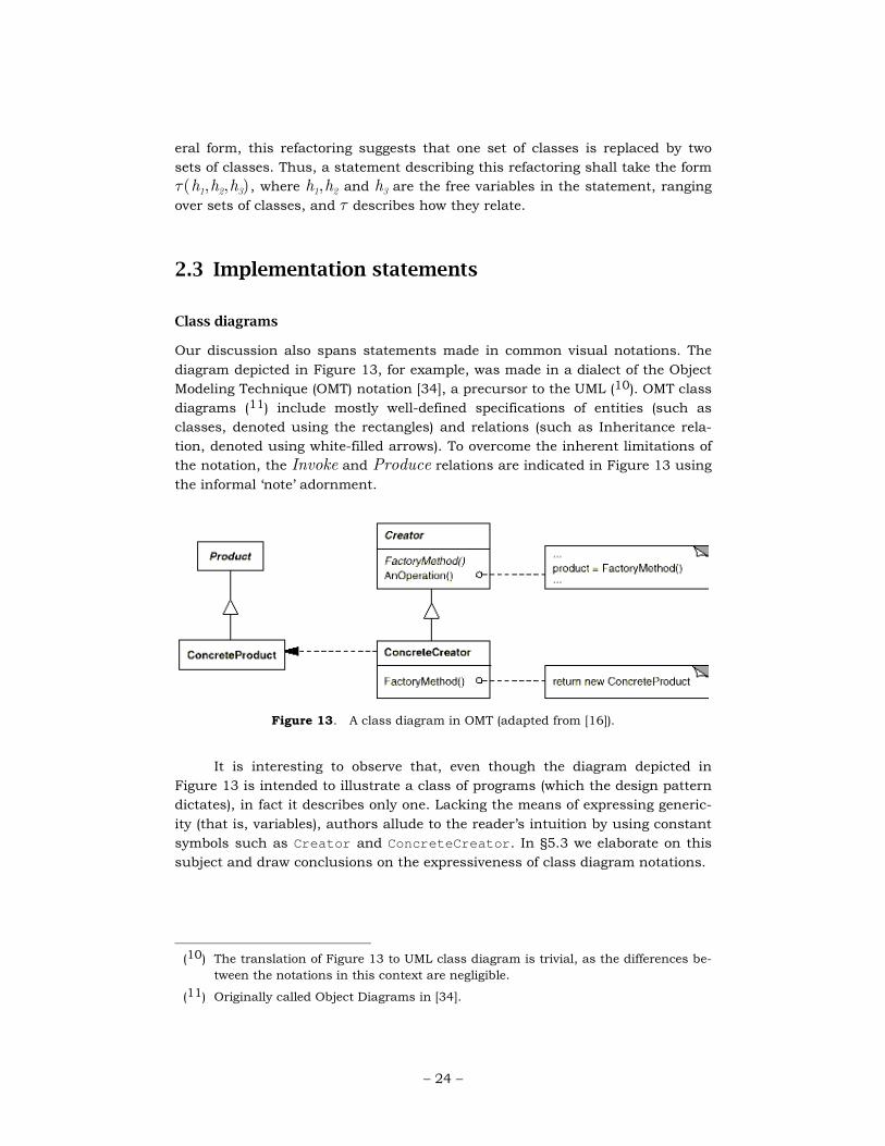
2.3 Implementation statements
Class diagrams
Our discussion also spans statements made in common visual notations. The
diagram depicted in Figure 13, for example, was made in a dialect of the Object
Modeling Technique (OMT) notation [34], a precursor to the UML (10). OMT class
diagrams (11) include mostly well-defined specifications of entities (such as
classes, denoted using the rectangles) and relations (such as Inheritance rela-
tion, denoted using white-filled arrows). To overcome the inherent limitations of
the notation, the Invoke and Produce relations are indicated in Figure 13 using the informal ‘note’ adornment.
It is interesting to observe that, even though the diagram depicted in
Figure 13 is intended to illustrate a class of programs (which the design pattern
dictates), in fact it describes only one. Lacking the means of expressing generic-
ity (that is, variables), authors allude to the reader’s intuition by using constant
symbols such as Creator and ConcreteCreator. In §5.3 we elaborate on this
subject and draw conclusions on the expressiveness of class diagram notations.
(10) The translation of Figure 13 to UML class diagram is trivial, as the differences be-
tween the notations in this context are negligible.
(11) Originally called Object Diagrams in [34].
Figure 13. A class diagram in OMT (adapted from [16]).

– 25 –
Program documentation
Software documentation frequently takes the form of natural language and ex-
amples—code excerpts. For example, the documentation of JNDI (Java Naming
and Directory Interface™) describes a specific (named) class and specific meth-
ods, their arguments and the purposes they serve. In terms of logic languages,
the library’s documentation consists of named elements of the program (con-
stants), specified either directly (e.g., class Attribute) or indirectly (e.g., the
methods defined in class Attribute). Figure 14 depicts a typical extract from
the JNDI documentation [39].
JNDI defines the Attribute interface for representing an attribute in a directory. An attribute consists of
an attribute identifier (a string) and a set of attribute values, which can be any object in the Java programming
language.
public class Attribute {
public DirContext getAttributeDefinition()
throws NamingException;
public DirContext getAttributeSyntaxDefinition()
throws NamingException;
... }
Figure 14. Excerpts from the JNDI documentation (adapted from [39]).

– 26 –
3 A formal vocabulary
In this section, we establish a vocabulary in mathematical logic that will furnish
us with the means to determine the abstraction classes of software design state-
ments.
3.1 Syntax
The examples given in §2 demonstrate that our discussion spans design state-
ments formulated in informal, semi-formal and formal, visual and textual lan-
guages (or notations). The first constraint is that the statement must be defini-
tive, that is, it must unambiguously distinguish between programs that ‘satisfy’
it from programs that do not. We further require that the statement describes
the collection of conforming programs in terms of entities and relations. This
requirement shall allow us to use Tarski’s truth semantics to determine ‘satis-
faction’ (§3.3).
Our investigation requires the notion of the signature of a statement. In
mathematical logic, the signature of a statement consists of the constant and
relation symbols appearing therein. For example, the signature of Statement (5)
consists of the constant symbol Object and the binary relation symbol Inherit. In another example, the signature of the statement in Figure 13 includes seven
constant symbols, such as Product and Product.FactoryMethod, the unary
relations Class and Method, and the binary relation Inherit represented by a decorated arc.
3.2 Semantics
Our discussion requires us to be able to determine and verify whether program
p satisfies ϕ. What notion of program semantics is suitable for this purpose?
Consider for example the principle of a Universal Base Class (Statement
(5)), and two C++ programs, designated Nil (Figure 15) and Nil2 (Figure 16).
class Object {
// ... };
class Nil: public Object {
// ... };
Figure 15. Nil, a C++ program satisfying the statement Universal Base Class.

– 27 –
class Object {
// ... };
class Nil: public Object {
// ... };
class Nil2 {};
Figure 16. Nil2, an expansion of Nil violating the statement Universal Base Class.
It is evident that Nil ‘satisfies’ the principle of Universal Base Class whereas its expansion, Nil2, does not. This suggests that Universal Base Class is non-local. But to establish that Nil indeed satisfies Statement (5) and that
Nil2 does not requires a definitive criterion of ‘satisfaction’. Automated verifica-
tion tools and environments, which support formal specifications (such as Ar-
chitecture Description Languages) and their verification with relation to the in-
tended implementation, are faced with the same problem.
We shall employ the notion of ‘finite structures’ (otherwise known as ‘de-
sign models’ [12]) in mathematical logic [2] for the purpose of representing the
semantics of a program, and use Tarski’s truth conditions to determine ‘satis-
faction’. By this approach, each program is implicitly accompanied by a mathe-
matical structure that consists of a universe of (ground) entities (such as Class, Procedure, and Component) and unary and binary relations (such as Inherit or Connect). Formally:
Definition I: Finite structure M is an ordered pair ⟨UM ,RM⟩ such that UM={a1,…ak} is a finite set of (ground) entities, and RM={R1,…Rn} is a fi-
nite set of (ground) relations over the entities in UM.
In informal terms, a finite structure consists of a universe of entities U,
and relations on these entities. A unary relation R1⊂U is simply a subset of
entities, and a binary relation R2⊂U×U is simply a set of pairs of entities. For
example, the unary relation Class is a set of entities, each of which represents a class defined in the program, whereas the binary relation Inherit is a set of pairs (c1,c2) such that c1 inherits from c2 (in Java: c1 implements, extends, or a
subtype of c2; in Smalltalk: c1 is a subclass of c2). Figure 17 illustrates �Nil�, a
finite structure for Nil (Figure 15), consisting of two entities, one unary relation (Class), and one binary relation (Inherit):

– 28 –
Entities: Object, Nil
Relations:
Class = {Object, Nil}
Inherit = {(Nil,Object)}
Figure 17. �Nil� , a finite structure representing Nil (Figure 15).
A finite structure can also be regarded as a relational database consisting
of a tabular representation for each relation, as demonstrated in Figure 18. By
this metaphor, �Nil� is a database with two tables: The table Class represents the unary relation Class, and therefore contains one column listing two entities,
Object and Nil. The table Inherit represents the inheritance relations in the program, and therefore contains two columns listing only the pair
(Nil,Object).
Class Inherit Object Nil Object
Nil
Figure 18. A database representing entities (Object, Nil) and relations (Inherit) in program Nil (Figure 15).
The notion of finite structures employed is that of untyped structures.
(The distinction between typed and untyped structures is immaterial here.)
Thus, saying “an entity of type Pipe” is merely a convenient way of saying “an
entity in the unary relation Pipe”, while referring to an entity of type Class is a way of referring to an entity in the unary relation Class.
The entities and relations that a finite structure captures depend on the
design statement in question. Consider for example the Pipes and Filters archi-
tectural style (Figure 5). The style is concerned with Pipe and Filter entities and in the way they are connected. The signature of this statement consists of
entities that are either Filter or Pipe, and the binary relation Connect. Thus, each structure that satisfiers the Pipes and Filters statement is a representation
(or ‘snapshot’) of a specific collection of Pipe and Filter entities and the relation Connect. Figure 19 depicts such a finite structure.

– 29 –
Entities: T1, T2, P
Relations:
Filter = {T1, T2}
Pipe = {P}
Connect = {(T1,P), (P,T2)}
Figure 19. Mpf, a finite structure satisfying Pipes and Filters (Figure 5).
Observe that finite structures can be used to represent both behavioural
and structural properties of programs. In other words, finite structures can be
obtained from analyzing the structure of the program (the source code), as de-
picted in Figure 17, or a snapshot in its execution, as depicted in Figure 19.
While finite structures are much simpler than other notions of program
semantics (discussed in §7.2), they are adequate for the purpose of determining
whether the program satisfies a given software design statement. In fact, their
simplicity is valuable in that they abstract the numerous details of data and
control, most of which are irrelevant for our purposes, into a ‘flat’ collection of
entities and relations.
Finite structures allow us to employ Tarski‘s truth conditions (discussed
in the following subsection), thereby providing a straightforward criterion of sat-
isfaction against statements formulated in the first-order predicate calculus. As
for statements formulated in other languages, we demonstrate in §5 that finite
structures can be used to analyze the semantics of any design statement that
can be expressed in the vocabulary of entities and relations, such as statements
formulated using context-free grammar (Figure 5), class diagrams and natural
language.
How are programs translated into finite structures? While the pragmatics
of computing finite structures are outside the scope of this paper, we represent
the mapping from a program into a finite structure using a function, called the
abstract interpretation function I (Definition VI, Appendix). The finite structure
I(p) to which I maps program p is written �p�I. We assume such a fixed ab-
stract interpretation function throughout our discussion. Thus, we may omit
the designation of the abstract interpretation function from the representation
of the finite structure of p, which shall be written simply as �p� . For instance, we say that the finite structure �Nil� (Figure 17) is the abstract interpretation of program Nil, namely: I(Nil)=�Nil�. More about abstract interpretation func-
tions appeared in [13].

– 30 –
3.3 Tarski’s truth conditions
Tarski’s truth conditions [2] furnish us with a straightforward method of deter-
mining whether a closed statement in the classical predicate calculus is satis-
fied by a given structure. Since the structures we are concerned with are finite,
checking Tarski’s truth conditions is decidable. We say that ‘M is satisfied in ϕ’
if and only if M satisfies ϕ, written M�ϕ (also ‘ϕ is true in M ’, ‘M is a model
of ϕ’, and ‘M models ϕ’). Below, we briefly examine the truth conditions for
closed and for open statements. Tarski’s truth condition is articulated in the
formal vocabulary in Definition VII (Appendix). Related definitions and addi-
tional examples for the notion of satisfaction can be found in [2].
The satisfaction of a closed statement (also ‘sentence’) in the propositional
calculus is determined by the combination of the truth table of the logical con-
nectives in the usual way, such as ∧ (conjunction), ∨ (disjunction), ¬ (nega-tion), and ⇒ (implication). For example, the closed statement
Class(Nil)∧Inherit(Nil,Object) is satisfied by M if and only if both state-
ments Class(Nil) and Inherit(Nil,Object) are true in M.
The satisfaction of a closed statement in the first-order predicate calculus
is determined by the respective quantifier in the usual way. For example, the
statement ∃x • Method(x) is satisfied in M if and only if there exists an entity
m in the universe of M such that m is a method entity in M (namely, Method is a unary relation in M and m is in Method).
Open statements are statements that contain free variables, such as (9)
and (10). We say that a finite structure ‘M satisfies open statement ϕ’ if and
only if there is an assignment [2] σ from the free variables to the entities in M
such that ϕ[σ(xi)/xi] (namely, the consistent replacement of free variable xi
with σ(xi) ) is satisfied in M , written M�σϕ. For example, the statement
Inherit(x,y) is open because x and y are free variables in it. To show that the structure �Nil� (Figure 17) satisfies it, consider the assignment σ where
σ(x)=Nil and σ(y)=Object: By replacing the variables x, y with the constant symbols Nil and Object, respectively, we obtain the statement
Inherit(Nil,Object), which is satisfied by �Nil�.

– 31 –
4 Abstraction classes
In this section, we formulate the Intension and the Locality criteria and define
the abstraction classes that arise from these definitions.
4.1 The Intension/Locality criteria
The Locality criterion attempts to capture the most salient element in the defini-
tions of ‘architecture’ quoted in §1. It distinguishes between global statements
and statements which merely describe a delineated part of the program:
Definition II: The Revised Locality Criterion. A statement ϕ is local if and only
if it is preserved under expansion (Definition IV).
This definition employs the notion of expansion in mathematical logic, which is
rigorously defined in the next subsection (Definition IV). Less formally, the Lo-
cality criterion stipulates that a statement ϕ is local if and only if a program
that satisfies ϕ cannot be expanded into a program that violates it. We further
illustrate this definition in the remainder of this section.
The Intension criterion is inspired by Frege's theory of extensions:
The extension of a concept is something like the set of all objects that
fall under the concept. For example, the extension of the concept “x is
a positive even integer less than 8” is something like the set consisting
of the numbers 2, 4, and 6. [42]
Taking Frege’s approach, we seek a semantic distinction between state-
ments that describe specific properties of named entities in the program (exten-
sional statements) vs. statements that describe programs via properties of un-
named entities and sets of unnamed entities (intensional statements), e.g., us-
ing variables [17]:
Definition III: The Revised Intension Criterion. We say that a statement ϕ is
extensional if and only if it is preserved both under expansion and under reduc-
tion (Definition IV). Otherwise we say that ϕ is intensional.
The Intension criterion stipulates that a statement ϕ is extensional if and only if
a program that satisfies ϕ cannot be expanded or reduced into a program that
violates it (where reductions may remove only entities that are not explicitly
mentioned in ϕ). In other words, an extensional statement is a statement such

– 32 –
that a program that satisfies it will continue to satisfy it even after expanding or
reducing the program. The notions of expansion and reduction are examined in
the following subsection.
4.2 Expansions and reductions
The notion of expansion is formally established as follows:
Definition IV: Expansion/reduction. Let M=⟨U,R⟩ designate a finite struc-ture. We say that a finite structure M’=⟨U’,R’⟩ is an expansion of M (M is a
reduction of M’) if M’ can result by the following:
♦ By adding a non-empty, finite set of new entities to U, i.e.,
U’=U∪{b1,…bj} ♦ By adding to each n-ary relation R in R zero or more n-tuples, each of
which contains at least one of b1,…bj.
Expansions (and symmetrically, reductions) must be treated with care.
Not any text added to the source code or variable added to the memory model is
considered an expansion. An expansion can only add new entities, it may not
modify existing entities. Thus, to determine which entities can be added in an
expansion, we must ask: What entities can be added to the existing program
without directly modifying it?
Let us demonstrate the notion of expansions (reductions) relevant to soft-
ware design statements in three categories:
♦ In examining a statement that is primarily concerned with classes in
class-based languages (such as Universal Base Class and design pat-
terns), expansions comprise adding new entities of type Class and possi-bly expanding any existing relations (such as Inherit) to include these en-tities. The statements may also mention secondary entities such as meth-
ods or fields, but we do not consider expanding a structure by adding
methods or fields to an existing class because this constitutes a modifica-
tion (to this class), not an expansion.
♦ In examining a statement that is primarily concerned with objects in ob-
ject-oriented languages (or instances of classes in class-based program-
ming languages) and the relations between them, such as Singleton
(Figure 28) and Publisher-Subscriber (Figure 11), an expansion step may
introduce new entities of type Object and possibly expand the relations to include them. The statement may also mention secondary entities such as
fields or methods, but we do not consider expanding a structure by adding
fields or methods to an existing object because this constitutes a modifica-
tion (to this object), not an expansion.

– 33 –
♦ In examining a statement that is primarily concerned with components,
connectors and their possible connections, such as Pipes and Filters
(Figure 5), an expansion step may introduce new Components or
Connectors and possibly expand the Connect relation to include them.
The statement may also mention secondary entities such as ports or roles,
but we do not consider expanding a structure by adding ports or roles to
an existing component (a role to a connector) because this constitutes a
modification (to this component/connector), not an expansion.
4.3 Applying the Intension/Locality criteria
Let us demonstrate how to use the Intension criterion to prove that the state-
ment ‘class Nil inherits from class Object’ is local and extensional. Articulated
in the first-order predicate calculus:
Inherit(Nil,Object) (11)
Let us demonstrate informally that statement (11) is extensional. We begin
by showing that the statement is preserved under expansion which, in the con-
text of entities such as classes and methods, means adding new class declara-
tions to the program. We observe the following:
1 Let p designate a well-formed program written in class-based program-
ming language that defines a class Nil inheriting from class Object.
Clearly, p satisfies Statement (11).
2 An expansion shall consist of adding any finite number of class declara-
tions to p. Clearly, the expanded program will continue to include the
classes Nil and Object such that Nil inherits from Object.
This line of reasoning can be articulated in our formal vocabulary as fol-
lows:
1’ Let M designate a finite structure that satisfies Statement (11). Thus, the
universe of M consists of the entities Nil and Object. The relations in M
include the binary relation Inherit which contains the pair (Nil,Object). 2’ An expansion shall consist of adding any finite number of entities (of any
type) to the universe of M and expanding the Inherit relation (in any way). Clearly, the expanded structure shall also to satisfy statement (11)
because the pair (Nil,Object) shall remain in the relation Inherit in any such expansion, hence (11) is preserved under expansion.
To complete the proof that Statement (11) is extensional we must show that it is
also preserved under reduction. In the context of entities such as classes and
methods, ‘reduction’ means removing any class declaration from the program
that is not part of the signature of Statement (11) (namely Object or Nil). This
can be done informally as follows:

– 34 –
3 After removing any class declaration from p other than Object or Nil, p will continue to include the classes Nil and Object such that Nil inher-
its from Object.
Formulating this line of reasoning is also straightforward:
3’ A reduction of M shall consist of removing any number of entities from
the universe of M other than Nil or Object, as well as removing from the
Inherit relation any pair apart from (Nil,Object) . Clearly, the reduced structure shall also to satisfy statement (11), hence the statement is pre-
served under expansion.
In §5, we use the Intension criterion and the Locality criterion to deter-
mine the abstraction class of the software statements presented in §2.
4.4 The Intension/Locality hierarchy
We designate the class of local statements _ , non-local statements a_ . By
Definition III, extensional statements are local. Hence, the Intension criterion
divides _ into two abstraction classes, designated _\ (local and intensional
statements) and _X (local and extensional statements). Since ‘local and exten-
sional’ is a redundancy, we refer to statements in _X as extensional.
The classes a_ , _\ and _X form a hierarchy of three abstraction
classes, which shall be referred to as the Intension/Locality hierarchy (Figure
2).
In the following section, we determine the abstraction class of each one of
the examples formulated in §2. Our analysis suggests that local statements are
usually in the form: “there exists an entity (set of entities) that satisfies so-and-
so condition”, whereas non-local statements are in the form “for all entities, so-
and-so condition applies”. We elaborate on the syntax (form) of local and exten-
sional statements in §6.
The analysis provided in §5 also suggests that intensional statements in-
clude variables (quantified or free) and, conversely, that statements consisting
entirely of constant symbols are extensional. The Intension criterion effectively
makes the same distinction without alluding to the form of the statement or re-
stricting its language. This conclusion is, in turn, consistent with the dictionary
definition of ‘extensional’, as well as with Frege’s notion of extensions.

– 35 –
5 Abstraction classes of design state-ments
In this section we provide evidence that corroborate the Intension/Locality hy-
pothesis. We apply the Intension/Locality criteria to the design statements for-
mulated in §2 and determine the abstraction class of each. Some proofs are
formal while others merely sketch our line of reasoning. We tend to omit from
our proofs parts that are either trivial or which follow the exact line of reasoning
that has already been followed.
5.1 Abstraction class of Strategic statements
In this subsection, we demonstrate that strategic statements are non-local.
Proposition 1. Information Hiding (1) is in a_ .
Proof: Let us show that statement (1) is not preserved under expansion. Con-
sider for example the C++ program depicted in Figure 20. It is easy to show that
this program satisfies Statement (1). The program can be expanded without
modifying class stack by adding the class Intruder (Figure 21), the result of
which does not satisfy Statement (1).
�
template <class T> class Stack {
public:
void push(T);
// ...
private:
T * theStack;
int size;
};
Stack<complex<float> > si;
Figure 20. Class Stack in C++.

– 36 –
// class Stack (see Figure 20)
class Intruder {
int foo() { return si.size; }
};
Figure 21. An expansion to the program in Figure 20 in which Statement (1) is not
satisfied.
Proposition 2. Each Axioms of Object-Oriented Design (2) is in a_ .
Proof: Let Mood designate a structure whose universe consists of Class {c1,…ci}, Method entities {m1,…mj} and Signature entities {s1,…sk} , and whose relations include the binary relation Inherit, Member and SignatureOf such that Mood satisfies statements (2.1)—(2.3). To demonstrate that none of
the statements is preserved under expansion, let us add three distinct Method entities mj+1, mj+2, mj+3, a Class entity ci+1 and a signature entity sk+1 and by
expanding the relations SignatureOf and Member such that
♦ SignatureOf(mj+1,sk+1) ♦ SignatureOf(mj+2,sk+1) ♦ Member(mj+1,ci+1) ♦ Member(mj+2,ci+1) ♦ Inherit(ci+1,ci+1)
We allow this expansion because it does not modify Mood. Clearly, the expanded
structure does not satisfy either axiom of object-oriented design (2), e.g., class
ci+1 inherits from itself, method mj+3 has no signature, and methods mj+1 and
mj+2 share the same signature and are members of the same class. �
Note that compilers of class-based languages such as C++, Java, and Eif-
fel assist in enforcing the axioms of OOD by providing error messages corre-
sponding to the violation of Clause (2.1), Clause (2.2,), or Clause (2.3).
Proposition 3. Implicit Invocation (Figure 7) is in a_ .
Proof: Let us show that Figure 7 is not preserved under expansion. Consider a
structure M ii in which Figure 7 is satisfied, whose universe consists of Module elements M=m1,…mk and of Procedure elements P=p1,…pn. The relations in
M ii include the binary relations InModule⊂P×M and Invoke⊂P×P. This
program can be expanded by adding a two modules mk+1, mk+2 and two proce-
dures pn+1, pn+2, and by expanding the relations InModule and Invoke such that

– 37 –
♦ mk+1 ≠ mk+2
♦ InModule(pn+1,mk+1) ♦ InModule(pn+2,mk+2) ♦ Invoke(pn+1,pn+2)
This expansion is allowed because it does not modify any existing module or
procedure in M ii. Clearly, it does not satisfy Statement (3). �
Proposition 4. Pipes and Filters (Figure 5) is in a_ .
Proof: We show that Figure 5 is not preserved under expansion. Clearly Mpf
(Figure 19) satisfies Figure 5. We may expand Mpf by adding a new Filter entity T3 that is not connected to any pipe because such an expansion does not modify
the entities in p. The expansion however does not satisfy Figure 5 because the statement requires every filter to be connected to some pipe. �
Proposition 5. Layered Architecture (4) is in a_ .
Proof: Let us show that (4) is not preserved under expansion. Let p designate a non-trivial program satisfying Layered Architecture with at least two non-empty
layers 1, 2. We may expand p by adding an element x to layer 1 (Layer(x)=1) because such expansion does not modify any element in p. We may also expand
the relation Depend to include the pair (x,y) for some element y in layer 2. Clearly, the finite structure representing the program resulting from this expan-
sion does not satisfy Statement (4). �
Proposition 6. MFC interaction protocol (Figure 10) is in a_ .
Proof: Let us show that Figure 10 is not preserved under expansion. Let Mmfc
designate a finite structure whose universe consists of the Class entities CWnd, newWindow1 and newWindow2 and the binary relation Inherit including both pairs (newWindow1,CWnd) and (newWindow2,CWnd). We may expand Mmfc by a
Class entity newWindow3 because this expansion does not modify any class in
Mmfc. Clearly, the expanded finite structure does not satisfy Figure 10. �
It is easy to prove along the same lines that the Law of Demeter (6) and
the Enterprise JavaBeans standard (7) are in a_ .
Minsky defines ‘regularity’ as “any global property of a system; that is, a
property that holds true for every part of the system”. [28] He demonstrates
regularities with the following example:

– 38 –
... the statement “class B inherits from class C,” in some object-
oriented system, does not express a regularity, since it concerns just
two specific classes; but the statement “every class in the system in-
herits from C” does express a regularity, and so does the statement
“only class B inherits from C,” both of which employ universal quanti-
fication. [28]
Note that the sample regularity given above is identical to the Universal
Base Class statement (5), which is demonstrated in §3.2 to be in a_ . From this
and other examples Minsky gives in his paper (such as Layered Architecture), as
well as from the spirit of the definition he gives, it is evident that Minsky’s regu-
larities are in non-local.
5.2 Abstraction class of Tactical statements
Our analysis of the design patterns in the patterns catalogue [16] reveals that,
with the exception of the Singleton pattern (discussed in §7.3), they are in _\ .
In this subsection, we examine the abstraction class of the design patterns de-
scribed in §0.5.
Proposition 7. Factory Method (9) is in _\ .
Proof: In [13] we prove that Statement (9) is preserved under expansion. Let us
show that it is not preserved under reduction. Consider FM (Figure 22), a
Smalltalk implementation of the Factory Method. Figure 23 depicts �FM� , a fi-nite structure for Figure 22. To show that �FM� satisfies Statement (9), we
must show a consistent assignment from the free variables in the statement to
the entities in the universe of �FM� such that the result is satisfied in �FM�. Figure 24 depicts such an assignment. We may reduce the finite structure by
removing MyDocument from the universe of �FM� because MyDocument is not part of the signature of Statement (9). This reduction violates clause (9.3). �

– 39 –
Object subclass: #Application instanceVariableNames: 'docs'. Application>>newDocument
self createDocument.
Application>>createDocument
self subclassResponsibility.
Application subclass: #MyApplication. MyApplication>>createDocument
^ MyDocument new.
Object subclass: #Document. Document subclass: #MyDocument.
Figure 22. FM, a Smalltalk program satisfying the statement Factory Method (adapted
from [16]).
Entities: Object, Application, Application>>newDocument, MyApplication, MyApplication>>createDocument, Document, MyDocument
Relations:
Class = { Object, Application, MyApplication, Document,
MyDocument}
Method = { Application>>newDocument,
Application>>createDocument,
MyApplication>>createDocument}
Inherit = { (Application,Object),
(MyApplication,Application),
(MyDocument,Document)}
Produce ={ (MyApplication>>createDocument,MyDocument)}
Figure 23. �FM� , a finite structure for FM.
Products = {MyDocument}
Factories = {MyApplication}
FactoryMethods = {MyApplication>>createDocument }
Figure 24. An assignment from the free variables in Factory Method to entities in the
universe of �FM� .

– 40 –
Proposition 8. Strategy (10) is in _\ .
Proof: Let us show that Statement (10) is preserved under expansion. Let ϕ des-
ignate the conjunction of the statements (10.1)–(10.5). According to [41], the
Schema in (10) effectively defines the open statement
ϕ(context,strategy,alrogithm,operation,Strategies,Algorithms)
with free variables context,…Algorithms. By Tarski’s truth conditions,
ϕ(context,…Algorithms) is satisfied in some finite structure mStrategy if and only
if its universe contains the Class entities context, strategy, cs1,…csk, and
the Method entities algorithm, operation, and ca1, …can such that the con-
sistent replacement of context…Algorithms with context,…{ca1,…cak} is sat-isfied in ϕ. Thus, ϕ(context,…{ca1,…cak}) is satisfied in mStrategy. We may ex-
pand the universe of mStrategy with any number of Class entities because this would not modify any of the entities in therein. Evidently, ϕ(context, …{ca1,…cak}) shall remain satisfied in any expansion of mStrategy, and hence
also ϕ(context,…Algorithms). �
Proposition 9. Publisher-Subscriber (Figure 11) is in _\.
Proof: Let us show that Figure 11 is preserved under expansion. Let p designate a program satisfying the statement in Figure 11. Let P designate the Publisher ob-
ject and S1,… Sn the Subscriber objects in p, such that P satisfies the condition
imposed by the clause “Publisher supports […]” and each one of the subscribers
satisfies the conditions imposed by the clause “Subscriber supports […]” in
Figure 11. Valid expansions to p consist of adding any number of new entities of
type Object to the universe of the finite structure representing p. Any such ex-pansion, however, does not affect the satisfaction of the contract by the objects
P, S1,… Sn and of the conditions imposes by the respective clauses. �
Proposition 10. Counted Pointer (Figure 12) is in _\ .
Proof: Let us show Figure 12 is preserved under expansion. Consider a program
p that satisfies Figure 12. Thus, p incorporates of a Handle class h and a Body class b, which satisfy the constraints imposed by the Statement. Valid expan-
sions add any number of new class declarations to p. Any such new class decla-ration will not affect the satisfaction of Figure 12. �

– 41 –
The same line of reasoning can be applied to refactorings that introduce
design patterns, as well as to statements describing the result of the four ‘big
refactorings’, such as Tease Apart Inheritance (§0.5).
5.3 Abstraction class of Implementation statements
The Unified Modeling Language (UML) [4] is widely used in the industry as a de-
sign and architectural specification language. This practice has been followed in
the academy [37]. Thus, it is of particular interest to determine the abstraction
class of UML statements.
Proposition 11. The class diagram in Figure 13 is in _X .
Proof: Let us show that Figure 13 is preserved under expansion. Let MCD des-
ignate a structure that satisfies Figure 13. Any such structure shall include,
among others, the following entities and relations:
♦ Class entities, such as Creator and ConcreteCreator, as well as Method entities, such as Creator::FactoryMethod and ConcreteCreator::FactoryMethod.
♦ The binary relation Member, which associates every method with one
class, such as the pair (Creator::FactoryMethod,Creator) ♦ The binary relation Inherit, which includes the pairs (ConcreteCreator,Creator) and (ConcreteProduct,Product)
Additional information in Figure 13 is represented informally. For example, the
relation Invoke(AnOperation,FactoryMethod) is represented by the note
“product=FactoryMethod()” at the top right corner of the diagram.
Note that every element in the diagram explicitly represents a specific en-
tity (e.g., class Creator) or a specific relation (e.g.,
Inherit(ConcreteCreator,Creator) ). Thus, expanding MCD with any number
of Class entities cannot violate Figure 13.
Let us show that Figure 13 is preserved under reduction. There are two
types of entities that can be removed from MCD:
♦ Entities that are explicitly mentioned in Figure 13.
♦ Entities that are not explicitly mentioned in Figure 13.
By the Intension criterion, we only consider reductions removing entities
that are not explicitly mentioned in Figure 13 from the universe of MCD. Obvi-
ously, any such reduction will continue to satisfy Figure 13. �
The same line of reasoning can be applied to any class or collaboration
diagram in version 1.5 of the Unified Modeling Language: In the absence of vari-

– 42 –
ables in such notations, diagrams may only express properties of named ele-
ments in the program.
UML is an ongoing effort. Recent versions of the notation [30] offer forms
of meta-descriptions (e.g., stereotypes, type variables). Unfortunately, these are
ill-defined and we are unaware of practicing software engineers that use them.
As a result, UML diagrams in actual practice represent only specific, named ele-
ments in a program. These diagrams are extensional. They do not represent in-
tensional design motifs, such design patterns and architectural styles, but only
specific implementations thereof.
A similar line of reasoning can also be applied to most forms of program
documentation: As Figure 14 demonstrates, a well-defined document consists of
named elements and their properties. Some descriptions include the words “all
classes in hierarchy h” or “there exists a method in class c”, but these state-
ments quantify bounded variables that range over explicitly named sets, such as
the set of classes in h or the set of methods in c. In conclusion, software design
statements in program documentation are extensional because they constitute
statements about explicitly named elements in the program.

– 43 –
6 Architectural mismatch
In their seminal paper on architectural mismatch [18], Garlan et. al argue that
“future breakthroughs in software productivity will depend on our ability to
combine existing pieces of software to produce new applications”. In particular,
they describe the problems arising from the attempt to construct a working sys-
tem from existing components, including excessive code size, poor performance
and error-prone construction process. In the analysis of these problems, the au-
thors conclude that they were primarily the result of a class of interoperability
problems arising from conflicting assumptions that modules make about the
application in which they are intended to operate. This class of problems is re-
ferred to as ‘architectural mismatch’.
The authors go on to describe the particulars of some of the assumptions
leading to architectural mismatch. Figure 25 depicts a summary of some of
these assumptions.
� The Softbench Broadcast Message Server expected all of the components to have a graphical user in-
terface ….
� The critical assumption made by Unidraw … was that all manipulations would be of top-level objects.
Thus, it was not possible to change a child object except by having the parent manipulate it.
� Packages make assumptions … about the data that would be communicated over the connectors. …
Softbench, on the other hand, assumes that … all data to be communicated … is represented as ASCII
strings. [However,] the main kind of data manipulated by our tools was database and C++ object point-
ers.
� OBST … assumed that all of the tools would be completely independent of each other. This assumption
meant that there would be no direct interactions between tools.
� … the Mach Interface Generator assumed that the rest of the code was a flat collection of C proce-
dures, and that its specification described the signature of all of these procedures.
Figure 25. Assumptions leading to architectural mismatch (adapted from [18]).
The authors do not provide a formal definition to architectural mismatch.
But by examining the assumptions leading to architectural mismatch, such as
the statements depicted in Figure 25, we conclude that they can be generalized
to the description given in Figure 26 and formulated as follows:

– 44 –
� Component p (e.g. Softbench) makes (implicitly
or explicitly) assumption ϕ (“all data to be com-
municated is represented as ASCII strings”).
� Let p designate a program, ϕ the assumption
that p makes.
� p satisfies the assumption it makes (e.g.,
“Softbench also communicates by ASCII strings”);
� �p��ϕ
(i.e., ϕ is satisfied in p).
� Let us consider an application q which includes p
such that q is not an application in which p is “in-
tended to operate”.
� Let q designate an expansion to p such that
�q��ϕ (i.e., ϕ is not satisfied in q)
� We say that p and q mismatch. � We say that p and q mismatch on ϕ
Figure 26. Formulation of architectural mismatch.
Definition V: Architectural Mismatch. Let ϕ designate a design statement sat-
isfied by component p. Let q designate an expansion of p. If �p��ϕ but �q��ϕ then we say that p, q mismatch on ϕ.
It is easy to prove that any assumption leading to architectural mismatch
by Definition V is in a_ . Formally:
The Architectural Mismatch theorem. If programs p, q mismatch on ϕ then ϕ
is in a_ .
Proof: Follows immediately from the Locality criterion. �
In Figure 27 (left column, adapted from [18]) we demonstrate how the Lo-
cality criterion contributes to the understanding of three of the “four necessary
aspects of a long-term solution” (to the problem of architectural mismatch).

– 45 –
(a) 1. “Make architectural assumptions ex-
plicit.”
Make non-local assumptions explicit.
(b) 2. “Construct large pieces of software
using orthogonal components. As
Parnas has long argued [Par72], each
module should hide certain design as-
sumptions. Unfortunately, the architec-
tural design assumptions of most sys-
tems are spread throughout the con-
stituent modules. Ideally one would like
to be able to tinker with the architectural
assumptions of a reused system by
substituting different modules for the
ones already there.”
Minimize the number of non-local assumptions. Ide-
ally, each module should only make local assump-
tions.
(c) 4. “Develop sources of architectural de-
sign guidance. … We need to find ways
codify and disseminate principles and
rules for composition of software.”
Design rules for composition: Whenever non-local
assumptions are made, either ensure that they are
compatible or else relinquish the attempt to combine
the components.
Figure 27. Solutions to architectural mismatch rephrased using non-locality.
Despite progress made since the origins for architectural mismatch have
been investigated, component integration and reuse have remained the panacea
of software engineering. The Architectural Mismatch theorem shall hopefully
shed light on the reasons for software mismatch and furnish practical means to
diagnose potential sources for this problem.

– 46 –
7 Discussion
In this section, we discuss issues arising from the vocabulary we defined and
the Intension/Locality hypothesis.
7.1 Syntactic criteria
Can we characterize our abstraction classes syntactically? An alternative to the
semantic approach we presented could operate within the confines of one speci-
fication language, thereby allowing the formulation of the Intension/Locality cri-
teria in syntactic terms. Turner [41], for example, describes a core theory of
specifications which is comprehensive enough to express in first-order predicate
calculus all the software design statements that we are interested in. Turner
developed a rich formal theory that will eventually shed light on the practical
use of specification languages in discussing programs, including Z, VDM and
LePUS. In particular, his approach rigorously represents the features of the
languages used in dealing with programs and provides means for investigating
the logical implications of these features. This approach, however, enforces a
commitment to the first-order predicate calculus as a language of specification,
while we set out to avoid such commitment.
In mathematical logic where the language, the structures and the notion
of expansion are well-defined, the theory is developed much deeper. First, we
have a complete mathematical characterization: Given a theory and the class of
its models, a statement is local if and only if it is equivalent in the theory to an
existential formula. This is a syntactic characterization. In §5 we demonstrated
that one direction of this assertion holds in the informal case, namely, that any
formula which asserts the existence of a collection of entities and relations is
local.
More interestingly, by the solution to Hilbert’s tenth problem in the class
of models of arithmetic (namely enumerable, not finite structures), the local
properties are exactly the recursively enumerable properties and the extensional
properties are the recursive properties.
In logic, extensional statements are called algebraic properties. A cele-
brated theorem by Abraham Robinson proves that in the theory of algebraically
closed fields every statement is equivalent to local statement. This can be used
for an algorithm to decide which statements are satisfied in all algebraically
closed fields. Similar analysis yields complete and decidable characterization of
the algebraic structure of the real numbers, thus establishing the (surprising at
first) fact that their analysis is much simpler than number theory (when re-
stricting ourselves to first order logic).

– 47 –
7.2 Semantic alternatives
Semantics of programs may be provided in terms of Zermelo-Fraenkel set theory
(‘denotational semantics’), turing automata, random access machines [7], ab-
stract state machines [19], graphs grammars, and lambda expressions [1]. One
may argue that our discussion should have employed one of these more familiar
formalisms rather than finite structures.
None of these formalisms, however, is appropriate for our investigation.
Each formalism supports a level of abstraction that is appropriate for determin-
ing properties specified in a vocabulary that is significantly more detailed then
necessary. For example, Turing and random access automata are not defined in
terms of the abstractions we are interested in and therefore could not possibly
furnish us with graspable means for determining whether a program satisfies a
design pattern or an architectural style. Thus, even if generating a turing ma-
chine representation of programs were at all practical (which, in the general
case, it is not), such a representation would be not be informative.
7.3 Architectural styles vs. design patterns: the Singleton anomaly
Reporter: What would you do if the measurements of bending starlight at the 1919 eclipse
contradicted your general theory of relativity?
Albert Einstein: Then I would feel sorry for the good Lord. The theory is correct.
Monroe, Kompanek, Melton and Garlan [29] discuss the differences between ob-
ject-oriented design patterns and architectural styles. The authors observe that
the vocabulary defining architectural styles is richer in abstractions and covers
a larger range of descriptions than those employed by design patterns. However,
the vocabulary of design patterns goes beyond object-oriented design, and pat-
terns appear in various forms in every programming paradigm; consider for in-
stance the rich variety of programming idioms and ‘programming blueprints’
used by the Java community.
Lacking a well-defined criterion, the distinction between design patterns
and architectural styles is open for interpretation. In the Intension/Locality hy-
pothesis we stipulate that the Locality criterion formulates this distinction. But
an initial analysis of the patterns catalogue [16] reveals that one design pattern
that violates the Intension/Locality hypothesis: the Singleton pattern. Figure 28
depicts an adapted description of the pattern.

– 48 –
[The motivation of the Singleton pattern is to] Ensure a class only has one instance, and provide a global point
of access to it.
It's important for some classes to have exactly one instance. [For example,] Although there can be many print-
ers in a system, there should be only one printer spooler. There should be only one file system and one win-
dow manager. …An accounting system will be dedicated to serving one company.
Figure 28. The Singleton design pattern (adapted from [16]).
Proposition 12. Singleton (Figure 28) is in a_ .
Proof: Let us demonstrate that Figure 28 is not preserved under expansion. A
structure satisfying the Singleton would represent a ‘snapshot’ in the execution
of the program, the universe of which consists of any number of Object and Class entities, as well as the binary relation InstanceOf. From Figure 28 it fol-
lows that there in only one entity, which can be designated i1, such that
InstanceOf(i1,singlton) . We may expand the universe of this finite structure
with another entity, i2, and expand the relation InstanceOf to include the pair (i2,singlton), resulting in a structure that violates Figure 28. �
There are two possible explanations to the anomaly arising from
Proposition 12: (1) the Intension/Locality hypothesis is wrong (and design pat-
terns can be non-local); or (2) the Singleton should be considered an architec-
tural style.
When deciding which explanation is more appropriate, we must ask: Is the
decision to adopt the Singleton pattern strategic or tactical? The examples illus-
trating possible motivations for using the pattern describe resources that are
central to the successful operation of the overall system (printer spooler, window
manager, accounting system). In addition, the term ‘global’ (Figure 28) suggests
that the singleton instance is designed to provide services to clients from the
entire scope of the program. This evidence suggests that the decision to use the
Singleton pattern is indeed strategic and that the reasons the Singleton was in-
cluded in the design patterns catalogue have nothing to do with the notion of
abstraction classes.

– 49 –
8 Summary and conclusions
8.1 Practical implications
The Locality criterion is paramount to any large development software develop-
ment project: Non-local design decisions must be taken (and made explicit) early
in the process because each non-local decision taken may potentially violate
every other design decision. In fact, the amount of effort required to settle po-
tential clashes is proportional to the amount of detail in the existing statements.
Fully completed programs are particularly sensitive to new non-local changes.
In contrast, Local design decisions have limited consequences and for the same
reason are better postponed to the point in the process following all non-local
design decisions.
From the theorem we prove in §6 we conclude that only non-local assump-
tions may lead to architectural mismatch. This leads to the following practical
conclusions:
♦ When developing a new component, minimize the non-local assumptions
it makes and make them explicit (see Figure 27).
♦ When assembling an application from existing components, use only com-
ponents whose non-local assumptions ‘match’ (by Definition V), or else
clashes may arise.
While following these conclusions does not guarantee the elimination of
architectural mismatches, they are necessary preconditions thereto.
Also, we observe that tools that enforce non-local rules are inherently dif-
ferent from tools that verify local statements. Proposition 1 explains why C++
compilers/linkers must examine the entire scope of the program (for example, in
enforcing the non-local principle of Information Hiding). Similarly, Darwin-E
[28], Minsky’s tool for enforcing Law-Governed Regularities (§5.1) must analyze
the complete program because regularities are non-local. In contrast, tools that
support the use of design patterns, refactorings and programming idioms may
focus on the part of the program that implements the statement (contains an
‘instance’, see Definition VII) and ignore the remainder. Thus, both tool design-
ers and users should carefully examine the class of statements the tool sup-
ports.
Finally, we have established that class diagrams, as well as package and
collaboration diagrams, are inadequate means for intensional specifications.
While UML diagrams may depict specific entities and relations in the application
(i.e., instances of the statement), even those of coarse granularity, UML-like dia-
grams lack the genericity and generality that intensional statements require.

– 50 –
8.2 Future directions
Further analysis may refine the abstraction classes a_ , _\ and _X. Also of
interest would be to determine the abstraction class of metaprogramming state-
ments, i.e., statements in a programming language that manipulate programs,
and of statements articulated in the language of communicating sequential
processes [22].
An alternative to the semantic approach we took could operate within one
specification language. Such a syntactic approach (sketched in §7.1) remains
the subject of future investigation.
The investigation of any scientific hypothesis is an open-ended process.
The investigation of the Intension/Locality hypothesis is further complicated for
the reasons elaborated in the Caveat (§1.6), including ambiguous articulations
of software design statements, their complexity, and the differences between the
application domain of each. Despite the anomalies observed (the Singleton pat-
tern, §7.3) and those that are yet to be observed, we hope that the Inten-
sion/Locality hypothesis with be further corroborated by the formulation of
other software design statements.
Acknowledgements
The authors wish to thank Raymond Turner for his contribution, Norbert Völker
and Andrew Malton for their comments, Yehuda Elkana for his guidance, Naomi
Draaijer for her continues support, and Marry J. Anna for her inspiration. This
research was supported in part by the U.S. Department of Defense.
Appendix
Definition VI. Let p designate a program, represented either as the source code
or as a snapshot of the abstract machine during the execution of such. An ab-
stract interpretation function I is a functional relation which maps each pro-
gram p into a finite structure (Definition I) I(p), written �p�I.

– 51 –
Definition VII. Let ϕ(x1,…xn) be a first-order expression such that x1,…xn are
free variables in ϕ. Let M designate a finite structure whose universe contains
the entities a1,…an. Let σ be the consistent assignment [2] of a1,…an to x1,…xn.
If the result of assignment σ in ϕ is satisfied in M then we say that
(a1,…an) is ‘an instance of ϕ in the context of σ’.
If there is such an assignment, we say that M satisfies ϕ (also M mod-
els ϕ), written M�ϕ.
In particular, ϕ may be a sentence (i.e., it has no free variables). We say
that M satisfies ϕ if and only if ϕ is satisfied in M [2].
This definition extends naturally to n-tuples of sets of entities of any or-
der, and to include expressions in higher-order languages.
References
[1] Martin Abadi, Luca Cardelli. A Theory of Objects. New York, USA: Springer-Verlag, Inc., 1996.
[2] John Barwise (ed.) Handbook of Mathematical Logic. Amsterdam, The Netherlands: North-Holland Publishing Co., 1977.
[3] Len Bass, Paul Clements, Rick Kazman. Software Architecture in Practice, 2nd ed. Reading, USA: Addison Wesley Longman, 2003.
[4] Grady Booch, Ivar Jacobson, James Rumbaugh. The Unified Modeling Language Reference Manual. Reading, USA: Addison-Wesley, 1999.
[5] Frank Buschmann, Regine Meunier, Hans Rohnert, Peter Sommerlad, Michael Stal. Pattern-Oriented Software Architecture—A System of Patterns. New York, USA: Wiley and Sons, 1996.
[6] Iain Craig. The Interpretation of Object-Oriented Programming Languages. New York, USA: Springer-Verlag, 2000.
[7] Stephen A. Cook, Robert A. Reckhow. “Time-Bounded Random Access Machines.” J. Computer System Sciences (1973), Vol. 7, pp. 354–475.
[8] Thomas R. Dean, James R. Cordy. “A Syntactic Theory of Software Architecture.” IEEE Trans. Software Engineering, Vol. 21, No. 4 (Apr. 1995), pp. 302–313.
[9] John Derrick, Eerke Boiten. Refinement in Z and Object-Z: Foundations and Ad-vanced Applications. Berlin, Germany: Springer-Verlag, 2001.
[10] Amnon H. Eden. “Formal Specification of Object-Oriented Design.” Int’l Conf. Mul-tidisciplinary Design in Engineering CSME-MDE (21–22 Nov. 2001), Montreal, Can-ada.
[11] Amnon H. Eden. “Strategic Versus Tactical Design”. Proc. 38th Hawaii Int'l Conf. System Sciences—HICSS (3–6 Jan. 2005), Honolulu, HI, USA.
[12] Amnon H. Eden, Yoram Hirshfeld. “Principles in Formal Specification of Object Oriented Architectures.” Proc. conf. Centre for Advanced Studies on Collaborative research—CASCON (5–8 Nov. 2001), Toronto, Canada.
[13] Amnon H. Eden, Rick Kazman. “Architecture, Design, Implementation”. Proc. 25th Int’l Conf. Software Engineering—ICSE (3–10 May 2003), Portland, OR, USA.
[14] Amnon H. Eden, Raymond Turner. “Towards an ontology of software design: The Intension/Locality Hypothesis.” Presented in: 3rd European conf. Computing And Philosophy—ECAP (2-4 Jun. 2005), Västerås, Sweden.
[15] Martin Fowler. Refactoring: Improving the Design of Existing Code. Reading, USA: Addison-Wesley, 2003.

– 52 –
[16] Erich Gamma, Richard Helm, Ralph Johnson, John Vlissides. Design Patterns: Elements of Reusable Object Oriented Software. Reading, USA: Addison-Wesley, 1995.
[17] David Garlan, Mary Shaw. “An Introduction to Software Architecture.” In: V. Ambriola, G. Tortora (eds.) Advances in Software Engineering and Knowledge Engi-neering (1993), Vol. 2, pp. 1–39. New Jersey, USA: World Scientific Publishing Company.
[18] David Garlan, Robert Allen, J. Ockerbloom. “Architectural Mismatch or, Why it's hard to build systems out of existing parts”. IEEE Software, Vol. 12, No. 6 (Nov. 1995), pp. 17–26.
[19] Yuri Gurevich. “Sequential Abstract State Machines Capture Sequential Algo-rithms.” ACM Trans. Computational Logic, Vol. 1, No. 1 (Jul. 2000), pp. 77–111.
[20] Jilles van Gurp, Jan Bosch. “Design, implementation and evolution of object ori-ented frameworks: concepts & guidelines.” Software Practice and Experience, Vol. 31, No. 3 (Mar. 2001), pp. 277–300.
[21] Richard Helm, Ian M. Holland, Dipayan Gangopadhyay. “Contracts: Specifying Behavioural Compositions in Object-Oriented Systems.” Proc. Conf. Object-Oriented Programming Systems, Languages and Applications—OPPSLA (21–25 Oct. 1990, Ottawa, Canada.
[22] C.A.R. Hoare. Communicating Sequential Processes. Prentice-Hall International, 1985.
[23] Daqing Hou, H. James Hoover. “Towards Specifying Constraints for Object-Oriented frameworks.” Proc. 2001 conf. Centre for Advanced Studies on Collabora-tive research—CASCON (5–8 Nov. 2001), Toronto, Canada.
[24] Ralph Johnson, Brian Foote. “Designing Reusable Classes.” J. Object-Oriented Pro-gramming, Vol. 1, No. 5 (Jun./Jul. 1988), pp. 22–35.
[25] Rick Kazman. “A New Approach to Designing and Analyzing Object-Oriented Soft-ware Architecture.” Invited talk, Conf. Object-Oriented Programming Systems, Lan-guages and Applications—OOPSLA (1–5 Nov. 1999), Denver, CO.
[26] Karl J. Lieberherr, Ian Holland, Arthur Riel. “Object-oriented programming: an objective sense of style.” Proc. Conf. Object-Oriented Programming Systems, Lan-guages and Applications—OOPSLA (25–30 Sep. 1988), San Diego, CA, pp. 323–334.
[27] Vlada Matena, Mark Hapner. Enterprise JavaBeans™ Specification, v1.1. Palo Alto, USA: Sun Microsystems, 1999.
[28] Naftaly Minsky. “Law-Governed Regularities in Object Systems; part 1: Principles.” Theory and Practice of Object Systems, Vol. 2, No. 4 (1996), pp. 283–301.
[29] Robert T. Monroe, Andrew J. Kompanek, Ralph Melton, David Garlan. “Architec-tural Styles, Design Patterns, and Objects.” IEEE Software, Vol. 14, No. 1 (Jan. 1997), pp. 43–52.
[30] Object Management Group. “Unified Modeling Language (UML), version 2.0”, 2004a. Available http://www.omg.org/technology/documents/formal/uml.htm.
[31] Dewayne E. Perry, Alexander L. Wolf. “Foundation for the Study of Software Archi-tecture.” ACM SIGSOFT Software Engineering Notes, Vol. 17, No. 4 (1992), pp. 40–52.
[32] Wolfgang Pree. Design Patterns for Object-Oriented Software Development. New York, USA: ACM Press, 1995.
[33] Terry Quatrani. Visual Modelling with Rational Rose 2000 and UML, Revised. Read-ing, USA: Addison Wesley Longman, 1999.
[34] James Rumbaugh, Michael Blaha, William Premerlani, Frederick Eddy, William Lorensen. Object Oriented Modeling and Design. New York, USA: Prentice Hall, 1991.
[35] Michael L. Scott. Programming Languages Pragmatics. San-Francisco, USA: Mor-gan-Kaufman, 2000.

– 53 –
[36] Robert W. Sebesta. Concepts of Programming Languages. Reading, USA: Addison Wesley, 1999.
[37] Software Engineering Institute, Carnegie Mellon University, 2002. http://www.sei.cmu.edu.
[38] Bjarne Stroustrup. The C++ Programming Language, special ed. Reading, USA: Addison Wesley, 2000.
[39] Sun Microsystems, Inc. “Java Naming and Directory Interface™ Service Provider Interface (JNDI SPI).” Sun Microsystems, 1999.
[40] Clement Szyperski. Component Software: Beyond Object-Oriented Programming, 2nd ed. Reading, USA: Addison-Wesley, 2003.
[41] Raymond Turner. “The Foundations of Specification”. J. of Logic and Computation Vol. 15, No. 5 (Oct. 2005), pp. 623–663.
[42] Edward N. Zalta. “Frege's Logic, Theorem, and Foundations for Arithmetic”. The Stanford Encyclopedia of Philosophy, Spring 2003 ed. Available: http://plato.stanford.edu/