ABSTRACT - Add docshare01.docshare.tips to server by...
17
Digital Tachometer ABSTRACT Basically a Tachometer is one which shows the speed of a rotating part in rpm which may be either the input/output of a motor or moving wheel or shaft, etc. Here we design a Tachometer which performs the same operation as above. The rotating shaft is used as an input which is fed to a digital circuit consisting of XNOR gate, resistance and capacitance. The part of input is directly passed as one of the input to the XNOR gate and another input to XNOR gate is passed through RC circuit. The XNOR logic doubles the frequency of input signal fed to UP counter thus increasing precision in measurement. On commercial scale Tachometer finds application in automobile industries where in it is used to measure the speed of vehicles like car, buses, bikes, etc. It is also used in small scale in laboratories to measure speed of rotating machines like motor, generator, etc.
Transcript of ABSTRACT - Add docshare01.docshare.tips to server by...

Digital Tachometer
ABSTRACT
Basically a Tachometer is one which shows the speed of a rotating part in rpm which
may be either the input/output of a motor or moving wheel or shaft, etc. Here we
design a Tachometer which performs the same operation as above.
The rotating shaft is used as an input which is fed to a digital circuit consisting of XNOR
gate, resistance and capacitance. The part of input is directly passed as one of the input
to the XNOR gate and another input to XNOR gate is passed through RC circuit. The
XNOR logic doubles the frequency of input signal fed to UP counter thus increasing
precision in measurement.
On commercial scale Tachometer finds application in automobile industries where in it is
used to measure the speed of vehicles like car, buses, bikes, etc. It is also used in small
scale in laboratories to measure speed of rotating machines like motor, generator, etc.

Digital Tachometer
Chapter 1
Introduction to Digital Tachometer
1.1 What is Digital Tachometer?
Basically a Tachometer is one which shows the speed of a rotating part in rpm which
may be either the output of a motor or moving wheel or shaft, etc. It can also be used to
measure flow of liquid by attaching a wheel with inclined vanes.
1.2 What Are the Different Types of Tachometers?
Tachometers can be classified on the basis of data acquisition – contact or non
contact types
They can also be classified on the basis of the measurement technique – time
based or frequency based technique of measurement
They can also be classified as analog or digital type
1.2.1 Classification Based on Data Acquisition Technique
o Contact type – The wheel of the tachometer needs to be brought into contact
with the rotating object
o Non Contact type – The measurement can be made without having to attach the
tachometer to the rotating object
1.2.2 Classification Based on Measurement Technique
o Time Measurement – The tachometer calculates speed by measuring the time
interval between the incoming pulses
o Frequency Measurement – The tachometer calculates speed by measuring the
frequency of the incoming pulses
Digital Tachometer
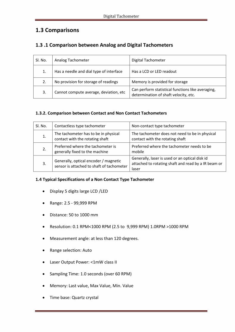
1.3 Comparisons
1.3 .1 Comparison between Analog and Digital Tachometers
Sl. No. Analog Tachometer Digital Tachometer
1. Has a needle and dial type of interface Has a LCD or LED readout
2. No provision for storage of readings Memory is provided for storage
3. Cannot compute average, deviation, etc Can perform statistical functions like averaging, determination of shaft velocity, etc.
1.3.2. Comparison between Contact and Non Contact Tachometers
Sl. No. Contactless type tachometer Non-contact type tachometer
1. The tachometer has to be in physical contact with the rotating shaft
The tachometer does not need to be in physical contact with the rotating shaft
2. Preferred where the tachometer is generally fixed to the machine
Preferred where the tachometer needs to be mobile
3. Generally, optical encoder / magnetic sensor is attached to shaft of tachometer
Generally, laser is used or an optical disk id attached to rotating shaft and read by a IR beam or laser
1.4 Typical Specifications of a Non Contact Type Tachometer
Display 5 digits large LCD /LED
Range: 2.5 - 99,999 RPM
Distance: 50 to 1000 mm
Resolution: 0.1 RPM<1000 RPM (2.5 to 9,999 RPM) 1.0RPM >1000 RPM
Measurement angle: at less than 120 degrees.
Range selection: Auto
Laser Output Power: <1mW class II
Sampling Time: 1.0 seconds (over 60 RPM)
Memory: Last value, Max Value, Min. Value
Time base: Quartz crystal

Digital Tachometer
Circuit: Exclusive one-chip LSI circuit
Battery: 4 X 1.5V AA
Weight: 300g/0.65lb
Size: 190 X 72 X 37 mm
1.5 Typical Specifications of a Contact Type Tachometer
Display 5-digit LCD/LED Display
Range selection Automatic range selection
Time Base 4MHz Quartz Crystal
Sampling Time 1 second (>60 rpm); >1 second (10 to 60 rpm)
Accuracy ± (0.1% of reading + 2 digits)
Photo Tachometer Distance 2 to 12” (5 to 30cm)
Operating Temperature 32 to 122oF (0 to 50oC)
Operating Humidity 80% RH Max.
Power supply 9V Battery
Battery Life 40 hours (approx.)
Dimensions 461700: 4.9 x 2.0 x 1.3” (124 x 51 x 33mm)
Weight 461700: 4.0 oz. (114g)
1.6.1 Disadvantage of Analog Tachometer
1. Less accuracy
2. Difficult to take reading as pointer takes long time to get stable.
3. No provision of storage of values
4. Cannot compute average deviations

Digital Tachometer
1.6 .2 Advantage of Digital Tachometer
1. Accuracy is high as display is used
2. Easy to take reading as little time delay is provided.
3. Memory is provided for storage of values
4. Can compute average deviations
1.6.3 Disadvantage of Digital Tachometer
1. Since the digital tachometer is held in hand, slight variation in its position
changes its speed.
2. If the speed is varying at every instant then the digital display fluctuates
and makes it difficult to read the actual speed.
Digital Tachometer
Chapter 2
Working Principle
2.1 General Concept of Digital Tachometer
Tachometer consists of an optical sensor which generates pulses proportional to the
speed of rotation. It counts the number of pulses sensed by the sensor and number of
pulses per second gives the rps and when multiplied by 60 gives rpm.
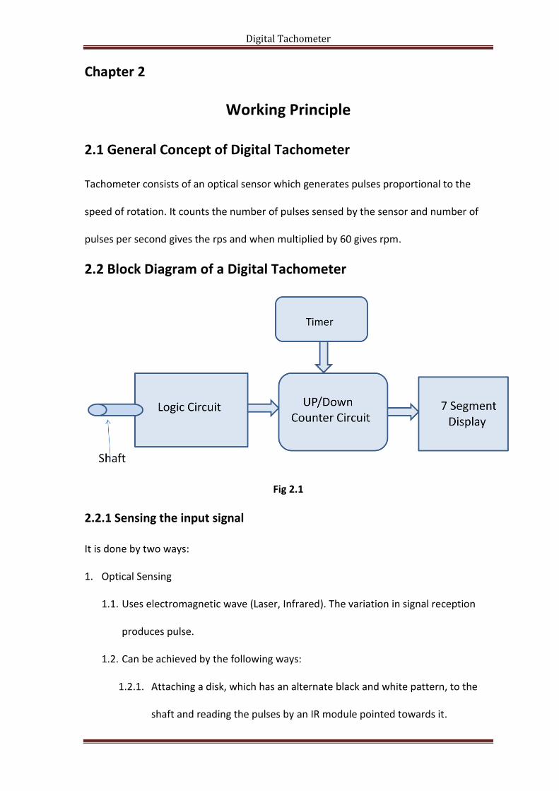
2.2 Block Diagram of a Digital Tachometer
Fig 2.1
2.2.1 Sensing the input signal
It is done by two ways:
1. Optical Sensing
1.1. Uses electromagnetic wave (Laser, Infrared). The variation in signal reception
produces pulse.
1.2. Can be achieved by the following ways:
1.2.1. Attaching a disk, which has an alternate black and white pattern, to the
shaft and reading the pulses by an IR module pointed towards it.

Digital Tachometer
1.2.2. Using a slotted disk and a U shaped IR emitter detector pair to generate
waveforms.
2. Magnetic Sensing
2.1. Hall Effect sensors – These make use of the Hall Effect to generate pulses
proportional to the speed of the shaft.
2.2. Passive magnetic sensors – These make use of variable reluctance to generate
pulses.
2.2.2 Logic circuit
Logic circuit, combination of XNOR gate and RC circuit, doubles the frequency of
input signal and helps in getting more precise value, thus it reduces counting period to
0.5 second instead of 1 second thus increasing the precision.
2.2.3 Counter circuit
To count the number of pulses sensed in a given period of time. A 4029[1] decade
counter IC is used. The counter is further cascaded with another 3 4029 ICs to get 4 digit
display, as a single counter facilitate only one digit display.
2.2.4 Timer circuit
To give the time delay during which the counter circuit counts the number of
pulses. An astable multivibrator is used to perform this delay operation.
2.2.5 Display
In order to display the speed of object under observation in revolutions per
minute (rpm), a common cathode 7-segment display is used with a driver IC 4511[2] to
display the speed in rps as counted by the counter.
Digital Tachometer
Chapter 3
Project Stage-I
3.1 Modelling and Simulation using Multisim
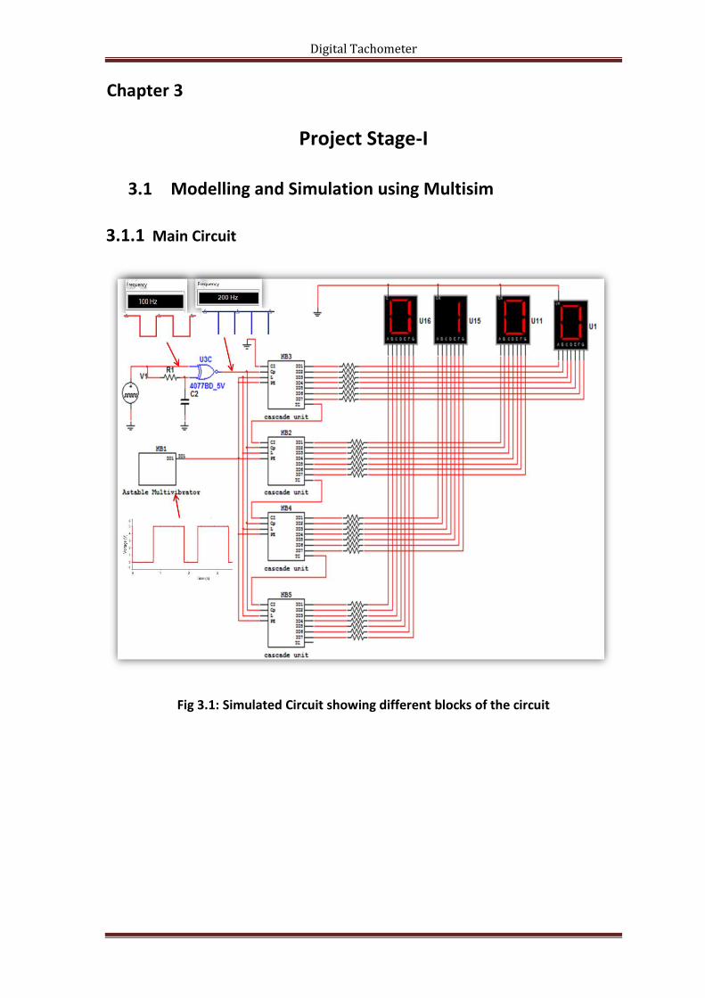
3.1.1 Main Circuit
Fig 3.1: Simulated Circuit showing different blocks of the circuit
Digital Tachometer
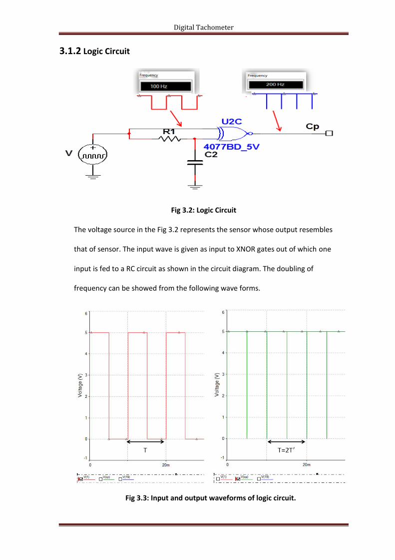
3.1.2 Logic Circuit
Fig 3.2: Logic Circuit
The voltage source in the Fig 3.2 represents the sensor whose output resembles
that of sensor. The input wave is given as input to XNOR gates out of which one
input is fed to a RC circuit as shown in the circuit diagram. The doubling of
frequency can be showed from the following wave forms.
Fig 3.3: Input and output waveforms of logic circuit.

Digital Tachometer
𝒇 =𝟏
𝑻 (3.1)
Or 𝒇′ =𝟏
𝑻′ (3.2)
Or 𝒇′ =𝟏𝑻
𝟐
Or 𝒇′ =𝟐
𝑻
Or 𝒇′ = 𝟐𝒇 (3.3)
3.1.3. Astable Multivibrator
Fig 3.4: Output waveform of Astable Multivibrator
The astable multivibrator circuit is realised using IC NE555 [3]. Its output is inverted using
the not gate IC 74LS04 [4] . The values of passive elements in the circuit are designed
using the following formulae for a frequency of 0.66Hz i.e. 1.5 sec time period.
F =1.44
R1 + R2 ∗ C (3.4)
For a required frequency standard capacitance value is assumed.
Ton=0.69*R1*C (3.5)
TOFF=0.69*R2*C (3.6)
The application demands to have Ton =.5 sec and TOFF = 1 sec.

Digital Tachometer
3.1.4. Counter cascaded with 7 segment display driver
Fig 3.5: Pin to Pin diagram of IC 4029 cascaded with IC 4511
The BCD (binary coded decimal) counter (IC 4029) start counting upwards at each rising
edge of clock pulse. The output of BCD counter as the name says is in BCD i.e. it cannot
be displayed on a 7 segment display. To have a display on 7 segment display the output
of counter is given as inputs of a BCD to 7 segment driver (IC 4511), the output of whose
drives the 7segment display. The 1st pins of all IC 4029 (reset pin) are shorted, similarly
the 5th pins of IC 4511 (latch enable pin) are shorted and the output of astable
multivibrator is given to them; this arrangement counts up to 0.5 sec and holds the
count for 1 sec(as per multivibrator design).

Digital Tachometer
Chapter 4
Project Stage-II
4.1 Hardware Implementation (Bread Board Implementation)
Fig 4.1: Implemented Circuit with respective blocks labelled

Digital Tachometer
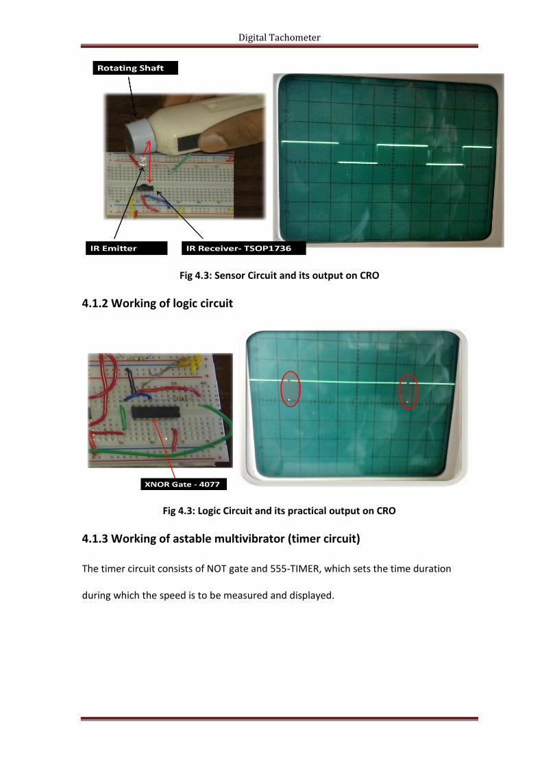
4.1.1 Working of sensor circuit
Fig 4.2: Circuit diagram of infrared sensor
The infrared(IR) sensor consists of IR emiter and IR reciever. An IR emitting diode is
suplied with a pulse of frequency 36kHz; since the IR reciever TSOP1736[5] is responsive
only when it recieves the IR signals with the carrier wave of frequency 36kHz. The IR
reciever will have its output low when it is not receiving any signal. The reflected signal
falls on the IR reciever causing its output to go low. This cointinous high and low output
results in pulse. This pulse is fed to the logic circuit. In order to reflect the IR rays a small
patch of white paint is painted on the shaft. The fig 4.3 shows the pulse generated by IR
receiver.
Digital Tachometer
Fig 4.3: Sensor Circuit and its output on CRO
4.1.2 Working of logic circuit
Fig 4.3: Logic Circuit and its practical output on CRO
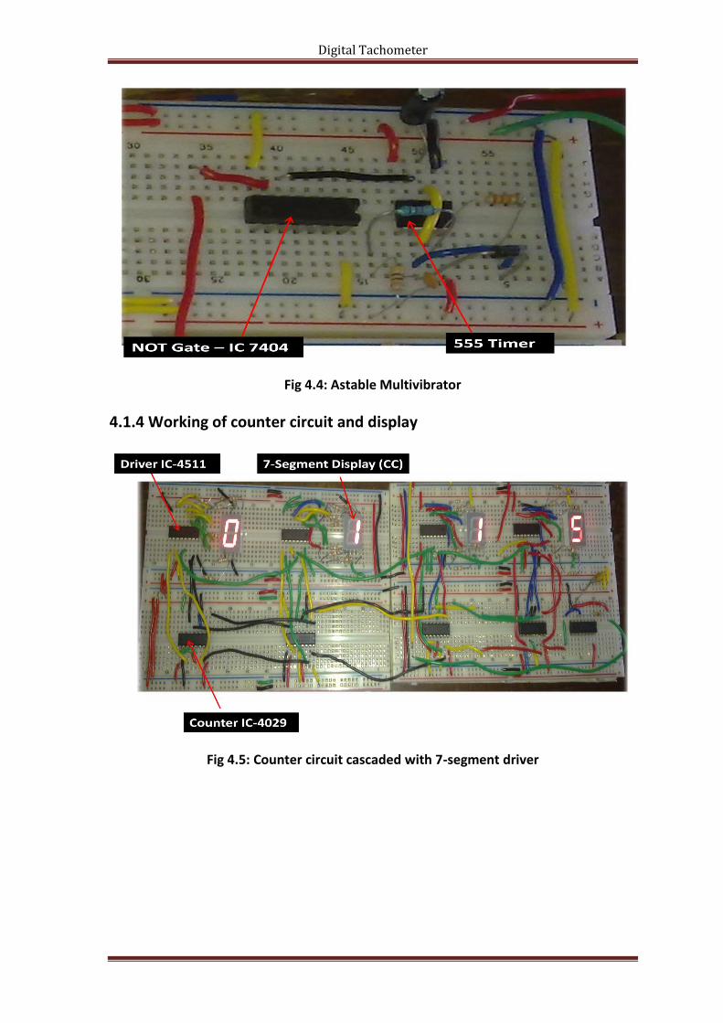
4.1.3 Working of astable multivibrator (timer circuit)
The timer circuit consists of NOT gate and 555-TIMER, which sets the time duration
during which the speed is to be measured and displayed.
Digital Tachometer
Fig 4.4: Astable Multivibrator
4.1.4 Working of counter circuit and display
Fig 4.5: Counter circuit cascaded with 7-segment driver

Digital Tachometer
Chapter 5
Conclusion
5.1 Applications
1. Used in laboratories to measure speed of motor/generator/engine.
2.
5.2 Future Scope
1. Can be Implemented using microcontroller so that size gets reduced .i.e. it
becomes compact.
2. Circuit can be modified to get speed in rpm using DAC[11], ADC[12] & op-
amp[13].
5.3 Merits
1. Can work efficiently in any light conditions.
2. Being contactless, doesn’t put load on rotating shaft.
5.4 Short comings
1. Speed measured is displayed in rps not in rpm.
2. Range of IR emitter used is limited, which causes hindrance.
5.5 Conclusions
1. The Digital Tachometer designed is economical for lab purposes.
Digital Tachometer
References
1. IC 4029
2. IC 4511
3. IC NE555
4. IC 74LS04
5. IC TSOP1736