About Estes Industries, Inc. - XMissionhuxley/rockets/vega/starship_vega_instr.… · Estes...
6
About the Starship Vega™ The original Starship Vega was designed by Wayne Kell- ner at Estes Industries. It was released as a futuristic planetary exploration vehicle in the style of illustrations by Frank Tinsley in the 1950’s. The Starship Vega only had a production run of five years, but it is remembered fondly by thousands of modelers as their first futuristic model rocket kit. It was first offered in the 1979 Catalog as Catalog Number 1320 and retailed for $6.50. The Semroc Retro-Repro™ Starship Vega™ is very close in design to the original. Precision laser-cut fins and rings make the assembly easier. The addition of a Kevlar shock cord mount increases reliability. A large full-color waterslide decal sheet adds the finishing touches. Copyright © 2012 Semroc Astronautics Corporation Box 1271 Knightdale, NC 27545 (919) 266-1977 February 29, 2012 Made in the U.S.A by Semroc Astronautics Corporation - Knightdale, N.C. 27545 Starship Vega™ Kit No. KV-78 Specifications Body Diameter 0.976” (2.5 cm) Length 20.4” (51.8 cm) Fin Span 9.0” (22.9 cm) Net Weight 1.3 oz. (37.0 g) Engine Approx. Altitude A8-3 175’ B6-4 425’ C6-5 900’ PARACHUTE RECOVERY STARSHIP SERIES CLASSIC DESIGN EASY TO BUILD BALSA FINS & NOSE CONE TM What is a Retro-Repro? A Retro-Repro™ is a retro reproduction of an out-of- production model rocket kit. It is a close approximation of a full scale model of an early historically significant model rocket kit from one of the many companies that pioneered the hobby over the past half century. A Retro- Repro™ is not a true clone or identical copy of the origi- nal. It incorporates improvements using modern tech- nology, while keeping the flavor and build appeal of the early kits. Design by Wayne Kellner About Estes Industries, Inc. In July 1958, G. Harry Stine of Model Missiles, Inc. in Denver, Colorado approached Vern Estes about making model rocket engines for them. On January 15, 1959, Vern’s automated model rocket engine fabricating ma- chine, “Mabel”, produced the first of many millions of Estes model rocket engines. In 1960, Estes was produc- ing more engines than Model Missiles could sell. Vern and his wife Gleda opened a mail order rocket company and introduced the Astron Scout and Astron Mark. In 1961, a catalog was mimeographed and hand stitched on Gleda’s sewing machine. Later that year, Estes Indus- tries had outgrown the confined space in Denver. In De- cember 1961, the entire operation was moved to an old farm in Penrose, Colorado quickly establishing the small town as the “Model Rocket Capital of the World.” Estes Industries was sold to Damon in September 1969. The name Estes is synonymous with model rocketry. Almost everyone remembers growing up firing Estes rockets or knowing someone that did. Estes Industries has introduced millions of youngsters of all ages to model rocketry for almost half a century.
Transcript of About Estes Industries, Inc. - XMissionhuxley/rockets/vega/starship_vega_instr.… · Estes...

About the Starship Vega™
The original Starship Vega was designed by Wayne Kell-
ner at Estes Industries. It was released as a futuristic
planetary exploration vehicle in the style of illustrations
by Frank Tinsley in the 1950’s. The Starship Vega only
had a production run of five years, but it is remembered
fondly by thousands of modelers as their first futuristic
model rocket kit. It was first offered in the 1979 Catalog
as Catalog Number 1320 and retailed for $6.50.
The Semroc Retro-Repro™ Starship Vega™ is very close
in design to the original. Precision laser-cut fins and
rings make the assembly easier. The addition of a Kevlar
shock cord mount increases reliability. A large full-color
waterslide decal sheet adds the finishing touches.
Copyright © 2012 Semroc Astronautics Corporation
Box 1271 Knightdale, NC 27545 (919) 266-1977
February 29, 2012
Made in the U.S.A by Semroc Astronautics Corporation - Knightdale, N.C. 27545
Starship Vega™
Kit No. KV-78
Specifications Body Diameter 0.976” (2.5 cm) Length 20.4” (51.8 cm) Fin Span 9.0” (22.9 cm) Net Weight 1.3 oz. (37.0 g)
Engine Approx. Altitude A8-3 175’ B6-4 425’ C6-5 900’
PARACHUTE RECOVERY
STARSHIP SERIES
CLASSIC DESIGN
EASY TO BUILD
BALSA FINS & NOSE CONE
TM
What is a Retro-Repro?
A Retro-Repro™ is a retro reproduction of an out-of-
production model rocket kit. It is a close approximation
of a full scale model of an early historically significant
model rocket kit from one of the many companies that
pioneered the hobby over the past half century. A Retro-
Repro™ is not a true clone or identical copy of the origi-
nal. It incorporates improvements using modern tech-
nology, while keeping the flavor and build appeal of the
early kits.
Design by Wayne Kellner
About Estes Industries, Inc.
In July 1958, G. Harry Stine of Model Missiles, Inc. in
Denver, Colorado approached Vern Estes about making
model rocket engines for them. On January 15, 1959,
Vern’s automated model rocket engine fabricating ma-
chine, “Mabel”, produced the first of many millions of
Estes model rocket engines. In 1960, Estes was produc-
ing more engines than Model Missiles could sell. Vern
and his wife Gleda opened a mail order rocket company
and introduced the Astron Scout and Astron Mark.
In 1961, a catalog was mimeographed and hand stitched
on Gleda’s sewing machine. Later that year, Estes Indus-
tries had outgrown the confined space in Denver. In De-
cember 1961, the entire operation was moved to an old
farm in Penrose, Colorado quickly establishing the small
town as the “Model Rocket Capital of the World.”
Estes Industries was sold to Damon in September 1969.
The name Estes is synonymous with model rocketry.
Almost everyone remembers growing up firing Estes
rockets or knowing someone that did. Estes Industries
has introduced millions of youngsters of all ages to
model rocketry for almost half a century.

EXPLODED VIEW Parts List
A 1 Balsa Nose Cone ... BNC-50AR
B 3 Balsa Nose Cones . BNC-5AW
C 1 Body Tube............. BT-50L
D 1 Body Tube............. BT-20J
E 3 Body Tubes ........... BT-5T
F 1 Laser Cut Fins ....... FV-78
G 1 Adapter Ring ......... AR-2050
H 1 Adapter Ring Split AR-2050S
I 1 Mylar Ring ............ HR-20
J 1 Engine Hook ......... EH-28
K 3 Wood Dowels ....... WD-202
L 2 Launch Lugs ......... LL-2AM
M 1 Ring Set ................ CR-KV-78
N 1 Elastic Cord ........... EC-118
O 1 Chute Pak .............. CP-12RY
P 1 Kevlar Thread ....... SCK-12
Q 1 Screw Eye ............. SE-1
R 1 Washer Weight ..... WW-8
S 1 Decal ..................... DKV-78
T 1 Wrap ..................... IKV-78W
Starship Vega KV-78 Page 3
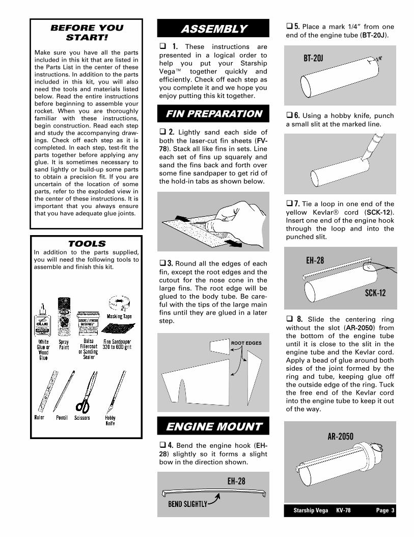
TOOLS In addition to the parts supplied,
you will need the following tools to
assemble and finish this kit.
BEFORE YOU START!
Make sure you have all the parts
included in this kit that are listed in
the Parts List in the center of these
instructions. In addition to the parts
included in this kit, you will also
need the tools and materials listed
below. Read the entire instructions
before beginning to assemble your
rocket. When you are thoroughly
familiar with these instructions,
begin construction. Read each step
and study the accompanying draw-
ings. Check off each step as it is
completed. In each step, test-fit the
parts together before applying any
glue. It is sometimes necessary to
sand lightly or build-up some parts
to obtain a precision fit. If you are
uncertain of the location of some
parts, refer to the exploded view in
the center of these instructions. It is
important that you always ensure
that you have adequate glue joints.
1. These instructions are
presented in a logical order to
help you put your Starship
Vega™ together quickly and
efficiently. Check off each step as
you complete it and we hope you
enjoy putting this kit together.
ASSEMBLY
2. Lightly sand each side of
both the laser-cut fin sheets (FV-
78). Stack all like fins in sets. Line
each set of fins up squarely and
sand the fins back and forth over
some fine sandpaper to get rid of
the hold-in tabs as shown below.
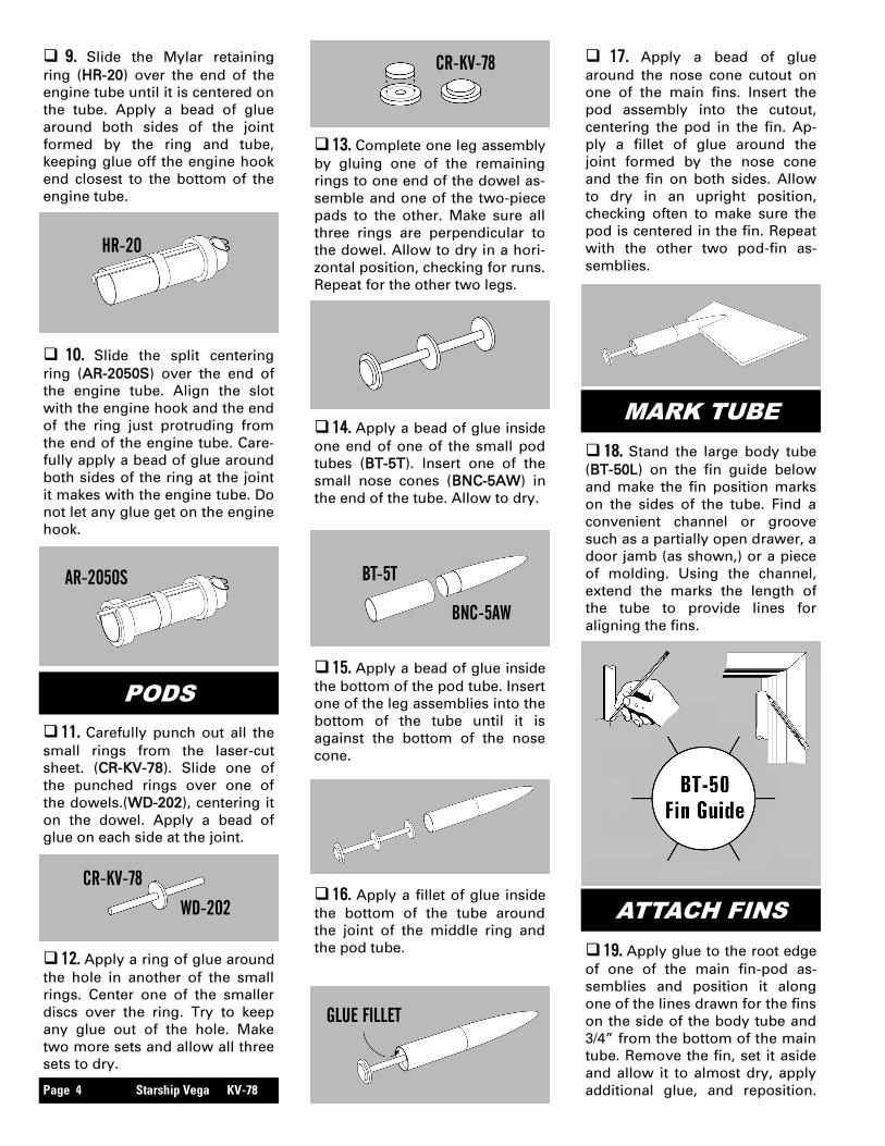
3. Round all the edges of each
fin, except the root edges and the
cutout for the nose cone in the
large fins. The root edge will be
glued to the body tube. Be care-
ful with the tips of the large main
fins until they are glued in a later
step.
FIN PREPARATION
ENGINE MOUNT
4. Bend the engine hook (EH-
28) slightly so it forms a slight
bow in the direction shown.
5. Place a mark 1/4” from one
end of the engine tube (BT-20J).
8. Slide the centering ring
without the slot (AR-2050) from
the bottom of the engine tube
until it is close to the slit in the
engine tube and the Kevlar cord.
Apply a bead of glue around both
sides of the joint formed by the
ring and tube, keeping glue off
the outside edge of the ring. Tuck
the free end of the Kevlar cord
into the engine tube to keep it out
of the way.
SCK-12
EH-28
BT-20J
7. Tie a loop in one end of the
yellow Kevlar® cord (SCK-12).
Insert one end of the engine hook
through the loop and into the
punched slit.
6. Using a hobby knife, punch
a small slit at the marked line.
AR-2050
EH-28
Page 4 Starship Vega KV-78
19. Apply glue to the root edge
of one of the main fin-pod as-
semblies and position it along
one of the lines drawn for the fins
on the side of the body tube and
3/4” from the bottom of the main
tube. Remove the fin, set it aside
and allow it to almost dry, apply
additional glue, and reposition.
ATTACH FINS
10. Slide the split centering
ring (AR-2050S) over the end of
the engine tube. Align the slot
with the engine hook and the end
of the ring just protruding from
the end of the engine tube. Care-
fully apply a bead of glue around
both sides of the ring at the joint
it makes with the engine tube. Do
not let any glue get on the engine
hook.
9. Slide the Mylar retaining
ring (HR-20) over the end of the
engine tube until it is centered on
the tube. Apply a bead of glue
around both sides of the joint
formed by the ring and tube,
keeping glue off the engine hook
end closest to the bottom of the
engine tube.
HR-20
18. Stand the large body tube
(BT-50L) on the fin guide below
and make the fin position marks
on the sides of the tube. Find a
convenient channel or groove
such as a partially open drawer, a
door jamb (as shown,) or a piece
of molding. Using the channel,
extend the marks the length of
the tube to provide lines for
aligning the fins.
MARK TUBE
AR-2050S
PODS
11. Carefully punch out all the
small rings from the laser-cut
sheet. (CR-KV-78). Slide one of
the punched rings over one of
the dowels.(WD-202), centering it
on the dowel. Apply a bead of
glue on each side at the joint.
12. Apply a ring of glue around
the hole in another of the small
rings. Center one of the smaller
discs over the ring. Try to keep
any glue out of the hole. Make
two more sets and allow all three
sets to dry.
CR-KV-78
WD-202
13. Complete one leg assembly
by gluing one of the remaining
rings to one end of the dowel as-
semble and one of the two-piece
pads to the other. Make sure all
three rings are perpendicular to
the dowel. Allow to dry in a hori-
zontal position, checking for runs.
Repeat for the other two legs.
14. Apply a bead of glue inside
one end of one of the small pod
tubes (BT-5T). Insert one of the
small nose cones (BNC-5AW) in
the end of the tube. Allow to dry.
CR-KV-78
BT-5T
BNC-5AW
15. Apply a bead of glue inside
the bottom of the pod tube. Insert
one of the leg assemblies into the
bottom of the tube until it is
against the bottom of the nose
cone.
16. Apply a fillet of glue inside
the bottom of the tube around
the joint of the middle ring and
the pod tube.
GLUE FILLET
17. Apply a bead of glue
around the nose cone cutout on
one of the main fins. Insert the
pod assembly into the cutout,
centering the pod in the fin. Ap-
ply a fillet of glue around the
joint formed by the nose cone
and the fin on both sides. Allow
to dry in an upright position,
checking often to make sure the
pod is centered in the fin. Repeat
with the other two pod-fin as-
semblies.

Starship Vega KV-78 Page 5
22. Apply a bead of glue to one
of the launch lugs (LL-2AM) and
apply it to the main body tube
against one of the main fins and
even with the bottom fin. Glue
the other launch lug against one
of the upper fins in line with the
first launch lug and even with the
bottom of the fin. Sight from one
end to make sure they are
aligned with each other.
25. After the fin assembly is
completely dry, run a small bead
of glue along both sides of each
of the fin-body tube joints. Using
your forefinger, smooth the glue
into fillets. Allow this assembly to
dry in a vertical position.
28. Assemble the chute (CP-12)
using instructions printed on the
canopy. Pull the lines tight on the
chute and make sure they are all
of equal length. Attach the chute
by tying them to the screw eye.
Put a drop of glue on the joint to
keep the lines from moving. At-
tach the free end of the elastic
cord to the screw eye. Put a drop
of glue on that joint as well.
FINAL ASSEMBLY
26. Insert the nose cone (BNC-
50AR) in the main tube and check
for proper fit. The nose cone
should be snug to hold itself in
alignment. If it is too loose, mask-
ing tape may be needed. If it is
too tight, sand the shoulder
slightly.
ATTACH MOUNT
LAUNCH LUG
APPLY FILLETS
NOSE CONE
EC-118
24. Run a thick bead of glue
inside the main tube and push
the engine mount into the main
tube until the bottom of the en-
gine tube is even with the bottom
of the main tube.
LL-2AM
LL-2AM
27. Insert the screw eye (SE-1)
into the center of the nose block,
remove, and insert glue into the
hole. Reinsert the screw eye
through the washer weight (WW-
8) into the nose cone. Allow to
dry.
23. Pull the Kevlar® cord out of
the engine mount assembly. Tie
the free end of the cord to one
end of the elastic cord (EC-118)
using an overhand knot. Store all
the cord and shock cord back into
the engine mount for now.
SE-1
WW-8
BNC-50AR 20. Apply glue to the root edge
of one of the triangular fins and
position it along one of the lines
drawn for the fins on the side of
the body tube and even with the
bottom of the main tube. Glue it
using the same technique used
on the main fins. Repeat for the
other triangular fins. Allow the
fins to completely dry, checking
carefully to make sure they are
parallel with the main body tube.
Repeat for the other two assem-
blies using every other line. If
you follow these instructions, the
fins will not require much addi-
tional work to keep them aligned.
Allow the assemblies to com-
pletely dry, checking carefully to
make sure they are parallel with
the main body tube.
21. Apply glue to the root edge
of one of the small fins and posi-
tion it along one of the lines
drawn for the main fins on the
side of the body tube and 4-5/8”
from the top of the main tube.
Glue it using the same technique
used on the main fins. Repeat for
the other small fins. Allow the
fins to completely dry, checking
carefully to make sure they are
parallel with the main body tube.
Page 6 Starship Vega KV-78
36. Refer to the model rocket
engine manufacturer’s instruc-
tions to complete the engine
prepping. Different engines have
different igniters and methods of
hooking them up to the launch
controllers.
37. Carefully check all parts of
your rocket before each flight as
a part of your pre-flight checklist.
Launch the Starship Vega™ from
a 1/8” diameter by 36” long
launch rod.
FLIGHT PREPPING
34. Mounting the engine: Insert
the engine and make sure the
engine hook keeps the engine in
snugly. The hook may be slightly
bent to make sure the engine is
retained.
35. Apply a few sheets of re-
covery wadding in the top of the
main body tube. Fold the para-
chute and pack it and the shock
cord on top of the recovery wad-
ding. Slide the nose cone into
place, making sure it does not
pinch the shock cord or para-
chute.
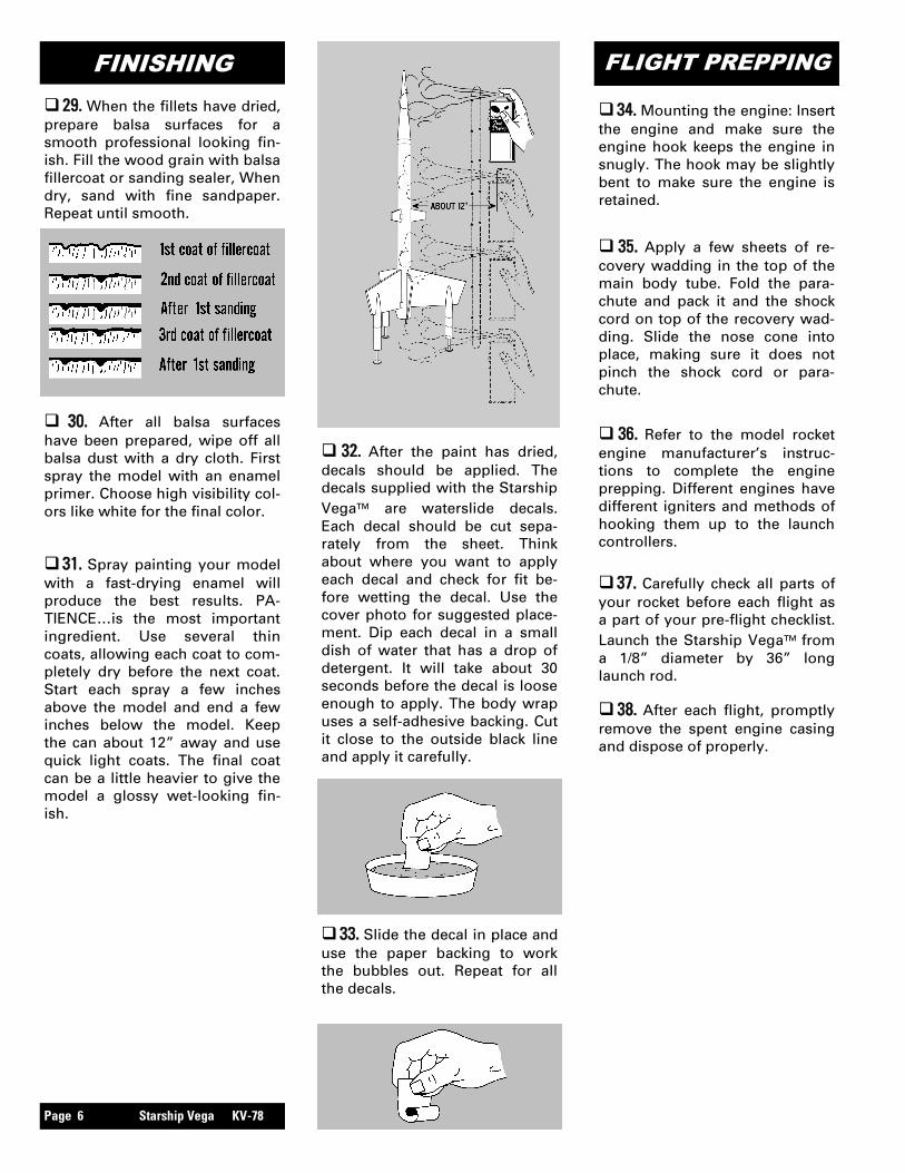
32. After the paint has dried,
decals should be applied. The
decals supplied with the Starship
Vega™ are waterslide decals.
Each decal should be cut sepa-
rately from the sheet. Think
about where you want to apply
each decal and check for fit be-
fore wetting the decal. Use the
cover photo for suggested place-
ment. Dip each decal in a small
dish of water that has a drop of
detergent. It will take about 30
seconds before the decal is loose
enough to apply. The body wrap
uses a self-adhesive backing. Cut
it close to the outside black line
and apply it carefully.
33. Slide the decal in place and
use the paper backing to work
the bubbles out. Repeat for all
the decals.
38. After each flight, promptly
remove the spent engine casing
and dispose of properly.
29. When the fillets have dried,
prepare balsa surfaces for a
smooth professional looking fin-
ish. Fill the wood grain with balsa
fillercoat or sanding sealer, When
dry, sand with fine sandpaper.
Repeat until smooth.
FINISHING
30. After all balsa surfaces
have been prepared, wipe off all
balsa dust with a dry cloth. First
spray the model with an enamel
primer. Choose high visibility col-
ors like white for the final color.
31. Spray painting your model
with a fast-drying enamel will
produce the best results. PA-
TIENCE…is the most important
ingredient. Use several thin
coats, allowing each coat to com-
pletely dry before the next coat.
Start each spray a few inches
above the model and end a few
inches below the model. Keep
the can about 12” away and use
quick light coats. The final coat
can be a little heavier to give the
model a glossy wet-looking fin-
ish.