About Centurion Features Specificationsstatic.highspeedbackbone.net/pdf/CM-Centurion5-Manual.pdf ·...
4
01 Index ABOUT CENTURION FEATURES SPECIFICATIONS DIAGRAM INSTALLATION REMOVING THE SIDE PANELS INSTALLING THE MOTHERBOARD TO INSTALL/ REPLACE THE POWER SUPPLY UNIT (PSU): INSTALLING DRIVES (CD-ROM, HDD, FDD, ETC.) REPLACING/INSTALLING THE CASE FANS 1. Replacing / Installing the Rear Case Fan 2. Replacing / Installing the Front Case Fans I/O FUNCTION PANEL INSTALLATION GUIDE 01 01 01 02 04 04 04 04 05 06 06 06 06 About Centurion "Centurion" represents quality of Discipline, Honor, Integrity & Loyalty. Now you don't have to be a Caesar to concord the digital world while feeling safe and proud.. Features Discipline Asymmetrical shape layout. Royal Appearance Equipped with detailed high gloss front Alloy Shield. Protection Proactive heat resistant design for abusive ambient environment Integrity World famous solid assembly. Unique Armor Unique side panel mechanism provides great accessibility for installation & upgrade. Loyalty - Long lasting ownership. Tool-free assembly/disassembly for quick and maintenance or upgrade Special perforated screen design provides the superior airflow and maximum cooling performance; easy to clean and maintain Dimensions: 480 mm x 202 mm x 435 mm (L x W x H) Material: Aluminum Bezel, SECC Chassis Main Board: ATX; 12"x 9.6"(30.5cm x 24.5cm) 5.25" Drive Bay: 5 (Exposed) 3.5" Drive Bay: 1 (Exposed), 4 (Hidden) Power Supply: Standard ATX PS2 Front I/O: USB 2.0 x 2, IEEE 1394 (FireWire) x1, MIC x1, SPK x 1 Cooling fan: One 80 x 80 x 25 mm Front Fan (intake) One 120 x 120 x 25 mm Rear Fan (exhaust) Specifications
Transcript of About Centurion Features Specificationsstatic.highspeedbackbone.net/pdf/CM-Centurion5-Manual.pdf ·...

01
Index
ABOUT CENTURION
FEATURES
SPECIFICATIONS
DIAGRAM
INSTALLATIONREMOVING THE SIDE PANELS
INSTALLING THE MOTHERBOARD
TO INSTALL/ REPLACE THE POWER SUPPLY UNIT (PSU):
INSTALLING DRIVES (CD-ROM, HDD, FDD, ETC.)
REPLACING/INSTALLING THE CASE FANS
1. Replacing / Installing the Rear Case Fan
2. Replacing / Installing the Front Case Fans
I/O FUNCTION PANEL INSTALLATION GUIDE
01
01
01
02
04
0404
040506
06
06
06
About Centurion"Centurion" represents quality of Discipline, Honor, Integrity & Loyalty.
Now you don't have to be a Caesar to concord the digital world while
feeling safe and proud..
FeaturesDiscipline Asymmetrical shape layout.
Royal Appearance Equipped with detailed high gloss front Alloy Shield.
Protection Proactive heat resistant design for abusive ambient environment
Integrity World famous solid assembly.
Unique Armor Unique side panel mechanism provides great accessibility for
installation & upgrade.
Loyalty - Long lasting ownership.
Tool-free assembly/disassembly for quick and maintenance or upgrade
Special perforated screen design provides the superior airflow and maximum cooling
performance; easy to clean and maintain
Dimensions: 480 mm x 202 mm x 435 mm (L x W x H)
Material: Aluminum Bezel, SECC Chassis
Main Board: ATX; 12"x 9.6"(30.5cm x 24.5cm)
5.25" Drive Bay: 5 (Exposed)
3.5" Drive Bay: 1 (Exposed), 4 (Hidden)
Power Supply: Standard ATX PS2
Front I/O: USB 2.0 x 2, IEEE 1394 (FireWire) x1, MIC x1, SPK x 1
Cooling fan: One 80 x 80 x 25 mm Front Fan (intake)
One 120 x 120 x 25 mm Rear Fan (exhaust)
Specifications

DiagramA. 3 Direction Diagram
B.Exploded Picture
02 03
Installation
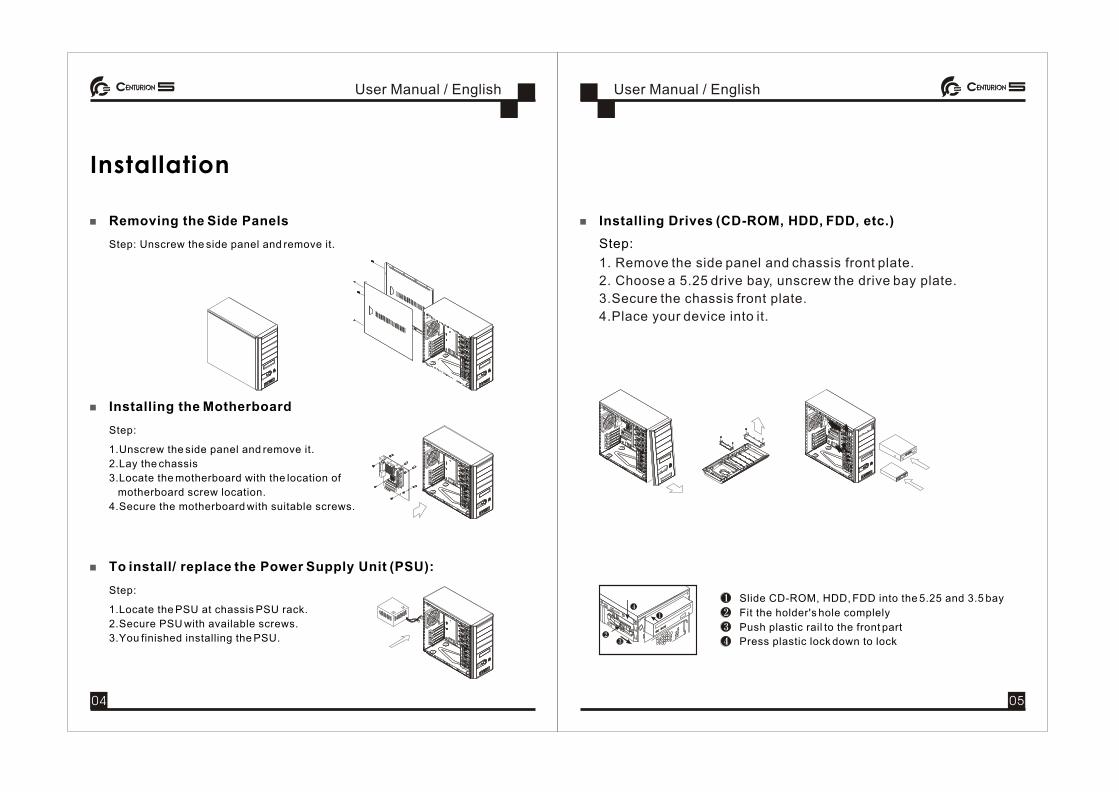
Removing the Side Panels
Step: Unscrew the side panel and remove it.
Installing the Motherboard
Step:
1.Unscrew the side panel and remove it.
2.Lay the chassis
3.Locate the motherboard with the location of
motherboard screw location.
4.Secure the motherboard with suitable screws.
To install/ replace the Power Supply Unit (PSU):
Step:
1.Locate the PSU at chassis PSU rack.
2.Secure PSU with available screws.
3.You finished installing the PSU.
Installing Drives (CD-ROM, HDD, FDD, etc.)
Step:
1. Remove the side panel and chassis front plate.
2. Choose a 5.25 drive bay, unscrew the drive bay plate.
3.Secure the chassis front plate.
4.Place your device into it.
Slide CD-ROM, HDD, FDD into the 5.25 and 3.5 bay
Push plastic rail to the front part
Press plastic lock down to lock
Fit the holder's hole complely
04 05

Replacing/Installing The Case Fans
1. Replacing / Installing the Rear Case Fan
Step:
1.Remove the side panel
2.Remove four screws securing the exterior fan cover.
3.Place the rear fan in position and secure it with four screws.
2. Replacing / Installing the Front Case Fans
Step:
1.Remove the side panel
2.Remove the front panel
3.Remove four screws securing the exterior fan cover
4.Place the rear fan in position and secure it with four screws
I/O function panel installation guide Please refer to the illustration on the section of USB,1394,Audio
connector from motherboard user's manual , and please select the
motherboard which use the same USB,1394,Audio standard as
below . Otherwise , it will cause damage for user's device.
The following illustration is a connection diagram for the Front Pane I/O cable.
Doing so will damage the device. NEVER connect a 1394 cable to the USB connector.
NEVER connect a USB cable to the 1394 connector. Doing so will damage the device.
On some motherboards the connectors for 1394, USB and audio are not the same as the below drawing. Please check with your motherboard manual before install.
IEEE 1394 Connector
USB Connector
Front panel audio connector (BLACK)
Front panel USB connector
No Pin
Front panel audio connector
No Pin
Pin
Front panel IEEE 1394 connector
Mother Board
No Pin
Cable
Pin
06 07