Abnormal and Emergency Procedures...
260
Abnormal and Emergency Procedures Manual MJC-8 Q400 PRO/TRAINING EDITION Version 1.0 Abnormal and Emergency Procedures Manual
Transcript of Abnormal and Emergency Procedures...
Abnormal and Emergency Procedures Manual
MJC-8 Q400 PRO/TRAINING EDITION Version 1.0
Abnormal and Emergency Procedures Manual

Abnormal and Emergency Procedures Manual
Intentionally Left Blank

Checklist Instructions
Instructions-1
Chapter1: Checklist Instructions
The checklists are organized into chapters alphabetically by aircraft
system or by type of Abnormal or Emergency Procedure. Each procedure
is listed in the Table of contents at the beginning of the corresponding
chapter.
The procedures presented in this manual are based on the best information
available. Pilots should follow these procedures as long as they apply to the
situation. If at any time the established procedures prove to be inadequate or
no longer apply, the Crew's best judgment shall prevail.
Throughout this document, the boxes (shown below) indicate either
Emergency Procedures (Black Box), or Non-Normal Procedures (Grey Box).
When the PM is utilizing a procedure, it is recommended the PF utilize the
highest level of automation available at that time and handle ATC
communication duties until the procedure has been completed by the PM.
This is on a workload permitting basis only.
Duplicate Items
Checklist items that have duplicate (e.g., #1/#2 or Left/Right) systems,
switches, levers, etc., will be preceded by a blank underlined space. In such a
case, the Pilot referring to the item or reading the checklist shall substitute the
number of the affected system, switch, lever, etc.
Example: The associated Aux Pump must be turned off when securing the left
engine. Checklist reads:
AUX PUMP........................................................................................ OFF
Pilot reading checklist states: ―Number one aux pump, off.‖
Memory items (if applicable to the procedure) are contained in a single box and presented in the order of accomplishment.
NON-NORMAL PROCEDURE
EMERGENCY PROCEDURES
Checklist Instructions Instructions-2
Confirmation and Command Items
Whenever an applicable procedural item is a Power Lever, Condition Lever, or
PULL/FUEL HYD OFF handle, the PM shall confirm the correct lever/handle
with the PF prior to initiating the procedural item.
Example:
Prior to shutting down the #1 engine, the PM shall touch the correct lever/
handle, state the correct handle/lever, (ex. #1―Power Lever‖), at which point
the PF will confirm lever/handle and state,‖Confirmed‖. Once the proper lever/
handle has been confirmed by the PF, the PM shall state and complete the
procedural item.
The PF must visually confirm the affected engine or
system following the initial malfunction callout. Failure
to do so may result in the inadvertent shutdown of the
operating engine or system.
The accomplishment of certain checklist items may require the transfer of
control of the aircraft to the other Pilot until the particular item can be
accomplished.
Warnings, Cautions, and Notes
All advisory items will be read aloud. Exception: when reading a procedure,
if an advisory item does not apply to the existing condition, it need not be read
aloud. Simply state ―Not applicable‖, and continue to the next applicable
checklist item.
Condition Statement
Some checklist procedures will present the Pilot with alternatives for
completing the checklist. This situation occurs when the outcome of a checklist
item is not predictable (e.g., ―Did the smoke stop after turning off the Bleed
switch?‖). The Pilot conducting the checklist must decide which of the
checklist choices to complete, or if the items are applicable, based upon the
outcome of previous steps. If possible, the decision is based on a ―YES‖/―NO‖
answer. These ―Condition Statements‖ are identified with arrow lines that take
the checklist reader to one action, or another. An example of this is shown
below:
WARNING
Checklist Instructions Instructions-3
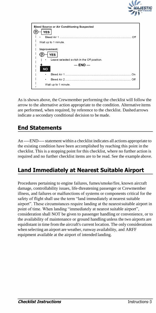
As is shown above, the Crewmember performing the checklist will follow the
arrow to the alternative action appropriate to the condition. Alternative items
are performed, when required, by reference to the checklist. Dashed arrows
indicate a secondary conditional decision to be made.
End Statements
An ----END---- statement within a checklist indicates all actions appropriate to
the existing condition have been accomplished by reaching this point in the
checklist. This is a stopping point for this checklist, where no further action is
required and no further checklist items are to be read. See the example above.
Land Immediately at Nearest Suitable Airport
Procedures pertaining to engine failures, fumes/smoke/fire, known aircraft
damage, controllability issues, life-threatening passenger or Crewmember
illness, and failures or malfunctions of systems or components critical for the
safety of flight shall use the term ―land immediately at nearest suitable
airport‖. These circumstances require landing at the nearest suitable airport in
point of time. When landing ―immediately at nearest suitable airport‖,
consideration shall NOT be given to passenger handling or convenience, or to
the availability of maintenance or ground handling unless the two airports are
equidistant in time from the aircraft's current location. The only considerations
when selecting an airport are weather, runway availability, and ARFF
equipment available at the airport of intended landing.

Checklist Instructions Instructions-4
Intentionally Left Blank

Air Conditioning, Pressurization, and Pneumatics 2-i
Chapter 2: Air Conditioning, Pressurization,
and Pneumatics
RAPID DEPRESSURIZATION / EMERGENCY DESCENT ........... 2-3
CABIN PRESSURIZATION FAILURE 2-4
―CABIN PRESS‖ (Warning Light) 2-4
UNPRESSURIZED FLIGHT 2-5
RAM VENTILATION 2-6
PRESSURIZATION — MANUAL MODE OPERATION ................ 2-6
LOSS OF CABIN ALTITUDE, CABIN RATE and CABIN DIFF INDICATORS 2-8
CABIN DIFF GREATER THAN 1.0 PSI ON APPROACH ............ 2-8
―CABIN PACK HOT‖ or ―FLT COMPT PACK HOT‖ (Caution Light) 2-8
―CABIN PACK HOT‖ and ―FLT COMPT PACK HOT‖ (Caution Lights) 2-9
―CABIN DUCT HOT‖ or ―FLT COMPT DUCT HOT‖ (Caution Light) 2-9
―#1 BLEED HOT‖ or ―#2 BLEED HOT‖ (Caution Light) 2-9
―#1 BLEED HOT‖ and ―#2 BLEED HOT‖ (Caution Lights) 2-10
CRACKED WINDSHIELD 2-11
―FUSELAGE DOORS‖ (Warning Light) 2-12
INTERNAL DOORS (Caution Light) 2-14

Air Conditioning, Pressurization, and Pneumatics 2-i
EMERGENCY OPENING OF FLIGHT COMPARTMENT DOOR (Door Jammed) 2-15
AIRSTAIR DOOR, FAILURE TO OPEN 2-16

Air Conditioning, Pressurization, and Pneumatics 2-1
Chapter 2: Air Conditioning,
Pressurization, and Pneumatics
PSM 1-84-1B (Oct 31, 2010)
Figure 2-1: Pressurization System

Air Conditioning, Pressurization, and Pneumatics 2-2
PSM 1-84-1B (Oct 31, 2010)
Figure 2-2: Air Conditioning System

Air Conditioning, Pressurization, and Pneumatics 2-3
NOTE:
EMERGENCY DESCENT, accomplish as required:
NOTE:
If structural integrity is in doubt, limit airspeed as much as
possible and avoid high maneuvering loads.
• POWER levers ........................................................ FLIGHT IDLE
• Condition Levers.................................................................... MAX
• Airspeed ...................................................................................VMO
• ATC ...................................................................................... Notify
— END —
• Oxygen Masks..................................................................ON/100%
• BOOM/MASK switch...........................................................MASK
• FASTEN BELTS switch............................................................ON
RAPID DEPRESSURIZATION / EMERGENCY DESCENT

Air Conditioning, Pressurization, and Pneumatics 2-4
OR
• CABIN ALT Indicator ...................................... Check CABIN ALT
Is FAULT light illuminated on the Cabin Pressure Controller? DH8-400-SL-21-014 APR 22/08
• AUTO/MAN/DUMP switch .......................... Select MAN for 2
………………… ........................................ seconds then AUTO
Is control of pressurization regained?
• No further action required.
— END —
AIR CONDITIONING Control Panel:
• CABIN pack and FLT COMP pack switches.........................AUTO
• BLEED switches 1 and 2......................................................BLEED
• BLEED selector....................................................................... MAX
Pressurization Control Panel:
• AUTO/MAN/DUMP switch ..................................................AUTO
• CABIN ALTITUDE FWD OUTFLOW ................................ CLSD
First Officer Side Panel—Safety Guard:
• FWD OUTFLOW VALVE .................................... NORM (Closed)
— CONTINUED —
―CABIN PRESS‖ (Warning Light)
CABIN PRESSURIZATION FAILURE

Air Conditioning, Pressurization, and Pneumatics 2-5
NOTE:
Is control of pressurization regained:
• No further action required.
— END —
• AUTO/MAN/DUMP switch ................................................... MAN
• MAN DIFF switch……………............Select INCR for 2 seconds
Is CABIN DIFF increasing and CABIN ALT decreasing:
– Control of pressurization is regained.
• MANUAL MODE OPERATION (Page 2-6) ..........Accomplish
— END —
• Descend to below 14,000 ft as soon as possible.
• UNPRESSURIZED FLIGHT (Page 2-5) ...................... Accomplish
— END —
• AUTO/MAN/DUMP switch..................................................DUMP
• BLEED switches 1 and 2 ..................................................... BLEED
• BLEED selector ......................................................NORM or MAX
• Oxygen Masks ................................................................... As Req‘d
For flight with BLEED switches OFF:
• RAM VENTILATION (Page 2-6)................................. Accomplish
— END —
UNPRESSURIZED FLIGHT
NOTE:
INCR--increases CABIN DIFF and decreases CABIN ALT
Air Conditioning, Pressurization, and Pneumatics 2-6
NOTE:
NOTE:
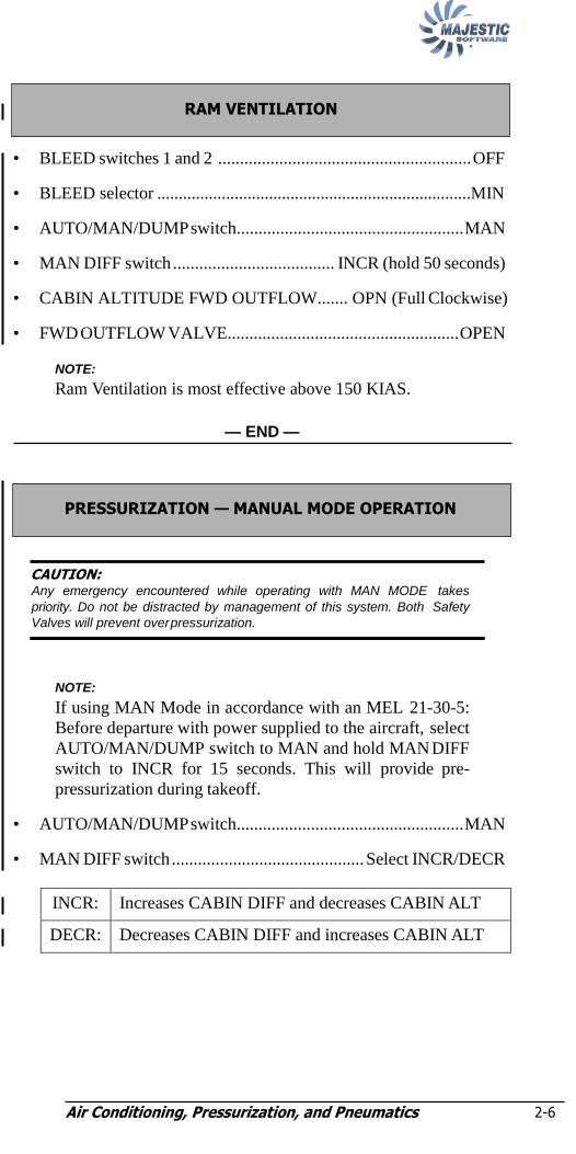
• BLEED switches 1 and 2 .......................................................... OFF
• BLEED selector .........................................................................MIN
• AUTO/MAN/DUMP switch.................................................... MAN
• MAN DIFF switch ..................................... INCR (hold 50 seconds)
• CABIN ALTITUDE FWD OUTFLOW....... OPN (Full Clockwise)
• FWD OUTFLOW VALVE..................................................... OPEN
— END —
CAUTION: Any emergency encountered while operating with MAN MODE takes
priority. Do not be distracted by management of this system. Both Safety
Valves will prevent over pressurization.
NOTE:
If using MAN Mode in accordance with an MEL 21-30-5:
Before departure with power supplied to the aircraft, select
AUTO/MAN/DUMP switch to MAN and hold MAN DIFF
switch to INCR for 15 seconds. This will provide pre-
pressurization during takeoff.
• AUTO/MAN/DUMP switch.................................................... MAN
• MAN DIFF switch ............................................ Select INCR/DECR
INCR: Increases CABIN DIFF and decreases CABIN ALT
DECR: Decreases CABIN DIFF and increases CABIN ALT
PRESSURIZATION — MANUAL MODE OPERATION
NOTE:
Ram Ventilation is most effective above 150 KIAS.
RAM VENTILATION
Air Conditioning, Pressurization, and Pneumatics 2-7
NOTE:
NOTE:
NOTE:
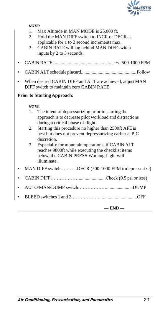
1. Max Altitude in MAN MODE is 25,000 ft.
2. Hold the MAN DIFF switch to INCR or DECR as
applicable for 1 to 2 second increments max.
3. CABIN RATE will lag behind MAN DIFF switch
inputs by 2 to 3 seconds.
• CABIN RATE..................................................... +/- 500-1000 FPM
• CABIN ALT schedule placard............................................... Follow
• When desired CABIN DIFF and ALT are achieved, adjust MAN
DIFF switch to maintain zero CABIN RATE
Prior to Starting Approach:
NOTE:
1. The intent of depressurizing prior to starting the
approach is to decrease pilot workload and distractions
during a critical phase of flight.
2. Starting this procedure no higher than 2500ft AFE is
best but does not prevent depressurizing earlier at PIC
discretion.
3. Especially for mountain operations, if CABIN ALT
reaches 9800ft while executing the checklist items
below, the CABIN PRESS Warning Light will
illuminate.
• MAN DIFF switch………..DECR (500-1000 FPM to depressurize)
• CABIN DIFF……………….......................Check (0.5 psi or less)
• AUTO/MAN/DUMP switch……………….......................DUMP
• BLEED switches 1 and 2………………................................OFF
— END —

Air Conditioning, Pressurization, and Pneumatics 2-8
NOTE:
(All Indicators at Zero)
– Descend to below 14,000 ft. as soon as possible.
• AUTO/MAN/DUMP switch.................................................... MAN
• MAN DIFF switch .......................................DECR (during descent)
• UNPRESSURIZED FLIGHT (Page 2-5) ...................... Accomplish
— END —
• CABIN ALTITUDE FWD OUTFLOW..... OPN (Fully Clockwise)
NOTE:
If CABIN DIFF does not decrease, assume indication
failure.
Prior to Landing:
• RAM VENTILATION (Page 2-6)................................. Accomplish
— END —
• CABIN pack or FLT COMP pack switch.................................. OFF
• BLEED selector ....................................................................... MAX
— END —
―CABIN PACK HOT‖ or ―FLT COMPT PACK HOT‖
(Caution Light)
CABIN DIFF GREATER THAN 1.0 PSI ON APPROACH
LOSS OF CABIN ALTITUDE, CABIN RATE and CABIN DIFF INDICATORS

Air Conditioning, Pressurization, and Pneumatics 2-9
NOTE:
• CABIN pack and FLT COMP pack switches ............................ OFF
• FASTEN BELTS switch..............................................................ON
– Descend to below 14,000 ft. as soon as possible.
When CABIN DIFF pressure has decreased to 0.5 psi or less:
• RAM VENTILATION (Page 2-6)................................. Accomplish
— END —
• CAB DUCT/CABIN/FC DUCT GAUGE..... Confirm Abnormal Temp
• CABIN pack or FLT COMP pack switch.................................. OFF
• BLEED selector ....................................................................... MAX
— END —
• BLEED switch (affected side) ............................................. OFF
— END —
―#1 BLEED HOT‖ or ―#2 BLEED HOT‖ (Caution Light)
―CABIN DUCT HOT‖ or ―FLT COMPT DUCT HOT‖
(Caution Light)
NOTE:
ECS pack airflow is lost and cabin will depressurize.
―CABIN PACK HOT‖ and ―FLT COMPT PACK HOT‖
(Caution Lights)
Air Conditioning, Pressurization, and Pneumatics 2-10
NOTE:
NOTE:
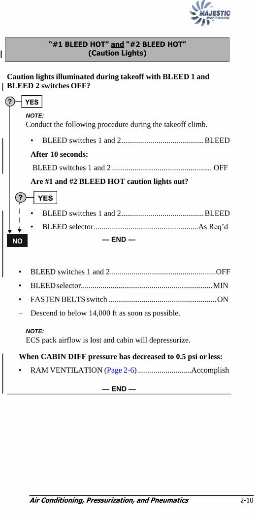
Caution lights illuminated during takeoff with BLEED 1 and
BLEED 2 switches OFF?
• BLEED switches 1 and 2......................................................OFF
• BLEED selector................................................................... MIN
• FASTEN BELTS switch ....................................................... ON
– Descend to below 14,000 ft as soon as possible.
When CABIN DIFF pressure has decreased to 0.5 psi or less:
• RAM VENTILATION (Page 2-6) ...........................Accomplish
— END —
NOTE:
ECS pack airflow is lost and cabin will depressurize.
NOTE:
Conduct the following procedure during the takeoff climb.
• BLEED switches 1 and 2.......................................... BLEED
After 10 seconds:
BLEED switches 1 and 2.................................................... OFF
Are #1 and #2 BLEED HOT caution lights out?
•
•
BLEED switches 1 and 2.......................................... BLEED
BLEED selector......................................................As Req‘d
— END —
―#1 BLEED HOT‖ and ―#2 BLEED HOT‖ (Caution Lights)

Air Conditioning, Pressurization, and Pneumatics 2-11
NOTE:
• Max Airspeed .................................................................. .210 KIAS
• AUTO/MAN/DUMP switch.................................................... MAN
• MAN DIFF switch .............................. DECR (hold 2 seconds max)
• Max CABIN DIFF ................................DECR to maintain < 3.0 psi
• FASTEN BELTS switch..............................................................ON
– Descend to below 14,000 ft. if practical.
– Use MAN DIFF switch to maintain < 3.0 psi diff, or less, in
descent.
– Refer to MANUAL MODE OPERATION for more detailed
operation of MAN MODE.
Prior to Starting Approach:
NOTE:
1. The intent of depressurizing prior to starting the
approach is to decrease pilot workload and distractions
during a critical phase of flight.
2. Starting this procedure no higher than 2500ft AFE is
best but does not prevent depressurizing earlier at PIC
discretion.
3. Especially for mountain operation, if CABIN ALT
reaches 9800ft while executing the checklist items
below. the CABIN PRESS Warning Light will
illuminate.
• MAN DIFF switch .............DECR (500-1000 FPM to depressurize)
• CABIN DIFF ................................................ Check (0.5 psi or less)
• AUTO/MAN/DUMP switch..................................................DUMP
• BLEED selector .........................................................................MIN
• BLEED switches 1 and 2 ........................................................... OFF
— END —
CRACKED WINDSHIELD

Air Conditioning, Pressurization, and Pneumatics 2-12
NOTE:
Is the airplane on the ground?
• Confirm affected door on MFD ‗DOORS‘ page.
• Inspect and secure affected door.
— END —
• FASTEN BELTS switch..............................................................ON
• Confirm affected door on MFD ‗DOORS‘ page.
• If operating the aircraft pressurized, confirm normal CABIN DIFF,
CABIN ALT, and RATE.
NOTE:
If MEL 21-30-5 is being used for both AUTO and MAN
mode of pressurization. Pressurization is NOT considered
normal.
— CONTINUED —
―FUSELAGE DOORS‖ (Warning Light)

Air Conditioning, Pressurization, and Pneumatics 2-13
NOTE:
Is pressurization normal?
• FASTEN BELTS switch........................................................ON
– The flight may continue to the destination, return to point of
departure, or continue to nearest airport where maintenance
services are available.
– Coordinate with Dispatch.
• Pressurization............................................. .Continue to monitor
– If pressurization is subsequently lost, CABIN
PRESSURIZATION FAILURE (Page 2-4) accomplish.
— END —
Security of affected door is confirmed visually?
NOTE:
If affected door is the AFT or FWD Baggage door,
continue to ―Security of the affected door cannot be
confirmed visually‖.
Do not attempt to secure affected door.
• FASTEN BELTS switch........................................................ON
– The flight may continue to the destination, return to point of
departure, or continue to nearest airport where maintenance
services are available.
– Coordinate with Dispatch.
• Pressurization.............................................. Continue to monitor
– If pressurization is subsequently lost, CABIN
PRESSURIZATION FAILURE (Page 2-4) accomplish.
— END —
Security of affected door cannot be confirmed visually or
Operating handle of affected door is not in the closed postion:
• FASTEN BELTS switch........................................................ON
– Land immediately at nearest suitable airport.
WARNING

Air Conditioning, Pressurization, and Pneumatics 2-14
— END —

Air Conditioning, Pressurization, and Pneumatics 2-15
―Internal Doors Fail‖ Advisory Light On (Overhead Pilot Control
Switch Panel)?
• Deadbolt Latch............................................Rotate to Lock Door
• LOCK ISOLATE Button .................................................... Press
— END —
―BAGG DOOR‖ Advisory Light On (Overhead Pilot Control
Switch Panel)?
• Internal Baggage Door .......................................... Check/Secure
— END —
―CKPT DOOR‖ Advisory Light On (Overhead Pilot Control
Switch Panel):
• Flight Compartment Door..................................... Check/Secure
— END —
INTERNAL DOORS (Caution Light)

Air Conditioning, Pressurization, and Pneumatics 2-16
NOTE:
NOTE:
• Unlock and step down on bottom hinge pin.
• Unlock and pull down upper hinge pin.
• Unlock and lift middle hinge pin.
• Push flight compartment door at hinge side.
NOTE:
It may require a large force to open the flight compartment
door.
• Rotate the flight compartment door counter-clockwise and stow
against the lavatory.
NOTE:
Upon forcing the flight compartment door open, it may fall
straight aft and lay flat on the cabin floor.
— END —
EMERGENCY OPENING OF FLIGHT COMPARTMENT DOOR (Door Jammed)
Air Conditioning, Pressurization, and Pneumatics 2-17
NOTE:
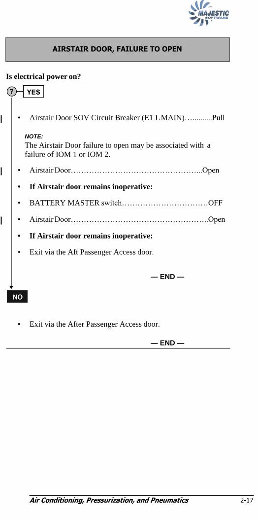
Is electrical power on?
• Airstair Door SOV Circuit Breaker (E1 L MAIN)…..........Pull
NOTE:
The Airstair Door failure to open may be associated with a
failure of IOM 1 or IOM 2.
• Airstair Door…………………………………………...Open
• If Airstair door remains inoperative:
• BATTERY MASTER switch……………………………OFF
• Airstair Door……………………………………………..Open
• If Airstair door remains inoperative:
• Exit via the Aft Passenger Access door.
— END —
• Exit via the After Passenger Access door.
— END —
AIRSTAIR DOOR, FAILURE TO OPEN

APU Engines and Propellers 3-i
Chapter 3: APU, Engines, and Propellers ENGINE FAILURE/FIRE/SHUTDOWN
(In Flight). 3-1
ON GROUND EMERGENCIES 3-5
UNSCHEDULED PROPELLER FEATHERING 3-5
Autofeather Fails to ARM during Takeoff (No Annunciation of A/F Arm) 3-6
ABORTED ENGINE START 3-7
START Light Remains On After Engine Start Sequence (No STARTER Cut Out) 3-8
SELECT Light Remains On After Engine Start (Possible ENGINE STARTER Failure on the Ground) ......... 3-9
APU FIRE 3-9
POST APU AUTOMATIC SHUTDOWN 3-10
APU START FAILURE (APU FAIL Advisory Light Illuminates during Start) ......... 3-11
APU STARTER FAILURE (START Light Remains Illuminated on APU Control Panel) 3-11
―APU‖ (CAUTION LIGHT) 3-12
APU BLEED AIR OVERHEAT 3-13
ENGINE AIRSTART 3-14
STARTER FAILURE IN FLIGHT 3-15
Low Oil Pressure or ―#1 ENG OIL PRESS‖ or ―#2 ENG OIL PRESS‖ (Warning Light) 3-16
HIGH OIL PRESSURE (72 psi or above) 3-17
HIGH OIL TEMPERATURE IN FLIGHT (107°C or above) 3-18

APU Engines and Propellers 3-i
LOW OIL TEMPERATURE (0° – 65° C) 3-19
―#1 ENG FADEC FAIL‖ or ―#2 ENG FADEC FAIL‖ (Warning Light) 3-19
―#1 ENG FADEC‖ (Caution Light) or ―#2 ENG FADEC‖ (Caution Light) 3-20
―POWERPLANT‖ (ED Advisory) 3-20
DUAL PROPELLER OVERSPEED 3-21
PROPELLER OVERSPEED 3-22
Power Lever Overtravel Reset 3-24
―#1 PEC‖ or ―#2 PEC‖ (Caution Light) 3-25
PROPELLER GROUND RANGE ADVISORY LIGHT CYCLING 3-26
―CHECK FIRE DET‖ Warning Light and ―FAULT A‖ or ―FAULT B‖ Advisory Light 3-27
―CHECK FIRE DET‖ Warning Light and ―BTL LOW‖ Advisory Light 3-27

APU Engines and Propellers 3-1
Chapter 3: APU, Engines, and Propellers
• Landing Gear ............................................................................... UP
• Flaps 0
• Condition Lever (Operating engine)........................................ MAX
• Ice Protection ..................................................................... As Req‘d
CAUTION:
Propeller may unfeather if Autofeather is selected off before
condition lever is selected to FUEL OFF.
• AUTOFEATHER ...................................................................... OFF
• POWER levers ........................................................Operate together
• Ignition (Affected Engine).................................................. OFF
• BLEED switch (Affected engine).............................................. OFF
• BLEED switch (Operating engine)...................................... BLEED
• BLEED selector (Operating engine).......................NORM or MAX
– Max Continuous power should be displayed on the ED.
• STBY HYD Press ........................................................................ON
• TANK AUX PUMP (Operating engine)................................ON
– Transfer fuel as required to maintain fuel balance.
— CONTINUED —
Affected Engine:
• POWER Lever .................................................. FLIGHT IDLE
• Condition Lever ...................................................... FUEL OFF
• Alternate Feather (If required) ........................................ FTHR
• PULL FUEL/HYD OFF handle.......................................... Pull
• TANK AUX PUMP........................................................... OFF
If Fire:
• EXTG switch (Affected engine) .................................... FWD BTL
If Fire Persists, Wait Up To 30 Seconds:
• EXTG switch (Affected engine) ..................................... AFT BTL
ENGINE FAILURE/FIRE/SHUTDOWN (In Flight)

APU Engines and Propellers 3-2
Is Driftdown required?
SINGLE ENGINE SERVICE CEILING/
DRIFTDOWN SPEEDS
Note: Icing Conditions with the Ice Protection Systems “On”:
Subtract 4,800 ft from single-engine service ceiling
Cruising
WT
KIAS ISA -20 ISA -10 ISA ISA +10 ISA +20 ISA +30
Level 1 Level 2
64500 158 178 19700 18000 16100 14200 12100 8900
64000 157 177 20000 18200 16300 14400 12300 9300
62000 154 174 20900 19100 17300 15400 13300 10400
60000 152 172 21800 20100 18300 16400 14400 11500
58000 149 169 22700 21000 19300 17500 15400 12600
56000 147 167 23700 22000 20300 18500 16500 13800
54000 144 164 24700 23000 21300 19600 17600 15000
52000 142 162 25000 24100 22400 20600 18700 16300
50000 139 159 25000 25000 23500 21700 19800 17600
48000 136 156 25000 25000 24600 22700 20900 18900
46000 134 154 25000 25000 25000 24000 22100 20000
44000 131 151 25000 25000 25000 25000 23300 21200
42000 130 150 25000 25000 25000 25000 24600 22500
Figure 3-1: Driftdown Speeds
– If unable to maintain airspeed at cruise altitude after engine
failure/fire/shutdown, descend at driftdown speed.
— CONTINUED —

APU, Engines, and Propellers 3-3
If #1 engine inoperative:
• PTU CNTRL................................................................ NORM (Off)
– DO NOT select PTU CNTRL to ON for landing.
If #2 engine inoperative:
• PTU CNTRL................................................................................ON
Landing Considerations:
Abnormal Landing Distance Factors
Flap Ice Protection
Level 1 Level 2/3
10 1.4 1.4
15 1.4 1.4
35 1.5 1.5
Conditional Landing Distance Statement
Level 1 Ice Protection
Landing Distance = 5100 ft
Wt. less than 64,500 lbs.
Flap greater than or equal to 10°
Dry Runway
Airport Elevation less than 2000 ft
Tailwind less than or equal to 10 kts.
After Landing:
– If possible, clear the runway.
Descent Checklist—One Engine Inoperative:
– Altimeters......................................................... SET / Crosscheck
– Fuel balance............................................................................Check
– Pressurization...............................................................................Set
– FASTEN BELTS switch.............................................................ON
– Approach & Landing Brief................................................Complete
– GPWS LANDING FLAP................................................Selected °
---------------------------------- LINE --------------------------------
— CONTINUED —

APU, Engines, and Propellers 3-4
Fuel Transfer....................................................................................OFF
Hyd Press/Qty................................................................................Check
Caution/Warning Lights................................................................Check
APPROACH/FLARE Lights.............................................................ON
REF SPEEDS switch/bugs................................................As Req‘d/Set
F/A Notification.......................................................................Complete
Before Landing Checklist --One Engine Inoperative:
• Autopilot .............................. Disengage (At or above 1000 ft AGL)
If #1 engine inoperative:
• PTU ..................................................................................... .OFF
• STBY HYD PRESS...............................................................ON
• LANDING GEAR ............................................. Down / 3 Green
• AUX PUMP (Operating engine)....................................ON
• Condition Lever (Operating engine).................................. MAX
• BLEED selector ...................................................................MIN
• Flaps.............................................. Indicating / Planned
— END —
OR
If #2 engine inoperative:
• PTU ........................................................................................ON
• STBY HYD PRESS...............................................................ON
• LANDING GEAR ............................................. Down / 3 Green
• AUX PUMP (Operating engine)....................................ON
• Condition Lever (Operating engine).................................. MAX
• BLEED selector ...................................................................MIN
• Flaps.............................................. Indicating / Planned
— END —
Go-Around / Missed Approach--One Engine Inoperative:
• LANDING GEAR........................................................................UP
• Flaps...............................................................................................0°
• BLEED selector......................................................NORM or MAX
• FUEL TRANSFER.............................................................As Req‘d
• One Engine Inoperative ..........Descent / Approach / Before Landing
..................................................................Checklists Accomplish
— END —

APU, Engines, and Propellers 3-5
• EMERG BRAKE .................................................................. PARK
• POWER Levers...................................................................... DISC
• CONDITION Levers .................................................... FUEL OFF
• PULL FUEL/HYD OFF Handle (Affected engine).................. Pull
• TANK AUX PUMPS............................................................... OFF
If Engine Fire:
• EXTG Switch................................................................. FWD BTL
• EXTG Switch.................................................................. AFT BTL
If Baggage Compartment Fire:
• Illuminated SMOKE/EXTG Switch ....................................... Press
If Evacuation:
• EMERG LIGHTS switch...........................................................ON
• FASTEN BELTS switch.......................................................... OFF
• Evacuate.......................................................................... Command
• AC/DC EXT PWR and APU ................................................... OFF
• BATTERY MASTER.............................................................. OFF
— END —
(May be indicated by high torque and/or low Prop RPM)
Above 400 ft AGL:
Affected Engine:
• ENGINE FAILURE/FIRE/SHUTDOWN (In Flight) (Page 3-1)....
.......................................................................................Accomplish
— END —
UNSCHEDULED PROPELLER FEATHERING
ON GROUND EMERGENCIES
APU, Engines, and Propellers 3-6
NOTE:
NOTE:
DH8-400-SL-61-011 19MAY11
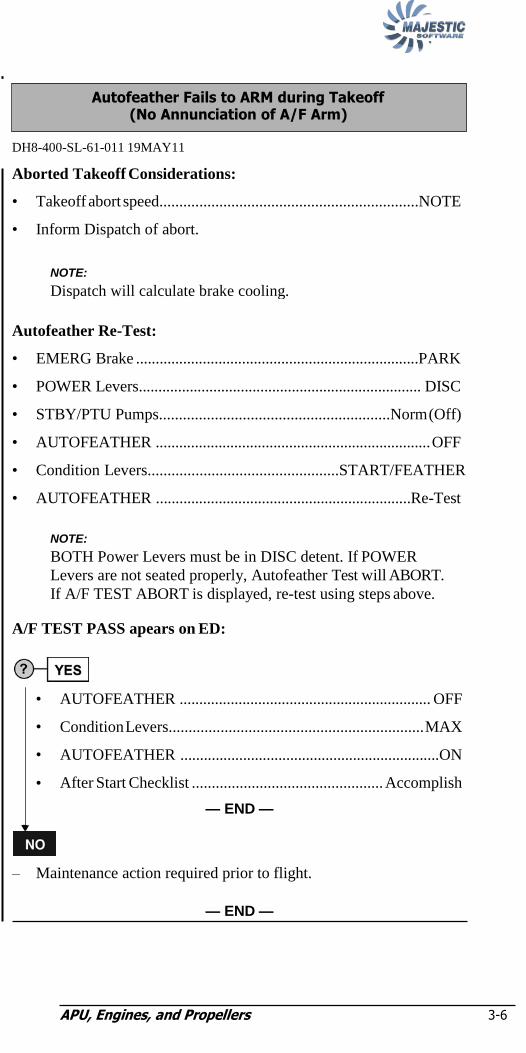
Aborted Takeoff Considerations:
• Takeoff abort speed.................................................................NOTE
• Inform Dispatch of abort.
Autofeather Re-Test:
• EMERG Brake ........................................................................PARK
• POWER Levers........................................................................ DISC
• STBY/PTU Pumps..........................................................Norm (Off)
• AUTOFEATHER ...................................................................... OFF
• Condition Levers................................................START/FEATHER
• AUTOFEATHER .................................................................Re-Test
NOTE:
BOTH Power Levers must be in DISC detent. If POWER
Levers are not seated properly, Autofeather Test will ABORT.
If A/F TEST ABORT is displayed, re-test using steps above.
A/F TEST PASS apears on ED:
AUTOFEATHER ................................................................ OFF
Condition Levers................................................................ MAX
AUTOFEATHER ..................................................................ON
After Start Checklist ................................................ Accomplish
— END —
– Maintenance action required prior to flight.
— END —
NOTE:
Dispatch will calculate brake cooling.
Autofeather Fails to ARM during Takeoff (No Annunciation of A/F Arm)
•
•
•
•
APU, Engines, and Propellers 3-7
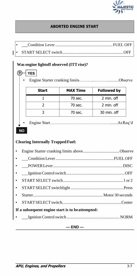
Was engine lightoff observed (ITT rise)?
• Engine Starter cranking limits………..………............Observe
Start MAX Time Followed by
1 70 sec. 2 min. off
2 70 sec. 2 min. off
3 70 sec. 30 min. off
• Engine Start……………………….……………........As Req‘d
Clearing Internally Trapped Fuel:
• Engine Starter cranking limits above................................... Observe
• Condition Lever ........................................................ FUEL OFF
• POWER Lever ................................................................... DISC
• Ignition Control switch ........................................................ OFF
• START SELECT switch.......................................................... 1 or 2
• START SELECT switchlight ................................................... Press
• Starter................................................................... Motor 30 seconds
• START SELECT switch.........................................................Center
If a subsequent engine start is to be attempted:
• Ignition Control switch ................................................... NORM
— END —
• Condition Lever ........................................................ FUEL OFF
• START SELECT switch............................................................ OFF
ABORTED ENGINE START

APU, Engines, and Propellers 3-8
NOTE:
NOTE:
(START Light remains illuminated after engine start sequence)
• START SELECT switch.........................................................Center
NOTE:
Engine START and SELECT lights will take approximately 15
seconds to go out.
NOTE:
If DC EXT PWR is used for start, wait for START and
SELECT lights to extinguish prior to moving EXT PWR switch
to OFF.
• DC EXT PWR switch ................................................................ OFF
Affected DC GEN caution light is illuminated?
• DC GEN switch ............................................... OFF then ON
Affected DC GEN caution remains illuminated?
• DC GEN switch ....................................................... OFF
If in flight:
– No further action required.
If on the ground:
– Accomplish normal After Landing and Parking Checklists.
– Maintenance action required prior to flight.
— END —
– Check affected DC Gen load for normal indications.
NOTE:
The flight may depart but maintenance action or
Flight Crew Deferral required after landing. Refer
to MEL 24-30-2 for more information.
— END —
START Light Remains On After Engine Start Sequence (No STARTER Cut Out)

APU, Engines, and Propellers 3-9
NOTE:
• EMER LIGHTS switch...................................................... As Req‘d
• MAIN, AUX, and STBY BATT switches ................................. OFF
• DC EXT PWR ........................................................................... OFF
• AC EXT PWR ........................................................................... OFF
• Condition Levers........................................................................ OFF
• APU Power ................................................................................ OFF
• EXTERIOR LIGHTS ........................................................ As Req‘d
— END —
(Illumination of Check Fire Detect Warning, APU Caution, and APU
Fire Advisory Lights)
Confirm APU Automatic Shutdown:
On APU CONTROL Panel
• PWR— RUN light ...................................................................Dark
• PWR—FAIL light............................................... FAIL Illuminated
On APU Fire Protection Panel
• BTL LOW light ......................................... BTL LOW Illuminated
• VALVE CLOSED light .................................................. Illuminated
BTL ARM or FIRE Lights remain illuminated after 7 seconds:
• EXTG switchlight ................................................................... Press
— CONTINUED —
APU FIRE
NOTE:
Consider returning to the gate prior continuing this checklist.
SELECT Light Remains On After Engine Start (Possible ENGINE STARTER Failure on the Ground)
APU, Engines, and Propellers 3-10
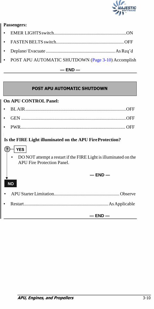
Passengers:
• EMER LIGHTS switch..............................................................ON
• FASTEN BELTS switch.......................................................... OFF
• Deplane/ Evacuate ........................................................... As Req‘d
• POST APU AUTOMATIC SHUTDOWN (Page 3-10) Accomplish
— END —
On APU CONTROL Panel:
• BL AIR ...................................................................................... OFF
• GEN ........................................................................................... OFF
• PWR........................................................................................... OFF
•
•
•
Is the FIRE Light illuminated on the APU Fire Protection?
• DO NOT attempt a restart if the FIRE Light is illuminated on the
APU Fire Protection Panel.
— END —
• APU Starter Limitation........................................................ Observe
• Restart ........................................................................ As Applicable
— END —
POST APU AUTOMATIC SHUTDOWN

APU, Engines, and Propellers 3-11
NOTE:
NOTE:
STARTER Light On APU CONTROL Panel is Dark?
• APU STARTER FAILURE (Page 3-11)..................Accomplish
— END —
NOTE:
Consider returning to the gate and deplaning passengers prior to
continuing this checklist.
• EMER LIGHTS switch.............................................................. OFF
• MAIN, AUX, and STBY BATT switches ................................. OFF
• DC EXT PWR ........................................................................... OFF
• AC EXT PWR ........................................................................... OFF
• Condition Levers........................................................................ OFF
• APU CONTROL—PWR ........................................................... OFF
• EXTERIOR LIGHTS ........................................................ As Req‘d
APU STARTER FAILURE (START Light Remains Illuminated on APU Control Panel)
• PWR ...................................................................... OFF then ON
NOTE:
After an APU start attempt, APU start will remain disabled for
approximately 7 seconds.
• APU Starter Limitation...................................................Observe
• Restart................................................................... As Applicable
— END —
APU START FAILURE (APU FAIL Advisory Light Illuminates during Start)

APU, Engines, and Propellers 3-12
Is the FAIL Light illuminated on the APU CONTROL Panel?
APU Failure:
• APU automatic shutdown.............................................. Confirm
• POST APU AUTOMATIC SHUTDOWN (Page 3-10)..............
.................................................................................Accomplish
— END —
Is the WARN Light illuminated on the APU CONTROL Panel?
APU GEN Failure:
• GEN ....................................................................... OFF then ON
WARN Light remains illuminated?
• GEN ............................................................................... OFF
— END —
• No further action required.
— END —
Is the GEN OHT Light illuminated on the APU CONTROL Panel
APU GEN Overheat?
• APU automatic shutdown...............................................Confirm
• POST APU AUTOMATIC SHUTDOWN (Page 3-10) .............
.................................................................................Accomplish
— END —
• No further action required.
— END —
―APU‖ (CAUTION LIGHT)

APU, Engines, and Propellers 3-13
(FLT COMPT DUCT HOT or CABIN DUCT HOT or CABIN PACK
HOT or FLT COMPT PACK HOT Caution Light):
NOTE:
On the AIR CONDITIONING Panel, ensure
PACKS switches are in AUTO.
• APU–BL AIR ............................................................................ OFF
— END —
APU BLEED AIR OVERHEAT

APU, Engines, and Propellers 3-14
NOTE:
Figure 3-2: Engine Airstart Envelope
Affected Engine:
• POWER Lever .................................................... FLIGHT IDLE
• Condition Lever ........................................................ FUEL OFF
• PULL FUEL/HYD OFF handle...................................... Push In
• Ignition Control switch ................................................... NORM
• BLEED switch ..................................................................... OFF
• TANK AUX PUMP...............................................................ON
• AUTOFEATHER ...................................................................... OFF
• ALT FTHR .......................................................................... OFF
• MAIN BUS TIE.......................................................................... TIE
• Autopilot ................................................................ Disengage
• Conduct normal start procedure and adhere to normal start
limitations.
When Engine Stabilizes:
• Condition Lever ...................................................................MIN
When Propeller NP Stabilizes:
• Condition Lever ........................................................... As Req‘d
• POWER Lever ............................................................. As Req‘d
— CONTINUED —
NOTE:
Minimum SAT for engine relight is – 40°C.
ENGINE AIRSTART
APU, Engines, and Propellers 3-15
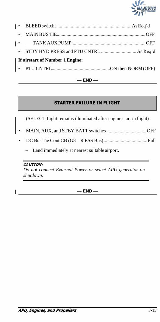
• BLEED switch ............................................................... As Req‘d
• MAIN BUS TIE......................................................................... OFF
• TANK AUX PUMP............................................................. OFF
• STBY HYD PRESS and PTU CNTRL ............................. As Req‘d
If airstart of Number 1 Engine:
• PTU CNTRL................................................ON then NORM (OFF)
— END —
(SELECT Light remains illuminated after engine start in flight)
• MAIN, AUX, and STBY BATT switches ................................. OFF
• DC Bus Tie Cont CB (G8 – R ESS Bus) .................................... Pull
– Land immediately at nearest suitable airport.
CAUTION:
Do not connect External Power or select APU generator on
shutdown.
— END —
STARTER FAILURE IN FLIGHT

APU, Engines, and Propellers 3-16
NOTE:
NOTE:
ti
Is indicated oil pressure below 44 psi (gauge is red) or continuous
illumination of the #1 ENG OIL PRESS or #2 ENG OIL PRESS
warning light?
Oil pressure is between 44 and 60 psi (gauge is yellow):
• POWER Lever (Affected engine) .................FLIGHT IDLE
To reduce in-flight drag:
• Conditional Lever.............................. START & FEATHER
• POWER Lever (Affected engine) ...............................FTHR
If oil pressure decreases to 44 psi or less:
Affected Engine:
— END —
• ENGINE FAILURE/FIRE/SHUTDOWN (Page 3-1) .........Accomplish
NOTE:
Monitor oil pressure closely.
• ENGINE FAILURE/FIRE/SHUTDOWN (Page 3-1) ..Accomplish
Affected Engine:
NOTE:
An OIL PRESS Warning light must be responded to
regardless of oil pressure gauge indication.
— END —
Low Oil Pressure or ―#1 ENG OIL PRESS‖ or ―#2 ENG OIL PRESS‖
(Warning Light)

APU, Engines, and Propellers 3-17
NOTE:
Affected Engine(s):
• Power....................................................................................Reduce
CAUTION:
Maximum power reduction must not exceed 20% of previously
set torque.
NOTE:
Power reduction will be dependant on performance, including
icing, and airspeed requirements. Minimum airspeed will be
appropriate to flap configuration and flight conditions.
Monitor oil pressure for 2 minutes:
Does oil pressure decrease to 72 psid or less?
– Maintain power at or below the adjusted torque setting for the
remainder of the flight.
– Maintenance action required prior to flight.
— END —
Affected engine:
— END —
• ENGINE FAILURE/FIRE/SHUTDOWN (Page 3-1) .....Accomplish
HIGH OIL PRESSURE (72 psi or above)
PSM 1-84-1B MAY 31/11

APU, Engines, and Propellers 3-18
NOTE:
Affected engine(s):
• Power....................................................................................Reduce
CAUTION:
Maximum power reduction must not exceed 20% of previously
set torque.
NOTE:
Power reduction will be dependant on performance, including
icing, and airspeed requirements. Minimum airspeed will be
appropriate to flap configuration and flight conditions.
• Monitor oil temperature
After 10 minutes:
Has the oil temperature decreased below 107°C?
– Maintain power at or below the adjusted torque setting for the
remainder of the flight.
– Maintenance action required prior to next flight.
— END —
Oil temperature does NOT decrease OR increases above 125 C:
Affected engine:
— END —
• ENGINE FAILURE/FIRE/SHUTDOWN (Page 3-1) .....Accomplish
HIGH OIL TEMPERATURE IN FLIGHT (107°C or above)

APU, Engines, and Propellers 3-19
NOTE:
NOTE:
(Prop Deice On In Flight)
NOTE:
To maintain the minimum engine oil temperature of 65° C in
icing conditions, it may be necessary to increase engine
power. The increase in engine power may be limited by
airspeed limitations and operational requirements.
– Monitor engine performance.
– Exit icing conditions as soon as possible.
— END —
Affected Engine:
NOTE:
FADEC Failure may cause the affected engine to shut down
automatically.
— END —
• ENGINE FAILURE/FIRE/SHUTDOWN (Page 3-1)........ Accomplish
―#1 ENG FADEC FAIL‖ or ―#2 ENG FADEC FAIL‖
(Warning Light)
LOW OIL TEMPERATURE (0° – 65° C)

APU, Engines, and Propellers 3-20
NOTE:
NOTE:
Affected Engine:
• POWER Lever ............................... Adjust slowly and smoothly
NOTE:
Symmetric torque may require asymmetric Power Lever
positions.
Landing Considerations:
DO NOT retard affected POWER Lever below DISC on landing.
— END —
• Monitor engine performance
— END —
NOTE:
Maintenance action required prior to next flight.
―POWERPLANT‖ (ED Advisory)
―#1 ENG FADEC‖ (Caution Light) or ―#2 ENG FADEC‖ (Caution Light)

APU, Engines, and Propellers 3-21
NOTE:
NOTE:
(Both propellers increase above 1020 RPM and ―#1 PEC‖ and ―#2
PEC‖ Caution Lights illuminate.)
– The flight may continue to the destination, return to point of
departure or the nearest airport where maintenance services are
available, as appropriate. (Coordinate with Dispatch/SOC.)
NOTE:
1. During overspeed governor control, an increase in
power or turbulence encounter may cause the propeller
speed to temporarily exceed 1080 rpm.
2. With Power Levers in the RATING DETENT, the
TRQ indication will be less than the displayed torque
rating.
Landing Considerations:
• DO NOT retard POWER Levers below FLT IDLE on landing and
during taxi, as propellers will feather.
• Anticipate greater than normal braking requirements due to
increased propeller thrust at FLT IDLE setting.
NOTE:
During the landing roll, propellers will decrease to approximately
500 – 550 RPM and may cause the AC generators to drop off-
line.
Abnormal Landing Distance Factors
Flap Ice Protection
Level 1 Level 2/3
10 1.35 1.35
15 1.35 1.35
35 1.35 1.35
Conditional Landing Distance Statement
Level 1 Ice Protection
Landing Distance = 5100 ft
Wt. less than 64,500 lbs.
Flap greater than or equal to 10°
Dry Runway
Airport Elevation less than 2000 ft
Tailwind less than or equal to 10 kts.
— END —
DUAL PROPELLER OVERSPEED

APU, Engines, and Propellers 3-22
NOTE:
NOTE:
(Propeller increases above 1020 RPM and ―#1 PEC‖ or ―#2 PEC‖
Caution Light illuminates.)
Above 400 ft AGL:
• Airspeed .................................................................. Reduce toward
minimum speed appropriate to flap configuration and flight
conditions.
Affected Engine:
• POWER Lever .................................................. FLIGHT IDLE
• Condition Lever .........................................START/FEATHER
• ALT FTHR (If required)................................................. FTHR
IF propeller feathers:
• ENGINE FAILURE/FIRE/SHUTDOWN (In Flight)
(Page 3-1)................................................ Accomplish Immediately
NOTE:
If the engine is not shutdown immediately after feathering the
propeller with the Alternate Feather system, the propeller may
unfeather. Reselect the ALT FTHR switch to feather the
propeller.
IF propeller does not feather:
– DO NOT SHUT DOWN ENGINE.
• Condition Levers.................................................................... MAX
• POWER Levers.....................................................Operate together
– Land immediately at the nearest suitable airport.
NOTE:
1. Symmetric Power levers will give approximately symmetric
power.
2. During overspeed governor control, an increase in power or
turbulence encounter may cause the propeller speed to
temporarily exceed 1080 rpm.
PROPELLER OVERSPEED
APU, Engines, and Propellers 3-23
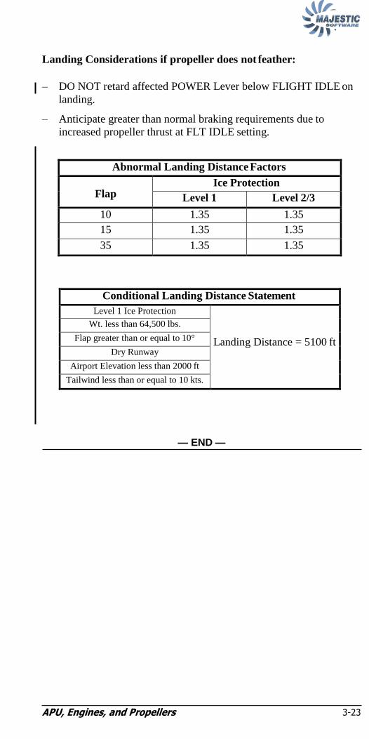
Landing Considerations if propeller does not feather:
– DO NOT retard affected POWER Lever below FLIGHT IDLE on
landing.
– Anticipate greater than normal braking requirements due to
increased propeller thrust at FLT IDLE setting.
Abnormal Landing Distance Factors
Flap Ice Protection
Level 1 Level 2/3
10 1.35 1.35
15 1.35 1.35
35 1.35 1.35
Conditional Landing Distance Statement
Level 1 Ice Protection
Landing Distance = 5100 ft
Wt. less than 64,500 lbs.
Flap greater than or equal to 10°
Dry Runway
Airport Elevation less than 2000 ft
Tailwind less than or equal to 10 kts.
— END —

APU, Engines, and Propellers 3-24
NOTE:
(Necessary or Inadvertent Power Lever movement past Rating
detent causing propeller RPM to increase to 1020 even with
Condition Lever in 850 or 900 detent)
NOTE:
Propeller RPM may exceed 1020 upon initial Power Lever
movement past the rating detent. Do not mis interpret as an
overspeed condition.
• POWER Lever (affected).......................... Rating Detent (or below)
• Condition Lever (affected)....................................................... MAX
• Condition Lever (affected)................................ As Req‘d (900/850)
• Engine Event Marker .............................................................PRESS
IF Engine Limitation exceeded:
• Exeedences...................................................................NOTE
• Maintenance action required prior to next flight.
• Following the flight, an Informational write-up should be made noting a successful reset and use of the Event Marker.
— END —
Power Lever Overtravel Reset DH8-400-SL-71-011

APU, Engines, and Propellers 3-25
Landing Considerations:
– DO NOT retard affected POWER Lever below FLIGHT IDLE on
landing.
– Anticipate greater than normal braking requirements due to
increased propeller thrust at FLT IDLE setting.
Abnormal Landing Distance Factors
Flap Ice Protection
Level 1 Level 2/3
10 1.35 1.35
15 1.35 1.35
35 1.35 1.35
Conditional Landing Distance Statement
Level 1 Ice Protection
Landing Distance = 5100 ft
Wt. less than 64,500 lbs.
Flap greater than or equal to 10°
Dry Runway
Airport Elevation less than 2000 ft
Tailwind less than or equal to 10 kts.
— END —
―#1 PEC‖ or
―#2 PEC‖
(Caution Light)

APU, Engines, and Propellers 3-26
• POWER Levers .....................................Advance above Flight Idle
CAUTION:
Avoid Power Lever positions that cause the Ground Range
lights to illuminate.
Landing Considerations:
– DO NOT select affected Power lever below FLIGHT IDLE on
landing.
– Anticipate greater than normal braking requirements due to
increased propeller thrust at FLT IDLE setting.
Abnormal Landing Distance Factors
Flap Ice Protection
Level 1 Level 2/3
10 1.35 1.35
15 1.35 1.35
35 1.35 1.35
Conditional Landing Distance Statement
Level 1 Ice Protection
Landing Distance = 5100 ft
Wt. less than 64,500 lbs.
Flap greater than or equal to 10°
Dry Runway
Airport Elevation less than 2000 ft
Tailwind less than or equal to 10 kts.
— END —
PROPELLER GROUND RANGE ADVISORY LIGHT CYCLING
APU, Engines, and Propellers 3-27
NOTE:
NOTE:
(Fire Detector Loop Failure)
– No Crew action required.
— END —
(Fire Bottle Pressure Low)
– No Crew action required.
— END —
NOTE:
Maintenance action required prior to next flight.
―CHECK FIRE DET‖ Warning Light and ―BTL LOW‖ Advisory Light
NOTE:
Maintenance action required prior to next flight.
―CHECK FIRE DET‖ Warning Light and ―FAULT A‖ or ―FAULT B‖ Advisory Light
APU, Engines, and Propellers 3-28
Intentionally Left Blank

Autoflight, Flight Instruments and Navigation 4-i
Chapter 4: Autoflight, Flight Instruments,
and Navigation "AP DISENGAGED" or
"AP/YD DISENGAGED" (Flashing PFD Message and Red "AP DISENG" Light) ....... 4-1
"YD DISENGAGED" (Flashing PFD Message) 4-1
"AP FAIL" (Message on PFD) 4-2
"AP/YD FAIL" (Message on PFD) 4-2
"MISTRIM [TRIM L WING DN]" or "MISTRIM [TRIM R WING DN]" (Message on PFD) 4-3
"MISTRIM [TRIM NOSE DOWN]" or "MISTRIM [TRIM NOSE UP]" (Message on PFD) 4-3
"AFCS CONTROLLER INOP" (Message on PFD) 4-4
"AFCS FAIL" (Message on PFD) 4-5
"AP PITCH TRIM FAIL" (Message on PFD) 4-5
"AUTO TRIM FAIL" (Message on PFD) 4-6
"L FD FAIL" or "R FD FAIL" (Message on PFD) 4-6
"YD NOT CENTERED" (Message on PFD) 4-7
"ALT OFF" (Message on PFD) 4-7
"CHECK NAV SOURCE" (Message on PFD) 4-8
"FD ADC DATA INVLD" (Message on PFD) 4-8

Autoflight, Flight Instruments and Navigation 4-i
"FD ATT DATA INVLD" (Message on PFD) 4-9
"FD HDG DATA INVLD" (Message on PFD) 4-9
"FD NAV DATA INVLD" (Message on PFD) 4-10
"CAT II FAIL" (Message on PFD) 4-10
"DUAL OFF" (Message on PFD) 4-11
"AP INHIBIT" (Message on PFD) 4-11
"YD INHIBIT" (Message on PFD) 4-11
PRIMARY FLIGHT DISPLAY FAILURE 4-12
"CHECK PFD 1" or "CHECK PFD 2" (Message on PFD) 4-12
"ATT FAIL" (Message on PFD) 4-13
"HDG FAIL" (Message on PFD) 4-13
"IVSI FAIL" (Message on PFD) 4-14
"PITCH MISMATCH" or "ROLL MISMATCH" (Message on PFD) 4-14
"HDG MISMATCH" (Message on PFD) 4-15
LOSS OF CAPTAIN, FIRST OFFICER and INTEGRATED STANDBY INSTRUMENT AIRSPEED and ALTITUDE FUNCTIONS 4-16
LOSS OF BOTH AIRSPEED and BOTH ALTITUDE INDICATIONS ON PILOT's and FIRST OFFICER's PFDs 4-18
"IAS FAIL" or "ALT FAIL" (Message on PFD) 4-20

Chapter 4: Autoflight, Flight Instruments, and Navigation 4-i
"CUE" (Message on PFD) 4-20
"IAS MISMATCH" (Message on PFD) 4-21
"ALT MISMATCH" (Message on PFD) 4-22
"LOC MISMATCH" or "GS MISMATCH" (Message on PFD) 4-23
"RA" (Message on PFD) 4-23
"RAD ALT MISMATCH" (Message on PFD) 4-24
"GPS INTEG" (Message on PFD) 4-24
"NAV INTEG" (Message on PFD) 4-25
"NAV DR" (Message on PFD) 4-25
"ALIGNING" (Message on PFD) 4-25
MULTIFUNCTION DISPLAY FAILURE 4-26
"TCAS FAIL" (Message on PFD and MFD) 4-26
"WX FAIL" (Message on MFD) 4-27
ENGINE DISPLAY FAILURE 4-27
Ghost Or Mirror Images On 4-28
Integrated Standby Instrument (ISI) 4-28
"CHECK ED" (Message on ED) 4-29
DU BAD CONFIG (ED) 4-30
ED MON FAIL (ED) 4-30
FADEC1/DU or FADEC2/DU or FADECS/DU (ED) 4-31
Chapter 4: Autoflight, Flight Instruments, and Navigation 4-i
FANS FAIL (ED) 4-31
"GPWS I/F FAIL" (Message on ED) 4-32
HOT DISPLAYS (Message on ED) 4-32
HOT ED (Message on ED) 4-32
HOT MFD1 or HOT MFD2 (Message on ED) 4-33
IOMS FAIL (Message on ED) 4-34
IOM1 FAIL or IOM2 FAIL (Message on ED) 4-34
IOP BAD CONF (Message on ED) 4-35
IOPS FAIL (Message on ED) 4-35
IOP1 FAIL or IOP2 FAIL (Message on ED) 4-36
MFD LINK FAIL or MFD2 LINK FAIL (Message on ED) 4-36
PFD LINK FAIL or PFD2 LINK FAIL (Message on ED) 4-36
PFD1 MON FAIL or PFD2 MON FAIL or PFDS MON FAIL (Message on ED) 4-37
"RAS FAIL" (Message on ED) 4-37
RA1 FAIL or RA2 FAIL (Message on ED) 4-38
WOW/IOPS FAIL (Message on ED) 4-38
WOW/IOP1 FAIL or WOW/IOP2 FAIL (Message on ED) 4-39
Chapter 4: Autoflight, Flight Instruments, and Navigation 4-i
WTGS FAIL
(Message on ED) 4-39
WTG1 FAIL or WTG2 FAIL (Message on ED) 4-40
PA CHIME INOPERATIVE 4-40
ARCDU Transmission Errors 4-41
DUAL ARCDU FAILURE 4-42
"ARCDU FAILED" (Message on ARCDU display) 4-43
"FAIL" (Message on ARCDU INT display area) 4-44
LOSS OF PILOT or FIRST OFFICER HEADSET AUDIO 4-44
"ALT" (Message on ARCDU ATC display area) 4-45
"FLT DATA RECORDER" (Caution Light) 4-46
"GPWS" (Caution Light) 4-46

Chapter 4: Autoflight, Flight Instruments, and Navigation 4-i
Intentionally Left Blank
Q400 Quick Reference Handbook 4-1
Chapter 4: Autoflight, Flight Instruments,
and Navigation
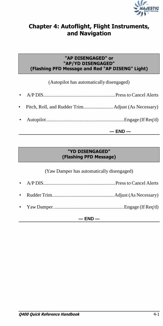
(Autopilot has automatically disengaged)
• A/P DIS.......................................................... Press to Cancel Alerts
• Pitch, Roll, and Rudder Trim........................ Adjust (As Necessary)
• Autopilot ...............................................................Engage (If Req'd)
— END —
(Yaw Damper has automatically disengaged)
• A/P DIS.......................................................... Press to Cancel Alerts
• Rudder Trim.................................................. Adjust (As Necessary)
• Yaw Damper ......................................................... Engage (If Req'd)
— END —
"YD DISENGAGED" (Flashing PFD Message)
"AP DISENGAGED" or "AP/YD DISENGAGED"
(Flashing PFD Message and Red "AP DISENG" Light)

Q400 Quick Reference Handbook 4-2
(Autopilot system is inoperative)
• Autopilot ................................................................... Do not Engage
IF message goes out:
• Autopilot ............................................................. Engage (As Req'd)
— END —
(Autopilot and Yaw Damper systems are inoperative)
• Autopilot or Yaw Damper ........................................ Do not Engage
IF message disappears:
• Autopilot or Yaw Damper .................................. Engage (As Req'd)
— END —
"AP/YD FAIL" (Message on PFD)
"AP FAIL" (Message on PFD)
Autoflight, Flight Instruments, and Navigation 4-3
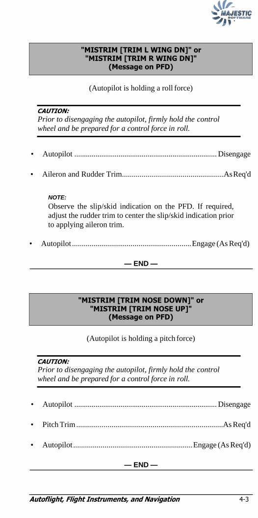
NOTE:
(Autopilot is holding a roll force)
CAUTION:
Prior to disengaging the autopilot, firmly hold the control
wheel and be prepared for a control force in roll.
• Autopilot .......................................................................... Disengage
• Aileron and Rudder Trim....................................................As Req'd
NOTE:
Observe the slip/skid indication on the PFD. If required,
adjust the rudder trim to center the slip/skid indication prior
to applying aileron trim.
• Autopilot ............................................................. Engage (As Req'd)
— END —
(Autopilot is holding a pitch force)
CAUTION:
Prior to disengaging the autopilot, firmly hold the control
wheel and be prepared for a control force in roll.
• Autopilot .......................................................................... Disengage
• Pitch Trim ...........................................................................As Req'd
• Autopilot ............................................................. Engage (As Req'd)
— END —
"MISTRIM [TRIM NOSE DOWN]" or "MISTRIM [TRIM NOSE UP]"
(Message on PFD)
"MISTRIM [TRIM L WING DN]" or "MISTRIM [TRIM R WING DN]"
(Message on PFD)
Autoflight, Flight Instruments, and Navigation 4-4
NOTE:
NOTE:
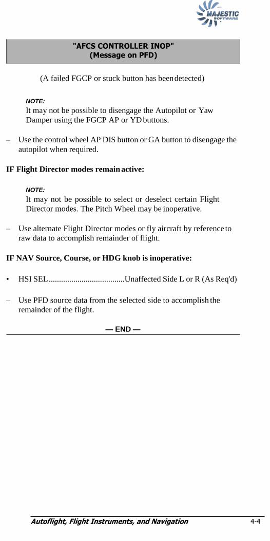
(A failed FGCP or stuck button has been detected)
NOTE:
It may not be possible to disengage the Autopilot or Yaw
Damper using the FGCP AP or YD buttons.
– Use the control wheel AP DIS button or GA button to disengage the
autopilot when required.
IF Flight Director modes remain active:
NOTE:
It may not be possible to select or deselect certain Flight
Director modes. The Pitch Wheel may be inoperative.
– Use alternate Flight Director modes or fly aircraft by reference to
raw data to accomplish remainder of flight.
IF NAV Source, Course, or HDG knob is inoperative:
• HSI SEL .....................................Unaffected Side L or R (As Req'd)
– Use PFD source data from the selected side to accomplish the
remainder of the flight.
— END —
"AFCS CONTROLLER INOP" (Message on PFD)

Autoflight, Flight Instruments, and Navigation 4-5
NOTE:
NOTE:
(Both Flight Guidance Modules have failed)
Lost Services:
– Autopilot
– Flight Director
– Auto Trim
• Autopilot or Yaw Damper ........................................ Do not Engage
– Fly aircraft manually by reference to raw data to accomplish
remainder of flight.
NOTE:
When selecting Flap 15 to Flap 35 or Flap 35 to Flap 15,
there will be an increase in the Pitch Trim requirement.
IF message disappears:
• Autopilot or Yaw Damper ........................................ Do not Engage
— END —
(Autopilot control of Pitch Trim is inoperative)
CAUTION:
Prior to disengaging the autopilot, firmly hold the control
wheel and be prepared for a control force in pitch.
• Autopilot .......................................................................... Disengage
• Pitch Trim ...........................................................................As Req'd
• Autopilot ............................................................. Engage (As Req'd)
— END —
NOTE:
The Auto Trim function will also be inoperative.
"AP PITCH TRIM FAIL" (Message on PFD)
"AFCS FAIL" (Message on PFD)

Autoflight, Flight Instruments, and Navigation 4-6
NOTE:
NOTE:
(Flap Automatic Pitch Trim is inoperative)
NOTE:
When selecting Flap 15 to Flap 35 or Flap 35 to Flap 15,
there will be an increase in the Pitch Trim adjustment.
— END —
(Left or Right Flight Guidance Module has failed)
Lost Services:
– Autopilot and Yaw Damper
– Auto Trim
– Dual FD Approach Mode
• Autopilot or Yaw Damper ........................................ Do not Engage
– Fly aircraft manually by reference to the Flight Director or raw
data.
NOTE:
When selecting Flap 15 to Flap 35 or Flap 35 to Flap 15,
there will be an increase in the Pitch Trim requirement.
IF message disappears:
• Autopilot or Yaw Damper .................................. Engage (As Req'd)
— END —
"L FD FAIL" or "R FD FAIL" (Message on PFD)
"AUTO TRIM FAIL" (Message on PFD)

Autoflight, Flight Instruments, and Navigation 4-7
(Yaw Damper has disengaged in a noncentered position)
Is the AP/YD message also displayed?
• Autopilot or Yaw Damper ................................... Do not Engage
— END —
Wait 15 seconds:
• Yaw Damper.................................................................... Engage
IF message remains displayed:
• Autopilot or Yaw Damper ................................... Do not Engage
— END —
(Pitch Thumbwheel motion has cancelled ALT* or ALT Mode)
– Confirm PRESELECT Altitude is set to an appropriate value.
• ALT SEL....................................................................................Push
• FD Vertical Mode ................................................. Select (As Req'd)
— END —
"ALT OFF" (Message on PFD)
"YD NOT CENTERED" (Message on PFD)

Autoflight, Flight Instruments, and Navigation 4-8
NOTE:
(NAV source or frequency change has cancelled NAV mode)
– Confirm appropriate navigation data source is selected.
• FD Lateral Mode................................................... Select (As Req'd)
— END —
(Selected air data on FD is invalid or mismatched)
– Determine valid air data source by comparing IAS and altitude
displayed on PFD 1 and 2 against the standby instrument.
• EFIS ADC Source....................................... Select 1 or 2 (As Req'd)
• FD Modes ............................................................. Select (As Req'd)
NOTE:
Autopilot and Yaw Damper are inoperative. ―ELEVATOR
FEEL‖, ―PITCH TRIM‖, ―SPLR OUTBD‖, and ―RUD
CTRL‖ Caution lights will be illuminated. Elevator forces,
roll rate, and rudder sensitivity may be higher or lower than
normal.
— END —
"FD ADC DATA INVLD" (Message on PFD)
"CHECK NAV SOURCE" (Message on PFD)

Autoflight, Flight Instruments, and Navigation 4-9
NOTE:
(Selected attitude data input to FD is invalid or mismatched)
– Determine valid attitude source by comparing pitch and roll
displayed on PFD 1 and 2 against the standby instrument.
• EFIS ATT/HDG Source....................Select 1 or 2 (As Appropriate)
• FD Modes ............................................................. Select (As Req'd)
NOTE:
Autopilot and Yaw Damper are inoperative. ―ELEVATOR
FEEL‖ Caution light will be illuminated. Elevator forces
may be higher or lower than normal.
— END —
(Selected heading data input to FD is invalid or mismatched)
– Determine valid heading source by comparing heading displayed on
PFD 1 and 2 against the standby compass.
• EFIS ATT/HDG Source....................Select 1 or 2 (As Appropriate)
• FD Lateral Mode................................................... Select (As Req'd)
— END —
"FD HDG DATA INVLD" (Message on PFD)
"FD ATT DATA INVLD" (Message on PFD)

Autoflight, Flight Instruments, and Navigation 4-10
NOTE:
(Selected navigation data input to FD is invalid or mismatched)
– Determine valid navigation source by confirming valid ground
station selection or comparing bearing and deviation data displayed
on PFD 1 and 2 against other available navigation information.
• NAV Source......................................Select 1 or 2 (As Appropriate)
• FD Lateral Mode................................................... Select (As Req'd)
— END —
(Required input for CAT II ILS approach is invalid or mismatched)
– Determine valid HSI source.
• HSI SEL ............................................Select 1 or 2 (As Appropriate)
NOTE:
If a mismatch appears between the two HSI sources in
DUAL APPR mode, the Flight Director will automatically
switch back to the HSI (which may not be valid) that was in
use at the commencement of the approach.
— END —
"CAT II FAIL" (Message on PFD)
"FD NAV DATA INVLD" (Message on PFD)

Autoflight, Flight Instruments, and Navigation 4-11
NOTE:
(Required input for a Dual Mode ILS approach is invalid or
mismatched)
– Determine valid HSI source.
• HSI SEL ............................................Select 1 or 2 (As Appropriate)
NOTE:
If a mismatch appears between the two HSI sources in
DUAL APPR mode, the Flight Director will automatically
switch back to the HSI (which may not be valid) that was in
use at the commencement of the approach.
— END —
(AFCS external failure or condition inhibits AP engagement)
• A/P DIS.......................................................... Press to Cancel Alerts
Wait 15 seconds:
– If AP INHIBIT is still displayed, Autopilot is inoperative.
— END —
(Autopilot and Yaw Damper are inoperative)
• A/P DIS.......................................................... Press to Cancel Alerts
Wait 15 seconds:
– If YD INHIBIT is still displayed, Autopilot and Yaw Damper are
inoperative.
— END —
"YD INHIBIT" (Message on PFD)
"AP INHIBIT" (Message on PFD)
"DUAL OFF" (Message on PFD)

Autoflight, Flight Instruments, and Navigation 4-12
(No data displayed on PFD screen)
– Fly the aircraft by reference to the operative PFD.
Affected Side:
• MFD........................................................................................... PFD
• PFD Brightness .......................................................................... OFF
— END —
(Critical data on the indicated PFD may be displayed incorrectly)
– Fly the aircraft by reference to the operative PFD.
Affected Side:
• MFD........................................................................................... PFD
– Monitor MFD display data for incorrectly displayed flight
information.
— END —
"CHECK PFD 1" or "CHECK PFD 2" (Message on PFD)
PRIMARY FLIGHT DISPLAY FAILURE

Autoflight, Flight Instruments, and Navigation 4-13
NOTE:
NOTE:
(Source of pitch and roll data to PFD has failed)
• EFIS ATT/HDG Source....................Select 1 or 2 (As Appropriate)
– Fly the airplane by reference to the remaining source of attitude
data.
• Max Airspeed.................................................................... 200 KIAS
NOTE:
Autopilot and Yaw Damper are inoperative. Flight Director
is available. ―ELEVATOR FEEL‖ Caution light will
illuminate. Elevator forces may be higher or lower than
usual.
— END —
(Source of heading data to PFD has failed)
• EFIS ATT/HDG Source....................Select 1 or 2 (As Appropriate)
– Fly the airplane by reference to the remaining source of heading
data.
NOTE:
Autopilot and Yaw Damper are inoperative. Flight Director
is available. If a malfunction of the flux valve is the cause
of the heading failure, the SLAVE advisory light, on the
AHRS controller, will also illuminate.
— END —
"HDG FAIL" (Message on PFD)
"ATT FAIL" (Message on PFD)

Autoflight, Flight Instruments, and Navigation 4-14
NOTE:
NOTE:
(Source of inertial vertical speed data to PFD has failed)
• EFIS ATT/HDG Source....................Select 1 or 2 (As Appropriate)
– Fly the airplane by reference to the remaining source of attitude
data.
• Max Airspeed.................................................................... 200 KIAS
NOTE:
Autopilot and Yaw Damper are inoperative. Flight Director
is available. ―ELEVATOR FEEL‖ Caution light will
illuminate. Elevator forces may be higher or lower than
usual.
— END —
(AHRS 1 and 2 attitudes do not match)
– Determine valid attitude source by comparing pitch and roll
displayed on PFD 1 and 2 against the standby instrument.
• EFIS ATT/HDG Source....................Select 1 or 2 (As Appropriate)
– Fly aircraft by reference to the selected attitude source.
• Max Airspeed.................................................................... 200 KIAS
NOTE:
Autopilot and Yaw Damper are inoperative. Flight Director
is available. ―ELEVATOR FEEL‖ Caution light will
illuminate. Elevator forces may be higher or lower than
usual.
— END —
"PITCH MISMATCH" or "ROLL MISMATCH" (Message on PFD)
"IVSI FAIL" (Message on PFD)

Autoflight, Flight Instruments, and Navigation 4-15
(AHRS 1 and 2 headings do not match)
– Determine valid heading source by comparing headings displayed
on PFD 1 and 2 against the standby compass.
• EFIS ATT/HDG Source....................Select 1 or 2 (As Appropriate)
– Fly aircraft by reference to the selected heading source.
— END —
"HDG MISMATCH" (Message on PFD)

Autoflight, Flight Instruments, and Navigation 4-16
NOTE:
(Loss of both pitot-static probes on the right side of the aircraft due to a
bird strike)
• Pitot Static Isolation Valve ....................................................... Press
– Fly the aircraft by reference to the airspeed and altitude
indications on PFD 1.
• Max Airspeed.................................................................... 200 KIAS
– Land immediately at the nearest suitable airport.
NOTE:
Autopilot and Yaw Damper are inoperative. Flight Director
is available. ―ELEVATOR FEEL‖, ―PITCH TRIM‖,
―SPLR OUTBD‖ and ―RUD CTRL‖ Caution lights will
illuminate. Elevator forces, roll rate, and rudder sensitivity
may be higher or lower than usual.
Landing Considerations:
– Land at an airport with minimum crosswind and turbulence using
Flaps 15.
Derived VREF
Weight (lbs) Flap 15
Level 1 Level 2
64,000 134 154
62,000 131 151
60,000 129 149
58,000 127 147
56,000 125 145
54,000 123 143
52,000 121 141
50,000 118 138
48,000 116 136
46,000 114 134
44,000 111 131
42,000 109 129
40,000 106 126
— CONTINUED —
LOSS OF CAPTAIN, FIRST OFFICER and INTEGRATED STANDBY INSTRUMENT AIRSPEED and
ALTITUDE FUNCTIONS

Autoflight, Flight Instruments, and Navigation 4-17
Abnormal Landing Distance Factors
Flap Ice Protection
Level 1 Level 2/3
15 1.45 1.45
Conditional Landing Distance Statement
Level 1 Ice Protection
Landing Distance = 5100 ft
Wt. less than 64,500 lbs.
Dry Runway
Airport Elevation less than 2000 ft
Tailwind 10 kts.
— END —

Autoflight, Flight Instruments, and Navigation 4-18
NOTE:
(Air Data 1 and 2 sources have failed)
– Fly the aircraft by reference to the Integrated Standby Instrument.
• Max Airspeed....... As shown in Derived Maximum Airspeed Table
below
Derived Max Airspeed
Weight
(lbs)
Flap 0 Flap 5 Flap 10 Flap 15
Level 1/2/3 Level 1/2/3 Level 1/2/3 Level 1/2/3
64,000 232 190 178 170
62,000 227 186 174 165
60,000 223 184 171 163
58,000 220 181 168 160
56,000 216 178 165 157
54,000 212 174 162 155
52,000 209 171 160 152
50,000 203 168 157 149
48,000 200 165 154 146
46,000 196 160 149 142
44,000 191 157 147 139
42,000 187 154 144 136
40,000 182 149 139 133
NOTE:
Autopilot and Yaw Damper are inoperative. Flight Director
is available. ―ELEVATOR FEEL‖, ―PITCH TRIM‖,
―SPLR OUTBD‖ and ―RUD CTRL‖ Caution lights will
illuminate. Elevator forces, roll rate, and rudder sensitivity
may be higher or lower than usual.
Landing Considerations:
– Land at an airport with minimum crosswind and turbulence using
Flaps 15.
– Approach Speed..........................................................Derived VREF
— CONTINUED —
LOSS OF BOTH AIRSPEED and BOTH ALTITUDE INDICATIONS ON PILOT's and
FIRST OFFICER's PFDs

Autoflight, Flight Instruments, and Navigation 4-19
Derived VREF
Weight (lbs) Flap 15
Level 1 Level 2
64,000 134 154
62,000 131 151
60,000 129 149
58,000 127 147
56,000 125 145
54,000 123 143
52,000 121 141
50,000 118 138
48,000 116 136
46,000 114 134
44,000 111 131
42,000 109 129
40,000 106 126
Abnormal Landing Distance Factors
Flap Ice Protection
Level 1 Level 2/3
15 1.45 1.45
Conditional Landing Distance Statement
Level 1 Ice Protection
Landing Distance = 5100 ft
Wt. less than 64,500 lbs.
Dry Runway
Airport Elevation less than 2000 ft
Tailwind 10 kts.
— END —

Autoflight, Flight Instruments, and Navigation 4-20
NOTE:
(Selected air data source has failed)
• EFIS ADC Source.............................Select 1 or 2 (As Appropriate)
– Fly aircraft by reference to the selected air data source.
• Max Airspeed.................................................................... 200 KIAS
NOTE:
Autopilot and Yaw Damper are inoperative. Flight Director
is available. ―ELEVATOR FEEL‖, ―PITCH TRIM‖,
―SPLR OUTBD‖ and ―RUD CTRL‖ Caution lights will
illuminate. Elevator forces, roll rate, and rudder sensitivity
may be higher or lower than usual.
— END —
(Low speed cue is invalid)
– Fly the aircraft by reference to the Standby Airspeed Indicator and
Altimeter.
— END —
"CUE" (Message on PFD)
"IAS FAIL" or "ALT FAIL" (Message on PFD)

Autoflight, Flight Instruments, and Navigation 4-21
NOTE:
(Air Data 1 or 2 airspeed indications do not match)
– Determine valid air data source by comparing airspeed displayed on
PFD 1 and 2 against the standby instrument.
• EFIS ADC Source.............................Select 1 or 2 (As Appropriate)
– Fly the aircraft by reference to the selected air data source.
NOTE:
Autopilot and Yaw Damper are inoperative. Flight Director
is available. ―ELEVATOR FEEL‖, ―PITCH TRIM‖,
―SPLR OUTBD‖ and ―RUD CTRL‖ Caution lights will
illuminate. Elevator forces, roll rate, and rudder sensitivity
may be higher or lower than usual.
— END —
"IAS MISMATCH" (Message on PFD)

Autoflight, Flight Instruments, and Navigation 4-22
NOTE:
(Air data 1 or 2 altitude indications do not match)
– Determine valid air data source by comparing airspeed displayed on
PFD 1 and 2 against the standby instrument.
• EFIS ADC Source...................................... Select 1 or 2 (As Req‘d)
– Fly the aircraft by reference to the selected air data source.
• Max Airspeed.................................................................... 200 KIAS
NOTE:
Autopilot and Yaw Damper are inoperative. Flight Director
is available. ―ELEVATOR FEEL‖, ―PITCH TRIM‖,
―SPLR OUTBD‖ and ―RUD CTRL‖ Caution lights will
illuminate. Elevator forces, roll rate, and rudder sensitivity
may be higher or lower than usual.
— END —
"ALT MISMATCH" (Message on PFD)

Autoflight, Flight Instruments, and Navigation 4-23
NOTE:
(ILS 1 and 2 deviation indications do not match)
– Determine valid localizer or glideslope source.
• HSI SEL ............................................Select 1 or 2 (As Appropriate)
NOTE:
If a Mismatch appears between the two ILS sources in
DUAL APPR mode, the Flight Director will automatically
switch back to the HSI (which may not be valid) that was in
use at the commencement of the approach.
— END —
Lost Services:
– Stick Pusher
– EGPWS
– TCAS
(Both Radar Altimeters have failed)
– Ensure required clearance from terrain, obstructions and other
aircraft is maintained using alternate sources of available
information.
Landing Considerations:
– Select approach where minimums and operating procedures are not
dependant upon radar altitude.
– Land with Condition Levers MAX/1020 only.
– Flap 35 Landing Distance on a contaminated runway is increased by
400 ft.
— END —
"RA" (Message on PFD)
"LOC MISMATCH" or "GS MISMATCH" (Message on PFD)

Autoflight, Flight Instruments, and Navigation 4-24
NOTE:
NOTE:
(Radar Altimeter 1 and 2 indications do not match)
Landing Considerations:
– Select approach where minimums and operating procedures are not
dependant upon radar altitude.
NOTE:
EGPWS Minimums callouts will be based on Rad Alt 1
altitudes.
— END —
(The integrity of the GPS position cannot be assured to meet minimum
requirements for the particular phase of flight)
– Monitor FMS position by cross-reference to other navigation
sensors.
NOTE:
―GPS INTEG‖ message can appear on the ground, due to
local obstructions to satellite reception.
Landing Considerations:
– GPS-based approaches are not available.
— END —
"GPS INTEG" (Message on PFD)
"RAD ALT MISMATCH" (Message on PFD)

Autoflight, Flight Instruments, and Navigation 4-25
NOTE:
(The integrity of the FMS position cannot be assured to meet minimum
requirements for the particular phase of flight)
– Revert to an alternate means of navigation using other available
navigation sensors.
NOTE:
―NAV INTEG‖ message can appear on the ground, due to
local signal reception characteristics.
— END —
(The FMS is navigating by dead reckoning on the last known track,
groundspeed, heading and TAS)
– Revert to an alternate means of navigation using other available
navigation sensors.
— END —
(AHRS is in the alignment mode)
– No Crew action required.
— END —
"ALIGNING" (Message on PFD)
"NAV DR" (Message on PFD)
"NAV INTEG" (Message on PFD)
Autoflight, Flight Instruments, and Navigation 4-26
NOTE:
(No data displayed on MFD screen)
• MFD (Affected) ......................................................................... OFF
– Use operating MFD to display systems or navigation data as
required.
— END —
(No TCAS TA or RA advisories or traffic display)
NOTE:
An amber "FAIL" annunciation is also displayed in the
TCAS display area on the TCAS/ATC page.
– Ensure adequate separation is maintained from other aircraft using
alternate sources of available information.
— END —
"TCAS FAIL" (Message on PFD and MFD)
MULTIFUNCTION DISPLAY FAILURE

Autoflight, Flight Instruments, and Navigation 4-27
NOTE:
On Ground Only:
(No weather radar display)
Refer to Chapter 14: Supplemental Resets for reset procedure.
In Air:
• WX Radar ................................................................... OFF then ON
IF message persists:
– Ensure required clearance from areas of convective weather is
maintained using alternate sources of available information.
— END —
(No data displayed on ED screen)
• MFD (Select 1 or 2 as appropriate)........................................... ENG
• ED Brightness ............................................................................ OFF
— END —
NOTE:
ED display will automatically transfer to MFD 1 in flight.
ENGINE DISPLAY FAILURE
"WX FAIL" (Message on MFD)

Autoflight, Flight Instruments, and Navigation 4-28
(On initial application of power after the aircraft has been cold-soaked,
the ISI displays ghost or mirror images)
• Wait a minimum of five (5) minutes for the ISI to warm up.
• ISI Circuit Breaker (H1 - Left Essential).............................. RESET
• Wait until ISI alignment sequence is complete.
Ghost or mirror images remain on the ISI?
– Maintenance action is required prior to flight.
— END —
– No Further crew action required.
— END —
Ghost Or Mirror Images On Integrated Standby Instrument (ISI)
AOM 3.4-6 MAY 31/11

Autoflight, Flight Instruments, and Navigation 4-29
(Critical data on the ED may be displayed incorrectly)
• MFD 1....................................................................................... ENG
Does the CHECK ED Advisory remain displayed?
• MFD 1 ................................................. NAV or SYS (As Req'd)
– Monitor engine display data for incorrect information.
— END —
– Continue using MFD 1 as primary engine display.
— END —
"CHECK ED" (Message on ED)
Autoflight, Flight Instruments, and Navigation 4-30
NOTE:
NOTE:
(Configuration of an EIS Display Unit is incorrect on aircraft
power-up)
Ground only:
• Display Units (All)..................................................................... OFF
• Display Units .......................................................... ON Individually
NOTE:
Wait 30 seconds for self-test to complete on each
individual display before selecting the next display ON.
IF message remains on:
– Maintenance action required prior to flight.
— END —
(The EIS is no longer able to monitor information displayed on the ED
for errors)
– Maintenance action required prior to next flight.
— END —
NOTE:
Avionics Caution light will illuminate after landing.
ED MON FAIL (ED)
DU BAD CONFIG (ED)

Autoflight, Flight Instruments, and Navigation 4-31
NOTE:
NOTE:
(EIS is no longer receiving information from
one or more engine FADECs)
– Operate Power Levers and Conditions Levers together.
– Maintenance action required prior to next flight.
— END —
(Two or more EIS display cooling fans have failed)
Is the airplane in the air?
Aircraft is on the ground only:
NOTE:
1. AVIONICS caution light will illuminate indicating an
avionics no dispatch condition has been sensed.
2. FANS FAIL message will clear when flight deck
temperature sensors warm above 5° C.
3. Refer to Chapter 14: Supplemental Resets.
IF message remains on after Flight Deck temperature rises above
5°C:
– Maintenance action required prior to flight.
— END —
– The flight may continue to the destination, return to point of departure or the nearest airport where maintenance are
available, as appropriate. (Coordinate with Dispatch/SOC.)
NOTE:
Avionics Caution light will illuminate after landing.
— END —
FANS FAIL (ED)
FADEC1/DU or FADEC2/DU or FADECS/DU (ED)

Autoflight, Flight Instruments, and Navigation 4-32
NOTE:
NOTE:
(The EIS is no longer receiving information for the EGPWS)
– Ensure required clearance from terrain and obstructions is
maintained using alternate sources of available information.
– Maintenance action required prior to next flight.
— END —
(Two or more EIS display units are overheating)
– The flight may continue to the destination, return to point of
departure or the nearest airport where maintenance are available, as
appropriate. (Coordinate with Dispatch/SOC.)
IF a PFD or ED should subsequently fail:
• MFD (Select 1 or 2 as appropriate).............................. PFD or ENG
— END —
(The ED display is overheating)
– Maintenance action required prior to next flight.
IF the ED should subsequently fail:
• MFD (Select 1 or 2 as appropriate)........................................... ENG
NOTE:
Avionics Caution light will illuminate after landing.
HOT ED (Message on ED)
NOTE:
Avionics Caution light will illuminate after landing.
HOT DISPLAYS (Message on ED)
"GPWS I/F FAIL" (Message on ED)
Autoflight, Flight Instruments, and Navigation 4-33
NOTE:
— END —
(The indicated MFD display is overheating)
– Maintenance action required prior to next flight.
IF the MFD should subsequently fail:
• Opposite MFD (1 or 2 as appropriate)....................................... PFD
— END —
NOTE:
Avionics Caution light will illuminate after landing.
HOT MFD1 or HOT MFD2 (Message on ED)

Autoflight, Flight Instruments, and Navigation 4-34
NOTE:
NOTE:
(Both avionics data Input/Output Modules have failed)
Lost Services:
– Stall Warning and Stick Pusher
– Warning Tones and Audible Alerts
– VHF Nav 1 and 2 Course Deviation and Bearing Pointers
– DME 1 and 2 Distance
– ADF 1 and 2 Bearing Pointers
– Marker Beacon Indications
– FMS 1 and 2 Course Deviation, Distance, Track, and Bearing
Pointers
– Radar Altitude Indication
– Weather Radar Display
– EGPWS Terrain Display and Audible Warnings
– TCAS Traffic Display, TA/RA Advisories, and Audible
Advisories
– ATC Mode S
– Establish and use alternate means to determine aircraft position
in order to navigate and to ensure required clearance from
terrain, obstructions, convective weather, and other aircraft is
maintained.
— END —
(One avionics data Input/Output Module has failed)
– Maintenance action required prior to next flight.
— END —
NOTE:
Avionics Caution light will illuminate after landing.
IOM1 FAIL or IOM2 FAIL (Message on ED)
NOTE:
Avionics Caution light will illuminate after landing.
IOMS FAIL (Message on ED)

Autoflight, Flight Instruments, and Navigation 4-35
NOTE:
(Configuration of an avionics Input/Output Processor is incorrect on
aircraft power-up)
– Maintenance action required prior to flight.
— END —
(Both avionics data Input/Output Processors have failed)
Lost Services:
– Stall Warning and Stick Pusher
– Warning Tones and Audible Alerts
– VHF Nav 1 and 2 Course Deviation and Bearing Pointers
– DME 1 and 2 Distance
– ADF 1 and 2 Bearing Pointers
– FMS 1 and 2 Course Deviation, Distance, Track, and Bearing
Pointers
– Radar Altitude Indication
– Weather Radar Display
– EGPWS Terrain Display and Audible Warnings
– TCAS Traffic Display, TA/RA Advisories, and Audible
Advisories
– ATC Mode S
– Establish and use alternate means to determine aircraft position
in order to navigate and to ensure required clearance from
terrain, obstructions, convective weather, and other aircraft is
maintained.
— END —
NOTE:
Avionics Caution light will illuminate after landing.
IOPS FAIL (Message on ED)
IOP BAD CONF (Message on ED)

Autoflight, Flight Instruments, and Navigation 4-36
NOTE:
(One avionics data Input/Output Processor has failed)
– Maintenance action required prior to next flight.
— END —
(The EIS is no longer able to monitor information displayed on the
indication MFD for errors)
– Maintenance action required prior to next flight.
— END —
(The EIS is no longer able to monitor information displayed on the
indication PFD for errors)
– Maintenance action required prior to next flight.
— END —
PFD LINK FAIL or PFD2 LINK FAIL (Message on ED)
MFD LINK FAIL or MFD2 LINK FAIL (Message on ED)
NOTE:
Avionics Caution light will illuminate after landing.
IOP1 FAIL or IOP2 FAIL (Message on ED)

Autoflight, Flight Instruments, and Navigation 4-37
NOTE:
(The EIS is no longer able to monitor information displayed on the
indication PFD for errors)
– Maintenance action required prior to next flight.
— END —
(Both Radar Altimeters have failed)
Lost Services:
– Stick Pusher
– EGPWS
– TCAS
– Ensure required clearance from terrain, obstructions and other
aircraft is maintained using alternate sources of available
information.
Landing Considerations:
– Select approach where minimums and operating procedures are not
dependant upon radar altitude.
– Land with Condition Levers MAX/1020 only.
– Flap 35 Landing Distance on a contaminated runway is increased by
400 ft.
— END —
"RAS FAIL" (Message on ED)
NOTE:
Avionics Caution light will illuminate after landing.
PFD1 MON FAIL or PFD2 MON FAIL or PFDS MON FAIL (Message on ED)

Autoflight, Flight Instruments, and Navigation 4-38
NOTE:
NOTE:
(The indicated Radar Altimeter has failed)
– Maintenance action required prior to next flight.
NOTE:
Radar altitude will continue to be displayed on PFD 1 and 2
from the remaining operative radar altimeter.
— END —
(Neither Input/Output Processor is receiving Weight On Wheels
information)
Landing Considerations:
– Airspeed indications will go invalid on both PFDs below 80 knots.
– Stick Shaker may activate during landing rollout and taxi.
NOTE:
Radar altitude will continue to be displayed on PFD 1 and 2
from the remaining operative radar altimeter.
— END —
WOW/IOPS FAIL (Message on ED)
RA1 FAIL or RA2 FAIL (Message on ED)

Autoflight, Flight Instruments, and Navigation 4-39
NOTE:
NOTE:
(The indicated Input/Output Processor is not receiving Weight On
Wheels information)
– Maintenance action required prior to next flight.
— END —
(Both Warning Tone Generators have failed)
Lost Warning Tones and Aural Alerts:
– EGPWS Audible Warnings
– TCAS TA/RA Advisories
– Overspeed Warning
– Beta Lockout
– Caution/Warning Alert
– Altitude Alert
– Unilink Alerts
– Establish and use alternate means to monitor aircraft airspeed,
altitude, position and operating condition.
— END —
NOTE:
Avionics Caution light will illuminate after landing.
WTGS FAIL (Message on ED)
NOTE:
Avionics Caution light will illuminate after landing.
WOW/IOP1 FAIL or WOW/IOP2 FAIL (Message on ED)

Autoflight, Flight Instruments, and Navigation 4-40
NOTE:
NOTE:
(The indicated Warning Tone Generator has failed)
– Maintenance action required prior to next flight.
NOTE:
Warning tones and audible alerting will continue to be
provided by the operative Warning Tone Generator.
Avionics Caution light will illuminate after landing.
— END —
for reset procedure.
– No crew action required in flight.
— END —
NOTE:
If on the ground, refer to Chapter 14: Supplemental Resets
PA CHIME INOPERATIVE AOM 3.4-8 NOV 21/11
WTG1 FAIL or WTG2 FAIL
(Message on ED)

Autoflight, Flight Instruments, and Navigation 4-41
DH8-400-SL-23-010 MAY 3/11
(Microphone/Interphone Rotary Selector (MIRS) Intermittent)
– Spurious interruptions of transmission, intermittent display of
selected transmission on ARCDU display, intermittent audio return
when pushing the PTT.
Inflight or on Ground:
– Confirm transmission source in INT box on ARCDU matches the
MIRS position by observing TX appears in the INT box when the
PTT switch is selected.
IF ARCDU and MIRS position disagree or TX does not appear in
lower left corner of ARCDU display when PTT switch is selected:
– Momentarily select alternate source with the MIRS.
— END —
IF problem persists:
– Pilot on side with working MIRS will make a radio transmissions.
— END —
ARCDU Transmission Errors
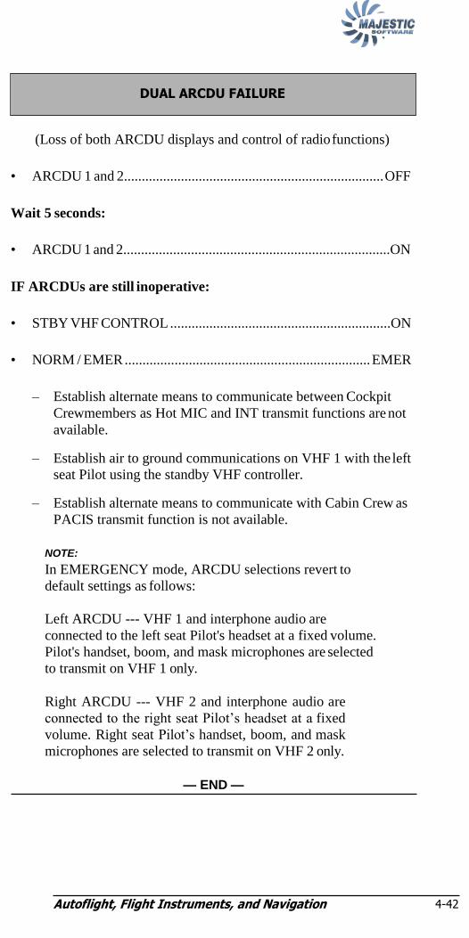
Autoflight, Flight Instruments, and Navigation 4-42
NOTE:
(Loss of both ARCDU displays and control of radio functions)
• ARCDU 1 and 2......................................................................... OFF
Wait 5 seconds:
• ARCDU 1 and 2...........................................................................ON
IF ARCDUs are still inoperative:
• STBY VHF CONTROL ..............................................................ON
• NORM / EMER ..................................................................... EMER
– Establish alternate means to communicate between Cockpit
Crewmembers as Hot MIC and INT transmit functions are not
available.
– Establish air to ground communications on VHF 1 with the left
seat Pilot using the standby VHF controller.
– Establish alternate means to communicate with Cabin Crew as
PACIS transmit function is not available.
NOTE:
In EMERGENCY mode, ARCDU selections revert to
default settings as follows:
Left ARCDU --- VHF 1 and interphone audio are
connected to the left seat Pilot's headset at a fixed volume.
Pilot's handset, boom, and mask microphones are selected
to transmit on VHF 1 only.
Right ARCDU --- VHF 2 and interphone audio are
connected to the right seat Pilot‘s headset at a fixed
volume. Right seat Pilot‘s handset, boom, and mask
microphones are selected to transmit on VHF 2 only.
— END —
DUAL ARCDU FAILURE
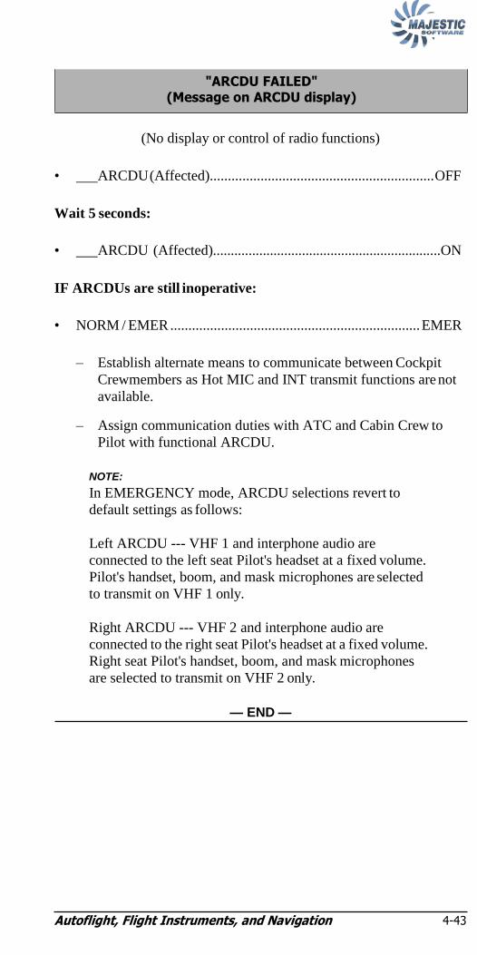
Autoflight, Flight Instruments, and Navigation 4-43
NOTE:
(No display or control of radio functions)
• ARCDU (Affected).............................................................. OFF
Wait 5 seconds:
• ARCDU (Affected)................................................................ON
IF ARCDUs are still inoperative:
• NORM / EMER ..................................................................... EMER
– Establish alternate means to communicate between Cockpit
Crewmembers as Hot MIC and INT transmit functions are not
available.
– Assign communication duties with ATC and Cabin Crew to
Pilot with functional ARCDU.
NOTE:
In EMERGENCY mode, ARCDU selections revert to
default settings as follows:
Left ARCDU --- VHF 1 and interphone audio are
connected to the left seat Pilot's headset at a fixed volume.
Pilot's handset, boom, and mask microphones are selected
to transmit on VHF 1 only.
Right ARCDU --- VHF 2 and interphone audio are
connected to the right seat Pilot's headset at a fixed volume.
Right seat Pilot's handset, boom, and mask microphones
are selected to transmit on VHF 2 only.
— END —
"ARCDU FAILED" (Message on ARCDU display)

Autoflight, Flight Instruments, and Navigation 4-44
NOTE:
NOTE:
(No control of audio level or transmit source selections)
– Maintenance action required prior to next flight.
NOTE:
RCAU has automatically reconfigured to select VHF1,
VHF 2, and interphone audio to the affected Pilot's headset
at a fixed volume. Affected Pilot handset, boom, and mask
microphones are selected to transmit on INT---only. VHF
1, VHF 2, and PACIS transmit functions are not available.
Assign communication duties with ATC and Cabin Crew to
Pilot with functional ARCDU.
— END —
(One headset is no longer receiving audio signals)
– Connect affected headset to the AUX output on the Audio Jack
Panel.
NOTE:
The AUX output is configured to receive the same audio
sources selected by the opposite Pilot. Own side VHF 1,
VHF 2, INT, and PACIS transmit functions continue to
operate normally.
— END —
LOSS OF PILOT or FIRST OFFICER HEADSET AUDIO
"FAIL" (Message on ARCDU INT display area)
Autoflight, Flight Instruments, and Navigation 4-45
NOTE:
(Message appears during climb or descent)
NOTE:
A red "FAIL" message is also displayed in the ALT and
TCAS display areas of the TCAS/ATC page.
IF annunciation remains on after aircraft is in level flight:
– Maintenance action requires prior to next flight.
— END —
"ALT" (Message on ARCDU ATC display area)

Autoflight, Flight Instruments, and Navigation 4-46
• Anti-Collision Light.....................................................Red or White
Does the Caution Light remain illuminated?
– Check CB: FDR (F3 - Avionics CB Panel)
— END —
– No further action required.
— END —
– Check CB: (E) GPWS (A1 - Avionics CB Panel).
— END —
"GPWS" (Caution Light)
"FLT DATA RECORDER" (Caution Light)

Fuselage Fire or Smoke 5-i
Chapter 5: Fuselage Fire or Smoke ―SMOKE‖
(Warning Light) 5-1
FUSELAGE FIRE or SMOKE 5-1

Fuselage Fire or Smoke 5-i
Intentionally Left Blank

Fuselage Fire or Smoke
5-1
NOTE:
NOTE:
Chapter 5: Fuselage Fire or Smoke
(SMOKE Warning Light and BAGGAGE FWD or
AFT SMOKE and EXTG Advisory Lights)
• RECIRC switch........................................................................ OFF
• Illuminated SMOKE/EXTG switchlight ................................ Press
NOTE:
The second Baggage compartment FIRE BTL LOW
Advisory Light may illuminate after the first bottle has
been discharged.
– Land immediately at the nearest suitable airport.
• RECIRC switch........................................................................ OFF
• EMER LIGHTS switch..............................................................ON
– Land immediately at nearest suitable airport if it cannot be visibly
verified that the fire has been extinguished following fire
suppression.
NOTE:
To prepare for and manage an immediate landing, the
procedures given in the Unknown Source of Fire or Smoke
section may be terminated prior to completion.
— CONTINUED —
• Oxygen Masks ................................................................. On/100%
• Smoke Goggles (If applicable) ...................................................On
• BOOM/MASK switch ......................................................... MASK
FUSELAGE FIRE or SMOKE
• Oxygen Masks ................................................................. On/100%
• Smoke Goggles (If applicable) ...................................................On
• BOOM/MASK switch ......................................................... MASK
―SMOKE‖ (Warning Light)

Fuselage Fire or Smoke
5-2
NOTE:
Known Source of Fire or Smoke:
Flight Compartment Fire or Smoke?
– Extinguish fire with halon fire extinguishers.
• CABIN ALT FWD OUTFLOW ........... Fully Clockwise (OPN)
IF necessary to assist in removal of smoke:
• FWD OUTFLOW VALVE selector .................................OPEN
– Descend to below 14,000 ft. as soon as possible.
— END —
Cabin Fire or Smoke:
• EMER LIGHTS switch ......................................................... ON
– Evacuate passengers from affected area.
– Extinguish fire with halon fire extinguishers.
NOTE:
If a Pilot is required to fight the fire, protective breathing
equipment must be donned prior to exiting the flight
compartment.
IF necessary to assist in removal of smoke:
• AUTO/MAN/DUMP switch ............................................DUMP
– Descend to below 14,000 ft. as soon as possible.
— END —
Baggage Compartment Fire or Smoke
• ―SMOKE‖ (Warning Light) (Page 5-1) .................. Accomplish
— END —
Unknown Source of Fire or Smoke:
— CONTINUED —

Fuselage Fire or Smoke 5-3
Unknown Source of Fire or Smoke:
Bleed Source or Air Conditioning Suspected?
• BLEED switch 1 ............................................................ OFF
Wait up to 1 minute.
Improvement?
• Leave selected switch in the OFF position.
— END —
• BLEED switch 1 ................................................ BLEED
• BLEED switch 2 ..................................................... OFF
Wait up to 1 minute.
Improvement?
• Leave selected switch in the OFF position.
— END —
• BLEED switch 2 ................................................ BLEED
• FLT COMP pack switch.......................................... OFF
Wait up to 1 minute.
— CONTINUED —

Fuselage Fire or Smoke 5-4
Improvement?
• Leave selected switch in the OFF position.
— END —
• FLT COMP pack switch........................AUTO or MAN
• CABIN pack switch................................................. OFF
Wait up to 1 minute.
Improvement?
• Leave selected switch in the OFF position.
— END —
• CABIN pack switch...............................AUTO or MAN
Source of Fire or Smoke cannot be Identified:
• DC GEN switches ................................................................ OFF
• AC GEN switches ................................................................ OFF
• STORM/DOME Light switch.......................STORM (If Req‘d)
• MAIN, AUX, and STBY BATT switches ........................... OFF
• EMER LIGHTS switch..................................OFF (Until Req‘d)
– Land immediately at the nearest suitable airport.
CAUTION:
Battery duration for operation of essential services is 60
minutes.
— CONTINUED —

Fuselage Fire or Smoke 5-5
NOTE:
NOTE:
The following services will be available with their associated caution/
warnings and advisory lights:
ADC 1 CB Panel Lights
Standby Pitot Heat Emergency Lights
Engine Fire Detection and Extinguishing Passenger Signs
Smoke Detectors Position Lights
Aileron Trim Actuation and Indication Baggage Lights
Rudder Trim Actuation and Indication Strobe Lights
Elevator Trim Actuation and Indication Flight Compartment Dome Lights
Flap Control and Indication Landing Gear Control and Indication
PFCS Indication Engine Ignition and Start
AHRS 1 and 2 #1 and #2 Engine Oil Pressure
VHF COMM 1 #1 Engine Fuel Temperature
VHF NAV 1 #1 and #2 FADECS
Captain and First Officer Audio #1 and #2 PECS
PA and Cabin Interphone Audio Fuel and Hydraulic Shut Off Valves
Clock 1 #1 and #3 Hydraulic Quantity
Indications
Integrated Standby Instrument (ISI) #1, #2, and #3 Hydraulic Pressure
Indications
No. 3 Hydraulic System
NOTE:
Engine bleed air flow to ECS packs lost. Cabin will
depressurize.
– Ventilate aircraft, when below 14,000 ft:
• AUTO/MAN/DUMP switch.............................................. MAN
• MAN DIFF switch ................................................ INCR(50 sec)
• CABIN ALT FWD OUTFLOW............ Fully clockwise (OPN)
• FWD OUTFLOW VALVE selector ................................. OPEN
— END —
NOTE:
Ram ventilation is most effective above 150 KIAS.

Fuselage Fire or Smoke 5-6
Intentionally Left Blank
Emergency Landing and Forced Landing 6-i
Chapter 6: Emergency Landing and
Forced Landing EMERGENCY LANDING
(Both Engines Operating) 6-1
FORCED LANDING (Both Engines Inoperative) 6-6
Emergency Landing and Forced Landing 6-i
Intentionally Left Blank
Emergency Landing and Forced Landing
6-1
NOTE:
Chapter 6: Emergency Landing and
Forced Landing
• Flight Compartment and Cabin.............................................. Secure
– If possible ensure no passengers are seated in the plane of the
propellers.
NOTE:
Configuring the forward right hand emergency exit for
ditching may required the aircraft to be depressurized to
reduce the force on the lower exit door handle.
• GPWS CB (A1 - Avionics CB Panel) ........................................ Pull
• EMER LIGHTS switch................................................................ON
• AUTO/MAN/DUMP switch..................................................DUMP
• ELT switch...................................................................................ON
• Shoulder Harness ...................................................................... Lock
Review appropriate Landing Considerations:
Landing Gear Extended ..................................................... Page 6-7
Landing Gear Retracted ..................................................... Page 6-3
Ditching ............................................................................. Page 6-4
EMERGENCY LANDING (Both Engines Operating)

Emergency Landing and Forced Landing
6-2
Landing Gear Extended--Landing Considerations:
When airplane comes to a stop:
• EMERG BRAKE ....................................................................PARK
• Condition Levers............................................................. FUEL OFF
• PULL FUEL/HYD OFF handles ................................................ Pull
• BATTERY MASTER switch .................................................... OFF
• Evacuation ........................................................................Command
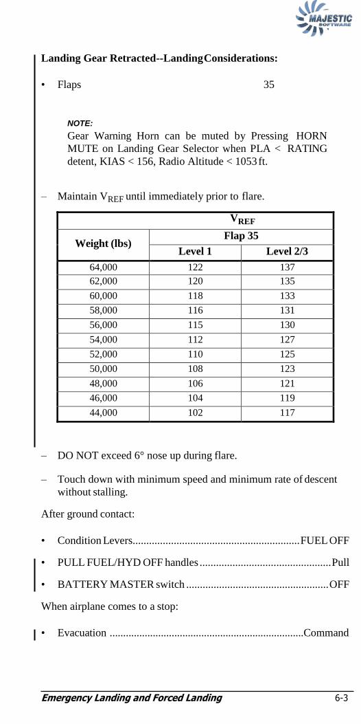
Emergency Landing and Forced Landing 6-3
NOTE:
Landing Gear Retracted--Landing Considerations:
• Flaps 35
NOTE:
Gear Warning Horn can be muted by Pressing HORN
MUTE on Landing Gear Selector when PLA < RATING
detent, KIAS < 156, Radio Altitude < 1053 ft.
– Maintain VREF until immediately prior to flare.
VREF
Weight (lbs) Flap 35
Level 1 Level 2/3
64,000 122 137
62,000 120 135
60,000 118 133
58,000 116 131
56,000 115 130
54,000 112 127
52,000 110 125
50,000 108 123
48,000 106 121
46,000 104 119
44,000 102 117
– DO NOT exceed 6° nose up during flare.
– Touch down with minimum speed and minimum rate of descent
without stalling.
After ground contact:
• Condition Levers............................................................. FUEL OFF
• PULL FUEL/HYD OFF handles ................................................ Pull
• BATTERY MASTER switch .................................................... OFF
When airplane comes to a stop:
• Evacuation ........................................................................Command
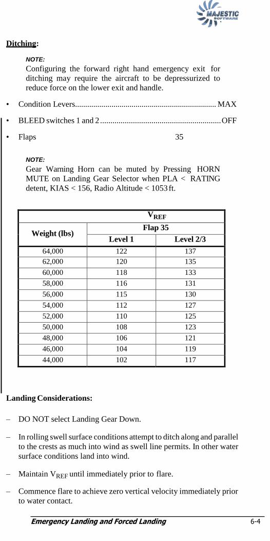
Emergency Landing and Forced Landing 6-4
NOTE:
NOTE:
Ditching:
NOTE:
Configuring the forward right hand emergency exit for
ditching may require the aircraft to be depressurized to
reduce force on the lower exit and handle.
• Condition Levers...................................................................... MAX
• BLEED switches 1 and 2 ........................................................... OFF
• Flaps 35
NOTE:
Gear Warning Horn can be muted by Pressing HORN
MUTE on Landing Gear Selector when PLA < RATING
detent, KIAS < 156, Radio Altitude < 1053 ft.
VREF
Weight (lbs) Flap 35
Level 1 Level 2/3
64,000 122 137
62,000 120 135
60,000 118 133
58,000 116 131
56,000 115 130
54,000 112 127
52,000 110 125
50,000 108 123
48,000 106 121
46,000 104 119
44,000 102 117
Landing Considerations:
– DO NOT select Landing Gear Down.
– In rolling swell surface conditions attempt to ditch along and parallel
to the crests as much into wind as swell line permits. In other water
surface conditions land into wind.
– Maintain VREF until immediately prior to flare.
– Commence flare to achieve zero vertical velocity immediately prior
to water contact.

Emergency Landing and Forced Landing 6-5
NOTE:
– Maintain pitch attitude of 10° nose up.
– Touch down with minimum speed and minimum rate of descent
without stalling.
– A transient nose-up pitching motion may result following
touchdown. Overcorrection of this tendency could result in
porpoising or nosing in.
After water contact:
• Condition Levers............................................................. FUEL OFF
• PULL FUEL/HYD OFF handles ................................................ Pull
• BATTERY MASTER switch .................................................... OFF
When airplane comes to a stop:
DO NOT open the Aft Doors or the lower portion of the right
forward Emergency Exit.
• Evacuation ........................................................................Command
NOTE:
After completion of the ditching run, the airplane will float
with one wing in the water. The upper portion of the right
forward emergency exit and the airstair door should be
used for evacuation. The airstair door ditching dam must be
in place prior to opening the door.
— END —
WARNING
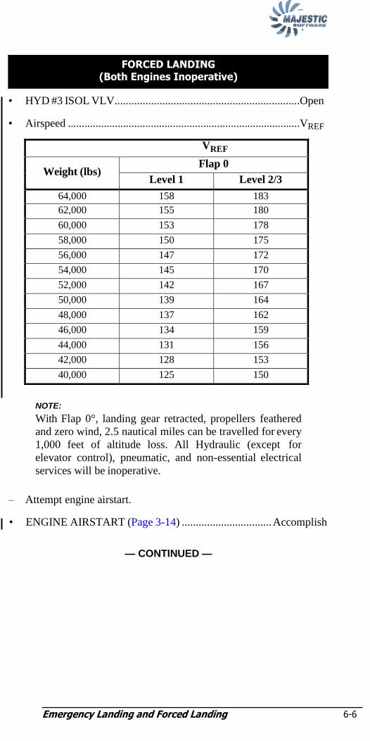
Emergency Landing and Forced Landing 6-6
NOTE:
• HYD #3 ISOL VLV..................................................................Open
• Airspeed ....................................................................................VREF
VREF
Weight (lbs) Flap 0
Level 1 Level 2/3
64,000 158 183
62,000 155 180
60,000 153 178
58,000 150 175
56,000 147 172
54,000 145 170
52,000 142 167
50,000 139 164
48,000 137 162
46,000 134 159
44,000 131 156
42,000 128 153
40,000 125 150
NOTE:
With Flap 0°, landing gear retracted, propellers feathered
and zero wind, 2.5 nautical miles can be travelled for every
1,000 feet of altitude loss. All Hydraulic (except for
elevator control), pneumatic, and non-essential electrical
services will be inoperative.
– Attempt engine airstart.
• ENGINE AIRSTART (Page 3-14) ................................ Accomplish
— CONTINUED —
FORCED LANDING (Both Engines Inoperative)

Emergency Landing and Forced Landing 6-7
When all attempts to achieve a successful airstart have failed:
• MAIN, AUX, and STBY BATT switches ................................. OFF
• FASTEN BELTS switch..............................................................ON
• EMER LIGHTS switch................................................................ON
• ELT switch...................................................................................ON
• Shoulder Harness ...................................................................... Lock
– Make the approach and landing into wind.
– Extending landing gear will steepen glide angle and decrease glide
distance.
Review Appropriate Landing Considerations:
Landing Gear Extended ..................................................... Page 6-7
Landing Gear Retracted ..................................................... Page 6-8
Ditching ........................................................................... Page 6-10
Landing Gear Extended--Landing Considerations:
IF the available surface is appropriate, extend landing gear allowing
sufficient time for alternate gear extension.
– Maintain VREF minimum until immediately prior to flare.
VREF
Weight (lbs) Flap 0
Level 1 Level 2/3
64,000 158 183
62,000 155 180
60,000 153 178
58,000 150 175
56,000 147 172
54,000 145 170
52,000 142 167
50,000 139 164
48,000 137 162
46,000 134 159
44,000 131 156
42,000 128 153
40,000 125 150
— CONTINUED —
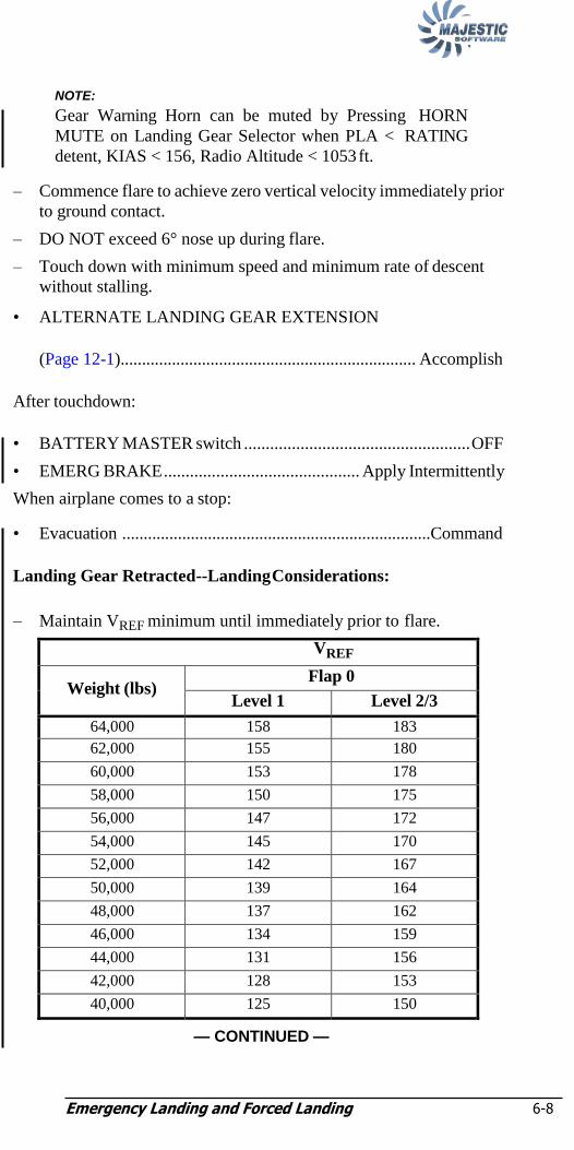
Emergency Landing and Forced Landing 6-8
NOTE: NOTE:
Gear Warning Horn can be muted by Pressing HORN
MUTE on Landing Gear Selector when PLA < RATING
detent, KIAS < 156, Radio Altitude < 1053 ft.
– Commence flare to achieve zero vertical velocity immediately prior
to ground contact.
– DO NOT exceed 6° nose up during flare.
– Touch down with minimum speed and minimum rate of descent
without stalling.
• ALTERNATE LANDING GEAR EXTENSION
(Page 12-1)..................................................................... Accomplish
After touchdown:
• BATTERY MASTER switch .................................................... OFF
• EMERG BRAKE ............................................. Apply Intermittently
When airplane comes to a stop:
• Evacuation ........................................................................Command
Landing Gear Retracted--Landing Considerations:
– Maintain VREF minimum until immediately prior to flare.
VREF
Weight (lbs) Flap 0
Level 1 Level 2/3
64,000 158 183
62,000 155 180
60,000 153 178
58,000 150 175
56,000 147 172
54,000 145 170
52,000 142 167
50,000 139 164
48,000 137 162
46,000 134 159
44,000 131 156
42,000 128 153
40,000 125 150
— CONTINUED —

Emergency Landing and Forced Landing 6-9
NOTE: NOTE:
Gear Warning Horn can be muted by Pressing HORN
MUTE on Landing Gear Selector when PLA <RATING
detent, KIAS < 156, Radio Altitude < 1053 ft.
– Commence flare to achieve zero vertical velocity immediately prior
to ground contact.
– DO NOT exceed 5° nose up during flare.
– Touch down with minimum speed and minimum rate of descent
without stalling.
When airplane comes to a stop:
• BATTERY MASTER switch .................................................... OFF
• Evacuation ........................................................................Command
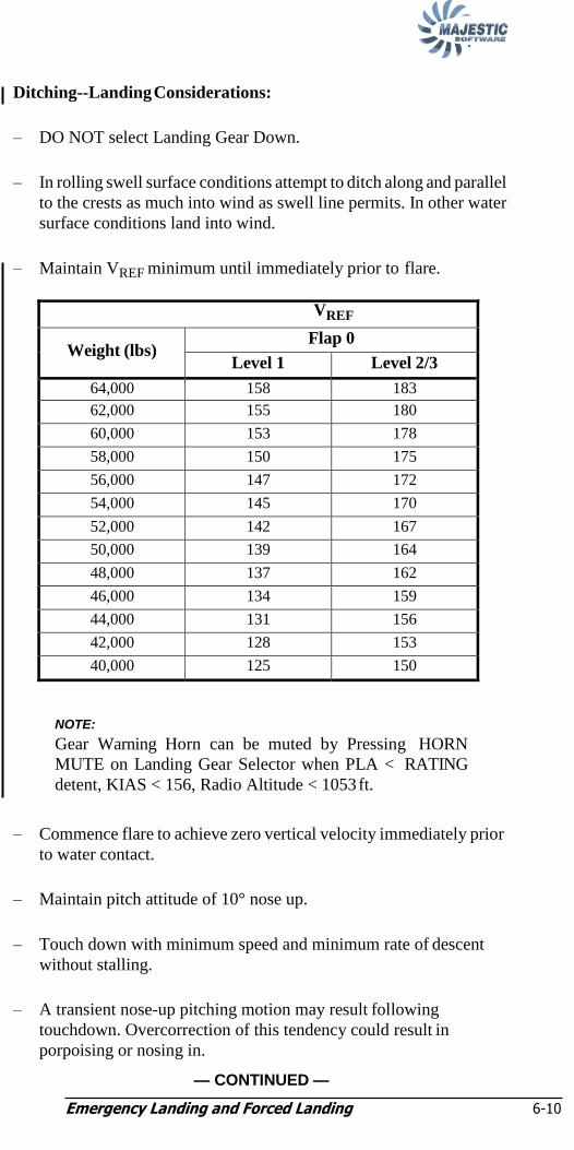
Emergency Landing and Forced Landing 6-10
NOTE:
Ditching--Landing Considerations:
– DO NOT select Landing Gear Down.
– In rolling swell surface conditions attempt to ditch along and parallel
to the crests as much into wind as swell line permits. In other water
surface conditions land into wind.
– Maintain VREF minimum until immediately prior to flare.
VREF
Weight (lbs) Flap 0
Level 1 Level 2/3
64,000 158 183
62,000 155 180
60,000 153 178
58,000 150 175
56,000 147 172
54,000 145 170
52,000 142 167
50,000 139 164
48,000 137 162
46,000 134 159
44,000 131 156
42,000 128 153
40,000 125 150
NOTE:
Gear Warning Horn can be muted by Pressing HORN
MUTE on Landing Gear Selector when PLA < RATING
detent, KIAS < 156, Radio Altitude < 1053 ft.
– Commence flare to achieve zero vertical velocity immediately prior
to water contact.
– Maintain pitch attitude of 10° nose up.
– Touch down with minimum speed and minimum rate of descent
without stalling.
– A transient nose-up pitching motion may result following
touchdown. Overcorrection of this tendency could result in
porpoising or nosing in.
— CONTINUED —

Emergency Landing and Forced Landing 6-11
NOTE:
NOTE:
NOTE:
Configuring the forward right hand emergency exit for
ditching may require the aircraft to be depressurized to
reduce force on the lower exit and handle.
After water contact:
• BATTERY MASTER switch .................................................... OFF
When airplane comes to a stop:
DO NOT open the Aft Doors or the lower portion of the right forward
emergency exit.
• Evacuation ........................................................................Command
NOTE:
After completion of the ditching run, the airplane will float
with one wing in the water. The upper portion of the right
forward emergency exit and the airstair door should be
used for evacuation. The airstair door ditching dam must be
in place prior to opening the door.
— END —
WARNING

Emergency Landing and Forced Landing 6-12
Intentionally Left Blank

Electrical 7-i
Chapter 7: Electrical ―MAIN BATTERY‖ or
―AUX BATTERY‖ or ―STBY BATTERY‖ (Caution Light) 7-3
―MAIN BAT HOT‖ or ―AUX BAT HOT‖ or ―STBY BAT HOT‖ (Warning Light) 7-3
―EMER LTS DISARMED‖ (Caution Light) 7-4
―DC BUS‖ (Caution Light) 7-4
MAIN DC BUS FAULT 7-4
―L AC BUS‖ or ―R AC BUS‖ (Caution Light) 7-7
LOSS OF GENERATED POWER 7-7
―#1 DC GEN‖ and ―#2 DC GEN‖ and either ―#1 AC GEN‖ and ―#2 AC GEN‖ or ―L TRU‖ and/or ―R TRU‖ (Caution Lights) 7-7
―#1 DC GEN‖ and ―#2 DC GEN‖ and ―#1 AC GEN‖ or ―#2 AC GEN‖ (Caution Lights) 7-9
―#1 DC GEN‖ and ―#2 DC GEN‖ (Caution Lights) 7-9
―#1 DC GEN‖ or ―#2 DC GEN‖ and ―L TRU‖ and ―R TRU‖ (Caution Lights) 7-10
―#1 DC GEN‖ or ―#2 DC GEN‖ (Caution Light) 7-10
―#1 DC GEN HOT‖ or ―#2 DC GEN HOT‖ (Caution Light) 7-11
Electrical 7-i
―#1 AC GEN‖ and ―#2 AC GEN‖ (Caution Light) 7-11
―#1 AC GEN‖ or ―#2 AC GEN‖ (Caution Light) 7-12
―#1 AC GEN HOT‖ or ―#2 AC GEN HOT‖ (Caution Light) 7-12
―L TRU‖ or ―R TRU‖ or ―L TRU HOT‖ or ―R TRU HOT‖ (Caution Light) 7-13
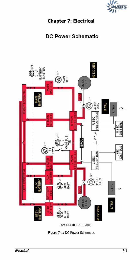
Electrical 7-1
Chapter 7: Electrical
PSM 1-84-1B (Oct 31, 2010)
Figure 7-1: DC Power Schematic

Electrical 7-2
PSM 1-84-1B (Oct 31, 2010)
Figure 7-2: AC Power Schematic
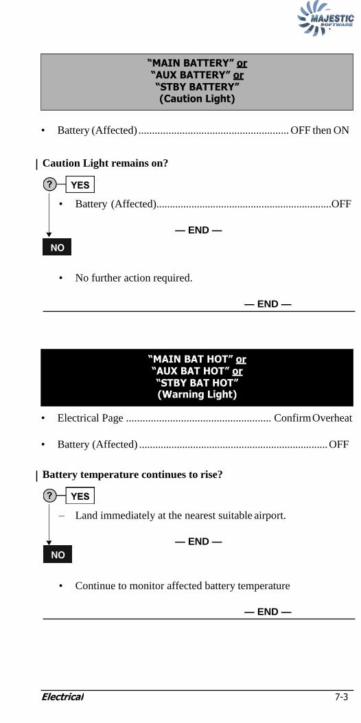
Electrical 7-3
• Battery (Affected) ....................................................... OFF then ON
Caution Light remains on?
• Battery (Affected).................................................................OFF
— END —
• No further action required.
— END —
• Electrical Page ..................................................... Confirm Overheat
• Battery (Affected) ...................................................................... OFF
Battery temperature continues to rise?
– Land immediately at the nearest suitable airport.
— END —
• Continue to monitor affected battery temperature
— END —
―MAIN BAT HOT‖ or ―AUX BAT HOT‖ or ―STBY BAT HOT‖ (Warning Light)
―MAIN BATTERY‖ or ―AUX BATTERY‖ or ―STBY BATTERY‖ (Caution Light)

Electrical 7-4
NOTE:
• EMER LIGHTS switch............................................................ ARM
— END —
NOTE:
If aircraft is on ground and APU start was completed using
ship's batteries prior to "DC BUS" Caution Light, refer to
Chapter 14: Supplemental Resets for reset procedure.
Other associated caution lights are illuminated?
(#1 DC GEN, STBY BATTERY and AUX BATTERY CAUTION
LIGHTS or #2 DC GEN AND MAIN BATTERY CAUTION LIGHTS)
• MAIN DC BUS FAULT (Next Checklist)...............Accomplish
— END —
• BUS FAULT RESET ......................................................... Reset
— END —
Left Main DC Bus Fault:
(―DC BUS‖, ―#1 DC GEN‖, ―STBY BATTERY‖ and ―AUX
BATTERY‖ Caution Lights)?
• AUX and STBY BATT switches......................................... OFF
• DC GEN 1 switch ................................................................ OFF
• BUS FAULT RESET switch ..............................................Reset
– Leave selected switches in the OFF position.
— CONTINUED —
MAIN DC BUS FAULT
―DC BUS‖ (Caution Light)
―EMER LTS DISARMED‖ (Caution Light)

Electrical 7-5
DC BUS Caution Light remains illuminated?
– Descend to below 14,000 ft. as soon as possible.
• AUTO/MAN/DUMP switch........................................ MAN
• MAN DIFF switch ......................................... INCR (50 sec)
– The flight may continue to the destination, return to point
of departure, or the nearest airport where maintenance
services are available, as appropriate. (Coordinate with
Dispatch/SOC.)
NOTE:
ECS pack airflow is lost and cabin will depressurize.
When below 14,000 ft., ventilate cabin:
• RECIRC switch.............................................................. OFF
• BLEED selector .............................................................MIN
• BLEED switches 1 and 2 ............................................... OFF
• CABIN ALT FWD OUTFLOW..... Fully Clockwise (OPN)
• FWD OUTFLOW VALVE selector ........................... OPEN
NOTE:
Ram ventilation is most effective above 150 KIAS.
— END —
• No further action required.
— CONTINUED —

Electrical 7-6
NOTE:
NOTE:
Right Main DC Bus Fault:
(―DC BUS‖, ―#2 DC GEN‖, and ―MAIN BATTERY‖ Caution
Lights)
• MAIN BATT switch .................................................................. OFF
• DC GEN 2 switch ...................................................................... OFF
• BUS FAULT RESET switch ................................................... Reset
– Leave selected switches in the OFF position.
DC BUS Caution light remains illuminated?
– Descend to below 14,000 ft. as soon as possible.
– The flight may continue to the destination, return to point of
departure or the nearest airport where maintenance services are
available, as appropriate. (Coordinate with Dispatch/SOC.)
When below 14,000 ft., ventilate cabin:
• RECIRC switch.................................................................... OFF
• BLEED selector ...................................................................MIN
• BLEED switch 1 and 2 ........................................................ OFF
• AUTO/MAN/DUMP switch.............................................. MAN
• MAN DIFF switch ................................................ INCR(50 sec)
• CABIN ALT FWD OUTFLOW.............Fully Clockwise (Opn)
• FWD OUTFLOW VALVE selector ................................. OPEN
• INBD ANTI-SKID and/or OUTBD ANTI-SKID
(Page 12-11)............................................................. Accomplish
— END —
• No further action required.
— END —
NOTE:
Ram ventilation is most effective above 150 KIAS.
NOTE:
ECS pack airflow is lost and cabin will depressurize.

Electrical 7-7
NOTE:
NOTE:
Affected variable AC BUS is depowered with loss of
associated services.
Lost Services:
L AC BUS R AC BUS
L Aux Fuel Pump R Aux Fuel Pump
L Prop Deicing R Prop Deicing
L Alpha Vane Heater R Alpha Vane Heater
L TRU R TRU
L Ice Detection Sensor R Ice Detection Sensor
Pilot Windshield Heat
(NORM & WARM UP)
Standby Hydraulic Pump
Co-pilot Windshield Heat
(NORM) L Engine Intake Heater
L Pitot Static Heater Pilot Side Window Heat
Stick Pusher System R Engine Intake Heater
R Pitot Static Heater
Stick Pusher System
— END —
(Loss of BOTH DC Generators and BOTH AC Generators or loss of
BOTH DC Generators and ONE or BOTH TRUs)
• STORM/DOME LIGHT switch ........................ STORM (If Req‘d)
• MAIN, AUX, and STBY BATT switches ................................. OFF
• EMER LIGHTS switch...................................................... As Req‘d
– Land immediately at nearest suitable airport.
— CONTINUED —
―#1 DC GEN‖ and ―#2 DC GEN‖ and either
―#1 AC GEN‖ and ―#2 AC GEN‖ or
―L TRU‖ and/or ―R TRU‖ (Caution Lights)
LOSS OF GENERATED POWER
―L AC BUS‖ or ―R AC BUS‖ (Caution Light)

Electrical 7-8
NOTE:
The following services WILL BE available along with their associated
caution/warnings and advisory lights:
ADC 1 CB Panel Lights
Standby Pitot Heat Emergency Lights
Engine Fire Detection and Extinguishing Passenger Signs
Smoke Detectors Position Lights
Aileron Trim Actuation and Indication Baggage Lights
Rudder Trim Actuation and Indication Strobe Lights
Elevator Trim Actuation and Indication Flight Compartment Dome Lights
Flap Control and Indication Landing Gear Control and Indication
PFCS Indication Engine Ignition and Start
AHRS 1 and 2 #1 and #2 Engine Oil Pressure
VHF COMM 1 #1 Engine Fuel Temperature
VHF NAV 1 #1 and #2 FADECS
Captain and First Officer Audio #1 and #2 PECS
PA and Cabin Interphone Audio Fuel and Hydraulic Shut Off Valves
Clock 1 #1 and #3 Hydraulic Quantity
Indications
Integrated Standby Instrument (ISI) #1, #2, and #3 Hydraulic Pressure
Indications
No. 3 Hydraulic System
CAUTION:
Battery duration for operation of essential services is 60
minutes.
— CONTINUED —
NOTE:
ECS pack air flow is lost and cabin will depressurize.

Electrical 7-9
NOTE:
When below 14,000 ft., ventilate cabin:
• AUTO/MAN/DUMP switch.................................................... MAN
• MAN DIFF switch ................................................... INCR (50 secs)
• CABIN ALT FWD OUTFLOW................. Fully Clockwise (OPN)
• FWD OUTFLOW VALVE selector ....................................... OPEN
— END —
(Loss of BOTH DC Generators and ONE AC Generator)
• AC GEN (Operative) .................................................. Monitor Load
– Land immediately at nearest suitable airport.
— END —
(Loss of BOTH DC Generators)
• DC GEN switches 1 and 2 ......................Individually OFF then ON
IF caution lights persist:
• L TRU and R TRU....................................................... Monitor load
— END —
―#1 DC GEN‖ and ―#2 DC GEN‖ (Caution Lights)
―#1 DC GEN‖ and ―#2 DC GEN‖ and
―#1 AC GEN‖ or ―#2 AC GEN‖ (Caution Lights)
NOTE:
Ram ventilation is most effective above 150 KIAS.

Electrical 7-10
NOTE:
NOTE:
(Loss of ONE DC Generator and BOTH TRUs)
– The flight may continue to the destination, return to point of
departure, or the nearest airport where maintenance services are
available, as appropriate. (Coordinate with Dispatch/SOC.)
— END —
(Loss of ONE DC Generator)
• GEN switch (Affected) ......................................... OFF then ON
Caution Light remains on?
• No further action required.
— END —
• GEN switch (Affected)...................................................OFF
NOTE:
If on the ground, consult Dispatch and Maintenance.
Consider MEL 24-30-6. Flight Crew placarding permitted.
— END —
―#1 DC GEN‖ or ―#2 DC GEN‖ (Caution Light)
NOTE:
All secondary bus services are inoperative.
―#1 DC GEN‖ or ―#2 DC GEN‖ and
―L TRU‖ and ―R TRU‖ (Caution Lights)

Electrical 7-11
NOTE:
NOTE:
(Overheat of ONE DC Generator)
• GEN switch (Affected) ........................................................ OFF
NOTE:
Continued operation of the associated engine is permissible
for the remainder of the flight. The affected GEN HOT
light may remain illuminated for the remainder of the
flight.
— END —
(Loss of both AC Generators with Propeller Deice selected ON)
• PROP selector ............................................................................ OFF
• Condition Levers...................................................................... MAX
• AC GEN 1 and AC GEN 2 switches ......OFF then ON Individually
– Check #1 and #2 AC GEN caution light out and affected AC
generator VOLTS and LOAD on ELECTRICAL page of MFD.
IF Caution Light remains on:
• AC GEN switch (Affected).................................................. OFF
– Exit icing conditions as soon as possible.
— END —
NOTE:
The PROP DEICE caution light may also be illuminated.
―#1 AC GEN‖ and ―#2 AC GEN‖ (Caution Light)
―#1 DC GEN HOT‖ or ―#2 DC GEN HOT‖
(Caution Light)
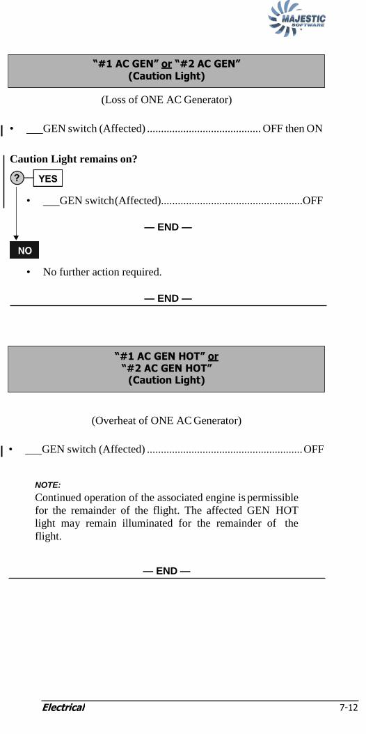
Electrical 7-12
NOTE:
(Loss of ONE AC Generator)
• GEN switch (Affected) ......................................... OFF then ON
Caution Light remains on?
• GEN switch (Affected)...................................................OFF
— END —
• No further action required.
— END —
(Overheat of ONE AC Generator)
• GEN switch (Affected) ........................................................ OFF
NOTE:
Continued operation of the associated engine is permissible
for the remainder of the flight. The affected GEN HOT
light may remain illuminated for the remainder of the
flight.
— END —
―#1 AC GEN HOT‖ or ―#2 AC GEN HOT‖
(Caution Light)
―#1 AC GEN‖ or ―#2 AC GEN‖ (Caution Light)

Electrical 7-13
(Loss or overheat of ONE TRU)
• TRU CB (AC CB panel behind F/O)(Affected) ................... Pull
AC CB Panel
— END —
L TRU R TRU
―L TRU‖ or ―R TRU‖ or
―L TRU HOT‖ or ―R TRU HOT‖
(Caution Light)

Electrical 7-14
Intentionally Left Blank

Q400 Quick Reference Handbook 8-i
Chapter 8: Flight Controls
ROLL CONTROL JAM 8-1
AILERON TRIM RUNAWAY 8-3
ROLL CONTROL MALFUNCTION 8-3
―ROLL SPLR INBD HYD‖ or ―ROLL SPLR OUTBD HYD‖ (Caution Light) 8-6
―ROLL SPLR INBD HYD‖ and ―ROLL SPLR OUTBD HYD‖ (Caution Lights) 8-7
―ROLL SPLR INBD GND‖ or ―ROLL SPLR OUTBD GND‖ (Caution Light) 8-9
―SPLR OUTBD‖ (Caution Light) 8-10
PITCH CONTROL JAM 8-10
―ELEVATOR FEEL‖ and ―PITCH TRIM‖ and ―SPLR OUTBD‖ and ―RUD CTRL‖ (Caution Lights) 8-12
―ELEVATOR ASYMMETRY‖ (Caution Light) 8-12
―ELEVATOR PRESS‖ (Caution Light) 8-13
―ELEVATOR FEEL‖ (Caution Light) 8-13
―PITCH TRIM‖ (Continuous illumination of Caution Light) 8-14
ELEVATOR TRIM SWITCH FAILURE 8-15
ELEVATOR TRIM INDICATOR FAILURE 8-15
ABNORMAL FLAP LANDING. 8-16
―FLAP DRIVE‖ (Caution Light) 8-18

Q400 Quick Reference Handbook 8-i
―FLAP POWER‖ (Caution Light) 8-18
RUDDER JAM 8-20
―RUD 1 PUSH OFF‖ or ―RUD 2 PUSH OFF‖ (Switchlight On) 8-22
―#1 RUD HYD‖ or ―#2 RUD HYD‖ (Caution Light) 8-22
―RUD CTRL‖ (Caution Light) 8-22
RUDDER TRIM ACTUATOR RUNAWAY 8-22

Q400 Quick Reference Handbook 8-1
NOTE:
Chapter 8: Flight Controls
ROLL CONTROL JAM
• Autopilot .........................................................................Disengage
• ROLL DISC handle ............................................ Pull and Turn 90°
CAUTION:
With the ROLL DISC handle pulled, the autopilot must not be
engaged.
– Pilot with unjammed Control Wheel will have roll control and
should take the following action:
Is the right Control Wheel Free?
NOTE:
Roll control will be degraded and forces will be normal.
IF continuous illumination of SPLR 1 and SPLR 2 PUSH OFF
switchlights:
• SPLR 1 PUSH OFF switchlight............................... PUSH OFF
• SPLR 2 PUSH OFF switchlight............................... PUSH OFF
Landing Considerations:
– Land at an airport with minimum crosswind and turbulence
using Flaps 10 or 15.
– Approach Speed................................................... Derived VREF
— CONTINUED —

Q400 Quick Reference Handbook 8-2
YES
Derived VREF
Weight
(lbs)
Flap 10 Flap 15
Level 1 Level 2/3 Level 1 Level 2/3
64,000 136 15 129 149
62,000 13 153 126 146
60,000 130 150 124 144
58,000 128 148 122 142
56,000 126 146 120 140
54,000 124 144 118 138
52,000 121 141 116 136
50,000 119 139 113 133
48,000 116 136 111 131
46,000 114 134 109 129
44,000 112 132 106 126
42,000 109 129 104 124
40,000 108 128 101 121
Abnormal Landing Distance Factors
Flap Ice Protection
Level 1 Level 2/3
10 1.4 1.4
15 1.4 1.4
Conditional Landing Distance Statement
Level 1 Ice Protection
Landing Distance = 5200 ft
Wt. less than 64,500 lbs.
Flap 10° or 15°
Dry Runway
Airport Elevation less than 2000 ft
Tailwind less than or equal to 10 kts.
— END —
— CONTINUED —

Flight Controls 8-3
NOTE:
Left Control Wheel free?
NOTE:
Roll control forces will be low and tendency to over control
is likely and should be avoided.
IF roll control is inadequate with Flaps 5, 10, or 15 selected:
• Max airspeed............................................................... 165 KIAS
Landing Considerations:
– Land at an airport with minimum crosswind and turbulence
using Flaps 15 or 35
— END —
• Airspeed ................................................................................ Reduce
• Aileron Trim ...................................................Opposite to Runaway
WHEN trim is at neutral position or if trim actuator cannot be reversed:
• Ail Trim Act CB (G8 – Left Essential)....................................... Pull
— END —
(Airplane rolls with no control wheel input)
— CONTINUED —
• Roll Control ........................................... Apply to hold wings level
IF continuous illumination of SPLR 1 or SPLR 2 PUSH OFF switchlights:
• Illuminated switchlight ................................................. PUSH OFF
ROLL CONTROL MALFUNCTION
AILERON TRIM RUNAWAY

Flight Controls 8-4
Landing Considerations:
– Approach Speed ........................................................................VREF
– Land at an airport with minimum crosswind and turbulence using
Flaps 10, 15. and 35.
VREF
Weight
(lbs)
Flap 10 Flap 15 Flap 35
Level 1 Level 2/3 Level 1 Level 2/3 Level 1 Level 2/3
64,000 136 156 129 149 123 138
62,000 133 153 126 146 121 136
60,000 130 150 124 144 119 134
58,000 128 148 122 142 117 132
56,000 126 146 120 140 115 130
54,000 124 144 118 138 113 128
52,000 121 141 116 136 110 125
50,000 119 139 113 133 108 123
48,000 116 136 111 131 106 121
46,000 114 134 109 129 104 119
44,000 112 132 106 126 102 117
42,000 109 129 104 124 100 115
40,000 108 128 101 121 97 112
Abnormal Landing Distance Factors
Flap Ice Protection
Level 1 Level 2/3
10 1.35 1.35
15 1.35 1.35
35 1.35 1.35
Conditional Landing Distance Statement
Level 1 Ice Protection
Landing Distance = 5100 ft
Wt. less than 64,500 lbs.
Flap greater than or equal to 10°
Dry Runway
Airport Elevation less than 2000 ft
Tailwind less than or equal to 10 kts.
— CONTINUED —

Flight Controls 8-5
If SPLR 1 or SPLR 2 PUSH OFF switchlights do not illuminate:
• Power .....................................................................................Apply
• Airspeed .............................................................. Increase as Req‘d
Landing Considerations:
– Approach Speed .......................................................... Derived VREF
– Land at an airport with minimum crosswind and turbulence using
Flap 10, 15, and 35.
Derived VREF
Weight
(lbs)
Flap 10 Flap 15 Flap 35
Level 1 Level 2/3 Level 1 Level 2/3 Level 1 Level 2/3
64,000 144 156 138 149 130 138
62,000 142 153 134 146 127 136
60,000 139 150 133 144 126 134
58,000 137 148 130 142 124 132
56,000 134 146 127 140 121 130
54,000 131 144 126 138 120 128
52,000 130 141 124 136 117 125
50,000 127 139 121 133 114 123
48,000 125 136 118 131 112 121
46,000 121 134 116 129 111 119
44,000 120 132 113 126 108 117
42,000 117 129 111 124 105 115
40,000 113 128 108 121 103 112
Abnormal Landing Distance Factors
Flap Ice Protection
Level 1 Level 2/3
10 1.50 1.52
15 1.50 1.52
35 1.50 1.50
Conditional Landing Distance Statement
Level 1 Ice Protection
Landing Distance = 5600 ft
Wt. less than 64,500 lbs.
Flap greater than or equal to 10°
Dry Runway
Airport Elevation less than 2000 ft
Tailwind less than or equal to 10 kts.
— END —

Flight Controls 8-6
NOTE:
NOTE:
If aircraft is on ground, refer to Chapter 14: Supplemental
Resets for reset procedure.
Landing Considerations:
– Approach Speed .......................................................... Derived VREF
Derived VREF
Weight
(lbs)
Flap 10 Flap 15 Flap 35
Level 1 Level 2/3 Level 1 Level 2/3 Level 1 Level 2/3
64,000 146 156 139 149 133 148
62,000 143 153 136 146 131 146
60,000 140 150 134 144 129 144
58,000 138 148 132 142 127 142
56,000 136 146 130 140 125 140
54,000 134 144 128 138 123 138
52,000 131 141 126 136 120 135
50,000 129 139 123 133 118 133
48,000 126 136 121 131 116 131
46,000 124 134 119 129 114 129
44,000 122 132 116 126 112 127
42,000 119 129 114 124 110 125
40,000 118 128 111 121 107 122
Abnormal Landing Distance Factors
Flap Ice Protection
Level 1 Level 2/3
10 1.50 1.35
15 1.50 1.35
35 1.50 1.50
— CONTINUED —
―ROLL SPLR INBD HYD‖ or ―ROLL SPLR OUTBD HYD‖
(Caution Light)

Flight Controls 8-7
Conditional Landing Distance Statement
Level 1 Ice Protection
Landing Distance = 5600 ft
Wt. less than 64,500 lbs.
Flap greater than or equal to 10°
Dry Runway
Airport Elevation less than 2000 ft
Tailwind less than or equal to 10 kts.
— END —
(Spoiler Cable Failure)
• SPLR 1 and 2 PUSH Off switchlights ............................PUSH OFF
Landing Considerations:
– Approach Speed .......................................................... Derived VREF
– Land at an airport with minimum crosswind and turbulence using
Flap 10 or 15.
VREF
Weight
(lbs)
Flap 10 Flap 15
Level 1 Level 2/3 Level 1 Level 2/3
64,000 136 156 129 149
62,000 133 153 126 146
60,000 130 150 124 144
58,000 128 148 122 142
56,000 126 146 120 140
54,000 124 144 118 138
52,000 121 141 116 136
50,000 119 139 113 133
48,000 116 136 111 131
46,000 114 134 109 129
44,000 112 132 106 126
42,000 109 129 104 124
40,000 108 128 101 121
— CONTINUED —
―ROLL SPLR INBD HYD‖ and ―ROLL SPLR OUTBD HYD‖
(Caution Lights)
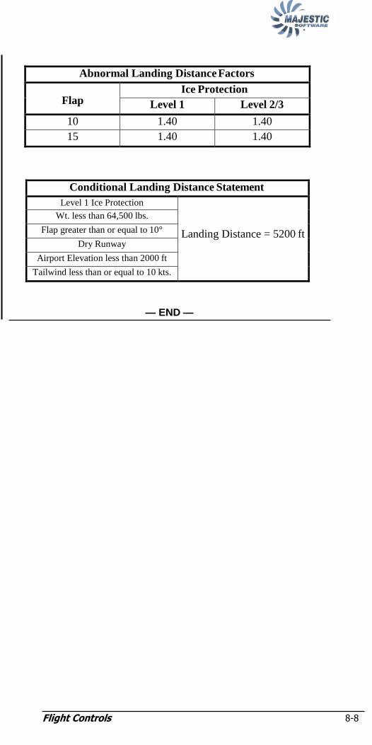
Flight Controls 8-8
Abnormal Landing Distance Factors
Flap Ice Protection
Level 1 Level 2/3
10 1.40 1.40
15 1.40 1.40
Conditional Landing Distance Statement
Level 1 Ice Protection
Landing Distance = 5200 ft
Wt. less than 64,500 lbs.
Flap greater than or equal to 10°
Dry Runway
Airport Elevation less than 2000 ft
Tailwind less than or equal to 10 kts.
— END —

Flight Controls 8-9
Landing Considerations:
– Approach Speed ........................................................................VREF
– Affected Inboard or Outboard roll spoilers may not extend at
touchdown.
VREF
Weight
(lbs)
Flap 10 Flap 15 Flap 35
Level 1 Level 2/3 Level 1 Level 2/3 Level 1 Level 2/3
64,000 136 156 129 149 123 138
62,000 133 153 126 146 121 136
60,000 130 150 124 144 119 134
58,000 128 148 122 142 117 132
56,000 126 146 120 140 115 130
54,000 124 144 118 138 113 128
52,000 121 141 116 136 110 125
50,000 119 139 113 133 108 123
48,000 116 136 111 131 106 121
46,000 114 134 109 129 104 119
44,000 112 132 106 126 102 117
42,000 109 129 104 124 100 115
40,000 108 128 101 121 97 112
Abnormal Landing Distance Factors
Flap Ice Protection
Level 1 Level 2/3
10 1.35 1.35
15 1.35 1.35
35 1.35 1.35
Conditional Landing Distance Statement
Level 1 Ice Protection
Landing Distance = 5100 ft
Wt. less than 64,500 lbs.
Flap greater than or equal to 10°
Dry Runway
Airport Elevation less than 2000 ft
Tailwind less than or equal to 10 kts.
— END —
―ROLL SPLR INBD GND‖ or ―ROLL SPLR OUTBD GND‖
(Caution Light)

Flight Controls 8-10
NOTE:
• Max Airspeed.................................................................... 200 KIAS — END —
• Max Airspeed.............................................................. 170 KIAS or
speed at which jam occurred, whichever is higher.
CAUTION:
With the PITCH disconnect handle pulled, the autopilot must
not be engaged.
NOTE:
Elevator forces will be lighter than normal and pitch
control degraded.
— CONTINUED —
• Autopilot .........................................................................Disengage
• Flap and Airspeed ......................................Maintain at time of jam
• Pitch Control ...........................................Attempt to overcome jam
IF unable to overcome jam:
• Relax control column force.
• Pitch Disc handle ................................................ Pull and Turn 90°
PITCH CONTROL JAM
―SPLR OUTBD‖ (Caution Light)
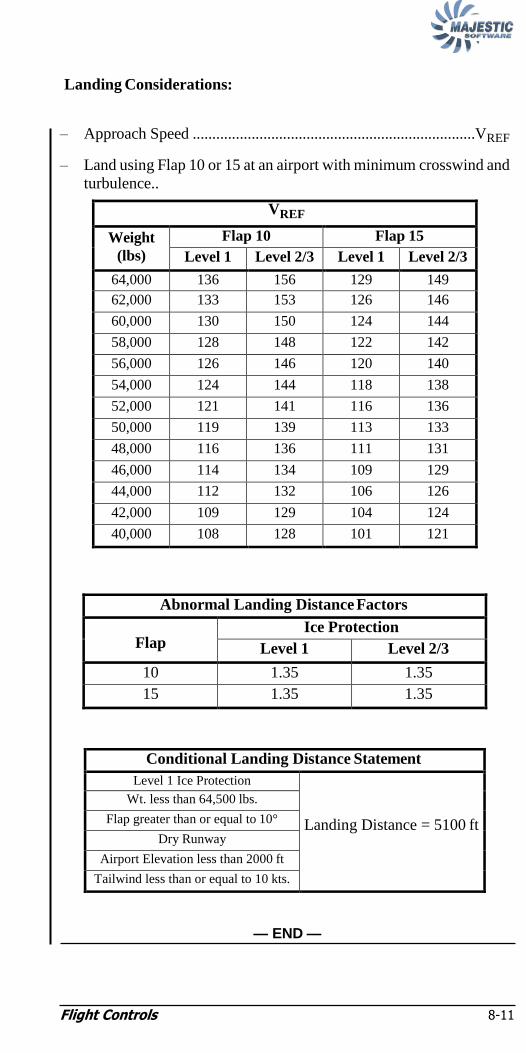
Flight Controls 8-11
Landing Considerations:
– Approach Speed ........................................................................VREF
– Land using Flap 10 or 15 at an airport with minimum crosswind and
turbulence..
VREF
Weight
(lbs)
Flap 10 Flap 15
Level 1 Level 2/3 Level 1 Level 2/3
64,000 136 156 129 149
62,000 133 153 126 146
60,000 130 150 124 144
58,000 128 148 122 142
56,000 126 146 120 140
54,000 124 144 118 138
52,000 121 141 116 136
50,000 119 139 113 133
48,000 116 136 111 131
46,000 114 134 109 129
44,000 112 132 106 126
42,000 109 129 104 124
40,000 108 128 101 121
Abnormal Landing Distance Factors
Flap Ice Protection
Level 1 Level 2/3
10 1.35 1.35
15 1.35 1.35
Conditional Landing Distance Statement
Level 1 Ice Protection
Landing Distance = 5100 ft
Wt. less than 64,500 lbs.
Flap greater than or equal to 10°
Dry Runway
Airport Elevation less than 2000 ft
Tailwind less than or equal to 10 kts.
— END —
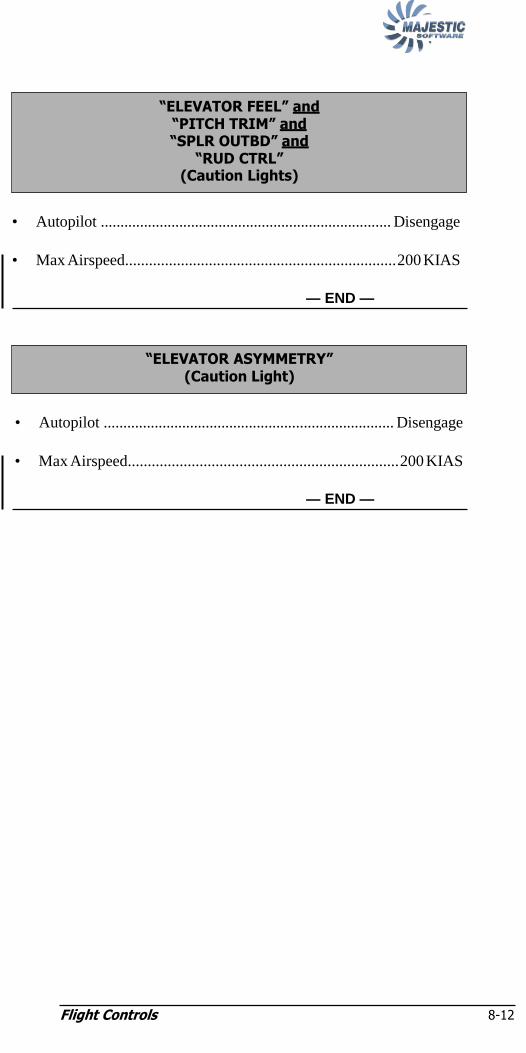
Flight Controls 8-12
• Autopilot .......................................................................... Disengage
• Max Airspeed.................................................................... 200 KIAS
— END —
• Autopilot .......................................................................... Disengage
• Max Airspeed.................................................................... 200 KIAS
— END —
―ELEVATOR ASYMMETRY‖ (Caution Light)
―ELEVATOR FEEL‖ and ―PITCH TRIM‖ and ―SPLR OUTBD‖ and
―RUD CTRL‖ (Caution Lights)
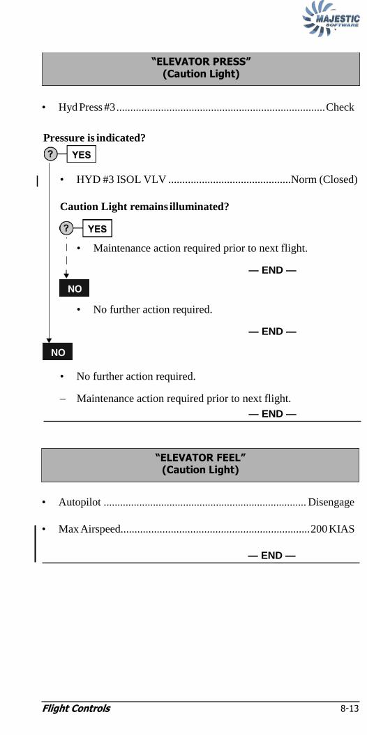
Flight Controls 8-13
• Hyd Press #3 ........................................................................... Check
Pressure is indicated?
• HYD #3 ISOL VLV ............................................Norm (Closed)
Caution Light remains illuminated?
• Maintenance action required prior to next flight.
— END —
• No further action required.
— END —
• No further action required.
– Maintenance action required prior to next flight.
— END —
• Autopilot .......................................................................... Disengage
• Max Airspeed.................................................................... 200 KIAS
— END —
―ELEVATOR FEEL‖ (Caution Light)
―ELEVATOR PRESS‖ (Caution Light)

Flight Controls 8-14
NOTE:
NOTE:
NOTE:
• Autopilot...........................................................................Disengage
• Elevator Trim....................................................................... Activate
NOTE:
Elevator Trim pointer may indicate full NU trim position
with PITCH TRIM caution light illuminated.
Elevator Trim is operative?
• Autopilot ........................................................ Engage as Req‘d
— END —
– Maintain aircraft configuration and airspeed as long as practical.
NOTE:
If the PITCH TRIM fails on takeoff with flap 10° or flap
15°, it is recommended that the landing be conducted with
the takeoff flap setting.
Landing Considerations:
– Land at an airport with minimum crosswind and turbulence.
NOTE:
During the airspeed deceleration to VFE, the elevator force
will increase. When decelerating from VMO with Flap 0,
the elevator force may be as high as 40 lb until flap is
extended.
— END —
―PITCH TRIM‖ (Continuous illumination of Caution Light)

Flight Controls 8-15
NOTE:
NOTE:
NOTE:
NOTE:
(Illumination of Elevator Trim Shutoff switchlight and
Audio Tone for elevator trim in motion)
• Autopilot .................................................................. Do Not Engage
– Maintain aircraft configuration and airspeed as long as
practicable.
NOTE:
If the pitch trim fails on takeoff with Flap 10 or Flap 15, it
is recommended that the landing be conducted with the
takeoff flap setting.
Landing Considerations:
– Land at an airport with minimum crosswind and turbulence.
NOTE:
During the airspeed deceleration to VFE, the elevator force
will increase. When decelerating from VMO with Flap 0,
the elevator force may be as high as 40 lb until flap is
extended.
— END —
(Elevator Trim Pointer indicates offscale ND)
• Elevator Trim ............................................................... Use as Req‘d
— END —
NOTE:
Maintenance action required prior to next flight.
ELEVATOR TRIM INDICATOR FAILURE
NOTE:
Elevator Trim pointer will indicate full NU trim position.
• ELEVATOR TRIM SHUT OFF.....................................PUSH OFF
ELEVATOR TRIM SWITCH FAILURE

Flight Controls 8-16
• GPWS FLAP OVERRIDE switchlight..................................... Press
Before 1,000 ft. AGL:
• Autopilot .......................................................................... Disengage
Flap failed between 0 and 10?
Landing Considerations
CAUTION:
1. Pitch attitudes greater than 6° in the landing flare may cause the fuselage to contact the runway. 2. Do not select POWER levers below FLIGHT IDLE until indicated airspeed is below 150 KIAS.
– Nosewheel should be promptly brought into contact with the ground following main wheel contact.
– High landing speeds may result in Brake Kinetic Energy
limits being exceeded.
– If flap failed between gated positions, the smaller flap angle
must be used when calculating the landing performance that
follows.
– Approach Speed .............................................. Derived VREF
Derived VREF
Weight
(lbs)
Flap 0 Flap 5
Level 1 Level 2/3 Level 1 Level 2/3
64,000 158 183 145 165
62,000 155 180 143 163
60,000 153 178 140 160
58,000 150 175 137 157
56,000 147 172 135 155
54,000 145 170 133 153
52,000 142 167 130 150
50,000 139 164 128 148
48,000 137 162 125 145
46,000 134 159 122 142
44,000 131 156 120 140
42,000 128 153 117 137
40,000 125 150 114 134
— CONTINUED —
ABNORMAL FLAP LANDING

Flight Controls 8-17
YES
Abnormal Landing Distance Factor:
– Use ―Actual Landing Distance Flap 0, Flap 5‖ table in
Chapter 1: Performance to calculate landing distance if
Conditional Landing Distance Statement does not apply.
– Enter the table using pressure altitude of field, ice protection
level, and predicted gross weight of the aircraft at the time of
landing.
– Distance shown includes the abnormal landing distance
factor for aircraft weight and pressure altitude.
– Add additional factor for headwind, tailwind and/or wet
runway below table.
CAUTION:
Avoid pitch attitudes in excess of 6° at touchdown. DO
NOT select POWER to FLIGHT IDLE above 150 knots.
Conditional Landing Distance Statement
Level 1 Ice Protection
Landing Distance = 6500 ft
Wt. less than 64,500 lbs.
Flap 0°-5°
Dry Runway
Airport Elevation less than 2000 ft
Tailwind less than or equal to 10 kts.
After Landing:
• GPWS FLAP OVERRIDE switchlight................Press (Off)
— END —
Flap failed between 10, 15 or 35:
Landing Considerations:
• The smaller flap angle must be used when calculating landing
performance.
• GPWS FLAP OVERRIDE switchlight.......................Press (off)
— END —
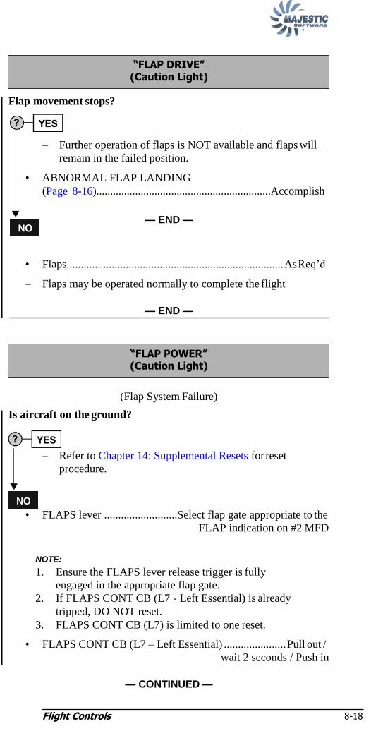
Flight Controls 8-18
NOTE:
Flap movement stops?
– Further operation of flaps is NOT available and flaps will
remain in the failed position.
• ABNORMAL FLAP LANDING
(Page 8-16)...............................................................Accomplish
— END —
• Flaps............................................................................. As Req‘d
– Flaps may be operated normally to complete the flight
— END —
(Flap System Failure)
Is aircraft on the ground?
– Refer to Chapter 14: Supplemental Resets for reset
procedure.
• FLAPS lever ..........................Select flap gate appropriate to the
FLAP indication on #2 MFD
NOTE:
1. Ensure the FLAPS lever release trigger is fully
engaged in the appropriate flap gate.
2. If FLAPS CONT CB (L7 - Left Essential) is already
tripped, DO NOT reset.
3. FLAPS CONT CB (L7) is limited to one reset.
• FLAPS CONT CB (L7 – Left Essential) ...................... Pull out /
wait 2 seconds / Push in
— CONTINUED —
―FLAP POWER‖ (Caution Light)
―FLAP DRIVE‖ (Caution Light)

Flight Controls 8-19
NOTE:
Caution Light remains on?
– Operation of flaps is NOT available and flaps will remain in the
last selected position.
• ABNORMAL FLAP LANDING
(Page 8-16) .............................................................. Accomplish
— END —
NOTE:
Delay the selection of the FLAPS lever for a minimum of
20 seconds following reset of the FLAPS CONT CB.
• FLAPS lever ........................................................ Select as req‘d
— END —

Flight Controls 8-20
(Restricted Rudder Pedal Movement)
• Affected Rudder Pedal ........................... Apply a normal push force
Rudder pedal moves as required?
• Affected Rudder Pedal ..................Reduce push force and allow
...................................................... rudder pedal to center
Should the rudder pedal (rudder jam) suddenly break free, DO
NOT apply rudder pedal input in the opposite direction.
• .Rudder Pedals........................................................Use as Req‘d
— END —
Rudder pedal does not respond to normal push force (rudder
remains jammed or rudder jam re-occurs):
– Use roll control required for directional control.
IF rudder jam occurs on take-off and conditions permit, return for
landing on the take-off runway.
Landing Considerations:
• STEERING switch .................................................................... OFF
– Land at an airport with no known or forecast icing conditions and
with minimum crosswind and turbulence, using Flaps 10, 15, or 35.
– Small amounts of asymmetric power may be used to maintain
directional control on approach.
– After touchdown, use asymmetric braking and power, as required, to
maintain directional control.
— CONTINUED —
WARNING
RUDDER JAM

Flight Controls 8-21
– Approach Speed........................................................................VREF
Conditional Landing Distance Statement
VREF
Weight
(lbs)
Flap 10 Flap 15 Flap 35
Level 1 Level 2/3 Level 1 Level 2/3 Level 1 Level 2/3
64,000 136 156 129 149 123 138
62,000 133 153 126 146 121 136
60,000 130 150 124 144 119 134
58,000 128 148 122 142 117 132
56,000 126 146 120 140 115 130
54,000 124 144 118 138 113 128
52,000 121 141 116 136 110 125
50,000 119 139 113 133 108 123
48,000 116 136 111 131 106 121
46,000 114 134 109 129 104 119
44,000 112 132 106 126 102 117
42,000 109 129 104 124 100 115
40,000 108 128 101 121 97 112
Abnormal Landing Distance Factors
Flap Ice Protection
Level 1 Level 2/3
10 1.40 N/A
15 1.40 N/A
35 1.50 N/A
Conditional Landing Distance Statement
Level 1 Ice Protection
Landing Distance = 5200 ft
Wt. less than 64,500 lbs.
Flap greater than or equal to 10°
Dry Runway
Airport Elevation less than 2000 ft
Tailwind less than or equal to 10 kts.
After the aircraft has come to a stop:
• STEERING switch.......................................................................ON
— END —

Flight Controls 8-22
NOTE:
NOTE:
• Illuminated switchlight ...................................................PUSH OFF
— END —
NOTE:
If aircraft is on ground, refer to Chapter 14: Supplemental
Resets for reset procedure.
• No Crew action required.
— END —
• Max Airspeed.................................................................... 200 KIAS
Landing Considerations:
– Maximum crosswind for landing is 20 kts.
— END —
• Rudder Trim....................................................Opposite to Runaway
WHEN trim is at the neutral position or if the trim actuator cannot be
reversed:
• Rud Trim Act CB (F7 – Left Essential)...................................... Pull
— END —
RUDDER TRIM ACTUATOR RUNAWAY
―RUD CTRL‖ (Caution Light)
NOTE:
Maintenance action required prior to next flight.
―#1 RUD HYD‖ or ―#2 RUD HYD‖ (Caution Light)
―RUD 1 PUSH OFF‖ or ―RUD 2 PUSH OFF‖ (Switchlight On)
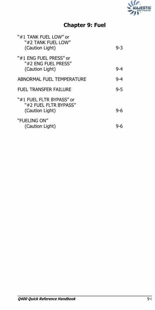
Q400 Quick Reference Handbook 9-i
Chapter 9: Fuel ―#1 TANK FUEL LOW‖ or
―#2 TANK FUEL LOW‖ (Caution Light) 9-3
―#1 ENG FUEL PRESS‖ or ―#2 ENG FUEL PRESS‖ (Caution Light) 9-4
ABNORMAL FUEL TEMPERATURE 9-4
FUEL TRANSFER FAILURE 9-5
―#1 FUEL FLTR BYPASS‖ or ―#2 FUEL FLTR BYPASS‖ (Caution Light) 9-6
―FUELING ON‖ (Caution Light) 9-6

Q400 Quick Reference Handbook 9-i
Intentionally Left Blank
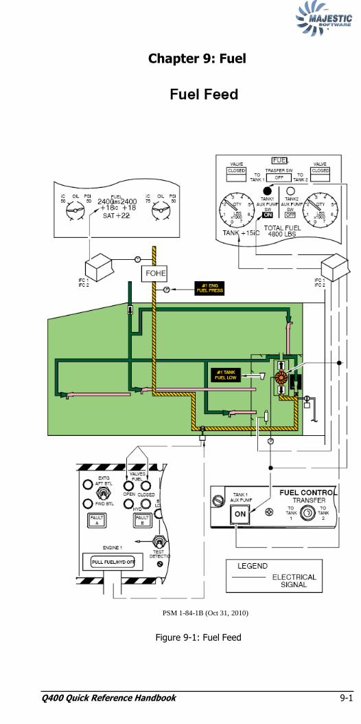
Q400 Quick Reference Handbook 9-1
Chapter 9: Fuel
PSM 1-84-1B (Oct 31, 2010)
Figure 9-1: Fuel Feed

Q400 Quick Reference Handbook 9-2
PSM 1-84-1B (Oct 31, 2010)
Figure 9-2: Fuel Transfer

Fuel 9-3
NOTE:
• Fuel Quantity .......................................................................... Check
Is the Fuel Quantity low?
• Maintain level attitude as much as possible.
• Tank Aux Pump (Affected side) ................................ON
– Monitor fuel quantity.
IF ―ENG FUEL PRESS‖ Caution Light illuminates:
• ENGINE FAILURE/FIRE/SHUTDOWN
(Page 3-1)........................................................... Accomplish
— END —
• Check for external and internal fuel leaks.
NOTE:
A check of the cabin will be necessary to identify a
possible internal fuel leak.
Fuel leak confirmed?
• ENGINE FAILURE/FIRE/SHUTDOWN
(Page 3-1)........................................................... Accomplish
— END —
• Transfer fuel from unaffected tank.
– Monitor fuel quantity.
— END —
―#1 TANK FUEL LOW‖ or ―#2 TANK FUEL LOW‖
(Caution Light)
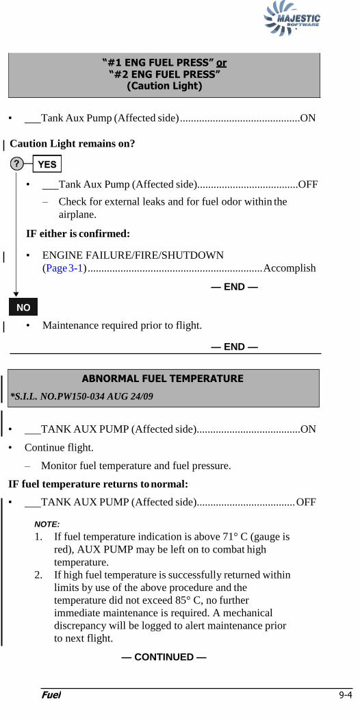
Fuel 9-4
NOTE:
• Tank Aux Pump (Affected side) ............................................ON
Caution Light remains on?
• Tank Aux Pump (Affected side).....................................OFF
– Check for external leaks and for fuel odor within the
airplane.
IF either is confirmed:
• ENGINE FAILURE/FIRE/SHUTDOWN
(Page 3-1) ................................................................ Accomplish
— END —
• Maintenance required prior to flight.
— END —
• TANK AUX PUMP (Affected side)......................................ON
• Continue flight.
– Monitor fuel temperature and fuel pressure.
IF fuel temperature returns to normal:
• TANK AUX PUMP (Affected side).................................... OFF
NOTE:
1. If fuel temperature indication is above 71° C (gauge is
red), AUX PUMP may be left on to combat high
temperature.
2. If high fuel temperature is successfully returned within
limits by use of the above procedure and the
temperature did not exceed 85° C, no further
immediate maintenance is required. A mechanical
discrepancy will be logged to alert maintenance prior
to next flight.
— CONTINUED —
ABNORMAL FUEL TEMPERATURE
*S.I.L. NO.PW150-034 AUG 24/09
―#1 ENG FUEL PRESS‖ or ―#2 ENG FUEL PRESS‖
(Caution Light)

Fuel 9-5
3. Flights may continue with the use of the applicable
AUX PUMP -- ON until repairs can be scheduled.
4. Fuel Temperature limitation applies to a running
engine ONLY. With a life limited thermal element, it is
not uncommon to see the fuel temperature in the red
until the engine is started and fuel is circulating.
— END —
Tank Aux Pump Fails to Automatically Activate:
Tank Aux Pump Advisory Light Fails to illuminates:
• TANK AUX PUMP (Appropriate side) ................................ON
When transfer is complete:
• TANK AUX PUMP (Appropriate side) .............................. OFF
• Fuel Transfer.............................................................................. OFF
— END —
One or Both Fuel Transfer Valves Fail(s) to Open:
• TRANSFER switch.................................................................... OFF
– Consider the effects of maximum lateral fuel asymmetry or fuel low
level.
— END —
FUEL TRANSFER FAILURE

Fuel 9-6
NOTE:
• No Crew action required.
NOTE:
Monitor fuel flow, ITT, and NH. If erratic, may indicate
contamination has passed filter.
— END —
• No Crew action required.
— END —
―FUELING ON‖ (Caution Light)
―#1 FUEL FLTR BYPASS‖ or ―#2 FUEL FLTR BYPASS‖
(Caution Light)
Q400 Quick Reference Handbook 10-i
Chapter 10: Hydraulic Power
No. 1 and No. 2 HYDRAULIC SYSTEMS FAILURE ................ 10-4
No. 1 HYDRAULIC SYSTEM FAILURE 10-6
LOSS of ALL FLUID from No. 1 HYDRAULIC SYSTEM 10-6
―#1 HYD ISO VLV‖ (Caution Light) 10-8
―#1 ENG HYD PUMP‖ (Caution Light) 10-9
No. 2 HYDRAULIC SYSTEM FAILURE 10-10
LOSS of ALL FLUID from No. 2 HYDRAULIC SYSTEM ......... 10-10
―#2 HYD ISO VLV‖ (Caution Light) 10-12
―#2 ENG HYD PUMP‖ (Caution Light) 10-13
PTU FAILURE 10-14
―#1 HYD FLUID HOT‖ or ―#2 HYD FLUID HOT‖ (Caution Light) 10-14
―#1 STBY HYD PUMP HOT‖ (Caution Light) 10-14
―#3 HYD PUMP‖ (Caution Light) 10-15

Q400 Quick Reference Handbook 10-i
Intentionally Left Blank
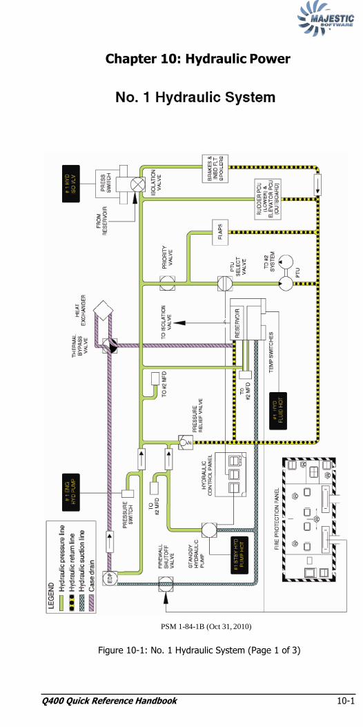
Q400 Quick Reference Handbook 10-1
Chapter 10: Hydraulic Power
PSM 1-84-1B (Oct 31, 2010)
Figure 10-1: No. 1 Hydraulic System (Page 1 of 3)

Q400 Quick Reference Handbook 10-2
PSM 1-84-1B (Oct 31, 2010)
Figure 10-2: No. 2 Hydraulic System (Page 2 of 3)

Hydraulic Power 10-3
PSM 1-84-1B (Oct 31, 2010)
Figure 10-3: No. 3 Hydraulic System (Page 3 of 3)

Hydraulic Power 10-4
NOTE:
(No. 1 HYD PRESS and No. 2 HYD PRESS indicating no pressure)
• Autopilot .......................................................................... Disengage
• Yaw Damper .................................................................... Disengage
• Max Airspeed.................................................................... 200 KIAS
– Use aileron, elevator and, if required for directional control, small
inputs of asymmetric power, to control the aircraft.
IF Flap at 0 or 5:
• GPWS FLAP OVERRIDE switchlight..................................... Press
Lost Services:
– All hydraulically-powered services except elevator.
Landing Considerations:
– Land at an airport with minimum crosswind and turbulence.
– Align aircraft with runway using asymmetric power prior to
lowering the nosewheel to the runway.
– Nose steering will be inoperative. To maintain directional control,
significant asymmetric power will be required.
– ALTERNATE LANDING GEAR EXTENSION
(Page 12-1)................................................ Accomplish when Req‘d
– Emergency braking will only produce about 6 brake applications.
Use of maximum reverse power for stopping may cause directional
deviation.
NOTE:
Emergency brake application is proportional to lever travel
with no differential braking and no anti-skid control.
Excessive application of emergency braking can result in
skidding and tire failure.
— CONTINUED —
No. 1 and No. 2 HYDRAULIC SYSTEMS FAILURE

Hydraulic Power 10-5
– Approach Speed .......................................................... Derived VREF
Abnormal Landing Distance Factors
Flap Ice Protection
Level 1 Level 2/3
0 1.33 1.16
5 1.33 1.16
10 1.85 1.68
15 1.85 1.68
35 1.85 1.84
Conditional Landing Distance Statement
Level 1 Ice Protection
Landing Distance = 7300 ft
Wt. less than 64,500 lbs.
Flap greater than or equal to 0°
Dry Runway
Airport Elevation less than 2000 ft
Tailwind 0 kts.
CAUTION:
Avoid pitch attitudes in excess of 6° at touchdown. Unless
required for immediate directional control, DO NOT select
power levers below flight idle until indicated airspeed is below
150 kts. Excessive application of emergency braking can result
in skidding and tire failure.
— END —

Hydraulic Power 10-6
(―#1ENG HYD PUMP‖ and ―#1HYD ISO VLV‖ Caution Lights, and
ENGINE 1 HYD valve CLOSED Advisory Light and no Quantity
indicated on No. 1 HYD QTY)
• HYD #3 ISOL VLV................................................................ OPEN
• STBY HYD PRESS........................................................Norm (Off)
IF Flap at 0 or 5:
• GPWS FLAP OVERRIDE switchlight..................................... Press
Before 1000 ft. AGL:
• Autopilot .......................................................................... Disengage
Lost Services:
– Flap
– Normal/Anti-Skid Brakes
– Inbd Roll Spoiler / Elevator No. 1 / Rudder No. 1 System
– PTU
Landing Considerations:
– Emergency braking only.
– Excessive application of emergency braking can result in skidding
and tire failure.
– Do not select STBY HYD PRESS or PTU CNTRL switches ON
before landing.
— CONTINUED —
LOSS of ALL FLUID from No. 1 HYDRAULIC SYSTEM
No. 1 HYDRAULIC SYSTEM FAILURE

Hydraulic Power 10-7
– Approach Speed .......................................................... Derived VREF
Abnormal Landing Distance Factors
Flap Ice Protection
Level 1 Level 2/3
0 1.33 1.16
5 1.33 1.16
10 1.85 1.68
15 1.85 1.68
35 1.85 1.84
Conditional Landing Distance Statement
Level 1 Ice Protection
Landing Distance = 7300 ft
Wt. less than 64,500 lbs.
Flap greater than or equal to 0°
Dry Runway
Airport Elevation less than 2000 ft
Tailwind 0 kts.
CAUTION:
Avoid pitch attitudes in excess of 6 degrees at touchdown.
DO NOT select Power Levers below Flight Idle until indicated
airspeed is below 150 kts.
Excessive application of emergency braking can result in
skidding and tire failure.
— END —
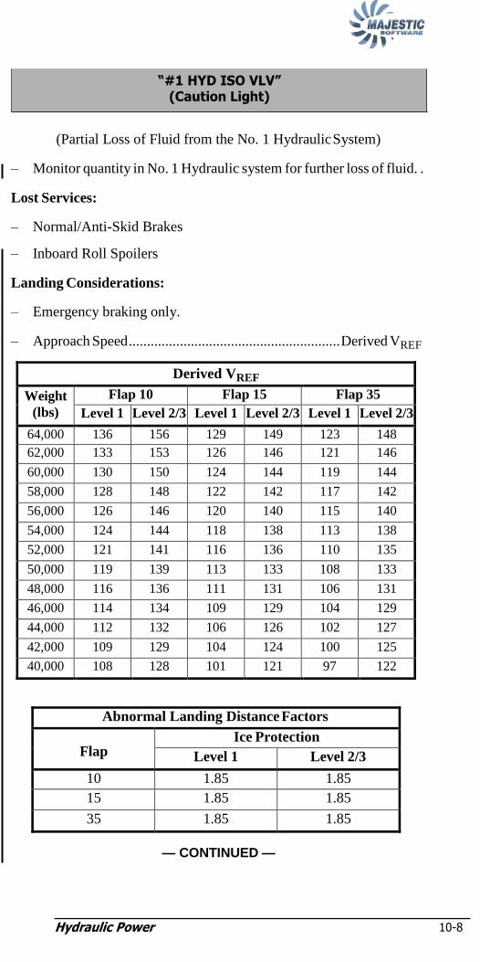
Hydraulic Power 10-8
(Partial Loss of Fluid from the No. 1 Hydraulic System)
– Monitor quantity in No. 1 Hydraulic system for further loss of fluid. .
Lost Services:
– Normal/Anti-Skid Brakes
– Inboard Roll Spoilers
Landing Considerations:
– Emergency braking only.
– Approach Speed .......................................................... Derived VREF
Derived VREF
Weight
(lbs)
Flap 10 Flap 15 Flap 35
Level 1 Level 2/3 Level 1 Level 2/3 Level 1 Level 2/3
64,000 136 156 129 149 123 148
62,000 133 153 126 146 121 146
60,000 130 150 124 144 119 144
58,000 128 148 122 142 117 142
56,000 126 146 120 140 115 140
54,000 124 144 118 138 113 138
52,000 121 141 116 136 110 135
50,000 119 139 113 133 108 133
48,000 116 136 111 131 106 131
46,000 114 134 109 129 104 129
44,000 112 132 106 126 102 127
42,000 109 129 104 124 100 125
40,000 108 128 101 121 97 122
Abnormal Landing Distance Factors
Flap Ice Protection
Level 1 Level 2/3
10 1.85 1.85
15 1.85 1.85
35 1.85 1.85
— CONTINUED —
―#1 HYD ISO VLV‖ (Caution Light)
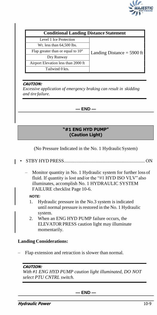
Hydraulic Power 10-9
NOTE:
Conditional Landing Distance Statement
Level 1 Ice Protection
Landing Distance = 5900 ft
Wt. less than 64,500 lbs.
Flap greater than or equal to 10°
Dry Runway
Airport Elevation less than 2000 ft
Tailwind 0 kts.
CAUTION: Excessive application of emergency braking can result in skidding
and tire failure.
— END —
(No Pressure Indicated in the No. 1 Hydraulic System)
• STBY HYD PRESS.................................................................... ON
– Monitor quantity in No. 1 Hydraulic system for further loss of
fluid. If quantity is lost and/or the ―#1 HYD ISO VLV‖ also
illuminates, accomplish No. 1 HYDRAULIC SYSTEM
FAILURE checklist Page 10-6.
NOTE:
1. Hydraulic pressure in the No.3 system is indicated
until normal pressure is restored in the No. 1 Hydraulic
system.
2. When an ENG HYD PUMP failure occurs, the
ELEVATOR PRESS caution light may illuminate
momentarily.
Landing Considerations:
– Flap extension and retraction is slower than normal.
CAUTION:
With #1 ENG HYD PUMP caution light illuminated, DO NOT
select PTU CNTRL switch.
— END —
―#1 ENG HYD PUMP‖ (Caution Light)

Hydraulic Power 10-10
(―#2 ENG HYD PUMP‖ and ―#2 HYD ISO VLV‖ Caution Lights, and
ENGINE 2 HYD valve CLOSED Advisory Light and no Quantity
indicated on No. 2 HYD QTY))
• HYD #3 ISOL VLV................................................................ OPEN
• PTU CNTRL...................................................................Norm (Off)
• HYD PWR XFER C/B (L8 - R Ess)........................................... Pull
• STBY HYD PRESS.....................................................................ON
Lost Services:
– Normal Gear Extension Retraction
– Nose Steering
– EMERG Brakes
– Outbd Roll Spoiler / Elevator No. 2 / Rudder No. 2 System
Landing Considerations:
– Normal / Anti-skid brakes are operational.
• ALTERNATE LANDING GEAR EXTENSION
(Page 12-1)...............................................Accomplish when Req‘d
– Do NOT select PTU CNTRL to ON before landing.
— CONTINUED —
LOSS of ALL FLUID from No. 2 HYDRAULIC SYSTEM
No. 2 HYDRAULIC SYSTEM FAILURE
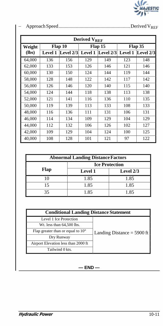
Hydraulic Power 10-11
– Approach Speed .......................................................... Derived VREF
Derived VREF
Weight
(lbs)
Flap 10 Flap 15 Flap 35
Level 1 Level 2/3 Level 1 Level 2/3 Level 1 Level 2/3
64,000 136 156 129 149 123 148
62,000 133 153 126 146 121 146
60,000 130 150 124 144 119 144
58,000 128 148 122 142 117 142
56,000 126 146 120 140 115 140
54,000 124 144 118 138 113 138
52,000 121 141 116 136 110 135
50,000 119 139 113 133 108 133
48,000 116 136 111 131 106 131
46,000 114 134 109 129 104 129
44,000 112 132 106 126 102 127
42,000 109 129 104 124 100 125
40,000 108 128 101 121 97 122
Abnormal Landing Distance Factors
Flap Ice Protection
Level 1 Level 2/3
10 1.85 1.85
15 1.85 1.85
35 1.85 1.85
Conditional Landing Distance Statement
Level 1 Ice Protection
Landing Distance = 5900 ft
Wt. less than 64,500 lbs.
Flap greater than or equal to 10°
Dry Runway
Airport Elevation less than 2000 ft
Tailwind 0 kts.
— END —

Hydraulic Power 10-12
(Partial Loss of Fluid from the No. 2 Hydraulic System)
• PTU CNTRL...................................................................Norm (Off)
• HYD PWR XFER C/B (L8 - R ESS) .........................................Pull
• Monitor quantity in No. 2 Hydraulic system for further loss of fluid.
Lost Services:
– Normal Gear Extention
– Nose Steering
– EMERG Brakes
– Outboard Roll Spoilers
Landing Considerations:
• Alternate Landing Gear Extension
(Page 12-1)...............................................Accomplish when Req‘d
– Approach Speed .......................................................... Derived VREF
Derived VREF
Weight
(lbs)
Flap 10 Flap 15 Flap 35
Level 1 Level 2/3 Level 1 Level 2/3 Level 1 Level 2/3
64,000 136 156 129 149 123 148
62,000 133 153 126 146 121 146
60,000 130 150 124 144 119 144
58,000 128 148 122 142 117 142
56,000 126 146 120 140 115 140
54,000 124 144 118 138 113 138
52,000 121 141 116 136 110 135
50,000 119 139 113 133 108 133
48,000 116 136 111 131 106 131
46,000 114 134 109 129 104 129
44,000 112 132 106 126 102 127
42,000 109 129 104 124 100 125
40,000 108 128 101 121 97 122
— CONTINUED —
―#2 HYD ISO VLV‖ (Caution Light)
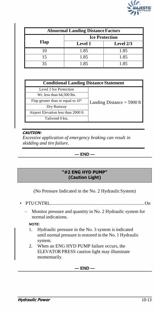
Hydraulic Power 10-13
NOTE:
Abnormal Landing Distance Factors
Flap Ice Protection
Level 1 Level 2/3
10 1.85 1.85
15 1.85 1.85
35 1.85 1.85
Conditional Landing Distance Statement
Level 1 Ice Protection
Landing Distance = 5900 ft
Wt. less than 64,500 lbs.
Flap greater than or equal to 10°
Dry Runway
Airport Elevation less than 2000 ft
Tailwind 0 kts.
CAUTION:
Excessive application of emergency braking can result in
skidding and tire failure.
— END —
(No Pressure Indicated in the No. 2 Hydraulic System)
• PTU CNTRL................................................................................ On
– Monitor pressure and quantity in No. 2 Hydraulic system for
normal indications.
NOTE:
1. Hydraulic pressure in the No. 3 system is indicated
until normal pressure is restored in the No. 1 Hydraulic
system.
2. When an ENG HYD PUMP failure occurs, the
ELEVATOR PRESS caution light may illuminate
momentarily.
— END —
―#2 ENG HYD PUMP‖ (Caution Light)
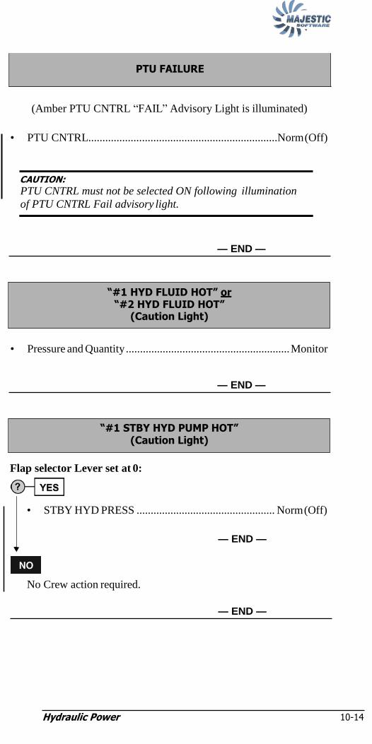
Hydraulic Power 10-14
(Amber PTU CNTRL ―FAIL‖ Advisory Light is illuminated)
• PTU CNTRL...................................................................Norm (Off)
CAUTION:
PTU CNTRL must not be selected ON following illumination
of PTU CNTRL Fail advisory light.
— END —
• Pressure and Quantity .......................................................... Monitor
— END —
Flap selector Lever set at 0:
• STBY HYD PRESS ................................................. Norm (Off)
— END —
No Crew action required.
— END —
―#1 STBY HYD PUMP HOT‖ (Caution Light)
―#1 HYD FLUID HOT‖ or ―#2 HYD FLUID HOT‖
(Caution Light)
PTU FAILURE

Hydraulic Power 10-15
NOTE:
• No Crew action required.
— END —
NOTE:
Maintenance action required prior to next flight.
―#3 HYD PUMP‖ (Caution Light)

Hydraulic Power 10-16
Intentionally Left Blank

Ice and Rain protection, stall protection 11-i
Chapter 11: Ice and Rain Protection,
Stall Protection ―DEICE PRESS‖
(Caution Light) 11-2
ENGINE INTAKE BOOT FAILURE 11-4
―DEICE TIMER‖ (Caution Light) 11-5
―PROP DEICE‖ (Caution Light) 11-6
―WSHLD HOT‖ (Caution Light) 11-7
―SIDE WDO HOT‖ (Caution Light) 11-7
―WSHLD CTRL‖ (Caution Light) 11-7
WINDSHIELD WIPER SWITCH FAILURE 11-7
―ICE DETECT FAIL‖ (Caution Light) 11-7
ENGINE OIL TEMP BELOW 65°C 11-8
―ENG ADPT HEAT 1" or ENG ADPT HEAT 2" (Caution Light) 11-8
―PITOT HEAT 1" or ―PITOT HEAT 2" or ―PITOT HEAT STBY‖ (Caution Light) 11-8
―#1 STALL SYST FAIL‖ or ―2 STALL SYST FAIL‖ and ―PUSHER SYST FAIL‖ (Caution Lights) 11-9
―PUSHER SYST FAIL‖ (Caution Light) 11-9

Ice and Rain protection, stall protection 11-i
Intentionally Left Blank

Ice and Rain protection, stall protection
11-1
Chapter 11: Ice and Rain Protection,
Stall Protection
PSM 1-84-1B (Oct 31, 2010)
Figure 11-1: Airframe Deicing System

Ice and Rain protection, stall protection
11-2
NOTE:
• AIRFRAME MODE SELECT selector ...........................MANUAL
After 10 seconds:
• AIRFRAME MANUAL SELECT selector ............ SLOW or FAST
NOTE:
Adjust power to maintain above 80% NL. It is not unusual
to experience intermittent DEICE PRESS caution light
with low power setting.
DEICE PRESS Caution Light persists?
No further action required.
— END —
• BOOT AIR............................................................................ ISO
• DEICE PRESS indicator............................... Check for pressure
in No. 1 or No. 2 system
• ICE PROTECTION panel ...... Check deice boot advisory lights
ONLY 1 Deice Boot Advisory Light fails to illuminate?
• Exit icing conditions as soon as possible.
– If the failed deice boot is associated with an engine intake
boot:
• ENGINE INTAKE BOOT FAILURE
(Page 11-4)...................................................Accomplish
— END —
— CONTINUED —
YES
―DEICE PRESS‖ (Caution Light)

Ice and Rain Protection, Stall Protection 11-3
NOTE:
Deice Pressure Indication is abnormal (less than 18 ±3 psi) on the
No. 1 and No. 2 DEICE PRESS gauges OR 2 or more wing deice
boot lights on the same side fail to illuminate:
• Exit icing conditions as soon as possible.
• ENGINE INTAKE switchlights ............................................... OPN
CAUTION:
Do not select the WING positions during manual deicing
of the tail and engine intake.
NOTE:
1. The engine intake boot on the side with normal
pressure can be deiced. For the failed side, refer to
ENGINE INTAKE BOOT FAILURE (Page 11-4).
2. Dwell period at each tail and engine intake position
should be approximately 6 seconds.
• AIRFRAME MODE SELECT selector ...........................MANUAL
• AIRFRAME MANUAL SELECT selector ..............Tail & Engines
Landing Considerations:
– Minimum Holding Speed..................................................190 kts
– For landing use flaps 10 or 15 only.
– Approach Speed.................................................Derived VREF
Derived VREF
Weight
(lbs)
Flap 10 Flap 15
Level 2/3
64,000 165 153
62,000 163 151
60,000 160 149
58,000 158 148
56,000 156 145
54,000 154 143
52,000 151 141
50,000 149 138
48,000 146 136
46,000 144 133
44,000 141 131
42,000 139 130
40,000 138 130
— CONTINUED —

Ice and Rain Protection, Stall Protection 11-4
Abnormal Landing Distance Factors
Flap Ice Protection
Level 1 Level 2/3
10 N/A 1.44
15 N/A 1.44
Conditional Landing Distance Statement
Level 2/3 Ice Protection
Landing Distance = 5800 ft
Wt. less than 64,500 lbs.
Flap 10°or 15°
Dry Runway
Airport Elevation less than 2000 ft
Tailwind o kts.
— END —
FOR remainder of flight (Affected engine):
• ENGINE INTAKE switchlight ................................................. OPN
• Exit icing conditions as soon as possible.
— END —
ENGINE INTAKE BOOT FAILURE

Ice and Rain Protection, Stall Protection 11-5
NOTE:
• Deice Boots Advisory Lights............................................... Monitor
If Deice Boot inflation sequencing is incorrect:
• AIRFRAME MODE SELECT selector ..................... MANUAL
• AIRFRAME MANUAL SELECT selector .... Cycle (As Req‘d)
• Exit icing conditions as soon as possible.
NOTE:
Dwell period at each position should be approximately 6
seconds.
Allow for a dwell period of not less than 24 seconds before
commencing subsequent inflation of boots.
— END —
―DEICE TIMER‖ (Caution Light)

Ice and Rain Protection, Stall Protection 11-6
NOTE:
NOTE:
NOTE:
If aircraft is on the ground, refer to Chapter 14:
Supplemental Resets for reset procedure.
• PROP selector ............................................................. OFF then ON
PROP DEICE Caution Light persists and aircraft in icing
conditions?
• Monitor PROPS Advisory lights for normal operation.
— END —
• Condition Levers ................................................................MAX
• Exit icing conditions as soon as possible.
– Confirm operation of the propeller deice system of the
operating engine by observing PROPS advisory light
(operating engine) illuminates and goes out repeatedly.
NOTE:
1. Only one reset of the PROP selector is allowed.
2. PROP selector must remain ON until clear of icing
conditions.
3. With an engine shutdown and PROP selector ON, the
PROP DEICE Caution Light will illuminate.
— END —
―PROP DEICE‖ (Caution Light)

Ice and Rain Protection, Stall Protection 11-7
• WINDSHIELD--HEAT selector.................................... WARM UP
• Exit icing conditions as soon as possible.
— END —
• PLT SIDE WDO/HT ................................................................. OFF
— END —
• Exit icing conditions as soon as possible.
— END —
• ALTERNATE PILOT WIPER switch (below GPWS FLAP
OVERRIDE switchlight) .............................................................ON
— END —
• Monitor ice detection spigots on windshield wipers and wing
leading edges to determine icing conditions.
— END —
―ICE DETECT FAIL‖ (Caution Light)
WINDSHIELD WIPER SWITCH FAILURE
―WSHLD CTRL‖ (Caution Light)
―SIDE WDO HOT‖ (Caution Light)
―WSHLD HOT‖ (Caution Light)

Ice and Rain Protection, Stall Protection 11-8
NOTE:
(Prop Deice On In Flight)
NOTE:
To maintain the minimum engine oil temperature of 65°C in
icing conditions, it may be necessary to increase engine
power. The increase in engine power may be limited by
airspeed limitations and operational requirements.
• Monitor affected engine performance.
• Exit icing conditions as soon as possible.
— END —
• Monitor affected engine performance.
• Exit icing conditions as soon as possible.
— END —
• PITOT STATIC switch (Affected) .............................................. On
— CONTINUED —
―PITOT HEAT 1" or ―PITOT HEAT 2" or ―PITOT HEAT STBY‖
(Caution Light)
―ENG ADPT HEAT 1" or ENG ADPT HEAT 2"
(Caution Light)
ENGINE OIL TEMP BELOW 65°C

Ice and Rain Protection, Stall Protection 11-9
NOTE:
Affected switch is on or there are abnormal indications of airspeed
or altitude on the Pilot’s or Co-pilot’s PFD?
• EFIS ADC Source ...........................................1 or 2 (As Req‘d)
— END —
• No further action required.
— END —
• Autopilot .......................................................................... Disengage
• Minimum Airspeed ...................................................................VREF
– Maintain airspeed appropriate for icing conditions and other
failures if applicable.
— END —
NOTE:
If aircraft is on the ground, refer to Chapter 14:
Supplemental Resets for reset procedure.
• Autopilot .......................................................................... Disengage
• STICK PUSHER SHUT OFF (on glareshield)...............PUSH OFF
• Minimum Airspeed ...................................................................VREF
– Maintain airspeed appropriate for icing conditions and other
failures if applicable.
— END —
―PUSHER SYST FAIL‖ (Caution Light)
―#1 STALL SYST FAIL‖ or ―2 STALL SYST FAIL‖
and ―PUSHER SYST FAIL‖
(Caution Lights)

Ice and Rain Protection, Stall Protection 11-10
Intentionally Left Blank

Landing Gear 12-i
Chapter 12: Landing Gear ALTERNATE LANDING GEAR EXTENSION or
ONE OR MORE LANDING GEAR FAIL TO EXTEND or ―LDG GEAR INOP‖ (Caution Light) 12-1
LANDING GEAR MALFUNCTIONS (Other Landing Gear or Gear Door Malfunctions) ........... 12-6
MAIN LANDING GEAR DOOR MALFUNCTIONS 12-7
NOSE LANDING GEAR DOOR MALFUNCTIONS 12-8
LANDING GEAR FAIL TO RETRACT 12-9
―INBD ANTI-SKID‖ and/or ―OUTBD ANTI-SKID‖ (Caution Lights) 12-11
―WT ON WHEELS‖ (Caution Light) 12-12
LANDING GEAR INDICATOR MALFUNCTION 12-12
―NOSE STEERING‖ (Caution Light) 12-13
―TOUCHED RUNWAY‖ (Warning Light) 12-13

Landing Gear 12-i
Intentionally Left Blank
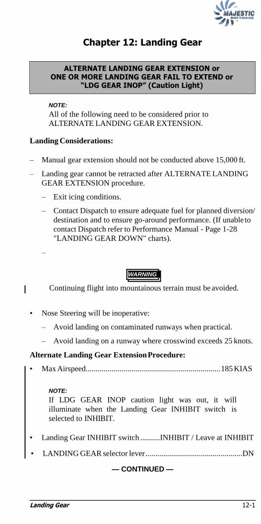
Landing Gear 12-1
NOTE:
NOTE:
Chapter 12: Landing Gear
NOTE:
All of the following need to be considered prior to
ALTERNATE LANDING GEAR EXTENSION.
Landing Considerations:
– Manual gear extension should not be conducted above 15,000 ft.
– Landing gear cannot be retracted after ALTERNATE LANDING
GEAR EXTENSION procedure.
– Exit icing conditions.
– Contact Dispatch to ensure adequate fuel for planned diversion/
destination and to ensure go-around performance. (If unable to
contact Dispatch refer to Performance Manual - Page 1-28
"LANDING GEAR DOWN" charts).
–
Continuing flight into mountainous terrain must be avoided.
• Nose Steering will be inoperative:
– Avoid landing on contaminated runways when practical.
– Avoid landing on a runway where crosswind exceeds 25 knots.
Alternate Landing Gear Extension Procedure:
• Max Airspeed.................................................................... 185 KIAS
NOTE:
If LDG GEAR INOP caution light was out, it will
illuminate when the Landing Gear INHIBIT switch is
selected to INHIBIT.
• Landing Gear INHIBIT switch ..........INHIBIT / Leave at INHIBIT
• LANDING GEAR selector lever .................................................DN
— CONTINUED —
WARNING
ALTERNATE LANDING GEAR EXTENSION or ONE OR MORE LANDING GEAR FAIL TO EXTEND or
―LDG GEAR INOP‖ (Caution Light)

Landing Gear 12-2
NOTE:
NOTE:
NOTE:
NOTE:
NOTE:
LANDING GEAR selector lever light will be amber
(indicating position disagreement), and any gear that is not
already down/locked/green will have its associated red
gear-unsafe advisory light illuminated .
• LANDING GEAR ALTERNATE RELEASE Door ..... Fully Open/
....................................................................................... Leave Open
• Main Gear Release handle ......................................Pull Fully Down
NOTE:
1. The main gear release handle pull force will be significantly
higher than experienced during alternate landing gear
extensions in the simulator.
2. The required pull force, to release the main gear
uplocks, will be as high as 90 pounds.
3. If main landing gear down-and-locked indication is not
achieved, PM should assume whatever position
necessary; and repeat pull action with whatever force
necessary to achieve a down-and-locked indication.
• LANDING GEAR ALTERNATE EXTENSION door . Fully Open/
........................................................................................Leave Open
NOTE:
IF LEFT and/or RIGHT green gear locked down Advisory
Lights do not illuminate, insert Hydraulic Pump handle in
socket and operate until LEFT and RIGHT green gear
locked down Advisory Lights illuminate.
• NOSE L/G RELEASE ................................................. Pull Fully up
NOTE:
1. The nose gear release handle pull force will be significantly
higher than experienced during alternate landing gear
extensions in the simulator.
2. The required pull force, to release the nose gear
uplock, will be as high as 90 pounds.
3. If nose landing gear down-and-locked indication is not
achieved, PM should assume whatever position
necessary; and repeat pull action with whatever force
necessary to achieve a down-and-locked indication.
• Landing Gear Downlock Verification switch (in floor)..............ON/
. ...........................................................................check 3 green/OFF
— CONTINUED —

Landing Gear 12-3
Is Landing Gear Downlock Verification and/or Landing Gear
Control Panel indicating 3 green?
• Anti-Skid...............................................................................Test
After Landing:
– If possible, clear the runway but do not attempt to taxi to the
gate.
As soon as possible after engine shutdown and prior to tow:
• Ground Locks ....................................................................Install
— END —
Nose Landing Gear unsafe, Main Landing Gear Down and Locked?
– Via ACARS, ARINC, Operations Frequency, or ATC,
communicate failure of procedure to Dispatcher and Fleet
Manager (or Duty Officer).
– Unless deemed necessary by the Pilot-in-Command due to low
fuel or other aircraft system malfunctions, do not land until all
available resources have been used.
Landing Considerations:
– Reduce landing weight through fuel burn.
– Attempt to achieve an aft C.G. by re-seating passengers.
– Select a runway with minimal crosswind.
– Land with flap 35°.
— CONTINUED —
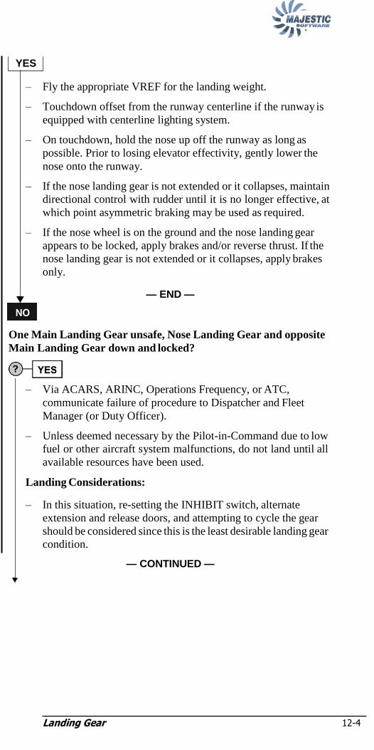
Landing Gear 12-4
YES
– Fly the appropriate VREF for the landing weight.
– Touchdown offset from the runway centerline if the runway is
equipped with centerline lighting system.
– On touchdown, hold the nose up off the runway as long as
possible. Prior to losing elevator effectivity, gently lower the
nose onto the runway.
– If the nose landing gear is not extended or it collapses, maintain
directional control with rudder until it is no longer effective, at
which point asymmetric braking may be used as required.
– If the nose wheel is on the ground and the nose landing gear
appears to be locked, apply brakes and/or reverse thrust. If the
nose landing gear is not extended or it collapses, apply brakes
only.
— END —
One Main Landing Gear unsafe, Nose Landing Gear and opposite
Main Landing Gear down and locked?
– Via ACARS, ARINC, Operations Frequency, or ATC,
communicate failure of procedure to Dispatcher and Fleet
Manager (or Duty Officer).
– Unless deemed necessary by the Pilot-in-Command due to low
fuel or other aircraft system malfunctions, do not land until all
available resources have been used.
Landing Considerations:
– In this situation, re-setting the INHIBIT switch, alternate
extension and release doors, and attempting to cycle the gear
should be considered since this is the least desirable landing gear
condition.
— CONTINUED —

Landing Gear 12-5
he flight crew must make a decision to perform a landing with
main landing gear unsafe or an all landing gear up landing
to the All Landing Gear Up Landing procedure on the page
follows).
educe landing weight through fuel burn.
assengers must be moved from the seats in the plane of the
and re-seated elsewhere in the cabin. Priority is to be
to the passengers seated on the side with the indicated
main landing gear.
rosswind (if any) would be advantageous from the side with
un-affected main landing gear.
and with flap 35°.
ly the appropriate VREF for landing weight.
iving due regard to the specific approach to be flown, flight
and possible missed approach; prior to commending
final approach, feather and secure the engine on the side with
affected main landing gear.
f the unsafe main landing gear collapses, in an effort to reduce
airplane turning moment in the direction of the failed main
gear, apply maximum braking and reverse thrust on the
with the un-affected main landing gear.
fter landing, feather and secure the operative engine and be
for the ON GROUND EMERGENCIES checklist.
— END —
All Landing Gear Up Landing
– Via ACARS, ARINC, Operations Frequency, or ATC,
communicate failure of procedure to Dispatcher and Fleet
Manager (or Duty Officer).
– Unless deemed necessary by the Pilot-in-Command due to low
fuel or other aircraft system malfunctions, do not land until all
available resources have been used.
Landing Considerations:
– In this situation, re-setting the INHIBIT switch, and alternate
extension and release doors, and attempting to cycle the gear
should be considered since this is one of the least desirable
landing gear condition.
— CONTINUED —
YES
– T
one
(refer
that
– R
– P
propellers
given
unsafe
– C
the
– L
– F
– G
conditions
the
the
– I
the
landing
side
– A
prepared

Landing Gear 12-6
NOTE:
– It is possible to safely land the Dash 8 Q400 airplane with all
landing gear retracted. The geometry of the Q400 airplane is
such that the propellers should not come in contact with the
ground with all landing gear retracted, if it is possible to
maintain the wings level throughout the landing.
– Reduce landing weight through fuel burn.
– Passengers must be moved from the seats in the plane of the
propellers and re-seated elsewhere in the cabin.
– Select a runway with minimal crosswind.
– Land with flap 35º.
– Fly the appropriate VREF for the landing weight.
– Touchdown offset from the runway centerline if the runway is
equipped with a centerline lighting system.
– Maintain a nose-up pitch attitude not exceeding 5º prior to
runway contact.
– On touchdown, maintain wings level using lateral control and
directional control with rudder.
– Feather and secure engines.
— END —
NOTE:
Following any landing gear extension or retraction
malfunction not covered by a specific procedure in this
chapter, the landing gear must be extended using the
ALTERNATE LANDING GEAR EXTENSION.
DO NOT ATTEMPT TO EXTEND or RETRACT the landing
gear normally.
• ALTERNATE LANDING GEAR EXTENSION (Page 12-1).........
Accomplish
— END —
WARNING
LANDING GEAR MALFUNCTIONS (Other Landing Gear or Gear Door Malfunctions)

Landing Gear 12-7
(Amber Main Gear Door Open Advisory Light remains
illuminated after Landing Gear selection)
Landing Gear Up selected?
• Max Airspeed.............................................................. 185 KIAS
• Flap .......................................................................................... 0°
Landing Gear Down selected:
• Max Airspeed.............................................................. 185 KIAS
– Complete flight with landing gear down.
Amber Main Gear Door Open Advisory Light remains
illuminated?
• Max Airspeed ..............................................................185 KIAS
– DO NOT extend landing gear via normal selection.
Landing Considerations:
• Extend landing gear via ALTERNATE LANDING
GEAR EXTENSION (Page 12-1).
NOTE:
Intermittent illumination of amber main gear door
open advisory light must be reported to maintenance.
— END —
• Continue flight at normal airspeed.
— END —
MAIN LANDING GEAR DOOR MALFUNCTIONS
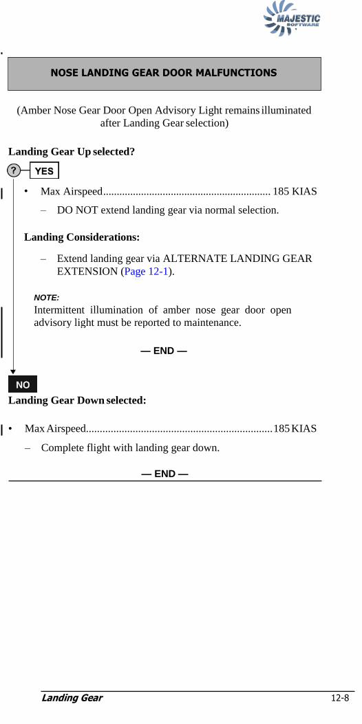
Landing Gear 12-8
NOTE:
(Amber Nose Gear Door Open Advisory Light remains illuminated
after Landing Gear selection)
Landing Gear Up selected?
Landing Gear Down selected:
• Max Airspeed.................................................................... 185 KIAS
– Complete flight with landing gear down.
— END —
• Max Airspeed.............................................................. 185 KIAS
– DO NOT extend landing gear via normal selection.
Landing Considerations:
– Extend landing gear via ALTERNATE LANDING GEAR
EXTENSION (Page 12-1).
NOTE:
Intermittent illumination of amber nose gear door open
advisory light must be reported to maintenance.
— END —
NOSE LANDING GEAR DOOR MALFUNCTIONS

Landing Gear 12-9
NOTE:
CAUTION:
If any Red Gear Unsafe Advisory Lights are illuminated with
Landing Gear Lever selected up, check landing gear alternate
release and extension door(s) CLOSED. If door(s) OPEN,
Landing gear will not retract when Landing Gear Selector
Lever selected to the UP position after lift off.
Are 3 Green Gear Locked Down Advisory Lights Illuminated with
Landing Gear Lever selected UP?
NOTE:
Landing Gear Doors may be open or closed.
IF Landing Gear Doors Open (Amber Doors Open Advisory
Lights illuminated):
• Max Airspeed ....................................................... 185 KIAS
IF Landing Gear Doors Closed (Amber Doors Open
Advisory Lights are out):
• Max Airspeed ....................................................... 215 KIAS
• Landing Gear selector...................................................... DN
– Confirm 3 Green Gear Locked Down Advisory Lights remain
illuminated.
– DO NOT select landing gear up.
Continuation Considerations:
• If conditions allow, consider return to departure airport.
• Do not operate above 15,000 ft with Landing Gear extended.
• Exit icing conditions.
• Continuing flight into mountainous terrain must be avoided.
— CONTINUED —
LANDING GEAR FAIL TO RETRACT

Landing Gear 12-10
NOTE:
• DO NOT select landing gear handle down.
• ALTERNATE LANDING GEAR EXTENSION (Page 12-1)....
Accomplish
— END —
• Contact Dispatch to coordinate fuel burn and go-around at planned diversion/destination. (If unable to contact Dispatch
refer to Performance Manual - Page 1-28 "LANDING GEAR
DOWN" charts).
NOTE:
The flight may continue to the destination, return to point
of departure, or the nearest airport where adequate services
are available based on the above considerations.
— END —

Landing Gear 12-11
NOTE:
Landing Considerations:
– Use Manual Technique for braking.
CAUTION:
Excessive brake application can result in skidding and
tire failure.
NOTE:
Manual Technique – For maximum deceleration, brakes
should be applied intermittently with momentary release at
1 second intervals.
— END —
• Anti-Skid......................................................................................ON
Caution Light remains on?
Abnormal Landing Distance Factors
Flap Ice Protection
Level 1 Level 2/3
10 1.70 1.68
15 1.70 1.68
35 1.70 1.71
Conditional Landing Distance Statement
Level 1 Ice Protection
Landing Distance = 5400 ft
Wt. less than 64,500 lbs.
Flap greater than or equal to 10°
Dry Runway
Airport Elevation less than 2000 ft
Tailwind 0 kts.
• No further action required.
— END —
―INBD ANTI-SKID‖ and/or ―OUTBD ANTI-SKID‖ (Caution Lights)

Landing Gear 12-12
NOTE:
NOTE:
Aircraft is on the ground at the gate?
– IF on the ground taxiing, maintenance action required prior to
flight.
– IF in flight, no Crew action required.
CAUTION:
Landing Gear may not retract.
NOTE:
Caution Light may extinguish after landing; however,
maintenance action will be required prior to next flight.
— END —
IF any of the Green Gear–Locked–Down Advisory Lights fail to
illuminate:
• LANDING GEAR ALTERNATE EXTENSION Door ...........Open
• Landing Gear Downlock Verification switch (in floor)..............ON/
. ...........................................................................check 3 green/OFF
• LANDING GEAR ALTERNATE EXTENSION Door .......... Close
— END —
LANDING GEAR INDICATOR MALFUNCTION
NOTE:
WT ON WHEELS caution light and other related caution
lights may be present if cargo is added to the AFT Baggage
Compartment prior to passenger boarding.
– Caution light will extiguish after nosewheel WOW sensor closes.
– Aircraft power down may be required to clear caution.
— END —
―WT ON WHEELS‖ (Caution Light)

Landing Gear 12-13
• Nose Steering handle ..............................................................Center
Caution Light remains illuminated?
• Steering switch .....................................................................OFF
Note:
4. Taxi using differential braking and
power.
5. Maneuver at a reduced taxi speed.
CAUTION:
Avoid tight turns. Tight turns may cause nosewheel to
caster to a greater than desired steering angle, making
it difficult to return to the center position.
– Maintenance action is required prior to flight.
— END —
– No further action required.
— END —
Due to the possibility of runway debris:
• Advise ATC and airport operation of fuselage/runway contact.
– Aircraft must not be flown prior to inspection and maintenance
approval.
— END —
―TOUCHED RUNWAY‖ (Warning Light)
―NOSE STEERING‖ (Caution Light)
Landing Gear 12-14
Intentionally Left Blank

Landing Gear 12-15

Landing Gear 12-16
Winter Operations (OPS) 13-i
Chapter 13: Winter Operations (OPS)
Takeoff 13-1
Engines Running Deice Checklist 13-2
Alternating Engines Deice Checklist 13-3
Engines Shutdown Deice Checklist 13-5
Holdover Tables 13-7
Snowfall Intensities 13-11
Braking Action and Estimated Correlations 13-12
Wind Components 13-13

Winter Operations (OPS) 13-i
Intentionally Left Blank

Winter Operations (OPS) 13-1
Is a Cold Weather Preflight check required? NO
YES
IS THERE CONTAMINATION ADHERING TO THE AIRCRAFT?
YES NO
Will frost be active, precipitation fall, or frozen contamination blow
on critical surfaces of aircraft
before takeoff?
NO YES
NO
DEICE OR DE / ANTI-ICE THE AIRCRAFT
De/Anti-icing crew will report the Post-Application check complete.
Receive De/Anti-ice crew and ATC clearances prior to taxi; complete all checklists.
Does the condition exist that will require a
Holdover / Allowance time to be established?
Establish Holdover / Allowance time,
as required for conditions.
Has Allowance time expired? Has Holdover time expired?
Is aircraft free of contamination (Pretakeoff Check?)
NO
YES
YES
NO NO
YES
YES YES
Chapter 13: Winter Operations (OPS)
Takeoff
Figure 13-1: Takeoff
T A K E O F
F
Will frost be active, precipitation fall and freeze to critical surfaces, or
frozen contamination blow on critical
surfaces of aircraft before takeoff?
Deice only? Deice / Anti-ice aircraft?
Configure aircraft for De / Anti-icing
NO

Winter Operations (OPS) 13-2
NOTE:
NOTE:
CAUTION:
All deicing will be accomplished with flaps 0.
At NO TIME will an aircraft be deiced with the APU running.
At NO TIME will an aircraft be deiced with any bleed air on.
NOTE:
Accomplish Reposition Checklist in lieu of After Start
Checklist if deicing cannot be accomplished at the gate. All
Deice/Anti-Ice operations must be conducted with flaps 0.
When ready for deice/anti-ice:
• EMERG BRAKE ....................................................................PARK
• Nose Steering ............................................................................. OFF
• Cabin Announcement ........................................................Complete
• AUTOFEATHER ...................................................................... OFF
• AUX/STBY/PTU Pumps ........................................................... OFF
• POWER Levers........................................................................ DISC
• Condition Levers............................................START & FEATHER
• BLEED selector .........................................................................MIN
• BLEED switches 1 and 2 ........................................................... OFF
• APU ........................................................................................... OFF
• Deicing........................................................................... Accomplish
• Start time of final application ....................................................Note
NOTE:
If Type I and IV fluid are applied on one side of the aircraft,
then the other, start-time of Type IV application on first
side is beginning of HOT.
When application is complete:
• Flight Controls .............................. Check for freedom of movement
• After Start Checklist ...................................................... Accomplish
— END —
Engines Running Deice Checklist

Winter Operations (OPS) 13-3
NOTE:
NOTE:
CAUTION:
All deicing will be accomplished with flaps 0.
At NO TIME will an aircraft be deiced with the APU running.
At NO TIME will an aircraft be deiced with any bleed air on.
NOTE:
Accomplish Reposition Checklist in lieu of After Start
Checklist if deicing cannot be accomplished at the gate. All
Deice/Anti-Ice operations must be conducted with flaps 0.
When ready for deice/anti-ice:
• EMERG BRAKE ....................................................................PARK
• Nose Steering ............................................................................. OFF
• Cabin Announcement ........................................................Complete
• AUTOFEATHER ...................................................................... OFF
• AUX/STBY/PTU Pumps ........................................................... OFF
• POWER Levers........................................................................ DISC
• Condition Levers.............................................START &FEATHER
• Transponder ............................................................................ STBY
• BLEED selector .........................................................................MIN
• BLEED switches 1 and 2 ........................................................... OFF
• MAIN BUS TIE.......................................................................... TIE
• APU ........................................................................................... OFF
• Start time of final application ....................................................Note
NOTE:
If Type I and IV fluid are applied on one side of the aircraft,
then the other, start-time of Type IV application on first
side is beginning of HOT.
Side to be deiced/anti-iced first (min. 30 seconds):
• Condition Levers............................................................. FUEL OFF
• Deicing........................................................................... Accomplish
— CONTINUED —
Alternating Engines Deice Checklist

Winter Operations (OPS) 13-4
NOTE:
NOTE:
NOTE:
When application on side with engine shutdown is complete:
• Engine ..…………………………………………………...CLEAR
• Engine Start Procedure .................................................. Accomplish
Side to be deiced/anti-iced second:
• Condition Levers..................……………..…………… FUEL OFF
• Deice .............................................................................. Accomplish
When application is complete:
• Engine ..…………………………………………………...CLEAR
• Engine Start Procedure .................................................. Accomplish
• Flight Controls .............................. Check for freedom of movement
• After Start Checklist ...................................................... Accomplish
— END —
NOTE:
Observe all engine start limitations.
NOTE:
Observe all engine start limitations.
NOTE:
Observe all engine start limitations.
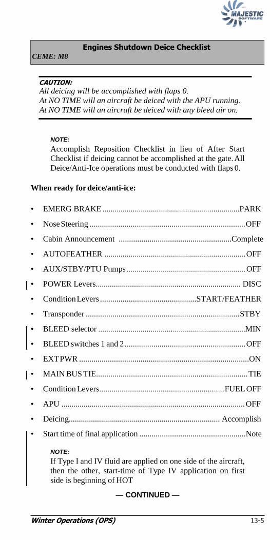
Winter Operations (OPS) 13-5
NOTE:
NOTE:
CAUTION:
All deicing will be accomplished with flaps 0.
At NO TIME will an aircraft be deiced with the APU running.
At NO TIME will an aircraft be deiced with any bleed air on.
NOTE:
Accomplish Reposition Checklist in lieu of After Start
Checklist if deicing cannot be accomplished at the gate. All
Deice/Anti-Ice operations must be conducted with flaps 0.
When ready for deice/anti-ice:
• EMERG BRAKE ....................................................................PARK
• Nose Steering ............................................................................ OFF
• Cabin Announcement .......................................................Complete
• AUTOFEATHER ...................................................................... OFF
• AUX/STBY/PTU Pumps ........................................................... OFF
• POWER Levers........................................................................ DISC
• Condition Levers ...............................................START/FEATHER
• Transponder ........................................................................... STBY
• BLEED selector .........................................................................MIN
• BLEED switches 1 and 2 ........................................................... OFF
• EXT PWR ...................................................................................ON
• MAIN BUS TIE.......................................................................... TIE
• Condition Levers............................................................. FUEL OFF
• APU ........................................................................................... OFF
• Deicing........................................................................... Accomplish
• Start time of final application ....................................................Note
NOTE:
If Type I and IV fluid are applied on one side of the aircraft,
then the other, start-time of Type IV application on first
side is beginning of HOT
— CONTINUED —
Engines Shutdown Deice Checklist CEME: M8

Winter Operations (OPS) 13-6
NOTE:
When application is complete:
• Engine ...…………………………………………………...CLEAR
• Engine Start Procedure .................................................. Accomplish
• Flight Controls .............................. Check for freedom of movement
• After Start Checklist ...................................................... Accomplish
— END —
NOTE:
Observe all engine start limitations.
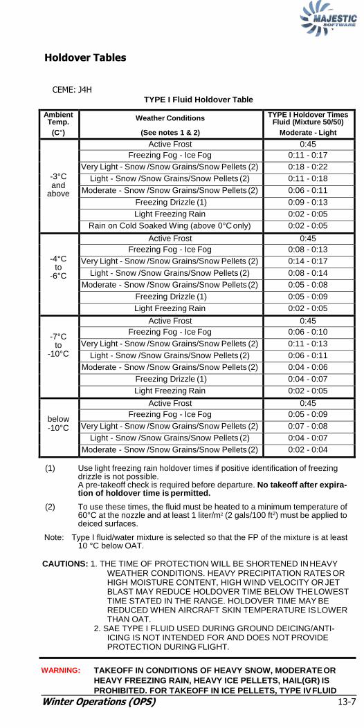
Winter Operations (OPS) 13-7
Holdover Tables
CEME: J4H
TYPE I Fluid Holdover Table
Ambient Temp.
(C°)
Weather Conditions
(See notes 1 & 2)
TYPE I Holdover Times Fluid (Mixture 50/50)
Moderate - Light
-3°C and
above
Active Frost 0:45
Freezing Fog - Ice Fog 0:11 - 0:17
Very Light - Snow /Snow Grains/Snow Pellets (2) 0:18 - 0:22
Light - Snow /Snow Grains/Snow Pellets (2) 0:11 - 0:18
Moderate - Snow /Snow Grains/Snow Pellets (2) 0:06 - 0:11
Freezing Drizzle (1) 0:09 - 0:13
Light Freezing Rain 0:02 - 0:05
Rain on Cold Soaked Wing (above 0°C only) 0:02 - 0:05
-4°C
to -6°C
Active Frost 0:45
Freezing Fog - Ice Fog 0:08 - 0:13
Very Light - Snow /Snow Grains/Snow Pellets (2) 0:14 - 0:17
Light - Snow /Snow Grains/Snow Pellets (2) 0:08 - 0:14
Moderate - Snow /Snow Grains/Snow Pellets (2) 0:05 - 0:08
Freezing Drizzle (1) 0:05 - 0:09
Light Freezing Rain 0:02 - 0:05
-7°C to
-10°C
Active Frost 0:45
Freezing Fog - Ice Fog 0:06 - 0:10
Very Light - Snow /Snow Grains/Snow Pellets (2) 0:11 - 0:13
Light - Snow /Snow Grains/Snow Pellets (2) 0:06 - 0:11
Moderate - Snow /Snow Grains/Snow Pellets (2) 0:04 - 0:06
Freezing Drizzle (1) 0:04 - 0:07
Light Freezing Rain 0:02 - 0:05
below -10°C
Active Frost 0:45
Freezing Fog - Ice Fog 0:05 - 0:09
Very Light - Snow /Snow Grains/Snow Pellets (2) 0:07 - 0:08
Light - Snow /Snow Grains/Snow Pellets (2) 0:04 - 0:07
Moderate - Snow /Snow Grains/Snow Pellets (2) 0:02 - 0:04
(1) Use light freezing rain holdover times if positive identification of freezing drizzle is not possible. A pre-takeoff check is required before departure. No takeoff after expira- tion of holdover time is permitted.
(2) To use these times, the fluid must be heated to a minimum temperature of 60°C at the nozzle and at least 1 liter/m2 (2 gals/100 ft2) must be applied to deiced surfaces.
Note: Type I fluid/water mixture is selected so that the FP of the mixture is at least 10 °C below OAT.
CAUTIONS: 1. THE TIME OF PROTECTION WILL BE SHORTENED IN HEAVY
WEATHER CONDITIONS. HEAVY PRECIPITATION RATES OR HIGH MOISTURE CONTENT, HIGH WIND VELOCITY OR JET BLAST MAY REDUCE HOLDOVER TIME BELOW THE LOWEST TIME STATED IN THE RANGE. HOLDOVER TIME MAY BE REDUCED WHEN AIRCRAFT SKIN TEMPERATURE IS LOWER THAN OAT.
2. SAE TYPE I FLUID USED DURING GROUND DEICING/ANTI- ICING IS NOT INTENDED FOR AND DOES NOT PROVIDE PROTECTION DURING FLIGHT.
WARNING: TAKEOFF IN CONDITIONS OF HEAVY SNOW, MODERATE OR
HEAVY FREEZING RAIN, HEAVY ICE PELLETS, HAIL(GR) IS
PROHIBITED. FOR TAKEOFF IN ICE PELLETS, TYPE IV FLUID

Winter Operations (OPS) 13-8
MUST BE APPLIED. SEE TYPE IV HOLDOVER TABLE.

Winter Operations (OPS) 13-9
TYPE III Fluid Holdover Table
Ambient Temp.
(C°)
Weather Conditions
(See notes 1 & 2)
TYPE III Holdover Times Fluid (Mixture 100%)
Moderate - Light
-3°C and
above
Active Frost 2:00
Freezing Fog - Ice Fog 0:20 - 0:40
Very Light - Snow /Snow Grains/Snow Pellets (2) 0:35 - 0:40
Light - Snow /Snow Grains/Snow Pellets (2) 0:20 - 0:35
Moderate - Snow /Snow Grains/Snow Pellets (2) 0:10 - 0:20
Freezing Drizzle (1) 0:10 - 0:20
Light Freezing Rain 0:08 - 0:10
Rain on Cold Soaked Wing (above 0°C only) 0:06 - 0:20
-4°C to
-10°C
Active Frost 2:00
Freezing Fog - Ice Fog 0:20 - 0:40
Very Light - Snow /Snow Grains/Snow Pellets (2) 0:30 - 0:35
Light - Snow /Snow Grains/Snow Pellets (2) 0:15 - 0:30
Moderate - Snow /Snow Grains/Snow Pellets (2) 0:09 - 0:15
Freezing Drizzle (1) 0:10 - 0:20
Light Freezing Rain 0:08 - 0:10
below -10°C
to -29°C
Active Frost 2:00
Freezing Fog - Ice Fog 0:20 - 0:40
Very Light - Snow /Snow Grains/Snow Pellets (2) 0:30 - 0:35
Light - Snow /Snow Grains/Snow Pellets (2) 0:15 - 0:30
Moderate - Snow /Snow Grains/Snow Pellets (2) 0:08 - 0:15
(1) Use light freezing rain holdover times if positive identification of freezing drizzle is not possible. A pre-takeoff check is required before departure. No takeoff after expira- tion of holdover time is permitted.
(2) A/C rotation speed (VR) must be 100 kts or greater. If any form of allowable mixed precipitation exceeds the listed intensity, operations are N/A. If mixed with -R, operations are N/A below 0°C.
Note: Type III fluid may be used below -10°C provided the freezing point of the fluid is at least 7°C below OAT.
CAUTIONS: 1. THE TIME OF PROTECTION WILL BE SHORTENED IN HEAVY
WEATHER CONDITIONS. HEAVY PRECIPITATION RATES OR HIGH MOISTURE CONTENT, HIGH WIND VELOCITY OR JET BLAST MAY REDUCE HOLDOVER TIME BELOW THE LOWEST TIME STATED IN THE RANGE. HOLDOVER TIME MAY BE REDUCED WHEN AIRCRAFT SKIN TEMPERATURE IS LOWER THAN OAT.
2. SAE TYPE III FLUID USED DURING GROUND DEICING/ANTI- ICING IS NOT INTENDED FOR AND DOES NOT PROVIDE PROTECTION DURING FLIGHT.
WARNING: TAKEOFF IN CONDITIONS OF HEAVY SNOW, MODERATE OR
HEAVY FREEZING RAIN, HEAVY ICE PELLETS, HAIL(GR) IS
PROHIBITED. FOR TAKEOFF IN ICE PELLETS, TYPE IV FLUID
MUST BE APPLIED. SEE TYPE IV HOLDOVER TABLE.

Winter Operations (OPS) 13-10
TYPE IV Fluid Holdover Table
Ambient Temp.
(C°)
Weather Conditions TYPE IV Holdover Times
Fluid (Mixture 100/0)
Octagon MAX-Flight 04
Clariant Safewing MP IV 2001
Killfrost ABC-S PLUS
-3°C and
above
Light Ice Pellets
0:50 / 0:25 if mixed with SN / ZD / -ZR / -R (1)(2)
Moderate Ice Pellets 0:25 (1)(2)
Active Frost 12:00 12:00 12:00
Freezing Fog - Ice Fog 2:40 - 4:00 1:20 - 3:20 2:10 - 4:00
Snow(SN)-SG-GS(pellets) 1:25 - 2:00 1:00 - 1:55 1:15 - 2:00
Heavy Snow Not applicable.
Freezing Drizzle (1) 2:00 - 2:00 0:55 - 1:55 1:50 - 2:00
Light Freezing Rain 1:10 - 1:30 0:40 - 1:00 1:05 - 2:00
Rain on Cold Soaked Wing (above 0°C only)
0:20 - 2:00
0:15 - 2:00
0:25 - 2:00
-4°C to
-14°C
Light Ice Pellets
0:30 / N/A if mixed with SN / ZD / -ZR / -R (1)(2)
Moderate Ice Pellets 0:10 (1)(2)
Active Frost 6:00 (3) 6:00 (3) 6:00 (3)
Freezing Fog - Ice Fog 0:50 - 2:30 0:45 - 1:35 0:55 - 3:30
Snow(SN)-SG-GS(pellets) 0:35 - 1:10 0:30 - 0:50 1:00 - 1:45
Heavy Snow Not applicable.
-4°C to -10°C
Freezing Drizzle (1) 0:25 - 1:30 0:55 - 1:35 0:25 - 1:35
Light Freezing Rain 0:20 - 0:40 0:30 - 0:45 0:20 - 0:30
-15°C to
-26°C
Active Frost 4:00 (2) (3) 4:00 (2) (3) 4:00 (2) (3)
Freezing Fog - Ice Fog 0:20 - 0:45 (2) 0:20 - 0:45 (2) 0:40 - 1:00 (2)
Snow(SN)-SG-GS(pellets) 0:15 - 0:30 (2) 0:15 - 0:30 (2) 0:15 - 0:30 (2)
Heavy Snow Not applicable.
Below -26°C
No holdover times for Type IV exist. Consider use of Type I.
(1) Use light freezing rain holdover times if positive identification of freezing drizzle is not possible. A pre-takeoff check is required before departure. No takeoff after expira- tion of holdover time is permitted. The aircraft must return for a new application of fluids.
(2) A/C rotation speed (VR) must be 100 kts or greater. If any form of allowable mixed precipitation exceeds the listed intensity, operations are N/A. If mixed with -R, operations are N/A below 0°C.
(3) Radiational cooling during active frost conditions may reduce holdover times when operating close to the lower end of the outside air temperature range.
CAUTIONS: 1. THE TIME OF PROTECTION WILL BE SHORTENED IN HEAVY
WEATHER CONDITIONS. HEAVY PRECIPITATION RATES OR HIGH MOISTURE CONTENT, HIGH WIND VELOCITY OR JET BLAST MAY REDUCE HOLDOVER TIME BELOW THE LOWEST TIME STATED IN THE RANGE. HOLDOVER TIME MAY BE REDUCED WHEN AIRCRAFT SKIN TEMPERATURE IS LOWER THAN OAT.
2. SAE TYPE IV FLUID USED DURING GROUND DEICING/ANTI- ICING IS NOT INTENDED FOR AND DOES NOT PROVIDE PROTECTION DURING FLIGHT.
WARNING: TAKEOFF IN CONDITIONS OF HEAVY SNOW, MODERATE OR
HEAVY FREEZING RAIN, HEAVY ICE PELLETS OR HAIL(GR) IS
PROHIBITED.

Winter Operations (OPS) 13-11
Type IV Fluid Holdover Table
Ambient Temp.
(C°)
Weather Conditions TYPE IV Holdover Times
Fluid (Mixture 100/0)
All Other Brands
-3°C and
above
Light Ice Pellets 0:50 / 0:25 if mixed with SN / ZD / -ZR / -R (1)(2)
Moderate Ice Pellets 0:25 (1)(2)
Active Frost 12:00 Freezing Fog - Ice Fog 1:20 - 3:10 Snow(SN)-SG-GS(pel-
lets) 0:35 - 1:15
Heavy Snow Not applicable.
Freezing Drizzle (1) 0:45 - 1:30 Light Freezing Rain 0:25 - 0:40
Rain on Cold Soaked Wing
(above 0°C only)
0:10 - 1:15
-4°C to
-14°C
Light Ice Pellets 0:30 / N/A if mixed with SN / ZD / -ZR / -R (1)(2)
Moderate Ice Pellets 0:10 (1)(2)
Active Frost 6:00 (3) Freezing Fog - Ice Fog 0:20 - 1:20 Snow(SN)-SG-GS(pel-
lets) 0:25 - 0:50
Heavy Snow Not applicable.
-4°C to -10°C
Freezing Drizzle (1) 0:20 - 1:00 Light Freezing Rain 0:10 - 0:25
-15°C to
-26°C
Active Frost 4:00 (3) Freezing Fog - Ice Fog 0:15 - 0:40 Snow(SN)-SG-GS(pel-
lets) 0:15 - 0:30
Heavy Snow Not applicable.
Below -26°C
No holdover times for Type IV exist. Consider use of Type I.
(1) Use light freezing rain holdover times if positive identification of freezing drizzle is not possible. A pre-takeoff check is required before departure. No takeoff after expira- tion of holdover time is permitted. The aircraft must return for a new application of fluids.
(2) A/C rotation speed (VR) must be 100 kts or greater. If any form of allowable mixed precipitation exceeds the listed intensity, operations are N/A. If mixed with -R, operations are N/A below 0°C.
(3) Radiational cooling during active frost conditions may reduce holdover times when operating close to the lower end of the outside air temperature range.
CAUTIONS: 1. THE TIME OF PROTECTION WILL BE SHORTENED IN HEAVY
WEATHER CONDITIONS. HEAVY PRECIPITATION RATES OR HIGH MOISTURE CONTENT, HIGH WIND VELOCITY OR JET BLAST MAY REDUCE HOLDOVER TIME BELOW THE LOWEST TIME STATED IN THE RANGE. HOLDOVER TIME MAY BE REDUCED WHEN AIRCRAFT SKIN TEMPERATURE IS LOWER THAN OAT.
2. SAE TYPE IV FLUID USED DURING GROUND DEICING/ANTI- ICING IS NOT INTENDED FOR AND DOES NOT PROVIDE PROTECTION DURING FLIGHT.
WARNING: TAKEOFF IN CONDITIONS OF HEAVY SNOW, MODERATE OR
HEAVY FREEZING RAIN, HEAVY ICE PELLETS OR HAIL(GR) IS
PROHIBITED.
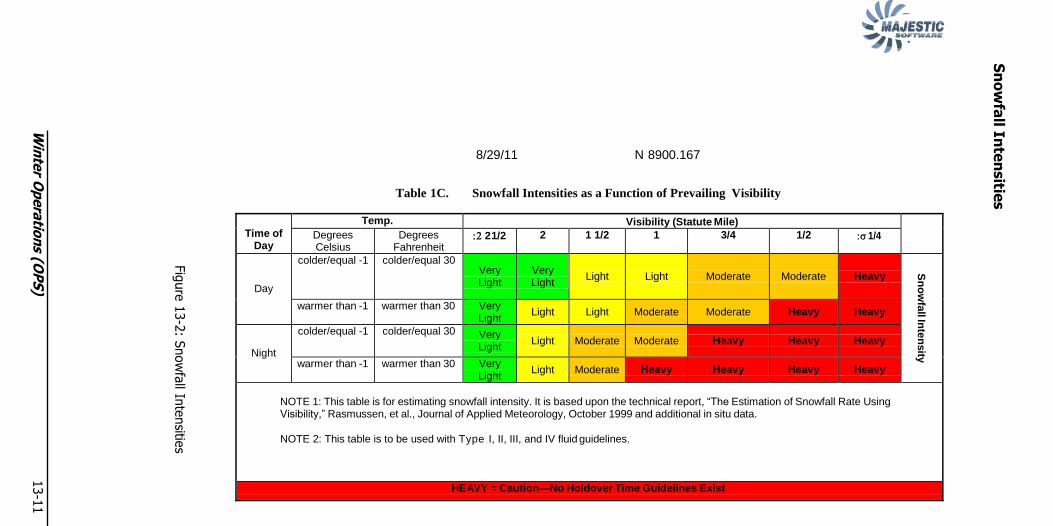
8/29/11 N 8900.167
Table 1C. Snowfall Intensities as a Function of Prevailing Visibility
Time of Day
Temp. Visibility (Statute Mile) Degrees Celsius
Degrees Fahrenheit
2 1/2 2 1 1/2 1 3/4 1/2 1/4
Day
colder/equal -1 colder/equal 30
Very Light
Very Light
Light
Light
Moderate
Moderate
Heavy
S
no
wfa
ll Inte
nsity
warmer than -1 warmer than 30 Very Light
Light Light Moderate Moderate Heavy Heavy
Night
colder/equal -1 colder/equal 30 Very Light
Light
Moderate
Moderate
Heavy
Heavy
Heavy
warmer than -1 warmer than 30 Very Light
Light Moderate Heavy Heavy Heavy Heavy
NOTE 1: This table is for estimating snowfall intensity. It is based upon the technical report, “The Estimation of Snowfall Rate Using Visibility,” Rasmussen, et al., Journal of Applied Meteorology, October 1999 and additional in situ data.
NOTE 2: This table is to be used with Type I, II, III, and IV fluid guidelines.
HEAVY = Caution—No Holdover Time Guidelines Exist
Sn
ow
fall In
ten
sitie
s
Fig
ure
13-2
: Snow
fall In
tensitie
s
Win
ter O
pera
tion
s (OP
S)
13-1
1
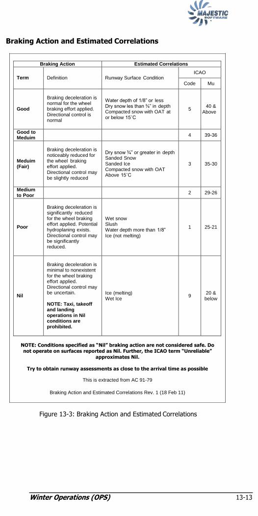
Winter Operations (OPS) 13-13
NOTE: Conditions specified as ―Nil‖ braking action are not considered safe. Do not operate on surfaces reported as Nil. Further, the ICAO term ―Unreliable‖
approximates Nil.
Try to obtain runway assessments as close to the arrival time as possible
This is extracted from AC 91-79
Braking Action and Estimated Correlations Rev. 1 (18 Feb 11)
Braking Action and Estimated Correlations
Braking Action Estimated Correlations
Term
Definition
Runway Surface Condition
ICAO
Code Mu
Good
Braking deceleration is normal for the wheel braking effort applied. Directional control is normal
Water depth of 1/8” or less Dry snow les than ¾” in depth Compacted snow with OAT at or below 15˚C
5
40 &
Above
Good to Meduim
4 39-36
Meduim (Fair)
Braking deceleration is noticeably reduced for the wheel braking effort applied.
Directional control may be slightly reduced
Dry snow ¾” or greater in depth Sanded Snow
Sanded Ice Compacted snow with OAT Above 15˚C
3
35-30
Medium to Poor
2 29-26
Poor
Braking deceleration is significantly reduced for the wheel braking effort applied. Potential hydroplaning exists. Directional control may be significantly reduced.
Wet snow Slush Water depth more than 1/8”
Ice (not melting)
1
25-21
Nil
Braking deceleration is minimal to nonexistent for the wheel braking effort applied. Directional control may be uncertain.
NOTE: Taxi, takeoff and landing operations in Nil conditions are prohibited.
Ice (melting) Wet Ice
9
20 &
below
Figure 13-3: Braking Action and Estimated Correlations

Winter Operations (OPS) 13-13
Wind Components
Figure 13-4: Conversion of Reported Wind to Head/Tailwind and Crosswind

Friction Coefficient vs. Max Crosswind Component
Friction Coefficient in MU/ ICAO surface condition
code
Max Crosswind Component
Braking Action
40 or above 5 32 KTS GOOD
39 – 36 4 25 KTS MEDIUM TO GOOD
35 – 30 3 20 KTS MEDIUM
29 – 26 2 15 KTS MEDIUM TO POOR
25 – 21 1 5 KTS POOR
20 or below 9 Not Applicable NIL
Warning: Taxi, Takeoff and Landing operations in Nil Conditions are Prohibited.
Fig
ure
13-5
: Frictio
n C
oefficie
nt v
s. Max C
rossw
ind C
om
ponent
Win
ter O
pe
ratio
ns (O
PS
) 13-1
4

Supplemental resets 14-i
Chapter 14: Supplemental Resets
Supplemental System Resets 14-1
General 14-1
Air Conditioning, Pressurization, and Pneumatics 14-2
FAULT Light (Illuminated on Pressurization Panel). 14-2
Erroneous CABIN Temperature Indication 14-2
Poor ECS Temperature Control 14-3
Hot Cabin During Boarding 14-4
Cold Soaked Aircraft 14-4
Auto, Flight Instruments, and Navigation 14-6
PA CHIME INOPERATIVE 14-6
―DU BAD CONFIG‖ (Message on ED) 14-6
Erroneous SAT Indications 14-7
―ALT‖ (Red Annunciation on ARCDU ATC Display Area).. 14-7
―FANS FAIL‖ (Message on ED) 14-8
Weather Radar Display Frozen 14-9
―WX FAIL‖ (Message on MFD) 14-10
Electrical 14-11
Tripped Circuit Breaker 14-11
―DC BUS‖ (Caution Light). 14-11
Flight Controls 14-12
―ROLL SPLR INBD GND‖ and ROLL SPLR OUTBD GND‖ (Caution Lights) 14-12
Erroneous Takeoff Warning Horn 14-13
―FLAP POWER‖ (Caution Light) 14-13
―#1 RUD HYD‖ or ―#2 RUD HYD‖ (Caution Lights) ....... 14-14
Ice and Rain Protection / Stall Protection 14-14
―PROP DEICE‖ (Caution Light) 14-14
―PUSHER SYST FAIL‖ (Caution Lights) 14-15

Supplemental resets 14-i
Intentionally Left Blank

Supplemental resets
14-1
Chapter 14: Supplemental Resets
Supplemental System Resets
A successful or unsuccessful reset must be entered in the aircraft Flight
Log.
After a successful or unsuccessful reset, the Pilot In Command will enter
the discrepancy under the Flight Log‘s ―Mechanical Discrepancy‖
column. Example:
Flap Power caution light illuminated. Signed by PIC (Name and
Employee number)
After a successful reset, the PIC will enter the corrective action under
the corrective action column. Example:
―Identified as a Nuisance Advisory Message per Chapter 14
―Supplemental System Resets‖. Clearing action accomplished, no
further discrepancy noted. Signed by Pilot In Command (Name and
Employee number).
After an unsuccessful reset, the PIC will contact SOC for further
assistance. If the discrepancy can not be deferred (MEL), the aircraft
will be returned to the gate for maintenance action.
General
Where corrective action to the affected system, has not been
implemented through a modification and/or Service Bulletin, the
following procedures provide the means to reset specific nuisance
caution lights, advisory messages or system faults. The following
general procedures MUST be adhered to in order to ensure the continued
safe operation of the aircraft:
• These procedures may only be used during ground operations unless
there is a note that specifically states that the procedure may be
performed in flight;
• Any procedure detailing the reset (pull out and push in) of circuit
breakers may only be used one time for each nuisance indication; and
• If these procedures are not sufficient to clear the nuisance indication,
then the MEL must be used if applicable, or the problem must be
rectified prior to aircraft dispatch.

Supplemental resets
14-2
Air Conditioning, Pressurization, and Pneumatics
CEME: N5 N24
– May be performed in flight.
Cabin Pressure Controller:
AUTO/MAN/DUMP switch......... Select MAN for 2 sec, then AUTO
IF annunciation remains:
– Cabin Pressurization must be managed in MANUAL MODE
OPERATION.
– Maintenance is required before the next flight.
— END —
(Flight Deck indication of cabin temperature reads up to 9ºC higher
than Flight Attendant‘s panel reading)
• No maintenance action required. Operation of the ECS system is
unaffected. — END —
Erroneous CABIN Temperature Indication AOM 3.4-2 REV.X MAY 31/11
FAULT Light (Illuminated on Pressurization Panel)

Supplemental Resets 14-3
(Recommended procedure to improve temperature control
throughout the aircraft)
RECIRC switch................................................................................ON
CABIN and FLT COMP pack switches .................................... AUTO
CABIN and FLT COMP Temperature selectors ................. 12 o‘clock
BLEED selector .......................................................... NORM or MAX
Flight Deck Gasper Vents (4 places) .................................. Fully Open
Flight Deck/Side Window Demist Flow Control Levers ... Fully Open
– Wait at least 5 minutes for compartment temperatures to stabilize.
IF a temperature adjustment is required:
Temp Control ........................................... Adjust by a small increment
– Wait at least 5 minutes for compartment temperatures to restabilize
before making a further adjustment.
— END —
.
Poor ECS Temperature Control AOM 3.4-3 REV.X MAY 31/11
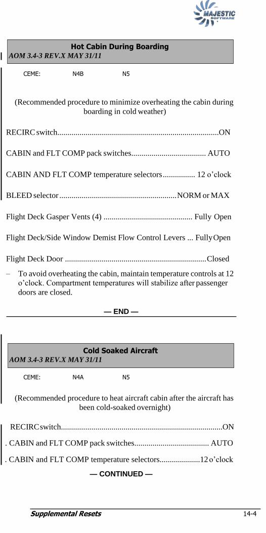
Supplemental Resets 14-4
CEME: N4B N5
(Recommended procedure to minimize overheating the cabin during
boarding in cold weather)
RECIRC switch................................................................................ON
CABIN and FLT COMP pack switches..................................... AUTO
CABIN AND FLT COMP temperature selectors ................ 12 o‘clock
BLEED selector .......................................................... NORM or MAX
Flight Deck Gasper Vents (4) ............................................ Fully Open
Flight Deck/Side Window Demist Flow Control Levers ... Fully Open
Flight Deck Door ...................................................................... Closed
– To avoid overheating the cabin, maintain temperature controls at 12
o‘clock. Compartment temperatures will stabilize after passenger
doors are closed.
— END —
CEME: N4A N5
(Recommended procedure to heat aircraft cabin after the aircraft has
been cold-soaked overnight)
RECIRC switch................................................................................ON
. CABIN and FLT COMP pack switches..................................... AUTO
. CABIN and FLT COMP temperature selectors....................12 o‘clock
— CONTINUED —
Cold Soaked Aircraft AOM 3.4-3 REV.X MAY 31/11
Hot Cabin During Boarding AOM 3.4-3 REV.X MAY 31/11

Supplemental Resets 14-5
APU Bleed....................................................................................... ON
Flight Deck Gasper Vents (4 places)................................... Fully Open
Flight Deck/Side Window Demist Flow Control Levers .... Fully Open
Flight Deck Door ....................................................................... Closed
– Maintain temperature control at 12 o‘clock until compartment
temperatures have stabilized.
– To avoid duct temperature overshoots and triggering a DUCT HOT
caution light, do not select packs to MAN.
— END —

Supplemental Resets 14-6
NOTE:
NOTE:
Auto, Flight Instruments, and Navigation
CEME: N32 N34
(Passenger Address Amplifier Chime is inoperative)
NOTE:
Related to possible low essential buss voltage during
initial power up.
– PA AMP CB (8B-Left Essential Avionics)Reset
PA Chime restored:
– No further action required
— END —
– Maintenance action is required prior to flight.
— END —
(Message appears after power-up of displays.)
PFD 1 and 2, MFD 1 and 2 and ED .......... OFF then ON one at a time
NOTE:
Wait 30 seconds for self-test to complete on each
individual display before selecting the next display On.
IF message remains on:
– Maintenance action is required prior to flight.
— END —
―DU BAD CONFIG‖ (Message on ED) AOM 3.4-5 REV.1 NOV 21/11
PA CHIME INOPERATIVE AOM 3.4-8 REV. 1 NOV 21/11

Supplemental Resets 14-7
NOTE:
(SAT differs from reported OAT by more than +/- 2°C)
• Monitor SAT indication during taxi with #1 engine operating and
propeller selected out of feather.
IF erroneous indications remain:
– Maintenance action is required prior to flight.
— END —
(Annunciation appeared on ARCDU main page ATC area
during climb or descent.)
NOTE:
A red ―FAIL‖ annunciation is also displayed in the ALT
and TCAS display areas on the TCAS/ATC expanded page.
IF annunciation remained on after aircraft levelled off:
– Maintenance action is required prior to flight.
— END —
―ALT‖ (Red Annunciation on ARCDU ATC Display Area) AOM 3.4-5 REV.1 NOV 21/11
Erroneous SAT Indications AOM 3.4-5 REV.1 NOV 21/11

Supplemental Resets 14-8
NOTE:
(Message appears after starting an engine in an aircraft with a cold
flight deck)
• Monitor message as flight deck warms.
IF message remains on after flight deck temperature rises:
– Maintenance action is required prior to flight.
NOTE:
FANS FAIL message will clear when flight deck
temperature sensors warm above 5°C.
— END —
―FANS FAIL‖ (Message on ED) AOM 3.4-5 REV.1 NOV 21/11

Supplemental Resets 14-9
NOTE:
(Weather radar data on MFD did not appear to update or respond to
control panel inputs.)
– Position aircraft so as to ensure that no ground personnel,
equipment, aircraft, vehicles or buildings are in the radar scan area
within 300 feet (100 meters).
Exposure to microwave radiation may cause serious bodily injury to
personnel or ignite combustible materials.
WX Radar ...................................................................................... OFF
Wait 10 sec then WX Radar........................................................ STBY
WX Radar ...................................................................................... TST
– Confirm yellow WX TEST and STAB OFF mode messages are
annunciated and weather radar test pattern is displayed on the MFD.
WX Radar ........................................................................................ON
– Confirm WX ON mode is annunciated.
NOTE:
A blue pattern may be displayed on the MFD if the
required 60 second warm up period has not elapsed before
the system will transmit.
Tilt .............................................................................................. Adjust
– Adjust tilt to obtain targets (weather or ground) for display on the
MFD. Confirm tilt angle display changes in response to inputs.
WX Radar ................................................................................... STBY
IF display data did not update or respond:
– Maintenance action is required prior to flight.
— END —
WARNING
Weather Radar Display Frozen AOM 3.4-6 REV.1 NOV 21/11

Supplemental Resets 14-10
NOTE:
(Message appeared during operation of WX radar)
– Position aircraft so as to ensure that no ground personnel,
equipment, aircraft, vehicles or buildings are in the radar scan area
within 300 feet (100 meters).
Exposure to microwave radiation may cause serious bodily injury to
personnel or ignite combustible materials.
WX Radar ...................................................................................... OFF
Wait 10 sec then WX Radar........................................................ STBY
WX Radar ...................................................................................... TST
– Confirm yellow WX TEST and STAB OFF mode messages are
annunciated and weather radar test pattern is displayed on the MFD.
WX Radar ........................................................................................ON
– Confirm WX ON mode is annunciated.
NOTE:
A blue pattern may be displayed on the MFD if the
required 60 second warm up period has not elapsed before
the system will transmit.
Tilt .............................................................................................. Adjust
– Adjust tilt to obtain targets (weather or ground) for display on the
MFD. Confirm tilt angle display changes in response to inputs.
WX Radar ................................................................................... STBY
IF display data did not update or respond:
– Maintenance action is required prior to flight.
— END —
WARNING
―WX FAIL‖ (Message on MFD) AOM 3.4-7 REV.1 NOV 21/11

Supplemental Resets 14-11
NOTE:
Electrical
CEME: N10 N8
(Circuit breaker(s) tripped after initial power-up of aircraft on ground)
NOTE:
This procedure MUST not be used if there is a recent
history (24 hours) of reported defects with the system or
related systems that are associated with the tripped circuit
breaker(s) or if there is other evidence of anomalies with
these systems.
• Pull out tripped circuit breaker to ensure it is fully disengaged.
• Push in circuit breaker until it reengages.
IF the circuit breaker trips again:
• Do not attempt any further resets.
– Maintenance action is required prior to flight.
— END —
(Associated with attempted APU start from batteries)
APU--PWR switchlight ................................................................. OFF
BUS FAULT RESET switch .................................................... RESET
IF DC Bus Caution Light goes out:
– Further APU start attempts may only be performed using an external
DC power source.
— END —
―DC BUS‖ (Caution Light) AOM 3.4-8 REV.1 NOV 21/11
Tripped Circuit Breaker AOM 3.4-8 REV.1 NOV 21/11

Supplemental Resets 14-12
NOTE:
Flight Controls
CEME: N35
(Associated with reversal of the FLIGHT/TAXI switch from
FLIGHT to TAXI back to FLIGHT)
– Clear active runway and park aircraft.
FLIGHT/TAXI switch ................................................................. TAXI
FCS ECU 1 and 2 CBs (M3-Left Essential and L6-Right Essential) ....
reset simultaneously
NOTE:
Wait 90 seconds until self-test sequence is complete before
moving flight controls.
Flight Controls ............................................................Check/full travel
IF Caution Lights remain on:
– Maintenance action is required prior to flight.
— END —
―ROLL SPLR INBD GND‖ and ROLL SPLR OUTBD GND‖
(Caution Lights)
AOM 3.4-9 REV.1 NOV 21/11
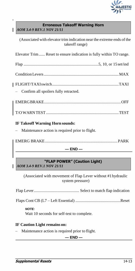
Supplemental Resets 14-13
NOTE:
(Associated with elevator trim indication near the extreme ends of the
takeoff range)
Elevator Trim ...... Reset to ensure indication is fully within TO range.
Flap .........................................................................5, 10, or 15 set/ind
Condition Levers ......................................................................... MAX
FLIGHT/TAXI switch ................................................................. TAXI
– Confirm all spoilers fully retracted.
EMERG BRAKE ........................................................................... OFF
T/O WARN TEST ....................................................................... TEST
IF Takeoff Warning Horn sounds:
– Maintenance action is required prior to flight.
EMERG BRAKE ........................................................................ PARK
— END —
(Associated with movement of Flap Lever without #1 hydraulic
system pressure)
Flap Lever ............................................ Select to match flap indication
Flaps Cont CB (L7 – Left Essential) ............................................Reset
IF Caution Light remains on:
– Maintenance action is required prior to flight.
— END —
NOTE:
Wait 10 seconds for self-test to complete.
―FLAP POWER‖ (Caution Light) AOM 3.4-9 REV.1 NOV 21/11
Erroneous Takeoff Warning Horn AOM 3.4-9 REV.1 NOV 21/11
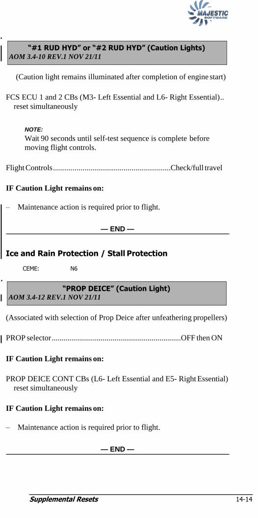
Supplemental Resets 14-14
NOTE:
(Caution light remains illuminated after completion of engine start)
FCS ECU 1 and 2 CBs (M3- Left Essential and L6- Right Essential) ..
reset simultaneously
NOTE:
Wait 90 seconds until self-test sequence is complete before
moving flight controls.
Flight Controls ............................................................Check/full travel
IF Caution Light remains on:
– Maintenance action is required prior to flight.
— END —
Ice and Rain Protection / Stall Protection
CEME: N6
(Associated with selection of Prop Deice after unfeathering propellers)
PROP selector ..................................................................OFF then ON
IF Caution Light remains on:
PROP DEICE CONT CBs (L6- Left Essential and E5- Right Essential)
reset simultaneously
IF Caution Light remains on:
– Maintenance action is required prior to flight.
— END —
―PROP DEICE‖ (Caution Light) AOM 3.4-12 REV.1 NOV 21/11
―#1 RUD HYD‖ or ―#2 RUD HYD‖ (Caution Lights) AOM 3.4-10 REV.1 NOV 21/11
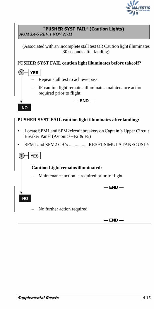
Supplemental Resets 14-15
(Associated with an incomplete stall test OR Caution light illuminates
30 seconds after landing)
PUSHER SYST FAIL caution light illuminates before takeoff?
– Repeat stall test to achieve pass.
– IF caution light remains illuminates maintenance action
required prior to flight.
— END —
PUSHER SYST FAIL caution light illuminates after landing:
• Locate SPM1 and SPM2circuit breakers on Captain‘s Upper Circuit
Breaker Panel (Avionics--F2 & F5)
• SPM1 and SPM2 CB‘s .................RESET SIMULATANEOUSLY
Caution Light remains illuminated:
– Maintenance action is required prior to flight.
— END —
– No further action required.
— END —
―PUSHER SYST FAIL‖ (Caution Lights) AOM 3.4-5 REV.1 NOV 21/11

Supplemental Resets 14-16
Intentionally Left Blank