Abhinav Training Report
46
SUMMER TRAINING REPORT 5 th July to 14 th August Submitted By:- Abhinav Singhal B.Tech. 3 rd year Roll no. 0709740003 GCET Gr. NOIDA
-
Upload
abhinav-singhal -
Category
Documents
-
view
223 -
download
0
Transcript of Abhinav Training Report

8/8/2019 Abhinav Training Report
http://slidepdf.com/reader/full/abhinav-training-report 1/46
SUMMER TRAINING REPORT
5th July to 14th August
Submitted By:-
Abhinav SinghalB.Tech. 3rd year
Roll no. 0709740003GCET Gr. NOIDA

8/8/2019 Abhinav Training Report
http://slidepdf.com/reader/full/abhinav-training-report 2/46
This is to certify that Abhinav Singhal , student of 2007-2011 Batch of
Mechanical branch in 3rd Year of Galgotias College Of Engineering And Technology, Gr. NOIDA has successfully completed his industrial
training at Badarpur Thermal Power Station- NTPC, New Delhi for six
weeks from 5th July to 14th August 2010. He has completed the whole
training as per the training report submitted by him.
Training In-charge
Badarpur Thermal Power Station
NTPC, Badarpur New
Delhi.
8/8/2019 Abhinav Training Report
http://slidepdf.com/reader/full/abhinav-training-report 3/46
Table of Contents
1. Acknowledgement
2. About the Company
3. Thermal Power Plant
Introduction
Operation
Functioning
4. Electricity Generation Process
5. PAM
6. TMD

8/8/2019 Abhinav Training Report
http://slidepdf.com/reader/full/abhinav-training-report 4/46
Acknowledgement
With profound respect and gratitude, I take the opportunity to conveymy thanks to NTPC Badarpur Management . I express gratitude to the
Program Manager and other faculty members of Mechanical
Engineering Department for providing this opportunity to undergo
industrial training at National Thermal Power Corporation, Badarpur,
New Delhi.
I do extend my heartfelt thanks to Ms. Rachna Singh Bhal for providingme this opportunity to be a part of this esteemed organization.
I am extremely grateful to Mr. G.D.Sharma, Superintendent of Im-Plant
Training at BTPS-NTPC, Badarpur for his guidance during whole
training.
I am extremely grateful to all the technical staff of BTPS-NTPC for their co-operation and guidance that helped me a lot during the course of
training. I have learnt a lot working under them and I will always be
indebted of them for this value addition in me.
Finally, I am indebted to all whosoever have contributed in this report
work and friendly stay at Badarpur Thermal Power Station, Badarpur,
New Delhi.

8/8/2019 Abhinav Training Report
http://slidepdf.com/reader/full/abhinav-training-report 5/46
About The Company
CORPORATE VISION “A world class integrated power major, powering India's
growth with increasing global presence .”
CORE VALUES
BCOMIT
B- Business ethics
C- Customer focus
O- Organizational & professional pride
M- Mutual respect & trust
I- Innovation & speed
T- Total quality for excellence

8/8/2019 Abhinav Training Report
http://slidepdf.com/reader/full/abhinav-training-report 6/46
Mission
Develop and provide reliable power related products and services at competitive prices, integrating multiple energy
resources with innovative & Eco-friendly technologies and
contribution to the society.

8/8/2019 Abhinav Training Report
http://slidepdf.com/reader/full/abhinav-training-report 7/46
NTPC Limited is the largest thermal power generating company of
India, Public Sector Company. It was incorporated in the year 1975 to
accelerate power development in the country as a wholly owned
company of the Government of India. At present, Government of Indiaholds 85% of the total equity shares of the company and the balance
15% is held by FIIs, Domestic Banks, Public and others. Within a span
of 31 years, NTPC has emerged as a truly national power company, with
power generating facilities in all the major regions of the country.
NTPC's core business is engineering, construction and operation of
power generating plants and providing consultancy to power utilities in
India and abroad.
The total installed capacity of the company is 31134 MW (including
JVs) with 15 coal based and 7 gas based stations, located across the
country. In addition under JVs, 3 stations are coal based & another
station uses naphtha/LNG as fuel. By 2017, the power generation
portfolio is expected to have a diversified fuel mix with coal based
capacity of around 53000 MW, 10000 MW through gas, 9000 MW
through Hydro generation, about 2000 MW from nuclear sources and
around 1000 MW from Renewable Energy Sources (RES). NTPC has
adopted a multi-pronged growth strategy which includes capacity
addition through green field projects, expansion of existing stations,
joint ventures, subsidiaries and takeover of stations.
NTPC has been operating its plants at high efficiency levels. Although
the company has 18.79% of the total national capacity it contributes
28.60% of total power generation due to its focus on high efficiency.

8/8/2019 Abhinav Training Report
http://slidepdf.com/reader/full/abhinav-training-report 8/46
A Graphical Overview
8/8/2019 Abhinav Training Report
http://slidepdf.com/reader/full/abhinav-training-report 9/46
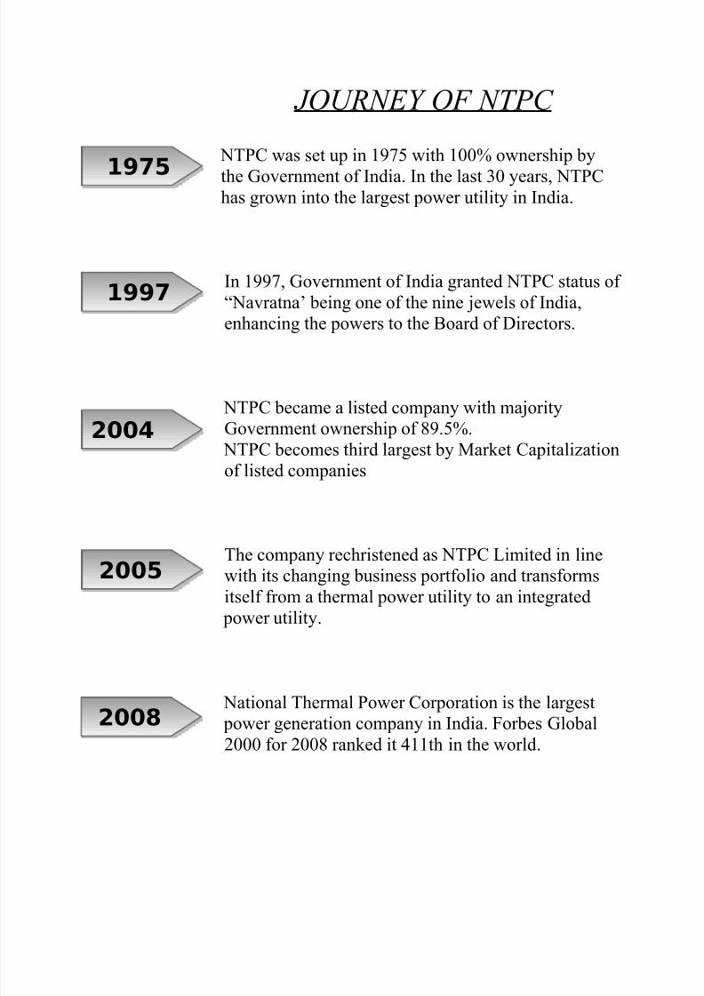
JOURNEY OF NTPC
NTPC was set up in 1975 with 100% ownership by
the Government of India. In the last 30 years, NTPChas grown into the largest power utility in India.
In 1997, Government of India granted NTPC status of
“Navratna’ being one of the nine jewels of India,
enhancing the powers to the Board of Directors.
NTPC became a listed company with majority
Government ownership of 89.5%.
NTPC becomes third largest by Market Capitalization
of listed companies
The company rechristened as NTPC Limited in line
with its changing business portfolio and transforms
itself from a thermal power utility to an integrated
power utility.
National Thermal Power Corporation is the largest power generation company in India. Forbes Global
2000 for 2008 ranked it 411th in the world.
1975
1997
2005
2004
2008

8/8/2019 Abhinav Training Report
http://slidepdf.com/reader/full/abhinav-training-report 10/46
National Thermal Power Corporation is the largest
power generation company in India. Forbes Global
2000 for 2008 ranked it 317th in the world.
NTPC has also set up a plan to achieve a target of
50,000 MW generation capacity.
NTPC has embarked on plans to become a 75,000MW company by 2017.
NTPC is the largest power utility in India, accounting for about 20% of
India’s installed capacity.
2009
2017
2012
8/8/2019 Abhinav Training Report
http://slidepdf.com/reader/full/abhinav-training-report 11/46
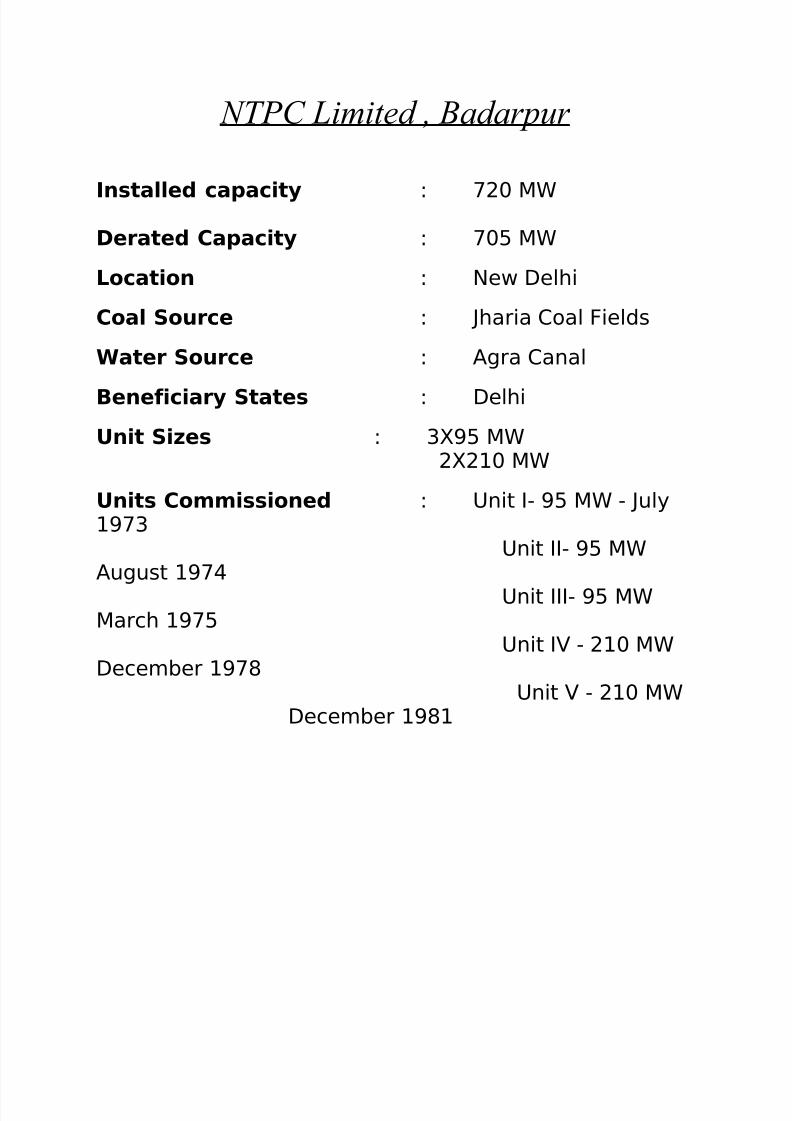
NTPC Limited , Badarpur
Installed capacity : 720 MW Derated Capacity : 705 MW
Location : New Delhi
Coal Source : Jharia Coal Fields
Water Source : Agra Canal
Beneficiary States : Delhi
Unit Sizes : 3X95 MW2X210 MW
Units Commissioned : Unit I- 95 MW - July1973
Unit II- 95 MWAugust 1974
Unit III- 95 MWMarch 1975
Unit IV - 210 MWDecember 1978
Unit V - 210 MWDecember 1981

8/8/2019 Abhinav Training Report
http://slidepdf.com/reader/full/abhinav-training-report 12/46
THEMAL POWER PLANT
• Introduction
• Classification
• Functioning
8/8/2019 Abhinav Training Report
http://slidepdf.com/reader/full/abhinav-training-report 13/46
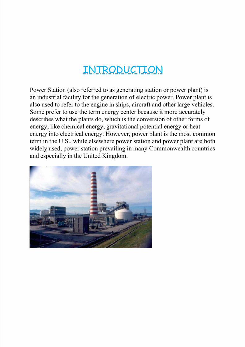
INTRODUCTION
Power Station (also referred to as generating station or power plant) is
an industrial facility for the generation of electric power. Power plant is
also used to refer to the engine in ships, aircraft and other large vehicles.
Some prefer to use the term energy center because it more accurately
describes what the plants do, which is the conversion of other forms of energy, like chemical energy, gravitational potential energy or heat
energy into electrical energy. However, power plant is the most common
term in the U.S., while elsewhere power station and power plant are both
widely used, power station prevailing in many Commonwealth countries
and especially in the United Kingdom.
8/8/2019 Abhinav Training Report
http://slidepdf.com/reader/full/abhinav-training-report 14/46
A coal-fired Thermal Power Plant
At the center of nearly all power stations is a generator, a rotating
machine that converts Mechanical energy into Electrical energy by
creating relative motion between a magnetic field and a conductor. The
energy source harnessed to turn the generator varies widely. It depends
chiefly on what fuels are easily available and the types of technology
that the power company has access to.
In thermal power stations, mechanical power is produced by a heat
engine, which transforms Thermal energy (often from combustion of a
fuel) into rotational energy. Most thermal power stations produce steam,
and these are sometimes called steam power stations. About 80% of all
electric power is generated by use of steam turbines. Not all thermal
energy can be transformed to mechanical power, according to the second
law of thermodynamics. Therefore, there is always heat lost to theenvironment. If this loss is employed as useful heat, for industrial
processes or district heating, the power plant is referred to as a
cogeneration power plant or CHP (combined heat-and-power) plant. In
countries where district heating is common, there are dedicated heat
plants called heat-only boiler stations. An important class of power
stations in the Middle East uses by-product heat for desalination of
water.
8/8/2019 Abhinav Training Report
http://slidepdf.com/reader/full/abhinav-training-report 15/46
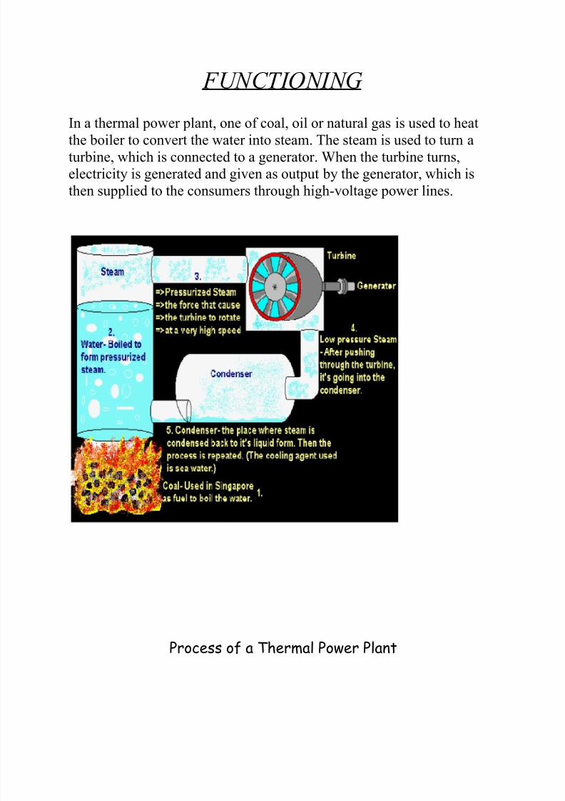
F UNCTIONING
In a thermal power plant, one of coal, oil or natural gas is used to heat
the boiler to convert the water into steam. The steam is used to turn aturbine, which is connected to a generator. When the turbine turns,
electricity is generated and given as output by the generator, which is
then supplied to the consumers through high-voltage power lines.
Process of a Thermal Power Plant

8/8/2019 Abhinav Training Report
http://slidepdf.com/reader/full/abhinav-training-report 16/46
Detailed process of power generation in a thermal power plant:
1) Water intake: Firstly, water is taken into the boiler through a water
source. If water is available in plenty in the region, then the source is anopen pond or river. If water is scarce, then it is recycled and the same
water is used over and over again.
2) Boiler heating: The boiler is heated with the help of oil, coal or
natural gas. A furnace is used to heat the fuel and supply the heat
produced to the boiler. The increase in temperature helps in the
transformation of water into steam.
3) Steam Turbine: The steam generated in the boiler is sent through a
steam turbine. The turbine has blades that rotate when high velocity
steam flows across them. This rotation of turbine blades is used to
generate electricity.
4) Generator: A generator is connected to the steam turbine. When the
turbine rotates, the generator produces electricity which is then passed
on to the power distribution systems.
5) Special mountings: There is some other equipment like the
economizer and air pre-heater.
An economizer uses the heat from the exhaust gases to heat the feed
water. An air pre-heater heats the air sent into the combustion chamber
to improve the efficiency of the combustion process.
6) Ash collection system: There is a separate residue and ash collection
system in place to collect all the waste materials from the combustion process and to prevent them from escaping into the atmosphere.
Apart from this, there are various other monitoring systems and
instruments in place to keep track of the functioning of all the devices.
This prevents any hazards from taking place in the plant.

8/8/2019 Abhinav Training Report
http://slidepdf.com/reader/full/abhinav-training-report 17/46
OPERATION
IntroductionThe operating performance of NTPC has been considerably above the national
average. The availability factor for coal stations has increased from 85.03 % in
1997-98 to 90.09 % in 2006-07, which compares favourably with international
standards. The PLF has increased from 75.2% in 1997-98 to 89.4% during the year
2006-07 which is the highest since the inception of NTPC.
Operation Room of Power Plant
In Badarpur Thermal Power Station, steam is produced and used to spin a turbine
that operates a generator. Water is heated, turns into steam and spins a steamturbine which drives an electrical generator. After it passes through the turbine, the
steam is condensed in a condenser; this is known as a Rankine cycle. The
electricity generated at the plant is sent to consumers through high-voltage power
lines.

8/8/2019 Abhinav Training Report
http://slidepdf.com/reader/full/abhinav-training-report 18/46
The Badarpur Thermal Power Plant has Steam Turbine-Driven Generators which
has a collective capacity of 705MW.
The fuel being used is Coal which is supplied from the Jharia Coal Field in
Jharkhand.
Water supply is given from the Agra Canal.
Table: Capacity of Badarpur Thermal Power Station, (BTPS) New Delhi
There are basically three main units of a thermal power plant:
1. Steam Generator or Boiler
2. Steam Turbine
3. Electric Generator
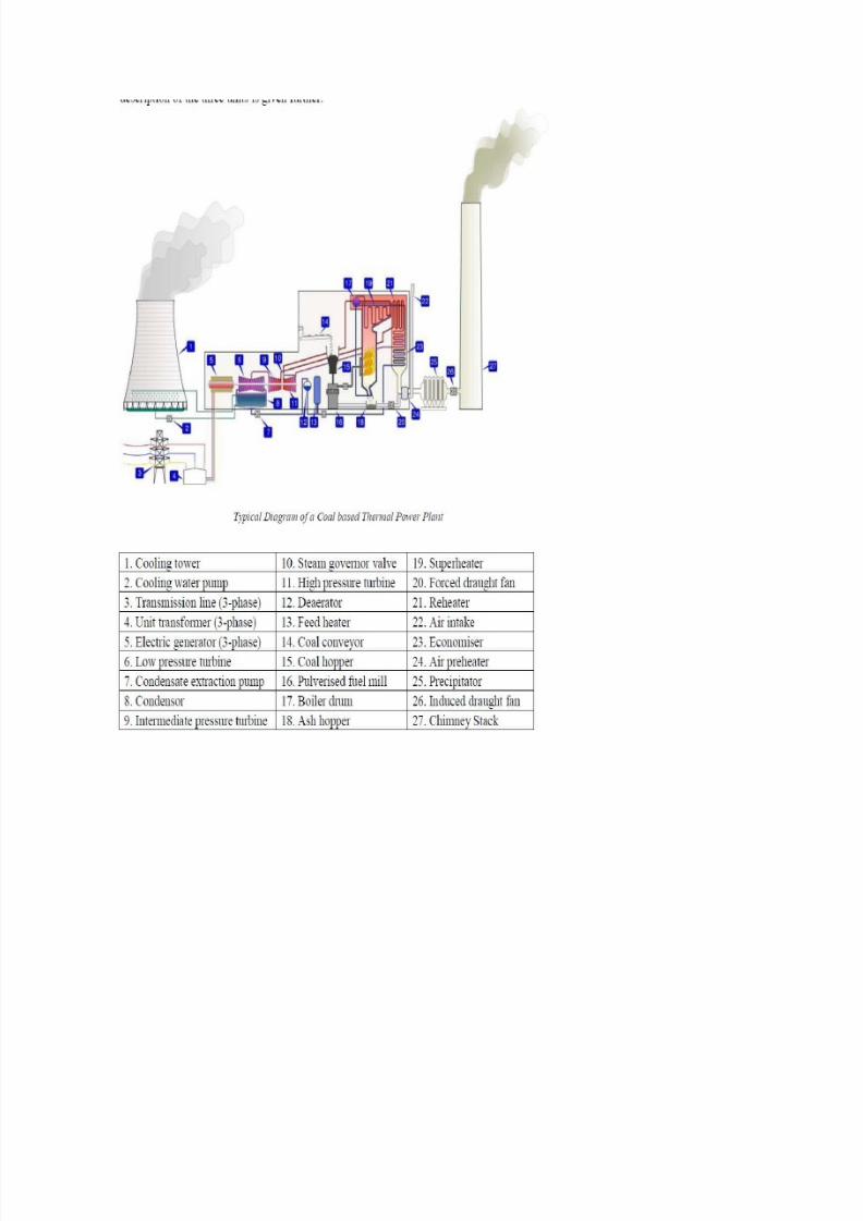
Coal is conveyed (14) from an external stack and ground to a very fine powder by
large metal spheres in the pulverised fuel mill (16). There it is mixed with
preheated air (24) driven by the forced draught fan (20). The hot air-fuel mixture is
forced at high pressure into the boiler where it rapidly ignites. Water of a high
purity flows vertically up the tube-lined walls of the boiler, where it turns into
steam, and is passed to the boiler drum, where steam is separated from any
remaining water. The steam passes through a manifold in the roof of the drum into
the pendant super heater (19) where its temperature and pressure increase rapidlyto around 200 bar and 540°C,
8/8/2019 Abhinav Training Report
http://slidepdf.com/reader/full/abhinav-training-report 19/46

8/8/2019 Abhinav Training Report
http://slidepdf.com/reader/full/abhinav-training-report 20/46
The steam is piped to the high pressure turbine (11), the first of a three-stage
turbine process. A steam governor valve (10) allows for both manual control of the
turbine and automatic set-point following. The steam is exhausted from the high
pressure turbine, and reduced in both pressure and temperature, is returned to the
boiler reheater (21). The reheated steam is then passed to the intermediate pressure
turbine (9), and from there passed directly to the low pressure turbine set (6). The
exiting steam, now a little above its boiling point, is brought into thermal contact
with cold water (pumped in from the Cooling tower) in the condenser (8), where it
condenses rapidly back into water, creating near vacuum-like conditions inside the
condensor chest. The condensed water is then passed by a feed pump (7) through a
deaerator (12), and pre-warmed, first in a feed heater (13) powered by steam drawn
from the high pressure set, and then in the economiser (23), before being returned
to the boiler drum. The cooling water from the condensor is sprayed inside a
cooling tower (1), creating a highly visible plume of water vapour, before being
pumped back to the condensor (8) in cooling water cycle. The three turbine sets aresometimes coupled on the same shaft as the three-phase electrical generator (5)
which generates an intermediate level voltage (typically 20-25 kV). This is stepped
up by the unit transformer (4) to a voltage more suitable for transmission (typically
220-250 kV) and is sent out onto the three-phase transmission system (3). Exhaust
gas from the boiler is drawn by the induced draft fan (26) through an electrostatic
precipitator (25) and is then vented through the chimney stack (27).
8/8/2019 Abhinav Training Report
http://slidepdf.com/reader/full/abhinav-training-report 21/46
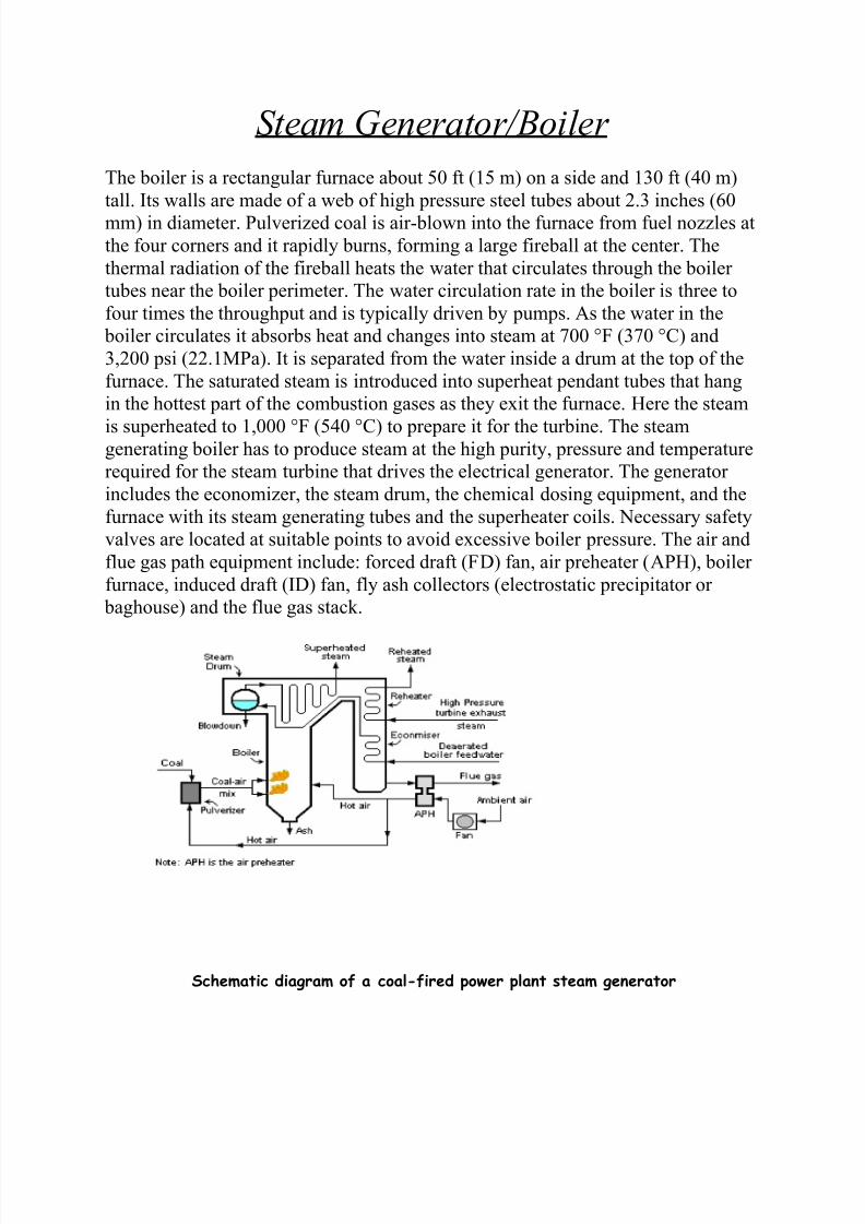
Steam Generator/ Boiler
The boiler is a rectangular furnace about 50 ft (15 m) on a side and 130 ft (40 m)
tall. Its walls are made of a web of high pressure steel tubes about 2.3 inches (60
mm) in diameter. Pulverized coal is air-blown into the furnace from fuel nozzles at
the four corners and it rapidly burns, forming a large fireball at the center. The
thermal radiation of the fireball heats the water that circulates through the boiler
tubes near the boiler perimeter. The water circulation rate in the boiler is three to
four times the throughput and is typically driven by pumps. As the water in the
boiler circulates it absorbs heat and changes into steam at 700 °F (370 °C) and
3,200 psi (22.1MPa). It is separated from the water inside a drum at the top of the
furnace. The saturated steam is introduced into superheat pendant tubes that hang
in the hottest part of the combustion gases as they exit the furnace. Here the steam
is superheated to 1,000 °F (540 °C) to prepare it for the turbine. The steamgenerating boiler has to produce steam at the high purity, pressure and temperature
required for the steam turbine that drives the electrical generator. The generator
includes the economizer, the steam drum, the chemical dosing equipment, and the
furnace with its steam generating tubes and the superheater coils. Necessary safety
valves are located at suitable points to avoid excessive boiler pressure. The air and
flue gas path equipment include: forced draft (FD) fan, air preheater (APH), boiler
furnace, induced draft (ID) fan, fly ash collectors (electrostatic precipitator or
baghouse) and the flue gas stack.
Schematic diagram of a coal-fired power plant steam generator

8/8/2019 Abhinav Training Report
http://slidepdf.com/reader/full/abhinav-training-report 22/46
Boiler Fur nace and Steam Drum
Once water inside the boiler or steam generator, the process of adding the latent
heat of vaporization or enthalpy is underway. The boiler transfers energy to the
water by the chemical reaction of burning some type of fuel.The water enters the boiler through a section in the convection pass called the
economizer. From the economizer it passes to the steam drum. Once the water
enters the steam drum it goes down the down comers to the lower inlet water wall
headers. From the inlet headers the water rises through the water walls and is
eventually turned into steam due to the heat being generated by
the burners located on the front and rear water walls (typically). As the water is
turned into steam/vapour in the water walls, the steam/vapour once again enters the
steam drum.
External view of a boiler
The steam/vapour is passed through a series of steam and water separators and then
dryers inside the steam drum. The steam separators and dryers remove the water
droplets from the steam and the cycle through the water walls is repeated. This
process is known as natural circulation. The boiler furnace auxiliary equipmentincludes coal feed nozzles and igniter guns, soot blowers, water lancing and
observation ports (in the furnace walls) for observation of the furnace interior.
Furnace explosions due to any accumulation of combustible gases after a tripout
are avoided by flushing out such gases from the combustion zone before igniting
the coal. The steam drum (as well as the superheater coils and headers) have air
vents and drains needed for initial start-up. The steam drum has an internal device
8/8/2019 Abhinav Training Report
http://slidepdf.com/reader/full/abhinav-training-report 23/46
that removes moisture from the wet steam entering the drum from the steam
generating tubes. The dry steam then flows into the superheater coils. Geothermal
plants need no boiler since they use naturally occurring steam sources. Heat
exchangers may be used where the geothermal steam is very corrosive or contains
excessive suspended solids. Nuclear plants also boil water to raise steam, either
directly passing the working steam through the reactor or else using an
intermediate heat exchanger.
Fuel Preparation System
In coal-fired power stations, the raw feed coal from the coal storage area is first
crushed into small pieces and then conveyed to the coal feed hoppers at the boilers.
The coal is next pulverized into a very fine powder. The pulverisers may be ballmills, rotating drum grinders, or other types of grinders. Some power stations burn
fuel oil rather than coal. The oil must kept warm (above its pour point) in the fuel
oil storage tanks to prevent the oil from congealing and becoming unpumpable.
The oil is usually heated to about 100°C before being pumped through the furnace
fuel oil spray nozzles. Boilers in some power stations use processed natural gas as
their main fuel. Other power stations may use processed natural gas as auxiliary
fuel in the event that their main fuel supply (coal or oil) is interrupted. In such
cases, separate gas burners are provided on the boiler furnaces.
Fuel Firing System and Igniter System
From the pulverized coal bin, coal is blown by hot air through the furnace coal
burners at an angle which imparts a swirling motion to the powdered coal to
enhance mixing of the coal powder with the incoming preheated combustion air
and thus to enhance the combustion. To provide sufficient combustion temperature
in the furnace before igniting the powdered coal, the furnace temperature is raised
by first burning some light fuel oil or processed natural gas (by using auxiliary
burners and igniters provide for that purpose).
8/8/2019 Abhinav Training Report
http://slidepdf.com/reader/full/abhinav-training-report 24/46
Air Path
External fans are provided to give sufficient air for combustion. The forced draft
fan takes air from the atmosphere and, first warming it in the air preheater for
better combustion, injects it via the air nozzles on the furnace wall. The induceddraft fan assists the FD fan by drawing out combustible gases from the furnace,
maintaining a slightly negative pressure in the furnace to avoid backfiring through
any opening. At the furnace outlet and before the furnace gases are handled by the
ID fan, fine dust carried by the outlet gases is removed to avoid atmospheric
pollution. This is an environmental limitation prescribed by law, and additionally
minimizes erosion of the ID fan.
Auxiliary SystemsFly Ash Collection
Fly ash is captured and removed from the flue gas by electrostatic precipitators or
fabric bag filters (or sometimes both) located at the outlet of the furnace and before
the induced draft fan. The fly ash is periodically removed from the collection
hoppers below the precipitators or bag filters. Generally, the fly ash is
pneumatically transported to storage silos for subsequent transport by trucks or
railroad cars.
Bottom Ash Collection and Disposal
At the bottom of every boiler, a hopper has been provided for collection of the
bottom ash from the bottom of the furnace. This hopper is always filled with water
to quench the ash and clinkers falling down from the furnace. Some arrangement is
included to crush the clinkers and for conveying the crushed clinkers and bottom
ash to a storage site.
Boiler Make-up Water Treatment Plant and Storage
Since there is continuous withdrawal of steam and continuous return of condensate
to the boiler, losses due to blow-down and leakages have to be made up for so as to
maintain the desired water level in the boiler steam drum. For this, continuous
make-up water is added to the boiler water system. The impurities in the raw water

8/8/2019 Abhinav Training Report
http://slidepdf.com/reader/full/abhinav-training-report 25/46
input to the plant generally consist of calcium and magnesium salts which impart
hardness to the water. Hardness in the make-up water to the boiler will form
deposits on the tube water surfaces which will lead to overheating and failure of
the tubes. Thus, the salts have to be removed from the water and that is done by a
Water Demineralising Treatment Plant (DM).
Ash Handling System at Badarpur Thermal Power Station, New Delhi
A DM plant generally consists of cation, anion and mixed bed exchangers. The
final water from this process consists essentially of hydrogen ions and hydroxide
ions which is the chemical composition of pure water. The DM water, being very
pure, becomes highly corrosive once it absorbs oxygen from the atmosphere
because of its very high affinity for oxygen absorption. The capacity of the DM plant is dictated by the type and quantity of salts in the raw water input. However,
some storage is essential as the DM plant may be down for maintenance. For this
purpose, a storage tank is installed from which DM water is continuously
withdrawn for boiler make-up. The storage tank for DM water is made from
materials not affected by corrosive water, such as PVC. The piping and valves are
generally of stainless steel. Sometimes, a steam blanketing arrangement or
8/8/2019 Abhinav Training Report
http://slidepdf.com/reader/full/abhinav-training-report 26/46
stainless steel doughnut float is provided on top of the water in the tank to avoid
contact with atmospheric air. DM water make-up is generally added at the steam
space of the surface condenser (i.e., the vacuum side). This arrangement not only
sprays the water but also DM water gets deaerated, with the dissolved gases being
removed by the ejector of the condenser itself.
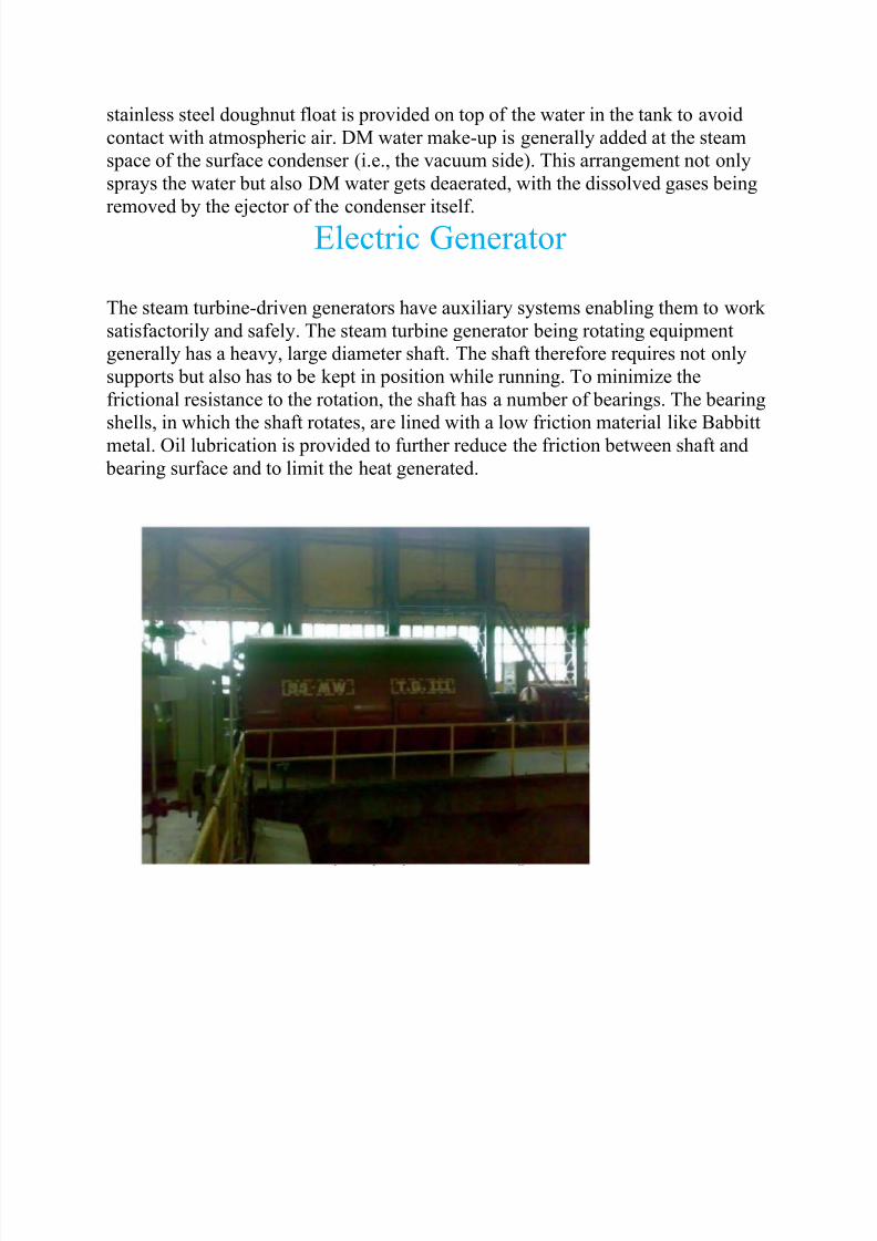
Electric Generator
The steam turbine-driven generators have auxiliary systems enabling them to work
satisfactorily and safely. The steam turbine generator being rotating equipment
generally has a heavy, large diameter shaft. The shaft therefore requires not only
supports but also has to be kept in position while running. To minimize the
frictional resistance to the rotation, the shaft has a number of bearings. The bearing
shells, in which the shaft rotates, are lined with a low friction material like Babbitt
metal. Oil lubrication is provided to further reduce the friction between shaft and
bearing surface and to limit the heat generated.
8/8/2019 Abhinav Training Report
http://slidepdf.com/reader/full/abhinav-training-report 27/46
A 95 MW Generator at BTPS, New Delhi
Barring Gear (or Turning Gear)
Barring gear is the term used for the mechanism provided for rotation of the
turbine generator shaft at a very low speed (about one revolution per minute) after
unit stoppages for any reason. Once the unit is "tripped" (i.e., the turbine steam
inlet valve is closed), the turbine starts slowing or "coasting down". When it stops
completely, there is a tendency for the turbine shaft to deflect or bend if allowed to
remain in one position too long. This deflection is because the heat inside the
turbine casing tends to concentrate in the top half of the casing, thus making thetop half portion of the shaft hotter than the bottom half. The shaft therefore warps
or bends by millionths of inches, only detectable by monitoring eccentricity
meters. But this small amount of shaft deflection would be enough to cause
vibrations and damage the entire steam turbine generator unit when it is restarted.
Therefore, the shaft is not permitted to come to a complete stop by a mechanism
known as "turning gear" or "barring gear" that automatically takes over to rotate
the unit at a preset low speed. If the unit is shut down for major maintenance, then
the barring gear must be kept in service until the temperatures of the casings and
bearings are sufficiently low.
Condenser
The surface condenser is a shell and tube heat exchanger in which cooling water is
circulated through the tubes. The exhaust steam from the low pressure turbine
enters the shell where it is cooled and converted to condensate (water) by flowing
over the tubes as shown in the adjacent diagram. Such condensers use steam
ejectors or rotary motor-driven exhausters for continuous removal of air and gases
from the steam side to maintain vacuum. A Typical Water Cooled Condenser For best efficiency, the temperature in the condenser must be kept as low as
practical in order to achieve the lowest possible pressure in the condensing steam.
Since the condenser temperature can almost always be kept significantly below
100ο
C where the vapour pressure of water is much less than atmospheric pressure,
the condenser generally works under vacuum. Thus leaks of noncondensible air

8/8/2019 Abhinav Training Report
http://slidepdf.com/reader/full/abhinav-training-report 28/46
into the closed loop must be prevented. Plants operating in hot climates may have
to reduce output if their source of condenser cooling water becomes warmer;
unfortunately this usually coincides with periods of high electrical demand for air
conditioning. The condenser generally uses either circulating cooling water from a
cooling tower to reject waste heat to the atmosphere, or once-through water from a
river, lake or ocean.
A typical water cooled condensor
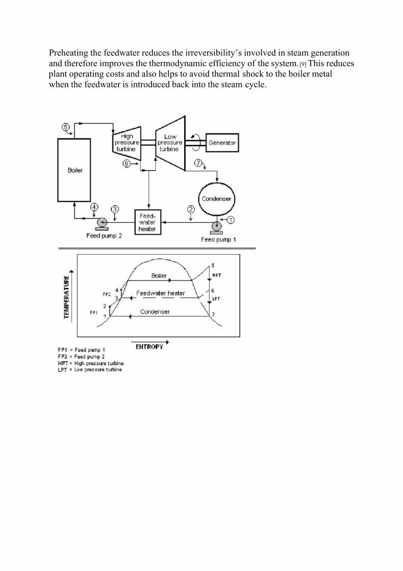
Feedwater Heater
A Rankine cycle with a two-stage steam turbine and a single feedwater heater. Inthe case of a conventional steam-electric power plant utilizing a drum boiler, the
surface condenser removes the latent heat of vaporization from the steam as it
changes states from vapour to liquid. The heat content (btu) in the steam is referred
to as Enthalpy. The condensate pump then pumps the condensate water through a
feedwater heater. The feedwater heating equipment then raises the temperature of
the water by utilizing extraction steam from various stages of the turbine.
8/8/2019 Abhinav Training Report
http://slidepdf.com/reader/full/abhinav-training-report 29/46
Preheating the feedwater reduces the irreversibility’s involved in steam generation
and therefore improves the thermodynamic efficiency of the system.[9] This reduces
plant operating costs and also helps to avoid thermal shock to the boiler metal
when the feedwater is introduced back into the steam cycle.
8/8/2019 Abhinav Training Report
http://slidepdf.com/reader/full/abhinav-training-report 30/46
A Rankine cycle with a 2-stage steam turbine and a single feedwater
heater
Superheater
As the steam is conditioned by the drying equipment inside the drum, it is pipedfrom the upper drum area into an elaborate set up of tubing in different areas of the
boiler. The areas known as superheater and reheater. The steam vapour picks up
energy and its temperature is now superheated above the saturation temperature.
The superheated steam is then piped through the main steam lines to the valves of
the high pressure turbine.
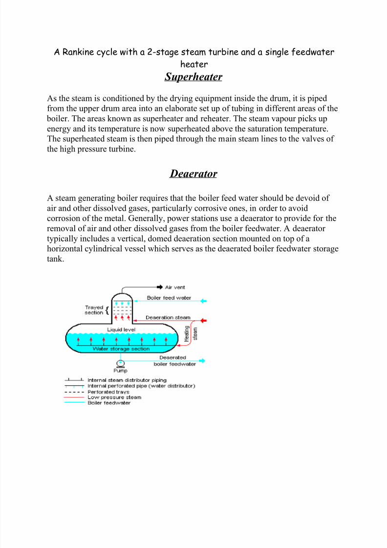
Deaerator
A steam generating boiler requires that the boiler feed water should be devoid of
air and other dissolved gases, particularly corrosive ones, in order to avoid
corrosion of the metal. Generally, power stations use a deaerator to provide for the
removal of air and other dissolved gases from the boiler feedwater. A deaerator
typically includes a vertical, domed deaeration section mounted on top of a
horizontal cylindrical vessel which serves as the deaerated boiler feedwater storage
tank.
8/8/2019 Abhinav Training Report
http://slidepdf.com/reader/full/abhinav-training-report 31/46
Boiler Feed Water DeaeratorThere are many different designs for a deaerator and the designs will vary from
one manufacturer to another. The adjacent diagram depicts a typical conventional
trayed deaerator. If operated properly, most deaerator manufacturers will guaranteethat oxygen in the deaerated water will not exceed 7 ppb by weight (0.005 cm3/L).
Auxiliary Systems
Oil System
An auxiliary oil system pump is used to supply oil at the start-up of the steam
turbine generator. It supplies the hydraulic oil system required for steam turbine's
main inlet steam stop valve, the governing control valves, the bearing and seal oilsystems, the relevant hydraulic relays and other mechanisms. At a preset speed of
the turbine during start-ups, a pump driven by the turbine main shaft takes over the
functions of the auxiliary system.
Generator Heat Dissipation
The electricity generator requires cooling to dissipate the heat that it generates.
While small units may be cooled by air drawn through filters at the inlet, larger
units generally require special cooling arrangements. Hydrogen gas cooling, in anoil-sealed casing, is used because it has the highest known heat transfer coefficient
of any gas and for its low viscosity which reduces windage losses. This system
requires special handling during start-up, with air in the chamber first displaced by
carbon dioxide before filling with hydrogen. This ensures that the highly
flammable hydrogen does not mix with oxygen in the air. The hydrogen pressure
inside the casing is maintained slightly higher than atmospheric pressure to avoid
outside air ingress. The hydrogen must be sealed against outward leakage where
the shaft emerges from the casing. Mechanical seals around the shaft are installed
with a very small annular gap to avoid rubbing between the shaft and the seals.
Seal oil is used to prevent the hydrogen gas leakage to atmosphere. The generator
also uses water cooling. Since the generator coils are at a potential of about
15.75kV and water is conductive, an insulating barrier such as Teflon is used to
interconnect the water line and the generator high voltage windings. Demineralised
water of low conductivity is used.

8/8/2019 Abhinav Training Report
http://slidepdf.com/reader/full/abhinav-training-report 32/46
Generator High Voltage System
The generator voltage ranges from 10.5 kV in smaller units to 15.75 kV in larger
units. The generator high voltage leads are normally large aluminum channels
because of their high current as compared to the cables used in smaller machines.They are enclosed in well-grounded aluminum bus ducts and are supported on
suitable insulators. The generator high voltage channels are connected to step-up
transformers for connecting to a high voltage electrical substation (of the order of
220 kV) for further transmission by the local power grid. The necessary protection
and metering devices are included for the high voltage leads. Thus, the steam
turbine generator and the transformer form one unit. In smaller units, generating at
10.5kV, a breaker is provided to connect it to a common 10.5 kV bus system.
ELECTRICITY GENERATION PROCESS
(A BASIC OVERVIEW)
HOW ELECTRICITY IS GENERATED?
Thermal power station burns fuel and uses the resultant heat to raise steam which
drives the TURBO GENERATOR. The fuel may be ‘fossil’(coal,oil,natural gas) or
it may be fissionable, whichever fuel is used, the objective is same to convert the
mechanical energy into electricity by rotating a magnet inside a set of winding.
COAL TO STAEM
Its other raw materials are air and water. The coal brought to the station by trains
or by other means, travels handling plant by conveyer belts, travels from
pulverizing mills, which grind it as fine as the face powder of size upto 20 microns.

8/8/2019 Abhinav Training Report
http://slidepdf.com/reader/full/abhinav-training-report 33/46
The finely produced coal mixed with preheated air is then blown into the boiler by
a fan called primary air fan where it burns more like a gas than as a solid, in the
conventional domestic or industrial grate, with additional amount of air, called
secondary air supply, by forced draft fan.
As coal is ground so finally the resultant ash is also a fine powder. Some of it binds
together to form pumps, which falls into ash pits at the bottom of the furnace. The
water-quenched ash from the bottom is conveyed to pits for subsequent disposal or
sale. Most of ash, still in fine partical form is carried out of boilers to the
precipitator as dust, where electrodes charged with high voltage electricity trap it.
The dust is then conveyed to water to disposal area or to bunker for sale while the
clean flue gases are passed on through IP fans to be discharged through chimneys.
The heat released from the coal has been absorbed by the many kilometers tubingwhich line the boiler walls. Inside the tubes the boiler feed water, which is
transformed by heat into staemat high temperature and pressure.. The steam
superheated in further tubes (superheaters) passes to turbine where it is discharged
through the nozzle on the turbine blades. Just as the energy of wind turns the sail of
the windmill, the energy of steam striking the blade makes the turbine rotate.
Coupled to the end of the turbine is the rotor of the generator. The rotor is housed
inside the stator having heavy coils of the bars in which electricity is produced
through the movement of magnetic field created by the rotor. Electricity passes
from stator windings to step-up transformer which increases its voltage so that itcan be transmited efficiently over lines of grid.
The staem which has given up its heat energy is cahnged back into water in a
condenser so that it is ready for re-use. The condenser contains many kilometers of
tubing through which cold water is constantly pumped. The staem passing around
the tubes looses heat.Thus it is rapidly changed back into water.
But, the two lots of water, that is, the boiler feed and cooling water must never
mix. Cooling water is drawn from river- bed, but the boiler feed water must beabsolutely pure, far purer than the water we drink (de-mineralized water),
otherwise it may damage the boiler tubes.

8/8/2019 Abhinav Training Report
http://slidepdf.com/reader/full/abhinav-training-report 34/46
My summer training of 4 weeks (5th July – 24th August ) has been
scheduled as follows:
CHP ( Coal Handling Plant ) --- 1week
PAM ( Plant Auxiliary Maintenance ) --- 2 week
TMD ( Turbine Maintenance Deptt. ) --- 1 weeks

8/8/2019 Abhinav Training Report
http://slidepdf.com/reader/full/abhinav-training-report 35/46
Coal Handling Plant
Coal is delivered by highway truck, rail, barge or collier ship. Some plants are even
built near coal mines and coal is delivered by conveyors. A large coal train called a
"unit train" may be a kilometres (over a mile) long, containing 60 cars with 100
tons of coal in each one, for a total load of 6,000 tons. A large plant under full load
requires at least one coal delivery this size every day. Plants may get as many as
three to five trains a day, especially in "peak season", during the summer months
when power consumption is high. A large thermal power plant such as the
Badarpur Thermal Power Station, New Delhi stores several million tons of coal for
use when there is no wagon supply.

8/8/2019 Abhinav Training Report
http://slidepdf.com/reader/full/abhinav-training-report 36/46
Coal Handling Plant Layout
Modern unloaders use rotary dump devices, which eliminate problems with coalfreezing in bottom dump cars. The unloader includes a train positioner arm that
pulls the entire train to position each car over a coal hopper. The dumper clamps an
individual car against a platform that swivels the car upside down to dump the
coal. Swivelling couplers enable the entire operation to occur while the cars are
still coupled together. Unloading a unit train takes about three hours.

8/8/2019 Abhinav Training Report
http://slidepdf.com/reader/full/abhinav-training-report 37/46
Shorter trains may use railcars with an "air-dump", which relies on air pressure
from the engine plus a "hot shoe" on each car. This "hot shoe" when it comes into
contact with a "hot rail" at the unloading trestle, shoots an electric charge through
the air dump apparatus and causes the doors on the bottom of the car to open,
dumping the coal through the opening in the trestle. Unloading one of these trains
takes anywhere from an hour to an hour and a half. Older unloaders may still use
manually operated bottom-dump rail cars and a "shaker" attached to dump the coal.
Generating stations adjacent to a mine may receive coal by conveyor belt or
massive diesel electric-drive trucks.
Coal is prepared for use by crushing the rough coal to pieces less than 2 inches (50mm) in size. The coal is then transported from the storage yard to in-plant storage
silos by rubberized conveyor belts at rates up to 4,000 tons/hour. In plants that
burn pulverized coal, silos feed coal pulverisers (coal mill) that take the larger 2
inch pieces grind them into the consistency of face powder, classify them, and
mixes them with primary combustion air which transports the coal to the furnace
and preheats the coal to drive off excess moisture content. In plants that do not
8/8/2019 Abhinav Training Report
http://slidepdf.com/reader/full/abhinav-training-report 38/46
burn pulverized coal, the larger 2 inch pieces may be directly fed into the silos
which then feed the cyclone burners, a specific kind of combust or that can
efficiently burn larger pieces of fuel.
Run-Of-Mine (ROM) Coal
The coal delivered from the mine that reports to the Coal Handling Plant is called
Run-of-mine, or ROM, coal. This is the raw material for the CHP, and consists of
coal, rocks, middling’s, minerals and contamination. Contamination is usually
introduced by the mining process and may include machine parts, used
consumables and parts of ground engaging tools. ROM coal can have a large
variability of moisture and maximum particle size.
Coal Handling
Coal needs to be stored at various stages of the preparation process, and conveyed
around the CHP facilities. Coal handling is part of the larger field of bulk material
handling, and is a complex and vital part of the CHP.
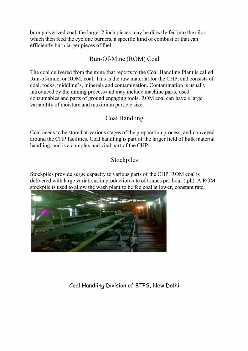
Stockpiles
Stockpiles provide surge capacity to various parts of the CHP. ROM coal is
delivered with large variations in production rate of tonnes per hour (tph). A ROM
stockpile is used to allow the wash plant to be fed coal at lower, constant rate.
Coal Handling Division of BTPS, New Delhi
8/8/2019 Abhinav Training Report
http://slidepdf.com/reader/full/abhinav-training-report 39/46
A simple stockpile is formed by machinery dumping coal into a pile, either from
dump trucks, pushed into heaps with bulldozers or from conveyor booms. More
controlled stockpiles are formed using stackers to form piles along the length of a
conveyor, and reclaimers to retrieve the coal when required for product loading,etc. Taller and wider stockpiles reduce the land area required to store a set tonnage
of coal. Larger coal stockpiles have a reduced rate of heat lost, leading to a higher
risk of spontaneous combustion.
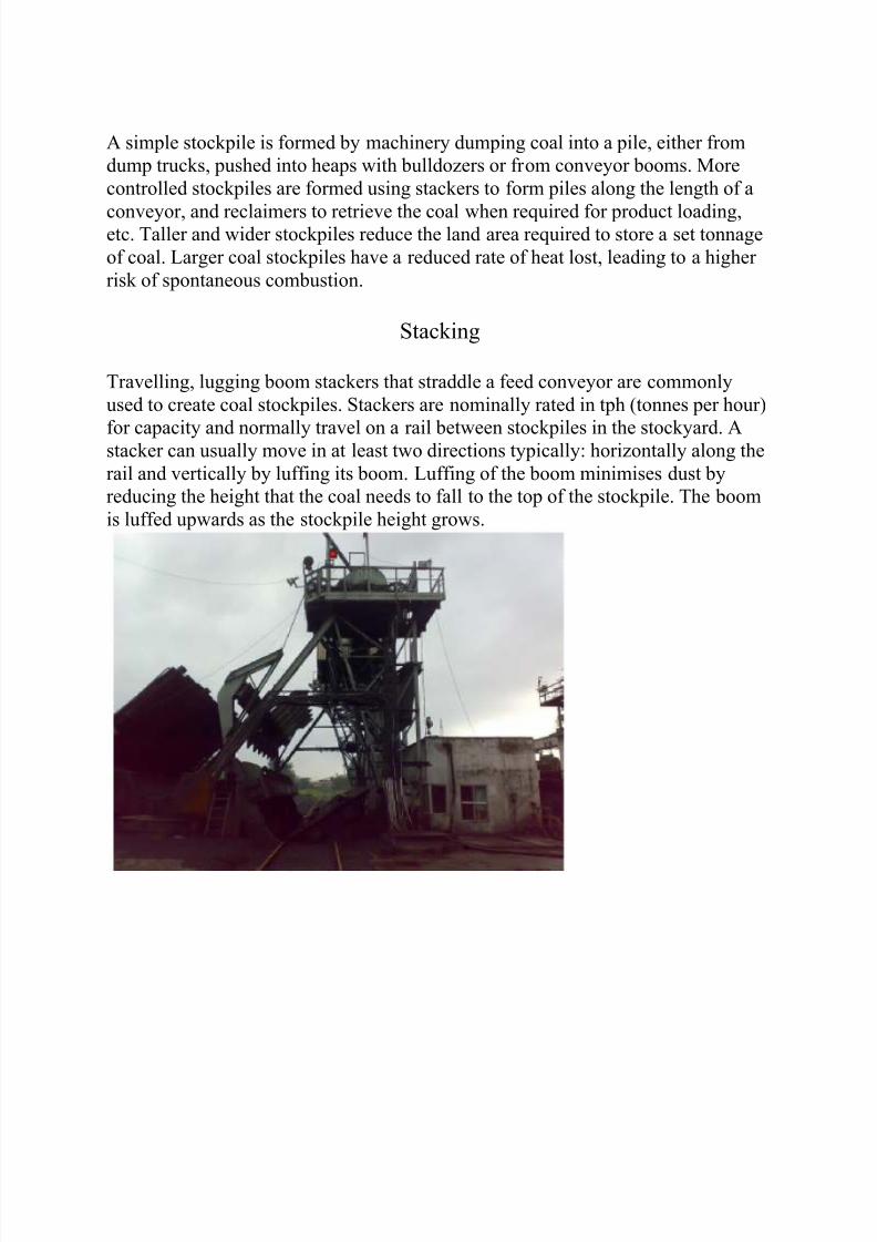
Stacking
Travelling, lugging boom stackers that straddle a feed conveyor are commonly
used to create coal stockpiles. Stackers are nominally rated in tph (tonnes per hour)
for capacity and normally travel on a rail between stockpiles in the stockyard. Astacker can usually move in at least two directions typically: horizontally along the
rail and vertically by luffing its boom. Luffing of the boom minimises dust by
reducing the height that the coal needs to fall to the top of the stockpile. The boom
is luffed upwards as the stockpile height grows.
8/8/2019 Abhinav Training Report
http://slidepdf.com/reader/full/abhinav-training-report 40/46
Wagon Tripler at Badarpur Thermal Power Station, New Delhi
Some stackers are able to rotate by slewing the boom. This allows a single stacker
to form two stockpiles, one on either side of the conveyor. Stackers are used to
stack into different patterns, such as cone stacking and chevron stacking. Stackingin a single cone tends to cause size segregation, with coarser material moving out
towards the base. Raw cone ply stacking is when additional cones are added next
to the first cone. Chevron stacking is when the stacker travels along the length of
the stockpile adding layer upon layer of material. Stackers and Reclaimers were
originally manually controlled manned machines with no remote control. Modern
machines are typically semi-automatic or fully automated, with parameters
remotely set.
Reclaiming
Tunnel conveyors can be fed by a continuous slot hopper or bunker beneath the
stockpile to reclaim material. Front-end loaders and bulldozers can be used to push
the coal into feeders. Sometimes front-end loaders are the only means of
reclaiming coal from the stockpile. This has a low up-front capital cost, but much
higher operating costs, measured in dollars per tonne handled.

8/8/2019 Abhinav Training Report
http://slidepdf.com/reader/full/abhinav-training-report 41/46
Coal Storage Area of the Badarpur Thermal Power Station, New Delhi
High-capacity stockpiles are commonly reclaimed using bucket-wheel reclaimers.These can achieve very high rates.
Coal Sampling
Sampling of coal is an important part of the process control in the CHP. A grab
sample is a one off sample of the coal at a point in the process stream, and tends
not to be very representative. A routine sample is taken at a set frequency, either
over a period of time or per shipment.
Screening

8/8/2019 Abhinav Training Report
http://slidepdf.com/reader/full/abhinav-training-report 42/46
Screens are used to group process particles into ranges by size. These size ranges
are also called grades. Dewatering screens are used to remove water from the
product. Screens can be static, or mechanically vibrated. Screen decks can be made
from different materials such as high tensile steel, stainless steel, or polyethylene.
Screening and Separation Unit of Coal Handling Division
Magnetic Separation
Magnetic separators shall be used in coal conveying systems to separate tramp iron
(including steel) from the coal. Basically, two types are available. One type
incorporates permanent or electromagnets into the head pulley of a belt conveyor.
The tramp iron clings to the belt as it goes around the pulley drum and falls off into
a collection hopper or trough after the point at which coal is charged from the belt.
The other type consists of permanent or electromagnets incorporated into a belt
8/8/2019 Abhinav Training Report
http://slidepdf.com/reader/full/abhinav-training-report 43/46
conveyor that is suspended above a belt conveyor carrying coal. The tramp iron is
pulled from the moving coal to the face of the separating conveyor, which in turn
holds and carries the tramp iron to a collection hopper or trough. Magnetic
separators shall be used just ahead of the coal crusher, if any, and/or just prior to
coal discharge to the in-plant bunker or silo fill system.
Coal Crusher
Before the coal is sent to the plant it has to be ensured that the coal is of uniform
size, and so it is passed through coal crushers. Also power plants using pulverized
coal specify a maximum coal size that can be fed into the pulverizer and so the
coal has to be crushed to the specified size using the coal crusher. Rotary crushers
are very commonly used for this purpose as they can provide a continuous flow of
coal to the pulverizer.
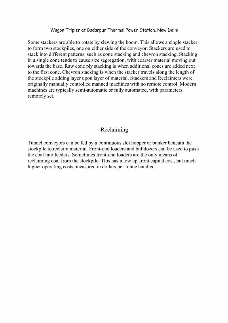
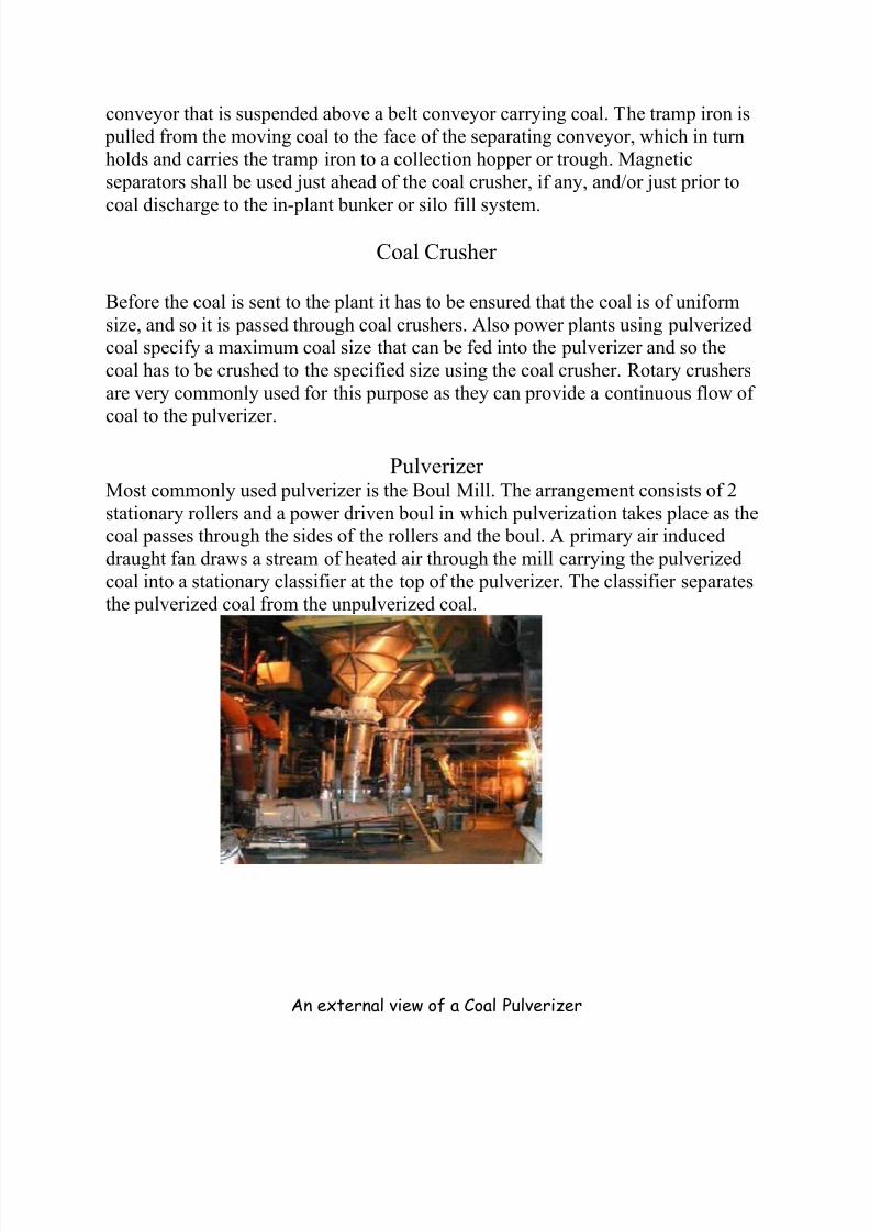
Pulverizer Most commonly used pulverizer is the Boul Mill. The arrangement consists of 2
stationary rollers and a power driven boul in which pulverization takes place as the
coal passes through the sides of the rollers and the boul. A primary air induced
draught fan draws a stream of heated air through the mill carrying the pulverized
coal into a stationary classifier at the top of the pulverizer. The classifier separates
the pulverized coal from the unpulverized coal.
An external view of a Coal Pulverizer

8/8/2019 Abhinav Training Report
http://slidepdf.com/reader/full/abhinav-training-report 44/46
Advantages of Pulverized Coal• Pulverized coal is used for large capacity plants.
• It is easier to adapt to fluctuating load as there are no limitations on the
combustion capacity.• Coal with higher ash percentage cannot be used without pulverizing because of
the problem of large amount ash deposition after combustion.
• Increased thermal efficiency is obtained through pulverization.
• The use of secondary air in the combustion chamber along with the powered coal
helps in creating turbulence and therefore uniform mixing of the coal and the air
during combustion.
• Greater surface area of coal per unit mass of coal allows faster combustion as
more coal is exposed to heat and combustion.
• The combustion process is almost free from clinker and slag formation.
• The boiler can be easily started from cold condition in case of emergency.• Practically no ash handling problem.
• The furnace volume required is less as the turbulence caused aids in complete
combustion of the coal with minimum travel of the particles.
The pulverized coal is passed from the pulverizer to the boiler by means of the
primary air that is used not only to dry the coal but also to heat is as it goes into the
boiler. The secondary air is used to provide the necessary air required for complete
combustion. The primary air may vary anywhere from 10% to the entire air
depending on the design of the boiler. The coal is sent into the boiler through
burners. A very important and widely used type of burner arrangement is theTangential Firing arrangement.
Tangential Burners
The tangential burners are arranged such that they discharge the fuel air mixture
tangentially to an imaginary circle in the center of the furnace. The swirling action
produces sufficient turbulence in the furnace to complete the combustion in a short
period of time and avoid the necessity of producing high turbulence at the burner
itself. High heat release rates are possible with this method of firing. The burners
are placed at the four corners of the furnace. At the Badarpur Thermal Power
Station five sets of such burners are placed one above the other to form six firing
zones. These burners are constructed with tips that can be angled through a small
vertical arc. By adjusting the angle of the burners the position of the fire ball can
be adjusted so as to raise or lower the position of the turbulent combustion region.
When the burners are tilted downward the furnace gets filled completely with the

8/8/2019 Abhinav Training Report
http://slidepdf.com/reader/full/abhinav-training-report 45/46
flame and the furnace exit gas temperature gets reduced. When the burners are
tiled upward the furnace exit gas temperature increases. A difference of
100 degrees can be achieved by tilting the burners.
Ash Handling
The ever increasing capacities of boiler units together with their ability to use low
grade high ash content coal have been responsible for the development of modern
day ash handling systems. The widely used ash handling systems are
1. Mechanical Handling System
2. Hydraulic System
3. Pneumatic System
4. Steam Jet System
The Hydraulic Ash handling system is used at the Badarpur Thermal Power
Station.
Ash Handling System of a Thermal Power Plant
Hydraulic Ash Handling System
The hydraulic system carried the ash with the flow of water with high velocity
through a channel and finally dumps into a sump. The hydraulic system is divided

8/8/2019 Abhinav Training Report
http://slidepdf.com/reader/full/abhinav-training-report 46/46
into a low velocity and high velocity system. In the low velocity system the ash
from the boilers falls into a stream of water flowing into the sump. The ash is
carried along with the water and they are separated at the sump. In the high
velocity system a jet of water is sprayed to quench the hot ash. Two other jets force
the ash into a trough in which they are washed away by the water into the sump,
where they are separated. The molten slag formed in the pulverized fuel system
can also be quenched and washed by using the high velocity system. The
advantages of this system are that its clean, large ash handling capacity,
considerable distance can be traversed, absence of working parts in contact with
ash.