Abhi monal
50
-
Upload
abhijeet-powar -
Category
Technology
-
view
247 -
download
2
Transcript of Abhi monal

By
A . S. Powar & M . S . Salunkhe
Guide
Dr. B. P. Ladgaonkar
Prof. S. K.Tilekar
VLSI Design and Research Center Post Graduate Department of Electronics
Shankarrao Mohite Mahavidyalaya, Akluj Tal - Malshiras , Dist. - Solapur – 413 101

1. Introduction
A) Origin of the Problem
B) Aim & Objectives
2. Designing of the System
Hardware Co-design
3. Result and Discussion
4. Conclusion
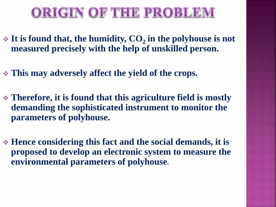
It is found that, the humidity, CO2 in the polyhouse is not measured precisely with the help of unskilled person.
This may adversely affect the yield of the crops.
Therefore, it is found that this agriculture field is mostly demanding the sophisticated instrument to monitor the parameters of polyhouse.
Hence considering this fact and the social demands, it is proposed to develop an electronic system to measure the environmental parameters of polyhouse.

To study the architectural details of PSoC1.
To study the PSoC designer IDE.
To configure the hardware using PSoC1.
Co development of necessary software.
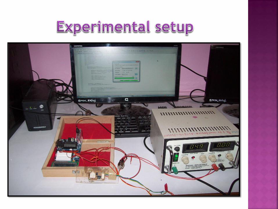
Implementation of the system.
Interpretation of result.
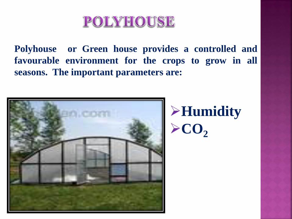
Polyhouse or Green house provides a controlled and
favourable environment for the crops to grow in all
seasons. The important parameters are:
Humidity
CO2
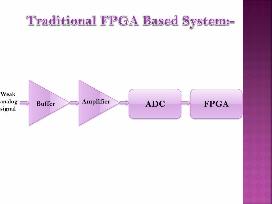
ADC FPGA Buffer Amplifier Weak
analog
signal
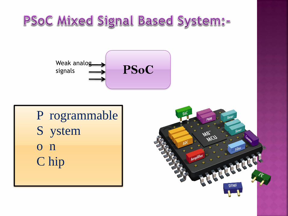
P rogrammable
S ystem
o n
C hip
PSoC Weak analog
signals

Block Diagram.
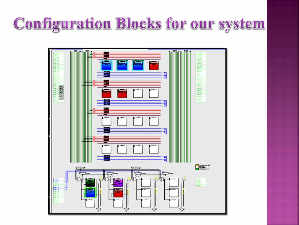
Configuration blocks for our
system.
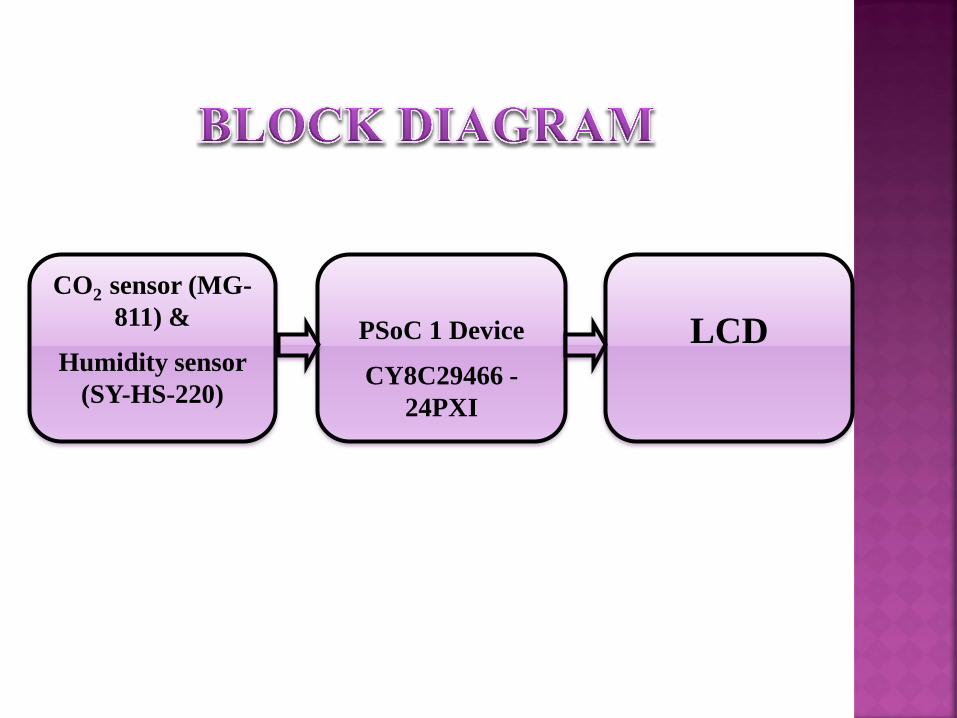
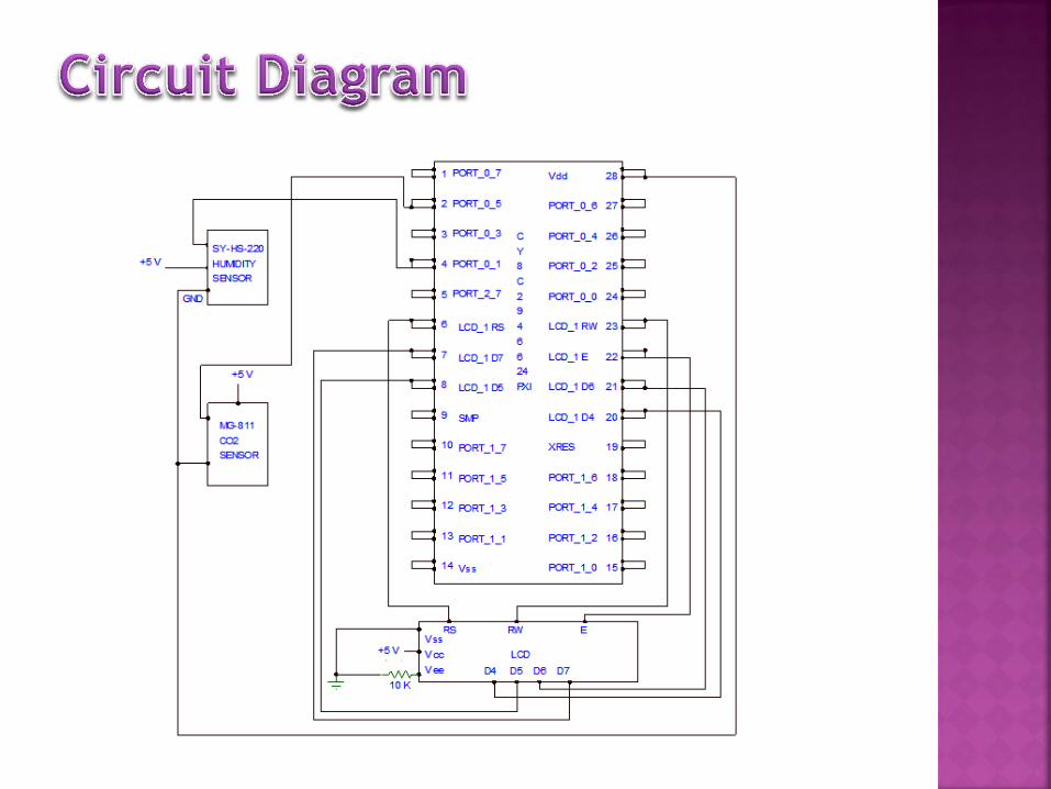
CO2 sensor (MG-
811) &
Humidity sensor
(SY-HS-220)
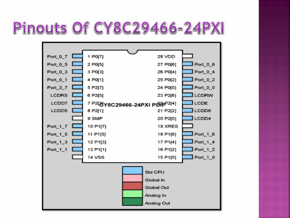
PSoC 1 Device
CY8C29466 -
24PXI
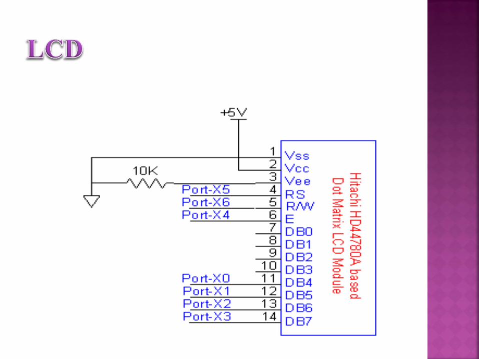
LCD
1) Humidity sensor(SY-HS-220).
2) CO2 sensor(MG-811).
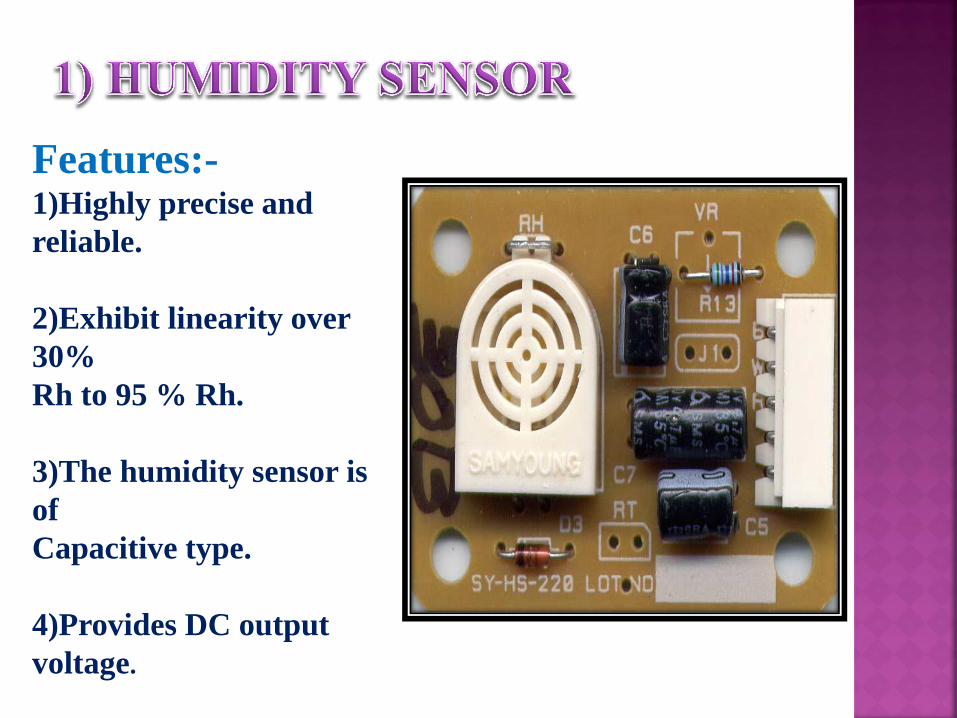
Features:- 1)Highly precise and
reliable.
2)Exhibit linearity over
30%
Rh to 95 % Rh.
3)The humidity sensor is
of
Capacitive type.
4)Provides DC output
voltage.

Features:-
1)Good sensitivity and
selectivity to CO2
2)Low humidity and
temperature
dependency.
3)Long stability and
reproducibility.
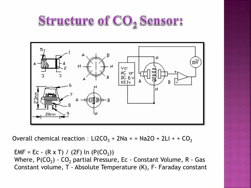
Overall chemical reaction:Li2CO3 + 2Na + = Na2O + 2Li + + CO2
EMF = Ec - (R x T) / (2F) ln (P(CO2))
Where, P(CO2) - CO2 partial Pressure, Ec - Constant Volume, R - Gas
Constant volume, T - Absolute Temperature (K), F- Faraday constant

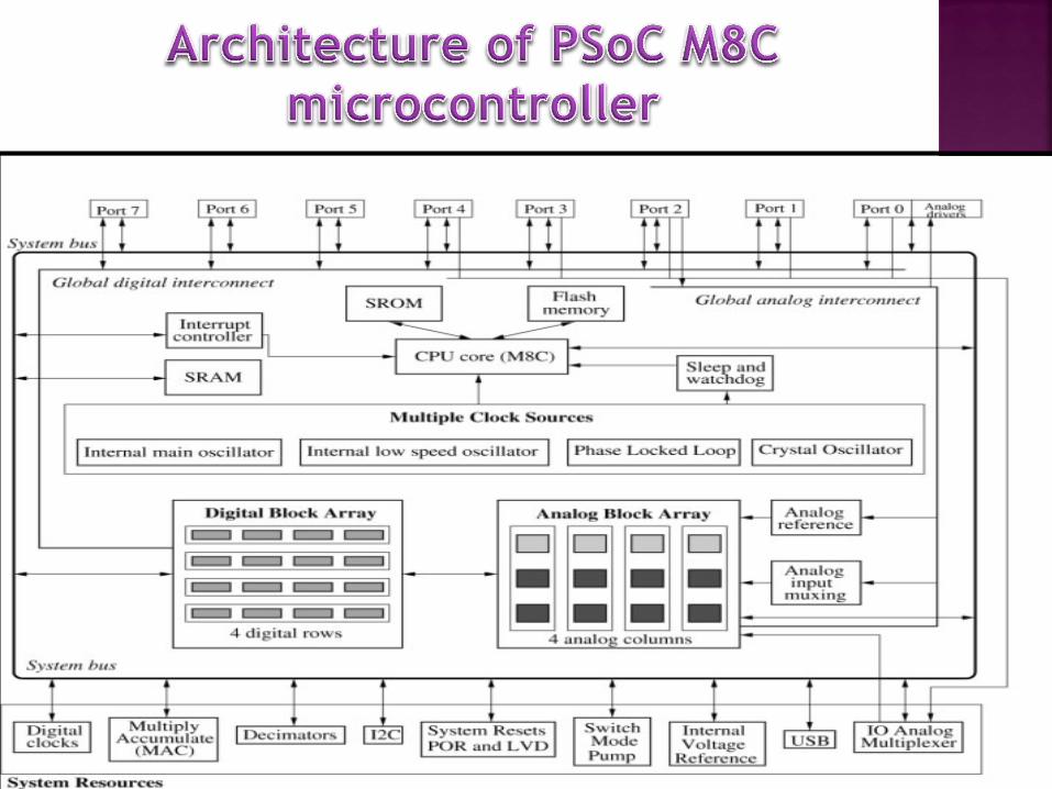
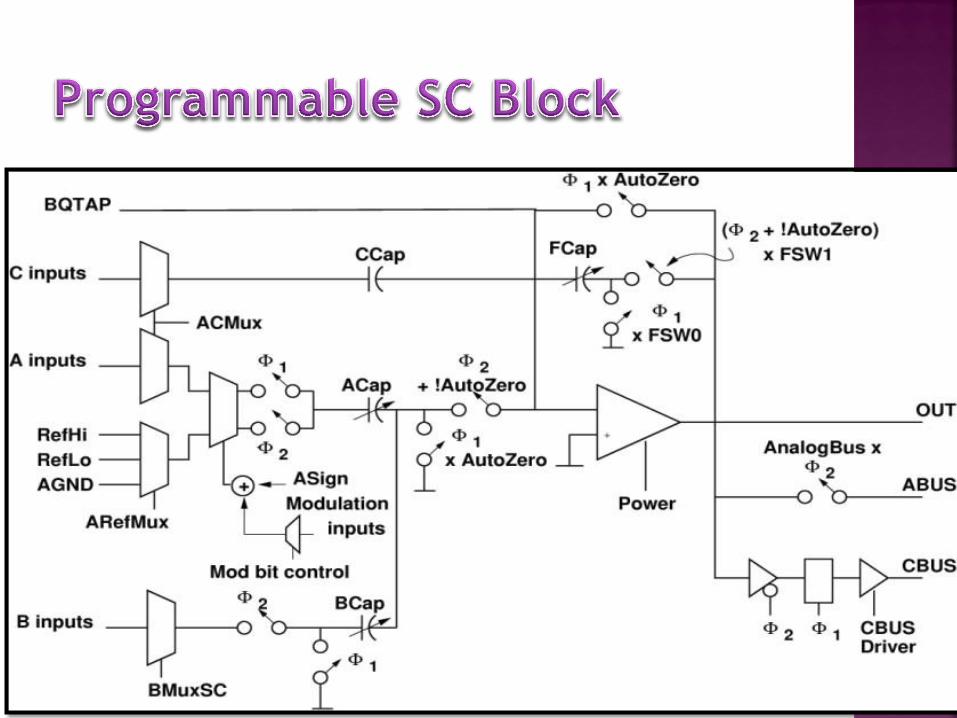
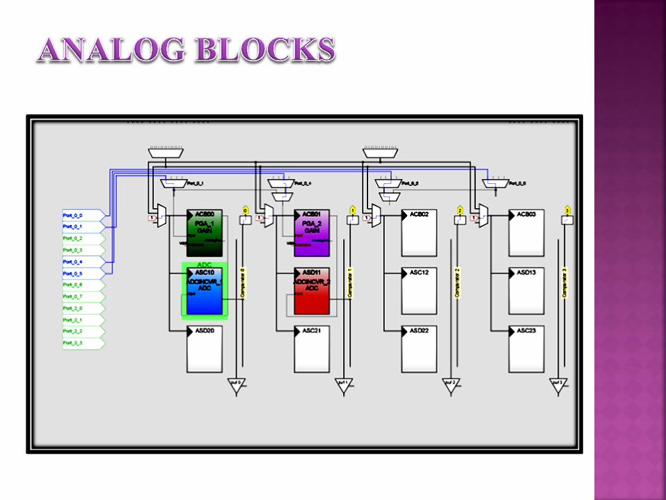
• Configurable Analog Blocks
Implement ADCs, DACs, filters,
amplifiers,
comparators, etc.
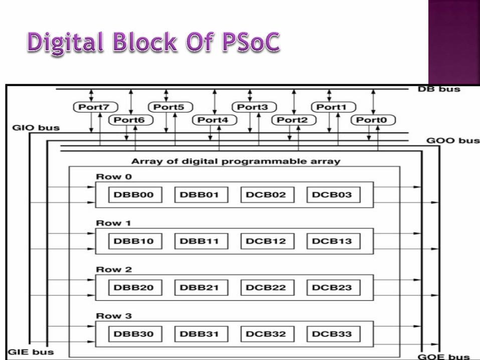
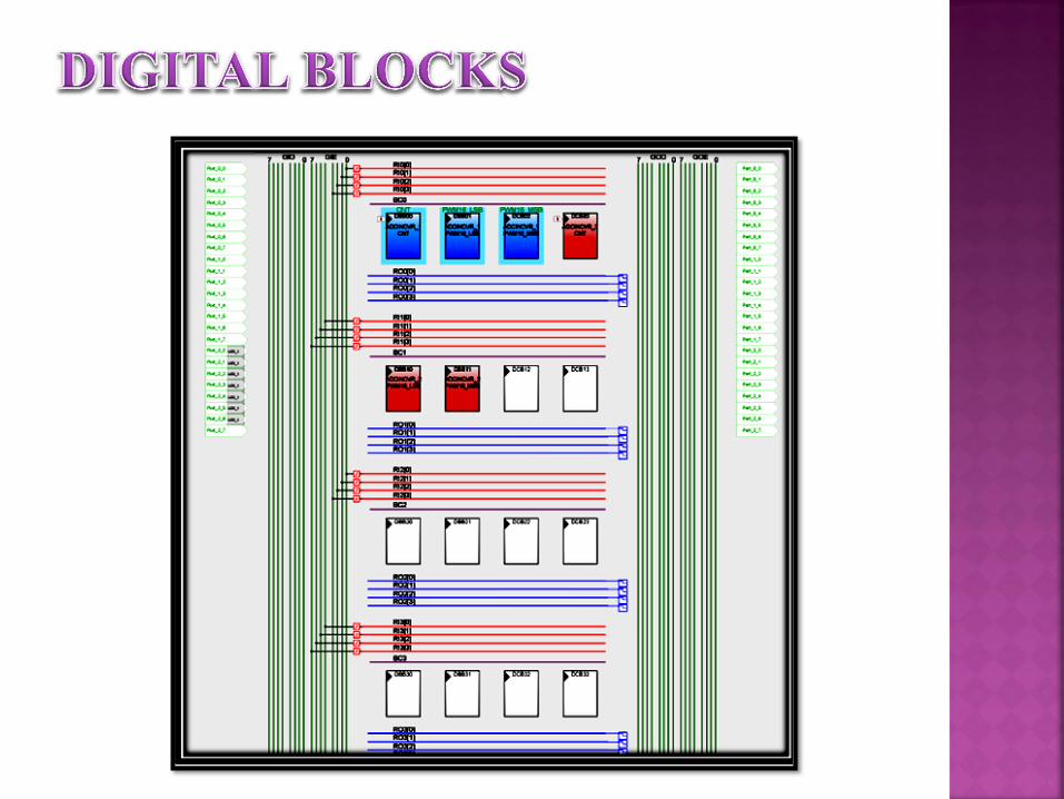
• Configurable Digital Blocks
Implement timers, counters, PWMs,
UART, SPI, IrDA, etc.
• 4KB to 32KB of Flash memory for
program storage
• 256B to 2KB of SRAM for data storage
• M8C Microcontroller: 4 Million
Instructions Per Sec
PSoC Device Features:

Inputs : Each pin can sink 25mA
Programmable filters
Flexible sensor interface I/O
3 types of ADCs, up to 4
Processing :
Outputs : Each pin can source 10mA
Up to 16 PWMs, Timers, Counters
Up to 9-bit DACs, 14-bit ADCs
Support Functions : EEPROM
Sleep Options
Watch Dog Timer
Low voltage detect
Fast M8 Microcontroller Core
Multiply Accumulate

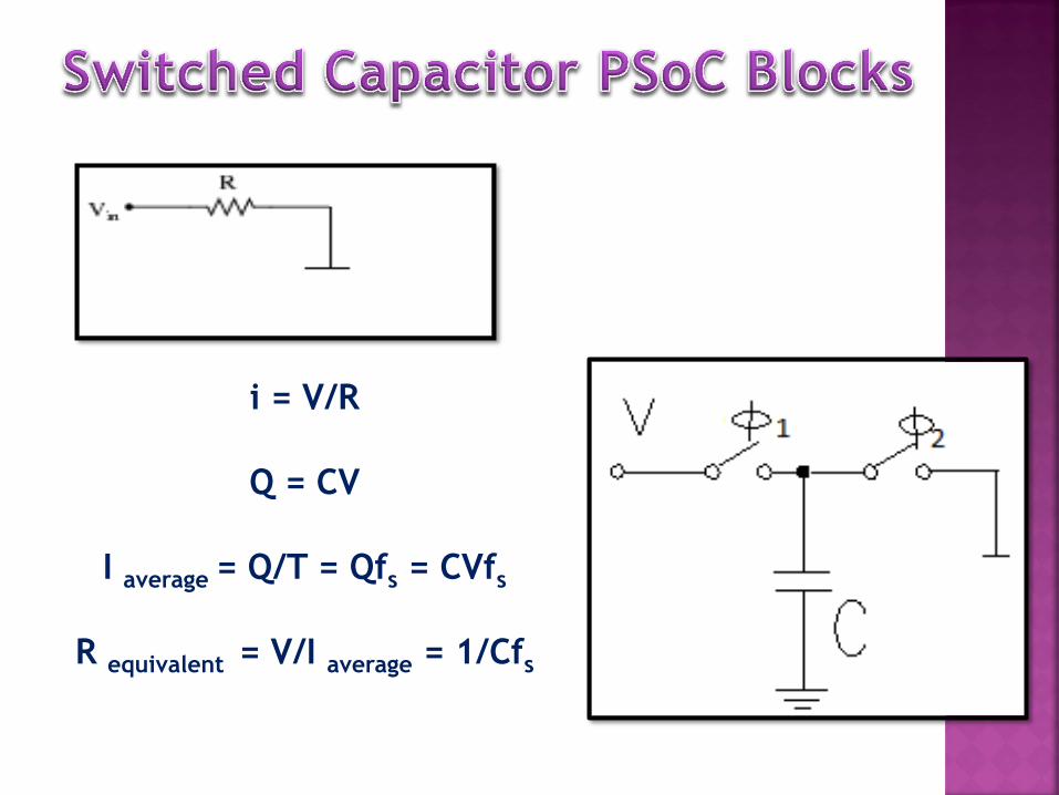
i = V/R
Q = CV
I average = Q/T = Qfs = CVfs
R equivalent = V/I average = 1/Cfs

Determine system requirements
Choose User Modules
Place User Modules
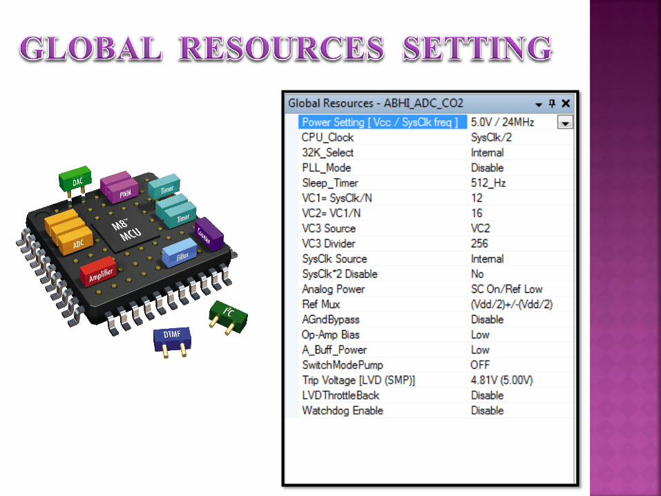
Set global and User Module parameters
Define the pin-out for the device
Generate the application
Review generated code
Demonstrate working configuration
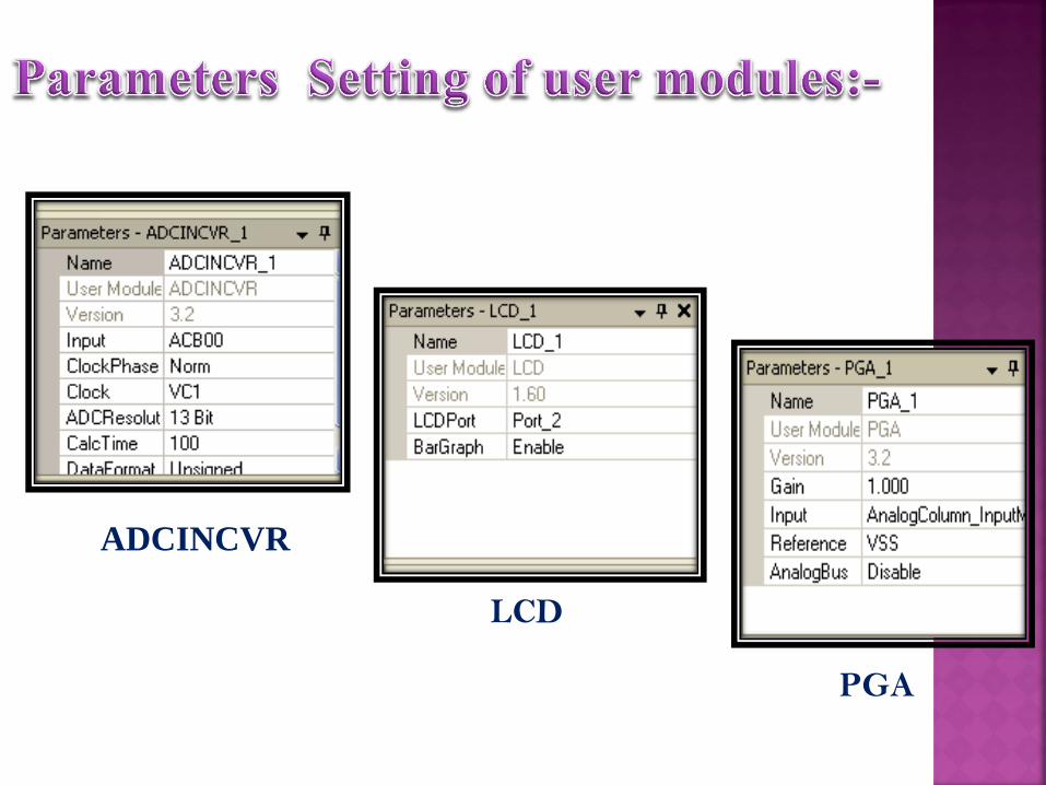
ADCINCVR
LCD
PGA
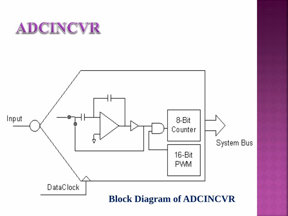
Block Diagram of ADCINCVR
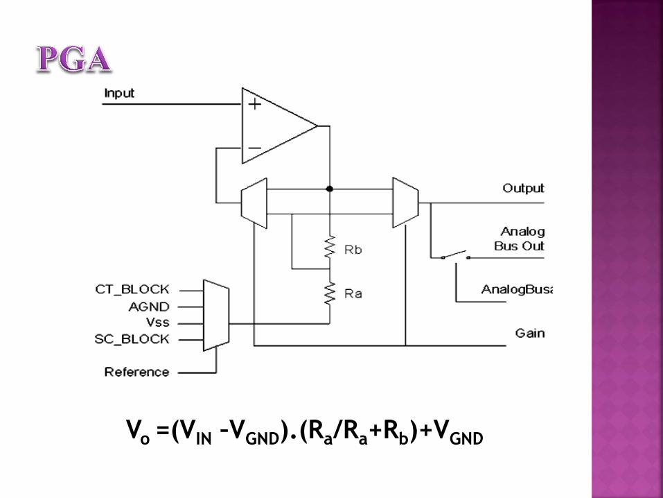
Vo =(VIN –VGND).(Ra/Ra+Rb)+VGND
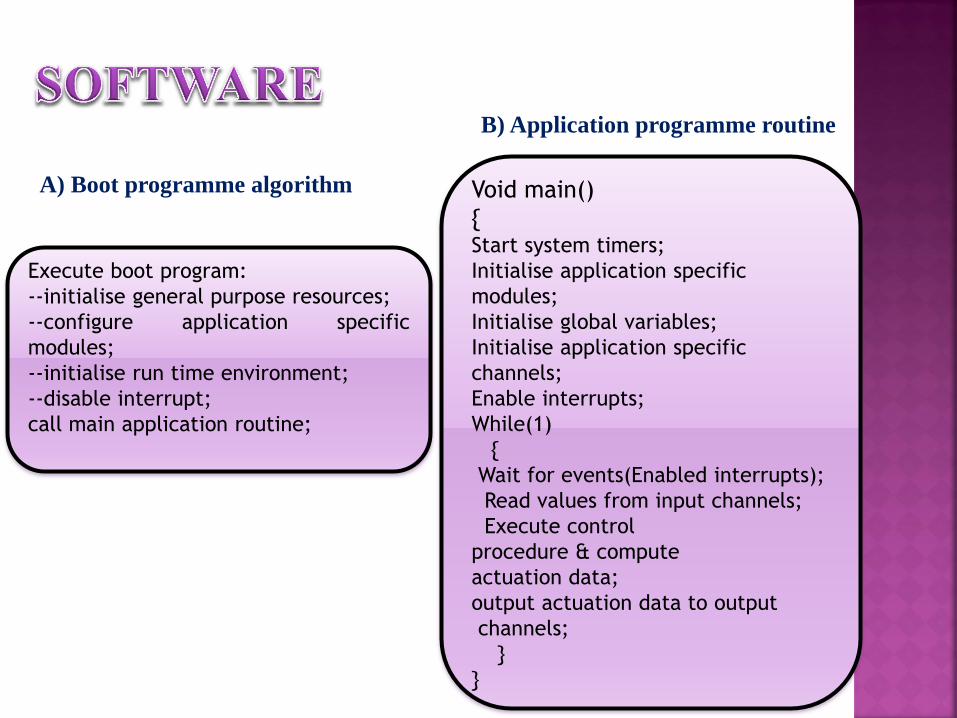
Execute boot program:
--initialise general purpose resources;
--configure application specific
modules;
--initialise run time environment;
--disable interrupt;
call main application routine;
Void main()
{ Start system timers;
Initialise application specific
modules;
Initialise global variables;
Initialise application specific
channels;
Enable interrupts;
While(1)
{
Wait for events(Enabled interrupts);
Read values from input channels;
Execute control
procedure & compute
actuation data;
output actuation data to output
channels;
}
}
B) Application programme routine
A) Boot programme algorithm
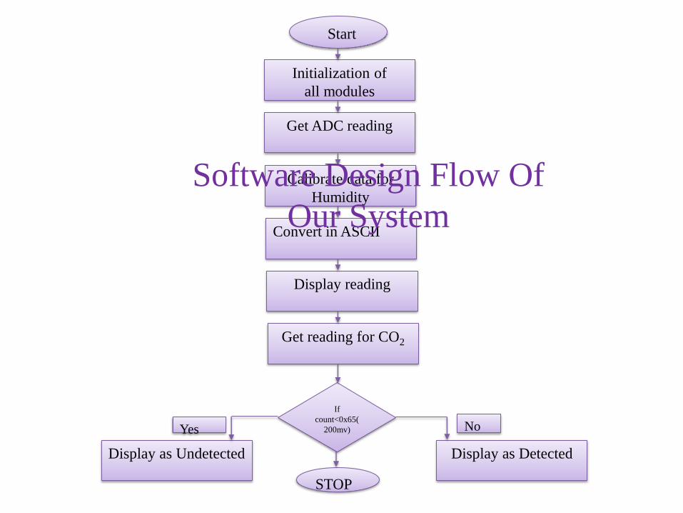
Start
Initialization of
all modules
Get ADC reading
Get reading for CO2
Display reading
Convert in ASCII
Calibrate data for
Humidity
If
count<0x65(
200mv)
STOP
Display as Detected Display as Undetected
No Yes
Software Design Flow Of
Our System
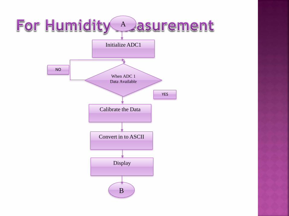
A
Initialize ADC1
When ADC 1
Data Available
Display
Calibrate the Data
Convert in to ASCII
NO
YES
B
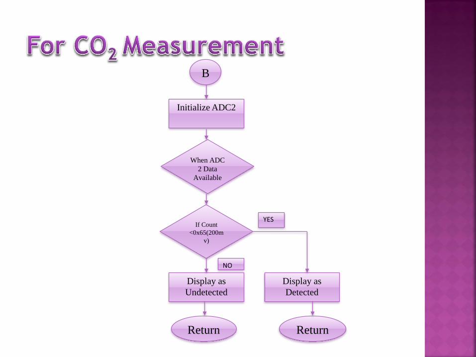
B
Initialize ADC2
When ADC
2 Data
Available
If Count
<0x65(200m
v)
Display as
Undetected
Display as
Detected
YES
NO
Return Return
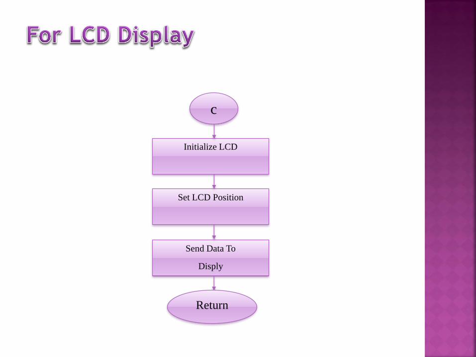
c
Initialize LCD
Set LCD Position
Send Data To
Disply
Return

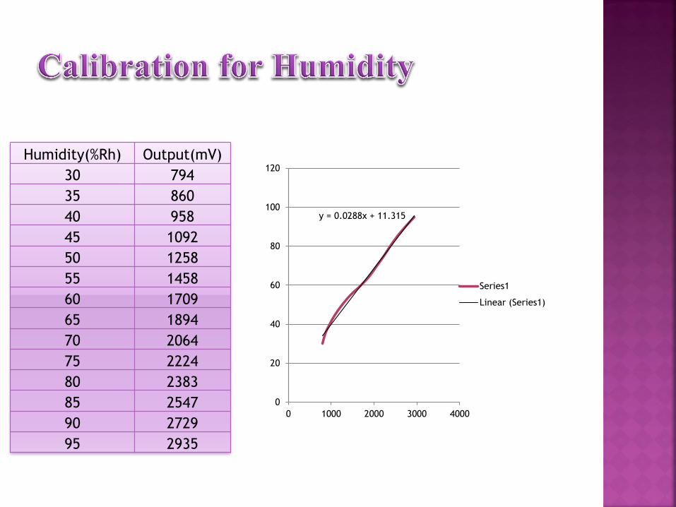
y = 0.0288x + 11.315
0
20
40
60
80
100
120
0 1000 2000 3000 4000
Series1
Linear (Series1)
Humidity(%Rh) Output(mV)
30 794
35 860
40 958
45 1092
50 1258
55 1458
60 1709
65 1894
70 2064
75 2224
80 2383
85 2547
90 2729
95 2935


System is designed for measurement of humidity and CO2 gas
The humidity observations shown by the system are highly reliable and
precise. Moreover, the presence of CO2 gas is also exhibited by the
present system.
System works successfully and gives the data regarding environmental
parameters very precisely.
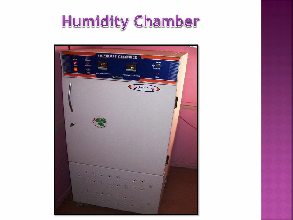
Particularly for measurement of carbon
dioxide (CO2) gas concentration, the
calibration in the respective units is
required. However, presently due to
unavailability of CO2 gas chamber the
calibration of carbon dioxide gas
concentration is left as future work.