
ABC Guide to Temporary Pipework-Feb 2012 Rev5-S (2)
84
ABC Guide to Temporary Pipework ABC Guide to Temporary Pipework Wells Wells Practices to implement EP 2006-5393 Shell Global Standard for Temporary Pipework Practices to implement EP 2006-5393 Shell Global Standard for Temporary Pipework Restricted EP2007-3153 rev 5 I.E. Iyamu (SPDC EPG-PN-WS; B.A. Beltman (SIEP EPT-WN); G. Hampden-Smith (SUKEP EPE-T-WS)
-
Upload
kwesi-edwards -
Category
Documents
-
view
1.572 -
download
93
Transcript of ABC Guide to Temporary Pipework-Feb 2012 Rev5-S (2)

ABC Guide to
Temporary PipeworkABC Guide to
Temporary Pipework
WellsWells
Practices to implement EP 2006-5393
Shell Global Standard for Temporary Pipework
Practices to implement EP 2006-5393
Shell Global Standard for Temporary Pipework
Restricted EP2007-3153 rev 5
I.E. Iyamu (SPDC EPG-PN-WS; B.A. Beltman (SIEP EPT-WN); G. Hampden-Smith (SUKEP EPE-T-WS)
ABC Guide to Temporary Pipework-Rev5-Feb20-12:Wells ABC Guide to Temporary Pipework 20/02/2012 10:42 Pa

WellsABC Guide to Temporary Pipework
Practices to Implement EP 2006-5393 Shell Global Standard for Temporary Pipework
byI. E. Iyamu (SPDC EPG-PN-WS);B. A. Beltman (SIEP EPT-WN);
G. Hampden-Smith (SUKEP EPE-T-WS)
Sponsor: P. Sharpe (SIEP EPT-W)Reviewed by: I. Duncan (SUKEP EPE-T-WS)Approved by: D. Stewart (SIEP EPT-WX)Date of issue: December 2007Period of work: November 2007Revised: February 2012ECCN number: EAR 99
The information in this document is shared under the Research Agreement between SIRM and Shell OilCompany dated January 1, 1960, as amended unless indicated otherwise above.
This document is classified as Restricted. Access is allowed to Shell personnel, designated Associate Companiesand Contractors working on Shell projects who have signed a confidentiality agreement with a Shell GroupCompany. 'Shell Personnel' includes all staff with a personal contract with a Shell Group Company. Issuance ofthis document is restricted to staff employed by a Shell Group Company. Neither the whole nor any part of thisdocument may be disclosed to Non-Shell Personnel without the prior written consent of the copyright owners.
Copyright 2007 SIEP, Inc.
SHELL INTERNATIONAL EXPLORATION AND PRODUCTION INC., HOUSTONFurther electronic copies can be obtained from the Global EP Library, Houston
Wells
Restricted EP2007-3153 rev 5
ABC Guide to Temporary Pipework-Rev5-Feb20-12:Wells ABC Guide to Temporary Pipework 20/02/2012 10:42 Pa

Summary
This ABC Guide to Temporary Pipework is designed as a practical guide to createan awareness of the risks when using temporary pipework in the field.
This guide covers:� Flowline equipment� Pressures and types of fluids involved� Operational hazards� Pipework connections and interfaces� Hazard identification and mitigation� Operational guidelines
This guide shall be read and understood by all involved in temporary pipeworkoperations. The guide shall be re-read prior to the commencement of each temp-orary pipework operation and also referred to during each step of that operation.
If the correct procedure is unclear at any stage of the operation: Stop and Ask.
Keywords
Temporary pipework, Hammer Union, Hub Connection, Hoses, Restraints.
Wells
Restricted EP2007-3153 rev 5- I -
Figure 1 - Examples oftemporary pipework
ABC Guide to Temporary Pipework-Rev5-Feb20-12:Wells ABC Guide to Temporary Pipework 20/02/2012 10:42 Pa

Revision History
Revision 4
Revision 5
- II - Restricted EP2007-3153 rev 5
Wells
Section Details
5.1.3 Replaced charts in the section and expanded on commercialoptions for restraining pipework.
5.1.4 Removed revision 3 content and replaced with selection andinstallation of Polyester Round Sling Restraints.
5.1.5 Removed revision 3 content and replaced with informationon the WeirSPM FLSR system.
5.1.6 Removed revision 3 content and replaced with informationon FMC TPR system
Appendix 3 Restraint Charts using ASME B 30.9 Polyester Roundslings
Section Details
2.10 Added section. Direction of flow through Hammer Unions.
4.4 Amended some text to include the use of NPT and linepipethreads.
4.4.3 Added this section to specify the conditions for using NPTand line pipe threaded connections > 1/2”.
ABC Guide to Temporary Pipework-Rev5-Feb20-12:Wells ABC Guide to Temporary Pipework 20/02/2012 10:42 Pa

- III -Restricted EP2007-3153 rev 5
Wells
Contents
Summary I
Keywords I
Revision History IIRevision 4 IIRevision 5 II
1 Introduction 11.1 What is Temporary Pipework 11.2 Pipework or Flowline Equipment 21.3 Equipment Boundaries 2
2 Hammer Unions and Operational Hazards 52.1 Origins of Hammer Unions 52.2 Female/Male Subs or Union Parts 52.3 Pressure 62.4 Stored Energy 82.5 Dynamic Loading 82.6 Vibration 82.7 Bending Forces 92.8 Shock Loading 102.9 Hazardous Fluids 102.10 Conventional Hammer Union Pipework Hook-up –
Direction of Flow 10
3 Loss of Containment 103.1 Leaks - Erosion 113.2 H2S 123.3 Catastrophic Failure 123.4 Energy Release 133.5 Polymers – Elastomers and Thermoplastics - suitability 13
3.5.1 Elastomers 163.5.2 Thermoplastics 17
3.6 Historic Incidents 18
ABC Guide to Temporary Pipework-Rev5-Feb20-12:Wells ABC Guide to Temporary Pipework 20/02/2012 10:42 Pa

- IV - Restricted EP2007-3153 rev 5
Wells
4 Pipework Connections and Interfaces 214.1 Hammer Union Mismatches 21
4.1.1 Mismatching the Same-Size Hammer Unions 214.1.2 Mismatching Pipe Pressure Ratings 244.1.3 Mismatching Wing Nuts 254.1.4 Mismatching Components 254.1.5 Mismatching Non-Detachable and Detachable
Components 264.1.6 Connecting a Hammer Union Male Sub from one
manufacturer to the Female Sub from a different manufacturer 26
4.2 Mismatching Swivel Joint Components 274.3 Mating Hub Connector Components from different
manufacturers 274.4 Threaded Connections 28
4.4.1 Non-Pressure Sealing Thread (NPST) & Pressure Sealing Thread (PST) Line Pipe and NPT 29
4.4.2 Line pipe, NPT, NPTF 324.4.3 Pressure Sealing Threaded (PST) Connections
greater than 1/2” 384.5 Flexible Pipes - Hoses 40
4.5.1 Suitability of hoses connected in the high pressure (> 285 psi) side of the process. 40
4.5.2 Handling, Storage and Maintainance of Flexible Pipe 41
4.6 Equipment Interfaces & Equipment Repair and Maintenance 42
5 Hazard Identification and Mitigation 435.1 Mitigation Methods 43
5.1.1 Checklists 435.1.2 No-Go areas 465.1.3 Restraints for Temporary Pipework using
Polyester Roundslings 475.1.4 Installation Steps for Polyester Round Slings 515.1.5 WeirSPM FSR System 565.1.6 FMC Technologies TPR System 57
ABC Guide to Temporary Pipework-Rev5-Feb20-12:Wells ABC Guide to Temporary Pipework 20/02/2012 10:42 Pa
6 Avoiding Injury 586.1 Hammering Unions 586.2 Positioning of Body 59
7 Completing the Connection Interface Diagram 60
8 Walking the Lines 638.1 Example walkthrough 63
9 Awareness of Safety Initiatives 659.1 Truncated 2 in. FIG 602 Female Sub 65
10 EP 2006-5393 Temporary Pipework Standard Compliance 6610.1 Gap Analysis and Corrective Action Checklist 66
References 67
Appendix 1 Different Hammer Union Male and Female Sub mating arrangements. 68
Appendix 2 Piping Schedules 70
Appendix 3 Restraint Charts using ASME B 30.9 Polyester
Roundslings. 72
List of Figures
Figure 1 Examples of temporary pipework I
Figure 2 Temporary pipework / permanent pipework 1
Figure 3 Typical temporary pipework set-ups 2
Figure 4 Equipment interface boundaries, welltest and pumping examples 3
Figure 5 Some typical temporary pipework 3
Figure 6 Temporary pipework connections 4
Figure 7 Female sub and male sub of hammer type union 5
Wells
Restricted EP2007-3153 rev 5- V -
ABC Guide to Temporary Pipework-Rev5-Feb20-12:Wells ABC Guide to Temporary Pipework 20/02/2012 10:42 Pa

Figure 8 3in. 1502 and 3 in. 206 connections 6
Figure 9 Relative Pressure Comparison 7
Figure 10 Vibration in Temporary Pipework 9
Figure 11 Bend is being straightened due to internal pressure 9
Figure 12 Direction of Flow in Conventional Hook-up 10
Figure 13 Erosion point in a short radius bend 11
Figure 14 Erosion of common equipment 12
Figure 15 Demonstration of energy involved in Catastrophic Failure 13
Figure 16 Example of Hammer Union Seals incorporating anti extrusion rings 16
Figure 17 Mismatch of hammer union end connections 22
Figure 18 Using the Go No-Go gauge 23
Figure 19 Mismatching of wing union components 24
Figure 20 Mismatch caused by misidentification - standard male sub 25
Figure 21 Mismatch caused by misidentification - detachable male sub 25
Figure 22 Misapplication of wing nuts 26
Figure 23 Another misapplication of wing nuts 26
Figure 25 Mating Hub Connectors 27
Figure 24 Dangers of mismatching swivel joint components 27
Figure 26 NPT in poor condition due to corrosion and with insufficient make-up 28
Figure 27 NPST vs. LPT 29
Figure 28 FMC NPST Hammer Union Subs with groove 0.38” from ends 30
Figure 29 FMC NPST Retrofitted-groove schematics 31
Wells
Restricted EP2007-3153 rev 5- VI -
ABC Guide to Temporary Pipework-Rev5-Feb20-12:Wells ABC Guide to Temporary Pipework 20/02/2012 10:42 Pa

Figure 30 Line pipe connections which parted under rapid pressure increase and violent transverse movement 32
Figure 31 NPT thread gauging 34
Figure 32 NPT thread gauging and engagement - high pressure (>6000 psi) fittings 35
Figure 33 Example of split female connections 36
Figure 34 Leakage path through NPT threads 36
Figure 35 Clock wise wrapping procedure 37
Figure 36 Minimum bending radius of flexible pipe 41
Figure 37 Hose installing concept for long spans 42
Figure 38 Dynamic loading and selection guide of EN 1492-2 round sling restraints for liquid pressurised piping 48
Figure 39 Dynamic loading and selection guide of EN 1492-2 round sling restraints for gas pressurised piping 49
Figure 40 Condition of lugs on hammer union wing nuts 58
Figure 41 Safety iron 58
Figure 42 Safety hammer 59
Figure 43 Gauge positioned directly above a pressurised pipe connection 59
Figure 44 Sand Filter and Dataheader showing NPT connections 59
Figure 45 CID toolbox guide 60
Figure 46 CID toolbox video tutorial 61
Figure 47 P & ID showing connections marked-up for walking the lines 62
Figure 48 Example things to consider during walking the lines 64
Figure 49 Truncated 2 in. Fig 602 Female Sub - new engineering design 65
Wells
Restricted EP2007-3153 rev 5- VII -
ABC Guide to Temporary Pipework-Rev5-Feb20-12:Wells ABC Guide to Temporary Pipework 20/02/2012 10:42 Pa

List of Tables
Table 1 Elastomer Selection Guide 14
Table 2 Thermoplastic Selection Guide 17
Table 3 Historic Incidents 18
Table 4 Hammer Union Mismatches To Avoid 21
Table 5 Indicative Torques for High Pressure (> 6000 psi) NPT fittings 34
Table 6: Allowed threaded connection working pressures for different pipe sizes 38
Table 7 Normal pressure < 6000 psi NPT nominal sizes and thread engagement data. 39
Table 8 Example of Pre-Mobilisation Temporary Pipework Checklist 44
Table 9 Pre-Pressure Test Temporary Pipework Checklist 45
Wells
Restricted EP2007-3153 rev 5- VIII -
ABC Guide to Temporary Pipework-Rev5-Feb20-12:Wells ABC Guide to Temporary Pipework 20/02/2012 10:42 Pa

1 Introduction
1.1 What is Temporary Pipework
Temporary pipework consists of the conduits and equipment for directing fluids(liquids or gasses):
� From a pump to a Xmas Tree.� A high pressure point to a lower pressure point.� Fluids directed to outlets ending with plugs on which sensors are mounted.
Temporary pipework is piping and flowline equipment that is mobilised to thewellsite for connecting or hooking up equipment for the following operations:
� General pumping operations (transfer of fluids, mud/brine mixing operations, (reverse) circulating well fluids, etc.
� Pressure testing of downhole equipment (casing, packers, tubing, plugs,valves, accessories).
� Cementing.� Well killing.� Well stimulation.� Nitrogen pumping.� Well clean-up (Flowbacks).� Well testing.� Under balanced drilling operations. � Managed pressure drilling operations.
Temporary
pipework
Permanent
pipework
To temporary
pipework system
Pipework part of
original design
(e.g. production
facilities)
Wells
Restricted EP2007-3153 rev 5- 1 -
Figure 2 - Temporary pipework / permanent pipework
ABC Guide to Temporary Pipework-Rev5-Feb20-12:Wells ABC Guide to Temporary Pipework 20/02/2012 10:42 Pa

Temporary pipework can be both hard and flexible pipe.
1.2 Pipework or Flowline equipment
The equipment involved can include:� Pipework runs (straights), pup joints, elbows.� T-pieces.� Laterals (Y-pieces).� Swivel joints. � Treating loops.� Crossovers.� High pressure hoses.� Flanges, blinds, plugs, tappings for sensors, sample points etc.
1.3 Equipment Boundaries
Pipework components contained within pumping or flowing packages:e.g. manifolds, pumping units, separator tanks are excluded where these are man-ufactured to a code or standard.
The pipework connections or interfaces to the equipment are included.
Figure 3 - Typical temporary pipework set-ups
- 2 -
Wells
Restricted EP2007-3153 rev 5
ABC Guide to Temporary Pipework-Rev5-Feb20-12:Wells ABC Guide to Temporary Pipework 20/02/2012 10:42 Pa

Swivel
Joint
Treating loop
Tee
Typical Coflexip Line
Pipework
Figure 5 - Some typical temporary pipework
- 3 -Restricted EP2007-3153 rev 5
Wells
Interfaces included Interfaces included
Equipment “C” e.g. MSRV
Equipment “D”e.g. Steam Heat
Exchanger
Equipment excluded
Equipment excluded
Equipment “B” e.g. Choke Manifold
Equipment excluded
Equipment “A” e.g. Surface Test
Interfaces included
e.g. Surface Test Tree
Interfaces included
Blender
Equipment excluded
Interfaces included
Equipment excluded
Equipment excluded
PumpTruck
TreatmentManifold Xmas
TreeTree
Interfaces included
Figure 4 - Equipment interface boundaries, welltest and pumping examples
ABC Guide to Temporary Pipework-Rev5-Feb20-12:Wells ABC Guide to Temporary Pipework 20/02/2012 10:42 Pa

The pipework connections referred to in the guide are known as:� Hammer-type connections.� Hub-type connections.� Flange connections.� Pipe body to pipe body (welded) or pipe body to Sub.
- gas welded- friction welded
Thread Pipe body to Sub- NPST (no pressure seal on thread)- PST (pressure seal on thread)
In summary, temporary pipework (chiksan, flowline equipment) comprises suchfittings as straights or “pup joints,” T-pieces, elbows, crosses, crossovers, blinds,plugs, swivel joints and plug, loops, and check valves.
Hammer-type union Hub-type connection
Welded connection
Flange connection
Figure 6 - Temporary pipework connections
- 4 -
Wells
Restricted EP2007-3153 rev 5
ABC Guide to Temporary Pipework-Rev5-Feb20-12:Wells ABC Guide to Temporary Pipework 20/02/2012 10:42 Pa

2 Hammer Unions and Operational Hazards
As previously described, temporary pipework operations involve the transport offluids under pressure from one point to another. Due to the typical pressures andflow rates involved, temporary pipework systems contain a lot of stored energywhich can cause vibration, bending forces, and shock loading on the system. Thefluids being flowed can be hazardous or erosive, and can also “attack” the integrityor strength of the system. It is therefore vitally important that all equipment used in a temporary pipework operation set-up is:
� Mechanically sound and has been properly inspected prior to use.� Of suitable material, particularly where seals are concerned; this applies
both to working pressure rating and to the fluid type being flowed (e.g. Sour Service).
� Made up correctly at all connections and unions as per the recommendations of the operational design.
� Secured with engineered restraints attached to strong anchor points in thesystem.
In order to better understand these requirements, we will now look at some of thephysical aspects of temporary pipework.
2.1 Origins of Hammer Unions
Pipework connected by hammer unions is used in chemical process plants, themining industry, on dredging vessels, and in the oil industry. It is an old design(early 1950s) created by the Well Equipment Company (WECO) which wasacquired by FMC Technologies.
2.2 Female/Male Subs or Union Parts
The identification of the female and male parts of a hammer type union is show inthe picture below.
Female SubMale Sub
Wing �ut Figure 7 - Female suband male sub of hammer type union
- 5 -Restricted EP2007-3153 rev 5
Wells
ABC Guide to Temporary Pipework-Rev5-Feb20-12:Wells ABC Guide to Temporary Pipework 20/02/2012 10:42 Pa

The union parts are “called out” using a Nominal pipe size, a FIG “designation”and a code e.g.1502.
For example: 3 in. FIG 1502
The “3 in.” is the nominal diameter and is close to the inside diameter. The meaning of “FIG” is probably an abbreviation of “figure” – meaning drawing, and1502 is a code for the working pressure rating – “15” referring to 15,000 psi. Theaddition of H2S pipework has led to the designation becoming corrupted. 3 in. Fig1502 H2S service pipework ordered from the major flowline equipment providershas a cold WP rating of 10,000 psi.
The last two digits in the designation of hammer unions generally refers to thesealing arrangements. “02” refers to a square gasket seal; “06” refers to an o-ringseal.
[See Appendix 1 showing different Hammer Union types]
2.3 Pressure
Pressure is the term for measuring the force per unit area, the units typically usedfor measuring pressure are pounds per square inch, which is abbreviated psi.
A familiar example is the air pressure in a tyre, which is typically around 30 psifor a car. What this means is that a force of 30 pounds is exerted on each andevery square inch of the inside of the tyre. There are a lot of square inches on theinside surface of a tyre, and because of this, the force exerted on that tyre is verylarge. Every square inch is pushed on with a force of 30 pounds.
In temporary pipework operations, “low pressure” is often used for values ofaround 300 psi (that is 10 times that of a car tyre) and the operational pressure
Figure 8 - 3in. 1502 and 3 in. 206 connections
1502 Square
gasket seal206 O-ring seal
- 6 -
Wells
Restricted EP2007-3153 rev 5
ABC Guide to Temporary Pipework-Rev5-Feb20-12:Wells ABC Guide to Temporary Pipework 20/02/2012 10:42 Pa

may be above 10,000 psi, that is, 10,000 lbs exerted on every square inch of theinside of piping, unions, swivel joints, crossovers, etc., in the system.
Thinking about the forces involved, it should be clear why it is vital to ensurethere are no weak points in the system. Any improper use of equipment such asmismatching pressure ratings or using poorly conditioned equipment can havedevastating consequences.
10,000 psi
10,000 psi
285 psi
30 psi30 psiCar Tyre
“LowPressure”
Normal Operating Pressure
~6000 psi(ASME B31.3)
High pressure
High pressure
Figure 9 - Relative Pressure Comparison
Units of Pressure
Pounds per square inch (or pounds-force per square inch) is still the most widelyused oilfield unit for pressure.Other common units are the SI (or metric) unit which is the Pascal (Pa), theAtmosphere (atm), and the Bar (bar).The Pascal is a very small unit, 1 Pa being only about 1/7000th p.s.i. 1 Atm and 1Bar are approximately 15 p.s.i.
- 7 -Restricted EP2007-3153 rev 5
Wells
ABC Guide to Temporary Pipework-Rev5-Feb20-12:Wells ABC Guide to Temporary Pipework 20/02/2012 10:42 Pa

2.4 Stored Energy
Stored energy is the capacity of a volume of pressured fluid to do work if allowedto expand. An example of this work would be a volume of pressurised gas expanding and pushing a piston. The greater the stored energy of the fluid, thegreater the force with which the piston would be pushed and the greater theamount of work that piston could perform.
The danger associated with stored energy in temporary pipework is that thestored energy is typically very large, and any weak point in the system will allowthis energy to discharge with potentially catastrophic results.
2.5 Dynamic Loading
When pipe fails the strain on any restraint when it snaps tight to restrain the pipeis called the dynamic loading by process engineers. The rule-of-thumb used towork out this dynamic loading is twice that due to the static force on the pipe arising from internal pressure.
2.6 Vibration
Vibration can be a significant risk to pipework integrity, leading to mechanicalfailure, fluid release, and potentially serious safety implications. Common areas ofvibration in Temporary Pipework are:
� Long pipe runs.� Piping fixtures and instrumentation such as gauges.� Equipment such as valves, chokes, etc.� Pumps.
Common causes of vibration include:� Excessive pulsation (from pumps for example).� Mechanical natural frequencies.� Inadequate supports and/or support structure.
Yield strength: - Pipework - Cannon comparison
Yield Strength is the stress a material can with-stand without permanent deformation. Typicalminimum yield strengths for pipework range from75,000 to 115,000 psi A liner comprising of steel tubing with 0.375 in.wall thickness and 85,000 psi yield strength iswhat is required to line the bore of 8-pounder can-nons to make them safe for re-enactments of theAmerican Civil War.
- 8 -
Wells
Restricted EP2007-3153 rev 5
ABC Guide to Temporary Pipework-Rev5-Feb20-12:Wells ABC Guide to Temporary Pipework 20/02/2012 10:42 Pa

Common effects of vibration include:� Loosening of bolts.� Compromising of mechanical joints (backing-off of wing nuts). � Movement or slackening of tie downs and restraints.
2.7 Bending Forces
Temporary pipework is commonly subjected to bending forces due to fluid velocityand internal pressure of the pipe. Bending force occurs at junctions or bends inthe pipework where it effectively tries to “straighten out the bend.”
Such bending forces are then transferred along the pipework and result in additional strain on connections. Improperly made-up connections (e.g., worn ormismatched components, wrong pressure rating, etc.) not able to cope with thisincreased load can fail catastrophically.
Figure 11 - Bend is being straightened due to internal pressure
Figure 10 - Vibration in Temporary Pipework
Internal pressure attempts to straighten out
the corner bend and forces the pipe out-
wards straining the connections
- 9 -Restricted EP2007-3153 rev 5
Wells
ABC Guide to Temporary Pipework-Rev5-Feb20-12:Wells ABC Guide to Temporary Pipework 20/02/2012 10:42 Pa

2.8 Shock Loading
A significant change in the flowrate, or pressure, during an operation (such as theemergency closure of a valve) causes a sudden extra load or “jolt” on the system.The temporary increase of load on the system usually imposes increased pressure,vibration, and bending forces on the system. During this period of Shock Loading,any sub-standard part of the system (inferior pipe, worn connections, mismatchedconnections, wrong pressure rated equipment) can fail with potentially disastrousconsequences.
2.9 Hazardous Fluids
While there are many physical factors (such as pressure, temperature, andflowrates) that must be considered when dealing with temporary pipework, chemical factors such as hazardous fluids must also be taken into account. Manyfluids used in operations (such as brines or acids) are corrosive to temporarypipework and will cause a reduction in wall thickness. It is important that allpipework and connections used have been properly maintained, inspected, andcertified before use. Standard Service components shall not be used on “SourService” wells (wells where Hydrogen Sulphide, H2S, is present), as this will causestress corrosion cracking, and pitting in the metal as well as destroying any elastomer seals in unions, etc. These factors can lead to premature failure underpressure of components in the system.
2.10 Conventional Hammer Union Pipework Hook-up – Direction
of Flow
By convention, the flow enters the pipe work on the female sub side and circulatesfrom the female sub to the male sub.
All testing services equipment is manufactured to adhere to this convention and itshould be followed whenever possible. However, there is no technical requirementfor this convention and under certain circumstances, such as in a complex rig upor due to crossover availability, it may be required to rig up a line where the direction of flow is reversed. Any such line where the direction of flow is reversedmust be clearly marked as to the true direction of flow.
- 10 -
Wells
Restricted EP2007-3153 rev 5
Figure 12 - Direction of Flow in Conventional Hook-up
ABC Guide to Temporary Pipework-Rev5-Feb20-12:Wells ABC Guide to Temporary Pipework 20/02/2012 10:42 Pa

3 Loss of Containment
3.1 Leaks - Erosion
Erosion takes place in flow systems where turbulence occurs, typically in pipebends (e.g., elbows), tube constrictions (e.g., chokes or valves), and other structures that alter flow direction such as laterals or tees. Specific erosion pointswithin these components can vary depending on the fluid velocity and size of anysuspended particles. With typically sized sand grains, the erosion point in a bendis usually past the mid-point of the bend, and it is for this reason that wall thick-ness is measured at the 80-90 degree point as well as at 45 degrees.
Erosion can lead to leakage and a rapid failure, and it is therefore important thatthe layout is designed, where possible, to minimise bends and constrictions andthat such areas are inspected regularly. Examples where erosion can be accelerated are:
� Connections downstream of the choke.� Points where the flowline is re-directed.
Protection is afforded by using Target “T”s and log sweep bends.
Intrusion into the flow path can cause vortices to be created and shed. The localfluid speed within the vortex can be much greater than the average fluid speed inthe pipe. Local pipe erosion, in an area as small as ½ inch square, can arisewhere the vortex makes contact with the equipment or pipe wall.
Since the pipe thickness can be otherwise within operational limits, workshop personnel should be vigilant when making visual inspections.
Figure 13 - Erosion point in a short radius bend
Erosion point~80o
- 11 -Restricted EP2007-3153 rev 5
Wells
ABC Guide to Temporary Pipework-Rev5-Feb20-12:Wells ABC Guide to Temporary Pipework 20/02/2012 10:42 Pa

3.2 H2S
When H2S is present, the system is known as Sour and Sour Service equipmentshall be used. For working pressure above 6000 psi, Sour Service equipment hasa significantly lower rated cold working pressure than the equivalent StandardService equipment and it is therefore important to avoid mixing Standard andSour Service equipment in the same operation.
3.3 Catastrophic Failure
When flow lines fail, whether it is due to excess pressure; faulty connections; worncomponents; damage to the piping connection; or other reasons, the results can bedevastating and catastrophic to both equipment and personnel. The metal components that were previously being subjected to up to 15,000 p.s.i. of internalpressure are suddenly and instantly forced to relieve their stored energy. In such afailure there could be hundreds or even thousands of pounds of iron pipe flailingaround. In that scenario, there is a high likelihood of severe personal injury ordeath. As we will cover later, restraint systems can help reduce this risk of damage or injury but they cannot eliminate it fully. Preventing the failure fromoccurring in the first place is the only truly safe method.
Figure 14 - Erosion of common equipment
Predicted erosion rates forstandard elbow, pluggedtee and long-radius elbow.Areas shown in red andyellow have maximum erosion
Standard elbow(r/D=1.5)
Pluggedtee
Long-radius elbow(r/D=5.0)
FlowFlow
Flow
Maximum
erosion
Maximum
erosion
Maximum
erosion
- 12 -
Wells
Restricted EP2007-3153 rev 5
ABC Guide to Temporary Pipework-Rev5-Feb20-12:Wells ABC Guide to Temporary Pipework 20/02/2012 10:42 Pa

3.4 Energy Release
The following sequence of pictures were taken from a Service Company demon-stration video showing the failure of a 15,000 p.s.i. unrestrained line. In this cata-strophic failure the energy release occurs in a very short period of time - a fractionof a second in fact, and the damage and risk to personnel would have been severe.
3.5 Polymers – Elastomers and Thermoplastics - suitability
“Polymer” is the name given to the class of chemical compounds that are mouldedto make the elements of a sealing system. The “elastomers” comprise thedeformable sealing element and the “thermoplastics” comprise the hard, non-deformable elements that limit the extrusion of the elastomers under pressure. Inselecting the elastomers and thermoplastics, consideration must be given to thepressure, temperature, fluids and duration to which the polymers are exposedalong with the mechanics of the leak path which the sealing arrangement “cuts-off”.
The selection of suitable o-ring, seal and back-up ring polymers, as environmentalconditions become more extreme, is challenging. It is difficult to be prescriptive onelastomer selection. Different grades or compounds of the same material typeextend its range of use, but generally in one direction - to only one end of the temperature range: Elastomers compounded for very high temperature are notgenerally suitable for very low temperatures and vice versa.
Test manikins
15,000 psiline
Line ruptures
Piece of loop fliesoutward
Pup joint flies off and lands200 yards away
Test manikinsdestroyed
Figure 15 - Demonstration of energy involved in Catastrophic Failure
- 13 -Restricted EP2007-3153 rev 5
Wells
ABC Guide to Temporary Pipework-Rev5-Feb20-12:Wells ABC Guide to Temporary Pipework 20/02/2012 10:42 Pa

Table 1 has been compiled by James Walker in consultation with Shell. Genericelastomer compounds are identified in this table. It is intended to guide WellsSupervisors and persons responsible for preparing equipment for Wells operationsas to the conditions where they should seek advice (from the Seal manufacturer inthe first instance) on the suitability of the seal etc. type and to where seal qualification may be appropriate.
Key 1 = excellent, 2 = good, 3 = poor, C = consult
James Walker grade(Note: alternative materials are available)
AF69/90
AF85/90
FR10/80 &
FR
10/95
FR25/90
FR58/90*
LR5853*
LR6316*
Elast-O
-Lion
® 101
Elast-O
-Lion
® 280
Elast-O-
Lion® 280LF
Elast-O
-Lion
® 985
PB
80
Kalrez
®
3018
Chem
-O-
Lion®
Material type
FEP
M(Aflas
®)
FEP
M(Aflas
®)
FKM
-A(fluorocarbon)
FKM
-GLT
(fluorocarbon)
FKM
-B(fluorocarbon)
FKM
-F(fluorocarbon)
FKM
-GFLT
(fluorocarbon)
HN
BR
(hydrogenatednitrile)
HN
BR
(hydrogenatednitrile)
HN
BR
(hydrogenatednitrile)
HN
BR
(hydrogenatednitrile)
NB
R(nitrile)
FFKM
(perfluoro-elastom
er)
Special
Acids
Weak mineral 1 1 1 1 1 1 1 2 2 2 2 2 1 1
Strong mineral 1 1 1 1 1 1 1 3 3 3 3 3 1 1
Weak carboxylic 1 1 1 1 1 1 1 1 1 1 1 1 1 1
Strong carboxylic 2 2 3 3 3 3 3 3 3 3 3 3 1 1
Alcohols except methanol 1 1 1 1 1 1 1 1 1 1 1 1 1 1
Aliphatic hydrocarbons 1 1 1 1 1 1 1 1 1 1 1 1 1 1
Aromatic hydrocarbons 2 2 1 1 1 1 1 C C C C 3 1 1
Brines
LD – Ca/Na chloride 1 1 1 1 1 1 1 1 1 1 1 1 1 1
HD – Na/Ca bromide 1 1 1 1 1 1 1 2 2 2 2 3 1 1
HD – Zn bromide 1 1 1 1 1 1 1 3 3 3 3 3 1 1
Alkaline – Na OH/KOH 1 1 3 3 3 3 2 1 1 1 1 2 1 2
BiocidesDilute 1 1 1 1 1 1 1 1 1 1 1 1 1 1
Concentrated 2 2 3 3 3 3 3 3 3 3 3 3 1 1
Carbon dioxide 2 2 3 2 2 3 3 1 1 1 1 1 1 3
Corrosioninhibitors
Amine based 1 1 3 3 3 2 2 1 1 1 1 3 1 1
Potassium carbonate 1 1 3 3 3 3 3 2 2 2 2 3 1 2
Crude oil, sweet 2 2 1 1 1 1 1 1 1 1 2 2 1 1
Crude oil, sour
<2000 ppm H2S 1 1 2 2 1 2 2 1 1 1 2 3 1 1
2000 ppm to 5% H2S 1 1 3 3 2 3 3 2 2 2 2 3 1 2
5% to 40% H2S 1 1 3 3 3 3 3 3 3 3 3 3 1 3
Drilling mud
Diesel based 2 2 2 2 2 2 2 1 1 1 1 2 1 2
Ester based 2 2 3 3 3 3 3 3 3 3 3 3 1 2
Mineral oil based 1 1 1 1 1 1 1 1 1 1 1 1 1 1
Silicate based 1 1 2 2 2 2 2 1 1 1 1 2 1 2
Rapid Gas Decompression
Sweet gas 1 2 3 1 1 3 3 1 3 3 1 3 3 3
Sour gas 1 2 3 2 2 3 3 1 3 3 2 3 3 3
High CO2 2 2 3 3 3 3 3 1 3 3 1 3 3 3
Fire fighting media 2 2 1 1 1 1 1 3 3 3 3 3 1 1
Glycols 1 1 1 1 1 1 1 1 1 1 1 1 1 1
Hydrogensulphide
Wet 1 1 3 3 3 2 2 2 2 2 2 3 1 1
Dry 1 1 3 3 2 2 2 1 1 1 1 3 1 1
Table 1 - Elastomer Selection Guide
- 14 -
Wells
Restricted EP2007-3153 rev 5
ABC Guide to Temporary Pipework-Rev5-Feb20-12:Wells ABC Guide to Temporary Pipework 20/02/2012 10:42 Pa

- 15 -Restricted EP2007-3153 rev 5
Wells
Table courtesy of James WalkerWebsite: www.jameswalker.biz/jwco/index/html
Hydraulicfluids
Phosphate ester (HFD) 3 3 1 1 1 1 1 3 3 3 3 3 1 1
Oil/water (HFA) 1 1 3 3 3 2 2 1 1 1 1 2 1 1
Water/glycol (HFC) 1 1 1 1 1 1 1 1 1 1 1 1 1 1
Mineral oil based 1 1 1 1 1 1 1 1 1 1 1 1 1 1
Mercaptans 1 1 3 3 2 2 2 2 2 2 1 2 1 1
Methane 1 1 1 1 1 1 1 1 1 1 1 1 1 1
Methanol
100% 1 1 3 3 3 1 1 1 1 1 1 1 1 1
With water 1 1 1 1 1 1 1 1 1 1 1 1 1 1
With hydrocarbons 1 1 1 1 1 1 1 C C C C C 1 1
Mineral lubricants 1 1 1 1 1 1 1 1 1 1 1 1 1 1
Synthetic lubricants 2 2 2 1 1 1 1 1 1 1 1 2 1 1
Salt water 1 1 1 1 1 1 1 1 1 1 1 2 1 1
Solvents
Toluene 2 2 1 1 1 1 1 3 3 3 3 3 1 1
Acetone 3 3 3 3 3 3 3 3 3 3 3 3 1 1
MEK 3 3 3 3 3 3 3 3 3 3 3 3 1 1
Steam 1 1 3 3 3 1 1 2 2 2 2 3 1 1
Scaleinhibitors/dissolvers
<5% and <40°C / 104°F 1 1 2 2 1 1 1 1 1 1 1 3 1 1
>5<10% and <40°C / 104°F 1 1 3 3 3 2 2 1 1 1 1 3 1 1
>10% and/or >40°C / 104°F 3 3 3 3 3 3 3 3 3 3 3 3 1 3
Wax dissolvers 2 2 1 1 1 1 1 2 2 2 3 3 1 1
Water
General 1 1 2 1 2 1 1 1 1 1 1 1 1 1
Produced 1 1 3 2 3 2 2 1 1 1 1 2 1 1
Treated 1 1 3 2 3 2 2 1 1 1 1 2 1 1
Mechanical strength 1 1 2 2 2 2 2 1 1 1 1 1 2 2
Friction 2 2 2 2 2 2 2 2 2 1 2 3 2 2
Abrasion resistance 2 2 2 2 2 2 2 1 1 1 1 2 2 2
Flex resistance 2 2 2 2 2 2 2 1 1 1 1 2 2 2
Temperature capability
Maximum, °C 205 200 200 200 210 230 205 160 150 150 150 110 280 205
Minimum, °C 5 5 –18 –30 –12 0 –29 –25 –10 –10 –40 –25 5 –10
Maximum, °F 400 392 392 392 410 446 400 320 302 302 302 230 550 400
Minimum, °F 41 41 0 –22 10 32 –20 –13 14 14 –40 –13 41 14
All temperatures quoted relate to performance in air. Low temperature limits are quoted at standard atmospheric pressure.
Key 1 = excellent, 2 = good, 3 = poor, C = consult
* These fluorocarbon compounds are based on Viton® polymers from DuPont Performance Elastomers.
WARNING: Please note that, due to the complexity of making a material selection for any given duty, all information provided in this documenton chemical compatibility is intended only as a guide. For example, a compound compatible at low temperatures may show considerable deteriorationat high temperatures; also, combinations of chemicals in a fluid medium may have detrimental effects. If any doubt exists, please seek advice fromJames Walker.
TRADEMARK ACKNOWLEDGEMENTS: Aflas® - Asahi Glass; Kalrez® & Viton® - DuPont Performance Elastomers. All other names bearing the ®symbolare registered trademarks of James Walker.
Material type
FEP
M(Aflas
®)
FEP
M(Aflas
®)
FKM
-A(fluorocarbon)
FKM
-GLT
(fluorocarbon)
FKM
-B(fluorocarbon)
FKM
-F(fluorocarbon)
FKM
-GFLT
(fluorocarbon)
HN
BR
(hydrogenatednitrile)
HN
BR
(hydrogenatednitrile)
HN
BR
(hydrogenatednitrile)
HN
BR
(hydrogenatednitrile)
NB
R(nitrile)
FFKM
(perfluoro-elastom
er)
Special
ABC Guide to Temporary Pipework-Rev5-Feb20-12:Wells ABC Guide to Temporary Pipework 20/02/2012 10:42 Pa

3.5.1 Elastomers
Hammer union connection seals which are exposed to high pressure or high temperature should be replaced with seals having an integral back-up / anti-extrusion ring. This is essential for obtaining reliable seal performance underadverse and challenging conditions.
[Note: The metal band if made of stainless steel is a Viton seal (H2S), thegreen dot on this black seal signifies sour service. A brass band denotes aBuna Nitrile seal (STD) in this example.]
Anti-extrusion union seals are recommended for the following applications:
� Applications with combined high pressure (exceeding 10,000 psi) and elevated temperature (exceeding 130°F ).
� Applications involving excessive side loading.� Applications where the pipework is in service for a long time e.g. extended
well test.� Applications where periodic maintenance checks (to verify union tightness
or seal status) are required but cannot be conducted. � Applications involving pumping aggressive fluids which may chemically
attack union seals, leading to softening of the composition and possibleextrusion. (This is especially important in applications in which the suitability of the union seal material is marginal).
Figure 16 - Example of Hammer Union Seals incorporating anti extrusion rings
- 16 -
Wells
Restricted EP2007-3153 rev 5
Courtesy of
WeirSPM
ABC Guide to Temporary Pipework-Rev5-Feb20-12:Wells ABC Guide to Temporary Pipework 20/02/2012 10:42 Pa

3.5.2 Thermoplastics
Table 2 has been compiled with significant input from MERL Ltd. It is intended toguide Wells Supervisors and persons responsible for preparing equipment forWells operations as to the conditions where they should seek advice (from the Sealmanufacturer in the first instance) on the suitability of the seal etc. type and towhere seal qualification may be appropriate.
Environment PTFE PEEK PPS PVDF homopolymer (flexible pipes)
Min / Max temperature (°F) 500 480 464 285
Min / Max temperature (°C) 260 249 240 141
Crude Oil OK OK OK OKHydrocarbons OK OK UP TO 392°F/200°C UP TO 170°F/ 77°CMethane Gas OK OK OK OK
Water OK OK OK OKUP TO 275°F/135°C DRYUP TO 220°F/104°C WET
CO2 Gas OK OK OK OKWater Based Muds OK OK OK OK
Oil Based Muds OK OK OK OKBrine Completion Fluid OK OK OK OK
Sea Water OK OK OK OKZinc Bromide OK OK OK UP TO 150°F
Amine Inhibitors OK OK OK NOHCl Acid OK OK, (NOT if
concentrated)OK OK
Methanol OK UP TO 392°F/200°C UP TO 356°F/180°C UP TO 77°F/ 25°C
GlycolSteam OK OK OK No info
No information, pretty inert
H2S OK UP TO 356°F / 180°C UP TO 356°F / 180°C
Note: Legal Disclaimer: The information given above has been compiled by MERL Ltd and is given in good faith, but MERL can accept no responsibility for the information. Normal screening procedures should be operated before any material is selected for service.
4) Information on the lower temperature limits for thermoplastics is not easily avaiable and must be sought from the product supplier.
3) Where the thermoplastic is used as the pressure sheath in a flexible hose, the temperature limit can be considerably reduced.
2) Coflon® is a brand name using PVDF.1) Teflon® is a brand name using PTFENOTES
Table 2 - Thermoplastic Selection Guide
- 17 -Restricted EP2007-3153 rev 5
Wells
ABC Guide to Temporary Pipework-Rev5-Feb20-12:Wells ABC Guide to Temporary Pipework 20/02/2012 10:42 Pa

3.6 Historic Incidents
Equipment Operation Event Immediate cause
chiksan PressureTesting
Chiksan elbow parted atswivel at 4800 psi
Snap Rings and BallPlugs were missing
HammerUnion
PressureTesting
WECO union pressuresensor connection on rigfloor ripped off.
Mismatch betweenstandard 2 in. 1502WECO Union and rigs“2” 1002 WECO union
HammerUnion /Chiksanconnection
Making uppipe
A 2 inch WECO unionwith a swivel connectionmade up hammer tight,became unscrewed whiletubing (onto which theunion was connected) wasbeing made up. The swiv-el assembly fell 10 meterson to a floor-man result-ing in severe injury lead-ing to death.
Hammer unions canback-off under unusual make-up conditions
HammerUnion PlugEnd
Well Test Female hammer unionplug end dislodged from aside outlet of a sand filter,with a pressure of 3,500psi, while the injuredparty was operating avalve. This resulted inmultiple injuries leadingto death.
Mismatch in connection between602 female and 1502hammer wingnut.
HammerUnion Seal
Well Clean-upOperation
Vapour release from con-nection
During operation,flowing temperaturewent below -20oC (-4oF) of the rating ofthe seal.
Table 3 - Historic Incidents
- 18 -
Wells
Restricted EP2007-3153 rev 5
ABC Guide to Temporary Pipework-Rev5-Feb20-12:Wells ABC Guide to Temporary Pipework 20/02/2012 10:42 Pa
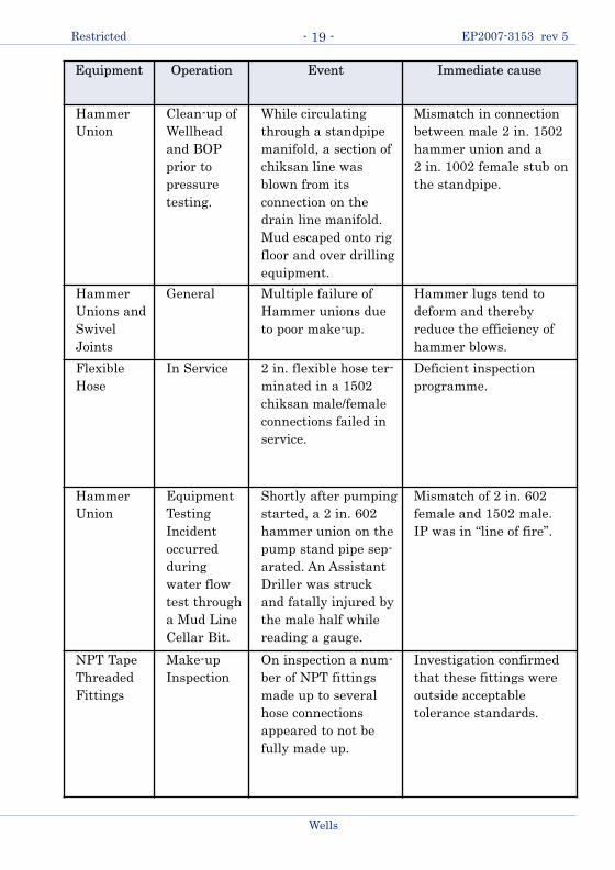
Equipment Operation Event Immediate cause
HammerUnion
Clean-up ofWellheadand BOPprior topressuretesting.
While circulatingthrough a standpipemanifold, a section ofchiksan line wasblown from its connection on thedrain line manifold.Mud escaped onto rigfloor and over drillingequipment.
Mismatch in connectionbetween male 2 in. 1502hammer union and a 2 in. 1002 female stub onthe standpipe.
HammerUnions andSwivelJoints
General Multiple failure ofHammer unions dueto poor make-up.
Hammer lugs tend todeform and therebyreduce the efficiency ofhammer blows.
FlexibleHose
In Service 2 in. flexible hose ter-minated in a 1502chiksan male/femaleconnections failed inservice.
Deficient inspection programme.
HammerUnion
EquipmentTestingIncidentoccurred duringwater flowtest througha Mud LineCellar Bit.
Shortly after pumpingstarted, a 2 in. 602hammer union on thepump stand pipe sep-arated. An AssistantDriller was struckand fatally injured bythe male half whilereading a gauge.
Mismatch of 2 in. 602female and 1502 male.IP was in “line of fire”.
NPT TapeThreadedFittings
Make-upInspection
On inspection a num-ber of NPT fittingsmade up to severalhose connectionsappeared to not befully made up.
Investigation confirmedthat these fittings were outside acceptable tolerance standards.
- 19 -Restricted EP2007-3153 rev 5
Wells
ABC Guide to Temporary Pipework-Rev5-Feb20-12:Wells ABC Guide to Temporary Pipework 20/02/2012 10:42 Pa

Equipment Operation Event Immediate cause
FlexibleHose
PressureVenting
During pressure venting aftertransfer of bulk chemicals, a 4 in. flexible hose was loweredover side of vessel into the seato prevent dust clouds duringventing. It was kept sub-merged by using an old valveand ballast chain on the out-board end and had a 4 mlength of rope to aid recovery.A sudden release of com-pressed air occurred when avent valve in the engine roomwas opened and caused thevent hose to whip out of thesea onto the deck of the vesselwhere a crewman was struckon the head and fatallyinjured.
The hose was notadequately secured toprevent whippingonto the deck and themethod used was nota safe or recommend-ed practice.
Threadedconnectionon pipe runto productiongas header
Coil tubingoperation
Accumulation of solids in theline downstream of the separa-tor to the production gas header caused a rapid build-upof pressure, to 2050 psi, whichwas relieved by the operationof the burst disc and reliefvalve on the separator. On discharge at the separator theseparator which was stationedon a trailer moved down, causing the line to “whip”about 6 inches and separate atthe threaded connections.
The down movementof the separator andlack of engagement ofthe threads – threadsnot stripped.
HammerUnion
PressureTesting
Pipework was dropped off atlocation for pump to comelater. The drill crew hooked uppipework to their 602 connection on their own pump.Driller was struck by pipe andkilled.
Mismatch betweenstandard 2 in. 1502WECO union andrig’s “2” 1602 WECOunion
- 20 -
Wells
Restricted EP2007-3153 rev 5
ABC Guide to Temporary Pipework-Rev5-Feb20-12:Wells ABC Guide to Temporary Pipework 20/02/2012 10:42 Pa

4 Pipework Connections and Interfaces
In earlier sections, it has been shown how important the quality of pipework connections and interfaces is to the integrity of the system. Improperly fitted,rated, or sized connections repeatedly prove to be the weak point of the systemwhen exposed to operating conditions.
4.1 Hammer Union Mismatches
Mismatches in hammer unions are severe mechanical hazards to the integrity ofthe temporary pipework system. They are weak points that may fail under pres-sure and can result in serious personal injury, death, and/or property damage.
Such Mismatches occur in 5 main categories:� Mismatching the same size.� Mismatching the pressure ratings.� Mismatching of wing nuts.� Mismatching of components.� Mismatching of non-detachable and detachable components.
Avoiding these mismatches is of prime importance in all aspects of temporarypipework operations. To further illustrate this, each mismatch is covered morefully in the sections below
4.1.1 Mismatching the Same-Size Hammer Unions
These mismatches refer to connecting hammer unions having the same size, butdifferent figure numbers. The Wing Half of the 2 in. Fig 1502 can accept a female2in. Fig 602 or 2 in. Fig 1002. This connection can appear to make-up will holdsome pressure, but will fail due to lack of thread engagement.
The following Hammer union mismatches have the same threads:
The 2 in. 602 and 2 in. 1002 unions are banned in Shell. They must be identifiedby contractors and installations and systematically removed and replaced with 2in. 1502 unions.
Size Union Figure Nos
1½ in. 600, 602, 1002
5 in. 400, 1002
Table 4 - Hammer Union Mismatches To Avoid
- 21 -Restricted EP2007-3153 rev 5
Wells
ABC Guide to Temporary Pipework-Rev5-Feb20-12:Wells ABC Guide to Temporary Pipework 20/02/2012 10:42 Pa

2” 1502 Segments
2” 1502 Male(Detachable Type)
2” 1502 Nut
Hazardous!!!Improperly Made-Up Acme Thread - as little
as 0.10in. Thread Flank contact per Side
Seal Ring
2” 602 FemaleMismatched!!!
MIS-MATCH!Never connect products with hammer union end
connections that are not positively identified as to
the manufacturer and that are not identified to have
identical union figure number, size and pressure rat-
ing. Mismatched connections may fail under pres-
sure, which can result in serious personal injury,
death and/or property damage.
Figure 17 - Mismatch of hammer union end connections
- 22 -
Wells
Restricted EP2007-3153 rev 5
ABC Guide to Temporary Pipework-Rev5-Feb20-12:Wells ABC Guide to Temporary Pipework 20/02/2012 10:42 Pa

4.1.1.1 Use of the Go No-Go Gauge
The Go No-Go Gauge shall be used to be sure you have a 1502 Female Sub. Thegauge will be “No-Go” on a 1502 sub but will be a “Go” on a 602 sub.
It is important that the inside diameter of the GO NO-GO ring reflects the NO-GO of the 2 in. 1502 rather than GO on the 2 in. 602. There are 2 in. 602 femalesubs which are not replicas of the original WECO 2 in. 602, having larger dia-meters. The flat gauge ring ID should have 4.000 inch (101.6mm) opening so itwill GO on these proprietary replica unions but still NO-GO on the 2 in. 1502female sub thread. The 2 in. 1502 union thread is 4.109 inch (104.4 mm)minimum OD.
2 in. Fig 1502 Female - NO-GO 2 in. Fig 602/G/Sealomatic/607 Female - GO
Figure 18 - Using the Go No-Go gauge
This go/no-go gauge can be purchased from either:
FMC at 800-772-8582 (Select 1, then 1 for Flowline Customer Service)
or
Wood Machine Company, Tulsa, OK (Part number 477990000) at 918-438-2412 or email: [email protected]
2 in Fig 1502
No-Go
interference
2 in Fig 602 2 in Kemper Fig G, Guiberson
Sealomatic & Best Fig 607
2 in American
Block Fig 602
Varying clearances between gauge and female stubs
4.109 in. 3.812 in. 3.938 in. 3.922 in.
- 23 -Restricted EP2007-3153 rev 5
Wells
ABC Guide to Temporary Pipework-Rev5-Feb20-12:Wells ABC Guide to Temporary Pipework 20/02/2012 10:42 Pa

4.1.2 Mismatching Pipe Pressure Ratings
This type of mismatch refers to connecting hammerlug union products having different pressure ratings but with end connections of the same size and figurenumber. This occurs when mixing sour gas pipe with standard service pipe orwhen unions are welded to pipe with a working pressure lower than that corresponding to the union.
The use of Sour Service pipework in Standard Service applications (but not theother way round) is allowed, but discouraged. In these instances, it is imperativethat the working pressure of the Sour Service pipework is not exceeded.
2 in. 1502 StandardFemale Sub
2 in. 1502 Sour ServiceMale Sub and Wing Nut
MIS-MATCH!Wing union components that cannot be positively identified
with regard to manufacturer, size, figure number, pressure
rating and type of service must never be used. Incorrectly
identified components will lead to hazardous assemblies,
which can fail under pressure and result in serious personal
injury, death and/or property damage.
15,000psiWP
10,000psiWP
Figure 19 - Mismatching of wing union components
- 24 -
Wells
Restricted EP2007-3153 rev 5
ABC Guide to Temporary Pipework-Rev5-Feb20-12:Wells ABC Guide to Temporary Pipework 20/02/2012 10:42 Pa

4.1.3 Mismatching Wing Nuts
This mismatch occurs when the wing nut of one size and figure number is mounted on the male sub of another size and figure number. There is only a smallamount of engagement of the male sub in the wing nut and therefore the connection will not safely hold typical working pressures.
4.1.4 Mismatching Components
Mismatching of components occur when segments and nut of one figure numberare made up to a detachable male sub with a different figure number. This resultsin a small amount of engagement of the male sub with the segment engaging thewing nut. This will not hold pressure safely during typical operations.
MIS-MATCH!
3 in. 1502Wing Nut
3 in. 602DetachableMale Sub
Never assemble any combination of malesub, wing nut or segments that are notpositively identified to assure that unionfigure number, size, pressure rating andmanufacturer are identical. Mismatchedcomponents will result in hazardous connections, which may fail under pres-sure, which can result in serious personalinjury, death and/or property damage.
Figure 21 - Mismatch caused by misidentification - detachable male sub
MIS-MATCH!
3 in. 1502Wing Nut
3 in. 602StandardMale Sub
Never assemble any combination of malesub, wing nut or segments that are notpositively identified to assure that unionfigure number, size, pressure rating andmanufacturer are identical. Mismatchedcomponents will result in hazardous connections, which may fail under pres-sure, which can result in serious personalinjury, death and/or property damage.
Figure 20 - Mismatch caused by misidentification - standard male sub
- 25 -Restricted EP2007-3153 rev 5
Wells
ABC Guide to Temporary Pipework-Rev5-Feb20-12:Wells ABC Guide to Temporary Pipework 20/02/2012 10:42 Pa

4.1.5 Mismatching Non-Detachable and Detachable Components
This mismatch is caused by the assembly of non-detachable nuts on detachablemale subs. The detachable wing nuts require a longer thread length to compensatefor the segments between the wingnut and the sub shoulder. Use of a non-detach-able wing nut in a detachable union results in a lack of thread engagement and aninsufficient engagement between of the male sub shoulder with the wing nut ID.
4.1.6 Connecting a Hammer Union Male Sub from one manufacturer to
the Female Sub from a different manufacturer.
The practice of mating connection components from different manufacturers whereno industry standard exists for the design and manufacture of the connection isgenerally not allowed. In the case of Hammer Unions, the acme thread is specifiedby ASME B 1.5, 1.8, but not the sealing arrangement.
The male sub (all components from one manufacturer) can be mated with thefemale sub from another manufacturer if there is an operational history of matingintegrity.
MIS-MATCH!
The misapplication of standard, non-detach-able style wing nuts on 2 in., 3 in. and 4 in.Figure 602 and 1002 detachable nut connec-tions will result in an unsafe connectionleading to separation when under pressure.Failure to avoid this condition may result indeath, serious personal injury and severeproperty damage.
4 in. 1002 non-detachable nut inappropriately
assembled to a detached male sub end. Notice
the excessive play between the ID of the nut
and male sub OD behind the shoulder.
Figure 23 - Another misapplication of wing nuts
MIS-MATCH!
The misapplication of standard, non-detach-able style wing nuts on 2 in., 3 in. and 4 in.Figure 602 and 1002 detachable nut connec-tions will result in an unsafe connectionleading to separation when under pressure.Failure to avoid this condition may result indeath, serious personal injury and severeproperty damage.
4 in. 1002 non-detachable nut inappropriately
used in a detachable union assembly. Notice
the resulting lack of thread engagement with
the female sub.
Figure 22 - Misapplication of wing nuts
- 26 -
Wells
Restricted EP2007-3153 rev 5
ABC Guide to Temporary Pipework-Rev5-Feb20-12:Wells ABC Guide to Temporary Pipework 20/02/2012 10:42 Pa

4.2 Mismatching Swivel Joint Components
Because of similarities in design, it is physically possible to erroneously assemblea male race end of a SPM 3 in. HD-LR component into the female race end of anFMC 3 in. TSi component. The assembly would not be structurally sound.
4.3 Mating Hub Connector Components from different
manufacturers
The issue arises as the patent for Grayloc© has expired and Grayloc will notendorse the integrity of the connection with components “copies” from anothermanufacturer. The mating of hub connector components from two different manu-facturers (only) is allowed if:
� The components are dimensionallythe same and mechanically equiva-lent.
� The hub connector face shall be fromone manufacturer and all the otherconnector components shall be sup-plied by the other manufacturer.
� The assembled connector integrityhas been validated at temperature,pressure and side-loading by themanufacturer supplying the majori-ty of the components.
If these conditions cannot be ascertained, a crossover should be manufacturedwith the sealing faces from the respective manufacturers on opposite ends to avoidmixing the connector components.
Wells
Restricted EP2007-3153 rev 5- 27 -
Gap in 3 in.
ball raceNo step between
second and third race
SPM 3 in. HD-LR
male ball race end
FMC 3 in. TripleStep
female ball race endSPM 3 in. HD-LR
female ball race end
FMC 3 in. TripleStep
male ball race end
Male race interferes
with female end
Dangerous Mismatch to be Avoided
Figure 24 - Dangers of mismatching swivel joint components
Do not mix components from different manufacturers
Figure 25 - Mating Hub Connectors
1 Hub Connector Facefrom Manufacture “A”
All other componentsfrom Manufacturer “B”
ABC Guide to Temporary Pipework-Rev5-Feb20-12:Wells ABC Guide to Temporary Pipework 20/02/2012 10:42 Pa

Restricted EP2007-3153 rev 5
Wells
- 28 -
4.4 Threaded Connections
The requirement limiting NPT and line pipe pressure sealing threads (PST) to 1/2”connections has been amended to allow larger nominal sizes, subject to strict QCcriteria. (See section 4.4.3).
The issues with pressure sealing threaded connections are illustrated below:
In Figure 26 the pressure containing equipment with 2” NPT (Pressure SealingThreads) provides a false sense of security - one cannot tell the condition of thethreaded connection as it can be corroded by well or pumped fluids, or been fullymade up.
2” NPT connection(Pressure
Sealing Thread)
Hammer lug Weco union to 2” nipple
engaged by 6 -7 threads only
(Normalengagement requires 8 - 9
threads)
Should be made up to this point
Figure 26 - NPT in poor condition due to corrosion and with insufficient make-up
ABC Guide to Temporary Pipework-Rev5-Feb20-12:Wells ABC Guide to Temporary Pipework 20/02/2012 10:42 Pa

4.4.1 Non-Pressure Sealing Thread (NPST) & Pressure Sealing Thread
(PST) Line Pipe and NPT
Wells
Restricted EP2007-3153 rev 5- 29 -
Figure 27 - NPST vs. LPT
The NPST connection was developed in order to isolate the tubingthread from the contained fluid.
Tubingthread
Male sub
Seal ring
Wing nut
Female sub
NPST Connection – Allowed(seal made by elastomer)
PST Connection - Banned for use above 285 psi(seal made by thread)
Wing nut
Female sub
Seal ring
Male sub
Linepipethread
WellFluids
Tubingthread
Bakerlok
Linepipethread
WellFluids
ABC Guide to Temporary Pipework-Rev5-Feb20-12:Wells ABC Guide to Temporary Pipework 20/02/2012 10:42 Pa

Differentiation of NPTS from PST hammer union connections.
Made-up pipework with NPST hammer union male and female connections can-not often be distinguished, viewed externally, from made-up pipework with PSTconnections.
A solution to distinguish between the two has been introduced by FMC. NPSThammer union subs will be identified by a groove 0.38” from the end of the subsand shown in the pictures below.
A viable method of retrospectively adding grooves to the NPST hammer unionsubs is proposed below.
1) Pipework Deployed on Current Operations.
Obtain confirmation from Supervisors that the Hammer union connectionsare NPST,
a) from records if the pipework is already made-up,
b) from internal visual inspection of the subs - internal threading on thesub is visible if it is a PST connection. Remove and replace any PSTconnections.
2) Pipework going through maintenance.
When pipework is pulled for maintenance, cut the grooves on the subs onboth ends of the pipe. - Figure 29 shows the dimensions and position, relative to the end of the
subs, of the grooves (one each end).- The copied email (green text) from FMC gives information on the
grinder that can be bought for cutting the grooves on the subs. Thegrinder is mobile, so the grooves can be cut in the Service Providers'
Restricted EP2007-3153 rev 5
Wells
- 30 -
Figure 28 - FMC NPST Hammer Union Subs with groove 0.38” from ends
GrooveGroove
ABC Guide to Temporary Pipework-Rev5-Feb20-12:Wells ABC Guide to Temporary Pipework 20/02/2012 10:42 Pa

workshops. According to FMC it takes about 10 mins per end. You needan adapter for this grinder which FMC have designed. They will providedetails - see below.
Following are the components that FMC purchased to cut the grooves on theNPST pups in the field.
1. Motorized Tubing Cutter, manufactured by Mathey Dearman p/n 03-0100-M00(operates off of 110V AC)
2. Heavy Duty Die Grinder, manufactured by Milwaukee Electric Tool p/n 5192(operates off of 110V AC)
3. Die Grinder Tip, manufactured by SGS p/n 12100, Tool SC-13, 1/8" shank, 5/32"Diameter Bur Tool.
One additional item, an adapter, is required to attach the Die Grinder to theTubing Cutter. FMC Manufacturing Engineering Dept. designed and built thisadapter for their use, but would be willing to share this information with anyoneneeding it in the future. Please let FMC know if you need additional information.
Wells
Restricted EP2007-3153 rev 5- 31 -
Figure 29 - FMC NPST Retrofitted-groove schematics
Male Sub
Female Sub
ABC Guide to Temporary Pipework-Rev5-Feb20-12:Wells ABC Guide to Temporary Pipework 20/02/2012 10:42 Pa

4.4.2 Line pipe, NPT, NPTF
4.4.2.1 Tapered Pipe Connections/Fittings - General
Tapered Pipe Fittings are prone to leakage because they are torque-sensitive.Over-tightening can distort the threads too much and create a leakage path. Also,tapered pipe threads are prone to loosening when exposed to high vibration andwide temperature variation. Repeated assembly and disassembly only aggravatesthe leakage problem by distorting the threads further. Tapered pipe threadsshould not be used for mechanically joining components in a system where loadwould be placed perpendicular to the pipe axis. This weight will further weakenthe sealing joint. In light of its sealing mechanism (described below), assemblyrestrictions and design limitations, pipe thread connections are optimal only whenthe following conditions exist:
� Minimum hydraulic shocks or vibration.� The fitting/connection is limited to few re-uses (makes and breaks).� For NPT fittings, few operating cycles for higher pressure service.� Connections are made-up by competent personnel.
Line pipe and NPT are pressure sealing threads (PST). Line pipe and NPTthreads for the same nominal pipe size are very similar, having the same taper,threads per inch and thread height.4.4.2.2 Line Pipe
To ensure that line pipe threaded connec-tions are leak-tight, the connections needto be made up “power-tight” after apply-ing thread compound. Note that after thefirst make-up of line pipe threads power-tight, the threads may not necessarilygauge. These threads are not designed to be made-up power-tight and brokenmany times and still remain pressure tight.
Figure 30 - Line pipe connections which parted under rapid pressure increase(pipework blockage) and violent transverse movement
Bent
linepipe
nipple
- 32 -
Wells
Restricted EP2007-3153 rev 5
ABC Guide to Temporary Pipework-Rev5-Feb20-12:Wells ABC Guide to Temporary Pipework 20/02/2012 10:42 Pa

For the above reasons line pipe pressure sealing threaded (PST) pipework is forbid-den on the high pressure side (> 285 psi) of the process. 4.4.2.3 NPT and NPTF - Similarities and Difference
NPTF (ANSI/ASME B1.20.3) threads are derived from the NPT (National PipeTaper ANSI/ASME B1.20.1) thread form adjusted to achieve metal-to-metal contactat the root and crest of the threads when they are assembled. The connection isknown as a “dryseal” connection – notionally it does not require any sealant inorder to be leak-tight. The applications for this connection are where it is necessaryfor preventing the process fluid becoming contaminated by the sealant or theprocess fluid is corrosive. The crests and roots of NPT never meet, even whentorqued up, but NPTF crests and roots are the first point of contact. As the connec-tion is torqued the crests deform until the thread flanks meet. NPT threads alwaysrequire a sealing compound to block the helical leak path. NPTF threads shouldseal if they are clean and perfectly formed, but a lubricant is still required so seal-ing liquid should still be used.
Consequently NPT fittings should not be mixed with NPTF connections. In factNPT male can be used with NPTF female, not the other way around, but to avoidconfusion it is best never to mix the threads at all. NPTF threads are common forsmall size steel couplings. Stainless fittings should always be NPT.
Rolled threads vs cut threads
Cut (machined) NPT or NPTF threads are sharp and clean, but rolled NPT threadshave a rough texture on the crests of the thread due to the manufacturing process.This is normal and does not mean the thread will gall as only the thread flankscome into contact.
One time make-up vs multiple use
NPT, NPTF has a thread interference design that means as the fitting is tightenedthere is some deformation of the material. This means that technically NPT, NPTFis a one-time make-up connection. NPT, NPTF are not a multiple make up fittings.NPTF is more susceptible to failure compared to NPT as a result of multiple make-up/break-out. Gauging requirements are much more stringent for NPTF comparedwith NPT. The dominant thread type for Wells applications is NPT.
For NPT and NPTF specifying torque values is unusual because with metal-to-metal contact and the thread tolerances on the threads, torque values would behighly variable, especially for NPTF. Leak-tight specification of the connection isbest done by number of exposed threads after the connection has been madewrench tight. However, some indication of torque values is given below.
- 33 -Restricted EP2007-3153 rev 5
Wells
ABC Guide to Temporary Pipework-Rev5-Feb20-12:Wells ABC Guide to Temporary Pipework 20/02/2012 10:42 Pa

NPT
On the high pressure side of operations using temporary pipework, only threadedconnections up to ½ in. are allowed for instrument or hose connections. At ½ in.nominal size, the cold working pressure for an NPT connection is 10,000psi. NPTthreads without the use of a sealant will not be leak-tight.
The NPT thread gauging illustrated in the following pictures should be incorporat-ed into the routine pipework maintenance.
Size - ins. Torque N-M ft-lbs1/41/2
4090
3067
Table 5 - Indicative Torques for High Pressure (> 6000 psi) NPT fittings
OK thread gauge sticks up to mark Not OK thread gauge passes mark when screwed tight
Mark
No. 1562 L1
Thin Ring
No. 1560 L1
Single End Plug
Ring Gauge Plug Gauge
Figure 31 - NPT thread gauging
- 34 -
Wells
Restricted EP2007-3153 rev 5
ABC Guide to Temporary Pipework-Rev5-Feb20-12:Wells ABC Guide to Temporary Pipework 20/02/2012 10:42 Pa

Gauges can be obtained from:http://www.kennametal.com/en-US/products_services/metalworking/tapping/Greenfield_tap_die/Greenfield_tap_die_products.jhtml
Figure 32 - NPT thread gauging and engagement - high pressure (>6000 psi) fittings
Nominal Size (in.)
Pipe ODThreads/
inch
Hand-tightengagement
Wrench-tightmake-up
Max lengthWrench-tight
makeup
in. mm Threads/turns
Threads/turns in. mm
1/16 0.31 7.9 27 4.3 23/4 - 3 0.11 2.81/8 0.4 10.2 27 4.3 23/4 - 3 0.11 2.81/4 0.54 13.7 18 4.1 3 -3.1 0.17 4.83/8 0.67 17 18 4.3 3 0.17 4.21/2 0.84 21.3 14 4.5 3 0.21 5.4
NPT (ASME B1.20.1)
Included in the standards for NPT threads are engagement lengths, both hand-tight and wrenched. For example, a 1/4inch tapered pipe fitting should screw in 4.1 threads until finger tight and 3 threads for wrench makeup. One problem is
the wide variance in quality of the fittings and threads. Few 1/4 inch fittings screw in 4.1 threads before they reach fin-
ger tight. As a general guideline, after hand-tight engagement, tighten 2 3/4 - 3 full turns for sizes up to 1/2 inch.
FlushOne turnlarge
One turnsmall
Plug
Gauge
Optimal diameter Maximum toleranceon diameter
Minimum toleranceon diameter
One turnlarge
One turnsmall
Flush
Female nipple internal threads
Optimal diameter Maximum toleranceon diameter
Minimum toleranceon diameter
Male nipple internal threads
Ring
Gauge
For gauging internal
taper threads, the plug
gage is screwed up tight
by hand into the internal
thread of the product.
The thread is within the
permissible tolerance
when the gauging notch
of the working plug gage
is not more than 1 turn,
large or small, from
being flush with the end
of the thread.
In gauging external taper
threads, the ring gage is
screwed up tight by hand
on external thread of
product. The thread is
within the permissible
tolerance when the
gauging face of the
working ring gage is not
more than 1 turn, large
or small, from being
flush with the end of the
thread.
- 35 -Restricted EP2007-3153 rev 5
Wells
ABC Guide to Temporary Pipework-Rev5-Feb20-12:Wells ABC Guide to Temporary Pipework 20/02/2012 10:42 Pa

Sealing liquid vs thread tape
Coupling and fitting suppliers commonly recommend using a liquid thread lubri-cant/sealant in place of sealing tape.
A down side of sealing tape is the risk of applying too much or too little. If toomuch is applied, not enough turns will be engaged and the threads will not inter-lock completely. In the worst case the fitting could fail under pressure. If the fit-ting starts to tighten within one turn due to the excess tape, all the force will beconcentrated in a small area and the female may split.
If too little tape is used the voids may not be filled and the connection could leak,or there could be too little lubrication and an increased risk of thread galling.
Shell guidelines (3804-005 MIMS Plant and Equipment – Guidance 1.002 SmallBore Tubing Installation) state that the sealant method chosen should be consis-tent with the design specification for the system. In other words, if liquid sealantis specified it must be used, but otherwise tape is acceptable.
Figure 33 - Example of split female connections: A combination of the female thread being slightly off-centre (but within tolerance) and using excessive Teflon®tape on the male thread
Split Split
Leakage path through
NPT threads shown at red
points. No matter how
tight you make NPT
threads, a leakage path
still exists. It is the
function of the sealant to
block the path between the
male and female thread
Figure 34 - Leakage path through NPT threads
- 36 -
Wells
Restricted EP2007-3153 rev 5
ABC Guide to Temporary Pipework-Rev5-Feb20-12:Wells ABC Guide to Temporary Pipework 20/02/2012 10:42 Pa

PTFE tape application and make-up
The PTFE tape (to spec AA-58092 or Mil-T-27730A) should be selected appropri-ate to the pressures, fluid type and fitting material (stainless steel). High densitytape (1.2 gm/cc) is recommended for sealing taper threaded connections againsthigh pressure gas.
� Apply PTFE TAPE to male threads as close as possible to end of threads.Hold end of PTFE TAPE firmly and wind clock wise on standard threads.Stretch tape tightly as you wind.
� Continue to wind and stretch tape so the tape seats into threads. Wind oncearound on joints under 1 in. with 50% overlap, as shown in the pictureabove.
� Complete winding and overlap bottom end of male thread by about 1/2 in.Tear tape by pulling in same direction as you were winding. Smooth tornend by running fingers over it. Make-up the connection in usual manner.
A
B
B
A TapeB 50% overlap to give double layer covering
Figure 35 - Clock wise wrapping procedure
- 37 -Restricted EP2007-3153 rev 5
Wells
ABC Guide to Temporary Pipework-Rev5-Feb20-12:Wells ABC Guide to Temporary Pipework 20/02/2012 10:42 Pa

4.4.3 Pressure Sealing Threaded (PST) Connections greater than 1/2”
The following NPT and Line Pipe threaded connections for pressure containmentfor 10,000 psi and below:
*Maximum size 2” if thread is exposed to H2S.
{Note: This table is more conservative than Table 1 in API SPEC 6A.}
The following conditions apply:i) The NPT connections are manufactured according to ASME/ANSI B1.20.1
and the Line Pipe connections according to API Specification 5B. ii) The minimum wall thickness of the connecting coupling in which the male
thread makes up shall be not less than that of the unthreaded connectedpipe/nipple wall thickness. (The coupling wall thickness being measuredfrom root of thread to the minimum outside diameter.)
iii) Internal threaded components shall be at least equivalent in strength andtoughness to the external threaded components. (The threaded connectionhas the same or higher service specification than that of thepart/equipment to which it is assembled.
iv) Threads exposed to pressured or produced fluids shall be subject to 100%examination for finish and fit. Items with visible imperfections in threadfinish or failure to meet gauging requirements in API Spec 5B or ASMEB1.20.1, as applicable, shall be rejected.
v) NPT and line pipe threaded connection make-up, requiring the applicationof sealing tape or sealing compound, is done by trained personnel. Thesealant or lubricant used on threads shall be compatible with the fluid service.
vi) The connection threads are inspected, gauged, maintained and controlledwithin a Quality Management System. The threaded parts shall be markedwith their maximum working pressure, thread type and their suitability forsour service.
{Note 1: The calculation of wall thickness is made using the equations andallowable stresses from ASME B31.3 for the specified internal design pressure. (The use of more conservative equations, e.g. Barlow, is accept-able.)Note 2: The calculation of shear strength is made using the equationsgiven in ISO TR 10400 or is based on empirical data.}
The following pressure sealing threaded connections are NOT allowed:i) Pressure sealing threaded connections cut on pipe body connected to
hammer unions or to any threaded connector which requires hammering
Restricted EP2007-3153 rev 5
Wells
- 38 -
Nominal Pipe Size (ins) 1/4”, 3/8”, 1/2” 3/4”, 1” 1 1/4” to 6” *Max. Rated WP (psi) 10,000 5,000 2,500
Table 6 - Allowed threaded connection working pressures for different pipe sizes
ABC Guide to Temporary Pipework-Rev5-Feb20-12:Wells ABC Guide to Temporary Pipework 20/02/2012 10:42 Pa

for its make-up or break-out.ii) Threaded connection sizes greater than 2” if exposed to sour fluids.iii) In conditions where the connections are subject to vibration, mechanical
shocks, hydraulic shocks.iv) Threaded connections greater than 6” nominal pipe size.{Note: ASME Pressure designations are: High Pressure > ~6000 psi; NormalPressure <~6000 psi.Shell designations: High Pressure > 10,000 psi; 500 psi <Normal Pressure <10,000 psi. Low Pressure <285 psi for threaded connections. Low pressurefor pressure testing is ~200-500psi.}
Situations where pressure sealing threaded connections may be found on well testing equipment are:
� Dataheaders 5000 psi WP 3/4” NPT (Thermowells).� HP Separator, Fisher Controller 2160 psi WP 1 1/2” NPT� Separator, Daniel orifice meter 1440 psi WP 3/4” NPT drain� HP Separator 3500 psi WP 3/4” NPT connections� Separator 1440 psi WP 1” NPT Isokinetic
sampling point on gas line
Threaded connections (taper and straight) on hydraulic hoses and control linesused for control systems containing clean and non-corrosive fluids are allowed.
Wells
Restricted EP2007-3153 rev 5- 39 -
Table 7 - Normal pressure < 6000 psi NPT nominal sizes and thread engagement data.
NominalSize (in.)
Max WP(psi)
Pipe ODThreadsper inch
Handtightengagement
Wrenchtightmake-up
Max Length Wrench-tight makeup
in. mm Threads:Turns
Threads:Turns in. mm
0.75 5000 1.05 26.7 14 4.75 3 0.21 5.3
1 5000 1.315 33.4 11.5 4.6 3 0.26 6.6
1.25 2500 1.66 42.2 11.5 4.8 3 0.26 6.6
1.5 2500 1.9 48.3 11.5 4.8 3 0.26 6.6
2 2500 2.375 60.3 11.5 5 3 0.26 6.6
2.5 2500 2.875 73.0 8 5.5 2 0.25 6.4
3 2500 3.5 88.9 8 6.1 2 0.25 6.4
3.5 2500 4 101.6 8 6.6 2 0.25 6.4
4 2500 4.5 114.3 8 6.75 2 0.25 6.4
5 2500 5.563 141.3 8 7.5 2 0.25 6.4
6 2500 6.635 168.5 8 7.7 2 0.25 6.4
ABC Guide to Temporary Pipework-Rev5-Feb20-12:Wells ABC Guide to Temporary Pipework 20/02/2012 10:42 Pa

4.5 Flexible Pipes - Hoses
4.5.1 Suitability of hoses connected in the high pressure (> 285 psi)
side of the process.
The high pressure hoses that are used in temporary operations include:� Hoses to direct well fluid from the test tree to the stand pipe or choke mani-
fold - test lines.� Hoses to direct fluids from the stimulation vessel to the frac head.� Cementing hoses.� Acid line.� Nitrogen lines� Chemical injection hoses.� Kill lines.
There are many standards for hoses which have been developed for specific indus-try applications. The standards for hose design and construction for application intemporary pipework operations include API 16C, API 17J (which is identical to ISO13628-2).It is generally accepted that the brand for high pressure hoses is Coflexip®(Technip). This hose design is classified as “unbonded flexible pipe”, the construc-tion consisting of separate unbonded polymeric and metallic layers, which allowsrelative movement between the layers. (ISO 13628-10 covers bonded hoses; API16C covers both unbonded and bonded hoses. API 16C gives rigorous requirementsfor the testing of flexible hoses and is not equivalent to ISO 13628-2.)Unbonded hoses are more suitable than bonded hoses in dynamic situations i.e.where there is relative movement between the hose ends. Unbonded hoses have asmaller bending radius in general for the same hose size and pressure rating.
Other established manufacturers of hoses, e.g. Parker with their Polyflex® prod-ucts, comply with criteria taken from both API 16C and ISO 13268-2. Some prop-retary criteria e.g. testing of the hoses, can be more stringent than that required inthe standards above or better reflect the conditions under which they will be used.
The expectation of Shell for the supply of high pressure flexible hoses given thediversity of their engineering and the polymer materials available today is that:
� Their design and construction in the main should comply with ISO 13268-2 /API 17J (unbonded) or ISO 13268-10 (bonded).
� Where there are differences between the specification and the standards,they should be evaluated for suitability with the proposed application.
� The hose should have a reliable track record; or, if a new design is proposed,that the hose should have been validated at the extremes of its operationalenvelope with the stressing parameters (pressure, temperature, flexing,vibration, etc.) applied simultaneously.
Restricted EP2007-3153 rev 5
Wells
- 40 -
ABC Guide to Temporary Pipework-Rev5-Feb20-12:Wells ABC Guide to Temporary Pipework 20/02/2012 10:42 Pa

4.5.2 Handling, Storage and Maintainance of Flexible Pipe
Flexible pipes or hoses are resistant to bending, including frequent continuousflexure, however it is imperative that they are handled, stored and maintainedcorrectly.
In general:� The preferred installation for a flexible line is with the pipe positioned in a
J or U configuration, with the end fittings pointing up in a vertical position.� Do not leave medium to longer lengths of horizontal pipe unsupported.� Ensure flexible pipe is not bent over or resting on sharp edges - any vibra-
tion will cause damage at such points.� Do not exceed the minimum bending radius of flexible pipe.
[ As a rule of thumb, the minimum bending radius (MBR) is roughly 12 xthe I.D. of the pipe].
Wells
Restricted EP2007-3153 rev 5- 41 -
d = (2 x MBR - OD)
“d” is the minimum inside distance between
two surfaces
MBR
Figure 36 - Minimum bending radius of flexible pipe
ABC Guide to Temporary Pipework-Rev5-Feb20-12:Wells ABC Guide to Temporary Pipework 20/02/2012 10:42 Pa

4.6 Equipment Interfaces & Equipment Repair and Maintenance
Replacement parts for temporary pipework should be built from design and manu-facturing files identical to the original parts and should have been validated at theextremes of the connection envelope:- pressure, temperature, side loading, etc.applied simultaneously.
Figure 37 - Hose installing concept for long spans
12
3
4 5Cable SWL 5.7t
Soft strops with
shackles
15m
SF4 PN
One shackle connection SWL 6t as cable
is not long enough Similar configuration for coflex on both ends
Cable
Chain block Steel sling or soft
strop SWL 5t
Deck beam
2
3
4
Anchor
Support to maintain bending radius
Cable anchor points
- 42 -
Wells
Restricted EP2007-3153 rev 5
ABC Guide to Temporary Pipework-Rev5-Feb20-12:Wells ABC Guide to Temporary Pipework 20/02/2012 10:42 Pa

Wells
Restricted EP2007-3153 rev 5- 43 -
5 Hazard Identification and Mitigation
5.1 Mitigation Methods
5.1.1 Checklists
5.1.1.1 Pre-Mobilisation Check List
Equipment for temporary operations can be assembled over several days as it isreleased after maintenance.
A final physical inspection when the package is complete will reduce the likelihoodof incorrect equipment being installed in the field.
A pre-mobilisation check is a specific activity independent of the ongoing checksmade when all the equipment is assembled and shall include verification:-
� that there are no mismatches of the types identified in this guide� of the mating integrity of connections� of the interfaces where equipment comes from different suppliers� of critical dimensions (IDs, ODs).
Where there is no categorical proof of the suitability of the equipment, physicalchecks shall be made.5.1.1.2 Pre-Pressure Test Temporary Pipework “Walk-the-Lines” Check List
The purpose of the checklist is to ensure that the Temporary Pipework and equip-ment:
� Is hooked-up in compliance with the approved drawings and equipmentlists.
� Can be operated as required by the Programme.� To ensure the adequacy of the ratings of the interfaces and blanked-off out-
lets.
Checklists are an orderly and sequential collection of “best practices” for confirm-ing the configuration of temporary pipework for safe operations. Checking a tem-porary layout must often be undertaken amid a host of competing job priorities.Routine supervisory duties can interfere with “walking-the lines” resulting in fail-ure to complete the checklist and confirm the correct configuration of the tempo-rary pipework. The consequences of disrupted or interrupted checklists are variedand potentially serious and must be avoided.
ABC Guide to Temporary Pipework-Rev5-Feb20-12:Wells ABC Guide to Temporary Pipework 20/02/2012 10:42 Pa

Restricted EP2007-3153 rev 5
Wells
- 44 -
NAME CLIENT RIG
GRADE CONTRACT NO. WELL
DATESUPERVISOR SNR TECH DATE
COLLECT LATEST P&IDESTABLISH EQUIPMENT TO BE SHIPPED MATCHES P&IDIF PROGRAMME/HAZ-OP AVAILABLE COMPARE WITH P&ID TO CHECK FOR INCONSISTANCIES
IMPLEMENT CHANGES IF REQUIRED
CHECK X-OVERS, ETC FOR ALL EQUIPMENTCHECK CHOKE MANIFOLD AND HEATER CHOKE FOR ALL NECESSARY EQUIPMENT AND THAT SPARES ARE AVAILABLELIASE WITH LOGISTICS/CERTIFICATION DEPT. ABOUT STATUS OF HIRE EQUIPMENT
IF FLOW CHECK VALVES ARE PRESENT ENSURE THEY OPERATE IN THE CORRECT DIRECTION
OBTAIN & CHECK RIG VISIT REPORT TO CHECK RIG INTERFACES WITH X-OVERS
DISCUSS WELLTEST DESIGN WITH OPERATIONS SUPERVISOR AND OPERATIONS SUPPORT TECHNICIAN
LIASE WITH WORKSHOP SUPERVISOR AND DISCUSS EQUIPMENT STATUS
CONFIRM VALVE HANDLES ARE PRESENT FOR ALL EQUIPMENT
IF ACID IS EXPECTED ENSURE REQUIRED PPE IS PACKED
CHECK SEPARATOR ORIFICE PLATES MATCHES SEPARATOR
CHECK STANDARD SPARES LIST MATCHES PACKAGEREQUIREMENT
CHECK SANDFILTER ELEMENTS SUIT PACKAGE IE. (GOLDEN SUPER), HIGH DIFF, FILTER CARRIERS
CONFIRM PILOT SETTINGS
CONFIRM ELEVATOR SIZES MATCH FLOWHEAD
CONFIRM TEST CAPS ARE AVAILABLE FOR ALL EQUIPMENT
CONFIRM STRING /WIRELINE X-OVERS ARE BEING SUPPLIED BY EXPRO, IF SO ARE THEY PRESENT?CONFIRM IF SUBSEA HAS INVOLVEMENT IN OPERATION, CHECK STATUS OF EQUIPMENT AND INTERFACESHAS BURNER BOOM INFORMATION BEEN CHECKED AND CONFIRMED WITH WORKSHOP?ARE ALL CREW MEMBERS SELECTED? ARE ANY OF THE CREW DUE TO GO ON ANNUAL LEAVE? DISCUSS RELIEF WITH CLIENT
SUPERVISOR SNR TECH DATEIS H2S OR CO2 EXPECTED? ARE ELASTOMERS ADEQUATE?
HAS SHIPPING LIST BEEN ADEQUATELY FILLED OUT? DISCUSS OMISSIONS WITH ONSHORE OPS SUPERVISOR, ENSURE ANY OMISSIONS OR MISTAKES ON SHIPPING LIST ARE RECTIFIED.NOTE: DISCUSS AND REVIEW ANY SIGNIFICANT CHANGES TO THE EQUIPMENT OR OPERATION (DOES THE CHANGE AFFECT THE OPERATIONAL REQUIREMENTS?)
WILL THERE BE/OR COULD THERE BE ANY LATE CHANGES TO ANY MAJOR ITEMS OF KIT? Eg. SEPARATOR, HEATER. IF SO, THE P&ID MUST BE CHANGED TO REFLECT THIS, CLIENT MUST ALSO BE INFORMED. HAZOP MAY HAVE TO BE RE-VISITED. ALL LATE CHANGES TO KIT MUST BE DISCUSSED WITH ONSHORE OPS SUPERVISOR AND RELEVANT INFO PASSED ONTO CLIENT
LIST OF ALL OUTSTANDING ITEMS - ADDITIONAL ITEMS, List all items that may be on order, are missing, or you are struggling to get hold of for the job. All items listed here should be passed onto Ops supervisor/workshop foreman for action.
Table 8 - Example of Pre-Mobilisation Temporary Pipework Checklist
ABC Guide to Temporary Pipework-Rev5-Feb20-12:Wells ABC Guide to Temporary Pipework 20/02/2012 10:42 Pa

Wells
Restricted EP2007-3153 rev 5- 45 -
Location/Well: Job No. Programme: Supervisors: Date: Reference Drawing No. Reference Equipment List(s):
Line Section:
Dispensations Requested for this line section:
Item/ Description of Check Procedure YES
Count/Eq No. NO
Reason N/A
1. Check pressure rating of upstream interface connection and subsequent connections in the line by reference to banding.
2. Check pipework material for suitability for service. 3. Check that the number of swivels has been minimised. 3. Check/confirm that correct bolts and gaskets are installed at all mechanical joints and bolt engagement. (Bolts shall extend completely through the nut with at least one thread exposed at each end. Confirm that bolting has been made up to the correct torque with calibrated torque wrenches.)
4. Check sealant on screwed connections is as per specification. 5. Check/confirm elastomers in hammer unions are compatible with fluids/service.
6a. Confirm that vessel/equipment outlets, not in the flow path and potentially subject to being pressured are appropriately blanked. Where the blanking comprises a male or female hammer union confirm the FIG no. and service is compatible with the vessel/equipment specification.
6. Check for correct flow through filters and strainers, traps, check valves, globe valves and control valves.
7. Check that the valve positions are tagged (open/closed) and are correctly lined up for the pressure testing. Where a valve is required to be locked open or closed, ensure that the locking system is sufficiently robust, preventing it from being simply overridden. Note those valves the position of which needs to be altered for the first operation.
8. Check that all chain wheels and extended spindles required for specified valves have been installed
9. Check that orifice flanges have required upstream and downstream ‘clearances’.
10. Check that all vents and drains are installed. The drains should be at the lowest points and vents at the highest points. Check for proper slope (e.g. flare lines).
11. Check all instrument thermowells installed. Check that welded nipples are properly installed. Threaded nipples shall be checked for engagement, Check that they have not been seal-welded.
12. Confirm the setting of pressure pilots, and sizing of pressure reliefs. 13. Confirm the safety of electrical instruments. 14. Check that all pipe supports, anchor point, clamps and restraints are adequate. (Confirm that expansion allowance has been provided. Confirm that there is no excessive bending moment resulting from lack of support or overloading from tugger lines on the pipework.)
15. For items marked ‘No’, raise outstanding works list and ensure that it is completed prior to pressure testing.
Table 9 - Pre-Pressure Test Temporary Pipework Checklist
ABC Guide to Temporary Pipework-Rev5-Feb20-12:Wells ABC Guide to Temporary Pipework 20/02/2012 10:42 Pa

Restricted EP2007-3153 rev 5
Wells
- 46 -
The key points are:1. The Wells Supervisor (WS) and the Contractor Services Supervisor (CSS)
are jointly responsible for ensuring that the Temporary Pipework is hooked-up as required by the approved P&ID or Process Flow Diagram.
2. Any deviation in the Temporary Pipework hook-up from the requirementsof the Standard for Temporary Pipework (EP 2006-5393) needs a“Dispensation”.
3. A confirmation that all temporary pipework has been certified (maintainedand tested) according to Contractors’ procedures (endorsed via contractawarded by Shell). Specifically that no equipment is “derated” or below theminimum wall thickness allowed.
4. The checks may be carried out Line Section by Line Section determined byspecification (pressure) breaks progressing from high pressure to low pres-sure.
5. Refer to EP 2006-5393 Appendix 3 for specific hammer union mismatchesand restraint dynamic loads. (Note specifically: Both male and female 2 in.Fig 402, 2 in. Fig 602 and 2 in. Fig 1002 unions are banned in all configura-tions e.g. vessel outlets, burner boom piping).
6. Where appropriate, record the number of connections inspected (Count) orequipment identification number (Eq. no.) in the “tick” column and if “NO”is ticked, the Reason.
5.1.2 No-Go areas
� During pressure testing keep at least 2 pipe run lengths away from the lineunder pressure.
� Keep out of line-of-sight of pressured plugged outlets, instrument connec-tions on vessels and flowline equipment.
ABC Guide to Temporary Pipework-Rev5-Feb20-12:Wells ABC Guide to Temporary Pipework 20/02/2012 10:42 Pa

5.1.3 Restraints for Temporary Pipework using Polyester Roundslings
The installation of temporary pipework restraints is mandatory where fluids arepumped or flowed through the pipework. The forces reacting on pipework whenfluids at high pressure are discharged through a rupture are large. A restraint sys-tem acts like a shock absorber. In order to absorb the kinetic energy of the pipe,the weakest part of the restraint system must have at least twice the strength(this is the dynamic force, or dynamic load) generated by the reactive force actingon the parted pipe. The maximum theoretical (corroborated by other calculationmethods and lower limit tests) dynamic forces generated in wire ropes, round-slings, fibre ropes, etc. used to restrain pipe when the pipe ruptures are given inthe charts Fig. 38, Fig. 39 for the pipe IDs and pressures in question.
When pumping non-energised liquid and the pipe runs are constrained fromswinging or from becoming projectiles, should a pipe section rupture, by the rigstructure (for example, pipe runs from an offshore cement unit) the installation ofa restraint system may be waived, subject to a suitable risk assessment.
Where pipework is “boxed-in” and cannot whip, become projectiles or indeed move(for example, boxed-in Compact Well Test equipment pipe runs between vesselsmounted on the same skid) installation of a restraint system around individualpipe sections is not required.Restraint Installation using Polyester Rounslings - General
The method for hitching round slings to pipework is similar to that which wasused for wire rope.
� It is assumed that the restraint installation requirements are straightfor-ward enough and the results obvious enough (when walking-the-lines) thatthe installation of roundslings as restraints can be performed competentlyby a person using these instructions.
� The roundsling restraint installation will generally start after all the temporary pipework is hooked up, prior to pressure testing.
� It is expected that the planning process will have identified the range (totallengths, individual lengths and WLLs) of the slings required and mobilisedfor the operation.
� It is not possible to prescribe restraint installation for every conceivableflow or pumping layout. It is expected that there is enough information inthe following instructions for the method to be applied to unusual pipeworkarrangements.
Wells
Restricted EP2007-3153 rev 5- 47 -
ABC Guide to Temporary Pipework-Rev5-Feb20-12:Wells ABC Guide to Temporary Pipework 20/02/2012 10:42 Pa

Restricted EP2007-3153 rev 5
Wells
- 48 -
30.0
40.0
50.0
ynamic Load (mT)
Cha
rt in
dica
ting
the
dyna
mic
load
ing
on, a
nd s
elec
tion
of E
N 1
492-
2 ro
und
slin
g re
stra
ints
in th
e ev
ent o
fpi
pe ru
ptur
e fo
r a ra
nge
of ID
's, t
he p
ipe
bein
g pr
essu
red
with
oil,
sea
wat
er (l
iqui
ds)
1500
0
Max
operating
2To
nne
Roundslings(workingloadlimit)EN14922(safetyfactor7:1)Colourcodes
pressure
(Liquid)
70.0
1000
2000
3000
4000
60.0
5000
6000
7000
8000
9000
1000
0
1100
0
1200
0
1300
0
1400
0
0.0
10.0
20.0
00.
51
1.5
22.
53
3.5
44.
55
5.5
66.
57
7.5
8
Dy
Pipe
ID (i
ns)
1600
0
1700
0
1800
0
1900
0
2000
0
42
65
38
1012
40Fto
194F
40Cto
90C
2"2.375"
OD
3"3.5"
OD
4"4.5"
OD
6"6.625"
OD
8"8.625"
OD
Joinbe
tweenhitche
swith
Exam
pleho
wto
usechartfor:
Processstep
s:Re
efKn
otor
shackle:
•Max
pressure
5000
psi(oil)
1.Drawverticallineup
from
3.152"
from
horizontal
•4.75
Tfor2,3,4WLL
restraints
Flow
edor
pumpe
d.Axisto
meet5
000psicurve.
•6.5T
for6
,7,8WLL
restraints
•4"
602pipe
sche
duleXX
S2.
From
pointo
fintersection,draw
aho
rizontalline
•8.5T
for9
,10WLL
restraints
•ID
ofschXX
S=3.152"
tomeetrou
ndslings
bars.
3.Th
efirstba
rintersected
givestheroun
dsling
WLL.H
itchpipe
with
6T(brown)
sling.
Reef
Knot
Half
Hitch
JoiningShackle
2To
nne
3To
nne
4To
nne
5To
nne
6To
nne
8To
nne
10To
nne
12To
nne
Roun
dslingrestraints
Max
load
(Ton
nes)
Hitche
dto
pipe
Figure 38 - Chart indicating dynamic loading and selection guide of EN 1492-2 roundsling restraints for liquid pressurised piping
ABC Guide to Temporary Pipework-Rev5-Feb20-12:Wells ABC Guide to Temporary Pipework 20/02/2012 10:42 Pa

Wells
Restricted EP2007-3153 rev 5- 49 -
40.0
50.0
60.0
70.0
mic Load (mT)
Cha
rt in
dica
ting
the
dyna
mic
load
ing
on, a
nd s
elec
tion
of E
N 1
492-
2 ro
und
slin
g re
stra
ints
in th
e ev
ent o
fpi
pe ru
ptur
e fo
r a ra
nge
of ID
's, t
he p
ipe
bein
g pr
essu
red
with
gas
1000
2000
3000
4000
5000
6000
7000
8000
9000
1000
0
1100
0
1200
0
1300
0
1400
0
Max
operating
pressure
(gas)
Roundslings(workingloadlimit)EN14922(safetyfactor7:1)Colourcodes
0.0
10.0
20.0
30.0
00.
51
1.5
22.
53
3.5
44.
55
5.5
66.
57
7.5
8
Dyna
Pipe
ID (i
ns)
1500
0
1600
0
1700
0
1800
0
1900
0
2000
0
42
65
38
1012
40Fto
194F
40Cto
90C
2"2.375"
OD
3"3.5"
OD
4"4.5"
OD
6"6.625"
OD
8"8.625"
OD
Joinbe
tweenhitche
swith
Exam
pleho
wto
usechartfor:
Processstep
s:Re
efKn
otor
shackle:
•Max
pressure
5000
psi(oil)
1.Drawverticallineup
from
3.152"
from
horizontal
•4.75
Tfor2,3,4WLL
restraints
Flow
edor
pumpe
d.Axisto
meet5
000psicurve.
•6.5T
for6
,7,8WLL
restraints
•4"
602pipe
sche
duleXX
S2.
From
pointo
fintersection,draw
aho
rizontalline
•8.5T
for9
,10WLL
restraints
•ID
ofschXX
S=3.152"
tomeetrou
ndslings
bars.
3.Th
efirstba
rintersected
givestheroun
dsling
WLL.H
itchpipe
with
5T(red
)sling.
Reef
Knot
Half
Hitch
JoiningShackle
2To
nne
3To
nne
4To
nne
5To
nne
6To
nne
8To
nne
10To
nne
12To
nne
Roun
dslingrestraints
Max
load
(Ton
nes)
Hitche
dto
pipe
Figure 39 - Chart indicating dynamic loading and selection guide of EN 1492-2 roundsling restraints for gas pressurised piping
ABC Guide to Temporary Pipework-Rev5-Feb20-12:Wells ABC Guide to Temporary Pipework 20/02/2012 10:42 Pa

Restricted EP2007-3153 rev 5
Wells
- 50 -
To use the charts:� Enter the horizontal axis with the pipe ID.� Draw a vertical line up from the ID to intersect the maximum internal
pipe pressure.� Draw a horizontal line to intersect the vertical axis and read the dynamic
loading in tonnes. (This first coloured vertical column that this line intersects just before meeting the vertical axis is the colour coding andstrength of the lowest safe roundsling restraint).
Note (1). Two charts are needed, giving the maximum dynamic loading onrestraints for open-ended pipe for:a. energised liquids, or non-energised liquids pressured from an
infinite source (oil reservoir), b. gasses.
The steady-state reactive force generated by the discharge is proportional to the density of the fluid being discharged, thus liquiddischarge, as indicated in the charts, produce a greater reactive forceon the pipe (and a corresponding greater dynamic loading on therestraints) than gas discharge.
Note (2). Although the restraints use lifting equipment technology, the SWL(Safe Working Load) or the WLL (Working Load Limit) of this equipment has no direct relevance for their use as pipeworkrestraints, except to indicate the breaking strength of the restraints,be it wire rope or roundslings. In the case of roundslings manufactured to EN 1492-2, the slings are designated by their WLLand the standard (1492-2) requires that their breaking strengthunder specific pull conditions is 7 times the WLL.
Note (3). Where Polyester roundslings are manufactured to ASME B 30.9 (USStandard), different Selection Charts apply. These are shown inAppendix 3.
ABC Guide to Temporary Pipework-Rev5-Feb20-12:Wells ABC Guide to Temporary Pipework 20/02/2012 10:42 Pa

Wells
Restricted EP2007-3153 rev 5- 51 -
5.1.4 Installation Steps for Polyester Round Slings
PRIOR TO PRESSURE TESTING
STEP 1 Selection of the round slings corresponding to line sizes
1. Verify the size and maxi-mum pressure of the linesections to be restrained.
2. Use the chart to selectrestraints suitable for thepipework being restrained.
3. Layout the slings required,checking the tags in addi-tion to the colour coding.
STEP 2 Pick anchor points
[Note: The following “Anchor Point” steps demonstrate restraint installa-tion using red (5T WLL) round slings.]
Identify an anchor pointon the equipment/rig,avoiding a pressured line,selecting a structural mem-ber without square edges.Try to pick the anchorpoint to minimise the free-dom for potential move-ment between the pointand the first half-hitch onthe pipework. Attach theroundsling restraint to thestructural member/anchorpoint with a choke-hitchand tighten.
ABC Guide to Temporary Pipework-Rev5-Feb20-12:Wells ABC Guide to Temporary Pipework 20/02/2012 10:42 Pa

Restricted EP2007-3153 rev 5
Wells
- 52 -
STEP 3 Hitching roundslings around the pipe away from the anchor point.
Make a half-hitch (illustrated with 3T WLL roundslings) around the nearestjoint of pipework in the process flow on the backside of a connection and removeany slack by pulling away from the anchor point and working and taking outany slack via the half-hitch.
AN
CH
OR
ABC Guide to Temporary Pipework-Rev5-Feb20-12:Wells ABC Guide to Temporary Pipework 20/02/2012 10:42 Pa

Wells
Restricted EP2007-3153 rev 5- 53 -
STEP 4 Joining two slings and connecting to the end anchor point
Warning: Slings must not be joined across connections (that is with the join,shackle or reef-knot, positioned between the half-hitches either side of a union orswivel connection).
1. Continue with the hitching away from the starting anchor point. Theroundslings can be joined by forming a reef-knot: pass one end of the slingto be joined through the free end of the restraining sling already installedand pull the free end back through itself.
Continue with hitching the roundsling to the pipework.
2. On reaching the anchor point, it will not be possible to make a chokehitch around a structural member. There are two possibilities illustratedhere with a 5T WLL roundsling, tieing off a roundsling to the structure ona separator:a) Wrap remaining slack around the member/bar/stiffener etc. and then
use a suitable shackle to tie-off.
b) Altenatively tie-off
ABC Guide to Temporary Pipework-Rev5-Feb20-12:Wells ABC Guide to Temporary Pipework 20/02/2012 10:42 Pa

Restricted EP2007-3153 rev 5
Wells
- 54 -
3. Where the restraints have been attached to anchor points at either end ofthe pipe run, it will not be possible to join their free ends together with areef-knot. The join can be made with a shackle of suitable size. (SeeAppendix A). (The roundslings may be additionally hitched either side ofthe shackle in order to take up slack).
4. Pipe runs which are not connected (anchored) by equipment at the ends,e.g. discharge lines, diversion lines, venting pipe runs, pressure relieflines, must be tied down to anchor points or solid structure withrestraints.
The 4” deluge water diversion lineshown right could rotate about anyof the connections (shown byorange arrows) injuring by contactwith or discharging the line con-tents at a person opening the valve(yellow arrow).
The discharge line should be reconfigured in the manner shown belowand restrained:
ABC Guide to Temporary Pipework-Rev5-Feb20-12:Wells ABC Guide to Temporary Pipework 20/02/2012 10:42 Pa

STEP 5 Encountering Swivels, Tee’s and Valves in the line
1. SWIVEL JOINT. On encountering aswivel joint in the line, a half-hitchmust be made across each breakablesection of the swivel and across the connecting unions.
2a. TEE 180 DEGREE BRANCH. Onencountering a TEE-180 degreebranch, continue with restraint instal-lation as if the TEE were a straight,half-hitching either side of the connection.
2b. 90 DEGREE BRANCH. If the TEE isencountered along the 90 degreebranch or a start to the installation ofthe restraints made from the 90 degreebranch, the connection should be madeas follow: pass the roundsling aroundthe 180 degree branch and thread itthrough itself to make a choke-hitch.Continue with half-hitches either sideof the connection on the branch as theyare encountered.
3. VALVE. On encountering a valve, whenrestraining pipework, half-hitch therestraint either side of the valve connections as shown.
STEP 6 Inspection of completed installation
Walk-the-Lines to verify that the sling installation has capturedevery connec-tion and that there is no “looping” slack in therestraints.
Wells
Restricted EP2007-3153 rev 5- 55 -
ABC Guide to Temporary Pipework-Rev5-Feb20-12:Wells ABC Guide to Temporary Pipework 20/02/2012 10:42 Pa

5.1.5 WeirSPM FSR System
Restricted EP2007-3153 rev 5
Wells
- 56 -
Flow Line Safety Restraint System (FSR)At a Glance
The Flow Line Safety Restraint System, or FSR, is the first and most utilized engineered restraint system specifically designed to reduce the area of danger around high-pressure flow line disengagements.
Now, the FSR System is available in two styles: the original Medium Duty FSR and the new Light Duty FSR.
Features of the Weir SPM FSR System:
• Rental packages available• Extreme high strength and reliability• Flexible & lightweight• Easy to install• Corrosion resistant• Works in both fluid and gas pumping operations
• Uniquely identifiable colors and labeling• Available Full-Service Assistance in the field• Ten years of proven, successful utilization
• Water resistant exterior covers
Medium Duty FSR Color Code:• Rib - Red• Spine - Blue
Medium Duty FSR Ratings:• 2" Iron - 20,000 psi• 3" Iron - 15,000 psi• 4" Iron - 10,000 psi
Medium Duty FSR Weights:(weight per foot of length)• Rib - .85 lbs. / ft.• Spine - 1.7 lbs. / ft.
Light Duty FSR Color Code:• Rib - Yellow• Spine - White
Light Duty FSR Ratings:• 2" Iron - 15,000 psi• 3" Iron - 7,500 psi• 4" Iron - 5,000 psi
Light Duty FSR Weights:(weight per foot of length)• Rib - .64 lbs. / ft.• Spine - 1.00 lbs. / ft.
For more information please visit the Weir SPM products page at
www.weiroilandgas.com
Available in offshore and onshorerental packages.
Training and full service support available.
Inspection / Rejection Criteria:
• Easy visual inspection process which can be performed in the field by competent personnel.• Any damaged items must be taken out of service immediately.• For more detailed inspection information visit the website below to view the FSR Operations Manual.
ABC Guide to Temporary Pipework-Rev5-Feb20-12:Wells ABC Guide to Temporary Pipework 20/02/2012 10:42 Pa

5.1.6 FMC Technologies TPR System
The FMC Technologies Temporary Pipeworks Restraint (TPR) System incorporates importantsafety and operational benefits for tough operating environments and demands for handlingpressurized fluids. The TPR System is designed to restrain potential separation of pipeworkat rated pressure for temporary pipework up to 4” Figure 1502. The design also takes intoconsideration the maximum fluid bore areas after material loss due to erosion.There are only two components in the TPR System: R-Links and C-Links. The R-Links arethe restraining components of the system, which are wrapped tightly to pipework. This instal-lation technique minimizes the strike zone, eliminates the need for anchor lines and mini-mizes tripping hazards. The C-Links are employed to connect the ends of two R-Links togeth-er. The C-Links have an integrated hitch pin to keep the assembly intact during pipeworkhandling and line vibrations. The simplicity of the TPR System facilitates the fastest possibleinstallation, removal for access to leaking connections and decommissioning.TPR System components can be quickly inspected on-site before or after each job through theapplication of the following inspection features:
� The fiber optic system, which will not pass light when internal yarn damage due tocrushing, cutting or chemical attack has occurred, even when the outer cover is intact.
� The External Warning Indicator, which disappears under the cover to indicate thatthe component had been misused or otherwise subjected to very high loads.
� A red undercover, which facilitates easy detection of damage to the outer cover.In most cases, TPR System components which have been rejected due to the above inspectionmethods are repairable through a refurbishment and recertification service provided by FMC.TPR System components employ the very best in high strength, chemically resistant fibertechnology. The two-layer cover is sized to reduce the amount of moisture that can beabsorbed. The TPR System is available in three models covering the broad range of pipeworksizes and pressure ratings. To learn more about the TPR System, see the link below:
http://www.fmctechnologies.com/FluidControl/Flowline/RestraintSystem.aspx
Wells
Restricted EP2007-3153 rev 5- 57 -
ABC Guide to Temporary Pipework-Rev5-Feb20-12:Wells ABC Guide to Temporary Pipework 20/02/2012 10:42 Pa

Restricted EP2007-3153 rev 5
Wells
- 58 -
6 Avoiding Injury
6.1 Hammering Unions
In order to minimise the risk of injury while hammering unions, the following aresuggested:
� The hammer heads and lugs on the Hammer Union Wing Nut should be ingood condition.
� The hammer shaft, if wood, should be in good condition. Preferably thehammer shafts should be made of composite material.
� Consideration should be given to using WeirSPM Safety Iron or Hub con-nections where possible.
Figure 40 - Condition of lugs on hammer union wing nuts
Acceptable Unacceptable
Figure 41 - Safety iron
MIN1/4”6
mm
< >
ABC Guide to Temporary Pipework-Rev5-Feb20-12:Wells ABC Guide to Temporary Pipework 20/02/2012 10:42 Pa

� Where hammer unions cannot be avoided then the WeirSPM SafetyHammer should be considered.
6.2 Positioning of Body
When reading gauges or working on pressured pipework, keep body out of “lineof fire” of all connections.
Wells
Restricted EP2007-3153 rev 5- 59 -
Figure 42 - Safety hammer
Figure 43 - Gauge positioneddirectly above a pressurised pipeconnection
�ote: the picture shows a
union with threaded make-
up to the pipe body.
This is banned in Shell
�PTPlugs
1/2" NPT plug, ejectedat 10,000 psi hasmore than twice theenergy of a 0.22 cali-bre rifle bullet.
A 1/2" NPT plug pro-jectile is potentiallylethal even if the pres-sure behind it is just1000 psi and cancause serious injury ifejected at any lowerpressure.
Figure 44 - Sand Filter and Dataheader showingNPT connections
Sandfilter
Dataheader �PT Connections
Gauge
Connection
Gauge
Connection
Sandfilter
ABC Guide to Temporary Pipework-Rev5-Feb20-12:Wells ABC Guide to Temporary Pipework 20/02/2012 10:42 Pa

Restricted EP2007-3153 rev 5
Wells
- 60 -
7 Completing the Connection Interface Diagram
In order to mitigate against the safety and operational risks associated with incor-rect connections in temporary pipework, a “toolbox” has been introduced to stan-dardise the construction of Completion Interface Diagrams (CIDs).The objectives of this toolbox are:
� To create a consistent standard for representation of temporary pipeworkconnections.
� To simplify layouts to remove unnecessary or confusing information.� To make identification of critical connections easier.� To mitigate against incorrect connections at pipe interfaces.
The procedure begins with a layout drawing or P&ID and, with the use of a MSWord templates or Visio templates (Visio is much easier to use), aides the con-struction of a clear layout design.
A guide to using this toolbox along with a video tutorial have been prepared andshould be reviewed before attempting the construction of the CID for your opera-tion.
Construction and Implementation of Connection Interface Diagrams
© Shell Exploration and Production – Nexus Consulting, 2006
Page 4
3. CID Key Features Software Platform
All existing CIDs have been created in Microsoft Word. They should be readable and editable in most
versions of this software package that are available. All new CIDs should be created in Microsoft Word. It
is advisable, but not necessary, to use the most recent version of this software that is available as this
should make the creation and editing process more simple.
Microsoft Word has been chosen over other packages due to its almost universal use on PCs. By the end
of this guide, users will be familiar with the drawing methods used in the package and will be confident
that it and they can produce the desired results in terms of neat, clear and consistent CIDs.
Figure 1 shows a completed CID for Well Testing Temporary Pipework. The key features of this diagram
are described as follows;
Figure 1 - Well Testing CID
Shell Exploration and Production
A Toolbox for the Construction and
Implementation of Connection
Interface Diagrams
Comprising part of the Guidance to the Temporary Pipework Standard
June 2006 – Rev. 1
Figure 45 - CID toolbox guide
ABC Guide to Temporary Pipework-Rev5-Feb20-12:Wells ABC Guide to Temporary Pipework 20/02/2012 10:42 Pa

The completed CID for an operation will be used as a check when walking thelines to confirm that it is safe to test.
Alternatively, Piping and Instrument Drawing (P and ID) can be used to show theconnections and their interfaces and as reference when walking the lines.
Wells
Restricted EP2007-3153 rev 5- 61 -
Figure 46 - CID toolbox video tutorial
ABC Guide to Temporary Pipework-Rev5-Feb20-12:Wells ABC Guide to Temporary Pipework 20/02/2012 10:42 Pa

Restricted EP2007-3153 rev 5
Wells
- 62 -
P a
nd
ID
Ma
rke
d-u
p s
ho
win
g
Co
nn
ec
tio
n I
nte
rfa
ce
EX
AM
PL
E:
To
be
use
d w
he
n "
Wa
lkin
g-t
he
-Lin
es"
prio
r to
pre
ssu
re t
estin
g.
All
bla
nke
d-o
ff o
utle
ts o
n v
esse
ls
mu
st
be
id
en
tifie
d.
2"
1502
3" 1
502
3" 1502
3" x 2
" 15
02X-ove
r
4" 6
024"
602
Fem
ale
- M
ale
X-O
ver
4" 6
02 x 4
" 20
6
4" 6
02
Figure 47 - P & ID showing connections marked-up for walking the lines
Exa
mpl
e of
mar
king
up
P an
d ID
ABC Guide to Temporary Pipework-Rev5-Feb20-12:Wells ABC Guide to Temporary Pipework 20/02/2012 10:42 Pa

Wells
Restricted EP2007-3153 rev 5- 63 -
8 Walking the Lines
Prior to pressure testing, the flowing or pumping lines shall be 'walked' andchecked against the Hook-up schematic to confirm that it is safe to proceed, therebeing no connection mismatches, that the pipework restraint arrangements havebeen installed as planned, and that suitable pressure test safety precautions -such as valves being in the correct position, air bleed points, and barriers - are allin place. Items of equipment that cannot be individually restrained, such as ham-mer union blanking plugs on process equipment outlets shall be specifically identi-fied and checked for compatibility with the mating union and process equipmentrating.
8.1 Example walkthrough
Some things to look out for, in addition to those previously mentioned, include:
Insufficient restraints All connections and long runs of pipework
should be suitably restrained
Earthing Point corroded
Insufficient/inappropriate support Pipework and connections must be adequately
supported
ABC Guide to Temporary Pipework-Rev5-Feb20-12:Wells ABC Guide to Temporary Pipework 20/02/2012 10:42 Pa

Also confirm that the design is not flawed e.g. check-valve reversal!
Restricted EP2007-3153 rev 5
Wells
- 64 -
Figure 48 - Example things to consider during walking the lines
Flange bolts do not fully penetrate nuts Flange bolts should extend completely through
the nut with at least one thread exposed
NPT thread showing some corrosion
Crossover with the potential to be used elsewhere
2 in. Threaded Connections
2 in. Fig 200 Female Sub
2 in. Fig 200 Male Sub
2 in. Fig 200 Wing Nut2 in. Fig 602 Male Sub2 in. Fig 602 Wing Nut2 in. Fig 602 Female Sub
Inlet toAtmosphericTank
Inlet toAtmosphericTank
ABC Guide to Temporary Pipework-Rev5-Feb20-12:Wells ABC Guide to Temporary Pipework 20/02/2012 10:42 Pa

Wells
Restricted EP2007-3153 rev 5- 65 -
9 Awareness of Safety Initiatives
9.1 Truncated 2 in. FIG 602 Female Sub
To prevent the female 2 in. FIG 602 sub mating with the 2 in. FIG 1502 male sub,a modification to the female 2 in. FIG 602, 1002 is proposed.
The truncation of the FIG 402, 602, and 1002 female subs, reducing the threaddiameter by ~ 30/1000th of an inch prevents the make up of these subs with the 2in. FIG 1502 male sub.
This modification has been endorsed by API in API RP 7HU1 (in draft currently)and the comparison with the old design is shown below.
Since there is no compromise on the banning of 2 in. FIG 602 unions, the truncat-ed 2 in. FIG 602 subs are not allowed on Shell installations, even though theirconstruction prevents mismatched make-up.
Figure 49 - Marked raisedshoulder on new engineeringdesign is illustrated by compar-ing the original geometry (onright with no raised shoulder)to the new geometry (on leftwith raised shoulder andsize/figure markings)
New design
Current design
ABC Guide to Temporary Pipework-Rev5-Feb20-12:Wells ABC Guide to Temporary Pipework 20/02/2012 10:43 Pa

Restricted EP2007-3153 rev 5
Wells
- 66 -
10 EP 2006-5393 Temporary Pipework Standard
Compliance
10.1 Gap Analysis and Corrective Action Checklist
The “requirements” have been extracted from EP2006-5393 and the gaps in com-pliance noted and the action taken to remedy then planned.
EP 2006 5393
Reference
Temporary Pipework Standard
Requirement
GAP
(Y/N/
TBD)
Gap Comments Proposed Corrective
Actions
ABC Guide to Temporary Pipework-Rev5-Feb20-12:Wells ABC Guide to Temporary Pipework 20/02/2012 10:43 Pa

Wells
Restricted EP2007-3153 rev 5- 67 -
References
Iyamu, I., Beltman, B., and Hampden-Smith, G. (2006), Shell Global Standard forTemporary Pipework, Shell International Exploration and Production bv (SIEP),Rijswijk, EP 2006-5393.
Hampden-Smith, G. (2009), Restraint Investigation Report (stored in Livelink).
ABC Guide to Temporary Pipework-Rev5-Feb20-12:Wells ABC Guide to Temporary Pipework 20/02/2012 10:43 Pa
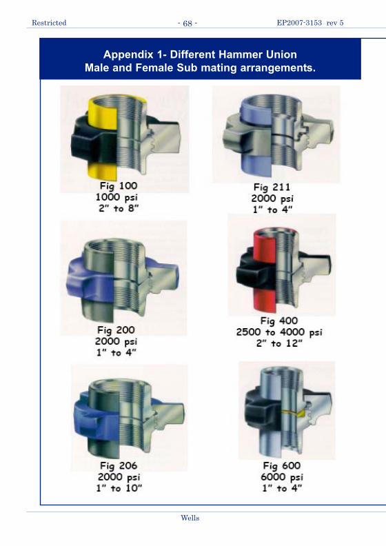
Restricted EP2007-3153 rev 5
Wells
- 68 -
Appendix 1- Different Hammer Union
Male and Female Sub mating arrangements.
ABC Guide to Temporary Pipework-Rev5-Feb20-12:Wells ABC Guide to Temporary Pipework 20/02/2012 10:43 Pa

[Note: The threaded connections to make-up on the pipe are not allowed.The purpose is to show the different Hammer Unions and sizes]
Wells
Restricted EP2007-3153 rev 5- 69 -
ABC Guide to Temporary Pipework-Rev5-Feb20-12:Wells ABC Guide to Temporary Pipework 20/02/2012 10:43 Pa

A certain pipe schedule is often established for certain services. This is dictated bythe classification of the piping system, based on the need and the application.
A pipe schedule to be used serves as the basic specification for the pipe thicknessand dimensions.
Industrial pipe thicknesses follow a set formula, expressed as the "schedule num-ber" as established ANSI. The schedule numbers that are available for use: 5, 10,20, 30, 40, 60, 80, 100, 120, 140,160, and double extra-heavy (XXS or XXH). Theschedule number is defined as the approximate value of the expression:
Schedule Number = 1,000*(P/S)
Where,
P = the internal working pressure, psig
S = the allowable stress (psi) for the material of construction at theconditions of use.
For example, the schedule number of 4” (nominal) steel pipe having an allowablestress of 50,000 psi for use at a working pressure of 5,000 psig would have:
Schedule Number =1,000*(5,000)/50,000) = 100 (indicating 120)
Restricted EP2007-3153 rev 5
Wells
- 70 -
Appendix 2 - Piping Schedules
Pipe Size (Nominal) Schedule OD ins ID ins Wall Thickness
ins Wt/ft lbs
1.00 40 1.315 1.049 0.133 1.6791.00 STD 1.315 1.049 0.133 1.6791.00 XS 1.315 0.957 0.179 2.1721.00 80 1.315 0.957 0.179 2.1721.00 160 1.315 0.815 0.25 2.8441.00 XXS 1.315 0.599 0.358 3.6591.25 40 1.66 1.38 0.14 2.2731.25 STD 1.66 1.38 0.14 2.2731.25 XS 1.66 1.278 0.191 2.9971.25 80 1.66 1.278 0.191 2.9971.25 160 1.66 1.16 0.25 3.7651.25 XXS 1.66 0.896 0.382 5.2142.00 40 2.375 2.067 0.154 3.6532.00 XS 2.375 1.939 0.218 5.0222.00 80 2.375 1.939 0.218 5.0222.00 160 2.375 1.687 0.344 7.4622.00 XXS 2.375 1.503 0.436 9.029
ABC Guide to Temporary Pipework-Rev5-Feb20-12:Wells ABC Guide to Temporary Pipework 20/02/2012 10:43 Pa

Wells
Restricted EP2007-3153 rev 5- 71 -
Pipe Size (Nominal) Schedule OD ins ID ins Wall Thickness
ins Wt/ft lbs
3.00 STD 3.5 3.068 0.216 7.5763.00 40 3.5 3.068 0.216 7.5763.00 XS 3.5 2.9 0.3 10.253.00 80 3.5 2.9 0.3 10.253.00 160 3.5 2.625 0.438 14.323.00 XXS 3.5 2.3 0.6 18.583.50 STD 4 3.548 0.226 9.1093.50 40 4 3.548 0.226 9.1093.50 XS 4 3.364 0.318 12.513.50 80 4 3.364 0.318 12.513.50 XXS 4 2.728 0.636 22.854.00 STD 4.5 4.026 0.237 10.794.00 40 4.5 4.026 0.237 10.794.00 XS 4.5 3.826 0.337 14.984.00 80 4.5 3.826 0.337 14.984.00 120 4.5 3.625 0.438 194.00 160 4.5 3.438 0.531 22.514.00 XXS 4.5 3.152 0.674 27.545.00 5 5.563 5.345 0.109 6.3495.00 10 5.563 5.295 0.134 7.775.00 STD 5.563 5.047 0.258 14.625.00 40 5.563 5.047 0.258 14.625.00 XS 5.563 4.813 0.375 20.785.00 80 5.563 4.813 0.375 20.785.00 120 5.563 4.563 0.5 27.045.00 160 5.563 4.313 0.625 32.965.00 XXS 5.563 4.063 0.75 38.556.00 STD 6.625 6.065 0.28 18.976.00 40 6.625 6.065 0.28 18.976.00 XS 6.625 5.761 0.432 28.576.00 80 6.625 5.761 0.432 28.576.00 120 6.625 5.5 0.562 36.396.00 160 6.625 5.187 0.719 45.356.00 XXS 6.625 4.897 0.864 53.168.00 STD 8.625 7.981 0.322 28.558.00 40 8.625 7.981 0.322 28.558.00 60 8.625 7.813 0.406 35.648.00 XS 8.625 7.625 0.5 43.398.00 80 8.625 7.625 0.5 43.398.00 100 8.625 7.437 0.594 50.958.00 120 8.625 7.187 0.719 60.718.00 140 8.625 7 0.812 67.768.00 160 8.625 6.813 0.906 74.698.00 XXS 8.625 6.875 0.875 72.42
ABC Guide to Temporary Pipework-Rev5-Feb20-12:Wells ABC Guide to Temporary Pipework 20/02/2012 10:43 Pa

Restricted EP2007-3153 rev 5
Wells
- 72 -
Appendix 3- Restraint Charts using ASME B 30.9 Polyester
Roundslings.
60.0
70.0
80.0
90.0
100.
0
110.
0
120.
0
130.
0
140.
0
150.
0Dynamic Load Klb-f
Cha
rt in
dica
ting
the
dyna
mic
load
ing
on, a
nd s
elec
tion
of A
SM
E B
30.
9 po
lyes
ter r
ound
slin
g re
stra
ints
in th
e ev
ent o
fpi
pe ru
ptur
e fo
r a ra
nge
of ID
's, t
he p
ipe
bein
g pr
essu
red
with
oil,
sea
wat
er (l
iqui
ds)
1000
2000
3000
4000
5000
6000
7000
8000
9000
1000
0
1100
0
1200
0
1300
0
1400
0
6
7
8
9
10
Max
operating
pressure
(seawater)
TagNo.
VerticalR
ated
Capa
city
Klbf
1040
931
825
721.2
616.8
513.2
410.6
38.4
25.3
0.0
10.0
20.0
30.0
40.0
50.0
00.
51
1.5
22.
53
3.5
44.
55
5.5
66.
57
7.5
8
Pipe
ID (i
ns)
000
1500
0
1600
0
1700
0
1800
0
1900
0
2000
0
3
4
Roun
dsling
Selection
5
2
40Fto
194F
40Cto
90C
2"2.375"
OD
3"3.5"
OD
4"4.5"
OD
6"6.625"
OD
8"8.625"
OD
Joinbe
tweenhitche
swith
Exam
pleho
wto
usechartfor:
Processstep
s:Re
efKn
otor
shackle:
•Max
pressure
5000
psi(oil)
1.Drawverticallineup
from
3.152"
from
horizontal
•4.75
Tfor2,3,4Tagrestraints
flowed
orpu
mpe
d.axis
tomeet5
000psicurve.
•6.5T
for6
,7,8Tagrestraints
•4"
602pipe
sche
duleXX
S2.
From
pointo
fintersection,draw
aho
rizontalline
•8.5T
for9
,10Tagrestraints
•ID
ofschXX
S=3.152"
tomeetrou
ndslings
bars.
3.Th
efirstba
rintersected
givestheroun
dsling
Note:AMSE
B30.9Ro
undslingbreaking
strength
=5x
ratedcapa
city.
Tagno
.Hitchpipe
with
thisratedsling.
Reef
Knot
Half
Hitch
JoiningShackle
ABC Guide to Temporary Pipework-Rev5-Feb20-12:Wells ABC Guide to Temporary Pipework 20/02/2012 10:43 Pa

Wells
Restricted EP2007-3153 rev 5- 73 -
60.0
70.0
80.0
90.0
100.
0
110.
0
120.
0
130.
0
140.
0
150.
0Dynamic Load Klb-f
Cha
rt in
dica
ting
the
dyna
mic
load
ing
on, a
nd s
elec
tion
of A
SM
E B
30.
9 po
lyes
ter r
ound
slin
g re
stra
ints
in th
e ev
ent o
fpi
pe ru
ptur
e fo
r a ra
nge
of ID
's, t
he p
ipe
bein
g pr
essu
red
with
gas
1000
2000
3000
4000
5000
6000
7000
8000
9000
1000
0
1100
0
1200
0
1300
0
1400
0
6
7
8
9
10TagNo.
VerticalR
ated
Capa
city
Klbf
1040
931
825
721.2
616.8
513.2
410.6
38.4
25.3
Max
operating
pressure
(gas)
0.0
10.0
20.0
30.0
40.0
50.0
00.
51
1.5
22.
53
3.5
44.
55
5.5
66.
57
7.5
8
Pipe
ID (i
ns)
000
1500
0
1600
0
1700
0
1800
0
1900
0
2000
0
3
4
5
2
Joinbe
tweenhitche
swith
Exam
pleho
wto
usechartfor:
Processstep
s:Re
efKn
otor
shackle:
•Max
pressure
5000
psi(oil)
1.Drawverticallineup
from
3.152"
from
horizontal
•4.75
Tfor2,3,4Tagrestraints
flowed
orpu
mpe
d.axis
tomeet5
000psicurve.
•6.5T
for6
,7,8Tagrestraints
•4"
602pipe
sche
duleXX
S2.
From
pointo
fintersection,draw
aho
rizontalline
•8.5T
for9
,10Tagrestraints
•ID
ofschXX
S=3.152"
tomeetrou
ndslings
bars.
3.Th
efirstba
rintersected
givestheroun
dsling
Note:AMSE
B30.9Ro
undslingbreaking
strength
=5x
ratedcapa
city.
Tagno
.Hitchpipe
with
thisratedsling.
40Fto
194F
40Cto
90C
2"2.375"
OD
3"3.5"
OD
4"4.5"
OD
6"6.625"
OD
8"8.625"
OD
Reef
Knot
Half
Roun
dsling
JoiningShackle
ABC Guide to Temporary Pipework-Rev5-Feb20-12:Wells ABC Guide to Temporary Pipework 20/02/2012 10:43 Pa

Wells
Restricted EP2007-3153 rev 5- 74 -
SHELL
The information in this document is shared under the Research Agreement between SIRM andShell Oil Company dated January 1, 1960, as amended unless indicated otherwise above.
This document is classified as Restricted. Access is allowed to Shell personnel, designatedAssociate Companies and Contractors working on Shell projects who have signed a confidentiali-ty agreement with a Shell Group Company. 'Shell Personnel' includes all staff with a personalcontract with a Shell Group Company. Issuance of this document is restricted to staff employedby a Shell Group Company. Neither the whole nor any part of this document may be disclosed toNon-Shell Personnel without the prior written consent of the copyright owners.
Copyright 2007 SIEP, Inc.
SHELL INTERNATIONAL EXPLORATION AND PRODUCTION INC.,HOUSTONFurther electronic copies can be obtained from the Global EP Library, Houston
ABC Guide to Temporary Pipework-Rev5-Feb20-12:Wells ABC Guide to Temporary Pipework 20/02/2012 10:43 Pa
![VW_CONF_2016_TEADIT Rev5[4]](https://static.fdocuments.us/doc/165x107/587382721a28ab431c8c5ae0/vwconf2016teadit-rev54.jpg)


