
ABB-Soft Starter Guide
94
SOFTSTARTER HANDBOOK
Transcript of ABB-Soft Starter Guide

SOFTSTARTERHANDBOOK

FOREWORD
This book is written with the thought of being a general guide for people working withsoftstarter applications but also for those just interested in learning more about this typeof starting method. It doesn’t matter if you are an expert or novice, hopefully you will findsome interesting and useful information either by reading from cover to cover or just thechapters of interest.The index at the end of the book can be used to simplify your search.
The content of this book is very much based on the 20 years of experience we have withinABB of developing, manufacturing and selling low voltage softstarters.The book is not a complete technical guide or manual for all type of ABB Softstarters thatmay exist on the market. It is a complement to the technical catalogues and brochures wehave for our products and will give a general picture of what to think about when workingwith softstarters.More information about softstarters as well as other ABB products is available on www.abb.com
All advice given in this book is only general and every single application must be handledas a specific case.
ABB Automation Technology Products AB, ControlFebruary 2003
Magnus Kjellberg Sören Kling

ABB will not take any responsibility for any type of faults or damage due to the use of thishandbook.
I
Standards ...1European Directives ...1CE Marking ...1Specification in USA and Canada ...1Used standards ...1
General about motors ...2Squirrel cage motors ...3Voltage ...4Power factor ...5Speed ...6Torque ...7Slip-ring motors ...7
Different starting methods ...8Direct-on-line start (D.O.L) ...9Star-delta start ...10Frequency converter ...12Softstarter ...13Common problem when starting and stopping motors ...14
Different applications ...15Centrifugal fan ...16
Direct-on-line start (D.O.L) ...16Star-delta start ...17Softstarter ...17Selection of a suitable Softstarter ...18
Centrifugal pump ...19Direct-on-line start (D.O.L) ...19Star-delta start ...20Softstarter ...21Selection of a suitable Softstarter ...22
ContentsC
onten
ts

II
Compressor ...23Direct-on-line start (D.O.L) ...23Star-delta start ...24Softstarter ...25Selection of a suitable Softstarter ...26
Conveyor belt ...27Direct-on-line start (D.O.L) ...27Star-delta start ...28Softstarter ...29Selection of a suitable Softstarter ...30
How to select a softstarter ...31
Description of the softstarters ...33
Description of different components ...34
Common settings ...36Start ramp ...36Stop ramp ...36Initial voltage ...36Current limit ...37Step down voltage ...38Adjustable rated motor current ...38
Different indications ...39
Different voltage names ...40
Ambient temperature ...41
High altitudes ...42Start of several motors ...43
Parallel start of motors ...43Sequential start of motors ...44
Con
ten
ts
III
Different ways of connecting the softstarter ...45In-Line connection ...46Inside Delta connection ...46Location of the main contactor ...47
Basic settings ...49Table for settings without current limit function ...50Table for settings with current limit function ...51
Starting capacity and overload protection ...52Starting capacity for softstarters ...52Starting capacity when using by-pass contactor ...53Starting capacity when using overload protection ...53
Number of starts/hour ...54Intermittance factor ...54
Harmonics ...55Harmonic content ...55
Explosive atmospheres (EEx) ...56Hazardous areas and zones ...57Location and selection of softstarter ...57
Co-ordination ...58Types of co-ordination ...59Utilization Categories ...60Types of fuses ...61Where to find the co-ordination tables ...62How to read the co-ordination tables ...63
ESD aspects ...65Two type of faults and different circuits ...65Electro static voltage levels ...66Protection against ESD damages ...66
Con
tents

IV
Frequently Asked Questions (FAQ) ...67
Environmental information ...69LCA ...69EPD ...70
Industrial IT ...71Different levels ...72Softstarter level ...72
Formulas and conversion factors ...73Formulas ...73Quantities and units ...75Conversion factors ...76
Glossary ...78
Index ...84
Con
ten
ts

1
Standards
European DirectivesThere are three essential European directives:
Low Voltage Directive 73/23/EECConcerns electrical equipment from 50 to1000 V AC and from 75 to 1500 V DC.
Machines Directive 89/392/EECConcerns safety specifications of machinesand equipment on complete machines.
Electromagnetic Compatibility Directive89/336/EECConcerns all devices able to create electro-magnetic disturbance including the level ofemission and immunity.
CE MarkingWhen a product is verified according to itsapplicable EN standard (EN 60947-4-2 forsoftstarters) the product will then fulfil both the”Low Voltage Directive” and ”ElectromagneticCompability Directive” and it is allowed to usethe CE marking on the product. In this casethe CE marking does not cover the ”MachinesDirective” concerning the connection of thesoftstarter for a safe run of the motor.The CE marking is not a quality label; it is proofof conformity with the European Directivesconcerning the product.
Specifications in USA andCanadaThe specifications for the American andCanadian markets are quite equal but differ alot from the IEC standards and other Europeanspecifications.
USA UL Underwriters LaboratoriesFile ref. 072301-E161428
110800-E161428
Canada CSA Canadian StandardsFile ref. 1031179
Used standardsFollowing standards are used or partly used forthe softstarters.
IEC 60947-1IEC 60947-4-2EN 60947-1EN 60947-4-2UL 508CSA C22.2 No. 14 - M91LRS 00/00154
All ABB low voltage softstarters are developed and manufactured according to the rulesset out in the IEC (International Electrotechnical Commission) which is a part of theInternational Standard Organisation, ISO.ISO issue IEC publications that act as a basis for the world market.
Softstarters built according to these standards are in most countries not subject toany other tests besides the manufacturer responsibility. In some countries, law requirescertificates.
For softstarters used on board ships, maritime insurance companies sometimes requirecertificates of approval from BV (Bureau Veritas), GL (Germanisher Lloyd) and LRS(Lloyd’s Register of Shipping) or other independent certification organisation.
Stan
dard
s
2
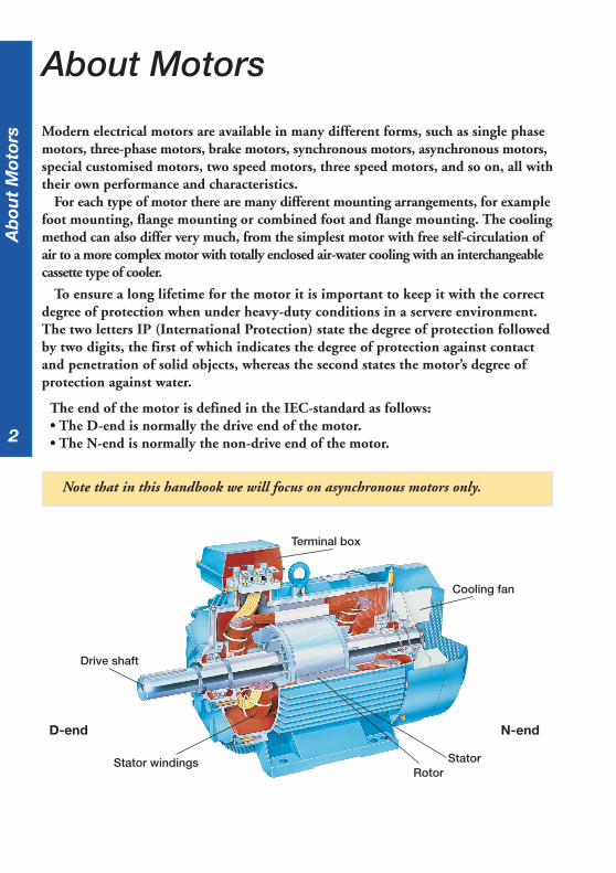
Modern electrical motors are available in many different forms, such as single phasemotors, three-phase motors, brake motors, synchronous motors, asynchronous motors,special customised motors, two speed motors, three speed motors, and so on, all withtheir own performance and characteristics.
For each type of motor there are many different mounting arrangements, for examplefoot mounting, flange mounting or combined foot and flange mounting. The coolingmethod can also differ very much, from the simplest motor with free self-circulation ofair to a more complex motor with totally enclosed air-water cooling with an interchangeablecassette type of cooler.
To ensure a long lifetime for the motor it is important to keep it with the correctdegree of protection when under heavy-duty conditions in a servere environment.The two letters IP (International Protection) state the degree of protection followedby two digits, the first of which indicates the degree of protection against contactand penetration of solid objects, whereas the second states the motor’s degree ofprotection against water.
The end of the motor is defined in the IEC-standard as follows:• The D-end is normally the drive end of the motor.• The N-end is normally the non-drive end of the motor.
About Motors
Note that in this handbook we will focus on asynchronous motors only.
Terminal box
Cooling fan
Drive shaft
Stator windingsRotor
Stator
N-endD-end
Ab
out
Mot
ors
3
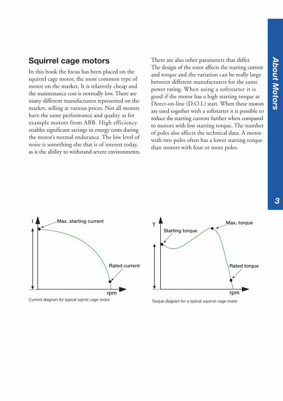
Squirrel cage motorsIn this book the focus has been placed on thesquirrel cage motor, the most common type ofmotor on the market. It is relatively cheap andthe maintenance cost is normally low. There aremany different manufacturers represented on themarket, selling at various prices. Not all motorshave the same performance and quality as forexample motors from ABB. High efficiencyenables significant savings in energy costs duringthe motor’s normal endurance. The low level ofnoise is something else that is of interest today,as is the ability to withstand severe environments.
There are also other parameters that differ.The design of the rotor affects the starting currentand torque and the variation can be really largebetween different manufacturers for the samepower rating. When using a softstarter it isgood if the motor has a high starting torque atDirect-on-line (D.O.L) start. When these motorsare used together with a softstarter it is possible toreduce the starting current further when comparedto motors with low starting torque. The numberof poles also affects the technical data. A motorwith two poles often has a lower starting torquethan motors with four or more poles.
Max. starting current
Rated current
I
rpm
T
rpm
Starting torque
Rated torque
Max. torque
Ab
out M
otors
Current diagram for typical sqirrel cage motor Torque diagram for a typical squirrel cage motor
4
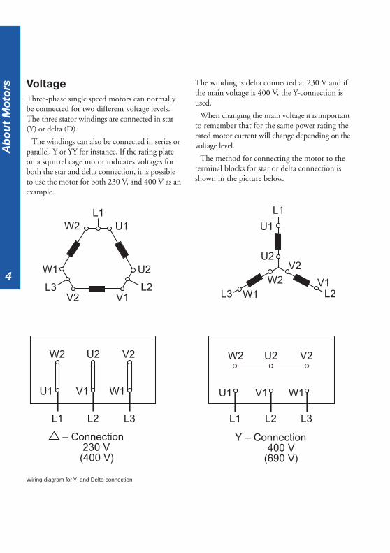
VoltageThree-phase single speed motors can normallybe connected for two different voltage levels.The three stator windings are connected in star(Y) or delta (D).
The windings can also be connected in series orparallel, Y or YY for instance. If the rating plateon a squirrel cage motor indicates voltages forboth the star and delta connection, it is possibleto use the motor for both 230 V, and 400 V as anexample.
The winding is delta connected at 230 V and ifthe main voltage is 400 V, the Y-connection isused.
When changing the main voltage it is importantto remember that for the same power rating therated motor current will change depending on thevoltage level.
The method for connecting the motor to theterminal blocks for star or delta connection isshown in the picture below.
L1
U2
U1
V2
V1W2
L3 W1 L2
L1
W2 U1
W1 U2
L2L3V2 V1
– Connection 230 V (400 V)
V2W2 U2V2W2 U2
W1U1 V1
L3L1 L2
W1U1 V1
L3L1 L2
Y – Connection400 V
(690 V)
Wiring diagram for Y- and Delta connection
Ab
out
Mot
ors
5
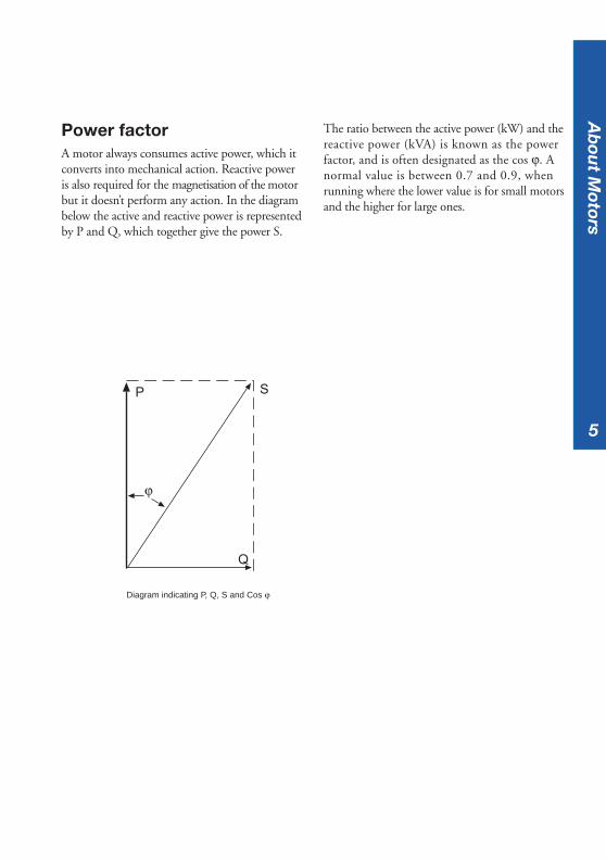
Power factorA motor always consumes active power, which itconverts into mechanical action. Reactive poweris also required for the magnetisation of the motorbut it doesn’t perform any action. In the diagrambelow the active and reactive power is representedby P and Q, which together give the power S.
The ratio between the active power (kW) and thereactive power (kVA) is known as the powerfactor, and is often designated as the cos ϕ. Anormal value is between 0.7 and 0.9, whenrunning where the lower value is for small motorsand the higher for large ones.
SP
Q
ϕ
Ab
out M
otors
Diagram indicating P, Q, S and Cos ϕ

6
The difference between the synchronous andasynchronous speed also named rated speed is”the slip” and it is possible to calculate this byusing the following formula:
s = n1 - n
n1s = slip (a normal value is between 1 and 3 %)
n1 = synchronous speed
n = asynchronous speed (rated speed)
Table for synchronous speed at differentnumber of poles and frequency:
No. of poles 50 Hz 60 Hz
2 3000 3600
4 1500 1800
6 1000 1200
8 750 900
10 600 720
12 500 600
16 375 450
20 300 360
SpeedThe speed of an AC motor depends on two things:the number of poles of the stator winding andthe main frequency. At 50 Hz, a motor will runat a speed related to a constant of 6000 dividedby the number of poles and for a 60 Hz motorthe constant is 7200 rpm.
To calculate the speed of a motor, the followingformula can be used:
n = 2 x f x 60p
n = speedf = net frequencyp = number of poles
Example:4-pole motor running at 50 Hz
n = 2 x 50 x 60 = 1500 rpm4
This speed is the synchronous speed and asquirrel-cage or a slip-ring motor can neverreach it. At unloaded condition the speed willbe very close to synchronous speed and willthen drop when the motor is loaded.
Slip
Syncronousspeed
T
rpm
Rated speed
Ab
out
Mot
ors
Diagram showing syncronous speed vs.rated speed
7
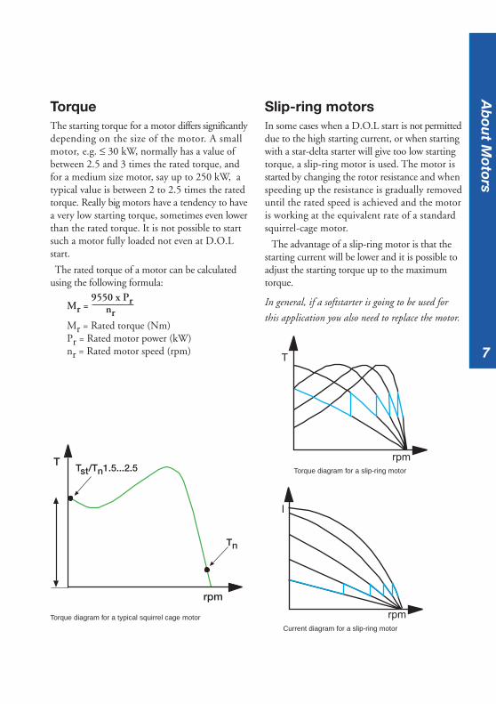
TorqueThe starting torque for a motor differs significantlydepending on the size of the motor. A smallmotor, e.g. ≤ 30 kW, normally has a value ofbetween 2.5 and 3 times the rated torque, andfor a medium size motor, say up to 250 kW, atypical value is between 2 to 2.5 times the ratedtorque. Really big motors have a tendency to havea very low starting torque, sometimes even lowerthan the rated torque. It is not possible to startsuch a motor fully loaded not even at D.O.Lstart.
The rated torque of a motor can be calculatedusing the following formula:
Mr = 9550 x Pr
nrMr = Rated torque (Nm)Pr = Rated motor power (kW)nr = Rated motor speed (rpm)
Slip-ring motorsIn some cases when a D.O.L start is not permitteddue to the high starting current, or when startingwith a star-delta starter will give too low startingtorque, a slip-ring motor is used. The motor isstarted by changing the rotor resistance and whenspeeding up the resistance is gradually removeduntil the rated speed is achieved and the motoris working at the equivalent rate of a standardsquirrel-cage motor.
The advantage of a slip-ring motor is that thestarting current will be lower and it is possible toadjust the starting torque up to the maximumtorque.
In general, if a softstarter is going to be used for
this application you also need to replace the motor.
T
rpm
Tn
Tst/Tn1.5...2.5
Torque diagram for a typical squirrel cage motor
Torque diagram for a slip-ring motor
Current diagram for a slip-ring motor
T
rpm
I
rpm
Ab
out M
otors
8
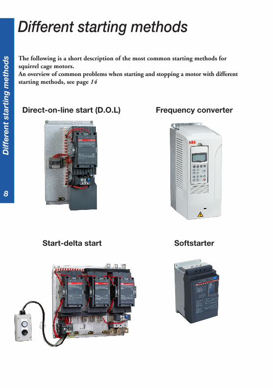
The following is a short description of the most common starting methods forsquirrel cage motors.An overview of common problems when starting and stopping a motor with differentstarting methods, see page 14
Direct-on-line start (D.O.L)
Start-delta start
Frequency converter
Softstarter
Different starting methods
Dif
fere
nt
star
tin
g m
eth
ods

9
Direct-on-line start (D.O.L)This is by far the most common starting methodavailable on the market. The starting equipmentconsists of only a main contactor and thermal orelectronic overload relay. The disadvantage withthis method is that it gives the highest possiblestarting current. A normal value is between 6 to 7times the rated motor current but values of up to9 or 10 times the rated current exist. Besides thestarting current there also exists a current peakthat can rise up to 14 times the rated currentsince the motor is not energised from the the firstmoment when starting.
The values are dependent on the design and sizeof the motor, but in general, a smaller motorgives higher values than a larger one.
During a direct-on-line start, the starting torqueis also very high, and is higher than necessary formost applications. The torque is the same as theforce, and an unnecessary high force givesunnecessary high stresses on couplings and thedriven application. Naturally, there are caseswhere this starting method works perfectly andin some cases also the only starting method thatworks.
KM 1 Main contactorFR 1 Overload relay
M
Single line diagramfor a D.O.L.
D.O.L. starter with contactorand O/L relay
KM 1
FR 1
Max. starting current
Rated current
I
rpm
T
rpm
Starting torque
Rated torque
Max. torque
Differen
t starting
meth
ods
Torque/speed curve att D.O.L start
Current curve at D.O.L start

10
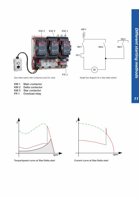
Star-delta startThis is a starting method that reduces the startingcurrent and starting torque. The device normallyconsists of three contactors, an overload relay anda timer for setting the time in the star-position(starting position). The motor must be deltaconnected during a normal run, in order to beable to use this starting method.
The received starting current is about 30 % ofthe starting current during direct on line start andthe starting torque is reduced to about 25 % ofthe torque available at a D.O.L start. This startingmethod only works when the application is lightloaded during the start. If the motor is too heavilyloaded, there will not be enough torque to
accelerate the motor up to speed before switchingover to the delta position.When starting up pumps and fans for example,the load torque is low at the beginning of thestart and increases with the square of the speed.When reaching approx. 80-85 % of the motorrated speed the load torque is equal to the motortorque and the acceleration ceases. To reach therated speed, a switch over to delta position isnecessary, and this will very often result in hightransmission and current peaks. In some cases thecurrent peak can reach a value that is even biggerthan for a D.O.L start. Applications with a loadtorque higher than 50 % of the motor rated torquewill not be able to start using the start-delta starter.
Dif
fere
nt
star
tin
g m
eth
ods
11
Single line diagram for a Star-delta starterStar-delta starter with contactors and O/L relay
KM 1 Main contactorKM 2 Delta contactorKM 3 Star contactorFR 1 Overload relay
Torque/speed curve at Star-Delta start Current curve at Star-Delta start
FR 1
KM 1 KM 3KM 2
400 V
230 V
M
KM 2 KM 3 KM 1
FR 1
rpm
T I
rpm
Differen
t starting
meth
ods
12
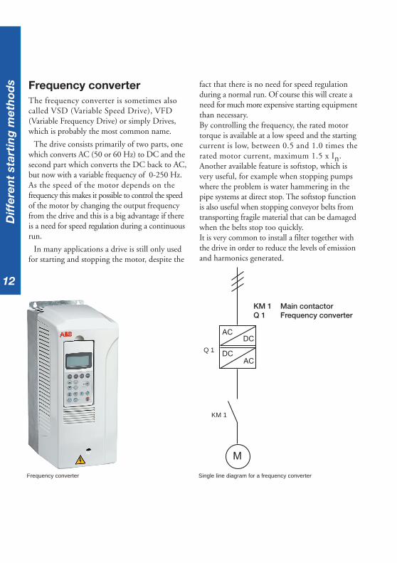
Frequency converterThe frequency converter is sometimes alsocalled VSD (Variable Speed Drive), VFD(Variable Frequency Drive) or simply Drives,which is probably the most common name.
The drive consists primarily of two parts, onewhich converts AC (50 or 60 Hz) to DC and thesecond part which converts the DC back to AC,but now with a variable frequency of 0-250 Hz.As the speed of the motor depends on thefrequency this makes it possible to control the speedof the motor by changing the output frequencyfrom the drive and this is a big advantage if thereis a need for speed regulation during a continuousrun.
In many applications a drive is still only usedfor starting and stopping the motor, despite the
fact that there is no need for speed regulationduring a normal run. Of course this will create aneed for much more expensive starting equipmentthan necessary.By controlling the frequency, the rated motortorque is available at a low speed and the startingcurrent is low, between 0.5 and 1.0 times therated motor current, maximum 1.5 x In.Another available feature is softstop, which isvery useful, for example when stopping pumpswhere the problem is water hammering in thepipe systems at direct stop. The softstop functionis also useful when stopping conveyor belts fromtransporting fragile material that can be damagedwhen the belts stop too quickly.It is very common to install a filter together withthe drive in order to reduce the levels of emissionand harmonics generated.
KM 1 Main contactorQ 1 Frequency converter
Frequency converter
AC
ACDC
DC
M
KM 1
Q 1
Dif
fere
nt
star
tin
g m
eth
ods
Single line diagram for a frequency converter
13
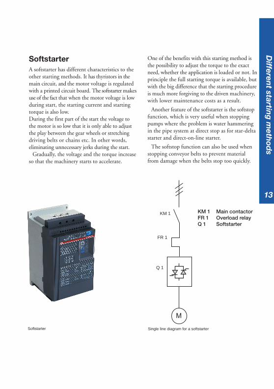
SoftstarterA softstarter has different characteristics to theother starting methods. It has thyristors in themain circuit, and the motor voltage is regulatedwith a printed circuit board. The softstarter makesuse of the fact that when the motor voltage is lowduring start, the starting current and startingtorque is also low.During the first part of the start the voltage tothe motor is so low that it is only able to adjustthe play between the gear wheels or stretchingdriving belts or chains etc. In other words,eliminating unnecessary jerks during the start.
Gradually, the voltage and the torque increaseso that the machinery starts to accelerate.
One of the benefits with this starting method isthe possibility to adjust the torque to the exactneed, whether the application is loaded or not. Inprinciple the full starting torque is available, butwith the big difference that the starting procedureis much more forgiving to the driven machinery,with lower maintenance costs as a result.
Another feature of the softstarter is the softstopfunction, which is very useful when stoppingpumps where the problem is water hammeringin the pipe system at direct stop as for star-deltastarter and direct-on-line starter.
The softstop function can also be used whenstopping conveyor belts to prevent materialfrom damage when the belts stop too quickly.
Softstarter
KM 1 Main contactorFR 1 Overload relayQ 1 Softstarter
M
KM 1
FR 1
Q 1
Differen
t starting
meth
ods
Single line diagram for a softstarter
14
Dif
fere
nt
star
tin
g m
eth
ods
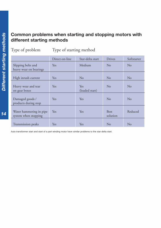
Auto transformer start and start of a part winding motor have similar problems to the star-delta start.
Common problems when starting and stopping motors withdifferent starting methods
Type of problem Type of starting method
Direct-on-line Star-delta start Drives Softstarter
Slipping belts and Yes Medium No Noheavy wear on bearings
High inrush current Yes No No No
Heavy wear and tear Yes Yes No Noon gear boxes (loaded start)
Damaged goods / Yes Yes No Noproducts during stop
Water hammering in pipe Yes Yes Best Reducedsystem when stopping solution
Transmission peaks Yes Yes No No
15
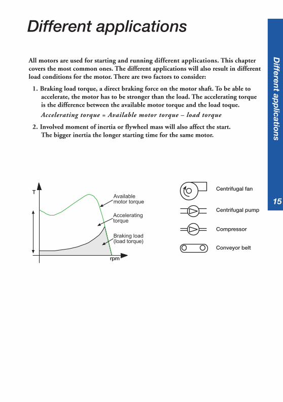
All motors are used for starting and running different applications. This chaptercovers the most common ones. The different applications will also result in differentload conditions for the motor. There are two factors to consider:
1. Braking load torque, a direct braking force on the motor shaft. To be able toaccelerate, the motor has to be stronger than the load. The accelerating torqueis the difference between the available motor torque and the load toque.
Accelerating torque = Available motor torque – load torque
2. Involved moment of inertia or flywheel mass will also affect the start.The bigger inertia the longer starting time for the same motor.
Different applications
Availablemotor torque
Acceleratingtorque
Braking load(load torque)
T
rpm
Centrifugal fan
Centrifugal pump
Compressor
Conveyor belt
Differen
t app
lications
1616
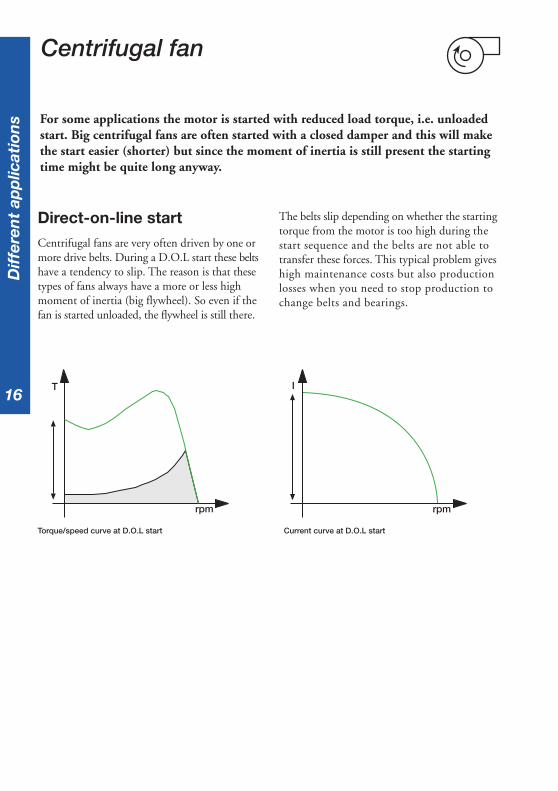
Direct-on-line startCentrifugal fans are very often driven by one ormore drive belts. During a D.O.L start these beltshave a tendency to slip. The reason is that thesetypes of fans always have a more or less highmoment of inertia (big flywheel). So even if thefan is started unloaded, the flywheel is still there.
Centrifugal fan
T
rpm
I
rpm
The belts slip depending on whether the startingtorque from the motor is too high during thestart sequence and the belts are not able totransfer these forces. This typical problem giveshigh maintenance costs but also productionlosses when you need to stop production tochange belts and bearings.
For some applications the motor is started with reduced load torque, i.e. unloadedstart. Big centrifugal fans are often started with a closed damper and this will makethe start easier (shorter) but since the moment of inertia is still present the startingtime might be quite long anyway.
Torque/speed curve at D.O.L start Current curve at D.O.L start
Dif
fere
nt
app
licat
ion
s
17
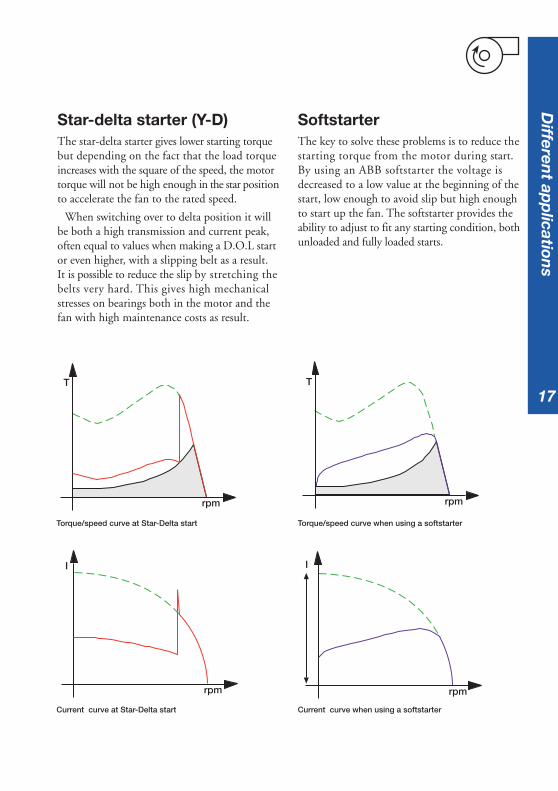
Star-delta starter (Y-D)The star-delta starter gives lower starting torquebut depending on the fact that the load torqueincreases with the square of the speed, the motortorque will not be high enough in the star positionto accelerate the fan to the rated speed.
When switching over to delta position it willbe both a high transmission and current peak,often equal to values when making a D.O.L startor even higher, with a slipping belt as a result.It is possible to reduce the slip by stretching thebelts very hard. This gives high mechanicalstresses on bearings both in the motor and thefan with high maintenance costs as result.
SoftstarterThe key to solve these problems is to reduce thestarting torque from the motor during start.By using an ABB softstarter the voltage isdecreased to a low value at the beginning of thestart, low enough to avoid slip but high enoughto start up the fan. The softstarter provides theability to adjust to fit any starting condition, bothunloaded and fully loaded starts.
rpm
T
I
rpm rpm
I
Torque/speed curve when using a softstarter
Current curve when using a softstarter
Torque/speed curve at Star-Delta start
Current curve at Star-Delta start
T
rpm
Differen
t app
lications
1818
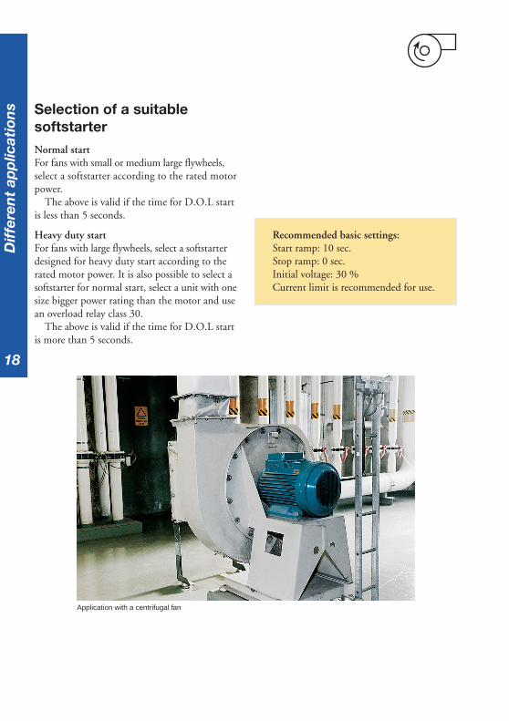
Selection of a suitablesoftstarterNormal startFor fans with small or medium large flywheels,select a softstarter according to the rated motorpower.
The above is valid if the time for D.O.L startis less than 5 seconds.
Heavy duty startFor fans with large flywheels, select a softstarterdesigned for heavy duty start according to therated motor power. It is also possible to select asoftstarter for normal start, select a unit with onesize bigger power rating than the motor and usean overload relay class 30.
The above is valid if the time for D.O.L startis more than 5 seconds.
Application with a centrifugal fan
Recommended basic settings:Start ramp: 10 sec.Stop ramp: 0 sec.Initial voltage: 30 %Current limit is recommended for use.
Dif
fere
nt
app
licat
ion
s
19
There are a lot of different types of pumps; like piston pumps, centrifugal pumps,screw pumps etc. But the most common version is the centrifugal pump and wehave selected this one to describe.
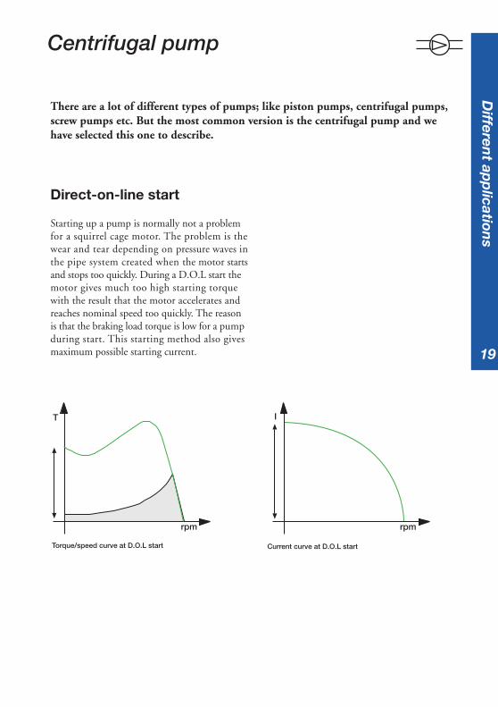
Direct-on-line start
Starting up a pump is normally not a problemfor a squirrel cage motor. The problem is thewear and tear depending on pressure waves inthe pipe system created when the motor startsand stops too quickly. During a D.O.L start themotor gives much too high starting torquewith the result that the motor accelerates andreaches nominal speed too quickly. The reasonis that the braking load torque is low for a pumpduring start. This starting method also givesmaximum possible starting current.
Centrifugal pump
T
rpm
I
rpm
Differen
t app
lications
Torque/speed curve at D.O.L start Current curve at D.O.L start

2020
Star-delta starter (Y-D)By using a star-delta starter it is possible toreduce the starting torque. The motor torquein the star position is too weak to be able tocomplete the start and reach the rated speed.
The quadratic load torque will become too highfor the motor when reaching approx. 80-85 % ofthe rated speed and the switch over to the deltaposition will give both high transmission andcurrent peaks with pressure waves as a result.The current peaks can be equally high as at aD.O.L start or even higher.
When stopping a pumpDuring stop it is also normal to have problems.When making a direct stop by disconnectingthe main supply the motor stops too quickly.Depending on high mass flow in the pipe systemthe water will continue with the same speed fora short period and then come back again,backwards in the pipe system. This creates highpressure shocks on valves and gives highmechanical stresses on the pipe system.
rpm
T I
rpm
Torque/speed curve at Star-Delta start Current curve at Star-Delta start
Dif
fere
nt
app
licat
ion
s

21
SoftstarterBy using an ABB softstarter the voltage is reducedduring the start sequence with the result that themotor torque is reduced. During the startsequence the softstarter increases the voltage sothat the motor will be strong enough to acceleratethe pump to the nominal speed without anytorque or current peaks. A normal startingcurrent with a softstarter when starting a fullyloaded centrifugal pump is approx. 4 times ratedmotor current.
T
rpm rpm
I
Also during the stop sequence the softstarter isthe solution. The softstarter reduces the voltageduring stop via a voltage ramp and the motorbecomes weaker and weaker. Because of this thewater speed slows down very smoothly withoutcreating any pressure waves.
A special function on the softstarter is sometimesavailable, called "step-down voltage",which ensuresan optimum setting to the actual need for anypipe system.
Torque/speed curve when using a softstarter Current curve when using a softstarter
Differen
t app
lications

2222
Selection of a suitablesoftstarterNormal startStarting a pump is a typical normal startcondition.Select a softstarter according to the ratedmotor power.
Heavy duty startNot applicable for this application.
Application with a pump.
Recommended basic settings:Start ramp: 10 sec.Stop ramp: 20 sec.Initial voltage: 30 %
Dif
fere
nt
app
licat
ion
s
23
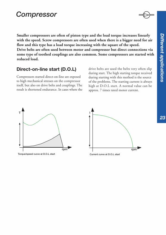
Smaller compressors are often of piston type and the load torque increases linearlywith the speed. Screw compressors are often used when there is a bigger need for airflow and this type has a load torque increasing with the square of the speed.Drive belts are often used between motor and compressor but direct connections viasome type of toothed couplings are also common. Some compressors are started withreduced load.
Direct-on-line start (D.O.L)Compressors started direct-on-line are exposedto high mechanical stresses on the compressoritself, but also on drive belts and couplings. Theresult is shortened endurance. In cases where the
I
rpm
drive belts are used the belts very often slipduring start. The high starting torque receivedduring starting with this method is the sourceof the problems. The starting current is alwayshigh at D.O.L start. A normal value can beapprox. 7 times rated motor current.
Compressor
Torque/speed curve at D.O.L start Current curve at D.O.L start
rpm
T
Differen
t app
lications
2424
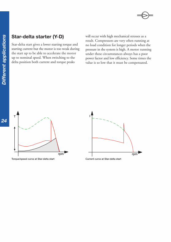
Star-delta starter (Y-D)Star-delta start gives a lower starting torque andstarting current but the motor is too weak duringthe start up to be able to accelerate the motorup to nominal speed. When switching to thedelta position both current and torque peaks
rpm
T I
rpm
will occur with high mechanical stresses as aresult. Compressors are very often running atno load condition for longer periods when thepressure in the system is high. A motor runningunder these circumstances always has a poorpower factor and low efficiency. Some times thevalue is so low that it must be compensated.
Torque/speed curve at Star-delta start Current curve at Star-delta start
Dif
fere
nt
app
licat
ion
s

25
SoftstarterBy using an ABB softstarter it is possible tolimit the starting torque to a level suitable forall different applications. The result is less stresson couplings, bearings and no slipping beltsduring start. The maintenance cost will bereduced to a minimum. When using a softstarterthe starting current received is approx. 3 to 4times the rated motor current.
rpm
T
rpm
I
Torque/speed curve when using a softstarter Current curve when using a softstarter
Differen
t app
lications

2626
Selection of a suitablesoftstarterNormal startFor compressors with D.O.L starting time lessthan 5 seconds, select a softstarter according tothe rated motor power.
Heavy duty startFor compressors with D.O.L starting time morethan 5 seconds, select a softstarter designed forheavy duty start according to the rated motorpower.
It is also possible to select a softstarter fornormal start, select a unit with one size biggerpower rating than the motor and use an overloadrelay class 30.
Application with a compressor
Recommended basic settings:Start ramp: 10 sec.Stop ramp: 0 sec.Initial voltage: 30 % (piston compressor)
40 % (screw compressor)
Dif
fere
nt
app
licat
ion
s
27
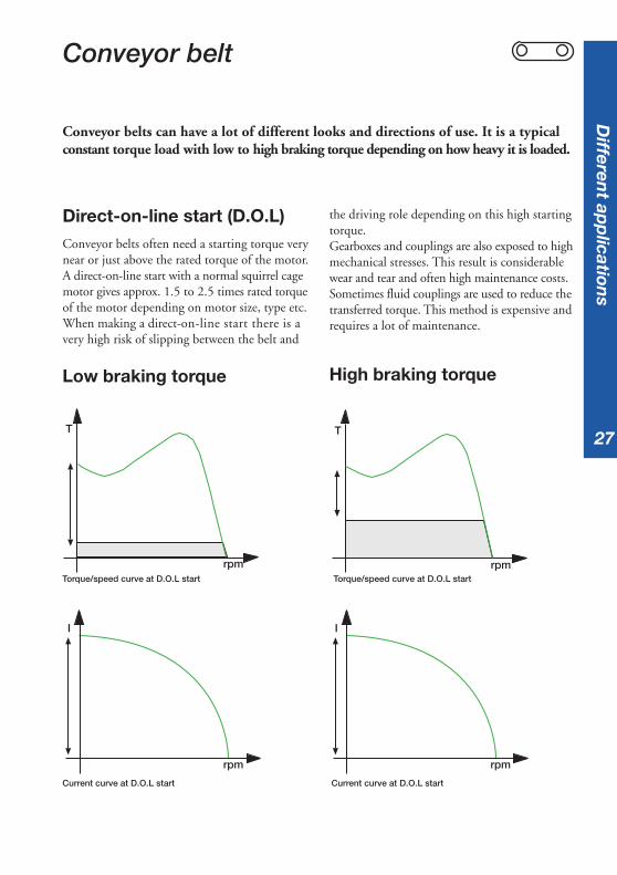
Direct-on-line start (D.O.L)Conveyor belts often need a starting torque verynear or just above the rated torque of the motor.A direct-on-line start with a normal squirrel cagemotor gives approx. 1.5 to 2.5 times rated torqueof the motor depending on motor size, type etc.When making a direct-on-line start there is avery high risk of slipping between the belt and
Conveyor belt
Low braking torque
I
rpm
High braking torque
rpm
T
I
rpm
the driving role depending on this high startingtorque.Gearboxes and couplings are also exposed to highmechanical stresses. This result is considerablewear and tear and often high maintenance costs.Sometimes fluid couplings are used to reduce thetransferred torque. This method is expensive andrequires a lot of maintenance.
Torque/speed curve at D.O.L start
Current curve at D.O.L start
Torque/speed curve at D.O.L start
T
rpm
Current curve at D.O.L start
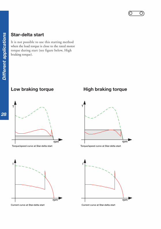
Conveyor belts can have a lot of different looks and directions of use. It is a typicalconstant torque load with low to high braking torque depending on how heavy it is loaded.
Differen
t app
lications
2828
Star-delta startIt is not possible to use this starting methodwhen the load torque is close to the rated motortorque during start (see figure below, Highbraking torque).
Low braking torque High braking torque
rpm
T
I
rpm
rpm
T
I
rpm
Current curve at Star-delta startCurrent curve at Star-delta start
Torque/speed curve at Star-delta start Torque/speed curve at Star-delta start
Dif
fere
nt
app
licat
ion
s

29
SoftstarterBy using an ABB softstarter the starting torquecan be reduced to a minimum value still able tostart up the conveyor belt. The setting possibilityof the softstarter makes it possible to adjust thetorque to exactly the level that is necessary forthe start. The result is the least possible stress on
High braking torqueLow braking torque
T
rpm
rpm
I
T
rpm
rpm
I
gearboxes and couplings and no slipping beltsduring start. This will reduce the maintenancecost to a minimum. When using a softstarteryou will receive approx. 3 to 4 times rated motorcurrent during start.
Torque/speed curve when using a softstarter
Current curve when using a softstarter
Torque/speed curve when using a softstarter
Current curve when using a softstarter
Differen
t app
lications

3030
Selection of a suitablesoftstarterNormal startA start of short and light loaded conveyor belt is atypical normal start.For conveyors with D.O.L starting time lessthan 5 seconds, select a softstarter according tothe rated motor power.
Heavy duty startConveyor belts can in some cases be very long andif the belt is fully loaded during start the startingtime can be very long. For such applications selecta softstarter designed for heavy duty start. It is alsopossible to select a softstarter for normal start ifthe softstarter is chosen one size larger than therated motor power and use an overload relayclass 30.
Application with a conveyor belt
Recommended basic settings:
Start ramp: 10 sec.Stop ramp: 0 sec.(If fragile material use 10 seconds)Initial voltage: 40 %
Dif
fere
nt
app
licat
ion
s

31
How to select a softstarter fordifferent applications
Quick guide
Normal startTypical applications
»Bow thruster »Centrifugal pump»Compressor »Conveyor belt (short)»Elevator »Escalator
SelectionSelect the softstarter according to therated motor power.For units with built-in overload, selecttrip class 10.
Heavy duty startTypical applications
»Centrifugal fan »Conveyor belt (long)»Crusher »Mill»Mixer »Stirrer
SelectionFor softstarters designed for nomal start,select one size larger than the rated motorpower.For softstarters designed for heavy dutystart, select according to the rated motorpower.For units with built-in overload, select tripclass 30.
If more than 6 starts /hSelect one size larger than the selection above.
It is normally possible to select a softstarter according to the rated motor power. Insome cases it is neccessary to select a larger softstarter than the rated motor powerdepending on the starting conditions (heavy duty start, many starts/h etc.) Thestarting capacity of a softstarter is very much depending on the thyristor capacity andthe heat sink.The table below can be used as a guide to select a softstarter if you need a quickanswer and you want to be sure that the size is large enough to suit the application.This selection will not give the most optimized solution.If an opimised solution is required, the software selection program ”ProSoft”for selection of softstarters can be used, available on www.abb.com/lowvoltage.
How
to select a softstarter

32
33
Description of the softstarters- Design, settings and signals
A softstarter in general is built up with a few main components such as a printedcircuit board (PCB), heat sink, thyristors, fans and housing (plastic or metal).The controlling circuits can be of digital type, analogue type or a combination ofthese. The output signal relays can be of a type with fixed function or as a freeprogrammable type where the user can decide upon the output function.
The softstarter is sometimes equipped with a built-in electronic overload relay(EOL) replacing the conventional bi-metal relay which is normally used.A built in EOL has much better accuracy than a conventional relay, since the valuesare calculated electronically and this is especially useful when on intermittent duty.
The need for communication between different devices in a plant and from thedevices to a control board is increasing all the time. Many of today’s softstarters areequipped with a port for such communication, which normally consists of a fewfibre optic cables instead of former solutions, which often reqired hundreds ofthousands of wires. Many different communication protocols exist today and someof them are more common than others, for example Modbus, Profibus, DeviceNet,Interbus-S, LON Works and so on.
Descrip
tion of th
e softstarter
34
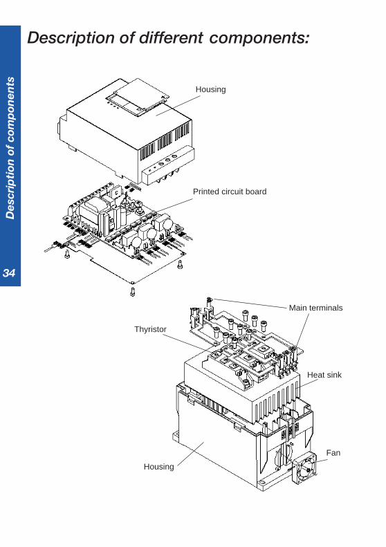
Description of different components:
Housing
Printed circuit board
Housing
Thyristor
Fan
Heat sink
Main terminals
Des
crip
tion
of
com
pon
ents
35
Printed circuit board is used tocontrol the firing of the thyristors based on thecurrent and voltage references, and also for thecalculation of different values, for example thepower factor, active power, etc. It can also beused for storing historical data, the event log,indicating trends and much more.
Heat sink is used to get rid of the heat inthe softstarter generated by the current duringthe start and the continuous run. The capacityof the heat sink very much reflects the startingcapacity and the operational current of thesoftstarter.
Fans are used to increase the coolingcapacity of the heat sink. One, two or severalfans can be used depending on size and design.Some smaller softstarters don’t have fans at alland the number of starts may be limited.
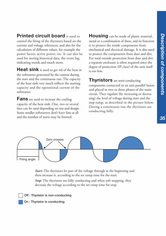
Start: The thyristors let part of the voltage through at the beginning andthen increase it, according to the set ramp time for the start.
Stop: The thyristors are fully conducting and when soft stopping, theydecrease the voltage according to the set ramp time for stop.
Housing can be made of plastic material,metal or a combination of these, and its functionis to protect the inside components frommechanical and electrical damage. It is also usedto protect the components from dust and dirt.For total outside protection from dust and dirta separate enclosure is often required since thedegree of protection (IP class) of the unit itselfis too low.
Thyristors are semi-conductingcomponents connected in an anti-parallel fasionand placed in two or three phases of the maincircuit. They regulate (by increasing or decrea-sing) the level of voltage during start and thestop ramp, as described in the picture below.During a continuous run the thyristors areconducting fully.
Off : Thyristor is non-conducting
On : Thyristor is conducting
Descrip
tion of com
pon
ents
Zero crosses
Firing angle

36
Initial voltage. Sometimes namedpedestrian voltage or torque, this is the pointfrom where the softstarter starts or stops its ramps.The torque of the motor will drop with thesquare of the voltage and if the voltage is settoo low, for example 20 %, the starting torquewill become 0.22 = 0.04 = 4 % only, and themotor will not start from the very beginning.Therefore it is very important to find a levelthat is just high enough to make the motor takeoff directly to avoid unnecessary heating.
Start ramp is the time from were thesoftstarter start its ramp (initial voltage) untilfull voltage is reached. The ramp time shouldnot be too long, as this will only result inunnecessary heating of the motor and a riskof the overload relay to trip. If the motor isunloaded the start time for the motor willprobably become shorter than the set ramptime, and if the motor is heavily loaded, thestart time will probably become longer.
Stop ramp is used when a soft stoppingof the motor is required, for example a pumpor a conveyor belt. The stop ramp is the timefrom full voltage until stop voltage (initialvoltage) is reached. If the ramp time is set tozero the stop will be like a direct stop.
Common settingsThis section includes a short description of some common setting parametersavailable on most of the softstarters. Other settings may be available dependingon the type of softstarter and manufacturer. The setting can be done either byadjusting potentiometers, changing dip switches, using a key pad, a computer orsimilar.
Ue
Initial voltage(U
ini)
Start ramp Stop ramp
Time
Com
mon
set
tin
gs
Diagram showing start ramp, stop ramp and initial voltage
37
reached set levelof current limit
U
100 %
30 %
fixed voltage
t1 t2 Time
t1 + t2 = set ramp time
I
5
2
set level ofcurrent limit
Time
Com
mon
setting
s
Current limit function in softstarter use
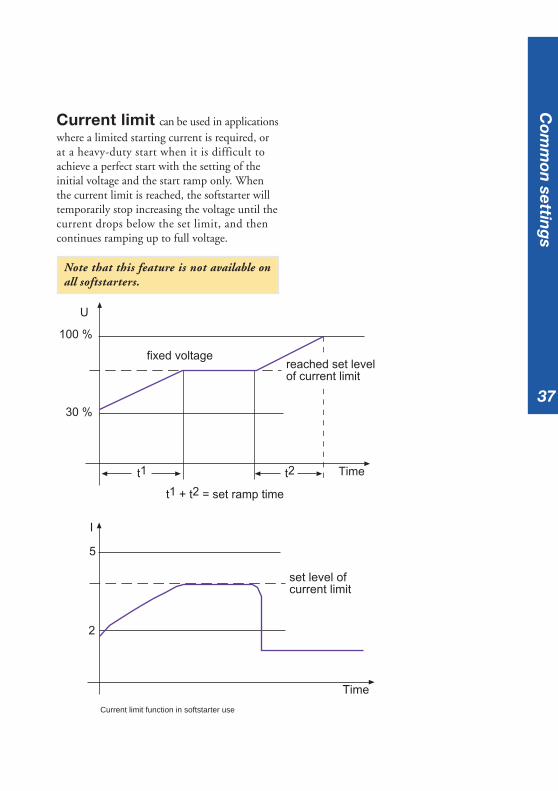
Current limit can be used in applicationswhere a limited starting current is required, orat a heavy-duty start when it is difficult toachieve a perfect start with the setting of theinitial voltage and the start ramp only. Whenthe current limit is reached, the softstarter willtemporarily stop increasing the voltage until thecurrent drops below the set limit, and thencontinues ramping up to full voltage.
Note that this feature is not available onall softstarters.

38
Step down voltage gives a specialtype of stop ramp. It is possible to adjust thevoltage to drop to a level where the speed ofthe motor starts to reduce immediately at thestop command. For low loaded motors thespeed will not reduce until a very low voltageis reached, but using the step down voltagefunction can eliminate this phenomenon andis especially useful for stopping pumps.
Adjustable rated motorcurrent makes it possible to set the motorrated current on the softstarter for the used motor.This setting may affect other values as well, suchas the trip level of the electronic overload relay,the level of the current limit function and so on.
Step down voltage = USD
U
100 %
30 %
Example 50 %
Stop Time
Initial voltage 30 %(= end voltage 30 %)
Com
mon
set
tin
gs
Curve showing the step down voltage function

39
Different indicationsThe indications on a softstarter differ very much from one type to another and also betweenmanufacturers. Some of the most common indications are described below.
On normally indicates that the power supplyis connected to the softstarter and that the unitis ready to start the motor.
Top of Ramp indicates that the startramp is completed and full voltage is reached.If a by-pass contactor is used it will be activatedat this point.
Fault indication can be of many differenttypes. One is if there is an internal fault on thesoftstarter itself, a fault on the feeding side (phaseloss, blown fuse or similar) or on the motor side(motor not connected, phase missing etc.)
Overload indicates that the overloadprotection has tripped. The reason for a trippingoverload can be too high motor current, too longstarting time, too many starts after each other,wrong set overload, wrong trip class of overloador a combination of these.
Overtemperature indicates that thesoftstarter unit is over-heated, due to the numberof starts exceeded, too high-rated current, toolong starting time or similar.
Differen
t ind
ications

40
Different voltages
Main Voltage (Ue),which is the voltage feeding the motor andalso the voltage exposed to the main circuit(thyristors) in the softstarter. 200 - 690 Vare normal values.
Supply voltage (Us),which is the voltage feeding the electroniccomponents inside the softstarter, for examplethe printed circuit board.Common values are 110 - 120 V or 220 - 240 V.
Control Voltage (Uc),which is the voltage for controlling the startand stop command of the softstarter.Values between 24 - 480 V exist.
Main voltage and supply voltage to a softstarter Main voltage and control voltage to a softstarter
Different named voltages are used for the softstarters. The name and use of thesedifferent voltages is stated in the IEC-standard as below.
M
Main Voltage (Ue)
Internal supply
Supply Voltage (Us)
L1 L2 L3
Start
Stop
T1 T2 T3
Powersupply
M
Main Voltage (Ue)
(Internalpower supply)
L1 L2 L3
Start
Stop
T1 T2 T3
Powersupply
ControlVoltage (Uc)
Dif
fere
nt
volt
ages
41
The ambient temperature is the averagesurrounding temperature of the softstarter over aperiod of 24 hours. For most types of softstarterthe temperature may not exceed 40 oC withoutderating the operational current for the unit.
The maximum ambient temperature duringoperation differs from one type of softstarterto another and must be checked individuallyaccording to the manufacturer’s specification.
When using an ABB softstarter with anambient temperature of above 40 oC, thefollowing formula can be used to calculatethe operational current:
Ie derated = Ie - (∆ T x Ie x 0.008)
Ie derated = maximum operational currentafter derating
Ie = rated current of the softstarter∆ T = temperature difference0.008 = derating factor
Ambient temperature
Example 1Rated current: 105 AAmbient temperature: 48 oCDerating with 0.8 % per oC above 40 oC(PS S 18...300)
∆ T = 48-40 oC = 8 oCNew current = Ie - (∆ T x Ie x 0.008) =105 - (8 x 105 x 0.008) = 98,2 A
Example 2Rated current: 300 AAmbient temperature: 46 oCDerating with 0.8 % per oC above 40 oC(PS S 18...300)
∆ T = 46-40 oC = 6 oCNew current = Ie - (∆ T x Ie x 0.008) =300 - (6 x 300 x 0.008) = 285.6 A
Am
bien
t temp
erature

42
When a softstarter is used at high altitudes therated current for the unit has to be derated, dueto less cooling. For most manufacturers thecatalogue values are valid up to 1000 m abovesea level before derating is necessary.
In some cases a larger softstarter is required tobe able to cope with the motor current whenused at high altitudes.
For ABB softstarters the following formulacan be used for calculating the derating:
% of Ie = 100 - x - 1000150
x = actual altitude for the softstarter
Derating when used at highaltitudes
Example:Softstarter with rated current 300 A used at2500 meter above sea level.
% of Ie = 100 - 2500 - 1000
=150
= 100 - 1500
= 90 150
Ie = 300 x 0.9 = 270 A
The diagram below can also be used fordefining the derating of the softstarter.
% of Ie
100 %
90 %
80 %
1000 2000 3000 4000 m
meter above sea level
Hig
h a
ltit
ud
es
Derating of motor current at high altitudes

43
Start of several motors
In some applications, more than one motor will be started with one softstarter,in parallel with each other or in a sequence. This is often possible to do but somedata has to be taken into consideration.
MM
KM 1
Q 1
FR 1
KM 1 Main contactorFR 1 Overload relayQ 1 Softstarter
Start of several m
otors
Parallel start of motors using a softstarter
Parallel start of motorsIf a softstarter is going to be used for startingseveral motors at the same time (parallel start),there are two important parameters to check:
1. The softstarter must be able to cope withthe rated current for all motors together.
2. The softstarter must be able to cope withthe starting current for all motors togetheruntil rated speed is achieved.
Note! If a by-pass contactor is used forthe softstarter, only point 2 above hasto be taken into consideration.
Example:Start of two motors with Ie
= 100 A andrelative starting current 4 x Ie.Starting time is 10 seconds.Total starting current is 100 x 4 x 2 = 800 Aover 10 seconds.
Check the softstarter starting capacity graph toverify the selected size.

44
Sequential start of motors
If a softstarter is going to be used for startingseveral motors one by one (sequential start), itis important to check that the softstarter is ableto cope with the starting current for each motorduring the whole starting sequence.
Example:Start of three motors with Ie=100 A andrelative starting current 4 x Ie.Starting time for the motors is:Motor 1 = 5 secondsMotor 2 = 10 secondsMotor 3 = 8 seconds KM 1 Main contactor
K 25, 27, 29 Starting contactorK 26, 26, 30 Run contactorFR 1, 2, 3 Overload relayQ 1 Softstarter
Sta
rt o
f se
vera
l mot
ors
MM M
KM 1
Q 1
FR 1 FR 2 FR 3
K 25 K 27 K 29
K 26 K 28 K 30
Sequential start of motors using a softstarter
The starting current for the motors is 100 x 4 =400 A and the total starting time is 5 + 10 + 8 =23 seconds.
Check the softstarter starting capacity graphto verify the selected size.
Note! It is not possible to add the startingtime for each motor if the rated currentis different from one motor to another. Aseparate calculation has to be made forthose applications.

45
Different ways of connecting thesoftstarter
There are two different ways of connecting the softstarter - In line, which is themost common method, and Inside Delta. Note that only a few types of softstarterscan actually be connected Inside Delta for example the ABB softstarter rangePS S 18/30...300/515.
In line Inside Delta
Differen
t ways of con
nectin
g

46
In-line connectionThis is easily the most common way to connectthe softstarter.All three phases are connected in a series withthe overload relay, the main contactor and otherdevices used just like the diagram below.The selected devices for Inline connection mustbe chosen to cope with the rated motor current.
Example: 100 A motor requires a 100 Asoftstarter, 100 A main contactor etc.
Softstarter connected Inside Delta
Inside Delta connectionThe Inside Delta connection makes it possibleto place the softstarter in the delta circuit andin that way it can easily replace an existingY/D-starter.
When the softstarter is Inside Delta it willonly be exposed to 58 % (1/√3) of the In-linecurrent. Therefore it is possible to downsize thedevices in order to achieve a more cost-effectivesolution.
Example: A 100 A motor requires a 58 Asoftstarter, a 58 A main contactor if placed inthe delta circuit, etc.
A motor used for an Inside Delta connectionmust be able to delta-connect during a continuousrun. In the USA and some other countries aspecial six-wire motor has to be ordered for thistype of connection.
Softstarter connected In-line with the motor
M
100 A
100 A
100 A
100 A
100 A
M
100 A
100 A
58 A
58 A
58 A
Dif
fere
nt
way
s of
con
nec
tin
g

47
Location of the main contactorWhen using the softstarter Inside Delta thereare two options for the main contactor: in thedelta circuit or outside. Both locations will stopthe motor but in alternative A, the motor is stillconsidered to be under tension.In alternative B the main contactor must bechosen according to the rated current of themotor, while the contactor in alternative A canbe chosen according to 58 % (1/√3) of therated current.
Alternative AMain contactor located in the delta circuit
Alternative BMain contactor located outside the delta circuit
M
A
x
B
M
x
Differen
t ways of con
nectin
g

48
49
Basic settings for differentapplications B
asic setting
s
The required settings for the softstarter will differ from one application to anotherdepending on the type of load, motor characteristics, how much the motor isloaded, etc.For a more in depth description of each setting, please see chapter ”Descriptionof the softstarters”.
Note ! All settings on next page are only proposals and may change from one applicationto another and therefore need to be checked individually.

50
Settings when using a softstarter without current limit function
Type of load Ramp time for Ramp time Initial voltagestart (sec.) for stop (sec.) Uini
Bow thruster 10 0 30 %
Centrifugal fan 10 0 30 %
Centrifugal pump 10 20 30 %
Centrifuge 10 0 40 %
Conveyor belt 10 01) 40 %
Crusher 10 0 60 %
Escalator 10 0 30 %
Heat pump 10 20 30 %
Hydraulic pump 10 0 30 %
Lifting equipment 10 10 60 %
Mill 10 0 60 %
Piston compressor 10 0 30 %
Rotary converter 10 0 30 %
Scraper 10 10 40 %
Screw compressor 10 0 40 %
Screw conveyor 10 10 40 %
Stirrer, Mixer 10 0 60 %
Unloaded motor 10 0 30 %
1) If fragile material, use 10 seconds.
Bas
ic s
etti
ng
s

51
Type of load Ramp time for Ramp time Initial voltage Current limitstart (sec.) for stop (sec.) Uini ( x Ie)
Bow thruster 10 0 30 % 3
Centrifugal fan 10 0 30 % 4
Centrifugal pump 10 20 30 % 3.5
Centrifuge 10 0 40 % 4.5
Conveyor belt 10 01) 40 % 4
Crusher 10 0 60 % 5
Escalator 10 0 30 % 3.5
Heat pump 10 20 30 % 3.5
Hydraulic pump 10 0 30 % 3.5
Lifting equipment 10 10 60 % 4
Mill 10 0 60 % 5
Piston compressor 10 0 30 % 4
Rotary converter 10 0 30 % 3
Scraper 10 10 40 % 4.5
Screw compressor 10 0 40 % 4
Screw conveyor 10 10 40 % 4
Stirrer, Mixer 10 0 60 % 5
Unloaded motor 10 0 30 % 2.5
Settings when using a softstarter with current limit function
1) If fragile material, use 10 seconds.
Basic settin
gs

52
Starting capacity and overloadprotection
Starting capacity for soft-startersWhen starting a squirrel cage motor there willalways be a starting current (Ist) which ishigher than the rated motor current.
The starting current depends on what type ofstarting method is used and in some cases alsothe size of the motor, particular at D.O.L-start.For a softstarter a normal value is 3-4 times therated motor current.
Typical starting capacty graph for a softstarter
Heavy duty applications normally requirea starting current between 4 and 5 times therated motor current.
The maximum permitted starting current fora softstarter depends on the starting time. Theratio between the current and time is displayedin the graph below.
A higher starting current will give a shorterpossible starting time, for example a crusherapplication. A lower current will allow a longerstarting time, for example a pump application.
Time
Sec.
1000
100
10
1100 200 300 400 A
Starting
current
Sta
rtin
g c
apac
ity

53
Starting capacity when usingby-pass contactorWhen using a softstarter with a by-pass contactorit is sometimes possible to select a softstarter witha lower rated power than the motor rated powersince the softstarter will be working during startand stop only, not continuously.
The softstarter can not withstand the ratedmotor current and therefore a check of the star-ting capacity must be carried out for the selectedsize.
Starting capacity when usingoverload protectionThe overload protection for the motor (thermalor electronic) will very often set the limit of thestarting capacity. A class 10 relay is used fornormal starts in general while a class 30 relay isused for heavy-duty starts where a longer star-ting time must be used.
In some applications where the overloadprotection is by-passed (other protection active)during a start to achieve a longer availablestarting time, it is particularly important tocheck the softstarter starting capacity since thiswill be the limitation.
Time
Starting
current
a
b
a) Tripping curve for overload protectionb) Max starting capacity for a softstarter (This will limit the starting time / current if the overload isby-passed during start)
Startin
g cap
acity

54
Number of starts/hour
The maximum number of starts/hour for a softstarter depends on several differentfactors such as the starting current, ambient temperature, starting time and theintermittens factor.
Intermittens factor
The intermittens factor is a figure indicatinghow long the softstarter has been runningfor (starting time and running time) comparedwith the total cycle time.
It is important to define the intermittensfactor when talking about the number of starts/hour since the OFF time is the cooling time forthe softstarter.
A high starting current and a long starting timerequire a longer OFF time than a low startingcurrent and short time to maintain the samenumber of starts/hour.
Examples:
If a softstarter has been running for 5 minutesof a total duty cycle of 10 minutes then theintermittens factor is 50 % ON time and 50 %OFF time.
If a softstarter has been running for 45minutes of a duty cycle of 60 minutes thenthe intermittens factor is 75 % ON time and25 % OFF time.
Duty cycle
Intermittens factor = on x 100 %on + off
OffOn
Time
Nu
mb
er o
f st
arts
/hou
r

5555
Harmonics
Harmonics are unwanted voltages and currents existing in almost every electricalsystem today and are always a multiple of the rated frequency.Typical harmonics are 3rd, 5th, 7th, 9th etc. The harmonics contribute to theunnecessary heating of motors, cables and other equipment and may shorten thelifetime of these devices if exposed for a long period of time.
It can sometimes also disturb functions on electronics and systems. The harmoniccontents and the level naturally depends on the source but also on several otherparameters such as the impedance in the feeding network, the motor, capacitors andother devices used in the system altogether - in other words a quite complexphenomenon.
Harmonic content andsoftstartersThe question of harmonic content for softstarterapplications is actually in general not relevantat all. These reflections usually come fromdrive applications where harmonics are generatedcontinuously and a filter is always required inpublic networks and very often used also inindustrial networks. With our softstarters wefulfil the EMC directive concerning emissionand immunity and there is no need for anyparticular actions regarding this matter at all.
Harm
onics
56
Explosive atmospheres (Ex)
For plants in environments where the hazard of explosion is due to an explosivemixture of gases, explosive matter or combustible dust other than explosive dust,special provisions are applicable regarding the use of electrical material. For electricalmotors there are two main principles for explosion protection. One is to designthe motor so that no sparks or dangerous heat occurs. The other method is to isolatesparks and dangerous heat inside the motor to prevent ignition of any explosivemixture of gases outside the motor.
The different classes of explosive protection (Ex) are described by the following parts ofIEC 60079:
IEC 600079-1: flameproof enclosures ”d”
IEC 600079-2: pressurised enclosures ”p”
IEC 600079-5: powder filling ”q”
IEC 600079-6: oil immersion ”o”
IEC 600079-7: increased safety ”e”
IEC 600079-11: intrinsic safety ”i”
IEC 600079-18: encapsulation ”m”
IEC 600079-22: caplights for mines susceptible to firedamp (under consideration)
Example: Electrical apparatus for explosive atmospheres - oil immersion ”o” shall be recognised as Exo.
Exp
losi
ve a
tmos
ph
eres

5757
Hazardous areas and zones
The hazardous areas are categorised inzones as follows:
Zone 0An area in which an explosive gas atmosphere ispresent continuously or for long periods. Onlyintrinsically-safe circuits of category Exi may beused in this zone. Motors are thus excluded.
Zone 1An area in which an explosive gas atmosphere islikely to occur in normal operation. Motors ofcategory Exd, Exe and Exp may be used in thiszone.
Zone 2An area in which an explosive gas atmosphere isnot likely to occur during normal operation andif it does occur it will exist for a short periodonly. Equipment permitted in zones 0 and 1may of course be used. Under certain conditionsthe equipment, motors for instance, need not tobe of explosion-protected design.
3 m
3 m
r4.5 m
Surface of liquid
Heightof wall
To wall
Zone 0 Zone 1 Zone 2
Low point
Exp
losive atmosp
heres
Example of classification and extent of the hazardous area in a tank
Location and selectionof softstarter for ExenvironmentsIf a softstarter is going to be used for an Exapplication it is normally located in a separateenclosure outside any of the hazardous zones.The overload relay used shall be of a specialversion designed for EEx motors, for exampleTA 25 DU...V 1000 to T 900 DU/SU...V 1000.This type of relay has a more accurate trippingcurve compared with the standard relay. Specialattention has to be paid to this.
The softstarter type and size and other devicesused in the circuit shall suitably be selectedaccording to type 2 co-ordination.
Note !If any electrical equipment is going to beused in any of the hazardous zones a specialenclosure must be used. This type ofenclosure (steel box or similar) must beable to withstand an inside explosioncaused by any of the components withoutletting anything out to the surroundings.This solution is in general very unusual.

58
Co-ordination
By co-ordination we mean a selected combination of electrical apparatus which issafe for the surroundings and personnel, even if an overload or a fault should occurin the system.
The co-ordinated group must ensure the following four essential functions:
• Protection against overloads. A protection, which guards all components, cablesand the motor from overheating, active for all currents up to, locked rotor current.This device will send a trip signal to a disconnection mean, which is normally acontactor used for the motor control.
• Motor control. This function is commonly carried out by a contactor.
• Protection against short-circuits, which takes care of all currents above the lockedrotor current - i.e. all fault currents.
• Isolation. Ensure an isolating air-gap when opened for personnel safety.
The co-ordinations for the ABB softstarters are done according to IEC 60947-4-2”AC semiconductor motor controllers and starters” and EN 60947-4-2.The provisions of IEC 60947-1, General Rules, are applicable to IEC 60947-4-2where specifically called for.
Co-
ord
inat
ion

5959
Types of co-ordinationThe standard IEC 60947-4-2 defines two typesof co-ordination according to the expected levelof service continuity. The standard IEC 60947-1,General Rule are applicable to this standard,where specifically called for.
Type 1:Co-ordination requires that, under short-circuitconditions, the device shall cause no danger topersons or installation and may not be suitablefor further service without repair and replacementof parts.
Co-ord
ination
Type 2:Co-ordination requires that, under short-circuitconditions, the device shall cause no danger topersons or installation and shall be suitable forfurther use. For hybrid controllers and starters,the risk of contact welding is recognized, inwhich case the manufacturer shall indicate themeasures to be taken as regards the maintenanceof the equipment.
Note !When using a softstarter in a type 2co-ordination, replacing the fuses andrestart has to be accepted after a short-circuit. Only semi-conductor fuses canbe used to achieve a type 2 co-ordinationfor a softstarter.

60
Utilization CategoriesSome utilization categories are stated in the standard IEC 60947-4-2, ”AC semiconductormotor controllers and starters”. The one used for ABB Low Voltage softstarters is AC-53.
Utilization Typical applicationCategory
AC-52a Control of slip-ring motor stators: 8 h duty with on-load currents forstart, acceleration, run
AC-52b Control of slip-ring motor stators: intermittent duty
AC-53a Control of squirrel cage motors: 8 h duty with on-load currents forstart, acceleration, run
AC-53b Control of squirrel cage motors: intermittent duty
AC-58a Control of hermetic refrigerant compressor motors with automatic resetting ofoverload releases: 8 h duty with on-load currents for start, acceleration, run
AC-58b Control of hermetic refrigerant compressor motors with automatic resetting ofoverload releases: intermittent duty
Remarks
AC-53 is the utilization category used for softstarters in general since this is aboutcontrolling squirrel cage motors. This is the category stated in the header of theco-ordination tables for softstarters.
AC-53a is about softstarter designed for use without by-pass contactor.AC-53b is about softstarter designed for use with by-pass contactor.
Co-
ord
inat
ion
6161
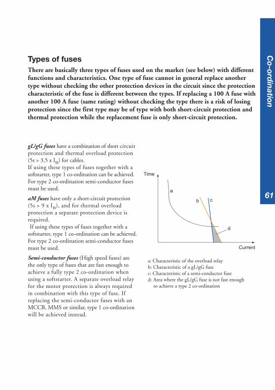
gL/gG fuses have a combination of short circuitprotection and thermal overload protection(5s > 3,5 x In) for cables.If using these types of fuses together with asoftstarter, type 1 co-ordination can be achieved.For type 2 co-ordination semi-conductor fusesmust be used.
aM fuses have only a short-circuit protection(5s > 9 x In), and for thermal overloadprotection a separate protection device isrequired.If using these types of fuses together with a
softstarter, type 1 co-ordination can be achieved.For type 2 co-ordination semi-conductor fusesmust be used.
Semi-conductor fuses (High speed fuses) arethe only type of fuses that are fast enough toachieve a fully type 2 co-ordination whenusing a softstarter. A separate overload relayfor the motor protection is always requiredin combination with this type of fuse. Ifreplacing the semi-conductor fuses with anMCCB, MMS or similar, type 1 co-ordinationwill be achieved instead.
a: Characteristic of the overload relayb: Characteristic of a gL/gG fusec: Characteristic of a semi-conductor fused: Area where the gL/gG fuse is not fast enough
to achieve a type 2 co-ordination
a
b c
d
Time
Current
Types of fusesThere are basically three types of fuses used on the market (see below) with differentfunctions and characteristics. One type of fuse cannot in general replace anothertype without checking the other protection devices in the circuit since the protectioncharacteristic of the fuse is different between the types. If replacing a 100 A fuse withanother 100 A fuse (same rating) without checking the type there is a risk of losingprotection since the first type may be of type with both short-circuit protection andthermal protection while the replacement fuse is only short-circuit protection.
Co-ord
ination
62
Where to find the co-ordination tables
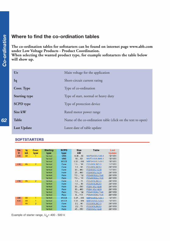
The co-ordination tables for softstarters can be found on internet page www.abb.comunder Low Voltage Products - Product Coordination.When selecting the wanted product type, for example softstarters the table belowwill show up.
Ue Main voltage for the application
Iq Short-circuit current rating
Coor. Type Type of co-ordination
Starting type Type of start, normal or heavy duty
SCPD type Type of protection device
Size kW Rated motor power range
Table Name of the co-ordination table (click on the text to open)
Last Update Latest date of table update
Co-
ord
inat
ion
Example of starter range, Ue= 400 - 500 V.

6363
Example of co-ordination table: 500V, 65kA, normal start, type 2 (PSD5065LINE40)
How to read the co-ordination tables
In the header of the selected table, information about softstarter type, main voltage, short-circuit rating, maximum ambient temperature, IEC-standard and co-ordination type can befound.
Motor Indicates the rated output of the motor and maximum current.If this does not correspond fully to the actual motor, select accordingto the maximum current.
Softstarter Indicates suitable softstarter type and size for this motor.
Semi-conductor fuses Indicates rated current and type of semi-conductor fuse.
Switch fuse Indicates suitable switch fuse for the semi-conductor fuses.
Thermal overload relay Indicates suitable thermal overload relay, type and setting range.
Line contactor Indicates suitable line (main) contactor for the motor.This contactor is given with AC-3 rating.
By-pass contactor Indicates suitable by-pass contactor which is not required for theco-ordination. This contactor is given with AC-1 rating.
Co-ord
ination

64
Starter and fuses In-line Starter Inside Delta andfuses In-line
The co-ordinations with the devices In-line arebased on this circuit diagram.
Note that the by-pass contactor is notrequired for the co-ordination.
The co-ordinations with the softstarter InsideDelta are based on this circuit diagram.
Note that the by-pass contactor is notrequired for the co-ordination.
M
Switch fuseSemi-conductor fuse
Line contactor
O/L relay
By-passcontactor
Softstarter
Motor M
Switch FuseSemi-conductor fuse
Line contactor
O/L relayBy-passcontactor
Softstarter
Motor
Starter inside delta and fuses In-lineLine contactor AC-3By-pass contactor AC-1Line contactor and by-pass contactor Inside Deltaconnected
Starter and fuses In-lineLine contactor AC-3By-pass contactor AC-1
Co-
ord
inat
ion
6565
ESD – Electro Static Discharge
An increasing problem today with the use of more and more electronic equipment inour systems is the Electro Static Discharge (ESD). The main source of the problem isthe wrong handling of electronic components, printed circuit-boards, etc. A componentdamaged by ESD has been exposed to a too high voltage level and today the componentsare much more sensitive depending on integration, which means more functions inthe same capsule. The distances between the conductors are decreased and thereforethe insulation distance will be at a minimum. A value of 0.002 mm is common inmodern integrated circuits.
Electro static charge is caused in three different ways:• Rubbing of two surfaces to each other.• Separation of two surfaces from each other, for example when removing a plastic cover from its contents.• Induction caused by static electricity without any contact of the material.
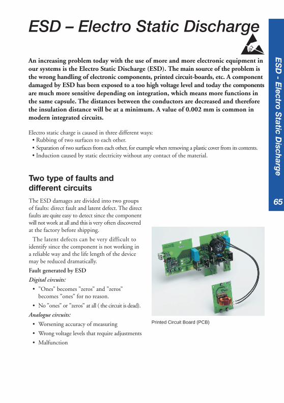
Two type of faults anddifferent circuitsThe ESD damages are divided into two groupsof faults: direct fault and latent defect. The directfaults are quite easy to detect since the componentwill not work at all and this is very often discoveredat the factory before shipping.
The latent defects can be very difficult toidentify since the component is not working ina reliable way and the life length of the devicemay be reduced dramatically.
Fault generated by ESD
Digital circuits:
• ”Ones” becomes ”zeros” and ”zeros”becomes ”ones” for no reason.
• No ”ones” or ”zeros” at all ( the circuit is dead).
Analogue circuits:
• Worsening accuracy of measuring
• Wrong voltage levels that require adjustments
• Malfunction
ES
D - E
lectro Static D
ischarg
e
Printed Circuit Board (PCB)
66
Electro static voltage levelsA voltage level of between 100-500 V candestroy any electronic components in principle.The most sensitive components can only with-stand voltages between 25-170 V.
Sometimes it is possible to hear a ”click”sound when touching an object and that istypical ESD phenomena. When it is possible tohear that ”click” sound the voltage level is alreadyat least 3,5 kV. Sometimes it is also possible tosee a spark when touching an object and thevoltage level is then at least 10 kV.
Below some values are given for typical Electrostatic charge:
Walking on a wall-to-wall carpet: 10 - 20 kV
Walking on a plastic floor (PVC): 2 - 5 kV
Walking on an anti-static floor: 0 - 2 kV
Lifting paper from a table: 5 - 35 kV
Rising from a chair: 10 -25 kV
Protection against ESDdamagesIt is possible to reduce the risk of ESD to aminimum for the equipment. This is veryimportant to remember when making serviceand/or repair with electronic components forexample the printed circuit board on a softstarter.
Actions to prevent damages:
• Avoid charge if possible
• Always use a wrist strap or similarconnected to ground potential whenworking with electrical components
• Always use the right type of package (ESDprotected bags, etc.)
• Connect all machines and apparatusto ground potential
• High humidity
ES
D -
Ele
ctro
Sta
tic
Dis
char
ge
6767
Main contactor
Q Is there any requirement to put a maincontactor in series before the softstarter?
A The softstarter does not require any maincontactor but we recommend the use of onefor emergency stop and/or trip of theoverload relay. In some applications an MCCBcan be used instead of the main contactor.
Ambient temperature
Q Can I use a softstarter if the ambienttemperature is higher than the recommendedvalue during operation?
A The softstarter can normally be operatedat a higher ambient temperature duringoperation if the rated current for the unit isderated according to the manufacturer’srecommendation.
Thyristor shorted
Q Is it possible to run a softstarter with onethyristor shorted?
A Yes, it is possible but not for all types ofsoftstarters.
Soft stop applications
Q What applications are suitable for soft stop?
A Pumps and conveyor belts loaded with fragileproducts are the two main applicationssuitable for soft stop.
Frequently asked questions (FAQ)
Advantages of by-pass
Q What are the advantages of using by-pass?
A Reduction of power loss. It is also possibleto reduce the enclosure size and use a higherIP-class since air ventilation is not required.
Power loss
Q What is the power loss of a softstarterduring a continuous run?
A The values can normally be found in thecatalogue. For ABB softstarters the followingformula can be used (for example forPS S 18...300):PLtot = [3 x Ie x 1.0] + 50 (W) reduced to50 W only which is the power of the coolingfans when using by-pass.Ie is the operational current of the motor.
Utilisation category
Q What utilisation category should be used forthe main contactor and the by-pass contactor?
A Main contactor: always use AC-3.By-pass contactor: it is possible to use AC-1.
Fault indication when starting
Q Why does the softstarter indicate a faultwhen the start signal is given to the maincontactor and softstarter at the same time?
A If the main contactor is closed too late thesoftstarter will indicate this as a phase lossfault. Delay the start signal to the soft starterby approx. 0.5 sec. to solve this phenomenon.
FAQ

68
Test without motor
Q Can I test a softstarter without using a motor?
A No, this is not possible since there will be nocurrent going through the softstarter andsome types will also indicate loss of load.
Overload relay trips during start
Q Why does the overload relay trip during start?
A Possible reasons can be one of these or in acombination:- too low current limit- too long ramp time- too low initial voltage- wrong tripping class on the overload- wrong setting on the overload
Separate overload relay whenusing by-pass
Q Do I need a separate overload relay whenusing a softstarter with built-in electronicoverload and by-pass?
A If the current transformers of the softstartercan be installed so that the measuring canbe performed when by-passed a separaterelay is not required; otherwise yes.
Different frequency
Q Can I use the same softstarter at both 50and 60 Hz?
A It is possible with all type of ABB softstartersas long as the curve is sinusoidal.
Voltage fluctuations
Q What voltage fluctuations are allowed forthe softstarters?
A The minimum and maximum value wherewe can guarantee full function is -15 % to+10 % of the rated value. This is also statedin the IEC-standard.Example: 400 V - 15 % to +10 % ≥ 340 V -440 V range.
Semi-conductor fuses
Q Do I always have to use semi-conductor fuses?
A When using semi-conductor fuses a type 2co-ordination can be achieved.It is possible to use an MCCB (mouldedcase circuit breaker) or MMS (manualmotorstarter) instead but then with a type 1co-ordination. For a more in-depthdescription see the chapter on co-ordination.
FAQ

69
Environmental information
How a product affects the environment is a matter that is becoming more and moreimportant when designing new products today but also when updating existing productranges. In order to get a complete picture of all environmental aspects, there are somedifferent methods of doing this.
LCALCA (Life Cycle Assessment) is a managementtool for appraising and quantifying the entirelife cycle of particular materials, the impact ofproducts or activities over their total lifetime byanalysing the entire life cycle of particularmaterials, processes, products, technologies,services or activities. The most important aspectsaffecting the environment for a softstarter hasproven to be:
• Choice of material in the softstarter
• Energy losses during lifetime
• Recycling possibilities
En
vironm
ental in
formation
The LCA process includes the entire lifecycle of a product
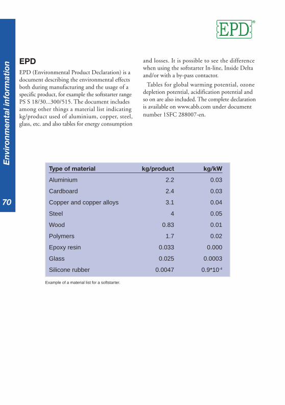
70
Type of material kg/product kg/kW
Aluminium 2.2 0.03
Cardboard 2.4 0.03
Copper and copper alloys 3.1 0.04
Steel 4 0.05
Wood 0.83 0.01
Polymers 1.7 0.02
Epoxy resin 0.033 0.000
Glass 0.025 0.0003
Silicone rubber 0.0047 0.9*10-4
EPDEPD (Environmental Product Declaration) is adocument describing the environmental effectsboth during manufacturing and the usage of aspecific product, for example the softstarter rangePS S 18/30...300/515. The document includesamong other things a material list indicatingkg/product used of aluminium, copper, steel,glass, etc. and also tables for energy consumption
Example of a material list for a softstarter.
and losses. It is possible to see the differencewhen using the softstarter In-line, Inside Deltaand/or with a by-pass contactor.
Tables for global warming potential, ozonedepletion potential, acidification potential andso on are also included. The complete declarationis available on www.abb.com under documentnumber 1SFC 288007-en.
En
viro
nm
enta
l in
form
atio
n

71
Industrial IT
ABB has committed, as a key element of its business strategy, to a broad program ofproduct development and positioning under the Industrial IT umbrella (IIT). Themain reason behind the Industrial IT certification is to make it easier and moreeffective to combine products into systems and solutions.
All products that pass the Industrial IT certification tests achieve the Industrial ITenabled sign.
Enabled products are verified for properties that make them work together in a pre-defined mannerwith other enabled products in an Industrial IT environment throughout the full life cycle of theplant. This means that IIT certified products should be easier to:
• Purchase
• Design
• Engineer
• Install
• Commission
• Operate
• Maintain
• De-install
Ind
ustrial IT
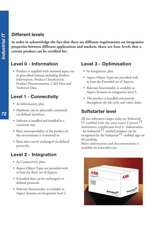
72
Level 0 - Information• Product is supplied with minimal aspect set
in prescribed formats including ProductInformation, Product Classification,Product Documentation, CAD Data andTechnical Data.
Level 1 - Connectivity• As Information, plus.
• Hardware can be physically connectedvia defined interfaces.
• Software is installed and handled in aconsistent way.
• Basic interoperability of the product inthe environment it is inserted in.
• Basic data can be exchanged via definedprotocols.
Level 2 - Integration• As Connectivity, plus.
• Aspect Object Types are provided withat least the Basic set of Aspects.
• Extended data can be exchanged viadefined protocols.
• Relevant functionality is available asAspect Systems on integration level 2.
Different levels
In order to acknowledge the fact that there are different requirements on integrationproperties between different applications and markets, there are four levels that acertain product can be certified for:
Level 3 - Optimisation• As Integration, plus.
• Aspect Object Types are provided withat least the Extended set of Aspects.
• Relevant functionality is available asAspect Systems on integration level 3.
• The product is handled consistentlythroughout the life cycle and value chain.
Softstarter levelAll our softstarter ranges today are IndustrialIT enabled with the suite name Control IT
Softstarters, certifiaction level 0 - Information.An Industrial IT enabled product can be
recognized by the Industrial IT enabled sign onthe packing.More information and documentation isavailable on www.abb.com
Ind
ust
rial
IT
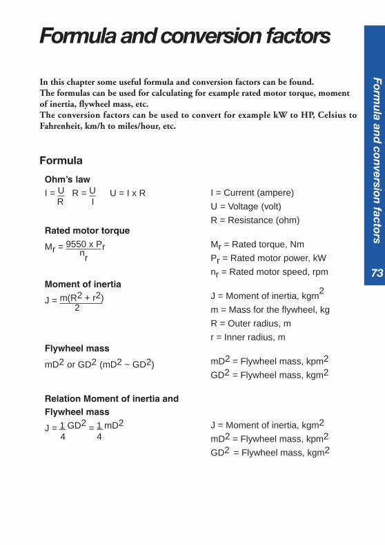
73
In this chapter some useful formula and conversion factors can be found.The formulas can be used for calculating for example rated motor torque, momentof inertia, flywheel mass, etc.The conversion factors can be used to convert for example kW to HP, Celsius toFahrenheit, km/h to miles/hour, etc.
Formula and conversion factors
I = Current (ampere)
U = Voltage (volt)
R = Resistance (ohm)
Mr = Rated torque, Nm
Pr = Rated motor power, kW
nr = Rated motor speed, rpm
J = Moment of inertia, kgm2
m = Mass for the flywheel, kg
R = Outer radius, m
r = Inner radius, m
mD2 = Flywheel mass, kpm2
GD2 = Flywheel mass, kgm2
J = Moment of inertia, kgm2
mD2 = Flywheel mass, kpm2
GD2 = Flywheel mass, kgm2
Formula
Ohm’s lawI = U R = U U = I x R
R I
Rated motor torque
Mr = 9550 x Prnr
Moment of inertia
J = m(R2 + r2)2
Flywheel mass
mD2 or GD2 (mD2 ~ GD2)
Relation Moment of inertia andFlywheel mass
J = 1 GD2 = 1 mD2
4 4
Formu
la and
conversion
factors
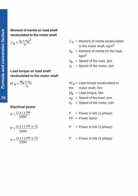
74
J´b = Moment of inertia recalcu lated
to the motor shaft, kgm2
Jb = Moment of inertia for the load,
kgm2
nb = Speed of the load, rpm
nr = Speed of the motor, rpm
M´b = Load torque recalculated to
the motor shaft, Nm
Mb = Load torque, Nm
nb = Speed of the load, rpm
nr = Speed of the motor, rpm
P = Power in kW (1-phase)
PF = Power factor
P = Power in kW (2-phase)
P = Power in kW (3-phase)
Moment of inertia on load shaftrecalculated to the motor shaft
J´b = Jb x nb2
n
Load torque on load shaftrecalculated to the motor shaft
M´b = Mb x nbnr
Electrical power
P = U x I x PF1000
P = U x I x PF x √2
1000
P = U x I x PF x √31000
Form
ula
an
d c
onve
rsio
n f
acto
rs

75
Quantities and units
Lengthyd. = yard
m = metre
mm = millimetre
cm = centimetre
in. = inch
ft. = feet
km = kilometre
Timeh = hour
min = minute
s = second
Weightoz. = ounce
lb. = pound
kg = kilogram
g = gram
Power / EnergyHP = horsepower
W = watt
kW = kilowatt
kWh = kilowatt-hours
Volumel = litre
ml = millilitre
cu.in. = cubic inch
cu.ft. = cubic feet
gal. = gallon
fl.oz. = fluid ounce
ElectricalA = Ampere
V = Volt
W = Watt
Ω = Ohm
F = Farad
Formu
la and
conversion
factors

76
Conversion factors
Length
1 mile = 1,609344 km 1 km = 0,621 mile
1 yd = 0,9144 m 1 m = 1,09 yd
1 ft = 0,3048 m 1 m = 3,28 ft
1 in = 25,4 mm 1 mm = 0,039 in
Velocity
1 knot = 1,852 km/h 1 km/h = 0,540 knot
1 mile/h = 1,61 km/h 1 km/h = 0,622 mile/h
1 m/s = 3,6 km/h 1 km/h = 0,278 m/s
Area
1 acre = 0,405 ha 1 ha = 2,471 acre
1 ft2 = 0,0929 m2 1 m2 = 10,8 ft2
1 in2 = 6,45 cm2 1 cm2 = 0,155 in2
Volume
1 ft3 = 0,0283 m3 1 m3 = 35,3 ft3
1 in3 = 16,4 cm3 1 cm3 = 0,0610 in3
1 gallon = 4,55 l (UK) 1 l = 0,220 gallon (UK)
1 gallon = 3,79 l (US) 1 l = 0,264 gallon (US)
1 pint = 0,568 l 1 l = 1,76 pint
Mass
1 lb = 0,454 kg 1 kg = 2,20 lb
1 oz = 28,3 g 1 g = 0,0352 oz
Form
ula
an
d c
onve
rsio
n f
acto
rs

77
Moment of Inertia
1 Nm2 = 2,42 ft.-lb2 1 ft.-lb2 = 0,41322 Nm2
1 kgm2 = 0,2469 ft.-lb2 1 ft.-lb2 = 4,0537 kgm2
1 oz.-in2 = 0,000434 ft.-lb2 1 ft.-lb2 = 2304,147 oz.-in2
Force
1 kp = 9,80665 N 1 N = 0,102 kp
1 lbf = 4,45 N 1 N = 0,225 lbf
Energy
1 kpm = 9,80665 J 1 J = 0,102 kpm
1 cal = 4,1868 J 1 J = 0,239 cal
1 kWh = 3,6 MJ 1 MJ = 0,278 kWh
Power
1 hp = 0,736 kW 1 kW = 1,36 hp
1 hp = 0,746 kW (UK,US) 1 kW = 1,34 hp (UK;US)
1 kcal/h = 1,16 W 1 W = 0,860 kcal/h
Temperature
0 oC = 32 oFoC = 5 / 9 (oF-32)
0 oF = -17,8 oCoF = 9 / 5 (oC+32)
Formu
la and
conversion
factors

78
AC Alternating current.
Ambient Temperature Ambient temperature is the temperature of water,air or surrounding medium where the equipment isused or stored.
Asynchronous speed The speed of an AC induction motor at full loadand full voltage, also defined as the rated speed.
Bearing A component used to reduce the friction and wearbetween rotating devices.
By-pass A by-pass contactor is used to by-pass another device,for example a softstarter to reduce the power loss.
CSA Canadian Standard Association
Current limit An electronic method to limit the starting currentto the motor during start up. It is normally possibleto adjust the function so that the motor torque willbe high enought to take off.
Cycle A sequence of operations that is repeated regularlyor the time it takes to complete one operation.
D-end The end that is normally the drive end of an electricalmotor.
DC Direct current
Degree of Protection Defined and stated as IP (International Protection)class indicating the degree of protection againstcontact and penetration of solid objects and water.
Derating When a device has to be operated with reducedratings (normally the current) due to high ambienttemperature or high altitude.
D.O.L Direct-on-line
Glossary
Glo
ssar
y
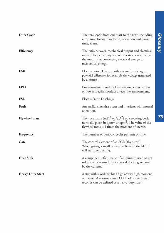
79
Duty Cycle The total cycle from one start to the next, includingramp time for start and stop, operation and pausetime, if any.
Efficiency The ratio between mechanical output and electricalinput. The percentage given indicates how effectivethe motor is at converting electrical energy tomechanical energy.
EMF Electromotive Force, another term for voltage orpotential difference, for example the voltage generatedby a motor.
EPD Environmental Product Declaration, a descriptionof how a specific product affects the environment.
ESD Electro Static Discharge.
Fault Any malfunction that occur and interferes with normaloperation.
Flywheel mass The total mass (mD2 or GD2) of a rotating bodynormally given in kpm2 or kgm2. The value of theflywheel mass is 4 times the moment of inertia.
Frequency The number of periodic cycles per unit of time.
Gate The control element of an SCR (thyristor).When giving a small positive voltage to the SCR itwill start conducting.
Heat Sink A component often made of aluminium used to getrid of the heat inside an electrical device generatedby the current.
Heavy Duty Start A start with a load that has a high or very high momentof inertia. A starting time D.O.L. of more then 5seconds can be defined as a heavy-duty start.
Glossary
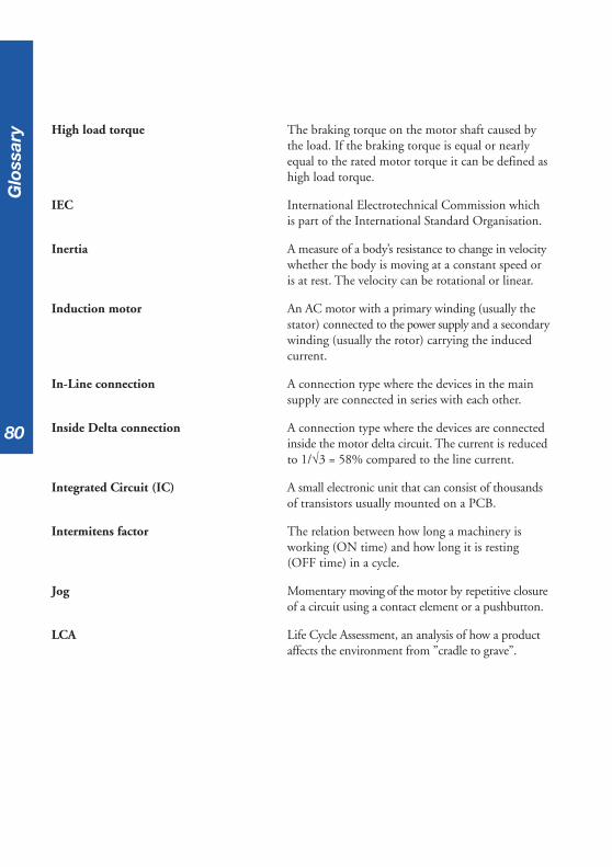
80
High load torque The braking torque on the motor shaft caused bythe load. If the braking torque is equal or nearlyequal to the rated motor torque it can be defined ashigh load torque.
IEC International Electrotechnical Commission whichis part of the International Standard Organisation.
Inertia A measure of a body’s resistance to change in velocitywhether the body is moving at a constant speed oris at rest. The velocity can be rotational or linear.
Induction motor An AC motor with a primary winding (usually thestator) connected to the power supply and a secondarywinding (usually the rotor) carrying the inducedcurrent.
In-Line connection A connection type where the devices in the mainsupply are connected in series with each other.
Inside Delta connection A connection type where the devices are connectedinside the motor delta circuit. The current is reducedto 1/√3 = 58% compared to the line current.
Integrated Circuit (IC) A small electronic unit that can consist of thousandsof transistors usually mounted on a PCB.
Intermitens factor The relation between how long a machinery isworking (ON time) and how long it is resting(OFF time) in a cycle.
Jog Momentary moving of the motor by repetitive closureof a circuit using a contact element or a pushbutton.
LCA Life Cycle Assessment, an analysis of how a productaffects the environment from ”cradle to grave”.
Glo
ssar
y
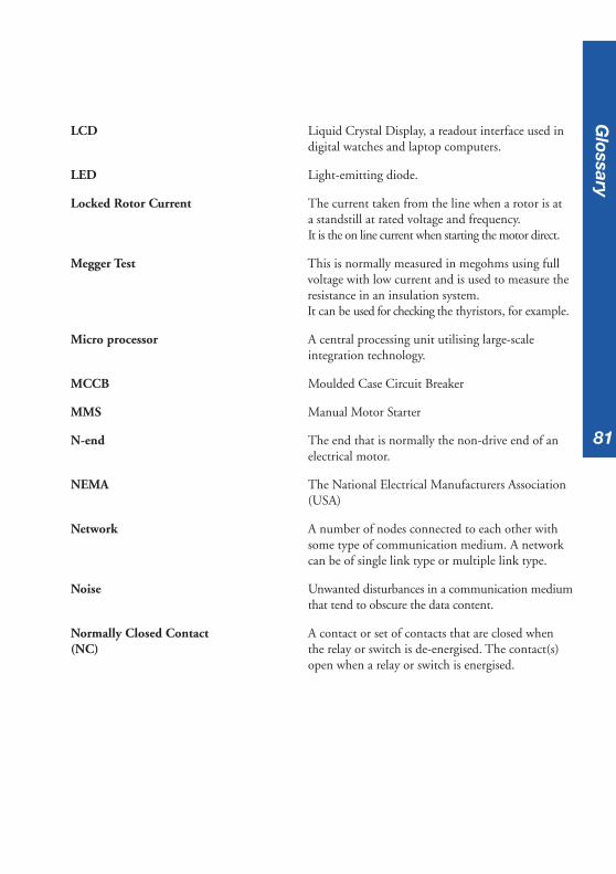
81
LCD Liquid Crystal Display, a readout interface used indigital watches and laptop computers.
LED Light-emitting diode.
Locked Rotor Current The current taken from the line when a rotor is ata standstill at rated voltage and frequency.It is the on line current when starting the motor direct.
Megger Test This is normally measured in megohms using fullvoltage with low current and is used to measure theresistance in an insulation system.It can be used for checking the thyristors, for example.
Micro processor A central processing unit utilising large-scaleintegration technology.
MCCB Moulded Case Circuit Breaker
MMS Manual Motor Starter
N-end The end that is normally the non-drive end of anelectrical motor.
NEMA The National Electrical Manufacturers Association(USA)
Network A number of nodes connected to each other withsome type of communication medium. A networkcan be of single link type or multiple link type.
Noise Unwanted disturbances in a communication mediumthat tend to obscure the data content.
Normally Closed Contact A contact or set of contacts that are closed when(NC) the relay or switch is de-energised. The contact(s)
open when a relay or switch is energised.
Glossary
82
Normally Open Contact A contact or set of contacts that are open when(NO) the relay or switch is de-energised. The contact(s)
close when the relay or switch is energised.
Normal Start A start with a load that has small or medium highmoment of inertia. A starting time D.O.L. of lessthen 5 seconds can be defined as normal start.
Overload relay A device used to avoid overheating of the motor.Can be of electronic or thermal type.
Parallel start Parallel start of motors is normally when two or moremotors are started at the same time with the samestarting equipment.
PCB Printed Circuit Board.
PLC Programmable Logic Controller, consists of a centralprocessor, input/output interfaces and a memorydesigned as an industrial control system. A PLCsystem is used for the storage of instructions, timing,counting, report generation I/O control and more.
Power Work done per unit of time measured in horsepower(HP) or watt (W).
Power Factor The phase difference measured between the voltageand the current in an AC circuit represented by thecosine angle.
Protocol A set of conventions governing the format and timingof data between communication devices.
Reversing Changing of the rotation direction of the rotor ormotor armature.
SCR Silicon Controlled Rectifier often referred to as athyristor.
Glo
ssar
y

83
Semi-conductor fuses A special type of high-speed fuse used as thyristorprotection since normal (gG/gL or aM) fuses are notfast enough.
Sequential start Sequential start of motors is normally when two ormore motors are started one by one in a sequencewith the same starting equipment.
Serial Communication The way of transmitting data in a networkbetween different nodes, using some type ofprotocol.
Slip The difference (usually expressed in percentage)between the synchronous speed and the rotor speedof an AC induction motor.
Star connection The connection type where each winding in a polyphasecircuit is connected at one end to a common point.
Synchronous speed The speed of the rotating magnetic field on an ACinduction motor determined by the frequency andthe number of magnetic poles in each phase of thestator windings.
Thyristor A solid-state switch that has an anode, cathode anda control element called the gate, which makes itpossible to turn it on at will. It can rapidly switchlarge currents at high voltages.
Tripping class The tripping class defines the starting time at aspecific current before tripping occurs.Different classes exist, for example 10, 20, 30 etc.where class 30 allows the longest starting time.
Torque A measure of the turning force ability for a device.
UL Underwrites Laboratories (an approval agency).
Y connection See Star connection.
Glossary
84
Ind
ex
IndexAAccelerating torque 15Adjustable rated motor current 38Ambient temperature 41
BBraking load torque 15
CCE Marking 1Centrifugal fan. See FanCentrifugal pump. See PumpCo-ordination 58, 59
table of 62, 63Common problems, table of 14Compressor 23
Suitable softstarter 26Control voltage 40Conveyor belt 27
Suitable softstarter 30CSA specifications 1Current limit 37
DD-end 2Delta connection 4Direct-on-line start 9, 16, 19, 23, 27
EElectro Static Discharge(ESD) 65, 66Electronic overload relay (EOL) 33Environmental Product Declaration
(EPD) 70Explosive atmospheres (Ex) 56
Zone catergories 57
FFan 35
Suitable softstarter 18FAQ - Softstarters 67Fault 39Firing angle 35Formula and conversion factors 73Frequency drive 12Fuses 61, 64
GGlossary 78
HHarmonics 55Heat sink 35High altitudes, derating 42Housing 35
IIn-line connection 46Indications 39Industrial IT 71, 72
Levels of certification 72Initial voltage 36Inside delta connection 46
LLife Cycle Assessment (LCA) 69

85
Ind
ex
MMain voltage 40Motors
about 2calculations, speed 6calculations, torque 7mechanical overview 2Parallel start 43problems, start & stop 14Sequential start 44Slip-ring 7Squirrel cage 3Winding 4
OOverload 39Overload relay. See Electronic
overload relay (EOL)
PPower factor 5Printed Circuit Board (PCB) 35Pump 19
stopping a pump 20Suitable softstarter 22
QQuick guide, softstarter applications
31
SSettings 36
Adjustable rated motor current 38Current limit 37Initial voltage 36
Start ramp 36Step down voltage 38table, with current lim. 51table, without current lim. 50
settingsStop ramp 36
Softstarter 13, 17, 21, 25, 29Component picture 34How to select - Quickguide 31Indications 39Starting capacity 52
starts/hour 54using by-pass contactor 53using overload protection 53
Standards 1Star-delta start 10Star-delta starter 17, 20, 24, 28Start connection 4Start ramp 36Starting capacity 52, 53Step down voltage 38Stop ramp 36Supply voltage 40
TTemperature, derating 41Thyristor 35
UUL specifications 1Utilization Categories 60
VVoltage 4Voltage definitions 40

86

AB
B A
uto
mat
ion
Tec
hn
olo
gie
s A
B/C
ewe-
Con
trol
, SE
-721
61
Väs
terå
s, S
wed
en, T
elep
hone
+46
21
32 0
7 00
, Tel
efax
+46
21
12 6
0 01
Id.N
o 1S
FC
1320
02M
0201
, ed.
2, S
epte
mbe
r 20
04, A
TAP
/CL/
XM,
repr
inte
d in
Sep
t.20
04/E
dita
Väs
tra
Aro
s