ABB Robotics System description Arc Welding system,...
36
ABB Robotics System description Arc Welding system, IRC5
Transcript of ABB Robotics System description Arc Welding system,...
ABB Robotics
System description Arc Welding system, IRC5


© C
opyr
ight
200
8 A
BB
. All
right
s res
erve
d.
System descriptionWelding robot products
IRC5Document ID: 3HAC031146-001
Revision: -
© C
opyr
ight
200
8 A
BB
. All
right
s res
erve
d.
The information in this manual is subject to change without notice and should not be construed as a commitment by ABB. ABB assumes no responsibility for any errors that may appear in this manual.Except as may be expressly stated anywhere in this manual, nothing herein shall be construed as any kind of guarantee or warranty by ABB for losses, damages to persons or property, fitness for a specific purpose or the like.In no event shall ABB be liable for incidental or consequential damages arising from use of this manual and products described herein.This manual and parts thereof must not be reproduced or copied without ABB's written permission, and contents thereof must not be imparted to a third party nor be used for any unauthorized purpose. Contravention will be prosecuted. Additional copies of this manual may be obtained from ABB at its then current charge.
© Copyright 2008 ABB All right reserved.
ABB AB Robotics Products
SE-721 68 Västerås Sweden

Table of Contents©
Cop
yrig
ht 2
008
AB
B. A
ll rig
hts r
eser
ved.
1: General 5
2: Welding robot system 7
3: Control system adapted for peripheral equipment 9
3.1: Robot control system . . . . . . . . . . . . . . . . . . . . . . . . . . . . . . . . . . . . . . . . . . . . . . . . . . . . . . . . . . . . . 93.2: Control system for peripheral equipment . . . . . . . . . . . . . . . . . . . . . . . . . . . . . . . . . . . . . . . . . . . . 11
3.2.1 Location . . . . . . . . . . . . . . . . . . . . . . . . . . . . . . . . . . . . . . . . . . . . . . . . . . . . . . . . . . . . . . . . . . 123.2.2 Block diagram . . . . . . . . . . . . . . . . . . . . . . . . . . . . . . . . . . . . . . . . . . . . . . . . . . . . . . . . . . . . . 133.2.3 Connections . . . . . . . . . . . . . . . . . . . . . . . . . . . . . . . . . . . . . . . . . . . . . . . . . . . . . . . . . . . . . . . 15
4: Robot with welding equipment 19
4.1: Welding power source. . . . . . . . . . . . . . . . . . . . . . . . . . . . . . . . . . . . . . . . . . . . . . . . . . . . . . . . . . . . 204.2: Welding torches . . . . . . . . . . . . . . . . . . . . . . . . . . . . . . . . . . . . . . . . . . . . . . . . . . . . . . . . . . . . . . . . . 214.3: Torch service units . . . . . . . . . . . . . . . . . . . . . . . . . . . . . . . . . . . . . . . . . . . . . . . . . . . . . . . . . . . . . . 224.4: Sensors . . . . . . . . . . . . . . . . . . . . . . . . . . . . . . . . . . . . . . . . . . . . . . . . . . . . . . . . . . . . . . . . . . . . . . . . 22
5: IRBP positioner 23
5.1: Positioner . . . . . . . . . . . . . . . . . . . . . . . . . . . . . . . . . . . . . . . . . . . . . . . . . . . . . . . . . . . . . . . . . . . . . . 23
6: Travel track for robot 27
6.1: Travel track . . . . . . . . . . . . . . . . . . . . . . . . . . . . . . . . . . . . . . . . . . . . . . . . . . . . . . . . . . . . . . . . . . . . . 27
7: Operator panel 29
7.1: Operator communication. . . . . . . . . . . . . . . . . . . . . . . . . . . . . . . . . . . . . . . . . . . . . . . . . . . . . . . . . . 297.2: Manual job control panel . . . . . . . . . . . . . . . . . . . . . . . . . . . . . . . . . . . . . . . . . . . . . . . . . . . . . . . . . . 30
8: Safety equipment 31
8.1: Safety functions . . . . . . . . . . . . . . . . . . . . . . . . . . . . . . . . . . . . . . . . . . . . . . . . . . . . . . . . . . . . . . . . . 31
3HAC031146-001 Revision: - 3

Table of Contents
4
1 General©
Cop
yrig
ht 2
008
AB
B. A
ll rig
hts r
eser
ved.
1: GeneralThis document describes ABB's standard assortment of arc-welding robot systems.
3HAC031146-001 Revision: - 5

1 General
© C
opyr
ight
200
8 A
BB
. All
right
s res
erve
d.
6 3HAC031146-001 Revision: -

2 Welding robot system©
Cop
yrig
ht 2
008
AB
B. A
ll rig
hts r
eser
ved.
2: Welding robot systemDelivery
The welding robot system is delivered in its standard configuration in sections. Everything included in the delivery is fitted to the respective sections.
Example of single robot systemThe component parts that can make up a welding robot system can consist of:
Figure 1: Complete welding robot station with one robot
Item Description
1. Positioner
2. Safety equipment
3. Robot, wire feeder, welding torch and hose bundle
4. Welding power source
5. Control cabinet
6. Operator panel
7. Travel track (not shown, see Figure 17: on page 27)
Accessories: cooling unit, mechanical splatter cleaning unit, wire cutter, unit for checking TCP (Tool Center Point), seam locator and seam tracker
1
3 4
5
6
2
3HAC031146-001 Revision: - 7

2 Welding robot system
© C
opyr
ight
200
8 A
BB
. All
right
s res
erve
d.
8 3HAC031146-001 Revision: -

3 Control system adapted for peripheral equipment3.1: Robot control system
© C
opyr
ight
200
8 A
BB
. All
right
s res
erve
d.
3: Control system adapted for peripheral equipmentDescription
The control system is used to control robots, welding equipment, positioners and all other peripheral equipment.
The product is designed for the following robot types:• IRB 1600/1600ID/2400 in AW configuration.
3.1: Robot control system
GeneralControl system IRC5 is available in two configurations: Single Cabinet Controller and Dual Cabinet Controller.
Figure 2: Single Cabinet Controller and Dual Cabinet Controller
Item Description
1. Single Cabinet Controller
2. Dual Cabinet Controller, Control Module
3. Dual Cabinet Controller, Drive Module
1
3
2
Note!There is a Drive Module for each additional robot that is connected to the system (for one robot, only Single Cabinet Controller or Dual Cabinet Controller).
3HAC031146-001 Revision: - 9
3 Control system adapted for peripheral equipment3.1: Robot control system
© C
opyr
ight
200
8 A
BB
. All
right
s res
erve
d.
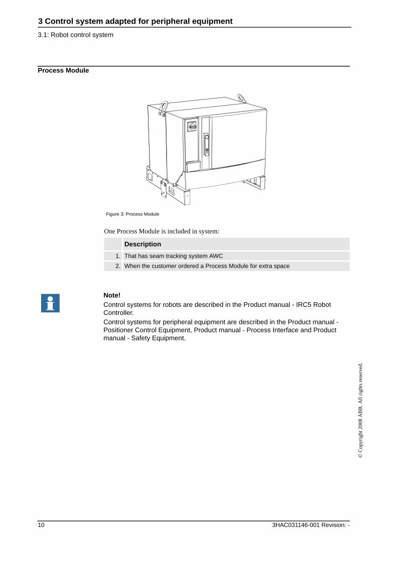
Process Module
One Process Module is included in system:
Figure 3: Process Module
Description
1. That has seam tracking system AWC
2. When the customer ordered a Process Module for extra space
Note!Control systems for robots are described in the Product manual - IRC5 Robot Controller.Control systems for peripheral equipment are described in the Product manual - Positioner Control Equipment, Product manual - Process Interface and Product manual - Safety Equipment.
10 3HAC031146-001 Revision: -

3 Control system adapted for peripheral equipment3.2: Control system for peripheral equipment
© C
opyr
ight
200
8 A
BB
. All
right
s res
erve
d.
3.2: Control system for peripheral equipment
DescriptionControl system IRC5 is complemented with control equipment for positioners, welding equipment, safety equipment and other peripheral equipment.
Figure 4: Control system for peripheral equipment
Pos. Description
1. Positioner and process control equipment
2. Safety control equipment
2
1
3HAC031146-001 Revision: - 11

3 Control system adapted for peripheral equipment3.2.1 Location
© C
opyr
ight
200
8 A
BB
. All
right
s res
erve
d.
3.2.1 Location
Positioner control equipmentPositioner control equipment is located in Single Cabinet Controller or Dual Cabinet Controller.
Process control equipmentProcess control equipment is located inside of the welding power source.
See ESAB weldíng power source manual.
Safety control equipmentSafety control equipment is located on the sidewall of the cabinet. The control equipment may also be located on the guard or on a stationary building wall.
Figure 5: Location of positioner control equipment
Figure 6: Placement of safety control equipment on Single Cabinet Controller and Dual Cabinet Controller
12 3HAC031146-001 Revision: -

3 Control system adapted for peripheral equipment3.2.2 Block diagram
© C
opyr
ight
200
8 A
BB
. All
right
s res
erve
d.
3.2.2 Block diagram
Positioner block diagram
Process block diagram
Figure 7: Positioner block diagram
Figure 8: Process block diagram
3HAC031146-001 Revision: - 13

3 Control system adapted for peripheral equipment3.2.2 Block diagram
© C
opyr
ight
200
8 A
BB
. All
right
s res
erve
d.
Operator panel and manual jog block diagram
Safety block diagram
Figure 9: Operator panel and manual jog block diagram
Figure 10: Safety block diagram
Item Description
1. Pre-reset
2. Gate reset
3. Gate switch
4. Light barrier
321
4
14 3HAC031146-001 Revision: -

3 Control system adapted for peripheral equipment3.2.3 Connections
© C
opyr
ight
200
8 A
BB
. All
right
s res
erve
d.
3.2.3 Connections
Positioner connection
The positioner connected to Single Cabinet Controller or the Drive Module to Dual Cabinet Controller are shown below:
Positioner 1
Positioner 2
Note!Control systems for positioners are described in the Product manual - Positioner Control Equipment.
Figure 11: Positioner 1 connection
Item Description
1. Positioner 1
2. Serial measurement board for positioner 1
1
2
Figure 12: Positioner 2 connection
Item Description
1. Positioner 2
2. Serial measurement board for positioner 2
1
2
3HAC031146-001 Revision: - 15

3 Control system adapted for peripheral equipment3.2.3 Connections
© C
opyr
ight
200
8 A
BB
. All
right
s res
erve
d.
Travel track RTT
Process/safety connection
The locations of cable bushings for process and safety equipment are shown below. The cables are connected to terminals or units inside the control cabinet.
Single Cabinet Controller
Figure 13: Travel track connection
Item Description
1. Travel track RTT
2. Serial measurement board for travel track RTT
1
2
Note!Process control equipment is described in the Product manual - Process Interface.
Note!Safety control equipment is described in the Product manual - Safety Equipment.
Figure 14: Bushings for process and safety, Single Cabinet Controller
16 3HAC031146-001 Revision: -

3 Control system adapted for peripheral equipment3.2.3 Connections
© C
opyr
ight
200
8 A
BB
. All
right
s res
erve
d.
Dual Cabinet Controller
Figure 15: Bushings for process and safety, Dual Cabinet Controller
3HAC031146-001 Revision: - 17
3 Control system adapted for peripheral equipment3.2.3 Connections
© C
opyr
ight
200
8 A
BB
. All
right
s res
erve
d.
18 3HAC031146-001 Revision: -

4 Robot with welding equipment©
Cop
yrig
ht 2
008
AB
B. A
ll rig
hts r
eser
ved.
4: Robot with welding equipmentArc-welding
In an arc-welding robot system, a IRB 1600 or IRB 2400L robot is normally used. In certain systems, other types can be included, such as welding, handling or machining robots.
In an arc-welding system, the robot is equipped with welding equipment consisting of the following units.
Example
Figure 16: IRB 2400 with welding equipment
Item Description
A Welding Power source AristoMig
B Wire MarathonPac
C Wire feed unit Aristo RoboFeed
D Torch Binzel
E TSC Torch service center
3HAC031146-001 Revision - 19

4 Robot with welding equipment4.1: Welding power source
© C
opyr
ight
200
8 A
BB
. All
right
s res
erve
d.
4.1: Welding power sourceThe following power source standard alternatives are available:
Description Illustration
ESAB AristoMig 4000iESAB AristoMig 4000iwESAB AristoMig 5000iESAB AristoMig 5000iw
20 3HAC031146-001 Revision -
4 Robot with welding equipment4.2: Welding torches
© C
opyr
ight
200
8 A
BB
. All
right
s res
erve
d.
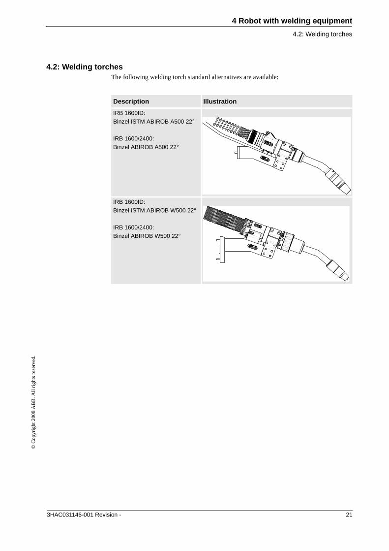
4.2: Welding torchesThe following welding torch standard alternatives are available:
Description Illustration
IRB 1600ID:Binzel ISTM ABIROB A500 22°
IRB 1600/2400:Binzel ABIROB A500 22°
IRB 1600ID:Binzel ISTM ABIROB W500 22°
IRB 1600/2400:Binzel ABIROB W500 22°
3HAC031146-001 Revision - 21

4 Robot with welding equipment4.3: Torch service units
© C
opyr
ight
200
8 A
BB
. All
right
s res
erve
d.
4.3: Torch service unitsThe following torch service unit standard alternatives are available:
4.4: SensorsThe following sensor standard alternatives are available:
Description Illustration
TSC Torch Service Center based on TC96/consisting of:
1. Torch cleaner
2. Wire cutter
3. TCP calibration unit
• Component parts can be bought as individ-ual components
2
3
1
Description
Seam locator
• SmarTacSeam tracker
• AWC
22 3HAC031146-001 Revision -

5 IRBP positioner5.1: Positioner
© C
opyr
ight
200
8 A
BB
. All
right
s res
erve
d.
5: IRBP positioner5.1: Positioner
DescriptionA positioner is used to position work pieces optimally for welding joints and robots. The IRBP positioner is equipped with maintenance-free AC motors with electro-magnetic brakes.
• The number in the positioner name indicates its maximum handling capacity.
• The letter in the positioner name indicates the positioner type.
The following positioner type standard alternatives are available:
Description Illustration
IRBP 500/1000C
IRBP 250/500C Index
3HAC031146-001 Revision - 23

5 IRBP positioner5.1: Positioner
© C
opyr
ight
200
8 A
BB
. All
right
s res
erve
d.
IRBP 250/500/750/2000/5000L
IRBP 250/500/750K
IRBP 250/500/750R
Description Illustration
24 3HAC031146-001 Revision -
5 IRBP positioner5.1: Positioner
© C
opyr
ight
200
8 A
BB
. All
right
s res
erve
d.
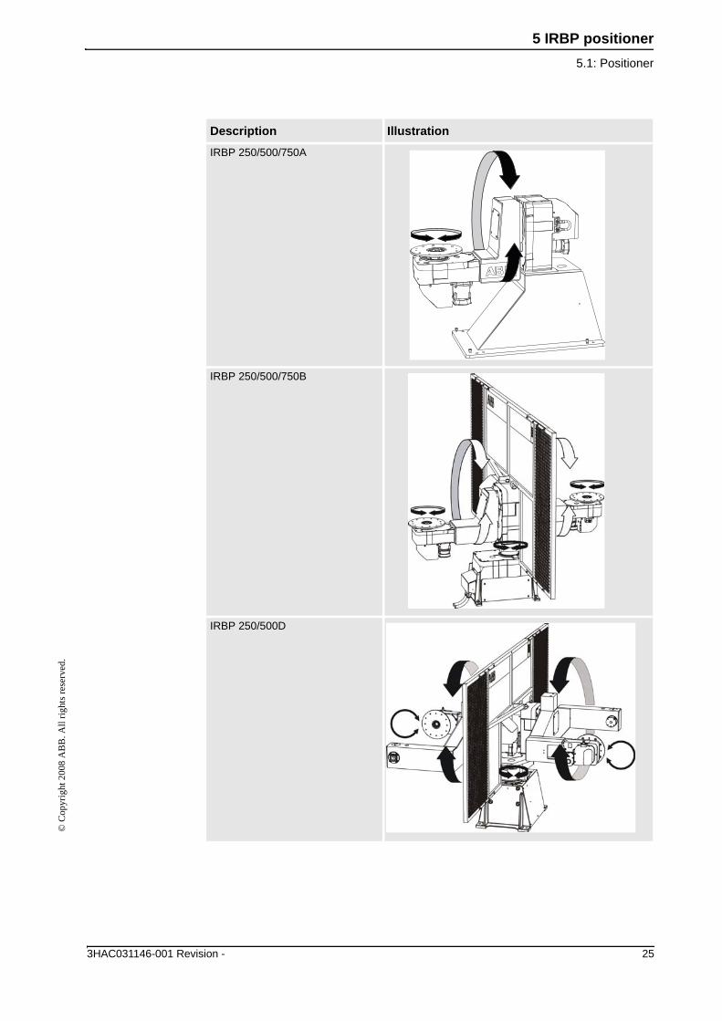
IRBP 250/500/750A
IRBP 250/500/750B
IRBP 250/500D
Description Illustration
3HAC031146-001 Revision - 25

5 IRBP positioner5.1: Positioner
© C
opyr
ight
200
8 A
BB
. All
right
s res
erve
d.
26 3HAC031146-001 Revision -

6 Travel track for robot6.1: Travel track
© C
opyr
ight
200
8 A
BB
. All
right
s res
erve
d.
6: Travel track for robot6.1: Travel track
DescriptionA travel track is used to position a robot at different work stations or within a large working area.
Figure 17: Travel track
Item Description
A Travel track, Marathon Pac or Bobin
Travel length
1.7m 7.7m
2.7m 8.7m
3.7m 9.7m
4.7m 10.7m
5.7m 11.7m
6.7m
A
3HAC031146-001 Revision - 27

6 Travel track for robot6.1: Travel track
© C
opyr
ight
200
8 A
BB
. All
right
s res
erve
d.
28 3HAC031146-001 Revision -

7 Operator panel7.1: Operator communication
© C
opyr
ight
200
8 A
BB
. All
right
s res
erve
d.
7: Operator panel7.1: Operator communication
There is an operator panel with a number of button functions to enable the operator to communicate with the arc-welding robot system. The following operator panel standard alternatives are available:
Description Illustration
Operator panel for one working area
Operator panel for two working areas
3HAC031146-001 Revision - 29

7 Operator panel7.2: Manual job control panel
© C
opyr
ight
200
8 A
BB
. All
right
s res
erve
d.
7.2: Manual job control panelThere is a control panel with two button functions (+/-) and a holding unit, so that the operator is able to manually control the positioner. The control panel is used to obtain an ergonomically correct position for loading/unloading the positioner.
Description Illustration
Manual jog for positioner:K/R/L.
30 3HAC031146-001 Revision -

8 Safety equipment8.1: Safety functions
© C
opyr
ight
200
8 A
BB
. All
right
s res
erve
d.
8: Safety equipmentFor personnel to work safely with an arc-welding robot system, the system must be equipped with a number of safety components, which are integrated into the control cabinet's safety system.
8.1: Safety functions
Safety functions
Working area supervision with light barriers
Pre-reset unit for light barriers
Working area indication for:
• Robot or travel track• PositionerGate supervision
Reset unit for gate supervision
Figure 18: Welding robot station with safety equipment
3HAC031146-001 Revision - 31

8 Safety equipment8.1: Safety functions
© C
opyr
ight
200
8 A
BB
. All
right
s res
erve
d.
32 3HAC031146-001 Revision -


3HA
C03
1146
-001
Rev
-, e
n
Contact us
ABB ABDiscrete Automation and MotionRobotics S-721 68 VÄSTERÅSSWEDENTelephone +46 (0) 21 344 400
www.abb.com