ABB AS, Robotics · PDF fileSet up a robot with external axis ... ABB AS, Robotics ... be...
64
ABB AS, Robotics User’s Guide Paint PowerPac 2.2 Publ.No.: 3HAC022725-001 en Rev.03
Transcript of ABB AS, Robotics · PDF fileSet up a robot with external axis ... ABB AS, Robotics ... be...

Publ.No.: 3HAC022725-001 en Rev.03
ABB AS, Robotics
User’s Guide
Paint PowerPac 2.2


Table of ContentsImportant Information . . . . . . . . . . . . . . . . . . . . . . . . . . . . . . . . . . . . . . . . . . . 2About Paint PowerPac. . . . . . . . . . . . . . . . . . . . . . . . . . . . . . . . . . . . . . . . . . . 3Installation . . . . . . . . . . . . . . . . . . . . . . . . . . . . . . . . . . . . . . . . . . . . . . . . . . . . 4
Chapter 1 Introduction. . . . . . . . . . . . . . . . . . . . . . . . . . . . . . . . . . . . . . . . . . . . . 7Introduction . . . . . . . . . . . . . . . . . . . . . . . . . . . . . . . . . . . . . . . . . . . . . . . . . . . 8Selection . . . . . . . . . . . . . . . . . . . . . . . . . . . . . . . . . . . . . . . . . . . . . . . . . . . . . 9Target tab. . . . . . . . . . . . . . . . . . . . . . . . . . . . . . . . . . . . . . . . . . . . . . . . . . . . . 10Instruction tab . . . . . . . . . . . . . . . . . . . . . . . . . . . . . . . . . . . . . . . . . . . . . . . . . 13Path tab . . . . . . . . . . . . . . . . . . . . . . . . . . . . . . . . . . . . . . . . . . . . . . . . . . . . . . 16Conveyor tab . . . . . . . . . . . . . . . . . . . . . . . . . . . . . . . . . . . . . . . . . . . . . . . . . . 19Misc tab . . . . . . . . . . . . . . . . . . . . . . . . . . . . . . . . . . . . . . . . . . . . . . . . . . . . . . 21AutoPath . . . . . . . . . . . . . . . . . . . . . . . . . . . . . . . . . . . . . . . . . . . . . . . . . . . . . 23BrushEditor . . . . . . . . . . . . . . . . . . . . . . . . . . . . . . . . . . . . . . . . . . . . . . . . . . . 27ColorChangeEditor . . . . . . . . . . . . . . . . . . . . . . . . . . . . . . . . . . . . . . . . . . . . . 28Mirror . . . . . . . . . . . . . . . . . . . . . . . . . . . . . . . . . . . . . . . . . . . . . . . . . . . . . . . 31
Chapter 2 Display Options . . . . . . . . . . . . . . . . . . . . . . . . . . . . . . . . . . . . . . . . . . 33The Display Option button bar . . . . . . . . . . . . . . . . . . . . . . . . . . . . . . . . . . . . 34
Chapter 3 Paint related functions . . . . . . . . . . . . . . . . . . . . . . . . . . . . . . . . . . . . 35Motion instructions . . . . . . . . . . . . . . . . . . . . . . . . . . . . . . . . . . . . . . . . . . . . . 36Action instructions. . . . . . . . . . . . . . . . . . . . . . . . . . . . . . . . . . . . . . . . . . . . . . 37Eventdata . . . . . . . . . . . . . . . . . . . . . . . . . . . . . . . . . . . . . . . . . . . . . . . . . . . . . 38Conveyor Tracking . . . . . . . . . . . . . . . . . . . . . . . . . . . . . . . . . . . . . . . . . . . . . 39
Chapter 4 How to use Paint PowerPac . . . . . . . . . . . . . . . . . . . . . . . . . . . . . . . . 41Create a simple program . . . . . . . . . . . . . . . . . . . . . . . . . . . . . . . . . . . . . . . . . 45How are things connected . . . . . . . . . . . . . . . . . . . . . . . . . . . . . . . . . . . . . . . . 51Set up a robot with external axis . . . . . . . . . . . . . . . . . . . . . . . . . . . . . . . . . . . 52Configure the VirtualController for a Paint robot . . . . . . . . . . . . . . . . . . . . . . 59


:
PAINT POWERPAC 2.2USER GUIDE
1

Paint PowerPac User’s Guide
Important InformationThe information in this document is subject to change without notice and should not be construed as a commitment by ABB. ABB assumes no responsibility for any errors that may appear in this document.
In no event shall ABB be liable for incidental or consequential dam-ages arising from use of this document or of the software and hardware described in this document.
We reserve all rights in this document and in the information contained therein. Reproduction, use or disclosure to third parties without express authority is strictly forbidden. Additional copies of this docu-ment may be obtained from ABB at its then current charge.
© 2005 ABB AS, RoboticsABB AS, Robotics
Automation Technology Products DivisionBryne - Norway
First Edition: 10. May 2004
2

:
About Paint PowerPac
The Paint PowerPac is a RobotStudio solution for paint simulation and offline programming. It will dramatically reduce installation and pro-gramming time, since programming and installation of new robots can be performed offline without disturbing ongoing production.
It can be used for verification of the paint line layout and painting pro-cess. Possible program weaknesses, such as singularity, speed devia-tions etc., can be discovered before production start. Cycle time and robot positioning challenges can be discovered at an early stage instead of after installation.
The user can test if new parts can be produced on the existing line without having to do extensive and expensive programming and test-ing. Several solutions (mechanical, positioning, movements etc.) can be tested at low cost
Use the Paint PowerPac for controlling the full range of features of the paint process. It includes functions such as:
• Creation and editing of brush tables
• Creation and editing of Color Change sequences
• Executing of special painting related instructions
• Setting paint events
• Graphical editing of paint events and positions
• Conveyor tracking
Paint instructions like UseBrushTab, PaintL, PaintC, SetBrush etc. are supported to give the programmer full control over the painting pro-cess.
3
Paint PowerPac User’s Guide
Installation
Install the software To install the RobotStudio software including the Paint add-in, follow these steps:
• Insert the Robot Studio CD in your computer's CD-ROM drive.
• The installation program will now guide you through the installation procedure. If the CD does not run automati-cally, double-click the Setup.exe file found in your com-puter's CD-ROM directory.
• At the end of the installation is the License Key Request Form displayed. To finish the software installation, either continue with completing the License Key Request Form, or cancel it if you want to request a license key later.
• Insert the Paint PowerPac CD in your computer's CD-ROM drive.
• The installation program will now guide you through the installation procedure. If the CD does not run automati-cally, double-click the Setup.exe file found in your com-puter's CD-ROM directory.
Request a License Key for Robot Studio including the Paint option
You request a license key by completing the License Key Request Form and sending it to ABB. The form is automatically displayed dur-ing the software installation, but can also be opened from the windows taskbar.
If you don't already have the License Key Request Form open, do this:
• Click the Start button and point to Programs, ABB Auto-mation and then click System Information.
• On the Products tab, go to the Installed products field and select RobotStudio. Then click the Request License Key for RobotStudio button.
To fill out the form and request a license key, do this:
• When the License Key Request Form is open, fill in all requested fields.
• Save the registration information to a file on your com-puter.
4

:
• To obtain a License Key, attach the saved registration information to an E-mail and send it to:
[email protected] Alternatively, print the file and send it by fax to:
ABB Robotics +46 31 773 85 40
A licence Key File will now be returned to you by E-mail within a few hours.
Register your License Key
When you receive your license key file, you need to authorize the com-puter you installed RobotStudio on by registering the key.
To register your license key, follow these steps:
5

Paint PowerPac User’s Guide
• Click the Start button in the Windows taskbar. Select Pro-grams>ABB Automation >System Information.
• Click the Licenses tab and click the Import Licenses from file. Browse to the license key file, click OK.
• or
• Click the Add License sting button and paste the license key from the clipboard.
• Remember to add the license both for Robot Studio and Paint PowerPac.
• Click OK again to exit the System Information dialog. You can now start using RobotStudio.
Include the Paint Addin in Robot Studio
In order to enable the paint functionality in Robot Studio you need to include Paint as an add-in:
• Start Robot Studio
• Select the Tools / Add-Ins... menu
• In the dialogue select Add and browse into the /Add-ins/Paint/ directory where you select the Paint.dll.
6

Chapter 1: Introduction
Chapter 1 Introduction
7

Paint PowerPac User’s Guide
Introduction
Paint Tab The Paint tab is designed so you should be able to perform most of your Paint related operations from it without changing back and forth between the object browser and the Paint tab.
The Paint tab contains tools and functions to create, modify and test your targets, path instructions and paths.
Help The paint tab contains a help button in the upper right corner. Pressing this button opens the Paint PowerPac user guide.
8

Chapter 1: Introduction
Selection
Introduction This box will show information on selected object.
Selection The selection box will show position information on the selected object.
The following object types are supported:
rsObjectTypeTarget
rsPaintEvent
rsObjectTypeWorkObject
rsObjectTypeMechanism
For other object types only the object name will be displayed.
If multiple objects are selected, only information on the first object is displayed.
For rsPaintEvent the event plane, position and brush number will be displayed instead of XYZ position and euler angles.
9
Paint PowerPac User’s Guide
Target tab
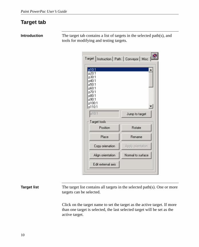
Introduction The target tab contains a list of targets in the selected path(s), and tools for modifying and testing targets.
Target list The target list contains all targets in the selected path(s). One or more targets can be selected.
Click on the target name to set the target as the active target. If more than one target is selected, the last selected target will be set as the active target.
10

Chapter 1: Introduction
Press the DELETE key on the keyboard to delete the selected tar-get(s).
Jump to target Pressing the Jump to target button positions the active robot with the active tool on the selected target.
NOTE: There must be a robot and a running VC for this to work.
Position Pressing the Position button opens the positioning dialog box of RS allowing you to position the selected target(s).
Rotate Pressing the Rotate button opens the rotation dialog box of RS allow-ing you to rotate the selected target(s).
Place Pressing the Place button opens the place dialog box of RS allowing you to offset the selected target(s).
Rename Pressing the rename button will rename the selected target(s). The name will be set to <Prefix>Number<Postfix>. Number will start at 1 and count upwards.
NOTE 1: Prefix and Postfix are user selectable in the Misc tab.
NOTE 2: If a name is already used, Rename will increase Number until a valid name is found.
Copy orientation Pressing the Copy orientation button stores a copy of the orientation of the selected object.
NOTE: You can copy the orientation from any object(s) in the station, not only targets.
Apply orientation Pressing the Apply orientation button will apply the stored orientation to all selected objects.
11

Paint PowerPac User’s Guide
NOTE 1: This button is disabled until you have copied an orientation using the Copy orientation button.
NOTE 2: You can apply the orientation to any object(s) in the station, not only targets.
Align orientation Pressing the Align orientation button opens the Align Target Orienta-tion dialog box of RS, allowing you to align the selected target(s).
Normal to surface Pressing the Normal to surface button opens the Set Normal to Sur-face dialog box of RS, allowing you to set the selected target(s) nor-mal to a part or surface.
Edit external axis Pressing the Edit external axis button opens the Edit Externals dialog box of RS, allowing you to edit the external axis values of the selected target(s).
NOTE: You can only change active external axis.
12

Chapter 1: Introduction
Instruction tab
Introduction The Instruction tab contains a list of instructions in the selected path(s), and tools for modifying and testing target references and action instructions.
13
Paint PowerPac User’s Guide
Instruction list The instruction list contains all instructions in the selected path(s). One or more instructions can be selected.
Click on the instruction name to set the instruction as the active instruction. If more than one instruction is selected, the last selected instruction will be set as the active instruction.
Press the DELETE key on the keyboard to delete the selected instruc-tion(s).
If the instruction is a target reference, you can click on the targets speed or zone value to change the value.
Move to target Pressing the Move to target button executes the selected target refer-ence.
NOTE: There must be a robot and a running VC for this to work.
Add event Pressing the Add event button opens the Add event dialog box of RS, allowing you to add an paint event to the selected target reference.
NOTE: The target reference must be of process type PaintWare
Add ActionInstr. Pressing the Add ActionInstr. button opens the Insert Action Instruc-tion dialog box of RS, allowing you to add an action instruction below the selected instruction.
Edit instruction Pressing the Edit instruction button opens the Edit Instruction dialog box of RS if one or more target references are selected, and Edit Action Instruction dialog box of RS is an action instruction is selected, allow-ing you to edit the parameters of the selected instruction(s).
NOTE: You can not select a mix of action instruction and target refer-ences, or more than one action instruction.
14

Chapter 1: Introduction
Move up Pressing the Move up button moves the selected instruction up one instruction.
Move down Pressing the Move up button moves the selected instruction down one instruction.
Edit external axis Pressing the Edit external axis button opens the Edit Externals dialog box of RS, allowing you to edit the external axis values of the selected target referense(s).
NOTE 1: You can not select a mix of action instruction and target ref-erences.
NOTE 2: You can only change active external axis.
15

Paint PowerPac User’s Guide
Path tab
Introduction The Path tab contains a list of paths in the active station, and tools for creating, modifying and testing paths.
Path list The path list contains all paths in the active station. One or more paths can be selected.
Click on the path name to set the path as the active path. If more than one path is selected, the last selected path will be set as the active path.
16

Chapter 1: Introduction
Press the DELETE key on the keyboard to delete the selected path, including targets used in the path.
Move along path Pressing the Move along path button executes the selected path.
Create path If the Create path checkbox is checked, clicking on a surface will add a target to the active path. A new path is created if there is no active path.
If the N key on the keyboard is held down while you click on the sur-face, a new path will be generated and set as the active path. The target will be created in the new path.
Uncheck Create path to stop creating targets.
Join paths Selecting two paths enables the ‘Join Paths’ button. Above the button you will also see how the paths will be joined. The path selected last will be added to the path selected first.
NOTE: This action can not be undone.
Add on/off event Pressing the Add on/off event button will add event E1, brush <On brush> at the position of the first target in the path, and event E2, brush <Off brush> at the position of the last target in the path. The first and last target in the path will then be moved to extend the path by the distance specified in the Misc tab Setup parameter ’Distance from tar-get to event’.
Selecting more than one path is possible, and the procedure will be applied to all paths as individual paths.
NOTE 1: On brush and Off brush are user selectable in the Misc tab.
NOTE 2: The target reference in the path must be of process type PaintWare
Auto path Pressing the Auto path button will launch the Paintpath generation tool. See separate chapter for more detailed description.
17

Paint PowerPac User’s Guide
Mirror Pressing the Mirror button launches the Mirror dialog box. See theMirror chapter for more detailed description.
Reverse Pressing the Reverse button will reverse the direction of the selected path(s)
NOTE: If the path contains instructions other than PaintL, the reverse function will ask if they can be removed. The path will only be reversed if the instructions can be removed.
Rename Pressing the rename button will rename the selected path(s). The name will be set to <Prefix>Number<Postfix>. Number will start at 1 and count upwards.
NOTE 1: Prefix and Postfix are user selectable in the Misc tab.
NOTE 2: If a name is already used, Rename will increase Number until a valid name is found.
18
Chapter 1: Introduction
Conveyor tab
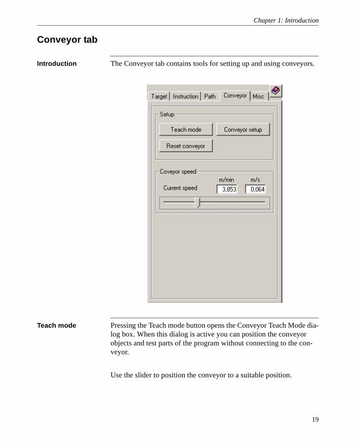
Introduction The Conveyor tab contains tools for setting up and using conveyors.
Teach mode Pressing the Teach mode button opens the Conveyor Teach Mode dia-log box. When this dialog is active you can position the conveyor objects and test parts of the program without connecting to the con-veyor.
Use the slider to position the conveyor to a suitable position.
19
Paint PowerPac User’s Guide
Conveyor setup Pressing the Conveyor setup button opens the conveyor setup dialog box of RS.
Reset conveyor Pressing the Reset conveyor button will reset the conveyor.
Conveyor speed Use the slider or enter a speed to adjust the conveyor speed during simulation. The speed can be adjusted from zero to the speed entered in the Current speed input box.
20

Chapter 1: Introduction
Misc tab
Introduction The Misc tab contains miscellaneous tools that did not fit other places.
Show tool at target If the Show tool at target is checked, a copy of the mounted tool is shown at each selected target whenever it is selected. By stepping through the targets in the Target or Instruction tab it is easy to see how the tool orientation changes.
Show robot at target
If the Show robot at target is checked, the robot is shown at each selected target whenever a target is selected. By stepping through the targets in the Target or Instruction tab it is easy to see how the robot position changes.
21

Paint PowerPac User’s Guide
Distance from target to event
This is the distance you want from the first and last target in a path to the paint event. If the painting speed is low, the distance can be shorter resulting in a shorter path and lower cycle time. If the distance is too short, the robot must lower the painting speed in the start and/or end of the paint stroke resulting in too much paint in the object. If the painting speed is high, the distance may have to be increased to prevent the robot from lowering the painting speed in the start and/or end of the paint stroke. This parameter is used in the Add on/off event function.
On brush This is the brush number that will be used as On brush in the Add on/off events function.
Off brush This is the brush number that will be used as Off brush in the Add on/off events function.
Target prefix This is the text that is used as prefix in renaming targets.
Target postfix This is the text that is used as postfix in renaming targets.
Path prefix This is the text that is used as prefix in renaming paths.
Path postfix This is the text that is used as postfix in renaming paths.
Strokes Pressing the Strokes button will show you the number of paint strokes in the selected path(s). The number of paint strokes is counted by counting the number of events with brush off.
Length Pressing the Length button will show you the total length of the selected path(s).
Brush Editor Pressing the BrushEditor button opens the BrushEditor. See separate chapter for more detailed description.
ColorChange Editor
Pressing the ColorChangeEditor button opens the ColorChangeEditor. See separate chapter for more detailed description.
22

Chapter 1: Introduction
AutoPath
Introduction AutoPath is a tool to create paths on a part.The path is generated by scanning the surface of the graphics in the part, and creating a path on the surface.
Where to create the path
Select where on the object you want to create the path.
Top is defined as the side on the most positive Z direction in world coordinate system.
Bottom is defined as the side on the most negative Z direction in world coordinate system.
Left is defined as the side most positive in Y direction in world coor-dinate system.
Right is defined as the side most negative in Y direction in world coor-dinate system.
23

Paint PowerPac User’s Guide
Front is defined as the side most positive in X direction in world coor-dinate system.
Back is defined as the side most negative in X direction in world coor-dinate system.
Middle is defined as the XZ plane of the world coordinate system. Please note the the compete part must be placed to the right/left of middle in order to create a path on it.
Pitch The parameter pitch is the distance you want between two parallel paint strokes.
24

Chapter 1: Introduction
Min stroke length This parameter is a filter that will remove any paths with a length less than the specified value. This is to prevent lots of small paths to be created on for example a long rod or pillar.
Max surface angle This parameter is a filter to prevent too long paths. If the filter has a value of 1 degree, the path direction can only change 1 degree from the selected plane to be painted, meaning that a sphere will not be painted because only a very small portion of the sphere is parallel to the plane you want to paint. A filter value of 90 degrees will allow any path direction.
Max surface deviation
This parameter is a filter that lowers the number of targets in the path. If no deviation is allowed there would be infinite number of targets in the path. Typically a tool to surface distance deviation of +-20-40 mm is allowed.
Scan resolution This parameter is to speed up the path generation process. A lower number will give a more accurate path, but it will take more time to create the path. A scan resolution of 20mm means that the surface is checked for every 20mm.
Overlap Selecting the 50% overlap button will create paths only on the surface of the object, as typically done when a program with 50% overlap is made.
Selecting the 75% overlap button will create one pass outside the object, as typically done when creating a program with 75% overlap.
25

Paint PowerPac User’s Guide
26

Chapter 1: Introduction
BrushEditor
Introduction The Brush Editor is used to edit Brush Tables. It shows the current brush dataes in a grid and as a bargraph, and it gives you the possibil-ity to select between the available brushtables in the brush file.
BrushEditor In the grid you can modify the brush values in a brush table by select-ing the corresponding cell. Clicking the right mouse button will open a context menu.
In the context menu you can offset the selected values by value or by percent.
In the chart you can click the left mouse button on a bar, and then drag the bar up or down. The brush values of the selected brush number in the grid will then be modified.
The drop down list contains the alias names of all the brush tables in the brush file. If several brush tables has got the same alias name, all the brush tables with the same alias name will be modified.
NOTE: It is only possible to modify existing brush tables.
27
Paint PowerPac User’s Guide
ColorChangeEditor
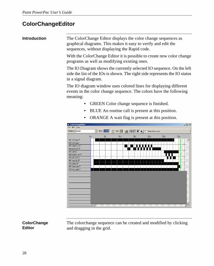
Introduction The ColorChange Editor displays the color change sequences as graphical diagrams. This makes it easy to verify and edit the sequences, without displaying the Rapid code.
With the ColorChange Editor it is possible to create new color change programs as well as modifying existing ones.
The IO Diagram shows the currently selected IO sequence. On the left side the list of the IOs is shown. The right side represents the IO status in a signal diagram.
The IO diagram window uses colored lines for displaying different events in the color change sequence. The colors have the following meaning:
• GREEN Color change sequence is finished.
• BLUE An routine call is present at this position.
• ORANGE A wait flag is present at this position.
ColorChange Editor
The colorchange sequence can be created and modified by clicking and dragging in the grid.
28

Chapter 1: Introduction
Editing Bar Routine Selection
Selects the color change sequence for viewing and editing. The drop down list contains all sequences of the currently opened file.
Grid Size
Sets the size of one grid step in milliseconds. Larger values will zoom out and smaller value will zoom in the view.
Show Alias Names
Shows the alias names or the physical IO names of the signal.
New Routine
In order to add color change routines click on the new routine button. The program will ask for the routine name.
Show Grid
Shows or hides the grid in the view.
Snap to Grid
Enables or disables the snap functionality. If snap to grid is disabled, color change editor will work in 10ms steps.
Edit Mode
Sets the window to edit mode. Add new events and change existing is possible in edit mode.
Selection Mode
Sets the window to selection mode. In selection mode, copy, paste, insert cells, delete and delete cells are possible.
Wait Before Exit
If the box is checked, the routine will exit after the last color change instruction is executed. If the box is not checked, the routine may be finished before the whole color change sequence is executed.
Configure IO List You may edit the IO configuration by selecting the File, Edit IO Con-figuaration. To create a new IO Configuration, select File Open and type a non-existing name when you are asked to select the IO Con-figuartion.
29

Paint PowerPac User’s Guide
The IO Configuration Dialog box is used to edit the signals used for color change sequences. Following parameters are available:
1 IO List shows a list of all defined signals for the color change editor.
2 Output, Name shows the name of the selected IO signal.
3 Type defines the IO type. Following types are available:
• DO - Digital output
• GO - Group output
• AO - Analog output
4 Alias defines the alias name for the signal.
5 Add adds a signal to the signal list
6 Delete deletes the selected signal from the signal list
7 Interlock Groups defines the interlock group. Only one signal out of a interlock group can be different from 0.
Other ColorChange Editor uses the SetTMSignal instruction for creating the color change sequences. To give more flexibility it is possible to add routine calls and wait flags into the color change program.
30

Chapter 1: Introduction
Mirror
Introduction This function is used to mirror a path. You can mirror the path in the XZ or YZ plane.You can also specify a mirror offset.
Mirror
• Select the path(s) to mirror and press the Mirror button
• Select mirror plane and offset
• Press the OK button
NOTE 1: Mirror will replace the original path with the mirrored path. Make a copy of the original paths before executing the mirror function if you want to keep the original path.
31

Paint PowerPac User’s Guide
32

Chapter 2: Display Options
Chapter 2 Display Options
33

Paint PowerPac User’s Guide
The Display Option button bar
Introduction This button bar allows the user to easily select what should be visible on the path.
The buttons Push the desired button to toggle object visibility.
Display/Hide Robtargets. You use this function to turn on or off the displaying of robtargets.
Display/Hide Robtargets Name. You use this function to turn on or off the names of the robtargets.
Display/Hide Path. You use this function to turn on or off the display-ing of the path.
Display/Hide Routine Names. You use this function to turn on or off the displaying of the routine names.
Display/Hide Brush. You use this function to turn on or off the dis-playing of the paint process data.The brush button will show/hide both the color on the path and the events
Display/Hide Trigger Positions. You use this function to turn on or off the displaying of the trigger positions.
Display/Hide Workobject. You use this function to turn on or off the displaying of the workobject associated to the selected point.
Display/Hide Zone Data. You use this function to turn on or off the displaying of zone size. The size of the zone is derived from the name of the zone data, not the actual data used by the controller.
NOTE 1: If the path is invisible, the brush and event will also be invis-ible.
34

Chapter 3: Paint related functions
Chapter 3 Paint related functions
35

Paint PowerPac User’s Guide
Motion instructions
Introduction The process template functionality provides support (including syn-chronization) for arbitrary motion instructions. A template for Paint-Ware is included in the RobotStudio installation, and is added to the default template during installation of Paint PowerPac.
Usage The motion instruction, including all possible arguments (such as E1 etc.) can be edited in the "Edit instruction" dialog.
For arguments of a specific type (such as eventdata), all variables of that type declared in the controller are included in a combo box.
36

Chapter 3: Paint related functions
Action instructions
Introduction Currently, process templates do not support action instructions. Instead, the instructions that RobotStudio recognizes are hard-coded. SetBrush, UseBrushTab, WaitWobj and DropWobj have been added to this set.
Usage Action instructions can be added to a path via the "Insert action instruction" menu command. This brings up a dialog with a set of action instructions with pre-defined arguments (such as ConfJ \Off).
For other arguments, use the advanced tab, and set the desired argu-ments.
37

Paint PowerPac User’s Guide
Eventdata
Introduction Eventdata is the PaintL argument that controls where and how to change brushes during the motion.
Usage The events will be visible in the browser beneath the corresponding path instruction. It will be editable through the property browser and (for PaintL) the edit instruction dialog. Creating an eventdata can also be done in the edit instruction dialog.
Graphical editing
It is possible to drag an event along the path between two targets.
Set selection level Target/Frame and choose a Freehand Movement (X, Y or Z).
Click on an event and drag it along the path. It is important that you choose the correct Freehand Movement, or you could select all three.
38
Chapter 3: Paint related functions
Conveyor Tracking
Introduction When simulating conveyor tracking in RobotStudio, the conveyor works in the same way as in a real cell. RobotStudio will simulate synchronization switches, encoders and other peripheral equipment once the conveyor is created and properly configured.
In addition to the positions and distances that controls the conveyor tracking in a real robot cell, the conveyor tracking in RobotStudio also has positions that determines where to start and stop moving parts along the conveyor.
Please refer to the Robot Studio 3.1. Users Guide for detailed informa-tion on how to configure and use the Conveyor Tracking functionality in Robot Studio.
39

Paint PowerPac User’s Guide
40

Chapter 4: How to use Paint PowerPac
Chapter 4 How to use Paint PowerPac
41

Paint PowerPac User’s Guide
Build a station
Purpose Example how to create a simple station
Goal Create a and set up a simple station with IRB5400-02 and a gun.
Create a new station
On the File menu, click New Station.
Import a robot On the File menu, point to Import and then click Library.
Browse to the \Library\Robots\ folder.
Select the IRB5400-02.rlb file.
Click Open.
Start the controller In the Object Browser right click the robot IRB5400_02.
On the context menu, click Start Controller.
42

Chapter 4: How to use Paint PowerPac
Wait until the Status bar turn green
Import a tool On the File menu, point to Import and then click Library.
Browse to the \Library\Tools\ folder.
Select the PaintGun.rlb file.
Click Open.
43
Paint PowerPac User’s Guide
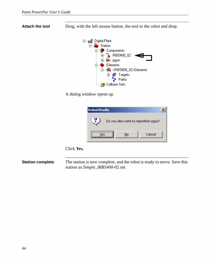
Attach the tool Drag, with the left mouse button, the tool to the robot and drop.
A dialog window opens up.
Click Yes.
Station complete The station is now complete, and the robot is ready to move. Save this station as Simple_IRB5400-02.stn.
44
Chapter 4: How to use Paint PowerPac
Create a simple program
Purpose Example how to create a simple program.
Goal Create and execute a simple paint program.
Start Open the station Simple_IRB5400-02.stn created in chapter How to use Paint PowerPac, paragraph Build a station.
Change active process template to PaintWareL
Create sphere at 1500,1000,1000, radius 500
In the Path tab, click Auto Path.
A new dialog box opens.
Click on the sphere to select it.
Click Top.
Click Front to rear.
Click Next.
Click 50% overlap.
Click Start.
Wait until the Paintpath generation dialog box closes.
Click on the Path tab to refresh the list of paths in the station.
In the graphics view, right click on the sphere.
In the context menu, click on Visible to hide the sphere.
Select Path3 and Path 5 in the Path tab list.
45

Paint PowerPac User’s Guide
Click Reverse in Path tools in the Path tab.
In the Path tab, select all paths. (Ctrl+a)
46

Chapter 4: How to use Paint PowerPac
Click Add on/off events in Path tools in the Path tab.
Select Path2 in the path list.
47

Paint PowerPac User’s Guide
Select Path3 in the graphics view.
Click Join paths in Path tools in the Path tab.
Select Path4 in the graphics view.
Click Join paths in Path tools in the Path tab.
Select Path5 in the graphics view.
Click Join paths in Path tools in the Path tab.
Select Path6 in the graphics view.
Click Join paths in Path tools in the Path tab.
Select Path2 in the path list.
Select all targets in the target list in the Target tab.
Click Rotate in Target tools in the Target tab.
48

Chapter 4: How to use Paint PowerPac
A new dialog box opens.
49

Paint PowerPac User’s Guide
Enter 90 in the Angle field of Rotation.
Click OK.
The dialog box closes.
Select Path2 in the path list in the Path tab.
Click Move along path in the Path tab.
The robot moves along the path.
50

Chapter 4: How to use Paint PowerPac
How are things connected
RobotStudio (RS)
Graphical display andeditor.
Create and edit motionpaths.
Changes made withPM, TPU or VCprogram are notreflected until a Syncto Station is executed.
VirtualController (VC)
Sync to VirtualController
Procedure Sync to Station
Conveyor speed
Joint positions
Program execution.
Calculate robot movements.
Changes made in RSare not reflected until aSync toVirtualController isexecuted.
ProgramMaker (PM)
TeachPendant (TPU)
Edit program directlyin VC programmemory.
Functions as the realTPU. Communicatesonly with VC
PC Harddisk= VC hd0:
TPU Load/Saveprogram
RS Import / Exportprogram
Changes made in RSare not reflected in theVC until a Sync toVirtualController isexecuted.
Changes made in VC,PM or TPU are notreflected in RS until aSync to Station isexecuted.
51

Paint PowerPac User’s Guide
Set up a robot with external axis
Purpose Example how to set up a robot with external axis
Import a robot On the File menu, point to Import and then click Library.
Browse to the \Library\Robots\ folder.
Select the IRB5400-03.rlb file.
Click Open.
Import the external axis
On the File menu, point to Import and then click Library.
Browse to the \Library\External Axes\ folder.
Select the T5403_L.rlb file.
Click Open.
Position the robot In the Object Browser select IRB5400_03.
On the Modify menu click Rotate.
Enter -90 in the Angle field of Rotation.
Click OK.
52

Chapter 4: How to use Paint PowerPac
Attach the robot to the external track
Drag, with the left mouse button, the IRB5400_03 to the T5403_L and drop.
A dialog window opens up.
Click Yes.
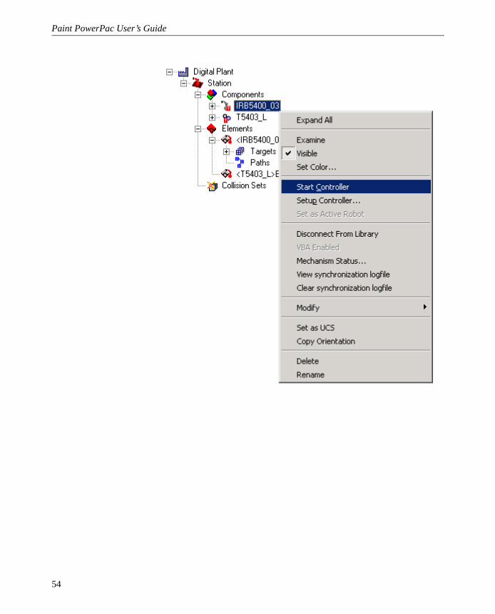
Start the controller In the Object Browser right click the robot IRB5400_03.
On the context menu, click Start Controller.
53
Paint PowerPac User’s Guide
54

Chapter 4: How to use Paint PowerPac
Wait until the statusbar turn green
On the Mechanism menu, point to Controller and then click Setup.
A new dialog box opens.
55

Paint PowerPac User’s Guide
In the Setup for IRB5400_03 dialog, click the Ext. Axis tab.
Click the Set Up external axis mapping button.
A new dialog box opens.
In the Mechanisms box select T5403_L and then in the MechUnits first select T5400 and check the T5400 checkbox.
Click OK.
56

Chapter 4: How to use Paint PowerPac
Click Yes.
The dialog closes.
Click the Robot tab.
Uncheck the Use Controller Definition checkbox
Enter -90 in the Orientation Rz input box. (Because the robot is rotated -90 degrees in Rz)
57

Paint PowerPac User’s Guide
Click OK in the Setup for IRB5400_03 dialog.
The VirtualController will now restart to activate the changes in baseframe.
The robot is now ready to use.
58

Chapter 4: How to use Paint PowerPac
Configure the VirtualController for a Paint robot
Purpose Example how to set up a virtual paint robot.
Setup the controller
In the Object Browser right click the robot IRB5400_02.
On the context menu, click Setup Controller.
In the Setup dialog box, click on Change Controller.
In the Virtual Robot Browser dialog box, click Create.
Enter System Name IRB5400-02-Test.
Select Program Revision 3HAC6811-2.00 RW 672 System Pack 4.0, or later.
Check the Use Paint Options checkbox.
Click the Insert Virtual Key button.
Click OK.
Go thru Robinstall
Click in IRB5400-02-Test in the systems
Click Set Current Robot.
Click Close.
Click OK.
59

Paint PowerPac User’s Guide
60