
AB SLC 503 DF1 DH485 Converter - IDEC Bradley SLC 503 DF1... · Introduction: The information here...
18
Communication Settings: Allen Bradley (CPU: SLC 503 using DH485 to DF1 Converter) and Idec Touchscreens (5.7”HG2G / HG2F, 10.4” HG3F, 12.1” HG4F)
-
Upload
duongkhuong -
Category
Documents
-
view
235 -
download
2
Transcript of AB SLC 503 DF1 DH485 Converter - IDEC Bradley SLC 503 DF1... · Introduction: The information here...

Communication Settings:
Allen Bradley
(CPU: SLC 503 using DH485 to DF1 Converter)
and
Idec Touchscreens
(5.7”HG2G / HG2F, 10.4” HG3F, 12.1” HG4F)

Introduction: The information here will help you configure the Idec toucschreens (5.7” HG2G /
HG2F, 10.4” HG3F, or 12.1” HG4F) and the Allen Bradley SLC 503 PLC using
Micrologix/SLC 500 (Full Duplex) protocol. For other supported Allen Bradley
PLCs and its communication settings/range of addresses, please refer to WindO/I-
NV2 manual. Select “Host Interface” then Connection to a PLC. http://www.idec.com/Products/ENG/PDF/manuals/WindOI/V282/English/mainmenue.pdf
COMMUNICATION SETTINGS:

ADDRESSING:

Allen Bradley: Data Files Format
Example of Allen Bradley Data Files format:
I:e.s/b
O:e.s/b
Nf:e/b
Bf:e/b
I = Input, O = Output, N= Integer file, B = Bit type file, f = File number
: = Element delimiter
e = Slot number
. = Word delimiter (only required when word number is used).
s = word number, / = Bit delimiter, b = Terminal number
Example: AB data file converted to WindO/I-NV2 address format.
(Note: You may skip this address format if you select the standard AB format data
type)
Example:
Micrologix Address -- I:2.12/6
WindO/I-NV2 Address – I 0201206

Required Cables:
HG9Z-XCM1A (Connects PC and HG2G/3F/4F)
HG9Z-GWDF1DH485-2 (Connects AB SLC503 and HG2G/3F/4F)
1747-PIC (Connects PC and AB SLC503)
Required Softwares:
Install WindO/I-NV2 (programming software for HG2G/3F/4F)
Install Allen Bradley RSLinx and RSLogix500 (programming software for Micrologix)
Devices used for this application note:
1. Allen Bradley SLC 503 PLC
2. HG9Z-GWDF1DH485-2 (DH485/DF1 Converter)
3. HG2G-SS22VCF (5.7” display)

Step 1: RSLinx SOFTWARE 1) Connect programming cable partnumber 1747-PIC from PC to SLC 503
PLC programming port.
2) Launch the RSLinx software. RSLinx links AB devices into Windows
application such as the RSLogix (programming and configuring software for
PLC).
3) Select Communications / Configure Drivers.
4) Configure the Driver:
a) Select 1747-PIC Device
b) Click the Add New button
c) Choose a name for the driver and click OK

5) Next, make sure to follow the settings below except the Comm Port (select
your own comm. port). These communication settings should match the
touchscreen settings.
6) If the settings are done, Click the OK button. It should show you that the
driver is in the Running status.

7) Once you have confirmed that the driver is running, then click the Close
button to close the dialogue box.
8) Next, go to Communications and select RSWho to confirm that your PC is
communicating with AB SLC503 PLC. The second image below displays the
1747-PIC and ABSLC503 is communicating.
9) Minimize RSLinx and Launch RSLogix software.
Step 3: RSLogix500 software
10) Launch RSLogix500 and select File/New.
(Note: Depending on the version of RSLogix, you might need an activation key to run RSLogix)
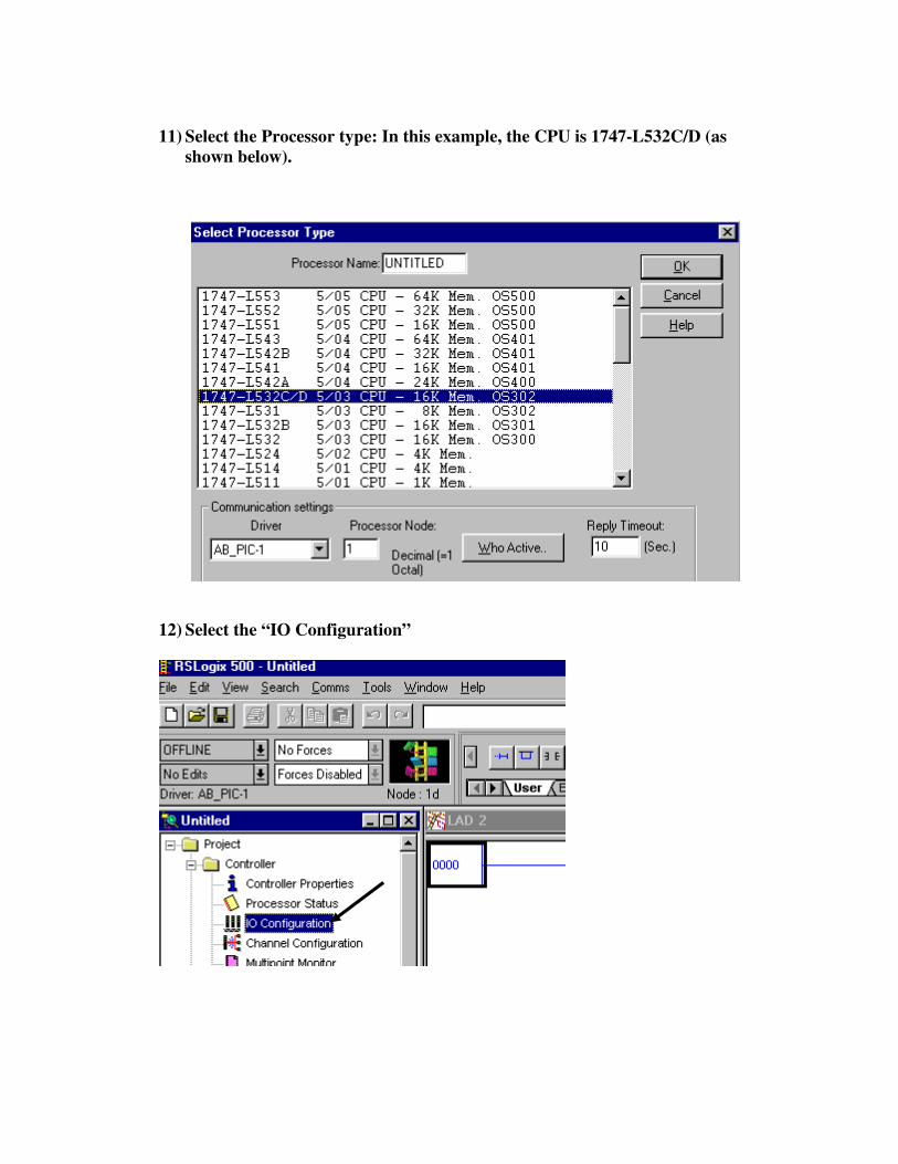
11) Select the Processor type: In this example, the CPU is 1747-L532C/D (as
shown below).
12) Select the “IO Configuration”

13) Click the Read IO Config. button to display the type of I/O modules are with
the CPU.
14) Select Channel Configuration to configure the communication ports.

15) Select the “Chan. 1-System” tab. Follow the settings as shown.
16) Select “Chan.0-User” tab. Driver is Shutdown.

17) Select the “General” tab. Make sure all settings are the same as shown.
18) Create a simple ladder logic as shown below. The normally open contact is
assign with B3:0/0 and the output coil is assign with O0:0/0. Then
download the project by selecting Comms / Download.

Step 1: WindO/I-NV2 software Configure the HG2G/3F/4F by creating a program in WindO/I-NV2
software
1) Connect the programming cable partnumber HG9Z-XCM1A from PC to
HG2G/3F/4F (Serial 1 port).
2) Launch WindO/I-NV2 software. Select File/New Project .
3) Create a project name. In this example, the project name is “AB SLC503”.
4) Click the Next button to choose the O/I and Model type.

5) In the Host I/F Driver, select Allen Bradley as the manufacturer and
MicroLogix/SLC500 (Full Duplex) as the protocol (since the test converter is
configured as Full Duplex). Click the Next button to continue.
6) In Project settings, select the Communication Interface tab. Under Interface
Configuration, select Serial 1 Host Communication. Then follow the
Interface Settings below.

7) Select the Host I/F Driver tab. The only changes you need to make are the
Node Address (PLC) and (HG). Make sure these settings match with the
SLC503 node address settings. In this example, the SLC503 is Node 1,
therefore the settings here for Node Address (PLC) and (HG) are both “1”.
Select the OK button to continue.

8) Create Base Screen 1. For a basic example, select the Bit Button icon
and drop it on the screen.
a) Double click on the bit button to view the Properties.
b) Action Mode: <select> Alternate
c) Destination Device select B: Binary, Address: 300000. This is
equivalent to B3:0/0 in Micrologix PLC.
d) Click the OK button.
9) Finally, download the project to the HG2G/3F/4F. Select Online then
Download.

Once both programs are downloaded, connect the cable converter
part# HG9Z-GWDF1DH485-2 (between the PLC and HG2G/3F/4F).
On the touchscreen, press the bit button and see if the output on the PLC is
triggered. If so, then the communication is successful. You may now start your
project.


