AB-Plot V. 1.x Software Manual - Literature Library
46
USER MANUAL (Catalog Number 1492-PLOTSOFT B) AB-Plot V. 1.x Software Manual
Transcript of AB-Plot V. 1.x Software Manual - Literature Library
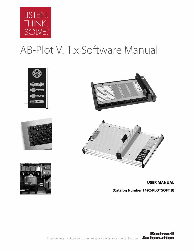
USER MANUAL
(Catalog Number 1492-PLOTSOFT B)
AB-Plot V. 1.x Software Manual

2

Table of Contents
SYSTEM REQUIREMENTS. . . . . . . . . . . . . . . . . . . . . . . . . . . . . . . . . 5INSTALLING PLOTTER SOFTWARE . . . . . . . . . . . . . . . . . . . . 5INSTALLING GENERIC PRINTER DRIVER. . . . . . . . . . . . . . 8
AN INTRODUCTION TO PLOTTER SOFTWARE . . . . . . . . . . . 17STARTING THE PLOTTER PROGRAM . . . . . . . . . . . . . . . . . 17CALIBRATING THE PLOTTER PLATE . . . . . . . . . . . . . . . . . 18THE MENU BAR OF THE INPUT SCREEN. . . . . . . . . . . . . . 24THE AUTOFILL FUNCTION. . . . . . . . . . . . . . . . . . . . . . . . . . . 27EDITING MARKER CARD CONFIGURATIONS . . . . . . . . . 30The Import and Export of Data . . . . . . . . . . . . . . . . . . . . . . . . . . . 32TEXT ORIENTATION AND PLOTTER . . . . . . . . . . . . . . . . . 35The Output Window . . . . . . . . . . . . . . . . . . . . . . . . . . . . . . . . . . . . 36PLOTTING. . . . . . . . . . . . . . . . . . . . . . . . . . . . . . . . . . . . . . . . . . . 37
INFORMATION . . . . . . . . . . . . . . . . . . . . . . . . . . . . . . . . . . . . . . . . . 39THE RIGHT MOUSE BUTTON. . . . . . . . . . . . . . . . . . . . . . . . . 39EDITING BLOCKS. . . . . . . . . . . . . . . . . . . . . . . . . . . . . . . . . . . . 39SUPPORT AND UPDATES . . . . . . . . . . . . . . . . . . . . . . . . . . . . . 40SYMBOLS . . . . . . . . . . . . . . . . . . . . . . . . . . . . . . . . . . . . . . . . . . . . 40LIST OF SHORTCUTS AND FUNCTION KEYS . . . . . . . . . . 40DEFINITIONS. . . . . . . . . . . . . . . . . . . . . . . . . . . . . . . . . . . . . . . . 41THE GRAPHAB.GDM CONFIGURATION FILE . . . . . . . . . 42THE ABPRINT.INI INITIALIZATION FILE . . . . . . . . . . . . . 44
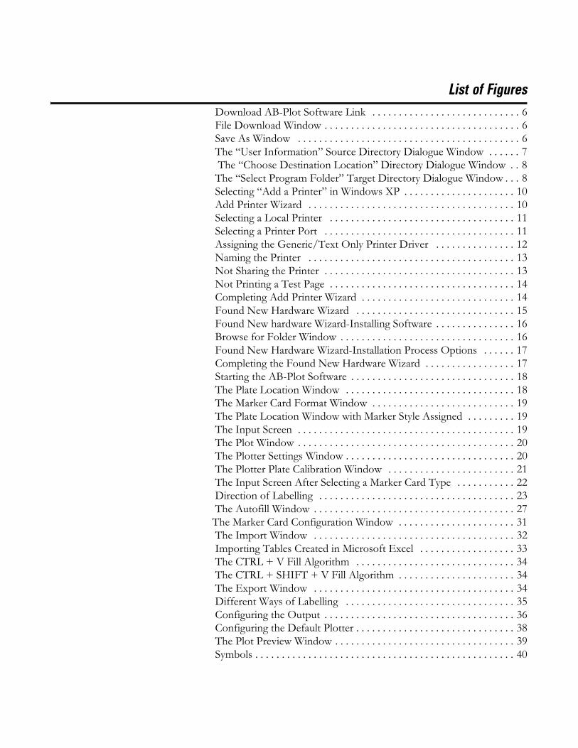
List of Figures Download AB-Plot Software Link . . . . . . . . . . . . . . . . . . . . . . . . . . . . 6 File Download Window . . . . . . . . . . . . . . . . . . . . . . . . . . . . . . . . . . . . . 6 Save As Window . . . . . . . . . . . . . . . . . . . . . . . . . . . . . . . . . . . . . . . . . . 6 The “User Information” Source Directory Dialogue Window . . . . . . 7 The “Choose Destination Location” Directory Dialogue Window . . 8 The “Select Program Folder” Target Directory Dialogue Window . . . 8 Selecting “Add a Printer” in Windows XP . . . . . . . . . . . . . . . . . . . . . 10 Add Printer Wizard . . . . . . . . . . . . . . . . . . . . . . . . . . . . . . . . . . . . . . . 10 Selecting a Local Printer . . . . . . . . . . . . . . . . . . . . . . . . . . . . . . . . . . . 11 Selecting a Printer Port . . . . . . . . . . . . . . . . . . . . . . . . . . . . . . . . . . . . 11 Assigning the Generic/Text Only Printer Driver . . . . . . . . . . . . . . . 12 Naming the Printer . . . . . . . . . . . . . . . . . . . . . . . . . . . . . . . . . . . . . . . 13 Not Sharing the Printer . . . . . . . . . . . . . . . . . . . . . . . . . . . . . . . . . . . . 13 Not Printing a Test Page . . . . . . . . . . . . . . . . . . . . . . . . . . . . . . . . . . . 14 Completing Add Printer Wizard . . . . . . . . . . . . . . . . . . . . . . . . . . . . . 14 Found New Hardware Wizard . . . . . . . . . . . . . . . . . . . . . . . . . . . . . . 15 Found New hardware Wizard-Installing Software . . . . . . . . . . . . . . . 16 Browse for Folder Window . . . . . . . . . . . . . . . . . . . . . . . . . . . . . . . . . 16 Found New Hardware Wizard-Installation Process Options . . . . . . 17 Completing the Found New Hardware Wizard . . . . . . . . . . . . . . . . . 17 Starting the AB-Plot Software . . . . . . . . . . . . . . . . . . . . . . . . . . . . . . . 18 The Plate Location Window . . . . . . . . . . . . . . . . . . . . . . . . . . . . . . . . 18 The Marker Card Format Window . . . . . . . . . . . . . . . . . . . . . . . . . . . 19 The Plate Location Window with Marker Style Assigned . . . . . . . . . 19 The Input Screen . . . . . . . . . . . . . . . . . . . . . . . . . . . . . . . . . . . . . . . . . 19 The Plot Window . . . . . . . . . . . . . . . . . . . . . . . . . . . . . . . . . . . . . . . . . 20 The Plotter Settings Window . . . . . . . . . . . . . . . . . . . . . . . . . . . . . . . . 20 The Plotter Plate Calibration Window . . . . . . . . . . . . . . . . . . . . . . . . 21 The Input Screen After Selecting a Marker Card Type . . . . . . . . . . . 22 Direction of Labelling . . . . . . . . . . . . . . . . . . . . . . . . . . . . . . . . . . . . . 23 The Autofill Window . . . . . . . . . . . . . . . . . . . . . . . . . . . . . . . . . . . . . . 27The Marker Card Configuration Window . . . . . . . . . . . . . . . . . . . . . . 31 The Import Window . . . . . . . . . . . . . . . . . . . . . . . . . . . . . . . . . . . . . . 32 Importing Tables Created in Microsoft Excel . . . . . . . . . . . . . . . . . . 33 The CTRL + V Fill Algorithm . . . . . . . . . . . . . . . . . . . . . . . . . . . . . . 34 The CTRL + SHIFT + V Fill Algorithm . . . . . . . . . . . . . . . . . . . . . . 34 The Export Window . . . . . . . . . . . . . . . . . . . . . . . . . . . . . . . . . . . . . . 34 Different Ways of Labelling . . . . . . . . . . . . . . . . . . . . . . . . . . . . . . . . 35 Configuring the Output . . . . . . . . . . . . . . . . . . . . . . . . . . . . . . . . . . . . 36 Configuring the Default Plotter . . . . . . . . . . . . . . . . . . . . . . . . . . . . . . 38 The Plot Preview Window . . . . . . . . . . . . . . . . . . . . . . . . . . . . . . . . . . 39 Symbols . . . . . . . . . . . . . . . . . . . . . . . . . . . . . . . . . . . . . . . . . . . . . . . . . 40
INSTALLATION 5
INSTALLATION Before installing the Plotter Software, make sure that your system complies with the following requirements.
SYSTEM REQUIREMENTS
• Personal computer with at least an 80486 processor
• Minimum RAM 8 MB
• Microsoft™ Windows 95 or later
• CD Drive
• Hard drive with at least 50 MB space available
• Windows-compatible mouse
• Screen resolution 640 x 480, 800 x 600 or 1024 x 768
• Open parallel communications port or USB port
INSTALLING PLOTTER SOFTWARE
The following procedure assumes that you have already installed the Win-dows operating system and are familiar with the basic principles of it. If this is not the case, you should refer to the Windows User's Handbook.Note: The screenshots correspond to Windows XP.
Installation/Update procedure (Online):
Use the following instructions to download the application.
1. Go to: http://www.ab.com/industrialcontrols/products/terminal_blocks_and_wiring/marking_systems_access/abplot.html

INSTALLATION 6
2. Click the Download ABPlot Software (Version 1.00 - 8.13 MB) link.
Figure 1 Download AB-Plot Software Link
3. When the “File Download” window pops up, click Save.
Figure 2 File Download Window
4. When the “Save As” window appears, choose the location that the download will be saved. Keep the location simple, as you will need to find the file later.
Figure 3 Save As Window
INSTALLATION 7
5. Once the file has saved to the specified location, find the file and double-click on it. This will start the installation. If any pop-up window appear asking if you would like to run the application or questioning security, click “OK” or “Yes.”
Installation/Update procedure (from CD):
Use the following instructions to install the application from CD.
1. Start Windows.
2. Insert CD in the disk drive.
3. Close all other applications and click on "My Computer". Activate the CD drive.
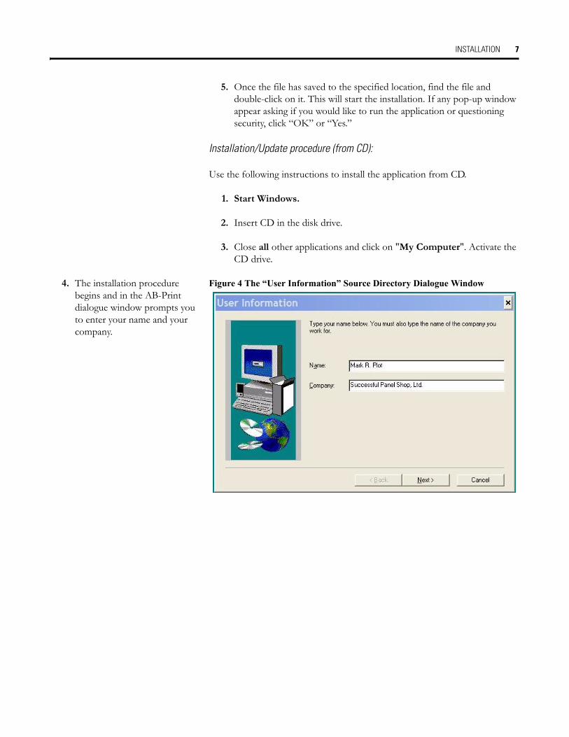
4. The installation procedure begins and in the AB-Print dialogue window prompts you to enter your name and your company.
Figure 4 The “User Information” Source Directory Dialogue Window

INSTALLATION 8
5. You are prompted to enter the drive or path to store the source files. After doing so, select Next.
Figure 5 The “Choose Destination Location” Directory Dialogue Window
6. Finally, the Setup Program displays the message that the installation has been successfully completed. Should you have any questions or encounter any problems, please refer to Support and Updates for further advice.
Figure 6 The “Select Program Folder” Target Directory Dialogue Window
INSTALLING GENERIC PRINTER DRIVERThe plotter software requires that a generic printer drive be installed on a parallel or USB printer port for your computer.
The following procedure assumes that you have already installed the Win-dows operating system and are familiar with the basic principles of it. If this is not the case, you should refer to the Windows User's Handbook.
This procedure shows screens from Windows XP. Earlier versions of win-dows will have a similar procedure, but the screens may look different.

INSTALLATION 9
Installation/Update Procedure Using a Parallel Port:
Use the following instructions if you intend to connect with a parallel port. For USB port instructions, please refer to USB Port Instructions on page 14.
For Windows XP:
1. Click on Start, then select Settings, then Printers and Faxes. A similar window is visible:
Figure 7 Selecting “Add a Printer” in Windows XP
2. This brings up the “Add Printer Wizard”:Select Next.
Figure 8 Add Printer Wizard
INSTALLATION 10
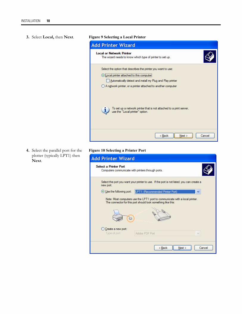
3. Select Local, then Next. Figure 9 Selecting a Local Printer
4. Select the parallel port for the plotter (typically LPT1) then Next.
Figure 10 Selecting a Printer Port
INSTALLATION 11
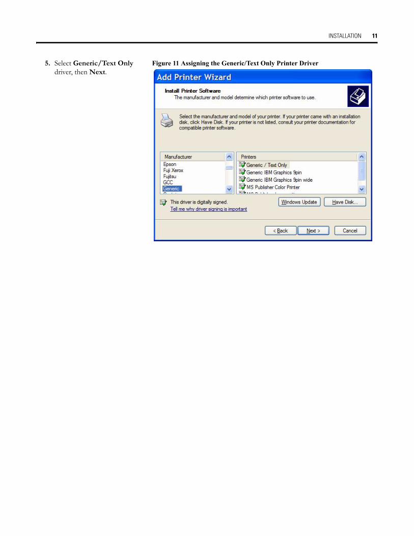
5. Select Generic/Text Only driver, then Next.
Figure 11 Assigning the Generic/Text Only Printer Driver

INSTALLATION 12
6. Name the printer. It has been named “Generic/Text Only” in this example. Select the printeras a default. Select Next.
Figure 12 Naming the Printer
7. Do not share the printer. Select Next.
Figure 13 Not Sharing the Printer

INSTALLATION 13
8. Do not print a test page. Select Next.
Figure 14 Not Printing a Test Page
9. Select Finish. Figure 15 Completing Add Printer Wizard
Now the printer driver has been assigned to the parallel port.
INSTALLATION 14
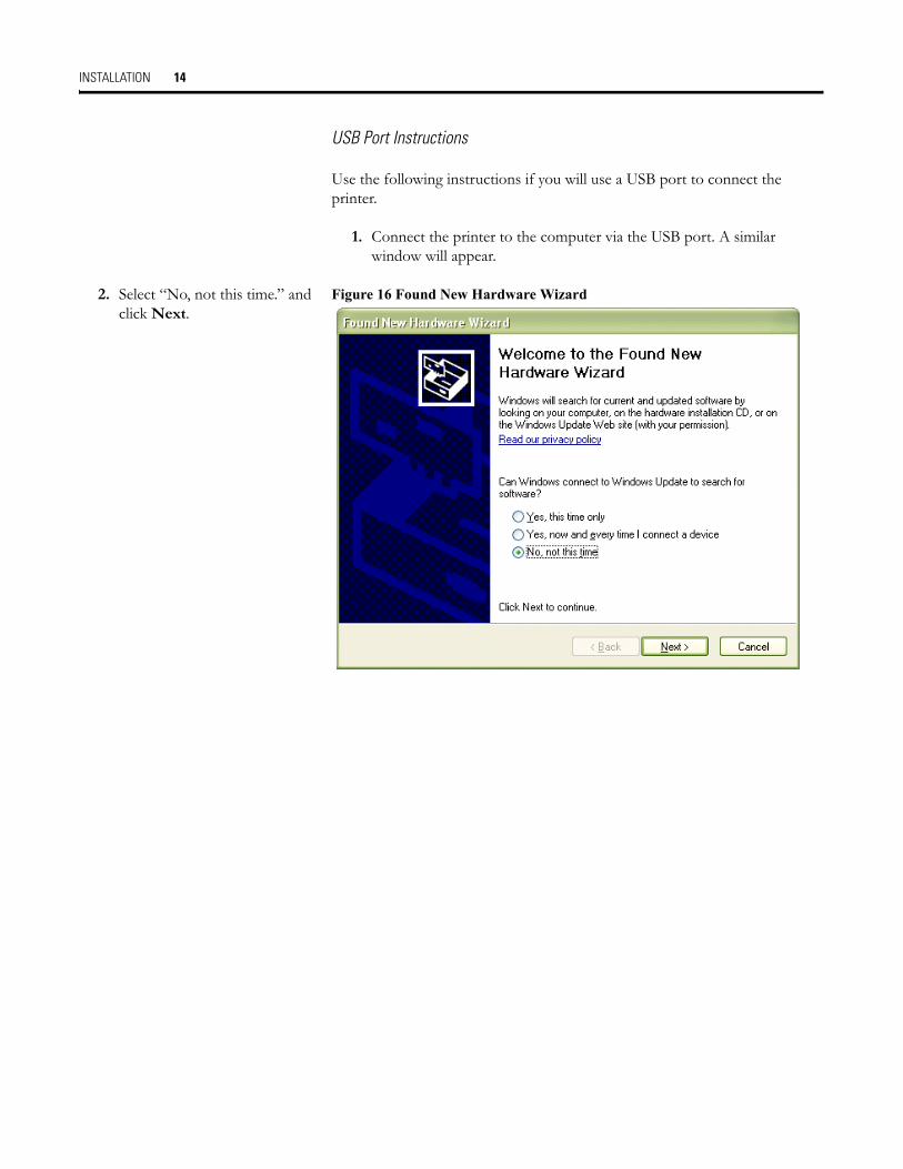
USB Port Instructions
Use the following instructions if you will use a USB port to connect the printer.
1. Connect the printer to the computer via the USB port. A similar window will appear.
2. Select “No, not this time.” and click Next.
Figure 16 Found New Hardware Wizard
INSTALLATION 15
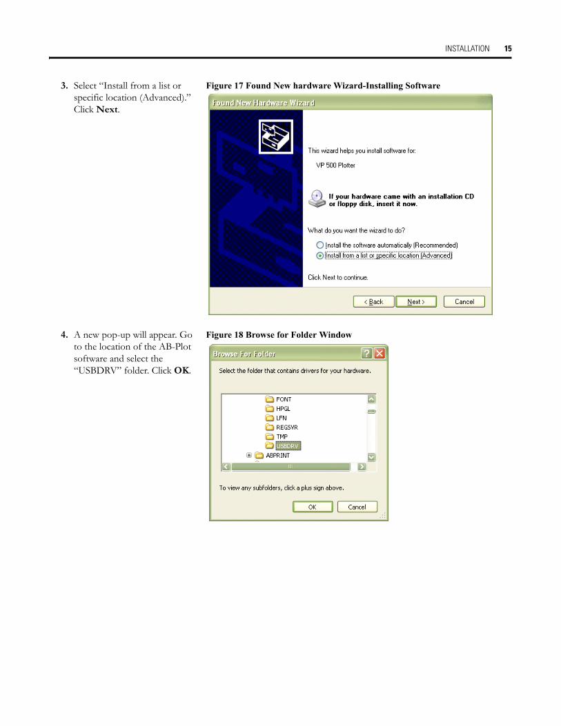
3. Select “Install from a list or specific location (Advanced).” Click Next.
Figure 17 Found New hardware Wizard-Installing Software
4. A new pop-up will appear. Go to the location of the AB-Plot software and select the “USBDRV” folder. Click OK.
Figure 18 Browse for Folder Window
INSTALLATION 16
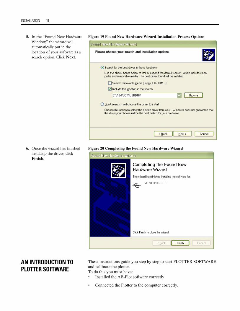
5. In the “Found New Hardware Window,” the wizard will automatically put in the location of your software as a search option. Click Next.
Figure 19 Found New Hardware Wizard-Installation Process Options
6. Once the wizard has finished installing the driver, click Finish.
Figure 20 Completing the Found New Hardware Wizard
AN INTRODUCTION TO PLOTTER SOFTWARE
These instructions guide you step by step to start PLOTTER SOFTWARE and calibrate the plotter.To do this you must have:• Installed the AB-Plot software correctly
• Connected the Plotter to the computer correctly.

INSTALLATION 17
STARTING THE PLOTTER PROGRAM
Start the program by opening the START menu, and navigating to:
Programs/ABPLOT/AB-PLOT
Note: The first time you open the software, you may be asked “Would you like to install the sub program for long file names support?” Select Yes. Installing this program allows the user to assign file names longer than 8 digits.
Figure 21 Starting the AB-Plot Software
CALIBRATING THE PLOTTER PLATE
1. Double-click on the plate location for the first marker card and select the type of marker you require from the list.
Figure 22 The Plate Location Window

INSTALLATION 18
2. Select OK in order to call up the Input Screen.
Figure 23 The Marker Card Format Window
3. Double click on the highlighted plate location to display the Input screen.
Figure 24 The Plate Location Window with Marker Style Assigned
4. The screen now contains a representation of the Marker Card you have selected. The current marker, bottom left, is shown highlighted. Type an X on the 4 markers in the corners of the marker card.
Figure 25 The Input Screen
INSTALLATION 19
5. Install a pen in the lower left penholder of the plotter. Install the appropriate marker card in the respective plate location.Hint: You can avoid wasting marker cards during this calibration by taping a clear transparency over the entire marker card.
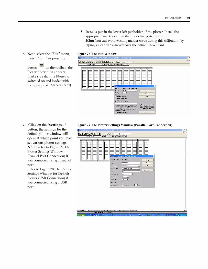
6. Next, select the "File" menu, then "Plot..." or press the
button on the toolbar ; the Plot window then appears (make sure that the Plotter is switched on and loaded with the appropriate Marker Card).
Figure 26 The Plot Window
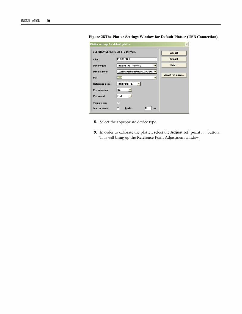
7. Click on the "Settings..." button; the settings for the default plotter window will open, at which point you may set various plotter settings.Note: Refer to Figure 27 The Plotter Settings Window (Parallel Port Connection) if you connected using a parallel port. Refer to Figure 28 The Plotter Settings Window for Default Plotter (USB Connection) if you connected using a USB port.
Figure 27 The Plotter Settings Window (Parallel Port Connection)
INSTALLATION 20
Figure 28The Plotter Settings Window for Default Plotter (USB Connection)
8. Select the appropriate device type.
9. In order to calibrate the plotter, select the Adjust ref. point . . . button. This will bring up the Reference Point Adjustment window.
INSTALLATION 21
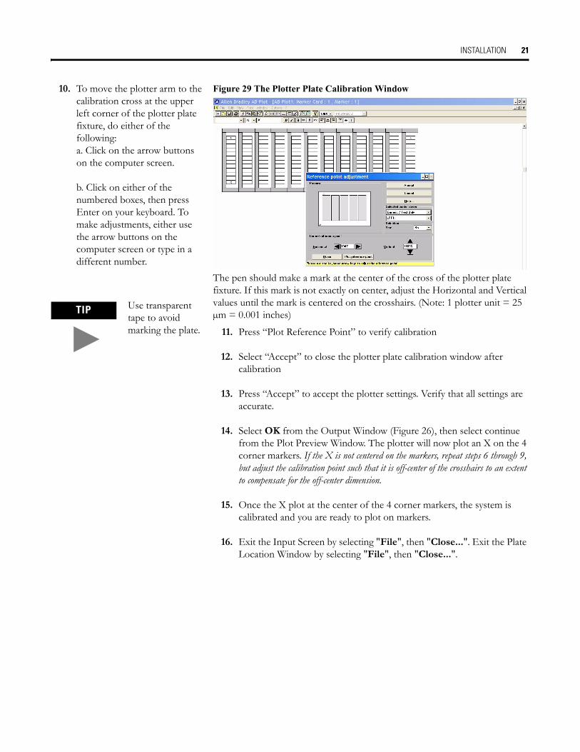
10. To move the plotter arm to the calibration cross at the upper left corner of the plotter plate fixture, do either of the following:a. Click on the arrow buttons on the computer screen.
b. Click on either of the numbered boxes, then press Enter on your keyboard. To make adjustments, either use the arrow buttons on the computer screen or type in a different number.
Figure 29 The Plotter Plate Calibration Window
The pen should make a mark at the center of the cross of the plotter plate fixture. If this mark is not exactly on center, adjust the Horizontal and Vertical values until the mark is centered on the crosshairs. (Note: 1 plotter unit = 25 µm = 0.001 inches)
11. Press “Plot Reference Point” to verify calibration
12. Select “Accept” to close the plotter plate calibration window after calibration
13. Press “Accept” to accept the plotter settings. Verify that all settings are accurate.
14. Select OK from the Output Window (Figure 26), then select continue from the Plot Preview Window. The plotter will now plot an X on the 4 corner markers. If the X is not centered on the markers, repeat steps 6 through 9, but adjust the calibration point such that it is off-center of the crosshairs to an extent to compensate for the off-center dimension.
15. Once the X plot at the center of the 4 corner markers, the system is calibrated and you are ready to plot on markers.
16. Exit the Input Screen by selecting "File", then "Close...". Exit the Plate Location Window by selecting "File", then "Close...".
TIP Use transparent tape to avoid marking the plate.

THE INPUT SCREEN 22
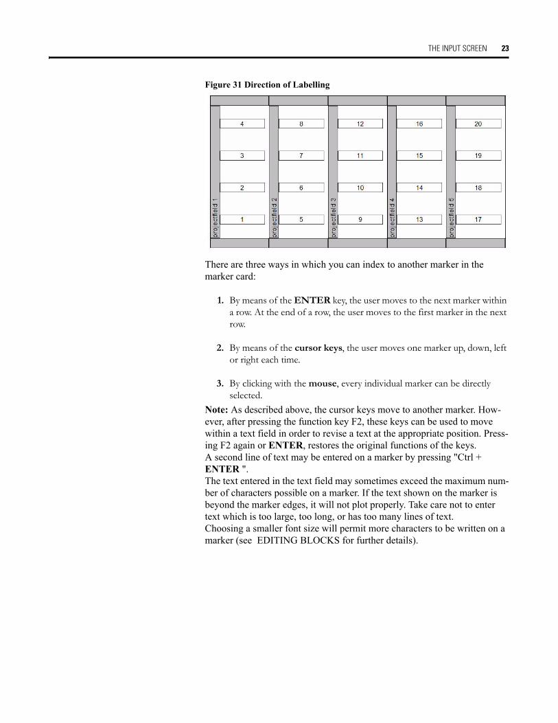
THE INPUT SCREEN Double-click on a marker card location in the Plate Location Window (see Figure 22), then select a Marker Card Type. This brings up the Input Screen.Figure 30 The Input Screen After Selecting a Marker Card Type
The scroll buttons (located in the lower left corner of the screen) will bring the marker card from another plotter plate location (locations 1-5) to view. In particular, each scroll button will bring about another marker card as fol-lows:
1. Marker Card configured in first location (location 1) of the Plotter Plate.
2. Marker Card configured in previous location of Plotter Plate.
3. Marker Card configured in next location of Plotter Plate.
4. Marker Card configured in last location (location 5) of the Plotter Plate.
THE INPUT FIELD
Enter data into the first marker by typing the desired information on the keyboard. The text appears on the marker and in the text field of the format-ting bar (next to the font size).After loading the Input Screen (Figure 25), the marker on the bottom left of the Marker Card is highlighted. This is the first marker. (Example: marker 1 in project 1 is the start marker in the figure below.)
The sequence of labelling is illustrated by means of the numbers 1-20 shown next.
1 2 3 4
THE INPUT SCREEN 23
Figure 31 Direction of Labelling
There are three ways in which you can index to another marker in the marker card:
1. By means of the ENTER key, the user moves to the next marker within a row. At the end of a row, the user moves to the first marker in the next row.
2. By means of the cursor keys, the user moves one marker up, down, left or right each time.
3. By clicking with the mouse, every individual marker can be directly selected.
Note: As described above, the cursor keys move to another marker. How-ever, after pressing the function key F2, these keys can be used to move within a text field in order to revise a text at the appropriate position. Press-ing F2 again or ENTER, restores the original functions of the keys.A second line of text may be entered on a marker by pressing "Ctrl + ENTER ".The text entered in the text field may sometimes exceed the maximum num-ber of characters possible on a marker. If the text shown on the marker is beyond the marker edges, it will not plot properly. Take care not to enter text which is too large, too long, or has too many lines of text.Choosing a smaller font size will permit more characters to be written on a marker (see EDITING BLOCKS for further details).
THE INPUT SCREEN 24
THE MENU BAR OF THE INPUT SCREEN
File
Note: The following menu, "Edit", can also be called up within the Input Screen as a pop-up menu. It appears at the position of the mouse pointer after pressing the right mouse button.
New Opens the Marker Card format window for choosing a new Marker Card.
Open Opens an existing document.Save (Shortcut: Ctrl + S) Saves the current document under its file name. In the case of a document
which has not yet been saved, the standard dialogue field "Save as..." appears automatically.Save as Loads the standard dialogue field "Save as..." for saving the current document with path
details.Close Closes the Input Screen and returns the user to the Plate Location Window.Import (Shortcut: Ctrl + I) Opens a window for importing various data formats from CAD/CAE pro-
grams. The following formats can be read at present:Eplan 4.1 terminal file *.wekEplan 4.1 cable file *.wecEplan 4.1 connection file *.weaEplan 4.1 ancillary equipment file *.wesAnsi *.ansUNIVERS/UNIPRINT *.makCAE33 *.elsMP data *.mpdVer. data *.verText *.txtComma Separated File *.csvFor Microsoft Excel import see Importing data and working with Microsoft ExcelOther formats can be added upon request. Please contact our ServiceLine for further informa-tion.Step 1: Select the desired start marker.Step 2: Open the Import dialogue window and select the appropriate filter from the "File for-mat" list.Step 3: After confirming the selection with "OK", the data is imported into the document starting at the current marker position.Step 4: If the imported marker data exceeds the labelling area of the Marker Card, then the next Marker Card is automatically written. If this has not yet been configured, then AB-Plot uses the last Marker Card type specified.
Export (Shortcut: Ctrl + E) Opens a window for exporting AB-Plot data in other data formats (.TXT).
Plot (Shortcut: Ctrl + P) Opens the "Plot" dialogue window.Exit Closes AB-Plot

THE INPUT SCREEN 25
Edit
Undo (Shortcut: Ctrl + Z) Reverses the last actionReverse data of marked rows (Shortcut: F9) First, highlight a row of markers (e.g. 1,2,3,4). Next, select this
function. This reverses the markers to read (4,3,2,1)Increase Current Value (Shortcut: Ctrl + N) If the value of a marker is a number n, this command will
label the next marker with a value equal to n + 1Duplicate Value (Shortcut: Ctrl + D) This function copies the value of the current marker into
the next markerCut (Shortcut: Ctrl + X) Copies the data of the highlighted marker to the clipboard
and deletes the marked areaCopy (Shortcut: Ctrl + C) Copies the data of the highlighted marker or area to the
clipboardPaste (Shortcut: Ctrl + V) Inserts the data from the clipboard onto the Marker Card
starting at the position of the current marker. In doing so, texts on markers already used are overwritten
Paste with project fields (Shortcut: Ctrl + B) Inserts the data from the clipboard with project field onto the Marker Card starting at the position of the current marker. In doing so, texts on markers already used are overwritten
Multiple paste (Shortcut: Ctrl + M) Opens an input window in which the user can enter the number of repetitions required of the data in the buffer. In this case too, the data is inserted starting at the current marker of the Marker Card. In doing so, texts on markers already used are overwritten
Insert copied markers (Shortcut: F5) Inserts the markers from the clipboard at the current position of the Marker Card, but in contrast to the normal paste command does not over-write existing data but instead displaces it further down the Marker Card
Search & replace (Shortcut: Ctrl + F) Opens the dialogue box "Search & replace". This function locates a given text and replaces it with another. The procedure can be per-formed automatically ("Replace all") or manually ("Replace..."). The area of the search can be selected by means of the options buttons The “Searc-h and Replace” Dialogue Box
Current Marker Card: searches through the Marker Card currently shownComplete document: searches through all the frames of the document openedClear: Opens a cascade menu with the following entriesAll: Deletes both the text and the formatting information of the marked areaText: Deletes the text of the marked area
THE INPUT SCREEN 26
View
Font
Format Deletes the formatting information of the marked areaClear Marker Card (Shortcut: Shift + Del) Deletes the text and formatting information of the
whole Marker Card. The user is prompted to confirm the delete command before it is carried out
Clear marked project field(s) Deletes the project fields markedNote: This is the only way to do this!
Mark all (Shortcut: Ctrl + A) Marks the whole Marker CardMarkers Insert: Empty markers are inserted into a Marker Card which is already writ-
ten. The markers already written are not deleted but displaced to allow inser-tion of the new ones.Delete: This command deletes not only the labelling but the markers them-selves as well. Unwritten markers automatically close up the gap left by the deleted markers
Autofill (Shortcut: F8) Opens the Autofill window for quick and easy writingProject fields (Shortcut: F4) This menu point is used to write or delete the information field
in each row
Horizontal Displays the Marker Card horizontally.Vertical Displays the Marker Card vertically.3D-look Displays the Marker Card with a perspective presentation.Zoom Opens a cascade menu with the entries 200%, 150%, 100%, 75% and 50%. This function can be
used to enlarge or reduce the view of the Marker Card depending on the entry selected.
Bold Sets the text attribute bold for the highlighted area of the Marker CardItalic Sets the text attribute italic for the highlighted area of the Marker CardAlignment Opens a cascade menu with the entries left, center, right and top, vertical center, bottom. These
commands allow the user to stipulate the position of the text in the highlighted area of the Marker Card. The same functions are also available in the icon bar.
Orientation This allows the orientation of the text on a marker to be specified (see Text orientation and Plot-ter for further details). The orientation applies to a highlighted marker or area. Text can be posi-tioned at 0°, 90°, 180° and 270°. The menu point "0°" corresponds to the "normal" orientation. The 90°, 180° and 270° rotations are all counterclockwise. The same functions are also available in the icon bar.

THE INPUT SCREEN 27
Window
Options (available in Card Edit view only)
Multiple lines Switches the highlighted area to the multiple line mode.Single line Switches the Highlighted area to the single line mode.?Help (Shortcut: F1) Calls up the AB-Plot help routine.About Shows a dialogue box with information about the program
THE AUTOFILL FUNCTION
THE AUTOFILL WINDOW
Figure 32 The Autofill Window
The Autofill window is opened when in the Input Screen the entry "Auto-fill..." is selected from the "Edit" menu or function key F8 is pressed.This makes a number of marking functions available to the user which can be used to generate the consecutive numbering systems often employed when labelling electrical equipment (e.g. terminal blocks: X1.1, X1.2, X1.3,...; contactors: K1, K2, K3,...; PLC labels: E 0.1, E 0.2, E0.3,... or A 0.1, A 0.2, A 0.3,...).
THE FUNCTIONS OF THE AUTOFILL WINDOW
The Autofill window is divided into several sections which contain various functions, options and input fields.
Document No. # Allows selection of open documents.
THE INPUT SCREEN 28
Input The extent of the labelling is specified here. The given values refer to the marked area.
System
Start value Any numerical value with which the labelling is to begin.End value Any numerical value with which the labelling is to finishPrefix One or more alphanumeric characters added before the numberSuffix One or more alphanumeric characters added after the numberBlock Another numeral which allows a block-type allocation of the labelling text. This figure defines the
start value for the block-type allocation.
Decimal 0-9 The start value must lie between 0 and 9. The decimal system is used for counting.Examples: step=1 ? start value=8, end value=2 ? sequence 8, 7, 6, 5, 4, 3, 2 step=1 ? start value=2, end value=8 ? sequence 2, 3, 4, 5, 6, 7, 8
Octal 0-7 The start value must lie between 0 and 7, i.e. octal notation.Hex 0-F The start value must lie between 0-9 and A-F, i.e. hexadecimal notation.Alphanumeric An alphanumeric character can be entered in the base section. Alphanumeric characters are, for
example, 1, 2, 3,...7, 8, 9 or a, b, c,...x, y, z or A, B, C,...X, Y, Z, whereas, for example, 11, 123 or aa, abc or AA, ABC are not (these are character strings). Entering an upper- or lower-case letter means that the following values are also upper- or lower-case letters.Example 1: step=1 ? start value=X, end value=B ? sequence X, W, V,...D, C, B step=1 ? start value=B, end value=X ? sequence B, C, D,...V, W, XExample 2: step=1 ? start value=x, end value=b ? sequence x, w, v,...d, c, b step=1 ? start value=b, end value=x ? sequence b, c, d,...v, w, x
Character string
Several alphanumeric characters may be entered in the Source section. Only an entry in the "Start value" field is possible; all the other fields in the Source section are inactive. Every high-lighted marker is provided with the same text. Examples of character strings: 1234 or abcd or ABCD or 1a2Bd3.
PLC This mode is used when the markers are to be provided with PLC-type labelling. When activat-ing this option, the program provides an example of how PLC (Programmable Logic Control) labelling is arranged.
THE INPUT SCREEN 29
Options (This section provides the additional functions described below.)
Text
Project Fields
Formatted Sequence
Clicking on the "OK" button executes the labelling functions which have been selected. In addition, the values entered in the Autofill window are checked for their validity. If the labelling area specified is invalid (e.g. the end of a block lies before the start or the start/end value is missing), then an error message appears. After acknowledging the error message, the user has the chance to check the entries and make changes if necessary.The "Cancel" button closes the Autofill window. No marking functions are carried out.
Step Determines the mode of counting, i.e. the increment between successive values.Example: step=1 ? 1 2 3 4; step=2 ? 1 3 5 7
Block step Determines the mode of counting for blocks.Duplicate each value Specifies how many copies of one marker are produced (with the same text)Duplicate sequence Specifies how many times a block is repeated.Skip markers Specifies the number of markers to be skipped over before the next marker is labelled.
Example: step=1 ? start value=1, end value=4Skip markers=0 ? 1 2 3 4Skip markers=1 ? 1 2 3 4
Add text Choosing this option adds the data (in the "Source" section) to existing texts. When switched off, data entered in the "Source" section overwrites existing texts. This option can be selected in any labelling mode.
Before existing text Characters are added to existing texts in the form of a prefix.After existing text Characters are added to existing texts in the form of a suffix.
Prefix One or more alphanumeric characters added to the start value in the form of a prefix.Row counter This number determines the value of the first field. Only numerical characters are possible.Suffix One or more alphanumeric characters added to the start value in the form of a suffix.
Left field The left-hand section of the formatting field applies to the block information. A number of control characters are available for formatting.
Right field The right-hand section of the formatting field applies to the start to end value characters. A number of control characters are available for formatting.
THE INPUT SCREEN 30
Control Characters for Autofill Functions The following special characters may be used to execute user-defined num-bering formats:
EDITING MARKER CARD CONFIGURATIONS
THIS SHOULD ONLY BE DONE IF THE PLOTTER SYSTEM CAN-NOT BE CENTERED ON A GIVEN MARKER BY ADJUSTING THE CALIBRATION POINT. THIS ACTIVITY WILL CHANGE THE .GDM FILES IN THE COMPUTER PROGRAM. This may be necessary when there are large fluctuations in humidity, which can affect the dimensions of a marker card. Typically, only dimension 4 requires modification.
0 (zero) Results in a digit on the marker instead of a zero. If the resulting value at this position does not contain a digit, then AB-Plot produces a zero. If the start value is 1 and the end value 3, then entering 0#.00 in the formatting field results in 01.00 ? 02.00 ? 03.00 on the marker.
# Results in a digit on the marker instead of "#". If the resulting value at this position does not contain a digit, then AB-Plot produces a blank space.
If the start value is 1 and the end value 3, then entering # $ in the formatting field results in 1 $ ? 2 $ ? 3 $ on the marker.
, (1000s separator) Divides large numbers into blocks of three digits.If the start value is 1000000 and the end value 1000003, then entering #,###,### $ in the formatting field results in 1,000,000 $ ? 1,000,001 $ ? 1,000,002 $ ? 1,000,003 $ on the marker.
- (minus sign) Adds a minus sign to the number. If the start value is 1 and the end value 3, then entering -# in the formatting field results in -1 ? -2 ? -3 on the marker.
+ (plus sign) Adds a plus sign to the number.If the start value is 1 and the end value 3, then entering +# in the formatting field results in +1 ? +2 ? +3 on the marker.
%, $, etc. Adds the given sign to the number as a prefix or a suffix.If the start value is 1 and the end value 3, then entering # % in the formatting field results in 1% ? 2 % ? 3 % on the marker.
THE INPUT SCREEN 31
Figure 33The Marker Card Configuration Window
Close all marker cards before modifying the configurations.The Marker Card Configuration window is called up from the Program Screen via the "Edit Marker Card configurations..." command in the "Options" menu. This window is used for configuring existing or new Marker Card types and for a fast check of existing configurations.
Information The list (bottom left) contains all the Marker Card types contained in the GRAPHAB.GDM configuration file. If you wish to edit an existing Marker Card type, then click on the appropriate type and alter the details given in the various fields. To do this, click on the respective field and use the spin buttons or enter the value directly via the keyboard.
Dimension 1-5 The dimensions 1-5 are to be specified in millimeters. The corresponding dimension is shown in red in the diagram while being edited. A sketch of the dimensions is shown in the configuration window.
Underlay This field shows the color of the spacer to be used for a given marker card.Part number This field shows the catalog number of a given product.Offset Value for a reference point compensation depending on the type of Marker CardMarker Type This field provides information whether a marker is suitable for terminal blocks, wires,
devices or competitor products as well as additional information for the applicable products for the selected marker.
Save The "Save" button enables you to overwrite the configuration file with the new values.
THE INPUT SCREEN 32
The Import and Export of Data
Importing Data and Working wth Microsoft Excel
Figure 34 The Import Window
The import function is started by selecting "Import..." from the "File" menu of the Input Screen. The import window then appears. This function can be used to read in data from other applications, e.g. CAD/CAE pro-grams, and enter this on the markers. The number of data formats that can be imported has been extended; the following file formats can now be imported:Allen Bradley *.abpAnsi *.ansEplan 4.1 terminal *.wekEplan 4.1 cable *.wecEplan 4.1 connection *.weaEplan 4.1 ancillary equipment *.wesUNIVERS/UNIPRINT *.makCAE33 *.elsMP data *.mpdVer. data *.verText *.txtComma Separated File *.csv
After selecting the file which is to be imported, the program prompts the user for the number of repetitions. If the data is to be inserted several times, then the markers with the same labelling are inserted in direct succession, i.e. in the case of insertion twice: 1, 1, 2, 2,...
Close The "Close" button exits the Marker Card Configuration window. Any values which have been altered are retained as long as the application remains in operation and are then saved.
Cancel The "Cancel" button closes the Marker Card Configuration window and ignores any changes.
Important The values of the first list entry cannot be stored. This type of Marker Card assumes that a Marker Card has already been selected.
THE INPUT SCREEN 33
The import of data from programs like Microsoft Excel is also possible via the simple copy function. To do this, the data is marked and copied in the other application (e.g. in Excel with Ctrl + C) and then pasted directly into AB-Plot from the clipboard.
Various options can be selected here in order to recognize/generate project fields.
For example, if a two-column table is created in Excel and the marked area of the two columns A and B is copied to the clipboard, then one of the fol-lowing paste variations may be chosen.
Figure 35 Importing Tables Created in Microsoft Excel
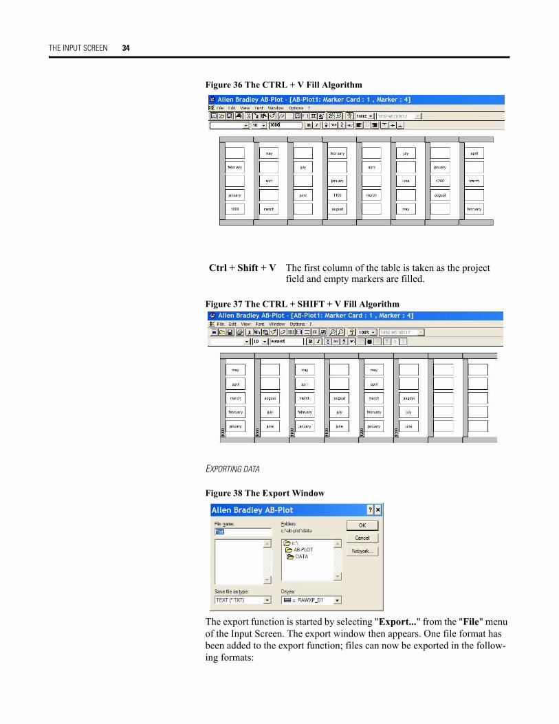
Ctrl + V The copied columns A and B are recognized as marker texts and entered in the sequence: 1996, Jan, space, Feb, space, etc. The data is read from left to right, with returns as well. This corresponds to the normal "Paste" command in the "Edit" menu (see Figure 35).
THE INPUT SCREEN 34
Figure 36 The CTRL + V Fill Algorithm
Figure 37 The CTRL + SHIFT + V Fill Algorithm
EXPORTING DATA
Figure 38 The Export Window
The export function is started by selecting "Export..." from the "File" menu of the Input Screen. The export window then appears. One file format has been added to the export function; files can now be exported in the follow-ing formats:
Ctrl + Shift + V The first column of the table is taken as the project field and empty markers are filled.

THE INPUT SCREEN 35
Text *.txt
In this format, project fields and marker data are exported together. If the data to be exported is stored the program automatically opens another win-dow with the designation "Export".
Note: When exporting from one marker format to a different format the input text is not adjusted to the size of the marker.
TEXT ORIENTATION AND PLOTTER
SPECIAL FEATURES OF PLOTTING AND SCREEN PRESENTATION
Figure 39 Different Ways of Labelling
The definition of the 0° orientation relates to a Marker Card in the ver-tical view with the project field at the top. Successive 90° rotations are all made counterclockwise.
PLOTTERFONT TYPEFACE
The default typeface, Plotterfont, is used for the on-screen presentation. This font is added to the table of Windows fonts upon installing the pro-gram.
PLOTTING 36
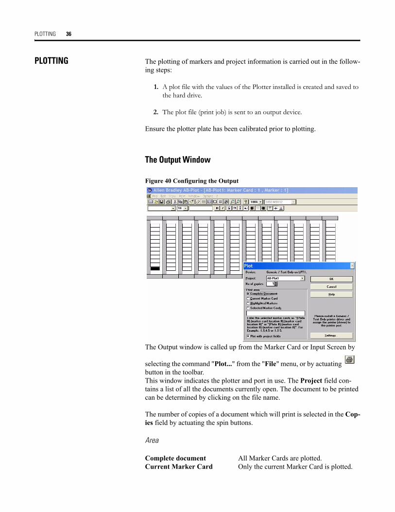
PLOTTING The plotting of markers and project information is carried out in the follow-ing steps:
1. A plot file with the values of the Plotter installed is created and saved to the hard drive.
2. The plot file (print job) is sent to an output device.
Ensure the plotter plate has been calibrated prior to plotting.
The Output Window
Figure 40 Configuring the Output
The Output window is called up from the Marker Card or Input Screen by
selecting the command "Plot..." from the "File" menu, or by actuating button in the toolbar.This window indicates the plotter and port in use. The Project field con-tains a list of all the documents currently open. The document to be printed can be determined by clicking on the file name.
The number of copies of a document which will print is selected in the Cop-ies field by actuating the spin buttons.
Area
Complete document All Marker Cards are plotted.Current Marker Card Only the current Marker Card is plotted.
PLOTTING 37
Highlighted marker Only highlighted markers are plotted.Selected Marker Card Only selected Marker Cards are plotted.
You can configure the parameters of the plotter/printer by actuating the "Settings..." button.
Pressing "OK" starts the plot output; "Cancel" exits the Output window without starting the plot.
PLOTTING
PLOTTER CONNECTION
The plotter is connected to the computer by means of a parallel or USB cable. It is not necessary to set the plotter dipswitches for parallel operation with a 1492-PLTKIT Series E plotter. However, when using the 1492-ABPLOT software with a 1492-PLTKIT Series C or D plotter, the dipswitches must be reset as follows:
Please refer to you plotter handbook for further information regarding the plotter connection.
PLOTTING
The plot job file is sent to the appropriate output device with the help of the generic text driver.
The advantage of this is that plotting takes place in the background under the Windows Print Manager.
DSW1: DSW2:1. Off 1. On
2. Off 2. On
3. Off 3. Off
4. Off 4. On
5. Off 5. On
6. On 6. Off
7. On 7. Off
8. On 8. Off
PLOTTING 38
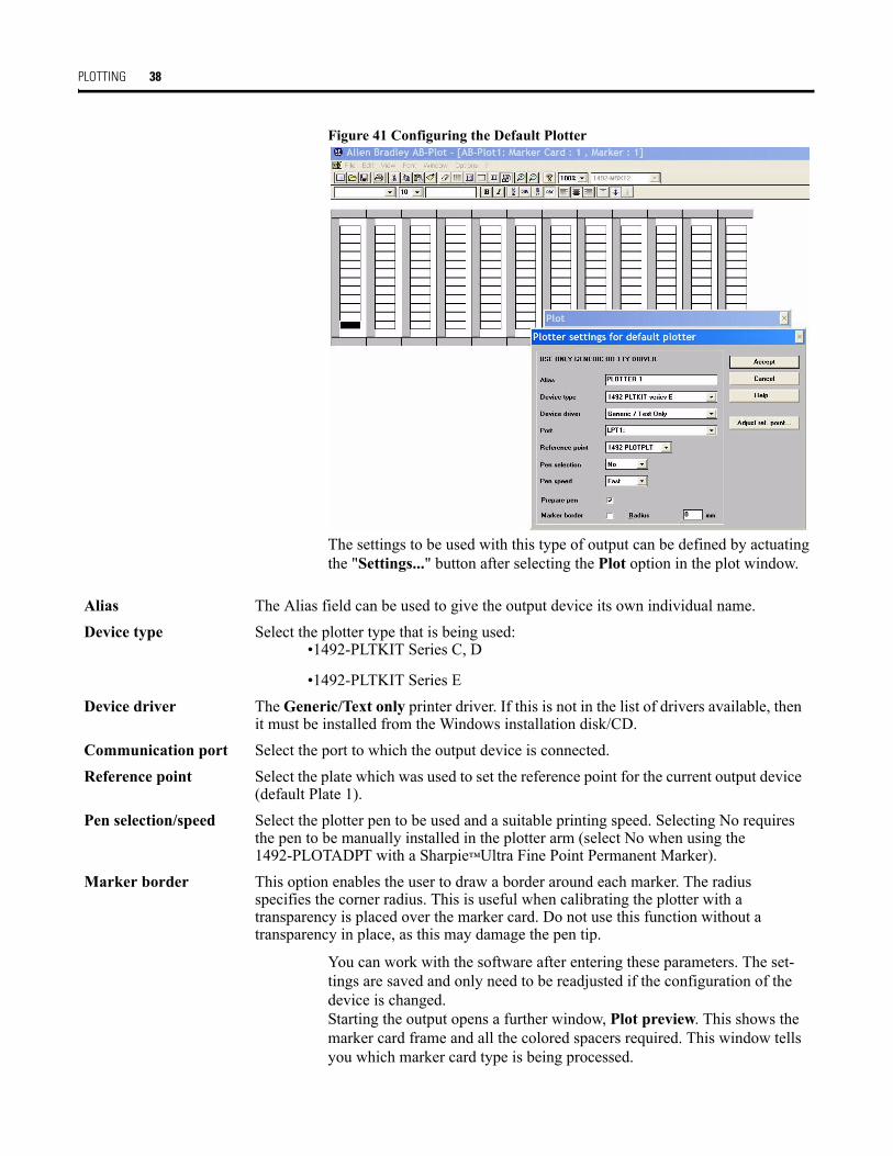
Figure 41 Configuring the Default Plotter
The settings to be used with this type of output can be defined by actuating the "Settings..." button after selecting the Plot option in the plot window.
You can work with the software after entering these parameters. The set-tings are saved and only need to be readjusted if the configuration of the device is changed.Starting the output opens a further window, Plot preview. This shows the marker card frame and all the colored spacers required. This window tells you which marker card type is being processed.
Alias The Alias field can be used to give the output device its own individual name.Device type Select the plotter type that is being used:
•1492-PLTKIT Series C, D
•1492-PLTKIT Series EDevice driver The Generic/Text only printer driver. If this is not in the list of drivers available, then
it must be installed from the Windows installation disk/CD.Communication port Select the port to which the output device is connected.Reference point Select the plate which was used to set the reference point for the current output device
(default Plate 1).Pen selection/speed Select the plotter pen to be used and a suitable printing speed. Selecting No requires
the pen to be manually installed in the plotter arm (select No when using the 1492-PLOTADPT with a Sharpie™Ultra Fine Point Permanent Marker).
Marker border This option enables the user to draw a border around each marker. The radius specifies the corner radius. This is useful when calibrating the plotter with a transparency is placed over the marker card. Do not use this function without a transparency in place, as this may damage the pen tip.

PLOTTING 39
Figure 42 The Plot Preview Window
INFORMATION THE RIGHT MOUSE BUTTON
After highlighting a Marker Card area with the mouse (left button), pressing the right button opens a pop-up menu containing the most important func-tions (Autofill, Cut, Copy, Paste, Multiple paste, Insert copied markers, Delete, Insert cells, Delete cells, Import, Plot) used in the Input Screen. Apart from the functions Import and Plot, all commands apply to the marked area.
EDITING BLOCKS
AB-Plot enables individual markers to be marked conveniently. This is done by positioning the cursor on the first marker of an area to be high-lighted, pressing and holding the left mouse button, pulling the cursor to the last marker and then releasing the button. The grouping of markers is now highlighted. Many commands from the "Edit" menu and most of the func-tions of the icon bars can be applied to the highlighted area. This allows the user to quickly delete, copy, cut, shift or write (using the Autofill function) on a group of markers.

PLOTTING 40
SUPPORT AND UPDATES
Information service
You can access information about software and product updates by visiting our website at:http://www.ab.com/industrialcontrols/productsOur website contains information about products and allows you to down-load updates and other information.
Telephone hotline for users
If you have any questions regarding our products, then please contact:Tel: 440-646-5800E-mail: [email protected]
SYMBOLS
The software includes the ability to plot these special symbols:Figure 43 Symbols
These special characters can be called up via the "Electrical symbols..." function in the "Options" menu of the Input Screen. A dummy character appears in the input field. Note that resolution of the symbols depends upon font size.LIST OF SHORTCUTS AND FUNCTION KEYS
Function Shortcut, Function Key Availability
New Ctrl + N Program Screen, Marker Card ScreenOpen Ctrl + O Program Screen, Marker Card ScreenSave Ctrl + S Marker Card Screen, Input ScreenImport Ctrl + I Input ScreenExport Ctrl + E Input Screen
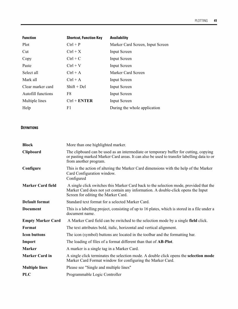
PLOTTING 41
DEFINITIONS
Plot Ctrl + P Marker Card Screen, Input ScreenCut Ctrl + X Input ScreenCopy Ctrl + C Input ScreenPaste Ctrl + V Input ScreenSelect all Ctrl + A Marker Card ScreenMark all Ctrl + A Input ScreenClear marker card Shift + Del Input ScreenAutofill functions F8 Input ScreenMultiple lines Ctrl + ENTER Input ScreenHelp F1 During the whole application
Function Shortcut, Function Key Availability
Block More than one highlighted marker.Clipboard The clipboard can be used as an intermediate or temporary buffer for cutting, copying
or pasting marked Marker Card areas. It can also be used to transfer labelling data to or from another program.
Configure This is the action of altering the Marker Card dimensions with the help of the Marker Card Configuration window.Configured
Marker Card field A single click switches this Marker Card back to the selection mode, provided that the Marker Card does not yet contain any information. A double-click opens the Input Screen for editing the Marker Card.
Default format Standard text format for a selected Marker Card.Document This is a labelling project, consisting of up to 16 plates, which is stored in a file under a
document name.Empty Marker Card A Marker Card field can be switched to the selection mode by a single field click.Format The text attributes bold, italic, horizontal and vertical alignment.Icon buttons The icon (symbol) buttons are located in the toolbar and the formatting bar.Import The loading of files of a format different than that of AB-Plot.Marker A marker is a single tag in a Marker Card.Marker Card in A single click terminates the selection mode. A double click opens the selection mode
Marker Card Format window for configuring the Marker Card.Multiple lines Please see "Single and multiple lines"PLC Programmable Logic Controller
THE GRAPHAB.GDM CONFIGURATION FILE
All the Marker Card dimensions and supplementary information relevant to the program are stored in the configuration file GRAPHAB.GDM. This file is in ASCII form and can be edited with any word processing program. As some dimensions cannot be adjusted with the Configu-ration Editor, you have the option of modifying the Marker Card configuration file
Pop-up menu A menu which appears within the application window by actuating the right mouse button.
Project field This is the outside rim (sprue) of a Marker Card which the individual markers are attached to. Additional information may be written here which helps to allocate the markers in the field afterwards. Note that some markers (1492-MR5X12, MR6X12, MR8X12, etc.) cannot have their project fields plotted upon. Verify that project field is available on the marker card before attempting to print on it. In some cases, more proejct fields are shown for the software than are on the marker card.
Rapid Clicking on this field switches all Marker Card fields to the Selection configuration mode and opens the Marker Card Format window.
Scroll bars The scroll bars are used to move the Marker Card around the screen. Scroll buttons The scroll buttons have different functions in the Marker Card and Input Screens.
Corresponding explanations can be found in The Input Screen.Shortcut Shortcut designates a key combination, mainly consisting of "Ctrl" and a letter. These
enable the user to execute program commands quickly with the help of the keyboard (see section 5.5 List of shortcuts and function keys).
Single and multiple lines
Multiple line mode is set as default.If the single line mode has been selected, then the text which appears on the marker includes no line returns. In the multiple line mode, a line return is generated by pressing Ctrl + ENTER.Note: A text in multiple line mode can be converted to single line mode but the returns are lost in doing so.
Status bar The status bar is located at the bottom edge of the screen. It shows program informa-tion during the application. For instance, you can have the functions of the icon buttons displayed without having to execute the command. To do this, click on an icon button and hold down the left mouse button. The function of that button is now displayed in the status bar. Pulling the mouse pointer clear of the button before releasing the left mouse button will ensure that the function is not executed.
Toolbar Symbol (icon) bar: a collection of icon buttons located along the top of the screen.
Publication 1492-UM007A-EN-P - October 2006 Copyright ©2006 Rockwell Automation, Inc. All Rights Reserved. Printed in USA.
PLOTTING 43
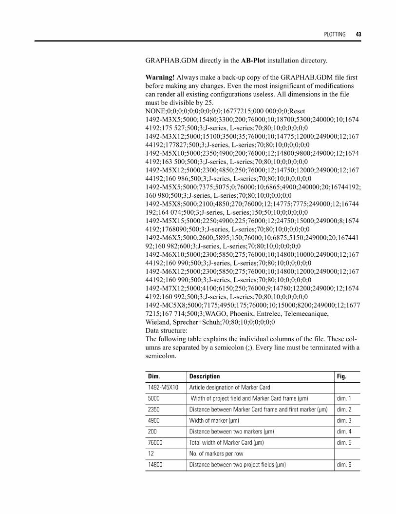
GRAPHAB.GDM directly in the AB-Plot installation directory.
Warning! Always make a back-up copy of the GRAPHAB.GDM file first before making any changes. Even the most insignificant of modifications can render all existing configurations useless. All dimensions in the file must be divisible by 25.NONE;0;0;0;0;0;0;0;0;0;0;16777215;000 000;0;0;Reset1492-M3X5;5000;15480;3300;200;76000;10;18700;5300;240000;10;16744192;175 527;500;3;J-series, L-series;70;80;10;0;0;0;0;01492-M3X12;5000;15100;3500;35;76000;10;14775;12000;249000;12;16744192;177827;500;3;J-series, L-series;70;80;10;0;0;0;0;01492-M5X10;5000;2350;4900;200;76000;12;14800;9800;249000;12;16744192;163 500;500;3;J-series, L-series;70;80;10;0;0;0;0;01492-M5X12;5000;2300;4850;250;76000;12;14750;12000;249000;12;16744192;160 986;500;3;J-series, L-series;70;80;10;0;0;0;0;01492-M5X5;5000;7375;5075;0;76000;10;6865;4900;240000;20;16744192;160 980;500;3;J-series, L-series;70;80;10;0;0;0;0;01492-M5X8;5000;2100;4850;270;76000;12;14775;7775;249000;12;16744192;164 074;500;3;J-series, L-series;150;50;10;0;0;0;0;01492-M5X15;5000;2250;4900;225;76000;12;24750;15000;249000;8;16744192;1768090;500;3;J-series, L-series;70;80;10;0;0;0;0;01492-M6X5;5000;2600;5895;150;76000;10;6875;5150;249000;20;16744192;160 982;600;3;J-series, L-series;70;80;10;0;0;0;0;01492-M6X10;5000;2300;5850;275;76000;10;14800;10000;249000;12;16744192;160 990;500;3;J-series, L-series;70;80;10;0;0;0;0;01492-M6X12;5000;2300;5850;275;76000;10;14800;12000;249000;12;16744192;160 990;500;3;J-series, L-series;70;80;10;0;0;0;0;01492-M7X12;5000;4100;6150;250;76000;9;14780;12200;249000;12;16744192;160 992;500;3;J-series, L-series;70;80;10;0;0;0;0;01492-MC5X8;5000;7175;4950;175;76000;10;15000;8200;249000;12;16777215;167 714;500;3;WAGO, Phoenix, Entrelec, Telemecanique,Wieland, Sprecher+Schuh;70;80;10;0;0;0;0;0Data structure:The following table explains the individual columns of the file. These col-umns are separated by a semicolon (;). Every line must be terminated with a semicolon.
Dim. Description Fig.
1492-M5X10 Article designation of Marker Card
5000 Width of project field and Marker Card frame (µm) dim. 1
2350 Distance between Marker Card frame and first marker (µm) dim. 2
4900 Width of marker (µm) dim. 3
200 Distance between two markers (µm) dim. 4
76000 Total width of Marker Card (µm) dim. 5
12 No. of markers per row
14800 Distance between two project fields (µm) dim. 6
PLOTTING 44
THE ABPRINT.INI INITIALIZATION FILE
The initialization file contains information which is necessary for the cor-rect running of the program. Most of the parameters are automatically updated by the settings in AB-Print.The following parameters can be only adjusted in the initialization file. To do this, open the file with the help of a text editor (e.g. MS Notepad, note-pad.exe).When you open, save, print, etc., data from various directories is used. You can adjust the path details by means of the following parameters:
9800 Length of marker (µm) dim. 7
249000 Total length of Marker Card (µm) dim. 8
12 No. of rows per Marker Card
16744192 Decimal value of a color. This is identical with the color of the underlay which is to be used when plotting. This decimal value is calculated from the color proportions of the primary colours (red/green/blue).
163 500 Article code for marker type
500 Y-offset from reference point. Height difference to set reference point. A negative value shifts the reference point upwards, a positive value shifts it downwards.
3 Marker type:1 = Wire marker2 = Device marker3 = Terminal marker
... Remarks (e.g. plug-in marker for transparent sleeve)
Align project fields in X-direction
Align project fields in Y-direction
Specify font size for project fields (in points)
Specify font size for markers (in points)
Specify text orientation for Marker Card labelling(0 =0°, 900 = 90°, 1800 = 180°, 2700 = 270°)
Dim. Description Fig.
[PATH] Path details of files required
HELP=C:\ABPRINT\ Path of AB-Print help fileSPOOLER=C:\ABPRINT\ Path for temporary file storeSFT=C:\ABPRINT\ASCII.SFT Path of ANSI/ASCII allocation fileSYMBOLS=C:\ABPRINT\ETSIGN.SYM Path of electrical symbols fileGRAPHGDI=C:\ABPRINT\GRAPH.GDI Path of initialization file

PLOTTING 45
It is possible to modify the pre set separating character for file import from text files under the Terminator heading.[TERMINATOR] Separating character for file importDATA=, Terminator for marker dataPROJECT=; Terminator for project fields
The Standard file type (e.g. *.txt) can be adjusted under the Import heading.[IMPORT]. DEFAULTEXT=txt File type
GRAPHGDM=C:\ABPRINT\GRAPHAB.GDM Path of Marker Card configuration fileSAVEDIR=C:\ABPRINT\DATA\ Standard directory for Save as...OPENDIR=C:\ABPRINT\DATA\ Standard directory for Open...IMPORTDIR=C:\ABPRINT\DATA\ Standard directory for Import...EXPORTDIR=C:\ABPRINT\DATA\ Standard directory for Export...
[PATH] Path details of files required

Publication 1492-UM007A-EN-P - October 2006 Copyright ©2006 Rockwell Automation, Inc. All Rights Reserved. Printed in USA.