AAVP Workshop December 2010 SKA 1 AA-low design. AAVP Workshop December 2010 SKA 1 AA-low design SKA...
16
AAVP Workshop December 2010 SKA 1 AA-low design SKA 1 AA-low system design considerations Andrew Faulkner
-
date post
19-Dec-2015 -
Category
Documents
-
view
215 -
download
0
Transcript of AAVP Workshop December 2010 SKA 1 AA-low design. AAVP Workshop December 2010 SKA 1 AA-low design SKA...
AAVP WorkshopDecember 2010 SKA1 AA-low design
SKA1 AA-low system design
considerations
Andrew Faulkner

AAVP WorkshopDecember 2010 SKA1 AA-low design
SKA1 AA-low is a major System:
>10x LOFAR sensitivity
>1 km2 collecting area
>6:1 frequency range 70 – 450MHz
~50 deg2 Field of View
Very quiet site
Required in SKA Memo 125
AAVP WorkshopDecember 2010 SKA1 AA-low design
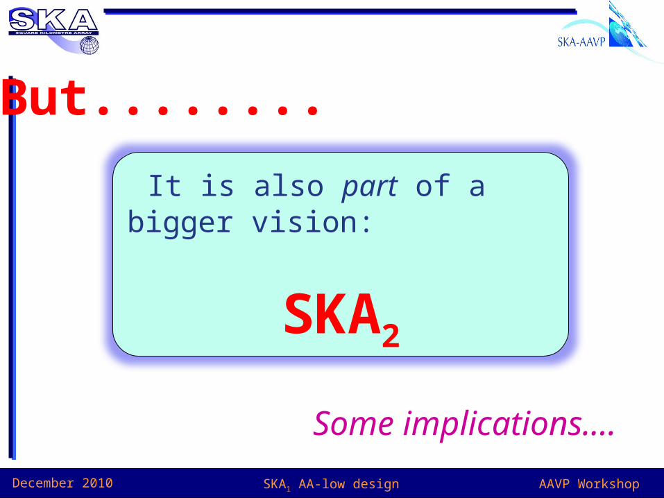
But........
It is also part of a bigger vision:
SKA2
Some implications....
AAVP WorkshopDecember 2010 SKA1 AA-low design
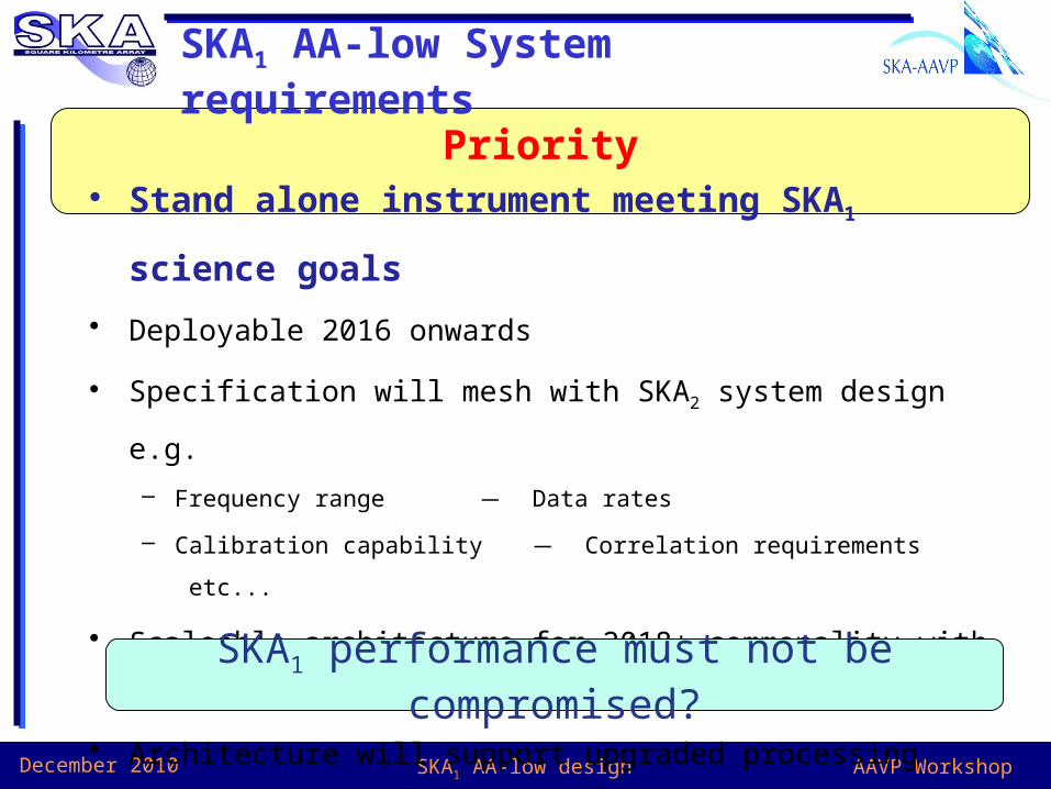
Priority
SKA1 AA-low System requirements
• Stand alone instrument meeting SKA1 science goals
• Deployable 2016 onwards
• Specification will mesh with SKA2 system design e.g.
– Frequency range ̶ Data rates
– Calibration capability ̶ Correlation requirements etc...
• Scaleable architecture for 2018+ commonality with AA-mid
• Architecture will support upgraded processing devices
– Phase 2 expansion ̶ Retro-fit Phase 1 (if good pay-back)
SKA1 performance must not be compromised?
AAVP WorkshopDecember 2010 SKA1 AA-low design
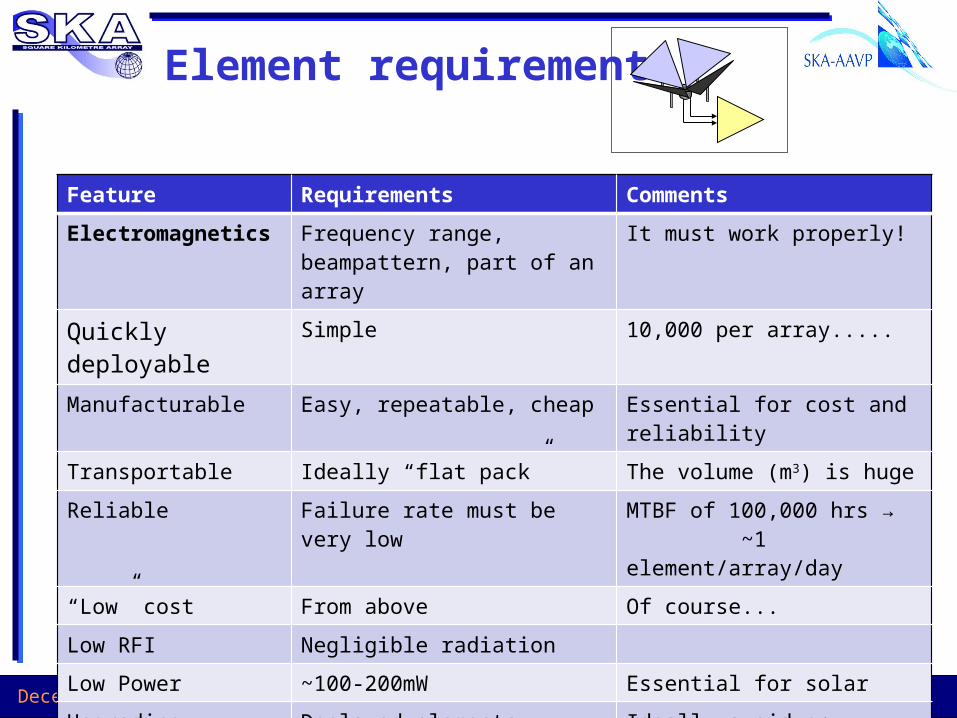
Element requirements
Feature Requirements Comments
Electromagnetics Frequency range, beampattern, part of an array
It must work properly!
Quickly deployable Simple 10,000 per array.....
Manufacturable Easy, repeatable, cheap Essential for cost and reliability
Transportable Ideally “flat pack” The volume (m3) is huge
Reliable Failure rate must be very low MTBF of 100,000 hrs → ~1 element/array/day
“Low” cost From above Of course...
Low RFI Negligible radiation
Low Power ~100-200mW Essential for solar
Upgrading Deployed elements cannot be upgradedAdditions functionally equivalent
Ideally avoid any modifications
AAVP WorkshopDecember 2010 SKA1 AA-low design
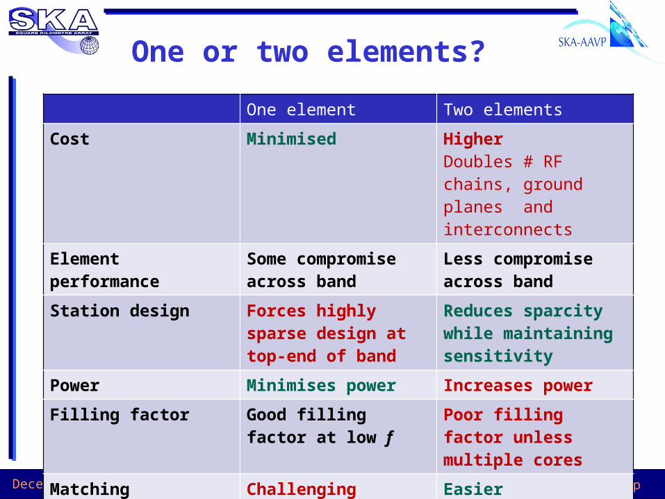
One or two elements?
One element Two elements
Cost Minimised HigherDoubles # RF chains, ground planes and interconnects
Element performance Some compromise across band
Less compromise across band
Station design Forces highly sparse design at top-end of band
Reduces sparcity while maintaining sensitivity
Power Minimises power Increases power
Filling factor Good filling factor at low f
Poor filling factor unless multiple cores
Matching Challenging Easier

AAVP WorkshopDecember 2010 SKA1 AA-low design
LWA element: mechanical example
Simple “skeleton” elements (delivered flat)
Cheap mesh groundplane
Single pole fixing – just sunk into ground
Electronics at top – well away from floods etc.
Clamp type rotational adjustment
Easy and quick deployment
Buried cables
AAVP WorkshopDecember 2010 SKA1 AA-low design
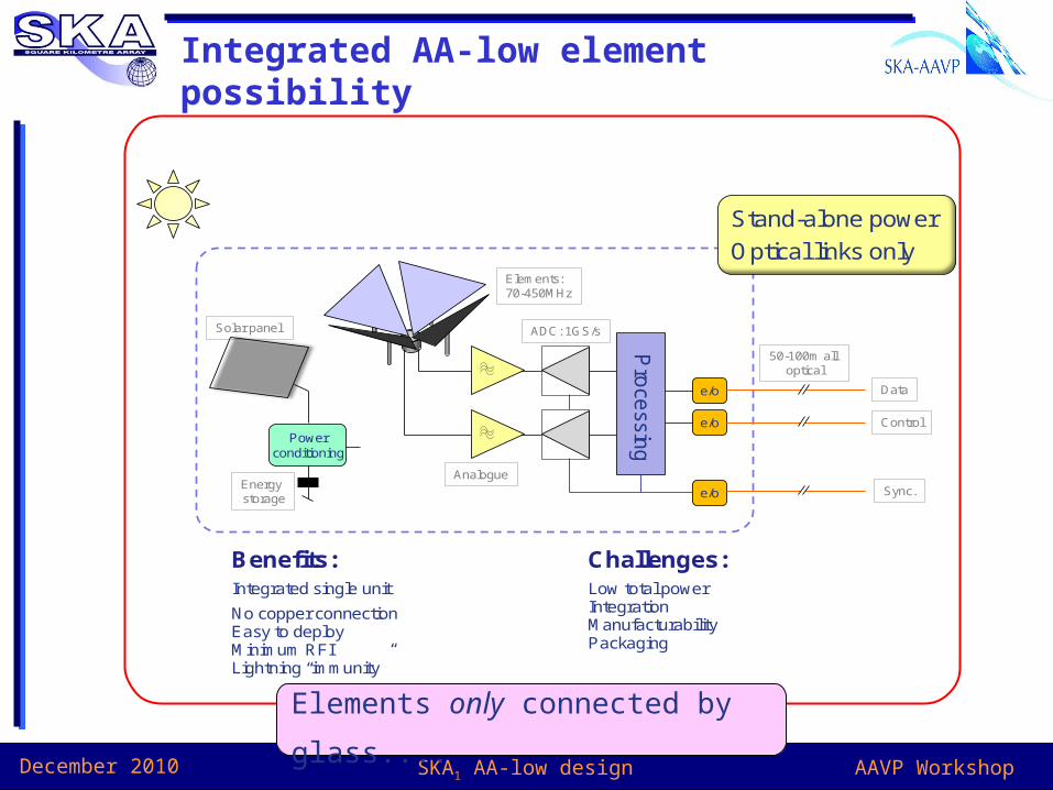
Integrated AA-low element possibility
Pro
cessin
ge/o
e/o
e/oPower
conditioning
Solar panel
Energy storage
Elements:70-450MHz
Analogue
ADC: 1GS/s
Data
Control
Sync.
50-100m all optical
Benefits:Integrated single unit
No copper connectionEasy to deployMinimum RFILightning “immunity”
Challenges:Low total powerIntegration ManufacturabilityPackaging
Stand-alone power
Optical links only
Elements only connected by glass....
AAVP WorkshopDecember 2010 SKA1 AA-low design
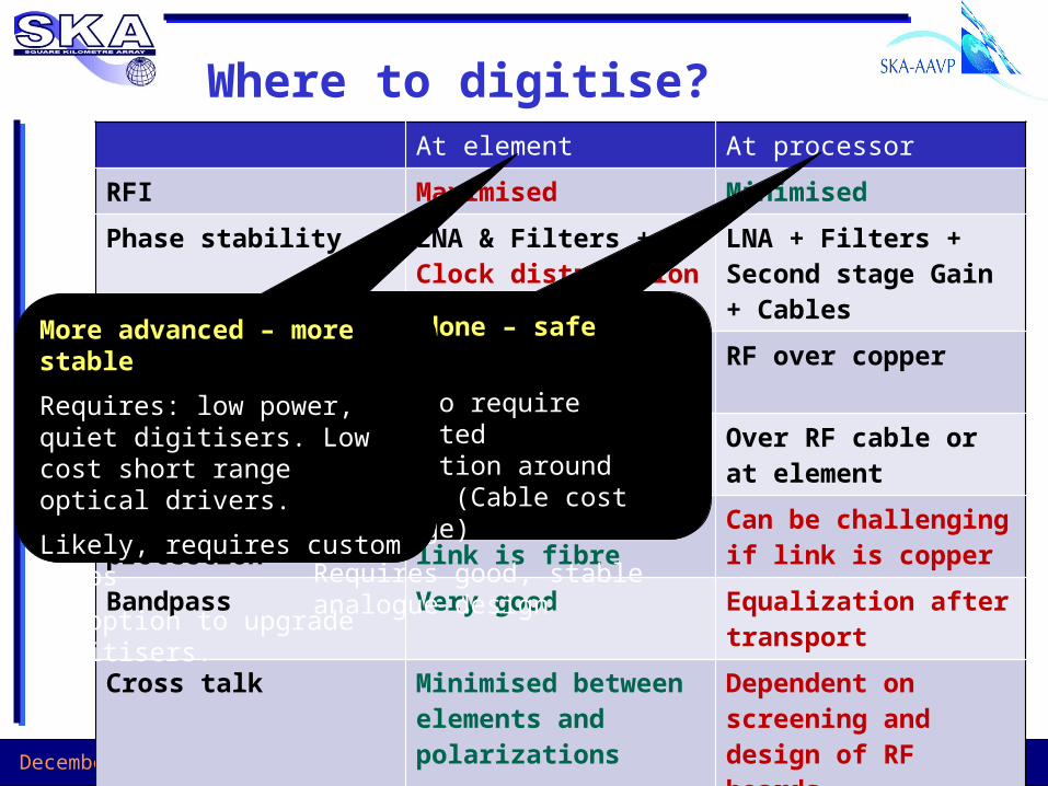
Where to digitise?At element At processor
RFI Maximised Minimised
Phase stability LNA & Filters +Clock distribution
LNA + Filters + Second stage Gain + Cables
Data transport Digital possibly over fibre
RF over copper
Power At element or over copper
Over RF cable or at element
Lightning protection Can be good if link is fibre
Can be challenging if link is copper
Bandpass Very good Equalization after transport
Cross talk Minimised between elements and polarizations
Dependent on screening and design of RF boards
Can be done – safe option
Likely to require distributed digitisation around station. (Cable cost and range)
Requires good, stable analogue design
More advanced – more stable
Requires: low power, quiet digitisers. Low cost short range optical drivers.
Likely, requires custom chips
No option to upgrade digitisers.

AAVP WorkshopDecember 2010 SKA1 AA-low design
Tile Digitisation
Tile Digitisation
Element
Digitisation
RFI Shielded
......
......
......
...
Power Distribution
Element Digitisation
...
Cooling
Element Digitisation
......
Station Processing
RFI shielded
System clock
Control &Monitoring
StationBeams
PowerGrid
Element Data
C & M
Clock
To Correlator
& Services
2x 500MHzAnalogue+ power
FibreCopper
2-PolElements
Front-end
Potential AA-low station:Safe solution:
Single element
Analog to clustered digitisation
Centrally powered elements

AAVP WorkshopDecember 2010 SKA1 AA-low design
Station processor
PrimaryStation
ProcessorBoard
0
…..
PrimaryStation
ProcessorBoard
1
…..
PrimaryStation
ProcessorBoard
(max 35)
…..
…..
SecondaryStation
ProcessorBoard
0
SecondaryStation
ProcessorBoard
1
SecondaryStation
ProcessorBoard
(max 35)
…..
…..
…..
…..
…..
…..
…..
012
35
ToElement
Digitisation
Long distance drivers
…..
0
1
2
Long distance drivers
…..
Long distance drivers
…..
Optical linksTo Correlator
Each link is 12 fibre lanes@10Gb/s
“All to All”Connections
Each link is 12 fibre lanes@10Gb/s
…..
…..
…..
Station Processor
o/eo/eo/eo/eo/eo/e
o/eo/eo/eo/eo/eo/e
o/eo/eo/eo/eo/eo/e
o/eo/eo/eo/eo/eo/e
o/eo/eo/eo/eo/eo/e
o/eo/eo/eo/eo/eo/e
e/oe/oe/oe/oe/oe/o
e/oe/oe/oe/oe/oe/o
e/oe/oe/oe/oe/oe/o
e/oe/oe/oe/oe/oe/o
e/oe/oe/oe/oe/oe/o
e/oe/oe/oe/oe/oe/o
PChip
PChip
PChip
PChip
PChip
PChip
PChip
PChip
PChip
PChip
PChip
PChip
0
1
2
3
4
5
30
31
32
33
34
35
Each link is 12 fibre lanes@10Gb/s
To Element digitisationor Primary
Station Processors
To Secondary Station Processors or long distance fibre drivers
Each link is 12 fibre lanes@10Gb/s
Each link is 12 diff. copper lanes@10Gb/s
12-channel Rx module. e.g Avago
AFBR-820BXXZ
12-channel Tx module. e.g Avago AFBR-810BXXZ
Total Raw input data rate: 4.32Tb/s
Total Raw output data rate: 4.32Tb/s max
“All to All”Connections
ControlProcessor
Lin
eT
x/Rx
Station Control
Requirements:• High bandwidth in • High bandwidth out• Largely cross connected• Scaleable at various levels• Programmable beamforming
AAVP WorkshopDecember 2010 SKA1 AA-low design
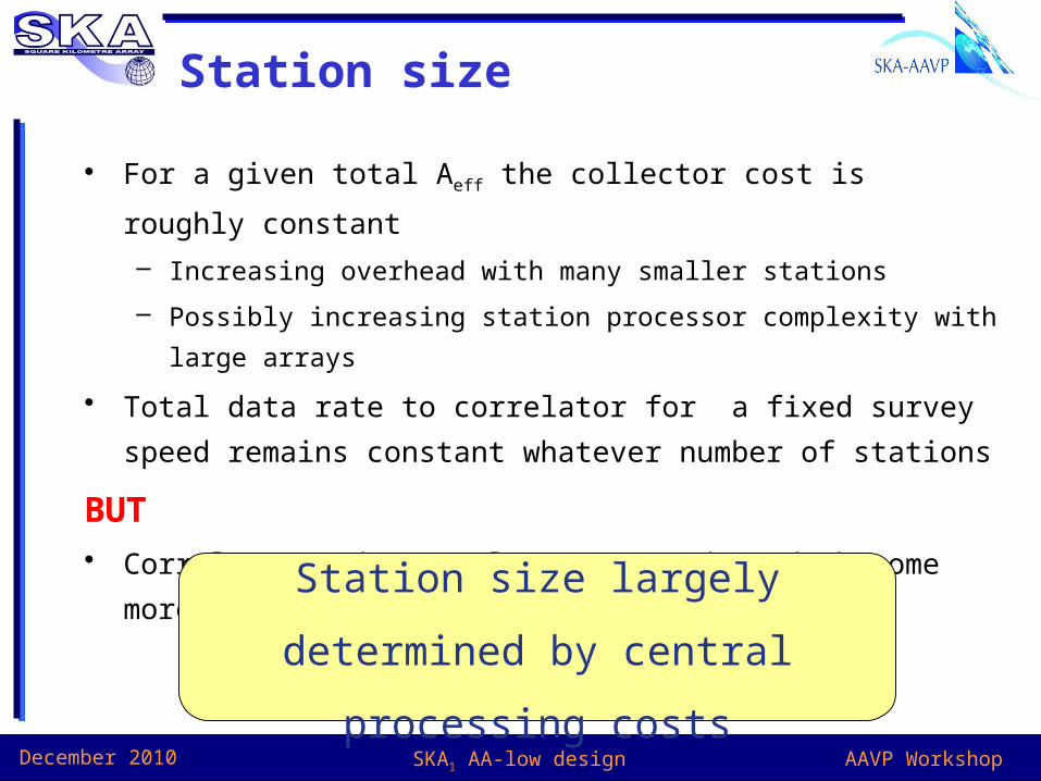
Station size
• For a given total Aeff the collector cost is roughly constant
– Increasing overhead with many smaller stations
– Possibly increasing station processor complexity with large arrays
• Total data rate to correlator for a fixed survey speed remains
constant whatever number of stations
BUT• Correlator and central processor demands become more
challenging
Station size largely determined by
central processing costs
AAVP WorkshopDecember 2010 SKA1 AA-low design
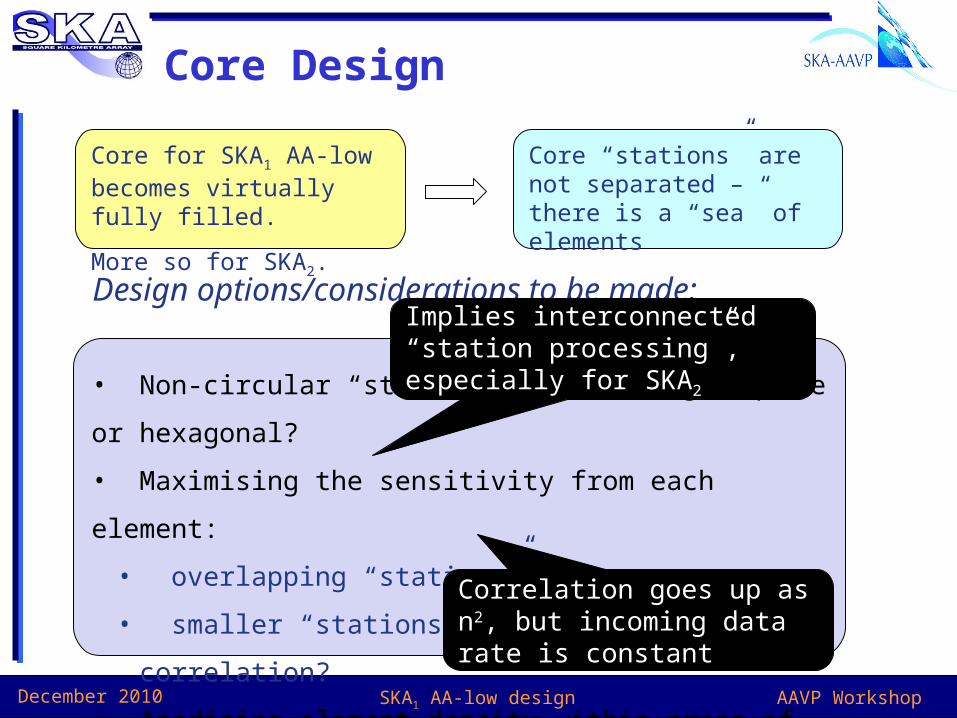
Core Design
Core for SKA1 AA-low becomes virtually fully filled.
More so for SKA2.
Core “stations” are not separated – there is a “sea” of elements
Design options/considerations to be made:
• Non-circular “stations” easier? e.g. Square or hexagonal?
• Maximising the sensitivity from each element:
• overlapping “stations”?
• smaller “stations” (how small) with more correlation?
• Apodising element density within areas of the core:
• Benefit? Save money?
Implies interconnected “station processing”, especially for SKA2
Correlation goes up as n2, but incoming data rate is constant
AAVP WorkshopDecember 2010 SKA1 AA-low design
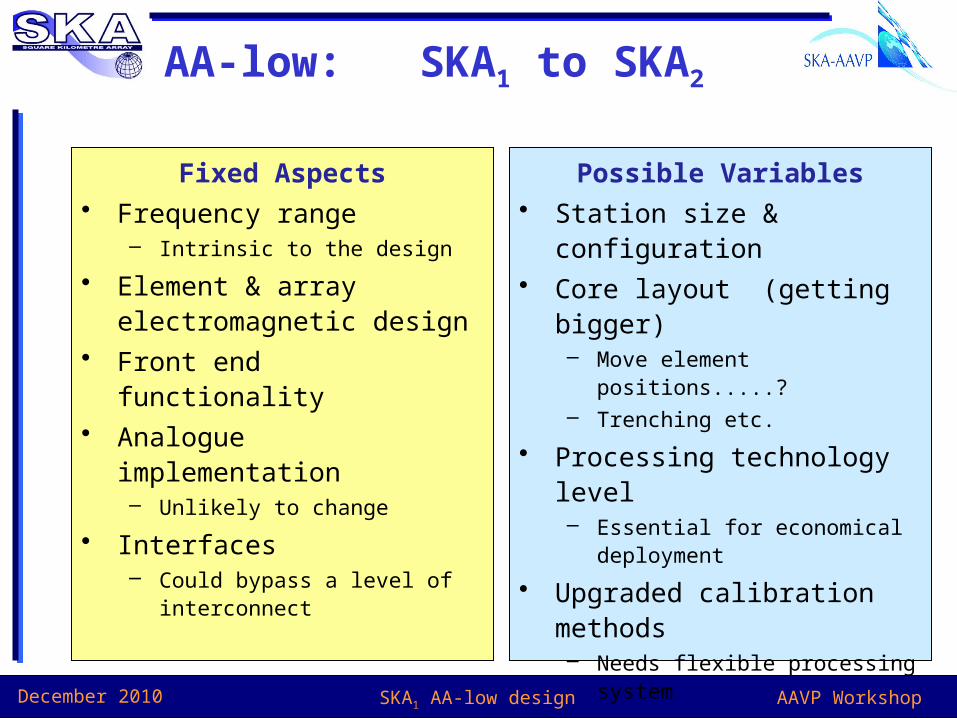
AA-low: SKA1 to SKA2
Fixed Aspects• Frequency range
– Intrinsic to the design
• Element & array electromagnetic design
• Front end functionality• Analogue implementation
– Unlikely to change
• Interfaces– Could bypass a level of
interconnect
Possible Variables• Station size & configuration• Core layout (getting bigger)
– Move element positions.....?– Trenching etc.
• Processing technology level– Essential for economical
deployment
• Upgraded calibration methods– Needs flexible processing system

AAVP WorkshopDecember 2010 SKA1 AA-low design
..
Sparse AA
Dense AA
..
Central Processing Facility - CPF
User interfacevia Internet
...
To 250 AA Stations
DSP
...
DSP
To 1200 Dishes
...15m Dishes
16 Tb/s
10 Gb/s
Data
Time
Control
70-450 MHzWide FoV
0.4-1.4 GHzWide FoV
1.2-10 GHzWB-Single Pixel feeds
Tile &Station
Processing
OpticalData links
... AA slice
... AA slice
... AA slice
...D
ish & AA+D
ish Correlation
ProcessorBuffer
ProcessorBuffer
ProcessorBuffer
ProcessorBuffer
ProcessorBuffer
ProcessorBuffer
ProcessorBuffer
ProcessorBuffer
ProcessorBuffer
ProcessorBuffer
ProcessorBuffer
ProcessorBuffer
ProcessorBuffer
ProcessorBuffer
ProcessorBuffer
ProcessorBuffer
ProcessorBuffer
ProcessorBuffer
ProcessorBuffer
ProcessorBuffer
ProcessorBuffer
ProcessorBuffer
Data sw
itch ......Data
Archive
ScienceProcessors
Tb/s Gb/s Gb/s
...
...
TimeStandard
Imaging P
rocessors
Control Processors & User interface
Pb/s
Correlator UV Processors Image formation Archive
Aperture Array Station
SKA2 System
A reminder for AA-mid!
A tremendous step forward in SKA2
There must be ongoing development:
which will also benefit AA-low
AAVP WorkshopDecember 2010 SKA1 AA-low design
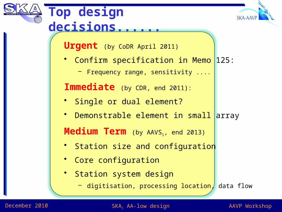
Top design decisions......
Urgent (by CoDR April 2011)
• Confirm specification in Memo 125:– Frequency range, sensitivity ....
Immediate (by CDR, end 2011):
• Single or dual element?
• Demonstrable element in small array
Medium Term (by AAVS1, end 2013)
• Station size and configuration
• Core configuration
• Station system design – digitisation, processing location, data flow