Aalborg Universitet Moulding technology based ferrite ... · MOULDING TECHNOLOGY BASED FERRITE...
186
Aalborg Universitet Moulding technology based ferrite assisted synchronous reluctance machine Wu, Qian DOI (link to publication from Publisher): 10.5278/VBN.PHD.ENG.00037 Publication date: 2018 Document Version Publisher's PDF, also known as Version of record Link to publication from Aalborg University Citation for published version (APA): Wu, Q. (2018). Moulding technology based ferrite assisted synchronous reluctance machine. Aalborg Universitetsforlag. Ph.d.-serien for Det Ingeniør- og Naturvidenskabelige Fakultet, Aalborg Universitet https://doi.org/10.5278/VBN.PHD.ENG.00037 General rights Copyright and moral rights for the publications made accessible in the public portal are retained by the authors and/or other copyright owners and it is a condition of accessing publications that users recognise and abide by the legal requirements associated with these rights. ? Users may download and print one copy of any publication from the public portal for the purpose of private study or research. ? You may not further distribute the material or use it for any profit-making activity or commercial gain ? You may freely distribute the URL identifying the publication in the public portal ? Take down policy If you believe that this document breaches copyright please contact us at [email protected] providing details, and we will remove access to the work immediately and investigate your claim. Downloaded from vbn.aau.dk on: May 20, 2020
Transcript of Aalborg Universitet Moulding technology based ferrite ... · MOULDING TECHNOLOGY BASED FERRITE...
Aalborg Universitet
Moulding technology based ferrite assisted synchronous reluctance machine
Wu, Qian
DOI (link to publication from Publisher):10.5278/VBN.PHD.ENG.00037
Publication date:2018
Document VersionPublisher's PDF, also known as Version of record
Link to publication from Aalborg University
Citation for published version (APA):Wu, Q. (2018). Moulding technology based ferrite assisted synchronous reluctance machine. AalborgUniversitetsforlag. Ph.d.-serien for Det Ingeniør- og Naturvidenskabelige Fakultet, Aalborg Universitethttps://doi.org/10.5278/VBN.PHD.ENG.00037
General rightsCopyright and moral rights for the publications made accessible in the public portal are retained by the authors and/or other copyright ownersand it is a condition of accessing publications that users recognise and abide by the legal requirements associated with these rights.
? Users may download and print one copy of any publication from the public portal for the purpose of private study or research. ? You may not further distribute the material or use it for any profit-making activity or commercial gain ? You may freely distribute the URL identifying the publication in the public portal ?
Take down policyIf you believe that this document breaches copyright please contact us at [email protected] providing details, and we will remove access tothe work immediately and investigate your claim.
Downloaded from vbn.aau.dk on: May 20, 2020


QIA
N W
UM
OU
LDIN
G TEC
HN
OLO
GY B
ASED
FERR
ITE ASSITED
SYNC
HR
ON
OU
S RELU
CTA
NC
E MA
CH
INE
MOULDING TECHNOLOGY BASEDFERRITE ASSITED SYNCHRONOUS
RELUCTANCE MACHINE
BYQIAN WU
DISSERTATION SUBMITTED 2018


MOULDING TECHNOLOGY BASED
FERRITE ASSITED SYNCHRONOUS
RELUCTANCE MACHINE
by
Qian Wu
Dissertation submitted
.

Dissertation submitted: February 2018
PhD supervisor: Associate Prof. Kaiyuan Lu Aalborg University
Assistant PhD supervisors: Associate Prof. Peter Omand Rasmussen Aalborg University
Chief Engineer Keld Folsach Rasmussen Grundfos A/S
PhD committee: Erik Schaltz (Chairman) Aalborg University
Yujing Liu Chalmers University of Technology
Gianmario Pellegrino Politecnico di Torino
PhD Series: Faculty of Engineering and Science, Aalborg University
Department: Department of Energy Technology
ISSN (online): 2446-1636 ISBN (online): 978-87-7210-157-6
Published byAalborg University PressLangagervej 2 • DK – 9220 Aalborg ØPhone: +45 99407140 • [email protected] • forlag.aau.dk
© Copyright: Qian Wu
Printed in Denmark by Rosendahls, 2018
List of papers[1] Q. Wu, K. Lu, P. O. Rasmussen and K. F. Rasmussen, "A new application and experimental validation of moulding technology for ferrite magnet assisted syn- chronous reluctance machine," 2016 IEEE Energy Conversion Congress and Exposition (ECCE), Milwaukee, WI, 2016, pp. 1-8.
[2] Q.Wu,K.Lu,P.O.Rasmussen,N.BianchiandK.F.Rasmussen,"Unifiedequi- valentMMFconceptfortorqueanalysisofACmachines,"2017IEEEInternational Electric Machines and Drives Conference (IEMDC), Miami, FL, 2017, pp. 1-8.
Award2017 First Prize Paper Award for the paper of “A new application and experimental validation of moulding technology for ferrite magnet assisted synchronous reluctance machine” in the IEEE Industry Application Society.

3
CV
Qian Wu
Experience
05/2014-09/2014 research assistance Current transformer design, Aalborg University.
09/2016-12/2016 Visiting researcher Investigation of AC motor torque performance, Padua University
10/2017-12/2017 Intern Prototype test, Grundfos A/S
Education
10/2014-05/2018 Ph.D on electrical motor design Aalborg University, Denmark Supervisor: Kaiyuan Lu
09/2011-07/2013 M.Sc on electrical Engineering Harbin Institute of Technology, China Supervisor: Jibin Zou
09/2007-07/2011 B.Sc on electrical engineering Harbin Institute of Technology, China


5
ENGLISH SUMMARY
Synchronous Reluctance Machine (SynRM) is a promising candidate in various industrial applications due to the advantages of competitive torque performance, low cost, simple manufacturing process and robust structure. For further improving torque production capability, the strategy of adding ferrite magnets to the rotor side of SynRM is generally recommended, leading to the machine type of Ferrite Assisted SynRM (FASynRM). The research work in this dissertation is dedicated to the design of a FASynRM based on moulding technology, taking an existing Induction Machine (IM) commercial product as a reference.
For the installation of ferrite magnet in FASynRM rotor, specific manufacturing process is required. According to the existing studies, the ferrite magnets are firstly shaped into the pieces fitting the flux barrier shape and then are inserted into each individual flux barrier one by one. Such ferrite shaping and inserting process are complicated and time consuming. In addition, the ferrite magnet pieces are generally in regular shape, like rectangular bar, for low processing cost, thus to some certain extend limiting the design flexibility of the flux barriers. An alternative ferrite installation method based on moulding technology is proposed in research, which removes all the problems associated to the most commonly utilized ferrite insertion method. Moulding technology based FASynRM prototypes are manufactured and tested, which fully validate the feasibility of the application of moulding technology for the ferrite installation of FASynRM.
There are various electric machine types being utilized in the industrial applications. For achieving an appropriate selection of an electric machine for a specific application, deep understanding of all the possible machine candidates with respect to the performance characteristics and the operation principle is highly desired. An easy and intuitive method for comparing the performance of different machine candidates in a general way could bring great convenience to the machine type selection. Torque performance is one of the key factors that measure the performance of an electric machine. In this dissertation, a torque expression is derived based on the principle of Lorenz force, which unifies the torque production mechanism of different AC machine types. Based on such a unified torque expression, a comparative study of the torque production capability is performed among the PM surface mounted machine, IM and SynRM.
Excellent torque performance is always one of the main objects of the design of an electric machine. For FASynRM, the reluctance torque component takes the predominant proportion of the torque production, which is highly dependent on the rotor saliency ratio. According to the existing studies, transversally laminated multi-barrier rotor topology is generally utilized for FASynRM due to the good compromise between simple manufacturing process and high saliency ratio. While, for such a rotor
MOULDING TECHNOLOGY BASED FERRITE ASSITED SYNCHRONOUS RELUCTANCE MACHINE
6
structure, it has many geometrical parameters that directly affect the rotor saliency ratio and consequently the reluctance torque. Therefore, in order to achieve a FASynRM design producing high torque performance, a clear knowledge of the geometrical parameter influence on the torque performance is highly desired. Besides the numerical method calculating and comparing the performance of a series of parameterized Finite Element (FE) models, theoretical analysis is also needed for deepening the understanding of the geometrical parameter influence on the torque performance. Based on the analytical and calculation results, design suggestions for achieving high torque performance are concluded.
A FASynRM is designed aiming at replacing an existing IM commercial product. To comply with an existing stator production line thus reducing manufacturing cost, the existing stator structure is utilized for the FASynRM. Transversally laminated multi-barrier rotor is designed and manufactured based on the moulding technology. To evaluate the performance of the designed FASynRM, both FE numerical calculation and prototype measurements are carried out. The results have demonstrated that the designed FASynRM competes advantageously over the existing IM with respect to the torque performance, efficiency, cost and manufacturing simplicity.
Future work is still needed for FASynRM to further improve the performance, reduce the cost and widen the application range.
7
DANSK RESUME
Synkron reluktans maskinen (SynRM) er en lovende kandidat i forskellige industrielle applikationer grundet en fornuftig momenttæthed, lav pris, enkel fremstillingsproces og en robust struktur. For yderligere at forbedre momenttætheden anbefales det, at tilføje ferritmagneter i rotoren, hvilket resulterer i maskintypen Ferrit Assisteret SynRM (FASynRM). Forskningsarbejdet i denne afhandling fokuserer på FASynRM, hvor ferrit magneterne på rotoren bliver fremstillet via en støbningsmetode. Målet er at opnå en ny konkurrencedygtig elektrisk maskine, der kan erstatte en kommerciel induktions maskine (IM).
For at indsætte ferritmagneterne i FASynRM’s rotor kræves der en speciel fremstillingsproces. I dag fremstilles ferritmagneterne typisk i flere små blokke, der passer ind i fluks barrierene, hvori de indsættes en efter en. Det er både en kompliceret og tidskrævende proces. Typisk er ferritmagnetblokkene rektangulære, hvilket letter indsætnings processen, men desværre giver dette også nogle design begrænsninger af fluks barrierene. En alternativ fremstillings metode er at støbe ferritmagneterne ind i rotoren, hvorved der opnås en mindre tidskrævende fremstillings proces og større design frihed af fluks barrierene / rotor blikkende. Afhandlingen beskriver fremstilling og test af forskellige demonstratorer af FASynRM lavet via støbeprocessen som bekræfter, at det er muligt at anvende støbeprocessen.
I industrielle applikationer anvendes der mange forskellige elektriske maskintyper. For at finde en passende type til en bestemt applikation kræves der en dyb forståelse af alle mulige maskintyper, hvor det blandt andet er nødvendigt, at kende virkemåden og drifts karakteristikkerne. Det er derfor ønskeligt med en simpel og intuitiv metode til at sammenligne ydeevnen for forskellige maskinkandidater, hvilket vil lette valget af den pågældende maskintype. Moment relaterede størrelser, så som moment tæthed og moment rippel, er nogle af de vigtigste faktorer, som beskriver ydelsen af en elektrisk maskine. I denne afhandling udledes der en momentligning baseret på Lorenz-kraftprincippet, som kan beskrive momentet for forskellige AC-maskintyper. Den udledte momentligning bruges herefter til at lave en sammenligning mellem en Permanent Magnet maskine med overflade magneter, en asynkron maskine og en Synkron reluktans maskine.
Ved konstruktion af en elektrisk maskine er en høj momenttæthed og lav moment rippel altid et af hoved målende. I en FASynRM er reluktansmoment komponenten typisk den største og er stærkt afhængig af hvorledes rotorens poler er udprægede. I tidligere studier af FASynRM anvendes der ofte en transversalt lamineret multi-barriere rotortopologi som et rimligt kompromis mellem et højt reluktansmoment og en simpel fremstillings proces. Denne rotor struktur har mange parametre der påvirker reluktans momentet, hvorfor det er nødvendigt at forstå de forskellige parametres indflydelse på momentet. Ud over at anvende en parametriseret finite element model

MOULDING TECHNOLOGY BASED FERRITE ASSITED SYNCHRONOUS RELUCTANCE MACHINE
8
(FEM) er det også nødvendigt med en analytisk model til at beskrive de geometriske parametres indflydelse på momentet. Baseret på FEM og den analytiske model er der lavet design forslag til at opnå en høj moment tæthed og lav rippel.
En FASynRM er designet til at erstatte en eksisterende kommerciel asynkron motor. For at bibeholde den eksisterende stator-produktionslinje, som reducerer produktionsomkostningerne, anvendes den eksisterende statorstruktur til FASynRM’en. En transversalt lamineret multi-barriere rotor er designet og fremstillet baseret på støbningsteknologien. For at evaluere den designede FASynRM udføres både FE numeriske beregninger og laboratorie test. Resultaterne har vist, at den designede FASynRM konkurrerer fordelagtigt overfor den eksisterende IM med hensyn til momentets ydeevne, effektivitet, omkostning og fremstillingsmåde.
Fremtidigt arbejde er stadig nødvendigt for FASynRM for yderligere at forbedre ydelsen, reducere omkostningerne og udvide applikationsområdet.

9
ACKNOWLEDGEMENTS
I would like to say thank you to many people who have helped me a lot in my Ph.D study.
This project is in cooperation with Grundfos A/S. I appreciate their financial and technical support.
This Ph.D project is supervised by Assoc. Prof. Kaiyuan Lu, Assoc. Prof. Peter Almond Rasmussen from Department of Energy Technology in Aalborg University and Keld Folsack Rasmussen a chief engineer from Grundfos A/S. They are committed to the supervision work to ensure that the project is finished well in the aspects of academic research and practical industrial application. I am very grateful for their excellent guidance, constructive advice and inspiring encouragement.
I also would like to thank my family members for their unconditional love and meticulous care. My husband is always giving me moral support and strong encouragement when I was exhausted, hopeless and demotivated during these years.
My sincere gratitude is also extended to Dong Wang an assistant professor at Department of Energy Technology in Aalborg University. I appreciate the valuable discussions and the happy working time with him. I also want to express my thanks to the laboratory administration staff who help me to establish the prototype test setup and to my colleagues in our group for their kind accompany.


11
TABLE OF CONTENTS
Chapter 1. Introduction .......................................................................................... 20
1.1. Research background ........................................................................................ 20
1.2. Development history of electric machine technology ....................................... 21
1.3. State of the art of SynRM technology ............................................................... 23
1.4. Issues of SynRM ............................................................................................... 26
1.4.1. Intuitive and unified understanding of torque production mechanism ... 26
1.4.2. Theoretical analysis of geometricla parameter influence on SynRM performacne .................................................................................................... 27
1.4.3. Manudacturing process of ferrite installation of FASynRM .................. 28
1.5. Reaearch objectives ........................................................................................... 29
1.6. Summary of chapter 1 ....................................................................................... 29
Chapter 2. Theoretical analysis of AC machine torque ....................................... 37
2.1. Introduction ....................................................................................................... 37
2.2. State of the art of torque evaluation methods .................................................... 37
2.3. Fundamental principle of torque production ..................................................... 40
2.4. Equivalent current ............................................................................................. 41
2.4.1. Permanent-magnet equivalent current .................................................... 42
2.4.2. Winding-equivalent current .................................................................... 46
2.5. Theoretical analysis of AC machine torque ...................................................... 47
2.5.1. Magnetic coupling .................................................................................. 47
2.5.2. PM surface-mounted machine ................................................................ 52
2.5.3. Induction machine .................................................................................. 55
2.5.4. Synchronous reluctance machine ........................................................... 59
2.5.5. Unified torque expression ...................................................................... 65
2.6. Torque comparison of AC machines ................................................................. 66
2.6.1. Existing torque comparison methods ..................................................... 66
2.6.2. Unified torque expression based torque comparison .............................. 67
2.7. Summary of chapter 2 ....................................................................................... 71
MOULDING TECHNOLOGY BASED FERRITE ASSITED SYNCHRONOUS RELUCTANCE MACHINE
12
Chapter 3. Prototyping of ferrite moulded SynRM ............................................. 77
3.1. Introduction ....................................................................................................... 77
3.2. Introduction of moulding technology ................................................................ 77
3.3. Comparison of ferrite installation strategies ..................................................... 79
3.3.1. Manufacturing process ........................................................................... 80
3.3.2. Magnetic performacne ........................................................................... 81
3.3.3. Mechanical strength ............................................................................... 84
3.3.4. Comparison conclusion .......................................................................... 86
3.4. Moulding technology based FASynRM ............................................................ 86
3.4.1. Dimensional specifications of FASynRM .............................................. 86
3.4.2. Arrangement of ferrite magnet ............................................................... 88
3.5. Performance evaluation of moulding technology based FASynRM ................. 92
3.5.1. FE modeling ........................................................................................... 92
3.5.2. Magnetic field evaluation ....................................................................... 94
3.6. Experiments of moulding technology based FASynRM prototype ................... 95
3.6.1. Magnetic field ........................................................................................ 95
3.6.2. Torque performance ............................................................................... 97
3.6.3. Sensitivity to manufacturing tolerance ................................................... 99
3.6.4. Demagnetization of ferrite magnet ....................................................... 100
3.7. Summary of chapter 3 ..................................................................................... 101
Chapter 4. Investigation of geometrical parameter influence on FASynRM performance ........................................................................................................... 104
4.1. Introduction ..................................................................................................... 104
4.2. Main geometrical parameters .......................................................................... 105
4.3. Optimizing parameter-1: pole pair number ..................................................... 107
4.3.1. Influence on iron loss production ......................................................... 107
4.3.2. Influence on torque performance ......................................................... 107
4.3.3. Influence on basic dimensions ............................................................. 112
4.3.4. Influence on flux barrier topology........................................................ 114
4.3.5. Conclusion of pole pair number influence ........................................... 116
4.4. Optimizing parameter-2: Flux barrier topology .............................................. 116
4.4.1. Flux barrier end span distribution ........................................................ 116
13
4.4.2. Flux barrier shape ................................................................................. 122
4.5. Optimizing parameter-3: Slot-pole combination ............................................. 128
4.5.1. Influence on reluctacne torque production ........................................... 128
4.5.2. Influence on torque ripple .................................................................... 132
4.6. Summary of chapter 4 ..................................................................................... 137
Chapter 5. Prototyping and testing ..................................................................... 142
5.1. Introduction ..................................................................................................... 142
5.2. Target specifications ....................................................................................... 142
5.3. Design of FASynRM rotor .............................................................................. 143
5.4. Performance evaluation of design options ...................................................... 147
5.4.1. Magnetic field production .................................................................... 147
5.4.2. Reluctance torque ................................................................................. 148
5.4.3. Total torque .......................................................................................... 149
5.4.4. Loss production .................................................................................... 151
5.4.5. Ferrite demagnetization ........................................................................ 152
5.4.6. Comparison result ................................................................................ 153
5.5. Prototyping and test ........................................................................................ 154
5.5.1. Prototyping ........................................................................................... 154
5.5.2. Measurement of magnetic field from ferrite magnet ............................ 155
5.5.3. Measurement of air gap magnetic field of FASynRM ......................... 157
5.5.4. Measurement of d- and q-inductance ................................................... 157
5.5.5. Measurement of reluctance torque of SynRM prototype ..................... 163
5.5.6. Measurement of torque performance of FASynRM prototype ............. 167
5.5.7. Performance comparison between FASynRM and SynRM prototypes 169
5.6. Conclusion of chapter 5 .................................................................................. 170
Chapter 6. Conclusion .......................................................................................... 173
6.1. Summary ......................................................................................................... 173
6.2. furture work .................................................................................................... 174
Appendices ............................................................................................................. 178
Appendix A. Simplified model of multi-barrier rotor ............................................ 179
MOULDING TECHNOLOGY BASED FERRITE ASSITED SYNCHRONOUS RELUCTANCE MACHINE
14
TABLE OF FIGURES
Chapter 1. Introduction.
Fig.1.1_1 Coverage of newly updated IE standards ................................................ 21
Fig.1.3_1 22kW, 1500rpm, drive system in pump duty (ABB) ............................... 25
Fig.1.3_2 37kW, 3000rpm, drive system in fan duty (ABB) ................................... 25
Fig.1.3_3 Efficiency curves of motors over different loads .................................... 25
Fig.1.4.3_1 FASynRM rotor manufactured based on ferrite insertion technology . 28
Chapter 2. Theoretical analysis of ac machine torque.
Fig.2.3_1 Physical picture of the interaction between rotor and stator MMF of an electric machine ...................................................................................................... 40
Fig.2.3_2 Lorentz force acting on a current-carrying conductor ............................. 40
Fig.2.4.1_1 Identical magnetic field from current and PMs .................................... 42
Fig.2.4.1_2 PMs equivalent current ........................................................................ 42
Fig.2.4.1_3 Radially magnetized PMs and the equivalent current .......................... 43
Fig.2.4.1_4 Square MMF produced from the radially magnetized PMs ................. 43
Fig.2.4.1_5 Sinusoidal component of the magnetic field produced from the radially magnetized PMs ....................................................................................................... 43
Fig.2.4.1_6 PM-equivalent current for producing sinusoidal magnetic field .......... 45
Fig.2.4.1_7 Waveforms of thePM-equivalent current and the PM magnetic field in space ......................................................................................................................... 45
Fig.2.4.2_1 Winding current in stator slots ............................................................. 46
Fig.2.4.2_2 Winding-equivalent current distributed along the smooth inner surface of an iron ring .............................................................................................................. 46
Fig.2.5.1_1 Magnetic coupling ............................................................................... 48
Fig.2.5.1_2 Equivalent model of magnetic coupling .............................................. 48
Fig. 2.5.1_3 Torque waveforms from the numerical analysis and the theoretical analysis ..................................................................................................................... 51
Fig.2.5.2_1 PM surface-mounted machine ............................................................. 52
Fig. 2.5.2_2 Torque waveforms of PM surface-mounted machine from numerical and analytical methods ................................................................................................... 55
Fig.2.5.3_1 Squirrel-cage rotor of IM ...................................................................... 56
15
Fig.2.5.3_2 PM rotor producing the same rotor MMF as that of squirrel-cage rotor 56
Fig.2.5.3_3 Spacial vector diagram of voltage components drop on rotor conductor ................................................................................................................................. 58
Fig.2.5.4_1 SynRM with multi-barrier rotor topology ............................................ 59
Fig.2.5.4_2 Spacial phasor diagram of stator MMF vector in d-q reference frame . 60
Fig.2.5.4_3 Equivalent models of SynRM for producing d- and q-axis air gap magnetic fields ......................................................................................................... 61
Fig.2.5.4_4 Equivalent model of SynRM for producing the same air gap magnetic field under the same stator current supply ............................................................... 62
Fig.2.5.4_5 Simple SynRM model with one-barrier rotor and PM surface-mounted stator ......................................................................................................................... 64
Fig.2.5.4_6 Torque performance of the simple SynRM calculated by FEM and theoretical analysis ................................................................................................... 65
Chapter 3. Prototyping of ferrite moulded SynRM.
Fig.3.2_1 Raw material of ferrite magnet powder for moulding technology ........... 78
Fig.3.2_2 Flow chart of ferrite moulding process .................................................... 78
Fig.3.2_3 Rotor prototype manufactured with moulding technology ...................... 78
Fig.3.3_1 Ferrite inserted multi-barrier rotor ........................................................... 79
Fig.3.3_2 Ferrite moulded multi-barrier rotor .......................................................... 79
Fig. 3.3.2_1 Second quadrant of BH curves of moulded ferrite magnet and sintered ferrite magnet ........................................................................................................... 81
Fig.3.3.2_2 Model-A: ferrite inserted rotor .............................................................. 82
Fig.3.3.2_3 Model-B: ferrite moulded rotor ............................................................ 82
Fig.3.3.2_4 Calculation of air gap magnetic field production ................................. 83
Fig.3.3.3_1 Ferrite inserted one-barrier rotor ........................................................... 84
Fig.3.3.3_2 Ferrite moulded one-barrier rotor ......................................................... 84
Fig.3.3.3_3 Attractive force produced by the two ferrite installation methods ........ 85
Fig.3.4.1_1 Structure design of FASynRM .............................................................. 87
Fig.3.4.2_1 Steel lamination of FASynRM rotor ..................................................... 88
Fig.3.4.2_2 Magnetic field produced from the rotor ferrite magnet ......................... 89
Fig.3.4.2_3 Halbach magnet ring ............................................................................. 89
Fig.3.4.2_4 Magnetization angle for each piece of ferrite magnet ........................... 90
Fig.3.4.2_5 Distribution of flux line produced from the Halbach magnet ring ........ 91

MOULDING TECHNOLOGY BASED FERRITE ASSITED SYNCHRONOUS RELUCTANCE MACHINE
16
Fig.3.4.2_6 Bn waveforms in the central air region of Halbach magnet ring .......... 91
Fig.3.4.2_7 Definition of d-axis for the aligning magnetic field produced from Halbach magnet ring ................................................................................................ 92
Fig.3.5.1_1 FE model of the Halbach magnet ring and multi-barrier rotor without ferrite magnet ........................................................................................................... 93
Fig.3.5.1_2 Halbach flux line distribution at presence of multi-barrier rotor .......... 93
Fig.3.5.1_3 Modelling of ferrite moulded rotor ....................................................... 94
Fig.3.5.2_1 FE model of ferrite moulded rotor and iron-ring stator ........................ 94
Fig.3.5.2_2 air gap magnetic field ........................................................................... 95
Fig.3.6.1_1 Experimental setup for magnetic field measurement ............................ 96
Fig.3.6.1_2 Air gap magnetic field waveform from experiments ............................ 96
Fig.3.6.1_3 Air gap magnetic field waveform from FE calculation ......................... 97
Fig.3.6.2_1 Schematic diagram of winding connection for torque performance measurement ............................................................................................................ 98
Fig.3.6.2_2 Experimental setup for torque performance measurement ................... 98
Fig.3.6.2_3 Experimental result of prototype torque performance .......................... 98
Fig.3.6.2_4 FE calculation result of prototype torque performance ......................... 99
Fig.3.6.4_1 Variation of emf constant in terms of current ..................................... 101
Chapter 4. Investigation of geometrical parameter influence on FASynRM performance.
Fig.4.2_1 Typical topology of SynRM rotor .......................................................... 106
Fig.4.2_2 Main geometrical parameters of SynRM ............................................... 106
Fig.4.3.2_1 Graphical presentation of the valuation of reluctance torque with respect to the pole pair number based on the torque expression ........................................ 109
Fig.4.3.2_2 Simplified model for replacing multi-barrier rotor topology .............. 109
Fig.4.3.2_3 Salient pole SynRMs with different pole pairs ................................... 110
Fig.4.3.2_4 Torque performance of the three models ............................................ 111
Fig.4.3.3_1 24-slot stator configuration ................................................................. 112
Fig.4.3.3_2 Flux density distribution of the four models ...................................... 113
Fig.4.3.3_3 Modified stator structures corresponding to different pole pairs ........ 114
Fig.4.3.4_1 Rotor topologies with different pole pairs for a give rotor dimension 115
Fig.4.4.1_1 Flux barriers with different end span angles ...................................... 117
17
Fig.4.4.1_2 Air gap magnetic field when the stator MMF axis is aligned with rotor q-axis ........................................................................................................................ 118
Fig.4.4.1_3 Air gap magnetic field when the stator MMF axis is aligned with rotor d-axis ........................................................................................................................ 118
Fig.4.4.1_4 Variation of and versus flux barrier span angle ............................... 120
Fig.4.4.1_5 Reluctance torque production versus flux barrier span angle ............. 120
Fig.4.4.1_6 Three-barrier rotor topologies with different flux barrier span angles 121
Fig.4.4.1_7 Flux line distribution of model-A and model-E for stator MMF aligning with the rotor d-axis ............................................................................................... 121
Fig.4.4.1_8 Performance evaluation with respect to the flux barrier span angle ... 122
Fig. 4.4.2_1 Possible topologies of flux barriers .................................................... 123
Fig.4.4.2_2 Flux line distribution in the solid iron rotor ........................................ 123
Fig. 4.4.2_3 Distributions of d- and q-axis flux lines for different flux barrier topologies ............................................................................................................... 124
Fig.4.4.2_4 Air gap magnetic field of the three rotor models under different stator MMF ...................................................................................................................... 125
Fig.4.4.2_5 Q-axis flux density distribution for the case where the remanent flux density is 1.2T ........................................................................................................ 126
Fig. 4.4.2_6 Reluctance torque performance with respect to the relative position between rotor d-axis and stator MMF axis ............................................................. 127
Fig.4.4.2_7 Mid-curved rotor topology for the thin rotor iron ............................... 127
Fig.4.5.1_1 SynRM models with different slot-pole combinations ....................... 129
Fig.4.5.1_2 Q- and d-axis flux line distributions for difference slot-pole combinations ............................................................................................................................... 130
Fig.4.5.1_3 Air gap magnetic field variation for different slot-pole combinations 131
Fig.4.5.1_4 Reluctance torque production for different slot-pole combinations with respect to the angular displacement of rotor d-axis and stator MMF axis .............. 132
Fig.4.5.2_1 Variation of relative position of stator slots and rotor flux barrier ends while rotor is rotating ............................................................................................. 133
Fig.4.5.2_2 Variation of d- and q-axis air gap magnetic field at different rotor positions ................................................................................................................. 134
Fig.4.5.2_3 Reluctance torque performance with respect to the rotor position at the maximum torque/current phase angle .................................................................... 135
Fig.4.5.2_4 Relative positions of stator slots and rotor flux barrier ends .............. 136
MOULDING TECHNOLOGY BASED FERRITE ASSITED SYNCHRONOUS RELUCTANCE MACHINE
18
Chapter 5. Prototyping and test.
Fig.5.2_1 Stator configuration for the intended FASynRM ................................... 143
Fig.5.3_1 Relative position of flux barrier ends and stator slots ............................ 144
Fig.5.3_2 suggested flux barrier end distribution for torque ripple reduction ........ 145
Fig.5.3_3 Preliminary designs of FASynRM rotor ................................................ 146
Fig.5.4.1_1 Magnetic fields produced from the rotor ferrite magnets .................. 147
Fig.5.4.1_2 Flux line distribution for the two rotor models ................................... 148
Fig.5.4.2_1 Reluctance torque of the 2- and 4-pole-pair models with respective the angular displacement between rotor d-axis and stator MMF axis for different current density .................................................................................................................... 149
Fig.5.4.3_1 Torque performance of the 2- and 4-pole-pair FASynRM for different current density with the maximum torque per ampere control strategy ................. 150
Fig.5.4.3_2 average torque production of the 2- and 4-pole-pair models for different current density ........................................................................................................ 150
Fig.5.4.3_3 Ratio of the average torque of the 2-pole-pair model to that of the 4-pole-pair model for different current density ................................................................. 150
Fig.5.4.5_1 Ratio of demagnetized ferrite magnet under different demagnetizing current .................................................................................................................... 153
Fig.5.5.1_1FASynRM prototype based on the moulding technology .................... 154
Fig.5.5.2_1 Setup for rotor magnetic field measurement ....................................... 155
Fig.5.5.2_2 FE model of ferrite moulded rotor and iron ring for air gap magnetic field calculation .............................................................................................................. 155
Fig.5.5.2_3 Air gap magnetic field produced from rotor ferrite magnet ................ 156
Fig.5.5.3_1 FE calculated and measured flux linkage of phase-A ......................... 157
Fig.5.5.4_1 Setup for d(q)-inductance measurement without considering cross coupling effect ....................................................................................................... 158
Fig.5.5.4_2 Stator winding connection for d- and q-inductance measurement ...... 158
Fig.5.5.4_3 Inductance of FASynRM on d- and q-axis without considering mutual coupling effect ....................................................................................................... 160
Fig.5.5.4_4 Setup for d- and q-inductance measurement ....................................... 181
Fig.5.5.4_5 Stator winding connection for d- and q-inductance measurement ...... 181
Fig. 5.5.4_6 Evaluation of cross coupling effect on d- and q-inductance .............. 163
Fig.5.5.5_1 Setup for the reluctance torque measurement of SynRM prototype ... 164

19
Fig.5.5.5_2 Measured and FE calculated reluctance torque for different DC current in phase-A .................................................................................................................. 165
Fig.5.5.5_3 Average reluctance torque of SynRM prototype under the maximum torque per ampere control at different speed for different current loading ............ 165
Fig.5.5.5_4 Measured and calculated average reluctance torque of FASynRM for different current loadings under the maximum torque per ampere control ............ 166
Fig.5.5.5_5 reluctance torque of SynRM prototype obtained with three methods . 167
Fig.5.5.6_1 Average output torque of FASynRM for different current loading and at different speed with the maximum torque per ampere control strategy ................. 168
Fig.5.5.6_2 Measured and calculated average output torque of FASynRM for different current loading under the MTPA control ............................................................... 168
Fig.5.5.6_3 Efficiency of the FASynRM prototype at different current loadings for different speeds ..................................................................................................... 169
Fig.5.5.7_1 Torque production of FASynRM and SynRM prototypes .................. 170
Fig.5.5.7_2 Efficiency of the FASynRM and SynRM prototypes at the speed of 2000rpm ................................................................................................................ 170
Fig.5.5.7_3 Power factor of the FASynRM and SynRM prototypes at the speed of 2000rpm ................................................................................................................. 170

20
CHAPTER 1. INTRODUCTION
1.1. RESEARCH BACKGROUND
Energy and resource are the foundations of the industrial development [1, 2]. With the rapid development, it has been increasingly clear that the huge consumptions of energy and resource have led to serious problems, e.g. environmental crisis and resource shortage, which will put the human health and the natural ecosystems under threat [1-3]. Therefore, a strategy that promotes a sustainable social development is desperately needed. In recent years, the concept of high energy efficiency is highly proposed in industrial applications for reducing the consumption of energy and resource [3-5]. It has been demonstrated that the benefits produced from such a concept is covering all levels of individual, nations and the global [4, 6]. Several local and international energy policies and regulations are established to further promote the implementation of the high energy efficiency requirement in the industrial applications [7, 8].
Electricity is one of the important energy forms, which has become the necessity of the human daily life and the industrial applications [8]. In the industrial applications, around 2/3 of the electricity is consumed by the machines driven by the electric machines [9-11]. Therefore, improving the efficiency of the electric machines could lead to great savings of electricity [9, 10]. An electric machine including the machine itself and the control system is generally defined as a device that converts electric energy into mechanical energy [9]. The efficiency of such an energy conversion device is denoted as
output mechanical energyefficiency
input electric energy (1.1_1)
To improve the efficiency of electric machines, governments, environmental groups and the policymakers have established and issued a series of standards and regulations [9, 10]. In 1999, a voluntary agreement supported by CEMEP and European commission was established which defined three efficiency classifications of electric machines with the power levels from 1.1KW to 90KW, namely low efficiency level, improved efficiency level and high efficiency level respectively [9]. Meanwhile, other countries focused on motor efficiency improvement with different systems [10]. In 2008, the International Electrotechnical Commission (IEC) developed a common international standard which unifies all the different national systems [9]. Similar to the CEMEP/EU agreement, IEC standard defined three efficiency levels for three-phase induction motors with power level from 0.75KW to 375KW, that is, IE1 IE2 IE3 respectively [9]. The version of IEC was updated in 2014, which developed a forth efficiency level. Furthermore, the scope of machine power was also extended
CHAPTER 1. INTRODUCTION
21
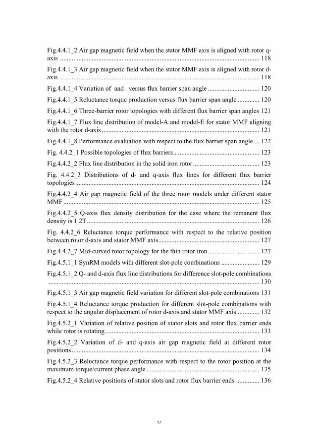
0.12KW to 1000KW [9]. Fig.1.1_1 presents the coverage of the newly updated IEC standard. It is required that form January 2017, commercial motors with power rating from 0.75KW to 375KW or an IE2 machines plus inverter need to meet IE3 efficiency level [9, 10].
Fig.1.1_1 Coverage of newly updated IE standards.
All of the regulations and standards above have put forward high requirements for the energy efficiency of the electric machines. As an electric machine designer, the characteristics of high torque performance, high efficiency, low material consumption and simple manufacturing process are always the objectives of FASynRM design.
1.2. DEVELOPMENT HISTORY OF ELECTRIC MACHINE TECHNOLOGY.
Right after the discovery of the basic theory of electromagnetic principles between 1729 and 1831, the concept of electric machine became into being and the practical application of electric machine technology followed [11, 12]. The electric machine was initially applied in industrial applications in 1830’s [12].
The knowledge of electric machine technology is a kind of subject involving different fields, like mechanics, electromagnetics, electronics, material science and manufacturing technology [12, 13]. The development in these related fields and the increasingly high requirements stimulate the development of the electric machine technology [12, 13]. According to the electric machine related industrial applications, it can be known an extensive range of electric machine types is available under the names of movement, utilizing material or the magnetic circuit profile [14]. Among these existing electric machine types, Permanent Magnet (PM) motor and Induction Motor (IM) take the predominant proportion of all the electric machine applications
MOULDING TECHNOLOGY BASED FERRITE ASSITED SYNCHRONOUS RELUCTANCE MACHINE
22
in various industries, which will be taken as examples to illustrate the development history of electric motor technology.
PM motor, just as the name implies, takes advantage of the high-energy-density rare-earth PMs to achieve high torque production capability [14]. Such a motor type started with the invention of brush Direct Current (DC) PM motor, which needs a commutator to switch the electromagnetic poles [15]. Then, a new type of DC motor without brushes came into being which satisfied the increasing requirements of compact structure, strong robustness, simple maintenance and long lifetime [16-18]. With the increasingly high requirements of smooth operation and low acoustic noise, symmetrical armature windings and balanced multi-phase Alternating Current (AC) are gradually applied, leading to the so-called PM synchronous motor (PMSM) [19, 20]. With the development of electronics, control strategy and manufacturing process, the PMSM becomes well known among all the machine types for its excellent efficiency, high torque performance and compact structure [21].
Induction Machine (IM), just as the name implies, is operated based on the principle of electromagnetic induction law [22]. Within a long development history from around 1900, the IM technology has become mature, consequently accounting for more than 90% of the electric machine applications in industry [22, 23]. With the development of electronics, variable frequency drive is utilized to replace the initial double cages or deep conducting bars for producing starting torque, which simplifies the rotor structure and realizes the smooth frequency change [22]. Compared with PM motor, IM has the advantages of simpler structure, lower manufacturing cost and more convenient maintenance [23]. While, such a machine type also suffers a drawback of relatively low power factor, which could lead to an increase in the frequency converter capability [23].
Reluctance machine with a long history was invented around 1842, while its development is suppressed by the obvious advantages of PM machine and IM since the start [24]. For the development of reluctance motor technology, it started with the Switched Reluctance Machine (SRM) which is constructed with salient poles on both stator and rotor sides [24]. By changing the sequence of DC current supply of the windings wound on the stator projecting poles, the produced MMF rotates at synchronous speed in the air gap [24]. In order to minimize the air gap reluctance thus maximizing the flux lines, the rotor rotates following the stator rotating magnetic field [24]. By replacing the initial open-loop control strategy of SRM with the current regulation scheme commonly utilized for IM, the performance of SRM was significantly improved [24]. Synchronous Reluctance Machine (SynRM), falling into the classification of reluctance machine, coexists in the industries with SRM. Different from SRM, SynRM utilizes the conventional stator assembled in the same way as that of IM [24]. Supplied with the poly-phase balanced AC current, SynRM operates more smoothly than SRM. Compared with PM machine and IM, there is no current or PMs on the rotor side of SRM and SynRM, thus leading to relatively lower
CHAPTER 1. INTRODUCTION
23
torque production of such two machine types [24-26]. Therefore, in a relatively long period, due to the relatively low torque production capability, reluctance machine didn’t actually appear on the stage of electric machine market [25]. With the development of manufacturing process, control strategy, material science and design method, the performance of SynRM was greatly improved [24]. With increasing emphasis on the energy and resource efficiency in recent decades, the reluctance machine gets more and more attentions due to the advantages of low cost, robust structure, long lifetime and simple maintenance [24, 27, 28].
Selecting the three motor types, PM machine, IM and reluctance machine, as representatives to illustrate the development history of the electric machine technology is somewhat subjective, while, it can be concluded that the electric machine development is always stimulated by the increasingly high requirements with respect to the torque performance, efficiency, manufacturing process and cost [25, 26]. According to the existing literature, it can be found SynRM regains great popularity in recent years due to its obvious advantages of robust structure, magnet- and current-free rotor and simple maintenance [24, 28].
1.3. STATE OF THE ART OF SYNRM TECHNOLOGY
Compared with the commonly utilized electric machine types, like Permanent Magnet (PM) machine and Induction Machine (IM), SynRM is totally free of rare earth magnets and conductors on the rotor side, which saves such a machine type from the issue of price fluctuation of neodymium and dysprosium as well as the risk of reliability due to the slip rings [29]. Furthermore, the magnet- and current-free character of SynRM simplifies the manufacturing process and leads to loss reduction on the rotor side, thus increasing the possibility of efficiency improvement and simplifying the cooling system [30]. Therefore, compared with the PM machine and the IM, SynRM is characterized by the features of simple manufacturing, the robust structure and the easy maintenance, which attract intensive research attentions in recent years [29]. However, SynRM also suffers the drawback of relatively low torque production, high torque ripple and bad power factor [31-34].
The performance of SynRM with respect to the efficiency, power factor, torque production and field weakening are fully evaluated with extensive academic studies for various industrial applications like fans, pumps and even electrical vehicles [35-37]. For SynRM, the torque production capability is closely related to the rotor saliency ratio which is determined by the rotor topologies [38-41]. In order to investigate the geometrical parameter influence on SynRM performance, a predominant proportion of the exiting SynRM related studies are carried out on the investigation of the geometrical parameters on rotor saliency ratio and consequently the reluctance torque [38]. Taking the multi-barrier rotor topology as an example which is commonly utilized for SynRM, the main geometrical parameters are including the slot-pole combination, the flux barrier topology, the iron bridge

MOULDING TECHNOLOGY BASED FERRITE ASSITED SYNCHRONOUS RELUCTANCE MACHINE
24
dimensions, etc [38-41]. Based on the calculation results of the geometrical parameter influence on reluctance torque, constructive design suggestions are concluded for SynRM for achieving high performance [40, 41]. Among all the strategies proposed for improving the torque performance of SynRM, adding ferrite magnet to the rotor side has been demonstrated as the most effective and economic way, thus leading to the wide application of FASynRM [42, 43]. In addition, the addition of ferrite magnet also effectively resolves the problem of low power factor associated to SynRM [44, 45]. Based on the researching results, it can be said competitive performance in contrast to that of PM machine and IM could be fully expected from a FASynRM. Some attempts to upgrade the electric machine related system by replacing the previous electric machines with the SynRM have been carried out, like in [46] where a FASynRM is intended to replace the Toyota second-generation IPMSM. The studying results for the designed FASynRM are encouraging: the FASynRM satisfies the mechanical strength requirements even in high-speed range and could resist the ferrite demagnetization in low temperature environment [46]; In addition, the designed FASynRM is capable to output the maximum power of 41.7 at the current density of 20 / and exceed 20 at the maximum speed of 10000 [46]. The power density and the constant power speed range of the designed FASynRM are almost the same as that of the IPMSM for the same size and with liquid cooling [46]. Furthermore, the efficiency of the designed FASynRM exceeds 90% for a wide operation range and achieves the maximum value of 97.2% which is higher than the target IPMSM [46]. Table. 1_3_1 presents the comparing results of the Toyota second-generation IPMSM and the proposed FASynRM.
TABLE.1.3_1 COMPARISON BETWEEN TOYOTA SECOND-GENERATION IPMSM AND PROPOSED FASYNRM
Specifications IPMSM FASynRM
Stator outer diameter ( ) 269 250
Stack length ( ) 83.6 40
Air gap ( ) 0.8 0.9
Max. current density ( / ) 20 20
Torque density at max. current density ( / ) 84 61
Max. output power ( ) 50 41.7
Speed ( ) 1200-6000 1200-6000
Max. efficiency (%) 95 97.2
Commercial products of SynRM have been launched by several companies, like ABB and KSB. ABB has produced SynRMs with the power range from 7.5 to 315 , all of which satisfy the IE4 efficiency level and are successfully applied in a wide range of applications like pumps, fans, compressors and conveyors [47]. Further reduction of rotor loss by 20% has been pronounced by ABB in 2015, which is intended to meet the IE5 ultra-premium efficiency level [48]. For this new technology platform, FASynRMs with power range between 1 15 and speed range of 1000 4000 are considered [48]. Two specific applications of ABB SynRMs
CHAPTER 1. INTRODUCTION
25
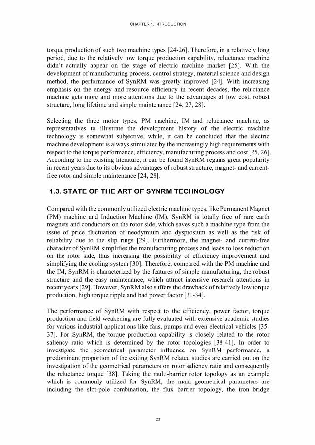
are taken as examples as shown in Fig.1.3_1 and Fig.1.3_2 to illustrate the improvement of efficiency of SynRM compared with IM [47]. For these two machine types used in the pump and fan applications, the SynRMs are smaller in both volume and weight than the IMs [47, 48]. While, from Fig.1.3_1 and Fig.1.3_2, it can be notice that within the speed range, the efficiency of SynRM package is higher than that of IM package [47]. Therefore, SynRM has higher output power density and lower loss production than IM.
Fig.1.3_1 22kW, 1500rpm, drive system in pump duty (ABB) [47].
Fig.1.3_2 37kW, 3000rpm, drive system in fan duty (ABB) [47].
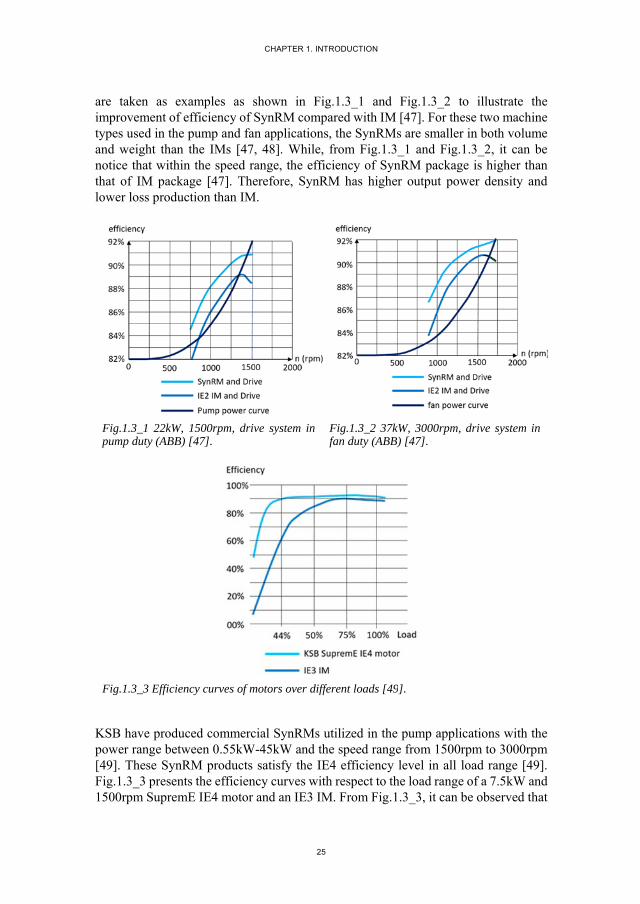
Fig.1.3_3 Efficiency curves of motors over different loads [49].
KSB have produced commercial SynRMs utilized in the pump applications with the power range between 0.55kW-45kW and the speed range from 1500rpm to 3000rpm [49]. These SynRM products satisfy the IE4 efficiency level in all load range [49]. Fig.1.3_3 presents the efficiency curves with respect to the load range of a 7.5kW and 1500rpm SupremE IE4 motor and an IE3 IM. From Fig.1.3_3, it can be observed that
MOULDING TECHNOLOGY BASED FERRITE ASSITED SYNCHRONOUS RELUCTANCE MACHINE
26
the efficiency of KSB SupremE IE4 motor is above 90% over a big load range from 44% to 100%; while, IM achieves the maximum efficiency slightly lower than 90% only within the load range from 60% to 100% [49]. The SynRM product from KSB is called SupremE IE4 motor, which is regarded as the typical representative of energy efficient motor generations due to its extraordinary efficiency [49].
The academic research of SynRM technology provides a strong theoretical support to the design of such a machine type for achieving high performance; the commercially available SynRM products demonstrate the advantages of such a machine type over IM with the same output power. SynRM technology is still in development, further efforts are desired to further improve the performance and widen the application range.
1.4. ISSUES OF SYNRM
1.4.1. INITUITIVE AND UNIFIED UNDERSTANDING OF TORQUE PRODUCTION MECHANISM
Different from the common electric machine types, like PM motor and IM, SynRM is constructed with a single magnetic field excitation associated to the stator side [50]. For SynRM, the torque is produced due to the intention of the rotor q-axis (aligned with the rotor axis with minimum permeance) moving towards the stator MMF axis in order to maximize the flux linkage in the air gap [50]. The most commonly utilized torque expression is also applied to the torque production of SynRM, which is written in d-q reference frame as
3( ( ) )
2 PM q d q d qT P i L L i i (1.4.1_1)
where PM is the flux linkage produced from rotor permanent magnets, equal to zero
for SynRM; P is the pole pair number; dL and qL are the inductance on d- and q-
axis respectively. This torque expression is derived based on the principle of energy conservation, presenting the relationship between the torque production of SynRM and the difference of d- and q-inductance. While, it fails to provide an insight into the fundamental torque production mechanism of SynRM [51].
The electromagnetic torque of an electric machine is actually generated due to the interaction between the air gap magnetic field and the soft magnetic material being exposed to the air gap magnetic field [51]. While, it is very difficult to evaluate the electromagnetic force acting on the iron material surface [51]. For the electric machines with two magnetic field sources associated to the rotor and stator side respectively, the torque of such machine types could be interpreted as being produced due to the interaction between the two interacting magnetic fields [50, 51]. In such a way, the electric machine is equivalent to a simple model with only two magnetic

CHAPTER 1. INTRODUCTION
27
fields associated with stator and rotor side respectively. With such an equivalent method, the torque production mechanism of an electric machine could be easily and clearly understood [50, 51]. However, the magnetic field equivalent method is only intended for the electric machines with two magnetic field excitations like PM machine and IM, consequently failing the machine types with only one magnetic field excitation, like SynRM.
The popularity of SynRM technology is resurged in recent years, which attracts extensive research investigating the performance of such a machine type. While, according to the existing studies, it can be found little research work is focused on finding a simple and intuitive way to understand the fundamental torque production mechanism of SynRM.
1.4.2. THEORETICAL ANALYSIS OF GEOMETRICAL PARAMETER INFLUENCE ON SYNRM PERFORMANCE
Transversally laminated multi-barrier rotor is generally utilized for SynRM due to the good compromise between the high saliency ratio and the simple manufacturing process [52, 53]. For such a rotor topology, it has many geometrical parameters that have direct or indirect effects on the torque performance of SynRM [52]. A clear knowledge of the geometrical parameter influence on the torque performance of SynRM is required for providing constructive design suggestions in order to achieve satisfied performance, especially in the machine initial design stage [50].
According to the existing literature related to the SynRM technology, it can be found extensive studies have been carried out on the investigation of the geometrical parameter influence on the machine performance [54, 55]. In these studies, the investigations are generally performed with the method of numerical analysis [56, 57]. By calculating the torque performance of a series of geometrical parameterized SynRM models with the aid of Finite Element (FE) software, the knowledge of the geometrical parameter influence on the torque performance is obtained. Like in [58], the influence of the combination of stator slot number, rotor pole pair number and flux barrier layer number on the rotor saliency ratio of SynRM is investigated, for which18 FE models with different slot-pole-barrier combinations are constructed and calculated. By comparing the calculated torque performance of these parameterized models, the influence of slot-pole-barrier combination on torque performance of SynRM are concluded [58]. The similar work is also performed in [59], where eighteen SynRM FE models with different slot-barrier combinations are constructed and calculated with the aid of FE software in order to investigate the influence of slot-barrier combination on torque and torque ripple. Comparing the conclusions obtained from the two studies mentioned above, it can be found the conclusions regarding the stator slot number influence on the torque performance obtained from the two studies are not coincident [58, 59]. Therefore, the comparative study based knowledge of the

MOULDING TECHNOLOGY BASED FERRITE ASSITED SYNCHRONOUS RELUCTANCE MACHINE
28
geometrical parameter influence on machine performance is highly dependent on the specific application, thus difficult to be used as general design guidelines.
It should be stressed that the optimal choice of SynRM geometrical parameters is based on an appropriate compromise between all the possible considerations for the specific application. While, a general idea of the geometrical parameter influence on the performance of SynRM is still needed for providing constructive design guidelines.
1.4.3. MANUFACTURING PROCESS OF FERRITE INSTALLATION OF FASYNRM
FASynRM with multi-barrier topology is widely utilized due to the improvement of torque production and power factor in contrast to SynRM, while it also requires an addition manufacturing process to install the ferrite magnet into the rotor flux barriers [60].
Fig.1.4.3_1 FASynRM rotor manufactured based on ferrite insertion technology [61].
Insertion strategy is the most commonly utilized for the installation of ferrite magnet of FASynRM [61]. Taking the model as shown in Fig.1.4.3_1 as an example to illustrate the manufacturing process associated to such a conventional ferrite installation method. From Fig.1.4.3_1, it is easy to notice that the ferrite magnet pieces are shaped into rectangular bars and each bar is inserted into the flux barrier cavities leaving air gaps between the adjacent two magnet bars [60]. For each flux barrier, there are two ferrite magnet bars, consequently amounting to 48 pieces in total that need to be inserted into the rotor flux barriers [60]. In addition, it can be observed that the ferrite magnet bars are in different sizes to fit the corresponding flux barrier cavities. Furthermore, to prevent the magnet bars from slipping inside the cavities, additional iron projections as shown in Fig.1.4.3_1 between two adjacent magnet bars have to be manufactured. Based on above description of the ferrite inserting process, it can be concluded that such a ferrite installation strategy is complex and time consuming which could lead to a huge consumption of human labor and manufacturing cost [60]. In addition, the ferrite magnet pieces used for such an insertion strategy are generally formed based on the sintering process, which mainly
CHAPTER 1. INTRODUCTION
29
produces regular shape for low manufacturing cost. In order to accommodate the ferrite magnet pieces, the design of flux barriers, to a large extent, has to be subject to the regular shape [60]. In such a case, the ferrite insertion strategy may impose a limit on the flexibility of flux barrier shapes and consequently the possibility of achieving the best torque performance by rotor optimal design.
In [62, 63], moulding technology is utilized for the ferrite installation of FASynRM. Instead of the pre-formed ferrite magnet pieces manufactured with sintering process, isotropic plasto-ferrite is used to fill the rotor flux barriers. By using such a moulding technology, the ferrite magnet could adapt itself to any shape of flux barriers, thus effectively solving the problem of limiting the flux barrier topology design associated with the ferrite insertion strategy. For the isotropic plasto-ferrite used in [62, 63], it needs to be magnetized after the moulding process for producing an expected magnetic field. The resulted remanent flux density of the plasto-ferrite after such moulding and magnetizing process is generally lower than 0.2T.
1.5. RESEARCH OBJECTIVES
This thesis is devoted to solving the problems associated with FASynRM.
1. This thesis investigates a unified and intuitive method for understanding the torque production mechanism of different AC machine types, like PM motor, IM and SynRM. Based on such a unified torque expression, a torque comparative study for the three mentioned machine types is presented [50].
2. This thesis performs a detailed theoretical analysis of the geometrical parameter influence on the performance of SynRM. The general ideas regarding the parameter influence obtained from the theoretical analysis are also validated with FE calculation [50].
3. This thesis present a detailed introduction of the moulding technology utilized for ferrite installation of FASynRM and the Halbach magnet ring for magnetizing the ferrite magnet. The feasibility of the application of moulding technology and Halbach magnet ring is fully validated by FASynRM prototyping [60].
4. This thesis provides an appropriate design of FASynRM, aiming at replacing a commercially available IM product.
1.6. SUMMARY OF CHAPTER 1.
The concept of energy and source efficiency has gradually infiltrated into various industrial fields, which promotes the resurgence of SynRM in recent years due to the
MOULDING TECHNOLOGY BASED FERRITE ASSITED SYNCHRONOUS RELUCTANCE MACHINE
30
advantages of permanent magnet free, robust structure, simple maintenance and low manufacturing cost.
The performance of SynRM has been fully investigated with the aid of FE Method (FEM). While, a systematic theoretical analysis to the fundamental torque production mechanism and the geometrical parameter influence on machine performance is still needed, which provides an insight into the operation principle of SynRM and general design suggestions for achieving high performance. The practical manufacturing process regarding the ferrite installation also needs special consideration when utilizing FASynRM in industries. To avoid the problems associated to the commonly utilized ferrite insertion strategy, moulding technology is one of the promising alternative solutions. Detailed investigation is needed to validate the feasibility of the application of moulding technology for ferrite installation of FASynRM.
CHAPTER 1. INTRODUCTION
31
Reference
1. Medium-Term Reports; Available at http://www.iea.org/publications/medium-termreports/
2. World Energy Perspective; Available at https://www.worldenergy.org/about-wec/brochure/english/
3. S. Jurkovic, K. Rahman, B. Bae, N. Patel and P. Savagian, "Next generation chevy volt electric machines; design, optimization and control for performance and rare-earth mitigation," 2015 IEEE Energy Conversion Congress and Exposition (ECCE), Montreal, QC, 2015, pp. 5219-5226.
4. Energy Efficiency 2017; Available at https://www.iea.org/topics/energyefficiency/
5. Efficiency requirements for low voltage motors updated for stages 3 requirements from January 1, 2017; Available at http://www.abb.com.sg/abblibrary/DownloadCenter/?showresultstab=true&categoryid=9AAC172859
6. Energy efficiency: a key tool for boosting economic and social development; Available at https://www.iea.org/newsroom/news/2014/september/energy-efficiency-a-key-tool-for-boosting-economic-and-social-development.html
7. Minimum energy efficiency standards; Available at https://www.rla.org.uk/landlord/guides/minimum-energy-efficiency-standards.shtml
8. Energy Efficiency; Available at http://www.ncsl.org/research/energy/energy-efficiency.aspx
9. Commission regulations (EC) no 640/2009 of 22 July 2009 implementing directive 2005/32/EC with regard to eco-design requirements for electric motors and No 4/2014 of 6 January 2014 amending regulation (EC) No 640/2009; Available at https://ec.europa.eu/energy/sites/ener/files/documents/20141211_GuidelinesElectricMotors%20cover.pdf
10. Policies and measures for promoting efficient electric motors in industry; Available at https://wec-policies.enerdata.net/Documents/cases-studies/WEC-case-study-Electric-motor.pdf
11. Motor and drives; Available at http://www.psee.org.za/downloads/publications/FPP9159_Motors_Drives2.pdf
12. J. F. Gieras, “Advancements in electric machines,” Springer, January 2008.
MOULDING TECHNOLOGY BASED FERRITE ASSITED SYNCHRONOUS RELUCTANCE MACHINE
32
13. Lorand Szabo, Andras Lelkes, “Variable reluctance PM synchronous motors: a short history and new developments,” Workshop on Variable Reluctance Electrical Machines, Sep. 2002, Technical University of Cluj-Napoca.
14. A sourcebook for industry, “Improving motor and drive system performance”; Available at https://www1.eere.energy.gov/manufacturing/tech_assistance/pdfs/motor.pdf
15. B. J. Chalmers, E. Spooner, A. M. Sitzia, K. M. Richardson, “Permanent-Magnet A.C. and D.C. Machines,”
16. C. Vangsness, "Comparison of brush and brushless servo motor designs," IEEE Conference Record of 1988 Fortieth Annual Conference of Electrical Engineering Problems in the Rubber and Plastics Industries, Akron, OH, 1988, pp. 60-65.
17. S. K. Pal, "Direct drive high energy permanent magnet brush and brushless DC motors for robotic applications," IEE Colloquium on Robot Actuators, London, 1991, pp. 12/1-12/4.
18. G. C. R. Sincero, J. Cros and P. Viarouge, "Efficient simulation method for comparison of brush and brushless DC motors for light traction application," 2009 13th European Conference on Power Electronics and Applications, Barcelona, 2009, pp. 1-10.
19. K. J. Binns and M. A. Jabbar, "High-field self-starting permanent-magnet synchronous motor," in IEE Proceedings B - Electric Power Applications, vol. 128, no. 3, pp. 157-160, May 1981.
20. M. H. Walshaw and J. W. Lynn, "A hunting analysis of a permanent-magnet alternator and a synchronous motor," in Proceedings of the IEE - Part C: Monographs, vol. 108, no. 14, pp. 516-527, September 1961.
21. C. C. Chan and K. T. Chau, "An advanced permanent magnet motor drive system for battery-powered electric vehicles," in IEEE Transactions on Vehicular Technology, vol. 45, no. 1, pp. 180-188, Feb 1996.
22. H. M. Norman, "Starting characteristics and control of polyphase squirrel-gage induction motors," in Journal of the A.I.E.E., vol. 45, no. 2, pp. 153-159, Feb. 1926.
23. C. Lewis, "The Advanced Induction Motor," IEEE Power Engineering Society Summer Meeting,, Chicago, IL, USA, 2002, pp. 250-253 vol.1.
24. T. A. Lipo, “Synchronous reluctance machine-A viable alternative for AC Drives?” a research report at Wisconsin electric machines and power electronics consortium, May 1991.
25. E. Bostanci, M. Moallem, A. Parsapour and B. Fahimi, "Opportunities and Challenges of Switched Reluctance Motor Drives for Electric Propulsion: A

CHAPTER 1. INTRODUCTION
33
Comparative Study," in IEEE Transactions on Transportation Electrification, vol. 3, no. 1, pp. 58-75, March 2017.
26. Klaus Lang; Annette Muetze; Robert Bauer; Stefan Pircher, “Comparison of Induction and Synchronous Reluctance Machine Based Actuators for Elevated Temperature Environments,” in IEEE Transactions on Energy Conversion, vol. 31, no.3, pp. 1012 – 1022, Sept. 2016.
27. H. Hofmann, S.R. Sanders, “High-speed synchronous reluctance machine with minimized rotor losses,” in IEEE Transactions on Industry Applications, vol. 36, no. 2, pp. 531 – 539, Mar/Apr 2000.
28. T. Matsuo, T.A. Lipo, “Rotor design optimization of synchronous reluctance machine,” in IEEE Transactions on Energy Conversion, vol. 9, no .2, pp. 359-365, Jun 1994.
29. T. A. Huynh and M. F. Hsieh, "Comparative Study of PM-Assisted SynRM and IPMSM on Constant Power Speed Range for EV Applications," in IEEE Transactions on Magnetics, vol. 53, no. 11, pp. 1-6, Nov. 2017.
30. P. Lazari, J. Wang, L. Chen and X. Chen, "Design optimisation and performance evaluation of a rare-earth-free Permanent Magnet Assisted Synchronous Reluctance Machine for electric vehicle traction," 7th IET International Conference on Power Electronics, Machines and Drives (PEMD 2014), Manchester, 2014, pp. 1-6.
31. M. Barcaro, T. Pradella and I. Furlan, "Low-torque ripple design of a ferrite-assisted synchronous reluctance motor," in IET Electric Power Applications, vol. 10, no. 5, pp. 319-329, 5 2016.
32. J. Bao, B. L. J. Gysen, K. Boynov, J. J. H. Paulides and E. A. Lomonova, "Torque Ripple Reduction for 12-Stator/10-Rotor-Pole Variable Flux Reluctance Machines by Rotor Skewing or Rotor Teeth Non-Uniformity," in IEEE Transactions on Magnetics, vol. 53, no. 11, pp. 1-5, Nov. 2017.
33. W. Chai, W. Zhao and B. i. Kwon, "Optimal Design of Wound Field Synchronous Reluctance Machines to Improve Torque by Increasing the Saliency Ratio," in IEEE Transactions on Magnetics, vol. 53, no. 11, pp. 1-4, Nov. 2017.
34. Y. Wang, D. Ionel, D. G. Dorrell and S. Stretz, "Establishing the Power Factor Limitations for Synchronous Reluctance Machines," in IEEE Transactions on Magnetics, vol. 51, no. 11, pp. 1-4, Nov. 2015.
35. F. P. Pop, D. C. Popa, R. Marţiş, C. Marţiş and A. C. Pop, "Comparative analysis of rare earth-less electrical machines for 48V automotive cooling fan applications," 2017 14th International Conference on Engineering of Modern Electric Systems (EMES), Oradea, 2017, pp. 180-183.
36. S. Urschel and J. Dolgirev, "Energy- and resource saving synchronous reluctance machine for the use in circulation pumps," 2017 IEEE 3rd International Future

MOULDING TECHNOLOGY BASED FERRITE ASSITED SYNCHRONOUS RELUCTANCE MACHINE
34
Energy Electronics Conference and ECCE Asia (IFEEC 2017 - ECCE Asia), Kaohsiung, 2017, pp. 2139-2144.
37. I. Boldea et al., "DTFC-SVM motion-sensorless control of a PM-assisted reluctance synchronous machine as starter-alternator for hybrid electric vehicles," in IEEE Transactions on Power Electronics, vol. 21, no. 3, pp. 711-719, May 2006.
38. H. A. Moghaddam, A. Vahedi and S. H. Ebrahimi, "Design Optimization of Transversely Laminated Synchronous Reluctance Machine for Flywheel Energy Storage System Using Response Surface Methodology," in IEEE Transactions on Industrial Electronics, vol. 64, no. 12, pp. 9748-9757, Dec. 2017.
39. J. Ikäheimo, J. Kolehmainen, T. Känsäkangas, V. Kivelä and R. R. Moghaddam, "Synchronous High-Speed Reluctance Machine With Novel Rotor Construction," in IEEE Transactions on Industrial Electronics, vol. 61, no. 6, pp. 2969-2975, June 2014.
40. B. Gaussens, J. Boisson, A. Abdelli, L. Favre and D. Bettoni, "Torque ripple mitigation of PM-assisted synchronous reluctance machine : Design and optimization," 2017 20th International Conference on Electrical Machines and Systems (ICEMS), Sydney, NSW, 2017, pp. 1-6.
41. F. P. Pop, R. Marţiş, A. Dărămus, C. Marţiş, A. C. Pop and I. Vintiloiu, "Design and analysis of slot-pole combination for synchronous reluctance machine with concentrated windings for automotive applications," 2016 International Conference and Exposition on Electrical and Power Engineering (EPE), Iasi, 2016, pp. 229-234.
42. R. Leuzzi, P. Cagnetta, F. Cupertino, S. Ferrari and G. Pellegrino, "Performance assessment of ferrite- and neodymiumassisted synchronous reluctance machines," 2017 IEEE Energy Conversion Congress and Exposition (ECCE), Cincinnati, OH, 2017, pp. 3958-3965.
43. T. Hamiti, R. Benlamine, F. Vangraefschepe and D. Lhotellier, "Analysis of ferrite assisted synchronous reluctance machines for medium sized electric," 2016 XXII International Conference on Electrical Machines (ICEM), Lausanne, 2016, pp. 139-144.
44. C. T. Liu et al., "On the Design and Construction Assessments of a Permanent-Magnet-Assisted Synchronous Reluctance Motor," in IEEE Transactions on Magnetics, vol. 53, no. 11, pp. 1-4, Nov. 2017.
45. M. N. Ibrahim, P. Sergeant and E. M. Rashad, "Rotor design with and without permanent magnets and performance evaluation of synchronous reluctance motors," 2016 19th International Conference on Electrical Machines and Systems (ICEMS), Chiba, 2016, pp. 1-7.
CHAPTER 1. INTRODUCTION
35
46. S. Ooi, S. Morimoto, M. Sanada and Y. Inoue, "Performance Evaluation of a High-Power-Density PMASynRM With Ferrite Magnets," in IEEE Transactions on Industry Applications, vol. 49, no. 3, pp. 1308-1315, May-June 2013.
47. ABB review of innovation, available at https://library.e.abb.com/public/46ab92b48dda3f248325785c005a701a/ABB%20Review%20ENG%201_11-0204_CMarticle.pdf
48. SynRM motor concept for variable speed applications: IE4-IE5 efficiency and beyond without rare earth magnets tailored motor solutions for OEMs. Available at https://library.e.abb.com/public/d910d818185a42438c23402af9e9cf24/13135_ABB_product_note_SynRM%20IE5-LOWRES.pdf
49. KSB supreme in IE5: the world’s most efficient magnet-less pump motor; Available at https://www.ksb.com/blob/961530/56b3c211d6e358f6b3f78f0bc1b19f7f/dow-supreme-bross%C3%BAra-data.pdf
50. Q. Wu, K. Lu, P. O. Rasmussen, N. Bianchi and K. F. Rasmussen, "Unified equivalent MMF concept for torque analysis of AC machines," 2017 IEEE International Electric Machines and Drives Conference (IEMDC), Miami, FL, 2017, pp. 1-8.
51. A. E. Fitzgerald, Charles Kingsley Jr, Stephen D. Umans, “Electric Machinery,” sixth edition.
52. S. Cai, J. Shen, H. Hao and M. Jin, "Design methods of transversally laminated synchronous reluctance machines," in CES Transactions on Electrical Machines and Systems, vol. 1, no. 2, pp. 164-173, 2017.
53. J. X. Shen, S. Cai, H. Hao and M. J. Jin, "Comprehensive parameter design for transversally laminated synchronous reluctance machines," 2016 19th International Conference on Electrical Machines and Systems (ICEMS), Chiba, 2016, pp. 1-9.
54. T. Mohanarajah, J. Rizk, M. Nagrial and A. Hellany, "Optimization of flux barrier parameters in synchronous reluctance machines," 2015 IEEE Conference on Energy Conversion (CENCON), Johor Bahru, 2015, pp. 299-304.
55. Y. Wang, G. Bacco and N. Bianchi, "Geometry Analysis and Optimization of PM-Assisted Reluctance Motors," in IEEE Transactions on Industry Applications, vol. 53, no. 5, pp. 4338-4347, Sept.-Oct. 2017.
56. M. H. Mohammadi, T. Rahman, R. Silva, M. Li and D. A. Lowther, "A Computationally Efficient Algorithm for Rotor Design Optimization of Synchronous Reluctance Machines," in IEEE Transactions on Magnetics, vol. 52, no. 3, pp. 1-4, March 2016.
MOULDING TECHNOLOGY BASED FERRITE ASSITED SYNCHRONOUS RELUCTANCE MACHINE
36
57. W. Zhao, F. Xing, X. Wang, T. A. Lipo and B. i. Kwon, "Design and Analysis of a Novel PM-Assisted Synchronous Reluctance Machine With Axially Integrated Magnets by the Finite-Element Method," in IEEE Transactions on Magnetics, vol. 53, no. 6, pp. 1-4, June 2017.
58. K. Wang, Z. Q. Zhu, G. Ombach, M. Koch, S. Zhang and J. Xu, "Optimal slot/pole and flux-barrier layer number combinations for synchronous reluctance machines," 2013 Eighth International Conference and Exhibition on Ecological Vehicles and Renewable Energies (EVER), Monte Carlo, 2013, pp. 1-8.
59. M. Palmieri, M. Perta, F. Cupertino and G. Pellegrino, "Effect of the numbers of slots and barriers on the optimal design of synchronous reluctance machines," 2014 International Conference on Optimization of Electrical and Electronic Equipment (OPTIM), Bran, 2014, pp. 260-267.
60. Q. Wu, K. Lu, P. O. Rasmussen and K. F. Rasmussen, "A new application and experimental validation of moulding technology for ferrite magnet assisted synchronous reluctance machine," 2016 IEEE Energy Conversion Congress and Exposition (ECCE), Milwaukee, WI, 2016, pp. 1-8.
61. H. Cai, B. Guan and L. Xu, "Low-Cost Ferrite PM-Assisted Synchronous Reluctance Machine for Electric Vehicles," in IEEE Transactions on Industrial Electronics, vol. 61, no. 10, pp. 5741-5748, Oct. 2014.
62. P. Guglielmi, M. Pastorelli, A. Carrer, A. Beato, D. D'Antonio and L. Fagnano, "An IPM-PMASR motor for home appliance washing machines," IECON 2013 - 39th Annual Conference of the IEEE Industrial Electronics Society, Vienna, 2013, pp. 2608-2613.
63. E. Armando, P. Guglielmi, M. Pastorelli, G. Pellegrino and A. Vagati, "Performance of IPM-PMASR Motors with Ferrite Injection for Home Appliance Washing Machine," 2008 IEEE Industry Applications Society Annual Meeting, Edmonton, Alta., 2008, pp. 1-6.
37
CHAPTER 2. THEORETICAL ANALYSIS
OF AC MACHINE TORQUE
2.1. INTRODUCTION
Torque production capability is one of the crucial factors that measure the performance of an electric machine [1]. A clear and intuitive knowledge of the torque production mechanism is highly appreciated for deepening the understanding of the machine operation principle and providing constructive suggestions in machine design and control [1].
A variety of electric machine types are available in the industrial applications, each of which has its own characteristics [2]. An appropriate choice of an electric machine type for each specific application has an important effect on the performance of the whole machine related system. Thus, a simple and unified torque evaluation strategy is highly required for providing an easy way to compare the torque performance of different electric machines [2, 3], thus providing suggestions for the machine choice.
This chapter is devoted to the fundamental torque production mechanism of AC electric machines. Emphasis is placed on the investigation of an intuitive and unified way to understand and evaluate the torque performance of different machine types. The purpose of such an investigation is threefold:
1. To aid in understanding the fundamental principle behind the torque production of different AC machines;
2. To provide a simple and intuitive way for general-purpose torque comparison among different machine types;
3. To provide constructive design suggestions for achieving specific requirements.
PM machine, IM and SynRM are taken as examples of AC machine types to present the investigation.
2.2. STATE OF THE ART OF TORQUE EVALUATION METHODS
Electromagnetic torque of an electric machine is basically produced due to the interaction between the air gap magnetic field and the magnetic material exposed to the air gap magnetic field [2]. Various techniques have evolved to calculate such detailed and localized electromagnetic force.

MOULDING TECHNOLOGY BASED FERRITE ASSITED SYNCHRONOUS RELUCTANCE MACHINE
38
In a magnetic field, the electromagnetic force acting on the magnetic material could be determined with the expression as
21
2sF H grad (2.2_1)
The subscript s indicates that sF is a force density (newtons per square meter). The
term of grad is known as the change rate of the material permeability both inside
and on the interface of two magnetic materials. Assuming constant permeability inside the iron structure, the torque performance of an electric machine could be evaluated by performing an integral of the torque density ( sF ) over the stator tooth surface. An
alternative method to calculate the electromagnetic force density ( sF ) is the Maxwell
stress tensor, which is expressed as
2 2
1
1( )
2
st n t
sn n t
F B B
F B B
(2.2_2)
where the subscripts of st and sn represent the force density acting on the surface along the tangential and radial directions respectively. As the performance of an electric machine is actually determined by the torque acting on the rotor side, it is not necessary to calculate the details of the internal force density distribution [2]. Thus, by using the Maxwell stress tensor, the torque performance could be evaluated by performing an integral of the tangential force density ( stF ) over a closed air gap
surface containing rotor only [2]. Detailed magnetic field distribution over the air gap region of an electric machine is required by both of the above mentioned torque evaluation methods [3]. Using FEM with the aid of FE software for magnetic field calculation, accurate torque calculation results could be fully expected with either of the torque evaluation methods [4-6]. The two methods mentioned above are more mathematical techniques for torque calculation, rather than providing a simple way to understand the torque production mechanism of electric machines [3].
Energy method is another technique for torque performance evaluation of electric machines, which is based on the principle of energy conservation [7-9]. Excluding the loss components like the copper loss, iron loss and mechanical loss, the electric machine could be indicated as a lossless magnetic-energy-storage system, where electromechanical energy conversion occurs via the medium of magnetic stored energy [2]. As the magnetic stored energy system is a conservative system uniquely specified by the state variables of flux linkage and rotor position, the machine torque is thus equal to the change rate of the magnetic stored energy with respect to the
CHAPTER 2. THEORETICAL ANALYSIS OF AC MACHINE TORQUE
39
variation of rotor positions [2, 8]. The energy method based torque expression is written as
magWT
(2.2_3)
where magW refers to magnetic stored energy, which could be calculated with two
concepts, magnetic field and magnetic circuit respectively. With the concept of magnetic field, the magnetic stored energy is evaluated by performing an integral calculation of energy density over the volume of air gap when infinite permeability of iron material is assumed [2]. The derived torque is expressed with the terms of stator and rotor MMFs, which is specifically written as
sin
2 s r
PT K F F
g (2.2_4)
Where K denotes a constant coefficient determined by the dimensions of electric machine; P represents the pole pair number; g refers to the air gap length; refers
to the angular displacement between the rotor MMF ( rF ) and the stator MMF ( sF ).
For the torque expression of (2.2_4), the torque production of an electric machine is interpreted as an interaction between two magnetic fields associated with stator and rotor side respectively, which provides an intuitive way for understanding the torque production mechanism [2, 10]. However, this derived torque expression is only intended for the electric machines with both uniform air gap and two excitations associated with stator and rotor, thus failing to analyze the torque of the singly excited electric machine types, like reluctance machine [10]. No attempt has been made to apply such a simple torque production principle to the torque analysis of singly excited electric machine types.
With the concept of magnetic circuit, the magnetic stored energy is evaluated with the terms of flux linkage and winding current, which are linearly related by the phase inductance [2, 11]. As the phase inductance of an electric machine is a function of rotor positions, it is more convenient to express the derived torque with the terms in d-q reference frame, written as
3
( ( ) )2 PM q d q d qT P i L L i i (2.2_5)
where PM refers to the permanent magnet flux linkage, equal to zero for the electric
machines without permanent magnets; dL and qL represent the inductance on d- and
q-axis respectively, which are independent of the rotor positions. This torque expression is applicable for all kinds of electric machines, while, it fails to indicate
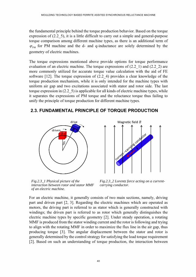
MOULDING TECHNOLOGY BASED FERRITE ASSITED SYNCHRONOUS RELUCTANCE MACHINE
40
the fundamental principle behind the torque production behavior. Based on the torque expression of (2.2_5), it is a little difficult to carry out a simple and general-purpose torque comparison among different machine types, as there is an additional term of
PM for PM machine and the d- and q-inductance are solely determined by the
geometry of electric machines.
The torque expressions mentioned above provide options for torque performance evaluation of an electric machine. The torque expressions of (2.2_1) and (2.2_2) are more commonly utilized for accurate torque value calculation with the aid of FE software [12]. The torque expression of (2.2_4) provides a clear knowledge of the torque production mechanism, while it is only intended for the machine types with uniform air gap and two excitations associated with stator and rotor side. The last torque expression in (2.2_5) is applicable for all kinds of electric machine types, while it separates the expressions of PM torque and the reluctance torque thus failing to unify the principle of torque production for different machine types.
2.3. FUNDAMENTAL PRINCIPLE OF TORQUE PRODUCTION
Fig.2.3_1 Physical picture of the interaction between rotor and stator MMF of an electric machine.
Fig.2.3_2 Lorentz force acting on a current-carrying conductor.
For an electric machine, it generally consists of two main sections, namely, driving part and driven part [2, 3]. Regarding the electric machines which are operated as motors, the driving part is referred to as stator which is generally constructed with windings; the driven part is referred to as rotor which generally distinguishes the electric machine types by specific geometry [2]. Under steady operation, a rotating MMF is produced from the stator winding current and the rotor is following and trying to align with the rotating MMF in order to maximize the flux line in the air gap, thus producing torque [3]. The angular displacement between the stator and rotor is generally determined by the control strategy for satisfying the load torque requirement [2]. Based on such an understanding of torque production, the interaction between

CHAPTER 2. THEORETICAL ANALYSIS OF AC MACHINE TORQUE
41
rotor and stator could be explained by analogy with the interaction between two interacting magnetic poles with opposite polarity as shown in Fig.2.3_1, where the N magnetic pole is initially rotating along the bigger circle and the S magnetic pole is following. The angular displacement of in Fig.2.3_1 is affected by the resistance
force acting on the S magnetic pole.
The torque produced from the two interacting magnetic poles in Fig.2.3_1 with constant angular displacement of could be evaluated with the law of Ampere force.
As is well known, the permanent magnet is equivalent to the current with respect to identical magneic field production [13-15], thus transforming the picture of two magneic poles in Fig.2.3_1 into an equivalent picture with magnetic-pole-equivalent current and the other magnetic pole. For the equivalent picture, the magnetic-pole-equivalent current is exposed to the magnetic field produced from the other magnetic pole, thus producing ampere force between them. The ampere force between magnetic field and current, e.g. the case in Fig.2.3_2, could be evaluated with the expression written as
t a nF l B I
(2.3_1)
where al represents the length of the current-carrying conductor, equal to stack length
for an electric machine; nB
refers to the magnetic field produced from the magnetic
pole; I
is the equivalent current of one magnetic pole. Assuming that the magnetic poles are magnetized along the radial direction, the flowing direction of the equivalent current is perpendicular to the magnetic field direction. In such a case, the cross product in the calculation of the tangential force between the equivalent current and the magnetic poles in Fig.2.3_1 is equal to 1. Thus, the produced torque is expressed as
a nT R l B I (2.3_2)
where R is the radius of the air gap. Therefore, interpreting the torque production mechanism of electric machines simply as the interaction between two magnetic poles with opposite polarities, the torque performance could be evaluated with the expression in (2.3_2). In order to achieve a unified torque evaluation method, the following analysis is dedicated to the investigation of the equivalent current ( I ) and the calculation of magnetic field ( nB ).
2.4. EQUIVALENT CURRENT
Permanent magnet and electric current are the only sources of magnetic field, either or both of which are involved in an electric machine [10]. When only considering the fundamental component of the magnetic field, the stator slot winding current or the
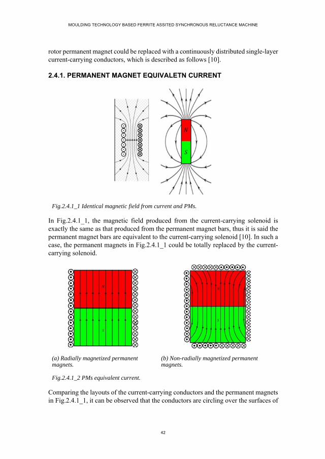
MOULDING TECHNOLOGY BASED FERRITE ASSITED SYNCHRONOUS RELUCTANCE MACHINE
42
rotor permanent magnet could be replaced with a continuously distributed single-layer current-carrying conductors, which is described as follows [10].
2.4.1. PERMANENT MAGNET EQUIVALETN CURRENT
Fig.2.4.1_1 Identical magnetic field from current and PMs.
In Fig.2.4.1_1, the magnetic field produced from the current-carrying solenoid is exactly the same as that produced from the permanent magnet bars, thus it is said the permanent magnet bars are equivalent to the current-carrying solenoid [10]. In such a case, the permanent magnets in Fig.2.4.1_1 could be totally replaced by the current-carrying solenoid.
(a) Radially magnetized permanent magnets.
(b) Non-radially magnetized permanent magnets.
Fig.2.4.1_2 PMs equivalent current.
Comparing the layouts of the current-carrying conductors and the permanent magnets in Fig.2.4.1_1, it can be observed that the conductors are circling over the surfaces of
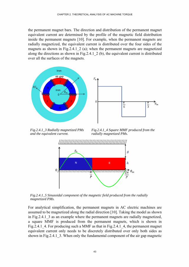
CHAPTER 2. THEORETICAL ANALYSIS OF AC MACHINE TORQUE
43
the permanent magnet bars. The direction and distribution of the permanent magnet equivalent current are determined by the profile of the magnetic field distribution inside the permanent magnets [10]. For example, when the permanent magnets are radially magnetized, the equivalent current is distributed over the four sides of the magnets as shown in Fig.2.4.1_2 (a); when the permanent magnets are magnetized along the directions as shown in Fig.2.4.1_2 (b), the equivalent current is distributed over all the surfaces of the magnets.
Fig.2.4.1_3 Radially magnetized PMs and the equivalent current.
Fig.2.4.1_4 Square MMF produced from the radially magnetized PMs.
Fig.2.4.1_5 Sinusoidal component of the magnetic field produced from the radially magnetized PMs.
For analytical simplification, the permanent magnets in AC electric machines are assumed to be magnetized along the radial direction [10]. Taking the model as shown in Fig.2.4.1_3 as an example where the permanent magnets are radially magnetized, a square MMF is produced from the permanent magnets, which is shown in Fig.2.4.1_4. For producing such a MMF as that in Fig.2.4.1_4, the permanent magnet equivalent current only needs to be discretely distributed over only both sides as shown in Fig.2.4.1_3. When only the fundamental component of the air gap magnetic
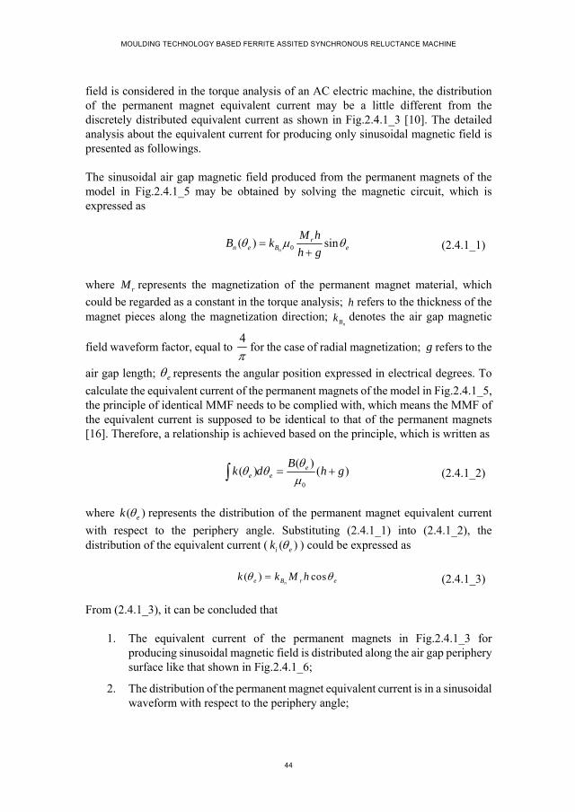
MOULDING TECHNOLOGY BASED FERRITE ASSITED SYNCHRONOUS RELUCTANCE MACHINE
44
field is considered in the torque analysis of an AC electric machine, the distribution of the permanent magnet equivalent current may be a little different from the discretely distributed equivalent current as shown in Fig.2.4.1_3 [10]. The detailed analysis about the equivalent current for producing only sinusoidal magnetic field is presented as followings.
The sinusoidal air gap magnetic field produced from the permanent magnets of the model in Fig.2.4.1_5 may be obtained by solving the magnetic circuit, which is expressed as
0( ) sin
n
rn e B e
M hB k
h g
(2.4.1_1)
where rM represents the magnetization of the permanent magnet material, which
could be regarded as a constant in the torque analysis; h refers to the thickness of the magnet pieces along the magnetization direction;
nBk denotes the air gap magnetic
field waveform factor, equal to 4
for the case of radial magnetization; g refers to the
air gap length; e represents the angular position expressed in electrical degrees. To
calculate the equivalent current of the permanent magnets of the model in Fig.2.4.1_5, the principle of identical MMF needs to be complied with, which means the MMF of the equivalent current is supposed to be identical to that of the permanent magnets [16]. Therefore, a relationship is achieved based on the principle, which is written as
0
( )( ) ( )e
e e
Bk d h g
(2.4.1_2)
where ( )ek represents the distribution of the permanent magnet equivalent current
with respect to the periphery angle. Substituting (2.4.1_1) into (2.4.1_2), the distribution of the equivalent current ( ( )i ek ) could be expressed as
( ) cosne B r ek k M h (2.4.1_3)
From (2.4.1_3), it can be concluded that
1. The equivalent current of the permanent magnets in Fig.2.4.1_3 for producing sinusoidal magnetic field is distributed along the air gap periphery surface like that shown in Fig.2.4.1_6;
2. The distribution of the permanent magnet equivalent current is in a sinusoidal waveform with respect to the periphery angle;
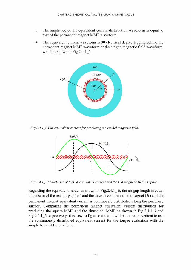
CHAPTER 2. THEORETICAL ANALYSIS OF AC MACHINE TORQUE
45
3. The amplitude of the equivalent current distribution waveform is equal to that of the permanent magnet MMF waveform.
4. The equivalent current waveform is 90 electrical degree lagging behind the permanent magnet MMF waveform or the air gap magnetic field waveform, which is shown in Fig.2.4.1_7.
Fig.2.4.1_6 PM-equivalent current for producing sinusoidal magnetic field.
Fig.2.4.1_7 Waveforms of thePM-equivalent current and the PM magnetic field in space.
Regarding the equivalent model as shown in Fig.2.4.1_ 6, the air gap length is equal to the sum of the real air gap ( g ) and the thickness of permanent magnet ( h ) and the
permanent magnet equivalent current is continously distributed along the periphery surface. Comparing the permanent magnet equivalent current distribution for producing the square MMF and the sinusoidal MMF as shown in Fig.2.4.1_3 and Fig.2.4.1_6 respectively, it is easy to figure out that it will be more convenient to use the continuously distributed equivalent current for the torque evaluation with the simple form of Lorenz force.

MOULDING TECHNOLOGY BASED FERRITE ASSITED SYNCHRONOUS RELUCTANCE MACHINE
46
2.4.2. WINDING-EQUIVALENT CURRENT
The stators of AC electric machines are generally constructed with symmetrical windings as shown in Fig.2.4.2_1, which produce a MMF rotating synchronously along the air gap [2]. By analogy with the calculation of the permanent magnet equivalent current for producing sinusoidal magnetic field, the stator slot winding current could also be replaced with the continuously distributed equivalent current when only the fundamental component of the air gap magnetic field is concerned [10].
The following analysis presents the details of replacing the stator slot windings with continuously distributed equivalent current. To complying with the principle of equal MMF for making equivalent current, the fundamental component of of the stator winding MMF needs to be firstly evaluated, which is written as
( ) sin( )e m e sF F t (2.4.2_1)
where mF refers to the amplitude of stator winding MMF waveform; s represents the
rotating speed of stator MMF, which is equal to the electrical angular frequency; is the initial angular position of stator MMF waveform.
Fig.2.4.2_1 Winding current in stator slots. Fig.2.4.2_2 Winding-equivalent current distributed along the smooth inner surface of an iron ring.
With the principle of equivalent MMF, the winding-equivalent current distribution needs to satisfy
( ) sin( )e e m e sk d F t (2.4.2_2)
It yields

CHAPTER 2. THEORETICAL ANALYSIS OF AC MACHINE TORQUE
47
( ) cos( )e m e sk F t (2.4.2_3)
Similar to the PM-equivalent current, the winding-equivalent current is continuously distributed along the circumferential surface in the air gap as shown in Fig.2.4.2_2 and the amplitude of the equivalent current waveform is also equal to that of the stator MMF sinusoidal waveform.
Based on above analysis of the permanent-magnet- and slot-winding-equivalent current for producing sinusoidal magnetic field, it can be concluded that
1. The principle of identical MMF should be complied with in equivalent current analysis.
2. The equivalent current for producing sinusoidal magnetic field is continuously distributed along the periphery surface in the air gap.
3. The equivalent current distribution is in a sinusoidal waveform and the amplitude is equal to that of the sinusoidal MMF waveform produced from the original magnetic field source.
2.5. THEORETICAL ANALYSIS OF AC MACHINE TORQUE
As discussed in section 2.3, the interaction between the rotor and the stator of an electric machine could be principally pictured as the attraction force between two interacting magnetic fields [3, 10]. For such an equivalent model of the electric machine, one of the magnetic field source could be replaced with the continuously distributed equivalent current, which is totally exposed to the magnetic field produced from the other magnetic field source [10]. In such a case, the force between the two magnetic fields could be easily evaluated by calculating the electromagnetic force acting on the equivalent current with the simple principle of Lorenz force [10]. This section is focused on the torque analysis of AC machines, like PM surface-mounted machine, IM and SynRM, based on above mentioned equivalent model.
2.5.1. MAGNETIC COUPLING
The torque of the magnetic coupling as shown in Fig.2.5.1_1 is typically produced due to the interaction between two groups of interacting permanent magnets associated with the inner and outer iron rings respectively [17-19]. Before applying the simple equivalent concept to the torque analysis of AC machines, the torque performance of the magnetic coupling is firstly analyzed based on such an equivalent concept.
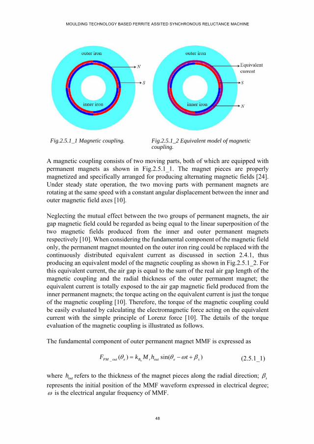
MOULDING TECHNOLOGY BASED FERRITE ASSITED SYNCHRONOUS RELUCTANCE MACHINE
48
Fig.2.5.1_1 Magnetic coupling. Fig.2.5.1_2 Equivalent model of magnetic coupling.
A magnetic coupling consists of two moving parts, both of which are equipped with permanent magnets as shown in Fig.2.5.1_1. The magnet pieces are properly magnetized and specifically arranged for producing alternating magnetic fields [24]. Under steady state operation, the two moving parts with permanent magnets are rotating at the same speed with a constant angular displacement between the inner and outer magnetic field axes [10].
Neglecting the mutual effect between the two groups of permanent magnets, the air gap magnetic field could be regarded as being equal to the linear superposition of the two magnetic fields produced from the inner and outer permanent magnets respectively [10]. When considering the fundamental component of the magnetic field only, the permanent magnet mounted on the outer iron ring could be replaced with the continuously distributed equivalent current as discussed in section 2.4.1, thus producing an equivalent model of the magnetic coupling as shown in Fig.2.5.1_2. For this equivalent current, the air gap is equal to the sum of the real air gap length of the magnetic coupling and the radial thickness of the outer permanent magnet; the equivalent current is totally exposed to the air gap magnetic field produced from the inner permanent magnets; the torque acting on the equivalent current is just the torque of the magnetic coupling [10]. Therefore, the torque of the magnetic coupling could be easily evaluated by calculating the electromagnetic force acting on the equivalent current with the simple principle of Lorenz force [10]. The details of the torque evaluation of the magnetic coupling is illustrated as follows.
The fundamental component of outer permanent magnet MMF is expressed as
_ ( ) sin( )nPM out e B r out e sF k M h t (2.5.1_1)
where outh refers to the thickness of the magnet pieces along the radial direction; srepresents the initial position of the MMF waveform expressed in electrical degree; is the electrical angular frequency of MMF.

CHAPTER 2. THEORETICAL ANALYSIS OF AC MACHINE TORQUE
49
Based on the principle of identical MMF, the equivalent current of the permanent magnets equipped on the outer iron as shown in Fig.2.5.1_2 could be calculated, which is expressed as
( ) cos( )ne B r out e sk k M h t (2.5.1_2)
Neglecting the variation of the magnetic field along the radial direction in the air gap, the fundamental magnetic field produced from the inner permanent magnets as shown in Fig.2.5.1_2 is expressed as
_ 0( ) sin( )n
r inPM in e B e r
in out
M hB k t
h h g
(2.5.1_3)
where inh refers to the thickness of the inner permanent magnets along the radial
direction; g represents the air gap length of the magnetic coupling as shown in
Fig.2.5.1_1; r is denoted as the initial position of the magnetic field waveform
expressed in electrical degree.
Regarding the equivalent model as shown in Fig.2.5.1_2, the outer-permanent-magnet equivalent current is totally exposed to the air gap magnetic field produced from the inner permanent magnets, thus producing electromagnetic force acting on the inner moving part [10]. By using the simple equation in (2.3_2), the produced torque could be calculated, which is written as
2
_0( ) ( )
2
P
a PM in e e
DT l B k d
(2.5.1_4)
where D is the air gap diameter. Substituting (2.5.1_2) and (2.5.1_3) into (2.5.1_4), it yields
0( )( ) ( )sin( )2 n n
r ina B B r out s r
in out
M hDT l k P k M h
h h g
(2.5.1_5)
According to the expression in (2.5.1_5), the torque production of a magnetic coupling
is determined by the dimension term (2 a
Dl
), the magnetic field ( 0n
r inB
in out
M hk
h h g
)
produced from the permanent magnets on one side, the product of the pole pair number ( ) and the MMF peak value of the permanent magnets on the other side ( ( )
nB r outP k M h ) and the sine function of their angular displacement ( sin( )s r ).
Representing each term in torque expression with a symbol, the torque equation in (2.5.1_5) is simplified into a form as

MOULDING TECHNOLOGY BASED FERRITE ASSITED SYNCHRONOUS RELUCTANCE MACHINE
50
sin( )m rm smT K B PF (2.5.1_6)
where
0
2
( )
n
n
m a
r inrm B
in out
sm B r out
s r
DK l
M hB k
h h g
PF P k M h
(2.5.1_7)
Ideal assumptions are made in the torque expression derivation, which are
1. No saturation in iron material; 2. Permeability of permanent magnet is regarded as being equal to the air [10]. 3. No leakage flux [10]; 4. No mutual effect between the two magnetic fields [10].
These assumptions may lead to the calculation result of the torque based on the torque expression of (2.5.1_7) being a little greater than the torque produced from the magnetic coupling porotype [10]. To examine the accuracy of the torque expression in (2.5.1_7) for magnetic coupling, the torque of the magnetic coupling model in Fig.2.5.1_1 is calculated with the torque expression of (2.5.1_7) and with the FE software respectively [10]. Table. 2.5.1_1 presents the dimensional specifications of the magnetic coupling model, based on which the terms involved in the torque expression including the basic dimensions of mK , the peak value of the magnetic field
produced from the inner permanent magnet ( rmB ) and the MMF amplitude of the outer
permanent magnet ( smF ) could be calculated.
TABLE 2.5.1_1 SPECIFICATIONS OF THE MAGNETIC COUPLING MODEL
Thickness of the outer permanent magnet ( ) 5
Remanent flux density of the permanent magnet ( ) 0.266
Air gap length ( ) 0.5
Air gap diameter ( ) 120.5
Stack length ( ) 100
Pole pair number 2
Fig.2.5.1_3 presents the waveforms of the torque with respect to the angular displacement between the inner magnetic field axis and the outer magnetic field axis

CHAPTER 2. THEORETICAL ANALYSIS OF AC MACHINE TORQUE
51
expressed in electrical degrees [10]. In Fig.2.5.1_3, the blue curve refers to the torque waveform obtained from the FE calculation; the green curve represents the fundamental component of the FE calculation result; the red curve is obtained based on the torque expression of (2.5.1_6). From Fig.2.5.1_3, it is easy to notice that the FE calculated torque is in a square waveform, which is caused by the magnetic field harmonics produced from the radially magnetized permanent magnet [10]. As only the sinusoidal components of the magnetic field and the MMF are considered in the torque evaluation based on the torque expression, the analytically calculated torque needs to be compared with the fundamental component of the FE calculated waveform. The FE calculated sinusoidal torque waveform is a little smaller than the torque expression based torque calculation result, which could be explained with the ideal assumptions made in the torque expression derivation [10]. Therefore, neglecting the influence of the assumptions on torque production, it could be believed that the FE calculated torque agrees well with the analytically calculated torque, which, to a large extend, validates the feasibility of apply the torque expression in (2.5.1_6) for the torque evaluation of magnetic coupling [10]. In addition, the torque expression provides a clear and intuitional understanding of the torque production mechanism [10].
Regarding the choice of the magnetic coupling model for validating accuracy of the torque expression, it is aimed to satisfy the assumptions of no leakage flux and no saturation made in the torque theoretical analysis [10]. As is known, leakage flux tends to increase with the increase of pole pair number and one-pole-pair model is easy to get saturated [10]. Thus, a two-pole-pair magnetic coupling model is finally determined for the torque expression validation.
Fig. 2.5.1_3 Torque waveforms from the numerical analysis and the theoretical analysis.
torq
ue (
Nm
)

MOULDING TECHNOLOGY BASED FERRITE ASSITED SYNCHRONOUS RELUCTANCE MACHINE
52
2.5.2. PM SURFACE-MOUNTED MACHINE
PM machine as shown in Fig.2.5.2_1 is constructed with permanent magnets on the rotor side and multi-phase symmetrical windings on the stator side [10]. Here the PM surface-mounted machine with three-phase winding is taken as an example to illustrate the application of the equivalent concept in the theoretical analysis of torque performance.
Fig.2.5.2_1 PM surface-mounted machine.
Supplied with balanced phase current, the stator symmetrical windings produce a sinusoidal MMF which is rotating at synchronous speed in the air gap [2, 10, 20]. Under the steady operating state, the rotating magnetic field produced from rotor permanent magnets is relatively stable with respect to the stator rotating MMF with a constant angular displacement between them [2, 10, 14]. Imagining the stator rotating MMF as being produced from a group of rotating permanent magnet rather than the stator slot winding current, the PM surface-mounted machine is identical to the a magnetic coupling [10]. Therefore, it can be said that the torque analysis of the magnetic coupling above mentioned is readily applied to the PM surface-mounted machine [21].
The stator winding current located in the slots is firstly replaced with the continuously distributed equivalent current [10]. Referring to the detailed analysis of winding-equivalent current in section 2.4.2, the stator equivalent current of PM surface-mounted machine is easily determined as
( ) cos( )s e sm e sk F t (2.5.2_1)
Where ( )s ek refers to the equivalent current distribution of the stator winding
current; smF represents the amplitude of the stator sinusoidal MMF, which is
determined by the stator current loading as

CHAPTER 2. THEORETICAL ANALYSIS OF AC MACHINE TORQUE
53
2
RMS filling windingsm
J Z S f kF
P
(2.5.2_2)
where RMSJ is denoted as the RMS value of current density of the stator slots
expressed in ampere per square meter; represents the number of stator slots; is the area of each slot; refers to the slot filling factor; represents the
winding factor, concerning both distribution factor and short pitch factor. The product of the terms of and actually represents the stator total effective
slot area, denoted as . Neglecting the case where the permanent magnet may be demagnetized and the variation of the magnetic field along the radial direction in the air gap, the magnetic field produced from rotor permanent magnets is expressed as
0( ) sin( )n
r PMr e B e s r
PM
M hB k t
h g
(2.5.2_3)
where PMh represents the thickness of the rotor magnet pieces along the radial
direction; g refers to the air gap effective length considering the stator slot opening
effect.
Thus, the torque of the PM surface-mounted machine could be evaluated as
2
0( ) ( )
2
P
a r e s e e
DT l B k d
(2.5.2_4)
Substituting (2.5.2_1), (2.5.2_2) and (2.5.2_3) into (2.5.2_4), the specific torque expression is obtained, which is written as
0( )( )( )sin( )2 2n
RMS effectiver PMa B s r
PM
J SM hDT l k
g h
(2.5.2_5)
With the same characters as that used in magnetic coupling torque equation of (2.5.1_6), the torque expression of PM surface-mounted machine as in (2.5.2_3) could also be simplified into the simple form as
( ) sin( )m rm smT K B PF (2.5.2_6)
where

MOULDING TECHNOLOGY BASED FERRITE ASSITED SYNCHRONOUS RELUCTANCE MACHINE
54
0
2
2
n
m a
r PMrm B
PM
RMS effectivesm
s r
DK l
M hB k
g h
J SPF
(2.5.2_7)
Therefore, from (2.5.2_6) it is easy to notice that the maximum torque production of the PM surface-mounted machine is determined by the basic dimensions including the air gap diameter and the stack length, the rotor magnetic field and the stator total current loading [10].
TABLE 2.5.2_1 SPECIFICATIONS OF THE PM SURFACE-MOUNTED MACHINE
Stator
Stack length ( ) 1000
Stator outer diameter ( ) 145
Stator inner diameter ( ) 75
Slot number 24
Current density ( ) √2
Air gap length ( ) 0.5
Rotor
Rotor outer diameter ( ) 73.4
Rotor inner diameter ( ) 30.4
Thickness of the rotor permanent magnet ( ) 2.5
Remanent flux density of the permanent magnet ( ) 0.6
To validate the feasibility of the derived torque expression in (2.5.2_4) for the torque evaluation of PM surface-mounted machine, the analytical result of the torque performance obtained based on the torque expression needs to be compared with the FE calculation result of the torque performance [10]. For such a purpose, a FE model of a two-pole-pair PM surface-mounted machine is constructed based on the dimensional specifications as shown in table.2.5.2_1. The torque performance with respect to the angular displacement between the rotor d-axis and the stator MMF axis is evaluated with the method of Maxwell stress tensor [10]. Fig.2.5.2_2 presents three torque waveforms, where the blue curve refers to the FE calculated torque waveform; the green curve is the fundamental component of the FE calculated torque waveform; the red curve represents the analytical result of the torque performance obtained based

CHAPTER 2. THEORETICAL ANALYSIS OF AC MACHINE TORQUE
55
on the torque expression. From Fig.2.5.2_2, it is easy to notice that there are 12 peaks on the blue curve in one electrical period, which are caused by the stator slot openings [10]. As in the torque expression derivation of (2.5.2_4), only the sinusoidal components of the air gap magnetic field and the stator MMF are considered, the analytical result of the torque waveform (red curve in Fig.2.5.2_2) needs to be compared with the fundamental component of the FE calculation result (green curve). Comparing the two curves, it can be observed that the fundamental component of the FE calculated torque is slightly smaller than the analytical result obtained based on the torque expression, which is reasonable as the negative effects of saturation and leakage flux on the torque production of PM surface-mounted machine are not considered in the derivation of the torque expression [10]. Therefore, based on the comparison of the torque performance obtained with both of the numerical method and the analytical method, the feasibility of the application of the torque expression for the torque evaluation of PM surface-mounted machine is validated [10].
Fig. 2.5.2_2 Torque waveforms of PM surface-mounted machine from numerical and analytical methods [10].
2.5.3. INDUCTION MACHINE
Induction Machine (IM) is also one of the typical AC machines [22, 23]. Different from the PM surface-mount machine, the rotor of IM is built with a polyphase winding with the same number of poles as the stator or equipped with a squirrel cage consisting of conducting bars embedded in the rotor slots [2]. In this chapter, the squirrel-cage IM is taken as an example to illustrate the theoretical analysis of the torque production mechanism of IM.
For the squirrel-cage IM, the rotor conducting bars are short circuited at each end [2]. Due to the slip between the rotor speed and the synchronous speed, current is induced in the rotor conductor bars [21, 24], thus producing rotor MMF. It is straightforward to conclude that the torque of IM is produced due to the interaction between the rotor and stator magnetic fields.
0 45 90 135 180 225 270 315 360-30
-20
-10
0
10
20
30
angular shift (electrical degree)
torq
ue (
Nm
)
FEMfundamental wave of FEMtheoretical analysis
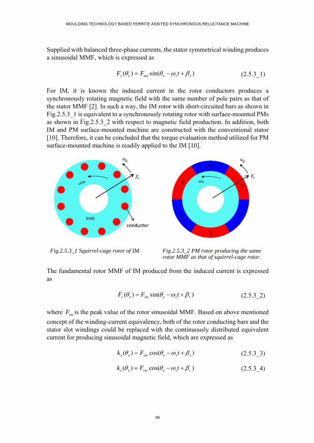
MOULDING TECHNOLOGY BASED FERRITE ASSITED SYNCHRONOUS RELUCTANCE MACHINE
56
Supplied with balanced three-phase currents, the stator symmetrical winding produces a sinusoidal MMF, which is expressed as
( ) sin( )s e sm e s sF F t (2.5.3_1)
For IM, it is known the induced current in the rotor conductors produces a synchronously rotating magnetic field with the same number of pole pairs as that of the stator MMF [2]. In such a way, the IM rotor with short-circuited bars as shown in Fig.2.5.3_1 is equivalent to a synchronously rotating rotor with surface-mounted PMs as shown in Fig.2.5.3_2 with respect to magnetic field production. In addition, both IM and PM surface-mounted machine are constructed with the conventional stator [10]. Therefore, it can be concluded that the torque evaluation method utilized for PM surface-mounted machine is readily applied to the IM [10].
Fig.2.5.3_1 Squirrel-cage rotor of IM. Fig.2.5.3_2 PM rotor producing the same rotor MMF as that of squirrel-cage rotor.
The fundamental rotor MMF of IM produced from the induced current is expressed as
( ) sin( )r e rm e s rF F t (2.5.3_2)
where rmF is the peak value of the rotor sinusoidal MMF. Based on above mentioned
concept of the winding-current equivalency, both of the rotor conducting bars and the stator slot windings could be replaced with the continuously distributed equivalent current for producing sinusoidal magnetic field, which are expressed as
( ) cos( )s e sm e s sk F t (2.5.3_3)
( ) cos( )r e rm e s rk F t (2.5.3_4)

CHAPTER 2. THEORETICAL ANALYSIS OF AC MACHINE TORQUE
57
Neglecting the mutual effect between rotor and stator magnetic fields, the air gap magnetic field could be regarded as the linear superposition of the two magnetic fields [10], which are expressed as
0
( )( ) sin( )s e sm
s e e s s
F FB t
g g
(2.5.3_5)
0
( )( ) sin( )r e rm
r e e s r
F FB t
g g
(2.5.3_6)
where g refers to the effective length of the uniform air gap considering the effects of
both stator and rotor slot openings.
For IM, the voltage across each rotor bar contains three components, the emf component induced from the stator magnetic field ( ( )s mB ), the emf component
induced from the rotor magnetic field ( ( )r mB ) and the voltage drop on the resistance.
As each bar is short-circuited connected, the terminal voltage is zero, thus satisfying
0rr rs Re e u
(2.5.3_7)
where the vector of rre
is the back emf induced from the rotor magnetic field; rse
is
the back emf induced from the stator magnetic field; Ru is the voltage drop in the
resistance of conducting bars. Based on the principle of electromagnetic induction, the voltage components on the left side of (2.5.3_7) could be evaluated with the equations of
0( ) sin( ( ) )
2rs a s r sm e s r s
De l B t
(2.5.3_8)
0( ) sin( ( ) )
2rr a s r rm e s r r
De l B t
(2.5.3_9)
0cos( ( ) )R r rm e s r ru R k t
(2.5.3_10)
where s represents the electrical angular speed of the stator rotating magnetic field;
r refers to the rotor speed expressed in electrical radian per second; smB and rmB are
denoted as the peak values of stator and rotor magnetic fields, which are equal to
0smF
g and 0
rmF
g respectively; 0s and 0r represent the initial positions of the rotor
and stator magnetic field waveforms respectively; rR represents the resistance of rotor
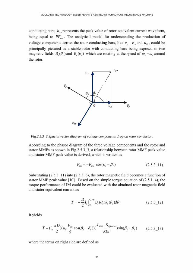
MOULDING TECHNOLOGY BASED FERRITE ASSITED SYNCHRONOUS RELUCTANCE MACHINE
58
conducting bars; rmk represents the peak value of rotor equivalent current waveform,
being equal to rmPF . The analytical model for understanding the production of
voltage components across the rotor conducting bars, like rre , rse and Ru , could be
principally pictured as a stable rotor with conducting bars being exposed to two magnetic fields ( )s eB and ( )r eB which are rotating at the speed of s r around
the rotor.
Fig.2.5.3_3 Spacial vector diagram of voltage components drop on rotor conductor.
According to the phasor diagram of the three voltage components and the rotor and stator MMFs as shown in Fig.2.5.3_3, a relationship between rotor MMF peak value and stator MMF peak value is derived, which is written as
scos( )rm sm rF F (2.5.3_11)
Substituting (2.5.3_11) into (2.5.3_6), the rotor magnetic field becomes a function of stator MMF peak value [10]. Based on the simple torque equation of (2.5.1_4), the torque performance of IM could be evaluated with the obtained rotor magnetic field and stator equivalent current as
2
0( ) ( )
2
P
a r e s e
DT l B k d
(2.5.3_12)
It yields
0 s s( )( cos( ))( )sin( )
2 2
RMS effectivesma r r
J SFDT l
g
(2.5.3_13)
where the terms on right side are defined as

CHAPTER 2. THEORETICAL ANALYSIS OF AC MACHINE TORQUE
59
0 s
2
cos( )
2
m a
smrm r
RMS effectivesm
s r
DK l
FB
g
J SPF
(2.5.3_14)
Thus, the simplified torque form is achieved for IM, which is written as
( ) sinm rm smT K B PF (2.5.3_15)
The same torque expression is achieved for IM as that of magnetic coupling and PM surface-mounted machine. For IM, the rotor magnetic field is determined by the basic dimensions, the peak value of stator MMF and the relative position between rotor and stator MMF axes [10].
2.5.4. SYNCHRONOUS RELUCTANCE MACHINE
Fig.2.5.4_1 SynRM with multi-barrier rotor topology.
SynRM is a typical representation of the salient-pole electric motors. For achieving a good compromise between the simple manufacturing process and high saliency effect, transversally laminated multi-barrier rotor geometry as shown in Fig.2.5.4_1 is widely utilized for such a machine type [22, 25-27]. Compared with PM surface-mounted machine and IM, it is easy to notice that SynRM has no magnetic field excitation source, like current or permanent magnets, on the rotor side [10]. Considering the simple torque evaluation method as mentioned above for PM surface-mounted machine and IM, it interprets the torque production principle as the interaction between two interacting magnetic fields which are associated with the stator and rotor sides respectively [10]. From such a point of view, the simple torque evaluation
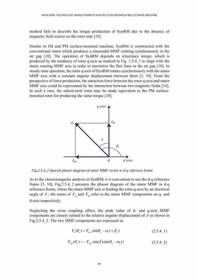
MOULDING TECHNOLOGY BASED FERRITE ASSITED SYNCHRONOUS RELUCTANCE MACHINE
60
method fails to describe the torque production of SynRM due to the absence of magnetic field source on the rotor side [10].
Similar to IM and PM surface-mounted machine, SynRM is constructed with the conventional stator which produces a sinusoidal MMF rotating synchronously in the air gap [10]. The operation of SynRM depends on reluctance torque, which is produced by the tendency of rotor q-axis as marked in Fig. 2.5.4_1 to align with the stator rotating MMF axis in order to maximize the flux lines in the air gap [10]. In steady state operation, the rotor q-axis of SynRM rotates synchronously with the stator MMF axis with a constant angular displacement between them [3, 10]. From the perspective of force production, the attraction force between the rotor q-axis and stator MMF axis could be represented by the interaction between two magnetic fields [10]. In such a case, the salient-pole rotor may be made equivalent to the PM surface-mounted rotor for producing the same torque [10].
Fig.2.5.4_2 Spacial phasor diagram of stator MMF vector in d-q reference frame.
As to the electromagnetic analysis in SynRM, it is convenient to use the d-q reference frame [3, 10]. Fig.2.5.4_2 presents the phasor diagram of the stator MMF in d-q reference frame, where the stator MMF axis is leading the rotor q-axis by an electrical angle of ; the terms of sqF and sdF refer to the stator MMF components on q- and
d-axis respectively.
Neglecting the cross coupling effect, the peak value of d- and q-axis MMF components are closely related to the relative angular displacement of as shown in Fig.2.5.4_2. The two MMF components are expressed as
( ) sin( )s e sm e s sF F t (2.5.4_1)
( ) sin( ) sin( )sd e sm e sF F t (2.5.4_2)
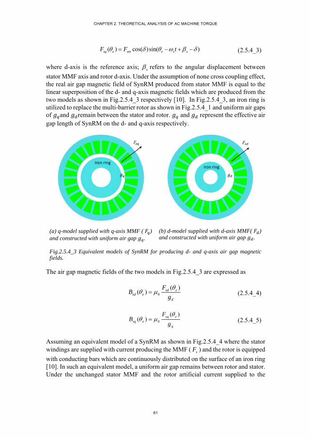
CHAPTER 2. THEORETICAL ANALYSIS OF AC MACHINE TORQUE
61
( ) cos( )sin( )sq e sm e s sF F t (2.5.4_3)
where d-axis is the reference axis; s refers to the angular displacement between
stator MMF axis and rotor d-axis. Under the assumption of none cross coupling effect, the real air gap magnetic field of SynRM produced from stator MMF is equal to the linear superposition of the d- and q-axis magnetic fields which are produced from the two models as shown in Fig.2.5.4_3 respectively [10]. In Fig.2.5.4_3, an iron ring is utilized to replace the multi-barrier rotor as shown in Fig.2.5.4_1 and uniform air gaps of and remain between the stator and rotor. and represent the effective air gap length of SynRM on the d- and q-axis respectively.
(a) q-model supplied with q-axis MMF ( ) and constructed with uniform air gap .
(b) d-model supplied with d-axis MMF( ) and constructed with uniform air gap .
Fig.2.5.4_3 Equivalent models of SynRM for producing d- and q-axis air gap magnetic fields.
The air gap magnetic fields of the two models in Fig.2.5.4_3 are expressed as
0
( )( ) sd e
sd ed
FB
g
(2.5.4_4)
0
( )( ) sq e
sq eq
FB
g
(2.5.4_5)
Assuming an equivalent model of a SynRM as shown in Fig.2.5.4_4 where the stator windings are supplied with current producing the MMF ( sF ) and the rotor is equipped
with conducting bars which are continuously distributed on the surface of an iron ring [10]. In such an equivalent model, a uniform air gap remains between rotor and stator. Under the unchanged stator MMF and the rotor artificial current supplied to the
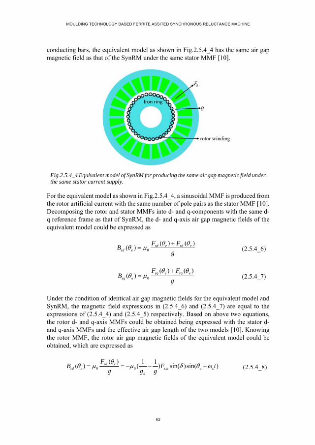
MOULDING TECHNOLOGY BASED FERRITE ASSITED SYNCHRONOUS RELUCTANCE MACHINE
62
conducting bars, the equivalent model as shown in Fig.2.5.4_4 has the same air gap magnetic field as that of the SynRM under the same stator MMF [10].
Fig.2.5.4_4 Equivalent model of SynRM for producing the same air gap magnetic field under the same stator current supply.
For the equivalent model as shown in Fig.2.5.4_4, a sinusoidal MMF is produced from the rotor artificial current with the same number of pole pairs as the stator MMF [10]. Decomposing the rotor and stator MMFs into d- and q-components with the same d-q reference frame as that of SynRM, the d- and q-axis air gap magnetic fields of the equivalent model could be expressed as
0
( ) ( )( ) sd e rd e
sd e
F FB
g
(2.5.4_6)
0
( ) ( )( ) sq e rq e
sq e
F FB
g
(2.5.4_7)
Under the condition of identical air gap magnetic fields for the equivalent model and SynRM, the magnetic field expressions in (2.5.4_6) and (2.5.4_7) are equal to the expressions of (2.5.4_4) and (2.5.4_5) respectively. Based on above two equations, the rotor d- and q-axis MMFs could be obtained being expressed with the stator d- and q-axis MMFs and the effective air gap length of the two models [10]. Knowing the rotor MMF, the rotor air gap magnetic fields of the equivalent model could be obtained, which are expressed as
0 0
( ) 1 1( ) ( ) sin( )sin( )rd e
rd e sm e sd
FB F t
g g g
(2.5.4_8)
CHAPTER 2. THEORETICAL ANALYSIS OF AC MACHINE TORQUE
63
0 0
( ) 1 1( ) ( ) cos( ) sin( )rq e
rq e sm e s sq
FB F t
g g g
(2.5.4_9)
For the equivalent model of SynRM as shown in Fig.2.5.4_4, the stator slot windings could be made equivalent to the continuously distributed current-carrying conductors exposed to the air gap magnetic field produced from the rotor current [10]. The stator equivalent current is expressed as
( ) cos( )e sm e s sk PF t (2.5.4_10)
Applying the simple torque equation of (2.5.1_4), the torque performance of the equivalent model of SynRM could be evaluated, which is expressed as
2
0( )( ( ) ( ))
2
P
a e rd e rq e e
DT l k B B d
(2.5.4_11)
It yields
0 cos
( )( (1 ))( ) sin2 2
q RMS effectivesma
q d
g J SFDT l
g g
(2.5.4_12)
where the terms on right side are defined as
0
2cos
(1 )
2sin sin
m a
qsmrm
q d
RMS effectivesm
DK l
gFB
g g
J SPF
(2.5.4_13)
Thus the torque expression of (2.5.4_12) could be transformed into the same form used for the other electric machines, as
( ) sin( )m rm smT K B PF (2.5.4_14)
SynRM has the same torque form as that of the electric machines above mentioned. While, in the torque expression of (2.5.4_14), the rotor magnetic field term ( rmB ) is
artificial, indicating the saliency effect of the multi-barrier rotor topology [10]. For SynRM, the rotor artificial magnetic field is acting on the q-axis of the multi-barrier

MOULDING TECHNOLOGY BASED FERRITE ASSITED SYNCHRONOUS RELUCTANCE MACHINE
64
rotor and its amplitude is determined by the stator MMF ( smF ), effective air gap ratio
( q
d
g
g) and the cosine function of the angular displacement between stator MMF axis
and rotor magnetic field axis ( cos ). Based on torque expression in (2.5.4_12), it can be figured out the angular displacement of 45 electrical degrees is the theoretical angle for achieving the maximum reluctance torque for per unit current [10].
Fig.2.5.4_5 Simple SynRM model with one-barrier rotor and PM surface-mounted stator.
It is a little difficult to validate the torque expression in (2.5.4_12) with the multi-barrier rotor topology, as the effective air gap length, dg and qg respectively, are
closely related to the geometrical parameters, like the flux barrier dimensions, the flux barrier end positions and the thickness of iron bridges [10]. For simplification, one-barrier rotor as shown in Fig.2.5.4_5 is intended for such a purpose. As is known, the torque expression in (2.5.4_12) is derived under the conditions of no leakage flux, no saturation in the main magnetic path and no coupling effect between the d- and the q-axis magnetic fields [10]. To comply with these ideal assumptions, a surface-mounted stator is placed out the one-barrier rotor as shown in Fig.2.5.4_5 in order to avoid the potential influence of the relative position between stator slots and rotor barrier ends on the leakage flux and magnetic field distribution [10]. In addition, the flux barriers of the one-barrier rotor are designed with large barrier end span angle under the condition of no saturation in the iron, aiming at allowing all the d-axis flux lines of one pole to pass across the flux barriers [10]. In such a way, the effective air gap length of qg and dg in the torque expression of (2.5.4_12) could reasonably be regarded as
being equal to the real air gap length and the sum of the real air gap length and the barrier width respectively [10]. Fig.2.5.4_6 presents the torque calculation results obtained from the torque expression in (2.5.4_12) and the FE model in Fig.2.5.4_5.

CHAPTER 2. THEORETICAL ANALYSIS OF AC MACHINE TORQUE
65
Fig.2.5.4_6 Torque performance of the simple SynRM calculated by FEM and theoretical analysis.
In Fig.2.5.4_6, the horizontal axis represents the angular displacement between the stator MMF axis and the rotor magnetic field axis. According to the torque expression in (2.5.4_12), it could be figured out that the reluctance torque of SynRM is theoretically in sine waveform and fluctuates twice in one electrical period [10]. The blue curve in Fig.2.5.4_6 obtained from numerical calculation is distorted from the sinusoidal waveform, which may be due to the square magnetic field produced from the stator permanent magnets [10]. Comparing the fundamental components of the FE calculation result with the torque waveform obtained from the torque expression, it can be found they match well, which validates the torque expression.
2.5.5. UNIFIED TORQUE EXPRESSION
Applying the principle of Lorenz force and the concept of current equivalency, the torque performance of AC machines, like PM surface-mounted machine, IM and SynRM, is theoretically analyzed. Under assumptions of no leakage flux, linear magnetic system as well as infinite iron permeability, a unified torque expression is achieved, which is written as
sinm rm smT K B P F (2.5.5_1)
where the terms on the right side represent
mK Function of dimensions, involving stack length of electric machine and the air gap diameter;
rmB Peak value of the rotor sinusoidal air gap magnetic field;
P Pole pair number;
smF Peak value of stator sinusoidal MMF;
0 22.5 45 67.5 90 112.5 135 157.5 180-30
-20
-10
0
10
20
30
angular displacement between stator MMF axis and rotor q-axis (electrical degree)
torq
ue
(Nm
)
FEMfundamental component of FEMtheoretical analysis

MOULDING TECHNOLOGY BASED FERRITE ASSITED SYNCHRONOUS RELUCTANCE MACHINE
66
Angular displacement between stator MMF axis and rotor magnetic field axis.
The torque expression of (2.5.5_1) presents a clear physical picture for the torque production mechanism of an electric machine, which is interpreted as the interaction between rotor magnetic field and stator current [10]. In addition, from (2.5.5_1), a clear knowledge of the main parameters that affect torque production capability could be obtained.
Even though the unified torque expression of (2.5.5_1) is derived under ideal assumptions, it provides a universal method for understanding the torque production mechanism of different AC machine types, consequently obtaining a simple way for a general-purpose torque comparison.
2.6. TORQUE COMPARISON AMONG AC MACHINES
Various electric machine types have evolved and widely applied in industry [28]. Regarding the appropriate selection of an electric machine for a specific industrial application, it should be the result of a good compromise among all the possible considerations. Torque performance is one of the important factors that need to be considered to measure the performance of an electric machine [10, 29, 30]. Therefore, a simple and quick way for rough torque evaluation and torque comparison among different electric machine types is highly desired especially in the initial design [10].
This section focuses on a general-purpose torque comparison among different AC machine types based on the unified torque expression.
2.6.1. EXISTING TORQUE COMPARISON METHODS
Numerical analysis with the aid of FE software and the theoretical analysis based on the energy conservation principle are the most common methods that are utilized for torque evaluation and torque comparison among different types of electric machines [31-34].
Numerical analysis of machine torque performance is generally performed by applying the techniques of flux-MMF diagram or the Maxwell stress tensor [11, 35, 36]. Both of these methods could produce accurate calculation result of torque performance, while requiring detailed knowledge of the structure and geometrical dimensions of the electric machine for FE model construction [1, 7, 37]. In addition, the computing process takes time [37]. From such a point, the numerical method is not a convenient method for the general-purpose torque comparison at the initial stage of machine type selection.
CHAPTER 2. THEORETICAL ANALYSIS OF AC MACHINE TORQUE
67
Theoretical analysis of machine torque performance is generally based on the principle of energy conservation [1, 8, 38, 39]. Torque production of an electric machine is equal to the variation of magnetic energy for each rotor step [38, 39]. As to the magnetic energy in an electrical machine, it is generally evaluated from the point of view of magnetic field or the magnetic circuit [2]. From the point of magnetic field, the obtained torque expression is more suitable for the electric machines with uniform air gap between stator and rotor, not convenient for the torque evaluate t of salient-pole machine, like SynRM [2]. From the circuit point of view, the obtained torque equation is expressed in terms stator winding current and inductance. As is known, inductance is a function of rotor positions, especially for salient-pole machines, which make it more difficult to compare the torque performance of different types of electric machines based on such a torque expression [10]. For example, the derived torque equation expressed with d- and q-inductance and current is utilized in [30] for torque comparison between SynRM and IM. Under the condition of the same stator current supply, the torque ratio of SynRM and IM could be obtained by comparing their inductance. However, when considering the torque comparison with PM surface-mounted machine, this torque expression fails to give the result directly and quickly due to an additional PM flux linkage component.
2.6.2. UNIFIED TORQUE EQUATION BASED TORQUE COMPARISON
The derived torque expression in previous sections unifies the torque production mechanism of different AC machine types, additionally provides a universal torque evaluation method [10]. Based on such a unified torque expression, the torque comparison among different AC electric machines becomes intuitive simple and convenient.
Torque comparison among different electric machines is generally performed under some certain conditions, like the same stator current supply, the same loss production or the same temperature rise [40]. In this section, the torque comparison of PM surface-mounted machine IM and SynRM is presented, which is performed based on the unified torque expression under the conditions of the same current supply and the same loss production.
A. Condition-1: Same current supply.
Assuming the optimal current control strategy is applied to the three machine types of PM surface-mounted machine, IM and SynRM, the angular displacement related term in the torque expression is equal to 1. In such a case, the torque production of three machine types is expressed as

MOULDING TECHNOLOGY BASED FERRITE ASSITED SYNCHRONOUS RELUCTANCE MACHINE
68
_ max 0
_max 0
_ max 0
( ) ( ) ( )2
22( ) ( ) ( )
2 2 2
22( ) ( (1 )) ( )
2 2 2
n
r PMPM a B sm
PM
smIM a sm
qsmSynRM a sm
q d
M hDT l k PF
g h
FDT l PF
g
gFDT l PF
g g
(2.6.2_1)
where the rotor magnetic fields are expressed as
_ 0
_ 0
_ 0
2
2
2(1 )
2
n
r PMrm PM B
PM
smrm IM
qsmrm SynRM
q d
M hB k
g h
FB
g
gFB
g g
(2.6.2_2)
Additionally, the same stator configuration is assumed for PM surface-mounted
machine, IM and SynRM, which leads to equal terms of 2 a
Dl
in (2.6.2_1) for the
three machine types. According to the analysis of the stator winding current equivalency in previous section, it is known that the term of smPF is the same for the
three machine types under the condition of the same stator configuration and the same current supply. Therefore, only the terms associated with rotor magnetic fields of the three machine types need to be compared for the torque comparison, which are written as
_ 0
_ 0
_ 0
22 2
2 2 2
22 2(1 )
2 2 2
n
r PMPM rm PM B
PM
smIM rm IM
qsmSynRM rm SynRM
q d
M hC B k
g h
FC B
g
gFC B
g g
(2.6.2_3)
For electric machines with the same stator configuration and the same current supply, their rotor magnetic fields are generally designed to be similar. Without considering iron saturation along the main magnetic path, the effective air gap of SynRM on the q-axis is reasonably regarded as being equal to the effective length of the real air gap, thus equal to that of IM and PM surface-mounted machine. According to the basic
CHAPTER 2. THEORETICAL ANALYSIS OF AC MACHINE TORQUE
69
definition of inductance, it can be derived that the ratio of q
d
g
gin the rotor magnetic
field expression of SynRM in (2.6.2_2) is equal to the inductance ratio of d
q
L
Lwhich
is generally utilized to represent the saliency effect of SynRM. According to the existing literature and the commercial products of SynRMs, the inductance ratios of 1/7 and 1/8 have been reported. Taking the air gap length ratio of 1/7 as an example, the rotor magnetic field of IM is about 1.17 times that of SynRM under the same current supply. In such a case, the ratio of the rotor magnetic field for the three machines is obtained as
_ _ _: : 1 :1: 0.857rm PM rm IM rm SynRMB B B (2.6.2_4)
Substituting the ratio values in (2.6.2_4) into (2.6.2_3), the torque ratio of the three machine types are calculated as
_ max _ max _max: : 1.414 :1: 0.857PM IM SynRMT T T (2.6.2_5)
Therefore, under the conditions of the same stator configuration, identical stator current supply and rotor magnetic field, PM surface-mounted machine has the highest torque production among the three machine types and the SynRM has the lowest torque production capability. When saliency ratio higher than 7 is achieved by optimal density of SynRM rotor structure, the torque production of SynRM is approaching that of the IM.
B. Condition-2: Same loss production.
Loss production not only affects the whole efficiency of an electric machine but also leads to temperature rise which could put machine at risk due to the problem of insulation deterioration. Therefore, loss production of an electric machine is also one of the important factors that measure the performance of electric machine. In this section, the torque performance of the three machine types are compared based on the unified torque expression under the condition of the same loss production.
Electric machine loss mainly consists of copper loss, iron loss, mechanical loss and stray load loss. The latter three loss components are closely related to rotor rotating speed, electrical frequency, flux density and machine volume, which are assumed to be identical for the three machine types. Therefore, only the copper loss of the three machine types is considered in the torque comparison.
1. Stator copper loss

MOULDING TECHNOLOGY BASED FERRITE ASSITED SYNCHRONOUS RELUCTANCE MACHINE
70
Assuming all the stator winding coils are connected in series. Without considering the end winding, the copper loss of stator windings could be expressed as
2_ _2s cu s RMS aP N J s l (2.6.2_6)
where N represents the turn number of total stator winding coils; s is the cross-sectional area of the copper conductor; al denotes the stack length of electric machine;
_s RMSJ is the RMS value of the current density supplied in the stator copper conductor.
Considering the product of 2N s being equal to the total slot effective area ( effectiveS ),
the expression of stator winding copper loss in (2.6.2_6) could be transformed into the form as
2_ _s cu s RMS effective aP J S l (2.6.2_7)
Considering the product of smP F being equal to _
2
s RMS effectiveJ S
, the expression of
stator winding copper loss in (2.6.2_7) is further transformed into the form as
_ _2 ( )s cu sm s RMS aP PF J l (2.6.2_8)
2. Rotor copper loss
Among the three electric machine types, only the IM has current supply on the rotor side, which leads to the production of copper loss.
According to the theoretical analysis of IM torque performance, it is known that sinusoidal current is induced in the rotor conductors, thus producing a sinusoidal MMF rotating synchronously with stator MMF waveform. With the same method as that used for calculating stator copper loss, the rotor copper loss could be expressed in a similar form which is written as
_ _2 ( )r cu rm r RMS aP PF J l (2.6.2_9)
where rmF represents the peak value of rotor MMF; _r RMSJ denotes the RMS value of
the current density in the rotor copper conductors.
The rotor current density ( _r RMSJ ) is assumed to be equal to the stator current density
( _s RMSJ ). Under optimal current control of IM, the relationship of 2
2rm smF F is
CHAPTER 2. THEORETICAL ANALYSIS OF AC MACHINE TORQUE
71
achieved. Based on above two conditions, the rotor copper loss expression in (2.6.2_9) is transformed in to a form as
_ _( )r cu sm s RMS aP PF J l (2.6.2_10)
3. Torque comparison
The copper loss of the three machine types are expressed as
2_ _
2_ _
2_ _
2(1 )
2
cu PM RMS PM effective a
cu IM RMS IM effective a
cu SynRM RMS SynRM effective a
P J S l
P J S l
P J S l
(2.6.2_11)
Under the conditions of the same stator configuration, the current density of the three electric machine types has to satisfy the relationship as written in (2.6.2_10) in order to produce the same copper loss.
_ _ _: : 1: 0.765 :1RMS PM RMS IM RMS SynRMJ J J (2.6.2_12)
Under such a current density supply, the product of smP F of the three electric
machine types has the same ratio as that of current density expressed in (2.6.2_10). The ratio of the rotor magnetic field for the three electric machines is expressed as
_ _ _: : 1 : 0.893 :1rm PM rm IM rm SynRMB B B (2.6.2_13)
Based on the torque expressions in (2.6.2_3), the torque ratio of the three machine types could be calculated, as
_ max _ max _max: : 2.07 :1:1.464PM IM SynRMT T T (2.6.2_14)
Under the condition of identical copper loss, PM surface-mounted machine has the highest torque production capability and SynRM has higher torque production than IM.
Based on the torque comparison analysis above, the unified torque expression provides a convenient way of torque comparison for different machine types.
2.7. SUMMARY OF CHAPTER 2.
This chapter is focused on

MOULDING TECHNOLOGY BASED FERRITE ASSITED SYNCHRONOUS RELUCTANCE MACHINE
72
1. Exploring an intuitive and universal way to understand the torque production mechanism for different machine types.
2. Unifying the torque expression for different AC machines.
3. Performing a simple torque comparison among different AC machines based on the unified torque expression.

CHAPTER 2. THEORETICAL ANALYSIS OF AC MACHINE TORQUE
73
Reference
1. S. Niu, S. L. Ho and W. N. Fu, "Power Balanced Electromagnetic Torque Computation in Electric Machines Based on Energy Conservation in Finite-Element Method," in IEEE Transactions on Magnetics, vol. 49, no. 5, pp. 2385-2388, May 2013.
2. A. E. Fitzgerald, Charles Kingsley, Jr., Stephen D. Umans, “Electric Machinery,” six edition, 2003.
3. D. Wang, K. Lu and P. O. Rasmussen, "A general and intuitive approach to understand and compare the torque production capability of AC machines," 2014 17th International Conference on Electrical Machines and Systems (ICEMS), Hangzhou, 2014, pp. 3136-3142.
4. C. M. Spargo, B. C. Mecrow and J. D. Widmer, "A Seminumerical Finite-Element Postprocessing Torque Ripple Analysis Technique for Synchronous Electric Machines Utilizing the Air-Gap Maxwell Stress Tensor," in IEEE Transactions on Magnetics, vol. 50, no. 5, pp. 1-9, May 2014.
5. C. Ferreira and J. Vaidya, "Torque analysis of permanent magnet coupling using 2D and 3D finite elements methods," in IEEE Transactions on Magnetics, vol. 25, no. 4, pp. 3080-3082, Jul 1989.
6. L. Petkovska, M. Cundev and G. Cvetkovski, "Torque estimation of permanent magnet DC motor by different numerical methods," IEMDC 2001. IEEE International Electric Machines and Drives Conference (Cat. No.01EX485), Cambridge, MA, 2001, pp. 803-805.
7. L. Perkkiö, P. Rasilo, B. Silwal, A. Hannukainen, A. Arkkio and T. Eirola, "Energy-Preserving Methods and Torque Computation From Energy Balance in Electrical Machine Simulations," in IEEE Transactions on Magnetics, vol. 52, no. 8, pp. 1-8, Aug. 2016.
8. P. L. Alger and W. R. Oney, "Torque-Energy Relations in Induction Machines [includes discussion]," in Transactions of the American Institute of Electrical Engineers. Part III: Power Apparatus and Systems, vol. 73, no. 1, Jan. 1954.
9. D. G. Dorrell, M. Popescu and M. I. McGilp, "Torque Calculation in Finite Element Solutions of Electrical Machines by Consideration of Stored Energy," in IEEE Transactions on Magnetics, vol. 42, no. 10, pp. 3431-3433, Oct. 2006.
10. Q. Wu, K. Lu, P. O. Rasmussen, N. Bianchi and K. F. Rasmussen, "Unified equivalent MMF concept for torque analysis of AC machines," 2017 IEEE International Electric Machines and Drives Conference (IEMDC), Miami, FL, 2017, pp. 1-8.
MOULDING TECHNOLOGY BASED FERRITE ASSITED SYNCHRONOUS RELUCTANCE MACHINE
74
11. D. A. Staton, R. P. Deodhar, W. L. Soong and T. J. E. Miller, "Torque prediction using the flux-MMF diagram in AC, DC, and reluctance motors," in IEEE Transactions on Industry Applications, vol. 32, no. 1, pp. 180-188, Jan/Feb 1996.
12. A. Bermúdez, A. L. Rodríguez and I. Villar, "Extended Formulas to Compute Resultant and Contact Electromagnetic Force and Torque From Maxwell Stress Tensors," in IEEE Transactions on Magnetics, vol. 53, no. 4, pp. 1-9, April 2017.
13. J. Wang and J. Zhu, "A Simple Method for Performance Prediction of Permanent Magnet Eddy Current Couplings Using a New Magnetic Equivalent Circuit Model," in IEEE Transactions on Industrial Electronics, vol. 65, no. 3, pp. 2487-2495, March 2018.
14. A. Tessarolo, M. Bortolozzi and C. Bruzzese, "Explicit Torque and Back EMF Expressions for Slotless Surface Permanent Magnet Machines With Different Magnetization Patterns," in IEEE Transactions on Magnetics, vol. 52, no. 8, pp. 1-15, Aug. 2016.
15. Gyu-Hong Kang, Jung-Pyo Hong and Gyu-Tak Kim, "Permanent-magnet linear brushless motor by using equivalent magnetizing current," in IEEE Transactions on Industry Applications, vol. 37, no. 5, pp. 1241-1247, Sept.-Oct. 2001.
16. M. Barcaro and N. Bianchi, "Air-Gap Flux Density Distortion and Iron Losses in Anisotropic Synchronous Motors," in IEEE Transactions on Magnetics, vol. 46, no. 1, pp. 121-126, Jan. 2010.
17. T. Lubin, S. Mezani and A. Rezzoug, "Simple Analytical Expressions for the Force and Torque of Axial Magnetic Couplings," in IEEE Transactions on Energy Conversion, vol. 27, no. 2, pp. 536-546, June 2012.
18. J. Y. Choi, H. J. Shin, S. M. Jang and S. H. Lee, "Torque Analysis and Measurements of Cylindrical Air-Gap Synchronous Permanent Magnet Couplings Based on Analytical Magnetic Field Calculations," in IEEE Transactions on Magnetics, vol. 49, no. 7, pp. 3921-3924, July 2013.
19. Yeong-Der Yao, Gwo-Ji Chiou, Der-Ray Huang and Shyh-Jier Wang, "Theoretical computations for the torque of magnetic coupling," in IEEE Transactions on Magnetics, vol. 31, no. 3, pp. 1881-1884, May 1995.
20. Antero Arkkio, “analysis of inductance motors based on the numerical solution of the magnetic field and circuit equation,” doctor thesis, Dec. 1987.
21. O. I. Okoro, "Steady and transient states thermal analysis of a 7.5-kW squirrel-cage induction machine at rated-load operation," in IEEE Transactions on Energy Conversion, vol. 20, no. 4, pp. 730-736, Dec. 2005.
22. S. Cai, J. Shen, H. Hao and M. Jin, "Design methods of transversally laminated synchronous reluctance machines," in CES Transactions on Electrical Machines and Systems, vol. 1, no. 2, pp. 164-173, 2017.
CHAPTER 2. THEORETICAL ANALYSIS OF AC MACHINE TORQUE
75
23. K. Lang, A. Muetze, R. Bauer and S. Pircher, "Comparison of Induction and Synchronous Reluctance Machine Based Actuators for Elevated Temperature Environments," in IEEE Transactions on Energy Conversion, vol. 31, no. 3, pp. 1012-1022, Sept. 2016.
24. E. B. Agamloh, A. Cavagnino and S. Vaschetto, "Impact of Number of Poles on the Steady-State Performance of Induction Motors," in IEEE Transactions on Industry Applications, vol. 52, no. 2, pp. 1422-1430, March-April 2016.
25. J. X. Shen, S. Cai, H. Hao and M. J. Jin, "Comprehensive parameter design for transversally laminated synchronous reluctance machines," 2016 19th International Conference on Electrical Machines and Systems (ICEMS), Chiba, 2016, pp. 1-9.
26. Z. Y. Zhang, M. C. Tsai, P. W. Huang, C. W. Cheng and J. M. Huang, "Characteristic comparison of transversally laminated anisotropic synchronous reluctance motor fabrication based on 2D lamination and 3D printing," 2015 18th International Conference on Electrical Machines and Systems (ICEMS), Pattaya, 2015, pp. 894-897.
27. P. Hudak, V. Hrabovcova and P. Rafajdus, "Geometrical dimension influence of multi-barrier rotor on reluctance synchronous motor performances," International Symposium on Power Electronics, Electrical Drives, Automation and Motion, 2006. SPEEDAM 2006, Taormina, 2006, pp. 346-351.
28. Gérard-André Capolino; Andrea Cavagnino, “New trends in electrical machines technology,” in IEEE Transactions on Industrial Electronics, vol. 61, no. 8, pp: 4281-4285, 2014.
29. H. B. Kang, J. Y. Choi, H. W. Cho and J. H. Kim, "Comparative Study of Torque Analysis for Synchronous Permanent Magnet Coupling With Parallel and Halbach Magnetized Magnets Based on Analytical Field Calculations," in IEEE Transactions on Magnetics, vol. 50, no. 11, pp. 1-4, Nov. 2014.
30. T. A.Lipo, “synchronous reluctance machine a variable alternative for ac drives,” research report at Wisconsin Electric Machines and Power Electronics Consortium, May 1991, Madison, USA.
31. G. Wakui, K. Kurihara and T. Kubota, "Radial flux type hysteresis motor with reaction torque--Numerical analysis of hysteresis motor using finite element method," in IEEE Transactions on Magnetics, vol. 23, no. 5, pp. 3845-3852, Sep 1987.
32. M. R. Alizadeh Pahlavani and H. A. Mohammadpour, "Electromagnetic Torque and Force Analysis of Toroidal Field Coil Using Numerical and Experimental Results Applicable to Tokamak Reactors," in IEEE Transactions on Plasma Science, vol. 38, no. 7, pp. 1632-1638, July 2010.
MOULDING TECHNOLOGY BASED FERRITE ASSITED SYNCHRONOUS RELUCTANCE MACHINE
76
33. A. K. Repo, P. Rasilo, A. Niemenmaa and A. Arkkio, "Identification of Electromagnetic Torque Model for Induction Machines With Numerical Magnetic Field Solution," in IEEE Transactions on Magnetics, vol. 44, no. 6, pp. 1586-1589, June 2008.
34. D. M. Ionel, M. Popescu, M. I. McGilp, T. J. E. Miller and S. J. Dellinger, "Assessment of torque components in brushless permanent-magnet machines through numerical analysis of the electromagnetic field," in IEEE Transactions on Industry Applications, vol. 41, no. 5, pp. 1149-1158, Sept.-Oct. 2005
35. R. P. Deodhar, D. A. Staton, T. M. Jahns and T. J. E. Miller, "Prediction of cogging torque using the flux-MMF diagram technique," in IEEE Transactions on Industry Applications, vol. 32, no. 3, pp. 569-576, May/Jun 1996.
36. A. Bermúdez, A. L. Rodríguez and I. Villar, "Extended Formulas to Compute Resultant and Contact Electromagnetic Force and Torque From Maxwell Stress Tensors," in IEEE Transactions on Magnetics, vol. 53, no. 4, pp. 1-9, April 2017.
37. X. Zhang, S. L. Ho and W. N. Fu, "Fast Algorithm to Obtain the Torque Characteristics With Respect to Load Angle of Synchronous Machines Using Finite Element Method," in IEEE Transactions on Magnetics, vol. 50, no. 11, pp. 1-4, Nov. 2014.
38. K. F. Wong, K. W. E. Cheng and S. L. Ho, "Four-quadrant instantaneous torque control of switched reluctance machine at low speed based on co-energy control," in IET Electric Power Applications, vol. 3, no. 5, pp. 431-444, September 2009.
39. C. Cossar, M. Popescu, T. J. E. Miller, M. McGilp and M. Olaru, "A General Magnetic-Energy-Based Torque Estimator: Validation via a Permanent-Magnet Motor Drive," in IEEE Transactions on Industry Applications, vol. 44, no. 4, pp. 1210-1217, July-aug. 2008.
40. H. Wang et al., "Loss Calculation and Temperature Field Analysis of Consequent-Pole Hybrid Excited Vernier Machine," in IEEE Transactions on Magnetics, vol. 53, no. 11, pp. 1-5, Nov. 2017.
CHAPTER 3. PROTOTYPING OF FERRITE MOULDED SYNRM
77
CHAPTER 3. PROTOTYPING OF
FERRITE MOULDED SYNRM
3.1. INTRODUCTION
SynRM is a promissing candidate in industrial applications due to the advantages of low cost, simple manufacturing process and robust geometrical structure [1]; while, it still suffers from the drawbacks of relatively low torque production capability, high torque ripple and bad power factor performance, which prevent such a machine type from being widely used in the industries [1-3]. Utilizing the multi-barrier rotor topology and adding ferrite magnet into the rotor flux barriers, leading to the machine type of Ferrite Assited SynRM (FASynRM), has been demonstrated as the most effective and economic strategies for improving the torque production and power factor, thus relieving the main problems associated with SynRM [4-7]. The ferrite installation of FASynRM needs special manufacturing process, which could be accomplished with the ferrite insertion strategy or the ferrite moulding technology. According to the existing literature, it can be found that ferrite insertion strategy is the most commonly adopted method for the ferrite installation of FASynRM. The application of moulding technology is mentioned in [9, 10], while little introduction about such a ferrite installation method is presented. In addition, the plasto-ferrite utilized in [9, 10] is isotropic, thus achieving remanent flux density even lower than half of the remanent flux density of the sintered ferrite magnet.
For achieving relatively simple ferrite installation manufacturing process in contrast to the ferrite insertion strategy while without reducing too much remanent flux density, moulding technology, anisotropic plasto-ferrite and together with the Halbach magnet ring are in this chapter.
3.2. INTRODUCTION OF MOULDING TECHNOLOGY
In industrial applications, moulding technology refers to the manufaturing process where the liquid or pliable raw materials are injected into a mold and solidified into the same shape as that of the mold [11]. Therefore, by utilizing the moulding technology for ferrite installation of FASynRM, the ferrite magnet could fit the flux barrier shape well and fully fill each individual flux barrier cavity [8]. Fig.3.2_1 presents the ferrite magnet material being used for moulding technology, which is made from a mixture of ferrite magnet powder and a kind of binder material. The ferrite magnet pellets in Fig.3.2_1 turns into liquid at high temperature and solidifies when temperature decreases [8].
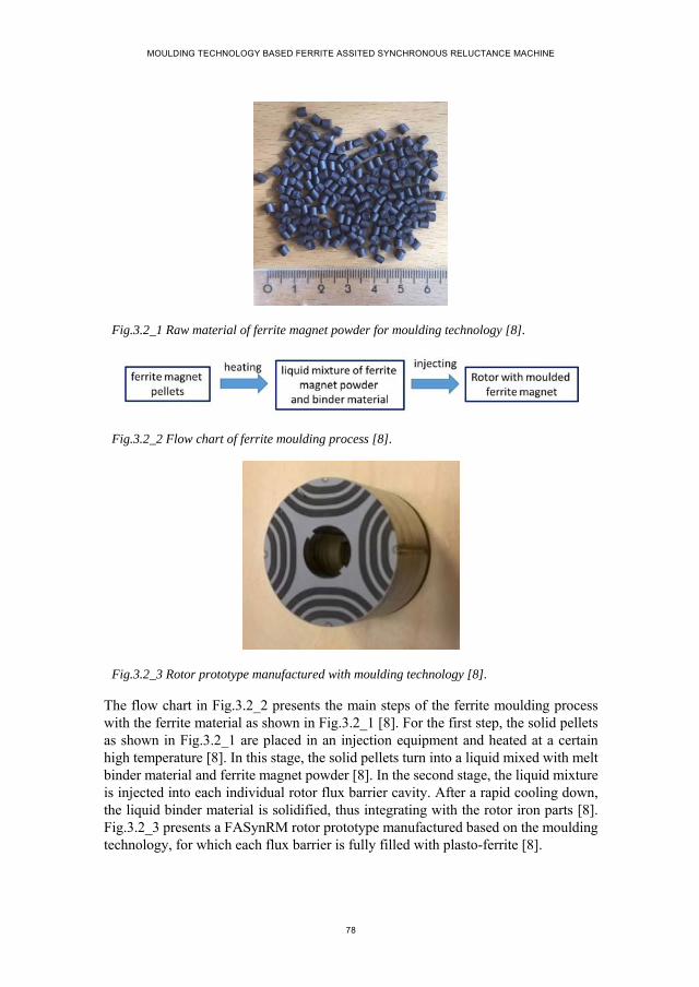
MOULDING TECHNOLOGY BASED FERRITE ASSITED SYNCHRONOUS RELUCTANCE MACHINE
78
Fig.3.2_1 Raw material of ferrite magnet powder for moulding technology [8].
Fig.3.2_2 Flow chart of ferrite moulding process [8].
Fig.3.2_3 Rotor prototype manufactured with moulding technology [8].
The flow chart in Fig.3.2_2 presents the main steps of the ferrite moulding process with the ferrite material as shown in Fig.3.2_1 [8]. For the first step, the solid pellets as shown in Fig.3.2_1 are placed in an injection equipment and heated at a certain high temperature [8]. In this stage, the solid pellets turn into a liquid mixed with melt binder material and ferrite magnet powder [8]. In the second stage, the liquid mixture is injected into each individual rotor flux barrier cavity. After a rapid cooling down, the liquid binder material is solidified, thus integrating with the rotor iron parts [8]. Fig.3.2_3 presents a FASynRM rotor prototype manufactured based on the moulding technology, for which each flux barrier is fully filled with plasto-ferrite [8].

CHAPTER 3. PROTOTYPING OF FERRITE MOULDED SYNRM
79
Based on the above detailed introduction of the ferrite moulding process, the characteristics of such a ferrite installation method could be concluded as
1. By using moulding technology, the ferrite installation could be automatically completed in a single step, which greatly simplifies the manufacturing process and saves a lot of the human labor [8];
2. By using moulding technology, all the rotor flux barriers of FASynRM are fully filled with ferrite magnet without leaving any air gaps between the rotor iron and the ferrite magnet, which is beneficial for the rotor mechanical strength [8];
3. By using moulding technology, the rotor flux barrier shape design is completely free from the shape of ferrite magnet, as the liquid mixture could fit any shapes of flux barriers well [8].
3.3. COMPARISON OF FERRITE INSTALLATION STRATEGIES
Two three-barrier rotors as shown in Fig.3.3_1 and Fig.3.3_2 are taken as an example to illustrate the difference between the two ferrite installation methods, that is, ferrite insertion strategy and ferrite moulding technology. The two rotors are exactly the same with respect to the rotor basic dimensions, flux barrier shape and loations in the rotor iron and the iron material [8]. For the rotor model in Fig.3.3_1, the ferrite magnet pieces are manufactured with sintering process and individually inserted into the rotor flux barriers. For the second rotor model in Fig.3.3_2, plasto-ferrite is utilized to fill the flux barriers with the moudling technology.
Fig.3.3_1 Ferrite inserted multi-barrier rotor.
Fig.3.3_2 Ferrite moulded multi-barrier rotor.
MOULDING TECHNOLOGY BASED FERRITE ASSITED SYNCHRONOUS RELUCTANCE MACHINE
80
3.3.1. MANUFACTURING PROCESS
Different ferrite installation methods have different manufacturing processes. Comparing the two rotor models as shown in Fig.3.3_1 and Fig.3.3_2 respectively, it is easy to tell that the ferrite magnets in the first rotor model are rectangular bars, while in the second rotor model are totally integrated with the rotor iron [8]. In addition, for the ferrite-inserted rotor model as shown in Fig.3.3_1, air gaps are left between two adjacent magnet bars as well as between the magnet and the rotor iron, which does not occur for the ferrite-moulded rotor as shown in Fig.3.3_2 [8].
Regarding the ferrite inserting process, the ferrite magnet pieces are firstly pre-formed into the shape fitting the flux barrier cavities, and then individually inserted into the rotor flux barriers [8]. In order to reduce the manufacturing cost, ferrite magnet pieces in regular shapes, like the rectangular bars as shown in Fig.3.3_1, are generally preferred [8]. In such a case, the flux barrier topology tends to be subject to the regular shape to accommodate the regular ferrite magnet pieces, thus leading to a limit on the flux barrier design flexibility and consequently limiting the potential of FASynRM for achieving the best performance by optimal rotor design [8]. In addition, to accommodate as big amount of ferrite magnet as possible, several pieces of ferrite magnet need to be inserted into each flux barrier e.g. 3 pieces for the rotor model as shown in Fig.3.3_1, counting to 36 pieces in total for the whole rotor that need to be shaped into different sizes and individually inserted into the rotor flux barriers [8]. Performing such ferrite magnet shaping and inserting processes leads to a significant increase in the cost, time and human labor [8]. Furthermore, iron ribs across the flux barriers as shown in Fig.3.3_1 are still needed by the ferrite insertion strategy to keep the ferrite magnet bars in position, which increases the manufacturing complexity of the laminations [8].
Comparing the ferrite insertion strategy with the ferrite moulding technology with respect to the manufacturing process, several conclusions may be summarized, as
1. Ferrite moulding process is much simpler and more time-saving than the ferrite inserting process [8].
2. The ferrite-inserted rotor suffers from limited flux barrier design flexibility, while such limit is completely removed by using the ferrite moulding technology [8].
3. Ferrite moulding technology allows the maximization of the ferrite magnet usage for any flux barrier topology and a strong integration of ferrite magnet and rotor iron [8].
4. Ferrite moulding technology allows a simpler lamination manufacturing process compared with the ferrite insertion strategy due to the absence of iron ribs across the flux barriers [8].

CHAPTER 3. PROTOTYPING OF FERRITE MOULDED SYNRM
81
Based on above comparison analysis, ferrite moulding technology competes advantageously over the ferrite insertion strategy with respect to the manufacturing process.
3.3.2. MAGNETIC PERFORMANCE
A. Property of ferrite magnet materials.
The ferrite magnet pieces used in the ferrite-inserted rotors are manufactured with the compressing and sintering process, producing 100% content of ferrite magnet [8]. For the plasto-ferrite magnet used for the moulding process, e.g. magnet pellets as shown in Fig.3.2_1, the ferrite magnet only accounts for approximately 86% by weight, the rest percentage being taken by the binder material [8]. Therefore, it is easy to figure out that the ferrite magnets used for the two installation methods respectively must be different in properties, like magnetic performance and mass density [8].
Taking the ferrite pallets as shown in Fig.3.2_1 as an example, Fig.3.3.2_1 presents the B-H curves of the sintered ferrite magnet pieces and the plasto-ferrite. From Fig.3.3.2_1, it is easy to notice that the magnetic performance of the sintered ferrite magnet is higher than that of the plasto-ferrite. The remanent flux density values are around 0.4T and 0.296T for the sintered ferrite magnet and the plasto-ferrite respectively [8].
Fig. 3.3.2_1 Second quadrant of BH curves of moulded ferrite magnet and sintered ferrite magnet [8].
The mass density of binder material is obviously lower than that of the ferrite magnet, thus leading to the mass density of the plasto-ferrite being lower than that of the pre-formed ferrite magnet pieces which are 3.5 / and4.85 / respectively [8]. For the two rotor models as shown in Fig.3.3_1 and Fig.3.3_2, it is a bit difficult to tell which one is necessarily heavier, as the volume of the ferrite magnet consumed
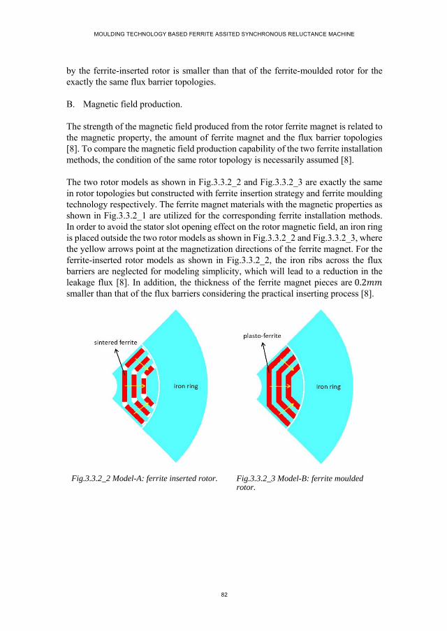
MOULDING TECHNOLOGY BASED FERRITE ASSITED SYNCHRONOUS RELUCTANCE MACHINE
82
by the ferrite-inserted rotor is smaller than that of the ferrite-moulded rotor for the exactly the same flux barrier topologies.
B. Magnetic field production.
The strength of the magnetic field produced from the rotor ferrite magnet is related to the magnetic property, the amount of ferrite magnet and the flux barrier topologies [8]. To compare the magnetic field production capability of the two ferrite installation methods, the condition of the same rotor topology is necessarily assumed [8].
The two rotor models as shown in Fig.3.3.2_2 and Fig.3.3.2_3 are exactly the same in rotor topologies but constructed with ferrite insertion strategy and ferrite moulding technology respectively. The ferrite magnet materials with the magnetic properties as shown in Fig.3.3.2_1 are utilized for the corresponding ferrite installation methods. In order to avoid the stator slot opening effect on the rotor magnetic field, an iron ring is placed outside the two rotor models as shown in Fig.3.3.2_2 and Fig.3.3.2_3, where the yellow arrows point at the magnetization directions of the ferrite magnet. For the ferrite-inserted rotor models as shown in Fig.3.3.2_2, the iron ribs across the flux barriers are neglected for modeling simplicity, which will lead to a reduction in the leakage flux [8]. In addition, the thickness of the ferrite magnet pieces are 0.2 smaller than that of the flux barriers considering the practical inserting process [8].
Fig.3.3.2_2 Model-A: ferrite inserted rotor. Fig.3.3.2_3 Model-B: ferrite moulded rotor.
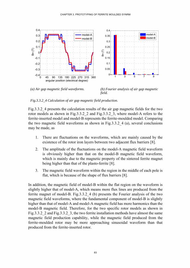
CHAPTER 3. PROTOTYPING OF FERRITE MOULDED SYNRM
83
(a) Air gap magnetic field waveforms. (b) Fourier analysis of air gap magnetic field.
Fig.3.3.2_4 Calculation of air gap magnetic field production.
Fig.3.3.2_4 presents the calculation results of the air gap magnetic fields for the two rotor models as shown in Fig.3.3.2_2 and Fig.3.3.2_3, where model-A refers to the ferrite-inserted model and model-B represents the ferrite-moulded model. Comparing the two magnetic field waveforms as shown in Fig.3.3.2_4 (a), several conclusions may be made, as
1. There are fluctuations on the waveforms, which are mainly caused by the existence of the rotor iron layers between two adjacent flux barriers [8].
2. The amplitude of the fluctuations on the model-A magnetic field waveform is obviously higher than that on the model-B magnetic field waveform, which is mainly due to the magnetic property of the sintered ferrite magnet being higher than that of the plasto-ferrite [8].
3. The magnetic field waveform within the region in the middle of each pole is flat, which is because of the shape of flux barriers [8].
In addition, the magnetic field of model-B within the flat region on the waveform is slightly higher that of model-A, which means more flux lines are produced from the ferrite magnet of model-B. Fig.3.3.2_4 (b) presents the Fourier analysis of the two magnetic field waveforms, where the fundamental component of model-B is slightly higher than that of model-A and model-A magnetic field has more harmonics than the model-B magnetic field. Therefore, for the two specific rotor models as shown in Fig.3.3.2_2 and Fig.3.3.2_3, the two ferrite installation methods have almost the same magnetic field production capability, while the magnetic field produced from the ferrite-moulded rotor may be more approaching sinusoidal waveform than that produced from the ferrite-inserted rotor.
0 45 90 135 180 225 270 315 360-0.4
-0.3
-0.2
-0.1
0
0.1
0.2
0.3
0.4
angular position (electrical degree)
Bn
(T)
model-Amodel-B
1 3 5 7 90
0.05
0.1
0.15
0.2
0.25
0.3
0.35
0.4
Bn
(T
)
model-Amodel-B
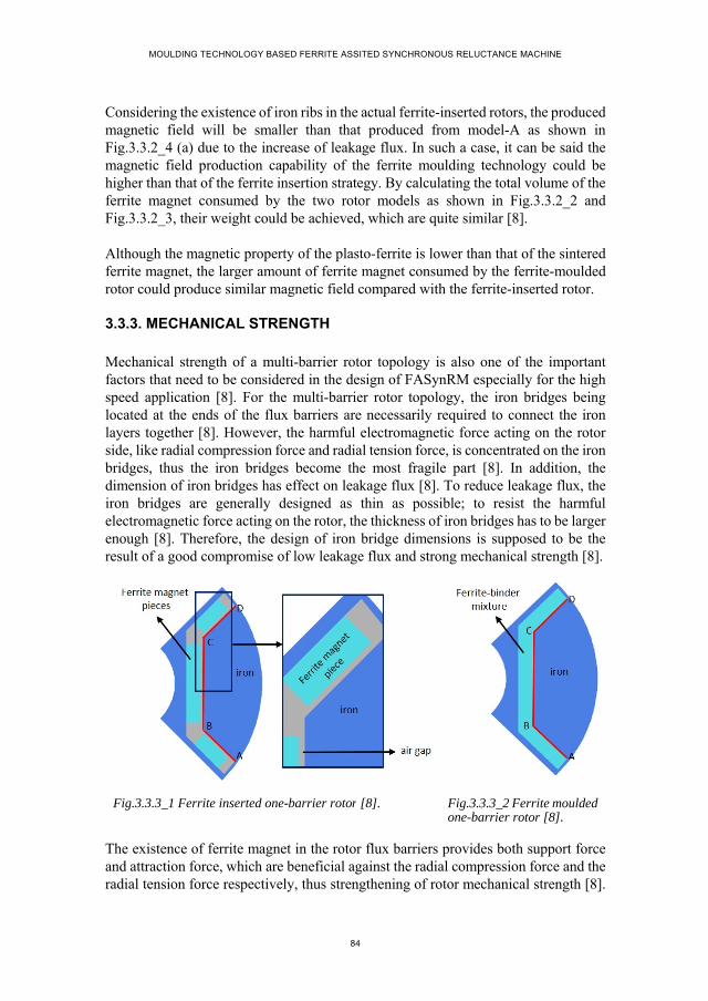
MOULDING TECHNOLOGY BASED FERRITE ASSITED SYNCHRONOUS RELUCTANCE MACHINE
84
Considering the existence of iron ribs in the actual ferrite-inserted rotors, the produced magnetic field will be smaller than that produced from model-A as shown in Fig.3.3.2_4 (a) due to the increase of leakage flux. In such a case, it can be said the magnetic field production capability of the ferrite moulding technology could be higher than that of the ferrite insertion strategy. By calculating the total volume of the ferrite magnet consumed by the two rotor models as shown in Fig.3.3.2_2 and Fig.3.3.2_3, their weight could be achieved, which are quite similar [8].
Although the magnetic property of the plasto-ferrite is lower than that of the sintered ferrite magnet, the larger amount of ferrite magnet consumed by the ferrite-moulded rotor could produce similar magnetic field compared with the ferrite-inserted rotor.
3.3.3. MECHANICAL STRENGTH
Mechanical strength of a multi-barrier rotor topology is also one of the important factors that need to be considered in the design of FASynRM especially for the high speed application [8]. For the multi-barrier rotor topology, the iron bridges being located at the ends of the flux barriers are necessarily required to connect the iron layers together [8]. However, the harmful electromagnetic force acting on the rotor side, like radial compression force and radial tension force, is concentrated on the iron bridges, thus the iron bridges become the most fragile part [8]. In addition, the dimension of iron bridges has effect on leakage flux [8]. To reduce leakage flux, the iron bridges are generally designed as thin as possible; to resist the harmful electromagnetic force acting on the rotor, the thickness of iron bridges has to be larger enough [8]. Therefore, the design of iron bridge dimensions is supposed to be the result of a good compromise of low leakage flux and strong mechanical strength [8].
Fig.3.3.3_1 Ferrite inserted one-barrier rotor [8]. Fig.3.3.3_2 Ferrite moulded one-barrier rotor [8].
The existence of ferrite magnet in the rotor flux barriers provides both support force and attraction force, which are beneficial against the radial compression force and the radial tension force respectively, thus strengthening of rotor mechanical strength [8].
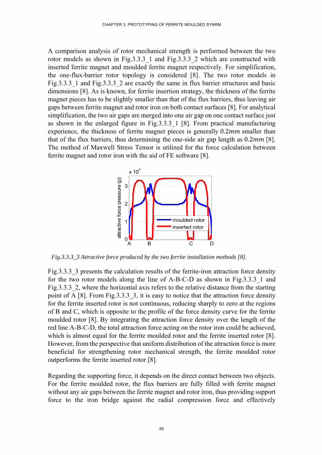
CHAPTER 3. PROTOTYPING OF FERRITE MOULDED SYNRM
85
A comparison analysis of rotor mechanical strength is performed between the two rotor models as shown in Fig.3.3.3_1 and Fig.3.3.3_2 which are constructed with inserted ferrite magnet and moulded ferrite magnet respectively. For simplification, the one-flux-barrier rotor topology is considered [8]. The two rotor models in Fig.3.3.3_1 and Fig.3.3.3_2 are exactly the same in flux barrier structures and basic dimensions [8]. As is known, for ferrite insertion strategy, the thickness of the ferrite magnet pieces has to be slightly smaller than that of the flux barriers, thus leaving air gaps between ferrite magnet and rotor iron on both contact surfaces [8]. For analytical simplification, the two air gaps are merged into one air gap on one contact surface just as shown in the enlarged figure in Fig.3.3.3_1 [8]. From practical manufacturing experience, the thickness of ferrite magnet pieces is generally 0.2 smaller than that of the flux barriers, thus determining the one-side air gap length as 0.2 [8]. The method of Maxwell Stress Tensor is utilized for the force calculation between ferrite magnet and rotor iron with the aid of FE software [8].
Fig.3.3.3_3 Attractive force produced by the two ferrite installation methods [8].
Fig.3.3.3_3 presents the calculation results of the ferrite-iron attraction force density for the two rotor models along the line of A-B-C-D as shown in Fig.3.3.3_1 and Fig.3.3.3_2, where the horizontal axis refers to the relative distance from the starting point of A [8]. From Fig.3.3.3_3, it is easy to notice that the attraction force density for the ferrite inserted rotor is not continuous, reducing sharply to zero at the regions of B and C, which is opposite to the profile of the force density curve for the ferrite moulded rotor [8]. By integrating the attraction force density over the length of the red line A-B-C-D, the total attraction force acting on the rotor iron could be achieved, which is almost equal for the ferrite moulded rotor and the ferrite inserted rotor [8]. However, from the perspective that uniform distribution of the attraction force is more beneficial for strengthening rotor mechanical strength, the ferrite moulded rotor outperforms the ferrite inserted rotor [8].
Regarding the supporting force, it depends on the direct contact between two objects. For the ferrite moulded rotor, the flux barriers are fully filled with ferrite magnet without any air gaps between the ferrite magnet and rotor iron, thus providing support force to the iron bridge against the radial compression force and effectively
A B C D0
1
2
3
x 104
attr
activ
e fo
rce
pres
sure
(p)
moulded rotor
inserted rotor
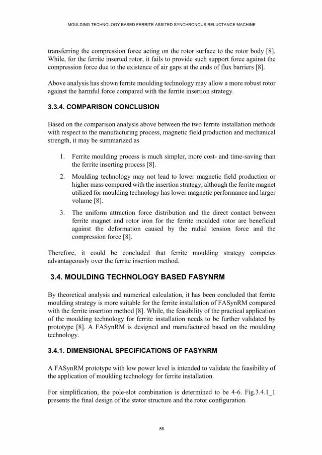
MOULDING TECHNOLOGY BASED FERRITE ASSITED SYNCHRONOUS RELUCTANCE MACHINE
86
transferring the compression force acting on the rotor surface to the rotor body [8]. While, for the ferrite inserted rotor, it fails to provide such support force against the compression force due to the existence of air gaps at the ends of flux barriers [8].
Above analysis has shown ferrite moulding technology may allow a more robust rotor against the harmful force compared with the ferrite insertion strategy.
3.3.4. COMPARISON CONCLUSION
Based on the comparison analysis above between the two ferrite installation methods with respect to the manufacturing process, magnetic field production and mechanical strength, it may be summarized as
1. Ferrite moulding process is much simpler, more cost- and time-saving than the ferrite inserting process [8].
2. Moulding technology may not lead to lower magnetic field production or higher mass compared with the insertion strategy, although the ferrite magnet utilized for moulding technology has lower magnetic performance and larger volume [8].
3. The uniform attraction force distribution and the direct contact between ferrite magnet and rotor iron for the ferrite moulded rotor are beneficial against the deformation caused by the radial tension force and the compression force [8].
Therefore, it could be concluded that ferrite moulding strategy competes advantageously over the ferrite insertion method.
3.4. MOULDING TECHNOLOGY BASED FASYNRM
By theoretical analysis and numerical calculation, it has been concluded that ferrite moulding strategy is more suitable for the ferrite installation of FASynRM compared with the ferrite insertion method [8]. While, the feasibility of the practical application of the moulding technology for ferrite installation needs to be further validated by prototype [8]. A FASynRM is designed and manufactured based on the moulding technology.
3.4.1. DIMENSIONAL SPECIFICATIONS OF FASYNRM
A FASynRM prototype with low power level is intended to validate the feasibility of the application of moulding technology for ferrite installation.
For simplification, the pole-slot combination is determined to be 4-6. Fig.3.4.1_1 presents the final design of the stator structure and the rotor configuration.
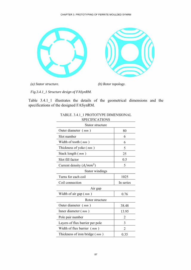
CHAPTER 3. PROTOTYPING OF FERRITE MOULDED SYNRM
87
(a) Stator structure. (b) Rotor topology.
Fig.3.4.1_1 Structure design of FASynRM.
Table 3.4.1_1 illustrates the details of the geometrical dimensions and the specifications of the designed FASynRM.
TABLE. 3.4.1_1 PROTOTYPE DIMENSIONAL SPECIFICATIONS
Stator structure
Outer diameter ( mm ) 80
Slot number 6
Width of tooth ( mm ) 6
Thickness of yoke ( mm ) 5
Stack length ( mm ) 25
Slot fill factor 0.5
Current density ( / ) 5
Stator windings
Turns for each coil 1025
Coil connection In series
Air gap
Width of air gap ( mm ) 0.76
Rotor structure
Outer diameter ( mm ) 38.48
Inner diameter ( mm ) 13.95
Pole pair number 2
Layers of flux barrier per pole 3
Width of flux barrier ( mm ) 2
Thickness of iron bridge ( mm ) 0.35
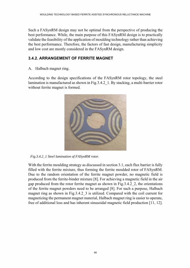
MOULDING TECHNOLOGY BASED FERRITE ASSITED SYNCHRONOUS RELUCTANCE MACHINE
88
Such a FASynRM design may not be optimal from the perspective of producing the best performance. While, the main purpose of this FASynRM design is to practically validate the feasibility of the application of moulding technology rather than achieving the best performance. Therefore, the factors of fast design, manufacturing simplicity and low cost are mostly considered in the FASynRM design.
3.4.2. ARRANGEMENT OF FERRITE MAGNET
A. Halbach magnet ring.
According to the design specifications of the FASynRM rotor topology, the steel lamination is manufactured as shown in Fig.3.4.2_1. By stacking, a multi-barrier rotor without ferrite magnet is formed.
Fig.3.4.2_1 Steel lamination of FASynRM rotor.
With the ferrite moulding strategy as discussed in section 3.1, each flux barrier is fully filled with the ferrite mixture, thus forming the ferrite moulded rotor of FASynRM. Due to the random orientation of the ferrite magnet powder, no magnetic field is produced from the ferrite-binder mixture [8]. For achieving a magnetic field in the air gap produced from the rotor ferrite magnet as shown in Fig.3.4.2_2, the orientations of the ferrite magnet powders need to be arranged [8]. For such a purpose, Halbach magnet ring as shown in Fig.3.4.2_3 is utilized. Compared with the coil current for magnetizing the permanent magnet material, Halbach magnet ring is easier to operate, free of additional loss and has inherent sinusoidal magnetic field production [11, 12].
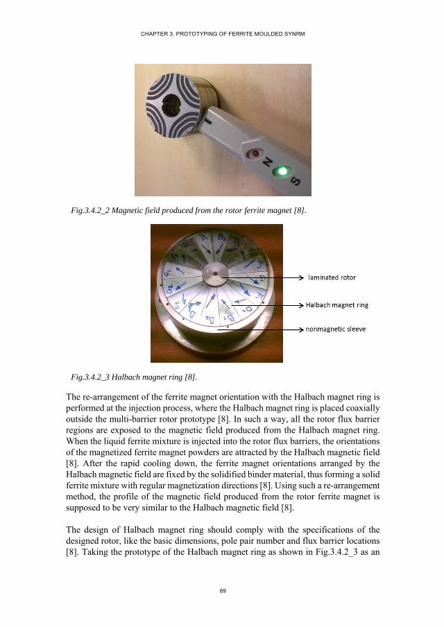
CHAPTER 3. PROTOTYPING OF FERRITE MOULDED SYNRM
89
Fig.3.4.2_2 Magnetic field produced from the rotor ferrite magnet [8].
Fig.3.4.2_3 Halbach magnet ring [8].
The re-arrangement of the ferrite magnet orientation with the Halbach magnet ring is performed at the injection process, where the Halbach magnet ring is placed coaxially outside the multi-barrier rotor prototype [8]. In such a way, all the rotor flux barrier regions are exposed to the magnetic field produced from the Halbach magnet ring. When the liquid ferrite mixture is injected into the rotor flux barriers, the orientations of the magnetized ferrite magnet powders are attracted by the Halbach magnetic field [8]. After the rapid cooling down, the ferrite magnet orientations arranged by the Halbach magnetic field are fixed by the solidified binder material, thus forming a solid ferrite mixture with regular magnetization directions [8]. Using such a re-arrangement method, the profile of the magnetic field produced from the rotor ferrite magnet is supposed to be very similar to the Halbach magnetic field [8].
The design of Halbach magnet ring should comply with the specifications of the designed rotor, like the basic dimensions, pole pair number and flux barrier locations [8]. Taking the prototype of the Halbach magnet ring as shown in Fig.3.4.2_3 as an
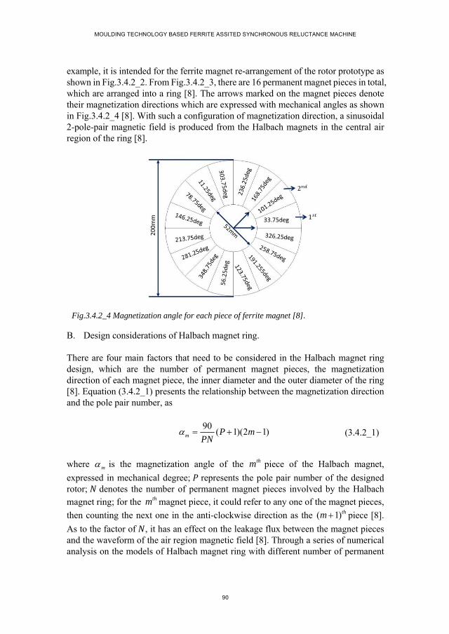
MOULDING TECHNOLOGY BASED FERRITE ASSITED SYNCHRONOUS RELUCTANCE MACHINE
90
example, it is intended for the ferrite magnet re-arrangement of the rotor prototype as shown in Fig.3.4.2_2. From Fig.3.4.2_3, there are 16 permanent magnet pieces in total, which are arranged into a ring [8]. The arrows marked on the magnet pieces denote their magnetization directions which are expressed with mechanical angles as shown in Fig.3.4.2_4 [8]. With such a configuration of magnetization direction, a sinusoidal 2-pole-pair magnetic field is produced from the Halbach magnets in the central air region of the ring [8].
Fig.3.4.2_4 Magnetization angle for each piece of ferrite magnet [8].
B. Design considerations of Halbach magnet ring.
There are four main factors that need to be considered in the Halbach magnet ring design, which are the number of permanent magnet pieces, the magnetization direction of each magnet piece, the inner diameter and the outer diameter of the ring [8]. Equation (3.4.2_1) presents the relationship between the magnetization direction and the pole pair number, as
90( 1)(2 1)m P m
PN (3.4.2_1)
where m is the magnetization angle of the thm piece of the Halbach magnet,
expressed in mechanical degree; represents the pole pair number of the designed rotor; denotes the number of permanent magnet pieces involved by the Halbach magnet ring; for the thm magnet piece, it could refer to any one of the magnet pieces,
then counting the next one in the anti-clockwise direction as the ( 1)thm piece [8].
As to the factor of , it has an effect on the leakage flux between the magnet pieces and the waveform of the air region magnetic field [8]. Through a series of numerical analysis on the models of Halbach magnet ring with different number of permanent

CHAPTER 3. PROTOTYPING OF FERRITE MOULDED SYNRM
91
magnet pieces, it can be concluded that when the number of magnet pieces for one pole is greater than 3, the influence of the magnet piece number on the magnetic field is not obvious [8]. Regarding the determination of the inner and outer diameter of the Halbach magnet ring, they depend on the rotor outer diameter and the flux barrier location [8]. Fig.3.4.2_5 presents a detailed FE calculation results of the flux-line and the flux-density distribution over the Halbach magnet ring and the central air region, where it is easy to notice that the flux density value is very high at the region near the inner surface of the Halbach magnet ring and then decreases gradually along the radial direction to zero at the central point [8]. The waveforms of the magnetic field normal component ( ) are also calculated in the central air region along different circles [8]. Fig.3.4.2_6 takes four waveforms as an example to illustrate the variation of the magnetic field in the air region of the Halbach magnet ring.
Fig.3.4.2_5 Distribution of flux line produced from the Halbach magnet ring [8].
Fig.3.4.2_6 waveforms in the central air region of Halbach magnet ring [8].
In Fig.3.4.2_6, the circle with the diameter of 50 is quite near the inner surface of the Halbach magnet ring which could be seen from Fig.3.4.2_5. The waveform on
0 30 60 90 120 150 180 210 240 270 300 330 360-2.1
-1.75
-1.4
-1.05
-0.7
-0.35
0
0.35
0.7
1.05
1.4
1.75
2.12.1
( mechanical degree )
Bn
(T
)
D=10mm
D=14mm
D=40mm
D=50mm

MOULDING TECHNOLOGY BASED FERRITE ASSITED SYNCHRONOUS RELUCTANCE MACHINE
92
this circle is obviously distorted. On the circles with diameter smaller than 14 , the flux density amplitude is lower than 0.36T which is the minimum requirement of the Halbach magnetic field for successfully re-arranging the ferrite magnet [8]. Therefore, the rotor flux barrier regions are supposed to be located within the air region between the circle with diameter greater than 14mm and smaller than 40mm where the magnetic field amplitude is higher than 0.35T and the waveform is sinusoidal [8]. For achieving such an agreement between the Halbach magnet ring and the rotor, the inner and outer diameter of the Halbach magnet ring needs to be carefully designed [8].
C. Placement of Halbach magnet ring.
Fig.3.4.2_7 Definition of d-axis for the aligning magnetic field produced from Halbach magnet ring [8].
The placement of the Halbach magnet ring and the multi-barrier rotor is also one of the important factors that need to be carefully considered in the re-arranging process [8]. By optimal design of the Halbach magnet ring, sinusoidal magnetic field with the same pole pair number as that of the rotor is produced within the flux barrier regions. In the placement, the magnetic field d-axes as shown in Fig.3.4.2_7 should be aligned with the rotor d-axes which are located in the middle of one pole [8].
3.5. PERFORMANCE EVALUATION OF MOULDING TECHNOLOGY BASED FASYNRM
The performance of the designed FASynRM is numerically evaluated with the aid of the FE software.
3.5.1. FE MOUDLING.
For the FE model, the magnetization direction needs to be assigned to the rotor ferrite magnet [8]. With the ferrite moulding technology, the ferrite magnetization direction
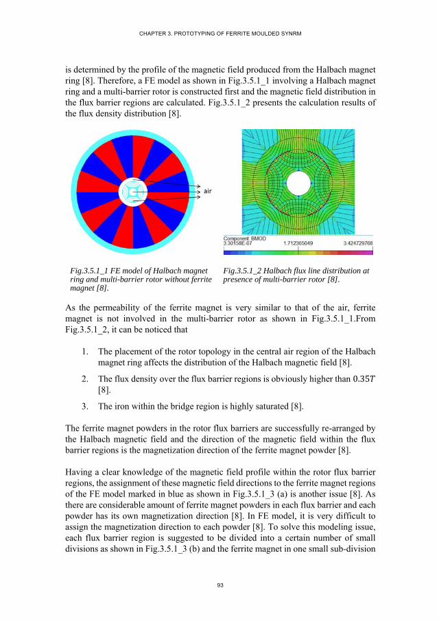
CHAPTER 3. PROTOTYPING OF FERRITE MOULDED SYNRM
93
is determined by the profile of the magnetic field produced from the Halbach magnet ring [8]. Therefore, a FE model as shown in Fig.3.5.1_1 involving a Halbach magnet ring and a multi-barrier rotor is constructed first and the magnetic field distribution in the flux barrier regions are calculated. Fig.3.5.1_2 presents the calculation results of the flux density distribution [8].
Fig.3.5.1_1 FE model of Halbach magnet ring and multi-barrier rotor without ferrite magnet [8].
Fig.3.5.1_2 Halbach flux line distribution at presence of multi-barrier rotor [8].
As the permeability of the ferrite magnet is very similar to that of the air, ferrite magnet is not involved in the multi-barrier rotor as shown in Fig.3.5.1_1.From Fig.3.5.1_2, it can be noticed that
1. The placement of the rotor topology in the central air region of the Halbach magnet ring affects the distribution of the Halbach magnetic field [8].
2. The flux density over the flux barrier regions is obviously higher than 0.35 [8].
3. The iron within the bridge region is highly saturated [8].
The ferrite magnet powders in the rotor flux barriers are successfully re-arranged by the Halbach magnetic field and the direction of the magnetic field within the flux barrier regions is the magnetization direction of the ferrite magnet powder [8].
Having a clear knowledge of the magnetic field profile within the rotor flux barrier regions, the assignment of these magnetic field directions to the ferrite magnet regions of the FE model marked in blue as shown in Fig.3.5.1_3 (a) is another issue [8]. As there are considerable amount of ferrite magnet powders in each flux barrier and each powder has its own magnetization direction [8]. In FE model, it is very difficult to assign the magnetization direction to each powder [8]. To solve this modeling issue, each flux barrier region is suggested to be divided into a certain number of small divisions as shown in Fig.3.5.1_3 (b) and the ferrite magnet in one small sub-division
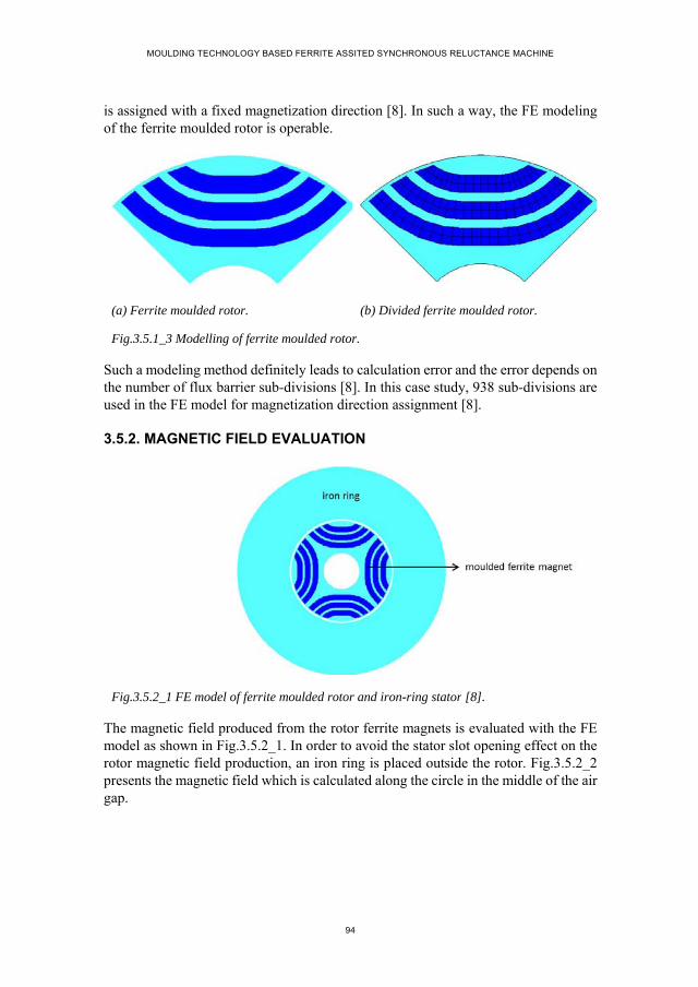
MOULDING TECHNOLOGY BASED FERRITE ASSITED SYNCHRONOUS RELUCTANCE MACHINE
94
is assigned with a fixed magnetization direction [8]. In such a way, the FE modeling of the ferrite moulded rotor is operable.
(a) Ferrite moulded rotor. (b) Divided ferrite moulded rotor.
Fig.3.5.1_3 Modelling of ferrite moulded rotor.
Such a modeling method definitely leads to calculation error and the error depends on the number of flux barrier sub-divisions [8]. In this case study, 938 sub-divisions are used in the FE model for magnetization direction assignment [8].
3.5.2. MAGNETIC FIELD EVALUATION
Fig.3.5.2_1 FE model of ferrite moulded rotor and iron-ring stator [8].
The magnetic field produced from the rotor ferrite magnets is evaluated with the FE model as shown in Fig.3.5.2_1. In order to avoid the stator slot opening effect on the rotor magnetic field production, an iron ring is placed outside the rotor. Fig.3.5.2_2 presents the magnetic field which is calculated along the circle in the middle of the air gap.

CHAPTER 3. PROTOTYPING OF FERRITE MOULDED SYNRM
95
(a) Magnetic field waveform. (b) Fourier analysis of the waveform.
Fig.3.5.2_2 air gap magnetic field [8].
The magnetic field waveform is not so sinusoidal. According to the Fourier analysis in Fig.3.5.2_2 (b), the waveform distortion is mainly caused by the third harmonic. For the magnetic field waveform, the flat top is due to the straight shape of the flux barrier in the middle part [8]. The leakage flux within the iron bridge region is also a main factor that leads to the distortion of magnetic field waveform [8]. The amplitude of the fundamental component is about 0.245 .
3.6. EXPERIMENTS OF MOULDING TECHNOLOGY BASED FASYNRM PROTOTYPE
A prototype of the designed FASynRM is manufactured to validate the feasibility of the application of the moulding technology for the installation of rotor ferrite magnet [8]. Corresponding FE models are also constructed and calculated. The measured performance is compared with the calculated results.
3.6.1. MAGNETIC FIELD
The magnetic field production of the ferrite moulded rotor is firstly measured. Fig.3.6.1_1 presents the setup for the magnetic field measurement, where an iron ring is placed outside the rotor [8]. To protect the measuring probe as marked in Fig.3.6.1_1, the length of the air gap between the rotor and the iron ring is much larger than that of the FASynRM prototype [8]. Fig.3.6.1_2 presents the experimental result of the air gap magnetic field, where the blue curve represents the waveform of the magnetic field normal component ( ) and the red curve refers to the fundamental component [8]. On the waveform, there are a certain number of small fluctuations, which are due to the leakage flux within the iron bridge regions. The peak marked with black circle in Fig.3.6.1_2 is caused by the groove on the rotor periphery surface
0 45 90 135 180 225 270 315 360relative position on air gap periphery surface
(electrical degree)
-0.25
-0.2
-0.15
-0.1
-0.05
0
0.05
0.1
0.15
0.2
0.25

MOULDING TECHNOLOGY BASED FERRITE ASSITED SYNCHRONOUS RELUCTANCE MACHINE
96
manufactured for aligning steel laminations. The peak value for the sinusoidal magnetic field is 0.222 .
Fig.3.6.1_1 Experimental setup for magnetic field measurement [8].
Fig.3.6.1_2 Air gap magnetic field waveform from experiments [8].
A FE model corresponding to the setup is constructed and the air gap magnetic field is calculated along the same circle as that on which the magnetic field is measured [8]. Fig.3.6.1_3 presents the FE calculation result of the air gap magnetic field, where the peak value of the fundamental component is 0.236 . As the aligning slots on the rotor periphery surface are not involved in the FE model, there are no peaks on the top of the magnetic field waveform [8].
0 40 80 120 160 200 240 280 320 360-0.25
-0.2-0.15
-0.1
-0.050
0.05
0.10.15
0.20.25
angle / mechanical degree
Bn
/ T

CHAPTER 3. PROTOTYPING OF FERRITE MOULDED SYNRM
97
Fig.3.6.1_3 Air gap magnetic field waveform from FE calculation [8].
Comparing the measured and calculated results of the air gap magnetic field produced from the rotor ferrite magnet, it could be concluded as
1. The fluctuations on the measured waveform are slightly bigger than that on the calculated waveform, which could be explained with the fact that compared with the FE model, more leakage flux around the iron bridge regions is produced for the prototype [8].
2. The measured magnetic field is slightly smaller than the calculation results, which is mainly due to the end effect, aligning slot and more leakage flux for the prototype [8].
3. Measuring error is also a possible factor that leads to the difference between the measured and calculated results [8].
Based on the analysis above, the difference between the measured and calculated results is reasonable.
3.6.2. TORQUE PERFORMANCE
The torque performance of the FASynRM prototype is measured. For measuring simplification, the stator windings are connected as shown in Fig.3.6.2_1 and the two terminals are connected to a DC current source [8]. Supplied with DC current, the stator windings produce a stable MMF which is aligned with the phase-A axis. The amplitude of the stator MMF is changed with the variation of DC current [8]. By rotating the rotor in one direction, the torque is produced [8]. Fig.3.6.2_2 presents the setup for the torque performance measurement with such a method. Fig.3.6.2_3 presents the torque waveforms with respect to the angular displacement between the rotor d-axis and the stator MMF axis for different DC currents [8].
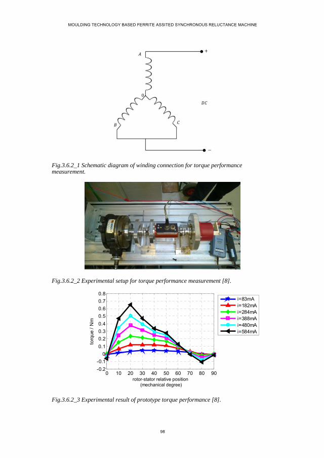
MOULDING TECHNOLOGY BASED FERRITE ASSITED SYNCHRONOUS RELUCTANCE MACHINE
98
Fig.3.6.2_1 Schematic diagram of winding connection for torque performance measurement.
Fig.3.6.2_2 Experimental setup for torque performance measurement [8].
Fig.3.6.2_3 Experimental result of prototype torque performance [8].
0 10 20 30 40 50 60 70 80 90-0.2
-0.1
0
0.1
0.2
0.3
0.4
0.5
0.6
0.7
0.8
torq
ue
/ N
m
i=83mAi=182mAi=284mAi=388mAi=480mAi=584mA
rotor-stator relative position (mechanical degree)

CHAPTER 3. PROTOTYPING OF FERRITE MOULDED SYNRM
99
Fig.3.6.2_4 FE calculation result of prototype torque performance [8].
The torque performance of the FASynRM is also evaluated with the numerical method. Fig.3.6.2_4 gives the FE calculation result of the torque waveforms with respect to angular displacement between the rotor d-axis and stator MMF axis for the same DC currents [8].
Comparing the experimental results and the calculation result, it can be found when DC current value is greater than 388 , the measured torque performance is a little smaller than the calculation result, which may be regarded as being reasonable when taking the effect of saturation, end effect on the torque production of the prototype into consideration [8]. Therefore, it can be concluded that the measured results agree well with the calculation result [8]
3.6.3. SENSITIVITY TO MANUFACTURING TPLERANCE
The sensitivity of the FASynRM performance to the manufacturing tolerance is evaluated [8]. For such a purpose, four rotor prototypes are manufactured based on the ferrite moulding technology [8]. The four rotors are exactly the same with respect to dimensions, materials and flux barrier topology [8].
The back EMF of the four rotor prototypes are measured in order to examine the difference between their air gap magnetic fields thus determining the sensitivity of the rotor performance to the manufacturing tolerance [8]. By rotating the rotor at a certain speed, voltage in the stator windings is induced, expressed as
4sin(2 )m
Ne f B ft
P
(3.6.3_1)
0 10 20 30 40 50 60 70 80 90-0.2
-0.1
0
0.1
0.2
0.3
0.4
0.5
0.6
0.7
0.8
torq
ue
/ N
m
i=83mAi=182mAi=284mAi=388mAi=480mAi=584mA
rotor-stator relative position (mechanical degree)
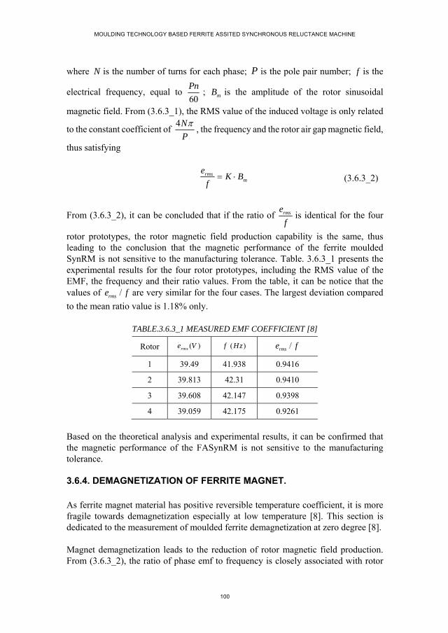
MOULDING TECHNOLOGY BASED FERRITE ASSITED SYNCHRONOUS RELUCTANCE MACHINE
100
where N is the number of turns for each phase; P is the pole pair number; f is the
electrical frequency, equal to 60
Pn; mB is the amplitude of the rotor sinusoidal
magnetic field. From (3.6.3_1), the RMS value of the induced voltage is only related
to the constant coefficient of 4N
P
, the frequency and the rotor air gap magnetic field,
thus satisfying
rmsm
eK B
f (3.6.3_2)
From (3.6.3_2), it can be concluded that if the ratio of rmse
fis identical for the four
rotor prototypes, the rotor magnetic field production capability is the same, thus leading to the conclusion that the magnetic performance of the ferrite moulded SynRM is not sensitive to the manufacturing tolerance. Table. 3.6.3_1 presents the experimental results for the four rotor prototypes, including the RMS value of the EMF, the frequency and their ratio values. From the table, it can be notice that the values of /rmse f are very similar for the four cases. The largest deviation compared
to the mean ratio value is 1.18% only.
TABLE.3.6.3_1 MEASURED EMF COEFFICIENT [8]
Rotor ( )rmse V ( )f Hz /rmse f
1 39.49 41.938 0.9416
2 39.813 42.31 0.9410
3 39.608 42.147 0.9398
4 39.059 42.175 0.9261
Based on the theoretical analysis and experimental results, it can be confirmed that the magnetic performance of the FASynRM is not sensitive to the manufacturing tolerance.
3.6.4. DEMAGNETIZATION OF FERRITE MAGNET.
As ferrite magnet material has positive reversible temperature coefficient, it is more fragile towards demagnetization especially at low temperature [8]. This section is dedicated to the measurement of moulded ferrite demagnetization at zero degree [8].
Magnet demagnetization leads to the reduction of rotor magnetic field production. From (3.6.3_2), the ratio of phase emf to frequency is closely associated with rotor
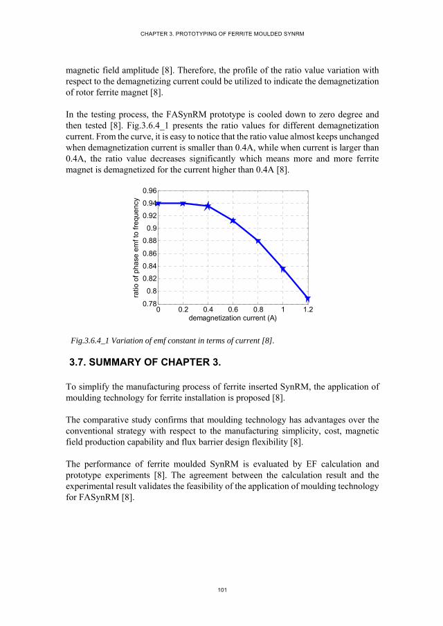
CHAPTER 3. PROTOTYPING OF FERRITE MOULDED SYNRM
101
magnetic field amplitude [8]. Therefore, the profile of the ratio value variation with respect to the demagnetizing current could be utilized to indicate the demagnetization of rotor ferrite magnet [8].
In the testing process, the FASynRM prototype is cooled down to zero degree and then tested [8]. Fig.3.6.4_1 presents the ratio values for different demagnetization current. From the curve, it is easy to notice that the ratio value almost keeps unchanged when demagnetization current is smaller than 0.4A, while when current is larger than 0.4A, the ratio value decreases significantly which means more and more ferrite magnet is demagnetized for the current higher than 0.4A [8].
Fig.3.6.4_1 Variation of emf constant in terms of current [8].
3.7. SUMMARY OF CHAPTER 3.
To simplify the manufacturing process of ferrite inserted SynRM, the application of moulding technology for ferrite installation is proposed [8].
The comparative study confirms that moulding technology has advantages over the conventional strategy with respect to the manufacturing simplicity, cost, magnetic field production capability and flux barrier design flexibility [8].
The performance of ferrite moulded SynRM is evaluated by EF calculation and prototype experiments [8]. The agreement between the calculation result and the experimental result validates the feasibility of the application of moulding technology for FASynRM [8].
0 0.2 0.4 0.6 0.8 1 1.20.78
0.8
0.82
0.84
0.86
0.88
0.9
0.92
0.94
0.96
demagnetization current (A)
ratio
of p
hase
em
f to
freq
uenc
y

MOULDING TECHNOLOGY BASED FERRITE ASSITED SYNCHRONOUS RELUCTANCE MACHINE
102
Reference
1. M. Palmieri, M. Perta and F. Cupertino, "Design of a 50.000-r/min Synchronous Reluctance Machine for an Aeronautic Diesel Engine Compressor," in IEEE Transactions on Industry Applications, vol. 52, no. 5, pp. 3831-3838, Sept.-Oct. 2016.
2. M. N. Ibrahim, P. Sergeant and E. E. M. Rashad, "Combined Star-Delta Windings to Improve Synchronous Reluctance Motor Performance," in IEEE Transactions on Energy Conversion, vol. 31, no. 4, pp. 1479-1487, Dec. 2016.
3. Q. Wu, K. Lu, P. O. Rasmussen, N. Bianchi and K. F. Rasmussen, "Unified equivalent MMF concept for torque analysis of AC machines," 2017 IEEE International Electric Machines and Drives Conference (IEMDC), Miami, FL, 2017, pp. 1-8.
4. W. Zhao, D. Chen, T. A. Lipo and B. I. Kwon, "Performance Improvement of Ferrite-Assisted Synchronous Reluctance Machines Using Asymmetrical Rotor Configurations," in IEEE Transactions on Magnetics, vol. 51, no. 11, pp. 1-4, Nov. 2015.
5. R. Lohninger, H. Grabner, G. Weidenholzer, S. Silber and W. Amrhein, "Modeling, Simulation, and Design of a Permanent-Magnet-Assisted Synchronous Reluctance Machine," in IEEE Transactions on Industry Applications, vol. 51, no. 1, pp. 196-203, Jan.-Feb. 2015.
6. M. Obata, S. Morimoto, M. Sanada and Y. Inoue, "Performance of PMASynRM With Ferrite Magnets for EV/HEV Applications Considering Productivity," in IEEE Transactions on Industry Applications, vol. 50, no. 4, pp. 2427-2435, July-Aug. 2014.
7. N. Bianchi, E. Fornasiero, M. Ferrari and M. Castiello, "Experimental Comparison of PM-Assisted Synchronous Reluctance Motors," in IEEE Transactions on Industry Applications, vol. 52, no. 1, pp. 163-171, Jan.-Feb. 2016.
8. Q. Wu, K. Lu, P. O. Rasmussen and K. F. Rasmussen, "A new application and experimental validation of moulding technology for ferrite magnet assisted synchronous reluctance machine," 2016 IEEE Energy Conversion Congress and Exposition (ECCE), Milwaukee, WI, 2016, pp. 1-8.
9. P. Guglielmi, M. Pastorelli, A. Carrer, A. Beato, D. D'Antonio and L. Fagnano, "An IPM-PMASR motor for home appliance washing machines," IECON 2013 - 39th Annual Conference of the IEEE Industrial Electronics Society, Vienna, 2013, pp. 2608-2613.
10. Armando, P. Guglielmi, M. Pastorelli, G. Pellegrino and A. Vagati, "Performance of IPM-PMASR Motors with Ferrite Injection for Home Appliance Washing Machine," 2008 IEEE Industry Applications Society Annual Meeting, Edmonton, Alta., 2008, pp. 1-6.

CHAPTER 3. PROTOTYPING OF FERRITE MOULDED SYNRM
103
11. Som et al., "Analysis and Testing of a Coaxial Magnetic Gearbox With Flux Concentration Halbach Rotors," in IEEE Transactions on Magnetics, vol. 53, no. 11, pp. 1-6, Nov. 2017.
12. J. Bird, K. Li, J. Kadel, J. Wright, D. Som and W. Williams, "Analysis and testing of a hybrid Halbach magnetic gearbox," 2017 IEEE International Magnetics Conference (INTERMAG).
MOULDING TECHNOLOGY BASED FERRITE ASSITED SYNCHRONOUS RELUCTANCE MACHINE
104
CHAPTER 4. INVESTIGATION OF
GEOMETRICAL PARAMETER
INFLUENCE ON FASYNRM
PERFORMANCE
4.1. INTRODUCTION
From the perspective of torque production principle, FASynRM belongs to the type of Interior Permanent Magnet (IPM) machine [1-4]. While, being different from the conventional IPM machine, FASynRM is characterized by the fully exploited reluctance torque [4].
For an optimally designed FASynRM, reluctance torque component is supposed to take a predominant proportion in the torque production, generally higher than 60% [1, 5, 6]. Thus, similar to SynRM, rotor structure with high saliency effect is also one of the main design objectives of FASynRM for achieving high reluctance torque production. Considering the compromise between simple manufacturing process and high saliency ratio, the multi-barrier rotor topology commonly utilized for SynRM is equally suitable for FASynRM [7-9]. As to the stator structures of FASynRM and SynRM, they are all assembled with the same production line as that of IM. Therefore, with respect to the geometrical structure, FASynRM and SynRM are theoretically identical to each other [2, 6]. While, additional considerations are needed for FASynRM on the geometrical design in order to avoid iron saturation caused by the ferrite magnet on the rotor side and to maximize the sum of reluctance torque and PM torque [2, 4, 6, 10].
The transversally laminated multi-barrier rotor topology has many geometrical parameters that have direct or indirect effects on rotor saliency effect and the magnetic field produced from the ferrite magnet and consequently affecting the reluctance torque and the PM torque [11-14]. Therefore, a clear knowledge of the geometrical parameter influence on torque performance of FASynRM is very necessary in the design and optimization of such a machine type in order to achieve high torque production capability [14-16]. According to the existing literature related to the FASynRM, a large number of studies have been carried out on such an investigation [14, 16-20]. Within these researches, the main proportion are performed by calculating the performance of a series of parameterized FASynRM models and then based on the calculation results summarizing the influence of each geometrical parameter on the torque performance. Finite Element (FE) software is very commonly utilized for the torque performance calculation [21-23].
CHAPTER 4. INVESTIGATION OF GEOMETRICAL PARAMETER INFLUENCE ON FASYNRM PERFORMANCE
105
This chapter is dedicated to the investigation of the geometrical parameter influence on the FASynRM performance with the aid of both theoretical analysis and numerical calculation.
4.2. MAIN GEOMETRICAL PARAMETERS
Torque performance of FASynRM could be evaluated with the most commonly utilized equation expressed in the d-q reference frame, as
3 3( )
2 2m q d q d qT P i P L L i i (4.2_1)
where d-axis and q-axis of FASynRM represent the axes on the rotor side with minimum and maximum permeance respectively; the two terms on the right side, 3
2 m qP i and 3
( )2 d q d qP L L i i respectively, are referred to as the PM torque
component and the reluctance torque component. From the torque expression of (4.2_1), it is easy to figure out that PM torque component is generated due to the interaction between the PM flux linkage and the q-axis stator current; reluctance torque is produced due to the difference of d- and q-inductance ( d qL L ), which could
be defined as rotor saliency effect. Therefore, it could be concluded that the geometrical parameters of FASynRM that are related to the PM flux linkage and the d-q inductance should be decided as the main optimizing parameters, which are not directly observed in (4.2_1).
Based on the theoretical analysis of the AC machine torque performance in chapter 2, the PM torque and the reluctance torque could be expressed with the geometrical parameters, which are written as
_ ( ) ( )sin(90 )
2PM a rm sm
DT l B PF
(4.2_2)
0
_
cos( )( (1 ))( )sin
2qsm
rel a smq d
gFDT l PF
g g
(4.2_3)
where rmB represents the peak value of the sinusoidal air gap magnetic field produced
from the rotor ferrite magnet; P denotes the pole pair number; smF represents the peak
value of the sinusoidal stator MMF; refers to the angular displacement between the stator MMF axis and the rotor q-axis; qg and dg represent the effective air gap length
on q- and d-axis respectively; D and al are the basic dimensions, being referred to as
the air gap diameter and stack length respectively. Neglecting the mutual effect
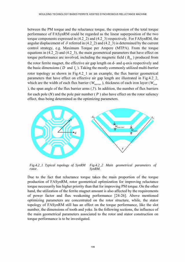
MOULDING TECHNOLOGY BASED FERRITE ASSITED SYNCHRONOUS RELUCTANCE MACHINE
106
between the PM torque and the reluctance torque, the expression of the total torque performance of FASynRM could be regarded as the linear superposition of the two torque components expressed in (4.2_2) and (4.2_3) respectively. For FASynRM, the angular displacement of referred in (4.2_2) and (4.2_3) is determined by the current control strategy, e.g. Maximum Torque per Ampere (MTPA). From the torque equations in (4.2_2) and (4.2_3), the main geometrical parameters that have effect on torque performance are involved, including the magnetic field ( rmB ) produced from
the rotor ferrite magnet, the effective air gap length on d- and q-axis respectively and the basic dimensions ( D and al ). Taking the mostly commonly utilized multi-barrier
rotor topology as shown in Fig.4.2_1 as an example, the flux barrier geometrical parameters that have effect on effective air gap length are illustrated in Fig.4.2_2, which are the width of each flux barrier ( barrierW ), thickness of each iron layer ( ironW
), the span angle of the flux barrier arms ( ). In addition, the number of flux barriers
for each pole ( ) and the pole pair number ( P ) also have effect on the rotor saliency effect, thus being determined as the optimizing parameters.
Fig.4.2_1 Typical topology of SynRM rotor.
Fig.4.2_2 Main geometrical parameters of SynRM.
Due to the fact that reluctance torque takes the main proportion of the torque production of FASynRM, rotor geometrical optimization for improving reluctance torque necessarily has higher priority than that for improving PM torque. On the other hand, the utilization of the ferrite magnet amount is also affected by the requirements of power factor and flux weakening performance [24-26]. Above mentioned optimizing parameters are concentrated on the rotor structure, while, the stator topology of FASynRM still has an effect on the torque performance, like the slot number, the dimensions of tooth and yoke. In the following sections, the influence of the main geometrical parameters associated to the rotor and stator construction on torque performance is to be investigated.
CHAPTER 4. INVESTIGATION OF GEOMETRICAL PARAMETER INFLUENCE ON FASYNRM PERFORMANCE
107
4.3. OPTIMIZING PARAMETER-1: POLE PAIR NUMBER
According to the existing studies, the influence of pole pair number on the performance of electric machines is intensively investigated [27-29]. Such an investigation is generally performed by studying the influence of pole-slot combination on machine torque performance with the aid of FE software. Based on the investigation results, the rotor design with low pole pair number, like 2 or 4, is widely preferred by SynRM and FASynRM. While, little theoretical analysis is given for such a preference of low-pole-pair-number design. Therefore, this section is focused on presenting a detailed theoretical analysis of the pole pair number influence on FASynRM performance.
4.3.1. INFLUENCE ON IRON LOSS PRODUCTION
For a given speed of an electric machine, the pole pair number determines the electrical frequency, which is written as
60e
P nf
(4.3.1_1)
Where n represents the rotating speed; ef refers to the electrical frequency.
According to the classical Steinmetz approximation of iron loss which is written in (4.3.1_2), it can be observed that the electrical frequency has significant effect on iron loss production. Combining (4.3.1_1) and (4.3.1_2), it is easy to conclude that electric machine with low pole pair number tends to produce less iron loss per iron volume.
2 2 2iron hys m e eddy m eP K B f K B f (4.3.1_2)
4.3.2. INFLUENCE ON TORQUE PERFORMANCE
A. Theoretical analysis
To focus on the investigation of pole pair number influence only, the other parameters of FASynRM, like stator structure, rotor saliency effect, total current loading as well as saturation degree, are assumed to be unchanged in the analysis.
For PM torque as expressed in (4.2_2), the maximum production is determined by the basic dimensions, the rotor magnetic field and the product of pole pair number and the stator MMF. As to the air gap magnetic field produced from the ferrite magnet, it is mainly determined by the PM permeability, the thickness along the radial direction and the leakage flux. Neglecting the influence of pole pair number on the amount of leakage flux, it can be said that the rotor magnetic field ( rmB ) is independent of the
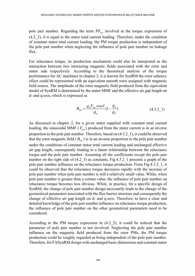
MOULDING TECHNOLOGY BASED FERRITE ASSITED SYNCHRONOUS RELUCTANCE MACHINE
108
pole pair number. Regarding the term smPF involved in the torque expression of
(4.2_2), it is equal to the stator total current loading. Therefore, under the condition of constant stator total current loading, the PM torque production is independent of the pole pair number when neglecting the influence of pole pair number on leakage flux.
For reluctance torque, its production mechanism could also be interpreted as the interaction between two interacting magnetic fields associated with the rotor and stator side respectively. According to the theoretical analysis of the torque performance for AC machines in chapter 2, it is known for SynRM the rotor saliency effect could be represented with an equivalent smooth rotor assigned with magnetic field source. The amplitude of the rotor magnetic field produced from the equivalent model of SynRM is determined by the stator MMF and the effective air gap length on d- and q-axis, which is expressed as
0 cos
(1 )qsmrm
q d
gFB
g g
(4.3.2_1)
As discussed in chapter 2, for a given stator supplied with constant total current loading, the sinusoidal MMF ( smF ) produced from the stator current is in an inverse
proportion to the pole pair number. Therefore, based on (4.3.2_1), it could be observed that the rotor magnetic field ( rmB ) is in an inverse proportion to the pole pair number
under the conditions of constant stator total current loading and unchanged effective air gap length, consequently leading to a linear relationship between the reluctance torque and the pole pair number. Assuming all the coefficients except the pole pair number on the right side of (4.2_3) as constants, Fig.4.3.2_1 presents a graph of the pole pair number influence on the reluctance torque production. From Fig.4.3.2_1, it could be observed that the reluctance torque decreases rapidly with the increase of pole pair number when pole pair number is still a relatively small value. While, when pole pair number is greater than a certain value, the influence of pole pair number on reluctance torque becomes less obvious. While, in practice, for a specific design of SynRM, the change of pole pair number design necessarily leads to the change of the geometrical parameters associated with the flux barrier structure and consequently the change of effective air gap length on d- and q-axis. Therefore, to have a clear and detailed knowledge of the pole pair number influence on reluctance torque production, the influence of pole pair number on the other geometrical parameters need to be considered.
According to the PM torque expression in (4.2_2), it could be noticed that the parameter of pole pair number is not involved. Neglecting the pole pair number influence on the magnetic field produced from the rotor PMs, the PM torque production could be roughly regarded as being independent of the pole pair number. Therefore, for FASynRM design with unchanged basic dimensions and constant stator
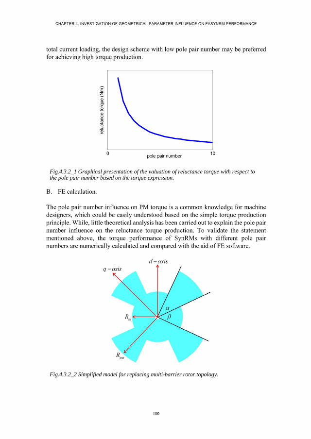
CHAPTER 4. INVESTIGATION OF GEOMETRICAL PARAMETER INFLUENCE ON FASYNRM PERFORMANCE
109
total current loading, the design scheme with low pole pair number may be preferred for achieving high torque production.
Fig.4.3.2_1 Graphical presentation of the valuation of reluctance torque with respect to the pole pair number based on the torque expression.
B. FE calculation.
The pole pair number influence on PM torque is a common knowledge for machine designers, which could be easily understood based on the simple torque production principle. While, little theoretical analysis has been carried out to explain the pole pair number influence on the reluctance torque production. To validate the statement mentioned above, the torque performance of SynRMs with different pole pair numbers are numerically calculated and compared with the aid of FE software.
Fig.4.3.2_2 Simplified model for replacing multi-barrier rotor topology.
0 10pole pair number
relu
ctan
ce to
rque
(N
m)
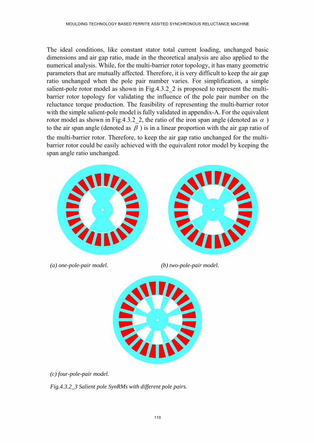
MOULDING TECHNOLOGY BASED FERRITE ASSITED SYNCHRONOUS RELUCTANCE MACHINE
110
The ideal conditions, like constant stator total current loading, unchanged basic dimensions and air gap ratio, made in the theoretical analysis are also applied to the numerical analysis. While, for the multi-barrier rotor topology, it has many geometric parameters that are mutually affected. Therefore, it is very difficult to keep the air gap ratio unchanged when the pole pair number varies. For simplification, a simple salient-pole rotor model as shown in Fig.4.3.2_2 is proposed to represent the multi-barrier rotor topology for validating the influence of the pole pair number on the reluctance torque production. The feasibility of representing the multi-barrier rotor with the simple salient-pole model is fully validated in appendix-A. For the equivalent rotor model as shown in Fig.4.3.2_2, the ratio of the iron span angle (denoted as ) to the air span angle (denoted as ) is in a linear proportion with the air gap ratio of
the multi-barrier rotor. Therefore, to keep the air gap ratio unchanged for the multi-barrier rotor could be easily achieved with the equivalent rotor model by keeping the span angle ratio unchanged.
(a) one-pole-pair model. (b) two-pole-pair model.
(c) four-pole-pair model.
Fig.4.3.2_3 Salient pole SynRMs with different pole pairs.

CHAPTER 4. INVESTIGATION OF GEOMETRICAL PARAMETER INFLUENCE ON FASYNRM PERFORMANCE
111
To validate the influence of pole pair number on reluctance torque production, three salient-pole machine models with one, two and four pole pairs respectively are constructed as shown in Fig.4.3.2_3, where the three models are exactly the same with respect to the span angle ratio, stator structure, stator total current loading and basic dimensions ( D , al and g ). Fig.4.3.2_4 presents the torque waveforms of the three
salient-pole models with respect to the angular displacement between the rotor d-axis and the stator MMF axis. From Fig.4.3.2_4 (a), it is easy to notice that for the three models the reluctance torque production decreases with the increase of pole pair number. According to the Fourier analysis of the torque waveforms as shown in Fig.4.3.2_4 (b), the fundamental components are 7.48 3.77 and 1.86 for one- two- and four-pole-pair salient-pole model respectively, which indicates that the reluctance torque production is in an approximately linear proportion to the pole pair number. The small deviation of the obtained torque-pole relationship from a perfect linear proportion could be explained with the winding factor and the leakage flux which are different for different pole pair numbers.
(a) Torque waveforms. (b) Fourier analysis.
Fig.4.3.2_4 Torque performance of the three models.
Based on the theoretical analysis and the FE validation above, the theoretical analysis of the pole pair number influence on reluctance torque production could be validated. The above theoretical analysis and FE calculation are performed under the conditions of unchanged basic dimensions, stator total current loading and air gap ratio. The following studies will further investigate the pole pair number influence on the other geometrical parameters and consequently the reluctance torque production.
relu
ctan
ce to
rque
(N
m)
0 1 2 3 4 5 6 70
1
2
3
4
5
6
7
8one-pole-pair modeltwo-pole-pair modelfour-pole-pair model

MOULDING TECHNOLOGY BASED FERRITE ASSITED SYNCHRONOUS RELUCTANCE MACHINE
112
4.3.3. INFLUENCE ON BASIC DIMENSIONS
In this section, the pole pair number influence on the design of air gap diameter is investigated under the condition of unchanged stator total current loading.
For a given stator with constant total current loading, the MMF amplitude is in an inverse proportion to the pole pair number, which is discussed in chapter 2. In such a case, the pole pair number mainly determines the amount of flux lines per pole and consequently the magnetic path dimensions in order to accommodate the flux lines. A stator structure with 24 slots as shown in Fig.4.3.3_1 is taken as an example to illustrate the different magnetic fields produced from different pole-pair winding configurations.
Fig.4.3.3_1 24-slot stator configuration.
The 24-slot stator is wound with different winding configurations, forming one-, two-, four-, and eight-pole-pair models respectively. In order to avoid the influence of the rotor structure on the stator magnetic field, an iron ring as shown in Fig.4.3.3_1 is placed inside the stator. Fig.4.3.3_2 presents the flux density distribution of the four models under the same stator total current loading.
(a) one-pole-pair model. (b) two-pole-pair model.
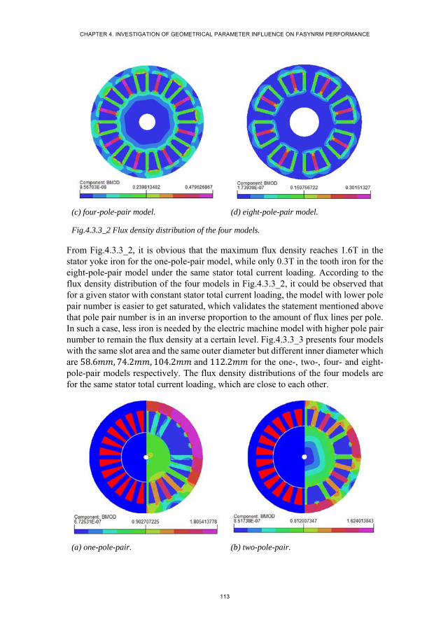
CHAPTER 4. INVESTIGATION OF GEOMETRICAL PARAMETER INFLUENCE ON FASYNRM PERFORMANCE
113
(c) four-pole-pair model. (d) eight-pole-pair model.
Fig.4.3.3_2 Flux density distribution of the four models.
From Fig.4.3.3_2, it is obvious that the maximum flux density reaches 1.6T in the stator yoke iron for the one-pole-pair model, while only 0.3T in the tooth iron for the eight-pole-pair model under the same stator total current loading. According to the flux density distribution of the four models in Fig.4.3.3_2, it could be observed that for a given stator with constant stator total current loading, the model with lower pole pair number is easier to get saturated, which validates the statement mentioned above that pole pair number is in an inverse proportion to the amount of flux lines per pole. In such a case, less iron is needed by the electric machine model with higher pole pair number to remain the flux density at a certain level. Fig.4.3.3_3 presents four models with the same slot area and the same outer diameter but different inner diameter which are 58.6 , 74.2 , 104.2 and 112.2 for the one-, two-, four- and eight-pole-pair models respectively. The flux density distributions of the four models are for the same stator total current loading, which are close to each other.
(a) one-pole-pair. (b) two-pole-pair.
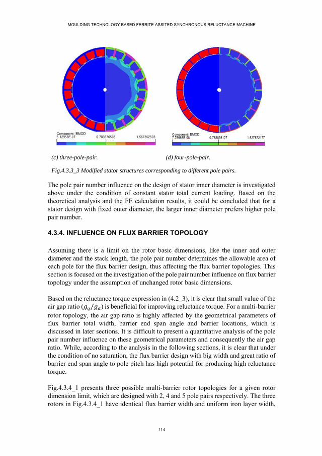
MOULDING TECHNOLOGY BASED FERRITE ASSITED SYNCHRONOUS RELUCTANCE MACHINE
114
(c) three-pole-pair. (d) four-pole-pair.
Fig.4.3.3_3 Modified stator structures corresponding to different pole pairs.
The pole pair number influence on the design of stator inner diameter is investigated above under the condition of constant stator total current loading. Based on the theoretical analysis and the FE calculation results, it could be concluded that for a stator design with fixed outer diameter, the larger inner diameter prefers higher pole pair number.
4.3.4. INFLUENCE ON FLUX BARRIER TOPOLOGY
Assuming there is a limit on the rotor basic dimensions, like the inner and outer diameter and the stack length, the pole pair number determines the allowable area of each pole for the flux barrier design, thus affecting the flux barrier topologies. This section is focused on the investigation of the pole pair number influence on flux barrier topology under the assumption of unchanged rotor basic dimensions.
Based on the reluctance torque expression in (4.2_3), it is clear that small value of the air gap ratio ( / ) is beneficial for improving reluctance torque. For a multi-barrier rotor topology, the air gap ratio is highly affected by the geometrical parameters of flux barrier total width, barrier end span angle and barrier locations, which is discussed in later sections. It is difficult to present a quantitative analysis of the pole pair number influence on these geometrical parameters and consequently the air gap ratio. While, according to the analysis in the following sections, it is clear that under the condition of no saturation, the flux barrier design with big width and great ratio of barrier end span angle to pole pitch has high potential for producing high reluctance torque.
Fig.4.3.4_1 presents three possible multi-barrier rotor topologies for a given rotor dimension limit, which are designed with 2, 4 and 5 pole pairs respectively. The three rotors in Fig.4.3.4_1 have identical flux barrier width and uniform iron layer width,
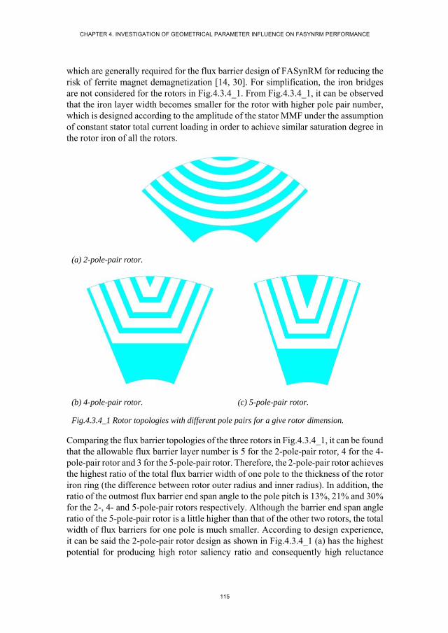
CHAPTER 4. INVESTIGATION OF GEOMETRICAL PARAMETER INFLUENCE ON FASYNRM PERFORMANCE
115
which are generally required for the flux barrier design of FASynRM for reducing the risk of ferrite magnet demagnetization [14, 30]. For simplification, the iron bridges are not considered for the rotors in Fig.4.3.4_1. From Fig.4.3.4_1, it can be observed that the iron layer width becomes smaller for the rotor with higher pole pair number, which is designed according to the amplitude of the stator MMF under the assumption of constant stator total current loading in order to achieve similar saturation degree in the rotor iron of all the rotors.
(a) 2-pole-pair rotor.
(b) 4-pole-pair rotor. (c) 5-pole-pair rotor.
Fig.4.3.4_1 Rotor topologies with different pole pairs for a give rotor dimension.
Comparing the flux barrier topologies of the three rotors in Fig.4.3.4_1, it can be found that the allowable flux barrier layer number is 5 for the 2-pole-pair rotor, 4 for the 4-pole-pair rotor and 3 for the 5-pole-pair rotor. Therefore, the 2-pole-pair rotor achieves the highest ratio of the total flux barrier width of one pole to the thickness of the rotor iron ring (the difference between rotor outer radius and inner radius). In addition, the ratio of the outmost flux barrier end span angle to the pole pitch is 13%, 21% and 30% for the 2-, 4- and 5-pole-pair rotors respectively. Although the barrier end span angle ratio of the 5-pole-pair rotor is a little higher than that of the other two rotors, the total width of flux barriers for one pole is much smaller. According to design experience, it can be said the 2-pole-pair rotor design as shown in Fig.4.3.4_1 (a) has the highest potential for producing high rotor saliency ratio and consequently high reluctance
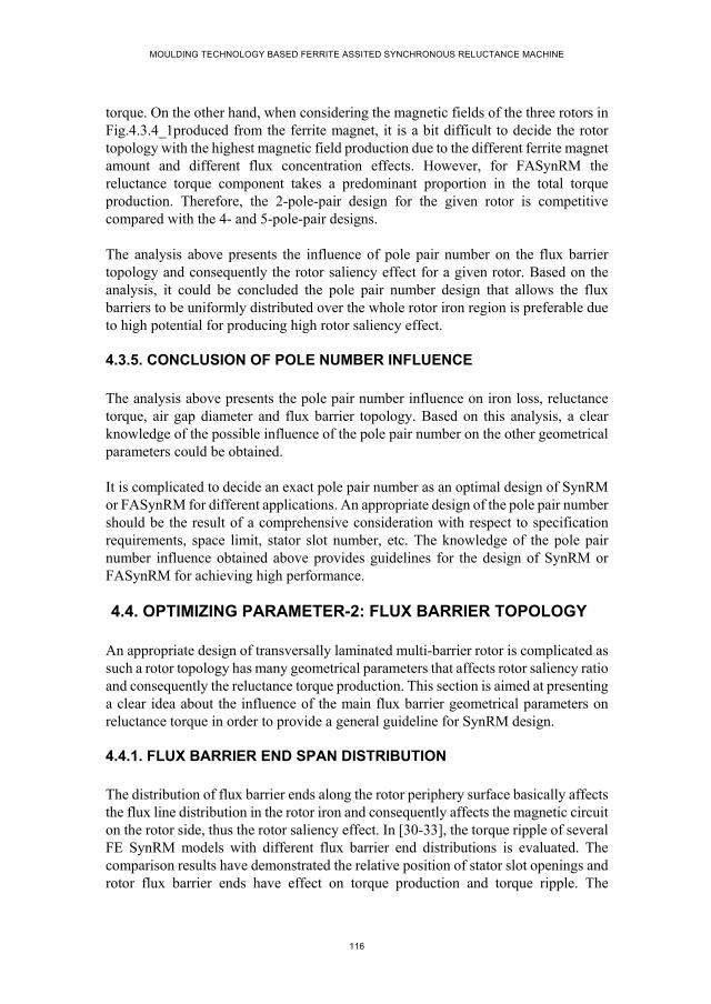
MOULDING TECHNOLOGY BASED FERRITE ASSITED SYNCHRONOUS RELUCTANCE MACHINE
116
torque. On the other hand, when considering the magnetic fields of the three rotors in Fig.4.3.4_1produced from the ferrite magnet, it is a bit difficult to decide the rotor topology with the highest magnetic field production due to the different ferrite magnet amount and different flux concentration effects. However, for FASynRM the reluctance torque component takes a predominant proportion in the total torque production. Therefore, the 2-pole-pair design for the given rotor is competitive compared with the 4- and 5-pole-pair designs.
The analysis above presents the influence of pole pair number on the flux barrier topology and consequently the rotor saliency effect for a given rotor. Based on the analysis, it could be concluded the pole pair number design that allows the flux barriers to be uniformly distributed over the whole rotor iron region is preferable due to high potential for producing high rotor saliency effect.
4.3.5. CONCLUSION OF POLE NUMBER INFLUENCE
The analysis above presents the pole pair number influence on iron loss, reluctance torque, air gap diameter and flux barrier topology. Based on this analysis, a clear knowledge of the possible influence of the pole pair number on the other geometrical parameters could be obtained.
It is complicated to decide an exact pole pair number as an optimal design of SynRM or FASynRM for different applications. An appropriate design of the pole pair number should be the result of a comprehensive consideration with respect to specification requirements, space limit, stator slot number, etc. The knowledge of the pole pair number influence obtained above provides guidelines for the design of SynRM or FASynRM for achieving high performance.
4.4. OPTIMIZING PARAMETER-2: FLUX BARRIER TOPOLOGY
An appropriate design of transversally laminated multi-barrier rotor is complicated as such a rotor topology has many geometrical parameters that affects rotor saliency ratio and consequently the reluctance torque production. This section is aimed at presenting a clear idea about the influence of the main flux barrier geometrical parameters on reluctance torque in order to provide a general guideline for SynRM design.
4.4.1. FLUX BARRIER END SPAN DISTRIBUTION
The distribution of flux barrier ends along the rotor periphery surface basically affects the flux line distribution in the rotor iron and consequently affects the magnetic circuit on the rotor side, thus the rotor saliency effect. In [30-33], the torque ripple of several FE SynRM models with different flux barrier end distributions is evaluated. The comparison results have demonstrated the relative position of stator slot openings and rotor flux barrier ends have effect on torque production and torque ripple. The
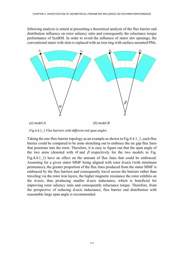
CHAPTER 4. INVESTIGATION OF GEOMETRICAL PARAMETER INFLUENCE ON FASYNRM PERFORMANCE
117
following analysis is aimed at presenting a theoretical analysis of the flux barrier end distribution influence on rotor saliency ratio and consequently the reluctance torque performance of SynRM. In order to avoid the influence of stator slot openings, the conventional stator with slots is replaced with an iron ring with surface-mounted PMs.
(a) model-A (b) model-B
Fig.4.4.1_1 Flux barriers with different end span angles.
Taking the one-flux-barrier topology as an example as shown in Fig.4.4.1_1, each flux barrier could be compared to be arms stretching out to embrace the air gap flux lines that penetrate into the rotor. Therefore, it is easy to figure out that the span angle of the two arms (denoted with and respectively for the two models in Fig.
Fig.4.4.1_1) have an effect on the amount of flux lines that could be embraced. Assuming for a given stator MMF being aligned with rotor d-axis (with minimum permeance), the greater proportion of the flux lines produced from the stator MMF is embraced by the flux barriers and consequently travel across the barriers rather than traveling via the rotor iron layers, the higher magnetic resistance the rotor exhibits on the d-axis, thus producing smaller d-axis inductance, which is beneficial for improving rotor saliency ratio and consequently reluctance torque. Therefore, from the perspective of reducing d-axis inductance, flux barrier end distribution with reasonable large span angle is recommended.
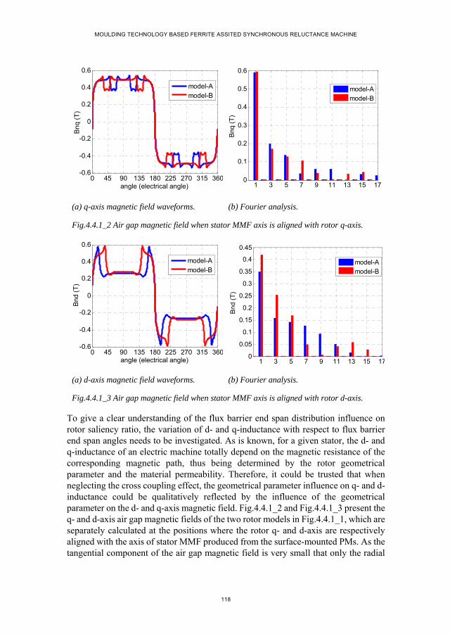
MOULDING TECHNOLOGY BASED FERRITE ASSITED SYNCHRONOUS RELUCTANCE MACHINE
118
(a) q-axis magnetic field waveforms. (b) Fourier analysis.
Fig.4.4.1_2 Air gap magnetic field when stator MMF axis is aligned with rotor q-axis.
(a) d-axis magnetic field waveforms. (b) Fourier analysis.
Fig.4.4.1_3 Air gap magnetic field when stator MMF axis is aligned with rotor d-axis.
To give a clear understanding of the flux barrier end span distribution influence on rotor saliency ratio, the variation of d- and q-inductance with respect to flux barrier end span angles needs to be investigated. As is known, for a given stator, the d- and q-inductance of an electric machine totally depend on the magnetic resistance of the corresponding magnetic path, thus being determined by the rotor geometrical parameter and the material permeability. Therefore, it could be trusted that when neglecting the cross coupling effect, the geometrical parameter influence on q- and d-inductance could be qualitatively reflected by the influence of the geometrical parameter on the d- and q-axis magnetic field. Fig.4.4.1_2 and Fig.4.4.1_3 present the q- and d-axis air gap magnetic fields of the two rotor models in Fig.4.4.1_1, which are separately calculated at the positions where the rotor q- and d-axis are respectively aligned with the axis of stator MMF produced from the surface-mounted PMs. As the tangential component of the air gap magnetic field is very small that only the radial
0 45 90 135 180 225 270 315 360-0.6
-0.4
-0.2
0
0.2
0.4
0.6
angle (electrical angle)
Bnq
(T
)
model-Amodel-B
1 3 5 7 9 11 13 15 170
0.1
0.2
0.3
0.4
0.5
0.6
Bnq
(T
)
model-A
model-B
0 45 90 135 180 225 270 315 360-0.6
-0.4
-0.2
0
0.2
0.4
0.6
angle (electrical angle)
Bnd
(T
)
model-Amodel-B
1 3 5 7 9 11 13 15 170
0.05
0.1
0.15
0.2
0.25
0.3
0.35
0.4
0.45
Bn
d (T
)
model-Amodel-B

CHAPTER 4. INVESTIGATION OF GEOMETRICAL PARAMETER INFLUENCE ON FASYNRM PERFORMANCE
119
component is considered in the investigation of the air gap magnetic field production. From Fig.4.4.1_2, it is easy to notice that similar q-axis air gap magnetic fields are produced for the two models, which indicates that the magnetic resistances on the q-axis of the two rotor models are similar. In Fig.4.4.1_3, the d-axis air gap magnetic field of model-A is smaller than that of model-B, which is obviously caused by the larger flux barrier span angle of model-A. Based on the d-axis magnetic field calculation results, it could be concluded that the d-axis magnetic resistance of model-A is greater than that of model-B.
Under the condition of constant stator MMF, the air gap magnetic field production on d- and q-axis respectively, to a large extend, reflects the magnetic resistance of the d- and q-axis magnetic path. To illustrate the relationship between the reluctance torque and the d- and q-axis air gap magnetic field production, the torque expression in (4.2_3) could be transformed into an equation as
_ ( )( )( )sin 2
4rel a mq md sm
DT l B B PF
(4.4.1_1)
where the mqB ( mdB ) refers to the q(d)-axis air gap magnetic field produced when
rotor q(d)-axis is aligned with the axis of the stator MMF ( smF ). The air gap magnetic
fields of mqB and mdB are calculated separately without considering the cross coupling
effect. Under ideal conditions, SynRM is theoretically operated under the current regulation scheme of the current component on d-axis being equal to that on q-axis for achieving the maximum torque production for per current. In such a case, the mutual effect between mqB and mdB is offset by applying the mathematical operation
of mq mdB B when both d- and q-axis are supplied with the same stator MMF.
Therefore, the expression in (4.4.1_1) could be applied for the reluctance torque evaluation of SynRM even for the case where cross coupling occurs between d- and q-axis. For a given SynRM with constant stator total current loading, the difference of the q- and d-axis magnetic field production could quantitatively reflect the reluctance torque production of different rotor topologies.
Fig.4.4.1_4 presents the amplitudes of the q- and d-axis magnetic field production of the one-barrier rotor model in Fig.4.4.1_1 under the same PM surface-mounted iron ring for different ratios of the flux barrier end span angle to the pole pitch. The calculation results in Fig.4.4.1_4 further validate the conclusion that enlarging the ratio of the flux barrier end span angle to the pole pitch leads to an increase in the difference of mq mdB B . Fig.4.4.1_5 presents the reluctance torque of the one-barrier
models with respect to different flux barrier end span angle ratios which are calculated under the condition that the MMF component on d-axis is equal to that on q-axis. The torque curve in Fig.4.4.1_5 demonstrates that for the one-barrier rotor model, the increase in the ratio of the flux barrier end span angle to the pole pitch leads to an

MOULDING TECHNOLOGY BASED FERRITE ASSITED SYNCHRONOUS RELUCTANCE MACHINE
120
increase in the reluctance torque production. Based on the theoretical analysis and the FE calculation on the one-barrier rotor, it can be concluded that the flux barrier end span angle ratio has an important effect on the reluctance torque production of SynRM. While, the conclusion obtained above needs to be further validated with the rotor models with more than one flux barrier for one pole.
Fig.4.4.1_4 Variation of ndB and nqB
versus flux barrier span angle.
Fig.4.4.1_5 Reluctance torque production versus flux barrier span angle.
A transversally laminated three-barrier rotor topology is taken as an example to further examine the conclusion about the influence of flux barrier end span angle on reluctance torque obtained from the above analysis on the one-barrier rotor. Fig.4.4.1_6 presents four possible flux barrier end distributions of the three-barrier rotor topology for a given rotor basic dimensions. In Fig.4.4.1_6, the four rotor models have the same width for the flux barriers and the flux barrier end span angle ratio for each flux barrier of the four rotor models decreases successively.
(a) Model-A (b) Model-B
0.4 0.5 0.6 0.7 0.8 0.90.1
0.2
0.3
0.4
0.5
0.6
0.7
ratio of flux barreir span angle to pole pitch of the one-flux-barrier rotor topology
Bn
(T)
BndBnqBnq-Bnd
0.4 0.5 0.6 0.7 0.8 0.98
9
10
11
12
13
14
15
ratio of flux flux barrier span angle to pole pitch of the one-flux-barrier rotor topology
max
imum
torq
ue (
Nm
)

CHAPTER 4. INVESTIGATION OF GEOMETRICAL PARAMETER INFLUENCE ON FASYNRM PERFORMANCE
121
(c) Model-C (d) Model-D
Fig.4.4.1_6 Three-barrier rotor topologies with different flux barrier span angles.
Fig.4.4.1_7 presents the flux line distribution of model-A and model-D under the same stator MMF with the rotor d-axis being aligned with stator MMF axis. Comparing the flux line distribution of the two rotor models, it can be said the amount of the flux lines that penetrate into the rotor iron and travel across three flux barriers of model-A is obviously more than that of model-D, which may indicate that the magnetic resistance effect of the flux barriers of model-A is higher than that of model-D. The theoretical explanation for the difference of the flux line distribution for the two rotor models may be made with the principle of minimizing the magnetic resistance of the magnetic circuit, which means the d-axis flux lines in the multi-barrier rotor always travel by the path with minimum magnetic resistance, thus attempting to across fewer flux barriers. Compared with model-A in Fig.4.4.1_7 (a), the model-D in Fig.4.4.1_7 (b) has more iron between the flux barriers, like the iron region of A1-B1, B1-C1, C2-B2 and B2-A2, and smaller span angle of the outmost flux barriers, both of which facilitate the d-axis flux lines traveling via the iron layer.
(a) Model-A (b) Model-D.
Fig.4.4.1_7 Flux line distribution of model-A and model-E for stator MMF aligning with the rotor d-axis.
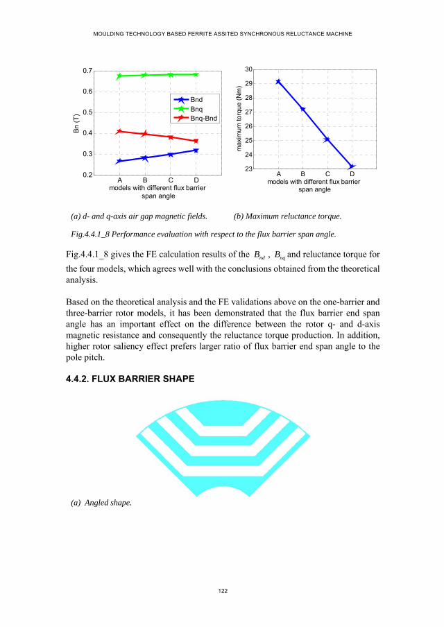
MOULDING TECHNOLOGY BASED FERRITE ASSITED SYNCHRONOUS RELUCTANCE MACHINE
122
(a) d- and q-axis air gap magnetic fields. (b) Maximum reluctance torque.
Fig.4.4.1_8 Performance evaluation with respect to the flux barrier span angle.
Fig.4.4.1_8 gives the FE calculation results of the ndB , nqB and reluctance torque for
the four models, which agrees well with the conclusions obtained from the theoretical analysis.
Based on the theoretical analysis and the FE validations above on the one-barrier and three-barrier rotor models, it has been demonstrated that the flux barrier end span angle has an important effect on the difference between the rotor q- and d-axis magnetic resistance and consequently the reluctance torque production. In addition, higher rotor saliency effect prefers larger ratio of flux barrier end span angle to the pole pitch.
4.4.2. FLUX BARRIER SHAPE
(a) Angled shape.
A B C D0.2
0.3
0.4
0.5
0.6
0.7
models with different flux barrier span angle
Bn
(T)
BndBnqBnq-Bnd
A B C D23
24
25
26
27
28
29
30
models with different flux barrier span angle
max
imum
torq
ue (
Nm
)
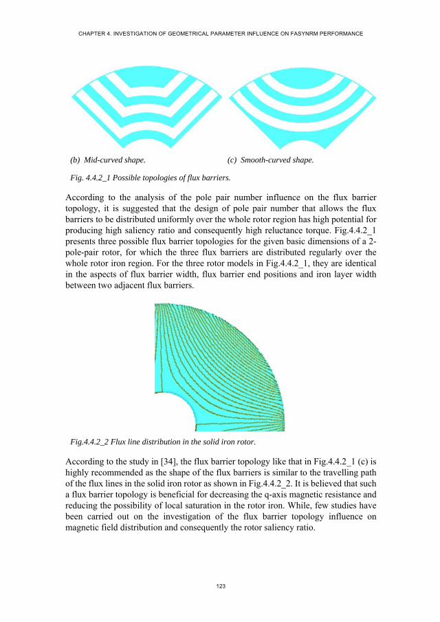
CHAPTER 4. INVESTIGATION OF GEOMETRICAL PARAMETER INFLUENCE ON FASYNRM PERFORMANCE
123
(b) Mid-curved shape. (c) Smooth-curved shape.
Fig. 4.4.2_1 Possible topologies of flux barriers.
According to the analysis of the pole pair number influence on the flux barrier topology, it is suggested that the design of pole pair number that allows the flux barriers to be distributed uniformly over the whole rotor region has high potential for producing high saliency ratio and consequently high reluctance torque. Fig.4.4.2_1 presents three possible flux barrier topologies for the given basic dimensions of a 2-pole-pair rotor, for which the three flux barriers are distributed regularly over the whole rotor iron region. For the three rotor models in Fig.4.4.2_1, they are identical in the aspects of flux barrier width, flux barrier end positions and iron layer width between two adjacent flux barriers.
Fig.4.4.2_2 Flux line distribution in the solid iron rotor.
According to the study in [34], the flux barrier topology like that in Fig.4.4.2_1 (c) is highly recommended as the shape of the flux barriers is similar to the travelling path of the flux lines in the solid iron rotor as shown in Fig.4.4.2_2. It is believed that such a flux barrier topology is beneficial for decreasing the q-axis magnetic resistance and reducing the possibility of local saturation in the rotor iron. While, few studies have been carried out on the investigation of the flux barrier topology influence on magnetic field distribution and consequently the rotor saliency ratio.

MOULDING TECHNOLOGY BASED FERRITE ASSITED SYNCHRONOUS RELUCTANCE MACHINE
124
(a) Angled shape.
(b) Mid-curved shape. (c) Smooth-curved shape.
Fig. 4.4.2_3 Distributions of d- and q-axis flux lines for different flux barrier topologies.
As is known, the rotor saliency ratio could be represented with the d- and q-axis effective air gap length, both of which in turn could be evaluated with the air gap magnetic field production on the corresponding axis for a given stator MMF. To have a good idea of the flux barrier topology influence on magnetic field distribution, the flux line distribution for the three rotor models is calculated under the same stator MMF, which are shown in Fig.4.4.2_3. The flux line distribution in each figure corresponds to two rotor positions: the upper half is for the rotor position where the d-axis is aligned with stator MMF axis; the lower half is for the rotor position where the q-axis is aligned with stator MMF. By comparing the flux line distribution of the three rotor models in Fig.4.4.2_3, it can be said under such a stator MMF, the influence of flux barrier topology on d- and q-axis magnetic field is not obvious.
Furthermore, to have a clear idea of the flux barrier topology influence on the magnetic field distribution under different stator MMF, the d-and q-axis air gap

CHAPTER 4. INVESTIGATION OF GEOMETRICAL PARAMETER INFLUENCE ON FASYNRM PERFORMANCE
125
magnetic field of the three rotor models are respectively calculated as shown in Fig.4.4.2_4. For modeling simplification and avoiding any potential influence of stator slot opening on magnetic field production, in the d- and q-axis magnetic field calculation the stator is constructed with surface-mounted PMs rather than the slot windings. In such a way, the stator MMF could be changed by just changing the magnetic property of the PM material. In Fig.4.4.2_4, the x-axis represents the remanent flux density of the PM and the y-axis represents the amplitude of the fundamental air gap magnetic field in the radial direction.
(a) Q-axis air gap magnetic field. (b) D-axis air gap magnetic field.
Fig.4.4.2_4 Air gap magnetic field of the three rotor models under different stator MMF.
Comparing the magnetic field amplitudes of the three rotor models for different stator MMF, it can be observed that
1. Rotor iron on the q-axis magnetic path starts to get saturated when the PM remanent flux density is higher than 1 .
2. The q-axis magnetic field of the three rotor models are almost identical under the same stator MMF. While, for the saturated state, a small difference occurs.
3. The d-axis magnetic field of the smooth-curved rotor model is slightly smaller than that of the other two rotor models.
Fig.4.4.2_5 presents the q-axis flux density distribution of the three rotor models for the case where the remanent flux density of the stator PM is 1.2T. It is easy to see that the flux density at the corner of the iron layer for the first two models is little smaller and the flux density for the smooth-curved rotor model is uniform in the iron layer. However, for the smooth-curved rotor model, the flux density in the iron region between two magnetic poles reaches 1.98T, which is because the iron layer is thinner due to the curve shape of the flux barriers. According to the flux density calculation results, it can be observed that the angular shapes of the flux barriers, like the angled
0 0.2 0.4 0.6 0.8 1 1.2 1.4 1.6 1.8Br (T)
0
0.2
0.4
0.6
0.8
1
1.2
1.4
1.6
angledmid-curvedsmooth-curved
0 0.2 0.4 0.6 0.8 1 1.2 1.4 1.6 1.8Br (T)
0
0.1
0.2
0.3
0.4
0.5
0.6
0.7
0.8
0.9
1
angledmid-curvedsmooth-curved

MOULDING TECHNOLOGY BASED FERRITE ASSITED SYNCHRONOUS RELUCTANCE MACHINE
126
and mid-curved rotor models in Fig.4.4.2_5 (a) and (b), do not lead to local saturation in the rotor iron. Fig.4.4.2_6 presents the torque performance of the three rotor models under the same stator MMF with respect to the relative position between rotor d-axis and stator MMF axis, which are almost identical to each other.
(a) Angled shape (b) Mid-curved shape
(c) Smooth-curved shape.
Fig.4.4.2_5 Q-axis flux density distribution for the case where the remanent flux density is 1.2T.

CHAPTER 4. INVESTIGATION OF GEOMETRICAL PARAMETER INFLUENCE ON FASYNRM PERFORMANCE
127
Fig. 4.4.2_6 Reluctance torque performance with respect to the relative position between rotor d-axis and stator MMF axis.
Rotor dimensional limit is also one of the factors that need to be considered in the flux barrier topology design. For example, for the rotor dimension as shown in Fig.4.4.2_7, it seems that only the mid-curved flux barrier topology could be applied.
Fig.4.4.2_7 Mid-curved rotor topology for the thin rotor iron.
Based on the analysis of the flux barrier topology influence on flux line distribution, d- and q-axis magnetic field production and reluctance torque, it can be concluded that the smooth-curved flux barrier topology slightly outperforms the angled and mid-curved flux barrier topologies. While, when considering the influence of rotor dimensional limit on the flux barrier topology design, the resulted performance difference could sufficiently be neglected.
0 22.5 45 67.5 90 112.5 135 157.5 180-20
-15
-10
-5
0
5
10
15
20
angular displacement (electrical degree)
torq
ue (
Nm
)
angledmid-curved smooth-curved
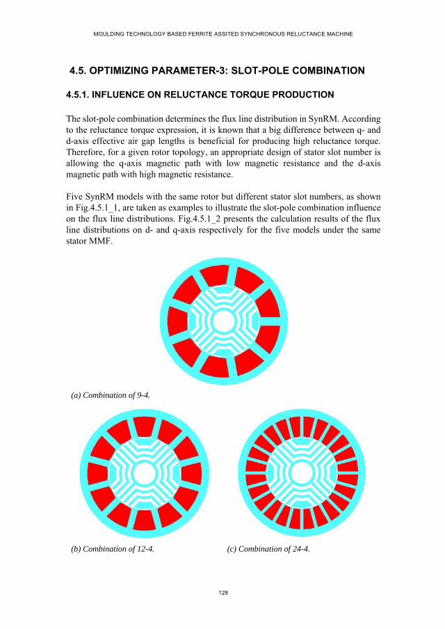
MOULDING TECHNOLOGY BASED FERRITE ASSITED SYNCHRONOUS RELUCTANCE MACHINE
128
4.5. OPTIMIZING PARAMETER-3: SLOT-POLE COMBINATION
4.5.1. INFLUENCE ON RELUCTANCE TORQUE PRODUCTION
The slot-pole combination determines the flux line distribution in SynRM. According to the reluctance torque expression, it is known that a big difference between q- and d-axis effective air gap lengths is beneficial for producing high reluctance torque. Therefore, for a given rotor topology, an appropriate design of stator slot number is allowing the q-axis magnetic path with low magnetic resistance and the d-axis magnetic path with high magnetic resistance.
Five SynRM models with the same rotor but different stator slot numbers, as shown in Fig.4.5.1_1, are taken as examples to illustrate the slot-pole combination influence on the flux line distributions. Fig.4.5.1_2 presents the calculation results of the flux line distributions on d- and q-axis respectively for the five models under the same stator MMF.
(a) Combination of 9-4.
(b) Combination of 12-4. (c) Combination of 24-4.
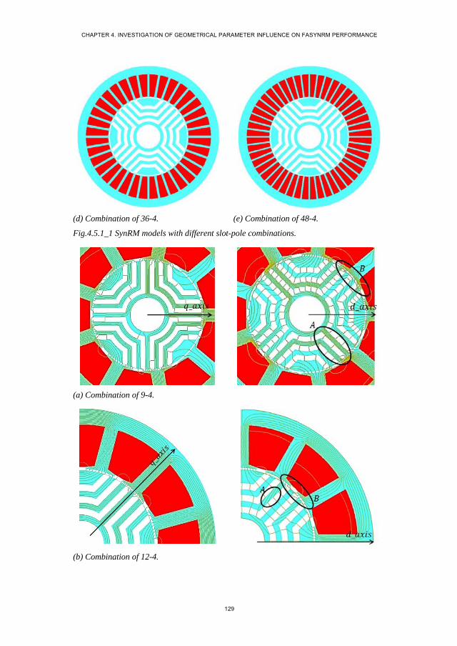
CHAPTER 4. INVESTIGATION OF GEOMETRICAL PARAMETER INFLUENCE ON FASYNRM PERFORMANCE
129
(d) Combination of 36-4. (e) Combination of 48-4.
Fig.4.5.1_1 SynRM models with different slot-pole combinations.
(a) Combination of 9-4.
(b) Combination of 12-4.

MOULDING TECHNOLOGY BASED FERRITE ASSITED SYNCHRONOUS RELUCTANCE MACHINE
130
(c) Combination of 24-4.
(d) Combination of 36-4.
(e) Combination of 48-4.
Fig.4.5.1_2 q- and d-axis flux line distributions for difference slot-pole combinations.

CHAPTER 4. INVESTIGATION OF GEOMETRICAL PARAMETER INFLUENCE ON FASYNRM PERFORMANCE
131
Fig.4.5.1_3 Air gap magnetic field variation for different slot-pole combinations.
From Fig.4.5.1_2, it can be observed that
1. The d- and q-axis flux line distribution for the models with integral slot winding is much more separated from each other compared with that of the model with fractional slot winding, which may indicate that the cross coupling effect of the integral-slot-winding model is less than that of the fractional-slot-winding model.
2. For the integral-slot-winding model with more stator slots, the amount of q-axis flux lines travelling in each iron layer is more uniform, which is beneficial for avoiding local saturation in rotor iron region.
3. For the integral-slot-winding model with more stator slots, the amount of d-axis zig-zag leakage flux between the rotor iron layer and the tip of stator teeth is smaller, which is shown in Fig.4.5.1_2 marked with circle B.
Fig.4.5.1_3 presents the amplitudes of the air gap sinusoidal magnetic field on d- and q-axis respectively for the different slot-pole combinations under the same stator MMF. From the curves in Fig.4.5.1_3, it is easy to notice that
1. Under the same stator MMF, the fractional-slot-winding model has the lowest q-axis magnetic field production and the integral-slot-winding models with more stator slots have higher q-axis magnetic field production.
2. Under the same stator MMF, the d-axis magnetic field of the fractional-slot-winding model is obviously higher than that of the integral-slot-winding models, which is because a certain amount of the d-axis flux lines travel in the rotor iron via the q-axis magnetic path, which is shown in Fig.4.5.1_2 (a) marked with circle A.
9-4 12-4 24-4 36-4 48-40.1
0.2
0.3
0.4
0.5
0.6
0.7
0.8
0.9
1
slot-pole combinations
Bn
(T)
BndBnqBnq-Bnd

MOULDING TECHNOLOGY BASED FERRITE ASSITED SYNCHRONOUS RELUCTANCE MACHINE
132
3. The slot-pole combinations of 24-4, 36-4 and 48-4 have similar d- and q-axis magnetic field production for the same stator MMF, thus leading to the similar difference between q- and d-axis magnetic field.
(a) Torque waveforms. (b) Fourier analysis.
Fig.4.5.1_4 Reluctance torque production for different slot-pole combinations with respect to the angular displacement of rotor d-axis and stator MMF axis.
The reluctance torque production of the five models with respect to the relative position between rotor d-axis and stator MMF is calculated under a certain value of stator MMF, which are shown in Fig.4.5.1_4. It is easy to see that reluctance torque production of the integral-slot-winding models is obviously higher than that of the fractional-slot-winding models. For the integral-slot-winding models, the combination of 36-4 has the highest reluctance torque production.
The analysis of d- and q-axis flux line distribution, air gap magnetic field production and reluctance torque performance for the five models validates that the mutual effect between d- and q-axis magnetic path for different slot-pole combinations is the main reason that leads to different rotor saliency ratio and consequently different reluctance torque production, which provides constructive guideline for the design of slot-pole combination for achieving high reluctance torque. Based on the calculation results, it can be concluded that integral slot winding is more beneficial for producing high reluctance torque. However, the long end winding resulted from the integral slot winding also needs to be considered.
4.5.2. INFLUENCE ON TORQUE RIPPLE
According to the torque expression of (4.4.1_1), it can be observed that the variation of q-axis and d-axis magnetic field difference (denoted as nq ndB B ) for different rotor
positions leads to the production of torque ripple, which is caused by the interaction between rotor flux barrier ends and the stator slots. Thus the slot-pole combination
0 22.5 45 67.5 90 112.5135157.5180-40
-30
-20
-10
0
10
20
30
40
displacement of rotor d-axisand stator MMF axis (electrical degree)
torq
ue (
Nm
)
9-412-424-436-448-4
0 1 2 3 4 5 6 70
5
10
15
20
25
30
torq
ue (
Nm
)
9-412-424-436-448-4
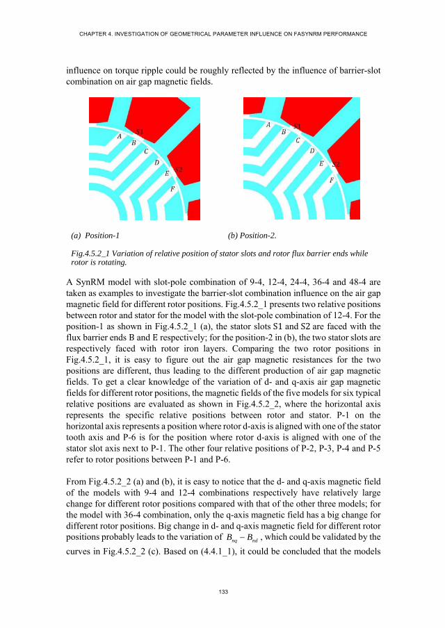
CHAPTER 4. INVESTIGATION OF GEOMETRICAL PARAMETER INFLUENCE ON FASYNRM PERFORMANCE
133
influence on torque ripple could be roughly reflected by the influence of barrier-slot combination on air gap magnetic fields.
(a) Position-1 (b) Position-2.
Fig.4.5.2_1 Variation of relative position of stator slots and rotor flux barrier ends while rotor is rotating.
A SynRM model with slot-pole combination of 9-4, 12-4, 24-4, 36-4 and 48-4 are taken as examples to investigate the barrier-slot combination influence on the air gap magnetic field for different rotor positions. Fig.4.5.2_1 presents two relative positions between rotor and stator for the model with the slot-pole combination of 12-4. For the position-1 as shown in Fig.4.5.2_1 (a), the stator slots S1 and S2are faced with the flux barrier ends B and E respectively; for the position-2 in (b), the two stator slots are respectively faced with rotor iron layers. Comparing the two rotor positions in Fig.4.5.2_1, it is easy to figure out the air gap magnetic resistances for the two positions are different, thus leading to the different production of air gap magnetic fields. To get a clear knowledge of the variation of d- and q-axis air gap magnetic fields for different rotor positions, the magnetic fields of the five models for six typical relative positions are evaluated as shown in Fig.4.5.2_2, where the horizontal axis represents the specific relative positions between rotor and stator. P-1 on the horizontal axis represents a position where rotor d-axis is aligned with one of the stator tooth axis and P-6 is for the position where rotor d-axis is aligned with one of the stator slot axis next to P-1. The other four relative positions of P-2, P-3, P-4 and P-5 refer to rotor positions between P-1 and P-6.
From Fig.4.5.2_2 (a) and (b), it is easy to notice that the d- and q-axis magnetic field of the models with 9-4 and 12-4 combinations respectively have relatively large change for different rotor positions compared with that of the other three models; for the model with 36-4 combination, only the q-axis magnetic field has a big change for different rotor positions. Big change in d- and q-axis magnetic field for different rotor positions probably leads to the variation of nq ndB B , which could be validated by the
curves in Fig.4.5.2_2 (c). Based on (4.4.1_1), it could be concluded that the models

MOULDING TECHNOLOGY BASED FERRITE ASSITED SYNCHRONOUS RELUCTANCE MACHINE
134
with 9-4, 12-4 and 36-4 combinations produce higher torque ripple compared with the models with 24-4 and 48-4 combinations.
(a) Amplitude of d-axis air gap magnetic field.
(b) Amplitude of q-axis air gap magnetic field.
(c) Difference of q- and d-axis magnetic field amplitude.
Fig.4.5.2_2 Variation of d- and q-axis air gap magnetic field at different rotor positions.
The transient torque performance of the five models are evaluated under the maximum torque/current control. The calculation result are shown in Fig.4.5.2_3, where the torque ripple for the models with 9-4, 12-4 and 36-4 combinations is obviously higher than that of the models with 24-4 and 48-4 combinations, which agrees well with the analytical result based on the air gap magnetic fields.
P-1 P-2 P-3 P-4 P-5 P-60.07
0.075
0.08
0.085
0.09
0.095
0.1
0.105
0.11
rotor position
Bnd
(T
)
9-412-424-436-448-4
P-1 P-2 P-3 P-4 P-5 P-60.34
0.36
0.38
0.4
0.42
0.44
0.46
0.48
rotor position B
nq (
T)
9-412-424-436-448-4
P-1 P-2 P-3 P-4 P-5 P-60.25
0.275
0.3
0.325
0.35
0.375
0.4
rotor position
Bn
q-B
nd (
T)
9-412-424-436-448-4
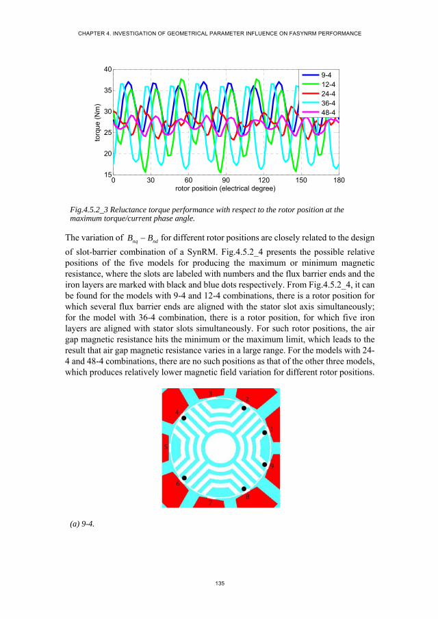
CHAPTER 4. INVESTIGATION OF GEOMETRICAL PARAMETER INFLUENCE ON FASYNRM PERFORMANCE
135
Fig.4.5.2_3 Reluctance torque performance with respect to the rotor position at the maximum torque/current phase angle.
The variation of nq ndB B for different rotor positions are closely related to the design
of slot-barrier combination of a SynRM. Fig.4.5.2_4 presents the possible relative positions of the five models for producing the maximum or minimum magnetic resistance, where the slots are labeled with numbers and the flux barrier ends and the iron layers are marked with black and blue dots respectively. From Fig.4.5.2_4, it can be found for the models with 9-4 and 12-4 combinations, there is a rotor position for which several flux barrier ends are aligned with the stator slot axis simultaneously; for the model with 36-4 combination, there is a rotor position, for which five iron layers are aligned with stator slots simultaneously. For such rotor positions, the air gap magnetic resistance hits the minimum or the maximum limit, which leads to the result that air gap magnetic resistance varies in a large range. For the models with 24-4 and 48-4 combinations, there are no such positions as that of the other three models, which produces relatively lower magnetic field variation for different rotor positions.
(a) 9-4.
0 30 60 90 120 150 18015
20
25
30
35
40
rotor positioin (electrical degree)
torq
ue (
Nm
)
9-412-424-436-448-4
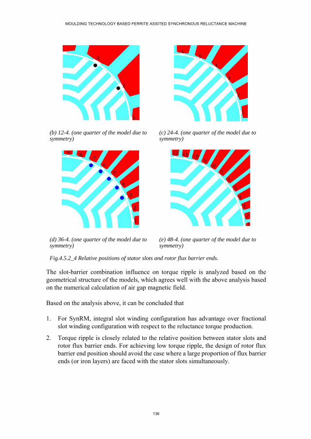
MOULDING TECHNOLOGY BASED FERRITE ASSITED SYNCHRONOUS RELUCTANCE MACHINE
136
(b) 12-4. (one quarter of the model due to symmetry)
(c) 24-4. (one quarter of the model due to symmetry)
(d) 36-4. (one quarter of the model due to symmetry)
(e) 48-4. (one quarter of the model due to symmetry)
Fig.4.5.2_4 Relative positions of stator slots and rotor flux barrier ends.
The slot-barrier combination influence on torque ripple is analyzed based on the geometrical structure of the models, which agrees well with the above analysis based on the numerical calculation of air gap magnetic field.
Based on the analysis above, it can be concluded that
1. For SynRM, integral slot winding configuration has advantage over fractional slot winding configuration with respect to the reluctance torque production.
2. Torque ripple is closely related to the relative position between stator slots and rotor flux barrier ends. For achieving low torque ripple, the design of rotor flux barrier end position should avoid the case where a large proportion of flux barrier ends (or iron layers) are faced with the stator slots simultaneously.
CHAPTER 4. INVESTIGATION OF GEOMETRICAL PARAMETER INFLUENCE ON FASYNRM PERFORMANCE
137
4.6. SUMMARY OF CHAPTER 4
Optimal design of SynRM is a complicated task, requiring a comprehensive knowledge of the direct and indirect influence of geometrical parameters on SynRM performance. Above mentioned analysis provides a general insight into the influence of several main parameters of SynRM on the torque performance, consequently concludes constructive suggestions for optimal design of SynRM which are summarized as
1. SynRM design with relatively low pole pair number may be preferred for achieving high reluctance torque production capability. However, the determination of pole pair number for a specific SynRM application is also affected by the rotor dimensional limit for allowing possible flux barrier topology as well as the stator dimensional limit like the thickness of stator yoke and tooth in order to avoid deep saturation.
2. Integral slot winding with relatively a large number of stator slots for one pole is generally preferred for producing high reluctance torque. While, integral slot winding tends to produce high copper loss due to the long end winding, which needs to be considered in the design of slot-pole combination.
3. Flux barrier location is closely related to the rotor basic dimensions and the pole pair number. The design of flux barriers which are uniformly distributed over the whole rotor iron region has high potential for producing good saliency effect.
4. Flux barrier span angle and width are subject to the iron layer width in order to avoid high saturation degrees in the rotor iron material. The design of flux barrier span angle which could embrace as many as d-axis flux lines as possible and fore the flux lines to travel across all the flux barriers is generally preferred to minimize the d-axis average permeance.
5. The interaction between flux barrier ends and stator slots has an effect on torque ripple. Optimal design of flux barrier end position over the rotor periphery surface should avoid the cases that a large number of rotor slots are aligned with stator slots or tooth at the same rotor position.

MOULDING TECHNOLOGY BASED FERRITE ASSITED SYNCHRONOUS RELUCTANCE MACHINE
138
Reference
1. M. Barcaro and N. Bianchi, "Interior PM Machines Using Ferrite to Replace Rare-Earth Surface PM Machines," in IEEE Transactions on Industry Applications, vol. 50, no. 2, pp. 979-985, March-April 2014.
2. S. S. R. Bonthu, A. Arafat and S. Choi, "Comparisons of Rare-Earth and Rare-Earth-Free External Rotor Permanent Magnet Assisted Synchronous Reluctance Motors," in IEEE Transactions on Industrial Electronics, vol. 64, no. 12, pp. 9729-9738, Dec. 2017.
3. T. A. Huynh and M. F. Hsieh, "Comparative Study of PM-Assisted SynRM and IPMSM on Constant Power Speed Range for EV Applications," in IEEE Transactions on Magnetics, vol. 53, no. 11, pp. 1-6, Nov. 2017.
4. M. N. Ibrahim, P. Sergeant and E. M. Rashad, "Rotor design with and without permanent magnets and performance evaluation of synchronous reluctance motors," 2016 19th International Conference on Electrical Machines and Systems (ICEMS), Chiba, 2016, pp. 1-7.
5. T. Liu et al., "On the Design and Construction Assessments of a Permanent-Magnet-Assisted Synchronous Reluctance Motor," in IEEE Transactions on Magnetics, vol. 53, no. 11, pp. 1-4, Nov. 2017.
6. M. Ferrari, N. Bianchi and E. Fornasiero, "Analysis of Rotor Saturation in Synchronous Reluctance and PM-Assisted Reluctance Motors," in IEEE Transactions on Industry Applications, vol. 51, no. 1, pp. 169-177, Jan.-Feb. 2015.
7. Z. Y. Zhang, M. C. Tsai, P. W. Huang, C. W. Cheng and J. M. Huang, "Characteristic comparison of transversally laminated anisotropic synchronous reluctance motor fabrication based on 2D lamination and 3D printing," 2015 18th International Conference on Electrical Machines and Systems (ICEMS), Pattaya, 2015, pp. 894-897.
8. S. Cai, J. Shen, H. Hao and M. Jin, "Design methods of transversally laminated synchronous reluctance machines," in CES Transactions on Electrical Machines and Systems, vol. 1, no. 2, pp. 164-173, 2017.
9. S. Taghavi and P. Pillay, "A mechanically robust rotor with transverse-laminations for a synchronous reluctance machine for traction applications," 2014 IEEE Energy Conversion Congress and Exposition (ECCE), Pittsburgh, PA, 2014, pp. 5131-5137.
10. Z. Zhengming and E. A. Ahmed, "Optimization of added permanent magnet amount in synchronous reluctance machines for high performance," in Tsinghua Science and Technology, vol. 3, no. 3, pp. 1137-1142, Sept. 1998.
11. M. A. Raj and A. Kavitha, "Effect of Rotor Geometry on Peak and Average Torque of External-Rotor Synchronous Reluctance Motor in Comparison With

CHAPTER 4. INVESTIGATION OF GEOMETRICAL PARAMETER INFLUENCE ON FASYNRM PERFORMANCE
139
Switched Reluctance Motor for Low-Speed Direct-Drive Domestic Application," in IEEE Transactions on Magnetics, vol. 53, no. 11, pp. 1-8, Nov. 2017..
12. W. Wu, X. Zhu, L. Quan, Y. Du, Z. Xiang and X. Zhu, "Design and Analysis of a Hybrid Permanent Magnet Assisted Synchronous Reluctance Motor Considering Magnetic Saliency and PM Usage," in IEEE Transactions on Applied Superconductivity, vol. 28, no. 3, pp. 1-6, April 2018.
13. W. Zhao, D. Chen, T. A. Lipo and B. I. Kwon, "Performance Improvement of Ferrite-Assisted Synchronous Reluctance Machines Using Asymmetrical Rotor Configurations," in IEEE Transactions on Magnetics, vol. 51, no. 11, pp. 1-4, Nov. 2015.
14. A. Vagati, B. Boazzo, P. Guglielmi and G. Pellegrino, "Design of Ferrite-Assisted Synchronous Reluctance Machines Robust Toward Demagnetization," in IEEE Transactions on Industry Applications, vol. 50, no. 3, pp. 1768-1779, May-June 2014.
15. A. Boazzo, A. Vagati, G. Pellegrino, E. Armando and P. Guglielmi, "Multipolar Ferrite-Assisted Synchronous Reluctance Machines: A General Design Approach," in IEEE Transactions on Industrial Electronics, vol. 62, no. 2, pp. 832-845, Feb. 2015.
16. H. C. Liu, I. G. Kim, Y. J. Oh, J. Lee and S. C. Go, "Design of Permanent Magnet-Assisted Synchronous Reluctance Motor for Maximized Back-EMF and Torque Ripple Reduction," in IEEE Transactions on Magnetics, vol. 53, no. 6, pp. 1-4, June 2017.
17. K. C. Kim, J. S. Ahn, S. H. Won, J. P. Hong and J. Lee, "A Study on the Optimal Design of SynRM for the High Torque and Power Factor," in IEEE Transactions on Magnetics, vol. 43, no. 6, pp. 2543-2545, June 2007.
18. J. M. Park, S. I. Kim, J. P. Hong and J. H. Lee, "Rotor Design on Torque Ripple Reduction for a Synchronous Reluctance Motor With Concentrated Winding Using Response Surface Methodology," in IEEE Transactions on Magnetics, vol. 42, no. 10, pp. 3479-3481, Oct. 2006.
19. R. Lohninger, H. Grabner, G. Weidenholzer, S. Silber and W. Amrhein, "Modeling, Simulation, and Design of a Permanent-Magnet-Assisted Synchronous Reluctance Machine," in IEEE Transactions on Industry Applications, vol. 51, no. 1, pp. 196-203, Jan.-Feb. 2015.
20. K. Khan, M. Leksell and O. Wallmark, "Design aspects on magnet placement in permanent-magnet assisted synchronous reluctance machines," 5th IET International Conference on Power Electronics, Machines and Drives (PEMD 2010), Brighton, UK, 2010, pp. 1-5.
21. R. Vartanian and H. A. Toliyat, "Design and comparison of an optimized permanent magnet-assisted synchronous reluctance motor (PMa-SynRM) with an
MOULDING TECHNOLOGY BASED FERRITE ASSITED SYNCHRONOUS RELUCTANCE MACHINE
140
induction motor with identical NEMA Frame stators," 2009 IEEE Electric Ship Technologies Symposium, Baltimore, MD, 2009, pp. 107-112.
22. M. Palmieri, M. Perta, F. Cupertino and G. Pellegrino, "Effect of the numbers of slots and barriers on the optimal design of synchronous reluctance machines," 2014 International Conference on Optimization of Electrical and Electronic Equipment (OPTIM), Bran, 2014, pp. 260-267.
23. T. Tokuda, M. Sanada and S. Morimoto, "Influence of rotor structure on performance of permanent magnet assisted synchronous reluctance motor," 2009 International Conference on Electrical Machines and Systems, Tokyo, 2009, pp. 1-6.
24. R. Vartanian, H. A. Toliyat, B. Akin and R. Poley, "Power factor improvement of synchronous reluctance motors (SynRM) using permanent magnets for drive size reduction," 2012 Twenty-Seventh Annual IEEE Applied Power Electronics Conference and Exposition (APEC), Orlando, FL, 2012, pp. 628-633.
25. Prieto, B. Dagusé, P. Dessante, P. Vidal and J. C. Vannier, "Effect of magnets on average torque and power factor of Synchronous Reluctance Motors," 2012 XXth International Conference on Electrical Machines, Marseille, 2012, pp. 213-219.
26. N. Bianchi, E. Fornasiero and W. Soong, "Selection of PM Flux Linkage for Maximum Low-Speed Torque Rating in a PM-Assisted Synchronous Reluctance Machine," in IEEE Transactions on Industry Applications, vol. 51, no. 5, pp. 3600-3608, Sept.-Oct. 2015.
27. P. Roshanfekr, S. Lundmark, B. Anvari and T. Thiringer, "Investigation of pole number selection in a synchronous reluctance generator for wind applications," 2017 IEEE International Electric Machines and Drives Conference (IEMDC), Miami, FL, 2017, pp. 1-6.
28. P. Pop, R. Marţiş, A. Dărămus, C. Marţiş, A. C. Pop and I. Vintiloiu, "Design and analysis of slot-pole combination for synchronous reluctance machine with concentrated windings for automotive applications," 2016 International Conference and Exposition on Electrical and Power Engineering (EPE), Iasi, 2016, pp. 229-234.
29. S. Taghavi and P. Pillay, "A comparative study of synchronous reluctance machine performance with different pole numbers for automotive applications," IECON 2014 - 40th Annual Conference of the IEEE Industrial Electronics Society, Dallas, TX, 2014, pp. 3812-3818.
30. H. Huang, Y. Hu, Y. Xiao and H. Lyu, "Research of parameters and anti-demagnetization of rare-earth-less permanent magnet assisted synchronous reluctance motor," 2015 IEEE Magnetics Conference (INTERMAG), Beijing, 2015, pp. 1-1.

CHAPTER 4. INVESTIGATION OF GEOMETRICAL PARAMETER INFLUENCE ON FASYNRM PERFORMANCE
141
31. M. N. Ibrahim, P. Sergeant and E. M. Rashad, "Influence of rotor flux-barrier geometry on torque and torque ripple of permanent-magnet-assisted synchronous reluctance motors," 2016 XXII International Conference on Electrical Machines (ICEM), Lausanne, 2016, pp. 398-404.
32. N. Bianchi, S. Bolognani, D. Bon and M. Dai Pre, "Rotor Flux-Barrier Design for Torque Ripple Reduction in Synchronous Reluctance and PM-Assisted Synchronous Reluctance Motors," in IEEE Transactions on Industry Applications, vol. 45, no. 3, pp. 921-928, May-june 2009.
33. M. Sanada, K. Hiramoto, S. Morimoto and Y. Takeda, "Torque ripple improvement for synchronous reluctance motor using an asymmetric flux barrier arrangement," in IEEE Transactions on Industry Applications, vol. 40, no. 4, pp. 1076-1082, July-Aug. 2004.
34. M. Palmieri, M. Perta, F. Cupertino and G. Pellegrino, "Effect of the numbers of slots and barriers on the optimal design of synchronous reluctance machines," 2014 International Conference on Optimization of Electrical and Electronic Equipment (OPTIM), Bran, 2014, pp. 260-267.
MOULDING TECHNOLOGY BASED FERRITE ASSITED SYNCHRONOUS RELUCTANCE MACHINE
142
CHAPTER 5. PROTYPING AND TEST
5.1. INTRODUCTION
FASynRM is a promising candidate in the various industrial applications due to the obvious advantages of simple structure, low cost, competetive torque performance and easy maintenance [1-3]. By applying the moulding technology as introduced in chapter 3, the installation of the ferrite magnets into the rotor flux barriers of FASynRM could be easily performed [4]. Based on the detailed analysis of the geometrical parameter influence on the performance of FASynRM in chapter 4, constructive design guidelines are obtained and an appropriate design of a FASynRM could then be expected.
This chapter is dedicated to the design and test of a FASynRM, taking an existing commercial product of induction machine as a reference.
5.2. TARGET SPECIFICATIONS
TABLE.5.2_1 SPECIFICATIONS OF THE TARGET IM.
Rated power ( ) 13
Rotating speed ( ) 3000
Stack length ( ) 260
Stator slot number 24
Stator inner diameter ( ) 65
Stator outer diameter ( ) 135
Pole pair 1
Shaft diameter ( ) 35
Copper loss ( ) 1342 554
Iron loss ( ) 233
Can loss ( ) 255
Efficiency 82.5%
Table.5.2_1 presents the specifications of the existing commercial product of IM, which is regarded as the target IM in this chapter. This IM is used under water for pump. The can structure is constructed in the air gap in order to protect the stator from water. In operation, the rotor of the target IM is completely submerged in the water,
CHAPTER 5. PROTYPING AND TEST
143
thus cooling the machine with water. The efficiency of the target IM is 82.5% under the water cooling including the can loss.
Taking the IM as a reference, the design of the FASynRM complies with the specifications of the target IM, like the power level, speed, stack length and the stator outer diameter. In order to reduce manufacturing cost, an existing stator assembly line is intended for the designed FASynRM, which is shown in Fig.5.2_1. The stator intended for the FASynRM is the same as that of the target IM except the yoke thickness being a little thinner. As the stator structure cannot be optimized, the potential of the FASynRM for achieving the best performance may be reduced.
Fig.5.2_1 Stator configuration for the intended FASynRM.
5.3. DESIGN OF FASYNRM ROTOR
A. Basic dimensions Air gap length
As the target IM is working under water, a can structure is needed to protect the stator from water. Considering the can thickness of 0.35 , the air gap length is determined to be 0.8 , which is equal to that of the target IM.
Inner and outer diameter. The final designs of stator structure and air gap length determine the rotor outer diameter. In order to reduce cost, an existing shaft is intended for the designed FASynRM, thus the rotor inner diameter is then determined.
Stack length. The stack length of FASynRM is equal to that of the target IM.
B. Rotor topology

MOULDING TECHNOLOGY BASED FERRITE ASSITED SYNCHRONOUS RELUCTANCE MACHINE
144
Transversally laminated multi-barrier rotor is decided for the FASynRM for the advantages of manufacturing simplicity and relatively high saliency effect.
C. Pole pair number
To combine with the stator slot number of 24, the most possible pole pair number for the FASynRM is 2, 4 and 5. For the pole pair number determination, several factors need to be considered, which are
1. Winding configuration: As discussed in chapter 4, the integral slot winding configuration is more beneficial to the high reluctance torque production compared with the factional slot winding.
2. Reluctance torque production: According to the torque theoretical analysis in chapter 2, the pole pair number theoretically has no effect on PM torque component, but is in an inverse proportion with the reluctance torque production.
Based on the above mentioned suggestions, the pole pair number of 2 is chosen as the initial design for FASynRM. While, considering the possible problems of saturation, leakage flux and the flux barrier distribution, the pole pair number of 4 also needs to be considered as a design option.
D. Flux barrier topology
The influence of the number of flux barrier layers for one pole on torque performance of FASynRM is not as significant as the other geometrical parameters, like the flux barrier width, flux barrier end position and the flux barrier span angle [5, 6]. Thus, the design of flux barrier layer number is subject to the design of the relative position between rotor flux barrier ends and the stator slots.
(a) End-tooth alignment. (b) End-slot alignment.
Fig.5.3_1 Relative position of flux barrier ends and stator slots.

CHAPTER 5. PROTYPING AND TEST
145
Taking the 2-pole-pair rotor as an example to illustrate the design of the flux barrier topology. According to the analysis of the geometrical parameter influence on torque performance in chapter 4, the relative position of the flux barrier ends and the stator slots as shown in Fig.5.3_1 should be avoided in order to achieve low torque ripple. For achieving the optimal design of the flux barrier end positions, a simple strategy for locating the flux barrier ends is proposed as shown in Fig.5.3_2, where the stator is divided into small sector regions separated by tooth and slot symmetrical axes. The two ends of one flux barrier are suggested to be located in the two regions marked with the same labels. For example, the possible flux barriers for the model as shown in Fig.5.3_2 are A1-A1, B2-B2, C3-C3, D4-D4, E5-E5 and F6-F6. The width of each iron layer is generally suggested to be close to the width of stator tooth in order to achieve similar saturation degree in stator and rotor iron. In addition, according to the geometrical parameter influence analysis in chapter 4, large flux barrier span angle is preferred in order to reduce the permeance on d-axis. Considering the design suggestions above, three-flux-barrier rotor topology is initially selected, which are A1-A1, C3-C3 and E5-E5. Due to the rotor limited space, only the middle-curved flux barrier shape is allowed for the 2-pole-pair three-flux-barrier rotor topology. As to the specific dimensions of the flux barrier, they are finally decided by trial and error aiming at achieving high torque production.
Fig.5.3_2 suggested flux barrier end distribution for torque ripple reduction.
With the same method used for the 2-pole-pair rotor design, the 4-pole-pair rotor topology is finally determined with identical flux barrier width. Fig.5.3_3 presents the rotor structures for the 2- and 4-pole-pair models. Comparing the two rotors in Fig.5.3_3, it could be noticed that more iron is left near the rotor inner surface for the 4-pole-pair model. The shaft used for FASynRM is made of magnetic material, while its permeability is lower than that of the rotor iron.
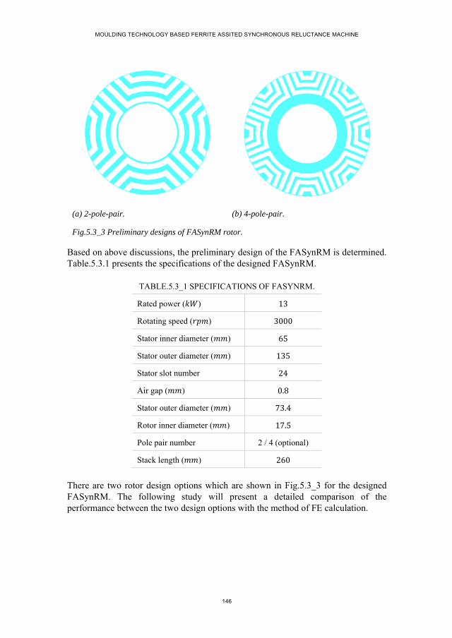
MOULDING TECHNOLOGY BASED FERRITE ASSITED SYNCHRONOUS RELUCTANCE MACHINE
146
(a) 2-pole-pair. (b) 4-pole-pair.
Fig.5.3_3 Preliminary designs of FASynRM rotor.
Based on above discussions, the preliminary design of the FASynRM is determined. Table.5.3.1 presents the specifications of the designed FASynRM.
TABLE.5.3_1 SPECIFICATIONS OF FASYNRM.
Rated power ( ) 13
Rotating speed ( ) 3000
Stator inner diameter ( ) 65
Stator outer diameter ( ) 135
Stator slot number 24
Air gap ( ) 0.8
Stator outer diameter ( ) 73.4
Rotor inner diameter ( ) 17.5
Pole pair number 2 / 4 (optional)
Stack length ( ) 260
There are two rotor design options which are shown in Fig.5.3_3 for the designed FASynRM. The following study will present a detailed comparison of the performance between the two design options with the method of FE calculation.
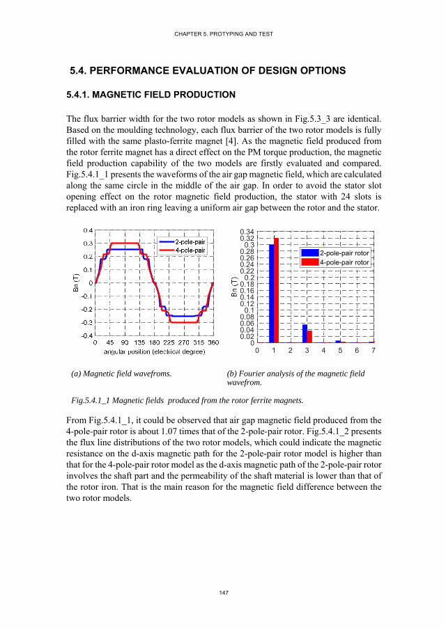
CHAPTER 5. PROTYPING AND TEST
147
5.4. PERFORMANCE EVALUATION OF DESIGN OPTIONS
5.4.1. MAGNETIC FIELD PRODUCTION
The flux barrier width for the two rotor models as shown in Fig.5.3_3 are identical. Based on the moulding technology, each flux barrier of the two rotor models is fully filled with the same plasto-ferrite magnet [4]. As the magnetic field produced from the rotor ferrite magnet has a direct effect on the PM torque production, the magnetic field production capability of the two models are firstly evaluated and compared. Fig.5.4.1_1 presents the waveforms of the air gap magnetic field, which are calculated along the same circle in the middle of the air gap. In order to avoid the stator slot opening effect on the rotor magnetic field production, the stator with 24 slots is replaced with an iron ring leaving a uniform air gap between the rotor and the stator.
(a) Magnetic field wavefroms. (b) Fourier analysis of the magnetic field wavefrom.
Fig.5.4.1_1 Magnetic fields produced from the rotor ferrite magnets.
From Fig.5.4.1_1, it could be observed that air gap magnetic field produced from the 4-pole-pair rotor is about 1.07 times that of the 2-pole-pair rotor. Fig.5.4.1_2 presents the flux line distributions of the two rotor models, which could indicate the magnetic resistance on the d-axis magnetic path for the 2-pole-pair rotor model is higher than that for the 4-pole-pair rotor model as the d-axis magnetic path of the 2-pole-pair rotor involves the shaft part and the permeability of the shaft material is lower than that of the rotor iron. That is the main reason for the magnetic field difference between the two rotor models.
0 1 2 3 4 5 6 70
0.020.040.060.08
0.10.120.140.160.18
0.20.220.240.260.28
0.30.320.34
2-pole-pair rotor4-pole-pair rotor
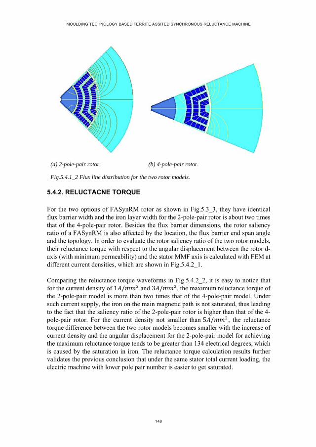
MOULDING TECHNOLOGY BASED FERRITE ASSITED SYNCHRONOUS RELUCTANCE MACHINE
148
(a) 2-pole-pair rotor. (b) 4-pole-pair rotor.
Fig.5.4.1_2 Flux line distribution for the two rotor models.
5.4.2. RELUCTACNE TORQUE
For the two options of FASynRM rotor as shown in Fig.5.3_3, they have identical flux barrier width and the iron layer width for the 2-pole-pair rotor is about two times that of the 4-pole-pair rotor. Besides the flux barrier dimensions, the rotor saliency ratio of a FASynRM is also affected by the location, the flux barrier end span angle and the topology. In order to evaluate the rotor saliency ratio of the two rotor models, their reluctance torque with respect to the angular displacement between the rotor d-axis (with minimum permeability) and the stator MMF axis is calculated with FEM at different current densities, which are shown in Fig.5.4.2_1.
Comparing the reluctance torque waveforms in Fig.5.4.2_2, it is easy to notice that for the current density of 1 / and 3 / , the maximum reluctance torque of the 2-pole-pair model is more than two times that of the 4-pole-pair model. Under such current supply, the iron on the main magnetic path is not saturated, thus leading to the fact that the saliency ratio of the 2-pole-pair rotor is higher than that of the 4-pole-pair rotor. For the current density not smaller than 5 / , the reluctance torque difference between the two rotor models becomes smaller with the increase of current density and the angular displacement for the 2-pole-pair model for achieving the maximum reluctance torque tends to be greater than 134 electrical degrees, which is caused by the saturation in iron. The reluctance torque calculation results further validates the previous conclusion that under the same stator total current loading, the electric machine with lower pole pair number is easier to get saturated.
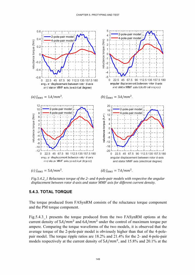
CHAPTER 5. PROTYPING AND TEST
149
(a) 1 / . (b) 3 / .
(c) 5 / . (d) 7 / .
Fig.5.4.2_1 Reluctance torque of the 2- and 4-pole-pair models with respective the angular displacement between rotor d-axis and stator MMF axis for different current density.
5.4.3. TOTAL TORQUE
The torque produced from FASynRM consists of the reluctance torque component and the PM torque component.
Fig.5.4.3_1 presents the torque produced from the two FASynRM options at the current density of 5 / and 6 / under the control of maximum torque per ampere. Comparing the torque waveforms of the two models, it is observed that the average torque of the 2-pole-pair model is obviously higher than that of the 4-pole-pair model. The torque ripple ratios are 18.2% and 21.4% for the 2- and 4-pole-pair models respectively at the current density of 5 / , and 15.8% and 20.1% at the
0 22.5 45 67.5 90 112.5 135 157.5 180-0.6
-0.4
-0.2
0
0.2
0.4
0.6re
luct
ance
torq
ue (
Nm
)
2-pole-pair model4-pole-pair model
0 22.5 45 67.5 90 112.5 135 157.5 180-5
-4
-3
-2
-1
0
1
2
3
4
5
relu
ctan
ce to
rque
(N
m)
2-pole-pair model4-pole-pair model
0 22.5 45 67.5 90 112.5 135 157.5 180-12-10-8-6-4-202468
1012
relu
ctan
ce to
rque
(N
m)
2-pole-pair model4-pole-pair model
0 22.5 45 67.5 90 112.5 135 157.5 180angular displacement between rotor d-axis
and stator MMF axis (electrical degree)
-20
-16
-12
-8
-4
0
4
8
12
16
202-pole-pair model4-pole-pair model
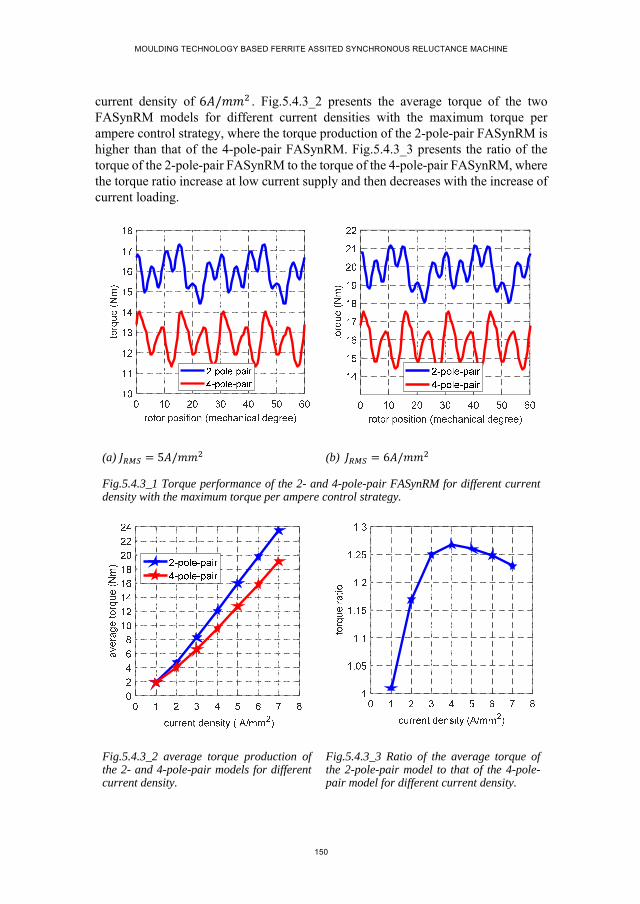
MOULDING TECHNOLOGY BASED FERRITE ASSITED SYNCHRONOUS RELUCTANCE MACHINE
150
current density of 6 / . Fig.5.4.3_2 presents the average torque of the two FASynRM models for different current densities with the maximum torque per ampere control strategy, where the torque production of the 2-pole-pair FASynRM is higher than that of the 4-pole-pair FASynRM. Fig.5.4.3_3 presents the ratio of the torque of the 2-pole-pair FASynRM to the torque of the 4-pole-pair FASynRM, where the torque ratio increase at low current supply and then decreases with the increase of current loading.
(a) 5 / (b) 6 /
Fig.5.4.3_1 Torque performance of the 2- and 4-pole-pair FASynRM for different current density with the maximum torque per ampere control strategy.
Fig.5.4.3_2 average torque production of the 2- and 4-pole-pair models for different current density.
Fig.5.4.3_3 Ratio of the average torque of the 2-pole-pair model to that of the 4-pole-pair model for different current density.
CHAPTER 5. PROTYPING AND TEST
151
For the designed FASynRM, the rated output torque is about 15.5 . Therefore, to produce the rated torque, the current density of about 5 / is required for for the 2-pole-pair model and 6 / for the 4-pole-pair model.
5.4.4. LOSS PRODUCTION
Loss production is also one of the important factors that measure the performance of an electric machine. The 2- and 4-pole-pair models are compared with respect to the copper loss and iron loss.
A. copper loss
The 2- and 4-pole-pair models share the same stator except the winding configurations. As the rated speed of 3000 , the skin effect on the copper conductors could reasonably be neglected. Therefore, the end winding length is the only factor that differs the winding resistance of the 2- and 4-pole-pair models.
The average length of each turn of the copper conductor consists of three parts, that is, stack length ( al ), straight extension beyond the stack ( el ) and the diagonal portion
of the end winding ( dl ) [7], which is expressed as
2 ( 2 2 )a e dl l l l (5.4.3_1)
For the single-layer integral slot winding configuration which is utilized by both of the 2- and 4-pole-pair models, the straight extension length ( el ) is approximately
equal to 1.1 times the average width of a slot [7]. The diagonal portion ( dl ) is about
65% of the length of one pole pitch measured along the periphery at the middle of stator [7]. With such an estimation method, the average length of one turn of the copper conductor is about 753.6 for the 2-pole-pair model and 655.6 for the 4-pole-pair model. Therefore, it can be concluded that the winding resistance of the 2-pole-pair model is about 1.15 times that of the 4-pole-pair model.
According to the torque analysis in section 5.4.3, it is known for producing the rated torque, the 2- and 4-pole-pair models need to be supplied with the current density of 5 / and 6 / respectively. Combining the analyzed winding resistance for the two models, it can be decided that the copper loss of the 4-pole-pair model for producing the rated torque is about 1.25 times that of the 2-pole-pair model.
B. Iron loss
Iron loss for an electric machine contains two components, which are the hysteresis loss and the eddy current loss respectively. According to the classical Bertotti model
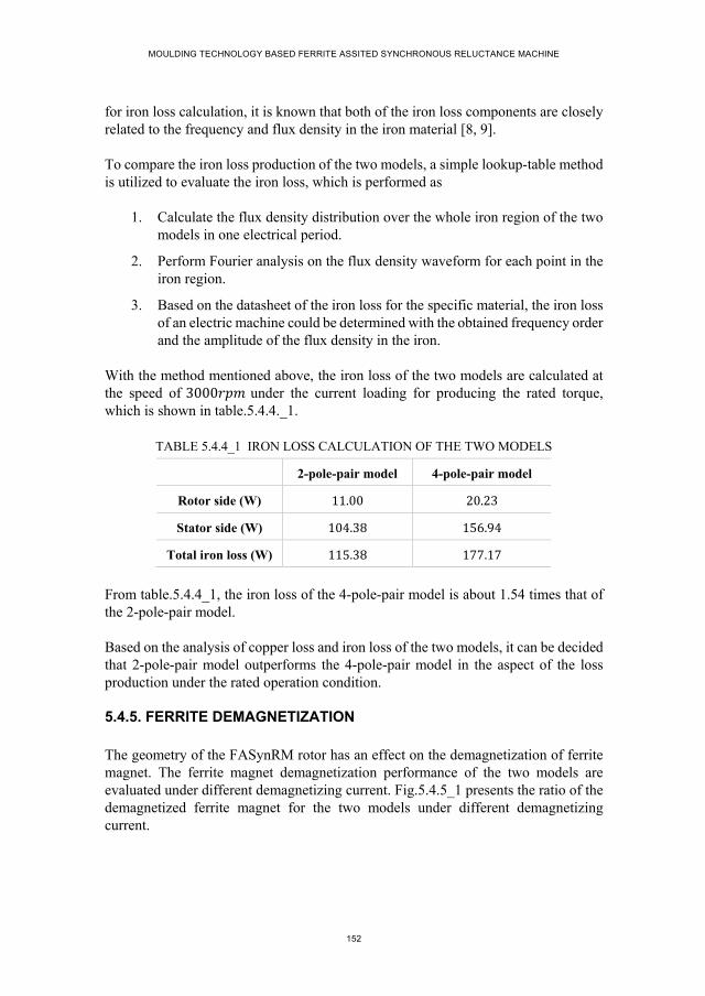
MOULDING TECHNOLOGY BASED FERRITE ASSITED SYNCHRONOUS RELUCTANCE MACHINE
152
for iron loss calculation, it is known that both of the iron loss components are closely related to the frequency and flux density in the iron material [8, 9].
To compare the iron loss production of the two models, a simple lookup-table method is utilized to evaluate the iron loss, which is performed as
1. Calculate the flux density distribution over the whole iron region of the two models in one electrical period.
2. Perform Fourier analysis on the flux density waveform for each point in the iron region.
3. Based on the datasheet of the iron loss for the specific material, the iron loss of an electric machine could be determined with the obtained frequency order and the amplitude of the flux density in the iron.
With the method mentioned above, the iron loss of the two models are calculated at the speed of 3000 under the current loading for producing the rated torque, which is shown in table.5.4.4._1.
TABLE 5.4.4_1 IRON LOSS CALCULATION OF THE TWO MODELS
2-pole-pair model 4-pole-pair model
Rotor side (W) 11.00 20.23
Stator side (W) 104.38 156.94
Total iron loss (W) 115.38 177.17
From table.5.4.4_1, the iron loss of the 4-pole-pair model is about 1.54 times that of the 2-pole-pair model.
Based on the analysis of copper loss and iron loss of the two models, it can be decided that 2-pole-pair model outperforms the 4-pole-pair model in the aspect of the loss production under the rated operation condition.
5.4.5. FERRITE DEMAGNETIZATION
The geometry of the FASynRM rotor has an effect on the demagnetization of ferrite magnet. The ferrite magnet demagnetization performance of the two models are evaluated under different demagnetizing current. Fig.5.4.5_1 presents the ratio of the demagnetized ferrite magnet for the two models under different demagnetizing current.
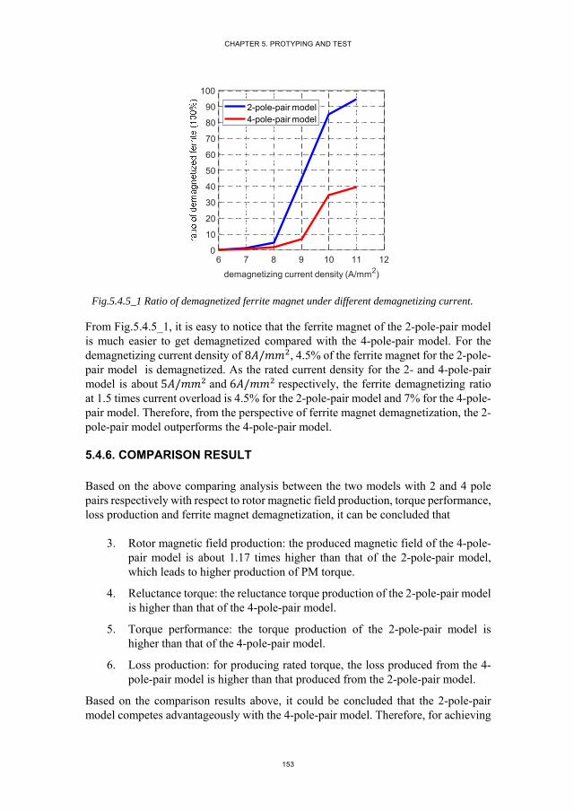
CHAPTER 5. PROTYPING AND TEST
153
Fig.5.4.5_1 Ratio of demagnetized ferrite magnet under different demagnetizing current.
From Fig.5.4.5_1, it is easy to notice that the ferrite magnet of the 2-pole-pair model is much easier to get demagnetized compared with the 4-pole-pair model. For the demagnetizing current density of 8 / , 4.5% of the ferrite magnet for the 2-pole-pair model is demagnetized. As the rated current density for the 2- and 4-pole-pair model is about 5 / and 6 / respectively, the ferrite demagnetizing ratio at 1.5 times current overload is 4.5% for the 2-pole-pair model and 7% for the 4-pole-pair model. Therefore, from the perspective of ferrite magnet demagnetization, the 2-pole-pair model outperforms the 4-pole-pair model.
5.4.6. COMPARISON RESULT
Based on the above comparing analysis between the two models with 2 and 4 pole pairs respectively with respect to rotor magnetic field production, torque performance, loss production and ferrite magnet demagnetization, it can be concluded that
3. Rotor magnetic field production: the produced magnetic field of the 4-pole-pair model is about 1.17 times higher than that of the 2-pole-pair model, which leads to higher production of PM torque.
4. Reluctance torque: the reluctance torque production of the 2-pole-pair model is higher than that of the 4-pole-pair model.
5. Torque performance: the torque production of the 2-pole-pair model is higher than that of the 4-pole-pair model.
6. Loss production: for producing rated torque, the loss produced from the 4-pole-pair model is higher than that produced from the 2-pole-pair model.
Based on the comparison results above, it could be concluded that the 2-pole-pair model competes advantageously with the 4-pole-pair model. Therefore, for achieving
6 7 8 9 10 11 12
demagnetizing current density (A/mm2)
0
10
20
30
40
50
60
70
80
90
100
2-pole-pair model4-pole-pair model
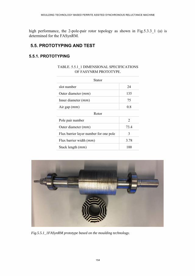
MOULDING TECHNOLOGY BASED FERRITE ASSITED SYNCHRONOUS RELUCTANCE MACHINE
154
high performance, the 2-pole-pair rotor topology as shown in Fig.5.3.3_1 (a) is determined for the FASynRM.
5.5. PROTOTYPING AND TEST
5.5.1. PROTOTYPING
TABLE. 5.5.1_1 DIMENSIONAL SPECIFICATIONS OF FASYNRM PROTOTYPE.
Stator
slot number 24
Outer diameter ( ) 135
Inner diameter ( ) 75
Air gap ( ) 0.8
Rotor
Pole pair number 2
Outer diameter ( ) 73.4
Flux barrier layer number for one pole 3
Flux barrier width ( ) 3.78
Stack length ( ) 100
Fig.5.5.1_1FASynRM prototype based on the moulding technology.

CHAPTER 5. PROTYPING AND TEST
155
Table 5.5.1_1 presents the final specifications of the FASynRM. According to the determined dimensions and structures, a prototype of FASynRM is manufactured based on moulding technology, which is shown in Fig.5.5.1_1. The following work is to test the performance of this FASynRM prototype. In order to fit the test bench, the stack length of the prototype is scaled down to 100 . Therefore, the rated power of the FASynRM prototype is consequently scaled down to 5 , thus the rated output torque is 16 .
5.5.2. MEASUREMENT OF MAGNETIC FIELD FROM FERRITE MAGNET
Fig.5.5.2_1 Setup for rotor magnetic field measurement.
Fig.5.5.2_2 FE model of ferrite moulded rotor and iron ring for air gap magnetic field calculation.
For this FASynRM prototype as shown in Fig.5.5.1_1, the flux barriers are fully filled with the plasto-ferrite magnet as shown in Fig.3.2_1 with the strategy of moulding

MOULDING TECHNOLOGY BASED FERRITE ASSITED SYNCHRONOUS RELUCTANCE MACHINE
156
technology [4]. By using the halbach magnet ring as described in chapter 3, the ferrite magnet mixed with liquid binder material is aligned in the moulding process [4]. In order to have a knowledge of the magnetic field production of the moulded ferrite magnets in the rotor prototype, a setup as shown in Fig.5.5.2_1 is established to measure the air gap magnetic field, where an iron ring rather than the conventional stator with slot openings is placed outside the rotor prototype in order to avoid the slot opening influence on the magnetic field production [4]. A FE model corresponding to the magnetic field measurement setup is also constructed as shown in Fig.5.5.2_2, where the flux line distribution is presented in detail. To protect the measuring probe as shown in Fig.5.5.2_1, the air gap length between the rotor prototype and the iron ring is designed to be 1.9 which is more than two times longer than that of the real air gap length of the FASynRM [4].
(a) Magnetic field waveforms. (b) Fourier analysis.
Fig.5.5.2_3 Air gap magnetic field produced from rotor ferrite magnet.
Fig.5.5.2_3 presents the measured and calculated waveforms of the air gap magnetic field in one electrical period. The fluctuations on the waveforms are caused by the leakage flux within the regions of iron bridges, which could be concluded from the calculated flux line distribution in Fig.5.5.2_2. On the top of the measured air gap magnetic field waveform, there is a sharp reduction marked with black circle in Fig.5.5.2_3 (a), which is due to the shallow slot on the rotor periphery surface as shown in Fig.5.5.1_1. In rotor manufacturing process, the shallow slot is required to ensure the alignment of the laminations, while which is not involved in the two-dimensional FE model. Fig.5.5.2_3 (b) presents the Fourier analysis of the two waveforms, where the peak values of the fundamental components are 0.264 and 0.30 for the calculated and the measured results respectively. Therefore, the measured magnetic field is 13.6% higher than the calculated result, which may be explained by the practical thickness of the iron bridge for the rotor prototype is slightly smaller than the theoretically designed dimension, leading to less leakage flux in the iron bridge for the rotor prototype, thus high flux density in the air gap. Although the
Bn
(T)
0 1 2 3 4 5 6 7 8 9 10 11 12harmonics
0
0.04
0.08
0.12
0.16
0.2
0.24
0.28
0.32
Bn
(T)
FEtest
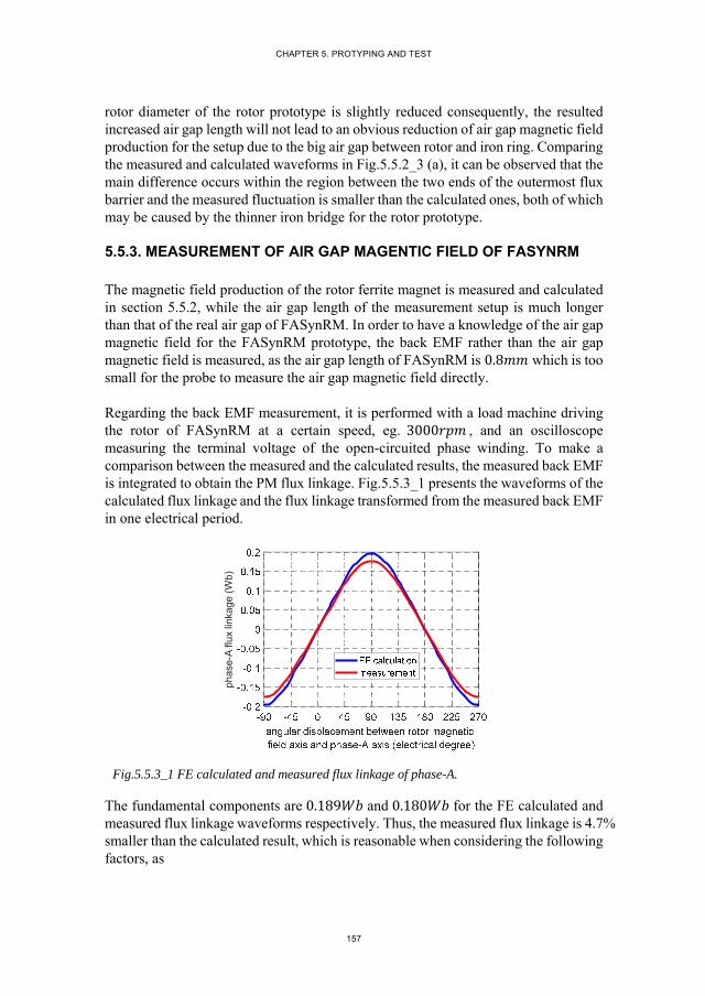
CHAPTER 5. PROTYPING AND TEST
157
rotor diameter of the rotor prototype is slightly reduced consequently, the resulted increased air gap length will not lead to an obvious reduction of air gap magnetic field production for the setup due to the big air gap between rotor and iron ring. Comparing the measured and calculated waveforms in Fig.5.5.2_3 (a), it can be observed that the main difference occurs within the region between the two ends of the outermost flux barrier and the measured fluctuation is smaller than the calculated ones, both of which may be caused by the thinner iron bridge for the rotor prototype.
5.5.3. MEASUREMENT OF AIR GAP MAGENTIC FIELD OF FASYNRM
The magnetic field production of the rotor ferrite magnet is measured and calculated in section 5.5.2, while the air gap length of the measurement setup is much longer than that of the real air gap of FASynRM. In order to have a knowledge of the air gap magnetic field for the FASynRM prototype, the back EMF rather than the air gap magnetic field is measured, as the air gap length of FASynRM is 0.8 which is too small for the probe to measure the air gap magnetic field directly.
Regarding the back EMF measurement, it is performed with a load machine driving the rotor of FASynRM at a certain speed, eg. 3000 , and an oscilloscope measuring the terminal voltage of the open-circuited phase winding. To make a comparison between the measured and the calculated results, the measured back EMF is integrated to obtain the PM flux linkage. Fig.5.5.3_1 presents the waveforms of the calculated flux linkage and the flux linkage transformed from the measured back EMF in one electrical period.
Fig.5.5.3_1 FE calculated and measured flux linkage of phase-A.
The fundamental components are 0.189 and 0.180 for the FE calculated and measured flux linkage waveforms respectively. Thus, the measured flux linkage is 4.7% smaller than the calculated result, which is reasonable when considering the following factors, as
phas
e-A
flux
link
age
(Wb)

MOULDING TECHNOLOGY BASED FERRITE ASSITED SYNCHRONOUS RELUCTANCE MACHINE
158
1. Leakage flux at both ends of the rotor prototype leads to reduction in stator winding flux linkage, while which is not considered in the two-dimensional FE model;
2. Practical manufacturing process results into a tiny reduction in rotor outer diameter, thus leading to a slight increase in air gap length. For FASynRM with small air gap, the slightly increase in air gap length may lead to a reduction of air gap magnetic field and consequently the flux linkage.
5.5.4. MEASUREMENT OF D- AMD Q-INDUCTANCE
The inductances on d- and q-axis are the main factors that predict the reluctance torque production capability of FASynRM. As mentioned in chapter 4, mutual coupling effects between the d- and q-axis magnetic circuits exists, which may lead to difference of the d(q)-inductance obtained with and without the presence of q(d)-axis current. The following work evaluates the d- and q-inductance of the SynRM prototype for the two cases with and without mutual coupling effects respectively.
A. Without mutual coupling effects.
A setup as shown in Fig.5.5.4_1 is established for the inductance measurement without mutual coupling effects, where the transformer is utilized for providing adjustable AC voltage; the oscilloscope is for measuring the current and the terminal voltage waveforms.
Fig.5.5.4_1 Setup for d(q)-inductance measurement without considering cross coupling effect.
Fig.5.5.4_2 Stator winding connection for d- and q-inductance measurement.
For the d(q)-inductance measurement without the presence of q(d)-axis current, the stator three phase windings need to be connected in a specific way that the three phase windings are connected in the star connection and any two terminals of the three are connected together, thus leading to a magnetic circuit of the phase winding with two
CHAPTER 5. PROTYPING AND TEST
159
terminals. Taking the winding connection as shown in Fig5.5.4_2 as an example, the phase-B and phase-C windings are connected in parallel and then connect to phase-A winding in series. Supplied with AC voltage (denoted as u in Fig5.5.4_2), the magnetic circuit as shown in Fig5.5.4_2 produces a MMF being aligned with phase-A axis, thus producing an air gap magnetic field which is also alighed with the phase-A axis. Therefore, when rotor d(q)-axis is aligned with the phase-A winding axis, the magnetic field on q(d)-axis is theoretically zero.
For the magnetic circuit in Fig5.5.4_2, the voltage and current quantities satisfy
2 2A B C
A B
B C
i i i
u u u
u u
(5.5.4_1)
where the voltage for each phase consists of two components, which are the voltage drop on the resistance and the induced voltage drop. For each phase voltage, it is expressed as
AA A A
BB B B
CC C C
u
u
u
di R
dtd
i Rdt
di R
dt
(5.5.4_2)
where R represents the phase winding resistance; refers to the phase flux linkage. For d-inductance evaluation, the rotor needs to be locked at the position where the rotor d-axis is aligned with the stator phase-A winding axis. For such a case, the components of the stator quantities on the d-axis are expressed as
2( cos(0) cos(0 120) cos(0 120))
32 2
( cos(0) cos(0 120) cos(0 120)) ( )3
3
d A B C A
d A B C A B
i i i i i
(5.5.4_3)
Similarly, the q-inductance is evaluated with the rotor q-axis being aligned with the stator phase-A winding axis. Thus, the components of current flux linkage on q-axis are expressed as

MOULDING TECHNOLOGY BASED FERRITE ASSITED SYNCHRONOUS RELUCTANCE MACHINE
160
2( sin(90) sin(90 120) sin(90 120))
32 2
( sin(90) sin(90 120) sin(90
120)) ( )3 3
q A B C A
q A B C A B
i i i i i
(5.5.4_4)
Therefore, the d- and q-inductance could be evaluated with the current and flux linkage components on d- and q-axis based on the following equations as
( ( / 2))2
3
( ( / 2))2
3
A A Bdd
d A
A A Bqq
q A
u i R R dtL
i i
u i R R dtL
i i
(5.5.4_5)
The winding resistance of phase-A and phase-B (denoted as AR and BR respectively
in (5.5.4_5)) could be easily measured by DC current test. The terminal voltage ( u ) and phase-A current ( Ai ) are measured with oscilloscope. Based on the method
described above, the d- and q-inductance of the SynRM are measured and meanwhile calculated with the aid of FE software. Fig.5.5.4_3 presents the calculated and measured results of d- and q-inductance for the SynRM, where the horizontal axis represents the peak value of the sinusoidal current flowing in phase-A winding.
(a) Measured and calculated d- and q-inductance.
(b) Difference of q- and d-inductance.
Fig.5.5.4_3 Inductance of FASynRM on d- and q-axis without considering mutual coupling effect.
Comparing the calculated and measured inductances on d- and q-axis respectively, it is observed that
0 1 2 3 4 5 6 7 8 9 10 11 12 13 14ia (A)
0
10
20
30
40
50
60
70
80
calculated Ldtested Ldcalculated Lqtested Lq
0 1 2 3 4 5 6 7 8 9 10 11 12 13 14ia (A)
20
25
30
35
40
45
50
55
60
calculated Lq- Ldtested Lq- Ld

CHAPTER 5. PROTYPING AND TEST
161
1. Regarding the inductance on q-axis ( qL ), the measured result is smaller than
the calculated result, which is mainly caused by the slight increase in the air gap length for the prototype due to the manufacturing error.
2. Regarding the inductance on d-axis ( dL ), the measured result is greater than
the calculated result, which is mainly due to the neglect of the end winding leakage flux in the two dimensional FE calculation.
3. The q-inductance decreases linearly with the increase of q-axis current, which indicates that the iron material on the q-axis magnetic path is easy to get saturated.
4. The decrease rate of the d-inductance slows down with the increase of d-axis current, which indicates that the effect of the d-axis current on the d-inductance is not obviously.
5. The value of both calculated and measured q dL L becomes smaller with
the increase of stator current, which is mainly due to the saturation effect in the iron material.
6. The difference between the calculated q dL L and the measured q dL L
becomes smaller with the increase of the current.
Based on the above inductance analysis, it can be predicted that the calculated reluctance torque will be higher than the reluctance torque of the prototype. In addition, the derivation between the calculated and measured reluctance torque may become smaller with the increase of the current loading.
B. Considering mutual coupling effect.
Fig.5.5.4_4 Setup for d- and q-inductance measurement.
Fig.5.5.4_5 Stator winding connection for d- and q-inductance measurement.
MOULDING TECHNOLOGY BASED FERRITE ASSITED SYNCHRONOUS RELUCTANCE MACHINE
162
Under normal operation, d- and q-axis current exist at the same time. Therefore, the practical d- and q-axis inductance of SynRM should be the results being affected by the q- and d-axis current. To examine the mutual coupling effect between d- and q-axis magnetic circuits, the d- and q-inductances of SynRM are measured with the setup as shown in Fig.5.5.4_4, where an additional DC voltage supply is utilized in the measurement. For the measurement of d- and q-inductance considering the mutual affect, the three-phase stator windings are connected in the method as shown in Fig.5.5.4_5, where there are two separate magnetic circuits. The two terminals of the magnetic circuit consisting of the series-connected phase-B and phase-C windings are connected to the transformer which provides adjustable AC voltage; the two terminals of the phase-A winding is connected to the DC voltage supply for providing bias DC current.
For the electrical circuit as shown in Fig.5.5.4_5, the voltages and currents satisfy
B C
B C
B C
u u
u
u
u
i i
(5.5.4_6)
For the d(q)-inductance measurement, the rotor is locked at the position where the rotor q(d)-axis is aligned with the stator phase-A winding axis. In such a way, the components of current and flux linkage on d-axis are expressed as
2 2 3( cos(90) cos(90 120) cos(90 120))
3 3
2 3( cos(90) cos(90 120) cos(90 120)) ( )
3 3
d A B C B
d A B C B C
i i i i i
(5.5.4_7)
On q-axis, the current and flux linkage components are expressed as
2 2 3( sin(0) sin(0 120) sin(0 120))
3 3
2 3( sin(0) sin(0 120) sin(0 120)) ( )
3
3
q A B C B
q A B C B C
i i i i i
(5.5.4_8)
Thus the d- and q-inductance could be calculated based on the expressions as

CHAPTER 5. PROTYPING AND TEST
163
( ( ))1
2
( ( ))1
2
B B Cdd
d B
B B Cqq
q B
u i R R dtL
i i
u i R R dtL
i i
(5.5.4_9)
With the method described above, the d- and q-inductance are measured at the presence of q- and d-axis DC current. Fig.5.5.5_6 presents the measured inductance.
(a) d-inductance. (b) q-inductance.
Fig. 5.5.4_6 Evaluation of cross coupling effect on d- and q-inductance.
From Fig.5.5.4_6, it is clear that the mutual coupling effect between d- and q-axis could lead to a reduction in q- and d-inductance. While, such a mutual coupling effect becomes less obvious to q-inductance especially at high current loading.
5.5.5. MEASUREMENT OF RELUCTANCE TORQUE OF SYNRM PROTOTYPE
Reluctance torque production of the FASynRM prototype is measured without ferrite magnet in the rotor (being called SynRM hereinafter).
A. Reluctance torque under DC current loading.
For simplification, the torque performance of the SynRM prototype is firstly evaluated with respect to the angular displacement between the rotor d-axis and the stator MMF axis. For such a measuring strategy, the three phase windings of SynRM are connected in the same way as that utilized for the d- and q-inductance measurement without considering the mutual coupling effect, which is shown in Fig.5.5.4_2 but supplied with DC current; the rotor of the SynRM prototype is driven by an additional load machine at a very low speed. Fig.5.5.5_1 presents the setup for the reluctance torque
0 1 2 3 4 5 6 7 8 9 10 11 12 13id (A)
14
16
18
20
22
24
26
28
30
32
34
36Iq=0AIq=2AIq=4AIq=6AIq=8A
0 1 2 3 4 5 6 7 8 9 10 11 12 13iq (A)
40
45
50
55
60
65
70
75id=0Aid=2Aid=4Aid=6Aid=8A

MOULDING TECHNOLOGY BASED FERRITE ASSITED SYNCHRONOUS RELUCTANCE MACHINE
164
measurement with such a strategy, where the torque transducer is utilized for measuring the reluctance torque of the SynRM prototype.
Fig.5.5.5_1 Setup for the reluctance torque measurement of SynRM prototype.
Fig.5.5.5_2 presents the measured and FE calculated reluctance torque waveforms of the SynRM prototype with respect to the angular displacement between the rotor d-axis and the stator MMF axis under the DC current of 4 , 6 , 8 and 10 . From Fig.5.5.5_2, it is easy to notice that the FE calculated maximum reluctance torque under different DC current supply is higher than the measured results, which may be explained by the same reasons as those behind the deviation between the calculated and measured d- and q-inductance. In addition, the measured reluctance torque represents the output torque of the prototype, while the calculated reluctance torque is the electromagnetic torque of the SynRM involving the output torque component and the friction torque component, thus leading to the fact that the calculated reluctance torque is higher than the measured result.
(a) 4 . (b) 6 .
0 22.5 45 67.5 90 112.5 135 157.5 180angular displacement between rotor d-axis
and stator MMF axis (electrical degree)
-1.5
-1
-0.5
0
0.5
1
1.5
testedFE
0 22.5 45 67.5 90 112.5 135 157.5 180angular displacement between rotor d-axis
and stator MMF axis (electrical degree)
-3
-2
-1
0
1
2
3
relu
cta
nce
torq
ue
(N
m)
testedFE

CHAPTER 5. PROTYPING AND TEST
165
(c) 8 . (d) 10 .
Fig.5.5.5_2 Measured and FE calculated reluctance torque for different DC current in phase-A.
B. Reluctance torque under the control of maximum torque per ampere.
Being operated in the motor mode, the SynRM is generally controlled with the Maximum Torque Per Ampere (MTPA) strategy for producing the maximum torque production at the minimum current supply. With such a control strategy, the average reluctance torque of the SynRM prototype at different speeds for different current loadings is measured, which is shown in Fig.5.5.5_3. From Fig.5.5.5_3, it could be concluded that the reluctance torque production of the SynRM prototype is independent of the rotor rotating speed.
Fig.5.5.5_3 Average reluctance torque of SynRM prototype under the maximum torque per ampere control at different speed for different current loading.
0 22.5 45 67.5 90 112.5 135 157.5 180angular displacement between rotor d-axis
and stator MMF axis (electrical degree)
-6
-4
-2
0
2
4
6re
luct
an
ce t
orq
ue
(N
m)
testedFE
0 22.5 45 67.5 90 112.5 135 157.5 180angular displacement between rotor d-axis
and stator MMF axis (electrical degree)
-8
-6
-4
-2
0
2
4
6
8
testedFE
3 3.5 4 4.5 5 5.5 6 6.5 7 7.5 8 8.5 9 9.5 1010.511peak value of phase current (A)
00.5
11.5
22.5
33.5
44.5
55.5
66.5
7
n=50rpmn=500rpmn=1000rpmn=2000rpmn=3000rpm
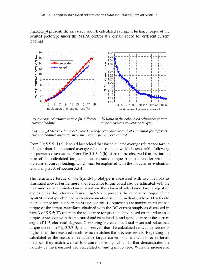
MOULDING TECHNOLOGY BASED FERRITE ASSITED SYNCHRONOUS RELUCTANCE MACHINE
166
Fig.5.5.5_4 presents the measured and FE calculated average reluctance torque of the SynRM prototype under the MTPA control at a certain speed for different current loadings.
(a) Average reluctance torque for different current loading.
(b) Ratio of the calculated reluctance torque to the measured reluctance torque.
Fig.5.5.5_4 Measured and calculated average reluctance torque of FASynRM for different current loadings under the maximum torque per ampere control.
From Fig.5.5.5_4 (a), it could be noticed that the calculated average reluctance torque is higher than the measured average reluctance toque, which is reasonable following the previous discussions. From Fig.5.5.5_4 (b), it could be observed that the torque ratio of the calculated torque to the measured torque becomes smaller with the increase of current loading, which may be explained with the inductance evaluation results in part A of section 5.5.4.
The reluctance torque of the SynRM prototype is measured with two methods as illustrated above. Furthermore, the reluctance torque could also be estimated with the measured d- and q-inductance based on the classical reluctance torque equation expressed in d-q reference frame. Fig.5.5.5_5 presents the reluctance torque of the SynRM prototype obtained with above mentioned three methods, where T1 refers to the reluctance torque under the MTPA control; T2 represents the maximum reluctance torque of the torque waveform obtained with the DC current supply as discussed in part-A of 5.5.5; T3 refers to the reluctance torque calculated based on the reluctance torque expression with the measured and calculated d- and q-inductance at the current angle of 145 electrical degrees. Comparing the calculated and measured reluctance torque curves in Fig.5.5.5_5, it is observed that the calculated reluctance torque is higher than the measured result, which matches the previous results. Regarding the calculated or the measured reluctance torque curves obtained with three different methods, they match well at low current loading, which further demonstrates the validity of the measured and calculated d- and q-inductance. With the increase of
1 3 5 7 9 11 13 15 17 19peak value of phase current (A)
0
2
4
6
8
10
12
14
16
18
calculatedtested
3 4 5 6 7 8 9 1011121314151617peak value of phase current (A)
1.121.141.161.18
1.21.221.241.261.28
1.31.321.341.361.38
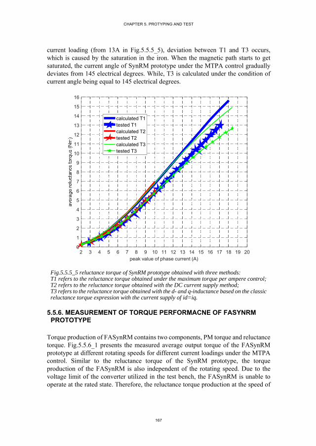
CHAPTER 5. PROTYPING AND TEST
167
current loading (from 13A in Fig.5.5.5_5), deviation between T1 and T3 occurs, which is caused by the saturation in the iron. When the magnetic path starts to get saturated, the current angle of SynRM prototype under the MTPA control gradually deviates from 145 electrical degrees. While, T3 is calculated under the condition of current angle being equal to 145 electrical degrees.
Fig.5.5.5_5 reluctance torque of SynRM prototype obtained with three methods: T1 refers to the reluctance torque obtained under the maximum torque per ampere control; T2 refers to the reluctance torque obtained with the DC current supply method; T3 refers to the reluctance torque obtained with the d- and q-inductance based on the classic reluctance torque expression with the current supply of id=iq.
5.5.6. MEASUREMENT OF TORQUE PERFORMACNE OF FASYNRM PROTOTYPE
Torque production of FASynRM contains two components, PM torque and reluctance torque. Fig.5.5.6_1 presents the measured average output torque of the FASynRM prototype at different rotating speeds for different current loadings under the MTPA control. Similar to the reluctance torque of the SynRM prototype, the torque production of the FASynRM is also independent of the rotating speed. Due to the voltage limit of the converter utilized in the test bench, the FASynRM is unable to operate at the rated state. Therefore, the reluctance torque production at the speed of
2 3 4 5 6 7 8 9 10 11 12 13 14 15 16 17 18 19 20peak value of phase current (A)
0
1
2
3
4
5
6
7
8
9
10
11
12
13
14
15
16
calculated T1tested T1calculated T2tested T2calculated T3tested T3
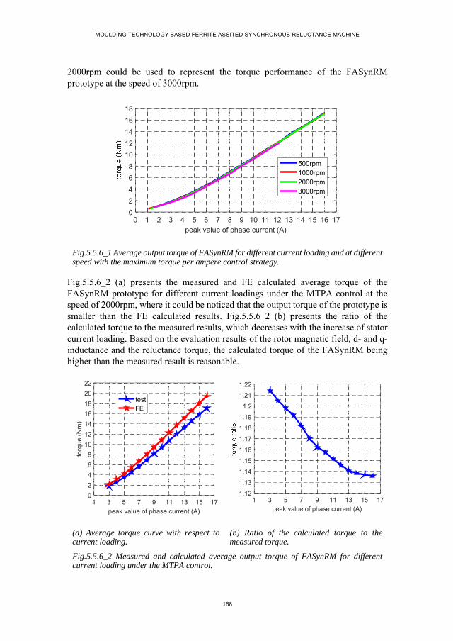
MOULDING TECHNOLOGY BASED FERRITE ASSITED SYNCHRONOUS RELUCTANCE MACHINE
168
2000rpm could be used to represent the torque performance of the FASynRM prototype at the speed of 3000rpm.
Fig.5.5.6_1 Average output torque of FASynRM for different current loading and at different speed with the maximum torque per ampere control strategy.
Fig.5.5.6_2 (a) presents the measured and FE calculated average torque of the FASynRM prototype for different current loadings under the MTPA control at the speed of 2000rpm, where it could be noticed that the output torque of the prototype is smaller than the FE calculated results. Fig.5.5.6_2 (b) presents the ratio of the calculated torque to the measured results, which decreases with the increase of stator current loading. Based on the evaluation results of the rotor magnetic field, d- and q-inductance and the reluctance torque, the calculated torque of the FASynRM being higher than the measured result is reasonable.
(a) Average torque curve with respect to current loading.
(b) Ratio of the calculated torque to the measured torque.
Fig.5.5.6_2 Measured and calculated average output torque of FASynRM for different current loading under the MTPA control.
0 1 2 3 4 5 6 7 8 9 10 11 12 13 14 15 16 17peak value of phase current (A)
0
2
4
6
8
10
12
14
16
18
500rpm1000rpm2000rpm3000rpm
1 3 5 7 9 11 13 15 17peak value of phase current (A)
0
2
4
6
8
10
12
14
16
18
20
22
torq
ue
(N
m)
testFE
1 3 5 7 9 11 13 15 17peak value of phase current (A)
1.12
1.13
1.14
1.15
1.16
1.17
1.18
1.19
1.2
1.21
1.22

CHAPTER 5. PROTYPING AND TEST
169
Fig.5.5.6_3 efficiency of FASynRM at different current loadings for different speeds.
Fig.5.5.6_3 presents the efficiency of the FASynRM prototype at different speed. The efficiency of the prototype increases with the increase of speed, approaching 94% at the rated speed of 3000 for the current loading about 8A. Although, the setup fails to measure the rated torque at the rated speed due to the voltage limit of the converter, it could be predicted from the efficiency waveform that the efficiency at the rated point will be about 92%.
5.5.7. PERFORMANCE COMPARISON BETWEEN FASYNRM AND SYNRM PROTOTYPES
The SynRM and the FASynRM prototypes are exactly the same except the existence of the ferrite magnet in the rotor flux barriers. According to the measurement results above, it could be concluded that the FASynRM prototype outperforms the SynRM prototype. Fig.5.5.7_1- Fig.5.5.7_3 present the performance of the SynRM and the FASynRM prototypes with respect to torque production, power factor and efficiency.
Regarding the torque curves in Fig.5.5.7_1 (a), both of which are measured under the MTPA control. For the same current loading, the torque production of the FASynRM prototype is about 1.4 times that of the SynRM prototype for the current loading of 16A according to the torque ratio curve in Fig.5.5.7_1 (b). From Fig.5.5.7_1 (b), it is observed that for the low current loadings, the torque ratio is greater than 2, which is mainly due to the fact that at relatively low current loadings the PM torque component takes predominant proportion of the torque production of FASynRM. With the increase of current loading, the proportion of the reluctance torque component in the torque production of FASynRM becomes larger, thus the variation of torque ratio value becomes less obvious for the current loading between 11A and 16A as shown in Fig.5.5.7_1 (b). According to the efficiency curves in Fig.5.5.7_2, it could be noticed that for the relatively low current loading, the efficiency of the SynRM is much lower than that of the FASynRM, which is caused by the absence of PM torque.
1 2 3 4 5 6 7 8 9 10 11 12 13 14 15 16 17peak value of phase current (A)
687072747678808284868890929496
n=500rpmn=1000rpmn=2000rpmn=3000rpm

MOULDING TECHNOLOGY BASED FERRITE ASSITED SYNCHRONOUS RELUCTANCE MACHINE
170
From Fig.5.5.7_3, it could be concluded that the power factor of the SynRM prototype could be improved by 36% by adding the ferrite magnet to the rotor.
(a) Torque production. (b) Torque ratio.
Fig.5.5.7_1 Torque production of FASynRM and SynRM prototypes.
Fig.5.5.7_2 Efficiency of FASynRM and SynRM prototypes at the speed of 2000rpm.
Fig.5.5.7_3 power factor of FASynRM and SynRM prototypes at the speed of 2000rpm.
5.6. CONCLUSION OF CHAPTER 5
SynRM and ferrite moulded SynRM prototypes are manufactured and tested in this chapter. By performing detailed comparing study, the pole pair number is determined, which further validates the previous conclusion about the pole pair number influence on the reluctance torque production. Regarding to the performance evaluation of the two prototypes, the measured results agree well with the FE calculated results. The comparing results between the two prototypes demonstrate the improvement of
2 3 4 5 6 7 8 9 10 11 12 13 14 15 16 17peak value of phase current (A)
0
2
4
6
8
10
12
14
16
18
FASynRMSynRM
2 3 4 5 6 7 8 9 10 11 12 13 14 15 16 17peak value of phase current (A)
11.21.41.61.8
22.22.42.62.8
33.23.43.63.8
4
1 2 3 4 5 6 7 8 9 1011121314151617peak value of phase current (A)
74
76
78
80
82
84
86
88
90
92
94
96
FASynRMSynRM
2 3 4 5 6 7 8 9 10 11 12 13 14 15 16peak value of phase current (A)
0
0.1
0.2
0.3
0.4
0.5
0.6
0.7
0.8
0.9
1
SynRMFASynRM

CHAPTER 5. PROTYPING AND TEST
171
efficiency, power factor and torque production by adding ferrite magnet to the rotor of SynRM.

MOULDING TECHNOLOGY BASED FERRITE ASSITED SYNCHRONOUS RELUCTANCE MACHINE
172
Reference
1. T. A. Huynh and M. F. Hsieh, "Comparative Study of PM-Assisted SynRM and IPMSM on Constant Power Speed Range for EV Applications," in IEEE Transactions on Magnetics, vol. 53, no. 11, pp. 1-6, Nov. 2017.
2. M. Barcaro, T. Pradella and I. Furlan, "Low-torque ripple design of a ferrite-assisted synchronous reluctance motor," in IET Electric Power Applications, vol. 10, no. 5, pp. 319-329, 5 2016.
3. S. S. R. Bonthu, A. Arafat and S. Choi, "Comparisons of Rare-Earth and Rare-Earth-Free External Rotor Permanent Magnet Assisted Synchronous Reluctance Motors," in IEEE Transactions on Industrial Electronics, vol. 64, no. 12, pp. 9729-9738, Dec. 2017.
4. Q. Wu, K. Lu, P. O. Rasmussen and K. F. Rasmussen, "A new application and experimental validation of moulding technology for ferrite magnet assisted synchronous reluctance machine," 2016 IEEE Energy Conversion Congress and Exposition (ECCE), Milwaukee, WI, 2016, pp. 1-8.
5. K. Wang, Z. Q. Zhu, G. Ombach, M. Koch, S. Zhang and J. Xu, "Optimal slot/pole and flux-barrier layer number combinations for synchronous reluctance machines," 2013 Eighth International Conference and Exhibition on Ecological Vehicles and Renewable Energies (EVER), Monte Carlo, 2013, pp. 1-8.
6. M. Palmieri, M. Perta, F. Cupertino and G. Pellegrino, "Effect of the numbers of slots and barriers on the optimal design of synchronous reluctance machines," 2014 International Conference on Optimization of Electrical and Electronic Equipment (OPTIM), Bran, 2014, pp. 260-267.
7. Thomas A. Lipo, “Introduction to AC machine design,” University of Wisconsin, 2 edition, Aug. 2007.
8. S. Müller, M. Keller, M. Maier and N. Parspour, "Comparison of iron loss calculation methods for soft magnetic composite," 2017 Brazilian Power Electronics Conference (COBEP), Juiz de Fora, 2017, pp. 1-6.
9. O. Bottesi, S. Calligaro and L. Alberti, "Investigation on the frequency effects on iron losses in laminations," 2017 IEEE Energy Conversion Congress and Exposition (ECCE), Cincinnati, OH, 2017, pp. 1161-1168.
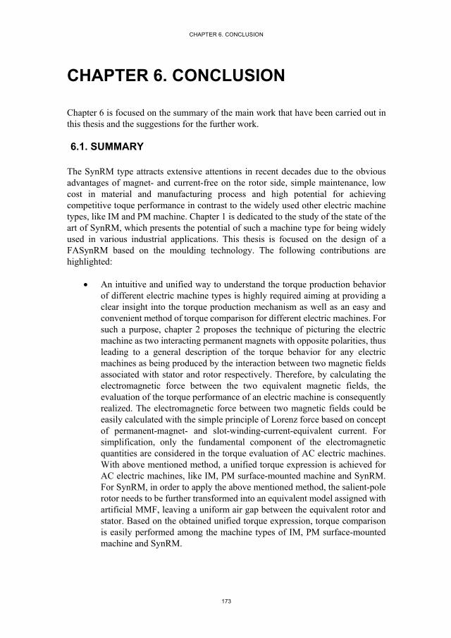
CHAPTER 6. CONCLUSION
173
CHAPTER 6. CONCLUSION
Chapter 6 is focused on the summary of the main work that have been carried out in this thesis and the suggestions for the further work.
6.1. SUMMARY
The SynRM type attracts extensive attentions in recent decades due to the obvious advantages of magnet- and current-free on the rotor side, simple maintenance, low cost in material and manufacturing process and high potential for achieving competitive toque performance in contrast to the widely used other electric machine types, like IM and PM machine. Chapter 1 is dedicated to the study of the state of the art of SynRM, which presents the potential of such a machine type for being widely used in various industrial applications. This thesis is focused on the design of a FASynRM based on the moulding technology. The following contributions are highlighted:
An intuitive and unified way to understand the torque production behavior of different electric machine types is highly required aiming at providing a clear insight into the torque production mechanism as well as an easy and convenient method of torque comparison for different electric machines. For such a purpose, chapter 2 proposes the technique of picturing the electric machine as two interacting permanent magnets with opposite polarities, thus leading to a general description of the torque behavior for any electric machines as being produced by the interaction between two magnetic fields associated with stator and rotor respectively. Therefore, by calculating the electromagnetic force between the two equivalent magnetic fields, the evaluation of the torque performance of an electric machine is consequently realized. The electromagnetic force between two magnetic fields could be easily calculated with the simple principle of Lorenz force based on concept of permanent-magnet- and slot-winding-current-equivalent current. For simplification, only the fundamental component of the electromagnetic quantities are considered in the torque evaluation of AC electric machines. With above mentioned method, a unified torque expression is achieved for AC electric machines, like IM, PM surface-mounted machine and SynRM. For SynRM, in order to apply the above mentioned method, the salient-pole rotor needs to be further transformed into an equivalent model assigned with artificial MMF, leaving a uniform air gap between the equivalent rotor and stator. Based on the obtained unified torque expression, torque comparison is easily performed among the machine types of IM, PM surface-mounted machine and SynRM.

MOULDING TECHNOLOGY BASED FERRITE ASSITED SYNCHRONOUS RELUCTANCE MACHINE
174
An alternative solution for ferrite installation of FASynRM is desired to relieve the drawbacks of the most commonly utilized ferrite insertion strategy. In chapter 3, the application of moulding technology for ferrite installation is fully described, which outperforms the ferrite insertion method with respect to the manufacturing simplicity, low cost, mechanical strength and the limit on flux barrier geometry. Halbach magnet ring is utilized for aligning the anisotropic plaso-ferrite magnet during the moulding process. A ferrite moulded SynRM prototype is manufactured and tested, which fully validates the feasibility of such a method for ferrite installation of FASynRM.
Both theoretical analysis and FE validation are desired for analyzing the influence of geometrical parameters on FASynRM performance, which is aimed at providing general guidelines for appropriate design of FASynRM. In chapter 4, the pole pair number influence on iron loss, reluctance torque production and basic dimensions is theoretically analyzed in detail and fully validated with FE models. In addition, the influence of main geometrical parameters, like the flux barrier shape and dimensions and the combination of pole pair number and stator slots, on the performance of FASynRM is investigated. Based on above theoretical analysis and FE validation, general design suggestions are concluded, which is summarized as
[1]. Low pole pair number is generally preferred for FASynRM;
[2]. The pole pair number which allows the flux barriers to be uniformly distributed over the whole rotor iron region has high potential for producing high saliency ratio and consequently high reluctance torque;
[3]. Integral slot winding configuration generally has higher potential for producing high reluctance torque in contrast to fractional slot winding. While, the drawback of long end winding associated with integral slot winding needs to be considered;
[4]. The design of flux barrier shape is more subject to the limit of rotor dimensions;
[5]. For reducing torque ripple, the relative distribution of the rotor flux barrier ends and the stator slot openings needs to be designed in a specific way in order to keep the variation of air gap magnetic resistance in as low level as possible.
The main objective of this project is to provide a properly designed FASynRM based on moulding technology which is aimed at replacing an existing IM product. In chapter 5, a FASynRM prototype with the same specifications as that of IM is designed and manufactured. The FE calculation and the measurement results of the
CHAPTER 6. CONCLUSION
175
designed FASynRM demonstrate that the designed FASynRM outperforms the existing IM.
6.2. FURTURE WORK
Regarding this project in cooperation with Grundfos A/S, the following furture work is suggested.
Optimal design of FASynRM: the FASynRM prototype is designed based on an existing stator structure, which limits the possibility of optimal design for achieving the best performance. Further performance improvement may be expected by optimizing the rotor and stator simultaneously. From the measurement results of the FASynRM prototype, the number of winding turns needs to be reduced for being able to operate at the rated torque at the designed speed of 3000rpm.
Can loss: can structure is required by the FASynRM prototype in order to protect the stator from water in operation, which produces additional iron loss. To evaluate the performance of the FASynRM prototype, an accurate knowledge of the can iron loss is highly desired.
Torque ripple: one of the main problems suffered by FASynRM is the torque ripple. Moudling technology allows the continuous rotor skewing for reducing the torque ripple. The existing torque transducer used in the torque measurement may not be accurate enough to measure the torque ripple. Therefore, further work is needed to measure accurately the torque ripple during steady state operation.


177

MOULDING TECHNOLOGY BASED FERRITE ASSITED SYNCHRONOUS RELUCTANCE MACHINE
178
APPENDICES
Appendix A. simplified model of multi-barrier rotor ....................................... 178
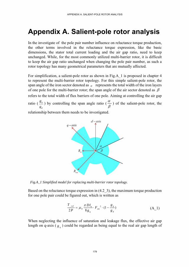
APPENDIX A. SALIENT-POLE ROTOR ANALYSIS
179
Appendix A. Salient-pole rotor analysis
In the investigate of the pole pair number influence on reluctance torque production, the other terms involved in the reluctance torque expression, like the basic dimensions, the stator total current loading and the air gap ratio, need to keep unchanged. While, for the most commonly utilized multi-barrier rotor, it is difficult to keep the air gap ratio unchanged when changing the pole pair number, as such a rotor topology has many geometrical parameters that are mutually affected.
For simplification, a salient-pole rotor as shown in Fig.A_1 is proposed in chapter 4 to represent the multi-barrier rotor topology. For this simple salient-pole rotor, the span angle of the iron sector denoted as represents the total width of the iron layers of one pole for the multi-barrier rotor; the span angle of the air sector denoted as refers to the total width of flux barriers of one pole. Aiming at controlling the air gap
ratio ( q
d
g
g) by controlling the span angle ratio (
) of the salient-pole rotor, the
relationship between them needs to be investigated.
Fig.A_1 Simplified model for replacing multi-barrier rotor topology.
Based on the reluctance torque expression in (4.2_3), the maximum torque production for one pole pair could be figured out, which is written as
_ 20 (1 )
2 8rel qa
smq d
T gDlF
P g g
(A_1)
When neglecting the influence of saturation and leakage flux, the effective air gap length on q-axis (
qg ) could be regarded as being equal to the real air gap length of
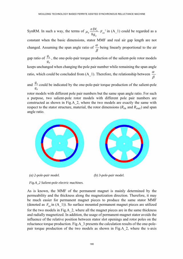
MOULDING TECHNOLOGY BASED FERRITE ASSITED SYNCHRONOUS RELUCTANCE MACHINE
180
SynRM. In such a way, the terms of 20 8
asm
q
DlF
g
in (A_1) could be regarded as a
constant when the basic dimensions, stator MMF and real air gap length are not
changed. Assuming the span angle ratio of
being linearly proportional to the air
gap ratio of q
d
g
g, the one-pole-pair torque production of the salient-pole rotor models
keeps unchanged when changing the pole pair number while remaining the span angle
ratio, which could be concluded from (A_1). Therefore, the relationship between
and q
d
g
gcould be indicated by the one-pole-pair torque production of the salient-pole
rotor models with different pole pair numbers but the same span angle ratio. For such a purpose, two salient-pole rotor models with different pole pair numbers are constructed as shown in Fig.A_2, where the two models are exactly the same with respect to the stator structure, material, the rotor dimensions ( and ) and span angle ratio.
(a) 2-pole-pair model. (b) 3-pole-pair model.
Fig.A_2 Salient-pole electric machines.
As is known, the MMF of the permanent magnet is mainly determined by the permeability and the thickness along the magnetization direction. Therefore, it may be much easier for permanent magnet pieces to produce the same stator MMF (denoted as smF in (A_1)). So surface mounted permanent magnet pieces are utilized
for the two models in Fig.A_2, where all the magnet pieces are in the same thickness and radially magnetized. In addition, the usage of permanent-magnet stator avoids the influence of the relative position between stator slot openings and rotor poles on the reluctance torque production. Fig.A_3 presents the calculation results of the one-pole-pair torque production of the two models as shown in Fig.A_2, where the x-axis
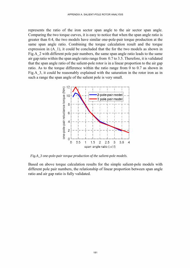
APPENDIX A. SALIENT-POLE ROTOR ANALYSIS
181
represents the ratio of the iron sector span angle to the air sector span angle. Comparing the two torque curves, it is easy to notice that when the span angle ratio is greater than 0.4, the two models have similar one-pole-pair torque production at the same span angle ratio. Combining the torque calculation result and the torque expression in (A_1), it could be concluded that the for the two models as shown in Fig.A_2 with different pole pair numbers, the same span angle ratio leads to the same air gap ratio within the span angle ratio range from 0.7 to 3.5. Therefore, it is validated that the span angle ratio of the salient-pole rotor is in a linear proportion to the air gap ratio. As to the torque difference within the ratio range from 0 to 0.7 as shown in Fig.A_3, it could be reasonably explained with the saturation in the rotor iron as in such a range the span angle of the salient pole is very small.
Fig.A_3 one-pole-pair torque production of the salient-pole models.
Based on above torque calculation results for the simple salient-pole models with different pole pair numbers, the relationship of linear proportion between span angle ratio and air gap ratio is fully validated.
one
-pol
e-pa
ir re
luct
ance
torq
ue (
Nm
)

QIA
N W
UM
OU
LDIN
G TEC
HN
OLO
GY B
ASED
FERR
ITE ASSITED
SYNC
HR
ON
OU
S RELU
CTA
NC
E MA
CH
INE
ISSN (online): 2446-1636 ISBN (online): 978-87-7210-157-6