
AA-780G Manual En
32
Preface Copyright This publication, including all photographs, illustrations and software, is protected under international copyright laws, with all rights reserved. Neither this manual, nor any of the material contained herein, may be reproduced without written consent of the author. Trademark Recognition Microsoft, MS-DOS and Windows are registered trademarks of Microsoft Corp. AMD is a registered trademark of AMD Corporation Other product names used in this manual are the properties of their respective owners and are acknowledged. Disclaimer The information in this document is subject to change without notice. The manufacturer makes no representations or warranties with respect to the contents hereof and specifically disclaims any implied warranties of merchantability or fitness for any particular purpose. Federal Communications Commission (FCC) This equipment has been tested and found to comply with the limits for a Class B digital device, pursuant to Part 15 of the FCC Rules. These limits are designed to provide reason- able protection against harmful interference in a residential installation. This equipment generates, uses, and can radiate radio frequency energy and, if not installed and used in accordance with the instructions, may cause harmful interference to radio communications. However, there is no guarantee that interference will not occur in a particular installation. If this equipment does cause harmful interference to radio or television reception, which can be determined by turning the equipment off and on, the user is encouraged to try to correct the interference by one or more of the following measures: • Reorient or relocate the receiving antenna. • Increase the separation between the equipment and the receiver. • Connect the equipment onto an outlet on a circuit different from that to which the receiver is connected. • Consult the dealer or an experienced radio/TV technician for help. Shielded interconnect cables and a shielded AC power cable must be employed with this equipment to ensure compliance with the pertinent RF emission limits governing this device. Changes or modifications not expressly approved by the system’s manufacturer could void the user’s authority to operate the equipment. Declaration of Conformity This device complies with part 15 of the FCC rules. Operation is subject to the following conditions: • This device may not cause harmful interference, and • This device must accept any interference received, including interference that may cause undesired operation MM-PA19
Transcript of AA-780G Manual En
PrefaceCopyrightThis publication, including all photographs, illustrations and software, is protected underinternational copyright laws, with all rights reserved. Neither this manual, nor any of thematerial contained herein, may be reproduced without written consent of the author.
Trademark RecognitionMicrosoft, MS-DOS and Windows are registered trademarks of Microsoft Corp.AMD is a registered trademark of AMD CorporationOther product names used in this manual are the properties of their respective owners andare acknowledged.
DisclaimerThe information in this document is subject to change without notice. The manufacturermakes no representations or warranties with respect to the contents hereof and specificallydisclaims any implied warranties of merchantability or fitness for any particular purpose.
Federal Communications Commission (FCC)This equipment has been tested and found to comply with the limits for a Class B digitaldevice, pursuant to Part 15 of the FCC Rules. These limits are designed to provide reason-able protection against harmful interference in a residential installation. This equipmentgenerates, uses, and can radiate radio frequency energy and, if not installed and used inaccordance with the instructions, may cause harmful interference to radio communications.However, there is no guarantee that interference will not occur in a particular installation.If this equipment does cause harmful interference to radio or television reception, whichcan be determined by turning the equipment off and on, the user is encouraged to try tocorrect the interference by one or more of the following measures:
• Reorient or relocate the receiving antenna.• Increase the separation between the equipment and the receiver.• Connect the equipment onto an outlet on a circuit different from that to which
the receiver is connected.• Consult the dealer or an experienced radio/TV technician for help.
Shielded interconnect cables and a shielded AC power cable must be employed with thisequipment to ensure compliance with the pertinent RF emission limits governing thisdevice. Changes or modifications not expressly approved by the system’s manufacturercould void the user’s authority to operate the equipment.
Declaration of ConformityThis device complies with part 15 of the FCC rules. Operation is subject to the followingconditions:
• This device may not cause harmful interference, and• This device must accept any interference received, including interference
that may cause undesired operation
MM-PA19

TTTTTABLE OF CONTENTSABLE OF CONTENTSABLE OF CONTENTSABLE OF CONTENTSABLE OF CONTENTSPreface
1. Product Package.........................................................................................12. Specifications..............................................................................................13. Motherboard Components.......................................................................2
Chapter 1Introducing the Motherboard
1. Check Jumper Settings..............................................................................42. Install CPU and Cooler..............................................................................53.Install Memory Modules...........................................................................64. Fix into the Case.........................................................................................65. Install Expansion Cards.............................................................................76. Connect IDE/SATA Devices....................................................................87. Connect Floppy Disk Drive......................................................................98. Connect Internal Headers and Connectors..........................................109. Connect Power Supply............................................................................1610. Connect Rear Panel Devices.................................................................18
Chapter 2Installing the Motherboard
1. Main Page..................................................................................................192. Standard CMOS Features........................................................................203. Advanced BIOS Features........................................................................ 214. Advanced Chipset Features.................................................................... 225. Integrated Peripherals............................................................................. 246. Power Management Setup.......................................................................267. PnP/PCI Configuration.............................................................................278. PC Health Status.......................................................................................279. Frequency/Voltage Control.....................................................................2810. BIOS Security Features..........................................................................28
Chapter 3BIOS Setup
1. About the Software CD................................................................ ..... .....292. Install Chipset Driver............................................................................... 293. Driver Disk Profile.....................................................................................304. Browse CD.................................................................................................30
Chapter 4Using the Software CD

1
Introducing the MotherboardChapter 1Introducing the MotherboardThank you for choosing the R780S motherboard. This motherboard is a high performance,enhanced function motherboard for high-end business or personal desktop markets.
After you purchase the product, please make sure following accessories are fully provided inthe package.
Product Package1
Specifications2
Above images are for reference only, which may be different from whatyou have purchased from your manufacturer.
Software CD SATA Cable
IDE Cable User’s Manual
SATA Power CableMotherboard
I/O Shield
Socket AM2/AM2+ for AMD Phenom Quad-Core/Athlon 64FX/64X2/64 and Sempron processors with Hyper Transport 3.0
DDRII 1066/800/667/533 SDRAM with Dual ChannelFour DDRII DIMMs (240pin/1.8v) with maximum memorycapacity up to 8 GB
7.1 channel audio codec by Realtek ALC883
1000 Mbps Ethernet by Realtek 8110SC
AMD 780 G
Processor
Chipset
Memory
LAN
Audio
ExpansionOptions
1 PCI Express x16 Graphics Interface1 PCI Express x1 slot2 PCI slots (v2.3 compliant)1 IDE connector (supporting up to two IDE devices)1 Floppy disk drive interface6 SATA connectors (3.0Gb/s transfer rate)

2
Introducing the Motherboard
Motherboard Components3
1 PS/2 mouse port1 PS/2 keyboard port1 Serial port1 VGA port1 DVI port4 USB 2.0 ports1 Gigabit Ethernet port6 Audio jacks for microphone in, line-in and line-out
Micro-ATX (244 x 240 mm)
8 mounting holes
IntegratedI/O
Mounting
Form Factor
InternalHeaders
4 Front USB 2.0 headers (8 ports)1 Front audio header1 Front panel switch/LED header1 CD-in header1 Infrared header1 SPDIF-out header1 Onboard parallel port header1 CPU cooling fan power connector1 System cooling fan power connector1 Internal speaker header
1
4
567
14
2
89
10
1112131516
1718
1920
21
3

3
Introducing the MotherboardTable of Motherboard Components
This concludes Chapter 1. The next chapter explains how to install the motherboard.
LABEL COMPONENTS
2.CPU_FAN1 CPU cooling fan power connector3.DDRII1~4 240-pin DDR2 SDRAM slots4.IR1 Infrared header5.PWR24P1 Standard 24-pin ATX power connector6.FDD1 Floppy disk drive connector7.IDE1 Primary IDE connector8.Sys_Fan1 System cooling fan power collector9.CLR_CMOS1 Clear CMOS jumper10.SATA1~6 Serial ATA connectors11.PANEL1 Front panel switch/LED header12.SPK1 Speaker header 13.F_USB1~4 Front panel USB headers14.LPT1 Onboard parallel port header15.SPDIFO1 SPDIF out header16.CD_IN1 Analog audio input header17.F_AUDIO1 Front panel audio header18.PCI1~2 PCI add-on card slots19.PCI-E2 PCI Express x16 slot20.PCI-E1 PCI Express x1 slot for graphics interface21.PWR8P1 Auxiliary 8-pin ATX power connector
1.CPU Socket Socket AM2/AM2+ for AMD Phenom Quad Core/Athlon64FX/64X2/64 and Sempron CPUs with Hyper Transport 3.0
Installing the Motherboard
4
Chapter 2Installing the Motherboard
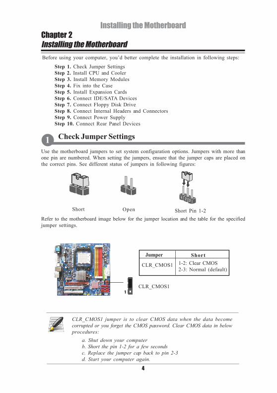
Refer to the motherboard image below for the jumper location and the table for the specifiedjumper settings.
Use the motherboard jumpers to set system configuration options. Jumpers with more thanone pin are numbered. When setting the jumpers, ensure that the jumper caps are placed onthe correct pins. See different status of jumpers in following figures:
Before using your computer, you’d better complete the installation in following steps:
Step 1. Check Jumper SettingsStep 2. Install CPU and CoolerStep 3. Install Memory ModulesStep 4. Fix into the CaseStep 5. Install Expansion CardsStep 6. Connect IDE/SATA DevicesStep 7. Connect Floppy Disk DriveStep 8. Connect Internal Headers and ConnectorsStep 9. Connect Power SupplyStep 10. Connect Rear Panel Devices
Check Jumper Settings1
Short Open Short Pin 1-2
CLR_CMOS1 jumper is to clear CMOS data when the data becomecorrupted or you forget the CMOS password. Clear CMOS data in belowprocedures:
a. Shut down your computerb. Short the pin 1-2 for a few secondsc. Replace the jumper cap back to pin 2-3d. Start your computer again.
1CLR_CMOS1
Jumper Short
CLR_CMOS1 1-2: Clear CMOS2-3: Normal (default)

Installing the Motherboard
5
Install the CPU components following instructions below.
Install CPU and Cooler2
a. Pull up the lever away from the socket and lift up to 90-degree angle.
b. Orientate CPU package to the socket. Make sure you match the golden triangle marker of the CPU to the triangle on the socket. Align and insert the CPU correctly.
c. Press the lever down and lock it.
d. Apply thermal grease on top of the CPU.
e. Fasten the cooling fan supporting base onto the CPU socket on the motherboard.
f. Make sure the CPU fan is plugged to the CPU fan connector (See pin definition on page 10). Please refer to the CPU cooling fan User’s Manual for more detailed installation procedures.
To achieve better airflow rates and heat dissipation, we suggest that you use ahigh quality fan with at least 4800 rpm. CPU fan and heatsink installationprocedures may vary with the type of CPU fan/heatsink supplied. The formand size of fan/heatsink may also vary.

Installing the Motherboard
6
a. This motherboard supports unbuffered DDRII SDRAM only.b. Push the latches on each side of the DIMM slot down.c. Align the memory module with the slot. The DIMM slots are keyed with notches and the DIMMs are keyed with cutouts so that they can only be installed correctly.d. Install the DIMM module into the slot and press it firmly down until it seats correctly. The slot latches are levered upwards and latch on to the edges of the DIMMe. Install any remaining DIMM modules.
Refer to the following steps to install the memory modules.
Most system cases have mounting bracketsinstalled in the case, which correspond tothe holes in the motherboard. Place themotherboard over the mounting bracketsand secure the motherboard onto themounting brackets with screws.
Users please find the I/O Shield from thepackage and install it onto the rear panel ofthe case.
Install Memory Modules3
Fix into Case4
Users please do not over-tighten the screws as that may stress themotherboard.
Do not remove any memory module from its antistatic packaging until youare ready to install it on the motherboard. Handle the modules only by theiredges. Do not touch the components or metal parts. Always wear a ground-ing strap when you handle the modules.

Installing the Motherboard
7
The slots on this motherboard are designed to hold expansion cards and connect them to thesystem bus. Refer to following motherboard image for the add-on cards slots location.
PCI-E1 SlotThe PCI Express x1 slot is fully compliantto the PCI Express Base Specificationrevision 1.1.
Follow these instructions to install an expansion card:
a. Remove a blanking plate from the system case corresponding to the slot you are going to use.b. Install the edge connector of the add-on card into the expansion slot. Ensure that the edge connector is correctly seated in the slot.c. Secure the metal bracket of the card to the system case with a screw.
Install Expansion Cards5
2. For some expansion cards, for example graphics adapters and networkadapters, you have to install drivers and software before you begin using theadd-on card.
1. When adding or removing expansion cards, make sure that you unplugthe power supply first.
Before installing an add-on card, check the documentation for the cardcarefully. If the card is not Plug and Play, you may have to manuallyconfigure the card before installation.
PCI1/2 SlotsThis motherboard is equipped with twostandard PCI slots, which are PCI v2.3compliant.
PCI-E2 SlotThe PCI Express x16 slot is used to installan external PCI Express interface graphicscard in AMD Crossfire configuration.
PCI1/2
PCI-E2 PCI-E1

Installing the Motherboard
8
This section describes how to install devices as hard disk drive and CD-ROM to an IDEconnector or SATA connector.
About IDE ConnectorThis motherboard has one IDE channel interface. An IDE ribbon cable supporting two IDEdevices is bundled with the motherboard. When installing, you must orient the cable connectorin the way that the pin1 (color) edge of the cable corresponds to the pin 1 of the connector.
Following images show the installation procedures.
About SATA ConnectorsLocate the SATA connectors on the motherboard and follow the illustrations below toinstall the SATA hard disk.
Installing Serial ATA Hard DiskTo install the Serial ATA (SATA) hard disk, use the SATA cable that supports the Serial ATAprotocol. This SATA cable comes with a SATA power cable.
Connect IDE/SATA Devices6
If you want to install two hard disks/CD-ROMs on one cable, you mustconfigure one to Master mode and the other to Slave mode. Please refer toyour disk/CD-ROM User’s Manual for details.
To get better system performance, we recommend users connect the CD-ROM to the IDE channel, and connect the hard disk to the SATA ports.
SATA power cableSATA cable

Installing the Motherboard
9
FDD1: Floppy Disk ConnectorFirst connect the end with “cable twist” to the floppy disk drive and then connect theremaining plug on the other end to the onboard FDD1 connector.
The motherboard has a floppy disk drive (FDD1) interface and ships with a ribbon cable(optional) that supports one floppy disk drive.
Refer to the instructions below for proper installation:
a. Attach either cable end to the connector on the motherboard.b. Attach the other cable end to the SATA hard disk.c. Attach the SATA power cable to the SATA hard disk and connect the other end to the power supply.
When installing, you must orient the cable connector in the way that the pin1 (color) edgeof the cable corresponds to the pin 1 of the connector.
Following images show the installation procedures.
Connect Floppy Disk Drive7
Installing the Motherboard
10
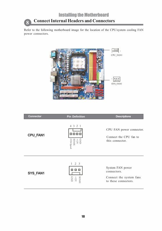
Refer to the following motherboard image for the location of the CPU/system cooling FANpower connectors.
Connect Internal Headers and Connectors8
System FAN powerconnectors.
Connect the system fansto these connectors.
SYS_FAN1
1 32
GN
D
+12V
SENSE
Pin Definition Connector Descriptions
Connect the CPU fan tothis connector.
CPU FAN power connector.
CPU_FAN1
14 23
GN
D+
12V
FAN
SpeedSEN
SE
CPU_FAN1
SYS_FAN1
1
1

Installing the Motherboard
11
Refer to the following motherboard image for the location of front panel switch/LEDheader.
Pin1 and pin 3 are used to be connected to a front panel-mounted LEDto indicate hard disk activity.
Pin 2 and pin 4 are used to be connected to a front panel-mounted LEDto indicate power on/off, sleep and message waiting status.
Pin 5 and pin 7 are used to be connected to the reset switch on the PCcase.
Pin 6 and pin 8 are used to be connected to the power button on the PCcase, to turn on the system. To turn off the system, press the power buttonfor 4 seconds.
Front panel switch/LEDheader
This header provides astandard set of switch andLED headers commonlyfound on ATX or MicroATX cases.
PANEL1
Pin Definition Connector Descriptions
1-3
6-85-72-4
HDD_LEDSUS_LEDRESETPWR_SW1
2 10
9
PWR_SW
_P
RSVD
HD
_LED
_PH
D_LE
D_N
RST_SW_N
RST_SW_P
PWR
/SLP_P
PWR_SW
_N K
EY
PWR/SLP_N
1
2 10
9PANEL1

Installing the Motherboard
12
Refer to the following motherboard image for the location of front panel audio header andSPDIF out header.
Pin Definition Connector Descriptions
Front panel audio header
This header connects tothe audio jacks located onthe front panel. Refer toyour case User’s Manualfor detailed installationinstructions.
F_AUDIO1
For AC97 front panel For HD front panel
SPDIF out header
This is a header thatprovides an S/PDIF (Sony/Philips Digital Interface)output to digital multimediadevice through optical fiberor coaxial connector.
SPDIFO1
AG
ND
AGN
D
Line out_L
Line out_RM
ICPW
R N
.C
N.C
MIC Input
KE
Y N
.C
N.C
1
2 10
9
KE
Y A
GN
D
AGN
D V
CC3PO
RT-F_L
PORT-E
_L
PORT-F_ R
PORT-E
_RSEN
SE
1
2 10
9
1 432
SPDIF O
UT
VCC5
KEY
GN
D12 1 0
9
1
SPDIFO1F-AUDIO1

Installing the Motherboard
13
Refer to the following motherboard image for the location of the analog audio input headerand the infrared header.
Figure Connector Definition Descriptions
Analog audio input header
This header is used to receiveaudio from a CD-ROMdrive, TV turner and so on.
CD_IN1
IR1
Infrared header
The infrared port allows thewireless exchange ofinformation between yourcomputer and similarlyequipped devices such asprinters, laptops, PersonalDigital Assistants (PDAs),and other computers.
Pin Definition Connector Descriptions
1
CD_IN1
CDIN
LG
ND
GN
D CD
IN R
1 432
GN
DK
EY
IRR
X
N.C
VCC5
IRTX
1
2 6
5
1
2 6
5IR1

Installing the Motherboard
14
Refer to the following motherboard image for the location of the front panel USB headers.
F_USB1~4
Front panel USB 2.0headers
The front USB 2.0headers can be connectedto the front-mountedports for more USBinterface peripherals.
Pin Definition Connector Descriptions
Please make sure that the USB cable has the same pin assignment as indi-cated above. A different pin assignment may cause damage or system hang-up.
9
N.C
VCC D
ATA
- D
ATA
+G
ND
KEY
VCCD
ATA
- D
ATA
+G
ND
1
2 10
2 109 1
2 109 1
2 10 1 92 10
1 9 F_USB1
F_USB2
F_USB3
F_USB4
Installing the Motherboard
15
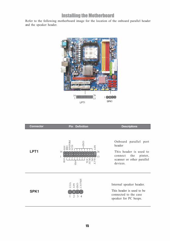
Refer to the following motherboard image for the location of the onboard parallel headerand the speaker header.
Connector Pin Definition Descriptions
Onboard parallel portheader
This header is used toconnect the pinter,scanner or other paralleldevices.
LPT1
SPK1
Internal speaker header.
This header is used to beconnected to the casespeaker for PC beeps.
VCC5K
EYG
ND
SPKO
UT
1 3 42
AFD
ERRPRN
INIT
SLIN
GN
D KEY
STB PD
SLCT
ACK
BUSY
PE
26
131
14
26131
14
LPT1 SPK1
1

Installing the Motherboard
16
Refer to the motherboard image below for power connectors location.
PWR24P1
PWR8P1
Standard 24-pin ATX powersupply connector
This header allows you toconnect an ATX 24-pinpower supply.
Axuiliary 8-pin ATX powersupply connector
This 12V power connectoris used to provide power tothe CPU.
Connector Pin Definition Descriptions
Connect Power Supply9
24123.3V
+12V+12V
AUX5VPWROK
GND+5V
GND+5V
GND3.3V3.3V
GND+5V+5V+5V-5VGNDGNDGNDPS_ONGND-12V3.3V
1 13
PWR8P1
1 5
8 4
13
24
1
12
PWR24P1
5
4
1
8+12V+12V+12V+12VGND
GND
GNDGND

Installing the Motherboard
17
Using 20-pin power cable may cause the system to become unbootable orunstable because of insufficient electricity. A minimum power of 300W isrecommended for a fully-configured system.
This motherboard provides a standard 24-pin ATX power connector and an auxiliary 8-pinATX power connector. Please refer to the following instructions for proper installation.
Connecting power cable
a. Align the pins of the plug of the power supply with the connctor. The plug of the power cables are designed to fit in only one orientation.b. Push down the power supply firmly into the connctor.
For 24-pin connector, you may use the 20-pin ATX power supply as well. When connectingthe 20-pin ATX power supply, please plug the power supply along with the pin 1 and pin 13of the power connector.
24-pin power cable
For 8-pin connector, you may use the 4-pin ATX power supply as well. When connectingthe 4-pin ATX power supply, please plug the power supply along with the pin 1 and pin 5 ofthe power connector.
8-pin power cable
20-pin power cable 4-pin power cable
Pin 5

Installing the Motherboard
18
The rear panel I/O ports of this motherboard are shown below.
This concludes Chapter 2. The next chapter covers the BIOS Setup.
A: Center & WooferB: Back SurroundC: Side SurroundD: Line-inE: Line-outF: Mic_in Rear
Connect Rear Panel Devices10
PS2 Mouse Use the upper PS/2 port to connect a PS/2 mouse.
PS2 Keyboard Use the lower PS/2 port to connect a PS/2 keyboard.
Serial Port Use the COM port to connect serial devices such as mice or(COM1) fax/modems.
VGA Port Connect your monitor to the VGA port (analog signal).
DVI Port Connect your monitor to the DVI port (digital signal).
LAN Port Connect an RJ-45 jack to the LAN port to connect your computerto the Network.
USB Ports Use the USB ports to connect USB devices.
Audio Ports Refer to above table for functions of each audio jack.
19
BIOS SetupChapter 3BIOS SetupWhen you power on the system, BIOS enters the Power-On Self Test (POST) routines.POST is a series of built-in diagnostics performed by the BIOS. After the POST routines arecompleted, the following message appears:
Press DEL to enter SETUPPress the Delete key to access the BIOS Setup Utility.
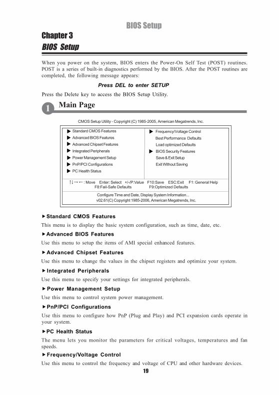
Standard CMOS FeaturesThis menu is to display the basic system configuration, such as time, date, etc.
Advanced BIOS FeaturesUse this menu to setup the items of AMI special enhanced features.
Advanced Chipset FeaturesUse this menu to change the values in the chipset registers and optimize your system.
Integrated PeripheralsUse this menu to specify your settings for integrated peripherals.
Power Management SetupUse this menu to control system power management.
PnP/PCI ConfigurationsUse this menu to configure how PnP (Plug and Play) and PCI expansion cards operate inyour system.
PC Health StatusThe menu lets you monitor the parameters for critical voltages, temperatures and fanspeeds.
Main Page1
Frequency/Voltage ControlUse this menu to control the frequency and voltage of CPU and other hardware devices.
CMOS Setup Utility - Copyright (C) 1985-2005, American Megatrends, Inc.
v02.61(C) Copyright 1985-2006, American Megatrends, Inc.
Load optimized Defaults
Save & Exit SetupExit Without Saving
Frequency/Voltage ControlStandard CMOS Features
Advanced BIOS Features
Advanced Chipset Features
Integrated Peripherals
Power Management Setup
PnP/PCI Configurations
PC Health Status
Best Performance Defaults
BIOS Security Features
F8:Fail-Safe Defaults F9:Optimized Defaults: Move Enter: Select +/-/P:Value F10:Save ESC:Exit F1: General Help
Configure Time and Date, Display System Information...
20
BIOS Setup
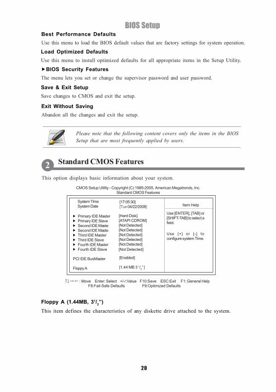
Floppy A (1.44MB, 31/2”)This item defines the characteristics of any diskette drive attached to the system.
Save & Exit SetupSave changes to CMOS and exit the setup.
Exit Without SavingAbandon all the changes and exit the setup.
Load Optimized DefaultsUse this menu to install optimized defaults for all appropriate items in the Setup Utility.
BIOS Security FeaturesThe menu lets you set or change the supervisor password and user password.
This option displays basic information about your system.
Standard CMOS Features2
Best Performance DefaultsUse this menu to load the BIOS default values that are factory settings for system operation.
CMOS Setup Utility - Copyright (C) 1985-2005, American Megatrends, Inc.Standard CMOS Features
System TImeSystem Date Item Help
Use [ENTER], [TAB] or[SHIFT-TAB] to select afield.
Primary IDE MasterPrimary IDE SlaveSecond IDE MasteSecond IDE MasteThird IDE MasterThird IDE SlaveFourth IDE MasterFourth IDE Slave [Not Detected]
PCI IDE BusMaster
Floppy A
[Hard Disk][ATAPI CDROM][Not Detected][Not Detected][Not Detected][Not Detected][Not Detected]
[17:05:30] [Tue 04/22/2008]
[Enabled]
[1.44 MB 3 1/2” ]
Use [+] or [-] toconfigure system Time.
Please note that the following content covers only the items in the BIOSSetup that are most frequently applied by users.
F8:Fail-Safe Defaults F9:Optimized Defaults: Move Enter: Select +/-/:Value F10:Save ESC:Exit F1: General Help
21
BIOS Setup
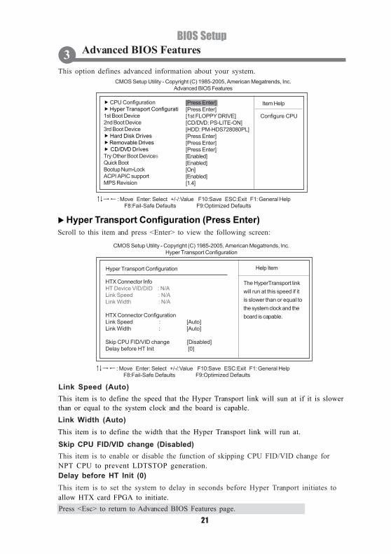
This option defines advanced information about your system.
Advanced BIOS Features3
CMOS Setup Utility - Copyright (C) 1985-2005, American Megatrends, Inc.Advanced BIOS Features
Link Speed (Auto)This item is to define the speed that the Hyper Transport link will sun at if it is slowerthan or equal to the system clock and the board is capable.Link Width (Auto)This item is to define the width that the Hyper Transport link will run at.
Skip CPU FID/VID change (Disabled)This item is to enable or disable the function of skipping CPU FID/VID change forNPT CPU to prevent LDTSTOP generation.Delay before HT Init (0)This item is to set the system to delay in seconds before Hyper Tranport initiates toallow HTX card FPGA to initiate.Press <Esc> to return to Advanced BIOS Features page.
Item Help CPU Configuration Hyper Transport Configurati
1st Boot Device2nd Boot Device3rd Boot Device
Hard Disk Drives Removable Drives CD/DVD Drives
Try Other Boot DevicesQuick BootBootup Num-LockACPI APIC supportMPS Revision
[Press Enter][Press Enter][1st FLOPPY DRIVE][CD/DVD: PS-LITE-ON][HDD: PM-HDS728080PL][Press Enter][Press Enter][Press Enter][Enabled][Enabled][On][Enabled][1.4]
Configure CPU
F8:Fail-Safe Defaults F9:Optimized Defaults: Move Enter: Select +/-/:Value F10:Save ESC:Exit F1: General Help
CMOS Setup Utility - Copyright (C) 1985-2005, American Megatrends, Inc.Hyper Transport Configuration
Hyper Transport Configuration Help Item
HTX Connector InfoHT Device VID/DID : N/ALink Speed : N/ALink Width : N/A
HTX Connector ConfigurationLink Speed : [Auto]Link Width : [Auto]
Skip CPU FID/VID change [Disabled]Delay before HT Init [0]
The HyperTransport linkwill run at this speed if itis slower than or equal tothe system clock and theboard is capable.
F8:Fail-Safe Defaults F9:Optimized Defaults: Move Enter: Select +/-/:Value F10:Save ESC:Exit F1: General Help
Hyper Transport Configuration (Press Enter)Scroll to this item and press <Enter> to view the following screen:
22
BIOS Setup
Quick Boot (Enabled)Enable this item to shorten the power on testing (POST) and have your system start upfaster. You might like to enable this item after you are confident that your systemhardware is operating smoothly.
ACPI APIC support (Enabled)This item allows you to enable or disable the ACPI (Advanced Configuration and PowerInterface) APIC (Advanced Programmable Interrupt Controller) mode. APIC providessymmetric multi-processing (SMP) for systems, allowing support for up to 60 processors.
Bootup Num-Lock (On)This item defines if the keyboard Num Lock key is active when your system is started.
Try Other Boot Devices (Enabled)When enabled, the system searches all other possible locations for an operating system ifit fails to find one in the devices specified under the First, Second, and Third boot devices.
1st/2nd/3rd Boot DeviceUse these items to select the priority and order of the devices that your systemsearches for an operating system at start-up time.
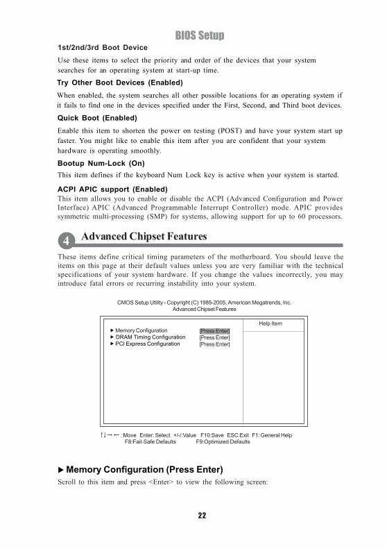
These items define critical timing parameters of the motherboard. You should leave theitems on this page at their default values unless you are very familiar with the technicalspecifications of your system hardware. If you change the values incorrectly, you mayintroduce fatal errors or recurring instability into your system.
Advanced Chipset Features4
CMOS Setup Utility - Copyright (C) 1985-2005, American Megatrends, Inc.Advanced Chipset Features
Help Item[Press Enter][Press Enter][Press Enter]
Memory Configuration DRAM Timing Configuration PCI Express Configuration
F8:Fail-Safe Defaults F9:Optimized Defaults: Move Enter: Select +/-/:Value F10:Save ESC:Exit F1: General Help
Memory Configuration (Press Enter)Scroll to this item and press <Enter> to view the following screen:

23
BIOS SetupCMOS Setup Utility - Copyright (C) 1985-2005, American Megatrends, Inc.
Memory Configuration
Help Item[Auto][XOR of Address bit][Disabled][Disabled][Enabled][Auto][Enabled]
Bank InterleavingChannel InterleavingEnable Clock to All DIMMsMemClk Tristate C3/ATLVIDMemory Hole RemappingDCT Unganged ModePower Down Enable
F8:Fail-Safe Defaults F9:Optimized Defaults: Move Enter: Select +/-/:Value F10:Save ESC:Exit F1: General Help
Enable Bank MemoryInterleaving
Bank Interleaving (Auto)This item is to enable or disable the memory bank interleaving function to enhancememory performance.Channel Interleaving (XOR of Address bit)This item is to enable or disable the channel memory interleaving function.
Enable Clock to All DIMMs (Disabled)This item is to enable or disable the unused clocks to DIMMs even the memory slotsare not populated.
MemClk Tristate C3/ATLVID (Disabled)This item is to enable or disable the memory clock tri-stating in C3 mode and ATLVID.Memory Hole Remapping (Disabled)Enable or disable memory remapping around the memory hole. Disable this item to notallow the remapping of memory.
DCT Unganged Mode (Auto)This item allows the selection of the unganged DRAM mode (64-bit width).
Power Down Enabled (Enabled)This item is to enable or disable the DDR power down mode.
DRAM Timing Configuration (Press Enter)Scroll to this item and press <Enter> to view the following screen:
CMOS Setup Utility - Copyright (C) 1985-2005, American Megatrends, Inc.DRAM Timing Configuration
Press <Esc> to return to Advanced Chipset Features page.
Help Item[Auto][Auto]
Memory Clock ModeDRAM Timing Mode Options
AutoLimitManual
F8:Fail-Safe Defaults F9:Optimized Defaults: Move Enter: Select +/-/:Value F10:Save ESC:Exit F1: General Help

24
BIOS Setup
These options display items that define the operation of peripheral components onthe system input/output ports.
Integrated Peripherals5
Item HelpSuper IO ConfigurationOnboard Devices Controller
[Press Enter][Press Enter]
CMOS Setup Utility - Copyright (C) 1985-2005, American Megatrends, Inc.Integrated Peripherals
F8:Fail-Safe Defaults F9:Optimized Defaults: Move Enter: Select +/-/:Value F10:Save ESC:Exit F1: General Help
Configure SuperIOChipset ITE8716
Onboard Floppy Controller (Enabled)This item is to enable or disable the floppy controller.
CMOS Setup Utility - Copyright (C) 1985-2005, American Megatrends, Inc.Super IO Configuration
Onboard Floppy ControllerSerial Port1 Address Serial Port1 ModeParallel Port Address Parallel Port Mode Parallel Port IRQ
Item Help
[3F8/IRQ4][Normal][378][Normal][IRQ7]
[Enabled]
Allows BIOS to Enableor Disable FloppyController.
F8:Fail-Safe Defaults F9:Optimized Defaults: Move Enter: Select +/-/:Value F10:Save ESC:Exit F1: General Help
Scroll to this item and press <Enter> to view the following screen: Super IO Configuration (Press Enter)
Memory Clock Mode (Auto)This item is to select the memory clock mode.
DRAM Timing Mode (Auto)This item is to select the DRAM Timing mode, configuration options include: Auto, DCT 0,DCT 1 and Both.
Press <Esc> to return to Integrated Peripherals page.
25
BIOS Setup
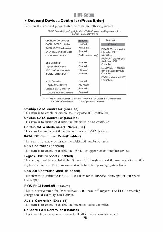
Scroll to this item and press <Enter> to view the following screen: Onboard Devices Controller (Press Enter)
OnChip PATA Controller (Enabled)This item is to enable or disable the integrated IDE controllers.
OnChip SATA Mode select (Native IDE)This item lets you select the operation mode of SATA devices.
OnChip SATA Controller (Enabled)This item is to enable or disable the integrated SATA controller.
Legacy USB Support (Enabled)This setting must be enabled if the PC has a USB keyboard and the user wants to use thiskeyboard either in a DOS environment or before the operating system loads
USB Controller (Enabled)This item is to enable or disable the USB1.1 or upper version interface devices.
USB 2.0 Controller Mode (HiSpeed)This item is to configure the USB 2.0 controller in HiSpeed (480Mbps) or FullSpeed(12 Mbps).
BIOS EHCI Hand-off [Enabled]This is a workaround for OSes without EHCI hand-off support. The EHCI ownershipchange should claim by EHCI driver.
OnBoard LAN Controller (Enabled)This item lets you enable or disable the built-in network interface card.
Audio Controller (Enabled)This item is to enable or disable the integrated audio controller.
CMOS Setup Utility - Copyright (C) 1985-2005, American Megatrends, Inc.Onboard Devices Controller
OnChip PATA ControllerOnChip SATA ControllerOnChip SATA Mode selectSATA IDE Combined ModeCombined Mode Option
USB ControllerLegacy USB SupportUSB 2.0 Controller ModeBIOS EHCI Hand-Off
Audio Controller Audio Mode SelectOnBoard LAN Controller Onboard LAN Boot ROM
Item Help
[Enabled][Native IDE][Enabled][SATA as secondary]
[Enabled][Enabled][HiSpeed][Enabled]
[Enabled][HD Mode][Enabled][Disabled]
DISABLED: disables theintegrated IDEController.PRIMARY: enables onlythe Primary IDEController.SECONDARY: enablesonly the Secondary IDEController.BOTH: enables both IDEControllers.
[Enabled]Options
F8:Fail-Safe Defaults F9:Optimized Defaults: Move Enter: Select +/-/:Value F10:Save ESC:Exit F1: General Help
SATA IDE Combined Mode(Enabled)This item is to enable or disable the SATA IDE combined mode.

26
BIOS Setup
Suspend Mode (S3 (STR))Use this item to define how your system suspends. In the default, S3 (STR), the suspendmode is a suspend to RAM, i.e., the system shuts down with the exception of a refreshcurrent to the system memory.
This option lets you control system power management.
Restore on AC Power Loss (Power Off)This option lets you tell the PC what to do in the event of a power loss.Soft-Off by PWR-BTTN (Instant-Off)Under ACPI (Advanced Configuration and Power management Interface) you can create asoftware power down. In a software power down, the system can be resumed by Wake UpAlarms. This item lets you install a software power down that is controlled by the powerbutton on your system. If the item is set to Instant-Off, then the power button causes asoftware power down. If the item is set to Delay 4 Sec. then you have to hold the powerbutton down for four seconds to cause a software power down.
PS2 Keyboard/Mouse Wakeup From S3 (Disabled)This item specifies whether the system will be awakened from power saving modes byPS2 Keyboard or Mouse.
Power Management Setup6
CMOS Setup Utility - Copyright (C) 1985-2005, American Megatrends, Inc.Power Management Setup
Resume On RTC Alarm (Disabled)This item allows users to enable or disable the alarm to wake up the system. If set toEnabled, users can specify the specific day of month and the exact time to power up thesystem.
Resume On Ring (Disabled)An input signal on the serial Ring Indicator (RI) line (in other words, an incoming call on themodem) awakens the system from a soft off state.
Resume On PME# (Disabled)This item specifies whether the system will be awakened from power saving modes whenactivity or input signal of the specified hardware peripheral or component (i.e. PME, PowerManagement Event) is detected.
Item Help
Suspend modeRepost Video on S3 ResumeRestore on AC Power Loss bySoft-Off by PWR-BTTNUSB Device Wakeup From S3PS2 Keyboard Wakeup From S3PS2 Mouse Wakeup From S3Support HPET Functioon
Resume On RingResume On PME#Resume On RTC Alarm
[No][Power Off][Instant-Off][Disabled][Disabled][Disabled][Enabled]
[Disabled][Disabled][Disabled]
[S3 (STR)]
Select the ACPIstate used forSystem Suspend.
F8:Fail-Safe Defaults F9:Optimized Defaults: Move Enter: Select +/-/:Value F10:Save ESC:Exit F1: General Help
USB Device Wakeup From S3 (Disabled)This item is to enable or disable the USB device to wakeup system from S3 mode

27
BIOS Setup
Primary Video Controller (Auto)This item is to select which graphics controller to use as the primary boot device.
PnP/PCI Configuration7CMOS Setup Utility - Copyright (C) 1985-2005, American Megatrends, Inc.
PnP/PCI Configuration
Smart Fan Control (Disabled)This item is to enable or disable the CPU smart fan function. When enabled, the speedof the CPU Fan is automatically controlled by CPU temperature
PC Health Status8On motherboards that support hardware monitoring, this menu lets you monitor theparameters for critical voltages, temperatures and fan speeds.
Primary Video ControllerAllocate IRQ to PCI VGA
Help Item
[Yes][Auto]
Options
AutoAlways
F8:Fail-Safe Defaults F9:Optimized Defaults: Move Enter: Select +/-/:Value F10:Save ESC:Exit F1: General Help
CMOS Setup Utility - Copyright (C) 1985-2005, American Megatrends, Inc.PC Health Status
Item HelpSmart Fan Control
CPU Temperature :54OC/129OF
CPU Fan Speed :3341 RPMSystem Fan1 Speed :N/A
CPU Vcore :1.296 VVDIMM :1.888 VNB Voltage :1.120 V
Options
DisabledEnabled
[Disabled]
F8:Fail-Safe Defaults F9:Optimized Defaults: Move Enter: Select +/-/:Value F10:Save ESC:Exit F1: General Help
28
BIOS Setup
This concludes Chapter 3. The next chapter covers the motherboard software.
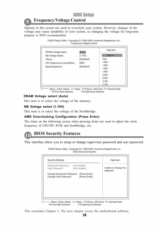
Options in this screen are used to overclock your system. However, changes of thevoltage may cause instability of your system, so changing the voltage for long-termpurpose is NOT recommended.
DRAM Voltage select (Auto)This item is to select the voltage of the memory.
NB Voltage select (1.10V)This item is to select the voltage of the Northbridge.
This interface allow you to setup or change supervisor password and user password.
BIOS Security Features10
AMD Overclocking Configuration (Press Enter)The items on the following screen when pressing Enter are used to adjust the clockfrequency of CPU/HT, PCIE and Sorthbridge, etc.
Frequency/Voltage Control9
CMOS Setup Utility - Copyright (C) 1985-2005, American Megatrends, Inc.Frequency/Voltage Control
DRAM Voltage selectNB Voltage SelectVSonicCPU Referrence Clock(MHz)Spread Spectrum
Help Item
[1.10V][Disabled][200][Disabled]
[Auto]Options
Auto1.80V1.85V1.90V1.95V2.00V2.05V2.10V2.15V
CMOS Setup Utility - Copyright (C) 1985-2005, American Megatrends, Inc.BIOS Security Features
Help ItemSecurity Settings
Supervisor Password : Not InstalledUser Password : Not Installed
Change Supervisor Password [Press Enter]Change User Password [Press Enter]
Install or Change thepassword.
F8:Fail-Safe Defaults F9:Optimized Defaults: Move Enter: Select +/-/:Value F10:Save ESC:Exit F1: General Help
F8:Fail-Safe Defaults F9:Optimized Defaults: Move Enter: Select +/-/:Value F10:Save ESC:Exit F1: General Help

29
Using the Software CDChapter 4Using the Software CD
The support software CD that is included in the motherboard package contains the driversand utilities needed to properly run the bundled products. Besides, User’s Manual and AdobeReader program are both provided for easier installation and setup of your motherboard.Insert the disk into the CD-ROM drive, the autorun feature will automatically bring up theinstallation auto-run screen as follows.
On the install guide screen, click the button Install Chipset Driver. A screen pops out withall the recommended drivers listed. Users please check before the driver you want to install,and click the button Install. The system will install the selected driver automatically.
For easy installation, users could install all the drivers continuously by checking all thedrivers and then simply pressing the button Fast Install.
The installation auto-run screen has three buttons on it, Install Chipset Driver, DriverDisk Profile and Browse CD.
About the Software CD1
Install Chipset Driver2

30
Using the Software CD
Click the button Driver Disk Profile, the screen will list all the drivers and tools availablein this driver disk.
Driver Disk Profile3
The Browse CD button is the standard Windows command that allows you to open WindowsExplorer and show the content of the support CD.
The above screens are examples only. The screens and driver lists will bedifferent according to the motherboard you are installing.
The format of the Browse CD screen is slightly different under differentOperating System you are using.
Browse CD4