A60 Marine June 09 - Nautique Products | Nautique Yacht ... · Marine and Offshore Projects ......
20
Designed for inclusion in Marine and Offshore Projects A-60 Marine Fire Damper YY denotes last two digits of year that Wheelmark is affixed to damper. Features Blades 430 stainless steel and 316 stainless steel options. Casings Lightweight cost effective design. Rectangular and circular flanges. Galvanised and 316 stainless steel options. 1.2, 2, and 3mm options. 150 and 210mm depths. Standard and customer flange drilling options. Visual indicator option. Actuators Electrical 24V, 120V and 230V options. Pneumatic ATEX (Ex) rated 3 second reset time. PTR release. ATEX (Ex) rated (Electrical) Universal voltage 24V - 230V AC/DC. May 2010 A-60 Marine Fire Dampers Dampers Controls Fancoils Ruskin Air Management Limited www.ruskinuk.co.uk
Transcript of A60 Marine June 09 - Nautique Products | Nautique Yacht ... · Marine and Offshore Projects ......
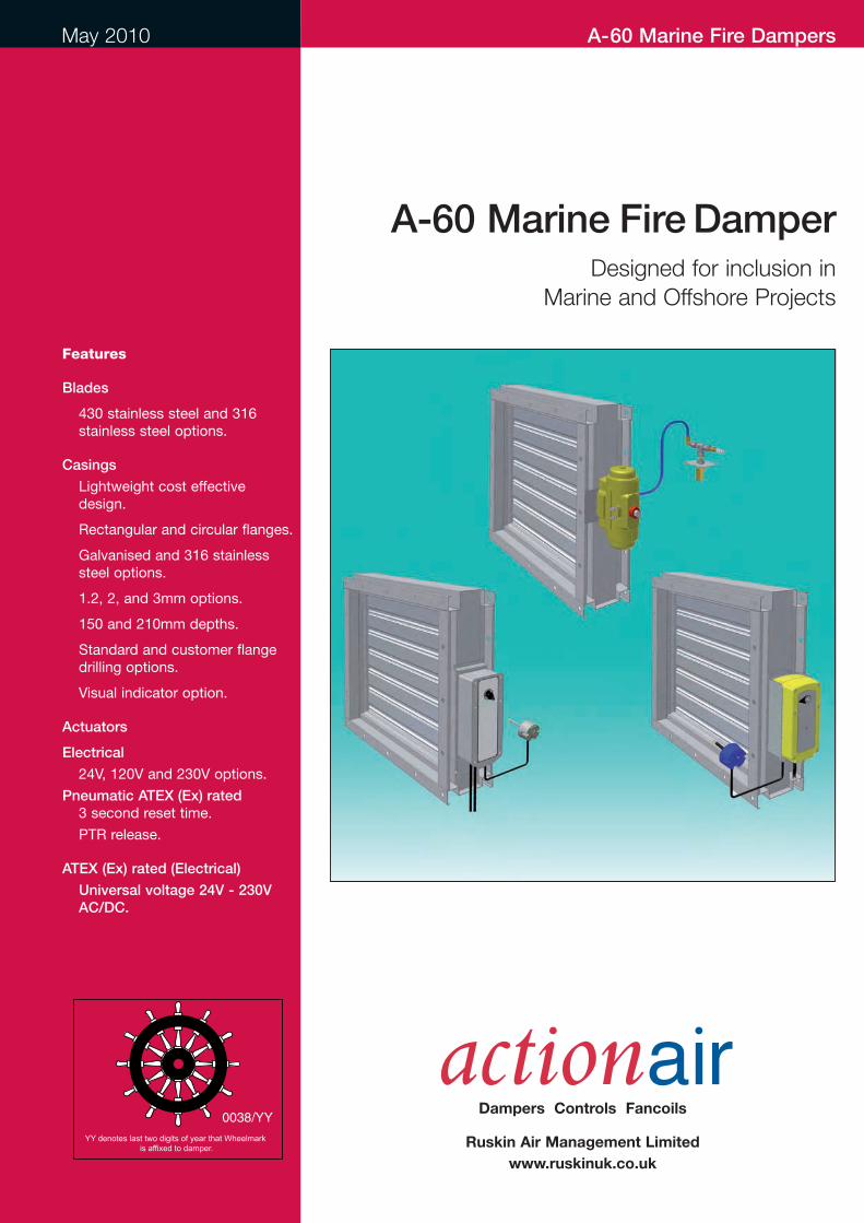
Designed for inclusion in
Marine and Offshore Projects
A-60 Marine FireDamper
YY denotes last two digits of year that Wheelmark is affixed to damper.
Features
Blades
� 430 stainless steel and 316stainless steel options.
Casings
� Lightweight cost effectivedesign.
� Rectangular and circular flanges.
� Galvanised and 316 stainlesssteel options.
� 1.2, 2, and 3mm options.
� 150 and 210mm depths.
� Standard and customer flangedrilling options.
� Visual indicator option.
Actuators
Electrical
� 24V, 120V and 230V options.
Pneumatic ATEX (Ex) rated3 second reset time.
� PTR release.
ATEX (Ex) rated (Electrical)
� Universal voltage 24V - 230VAC/DC.
May 2010 A-60 Marine Fire Dampers
Dampers Controls Fancoils
Ruskin Air Management Limited
www.ruskinuk.co.uk

A-60 Marine Fire Dampers
Introduction
Specification
Actionair has, for many years, been
associated in the design, development
and manufacture of life safety equipment,
including the supply of fire damper
products to the offshore and marine
industry. The Actionair A-60 Marine Fire
Damper has been specifically engineered
to meet stringent legislation.
The A-60 Marine Fire Damper
compliments the comprehensive range of
automatic fire and smoke dampers and
associated controls, provides the
complete solution for shipboard air
conditioning and ventilation systems fire
safety engineering strategies.
The A-60 Marine Fire Damper has been
designed for inclusion in air conditioning
and ventilation systems, in dry filtered air,
and is tested and approved for fitting to
class A-60 divisions (bulkheads and
decks), when suitably insulated (refer to
insulation details).
The Actionair A-60 Marine Fire Damper is
constructed from galvanised steel 1.2mm
thick, (2 and 3mm options available),
40mm flanged rectangular or circular
casing.
Electrical
The Actionair direct-coupled spring return
fail-safe electrical control modes are fitted
with halogen free low smoke and fume
electrical cable. They have a 60 second
reset time and a 20 second release time.
Each actuator has a 72°C rated Electrical
Thermal Release (ETR). The ETR
incorporates a safety electrical interlock
that only permits actuator operation when
correctly fitted. A green 'Healthy'
indication lamp is built into the ETR
housing to give a simple and clear visual
check that the actuator is receiving
power, the ETR is correctly fitted, and the
thermal fuse is intact. A manual test
switch allowing periodic operation of the
damper for testing purposes simulates
actual fail-safe release under smoke/fire
conditions. End switches are provided
with each mode for reset and release
monitoring.
Electrical ATEX (Ex) ratedThe Actionair direct-coupled spring return
fail-safe ATEX (Ex) electrical control
modes are fitted with 1 metre of cable for
connection inside hazardous areas.
They have the benefit of a Universal
electrical supply using any Voltage
between 24-230V AC/DC, which is self
adaptable. They have Variable (3 -15-30 -
60 -120 sec) Reset and (3 -10 sec )
Release times, which are selectable on
site. Each actuator has a Integral Safety
Temperature Sensor (STS) rated at 72 °C.
The STS incorporates a triple fail-safe
thermal fuse arrangement, 2 induct and
one outside, to ensure the fail-safe
actuator operates in all conditions. A
manual test switch allowing periodic
operation of the damper for testing
purposes simulates actual fail-safe release
under smoke/fire conditions. End
switches are provided with each mode
for reset and release monitoring. An
Integral heater allows the unit to be
operated within ambient temperatures
down to – 40°C.
Pneumatic ATEX (Ex) ratedThe Actionair direct coupled spring return
fail-safe pneumatic control mode requires
an air pressure of between 5 to 8 bar (72
to 116 psi) to operate. They have 3
second reset and release time. Each
actuator has a Pneumatic Thermal
Release (PTR). The PTR assembly is
supplied with 500mm nylon tubing that
connects to the quick fit couplings of the
PTR and actuator. Incorporated is a fail-
safe 74 °C fusible link. When this operates,
air exhausts from the actuator, permitting
the spring return actuator to go to the fail-
safe position, thus closing the damper.
Switch box and solenoid accessories are
available for monitoring and control.
Testing-Maintenance and cleaningA-60 Dampers are supplied in 2 casing
and blade options:-
1. 430 Standard steel blades, Galvanised
Steel casing - only suitable for installation
in dry filtered systems.
2. 316 Standard steel blades, casing and
drive - more suited for corrosive
conditions, but even this will rapidly
corrode and fail if not properly maintained,
when used in air intake systems at sea.
The addition of a mist eliminator is highly
recommended and access must be
provided for maintenance.
Pay particular attention to the blade rivets,
where crevice corrosion will cause rapid
failure of blades if not kept in check.
TestingTwo levels of testing exists.
1. Routine testingMonthly, or in accordance with maintenance
programme, release and reset damper
2 www.actionair.co.uk
(via control system or ETR test switch).
Check remote indication or visual check
of mechanical pointer as appropriate.
2. Visual check at damperAt commissioning and at least once a
year, check damper operation by removing
and re-applying power to actuator. (via
ETR test switch). Visually check blades for
damper closed and open positions. Prove
remote indication if applicable.
Routine MaintenanceDepending upon environmental
conditions, each damper will merit its own
cleaning regime. Particularly hostile areas
may require monthly cleaning and
lubrication.
‘Frequency of maintenance’ should be
determined by collecting historical data
from previous visits, and for this reason,
commence maintenance programmes at
very frequent intervals. Dampers in ‘Dry
Filtered Air’ require very limited
maintenance.
Using Duck Oil (recommended lubricant,
or similar equivalent), clean all exposed
surfaces, using a cloth. Remove all traces
of surface staining, as this will deteriorate
further causing deeper material corrosion.
If damper is stiff to operate, lubricate
blade ends and open and close damper
successively until the damper moves with
ease. (This may necessitate removal of
the actuator and operating the blades
manually by the drive shaft). Refit
actuator, and re-test. Clean off excessive
lubricant.
Tests and Approval listMarine Equipment Directive (MED) 96/98 /EC.
Lloyds Register Group Approval to IMO
Fire Test Procedures Code, Annex 1,
Part 3, for Class A60 bulkheads and decks.
DNV Type Approval Certificate No. F-18845.
USCG Approved (product category
164.139).
Germanischer Lloyds Approved to IMO
Res. A.754. (18) and IMO Res.
MSC61(67), Annex 1 Part 3.
American Bureau of Shipping Approved
to: 2005 Steel Vessel Rules 1-1-4/7.7.
(Please note maximum size restrictions -
see page 4.)
Corrosion tested.
Vibration tested.
All certificates are available via the
Actionair website. www.actionair.co.uk
A-60 Marine Fire Dampers
Application
The A-60 dampers can be used where the
maximum system pressure is up to 1500
Pa and duct velocities to 15m/s.
Pay particular attention to the blade rivets,
where crevice corrosion will cause rapid
failure of blades if not kept in check.
The A-60 Marine Fire Damper is suitable
for both vertical and horizontal
applications, with airflow in either direction.
The dampers are normally open, and fail-
safe to the closed position.
A-60 Dampers are supplied in 2 casing
and blade options:-
1. 430 Standard steel blades, Galvanised
Steel casing - only suitable for installation
in dry filtered systems.
2. 316 Standard steel blades, casing and
drive - more suited for corrosive
conditions, but even this will rapidly
corrode and fail if not properly maintained,
when used in air intake systems at sea.
The addition of a mist eliminator is highly
recommended and access must be
provided for maintenance.
3www.actionair.co.uk
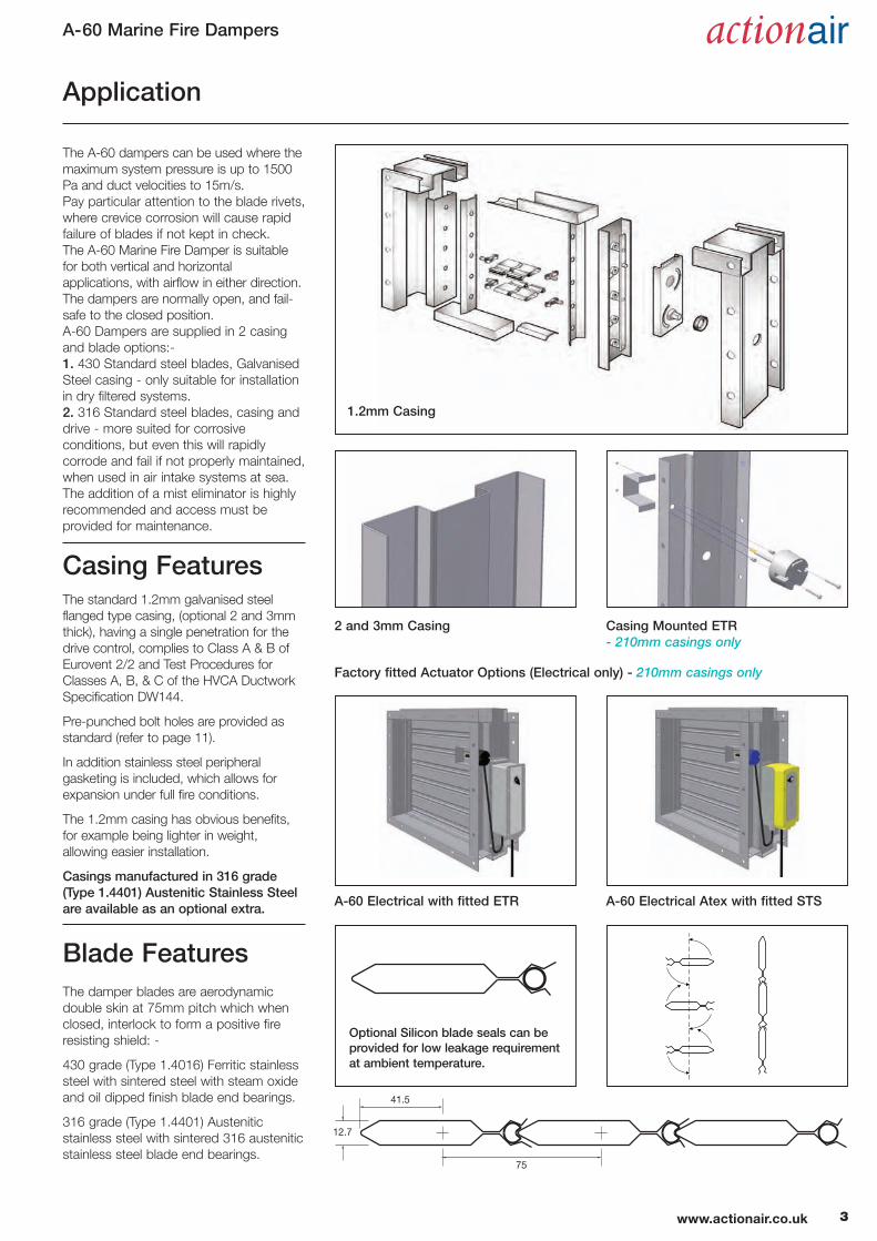
Casing FeaturesThe standard 1.2mm galvanised steel
flanged type casing, (optional 2 and 3mm
thick), having a single penetration for the
drive control, complies to Class A & B of
Eurovent 2/2 and Test Procedures for
Classes A, B, & C of the HVCA Ductwork
Specification DW144.
Pre-punched bolt holes are provided as
standard (refer to page 11).
In addition stainless steel peripheral
gasketing is included, which allows for
expansion under full fire conditions.
The 1.2mm casing has obvious benefits,
for example being lighter in weight,
allowing easier installation.
Casings manufactured in 316 grade(Type 1.4401) Austenitic Stainless Steelare available as an optional extra.
1.2mm Casing
A-60 Electrical with fitted ETR A-60 Electrical Atex with fitted STS
2 and 3mm Casing
Factory fitted Actuator Options (Electrical only) - 210mm casings only
Casing Mounted ETR - 210mm casings only
Blade Features
75
41.5
12.7
Optional Silicon blade seals can beprovided for low leakage requirementat ambient temperature.
The damper blades are aerodynamic
double skin at 75mm pitch which when
closed, interlock to form a positive fire
resisting shield: -
430 grade (Type 1.4016) Ferritic stainless
steel with sintered steel with steam oxide
and oil dipped finish blade end bearings.
316 grade (Type 1.4401) Austenitic
stainless steel with sintered 316 austenitic
stainless steel blade end bearings.
A-60 Marine Fire Dampers
Insulation Details
75
4050
40 25
225
300
**
4040
5025
CONNECTION OF DAMPERTO COAMING
CONNECTION OF DAMPERTO COAMING
See page 7
See
pag
e 7
MINERAL FIBRE INSULATION(110Kg PER CUBIC METRE) DAMPER
COAMING
See Below
**See Below**See Below
COAMING
DAMPER
STRUCTURAL STEEL CORE
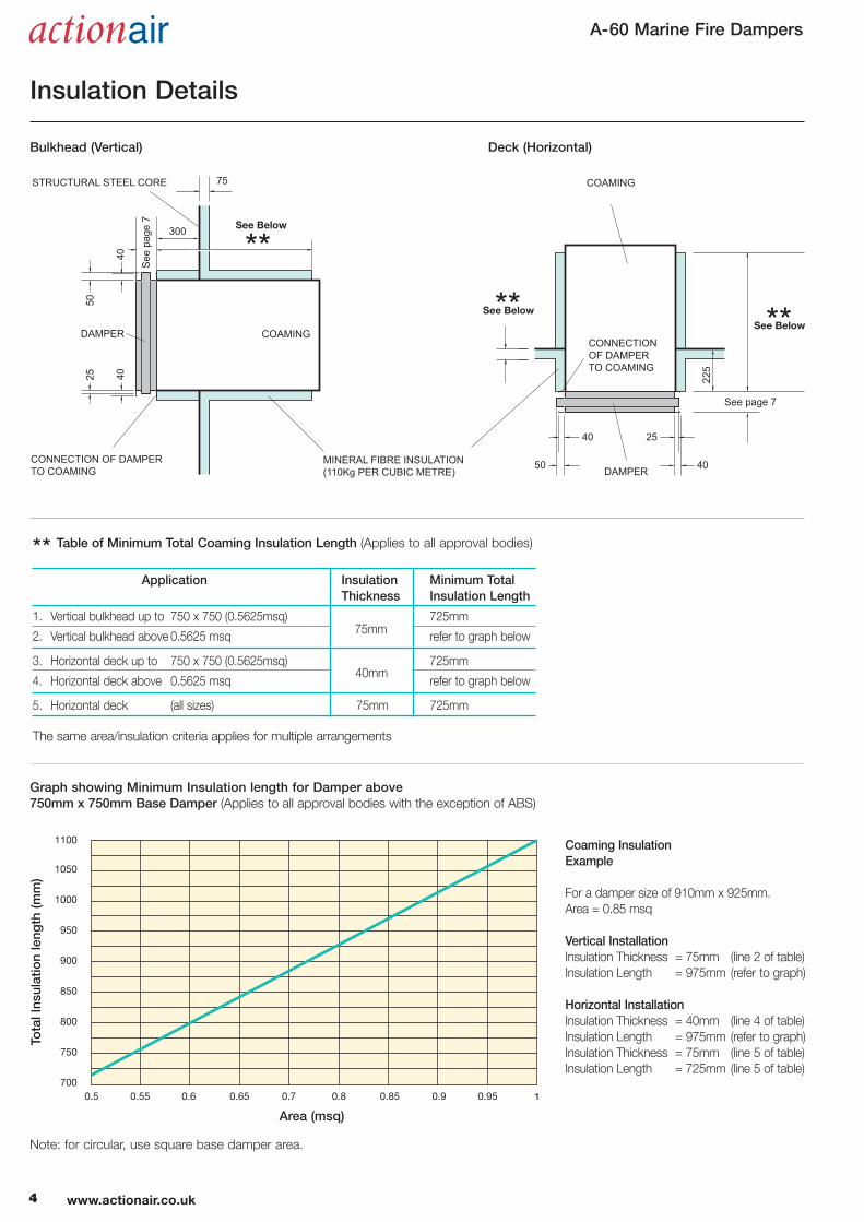
Deck (Horizontal)Bulkhead (Vertical)
Application Insulation Minimum TotalThickness Insulation Length
1. Vertical bulkhead up to 750 x 750 (0.5625msq) 725mm
2. Vertical bulkhead above 0.5625 msq refer to graph below
3. Horizontal deck up to 750 x 750 (0.5625msq) 725mm
4. Horizontal deck above 0.5625 msq refer to graph below
5. Horizontal deck (all sizes) 75mm 725mm
The same area/insulation criteria applies for multiple arrangements
Note: for circular, use square base damper area.
1100
1050
1000
950
900
850
800
750
7000.5 0.55 0.6 0.65 0.7 0.8 0.85 0.9 0.95 1
Area (msq)
Graph showing Minimum Insulation length for Damper above 750mm x 750mm Base Damper (Applies to all approval bodies with the exception of ABS)
Coaming Insulation Example
For a damper size of 910mm x 925mm.
Area = 0.85 msq
Vertical Installation Insulation Thickness = 75mm (line 2 of table)
Insulation Length = 975mm (refer to graph)
Horizontal Installation Insulation Thickness = 40mm (line 4 of table)
Insulation Length = 975mm (refer to graph)
Insulation Thickness = 75mm (line 5 of table)
Insulation Length = 725mm (line 5 of table)
** Table of Minimum Total Coaming Insulation Length (Applies to all approval bodies)
75mm
40mm
Total Insulation length (m
m)
4 www.actionair.co.uk
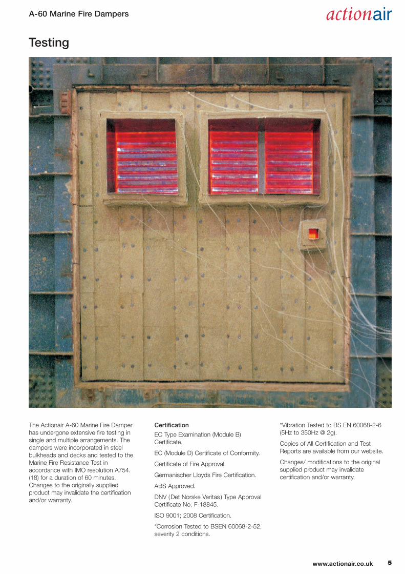
A-60 Marine Fire Dampers
The Actionair A-60 Marine Fire Damper
has undergone extensive fire testing in
single and multiple arrangements. The
dampers were incorporated in steel
bulkheads and decks and tested to the
Marine Fire Resistance Test in
accordance with IMO resolution A754.
(18) for a duration of 60 minutes.
Changes to the originally supplied
product may invalidate the certification
and/or warranty.
Testing
5www.actionair.co.uk
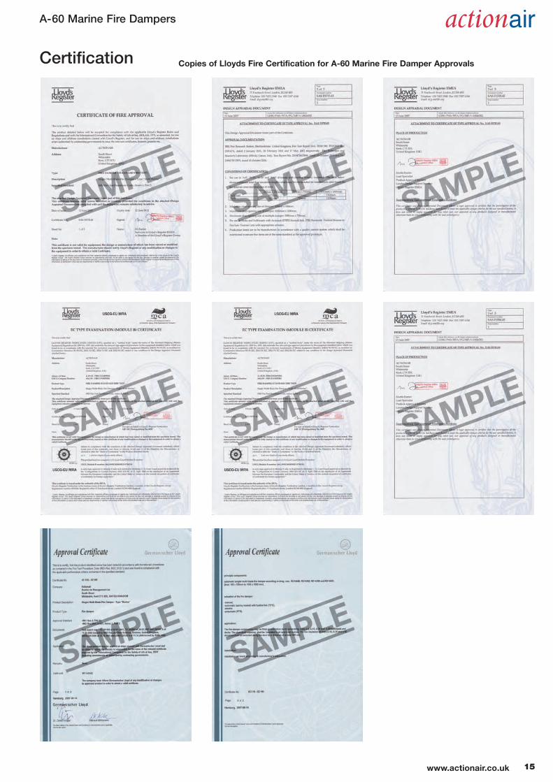
Certification
EC Type Examination (Module B)
Certificate.
EC (Module D) Certificate of Conformity.
Certificate of Fire Approval.
Germanischer Lloyds Fire Certification.
ABS Approved.
DNV (Det Norske Veritas ) Type Approval
Certificate No. F-18845.
ISO 9001; 2008 Certification.
*Corrosion Tested to BSEN 60068-2-52,
severity 2 conditions.
*Vibration Tested to BS EN 60068-2-6
(5Hz to 350Hz @ 2g).
Copies of All Certification and Test
Reports are available from our website.
Changes/ modifications to the original
supplied product may invalidate
certification and/or warranty.
A-60 Marine Fire Dampers
6 www.actionair.co.uk
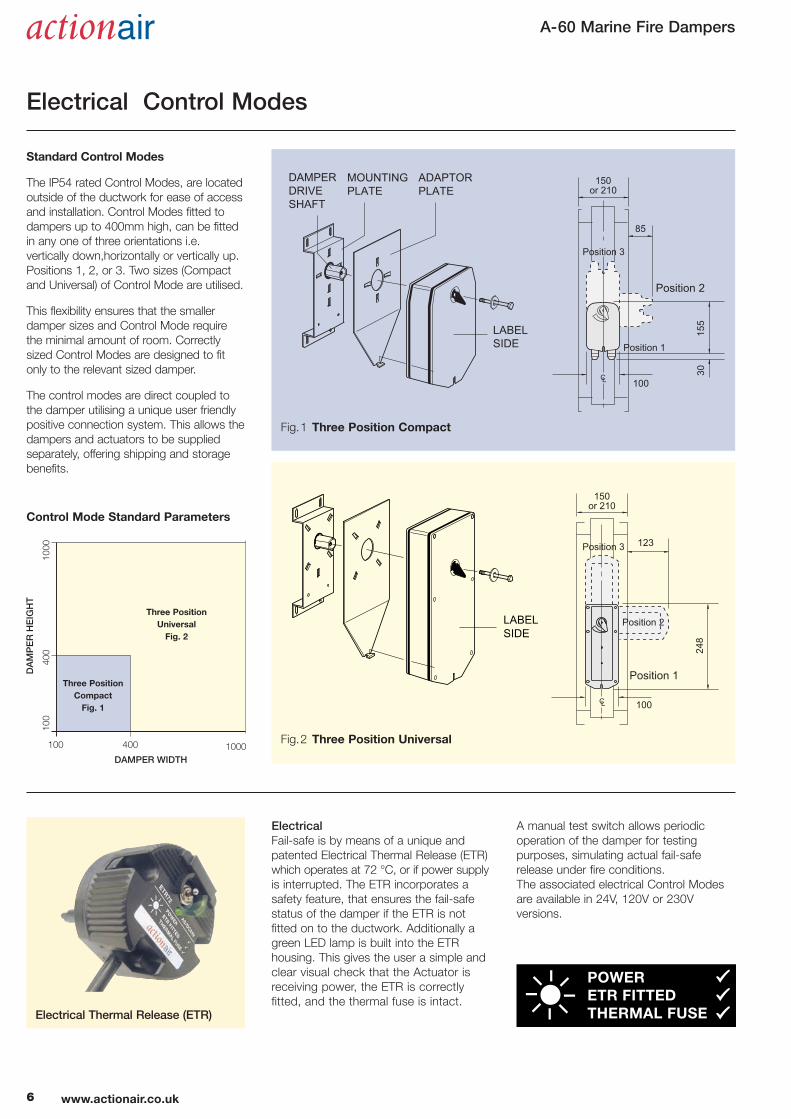
ElectricalFail-safe is by means of a unique and
patented Electrical Thermal Release (ETR)
which operates at 72 °C, or if power supply
is interrupted. The ETR incorporates a
safety feature, that ensures the fail-safe
status of the damper if the ETR is not
fitted on to the ductwork. Additionally a
green LED lamp is built into the ETR
housing. This gives the user a simple and
clear visual check that the Actuator is
receiving power, the ETR is correctly
fitted, and the thermal fuse is intact.
A manual test switch allows periodic
operation of the damper for testing
purposes, simulating actual fail-safe
release under fire conditions.
The associated electrical Control Modes
are available in 24V, 120V or 230V
versions.
Electrical Thermal Release (ETR)
Electrical Control Modes
LABEL SIDE
DAMPER DRIVE SHAFT
MOUNTING PLATE
ADAPTOR PLATE
LABEL SIDE
85
155
30
100
Position 1
Position 2
Position 3
150or 210
123
248
100
Position 1
Position 2
Position 3
150or 210
Standard Control Modes
The IP54 rated Control Modes, are located
outside of the ductwork for ease of access
and installation. Control Modes fitted to
dampers up to 400mm high, can be fitted
in any one of three orientations i.e.
vertically down,horizontally or vertically up.
Positions 1, 2, or 3. Two sizes (Compact
and Universal) of Control Mode are utilised.
This flexibility ensures that the smaller
damper sizes and Control Mode require
the minimal amount of room. Correctly
sized Control Modes are designed to fit
only to the relevant sized damper.
The control modes are direct coupled to
the damper utilising a unique user friendly
positive connection system. This allows the
dampers and actuators to be supplied
separately, offering shipping and storage
benefits.
Fig.1 Three Position Compact
Fig.2 Three Position Universal
Three Position
Universal
Fig. 2
Control Mode Standard Parameters
DAMPER WIDTH
100
100
400 1000
400
1000
DAMPER HEIGHT
Three Position
Compact
Fig. 1
A-60 Marine Fire Dampers
Electrical Application and Wiring
�–
+
1
2
1
2
3
5
6
4
VOLT FREECONTACT MADE BETWEEN 1 AND 2 WHEN DAMPER FULLY RELEASED
AC 250V6(3)A
DIAGRAM SHOWS ACTUATOR IN FULLY RELEASED STATE
M
ELECTRICAL THERMAL RELEASE (MUST BE FITTED FOR DAMPER OPERATION).
(SPRING BIASED TEST SWITCH)
TF 72 C
VOLT FREECONTACT MADE BETWEEN 4 AND 6 WHEN DAMPER FULLY RESET
BLACK
WHITE
AC / DC 24V50 / 60 Hz
12.5 V AMax
10 / 2 W
Imax8.3A @ 5ms
–30...+50 CCONTINUOUS
SUPPLY24V AC or DCTYPICALLY 10W (MOTORING) 2W (RESET)
BLUE N
L1BROWN
�
DIAGRAM SHOWS ACTUATOR IN FULLY RELEASED STATE
AC250V6(3)A
1
2
3
5
6
4
VOLT FREECONTACT MADE BETWEEN 1 AND 2 WHEN DAMPER FULLY RELEASED
SUPPLY230VAC 50/60 HzTYPICALLY12W (MOTORING)4W (RESET
M
ELECTRICAL THERMAL RELEASE (MUST BE FITTED FOR DAMPER OPERATION).
(SPRING BIASED TEST SWITCH)
TF 72 C
VOLT FREECONTACT MADE BETWEEN 4 AND 6 WHEN DAMPER FULLY RESET
AC 230V50 / 60 Hz
14 V AMax
12 / 4 W
–30...+50 CCONTINUOUS
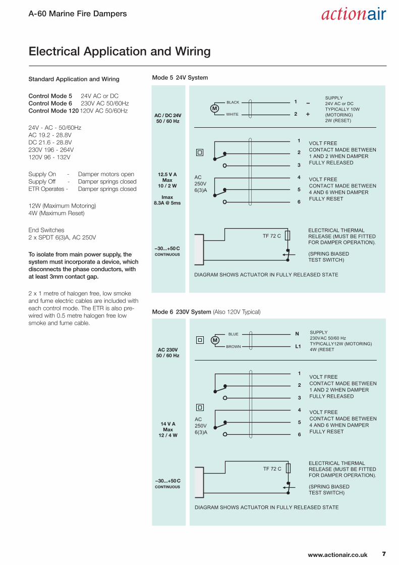
Mode 5 24V System
Mode 6 230V System (Also 120V Typical)
Standard Application and Wiring
Control Mode 5 24V AC or DC
Control Mode 6 230V AC 50/60Hz
Control Mode 120 120V AC 50/60Hz
24V - AC - 50/60Hz
AC 19.2 - 28.8V
DC 21.6 - 28.8V
230V 196 - 264V
120V 96 - 132V
Supply On - Damper motors open
Supply Off - Damper springs closed
ETR Operates - Damper springs closed
12W (Maximum Motoring)
4W (Maximum Reset)
End Switches
2 x SPDT 6(3)A, AC 250V
To isolate from main power supply, thesystem must incorporate a device, whichdisconnects the phase conductors, withat least 3mm contact gap.
2 x 1 metre of halogen free, low smoke
and fume electric cables are included with
each control mode. The ETR is also pre-
wired with 0.5 metre halogen free low
smoke and fume cable.
7www.actionair.co.uk

A-60 Marine Fire Dampers
ATEX (Ex) Rated Control Modes
The ATEX rated Control Modes, are
located outside of the ductwork for ease
of access and installation.
Control Modes can be fitted in any one of
three orientations, i.e. vertically down,
horizontally or vertically up. Positions 1, 2,
or 3.
8 www.actionair.co.uk
Safety Temperature Sensor (STS)
Electrical ATEX (Ex) rated.
Fail-safe is by means of a Safety
Temperature Sensor (STS) which operates
at 72 °C, or if power supply is interrupted.
A manual test switch allows periodic
operation of the damper for testing
purposes, simulating actual fail-safe
release under fire conditions.
The associated electrical Control Modes
are available in one Universal version with
24 – 230V AC/DC supply.
The control modes are direct coupled to
the damper utilising a unique user friendly
positive connection system. This allows
the dampers and actuators to be supplied
separately, offering shipping and storage
benefits.
A-60 Marine Fire Dampers
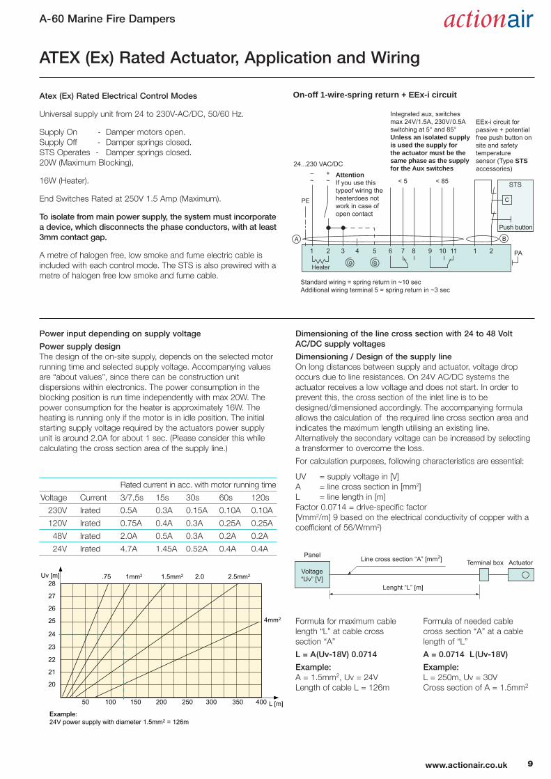
Atex (Ex) Rated Electrical Control Modes
Universal supply unit from 24 to 230V-AC/DC, 50/60 Hz.
Supply On - Damper motors open.
Supply Off - Damper springs closed.
STS Operates - Damper springs closed.
20W (Maximum Blocking),
16W (Heater).
End Switches Rated at 250V 1.5 Amp (Maximum).
To isolate from main power supply, the system must incorporatea device, which disconnects the phase conductors, with at least3mm contact gap.
A metre of halogen free, low smoke and fume electric cable is
included with each control mode. The STS is also prewired with a
metre of halogen free low smoke and fume cable.
Power input depending on supply voltage
Power supply design The design of the on-site supply, depends on the selected motor
running time and selected supply voltage. Accompanying values
are “about values”, since there can be construction unit
dispersions within electronics. The power consumption in the
blocking position is run time independently with max 20W. The
power consumption for the heater is approximately 16W. The
heating is running only if the motor is in idle position. The initial
starting supply voltage required by the actuators power supply
unit is around 2.0A for about 1 sec. (Please consider this while
calculating the cross section area of the supply line.)
1
PE
2
Heater
3 4 5 6 7 8 9 10 11 1 2
Standard wiring = spring return in ~10 secAdditional wiring terminal 5 = spring return in ~3 sec
AttentionIf you use this typeof wiring the heaterdoes not work in case of open contact
On-off 1-wire-spring return + EEx-i circuit
24...230 VAC/DC
< 5 < 85 STS
C
Push button
B
PA
A
–~
+~
EEx-i circuit forpassive + potentialfree push button onsite and safety temperaturesensor (Type STSaccessories)
Integrated aux, switchesmax 24V/1.5A, 230V/0.5A switching at 5° and 85°Unless an isolated supply is used the supply for the actuator must be the same phase as the supplyfor the Aux switches
ATEX (Ex) Rated Actuator, Application and Wiring
28
27
26
25
24
23
22
21
20
50 100 150 200 250 300 350 400 L [m]
Uv [m] 1mm.75 2.02 1.5mm2 2.5mm2
4mm2
Example:24V power supply with diameter 1.5mm2 = 126m
Panel Line cross section “A” [mm2]
Lenght “L” [m]
Voltage“Uv” [V]
Terminal box Actuator
Rated current in acc. with motor running time
Voltage Current 3/7,5s 15s 30s 60s 120s
230V Irated 0.5A 0.3A 0.15A 0.10A 0.10A
120V Irated 0.75A 0.4A 0.3A 0.25A 0.25A
48V Irated 2.0A 0.5A 0.3A 0.2A 0.2A
24V Irated 4.7A 1.45A 0.52A 0.4A 0.4A
Formula for maximum cable
length “L” at cable cross
section “A”
L = A(Uv-18V) 0.0714
Example: A = 1.5mm2, Uv = 24V
Length of cable L = 126m
Formula of needed cable
cross section “A” at a cable
length of “L”
A = 0.0714 L (Uv-18V)
Example: L = 250m, Uv = 30V
Cross section of A = 1.5mm2
Dimensioning of the line cross section with 24 to 48 VoltAC/DC supply voltages
Dimensioning / Design of the supply lineOn long distances between supply and actuator, voltage drop
occurs due to line resistances. On 24V AC/DC systems the
actuator receives a low voltage and does not start. In order to
prevent this, the cross section of the inlet line is to be
designed/dimensioned accordingly. The accompanying formula
allows the calculation of the required line cross section area and
indicates the maximum length utilising an existing line.
Alternatively the secondary voltage can be increased by selecting
a transformer to overcome the loss.
For calculation purposes, following characteristics are essential:
UV = supply voltage in [V]
A = line cross section in [mm2]
L = line length in [m]
Factor 0.0714 = drive-specific factor
[Vmm2/m] 9 based on the electrical conductivity of copper with a
coefficient of 56/Wmm2)
9www.actionair.co.uk

A-60 Marine Fire Dampers
MINIMUM REMOVAL DIMENSION
275mm40
8
78
25
Plan view cross section showing Control Mode dimensions
115
255
95
55 59
160
CABLE ENTRY POINTS
*SWITCHBOX / STATUS BEACON
*SOLENOID*Optional Extras
102
222
Pneumatic Spring Return Actuator
Pneumatic Thermal Release (PTR)
Pneumatic Actuator
Pneumatic Control Mode
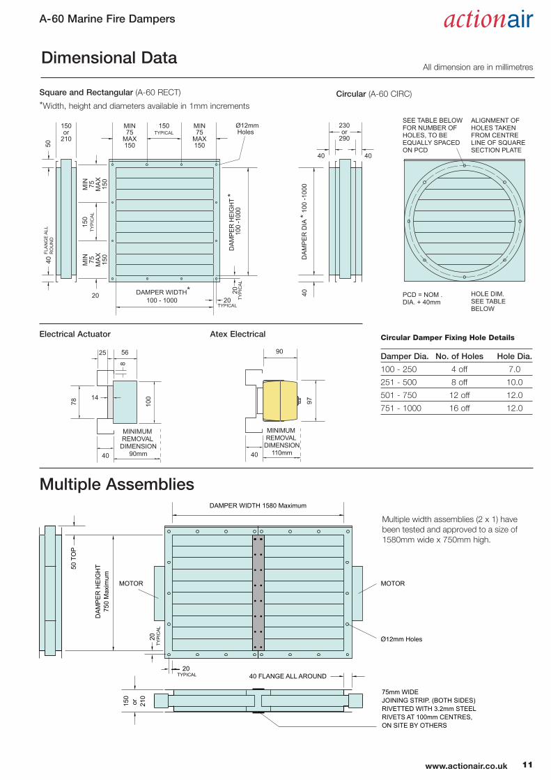
Dimensional Data
All dimension are in millimetres
Pneumatic Operation
Air On - Damper opens.
Air Off - Spring closure.
Release time ≈ 2 - 4 secs.
Reset time ≈ 2 - 4 secs.
Air inlet 6mm dia. quick fit coupling.
74 °C Pneumatic Thermal Release (PTR).
Air pressure = 5.5 - 8.0 Bar.
Air consumption to reset
@ 5.5 bar = 535cc.
External mechanical position indicator.
Test operation by removing fusible link
element.
4mm diameter tubing 500mm
length connection to actuator
Input: 6mm diameter,
quick release
connector,
pressure range
5 - 8 Bar
2 off quick
release
connectors,
supplied
10 www.actionair.co.uk
PneumaticThe special purpose design Pneumatic
Thermal Release (PTR) assembly is
supplied with 500mm nylon tubing that
connects to the quick fit couplings of the
PTR and actuator. Incorporated is a failsafe
74°C fusible link. When this activates, air
exhausts from the actuator, enabling the
PTR to spring return to the fail-safe
position, thus closing the damper.
Pneumatic Control Mode with optionalsolenoid and switchbox/status beacon.
A-60 Marine Fire Dampers
40
4020 DAMPER WIDTH* 100 - 1000
150or
210
150TYPICAL
Ø12mm Holes
230or
290
MIN75
MAX150
MIN75
MAX150
MIN 75 MA
X15
0
MIN 75 MA
X15
0
DAM
PER
HEI
GH
T *
100
-100
020
TYP
ICA
L
20TYPICAL
50
150
TYP
ICA
L
40 DA
MP
ER
DIA
* 10
0 -1
000
40
SEE TABLE BELOW FOR NUMBER OF HOLES, TO BE EQUALLY SPACED ON PCD
PCD = NOM . DIA. + 40mm
HOLE DIM. SEE TABLE BELOW
ALIGNMENT OF HOLES TAKEN FROM CENTRE LINE OF SQUARE SECTION PLATE
FLA
NG
E A
LL
RO
UN
D
Dimensional Data
Multiple Assemblies
All dimension are in millimetres
Damper Dia. No. of Holes Hole Dia.
100 - 250 4 off 7.0
251 - 500 8 off 10.0
501 - 750 12 off 12.0
751 - 1000 16 off 12.0
Circular Damper Fixing Hole Details
Square and Rectangular (A-60 RECT)
*Width, height and diameters available in 1mm increments
Circular (A-60 CIRC)
Electrical Actuator Atex Electrical
MINIMUM REMOVAL
DIMENSION90mm40
5625
8
100
78
14
90
97
MINIMUM REMOVAL
DIMENSION110mm40
20 TYPICAL
20 T
YP
ICA
L
150
or
210
40 FLANGE ALL AROUND
MOTORMOTOR
75mm WIDE JOINING STRIP. (BOTH SIDES) RIVETTED WITH 3.2mm STEEL RIVETS AT 100mm CENTRES, ON SITE BY OTHERS
DAMPER WIDTH 1580 Maximum
DA
MP
ER
HE
IGH
T75
0 M
axim
um
50 T
OP
Multiple width assemblies (2 x 1) have
been tested and approved to a size of
1580mm wide x 750mm high.
11www.actionair.co.uk

Weights (kg) of A-60 Rectangular (Excluding Actuator)
100 200 300 400 500 600 700 800 900 1000
100 5.5 7.1 8.7 10.3 11.9 13.5 15.1 16.7 18.3 19.9
200 7.4 9.1 10.7 12.4 14.0 15.7 17.4 19.0 20.7 22.4
300 9.3 11.1 12.9 14.7 16.5 18.2 20.1 21.8 23.6 25.4
400 10.8 12.7 14.5 16.4 18.3 20.1 22.0 23.9 25.7 27.6
500 12.7 14.7 16.6 18.5 20.5 22.4 24.3 26.3 28.2 30.1
600 14.6 16.7 18.7 20.8 22.9 24.9 27.0 29.1 31.1 33.2
700 16.2 18.3 20.4 22.6 24.7 26.8 29.0 31.1 33.3 35.4
800 17.7 19.9 22.1 24.3 26.5 28.7 31.0 33.1 35.3 37.6
900 19.6 22.0 24.3 26.6 29.0 31.3 33.6 36.0 38.3 40.7
1000 21.2 23.6 26.0 28.4 30.8 33.2 35.6 38.0 40.4 42.8
Weights (kg) of A-60 Rectangular (Excluding Actuator)
100 200 300 400 500 600 700 800 900 1000
100 4.1 5.3 6.4 7.6 8.8 10.0 11.1 12.3 13.5 14.7
200 5.6 6.8 8.1 9.3 10.5 11.8 13.0 14.3 15.5 16.7
300 7.1 8.4 9.8 11.2 12.6 13.9 15.3 16.7 18.0 19.4
400 8.2 9.7 11.1 12.5 14.0 15.4 16.9 18.3 19.7 21.2
500 9.8 11.3 12.8 14.3 15.8 17.3 18.8 20.3 21.8 23.3
600 11.3 12.9 14.5 16.2 17.8 19.5 21.1 22.8 24.4 26.0
700 12.4 14.2 15.9 17.6 19.3 21.0 22.7 24.4 26.1 27.8
800 13.6 15.4 17.2 18.9 20.7 22.5 24.3 26.1 27.8 29.6
900 15.1 17.0 18.9 20.9 22.8 24.7 26.6 28.5 30.4 32.3
1000 16.3 18.3 20.3 22.2 24.2 26.2 28.2 30.2 32.1 34.1
Compact Including Adaptor Plate 1.85kg
Universal Including Adaptor Plate 3.00kg
Pneumatic Including Adaptor Plate 3.00kg
Electrical Atex Including Adaptor Plate 3.50kg
Compact Including Adaptor Plate 1.85kg
Universal Including Adaptor Plate 3.00kg
Pneumatic Including Adaptor Plate 3.00kg
Electrical Atex Including Adaptor Plate 3.50kg
Compact Including Adaptor Plate 1.85kg
Universal Including Adaptor Plate 3.00kg
Pneumatic Including Adaptor Plate 3.00kg
Electrical Atex Including Adaptor Plate 3.50kg
Compact Including Adaptor Plate 1.85kg
Universal Including Adaptor Plate 3.00kg
Pneumatic Including Adaptor Plate 3.00kg
Electrical Atex Including Adaptor Plate 3.50kg
A-60 Marine Fire Dampers
Weights (kg) of A-60 Rectangular (Excluding Actuator)
100 200 300 400 500 600 700 800 900 1000
100 3.0 3.8 4.6 5.5 6.3 7.1 8.0 8.8 9.7 10.5
200 4.1 5.0 5.9 6.9 7.8 8.7 9.6 10.5 11.4 12.3
300 5.3 6.4 7.4 8.4 9.5 10.5 11.5 12.6 13.6 14.7
400 6.2 7.3 8.4 9.5 10.6 11.7 12.8 13.9 15.0 16.1
500 7.4 8.6 9.7 10.9 12.1 13.3 14.4 15.6 16.8 18.0
600 8.6 9.9 11.2 12.5 13.8 15.1 16.4 17.7 19.0 20.4
700 9.5 10.9 12.2 13.6 15.0 16.3 17.7 19.1 20.5 21.8
800 10.3 11.8 13.2 14.7 16.1 17.5 19.0 20.4 21.9 23.3
900 11.5 13.1 14.7 16.3 17.8 19.4 21.0 22.6 24.1 25.7
1000 12.4 14.1 15.7 17.4 19.0 20.6 22.3 23.9 25.6 27.2
100 Dia. 4.6
200 Dia. 8.1
300 Dia. 12.0
400 Dia. 15.4
500 Dia. 19.8
600 Dia. 24.6
700 Dia. 28.9
800 Dia. 33.6
900 Dia. 39.4
1000 Dia. 44.5
Weights
Weights (kg) of A-60 Circular
(Excluding Actuator)
100 Dia. 6.1
200 Dia. 10.7
300 Dia. 15.6
400 Dia. 20.1
500 Dia. 25.6
600 Dia. 31.6
700 Dia. 37.0
800 Dia. 43.0
900 Dia. 50.1
1000 Dia. 56.4
2mm Galvanised Casings, 150mm DeepWeights
(kg) of A-60 Circular(Excluding Actuator)
100 Dia. 8.4
200 Dia. 14.5
300 Dia. 21.1
400 Dia. 27.3
500 Dia. 34.5
600 Dia. 42.4
700 Dia. 49.7
800 Dia. 57.6
900 Dia. 66.7
1000 Dia. 75.1
3mm Galvanised Casings, 150mm DeepWeights
(kg) of A-60 Circular(Excluding Actuator)
Weights (kg) of A-60 Rectangular (Excluding Actuator)
100 200 300 400 500 600 700 800 900 1000
100 3.0 3.9 4.7 5.6 6.4 7.3 8.1 9.0 9.8 10.7
200 4.2 5.1 6.0 7.0 7.9 8.8 9.7 10.6 11.6 12.5
300 5.4 6.4 7.5 8.6 9.6 10.7 11.8 12.8 13.9 15.0
400 6.2 7.4 8.5 9.7 10.8 11.9 13.1 14.2 15.3 16.5
500 7.5 8.7 9.9 11.1 12.3 13.5 14.7 15.9 17.1 18.4
600 8.7 10.1 11.4 12.8 14.1 15.5 16.8 18.2 19.5 20.9
700 9.6 11.0 12.4 13.9 15.3 16.7 18.1 19.5 21.0 22.4
800 10.5 12.0 13.5 15.0 16.4 17.9 19.4 20.9 22.4 23.9
900 11.7 13.3 15.0 16.6 18.2 19.9 21.5 23.1 24.8 26.4
1000 12.6 14.3 16.0 17.7 19.4 21.1 22.8 24.5 26.2 27.9
100 Dia. 4.7
200 Dia. 8.2
300 Dia. 12.2
400 Dia. 15.7
500 Dia. 20.1
600 Dia. 25.1
700 Dia. 29.5
800 Dia. 34.3
900 Dia. 40.4
1000 Dia. 45.5
1.2mm 316 Stainless Steel Casings, 150mm DeepWeights
(kg) of A-60 Circular(Excluding Actuator)
1.2mm Galvanised Casings, 150mm Deep
12 www.actionair.co.uk

A-60 Marine Fire Dampers
Weights (kg) of A-60 Rectangular (Excluding Actuator)
100 200 300 400 500 600 700 800 900 1000
100 4.2 5.3 6.5 7.7 8.9 10.1 11.3 12.5 13.7 14.9
200 5.6 6.9 8.2 9.4 10.7 12.0 13.2 14.5 15.7 17.0
300 7.2 8.6 10.0 11.4 12.8 14.2 15.6 17.0 18.4 19.8
400 8.3 9.8 11.3 12.8 14.2 15.7 17.2 18.7 20.1 21.6
500 9.9 11.4 13.0 14.5 16.1 17.6 19.2 20.7 22.3 23.8
600 11.4 13.1 14.8 16.5 18.2 19.8 21.5 23.2 24.9 26.6
700 12.6 14.4 16.1 17.9 19.6 21.4 23.2 24.9 26.7 28.5
800 13.8 15.6 17.4 19.3 21.1 22.9 24.8 26.6 28.4 30.3
900 15.3 17.3 19.3 21.2 23.2 25.2 27.2 29.1 31.1 33.1
1000 16.5 18.5 20.6 22.6 24.7 26.7 28.8 30.8 32.9 34.9
100 Dia. 6.2
200 Dia. 10.8
300 Dia. 15.9
400 Dia. 20.5
500 Dia. 26.0
600 Dia. 32.2
700 Dia. 37.8
800 Dia. 43.8
900 Dia. 51.1
1000 Dia. 57.6
2mm 316 Stainless Steel Casings, 150mm DeepWeights
(kg) of A-60 Circular(Excluding Actuator)
Compact Including Adaptor Plate 1.85kg
Universal Including Adaptor Plate 3.00kg
Pneumatic Including Adaptor Plate 3.00kg
Electrical Atex Including Adaptor Plate 3.50kg
Weights (kg) of A-60 Rectangular (Excluding Actuator)
100 200 300 400 500 600 700 800 900 1000
100 5.6 7.2 8.8 10.4 12.0 13.7 15.3 16.9 18.5 20.1
200 7.5 9.1 10.8 12.5 14.2 15.9 17.6 19.3 20.9 22.6
300 9.3 11.2 13.0 14.8 16.7 18.5 20.3 22.2 24.0 25.8
400 10.9 12.8 14.7 16.6 18.5 20.4 22.3 24.2 26.1 28.0
500 12.8 14.8 16.8 18.8 20.7 22.7 24.7 26.6 28.6 30.6
600 14.7 16.9 19.0 21.1 23.2 25.3 27.4 29.5 31.7 33.8
700 16.3 18.5 20.7 22.9 25.1 27.3 29.4 31.6 33.8 36.0
800 17.9 20.2 22.4 24.7 26.9 29.2 31.4 33.7 36.0 38.2
900 19.8 22.2 24.6 27.0 29.4 31.8 34.2 36.6 39.0 41.4
1000 21.4 23.9 26.3 28.80 31.3 33.7 36.2 38.7 41.2 43.6
100 Dia. 8.5
200 Dia. 14.7
300 Dia. 21.4
400 Dia. 27.7
500 Dia. 35.0
600 Dia. 43.1
700 Dia. 50.5
800 Dia. 58.6
900 Dia. 67.9
1000 Dia. 76.5
3mm 316 Stainless Steel Casings, 150mm DeepWeights
(kg) of A-60 Circular(Excluding Actuator)
Compact Including Adaptor Plate 1.85kg
Universal Including Adaptor Plate 3.00kg
Pneumatic Including Adaptor Plate 3.00kg
Electrical Atex Including Adaptor Plate 3.50kg
Weights (kg) of A-60 Rectangular (Excluding Actuator)
100 200 300 400 500 600 700 800 900 1000
100 4.8 6.1 7.5 8.9 10.2 11.6 12.9 14.3 15.7 17.0
200 6.4 7.9 9.3 10.7 12.1 13.6 15.0 16.4 17.9 19.3
300 8.1 9.7 11.2 12.8 14.4 15.9 17.5 19.0 20.6 22.2
400 9.5 11.1 12.7 14.3 16.0 17.6 19.2 20.9 22.5 24.1
500 11.2 12.9 14.6 16.3 18.0 19.7 21.4 23.1 24.7 26.5
600 12.9 14.7 16.5 18.4 20.2 22.0 23.9 25.7 27.5 29.4
700 14.2 16.1 18.0 19.9 21.8 23.7 25.6 27.5 29.4 31.3
800 15.6 17.6 19.5 21.5 23.5 25.4 27.4 29.4 31.3 33.3
900 17.3 19.4 21.5 23.6 25.7 27.8 29.9 32.0 34.1 36.2
1000 18.7 20.8 23.0 25.2 27.3 29.5 31.7 33.8 36.0 38.2
100 Dia. 6.8
200 Dia. 11.7
300 Dia. 17.0
400 Dia. 21.9
500 Dia. 27.8
600 Dia. 34.2
700 Dia. 40.0
800 Dia. 46.3
900 Dia. 53.8
1000 Dia. 60.4
2mm Galvanised Casings, 210mm DeepWeights
(kg) of A-60 Circular(Excluding Actuator)
Compact Including Adaptor Plate 1.85kg
Universal Including Adaptor Plate 3.00kg
Pneumatic Including Adaptor Plate 3.00kg
Electrical Atex Including Adaptor Plate 3.50kg
Weights (kg) of A-60 Rectangular (Excluding Actuator)
100 200 300 400 500 600 700 800 900 1000
100 6.5 8.4 10.3 12.2 14.0 15.9 17.8 19.7 21.6 23.4
200 8.7 10.6 12.6 14.5 16.5 18.4 20.4 22.3 24.2 26.2
300 10.8 12.9 15.0 17.1 19.2 21.2 23.3 25.4 27.5 29.6
400 12.7 14.8 16.9 19.1 21.2 23.4 25.5 27.7 29.8 32.0
500 14.9 17.1 19.3 21.5 23.7 25.9 28.2 30.4 32.6 34.8
600 17.0 19.4 21.7 24.1 26.4 28.8 31.1 33.5 35.8 38.2
700 18.9 21.3 23.7 26.1 28.5 31.0 33.4 35.8 38.2 40.6
800 20.7 23.2 25.7 28.2 30.7 33.1 35.6 38.1 40.6 43.1
900 22.9 25.5 28.1 30.8 33.4 36.0 38.6 41.2 43.8 46.5
1000 24.7 27.4 30.1 32.8 35.5 38.2 40.9 43.5 46.2 48.9
100 Dia. 9.4
200 Dia. 16.1
300 Dia. 23.2
400 Dia. 30.0
500 Dia. 37.8
600 Dia. 46.2
700 Dia. 54.1
800 Dia. 62.5
900 Dia. 72.2
1000 Dia. 81.2
3mm Galvanised Casings, 210mm DeepWeights
(kg) of A-60 Circular(Excluding Actuator)
Compact Including Adaptor Plate 1.85kg
Universal Including Adaptor Plate 3.00kg
Pneumatic Including Adaptor Plate 3.00kg
Electrical Atex Including Adaptor Plate 3.50kg
Weights
13www.actionair.co.uk
A-60 Marine Fire Dampers
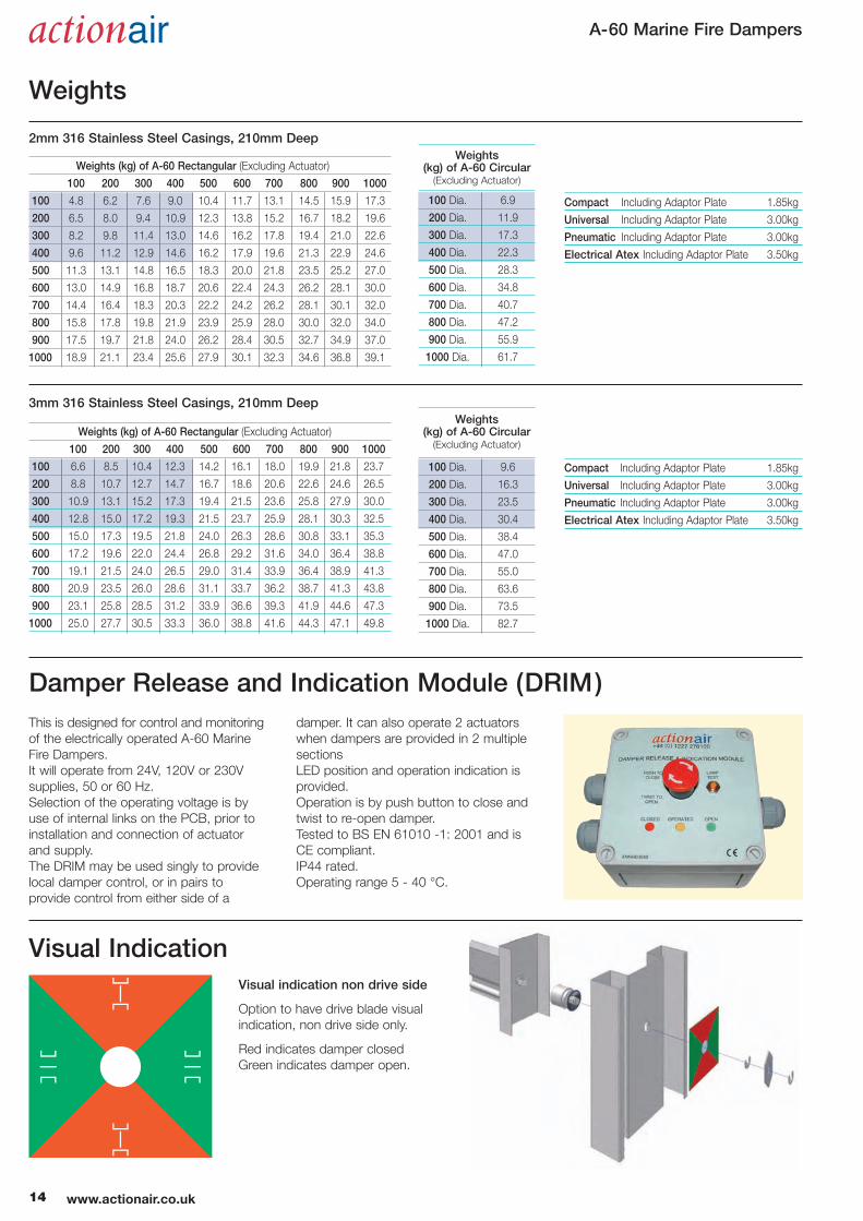
Weights (kg) of A-60 Rectangular (Excluding Actuator)
100 200 300 400 500 600 700 800 900 1000
100 4.8 6.2 7.6 9.0 10.4 11.7 13.1 14.5 15.9 17.3
200 6.5 8.0 9.4 10.9 12.3 13.8 15.2 16.7 18.2 19.6
300 8.2 9.8 11.4 13.0 14.6 16.2 17.8 19.4 21.0 22.6
400 9.6 11.2 12.9 14.6 16.2 17.9 19.6 21.3 22.9 24.6
500 11.3 13.1 14.8 16.5 18.3 20.0 21.8 23.5 25.2 27.0
600 13.0 14.9 16.8 18.7 20.6 22.4 24.3 26.2 28.1 30.0
700 14.4 16.4 18.3 20.3 22.2 24.2 26.2 28.1 30.1 32.0
800 15.8 17.8 19.8 21.9 23.9 25.9 28.0 30.0 32.0 34.0
900 17.5 19.7 21.8 24.0 26.2 28.4 30.5 32.7 34.9 37.0
1000 18.9 21.1 23.4 25.6 27.9 30.1 32.3 34.6 36.8 39.1
100 Dia. 6.9
200 Dia. 11.9
300 Dia. 17.3
400 Dia. 22.3
500 Dia. 28.3
600 Dia. 34.8
700 Dia. 40.7
800 Dia. 47.2
900 Dia. 55.9
1000 Dia. 61.7
2mm 316 Stainless Steel Casings, 210mm DeepWeights
(kg) of A-60 Circular(Excluding Actuator)
Weights (kg) of A-60 Rectangular (Excluding Actuator)
100 200 300 400 500 600 700 800 900 1000
100 6.6 8.5 10.4 12.3 14.2 16.1 18.0 19.9 21.8 23.7
200 8.8 10.7 12.7 14.7 16.7 18.6 20.6 22.6 24.6 26.5
300 10.9 13.1 15.2 17.3 19.4 21.5 23.6 25.8 27.9 30.0
400 12.8 15.0 17.2 19.3 21.5 23.7 25.9 28.1 30.3 32.5
500 15.0 17.3 19.5 21.8 24.0 26.3 28.6 30.8 33.1 35.3
600 17.2 19.6 22.0 24.4 26.8 29.2 31.6 34.0 36.4 38.8
700 19.1 21.5 24.0 26.5 29.0 31.4 33.9 36.4 38.9 41.3
800 20.9 23.5 26.0 28.6 31.1 33.7 36.2 38.7 41.3 43.8
900 23.1 25.8 28.5 31.2 33.9 36.6 39.3 41.9 44.6 47.3
1000 25.0 27.7 30.5 33.3 36.0 38.8 41.6 44.3 47.1 49.8
100 Dia. 9.6
200 Dia. 16.3
300 Dia. 23.5
400 Dia. 30.4
500 Dia. 38.4
600 Dia. 47.0
700 Dia. 55.0
800 Dia. 63.6
900 Dia. 73.5
1000 Dia. 82.7
3mm 316 Stainless Steel Casings, 210mm DeepWeights
(kg) of A-60 Circular(Excluding Actuator)
Compact Including Adaptor Plate 1.85kg
Universal Including Adaptor Plate 3.00kg
Pneumatic Including Adaptor Plate 3.00kg
Electrical Atex Including Adaptor Plate 3.50kg
Compact Including Adaptor Plate 1.85kg
Universal Including Adaptor Plate 3.00kg
Pneumatic Including Adaptor Plate 3.00kg
Electrical Atex Including Adaptor Plate 3.50kg
Visual Indication
Damper Release and Indication Module (DRIM)
Visual indication non drive side
Option to have drive blade visual
indication, non drive side only.
Red indicates damper closed
Green indicates damper open.
This is designed for control and monitoring
of the electrically operated A-60 Marine
Fire Dampers.
It will operate from 24V, 120V or 230V
supplies, 50 or 60 Hz.
Selection of the operating voltage is by
use of internal links on the PCB, prior to
installation and connection of actuator
and supply.
The DRIM may be used singly to provide
local damper control, or in pairs to
provide control from either side of a
damper. It can also operate 2 actuators
when dampers are provided in 2 multiple
sections
LED position and operation indication is
provided.
Operation is by push button to close and
twist to re-open damper.
Tested to BS EN 61010 -1: 2001 and is
CE compliant.
IP44 rated.
Operating range 5 - 40 °C.
14 www.actionair.co.uk
Weights
A-60 Marine Fire Dampers
Certification Copies of Lloyds Fire Certification for A-60 Marine Fire Damper Approvals
15www.actionair.co.uk

A-60 Marine Fire Dampers
16 www.actionair.co.uk
1000
500
1500
100
10
1 10 10050 200
LEAKAGE (I/s per m2)
DIFFERENTIAL PRESSURE (Pa)
The data presented is from the
Laboratory Determination of Acoustic and
Aerodynamic Performance of A-60 Marine
Fire Dampers.
A programme of extensive tests was
carried out by an independent test facility,
approved under the NAMAS Scheme, in
accordance with BRITISH STANDARDS
Nos. 4196, 4773, 4856, 4857 and 4954.
From the selection of a duct velocity
within the operational parameters of the
damper a resultant pressure drop from
Table 1 can be determined and the sum
of these two components applied to the
Velocity x Pressure Drop Vs Sound Power
Level Graph. (Table 2).
The graph is the result of a full
range of acoustic tests with the blades
set in the fully open position.
The Spectrum Correction Data is applied
to the number obtained from the graph
and a complete Sound Spectrum of Flow
Generated Noise for both Outlet (in duct)
and Breakout (casing radiated) is obtained.
Damper Leakage Table 3
A-60 Marine Fire Damper damper closed blade leakage.
Breakout Spectrum Corrections
63 125 250 500 1k 2k 4k 8k Hz
8 11 9 6 -3 -6 -14 -17 dB
6 10 8 4 -3 -3 -11 -14 dB
Outlet (Induct) Spectrum Corrections
Octave Band63 125 250 500 1k 2k 4k 8k
A-60 RECT 5 4 5 5 3 1 -3 -5
A-60 CIRC 9 4 4 5 3 1 -3 -6
Pressure Drop Vs Velocity Table 1 Velocity (m/s) X Pressure Drop (Pa) Vs Sound Power Level (dBW) Table 2
1 2 3 4 5 6 7 8 9 10 15
1009080706050
40
30
20
1098765
4
3
2
1
A-6
0 R
EC
T
A-6
0 C
IRC
EXAMPLE LINE
90
70
80
60
50
40
30
20
10
0
10 20 30 40 50 60 70 80 90 100
200
300
400
500
600
700
800
900
1000
2000
3000
4000
5000
6000
7000
8000
9000
1000
0
A-60 CIRC BREAKOUT
A-60 RECT BREAKOUT
A-60 CIRC OUTLET (INDUCT)
A-60 RECT OUTLET (INDUCT)
EXAMPLE LINE
SOUND POWER LEVEL (dBW)
VELOCITY X PRESSURE DROP (m/s Pa)
PRESSURE DROP (Pa)
VELOCITY (m/s)
Acoustic Data
Standard (without blade seals)
Optional (with blade seals)
Example:
Duct with a design velocity of 8 m/sec
and the A-60 Marine Fire Damper RECT
damper blades in the fully open position.
Pressure Drop = 22 Pa (Table 1).
Multiply Velocity x Pressure Drop
8 x 22 = 176.
From Sound Power Graph (Table 2) plot
176 on horizontal Velocity/Pressure axis
against the A-60 Marine Fire Damper
RECT outlet (induct) graph to obtain
47dBW on Vertical Sound Power Level
Axis. Add or subtract corrections to the
47dBW to provide full spectrum analysis.
A-60 Marine Fire Dampers
17www.actionair.co.uk
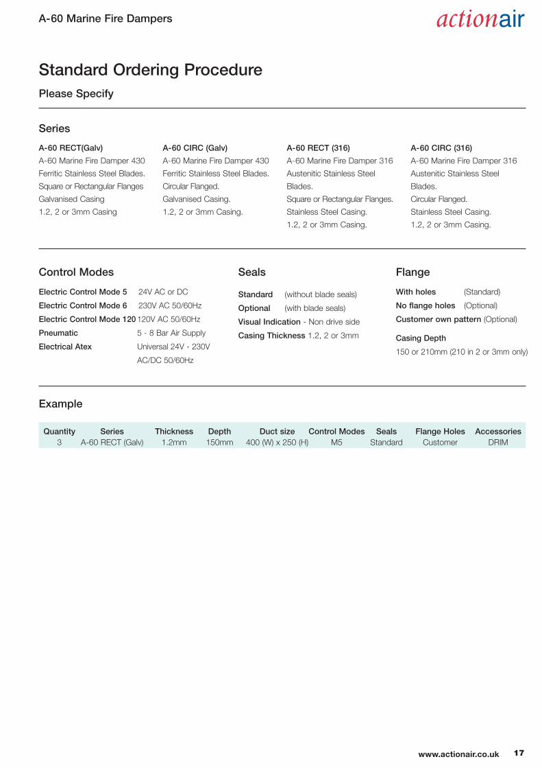
Standard Ordering Procedure
A-60 RECT(Galv)
A-60 Marine Fire Damper 430
Ferritic Stainless Steel Blades.
Square or Rectangular Flanges
Galvanised Casing
1.2, 2 or 3mm Casing
A-60 CIRC (Galv)
A-60 Marine Fire Damper 430
Ferritic Stainless Steel Blades.
Circular Flanged.
Galvanised Casing.
1.2, 2 or 3mm Casing.
A-60 RECT (316)
A-60 Marine Fire Damper 316
Austenitic Stainless Steel
Blades.
Square or Rectangular Flanges.
Stainless Steel Casing.
1.2, 2 or 3mm Casing.
A-60 CIRC (316)
A-60 Marine Fire Damper 316
Austenitic Stainless Steel
Blades.
Circular Flanged.
Stainless Steel Casing.
1.2, 2 or 3mm Casing.
Quantity Series Thickness Depth Duct size Control Modes Seals Flange Holes Accessories3 A-60 RECT (Galv) 1.2mm 150mm 400 (W) x 250 (H) M5 Standard Customer DRIM
Control Modes
Electric Control Mode 5 24V AC or DC
Electric Control Mode 6 230V AC 50/60Hz
Electric Control Mode 120120V AC 50/60Hz
Pneumatic 5 - 8 Bar Air Supply
Electrical Atex Universal 24V - 230V
AC/DC 50/60Hz
Seals
Standard (without blade seals)
Optional (with blade seals)
Visual Indication - Non drive side
Casing Thickness 1.2, 2 or 3mm
Flange
With holes (Standard)
No flange holes (Optional)
Customer own pattern (Optional)
Casing Depth
150 or 210mm (210 in 2 or 3mm only)
Series
Please Specify
Example
A-60 Marine Fire Dampers
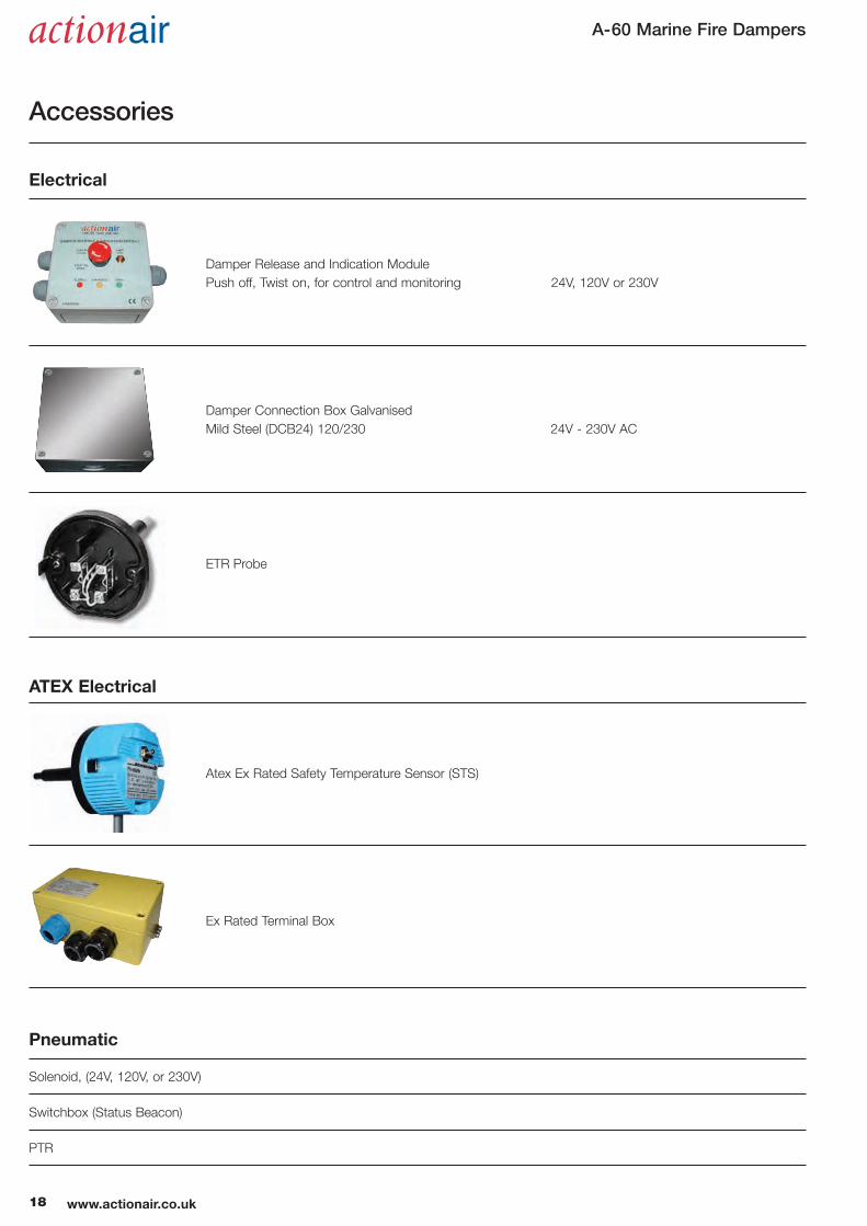
Electrical
ATEX Electrical
Pneumatic
Solenoid, (24V, 120V, or 230V)
Switchbox (Status Beacon)
PTR
Atex Ex Rated Safety Temperature Sensor (STS)
Damper Release and Indication Module
Push off, Twist on, for control and monitoring 24V, 120V or 230V
Damper Connection Box Galvanised
Mild Steel (DCB24) 120/230 24V - 230V AC
ETR Probe
Ex Rated Terminal Box
18 www.actionair.co.uk
Accessories

A-60 Marine Fire Dampers
19www.actionair.co.uk
BROCHURE PRODUCTION www.GeoffStrange.co.uk LNNN00313
A-60 Marine Fire Dampers
Ruskin Air Management Limitedis a ISO 9001 and 14001 registeredcompany.
The statements made in this brochure or by our
representatives in consequence of any enquiries
arising out of this document are given for information
purposes only. They are not intended to have any
legal effect and the company is not to be regarded
as bound thereby. The company will only accept
obligations which are expressly negotiated for and
agreed and incorporated into a written agreement
made with its customers.
Due to a policy of continuous product development
the specification and details contained herein are
subject to alteration without prior notice.
Comprehensive and detailed informationis available for all Actionair products.Visit our website at www.actionair.co.uk
South Street, Whitstable, Kent CT5 3DU England.Tel: 01227 276100 Fax: 01227 264262 Email: [email protected] Website: www.actionair.co.uk
Ruskin Air Management Limited