a5 a3 Service Manual 2013
400
Service Manual Anesthesia System |
-
Upload
francisco-solano -
Category
Documents
-
view
21 -
download
0
description
Service manual Mindray A series
Transcript of a5 a3 Service Manual 2013

7/21/2019 a5 a3 Service Manual 2013
http://slidepdf.com/reader/full/a5-a3-service-manual-2013 1/399
Service Manual
Anesthesia System|
™
™

7/21/2019 a5 a3 Service Manual 2013
http://slidepdf.com/reader/full/a5-a3-service-manual-2013 2/399
Service Manual
Anesthesia System|
™
™

7/21/2019 a5 a3 Service Manual 2013
http://slidepdf.com/reader/full/a5-a3-service-manual-2013 3/399
046-001141-00 A5/A3™ Service Manual
A5™ and A3™ are U.S. trademarks of Mindray DS USA, Inc.
Selectatec ® is a registered trademark of Ohmeda.
Copyright © Mindray DS USA, Inc., 2010. All rights reserved. Contents of this publication may not be reproduced in any form without permission of Mindray DS USA, Inc.
7/21/2019 a5 a3 Service Manual 2013
http://slidepdf.com/reader/full/a5-a3-service-manual-2013 4/399
A5/A3™ Service Manual 046-001141-00 i
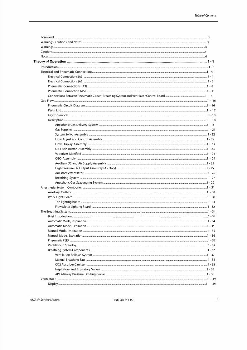
Table of Contents
Foreword ............................. ............................. ............................. ............................... ............................... ............................. ............................. .................. ix
Warnings, Cautions, and Notes ..................................... ................................ ............................. ............................. ............................. ........................... ix
Warnings..................................................................................................................................................................................................................................ix
Cautions...................................................................................................................................................................................................................................x
Notes.........................................................................................................................................................................................................................................xi
Theory of Operation .......................... ............................. ........................... ............................... .......................... ........1 - 1Introduction ........................... .............................. ............................. .................................... .................................. ................................. ................................ 1 - 2
Electrical and Pneumatic Connections...........................................................................................................................................................................1 - 4
Electrical Connections (A3) .............................. ................................. ................................ .................................... ................................ ................... 1 - 4
Electrical Connections (A5) .............................. ................................. ................................ .................................... ................................ ................... 1 - 6
Pneumatic Connections (A3)...................................................................................................................................................................................1 - 8
Pneumatic Connection (A5).....................................................................................................................................................................................1 - 11
Connections Between Pneumatic Circuit, Breathing System and Ventilator Control Board....................... ................................. ...1 - 14
Gas Flow.....................................................................................................................................................................................................................................1 - 16
Pneumatic Circuit Diagram......................................................................................................................................................................................1 - 16
Parts List..........................................................................................................................................................................................................................1 - 17
Key to Symbols.... ............................... .............................. ............................... .................................... ................................ ............................... ..........1 - 18
Description.....................................................................................................................................................................................................................1 - 18
Anesthetic Gas Delivery System .................................................................................................................................................................1 - 18
Gas Supplies ............................................. .............................. ............................. .................................... ................................. ......................... 1 - 21
System Switch Assembly ............................. ................................. .............................. .................................. ................................. ............... 1 - 22
Flow Adjust and Control Assembly ...........................................................................................................................................................1 - 22
Flow Display Assembly ..................................................................................................................................................................................1 - 23
O2 Flush Button Assembly ...........................................................................................................................................................................1 - 23
Vaporizer Manifold ..........................................................................................................................................................................................1 - 24
CGO Assembly ..................................................................................................................................................................................................1 - 24
Auxiliary O2 and Air Supply Assembly .....................................................................................................................................................1 - 25
High Pressure O2 Output Assembly (A5 Only) ......................................................................................................................................1 - 25
Anesthetic Ventilator .................................. ................................. ................................ .................................. ................................. ............... 1 - 26
Breathing System .............................................................................................................................................................................................1 - 27
Anesthetic Gas Scavenging System ..........................................................................................................................................................1 - 29Anesthesia System Components......................................................................................................................................................................................1 - 31
Auxiliary Outlets...........................................................................................................................................................................................................1 - 31
Work Light Board.........................................................................................................................................................................................................1 - 31
Top lighting board .......... ............................... ............................... ............................... ................................... ................................. ............... 1 - 31
Flow Meter Lighting Board ............ ................................ .................................. .................................. ............................... ........................... 1 - 32
The Breathing System......................................... ................................. .............................. ...................................... ................................ ............................. 1 - 34
Brief Introduction............................ ................................ ............................... ...................................... ................................ ................................ .......1 - 34
Automatic Mode, Inspiration ............................... ................................. ................................ .................................. ................................. ............... 1 - 34
Automatic Mode, Expiration ...................................................................................................................................................................................1 - 35
Manual Mode, Inspiration ............................... ................................ ................................. ................................... ................................. .................... 1 - 35
Manual Mode, Expiration..........................................................................................................................................................................................1 - 36
Pneumatic PEEP ............................. ............................... ............................. .................................... ................................ ............................... ............... 1 - 37
Ventilator in Standby ............................... ............................... ................................ .................................... ................................. .............................. 1 - 37Breathing System Components............. ............................... .............................. .................................... ................................. .............................. 1 - 37
Ventilation Bellows System ..........................................................................................................................................................................1 - 37
Manual Breathing Bag ................... ............................... ................................ .................................. ................................. .............................. 1 - 38
CO2 Absorber Canister ........................................ ............................... ............................. .................................... ................................ ..........1 - 38
Inspiratory and Expiratory Valves ..............................................................................................................................................................1 - 38
APL (Airway Pressure Limiting) Valve .......................................................................................................................................................1 - 38
Ventilator UI..............................................................................................................................................................................................................................1 - 39
Display.............................................................................................................................................................................................................................1 - 39

7/21/2019 a5 a3 Service Manual 2013
http://slidepdf.com/reader/full/a5-a3-service-manual-2013 5/399
Table of Contents
ii 046-001141-00 A5/A3™ Service Manual
Display Interface Board ................... ............................. .............................. .................................... ................................. .............................. 1 - 39
Warning Light Board ......................... ............................... ............................. .................................. ................................. .............................. 1 - 41
Display .................................................................................................................................................................................................................1 - 41
Fresh Flow Sensor Board ...............................................................................................................................................................................1 - 42
Indicator Light Board ......................................................................................................................................................................................1 - 43
CPU Board ......................... ............................. ............................... ............................. ....................................... ................................ ............................. 1 - 44Ventilator Control and Drive ................................ ................................ ................................ ...................................... ................................ ........................ 1 - 47
Mother Board................................................................................................................................................................................................................1 - 47
Ventilator Control and Drive Board ............................ .................................. .................................... ............................... ................................ .....1 - 57
Monitor Signal Detection Board .................................................................................................................................................................1 - 57
Valve Drive Board ..................... ............................... .............................. .................................... ............................... ................................ .......1 - 60
Sensor Interface Board ...................................................................................................................................................................................1 - 62
Battery ............................ ............................. ............................. ............................... ...................................... ................................ ................................. .1 - 63
Battery Power ....................................................................................................................................................................................................1 - 63
Battery Adaptation Board .............................................................................................................................................................................1 - 64
Breathing System Heater..........................................................................................................................................................................................1 - 65
Ventilator Pneumatic- O2 Drive Gas................................................................................................................................................................................1 - 66
Ventilator Pneumatic Drive......................................................................................................................................................................................1 - 66
Drive Pressure-High Pressure Regulator (200 kPa, 29 psi)............................................................................................................................1 - 66
Drive Gas Assembly .......................... .............................. ............................. ...................................... ................................ ............................... ..........1 - 66
Tube Color Coding.... .............................. ............................. ............................... ............................... ................................ ............................... ..........1 - 66
Installation Guide ........................ ........................... ............................. ........................... .......................... .................. 2 - 1
Preparation - Additional Material Required..................................................................................................................................................................2 - 2
Assembly ............................. ............................. ............................... ............................. ....................................... ................................. ................................ .....2 - 3
Unpacking and Setup ........................... ............................. .............................. ........................................ ................................ ................................. .2 - 3
Breathing System and Breathing System Accessories and Checkout Procedures... ............................... ............................... .............2 - 17
AGSS Connections.......................................................................................................................................................................................................2 - 17
Tank Wrench and Pre-operation Checklist ................. .................................... ................................... ................................. .................... 2 - 17
2.2.4 Vaporizers (if available)...................................................................................................................................................................................2 - 18
Assemble the Vaporizer .................. .............................. ................................. ................................ ................................. .............................. 2 - 19
Fill the Vaporizer ..............................................................................................................................................................................................2 - 19Drain the Vaporizer .........................................................................................................................................................................................2 - 19
Emergency Cylinder(s) (if available)......................................................................................................................................................................2 - 20
Breathing Circuit, CO2 Absorbent and Liquid Vaporizer Agent.................................................................................................................2 - 20
Monitoring Products Mounting and Electrical Connection (if available)................................................................................................2 - 20
Agent Monitor Waste Gas Scavenging................................................................................................................................................................2 - 20
Functional Tests......................................................................................................................................................................................................................2 - 21
Gas Delivery System Tests........................................................................................................................................................................................2 - 21
O2 Flush Verification ......................... ................................. .............................. ...................................... ............................... ......................... 2 - 21
O2:N2O Ratio System .....................................................................................................................................................................................2 - 21
Breathing System Leak Test.....................................................................................................................................................................................2 - 21
Breathing System Leak Test in Mechanical Ventilation Mode .................................... .................................... ................................ 2 - 21
Breathing System Leak Test in Manual Ventilation Mode ....................................... .................................... ................................ .....2 - 26
Vaporizer Leak Test .........................................................................................................................................................................................2 - 27Check Valve Test ................................ .............................. ............................. ...................................... ............................... .............................. 2 - 28
Troubleshooting: Leak Test ......................................... .............................. .................................... ................................. .............................. 2 - 29
Display Setup Check...................................................................................................................................................................................................2 - 29
O2 Sensor Calibration. ............................. ............................... ............................... ............................. ................................ ............................... ........2 - 30
21% O2 Calibration .........................................................................................................................................................................................2 - 30
100% O2 Calibration .......................................................................................................................................................................................2 - 33
Troubleshooting: O2 Sensor Calibration ................................ ................................ ................................ ................................. ............... 2 - 37
Pneumatic Leak Tests............................................................................................................................................................................................................2 - 38

7/21/2019 a5 a3 Service Manual 2013
http://slidepdf.com/reader/full/a5-a3-service-manual-2013 6/399
A5/A3™ Service Manual 046-001141-00 iii
Table of Contents
N2O Cylinder Leak Test ............................... .............................. ................................. .................................. ............................... .............................. 2 - 38
O2 Cylinder Leak Test.................................................................................................................................................................................................2 - 38
AIR Cylinder Leak Test................................................................................................................................................................................................2 - 38
N2O Line Pressure Leak Test....................................................................................................................................................................................2 - 38
O2 Line Pressure Leak Test.......................................................................................................................................................................................2 - 39
AIR Line Pressure Leak Test......................................................................................................................................................................................2 - 39Breathing System Checks....................................................................................................................................................................................................2 - 40
Waste Gas Scavenger Test (if available) .............................. .................................. ............................... ................................. .............................. 2 - 40
Internal Gas Connections Test.... ................................ ................................. .................................. ................................ ............................... ..........2 - 40
Drive Gas Pressure Loss Alarm, N2O Cutoff Test..............................................................................................................................................2 - 40
Performance Verification.....................................................................................................................................................................................................2 - 41
Manual Ventilation Test .............................. ................................ ............................... .................................... ................................ ........................... 2 - 41
Manual Mode Ventilation Test................................................................................................................................................................................2 - 41
APNEA Alarm Test .............................. ............................... ................................ ............................ ................................ ............................... ...............2 - 41
Alarm Silence Test.......................................................................................................................................................................................................2 - 42
VCV Adult Ventilation Mode Test ............................. ................................ ............................... ..................................... ............................... ..........2 - 42
VCV Adult Ventilation Mode Test 2.......................................................................................................................................................................2 - 42
VCV Child Ventilation Mode Test...........................................................................................................................................................................2 - 44
Airway Disconnect Alarm Test................................................................................................................................................................................2 - 44
PCV Adult Ventilation Mode Test ............................. ................................ ................................ .................................... ............................... ..........2 - 45
Pressure Support (PS) Ventilation Mode Test ...................................................................................................................................................2 - 45
Alarms and Fail safe Functions..........................................................................................................................................................................................2 - 46
Set Up...............................................................................................................................................................................................................................2 - 46
Low FiO2 Alarm Test...................................................................................................................................................................................................2 - 46
High FiO2 Alarm Test ............................. ............................... ............................... .................................... .............................. ................................. ...2 - 46
Peak Pressure Alarms Test........................................................................................................................................................................................2 - 47
Minute Volume Alarm Test ............................. .............................. ............................... .................................... ............................... ......................... 2 - 47
Miscellaneous Tests...............................................................................................................................................................................................................2 - 48
Test the Line Voltage Alarm......................................... ............................... .................................... ................................ ............................... ..........2 - 48
Top Light and Auxiliary Light Test............................... ................................ ................................. ................................ ................................. ........2 - 48
Touchpad /USB Mouse Test........................................... ............................... .............................. ............................... ................................. .............2 - 48
Vaporizer Interlock Test .............................. ............................... ................................ ................................... ................................ ................................ .......2 - 49
Vaporizer Accuracy Test.......................................................................................................................................................................................................2 - 50
Electrical Tests ........................ ............................... ............................... ..................................... ................................. ................................ ............................. 2 - 51
Auxiliary AC Outlets Test...........................................................................................................................................................................................2 - 51
Electrical Safety Inspection Test.............................................................................................................................................................................2 - 51
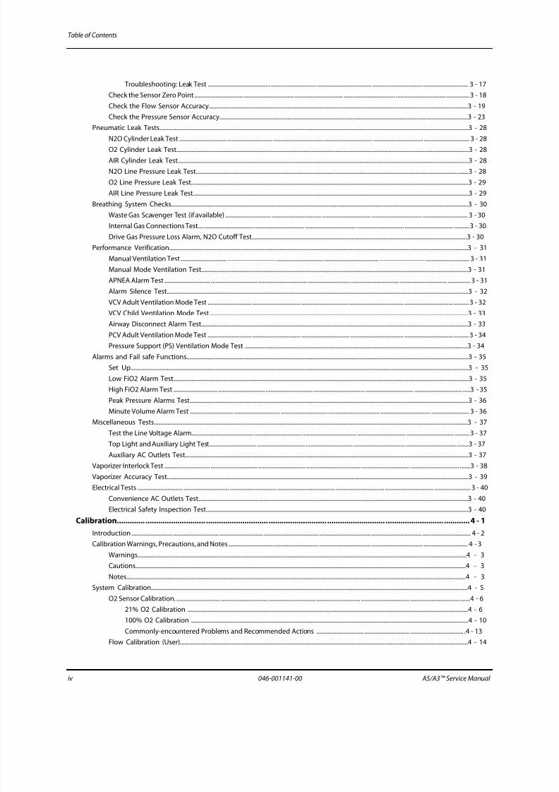
Periodic Maintenance............ ............................ ............................. ........................... ............................. .................... 3 - 1
Maintenance Schedule.........................................................................................................................................................................................................3 - 2
Periodical Maintenance Consumable Parts Kits..........................................................................................................................................................3 - 2
Periodical Maintenance Schedule....................................................................................................................................................................................3 - 2
Visual Inspection Checklist..................................................................................................................................................................................................3 - 3
List of Parts inside the Periodical Maintenance Consumable Parts Kits............ ................................ ................................... .............................. 3 - 4
Battery Maintenance and Replacement.........................................................................................................................................................................3 - 8
Functional Tests......................................................................................................................................................................................................................3 - 9Gas Delivery System Tests........................................................................................................................................................................................3 - 9
O2 Flush Verification ......................... ................................. .............................. ...................................... ................................ ........................ 3 - 9
O2:N2O Ratio System .....................................................................................................................................................................................3 - 9
Breathing System Leak Test.....................................................................................................................................................................................3 - 9
Breathing System Leak Test in Mechanical Ventilation Mode .................................... .................................... ................................ 3 - 10
Breathing System Leak Test in Manual Ventilation Mode ..................................... ...................................... .............................. .......3 - 14
Vaporizer Leak Test .........................................................................................................................................................................................3 - 16
Check Valve Test ..................................... .............................. ............................. ...................................... ............................... ......................... 3 - 17
7/21/2019 a5 a3 Service Manual 2013
http://slidepdf.com/reader/full/a5-a3-service-manual-2013 7/399
Table of Contents
iv 046-001141-00 A5/A3™ Service Manual
Troubleshooting: Leak Test ......................................... .............................. .................................... ................................. .............................. 3 - 17
Check the Sensor Zero Point ................................ ................................. ................................ .................................. ................................. ............... 3 - 18
Check the Flow Sensor Accuracy...........................................................................................................................................................................3 - 19
Check the Pressure Sensor Accuracy....................................................................................................................................................................3 - 23
Pneumatic Leak Tests............................................................................................................................................................................................................3 - 28
N2O Cylinder Leak Test ............................... .............................. ................................. ................................ ................................. .............................. 3 - 28O2 Cylinder Leak Test.................................................................................................................................................................................................3 - 28
AIR Cylinder Leak Test................................................................................................................................................................................................3 - 28
N2O Line Pressure Leak Test....................................................................................................................................................................................3 - 28
O2 Line Pressure Leak Test.......................................................................................................................................................................................3 - 29
AIR Line Pressure Leak Test......................................................................................................................................................................................3 - 29
Breathing System Checks....................................................................................................................................................................................................3 - 30
Waste Gas Scavenger Test (if available) .............................. ................................. ................................ ................................. .............................. 3 - 30
Internal Gas Connections Test.... ................................ ................................. .................................. ............................... ................................ ..........3 - 30
Drive Gas Pressure Loss Alarm, N2O Cutoff Test..............................................................................................................................................3 - 30
Performance Verification.....................................................................................................................................................................................................3 - 31
Manual Ventilation Test .............................. ................................ ............................... .................................... .............................. ............................. 3 - 31
Manual Mode Ventilation Test................................................................................................................................................................................3 - 31
APNEA Alarm Test .............................. ............................... ................................ ............................ ................................ ............................... ............... 3 - 31
Alarm Silence Test.......................................................................................................................................................................................................3 - 32
VCV Adult Ventilation Mode Test ............................. ................................ ............................... .................................... ................................ ..........3 - 32
VCV Child Ventilation Mode Test...........................................................................................................................................................................3 - 33
Airway Disconnect Alarm Test................................................................................................................................................................................3 - 33
PCV Adult Ventilation Mode Test ............................. ................................ ................................ ................................... ................................ ..........3 - 34
Pressure Support (PS) Ventilation Mode Test ...................................................................................................................................................3 - 34
Alarms and Fail safe Functions..........................................................................................................................................................................................3 - 35
Set Up...............................................................................................................................................................................................................................3 - 35
Low FiO2 Alarm Test...................................................................................................................................................................................................3 - 35
High FiO2 Alarm Test ............................. ............................... ............................... .................................. ................................ ............................... .....3 - 35
Peak Pressure Alarms Test........................................................................................................................................................................................3 - 36
Minute Volume Alarm Test ............................. .............................. ............................... .................................. ................................. ......................... 3 - 36
Miscellaneous Tests...............................................................................................................................................................................................................3 - 37
Test the Line Voltage Alarm......................................... ............................... .................................... ................................ ............................... ..........3 - 37
Top Light and Auxiliary Light Test............................... ................................ ............................... .................................. ................................. ........3 - 37
Auxiliary AC Outlets Test...........................................................................................................................................................................................3 - 37
Vaporizer Interlock Test .............................. ............................... ............................... .................................... ................................ ................................ .......3 - 38
Vaporizer Accuracy Test.......................................................................................................................................................................................................3 - 39
Electrical Tests .............................. .............................. ............................... ...................................... ................................ ................................ ........................ 3 - 40
Convenience AC Outlets Test..................................................................................................................................................................................3 - 40
Electrical Safety Inspection Test.............................................................................................................................................................................3 - 40
Calibration............. ............................ ............................. ........................... ........................... ........................... ............4 - 1
Introduction ........................... .............................. ............................. .................................... .................................. ................................. ................................ 4 - 2
Calibration Warnings, Precautions, and Notes .............................. ............................. .................................. .................................. ............................. 4 - 3
Warnings.........................................................................................................................................................................................................................4 - 3Cautions..........................................................................................................................................................................................................................4 - 3
Notes................................................................................................................................................................................................................................4 - 3
System Calibration.................................................................................................................................................................................................................4 - 5
O2 Sensor Calibration. ............................. ............................... ............................... ............................. ................................ ................................ .......4 - 6
21% O2 Calibration .........................................................................................................................................................................................4 - 6
100% O2 Calibration .......................................................................................................................................................................................4 - 10
Commonly-encountered Problems and Recommended Actions ............................... .............................. ................................... .4 - 13
Flow Calibration (User)..............................................................................................................................................................................................4 - 14

7/21/2019 a5 a3 Service Manual 2013
http://slidepdf.com/reader/full/a5-a3-service-manual-2013 8/399
A5/A3™ Service Manual 046-001141-00 v
Table of Contents
Flow Calibration (Service).........................................................................................................................................................................................4 - 17
Calibration Procedures..............................................................................................................................................................................................4 - 18
Auto Calibration ...............................................................................................................................................................................................4 - 18
Manual Calibration (software version 01.03.00 and higher) ............................................................................................................4 - 28
Commonly-encountered Problems and Recommended Actions ............................ ................................ ................................... .4 - 35
Pressure Calibration (Service) .............................. ................................. ................................ .................................... ............................... ............... 4 - 37Calibration Procedures ..................................................................................................................................................................................4 - 37
Commonly-encountered Problems and Recommended Actions ............................. ................................ ................................... .4 - 50
Pressure and Flow Zeroing (Service) ............................. ................................. .................................. ................................ ............................... .....4 - 52
Zeroing Procedures ................................................. ............................... ............................... ................................ ............................... ..........4 - 52
Troubleshoot Pressure and Flow Zeroing Failure ...................................... ................................ ...................................... .................... 4 - 55
Electronic Flowmeter Zeroing (user)....................................................................................................................................................................4 - 55
Zeroing Procedures ................................................. ............................... ................................. .............................. ................................. ........4 - 55
Troubleshoot Electronic Flowmeter Zeroing Failure ................................................... .................................. ................................ .....4 - 58
ORC Calibration............................................................................................................................................................................................................4 - 58
Cylinder Yoke Regulator Calibration............................. ............................... .................................... ................................ ............................... .....4 - 65
Repair and Troubleshooting................... ........................... .......................... ................................ ............................ ..5 - 1
Troubleshooting Guidelines............................... ............................... ................................ .................................... ................................ ............................. 5 - 2
Identify the problem ............................. .............................. ............................... ...................................... ................................ ................................. .5 - 2
Avoid shorting component leads together. ...................................... ................................ ................................ ................................. ............... 5 - 2
Use the proper equipment ............................. ............................. .............................. ...................................... ................................ ........................ 5 - 2
Clean up the repair area............................................................................................................................................................................................5 - 2
Technical Alarms Check .............................. ................................. ................................ ........................... ................................. ................................ ............5 - 3
Startup Alarm Messages ............................. .............................. ............................. ...................................... ................................ ............................. 5 - 4
CPU Board Runtime Alarm ............................ ................................ ............................... .................................... ................................ ........................ 5 - 6
Power Board Runtime Alarm...................................................................................................................................................................................5 - 6
Fresh Flow Sensor Board Alarm .............................. ................................ ............................... .................................. ................................. .............5 - 8
Ventilator Control Board Runtime Alarm............................................................................................................................................................5 - 9
Pneumatic Circuit System Problems. ............................. ............................. ............................... ....................................... ............................... ............... 5 - 11
Tools for on-site Maintenance................ ..................................... ................................. ................................ ................................. ......................... 5 - 11
Precautions for Use of Circuit Adapter Test Fixture ........ ................................. ................................... ............................... ................. 5 - 15Precautions for Use of Flow Sensor Pressure Sampling Pipeline Test Fixture ............ .................................. ............................. 5 - 17
Precautions for Use of Vaporizer Manifold Test Fixture ............................ .............................. .................................... ...................... 5 - 18
Precautions for Use of Negative Pressure Ball .......................................................................................................................................5 - 19
Gas Supplies and Drive Gas ............................ .............................. ............................... .................................... ............................... ......................... 5 - 20
Test the Pipeline Pressure Gauge and Correct the Regulator ...... .................................. ................................. ................................ 5 - 21
Test the Pressure Switch .............................. ................................. ................................ ................................ ............................... ................. 5 - 26
Adjust the Pressure Switch ...........................................................................................................................................................................5 - 28
Adjust the Regulator of the Pipeline Gas Supply Inlet Assembly ...................................................................................................5 - 28
Anesthetic Gas Delivery System.............................................................................................................................................................................5 - 29
Leak Test of the O2 Flush Button Assembly ...........................................................................................................................................5 - 30
Leak Test of the Flowmeter Related Assembly .....................................................................................................................................5 - 31
Leak Test of the System Switch Assembly ..............................................................................................................................................5 - 38
Leak Test of the Oxygen Ratio Controller (ORC) ...................................................................................................................................5 - 40Leak Test of the Vaporizer Manifold Assembly .....................................................................................................................................5 - 41
Breathing System ........................ ............................... ............................... .................................... .............................. ................................. ............... 5 - 44
Leak Test of Flow Sensor Pressure Sampling Pipeline .................................... ................................... .......................... ...................... 5 - 45
Leak Test of Low-pressure Pneumatic Circuit System ........................................................................................................................5 - 47
Tidal Volume .............................. ............................. ............................. ...................................... .............................. ................................. .................... 5 - 58
Sensors and Valves Problems ............................................................................................................................................................................................5 - 61
Correspondence with Pneumatic Circuit Components ................................................................................................................................5 - 61
Correspondence with Hardware Components ................................................................................................................................................5 - 61

7/21/2019 a5 a3 Service Manual 2013
http://slidepdf.com/reader/full/a5-a3-service-manual-2013 9/399
Table of Contents
vi 046-001141-00 A5/A3™ Service Manual
Preparations before Using Diagnostic Tests......................................................................................................................................................5 - 62
Zero Points of Flow & Pressure Sensors Problems ............................... ................................ ................................. ................................ ..........5 - 62
Connections and Measurement of the Flow Sensors Problems.................................................................................................................5 - 63
Connections and Measurement of the Pressure Sensors Problems ................................ .................................... .............................. .......5 - 64
Opening State of the Inspiratory Valve Problems ................................ .................................... ................................... ............................... .....5 - 65
Opening States of the PEEP Safety Valve Problems........................................................................................................................................5 - 65Opening State of the PEEP Valve Problems.......................................................................................................................................................5 - 66
Hardware and Electrical Problems....... ................................ ................................. .................................. ................................ ............................... ..........5 - 67
Software Update and Software Configuration Activation ............................ ................................... .................................. ................................ .....5 - 69
Repair and Disassembly ............................ ........................... ............................. ........................... ............................ ..6 - 1
Prepare for Disassembly ............................. ............................... ............................... .................................... ................................ ................................ .......6 - 2
Tools....... ............................... ............................. ............................. ..................................... ................................. ................................ ........................... 6 - 2
Preparations ............................. ............................... ............................. ....................................... ................................. ................................ ................. 6 - 2
Bleed Gas Pressure......................................................................................................................................................................................................6 - 2
Disassemble the Assemblies......... ............................... ............................... ..................................... ................................. .............................. ................... 6 - 3
Disassemble the Internal Assemblies of the Machine Upper Half.............................................................................................................6 - 3
Open the Service Door ........... ............................... .............................. ............................... .................................. .................................. .......6 - 3
Remove the Gas Supply Inlet Assembly ..................................................................................................................................................6 - 3
Remove the Pressure Regulator Assembly .............................................................................................................................................6 - 4
Remove the Electronic Flowmeter Assembly ........................................................................................................................................6 - 4
Remove the Poppet Valve Assembly ........................................................................................................................................................6 - 5
Remove the Gas Mixer Assembly ...............................................................................................................................................................6 - 5
Remove the ORC Assembly ..........................................................................................................................................................................6 - 6
Remove the Back Pressure Valve Assembly ...........................................................................................................................................6 - 6
Replace the Lithium-ion battery ................... .............................. ............................... ....................................... ................................. ........6 - 7
Remove the Vaporizer Manifold .................................................................................................................................................................6 - 7
Disassemble Hardware Box ............................. ............................... ............................... .................................. ................................ ........................ 6 - 8
Remove the Top Plate of the Hardware Box ..........................................................................................................................................6 - 8
Remove the CPU Board ................. ................................ ............................... .................................... ................................ ............................. 6 - 9
Remove the Ventilator Control Board ......................................................................................................................................................6 - 9
Remove the Power Board .............................................................................................................................................................................6 - 10Remove the Solenoid Valve Assembly .....................................................................................................................................................6 - 10
Remove the Speaker .......................................................................................................................................................................................6 - 11
Disassemble the Rear Panel Assembly ................................ ................................. ................................... ................................. ............... 6 - 12
Disassemble the Work Surface ............................ ............................... ............................. .................................... ............................... .................... 6 - 16
Remove the Drawer Assembly ....................................................................................................................................................................6 - 16
Remove the Work Surface Cover Plate ................................ ................................. ................................... ................................. ............... 6 - 17
Remove the Metal Cover Plate . ................................. .............................. ............................... ...................................... .............................. 6 - 18
Remove the Rear Panel Assembly .............. ............................... .............................. .................................. ................................. ............... 6 - 18
Remove the Expiration Valve Assembly ..................................................................................................................................................6 - 20
Remove the O2 Flush Assembly .................................................................................................................................................................6 - 21
Remove the Touch Panel (A5 Only) . .............................. ............................. ............................... ...................................... ......................... 6 - 22
Remove the Common Gas Outlet Assembly . ................................ ................................. ................................... ............................... .....6 - 23
Remove the Cylinder Bracket Assembly ..................................................................................................................................................6 - 23Disassemble the Display...........................................................................................................................................................................................6 - 24
Remove the Alarm Lamp Board . ................................ ................................. .............................. ................................... .............................. 6 - 25
Remove the Display Adaptation Board ......... .................................... ................................ ................................. ................................ .....6 - 25
Remove the Touch Screen Control Board .............................. .............................. .................................. ................................. ............... 6 - 26
Remove the Backlight Inverter Board .. ................................ ................................. ................................... ................................. ............... 6 - 27
Remove the Needle Valve Assemblies .....................................................................................................................................................6 - 28
Remove the Touch Screen ....... ............................... ............................... ............................... ................................... ............................... .....6 - 29
Remove the Display Replacement Package ...........................................................................................................................................6 - 31
7/21/2019 a5 a3 Service Manual 2013
http://slidepdf.com/reader/full/a5-a3-service-manual-2013 10/399
A5/A3™ Service Manual 046-001141-00 vii
Table of Contents
Remove the Panel of Pressure Gauges ............................... .............................. .................................... ................................. .............................. 6 - 31
Remove the Pressure Gauges ..... ............................... .............................. ............................... ...................................... .............................. 6 - 32
Remove the Total Flowmeter ......................................................................................................................................................................6 - 33
Remove the System Switch ..........................................................................................................................................................................6 - 33
Remove the Indicator Light Board .... ........................................ ................................ ................................ ................................. ............... 6 - 34
Remove the Auxiliary Gas Outlet Assembly.......................................................................................................................................................6 - 34Remove the Rotating Block of Breathing Circle .................................... ................................ ................................. ................................ ..........6 - 35
Remove the AGSS Assembly ............................... ............................. ............................. ..................................... ................................. .................... 6 - 35
Disassemble the Base Assembly..... ................................ ................................. .................................. ................................ ............................... .....6 - 36
Remove the Caster Assembly ......................................................................................................................................................................6 - 36
Remove the Brake Indicator Drive Plate I and II (A5 Only) ................................................................................................................6 - 37
Remove the Brake Assembly (A5 Only) ............................ ................................ .................................. ............................... ...................... 6 - 38
Remove the Brake Main Axis (A5 Only) ....................................................................................................................................................6 - 38
Remove the Principal Axis of Brake (A5 Only) .......................................................................................................................................6 - 39
Disassemble the Breathing System ................................ .................................. ............................... ................................ ................................... .............6 - 40
Remove the O2 Sensor and Cable.........................................................................................................................................................................6 - 40
Remove the Breathing Tubes..................................................................................................................................................................................6 - 40
Remove the Flow Sensor ............................... ............................... .............................. .................................... ................................. ......................... 6 - 41
Remove the Manual Bag...........................................................................................................................................................................................6 - 43
Remove the Absorbent Canister............................................................................................................................................................................6 - 43
Remove the CO2 Bypass Assembly.......................................................................................................................................................................6 - 44
Remove the drain valve.............................................................................................................................................................................................6 - 45
Remove the Bypass Valve And the Trigger Board ............................ ............................... ...................................... .............................. ............6 - 46
Remove the Patient Circle Assembly....................................................................................................................................................................6 - 48
Remove the Bellows Assembly...............................................................................................................................................................................6 - 49
Remove the Pop-off Valve Assembly ........................... ................................ ............................... ..................................... ............................... .....6 - 50
Disassemble the Expiratory/Inspiratory Check Valve Assemblies ................................ ................................. ................................ ............6 - 51
Remove the Water Collection Cup........................................................................................................................................................................6 - 52
Remove the Airway Pressure Gauge ............................... ............................... ............................... ................................... ............................... .....6 - 53
Remove the Bag Arm ............................. ............................. ............................. ...................................... ................................ ............................... .....6 - 53
Remove the Back Upper Cover and Back Lower Cover Assemblies..........................................................................................................6 - 54
Remove the Front Upper Cover, Median Plate and Front Lower Cover Assemblies ................................. .................................. .......6 - 56
Disassemble the Automatic/Manual Ventilation Switch Assembly..........................................................................................................6 - 59
Remove the APL Valve Assembly ............................. ............................. .............................. .................................. ................................. ............... 6 - 61
Replacement Parts... ............................ ............................. ........................... ............................. .......................... ........7 - 1
Introduction ........................... .............................. ............................. .................................... .................................. ................................. ................................ 7 - 2
Ordering Replaceable Parts ............................ ............................. .............................. ...................................... ................................ ........................ 7 - 2
Diagrams and Tables..................................................................................................................................................................................................7 - 3
A5/A3 Structure ................................................................................................................................................................................................7 - 3
A5/A3 Upper Half .............................................................................................................................................................................................7 - 5
A5/A3 Hardware Box .............................. ............................... ............................. .................................. .................................. ........................ 7 - 6
A5/A3 Work Surface ........................................................................................................................................................................................7 - 7
A5/A3 Patient Circuit Main Body ................................................................................................................................................................7 - 8
A5/A3 Pre-pak Absorber Canister Assembly ............................ ................................ ................................... ................................ ..........7 - 9A5/A3 Valve assembly ....................................................................................................................................................................................7 - 10
A5/A3 O2 Cable Assembly ............................................................................................................................................................................7 - 11
A5/A3 Display Assembly ..................................... ............................... ............................. ..................................... ............................... ..........7 - 12
A5/A3 Display Assembly Main Body .........................................................................................................................................................7 - 13
A5/A3 Vaporizer Mounting Minifold ........... ................................ ................................ ................................... ................................ ..........7 - 14
A5/A3 Auxiliary Gas Outlet Assembly ................. ............................... ................................ ................................. ................................ .....7 - 15
Base Assembly (A5) .........................................................................................................................................................................................7 - 16
Other ....................................................................................................................................................................................................................7 - 17

7/21/2019 a5 a3 Service Manual 2013
http://slidepdf.com/reader/full/a5-a3-service-manual-2013 11/399
Table of Contents
viii 046-001141-00 A5/A3™ Service Manual
Tubes (A5/A3) .......................... ................................. ................................ .......................... ................................ .................................. ............7 - 18
O-rings (A5/A3) .................................................................................................................................................................................................7 - 19
Yellow Number Rings (A5/A3) ........... ................................ ............................... ................................ ................................. ......................... 7 - 19
Cables ...................................................................................................................................................................................................................7 - 20
Warranty... .......................... ............................. .......................... ............................. ........................... .......................... 8 - 1
Warranty Statements ................................ ................................ ................................. .................................... ................................ ................................ .......8 - 2
Disclaimers................................................................................................................................................................................................................................8 - 3
Manufacturer's Responsibility .................................. ................................ ................................. .............................. .................................. ........................ 8 - 3
Phone Numbers and How to Get Assistance................................................................................................................................................................8 - 3
7/21/2019 a5 a3 Service Manual 2013
http://slidepdf.com/reader/full/a5-a3-service-manual-2013 12/399
A5/A3™ Service Manual 046-001141-00 ix
Foreword Introduction
Foreword
This Service Manual is intended as a guide for technically qualified personnel performing repair and
calibration procedures.
Warnings, Cautions, and Notes
Please read and adhere to all warnings, cautions, and notes listed here and in the appropriate areas
throughout this manual.
A WARNING is provided to alert the user to potential serious outcomes (death, injury, or serious
adverse events) to the patient or the user.
A CAUTION is provided to alert the user to use special care necessary for the safe and effective use of
the device. They may include actions to be taken to avoid effects on patients or users that may not be
potentially life threatening or result in serious injury, but about which the user should be aware.
Cautions are also provided to alert the user to adverse effects on this device of use or misuse and thecare necessary to avoid such effects.
A NOTE is provided when additional general information is applicable.
Warnings
WARNING: Whenever using anesthetic gases, nitrous oxide, oxygen, orany hospital gas, always follow the appropriate agentevacuation/collection procedures. Use the hospital gasevacuation system.
WARNING: Use only an approved lubricant on any O-ring in contact
with oxygen. Krytox® is the recommended oxygen servicelubricant.
WARNING: For continued protection against fire hazard, replace allfuses with the specified type and rating.
WARNING: In order to prevent an electric shock, the machine(protection class I) may only be connected to a correctlygrounded mains connection (socket outlet with groundingcontact).
WARNING: Remove all accessory equipment from the shelf beforemoving the anesthesia machine over bumps or on anyinclined surface. Heavy top loading can cause the machineto tip over causing injury.
WARNING: Possible explosion hazard. Do not operate machine nearflammable anesthetic agents or other flammablesubstances. Do not use flammable anesthetic agents (e.g.,ether or cyclopropane.)
7/21/2019 a5 a3 Service Manual 2013
http://slidepdf.com/reader/full/a5-a3-service-manual-2013 13/399
Introduction Cautions
x 046-001141-00 A5/A3™ Service Manual
WARNING: The use of anti-static or electrically conductive respirationtubes, when utilizing high frequency electric surgeryequipment, may cause burns and is therefore notrecommended in any application of this machine.
WARNING: Possible electric shock hazard. The machine may only be
opened by authorized service personnel.
WARNING: Compressed gasses are considered Dangerous Goods/Hazardous Materials per I.A.T.A (International Air Transport Association). and D.O.T. (Department Of Transport)regulations. It is a violation of federal and international lawto transport dangerous goods without the packages beingappropriately identified, packed, marked, classified,labeled and documented according to D.O.T. and I.A.T.A.regulations. Please refer to the applicable I.A.T.A.Dangerous Goods Regulations and /or the Code of FederalRegulations 49 (Transportation, Parts 171-180) for furtherinformation.
WARNING: Avoid exposure to respiratory gases by always directing
the fresh gas flow from the fresh gas outlet to the waste gasscavenger.
Cautions
CAUTION: This device uses high pressure compressed gas. When attaching or
disconnecting backup gas cylinders, always turn the cylinder valves
slowly. Use the A5/A3 flow meters to bleed down the pressure,
watching the cylinder gauge indicate the depleting cylinder pressure,
before disconnecting the cylinder from the yoke. Always open and
close cylinder valves fully.
CAUTION: This device operates using compressed gas at high pressures from the
hospital central supply. When connecting gas supply lines attach the
hose connection to the machine before connecting the quickdisconnect fitting to the hospital source. Disconnect the supply hose
from the hospital source connection prior to disconnecting it from the
A5/A3 gas connection fittings.
CAUTION: Refer to section 3.3 Periodical Maintenance Schedule for assistance
when performing scheduled periodic maintenance.
CAUTION: Do not leave gas cylinder valves open if the pipeline supply is in use
and the system master switch is turned to 'ON'. If used simultaneously,
cylinder supplies could be depleted, leaving an insufficient reserve
supply in the event of pipeline failure.
CAUTION: Use cleaning agent sparingly. Excess fluid could enter the machine,
causing damage.
CAUTION: This machine must only be operated by trained, skilled medical staff.
CAUTION: Perform the electrical safety inspection as the last step after
completing a repair or after routine maintenance. Perform this
inspection with all covers, panels, and screws installed.
CAUTION: After changing the CO2 absorbent, carry out a system leak test.

7/21/2019 a5 a3 Service Manual 2013
http://slidepdf.com/reader/full/a5-a3-service-manual-2013 14/399
A5/A3™ Service Manual 046-001141-00 xi
Notes Introduction
CAUTION: Only Selectatec™ compatible vaporizers with Interlock-System may be
used with the A5/A3 unit.
CAUTION: After each exchange of a vaporizer, carry out a system Leak test.
CAUTION: Do not clean the machine while it is on and/or plugged in.
CAUTION: Pressing "cancel" at any time during the procedure will cancel the
session's settings and reload the previously-stored calibration
coefficients.
CAUTION: Depleted sodalime changes color. Replace the sodalime if
approximately 2/3 of the absorber content is discolored. CO2 absorbent
can be safely changed without stopping mechanical ventilation.
CAUTION: This equipment contains parts sensitive to damage by electrostatic
discharge (ESD). Use ESD precautionary procedures when touching,
removing, or inserting parts or assemblies.
Notes
NOTE: Unauthorized servicing may void the remainder of the warranty. Check
with the factory or with a local authorized distributor to determine the
warranty status of a particular instrument.

7/21/2019 a5 a3 Service Manual 2013
http://slidepdf.com/reader/full/a5-a3-service-manual-2013 15/399
Introduction Notes
xii 046-001141-00 A5/A3™ Service Manual
This page intentionally left blank.

7/21/2019 a5 a3 Service Manual 2013
http://slidepdf.com/reader/full/a5-a3-service-manual-2013 16/399
A5/A3™ Service Manual 046-001141-00 1 - 1
1.0 Theory of Operation
Introduction.................................................................................................................................................................................................1-2
Electrical and Pneumatic Connections.......................................................................................................................................1-4
Gas Flow ......................................................................................................................................................................................................1-16
Anesthesia System Components.................................................................................................................................................1-31
The Breathing System.........................................................................................................................................................................1-34
Ventilator UI...............................................................................................................................................................................................1-39
Ventilator Control and Drive ...........................................................................................................................................................1-39
Ventilator Pneumatic- O2 Drive Gas...........................................................................................................................................1-66

7/21/2019 a5 a3 Service Manual 2013
http://slidepdf.com/reader/full/a5-a3-service-manual-2013 17/399
Introduction Theory of Operation
1 - 2 046-001141-00 A5/A3™ Service Manual
1.1 Introduction
The A5/A3 Anesthesia System is a continuous flow inhalation gas anesthesia system that delivers
anesthetic vapor, and provides for automatic and manual modes of ventilation. It is equipped with a
monitoring system for ventilation, inspired, and expired gas. The A5/A3 is intended for use inoperating rooms. It will be used with O2, N2O, and AIR supplied by a medical gas pipeline system or
by externally mounted gas cylinders. Anesthetic agents can be delivered via vaporizers mounted on
the machine.
The A5 ventilator provides the following ventilation modes:
• Volume Control Ventilation (VCV), which includes the Pressure Limit Ventilation (PLV) function
• Pressure Control Ventilation (PCV) with/without Volume Guarantee (VG) ventilation mode
• Synchronized Intermittent Mandatory Ventilation (SIMV) with VC mode
• Synchronized Intermittent Mandatory Ventilation (SIMV) with PC mode
• Pressure Support (PS) ventilation mode
• Spontaneous ventilation in Manual mode with APL fully open
• Manual ventilation through the use of a breathing bag
The A3 ventilator provides the following ventilation modes:
• Volume Control Ventilation (VCV), which includes the Pressure Limit Ventilation (PLV) function
• Pressure Control Ventilation (PCV)
• Synchronized Intermittent Mandatory Ventilation (SIMV) with VC mode
• Pressure Support (PS) ventilation mode
• Spontaneous ventilation in Manual mode with APL fully open
• Manual ventilation through the use of a breathing bag
Electronic PEEP is available in all ventilation modes. User control over inspiratory flow (Tslope) is
possible in PCV, SIMV, and PS modes. Automatic fresh gas compensation limits the effect on the
patient ventilation from changes in fresh gas flow rate by the operator. The traditional bellows system
is driven by oxygen and makes patient disconnections clearly visible.
The A5/A3 fresh gas dosing subsystem offers the ease of use and features of a traditional anesthesia
system. The dual-flow tubes electronic flowmeter, which includes redundant numerical readouts,
displays the O2, N2O, and Air flows at all times. A knob guard prevents inadvertent movement of the
flow control knobs. Gas supply gauges and auxiliary O2/Air flowmeters with blended output indicate
the gas pipeline supply pressures and gas cylinder pressures. An auxiliary O2 flowmeter is placed at a
convenient location for the operator. The O2 flush button is in the traditional location near the front
left corner of the table top.
Safety systems within the A5/A3 work to prevent hypoxic mixtures from being delivered to the
patient. Nitrous oxide will not be delivered unless oxygen pressure is present. A pneumatic safety
system assures that at least 21% O2 is present when setting mixtures of O2 and N2O.

7/21/2019 a5 a3 Service Manual 2013
http://slidepdf.com/reader/full/a5-a3-service-manual-2013 18/399
A5/A3™ Service Manual 046-001141-00 1 - 3
Theory of Operation Introduction
The A5/A3 breathing system is warmed to minimize condensation inside the breathing system block
and to return humid gas to the patient. The breathing system provides easy access to the Airway
Pressure Limiting (APL) valve and breathing bag, and easy viewing of the Airway Pressure gauge
(PAW). The APL valve has a comfortable, single turn knob that provides a clear view of the manual
breathing pressure setting. The absorber assembly incorporates a cam lock device that is convenientto open and close. CO2 absorbent Pre-paks or loose fill can be used. A water trap that can be drained
is also provided on the absorber assembly.
Two flow sensors in the breathing system measure inspired and expired gases for control and
monitoring. Spirometry is standard on the A5. Inspired oxygen is monitored via a fuel-cell type sensor.
Breathing pressure is also monitored. The breathing system can swivel into position. A test plug, next
to the two main hose connections, allows automated leak testing during startup. The Anesthesia Gas
Scavenging System (AGSS) connections are at the rear of A5/A3.
The A5/A3 is powered by an AC power source. In turn, the A5/A3 power management system
provides DC power for its main system functions while charging its internal battery supply. In case of
AC power failure, the A5/A3 operates on battery power for a minimum of 75 minutes with one (1)new battery installed (A3) or 150 minutes with two (2) new batteries installed (A5). A recessed main
switch is provided to power the system ON and OFF. Four (4) auxiliary AC outlets on the A5 and three
(3) auxiliary AC outlets on the A3 at the rear of the machine operate independently of the main
switch position.
NOTE: The breathing system warmer does not operate when the A5/A3 is on
battery power.
NOTE: If the main switch is set to OFF, the O2 fresh gas flow will not flow.
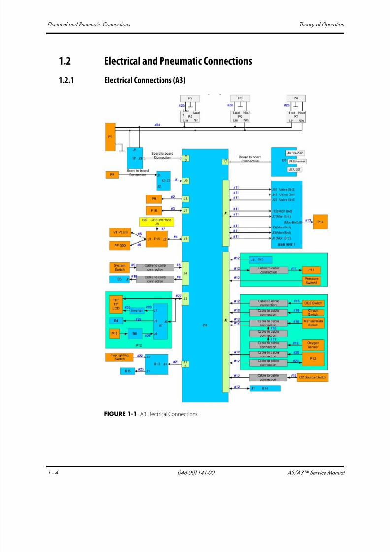
7/21/2019 a5 a3 Service Manual 2013
http://slidepdf.com/reader/full/a5-a3-service-manual-2013 19/399
Electrical and Pneumatic Connections Theory of Operation
1 - 4 046-001141-00 A5/A3™ Service Manual
1.2 Electrical and Pneumatic Connections
1.2.1 Electrical Connections (A3)
FIGURE 1-1 A3 Electrical Connections

7/21/2019 a5 a3 Service Manual 2013
http://slidepdf.com/reader/full/a5-a3-service-manual-2013 20/399
A5/A3™ Service Manual 046-001141-00 1 - 5
Theory of Operation Electrical and Pneumatic Connections
No. Description P/N
B1 Power Board 801-0631-00025-00
B2 Battery Interface Board 801-0631-00109-00
B3 Mother Board 801-0631-00108-00
B4 Warning Light Board 801-0631-00019-00
B5 Indicator Light Board 801-0631-00004-00
B6 Touch Screen Control Board 801-0631-00018-00
B7 Display Interface Board 801-0631-00017-00
B8 A3 CPU Board 801-0633-00004-00
B9-11 Ventilator Control Board 801-0631-00027-00
B12 Sensor Interface board 801-0631-00089-00
B13 Top Lighting Board 801-0631-00039-00
B14 Fresh Flow Sensor Board 801-0631-00040-00
B15 Flow Meter Lighting Board 801-0631-00002-00
P1 Filter Power 250VAC 15A Panel Mount 801-0631-00029-00
P2-4 Auxiliary Output Socket 801-0631-00032-00
P5-7 Breaker (3.0A) 801-0631-00031-00
P8 Lithium-ion Battery 022-000008-00
P9 Speaker and Connecting Cable 801-0631-00038-00
P10 Fan 801-0631-00028-00
P11 Main Body of Drive Gas Assembly 801-0631-00088-00
P12 Display Exchange Package 801-0631-00075-00
P13 Circuit Heater 801-0631-00069-00
P14 Solenoid valve assembly 801-0631-00046-00
P15 A5 Calibration set FRU 801-0631-00121-00
P16 Touch Screen 801-0631-00014-00

7/21/2019 a5 a3 Service Manual 2013
http://slidepdf.com/reader/full/a5-a3-service-manual-2013 21/399
Electrical and Pneumatic Connections Theory of Operation
1 - 6 046-001141-00 A5/A3™ Service Manual
1.2.2 Electrical Connections (A5)
FIGURE 1-2 A5 Electrical Connections

7/21/2019 a5 a3 Service Manual 2013
http://slidepdf.com/reader/full/a5-a3-service-manual-2013 22/399
A5/A3™ Service Manual 046-001141-00 1 - 7
Theory of Operation Electrical and Pneumatic Connections
No. Description P/N
B1 Power Board 801-0631-00025-00
B2 Battery Interface Board 801-0631-00109-00
B3 Mother Board 801-0631-00108-00
B4 Warning Light Board 801-0631-00019-00
B5 Indicator Light Board 801-0631-00004-00
B6 Touch Screen Control Board 801-0631-00018-00
B7 Display Interface Board 801-0631-00017-00
B8 A5 CPU Board PCBA 801-0631-00026-00
B9-11 Ventilator Control Board 801-0631-00027-00
B12 Sensor Interface board 801-0631-00089-00
B13 Top Lighting Board 801-0631-00039-00
B14 Fresh Flow Sensor Board 801-0631-00040-00
B15 Flow Meter Lighting Board 801-0631-00002-00
P1 Filter Power 250VAC 15A Panel Mount 801-0631-00029-00
P2 Breaker (10.0A) 801-0631-00030-00
P3-6 Auxiliary Output Socket 801-0631-00032-00
P7-10 Breaker (3.0A) 801-0631-00031-00
P11-12 Lithium-ion Battery 022-000008-00
P13 Speaker and Connecting Cable 801-0631-00038-00
P14 Fan 801-0631-00028-00
P15 Touchpad 801-0631-00052-00
P16 Main Body of Drive Gas Assembly 801-0631-00088-00
P17 Display Exchange Package 801-0631-00075-00
P18 Circuit Heater 801-0631-00069-00
P19 Solenoid valve assembly 801-0631-00046-00
P20 A5 calibration set FRU 801-0631-00121-00
P21 Touch Screen 801-0631-00014-00

7/21/2019 a5 a3 Service Manual 2013
http://slidepdf.com/reader/full/a5-a3-service-manual-2013 23/399
Electrical and Pneumatic Connections Theory of Operation
1 - 8 046-001141-00 A5/A3™ Service Manual
1.2.3 Pneumatic Connections (A3)
FIGURE 1-3 A3 Pneumatic Connections
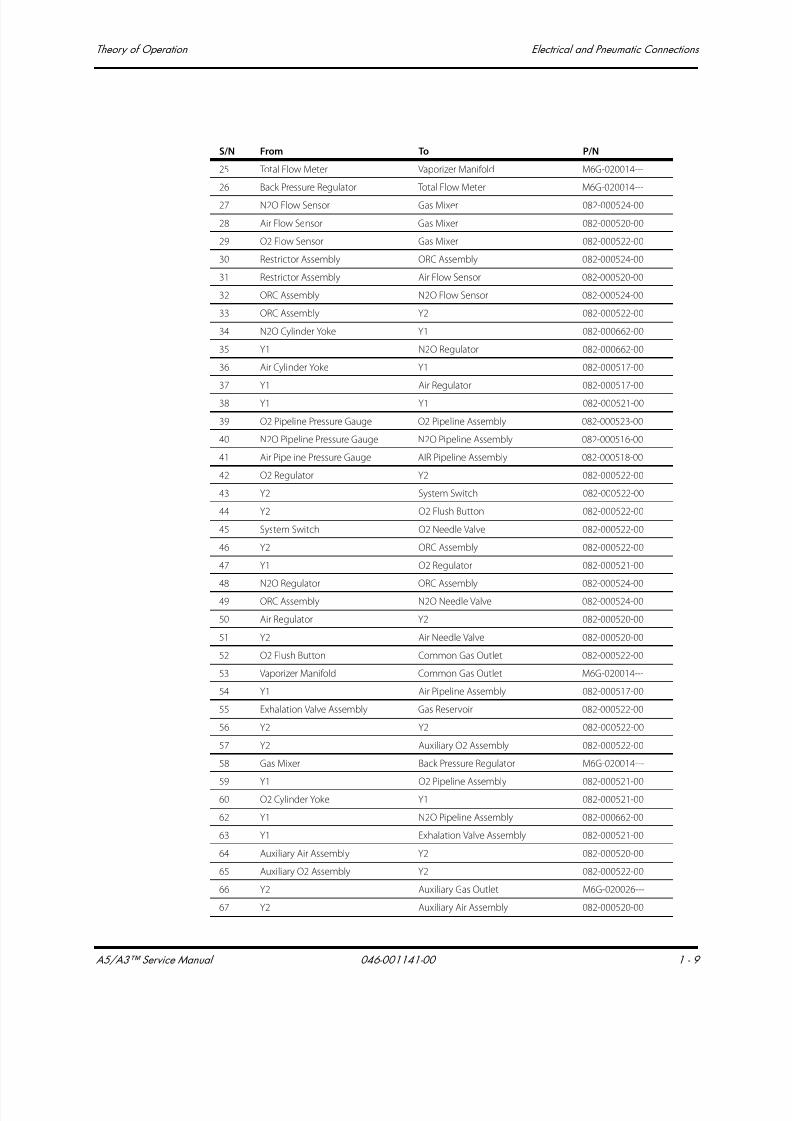
7/21/2019 a5 a3 Service Manual 2013
http://slidepdf.com/reader/full/a5-a3-service-manual-2013 24/399
A5/A3™ Service Manual 046-001141-00 1 - 9
Theory of Operation Electrical and Pneumatic Connections
S/N From To P/N
25 Total Flow Meter Vaporizer Manifold M6G-020014---
26 Back Pressure Regulator Total Flow Meter M6G-020014---
27 N2O Flow Sensor Gas Mixer 082-000524-00
28 Air Flow Sensor Gas Mixer 082-000520-00
29 O2 Flow Sensor Gas Mixer 082-000522-00
30 Restrictor Assembly ORC Assembly 082-000524-00
31 Restrictor Assembly Air Flow Sensor 082-000520-00
32 ORC Assembly N2O Flow Sensor 082-000524-00
33 ORC Assembly Y2 082-000522-00
34 N2O Cylinder Yoke Y1 082-000662-00
35 Y1 N2O Regulator 082-000662-00
36 Air Cylinder Yoke Y1 082-000517-00
37 Y1 Air Regulator 082-000517-00
38 Y1 Y1 082-000521-00
39 O2 Pipeline Pressure Gauge O2 Pipeline Assembly 082-000523-00
40 N2O Pipeline Pressure Gauge N2O Pipeline Assembly 082-000516-00
41 Air Pipeline Pressure Gauge AIR Pipeline Assembly 082-000518-00
42 O2 Regulator Y2 082-000522-00
43 Y2 System Switch 082-000522-00
44 Y2 O2 Flush Button 082-000522-00
45 System Switch O2 Needle Valve 082-000522-00
46 Y2 ORC Assembly 082-000522-00
47 Y1 O2 Regulator 082-000521-00
48 N2O Regulator ORC Assembly 082-000524-00
49 ORC Assembly N2O Needle Valve 082-000524-00
50 Air Regulator Y2 082-000520-00
51 Y2 Air Needle Valve 082-000520-00
52 O2 Flush Button Common Gas Outlet 082-000522-00
53 Vaporizer Manifold Common Gas Outlet M6G-020014---
54 Y1 Air Pipeline Assembly 082-000517-00
55 Exhalation Valve Assembly Gas Reservoir 082-000522-00
56 Y2 Y2 082-000522-00
57 Y2 Auxiliary O2 Assembly 082-000522-00
58 Gas Mixer Back Pressure Regulator M6G-020014---
59 Y1 O2 Pipeline Assembly 082-000521-0060 O2 Cylinder Yoke Y1 082-000521-00
62 Y1 N2O Pipeline Assembly 082-000662-00
63 Y1 Exhalation Valve Assembly 082-000521-00
64 Auxiliary Air Assembly Y2 082-000520-00
65 Auxiliary O2 Assembly Y2 082-000522-00
66 Y2 Auxiliary Gas Outlet M6G-020026---
67 Y2 Auxiliary Air Assembly 082-000520-00

7/21/2019 a5 a3 Service Manual 2013
http://slidepdf.com/reader/full/a5-a3-service-manual-2013 25/399
Electrical and Pneumatic Connections Theory of Operation
1 - 10 046-001141-00 A5/A3™ Service Manual
73 O2 Needle Valve Y2 082-000522-00
74 Y2 Y2 082-000522-00
75 O2 Poppet Valve Y2 082-000522-00
76 O2 Poppet Valve Y2 082-000522-00
77 Y2 O2 Poppet Valve 082-000522-00
78 Y2 O2 Flow Sensor 082-000522-00
79 Y1 O2 Pipeline Assembly 082-000521-00
81 Y1 Y1 082-000521-00
90 Air Needle Valve Restrictor Assembly 082-000520-00
91 N2O Needle Valve Restrictor Assembly 082-000524-00
Y1 Three-way Connector 082-000583-00
Y2 Three-way Connector 082-000582-00
S/N From To P/N

7/21/2019 a5 a3 Service Manual 2013
http://slidepdf.com/reader/full/a5-a3-service-manual-2013 26/399
A5/A3™ Service Manual 046-001141-00 1 - 11
Theory of Operation Electrical and Pneumatic Connections
1.2.4 Pneumatic Connection (A5)
FIGURE 1-4 A5 Pneumatic Connections
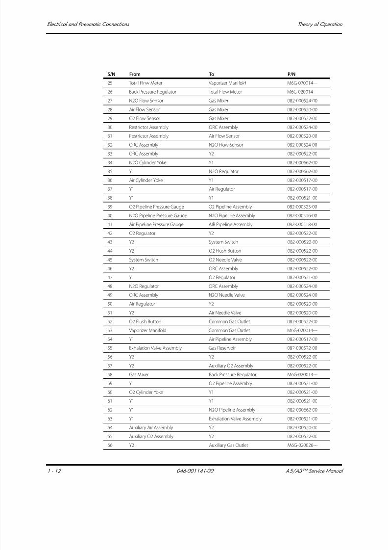
7/21/2019 a5 a3 Service Manual 2013
http://slidepdf.com/reader/full/a5-a3-service-manual-2013 27/399
Electrical and Pneumatic Connections Theory of Operation
1 - 12 046-001141-00 A5/A3™ Service Manual
S/N From To P/N
25 Total Flow Meter Vaporizer Manifold M6G-020014---
26 Back Pressure Regulator Total Flow Meter M6G-020014---
27 N2O Flow Sensor Gas Mixer 082-000524-00
28 Air Flow Sensor Gas Mixer 082-000520-00
29 O2 Flow Sensor Gas Mixer 082-000522-00
30 Restrictor Assembly ORC Assembly 082-000524-00
31 Restrictor Assembly Air Flow Sensor 082-000520-00
32 ORC Assembly N2O Flow Sensor 082-000524-00
33 ORC Assembly Y2 082-000522-00
34 N2O Cylinder Yoke Y1 082-000662-00
35 Y1 N2O Regulator 082-000662-00
36 Air Cylinder Yoke Y1 082-000517-00
37 Y1 Air Regulator 082-000517-00
38 Y1 Y1 082-000521-00
39 O2 Pipeline Pressure Gauge O2 Pipeline Assembly 082-000523-00
40 N2O Pipeline Pressure Gauge N2O Pipeline Assembly 082-000516-00
41 Air Pipeline Pressure Gauge AIR Pipeline Assembly 082-000518-00
42 O2 Regulator Y2 082-000522-00
43 Y2 System Switch 082-000522-00
44 Y2 O2 Flush Button 082-000522-00
45 System Switch O2 Needle Valve 082-000522-00
46 Y2 ORC Assembly 082-000522-00
47 Y1 O2 Regulator 082-000521-00
48 N2O Regulator ORC Assembly 082-000524-00
49 ORC Assembly N2O Needle Valve 082-000524-00
50 Air Regulator Y2 082-000520-00
51 Y2 Air Needle Valve 082-000520-00
52 O2 Flush Button Common Gas Outlet 082-000522-00
53 Vaporizer Manifold Common Gas Outlet M6G-020014---
54 Y1 Air Pipeline Assembly 082-000517-00
55 Exhalation Valve Assembly Gas Reservoir 082-000522-00
56 Y2 Y2 082-000522-00
57 Y2 Auxiliary O2 Assembly 082-000522-00
58 Gas Mixer Back Pressure Regulator M6G-020014---
59 Y1 O2 Pipeline Assembly 082-000521-0060 O2 Cylinder Yoke Y1 082-000521-00
61 Y1 Y1 082-000521-00
62 Y1 N2O Pipeline Assembly 082-000662-00
63 Y1 Exhalation Valve Assembly 082-000521-00
64 Auxiliary Air Assembly Y2 082-000520-00
65 Auxiliary O2 Assembly Y2 082-000522-00
66 Y2 Auxiliary Gas Outlet M6G-020026---
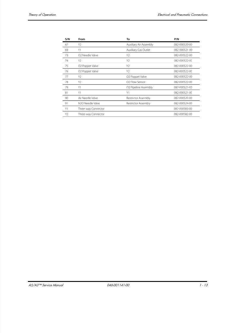
7/21/2019 a5 a3 Service Manual 2013
http://slidepdf.com/reader/full/a5-a3-service-manual-2013 28/399
A5/A3™ Service Manual 046-001141-00 1 - 13
Theory of Operation Electrical and Pneumatic Connections
67 Y2 Auxiliary Air Assembly 082-000520-00
69 Y1 Auxiliary Gas Outlet 082-000521-00
73 O2 Needle Valve Y2 082-000522-00
74 Y2 Y2 082-000522-00
75 O2 Poppet Valve Y2 082-000522-00
76 O2 Poppet Valve Y2 082-000522-00
77 Y2 O2 Poppet Valve 082-000522-00
78 Y2 O2 Flow Sensor 082-000522-00
79 Y1 O2 Pipeline Assembly 082-000521-00
81 Y1 Y1 082-000521-00
90 Air Needle Valve Restrictor Assembly 082-000520-00
91 N2O Needle Valve Restrictor Assembly 082-000524-00
Y1 Three-way Connector 082-000583-00
Y2 Three-way Connector 082-000582-00
S/N From To P/N
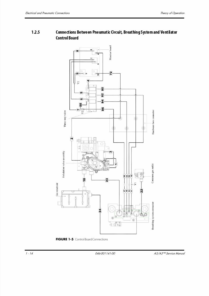
7/21/2019 a5 a3 Service Manual 2013
http://slidepdf.com/reader/full/a5-a3-service-manual-2013 29/399
Electrical and Pneumatic Connections Theory of Operation
1 - 14 046-001141-00 A5/A3™ Service Manual
1.2.5 Connections Between Pneumatic Circuit, Breathing System and Ventilator
Control Board
FIGURE 1-5 Control Board Connections

7/21/2019 a5 a3 Service Manual 2013
http://slidepdf.com/reader/full/a5-a3-service-manual-2013 30/399
A5/A3™ Service Manual 046-001141-00 1 - 15
Theory of Operation Electrical and Pneumatic Connections
S/N From To P/N
1 Exhalation Gas Assembly Flow Sensor connector A21-000007---
2 Exhalation Gas Assembly Hardware Box Connector A21-000007---
3 Exhalation Gas Assembly Flow sensor connector A21-000007---
4 Three-way Valve Ventilator Control Board A21-000007---
5 Three-way Valve Y2 A21-000007---
6 Three-way Valve Ventilator Control Board A21-000007---
7 Three-way Valve Y2 A21-000007---
8 Y2 Ventilator Control Board A21-000007---
9 Y2 Ventilator Control Board A21-000007---
10 Hardware Box Connector Y1 A21-000007---
11 Y1 Breathing System Connector M6G-020046---
12 Hardware Box Connector Y1 A21-000007---
13 Y1 Breathing System Connector M6G-020046---
14 Hardware Box Connector Y1 A21-000007---
15 Y1 Breathing System Connector M6G-020046---
16 Hardware Box Connector Y1 A21-000007---
17 Y1 Breathing System Connector M6G-020046---
18 Exhalation Gas Assembly Gas Reservoir M6G-020018---
22Gas-out Connector of CGO
ConnectorFresh Gas 082-000519-00
23 Breathing System Connector Exhalation Gas Assembly M6G-020039---
24 Breathing System Connector Gas Reservoir M6G-020042---
72 Hardware Box Connector Ventilator Control Board A21-000007---
80 Hardware Box Connector Ventilator Control Board A21-000007---
82 Hardware Box Connector Ventilator Control Board A21-000007---
84 Hardware Box Connector Ventilator Control Board A21-000007---
86 Hardware Box Connector Y2 A21-000007---
88 Y2 Three-way Valve A21-000007---
Y1 Two-way Connector M02A-10-25945
Y2 Three-way Connector M90-100030---

7/21/2019 a5 a3 Service Manual 2013
http://slidepdf.com/reader/full/a5-a3-service-manual-2013 31/399
Gas Flow Theory of Operation
1 - 16 046-001141-00 A5/A3™ Service Manual
1.3 Gas Flow
1.3.1 Pneumatic Circuit Diagram
FIGURE 1-6 Pneumatic Circuit Diagram
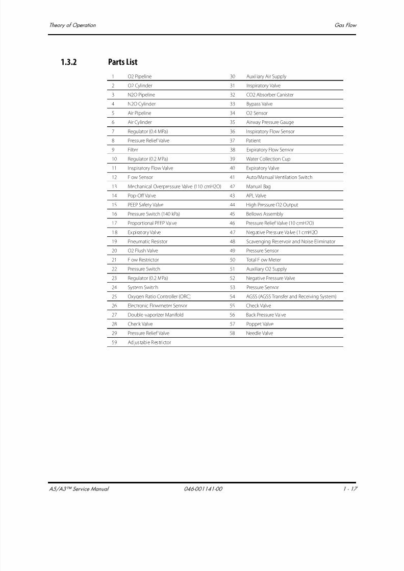
7/21/2019 a5 a3 Service Manual 2013
http://slidepdf.com/reader/full/a5-a3-service-manual-2013 32/399
A5/A3™ Service Manual 046-001141-00 1 - 17
Theory of Operation Gas Flow
1.3.2 Parts List
1 O2 Pipeline 30 Auxiliary Air Supply
2 O2 Cylinder 31 Inspiratory Valve
3 N2O Pipeline 32 CO2 Absorber Canister
4 N2O Cylinder 33 Bypass Valve
5 Air Pipeline 34 O2 Sensor
6 Air Cylinder 35 Airway Pressure Gauge
7 Regulator (0.4 MPa) 36 Inspiratory Flow Sensor
8 Pressure Relief Valve 37 Patient
9 Filter 38 Expiratory Flow Sensor
10 Regulator (0.2 MPa) 39 Water Collection Cup
11 Inspiratory Flow Valve 40 Expiratory Valve
12 Flow Sensor 41 Auto/Manual Ventilation Switch
13 Mechanical Overpressure Valve (110 cmH2O) 42 Manual Bag
14 Pop-Off Valve 43 APL Valve
15 PEEP Safety Valve 44 High Pressure O2 Output
16 Pressure Switch (140 kPa) 45 Bellows Assembly
17 Proportional PEEP Valve 46 Pressure Relief Valve (10 cmH2O)
18 Expiratory Valve 47 Negative Pressure Valve (1 cmH2O
19 Pneumatic Resistor 48 Scavenging Reservoir and Noise Eliminator
20 O2 Flush Valve 49 Pressure Sensor
21 Flow Restrictor 50 Total Flow Meter
22 Pressure Switch 51 Auxiliary O2 Supply
23 Regulator (0.2 MPa) 52 Negative Pressure Valve
24 System Switch 53 Pressure Sensor
25 Oxygen Ratio Controller (ORC) 54 AGSS (AGSS Transfer and Receiving System)
26 Electronic Flowmeter Sensor 55 Check Valve
27 Double-vaporizer Manifold 56 Back Pressure Valve
28 Check Valve 57 Poppet Valve
29 Pressure Relief Valve 58 Needle Valve
59 Adjustable Restrictor

7/21/2019 a5 a3 Service Manual 2013
http://slidepdf.com/reader/full/a5-a3-service-manual-2013 33/399
Gas Flow Theory of Operation
1 - 18 046-001141-00 A5/A3™ Service Manual
1.3.3 Key to Symbols
1.3.4 Description
1.3.4.1 Anesthetic Gas Delivery System
The Anesthetic Gas Delivery System is connected to the anesthetic agent delivery device (vaporizer),
breathing system, and anesthetic ventilator; and outputs fresh gas. The following figure shows the
pneumatic circuit of the Anesthetic Gas Delivery System.
FIGURE 1-7 Pneumatic Circuit Diagram
Filter
Regulator
Pressure Gauge
Check Valve
Gas Supply Connector
Pressure Relief Valve
Flowmeter
Flow Control Valve
Pressure Switch
Flow Restrictor

7/21/2019 a5 a3 Service Manual 2013
http://slidepdf.com/reader/full/a5-a3-service-manual-2013 34/399
A5/A3™ Service Manual 046-001141-00 1 - 19
Theory of Operation Gas Flow
The following picture illustrates how gas supplies are outputted. O2 is divided into four pathways -
system switch (24), O2 flush valve (20), auxiliary O2 supply (51), and high pressure O2 output (44),
respectively. Air enters two pathways - one pathway to the needle valve (58) and the other to the
auxiliary Air supply (3). N2O goes to the ORC (25).
When the system switch (24) is turned on, O2 enters the needle valve (58). When O2 flow is greater
than 300ml, N2O can enter the needle valve (58) through ORC 25. After passing through the needle
valve (58), the pre-set pneumatic resistance (59) controls the O2 and N2O proportions and ensures
the minimum O2 concentration.
FIGURE 1-8 Gas Supply Output
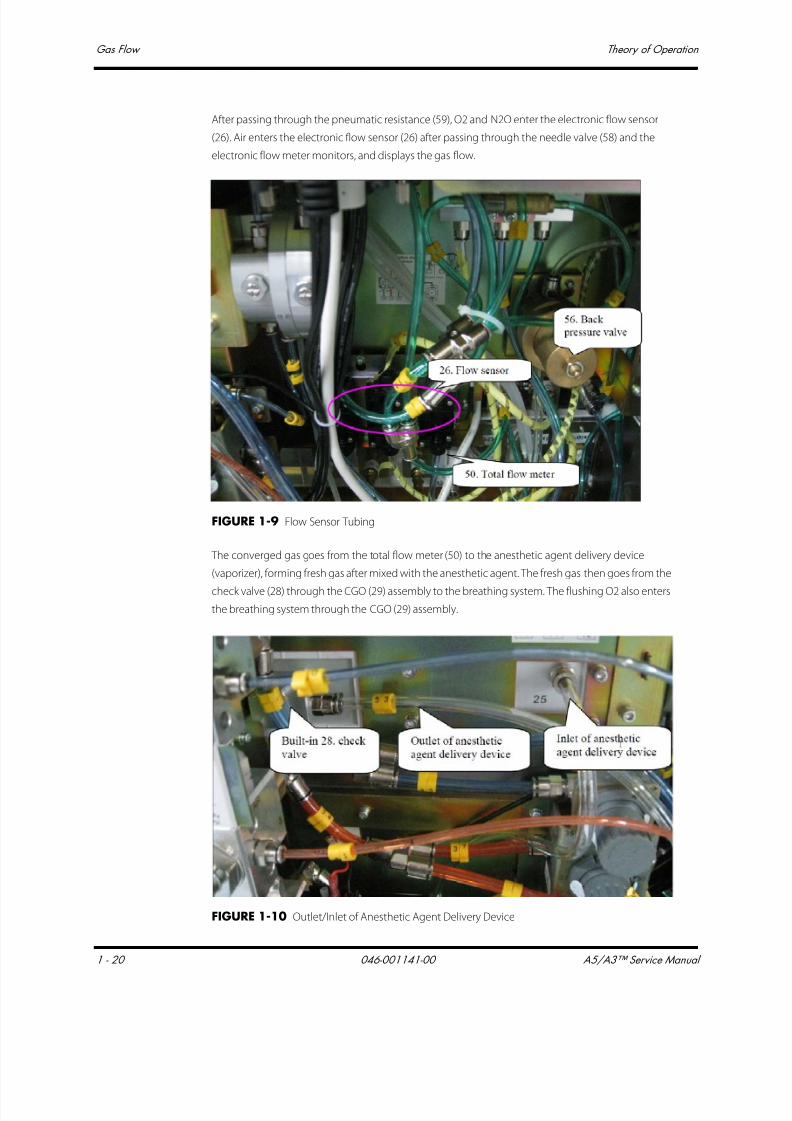
7/21/2019 a5 a3 Service Manual 2013
http://slidepdf.com/reader/full/a5-a3-service-manual-2013 35/399
Gas Flow Theory of Operation
1 - 20 046-001141-00 A5/A3™ Service Manual
After passing through the pneumatic resistance (59), O2 and N2O enter the electronic flow sensor
(26). Air enters the electronic flow sensor (26) after passing through the needle valve (58) and the
electronic flow meter monitors, and displays the gas flow.
FIGURE 1-9 Flow Sensor Tubing
The converged gas goes from the total flow meter (50) to the anesthetic agent delivery device
(vaporizer), forming fresh gas after mixed with the anesthetic agent. The fresh gas then goes from the
check valve (28) through the CGO (29) assembly to the breathing system. The flushing O2 also enters
the breathing system through the CGO (29) assembly.
FIGURE 1-10 Outlet/Inlet of Anesthetic Agent Delivery Device

7/21/2019 a5 a3 Service Manual 2013
http://slidepdf.com/reader/full/a5-a3-service-manual-2013 36/399
A5/A3™ Service Manual 046-001141-00 1 - 21
Theory of Operation Gas Flow
1.3.4.2 Gas Supplies
FIGURE 1-11 O2 Pipeline Supply Inlet Assembly
The above picture shows the O2 pipeline supply inlet assembly. The anesthesia machine's pneumatic
circuit starts from the gas supplies, which function to introduce the external pipeline or cylindergases into the machine. Since the pressure of external gas is very high and the external gas contains
foreign substances, the pressure reducing valves, filters, and pressure relief valves are available in the
supply gas circuit. Also, the check valves are equipped in the supply gas circuit to prevent gas from
flowing back into the pipeline or cylinder.
The anesthesia machine has pipeline and cylinder gas supplies available. Pipeline gas supplies go
into the pipeline gas supply inlet assemblies through pipeline connectors 1, 3, and 5, respectively.
The pipeline pressure ranges between 280 and 600 kPa. Cylinder gas supplies go into the system
through cylinder connectors 2, 4, and 6, respectively. The O2 and Air cylinder pressures are 6.9 to 15
MPa, and the N2O cylinder pressure is 4.2 to 6 MPa, both of which are decreased to 400 kPa through
three regulators (7). Each connector is clearly marked and designed to prevent misconnection. All
connectors have filters and check valves. Color coded gauges show the pipeline and cylinder
pressures. The Pressure Relief Valve (8) functions to prevent the supply gas pressure from being too
high. It releases excess gas when the gas pressure exceeds 758 kPa. Each supply gas is outputted after
gas pressure is decreased below 200 kPa through the regulator (23). The Pressure Switch (22)
monitors the O2 supply pressure. When the O2 supply pressure is less than approximately 220 kPa,
the ventilator gives an alarm indicating O2 supply failure.
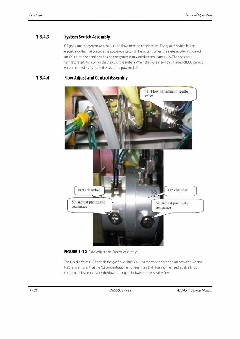
7/21/2019 a5 a3 Service Manual 2013
http://slidepdf.com/reader/full/a5-a3-service-manual-2013 37/399
Gas Flow Theory of Operation
1 - 22 046-001141-00 A5/A3™ Service Manual
1.3.4.3 System Switch Assembly
O2 goes into the system switch (24); and flows into the needle valve. The system switch has an
electrical outlet that controls the power-on status of the system. When the system switch is turned
on, O2 enters the needle valve and the system is powered on simultaneously. The anesthetic
ventilator starts to monitor the status of the system. When the system switch is turned off, O2 cannot
enter the needle valve and the system is powered off.
1.3.4.4 Flow Adjust and Control Assembly
FIGURE 1-12 Flow Adjust and Control Assembly
The Needle Valve (58) controls the gas flows. The ORC (25) controls the proportion between O2 and
N2O, and ensures that the O2 concentration is not less than 21%. Turning the needle valve knob
counterclockwise increases the flow; turning it clockwise decreases the flow.

7/21/2019 a5 a3 Service Manual 2013
http://slidepdf.com/reader/full/a5-a3-service-manual-2013 38/399
A5/A3™ Service Manual 046-001141-00 1 - 23
Theory of Operation Gas Flow
1.3.4.5 Flow Display Assembly
The electronic flowmeter (26) and total flow meter (50) constitute the flow display assembly. Gases
from the flow adjust and control assembly and mixed gas going through the anesthetic agent
delivery device (vaporizer) are outputted. The electronic flowmeter (26) measures and displays the
flow of each gas. The total flow meter (50) displays the total gas flow.
FIGURE 1-13 Flow Display Assembly
1.3.4.6 O2 Flush Button Assembly
FIGURE 1-14 O2 Flush Button Assembly
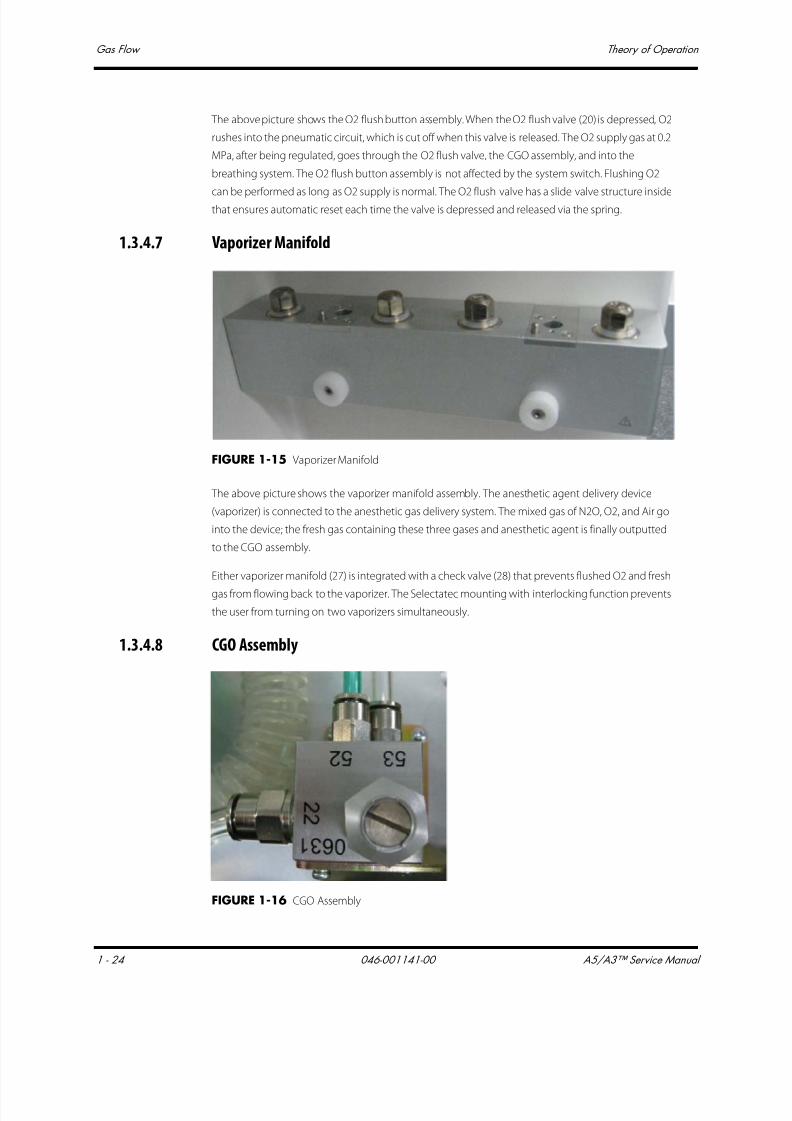
7/21/2019 a5 a3 Service Manual 2013
http://slidepdf.com/reader/full/a5-a3-service-manual-2013 39/399
Gas Flow Theory of Operation
1 - 24 046-001141-00 A5/A3™ Service Manual
The above picture shows the O2 flush button assembly. When the O2 flush valve (20) is depressed, O2
rushes into the pneumatic circuit, which is cut off when this valve is released. The O2 supply gas at 0.2
MPa, after being regulated, goes through the O2 flush valve, the CGO assembly, and into the
breathing system. The O2 flush button assembly is not affected by the system switch. Flushing O2
can be performed as long as O2 supply is normal. The O2 flush valve has a slide valve structure insidethat ensures automatic reset each time the valve is depressed and released via the spring.
1.3.4.7 Vaporizer Manifold
FIGURE 1-15 Vaporizer Manifold
The above picture shows the vaporizer manifold assembly. The anesthetic agent delivery device
(vaporizer) is connected to the anesthetic gas delivery system. The mixed gas of N2O, O2, and Air go
into the device; the fresh gas containing these three gases and anesthetic agent is finally outputted
to the CGO assembly.
Either vaporizer manifold (27) is integrated with a check valve (28) that prevents flushed O2 and fresh
gas from flowing back to the vaporizer. The Selectatec mounting with interlocking function prevents
the user from turning on two vaporizers simultaneously.
1.3.4.8 CGO Assembly
FIGURE 1-16 CGO Assembly
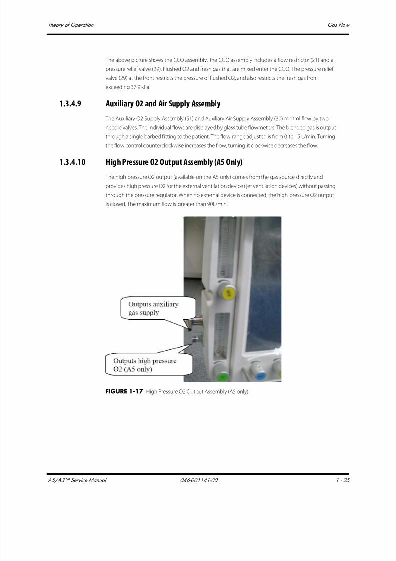
7/21/2019 a5 a3 Service Manual 2013
http://slidepdf.com/reader/full/a5-a3-service-manual-2013 40/399
A5/A3™ Service Manual 046-001141-00 1 - 25
Theory of Operation Gas Flow
The above picture shows the CGO assembly. The CGO assembly includes a flow restrictor (21) and a
pressure relief valve (29). Flushed O2 and fresh gas that are mixed enter the CGO. The pressure relief
valve (29) at the front restricts the pressure of flushed O2, and also restricts the fresh gas from
exceeding 37.9 kPa.
1.3.4.9 Auxiliary O2 and Air Supply Assembly
The Auxiliary O2 Supply Assembly (51) and Auxiliary Air Supply Assembly (30) control flow by two
needle valves. The individual flows are displayed by glass tube flowmeters. The blended gas is output
through a single barbed f itting to the patient. The flow range adjusted is from 0 to 15 L/min. Turning
the flow control counterclockwise increases the flow; turning it clockwise decreases the flow.
1.3.4.10 High Pressure O2 Output Assembly (A5 Only)
The high pressure O2 output (available on the A5 only) comes from the gas source directly and
provides high pressure O2 for the external ventilation device ( jet ventilation devices) without passing
through the pressure regulator. When no external device is connected, the high pressure O2 outputis closed. The maximum flow is greater than 90L/min.
FIGURE 1-17 High Pressure O2 Output Assembly (A5 only)
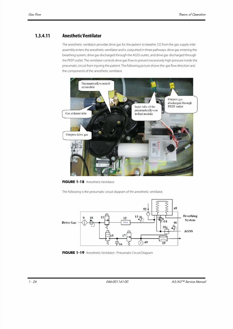
7/21/2019 a5 a3 Service Manual 2013
http://slidepdf.com/reader/full/a5-a3-service-manual-2013 41/399
Gas Flow Theory of Operation
1 - 26 046-001141-00 A5/A3™ Service Manual
1.3.4.11 Anesthetic Ventilator
The anesthetic ventilator provides drive gas for the patient to breathe. O2 from the gas supply inlet
assembly enters the anesthetic ventilator and is outputted in three pathways: drive gas entering the
breathing system, drive gas discharged through the AGSS outlet, and drive gas discharged through
the PEEP outlet. The ventilator controls drive gas flow to prevent excessively high pressure inside the
pneumatic circuit from injuring the patient. The following picture shows the gas flow direction and
the components of the anesthetic ventilator.
FIGURE 1-18 Anesthetic Ventilator
The following is the pneumatic circuit diagram of the anesthetic ventilator.
FIGURE 1-19 Anesthetic Ventilator - Pneumatic Circuit Diagram

7/21/2019 a5 a3 Service Manual 2013
http://slidepdf.com/reader/full/a5-a3-service-manual-2013 42/399
A5/A3™ Service Manual 046-001141-00 1 - 27
Theory of Operation Gas Flow
The proportional electromagnetic valve (11) controls inlet gas flow. The filter (9) filters drive gas again.
The regulator (10) regulates pressure inside the pneumatic circuit. Component 12 is a flow sensor of
differential pressure type that monitors gas flow in the drive gas circuit. The Mechanical overpressure
valve (13) ensures that the pressure in the drive gas circuit does not exceed safe pressure. It releases
excess gas when gas pressure exceeds 11 kPa. Component 18 is the expiratory valve. Duringexpiration, gas inside the bellows is discharged from this valve.
The PEEP function is performed through the expiratory valve. Component 15 is a low-flow
proportional electromagnetic valve. When it opens, gas is bled from the pneumatic resistor (19),
forming relatively stable pressure in the PEEP branch. Such pressure is exerted on the membrane of
the expiratory valve (18) to form PEEP.
To prevent excessively high pressure inside the pneumatic circuit from injuring the patient and
damaging the equipment, the pressure relief valve (15), which is an electromagnetic on-off valve, is
placed before the gas pathway of the expiratory valve. The "16" component is a pressure switch.
When the drive gas pressure is less than 140 kPa, an alarm is triggered. Component 49 is a pressure
sensor that monitors the pressure at which the expiratory valve is closed. The Pressure relief valve (46)ensures the tube pressure after the expiratory valve is less than 10 cmH2O.
1.3.4.12 Breathing System
The breathing system provides a closed loop for the anesthetic gas. The expired gas from the patient
can be inspired in the inspiration phase to maintain the temperature and humidity conditions of the
patient's expired gas. During inspiration, the drive gas depresses the bag inside the bellows to force
the inside gas to enter the patient's lung. During expiration, the patient's expired gas goes into the
bag inside the bellows. The CO2 Absorber Canister (32) absorbs CO2 that the patient expires. The
following figure shows the pneumatic circuit of the breathing system.
FIGURE 1-20 Breathing System Circuit Diagram
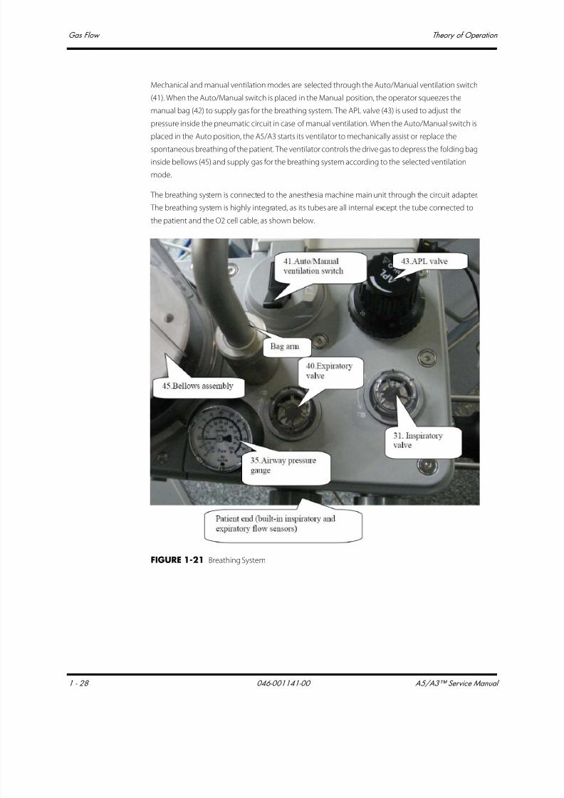
7/21/2019 a5 a3 Service Manual 2013
http://slidepdf.com/reader/full/a5-a3-service-manual-2013 43/399
Gas Flow Theory of Operation
1 - 28 046-001141-00 A5/A3™ Service Manual
Mechanical and manual ventilation modes are selected through the Auto/Manual ventilation switch
(41). When the Auto/Manual switch is placed in the Manual position, the operator squeezes the
manual bag (42) to supply gas for the breathing system. The APL valve (43) is used to adjust the
pressure inside the pneumatic circuit in case of manual ventilation. When the Auto/Manual switch is
placed in the Auto position, the A5/A3 starts its ventilator to mechanically assist or replace thespontaneous breathing of the patient. The ventilator controls the drive gas to depress the folding bag
inside bellows (45) and supply gas for the breathing system according to the selected ventilation
mode.
The breathing system is connected to the anesthesia machine main unit through the circuit adapter.
The breathing system is highly integrated, as its tubes are all internal except the tube connected to
the patient and the O2 cell cable, as shown below.
FIGURE 1-21 Breathing System
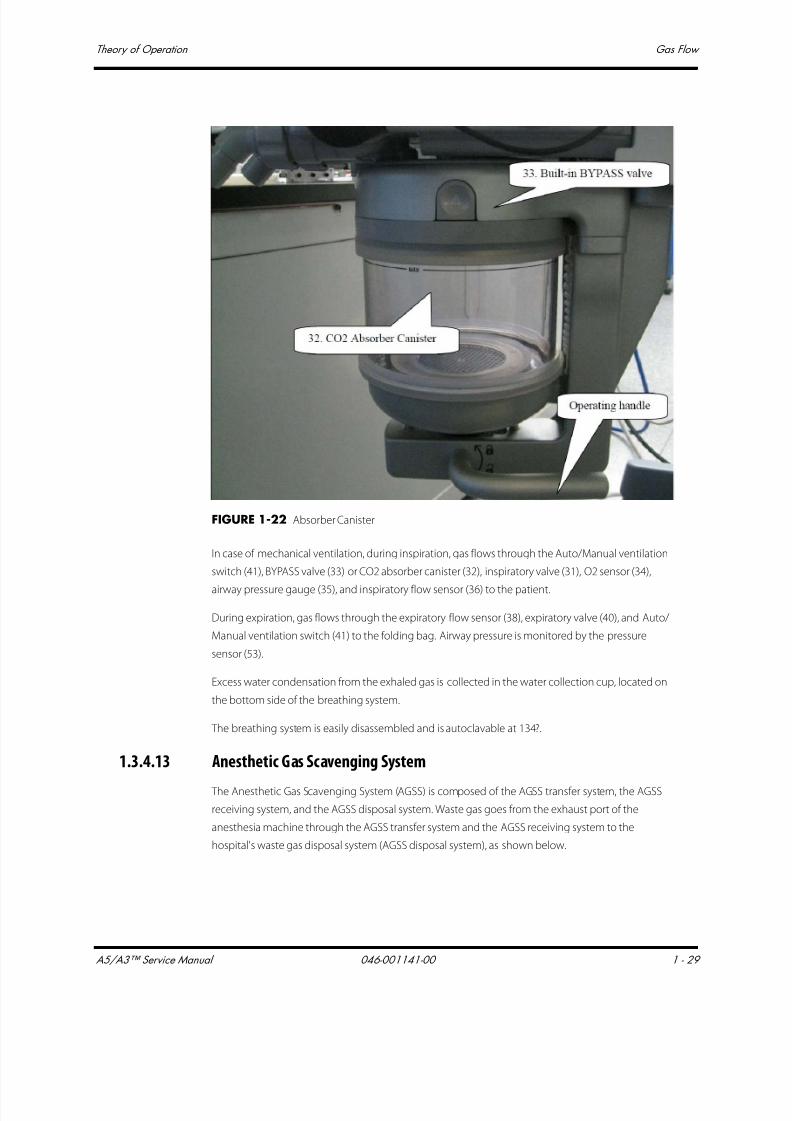
7/21/2019 a5 a3 Service Manual 2013
http://slidepdf.com/reader/full/a5-a3-service-manual-2013 44/399
A5/A3™ Service Manual 046-001141-00 1 - 29
Theory of Operation Gas Flow
FIGURE 1-22 Absorber Canister
In case of mechanical ventilation, during inspiration, gas flows through the Auto/Manual ventilation
switch (41), BYPASS valve (33) or CO2 absorber canister (32), inspiratory valve (31), O2 sensor (34),
airway pressure gauge (35), and inspiratory flow sensor (36) to the patient.
During expiration, gas flows through the expiratory flow sensor (38), expiratory valve (40), and Auto/
Manual ventilation switch (41) to the folding bag. Airway pressure is monitored by the pressure
sensor (53).
Excess water condensation from the exhaled gas is collected in the water collection cup, located on
the bottom side of the breathing system.
The breathing system is easily disassembled and is autoclavable at 134?.
1.3.4.13 Anesthetic Gas Scavenging System
The Anesthetic Gas Scavenging System (AGSS) is composed of the AGSS transfer system, the AGSS
receiving system, and the AGSS disposal system. Waste gas goes from the exhaust port of the
anesthesia machine through the AGSS transfer system and the AGSS receiving system to the
hospital's waste gas disposal system (AGSS disposal system), as shown below.
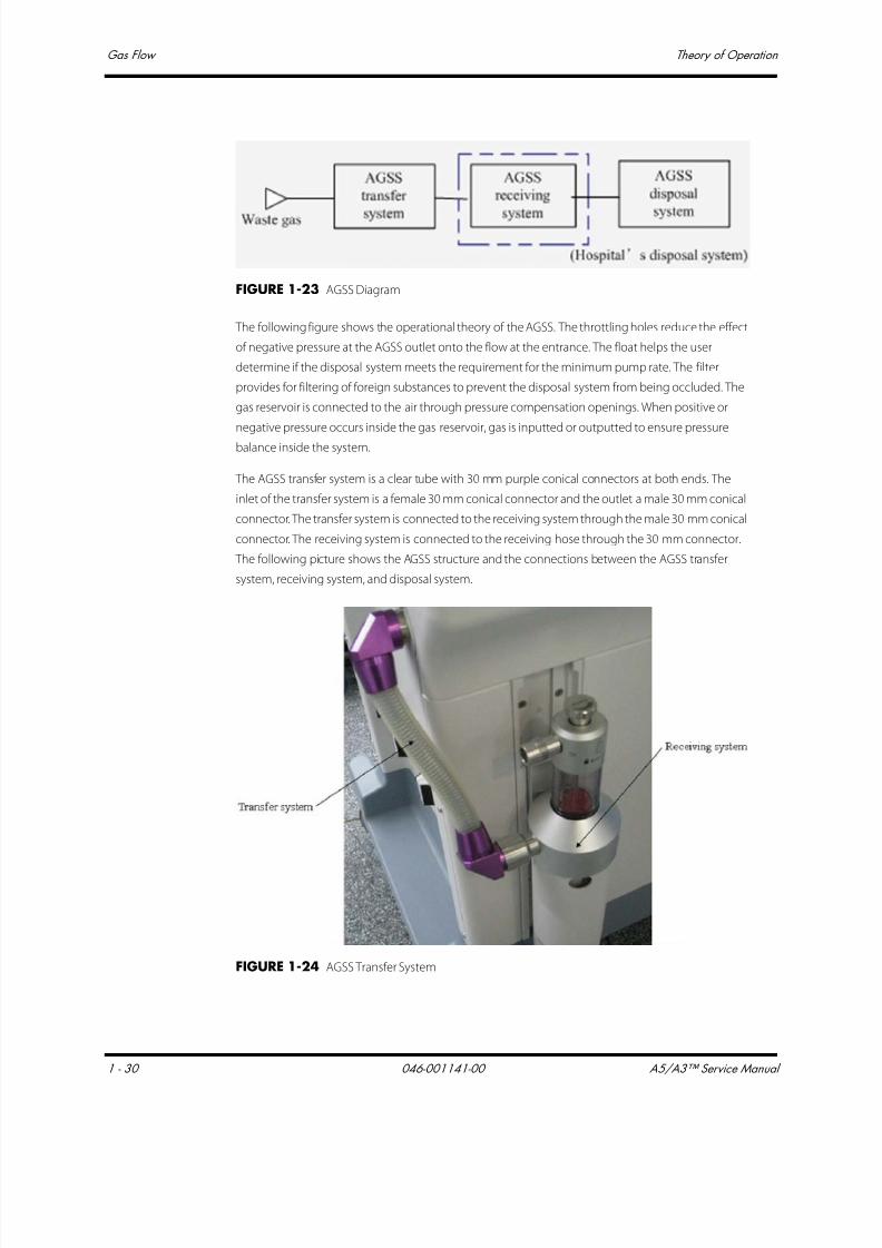
7/21/2019 a5 a3 Service Manual 2013
http://slidepdf.com/reader/full/a5-a3-service-manual-2013 45/399
Gas Flow Theory of Operation
1 - 30 046-001141-00 A5/A3™ Service Manual
FIGURE 1-23 AGSS Diagram
The following figure shows the operational theory of the AGSS. The throttling holes reduce the effect
of negative pressure at the AGSS outlet onto the flow at the entrance. The float helps the user
determine if the disposal system meets the requirement for the minimum pump rate. The filter
provides for filtering of foreign substances to prevent the disposal system from being occluded. The
gas reservoir is connected to the air through pressure compensation openings. When positive or
negative pressure occurs inside the gas reservoir, gas is inputted or outputted to ensure pressure
balance inside the system.
The AGSS transfer system is a clear tube with 30 mm purple conical connectors at both ends. The
inlet of the transfer system is a female 30 mm conical connector and the outlet a male 30 mm conical
connector. The transfer system is connected to the receiving system through the male 30 mm conical
connector. The receiving system is connected to the receiving hose through the 30 mm connector.
The following picture shows the AGSS structure and the connections between the AGSS transfer
system, receiving system, and disposal system.
FIGURE 1-24 AGSS Transfer System

7/21/2019 a5 a3 Service Manual 2013
http://slidepdf.com/reader/full/a5-a3-service-manual-2013 46/399
A5/A3™ Service Manual 046-001141-00 1 - 31
Theory of Operation Anesthesia System Components
1.4 Anesthesia System Components
1.4.1 Auxiliary Outlets
The A3 anesthesia system has three 125V 15A Hospital Grade auxiliary outlets. Each outlet has one250V 3A breaker.
FIGURE 1-25 Auxiliary Outlet Diagram for the A3
The A5 anesthesia system has four 125V 15A Hospital Grade auxiliary outlets. Each outlet has one
250V 3A breaker. Additionally, a main breaker limits the combined current of the four outlets to 10A.
FIGURE 1-26 Auxiliary Outlet Diagram for the A5
1.4.2 Work Light Board
1.4.2.1 Top lighting board
FIGURE 1-27 Top Lighting Board, Top View
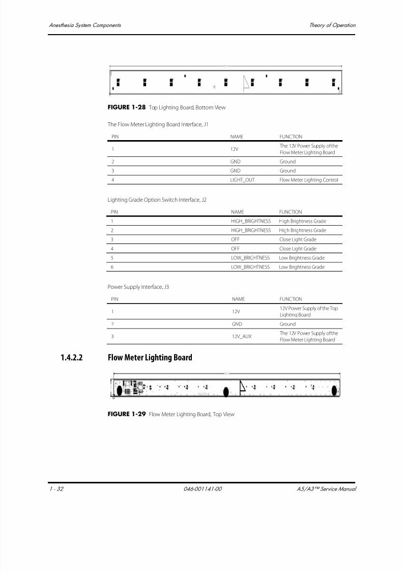
7/21/2019 a5 a3 Service Manual 2013
http://slidepdf.com/reader/full/a5-a3-service-manual-2013 47/399
Anesthesia System Components Theory of Operation
1 - 32 046-001141-00 A5/A3™ Service Manual
FIGURE 1-28 Top Lighting Board, Bottom View
The Flow Meter Lighting Board Interface, J1
Lighting Grade Option Switch Interface, J2
Power Supply Interface, J3
1.4.2.2 Flow Meter Lighting Board
FIGURE 1-29 Flow Meter Lighting Board, Top View
PIN NAME FUNCTION
1 12V The 12V Power Supply of the
Flow Meter Lighting Board
2 GND Ground
3 GND Ground
4 LIGHT_OUT Flow Meter Lighting Control
PIN NAME FUNCTION
1 HIGH_BRIGHTNESS High Brightness Grade
2 HIGH_BRIGHTNESS High Brightness Grade
3 OFF Close Light Grade
4 OFF Close Light Grade
5 LOW_BRIGHTNESS Low Brightness Grade
6 LOW_BRIGHTNESS Low Brightness Grade
PIN NAME FUNCTION
1 12V 12V Power Supply of the Top
Lighting Board
2 GND Ground
3 12V_AUX The 12V Power Supply of the
Flow Meter Lighting Board

7/21/2019 a5 a3 Service Manual 2013
http://slidepdf.com/reader/full/a5-a3-service-manual-2013 48/399
A5/A3™ Service Manual 046-001141-00 1 - 33
Theory of Operation Anesthesia System Components
FIGURE 1-30 Flow Meter Lighting Board, Bottom View
Flow Meter Lighting Board Interface, J1
PIN NAME FUNCTION
1 12V 12V Power Supply of the Flow Meter Lighting board
2 GND Ground
3 GND Ground
4 LIGHT_IN Flow Meter Lighting Control Signal

7/21/2019 a5 a3 Service Manual 2013
http://slidepdf.com/reader/full/a5-a3-service-manual-2013 49/399
The Breathing System Theory of Operation
1 - 34 046-001141-00 A5/A3™ Service Manual
1.5 The Breathing System
1.5.1 Brief Introduction
The A5/A3 Breathing System supports three types of operational modes: mechanical ventilation,manual ventilation, and standby. These modes allow the operator to apply proper ventilation strategy
based on the patient’s needs.
The types of flow paths through the breathing system vary with the operating mode or status.
1.5.2 Automatic Mode, Inspiration
When the Auto/Manual switch is positioned at Auto, the system closes the manual ventilation path.
Drive gas pushes down on the bellows. Gas flows from the bellows, through the CO2 absorber
canister, and through the inspiratory check valve to the patient.
During inspiration, fresh gas flows into the inspiratory limb, upstream of the inspiratory check valve.
In volume mode, tidal volume is compensated for variations in fresh gas flow to ensure that the
volume delivered to the patient meets the set value.
In pressure mode, the inspiratory pressure is regulated both in gas flow and airway pressure to ensure
the airway pressure is held at the set inspiratory pressure during the patient inspiration.
FIGURE 1-31 Automatic Mode, Inspiration Diagram

7/21/2019 a5 a3 Service Manual 2013
http://slidepdf.com/reader/full/a5-a3-service-manual-2013 50/399
A5/A3™ Service Manual 046-001141-00 1 - 35
Theory of Operation The Breathing System
1.5.3 Automatic Mode, Expiration
When the Auto/Manual switch is set to Auto, the system closes the manual ventilation path. Drive-
gas flow stops and the exhaust valve opens. Exhaled gas flows from the patient, through the
expiratory check valve, and into the bellows.
Residual drive gas flows out of the bellows dome through the exhaust valve to the scavenging
system (AGSS).
If PEEP is selected, static pressure on the pilot port of the exhaust valve sets the PEEP level.
During exhalation, fresh gas flows backwards through the CO2 absorber into the expiratory limb,
downstream of the expiratory check valve.
FIGURE 1-32 Automatic Mode, Expiration Diagram
1.5.4 Manual Mode, Inspiration
When the Auto/Manual switch is set to Manual, the system closes the Auto ventilation path. Gas
flows from the breathing bag when compressed, through the CO2 absorber canister, into the
breathing circuit, and through the inspiratory check valve to the patient.
During inspiration, fresh gas flows from the machine into the inspiratory limb, upstream of the
inspiratory check valve.

7/21/2019 a5 a3 Service Manual 2013
http://slidepdf.com/reader/full/a5-a3-service-manual-2013 51/399
The Breathing System Theory of Operation
1 - 36 046-001141-00 A5/A3™ Service Manual
If airway pressure exceeds the set value of the APL Valve, the residual gas will pass through the APL
Valve to the scavenging system (AGSS).
FIGURE 1-33 Manual Mode, Inspiration Diagram
1.5.5 Manual Mode, Expiration
When the Auto/Manual switch is set to Manual, the system closes the Auto ventilation path. Gas
flows from the patient, through the expiratory check valve, and into the breathing bag. During
exhalation, fresh gas enters the Breathing System. Residual fresh gas passes through the APL valve to
the AGSS.
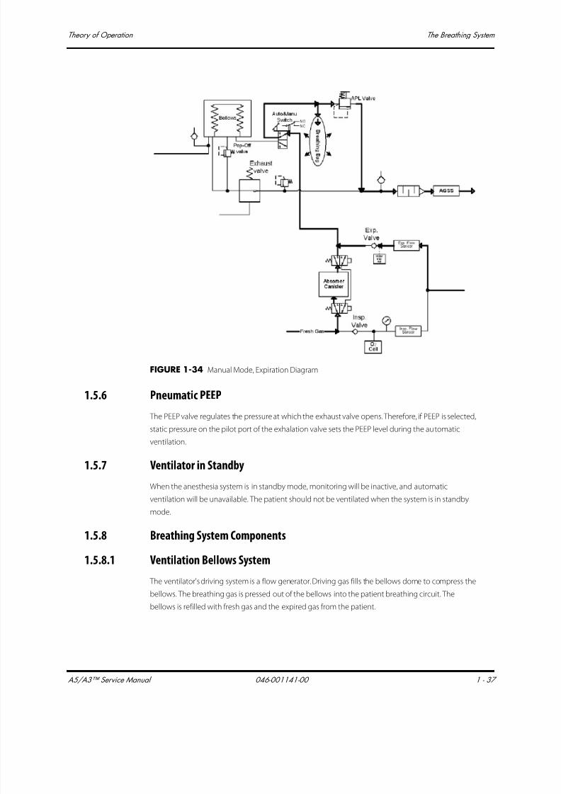
7/21/2019 a5 a3 Service Manual 2013
http://slidepdf.com/reader/full/a5-a3-service-manual-2013 52/399
A5/A3™ Service Manual 046-001141-00 1 - 37
Theory of Operation The Breathing System
FIGURE 1-34 Manual Mode, Expiration Diagram
1.5.6 Pneumatic PEEP
The PEEP valve regulates the pressure at which the exhaust valve opens. Therefore, if PEEP is selected,static pressure on the pilot port of the exhalation valve sets the PEEP level during the automatic
ventilation.
1.5.7 Ventilator in Standby
When the anesthesia system is in standby mode, monitoring will be inactive, and automatic
ventilation will be unavailable. The patient should not be ventilated when the system is in standby
mode.
1.5.8 Breathing System Components
1.5.8.1 Ventilation Bellows System
The ventilator's driving system is a flow generator. Driving gas fills the bellows dome to compress the
bellows. The breathing gas is pressed out of the bellows into the patient breathing circuit. The
bellows is refilled with fresh gas and the expired gas from the patient.

7/21/2019 a5 a3 Service Manual 2013
http://slidepdf.com/reader/full/a5-a3-service-manual-2013 53/399
The Breathing System Theory of Operation
1 - 38 046-001141-00 A5/A3™ Service Manual
1.5.8.2 Manual Breathing Bag
In manual mode, this device acts as a normal breathing bag, enabling the user to ventilate the
patient manually.
1.5.8.3 CO2 Absorber Canister
The sodalime inside the CO2 absorber canister absorbs the carbon dioxide from the exhaled gas. The
CO2 absorber canister accommodates standard sized Pre-paks or loose-fill CO2 absorbent.
1.5.8.4 Inspiratory and Expiratory Valves
To ensure correct gas flow direction to and from the patient, check-valves are integrated in the
inspiratory and expiratory limb of the Breathing System.
1.5.8.5 APL (Airway Pressure Limiting) Valve
In manual mode, the APL Valve acts as a normal spring-loaded pressure relief valve, limiting the
maximum pressure in the Breathing System.

7/21/2019 a5 a3 Service Manual 2013
http://slidepdf.com/reader/full/a5-a3-service-manual-2013 54/399
A5/A3™ Service Manual 046-001141-00 1 - 39
Theory of Operation Ventilator UI
1.6 Ventilator UI
1.6.1 Display
1.6.1.1 Display Interface Board
FIGURE 1-35 Display Interface Board, Top View
FIGURE 1-36 Display Interface Board, Bottom View
Inverter interface, J1
PIN NAME FUNCTION
1 12V Inverter 12V Power Supply
2 12V Inverter 12V Power Supply
3 GND Ground
4 GND Ground
5 LCD_EN LCD Backlight Enable
6 LCD_BR LCD Backlight Brightness Control
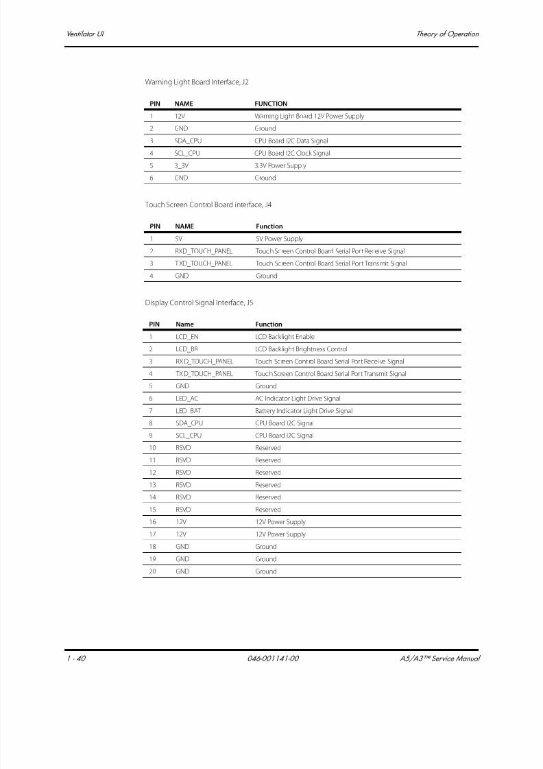
7/21/2019 a5 a3 Service Manual 2013
http://slidepdf.com/reader/full/a5-a3-service-manual-2013 55/399
Ventilator UI Theory of Operation
1 - 40 046-001141-00 A5/A3™ Service Manual
Warning Light Board Interface, J2
Touch Screen Control Board interface, J4
Display Control Signal Interface, J5
PIN NAME FUNCTION
1 12V Warning Light Board 12V Power Supply
2 GND Ground
3 SDA_CPU CPU Board I2C Data Signal
4 SCL_CPU CPU Board I2C Clock Signal
5 3_3V 3.3V Power Supply
6 GND Ground
PIN NAME Function
1 5V 5V Power Supply
2 RXD_TOUCH_PANEL Touch Screen Control Board Serial Por t Receive Signal
3 TXD_TOUCH_PANEL Touch Screen Control Board Serial Por t Transmit Signal
4 GND Ground
PIN Name Function
1 LCD_EN LCD Backlight Enable
2 LCD_BR LCD Backlight Brightness Control
3 RXD_TOUCH_PANEL Touch Screen Control Board Serial Por t Receive Signal
4 TXD_TOUCH_PANEL Touch Screen Control Board Serial Por t Transmit Signal
5 GND Ground
6 LED_AC AC Indicator Light Drive Signal
7 LED_BAT Battery Indicator Light Drive Signal
8 SDA_CPU CPU Board I2C Signal
9 SCL_CPU CPU Board I2C Signal
10 RSVD Reserved
11 RSVD Reserved
12 RSVD Reserved
13 RSVD Reserved
14 RSVD Reserved
15 RSVD Reserved
16 12V 12V Power Supply
17 12V 12V Power Supply
18 GND Ground
19 GND Ground
20 GND Ground
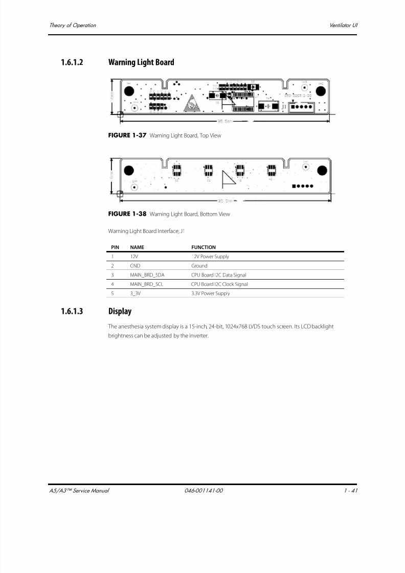
7/21/2019 a5 a3 Service Manual 2013
http://slidepdf.com/reader/full/a5-a3-service-manual-2013 56/399
A5/A3™ Service Manual 046-001141-00 1 - 41
Theory of Operation Ventilator UI
1.6.1.2 Warning Light Board
FIGURE 1-37 Warning Light Board, Top View
FIGURE 1-38 Warning Light Board, Bottom View
Warning Light Board Interface, J1
1.6.1.3 Display
The anesthesia system display is a 15-inch, 24-bit, 1024x768 LVDS touch screen. Its LCD backlight
brightness can be adjusted by the inverter.
PIN NAME FUNCTION
1 12V 12V Power Supply
2 GND Ground
3 MAIN_BRD_SDA CPU Board I2C Data Signal
4 MAIN_BRD_SCL CPU Board I2C Clock Signal
5 3_3V 3.3V Power Supply
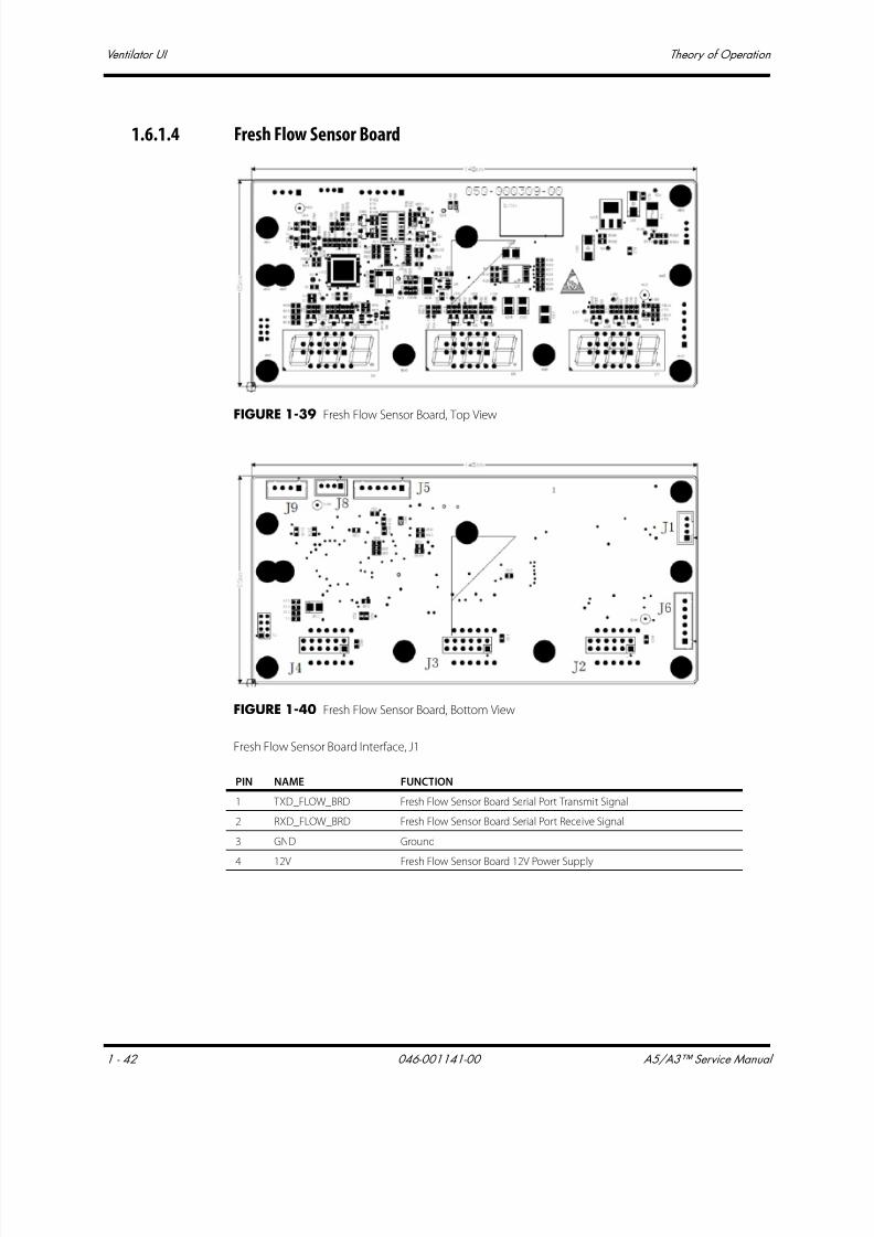
7/21/2019 a5 a3 Service Manual 2013
http://slidepdf.com/reader/full/a5-a3-service-manual-2013 57/399
Ventilator UI Theory of Operation
1 - 42 046-001141-00 A5/A3™ Service Manual
1.6.1.4 Fresh Flow Sensor Board
FIGURE 1-39 Fresh Flow Sensor Board, Top View
FIGURE 1-40 Fresh Flow Sensor Board, Bottom View
Fresh Flow Sensor Board Interface, J1
PIN NAME FUNCTION
1 TXD_FLOW_BRD Fresh Flow Sensor Board Serial Port Transmit Signal
2 RXD_FLOW_BRD Fresh Flow Sensor Board Serial Port Receive Signal
3 GND Ground
4 12V Fresh Flow Sensor Board 12V Power Supply

7/21/2019 a5 a3 Service Manual 2013
http://slidepdf.com/reader/full/a5-a3-service-manual-2013 58/399
A5/A3™ Service Manual 046-001141-00 1 - 43
Theory of Operation Ventilator UI
1.6.1.5 Indicator Light Board
FIGURE 1-41 Indicator Light Board, Top View
FIGURE 1-42 Indicator Light Board, Bottom View

7/21/2019 a5 a3 Service Manual 2013
http://slidepdf.com/reader/full/a5-a3-service-manual-2013 59/399
Ventilator UI Theory of Operation
1 - 44 046-001141-00 A5/A3™ Service Manual
Indicator Light Board interface, J1
1.6.2 CPU Board
FIGURE 1-43 CPU Board, Top View
PIN NAME FUNCTION
1 LED_AC AC Indicator Light Drive Signal
2 LED_BAT Battery Indicator Light Drive Signal
3 GND Ground
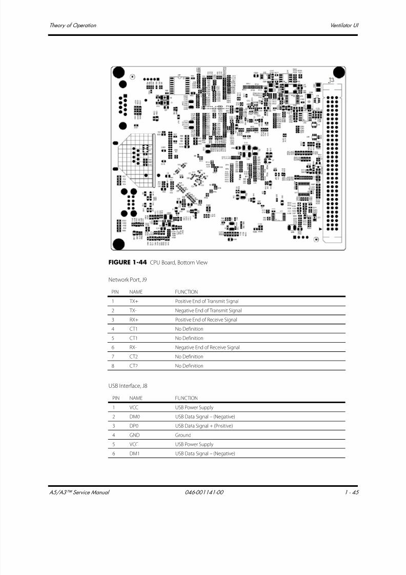
7/21/2019 a5 a3 Service Manual 2013
http://slidepdf.com/reader/full/a5-a3-service-manual-2013 60/399
A5/A3™ Service Manual 046-001141-00 1 - 45
Theory of Operation Ventilator UI
FIGURE 1-44 CPU Board, Bottom View
Network Port, J9
USB Interface, J8
PIN NAME FUNCTION
1 TX+ Positive End of Transmit Signal2 TX- Negative End of Transmit Signal
3 RX+ Positive End of Receive Signal
4 CT1 No Definition
5 CT1 No Definition
6 RX- Negative End of Receive Signal
7 CT2 No Definition
8 CT2 No Definition
PIN NAME FUNCTION
1 VCC USB Power Supply
2 DM0 USB Data Signal – (Negative)
3 DP0 USB Data Signal + (Positive)
4 GND Ground
5 VCC USB Power Supply
6 DM1 USB Data Signal – (Negative)

7/21/2019 a5 a3 Service Manual 2013
http://slidepdf.com/reader/full/a5-a3-service-manual-2013 61/399
Ventilator UI Theory of Operation
1 - 46 046-001141-00 A5/A3™ Service Manual
RS-232 Interface, J4
7 DP1 USB Data Signal + (Positive)
8 GND Ground
PIN NAME FUNCTION
1 NC No Connection
2 RXD RS-232 Receive Signal
3 TXD RS-232 Transmit Signal
4 NC No Connection
5 GND Ground
6 NC No Connection
7 NC No Connection
8 NC No Connection
9 NC No Connection
PIN NAME FUNCTION
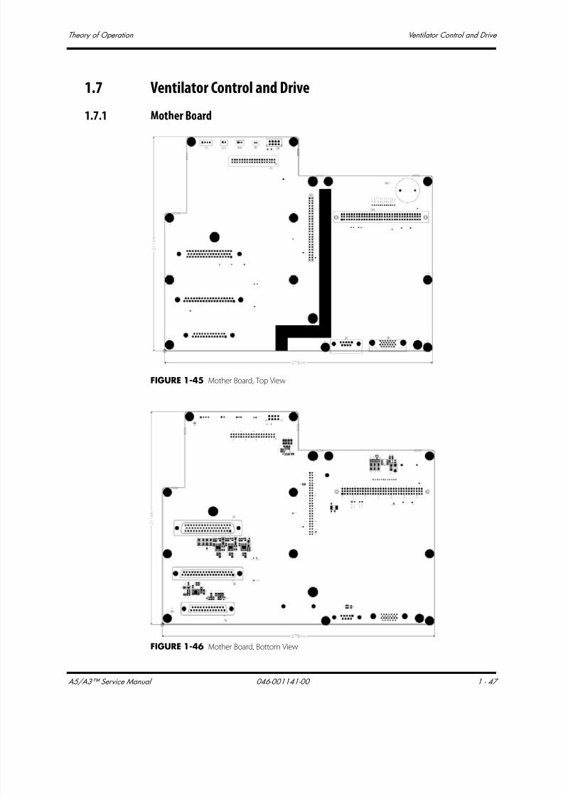
7/21/2019 a5 a3 Service Manual 2013
http://slidepdf.com/reader/full/a5-a3-service-manual-2013 62/399
A5/A3™ Service Manual 046-001141-00 1 - 47
Theory of Operation Ventilator Control and Drive
1.7 Ventilator Control and Drive
1.7.1 Mother Board
FIGURE 1-45 Mother Board, Top View
FIGURE 1-46 Mother Board, Bottom View

7/21/2019 a5 a3 Service Manual 2013
http://slidepdf.com/reader/full/a5-a3-service-manual-2013 63/399
Ventilator Control and Drive Theory of Operation
1 - 48 046-001141-00 A5/A3™ Service Manual
VCM Interface, J1
Pneumatic Assembly Interface, J2
PIN NAME FUNCTION
1 SAFE_VALVE Pressure Relief Valve Drive Signal
2 7VIN Inspiration Valve Drive Signal
3 INSP_VALVE Inspiration Valve Drive Signal
4 7VIN PEEP Valve Drive Signal
5 PEEP_VALVE PEEP Valve Drive Signal
6 SOLENOID_VALVE1 Three-way Valve 1
7 SOLENOID_VALVE2 Three-way Valve 2
8 SOLENOID_VALVE3 Three-way Valve 3
9 SOLENOID_VALVE4 Three-way Valve 4
10 PNEUM_PRES_SW Pneumatic Block Pressure Switch Signal
11 NC No Connection
12 NC No Connection
13 O2_PRE_SW O2 Pressure Switch Signal at Gas Supply Inlet
14 MANU_AUTO_SW Auto/Manual Switch Signal
15 GND Ground
16 CO2_BYPASS_SW Circuit CO2 Absorber Canister Signal
17 O2+ O2 Concentration Signal
18 O2- O2 Concentration Signal
19 TXD_AUX_BRD VPM Serial Port Transmit Signal
20 RXD_AUX_BRD VPM Serial Port Receive Signal
21 GND Ground
22 RSVD Reserved
23 RSVD Reserved
24 RSVD Reserved
25 VF Differential Pressure Sensor Flow Signal
26 GND Ground
27 TXD_MON_BRD VCM Serial Port Transmit Signal
28 RXD_MON_BRD VCM Serial Port Receive Signal
29 12V 12V Power Supply
30 GND Ground
31 5V VCM Close Pressure Relief Valve Signal
32 5V 5V Power Supply
33 TXD_CALIBRATE Calibration Serial Port Transmit Signal
34 RXD_CALIBRATE Calibration Serial Port Receive Signal
35 GND Ground36 12V 12V Power Supply
PIN NAME FUNCTION
1 7Vout Pressure Relief Valve Power Supply
2 SAFE_VALVE Pressure Relief Valve Drive Signal
3 7Vout Inspiration Valve Power Supply
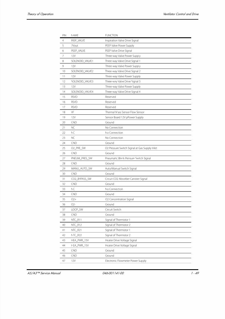
7/21/2019 a5 a3 Service Manual 2013
http://slidepdf.com/reader/full/a5-a3-service-manual-2013 64/399
A5/A3™ Service Manual 046-001141-00 1 - 49
Theory of Operation Ventilator Control and Drive
4 INSP_VALVE Inspiration Valve Drive Signal
5 7Vout PEEP Valve Power Supply
6 PEEP_VALVE PEEP Valve Drive Signal
7 12V Three-way Valve Power Supply
8 SOLENOID_VALVE1 Three-way Valve Drive Signal 1
9 12V Three-way Valve Power Supply
10 SOLENOID_VALVE2 Three-way Valve Drive Signal 2
11 12V Three-way Valve Power Supply
12 SOLENOID_VALVE3 Three-way Valve Drive Signal 3
13 12V Three-way Valve Power Supply
14 SOLENOID_VALVE4 Three-way Valve Drive Signal 4
15 RSVD Reserved
16 RSVD Reserved
17 RSVD Reserved
18 VF Thermal Mass Sensor Flow Sensor
19 12V Sensor Board 12V pPower Supply
20 GND Ground
21 NC No Connection
22 NC No Connection
23 NC No Connection
24 GND Ground
25 O2_PRE_SW O2 Pressure Switch Signal at Gas Supply Inlet
26 GND Ground
27 PNEUM_PRES_SW Pneumatic Block Pressure Switch Signal
28 GND Ground
29 MANU_AUTO_SW Auto/Manual Switch Signal
30 GND Ground
31 CO2_BYPASS_SW Circuit CO2 Absorber Canister Signal
32 GND Ground
33 NC No Connection
34 GND Ground
35 O2+ O2 Concentration Signal
36 O2- Ground
37 LOOP_SW Circuit Switch
38 GND Ground
39 NTC_R11 Signal of Thermistor 1
40 NTC_R12 Signal of Thermistor 2
41 NTC_R21 Signal of Thermistor 1
42 NTC_R22 Signal of Thermistor 2
43 HEA_PWR_15V Heater Drive Voltage Signal
44 HEA_PWR_15V Heater Drive Voltage Signal
45 GND Ground
46 GND Ground
47 12V Electronic Flowmeter Power Supply
PIN NAME FUNCTION
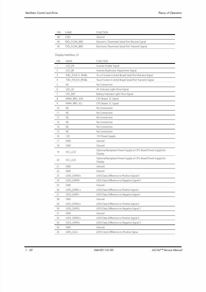
7/21/2019 a5 a3 Service Manual 2013
http://slidepdf.com/reader/full/a5-a3-service-manual-2013 65/399
Ventilator Control and Drive Theory of Operation
1 - 50 046-001141-00 A5/A3™ Service Manual
Display Interface, J3
48 GND Ground
49 RXD_FLOW_BRD Electronic Flowmeter Serial Port Receive Signal
50 TXD_FLOW_BRD Electronic Flowmeter Serial Port Transmit Signal
PIN NAME FUNCTION
1 LCD_EN Inverter Enable Signal
2 LCD_BR Inverter Brightness Adjustment Signal
3 RXD_TOUCH_PANEL Touch Screen Control Board Ser ial Port Receive Signal
4 TXD_TOUCH_PANEL Touch Screen Control Board Ser ial Port Transmit Signal
5 NC No Connection
6 LED_AC AC Indicator Light Drive Signal
7 LED_BAT Battery Indicator Light Drive Signal
8 MAIN_BRD_SDA CPU Board I2C Signal
9 MAIN_BRD_SCL CPU Board I2C Signal
10 NC No Connection
11 NC No Connection
12 NC No Connection
13 NC No Connection
14 NC No Connection
15 NC No Connection
16 12V 12V Power Supply
17 GND Ground
18 GND Ground
19 VCC_LCDOptional Backplane Power Supply or CPU Board Power Supply for
Display
20 VCC_LCDOptional Backplane Power Supply or CPU Board Power Supply for
Display
21 GND Ground
22 GND Ground
23 LVDS_DATA0+ LVDS Data Difference to Positive Signal 0
24 LVDS_DATA0- LVDS Data Difference to Negative Signal 0
25 GND Ground
26 LVDS_DATA1+ LVDS Data Difference to Positive Signal 1
27 LVDS_DATA1- LVDS Data Difference to Negative Signal 1
28 GND Ground
29 LVDS_DATA2+ LVDS Data Difference to Positive Signal 230 LVDS_DATA2- LVDS Data Difference to Negative Signal 2
31 GND Ground
32 LVDS_DATA3+ LVDS Data Difference to Positive Signal 3
33 LVDS_DATA3- LVDS Data Difference to Negative Signal 3
34 GND Ground
35 LVDS_CLK+ LVDS Clock Difference to Positive Signal
PIN NAME FUNCTION

7/21/2019 a5 a3 Service Manual 2013
http://slidepdf.com/reader/full/a5-a3-service-manual-2013 66/399
A5/A3™ Service Manual 046-001141-00 1 - 51
Theory of Operation Ventilator Control and Drive
Infrared Module Rack Interface for Patient Monitor, J4
Calibration Interface, J5
36 LVDS_CLK- LVDS Clock Difference to Negative Signal
37 GND Ground
PIN NAME FUNCTION
1 LED_AC AC Indicator Light Drive Signal
2 3V3 3.3V Power Supply
3 12V 12V Power Supply
4 12V 12V Power Supply
5 GND Ground
6 GND Ground
7 NC No Connection
8 NC No Connection
9 12V 12V Power Supply
10 RSVD Reserved
11 RSVD Reserved
12 GND Ground
13 LED_BAT Battery Indicator Light Drive Signal
14 PCON-_NON Power ON/OFF Inverse Phase Signal
15 GND Ground
16 PCON+ Power ON/OFF Circuit 3.3V
17 PCON- Power ON/OFF Signal
18 TOUCHPAD_5V 5V Power Supply
19 TOUCHPAD_GND Ground
20 TOUCHPAD_USB+ TOUCHPAD_USB Difference to Positive Signal
21 TOUCHPAD_USB- TOUCHPAD_USB Difference to Negative Signal
22 12V 12V Power Supply
23 GND Ground
24 NC No Connection
25 NC No Connection
PIN NAME FUNCTION
1 NC No Connection
2 NC No Connection
3 NC No Connection4 NC No Connection
5 NC No Connection
6 12V 12V Power Supply
7 RXD_CALIBRATE Calibration Serial Port Receive Signal
8 TXD_CALIBRATE Calibration Serial port Transmit Signal
9 GND Ground
PIN NAME FUNCTION

7/21/2019 a5 a3 Service Manual 2013
http://slidepdf.com/reader/full/a5-a3-service-manual-2013 67/399
Ventilator Control and Drive Theory of Operation
1 - 52 046-001141-00 A5/A3™ Service Manual
Anesthetic Ventilator Cooling Fan Interface, J7
Speaker Interface, J8
Battery Adaptation Board Interface, J9
Power Board Interface, J10
PIN NAME FUNCTION
1 12V3 12V Power Supply
2 RSVD Reserved
3 FAN1_STATE Fan Status Signal
4 GND Ground
PIN NAME FUNCTION
1 Speak+ Speaker Positive End
2 Speak- Speaker Negative End
PIN NAME FUNCTION
1 BAT1+ Battery Voltage
2 NTC1 Battery Internal Thermistor
3 BC1 Battery In-position Signal
4 GND Ground
5 BAT2+ Battery Voltage
6 NTC2 Battery Internal thermistor
7 BC2 Battery In-position Signal
8 GND Ground
PIN NAME FUNCTION
1 PLAM Buzzer Drive Signal (drives the buzzer directly)
2 RXD_PWR_BRD Power Board Serial Por t (receives signal)
3 LOOP_SW Circuit Switch (reflects if the circuit is in position)
4 TXD_PWR_BRD Power Board Ser ial Por t (transmits signal)
5 NC Power Board Cooling Fan Drive
6 GND Ground
7 LED-BAT Battery Status Indicator Light Drive Output
8 LCD_EN Backlight Enable Signal
9 LED-AC AC Status Indicator Light Drive Output
10 LCD_BR Backlight Brightness Control Voltage
11 PCON-Power ON/OFF Signal, LVTTL Pulse Signal. If this signal is high level, the system is
turned on; if this signal is low level, the system is turned off.
12 3.3VBF 3.3V only used for power ON/OFF the machine
13 BAT2+ 2? Battery Input, connect to battery positive end
14 GND Ground
15 BC2F2? Battery Availability Signal. Low level indicates battery available; high level
indicates battery unavailable

7/21/2019 a5 a3 Service Manual 2013
http://slidepdf.com/reader/full/a5-a3-service-manual-2013 68/399
A5/A3™ Service Manual 046-001141-00 1 - 53
Theory of Operation Ventilator Control and Drive
CPU Board Interface, J11
16 NTC2 2? Lithium-ion Battery Internal Thermistor Signal
17 BAT1+ 1? Battery Input, connect to battery positive end
18 GND Ground
19 BC1F1? Battery Availability Signal. Low level indicates battery available; high level
indicates battery unavailable
20 NTC1 1? Lithium-ion Battery Internal Thermistor Signal
21 GND Ground
22 GND Ground
23 HEA_PWR_15V Heat Wire Drive Voltage Output
24 HEA_PWR_15V Heat Wire Drive Voltage Output
25 NTC_R12 Thermistor (for controlling heat wire) Pin 1
26 NTC_R22 Thermistor (for controlling heat wire) Pin 2
27 NTC_R11 Thermistor (for controlling heat wire) Pin 1
28 NTC_R21 Thermistor (for controlling heat wire) Pin 2
29 GND Ground
30 GND Ground
31 3V3 3.3V Supply Voltage Output
32 3V3 3.3V Supply Voltage Output
33 5V 5V Supply Voltage Output
34 GND Ground
35 GND Ground
36 GND Ground
37 NC No Connection
38 GND Ground
39 NC No Connection
40 NC No Connection
41 GND Ground
42 GND Ground
43 12V 12V Power Supply Output
44 GND Ground
45 12V 12V Power Supply Output
46 12V 12V Power Supply Output
47 NC No Connection
48 15V2 15.2V Supply Voltage Output
49 NC No Connection
50 15V2 15.2V Supply Voltage Output
PIN NAME FUNCTION
A1 LCD_VDD LCD Power Supply
A2 GND LCD Ground
A3 NC No Connection
A4 NC No Connection
PIN NAME FUNCTION (Continued)

7/21/2019 a5 a3 Service Manual 2013
http://slidepdf.com/reader/full/a5-a3-service-manual-2013 69/399
Ventilator Control and Drive Theory of Operation
1 - 54 046-001141-00 A5/A3™ Service Manual
A5 RSVD Serial Port Transmit Signal
A6 RSVD Serial Port Receive Signal
A7 GND Ground
A8 RSVD Serial Port Transmit Signal
A9 RSVD Serial Port Receive Signal
A10 GND Ground
A11 UIVCC_USB USB Power Supply
A12 TOUCHPAD_USB+ TOUCHPAD_USB Data Signal +
A13 TOUCHPAD_USB- TOUCHPAD_USB Data Signal -
A14 GND Ground
A15 SCL CPU Board I2C Clock
A16 SDA CPU Board I2C Data
A17 GND Ground
A18 NC No Connection
A19 NC No Connection
A20 NC No Connection
A21 NC No Connection
A22 FAN1_STATE Fan Status Detected Signal
A23 NC No Connection
A24 GND Ground
A25 3V3 CPU Board Main Power Supply
A26 3V3 CPU Board main Power Supply
A27 GND Ground
A28 GND Ground
A29 5V CPU Board Interface Chip Power Supply
A30 5V CPU Board Interface Chip Power Supply
A31 GND Ground
A32 GND Ground
B1 NC Not Connected
B2 NC Not Connected
B3 NC Not Connected
B4 SPK_OUT+ Speaker Drive Signal +
B5 SPK_OUT- Speaker Drive Signal -
B6 GND Ground
B7 NC No Connection
B8 NC No Connection
B9 NC No Connection
B10 NC No Connection
B11 NC No Connection
B12 GND Ground
B13 TXD_PWR_BRD Power Board Serial Port Transmit Signal
B14 RXD_PWR_BRD Power Board Serial Port Receive Signal
B15 GND Ground
PIN NAME FUNCTION (Continued)
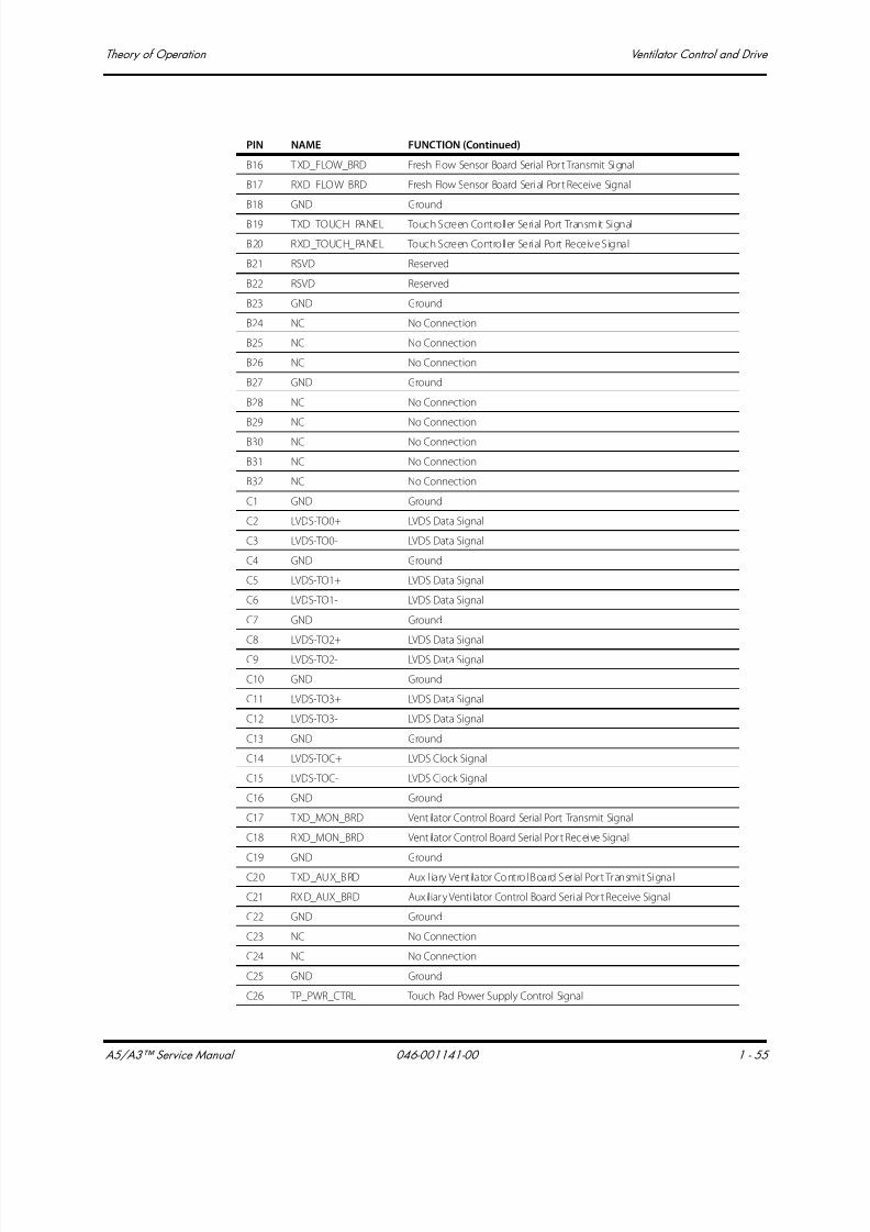
7/21/2019 a5 a3 Service Manual 2013
http://slidepdf.com/reader/full/a5-a3-service-manual-2013 70/399
A5/A3™ Service Manual 046-001141-00 1 - 55
Theory of Operation Ventilator Control and Drive
B16 TXD_FLOW_BRD Fresh Flow Sensor Board Serial Por t Transmit Signal
B17 RXD_FLOW_BRD Fresh Flow Sensor Board Serial Por t Receive Signal
B18 GND Ground
B19 TXD_TOUCH_PANEL Touch Screen Controller Serial Port Transmit Signal
B20 RXD_TOUCH_PANEL Touch Screen Controller Serial Port Receive Signal
B21 RSVD Reserved
B22 RSVD Reserved
B23 GND Ground
B24 NC No Connection
B25 NC No Connection
B26 NC No Connection
B27 GND Ground
B28 NC No Connection
B29 NC No Connection
B30 NC No Connection
B31 NC No Connection
B32 NC No Connection
C1 GND Ground
C2 LVDS-TO0+ LVDS Data Signal
C3 LVDS-TO0- LVDS Data Signal
C4 GND Ground
C5 LVDS-TO1+ LVDS Data Signal
C6 LVDS-TO1- LVDS Data Signal
C7 GND Ground
C8 LVDS-TO2+ LVDS Data Signal
C9 LVDS-TO2- LVDS Data Signal
C10 GND Ground
C11 LVDS-TO3+ LVDS Data Signal
C12 LVDS-TO3- LVDS Data Signal
C13 GND Ground
C14 LVDS-TOC+ LVDS Clock Signal
C15 LVDS-TOC- LVDS Clock Signal
C16 GND Ground
C17 TXD_MON_BRD Vent ilator Control Board Serial Port Transmit Signal
C18 RXD_MON_BRD Vent ilator Control Board Serial Por t Receive Signal
C19 GND Ground
C20 TXD_AUX_BRD Auxil iary Ventilator Control Board Ser ial Port Transmit Signal
C21 RXD_AUX_BRD Auxiliary Venti lator Control Board Serial Por t Receive Signal
C22 GND Ground
C23 NC No Connection
C24 NC No Connection
C25 GND Ground
C26 TP_PWR_CTRL Touch Pad Power Supply Control Signal
PIN NAME FUNCTION (Continued)
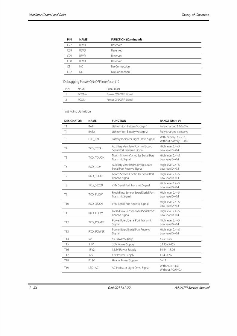
7/21/2019 a5 a3 Service Manual 2013
http://slidepdf.com/reader/full/a5-a3-service-manual-2013 71/399
Ventilator Control and Drive Theory of Operation
1 - 56 046-001141-00 A5/A3™ Service Manual
Debugging Power ON/OFF Interface, J12
Test Point Definition
C27 RSVD Reserved
C28 RSVD Reserved
C29 RSVD Reserved
C30 RSVD Reserved
C31 NC No Connection
C32 NC No Connection
PIN NAME FUNCTION
1 PCON+ Power ON/OFF Signal
2 PCON- Power ON/OFF Signal
DESIGNATOR NAME FUNCTION RANGE (Unit: V)
T1 BAT1 Lithium-ion Battery Voltage 1 Fully charged 12.6±5%
T2 BAT2 Lithium-ion Battery Voltage 2 Fully charged 12.6±5%
T3 LED_BAT Battery Indicator Light Drive SignalWith battery: 2.5~3.5;
Without battery: 0~0.4
T4 TXD_7024Auxiliary Ventilator Control Board
Serial Port Transmit Signal
High level 2.4~5;
Low level 0~0.4
T5 TXD_TOUCH Touch Screen Controller Serial Port
Transmit Signal
High level 2.4~5;
Low level 0~0.4
T6 RXD_7024Auxiliary Ventilator Control Board
Serial Port Receive Signal
High level 2.4~5;
Low level 0~0.4
T7 RXD_TOUCH
Touch Screen Controller Serial Port
Receive Signal
High level 2.4~5;
Low level 0~0.4
T8 TXD_33209 VPM Serial Port Transmit SignalHigh level 2.4~5;
Low level 0~0.4
T9 TXD_FLOWFresh Flow Sensor Board Serial Port
Transmit Signal
High level 2.4~5;
Low level 0~0.4
T10 RXD_33209 VPM Serial Port Receive SignalHigh level 2.4~5;
Low level 0~0.4
T11 RXD_FLOWFresh Flow Sensor Board Serial Port
Receive Signal
High level 2.4~5;
Low level 0~0.4
T12 TXD_POWERPower Board Serial Port Transmit
Signal
High level 2.4~5;
Low level 0~0.4
T13 RXD_POWERPower Board Serial Port Receive
Signal
High level 2.4~5;
Low level 0~0.4
T14 5V 5V Power Supply 4.75~5.25
T15 3.3V 3.3V Power Supply 3.135~3.465
T16 15V2 15.2V Power Supply 14.44~15.96
T17 12V 12V Power Supply 11.4~12.6
T18 P15V Heater Power Supply 0~15
T19 LED_AC AC Indicator Light Drive SignalWith AC: 5~3.5;
Without AC: 0~0.4
PIN NAME FUNCTION (Continued)
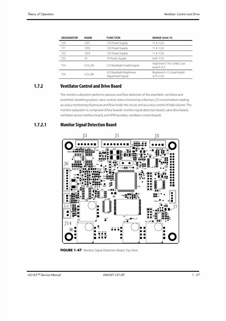
7/21/2019 a5 a3 Service Manual 2013
http://slidepdf.com/reader/full/a5-a3-service-manual-2013 72/399
A5/A3™ Service Manual 046-001141-00 1 - 57
Theory of Operation Ventilator Control and Drive
1.7.2 Ventilator Control and Drive Board
The monitor subsystem performs pressure and flow detection of the anesthetic ventilator and
anesthetic breathing system, valve control, status monitoring collection, O2 concentration reading,
accuracy monitoring of pressure and flow inside the circuit, and accuracy control of tidal volume. The
monitor subsystem is composed of four boards: monitor signal detection board, valve drive board,
ventilator sensor interface board, and VPM (auxiliary ventilator control board).
1.7.2.1 Monitor Signal Detection Board
FIGURE 1-47 Monitor Signal Detection Board, Top View
T20 12V1 12V Power Supply 11.4~12.6
T21 12V2 12V Power Supply 11.4~12.6
T22 12V3 12V Power Supply 11.4~12.6
T23 7V 7V Power Supply 6.65~7.35
T24 LCD_EN LCD Backlight Enable SignalHigh level 3.145~3.465; Low
level 0~0.3
T25 LCD_BRLCD Backlight Brightness
Adjustment Signal
Brightest 0~1.5; least bright
4.75~5.25
DESIGNATOR NAME FUNCTION RANGE (Unit: V)
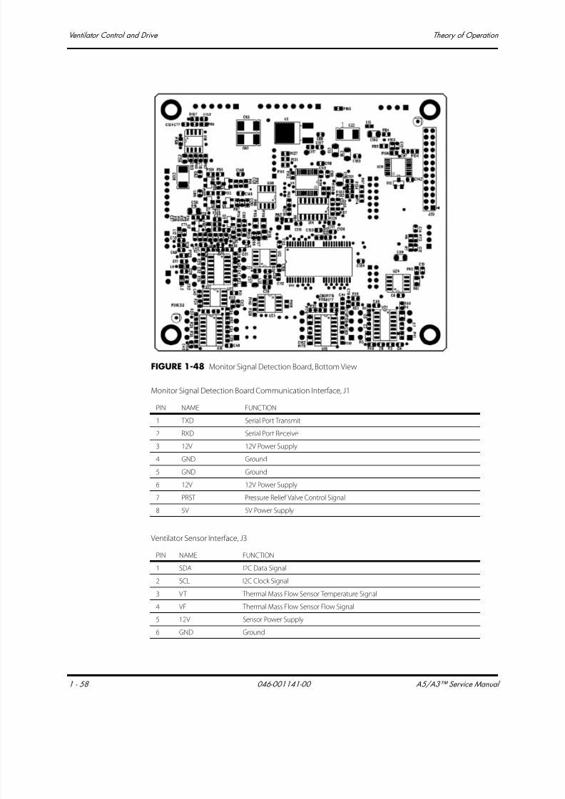
7/21/2019 a5 a3 Service Manual 2013
http://slidepdf.com/reader/full/a5-a3-service-manual-2013 73/399
Ventilator Control and Drive Theory of Operation
1 - 58 046-001141-00 A5/A3™ Service Manual
FIGURE 1-48 Monitor Signal Detection Board, Bottom View
Monitor Signal Detection Board Communication Interface, J1
Ventilator Sensor Interface, J3
PIN NAME FUNCTION
1 TXD Serial Port Transmit
2 RXD Serial Port Receive
3 12V 12V Power Supply
4 GND Ground
5 GND Ground
6 12V 12V Power Supply
7 PRST Pressure Relief Valve Control Signal
8 5V 5V Power Supply
PIN NAME FUNCTION
1 SDA I2C Data Signal
2 SCL I2C Clock Signal
3 VT Thermal Mass Flow Sensor Temperature Signal
4 VF Thermal Mass Flow Sensor Flow Signal
5 12V Sensor Power Supply
6 GND Ground

7/21/2019 a5 a3 Service Manual 2013
http://slidepdf.com/reader/full/a5-a3-service-manual-2013 74/399
A5/A3™ Service Manual 046-001141-00 1 - 59
Theory of Operation Ventilator Control and Drive
VT Calibration Communication Interface, J7
Three-way Valve Control Interface, J6
VPM Communication Interface, J5
O2 Cell Detection Interface, J12
Test Point Definition
PIN NAME FUNCTION
1 TXD_CALIBRATE Calibration Serial Port Transmit Signal
2 RXD_CALIBRATE Calibration Serial Port Receive Signal
3 GND Ground
4 12V 12V Power Supply
PIN NAME FUNCTION
1 12V Three-way Valve Power Supply
2 SOLENOID_VALVE1 Three-way Valve Control 1
3 12V Three-way Valve Power Supply
4 SOLENOID_VALVE2 Three-way Valve Control 2
5 12V Three-way Valve Power Supply
6 SOLENOID_VALVE3 Three-way Valve Control 3
7 12V Three-way Valve Power Supply
8 SOLENOID_VALVE4 Three-way Valve Control 4
PIN NAME FUNCTION
1 TXD_AUX_BRD VPM Serial Port Transmit Signal
2 RXD_AUX_BRD VPM Serial Port Receive Signal
3 GND Ground
4 12V 12V Power Supply
PIN NAME FUNCTION
1 O2+ O2 Cell +
2 O2- O2 Cell -
3 GND Ground
DESIGNATOR NAME FUNCTION RANGE (unit: V)
T1 O2 O2 Concentration Voltage 0~3.5
T2 PP PEEP Pressure 0.2~4.5
T3 PW Airway Pressure 0.2~4.5
T6 FM Ventilator Flow Detection 0.21~5.25
T8 FE Expiratory Flow Value 0.2~5.5
T9 VAJF3 Offset Voltage 0.602~0.622
T10 10V5 10.5V 10.25~10.75
T11 REF_4V 4.096V Baseline Power Supply 3.096~4.196
T12 1V2 1.2V Baseline Power Supply 1.1~1.3
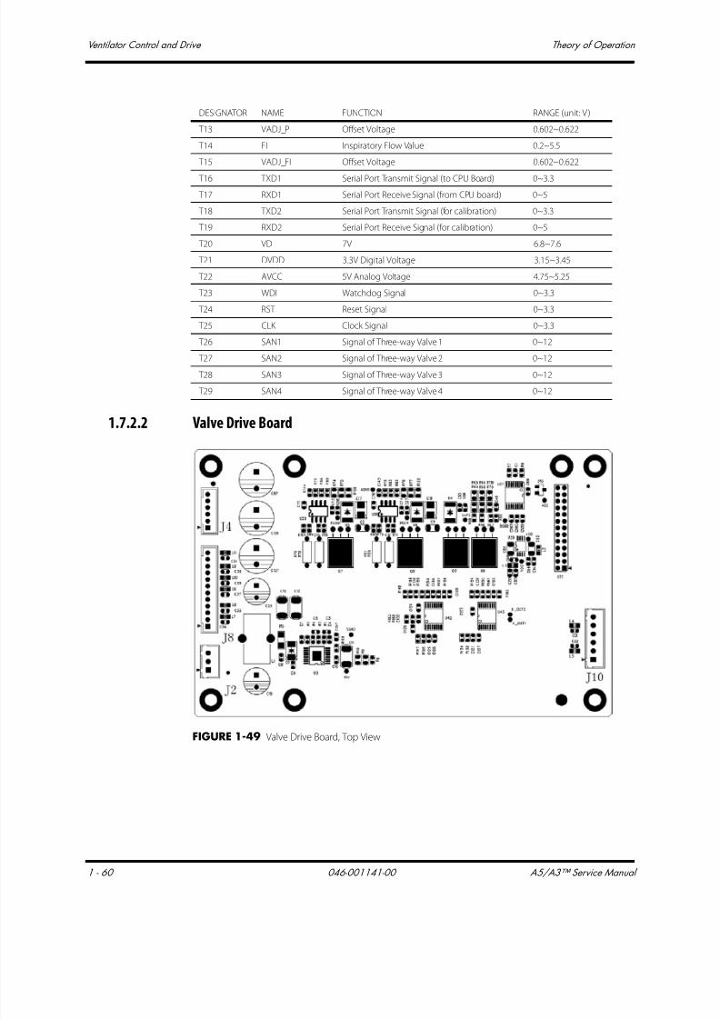
7/21/2019 a5 a3 Service Manual 2013
http://slidepdf.com/reader/full/a5-a3-service-manual-2013 75/399
Ventilator Control and Drive Theory of Operation
1 - 60 046-001141-00 A5/A3™ Service Manual
1.7.2.2 Valve Drive Board
FIGURE 1-49 Valve Drive Board, Top View
T13 VADJ_P Offset Voltage 0.602~0.622
T14 FI Inspiratory Flow Value 0.2~5.5
T15 VADJ_FI Offset Voltage 0.602~0.622
T16 TXD1 Serial Port Transmit Signal (to CPU Board) 0~3.3
T17 RXD1 Serial Port Receive Signal (from CPU board) 0~5
T18 TXD2 Serial Port Transmit Signal (for calibration) 0~3.3
T19 RXD2 Serial Port Receive Signal (for calibration) 0~5
T20 VD 7V 6.8~7.6
T21 DVDD 3.3V Digital Voltage 3.15~3.45
T22 AVCC 5V Analog Voltage 4.75~5.25
T23 WDI Watchdog Signal 0~3.3
T24 RST Reset Signal 0~3.3
T25 CLK Clock Signal 0~3.3
T26 SAN1 Signal of Three-way Valve 1 0~12
T27 SAN2 Signal of Three-way Valve 2 0~12
T28 SAN3 Signal of Three-way Valve 3 0~12
T29 SAN4 Signal of Three-way Valve 4 0~12
DESIGNATOR NAME FUNCTION RANGE (unit: V)

7/21/2019 a5 a3 Service Manual 2013
http://slidepdf.com/reader/full/a5-a3-service-manual-2013 76/399
A5/A3™ Service Manual 046-001141-00 1 - 61
Theory of Operation Ventilator Control and Drive
FIGURE 1-50 Valve Drive Board, Bottom View
Proportional Valve and Pressure Relief Valve Drive Interface, J4
Power Supply Interface, J2
Status Monitor Detection Interface, J8
PIN NAME FUNCTION
1 7V Pressure Relief Valve Power Supply
2 SAFE_VALVE Pressure Relief Valve Control Signal
3 7V Inspiration Valve Power Supply
4 INSP_VALVE Inspiration Valve Control Signal
5 7V PEEP Valve Power Supply
6 PEEP_VALVE PEEP Valve Control Signal
PIN NAME FUNCTION
1 GND Ground
2 GND Ground
3 12V 12V Power Supply
PIN NAME FUNCTION
1 GND Ground
2 PNEUM_PRE_SW Circuit block pressure Switch Signal
3 GND Ground
4 NC /
5 GND Ground
6 QUICK_O2_SW O2 Flushing Pressure Switch Signal
7 GND Ground

7/21/2019 a5 a3 Service Manual 2013
http://slidepdf.com/reader/full/a5-a3-service-manual-2013 77/399
Ventilator Control and Drive Theory of Operation
1 - 62 046-001141-00 A5/A3™ Service Manual
Test Point Definition
1.7.2.3 Sensor Interface Board
FIGURE 1-51 Sensor Interface Board, Top View
8 CGO_PRE_SW CGO Switch Signal
9 GND Ground
10 O2_PRE_SW O2 Pressure Switch Signal at Gas Supply Inlet
11 GND Ground
12 MANU_AUTO_SW Auto/Manual Switch Signal
DESIGNATOR NAME FUNCTION RANGE (unit: V)
T1 K_OUT1 Status Monitor Signal 0~3.45
T2 K_OUT2 Status Monitor Signal 0~3.45
T3 SAFE Pressure Relief Valve Signal 0~7
T4 VOC Reserved DA Output Signal 0~1.2
T5 AD2 Analog Channel Output Signal 0~5
T6 FLOW Inspiration Valve Control Signal 0~7
T7 PEEP PEEP Valve Control Signal 0~7
T8 10V 12V Input Signal 10~14
T9 7V Valve Power Supply 6.65~7.35
T10 SGND Ground 0
PIN NAME FUNCTION

7/21/2019 a5 a3 Service Manual 2013
http://slidepdf.com/reader/full/a5-a3-service-manual-2013 78/399
A5/A3™ Service Manual 046-001141-00 1 - 63
Theory of Operation Ventilator Control and Drive
FIGURE 1-52 Sensor Interface Board, Bottom View
Sensor Interface Board Interface, J2
Test Point Definition
1.7.3 Battery
1.7.3.1 Battery Power
For A3 anesthesia system:
Battery: 11.1V, 4.5Ah×1 Lithium-ion battery (sealed)
Battery running time: 75 minutes (new battery)
Battery charge time: 8 hours max from an initial charge of 10%
PIN NAME FUNCTION
1 MON_BRD_SDA VCM I2C Data Signal
2 MON_BRD_SCL VCM I2C Clock Signal
3 VT Thermal Mass Flow Sensor Temperature Signal
4 VF Thermal Mass Flow Sensor Flow Signal
5 12V 12V Power Supply
6 GND Ground
PIN NAME FUNCTION
TP1 3V3 Test 3.3V Power Supply
TP2 5V Test 5V Power Supply
TP3 5VA Test Analog 5V Power Supply

7/21/2019 a5 a3 Service Manual 2013
http://slidepdf.com/reader/full/a5-a3-service-manual-2013 79/399
Ventilator Control and Drive Theory of Operation
1 - 64 046-001141-00 A5/A3™ Service Manual
For A5 anesthesia system:
Battery: 11.1V, 4.5Ah×2 Lithium-ion Battery (sealed)
Battery Run Time: 150 minutes (new battery)
Battery Charge Time: 8 hours max from an initial charge of 10%
1.7.3.2 Battery Adaptation Board
FIGURE 1-53 Battery Adaptation Board, Top View
FIGURE 1-54 Battery Adaptation Board, Bottom View
Battery Interface, J1 and J2
Battery Cable Interface, J3
PIN NAME FUNCTION
1 BAT+ Battery+
2 BAT+ Battery+
3 BC Battery In-position Signal
4 BAT- Battery-
5 NTC Temperature Signal
6 BAT- Battery-
7 BAT- Battery-
PIN NAME FUNCTION
1 VBAT1 Battery Voltage
2 NTC1 Battery Internal Thermistor
3 BC1 Battery In-position Signal
4 GND Ground
5 VBAT2 Battery Voltage
6 NTC2 Battery Internal Thermistor
7 BC2 Battery In-position Signal
8 GND Ground
7/21/2019 a5 a3 Service Manual 2013
http://slidepdf.com/reader/full/a5-a3-service-manual-2013 80/399
A5/A3™ Service Manual 046-001141-00 1 - 65
Theory of Operation Ventilator Control and Drive
1.7.4 Breathing System Heater
The anesthesia system heater provides software and hardware dual-protection from overheating. The
heater can switch over its operating mode automatically according to the change in ambient
temperature.

7/21/2019 a5 a3 Service Manual 2013
http://slidepdf.com/reader/full/a5-a3-service-manual-2013 81/399
Ventilator Pneumatic- O2 Drive Gas Theory of Operation
1 - 66 046-001141-00 A5/A3™ Service Manual
1.8 Ventilator Pneumatic- O2 Drive Gas
1.8.1 Ventilator Pneumatic Drive
Oxygen is the driving gas for the ventilator. In addition to the flow meter block, a high pressureregulator reduces the supply pressure to 200 kPa (29 psi). This pressure represents the drive gas for
the ventilator.
The drive pressure regulator is placed ahead of the proportional valve that generates the driving gas
flow during the inspiratory phase. This flow fills the bellows dome that surrounds the bellows.
1.8.2 Drive Pressure-High Pressure Regulator (200 kPa, 29 psi)
The drive pressure regulator stabilizes the supply pressure provided to the proportional valve. The
flow generated by the proportional valve is therefore independent of pressure variations at the
supply.
Setting the drive pressure regulator at 200 kPa (29 psi) allows for a maximum inspiratory flow of 110
L/min at the ventilator.
1.8.3 Drive Gas Assembly
The manifold assembly module mainly consists of the inspiratory circuit and PEEP circuit. The
inspiratory circuit goes through the normally closed proportional solenoid valve, which generates a
gas flow of 0 to 110 L/min by the valve drive board. The gas flow of the PEEP circuit goes through the
normally closed proportional solenoid valve, which also generates a gas pressure of 3 to 30 cmH2O
by the valve drive board.
1.8.4 Tube Color CodingAll the pneumatic tubes used in the anesthesia system are color coded for use in the United States
only.
GAS US STANDARD
O2 GREEN
N2O BLUE
AIR ORANGE

7/21/2019 a5 a3 Service Manual 2013
http://slidepdf.com/reader/full/a5-a3-service-manual-2013 82/399
A5/A3™ Service Manual 046-001141-00 2 - 1
2.0 Installation Guide
Preparation - Additional Material Required..........................................................................................................................2-2
Assembly....................................................................................................................................................................................................2-3
Functional Tests....................................................................................................................................................................................2-21
Pneumatic Leak Tests ........................................................................................................................................................................2-38
Breathing System Checks ...............................................................................................................................................................2-40
Performance Verification................................................................................................................................................................. 2-41
Alarms and Fail safe Functions ....................................................................................................................................................2-46
Miscellaneous Tests............................................................................................................................................................................2-48
Vaporizer Interlock Test....................................................................................................................................................................2-49
Vaporizer Accuracy Test...................................................................................................................................................................2-50
Electrical Tests........................................................................................................................................................................................2-51

7/21/2019 a5 a3 Service Manual 2013
http://slidepdf.com/reader/full/a5-a3-service-manual-2013 83/399
Preparation - Additional Material Required Installation Guide
2 - 2 046-001141-00 A5/A3™ Service Manual
2.1 Preparation - Additional Material Required
The following additional material are required before installation. The customer is responsible for
supplying this material. Missing items may result in delays, incomplete installations, and/or additional
service visits.
• Compatible emergency O2, N2O, and AIR cylinders
• Agent vaporizers and key fillers (if not purchased with the anesthesia system)
• Liquid agent medication
• CO2 absorbent Pre-Paks or loose fill
• Active O2, N2O, and AIR lines (280 to 600 kPa (40 to 87 psi))
• Dropdown hoses for ceiling-mounted medical gas utilities that are compatible with quick-
disconnect hoses (if not purchased with the anesthesia system)

7/21/2019 a5 a3 Service Manual 2013
http://slidepdf.com/reader/full/a5-a3-service-manual-2013 84/399
A5/A3™ Service Manual 046-001141-00 2 - 3
Installation Guide Assembly
2.2 Assembly
NOTE: The Anesthesia Machine is matched with its Breathing System Block via
calibration of its Flow Sensors. If the Breathing System Block is
removed, ensure that it is reinstalled on its matching Anesthesia
Machine. If a different Breathing System Block is reinstalled, then theFlow Sensors must be recalibrated. Refer to Section NOTE: on page 4-
17.
NOTE: Forward going the breathing system will have a serial number label on
it. On the back of the machine, next to the serial number label, there is a
serial number label of the breathing system that the unit was calibrated
and shipped with.
2.2.1 Unpacking and Setup
1. When the A5/A3 is delivered, IMMEDIATELY inspect the box for any damage.
a. If there is NO damage and ALL tip indicators on the box exterior are intact, then sign and
date the bill of lading or airway bill to indicate safe receipt of the anesthesia system.
b. If there is DAMAGE or ANY of the tip indicators on the box exterior have activated, then
conditionally accept the delivery and clearly describe the damages on the bill of lading or
airway bill. BOTH the carrier and recipient must sign and date the bill of lading or airway bill.
Save all damaged factory packaging until further instructed by Mindray. The receiver should
immediately contact Mindray Customer Service at (800) 288-2121 or (201) 995-8000.
NOTE: When unpacking the unit, keep as much of the plastic covering on the
unit as possible. When all parts are unpacked, return the packing
material to its original box. Place the smaller box inside the larger box.
2. Cut, remove, and discard the white shipping straps from the box.
FIGURE 2-1
3. Pull the box top straight up off the box and place on the floor near the unit. The box top will be
used later as a ramp when rolling down the A5/A3 onto the floor.
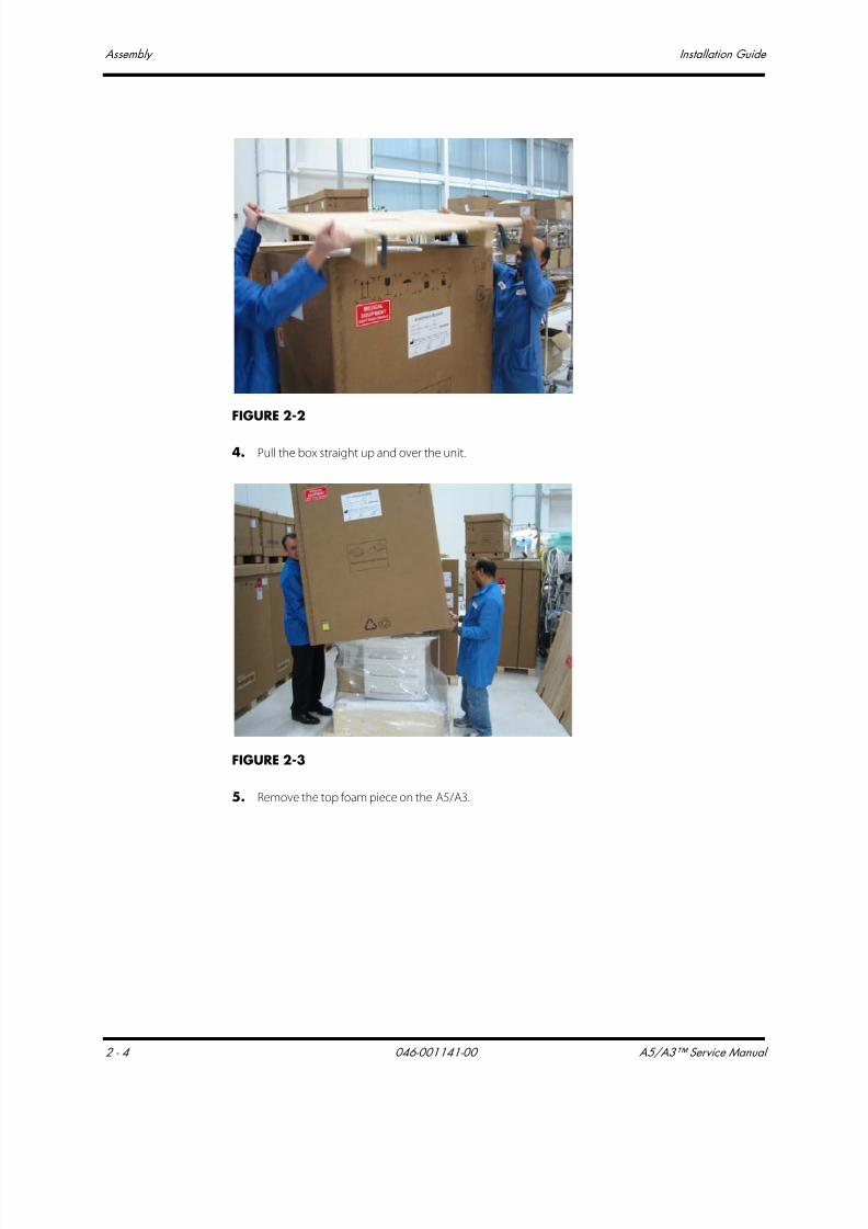
7/21/2019 a5 a3 Service Manual 2013
http://slidepdf.com/reader/full/a5-a3-service-manual-2013 85/399
Assembly Installation Guide
2 - 4 046-001141-00 A5/A3™ Service Manual
FIGURE 2-2
4. Pull the box straight up and over the unit.
FIGURE 2-3
5. Remove the top foam piece on the A5/A3.

7/21/2019 a5 a3 Service Manual 2013
http://slidepdf.com/reader/full/a5-a3-service-manual-2013 86/399
A5/A3™ Service Manual 046-001141-00 2 - 5
Installation Guide Assembly
FIGURE 2-4
6. Cut the plastic tie wrap as shown below. Roll down the plastic bag from the unit.
FIGURE 2-5
7. Using a pair of scissors, cut the plastic wrap from the A5/A3 near the back of the unit, using care
to not scratch or otherwise damage the unit. Remove and discard the plastic wrap. Remove the
empty box on the tray from the unit.
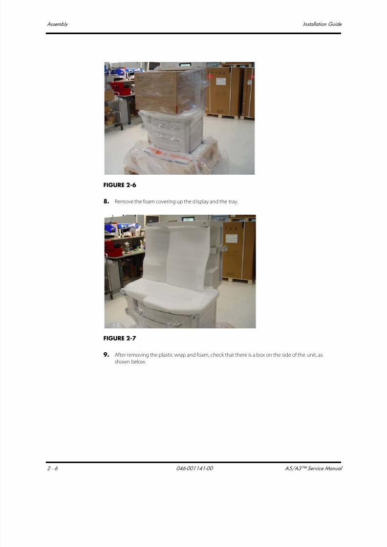
7/21/2019 a5 a3 Service Manual 2013
http://slidepdf.com/reader/full/a5-a3-service-manual-2013 87/399
Assembly Installation Guide
2 - 6 046-001141-00 A5/A3™ Service Manual
FIGURE 2-6
8. Remove the foam covering up the display and the tray.
FIGURE 2-7
9. After removing the plastic wrap and foam, check that there is a box on the side of the unit, as
shown below.

7/21/2019 a5 a3 Service Manual 2013
http://slidepdf.com/reader/full/a5-a3-service-manual-2013 88/399
A5/A3™ Service Manual 046-001141-00 2 - 7
Installation Guide Assembly
FIGURE 2-8
10. At the base of the box platform, remove both sets of orange straps. Save the straps in case the
A5/A3 needs to be repacked.
FIGURE 2-9
11. Remove the piece of wood at the front of the A5/A3. Then, remove the foam packing material
from around the front of the unit.
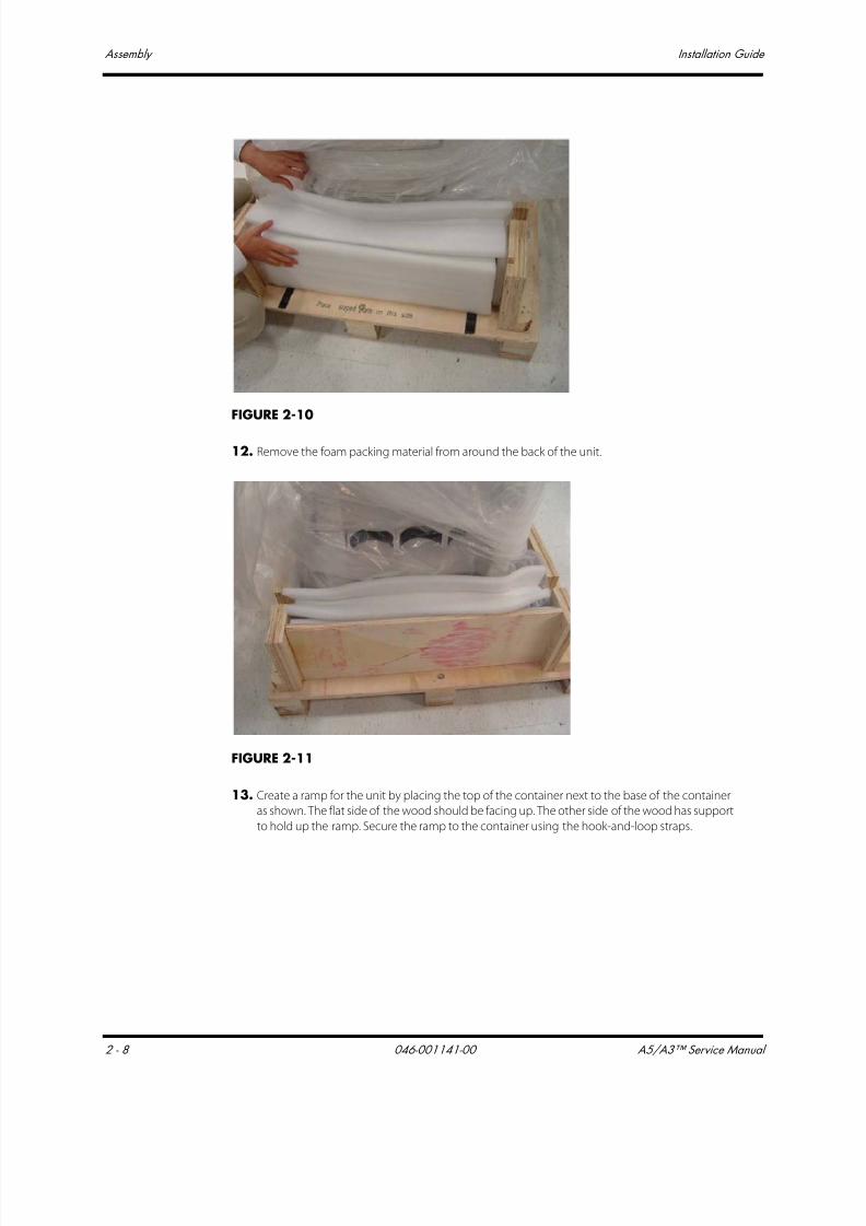
7/21/2019 a5 a3 Service Manual 2013
http://slidepdf.com/reader/full/a5-a3-service-manual-2013 89/399
Assembly Installation Guide
2 - 8 046-001141-00 A5/A3™ Service Manual
FIGURE 2-10
12. Remove the foam packing material from around the back of the unit.
FIGURE 2-11
13. Create a ramp for the unit by placing the top of the container next to the base of the container
as shown. The flat side of the wood should be facing up. The other side of the wood has support
to hold up the ramp. Secure the ramp to the container using the hook-and-loop straps.
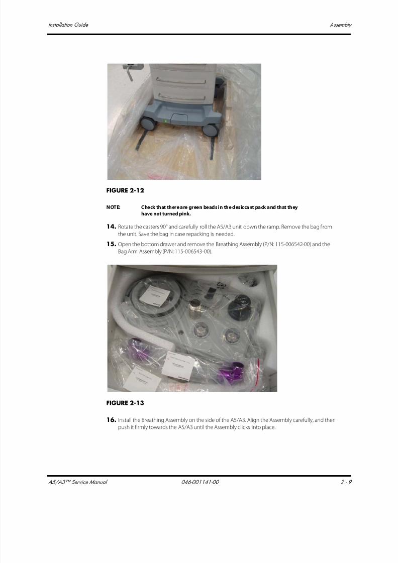
7/21/2019 a5 a3 Service Manual 2013
http://slidepdf.com/reader/full/a5-a3-service-manual-2013 90/399
A5/A3™ Service Manual 046-001141-00 2 - 9
Installation Guide Assembly
FIGURE 2-12
NOTE: Check that there are green beads in the desiccant pack and that they
have not turned pink.
14. Rotate the casters 90° and carefully roll the A5/A3 unit down the ramp. Remove the bag from
the unit. Save the bag in case repacking is needed.
15. Open the bottom drawer and remove the Breathing Assembly (P/N: 115-006542-00) and the
Bag Arm Assembly (P/N: 115-006543-00).
FIGURE 2-13
16. Install the Breathing Assembly on the side of the A5/A3. Align the Assembly carefully, and then
push it firmly towards the A5/A3 until the Assembly clicks into place.
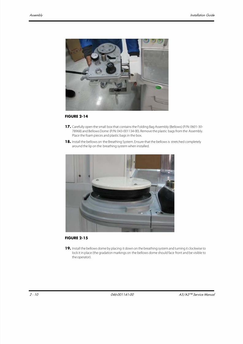
7/21/2019 a5 a3 Service Manual 2013
http://slidepdf.com/reader/full/a5-a3-service-manual-2013 91/399
Assembly Installation Guide
2 - 10 046-001141-00 A5/A3™ Service Manual
FIGURE 2-14
17. Carefully open the small box that contains the Folding Bag Assembly (Bellows) (P/N: 0601-30-
78968) and Bellows Dome (P/N: 043-001134-00). Remove the plastic bags from the Assembly.
Place the foam pieces and plastic bags in the box.
18. Install the bellows on the Breathing System. Ensure that the bellows is stretched completely
around the lip on the breathing system when installed.
FIGURE 2-15
19. Install the bellows dome by placing it down on the breathing system and turning it clockwise to
lock it in place (the gradation markings on the bellows dome should face front and be visible to
the operator).

7/21/2019 a5 a3 Service Manual 2013
http://slidepdf.com/reader/full/a5-a3-service-manual-2013 92/399
A5/A3™ Service Manual 046-001141-00 2 - 11
Installation Guide Assembly
FIGURE 2-16
20. Install the Bag Arm Assembly, aligning the keyed features as shown below.
FIGURE 2-17
21. Then, push the Bag Arm Assembly into the Breathing System and tighten the knurled collar asshown below.

7/21/2019 a5 a3 Service Manual 2013
http://slidepdf.com/reader/full/a5-a3-service-manual-2013 93/399
Assembly Installation Guide
2 - 12 046-001141-00 A5/A3™ Service Manual
FIGURE 2-18
22. Open the middle and bottom drawers and carefully remove the Removable Absorber Assembly
(P/N: 115-007453-00), Waste Gas Scavenger Hose (P/N: 115-006557-00) and the Waste Gas
Scavenger Assembly (P/N: 115-006556-00).
FIGURE 2-19
23. Install the white Absorber hose on the Absorber Assembly. Then, install the Absorber Assembly
without the canister in place. Install the lower part first, line up the pins with the holes, and then
align the top part. Push the top part in (upward) until both the front and back latches click into
place.

7/21/2019 a5 a3 Service Manual 2013
http://slidepdf.com/reader/full/a5-a3-service-manual-2013 94/399
A5/A3™ Service Manual 046-001141-00 2 - 13
Installation Guide Assembly
FIGURE 2-20
24. Add CO2 absorbent Pre-Pak or loose fill to the canister. Slide the canister into the Absorber
Assembly. Turn the locking lever 90° counter-clockwise to lock the canister in place.
FIGURE 2-21
25. Slide the Scavenger Assembly in the track on the lower left side (i.e., same side as the Breathing
Assembly) of the A5/A3 and tighten the thumbscrew on the Scavenger Assembly to lock it in
place. Install one side of the Scavenger Hose to the Scavenger Assembly and the other side of
the Hose to the A5/A3 as shown below.

7/21/2019 a5 a3 Service Manual 2013
http://slidepdf.com/reader/full/a5-a3-service-manual-2013 95/399
Assembly Installation Guide
2 - 14 046-001141-00 A5/A3™ Service Manual
FIGURE 2-22
26. Open the top drawer and check that it contains the following contents:
• Auxiliary O2/Air Reference Card (PN: 047-004342-00)
• Preoperative Checkout List (PN: 047-004343-00)
• Exhaust Emission Pipe (PN: 115-008426-00)
• Inspiratory Flow Sensor & Expiratory Flow Sensor (PN: 115-008264-00)
• O2 Cable Assembly (PN: 115-006551-00)
• Gas Cylinder Wrench (PN: 041-004480-00)
• Wired USB Mouse (PN: 0000-10-10751) (A3 only)
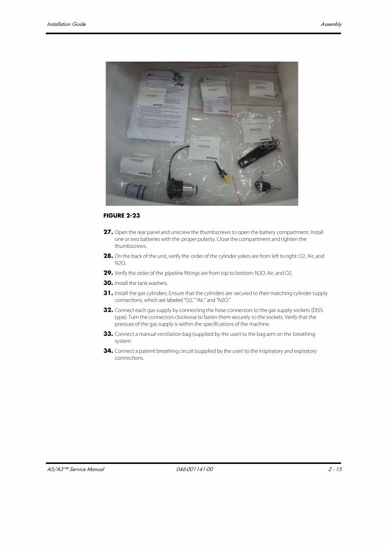
7/21/2019 a5 a3 Service Manual 2013
http://slidepdf.com/reader/full/a5-a3-service-manual-2013 96/399
A5/A3™ Service Manual 046-001141-00 2 - 15
Installation Guide Assembly
FIGURE 2-23
27. Open the rear panel and unscrew the thumbscrews to open the battery compartment. Install
one or two batteries with the proper polarity. Close the compartment and tighten the
thumbscrews.
28. On the back of the unit, verify the order of the cylinder yokes are from left to right: O2, Air, and
N2O.
29. Verify the order of the pipeline fittings are from top to bottom: N2O, Air, and O2.
30. Install the tank washers.
31. Install the gas cylinders. Ensure that the cylinders are secured to their matching cylinder supply
connections, which are labeled “O2,” “Air,” and “N2O.”
32. Connect each gas supply by connecting the hose connectors to the gas supply sockets (DISS
type). Turn the connectors clockwise to fasten them securely to the sockets. Verify that the
pressure of the gas supply is within the specifications of the machine.
33. Connect a manual ventilation bag (supplied by the user) to the bag arm on the breathing
system.
34. Connect a patient breathing circuit (supplied by the user) to the inspiratory and expiratory
connections.
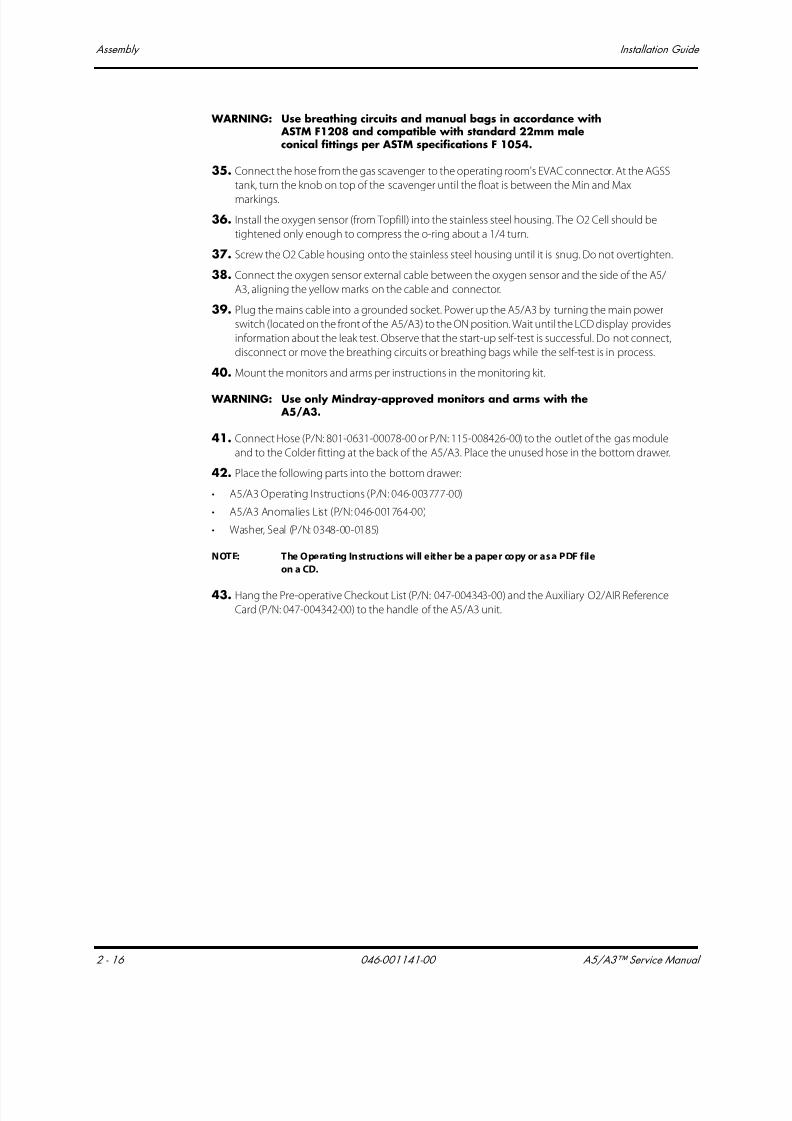
7/21/2019 a5 a3 Service Manual 2013
http://slidepdf.com/reader/full/a5-a3-service-manual-2013 97/399
Assembly Installation Guide
2 - 16 046-001141-00 A5/A3™ Service Manual
WARNING: Use breathing circuits and manual bags in accordance with ASTM F1208 and compatible with standard 22mm maleconical fittings per ASTM specifications F 1054.
35. Connect the hose from the gas scavenger to the operating room's EVAC connector. At the AGSS
tank, turn the knob on top of the scavenger until the float is between the Min and Max
markings.
36. Install the oxygen sensor (from Topfill) into the stainless steel housing. The O2 Cell should be
tightened only enough to compress the o-ring about a 1/4 turn.
37. Screw the O2 Cable housing onto the stainless steel housing until it is snug. Do not overtighten.
38. Connect the oxygen sensor external cable between the oxygen sensor and the side of the A5/
A3, aligning the yellow marks on the cable and connector.
39. Plug the mains cable into a grounded socket. Power up the A5/A3 by turning the main power
switch (located on the front of the A5/A3) to the ON position. Wait until the LCD display provides
information about the leak test. Observe that the start-up self-test is successful. Do not connect,
disconnect or move the breathing circuits or breathing bags while the self-test is in process.
40. Mount the monitors and arms per instructions in the monitoring kit.
WARNING: Use only Mindray-approved monitors and arms with the A5/A3.
41. Connect Hose (P/N: 801-0631-00078-00 or P/N: 115-008426-00) to the outlet of the gas module
and to the Colder fitting at the back of the A5/A3. Place the unused hose in the bottom drawer.
42. Place the following parts into the bottom drawer:
• A5/A3 Operating Instructions (P/N: 046-003777-00)
• A5/A3 Anomalies List (P/N: 046-001764-00)
• Washer, Seal (P/N: 0348-00-0185)
NOTE: The Operating Instructions will either be a paper copy or as a PDF file
on a CD.
43. Hang the Pre-operative Checkout List (P/N: 047-004343-00) and the Auxiliary O2/AIR Reference
Card (P/N: 047-004342-00) to the handle of the A5/A3 unit.

7/21/2019 a5 a3 Service Manual 2013
http://slidepdf.com/reader/full/a5-a3-service-manual-2013 98/399
A5/A3™ Service Manual 046-001141-00 2 - 17
Installation Guide Assembly
2.2.2 Breathing System and Breathing System Accessories and Checkout
Procedures
FIGURE 2-24
1. Breathing System
2. AGSS Transfer Hose3. AGSS
4. CO2 Absorbent
5. O2 sensor cable with sensor
2.2.3 AGSS Connections
1. Remove the Anesthetic Gas Scavenging System (AGSS) from the foam and bag.
2. Mount the AGSS to the A5/A3 via the GCX compatible rail system.
3. Attach the AGSS Transfer Hose between the inlet port of the AGSS and the exhaust port of the
A5/A3.
2.2.3.1 Tank Wrench and Pre-operation Checklist1. Mount the tank wrench on the rear of the A5/A3 so that it can be used to open or close each
cylinder without disconnecting it from the machine.
2. Attach the pre-operation checklist to a location on the A5/A3 where the operator can access it.

7/21/2019 a5 a3 Service Manual 2013
http://slidepdf.com/reader/full/a5-a3-service-manual-2013 99/399
Assembly Installation Guide
2 - 18 046-001141-00 A5/A3™ Service Manual
2.2.4 2.2.4 Vaporizers (if available)
WARNING: If the vaporizer is incompatible with the A5/A3 AnesthesiaSystem, the vaporizer will not work at all. Use vaporizers with Selectatec mounting system that are compliant to ISO
8835-4. Refer to the vaporizer manufacturer's InstructionsFor Use for filling or draining the vaporizer and otherinformation.
WARNING: The A5/A3 Anesthesia System has a Selectatec mountsystem which will only allow vaporizers to be mounted thathave an interlock system which prevents more than one vaporizer simultaneously being turned on. Do not attemptto override this safety feature.
WARNING: Use care in lifting and manipulating vaporizers during themounting process as their weight may be greater thanexpected, based on their size and shape.
NOTE: The barometric pressure may differ from the calibration pressure of the
anesthetic vaporizer. This may cause an inaccurate output of the
anesthetic agent. The operator should continuously monitor the
concentration of anesthetic agent during system use.
1. Align the vaporizer over the valve cartridges of the mounting bar. Hang the vaporizer on the
mounting bar as shown below. Note that the locking mechanism handle is in the unlocked
position.
FIGURE 2-25
2. Rotate the locking mechanism handle clockwise into the locked position as shown below.
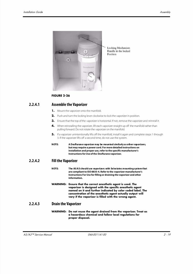
7/21/2019 a5 a3 Service Manual 2013
http://slidepdf.com/reader/full/a5-a3-service-manual-2013 100/399
A5/A3™ Service Manual 046-001141-00 2 - 19
Installation Guide Assembly
FIGURE 2-26
2.2.4.1 Assemble the Vaporizer
1. Mount the vaporizer onto the manifold.
2. Push and turn the locking lever clockwise to lock the vaporizer in position.
3. Ensure that the top of the vaporizer is horizontal. If not, remove the vaporizer and reinstall it.
4. When reinstalling the vaporizer, lift each vaporizer straight up off the manifold rather than
pulling forward. Do not rotate the vaporizer on the manifold.
5. If a vaporizer unintentionally lifts off the manifold, install it again and complete steps 1 through
3. If the vaporizer lifts off a second time, do not use the system.
NOTE: A Desflurane vaporizer may be mounted similarly as other vaporizers,but may require a power cord. For more detailed instructions on
installation and proper use, refer to the specific manufacturer's
Instructions for Use of the Desflurane vaporizer.
2.2.4.2 Fill the Vaporizer
NOTE: The A5/A3 should use vaporizers with Selectatec mounting system that
are compliant to ISO 8835-4. Refer to the vaporizer manufacturer's
Instructions For Use for filling or draining the vaporizer and other
information.
WARNING: Ensure that the correct anesthetic agent is used. The vaporizer is designed with the specific anesthetic agentnamed on it and further indicated by color coded label. Theconcentration of the anesthetic agent actually output will vary if the vaporizer is filled with the wrong agent.
2.2.4.3 Drain the Vaporizer
WARNING: Do not reuse the agent drained from the vaporizer. Treat asa hazardous chemical and follow local regulations forproper disposal.

7/21/2019 a5 a3 Service Manual 2013
http://slidepdf.com/reader/full/a5-a3-service-manual-2013 101/399
Assembly Installation Guide
2 - 20 046-001141-00 A5/A3™ Service Manual
NOTE: The A5/A3 should use vaporizers with Selectatec mounting system that
are compliant to ISO 8835-4. Refer to the vaporizer manufacturer's
Instructions For Use for filling or draining the vaporizer.
2.2.5 Emergency Cylinder(s) (if available)
1. Remove the cover from a new O2, N2O, and AIR cylinder.
2. Mount one cylinder at a time onto the rear of the anesthesia machine.
3. Discard the cylinder's tank washer. Always use the approved tank washer provided with the A5/
A3.
4. Open the bail of each yoke and mount the cylinder over the tank washer.
5. Ensure the O2 cylinder mates to the O2 Pin Index Safety System (PISS) connection on the O2
yoke. Close the yoke bail and use the hand-screw to tighten the cylinder to the yoke port.
6. Ensure that the N2O cylinder mates to the N2O PISS connection on the N2O yoke. Close the
yoke bail and use the hand-screw to tighten the cylinder to the yoke port.
7. Ensure that the AIR cylinder mates to the AIR PISS connection on the AIR yoke. Close the yoke
bail and use the hand-screw to tighten the cylinder to the yoke port.
2.2.6 Breathing Circuit, CO2 Absorbent and Liquid Vaporizer Agent
1. Attach a breathing circuit to the inspiratory and expiratory ports as detailed in the directions for
use. Attach the breathing bag and any other respiratory accessories as described.
2. Insert the Pre-Pak or the loosefill sodalime (if available) into the absorber canister.
3. Install the absorber canister with a quarter turn of the lever at the bottom the absorber
assembly, ensuring tight seal.
2.2.7 Monitoring Products Mounting and Electrical Connection (if available)
1. Mount the monitor (if available) according to the manufacturer's monitor assembly instructions.
NOTE: Use of other monitors and mounting hardware is the responsibility ofthe installer.
2. After mounting a monitor to the A5/A3, connect it to one of the AC outlets located on the rear
of the A5/A3.
3. Turn on each monitor one at a time. Verify that the circuit breaker holds without tripping.
4. Dress each line cord neatly along the side of the anesthesia machine or tucked inside the
monitor arm. An optional cable routing kit is available. The cable routing kit contains three (3)
clips, screws, and two (2) ethernet cables. The clips attach to three (3) sets of holes on the rear
door of the A5/A3. Ethernet and power cables can be routed through the clips.
2.2.8 Agent Monitor Waste Gas Scavenging
1. Respiratory gas monitoring products have an exhaust port from which waste gas expels. The
exhaust port on the gas monitor must be connected to the open Colder fitting on the rear side
of the A5/A3.
2. Ensure that a tight connecting fitting is attached to the exhaust port of the gas monitor. Ensure
that the other end of the same tube has a tight fitting connection attached on the rear side of
the A5/A3.
3. Dress the exhaust tubing neatly along the side of the anesthesia machine or tucked inside the
monitor arm so that it can not be easily pulled and it does not extend far from the main chassis.

7/21/2019 a5 a3 Service Manual 2013
http://slidepdf.com/reader/full/a5-a3-service-manual-2013 102/399
A5/A3™ Service Manual 046-001141-00 2 - 21
Installation Guide Functional Tests
2.3 Functional Tests
Refer to Chapter 4.0 Calibration if any values are out of specification.
NOTE: The A5/A3 system must be powered on (AC power, not battery) and the
Breathing System Warmer set to ON (version 2.01.00 and higher) at
least an hour before performing the Ventilation Tests described in “VCV
Adult Ventilation Mode Test” on page 2-42.
2.3.1 Gas Delivery System Tests
2.3.1.1 O2 Flush Verification
1. Using a breathing hose, connect the bag arm to the expiratory port.
2. Put the Manual/Auto lever to the manual position.
3. Set the APL Valve to 75.
4. Connect a flow meter to the inspiratory port.
5. Verify that the O2 flush flow is between 35 to 50 L/min when pressing the O2 flush valve.
2.3.1.2 O2:N2O Ratio System
1. Set the O2 and N2O Flow Control Valves to minimum.
2. Turn on the N2O flow control and adjust N2O flow to maximum.
3. Adjust O2 flows according to the following table.
4. Verify that the corresponding N2O flows are according to the following table.
5. Lower the N2O flow to minimum.
6. Lower the O2 flow to minimum.
2.3.2 Breathing System Leak TestNOTE: Always perform a leak test after servicing the anesthesia machine,
replacing the components, or reconnecting the tubes.
2.3.2.1 Breathing System Leak Test in Mechanical Ventilation Mode
This test checks the pneumatic circuit for leaks in mechanical ventilation mode. Test items include the
bellows, drive gas circuit, CO2 absorber canister, patient tubes, flow sensors, and flow sensor
connectors.
O2 Flow Setting N2O Flow
0 L/min 0 L/min
0.3 L/min ≤1.2 L/min
0.8 L/min ≥2.0 L/min and ≤3.0 L/min
1.0 L/min ≥2.5 L/min and ≤3.7 L/min
2.0 L/min ≥4.9 L/min and ≤7.5 L/min
3.0 L/min ≥7.4 L/min and ≤11.2 L/min
0 L/min 0 L/min
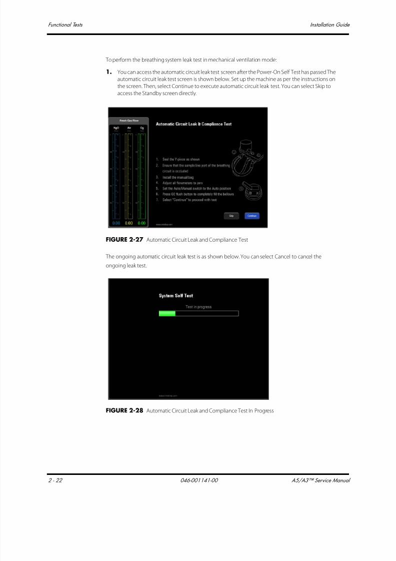
7/21/2019 a5 a3 Service Manual 2013
http://slidepdf.com/reader/full/a5-a3-service-manual-2013 103/399
Functional Tests Installation Guide
2 - 22 046-001141-00 A5/A3™ Service Manual
To perform the breathing system leak test in mechanical ventilation mode:
1. You can access the automatic circuit leak test screen after the Power-On Self Test has passed The
automatic circuit leak test screen is shown below. Set up the machine as per the instructions on
the screen. Then, select Continue to execute automatic circuit leak test. You can select Skip to
access the Standby screen directly.
FIGURE 2-27 Automatic Circuit Leak and Compliance Test
The ongoing automatic circuit leak test is as shown below. You can select Cancel to cancel the
ongoing leak test.
FIGURE 2-28 Automatic Circuit Leak and Compliance Test In Progress

7/21/2019 a5 a3 Service Manual 2013
http://slidepdf.com/reader/full/a5-a3-service-manual-2013 104/399
A5/A3™ Service Manual 046-001141-00 2 - 23
Installation Guide Functional Tests
During the automatic circuit leak test, the safety valve control test is also being conducted. The
automatic circuit leak test results are listed in the following table.
The following screen is displayed if the safety valve control test is failed. You can select Service Access
and enter the required service password to access service mode. You can select Retry to perform
automatic circuit leak test again.
FIGURE 2-29 Machine Non-Functional Screen
The following screen is displayed if the automatic circuit leak test is failed and the Leak ≥200 mL/min
and ≤1000 mL. You can select Retry to perform the automatic circuit leak test again or accept the
result continue with automatic ventilation.
Test results System Limitation
Safety valve control failed The machine cannot be used.
Automatic circuit leak test failedLeak ≥200 mL/min and ≤1000 mL
The user can acknowledge the leak and continue with automaticventilation
Automatic circuit leak test failed
Leak >1000 mLOnly manual ventilation can be applied
Compliance test failed
Both automatic ventilation and manual ventilation can st ill be applied
using the previous compliance value in the A5/A3 system memory,
but may not meet the accuracy of the delivered volume.
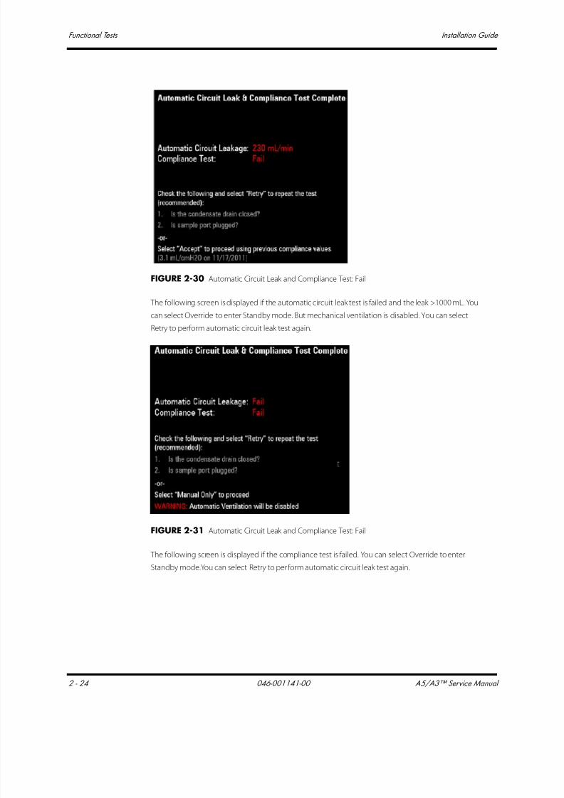
7/21/2019 a5 a3 Service Manual 2013
http://slidepdf.com/reader/full/a5-a3-service-manual-2013 105/399
Functional Tests Installation Guide
2 - 24 046-001141-00 A5/A3™ Service Manual
FIGURE 2-30 Automatic Circuit Leak and Compliance Test: Fail
The following screen is displayed if the automatic circuit leak test is failed and the leak >1000 mL. You
can select Override to enter Standby mode. But mechanical ventilation is disabled. You can select
Retry to perform automatic circuit leak test again.
FIGURE 2-31 Automatic Circuit Leak and Compliance Test: Fail
The following screen is displayed if the compliance test is failed. You can select Override to enter
Standby mode.You can select Retry to perform automatic circuit leak test again.
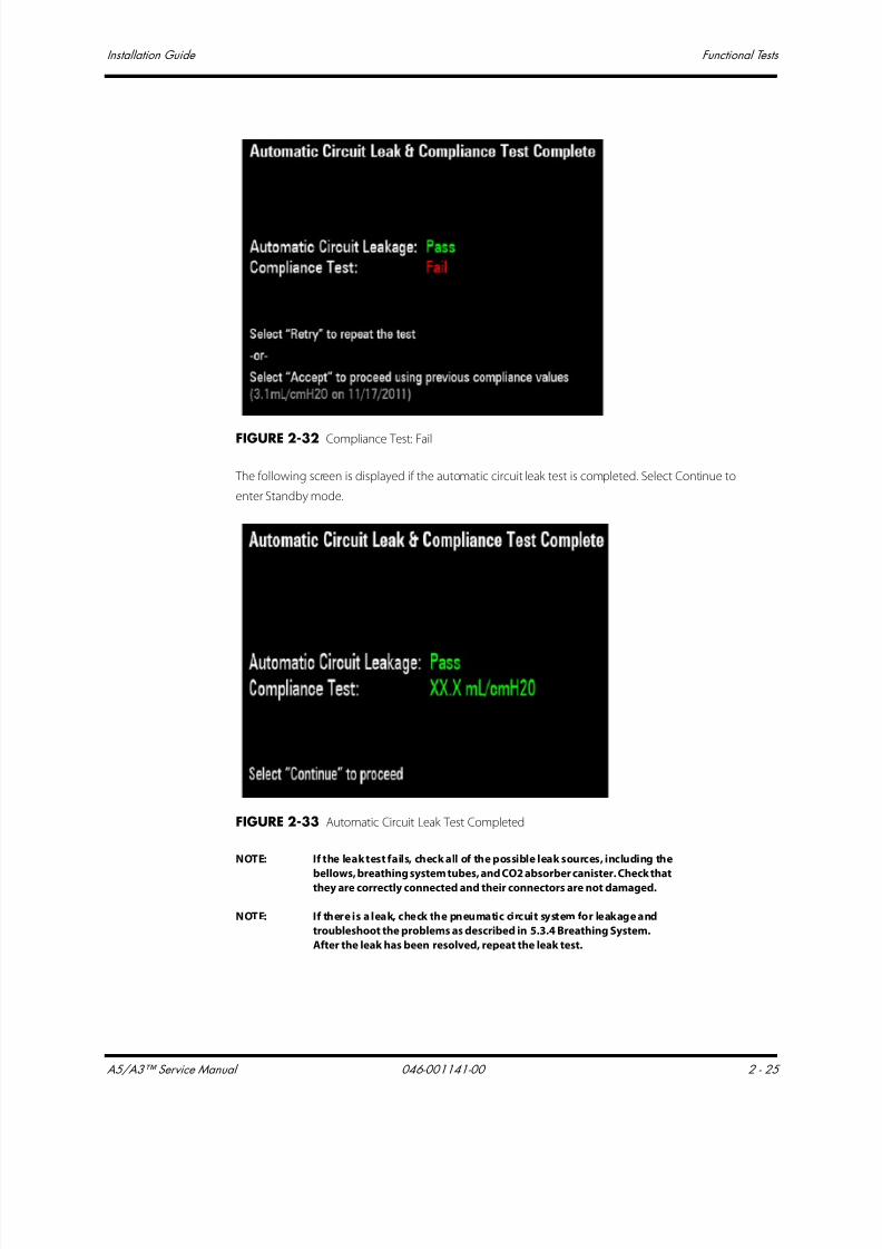
7/21/2019 a5 a3 Service Manual 2013
http://slidepdf.com/reader/full/a5-a3-service-manual-2013 106/399
A5/A3™ Service Manual 046-001141-00 2 - 25
Installation Guide Functional Tests
FIGURE 2-32 Compliance Test: Fail
The following screen is displayed if the automatic circuit leak test is completed. Select Continue to
enter Standby mode.
FIGURE 2-33 Automatic Circuit Leak Test Completed
NOTE: If the leak test fails, check all of the possible leak sources, including the
bellows, breathing system tubes, and CO2 absorber canister. Check thatthey are correctly connected and their connectors are not damaged.
NOTE: If there is a leak, check the pneumatic circuit system for leakage and
troubleshoot the problems as described in 5.3.4 Breathing System.
After the leak has been resolved, repeat the leak test.
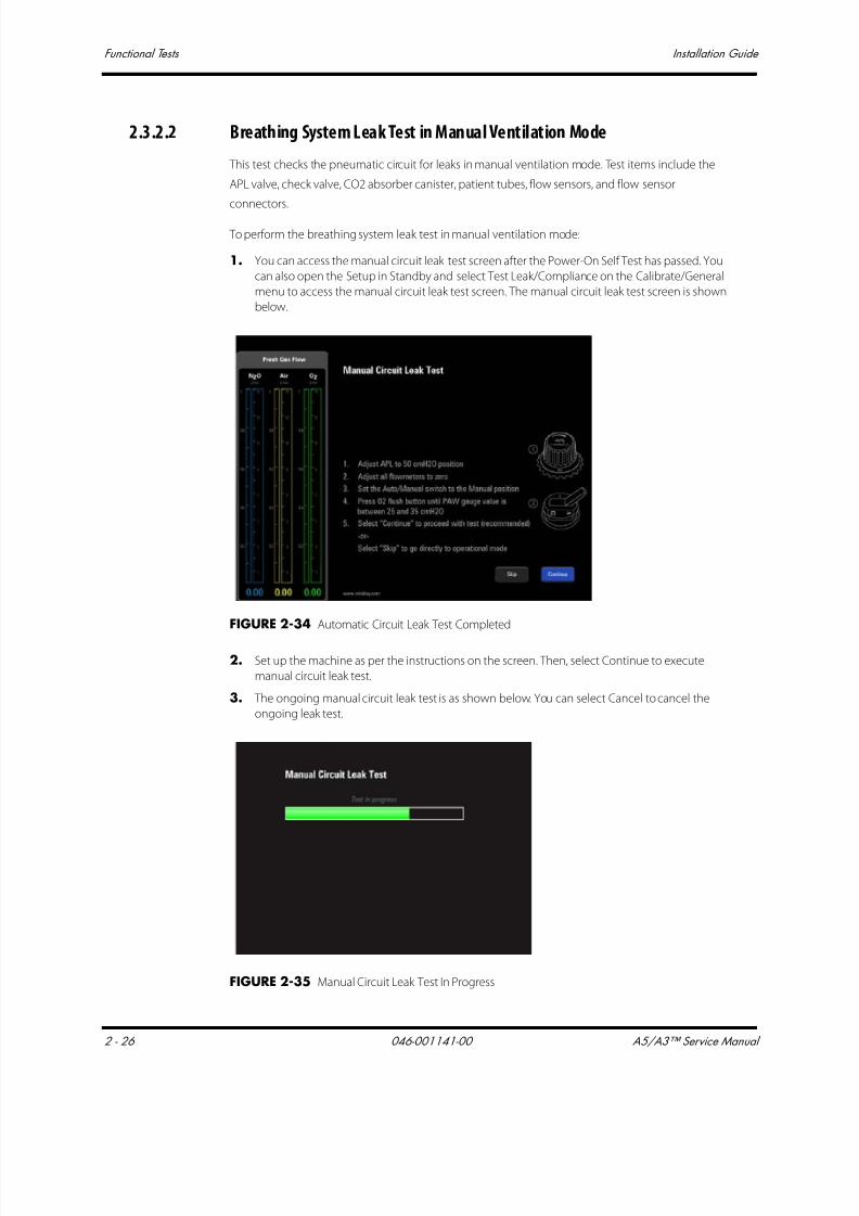
7/21/2019 a5 a3 Service Manual 2013
http://slidepdf.com/reader/full/a5-a3-service-manual-2013 107/399
Functional Tests Installation Guide
2 - 26 046-001141-00 A5/A3™ Service Manual
2.3.2.2 Breathing System Leak Test in Manual Ventilation Mode
This test checks the pneumatic circuit for leaks in manual ventilation mode. Test items include the
APL valve, check valve, CO2 absorber canister, patient tubes, flow sensors, and flow sensor
connectors.
To perform the breathing system leak test in manual ventilation mode:
1. You can access the manual circuit leak test screen after the Power-On Self Test has passed. You
can also open the Setup in Standby and select Test Leak/Compliance on the Calibrate/General
menu to access the manual circuit leak test screen. The manual circuit leak test screen is shown
below.
FIGURE 2-34 Automatic Circuit Leak Test Completed
2. Set up the machine as per the instructions on the screen. Then, select Continue to execute
manual circuit leak test.
3. The ongoing manual circuit leak test is as shown below. You can select Cancel to cancel the
ongoing leak test.
FIGURE 2-35 Manual Circuit Leak Test In Progress

7/21/2019 a5 a3 Service Manual 2013
http://slidepdf.com/reader/full/a5-a3-service-manual-2013 108/399
A5/A3™ Service Manual 046-001141-00 2 - 27
Installation Guide Functional Tests
The following screen is displayed if the manual circuit leak test is failed. If so, you must perform the
test again.
FIGURE 2-36 Manual Circuit Leak Test: Fail
The following screen is displayed if the manual circuit leak test is completed. Select Continue to enter
automatic circuit leak test.
FIGURE 2-37 Manual Circuit Leak Test: Passed
NOTE: If there is a leak, check the pneumatic circuit system for leakage and
troubleshoot the problems as described in 5.3 Pneumatic Circuit
System Problems. Repeat the leak test after the source of the failure has
been resolved.
2.3.2.3 Vaporizer Leak Test1. Set the ventilation Auto/Manual ventilation switch to Manual.
2. Set the APL valve to the SP position.
3. Connect one end of the breathing circuit to the bag arm, one end to the inspiratory port and
the Y-piece to the test port:

7/21/2019 a5 a3 Service Manual 2013
http://slidepdf.com/reader/full/a5-a3-service-manual-2013 109/399
Functional Tests Installation Guide
2 - 28 046-001141-00 A5/A3™ Service Manual
FIGURE 2-38
4. Mount and lock the vaporizer onto the vaporizer mount. (Certain vaporizers need to be set to atleast 1% for correct testing. See the vaporizer manufacturer's manual for details.)
5. Set the fresh gas flow to 200 mL/min.
6. Set the APL valve to 75 and verify that the pressure on the airway pressure gauge increases
above 30 cmH2O within 2 minutes.
7. Turn off the vaporizer.
8. Repeat Steps 4, 5, 6, and 7 for the other vaporizer.
2.3.2.4 Check Valve Test
1. Set the ventilation Auto/Manual ventilation switch to Manual.
2. Set the APL valve to 75.
3. Connect the breathing bag to the Inspiratory port.
4. Plug the bag arm.
5. Press the FLUSH button until the pressure on the airway pressure gauge reaches 35 cmH2O.
6. Set the APL valve to SP.
7. Verify that the pressure does not drop below 30 cmH2O after 10 seconds
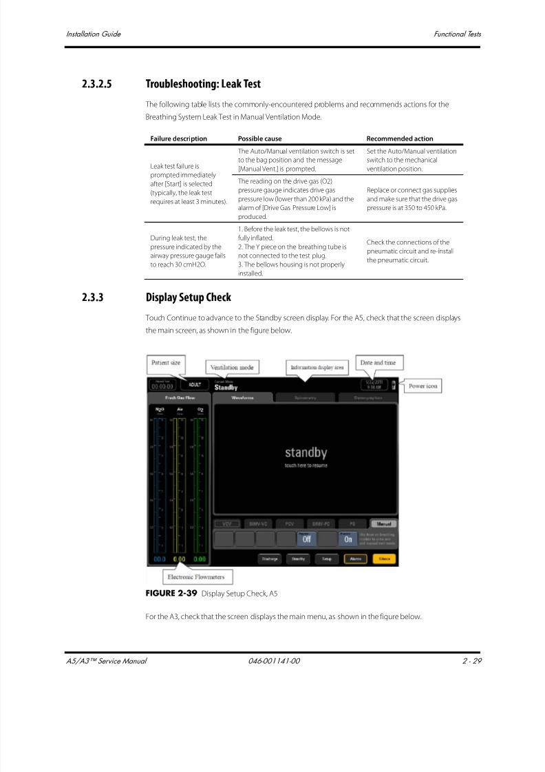
7/21/2019 a5 a3 Service Manual 2013
http://slidepdf.com/reader/full/a5-a3-service-manual-2013 110/399
A5/A3™ Service Manual 046-001141-00 2 - 29
Installation Guide Functional Tests
2.3.2.5 Troubleshooting: Leak Test
The following table lists the commonly-encountered problems and recommends actions for the
Breathing System Leak Test in Manual Ventilation Mode.
2.3.3 Display Setup Check
Touch Continue to advance to the Standby screen display. For the A5, check that the screen displays
the main screen, as shown in the figure below.
FIGURE 2-39 Display Setup Check, A5
For the A3, check that the screen displays the main menu, as shown in the figure below.
Failure description Possible cause Recommended action
Leak test failure is
prompted immediately
after [Start] is selected
(typically, the leak test
requires at least 3 minutes).
The Auto/Manual ventilation switch is set
to the bag position and the message
[Manual Vent.] is prompted.
Set the Auto/Manual ventilation
switch to the mechanical
ventilation position.
The reading on the drive gas (O2)
pressure gauge indicates drive gas
pressure low (lower than 200 kPa) and the
alarm of [Drive Gas Pressure Low] is
produced.
Replace or connect gas supplies
and make sure that the drive gas
pressure is at 350 to 450 kPa.
During leak test, the
pressure indicated by the
airway pressure gauge fails
to reach 30 cmH2O.
1. Before the leak test, the bellows is not
fully inflated.
2. The Y piece on the breathing tube is
not connected to the test plug.
3. The bellows housing is not properly
installed.
Check the connections of the
pneumatic circuit and re-install
the pneumatic circuit.

7/21/2019 a5 a3 Service Manual 2013
http://slidepdf.com/reader/full/a5-a3-service-manual-2013 111/399
Functional Tests Installation Guide
2 - 30 046-001141-00 A5/A3™ Service Manual
FIGURE 2-40 Display Setup Check, A3
2.3.4 O2 Sensor Calibration
NOTE: Both a 21% and 100% O2 calibration MUST BE performed before first
use of the A5/A3. The O2 sensor is not calibrated with the machine at
the factory.
NOTE: Calibrate the O2 sensor when a great deviation of O2 concentration
monitored value occurs or when the O2 sensor or ventilator control
board is replaced or when prompted by the anesthesia system.
NOTE: Before calibration, observe if the O2 sensor displays numerics on the
measure screen. If not, check the O2 sensor connection l ine, or replace
the O2 sensor until measure numerics are displayed.
2.3.4.1 21% O2 Calibration
Follow these steps to calibrate the O2 sensor at 21% O2:
1. Select Setup > System > Calibrate O2 Sensor or Setup > Service > Calibration > O2 Sensor to
access the screen as shown below. The General tab shows only 21% O2 Sensor calibration; the
System and Service tabs require passwords and show both 21% and 100% O2 Sensorcalibration. Set up the machine as per the instructions on the screen. Select Begin to start
calibration.
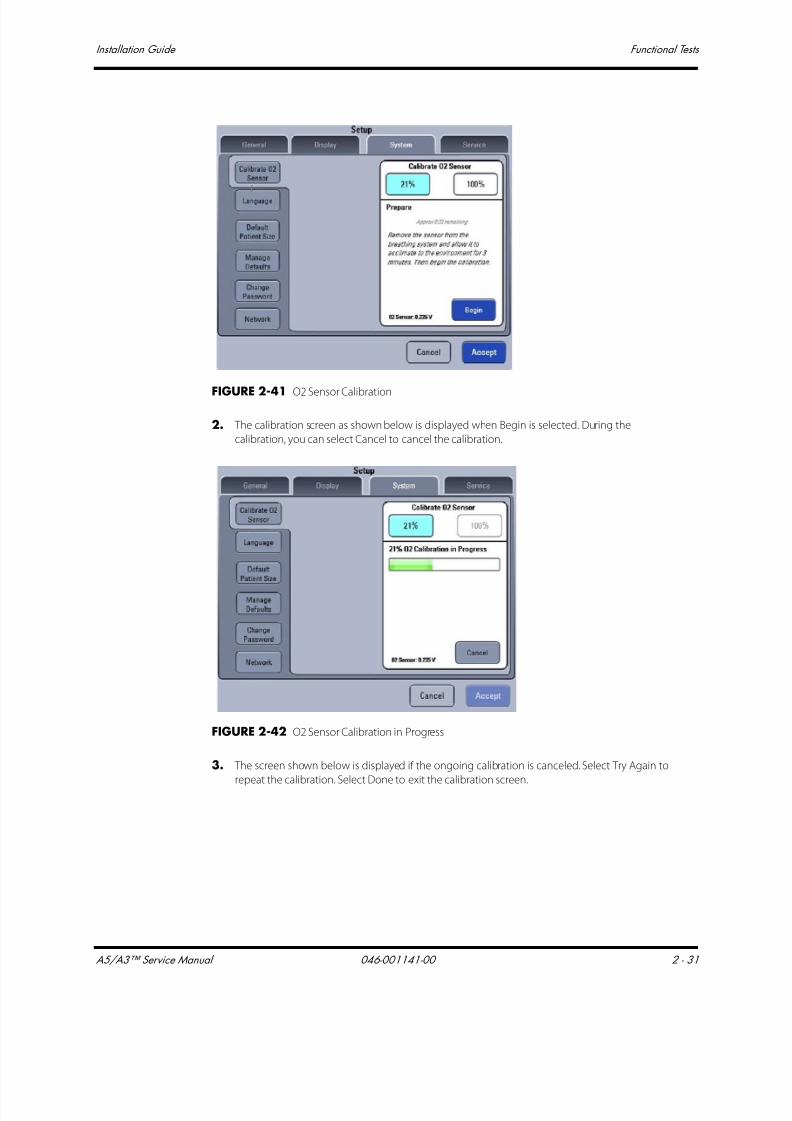
7/21/2019 a5 a3 Service Manual 2013
http://slidepdf.com/reader/full/a5-a3-service-manual-2013 112/399
A5/A3™ Service Manual 046-001141-00 2 - 31
Installation Guide Functional Tests
FIGURE 2-41 O2 Sensor Calibration
2. The calibration screen as shown below is displayed when Begin is selected. During the
calibration, you can select Cancel to cancel the calibration.
FIGURE 2-42 O2 Sensor Calibration in Progress
3. The screen shown below is displayed if the ongoing calibration is canceled. Select Try Again to
repeat the calibration. Select Done to exit the calibration screen.
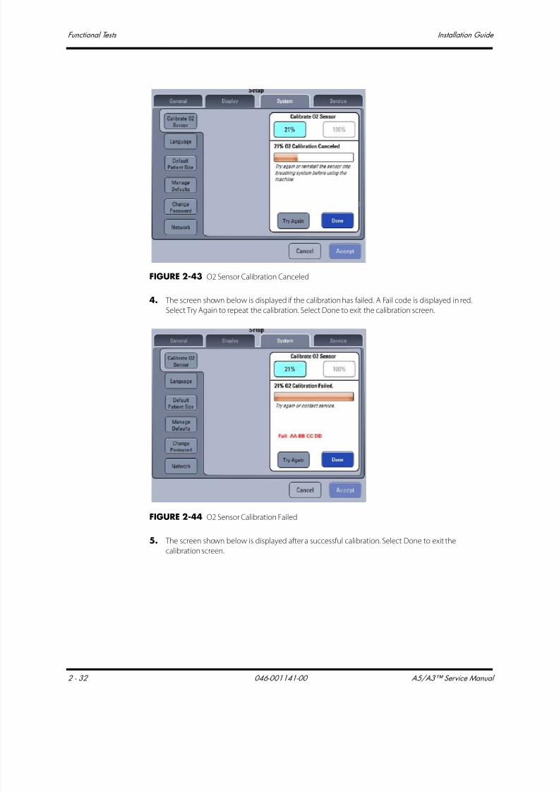
7/21/2019 a5 a3 Service Manual 2013
http://slidepdf.com/reader/full/a5-a3-service-manual-2013 113/399
Functional Tests Installation Guide
2 - 32 046-001141-00 A5/A3™ Service Manual
FIGURE 2-43 O2 Sensor Calibration Canceled
4. The screen shown below is displayed if the calibration has failed. A Fail code is displayed in red.
Select Try Again to repeat the calibration. Select Done to exit the calibration screen.
FIGURE 2-44 O2 Sensor Calibration Failed
5. The screen shown below is displayed after a successful calibration. Select Done to exit the
calibration screen.

7/21/2019 a5 a3 Service Manual 2013
http://slidepdf.com/reader/full/a5-a3-service-manual-2013 114/399
A5/A3™ Service Manual 046-001141-00 2 - 33
Installation Guide Functional Tests
FIGURE 2-45 O2 Sensor Calibration Successful
2.3.4.2 100% O2 Calibration
NOTE: 100% O2 calibration must be performed in standby mode.
NOTE: 100% O2 calibration can be performed only after a successful 21% O2
calibration.
Follow these steps to calibrate O2 sensor at 100% O2:
1. Enter Standby.
2. Select Setup > System > Calibrate O2 Sensor or Setup > Service > Calibration > O2 Sensor. The
System and Service tabs require passwords and shows both 21% and 100% O2 Sensorcalibration. The calibration screen shown below is displayed when 100% is selected. Set up the
machine as per the instructions on the screen and select Next. Set the AUTO/MANUAL lever to
the AUTO position.

7/21/2019 a5 a3 Service Manual 2013
http://slidepdf.com/reader/full/a5-a3-service-manual-2013 115/399
Functional Tests Installation Guide
2 - 34 046-001141-00 A5/A3™ Service Manual
FIGURE 2-46 100% O2 Sensor Calibration
3. The calibration screen shown below is displayed when Next is selected. Set up the machine as
per the instructions on the screen. Wait 2 minutes to ensure that the O2 cell voltage has
stabilized at the maximum value for at least 30s. Select Begin.
FIGURE 2-47 100% O2 Sensor Calibration Preparation
4. The calibration screen as shown below is displayed when Begin is selected. During the
calibration, you can select Cancel to cancel the calibration.

7/21/2019 a5 a3 Service Manual 2013
http://slidepdf.com/reader/full/a5-a3-service-manual-2013 116/399
A5/A3™ Service Manual 046-001141-00 2 - 35
Installation Guide Functional Tests
FIGURE 2-48 100% O2 Sensor Calibration in Progress
5. The screen shown below is displayed if the ongoing calibration is canceled. Select Try Again to
repeat the calibration. Select Done to exit the calibration screen.
FIGURE 2-49 100% O2 Sensor Calibration Canceled
6. The screen shown below is displayed if the calibration has failed. A Fail code is displayed in red.Select Try Again to repeat the calibration. Select Done to exit the calibration screen.
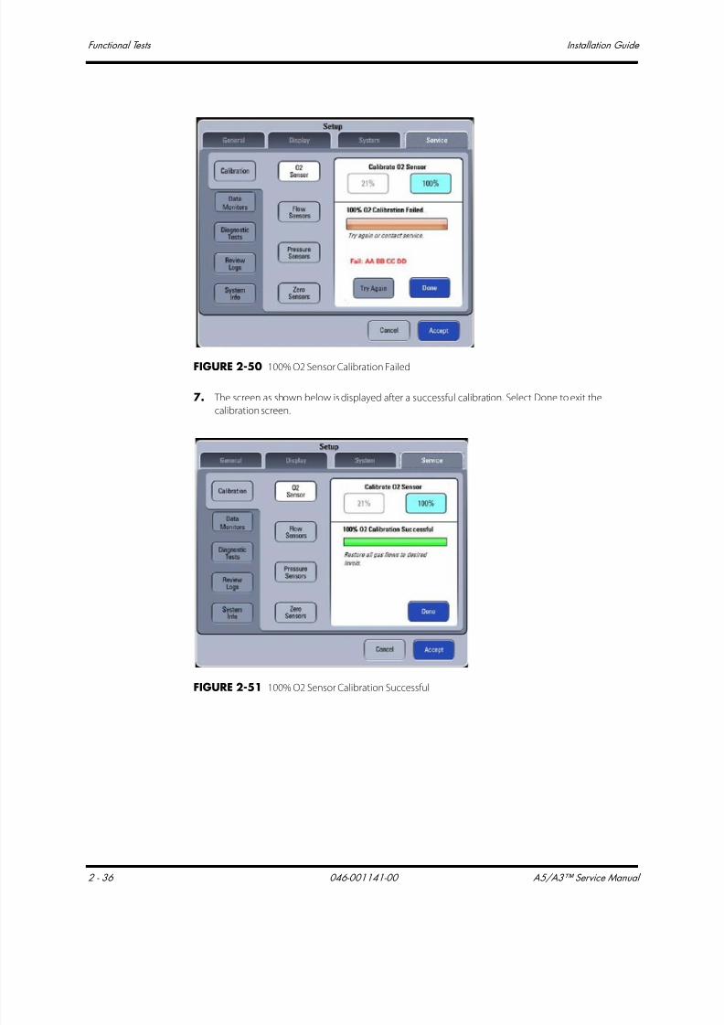
7/21/2019 a5 a3 Service Manual 2013
http://slidepdf.com/reader/full/a5-a3-service-manual-2013 117/399
Functional Tests Installation Guide
2 - 36 046-001141-00 A5/A3™ Service Manual
FIGURE 2-50 100% O2 Sensor Calibration Failed
7. The screen as shown below is displayed after a successful calibration. Select Done to exit the
calibration screen.
FIGURE 2-51 100% O2 Sensor Calibration Successful
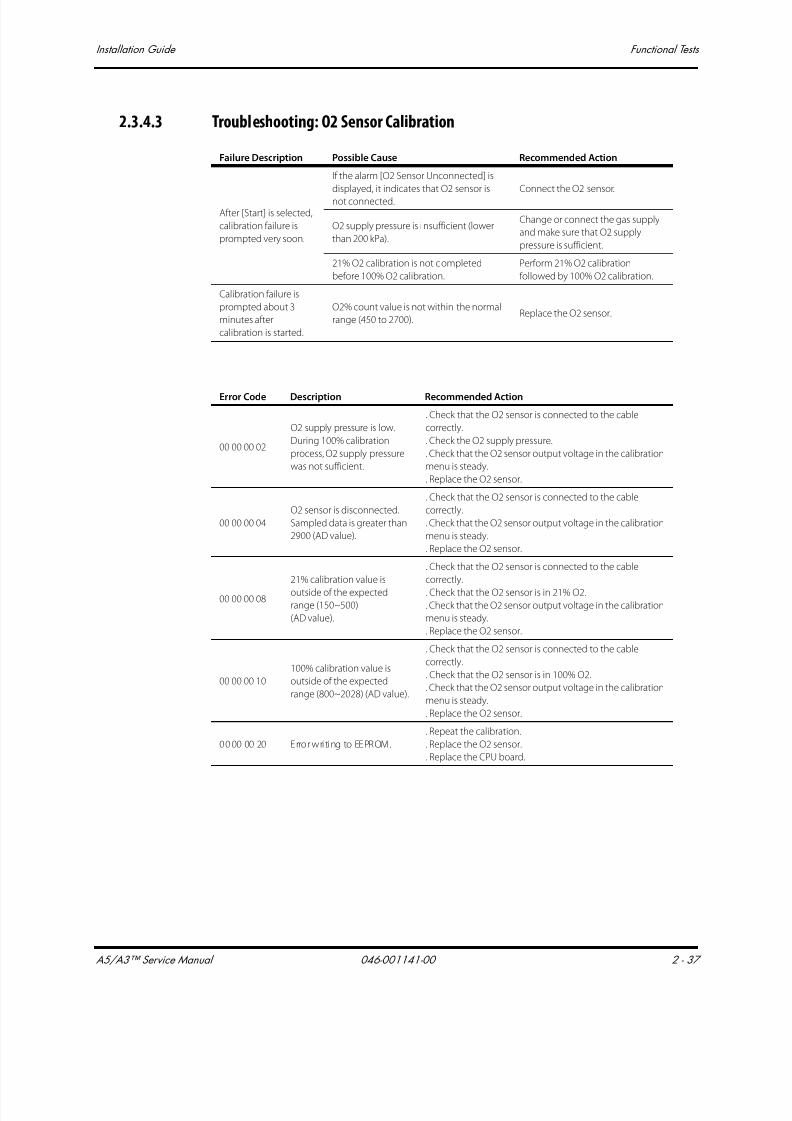
7/21/2019 a5 a3 Service Manual 2013
http://slidepdf.com/reader/full/a5-a3-service-manual-2013 118/399
A5/A3™ Service Manual 046-001141-00 2 - 37
Installation Guide Functional Tests
2.3.4.3 Troubleshooting: O2 Sensor Calibration
Failure Description Possible Cause Recommended Action
After [Start] is selected,
calibration failure is
prompted very soon.
If the alarm [O2 Sensor Unconnected] is
displayed, it indicates that O2 sensor is
not connected.
Connect the O2 sensor.
O2 supply pressure is insufficient (lower
than 200 kPa).
Change or connect the gas supply
and make sure that O2 supply
pressure is sufficient.
21% O2 calibration is not completed
before 100% O2 calibration.
Perform 21% O2 calibration
followed by 100% O2 calibration.
Calibration failure is
prompted about 3
minutes after
calibration is started.
O2% count value is not within the normal
range (450 to 2700).Replace the O2 sensor.
Error Code Description Recommended Action
00 00 00 02
O2 supply pressure is low.
During 100% calibration
process, O2 supply pressure
was not sufficient.
. Check that the O2 sensor is connected to the cable
correctly.
. Check the O2 supply pressure.
. Check that the O2 sensor output voltage in the calibration
menu is steady.
. Replace the O2 sensor.
00 00 00 04
O2 sensor is disconnected.
Sampled data is greater than
2900 (AD value).
. Check that the O2 sensor is connected to the cable
correctly.
. Check that the O2 sensor output voltage in the calibration
menu is steady.
. Replace the O2 sensor.
00 00 00 08
21% calibration value is
outside of the expectedrange (150~500)
(AD value).
. Check that the O2 sensor is connected to the cable
correctly.
. Check that the O2 sensor is in 21% O2.
. Check that the O2 sensor output voltage in the calibration
menu is steady.
. Replace the O2 sensor.
00 00 00 10
100% calibration value is
outside of the expected
range (800~2028) (AD value).
. Check that the O2 sensor is connected to the cable
correctly.
. Check that the O2 sensor is in 100% O2.
. Check that the O2 sensor output voltage in the calibration
menu is steady.
. Replace the O2 sensor.
00 00 00 20 Error writing to EEPROM.
. Repeat the calibration.
. Replace the O2 sensor.
. Replace the CPU board.

7/21/2019 a5 a3 Service Manual 2013
http://slidepdf.com/reader/full/a5-a3-service-manual-2013 119/399
Pneumatic Leak Tests Installation Guide
2 - 38 046-001141-00 A5/A3™ Service Manual
2.4 Pneumatic Leak Tests
Turn all fresh gas flows to 0 L/min.
2.4.1 N2O Cylinder Leak Test1. Remove the N2O line pressure hose from the line pressure inlet on the A5/A3.
2. Mount a full N2O cylinder to the rear panel yoke. If necessary, place a new clean tank washer
between the cylinder and the yoke to minimize any leaks at the yoke connection.
3. Open the N2O cylinder until its pressure gauge indicates cylinder pressure.
4. Close the N2O cylinder.
The N2O cylinder pressure gauge should not drop more than 10% of its initial pressure over 1 minute.
2.4.2 O2 Cylinder Leak Test
1. Remove the O2 line pressure hose from the line pressure inlet on the anesthesia system.
2. Mount a full O2 cylinder to the rear panel yoke. If necessary, place a new clean tank washer
between the cylinder and the yoke to minimize any leaks at the yoke connection.
3. Open the O2 cylinder until its pressure gauge indicates cylinder pressure.
4. Close the O2 cylinder.
The O2 cylinder pressure gauge should not drop more than 10% of its initial pressure over 1 minute.
2.4.3 AIR Cylinder Leak Test
1. Remove the AIR line pressure hose from the line pressure inlet on the anesthesia system.
2. Mount a full AIR cylinder to the rear panel yoke. If necessary, place a new clean tank washer
between the cylinder and the yoke to minimize any leaks at the yoke connection.
3. Open the AIR cylinder until its pressure gauge indicates cylinder pressure.
4. Close the AIR cylinder.
The AIR cylinder pressure gauge should not drop more than 10% of its initial pressure over 1 minute.
2.4.4 N2O Line Pressure Leak Test
1. Remove the N2O cylinder from the anesthesia system.
2. Connect the N2O line pressure hose to the line pressure inlet on the anesthesia system.
3. Pinch the N2O line pressure hose to stop N2O line flow.
4. Remove the N2O line pressure hose from the N2O line source while keeping the hose pinched.
5. The N2O line pressure gauge should not fall more than 10 psi per 100 seconds (2 psi per 20 sec).
6. Reconnect the N2O line pressure and remove the pinch in the hose.

7/21/2019 a5 a3 Service Manual 2013
http://slidepdf.com/reader/full/a5-a3-service-manual-2013 120/399
A5/A3™ Service Manual 046-001141-00 2 - 39
Installation Guide Pneumatic Leak Tests
2.4.5 O2 Line Pressure Leak Test
1. Remove the O2 cylinder from the anesthesia system.
2. Connect the O2 line pressure hose to the line pressure inlet on the anesthesia system.
3. Pinch the O2 line pressure hose to stop O2 line flow.
4. Remove the O2 line pressure hose from the O2 line source while keeping the hose pinched.
5. The O2 line pressure gauge should not fall more than 10 psi per 100 seconds (2 psi per 20 sec).
6. Reconnect the O2 line pressure and remove the pinch in the hose.
2.4.6 AIR Line Pressure Leak Test
1. Remove the AIR cylinder from the anesthesia system.
2. Connect the AIR line pressure hose to the line pressure inlet on the anesthesia system.
3. Pinch the AIR line pressure hose to stop AIR line flow.
4. Remove the AIR line pressure hose from the AIR line source while keeping the hose pinched.
5. The AIR line pressure gauge should not fall more than 10 psi per 100 seconds (2 psi per 20 sec).6. Reconnect the AIR line pressure and remove the pinch in the hose.
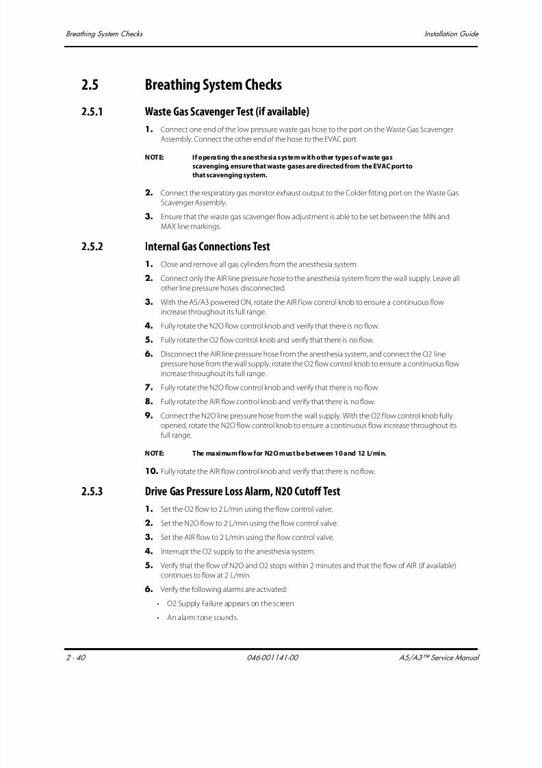
7/21/2019 a5 a3 Service Manual 2013
http://slidepdf.com/reader/full/a5-a3-service-manual-2013 121/399
Breathing System Checks Installation Guide
2 - 40 046-001141-00 A5/A3™ Service Manual
2.5 Breathing System Checks
2.5.1 Waste Gas Scavenger Test (if available)
1. Connect one end of the low pressure waste gas hose to the port on the Waste Gas Scavenger
Assembly. Connect the other end of the hose to the EVAC port.
NOTE: If operating the anesthesia system with other types of waste gas
scavenging, ensure that waste gases are directed from the EVAC port to
that scavenging system.
2. Connect the respiratory gas monitor exhaust output to the Colder fitting port on the Waste Gas
Scavenger Assembly.
3. Ensure that the waste gas scavenger flow adjustment is able to be set between the MIN and
MAX line markings.
2.5.2 Internal Gas Connections Test
1. Close and remove all gas cylinders from the anesthesia system.
2. Connect only the AIR line pressure hose to the anesthesia system from the wall supply. Leave all
other line pressure hoses disconnected.
3. With the A5/A3 powered ON, rotate the AIR f low control knob to ensure a continuous flow
increase throughout its full range.
4. Fully rotate the N2O flow control knob and verify that there is no flow.
5. Fully rotate the O2 flow control knob and verify that there is no flow.
6. Disconnect the AIR line pressure hose from the anesthesia system, and connect the O2 line
pressure hose from the wall supply, rotate the O2 flow control knob to ensure a continuous flow
increase throughout its full range.
7. Fully rotate the N2O flow control knob and verify that there is no flow.
8. Fully rotate the AIR flow control knob and verify that there is no flow.9. Connect the N2O line pressure hose from the wall supply. With the O2 f low control knob fully
opened, rotate the N2O flow control knob to ensure a continuous flow increase throughout its
full range.
NOTE: The maximum flow for N2O must be between 10 and 12 L/min.
10. Fully rotate the AIR flow control knob and verify that there is no flow.
2.5.3 Drive Gas Pressure Loss Alarm, N2O Cutoff Test
1. Set the O2 flow to 2 L/min using the flow control valve.
2. Set the N2O flow to 2 L/min using the flow control valve.
3. Set the AIR flow to 2 L/min using the flow control valve.
4. Interrupt the O2 supply to the anesthesia system.
5. Verify that the flow of N2O and O2 stops within 2 minutes and that the flow of AIR (if available)
continues to flow at 2 L/min.
6. Verify the following alarms are activated:
• O2 Supply Failure appears on the screen
• An alarm tone sounds.

7/21/2019 a5 a3 Service Manual 2013
http://slidepdf.com/reader/full/a5-a3-service-manual-2013 122/399
A5/A3™ Service Manual 046-001141-00 2 - 41
Installation Guide Performance Verification
2.6 Performance Verification
2.6.1 Manual Ventilation Test
1. Ensure that the gas pressure for O2, N2O, and AIR is within specifications.
2. Power ON the anesthesia system.
3. Attach a breathing circuit and test lung to the Y-fitting of the breathing circuit.
NOTE: For testing purposes, always use a reusable breathing circuit.
4. Perform the start up tests per the on-screen instructions. Ensure successful completion.
5. Power OFF the anesthesia system.
6. Set the mechanical Auto/Manual switch to MANUAL.
7. Set the APL Valve to approximately 15 cmH2O.
8. Set the AIR flow to approximately 5 L/min using the flow control valve. Use O2 if AIR is not
available. This will require turning the main switch to the ON position.
9. Squeeze the breathing bag once every 10 seconds to inflate and deflate the test lung to
approximately 20 cmH2O of pressure.
10. Verify the inflation and deflation of the test lung.
2.6.2 Manual Mode Ventilation Test
1. Power ON the anesthesia system.
2. Attach a breathing circuit and test lung to the Y-fitting of the breathing circuit.
NOTE: For testing purposes, always use a reusable breathing circuit.
3. Perform the start up tests per the on-screen instructions. Ensure successful completion.
4. Set the mechanical Auto/Manual switch to MANUAL. Press the screen for the screen to changeto manual Mode.
5. Set the APL Valve to approximately 25 cmH2O. Push the O2 Flush button to fill the breathing
bag.
6. Set the AIR flow to 1 L/min using the flow control valve. This will change the screen to manual
Mode.
7. Squeeze the breathing bag once every 3 seconds.
8. Verify the inflation and deflation of the test lung.
9. Verify that an airway pressure waveform and all numeric values appear on screen during bag
compressions.
10. Stop squeezing the breathing bag and set the APL Valve to the open position (SP).
2.6.3 APNEA Alarm Test
1. While in the Manual Ventilation Mode, stop ventilating the test lung.
2. Verify that the following APNEA alarm signals activate at approximately 30 seconds from the last
bag compression.
• APNEA appears on the screen.
• An alarm tone sounds.
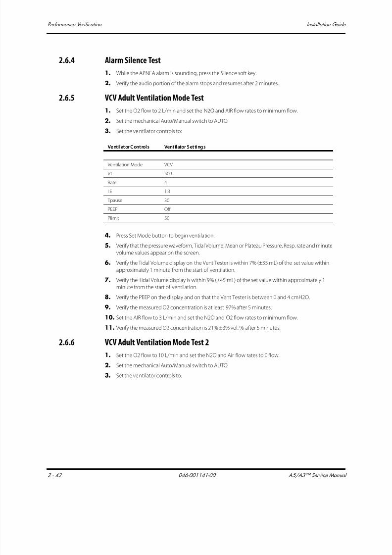
7/21/2019 a5 a3 Service Manual 2013
http://slidepdf.com/reader/full/a5-a3-service-manual-2013 123/399
Performance Verification Installation Guide
2 - 42 046-001141-00 A5/A3™ Service Manual
2.6.4 Alarm Silence Test
1. While the APNEA alarm is sounding, press the Silence soft key.
2. Verify the audio portion of the alarm stops and resumes after 2 minutes.
2.6.5 VCV Adult Ventilation Mode Test1. Set the O2 flow to 2 L/min and set the N2O and AIR flow rates to minimum flow.
2. Set the mechanical Auto/Manual switch to AUTO.
3. Set the ventilator controls to:
4. Press Set Mode button to begin ventilation.
5. Verify that the pressure waveform, Tidal Volume, Mean or Plateau Pressure, Resp. rate and minute
volume values appear on the screen.
6. Verify the Tidal Volume display on the Vent Tester is within 7% (±35 mL) of the set value within
approximately 1 minute from the start of ventilation.
7. Verify the Tidal Volume display is within 9% (±45 mL) of the set value within approximately 1
minute from the start of ventilation.
8. Verify the PEEP on the display and on that the Vent Tester is between 0 and 4 cmH2O.
9. Verify the measured O2 concentration is at least 97% after 5 minutes.
10. Set the AIR flow to 3 L/min and set the N2O and O2 flow rates to minimum flow.
11. Verify the measured O2 concentration is 21% ±3% vol. % after 5 minutes.
2.6.6 VCV Adult Ventilation Mode Test 2
1. Set the O2 flow to 10 L/min and set the N2O and Air flow rates to 0 flow.
2. Set the mechanical Auto/Manual switch to AUTO.
3. Set the ventilator controls to:
Ventilator Controls Ventilator Settings
Ventilation Mode VCV
Vt 500
Rate 4
I:E 1:3
Tpause 30
PEEP Off
Plimit 50

7/21/2019 a5 a3 Service Manual 2013
http://slidepdf.com/reader/full/a5-a3-service-manual-2013 124/399
A5/A3™ Service Manual 046-001141-00 2 - 43
Installation Guide Performance Verification
4. Press the Set Mode button to begin ventilation.
5. Verify that the pressure waveform, Tidal Volume, Mean or Plateau Pressure, Resp. rate and minute
volume values appear on the screen.
6. Verify the Tidal Volume display on the Vent Tester is within 7% (+/- 49 mL) of the set value within
approximately 1 minute from the start of ventilation.
7. Verify the Tidal Volume display is within 9% (+/-63 mL) of the set value within approximately 1
minute from the start of ventilation.
8. Verify the PEEP on the display and on the Vent Tester is between 0 and 4 cmH20.
9. Verify the measured 02 concentration is at least 97% after 5 minutes.
10. Set the AIR flow to 3 L/min and set the N2O and O2 flow rates to 0 flow.
11. Verify the measured 02 concentration is 21% +/-3% vol. % after 5 minutes.
Ventilator Controls Ventilator Settings
Ventilation Mode VCV
Vt 700
Rate 10
I:E 1:3
Tpause 60
PEEP OFF
Plimit 50
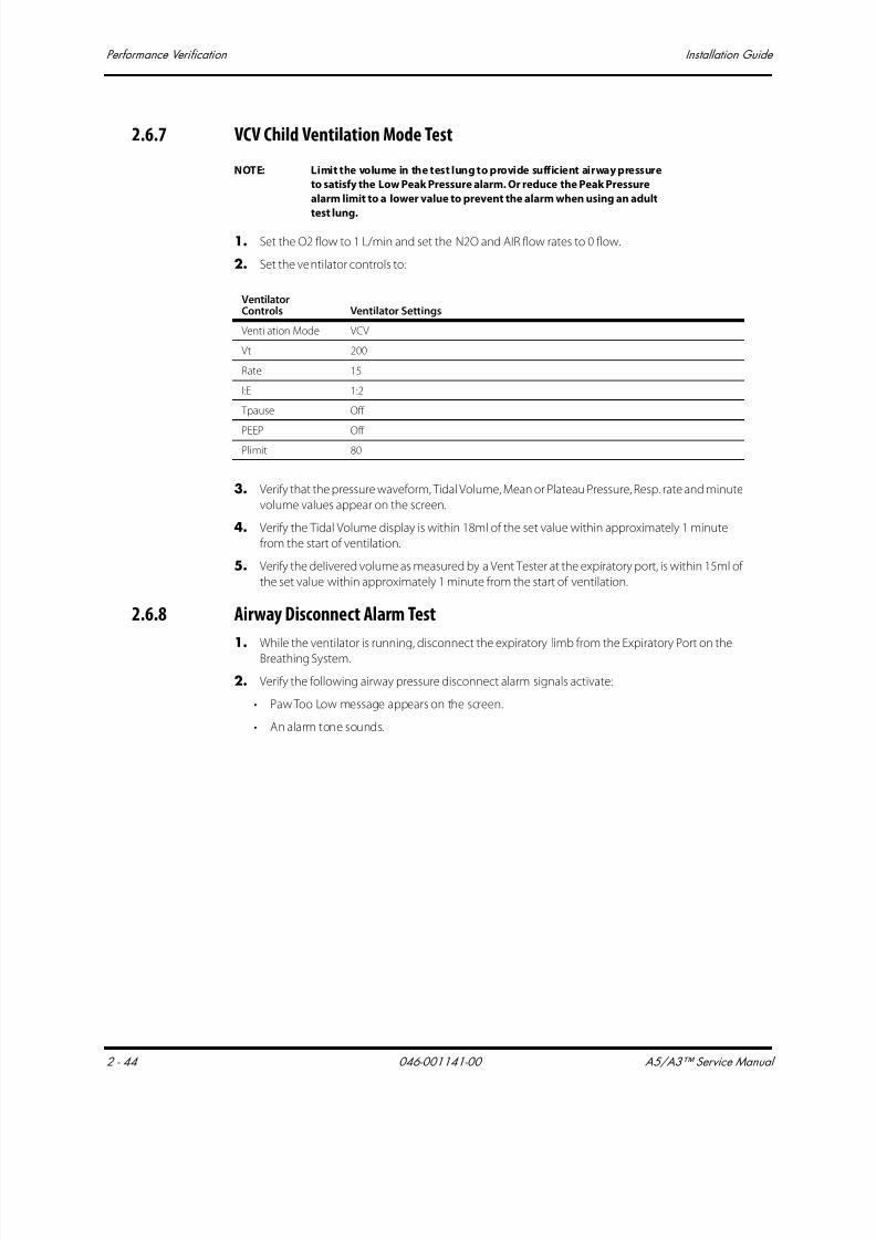
7/21/2019 a5 a3 Service Manual 2013
http://slidepdf.com/reader/full/a5-a3-service-manual-2013 125/399
Performance Verification Installation Guide
2 - 44 046-001141-00 A5/A3™ Service Manual
2.6.7 VCV Child Ventilation Mode Test
NOTE: Limit the volume in the test lung to provide sufficient airway pressure
to satisfy the Low Peak Pressure alarm. Or reduce the Peak Pressure
alarm limit to a lower value to prevent the alarm when using an adult
test lung.
1. Set the O2 flow to 1 L/min and set the N2O and AIR flow rates to 0 flow.
2. Set the ventilator controls to:
3. Verify that the pressure waveform, Tidal Volume, Mean or Plateau Pressure, Resp. rate and minute
volume values appear on the screen.
4. Verify the Tidal Volume display is within 18ml of the set value within approximately 1 minute
from the start of ventilation.
5. Verify the delivered volume as measured by a Vent Tester at the expiratory port, is within 15ml of
the set value within approximately 1 minute from the start of ventilation.
2.6.8 Airway Disconnect Alarm Test
1. While the ventilator is running, disconnect the expiratory limb from the Expiratory Port on the
Breathing System.
2. Verify the following airway pressure disconnect alarm signals activate:
• Paw Too Low message appears on the screen.
• An alarm tone sounds.
VentilatorControls Ventilator Settings
Ventilation Mode VCV
Vt 200
Rate 15
I:E 1:2
Tpause Off
PEEP Off Plimit 80

7/21/2019 a5 a3 Service Manual 2013
http://slidepdf.com/reader/full/a5-a3-service-manual-2013 126/399
A5/A3™ Service Manual 046-001141-00 2 - 45
Installation Guide Performance Verification
2.6.9 PCV Adult Ventilation Mode Test
1. Set the O2 flow to 3 L/min and set the N2O and AIR flow rates to minimum flow.
2. Set the ventilator controls to:
3. Press Set Mode button to begin ventilation.
4. Verify the Peak Pressure reading of the display is within ±2 cmH2O of the set Pinsp.
5. Verify that the pressure waveform, Tidal Volume, Resp. Rate and minute volume values appear
on the screen.
6. Verify that the PEAK Value measured with the Vent Tester reaches 15 ±2.5 cmH2O within five
breaths from the start of ventilation.
2.6.10 Pressure Support (PS) Ventilation Mode Test
1. Set the O2 flow to 1 L/min and set the N2O and AIR flow rates to minimum flow.
2. Set the ventilator controls to:
3. Press Set Mode button to begin ventilation.
4. Begin triggering breaths by slightly squeezing the test lung and releasing. Maintain a
continuous breath rate.
5. Verify that a pressure waveform and all ventilation parameters appear on the screen.
6. Verify that the Peak Pressure reading on the display is ±2 the value ofΔP + PEEP.
7. Stop triggering breaths.
8. Verify that after 15 seconds the ventilator delivers a breath and displays the message Apnea
Ventilation.
9. Verify the system ventilates with a frequency of 4 bpm.
Ventilator Controls Ventilator Settings
Ventilation Mode PCV
VtG (A5 only) Off
Pinsp 15
Rate 8
I:E 1:2
PEEP Off
Tslope 0.2
PlimVG NA
Ventilator Controls Ventilator Settings
Ventilation Mode PS
Min Rate 4
∆P 20
Trigger 3
PEEP Off
Tslope 0.2
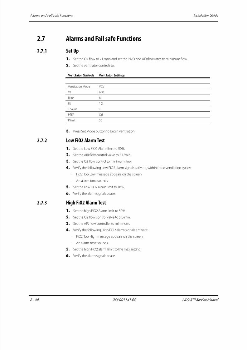
7/21/2019 a5 a3 Service Manual 2013
http://slidepdf.com/reader/full/a5-a3-service-manual-2013 127/399
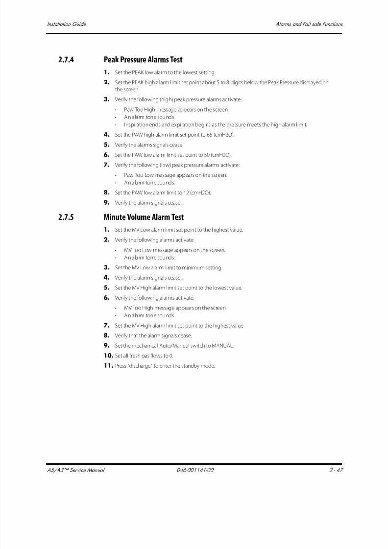
7/21/2019 a5 a3 Service Manual 2013
http://slidepdf.com/reader/full/a5-a3-service-manual-2013 128/399
A5/A3™ Service Manual 046-001141-00 2 - 47
Installation Guide Alarms and Fail safe Functions
2.7.4 Peak Pressure Alarms Test
1. Set the PEAK low alarm to the lowest setting.
2. Set the PEAK high alarm limit set point about 5 to 8 digits below the Peak Pressure displayed on
the screen.
3. Verify the following (high) peak pressure alarms activate:
• Paw Too High message appears on the screen.
• An alarm tone sounds.
• Inspiration ends and expiration begins as the pressure meets the high alarm limit.
4. Set the PAW high alarm limit set point to 65 (cmH2O).
5. Verify the alarms signals cease.
6. Set the PAW low alarm limit set point to 50 (cmH2O).
7. Verify the following (low) peak pressure alarms activate:
• Paw Too Low message appears on the screen.
• An alarm tone sounds.
8. Set the PAW low alarm limit to 12 (cmH2O).
9. Verify the alarm signals cease.
2.7.5 Minute Volume Alarm Test
1. Set the MV Low alarm limit set point to the highest value.
2. Verify the following alarms activate:
• MV Too Low message appears on the screen.
• An alarm tone sounds.
3. Set the MV Low alarm limit to minimum setting.
4. Verify the alarm signals cease.
5. Set the MV High alarm limit set point to the lowest value.
6. Verify the following alarms activate:
• MV Too High message appears on the screen.
• An alarm tone sounds.
7. Set the MV High alarm limit set point to the highest value
8. Verify that the alarm signals cease.
9. Set the mechanical Auto/Manual switch to MANUAL.
10. Set all fresh gas flows to 0.
11. Press “discharge” to enter the standby mode.
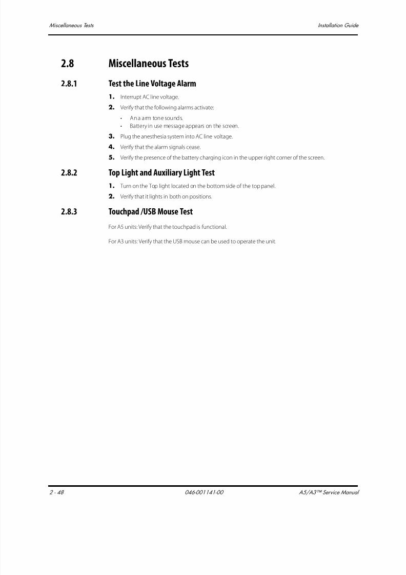
7/21/2019 a5 a3 Service Manual 2013
http://slidepdf.com/reader/full/a5-a3-service-manual-2013 129/399
Miscellaneous Tests Installation Guide
2 - 48 046-001141-00 A5/A3™ Service Manual
2.8 Miscellaneous Tests
2.8.1 Test the Line Voltage Alarm
1. Interrupt AC line voltage.
2. Verify that the following alarms activate:
• An alarm tone sounds.
• Battery in use message appears on the screen.
3. Plug the anesthesia system into AC line voltage.
4. Verify that the alarm signals cease.
5. Verify the presence of the battery charging icon in the upper right corner of the screen.
2.8.2 Top Light and Auxiliary Light Test
1. Turn on the Top light located on the bottom side of the top panel.
2. Verify that it lights in both on positions.
2.8.3 Touchpad /USB Mouse Test
For A5 units: Verify that the touchpad is functional.
For A3 units: Verify that the USB mouse can be used to operate the unit.
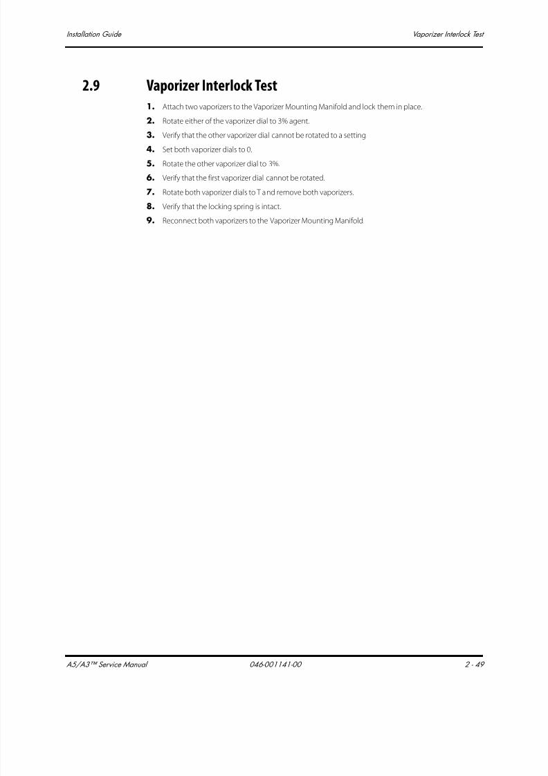
7/21/2019 a5 a3 Service Manual 2013
http://slidepdf.com/reader/full/a5-a3-service-manual-2013 130/399
A5/A3™ Service Manual 046-001141-00 2 - 49
Installation Guide Vaporizer Interlock Test
2.9 Vaporizer Interlock Test
1. Attach two vaporizers to the Vaporizer Mounting Manifold and lock them in place.
2. Rotate either of the vaporizer dial to 3% agent.
3. Verify that the other vaporizer dial cannot be rotated to a setting.
4. Set both vaporizer dials to 0.
5. Rotate the other vaporizer dial to 3%.
6. Verify that the first vaporizer dial cannot be rotated.
7. Rotate both vaporizer dials to T and remove both vaporizers.
8. Verify that the locking spring is intact.
9. Reconnect both vaporizers to the Vaporizer Mounting Manifold.

7/21/2019 a5 a3 Service Manual 2013
http://slidepdf.com/reader/full/a5-a3-service-manual-2013 131/399
Vaporizer Accuracy Test Installation Guide
2 - 50 046-001141-00 A5/A3™ Service Manual
2.10 Vaporizer Accuracy Test
1. Set the APL Valve to 70 cmH2O.
2. Put the AUTO / MANUAL lever in the MANUAL position.
3. Connect one end of a breathing hose to the expiratory port. Connect the other end to the bagarm.
4. Connect the sampling tee of the Gas analyzer to the inspiratory port.
5. Use a breathing hose to connect the output of the sampling tee to the scavenger.
FIGURE 2-52 Vaporizer Accuracy Test Setup
6. Verify the scavenger is connected at the wall and the floater is between MIN and MAX.
7. Mount the vaporizers and fill with anesthetic agent (if necessary).
NOTE: Do not fill past the indicator line on the vaporizer.
8. Turn on the Unit
9. Test the vaporizer accuracy per the manufacturer's instructions.
10. Test each vaporizer in turn.
11. Test any vaporizer on the Vaporizer Storage Mount.
12. Remove the measuring equipment.
13. Reconnect the Waste Gas Scavenger Hose.
NOTE: The deviation of the vaporizers due to change of barometric pressure
(high altitude) and the deviation of the Riken F-211 gas analyzer are the
same. When testing the Vaporizers using the Riken F-211 gas analyzer,
the altitude can be ignored as the deviations cancel each other out. If
using a different gas analyzer, check the effect of change of barometric
pressure before using in high elevations.

7/21/2019 a5 a3 Service Manual 2013
http://slidepdf.com/reader/full/a5-a3-service-manual-2013 132/399

7/21/2019 a5 a3 Service Manual 2013
http://slidepdf.com/reader/full/a5-a3-service-manual-2013 133/399
Electrical Tests Installation Guide
2 - 52 046-001141-00 A5/A3™ Service Manual
This page intentionally left blank.
7/21/2019 a5 a3 Service Manual 2013
http://slidepdf.com/reader/full/a5-a3-service-manual-2013 134/399
A5/A3™ Service Manual 046-001141-00 3 - 1
3.0 Periodic Maintenance
Maintenance Schedule .........................................................................................................................................................................3-2
Periodical Maintenance Consumable Parts Kits ....................................................................................................................3-2
Periodical Maintenance Schedule..................................................................................................................................................3-2
Visual Inspection Checklist..................................................................................................................................................................3-3
List of Parts inside the Periodical Maintenance Consumable Parts Kits .................................................................3-4
Battery Maintenance and Replacement.....................................................................................................................................3-8
Functional Tests.........................................................................................................................................................................................3-9
Pneumatic Leak Tests.......................................................................................................................................................................... 3-28
Breathing System Checks .................................................................................................................................................................3-30
Performance Verification................................................................................................................................................................... 3-31
Alarms and Fail safe Functions......................................................................................................................................................3-35
Miscellaneous Tests..............................................................................................................................................................................3-37
Vaporizer Interlock Test......................................................................................................................................................................3-38
Vaporizer Accuracy Test.....................................................................................................................................................................3-39
Electrical Tests..........................................................................................................................................................................................3-40

7/21/2019 a5 a3 Service Manual 2013
http://slidepdf.com/reader/full/a5-a3-service-manual-2013 135/399
Maintenance Schedule Periodic Maintenance
3 - 2 046-001141-00 A5/A3™ Service Manual
3.1 Maintenance Schedule
The following is a list of activities required for periodic maintenance of the A5/A3 Anesthesia System.
Physical inspection, replacement of consumables, and performance checks should be periodically
performed per the schedule listed below. The manufacturer is not responsible for component failureor loss resulting from the use of stated consumables beyond their recommended replacement
interval. These are noted in the Periodic Maintenance Schedule (See “Periodical Maintenance
Schedule” on page 3-2).
3.2 Periodical Maintenance Consumable Parts Kits
Consumable parts are available in the periodical maintenance kits listed below:
• Periodic maintenance kit (12 month), P/N: 801-0631-00084-00A3 Periodic maintenance kit (36
months), P/N: 121-001072-00
• A5 Periodic maintenance kit (36 months), P/N: 121-001061-00
3.3 Periodical Maintenance Schedule
Required action After each service Every 12 months Every 36 months
Checklist before surgery x x
Visual inspection checklist x x
Replacement of consumable parts x x
Battery maintenance and replacement x
Functional tests x x
Preoperative checklist x x x

7/21/2019 a5 a3 Service Manual 2013
http://slidepdf.com/reader/full/a5-a3-service-manual-2013 136/399
A5/A3™ Service Manual 046-001141-00 3 - 3
Periodic Maintenance Visual Inspection Checklist
3.4 Visual Inspection Checklist
1. Verify that the anesthesia system has no physical damage that would prevent operation.
2. Verify that the breathing circuit and Pre-pak absorber canister are present.
3. Verify that the vaporizers are filled but not overfilled.
4. Verify that the Preoperative Checkout List is attached.
5. Verify that the tank wrench is attached.
6. Verify that the transfer tube of the AGSS is not damaged. Drain any moisture.
7. Verify that the AC power cord is not damaged.
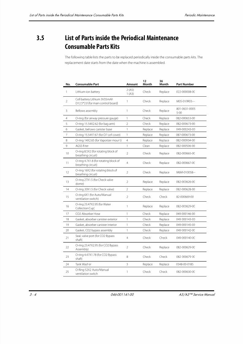
7/21/2019 a5 a3 Service Manual 2013
http://slidepdf.com/reader/full/a5-a3-service-manual-2013 137/399
List of Parts inside the Periodical Maintenance Consumable Parts Kits Periodic Maintenance
3 - 4 046-001141-00 A5/A3™ Service Manual
3.5 List of Parts inside the Periodical Maintenance
Consumable Parts Kits
The following table lists the parts to be replaced periodically inside the consumable parts kits. The
replacement date starts from the date when the machine is assembled.
No. Consumable Part Amount12Month
36Month Part Number
1 Lithium-ion battery2 (A5)
1 (A3)Check Replace 022-000008-00
2Cell battery Lithium 3V35mAh
D12.5*2.0 (for main control board)1 Check Replace M05-010R03---
3 Bellows assembly 1 Check Replace801-0631-0005
5-00
4 O-ring (for airway pressure gauge) 1 Check Replace 082-000653-00
5 O-ring 15.54X2.62 (for bag arm) 2 Check Replace 082-000673-00
6 Gasket, bellows canister base 1 Replace Replace 049-000243-00
7 O-ring 15.54X2.62 (for O2 cell cover) 1 Replace Replace 082-000673-00
8 O-ring 14X2.65 (for Vaporizer mount) 4 Replace Replace 082-000934-00
9 AGSS filter 1 Clean Replace 082-000506-00
10O-ring 8.5X2 (for rotating block of
breathing circuit)2 Check Replace 082-000665-00
11O-ring 4.7X1.8 (for rotating block of
breathing circuit)4 Check Replace 082-000667-00
12O-ring 16X2 (for rotating block of
breathing circuit)2 Check Replace M6M-010058---
13 O-ring 27X1.5 (for Check valvedome)
2 Replace Replace 082-000626-00
14 O-ring 20X1.5 (for Check valve) 2 Replace Replace 082-000628-00
15O-ring 6X1 (for Auto/Manual
ventilation switch)2 Check Check 82-000669-00
16O-ring 23.47X2.95 (for Water
Collection Cup)1 Replace Replace 082-000629-00
17 CO2 Absorber Hose 1 Check Replace 049-000146-00
18 Gasket, absorber canister exterior 1 Check Replace 049-000143-00
19 Gasket, absorber canister interior 1 Check Replace 049-000145-00
20 Gasket, CO2 bypass assembly 1 Check Replace 049-000142-00
21Seal, valve port (for CO2 Bypass
shaft)
4 Check Check 049-000140-00
22O-ring 23.47X2.95 (for CO2 Bypass
Assembly)2 Check Replace 082-000629-00
23O-ring 4.47X1.78 (for CO2 Bypass
shaft)8 Check Check 082-000679-00
24 Tank Washer 3 Replace Replace 0348-00-0185
25O-Ring 52X2 Auto/Manual
ventilation switch1 Check Check 082-000630-00

7/21/2019 a5 a3 Service Manual 2013
http://slidepdf.com/reader/full/a5-a3-service-manual-2013 138/399
A5/A3™ Service Manual 046-001141-00 3 - 5
Periodic Maintenance List of Parts inside the Periodical Maintenance Consumable Parts Kits
The locations of the O-rings / Gaskets are shown in FIGURE 3-1.
FIGURE 3-1 Locations of the O-rings / gaskets
26O-Ring 40X2.2 Auto/Manual
ventilation switch2 Check Check 082-000648-00
27 O-Ring 30X2 bag arm base 1 Check Check 082-000624-0028 O-Ring 8.5X2.0 O2 cell port 1 Check Replace 082-000654-00
29 Inspiratory Flow Sensor 1 Check Check 801-0631-00060-00
30 Expiratory Flow Sensor 1 Check Check 801-0631-00056-00
31 O-ring 18X2.5 Breathing system base 2 Check Check 082-000627-00
32 Bellow check valve membrane 1 Check Replace 049-000240-00
33 O-Ring 20.29X2.62 Bellows base 1 Check Check 082-000633-00
34 O-Ring 29.82X2.62 APL valve 1 Check Check 082-000642-00
35 O-Ring 25X2 APL valve 1 Check Check 082-000625-00
No. Consumable Part Amount12Month
36Month Part Number

7/21/2019 a5 a3 Service Manual 2013
http://slidepdf.com/reader/full/a5-a3-service-manual-2013 139/399
List of Parts inside the Periodical Maintenance Consumable Parts Kits Periodic Maintenance
3 - 6 046-001141-00 A5/A3™ Service Manual
FIGURE 3-2 Breathing System
FIGURE 3-3 Breathing System Adapter

7/21/2019 a5 a3 Service Manual 2013
http://slidepdf.com/reader/full/a5-a3-service-manual-2013 140/399
A5/A3™ Service Manual 046-001141-00 3 - 7
Periodic Maintenance List of Parts inside the Periodical Maintenance Consumable Parts Kits
FIGURE 3-4 CO2 Bypass Shaft and CO2 Absorber Assembly
7/21/2019 a5 a3 Service Manual 2013
http://slidepdf.com/reader/full/a5-a3-service-manual-2013 141/399
Battery Maintenance and Replacement Periodic Maintenance
3 - 8 046-001141-00 A5/A3™ Service Manual
3.6 Battery Maintenance and Replacement
Maintenance is not required for the lithium-ion battery supply in the A5/A3. If the battery supply
does not function normally, replace it as follows:
1. Open the rear cover of the anesthesia system.
2. Open the battery box of the anesthesia system.
3. Remove the old battery.
4. Install the new battery.
5. Close the battery box.
6. Close the rear cover.
7. Use only Mindray approved batteries (P/N 022-000008-00).
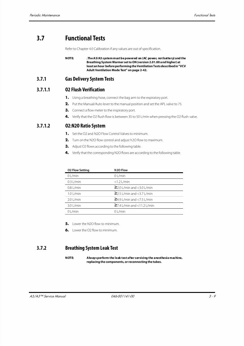
7/21/2019 a5 a3 Service Manual 2013
http://slidepdf.com/reader/full/a5-a3-service-manual-2013 142/399
A5/A3™ Service Manual 046-001141-00 3 - 9
Periodic Maintenance Functional Tests
3.7 Functional Tests
Refer to Chapter 4.0 Calibration if any values are out of specification.
NOTE: .The A5/A3 system must be powered on (AC power, not battery) and the
Breathing System Warmer set to ON (version 2.01.00 and higher) at
least an hour before performing the Ventilation Tests described in “VCV
Adult Ventilation Mode Test” on page 2-42.
3.7.1 Gas Delivery System Tests
3.7.1.1 O2 Flush Verification
1. Using a breathing hose, connect the bag arm to the expiratory port.
2. Put the Manual/Auto lever to the manual position and set the APL valve to 75.
3. Connect a flow meter to the inspiratory port.
4. Verify that the O2 flush flow is between 35 to 50 L/min when pressing the O2 flush valve.
3.7.1.2 O2:N2O Ratio System
1. Set the O2 and N2O Flow Control Valves to minimum.
2. Turn on the N2O flow control and adjust N2O flow to maximum.
3. Adjust O2 flows according to the following table.
4. Verify that the corresponding N2O flows are according to the following table.
5. Lower the N2O flow to minimum.
6. Lower the O2 flow to minimum.
3.7.2 Breathing System Leak Test
NOTE: Always perform the leak test after servicing the anesthesia machine,
replacing the components, or reconnecting the tubes.
O2 Flow Setting N2O Flow
0 L/min 0 L/min
0.3 L/min <1.2 L/min
0.8 L/min ≥2.0 L/min and <3.0 L/min
1.0 L/min ≥2.5 L/min and <3.7 L/min
2.0 L/min ≥4.9 L/min and <7.5 L/min
3.0 L/min ≥7.4 L/min and <11.2 L/min
0 L/min 0 L/min
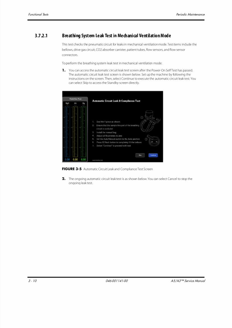
7/21/2019 a5 a3 Service Manual 2013
http://slidepdf.com/reader/full/a5-a3-service-manual-2013 143/399
Functional Tests Periodic Maintenance
3 - 10 046-001141-00 A5/A3™ Service Manual
3.7.2.1 Breathing System Leak Test in Mechanical Ventilation Mode
This test checks the pneumatic circuit for leaks in mechanical ventilation mode. Test items include the
bellows, drive gas circuit, CO2 absorber canister, patient tubes, flow sensors, and flow sensor
connectors.
To perform the breathing system leak test in mechanical ventilation mode:
1. You can access the automatic circuit leak test screen after the Power-On Self Test has passed.
The automatic circuit leak test screen is shown below. Set up the machine by following the
instructions on the screen. Then, select Continue to execute the automatic circuit leak test. You
can select Skip to access the Standby screen directly.
FIGURE 3-5 Automatic Circuit Leak and Compliance Test Screen
2. The ongoing automatic circuit leak test is as shown below. You can select Cancel to stop the
ongoing leak test.

7/21/2019 a5 a3 Service Manual 2013
http://slidepdf.com/reader/full/a5-a3-service-manual-2013 144/399
A5/A3™ Service Manual 046-001141-00 3 - 11
Periodic Maintenance Functional Tests
FIGURE 3-6 Automatic Circuit Leak and Compliance Test In Progress
3. During the automatic circuit leak test, the safety valve control test is also being conducted. The
automatic circuit leak test results are listed in the following table.
The following screen is displayed if the safety valve control test is failed. You can select Service Access
and enter the required service password to access service mode. You can select Retry to perform
automatic circuit leak test again.
Test Result System Limitation
Safety valve control failed The machine cannot be used.
Automatic circuit leak test failed
Leak ≥200 mL/min and ≤1000 mL
The user can acknowledge the leak and continue with automatic
ventilation.
Automatic circuit leak test failed
Leak >1000 mLOnly manual ventilation can be applied.
Compliance test failed
Both automatic ventilation and manual ventilation can still be
applied using the previous compliance value in the A5/A3 system
memory, but may not meet the accuracy of the delivered volume.

7/21/2019 a5 a3 Service Manual 2013
http://slidepdf.com/reader/full/a5-a3-service-manual-2013 145/399
Functional Tests Periodic Maintenance
3 - 12 046-001141-00 A5/A3™ Service Manual
FIGURE 3-7 Machine Non-Functional Screen
The following screen is displayed if the automatic circuit leak test is failed and the Leak ≥200 mL/minand ≤1000 mL. You can select Retry to perform the automatic circuit leak test again or accept the
result continue with automatic ventilation.
FIGURE 3-8 Automatic Circuit Leak and Compliance Test: Fail
The following screen is displayed if the automatic circuit leak test is failed and the leak >1000 mL. You
can select Override to enter Standby mode. But mechanical ventilation is disabled. You can select
Retry to perform automatic circuit leak test again.
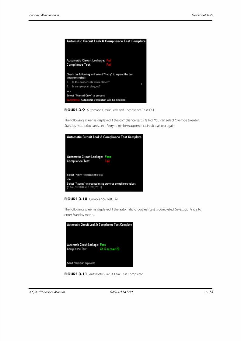
7/21/2019 a5 a3 Service Manual 2013
http://slidepdf.com/reader/full/a5-a3-service-manual-2013 146/399
A5/A3™ Service Manual 046-001141-00 3 - 13
Periodic Maintenance Functional Tests
FIGURE 3-9 Automatic Circuit Leak and Compliance Test: Fail
The following screen is displayed if the compliance test is failed. You can select Override to enter
Standby mode.You can select Retry to perform automatic circuit leak test again.
FIGURE 3-10 Compliance Test: Fail
The following screen is displayed if the automatic circuit leak test is completed. Select Continue to
enter Standby mode.
FIGURE 3-11 Automatic Circuit Leak Test Completed

7/21/2019 a5 a3 Service Manual 2013
http://slidepdf.com/reader/full/a5-a3-service-manual-2013 147/399
Functional Tests Periodic Maintenance
3 - 14 046-001141-00 A5/A3™ Service Manual
NOTE: If the leak test fails, check all of the possible leak sources, including the
bellows, breathing system tubes, and CO2 absorber canister. Check that
they are correctly connected and their connectors are not damaged.
NOTE: If there is a leak, check the pneumatic circuit system for leakage and
troubleshoot the problems as described in 5.3.4 Breathing System.
After the leak has been resolved, repeat the leak test.
3.7.2.2 Breathing System Leak Test in Manual Ventilation Mode
This test checks the pneumatic circuit for leaks in manual ventilation mode. Test items include the
APL valve, check valve, CO2 absorber canister, patient tubes, flow sensors, and flow sensor
connectors.
To perform the breathing system leak test in manual ventilation mode:
1. You can access the manual circuit leak test screen after the Power-On Self Test has passed. You
can also open the Setup in Standby and select Test Leak/Compliance on the Calibrate/General
menu to access the manual circuit leak test screen. The manual circuit leak test screen is shown
below.
FIGURE 3-12 Automatic Circuit Leak Test Completed
2. Set up the machine as per the instructions on the screen. Then, select Continue to execute
manual circuit leak test.
3. The ongoing manual circuit leak test is as shown below. You can select Cancel to cancel the
ongoing leak test.
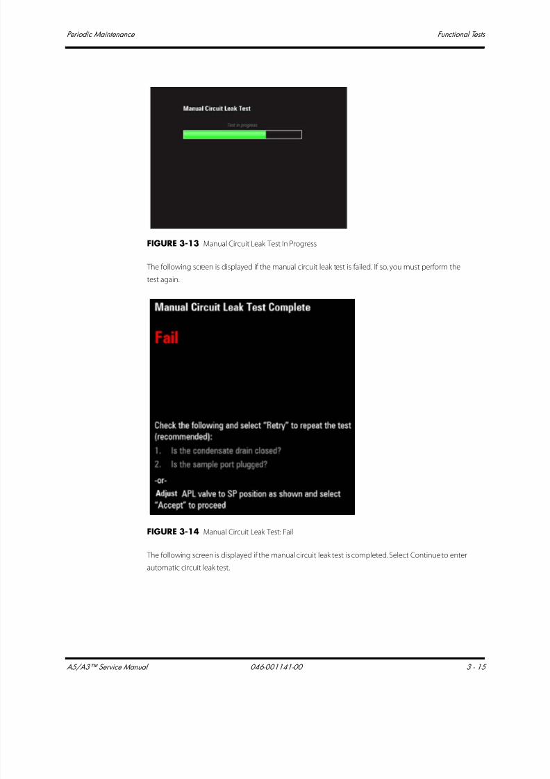
7/21/2019 a5 a3 Service Manual 2013
http://slidepdf.com/reader/full/a5-a3-service-manual-2013 148/399
A5/A3™ Service Manual 046-001141-00 3 - 15
Periodic Maintenance Functional Tests
FIGURE 3-13 Manual Circuit Leak Test In Progress
The following screen is displayed if the manual circuit leak test is failed. If so, you must perform the
test again.
FIGURE 3-14 Manual Circuit Leak Test: Fail
The following screen is displayed if the manual circuit leak test is completed. Select Continue to enter
automatic circuit leak test.

7/21/2019 a5 a3 Service Manual 2013
http://slidepdf.com/reader/full/a5-a3-service-manual-2013 149/399
Functional Tests Periodic Maintenance
3 - 16 046-001141-00 A5/A3™ Service Manual
FIGURE 3-15 Manual Circuit Leak Test: Passed
NOTE: If there is a leak, check the pneumatic circuit system for leakage and
troubleshoot the problems as described in 5.3 Pneumatic Circuit
System Problems. Repeat the leak test after the source of the failure hasbeen resolved.
3.7.2.3 Vaporizer Leak Test
1. Set the ventilation Auto/Manual ventilation switch to Manual.
2. Set the APL valve to the SP position.
3. Connect one end of the breathing circuit to the bag arm, one end to the inspiratory port and
the Y-piece to the test port:

7/21/2019 a5 a3 Service Manual 2013
http://slidepdf.com/reader/full/a5-a3-service-manual-2013 150/399
A5/A3™ Service Manual 046-001141-00 3 - 17
Periodic Maintenance Functional Tests
FIGURE 3-16 Vaporizer Leak Test Setup
4. Mount and lock the vaporizer onto the vaporizer mount. (Certain vaporizers need to be set to at
least 1% for correct testing. See the vaporizer manufacturer’s manual for details.)
5. Set the fresh gas flow to 200 mL/min.
6. Set the APL valve to 75 and verify that the pressure on the airway pressure gauge increases
above 30 cmH2O within 2 minutes.
7. Turn off the vaporizer.
8. Repeat Steps 4, 5, 6, and 7 for the other vaporizer.
3.7.2.4 Check Valve Test1. Set the ventilation Auto/Manual ventilation switch to Manual.
2. Set the APL valve to 75.
3. Connect the breathing bag to the Inspiratory port.
4. Plug the bag arm.
5. Press the FLUSH button until the pressure on the airway pressure gauge reaches 35 cmH2O.
6. Set the APL valve to SP.
7. Verify that the pressure does not drop below 30 cmH2O after 10 seconds
3.7.2.5 Troubleshooting: Leak Test
The following table lists the commonly-encountered problems and recommended actions for
Section 3.7.2.2 Breathing System Leak Test in Manual Ventilation Mode.
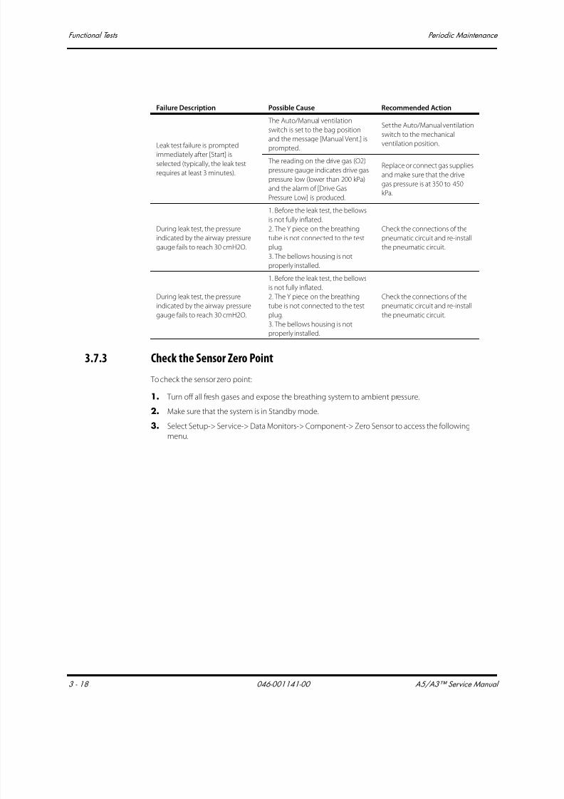
7/21/2019 a5 a3 Service Manual 2013
http://slidepdf.com/reader/full/a5-a3-service-manual-2013 151/399
Functional Tests Periodic Maintenance
3 - 18 046-001141-00 A5/A3™ Service Manual
3.7.3 Check the Sensor Zero Point
To check the sensor zero point:
1. Turn off all fresh gases and expose the breathing system to ambient pressure.
2. Make sure that the system is in Standby mode.
3. Select Setup-> Service-> Data Monitors-> Component-> Zero Sensor to access the following
menu.
Failure Description Possible Cause Recommended Action
Leak test failure is prompted
immediately after [Start] is
selected (typically, the leak test
requires at least 3 minutes).
The Auto/Manual ventilation
switch is set to the bag position
and the message [Manual Vent.] isprompted.
Set the Auto/Manual ventilation
switch to the mechanical
ventilation position.
The reading on the drive gas (O2)
pressure gauge indicates drive gas
pressure low (lower than 200 kPa)
and the alarm of [Drive Gas
Pressure Low] is produced.
Replace or connect gas supplies
and make sure that the drive
gas pressure is at 350 to 450
kPa.
During leak test, the pressure
indicated by the airway pressure
gauge fails to reach 30 cmH2O.
1. Before the leak test, the bellows
is not fully inflated.
2. The Y piece on the breathing
tube is not connected to the test
plug.
3. The bellows housing is not
properly installed.
Check the connections of the
pneumatic circuit and re-install
the pneumatic circuit.
During leak test, the pressure
indicated by the airway pressure
gauge fails to reach 30 cmH2O.
1. Before the leak test, the bellowsis not fully inflated.
2. The Y piece on the breathing
tube is not connected to the test
plug.
3. The bellows housing is not
properly installed.
Check the connections of the
pneumatic circuit and re-install
the pneumatic circuit.

7/21/2019 a5 a3 Service Manual 2013
http://slidepdf.com/reader/full/a5-a3-service-manual-2013 152/399
A5/A3™ Service Manual 046-001141-00 3 - 19
Periodic Maintenance Functional Tests
FIGURE 3-17 Data Monitors Menu
4. The second column is the current reading of the sensors and the third column is the zero that is
saved in the EEPROM.
The following table lists the normal range of the zero point of the A5/A3 pressure and flow sensors.
• If there is a great deviation between the current zero point and the saved zero point, it indicates
that the sensor is aging but it does not mean that normal measurement cannot be performed.
The sensor will need to be recalibrated.
If the zero point of the flow sensor is not within 0 to 2000 and the zero point of the pressure
sensor is not within 0 to 1200, the Ventilator Control Board needs to be replaced.
3.7.4 Check the Flow Sensor Accuracy
NOTE: You can use any flow meter that has an accuracy of at least ±2% for the
accuracy measurement of the flow sensors.
To check the measurement accuracy of flow sensors:
1. Remove the bellows and water trap.
2. The pneumatic connections between the anesthesia machine and calibration device are as
shown in the following picture. You can connect the tube to a high-flow connector or low-flow
connector based on the requirements.
Sensor Name Normal Range of Zero Point (AD Counts)
Paw sensor 200~800
PEEP pressure sensor 200~800
Inspiratory flow sensor 200~1400
Expiratory flow sensor 200~1400
Ventilator internal flow sensor 100~400
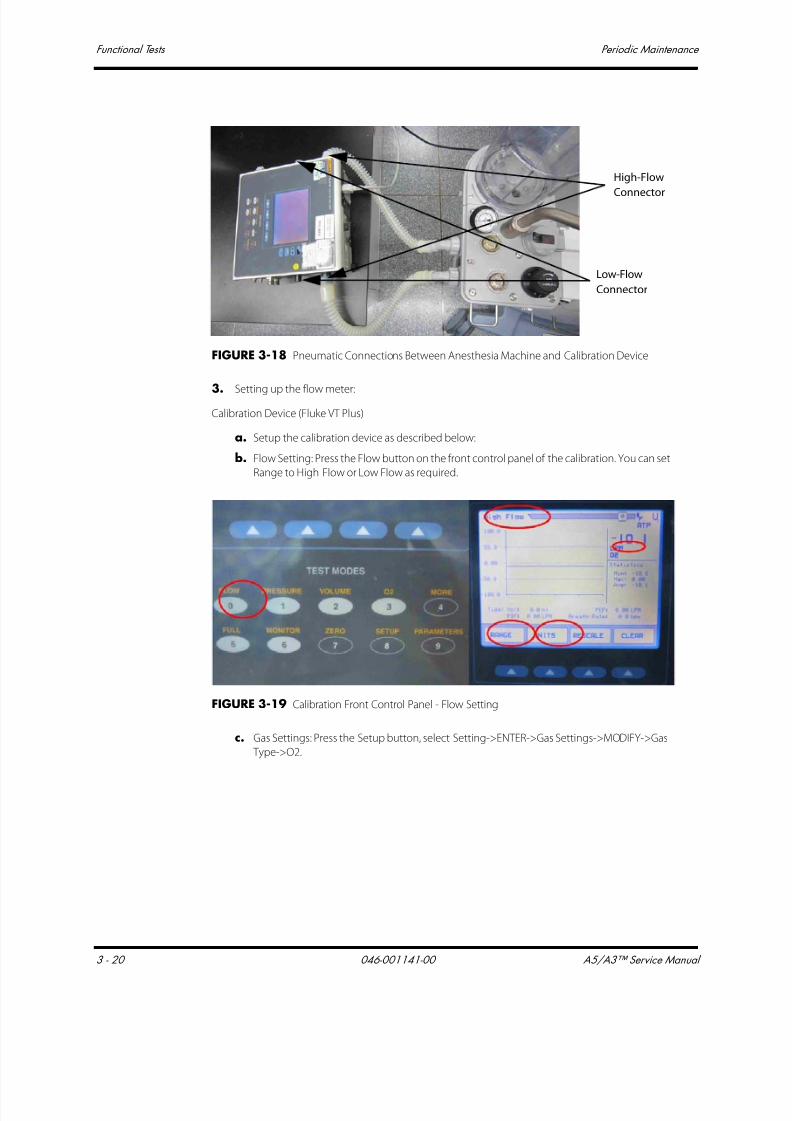
7/21/2019 a5 a3 Service Manual 2013
http://slidepdf.com/reader/full/a5-a3-service-manual-2013 153/399
Functional Tests Periodic Maintenance
3 - 20 046-001141-00 A5/A3™ Service Manual
FIGURE 3-18 Pneumatic Connections Between Anesthesia Machine and Calibration Device
3. Setting up the flow meter:
Calibration Device (Fluke VT Plus)
a. Setup the calibration device as described below:
b. Flow Setting: Press the Flow button on the front control panel of the calibration. You can set
Range to High Flow or Low Flow as required.
FIGURE 3-19 Calibration Front Control Panel - Flow Setting
c. Gas Settings: Press the Setup button, select Setting->ENTER->Gas Settings->MODIFY->Gas
Type->O2.
High-Flow
Connector
Low-Flow
Connector
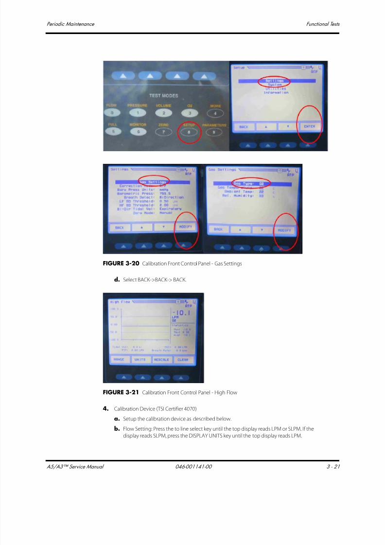
7/21/2019 a5 a3 Service Manual 2013
http://slidepdf.com/reader/full/a5-a3-service-manual-2013 154/399
A5/A3™ Service Manual 046-001141-00 3 - 21
Periodic Maintenance Functional Tests
FIGURE 3-20 Calibration Front Control Panel - Gas Settings
d. Select BACK->BACK-> BACK.
FIGURE 3-21 Calibration Front Control Panel - High Flow
4. Calibration Device (TSI Certifier 4070)
a. Setup the calibration device as described below.
b. Flow Setting: Press the to line select key until the top display reads LPM or SLPM. If the
display reads SLPM, press the DISPLAY UNITS key until the top display reads LPM.
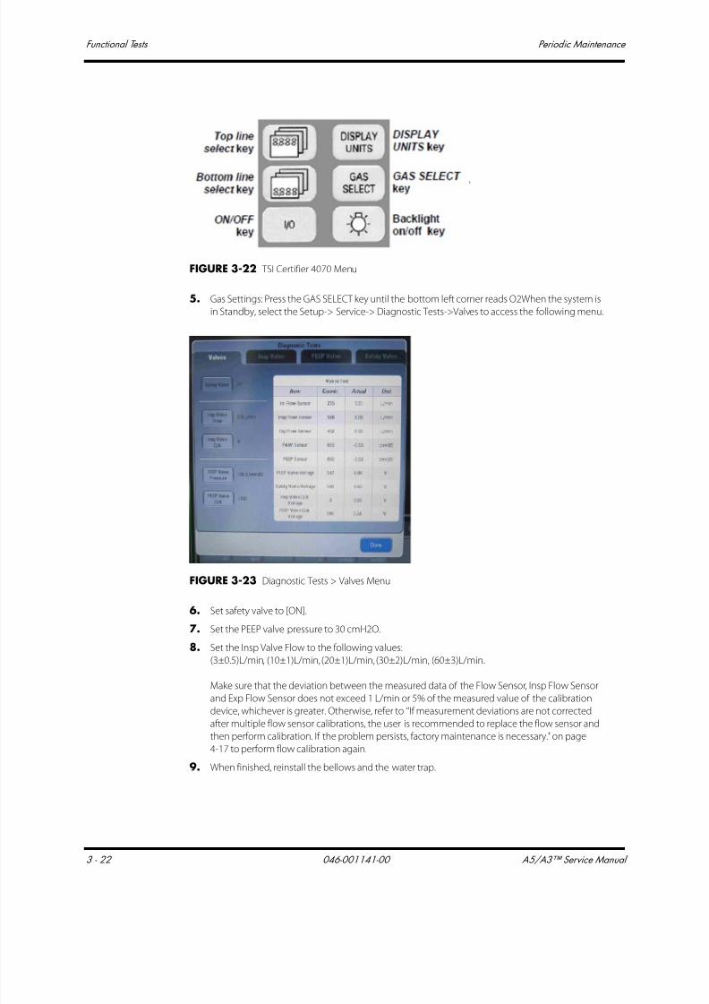
7/21/2019 a5 a3 Service Manual 2013
http://slidepdf.com/reader/full/a5-a3-service-manual-2013 155/399
Functional Tests Periodic Maintenance
3 - 22 046-001141-00 A5/A3™ Service Manual
FIGURE 3-22 TSI Certifier 4070 Menu
5. Gas Settings: Press the GAS SELECT key until the bottom left corner reads O2When the system is
in Standby, select the Setup-> Service-> Diagnostic Tests->Valves to access the following menu.
FIGURE 3-23 Diagnostic Tests > Valves Menu
6. Set safety valve to [ON].
7. Set the PEEP valve pressure to 30 cmH2O.
8. Set the Insp Valve Flow to the following values:
(3±0.5)L/min, (10±1)L/min, (20±1)L/min, (30±2)L/min, (60±3)L/min.
Make sure that the deviation between the measured data of the Flow Sensor, Insp Flow Sensor
and Exp Flow Sensor does not exceed 1 L/min or 5% of the measured value of the calibrationdevice, whichever is greater. Otherwise, refer to ‘‘If measurement deviations are not corrected
after multiple flow sensor calibrations, the user is recommended to replace the flow sensor and
then perform calibration. If the problem persists, factory maintenance is necessary.’’ on page
4-17 to perform flow calibration again.
9. When finished, reinstall the bellows and the water trap.
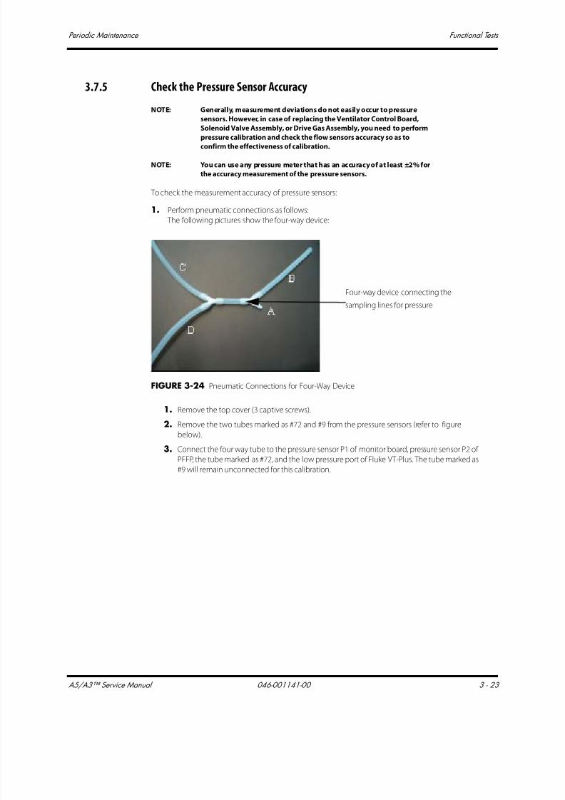
7/21/2019 a5 a3 Service Manual 2013
http://slidepdf.com/reader/full/a5-a3-service-manual-2013 156/399
A5/A3™ Service Manual 046-001141-00 3 - 23
Periodic Maintenance Functional Tests
3.7.5 Check the Pressure Sensor Accuracy
NOTE: Generally, measurement deviations do not easily occur to pressure
sensors. However, in case of replacing the Ventilator Control Board,
Solenoid Valve Assembly, or Drive Gas Assembly, you need to perform
pressure calibration and check the flow sensors accuracy so as toconfirm the effectiveness of calibration.
NOTE: You can use any pressure meter that has an accuracy of at least ±2% for
the accuracy measurement of the pressure sensors.
To check the measurement accuracy of pressure sensors:
1. Perform pneumatic connections as follows:
The following pictures show the four-way device:
FIGURE 3-24 Pneumatic Connections for Four-Way Device
1. Remove the top cover (3 captive screws).
2. Remove the two tubes marked as #72 and #9 from the pressure sensors (refer to figure
below).
3. Connect the four way tube to the pressure sensor P1 of monitor board, pressure sensor P2 of
PEEP, the tube marked as #72, and the low pressure port of Fluke VT-Plus. The tube marked as
#9 will remain unconnected for this calibration.
Four-way device connecting the
sampling lines for pressure
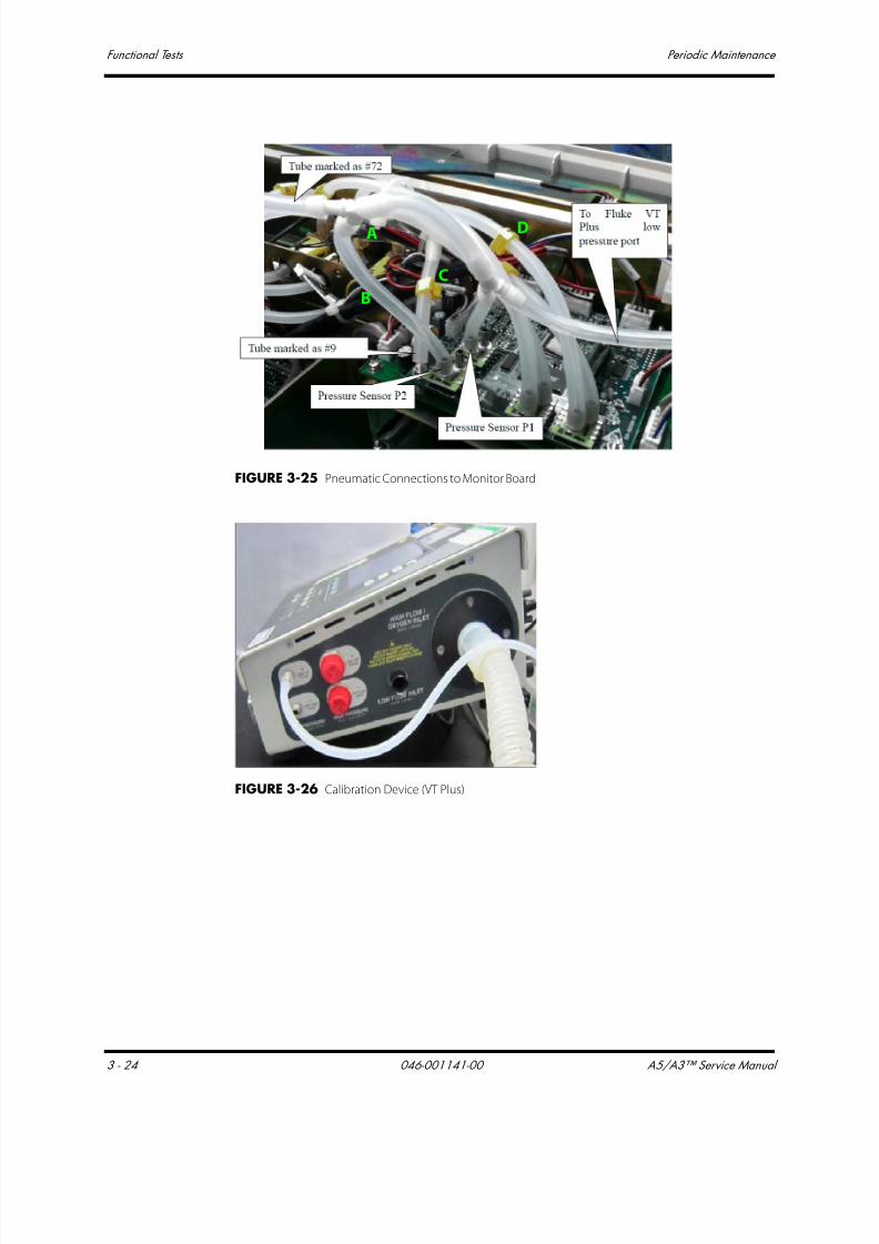
7/21/2019 a5 a3 Service Manual 2013
http://slidepdf.com/reader/full/a5-a3-service-manual-2013 157/399
Functional Tests Periodic Maintenance
3 - 24 046-001141-00 A5/A3™ Service Manual
FIGURE 3-25 Pneumatic Connections to Monitor Board
FIGURE 3-26 Calibration Device (VT Plus)
A
B
C
D
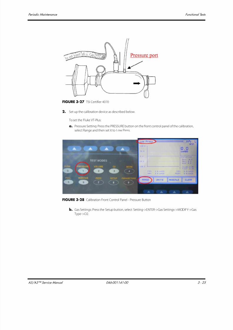
7/21/2019 a5 a3 Service Manual 2013
http://slidepdf.com/reader/full/a5-a3-service-manual-2013 158/399
A5/A3™ Service Manual 046-001141-00 3 - 25
Periodic Maintenance Functional Tests
FIGURE 3-27 TSI Certifier 4070
2. Set up the calibration device as described below.
To set the Fluke VT-Plus:
a. Pressure Setting: Press the PRESSURE button on the front control panel of the calibration,
select Range and then set it to Low Press.
FIGURE 3-28 Calibration Front Control Panel - Pressure Button
b. Gas Settings: Press the Setup button, select Setting->ENTER->Gas Settings->MODIFY->Gas
Type->O2.

7/21/2019 a5 a3 Service Manual 2013
http://slidepdf.com/reader/full/a5-a3-service-manual-2013 159/399
Functional Tests Periodic Maintenance
3 - 26 046-001141-00 A5/A3™ Service Manual
FIGURE 3-29 Calibration Front Control Panel - Gas Settings
4. Select BACK->BACK-> BACK.
FIGURE 3-30 Calibration Front Control Panel - Gas Settings
3. When the system is Standby, select the Setup->Service-> Diagnostic Tests-> Valves to access the
following menu.

7/21/2019 a5 a3 Service Manual 2013
http://slidepdf.com/reader/full/a5-a3-service-manual-2013 160/399
A5/A3™ Service Manual 046-001141-00 3 - 27
Periodic Maintenance Functional Tests
FIGURE 3-31 Calibration Front Control Panel - Gas Settings
4. Set safety valve to ON.
5. Set the PEEP valve pressure to the following values:
(5±1) cmH2O, (20±1) cmH2O, (50±1) cmH2O, (70±2) cmH2O, (90±2) cmH2O.
6. Make sure that the deviation between the measured data of the PAW Sensor, PEEP pressure
sensor and that of the anesthesia machine calibration device must not exceed 1 cmH2O or 2%
of the measured value of the calibration device, whichever is greater. Otherwise, refer to Section
4.3.5 Pressure Calibration (Service) to perform pressure calibration again.

7/21/2019 a5 a3 Service Manual 2013
http://slidepdf.com/reader/full/a5-a3-service-manual-2013 161/399
Pneumatic Leak Tests Periodic Maintenance
3 - 28 046-001141-00 A5/A3™ Service Manual
3.8 Pneumatic Leak Tests
Turn all fresh gas flows to 0 L/min.
3.8.1 N2O Cylinder Leak Test1. Remove the N2O line pressure hose from the line pressure inlet on the A5/A3.
2. Mount a full N2O cylinder to the rear panel yoke. If necessary, place a new clean tank washer
between the cylinder and the yoke to minimize any leaks at the yoke connection.
3. Open the N2O cylinder until its pressure gauge indicates cylinder pressure.
4. Close the N2O cylinder.
5. The N2O cylinder pressure gauge should not drop more than 10% of its initial pressure over 1
minute.
3.8.2 O2 Cylinder Leak Test
1. Remove the O2 line pressure hose from the line pressure inlet on the A5/A3.
2. Mount a full O2 cylinder to the rear panel yoke. If necessary, place a new clean tank washer
between the cylinder and the yoke to minimize any leaks at the yoke connection.
3. Open the O2 cylinder until its pressure gauge indicates cylinder pressure.
4. Close the O2 cylinder.
5. The O2 cylinder pressure gauge should not drop more than 10% of its initial pressure over 1
minute.
3.8.3 AIR Cylinder Leak Test
1. Remove the AIR line pressure hose from the line pressure inlet on the A5/A3.
2. Mount a full AIR cylinder to the rear panel yoke. If necessary, place a new clean tank washer
between the cylinder and the yoke to minimize any leaks at the yoke connection.3. Open the AIR cylinder until its pressure gauge indicates cylinder pressure.
4. Close the AIR cylinder.
5. The AIR cylinder pressure gauge should not drop more than 10% of its initial pressure over 1
minute.
3.8.4 N2O Line Pressure Leak Test
1. Remove the N2O cylinder from the A5/A3.
2. Connect the N2O line pressure hose to the line pressure inlet on the A5/A3.
3. Pinch the N2O line pressure hose to stop N2O line flow.
4. Remove the N2O line pressure hose from the N2O line source while keeping the hose pinched.
5. The N2O line pressure gauge should not fall more than 10 psi per 100 seconds (2 psi per 20 sec).
6. Reconnect the N2O line pressure and remove the pinch in the hose.

7/21/2019 a5 a3 Service Manual 2013
http://slidepdf.com/reader/full/a5-a3-service-manual-2013 162/399
A5/A3™ Service Manual 046-001141-00 3 - 29
Periodic Maintenance Pneumatic Leak Tests
3.8.5 O2 Line Pressure Leak Test
1. Remove the O2 cylinder from the A5/A3.
2. Connect the O2 line pressure hose to the line pressure inlet on the A5/A3.
3. Pinch the O2 line pressure hose to stop O2 line flow.
4. Remove the O2 line pressure hose from the O2 line source while keeping the hose pinched.
5. The O2 line pressure gauge should not fall more than 10 psi per 100 seconds (2 psi per 20 sec).
6. Reconnect the O2 line pressure and remove the pinch in the hose.
3.8.6 AIR Line Pressure Leak Test
1. Remove the AIR cylinder from the A5/A3.
2. Connect the AIR line pressure hose to the line pressure inlet on the A5/A3.
3. Pinch the AIR line pressure hose to stop AIR line flow.
4. Remove the AIR line pressure hose from the AIR line source while keeping the hose pinched.
5. The AIR line pressure gauge should not fall more than 10 psi per 100 seconds (2 psi per 20 sec).6. Reconnect the AIR line pressure and remove the pinch in the hose.

7/21/2019 a5 a3 Service Manual 2013
http://slidepdf.com/reader/full/a5-a3-service-manual-2013 163/399
Breathing System Checks Periodic Maintenance
3 - 30 046-001141-00 A5/A3™ Service Manual
3.9 Breathing System Checks
3.9.1 Waste Gas Scavenger Test (if available)
1. Connect one end of the low pressure waste gas hose to the port on the Waste Gas Scavenger
Assembly. Connect the other end of the hose to the EVAC port.
NOTE: If operating the A5/A3 with other types of waste gas scavenging,
ensure that waste gases are directed from the EVAC port to that
scavenging system.
2. Connect the respiratory gas monitor exhaust output to the barbed fitting port on the Waste Gas
Scavenger Assembly.
3. Ensure that the waste gas scavenger flow adjustment is able to be set between the MIN and
MAX line markings.
3.9.2 Internal Gas Connections Test
1. Close and remove all gas cylinders from the A5/A3.
2. Connect only the AIR line pressure hose to the A5/A3 from the wall supply. Leave all other line
pressure hoses disconnected.
3. With the A5/A3 powered ON, rotate the AIR f low control knob to ensure a continuous flow
increase throughout its full range
4. Fully rotate the N2O flow control knob and verify that there is no flow.
5. Fully rotate the O2 flow control knob and verify that there is no flow.
6. Disconnect the AIR line pressure hose from the A5/A3, and connect the O2 line pressure hose
from the wall supply, rotate the O2 flow control knob to ensure a continuous flow increase
throughout its full range (0 to 15 L/min).
7. Fully rotate the N2O flow control knob and verify that there is no flow.
8. Fully rotate the AIR flow control knob and verify that there is no flow.9. Connect the N2O line pressure hose from the wall supply. With the O2 f low control knob fully
opened, rotate the N2O flow control knob to ensure a continuous flow increase throughout its
full range.
NOTE: The maximum flow for N2O must be between 10 and 12 L/min.
10. Fully rotate the AIR flow control knob and verify that there is no flow.
3.9.3 Drive Gas Pressure Loss Alarm, N2O Cutoff Test
1. Set the O2 flow to 2 L/min using the flow control valve.
2. Set the N2O flow to 2 L/min using the flow control valve.
3. Set the AIR flow to 2 L/min using the flow control valve.
4. Interrupt the O2 supply to the A5/A3.
5. Verify that the flow of N2O and O2 stops within 2 minutes and that the flow of AIR (if available)
continues to flow at 2 L/min.
6. Verify the following alarms are activated:
• O2 Supply Failure appears on the screen
• An alarm tone sounds

7/21/2019 a5 a3 Service Manual 2013
http://slidepdf.com/reader/full/a5-a3-service-manual-2013 164/399
A5/A3™ Service Manual 046-001141-00 3 - 31
Periodic Maintenance Performance Verification
3.10 Performance Verification
3.10.1 Manual Ventilation Test
1. Ensure that the gas pressure for O2, N2O, and AIR is within specifications.
2. Power ON the anesthesia system.
3. Attach a breathing circuit and test lung to the Y-fitting of the breathing circuit.
NOTE: For testing purposes always use a reusable breathing circuit.
4. Perform the start up tests per the on-screen instructions. Ensure successful completion.
5. Power OFF the anesthesia system.
6. Set the mechanical Auto/Manual switch to MANUAL.
7. Set the APL Valve to approximately 15 cmH2O.
8. Set the AIR flow to approximately 5 L/min using the flow control valve. Use O2 if AIR is not
available.
9. Set the AIR flow to approximately 5 L/min using the flow control valve. Use O2 if AIR is not
available. Use O2 if AIR is not available. This will require turning the main switch to the ON
position.
10. Verify the inflation and deflation of the test lung.
3.10.2 Manual Mode Ventilation Test
1. Power ON the anesthesia system.
2. Attach a breathing circuit and test lung to the Y-fitting of the breathing circuit.
NOTE: For testing purposes always use a reusable breathing circuit.
3. Perform the start up tests per the on-screen instructions. Ensure successful completion.
4. Set the mechanical Auto/Manual switch to MANUAL. Press the screen for the screen to change
to manual Mode.
5. Set the APL Valve to approximately 25 cmH2O. Push the O2 Flush button to fill the breathing
bag.
6. Set the AIR flow to 1 L/min using the flow control valve. This will change the screen to manual
Mode
7. Squeeze the breathing bag once every 3 seconds.
8. Verify the inflation and deflation of the test lung.
9. Verify that an airway pressure waveform and all numeric values appear on screen during bag
compressions.
10. Stop squeezing the breathing bag and set the APL Valve to the open position (SP).
3.10.3 APNEA Alarm Test
1. While in the Manual Ventilation Mode, stop ventilating the test lung.
2. Verify that the following APNEA alarm signals activate at approximately 30 seconds from the last
bag compression.• APNEA appears on the screen.
• An alarm tone sounds.
7/21/2019 a5 a3 Service Manual 2013
http://slidepdf.com/reader/full/a5-a3-service-manual-2013 165/399
Performance Verification Periodic Maintenance
3 - 32 046-001141-00 A5/A3™ Service Manual
3.10.4 Alarm Silence Test
1. While the APNEA alarm is sounding, press the Silence soft key.
2. Verify the audio portion of the alarm stops and resumes after 2 minutes.
3.10.5 VCV Adult Ventilation Mode Test1. Set the O2 flow to 2 L/min and set the N2O and AIR flow rates to minimum flow.
2. Set the mechanical Auto/Manual switch to AUTO.
3. Set the ventilator controls to the following:
4. Press Set Mode button to begin ventilation.
5. Verify that the pressure waveform, Tidal Volume, Mean or Plateau Pressure, Resp. rate and minute
volume values appear on the screen.
6. Verify the Tidal Volume display on the Vent Tester is within 7% (±42 mL) of the set value within
approximately 1 minute from the start of ventilation.
7. Verify the Tidal Volume display is within 9% (±54 mL) of the set value within approximately 1
minute from the start of ventilation.
8. Verify the measured O2 concentration is at least 97% after 5 minutes.
9. Set the AIR flow to 3 L/min and set the N2O and O2 flow rates to minimum flow.
10. Verify the measured O2 concentration is 21% ±3% vol. % after 5 minutes.
Ventilator Controls Ventilator Settings
Ventilation Mode VCV
Vt 600
Rate 8
I:E 1:2
Tpause 10
PEEP Off
Plimit 50
7/21/2019 a5 a3 Service Manual 2013
http://slidepdf.com/reader/full/a5-a3-service-manual-2013 166/399
A5/A3™ Service Manual 046-001141-00 3 - 33
Periodic Maintenance Performance Verification
3.10.6 VCV Child Ventilation Mode Test
1. Set the ventilator controls to:
2. Press Set Mode button to begin ventilation.
3. Verify that the pressure waveform, Tidal Volume, Mean or Plateau Pressure, Resp. rate and minute
volume values appear on the screen.
4. Verify the Tidal Volume display is within 18ml of the set value within approximately 1 minutefrom the start of ventilation.
5. Verify the delivered volume, as measured by a Vent Tester at the expiratory port, is within 15ml of
the set value within approximately 1 minute from the start of ventilation.
3.10.7 Airway Disconnect Alarm Test
1. While the ventilator is running, disconnect the expiratory limb from the Expiratory Port on the
Breathing System.
2. Verify the following airway pressure disconnect alarm signals activate:
• Paw Too Low message appears on the screen.
• An alarm tone sounds.
Ventilator Controls Ventilator S ettings
Ventilation Mode VCV
Vt 120
Rate 15
I:E 1:2
Tpause 10
PEEP Off
Plimit 40

7/21/2019 a5 a3 Service Manual 2013
http://slidepdf.com/reader/full/a5-a3-service-manual-2013 167/399
Performance Verification Periodic Maintenance
3 - 34 046-001141-00 A5/A3™ Service Manual
3.10.8 PCV Adult Ventilation Mode Test
1. Set the O2 flow to 3 L/min and set the N2O and AIR flow rates to minimum flow.
2. Set the ventilator controls to:
3. Press Set Mode button to begin ventilation.
4. Verify the Peak Pressure reading of the display is within ±2 cmH2O of the Peak Pressure
measured with the Vent Tester.
5. Verify that the pressure waveform, Tidal Volume, Resp. Rate and minute volume values appear
on the screen.
6. Verify that the PEAK Value reaches 15 ±2.5 cmH2O within five breaths from the start of
ventilation.
3.10.9 Pressure Support (PS) Ventilation Mode Test
1. Set the O2 flow to 1 L/min and set the N2O and AIR flow rates to minimum flow.
2. Set the ventilator controls to:
3. Press Set Mode button to begin ventilation.
4. Begin triggering breaths by slightly squeezing the test lung and releasing. Maintain a
continuous breath rate.
5. Verify that a pressure waveform and all ventilation parameters appear on the screen.
6. Verify that the Peak Pressure reading on the display is ±2 the value ofΔP + PEEP.
7. Stop triggering breaths.
8. Verify that after 15 seconds the ventilator delivers a breath and displays the message Apnea
Ventilation.
9. Verify the system ventilates with a frequency of 4 bpm.
Ventilator Controls Ventilator Settings
Ventilation Mode PCV
VtG (A5 only) Off
Pinsp 15
Rate 8
I:E 1:2
PEEP Off
Tslope 0.2
PlimVG NA
Ventilator Controls Ventilator S ettings
Ventilation Mode PS
Min Rate 4
∆P 20
Trigger 3
PEEP Off
Tslope 0.2

7/21/2019 a5 a3 Service Manual 2013
http://slidepdf.com/reader/full/a5-a3-service-manual-2013 168/399
A5/A3™ Service Manual 046-001141-00 3 - 35
Periodic Maintenance Alarms and Fail safe Functions
3.11 Alarms and Fail safe Functions
3.11.1 Set Up
1. Set the O2 flow to 2 L/min and set the N2O and AIR flow rates to minimum flow.
2. Set the ventilator controls to:
3. Press Set Mode button to begin ventilation.
3.11.2 Low FiO2 Alarm Test
1. Set the Low FiO2 Alarm limit to 50%.
2. Set the AIR flow control valve to 5 L/min.
3. Set the O2 flow control to minimum flow.
4. Verify the following Low FiO2 alarm signals activate, within three ventilation cycles:
• FiO2 Too Low message appears on the screen.
• An alarm tone sounds.
5. Set the Low FiO2 alarm limit to 18%.
6. Verify the alarm signals cease.
3.11.3 High FiO2 Alarm Test
1. Set the high FiO2 Alarm limit to 50%.
2. Set the O2 flow control valve to 5 L/min.
3. Set the AIR flow controller to minimum.
4. Verify the following High FiO2 alarm signals activate:
• FiO2 Too High message appears on the screen.
• An alarm tone sounds.•
•
5. Set the high FiO2 alarm limit to the max setting.
6. Verify the alarm signals cease.
Ventilator Controls Ventilator Settings
Ventilation Mode VCV
Vt 600
Rate 8
I:E 1:2
Tpause 10
PEEP Off
Plimit 50

7/21/2019 a5 a3 Service Manual 2013
http://slidepdf.com/reader/full/a5-a3-service-manual-2013 169/399

7/21/2019 a5 a3 Service Manual 2013
http://slidepdf.com/reader/full/a5-a3-service-manual-2013 170/399
A5/A3™ Service Manual 046-001141-00 3 - 37
Periodic Maintenance Miscellaneous Tests
3.12 Miscellaneous Tests
3.12.1 Test the Line Voltage Alarm
1. Interrupt AC line voltage.
2. Verify that the following alarms activate:
• An alarm tone sounds.
• Battery in use message appears on the screen.
3. Plug the A5/A3 into AC line voltage.
4. Verify that the alarm signals cease.
5. Verify the presence of the battery charging icon in the upper right corner of the screen.
3.12.2 Top Light and Auxiliary Light Test
1. Turn on the Top light located on the bottom side of the top panel.
2. Verify that it lights in both on positions.
3.12.3 Auxiliary AC Outlets Test
CAUTION: Perform the electrical safety inspection as the last step after
completing a repair or after routine maintenance. Perform this
inspection with all covers, panels, and screws installed.
Verify AC voltage is present at each AC outlet with the A5/A3 3A Breaker in both the ON and OFF
positions.

7/21/2019 a5 a3 Service Manual 2013
http://slidepdf.com/reader/full/a5-a3-service-manual-2013 171/399
Vaporizer Interlock Test Periodic Maintenance
3 - 38 046-001141-00 A5/A3™ Service Manual
3.13 Vaporizer Interlock Test
1. Attach two vaporizers to the Vaporizer Mounting Manifold and lock them in place.
2. Rotate either of the vaporizer dial to 3% agent.
3. Verify that the other vaporizer dial cannot be rotated to a setting.
4. Set both vaporizer dials to 0.
5. Rotate the other vaporizer dial to 3%.
6. Verify that the first vaporizer dial cannot be rotated.
7. Rotate both vaporizer dials to T and remove both vaporizers.
8. Verify that the locking spring is intact.
9. Reconnect both vaporizers to the Vaporizer Mounting Manifold.
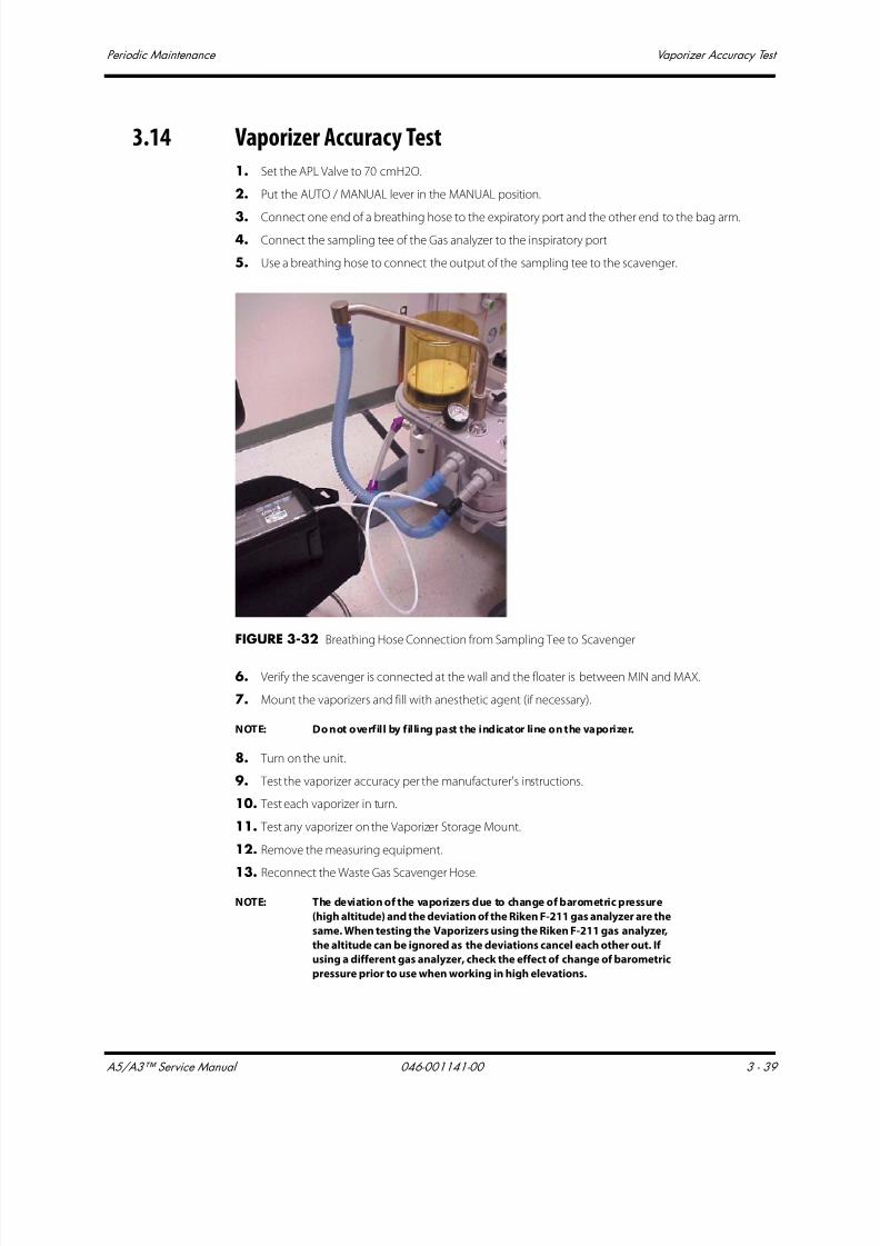
7/21/2019 a5 a3 Service Manual 2013
http://slidepdf.com/reader/full/a5-a3-service-manual-2013 172/399
A5/A3™ Service Manual 046-001141-00 3 - 39
Periodic Maintenance Vaporizer Accuracy Test
3.14 Vaporizer Accuracy Test
1. Set the APL Valve to 70 cmH2O.
2. Put the AUTO / MANUAL lever in the MANUAL position.
3. Connect one end of a breathing hose to the expiratory port and the other end to the bag arm.
4. Connect the sampling tee of the Gas analyzer to the inspiratory port
5. Use a breathing hose to connect the output of the sampling tee to the scavenger.
FIGURE 3-32 Breathing Hose Connection from Sampling Tee to Scavenger
6. Verify the scavenger is connected at the wall and the floater is between MIN and MAX.
7. Mount the vaporizers and fill with anesthetic agent (if necessary).
NOTE: Do not overfill by filling past the indicator line on the vaporizer.
8. Turn on the unit.
9. Test the vaporizer accuracy per the manufacturer's instructions.
10. Test each vaporizer in turn.
11. Test any vaporizer on the Vaporizer Storage Mount.
12. Remove the measuring equipment.
13. Reconnect the Waste Gas Scavenger Hose.
NOTE: The deviation of the vaporizers due to change of barometric pressure
(high altitude) and the deviation of the Riken F-211 gas analyzer are the
same. When testing the Vaporizers using the Riken F-211 gas analyzer,
the altitude can be ignored as the deviations cancel each other out. If
using a different gas analyzer, check the effect of change of barometric
pressure prior to use when working in high elevations.
7/21/2019 a5 a3 Service Manual 2013
http://slidepdf.com/reader/full/a5-a3-service-manual-2013 173/399
Electrical Tests Periodic Maintenance
3 - 40 046-001141-00 A5/A3™ Service Manual
3.15 Electrical Tests
CAUTION: Perform the electrical safety inspection as the last step after
completing a repair or after routine maintenance. Perform this
inspection with all covers, panels, and screws installed.
3.15.1 Convenience AC Outlets Test
Verify AC voltage is present at each AC outlet with the A5/A3 system switch in both the ON and OFF
positions.
3.15.2 Electrical Safety Inspection Test
1. Unplug the Power cable(s) from the convenience receptacles at the rear of the A5/A3.
2. Plug the anesthesia system into a Safety Analyzer.
3. Connect the case ground lead of the analyzer to the U-blade ground of one of the convenience
receptacles.
4. Perform the following tests with the case grounded:
• Normal polarity
• Normal polarity with open neutral
5. Perform the following tests with the case ungrounded:
• Normal polarity
• Normal polarity with open neutral
• Reverse polarity
6. Verify the maximum leakage current does not exceed 300 μA (0.3 mA).
7. Ground Resistance Test (between the U-blade ground on any convenience outlet to the U-blade
ground on the AC line cord):
a. Plug the anesthesia system into the safety analyzer.
b. Attach the resistance-measuring probe on the analyzer to the A5/A3 U-blade ground on anyconvenience outlet.
c. Invoke the resistance function on the safety analyzer, following the instructions for the
analyzer.
d. Verify the resistance to ground is less than 0.1 ohms (100 mOhms).

7/21/2019 a5 a3 Service Manual 2013
http://slidepdf.com/reader/full/a5-a3-service-manual-2013 174/399
A5/A3™ Service Manual 046-001141-00 4 - 1
4.0 Calibration
Introduction.................................................................................................................................................................................................4-2
Calibration Warnings, Precautions, and Notes........................................................................................................................4-3
System Calibration...................................................................................................................................................................................4-5

7/21/2019 a5 a3 Service Manual 2013
http://slidepdf.com/reader/full/a5-a3-service-manual-2013 175/399
Introduction Calibration
4 - 2 046-001141-00 A5/A3™ Service Manual
4.1 Introduction
This section provides detailed information required to properly test and calibrate the A5/A3
anesthesia system. Calibration consists of making mechanical and electrical adjustments with the
proper test equipment. The instrument should be tested and calibrated after repairs have beencompleted or at regular intervals as part of a periodic maintenance procedure.
NOTE: Both calibration and a functional test must be performed to verify
complete and proper operation.
Ensure that all testing materials, including drive gas, breathing circuits, test fixtures, tools and
documents are available and current, calibrated and in good working order prior to beginning.

7/21/2019 a5 a3 Service Manual 2013
http://slidepdf.com/reader/full/a5-a3-service-manual-2013 176/399
A5/A3™ Service Manual 046-001141-00 4 - 3
Calibration Calibration Warnings, Precautions, and Notes
4.2 Calibration Warnings, Precautions, and Notes
4.2.1 Warnings
WARNING: For continued protection against fire hazard, replace all fuses with thespecified type and rating.
WARNING: In order to prevent an electric shock, the machine (protection class I)
may only be connected to a correctly grounded mains connection
(socket outlet with grounding contact).
WARNING: Remove all accessory equipment from the shelf before moving the
anesthesia machine over bumps or on any inclined surface. Heavy top
loading can cause the machine to tip over causing injury.
WARNING: Possible explosion hazard. Do not operate machine near flammable
anesthetic agents or other flammable substances. Do not use
flammable anesthetic agents (i.e., ether or cyclopropane.)
WARNING: The use of anti-static or electrically conductive respiration tubes, whenutilizing high frequency electric surgery equipment, may cause burns
and is therefore not recommended in any application of this machine.
WARNING: Possible electric shock hazard. The machine may only be opened by
authorized service personnel.
WARNING: Compressed gasses are considered Dangerous Goods/Hazardous
Materials per I.A.T.A. and D.O.T. regulations. It is a violation of federal
and international law to offer any package or over pack of dangerous
goods for transportation without the package being appropriately
identified, packed, marked, classified, labeled and documented
according to D.O.T. and I.A.T.A. regulations. Please refer to the
applicable I.A.T.A. Dangerous Goods Regulations and /or the Code of
Federal Regulations 49 (Transportation, Parts 171-180) for further
information.
4.2.2 Cautions
CAUTION: Refer to the ‘‘Periodical Maintenance Schedule’’ on page 3-2 for
assistance when performing scheduled periodic maintenance.
CAUTION: Do not leave gas cylinder valves open if the pipeline supply is in use
and the system master switch is turned to 'ON'. If used simultaneously,
cylinder supplies could be depleted, leaving an insufficient reserve
supply in the event of pipeline failure.
CAUTION: Use cleaning agent sparingly. Excess fluid could enter the machine,
causing damage.
CAUTION: This machine must only be operated by trained, skilled medical staff.
4.2.3 Notes
NOTE: Only bacterial filters with a low flow resistance must be connected to
the patient module and/or the patient connection.

7/21/2019 a5 a3 Service Manual 2013
http://slidepdf.com/reader/full/a5-a3-service-manual-2013 177/399
Calibration Warnings, Precautions, and Notes Calibration
4 - 4 046-001141-00 A5/A3™ Service Manual
NOTE: Use surgical gloves whenever touching or disassembling valves or
other internal components of the Breathing System.
NOTE: Ensure that the gas supply of the machine always complies with the
technical specification.
NOTE: The APL Valve and PAW gauge marker are for reference only. Calibratedpatient airway pressure is available on the ventilator screen.
NOTE: If the machine should show faults during the initial calibration or
testing, the machine should not be operated until the fault has been
repaired by a qualified service technician.
NOTE: After servicing, functional, sensor and system tests must be carried out
before clinical use.
NOTE: To accommodate additional monitors and other equipment the
anesthesia offers up to two vertical mounting tracks. Use of
unauthorized mounting accessories is not recommended.
NOTE: Always secure any equipment placed on the top shelf of anesthesia
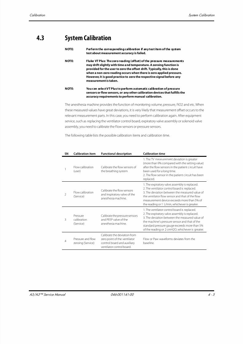
7/21/2019 a5 a3 Service Manual 2013
http://slidepdf.com/reader/full/a5-a3-service-manual-2013 178/399
A5/A3™ Service Manual 046-001141-00 4 - 5
Calibration System Calibration
4.3 System Calibration
NOTE: Perform the corresponding calibration if any test item of the system
test about measurement accuracy is failed.
NOTE: Fluke VT Plus: The zero reading (offset) of the pressure measurementsmay drift slightly with time and temperature. A zeroing function is
provided for the user to zero the offset drift. Typically, this is done
when a non-zero reading occurs when there is zero applied pressure.
However, it is good practice to zero the respective signal before any
measurement is taken.
NOTE: You can select VT Plus to perform automatic calibration of pressure
sensors or flow sensors, or any other calibration devices that fulfills the
accuracy requirements to perform manual calibration.
The anesthesia machine provides the function of monitoring volume, pressure, FiO2 and etc. When
these measured values have great deviations, it is very likely that measurement offset occurs to the
relevant measurement parts. In this case, you need to perform calibration again. After equipment
service, such as replacing the ventilator control board, expiratory valve assembly or solenoid valve
assembly, you need to calibrate the f low sensors or pressure sensors.
The following table lists the possible calibration items and calibration time.
SN Calibration item Functional description Calibration time
1Flow calibration
(user)
Calibrate the flow sensors of
the breathing system.
1. The TV measurement deviation is greater
(more than 9% compared with the setting value)
after the flow sensors in the patient c ircuit have
been used for a long time.
2. The flow sensor in the patient c ircuit has been
replaced.
2Flow calibration
(Service)
Calibrate the flow sensors
and inspiratory valve of the
anesthesia machine.
1. The expiratory valve assembly is replaced.
2. The ventilator control board is replaced.
3. The deviation between the measured value of
the ventilator flow sensor and that of the flow
measurement device exceeds more than 5% of
the reading or 1 L/min, whichever is greater.
3
Pressure
calibration
(Service)
Calibrate the pressure sensors
and PEEP valve of the
anesthesia machine.
1. The ventilator control board is replaced.
2. The expiratory valve assembly is replaced.
3. The deviation between the measured value of
the machine's pressure sensor and that of the
standard pressure gauge exceeds more than 5%
of the reading or 2 cmH2O, whichever is greater.
4Pressure and flow
zeroing (Service)
Calibrate the deviation from
zero point of the ventilator
control board and auxiliary
ventilator control board.
Flow or Paw waveforms deviates from the
baseline.
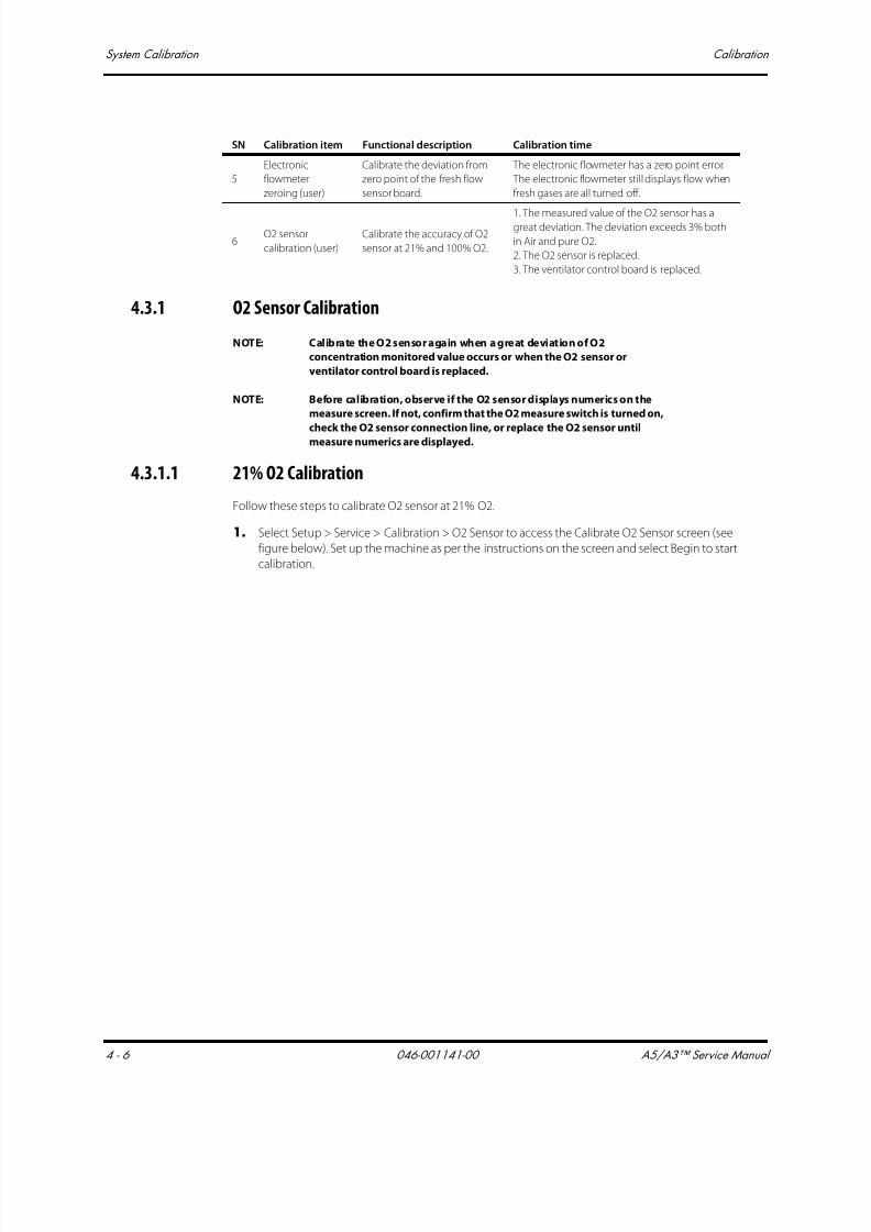
7/21/2019 a5 a3 Service Manual 2013
http://slidepdf.com/reader/full/a5-a3-service-manual-2013 179/399
System Calibration Calibration
4 - 6 046-001141-00 A5/A3™ Service Manual
4.3.1 O2 Sensor Calibration
NOTE: Calibrate the O2 sensor again when a great deviation of O2
concentration monitored value occurs or when the O2 sensor or
ventilator control board is replaced.
NOTE: Before calibration, observe if the O2 sensor displays numerics on the
measure screen. If not, confirm that the O2 measure switch is turned on,
check the O2 sensor connection line, or replace the O2 sensor untilmeasure numerics are displayed.
4.3.1.1 21% O2 Calibration
Follow these steps to calibrate O2 sensor at 21% O2.
1. Select Setup > Service > Calibration > O2 Sensor to access the Calibrate O2 Sensor screen (see
figure below). Set up the machine as per the instructions on the screen and select Begin to start
calibration.
5
Electronic
flowmeter
zeroing (user)
Calibrate the deviation from
zero point of the fresh flow
sensor board.
The electronic flowmeter has a zero point error.
The electronic flowmeter still displays flow when
fresh gases are all turned off.
6O2 sensor
calibration (user)
Calibrate the accuracy of O2
sensor at 21% and 100% O2.
1. The measured value of the O2 sensor has agreat deviation. The deviation exceeds 3% both
in Air and pure O2.
2. The O2 sensor is replaced.
3. The ventilator control board is replaced.
SN Calibration item Functional description Calibration time

7/21/2019 a5 a3 Service Manual 2013
http://slidepdf.com/reader/full/a5-a3-service-manual-2013 180/399
A5/A3™ Service Manual 046-001141-00 4 - 7
Calibration System Calibration
FIGURE 4-1
2. The calibration screen shown below is displayed when Begin is selected. During the calibration,
you can select Cancel to cancel the calibration.
FIGURE 4-2
3. The screen shown below is displayed if the ongoing calibration is canceled. Select Try Again to
do the calibration again.Select Done to exit the calibration screen.
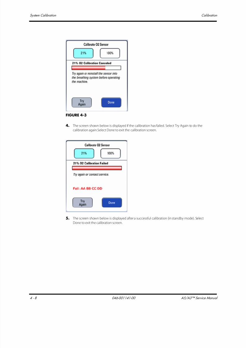
7/21/2019 a5 a3 Service Manual 2013
http://slidepdf.com/reader/full/a5-a3-service-manual-2013 181/399
System Calibration Calibration
4 - 8 046-001141-00 A5/A3™ Service Manual
FIGURE 4-3
4. The screen shown below is displayed if the calibration has failed. Select Try Again to do the
calibration again.Select Done to exit the calibration screen.
5. The screen shown below is displayed after a successful calibration (in standby mode). Select
Done to exit the calibration screen.
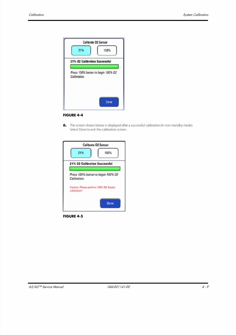
7/21/2019 a5 a3 Service Manual 2013
http://slidepdf.com/reader/full/a5-a3-service-manual-2013 182/399

7/21/2019 a5 a3 Service Manual 2013
http://slidepdf.com/reader/full/a5-a3-service-manual-2013 183/399

7/21/2019 a5 a3 Service Manual 2013
http://slidepdf.com/reader/full/a5-a3-service-manual-2013 184/399
A5/A3™ Service Manual 046-001141-00 4 - 11
Calibration System Calibration
FIGURE 4-7
5. The calibration screen shown below is displayed when Begin is selected. During the calibration,you can select Cancel to cancel the calibration.
FIGURE 4-8
6. The screen shown below is displayed if the ongoing calibration is canceled. Select Try Again to
do the calibration again.Select Done to exit the calibration screen.
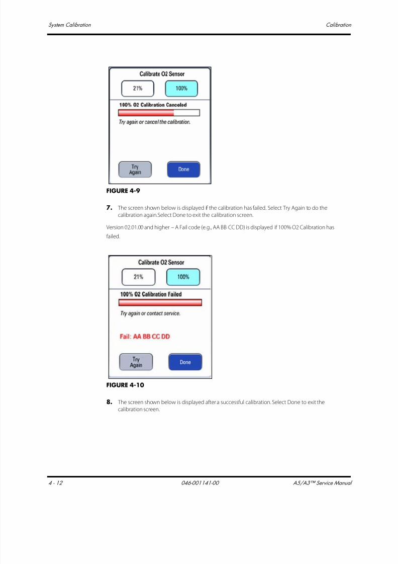
7/21/2019 a5 a3 Service Manual 2013
http://slidepdf.com/reader/full/a5-a3-service-manual-2013 185/399
System Calibration Calibration
4 - 12 046-001141-00 A5/A3™ Service Manual
FIGURE 4-9
7. The screen shown below is displayed if the calibration has failed. Select Try Again to do the
calibration again.Select Done to exit the calibration screen.
Version 02.01.00 and higher – A Fail code (e.g., AA BB CC DD) is displayed if 100% O2 Calibration has
failed.
FIGURE 4-10
8. The screen shown below is displayed after a successful calibration. Select Done to exit the
calibration screen.

7/21/2019 a5 a3 Service Manual 2013
http://slidepdf.com/reader/full/a5-a3-service-manual-2013 186/399
A5/A3™ Service Manual 046-001141-00 4 - 13
Calibration System Calibration
FIGURE 4-11
4.3.1.3 Commonly-encountered Problems and Recommended Actions
Failure Description Possible Cause Recommended Action
After [Start] is selected,
calibration failure is
prompted very soon.
If the alarm [O2 Sensor Unconnected] is
displayed, it indicates that O2 sensor is
not connected.
Connect the O2 sensor.
O2 supply pressure is insufficient (lower
than 200 kPa).
Change or connect the gas supply
and make sure that O2 supply
pressure is sufficient.
21% O2 calibration is not completed
before 100% O2 calibration.
Perform 21% O2 calibration
followed by 100% O2 calibration.
Calibration failure is
prompted about 3
minutes after
calibration is started.
O2% count value is not within the normal
range (450 to 2700).Replace the O2 sensor.
Error Code Description Recommended Action
00 00 00 02
O2 supply pressure is low.
During 100% calibrationprocess, O2 supply pressure
was not sufficient.
. Check that the O2 sensor is connected to the cable
correctly.
. Check the O2 supply pressure.. Check that the O2 sensor output voltage in the calibration
menu is steady.
. Replace the O2 sensor.
00 00 00 04
O2 sensor is disconnected.
Sampled data is greater than
2900 (AD value).
. Check that the O2 sensor is connected to the cable
correctly.
. Check that the O2 sensor output voltage in the calibration
menu is steady.
. Replace the O2 sensor.

7/21/2019 a5 a3 Service Manual 2013
http://slidepdf.com/reader/full/a5-a3-service-manual-2013 187/399
System Calibration Calibration
4 - 14 046-001141-00 A5/A3™ Service Manual
4.3.2 Flow Calibration (User)
NOTE: The flow sensors must be recalibrated after replacing or re-calibrating
the O2 sensors.
NOTE: This calibration is only intended for the user. A trained technician
should always perform the flow calibration in the service mode when a
calibration is required.
NOTE: The measurements performed by the flow sensors may be affected by
the environment where the sensors are used. After the sensors have
been used for a long time, great deviations may occur to the
measurement results and tidal volume control as well. This problem can
be fixed through flow sensor calibration.
NOTE: Before calibration, perform leak test of the breathing system in
mechanical ventilation mode first and make sure that the test is passed.
NOTE: During calibration, make sure that the drive gas pressure is kept within
specifications. Failure to do so may lead to calibration failure.
This calibration is only intended for the flow sensors in the breathing circuit. The inspiratory flow
sensor and expiratory flow sensor in the breathing system are calibrated through the built-in flow
measurement reference.
After the inspiratory flow sensor and expiratory flow sensor have been used for several months, for
example, three months after calibration, great deviations (more than 9% compared with the setting
value) may occur to tidal volume measurement due to sensor ageing or environmental factors. Or,
the user replaces flow sensors. In this case, you need to re-calibrate flow sensors.
Follow these steps to calibrate flow sensors.
1. Enter Standby.
2. Select Setup-> Calibrate-> Calibrate Flow Sensor (version 1.03.02 and earlier) or Setup->
General-> Calibrate Flow Sensor (version 2.01.00 and higher) to access the screen shown below.
00 00 00 08
21% calibration value is
outside of the expected
range (150~500)
(AD value).
. Check that the O2 sensor is connected to the cable
correctly.
. Check that the O2 sensor is in 21% O2.
. Check that the O2 sensor output voltage in the calibration
menu is steady.
. Replace the O2 sensor.
00 00 00 10
100% calibration value is
outside of the expected
range (800~2028) (AD value).
. Check that the O2 sensor is connected to the cable
correctly.
. Check that the O2 sensor is in 100% O2.
. Check that the O2 sensor output voltage in the calibration
menu is steady.
. Replace the O2 sensor.
00 00 00 20 Error writing to EEPROM.
. Repeat the calibration.
. Replace the O2 sensor.
. Replace the CPU board.
Error Code Description Recommended Action

7/21/2019 a5 a3 Service Manual 2013
http://slidepdf.com/reader/full/a5-a3-service-manual-2013 188/399
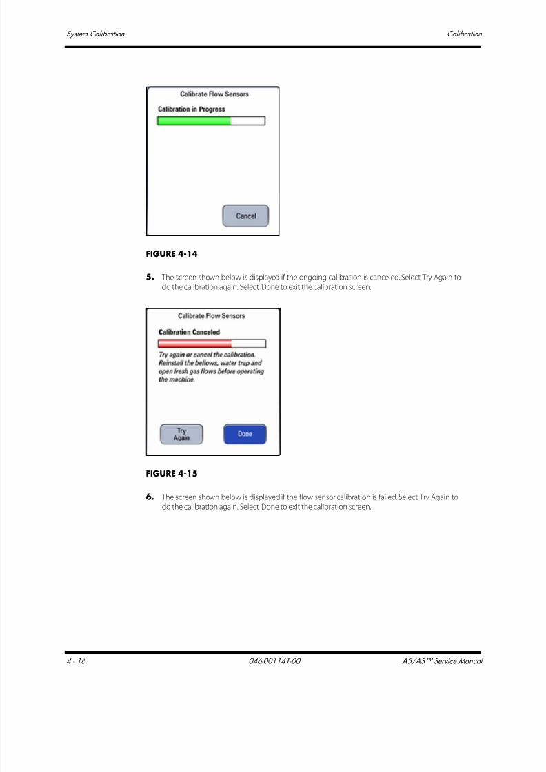
7/21/2019 a5 a3 Service Manual 2013
http://slidepdf.com/reader/full/a5-a3-service-manual-2013 189/399
System Calibration Calibration
4 - 16 046-001141-00 A5/A3™ Service Manual
FIGURE 4-14
5. The screen shown below is displayed if the ongoing calibration is canceled. Select Try Again to
do the calibration again. Select Done to exit the calibration screen.
FIGURE 4-15
6. The screen shown below is displayed if the flow sensor calibration is failed. Select Try Again to
do the calibration again. Select Done to exit the calibration screen.

7/21/2019 a5 a3 Service Manual 2013
http://slidepdf.com/reader/full/a5-a3-service-manual-2013 190/399
A5/A3™ Service Manual 046-001141-00 4 - 17
Calibration System Calibration
FIGURE 4-16
7. The screen shown below is displayed after a successful flow sensor calibration. Select Done toexit the calibration screen.
FIGURE 4-17
NOTE: If measurement deviations are not corrected after multiple flow sensor
calibrations, the user is recommended to replace the flow sensor and
then perform calibration. If the problem persists, factory maintenance
is necessary.
4.3.3 Flow Calibration (Service)NOTE: Flow Calibration (Service) is necessary in case of replacing the
ventilator control board, drive gas assembly or solenoid valve
assembly.
NOTE: When a great deviation is detected between the measured value of the
built-in flow sensor and that of the standard flow measurement device,
you need to perform Flow Calibration (Service).

7/21/2019 a5 a3 Service Manual 2013
http://slidepdf.com/reader/full/a5-a3-service-manual-2013 191/399
System Calibration Calibration
4 - 18 046-001141-00 A5/A3™ Service Manual
This calibration is intended for the flows sensors in the breathing circuit, ventilator flow sensor, and
also inspiratory valve. The standard flow measurement device is used to calibrate the flow sensors
and inspiratory valve.
4.3.4 Calibration ProceduresNOTE: Make sure that the tubes are not leaking when connected.
NOTE: Do not move or press the tubes during calibration.
NOTE: When connecting calibration tubes, make sure that gas flows in the
correct direction, which is from the inspiration connector of the
breathing system, through high flow inlet of the anesthesia machine
calibration device, anesthesia machine calibration device, high flow
outlet of the anesthesia machine calibration device, and to the
expiration connector of the breathing system.
NOTE: Before calibration, make sure that no sensor or valve related technical
alarms occurred.
NOTE: During calibration, make sure that the drive gas pressure is enough.
Failure to do so may lead to calibration failure.
NOTE: You can select VT Plus for auto calibration. You can also select flow
calibration device which satisfies the accuracy requirement for manual
calibration.
NOTE: For calibration device with high flow channel and low flow channel,
flow channel switch over is required during auto or manual calibration.
Manual calibration is available in version 1.03.00 and higher.
4.3.4.1 Auto Calibration
Follow these steps to calibrate flow sensors.
1. Enter Standby.
2. Select Setup-> Service-> Calibration-> Flow Sensors to access the screen as shown.
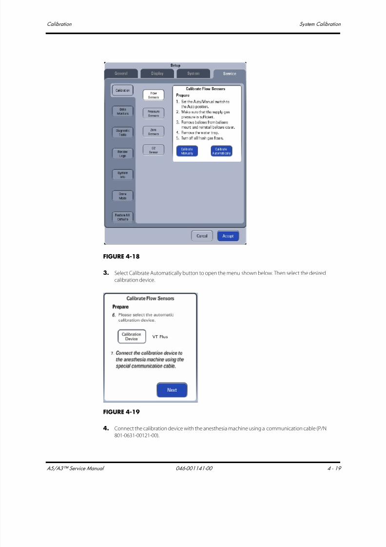
7/21/2019 a5 a3 Service Manual 2013
http://slidepdf.com/reader/full/a5-a3-service-manual-2013 192/399
A5/A3™ Service Manual 046-001141-00 4 - 19
Calibration System Calibration
FIGURE 4-18
3. Select Calibrate Automatically button to open the menu shown below. Then select the desired
calibration device.
FIGURE 4-19
4. Connect the calibration device with the anesthesia machine using a communication cable (P/N:
801-0631-00121-00).

7/21/2019 a5 a3 Service Manual 2013
http://slidepdf.com/reader/full/a5-a3-service-manual-2013 193/399
System Calibration Calibration
4 - 20 046-001141-00 A5/A3™ Service Manual
FIGURE 4-20 Cable connections at the anesthesia machine end
FIGURE 4-21 Cable connections at the calibration device (VT Plus) end
5. Set up the calibration device as described below.
To set the VT-Plus:
a. Gas Settings: Press the Setup button, select Setting->ENTER->Gas Settings->MODIFY->Gas
Type->O2->BACK->BACK.
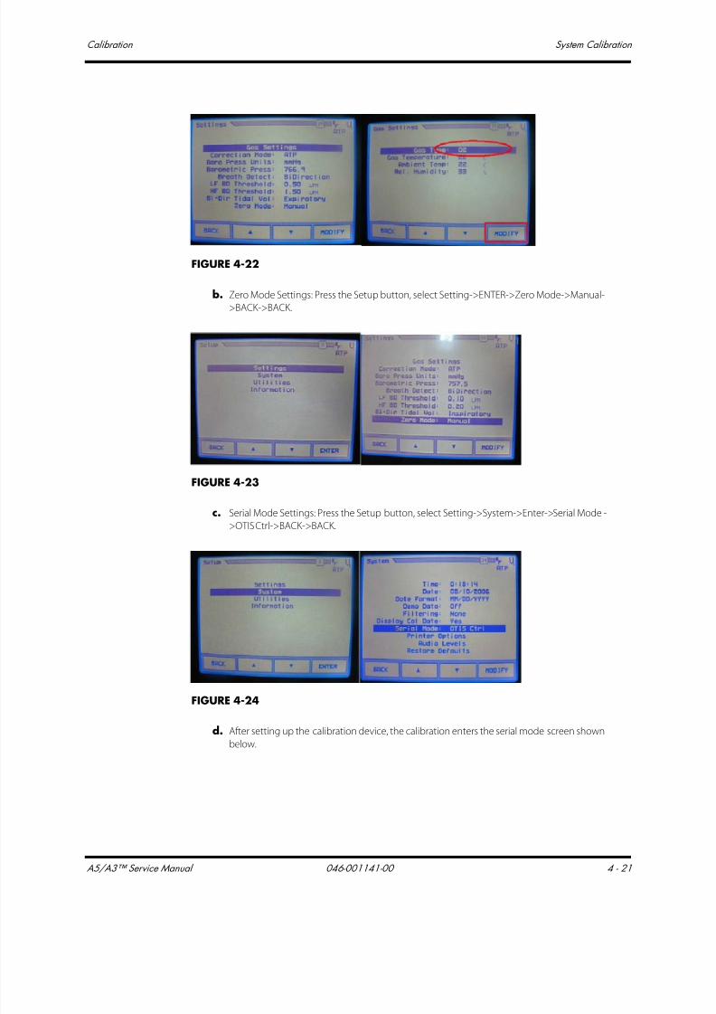
7/21/2019 a5 a3 Service Manual 2013
http://slidepdf.com/reader/full/a5-a3-service-manual-2013 194/399
A5/A3™ Service Manual 046-001141-00 4 - 21
Calibration System Calibration
FIGURE 4-22
b. Zero Mode Settings: Press the Setup button, select Setting->ENTER->Zero Mode->Manual-
>BACK->BACK.
FIGURE 4-23
c. Serial Mode Settings: Press the Setup button, select Setting->System->Enter->Serial Mode -
>OTIS Ctrl->BACK->BACK.
FIGURE 4-24
d. After setting up the calibration device, the calibration enters the serial mode screen shown
below.
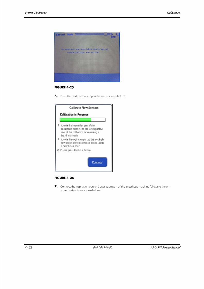
7/21/2019 a5 a3 Service Manual 2013
http://slidepdf.com/reader/full/a5-a3-service-manual-2013 195/399
System Calibration Calibration
4 - 22 046-001141-00 A5/A3™ Service Manual
FIGURE 4-25
6. Press the Next button to open the menu shown below.
FIGURE 4-26
7. Connect the inspiration port and expiration port of the anesthesia machine following the on-
screen instructions, shown below.
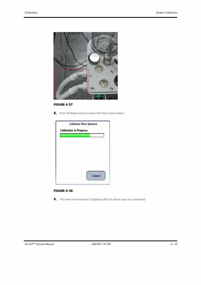
7/21/2019 a5 a3 Service Manual 2013
http://slidepdf.com/reader/full/a5-a3-service-manual-2013 196/399
A5/A3™ Service Manual 046-001141-00 4 - 23
Calibration System Calibration
FIGURE 4-27
8. Press the Begin button to open the menu shown below.
FIGURE 4-28
9. The menu shown below is displayed after the above steps are completed.
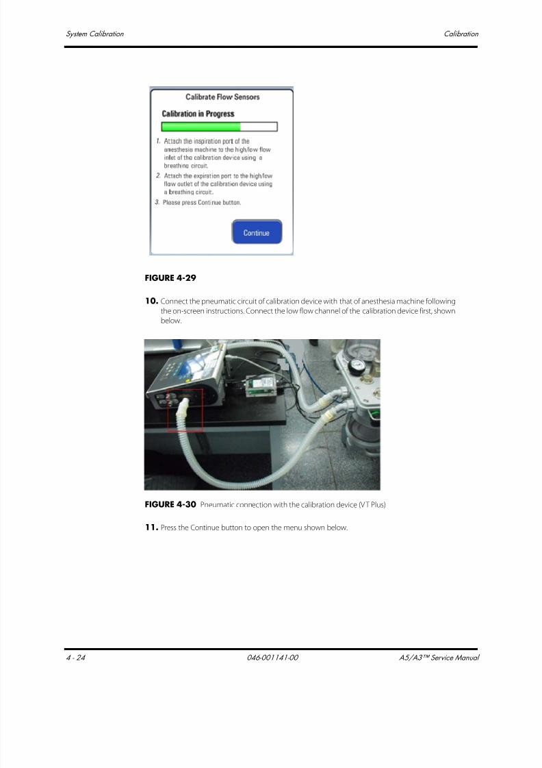
7/21/2019 a5 a3 Service Manual 2013
http://slidepdf.com/reader/full/a5-a3-service-manual-2013 197/399
System Calibration Calibration
4 - 24 046-001141-00 A5/A3™ Service Manual
FIGURE 4-29
10. Connect the pneumatic circuit of calibration device with that of anesthesia machine following
the on-screen instructions. Connect the low flow channel of the calibration device first, shown
below.
FIGURE 4-30 Pneumatic connection with the calibration device (VT Plus)
11. Press the Continue button to open the menu shown below.
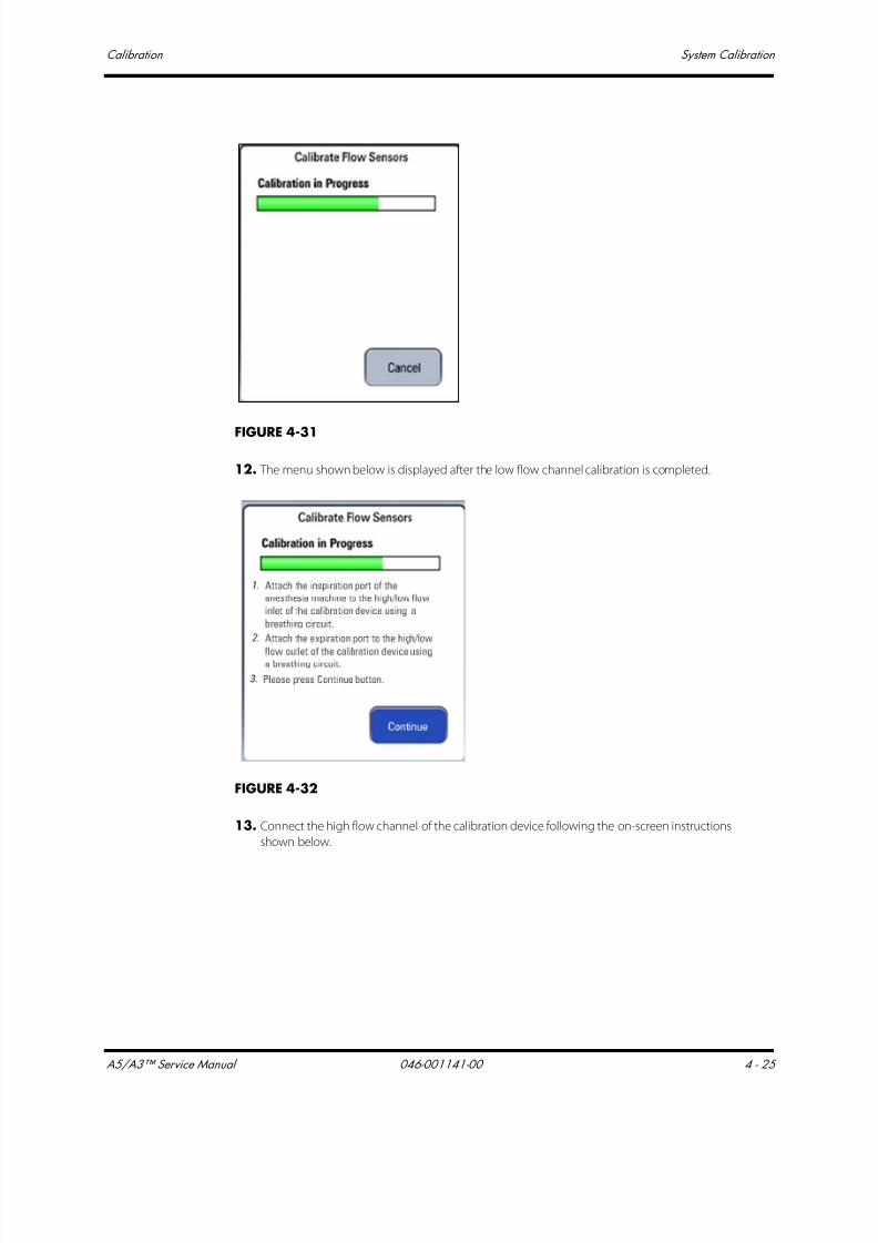
7/21/2019 a5 a3 Service Manual 2013
http://slidepdf.com/reader/full/a5-a3-service-manual-2013 198/399
A5/A3™ Service Manual 046-001141-00 4 - 25
Calibration System Calibration
FIGURE 4-31
12. The menu shown below is displayed after the low flow channel calibration is completed.
FIGURE 4-32
13. Connect the high flow channel of the calibration device following the on-screen instructions
shown below.

7/21/2019 a5 a3 Service Manual 2013
http://slidepdf.com/reader/full/a5-a3-service-manual-2013 199/399
System Calibration Calibration
4 - 26 046-001141-00 A5/A3™ Service Manual
FIGURE 4-33 Pneumatic connection with the calibration device (VT Plus)
14. Press the Continue button to open the menu shown below.
FIGURE 4-34
15. The screen shown below is displayed after the calibration is completed.
• The screen shown below is displayed if the flow sensor calibration has failed. When the
calibration has failed, read the screen of the calibration device for further information on the
cause of the failure. Select Try Again to do the calibration again. Select Done to exit thecalibration screen.
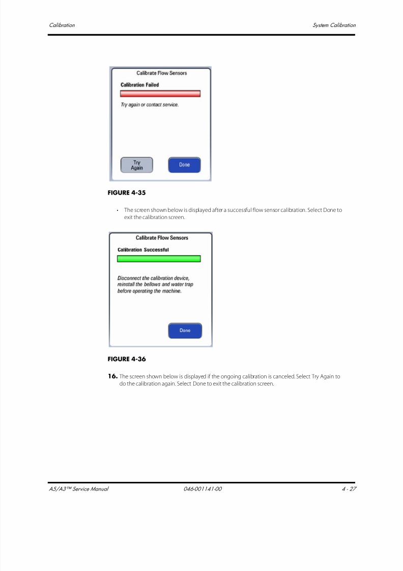
7/21/2019 a5 a3 Service Manual 2013
http://slidepdf.com/reader/full/a5-a3-service-manual-2013 200/399
A5/A3™ Service Manual 046-001141-00 4 - 27
Calibration System Calibration
FIGURE 4-35
• The screen shown below is displayed after a successful flow sensor calibration. Select Done to
exit the calibration screen.
FIGURE 4-36
16. The screen shown below is displayed if the ongoing calibration is canceled. Select Try Again to
do the calibration again. Select Done to exit the calibration screen.
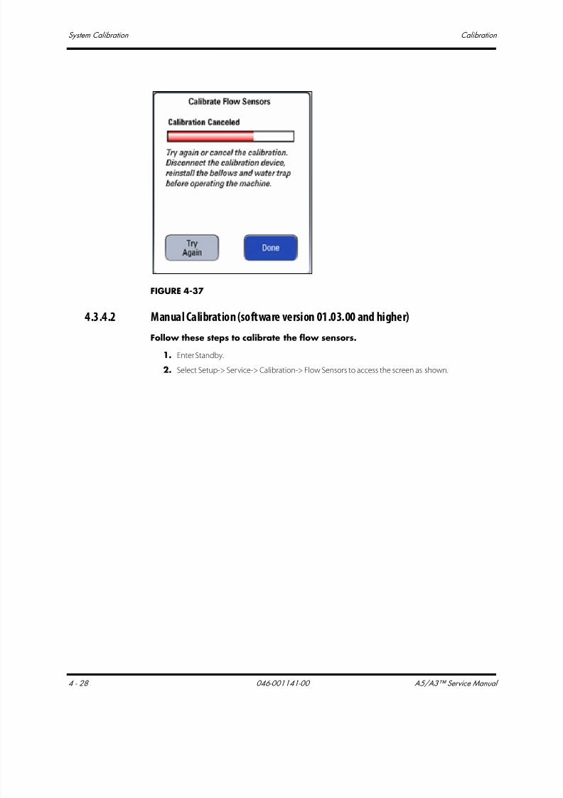
7/21/2019 a5 a3 Service Manual 2013
http://slidepdf.com/reader/full/a5-a3-service-manual-2013 201/399
System Calibration Calibration
4 - 28 046-001141-00 A5/A3™ Service Manual
FIGURE 4-37
4.3.4.2 Manual Calibration (software version 01.03.00 and higher)
Follow these steps to calibrate the flow sensors.
1. Enter Standby.
2. Select Setup-> Service-> Calibration-> Flow Sensors to access the screen as shown.

7/21/2019 a5 a3 Service Manual 2013
http://slidepdf.com/reader/full/a5-a3-service-manual-2013 202/399
A5/A3™ Service Manual 046-001141-00 4 - 29
Calibration System Calibration
FIGURE 4-38
3. Select Calibrate Manually button to open the menu shown below.
FIGURE 4-39
4. Connect the inspiration port and expiration port of the anesthesia machine following the on-
screen instruction as shown below.

7/21/2019 a5 a3 Service Manual 2013
http://slidepdf.com/reader/full/a5-a3-service-manual-2013 203/399
System Calibration Calibration
4 - 30 046-001141-00 A5/A3™ Service Manual
FIGURE 4-40
5. Press the Begin button to open the menu shown below.
FIGURE 4-41
6. The menu shown below is displayed after the first step of manual calibration is completed.
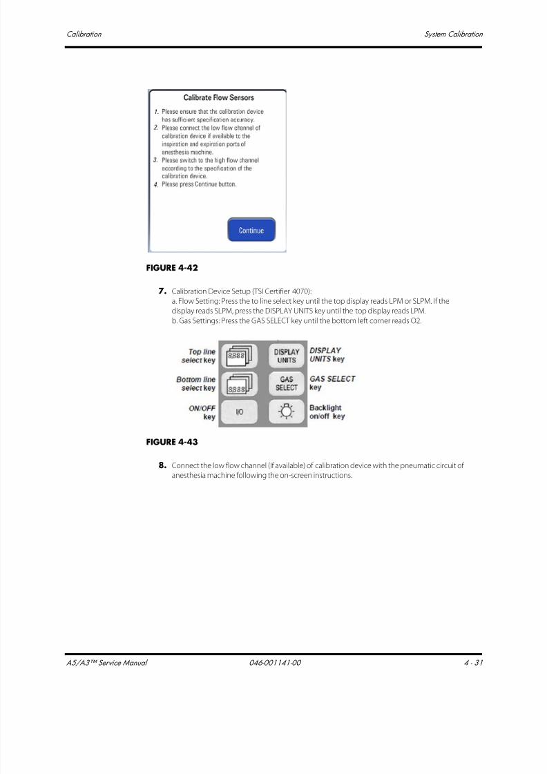
7/21/2019 a5 a3 Service Manual 2013
http://slidepdf.com/reader/full/a5-a3-service-manual-2013 204/399
A5/A3™ Service Manual 046-001141-00 4 - 31
Calibration System Calibration
FIGURE 4-42
7. Calibration Device Setup (TSI Certifier 4070):
a. Flow Setting: Press the to line select key until the top display reads LPM or SLPM. If the
display reads SLPM, press the DISPLAY UNITS key until the top display reads LPM.
b. Gas Settings: Press the GAS SELECT key until the bottom left corner reads O2.
FIGURE 4-43
8. Connect the low flow channel (If available) of calibration device with the pneumatic circuit of
anesthesia machine following the on-screen instructions.

7/21/2019 a5 a3 Service Manual 2013
http://slidepdf.com/reader/full/a5-a3-service-manual-2013 205/399
System Calibration Calibration
4 - 32 046-001141-00 A5/A3™ Service Manual
FIGURE 4-44 Pneumatic connection with the calibration device (TSI Certifier 4070)
9. If applicable, determine when to switch to the high flow channel of calibration device.
NOTE: If the flow meter has more than one channel, refer to the
manufacturer's specification for when to change from one channel to
the other.
10.Select Continue to access the menu shown below. The system will calibrate the 32
calibration points one by one. When Waiting is displayed in the cell, wait for the system to
control flow. When Input Cal Value is displayed in the cell, input the standard flow value
displayed by the calibration device. During the calibration, you can select to re-calibrate any
calibration point. After having inputted the standard flow values of all the 32 calibration
points, select Accept to check and save the calibration data.
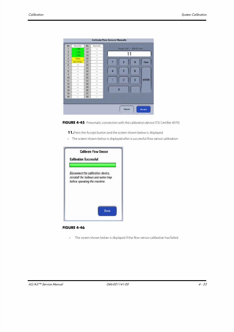
7/21/2019 a5 a3 Service Manual 2013
http://slidepdf.com/reader/full/a5-a3-service-manual-2013 206/399
A5/A3™ Service Manual 046-001141-00 4 - 33
Calibration System Calibration
FIGURE 4-45 Pneumatic connection with the calibration device (TSI Certifier 4070)
11.Press the Accept button and the screen shown below is displayed.
• The screen shown below is displayed after a successful flow sensor calibration.
FIGURE 4-46
• The screen shown below is displayed if the flow sensor calibration has failed.
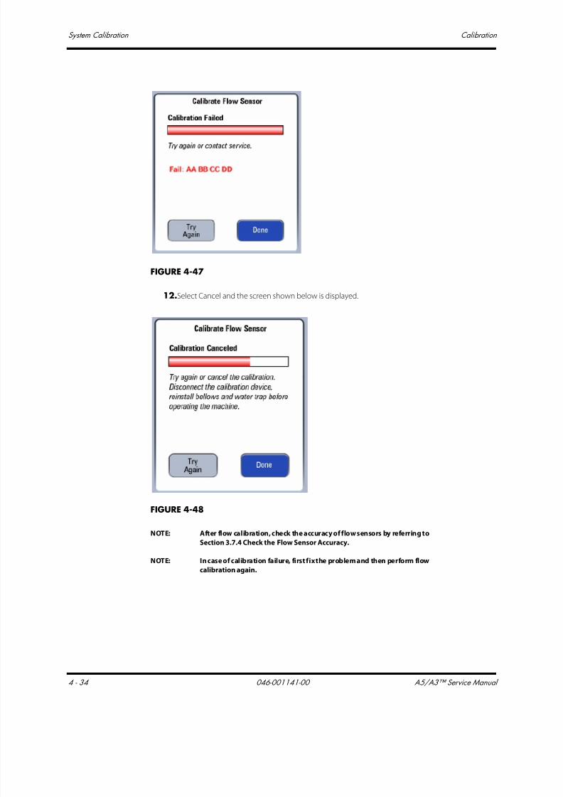
7/21/2019 a5 a3 Service Manual 2013
http://slidepdf.com/reader/full/a5-a3-service-manual-2013 207/399
System Calibration Calibration
4 - 34 046-001141-00 A5/A3™ Service Manual
FIGURE 4-47
12.Select Cancel and the screen shown below is displayed.
FIGURE 4-48
NOTE: After flow calibration, check the accuracy of flow sensors by referring to
Section 3.7.4 Check the Flow Sensor Accuracy.
NOTE: In case of calibration failure, first fix the problem and then perform flowcalibration again.
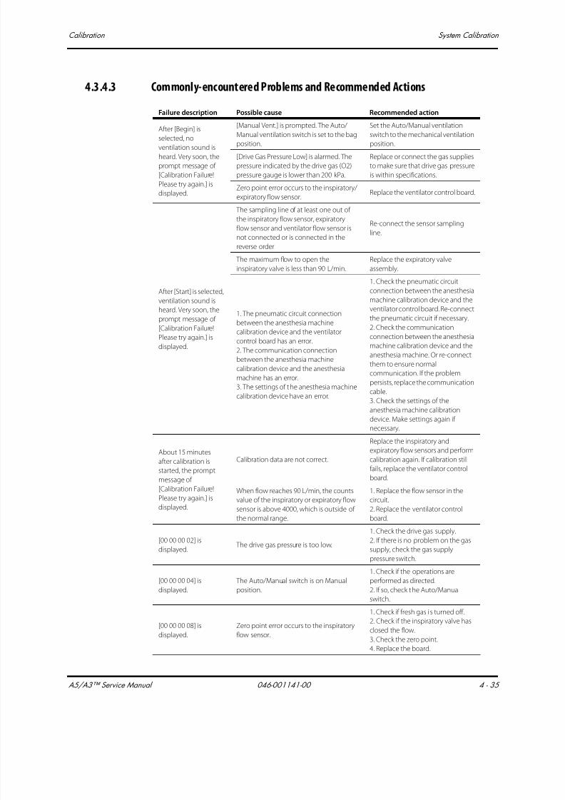
7/21/2019 a5 a3 Service Manual 2013
http://slidepdf.com/reader/full/a5-a3-service-manual-2013 208/399
A5/A3™ Service Manual 046-001141-00 4 - 35
Calibration System Calibration
4.3.4.3 Commonly-encountered Problems and Recommended Actions
Failure description Possible cause Recommended action
After [Begin] is
selected, noventilation sound is
heard. Very soon, the
prompt message of
[Calibration Failure!
Please try again.] is
displayed.
[Manual Vent.] is prompted. The Auto/
Manual ventilation switch is set to the bag
position.
Set the Auto/Manual ventilation
switch to the mechanical ventilation
position.
[Drive Gas Pressure Low] is alarmed. The
pressure indicated by the drive gas (O2)
pressure gauge is lower than 200 kPa.
Replace or connect the gas supplies
to make sure that drive gas pressure
is within specifications.
Zero point error occurs to the inspiratory/
expiratory flow sensor.Replace the ventilator control board.
After [Start] is selected,
ventilation sound is
heard. Very soon, the
prompt message of
[Calibration Failure!
Please try again.] is
displayed.
The sampling line of at least one out of
the inspiratory flow sensor, expiratory
flow sensor and ventilator flow sensor is
not connected or is connected in the
reverse order.
Re-connect the sensor sampling
line.
The maximum flow to open the
inspiratory valve is less than 90 L/min.
Replace the expiratory valve
assembly.
1. The pneumatic circuit connection
between the anesthesia machine
calibration device and the ventilator
control board has an error.
2. The communication connection
between the anesthesia machine
calibration device and the anesthesia
machine has an error.
3. The settings of the anesthesia machine
calibration device have an error.
1. Check the pneumatic circuitconnection between the anesthesia
machine calibration device and the
ventilator control board. Re-connect
the pneumatic circuit if necessary.
2. Check the communication
connection between the anesthesia
machine calibration device and the
anesthesia machine. Or re-connect
them to ensure normal
communication. If the problem
persists, replace the communication
cable.
3. Check the settings of the
anesthesia machine calibration
device. Make settings again ifnecessary.
About 15 minutes
after calibration is
started, the prompt
message of
[Calibration Failure!
Please try again.] is
displayed.
Calibration data are not correct.
Replace the inspiratory and
expiratory flow sensors and perform
calibration again. If calibration still
fails, replace the ventilator control
board.
When flow reaches 90 L/min, the counts
value of the inspiratory or expiratory flow
sensor is above 4000, which is outside of
the normal range.
1. Replace the flow sensor in the
circuit.
2. Replace the ventilator control
board.
[00 00 00 02] is
displayed. The drive gas pressure is too low.
1. Check the drive gas supply.
2. If there is no problem on the gas
supply, check the gas supply
pressure switch.
[00 00 00 04] is
displayed.
The Auto/Manual switch is on Manual
position.
1. Check if the operations are
performed as directed.
2. If so, check the Auto/Manual
switch.
[00 00 00 08] is
displayed.
Zero point error occurs to the inspiratory
flow sensor.
1. Check if fresh gas is turned off.
2. Check if the inspiratory valve has
closed the flow.
3. Check the zero point.
4. Replace the board.

7/21/2019 a5 a3 Service Manual 2013
http://slidepdf.com/reader/full/a5-a3-service-manual-2013 209/399
System Calibration Calibration
4 - 36 046-001141-00 A5/A3™ Service Manual
[00 00 00 10] is
displayed.
Zero point error occurs to the expiratory
flow sensor.
1. Check if fresh gas is turned off.
2. Check if the inspiratory valve has
closed the flow.
3. Check the zero point.
4. Replace the board.
[00 00 00 20] is
displayed.
Zero point error occurs to the internal
flow sensor.
1. Check the zero point.
2. Check if the inspiratory valve has
closed the flow.
3. Replace the board.
[00 00 00 40] is
displayed.
Measurement range error occurs to the
inspiratory flow sensor.
1. Check if the sampling line is
properly connected.
2. Replace the inspiratory flow
sensor.
3. Replace the board.
[00 00 00 80] is
displayed.
Measurement range error occurs to the
expiratory flow sensor.
1. Check if the sampling line is
properly connected.
2. Replace the expiratory flow
sensor.
3. Replace the board.
[00 00 01 00] is
displayed.
Measurement range error occurs to the
internal flow sensor.
1. Check if the sampling line is
properly connected.
2. Replace the internal flow sensor.
3. Replace the board.
[00 00 02 00] is
displayed.
The calibration data of the inspiratory
flow sensor is not unidirectional.
1. Check if the sampling line is
properly connected.
2. Replace the inspiratory flow
sensor.
3. Replace the board.
[00 00 04 00] is
displayed.
The calibration data of the expiratory flow
sensor is not unidirectional.
1. Check if the sampling line is
properly connected.
2. Replace the expiratory flow
sensor.
3. Replace the board.
[00 00 08 00] is
displayed.
The calibration data of the internal flow
sensor is not unidirectional.
1. Check if the sampling line is
properly connected.
2. Replace the internal flow sensor.
3. Replace the board.
[00 00 10 00] is
displayed.
Resolution error occurs to the inspiratory
flow sensor.
1. Check if the sampling line is
properly connected.
2. Replace the inspiratory flow
sensor.
3. Replace the board.
[00 00 20 00] is
displayed.
Resolution error occurs to the expiratory
flow sensor.
1. Check if the sampling line is
properly connected.
2. Replace the expiratory flow
sensor.
3. Replace the board.
[00 00 40 00] is
displayed.
Resolution error occurs to the internal
flow sensor.
1. Check if the sampling line is
properly connected.
2. Replace the internal flow sensor.
3. Replace the board.
Failure description Possible cause Recommended action
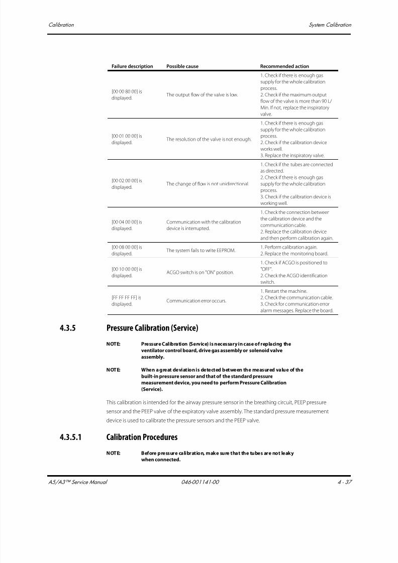
7/21/2019 a5 a3 Service Manual 2013
http://slidepdf.com/reader/full/a5-a3-service-manual-2013 210/399
A5/A3™ Service Manual 046-001141-00 4 - 37
Calibration System Calibration
4.3.5 Pressure Calibration (Service)
NOTE: Pressure Calibration (Service) is necessary in case of replacing the
ventilator control board, drive gas assembly or solenoid valve
assembly.
NOTE: When a great deviation is detected between the measured value of the
built-in pressure sensor and that of the standard pressure
measurement device, you need to perform Pressure Calibration
(Service).
This calibration is intended for the airway pressure sensor in the breathing circuit, PEEP pressure
sensor and the PEEP valve of the expiratory valve assembly. The standard pressure measurement
device is used to calibrate the pressure sensors and the PEEP valve.
4.3.5.1 Calibration Procedures
NOTE: Before pressure calibration, make sure that the tubes are not leaky
when connected.
[00 00 80 00] is
displayed. The output flow of the valve is low.
1. Check if there is enough gas
supply for the whole calibration
process.
2. Check if the maximum output
flow of the valve is more than 90 L/
Min. If not, replace the inspiratory
valve.
[00 01 00 00] is
displayed. The resolution of the valve is not enough.
1. Check if there is enough gas
supply for the whole calibration
process.
2. Check if the calibration device
works well.
3. Replace the inspiratory valve.
[00 02 00 00] is
displayed. The change of flow is not unidirectional.
1. Check if the tubes are connected
as directed.
2. Check if there is enough gas
supply for the whole calibration
process.
3. Check if the calibration device isworking well.
[00 04 00 00] is
displayed.
Communication with the calibration
device is interrupted.
1. Check the connection between
the calibration device and the
communication cable.
2. Replace the calibration device
and then perform calibration again.
[00 08 00 00] is
displayed. The system fails to write EEPROM.
1. Perform calibration again.
2. Replace the monitoring board.
[00 10 00 00] is
displayed.ACGO switch is on "ON" position.
1. Check if ACGO is positioned to
"OFF".
2. Check the ACGO identification
switch.
[FF FF FF FF] isdisplayed.
Communication error occurs.
1. Restart the machine.
2. Check the communication cable.3. Check for communication error
alarm messages. Replace the board.
Failure description Possible cause Recommended action
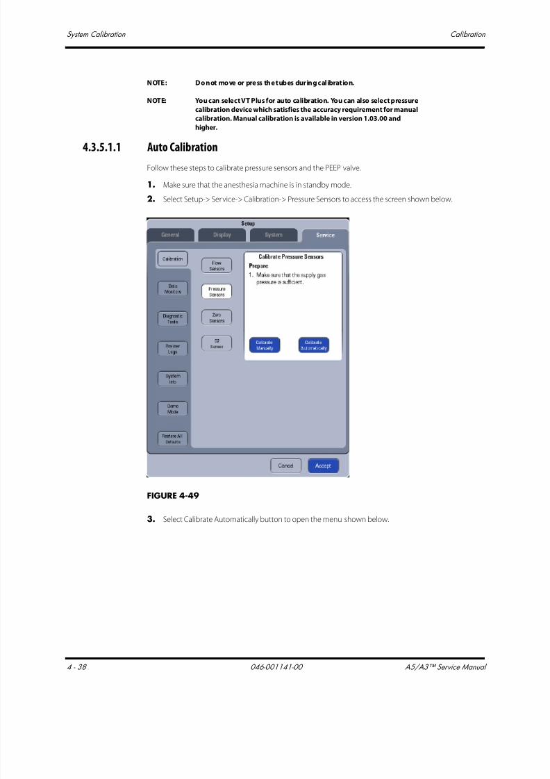
7/21/2019 a5 a3 Service Manual 2013
http://slidepdf.com/reader/full/a5-a3-service-manual-2013 211/399
System Calibration Calibration
4 - 38 046-001141-00 A5/A3™ Service Manual
NOTE: Do not move or press the tubes during calibration.
NOTE: You can select VT Plus for auto calibration. You can also select pressure
calibration device which satisfies the accuracy requirement for manual
calibration. Manual calibration is available in version 1.03.00 and
higher.
4.3.5.1.1 Auto Calibration
Follow these steps to calibrate pressure sensors and the PEEP valve.
1. Make sure that the anesthesia machine is in standby mode.
2. Select Setup-> Service-> Calibration-> Pressure Sensors to access the screen shown below.
FIGURE 4-49
3. Select Calibrate Automatically button to open the menu shown below.
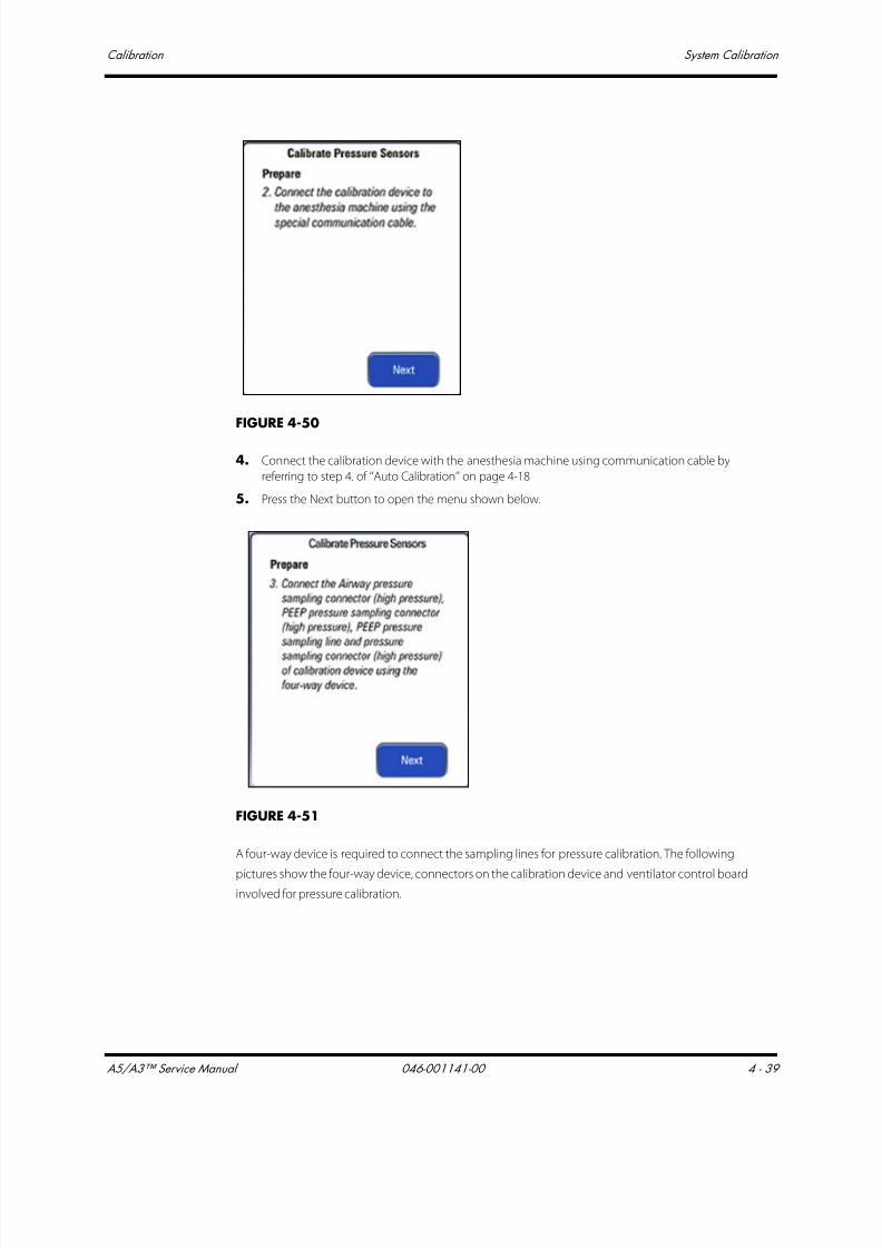
7/21/2019 a5 a3 Service Manual 2013
http://slidepdf.com/reader/full/a5-a3-service-manual-2013 212/399
A5/A3™ Service Manual 046-001141-00 4 - 39
Calibration System Calibration
FIGURE 4-50
4. Connect the calibration device with the anesthesia machine using communication cable by
referring to step 4. of ‘‘Auto Calibration’’ on page 4-18
5. Press the Next button to open the menu shown below.
FIGURE 4-51
A four-way device is required to connect the sampling lines for pressure calibration. The following
pictures show the four-way device, connectors on the calibration device and ventilator control boardinvolved for pressure calibration.

7/21/2019 a5 a3 Service Manual 2013
http://slidepdf.com/reader/full/a5-a3-service-manual-2013 213/399
System Calibration Calibration
4 - 40 046-001141-00 A5/A3™ Service Manual
a. Remove the two tubes marked as #72 and #9 from the pressure sensors (refer to the figure
below).
b. Connect the four way tube to the pressure sensor P1 of monitor board, pressure sensor P2 of
PEEP, the tube marked as #72, and the low pressure port of Fluke V T-Plus. The tube marked
as #9 will remain unconnected for this calibration.
FIGURE 4-52
Four-way device connectingthe sampling lines forpressure calibration

7/21/2019 a5 a3 Service Manual 2013
http://slidepdf.com/reader/full/a5-a3-service-manual-2013 214/399
A5/A3™ Service Manual 046-001141-00 4 - 41
Calibration System Calibration
FIGURE 4-53 Pneumatic connections with the calibration device (VT-Plus)
6. Let the anesthesia machine calibration device be powered and manually zero the calibration
device first.7. Set up the calibration device.
Refer to step 5. of ‘‘Auto Calibration’’ on page 4-18
8. Press the Next button to open the menu shown below.
FIGURE 4-54
9. After selecting the desired auto calibration device, select Begin to access the calibration screen
shown below. During the calibration, you can select Cancel to stop the calibration.

7/21/2019 a5 a3 Service Manual 2013
http://slidepdf.com/reader/full/a5-a3-service-manual-2013 215/399
System Calibration Calibration
4 - 42 046-001141-00 A5/A3™ Service Manual
FIGURE 4-55
10. The screens shown below are displayed after the calibration is completed.
• The screen shown below is displayed if the pressure sensor calibration has failed. Select Try
Again to do the calibration again.Select Done to exit the calibration screen.
FIGURE 4-56
• The screen shown below is displayed after a successful pressure sensor calibration. SelectDone to exit the calibration screen.

7/21/2019 a5 a3 Service Manual 2013
http://slidepdf.com/reader/full/a5-a3-service-manual-2013 216/399
A5/A3™ Service Manual 046-001141-00 4 - 43
Calibration System Calibration
FIGURE 4-57
11. The screen shown below is displayed if the ongoing calibration is canceled. Select Try Again to
do the calibration again. Select Done to exit the calibration screen.
FIGURE 4-58
4.3.5.1.2 Manual CalibrationNOTE: Manual calibration is available in software version 01.03.00 and higher.
Follow these steps to calibrate pressure sensors and the PEEP valve.
1. Make sure that the anesthesia machine is in standby mode.
2. Select Setup-> Service-> Calibration-> Pressure Sensors to access the screen shown below.

7/21/2019 a5 a3 Service Manual 2013
http://slidepdf.com/reader/full/a5-a3-service-manual-2013 217/399
System Calibration Calibration
4 - 44 046-001141-00 A5/A3™ Service Manual
FIGURE 4-59
3. Select Calibrate Manually button to open the menu shown below.

7/21/2019 a5 a3 Service Manual 2013
http://slidepdf.com/reader/full/a5-a3-service-manual-2013 218/399
A5/A3™ Service Manual 046-001141-00 4 - 45
Calibration System Calibration
FIGURE 4-60
4. Perform pneumatic connections:
1. A four-way device is required to connect the sampling lines for pressure calibration. The
following pictures show the four-way device, connectors on the calibration device and
ventilator control board involved for pressure calibration.
FIGURE 4-61
2. Remove the two tubes marked as #72 and #9 from the pressure sensors (the figure below).
3. Connect the four way tube to the pressure sensor P1 of monitor board, pressure sensor P2 of
PEEP, the tube marked as #72, and the low pressure port of Fluke VT-Plus. The tube marked as#9 will remain unconnected for this calibration.
Four-way device connectingthe sampling lines for
pressure calibration
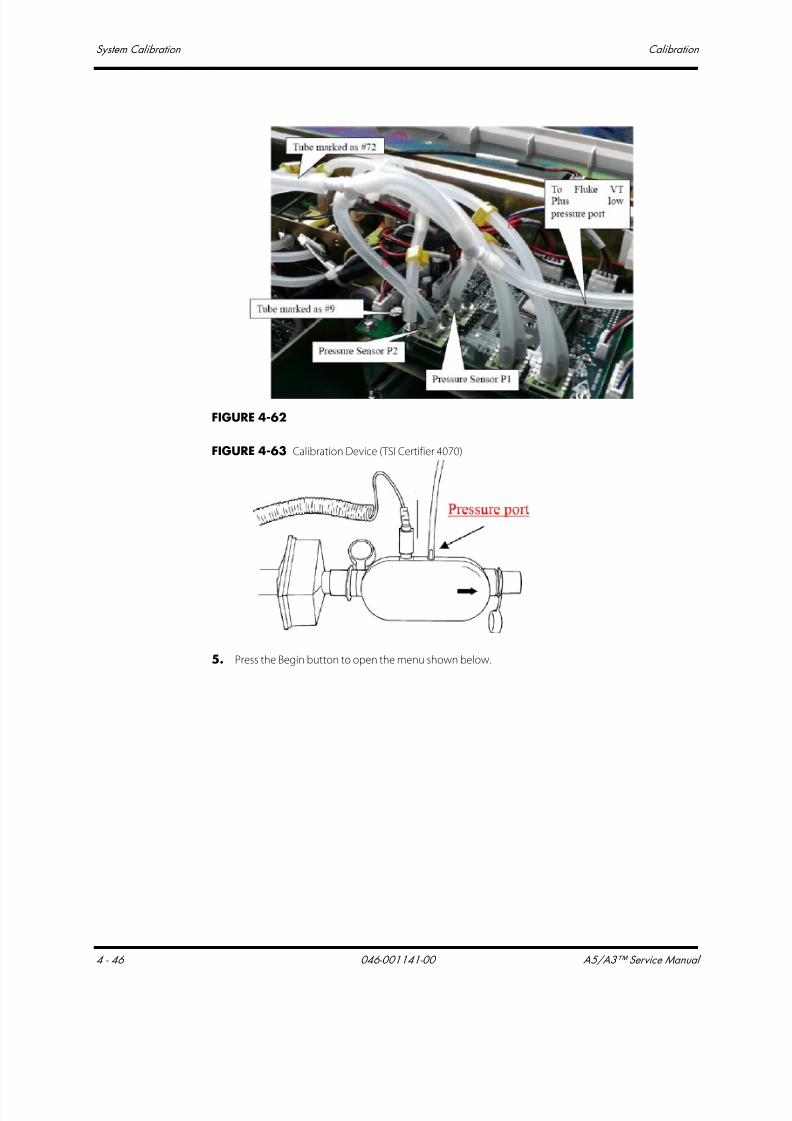
7/21/2019 a5 a3 Service Manual 2013
http://slidepdf.com/reader/full/a5-a3-service-manual-2013 219/399
System Calibration Calibration
4 - 46 046-001141-00 A5/A3™ Service Manual
FIGURE 4-62
FIGURE 4-63 Calibration Device (TSI Certifier 4070)
5. Press the Begin button to open the menu shown below.

7/21/2019 a5 a3 Service Manual 2013
http://slidepdf.com/reader/full/a5-a3-service-manual-2013 220/399
A5/A3™ Service Manual 046-001141-00 4 - 47
Calibration System Calibration
FIGURE 4-64
6. The menu shown below is displayed after the first step of manual calibration is completed.
FIGURE 4-65
7. Select Continue to access the menu shown below. The system will calibrate the 32 calibration
points one by one. Of the 32 calibration points, points 1 to 16 correspond to the rising curve
while points 17-32 correspond to the falling curves. During the calibration, you can select to re-
calibrate any calibration point. When calibrating the point corresponding to falling curve, you
cannot change the point corresponding to rising curve. When Waiting is displayed in the cell,
wait for the system to control pressure. When Input Cal Value is displayed in the cell, input the
standard pressure value displayed by the calibration device. After having inputted the standard
pressure values of all the 32 calibration points, select Accept to check and save the calibration
data.

7/21/2019 a5 a3 Service Manual 2013
http://slidepdf.com/reader/full/a5-a3-service-manual-2013 221/399
System Calibration Calibration
4 - 48 046-001141-00 A5/A3™ Service Manual
FIGURE 4-66
8. Press the Accept button and the screen shown below is displayed.
• The screen shown below is displayed after a successful pressure sensor calibration.
FIGURE 4-67
• The screen shown below is displayed if the pressure sensor calibration has failed.
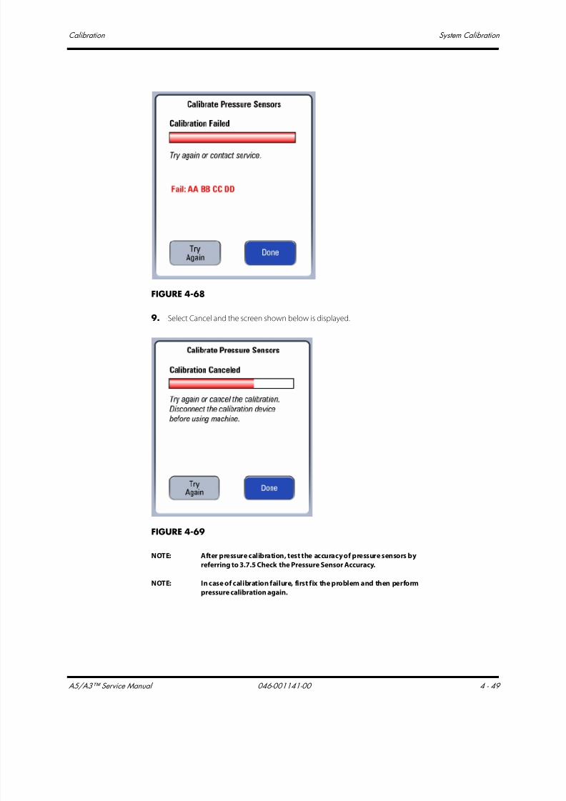
7/21/2019 a5 a3 Service Manual 2013
http://slidepdf.com/reader/full/a5-a3-service-manual-2013 222/399
A5/A3™ Service Manual 046-001141-00 4 - 49
Calibration System Calibration
FIGURE 4-68
9. Select Cancel and the screen shown below is displayed.
FIGURE 4-69
NOTE: After pressure calibration, test the accuracy of pressure sensors by
referring to 3.7.5 Check the Pressure Sensor Accuracy.
NOTE: In case of calibration failure, first fix the problem and then perform
pressure calibration again.

7/21/2019 a5 a3 Service Manual 2013
http://slidepdf.com/reader/full/a5-a3-service-manual-2013 223/399
System Calibration Calibration
4 - 50 046-001141-00 A5/A3™ Service Manual
4.3.5.2 Commonly-encountered Problems and Recommended Actions
Failure description Possible cause Recommended action
After [Begin] is selected, no
ventilation sound is heard.Very soon, the prompt
message of [Calibration
Failure! Please try again.] is
displayed.
[Drive Gas Pressure Low] is alarmed.
The pressure indicated by the drivegas (O2) pressure gauge is lower
than 200 kPa.
Replace or connect the gas supplies to
make sure that drive gas pressure isenough.
Zero point error occurs to the
airway pressure gauge or PEEP
pressure sensor. Refer to ‘‘Check the
Sensor Zero Point’’ on page 3-18.
Replace the ventilator control board.
After [Begin] is selected,
ventilation sound is heard.
Very soon, the prompt
message of [Calibration
Failure! Please try again.] is
displayed.
The sampling line of at least one
out of the airway pressure sensor
and PEEP pressure sensor is not
connected or is connected
improperly. Refer to ‘‘Sensors and
Valves Problems’’ on page 5-61.
Re-connect the sensor sampling line.
The maximum pressure which the
PEEP valve produces is less than 95
cmH2O. Refer to ‘‘Sensors and
Valves Problems’’ on page 5-61.
Replace the expiratory valve assembly.
1. The pneumatic circuit
connection between the
anesthesia machine calibration
device and the ventilator control
board has an error.
2. The communication connection
between the anesthesia machine
calibration device and the
anesthesia machine has an error.
3. The settings of the anesthesia
machine calibration device have an
error.
1. Check the pneumatic circuit
connection between the anesthesia
machine calibration device and the
ventilator control board. Re-connect
the pneumatic circuit if necessary.
2. Check the communication
connection between the anesthesia
machine calibration device and the
anesthesia machine. Or re-connect
them to ensure normal
communication. If the problem
persists, replace the communication
cable.
3. Check the settings of the anesthesia
machine calibration device. Make
settings again if necessary.
About 15 minutes after
calibration is started, the
prompt message of
[Calibration Failure! Please try
again.] is displayed.
Calibration data are not correct.
Refer to ‘‘Check the Pressure Sensor
Accuracy’’ on page 3-23.
Replace the ventilator control board.
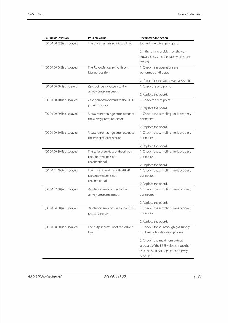
7/21/2019 a5 a3 Service Manual 2013
http://slidepdf.com/reader/full/a5-a3-service-manual-2013 224/399
A5/A3™ Service Manual 046-001141-00 4 - 51
Calibration System Calibration
[00 00 00 02] is displayed. The drive gas pressure is too low. 1. Check the drive gas supply.
2. If there is no problem on the gas
supply, check the gas supply pressureswitch.
[00 00 00 04] is displayed. The Auto/Manual switch is on
Manual position.
1. Check if the operations are
performed as directed.
2. If so, check the Auto/Manual switch.
[00 00 00 08] is displayed. Zero point error occurs to the
airway pressure sensor.
1. Check the zero point.
2. Replace the board.
[00 00 00 10] is displayed. Zero point error occurs to the PEEP
pressure sensor.
1. Check the zero point.
2. Replace the board.
[00 00 00 20] is displayed. Measurement range error occurs to
the airway pressure sensor.
1. Check if the sampling line is properly
connected.
2. Replace the board.
[00 00 00 40] is displayed. Measurement range error occurs to
the PEEP pressure sensor.
1. Check if the sampling line is properly
connected.
2. Replace the board.
[00 00 00 80] is displayed. The calibration data of the airway
pressure sensor is not
unidirectional.
1. Check if the sampling line is properly
connected.
2. Replace the board.
[00 00 01 00] is displayed. The calibration data of the PEEP
pressure sensor is not
unidirectional.
1. Check if the sampling line is properly
connected.
2. Replace the board.
[00 00 02 00] is displayed. Resolution error occurs to the
airway pressure sensor.
1. Check if the sampling line is properly
connected.
2. Replace the board.
[00 00 04 00] is displayed. Resolution error occurs to the PEEP
pressure sensor.
1. Check if the sampling line is properly
connected.
2. Replace the board.
[00 00 08 00] is displayed. The output pressure of the valve is
low.
1. Check if there is enough gas supply
for the whole calibration process.
2. Check if the maximum output
pressure of the PEEP valve is more than
90 cmH2O. If not, replace the airway
module.
Failure description Possible cause Recommended action

7/21/2019 a5 a3 Service Manual 2013
http://slidepdf.com/reader/full/a5-a3-service-manual-2013 225/399
System Calibration Calibration
4 - 52 046-001141-00 A5/A3™ Service Manual
4.3.6 Pressure and Flow Zeroing (Service)
During the operation of the anesthesia machine, pressure and flow are zeroed automatically at a
specific interval. You can also zero pressure and flow manually in the factory maintenance menu.
Manual zeroing can eliminate the measurement deviations caused by zero offset immediately. This
system provides the function of pressure and flow automatic zeroing at a specific interval.
4.3.6.1 Zeroing Procedures
Follow these steps to zero pressure and flow sensors.
1. Select Setup-> Service-> Calibration-> Zero Sensors to access the screen shown below.
[00 00 10 00] is displayed. The change of flow is not
unidirectional.
1. Check if the sampling line is properly
connected.
2. Replace the board.
[00 00 20 00] is displayed. Communication with the
calibration device is interrupted.
1. Check the connection between the
calibration device and communication
cable.
2. Replace the calibration device and
then perform calibration again.
[00 00 40 00] is displayed. The system fails to write EEPROM. 1. Perform calibration again.
2. Replace the monitoring board.
[00 00 80 00] is displayed. ACGO switch is on "ON" position. 1. Check if ACGO is positioned to "OFF".
2. Check the ACGO identification
switch.
[00 01 00 00] is displayed. The resolution of the valve is not
enough.
1. Check if there is enough gas supply
for the whole calibration process.
2. Check if the calibration device works
well.
3. Replace the PEEP valve.
[FF FF FF FF] is displayed. Communication error occurs. 1. Restart the machine.
2. Check the communication cable.
3. Check for communication error
alarm messages. Replace the board.
Failure description Possible cause Recommended action

7/21/2019 a5 a3 Service Manual 2013
http://slidepdf.com/reader/full/a5-a3-service-manual-2013 226/399
A5/A3™ Service Manual 046-001141-00 4 - 53
Calibration System Calibration
FIGURE 4-70
2. Select Begin to access the zeroing screen as show below. During the zeroing, you can select
Cancel to cancel the zeroing.
FIGURE 4-71
3. The screen shown below is displayed if the ongoing zeroing is canceled. Select Try Again to do
the zeroing again.Select Done to exit the zeroing screen.

7/21/2019 a5 a3 Service Manual 2013
http://slidepdf.com/reader/full/a5-a3-service-manual-2013 227/399
System Calibration Calibration
4 - 54 046-001141-00 A5/A3™ Service Manual
FIGURE 4-72
4. The screen shown below is displayed if the zeroing has failed. Select Try Again to do the zeroing
again.Select Done to exit the zeroing screen.
FIGURE 4-73
5. The screen shown below is displayed after a successful zeroing. Select Done to exit the zeroing
screen.
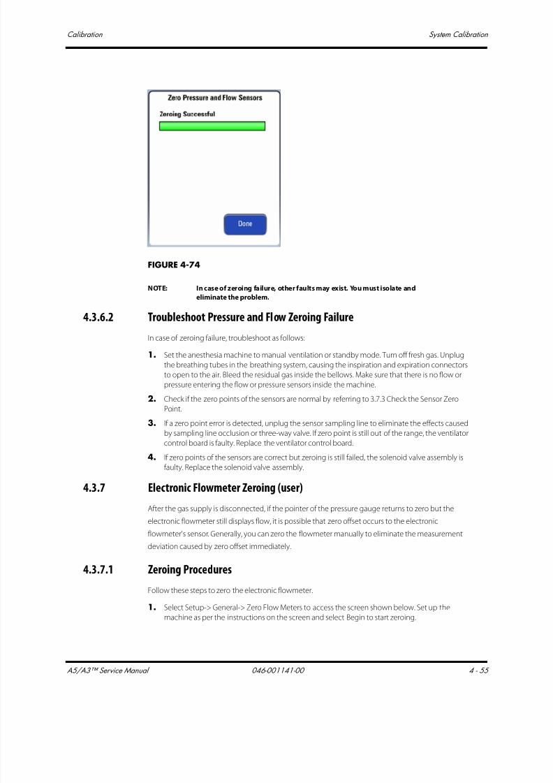
7/21/2019 a5 a3 Service Manual 2013
http://slidepdf.com/reader/full/a5-a3-service-manual-2013 228/399
A5/A3™ Service Manual 046-001141-00 4 - 55
Calibration System Calibration
FIGURE 4-74
NOTE: In case of zeroing failure, other faults may exist. You must isolate and
eliminate the problem.
4.3.6.2 Troubleshoot Pressure and Flow Zeroing Failure
In case of zeroing failure, troubleshoot as follows:
1. Set the anesthesia machine to manual ventilation or standby mode. Turn off fresh gas. Unplug
the breathing tubes in the breathing system, causing the inspiration and expiration connectors
to open to the air. Bleed the residual gas inside the bellows. Make sure that there is no flow or
pressure entering the flow or pressure sensors inside the machine.
2. Check if the zero points of the sensors are normal by referring to 3.7.3 Check the Sensor Zero
Point.3. If a zero point error is detected, unplug the sensor sampling line to eliminate the effects caused
by sampling line occlusion or three-way valve. If zero point is still out of the range, the ventilator
control board is faulty. Replace the ventilator control board.
4. If zero points of the sensors are correct but zeroing is still failed, the solenoid valve assembly is
faulty. Replace the solenoid valve assembly.
4.3.7 Electronic Flowmeter Zeroing (user)
After the gas supply is disconnected, if the pointer of the pressure gauge returns to zero but the
electronic flowmeter still displays flow, it is possible that zero offset occurs to the electronic
flowmeter's sensor. Generally, you can zero the flowmeter manually to eliminate the measurement
deviation caused by zero offset immediately.
4.3.7.1 Zeroing Procedures
Follow these steps to zero the electronic flowmeter.
1. Select Setup-> General-> Zero Flow Meters to access the screen shown below. Set up the
machine as per the instructions on the screen and select Begin to start zeroing.
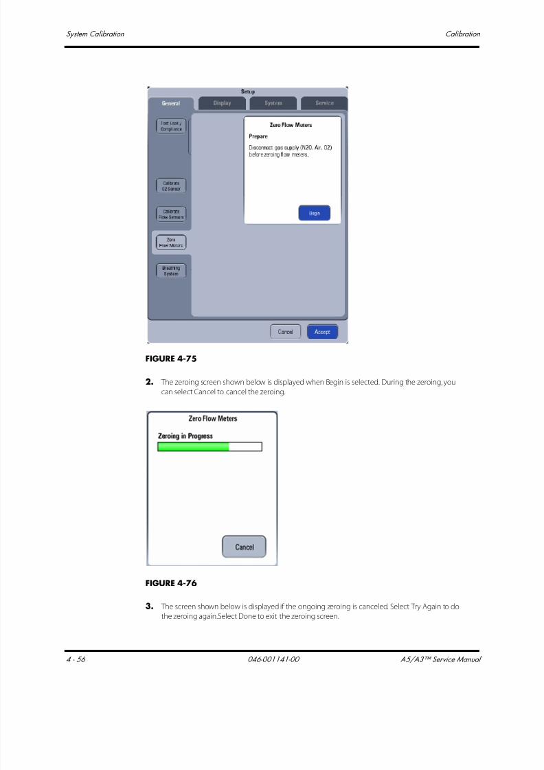
7/21/2019 a5 a3 Service Manual 2013
http://slidepdf.com/reader/full/a5-a3-service-manual-2013 229/399
System Calibration Calibration
4 - 56 046-001141-00 A5/A3™ Service Manual
FIGURE 4-75
2. The zeroing screen shown below is displayed when Begin is selected. During the zeroing, you
can select Cancel to cancel the zeroing.
FIGURE 4-76
3. The screen shown below is displayed if the ongoing zeroing is canceled. Select Try Again to do
the zeroing again.Select Done to exit the zeroing screen.

7/21/2019 a5 a3 Service Manual 2013
http://slidepdf.com/reader/full/a5-a3-service-manual-2013 230/399
A5/A3™ Service Manual 046-001141-00 4 - 57
Calibration System Calibration
FIGURE 4-77
4. The screen shown below is displayed if the zeroing has failed. Select Try Again to do the zeroing
again.Select Done to exit the zeroing screen.
FIGURE 4-78
5. The screen shown below is displayed after a successful zeroing. Select Done to exit the zeroing
screen.

7/21/2019 a5 a3 Service Manual 2013
http://slidepdf.com/reader/full/a5-a3-service-manual-2013 231/399
System Calibration Calibration
4 - 58 046-001141-00 A5/A3™ Service Manual
FIGURE 4-79
NOTE: In case of zeroing failure, other faults may exist. You must isolate and
eliminate the problem.
4.3.7.2 Troubleshoot Electronic Flowmeter Zeroing Failure
In case of zeroing failure, troubleshoot as follows:
1. Disconnect the gas supplies. After bleeding the residual gas inside the machine (or after
adjusting the flowmeter to cause the pointer of the pressure gauge to go to zero), perform
zeroing again.
2. If zeroing is completed, we can conclude that zeroing failure is caused by the three-way valve
mechanical fault. Replace the solenoid valve assembly.
3. If zeroing is still failed, we can conclude that zeroing is caused by the three-way valve hardwarecircuit fault or fresh flow sensor board fault. Replace the solenoid valve assembly or fresh flow
sensor board.
4.3.8 ORC Calibration
Follow these steps to perform ORC calibration:
1. Connect the anesthesia machine to the O2, AIR and N2O supplies. Close the O2, AIR and N2O
needle valves. Switch the screen to Standby.

7/21/2019 a5 a3 Service Manual 2013
http://slidepdf.com/reader/full/a5-a3-service-manual-2013 232/399
A5/A3™ Service Manual 046-001141-00 4 - 59
Calibration System Calibration
FIGURE 4-80
2. Turn the N2O needle valve to the maximum position. Slowly turn the O2 needle valve to
produce O2 flow of 0.3 L/min. If there is N2O flow displayed, turn the O2 resistor on the ORC
anti-clockwise with the flathead screwdriver until there is no N2O flow. If there is no NO2 flow
displayed, turn the O2 resistor on the ORC clockwise with the flathead screwdriver until the N2O
flow just begins.
FIGURE 4-81

7/21/2019 a5 a3 Service Manual 2013
http://slidepdf.com/reader/full/a5-a3-service-manual-2013 233/399
System Calibration Calibration
4 - 60 046-001141-00 A5/A3™ Service Manual
FIGURE 4-82
FIGURE 4-83
O2 Resistor
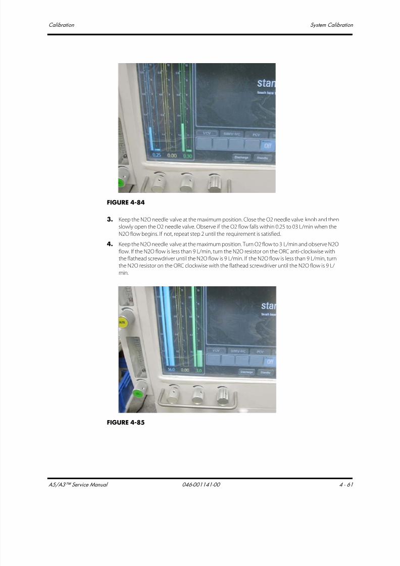
7/21/2019 a5 a3 Service Manual 2013
http://slidepdf.com/reader/full/a5-a3-service-manual-2013 234/399
A5/A3™ Service Manual 046-001141-00 4 - 61
Calibration System Calibration
FIGURE 4-84
3. Keep the N2O needle valve at the maximum position. Close the O2 needle valve knob and then
slowly open the O2 needle valve. Observe if the O2 flow falls within 0.25 to 03 L/min when the
N2O flow begins. If not, repeat step 2 until the requirement is satisfied.
4. Keep the N2O needle valve at the maximum position. Turn O2 flow to 3 L/min and observe N2O
flow. If the N2O flow is less than 9 L/min, turn the N2O resistor on the ORC anti-clockwise with
the flathead screwdriver until the N2O flow is 9 L/min. If the N2O flow is less than 9 L/min, turn
the N2O resistor on the ORC clockwise with the flathead screwdriver until the N2O flow is 9 L/
min.
FIGURE 4-85

7/21/2019 a5 a3 Service Manual 2013
http://slidepdf.com/reader/full/a5-a3-service-manual-2013 235/399
System Calibration Calibration
4 - 62 046-001141-00 A5/A3™ Service Manual
FIGURE 4-86
FIGURE 4-87
5. Turn the O2, AIR and N2O needle valves to the maximum positions. Turn the AIR resistor on the
pneumatic resistor block assembly to cause the AIR f low to fall within 15 to 15.5 L/min. Turn the
N2O resistor on the pneumatic resistor block assembly to cause the N2O flow to fall within 10 to
12 L/min.
N2O Resistor
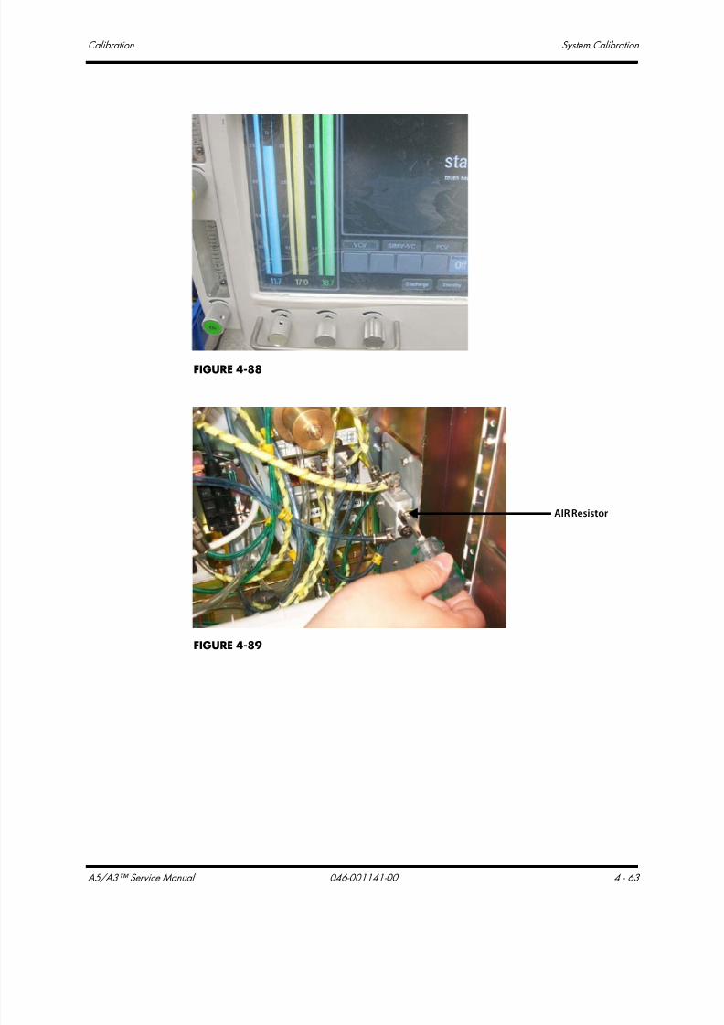
7/21/2019 a5 a3 Service Manual 2013
http://slidepdf.com/reader/full/a5-a3-service-manual-2013 236/399
A5/A3™ Service Manual 046-001141-00 4 - 63
Calibration System Calibration
FIGURE 4-88
FIGURE 4-89
AIR Resistor

7/21/2019 a5 a3 Service Manual 2013
http://slidepdf.com/reader/full/a5-a3-service-manual-2013 237/399
System Calibration Calibration
4 - 64 046-001141-00 A5/A3™ Service Manual
FIGURE 4-90
FIGURE 4-91
N2O Resistor

7/21/2019 a5 a3 Service Manual 2013
http://slidepdf.com/reader/full/a5-a3-service-manual-2013 238/399
A5/A3™ Service Manual 046-001141-00 4 - 65
Calibration System Calibration
FIGURE 4-92
4.3.9 Cylinder Yoke Regulator Calibration
Follow these steps to perform cylinder yoke regulator calibration (the following takes N2O cylinder
yoke assembly as an example. The calibration steps of O2 and Air cylinder yoke regulators are same to
those of N2O).
For O2 and Air, the pressure in the cylinder must be at least 1000 psi. For N2O, the pressure in the
cylinder must be at least 500 psi.
For O2 and AIR, set the output pressure using the table below. For N2O, set the output pressure to 58
psi.
1. Turn off the power supply and all gas supplies. Open the service door.
cylinder pressure (psi) regulator pressure (psi)
1000 62.7
1250 58.9
1500 55.8
1750 53.2
2000 51.0
2250 49.0
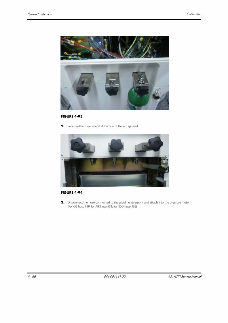
7/21/2019 a5 a3 Service Manual 2013
http://slidepdf.com/reader/full/a5-a3-service-manual-2013 239/399
System Calibration Calibration
4 - 66 046-001141-00 A5/A3™ Service Manual
FIGURE 4-93
2. Remove the sheet metal at the rear of the equipment.
FIGURE 4-94
3. Disconnect the hose connected to the pipeline assembly and attach it to the pressure meter
(For O2 hose #59; for AIR hose #54; for N2O hose #62).

7/21/2019 a5 a3 Service Manual 2013
http://slidepdf.com/reader/full/a5-a3-service-manual-2013 240/399
A5/A3™ Service Manual 046-001141-00 4 - 67
Calibration System Calibration
FIGURE 4-95
4. Set the fresh gas flow of the gas being adjusted to 1 L/min.
5. Remove the self-locking acorn nut at the head of the regulator. Install the cylinder.
FIGURE 4-96
Self-lockingnut
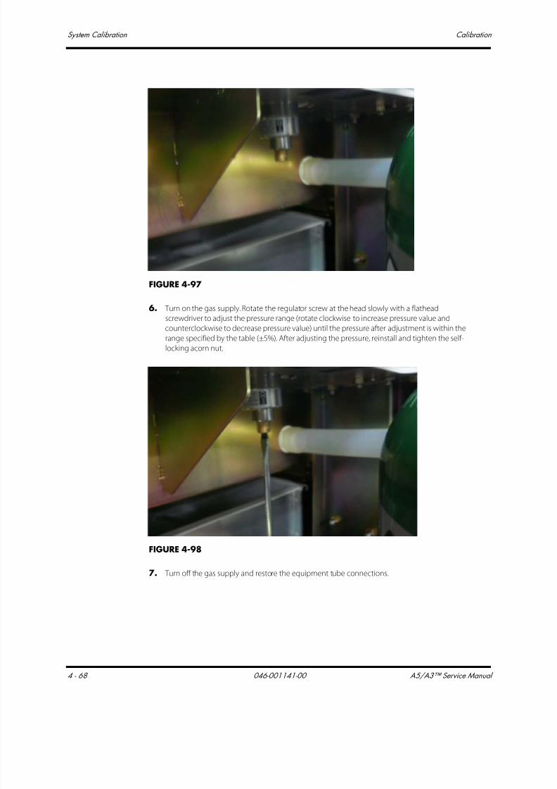
7/21/2019 a5 a3 Service Manual 2013
http://slidepdf.com/reader/full/a5-a3-service-manual-2013 241/399
System Calibration Calibration
4 - 68 046-001141-00 A5/A3™ Service Manual
FIGURE 4-97
6. Turn on the gas supply. Rotate the regulator screw at the head slowly with a flathead
screwdriver to adjust the pressure range (rotate clockwise to increase pressure value and
counterclockwise to decrease pressure value) until the pressure after adjustment is within the
range specified by the table (±5%). After adjusting the pressure, reinstall and tighten the self-
locking acorn nut.
FIGURE 4-98
7. Turn off the gas supply and restore the equipment tube connections.
7/21/2019 a5 a3 Service Manual 2013
http://slidepdf.com/reader/full/a5-a3-service-manual-2013 242/399
A5/A3™ Service Manual 046-001141-00 5 - 1
5.0 Repair and Troubleshooting
Troubleshooting Guidelines...............................................................................................................................................................5-2
Technical Alarms Check........................................................................................................................................................................5-3
Pneumatic Circuit System Problems.......................................................................................................................................... 5-11
Sensors and Valves Problems ......................................................................................................................................................... 5-61
Hardware and Electrical Problems..............................................................................................................................................5-67
Software Update and Software Configuration Activation ........................................................................................... 5-69

7/21/2019 a5 a3 Service Manual 2013
http://slidepdf.com/reader/full/a5-a3-service-manual-2013 243/399
Troubleshooting Guidelines Repair and Troubleshooting
5 - 2 046-001141-00 A5/A3™ Service Manual
5.1 Troubleshooting Guidelines
5.1.1 Identify the problem
Due to the wide variety of potential symptoms, certain problems may be more subtle than others.Following the guidelines of the tests will help determine the problem, if one exists.
5.1.2 Avoid shorting component leads together
During repair procedures, it can be tempting to make a quick series of measurements. Always turn
the power off before connecting and disconnecting the test leads and probes. The accidental
shorting of leads can easily stress the components and cause a second failure (aside from the safety
risk).
5.1.3 Use the proper equipment
During repair procedures, the following tools may be required:
• Metric Allen wrench es (2.5, 3, 4, 5, 8 mm)
• Phillips screwdriver (#1 and #2)
• Diagonal pliers
• Flathead screwdriver
• Metric M3 and M4 socket screwdriver
• Adjustable wrench
• Tweezers
• Krytox Lubricant (P/N:0510-00-0020)
It is imperative to use the designated equipment in order to ensure proper results of any and all test
procedures.
5.1.4 Clean up the repair area
After any repair, clean off the repair area.

7/21/2019 a5 a3 Service Manual 2013
http://slidepdf.com/reader/full/a5-a3-service-manual-2013 244/399
A5/A3™ Service Manual 046-001141-00 5 - 3
Repair and Troubleshooting Technical Alarms Check
5.2 Technical Alarms Check
A technical alarm, as apposed to a parameter alarm, is an alarm condition that exists whether or not a
patient is connected to the machine. Technical alarms include:
• Startup alarm Messages
• CPU Board Runtime Alarm
• Power Board Runtime Alarm
• Fresh Flow Sensor Board Alarm
• Ventilation Control Board Runtime Alarm
Before troubleshooting the anesthesia machine, check for technical alarm message. If an alarm
message is presented, eliminate the alarm f irst.
The following sections detail how to troubleshoot technical alarms related to the modules
mentioned above.
For detailed information on possible causes and actions for other alarm and prompt messages, referto the Operator’s Manual.
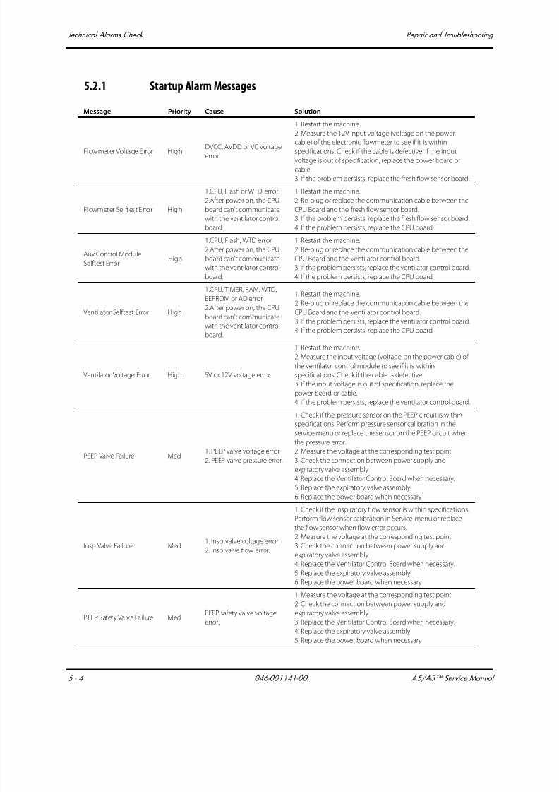
7/21/2019 a5 a3 Service Manual 2013
http://slidepdf.com/reader/full/a5-a3-service-manual-2013 245/399
Technical Alarms Check Repair and Troubleshooting
5 - 4 046-001141-00 A5/A3™ Service Manual
5.2.1 Startup Alarm Messages
Message Priority Cause Solution
Flowmeter Voltage Error HighDVCC, AVDD or VC voltage
error
1. Restart the machine.
2. Measure the 12V input voltage (voltage on the power
cable) of the electronic flowmeter to see if it is within
specifications. Check if the cable is defective. If the input
voltage is out of specification, replace the power board or
cable.
3. If the problem persists, replace the fresh flow sensor board.
Flowmeter Sel ftest Error High
1.CPU, Flash or WTD error.
2.After power on, the CPU
board can't communicate
with the ventilator control
board.
1. Restart the machine.
2. Re-plug or replace the communication cable between the
CPU Board and the fresh flow sensor board.
3. If the problem persists, replace the fresh flow sensor board.
4. If the problem persists, replace the CPU board.
Aux Control Module
Selftest ErrorHigh
1.CPU, Flash, WTD error
2.After power on, the CPU
board can't communicate
with the ventilator control
board.
1. Restart the machine.
2. Re-plug or replace the communication cable between the
CPU Board and the ventilator control board.
3. If the problem persists, replace the ventilator control board.
4. If the problem persists, replace the CPU board.
Venti lator Selftest Error High
1.CPU, TIMER, RAM, WTD,
EEPROM or AD error
2.After power on, the CPU
board can't communicate
with the ventilator control
board.
1. Restart the machine.
2. Re-plug or replace the communication cable between the
CPU Board and the ventilator control board.
3. If the problem persists, replace the ventilator control board.
4. If the problem persists, replace the CPU board.
Ventilator Voltage Error High 5V or 12V voltage error
1. Restart the machine.
2. Measure the input voltage (voltage on the power cable) of
the ventilator control module to see if it is within
specifications. Check if the cable is defective.
3. If the input voltage is out of specification, replace the
power board or cable.
4. If the problem persists, replace the ventilator control board.
PEEP Valve Failure Med1. PEEP valve voltage error.
2. PEEP valve pressure error.
1. Check if the pressure sensor on the PEEP circuit is withinspecifications. Perform pressure sensor calibration in the
service menu or replace the sensor on the PEEP circuit when
the pressure error.
2. Measure the voltage at the corresponding test point
3. Check the connection between power supply and
expiratory valve assembly
4. Replace the Ventilator Control Board when necessary.
5. Replace the expiratory valve assembly.
6. Replace the power board when necessary
Insp Valve Failure Med1. Insp valve voltage error.
2. Insp valve flow error.
1. Check if the Inspiratory flow sensor is within specifications.
Perform flow sensor calibration in Service menu or replace
the flow sensor when flow error occurs.
2. Measure the voltage at the corresponding test point
3. Check the connection between power supply and
expiratory valve assembly4. Replace the Ventilator Control Board when necessary.
5. Replace the expiratory valve assembly.
6. Replace the power board when necessary
PEEP Safety Valve Failure MedPEEP safety valve voltage
error.
1. Measure the voltage at the corresponding test point
2. Check the connection between power supply and
expiratory valve assembly
3. Replace the Ventilator Control Board when necessary.
4. Replace the expiratory valve assembly.
5. Replace the power board when necessary
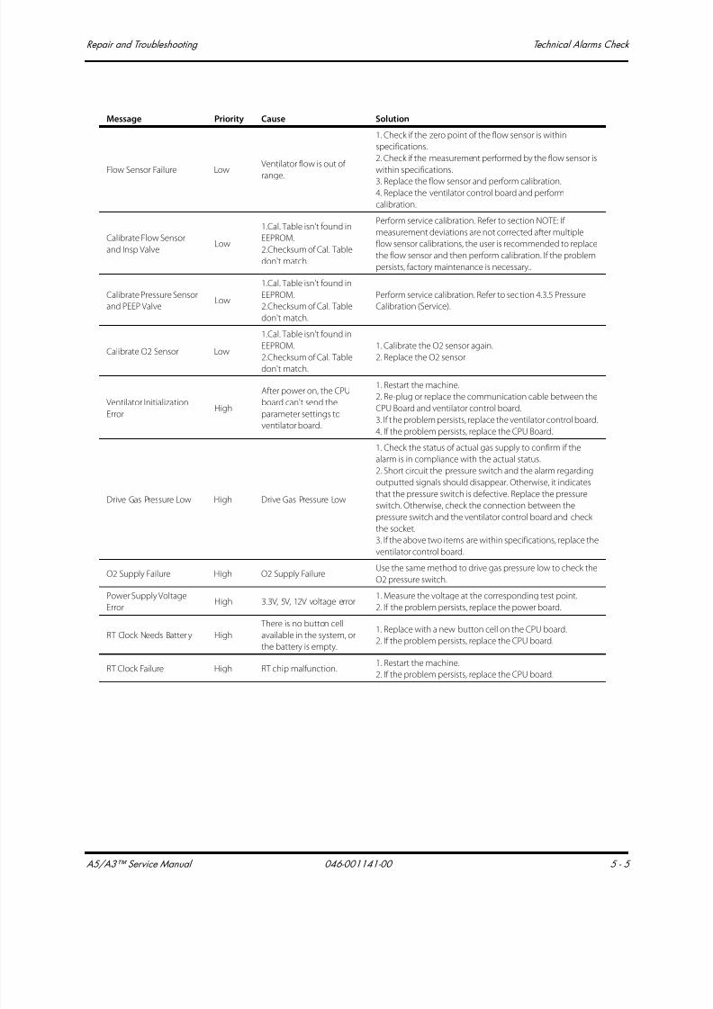
7/21/2019 a5 a3 Service Manual 2013
http://slidepdf.com/reader/full/a5-a3-service-manual-2013 246/399
A5/A3™ Service Manual 046-001141-00 5 - 5
Repair and Troubleshooting Technical Alarms Check
Flow Sensor Failure LowVentilator flow is out of
range.
1. Check if the zero point of the flow sensor is within
specifications.
2. Check if the measurement performed by the flow sensor is
within specifications.
3. Replace the flow sensor and perform calibration.
4. Replace the ventilator control board and perform
calibration.
Calibrate Flow Sensor
and Insp ValveLow
1.Cal. Table isn't found in
EEPROM.
2.Checksum of Cal. Table
don't match.
Perform service calibration. Refer to section NOTE: If
measurement deviations are not corrected after multiple
flow sensor calibrations, the user is recommended to replace
the flow sensor and then perform calibration. If the problem
persists, factory maintenance is necessary..
Calibrate Pressure Sensor
and PEEP ValveLow
1.Cal. Table isn't found in
EEPROM.
2.Checksum of Cal. Table
don't match.
Perform service calibration. Refer to section 4.3.5 Pressure
Calibration (Service).
Calibrate O2 Sensor Low
1.Cal. Table isn't found in
EEPROM.
2.Checksum of Cal. Table
don't match.
1. Calibrate the O2 sensor again.
2. Replace the O2 sensor.
Ventilator Initialization
ErrorHigh
After power on, the CPU
board can't send the
parameter settings to
ventilator board.
1. Restart the machine.
2. Re-plug or replace the communication cable between the
CPU Board and ventilator control board.
3. If the problem persists, replace the ventilator control board.
4. If the problem persists, replace the CPU Board.
Drive Gas Pressure Low High Drive Gas Pressure Low
1. Check the status of actual gas supply to confirm if the
alarm is in compliance with the actual status.
2. Short circuit the pressure switch and the alarm regarding
outputted signals should disappear. Otherwise, it indicates
that the pressure switch is defective. Replace the pressure
switch. Otherwise, check the connection between the
pressure switch and the ventilator control board and check
the socket.3. If the above two items are within specifications, replace the
ventilator control board.
O2 Supply Failure High O2 Supply FailureUse the same method to drive gas pressure low to check the
O2 pressure switch.
Power Supply Voltage
ErrorHigh 3.3V, 5V, 12V voltage error
1. Measure the voltage at the corresponding test point.
2. If the problem persists, replace the power board.
RT Clock Needs Batter y High
There is no button cell
available in the system, or
the battery is empty.
1. Replace with a new button cell on the CPU board.
2. If the problem persists, replace the CPU board.
RT Clock Failure High RT chip malfunction.1. Restart the machine.
2. If the problem persists, replace the CPU board.
Message Priority Cause Solution

7/21/2019 a5 a3 Service Manual 2013
http://slidepdf.com/reader/full/a5-a3-service-manual-2013 247/399
Technical Alarms Check Repair and Troubleshooting
5 - 6 046-001141-00 A5/A3™ Service Manual
5.2.2 CPU Board Runtime Alarm
5.2.3 Power Board Runtime Alarm
Message Priority Cause Solution
IP Address Conflict Med
The IP address is same
with other machine in
the local network.
1. Set the IP address again.
2. If the problem persists, update the system software code or
replace the CPU Board.
Fan Failure Med
The speed of the fan is
20% off of the nominal
value.
1. Check if the fan stops running or runs slowly (around 4000 rounds
normally).
2. Plug in and out the fan power cable again.
3. If the problem persists, check if 12V for fan power supply on the
power board is within specifications. If not, check the power board.
4. If the problem persists, replace the fan.
5. If the problem persists, replace the CPU board.
Message Priority Cause Solution
Power System Comm Stop High
Lost
communication
with CPU board
for 10 seconds.
1. Restart the machine.2. Re-plug the communication cable.
3. Disconnect the battery from the AC mains. After the power board
processor is powered off for 5 minutes, power it on again.
4. Replace with a new communication cable.
5. Check if the power board software is correct. Update the power
board software again when necessary.
6. If the problem persists, replace the Power Board.
7. If the problem persists, replace the CPU Board.
Power Supply Voltage Error High3.3V, 5V, 12V
voltage error
1. Measure the voltage at the corresponding test point.
2. Disconnect the battery from the AC mains. After the power board
processor is powered off for 5 minutes, power it on again. Repeat
Step 1
3. If the problem persists, replace the Power Board.
4. If the problem persists, contact the technical support.
Low Battery Voltage! High
Battery voltage is
less than 10.6V for
5 seconds.
1. Check the connection to the AC mains. Re-connect the AC mainsimmediately.
2. Check if the battery voltage is within specifications.
3. Check if the charging circuit is working correctly. If not, replace
the Power Board.
System going DOWN,
Battery depleted!High
Battery voltage is
less than 10.2V.
1. Restart the machine.
2. If the problem persists, connect to the normal mains supply. Make
sure that the AC indicator is lit and charges the battery for 20
minutes.
3. If the problem persists, replace the battery.
4. If the problem persists, replace the power module.
Battery Undetected MedBattery
Undetected
1. Check if the battery voltage is within specifications.
2. Check if the cable is connected correctly.
3. Replace the battery.
4. If the problem persists, replace the power board.
Battery in Use Low AC power fail
1. Check the connection to the AC mains.
2. If the AC mains supply is connected correctly and the voltage is
within specifications, check the connection between the AC mains
and the power board. Check the AC mains inlet.
3. If the problem persists, replace the power board.
Power Board High Temp High
Power board
temp is greater
than 95 C
1. Check the fan for the power module.
2. Stop using the machine for a period of time. If the problem
persists after the machine is restarted, replace the power board.

7/21/2019 a5 a3 Service Manual 2013
http://slidepdf.com/reader/full/a5-a3-service-manual-2013 248/399
A5/A3™ Service Manual 046-001141-00 5 - 7
Repair and Troubleshooting Technical Alarms Check
Heating Module Failure Low
1. Both resistance
temps are greater
than 70 C or less
than 0 C for 20
seconds.
2. One of
resistance temp is
greater than 75 C
for 15 seconds.
1. Restart the machine.
2. If the problem persists, check if the heating temperature and
voltage are within specifications. If not, replace the power board.
3. If the problem persists, update the SW of the CPU board and
replace the CPU board if necessary.
Breathing Circuit Not
MountedHigh
Breathing Circuit
Not Mounted
1. Check that the circuit is installed in place.
2. Test the connection between the connection line and the
connector.
3. Replace the power board.
Message Priority Cause Solution

7/21/2019 a5 a3 Service Manual 2013
http://slidepdf.com/reader/full/a5-a3-service-manual-2013 249/399
Technical Alarms Check Repair and Troubleshooting
5 - 8 046-001141-00 A5/A3™ Service Manual
5.2.4 Fresh Flow Sensor Board Alarm
Message Priority Cause Solution
Flowmeter Voltage Error High DVCC, AVDD or VCvoltage error
1. Restart the machine.
2. Measure the 12V input voltage (voltage on the power cable) of
the electronic flowmeter to see if it is within specifications. Check ifthe cable is defective. If the input voltage is out of specification,
replace the power board or cable.
3. If the problem persists, replace the fresh flow sensor board.
N2O Flow Too High Low
N2O flow is
greater than 15L/
min for 1 second.
1. Turn off other gas flow. Compare the concerned gas flow with the
measurement result displayed on the total flowmeter.
2. Use test tools. Turn Auto/Manual to Manual, Set APL valve at Max
value. Measure fresh gas flow at the inspiration connector. Check
the measurement error of electronic flowmeter.
3. If the problem persists, replace the flowmeter relative
subassembly.
O2 Flow Too High Low
O2 flow is greater
than 15L/min for 1
second.
Use the same method as “N2O Flow Too High” to “O2 Flow Too
High” to check the O2 flowmeter.
Air Flow Too High LowAir flow is greaterthan 15L/min for 1
second.
Use the same method as “N2O Flow Too High” to “Air Flow TooHigh” to check the Air flowmeter.
O2-N2O Ratio Error High
N2O flow is
greater than 0.5 L/
min and greater
than 4 times O2
flow, this
condition last for
1.6 seconds.
1. Restart the machine.
2. Check the measurement correctness of O2 and N2O flow sensors.
If measurement error occurs, replace the flow sensor.
3. Check the ORC for leakage. Connect the tubes again. If an error
occurs, replace the ORC.
4. If the problem persists, replace the fresh flow sensor board.
Flowmeter Comm Stop High
Lost
communication
with CPU board
for 10 seconds.
1. Restart the machine.
2. Re-plug or replace the communication cable between the CPU
board and the fresh flow sensor board.
3. If the problem persists, replace the fresh flow sensor board.
5. If the problem persists, replace the CPU board.
NO Fresh Gas Med
Fresh gas flow is
less than 50 mL/
min
1.Check if the fresh gas knob is opened.
2. Check the measurement correctness of flow sensors. If
measurement error occurs, replace the flow sensor.
3. Check the ORC for leakage. Connect the tubes again. If an error
occurs, replace the ORC.
4. If the problem persists, replace the fresh flow sensor board.
Internal N2O Flow Failure LowN2O flow is out of
range
1. Restart the machine.
2. Check the measurement correctness of flow sensors. If
measurement error occurs, replace the flow sensor.
3. If the problem persists, replace the fresh flow sensor board.
Internal O2 Flow Failure LowO2 flow is out of
rangeHandle in the similar way to handling “Internal N2O Flow Failure”.
Internal Air Flow Failure LowAir flow is out of
rangeHandle in the similar way to handling “Internal N2O Flow Failure”.
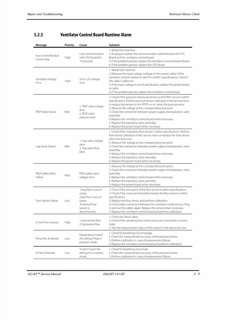
7/21/2019 a5 a3 Service Manual 2013
http://slidepdf.com/reader/full/a5-a3-service-manual-2013 250/399
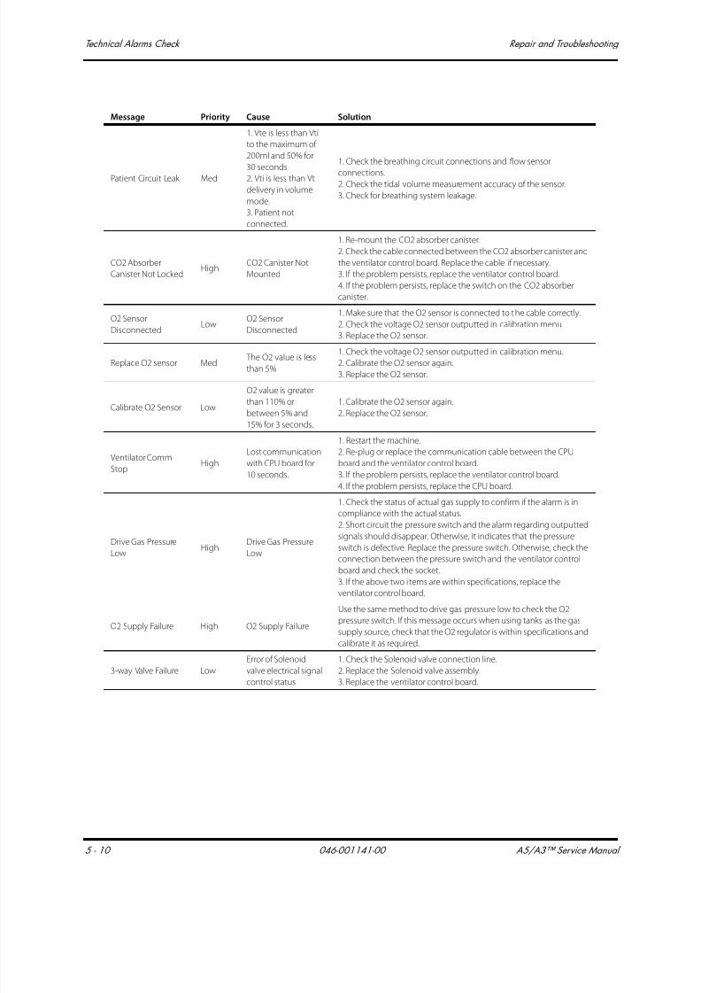
7/21/2019 a5 a3 Service Manual 2013
http://slidepdf.com/reader/full/a5-a3-service-manual-2013 251/399
Technical Alarms Check Repair and Troubleshooting
5 - 10 046-001141-00 A5/A3™ Service Manual
Patient Circuit Leak Med
1. Vte is less than Vti
to the maximum of
200ml and 50% for
30 seconds
2. Vti is less than Vt
delivery in volume
mode.
3. Patient not
connected.
1. Check the breathing circuit connections and flow sensor
connections.2. Check the tidal volume measurement accuracy of the sensor.
3. Check for breathing system leakage.
CO2 Absorber
Canister Not LockedHigh
CO2 Canister Not
Mounted
1. Re-mount the CO2 absorber canister.
2. Check the cable connected between the CO2 absorber canister and
the ventilator control board. Replace the cable if necessary.
3. If the problem persists, replace the ventilator control board.
4. If the problem persists, replace the switch on the CO2 absorber
canister.
O2 Sensor
DisconnectedLow
O2 Sensor
Disconnected
1. Make sure that the O2 sensor is connected to the cable correctly.
2. Check the voltage O2 sensor outputted in calibration menu.
3. Replace the O2 sensor.
Replace O2 sensor Med The O2 value is less
than 5%
1. Check the voltage O2 sensor outputted in calibration menu.
2. Calibrate the O2 sensor again.
3. Replace the O2 sensor.
Calibrate O2 Sensor Low
O2 value is greater
than 110% or
between 5% and
15% for 3 seconds.
1. Calibrate the O2 sensor again.
2. Replace the O2 sensor.
Ventilator Comm
StopHigh
Lost communication
with CPU board for
10 seconds.
1. Restart the machine.
2. Re-plug or replace the communication cable between the CPU
board and the ventilator control board.
3. If the problem persists, replace the ventilator control board.
4. If the problem persists, replace the CPU board.
Drive Gas Pressure
LowHigh
Drive Gas Pressure
Low
1. Check the status of actual gas supply to confirm if the alarm is in
compliance with the actual status.
2. Short circuit the pressure switch and the alarm regarding outputtedsignals should disappear. Otherwise, it indicates that the pressure
switch is defective. Replace the pressure switch. Otherwise, check the
connection between the pressure switch and the ventilator control
board and check the socket.
3. If the above two i tems are within specifications, replace the
ventilator control board.
O2 Supply Failure High O2 Supply Failure
Use the same method to drive gas pressure low to check the O2
pressure switch. If this message occurs when using tanks as the gas
supply source, check that the O2 regulator is within specifications and
calibrate it as required.
3-way Valve Failure Low
Error of Solenoid
valve electrical signal
control status
1. Check the Solenoid valve connection line.
2. Replace the Solenoid valve assembly.
3. Replace the ventilator control board.
Message Priority Cause Solution
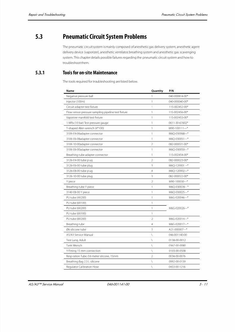
7/21/2019 a5 a3 Service Manual 2013
http://slidepdf.com/reader/full/a5-a3-service-manual-2013 252/399
A5/A3™ Service Manual 046-001141-00 5 - 11
Repair and Troubleshooting Pneumatic Circuit System Problems
5.3 Pneumatic Circuit System Problems
The pneumatic circuit system is mainly composed of anesthetic gas delivery system, anesthetic agent
delivery device (vaporizer), anesthetic ventilator, breathing system and anesthetic gas scavenging
system. This chapter details possible failures regarding the pneumatic circuit system and how totroubleshoot them.
5.3.1 Tools for on-site Maintenance
The tools required for troubleshooting are listed below.
Name Quantity P/N
Negative pressure ball 1 040-000814-00*
Injector (100m) 1 040-000040-00*
Circuit adapter test fixture 1 115-002452-00*
Flow sensor pressure sampling pipeline test fixture 1 115-002456-00*
Vaporizer manifold test fixture 1 115-002453-00*
1 MPa (10 bar) Test pressure gauge 1 0611-30-67602*
T-shaped Allen wrench (4*100) 1 M90-100111---*
3106-04-06adapter connector 1 M6Q-030068---*
3106-06-08adapter connector 1 M6Q-030051---*
3106-10-00adapter connector 2 082-000021-00*
3106-06-00adapter connector 1 M6Q-030059---*
Breathing tube adapter connector 1 115-002454-00*
3126-04-00 tube plug 2 082-000023-00*
3126-06-00 tube plug 3 M6Q-120001---*
3126-08-00 tube plug 4 M6Q-120002---*
3126-10-00 tube plug 3 082-000022-00*
Y piece 2 M90-100030---*
Breathing tube Y piece 1 M6Q-030028---*
3140-08-00 Y piece 1 M6Q-030025---*
PU tube (4X200) 1 M6G-020046---*
PU tube (6X100) 1
M6G-020026---*PU tube (6X200) 1
PU tube (6X300) 1
PU tube (8X200) 2 M6G-020014---*
Breathing tube 4 M6G-020017---*
Ø6 silicone tube 3 A21-000007---*
A5/A3 Service Manual \ 046-001140-00
Test Lung, Adult \ 0138-00-0012
Tank Wrench \ 0367-00-0080
Y-Fitting 15 mm connection \ 0103-00-0508
Respiration Tube, 0.6 meter silicone, 15mm 2 0004-00-0076
Breathing Bag 2.3 L silicone \ 0992-00-0139
Regulator Calibration Hose \ 0453-00-1216

7/21/2019 a5 a3 Service Manual 2013
http://slidepdf.com/reader/full/a5-a3-service-manual-2013 253/399
Pneumatic Circuit System Problems Repair and Troubleshooting
5 - 12 046-001141-00 A5/A3™ Service Manual
The following pictures show the tools listed above.
FIGURE 5-1 (1) PU tube (4X200), (2) PU tube (6X100), (3) PU tube (6X200), (4) PU tube (6X300), (5)
PU tube (8X200), (6) Ø6 silicone tube, (7) Breathing tube, (8) 3106-04-06 adapter
connector, (9) 3106-06-00 adapter connector, (10) 3106-06-08 adapter connector,
(11) 3106-10-00 adapter connector, (12) Breathing tube adapter connector, (13)
3126-04-00 tube plug, (14) 3126-06-00 tube plug, (15) 3126-08-00 tube plug, (16)
A5/A3 troubleshooting kit \ 115-009450-00
Vaporizer Instruction Manual \ \
Safety Analyzer Dempsey 430 or equivalent \ \
Digital Volt Meter 3 1/2 digit \ \
Agent (and NO2) Analyzer ±0.3 V/V%+5% of reading \ \
Digital Pressure Meter BC Biomedical DPM-2301751 NMC Digital
Pressure Meter or equivalent \ \
Central supplied O2,NO2,AIR Minimum of 35 psi, DISS
connections. \ \
Cylinder gases O2,NO2,AIR Full PISS yoke connections \ \
Hand tools, Allen wrench set Metric \ \
Gas Flow Analyzer with 2% accuracy \ \
A Series Calibration Set (required if using Fluke VT Plus Gas Flow
Analyzer) \ 801-0631-00121-00
Lucer adapter connector \ \
Ethernet Crossover Cable \ 0012-00-1392-06
USB flash drive \ 0992-00-0297-04
* = is part of the 115-009450-00 A5/A3 troubleshooting kit.
Name Quantity P/N

7/21/2019 a5 a3 Service Manual 2013
http://slidepdf.com/reader/full/a5-a3-service-manual-2013 254/399
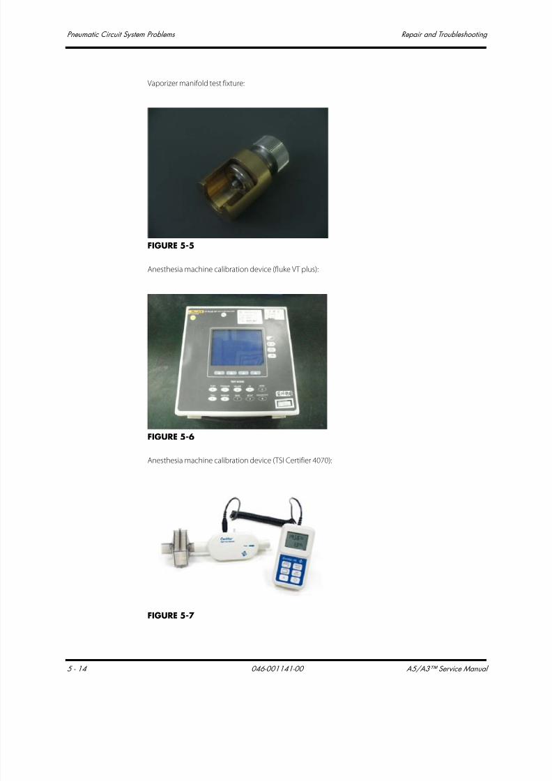
7/21/2019 a5 a3 Service Manual 2013
http://slidepdf.com/reader/full/a5-a3-service-manual-2013 255/399
Pneumatic Circuit System Problems Repair and Troubleshooting
5 - 14 046-001141-00 A5/A3™ Service Manual
Vaporizer manifold test fixture:
FIGURE 5-5
Anesthesia machine calibration device (fluke VT plus):
FIGURE 5-6
Anesthesia machine calibration device (TSI Certifier 4070):
FIGURE 5-7
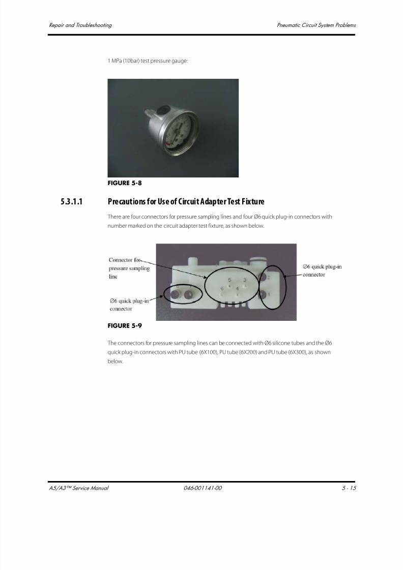
7/21/2019 a5 a3 Service Manual 2013
http://slidepdf.com/reader/full/a5-a3-service-manual-2013 256/399
A5/A3™ Service Manual 046-001141-00 5 - 15
Repair and Troubleshooting Pneumatic Circuit System Problems
1 MPa (10bar) test pressure gauge:
FIGURE 5-8
5.3.1.1 Precautions for Use of Circuit Adapter Test Fixture
There are four connectors for pressure sampling lines and four Ø6 quick plug-in connectors with
number marked on the circuit adapter test fixture, as shown below.
FIGURE 5-9
The connectors for pressure sampling lines can be connected with Ø6 silicone tubes and the Ø6
quick plug-in connectors with PU tube (6X100), PU tube (6X200) and PU tube (6X300), as shown
below.

7/21/2019 a5 a3 Service Manual 2013
http://slidepdf.com/reader/full/a5-a3-service-manual-2013 257/399
Pneumatic Circuit System Problems Repair and Troubleshooting
5 - 16 046-001141-00 A5/A3™ Service Manual
FIGURE 5-10
The circuit adapter test fixture can be mounted either onto the circuit adapter or onto the removed
breathing system. The following pictures show the test fixture mounted in position.
FIGURE 5-11
FIGURE 5-12

7/21/2019 a5 a3 Service Manual 2013
http://slidepdf.com/reader/full/a5-a3-service-manual-2013 258/399
A5/A3™ Service Manual 046-001141-00 5 - 17
Repair and Troubleshooting Pneumatic Circuit System Problems
If it is hard to install and remove the test fixture, apply a layer of KRYTOX lubricant to the seals (as
shown below).
FIGURE 5-13
5.3.1.2 Precautions for Use of Flow Sensor Pressure Sampling Pipeline Test Fixture
There are two connectors for pressure sampling lines on the flow sensor pressure sampling pipeline
test fixture, as shown below.
FIGURE 5-14
The connector for pressure sampling line can be connected with Ø6 silicone tubes. When using theflow sensor pressure sampling pipeline test fixture, remove the expiratory or inspiratory flow sensor
from the breathing system first. Then mount the flow sensor pressure sampling pipeline test fixture
onto the position where the expiratory or inspiratory flow sensor was originally mounted and tighten
the Inspiration/Expiration Connector Coupling, as shown below. Perform test after connecting the Ø6
silicone tube to the connector for pressure sampling line.

7/21/2019 a5 a3 Service Manual 2013
http://slidepdf.com/reader/full/a5-a3-service-manual-2013 259/399
Pneumatic Circuit System Problems Repair and Troubleshooting
5 - 18 046-001141-00 A5/A3™ Service Manual
FIGURE 5-15
FIGURE 5-16
5.3.1.3 Precautions for Use of Vaporizer Manifold Test Fixture
When using the vaporizer manifold test f ixture, remove the o-ring seal on the vaporizer manifold
assembly. Then slide the test fixture onto the connector, as shown below.
FIGURE 5-17

7/21/2019 a5 a3 Service Manual 2013
http://slidepdf.com/reader/full/a5-a3-service-manual-2013 260/399
A5/A3™ Service Manual 046-001141-00 5 - 19
Repair and Troubleshooting Pneumatic Circuit System Problems
Turn the knob clockwise until the bottom surface of the pressure head is in contact with the top
surface of the connector, as shown below.
FIGURE 5-18
5.3.1.4 Precautions for Use of Negative Pressure Ball
Besides one sealing cover, the negative pressure ball also has two one-way valves at its front end, as
shown below. The built-in one is connected with the gas inlet of the ball which permits the gas come
in only, and the exterior one only permits the gas come out. If the front sealing cover is removed or
loosened, the sealing performance of the negative pressure ball will compromise. In this case, you
need to tighten the sealing cover.
FIGURE 5-19
When the negative pressure ball is connected with the tested component, the ball permits the gas in
only, but meanwhile it’s free to release air when it’s pressed.

7/21/2019 a5 a3 Service Manual 2013
http://slidepdf.com/reader/full/a5-a3-service-manual-2013 261/399
Pneumatic Circuit System Problems Repair and Troubleshooting
5 - 20 046-001141-00 A5/A3™ Service Manual
FIGURE 5-20
Before using the negative pressure ball, make sure that it is not leaky. Check if the front sealing coveris tightened. Then flatten the negative pressure ball to remove the gas inside. Install the gas outlet
plug properly. Block the front gas inlet with your finger then release the ball. Ball should not visibly
inflate for at least 30 seconds. If it does, replace the ball.
5.3.2 Gas Supplies and Drive Gas
The following table lists gas supplies and drive gas related failures.
Failure description Possible cause Recommended action
Leak
The gas supply tube is
damaged or the seal at the
connection is damaged.
Replace the gas supply tube or the seal at the
connection.
The quick plug-in
connector leaks.
Replace the quick plug-in connector or PU tube
(when the PU tube is not damaged, if the tube is
long enough, cut off a small segment of the tube
where the quick plug-in connector is met, and
then insert the tube into position).
The pipeline gas supply
inlet assembly leaks.
Check if the check valve of the pipeline gas
supplies inlet assembly leaks in the reverse
direction. Replace it if necessary. Check and
replace the damaged seal of the pipeline gas
supplies inlet assembly. If the problem persists,
replace the pipeline gas supplies inlet assembly.
The drive gas pipeline
leaks.
Check and repair the expiratory valve assembly as
per the procedures described in ‘‘Leak Test of Low-
pressure Pneumatic Circuit System’’ on page 5-47,Pipeline pressure gauge
shows inaccurate
readings or no readings.
The pipeline pressure
gauge is damaged.Replace the pipeline pressure gauge.

7/21/2019 a5 a3 Service Manual 2013
http://slidepdf.com/reader/full/a5-a3-service-manual-2013 262/399
A5/A3™ Service Manual 046-001141-00 5 - 21
Repair and Troubleshooting Pneumatic Circuit System Problems
5.3.2.1 Test the Pipeline Pressure Gauge and Correct the Regulator
Use the following tools to test the pipeline pressure gauge and regulator of the pipeline gas supply
inlet assembly:
• 1 MPa (10bar) test pressure gauge (before the test, make sure that the 1 MPa (10bar) test pressure
gauge is in good condition) (quantity: 1)
• 3106-04-06 adapter connector (quantity: 1)
• PU tube (4X200) (quantity: 1)
• PU tube (6X200) (quantity: 1)
Test procedures:
I O2 supply inlet assembly:
1. Turn off the pipeline gas supply and bleed the residual pressure through O2 flushing.
2. Disconnect tube 57. The end of the tube which connects the auxiliary O2 supply is not pulled
out but the end to Y piece is pulled out.Connect 1MPa test pressure gauge to the above Y piece
through “3106-04-06 adapter connector”.
The readings on the
pipeline pressure gauge
fluctuate greatly.
The filter of pipeline gas
supply inlet assembly or
the PU tube of the pipeline
pressure gauge isoccluded or the pressure
gauge is damaged.
1. After confirming that the pipeline gas pressure is
stable, check the PU tube of the pipeline pressure
gauge and filter of the pipeline gas supply inlet
assembly. If the tube or the filer is occluded,
replace it.
2. If the problem persists, replace the pipeline
pressure gauge.
No “O2 Supply Failure”
alarm occurs when the
O2 pressure is low or
this alarm occurs when
the O2 supply pressure
is within specifications.
The gas pressure switch of
the O2 supply inlet
assembly is ineffective.
Adjust the pressure switch of the O2 supply inlet
assembly to cause O2 supply pressure to approach
0.2 MPa as much as possible within the range of
0.15 to 0.25 MPa when this alarm occurs. I f the
adjustment fails, replace the pressure switch (refer
to “Adjust the Pressure Switch” on page 5-28.).
No “Drive Gas Pressure
Low” alarm occurs when
the drive gas pressure is
low or this alarm occurs
when the drive gas
pressure is within
specifications.
The pressure switch on the
integrated pneumatic
circuit of the expiratory
valve assembly or the PEEP
safety valve is ineffective.
Or, the filter on theintegrated pneumatic
circuit of the expiratory
valve assembly is
occluded.
Adjust the pressure switch on the integrated
pneumatic circuit of the expiratory valve assembly
to cause drive gas pressure to approach 0.14 MPa
as much as possible within the range of 0.05 to 0.2
MPa when this alarm occurs. If the adjustment fails,
replace the pressure switch. If the problem persistsafter the pressure switch is replaced, replace the
integrated pneumatic circuit of the expiratory
valve assembly (refer to ‘‘Adjust the Pressure
Switch’’ on page 5-28)
Failure description Possible cause Recommended action
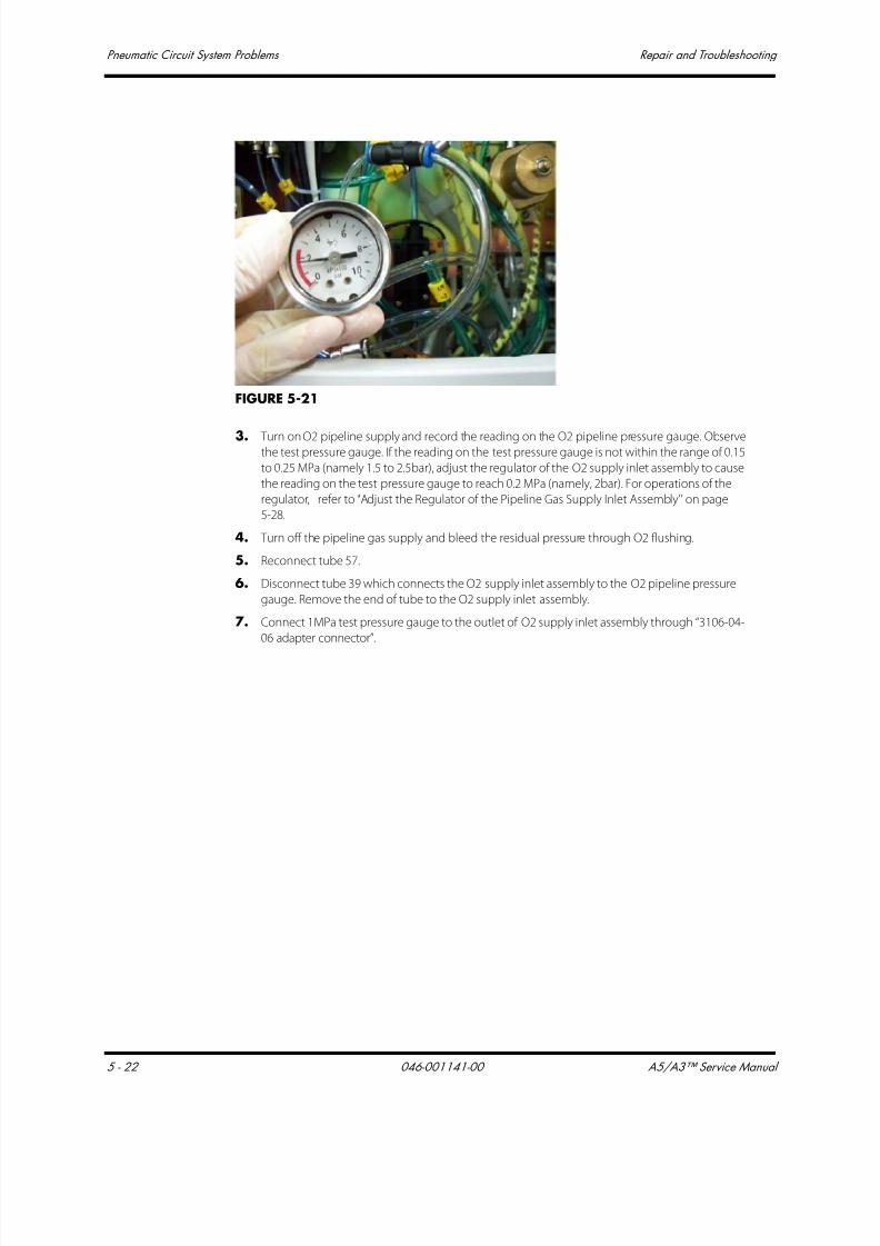
7/21/2019 a5 a3 Service Manual 2013
http://slidepdf.com/reader/full/a5-a3-service-manual-2013 263/399
Pneumatic Circuit System Problems Repair and Troubleshooting
5 - 22 046-001141-00 A5/A3™ Service Manual
FIGURE 5-21
3. Turn on O2 pipeline supply and record the reading on the O2 pipeline pressure gauge. Observethe test pressure gauge. If the reading on the test pressure gauge is not within the range of 0.15
to 0.25 MPa (namely 1.5 to 2.5bar), adjust the regulator of the O2 supply inlet assembly to cause
the reading on the test pressure gauge to reach 0.2 MPa (namely, 2bar). For operations of the
regulator, refer to ‘‘Adjust the Regulator of the Pipeline Gas Supply Inlet Assembly’’ on page
5-28.
4. Turn off the pipeline gas supply and bleed the residual pressure through O2 flushing.
5. Reconnect tube 57.
6. Disconnect tube 39 which connects the O2 supply inlet assembly to the O2 pipeline pressure
gauge. Remove the end of tube to the O2 supply inlet assembly.
7. Connect 1MPa test pressure gauge to the outlet of O2 supply inlet assembly through “3106-04-
06 adapter connector”.

7/21/2019 a5 a3 Service Manual 2013
http://slidepdf.com/reader/full/a5-a3-service-manual-2013 264/399
A5/A3™ Service Manual 046-001141-00 5 - 23
Repair and Troubleshooting Pneumatic Circuit System Problems
FIGURE 5-22
8. Turn on the pipeline gas supply and record the reading on the test pressure gauge. If thedifference between this reading and the reading on the O2 pipeline pressure gauge is more
than 0.1 MPa (1bar), it indicates that the O2 pipeline pressure gauge is damaged. Handle this
problem as described in the troubleshooting table.
9. Reconnect tube 39.
NOTE: For numbers of all PU tubes, refer to sections 1.2.3 and 1.2.4 Pneumatic
Connections.
II N2O supply inlet assembly:
1. Turn off the pipeline gas supply. Open the needle valve to bleed the residual pressure and close
the needle valve. Disconnect tube 49. The end of the tube which connects the ORC is pulled out
but the other end is not pulled out.
2. Connect 1MPa test pressure gauge, the pulled-out end of tube 49, and ORC N2O outlet through
“3106-04-06 adapter connector” and Y piece (17).
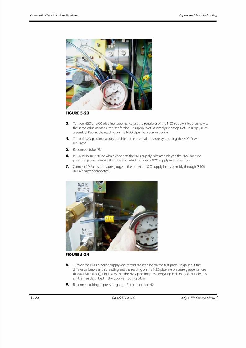
7/21/2019 a5 a3 Service Manual 2013
http://slidepdf.com/reader/full/a5-a3-service-manual-2013 265/399
Pneumatic Circuit System Problems Repair and Troubleshooting
5 - 24 046-001141-00 A5/A3™ Service Manual
FIGURE 5-23
3. Turn on N2O and O2 pipeline supplies. Adjust the regulator of the N2O supply inlet assembly to
the same value as measured/set for the O2 supply inlet assembly (see step 4 of O2 supply inlet
assembly) Record the reading on the N2O pipeline pressure gauge.
4. Turn off N2O pipeline supply and bleed the residual pressure by opening the N2O flow
regulator.
5. Reconnect tube 49.
6. Pull out No.40 PU tube which connects the N2O supply inlet assembly to the N2O pipeline
pressure gauge. Remove the tube end which connects N2O supply inlet assembly.
7. Connect 1MPa test pressure gauge to the outlet of N2O supply inlet assembly through “3106-
04-06 adapter connector”.
FIGURE 5-24
8. Turn on the N2O pipeline supply and record the reading on the test pressure gauge. If the
difference between this reading and the reading on the N2O pipeline pressure gauge is more
than 0.1 MPa (1bar), it indicates that the N2O pipeline pressure gauge is damaged. Handle this
problem as described in the troubleshooting table.
9. Reconnect tubing to pressure gauge. Reconnect tube 40.

7/21/2019 a5 a3 Service Manual 2013
http://slidepdf.com/reader/full/a5-a3-service-manual-2013 266/399
A5/A3™ Service Manual 046-001141-00 5 - 25
Repair and Troubleshooting Pneumatic Circuit System Problems
III AIR supply inlet assembly:
1. Turn off the pipeline gas supply. Disconnect tube 67. The end of the tube which connects
auxiliary gas supply is not pulled out but the other end which connects the Y piece is pulled out.
2. Connect 1MPa test pressure gauge to the above Y piece through “3106-04-06 adapter
connector”.
FIGURE 5-25
3. Turn on AIR pipeline supply. If the reading on the test pressure gauge is not within the range of
0.2±0.05 MPa (2.0±0. 5bar), adjust the regulator to cause the reading on the test pressure gauge
to reach 0.2 MPa (2.0bar). Record the reading on the AIR pipeline pressure gauge.
4. Turn off AIR pipeline supply and bleed the residual pressure by opening the AIR flow regulator.
5. Reconnect PU tube No.50 into the “Y” fitting. Reconnect tube 67.
6. Pull out No.41 PU tube which connects the AIR supply inlet assembly to the AIR pipelinepressure gauge. Remove the tube end which connects AIR supply inlet assembly.
7. Connect 1MPa test pressure gauge to the outlet of AIR supply inlet assembly through “3106-04-
06 adapter connector”.
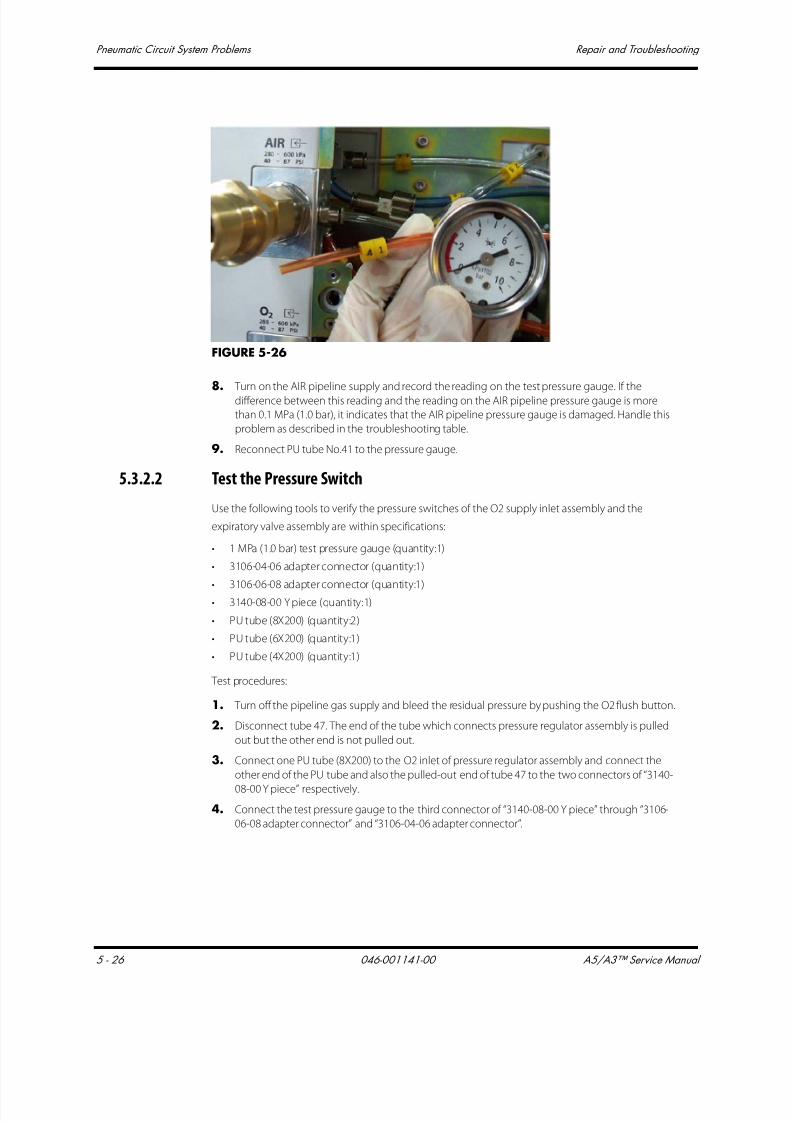
7/21/2019 a5 a3 Service Manual 2013
http://slidepdf.com/reader/full/a5-a3-service-manual-2013 267/399
Pneumatic Circuit System Problems Repair and Troubleshooting
5 - 26 046-001141-00 A5/A3™ Service Manual
FIGURE 5-26
8. Turn on the AIR pipeline supply and record the reading on the test pressure gauge. If the
difference between this reading and the reading on the AIR pipeline pressure gauge is more
than 0.1 MPa (1.0 bar), it indicates that the AIR pipeline pressure gauge is damaged. Handle this
problem as described in the troubleshooting table.
9. Reconnect PU tube No.41 to the pressure gauge.
5.3.2.2 Test the Pressure Switch
Use the following tools to verify the pressure switches of the O2 supply inlet assembly and the
expiratory valve assembly are within specifications:
• 1 MPa (1.0 bar) test pressure gauge (quantity:1)
• 3106-04-06 adapter connector (quantity:1)
• 3106-06-08 adapter connector (quantity:1)• 3140-08-00 Y piece (quantity:1)
• PU tube (8X200) (quantity:2)
• PU tube (6X200) (quantity:1)
• PU tube (4X200) (quantity:1)
Test procedures:
1. Turn off the pipeline gas supply and bleed the residual pressure by pushing the O2 flush button.
2. Disconnect tube 47. The end of the tube which connects pressure regulator assembly is pulled
out but the other end is not pulled out.
3. Connect one PU tube (8X200) to the O2 inlet of pressure regulator assembly and connect the
other end of the PU tube and also the pulled-out end of tube 47 to the two connectors of “3140-
08-00 Y piece” respectively.
4. Connect the test pressure gauge to the third connector of “3140-08-00 Y piece” through “3106-
06-08 adapter connector” and “3106-04-06 adapter connector”.
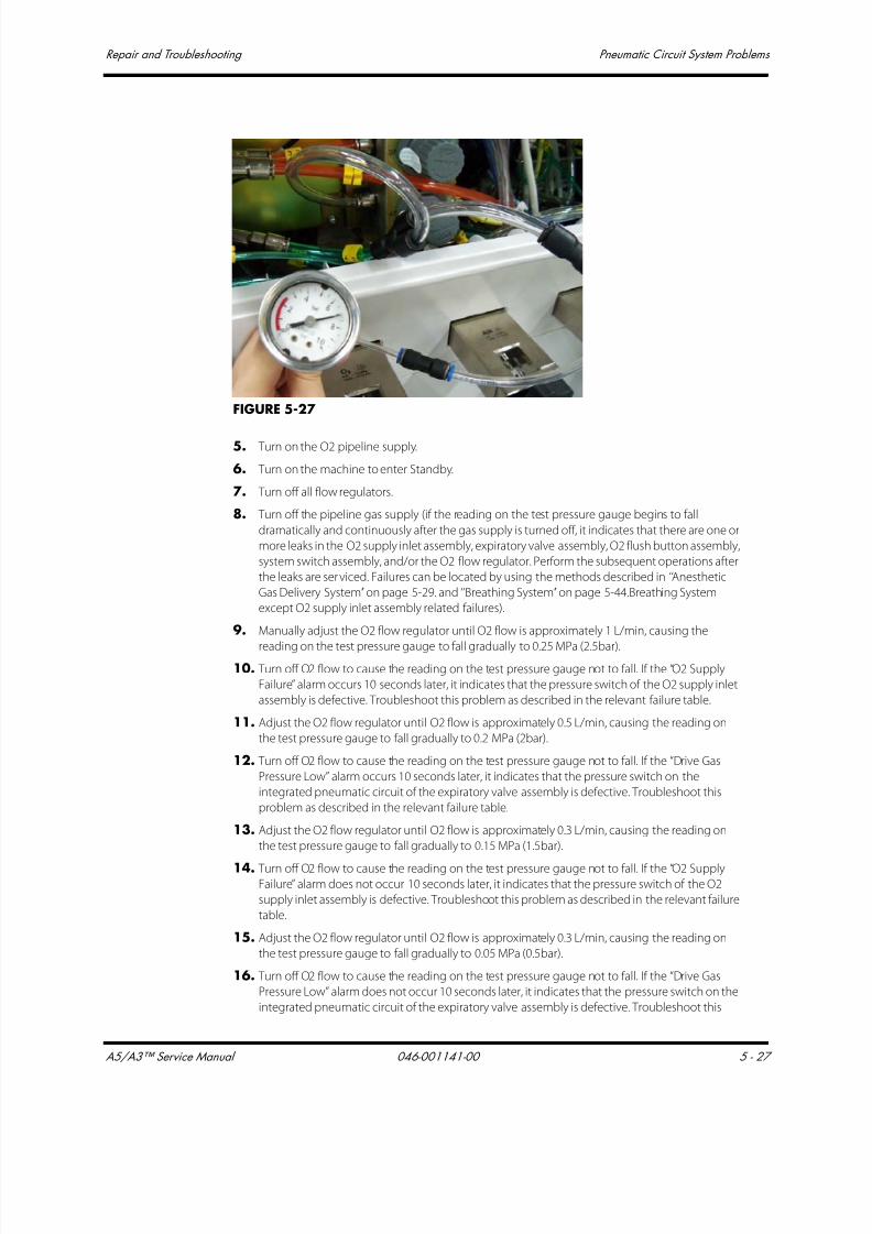
7/21/2019 a5 a3 Service Manual 2013
http://slidepdf.com/reader/full/a5-a3-service-manual-2013 268/399
A5/A3™ Service Manual 046-001141-00 5 - 27
Repair and Troubleshooting Pneumatic Circuit System Problems
FIGURE 5-27
5. Turn on the O2 pipeline supply.
6. Turn on the machine to enter Standby.
7. Turn off all flow regulators.
8. Turn off the pipeline gas supply (if the reading on the test pressure gauge begins to fall
dramatically and continuously after the gas supply is turned off, it indicates that there are one or
more leaks in the O2 supply inlet assembly, expiratory valve assembly, O2 flush button assembly,
system switch assembly, and/or the O2 flow regulator. Perform the subsequent operations after
the leaks are serviced. Failures can be located by using the methods described in ‘‘Anesthetic
Gas Delivery System’’ on page 5-29. and ‘‘Breathing System’’ on page 5-44.Breathing System
except O2 supply inlet assembly related failures).
9. Manually adjust the O2 flow regulator until O2 flow is approximately 1 L/min, causing the
reading on the test pressure gauge to fall gradually to 0.25 MPa (2.5bar).10. Turn off O2 flow to cause the reading on the test pressure gauge not to fall. If the “O2 Supply
Failure” alarm occurs 10 seconds later, it indicates that the pressure switch of the O2 supply inlet
assembly is defective. Troubleshoot this problem as described in the relevant failure table.
11. Adjust the O2 flow regulator until O2 flow is approximately 0.5 L/min, causing the reading on
the test pressure gauge to fall gradually to 0.2 MPa (2bar).
12. Turn off O2 flow to cause the reading on the test pressure gauge not to fall. If the “Drive Gas
Pressure Low” alarm occurs 10 seconds later, it indicates that the pressure switch on the
integrated pneumatic circuit of the expiratory valve assembly is defective. Troubleshoot this
problem as described in the relevant failure table.
13. Adjust the O2 flow regulator until O2 flow is approximately 0.3 L/min, causing the reading on
the test pressure gauge to fall gradually to 0.15 MPa (1.5bar).
14. Turn off O2 flow to cause the reading on the test pressure gauge not to fall. If the “O2 SupplyFailure” alarm does not occur 10 seconds later, it indicates that the pressure switch of the O2
supply inlet assembly is defective. Troubleshoot this problem as described in the relevant failure
table.
15. Adjust the O2 flow regulator until O2 flow is approximately 0.3 L/min, causing the reading on
the test pressure gauge to fall gradually to 0.05 MPa (0.5bar).
16. Turn off O2 flow to cause the reading on the test pressure gauge not to fall. If the “Drive Gas
Pressure Low” alarm does not occur 10 seconds later, it indicates that the pressure switch on the
integrated pneumatic circuit of the expiratory valve assembly is defective. Troubleshoot this

7/21/2019 a5 a3 Service Manual 2013
http://slidepdf.com/reader/full/a5-a3-service-manual-2013 269/399
Pneumatic Circuit System Problems Repair and Troubleshooting
5 - 28 046-001141-00 A5/A3™ Service Manual
problem as described in the relevant failure table.
5.3.2.3 Adjust the Pressure Switch
Adjust the O2 supply pressure switch and drive gas pressure switch as described below.
Use a flathead screwdriver to adjust the O2 supply pressure switch as shown below. Turn for small
degrees each time such as 30 degrees. Note that turning the pressure switch clockwise will decrease
its alarm limits and counterclockwise increase its alarm limits. Test the assembly after each pressure
adjustment is made. Repeat until the pressure switch is properly adjusted and is within specification
(nominal 220 kPa +/- 10 kPa).
FIGURE 5-28
5.3.2.4 Adjust the Regulator of the Pipeline Gas Supply Inlet Assembly
Pull up the knob cover of the regulator. Turn the cover clockwise to increase pressure or
counterclockwise to decrease pressure, as shown below. Bleed the inside pressure of the pipeline gas
supply inlet assembly after each pressure adjustment is made, using the Regulator Calibration hose
(PN 0453-00-1216). Then, turn on the pipeline gas supply again. Observe the adjusted pressure
through the test pressure gauge. Adjust to 200kPa.
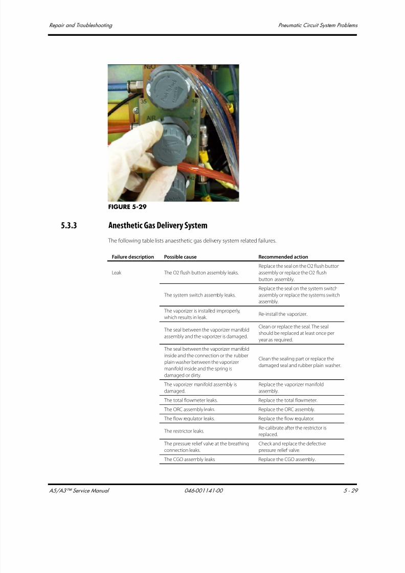
7/21/2019 a5 a3 Service Manual 2013
http://slidepdf.com/reader/full/a5-a3-service-manual-2013 270/399
A5/A3™ Service Manual 046-001141-00 5 - 29
Repair and Troubleshooting Pneumatic Circuit System Problems
FIGURE 5-29
5.3.3 Anesthetic Gas Delivery System
The following table lists anaesthetic gas delivery system related failures.
Failure description Possible cause Recommended action
Leak The O2 flush button assembly leaks.
Replace the seal on the O2 flush button
assembly or replace the O2 flush
button assembly.
The system switch assembly leaks.
Replace the seal on the system switch
assembly or replace the systems switch
assembly.
The vaporizer is installed improperly,
which results in leak.Re-install the vaporizer.
The seal between the vaporizer manifold
assembly and the vaporizer is damaged.
Clean or replace the seal. The seal
should be replaced at least once per
year as required.
The seal between the vaporizer manifold
inside and the connection or the rubber
plain washer between the vaporizer
manifold inside and the spring is
damaged or dirty.
Clean the sealing part or replace the
damaged seal and rubber plain washer.
The vaporizer manifold assembly is
damaged.
Replace the vaporizer manifold
assembly.
The total flowmeter leaks. Replace the total flowmeter. The ORC assembly leaks. Replace the ORC assembly.
The flow regulator leaks. Replace the flow regulator.
The restrictor leaks.Re-calibrate after the restrictor is
replaced.
The pressure relief valve at the breathing
connection leaks.
Check and replace the defective
pressure relief valve.
The CGO assembly leaks. Replace the CGO assembly.

7/21/2019 a5 a3 Service Manual 2013
http://slidepdf.com/reader/full/a5-a3-service-manual-2013 271/399
Pneumatic Circuit System Problems Repair and Troubleshooting
5 - 30 046-001141-00 A5/A3™ Service Manual
5.3.3.1 Leak Test of the O2 Flush Button Assembly
Perform a leak test of the O2 flush button assembly by using the following tools:
• Negative pressure ball (quantity:1)
• 3106-06-00 adapter connector (quantity:1)
• PU tube (6X100) (quantity:1)
Test procedures:
1. Turn off the pipeline gas supplies and bleed the residual pressure through O2 flushing.
2. Remove the work surface. Pull out No.52 PU tube which connects the O2 flush button assembly
to the CGO assembly. Disconnect at the CGO end.
3. Connect the inlet of the negative pressure ball to PU No.52 through 3106-06-00 adapter
connector and then flatten the negative pressure ball to remove the gas inside.
4. Release the negative pressure ball as shown below. If the negative pressure ball is fully
expanded within 30 seconds, it indicates that the O2 flush button assembly is damaged.
The fresh gas connections of the circuit
adapter assembly leak.
Check the seals and tubes at the fresh
gas connections. Replace the defective
parts and re-install the parts.
The gas suppliescannot be turned off
after the machine is
turned off.
The seal inside the system switch
assembly is damaged.Replace the system switch.
The machine cannot
be powered on after
turned on.
The contact switch is ineffective.Replace the contact switch of the
system switch assembly.
The flowmeter float
indicates inaccurate
value or remains
unmoved.
The total float rotameter is damaged. Replace the total float rotameter.
The knob of the flow
regulator gets loose. The flow regulator is damaged. Replace the flow regulator.
N2O supply cannot
be cut off in case ofO2 supply failure.
The ORC assembly is damaged. Replace the ORC assembly.
Failure description Possible cause Recommended action

7/21/2019 a5 a3 Service Manual 2013
http://slidepdf.com/reader/full/a5-a3-service-manual-2013 272/399
A5/A3™ Service Manual 046-001141-00 5 - 31
Repair and Troubleshooting Pneumatic Circuit System Problems
FIGURE 5-30
5.3.3.2 Leak Test of the Flowmeter Related Assembly
Perform a leak test of the flowmeter related assembly (from flow regulator to total flowmeter) by
using the following tools:
• Negative pressure ball (quantity:1)
• 3106-06-00 adapter connector (quantity:1)
• 3106-06-08 adapter connector (quantity:1)
• 3126-06-00 tube plug (quantity:3)
• 3126-08-00 tube plug (quantity:1)
• PU tube (6X100) (quantity:1)
Test procedures:
1. Turn off the pipeline gas supplies and turn on the system switch. Bleed the residual pressure by
opening the flow regulators.
2. Turn off the system switch. Turn on the flow regulators and turn them counterclockwise for
more than half a circle.
3. Pull out No.25 PU tube which connects the total flowmeter to the vaporizer manifold assembly.
Disconnect at the vaporizer manifold end.
4. Pull out No.46, 49 and 51 PU tubes which connect with the flow regulator. Disconnect at flow
regulator end.
5. Occlude the pulled-out tube end on the f low regulator by using three 3126-06-00 tube plugs.
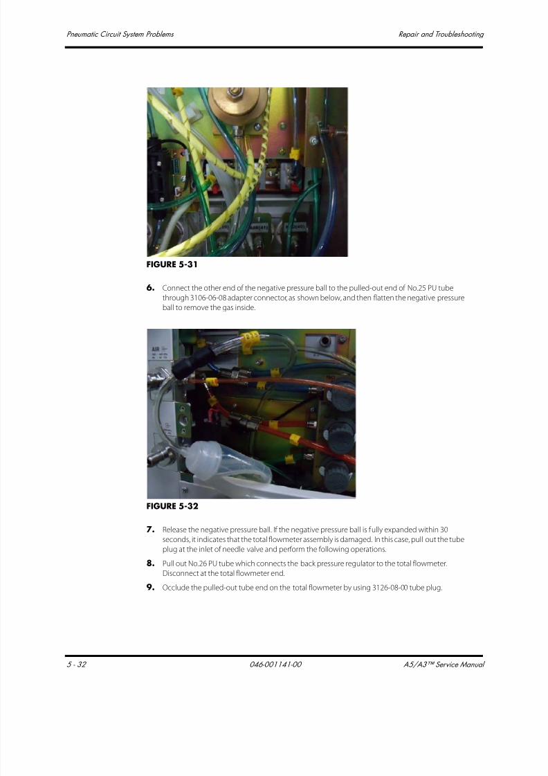
7/21/2019 a5 a3 Service Manual 2013
http://slidepdf.com/reader/full/a5-a3-service-manual-2013 273/399
Pneumatic Circuit System Problems Repair and Troubleshooting
5 - 32 046-001141-00 A5/A3™ Service Manual
FIGURE 5-31
6. Connect the other end of the negative pressure ball to the pulled-out end of No.25 PU tube
through 3106-06-08 adapter connector, as shown below, and then flatten the negative pressure
ball to remove the gas inside.
FIGURE 5-32
7. Release the negative pressure ball. If the negative pressure ball is fully expanded within 30
seconds, it indicates that the total flowmeter assembly is damaged. In this case, pull out the tube
plug at the inlet of needle valve and perform the following operations.
8. Pull out No.26 PU tube which connects the back pressure regulator to the total flowmeter.
Disconnect at the total flowmeter end.
9. Occlude the pulled-out tube end on the total flowmeter by using 3126-08-00 tube plug.

7/21/2019 a5 a3 Service Manual 2013
http://slidepdf.com/reader/full/a5-a3-service-manual-2013 274/399
A5/A3™ Service Manual 046-001141-00 5 - 33
Repair and Troubleshooting Pneumatic Circuit System Problems
FIGURE 5-33
10. Compress the negative pressure ball still connected to tube 25 to bleed the air inside.
FIGURE 5-34
11. Release the negative pressure ball. If the negative pressure ball is fully expanded within 30seconds, it indicates that the total flowmeter leaks.
12. Re-connect tube 25. Disconnect tube 58 and pull out its end connecting the back pressure
valve. Disconnect tube 26 and pull out its end connecting the total flowmeter.
13. Occlude the pulled-out tube end on the back pressure regulator by using one 3126-08-00 tube
plug and connect the negative pressure ball to the pulled-out end of No.26 PU tube through
3106-06-08 adapter connector.

7/21/2019 a5 a3 Service Manual 2013
http://slidepdf.com/reader/full/a5-a3-service-manual-2013 275/399
Pneumatic Circuit System Problems Repair and Troubleshooting
5 - 34 046-001141-00 A5/A3™ Service Manual
FIGURE 5-35
14. Compress the negative pressure ball to bleed the air inside.
FIGURE 5-36
15. Release the negative pressure ball. If the negative pressure ball is fully expanded within 30
seconds, it indicates that the back pressure regulator leaks.
16. Pull out No.27, 28 and 29 PU tubes which connect the flow sensor to the gas mixer. Disconnectat the gas mixer end.
17. Occlude the pulled-out tube end on the gas mixer by using three 3126-06-00 tube plugs.
18. Disconnect tube 58 and plug out its end connecting the back pressure valve. Connect the
negative pressure ball to the pulled-out end of tube 58 through “3106-06-08 adapter
connector”.
19. Flatten the negative pressure ball to remove the gas inside.

7/21/2019 a5 a3 Service Manual 2013
http://slidepdf.com/reader/full/a5-a3-service-manual-2013 276/399
A5/A3™ Service Manual 046-001141-00 5 - 35
Repair and Troubleshooting Pneumatic Circuit System Problems
FIGURE 5-37
20. Release the negative pressure ball. If the negative pressure ball is fully expanded within 30
seconds, it indicates that the gas mixer leaks.
21. For N2O branch, disconnect tube 32 and pull out its end connecting the sensor (disconnect
tube 31 for AIR branch and tube 78 for O2 branch.
22. Occlude the pulled-out tube end on the f low sensor by using 3126-06-00 tube plug.
23. For N2O branch, disconnect tube 27, pull out its end connecting gas mixer and connect it to the
gas inlet of the negative pressure ball through “3106-06-00 adapter connector” (disconnect tube
28 for AIR branch and tube 29for O2 branch). Compress the negative pressure ball to bleed the
gas inside.
FIGURE 5-38
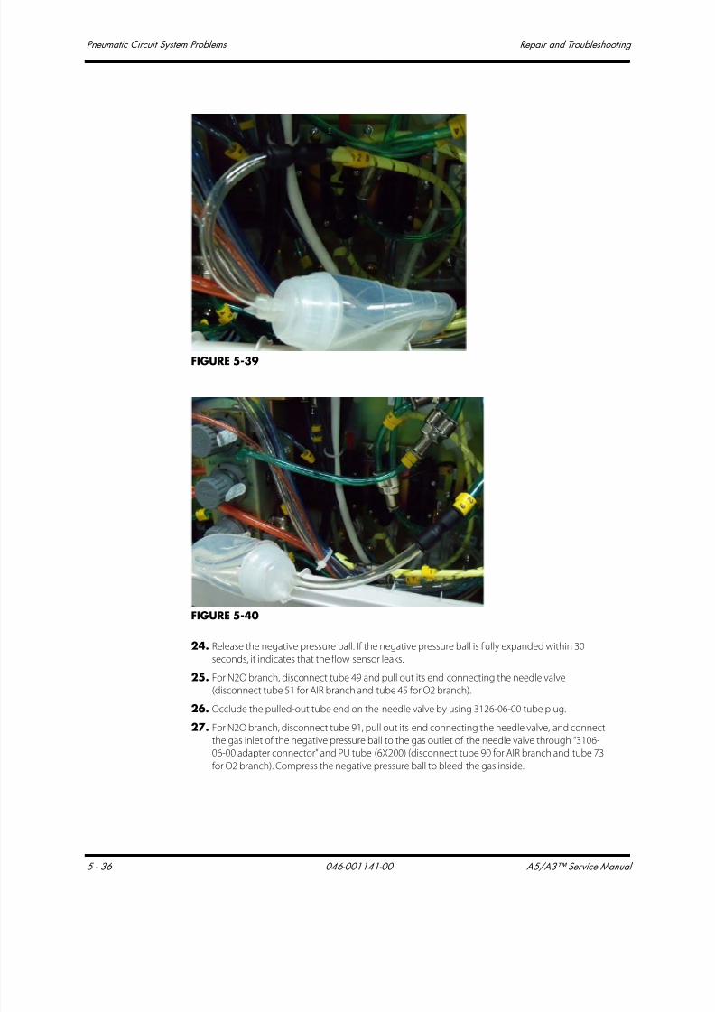
7/21/2019 a5 a3 Service Manual 2013
http://slidepdf.com/reader/full/a5-a3-service-manual-2013 277/399
Pneumatic Circuit System Problems Repair and Troubleshooting
5 - 36 046-001141-00 A5/A3™ Service Manual
FIGURE 5-39
FIGURE 5-40
24. Release the negative pressure ball. If the negative pressure ball is fully expanded within 30
seconds, it indicates that the flow sensor leaks.
25. For N2O branch, disconnect tube 49 and pull out its end connecting the needle valve
(disconnect tube 51 for AIR branch and tube 45 for O2 branch).
26. Occlude the pulled-out tube end on the needle valve by using 3126-06-00 tube plug.
27. For N2O branch, disconnect tube 91, pull out its end connecting the needle valve, and connect
the gas inlet of the negative pressure ball to the gas outlet of the needle valve through “3106-
06-00 adapter connector” and PU tube (6X200) (disconnect tube 90 for AIR branch and tube 73
for O2 branch). Compress the negative pressure ball to bleed the gas inside.

7/21/2019 a5 a3 Service Manual 2013
http://slidepdf.com/reader/full/a5-a3-service-manual-2013 278/399
A5/A3™ Service Manual 046-001141-00 5 - 37
Repair and Troubleshooting Pneumatic Circuit System Problems
FIGURE 5-41
FIGURE 5-42
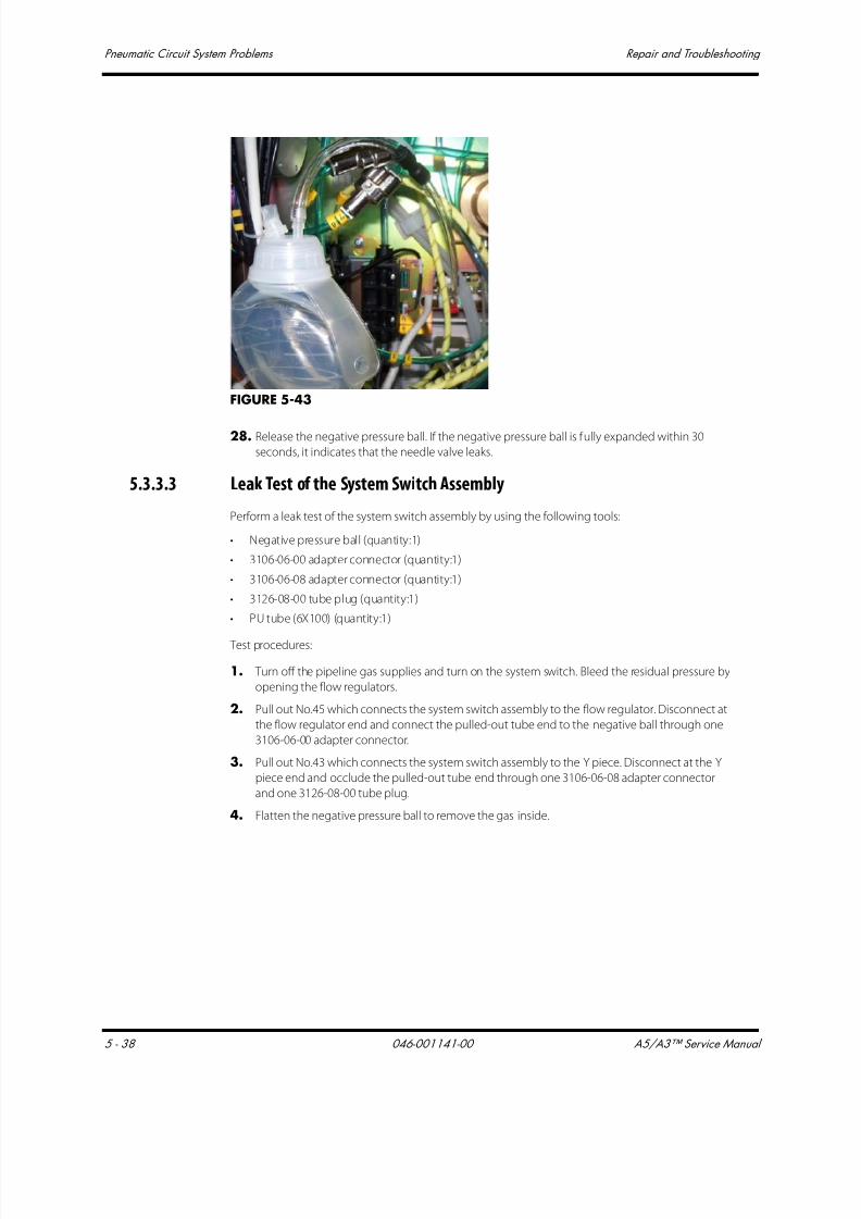
7/21/2019 a5 a3 Service Manual 2013
http://slidepdf.com/reader/full/a5-a3-service-manual-2013 279/399
Pneumatic Circuit System Problems Repair and Troubleshooting
5 - 38 046-001141-00 A5/A3™ Service Manual
FIGURE 5-43
28. Release the negative pressure ball. If the negative pressure ball is fully expanded within 30
seconds, it indicates that the needle valve leaks.
5.3.3.3 Leak Test of the System Switch Assembly
Perform a leak test of the system switch assembly by using the following tools:
• Negative pressure ball (quantity:1)
• 3106-06-00 adapter connector (quantity:1)
• 3106-06-08 adapter connector (quantity:1)
• 3126-08-00 tube plug (quantity:1)
• PU tube (6X100) (quantity:1)
Test procedures:
1. Turn off the pipeline gas supplies and turn on the system switch. Bleed the residual pressure by
opening the flow regulators.
2. Pull out No.45 which connects the system switch assembly to the flow regulator. Disconnect at
the flow regulator end and connect the pulled-out tube end to the negative ball through one
3106-06-00 adapter connector.
3. Pull out No.43 which connects the system switch assembly to the Y piece. Disconnect at the Y
piece end and occlude the pulled-out tube end through one 3106-06-08 adapter connector
and one 3126-08-00 tube plug.
4. Flatten the negative pressure ball to remove the gas inside.

7/21/2019 a5 a3 Service Manual 2013
http://slidepdf.com/reader/full/a5-a3-service-manual-2013 280/399
A5/A3™ Service Manual 046-001141-00 5 - 39
Repair and Troubleshooting Pneumatic Circuit System Problems
FIGURE 5-44
5. Release the negative pressure ball. If the negative pressure ball is fully expanded within 30seconds, it indicates that tube connected with the system switch assembly is damaged.
6. Turn off the system switch.
7. Pull out the 3126-08-00 tube plug which was used to occlude tube No.43 before.
8. Flatten the negative pressure ball to remove the gas inside.
FIGURE 5-45
9. Release the negative pressure ball. If the negative pressure ball is fully expanded within 30
seconds during one of the two tests, it indicates that the system switch assembly is damaged.

7/21/2019 a5 a3 Service Manual 2013
http://slidepdf.com/reader/full/a5-a3-service-manual-2013 281/399
Pneumatic Circuit System Problems Repair and Troubleshooting
5 - 40 046-001141-00 A5/A3™ Service Manual
5.3.3.4 Leak Test of the Oxygen Ratio Controller (ORC)
Perform a leak test of the ORC assembly by using the following tools:
• Negative pressure ball (quantity:1)
• 3106-06-00 adapter connector (quantity:1)• 3126-06-00 tube plug (quantity:2)
• 3126-04-00 tube plug (quantity:1)
• PU tube (6X100) (quantity:1)
Test procedures:
1. Disconnect tube 3 and pull out the end of the tube which connects to the Y piece. Occlude the
pulled-out end with “3106-06-00 adapter connector and 3126-06-00 tube plug.
2. Disconnect tube 46 and pull out the end of the tube which connects to the Y piece. Connect
the pulled- out end to the negative pressure ball directly.
3. Flatten the negative pressure ball to remove the gas inside.
FIGURE 5-46
4. Release the negative pressure ball. If the negative pressure ball is fully expanded within 30
seconds, it indicates that the Oxygen Ratio Controller is damaged. Handle this problem as
described in the troubleshooting table. If not, continue the following test.
5. Re-connect the tube.
6. Disconnect tubes 48, 49, and 32. Pull out the tube ends which connect the ORC. Occlude the
pulled-out ends with two 3126-06-00 tube plugs and one 3126-04-00 tube plug. Disconnect
tube 30. The end of the tube which connects the ORC is not pulled out but the other end is
pulled out and is connected to the negative pressure ball through “3106-06-00 adapterconnector”.
No. 33 PU Tube
No. 46 PU Tube

7/21/2019 a5 a3 Service Manual 2013
http://slidepdf.com/reader/full/a5-a3-service-manual-2013 282/399
A5/A3™ Service Manual 046-001141-00 5 - 41
Repair and Troubleshooting Pneumatic Circuit System Problems
FIGURE 5-47
FIGURE 5-48
7. Flatten the negative pressure ball to remove the gas inside.
8. Release the negative pressure ball. If the negative pressure ball is fully expanded within 30
seconds, it indicates that the Oxygen Ratio Controller is damaged. Handle this problem as
described in the troubleshooting table.
5.3.3.5 Leak Test of the Vaporizer Manifold Assembly
Perform a leak test of the vaporizer manifold assembly by using the following tools:
• Negative pressure ball (quantity:1)
• 3106-06-08 adapter connector (quantity:1)
• 3126-06-00 tube plug (quantity:1)
• PU tube (6X100) (quantity:1)
• PU tube (8X200) (quantity:1)
• Vaporizer manifold test fixture (quantity:1)

7/21/2019 a5 a3 Service Manual 2013
http://slidepdf.com/reader/full/a5-a3-service-manual-2013 283/399
Pneumatic Circuit System Problems Repair and Troubleshooting
5 - 42 046-001141-00 A5/A3™ Service Manual
Test procedures:
1. Turn off the system switch.
2. Remove the vaporizer.
FIGURE 5-49
3. Pull out No.25 PU tube which connects the total flowmeter to the vaporizer manifold assembly.
Disconnect at the vaporizer manifold end and occlude it with 3126-08-00 tube plug
4. Pull out No.53 PU tube which connects the vaporizer manifold assembly to the CGO assembly.
The end of the tube which connects the vaporizer manifold assembly is pulled out, and
connected with the negative ball through one 3106-06-08 adapter connector
5. Flatten the negative pressure ball to remove the gas inside.
FIGURE 5-50
6. Release the negative pressure ball. If the negative pressure ball is fully expanded within 30s, it
indicates that the rubber plain washers or its upper surface contacted mechanical surface are
damaged. Handle this problem as described in the troubleshooting table. If not, continue the
following tests.
7. Remove the seal ring, and mount the vaporizer manifold test fixture onto the connector of the
vaporizer manifold assembly (remove the seal between the connector and the vaporizer when
mounting the test fixture)

7/21/2019 a5 a3 Service Manual 2013
http://slidepdf.com/reader/full/a5-a3-service-manual-2013 284/399
A5/A3™ Service Manual 046-001141-00 5 - 43
Repair and Troubleshooting Pneumatic Circuit System Problems
FIGURE 5-51
8. Repeat step 5 and step 6 every time when the vaporizer manifold test fixture is transferred to thenext position. Once the negative pressure ball is fully expanded within 30s, it indicates that the
rubber plain washers or its lower surface contacted mechanical surface are damaged. Handle
this problem as described in the troubleshooting table. If the four tests are all past, then
continue the following tests.
9. Put the seal ring back, mount the vaporizer and turn it on.
FIGURE 5-52
10. Repeat step 5 and step 6 every time when the vaporizer manifold test fixture is transferred to the
next position. Once the negative pressure ball is fully expanded within 30s, it indicates that the
seal rings are damaged. If the two tests are both past, then the vaporizer manifold assembly and
the four seal rings are OK.
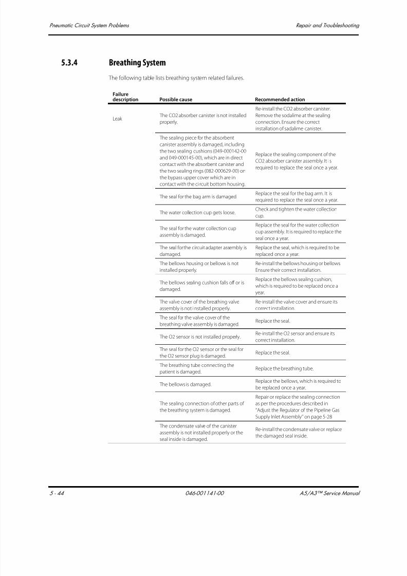
7/21/2019 a5 a3 Service Manual 2013
http://slidepdf.com/reader/full/a5-a3-service-manual-2013 285/399
Pneumatic Circuit System Problems Repair and Troubleshooting
5 - 44 046-001141-00 A5/A3™ Service Manual
5.3.4 Breathing System
The following table lists breathing system related failures.
Failure
description Possible cause Recommended action
Leak The CO2 absorber canister is not installed
properly.
Re-install the CO2 absorber canister.
Remove the sodalime at the sealing
connection. Ensure the correct
installation of sadalime canister.
The sealing piece for the absorbent
canister assembly is damaged, including
the two sealing cushions (049-000142-00
and 049-000145-00), which are in direct
contact with the absorbent canister and
the two sealing rings (082-000629-00) on
the bypass upper cover which are in
contact with the ci rcuit bottom housing.
Replace the sealing component of the
CO2 absorber canister assembly. It i s
required to replace the seal once a year.
The seal for the bag arm is damaged.Replace the seal for the bag arm. It is
required to replace the seal once a year.
The water collection cup gets loose.Check and tighten the water collection
cup.
The seal for the water collection cup
assembly is damaged.
Replace the seal for the water collection
cup assembly. It is required to replace the
seal once a year.
The seal for the circuit adapter assembly is
damaged.
Replace the seal, which is required to be
replaced once a year.
The bellows housing or bellows is not
installed properly.
Re-install the bellows housing or bellows.
Ensure their correct installation.
The bellows sealing cushion falls off or is
damaged.
Replace the bellows sealing cushion,
which is required to be replaced once a
year.
The valve cover of the breathing valveassembly is not installed properly.
Re-install the valve cover and ensure itscorrect installation.
The seal for the valve cover of the
breathing valve assembly is damaged.Replace the seal.
The O2 sensor is not installed properly.Re-install the O2 sensor and ensure its
correct installation.
The seal for the O2 sensor or the seal for
the O2 sensor plug is damaged.Replace the seal.
The breathing tube connecting the
patient is damaged.Replace the breathing tube.
The bellows is damaged.Replace the bellows, which is required to
be replaced once a year.
The sealing connection of other parts ofthe breathing system is damaged.
Repair or replace the sealing connection
as per the procedures described in‘‘Adjust the Regulator of the Pipeline Gas
Supply Inlet Assembly’’ on page 5-28
The condensate valve of the canister
assembly is not installed properly or the
seal inside is damaged.
Re-install the condensate valve or replace
the damaged seal inside.

7/21/2019 a5 a3 Service Manual 2013
http://slidepdf.com/reader/full/a5-a3-service-manual-2013 286/399
A5/A3™ Service Manual 046-001141-00 5 - 45
Repair and Troubleshooting Pneumatic Circuit System Problems
5.3.4.1 Leak Test of Flow Sensor Pressure Sampling Pipeline
If the flow waveform is displayed irregularly, the flow sensor pressure sampling pipeline may be leaky.
Perform the leak test by using the following tools:
• Anesthesia machine calibration device (quantity:1)
• Flow sensor pressure sampling pipeline test fixture (quantity:1)
• Circuit adapter test fixture (quantity:1)
• Injector (quantity:1)
• Ø6 silicone tube (quantity:3)• Y piece (quantity:1)
Test procedures:
O2 concentration
measurement fails
or has greatdeviations.
There is water built up on the
measurement surface of O2 sensor.
Remove the built-up water and allow the
O2 sensor to air dry.
The O2 sensor is not calibrated. Calibrate the O2 sensor as per section4.3.1 O2 Sensor Calibration.
The O2 sensor is damaged. Replace the O2 sensor.
The airway
pressure gauge
shows inaccurate
reading or its
pointer cannot
move.
The airway pressure gauge is damaged. Replace the airway pressure gauge.
The flow wave is
displayed
irregularly.
The flow sensor assembly is not installed
properly.Re-install the flow sensor assembly.
There is water built up inside the flow
sensor assembly.
Remove the flow sensor assembly and
clear its inside water build-up.
The membrane of the flow sensor
assembly is distorted, dirty or its inside
resistance changes. Zero drift occurs to
the pressure sensor of the fresh flow
sensor board.
Enter the service mode and calibrate the
flow sensor as per the procedures
described in ‘‘If measurement deviations
are not corrected after multiple flow
sensor calibrations, the user is
recommended to replace the flow sensor
and then perform calibration. If the
problem persists, factory maintenance is
necessary.’’ on page 4-17.
The flow sensor is damaged. Replace the flow sensor assembly.
The pressure sensor on the fresh flow
sensor board is defective.Replace the fresh flow sensor board.
The flow sensor pressure sampling
pipeline leaks.
Repair the flow sensor pressure sampling
pipeline after checking as per the
procedures described in “Leak Test of
Flow Sensor Pressure Sampling Pipeline”on page 5-45.
Failuredescription Possible cause Recommended action
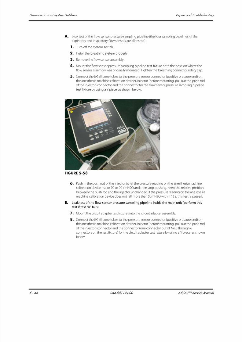
7/21/2019 a5 a3 Service Manual 2013
http://slidepdf.com/reader/full/a5-a3-service-manual-2013 287/399
Pneumatic Circuit System Problems Repair and Troubleshooting
5 - 46 046-001141-00 A5/A3™ Service Manual
A. Leak test of the flow sensor pressure sampling pipeline (the four sampling pipelines of the
expiratory and inspiratory flow sensors are all tested)
1. Turn off the system switch.
2. Install the breathing system properly.
3. Remove the flow sensor assembly.
4. Mount the flow sensor pressure sampling pipeline test fixture onto the position where the
flow sensor assembly was originally mounted. Tighten the breathing connector rotary cap.
5. Connect the Ø6 silicone tubes to the pressure sensor connector (positive pressure end) on
the anesthesia machine calibration device), injector (before mounting, pull out the push rod
of the injector) connector and the connector for the flow sensor pressure sampling pipeline
test fixture by using a Y piece, as shown below.
FIGURE 5-53
6. Push in the push rod of the injector to let the pressure reading on the anesthesia machine
calibration device rise to 70 to 90 cmH2O and then stop pushing. Keep the relative position
between the push rod and the injector unchanged. If the pressure reading on the anesthesia
machine calibration device does not fall more than 5cmH2O within 15 s, this test is passed.
B. Leak test of the flow sensor pressure sampling pipeline inside the main unit (perform this
test if test “A” fails)
7. Mount the circuit adapter test fixture onto the circuit adapter assembly.
8. Connect the Ø6 silicone tubes to the pressure sensor connector (positive pressure end) on
the anesthesia machine calibration device), injector (before mounting, pull out the push rod
of the injector) connector and the connector (one connector out of No.3 through 6
connectors on the test fixture) for the circuit adapter test fixture by using a Y piece, as shown
below.

7/21/2019 a5 a3 Service Manual 2013
http://slidepdf.com/reader/full/a5-a3-service-manual-2013 288/399
A5/A3™ Service Manual 046-001141-00 5 - 47
Repair and Troubleshooting Pneumatic Circuit System Problems
FIGURE 5-54
9. Push in the push rod of the injector to let the pressure reading on the anesthesia machine
calibration device rise to 70 to 90 cmH2O and then stop pushing. Keep the relative position
between the push rod and the injector unchanged. If the pressure reading on the anesthesia
machine calibration device does not fall more than 5cmH2O within 15s, this test is passed.
If test “A” is failed and “B” passed, it indicates that the flow sensor pressure sampling pipeline on the
breathing system is damaged. In this case, replace the breathing system. If both tests “A” and “B” are
failed, check the sampling lines and connectors inside the main unit, seals and solenoid valve of the
circuit adapter assembly until test “B” is passed. Then perform test “A”. If test “A” is still failed, it
indicates the flow sensor pressure sampling pipeline on the breathing system is damaged. In this
case, replace the breathing system.
5.3.4.2 Leak Test of Low-pressure Pneumatic Circuit System
After making sure that the flow sensor pressure sampling pipeline is not leaky, perform leak tests of
the low-pressure pneumatic circuit system as shown in the following figures.
FIGURE 5-55 System Leak Test
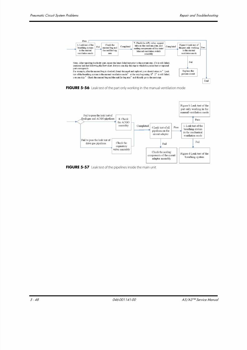
7/21/2019 a5 a3 Service Manual 2013
http://slidepdf.com/reader/full/a5-a3-service-manual-2013 289/399
Pneumatic Circuit System Problems Repair and Troubleshooting
5 - 48 046-001141-00 A5/A3™ Service Manual
FIGURE 5-56 Leak test of the part only working in the manual ventilation mode
FIGURE 5-57 Leak test of the pipelines inside the main unit
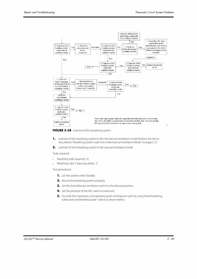
7/21/2019 a5 a3 Service Manual 2013
http://slidepdf.com/reader/full/a5-a3-service-manual-2013 290/399
A5/A3™ Service Manual 046-001141-00 5 - 49
Repair and Troubleshooting Pneumatic Circuit System Problems
FIGURE 5-58 Leak test of the breathing system
1. Leak test of the breathing system in the mechanical ventilation mode Perform the test as
described in‘‘Breathing System Leak Test in Mechanical Ventilation Mode’’ on page 2-21.
2. Leak test of the breathing system in the manual ventilation mode
Tools required:
• Breathing tube (quantity: 3)
• Breathing tube Y piece (quantity: 1)
Test procedures:
1. Let the system enter Standby.
2. Mount the breathing system properly.
3. Set the Auto/Manual ventilation switch to the Manual position.
4. Set the pressure of the APL valve to maximum.
5. Occlude the inspiratory and expiratory ports and bag arm port by using three breathingtubes and one breathing tube Y piece as shown below.

7/21/2019 a5 a3 Service Manual 2013
http://slidepdf.com/reader/full/a5-a3-service-manual-2013 291/399
Pneumatic Circuit System Problems Repair and Troubleshooting
5 - 50 046-001141-00 A5/A3™ Service Manual
FIGURE 5-59
6. Turn on the O2 flow regulator and adjust O2 flow to 0.2L/min,
7. Push the O2 flush button to let the reading on the Paw pressure gauge rise to 30cmH2O.
8. Stop O2 flushing. If the reading on the Paw pressure gauge falls under 30cmH2O, this test is
failed.
9. If the reading on the Paw pressure gauge rises rapidly, to prevent defective APL valve from
damaging the Paw pressure gauge, note to turn off the O2 flow regulator timely to prevent
the over range of the Paw pressure gauge (The test which involves O2 flow regulator turned
off due to this reason is considered to be passed).
3. Check the bellows housing and the Manual position of the Auto/Manual ventilation switch
Tools required:
• Anesthesia machine calibration device (quantity: 1)
• Circuit adapter test fixture (quantity: 1)
• Injector (quantity: 1)
• Ø6 silicone tube (quantity: 2)
• PU tube (6X300) (quantity: 1)
• Y piece (quantity: 1)
Test procedures:
1. Remove the bellows.
2. Mount the bellows housing properly.
3. Set the Auto/Manual ventilation switch to the Manual position
4. Remove the breathing system.
5. Mount the circuit adapter test fixture onto the breathing system.
6. Connect the Ø6 silicone tubes and PU tube (6X300) to the injector connector, pressure
sensor (of the anesthesia machine calibration device) connector (positive pressure end), and
No.2 connector to which drive gas corresponds on the circuit adapter test fixture by using a Y
piece, as shown below.
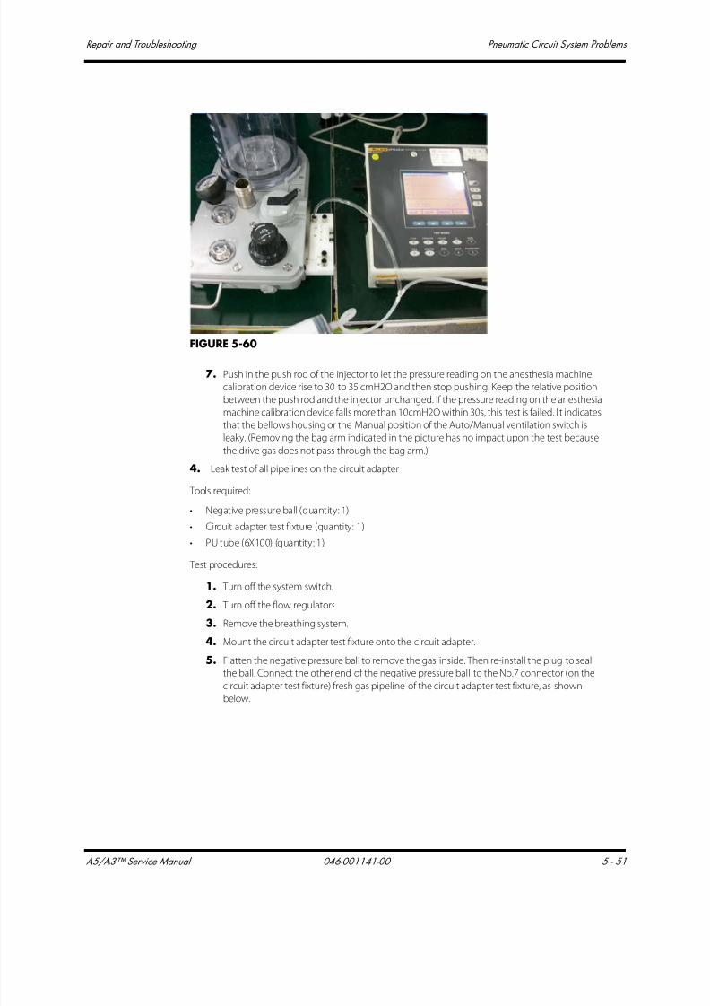
7/21/2019 a5 a3 Service Manual 2013
http://slidepdf.com/reader/full/a5-a3-service-manual-2013 292/399
A5/A3™ Service Manual 046-001141-00 5 - 51
Repair and Troubleshooting Pneumatic Circuit System Problems
FIGURE 5-60
7. Push in the push rod of the injector to let the pressure reading on the anesthesia machine
calibration device rise to 30 to 35 cmH2O and then stop pushing. Keep the relative position
between the push rod and the injector unchanged. If the pressure reading on the anesthesia
machine calibration device falls more than 10cmH2O within 30s, this test is failed. I t indicates
that the bellows housing or the Manual position of the Auto/Manual ventilation switch is
leaky. (Removing the bag arm indicated in the picture has no impact upon the test because
the drive gas does not pass through the bag arm.)
4. Leak test of all pipelines on the circuit adapter
Tools required:
• Negative pressure ball (quantity: 1)
• Circuit adapter test fixture (quantity: 1)• PU tube (6X100) (quantity: 1)
Test procedures:
1. Turn off the system switch.
2. Turn off the flow regulators.
3. Remove the breathing system.
4. Mount the circuit adapter test fixture onto the circuit adapter.
5. Flatten the negative pressure ball to remove the gas inside. Then re-install the plug to seal
the ball. Connect the other end of the negative pressure ball to the No.7 connector (on the
circuit adapter test fixture) fresh gas pipeline of the circuit adapter test fixture, as shown
below.

7/21/2019 a5 a3 Service Manual 2013
http://slidepdf.com/reader/full/a5-a3-service-manual-2013 293/399
Pneumatic Circuit System Problems Repair and Troubleshooting
5 - 52 046-001141-00 A5/A3™ Service Manual
FIGURE 5-61
6. Release the negative pressure ball. If the negative pressure ball is fully expanded within 30
seconds, it indicates that the test of fresh gas pipeline has failed. Locate the leak inside the
main unit as per the method described in “Anesthetic Gas Delivery System” on page 5-29..
7. Turn on the system switch and let the systems enter Standby.
8. Select [Setup] >[Service] > [Diagnostic Tests] > [Valves] to set the A/D value of the PEEP valve
to make PEEP exceed 50 cmH2O. Set the A/D value of the inspiratory valve to “0” to produce
0 L/min of flow. Set PEEP safety valve to ON, as shown below.

7/21/2019 a5 a3 Service Manual 2013
http://slidepdf.com/reader/full/a5-a3-service-manual-2013 294/399
A5/A3™ Service Manual 046-001141-00 5 - 53
Repair and Troubleshooting Pneumatic Circuit System Problems
FIGURE 5-62
9. Flatten the negative pressure ball to remove the gas inside. Then re-install the plug to seal
the ball. Connect the other end of the negative pressure ball to No.1 connector to which
drive gas pipeline of the circuit adapter test fixture corresponds, as shown below.
10.Release the negative pressure ball. If the negative pressure ball is fully expanded within 30
seconds, it indicates that the test of the drive gas pipeline has failed. Check the expiratory
valve assembly and the drive gas related pipeline inside the main unit.
5. Check the absorb canister assembly
Tools required:
• VT PLUS (quantity: 1)
• Lucer adapter connector (quantity: 1)• Injector (quantity: 1)
• Ø6 silicone tube (quantity: 2)
• PU tube (6X300) (quantity: 1)
• Breathing tube (quantity: 3)
• Y piece (quantity: 1)
• Breathing tube Y piece (quantity: 1)
• Breathing tube adapter connector (quantity: 1)
• T-shaped Allen wrench (quantity: 1)

7/21/2019 a5 a3 Service Manual 2013
http://slidepdf.com/reader/full/a5-a3-service-manual-2013 295/399
Pneumatic Circuit System Problems Repair and Troubleshooting
5 - 54 046-001141-00 A5/A3™ Service Manual
Test procedures:
1. Turn off the system switch.
2. Disassemble the pre-pak assembly and remove the patient circuit.
3. Mount the pre-pak assembly.
4. Remove the seals on the two connectors of the absorb canister assembly. Connect the two
connectors of the lifting device by using two breathing tubes and one breathing tube Y
piece. The other end of the breathing tube Y piece is connected to the breathing tube
adapter connector through another breathing tube. Connect the injector connector,
pressure sensor (of the anesthesia machine calibration device) connector (positive pressure
end), and the breathing tube adapter connector to a Y piece, as shown below.
5. Push in the push rod of the injector to cause the pressure reading on the anesthesia machine
calibration device rise to 30 to 35 cmH2O and then stop pushing. Keep the relative position
between the push rod and the injector unchanged. If the pressure reading on the anesthesia
machine calibration device falls more than 10cmH2O within 30 seconds, it indicates that
absorb canister assembly are leaky. The test is failed. This step is required when the absorbent
canister assembly is in bypass on or bypass off status.
FIGURE 5-63 Lucer adapter connector
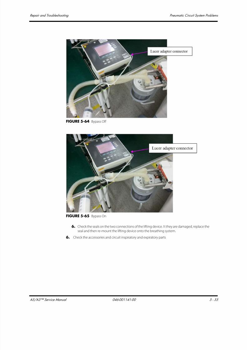
7/21/2019 a5 a3 Service Manual 2013
http://slidepdf.com/reader/full/a5-a3-service-manual-2013 296/399
A5/A3™ Service Manual 046-001141-00 5 - 55
Repair and Troubleshooting Pneumatic Circuit System Problems
FIGURE 5-64 Bypass Off
FIGURE 5-65 Bypass On
6. Check the seals on the two connections of the lifting device. I t they are damaged, replace the
seal and then re-mount the lifting device onto the breathing system.
6. Check the accessories and circuit inspiratory and expiratory parts

7/21/2019 a5 a3 Service Manual 2013
http://slidepdf.com/reader/full/a5-a3-service-manual-2013 297/399
Pneumatic Circuit System Problems Repair and Troubleshooting
5 - 56 046-001141-00 A5/A3™ Service Manual
Test procedures:
1. Turn off the system switch.
2. Check the manual bag and replace if damaged.
3. Check the breathing tube and replace if damaged.
4. Remove the Paw pressure gauge. Check the seal and replace if found damaged.
5. Remove the water collection cup. Check the seal and replace if found damaged.
6. Remove the O2 sensor (if there is no O2 sensor, remove the plug where the O2 sensor should
be installed). Check the seal and replace if damaged.
7. Remove the check valve dome. Check the seal and replace if damaged.
8. Remove the bag arm. Check the seal and replace if damaged.
9. Remove the prepak assembly as shown below. Check the seal and replace if damaged.
FIGURE 5-66
7. Check the APL valve, support tube on the median plate, and sealing components of the Auto/
Manual ventilation switch assembly
The test requires a T-shaped Allen wrench.
Test procedures:
1. Turn off the system switch.
2. Remove the APL valve. Check all seals and replace the defective ones.
3. Remove the support tube on the median plate. Check the seals and replace the defective
ones.
4. Remove the Auto/Manual ventilation switch. Check the seals and replace the defective ones.
8. Check the CGO assembly
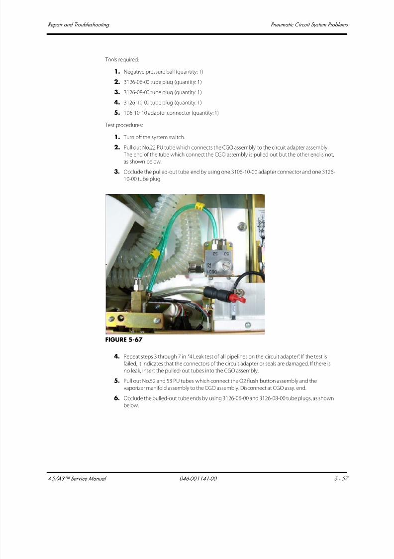
7/21/2019 a5 a3 Service Manual 2013
http://slidepdf.com/reader/full/a5-a3-service-manual-2013 298/399
A5/A3™ Service Manual 046-001141-00 5 - 57
Repair and Troubleshooting Pneumatic Circuit System Problems
Tools required:
1. Negative pressure ball (quantity: 1)
2. 3126-06-00 tube plug (quantity: 1)
3. 3126-08-00 tube plug (quantity: 1)
4. 3126-10-00 tube plug (quantity: 1)
5. 106-10-10 adapter connector (quantity: 1)
Test procedures:
1. Turn off the system switch.
2. Pull out No.22 PU tube which connects the CGO assembly to the circuit adapter assembly.
The end of the tube which connect the CGO assembly is pulled out but the other end is not,
as shown below.
3. Occlude the pulled-out tube end by using one 3106-10-00 adapter connector and one 3126-
10-00 tube plug.
FIGURE 5-67
4. Repeat steps 3 through 7 in “4 Leak test of all pipelines on the circuit adapter”. If the test is
failed, it indicates that the connectors of the circuit adapter or seals are damaged. If there is
no leak, insert the pulled-out tubes into the CGO assembly.
5. Pull out No.52 and 53 PU tubes which connect the O2 flush button assembly and the
vaporizer manifold assembly to the CGO assembly. Disconnect at CGO assy. end.
6. Occlude the pulled-out tube ends by using 3126-06-00 and 3126-08-00 tube plugs, as shown
below.
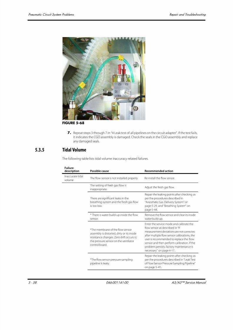
7/21/2019 a5 a3 Service Manual 2013
http://slidepdf.com/reader/full/a5-a3-service-manual-2013 299/399
Pneumatic Circuit System Problems Repair and Troubleshooting
5 - 58 046-001141-00 A5/A3™ Service Manual
FIGURE 5-68
7. Repeat steps 3 through 7 in “4 Leak test of all pipelines on the circuit adapter”. If the test fails,
it indicates the CGO assembly is damaged. Check the seals in the CGO assembly and replace
any damaged seals.
5.3.5 Tidal Volume
The following table lists tidal volume inaccuracy related failures.
Failuredescription Possible cause Recommended action
Inaccurate tidal
volume The flow sensor is not installed properly. Re-install the flow sensor.
The setting of fresh gas flow is
inappropriate.Adjust the fresh gas flow.
There are significant leaks in the
breathing system and the fresh gas flow
is too low.
Repair the leaking points after checking as
per the procedures described in
“Anesthetic Gas Delivery System” on
page 5-29. and “Breathing System” on
page 5-44.
* There is water build-up inside the flow
sensor.
Remove the flow sensor and clear its inside
water build-up.
*The membrane of the flow sensorassembly is distorted, dirty or its inside
resistance changes. Zero drift occurs to
the pressure sensor on the ventilator
control board.
Enter the service mode and calibrate the
flow sensor as described in “If
measurement deviations are not correctedafter multiple flow sensor calibrations, the
user is recommended to replace the flow
sensor and then perform calibration. If the
problem persists, factory maintenance is
necessary.” on page 4-17..
*The flow sensor pressure sampling
pipeline is leaky.
Repair the leaking points after checking as
per the procedures described in “Leak Test
of Flow Sensor Pressure Sampling Pipeline”
on page 5-45..
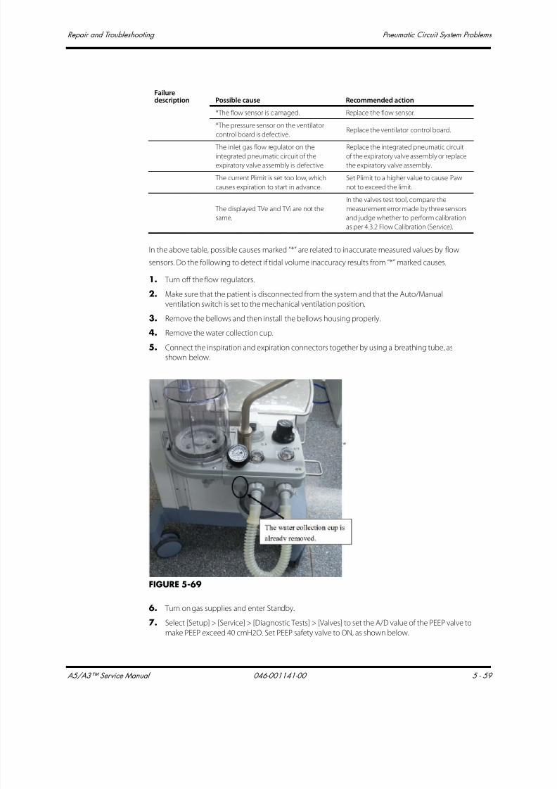
7/21/2019 a5 a3 Service Manual 2013
http://slidepdf.com/reader/full/a5-a3-service-manual-2013 300/399
A5/A3™ Service Manual 046-001141-00 5 - 59
Repair and Troubleshooting Pneumatic Circuit System Problems
In the above table, possible causes marked “*” are related to inaccurate measured values by flow
sensors. Do the following to detect if tidal volume inaccuracy results from “*” marked causes.
1. Turn off the flow regulators.
2. Make sure that the patient is disconnected from the system and that the Auto/Manual
ventilation switch is set to the mechanical ventilation position.
3. Remove the bellows and then install the bellows housing properly.
4. Remove the water collection cup.
5. Connect the inspiration and expiration connectors together by using a breathing tube, as
shown below.
FIGURE 5-69
6. Turn on gas supplies and enter Standby.
7. Select [Setup] > [Service] > [Diagnostic Tests] > [Valves] to set the A/D value of the PEEP valve to
make PEEP exceed 40 cmH2O. Set PEEP safety valve to ON, as shown below.
*The flow sensor is damaged. Replace the flow sensor.
*The pressure sensor on the ventilator
control board is defective.
Replace the ventilator control board.
The inlet gas flow regulator on the
integrated pneumatic circuit of the
expiratory valve assembly is defective.
Replace the integrated pneumatic circuit
of the expiratory valve assembly or replace
the expiratory valve assembly.
The current Plimit is set too low, which
causes expiration to start in advance.
Set Plimit to a higher value to cause Paw
not to exceed the limit.
The displayed TVe and TVi are not the
same.
In the valves test tool, compare the
measurement error made by three sensors
and judge whether to perform calibration
as per 4.3.2 Flow Calibration (Service).
Failuredescription Possible cause Recommended action

7/21/2019 a5 a3 Service Manual 2013
http://slidepdf.com/reader/full/a5-a3-service-manual-2013 301/399
Pneumatic Circuit System Problems Repair and Troubleshooting
5 - 60 046-001141-00 A5/A3™ Service Manual
FIGURE 5-70
Set the A/D value of the inspiratory valve to cause the flow of inspiratory valve to reach a certain
value. In this case, the flows measured by the ventilator flow sensor, inspiratory flow sensor, and
expiratory flow sensor should be the same. Test multiple points by setting the A/D value of the
inspiratory valve. For each point, the flows measured by the three sensors should be the same. If not,
the measured value by the flow sensor is inaccurate. Troubleshoot the possible causes marked “*” in
the above table.
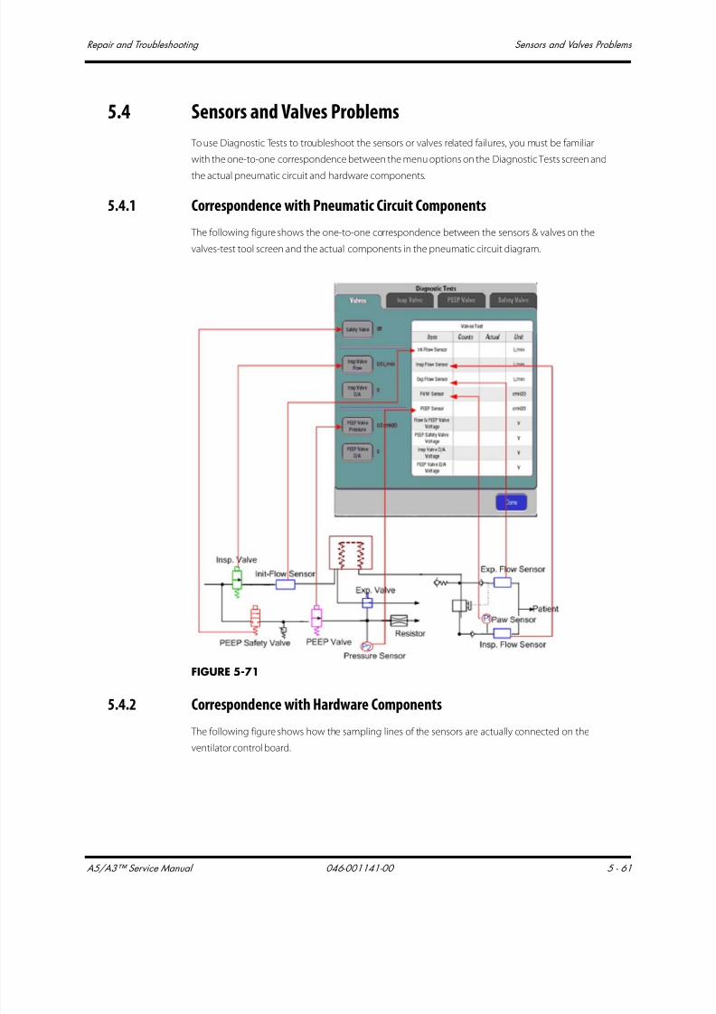
7/21/2019 a5 a3 Service Manual 2013
http://slidepdf.com/reader/full/a5-a3-service-manual-2013 302/399
A5/A3™ Service Manual 046-001141-00 5 - 61
Repair and Troubleshooting Sensors and Valves Problems
5.4 Sensors and Valves Problems
To use Diagnostic Tests to troubleshoot the sensors or valves related failures, you must be familiar
with the one-to-one correspondence between the menu options on the Diagnostic Tests screen and
the actual pneumatic circuit and hardware components.
5.4.1 Correspondence with Pneumatic Circuit Components
The following figure shows the one-to-one correspondence between the sensors & valves on the
valves-test tool screen and the actual components in the pneumatic circuit diagram.
FIGURE 5-71
5.4.2 Correspondence with Hardware Components The following figure shows how the sampling lines of the sensors are actually connected on the
ventilator control board.

7/21/2019 a5 a3 Service Manual 2013
http://slidepdf.com/reader/full/a5-a3-service-manual-2013 303/399
Sensors and Valves Problems Repair and Troubleshooting
5 - 62 046-001141-00 A5/A3™ Service Manual
FIGURE 5-72
5.4.3 Preparations before Using Diagnostic Tests
Make the following preparations before using the valves-test tool to locate the valves or sensors
related failures:
1. Connect the pneumatic circuit according to the type of sensor or valve to be checked.
Before using the Diagnostic Tests Menu: connect the tubes of the anesthesia machine following
the constant-flow connection method to check the flow sensors and inspiratory valve. For
details, refer to ‘‘If measurement deviations are not corrected after multiple flow sensor
calibrations, the user is recommended to replace the flow sensor and then perform calibration. If
the problem persists, factory maintenance is necessary.’’ on page 4-17.
2. Make sure that the supply gas pressure is within specifications.
3. When the system is in Standby, select the [Setup] shortcut key > [Service] > [Diagnostic Tests] to
access the [Diagnostic Tests] menu.
5.4.4 Zero Points of Flow & Pressure Sensors Problems
By using the [Diagnostic Tests], you can easily detect if the zero points of all the pressure and flow
sensors are within specifications.

7/21/2019 a5 a3 Service Manual 2013
http://slidepdf.com/reader/full/a5-a3-service-manual-2013 304/399
A5/A3™ Service Manual 046-001141-00 5 - 63
Repair and Troubleshooting Sensors and Valves Problems
To diagnose the zero points of the sensors:
1. Disconnect all gas supplies and make sure that the actual values of the sensors are “0”.
2. Check the A/D counts of the sensors in the valve-test tool menu, which are the zero points of
the sensors.
3. If the zero point of one sensor is outside of specifications, it indicates that the ventilator controlboard is defective. You need to replace the board.
You can also detect the zero points of the sensors by referring to 3.7.3 Check the Sensor Zero Point.
NOTE: For the normal range of sensors’ zero points, refer to “Check the Sensor
Zero Point” on page 3-18.
5.4.5 Connections and Measurement of the Flow Sensors Problems
The flow sensor has two sampling lines. Connection errors include:
• The two sampling lines are connected backward.
• One sampling line is not connected.
• Both sampling lines are not connected.
By using the Diagnostic Tests tool, you can detect if the sampling lines are connected correctly.
To diagnose the sampling line connection of the flow sensor:
1. Connect the tubes of the anesthesia machine following the constant-flow connection method.
Refer to “Preparations before Using Diagnostic Tests” on page 5-62.
2. Make sure that gas supplies are within specifications. In the [Diagnostic Tests], PEEP safety valve
to ON and the D/A value of the PEEP valve to more than “1500”, making sure that the PEEP valve
closes at above 30 cmH2O.
3. Increase the D/A value of the inspiratory valve gradually and the A/D value of the flow sensor
should also increase. With the gradual increase of gas supplied,
• If the A/D value of one sensor decreases gradually, it is possible that the two sampling linesof the sensor are connected backward.
• If the A/D value of one sensor stays unchanged, it is possible that the two sampling lines of
the sensor are broken or not connected.
• If the A/D value of one sensor nears saturation (above “4000”) quickly, it is possible that the
sampling line at the low pressure end (gas outlet end) of the sensor is not connected.
4. If sampling line connection errors are detected, re-connect all sampling lines and verify proper
connection of lines.
To diagnose the measurement error of the flow sensors:
1. After confirming that both the zero points of the sensors and the sampling line connections of
the sensors are correct, check the flow sensor accuracy:
• With the gradual increase of actual flow, the measured value of the flow sensor should alsoincrease. Otherwise, the calibration data have errors. You need to calibrate the flow sensor
again.
• Compared with the measured value of the standard flow measurement device (anesthesia
machine calibration device), the measured value of the flow sensor should be accurate.
Otherwise, the calibration data have errors. You need to calibrate the flow sensor again.
For details, refer to “Check the Flow Sensor Accuracy” on page 3-19..

7/21/2019 a5 a3 Service Manual 2013
http://slidepdf.com/reader/full/a5-a3-service-manual-2013 305/399
Sensors and Valves Problems Repair and Troubleshooting
5 - 64 046-001141-00 A5/A3™ Service Manual
5.4.6 Connections and Measurement of the Pressure Sensors Problems
The pressure sensor has one sampling line. Connection errors include:
• The sampling line is not connected.
• The sampling line is connected incorrectly.
By using the Diagnostic Tests tool, you can detect if the sampling lines are connected correctly.
To diagnose the sampling line connection of the pressure sensor: ...............................................................................
• During normal ventilation, if a sampling line connection error occurs, it is easily detected through
the Paw waveform and technical alarms. If with the increase of actual pressure, pressure
waveform data decreases and the alarm of “Paw Too Low” or “Patient Circuit Leak” occurs
simultaneously, it is possible that the sampling line of the airway pressure sensor is connected
incorrectly.
• You can enter the [Diagnostic Tests] menu to set the PEEP safety valve to ON. Gradually increase
the D/A value of the PEEP valve and observe if the A/D value of the PEEP pressure sensor also
increases gradually. If not, it further indicates that the PEEP pressure sensor may be connected
incorrectly.
To diagnose the sampling line connection of the pressure sensor in case of pressure calibration
failure:
1. Connect the tubes of the anesthesia machine just like described in ‘‘Preparations before Using
Diagnostic Tests’’ on page 5-62.
2. Make sure to mount the water collection cup again
3. Make sure that gas supplies are within specifications. In the [Diagnostic Tests] menu, set the
PEEP safety valve to ON. Set the Insp. Valve at 5 L/min.
4. Increase the D/A value of the PEEP valve gradually and the A/D value of the pressure sensor
should also increase due to the gradual increase of actual pressure,
• If the A/D value of one sensor decreases gradually, it is possible that the sampling line of the
sensor is connected incorrectly.• If the A/D value of one sensor remains unchanged, it is possible that the sampling line of the
sensor is not connected.
• The pressure of the airway pressure gauge should increase. If not, it is possible that the
airway pressure gauge is defective.
5. If sampling line connection errors are detected, re-connect the sampling lines and verify proper
connection of all lines.
To diagnose the measurement error of the flow sensors:
1. With the gradual increase of actual pressure, the measured value of the pressure sensor should
also increase. Otherwise, the calibration data have errors. You need to calibrate the pressure
sensor again.
2. Compared with the measured value of the standard pressure measurement device (anesthesiamachine calibration device), the measured value of the pressure sensor should be accurate.
Otherwise, the calibration data have errors. You need to calibrate the pressure sensor again.
For details, refer to “Check the Flow Sensor Accuracy” on page 3-19.

7/21/2019 a5 a3 Service Manual 2013
http://slidepdf.com/reader/full/a5-a3-service-manual-2013 306/399
A5/A3™ Service Manual 046-001141-00 5 - 65
Repair and Troubleshooting Sensors and Valves Problems
5.4.7 Opening State of the Inspiratory Valve Problems
By using [Diagnostic Tests], you can detect if the opening state of the inspiratory valve is correct.
1. The methods for tube connections and settings of the anesthesia machine are the same as
those for sampling line connections of the flow sensors. For details, refer to ‘‘Preparations beforeUsing Diagnostic Tests’’ on page 5-62.
2. In the [Diagnostic Tests] menu, gradually increase the D/A value of the inspiratory valve. If the
measured values of the ventilator flow sensor, inspiratory flow sensor, and expiratory flow sensor
change very little and low gas flow is felt at the connector of water collection cup, it indicates
that the inspiratory valve or the D/A on the Ventilator Control Board is defective.
3. Normally, when the D/A value of the inspiratory valve is set to “2500”, the flow measured by the
standard flow measurement device can reach 90 L/min.
4. If when the D/A value of the inspiratory valve is set to more than “4000”, the flow measured by
the standard flow measurement device fails to reach 90 L/min, flow calibration will fail. In this
case, you need to replace the expiratory valve assembly or the ventilator control board.
5. To locate if the DA on the Ventilator Control Board is defective, you can use a multimeter to
measure the output of DA on the Ventilator Control Board corresponding to the inspiratory
valve. If voltage also increases with the increase of D/A value, and voltage nears 6V when D/A
value is set to more than “4000”, it indicates that the DA on the Ventilator Control Board
corresponding to the inspiratory valve may be correct.
6. After the expiratory valve assembly or the Ventilator Control Board is replaced, you can use the
similar method to check if the problem is fixed.
5.4.8 Opening States of the PEEP Safety Valve Problems
When the PEEP safety valve is permanently OFF and the gas supplies are within specifications, the
[Drive Gas Pressure Low] is alarmed.
By using Diagnostic Tests, you can detect if the opening states of the PEEP safety valve and PEEP valve
are correct.
To diagnose the opening state of the PEEP safety valve:
1. Make sure that gas supplies are within specifications.
2. In the [Diagnostic Tests] menu, when the PEEP safety valve is switched on, a subtle click is heard.
3. Adjust the D/A value of the PEEP valve to cause the pressure measured by the PEEP pressure
sensor to exceed 0 cmH2O.
4. Switch off the PEEP safety valve. The pressure measured by the PEEP pressure sensor should
drop to 0 cmH2O immediately. Switch on the PEEP safety valve again. The measured value of the
PEEP pressure sensor rapidly restores almost the same value to that before PEEP safety valve is
switched off. During this period, gas flow and also change of gas flow when the PEEP safety
valve is switched on or off can be felt at the PEEP outlet, which helps to judge if the PEEP safety
valve can be switched on or off correctly.
5. If an error is detected, it is possible that the PEEP safety valve or the safety valve drive voltage on
the ventilator control board is defective. You can use a multimeter to measure the drive signals
on the ventilator control board corresponding to the PEEP safety valve (measurement can be
performed at the corresponding socket). When the PEEP safety valve is turned on, the drive
voltage should near 6V. When the PEEP safety valve is turned off, the drive voltage should near
0V. If these two conditions are met simultaneously, the ventilator control board is normal.
6. If the PEEP safety valve is defective, replace the expiratory valve assembly. After replacement,
you can use the similar method to check if the problem is fixed.
7/21/2019 a5 a3 Service Manual 2013
http://slidepdf.com/reader/full/a5-a3-service-manual-2013 307/399
Sensors and Valves Problems Repair and Troubleshooting
5 - 66 046-001141-00 A5/A3™ Service Manual
5.4.9 Opening State of the PEEP Valve Problems
When the PEEP valve is defective, pressure related alarms occur in mechanical ventilation modes.
By using Diagnostic Tests, you can detect if the opening states of the PEEP valve is correct.
To diagnose the opening state of the PEEP valve:
1. Make sure that gas supplies are within specifications. In the [Diagnostic Tests] menu, set the
PEEP safety valve to ON.
2. With the increase of D/A value of the PEEP valve, the measured value of the PEEP pressure
sensor (or the anesthesia machine calibration device) should also rise. Note that there is a non-
response area for the PEEP valve when the D/A value is relatively small. When the D/A value is
less than this range, the PEEP valve cannot be opened and the output is “0” continuously. When
the D/A value is greater than this range, the pressure output will increase with the increase of D/
A value. This phenomenon also exists for the inspiratory valve.
3. For subsequent diagnosis rules, refer to ‘‘Opening State of the Inspiratory Valve Problems’’ on
page 5-65.
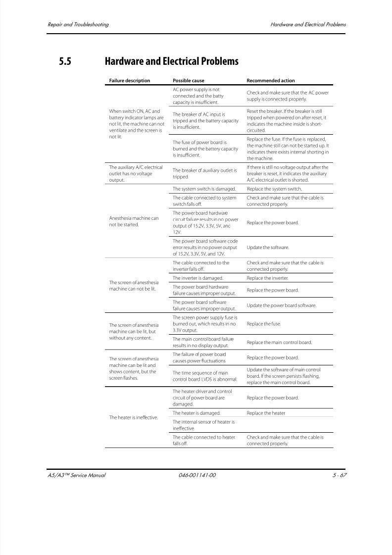
7/21/2019 a5 a3 Service Manual 2013
http://slidepdf.com/reader/full/a5-a3-service-manual-2013 308/399
A5/A3™ Service Manual 046-001141-00 5 - 67
Repair and Troubleshooting Hardware and Electrical Problems
5.5 Hardware and Electrical Problems
Failure description Possible cause Recommended action
When switch ON, AC and
battery indicator lamps are
not lit, the machine can not
ventilate and the screen is
not lit.
AC power supply is not
connected and the battycapacity is insufficient.
Check and make sure that the AC power
supply is connected properly.
The breaker of AC input is
tripped and the battery capacity
is insufficient.
Reset the breaker. If the breaker is still
tripped when powered on after reset, it
indicates the machine inside is short-
circuited.
The fuse of power board is
burned and the battery capacity
is insufficient.
Replace the fuse. If the fuse is replaced,
the machine still can not be started up. It
indicates there exists internal shorting in
the machine.
The auxiliary A/C electrical
outlet has no voltage
output.
The breaker of auxiliary outlet is
tripped.
If there is still no voltage output after the
breaker is reset, it indicates the auxiliary
A/C electrical outlet is shorted.
Anesthesia machine can
not be started.
The system switch is damaged. Replace the system switch.
The cable connected to system
switch falls off.
Check and make sure that the cable is
connected properly.
The power board hardware
circuit failure results in no power
output of 15.2V, 3.3V, 5V, and
12V.
Replace the power board.
The power board software code
error results in no power output
of 15.2V, 3.3V, 5V, and 12V.
Update the software.
The screen of anesthesia
machine can not be lit.
The cable connected to the
inverter falls off.
Check and make sure that the cable is
connected properly.
The inverter is damaged. Replace the inverter.
The power board hardware
failure causes improper output. Replace the power board.
The power board software
failure causes improper output.Update the power board software.
The screen of anesthesia
machine can be lit, but
without any content.
The screen power supply fuse is
burned out, which results in no
3.3V output.
Replace the fuse.
The main control board failure
results in no display output.Replace the main control board.
The screen of anesthesia
machine can be lit and
shows content, but the
screen flashes.
The failure of power board
causes power fluctuationsReplace the power board.
The time sequence of main
control board LVDS is abnormal.
Update the software of main control
board. If the screen persists flashing,
replace the main control board.
The heater is ineffective.
The heater driver and control
circuit of power board are
damaged.
Replace the power board.
The heater is damaged. Replace the heater.
The internal sensor of heater is
ineffective.
The cable connected to heater
falls off.
Check and make sure that the cable is
connected properly.

7/21/2019 a5 a3 Service Manual 2013
http://slidepdf.com/reader/full/a5-a3-service-manual-2013 309/399
Hardware and Electrical Problems Repair and Troubleshooting
5 - 68 046-001141-00 A5/A3™ Service Manual
The touch panel is
ineffective.
The touch panel is damaged. Replace the touch screen.
The controller of touch panel is
damaged.
The cable connected to touchpanel falls off.
Check and make sure that the cable isconnected properly.
During the operation of the
anesthesia machine,
ventilation stops all of a
sudden but the display and
buttons work normally.
The ventilator control board or
valve is damaged.
Select [Setup] > [Service] > [Diagnostic
Tests] > [Valves] Test the status of each
valve and reference power supply in the
valves-test tool window. If valve
malfunction or reference power supply
error is detected, replace the valve or
ventilator control board.
Exiting Standby fails. The ventilator control board
hardware self-test is failed.Replace the ventilator control board.
Alarm messages are
displayed on the screen but
without alarm sound.
The speaker is damaged. Replace the speaker.
The speaker cable is
disconnected
Check and make sure that the cable is
properly connected.
Network connection is
failed.
The cables connected to
the network connection
board get loose.
Properly insert the cables.
The network cable is too long.
Shorten the network cable.
Recommended cable length is
approximately 1.5 m.
The network cable is used
incorrectly.
The network cable has two linear
orderings that should be differentiated.
No gas is outputted
through the valve in
mechanical ventilation
mode.
The Auto/Manual ventilation
switch is defective.
Check the screen to see if the anesthesia
machine is in mechanical ventilation
mode and if there is an alarm triggered.
The valve cannot be opened.
1. Set tidal volume to maximum.
2. Switch between standby andmechanical statuses or between manual
and mechanical statuses repeatedly.
3. Replace the pneumatic circuit block.
Failure description Possible cause Recommended action
7/21/2019 a5 a3 Service Manual 2013
http://slidepdf.com/reader/full/a5-a3-service-manual-2013 310/399
A5/A3™ Service Manual 046-001141-00 5 - 69
Repair and Troubleshooting Software Update and Software Configuration Activation
5.6 Software Update and Software Configuration Activation
NOTE: Software upgrade may by required when replacing the CPU Board (P/N:
801-0631-00026-00), the Ventilator Control Board (P/N: 801-0631-
00027-00), the Power Board (P/N: 801-0631-00025-00) or the Fresh
Flow Sensor Board (P/N: 801-0631-00040-00).
1. Connect the Ethernet port of the PC to the Ethernet port of the A5/A3 using the Ethernet
Crossover Cable.
2. Before running Mindray Patient Monitor System Update Tool, verify that the IP address of the PC
is set to 192.168.23.1., and the Subnet mask is set to 255.255.255.0. To check and set the IP
address on the PC follow these instructions.
1. On the PC click Start, Settings and then Network Connections
2. Right click Local Area Connection and then left click Properties
3. Scroll down to Internet Protocol (TCP/IP), click on it and then click Properties
4. Click the radio button for "Use the following IP address:" Set the IP address and Subnet mask
and then click OK.

7/21/2019 a5 a3 Service Manual 2013
http://slidepdf.com/reader/full/a5-a3-service-manual-2013 311/399
Software Update and Software Configuration Activation Repair and Troubleshooting
5 - 70 046-001141-00 A5/A3™ Service Manual
FIGURE 5-73
3. Make sure that the Mindray Patient Monitor System Update Tool has been installed to the PC. If it
has not been installed then follow these steps:
1. Run the SystemUpdateToolForService.exe file (G-110-001396-00).
2. When prompted to setup a language select “English” and then select “OK”.
3. When the Welcome dialog window is displayed select “Next”.
4. When the Customer Information dialog window is displayed enter the following:
5. User Name: Manufacturing
6. Company Name: Mindray
7. Serial Number: 366-267-2667
8. Select “Next”.
9. When the Administrator password dialog window is displayed enter “datascope” as the
password and confirm it, then select “Next”.
10.When the Destination Location dialog window is displayed select “Next” to accept the
default Destination Folders.
11.When the Select Program Folders dialog window is displayed select “Next” to accept the
default Program Folder.
12.When the Install Shield Wizard dialog window is displayed select “Finish” to complete theinstallation.
4. Upgrade Software:
1. From the Desktop, run the Mindray Anesthesia Machine and Ventilator Software Upgrade
Tool 4.3 Icon. When the “Select Product Series” dialog is displayed select A Series followed by
OK. Once the System Update Tool starts perform the following to update the software:
2. Select “Select Package” from the top tool bar.
3. When the Select Package dialog is displayed select “>>>”

7/21/2019 a5 a3 Service Manual 2013
http://slidepdf.com/reader/full/a5-a3-service-manual-2013 312/399
A5/A3™ Service Manual 046-001141-00 5 - 71
Repair and Troubleshooting Software Update and Software Configuration Activation
4. When the Open dialog is displayed select down arrow “?” for Look in.
5. If changing the CPU Board (P/N: 801-0631-00026-00), the Ventilator Control Board (P/N: 801-
0631-00027-00) or Fresh Flow Sensor Board (P/N: 801-0631-00040-00), select the System
VXX.XX.XX XXXX-XX-XX.mpkg
6. If changing the Power Board (P/N: 801-0631-00025-00), select the POWER VX.X.pkg
NOTE: This only an example of a Software version / Checksum table. Check for
Technical bulletins to find the correct table for the software version you
are installing.
7. Select “Open”.
8. A dialog box will appear. Verify that for each file the Creating Time, Module, Checksum,
Version and Note are correct from the table above. If they are correct then click OK.
9. Turn on the A5/A3 unit on, wait at least ten seconds before proceeding to the next step.
10.Click “Start (Single)” on the Mind ray Anesthesia Machine and Ventilator Software Upgrade
Tool 4.0.
11. Turn off and then turn on the A5/A3 unit within one second of each other.
12.You will see that the Windows XP network icon indicate that it is connected.
FIGURE 5-74
13.While updating the software the A5/A3 will show text which explains the progress of the
software update.
14.Once the Download is complete the Mind ray Anesthesia Machine will display “succeeded”.
And Ventilator Software Upgrade Tool will display “update system successfully”.
File NameCreatingTime Module Checksum Version Note
System V01.02.00
2011-03-04.mpkg
2011-03-
04 01:56:24
BIOS 36 72 B7 0E 1.3.0.0 \
System Program 0F 77 D5 5F 1.2.0.8 AS3700
Language file \ \ \
Startup screen file \ \ \
Icons resource file \ \ \
FPGA display drive 17 69 B2 5A \ \
FPGA sound drive 34 BB B8 13 \ \ Module software C9 D4 92 D2 \ FLOW
Module software A9 87 8F 7A \ VCM
Module software CF A3 04 4D \ VPM
POWER V1.3.pkg2011-01-
20 22:04:00Module software 2C 68 E3 56 \ POWER
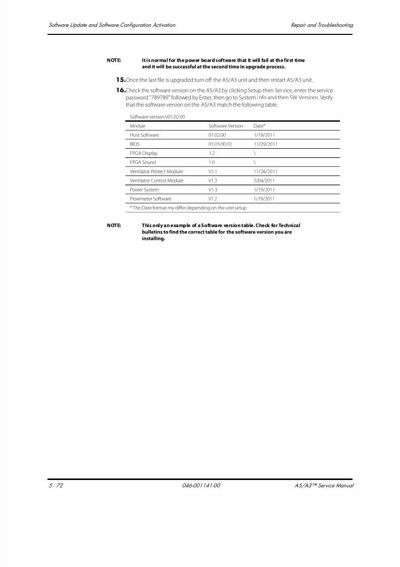
7/21/2019 a5 a3 Service Manual 2013
http://slidepdf.com/reader/full/a5-a3-service-manual-2013 313/399
Software Update and Software Configuration Activation Repair and Troubleshooting
5 - 72 046-001141-00 A5/A3™ Service Manual
NOTE: It is normal for the power board software that it will fail at the first time
and it will be successful at the second time in upgrade process.
15.Once the last file is upgraded turn off the A5/A3 unit and then restart A5/A3 unit.
16.Check the software version on the A5/A3 by clicking Setup then Service, enter the service
password "789789" followed by Enter, then go to System Info and then SW Versions. Verifythat the software version on the A5/A3 match the following table.
NOTE: This only an example of a Software version table. Check for Technical
bulletins to find the correct table for the software version you are
installing.
Software version V01.02.00
Module Software Version Date*
Host Software 01.02.00 1/19/2011
BIOS 01.03.00.00 11/29/2011
FPGA Display 1.2 \
FPGA Sound 1.0 \
Ventilator Protect Module V1.1 11/26/2011
Ventilator Control Module V1.3 3/04/2011
Power System V1.3 1/19/2011
Flowmeter Software V1.2 1/19/2011
* The Date format my differ depending on the unit setup
7/21/2019 a5 a3 Service Manual 2013
http://slidepdf.com/reader/full/a5-a3-service-manual-2013 314/399
A5/A3™ Service Manual 046-001141-00 6 - 1
6.0 Repair and Disassembly
Prepare for Disassembly .......................................................................................................................................................................6-2
Disassemble the Assemblies .............................................................................................................................................................6-3
Disassemble the Breathing System............................................................................................................................................ 6-40

7/21/2019 a5 a3 Service Manual 2013
http://slidepdf.com/reader/full/a5-a3-service-manual-2013 315/399
Prepare for Disassembly Repair and Disassembly
6 - 2 046-001141-00 A5/A3™ Service Manual
6.1 Prepare for Disassembly
6.1.1 Tools
During parts disassembly and replacement, the following tools may be required:• Metric Allen wrench es (2.5, 3, 4, 5, 8mm)
• Phillips screwdriver (#1 and #2)
• Diagonal pliers
• Flathead screwdriver
• Metric M3 and M4 socket screwdriver
• Adjustable wrench
• Tweezers
• Krytox Lubricant (P/N: 0510-00-0020)
6.1.2 Preparations
Before disassembly:
• Make sure that the anesthesia machine is turned off and disconnected from the A/C power
source.
• Bleed down the gas pressure inside the anesthesia machine as described below.
• Disconnect all pipeline and cylinder gas supplies.
• Prepare the tools required for disassembly.
• Maneuver the anesthesia machine to an appropriate location and then apply the brake.
CAUTION: The internal parts may be contaminated. Wear special gloves during
disassembly and inspection.
6.1.3 Bleed Gas Pressure
Make sure to bleed down the gas pressure inside the anesthesia machine before disassembling
pneumatic fittings to avoid personal injury or equipment damage. To bleed gas pressure:
1. Close other cylinder valves and disconnect pipeline gas supplies. Do not disconnect the O2
pipeline. If O2 pipeline is not available, connect O2 cylinder and open the O2 cylinder valve.
2. Set the system switch to ON.
3. Turn on all the flow controls (except O2).
4. Make sure that N2O and AIR pipeline pressure gauges read zero.
5. Disconnect the O2 pipeline supply (or close the O2 cylinder valve). Push the O2 flush button to
bleed O2 from the system.
6.Set the system switch to OFF.

7/21/2019 a5 a3 Service Manual 2013
http://slidepdf.com/reader/full/a5-a3-service-manual-2013 316/399
A5/A3™ Service Manual 046-001141-00 6 - 3
Repair and Disassembly Disassemble the Assemblies
6.2 Disassemble the Assemblies
6.2.1 Disassemble the Internal Assemblies of the Machine Upper Half
6.2.1.1 Open the Service Door
Turn the two screws on the service door counter-clockwise one half turn to open the door.
FIGURE 6-1
6.2.1.2 Remove the Gas Supply Inlet Assembly1. Open the service door.
2. Disconnect the tubes from the N2O, AIR and O2 supply inlet assemblies.
3. Unscrew the two screws from the N2O and AIR supply inlet assemblies.
4. Unplug the related cables from O2 supply inlet assembly and unscrew the two screws to
remove the assembly.
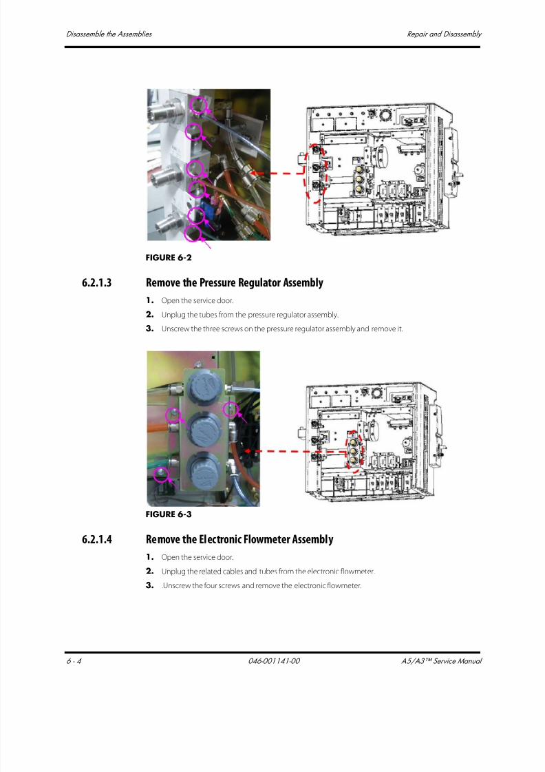
7/21/2019 a5 a3 Service Manual 2013
http://slidepdf.com/reader/full/a5-a3-service-manual-2013 317/399
Disassemble the Assemblies Repair and Disassembly
6 - 4 046-001141-00 A5/A3™ Service Manual
FIGURE 6-2
6.2.1.3 Remove the Pressure Regulator Assembly
1. Open the service door.
2. Unplug the tubes from the pressure regulator assembly.
3. Unscrew the three screws on the pressure regulator assembly and remove it.
FIGURE 6-3
6.2.1.4 Remove the Electronic Flowmeter Assembly1. Open the service door.
2. Unplug the related cables and tubes from the electronic flowmeter.
3. .Unscrew the four screws and remove the electronic flowmeter.

7/21/2019 a5 a3 Service Manual 2013
http://slidepdf.com/reader/full/a5-a3-service-manual-2013 318/399
A5/A3™ Service Manual 046-001141-00 6 - 5
Repair and Disassembly Disassemble the Assemblies
FIGURE 6-4
6.2.1.5 Remove the Poppet Valve Assembly
1. Open the service door.
2. Unplug the tubes from the poppet valve assembly.
3. Unscrew the two screws on the valve to remove the poppet valve.
FIGURE 6-5
6.2.1.6 Remove the Gas Mixer Assembly
1. Open the service door.
2. Unplug the tubes from the gas mixer assembly.
3. Unscrew the four screws on the gas mixer assembly to remove the assembly.

7/21/2019 a5 a3 Service Manual 2013
http://slidepdf.com/reader/full/a5-a3-service-manual-2013 319/399
Disassemble the Assemblies Repair and Disassembly
6 - 6 046-001141-00 A5/A3™ Service Manual
FIGURE 6-6
6.2.1.7 Remove the ORC Assembly
1. Open the service door.2. Unplug the tubes from ORC assembly.
3. .Unscrew the two screws on the ORC assembly to remove the assembly.
FIGURE 6-7
6.2.1.8 Remove the Back Pressure Valve Assembly
1. Open the service door.
2. Unplug the tubes from back pressure valve assembly.
3. Unscrew the four screws on the back pressure valve assembly to remove the assembly.

7/21/2019 a5 a3 Service Manual 2013
http://slidepdf.com/reader/full/a5-a3-service-manual-2013 320/399
A5/A3™ Service Manual 046-001141-00 6 - 7
Repair and Disassembly Disassemble the Assemblies
FIGURE 6-8
6.2.1.9 Replace the Lithium-ion battery1. Open the service door.
2. Unscrew the two screws on the battery box cover, and then you can take out the lithium-ion
battery.
3. Place the new lithium-ion battery into the battery box in the original direction to complete
battery replacement.
FIGURE 6-9
6.2.1.10 Remove the Vaporizer Manifold
1. Open the service door.
2. Unplug the tubes from the vaporizer manifold.
3. Unscrew the four screws and remove the vaporizer manifold.

7/21/2019 a5 a3 Service Manual 2013
http://slidepdf.com/reader/full/a5-a3-service-manual-2013 321/399
Disassemble the Assemblies Repair and Disassembly
6 - 8 046-001141-00 A5/A3™ Service Manual
FIGURE 6-10
6.2.2 Disassemble Hardware Box
6.2.2.1 Remove the Top Plate of the Hardware Box
1. Unscrew the three screws from the top plate of the hardware box.
FIGURE 6-11
2. Lift off the top plate to remove it.
FIGURE 6-12

7/21/2019 a5 a3 Service Manual 2013
http://slidepdf.com/reader/full/a5-a3-service-manual-2013 322/399
A5/A3™ Service Manual 046-001141-00 6 - 9
Repair and Disassembly Disassemble the Assemblies
6.2.2.2 Remove the CPU Board
NOTE: When replacing the CPU Board, software reinstallation may be
required.
1. Remove the top plate assembly.2. Unscrew the four screws fastening the main control board to remove the board.
FIGURE 6-13
6.2.2.3 Remove the Ventilator Control Board
NOTE: When replacing the Ventilator Control Board, software reinstallation
may be required.
1. Remove the top plate assembly.
2. Unplug the related cables and tubes from the ventilator control board.
FIGURE 6-14
3. Unscrew the four screws fastening the ventilator control board to remove it.
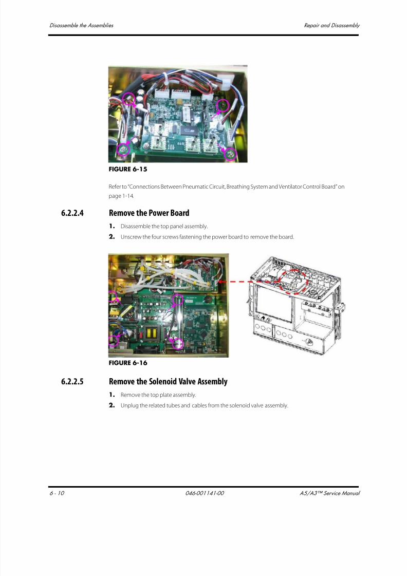
7/21/2019 a5 a3 Service Manual 2013
http://slidepdf.com/reader/full/a5-a3-service-manual-2013 323/399
Disassemble the Assemblies Repair and Disassembly
6 - 10 046-001141-00 A5/A3™ Service Manual
FIGURE 6-15
Refer to “Connections Between Pneumatic Circuit, Breathing System and Ventilator Control Board” on
page 1-14.
6.2.2.4 Remove the Power Board
1. Disassemble the top panel assembly.
2. Unscrew the four screws fastening the power board to remove the board.
FIGURE 6-16
6.2.2.5 Remove the Solenoid Valve Assembly
1. Remove the top plate assembly.
2. Unplug the related tubes and cables from the solenoid valve assembly.
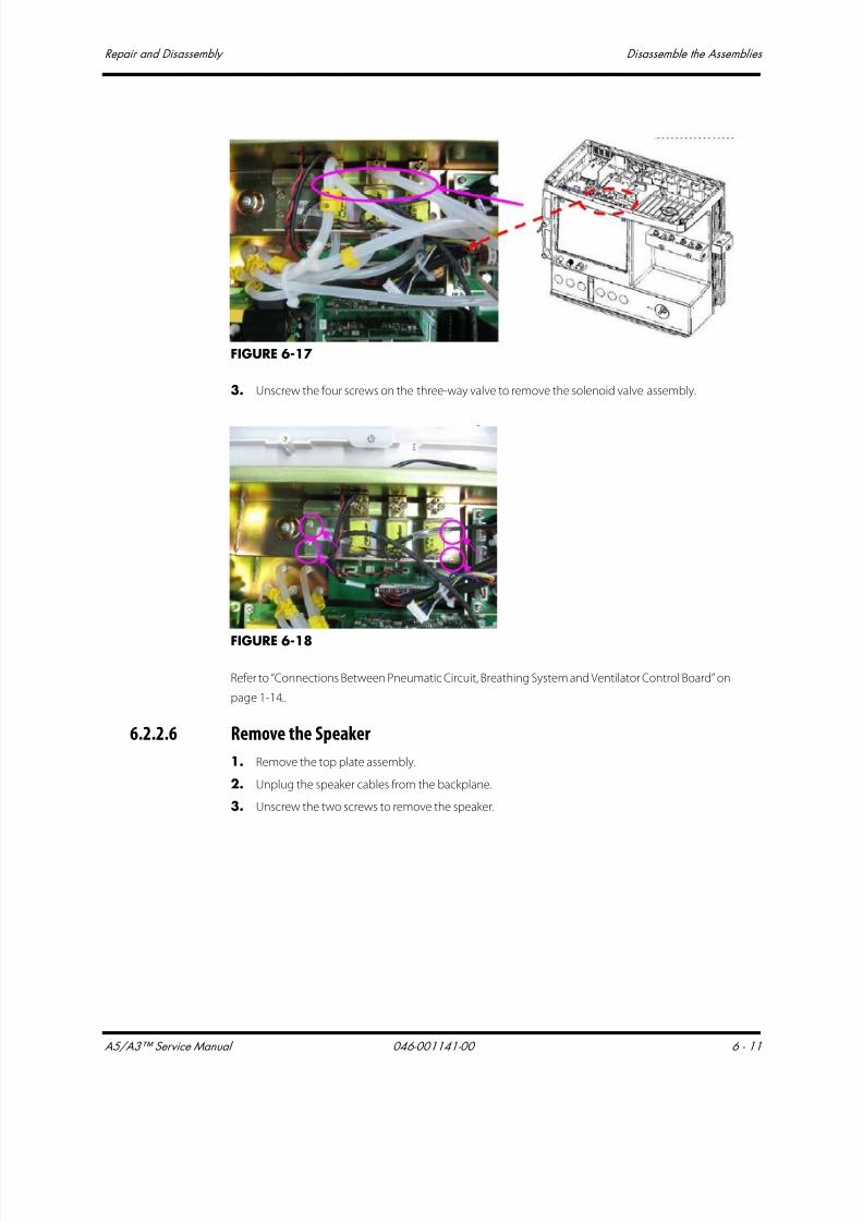
7/21/2019 a5 a3 Service Manual 2013
http://slidepdf.com/reader/full/a5-a3-service-manual-2013 324/399
A5/A3™ Service Manual 046-001141-00 6 - 11
Repair and Disassembly Disassemble the Assemblies
FIGURE 6-17
3. Unscrew the four screws on the three-way valve to remove the solenoid valve assembly.
FIGURE 6-18
Refer to “Connections Between Pneumatic Circuit, Breathing System and Ventilator Control Board” on
page 1-14..
6.2.2.6 Remove the Speaker
1. Remove the top plate assembly.
2. Unplug the speaker cables from the backplane.
3. Unscrew the two screws to remove the speaker.
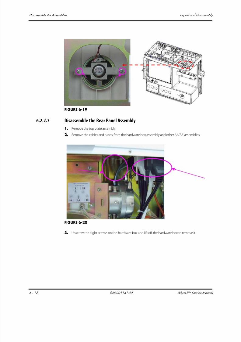
7/21/2019 a5 a3 Service Manual 2013
http://slidepdf.com/reader/full/a5-a3-service-manual-2013 325/399
Disassemble the Assemblies Repair and Disassembly
6 - 12 046-001141-00 A5/A3™ Service Manual
FIGURE 6-19
6.2.2.7 Disassemble the Rear Panel Assembly1. Remove the top plate assembly.
2. Remove the cables and tubes from the hardware box assembly and other A5/A3 assemblies.
FIGURE 6-20
3. Unscrew the eight screws on the hardware box and lift off the hardware box to remove it.

7/21/2019 a5 a3 Service Manual 2013
http://slidepdf.com/reader/full/a5-a3-service-manual-2013 326/399
A5/A3™ Service Manual 046-001141-00 6 - 13
Repair and Disassembly Disassemble the Assemblies
FIGURE 6-21
4. Remove related cables and tubes on the rear panel assembly from other assemblies
5. Unscrew the seven screws on the rear panel of hardware box to remove the rear panel assembly.
FIGURE 6-22
Remove the Fan
1. Remove the rear panel of hardware box.
2. Unscrew the four screws on the fan to remove the fan.
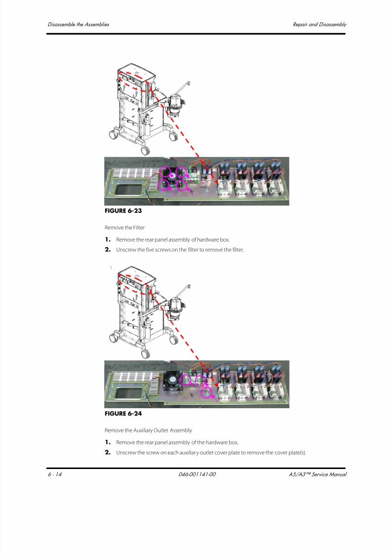
7/21/2019 a5 a3 Service Manual 2013
http://slidepdf.com/reader/full/a5-a3-service-manual-2013 327/399
Disassemble the Assemblies Repair and Disassembly
6 - 14 046-001141-00 A5/A3™ Service Manual
FIGURE 6-23
Remove the Filter
1. Remove the rear panel assembly of hardware box.
2. Unscrew the five screws on the filter to remove the filter.
FIGURE 6-24
Remove the Auxiliary Outlet Assembly
1. Remove the rear panel assembly of the hardware box.
2. Unscrew the screw on each auxiliary outlet cover plate to remove the cover plate(s).

7/21/2019 a5 a3 Service Manual 2013
http://slidepdf.com/reader/full/a5-a3-service-manual-2013 328/399
A5/A3™ Service Manual 046-001141-00 6 - 15
Repair and Disassembly Disassemble the Assemblies
The figure bellow shows the auxiliary outlet cover plates (2) of the A5. The cover plate of the A3 is a
single plate.
FIGURE 6-25
3. Unscrew the two screws on each auxiliary outlet to remove the auxiliary outlets. The A5 has four
(4) auxiliary outlets, as shown in the photograph below. The A3 has three (3) auxiliary outlets
(not shown).
FIGURE 6-26
Remove the Breaker Assembly
1. Remove the rear panel assembly of the hardware box.
2. Unscrew the breaker screws to remove each breaker. The A5 has five (5) breakers. The A3 has
three (3) breakers.
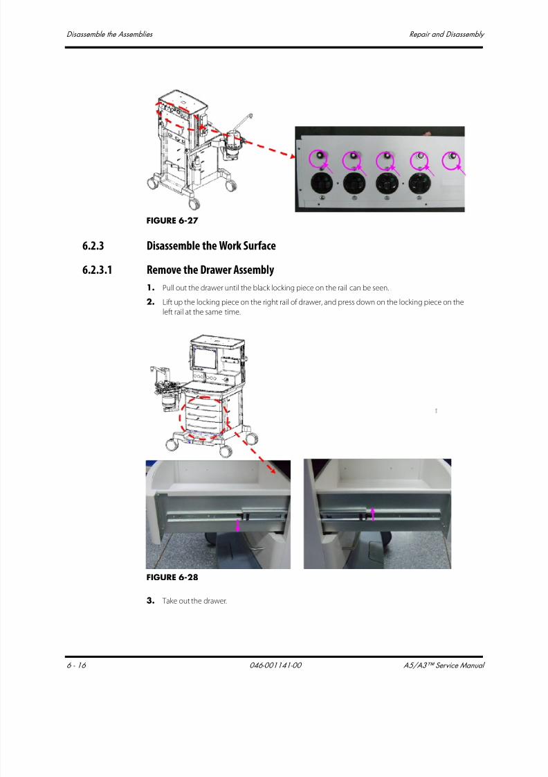
7/21/2019 a5 a3 Service Manual 2013
http://slidepdf.com/reader/full/a5-a3-service-manual-2013 329/399
Disassemble the Assemblies Repair and Disassembly
6 - 16 046-001141-00 A5/A3™ Service Manual
FIGURE 6-27
6.2.3 Disassemble the Work Surface
6.2.3.1 Remove the Drawer Assembly1. Pull out the drawer until the black locking piece on the rail can be seen.
2. Lift up the locking piece on the right rail of drawer, and press down on the locking piece on the
left rail at the same time.
FIGURE 6-28
3. Take out the drawer.

7/21/2019 a5 a3 Service Manual 2013
http://slidepdf.com/reader/full/a5-a3-service-manual-2013 330/399
A5/A3™ Service Manual 046-001141-00 6 - 17
Repair and Disassembly Disassemble the Assemblies
6.2.3.2 Remove the Work Surface Cover Plate
1. Remove the first drawer.
2. Unscrew the five screws on the work surface cover plate.
FIGURE 6-29
3. .Lift off the cover plate from the work surface. When the cover plate is removed, the internal
structure of the work surface is shown as below:
FIGURE 6-30
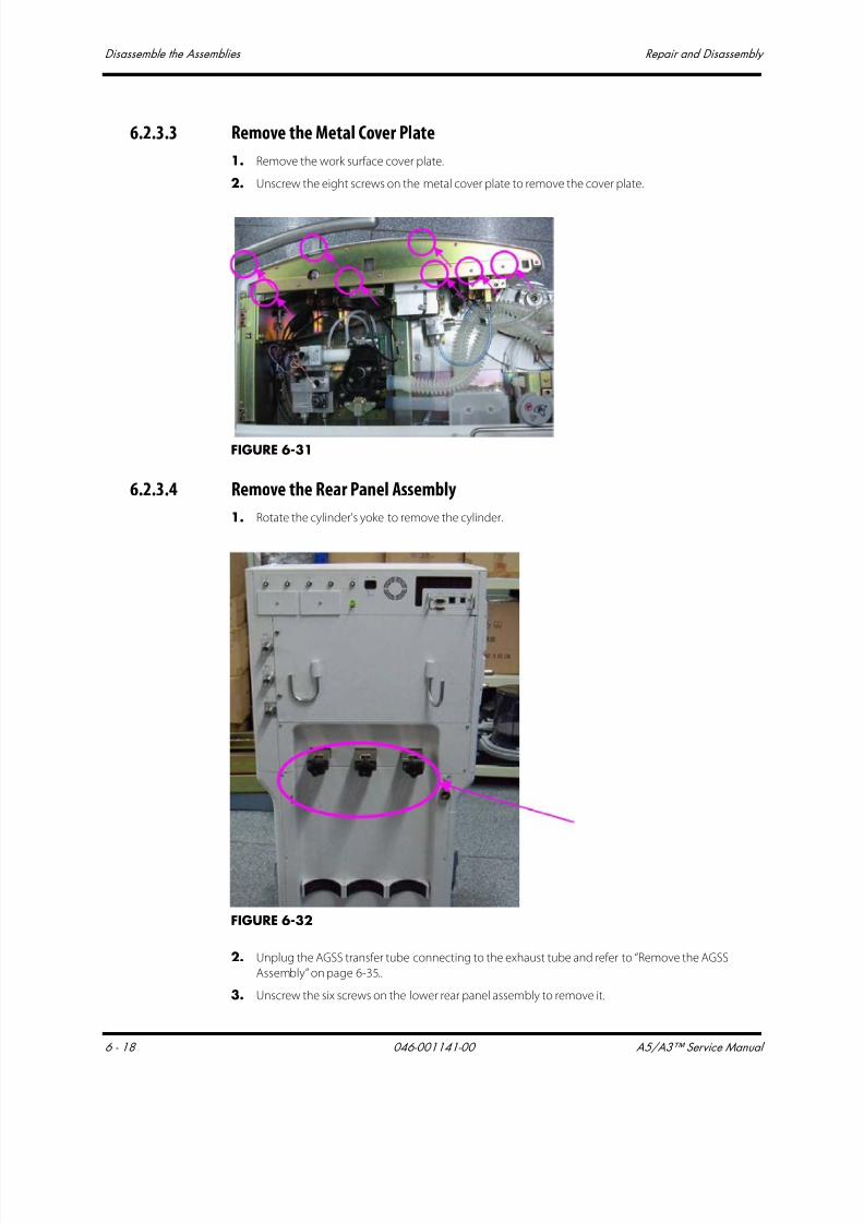
7/21/2019 a5 a3 Service Manual 2013
http://slidepdf.com/reader/full/a5-a3-service-manual-2013 331/399
Disassemble the Assemblies Repair and Disassembly
6 - 18 046-001141-00 A5/A3™ Service Manual
6.2.3.3 Remove the Metal Cover Plate
1. Remove the work surface cover plate.
2. Unscrew the eight screws on the metal cover plate to remove the cover plate.
FIGURE 6-31
6.2.3.4 Remove the Rear Panel Assembly
1. Rotate the cylinder's yoke to remove the cylinder.
FIGURE 6-32
2. Unplug the AGSS transfer tube connecting to the exhaust tube and refer to “Remove the AGSS
Assembly” on page 6-35..
3. Unscrew the six screws on the lower rear panel assembly to remove it.

7/21/2019 a5 a3 Service Manual 2013
http://slidepdf.com/reader/full/a5-a3-service-manual-2013 332/399
A5/A3™ Service Manual 046-001141-00 6 - 19
Repair and Disassembly Disassemble the Assemblies
FIGURE 6-33
4. Unscrew the four screws on the upper rear panel (yoke cover) to remove it.
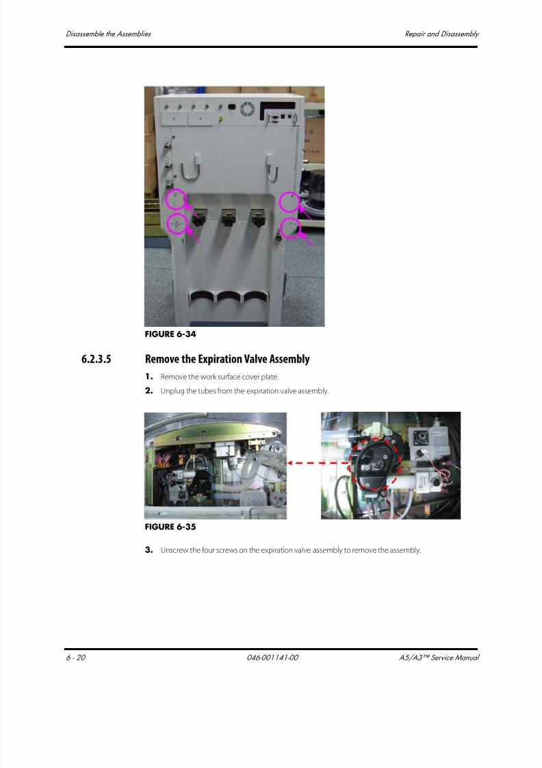
7/21/2019 a5 a3 Service Manual 2013
http://slidepdf.com/reader/full/a5-a3-service-manual-2013 333/399
Disassemble the Assemblies Repair and Disassembly
6 - 20 046-001141-00 A5/A3™ Service Manual
FIGURE 6-34
6.2.3.5 Remove the Expiration Valve Assembly
1. Remove the work surface cover plate.
2. Unplug the tubes from the expiration valve assembly.
FIGURE 6-35
3. Unscrew the four screws on the expiration valve assembly to remove the assembly.

7/21/2019 a5 a3 Service Manual 2013
http://slidepdf.com/reader/full/a5-a3-service-manual-2013 334/399
A5/A3™ Service Manual 046-001141-00 6 - 21
Repair and Disassembly Disassemble the Assemblies
FIGURE 6-36
6.2.3.6 Remove the O2 Flush Assembly1. Remove the work surface cover plate.
2. Remove the metal cover plate.
3. Unplug the tubes from the O2 flush assembly.
4. Unscrew the two screws on the bracket and remove it.
FIGURE 6-37
5. Remove the metal post on the right side of the O2 flush assembly.
6. Unscrew the five screws around the O2 flush assembly to remove it.

7/21/2019 a5 a3 Service Manual 2013
http://slidepdf.com/reader/full/a5-a3-service-manual-2013 335/399
Disassemble the Assemblies Repair and Disassembly
6 - 22 046-001141-00 A5/A3™ Service Manual
FIGURE 6-38
7. Unscrew the four screws around the O2 flush assembly to remove the assembly from the
manifold.
FIGURE 6-39
6.2.3.7 Remove the Touch Panel (A5 Only)
1. Remove the work surface cover plate.
2. Remove the metal cover plate.
3. Unplug the touch panel data cable.
4. Remove the six screws on the touch panel to remove the panel.

7/21/2019 a5 a3 Service Manual 2013
http://slidepdf.com/reader/full/a5-a3-service-manual-2013 336/399
A5/A3™ Service Manual 046-001141-00 6 - 23
Repair and Disassembly Disassemble the Assemblies
FIGURE 6-40
6.2.3.8 Remove the Common Gas Outlet Assembly
1. Remove the work surface cover plate.
2. Unplug the tubes from common gas outlet assembly.
3. Remove the two screws on the common gas outlet assembly to remove the assembly.
FIGURE 6-41
6.2.3.9 Remove the Cylinder Bracket Assembly
1. Open the service door and refer to“Open the Service Door” on page 6-3..
2. Remove the rear panel and refer to “Remove the Rear Panel Assembly” on page 6-18..
3. Unplug the tubes from the cylinder bracket assembly.
4. Remove the copper pipe from cylinder bracket assembly.
5. Remove the four screws on the cylinder bracket to remove the assembly.
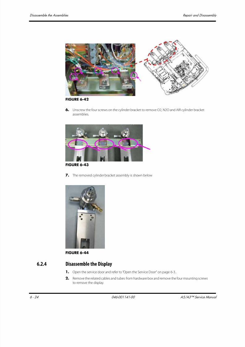
7/21/2019 a5 a3 Service Manual 2013
http://slidepdf.com/reader/full/a5-a3-service-manual-2013 337/399
Disassemble the Assemblies Repair and Disassembly
6 - 24 046-001141-00 A5/A3™ Service Manual
FIGURE 6-42
6. Unscrew the four screws on the cylinder bracket to remove O2, N2O and AIR cylinder bracket
assemblies.
FIGURE 6-43
7. The removed cylinder bracket assembly is shown below
FIGURE 6-44
6.2.4 Disassemble the Display
1. Open the service door and refer to “Open the Service Door” on page 6-3..
2. Remove the related cables and tubes from hardware box and remove the four mounting screws
to remove the display.

7/21/2019 a5 a3 Service Manual 2013
http://slidepdf.com/reader/full/a5-a3-service-manual-2013 338/399
A5/A3™ Service Manual 046-001141-00 6 - 25
Repair and Disassembly Disassemble the Assemblies
FIGURE 6-45
6.2.4.1 Remove the Alarm Lamp Board
1. Remove the display assembly.
2. Unplug the related cables from the alarm lamp board.
3. Remove the two mounting screws on the alarm lamp board to remove the board.
FIGURE 6-46
6.2.4.2 Remove the Display Adaptation Board
1. Remove display assembly and refer to “Disassemble the Display” on page 6-24..
2. Unscrew the five screws on the cover plate of the display mount.

7/21/2019 a5 a3 Service Manual 2013
http://slidepdf.com/reader/full/a5-a3-service-manual-2013 339/399
Disassemble the Assemblies Repair and Disassembly
6 - 26 046-001141-00 A5/A3™ Service Manual
FIGURE 6-47
3. Unplug the related cables from the display interface board.
4. Remove the four screws on the display interface board and remove the board.
FIGURE 6-48
6.2.4.3 Remove the Touch Screen Control Board
1. Remove display assembly.
2. Remove the four screws and the cover plate of the touch screen control board.
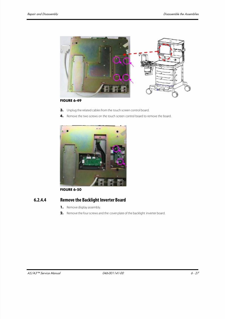
7/21/2019 a5 a3 Service Manual 2013
http://slidepdf.com/reader/full/a5-a3-service-manual-2013 340/399
A5/A3™ Service Manual 046-001141-00 6 - 27
Repair and Disassembly Disassemble the Assemblies
FIGURE 6-49
3. Unplug the related cables from the touch screen control board.4. Remove the two screws on the touch screen control board to remove the board.
FIGURE 6-50
6.2.4.4 Remove the Backlight Inverter Board
1. Remove display assembly.
2. Remove the four screws and the cover plate of the backlight inverter board.

7/21/2019 a5 a3 Service Manual 2013
http://slidepdf.com/reader/full/a5-a3-service-manual-2013 341/399
Disassemble the Assemblies Repair and Disassembly
6 - 28 046-001141-00 A5/A3™ Service Manual
FIGURE 6-51
3. Unplug the related cables from the backlight inverter board.
4. Remove the two screws on the backlight inverter board to remove the board.
FIGURE 6-52
6.2.4.5 Remove the Needle Valve Assemblies
1. Remove display assembly and refer to “Disassemble the Display” on page 6-24..
2. Loosen the two Allen set screws on the knob of needle valve to remove the knob.
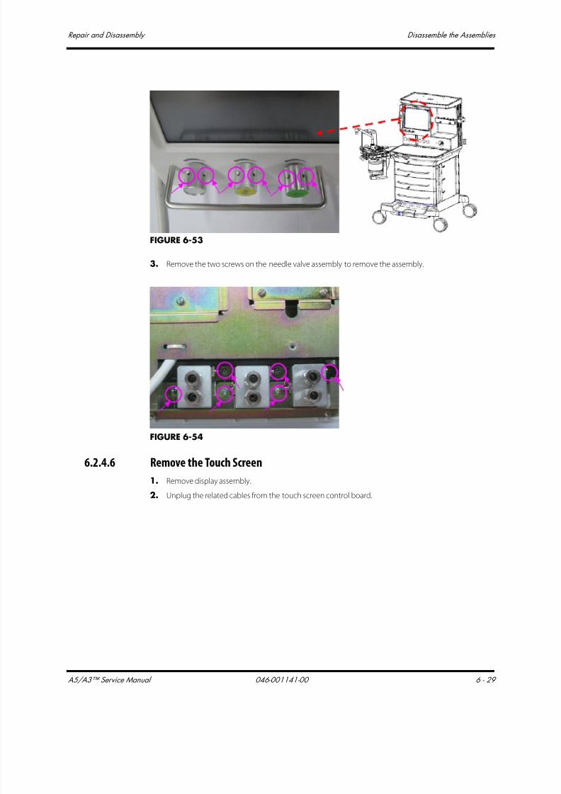
7/21/2019 a5 a3 Service Manual 2013
http://slidepdf.com/reader/full/a5-a3-service-manual-2013 342/399
A5/A3™ Service Manual 046-001141-00 6 - 29
Repair and Disassembly Disassemble the Assemblies
FIGURE 6-53
3. Remove the two screws on the needle valve assembly to remove the assembly.
FIGURE 6-54
6.2.4.6 Remove the Touch Screen
1. Remove display assembly.
2. Unplug the related cables from the touch screen control board.

7/21/2019 a5 a3 Service Manual 2013
http://slidepdf.com/reader/full/a5-a3-service-manual-2013 343/399
Disassemble the Assemblies Repair and Disassembly
6 - 30 046-001141-00 A5/A3™ Service Manual
FIGURE 6-55
3. Remove the 11 screws around the display mount then remove the display front cover.
FIGURE 6-56
4. Slightly lift the touch screen off the display front cover to remove the touch screen.
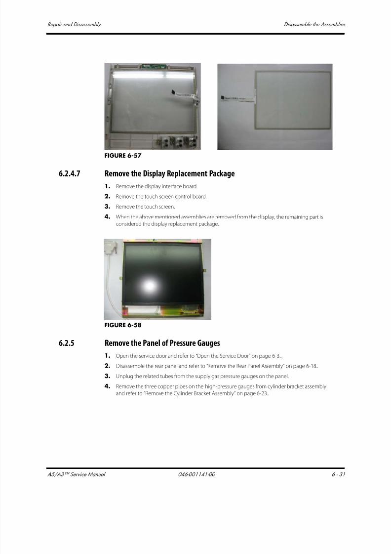
7/21/2019 a5 a3 Service Manual 2013
http://slidepdf.com/reader/full/a5-a3-service-manual-2013 344/399
A5/A3™ Service Manual 046-001141-00 6 - 31
Repair and Disassembly Disassemble the Assemblies
FIGURE 6-57
6.2.4.7 Remove the Display Replacement Package
1. Remove the display interface board.
2. Remove the touch screen control board.
3. Remove the touch screen.
4. When the above mentioned assemblies are removed from the display, the remaining part is
considered the display replacement package.
FIGURE 6-58
6.2.5 Remove the Panel of Pressure Gauges
1. Open the service door and refer to “Open the Service Door” on page 6-3..
2. Disassemble the rear panel and refer to “Remove the Rear Panel Assembly” on page 6-18..
3. Unplug the related tubes from the supply gas pressure gauges on the panel.
4. Remove the three copper pipes on the high-pressure gauges from cylinder bracket assemblyand refer to “Remove the Cylinder Bracket Assembly” on page 6-23..
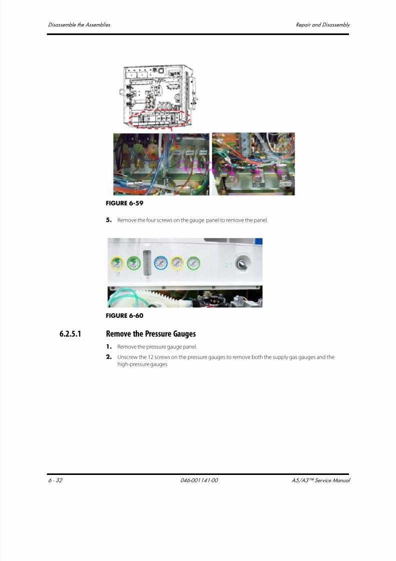
7/21/2019 a5 a3 Service Manual 2013
http://slidepdf.com/reader/full/a5-a3-service-manual-2013 345/399
Disassemble the Assemblies Repair and Disassembly
6 - 32 046-001141-00 A5/A3™ Service Manual
FIGURE 6-59
5. Remove the four screws on the gauge panel to remove the panel.
FIGURE 6-60
6.2.5.1 Remove the Pressure Gauges
1. Remove the pressure gauge panel.
2. Unscrew the 12 screws on the pressure gauges to remove both the supply gas gauges and the
high-pressure gauges.

7/21/2019 a5 a3 Service Manual 2013
http://slidepdf.com/reader/full/a5-a3-service-manual-2013 346/399
A5/A3™ Service Manual 046-001141-00 6 - 33
Repair and Disassembly Disassemble the Assemblies
FIGURE 6-61
6.2.5.2 Remove the Total Flowmeter
1. Remove the meter panel.
2. Remove the four screws on the total f lowmeter and to remove it.
FIGURE 6-62
6.2.5.3 Remove the System Switch
1. Remove the pressure gauge panel.
2. Remove the four screws on the system switch to remove the switch.
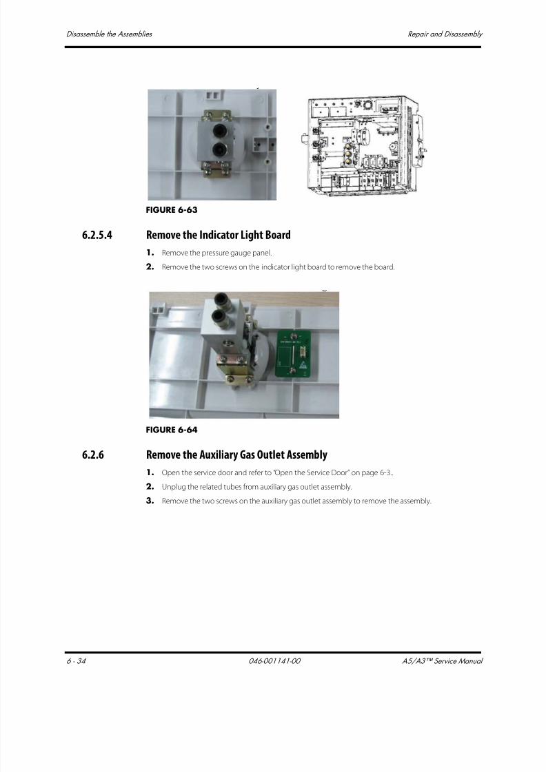
7/21/2019 a5 a3 Service Manual 2013
http://slidepdf.com/reader/full/a5-a3-service-manual-2013 347/399
Disassemble the Assemblies Repair and Disassembly
6 - 34 046-001141-00 A5/A3™ Service Manual
FIGURE 6-63
6.2.5.4 Remove the Indicator Light Board
1. Remove the pressure gauge panel.
2. Remove the two screws on the indicator light board to remove the board.
FIGURE 6-64
6.2.6 Remove the Auxiliary Gas Outlet Assembly
1. Open the service door and refer to “Open the Service Door” on page 6-3..
2. Unplug the related tubes from auxiliary gas outlet assembly.
3. Remove the two screws on the auxiliary gas outlet assembly to remove the assembly.
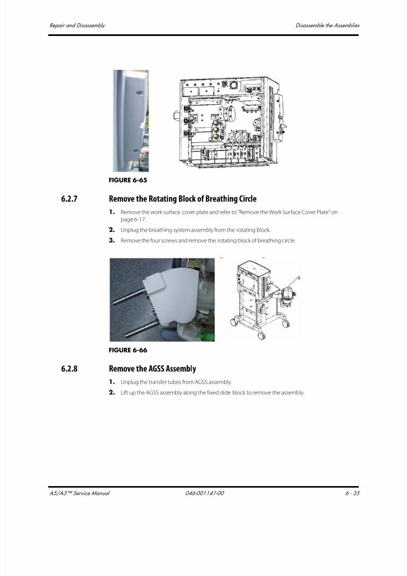
7/21/2019 a5 a3 Service Manual 2013
http://slidepdf.com/reader/full/a5-a3-service-manual-2013 348/399
A5/A3™ Service Manual 046-001141-00 6 - 35
Repair and Disassembly Disassemble the Assemblies
FIGURE 6-65
6.2.7 Remove the Rotating Block of Breathing Circle1. Remove the work surface cover plate and refer to “Remove the Work Surface Cover Plate” on
page 6-17.
2. Unplug the breathing system assembly from the rotating block.
3. Remove the four screws and remove the rotating block of breathing circle.
FIGURE 6-66
6.2.8 Remove the AGSS Assembly
1. Unplug the transfer tubes from AGSS assembly.
2. Lift up the AGSS assembly along the fixed slide block to remove the assembly.

7/21/2019 a5 a3 Service Manual 2013
http://slidepdf.com/reader/full/a5-a3-service-manual-2013 349/399
Disassemble the Assemblies Repair and Disassembly
6 - 36 046-001141-00 A5/A3™ Service Manual
FIGURE 6-67
6.2.9 Disassemble the Base Assembly
6.2.9.1 Remove the Caster Assembly
1. Remove the breathing system and tilt the A5/A3 backward.
FIGURE 6-68
2. Remove the four screws and remove the caster assembly.
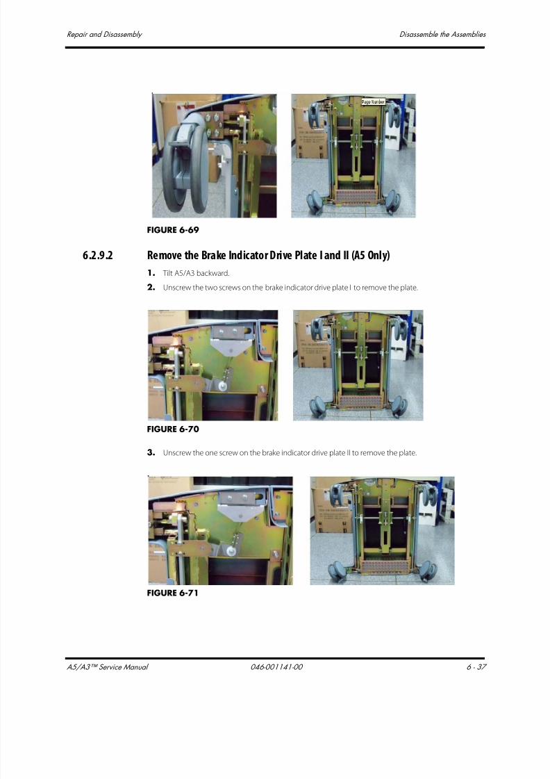
7/21/2019 a5 a3 Service Manual 2013
http://slidepdf.com/reader/full/a5-a3-service-manual-2013 350/399
A5/A3™ Service Manual 046-001141-00 6 - 37
Repair and Disassembly Disassemble the Assemblies
FIGURE 6-69
6.2.9.2 Remove the Brake Indicator Drive Plate I and II (A5 Only)
1. Tilt A5/A3 backward.
2. Unscrew the two screws on the brake indicator drive plate I to remove the plate.
FIGURE 6-70
3. Unscrew the one screw on the brake indicator drive plate II to remove the plate.
FIGURE 6-71
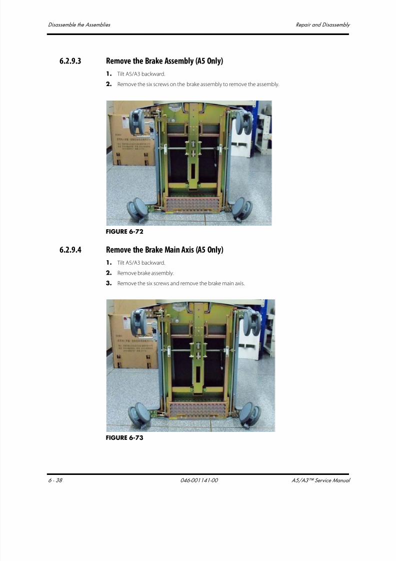
7/21/2019 a5 a3 Service Manual 2013
http://slidepdf.com/reader/full/a5-a3-service-manual-2013 351/399
Disassemble the Assemblies Repair and Disassembly
6 - 38 046-001141-00 A5/A3™ Service Manual
6.2.9.3 Remove the Brake Assembly (A5 Only)
1. Tilt A5/A3 backward.
2. Remove the six screws on the brake assembly to remove the assembly.
FIGURE 6-72
6.2.9.4 Remove the Brake Main Axis (A5 Only)
1. Tilt A5/A3 backward.
2. Remove brake assembly.
3. Remove the six screws and remove the brake main axis.
FIGURE 6-73

7/21/2019 a5 a3 Service Manual 2013
http://slidepdf.com/reader/full/a5-a3-service-manual-2013 352/399
A5/A3™ Service Manual 046-001141-00 6 - 39
Repair and Disassembly Disassemble the Assemblies
6.2.9.5 Remove the Principal Axis of Brake (A5 Only)
1. Tilt A5/A3 backward.
2. Remove the brake indicator drive plate II.
3. Unscrew the six screws on the brake rod to remove the rod.

7/21/2019 a5 a3 Service Manual 2013
http://slidepdf.com/reader/full/a5-a3-service-manual-2013 353/399
Disassemble the Breathing System Repair and Disassembly
6 - 40 046-001141-00 A5/A3™ Service Manual
6.3 Disassemble the Breathing System
6.3.1 Remove the O2 Sensor and Cable
1. Remove one end of the O2 sensor cable from the connector on the anesthesia machine.
Unplug the O2 sensor from the port on the Breathing System by pulling straight out.
FIGURE 6-74
2. Turn the black plug counterclockwise to take it out of the housing.And then turn the O2 sensor
counterclockwise to take it out of the threaded cup.
FIGURE 6-75
6.3.2 Remove the Breathing Tubes
NOTE: When disassembling the breathing tube, hold the tube connectors at
both ends of the tube to prevent damage to the tube.
1. Remove the filter from the Y piece.
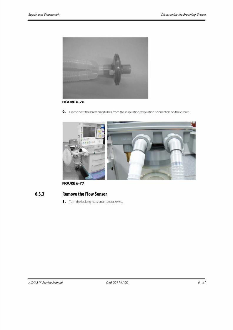
7/21/2019 a5 a3 Service Manual 2013
http://slidepdf.com/reader/full/a5-a3-service-manual-2013 354/399
A5/A3™ Service Manual 046-001141-00 6 - 41
Repair and Disassembly Disassemble the Breathing System
FIGURE 6-76
2. Disconnect the breathing tubes from the inspiration/expiration connectors on the circuit.
FIGURE 6-77
6.3.3 Remove the Flow Sensor
1. Turn the locking nuts counterclockwise.

7/21/2019 a5 a3 Service Manual 2013
http://slidepdf.com/reader/full/a5-a3-service-manual-2013 355/399
Disassemble the Breathing System Repair and Disassembly
6 - 42 046-001141-00 A5/A3™ Service Manual
FIGURE 6-78
2. Pull out the inspiration and expiration connectors together with their locking nuts. And thenpull out the f low sensors horizontally.
FIGURE 6-79
3. The following pictures show the appearance of inspiratory and expiratory flow sensor
assemblies.
FIGURE 6-80

7/21/2019 a5 a3 Service Manual 2013
http://slidepdf.com/reader/full/a5-a3-service-manual-2013 356/399
A5/A3™ Service Manual 046-001141-00 6 - 43
Repair and Disassembly Disassemble the Breathing System
6.3.4 Remove the Manual Bag
Remove the manual bag from the connector on the breathing system as shown below.
FIGURE 6-81
6.3.5 Remove the Absorbent Canister
1. Hold and turn the rotary handle clockwise for 45 degrees.
FIGURE 6-82
2. Pull out the absorbent canister horizontally.

7/21/2019 a5 a3 Service Manual 2013
http://slidepdf.com/reader/full/a5-a3-service-manual-2013 357/399
Disassemble the Breathing System Repair and Disassembly
6 - 44 046-001141-00 A5/A3™ Service Manual
FIGURE 6-83
WARNING: Sodalime is a caustic substance and is a strong irritant toeyes, skin and respiratory system. Affected areas should beflushed with water. If irritation continues after flushing with water, seek medical assistance immediately.
6.3.6 Remove the CO2 Bypass Assembly
1. Remove the absorbent canister as per section 6.3.5?
2. Press inward the fasteners on both sides and the CO2 bypass assembly will drop down for
removal.
FIGURE 6-84
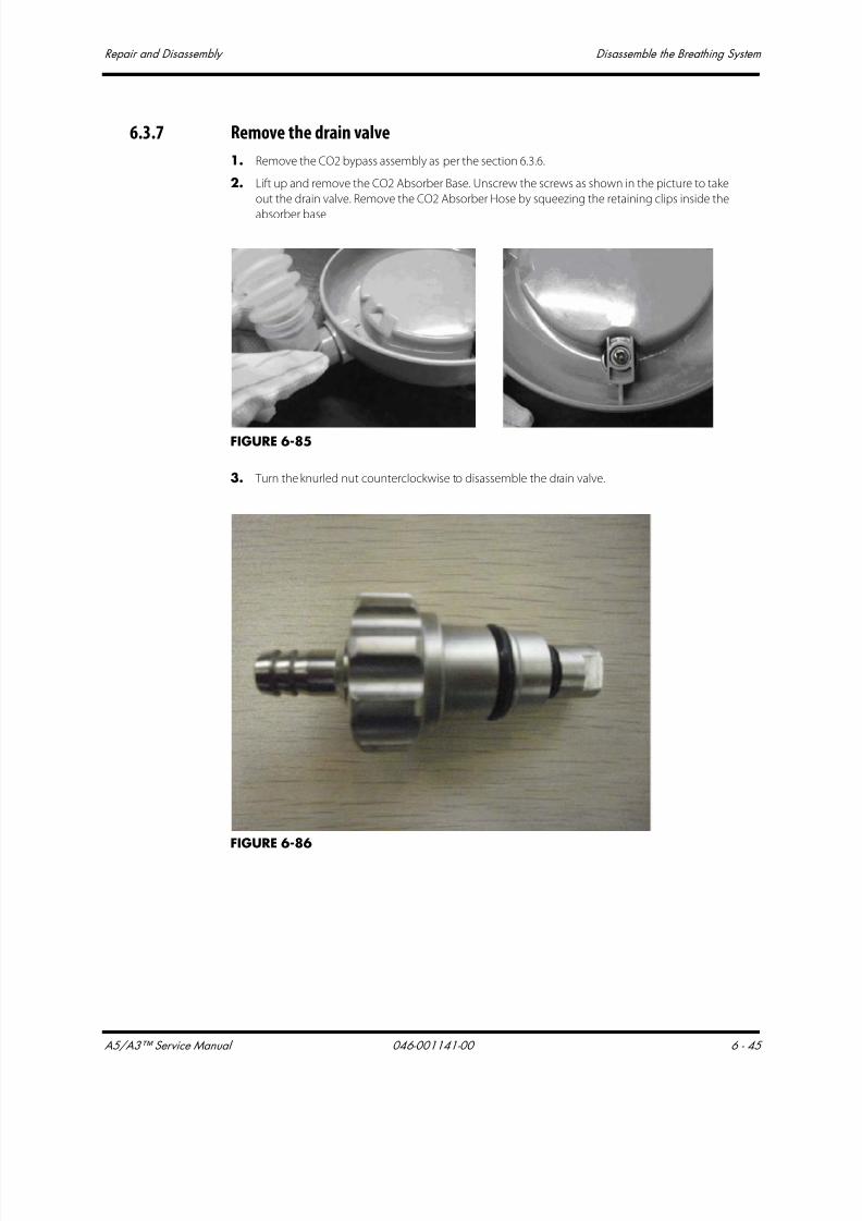
7/21/2019 a5 a3 Service Manual 2013
http://slidepdf.com/reader/full/a5-a3-service-manual-2013 358/399
A5/A3™ Service Manual 046-001141-00 6 - 45
Repair and Disassembly Disassemble the Breathing System
6.3.7 Remove the drain valve
1. Remove the CO2 bypass assembly as per the section 6.3.6.
2. Lift up and remove the CO2 Absorber Base. Unscrew the screws as shown in the picture to take
out the drain valve. Remove the CO2 Absorber Hose by squeezing the retaining clips inside the
absorber base
FIGURE 6-85
3. Turn the knurled nut counterclockwise to disassemble the drain valve.
FIGURE 6-86
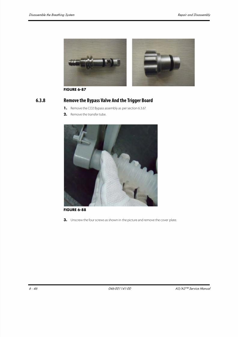
7/21/2019 a5 a3 Service Manual 2013
http://slidepdf.com/reader/full/a5-a3-service-manual-2013 359/399
Disassemble the Breathing System Repair and Disassembly
6 - 46 046-001141-00 A5/A3™ Service Manual
FIGURE 6-87
6.3.8 Remove the Bypass Valve And the Trigger Board
1. Remove the CO2 Bypass assembly as per section 6.3.6?
2. Remove the transfer tube.
FIGURE 6-88
3. Unscrew the four screws as shown in the picture and remove the cover plate.
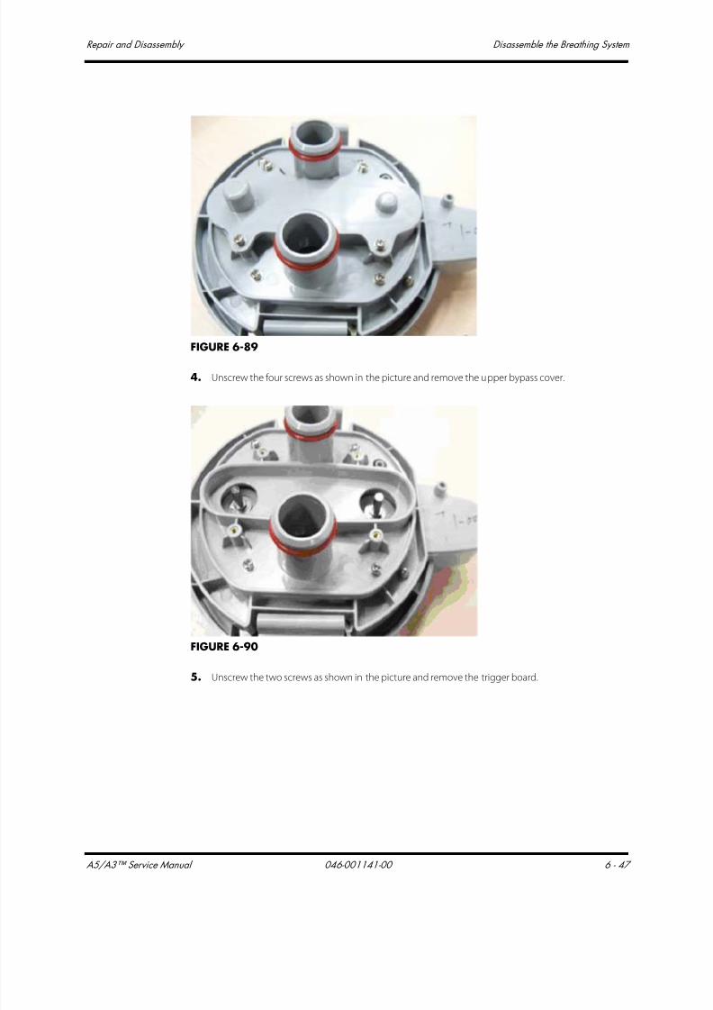
7/21/2019 a5 a3 Service Manual 2013
http://slidepdf.com/reader/full/a5-a3-service-manual-2013 360/399
A5/A3™ Service Manual 046-001141-00 6 - 47
Repair and Disassembly Disassemble the Breathing System
FIGURE 6-89
4. Unscrew the four screws as shown in the picture and remove the upper bypass cover.
FIGURE 6-90
5. Unscrew the two screws as shown in the picture and remove the trigger board.
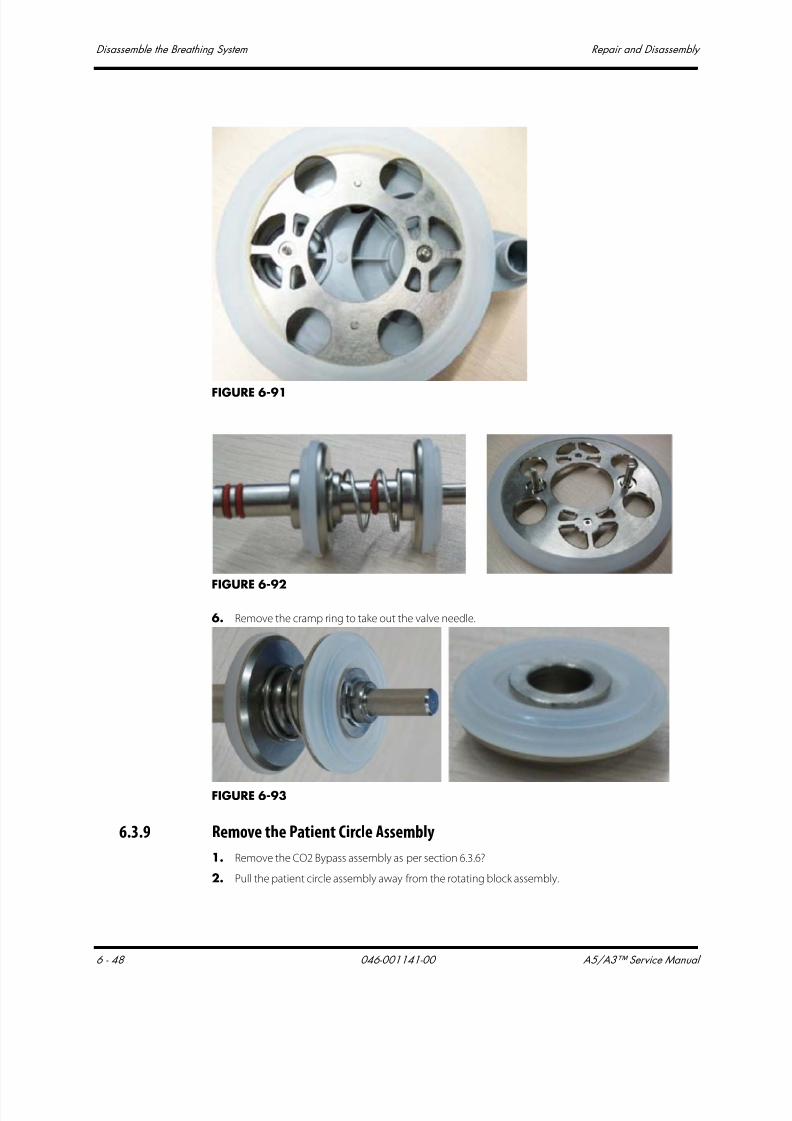
7/21/2019 a5 a3 Service Manual 2013
http://slidepdf.com/reader/full/a5-a3-service-manual-2013 361/399
Disassemble the Breathing System Repair and Disassembly
6 - 48 046-001141-00 A5/A3™ Service Manual
FIGURE 6-91
FIGURE 6-92
6. Remove the cramp ring to take out the valve needle.
FIGURE 6-93
6.3.9 Remove the Patient Circle Assembly
1. Remove the CO2 Bypass assembly as per section 6.3.6?
2. Pull the patient circle assembly away from the rotating block assembly.
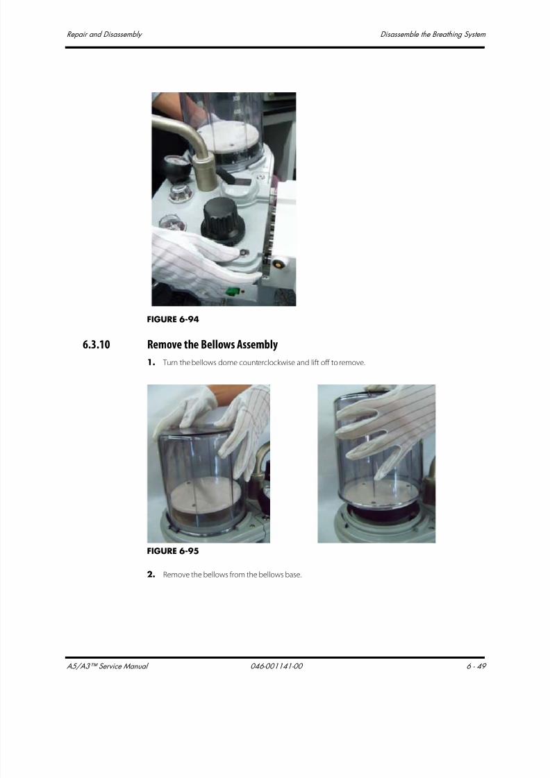
7/21/2019 a5 a3 Service Manual 2013
http://slidepdf.com/reader/full/a5-a3-service-manual-2013 362/399
A5/A3™ Service Manual 046-001141-00 6 - 49
Repair and Disassembly Disassemble the Breathing System
FIGURE 6-94
6.3.10 Remove the Bellows Assembly
1. Turn the bellows dome counterclockwise and lift off to remove.
FIGURE 6-95
2. Remove the bellows from the bellows base.

7/21/2019 a5 a3 Service Manual 2013
http://slidepdf.com/reader/full/a5-a3-service-manual-2013 363/399
Disassemble the Breathing System Repair and Disassembly
6 - 50 046-001141-00 A5/A3™ Service Manual
FIGURE 6-96
6.3.11 Remove the Pop-off Valve Assembly
1. Remove the bellows assembly as per section 6.3.10.
2. Unscrew the four locking screws as shown in the picture. Hold and pull up the Pop-Off valve
cover to remove it.?
FIGURE 6-97
3. Take out the rubber and metal Pop-Off valve.

7/21/2019 a5 a3 Service Manual 2013
http://slidepdf.com/reader/full/a5-a3-service-manual-2013 364/399
A5/A3™ Service Manual 046-001141-00 6 - 51
Repair and Disassembly Disassemble the Breathing System
FIGURE 6-98
6.3.12 Disassemble the Expiratory/Inspiratory Check Valve Assemblies
1. Turn the check valve cover counterclockwise to remove it.
FIGURE 6-99
2. Pull out the check valve as shown in the following picture.

7/21/2019 a5 a3 Service Manual 2013
http://slidepdf.com/reader/full/a5-a3-service-manual-2013 365/399
Disassemble the Breathing System Repair and Disassembly
6 - 52 046-001141-00 A5/A3™ Service Manual
FIGURE 6-100
6.3.13 Remove the Water Collection Cup
1. Hold the water collection cup and turn it counterclockwise to remove it.
FIGURE 6-101
2. Remove the water collection cup.

7/21/2019 a5 a3 Service Manual 2013
http://slidepdf.com/reader/full/a5-a3-service-manual-2013 366/399
A5/A3™ Service Manual 046-001141-00 6 - 53
Repair and Disassembly Disassemble the Breathing System
FIGURE 6-102
6.3.14 Remove the Airway Pressure Gauge
Lift the airway pressure gauge straight up to remove it.
FIGURE 6-103
6.3.15 Remove the Bag Arm
1. Unscrew the locking nut counterclockwise and lift straight up to remove bag arm.
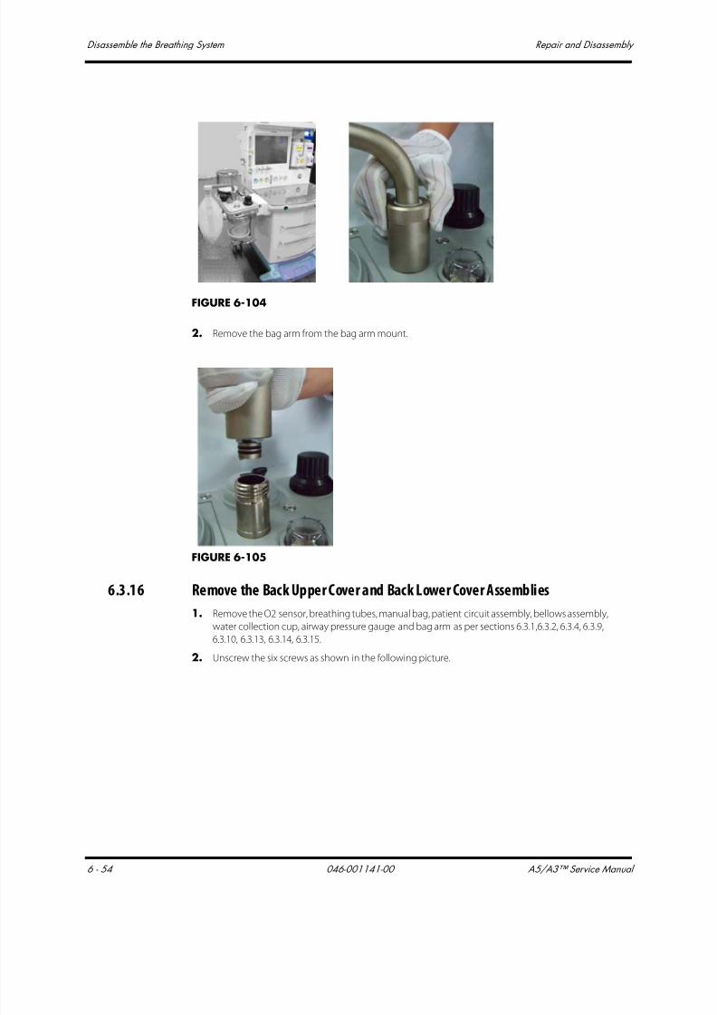
7/21/2019 a5 a3 Service Manual 2013
http://slidepdf.com/reader/full/a5-a3-service-manual-2013 367/399
Disassemble the Breathing System Repair and Disassembly
6 - 54 046-001141-00 A5/A3™ Service Manual
FIGURE 6-104
2. Remove the bag arm from the bag arm mount.
FIGURE 6-105
6.3.16 Remove the Back Upper Cover and Back Lower Cover Assemblies
1. Remove the O2 sensor, breathing tubes, manual bag, patient circuit assembly, bellows assembly,
water collection cup, airway pressure gauge and bag arm as per sections 6.3.1,6.3.2, 6.3.4, 6.3.9,
6.3.10, 6.3.13, 6.3.14, 6.3.15.
2. Unscrew the six screws as shown in the following picture.

7/21/2019 a5 a3 Service Manual 2013
http://slidepdf.com/reader/full/a5-a3-service-manual-2013 368/399
A5/A3™ Service Manual 046-001141-00 6 - 55
Repair and Disassembly Disassemble the Breathing System
FIGURE 6-106
3. Unscrew the knurled thumb nut as shown in the following picture.
FIGURE 6-107
4. Turn over the circle. Pull up to separate the back upper cover assembly.

7/21/2019 a5 a3 Service Manual 2013
http://slidepdf.com/reader/full/a5-a3-service-manual-2013 369/399
Disassemble the Breathing System Repair and Disassembly
6 - 56 046-001141-00 A5/A3™ Service Manual
FIGURE 6-108
5. Pull leftwards to take out the back lower cover assemblies.
FIGURE 6-109
6.3.17 Remove the Front Upper Cover, Median Plate and Front Lower Cover
Assemblies
1. Remove the Back Upper Cover and Back Lower Cover Assemblies as per section 6.3.16.
2. Remove the two screws on the lower cover.
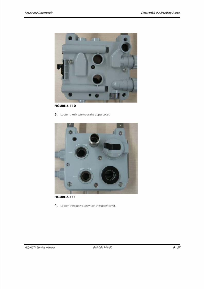
7/21/2019 a5 a3 Service Manual 2013
http://slidepdf.com/reader/full/a5-a3-service-manual-2013 370/399
A5/A3™ Service Manual 046-001141-00 6 - 57
Repair and Disassembly Disassemble the Breathing System
FIGURE 6-110
3. Loosen the six screws on the upper cover.
FIGURE 6-111
4. Loosen the captive screws on the upper cover.

7/21/2019 a5 a3 Service Manual 2013
http://slidepdf.com/reader/full/a5-a3-service-manual-2013 371/399
Disassemble the Breathing System Repair and Disassembly
6 - 58 046-001141-00 A5/A3™ Service Manual
FIGURE 6-112
5. Hold the upper cover assembly tightly and pull it up to remove it.
FIGURE 6-113
6. Remove the spring washer and plain washer (Note: pay special attention to the spring washerand plain washer when removing them because they easily get loose).
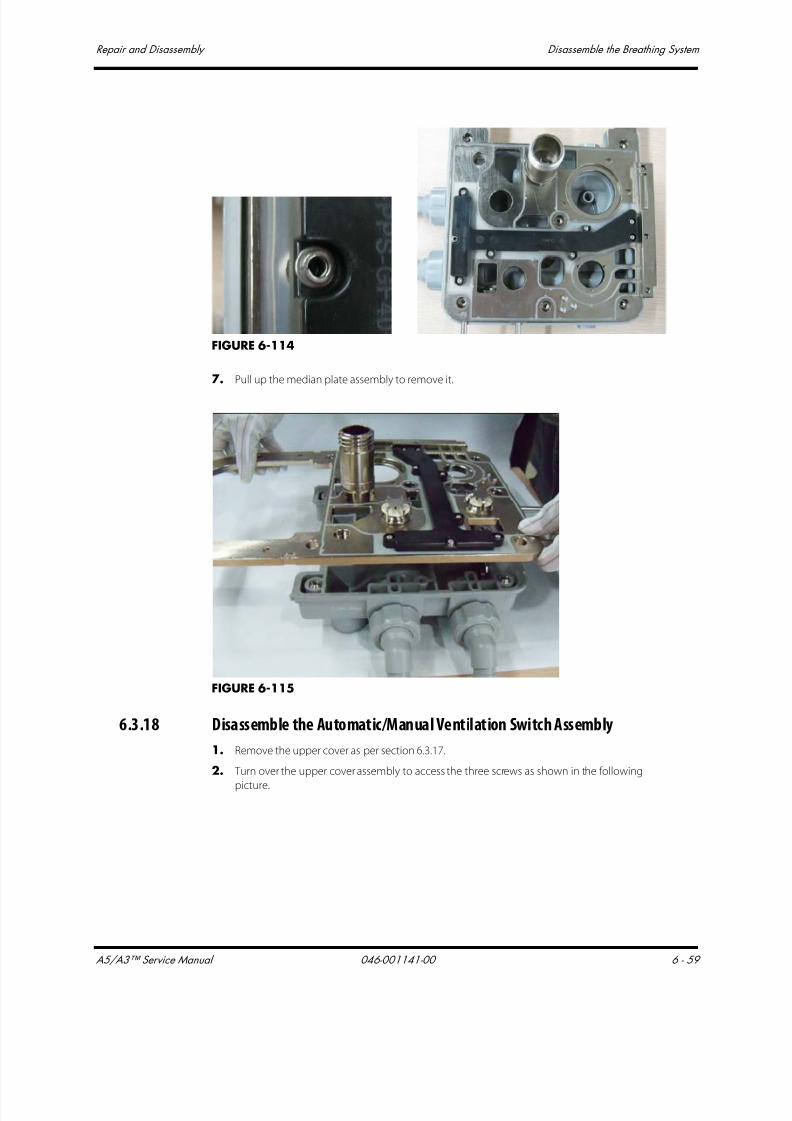
7/21/2019 a5 a3 Service Manual 2013
http://slidepdf.com/reader/full/a5-a3-service-manual-2013 372/399
A5/A3™ Service Manual 046-001141-00 6 - 59
Repair and Disassembly Disassemble the Breathing System
FIGURE 6-114
7. Pull up the median plate assembly to remove it.
FIGURE 6-115
6.3.18 Disassemble the Automatic/Manual Ventilation Switch Assembly
1. Remove the upper cover as per section 6.3.17.
2. Turn over the upper cover assembly to access the three screws as shown in the following
picture.
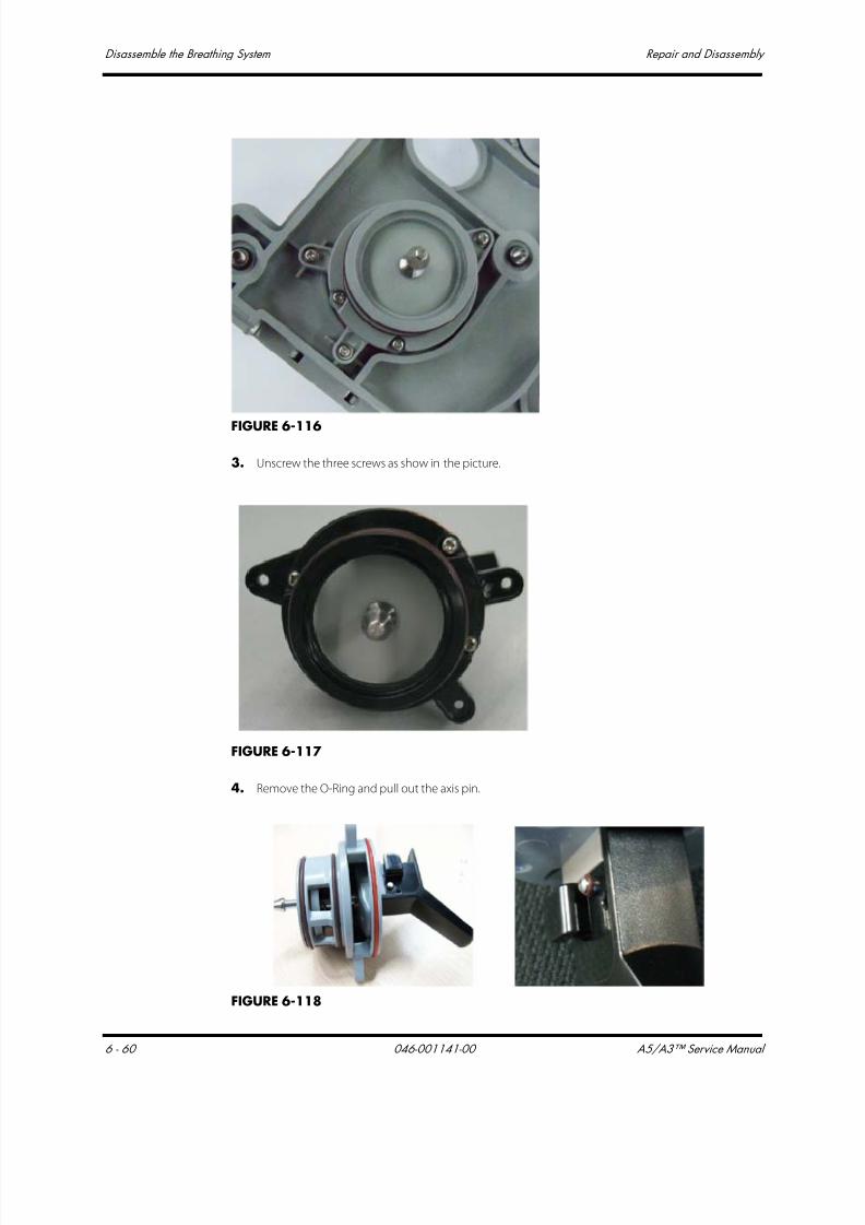
7/21/2019 a5 a3 Service Manual 2013
http://slidepdf.com/reader/full/a5-a3-service-manual-2013 373/399
Disassemble the Breathing System Repair and Disassembly
6 - 60 046-001141-00 A5/A3™ Service Manual
FIGURE 6-116
3. Unscrew the three screws as show in the picture.
FIGURE 6-117
4. Remove the O-Ring and pull out the axis pin.
FIGURE 6-118
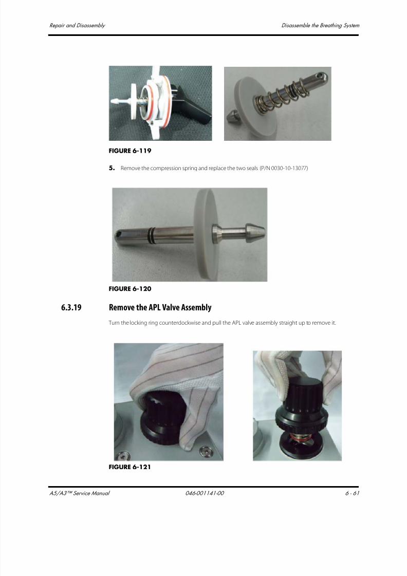
7/21/2019 a5 a3 Service Manual 2013
http://slidepdf.com/reader/full/a5-a3-service-manual-2013 374/399
A5/A3™ Service Manual 046-001141-00 6 - 61
Repair and Disassembly Disassemble the Breathing System
FIGURE 6-119
5. Remove the compression spring and replace the two seals (P/N 0030-10-13077)
FIGURE 6-120
6.3.19 Remove the APL Valve Assembly
Turn the locking ring counterclockwise and pull the APL valve assembly straight up to remove it.
FIGURE 6-121

7/21/2019 a5 a3 Service Manual 2013
http://slidepdf.com/reader/full/a5-a3-service-manual-2013 375/399
Disassemble the Breathing System Repair and Disassembly
6 - 62 046-001141-00 A5/A3™ Service Manual
This page intentionally left blank.

7/21/2019 a5 a3 Service Manual 2013
http://slidepdf.com/reader/full/a5-a3-service-manual-2013 376/399
A5/A3™ Service Manual 046-001141-00 7 - 1
7.0 Replacement Parts
Introduction.................................................................................................................................................................................................7-2

7/21/2019 a5 a3 Service Manual 2013
http://slidepdf.com/reader/full/a5-a3-service-manual-2013 377/399
Introduction Replacement Parts
7 - 2 046-001141-00 A5/A3™ Service Manual
7.1 Introduction
The A5/A3 anesthesia system can be broken down into 18 big parts based on its structure and
function. Each big part includes several replaceable parts. Tables 8-1 through 8-18 list the information
about each replaceable part and Figures 8-1 through 8-14 indicate the position of each replaceablepart on the A5/A3. The selection of replaceable parts gives consideration to the characteristics of the
parts, cost of replacement, and maintenance efficiency. When the parts whose sub components are
not convenient to replace (such as the electronic component on the board) are faulty, replacing the
board can improve the maintenance efficiency. For example, if a pressure gauge on the instrument
panel is faulty, replacing the pressure gauge can reduce the cost.
7.1.1 Ordering Replaceable Parts
Provide the following information to order replaceable parts:
FRU code of the parts;
Number of the parts in the document table;
Description of the feature of the parts.
For example: P/N: 801-0631-00001-00................................................................................... Auxiliary gas supply, NO.1
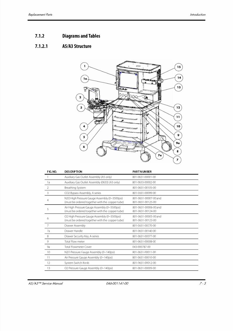
7/21/2019 a5 a3 Service Manual 2013
http://slidepdf.com/reader/full/a5-a3-service-manual-2013 378/399
A5/A3™ Service Manual 046-001141-00 7 - 3
Replacement Parts Introduction
7.1.2 Diagrams and Tables
7.1.2.1 A5/A3 Structure
1
1a
7a
7
12
13
14
15
3
4
5
6
2
11
10
9
8
9a
FIG.NO. DESCRIPTION PART NUMBER
1 Auxiliary Gas Outlet Assembly (A5 only) 801-0631-00001-00
1a Auxiliary Gas Outlet Assembly (0633) (A3 only) 801-0633-00002-00
2 Breathing System 801-0631-00105-00
3 CO2 Bypass Assembly, A series 801-0631-00099-00
4N2O High Pressure Gauge Assembly (0~3500psi)
(must be ordered together with the copper tube)
801-0631-00007-00 and
801-0631-00125-00
5Air High Pressure Gauge Assembly (0~3500psi)
(must be ordered together with the copper tube)
801-0631-00006-00 and
801-0631-00124-00
6O2 High Pressure Gauge Assembly (0~3500psi)
(must be ordered together with the copper tube)
801-0631-00005-00 and
801-0631-00123-00
7 Drawer Assembly 801-0631-00070-00
7a Drawer Handle 801-0631-00140-008 Drawer Security Key, A-series 801-0631-00077-00
9 Total Flow meter 801-0631-00008-00
9a Total Flowmeter Cover 043-000787-00
10 N2O Pressure Gauge Assembly (0~140psi) 801-0631-00011-00
11 Air Pressure Gauge Assembly (0~140psi) 801-0631-00010-00
12 System Switch Knob 801-0631-00012-00
13 O2 Pressure Gauge Assembly (0~140psi) 801-0631-00009-00
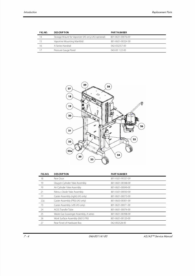
7/21/2019 a5 a3 Service Manual 2013
http://slidepdf.com/reader/full/a5-a3-service-manual-2013 379/399
Introduction Replacement Parts
7 - 4 046-001141-00 A5/A3™ Service Manual
14 Storage Mount for Vaporizer (A5 only) (A3 opt ional) 801-0631-00076-00
15 Vaporizer Mounting Manifold 801-0631-00024-00
16 A-Series Handrail 042-002357-00
17 Pressure Gauge Panel 043-001122-00
FIG.NO. DESCRIPTION PART NUMBER
18
19
20
21
22
22a
23
24
25
26
2728
29
30
FIG.NO. DESCRIPTION PART NUMBER
18 Rear Door 801-0631-00037-00
19 Oxygen Cylinder Yoke Assembly 801-0631-00048-00
20 Air Cylinder Yoke Assembly 801-0631-00049-00
21 Nitrous Oxide Yoke Assembly 801-0631-00050-00
22 Caster Assembly (right) (A5 only) 801-0631-00073-00
22a Caster Assembly (FRU) (A3 only) 801-0633-00001-00
23 Caster Assembly (left) (A5 only) 801-0631-00071-00
24 AGSS Transfer Tube 801-0631-00074-00
25 Waste Gas Scavenger Assembly, A series 801-0631-00098-00
26 Work Surface Assembly (0631) FRU 801-0631-00120-00
27 Rear Panel of Hardware Box 042-002528-00

7/21/2019 a5 a3 Service Manual 2013
http://slidepdf.com/reader/full/a5-a3-service-manual-2013 380/399
A5/A3™ Service Manual 046-001141-00 7 - 5
Replacement Parts Introduction
7.1.2.2 A5/A3 Upper Half
28 Top Deck Assembly 115-006541-00
29 Yoke Panel 043-000800-00
30 Rear Panel 115-007450-00
FIG.NO. DESCRIPTION PART NUMBER
2
1
3
4
5
6
78 9 10 11 12 13
14
15
16
17
FIG.NO. DESCRIPTION PART NUMBER
1 Resister block assembly 801-0631-00119-00
2 ORC Assembly 801-0631-00041-00
3 Nitrous Oxide Inlet Assembly 801-0631-00034-00
4 Air Inlet Assembly 801-0631-00035-00
5 Oxygen Inlet Assembly 801-0631-00036-00
6 N2O Regulator Assembly 801-0631-00086-00
7 O2 & AIR Regulator Assembly 801-0631-00087-00
8 Oxygen System Switch 801-0631-00003-00
9 Indicator Light Board PCBA 801-0631-00004-00
10 Tube of Pressure Gauge (Left) FRU (O2) 801-0631-00123-00
11 Tube of Pressure Gauge (Middle) FRU (AIR) 801-0631-00124-00
12 Tube of Pressure Gauge (Right) FRU (N2O) 801-0631-00125-00
13 Flow Control Board PCBA 801-0631-00040-00
14 Back Pressure Valve 801-0631-00042-00
15 Gas Mixer Assembly 801-0631-00043-00
16 Compensate Valve 801-0631-00116-00
17 Lithium-ion Battery (11.1V, 4500 mAh) 022-000008-00

7/21/2019 a5 a3 Service Manual 2013
http://slidepdf.com/reader/full/a5-a3-service-manual-2013 381/399
Introduction Replacement Parts
7 - 6 046-001141-00 A5/A3™ Service Manual
7.1.2.3 A5/A3 Hardware Box
14
13
15
566a78
12
11
10
9 4
3
2
1
FIG.NO. DESCRIPTION PART NUMBER
1 Top lighting board PCBA 801-0631-00039-00
2 Speaker and Connecting Cable 801-0631-00038-003 Auxiliary AC Output Socket (NEMA 5-15) 801-0631-00032-00
4 Breaker (3.0A) 801-0631-00031-00
5 Breaker (10.0A) (A5 only) 801-0631-00030-00
6 Filter Power 250VAC 10A Panel Mount (A5 only) 801-0631-00029-00
6a Filter (0633) (FRU) (A3 only) 801-0633-00003-00
7 Fan 801-0631-00028-00
8 Power Board PCBA 801-0631-00025-00
9 Flow Channel 042-002414-00
10 Cell battery Lithium-ion 3V35mAh D12.5*2.0 M05-010R03---
11A5 CPU Board
A3 CPU Board
801-0631-00026-00
801-0633-00004-00
12 Battery Interface Board PCBA 801-0631-00109-00
13 Ventilator Control Board 801-0631-00027-00
14 Mother Board PCBA 801-0631-00108-00
15 Solenoid valve assembly 801-0631-00046-00

7/21/2019 a5 a3 Service Manual 2013
http://slidepdf.com/reader/full/a5-a3-service-manual-2013 382/399
A5/A3™ Service Manual 046-001141-00 7 - 7
Replacement Parts Introduction
7.1.2.4 A5/A3 Work Surface
4
6
7108 9
11
5
21
3
12
13
FIG.NO. DESCRIPTION (English) PART NUMBER
1 Docking Station Switch 801-0631-00101-00
2 Auto/Manual spring 801-0631-00114-00
3 Auto/Manual pin 801-0631-00113-00
4 Circuit Heater 801-0631-00069-00
5 Docking Station Cover 801-0631-00068-00
6 O2 Connector 801-0631-00067-00
7 O2 Flush Assembly 801-0631-00044-00
8 Common Gas Outlet 801-0631-00045-00
9 Track Pad (A5 only) 801-0631-00051-00
10 Touch Pad (A5 only) 801-0631-00052-00
11 Drive gas assembly 801-0631-00047-00
12 Main body of Drive Gas Assembly 801-0631-00088-00
13 Sensor interface board PCBA 801-0631-00089-00
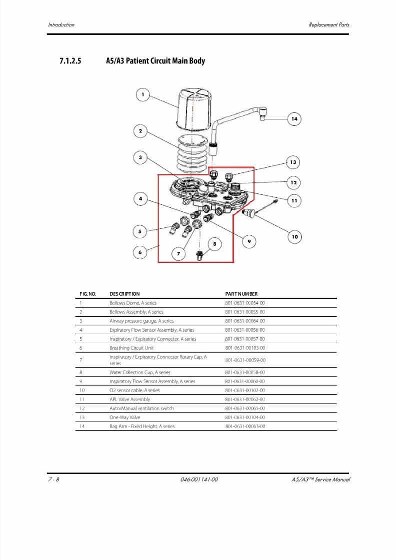
7/21/2019 a5 a3 Service Manual 2013
http://slidepdf.com/reader/full/a5-a3-service-manual-2013 383/399
Introduction Replacement Parts
7 - 8 046-001141-00 A5/A3™ Service Manual
7.1.2.5 A5/A3 Patient Circuit Main Body
1
2
3
4
5
6
14
13
12
11
10
7
8 9
FIG.NO. DESCRIPTION PART NUMBER
1 Bellows Dome, A series 801-0631-00054-00
2 Bellows Assembly, A series 801-0631-00055-00
3 Airway pressure gauge, A series 801-0631-00064-00
4 Expiratory Flow Sensor Assembly, A series 801-0631-00056-00
5 Inspiratory / Expiratory Connector, A series 801-0631-00057-00
6 Breathing Circuit Unit 801-0631-00103-00
7Inspiratory / Expiratory Connector Rotary Cap, A
series801-0631-00059-00
8 Water Collection Cup, A series 801-0631-00058-00
9 Inspiratory Flow Sensor Assembly, A series 801-0631-00060-00
10 O2 sensor cable, A series 801-0631-00102-0011 APL Valve Assembly 801-0631-00062-00
12 Auto/Manual ventilation switch 801-0631-00065-00
13 One-Way Valve 801-0631-00104-00
14 Bag Arm - Fixed Height, A series 801-0631-00063-00
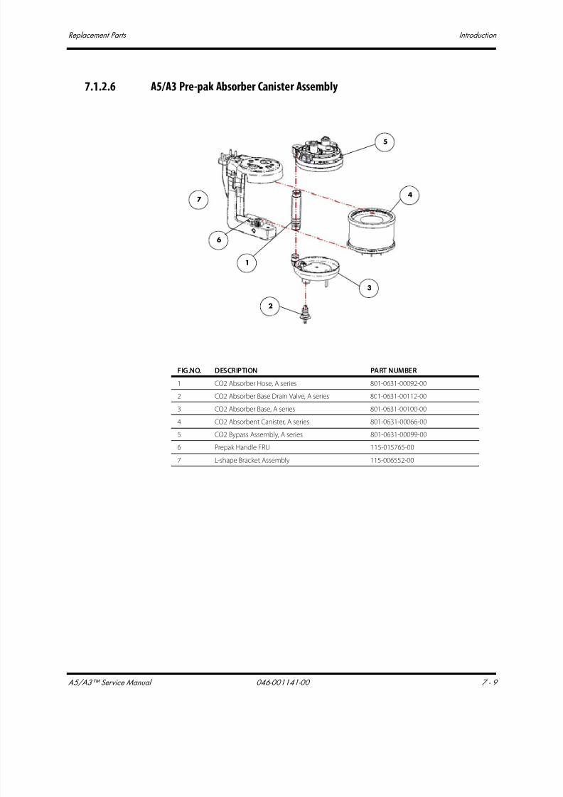
7/21/2019 a5 a3 Service Manual 2013
http://slidepdf.com/reader/full/a5-a3-service-manual-2013 384/399
A5/A3™ Service Manual 046-001141-00 7 - 9
Replacement Parts Introduction
7.1.2.6 A5/A3 Pre-pak Absorber Canister Assembly
FIG.NO. DESCRIPTION PART NUMBER
1 CO2 Absorber Hose, A series 801-0631-00092-00
2 CO2 Absorber Base Drain Valve, A series 801-0631-00112-00
3 CO2 Absorber Base, A series 801-0631-00100-00
4 CO2 Absorbent Canister, A series 801-0631-00066-00
5 CO2 Bypass Assembly, A series 801-0631-00099-00
6 Prepak Handle FRU 115-015765-00
7 L-shape Bracket Assembly 115-006552-00
3
4
5
2
1
7
6
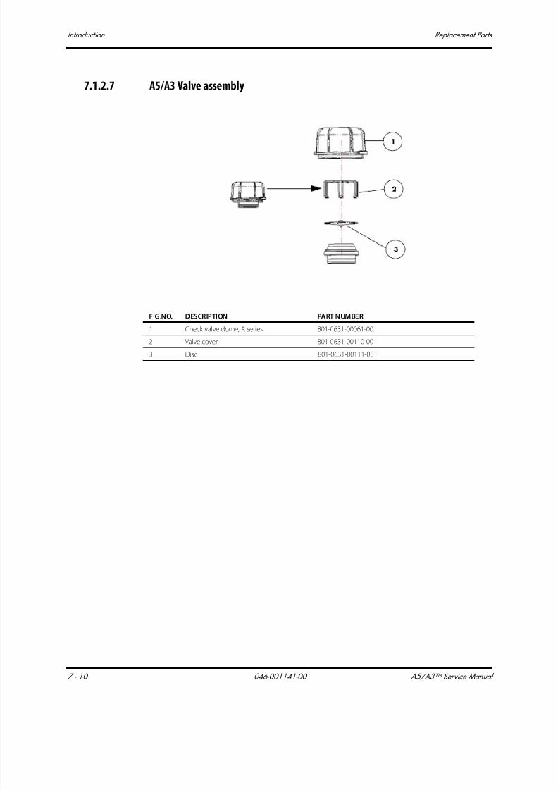
7/21/2019 a5 a3 Service Manual 2013
http://slidepdf.com/reader/full/a5-a3-service-manual-2013 385/399
Introduction Replacement Parts
7 - 10 046-001141-00 A5/A3™ Service Manual
7.1.2.7 A5/A3 Valve assembly
FIG.NO. DESCRIPTION PART NUMBER
1 Check valve dome, A series 801-0631-00061-00
2 Valve cover 801-0631-00110-00
3 Disc 801-0631-00111-00
1
2
3
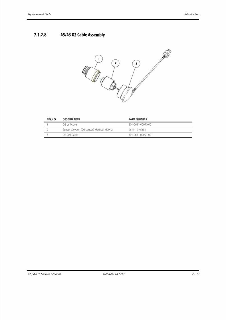
7/21/2019 a5 a3 Service Manual 2013
http://slidepdf.com/reader/full/a5-a3-service-manual-2013 386/399
A5/A3™ Service Manual 046-001141-00 7 - 11
Replacement Parts Introduction
7.1.2.8 A5/A3 O2 Cable Assembly
1
2 3
FIG.NO. DESCRIPTION PART NUMBER
1 O2 cell cover 801-0631-00090-00
2 Sensor Oxygen (O2 sensor) Medicel MOX-2 0611-10-45654
3 O2 Cell Cable 801-0631-00091-00
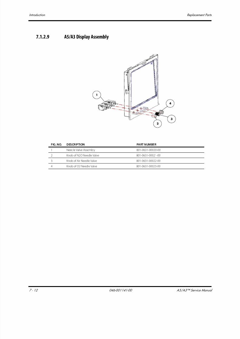
7/21/2019 a5 a3 Service Manual 2013
http://slidepdf.com/reader/full/a5-a3-service-manual-2013 387/399
Introduction Replacement Parts
7 - 12 046-001141-00 A5/A3™ Service Manual
7.1.2.9 A5/A3 Display Assembly
1
23
4
FIG. NO. DESCRIPTION PART NUMBER
1 Needle Valve Assembly 801-0631-00020-00
2 Knob of N2O Needle Valve 801-0631-00021-00
3 Knob of Air Needle Valve 801-0631-00022-00
4 Knob of O2 Needle Valve 801-0631-00023-00
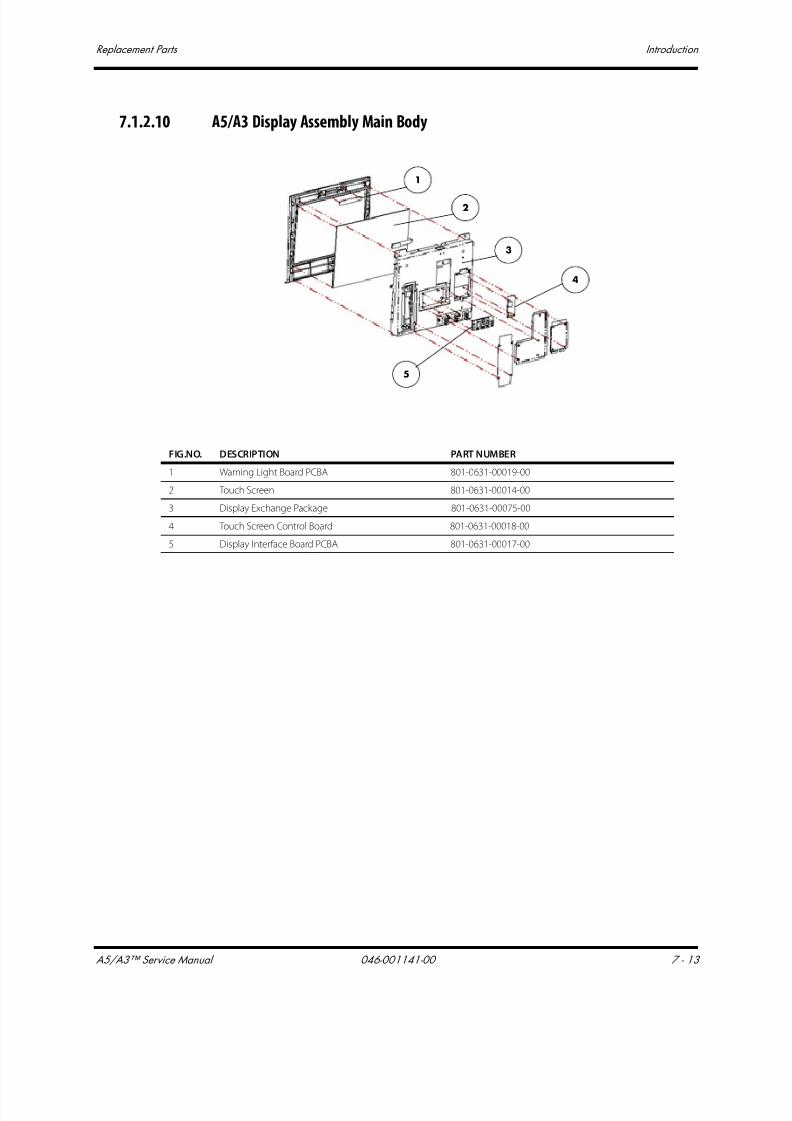
7/21/2019 a5 a3 Service Manual 2013
http://slidepdf.com/reader/full/a5-a3-service-manual-2013 388/399
A5/A3™ Service Manual 046-001141-00 7 - 13
Replacement Parts Introduction
7.1.2.10 A5/A3 Display Assembly Main Body
5
4
3
2
1
FIG.NO. DESCRIPTION PART NUMBER
1 Warning Light Board PCBA 801-0631-00019-00
2 Touch Screen 801-0631-00014-00
3 Display Exchange Package 801-0631-00075-00
4 Touch Screen Control Board 801-0631-00018-00
5 Display Interface Board PCBA 801-0631-00017-00
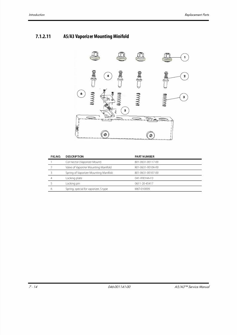
7/21/2019 a5 a3 Service Manual 2013
http://slidepdf.com/reader/full/a5-a3-service-manual-2013 389/399
Introduction Replacement Parts
7 - 14 046-001141-00 A5/A3™ Service Manual
7.1.2.11 A5/A3 Vaporizer Mounting Minifold
1
2
3
4
5
6
FIG.NO. DESCRIPTION PART NUMBER
1 Connector (Vaporizer Mount) 801-0631-00117-00
2 Valve of Vaporizer Mounting Manifold 801-0631-00106-00
3 Spring of Vaporizer Mounting Manifold 801-0631-00107-00
4 Locking plate 041-000166-00
5 Locking pin 0611-20-45417
6 Spring, special for vaporizer, S type M6T-010009

7/21/2019 a5 a3 Service Manual 2013
http://slidepdf.com/reader/full/a5-a3-service-manual-2013 390/399
A5/A3™ Service Manual 046-001141-00 7 - 15
Replacement Parts Introduction
7.1.2.12 A5/A3 Auxiliary Gas Outlet Assembly
FIG.NO. DESCRIPTION PART NUMBER
1 Aux Gas Supply Flow Meter Lighting Board PCBA 801-0631-00002-00
2 Auxiliary Gas Outlet Fittings (FRU) 801-0631-00122-00
1
2

7/21/2019 a5 a3 Service Manual 2013
http://slidepdf.com/reader/full/a5-a3-service-manual-2013 391/399
Introduction Replacement Parts
7 - 16 046-001141-00 A5/A3™ Service Manual
7.1.2.13 Base Assembly (A5)
1
2
3
4
5
FIG.NO. DESCRIPTION PART NUMBER
1 Brake Assembly (A5 only) 801-0631-00094-00
2 Connector of Brake (A5 only) 801-0631-00095-00
3 Indicator Drive Plate (A5 only) 801-0631-00072-00
4 Principal Axis of Brake (A5 only) 801-0631-00096-00
5 Base of Chasis Assembly (A5 only) 801-0631-00097-00

7/21/2019 a5 a3 Service Manual 2013
http://slidepdf.com/reader/full/a5-a3-service-manual-2013 392/399
A5/A3™ Service Manual 046-001141-00 7 - 17
Replacement Parts Introduction
7.1.2.14 Other
FIG.NO. DESCRIPTION PART NUMBER
1 Waste Gas Hose for Gas module to Colder fitting 801-0631-00078-00
2 Gas Cylinder Wrench 801-0631-00079-00
3 A5/A3 Pre-Operation Checklist, English 801-0631-00081-00
4 A5/A3 Auxiliary O2/Air Reference Card 801-0631-00082-00
- Preventative Maintenance Kit (12 months) 801-0631-00084-00
- A3 Periodic Maintenance Kit (36 months) 121-001072-00- A5 Periodic Maintenance Kit (36 months) 121-001061-00
1
43
2
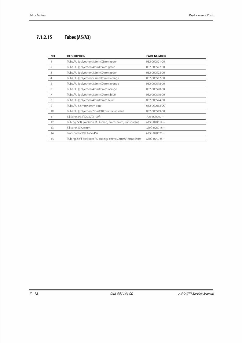
7/21/2019 a5 a3 Service Manual 2013
http://slidepdf.com/reader/full/a5-a3-service-manual-2013 393/399
Introduction Replacement Parts
7 - 18 046-001141-00 A5/A3™ Service Manual
7.1.2.15 Tubes (A5/A3)
NO. DESCRIPTION PART NUMBER
1 Tube.PU (polyether) 5.5mmX8mm green 082-000521-00
2 Tube.PU (polyether) 4mmX6mm green 082-000522-00
3 Tube.PU (polyether) 2.5mmX4mm green 082-000523-00
4 Tube.PU (polyether) 5.5mmX8mm orange 082-000517-00
5 Tube.PU (polyether) 2.5mmX4mm orange 082-000518-00
6 Tube.PU (polyether) 4mmX6mm orange 082-000520-00
7 Tube.PU (polyether) 2.5mmX4mm blue 082-000516-00
8 Tube.PU (polyether) 4mmX6mm blue 082-000524-00
9 Tube.PU 5.5mmX8mm blue 082-000662-00
10 Tube.PU (polyether) 7mmX10mm transparent 082-000519-00
11 Silicone,3/32"X7/32"X100ft A21-000007---
12 Tubing. Soft precision PU tubing, 8mmx5mm, transparent M6G-020014---
13 Silicone 20X25mm M6G-020018---
14 Transparent PU Tube 4*6 M6G-020026---
15 Tubing. Soft precision PU tubing, 4mmx2.5mm, transparent M6G-020046---
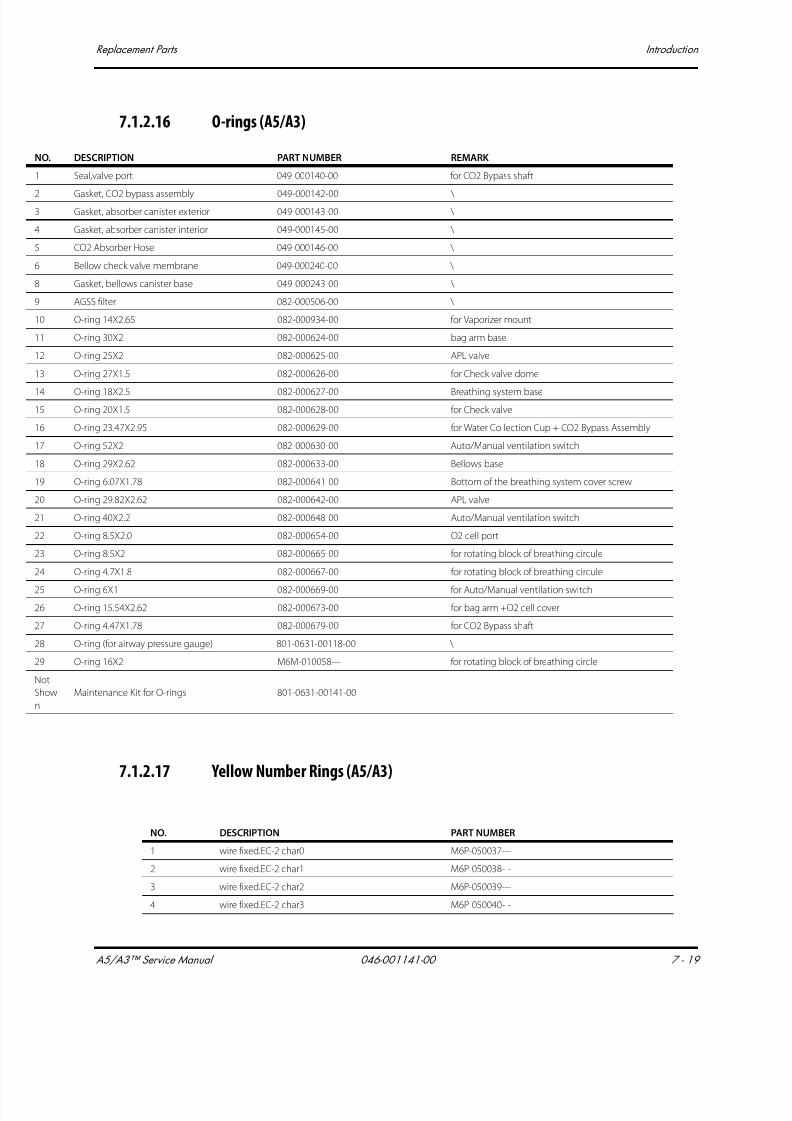
7/21/2019 a5 a3 Service Manual 2013
http://slidepdf.com/reader/full/a5-a3-service-manual-2013 394/399
A5/A3™ Service Manual 046-001141-00 7 - 19
Replacement Parts Introduction
7.1.2.16 O-rings (A5/A3)
7.1.2.17 Yellow Number Rings (A5/A3)
NO. DESCRIPTION PART NUMBER REMARK
1 Seal,valve port 049-000140-00 for CO2 Bypass shaft
2 Gasket, CO2 bypass assembly 049-000142-00 \ 3 Gasket, absorber canister exterior 049-000143-00 \
4 Gasket, absorber canister interior 049-000145-00 \
5 CO2 Absorber Hose 049-000146-00 \
6 Bellow check valve membrane 049-000240-00 \
8 Gasket, bellows canister base 049-000243-00 \
9 AGSS filter 082-000506-00 \
10 O-ring 14X2.65 082-000934-00 for Vaporizer mount
11 O-ring 30X2 082-000624-00 bag arm base
12 O-ring 25X2 082-000625-00 APL valve
13 O-ring 27X1.5 082-000626-00 for Check valve dome
14 O-ring 18X2.5 082-000627-00 Breathing system base
15 O-ring 20X1.5 082-000628-00 for Check valve
16 O-ring 23.47X2.95 082-000629-00 for Water Collection Cup + CO2 Bypass Assembly
17 O-ring 52X2 082-000630-00 Auto/Manual ventilation switch
18 O-ring 29X2.62 082-000633-00 Bellows base
19 O-ring 6.07X1.78 082-000641-00 Bottom of the breathing system cover screw
20 O-ring 29.82X2.62 082-000642-00 APL valve
21 O-ring 40X2.2 082-000648-00 Auto/Manual ventilation switch
22 O-ring 8.5X2.0 082-000654-00 O2 cell port
23 O-ring 8.5X2 082-000665-00 for rotating block of breathing circule
24 O-ring 4.7X1.8 082-000667-00 for rotating block of breathing circule
25 O-ring 6X1 082-000669-00 for Auto/Manual ventilation switch
26 O-ring 15.54X2.62 082-000673-00 for bag arm +O2 cell cover
27 O-ring 4.47X1.78 082-000679-00 for CO2 Bypass shaft
28 O-ring (for airway pressure gauge) 801-0631-00118-00 \
29 O-ring 16X2 M6M-010058--- for rotating block of breathing circle
Not
Show
n
Maintenance Kit for O-rings 801-0631-00141-00
NO. DESCRIPTION PART NUMBER
1 wire fixed.EC-2 char0 M6P-050037---
2 wire fixed.EC-2 char1 M6P-050038---
3 wire fixed.EC-2 char2 M6P-050039---
4 wire fixed.EC-2 char3 M6P-050040---

7/21/2019 a5 a3 Service Manual 2013
http://slidepdf.com/reader/full/a5-a3-service-manual-2013 395/399
Introduction Replacement Parts
7 - 20 046-001141-00 A5/A3™ Service Manual
7.1.2.18 Cables
5 wire fixed.EC-2 char4 M6P-050041---
6 wire fixed.EC-2 char5 M6P-050042---
7 wire fixed.EC-2 char6 M6P-050043---
8 wire fixed.EC-2 char7 M6P-050044---
9 wire fixed.EC-2 char8 M6P-050045---
10 wire fixed.EC-2 char9 M6P-050046---
11 wire fixed.EC-3 char0 M6P-050048---
12 wire fixed.EC-3 char1 M6P-050049---
13 wire fixed.EC-3 char2 M6P-050050---
14 wire fixed.EC-3 char3 M6P-050051---
15 wire fixed.EC-3 char4 M6P-050052---
16 wire fixed.EC-3 char5 M6P-050053---
17 wire fixed.EC-3 char6 M6P-050054---
18 wire fixed.EC-3 char7 M6P-050055---
19 wire fixed.EC-3 char8 M6P-050056---
20 wire fixed.EC-3 char9 M6P-050057---
- Maintenance Kit for Yellow Number Rings 801-0631-00138-00
NO. DESCRIPTION PART NUMBER
Cable, Norgren Avm Manifold Assy 009-000066-00
Cable, Three Way Valve 009-000957-00
Cable, Patient Monitor 009-000971-00
Cable, Touchpad 009-000972-00
Cable, Display 009-000973-00
Cable, Inverter LED 009-000974-00
Cable, Alarm 009-000976-00
Cable, Indicator 009-000977-00
Cable, Touch Screen 009-000978-00
Cable, Ventilator 009-000979-00
Cable, Lighting Switch 009-000981-00
Cable, AC Power 009-000983-00
Cable, Auxiliary Outlet 009-000984-00
Cable, Power, AC Internal 009-000985-00
Cable, Sodalime Canister Switch Cable 009-000987-00
Cable, Inverter Cable 009-000988-00
Cable, System Switch 009-001776-00
NO. DESCRIPTION PART NUMBER

7/21/2019 a5 a3 Service Manual 2013
http://slidepdf.com/reader/full/a5-a3-service-manual-2013 396/399
A5/A3™ Service Manual 046-001141-00 8 - 1
8.0 Warranty
Warranty Statements..............................................................................................................................................................................8-2
Disclaimers....................................................................................................................................................................................................8-3
Manufacturer's Responsibility...........................................................................................................................................................8-3
Phone Numbers and How to Get Assistance..........................................................................................................................8-3
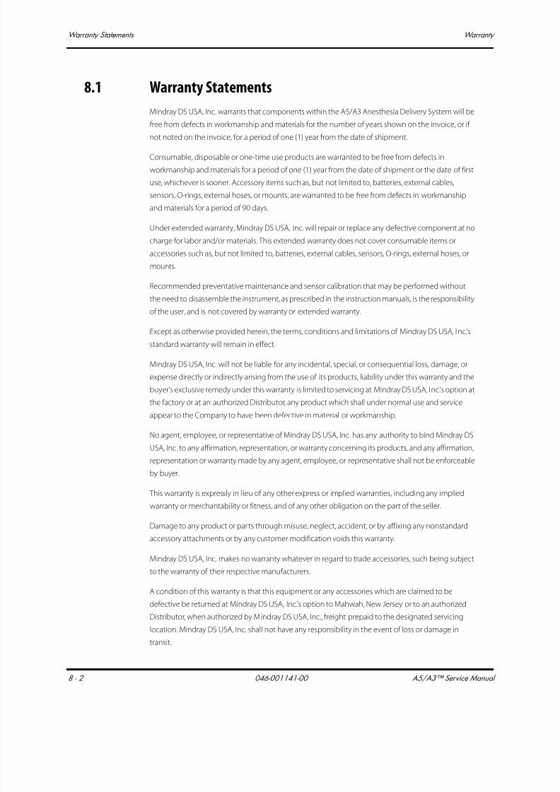
7/21/2019 a5 a3 Service Manual 2013
http://slidepdf.com/reader/full/a5-a3-service-manual-2013 397/399
Warranty Statements Warranty
8 - 2 046-001141-00 A5/A3™ Service Manual
8.1 Warranty Statements
Mindray DS USA, Inc. warrants that components within the A5/A3 Anesthesia Delivery System will be
free from defects in workmanship and materials for the number of years shown on the invoice, or if
not noted on the invoice, for a period of one (1) year from the date of shipment.
Consumable, disposable or one-time use products are warranted to be free from defects in
workmanship and materials for a period of one (1) year from the date of shipment or the date of first
use, whichever is sooner. Accessory items such as, but not limited to, batteries, external cables,
sensors, O-rings, external hoses, or mounts, are warranted to be free from defects in workmanship
and materials for a period of 90 days.
Under extended warranty, Mindray DS USA, Inc. will repair or replace any defective component at no
charge for labor and/or materials. This extended warranty does not cover consumable items or
accessories such as, but not limited to, batteries, external cables, sensors, O-rings, external hoses, or
mounts.
Recommended preventative maintenance and sensor calibration that may be performed without
the need to disassemble the instrument, as prescribed in the instruction manuals, is the responsibility
of the user, and is not covered by warranty or extended warranty.
Except as otherwise provided herein, the terms, conditions and limitations of Mindray DS USA, Inc.'s
standard warranty will remain in effect.
Mindray DS USA, Inc. will not be liable for any incidental, special, or consequential loss, damage, or
expense directly or indirectly arising from the use of its products, liability under this warranty and the
buyer's exclusive remedy under this warranty is limited to servicing at Mindray DS USA, Inc.'s option at
the factory or at an authorized Distributor, any product which shall under normal use and service
appear to the Company to have been defective in material or workmanship.
No agent, employee, or representative of Mindray DS USA, Inc. has any authority to bind Mindray DS
USA, Inc. to any affirmation, representation, or warranty concerning its products, and any affirmation,
representation or warranty made by any agent, employee, or representative shall not be enforceable
by buyer.
This warranty is expressly in lieu of any other express or implied warranties, including any implied
warranty or merchantability or fitness, and of any other obligation on the part of the seller.
Damage to any product or parts through misuse, neglect, accident, or by affixing any nonstandard
accessory attachments or by any customer modification voids this warranty.
Mindray DS USA, Inc. makes no warranty whatever in regard to trade accessories, such being subject
to the warranty of their respective manufacturers.
A condition of this warranty is that this equipment or any accessories which are claimed to be
defective be returned at Mindray DS USA, Inc.'s option to Mahwah, New Jersey or to an authorized
Distributor, when authorized by Mindray DS USA, Inc., freight prepaid to the designated servicing
location. Mindray DS USA, Inc. shall not have any responsibility in the event of loss or damage in
transit.

7/21/2019 a5 a3 Service Manual 2013
http://slidepdf.com/reader/full/a5-a3-service-manual-2013 398/399
A5/A3™ Service Manual 046-001141-00 8 - 3
Warranty Disclaimers
8.2 Disclaimers
Product Improvements - Mindray DS USA, Inc. retains the right to modify the machine and/ or
operating instructions without prior notification. These operating instructions explain all features of
the A5/A3 system and are correct at time of manufacture. Instructions and models produced at alater stage, may contain improvements or modifications that were not included in previous models.
8.3 Manufacturer's Responsibility
The effects on safety, reliability, and performance of the equipment are the manufacturer's
responsibility only if:
a. assembly operations, extensions, readjustments, modifications or repairs are carriedout by authorized personnel; and
b. the electrical installation of the relevant room complies with the appropriaterequirements; and
c. the equipment is used in accordance with the instructions for use
8.4 Phone Numbers and How to Get Assistance
A network of service representatives and factory-trained distributors is available. Prior to requesting
service, perform a complete operational check of the instrument to verify proper control settings. If
operational problems continue to exist, contact the Service Department at (800) 288-2121, ext: 8116
for Technical Support or (201) 995-8000 for assistance in determining the nearest field service
location.
Please include the instrument model number, the serial number, and a description of the problem
with all requests for service.
Warranty questions should be directed to a local representative. A list of offices, along with their
phone numbers, is provided at the end of this manual.
NOTE: Upon request, calibration instructions or other information will be
provided to assist the user's appropriately qualified technical
personnel in repairing those

7/21/2019 a5 a3 Service Manual 2013
http://slidepdf.com/reader/full/a5-a3-service-manual-2013 399/399