![Intel® AVX-512 Architecture - LLVM...A0 A1 A2 A3 A1 A2 A3 A6 A4 A5 A6 A7 A7 Mask: k[] = 01110011 Zeroed in the ss register form X A0 A1 A2 A0 A1 A2 A3 X X A3 A4 A4 Mask: k[] = 01110011](https://static.fdocuments.us/doc/165x107/5f31b370c034de36036a9e97/intel-avx-512-architecture-llvm-a0-a1-a2-a3-a1-a2-a3-a6-a4-a5-a6-a7-a7-mask.jpg)
A2, A6 PEK Control panel - ESAB Welding & · PDF fileGB 0460 949 074 GB 100127 Valid from...
62
GB Valid from program version 1.00 0460 949 074 GB 100127 A2, A6 PEK Control panel Instruction manual
Transcript of A2, A6 PEK Control panel - ESAB Welding & · PDF fileGB 0460 949 074 GB 100127 Valid from...

GB
Valid from program version 1.000460 949 074 GB 100127
A2, A6
PEK Control panel
Instruction manual

- 2 -TOCe
Rights reserved to alter specifications without notice.
1 INTRODUCTION 5. . . . . . . . . . . . . . . . . . . . . . . . . . . . . . . . . . . . . . . . . . . . . . . . . . . 1.1 Control panel 5. . . . . . . . . . . . . . . . . . . . . . . . . . . . . . . . . . . . . . . . . . . . . . . . . . . . . . . . . . . . .
1.1.1 Keys and knobs 6. . . . . . . . . . . . . . . . . . . . . . . . . . . . . . . . . . . . . . . . . . . . . . . . . . . . . .
1.2 First step 7. . . . . . . . . . . . . . . . . . . . . . . . . . . . . . . . . . . . . . . . . . . . . . . . . . . . . . . . . . . . . . . . .
1.2.1 Choice of language 7. . . . . . . . . . . . . . . . . . . . . . . . . . . . . . . . . . . . . . . . . . . . . . . . . . .
1.2.2 Unit of measurements 8. . . . . . . . . . . . . . . . . . . . . . . . . . . . . . . . . . . . . . . . . . . . . . . . .
1.3 Display 10. . . . . . . . . . . . . . . . . . . . . . . . . . . . . . . . . . . . . . . . . . . . . . . . . . . . . . . . . . . . . . . . . . .
1.3.1 Symbols in the display 10. . . . . . . . . . . . . . . . . . . . . . . . . . . . . . . . . . . . . . . . . . . . . . . . .
1.4 General information about settings 11. . . . . . . . . . . . . . . . . . . . . . . . . . . . . . . . . . . . . . . . . . .
1.4.1 Setting of numerical values 11. . . . . . . . . . . . . . . . . . . . . . . . . . . . . . . . . . . . . . . . . . . . .
1.4.2 Setting with given alternatives 11. . . . . . . . . . . . . . . . . . . . . . . . . . . . . . . . . . . . . . . . . .
1.5 QUIT and ENTER 11. . . . . . . . . . . . . . . . . . . . . . . . . . . . . . . . . . . . . . . . . . . . . . . . . . . . . . . . .
2 MENUS 12. . . . . . . . . . . . . . . . . . . . . . . . . . . . . . . . . . . . . . . . . . . . . . . . . . . . . . . . . . . 2.1 Main menu 12. . . . . . . . . . . . . . . . . . . . . . . . . . . . . . . . . . . . . . . . . . . . . . . . . . . . . . . . . . . . . . .
2.1.1 Configuration menu 13. . . . . . . . . . . . . . . . . . . . . . . . . . . . . . . . . . . . . . . . . . . . . . . . . . .
2.1.2 Tools menu 13. . . . . . . . . . . . . . . . . . . . . . . . . . . . . . . . . . . . . . . . . . . . . . . . . . . . . . . . . .
2.1.3 Weld data setting menu 13. . . . . . . . . . . . . . . . . . . . . . . . . . . . . . . . . . . . . . . . . . . . . . . .
2.1.4 Measurements menu 14. . . . . . . . . . . . . . . . . . . . . . . . . . . . . . . . . . . . . . . . . . . . . . . . . .
2.1.5 Weld data memory menu 15. . . . . . . . . . . . . . . . . . . . . . . . . . . . . . . . . . . . . . . . . . . . . .
2.1.6 Fast mode menu 16. . . . . . . . . . . . . . . . . . . . . . . . . . . . . . . . . . . . . . . . . . . . . . . . . . . . . .
3 SUBMERGED ARC WELDING 17. . . . . . . . . . . . . . . . . . . . . . . . . . . . . . . . . . . . . . . 3.1 Settings for submerged arc welding 17. . . . . . . . . . . . . . . . . . . . . . . . . . . . . . . . . . . . . . . . . .
4 GAS METAL ARC WELDING 18. . . . . . . . . . . . . . . . . . . . . . . . . . . . . . . . . . . . . . . . 4.1 Settings for Gas Metal Arc Welding 18. . . . . . . . . . . . . . . . . . . . . . . . . . . . . . . . . . . . . . . . . .
5 GOUGING 19. . . . . . . . . . . . . . . . . . . . . . . . . . . . . . . . . . . . . . . . . . . . . . . . . . . . . . . . . 5.1 Settings for gouging 19. . . . . . . . . . . . . . . . . . . . . . . . . . . . . . . . . . . . . . . . . . . . . . . . . . . . . . .
6 FUNCTION EXPLANATIONS 20. . . . . . . . . . . . . . . . . . . . . . . . . . . . . . . . . . . . . . . . 6.1 CA, constant amperage 20. . . . . . . . . . . . . . . . . . . . . . . . . . . . . . . . . . . . . . . . . . . . . . . . . . . .
6.2 CW, constant wire feed 20. . . . . . . . . . . . . . . . . . . . . . . . . . . . . . . . . . . . . . . . . . . . . . . . . . . . .
6.3 Wire / electrode dimension 20. . . . . . . . . . . . . . . . . . . . . . . . . . . . . . . . . . . . . . . . . . . . . . . . . .
6.4 Arc voltage 20. . . . . . . . . . . . . . . . . . . . . . . . . . . . . . . . . . . . . . . . . . . . . . . . . . . . . . . . . . . . . . .
6.5 Wire feed speed 20. . . . . . . . . . . . . . . . . . . . . . . . . . . . . . . . . . . . . . . . . . . . . . . . . . . . . . . . . . .
6.6 Travel speed 20. . . . . . . . . . . . . . . . . . . . . . . . . . . . . . . . . . . . . . . . . . . . . . . . . . . . . . . . . . . . . .
6.7 Welding direction 20. . . . . . . . . . . . . . . . . . . . . . . . . . . . . . . . . . . . . . . . . . . . . . . . . . . . . . . . . .
6.8 Flux pre-flow 21. . . . . . . . . . . . . . . . . . . . . . . . . . . . . . . . . . . . . . . . . . . . . . . . . . . . . . . . . . . . . .
6.9 Gas pre-flow 21. . . . . . . . . . . . . . . . . . . . . . . . . . . . . . . . . . . . . . . . . . . . . . . . . . . . . . . . . . . . . .
6.10 Air pre-flow 21. . . . . . . . . . . . . . . . . . . . . . . . . . . . . . . . . . . . . . . . . . . . . . . . . . . . . . . . . . . . . . .
6.11 Start type 21. . . . . . . . . . . . . . . . . . . . . . . . . . . . . . . . . . . . . . . . . . . . . . . . . . . . . . . . . . . . . . . . .
6.12 Wire creep start 21. . . . . . . . . . . . . . . . . . . . . . . . . . . . . . . . . . . . . . . . . . . . . . . . . . . . . . . . . . .
6.13 Start phases 22. . . . . . . . . . . . . . . . . . . . . . . . . . . . . . . . . . . . . . . . . . . . . . . . . . . . . . . . . . . . . .
6.14 Max Open Circuit Voltage (OCV) 22. . . . . . . . . . . . . . . . . . . . . . . . . . . . . . . . . . . . . . . . . . . .
6.15 Flux post-flow 22. . . . . . . . . . . . . . . . . . . . . . . . . . . . . . . . . . . . . . . . . . . . . . . . . . . . . . . . . . . . .
6.16 Gas post-flow 22. . . . . . . . . . . . . . . . . . . . . . . . . . . . . . . . . . . . . . . . . . . . . . . . . . . . . . . . . . . . .
6.17 Air post-flow 22. . . . . . . . . . . . . . . . . . . . . . . . . . . . . . . . . . . . . . . . . . . . . . . . . . . . . . . . . . . . . .
6.18 Crater filling 22. . . . . . . . . . . . . . . . . . . . . . . . . . . . . . . . . . . . . . . . . . . . . . . . . . . . . . . . . . . . . . .
6.19 Burnback time 23. . . . . . . . . . . . . . . . . . . . . . . . . . . . . . . . . . . . . . . . . . . . . . . . . . . . . . . . . . . .
6.20 Stop phases 23. . . . . . . . . . . . . . . . . . . . . . . . . . . . . . . . . . . . . . . . . . . . . . . . . . . . . . . . . . . . . .
6.21 Dynamic regulation 23. . . . . . . . . . . . . . . . . . . . . . . . . . . . . . . . . . . . . . . . . . . . . . . . . . . . . . . .
6.22 Setting limits 23. . . . . . . . . . . . . . . . . . . . . . . . . . . . . . . . . . . . . . . . . . . . . . . . . . . . . . . . . . . . . .
6.23 Measure limits 23. . . . . . . . . . . . . . . . . . . . . . . . . . . . . . . . . . . . . . . . . . . . . . . . . . . . . . . . . . . .

- 3 -TOCe
Rights reserved to alter specifications without notice.
7 MEMORY MANAGEMENT 24. . . . . . . . . . . . . . . . . . . . . . . . . . . . . . . . . . . . . . . . . . . 7.1 Control panel working method 24. . . . . . . . . . . . . . . . . . . . . . . . . . . . . . . . . . . . . . . . . . . . . . .
7.2 Store 25. . . . . . . . . . . . . . . . . . . . . . . . . . . . . . . . . . . . . . . . . . . . . . . . . . . . . . . . . . . . . . . . . . . .
7.3 Recall 26. . . . . . . . . . . . . . . . . . . . . . . . . . . . . . . . . . . . . . . . . . . . . . . . . . . . . . . . . . . . . . . . . . . .
7.4 Delete 27. . . . . . . . . . . . . . . . . . . . . . . . . . . . . . . . . . . . . . . . . . . . . . . . . . . . . . . . . . . . . . . . . . .
7.5 Copy 28. . . . . . . . . . . . . . . . . . . . . . . . . . . . . . . . . . . . . . . . . . . . . . . . . . . . . . . . . . . . . . . . . . . . .
7.6 Name 29. . . . . . . . . . . . . . . . . . . . . . . . . . . . . . . . . . . . . . . . . . . . . . . . . . . . . . . . . . . . . . . . . . . .
7.7 Edit 30. . . . . . . . . . . . . . . . . . . . . . . . . . . . . . . . . . . . . . . . . . . . . . . . . . . . . . . . . . . . . . . . . . . . . .
8 CONFIGURATION MENU 31. . . . . . . . . . . . . . . . . . . . . . . . . . . . . . . . . . . . . . . . . . . 8.1 Code lock 31. . . . . . . . . . . . . . . . . . . . . . . . . . . . . . . . . . . . . . . . . . . . . . . . . . . . . . . . . . . . . . . .
8.1.1 Lock code status 32. . . . . . . . . . . . . . . . . . . . . . . . . . . . . . . . . . . . . . . . . . . . . . . . . . . . . .
8.1.2 Specify/edit lock code 33. . . . . . . . . . . . . . . . . . . . . . . . . . . . . . . . . . . . . . . . . . . . . . . . .
8.2 General configuration 33. . . . . . . . . . . . . . . . . . . . . . . . . . . . . . . . . . . . . . . . . . . . . . . . . . . . . .
8.2.1 Fast mode soft keys 33. . . . . . . . . . . . . . . . . . . . . . . . . . . . . . . . . . . . . . . . . . . . . . . . . . .
8.2.2 Quality data log to file 34. . . . . . . . . . . . . . . . . . . . . . . . . . . . . . . . . . . . . . . . . . . . . . . . .
8.2.3 Soft key configuration 34. . . . . . . . . . . . . . . . . . . . . . . . . . . . . . . . . . . . . . . . . . . . . . . . .
8.2.4 Auto save mode 36. . . . . . . . . . . . . . . . . . . . . . . . . . . . . . . . . . . . . . . . . . . . . . . . . . . . . .
8.3 Machine configuration 36. . . . . . . . . . . . . . . . . . . . . . . . . . . . . . . . . . . . . . . . . . . . . . . . . . . . . .
8.3.1 Product code 37. . . . . . . . . . . . . . . . . . . . . . . . . . . . . . . . . . . . . . . . . . . . . . . . . . . . . . . . .
8.3.2 Wire feed axis 37. . . . . . . . . . . . . . . . . . . . . . . . . . . . . . . . . . . . . . . . . . . . . . . . . . . . . . . .
8.3.3 Travel axis 38. . . . . . . . . . . . . . . . . . . . . . . . . . . . . . . . . . . . . . . . . . . . . . . . . . . . . . . . . . .
8.3.4 Outer axis 38. . . . . . . . . . . . . . . . . . . . . . . . . . . . . . . . . . . . . . . . . . . . . . . . . . . . . . . . . . .
8.3.5 Tandem 39. . . . . . . . . . . . . . . . . . . . . . . . . . . . . . . . . . . . . . . . . . . . . . . . . . . . . . . . . . . . .
8.4 Cable length 41. . . . . . . . . . . . . . . . . . . . . . . . . . . . . . . . . . . . . . . . . . . . . . . . . . . . . . . . . . . . . .
8.5 Maintenance 42. . . . . . . . . . . . . . . . . . . . . . . . . . . . . . . . . . . . . . . . . . . . . . . . . . . . . . . . . . . . . .
8.6 Network settings 42. . . . . . . . . . . . . . . . . . . . . . . . . . . . . . . . . . . . . . . . . . . . . . . . . . . . . . . . . .
8.6.1 System overview 43. . . . . . . . . . . . . . . . . . . . . . . . . . . . . . . . . . . . . . . . . . . . . . . . . . . . .
9 TOOLS 43. . . . . . . . . . . . . . . . . . . . . . . . . . . . . . . . . . . . . . . . . . . . . . . . . . . . . . . . . . . . 9.1 Error log 44. . . . . . . . . . . . . . . . . . . . . . . . . . . . . . . . . . . . . . . . . . . . . . . . . . . . . . . . . . . . . . . . . .
9.1.1 Units 44. . . . . . . . . . . . . . . . . . . . . . . . . . . . . . . . . . . . . . . . . . . . . . . . . . . . . . . . . . . . . . . .
9.1.2 Description of fault management codes 44. . . . . . . . . . . . . . . . . . . . . . . . . . . . . . . . . .
9.2 Export/Import 46. . . . . . . . . . . . . . . . . . . . . . . . . . . . . . . . . . . . . . . . . . . . . . . . . . . . . . . . . . . . .
9.3 File manager 46. . . . . . . . . . . . . . . . . . . . . . . . . . . . . . . . . . . . . . . . . . . . . . . . . . . . . . . . . . . . . .
9.3.1 Delete a file/folder 47. . . . . . . . . . . . . . . . . . . . . . . . . . . . . . . . . . . . . . . . . . . . . . . . . . . . .
9.3.2 Rename a file/folder 48. . . . . . . . . . . . . . . . . . . . . . . . . . . . . . . . . . . . . . . . . . . . . . . . . . .
9.3.3 Create new folder 48. . . . . . . . . . . . . . . . . . . . . . . . . . . . . . . . . . . . . . . . . . . . . . . . . . . . .
9.3.4 Copy and paste files 48. . . . . . . . . . . . . . . . . . . . . . . . . . . . . . . . . . . . . . . . . . . . . . . . . . .
9.4 Setting limit editor 49. . . . . . . . . . . . . . . . . . . . . . . . . . . . . . . . . . . . . . . . . . . . . . . . . . . . . . . . .
9.5 Measure limits editor 50. . . . . . . . . . . . . . . . . . . . . . . . . . . . . . . . . . . . . . . . . . . . . . . . . . . . . . .
9.6 Production statistics 50. . . . . . . . . . . . . . . . . . . . . . . . . . . . . . . . . . . . . . . . . . . . . . . . . . . . . . .
9.7 Quality functions 51. . . . . . . . . . . . . . . . . . . . . . . . . . . . . . . . . . . . . . . . . . . . . . . . . . . . . . . . . .
9.7.1 Store quality data 52. . . . . . . . . . . . . . . . . . . . . . . . . . . . . . . . . . . . . . . . . . . . . . . . . . . . .
9.8 Calendar 53. . . . . . . . . . . . . . . . . . . . . . . . . . . . . . . . . . . . . . . . . . . . . . . . . . . . . . . . . . . . . . . . .
9.9 User accounts 53. . . . . . . . . . . . . . . . . . . . . . . . . . . . . . . . . . . . . . . . . . . . . . . . . . . . . . . . . . . .
9.10 Unit information 55. . . . . . . . . . . . . . . . . . . . . . . . . . . . . . . . . . . . . . . . . . . . . . . . . . . . . . . . . . .
MENU STRUCTURE 56. . . . . . . . . . . . . . . . . . . . . . . . . . . . . . . . . . . . . . . . . . . . . . . . . . .
WIRE DIMENSION 60. . . . . . . . . . . . . . . . . . . . . . . . . . . . . . . . . . . . . . . . . . . . . . . . . . . .

- 4 -TOCe
Rights reserved to alter specifications without notice.
ORDERING NUMBER 61. . . . . . . . . . . . . . . . . . . . . . . . . . . . . . . . . . . . . . . . . . . . . . . . .

- 5 -bi24d1ea
1 INTRODUCTION
To benefit as much as possible from your welding equipment, we recommend thatyou read this instruction manual.
For general information about operation, see the instruction manual for the controlunit, automatic welding machine, column and boom or power source.
The text presented in the display is available in the following languages:English, Swedish, Finnish, Norwegian, Danish, German, French, Italian, Dutch,Spanish, Portuguese, Hungarian, Polish, American, Czech, Chinese and Russian.
1.1 Control panel
1 Menu
2 Knob for moving cursor(positioning knob)
3 ENTER
4 Green indicating lamp,illuminates when thefunction is active
5 Welding start
6 Welding stop
7 Knob for setting the travel speed inthe measurements menu, in othermenus to increase or decrease the set values (settings knob)
8 Manual travel motion
9 Manual wire feed downwards
10 Knob for setting the arc voltage in the measurements menu, in other menus toincrease or decrease the set values (settings knob)
11 Fast motion
12 Manual travel motion
13 Knob for setting the welding current / wire feed speed in the measurementsmenu, in other menus to increase or decrease the set values (settings knob)
14 Emergency stop
15 Manual wire feed upwards
GB

- 6 -bi24d1ea
16 Soft keys
17 Display
1.1.1 Keys and knobs
Menu
The Menu key always takes you back to the main menu in the relevant process:
SAW
PROCESS SAW
REGULATION TYPE CA
WIRE TYPE Fe SOLID
WIRE DIMENSION 3.0 mm
CONFIGURATION�
TOOLS�
SET MEASURE MEMORY
FAST
MODE
ENTER
Use the ENTER key to confirm a selection.
Soft keys
The five keys (S1 - S5) under the display have different functions. They are called”soft” keys, i.e. they can have different functions depending on which menu you arein. The current function for these keys can be seen from the text in the bottom row ofthe display. When the function is active, this is indicated by the field with the text boxturning white.
Wire feed upwards
Key for reversing the wire without arc voltage, when replacing wire bobbin forexample. The wire is fed as long as the button is depressed.
Wire feed downwards
Key for feeding wire without arc voltage. The wire is fed as long as the button isdepressed.
Travel motion
Key for travel motion in the direction of welding where the symbol is indicated on the
weld equipment. To stop travel motion press , or .
The LED illuminates during travel motion.
GB

- 7 -bi24d1ea
Travel motion
Key for travel motion in the direction of welding where the symbol is indicated on the
weld equipment. To stop travel motion press , or .
The LED illuminates during travel motion.
Fast motion
Key for fast motion of wire feed or travel motion.
The LED illuminates during fast motion.
Welding start
Key for welding start.
Welding stop
Key for welding stop for all travel motions and all motors.
Positioning knob
The uppermost right-hand knob is called the positioning knob in the instructionmanual and is used to position the cursor.
Settings knob
The three knobs under the panel are called settings knobs in the instruction manualand are used to change the set values in the panel.
1.2 First step
1.2.1 Choice of language
This menu appears when the machine is first started:
SAW: CA
A 450 AmpV 30.0 Volt 50 cm/min
|||
|||
NONE NONE
GAS /
FLUX NONE
2ND
FUNCT
The control panel is set to English on delivery. To select your language, proceed asfollows:
GB

- 8 -bi24d1ea
Press Menu to access the main menu.
Position the cursorusing the positioningknob on the CONFIGURATION row.
SAW
PROCESS SAW
REGULATION TYPE CA
WIRE TYPE Fe SOLID
WIRE DIMENSION 3.0 mm
CONFIGURATION�
TOOLS�
SET MEASURE MEMORY
FAST
MODE
Press ENTER to confirm the selection.
Position the cursor onthe LANGUAGE row.Press ENTER to bringup a list of the languages that are available in the controlpanel.
CONFIGURATION
LANGUAGE ENGLISH
CODE LOCK
GENERAL CONFIGURATION�
MACHINE CONFIGURATION�
CABLE LENGTHS�
MAINTENANCE�
NETWORK SETTINGS�
QUIT
Position the cursor on the row for your language andpress ENTER.
NORSK
POLSKI
PORTUGUES
SUOMI
SVENSKA
CHINESE
|||
1.2.2 Unit of measurements
The control panel is set to metric measurement on delivery. To select anothermesurement, proceed as follows:
GB

- 9 -bi24d1ea
Press Menu to access the main menu.
Position the cursorusing the positioningknob on the CONFIGURATION row.
SAW
PROCESS SAW
REGULATION TYPE CA
WIRE TYPE Fe SOLID
WIRE DIMENSION 3.0 mm
CONFIGURATION�
TOOLS�
SET MEASURE MEMORY
FAST
MODE
Press ENTER to confirm the selection.
Position the cursor onthe GENERAL CONFIGURATION row.
CONFIGURATION
LANGUAGE ENGLISH
CODE LOCK
GENERAL CONFIGURATION�
MACHINE CONFIGURATION�
CABLE LENGTHS�
MAINTENANCE�
NETWORK SETTINGS�
QUIT
Press ENTER to confirm the selection.
Position the cursor onthe UNIT OF LENGTHrow. Press ENTER tobring up a list of themesurements that areavailable in the controlpanel.
GENERAL CONFIGURATION
FAST MODE SOFT BUTTONS 1
QUALITY DATA LOG TO FILE ON
SOFT KEYS SETUP�
AUTO SAVE MODE OFF
UNIT OF LENGTH METRIC
QUIT
Position the cursor on the row for correct mesurement and pressENTER.
METRIC
INCH.
GB

- 10 -bi24d1ea
1.3 Display
SAW
PROCESS SAW
REGULATION TYPE CW
WIRE TYPE Fe SOLID
WIRE DIMENSION 0.8 mm
CONFIGURATION�
TOOLS�
SET MEASURE MEMORY
FAST
MODE
Cursor
The control panel's cursor is presented as a black field around the text, with theselected text turning white. The cursor is displayed in the instruction manual withbold text.
Text boxes
At the bottom of the display are five boxes containing text that describes the currentfunction of the five soft keys below the display.
1.3.1 Symbols in the display
A The selected weld data set
B Welding direction
C A fault has occurred. See chapter9.1
D Recalled memory position number
E Scroll bar. Further information canbe found in this menu
Arrows
Where there is more information behind a row, this is indicated with a black arrow �behind the text.
GB

- 11 -bi24d1ea
1.4 General information about settings
There are three types of setting:
� Setting of numerical values
� Setting of given alternatives
� Setting of ON/OFF mode
1.4.1 Setting of numerical values
The settings knobs are used to increase or decrease the set values when settingnumerical values. In the measurements menu, the knobs for welding current / wirefeed speed, arc voltage or travel motion are used.
1.4.2 Setting with given alternatives
Some settings are made by selecting an option from a list.
This is an example of the list:
SAW
GMAW
GOUGING
The cursor is positioned on the row for SAW. By pressing ENTER in this position, theSAW option is selected. If you want to choose another option instead, position thecursor on the correct row by scrolling up or down using the positioning knob. Thenpress ENTER. If you want to exit the list without making a selection, press QUIT.
1.5 QUIT and ENTER
The “soft” key farthest to the right is used primarily for QUIT, although it isoccasionally used for other functions.
� QUIT returns you to the previous menu or image.
� Pressing ENTER entails the execution of a selected choice in a menu or a list.
The key is called ENTER in this manual.
GB

- 12 -bi24d1ea
2 MENUS
The control panel uses several different menus:
� Main menu
� Configuration menu
� Tools menu
� Weld data setting menu
� Measurements menu
� Weld data memory menu
� Fast mode menu
The menu trees are displayed on page 56 and onwards. During start-up, a start-upscreen containing information about the current program version is displayed briefly.
Start-up screen
2.1 Main menu
In the MAIN MENU,you can change welding process, wire type,control method, wire dimension etc.
You can access othersub menus from thismenu.
SAW
PROCESS SAW
REGULATION TYPE CA
WIRE TYPE Fe SOLID
WIRE DIMENSION 0.8 mm
CONFIGURATION�
TOOLS�
SET MEASURE MEMORY
FAST
MODE
GB

- 13 -bi24d1ea
2.1.1 Configuration menu
Main menu � Configuration
In the CONFIGURATION menu it ispossible to changelanguage, changepassword, makeGeneral configuration,make machineadjustments etc.
CONFIGURATION
LANGUAGE ENGLISH
CODE LOCK
GENERAL CONFIGURATION�
MACHINE CONFIGURATION�
CABLE LENGTHS�
MAINTENANCE�
NETWORK SETTINGS�
QUIT
2.1.2 Tools menu
Main menu � Tools
In the TOOLS menuyou can transfer files,view quality andproduction statistics,error logs, etc.
TOOLS
ERROR LOG�
EXPORT / IMPORT�
FILE MANAGER�
SETTING LIMIT EDITOR�
MEASURE LIMIT EDITOR�
PRODUCTION STATISTICS�
QUALITY FUNCTIONS�
CALENDAR�
USER ACCOUNTS�
UNIT INFORMATION�
QUIT
2.1.3 Weld data setting menu
Main menu �
In the weld data settingmenu, SET, it ispossible to changedifferent weldingparameters. The menuhas different appearances depending onwhich welding processis selected.
SAW WELD DATA SETTING
VOLTAGE 20.5 V
CURRENT 395 A
TRAVEL SPEED 0 cm/min
DIRECTION �
START DATA�
STOP DATA�
DYNAMIC REGULATION AUTO
SETTING LIMITS�
MEASURE LIMITS�
QUIT
GB
- 14 -bi24d1ea
2.1.4 Measurements menu
Main menu �
In MEASURE, you can view measured values for various welding parameters whilewelding is in progress.
A 450 AMP
Measured weldingcurrent
30.0 Volt
Measured arc voltage
50 cm/min
Measured travel speed
SAW: CW
A 450 AmpV 30.0 Volt 50 cm/min
|||
|||
NONE NONE
GAS /
FLUX NONE
2ND
FUNCT
300 cm/min
Measured wire feedspeed
30 kJ/cm
Indicates energy perunit length, which isobtained using thevalues selected forwelding current, arcvoltage and travelspeed
SAW: CW
50 cm/min 300 cm/min 30.0 kJ/cm
|||
|||
NONE NONE
GAS /
FLUX NONE
2ND
FUNCT
The measured values remain in the display even after welding has been completed.
You can move to different menus without losing the measurement values.
The settings knobs can be used to change the welding parameters in themeasurement display.
If the set value is changed when welding is not in progress, the measurement valuechanges to zero.
GB

- 15 -bi24d1ea
In the measurement display one can also see the set values if the soft key SETVALUES is activated. For activating see chapter ”Setting soft keys“ 8.2.3 .
300 cm/min
Set wire feed speed
20.0 Volt
Set arc voltage
30 cm/min
Set travel speed
SAW: CW
300 cm/minV 20.0 Volt 30 cm/min
|||
|||
NONE NONE
SET
VALUES NONE
2ND
FUNCT
2.1.5 Weld data memory menu
Main menu �
In the WELD DATAMEMORY menu youcan store, recall, deleteand copy various setweld data. The welddata sets can be storedin 255 different memorypositions.
WELD DATA MEMORY
1 (SAW)
7 (GMAW)
STORE
2ND
FUNCT QUIT
For further information, see the chapter 7 “Memory management”.
GB
- 16 -bi24d1ea
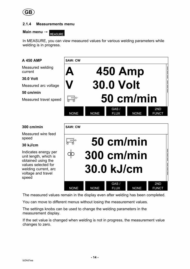
2.1.6 Fast mode menu
Main menu �
In the FAST MODEmenu, you can “link”soft keys to weld datamemory positions.These settings arecarried out in theConfiguration menu.The number of theselected memoryposition is displayed inthe top right corner.
A 450 AmpV 30.0 Volt 50 cm/minWELD
DATA 1
WELD
DATA 2
WELD
DATA 3
WELD
DATA 4
2ND
FUNCT
For further information, see the chapter 8.2.1 “Fast mode soft keys”.
GB
16

- 17 -bi24d1ea
3 SUBMERGED ARC WELDING
Main menu � Process
During Submerged Arc Welding (SAW), an arc melts a continuously supplied wire.The weld pool is protected by flux.
When the submerged arc welding process is selected, you can choose between twocontrol methods by marking REGULATION TYPE using the positioning knob andpressing ENTER. Choose between constant amperage CA or constant wire feedCW, see explanation in chapter 6.1 and 6.2.
3.1 Settings for submerged arc welding
Settings Setting range In steps of Value afterresetting
Arc voltage* 14 - 50 V 0.1 V (1V) 30 V
Welding current* (CA) 0 - 3200 A 1 A 400 A
Wire feed speed* (CW) 0 - 2500 cm/min 1 cm/min 300 cm/min
Travel speed* 0 - 200 cm/min 1 cm/min 50 cm/min
Welding direction � - � - �
Start data
Flux pre-flow 0 - 99.0 s 0.1 s 0 s
Start type Direct or Scrape - Direct
Wire creep start Auto or Set speed - Auto
Wire creep start speed 0 - 1000 cm/min 1 cm/min 20 cm/min
Start phases OFF or ON - OFF
Open-circuit voltage OFF or ON - OFF
Maximum open-circuit voltage 5 - 60 V 0.1 V 50 V
Stop data
Flux post-flow 0 - 99.0 s 0.1 s 0 s
Crater filling OFF or ON - OFF
Crater filling time 0 - 10 s 0.01 s 1 s
Burnback time 0 - 10 s 0.01 s 1 s
Stop phases OFF or ON - OFF
Dynamic regulation Auto or Set value - Auto
Setting limits - - -
Measure limits - - -
*) The setting range is dependent on the product used.
GB

- 18 -bi24d1ea
4 GAS METAL ARC WELDING
Main menu � Process
During Gas Metal Arc Welding (GMAW), an arc melts a continuously supplied wire.The weld pool is protected by shielding gas.
When the Gas Metal Arc Welding (GMAW) process is selected, you can choosebetween two control methods by marking REGULATION TYPE using the positioningknob and pressing ENTER. Choose between constant amperage CA or constantwire feed CW, see explanation in chapter 6.1 and 6.2.
4.1 Settings for Gas Metal Arc Welding
Settings Setting range In steps of Value afterresetting
Arc voltage* 14 - 50 V 0.1 V (1V) 30 V
Welding current* (CA) 0 - 3200 A 1 A 400 A
Wire feed speed* (CW) 0 - 2500 cm/min 1 cm/min 300 cm/min
Travel speed* 0 - 200 cm/min 1 cm/min 50 cm/min
Welding direction � - � - �
Start data
Gas pre-flow 0 - 99.0 s 0.1 s 2.0 s
Start type Direct or Scrape - Direct
Wire creep start Auto or Set speed - Auto
Wire creep start speed 0 - 1000 cm/min 1 cm/min 20 cm/min
Start phases OFF or ON - OFF
Open-circuit voltage OFF or ON - OFF
Maximum open-circuit voltage 5 - 60 V 0.1 V 50 V
Stop data
Gas post-flow 0 - 99.0 s 0.1 s 2.0 s
Crater filling OFF or ON - OFF
Crater filling time 0 - 10 s 0.01 s 1 s
Burnback time 0 - 10 s 0.01 s 1 s
Stop phases OFF or ON - OFF
Dynamic regulation Auto or Set value - Auto
Setting limits - - -
Measure limits - - -
*) The setting range is dependent on the product used.
GB

- 19 -bi24d1ea
5 GOUGING
Main menu � Process
With arc air gouging, a special electrode comprising a carbon rod with a coppercasing is used.
An arc is formed between the carbon rod and the work piece, which melts thematerial. Air is supplied so that the melted material is blown away.
When the GOUGING process is selected, you can choose between two controlmethods by marking REGULATION TYPE using the positioning knob and pressingENTER. Choose between constant amperage CA or constant wire feed CW, seeexplanation in chapter 6.1 and 6.2.
5.1 Settings for gouging
Settings Setting range In steps of Value afterresetting
Arc voltage* 14 - 50 V 0.1 V (1V) 30 V
Welding current* (CA) 0 - 3200 A 1 A 400 A
Wire feed speed* (CW) 0 - 2500 cm/min 1 cm/min 300 cm/min
Travel speed* 0 - 200 cm/min 1 cm/min 40 cm/min
Welding direction � - � - �
Start data
Air pre-flow 0 - 99.0 s 0.1 s 0 s
Start type Direct or Scrape - Direct
Wire creep start Auto or Set speed - Auto
Wire creep start speed 0 - 1000 cm/min 1 cm/min 20 cm/min
Start phases OFF or ON - OFF
Open-circuit voltage OFF or ON - OFF
Maximum open-circuit voltage 5 - 60 V 0.1 V 50 V
Stop data
Air post-flow 0 - 99.0 s 0.1 s 0 s
Crater filling OFF or ON - OFF
Crater filling time 0 - 10 s 0.01 s 1 s
Burnback time 0 - 10 s 0.01 s 1 s
Stop phases OFF or ON - OFF
Dynamic regulation Auto or Set value - Auto
Setting limits - - -
Measure limits - - -
*) The setting range is dependent on the product used.
GB

- 20 -bi24d1ea
6 FUNCTION EXPLANATIONS
6.1 CA, constant amperage
The wire feed is controlled by the power source so that a constant amperage can beachieved.
- Constant current value can be selected in the main menu.
6.2 CW, constant wire feed
The welding current is a result of the selected wire feed speed.
- Constant wire feed can be selected in the main menu.
6.3 Wire / electrode dimension
The table on page 60 shows the wire / electrode dimensions that can be selected.
Selected dimensions have a great impact on the start procedure and crater filling.When welding with other wire dimensions other than those found in the table, selectone that has a dimension close to one in the list.
- Wire / electrode dimension can be selected in the main menu.
6.4 Arc voltage
Higher arc voltage increases the arc length and produces a hotter, wider weld pool.
- The arc voltage is set in the measurement display, weld data setting menu, or fastmode menu.
6.5 Wire feed speed
This sets the required feed speed of the filler wire in cm/minute.
- The wire feed speed is set in the measurement display, weld data setting menu, orfast mode menu.
6.6 Travel speed
Travel speed indicates the required speed (cm/min) at which a column and boom ortrolley is to move.
- The travel speed is set in the measurement display, weld data setting menu, or fastmode menu.
6.7 Welding direction
Travel motion in the direction that the symbol indicates.
- Welding direction is selected in the weld data setting menu.
GB

- 21 -bi24d1ea
6.8 Flux pre-flow
This controls the time during which flux flows before the arc is struck.
- Flux pre-flow is set in the weld data setting menu under start data.
6.9 Gas pre-flow
This controls the time during which shielding gas flows before the arc is struck.
- Gas pre-flow is set in the weld data setting menu under start data.
6.10 Air pre-flow
This controls the time during which air flows before the arc is struck.
- Air pre-flow is set in the weld data setting menu under start data.
6.11 Start type
There are two options for start type:
� Direct start, means that the travel speed starts when the arc is struck.
� Scrape start, means that the travel speed starts at the same time as wire feed.
- Start type is selected in the weld data setting menu under start data.
6.12 Wire creep start
Wire creep start is used to set the desired creep speed on the electrode motor uponstart-up.
If, for example, 50 is set in the menu a creep speed of 50 cm/min is obtained.
Preset value ”AUTO” gives a creep speed calculated from the set values.
- Wire creep speed is set in the weld data setting menu under start data.
GB

- 22 -bi24d1ea
6.13 Start phases
When welding special wire or material, it may be necessary to create your own startsequence. The start sequence can affect the appearance of the weld pool.
The following can be set for Startphase1 ON
The following can be set for Startphase2 ON
� Time s
Time for welding in phase 1.
� Time s
Time for welding in phase 2.
� Arc voltage %
In percent of set voltage
� Arc voltage %
In percent of set voltage
� Wire feed %
In percent of set wire feed
� Wire feed %
In percent of set wire feed
� Welding current %
In percent of set welding current
� Welding current %
In percent of set welding current
� Travel speed %
In percent of set travel speed
� Travel speed %
In percent of set travel speed
- Start phases are set in the weld data setting menu under start data.
6.14 Max Open Circuit Voltage (OCV)
ON means that OCV can be set.
OFF means that OCV is set to the set value for welding voltage.
- OCV is set in the weld data setting menu under start data.
6.15 Flux post-flow
This controls the time during which flux flows after the arc is extinguished.
- Flux post-flow is set in the weld data setting menu under stop data.
6.16 Gas post-flow
This controls the time during which shielding gas flows after the arc is extinguished.
- Gas post-flow is set in the weld data setting menu under stop data.
6.17 Air post-flow
This controls the time during which air flows after the arc is extinguished.
- Air post-flow is set in the weld data setting menu under stop data.
6.18 Crater filling
Crater filling makes a controlled reduction in the heat and size of the weld poolpossible when completing the weld. This makes it easier to avoid pores, thermalcracking and crater formation in the weld joint.
- Crate filling is set in the weld data setting menu under stop data.
GB

- 23 -bi24d1ea
6.19 Burnback time
Burnback time is a delay between the time when the wire starts to brake until thetime when the power source switches off the arc voltage. Too short burnback timeresults in a long wire stickout after completion of welding, with a risk of the wire beingcaught in the solidifying weld pool. Too long a burnback time results in a shorterstickout, with increased risk of the arc striking back to the contact tip.
- Burnback time is set in the weld data setting menu under stop data.
6.20 Stop phases
Stop phases are mainly used for setting crater filling.
The following can be set for Stopphase1 ON
The following can be set for Stopphase2 ON
� Time s
Time for welding in phase 1.
� Time s
Time for welding in phase 2.
� Arc voltage %
In percent of set voltage
� Arc voltage %
In percent of set voltage
� Wire feed %
In percent of set wire feed
� Wire feed %
In percent of set wire feed
� Welding current %
In percent of set welding current
� Welding current %
In percent of set welding current
� Travel speed %
In percent of set travel speed
� Travel speed %
In percent of set travel speed
- Stop phases are set in the weld data setting menu under stop data.
6.21 Dynamic regulation
The dynamic regulation function is developed for multiple electrode welding andalters the characteristics of the power source. The characteristics of the powersource are calculated from the set wire data.
- Dynamic regulation is selected in the weld data setting menu.
6.22 Setting limits
For information about setting limits see chapter 9.4 ”Setting limit editor”
6.23 Measure limits
For information about measurement parameters see chapter 9.5 ”Measure limitseditor”
GB
- 24 -bi24d1ea
7 MEMORY MANAGEMENT
7.1 Control panel working method
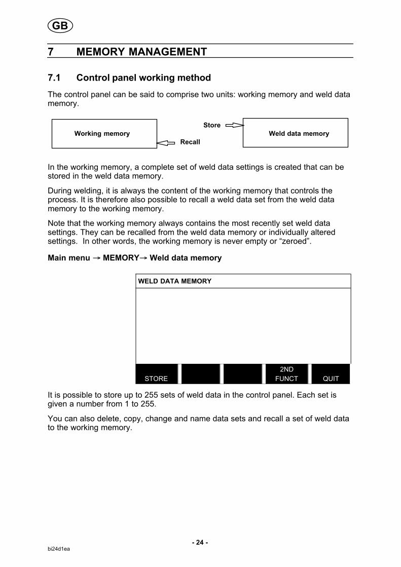
The control panel can be said to comprise two units: working memory and weld datamemory.
StoreWorking memory Weld data memory
Recall
In the working memory, a complete set of weld data settings is created that can bestored in the weld data memory.
During welding, it is always the content of the working memory that controls theprocess. It is therefore also possible to recall a weld data set from the weld datamemory to the working memory.
Note that the working memory always contains the most recently set weld datasettings. They can be recalled from the weld data memory or individually alteredsettings. In other words, the working memory is never empty or “zeroed”.
Main menu � MEMORY� Weld data memory
WELD DATA MEMORY
STORE
2ND
FUNCT QUIT
It is possible to store up to 255 sets of weld data in the control panel. Each set isgiven a number from 1 to 255.
You can also delete, copy, change and name data sets and recall a set of weld datato the working memory.
GB

- 25 -bi24d1ea
7.2 Store
If the weld data memory is empty, the following screen appears in the display.
Storing a set of welddata. This will be givenmemory position 5.Press STORE. Position1 is displayed. Turnone of the settingsknobs until you reachposition 5. PressSTORE.
WELD DATA MEMORY
STORE
2ND
FUNCT QUIT
The following screen appears in the display.
The weld data set isnow stored as number5.
WELD DATA MEMORY
5 - (SAW)
SAW: CA: FE SOLID: 3.0 mm
30.0 V: 450 A: 50 cm/min
STORE RECALL
DELETE
2ND
FUNCT QUIT
Parts of the content of weld data set number 5 are presented at the bottom of thedisplay.
GB

- 26 -bi24d1ea
If a data set is alreadystored in the selectedlocation, you will beasked if you want tooverwrite that set ornot, YES or NO.
WELD DATA MEMORY
5 - (SAW)
SAW: CA: FE SOLID: 3.0 mm
30.0 V: 450 A: 50 cm/min
NO YES
Return to the memory menu using NO.
7.3 Recall
We are going to recall astored data set:
Mark the row using thepositioning knob. PressRECALL.
WELD DATA MEMORY
5 - (SAW)
SAW: CA: FE SOLID: 3.0 mm
30.0 V: 450 A: 50 cm/min
STORE RECALL
DELETE
2ND
FUNCT QUIT
Press YES to confirmthat you want to recalldata set number 5.
WELD DATA MEMORY
5 - (SAW)
SAW: CA: FE SOLID: 3.0 mm
30.0 V: 450 A: 50 cm/min
NO YES
GB

- 27 -bi24d1ea
This icon in the measurement display showswhich memory position number has beenrecalled.
7.4 Delete
It is possible to delete one or more data sets in the memory menu.
Deleting a data set.
Select the data set.Press DELETE.
WELD DATA MEMORY
5 - (SAW)
SAW: CA: FE SOLID: 3.0 mm
30.0 V: 450 A: 50 cm/min
STORE RECALL
DELETE
2ND
FUNCT QUIT
Press YES to confirmthat you want to delete.
WELD DATA MEMORY
5 - (SAW)
SAW: CA: FE SOLID: 3.0 mm
30.0 V: 450 A: 50 cm/min
NO YES
GB

- 28 -bi24d1ea
7.5 Copy
To copy the content of a weld data set to a new memory position, proceed asfollows:
Press 2ND FUNCT. WELD DATA MEMORY
5 - (SAW)
SAW: CA: FE SOLID: 3.0 mm
30.0 V: 450 A: 50 cm/min
STORE RECALL
DELETE
2ND
FUNCT QUIT
Select the memory position you want to copyand press COPY.
WELD DATA MEMORY
5 - (SAW)
SAW: CA: FE SOLID: 3.0 mm
30.0 V: 450 A: 50 cm/min
COPY RENAME
EDIT
2ND
FUNCT QUIT
GB

- 29 -bi24d1ea
We are now going to copy the content of memory position 5 to position 50.
Select memory position1 and scroll through using one of the settingsknobs to the selectedmemory position; in thiscase, position 50.PressYES.
WELD DATA MEMORY
1 -
5 - (SAW)
COPY
DATA SET 5 TO POSITION: 50
NO YES
Weld data number 5 has now been copied to memory position 50.
7.6 Name
To give a stored weld data set its own name, proceed as follows:
Press 2ND FUNCT.Select the memory position you want to rename and pressRENAME.
WELD DATA MEMORY
5 - (SAW)
50 -
SAW: CA: FE SOLID: 3.0 mm
30.0 V: 450 A: 50 cm/min
COPY RENAME
EDIT
2ND
FUNCT QUIT
Here you have access to a keyboard that is used as follows:
� Position the cursor on the desiredkeyboard character using the arrowsand the positioning knob. PressDONE. Enter a complete text stringwith a maximum of 40 characters inthis way.
� Press DONE to store. The alternativeyou have named can now be seen inthe list.
GB

- 30 -bi24d1ea
7.7 Edit
To edit the content of a weld data set, proceed as follows:
Press 2ND FUNCT.Select the memory position you want to editand then press EDIT.
WELD DATA MEMORY
5 - (SAW)
SAW: CA: FE SOLID: 3.0 mm
30.0 V: 450 A: 50 cm/min
COPY
EDIT
2ND
FUNCT QUIT
Part of the main menu is displayed and the menu shows the symbol whichmeans that you are in an editing mode.
Press SET and makethe relevant changes. 7
SAW
REGULATION TYPE CA
WIRE TYPE SS FLUX CORED
WIRE DIMENSION 2.0 mm
SET QUIT
GB

- 31 -bi24d1ea
The following menu appears:
In this example wechange the weldingcurrent from 400 A to500 A.
Select the weldingcurrent and scrollthrough to 500 usingone of the settingsknobs.
Press QUIT twice.
SAW WELD DATA SETTING
VOLTAGE 20.0 V
CURRENT 500 A
TRAVEL SPEED 0 cm/min
DIRECTION �
START DATA�
STOP DATA�
DYNAMIC REGULATION AUTO
SETTING LIMITS�
MEASURE LIMITS�
QUIT
The setting for weld data number 5 has now been edited and stored.
8 CONFIGURATION MENU
Main menu � Configuration menu
This menu contains the following sub-menus:
� Language, see chapter 1.2.1 “Choice of language”
� Code lock, see chapter 8.1
� General configuration, see chapter 8.2
� Machine configuration, see chapter 8.3
� Cable length, see chapter 8.4
� Maintenance, see chapter 8.5
� Network settings, see chapter 8.6
8.1 Code lock
Main menu � Configuration menu � Code lock
When the lock function is activated and you are in the measure screen or fast modemenu, a password (lock code) is required to exit from these menus.
GB

- 32 -bi24d1ea
CODE LOCK
LOCK STATUS OFF
SET / CHANGE LOCK CODE
QUIT
Code lock is activated in the configuration menu.
8.1.1 Lock code status
In lock code status, you can activate/deactivate the lock function without deleting theexisting lock code in the event you deactivate the function. If no lock code is storedand you try to activate the code lock, the keyboard is displayed for entering a newlock code.
To exit lock status.
When you are in the measure screen or the fast mode menu and the code lock isdeactivated, you can exit these menus without restrictions by press QUIT or MENUin order to go to the main menu.
If it is activated and you try to exit, the following screen appears in order to warn theuser about the lock protection.
PRESS ENTER FOR LOCK CODE... PRESS ENTER FOR
LOCK CODE...
Here you can select QUIT to undo and return to the previous menu, or proceed bypressing ENTER to enter the lock code.
You will then move to the menu with the keyboard, where you can enter the code.Press ENTER after each character, and confirm the code by pressing ENTER again.
The following text box appears:
UNIT UNLOCKED! UNIT UNLOCKED!
GB
- 33 -bi24d1ea
If the code is not correct, an error message is displayed that offers the option oftrying again or returning to the original menu, i.e. the measure screen or the fastmode menu.
If the code is correct, all blocks to other menus will be removed, although the codelock remains activated. This means that you can leave the measure screen and thefast mode menu temporarily, yet still retain the lock status when you return to thesemenus.
8.1.2 Specify/edit lock code
In specify/edit lock code, you can edit an existing lock code or enter a new one. Alock code can comprise a maximum of 16 optional letters or figures.
8.2 General configuration
Main menu � Configuration menu � General configuration
In this menu you can set:
� Fast mode soft keys, see chapter 8.2.1
� Quality data log to file, see chapter 8.2.2
� Setting soft keys, see chapter 8.2.3
� Automatic weld data storage, see chapter 8.2.4
� Unit of length, see chapter 1.2.2 “unit of measurement”
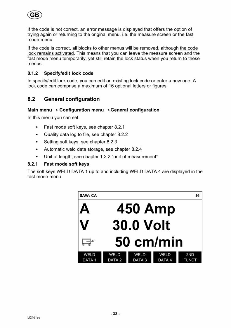
8.2.1 Fast mode soft keys
The soft keys WELD DATA 1 up to and including WELD DATA 4 are displayed in thefast mode menu.
SAW: CA 16
A 450 AmpV 30.0 Volt 50 cm/min
WELD
DATA 1
WELD
DATA 2
WELD
DATA 3
WELD
DATA 4
2ND
FUNCT
GB

- 34 -bi24d1ea
These are configured as follows:
Position the cursor onthe row for SOFT KEYNUMBER.
FAST MODE SOFT KEYS
SOFT KEY NUMBER 1
ASSOCIATED WELD DATA 5
SAW: CA: FE SOLID: 0.8 mm
20.0 V: 500 A: 0 cm/min
STORE
DELETE QUIT
The keys are numbered 1-4 from left to right. Select the desired key by giving itsnumber using the setting knobs.
Then scroll to the next row, ASSOCIATED WELD DATA. Here you can browsethrough the weld data sets that are stored in the weld data memory. Selected thedesired weld data number using the setting knobs. Press STORE to save. To deletethe stored set, press DELETE.
8.2.2 Quality data log to file
In the QUALITY DATALOG TO FILE menu itis possible to activate itwith ON.
GENERAL CONFIGURATION
FAST MODE SOFT BUTTONS 1
QUALITY DATA LOG TO FILE ON
SOFT KEYS SETUP�
AUTO SAVE MODE OFF
UNIT OF LENGTH METRIC
QUIT
Read more about settings for the quality function in chapter 9.7.
8.2.3 Soft key configuration
We have previously described the control panel's “soft” keys. For Submerged ArcWelding (SAW) and for Gas Metal Arc Welding (GMAW) welding, the user has thepossibility of setting the function of these keys by selecting from a list of set options.There are eight soft keys that can be allocated a function.
GB

- 35 -bi24d1ea
It is possible to choose between the following options:
� None
� Gas purge / Flux valve
� Set values
Set reference values are displayed instead of the measured values in themeasurements menu.
� Relay 1Sets relay output no.1 on the motor circuit board, which can be used for anyfunction by the customer.
� Direction
� Remote I/O
Used when you want to control PEK and a welding power source via an externalI/O unit.
� External axis
To be activated when there is an external I/O unit for controlling a roller bed, forexample.
In the display screenthere are two columns;one for SOFT KEYSand one for FUNCTION.
SOFT KEYS SETUP
SOFT KEYS FUNCTION
S1 NONE
S2 NONE
S3 NONE
S4 NONE
S1 2ND FUNCT NONE
S2 2ND FUNCT NONE
S3 2ND FUNCT NONE
S4 2ND FUNCT NONE
QUIT
When you allocate functions to these keys, they are numbered from the left asfollows:
S1 S2 S3 S4
2ND
FUNCT
S1 2ND
FUNCT
S2 2ND
FUNCT
S3 2ND
FUNCT
S4 2ND
FUNCT
2ND
FUNCT
GB

- 36 -bi24d1ea
To allocate a new function to a soft key, proceed as follows:
Position the cursor onthe row with the softkey number you wish touse and press ENTER.A pop-up menu showsthe function selections.Select using the positioning knob and pressENTER.
SOFT KEYS SETUP
SOFT KEYS FUNCTION
S1 NONE
S2 NONE
S3 NONE
S4 NONE
S1 2ND FUNCT NONE
S2 2ND FUNCT NONE
S3 2ND FUNCT NONE
S4 2ND FUNCT NONE
QUIT
You can allocate new functions to the other keys in the same way, by pairing a keynumber in the left-hand column with a function in the right-hand column.
8.2.4 Auto save mode
When a weld data set has been recalled from a memory position in the weld datamemory and you change the settings, the changes will be saved in the workingmemory at welding stop in the last recalled memory position.
Saving weld data manually in a memory position disables the next automatic save.
The memory position in which the weld data set is stored is displayed in the top rightcorner of the measure screen.
8.3 Machine configuration
Main menu � Configuration menu � Machine configuration
In this menu you can set:
� Product code, see chapter 8.3.1
� Wire feed axis, see chapter 8.3.2
� Travel axis, see chapter 8.3.3
� Outer axis, see chapter 8.3.4
� Tandem, see chapter 8.3.5
GB

- 37 -bi24d1ea
8.3.1 Product code
In the PRODUCTCODE menu it is possible to select the automatic welding machine,column and boom,roller bed or positionerto be used.
MACHINE CONFIGURATION
PRODUCT CODE A2TFX
WIRE FEED AXIS�
TRAVEL AXIS�
TANDEM OFF
QUIT
When selecting product code, the correct motor type and gear ratio for the usedgearbox in the relevant product are selected automatically.
The following options can be selected:
� A2TFJ1
A2 tractor automatic welding machine for Submerged Arc Welding (SAW)
� A2TGJ1
A2 tractor automatic welding machine for Gas-Shielded Metal Arc Welding(GMAW)
� A6TFF1
A6 tractor automatic welding machine for Submerged Arc Welding (SAW)
� FREE 2 AXIS
Optional configuration for connecting 2 motors to the actuator board. One forwire feed and one for travel motion.
� FREE 3 AXIS
Optional configuration for connecting external roller beds, positioners or linearaxis as well as for 2 motors to the actuator board. One for wire feed and one fortravel motion.
8.3.2 Wire feed axis
The wire feed motor is set automatically according to the tables below.
A2TFJ1 A2TGJ1 A6TFF1
Motor 5035 38 RPM 5035 68 RPM VEC4000
Gear 1 49:1 49:1 156:1
Gear 2 1:1 1:1 1:1
Diameter feed rollers 49 mm 49 mm 49 mm
Pulse sensor 28 ppr 28 ppr 32 ppr
Low manual speed 150 cm/min 150 cm/min 150 cm/min
High manual speed 300 cm/min 300 cm/min 300 cm/min
GB

- 38 -bi24d1ea
FREE 2 AXIS FREE 3 AXIS
Motor VEC 4000 VEC 4000
Gear 1 156:1 156:1
Gear 2 1:1 1:1
Diameter feed rollers 49 mm 49 mm
Pulse sensor 32 ppr 32 ppr
Low manual speed 150 cm/min 150 cm/min
High manual speed 300 cm/min 300 cm/min
8.3.3 Travel axis
The travel motor is set automatically according to the tables below.
A2TFJ1 A2TGJ1 A6TFF1
Motor 4030-350 4030-350 FHP258
Gear 1 375:10 375:10 24:1
Gear 2 51:1 51:1 51:1
Wheel diameter 158 mm 158 mm 180 mm
Pulse sensor 60 ppr 60 ppr 28 ppr
High manual speed 200 cm/min 200 cm/min 200 cm/min
FREE 2 AXIS FREE 3 AXIS
Motor VEC 4000 VEC 4000
Gear 1 312:1 312:1
Gear 2 1:1 1:1
Wheel diameter 65 mm 65 mm
Pulse sensor 32 ppr 32 ppr
High manual speed 200 cm/min 200 cm/min
8.3.4 Outer axis
When connecting an external roller bed, positioner or linear axis, FREE 3 AXIS mustbe selected.
When FREE 3 AXIS is selected, the motor is automatically set according to thetables below.
Roller bed Linear Positioner
Gear 1 560:1 560:1 560:1
Gear 2 111:22 111:22 111:22
Gear 3 1:1 1:1 1:1
Wheel diameter 160 mm 160 mm 160 mm
Pulse sensor 30 ppr 30 ppr 30 ppr
High manual speed 200 cm/min 200 cm/min 200 cm/min
Frequency ratio 85:50 85:50 85:50
Motor 2000 rpm 2000 rpm 2000 rpm
Weld diameter 1000 mm - 1000 mm
Roller diameter 1000 mm - -
GB

- 39 -bi24d1ea
8.3.5 Tandem
Used when welding with two welding heads.
Position the cursor onthe TANDEM row andpress ENTER.
Select ON using thepositioning knob andpress ENTER.
MACHINE CONFIGURATION
PRODUCT CODE A2TFX
WIRE FEED AXIS�
TRAVEL AXIS�
TANDEM ON
� WELDING HEAD HEAD
� WELD HEAD OFFSET 20 mm
� WITH I/O ON
QUIT
In order to weld with two welding heads, the WELD HEAD OFFSET function must beset.
WELD HEAD OFFSET is the distance in millimetres between the welding heads.
When you specify the distance between welding head 1 HEAD and welding head 2TAIL, the value is recalculated by the control unit to a time between when weldinghead 1 starts and welding head 2 is to start.
The time that the control unit can calculate for the distance between the starting andstopping of the welding power sources is a maximum of 65 seconds. This meansthat if, for example, 50 cm/min is specified, 2000 mm can be entered as themaximum WELD HEAD OFFSET. This is so that time does not expire before weldinghead 2 reaches the start point.
TAIL HEAD
WELD HEAD OFFSET
NOTE!
Ensure that both control units have the same settings for WELD HEAD OFFSET andspecify the same travel speed. The ”Master” control unit must be allocated HEADand the ”Slave” control unit TAIL. Travel motion is always controlled from ”Master”.
GB

- 40 -bi24d1ea
Specify the values to weld with two welding heads as follows:
Position the cursor onthe WELDING HEADrow.
Select whether the setting is to apply to”master” control unitHEAD or ”slave” controlunit TAIL.
MACHINE CONFIGURATION
PRODUCT CODE A2TFX
WIRE FEED AXIS�
TRAVEL AXIS�
TANDEM ON
� WELDING HEAD HEAD
� WELD HEAD OFFSET 20 mm
� WITH I/O ON
QUIT
� Position the cursor on the WELD HEAD OFFSET row and specify the distancebetween the two welding heads.
Example, I/O ON
Welding head2, (slave) Welding head1, (master)
TAIL HEAD
WELD HEAD OFFSET
Example , I/O ON
� Press Start, for welding head1.
� Welding head1 starts to weld.
� Welding head2 only starts welding when the start position for welding head1 hasbeen reached (the distance given in WELD HEAD OFFSET.
� Press Stop, for welding head1.
� Welding head1 stops welding but continues travelling.
� Welding head2 stops welding once it reaches the point where equipment1stopped welding (the distance given in WELD HEAD OFFSET.
� Welding is complete.
GB

- 41 -bi24d1ea
Example, I/O OFF
Welding head2, (slave) Welding head1, (master)
TAIL HEAD
WELD HEAD OFFSET
� Press Start, for welding head1 and welding head2 at the same time.
� Welding head1 starts to weld.
� Welding head2 starts to weld first when the start position for welding head1 hasbeen reached (the distance given WELD HEAD OFFSET).
� Press stop, for welding head1 and welding head2 at the same time.
� Welding head1 stops welding but travel motion continues.
� Welding head2 stops welding when it has reached the point where equipment1stopped welding (the distance that is given in WELD HEAD OFFSET).
� Welding is complete.
8.4 Cable length
The arc voltage is affected by the impedance in the welding cables. The impedanceis affected by the length and area of the cables as well as by how they are routed.This is especially prominent during AC welding.
Compensation for the voltage drop with long cables is maintained if the actual cablelength is specified.
The total cable length (weld cable and connector together) must be fed in.
Note! When using two cables, the areas must be combined for both cables.
This function is active during the start process before the power source has receiveda measurement value that it can regulate at.
If ”Max OCV” has been selected this function is inactive.
GB

- 42 -bi24d1ea
8.5 Maintenance
Main menu � Configuration menu � Maintenance
In this menu you set how often the contact tip is to be changed. Specify the numberof weld starts after which the tip is to be changed by selecting the CONTACT TIPCHANGE INTERVAL row and pressing ENTER. Change the value using the settingknobs. When the interval has been passed, fault code 54 is displayed in the errorlog. Reset by pressing RESET.
When TOTAL RUNNING TIME LIMIT is selected instead of the number of starts, anauthorised ESAB service technician is contacted.
MAINTENANCE
CONTACT TIP CHANGE INTERVAL 0 Welds
� WELD COUNT 0 Welds
TOTAL RUNNING TIME LIMIT 0d00:00:00
� TOTAL RUNNING TIME 0d00:00:00
RESET
QUIT
8.6 Network settings
Main menu � Configuration menu � Network settings
This menu enables you to connect to an administrative tool on a local network.
For more information on the administrative tool, see the instruction manual forWELDPOINT. The manual can be downloaded from www.esab.com.
NETWORK SETTINGS
DHCP ON
IP ADDRESS 172.20.125.74
SUBNET MASK 0.0.0.0.
DEFAULT GATEWAY 0.0.0.0.
HOSTNAME ESAB_W82
QUIT
GB

- 43 -bi24d1ea
8.6.1 System overview
1 Welding power source 4 Administrative tool, Weldpoint
2 Wire feed unit / Automatic welder 5 Network connection
3 Weld data unit, PEK 6 USB memory
9 TOOLS
Main menu � Tools
This menu contains the following sub-menus:
� Error log, see chapter 9.1
� Export/Import, see chapter 9.2
� File manager, see chapter 9.3
� Edit setting limits, see chapter 9.4
� Edit measure limits, see chapter 9.5
� Production statistics, see chapter 9.6
� Quality functions, see chapter 9.7
� Calendar, see chapter 9.8
� User accounts, see chapter 9.9
� Unit information, see chapter 9.10
GB
- 44 -bi24d1ea
9.1 Error log
Main menu � Tools � Error log
Fault management codes are used to indicate that a fault has occurred in thewelding process. Indicated in the display via a pop-up menu and an exclamation
mark appears in the upper right-hand corner of the display.
Note! disappears from the display as soon as you enter the error log menu.
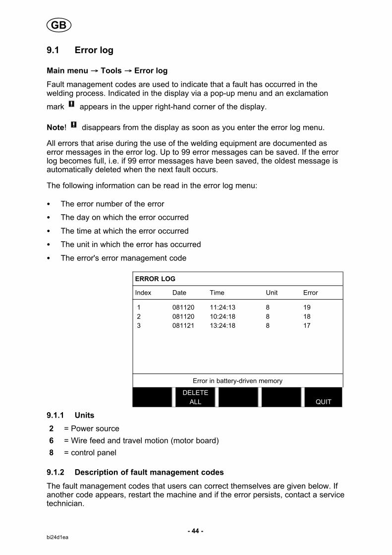
All errors that arise during the use of the welding equipment are documented aserror messages in the error log. Up to 99 error messages can be saved. If the errorlog becomes full, i.e. if 99 error messages have been saved, the oldest message isautomatically deleted when the next fault occurs.
The following information can be read in the error log menu:
� The error number of the error
� The day on which the error occurred
� The time at which the error occurred
� The unit in which the error has occurred
� The error's error management code
ERROR LOG
Index Date Time Unit Error
1 081120 11:24:13 8 19
2 081120 10:24:18 8 18
3 081121 13:24:18 8 17
Error in battery-driven memory
DELETE
ALL
QUIT
9.1.1 Units
2 = Power source
6 = Wire feed and travel motion (motor board)
8 = control panel
9.1.2 Description of fault management codes
The fault management codes that users can correct themselves are given below. Ifanother code appears, restart the machine and if the error persists, contact a servicetechnician.
GB

- 45 -bi24d1ea
Errorcode
Description
6 High temperature
The power source has overheated and cancels welding. Welding is permitted again whenthe temperature falls below the maximum temperature parameter.
Action: Check that the cooling air inlets or outlets are not blocked or clogged with dirt.Check the duty cycle being used, to make sure that the equipment is not being overloaded.
If the error persists, send for a service technician.
7 Low welding current
The weld arc has been shut down due to too low welding current during the weldingprocess.
Action:Turn off the mains power supply to reset the unit. If the error persists, send for aservice technician.
8 Low battery voltage
Battery voltage too low. If the battery is not replaced, all stored data will be lost.
This error does not disable any functions.
Action: Send for a service technician to replace the battery.
11 Speed error on a motor, (wire feed, travel motor)
A motor cannot maintain its speed. Welding stops.
Action: Check that the wire feed has not jammed or runs too fast. If the error persists,send for a service technician.
12 Internal communication error (warning)
The load on the system's CAN-bus is temporarily too high.
The power source may have lost contact with the control unit.
Action: Check that all the equipment is correctly connected. If the error persists, send fora service technician.
14 Communication error
The system's CAN-bus has temporarily stopped working due to the load being too high.
The current welding process stops.
Action: Check that all the equipment is correctly connected. Turn off the mains powersupply to reset the unit. If the error persists, send for a service technician.
17 Lost contact with the unit
Lost contact with a unit.
Action: Check wiring and the connector between the control unit and power source. If theerror persists, send for a service technician.
32 No gas flow
Start prevented.
Action: Check the gas valve, hoses and connectors.
43 High welding current
Power source have switched off the welding process because the current has exceededthe maximum current parameter for the power source.
Action: Turn off the mains power supply to reset the unit. If the error persists, send for aservice technician.
44 Start pause welding current
The welding process has stopped because it has not advanced within 10 seconds.
Action: Turn off the mains power supply to reset the unit. If the error persists, send for aservice technician.
GB

- 46 -bi24d1ea
9.2 Export/Import
Main menu � Tools � Export / Import
In the Export/Import menu, it is possible to transfer information to and from thecontrol panel via a USB memory.
The following information can be transferred:
� Weld data sets Export/Import
� System setting Export / Import
� Setting limits Export / Import
� Measure limits Export / Import
� Error log Export
� Quality function log Export
� Production statistics Export
Carry out the following to save on a USB memory:
Insert the USB memory into the control unit.
Select the row with theinformation that is to betransferred. PressEXPORT or IMPORT,depending on whetherthe information is to beexported or imported.
EXPORT/IMPORT
WELD DATA SETS
SYSTEM SETTINGS
SETTING LIMITS
MEASURE LIMITS
ERROR LOG
QUALITY FUNCTION LOG
PRODUCTION STATISTICS
EXPORT IMPORT
QUIT
9.3 File manager
Main menu � Tools � File manager
In the file manager it is possible to manage information on a USB memory (C:\). Filemanager makes it possible to delete and copy weld data and quality data manually.
When the USB memory is connected, the display shows the memory's default folderif one is not previously selected.
The control panel remembers where you were the last time you used file manager,so that you return to the same place in the file structure when you come back.
GB

- 47 -bi24d1ea
FILE MANAGER
..NEW FOLDER
QData.xml
INFO UPDATE
ALT. QUIT
� In order to ascertain how much storage space remains for the memory, use theINFO function.
� Update the information by pressing UPDATE.
� When you want to delete, change name, create new folder, copy or paste, pressALT. A list then appears from which you can choose. If (..) or a folder is selected,you can only create a new folder or paste in a file that you have previouslycopied. If you have selected a file, the options RENAME, COPY or PASTE willbe added if you have previously copied a file.
Select a folder or fileand press ALT.
FILE MANAGER
..WeldData
NEW FOLDER
ErrorLog.xml
QData.xml
�Weldoffice.dat
INFO UPDATE
ALT. QUIT
This list is displayed when you have pressed ALT. COPY
PASTE
DELETE
RENAME
NEW FOLDER
9.3.1 Delete a file/folder
Select the file or folder that is to be deleted and press ALT.
Select DELETE and press ENTER. DELETE
RENAME
NEW FOLDER
The file/folder is now removed. In order to delete a folder it must be empty, i.e. firstdelete the files contained in the folder.
GB

- 48 -bi24d1ea
9.3.2 Rename a file/folder
Select the file or folder that is to be renamed and press ALT.
Select RENAME and press ENTER. DELETE
RENAME
NEW FOLDER
A keyboard appears in the display. Use the positioning knob to change row and thearrows to move left and right. Select the character/function that is to be used andpress ENTER.
9.3.3 Create new folder
Select where the new folder is to be located and press ALT.
Select NEW FOLDER and press ENTER. DELETE
RENAME
NEW FOLDER
A keyboard then appears in the display. Use the positioning knob to change row andthe arrows to move left and right. Select the character/function that is to be used andpress ENTER.
9.3.4 Copy and paste files
Select the file that is to be copied and press ALT.
Select COPY and press ENTER. COPY
PASTE
DELETE
RENAME
NEW FOLDER
Position the cursor in the folder in which the copied file is to be located and pressALT.
Select PASTE and press ENTER. COPY
PASTE
DELETE
RENAME
NEW FOLDER
The copy is saved as Copy of plus the original name, e.g. Copy of WeldData.awd.
GB

- 49 -bi24d1ea
9.4 Setting limit editor
Main menu � Tools � Setting limit editor
In this menu you set your own max. and min. values for various welding methods.The limits cannot be above or below the values for which the power source isdimensioned. There are 50 storage points. Select the row for an empty storage pointand press ENTER. Select process by pressing ENTER and select the weldingprocess using the positioning knob and press ENTER.
The maximum and minimum values for arc voltage, wire feed speed, travel speedand welding current can be selected for all processes.
EDIT LIMITS
PROCESS SAW
VOLTAGE MIN 17.0
VOLTAGE MAX 47.0
WIRE SPEED MIN 50
WIRE SPEED MAX 970
TRAVEL SPEED MIN 100
TRAVEL SPEED MAX 2400
CURRENT MIN 70
CURRENT MAX 1500
STORE
DELETE QUIT
When the values have been adjusted, press STORE. When asked if the limit value isto be saved at the selected storage point, press NO or YES. The storage point'svalues can be seen under the line at the bottom.
With the AUTO soft key, the parameters are set automatically according to the mostrecently used parameters.
When asked if the limit settings are to be set automatically, press NO or YES andthen STORE if the setting is to be retained.
GB

- 50 -bi24d1ea
9.5 Measure limits editor
Main menu � Tools � Measure limits editor
In this menu you set your own measurement values for the various welding methods.There are 50 storage points. Select the row for an empty storage point and pressENTER. Select process by pressing ENTER and select the welding process usingthe positioning knob and press ENTER.
The following values can be selected:
� arc voltage: min, max
� wire feed speed: min, max
� welding current: min, max
� travel speed: min, max
� energy per unit length: min, max
Set the desired value using the setting knobs and press STORE.
In the dialogue box, you are asked if you want to store the selected storage point.Press YES to save the value. The storage point's values can be seen under the lineat the bottom.
MEASURE LIMITS
1 - SAW
2 - GMAW
3 -
4 -
5 -
6 -
7 -
0.0 - 46.9 Volt , 0 - 2495 cm/min
3 - 994 cm/min , 3 - 990 Amp
5 - 500 kJ/min
QUIT
With the AUTO soft key, the parameters are set automatically according to the mostrecently used measurement values.
When asked if the measurement values are to be set automatically, press NO orYES and then STORE if the setting is to be retained.
9.6 Production statistics
Main menu � Tools � Production statistics
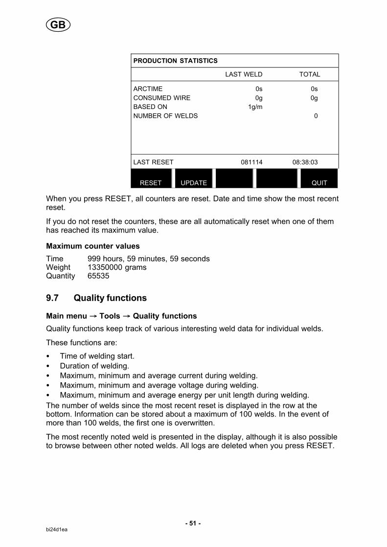
The production statistics will keep track of the total arc time, the total amount ofmaterial and the number of welds since the most recent reset. They will also keeptrack of the arc time and the amount of material used in the most recent weld. Forinformation purposes, the melted wire material per length unit that has beencalculated and when the most recent reset occurred are also displayed.
GB
- 51 -bi24d1ea
PRODUCTION STATISTICS
LAST WELD TOTAL
ARCTIME 0s 0s
CONSUMED WIRE 0g 0g
BASED ON 1g/m
NUMBER OF WELDS 0
LAST RESET 081114 08:38:03
RESET UPDATE
QUIT
When you press RESET, all counters are reset. Date and time show the most recentreset.
If you do not reset the counters, these are all automatically reset when one of themhas reached its maximum value.
Maximum counter values
Time 999 hours, 59 minutes, 59 secondsWeight 13350000 gramsQuantity 65535
9.7 Quality functions
Main menu � Tools � Quality functions
Quality functions keep track of various interesting weld data for individual welds.
These functions are:
� Time of welding start.
� Duration of welding.
� Maximum, minimum and average current during welding.
� Maximum, minimum and average voltage during welding.
� Maximum, minimum and average energy per unit length during welding.
The number of welds since the most recent reset is displayed in the row at thebottom. Information can be stored about a maximum of 100 welds. In the event ofmore than 100 welds, the first one is overwritten.
The most recently noted weld is presented in the display, although it is also possibleto browse between other noted welds. All logs are deleted when you press RESET.
GB

- 52 -bi24d1ea
QUALITY FUNCTIONS
#WELD: 1 / 4
START 20090107 15:59:14
WELD TIME 00:00:20 WELD DATA:
HEAT INPUT: 3.12 kJ/mm
MAX MIN AVE.
I (Amp) 293.00 243.00 289.00
U (V) 41.50 16.20 39.40
Q (kJ/min) 7.00 0.00 2.00
NUMBER OF WELDS SINCE RESET: 4
RESET UPDATE
QUIT
9.7.1 Store quality data
Main menu � Tools � Export / Import
The files that are produced in the control panel are stored as xml files. The USBmemory must be formatted as FAT32 in order to work.
Insert a USB memory in the control panel, see chapter 9.3 “File manager”.
Select QUALITYFUNCTION LOG, pressEXPORT.
EXPORT/IMPORT
WELD DATA SETS
SYSTEM SETTINGS
SETTING LIMITS
MEASURE LIMITS
ERROR LOG
QUALITY FUNCTION LOG
PRODUCTION STATISTICS
EXPORT
QUIT
The entire set of quality data (information about the 100 most recent welds) that isstored in the control panel is now saved on the USB memory.
The file is in a folder called QData. QData is created automatically when you insert aUSB memory.
GB

- 53 -bi24d1ea
9.8 Calendar
Main menu � Tools � Calendar
Date and time are set here.
Select the row that is tobe set: year, month,day, hour, minutes andseconds. Set thecorrect value using oneof the setting knobs.Press SET.
DATE & TIME
YEAR 2008
MONTH NOV
DAY 21
HOUR 10
MINUTES 45
SECONDS 55
20100115 10:48:59
SET QUIT
9.9 User accounts
Main menu � Tools � User accounts
Occasionally it is particularly important from a quality perspective that the productcannot be used by unauthorised parties.
User name, account level and password are registered in this menu.
Select USER NAMEand press ENTER.Step down to an emptyrow and press ENTER.Key in a new username on the keyboardusing the positioningknob and the arrowsand ENTER.
USER ACCOUNTS
USER NAME ADMINISTRATOR
� ACCOUNT LEVEL ADMIN
� PASSWORD
USER ACCOUNTS OFF
STORE DELETE
QUIT
There is space for 16 user accounts. In the quality data files it will be evident whichusers have executed a particular weld.
GB

- 54 -bi24d1ea
Under ACCOUNT LEVEL choose from:
� Administrator
full access (can add new users)
� Senior user
can access everything except:
� machine configuration
� user accounts
� network settings
� Normal user
can access:
� In the Configuration menu:
� Maintenance
� In the Tools menu:
� Unit information
� In the Settings menu:
� Voltage
� Current / wire feed
� Travel speed
� Welding direction
In the PASSWORD row, key in a password using the keyboard. When the powersource is switched on and the control panel activated, you are asked in the display toenter your password.
If you choose not to have this function, but instead want the power source andcontrol panel to be unlocked for all users, select USER ACCOUNTS OFF.
GB

- 55 -bi24d1ea
9.10 Unit information
Main menu � Tools � Unit information
I this menu you can see the following information:
� Machin ID
� Node ID
2 = power source
6 = wire feed and travel motion (motor board)
8 = control panel
� Software version
UNIT INFORMATION
Machine ID Node ID Software Version
44 8 1.00A
23 2 2.00A
5 6 1.18A
SETTING WELD DATA UNIT
QUIT
GB

PEK Control panel
Edition 100127
Menu structure
- 56 -bi24menu
NO TAG56
SAW (CA)
- Process
- Regulation type
- Wire type
- Wire dimension
- Configuration, see page 59
- Tools, see page 59
Voltage
Current
Travel speed
Direction
Start data
- flux preflow
- start type
- wire creep start
- start phases
- max OCV
Stop data
- flux postflow
- crater fill
- burn-back time
- stop phases
Dynamic regulation
Setting limits
Measure limits

PEK Control panel
Edition 100127- 57 -bi24menu
GMAW (CA)
- Process
- Regulation type
- Wire type
- Wire dimension
- Configuration, see page 59
- Tools, see page 59
Voltage
Current
Travel speed
Direction
Start data
- gas preflow
- start type
- wire creep start
- start phases
- max OCV
Stop data
- gas postflow
- crater fill
- burn-back time
- stop phases
Dynamic regulation
Setting limits
Measure limits

PEK Control panel
Edition 100127- 58 -bi24menu
GOUGING (CA)
- Process
- Regulation type
- Electrode dimension
- Configuration, see page 59
- Tools, see page 59
Voltage
Current
Travel speed
Direction
Start data
- air preflow
- start type
- wire creep start
- start phases
- max OCV
Stop data
- air postflow
- crater fill
- burn-back time
- stop phases
Dynamic regulation
Setting limits
Measure limits

PEK Control panel
Edition 100127- 59 -bi24menu
NO TAG
SAW, GMAW, GOUGING
Configuration Tools
Language
Code lock
General configuration
- fast mode soft buttons
- quality data log to file
- soft keys setup
- auto save mode
- unit of length
Machine configuration
- product code
- wire axis
- travel axis
- tandem
Cable lengths
- cable lengths
- cable area
Maintenance
- Contact tip change interval
- Total running time limit
Network setting
Error log
Export / Import
File manager
Setting limit editor
Measure limit editor
Production statistics
Quality functions
Calendar
User accounts
Unit information

Wire dimension
- 60 -bi24wire
Submerged arc welding with constant ampere (SAW CA)
Wire type Wire diameter (mm)
Fe Solid 0.8 1.0 1.2 1.6 2.0 2.4 3.0 3.2 4.0 5.0 6.0
Fe Solid Twin 2x0.8 2x1.0 2x1.2 2x1.6 2x2.0 2x2.4 2x3.0 2x4.0 2x5.0
Fe Flux Cored 0.8 1.0 1.2 1.6 2.0 2.4 3.0 3.2 4.0
Fe Flux Cored Twin 2x0.8 2x1.0 2x1.2 2x1.6 2x2.0 2x2.4 2x3.0 2x4.0
SS Solid 0.8 1.0 1.2 1.6 2.0 2.4 3.0 3.2 4.0 5.0 6.0
SS Solid Twin 2x0.8 2x1.0 2x1.2 2x1.6 2x2.0 2x2.4 2x3.0 2x3.2 2x4.0
SS Strip 30 x 0.5 60 x 0.5 90 x 0.5
SS Flux Cored 0.8 1.0 1.2 1.6 2.0 2.4 3.0 3.2 4.0 5.0 6.0
SS Flux Cored Twin 2x0.8 2x1.0 2x1.2 2x1.6 2x2.0 2x2.4 2x3.0 2x3.2 2x4.0
MIG/MAG welding with constant ampere (GMAW CA)
Wire type Wire diameter (mm)
Fe Solid 0.8 1.0 1.2 1.6 2.0 2.4
Fe Flux Cored 0.8 1.0 1.2 1.6 2.0 2.4
SS Solid 0.8 1.0 1.2 1.6 2.0 2.4
SS Flux Cored 0.8 1.0 1.2 1.6 2.0 2.4
Al Solid 0.8 1.0 1.2 1.6 2.0 2.4
Al Flux Cored 0.8 1.0 1.2 1.6 2.0 2.4
Gouging with constant ampere (CA)
Electrode dimension (mm)
8.0 9.5 13.0

PEK Control panel
Edition 100127
Ordering number
- 61 -bi24o
Ordering no. Denomination
0460 504 880 Control unit PEK
0460 949 070 Instruction manual SE
0460 949 071 Instruction manual DK
0460 949 072 Instruction manual NO
0460 949 073 Instruction manual FI
0460 949 074 Instruction manual GB
0460 949 075 Instruction manual DE
0460 949 076 Instruction manual FR
0460 949 077 Instruction manual NL
0460 949 078 Instruction manual ES
0460 949 079 Instruction manual IT
0460 949 080 Instruction manual PT
0460 949 081 Instruction manual GR
0460 949 082 Instruction manual PL
0460 949 083 Instruction manual HU
0460 949 084 Instruction manual CZ
0460 949 085 Instruction manual SK
0460 949 086 Instruction manual RU
0460 949 089 Instruction manual EE
0460 949 090 Instruction manual LV
0460 949 091 Instruction manual SI
0460 949 092 Instruction manual LT
0460 949 093 Instruction manual CN
Instruction manuals are available on the Internet at www.esab.com

ESAB ABSE-695 81 LAXÅSWEDENPhone +46 584 81 000
www.esab.com
081016
ESAB subsidiaries and representative offices
EuropeAUSTRIAESAB Ges.m.b.H Vienna-Liesing Tel: +43 1 888 25 11 Fax: +43 1 888 25 11 85
BELGIUMS.A. ESAB N.V. Brussels Tel: +32 2 745 11 00 Fax: +32 2 745 11 28
THE CZECH REPUBLICESAB VAMBERK s.r.o. VamberkTel: +420 2 819 40 885 Fax: +420 2 819 40 120
DENMARKAktieselskabet ESAB HerlevTel: +45 36 30 01 11 Fax: +45 36 30 40 03
FINLANDESAB Oy Helsinki Tel: +358 9 547 761 Fax: +358 9 547 77 71
FRANCEESAB France S.A. Cergy Pontoise Tel: +33 1 30 75 55 00 Fax: +33 1 30 75 55 24
GERMANYESAB GmbH Solingen Tel: +49 212 298 0 Fax: +49 212 298 218
GREAT BRITAINESAB Group (UK) Ltd Waltham Cross Tel: +44 1992 76 85 15 Fax: +44 1992 71 58 03
ESAB Automation Ltd Andover Tel: +44 1264 33 22 33 Fax: +44 1264 33 20 74
HUNGARYESAB Kft Budapest Tel: +36 1 20 44 182 Fax: +36 1 20 44 186
ITALYESAB Saldatura S.p.A. Mesero (Mi) Tel: +39 02 97 96 81 Fax: +39 02 97 28 91 81
THE NETHERLANDSESAB Nederland B.V. Amersfoort Tel: +31 33 422 35 55Fax: +31 33 422 35 44
NORWAYAS ESAB Larvik Tel: +47 33 12 10 00 Fax: +47 33 11 52 03
POLANDESAB Sp.zo.o.Katowice Tel: +48 32 351 11 00Fax: +48 32 351 11 20
PORTUGALESAB Lda Lisbon Tel: +351 8 310 960Fax: +351 1 859 1277
SLOVAKIAESAB Slovakia s.r.o. Bratislava Tel: +421 7 44 88 24 26 Fax: +421 7 44 88 87 41
SPAINESAB Ibérica S.A. Alcalá de Henares (MADRID)Tel: +34 91 878 3600Fax: +34 91 802 3461
SWEDENESAB Sverige AB Gothenburg Tel: +46 31 50 95 00 Fax: +46 31 50 92 22
ESAB international AB Gothenburg Tel: +46 31 50 90 00 Fax: +46 31 50 93 60
SWITZERLANDESAB AG Dietikon Tel: +41 1 741 25 25 Fax: +41 1 740 30 55
North and South AmericaARGENTINACONARCO Buenos Aires Tel: +54 11 4 753 4039 Fax: +54 11 4 753 6313
BRAZILESAB S.A. Contagem-MG Tel: +55 31 2191 4333 Fax: +55 31 2191 4440
CANADAESAB Group Canada Inc.Missisauga, Ontario Tel: +1 905 670 02 20 Fax: +1 905 670 48 79
MEXICOESAB Mexico S.A. Monterrey Tel: +52 8 350 5959 Fax: +52 8 350 7554
USAESAB Welding & Cutting Products Florence, SC Tel: +1 843 669 44 11 Fax: +1 843 664 57 48
Asia/PacificCHINAShanghai ESAB A/PShanghaiTel: +86 21 2326 3000Fax: +86 21 6566 6622
INDIAESAB India Ltd CalcuttaTel: +91 33 478 45 17 Fax: +91 33 468 18 80
INDONESIAP.T. ESABindo Pratama Jakarta Tel: +62 21 460 0188 Fax: +62 21 461 2929
JAPANESAB JapanTokyoTel: +81 45 670 7073Fax: +81 45 670 7001
MALAYSIAESAB (Malaysia) Snd Bhd USJTel: +603 8023 7835Fax: +603 8023 0225
SINGAPOREESAB Asia/Pacific Pte LtdSingapore Tel: +65 6861 43 22 Fax: +65 6861 31 95
SOUTH KOREAESAB SeAH Corporation Kyungnam Tel: +82 55 269 8170Fax: +82 55 289 8864
UNITED ARAB EMIRATESESAB Middle East FZEDubai Tel: +971 4 887 21 11Fax: +971 4 887 22 63
Representative officesBULGARIAESAB Representative OfficeSofiaTel/Fax: +359 2 974 42 88
EGYPTESAB Egypt Dokki-CairoTel: +20 2 390 96 69 Fax: +20 2 393 32 13
ROMANIAESAB Representative Office BucharestTel/Fax: +40 1 322 36 74
RUSSIALLC ESABMoscowTel: +7 095 543 9281 Fax: +7 095 543 9280
LLC ESABSt PetersburgTel: +7 812 336 7080Fax: +7 812 336 7060
DistributorsFor addresses and phonenumbers to our distributors inother countries, please visit ourhome page
www.esab.com