A175-M62 Operation Manual...u Indicates an action step. 1. Indicates a numbered action step. →...
144
ABB Switzerland Ltd, Turbocharging Operation Manual A175-M62 HT596623 English Original Operation Manual Chapter Document-ID 1 Introduction HZTL4005_EN_G 2 Safety HZTL4023_EN_D 3 Safety data sheet HT596623 4 Product description HZTL4033_EN_E
Transcript of A175-M62 Operation Manual...u Indicates an action step. 1. Indicates a numbered action step. →...

ABB Switzerland Ltd, Turbocharging
Operation Manual
A175-M62HT596623 English
Original Operation Manual
Chapter Document-ID
1 Introduction HZTL4005_EN_G
2 Safety HZTL4023_EN_D
3 Safety data sheet HT596623
4 Product description HZTL4033_EN_E

Operating limits and replacement intervals
The recommended replacement intervals and the corresponding operating limits in chapter 3 are jointly definedwith the enginebuilder. This information is specific to the product.
Non-observance of the recommended replacement intervals and the operating limits increases the risk of unpre-dictable component failures.

Operation Manual / 1 IntroductionTable of contents
© Copyright 2020 ABB. All rights reserved. HZTL4005_EN Rev.G March 2020
Introduction1 Introduction............................................................................................................ 21.1 Purpose of the manual.................................................................................................. 21.2 Symbols, definitions...................................................................................................... 31.3 Storage of new turbochargers and spare parts ...................................................... 51.4 Contact information...................................................................................................... 7

Operation Manual / 1 Introduction1 Introduction / 1.1 Purpose of the manual
© Copyright 2020 ABB. All rights reserved. HZTL4005_EN Rev.G March 2020
1 Introduction
1.1 Purpose of the manual
Fig. 1: Serial number (01) on the rating plate
This Operation Manual belongs to the turbocharger with the identical serial number (01), seechapter 3 (Safety data sheet) and the rating plate on the turbocharger.
Operation Manual
The Operation Manual explains the turbocharger and contains instructions for safe opera-tion.
The Operation Manual is a complement to and expansion of existing national regulations foroccupational safety, accident prevention and environmental protection.
Target group
The Operation Manual is aimed at engineers and trained mechanics responsible for theproper operation of the engine and for the turbocharger connected to it.
Availability of the Operation Manual
The Operation Manual must be available where the turbocharger is used.
All persons operating or working on the turbocharger must have read and fully understoodthe Operation Manual.
Pag
e 2
/ 7

Operation Manual / 1 Introduction1 Introduction / 1.2 Symbols, definitions
© Copyright 2020 ABB. All rights reserved. HZTL4005_EN Rev.G March 2020
1.2 Symbols, definitions
Symbols
The following symbols are used in this document:
u Indicates an action step.
1. Indicates a numbered action step.
→ Refers to a page number
Definition of Note
NOTICENoteThe note provides advice which facilitates the work.
Definition of mandatory signs
Mandatory signs show the protective equipment to be worn for a task. The mandatory signsare described in chapter Safety and must be complied with.
Definition of Caution / Warning
Caution and warning signs are described in chapter Safety.
ABB Turbocharging
ABB Switzerland Ltd, Turbocharging is identified as ABB Turbocharging or as ABB Turbo Sys-tems in this document.
Official service stations of ABB Turbocharging
Official service stations are regularly audited and certified by ABB Turbocharging. See alsochapter Contact information →7.
Pag
e 3
/ 7

Operation Manual / 1 Introduction1 Introduction / 1.2 Symbols, definitions
© Copyright 2020 ABB. All rights reserved. HZTL4005_EN Rev.G March 2020
Definition of pictograms
The following pictograms can occur in this document. These point out actions that must betaken in accordance with the meaning of the relevant pictogram.
Pictogram MeaningTighten with specified torque
Tighten over specified tightening angle
Hand-tight, tighten without tools
Oil
Apply screw locking paste (e.g. Loctite)
Apply high-temperature grease
Apply other paste in accordance with specifications
Oil free, grease free and dry
Affix
Measure
Note
Visually inspect
Please note text for numbered work step.
See document
Dispose of in an environmentally compatible, professional way and in compliancewith locally applicable regulations.
Table 1: Definition of pictograms
Pag
e 4
/ 7

Operation Manual / 1 Introduction1 Introduction / 1.3 Storage of new turbochargers and spare parts
© Copyright 2020 ABB. All rights reserved. HZTL4005_EN Rev.G March 2020
1.3 Storage of new turbochargers and spare parts
Storage of new turbochargers and spare parts up to 6 months
New turbochargers and spare parts can be stored in sealed packaging without additionalmothballing measures for up to 6 months from the date of delivery (marked by the VCI labelon the package).
Fig. 2: Volatile Corrosion Inhibitor (VCI)
Only dry rooms in which the relative humidity is between 40…70 % and no condensation canform are suitable for storage.
Storage of new turbochargers and spare parts for more than 6 months
WARNINGProtection of health when handling VCIsVCI products are not hazardous in the sense of the Hazardous SubstancesOrdinance. Nevertheless, the following points are to be observed whenhandling VCIs:
u Observe specifications in the safety data sheet
u Ensure good room ventilation.
u Do not eat, drink or keep food at the workplace while working with VCIs.
u Clean hands and face after working with VCIs.
u For further information refer to www.branopac.com.
Wear safety gloves to protect against mechanical hazards.
The following mothballing measures are required every 6 months:
u Open the package.
u Remove the VCI corrosion protection emitter from the package and replace it with a new,identical VCI corrosion protection emitter. New VCI corrosion protection emitters can beobtained at www.branopac.com.
u Dispose of the old VCI corrosion protection emitter in an environmentally compatiblemanner, professionally and in accordance with local regulations.
u Seal the package. The better the external seal is designed, the more permanent the pro-tection.
Pag
e 5
/ 7

Operation Manual / 1 Introduction1 Introduction / 1.3 Storage of new turbochargers and spare parts
© Copyright 2020 ABB. All rights reserved. HZTL4005_EN Rev.G March 2020
Long-term storage of turbochargers
The turbochargers will be prepared for prolonged storage by ABB Turbo Systems on re-quest. The package is equipped with a hygrometer (see illustration).
Fig. 3: Package with hygrometer
The following measures are required every 6 months:
u Check the hygrometer (02) in the sight-glass. There is an opening (01) in the woodencrate which allows this check to be carried out. When the display field has changed colourat the 70% level, the maximum permissible humidity has been exceeded. In this case theturbocharger must be inspected by an ABB Turbocharging Service Station and repacked.
u Inspect the package for damage. If the package is damaged, the turbocharger must be in-spected by an ABB Turbocharging Service Station and repacked.
After every 3 years the following work steps must be performed by an ABB TurbochargingService Station:
¡ Inspect the components
¡ Replace the desiccant agent
¡ Repackage the components.
If the 70% display field of the hygrometer (02) has not changed colour and the package isundamaged, the turbocharger can be placed into operation without any prior testing by anABB Turbocharging Service Station.
Unpacking turbochargers
The corrosion protection effect ends after the material is unpacked from the VCI package.
To avoid the formation of condensation, the surroundings and the content of the packagemust have the same temperature during unpacking.
Pag
e 6
/ 7

Operation Manual / 1 Introduction1 Introduction / 1.4 Contact information
© Copyright 2020 ABB. All rights reserved. HZTL4005_EN Rev.G March 2020
1.4 Contact informationContact information for the ABB Turbocharging Service Stations is available online.
u Scan the QR code to access our website.
ABB Switzerland Ltd, TurbochargingBruggerstrasse 71aCH-5401 BadenSwitzerland
www.abb.com/turbocharging
Pag
e 7
/ 7


Operation Manual / 2 Safety / A100-M axialTable of contents
© Copyright 2017 ABB. All rights reserved. HZTL4023_EN Revision D June 2017
Safety1 Safety ...................................................................................................................... 21.1 Introduction .................................................................................................................... 21.2 CE conformity................................................................................................................. 21.3 Definition of mandatory signs .................................................................................... 31.4 Definition of safety instructions ................................................................................ 31.5 Intended use .................................................................................................................. 41.6 Deflagration on gas engines ....................................................................................... 51.7 Warning plates on the turbocharger......................................................................... 61.8 Turbocharger rating plate............................................................................................ 71.9 Periodic check of the pressure vessels..................................................................... 81.10 Lifting of loads .............................................................................................................. 91.11 Prerequisites for operation and maintenance....................................................... 101.12 Hazards during operation and maintenance ......................................................... 111.13 Safe operation .............................................................................................................. 131.14 Safe maintenance ........................................................................................................ 14
Operation Manual / 2 Safety / A100-M axial1 Safety / 1.1 Introduction
© Copyright 2017 ABB. All rights reserved. HZTL4023_EN Revision D June 2017
1 Safety
1.1 IntroductionTurbochargers manufactured by ABB reflect the state of the art. The respective safety andhealth protection requirements are met. This ensures safe operation of the turbocharger.Nevertheless, there may be some residual risks during operation of and work on the tur-bocharger which:
¡ Are caused by the turbocharger itself or its accessories.
¡ Are caused by the operating equipment used or supplies and materials.
¡ Are a consequence of insufficient compliance with safety instructions.
¡ Are a consequence of insufficient or inappropriate performance of maintenance and in-spection work.
The operating company is responsible for defining measures that regulate safe access toand safe handling of the turbocharger.
All instructions contained in this chapter must be observed for safe and trouble-free opera-tion of the turbocharger and during all work on the turbocharger.
All further safety instructions contained and specifically identified in every chapter of thismanual (Definition of safety instructions →3) must also be observed.
1.2 CE conformity
Information
ABB turbochargers comply with the Machinery Directive 2006/42/EC and are partly com-pleted machinery as defined by Article 2 g in this directive.
Pag
e 2
/ 17

Operation Manual / 2 Safety / A100-M axial1 Safety / 1.3 Definition of mandatory signs
© Copyright 2017 ABB. All rights reserved. HZTL4023_EN Revision D June 2017
1.3 Definition of mandatory signs
To be worn at all timesProtective clothing Safety footwear to protect
against mechanical hazard andrisk of falling
Table 1: Personal protective equipment to be worn at all times
To be worn specific to the respective taskSafety glasses Safety goggles
Safety gloves to protectagainst- Mechanical hazard- Chemical hazard- Thermal hazard
Respiratory mask to protectagainst- Dusts- Gases
Safety helmet Ear protection
Table 2: Personal protective equipment to be worn specific to the respective task
1.4 Definition of safety instructions
WARNINGDefinition of WarningNon-compliance or inaccurate compliance with working or operating in-structions indicated by this symbol and the word WARNING can lead to seri-ous injuries to personnel and even to fatal accidents.
u Warning signs must always be observed.
CAUTIONDefinition of CautionNon-compliance or inaccurate compliance with working or operating in-structions indicated by this symbol and the word CAUTION can lead to seri-ous damage to engine or property with grave consequences.
u Caution signs must always be observed.
Pag
e 3
/ 17

Operation Manual / 2 Safety / A100-M axial1 Safety / 1.5 Intended use
© Copyright 2017 ABB. All rights reserved. HZTL4023_EN Revision D June 2017
1.5 Intended use
Use on internal combustion engines in general
ABB turbochargers are intended for turbocharging internal combustion engines.
To ensure compliance with the machinery directive 2006/42/EC when using on gas engines,the turbocharger must be operated in an engine room classified as "not at risk of explosion".This is in accordance with the position paper [2] relating to ATEX issued by EUROMOT [1].
The turbocharger supplies the engine with the air volume or air/gas mixture and the associ-ated charging pressure required for operation.
The turbocharger is solely intended to be operated with a clockwise direction of rotation asviewed from the turbine end.
The specific operating limits of the turbocharger were determined on the basis of informa-tion from the enginebuilder about the intended use. These data are given on the ratingplate.
ABB accepts no liability and rejects all warranty claims for any non-intended uses.
[1]Euromot = The European Association of Internal Combustion Engine Manufacturers[2]Directive 94/9/EC concerning equipment and protective systems intended for use in po-
tentially explosive atmospheres (ATEX) The Euromot Position as of November 2003, ATEXEuromot Position 191103
WARNINGUnapproved operationAny operation of the turbocharger outside of its operating limits can be haz-ardous to personnel.
u Only operate the turbocharger within the operating limits.
u Only trained personnel must operate the turbocharger.
The intended use of the turbocharger includes compliance with all regulations and condi-tions. In particular, the following must be observed:
¡ Operation Manual
¡ Instructions of the enginebuilder
Pag
e 4
/ 17
Operation Manual / 2 Safety / A100-M axial1 Safety / 1.6 Deflagration on gas engines
© Copyright 2017 ABB. All rights reserved. HZTL4023_EN Revision D June 2017
State of the art
The turbocharger is designed and manufactured according to the state of the art and is safeto operate.
Perfect condition
The turbocharger must only be used when it is in a technically flawless condition and oper-ated in compliance with its intended use.
ABB excludes any liability for damage resulting from unauthorized modifications to the tur-bocharger or improper operation.
1.6 Deflagration on gas enginesABB turbochargers can tolerate a deflagration with a transient pressure increase of 12 bar.
After a deflagration event ABB Turbo Systems recommends verifying the following points onthe turbocharger:
¡ Position of the turbine and compressor casings to the bearing casing
¡ Shifting of the bearing casing in relation to the bracket
¡ Cracks in casings
If during external inspection anomalies are found or if a particularly strong deflagrationevent has taken place, it is also recommended to check the bearings of the turbochargersbefore the next start. An ABB Turbocharging Service Station should be instructed to carryout this inspection.
Pag
e 5
/ 17
Operation Manual / 2 Safety / A100-M axial1 Safety / 1.7 Warning plates on the turbocharger
© Copyright 2017 ABB. All rights reserved. HZTL4023_EN Revision D June 2017
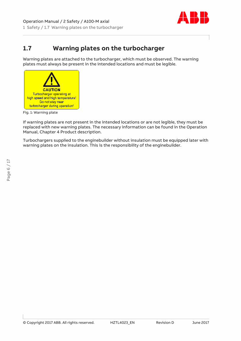
1.7 Warning plates on the turbochargerWarning plates are attached to the turbocharger, which must be observed. The warningplates must always be present in the intended locations and must be legible.
Fig. 1: Warning plate
If warning plates are not present in the intended locations or are not legible, they must bereplaced with new warning plates. The necessary information can be found in the OperationManual, Chapter 4 Product description.
Turbochargers supplied to the enginebuilder without insulation must be equipped later withwarning plates on the insulation. This is the responsibility of the enginebuilder.
Pag
e 6
/ 17

Operation Manual / 2 Safety / A100-M axial1 Safety / 1.8 Turbocharger rating plate
© Copyright 2017 ABB. All rights reserved. HZTL4023_EN Revision D June 2017
1.8 Turbocharger rating plate
Fig. 2: Rating plate
Operating limits
01 Turbocharger operating limits at engine overload (110 %). In test rig operation only, unless otherwise agreed with the en-ginebuilder.
02 Turbocharger operating limits during operation
Recommended replacement intervals of turbocharger components
03 Replacement interval of plain bearings in 1000 h04 Replacement interval of compressor in 1000 h05 Replacement interval of turbine in 1000 h
Further data
06 Customer part number07 Designation for special design08 Weight of turbocharger in kg09 Turbocharger type10 Serial number11 Year of construction of turbocharger12 Manufacturing plant
Pag
e 7
/ 17
Operation Manual / 2 Safety / A100-M axial1 Safety / 1.9 Periodic check of the pressure vessels
© Copyright 2017 ABB. All rights reserved. HZTL4023_EN Revision D June 2017
Explanations regarding the rating plate
The recommended replacement intervals and the corresponding operating limits are jointlydefined with the enginebuilder. This information is specific to the system.
Operation above the indicated values nBmax, tBmax can considerably shorten the recommendedreplacement intervals. In such cases ABB recommends contacting the nearest ABB Tur-bocharging Service Station.
nMmax, tMmax normally apply only when running at overload (110%) during trials on the enginetest bed. These limit values can also be permitted during operation for special applications.Operation above nMmax and tMmax is not permitted.
Non-observance of the recommended replacement intervals increases the risk of unpredict-able component failures.
Locations of the rating plates
The locations of the rating plates are defined in the Operation Manual, Chapter 4 Productdescription.
1.9 Periodic check of the pressure vesselsThe pressure vessels used by ABB Turbocharging, such as those for wet or dry cleaning, areso-called "simple pressure vessels".
¡ The locally applicable legal regulations regarding periodic checks of the pressure vesselsmust be observed.
¡ The operating company is responsible for the safe operation of the pressure vessel.
WARNINGDanger due to pressure vesselsThe operating company must make sure the pressure vessels are in properworking condition and monitor them. Necessary repair or maintenance workmust be performed promptly, and the required safety measures must betaken.
u Pressure equipment must not be operated if defects are present.
Pag
e 8
/ 17

Operation Manual / 2 Safety / A100-M axial1 Safety / 1.10 Lifting of loads
© Copyright 2017 ABB. All rights reserved. HZTL4023_EN Revision D June 2017
1.10 Lifting of loads
WARNINGSuspended loadsLoads that are not attached according to regulations can cause injury topersonnel or fatal accidents.
u Loads must always be fastened to properly functional lifting gear with asufficient load limit.
u Pay attention to the correct attachment of loads on the crane hook.
u People must not stand beneath suspended loads.
Wear safety gloves to protect against mechanical hazards.
Wear safety helmet.
Fig. 3: Attachment of loads on the crane hook
Fig. 4: Attachment angle
If there are two or more suspension points, the attachment angle of 45° must not be ex-ceeded. This prevents excessive loading due to diagonal pull.
u Before looping around the components of the turbocharger, let them cool down (max-imum 80 °C).
u Attach components of the turbocharger as described in the respective action steps.
u Use a suitable edge guard if there are sharp edges.
u The assembly devices must be completely screwed in and must not unscrew during use.
u Use assembly devices only for the described applications.
u Put down dismantled components of the turbocharger in such a way that they cannot tipover.
Pag
e 9
/ 17

Operation Manual / 2 Safety / A100-M axial1 Safety / 1.11 Prerequisites for operation and maintenance
© Copyright 2017 ABB. All rights reserved. HZTL4023_EN Revision D June 2017
1.11 Prerequisites for operation and maintenance
Responsibility of the operating company
In awareness of its responsibility, the operating company must ensure that only authorisedpersonnel work on the turbocharger, who:
¡ Are versed in the general and locally applicable regulations for occupational safety andaccident prevention
¡ Are equipped with the prescribed personal protective equipment
¡ Have read and understood the Operation Manual
¡ Have been instructed in the use of the turbocharger.
The safety-conscious work of the personnel and adherence to the Operation Manual must bechecked periodically.
Suitable working materials and personal protective equipment must be kept in a perfectcondition.
Only authorised personnel may remain in the vicinity of the turbocharger when the engine isrunning.
Competence of personnel
The turbocharger must only be operated and serviced by trained and authorised personnel.Basic mechanical training is a prerequisite.
Modifications to the turbocharger
Modifications to the turbocharger must be approved by ABB Turbo Systems.
WARNINGUse original partsOperation of the turbocharger with non-original parts can impair the safetyof the turbocharger and can cause serious damage to property and injury topersonnel.
u Only use original parts from ABB Turbo Systems.
Original parts and accessories are specially designed by ABB Turbo Systems for the ABB tur-bochargers.
ABB accepts no liability for any damage resulting from the use of non-original parts and cor-responding accessories.
Pag
e 10
/ 1
7

Operation Manual / 2 Safety / A100-M axial1 Safety / 1.12 Hazards during operation and maintenance
© Copyright 2017 ABB. All rights reserved. HZTL4023_EN Revision D June 2017
1.12 Hazards during operation and maintenance
Noise hazards
The turbocharger's noise emission during operation is influenced by its installation and op-erating conditions. A noise level exceeding 85 dB(A) is harmful.
WARNINGDanger due to noiseExposure to noise can harm the hearing system, impair health and the psy-chological state and may lead to lack of attention and irritation.
u When the engine is running, always wear ear protection.
u Always wear ear protection if the sound pressure level exceeds 85 dB(A).
Wear ear protection.
Hazards due to hot surfaces
Surfaces of the turbocharger, attached parts and operating fluids (lubricating oil) get hotduring operation. The surface temperature depends on the efficacy of the existing insula-tion. The temperature may rise to a level that can cause burns.
WARNINGDanger of burnsTouching hot surfaces or contact with hot operating fluids can cause burns.
u Do not touch hot surfaces. Observe the warning plate on the turbochar-ger.
u Wear heat-resistant safety gloves and protective clothing.
u Wait for the turbocharger to cool down before carrying out any work.
Wear safety gloves to protect against thermal hazards.Pa
ge
11 /
17
Operation Manual / 2 Safety / A100-M axial1 Safety / 1.12 Hazards during operation and maintenance
© Copyright 2017 ABB. All rights reserved. HZTL4023_EN Revision D June 2017
WARNINGHot surfaces on the non-insulated turbochargerNon-insulated turbochargers can cause serious injuries to personnel (burns).
The turbocharger is supplied with or without insulation in accordance withthe purchase order received from the enginebuilder. If supply is without in-sulation, the enginebuilder is responsible for providing the turbochargerwith proper insulation and for providing protection against contact with hotsurfaces.
u Compliance with the instructions and specifications given by the en-ginebuilder to protect against hot turbocharger surfaces is compulsory.
Wear safety gloves to protect against thermal hazards.
Hazards due to rotating parts
WARNINGPhysical hazardsContact with rotating parts can cause severe injury. The turbocharger mustnever be used without the filter silencer or the air suction branch. With theengine stopped, the rotor can rotate due to the stack draught alone.
u Operate the turbocharger in compliance with the specifications.
u Secure the rotor against unintentional rotation during maintenance.
Wear safety gloves to protect against mechanical hazards.
Hazards due to electrical installations (if present)
WARNINGDangers during work on electrical installationsElectrical installations use voltages that can lead to severe injury to person-nel or accidents resulting in fatalities.
At the same time, electrical or electronic components and parts can also bedamaged or destroyed.
u Only specially trained personnel should perform work on, or with, elec-trical components.
u Observe national regulations.
Pag
e 12
/ 1
7

Operation Manual / 2 Safety / A100-M axial1 Safety / 1.13 Safe operation
© Copyright 2017 ABB. All rights reserved. HZTL4023_EN Revision D June 2017
WARNINGAbsence of grounding on electrical installationsMissing or incorrectly fitted grounding conductors can lead to severe injuryto personnel or accidents resulting in fatalities.
Electric shock or elevated electromagnetic disturbances can damage or des-troy electrical and electronic components.
u Ground electrical installations properly with grounding conductors.
u Check the grounding connections on a regular basis and make sure theyare properly connected.
u Switch off the power supply before working on any electrical installations.
u After switching off the power supply, wait for 5 minutes to allow capacitors to dischargeand hot components to cool down.
u Ensure the power supply is switched off when working on electrical installations.
u Do not carry out any tests with regard to insulation resistance or voltage on the electricalcomponents.
1.13 Safe operation
Mechanical hazards during operation
During standard operation, no mechanical hazards are caused by the turbocharger itself if ithas been properly installed.
Safety during commissioning and operation
u Visually inspect your working environment before starting work.
u Remove any obstacles and objects littering the workplace.
u Check all pipes to and from the turbocharger for damage and leaks before commission-ing.
u Check turbocharger for recognisable damage or defects every 12 hours of operation or atleast once a day.
u Report any damage and any alterations of operational characteristics to the responsibledepartment immediately.
u In case of damage, take the turbocharger out of operation immediately and safeguardagainst accidental/unauthorised use.
u When switching on operating energy supplies (hydraulics, pneumatics, electricity), pay at-tention to the risks that may occur as a consequence of this energy input.
Pag
e 13
/ 1
7

Operation Manual / 2 Safety / A100-M axial1 Safety / 1.14 Safe maintenance
© Copyright 2017 ABB. All rights reserved. HZTL4023_EN Revision D June 2017
1.14 Safe maintenance
Occupational safety
WARNINGInjuries to personsSevere injuries to personnel or fatal accidents can be caused by mechanicalinfluences as a consequence of hazardous and inadequate operational pro-cedures or non-compliance with safety and health standards.
u When working on the turbocharger always wear safety footwear and pro-tective clothing to protect against mechanical hazards.
u Keep personal protective equipment in perfect condition.
u Obey mandatory signs.
u Observe the general rules for occupational safety and prevention of acci-dents.
u Only perform operations that are described in this manual.
u Only perform operations for which you have received instruction or train-ing.
Wear safety footwear to protect against mechanical hazard and risk of fall-ing.
Wear protective clothing.
WARNINGRisk of fallingWhen working on the turbocharger, there is a risk of falling.
u Do not climb onto the turbocharger or onto attached parts and do notuse them as climbing aids.
u Use suitable climbing aids and working platforms for work above bodyheight.
u Comply with the general accident prevention regulations.
u Only perform work on the turbocharger when you are in a physically and psychologicallystable condition.
u Only work with suitable tools, equipment and appliances that function properly.
u Power tools must be grounded and cables must be undamaged.
u Keep the workplace clean; clear away any loose objects and obstacles on the floor.
u Keep the floor, equipment, and turbocharger clean.
u Have oil binding agents ready and provide or keep oil pans at hand.
u Clean up any spills.
u Have fire protection means and extinguishing agents available.
Pag
e 14
/ 1
7

Operation Manual / 2 Safety / A100-M axial1 Safety / 1.14 Safe maintenance
© Copyright 2017 ABB. All rights reserved. HZTL4023_EN Revision D June 2017
Welding work in the vicinity of the turbocharger
u When performing welding work in the vicinity of the turbocharger, always cover the filtersilencer to prevent the filter mat from being damaged.
u Keep flammable objects and substances out of the vicinity of flying sparks.
u Cover all connections on the turbocharger so that no foreign objects can enter the tur-bocharger.
u Wear personal protective equipment (PPE) for welding operations.
Safety during cleaning
If cleaning agents or solvents are used for cleaning, the corresponding material safety datasheet and the safety instructions in section Hazards due to operating materials and suppliesmust be observed.
u Observe the material safety data sheet for the cleaning agent or solvent.
u Wear personal protective equipment (PPE) according to the material safety data sheet.
u Inspect the electric cables for abrasion and damage before and after your cleaning work.
Safety during disassembly, assembly, maintenance and repair
u Observe the procedures for set-up, service and inspection work and the inspection inter-vals.
u Inform the operating staff before starting any service or repair work. Make sure the en-gine is not started while work is being conducted on the turbocharger.
u Before taking off any cover or removing any guard from the turbocharger, switch off theengine and wait until the turbocharger has come to a standstill.
u Make sure that the oil supply is interrupted, especially with an external oil supply.
u Only restart the engine after all parts have been properly fitted again and oil supply is en-sured.
CAUTIONMechanical operations on the turbochargerComponents of the turbocharger can be damaged or destroyed as a resultof improper procedures.
u Only perform operations that are described in this manual.
u Only perform operations for which you have received instruction or train-ing.
Safety when taking out of operation or preparing for mothballing
u Secure rotor against turning. The rotor can rotate due to the stack draught alone.
u Observe the material safety data sheet for the cleaning and mothballing agents.
u Wear personal protective equipment (PPE) according to the material safety data sheet.
Pag
e 15
/ 1
7

Operation Manual / 2 Safety / A100-M axial1 Safety / 1.14 Safe maintenance
© Copyright 2017 ABB. All rights reserved. HZTL4023_EN Revision D June 2017
Mechanical hazards when working on the turbocharger
WARNINGPhysical hazards due to rotating partsThe rotor can rotate due to the stack draught alone. Contact with rotatingparts can cause severe injury.
u Secure rotor against turning.
WARNINGMechanical hazardsSevere injuries to personnel or fatal accidents can be caused by mechanicalinfluences as a consequence of hazardous and inadequate operational pro-cedures.
u Observe the general rules for occupational safety and prevention of acci-dents.
u Ensure workplace safety.
u Only perform operations that are described in this chapter.
u Only perform operations for which you have previously received instruc-tion or training.
Hazards due to operating materials and supplies
Operating materials and supplies are substances required for the operation of the tur-bocharger or for the performance of maintenance work. Oils, greases, coolants, detergentsand solvents, acids and similar substances can be classified as hazardous substances.
WARNINGHandling operating materials and suppliesSwallowing or inhaling vapours of operating materials and supplies or con-tact with them may be harmful to health.
u Do not breathe in these substances and avoid contact with the skin.
u Ensure proper ventilation.
u Observe the information in the material safety data sheet for the operat-ing materials and supplies.
u Wear personal protective equipment (PPE) according to the materialsafety data sheet.
u Comply with local legislation.
Wear safety goggles.
Wear safety gloves to protect against chemical hazards.
Wear a respiratory mask to protect against gases.
Pag
e 16
/ 1
7

Operation Manual / 2 Safety / A100-M axial1 Safety / 1.14 Safe maintenance
© Copyright 2017 ABB. All rights reserved. HZTL4023_EN Revision D June 2017
WARNINGDanger of fire or explosionFlammable and combustible operating materials and supplies can catch fireor resulting vapours can lead to an explosion.
u Observe the information in the material safety data sheet for the operat-ing materials and supplies.
u Comply with local legislation.
u Do not allow any exposed flame or ignition source during cleaning work.
u Carry out cleaning in the open or provide sufficient ventilation.
CAUTIONEnvironmental hazardImproper handling of operating materials and supplies can lead to environ-mental damage.
u Observe the information in the material safety data sheet for the operat-ing materials and supplies.
u Comply with local legislation.
Hazards due to the handling of insulation materials
WARNINGDanger from insulation materialsDust or fibres from insulation materials can have adverse effects on thehealth or cause irritations. Unsuitable and combustible insulation materialsare a fire hazard.
u Only use suitable and non-combustible insulation materials.
u Ensure good ventilation at the workplace.
u Avoid whirling up dust.
u Use dust-free tools and working methods.
u Remove package at the workplace only.
u Proceed with particular care when removing old insulation materials.
u Dispose of insulation materials properly and in an environmentally com-patible manner in compliance with the legal regulations.
Wear safety goggles.
Wear a respiratory mask to protect against dusts.
Wear safety gloves to protect against chemical hazards.
Pag
e 17
/ 1
7


Operation Manual / A175-M62 / Safety data sheet
Page 1 / 1
Safety data sheet
© Copyright 2020 ABB. All rights reserved. HT596623 July 2020
A175-M62 HT596623
A175-M62 HT596623
320 650
305 620
4600 36 50 50
2020


Operation Manual / 4 Product description / A100-M axialTable of contents
© Copyright 2020 ABB. All rights reserved. HZTL4033_EN Rev.E May 2020
Product description1 Introduction............................................................................................................ 31.1 Essential information.................................................................................................... 31.2 Registered trademarks................................................................................................. 31.3 Related documents........................................................................................................ 31.4 Layout and function of the turbocharger ................................................................ 41.5 Warning plates on the turbocharger......................................................................... 61.6 Locations of the rating plates..................................................................................... 7
2 Removal and installation ...................................................................................... 82.1 Turbocharger weight ................................................................................................... 82.2 Removing the turbocharger........................................................................................ 92.3 Installing the turbocharger........................................................................................ 12
3 Commissioning .................................................................................................... 183.1 Oil supply ....................................................................................................................... 183.2 Inspection procedures................................................................................................ 193.3 Commissioning after taking out of operation...................................................... 20
4 Monitoring during operation.............................................................................. 214.1 Oil pressure, oil temperature..................................................................................... 214.2 Turbocharger speed.................................................................................................... 23
5 Operation and service ......................................................................................... 265.1 Noise emission ............................................................................................................ 265.2 Service work................................................................................................................. 285.3 Expected replacement intervals ............................................................................... 315.4 Stopping the engine.................................................................................................... 32
6 Periodic maintenance.......................................................................................... 336.1 Foreword to maintenance......................................................................................... 336.2 Cleaning the filter silencer ........................................................................................ 346.3 Cleaning the slotted diffuser..................................................................................... 376.4 Cleaning the compressor during operation .......................................................... 386.5 Cleaning turbine and nozzle ring ............................................................................. 44
7 Troubleshooting................................................................................................... 507.1 Malfunctions when starting...................................................................................... 507.2 Malfunctions during operation ................................................................................. 517.3 Surging of the turbocharger..................................................................................... 537.4 Malfunctions when stopping.................................................................................... 547.5 Speed measurement system.................................................................................... 55

Operation Manual / 4 Product description / A100-M axialTable of contents
© Copyright 2020 ABB. All rights reserved. HZTL4033_EN Rev.E May 2020
8 Disassembly and assembly................................................................................. 568.1 Introduction ................................................................................................................. 568.2 Weight of assemblies................................................................................................. 588.3 Removing the air inlets .............................................................................................. 598.4 Axial clearance A prior to disassembly .................................................................... 618.5 Removing the compressor casing........................................................................... 628.6 Removing the cartridge group................................................................................. 658.7 Removing the nozzle ring .......................................................................................... 688.8 Installing the nozzle ring ............................................................................................ 728.9 Installing the cartridge group ................................................................................... 778.10 Fitting the spinner nose cone .................................................................................. 808.11 Installing the compressor casing ............................................................................ 828.12 Axial clearance A after assembly.............................................................................. 868.13 Installing the air inlets ............................................................................................... 878.14 Removing and installing turbine-end nozzle ring................................................. 898.15 Table of tightening torques...................................................................................... 93
9 Taking a turbocharger out of operation........................................................... 969.1 Possible emergency repairs...................................................................................... 969.2 Locking the rotor ........................................................................................................ 979.3 Fitting the cover plate.............................................................................................. 1009.4 Blanking off the inlets and outlets ........................................................................ 1029.5 Engines with bypass around the turbocharger .................................................. 102
10 Mothballing the turbocharger.......................................................................... 10310.1 Taking the engine out of operation for up to 12 months ................................. 10310.2 Taking the engine out of operation for more than 12 months ........................ 104
11 Disposing of turbocharger components ........................................................ 105
12 Spare parts ......................................................................................................... 10612.1 Ordering spare parts................................................................................................ 10612.2 View of turbocharger with part numbers ............................................................ 107
13 Tools .................................................................................................................... 109
Figures................................................................................................................. 110
Tables ................................................................................................................... 112

Operation Manual / 4 Product description / A100-M axial1 Introduction / 1.1 Essential information
© Copyright 2020 ABB. All rights reserved. HZTL4033_EN Rev.E May 2020
1 Introduction
1.1 Essential information
Design variants
This document is valid for different design variants of turbochargers. There may be sectionsand descriptions of components that are not relevant for a specific turbocharger variant.
Please contact an ABB Turbocharging Service Station if you have any questions regarding adesign variant (see Contact information at www.abb.com/turbocharging).
Accuracy of illustrations
The illustrations in this document are general in nature and intended for ease of understand-ing. Differences in detail are therefore possible.
1.2 Registered trademarksThe trademarks of outside companies are used in this document. These are marked with the® symbol.
1.3 Related documents
Chapter Document numberOperation Manual / 1 Introduction HZTL4005Operation Manual / 2 Safety HZTL4023Operation Manual / 3 Safety data sheet *) Serial number of the turbochargerTable 1: Related documents
*) This chapter is only available in serialised operation manuals.Pa
ge
3 /
113
Operation Manual / 4 Product description / A100-M axial1 Introduction / 1.4 Layout and function of the turbocharger
© Copyright 2020 ABB. All rights reserved. HZTL4033_EN Rev.E May 2020
1.4 Layout and function of the turbocharger
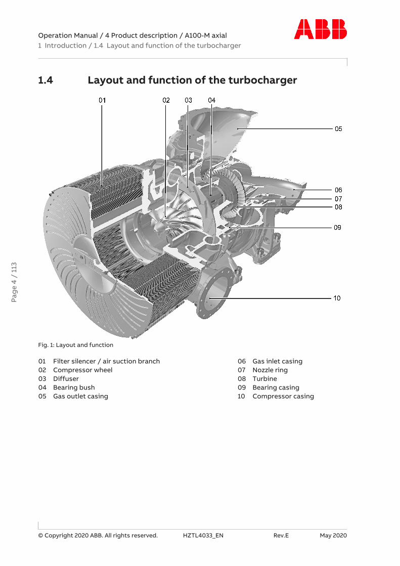
Fig. 1: Layout and function
01 Filter silencer / air suction branch 06 Gas inlet casing02 Compressor wheel 07 Nozzle ring03 Diffuser 08 Turbine04 Bearing bush 09 Bearing casing05 Gas outlet casing 10 Compressor casing
Pag
e 4
/ 11
3

Operation Manual / 4 Product description / A100-M axial1 Introduction / 1.4 Layout and function of the turbocharger
© Copyright 2020 ABB. All rights reserved. HZTL4033_EN Rev.E May 2020
Mode of operation
The turbocharger is a turbomachine consisting of two main components, a turbine and acompressor. These components are mounted on a common shaft and form the rotor.
In the turbocharger shown in the illustration, the exhaust gas flows through the gas inletcasing (06) and the nozzle ring (07) and arrives at the turbine (08). The turbine utilises theenergy contained in the exhaust gas to drive the rotor. The exhaust gases then escape intothe open air through the gas outlet casing (05) and the exhaust gas pipe connected to it.
The rotor runs in two radial plain bearings, which are located between the compressor andthe turbine in the bearing bush (04). The axial bearing is also a plain bearing. The plain bear-ings are connected to a central lubricating oil duct which is normally supplied by the lubric-ating oil circuit of the engine. The oil outlet is situated at the lowest point of the bearingcasing (09).
The compressor wheel (02) connected to the shaft draws in fresh air through the filter silen-cer (01) or the air suction branch. The air is compressed in the compressor and the down-stream diffuser (03) and then led to the charge air cooler via the compressor casing (10).
Turbocharger version with compressor wheel cooling
Fig. 2: Connection of the compressor wheel cooling
Depending on the application, the turbocharger is equipped with compressor wheel cooling.With compressor wheel cooling, after the compressor air has cooled down by passingthrough the charge air cooler on the engine side, it is supplied to the turbocharger for cool-ing the compressor wheel.
Cooling of the compressor wheel is compulsory to ensure the reliability and replacement in-tervals for the relevant operating conditions. In the turbocharger version with compressorwheel cooling, the cooling air is supplied through the lateral connection (15) in the bearingcasing.
Pag
e 5
/ 11
3

Operation Manual / 4 Product description / A100-M axial1 Introduction / 1.5 Warning plates on the turbocharger
© Copyright 2020 ABB. All rights reserved. HZTL4033_EN Rev.E May 2020
1.5 Warning plates on the turbochargerWarning plates are affixed at the following locations:
Fig. 3: Warning plates on the turbocharger
If warning plates are not present in the designated locations or not readable, proceed as fol-lows:
u Order new warning plates from ABB Turbocharging Service Stations.
u Remove any warning plates that have become unreadable.
u Clean and degrease the areas designated for the warning plates.
u Fit new warning plates and remove protective sheets.
Turbochargers supplied to the enginebuilder without insulation must be equipped later withwarning plates on the insulation. This is the responsibility of the enginebuilder.
Pag
e 6
/ 11
3

Operation Manual / 4 Product description / A100-M axial1 Introduction / 1.6 Locations of the rating plates
© Copyright 2020 ABB. All rights reserved. HZTL4033_EN Rev.E May 2020
1.6 Locations of the rating plates
Fig. 4: Locations of the rating plates
One rating plate (01) each is attached on the left and the right side of the foot of the tur-bocharger.
On turbochargers with insulation supplied by ABB, at least one additional rating plate is at-tached to the insulation of the gas outlet casing.
Pag
e 7
/ 11
3

Operation Manual / 4 Product description / A100-M axial2 Removal and installation / 2.1 Turbocharger weight
© Copyright 2020 ABB. All rights reserved. HZTL4033_EN Rev.E May 2020
2 Removal and installation
2.1 Turbocharger weightLifting gear with a sufficient load limit must be used for removing, installing and transport-ing the turbocharger. The weight specified below applies to the heaviest variant possible.Depending on the specification, the weight specified on the rating plate may be lower thanthe standard value specified here.
Fig. 5: Turbocharger suspension points
Product Weight of complete turbocharger unit [kg]A170-M 3100A175-M 4600Table 2: Weight of complete turbocharger unit
Pag
e 8
/ 11
3

Operation Manual / 4 Product description / A100-M axial2 Removal and installation / 2.2 Removing the turbocharger
© Copyright 2020 ABB. All rights reserved. HZTL4033_EN Rev.E May 2020
2.2 Removing the turbocharger
WARNINGRisk of tippingIf the turbocharger is not sufficiently supported or not supported at all dur-ing removal and installation, it may tip over and cause severe injury to per-sonnel or accidents resulting in fatalities.
u Support the turbocharger at a suitable location.
u Secure with lifting gear wherever possible.
u If present: Loosen cable to speed sensor.
u Disconnect all gas, air and lubricating oil pipes.
Fig. 6: Turbocharger suspension points
u If present: Remove insulation segments on bearing casing and feet.
u Attach lifting gear to the suspension lug of the bearing casing and through the boles onthe turbine-end foot.
Pag
e 9
/ 11
3

Operation Manual / 4 Product description / A100-M axial2 Removal and installation / 2.2 Removing the turbocharger
© Copyright 2020 ABB. All rights reserved. HZTL4033_EN Rev.E May 2020
Turbocharger with clamping nuts
Fig. 7: Removing the foot mounting
1. Treat the threads of the threaded rods with penetrating oil and allow it to work in. Do not oil the pressure screws of the clamping nut.
2. Loosen the clamping nuts at the compressor-end and turbine-end foot (see Spannmutterlösen →11).
3. Fit transport screws (90334 / 90335) to secure the sliding block (68003) on the left andright on the turbine-end foot.
u Lift the turbocharger from the engine and put it down.
u Cover all oil connections.
Pag
e 10
/ 1
13

Operation Manual / 4 Product description / A100-M axial2 Removal and installation / 2.2 Removing the turbocharger
© Copyright 2020 ABB. All rights reserved. HZTL4033_EN Rev.E May 2020
2.2.1 Loosening the clamping nut
CAUTIONIncorrect procedure can make loosening impossibleIf individual pressure screws are fully relieved, the pressure screws can be-come compressed, making it impossible to loosen them.
u Comply with the following steps for loosening the pressure screws.
CAUTIONDo not clean pressure screwsThe pressure screws are equipped with a permanent sliding layer that mustnot be removed. In case of non-compliance, it cannot be ensured that thenecessary tension force is reached.
u Do not clean pressure screws.
u Do not lubricate pressure screws.
If a screw jams, the previously loosened screw must be tightened again a little.
Fig. 8: Loosening the clamping nut
1. Working in a circle, break loose each pressure screw (≤ 20°).
2. Working in a circle, loosen each pressure screw by 45° in 4 rounds.
3. In 1 to 5 rounds, loosen each pressure screw by 90° in circular order until all pressurescrews have been relieved.
u Unscrew and remove the clamping nut by hand.
Pag
e 11
/ 1
13

Operation Manual / 4 Product description / A100-M axial2 Removal and installation / 2.3 Installing the turbocharger
© Copyright 2020 ABB. All rights reserved. HZTL4033_EN Rev.E May 2020
2.3 Installing the turbocharger
WARNINGRisk of tippingIf the turbocharger is not sufficiently supported or not supported at all dur-ing removal and installation, it may tip over and cause severe injury to per-sonnel or accidents resulting in fatalities.
u Support the turbocharger at a suitable location.
u Secure with lifting gear wherever possible.
Fig. 9: Turbocharger suspension points
u If present: Remove insulation segment on the bearing casing.
u Attach lifting gear to the suspension lug of the bearing casing and the turbine-end foot.
u Remove the covers from the oil connections.
u Align turbocharger and place on bracket.
Pag
e 12
/ 1
13

Operation Manual / 4 Product description / A100-M axial2 Removal and installation / 2.3 Installing the turbocharger
© Copyright 2020 ABB. All rights reserved. HZTL4033_EN Rev.E May 2020
Removing auxiliary screws
Fig. 10: Removing auxiliary screw
u Remove shipping screws (90334 / 90335) on the left and right side of the foot and placein the toolbox.
The turbocharger is delivered with a pre-installed sliding block (68003). The shipping screwssecure the sliding block in the preset position. In operation, the foot can slip due to thermalexpansion.
u Tighten clamping nuts as described in the following sections.
u Connect all gas, air and oil pipes.
u If present: Re-fit the insulation segments.
u If present: Connect cable to speed sensor.
Compressor-end (CE) foot
Fig. 11: Compressor-end foot
Pag
e 13
/ 1
13

Operation Manual / 4 Product description / A100-M axial2 Removal and installation / 2.3 Installing the turbocharger
© Copyright 2020 ABB. All rights reserved. HZTL4033_EN Rev.E May 2020
Turbine-end (TE) foot
Fig. 12: Turbine-end foot
Product Foot screw dimension[mm]
Strength class
A170-M M30 10.9A175-M M36 10.9Table 3: Foot screws, dimension and strength class
Product Dimension CE [mm]a1 b1 c1
A170-M 82 ø32x23 68A175-M 95 ø38x31 85Table 4: Foot screws, dimension CE
Product Dimension TE [mm]a2 / a3 b2 c2 / c3
A170-M 94 / 124 ø32x11 56 / 45A175-M 113 / 148 ø38x12 66 / 54Table 5: Foot screws, dimension TE
Product Number of cup springs XA170-M 9A175-M 11Table 6: Foot screws, number of cup springs
Holes b1/b2 are needed to achieve the required clamping length. An additional drill hole isnot needed at the higher turbine-end foot side (01).
Pag
e 14
/ 1
13

Operation Manual / 4 Product description / A100-M axial2 Removal and installation / 2.3 Installing the turbocharger
© Copyright 2020 ABB. All rights reserved. HZTL4033_EN Rev.E May 2020
Fixing clamping nuts
Fig. 13: CE foot contact surface
u Tighten clamping nuts on compressor end (CE) (see Tightening the clamping nut →16).
Fig. 14: TE foot: Handling of cup spring contact surface / foot contact surface
u Grease the contact surface (F) for the cup springs (X) (see Table 3: Foot screws, dimen-sion and strength class →14) on the foot of the turbine end (TE) with high-temperaturegrease.
u Tighten clamping nuts on turbine end (TE) (see Tightening the clamping nut →16).
Pag
e 15
/ 1
13

Operation Manual / 4 Product description / A100-M axial2 Removal and installation / 2.3 Installing the turbocharger
© Copyright 2020 ABB. All rights reserved. HZTL4033_EN Rev.E May 2020
2.3.1 Tightening the clamping nut
Preparation for tightening
CAUTIONDo not clean pressure screws (d)The pressure screws are equipped with a permanent sliding layer that mustnot be removed.
Do neither clean nor lubricate the pressure screws. In case of non-compli-ance, it cannot be ensured that the necessary tension force is reached.
u Do not clean pressure screws.
u Do not lubricate pressure screws.
NOTICEPressure screws (d) must not protrude from the clamping nut (c) in the dir-ection of the thrust washer (b)In order to correctly fit the clamping nuts, the pressure screws must notprotrude in the direction of the thrust washer.
Fig. 15: Tightening the foot screws (1)
1. Clean the bolt thread (a) and the contact surface.Coat the bolt thread with grease.
2. Fit thrust washer (b) (component of clamping nut).
3. Tighten clamping nut (c) by hand.
4. Screw back clamping nut by ¼ of a turn (90°).
The distance between the thrust washer and the clamping nut is now about 1 mm.
Pag
e 16
/ 1
13

Operation Manual / 4 Product description / A100-M axial2 Removal and installation / 2.3 Installing the turbocharger
© Copyright 2020 ABB. All rights reserved. HZTL4033_EN Rev.E May 2020
Tightening procedure
Fig. 16: Tightening procedure
Product Fixing screw [mm] Tightening torques [Nm]A170-M M30 45A175-M M36 85Table 7: Torque-controlled tightening of the pressure screws
1. Screw in pressure screws crosswise by hand until reaching the stop.
2. Tighten pressure screws crosswise to 50 % of the tightening torque specified in thetable.
3. Tighten pressure screws crosswise to 100 % of the tightening torque specified in thetable.
4. Work in a circle to tighten all pressure screws to 100 % of the tightening torque specifiedin the table.
5. Tighten pressure screws to 100 % in 5 … 7 rounds until the required residual tighteningangle of < 20° is achieved.
Pag
e 17
/ 1
13

Operation Manual / 4 Product description / A100-M axial3 Commissioning / 3.1 Oil supply
© Copyright 2020 ABB. All rights reserved. HZTL4033_EN Rev.E May 2020
3 Commissioning
3.1 Oil supply
3.1.1 Introduction
In all operating states, a functioning and carefully executed oil supply is an important pre-requisite for trouble-free operation of the turbocharger.
The lubrication of the turbocharger is usually carried out with oil from the engine oil circula-tion.
u Comply with the enginebuilder's specifications regarding the selection of lubricating oiland the oil change intervals.
For more information on the oil supply, refer to Chapter Oil pressure, oil temperature →21.
3.1.2 Pre-lubrication and post-lubrication
The pre-lubrication time is at least 2 minutes.
The post-lubrication time is 10 minutes.
If the engine is operated in idle mode 10 minutes before stopping, no additional post-lubric-ation is required.
3.1.3 Oil filtering
Filtering of the lubricating oil with a filter mesh width of ≤ 0.050 mm is sufficient for the tur-bocharger.
3.1.4 Oil pressure
Comply precisely with the oil pressure before the turbocharger for trouble-free operation.
Pag
e 18
/ 1
13

Operation Manual / 4 Product description / A100-M axial3 Commissioning / 3.2 Inspection procedures
© Copyright 2020 ABB. All rights reserved. HZTL4033_EN Rev.E May 2020
3.2 Inspection procedures
3.2.1 Introduction
Inspection procedures include preventative visual controls, monitoring and measuring workbefore and during commissioning. Inspection procedures enable changes to the turbochar-ger to be detected. Machine damage can be prevented.
3.2.2 Checks before commissioning
Filter mat (if available)
u Check for damage and contamination.
Lubricating system
CAUTIONContaminated oilSerious damage to engine or property can be caused by dirt and solid ma-terial particles in the oil.
u For the initial commissioning phase and after all service work, flush thecomplete lubricating system with warm oil.
u Use special running-in filters when running in the engine and after all ser-vice work on the lubricating system.
u Check that the oil filter is clean before commissioning.
u Check the oil pressure in the oil supply pipes.
3.2.3 Checks after commissioning (engine in idle mode)
Lubricating system
u Check the oil pressure in the oil supply pipes.
u Check oil inlet temperature.
The admissible values are specified in section Oil supply.
Gas, air and oil pipes
u After starting the engine, check all gas, air and oil pipes for leaks.
Pag
e 19
/ 1
13

Operation Manual / 4 Product description / A100-M axial3 Commissioning / 3.3 Commissioning after taking out of operation
© Copyright 2020 ABB. All rights reserved. HZTL4033_EN Rev.E May 2020
3.2.4 Checks when starting up the engine
u Measure speed, oil pressure and charging pressure at various engine performances.
u Measure the exhaust gas temperature before and after the turbine.
u Measure the air temperature before and after the compressor.
u Compare the measured values with the values of the acceptance report. Different operat-ing conditions indicate a malfunction (see Chapter Troubleshooting →50).
Escape of oily fluids
Lubricants and pastes used during assembly can liquefy or vaporise and escape as oily fluidsduring the initial hours of operation. Continual escape of an oily fluid indicates an oil leak.
u If there is a leak, contact an ABB Turbocharging Service Station.
3.3 Commissioning after taking out of operation
If present
u Remove cover plates (blind flanges) from the compressor casing, the gas inlet and thegas outlet.
General
u Check the exhaust gas pipe before and after the turbine for combustion residues or wa-ter residues and clean it. Remove any foreign objects that may be present.
u Check and clean filter silencer or air supply line, and remove any foreign objects that maybe present.
u Put engine-side oil circulation to the turbocharger into operation.
u Prepare the turbocharger for operation (see Checks before commissioning →19).
u The turbocharger is now ready for operation.
Pag
e 20
/ 1
13

Operation Manual / 4 Product description / A100-M axial4 Monitoring during operation / 4.1 Oil pressure, oil temperature
© Copyright 2020 ABB. All rights reserved. HZTL4033_EN Rev.E May 2020
4 Monitoring during operation
4.1 Oil pressure, oil temperature
Lubricating oil pressure
CAUTIONAssuring lubricating oil pressureSerious damage to the engine or property can result from a missing or insuf-ficient lubricating oil supply.
u The lubricating oil pressure must be monitored during operation and thenecessary pressure assured at the oil inlet.
For monitoring the lubricating oil pressure, ABB Turbocharging recommends installing amanometer "M". If the pressure is controlled electronically, the relevant signals should betriggered at the warning and alarm values.
Fig. 17: Lubricating oil pressure measuring point
The permitted oil pressure ranges at measuring point M of the turbocharger are listed be-low.
Status for operation Pressure at measuring point MPoil, in [bar]
Normal operation 1.3 ... 2.5Engine start: Cold oil, admissible for max. 15 minutes 1.3 ... 5.0Pre-lubrication 1.3 ... 2.5Post-lubrication 1.3 ... 2.5Long-term lubrication 0.2 ... 0.5Warning signal: Temporarily admissible (<1 h ) 1.0 ... 1.3Alarm signal: Not permissible. Stop the engine immediately < 1.0Table 8: Oil pressure range
Lubricating oil temperature at the inlet
CAUTIONMachine damageIf the oil temperature at the oil inlet exceeds the admissible range, this maylead to engine damage.
u Observe oil temperature at the oil inlet according to the following table.
Pag
e 21
/ 1
13

Operation Manual / 4 Product description / A100-M axial4 Monitoring during operation / 4.1 Oil pressure, oil temperature
© Copyright 2020 ABB. All rights reserved. HZTL4033_EN Rev.E May 2020
Status for operation Oil temperature at the inletToil,inlet [°C]
Admissible < 90Temporarily admissible (< 1 h) → alarm > 90Not admissible → stop engine > 95Table 9: Oil temperature at the inlet
Lubricating oil temperature at the outlet
The oil temperature at the outlet is mainly dependant on:
¡ Lubricating oil temperature and pressure at the oil inlet
¡ Engine load and turbocharger speed
¡ Exhaust gas temperature
The maximum admissible oil temperature at the outlet is listed in the following table. Thespecified oil outlet temperature is to be considered as alarm value for the turbocharger op-eration and must be monitored according to the current regulations.
Status for operation Oil temperature at the outletToil,outlet [°C]
Admissible ≤ 135Temporarily admissible → alarm > 135Not admissible → stop engine > 155Table 10: Oil temperature at the outlet
If the turbocharger has been operated for a longer period of time outside the admissiblerange, ABB Turbocharging recommends having the turbocharger inspected by an ABB Tur-bocharging Service Station.
Pag
e 22
/ 1
13

Operation Manual / 4 Product description / A100-M axial4 Monitoring during operation / 4.2 Turbocharger speed
© Copyright 2020 ABB. All rights reserved. HZTL4033_EN Rev.E May 2020
4.2 Turbocharger speed
4.2.1 Introduction
Speed measurement systems enable the constant monitoring of the turbocharger speeds.
CAUTIONDo not put the speed measurement cables under strain by pulling themIf you pull the speed measurement cables too hard, contacts can be pulledout.
u Do not strain the speed measurement cables by pulling.
4.2.2 Layout and overview
Fig. 18: Speed measurement
86505 Speed sensor86506 O-ring86515 Cable connector86526 F/I converter86528 Tachometer42047 Screw plug32118 Auxiliary bearing with cams*) Alternative mounting position for speed sensor
Pag
e 23
/ 1
13
Operation Manual / 4 Product description / A100-M axial4 Monitoring during operation / 4.2 Turbocharger speed
© Copyright 2020 ABB. All rights reserved. HZTL4033_EN Rev.E May 2020
4.2.3 Speed differences with several turbochargers per engine
The speeds of all turbochargers on an engine vary only slightly from each other in standardoperation.
The difference between the highest and the lowest turbocharger speed must not be morethan 3 %, relative to the speed limit nBmax.
If this permissible range of difference is exceeded, the following steps must be carried out:
u Reduce the engine performance immediately to the point at which the maximum tur-bocharger speed does not exceed 70 % of nBmax.
u If the engine cannot be stopped, it can continue to be driven at this reduced engine loador turbocharger speed.
u If a turbocharger surges continuously, the engine performance must be reduced further.
u Measure the temperatures in the air lines and gas piping from and to the turbochargersand compare with normal values. If clear deviations of temperature are found, the nearestABB Turbocharging Service Station has to be contacted.
u Check the pressure loss of the alternative air inlet and compare it with normal values.
If the engine can be stopped temporarily:
u Inspect air lines, gas piping and the turbochargers and remedy any malfunctions.
u In any case, contacting the nearest ABB Turbocharging Service Station is recommended.
Pag
e 24
/ 1
13

Operation Manual / 4 Product description / A100-M axial4 Monitoring during operation / 4.2 Turbocharger speed
© Copyright 2020 ABB. All rights reserved. HZTL4033_EN Rev.E May 2020
4.2.4 Replacing the speed sensor
WARNINGHot cable connector and hot speed sensorDanger of burns. The cable connector and speed sensor can reach temperat-ures in excess of 100 °C during operation.
u When disassembling the cable connector and speed sensor, wear safetygloves.
Wear safety gloves to protect against thermal hazards.
u Reduce the engine performance to idling and then stop the engine. Pay attention to post-lubrication (Stopping the engine →32).
u Switch off the lubricating oil supply to the turbocharger.
u Disconnect the cable connector from the speed sensor.
u Screw out defective speed sensor.
u Screw in new speed sensor to the stop.
The speed sensor is designed with a sealing lip and does not require any additional gasketfor assembly.
u Connect cable connector (86515) with the speed sensor (86505)
u Switch on lubricating oil supply to the turbocharger.
4.2.5 Malfunction of the speed measurement system
The possible reasons for malfunction of the speed measurement system are described inchapter Troubleshooting (Reasons for malfunction of the speed sensor).
Pag
e 25
/ 1
13

Operation Manual / 4 Product description / A100-M axial5 Operation and service / 5.1 Noise emission
© Copyright 2020 ABB. All rights reserved. HZTL4033_EN Rev.E May 2020
5 Operation and service
5.1 Noise emission
WARNINGNoise hazardsExposure to noise can harm the hearing system, impair health and the psy-chological state and may lead to lack of attention and irritation.
u When the engine is running, always wear ear protection.
u Always wear ear protection if the sound pressure level exceeds 85 dB(A).
Wear ear protection.
The emission sound pressure level (A-weighted) is measured at a distance of 1 meter fromthe turbocharger.
The highest value of the emission sound pressure level1) reaches a maximum of 105 dB(A)near the air inlet. The following prerequisites must be fulfilled with regard to the turbochar-ger to observe this limit value:
¡ Air-inlet system has been fitted
¡ All standard, noise-reducing measures2) have been fitted
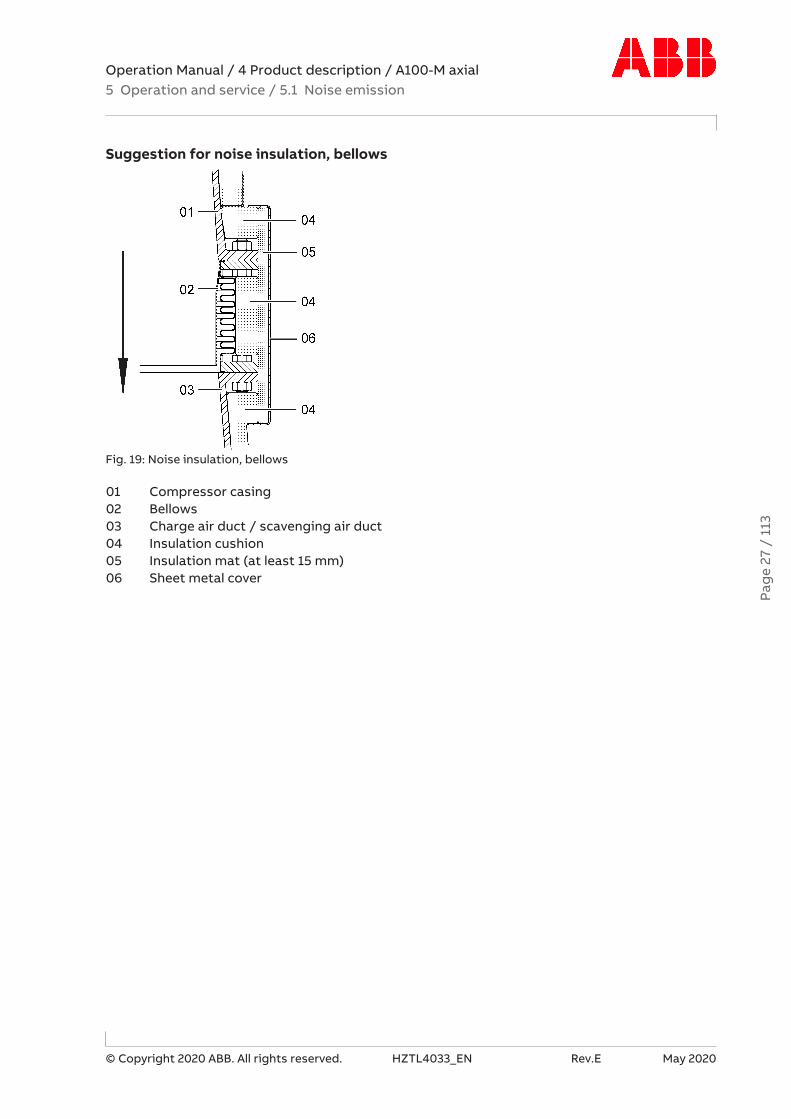
¡ Bellows at the air outlet has been acoustically insulated by the enginebuilder (see Fig. 19:Noise insulation, bellows →27).
The enginebuilder is responsible for insulating the charge air/scavenging air line and thecharge air cooler.
1) Directive 2006/42/EC, 1.7.4.2 / u / Paragraphs 5 + 7 : A-weighted emission sound pressure level
2) The enginebuilder must provide acoustically equivalent measures in case of deviating in-sulation versions
Pag
e 26
/ 1
13
Operation Manual / 4 Product description / A100-M axial5 Operation and service / 5.1 Noise emission
© Copyright 2020 ABB. All rights reserved. HZTL4033_EN Rev.E May 2020
Suggestion for noise insulation, bellows
Fig. 19: Noise insulation, bellows
01 Compressor casing02 Bellows03 Charge air duct / scavenging air duct04 Insulation cushion05 Insulation mat (at least 15 mm)06 Sheet metal cover
Pag
e 27
/ 1
13

Operation Manual / 4 Product description / A100-M axial5 Operation and service / 5.2 Service work
© Copyright 2020 ABB. All rights reserved. HZTL4033_EN Rev.E May 2020
5.2 Service workService work includes visual controls, monitoring, measuring and inspection as well as func-tional checks. Service work enables the detection and rectification of changes to the tur-bocharger and ensures full operability of the turbocharger.
CAUTIONService intervalsAny service work on the turbocharger that is omitted or performed too latecan cause excessive contamination, wear and operating failures.
u Carry out the service work at the specified time intervals.
CAUTIONSpecific service intervalExceptional stresses such as a high number of starts and stops, harsh envir-onmental conditions, poor fuel quality or high system vibrations can lead tountimely machine damage even if the prescribed service intervals are ob-served.
u Agree on a specific service interval with ABB Turbocharging.
To prevent machine damage caused by ageing and downtime, we recommend having an in-spection carried out by an ABB Turbocharging Service Station no later than 5 years after thelast service.
5.2.1 Service work every 25 … 50 hours
u Visual check for air, exhaust gas, water and oil leaks.
u Record operating data and enter in the engine logbook.
u In case of deviations, determine the cause.
CAUTIONUnknown operational changesUnknown operating conditions may result in problems ranging from impair-ment to possible operating failure.
u Unknown causes must be clarified by an ABB Turbocharging Service Sta-tion.
5.2.2 Service work at 100 hours after commissioning
u Clean or replace the oil filter located in the supply pipe to the turbocharger while the en-gine is stopped, in accordance with the instructions of the enginebuilder.
Pag
e 28
/ 1
13
Operation Manual / 4 Product description / A100-M axial5 Operation and service / 5.2 Service work
© Copyright 2020 ABB. All rights reserved. HZTL4033_EN Rev.E May 2020
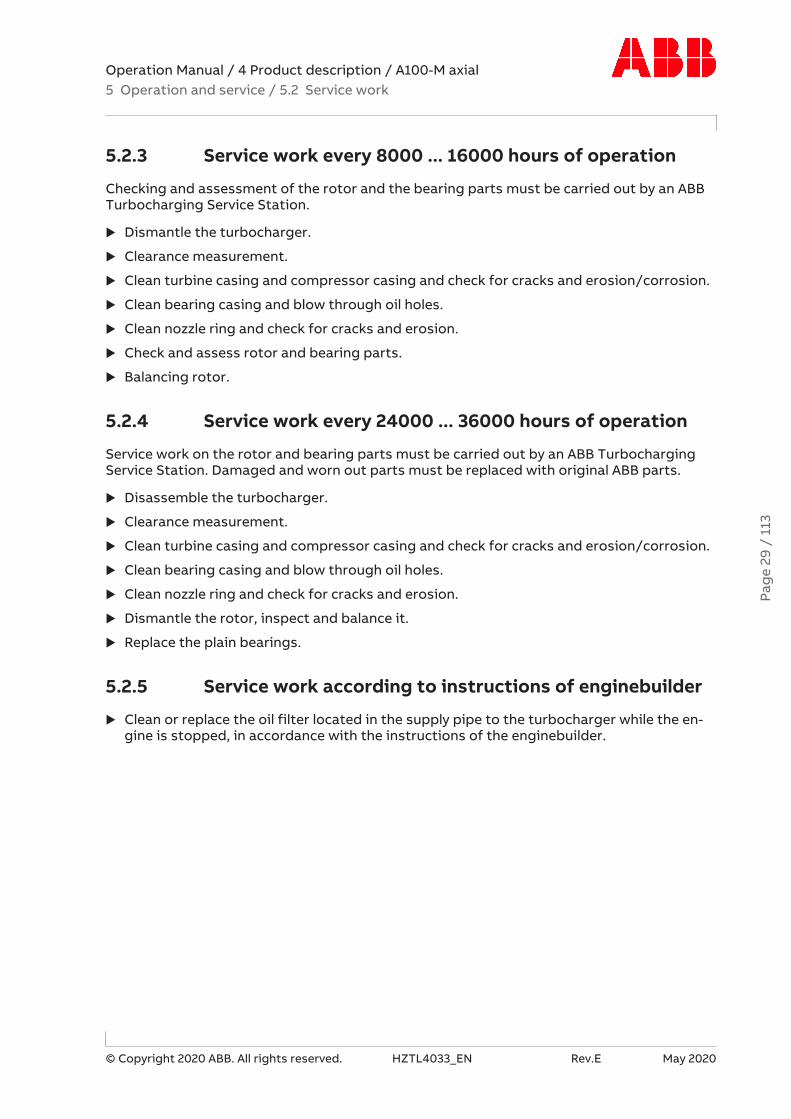
5.2.3 Service work every 8000 ... 16000 hours of operation
Checking and assessment of the rotor and the bearing parts must be carried out by an ABBTurbocharging Service Station.
u Dismantle the turbocharger.
u Clearance measurement.
u Clean turbine casing and compressor casing and check for cracks and erosion/corrosion.
u Clean bearing casing and blow through oil holes.
u Clean nozzle ring and check for cracks and erosion.
u Check and assess rotor and bearing parts.
u Balancing rotor.
5.2.4 Service work every 24000 ... 36000 hours of operation
Service work on the rotor and bearing parts must be carried out by an ABB TurbochargingService Station. Damaged and worn out parts must be replaced with original ABB parts.
u Disassemble the turbocharger.
u Clearance measurement.
u Clean turbine casing and compressor casing and check for cracks and erosion/corrosion.
u Clean bearing casing and blow through oil holes.
u Clean nozzle ring and check for cracks and erosion.
u Dismantle the rotor, inspect and balance it.
u Replace the plain bearings.
5.2.5 Service work according to instructions of enginebuilder
u Clean or replace the oil filter located in the supply pipe to the turbocharger while the en-gine is stopped, in accordance with the instructions of the enginebuilder.
Pag
e 29
/ 1
13

Operation Manual / 4 Product description / A100-M axial5 Operation and service / 5.2 Service work
© Copyright 2020 ABB. All rights reserved. HZTL4033_EN Rev.E May 2020
5.2.6 Entries in the engine logbook
Monitoring the engine system enables conclusions to be made on the operating behaviourof the turbocharger.
The following operating data and measured values must be entered regularly into the enginelogbook of the enginebuilder:
¡ Performance and speed of the engine
¡ Speed of the turbocharger
¡ Air intake temperature
¡ Exhaust gas temperature before and after the turbine
¡ Pressure of the charge air
¡ Pressure loss in the charge air cooler
¡ Lubricating oil pressure and lubricating oil temperature
If present:
¡ Air temperature after the compressor and after the charge-air cooler
¡ Pressure loss in the filter silencer
Pag
e 30
/ 1
13

Operation Manual / 4 Product description / A100-M axial5 Operation and service / 5.3 Expected replacement intervals
© Copyright 2020 ABB. All rights reserved. HZTL4033_EN Rev.E May 2020
5.3 Expected replacement intervals
5.3.1 Influencing parameters
Rotating components
The recommended replacement intervals for compressor wheels and turbine wheels are spe-cified based on the safety concept for rotating parts (SIKO) and dependent on the operatingconditions. These intervals are shown on the rating plate of the turbocharger.
Non-rotating components
Depending on the system-specific operating conditions, a differentiation must be madebetween the intervals to be expected for:
¡ replacing the bearing parts and
¡ replacing the non-rotating components exposed to hot gas.
A decisive role is played by various influencing parameters which, in extreme cases, candrastically reduce the replacement interval of these parts.
During the prescribed periodic service work, the individual parts are examined for wear andreplaced if necessary.
Influencing parameters for bearing parts
¡ Inferior lubricating oil quality (lubricating oil filtering, lubricating oil condition)
¡ Exceptional stresses (vibrations, start/stop frequency)
¡ Inadmissible unbalance of the rotor
Influencing parameters for exhaust gas-charged, non-rotating components
¡ Fuel quality (gas, MDO, HFO)
¡ Load profile (thermal cycling, number of start/stop cycles)
¡ Temperature level of the exhaust gas
¡ Frequency of turbine cleaning
¡ Turbine cleaning process
Influencing parameters for exhaust gas-charged, rotating components
¡ Fuel quality (gas, MDO, HFO)
¡ Frequency of turbine cleaning
¡ Turbine cleaning process
¡ Load profile
Pag
e 31
/ 1
13

Operation Manual / 4 Product description / A100-M axial5 Operation and service / 5.4 Stopping the engine
© Copyright 2020 ABB. All rights reserved. HZTL4033_EN Rev.E May 2020
5.3.2 Replacement intervals
The specified values are only guide values and not guaranteed, see influencing parameters.
Expected replacement intervals [h]
Component GAS / MDO HFOGas inlet casing 50000 …
10000025000 … 50000
Gas outlet casing 50000 …100000
35000 …100000
Nozzle ring 35000 … 50000 25000 … 50000Turbine diffuser / cover ring 35000 … 50000 25000 … 50000Other casings 100000 100000Turbine blades (due to wear) - - ≥ 12000Table 11: Expected replacement intervals
GAS = GasMDO = Marine Diesel OilHFO = Heavy Fuel Oil
Recommended replacement intervals [h]
Rotor components See information on rating plateBearings See information on rating plateTable 12: Recommended replacement intervals
5.4 Stopping the engine
CAUTIONStopping the engineIn the turbocharger, the heat from the lubricating oil that continues to circu-late must be dissipated.
u Let the engine continue to run at idling speed for 10 minutes before stop-ping it.
u Post-lubrication can also be used instead of engine idling (see Pre-lubric-ation and post-lubrication →18).
Pag
e 32
/ 1
13

Operation Manual / 4 Product description / A100-M axial6 Periodic maintenance / 6.1 Foreword to maintenance
© Copyright 2020 ABB. All rights reserved. HZTL4033_EN Rev.E May 2020
6 Periodic maintenance
6.1 Foreword to maintenanceMaintenance work includes regular visual controls and cleaning operations which are inten-ded to ensure the trouble-free functioning of the turbocharger.
Described maintenance points:
¡ Filter silencer
¡ Diffuser
¡ Compressor
¡ Turbine and nozzle ring
Pag
e 33
/ 1
13

Operation Manual / 4 Product description / A100-M axial6 Periodic maintenance / 6.2 Cleaning the filter silencer
© Copyright 2020 ABB. All rights reserved. HZTL4033_EN Rev.E May 2020
6.2 Cleaning the filter silencer
Fig. 20: Cleaning the filter silencer
81135 Filter silencer body 81266 Cover grid81136 Absorption segment 81269 Connecting rods81137 Sheet-metal covering 81272 Screw81265 Filter ring (if present) 81273 Lock nutE Insert unit = absorption segment + sheet-metal covering
Cleaning the filter ring (if present)
u Remove filter ring (81265).
u Clean filter ring (81265) as required or every 500 hours of operation and replace after thefifth cleaning process at the latest.Contamination of the filter ring depends on the degree of purity of the sucked-in air.
u Rinse the filter ring (81265) with water and mild detergent or, in the case of heavy con-tamination, soak and carefully push through. Rinse in cold water. Avoid high mechanicalloads (water jet).
u Let the filter ring dry completely before assembling.
u Dirty water and mild detergent must be disposed of in compliance with locally applicableregulations.
Pag
e 34
/ 1
13

Operation Manual / 4 Product description / A100-M axial6 Periodic maintenance / 6.2 Cleaning the filter silencer
© Copyright 2020 ABB. All rights reserved. HZTL4033_EN Rev.E May 2020
Cleaning the absorption segments
(see Fig. 20: Cleaning the filter silencer →34)
u Loosen and remove lock nuts (81273).
u Loosen and remove screws (81272) to the connecting rods (81269).
u Remove connecting rods (81269).
u Remove and clean cover grid (81266).
u Pull out insert units (E), bend up sheet-metal coverings (81137) and take out absorptionsegments (81136).
u Clean the absorption segments (81136).When cleaning, note that the absorption segments (81136) must only be cleaned lightlywith pressurized air, with a soft brush or a moist cleaning cloth.
u Have any heavily contaminated absorption segments and filter rings as well as damagedconnecting rods replaced by an ABB Turbocharging Service Station.
Fitting the cover grids and absorption segments
(see Fig. 20: Cleaning the filter silencer →34)
CAUTIONPenetration of dirt and foreign particlesAny penetration of dirt and foreign particles into the compressor can dam-age it.
u Fit the connecting rods (81269) correctly in the slots on the filter silencerbody (81135).
u It must not be possible to rotate or move the cover grid (81266) after as-sembly.
u Check the position and alignment of the connecting rods during and afterassembly.
u Assemble the insert units (E) by inserting the absorption segments (81136) into thesheet-metal coverings (81137).
u Bend the sheet-metal coverings (81137) back into the original shape.
u Insert the insert units (E) into the slotted guides in the filter silencer body (81135).
If a cleaning container is attached to the filter silencer (option, depending on turbocharger),the water injection pipe must now be reinstalled.
u Place the cover grids (81266) evenly and in the correct position.
Pag
e 35
/ 1
13

Operation Manual / 4 Product description / A100-M axial6 Periodic maintenance / 6.2 Cleaning the filter silencer
© Copyright 2020 ABB. All rights reserved. HZTL4033_EN Rev.E May 2020
Fig. 21: Cleaning the filter silencer (2)
u Push the connecting rods (81269) through the lugs of the cover grids (81266).
u Connect the connecting rods (81269) with the screws (81272). While tightening the screws(81272), make sure that the connecting rods (81269) lie correctly in the slots on the filtersilencer body (81135). Now alternately tighten the screws (81272) up to the following max-imum tightening torque:
Screw Tightening torque [Nm]81272 20Table 13: Tightening torque (81272)
u Fit lock nuts (81273) on screws (81272) and tighten with the following tightening torque:
Lock nut Tightening torque [Nm]81273 40Table 14: Tightening torque (81273)
u Fit the filter ring (81265), if present.
Pag
e 36
/ 1
13

Operation Manual / 4 Product description / A100-M axial6 Periodic maintenance / 6.3 Cleaning the slotted diffuser
© Copyright 2020 ABB. All rights reserved. HZTL4033_EN Rev.E May 2020
6.3 Cleaning the slotted diffuseru Remove the diffuser (see Removing the compressor casing →62).
Fig. 22: Cleaning the slotted diffuser
u Clean the diffuser slots (S).When cleaning, please note that this should only take place using lightly pressurized air, abrush and a moist cleaning cloth.
u Have any heavily contaminated or damaged diffusers replaced by an ABB TurbochargingService Station.
Pag
e 37
/ 1
13

Operation Manual / 4 Product description / A100-M axial6 Periodic maintenance / 6.4 Cleaning the compressor during opera-tion
© Copyright 2020 ABB. All rights reserved. HZTL4033_EN Rev.E May 2020
6.4 Cleaning the compressor during operation
6.4.1 Introduction
Approval by enginebuilder
The following instructions for wet cleaning only apply to cleaning with pure water and underthe precondition that the enginebuilder approves the process.
General
The contamination of the compressor stage (compressor wheel and diffuser) depends onthe degree of purity of the sucked-in air.
Deposits can form in the flow channels if salt, oil mist or dust are sucked in with the air.
Consequences of contamination:
¡ Impaired compressor efficiency
¡ Higher exhaust gas temperatures
¡ Increased fuel consumption
¡ Increased rotor unbalance
Periodic cleaning of the compressor during operation prevents or delays any major increasein contamination. But it never replaces the regular service work where the turbocharger iscompletely dismantled and the compressor is mechanically cleaned.
6.4.2 Cleaning interval
The time period between the periodical cleaning cycles depends greatly on the operatingconditions. Cleaning should normally be done every 25 … 100 hours of operation.
If the specified cleaning intervals are incompatible with operation of the engine, contactABB.
Pag
e 38
/ 1
13
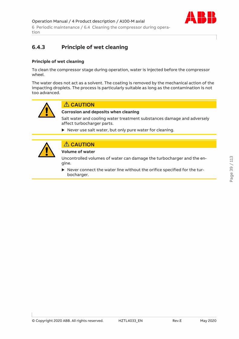
Operation Manual / 4 Product description / A100-M axial6 Periodic maintenance / 6.4 Cleaning the compressor during opera-tion
© Copyright 2020 ABB. All rights reserved. HZTL4033_EN Rev.E May 2020
6.4.3 Principle of wet cleaning
Principle of wet cleaning
To clean the compressor stage during operation, water is injected before the compressorwheel.
The water does not act as a solvent. The coating is removed by the mechanical action of theimpacting droplets. The process is particularly suitable as long as the contamination is nottoo advanced.
CAUTIONCorrosion and deposits when cleaningSalt water and cooling water treatment substances damage and adverselyaffect turbocharger parts.
u Never use salt water, but only pure water for cleaning.
CAUTIONVolume of waterUncontrolled volumes of water can damage the turbocharger and the en-gine.
u Never connect the water line without the orifice specified for the tur-bocharger.
Pag
e 39
/ 1
13
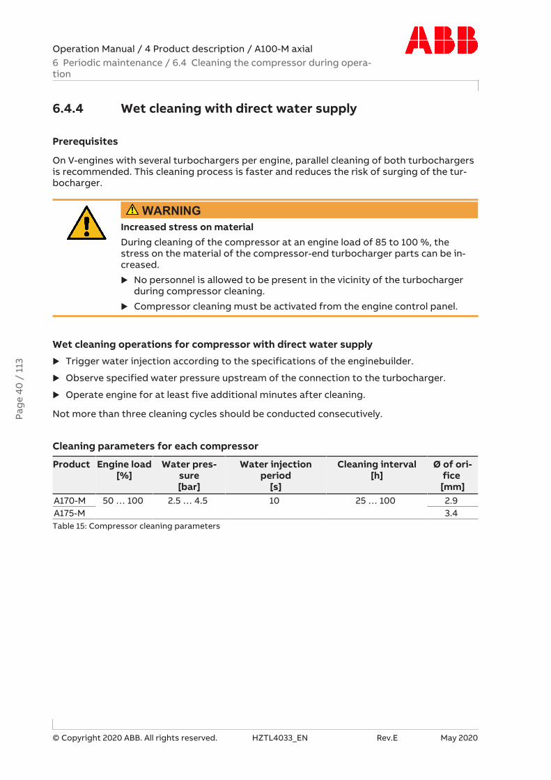
Operation Manual / 4 Product description / A100-M axial6 Periodic maintenance / 6.4 Cleaning the compressor during opera-tion
© Copyright 2020 ABB. All rights reserved. HZTL4033_EN Rev.E May 2020
6.4.4 Wet cleaning with direct water supply
Prerequisites
On V-engines with several turbochargers per engine, parallel cleaning of both turbochargersis recommended. This cleaning process is faster and reduces the risk of surging of the tur-bocharger.
WARNINGIncreased stress on materialDuring cleaning of the compressor at an engine load of 85 to 100 %, thestress on the material of the compressor-end turbocharger parts can be in-creased.
u No personnel is allowed to be present in the vicinity of the turbochargerduring compressor cleaning.
u Compressor cleaning must be activated from the engine control panel.
Wet cleaning operations for compressor with direct water supply
u Trigger water injection according to the specifications of the enginebuilder.
u Observe specified water pressure upstream of the connection to the turbocharger.
u Operate engine for at least five additional minutes after cleaning.
Not more than three cleaning cycles should be conducted consecutively.
Cleaning parameters for each compressor
Product Engine load[%]
Water pres-sure[bar]
Water injectionperiod
[s]
Cleaning interval[h]
Ø of ori-fice
[mm]A170-M 50 … 100 2.5 … 4.5 10 25 … 100 2.9A175-M 3.4Table 15: Compressor cleaning parameters
Pag
e 40
/ 1
13

Operation Manual / 4 Product description / A100-M axial6 Periodic maintenance / 6.4 Cleaning the compressor during opera-tion
© Copyright 2020 ABB. All rights reserved. HZTL4033_EN Rev.E May 2020
Surging of the compressor stage
Should repeated surging of the compressor stage occur during compressor cleaning, firstthe cleaning parameters (water flow rate) as well as the engine-side system must bechecked with regard to deviations (e.g. an increased pressure loss in the charge air cooler)and corrected if necessary.
If surging of the compressor stage continues to occur during compressor cleaning despitecorrect settings, this can be remedied by reducing the engine load further during cleaning ofthe compressor. The reduction of the engine load can lead to a reduction in the effective-ness of the compressor cleaning.
u To avoid a reduction in engine availability, the compressor stage can be cleaned at re-duced engine load during the drying time after wet cleaning of the turbine has been com-pleted (see section Cleaning turbine and nozzle ring →44).
Pag
e 41
/ 1
13
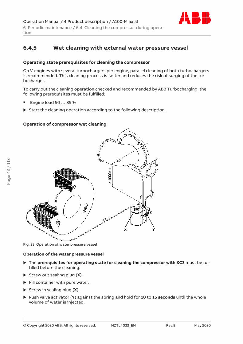
Operation Manual / 4 Product description / A100-M axial6 Periodic maintenance / 6.4 Cleaning the compressor during opera-tion
© Copyright 2020 ABB. All rights reserved. HZTL4033_EN Rev.E May 2020
6.4.5 Wet cleaning with external water pressure vessel
Operating state prerequisites for cleaning the compressor
On V-engines with several turbochargers per engine, parallel cleaning of both turbochargersis recommended. This cleaning process is faster and reduces the risk of surging of the tur-bocharger.
To carry out the cleaning operation checked and recommended by ABB Turbocharging, thefollowing prerequisites must be fulfilled:
¡ Engine load 50 … 85 %
u Start the cleaning operation according to the following description.
Operation of compressor wet cleaning
Fig. 23: Operation of water pressure vessel
Operation of the water pressure vessel
u The prerequisites for operating state for cleaning the compressor with XC3 must be ful-filled before the cleaning.
u Screw out sealing plug (X).
u Fill container with pure water.
u Screw in sealing plug (X).
u Push valve activator (Y) against the spring and hold for 10 to 15 seconds until the wholevolume of water is injected.
Pag
e 42
/ 1
13

Operation Manual / 4 Product description / A100-M axial6 Periodic maintenance / 6.4 Cleaning the compressor during opera-tion
© Copyright 2020 ABB. All rights reserved. HZTL4033_EN Rev.E May 2020
u After cleaning operations, a waiting period of at least 5 minutes is required for the tur-bocharger to dry.
If the cleaning is unsuccessful after three attempts, we recommend having the turbochargerchecked and cleaned by an ABB Turbocharging Service Station in the event of unsatisfactoryengine values.
Cleaning parameters for each turbocharger compressor
Product Engine load Water temperature[°C]
Contents of meteringcontainer
[dm3]A170-M 50 … 85% 5 … 50 1A175-MTable 16: Compressor cleaning parameters
Surging of the compressor stage
Should repeated surging of the compressor stage occur during compressor cleaning, firstthe cleaning parameters (water flow rate) as well as the engine-side system must bechecked with regard to deviations (e.g. an increased pressure loss in the charge air cooler)and corrected if necessary.
If surging of the compressor stage continues to occur during compressor cleaning despitecorrect settings, this can be remedied by reducing the engine load further during cleaning ofthe compressor. The reduction of the engine load can lead to a reduction in the effective-ness of the compressor cleaning.
u To avoid a reduction in engine availability, the compressor stage can be cleaned at re-duced engine load during the drying time after wet cleaning of the turbine has been com-pleted (see section Cleaning turbine and nozzle ring →44).
Pag
e 43
/ 1
13

Operation Manual / 4 Product description / A100-M axial6 Periodic maintenance / 6.5 Cleaning turbine and nozzle ring
© Copyright 2020 ABB. All rights reserved. HZTL4033_EN Rev.E May 2020
6.5 Cleaning turbine and nozzle ring
6.5.1 Introduction
Approval by enginebuilder
The following instructions for wet cleaning only apply to cleaning with pure water and underthe precondition that the enginebuilder approves the process.
General
The combustion of heavy fuel oil (HFO) has the effect of contaminating the turbine stage(turbine wheel and nozzle ring).
The use of fuels with poor quality in conjunction with high exhaust gas temperatures canlead to extremely hard deposits on turbine components.
ABB Turbocharging recommends the use of fuels with low ash, sulphur, sodium and vana-dium contents.
Consequences of contamination:
¡ Low turbine efficiency
¡ Elevated exhaust gas temperatures
¡ Increased charging and ignition pressures with increasing turbocharger speed
¡ Lower engine performance
¡ Rotor sticking after stopping the engine
Periodic cleaning of the turbine during operation prevents or delays any major increase incontamination, but never replaces the regular service work where the turbocharger is com-pletely dismantled and mechanically cleaned.
6.5.2 Cleaning interval
The time period between the periodical cleaning cycles depends greatly on the operatingconditions. Cleaning should normally be carried out every 50 … 200 hours of operation.
If the specified cleaning intervals are incompatible with operation of the engine, contactABB.
Pag
e 44
/ 1
13
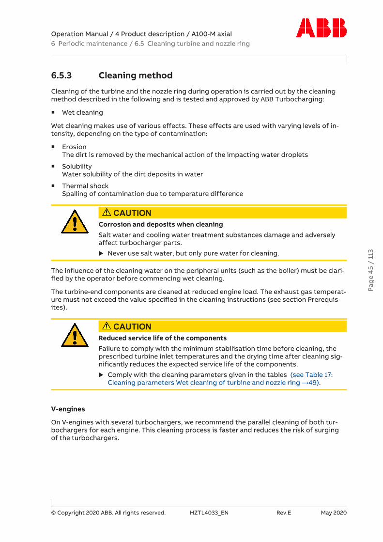
Operation Manual / 4 Product description / A100-M axial6 Periodic maintenance / 6.5 Cleaning turbine and nozzle ring
© Copyright 2020 ABB. All rights reserved. HZTL4033_EN Rev.E May 2020
6.5.3 Cleaning method
Cleaning of the turbine and the nozzle ring during operation is carried out by the cleaningmethod described in the following and is tested and approved by ABB Turbocharging:
¡ Wet cleaning
Wet cleaning makes use of various effects. These effects are used with varying levels of in-tensity, depending on the type of contamination:
¡ ErosionThe dirt is removed by the mechanical action of the impacting water droplets
¡ SolubilityWater solubility of the dirt deposits in water
¡ Thermal shockSpalling of contamination due to temperature difference
CAUTIONCorrosion and deposits when cleaningSalt water and cooling water treatment substances damage and adverselyaffect turbocharger parts.
u Never use salt water, but only pure water for cleaning.
The influence of the cleaning water on the peripheral units (such as the boiler) must be clari-fied by the operator before commencing wet cleaning.
The turbine-end components are cleaned at reduced engine load. The exhaust gas temperat-ure must not exceed the value specified in the cleaning instructions (see section Prerequis-ites).
CAUTIONReduced service life of the componentsFailure to comply with the minimum stabilisation time before cleaning, theprescribed turbine inlet temperatures and the drying time after cleaning sig-nificantly reduces the expected service life of the components.
u Comply with the cleaning parameters given in the tables (see Table 17:Cleaning parameters Wet cleaning of turbine and nozzle ring →49).
V-engines
On V-engines with several turbochargers, we recommend the parallel cleaning of both tur-bochargers for each engine. This cleaning process is faster and reduces the risk of surgingof the turbochargers.
Pag
e 45
/ 1
13

Operation Manual / 4 Product description / A100-M axial6 Periodic maintenance / 6.5 Cleaning turbine and nozzle ring
© Copyright 2020 ABB. All rights reserved. HZTL4033_EN Rev.E May 2020
6.5.4 Wet cleaning of turbine and nozzle ring
Prerequisites:
Procedure without automated cleaning
The following operating state and the following prerequisites have been tested and ap-proved by ABB Turbocharging for cleaning operations:
u Set the engine load between 20 … 50 % so that the turbine inlet temperature is between380 … 430 °C.
Fig. 24: Turbine and nozzle ring cleaning cycle
u Once the turbine inlet temperature is stable and has dropped below 430 °C, wait at leastanother 10 minutes to allow the turbine-end turbocharger parts to cool down.
u Start the cleaning cycle according to the following description Wet cleaning procedure.
Pag
e 46
/ 1
13

Operation Manual / 4 Product description / A100-M axial6 Periodic maintenance / 6.5 Cleaning turbine and nozzle ring
© Copyright 2020 ABB. All rights reserved. HZTL4033_EN Rev.E May 2020
Procedure with automated cleaning
The following operating state and the following prerequisites have been tested and ap-proved by ABB Turbocharging for cleaning operations:
u Set the engine load as follows:
¡ Turbine mass flow MTurb ≈ 4.1 kg/s
¡ Turbine pressure ratio PIT ≈ 1.1
¡ Turbine inlet temperature between 380 … 430 °C
Fig. 25: Cleaning cycle of turbine and nozzle ring with load ramp
u As soon as the turbine inlet temperature is stable and less than 430 °C, wait for least 10additional minutes for the turbine-end turbocharger components to cool down.
u Start the cleaning cycle according to the following description Wet cleaning procedure.
u Continuously increase the engine load during washing:
¡ Turbine mass flow MTurb ≈ 6.5 kg/s
¡ Turbine pressure ratio PIT = 1.6 … 2.0
¡ Turbine inlet temperature <430 °C
Pag
e 47
/ 1
13

Operation Manual / 4 Product description / A100-M axial6 Periodic maintenance / 6.5 Cleaning turbine and nozzle ring
© Copyright 2020 ABB. All rights reserved. HZTL4033_EN Rev.E May 2020
Procedure
Fig. 26: Procedure Wet cleaning of turbine and nozzle ring
The prerequisites and the operating state must be fulfilled prior to cleaning.
u Make sure that the water supply (01) is connected, switched on and safeguarded.
u Switch the 3-way valve (04) from scavenging air mode to water supply.
u Set the necessary water quantity on the flowmeter (08) according to the table Cleaningparameters (see Table 17: Cleaning parameters Wet cleaning of turbine and nozzle ring→49).
u Shut off the water supply again by switching the 3-way valve (04) to scavenging air modeafter the prescribed injection time has elapsed.
The injection process is complete.
u After cleaning, continue to operate the engine for at least 10 minutes without any loadchange.
It is necessary to have the corresponding water pipe pressure in order to achieve the correctwater flow rate (see Table 17: Cleaning parameters Wet cleaning of turbine and nozzle ring→49). If there is insufficient water pressure, the water flow rate specified in the table willnot be achieved. A reduced cleaning effect can be expected in this case.
Repetition of wet cleaning
The repeating of cleaning cycles one immediately after the other must be avoided as thiscan lead to excessive mechanical stress, hence reducing the operating life of the compon-ents.
If the cleaning process is ineffective, the duration can be extended. If the injection time is ex-tended, it is important to ensure that no impermissible volume of water collects in the gasoutlet casing. A drainage system should be installed for the gas outlet casing and openedduring cleaning. If there is no drainage system, the amount of water injected can be mon-itored with a flowmeter in the water supply. The permitted amount of water must be de-termined with the help of an ABB Turbocharging Service Station.
To be observed during cleaning
¡ The action of the cleaning water on the peripheral units (such as boiler) must be clarifiedby the operator.
Pag
e 48
/ 1
13

Operation Manual / 4 Product description / A100-M axial6 Periodic maintenance / 6.5 Cleaning turbine and nozzle ring
© Copyright 2020 ABB. All rights reserved. HZTL4033_EN Rev.E May 2020
¡ The exhaust gas temperature downstream of the turbocharger drops drastically duringcleaning (typical turbocharger outlet temperatures during cleaning: 60...180°C).
¡ If there is no drainage of the gas outlet casing, the turbocharger speed and/or the gasinlet temperature must be monitored during the cleaning process. If the load is too low,water can collect in the gas outlet casing. Indicators for this are a sudden severe drop inthe turbocharger speed or a very large increase in the gas inlet temperature. In suchcases, the cleaning operations must be stopped and the cleaning cycle restarted with re-duced water pressure or higher engine load.
Cleaning parameters for wet cleaning of turbine and nozzle ring
Product Maximum temperaturewhen starting cleaning
TTI [°C]
Injection timet i [min]
Water volume flow per turbocharger1)
VW [dm³/min]
A170-M 430 10 30A175-M 430 10 41Table 17: Cleaning parameters Wet cleaning of turbine and nozzle ring
1) Water pressure pwater as guideline value:
¡ 2.3 bar when used with an axial gas inlet casing
¡ 3 bar when used with a radial gas inlet casing
Pag
e 49
/ 1
13

Operation Manual / 4 Product description / A100-M axial7 Troubleshooting / 7.1 Malfunctions when starting
© Copyright 2020 ABB. All rights reserved. HZTL4033_EN Rev.E May 2020
7 Troubleshooting
7.1 Malfunctions when starting
Delayed start-up
Possible causes RemedyTurbochar-ger
Turbocharger contaminated Clean (Periodic maintenance →33)Bearing damaged Contact ABB Turbocharging Service
StationRotor rubbingForeign object in the turbocharger
Table 18: Malfunctions when starting – Delayed start-up
Vibrations
Possible causes RemedyTurbochar-ger
Rotor unbalance Contact ABB Turbocharging ServiceStationTurbine or compressor damaged
Bearing damagedEngine Vibrations from engine Contact enginebuilderTable 19: Malfunctions when starting – Vibrations
Rubbing of rotating parts
Normal behaviour, not a malfunctionTurbochar-ger
A slight amount of uniform wear at the circumference of the rotor componentscaused by slight local rubbing against adjacent components is permitted. Thiscauses the compressor or turbine blades to be somewhat shortened. To preventsignificant loss of efficiency, specific tolerances must be fulfilled.
¡ If there is any doubt about the extent of the rubbing, contact an ABB Tur-bocharging Service Station.
¡ Have a dimension check carried out by an ABB Turbocharging Service Sta-tion.
Table 20: Malfunctions when starting – Rubbing of rotating parts
Pag
e 50
/ 1
13

Operation Manual / 4 Product description / A100-M axial7 Troubleshooting / 7.2 Malfunctions during operation
© Copyright 2020 ABB. All rights reserved. HZTL4033_EN Rev.E May 2020
7.2 Malfunctions during operation
Lubricating oil pressure too low
WARNINGDanger of fire and explosion due to lubricating oil leaksLeaking oil may ignite on hot surfaces. This can result in serious injuries topersonnel or fatal accidents.
u Cordon off danger area.
u Raise the alarm and, depending on the situation, stop the engine.
u Seal the oil leak.
u Soak up oil and dispose of in an environmentally compatible manner.
Wear safety gloves to protect against thermal hazards.
Possible causes RemedyTurbochar-ger
Axial clearance of the rotor excessive Contact an ABB TurbochargingService Station
Engine Oil filter heavily contaminated CleanOil pump in lubricating system defect-ive
Check/replace
Manometer displays incorrectly Replace manometerTable 21: Malfunctions during operation – Lubricating oil pressure too low
Drop in speed
Possible causes RemedyTurbochar-ger
Heavy contamination of the turbineand/or nozzle ring
Clean (see chapter Periodic mainten-ance →33)
Damaged rotor components or bearing Contact ABB Turbocharging ServiceStation
Engine Defect on the connected cylinders inpulse charging
Contact enginebuilder
Pipes Defects, such as leaks, in the exhaustgas pipes or charge air ducts
Repair
Table 22: Malfunctions during operation – Drop in speed
Increase in speed
Possible causes RemedyTurbochar-ger
Light to medium contamination of theturbine and/or nozzle ring (with 4-stroke application)
Clean (see chapter Periodic mainten-ance →33) or contact an ABB Tur-bocharging Service Station
Table 23: Malfunctions during operation – Speed increases
Pag
e 51
/ 1
13

Operation Manual / 4 Product description / A100-M axial7 Troubleshooting / 7.2 Malfunctions during operation
© Copyright 2020 ABB. All rights reserved. HZTL4033_EN Rev.E May 2020
Exhaust gas temperature too high
Engine performance and engine speed unchanged
Possible causes RemedyTurbocharger Insufficient air, for example, when fil-
ter silencer is blocked by dirtClean (Periodic maintenance →33)
Compressor/turbine contaminatedExhaust gas back pressure too high Clean or repair boiler or exhaust gas si-
lencerTurbine damaged or eroded Contact ABB Turbocharging Service
StationEngine Malfunction in the injection system Repair or contact manufacturerCharge aircooler
Cooler contaminated CleanCooling water volume too low FillInlet temperature of cooling watertoo high
Check/clean cooling system
Insufficient ventilation Improve ventilationTable 24: Malfunctions during operation – Exhaust gas temperature too high
Charge air pressure too low
Engine performance and engine speed unchanged, suction condition normal
Possible causes RemedyTurbochar-ger
Manometer display not correct Replace manometerSupply pipe to manometer not sealed Repair leakFilter silencer contaminated, thereforepressure drop too high
Clean (Periodic maintenance →33)
Compressor end and/or turbine endcontaminatedCompressor/turbine damaged Contact ABB Turbocharging Service
StationExhaust gas back pressure too high Clean or repair boiler or exhaust gas si-
lencerEngine Air receiver not sealed Repair
Gas pipe between engine and turbinenot sealedInjection mistimed Set correctlyValve control misadjusted
Pipes Pipes downstream to the compressoroutlet not sealed.
Repair.
Table 25: Malfunctions during operation – Charge air pressure too low
Pag
e 52
/ 1
13

Operation Manual / 4 Product description / A100-M axial7 Troubleshooting / 7.3 Surging of the turbocharger
© Copyright 2020 ABB. All rights reserved. HZTL4033_EN Rev.E May 2020
Charge air pressure too high
Engine performance and engine speed unchanged, suction condition normal
Possible causes RemedyTurbochar-ger
Manometer display not correct Replace manometer
Engine Malfunction in the injection system Repair or contact manufacturerInjection mistimed Set correctlyEngine performance higher than indic-ated
Check engine performance
Table 26: Malfunctions during operation – Charge air pressure too high
7.3 Surging of the turbocharger
CAUTIONContinuous or periodic surgingIf the turbocharger surges continuously or periodically, parts of the tur-bocharger may be damaged.
u Gradually reduce the engine load.
u Have the cause clarified and remedied immediately by an ABB Turbochar-ging Service Station.
u Have parts assessed for damage and, if necessary, replaced by an ABBTurbocharging Service Station.
Surging of the turbocharger
Possible causes RemedyTurbocharger Filter silencer or diffuser contamin-
atedClean (Periodic maintenance →33)
Heavy dirt deposits in the turbine orin the nozzle ring
Engine Protective grating in front of the tur-bocharger contaminated or damaged
Clean/replace
Charge aircooler
Cooler contaminated CleanCharge air duct blocked
Table 27: Surging of the turbocharger
Pag
e 53
/ 1
13

Operation Manual / 4 Product description / A100-M axial7 Troubleshooting / 7.4 Malfunctions when stopping
© Copyright 2020 ABB. All rights reserved. HZTL4033_EN Rev.E May 2020
Sporadic surge blows
Surging of the turbocharger can occur during certain operating states, such as when redu-cing the engine load quickly when manoeuvring. When this happens, the flow direction in thecompressor is momentarily reversed. Such sporadic surge blows do not impair the safe op-eration of the turbocharger.
¡ A surge blow is accompanied by a loud bang and escape of hot air from the filter silencer.
7.4 Malfunctions when stopping
Runout noises
Possible causes RemedyTurbochar-ger
Turbocharger contaminated CleanBearing damaged Contact an ABB Turbocharging
Service StationRotor rubbingForeign object in the turbocharger
Table 28: Malfunctions when stopping – Runout noises
Shortened runout time
Possible causes RemedyTurbochar-ger
Turbocharger contaminated CleanBearing damaged Contact an ABB Turbocharging
Service StationRotor rubbingForeign object in the turbocharger
Table 29: Malfunctions when stopping – Shortened runout time
Pag
e 54
/ 1
13

Operation Manual / 4 Product description / A100-M axial7 Troubleshooting / 7.5 Speed measurement system
© Copyright 2020 ABB. All rights reserved. HZTL4033_EN Rev.E May 2020
7.5 Speed measurement system
No signal or poor signal amplitude of the speed measurement
Possible causes RemedyTurbochar-ger
The speed sensor was acci-dentally fitted with an addi-tional gasket.An enlarged distancebetween the sensor tip andthe signal-emitting sealingdisc reduces the voltageamplitude of the speed sig-nal.
The screw plug for the sensor is fitted with an ad-ditional gasket (copper ring).For information regarding the disassembly and as-sembly of the speed sensor, refer to the chapterTurbocharger speed.Install the speed sensor without the additionalgasket (copper ring).
Sensor defective Contact ABB Turbocharging Service Station.Table 30: Malfunction, No speed measurement signal or poor signal amplitude
Measured speed too high
Possible causes RemedyTurbochar-ger
Sensor tip contaminated,since it is magnetic and canattract metallic particles.This reduces the distance tothe signal-emitting sealingdisc, which can lead to ampli-fication of the noise com-ponent and, hence, to falsetriggering.
For information regarding the disassembly and as-sembly of the speed sensor, refer to the chapterTurbocharger speed.Dismantle the sensor, clean the sensor tip, and fitthe sensor back on with the specified tighteningtorque.
Table 31: Malfunction, Measured speed too high
Measured speed too low
Possible causes RemedyTurbochar-ger
- - Contact ABB Turbocharging Service Station
Table 32: Malfunction, Measured speed too low
NOTICEOther causes of malfunctionIf none of the measures described above remedy the malfunction, have thespeed measurement system checked by an ABB Turbocharging Service Sta-tion.
Pag
e 55
/ 1
13

Operation Manual / 4 Product description / A100-M axial8 Disassembly and assembly / 8.1 Introduction
© Copyright 2020 ABB. All rights reserved. HZTL4033_EN Rev.E May 2020
8 Disassembly and assembly
8.1 Introduction
CAUTIONFurther workThis Operation Manual may be used to carry out only the work described init. Further work that is carried out in an incorrect way can lead to seriousdamage to the machine.
u ABB Turbocharging recommends having further work carried out only bytrained personnel from an ABB Turbocharging Service Station.
u Mark the casing position for assembly.
Customer tool set
Before starting work, make sure the required tool set is available (see chapter Tools →109).
Not all tools are marked with a part number. Identification is guaranteed by the tool list. Thislist is enclosed with the tool set.
WARNINGServicing the toolsThe tools must be checked for damage before and after use.
u Visually inspect for corrosion, cracks, deformation and wear.
u Damaged tools must no longer be used and must be replaced.
Customer spare part set
Before starting work, make sure the required customer spare part set is available (seechapter Spare parts →106).
Tightening torques for components
The specified tightening torques of the bolted connections must be observed.
Tightening torques for assembly devices
Unless described otherwise, the screws and nuts of the assembly devices supplied by ABBmust be tightened so they are tight-fitting.
Pag
e 56
/ 1
13

Operation Manual / 4 Product description / A100-M axial8 Disassembly and assembly / 8.1 Introduction
© Copyright 2020 ABB. All rights reserved. HZTL4033_EN Rev.E May 2020
WARNINGSuspended loadsLoads that are not attached according to regulations can cause injury topersonnel or fatal accidents.
u Only fasten the turbocharger, assemblies or individual parts on properlyfunctional lifting gear with sufficient load limit.
u Pay attention to the correct attachment of loads on the crane hook.
u People must not stand beneath suspended loads.
Wear safety gloves to protect against mechanical hazards.
Wear safety helmet.
Definition of terms
¡ Suspension pointDefined loading point on a component or an assembly (blind hole thread, eyelet, lug).
¡ Assembly deviceDevices that are fitted on the turbocharger in order to obtain a suspension point. As-sembly devices are specially constructed and designed for the defined use; they are notcommercially available products. Use assembly devices only for the described applica-tions.
¡ Lifting gearEquipment for the lifting and transporting of loads (ropes, chain block, crane). Liftinggear is not supplied by ABB.
See also
2 Tools [} 109]
Pag
e 57
/ 1
13

Operation Manual / 4 Product description / A100-M axial8 Disassembly and assembly / 8.2 Weight of assemblies
© Copyright 2020 ABB. All rights reserved. HZTL4033_EN Rev.E May 2020
8.2 Weight of assembliesThe specified weights of the individual parts or assemblies are rounded-up standard values.
Fig. 27: Weight of assemblies
Position Component A170-M[kg]
A175-M[kg]
01 Filter silencer 260 40002 Radial air suction branch 120 17003 Wall insert 210 32004 Diffuser 30 4505 Compressor casing 430 62006 Cartridge group 750 110007 Turbine diffuser 80 13008 Cover ring 40 6009 Nozzle ring 17 2510 Gas inlet casing, radial 170 23011 Gas inlet casing, axial 115 170
Table 33: Assembly weights
Pag
e 58
/ 1
13
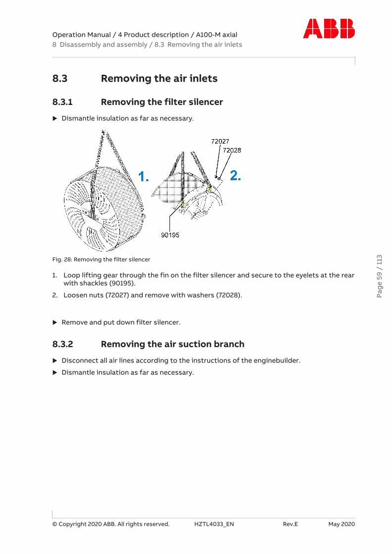
Operation Manual / 4 Product description / A100-M axial8 Disassembly and assembly / 8.3 Removing the air inlets
© Copyright 2020 ABB. All rights reserved. HZTL4033_EN Rev.E May 2020
8.3 Removing the air inlets
8.3.1 Removing the filter silencer
u Dismantle insulation as far as necessary.
Fig. 28: Removing the filter silencer
1. Loop lifting gear through the fin on the filter silencer and secure to the eyelets at the rearwith shackles (90195).
2. Loosen nuts (72027) and remove with washers (72028).
u Remove and put down filter silencer.
8.3.2 Removing the air suction branch
u Disconnect all air lines according to the instructions of the enginebuilder.
u Dismantle insulation as far as necessary.Pa
ge
59 /
113

Operation Manual / 4 Product description / A100-M axial8 Disassembly and assembly / 8.3 Removing the air inlets
© Copyright 2020 ABB. All rights reserved. HZTL4033_EN Rev.E May 2020
Fig. 29: Removing the air suction branch
1. Loop lifting gear around air suction branch.
2. Loosen and remove the nuts (72027) with washers (72028).
u Remove and put down the air suction branch.
Pag
e 60
/ 1
13

Operation Manual / 4 Product description / A100-M axial8 Disassembly and assembly / 8.4 Axial clearance A prior to disas-sembly
© Copyright 2020 ABB. All rights reserved. HZTL4033_EN Rev.E May 2020
8.4 Axial clearance A prior to disassembly
WARNINGPhysical hazards due to sharp edges on compressor wheelThe compressor wheel has sharp edges which can result in injury.
u Wear safety gloves.
Wear safety gloves to protect against mechanical hazards.
The axial clearance (A) must be measured prior to removal and after installation of the cart-ridge group.
CAUTIONClearances outside the toleranceSerious damage to engines or property can be caused by clearances outsidethe tolerance and excessively worn parts.
u Have the components assessed and, if necessary, replaced by an ABB Tur-bocharging Service Station.
Fig. 30: Axial clearance
Product Axial clearance A [mm]A170-M 0.30 ... 0.61A175-M 0.35 ... 0.69Table 34: Axial clearance A
u Measure and note axial clearance (A).
Pag
e 61
/ 1
13

Operation Manual / 4 Product description / A100-M axial8 Disassembly and assembly / 8.5 Removing the compressor casing
© Copyright 2020 ABB. All rights reserved. HZTL4033_EN Rev.E May 2020
8.5 Removing the compressor casing
Removing wall insert
Fig. 31: Removing wall insert
1. Loosen screws (72011) and remove with washers (72008).
2. To secure the wall insert, screw in one screw (72011) a third of the way.
3. Press off wall insert with three press-off screws (90900) until the lifting device(90190/90195) can be fitted.
4. Using shackle (90195) and lifting gear, fit lifting device (90190) to wall insert (77000).
5. Put on shackle (90195) and fasten to lifting gear.
6. Remove locking screw (72011).
7. Pull out wall insert (77000).
Pag
e 62
/ 1
13

Operation Manual / 4 Product description / A100-M axial8 Disassembly and assembly / 8.5 Removing the compressor casing
© Copyright 2020 ABB. All rights reserved. HZTL4033_EN Rev.E May 2020
Transporting and turning wall insert
Fig. 32: Transporting and turning wall insert
1. Fit support angle (90025) with bolts and nuts.
2. Carefully turn wall insert over support angle (90025) and place on supports.
u Place wall insert such that lifting device (90190/90195) can be removed.
Removing the diffuser
Fig. 33: Removing the diffuser
1. Remove and dispose of the O-ring (77040).
2. Loosen and remove screws (77015).
3. Loop lifting gear around diffuser (79000) and remove diffuser.
Pag
e 63
/ 1
13
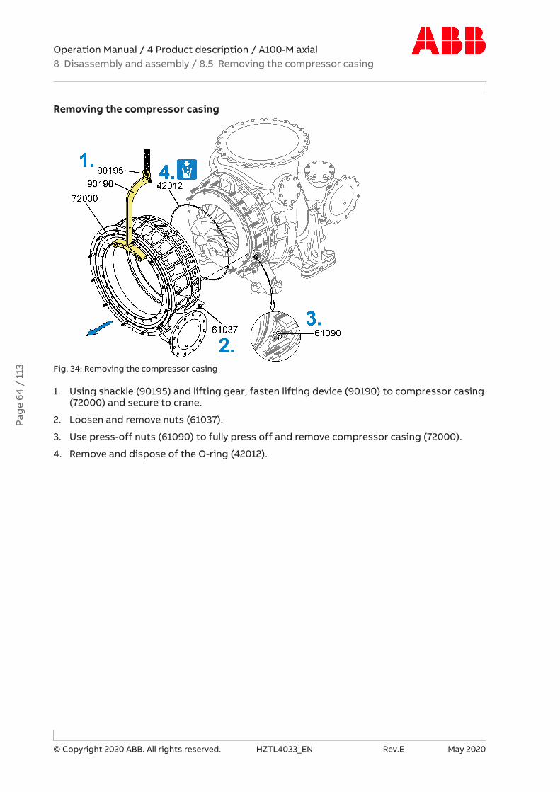
Operation Manual / 4 Product description / A100-M axial8 Disassembly and assembly / 8.5 Removing the compressor casing
© Copyright 2020 ABB. All rights reserved. HZTL4033_EN Rev.E May 2020
Removing the compressor casing
Fig. 34: Removing the compressor casing
1. Using shackle (90195) and lifting gear, fasten lifting device (90190) to compressor casing(72000) and secure to crane.
2. Loosen and remove nuts (61037).
3. Use press-off nuts (61090) to fully press off and remove compressor casing (72000).
4. Remove and dispose of the O-ring (42012).
Pag
e 64
/ 1
13

Operation Manual / 4 Product description / A100-M axial8 Disassembly and assembly / 8.6 Removing the cartridge group
© Copyright 2020 ABB. All rights reserved. HZTL4033_EN Rev.E May 2020
8.6 Removing the cartridge group
CAUTIONSafety-relevant screwsThe six screws (01) are relevant for containment safety and must not beloosened.
Fig. 35: Safety-relevant screws
CAUTIONOil orificesThere is an orifice for adjusting the oil pressure in each of the two oil supplypipes of the bearing casing. When the cartridge group, the bearing casing orthe turbocharger-is being fitted to the engine, it must be ensured that theorifices specified for the turbocharger are installed in both oil supply pipes.
u Check that the oil orifices have been correctly installed.
Version with compressor wheel cooling
u Dismantle air supply line (see Compressor wheel cooling →5).
u Separate oil inlet and outlet pipes.
Pag
e 65
/ 1
13

Operation Manual / 4 Product description / A100-M axial8 Disassembly and assembly / 8.6 Removing the cartridge group
© Copyright 2020 ABB. All rights reserved. HZTL4033_EN Rev.E May 2020
Fig. 36: Removing cartridge group 1
1. Unplug cable connector (86515) and unscrew speed sensor (86505) with O-ring (86506). Dispose of the O-Ring (86506).
2. Loosen socket screw (25013) and remove washer (25014).
3. Press off the spinner nose cone (25012) using the press-off screw (90917).
4. Loosen and remove the screw (61059).
5. Loosen and remove nuts (42128).
6. Attach lifting gear to bearing casing.
Pag
e 66
/ 1
13

Operation Manual / 4 Product description / A100-M axial8 Disassembly and assembly / 8.6 Removing the cartridge group
© Copyright 2020 ABB. All rights reserved. HZTL4033_EN Rev.E May 2020
CAUTIONClearance between blade tip and casingSerious damage to machinery or property can result from the rubbing orjamming of the blade tips on the casing.
u Check that the blades do not rub on the turbine diffuser during disas-sembly/assembly by rotating the rotor.
Fig. 37: Removing cartridge group 2
1. Evenly press off cartridge group by screwing three press-off screws (90900) into thedesignated holes.
2. Using two guide studs (90490), move out cartridge group.
3. Fit supports (90450) and put down cartridge group.
4. Remove guide studs (90490). Fit and tighten the spinner nose cone (25012) togetherwith socket screw (25013) and washer (25014) until hand-tight.
Pag
e 67
/ 1
13

Operation Manual / 4 Product description / A100-M axial8 Disassembly and assembly / 8.7 Removing the nozzle ring
© Copyright 2020 ABB. All rights reserved. HZTL4033_EN Rev.E May 2020
8.7 Removing the nozzle ring
Removing turbine diffuser
Fig. 38: Removing turbine diffuser 1
1. Remove screws (61069).
2. Using press-off screws (90915), press off turbine diffuser.
3. Fit guide plates (90328) with nuts (61037).
4. Screw in guide stud (90802).
Fig. 39: Removing turbine diffuser 2
5. Pull turbine diffuser (63000) out as far as it will go at guide plates.
6. Loop around turbine diffuser and secure to lifting gear.
7. Remove nuts (61037) and guide plates (90328).
8. Completely pull out and put down turbine diffuser.
Pag
e 68
/ 1
13

Operation Manual / 4 Product description / A100-M axial8 Disassembly and assembly / 8.7 Removing the nozzle ring
© Copyright 2020 ABB. All rights reserved. HZTL4033_EN Rev.E May 2020
Removing cover ring
Fig. 40: Removing cover ring 1
1. Refit guide plates (90328) with nuts (61037).
2. Loosen and remove (57005) bolts.Press off cover ring with the press-off screws (90916 for A170-M or 90901 for A175-M) inthe provided holes.
3. Pull cover ring (57001) out as far as it will go at the guide plates.
Pag
e 69
/ 1
13
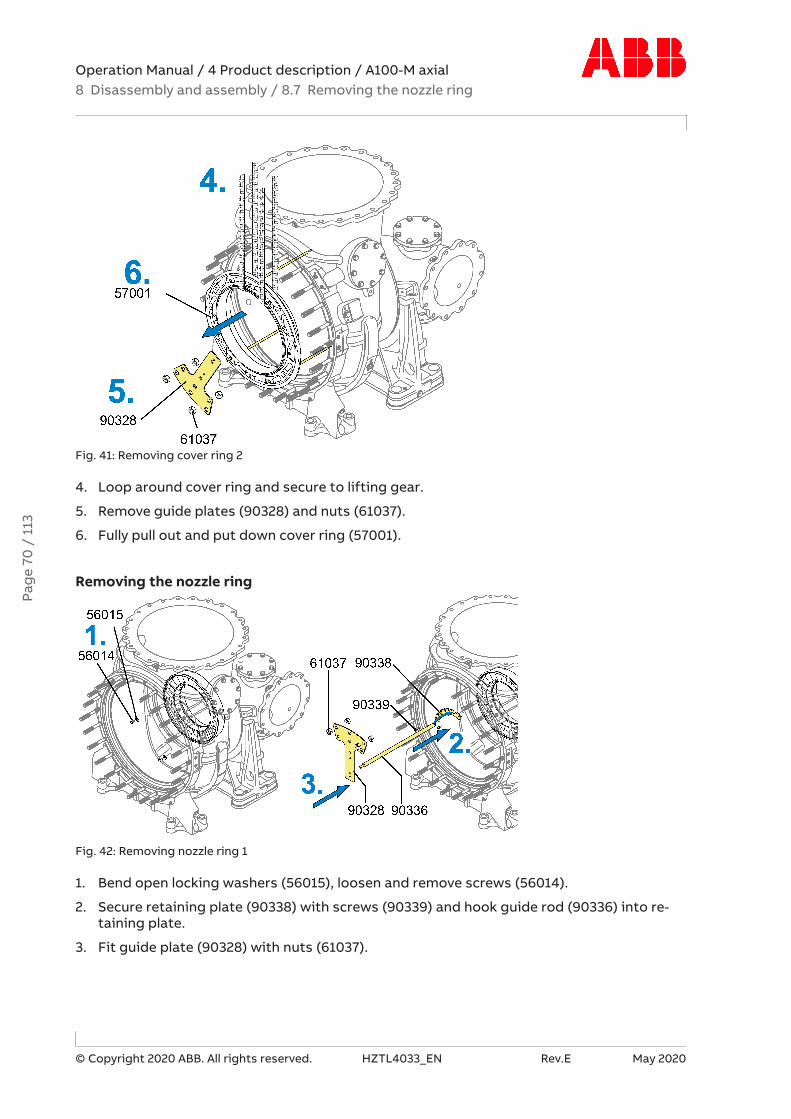
Operation Manual / 4 Product description / A100-M axial8 Disassembly and assembly / 8.7 Removing the nozzle ring
© Copyright 2020 ABB. All rights reserved. HZTL4033_EN Rev.E May 2020
Fig. 41: Removing cover ring 2
4. Loop around cover ring and secure to lifting gear.
5. Remove guide plates (90328) and nuts (61037).
6. Fully pull out and put down cover ring (57001).
Removing the nozzle ring
Fig. 42: Removing nozzle ring 1
1. Bend open locking washers (56015), loosen and remove screws (56014).
2. Secure retaining plate (90338) with screws (90339) and hook guide rod (90336) into re-taining plate.
3. Fit guide plate (90328) with nuts (61037).
Pag
e 70
/ 1
13

Operation Manual / 4 Product description / A100-M axial8 Disassembly and assembly / 8.7 Removing the nozzle ring
© Copyright 2020 ABB. All rights reserved. HZTL4033_EN Rev.E May 2020
Fig. 43: Removing nozzle ring 2
4. Pull nozzle ring (56001) out as far as it will go at guide plate.
5. Loop around nozzle ring (56001) and secure to lifting gear.
6. Remove guide plate (90328) and nuts (61037).
7. Fully pull out and put down nozzle ring (56001).
Blocked areas on nozzle ring
If a nozzle ring is blocked in some areas or is covered by loose parts, it is recommended toappoint an ABB Turbocharging Service Station to inspect the turbine blades and carry out acrack inspection.
Pag
e 71
/ 1
13

Operation Manual / 4 Product description / A100-M axial8 Disassembly and assembly / 8.8 Installing the nozzle ring
© Copyright 2020 ABB. All rights reserved. HZTL4033_EN Rev.E May 2020
8.8 Installing the nozzle ring
Fig. 44: Installing nozzle ring 1
1. Secure retaining plate (90338) with screws (90339) and hook in guide rod (90336).
2. Using lifting gear, position nozzle ring (56001) on guide rod (90336). Do not take strainoff lifting gear yet.
3. Fit guide plate (90328) with nuts (61037).
4. Remove the lifting gear.
5. Position nozzle ring (56001) in gas outlet casing.
Pag
e 72
/ 1
13

Operation Manual / 4 Product description / A100-M axial8 Disassembly and assembly / 8.8 Installing the nozzle ring
© Copyright 2020 ABB. All rights reserved. HZTL4033_EN Rev.E May 2020
Fig. 45: Installing nozzle ring 2
Product Size Tightening torque [Nm]A170-M M10 50A175-M M10 50Table 35: Tightening torque (56014)
6. Loosen nuts (61037) and remove guide plate (90328).
7. Loosen screws (90339) and remove retaining plate (90338) with guide rod (90336).
8. Coat the threads of screws (56014) and the contact surface between screw and lockingwasher with high-temperature grease.
9. Fit the nozzle ring (56001) on the gas inlet casing (51001) using the screws (56014) andlocking washers (56015).
10. Bend over locking washers (56015).
Pag
e 73
/ 1
13

Operation Manual / 4 Product description / A100-M axial8 Disassembly and assembly / 8.8 Installing the nozzle ring
© Copyright 2020 ABB. All rights reserved. HZTL4033_EN Rev.E May 2020
Installing cover ring
Fig. 46: Installing cover ring
Product Size Tightening torque [Nm]A170-M M14 130A175-M M16 200Table 36: Tightening torque (57005)
1. Using lifting gear, move in cover ring (57001) over guide studs (90802) with notch (V) fa-cing the gas outlet flange until the lifting gear is on the gas outlet casing.
2. Fit guide plates (90328) with nuts (61037).
3. Remove the lifting gear.
4. Slide in cover ring as far as it will go.
5. Remove guide plates (90328) and nuts (61037).
6. Coat threads of screws (57005) with high-temperature grease.
7. Fit and tighten screws (57005).
Pag
e 74
/ 1
13
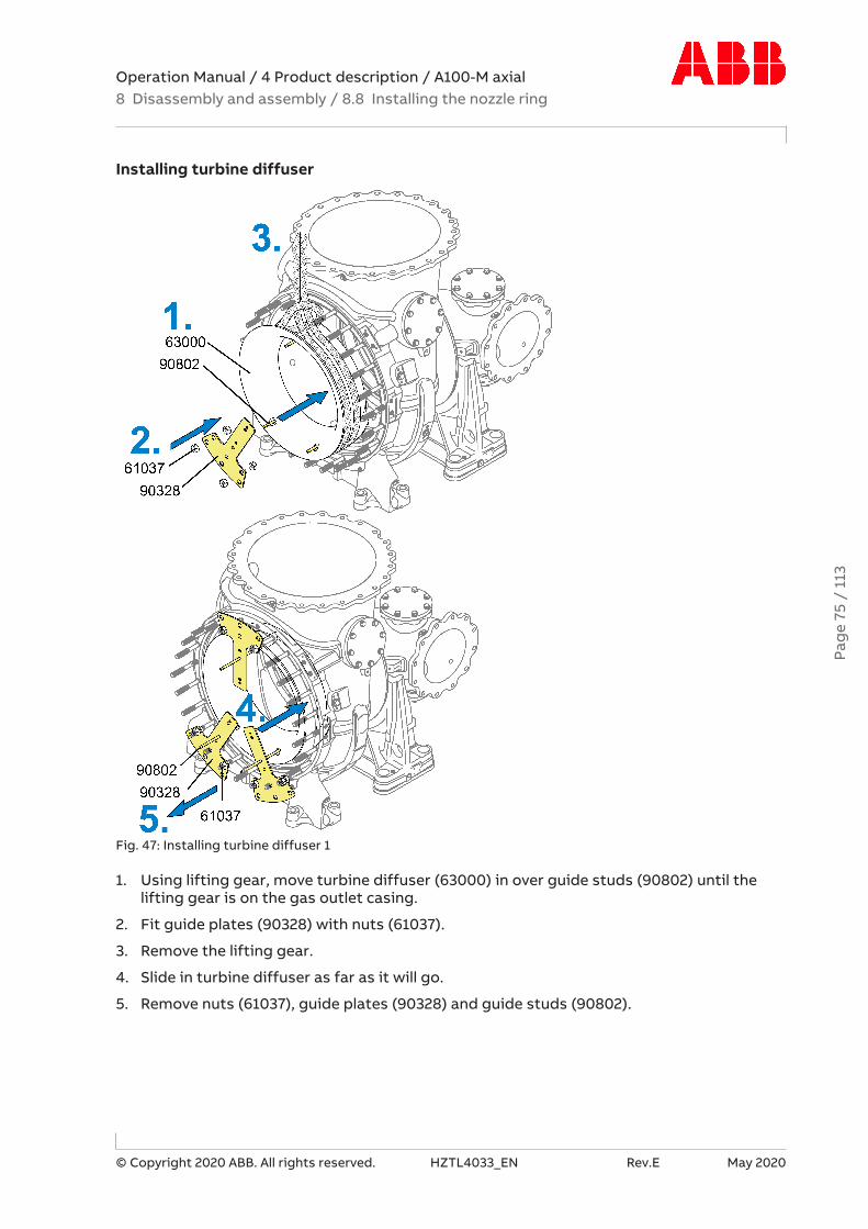
Operation Manual / 4 Product description / A100-M axial8 Disassembly and assembly / 8.8 Installing the nozzle ring
© Copyright 2020 ABB. All rights reserved. HZTL4033_EN Rev.E May 2020
Installing turbine diffuser
Fig. 47: Installing turbine diffuser 1
1. Using lifting gear, move turbine diffuser (63000) in over guide studs (90802) until thelifting gear is on the gas outlet casing.
2. Fit guide plates (90328) with nuts (61037).
3. Remove the lifting gear.
4. Slide in turbine diffuser as far as it will go.
5. Remove nuts (61037), guide plates (90328) and guide studs (90802).
Pag
e 75
/ 1
13

Operation Manual / 4 Product description / A100-M axial8 Disassembly and assembly / 8.8 Installing the nozzle ring
© Copyright 2020 ABB. All rights reserved. HZTL4033_EN Rev.E May 2020
Fig. 48: Installing turbine diffuser 2
Product Size Tightening torque [Nm]A170-M M14 130A175-M M16 200Table 37: Tightening torque (61069)
6. Coat threads of screws (61069) with high-temperature grease.
7. Fit and tighten screws (61069).
Pag
e 76
/ 1
13

Operation Manual / 4 Product description / A100-M axial8 Disassembly and assembly / 8.9 Installing the cartridge group
© Copyright 2020 ABB. All rights reserved. HZTL4033_EN Rev.E May 2020
8.9 Installing the cartridge group
CAUTIONClearance between blade tip and casingSerious damage to machinery or property can result from the rubbing orjamming of the blade tips on the casing.
u Check that the blades do not rub on the turbine diffuser during disas-sembly/assembly by rotating the rotor.
Fig. 49: Installing the cartridge group 1
1. Fasten lifting gear to bearing casing and lift cartridge group slightly.
2. Remove support (90450).
3. Using two guide rods (90490), carefully move in cartridge group.
4. Remove guide rods (90490).Pa
ge
77 /
113

Operation Manual / 4 Product description / A100-M axial8 Disassembly and assembly / 8.9 Installing the cartridge group
© Copyright 2020 ABB. All rights reserved. HZTL4033_EN Rev.E May 2020
Fig. 50: Installing the cartridge group 2
Product Size Tightening torque [Nm]A170-M M22 415A175-M M24 490Table 38: Tightening torque (61059 / 42128)
1. Coat thread of screw (61059) and two bolts for the nuts (42128) with high-temperaturegrease.
2. Secure cartridge group with screw (61059) and nuts (42128).
3. Remove the lifting gear.
Pag
e 78
/ 1
13

Operation Manual / 4 Product description / A100-M axial8 Disassembly and assembly / 8.9 Installing the cartridge group
© Copyright 2020 ABB. All rights reserved. HZTL4033_EN Rev.E May 2020
Fig. 51: Installing the cartridge group 3
Product Size Tightening torque [Nm]A170-M M18x1.5 150A175-M M18x1.5 150Table 39: Tightening torque (86505)
1. Screw in and tighten speed sensor (86505) with new O-ring (86506).
2. Insert cable connector (86515).
CAUTIONOil orificesThere is an orifice for adjusting the oil pressure in each of the two oil supplypipes of the bearing casing. When the cartridge group, the bearing casing orthe turbocharger-is being fitted to the engine, it must be ensured that theorifices specified for the turbocharger are installed in both oil supply pipes.
u Check that the oil orifices have been correctly installed.
u Remove temporary covers on oil connections.
u Fit all oil pipes according to instructions of enginebuilder.
Version with compressor wheel cooling
u Fit air supply line (see Compressor wheel cooling →5).
Pag
e 79
/ 1
13

Operation Manual / 4 Product description / A100-M axial8 Disassembly and assembly / 8.10 Fitting the spinner nose cone
© Copyright 2020 ABB. All rights reserved. HZTL4033_EN Rev.E May 2020
8.10 Fitting the spinner nose cone
If present:
The spinner nose cone (25012) and Loctite®542 are supplied by the ABB service station to-gether with the overhauled cartridge group.
CAUTIONTotal failure of turbochargerIf the spinner nose cone (25012) is not fitted correctly, or the socket screw(25013) is not correctly tightened, the spinner nose cone can work loose dur-ing operation and cause total failure of the turbocharger.
u Follow the assembly instructions.
u Always use a new socket screw (25013) and washer (25014) from the cus-tomer spare part set (97070).
u Only use new Loctite®542 supplied by the ABB service station.
u Observe and note down control dimension Z.
Fig. 52: Preparing the threaded stud (25008)
Product SizeA170-M M8A175-M M10Table 40: Inner thread size (25008)
Pag
e 80
/ 1
13
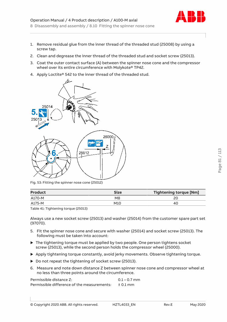
Operation Manual / 4 Product description / A100-M axial8 Disassembly and assembly / 8.10 Fitting the spinner nose cone
© Copyright 2020 ABB. All rights reserved. HZTL4033_EN Rev.E May 2020
1. Remove residual glue from the inner thread of the threaded stud (25008) by using ascrew tap.
2. Clean and degrease the inner thread of the threaded stud and socket screw (25013).
3. Coat the outer contact surface (A) between the spinner nose cone and the compressorwheel over its entire circumference with Molykote® TP42.
4. Apply Loctite® 542 to the inner thread of the threaded stud.
Fig. 53: Fitting the spinner nose cone (25012)
Product Size Tightening torque [Nm]A170-M M8 20A175-M M10 40Table 41: Tightening torque (25013)
Always use a new socket screw (25013) and washer (25014) from the customer spare part set(97070).
5. Fit the spinner nose cone and secure with washer (25014) and socket screw (25013). Thefollowing must be taken into account:
u The tightening torque must be applied by two people. One person tightens socketscrew (25013), while the second person holds the compressor wheel (25000).
u Apply tightening torque constantly, avoid jerky movements. Observe tightening torque.
u Do not repeat the tightening of socket screw (25013).
6. Measure and note down distance Z between spinner nose cone and compressor wheel atno less than three points around the circumference.
Permissible distance Z: 0.1 – 0.7 mmPermissible difference of the measurements: ± 0.1 mm
Pag
e 81
/ 1
13

Operation Manual / 4 Product description / A100-M axial8 Disassembly and assembly / 8.11 Installing the compressor casing
© Copyright 2020 ABB. All rights reserved. HZTL4033_EN Rev.E May 2020
8.11 Installing the compressor casing
Installing the compressor casing external part
Fig. 54: Installing the compressor casing
Product Size Tightening torque [Nm]A175-M M24 490A170-M M22 415Table 42: Tightening torque (61037)
Product Pre-tightening torque [Nm] Tightening angle [°]A175-M 40 45° ±5°A170-M 30 45° ±5°Table 43: Tightening torque, nuts that are difficult to access (61037)
Product Size Tightening torque [Nm]A170-M M22 50A175-M M24 50Table 44: Tightening torque (61090)
Pag
e 82
/ 1
13

Operation Manual / 4 Product description / A100-M axial8 Disassembly and assembly / 8.11 Installing the compressor casing
© Copyright 2020 ABB. All rights reserved. HZTL4033_EN Rev.E May 2020
1. Distributed evenly around the circumference, screw the press-off nuts (61090) onto thestuds of the bearing casing and turn them by hand until they are at the end of the thread.
2. Grease the new O-ring (42012) and fit it.
3. Fasten lifting device (90190 / 90195) to compressor casing (72000) and secure to crane.
4. Position the compressor casing (72000).Tighten nuts (61037) crosswise.
5. Remove lifting device (90190 / 90195).
6. Tighten the three press-off nuts (61090) against compressor casing (72000) by applyingthe corresponding tightening torque.
Installing diffuser
Fig. 55: Installing diffuser
Product Size Tightening torque [Nm]A170-M M5 6A175-M M6 10Table 45: Tightening torque (77015)
1. Loop around diffuser (79000) with lifting gear and position it on the wall insert (77000).
2. Attach diffuser with screws (77015).
3. Grease the new O-ring (77040) and fit it.
Pag
e 83
/ 1
13

Operation Manual / 4 Product description / A100-M axial8 Disassembly and assembly / 8.11 Installing the compressor casing
© Copyright 2020 ABB. All rights reserved. HZTL4033_EN Rev.E May 2020
Turning and moving in wall insert
Fig. 56: Turning and moving in wall insert
1. Fasten lifting device (90190 / 90195) to front of flange.Carefully turn wall insert (77000) with fitted diffuser over the support angle (90025) andpull up vertically.
2. Remove support angle (90025), bolts and nuts.
3. Fit guide studs (90319).
4. Carefully install the wall insert (77000) in the compressor casing. Make sure both mark-ings are in the correct position.
Pag
e 84
/ 1
13

Operation Manual / 4 Product description / A100-M axial8 Disassembly and assembly / 8.11 Installing the compressor casing
© Copyright 2020 ABB. All rights reserved. HZTL4033_EN Rev.E May 2020
Fitting wall insert
Fig. 57: Fitting wall insert
Product Size Tightening torque [Nm]A170-M M20 580A175-M M24 1000Table 46: Tightening torque (72011)
1. Remove lifting device (90190/90195).
2. Slide wall insert (77000) into compressor casing up to stop and remove guide stud(90319).
3. Secure wall insert with screws (72011) and washers (72008).
For assembly of the alternative air inlet, see section Lufteintritte anbauen.
See also
2 Installing the air inlets [} 87]
Pag
e 85
/ 1
13

Operation Manual / 4 Product description / A100-M axial8 Disassembly and assembly / 8.12 Axial clearance A after assembly
© Copyright 2020 ABB. All rights reserved. HZTL4033_EN Rev.E May 2020
8.12 Axial clearance A after assembly
WARNINGPhysical hazards due to sharp edges on compressor wheelThe compressor wheel has sharp edges which can result in injury.
u Wear safety gloves.
Wear safety gloves to protect against mechanical hazards.
The axial clearance (A) must be measured prior to removal and after installation of the cart-ridge group.
CAUTIONClearances outside the toleranceSerious damage to engines or property can be caused by clearances outsidethe tolerance and excessively worn parts.
u Have the components assessed and, if necessary, replaced by an ABB Tur-bocharging Service Station.
Fig. 58: Axial clearance
Product Axial clearance A [mm]A170-M 0.30 ... 0.61A175-M 0.35 ... 0.69Table 47: Axial clearance A
u Measure and note axial clearance (A).
Pag
e 86
/ 1
13

Operation Manual / 4 Product description / A100-M axial8 Disassembly and assembly / 8.13 Installing the air inlets
© Copyright 2020 ABB. All rights reserved. HZTL4033_EN Rev.E May 2020
8.13 Installing the air inlets
8.13.1 Installing the air suction branch
Fig. 59: Installing the air suction branch
Product Size Tightening torque [Nm]A175-M M20 220A170-M M18 170Table 48: Tightening torque (72027)
1. Loop lifting gear around air suction branch.
2. Fit air suction branch together with nuts (72027) and washer (72028). Observe tighteningtorque.
u Disconnect all air lines according to the instructions of the enginebuilder.
u Dismantle insulation as far as necessary.Pa
ge
87 /
113

Operation Manual / 4 Product description / A100-M axial8 Disassembly and assembly / 8.13 Installing the air inlets
© Copyright 2020 ABB. All rights reserved. HZTL4033_EN Rev.E May 2020
8.13.2 Installing the filter silencer
Fig. 60: Installing the filter silencer
Product Size Tightening torque [Nm]A170-M M18 170A175-M M20 220Table 49: Tightening torque (72027)
1. Loop lifting gear through the fin on the filter silencer and secure to the eyelets at the rearwith shackles (90195).
2. Fit filter silencer together with nuts (72027) and washers (72028). Observe tighteningtorque.
u Fit insulation.
Pag
e 88
/ 1
13
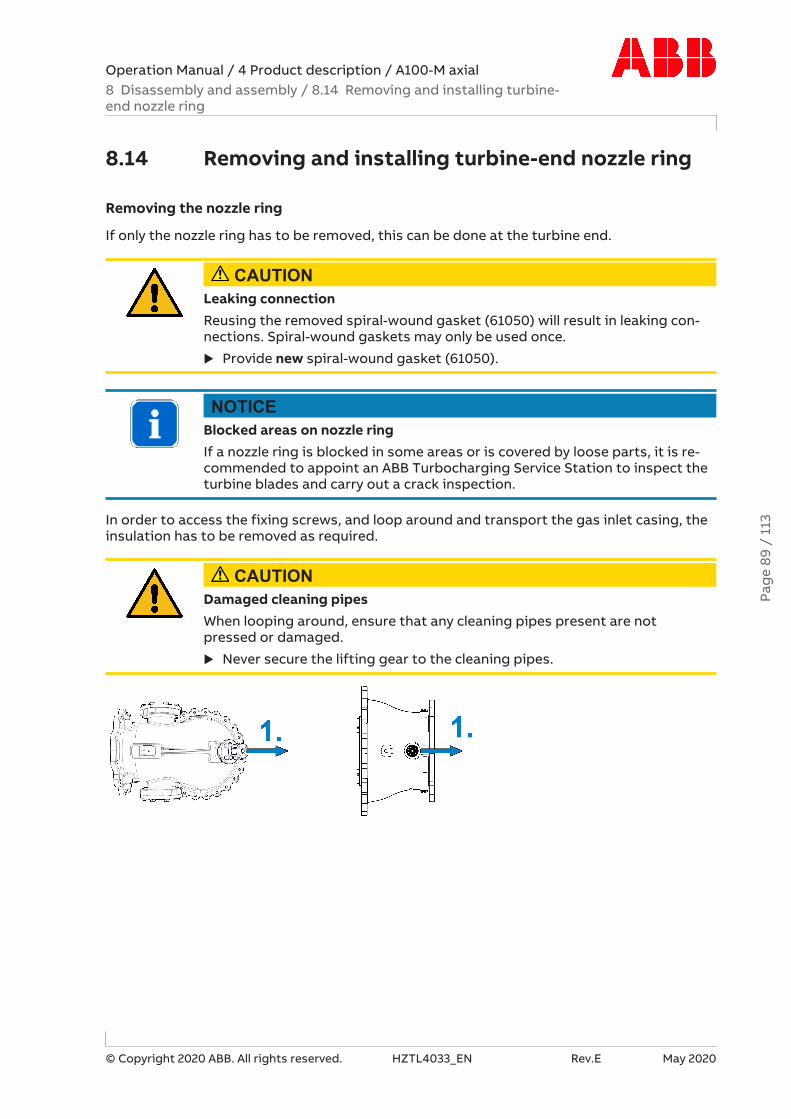
Operation Manual / 4 Product description / A100-M axial8 Disassembly and assembly / 8.14 Removing and installing turbine-end nozzle ring
© Copyright 2020 ABB. All rights reserved. HZTL4033_EN Rev.E May 2020
8.14 Removing and installing turbine-end nozzle ring
Removing the nozzle ring
If only the nozzle ring has to be removed, this can be done at the turbine end.
CAUTIONLeaking connectionReusing the removed spiral-wound gasket (61050) will result in leaking con-nections. Spiral-wound gaskets may only be used once.
u Provide new spiral-wound gasket (61050).
NOTICEBlocked areas on nozzle ringIf a nozzle ring is blocked in some areas or is covered by loose parts, it is re-commended to appoint an ABB Turbocharging Service Station to inspect theturbine blades and carry out a crack inspection.
In order to access the fixing screws, and loop around and transport the gas inlet casing, theinsulation has to be removed as required.
CAUTIONDamaged cleaning pipesWhen looping around, ensure that any cleaning pipes present are notpressed or damaged.
u Never secure the lifting gear to the cleaning pipes.
Pag
e 89
/ 1
13
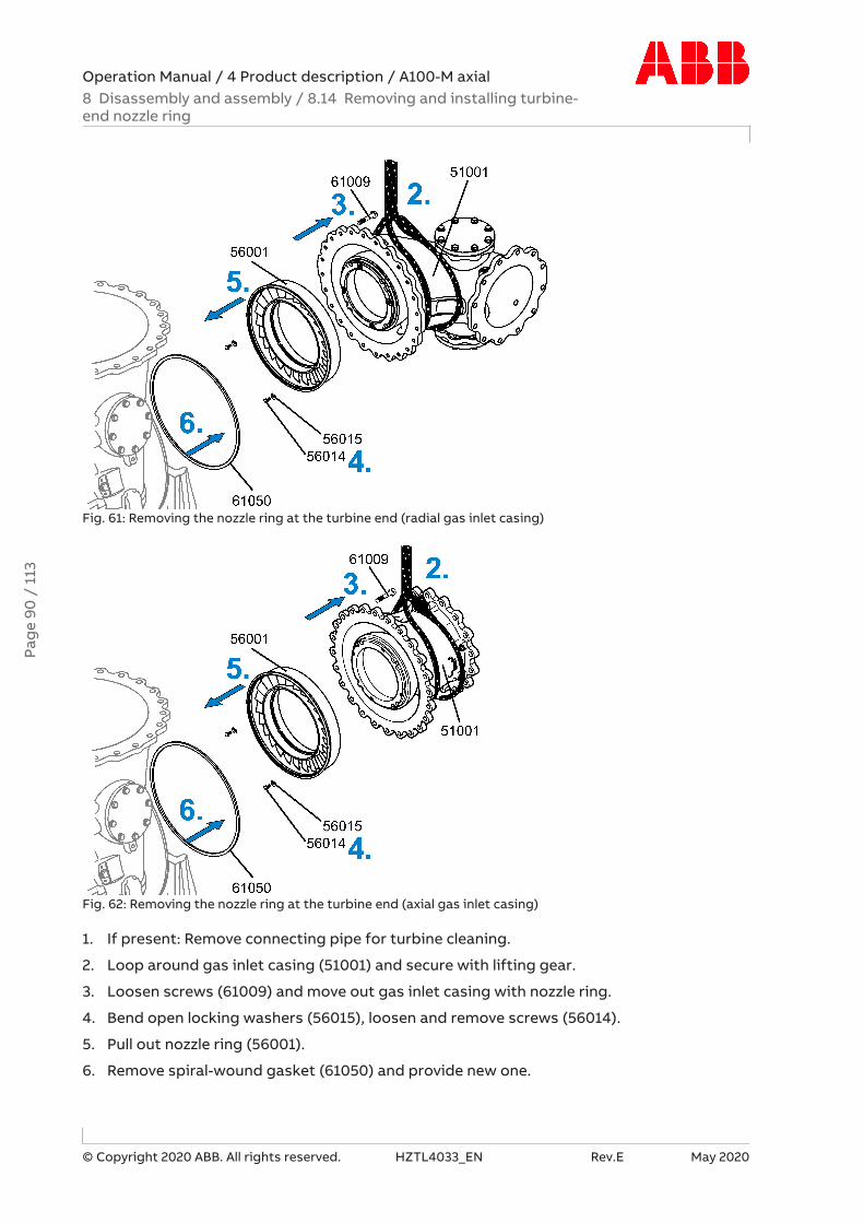
Operation Manual / 4 Product description / A100-M axial8 Disassembly and assembly / 8.14 Removing and installing turbine-end nozzle ring
© Copyright 2020 ABB. All rights reserved. HZTL4033_EN Rev.E May 2020
Fig. 61: Removing the nozzle ring at the turbine end (radial gas inlet casing)
Fig. 62: Removing the nozzle ring at the turbine end (axial gas inlet casing)
1. If present: Remove connecting pipe for turbine cleaning.
2. Loop around gas inlet casing (51001) and secure with lifting gear.
3. Loosen screws (61009) and move out gas inlet casing with nozzle ring.
4. Bend open locking washers (56015), loosen and remove screws (56014).
5. Pull out nozzle ring (56001).
6. Remove spiral-wound gasket (61050) and provide new one.
Pag
e 90
/ 1
13

Operation Manual / 4 Product description / A100-M axial8 Disassembly and assembly / 8.14 Removing and installing turbine-end nozzle ring
© Copyright 2020 ABB. All rights reserved. HZTL4033_EN Rev.E May 2020
Installing the nozzle ring
Fig. 63: Installing the nozzle ring at the turbine end (radial gas inlet casing)
Fig. 64: Installing the nozzle ring at the turbine end (axial gas inlet casing)
Pag
e 91
/ 1
13

Operation Manual / 4 Product description / A100-M axial8 Disassembly and assembly / 8.14 Removing and installing turbine-end nozzle ring
© Copyright 2020 ABB. All rights reserved. HZTL4033_EN Rev.E May 2020
Product Size Tightening torque [Nm]A170-M M10 50A175-M M10 50Table 50: Tightening torque (56014)
Product Size Tightening torque [Nm]Stage 1 Stage 2 Stage 3
A170-M M18 80 170 280A175-M M20 100 240 380Table 51: Tightening torque (61009)
1. Coat threads of new screws (56014) with high-temperature grease.Fit the nozzle ring (56001) to the gas inlet casing (51001) using the screws (56014) andnew locking washers (56015).Bend over locking washers.
2. Fix new spiral-wound gasket (61050) in groove of gas outlet casing (61001) at threeevenly distributed points with a little superglue (such as Loctite® 454).
3. Fit two guide studs (90321) in the upper part of the gas outlet casing (61001).
4. Coat threads of screws (61009) with high-temperature grease.
5. Loop around gas inlet casing (51001) and, using lifting gear, slide over guide studs untilat the gas outlet casing (61001) and secure with screws (61009).
6. Remove the guide studs (90321).
7. Fit remaining screws (61009), then crosswise tighten all screws (61009). Observe tight-ening torque.
8. If present: Fit connecting pipe for turbine cleaning
u Refit dismantled insulation.
Pag
e 92
/ 1
13

Operation Manual / 4 Product description / A100-M axial8 Disassembly and assembly / 8.15 Table of tightening torques
© Copyright 2020 ABB. All rights reserved. HZTL4033_EN Rev.E May 2020
8.15 Table of tightening torques
Fig. 65: Tightening torques 1
Fig. 66: Tightening torques 2
Pag
e 93
/ 1
13

Operation Manual / 4 Product description / A100-M axial8 Disassembly and assembly / 8.15 Table of tightening torques
© Copyright 2020 ABB. All rights reserved. HZTL4033_EN Rev.E May 2020
Thread sizes and tightening torques [Nm]
Position Part number A170-M A175-M01 82005 M22x1.5
80M22x1.5
8002 77015 M5
6M610
03 61036 M2260
M2480
04 61037 M22415
M24490
05 61090 M2250
M2450
06 61059 / 42128 M22415
M24490
07 61069 M14130
M16200
08 63001 M14170
M18240
09 56014 M1050
M1050
10 61009 M182801)
M203801)
11 57005 M14130
M16200
12 42059 M16200
M16200
13 72011 M20580
M241000
14 72027 M18170
M20220
15 72026 M1840
M2050
16 25013 M820
M1040
17 86505 M18x1.5150
M18x1.5150
Table 52: Tightening torques
1) Tighten screws (61009) crosswise in four steps (see Table 53: Tightening torques 61009→95).
Pag
e 94
/ 1
13

Operation Manual / 4 Product description / A100-M axial8 Disassembly and assembly / 8.15 Table of tightening torques
© Copyright 2020 ABB. All rights reserved. HZTL4033_EN Rev.E May 2020
Tightening sequence
Fig. 67: Flange tightening sequence
Product Tightening torque (61009) [Nm]Step 1 Step 2 Step 3 Step 4
A170-M hand-tight 80 170 280A175-M hand-tight 100 240 380Table 53: Tightening torques 61009
Pag
e 95
/ 1
13

Operation Manual / 4 Product description / A100-M axial9 Taking a turbocharger out of operation / 9.1 Possible emergency re-pairs
© Copyright 2020 ABB. All rights reserved. HZTL4033_EN Rev.E May 2020
9 Taking a turbocharger out of operation
9.1 Possible emergency repairs
CAUTIONMachine damage in emergency operationThe assembly of the locking device on the turbocharger is only permissiblein emergencies. It is not permitted to lock the rotor for an engine test. Seri-ous damage to engine or property can be caused by non-compliance withthe regulations in the event of an emergency.
u The permissible turbocharger speed for the unlocked turbocharger maynot exceed 45% of nBmax. Take note of the rating plate.
u After locking the turbocharger, contact an ABB Turbocharging ServiceStation and find the nearest port.
u Observe the safety regulations.
u Follow the directives of the enginebuilder.
WARNINGDanger of fire and explosion due to lubricating oil leaksLeaking oil may ignite on hot surfaces. This can result in serious injuries topersonnel or fatal accidents.
u Cordon off danger area.
u Raise the alarm and, depending on the situation, stop the engine.
u Seal the oil leak.
u Soak up oil and dispose of in an environmentally compatible manner.
Wear safety gloves to protect against thermal hazards.
If damage has occurred to the turbocharger and the engine has to be brought back into op-eration again as quickly as possible, the following emergency repair options are available:
¡ Lock the rotor
¡ Attach a cover plate
¡ Blank off the inlet and outlet flanges of casings
¡ Bypass the turbocharger
Pag
e 96
/ 1
13

Operation Manual / 4 Product description / A100-M axial9 Taking a turbocharger out of operation / 9.2 Locking the rotor
© Copyright 2020 ABB. All rights reserved. HZTL4033_EN Rev.E May 2020
9.2 Locking the rotor
9.2.1 Introduction
CAUTIONCooling of a locked rotorSerious damage to engine or property can be caused by the overheating ofintact turbocharger components.
If the gas inlet is not blanked off, the lubricating oil supply remains switchedon (see section Further information for operation of 4-stroke engines withlocked rotor).
u If there is a lubricating oil leak on the turbocharger, stop the oil supply.
A locked rotor must be removed after emergency operation and checked for unbalance (seechapter Removing the cartridge group).
The unbalance check must be carried out by an ABB Turbocharging Service Station.
Exception
The exception concerns customer requirements for test bed runs of new engines at a max-imum engine load of up to 25 %.
In these cases, subsequent removal of the rotor is not required as the engine is only oper-ated briefly with a locked rotor.
In these test bed runs, it is not allowed to remove any set screws from the compressor wheelwhen fitting the locking device (see section Fitting the locking device →98).
Pag
e 97
/ 1
13
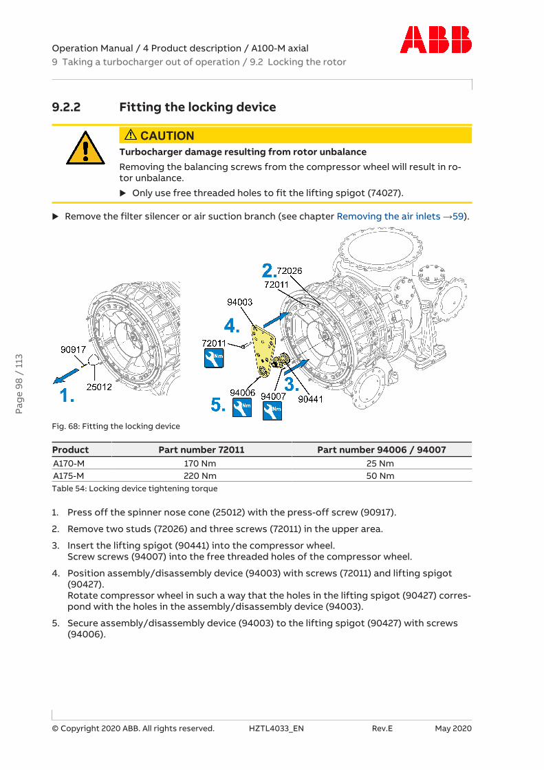
Operation Manual / 4 Product description / A100-M axial9 Taking a turbocharger out of operation / 9.2 Locking the rotor
© Copyright 2020 ABB. All rights reserved. HZTL4033_EN Rev.E May 2020
9.2.2 Fitting the locking device
CAUTIONTurbocharger damage resulting from rotor unbalanceRemoving the balancing screws from the compressor wheel will result in ro-tor unbalance.
u Only use free threaded holes to fit the lifting spigot (74027).
u Remove the filter silencer or air suction branch (see chapter Removing the air inlets →59).
Fig. 68: Fitting the locking device
Product Part number 72011 Part number 94006 / 94007A170-M 170 Nm 25 NmA175-M 220 Nm 50 NmTable 54: Locking device tightening torque
1. Press off the spinner nose cone (25012) with the press-off screw (90917).
2. Remove two studs (72026) and three screws (72011) in the upper area.
3. Insert the lifting spigot (90441) into the compressor wheel.Screw screws (94007) into the free threaded holes of the compressor wheel.
4. Position assembly/disassembly device (94003) with screws (72011) and lifting spigot(90427).Rotate compressor wheel in such a way that the holes in the lifting spigot (90427) corres-pond with the holes in the assembly/disassembly device (94003).
5. Secure assembly/disassembly device (94003) to the lifting spigot (90427) with screws(94006).
Pag
e 98
/ 1
13
Operation Manual / 4 Product description / A100-M axial9 Taking a turbocharger out of operation / 9.2 Locking the rotor
© Copyright 2020 ABB. All rights reserved. HZTL4033_EN Rev.E May 2020
9.2.3 Further information for operation of 4-stroke engineswith locked rotor
4-stroke engine with one turbocharger
No further measures are necessary. The engine can be operated as a suction engine accord-ing to the instructions of the enginebuilder.
4-stroke engine with several turbochargers
Separate receivers
In engines with separate air and exhaust gas receivers, no further measures are necessary.The engine can be operated as a suction engine according to the instructions of the en-ginebuilder.
Common air receiver
CAUTIONExcessive speeds on undamaged turbochargersThe speed limit nBmax specified on the rating plate of the turbocharger mustnot be exceeded. Serious damage to engine or property can be caused byexcessive speeds.
u Observe the speeds of the undamaged turbochargers.
u Reduce the engine load if necessary.
If the engine is equipped with a common air receiver and separate exhaust gas receivers, thebellows on the compressor outlet of the damaged turbocharger must always be removedand the air line on the engine side must be blanked off. Otherwise the undamaged tur-bocharger can spin "empty" (without load) and run at overspeed.
Depending on the turbocharging system of the engine, the locked rotor is exposed to moreor less strong pulses from the exhaust gas system. Especially in pulse charging (turbine cas-ing with more than one gas inlet), the locking device is heavily strained by this process.Therefore the following operating limits should not be exceeded:
¡ In constant-pressure-similar systems (1 gas inlet), the engine can be operated at a max-imum engine load of up to 25 %. The pressure in the charge air receiver must not exceed0.9 bar overpressure.
¡ In pulse charging (2 to 4 gas inlets), the engine can be operated at a maximum engineload of up to 20 %. The pressure in the charge air receiver must not exceed 0.5 bar over-pressure.
Pag
e 99
/ 1
13

Operation Manual / 4 Product description / A100-M axial9 Taking a turbocharger out of operation / 9.3 Fitting the cover plate
© Copyright 2020 ABB. All rights reserved. HZTL4033_EN Rev.E May 2020
9.3 Fitting the cover plateThe cover plate (01) and spacer sleeves (02) (material: general construction steel, in compli-ance with DIN EN 10025-2) must be manufactured according to the drawing from the oper-ator.
Fig. 69: Cover plate (01) / spacer sleeves (02) dimensions
Cover plate (01) / spacer sleeves (02) dimensions [mm]
Product B1 B2 B3 B4 B5 B6 B7 B8A170-M 13 432 50 50 9 12 8 96A175-M 13 500 50 50 9 12 8 112Table 55: Cover plate dimensions 1
Product Ø 1 Ø 2 Ø 3 Ø 4 Ø 5 Ø 6A170-M 835 915 872.4 24 34 20A175-M 965 1050 1007.5 26 36 20Table 56: Cover plate dimensions 2
Product ⍺ 1 ⍺ 2 ⍺ 3A170-M 4 x 90° 37.5° 24 x 15°A175-M 4 x 90° 37.5° 24 x 15°Table 57: Cover plate dimensions 3
Pag
e 10
0 /
113
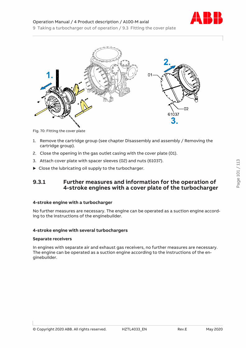
Operation Manual / 4 Product description / A100-M axial9 Taking a turbocharger out of operation / 9.3 Fitting the cover plate
© Copyright 2020 ABB. All rights reserved. HZTL4033_EN Rev.E May 2020
Fig. 70: Fitting the cover plate
1. Remove the cartridge group (see chapter Disassembly and assembly / Removing thecartridge group).
2. Close the opening in the gas outlet casing with the cover plate (01).
3. Attach cover plate with spacer sleeves (02) and nuts (61037).
u Close the lubricating oil supply to the turbocharger.
9.3.1 Further measures and information for the operation of4-stroke engines with a cover plate of the turbocharger
4-stroke engine with a turbocharger
No further measures are necessary. The engine can be operated as a suction engine accord-ing to the instructions of the enginebuilder.
4-stroke engine with several turbochargers
Separate receivers
In engines with separate air and exhaust gas receivers, no further measures are necessary.The engine can be operated as a suction engine according to the instructions of the en-ginebuilder.
Pag
e 10
1 /
113

Operation Manual / 4 Product description / A100-M axial9 Taking a turbocharger out of operation / 9.4 Blanking off the inletsand outlets
© Copyright 2020 ABB. All rights reserved. HZTL4033_EN Rev.E May 2020
Common air receiver
CAUTIONExcessive speeds on undamaged turbochargersThe speed limit nBmax specified on the rating plate of the turbocharger mustnot be exceeded. Serious damage to engine or property can be caused byexcessive speeds.
u Observe the speeds of the undamaged turbochargers.
u Reduce the engine load if necessary.
The air line must be blanked off on the engine side because the undamaged turbochargersbuild up a receiver pressure.
9.4 Blanking off the inlets and outletsThe chapter is only applicable for engines with several turbochargers and joint air and ex-haust gas receivers.
u Close the lubricating oil supply to the turbocharger.
u Blank off flange from compressor casing outlet, gas inlet and gas outlet by the installa-tion of cover plates.
u Observe specifications from enginebuilder.
9.5 Engines with bypass around the turbochargerThe chapter only applies for engines with one turbocharger and for systems on which theconnections for a bypass have been prepared and the necessary pipe connections have beenprovided.
u Close the lubricating oil supply to the turbocharger.
u Open the bypass around the turbocharger.
u Observe specifications from enginebuilder.
Pag
e 10
2 /
113

Operation Manual / 4 Product description / A100-M axial10 Mothballing the turbocharger / 10.1 Taking the engine out of opera-tion for up to 12 months
© Copyright 2020 ABB. All rights reserved. HZTL4033_EN Rev.E May 2020
10 Mothballing the turbocharger
10.1 Taking the engine out of operation for up to12 months
State of the engine lubricating oil
The turbocharger normally remains attached to the engine. The measures to be taken formothballing the turbocharger depend on the state of the lubricating oil. No measures are re-quired under the following conditions:
¡ Acid number (TAN) < 2 mg KOH/g
¡ The engine lubricating oil is replaced by a preservative oil and circulated with the pre-lub-rication pump before the engine is taken out of operation. Residues of old engine oil areflushed away in this way and the bearing parts are largely protected against corrosion.
Preparations for mothballing
WARNINGHandling operating materials and suppliesSwallowing or inhaling vapours of operating materials and supplies or con-tact with them may be harmful to health.
u Do not breathe in these substances and avoid contact with the skin.
u Ensure proper ventilation.
u Observe the information in the material safety data sheet for the operat-ing materials and supplies.
u Wear personal protective equipment (PPE) according to the materialsafety data sheet.
u Comply with local legislation.
Wear safety goggles.
Wear safety gloves to protect against chemical hazards.
Wear a respiratory mask to protect against gases.
If the acid number (TAN) is greater than 2 mg KOH/g, the following mothballing measuresare necessary after taking the engine out of operation:
u Dismantle the turbocharger.
u The rotor and bearing parts must be dismantled and subsequently refitted by an ABB Tur-bocharging Service Station.
u Clean all parts.
Pag
e 10
3 /
113

Operation Manual / 4 Product description / A100-M axial10 Mothballing the turbocharger / 10.2 Taking the engine out of oper-ation for more than 12 months
© Copyright 2020 ABB. All rights reserved. HZTL4033_EN Rev.E May 2020
u Coat plain surfaces of steel and cast parts with anticorrosive oil.
u Fit turbocharger completely.
Rotation of the rotor in the stack draught
If the rotor turns as a result of the stack draught:
u Install a blind flange between the outlet flange of the compressor casing and the chargeair duct.
10.2 Taking the engine out of operation for more than12 months
If the engine is taken out of operation, the following variants are possible with regard to theturbocharger:
¡ Turbocharger remains attached to the engine
¡ The casings of the turbocharger remain attached to the engine, the rotor and bearingparts are dismantled by an ABB Turbocharging Service Station and stored separately
¡ The turbocharger is completely removed, either as a whole unit or in individual parts
For the measures always necessary for preparing the turbocharger parts for mothballing,see section Taking the engine out of operation for up to 12 months, subsection Preparationsfor mothballing.
If the turbocharger remains attached to the engine, see section Taking the engine out of op-eration for up to 12 months, subsection Rotor turning in stack draught.
If the complete turbocharger is removed or the turbocharger is assembled again from theindividual parts:
u Seal all openings of the turbocharger with paraffin paper and wooden lids.
Only dry rooms with 40 ... 70 % atmospheric humidity, in which no water condensation canform, are suitable as storage locations.
State of the mothballed turbocharger
u Check the turbocharger parts annually for corrosion.
u If there are signs of rust: Thoroughly clean parts and renew corrosion protection.
Pag
e 10
4 /
113

Operation Manual / 4 Product description / A100-M axial11 Disposing of turbocharger components /
© Copyright 2020 ABB. All rights reserved. HZTL4033_EN Rev.E May 2020
11 Disposing of turbocharger components
WARNINGHandling damaged thermal insulationDamaged thermal insulation can lead to dust exposure. The glass fibres cancause mechanical irritation of the eyes, skin, and respiratory tracts.
u Avoid the formation of dust.
u Vacuum up dust with a suitable vacuum cleaner.
u Wear a respiratory mask to protect against dusts (P1 or P2 mask).
u Wear safety gloves.
Wear safety goggles.
Wear a respiratory mask to protect against dusts.
Wear safety gloves to protect against mechanical hazards.
Disposal must be environmentally compatible, professional, and in compliance with locallyapplicable regulations.
The turbocharger consists largely of metal (cast iron materials, steel, nickel-steel alloys, alu-minium and bearing brass).
Further components are: Non-metallic materials (filter components of felt and polyethylene),lubricants (engine oil), electronic parts (speed sensor and associated components), andthermal insulation.
u Dispose of metals as scrap metal for recycling.
u Dispose of non-metallic materials as waste.
u Dispose of residues of lubricants as waste oil.
u Dispose of electronic components as electronic waste.
u Dispose of thermal insulation as hazardous waste.Pa
ge
105
/ 11
3
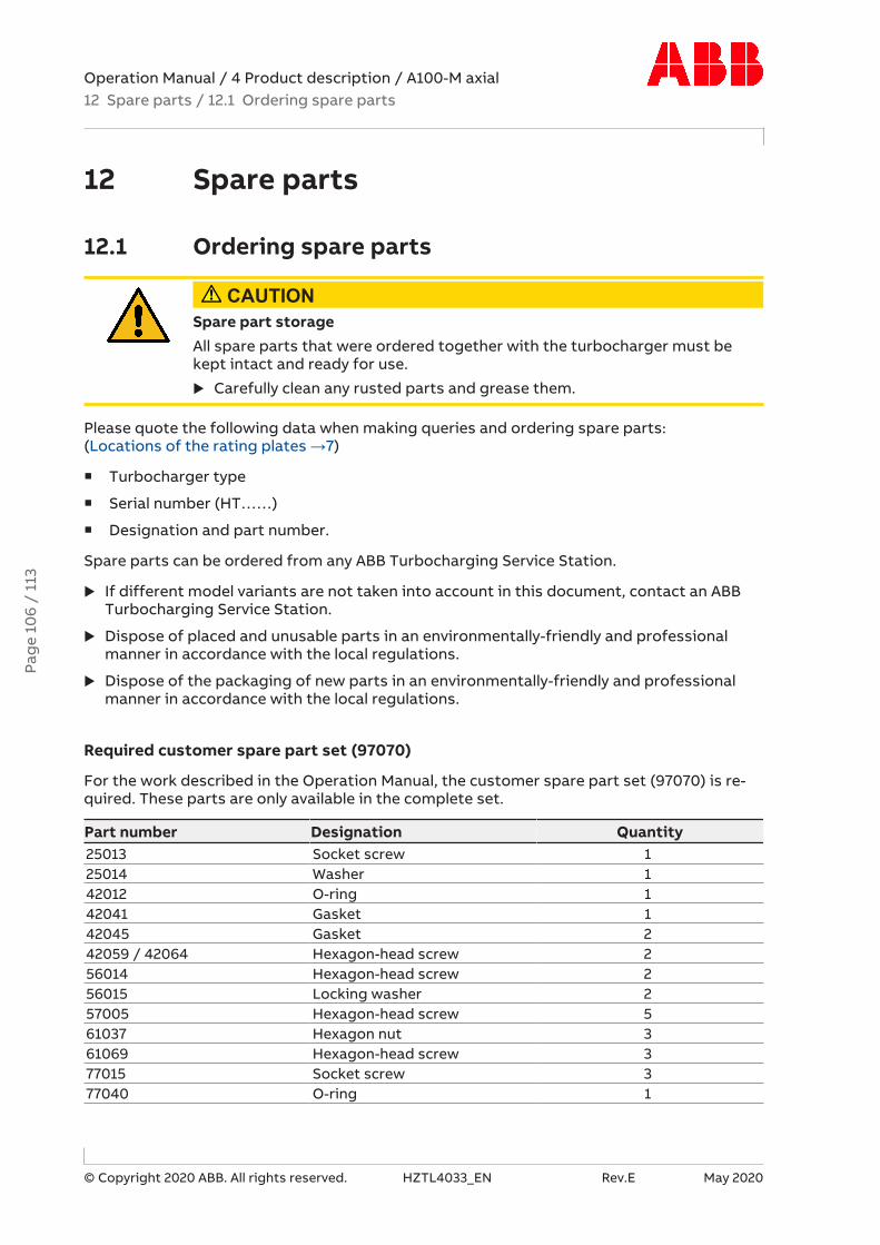
Operation Manual / 4 Product description / A100-M axial12 Spare parts / 12.1 Ordering spare parts
© Copyright 2020 ABB. All rights reserved. HZTL4033_EN Rev.E May 2020
12 Spare parts
12.1 Ordering spare parts
CAUTIONSpare part storageAll spare parts that were ordered together with the turbocharger must bekept intact and ready for use.
u Carefully clean any rusted parts and grease them.
Please quote the following data when making queries and ordering spare parts:(Locations of the rating plates →7)
¡ Turbocharger type
¡ Serial number (HT……)
¡ Designation and part number.
Spare parts can be ordered from any ABB Turbocharging Service Station.
u If different model variants are not taken into account in this document, contact an ABBTurbocharging Service Station.
u Dispose of placed and unusable parts in an environmentally-friendly and professionalmanner in accordance with the local regulations.
u Dispose of the packaging of new parts in an environmentally-friendly and professionalmanner in accordance with the local regulations.
Required customer spare part set (97070)
For the work described in the Operation Manual, the customer spare part set (97070) is re-quired. These parts are only available in the complete set.
Part number Designation Quantity25013 Socket screw 125014 Washer 142012 O-ring 142041 Gasket 142045 Gasket 242059 / 42064 Hexagon-head screw 256014 Hexagon-head screw 256015 Locking washer 257005 Hexagon-head screw 561037 Hexagon nut 361069 Hexagon-head screw 377015 Socket screw 377040 O-ring 1
Pag
e 10
6 /
113

Operation Manual / 4 Product description / A100-M axial12 Spare parts / 12.2 View of turbocharger with part numbers
© Copyright 2020 ABB. All rights reserved. HZTL4033_EN Rev.E May 2020
Part number Designation Quantity86506 O-ring (speed sensor) 1Table 58: Customer spare part set (97070)
12.2 View of turbocharger with part numbers
Fig. 71: Turbocharger with part numbers
( . . . . . ) only available in customer spare part set (97070)
Pag
e 10
7 /
113

Operation Manual / 4 Product description / A100-M axial12 Spare parts / 12.2 View of turbocharger with part numbers
© Copyright 2020 ABB. All rights reserved. HZTL4033_EN Rev.E May 2020
Turbocharger
Part number Designation51001 Gas inlet casing, axial / radial56001 Nozzle ring56014 (in customer spare part set) Hexagon-head screw56015 (in customer spare part set) Locking washer57001 Cover ring57005 (in customer spare part set) Hexagon-head screw61001 Gas outlet casing61037 (in customer spare part set) Hexagon nut61050 Gasket61069 (in customer spare part set) Hexagon-head screw63000 Turbine diffuser68001 Foot, compressor end68002 Foot, turbine end68003 Sliding block72000 Compressor casing77015 (in customer spare part set) Socket screw77000 Wall insert77040 (in customer spare part set) O-ring79000 Diffuser81000 Filter silencer82000 Radial air suction branchTable 59: Turbocharger with part numbers
Pag
e 10
8 /
113

Operation Manual / 4 Product description / A100-M axial13 Tools /
© Copyright 2020 ABB. All rights reserved. HZTL4033_EN Rev.E May 2020
13 ToolsFor the work described in the Operation Manual, the customer tool set 90009 is required.
90009 Designation Quantity90010 Wooden crate 190025 Support angle complete 190190 Lifting device 190195 Shackle 290319 Guide stud 290321 Guide stud 290328 Guide plate bolt 390336 Guide stud 190338 Mounting plate 190339 Socket screw 290441 Lifting spigot 190450 Support 290490 Guide stud 290802 Guide stud 390900 Press-off screw 390915 Press-off screw 390916 / 90901 Press-off screw 390917 Press-off screw 194003 Locking device 194006 Hexagon-head screw 1094007 Hexagon-head screw 1290321 Guide stud 2Table 60: Customer tool set 90009
This tool set can be ordered from any ABB Turbocharging Service Station. The following spe-cifications must be included in the order:
¡ Turbocharger type
¡ Designation and part number of the tool set.Pa
ge
109
/ 11
3
Operation Manual / 4 Product description / A100-M axial Figures
© Copyright 2020 ABB. All rights reserved. HZTL4033_EN Revision E May 2020
FiguresFig. 1: Layout and function ........................................... 4
Fig. 2: Connection of the compressor wheel cooling.... 5
Fig. 3: Warning plates on the turbocharger .............. 6
Fig. 4: Locations of the rating plates .......................... 7
Fig. 5: Turbocharger suspension points.................... 8
Fig. 6: Turbocharger suspension points.................... 9
Fig. 7: Removing the foot mounting.......................... 10
Fig. 8: Loosening the clamping nut ........................... 11
Fig. 9: Turbocharger suspension points................... 12
Fig. 10: Removing auxiliary screw .............................. 13
Fig. 11: Compressor-end foot ..................................... 13
Fig. 12: Turbine-end foot.............................................. 14
Fig. 13: CE foot contact surface ................................. 15
Fig. 14: TE foot: Handling of cup spring contact sur-face / foot contact surface ......................................... 15
Fig. 15: Tightening the foot screws (1)...................... 16
Fig. 16: Tightening procedure..................................... 17
Fig. 17: Lubricating oil pressure measuring point .. 21
Fig. 18: Speed measurement....................................... 23
Fig. 19: Noise insulation, bellows ............................... 27
Fig. 20: Cleaning the filter silencer ........................... 34
Fig. 21: Cleaning the filter silencer (2) ...................... 36
Fig. 22: Cleaning the slotted diffuser ........................ 37
Fig. 23: Operation of water pressure vessel ........... 42
Fig. 24: Turbine and nozzle ring cleaning cycle ...... 46
Fig. 25: Cleaning cycle of turbine and nozzle ringwith load ramp.............................................................. 47
Fig. 26: Procedure Wet cleaning of turbine andnozzle ring...................................................................... 48
Fig. 27: Weight of assemblies .................................... 58
Fig. 28: Removing the filter silencer ......................... 59
Fig. 29: Removing the air suction branch ............... 60
Fig. 30: Axial clearance ................................................. 61
Fig. 31: Removing wall insert...................................... 62
Fig. 32: Transporting and turning wall insert........... 63
Fig. 33: Removing the diffuser .................................... 63
Fig. 34: Removing the compressor casing ............... 64
Fig. 35: Safety-relevant screws ................................... 65
Fig. 36: Removing cartridge group 1.......................... 66
Fig. 37: Removing cartridge group 2.......................... 67
Fig. 38: Removing turbine diffuser 1.......................... 68
Fig. 39: Removing turbine diffuser 2.......................... 68
Fig. 40: Removing cover ring 1 .................................... 69
Fig. 41: Removing cover ring 2 .................................... 70
Fig. 42: Removing nozzle ring 1 ................................... 70
Fig. 43: Removing nozzle ring 2.................................... 71
Fig. 44: Installing nozzle ring 1 .................................... 72
Fig. 45: Installing nozzle ring 2.................................... 73
Fig. 46: Installing cover ring ........................................ 74
Fig. 47: Installing turbine diffuser 1 ........................... 75
Fig. 48: Installing turbine diffuser 2........................... 76
Fig. 49: Installing the cartridge group 1.................... 77
Fig. 50: Installing the cartridge group 2.................... 78
Fig. 51: Installing the cartridge group 3 .................... 79
Fig. 52: Preparing the threaded stud (25008).......... 80
Fig. 53: Fitting the spinner nose cone (25012)......... 81
Fig. 54: Installing the compressor casing................. 82
Fig. 55: Installing diffuser ............................................ 83
Fig. 56: Turning and moving in wall insert................ 84
Fig. 57: Fitting wall insert............................................. 85
Fig. 58: Axial clearance.................................................. 86
Fig. 59: Installing the air suction branch................... 87
Fig. 60: Installing the filter silencer............................ 88
Fig. 61: Removing the nozzle ring at the turbine end(radial gas inlet casing) ................................................ 90
Fig. 62: Removing the nozzle ring at the turbine end(axial gas inlet casing) .................................................. 90
Pag
e 11
0 /
113
Pag
e 11
0 /
113

Operation Manual / 4 Product description / A100-M axial Figures
© Copyright 2020 ABB. All rights reserved. HZTL4033_EN Revision E May 2020
Fig. 63: Installing the nozzle ring at the turbine end(radial gas inlet casing)................................................ 91
Fig. 64: Installing the nozzle ring at the turbine end(axial gas inlet casing).................................................. 91
Fig. 65: Tightening torques 1 ..................................... 93
Fig. 66: Tightening torques 2..................................... 93
Fig. 67: Flange tightening sequence......................... 95
Fig. 68: Fitting the locking device............................. 98
Fig. 69: Cover plate (01) / spacer sleeves (02) dimen-sions.............................................................................. 100
Fig. 70: Fitting the cover plate.................................. 101
Fig. 71: Turbocharger with part numbers............... 107
Pag
e 11
1 /
113
Pag
e 11
1 /
113

Operation Manual / 4 Product description / A100-M axial Tables
© Copyright 2020 ABB. All rights reserved. HZTL4033_EN Revision E May 2020
TablesTable 1: Related documents .......................................... 3
Table 2: Weight of complete turbocharger unit....... 8
Table 3: Foot screws, dimension and strength class..14
Table 4: Foot screws, dimension CE.......................... 14
Table 5: Foot screws, dimension TE.......................... 14
Table 6: Foot screws, number of cup springs ......... 14
Table 7: Torque-controlled tightening of the pres-sure screws .................................................................... 17
Table 8: Oil pressure range.......................................... 21
Table 9: Oil temperature at the inlet ......................... 22
Table 10: Oil temperature at the outlet .................... 22
Table 11: Expected replacement intervals ................ 32
Table 12: Recommended replacement intervals ..... 32
Table 13: Tightening torque (81272) ......................... 36
Table 14: Tightening torque (81273)......................... 36
Table 15: Compressor cleaning parameters ........... 40
Table 16: Compressor cleaning parameters ........... 43
Table 17: Cleaning parameters Wet cleaning of tur-bine and nozzle ring..................................................... 49
Table 18: Malfunctions when starting – Delayedstart-up .......................................................................... 50
Table 19: Malfunctions when starting – Vibrations 50
Table 20: Malfunctions when starting – Rubbing ofrotating parts................................................................ 50
Table 21: Malfunctions during operation – Lubricat-ing oil pressure too low................................................ 51
Table 22: Malfunctions during operation – Drop inspeed ............................................................................... 51
Table 23: Malfunctions during operation – Speed in-creases ............................................................................ 51
Table 24: Malfunctions during operation – Exhaustgas temperature too high .......................................... 52
Table 25: Malfunctions during operation – Charge airpressure too low........................................................... 52
Table 26: Malfunctions during operation – Charge airpressure too high ......................................................... 53
Table 27: Surging of the turbocharger..................... 53
Table 28: Malfunctions when stopping – Runoutnoises............................................................................... 54
Table 29: Malfunctions when stopping – Shortenedrunout time ..................................................................... 54
Table 30: Malfunction, No speed measurement sig-nal or poor signal amplitude ....................................... 55
Table 31: Malfunction, Measured speed too high ... 55
Table 32: Malfunction, Measured speed too low..... 55
Table 33: Assembly weights ........................................ 58
Table 34: Axial clearance A ........................................... 61
Table 35: Tightening torque (56014) ......................... 73
Table 36: Tightening torque (57005) ......................... 74
Table 37: Tightening torque (61069) ......................... 76
Table 38: Tightening torque (61059 / 42128)........... 78
Table 39: Tightening torque (86505)......................... 79
Table 40: Inner thread size (25008) ........................... 80
Table 41: Tightening torque (25013).......................... 81
Table 42: Tightening torque (61037).......................... 82
Table 43: Tightening torque, nuts that are difficultto access (61037) ........................................................... 82
Table 44: Tightening torque (61090)......................... 82
Table 45: Tightening torque (77015).......................... 83
Table 46: Tightening torque (72011) .......................... 85
Table 47: Axial clearance A ........................................... 86
Table 48: Tightening torque (72027) ......................... 87
Table 49: Tightening torque (72027) ......................... 88
Table 50: Tightening torque (56014) ......................... 92
Table 51: Tightening torque (61009) ......................... 92
Table 52: Tightening torques ...................................... 94
Table 53: Tightening torques 61009.......................... 95
Table 54: Locking device tightening torque ............ 98
Table 55: Cover plate dimensions 1 ......................... 100
Table 56: Cover plate dimensions 2 ......................... 100
Table 57: Cover plate dimensions 3 ......................... 100
Table 58: Customer spare part set (97070)............ 107
Pag
e 11
2 /
113
Pag
e 11
2 /
113
Operation Manual / 4 Product description / A100-M axial Tables
© Copyright 2020 ABB. All rights reserved. HZTL4033_EN Revision E May 2020
Table 59: Turbocharger with part numbers.......... 108
Table 60: Customer tool set 90009........................ 109
Pag
e 11
3 /
113
Pag
e 11
3 /
113